PDHonline Course E299 (3 PDH) Written Pole Motors 2012 Instructor: Lee Layton, PE PDH Online | PDH Center 5272 Meadow Estates Drive Fairfax, VA 22030-6658 Phone & Fax: 703-988-0088 www.PDHonline.org www.PDHcenter.com An Approved Continuing Education Provider

Welcome message from author
This document is posted to help you gain knowledge. Please leave a comment to let me know what you think about it! Share it to your friends and learn new things together.
Transcript

PDHonline Course E299 (3 PDH)
Written Pole Motors
2012
Instructor: Lee Layton, PE
PDH Online | PDH Center5272 Meadow Estates Drive
Fairfax, VA 22030-6658Phone & Fax: 703-988-0088
www.PDHonline.orgwww.PDHcenter.com
An Approved Continuing Education Provider

www.PDHcenter.com PDH Course E299 www.PDHonline.org
Written Pole® Motors
Lee Layton, P.E
Table of Contents
Section Page
Introduction ………………………………………… 3
I. Basic Operation of Electric Motors ……………… 5
II. Written Pole Motor Design ……………………… 20
III. Operational Benefits of Written-Pole® Motors …. 26
Summary ..…………………………………………. 30
© Lee Layton. Page 2 of 30
The term Written-Pole® motor is trademarked by Precise Power Corporation of Bradenton, Fl. All references in this course to Written-Pole motors refer to the trademarked name registered to Precise Power Corporation.

www.PDHcenter.com PDH Course E299 www.PDHonline.org
Introduction In the 1990’s, with support from the Electric Power Research Institute (EPRI), the Precise Power Corporation of Bradenton, Florida, developed a new concept in electric motors called the Written Pole® electric motor. This new motor type dramatically reduces starting currents of single phase motors and allows the design of single phase motors up to 100 hp as compared to conventional single phase motors, which are generally limited to units of 15 hp and smaller. Electric motors are the backbone of an electrified society and electric motors are responsible for two-thirds of all electric energy generated in the United States today. Most electric motors are small and only 2% of the motors in the United States are over 5 hp, but they account for over 70% of the energy used to drive electric motors. The electric distribution system in the United States is comprised of three-phase lines for main feeders and heavily congested areas and single-phase lines for laterals and rural areas. Electric service connections are primarily single phase. Thiarrangement is ideal for residential and small commercial loads that are predominately lighsmall motors, and miscellaneous appliances. Yet, there are small commercial and agriculturalloads that require motors larger than the traditional limits of 10-15 hp. In this case, a three phasepower supply is needed to for the three-phase motor load. However, it is often not economicalextend three-phase power into s
s ting,
to parsely populated areas.
One fundamental problem with single-phase motors is the very high starting current required to get the motor up to speed. A typical single-phase motor may have starting currents that are six to ten times their normal running current. Newer motors with higher efficiency usually have even higher starting current inrush. This presents a major problem in areas with limited electric supply or in rural areas where only single-phase lines are available. Because of high starting currents, single-phase motors are not generally available in sizes over 15 hp. Many utilities restrict the use of single-phase motors to sizes under 10 hp for ordinary electric motors. High motor starting currents on single-phase lines can cause line voltage dips that can cause problems for other loads. The motor developed by Precise Power Corporation, known as the Written-Pole® motor, uses an innovative approach of controlling the magnetic field of the motor to reduce the starting current requirements. The result is a motor that has starting current requirements of only about twice the normal running current and, as an added benefit, the motors have efficiencies of 90% or better compared to conventional motors, which have efficiencies of around 85%. The Written-Pole® motor has been developed with inherently low per-unit starting current and they can be applied in single-phase service areas to ratings of over 100 hp without exceeding the starting current limits of many utility systems.
© Lee Layton. Page 3 of 30
www.PDHcenter.com PDH Course E299 www.PDHonline.org
Written-pole motors differ from conventional motors in the way the magnetic field is developed. In a conventional motor, the poles are in fixed positions. In a written-pole motor, a magnetic layer is written in different places on the motor's poles as the rotor turns. Advantages of Written-Pole® motors include,
• Low starting current • High operating efficiency • Excellent torque characteristics • Unity power factor operation • Ability to start high-inertia loads • Ability to re-synchronous under load after pull-out
Because a written-pole motor has much lower starting current than a traditional electric motor, it takes longer to reach full speed. A conventional motor generally reaches full speed in a matter of seconds - it must to prevent overheating – whereas, a written-pole motor may take several minutes to reach full speed. The slow start up speed is beneficial in some applications such as water pumps; since the slow speed can prevent water hammering that is prevalent in water pumping applications with fast ramp up speeds of conventional motors.
© Lee Layton. Page 4 of 30
In this course we will look at the operation of a typical induction motor, the characteristics of induction motors, the design features of Written-Pole® motors, and a review of the benefits of written-pole motors. First, let’s look at the basic operation of an electric motor.
www.PDHcenter.com PDH Course E299 www.PDHonline.org
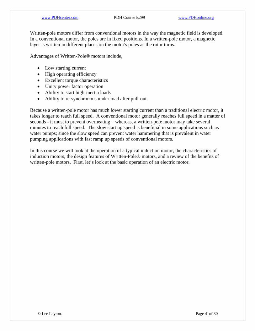
I. Basic Operation of Electric Motors To understand how an electric motor works, we must first understand the principles of magnetism and electromagnetism. An electromagnet is simply a piece of iron or other ferrous material that has been wound with a conductor through which an electric current can pass. When a current is passed through the conductor the iron is magnetized and acts just like a permanent magnetic. Consider two electromagnets and one permanent magnet aligned as shown in the figure below. The top electromagnet is oriented with the north-pole pointing up. The middle permanent magnet is oriented in the reverse fashion, with its north-pole pointing down and the bottom electromagnet has its north pole pointing up. There will be a force of repulsion between the center magnet and the other two since the south pole of the top magnet is aligned with the south pole of the center magnet and the north pole of the bottom magnet is aligned with the north pole of the center magnet.
If the center magnet is free to rotate it will turn until its north pole is aligned with the south pole of the top magnet. At this point the magnetic fields will be aligned and no further rotation will occur. A motor that makes one-half turn and then stops is not very useful though. To make the center magnet continue to turn, the poles of the top and bottom magnets must be reversed. This is the advantage of the electromagnet – It can reverse polarity by merely changing the direction of current flow. In an actual motor, the stationary electromagnets are called the stators, and the rotating magnet is known as the rotor. The rotor is not actually a permanent magnet, but instead is a form of an electromagnet.
© Lee Layton. Page 5 of 30
The most common type of motor is an induction motor which is based on electromagnetic theory. According to electromagnetic theory, if an electric current is passed through a conductor, which is positioned perpendicular to the direction of a magnetic field, the conductor will

www.PDHcenter.com PDH Course E299 www.PDHonline.org
experience a mechanical force that will cause it to move in a direction that is perpendicular to the current flowing through the conductor and the direction of the magnetic field. In an induction motor, the rotor is magnetized through a process known as induction. The rotor is an electromagnet that is energized by inducing a current in the rotor winding. Induction occurs when a conducting material, such as copper wire, is passed through a magnetic field. Passing a conductor through a magnetic field impresses a voltage on the conductor, which causes a current to flow. In the case of an induction motor, the conductor is the rotor winding and the magnetic field is produced by the stator windings. Alternating current makes it easy to design induction motors. Alternating current (AC) reverses direction rapidly. The current increases, reaches a maximum value, decreases, passes through zero current, reaches a maximum negative value, and then repeats the cycle. The number of cycles that occur each second is known as the frequency. Frequency is measured in Hertz (Hz.) and one hertz is one cycle per second. The electric system in the United States is based on a frequency of 60 Hz. Therefore, alternating current reverses directions 60 times per second. In some countries the electric supply frequency is 50 Hz, which means the alternating current reverses directions 50 times per second. The figure below shows a single phase, alternating current waveform.
When applied to a motor, AC current will reverse the polarity of the electromagnets 60 times per second.
© Lee Layton. Page 6 of 30
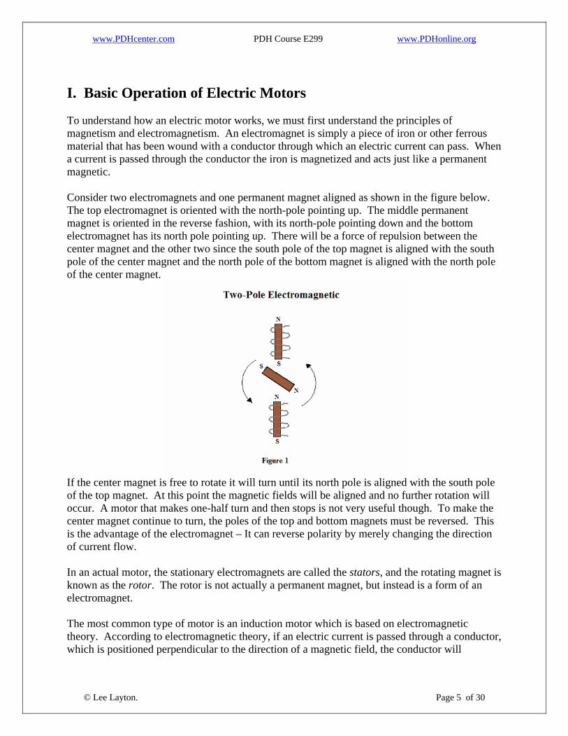
To increase the efficiency of electric motors and for smoother operation, three-phase alternating current is commonly used. Three-phase power consists of three voltage (and current) waves that
www.PDHcenter.com PDH Course E299 www.PDHonline.org
are separated in time by 120 degrees. Each current wave reaches a maximum 120 degrees after the previous current wave. Shown below is a three-phase waveform.
Large three-phase motors are simpler to construct than their single-phase counterparts. This allows the motors to be built on a smaller frame and to operate at a higher efficiency. An alternating current, three phase, grounded-wye, electric distribution system consists of three primary current carrying wires and a fourth wire for the neutral. In contrast, single-phase laterals and rural feeds consist of one primary current carrying wire and a neutral wire. A three-phase system has alternating current and voltage waves, with each successive phase occurring 120 degrees after the previous phase that alternate 60 times per second (for a 60 Hz system). To explain the design of a squirrel-cage motor, a three-phase, two-pole motor will be illustrated. The stator of a three-phase, two-pole motor will have six coils, one for each phase of the electric supply for each of the poles. Since each phase of a three phase circuit reaches each maximum value 120 degrees after the previous phase, the peak current in the stator will appear to “move” around the stator. Therefore it seems that the stator actually has a rotating magnetic field. This rotating magnetic field will induce a voltage onto the rotor causing a current to flow and magnetize the rotor. The rotor will then turn as the interaction with the stator’s magnetic field causes an alternating attraction and repulsion between the stator and the rotor. The figure below is a simple diagram of a three-phase, two-pole induction motor.
© Lee Layton. Page 7 of 30

www.PDHcenter.com PDH Course E299 www.PDHonline.org
Single-phase motors are used successfully in applications, such as fans, refrigerators, freezers, blower motors, drills, and air conditioners that require less than 15 hp. Single-phase motors are designed with a primary and secondary winding. The primary winding is for continuous duty, while the secondary winding is used for starting the motor (in some cases the secondary winding is also used during the run cycle.) To start a single-phase motor, the secondary winding is connected in series with a capacitor to produce a phase shift to start the motor. Once the motor is running, a switch inside the motor either disconnects the secondary winding, or connects it to a different value capacitor for the run cycle. This approach is fine for small motors, but for larger motors, motors that require frequent starting and stopping, and motors that need to reverse directions, a three-phase motor is a better choice. In a single-phase motor, the most common failure mode is the failure of the switch that controls the secondary winding. This will cause the motor not to start and may overheat the primary winding, destroying the motor.
© Lee Layton. Page 8 of 30

www.PDHcenter.com PDH Course E299 www.PDHonline.org
Conventional Motor Types There are three primary forms of traditional electric motors including; the squirrel-cage induction motor, wound-rotor induction motor, and the synchronous motor. Squirrel-Cage Induction Motor The most common type of AC motor is the squirrel-cage induction motor. The squirrel induction motor gets its name from the design of the rotor, which resembles a squirrel or hamster cage wheel. The induction motor is one of the simplest types of motors and is well suited for constant speed applications such as blowers, pumps, and compressors. The induction motor has a stator with windings of insulated copper inserted into slots in the stator laminations. The slots have insulation between the windings and the steel laminations and are known as the stator pack. The stator pack is inserted into the motor casing, which is known as the stator frame. The rotor consists of a laminated steel core with solid copper bars for the winding. The copper bars have a shorting ring welded to the ends of the bars. A typical induction motor will have a starting torque of about 200%; pull up torque of around 100%, and breakdown torque of 300% of full load torque. With the availability of solid state starters, induction motors can now fulfill just about any application, including those traditionally reserved for wound rotor motors. Wound-Rotor Induction Motor In a wound-rotor induction motor the rotor windings consist of insulated copper windings similar to the stator. Unlike the squirrel-cage motor the rotor windings must be brought out through slip rings and brushes. This is the main disadvantage of wound rotor motors - slip rings and brushers require periodic maintenance. By varying the resistance across the rotor windings, the speed and torque of the motor can be adjusted. Wound-rotor induction motors are used where a variable speed motor is required and are especially useful for frequent starting and accelerating high inertia loads. Synchronous Motor The design of the stator of a synchronous motor is the same as an induction motor. The stator is called the armature winding. Unlike an induction motor, the rotor has two windings: a field winding and a damper winding. The field winding is excited from a DC source. The damper winding is similar to the squirrel-cage rotor winding in an induction motor, but is used during starting to create asynchronous torque and to damp oscillations from varying loads during normal operations.
© Lee Layton. Page 9 of 30
Synchronous motors run at their design speed regardless of the load applied. The speed of a synchronous motor is determined by the design of the motor and the power line frequency. Synchronous motors are more complex than either squirrel-cage or wound rotor induction motors. Unlike induction motors, synchronous motors do not experience slip. They will continue to maintain a constant speed up to some point where the motor is overloaded and can no longer maintain speed.

www.PDHcenter.com PDH Course E299 www.PDHonline.org
They are ideally suited for applications requiring a constant speed be maintained. An additional advantage is that synchronous motors can be over-excited and draw leading current from the power supply, which will improve the power factor of the electrical service. Phase Converters Until the advent of the Written-Pole® motor, the only alternative for supplying a large motor load on a single-phase supply was to use a phase converter. A phase converter is a device that allows a three-phase motor to operate on a single-phase supply by electrically adding another phase from the existing single-phase supply. There are two categories of phase converters: Static and Rotary. Static units are simple devices with limited applications. In contrast, rotary phase converters can be designed for just about any reasonable application. Since a single-phase service, such as a 240-volt residential service, is center-tapped it can actually be considered as two separate phases, one 120 volt-to-ground phase and another 120 volt-to-ground phase that are 180 degrees out of phase with each other. Both static and rotary phase converters take these two phases and manufacture a third phase. In fact, this generated phase is commonly called the “manufactured” phase. The purpose of the phase converter is to produce enough voltage on the manufactured phase to deliver starting and running torque. Static Phase Converters A static converter uses capacitors to create a “manufactured” phase. The capacitors are used to shift one of the incoming phases 90 degrees out of phase with the incoming phase. This “shifted-phase” voltage is then applied to one leg of the induction motor. The magnetic field from this phase interacts with the fields in the adjacent legs of the motor creating motor starting and running torque. The simplest static converter is known as a start-only static converter. A start-only converter has starting capacitors, but does not have running capacitors. The starting capacitors remain in the circuit until the motor is up to speed and then they are removed from the circuit and the motor is left to operate in a single-phase condition. This will cause objectionable heating and damage to the motor if there is significant load on the motor. However, for lightly loaded motors this may be acceptable. Generally, start-only converters should only be used for loads up to about 67% of nameplate and for only small motors. Two sets of capacitors are needed in the capacitor type static phase converter. Because of the high inrush current that a motor experiences during startup, a larger bank of capacitors is needed for starting than the capacitors used for running. The first set of capacitors, which are usually electrolytic, are used for starting. The second, smaller, set of capacitors is used for running and they are oil-filled. The following diagram shows how a capacitor static phase converter is connected.
© Lee Layton. Page 10 of 30

www.PDHcenter.com PDH Course E299 www.PDHonline.org
When load is initially applied, both the starting capacitors and the running capacitors are in the circuit. As the inrush current subsides the voltage on the manufactured phase will begin to rise. A relay in the starting capacitor circuit will operate and remove the starting capacitors as the voltage begins rising in the manufactured phase. If the motor slows down, the resulting lower voltage on the manufactured phase will cause the relay in the starting capacitor circuit to operate to bring the starting capacitors back into the circuit to help get the motor back up to speed. The major disadvantage of a capacitor static converter is that the output voltage cannot be adjusted, which results in current imbalance between the phases. To compensate for the resulting current imbalance in capacitor static converters, the motor output must be de-rated to approximately 80% of the motor’s nameplate. Another form of static converter is the autotransformer type. The autotransformer type static converter allows for adjustments to the voltage in the manufactured phase, which allows for better balancing of the phase currents. The autotransformer steps up the incoming voltage to the manufactured leg and then serves the load through a capacitor arrangement like the capacitor type converter. See the figure below for an explanation of the autotransformer type static converter.
© Lee Layton. Page 11 of 30

www.PDHcenter.com PDH Course E299 www.PDHonline.org
The autotransformer has taps in the winding supplying the manufactured phase, so the voltage can be adjusted to produce the desired voltage and current balance. With this compensating mechanism, autotransformer static converters can usually supply the nameplate rating of the motor. Whether a start-only, capacitor-type, or autotransformer type, static converter is used, the converter must be designed for a specific motor application. Static converters cannot be used to operate multiple motors. Rotary Phase Converters Rotary phase converters were developed to overcome the inherent disadvantages of static phase converters. A rotary phase converter is an induction machine that operates on a single-phase source to deliver three-phase power. Like an induction motor, a rotary converter has a stator frame with a three-phase winding and a squirrel cage rotor. The unit uses capacitors like a static converter to start the rotary phase converter. Just like a static converter, the capacitors create a phase voltage that is 90 degrees out of phase with the adjacent phase, which produces torque in the rotor. The following figure is a schematic of a rotary phase converter.
© Lee Layton. Page 12 of 30

www.PDHcenter.com PDH Course E299 www.PDHonline.org
As the rotor turns the current in the rotor produces a field that energizes the other coils in the stator. Since the stator coils are 120 degrees apart, a representative three-phase output is created. This arrangement is sometimes called a rotating transformer. The output of a rotary phase converter must, by design, be three-phase, three-wire delta. If a three-phase, four-wire, wye output is required; a delta-wye transformer must be installed. Like a static converter, the third phase, which is created by the rotary phase converter, is called the manufactured phase. The voltage on the manufactured phase varies with the load applied to the converter. However, a rotary converter has a reasonably stable voltage output over a load range of about 50 to 110% of rated load. Below 50% of rated load the voltage in the manufactured phase will drift considerably above the nominal voltage, and above 110% of rated load the voltage will sag below rated voltage. Rotary phase converters can easily supply multiple motor loads and the units can be paralleled for additional capacity and to limit inrush currents on the utility system. Since a rotary must be designed to handle the inrush currents of the motors that it serves, a rotary can supply motor loads up to three times its rated capacity. For instance if an application has a 50 Hp motor and several smaller motors, the unit should be designed for the 50 Hp motor, but it will have the capacity to serve another 100 Hp of smaller motors. This relationship is valid for many applications, but it does not hold true for all applications. CNC equipment is especially difficult to size for a rotary. A rotary unit must be energized and brought up to speed prior to applying a load. Other disadvantages include the noise and heat generated by the rotary. Rotaries can also not deliver as much starting torque as a static converter. The advantages of the rotary units are the ability to provide better voltage balance, serve multiple loads, severe loads that stop and start frequently, and serve loads such as resistance and rectifier loads. Rotary phase converters have efficiencies similar to induction motors, which is in the range of 85 to 90 percent.
© Lee Layton. Page 13 of 30

www.PDHcenter.com PDH Course E299 www.PDHonline.org
Motor Characteristics The defining characteristics of a squirrel-cage induction motor include the motor speed, slip, torque, and efficiency. Let’s look at each of these characteristics in more detail.
Speed The speed of a squirrel cage motor depends on the electric line frequency and the number of poles in the motor. The synchronous speed of a motor is design speed of the motor based on frequency and the number of poles. The stator windings can have any even number of pairs of poles. Most motor designs have between 2 and 12 pairs of motor poles. The following formula can be used to find the speed of any squirrel-cage induction motor:
NS = Where, Ns = Synchronous speed, RPM. F = Frequency, Hz P = Number of poles. For example, what is the synchronous speed of a 4-pole, 60 Hz motor?
NS = Ns = 1,800 RPM. The following chart shows the synchronous speed for several different pole designs (at 60 Hz.)
Table 1 Synchronous Speed vs. PolesNumber of Poles Synchronous Speed
(60 Hz) 2 3,600 4 1,800 6 1,200 8 900 10 720 12 600
© Lee Layton. Page 14 of 30
As can be seen in the chart above, as the number of poles increases the synchronous speed of the motor decreases.

www.PDHcenter.com PDH Course E299 www.PDHonline.org
Slip An induction motor’s rotor must turn slightly slower than the stator’s rotating magnetic field for a current to be induced into the rotor. The difference between the synchronous speed and the actual speed is known as slip. Slip is defined as:
Percent Slip = Where, Percent Slip = the motor slip, percent. ns = Synchronous speed, RPM. na = Actual Speed, RPM. For example, what is the slip for a 2-pole, 60 Hz. Motor with an actual speed of 3,500 Rpm? From Table 1, we see that the synchronous speed of a two-pole, 60 Hz motor is 3,600, so the synchronous speed is,
Percent Slip = Slip = 2.78%. Inductions motors with a slip of 5% or less are known as constant speed motors. A constant speed motor experiences only minor speed changes over the range of normal loads that it serves. Motor designs may include slip characteristics from 2-20%. High slip motors are used in hard to start applications. Usually larger motors have less slip and for any motor, slip will decrease as the load decreases.
Torque Torque is the work that a motor does and is defined as a force of one pound times a lever of one foot. The unit of measure is foot-pounds. Horsepower is the rate of doing work. One horsepower is defined as 33,000 foot-pounds per minute. Therefore torque of a motor is:
τ =
Where, Torque = Foot-pounds. HP = Horsepower. RPM = Speed of the motor. For instance, how much torque will a 15 horsepower motor operating at a full load speed of 3,500 RPM generate?
© Lee Layton. Page 15 of 30
τ =

www.PDHcenter.com PDH Course E299 www.PDHonline.org
Torque = 22.5 Foot-pounds. Since this torque is occurring at the motor’s synchronous speed (less slip) it is known as the rated load torque. In addition to rated load torque, the characteristics of a motor are also described by the locked rotor torque, breakdown torque, and pull-up torque. The following graph shows the relationship of these various factors to the synchronous speed.
Locked rotor torque is the torque available at the start up of the motor. When a motor starts additional torque is necessary to get the load moving. This start-up torque is known as the locked rotor torque and is considerably higher than the rated load torque. Motors are designed with different Locked Rotor Torque values based on the characteristics of the particular application. Pull-up torque is the minimum torque that is developed by a motor from start-up to acceleration to breakdown torque. The breakdown torque is the maximum torque the motor will develop without losing speed. The breakdown torque is higher than the rated load torque so that a sudden overload will not stall the motor.
© Lee Layton. Page 16 of 30

www.PDHcenter.com PDH Course E299 www.PDHonline.org
Motors are designed for specific applications and each of the torque characteristics mentioned above must be considered in the motor’s design. The National Equipment Manufacturers Association (NEMA) has defined several standard designs that have specific torque characteristics. If a motor is needed for a compressor that requires a high locked rotor torque, but a high breakdown torque is not required then, from the chart above, a NEMA design “C” would be a suitable choice. The most prevalent induction motor is a NEMA design “B”.
Efficiency A 100% efficient motor will require 746 watts of electrical power for each horsepower. In actual practice, motors tend to be between 80-95% efficient. The efficiency of a motor is calculated as the ratio of the output power to the input power as shown below:
Where, E = Motor efficiency, percent. Pout = Theoretical power output of the motor, watts. Pin = actual power consumed by the motor, watts. For example a 15 horsepower motor should require 15 x 746, or 11,190 watts of power to operate. If the actual input power is 13,165 watts, what is the motor’s efficiency?
Efficiency = 85%. Motors usually achieve peak efficiency at around 75% of full load. The motor’s efficiency will be significantly less at light loads. Care must be taken when replacing a motor to be sure that the replacement motor is not oversized, which causes reduced efficiency.
Starting Electric induction motors can be started directly “across the line” with full line voltage, or through some type of reduced voltage start. Advances in power electronics now make it possible to have solid-state and microprocessor based starters. These electronic devices have opened up a wide range of opportunities for induction motors. Direct on Line Starting
© Lee Layton. Page 17 of 30
Starting a motor directly on the power line supply is the simplest, most economical, and most reliable method to start a motor. Small induction motors can be started directly on line. This works fine where starting torque or current do not need to be limited. Direct start induction motors should not be started more than six to eight times per hour to prevent overheating the windings.

www.PDHcenter.com PDH Course E299 www.PDHonline.org
A common direct on line starting method uses a capacitor to help start the motor. Figure 9, shown below, is a schematic of a capacitor start motor. The capacitor is in series with a starting winding. After start-up a “throw-out” switch disables the capacitor and starting winding, then the rotor is only influenced by the running winding.
Reduced Current Starting Frequently, utility companies will require that the starting currents of motors be limited to some value. Listed below are three methods to limit starting current for induction motors.
One of the simplest reduced current starting mechanisms involves inserting a resistive load in series with the motor to limit the starting current. After a preset time the primary resistor is removed and the motor is connected directly across the line. The Primary Resistor method has the effect of limit starting current to about 50% of the direct on line starting current. It has the undesirable effect of limiting starting torque to about 25% of the direct on line torque. An advantage to the primary resistor method is that it can be used with any induction motor.
The wye-delta is the most common method of reduced current starting. It involves impressing a “wye” voltage across the “delta” connected motor. This reduces the voltage seen by the motor to 57.7% of nominal and the winding draws only 57.7% of nominal current. The result is that the starting torque is also reduced to 33% of normal. When the motor reaches about 90% of full speed, the “wye” connection is dropped out and the normal “delta” connection is established. At this point the motor can reach full speed and the normal current and torque values will be seen. With a wye-delta starter it is important that the speed-torque curve of the load be matched to the speed-torque curve of the motor with the wye-delta starter so that the torque values of the load are never greater than the torque capability of the motor.
© Lee Layton. Page 18 of 30
Wye-delta starters are a simple, economical, reduced current starter for applications that do not require high starting torques.

www.PDHcenter.com PDH Course E299 www.PDHonline.org
An autotransformer starter will allow a higher starting torque than a wye-delta starter. With this method, an autotransformer is inserted in line with the motor. After a preset time, the transformer is removed and the motor is allowed to reach full speed. Actually a small portion of the autotransformer winding remains in the circuit as the delta connection takes over to limit high transient currents. The delta then shorts out the autotransformer, effectively removing it from the circuit. The torque values will vary with the autotransformer tap selected. Typical tap values are 50%, 65%, and 80% of line voltage. Since the torque value will vary with the square of the applied voltage, the starting torque with these tap values will be 25%, 42%, and 64% of the nominal values. Autotransformers are a good choice for applications that require higher starting torque than can be achieved with other methods. However, as with the wye-delta starters, care must be taken to ensure that the speed-torque curve of the load does not drop below the motor/starter combination. Solid-State Starter The most advanced and the most versatile type of starter is a solid-state starter. These electronic devices utilize semiconductors to allow a variety of starting characteristics. They can be programmed to offer higher starting torques than are possible with either wye-delta or autotransformers. An advantage of the solid-state units is they have a step-less transition to full load. Solid-state starters can be used for soft starts, current limiting starts, and full voltage starts. The solid state controller allows the time from start to full load to be selected by the user. In addition, both the starting torque and the starting current are adjustable up to the direct start values. Another advantage is that there is no transition point, or step, where the transition occurs to full speed. Variable Speed Drives With the advent of digital microprocessor controllers a new type of motor controller has become popular. Adjustable speed drives and variable speed drives are finding many applications because of their flexibility. A variable speed drive consists of a rectifier, inductive filter, and an inverter. The rectifier uses electronic thyristers to convert the incoming alternating current into direct current (DC). The inductive filter uses an inductor and capacitors to deliver a steady DC signal to the inverter. The inverter converts the DC voltage back to AC at the selected voltage and frequency. The inverter is capable of delivering any combination of voltage and frequency to obtain the desired motor output.
© Lee Layton. Page 19 of 30

www.PDHcenter.com PDH Course E299 www.PDHonline.org
II. Written Pole® Motor Design As we saw in the previous section, conventional induction motors have a fixed, even number of discrete field pole structures, and therefore have a fixed relationship between shaft speed and the frequency of the electrical input. In contrast, the written-pole motor operates as if it has a variable number of poles. The keys to the operation of a written-pole motor consist of a special magnetic layer on the rotor and a special exciter winding. The written-pole motor has a continuous layer of “permanent” magnetic material on the surface of the rotor. The main windings of the stator are similar to those of conventional motors, with an additional concentrated winding around an exciter pole. The magnetic layer can be magnetized, or written, into any desired magnetic pole pattern by the exciter pole while the motor is operating. Construction The main elements of a written-pole motor are illustrated in Figure 10. Written Pole motors use similar construction techniques found in conventional motors.
© Lee Layton. Page 20 of 30

www.PDHcenter.com PDH Course E299 www.PDHonline.org
The rotor of a written-pole motor is a combination of induction hysteresis and permanent magnet technology. The basic platform consists of a conventional steel shaft inserted into a lamination stack containing a high resistance rotor cage. The high resistance cage is a key factor in limiting the starting current of written-pole motors and provides considerable induction torque during the initial stage of starting. The total cross sectional area and resistivity of the rotor cage is selected to provide high slip, high power factor starting characteristics. While this configuration would be detrimental to the operating efficiency of a conventional induction motor, the synchronous mode of operation used in written-pole motor eliminates induced currents in the rotor bars and the resulting electrical losses. A continuous layer of permanent magnetic ferrite material covers the rotor lamination stack and its exact makeup is proprietary to Precise Power Corporation. The ferrite material used in the rotor is similar to the magnetic material used in conventional permanent magnet synchronous motors, enabling it to maintain its magnetization throughout the normal range of operation. However, the unique properties of this proprietary material reduce the strength of the magnetic field required to magnetize or re-orient the material to a level low enough that it becomes practical to re-magnetize the rotor while it is rotating. This can be accomplished without losing the properties required for normal operation and has the added benefit of increasing the amount of hysteresis torque available during starting. The stator of a written-pole motor is very similar to a typical induction motor. The stator lamination stack is constructed using low loss electrical steel laminations. The windings are similar in design and function to those used in a conventional induction or synchronous motor. When connected to input utility power, the currents in the windings produce a rotating magnetic field, which interacts with the rotor to apply rotational force to the shaft. A unique feature of a written-pole motor is the use of a concentrated excitation winding located at one or two points on the stator. The excitation windings are contained within the stator structure and are located between the main stator windings. The excitation winding is designed to produce a magnetic field powerful enough to fully magnetize the portion of the rotors' magnetic layer that is immediately across the air gap from it. This winding is used to maintain the correct pole geometry in the rotor. Energy required for operation of the excitation windings is magnetically coupled through the stator from the adjacent stator windings. As previously mentioned, the speed of an electric motor is directly proportional to both input frequency and number of poles. Conversely, the output frequency of a generator is directly proportional to its speed and number of poles. The requirement for smooth balanced output dictates that conventional electric machines must have an even number of magnetic poles with an equal number of north and south orientations. For instance, a 4-pole machine will have 2-pairs of North-South poles; a 6-pole machine will have 3-pairs of North-South poles, etc. Deviating from this principle will produce an electric machine that is magnetically unstable at its rated speed and unsuitable for steady-state operation. Written-pole motors overcome this technical barrier and make it possible to produce a pole pattern that correlates directly to the rotational speed of the machine enhancing performance through a considerable speed range.
© Lee Layton. Page 21 of 30

www.PDHcenter.com PDH Course E299 www.PDHonline.org
The continuous layer of magnetic material on the surface of the rotor which can be magnetized into any desired pole configuration using the exciter winding contained within the stator windings. As the magnet material passes beneath this excitation winding, it is subjected to an alternating magnetic field produced by AC current flowing in the winding. The strength and orientation of this magnetic field controls the geometry of the magnetic poles induced on the rotor. If the polarity of the magnet material passing beneath the excitation winding does not match the polarity of the magnetic field produced by the winding, the polarity of the magnet is reversed to match the field produced by the excitation winding.
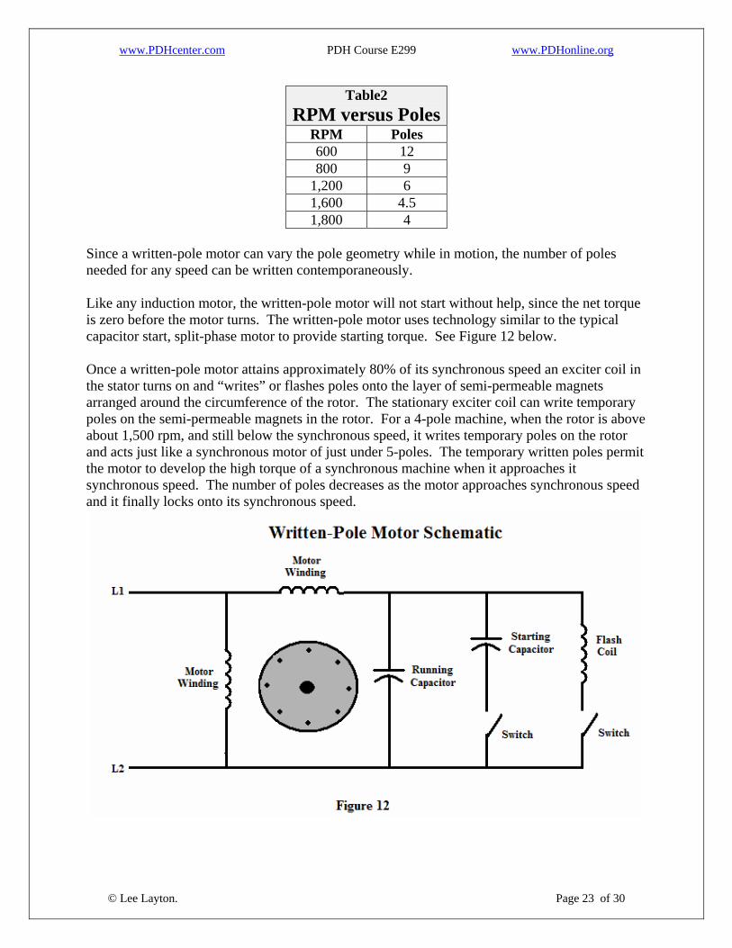
Look at the drawing in Figure 11. In this example the poles are being rewritten to maintain the motors speed and proper rotation. The first motor in Figure 11 shows the motor in normal operation, the second motor shows the poles have been re-written slightly clockwise from their previous position, and the third motor shows the poles re-written further clockwise. Since the power supplied to the excitation winding is a constant frequency 60 Hz, AC sinusoidal supply, the actual size and quantity of poles generated on the surface of the rotor are dependent on the rotational speed of the machine. Lower speeds result in a larger number of smaller poles with shorter spans, while higher speeds result in a smaller number of larger poles with longer spans. Consider a 4-pole induction motor. The synchronous speed of the motor is 1,800 rpm. However, at start-up it obviously is not running at 1,800 rpm. The Written-pole motor can appear to run at synchronous speed by writing poles as needed to maintain the synchronous relationship. For instance, look at the following chart of speed versus the number of poles.
© Lee Layton. Page 22 of 30
www.PDHcenter.com PDH Course E299 www.PDHonline.org
Table2 RPM versus Poles
RPM Poles 600 12 800 9
1,200 6 1,600 4.5 1,800 4
Since a written-pole motor can vary the pole geometry while in motion, the number of poles needed for any speed can be written contemporaneously. Like any induction motor, the written-pole motor will not start without help, since the net torque is zero before the motor turns. The written-pole motor uses technology similar to the typical capacitor start, split-phase motor to provide starting torque. See Figure 12 below. Once a written-pole motor attains approximately 80% of its synchronous speed an exciter coil in the stator turns on and “writes” or flashes poles onto the layer of semi-permeable magnets arranged around the circumference of the rotor. The stationary exciter coil can write temporary poles on the semi-permeable magnets in the rotor. For a 4-pole machine, when the rotor is above about 1,500 rpm, and still below the synchronous speed, it writes temporary poles on the rotor and acts just like a synchronous motor of just under 5-poles. The temporary written poles permit the motor to develop the high torque of a synchronous machine when it approaches it synchronous speed. The number of poles decreases as the motor approaches synchronous speed and it finally locks onto its synchronous speed.
© Lee Layton. Page 23 of 30
www.PDHcenter.com PDH Course E299 www.PDHonline.org
Upon attaining its rated speed, power to the excitation winding is removed allowing the machine to operate as a synchronous machine. Variation from the machine's rated speed restores power to the excitation winding thereby ensuring that the pole geometry on the rotor remains matched to the rotating electromotive fields produced by the stator winding.
Operation A written-pole motor employs one of three modes of operation based on the rotational speed of the machine. They are: the start mode, transition mode, and run mode. Start Mode In the start mode, a written-pole motor produces large amounts of hysteresis and induction torque, which begin to accelerate the motor to its rated speed. Hysteresis torque is developed when the magnetic fields produced by the stator currents are sufficiently strong to slightly magnetize the ferrite material on the rotor producing useful torque. The magnitude of the input starting current and induction torque produced in this mode are determined by the properties of the rotor cage. A written-pole motor is able to generate synchronous torque over a broad speed range, unlike conventional synchronous motors that rely on induction torque to accelerate the machine to synchronous speed. This process provides a trade-off between gentle, low current starts versus fast, abrupt, high current starts. This approach yields several long-term benefits, including a gentler starting ramp that protects the connected load from damaging acceleration and mechanical shock. When connected to similar high inertia loads, the lower starting current also reduces the temperature rise in the stator windings, permitting more frequent starts and restarts than are possible with conventional motors. Transition Mode As the written-pole motor accelerates toward its rated speed, it enters the transition mode, during which the excitation winding begins to influence the magnetic geometry of the rotor. The rotational speed at which the motor switches to transition mode is generally in the range of 80 to 90% of normal synchronous speed. Upon entering the transition mode, a written-pole motor becomes electrically synchronous allowing it to produce synchronous torque even though it has not yet attained true synchronous speed. The ability to operate as a synchronous motor over a wide range of speed enables a written-pole motor to attain mechanical synchronization over a period of seconds or minutes, dramatically enhancing the machines' ability to start high inertia loads. Since written-pole motors do not rely on induction torque to achieve near synchronous speed prior to making the transition to synchronous operation, the motor's starting characteristics can be optimized without sacrificing steady state performance and efficiency.
© Lee Layton. Page 24 of 30

www.PDHcenter.com PDH Course E299 www.PDHonline.org
Run Mode A written-pole motor enters run mode upon reaching its rated synchronous speed. Since operation of the excitation winding is not required in this mode, it is turned off and the motor continues to operate as a permanent magnet synchronous motor until power is removed from the input capacitor. Another example of the enhanced operation provided by the written-pole motor is the capability to recover from momentary overloads. It excessive torque is applied to the output shaft, causing the motor to pull out of synchronization, it re-enters the transition mode and attempts to re-accelerate the load back to synchronous speed. In the event that the load torque continues to exceed the capability of the machine, standard overload devices disconnect power form the motor preventing damage to the motor or the load. Re-start Operation Another important feature of written-pole motor is unlike a conventional electric motor, which requires a delay to minimize the generation of large torque transients resulting from the phase shift between the rotor and the input power supply, a written-pole motor can be reconnected to input electrical power at any time following a loss of input power. In addition, the written-pole motor continues to deliver smooth, even torque and draws only normal starting currents when power is reapplied, regardless of the phase of the rotor field relative to the stator field. The motor will resume operation either in the Start mode or Transition Mode depending on its speed when the power is reapplied.
© Lee Layton. Page 25 of 30
www.PDHcenter.com PDH Course E299 www.PDHonline.org
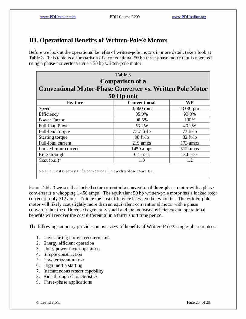
III. Operational Benefits of Written-Pole® Motors Before we look at the operational benefits of written-pole motors in more detail, take a look at Table 3. This table is a comparison of a conventional 50 hp three-phase motor that is operated using a phase-converter versus a 50 hp written-pole motor.
Table 3 Comparison of a
Conventional Motor-Phase Converter vs. Written Pole Motor50 Hp unit
Feature Conventional WP Speed 3,560 rpm 3600 rpm Efficiency 85.0% 93.0% Power Factor 90.5% 100% Full-load Power 53 kW 40 kW Full-load torque 73.7 ft-lb 73 ft-lb Starting torque 88 ft-lb 82 ft-lb Full-load current 219 amps 173 amps Locked rotor current 1450 amps 312 amps Ride-through 0.1 secs 15.0 secs Cost (p.u.)1 1.0 1.2 Note: 1. Cost is per-unit of a conventional unit with a phase converter.
From Table 3 we see that locked rotor current of a conventional three-phase motor with a phase-converter is a whopping 1,450 amps! The equivalent 50 hp written-pole motor has a locked rotor current of only 312 amps. Notice the cost difference between the two units. The written-pole motor will likely cost slightly more than an equivalent conventional motor with a phase converter, but the difference is generally small and the increased efficiency and operational benefits will recover the cost differential in a fairly short time period. The following summary provides an overview of benefits of Written-Pole® single-phase motors.
1. Low starting current requirements 2. Energy efficient operation 3. Unity power factor operation 4. Simple construction 5. Low temperature rise 6. High inertia starting 7. Instantaneous restart capability 8. Ride through characteristics
© Lee Layton. Page 26 of 30
9. Three-phase applications

www.PDHcenter.com PDH Course E299 www.PDHonline.org
1. Low starting current requirementsThe single most significant characteristic of a written-pole single-phase motor is its low inherent starting current. Written-pole single-phase motors exhibit starting current requirements ranging from 1.7 to 3 times their rated current, unlike conventional induction motors that have typical starting currents ranging from 6 to 10 times their rated current. A typical written-pole single-phase motor has a starting current, comparable to a conventional single-phase motor one-fourth its rating, dramatically increasing the maximum rating that may be started on rural single-phase distribution systems. Since a written-pole single-phase motor's low starting current is attained without reduced voltage starting, the design does not sacrifice starting torque as is common with three-phase motors started using reduced voltage devices designed to limit starting current. Not only does this simplify the design and construction of the motor, but it also enhances the usability of written-pole single-phase motors under a variety of applications. As you can see in Table 3, that starting amps are only 1.8 times the running current and the starting torque is almost identical to the conventional induction motor. 2. Energy efficient operationThe synchronous mode of operation of a written-pole single-phase motor allows for very high operating efficiencies, comparable to those of premium efficiency three-phase motors with similar ratings. The resulting reductions in transformer loading and operating costs can represent a significant advantage over comparable installations using three-phase motors and phase converters. In our example in Table 3, the conventional induction motor has an efficiency of 85% versus 93% for the written-pole motor. The high operating efficiency of a written-pole single-phase motor is made possible by the fact that its synchronous mode of operation eliminates losses commonly associated with the slip in conventional induction motors. By eliminating the resulting rotor losses, written-pole single-phase motors are able to substantially reduced total losses, improving operating efficiency. In addition to limited application because of high starting current, large single-phase induction motors cannot operate at the efficiency of three-phase motors. This is largely due to double-frequency rotor losses that are characteristic of single-phase machines. The written-pole motor is designed to virtually eliminate these additional losses and can operate at efficiencies approaching those of the best three-phase machines. This, together with the inherently low starting current, makes this type of motor a good choice for large single-phase applications. 3. Unity power factor operation The Synchronous mode of operation also results in near unity power factor operation at rated load further reducing transformer and distribution line loading. As you can see in our example in Table 3, a 50 hp written-pole motor will have a power factor of 100% while the corresponding three-phase induction motor may be around 90%.
© Lee Layton. Page 27 of 30

www.PDHcenter.com PDH Course E299 www.PDHonline.org
4. Simple constructionAs we discussed in the previous section, the basic construction of a written-pole single-phase motor is similar to that of a conventional single or three-phase induction motor. The motor frame is constructed using ductile iron or aluminum castings for maximum durability. Stator laminations and windings are constructed using high grade electrical steel laminations and inverter-grade copper wire for long-term reliability and surge resistance. The basic layout of the stator windings is similar to a conventional capacitor start/run single-phase induction motor with the addition of a concentrated excitation winding occupying four slots in the stator. The rotor construction is also similar to that of a conventional cage induction motor with the addition of a continuous ferrite magnet layer on the surface of the rotor. The center portion of the rotor is manufactured using high-grade electrical steel lamination and a high resistance induction cage constructed of carbon steel rotor bars and end-rings. The ferrite layer is constructed using specially developed magnets, which enable the excitation coil to alter the magnetic pole configuration as needed during operation and is bonded to the rotor. From an installation viewpoint, a written-pole motor has that same general physical layout as a standard induction motor. Even though frame type is not universal, there are standards that describe the physical dimensions of motors using a frame designation. For instance, a 15 hp written-pole motor uses a 256T frame size. The first two digits of the frame type are used to describe the height of the output shaft above the motor base. To determine the height of the output shaft divide the first two digits by 4. For instance, for a 256T motor the output shaft will be, Output Shaft height = 25 / 4 = 6.25 inches. The third digit describes the longitudinal distance between the mounting holes in the base. It no longer indicates a specific distance, but in general, the larger the third number, the greater the spacing between the mounting holes. The “T” in our 256T example describes physical characteristics including shape and size of the motor. The NEMA specifications describe several different frame types such as “T”, “D”, “U”, etc. 5. Low temperature rise under starting conditions Since written-pole motors are generally much more efficient under starting conditions than conventional induction motors, current requirements and corresponding electrical losses are reduced dramatically. Since electrical losses in the stator windings of an electric motor are proportional to the square of current, a typical written-pole motor generates nine times less heat under starting than a conventional induction motor. The resulting reduction in heat provides for improved reliability, increased starting duration and a higher frequency of start cycles. 6. High inertia starting capability
© Lee Layton. Page 28 of 30
Since written-pole motors are capable of sustaining starting conditions for much greater duration than conventional motors without overheating, they are able to start very high inertia loads for a
www.PDHcenter.com PDH Course E299 www.PDHonline.org
given rating. This capability is further enhanced by the ability to synchronize under load allowing synchronous operation to be attained even though the motor is under load. 7. Instantaneous restart capabilityThe low starting current and flexible starting characteristics of written-pole single-phase motors allow them to undertake an instantaneous re-start after a momentary power interruption without inducing the high transient torque pulsations common to conventional single or three-phase induction motors when re-closed out of phase with the utility supply. This capability allows written-pole single-phase motors to be configured for instantaneous restarts without fear of damaging the motor or driven equipment. 8. Ride-through characteristicsAn external rotor configuration is available which integrates a substantial flywheel into the written-pole single-phase motor allowing the motor to continue powering its load (at a slightly reduced speed) during momentary power interruptions such as a utility breaker operation. The flywheel also has the effect of softening the motor's starting and stopping characteristics enabling a dramatic reduction in the generation of water hammer in irrigation or water pumping systems. One advantage of the external rotor ride-through construction is the motor can continue to support a load for some time after a power interruption. This feature is particularly advantageous to loads such as water-pumps, blowers, and conveyor systems. Looking at our sample motor in Table 3, the written-pole motor has a potential ride through time of 15 seconds compared to less than 0.1 seconds for the conventional induction motor. 9. Three Phase applications In applications where the load must be operated on three-phase power, a single-phase written-pole motor can be coupled with a three-phase generator to provide the required three-phase power. While this is a hybrid design, it does not have some of the inherent disadvantages of the alternative phase-converter/three-phase motor solution that is typically used.
© Lee Layton. Page 29 of 30

www.PDHcenter.com PDH Course E299 www.PDHonline.org
Summary The written-pole motor, developed by Precise Power Corporation, is a motor design that allows for the operation of very large single-phase motors. This unique product has applications virtually anywhere that three-phase power is either not available, or is not economical to provide. The written-pole motor also has performance advantages over a conventional induction motor including low starting current, very high operating efficiency, and excellent power factor. This motor technology has the additional benefit of being able to ride through brief service interruptions on single-phase power lines. When compared to the total system costs, written-pole motors are an attractive alternative to convention three-phase induction motors.
Copyright © 2009 Lee Layton. All Rights Reserved.
+++
© Lee Layton. Page 30 of 30
Related Documents