A L T R A M O T I O N Wrap Spring Clutches and Clutch/Brakes

Welcome message from author
This document is posted to help you gain knowledge. Please leave a comment to let me know what you think about it! Share it to your friends and learn new things together.
Transcript
A L T R A M O T I O N
Wrap Spring Clutchesand Clutch/Brakes
CHECK OUTwarnerelectric.comwarnerelectric.com now features our new interactive eCATALOG making it faster and easier to find and spec the motion control products you need.
Within the Warner Electric Interactive eCATALOG, you can start your search for basic components, such as clutches or brakes, and then quickly refine your search from hundreds of possibilities to one that meets your specific power transmission requirements for NEMA, input/output configurations and other factors. You can also download specifications and PDF pages or submit an RFQ for any of your selections.
FIND IT FAST AT WARNERELECTRIC.COM
Altra is a leading global designer and producer of a wide range of electromechanical power transmission and motion control components and systems. Providing the essential control of equipment speed, torque, positioning, and other functions, Altra products can be used in nearly any machine, process or application involving motion. From engine braking systems for heavy duty trucks to precision motors embedded in medical robots to brakes used on offshore wind turbines, Altra has been serving customers around the world for decades.
Altra’s leading brands include Ameridrives, Bauer Gear Motor, Bibby Turboflex, Boston Gear, Delevan, Delroyd Worm Gear, Deltran, Formsprag Clutch, Guardian Couplings, Huco, Jacobs Vehicle Systems, Kilian, Kollmorgen, Lamiflex Couplings, Marland Clutch, Matrix, Nuttall Gear, Portescap, Stieber, Stromag, Svendborg Brakes, TB Wood’s, Thomson, Twiflex, Warner Electric and Wichita Clutch.
VISIT US ON THE WEB AT ALTRAMOTION.COM
Altra Motion
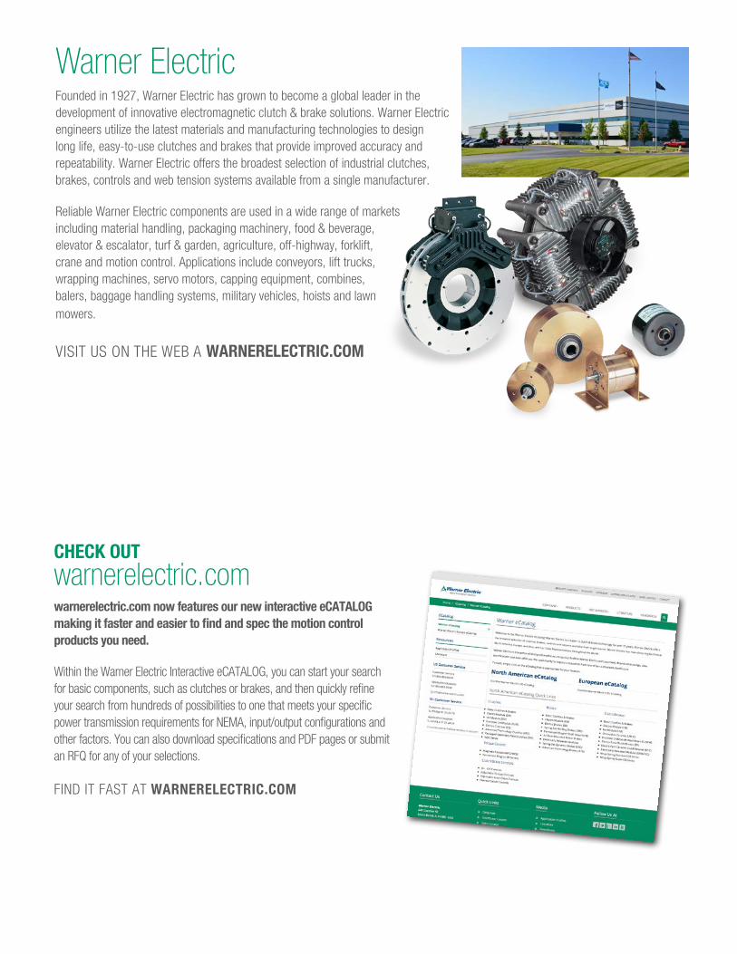
Warner ElectricFounded in 1927, Warner Electric has grown to become a global leader in the development of innovative electromagnetic clutch & brake solutions. Warner Electric engineers utilize the latest materials and manufacturing technologies to design long life, easy-to-use clutches and brakes that provide improved accuracy and repeatability. Warner Electric offers the broadest selection of industrial clutches, brakes, controls and web tension systems available from a single manufacturer.
Reliable Warner Electric components are used in a wide range of markets including material handling, packaging machinery, food & beverage, elevator & escalator, turf & garden, agriculture, off-highway, forklift, crane and motion control. Applications include conveyors, lift trucks, wrapping machines, servo motors, capping equipment, combines, balers, baggage handling systems, military vehicles, hoists and lawn mowers.
VISIT US ON THE WEB A WARNERELECTRIC.COM
Principle of OperationPage 3
Application ExamplesPage 4 SelectionPage 6
CB Mounting RequirementsPage 8 CB Stop Collar AdjustmentPage 10
CB Series Clutch/BrakesPage 11
SCB Series Clutch/BrakesPage 19
SCB-10 Features & ImprovementsPage 25
WSC Series ClutchesPage 26
Power SuppliesPage 32
CB Spring Differential SettingPage 34
CB Actuator Gap AdjustmentPage 35
Application EngineeringPage 36
Part NumbersPage 39
Metric Part NumbersPage 40
Application Data FormPage 41
Wrap Spring Product LinePage 2
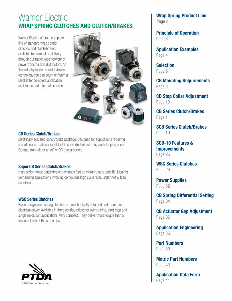
CB Series Clutch/BrakesElectrically actuated clutch/brake package. Designed for applications requiring a continuous rotational input that is converted into starting and stopping a load. Operate from either an AC or DC power source.
Super CB Series Clutch/BrakesHigh performance clutch/brake packages feature extraordinary long life. Ideal for demanding applications involving continuous high cycle rates under heavy load conditions.
WSC Series ClutchesBasic design wrap spring clutches are mechanically actuated and require no electrical power. Available in three configurations for overrunning, start-stop and single revolution applications. Very compact. They deliver more torque than a friction clutch of the same size.
© 2011 Warner Electric, Inc.
Warner Electric offers a complete line of standard wrap spring clutches and clutch/brakes, available for immediate delivery through our nationwide network of power transmission distributors. As the industry leader in clutch/brake technology you can count on Warner Electric for complete application assistance and after sale service.
Warner ElectricWRAP SPRING CLUTCHES AND CLUTCH/BRAKES
2 www.warnerelectric.com P-1310-WE 1/20
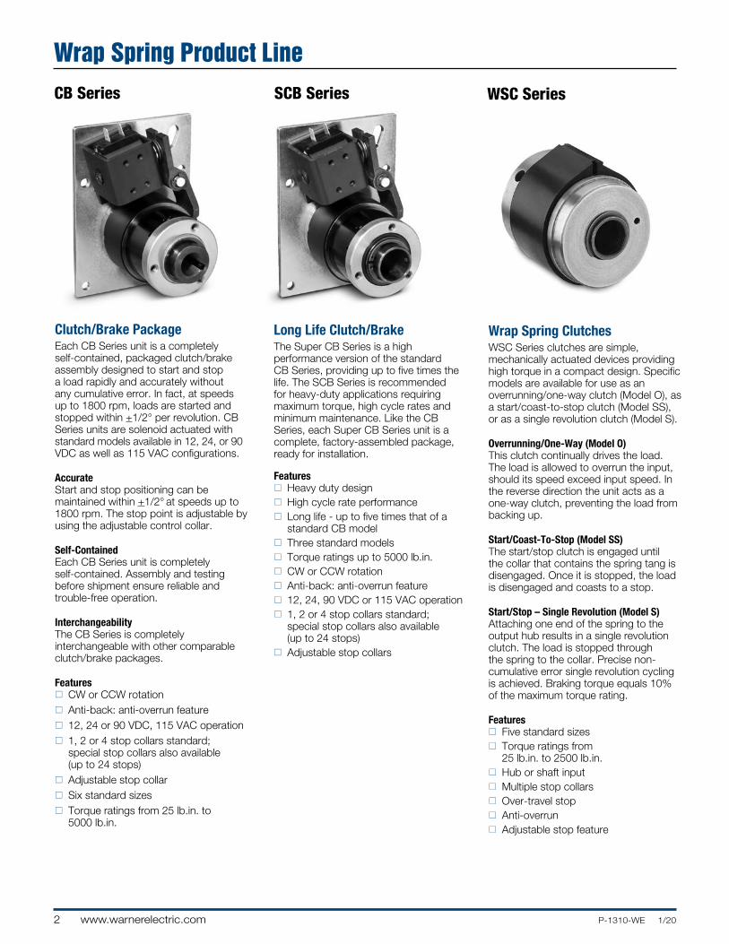
Wrap Spring ClutchesWSC Series clutches are simple, mechanically actuated devices providing high torque in a compact design. Specific models are available for use as an overrunning/one-way clutch (Model O), as a start/coast-to-stop clutch (Model SS), or as a single revolution clutch (Model S).
Overrunning/One-Way (Model O)This clutch continually drives the load. The load is allowed to overrun the input, should its speed exceed input speed. In the reverse direction the unit acts as a one-way clutch, preventing the load from backing up.
Start/Coast-To-Stop (Model SS)The start/stop clutch is engaged until the collar that contains the spring tang is disengaged. Once it is stopped, the load is disengaged and coasts to a stop.
Start/Stop – Single Revolution (Model S)Attaching one end of the spring to the output hub results in a single revolution clutch. The load is stopped through the spring to the collar. Precise non-cumulative error single revolution cycling is achieved. Braking torque equals 10% of the maximum torque rating.
Featuresn Five standard sizesn Torque ratings from
25 lb.in. to 2500 lb.in.n Hub or shaft inputn Multiple stop collarsn Over-travel stopn Anti-overrunn Adjustable stop feature
Clutch/Brake PackageEach CB Series unit is a completely self-contained, packaged clutch/brake assembly designed to start and stop a load rapidly and accurately without any cumulative error. In fact, at speeds up to 1800 rpm, loads are started and stopped within +1/2° per revolution. CB Series units are solenoid actuated with standard models available in 12, 24, or 90 VDC as well as 115 VAC configurations.
AccurateStart and stop positioning can be maintained within +1/2° at speeds up to 1800 rpm. The stop point is adjustable by using the adjustable control collar.
Self-ContainedEach CB Series unit is completely self-contained. Assembly and testing before shipment ensure reliable and trouble-free operation.
InterchangeabilityThe CB Series is completely interchangeable with other comparable clutch/brake packages.
Featuresn CW or CCW rotationn Anti-back: anti-overrun featuren 12, 24 or 90 VDC, 115 VAC operationn 1, 2 or 4 stop collars standard;
special stop collars also available (up to 24 stops)
n Adjustable stop collarn Six standard sizesn Torque ratings from 25 lb.in. to
5000 lb.in.
Long Life Clutch/Brake The Super CB Series is a high performance version of the standard CB Series, providing up to five times the life. The SCB Series is recommended for heavy-duty applications requiring maximum torque, high cycle rates and minimum maintenance. Like the CB Series, each Super CB Series unit is a complete, factory-assembled package, ready for installation.
Featuresn Heavy duty designn High cycle rate performancen Long life - up to five times that of a
standard CB modeln Three standard modelsn Torque ratings up to 5000 lb.in.n CW or CCW rotationn Anti-back: anti-overrun featuren 12, 24, 90 VDC or 115 VAC operationn 1, 2 or 4 stop collars standard;
special stop collars also available (up to 24 stops)
n Adjustable stop collars
SCB Series WSC SeriesCB Series
Wrap Spring Product Line
3P-1310-WE 1/20 www.warnerelectric.com
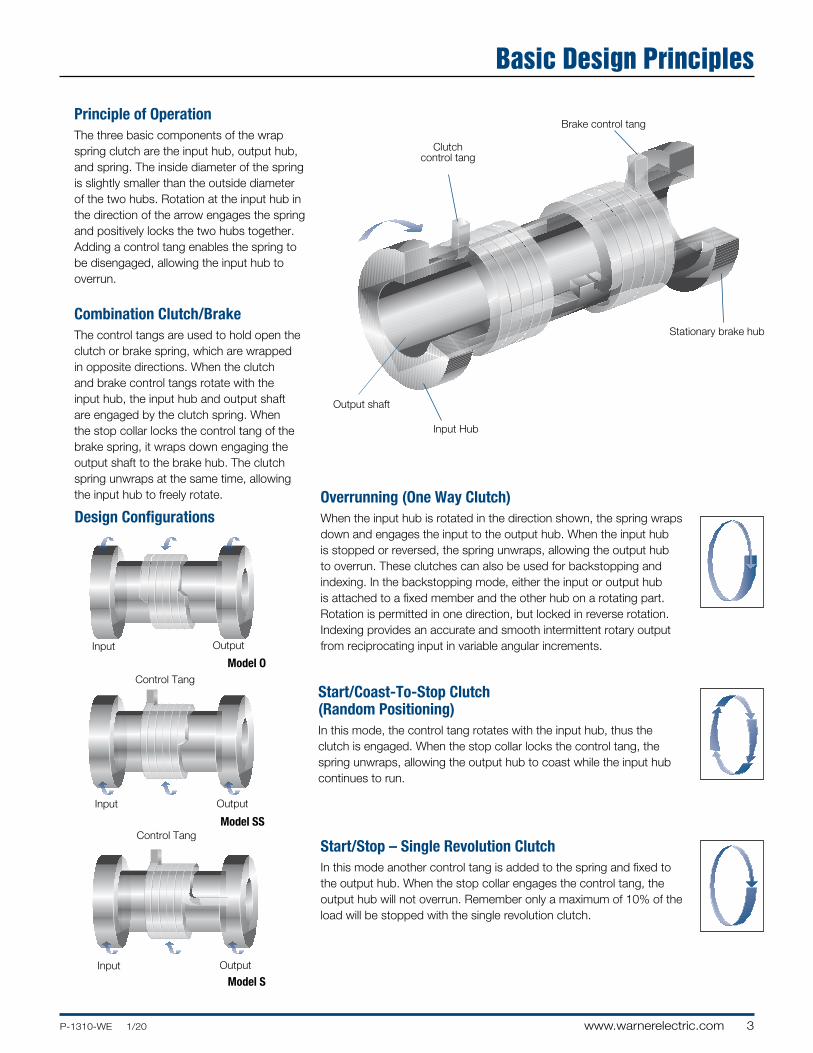
Principle of OperationThe three basic components of the wrap spring clutch are the input hub, output hub, and spring. The inside diameter of the spring is slightly smaller than the outside diameter of the two hubs. Rotation at the input hub in the direction of the arrow engages the spring and positively locks the two hubs together. Adding a control tang enables the spring to be disengaged, allowing the input hub to overrun.
Combination Clutch/BrakeThe control tangs are used to hold open the clutch or brake spring, which are wrapped in opposite directions. When the clutch and brake control tangs rotate with the input hub, the input hub and output shaft are engaged by the clutch spring. When the stop collar locks the control tang of the brake spring, it wraps down engaging the output shaft to the brake hub. The clutch spring unwraps at the same time, allowing the input hub to freely rotate.
Brake control tang
Stationary brake hub
Clutchcontrol tang
Input Hub
Output shaft
Overrunning (One Way Clutch)When the input hub is rotated in the direction shown, the spring wraps down and engages the input to the output hub. When the input hub is stopped or reversed, the spring unwraps, allowing the output hub to overrun. These clutches can also be used for backstopping and indexing. In the backstopping mode, either the input or output hub is attached to a fixed member and the other hub on a rotating part. Rotation is permitted in one direction, but locked in reverse rotation. Indexing provides an accurate and smooth intermittent rotary output from reciprocating input in variable angular increments.
Start/Coast-To-Stop Clutch (Random Positioning)In this mode, the control tang rotates with the input hub, thus the clutch is engaged. When the stop collar locks the control tang, the spring unwraps, allowing the output hub to coast while the input hub continues to run.
Start/Stop – Single Revolution ClutchIn this mode another control tang is added to the spring and fixed to the output hub. When the stop collar engages the control tang, the output hub will not overrun. Remember only a maximum of 10% of the load will be stopped with the single revolution clutch.
Input Output
Control Tang
Model SS
Input Output
Control Tang
Model S
Design Configurations
Input Output
Model O
Basic Design Principles
4 www.warnerelectric.com P-1310-WE 1/20
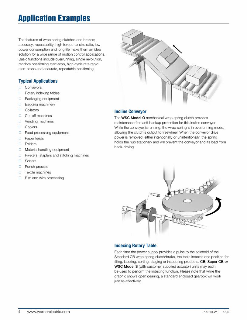
The features of wrap spring clutches and brakes; accuracy, repeatability, high torque-to-size ratio, low power consumption and long life make them an ideal solution for a wide range of motion control applications. Basic functions include overrunning, single revolution, random positioning start-stop, high cycle rate rapid start-stops and accurate, repeatable positioning.
Typical Applicationsn Conveyors
n Rotary indexing tables
n Packaging equipment
n Bagging machinery
n Collators
n Cut-off machines
n Vending machines
n Copiers
n Food processing equipment
n Paper feeds
n Folders
n Material handling equipment
n Riveters, staplers and stitching machines
n Sorters
n Punch presses
n Textile machines
n Film and wire processing
Incline ConveyorThe WSC Model O mechanical wrap spring clutch provides maintenance free anti-backup protection for this incline conveyor. While the conveyor is running, the wrap spring is in overrunning mode, allowing the clutch’s output to freewheel. When the conveyor drive power is removed, either intentionally or unintentionally, the spring holds the hub stationary and will prevent the conveyor and its load from back-driving.
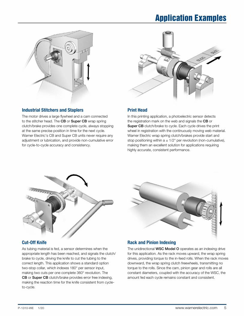
Indexing Rotary TableEach time the power supply provides a pulse to the solenoid of the Standard CB wrap spring clutch/brake, the table indexes one position for filling, labeling, sorting, staging or inspecting products. CB, Super CB or WSC Model S (with customer supplied actuator) units may each be used to perform the indexing function. Please note that while the graphic shows open gearing, a standard enclosed gearbox will work just as effectively.
Application Examples
5P-1310-WE 1/20 www.warnerelectric.com
Industrial Stitchers and StaplersThe motor drives a large flywheel and a cam connected to the stitcher head. The CB or Super CB wrap spring clutch/brake provides one complete cycle, always stopping at the same precise position in time for the next cycle. Warner Electric’s CB and Super CB units never require any adjustment or lubrication, and provide non-cumulative error for cycle-to-cycle accuracy and consistency.
Rack and Pinion IndexingThe unidirectional WSC Model O operates as an indexing drive for this application. As the rack moves upward, the wrap spring drives, providing torque to the in-feed rolls. When the rack moves downward, the wrap spring clutch freewheels, transmitting no torque to the rolls. Since the cam, pinion gear and rolls are all constant diameters, coupled with the accuracy of the WSC, the amount fed each cycle remains constant and consistent.
Print HeadIn this printing application, a photoelectric sensor detects the registration mark on the web and signals the CB or Super CB clutch/brake to cycle. Each cycle drives the print wheel in registration with the continuously moving web material. Warner Electric wrap spring clutch/brakes provide start and stop positioning within a ± 1/2° per revolution (non-cumulative), making them an excellent solution for applications requiring highly accurate, consistent performance.
Cut-Off KnifeAs tubing material is fed, a sensor determines when the appropriate length has been reached, and signals the clutch/brake to cycle, driving the knife to cut the tubing to the correct length. This application shows a standard option two-stop collar, which indexes 180° per sensor input, making two cuts per one complete 360° revolution. The CB or Super CB clutch/brake provides error free indexing, making the reaction time for the knife consistent from cycle-to-cycle.
Application Examples
6 www.warnerelectric.com P-1310-WE 1/20
For Product Selection Follow 3 Easy Steps
Max. Torque
Function Performance Wrap Spring Starting Stopping Max. Actuation Product lb. in. lb. in. rpm Method (N-m) (N-m)
required load/speed performance data is known and unit size is uncertain, use the technical selection process starting on page 36 which will help you review the neces sary aspects of your application.
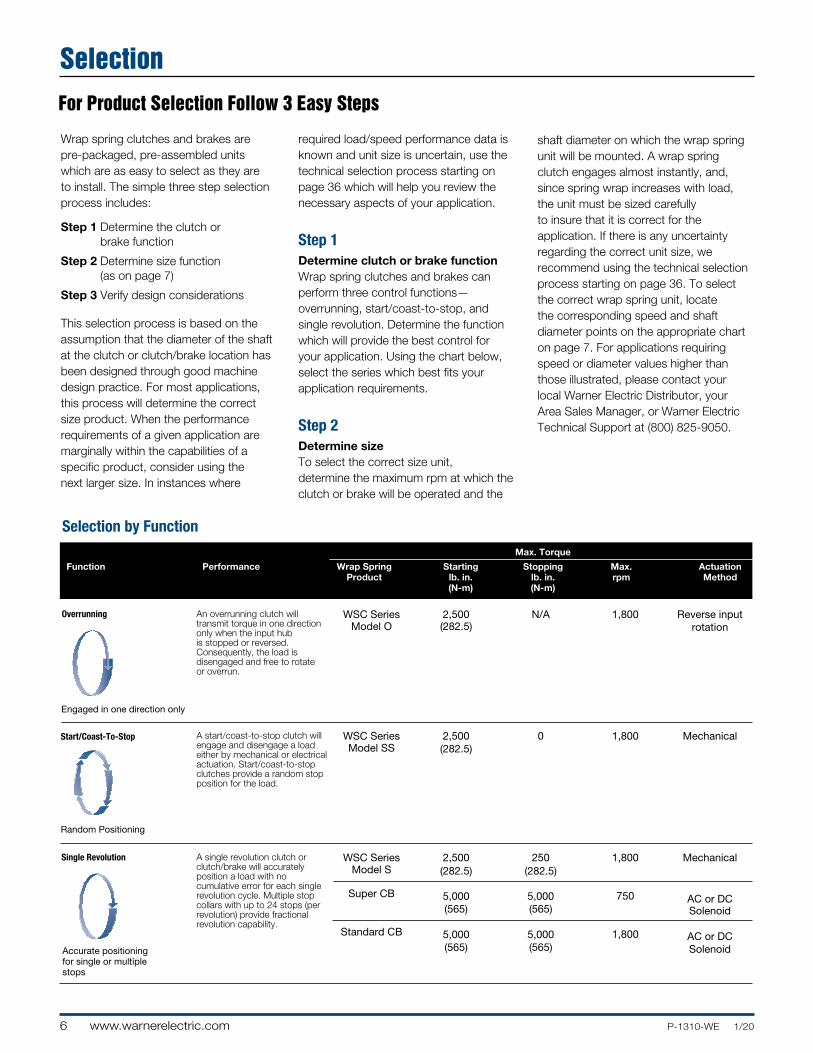
Step 1 Determine clutch or brake functionWrap spring clutches and brakes can perform three control functions—overrunning, start/coast-to-stop, and single revolution. Determine the function which will provide the best control for your application. Using the chart below, select the series which best fits your application requirements.
Step 2 Determine sizeTo select the correct size unit, deter mine the maximum rpm at which the clutch or brake will be operated and the
shaft diameter on which the wrap spring unit will be mounted. A wrap spring clutch engages almost instantly, and, since spring wrap increases with load, the unit must be sized carefully to insure that it is correct for the application. If there is any uncertainty regarding the correct unit size, we recommend using the technical selection process starting on page 36. To select the correct wrap spring unit, locate the corresponding speed and shaft diameter points on the appropriate chart on page 7. For appli ca tions requiring speed or diameter values higher than those illustrated, please contact your local Warner Electric Distributor, your Area Sales Manager, or Warner Electric Technical Support at (800) 825-9050.
Selection by Function
Wrap spring clutches and brakes are pre-packaged, pre-assembled units which are as easy to select as they are to install. The simple three step selection process includes:
Step 1 Determine the clutch or brake function
Step 2 Determine size function (as on page 7)
Step 3 Verify design considerations
This selection process is based on the assumption that the diameter of the shaft at the clutch or clutch/brake location has been designed through good machine design practice. For most applications, this process will determine the correct size product. When the performance requirements of a given application are marginally within the capabilities of a specific product, consider using the next larger size. In instances where
Overrunning
Start/Coast-To-Stop
Single Revolution
Accurate positioning for single or multiple stops
Random Positioning
An overrunning clutch will transmit torque in one direction only when the input hub is stopped or reversed. Consequently, the load is disengaged and free to rotate or overrun.
WSC Series Model O
2,500(282.5)
N/A 1,800 Reverse inputrotation
A start/coast-to-stop clutch will engage and disengage a load either by mechanical or electrical actuation. Start/coast-to-stop clutches provide a random stop position for the load.
WSC Series Model SS
2,500(282.5)
0 1,800 Mechanical
A single revolution clutch or clutch/brake will accurately position a load with no cumulative error for each single revolution cycle. Multiple stop collars with up to 24 stops (per revolution) provide fractional revolution capability.
WSC SeriesModel S
Super CB
Standard CB
2,500(282.5)
5,000(565)
5,000(565)
250(282.5)
5,000(565)
5,000(565)
1,800
750
1,800
Mechanical
AC or DCSolenoid
AC or DCSolenoid
Engaged in one direction only
Selection
7P-1310-WE 1/20 www.warnerelectric.com
2
6
6
8
8
8
8
4
5
1/4
3/8
1/2
3/4
1*
1
11/4
13/8*
11/2
RPM
200 300 400 500 600 700 800 900 1000 1100 1200 1300 1400 1500 1600 1700 1800
ClutchSize
BoreSize
WSC Series
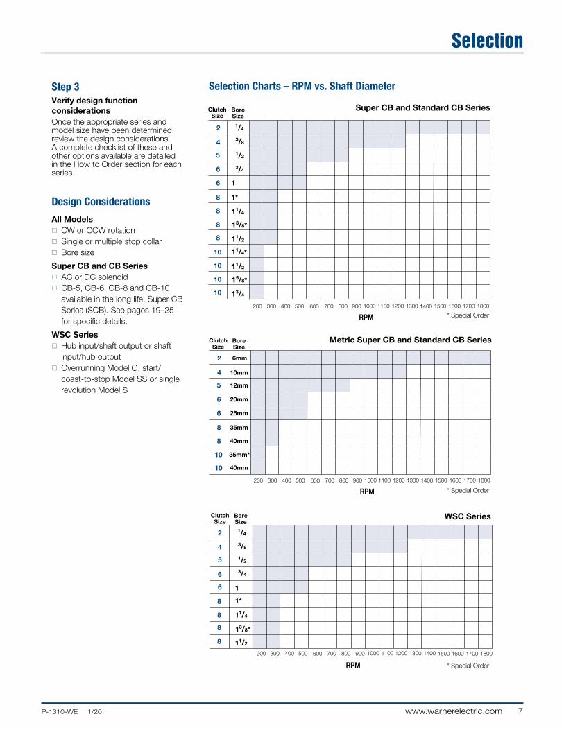
Step 3Verify design function considerationsOnce the appropriate series and model size have been determined, review the design considerations. A complete checklist of these and other options available are detailed in the How to Order section for each series.
2
6
6
4
5
1/4
3/8
1/2
3/4
1
RPM
200 300 400 500 600 700 800 900 1000 1100 1200 1300 1500 1700 18001400 1600
8
8
8
8
1*
11/4
13/8*
11/2
10
10
10
10
11/4*
11/2
15/8*
13/4
ClutchSize
BoreSize
Selection Charts – RPM vs. Shaft Diameter
Super CB and Standard CB Series
2
6
6
4
5
6mm
10mm
12mm
20mm
25mm
35mm
35mm*
40mm
40mm
ClutchSize
BoreSize
RPM
200 300 400 500 600 700 800 900 1000 1100 1200 1300 1500 1700 18001400 1600
8
8
10
10
Metric Super CB and Standard CB Series
Design Considerations
All Modelsn CW or CCW rotationn Single or multiple stop collarn Bore size
Super CB and CB Seriesn AC or DC solenoidn CB-5, CB-6, CB-8 and CB-10
available in the long life, Super CB Series (SCB). See pages 19–25 for specific details.
WSC Seriesn Hub input/shaft output or shaft
input/hub outputn Overrunning Model O, start/
coast-to-stop Model SS or single revolution Model S
* Special Order
* Special Order
* Special Order
Selection
8 www.warnerelectric.com P-1310-WE 1/20
mount the input pulley sprocket or gear.
Maximum Radial Bearing Load at Maximum Speed
CB-2 = 7.5 lbs. CB-4 = 14 lbs. CB-5/Super CB-5 = 32 lbs. CB-6/Super CB-6 = 63 lbs. CB-8/Super CB-8 = 300 lbs. CB-10/Super CB-10 = 500 lbs.
CB and Super CB style clutch/brakes are designed for horizontal shaft mounting. While it is possible to mount units vertically, vertically mounted units will see lower life than those mounted horizontally due to the wear between hubs resulting from gravity.
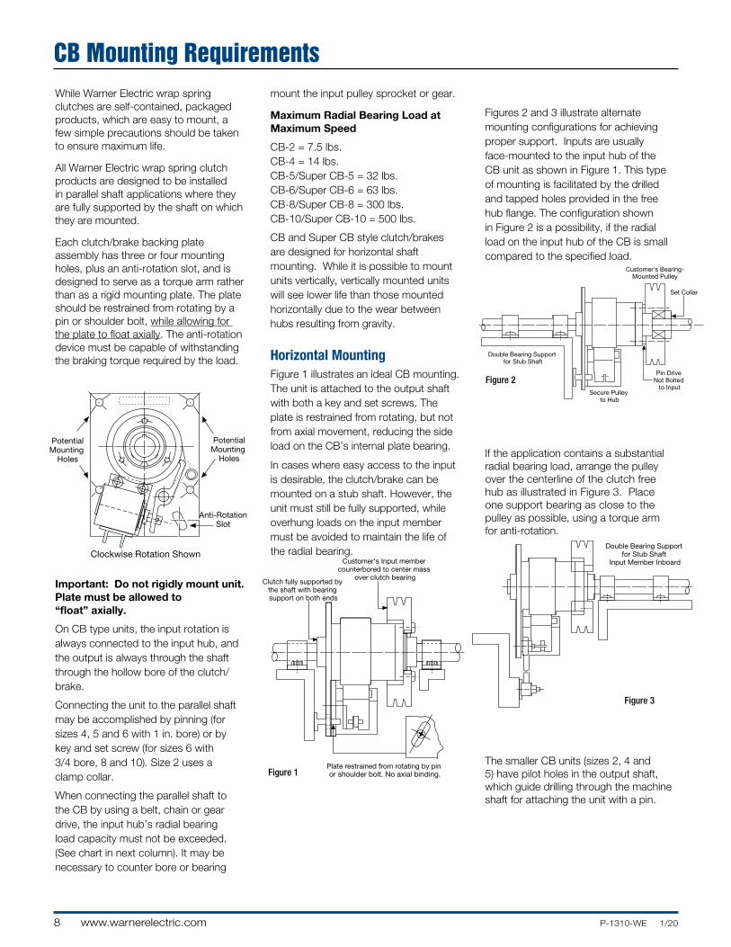
Horizontal Mounting Figure 1 illustrates an ideal CB mounting. The unit is attached to the output shaft with both a key and set screws. The plate is restrained from rotating, but not from axial movement, reducing the side load on the CB’s internal plate bearing.
In cases where easy access to the input is desirable, the clutch/brake can be mounted on a stub shaft. However, the unit must still be fully supported, while overhung loads on the input member must be avoided to maintain the life of the radial bearing.
Figures 2 and 3 illustrate alternate mounting configurations for achieving proper support. Inputs are usually face-mounted to the input hub of the CB unit as shown in Figure 1. This type of mounting is facilitated by the drilled and tapped holes provided in the free hub flange. The configuration shown in Figure 2 is a possibility, if the radial load on the input hub of the CB is small compared to the specified load.
If the application contains a substantial radial bearing load, arrange the pulley over the centerline of the clutch free hub as illustrated in Figure 3. Place one support bearing as close to the pulley as possible, using a torque arm for anti-rotation.
The smaller CB units (sizes 2, 4 and 5) have pilot holes in the output shaft, which guide drilling through the machine shaft for attaching the unit with a pin.
While Warner Electric wrap spring clutches are self-contained, packaged products, which are easy to mount, a few simple precautions should be taken to ensure maximum life.
All Warner Electric wrap spring clutch products are designed to be installed in parallel shaft applications where they are fully supported by the shaft on which they are mounted.
Each clutch/brake backing plate assembly has three or four mounting holes, plus an anti-rotation slot, and is designed to serve as a torque arm rather than as a rigid mounting plate. The plate should be restrained from rotating by a pin or shoulder bolt, while allowing for the plate to float axially. The anti-rotation device must be capable of withstanding the braking torque required by the load.
Important: Do not rigidly mount unit. Plate must be allowed to “float” axially.
On CB type units, the input rotation is always connected to the input hub, and the output is always through the shaft through the hollow bore of the clutch/brake.
Connecting the unit to the parallel shaft may be accomplished by pinning (for sizes 4, 5 and 6 with 1 in. bore) or by key and set screw (for sizes 6 with 3/4 bore, 8 and 10). Size 2 uses a clamp collar.
When connecting the parallel shaft to the CB by using a belt, chain or gear drive, the input hub’s radial bearing load capacity must not be exceeded. (See chart in next column). It may be necessary to counter bore or bearing
++
+
+ +
++
++++
PotentialMounting
Holes
PotentialMounting
Holes
Anti-RotationSlot
Clockwise Rotation Shown
Clutch fully supported by the shaft with bearing support on both ends
Customer's Input member counterbored to center mass
over clutch bearing
Plate restrained from rotating by pin or shoulder bolt. No axial binding.
+
Figure 1
Double Bearing Support for Stub Shaft
Input Member Inboard
Figure 3
Customer's Bearing-Mounted Pulley
Double Bearing Support for Stub Shaft
Set Collar
Pin Drive Not Bolted
to InputSecure Pulley
to Hub
Figure 2
CB Mounting Requirements
9P-1310-WE 1/20 www.warnerelectric.com
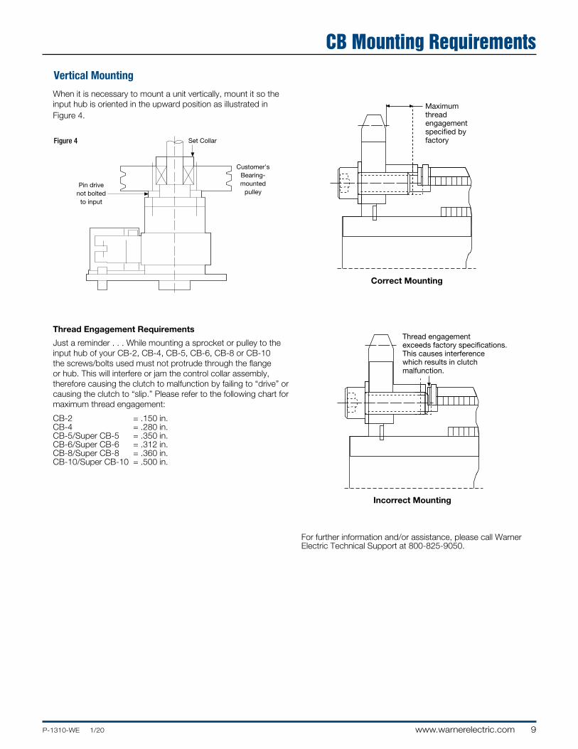
When it is necessary to mount a unit vertically, mount it so the input hub is oriented in the upward position as illustrated in Figure 4.
Thread Engagement Requirements
Just a reminder . . . While mounting a sprocket or pulley to the input hub of your CB-2, CB-4, CB-5, CB-6, CB-8 or CB-10 the screws/bolts used must not protrude through the flange or hub. This will interfere or jam the control collar assembly, therefore causing the clutch to malfunction by failing to “drive” or causing the clutch to “slip.” Please refer to the following chart for maximum thread engagement:
CB-2 = .150 in. CB-4 = .280 in. CB-5/Super CB-5 = .350 in. CB-6/Super CB-6 = .312 in. CB-8/Super CB-8 = .360 in. CB-10/Super CB-10 = .500 in.
Vertical Mounting
Pin drivenot bolted
to input
Customer'sBearing-mounted
pulley
Set CollarFigure 4
Maximum thread engagementspecified by factory
Correct Mounting
Thread engagement exceeds factory specifications.This causes interferencewhich results in clutch malfunction.
Incorrect Mounting
For further information and/or assistance, please call Warner Electric Technical Support at 800-825-9050.
CB Mounting Requirements
10 www.warnerelectric.com P-1310-WE 1/20
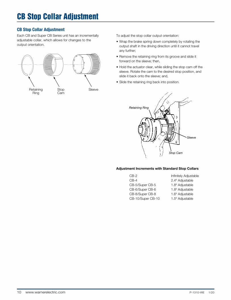
CB Stop Collar AdjustmentEach CB and Super CB Series unit has an incrementally adjustable collar, which allows for changes to the output orientation.
RetainingRing
StopCam
Sleeve
Adjustment Increments with Standard Stop Collars
CB-2 Infinitely Adjustable CB-4 2.4º Adjustable CB-5/Super CB-5 1.8º Adjustable CB-6/Super CB-6 1.8º Adjustable CB-8/Super CB-8 1.6º Adjustable CB-10/Super CB-10 1.5º Adjustable
Retaining Ring
Sleeve
Stop Cam
To adjust the stop collar output orientation:
• Wrap the brake spring down completely by rotating the output shaft in the driving direction until it cannot travel any further;
• Remove the retaining ring from its groove and slide it forward on the sleeve; then,
• Hold the actuator clear, while sliding the stop cam off the sleeve. Rotate the cam to the desired stop position, and slide it back onto the sleeve; and,
• Slide the retaining ring back into position.
CB Stop Collar Adjustment
11P-1310-WE 1/20 www.warnerelectric.com
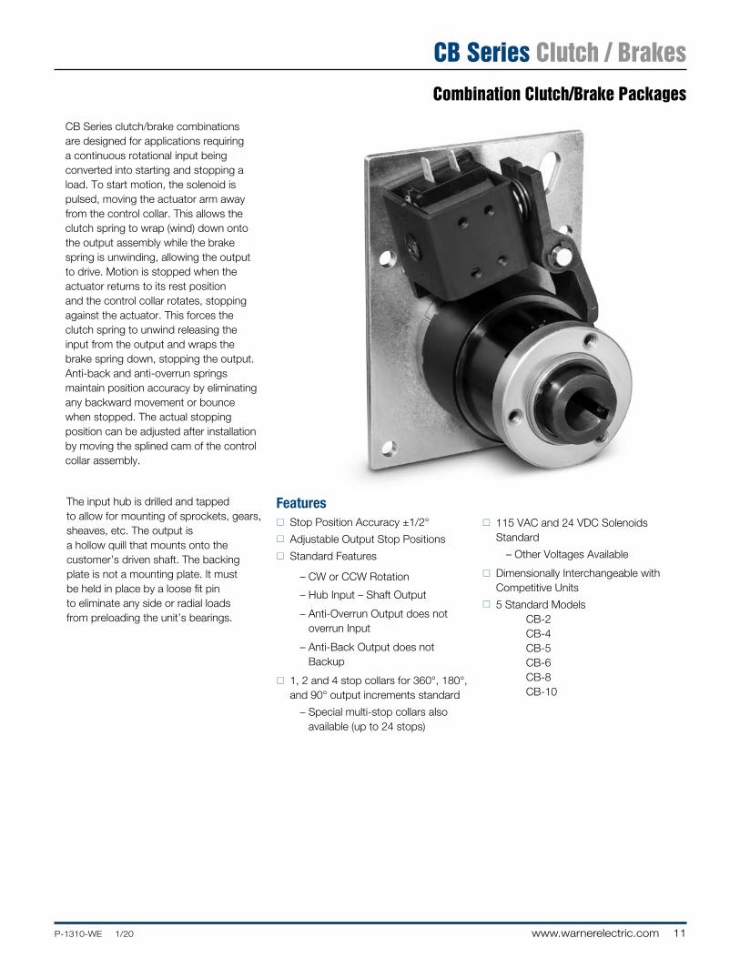
Combination Clutch/Brake Packages
CB Series clutch/brake combinations are designed for applications requiring a continuous rotational input being converted into starting and stopping a load. To start motion, the solenoid is pulsed, moving the actuator arm away from the control collar. This allows the clutch spring to wrap (wind) down onto the output assembly while the brake spring is unwinding, allowing the output to drive. Motion is stopped when the actuator returns to its rest position and the control collar rotates, stopping against the actuator. This forces the clutch spring to unwind releasing the input from the output and wraps the brake spring down, stopping the output. Anti-back and anti-overrun springs maintain position accuracy by eliminating any backward movement or bounce when stopped. The actual stopping position can be adjusted after installation by moving the splined cam of the control collar assembly.
The input hub is drilled and tapped to allow for mounting of sprockets, gears, sheaves, etc. The output is a hollow quill that mounts onto the customer’s driven shaft. The backing plate is not a mounting plate. It must be held in place by a loose fit pin to eliminate any side or radial loads from preloading the unit’s bearings.
Featuresn Stop Position Accuracy ±1/2°
n Adjustable Output Stop Positions
n Standard Features
– CW or CCW Rotation
– Hub Input – Shaft Output
– Anti-Overrun Output does not overrun Input
– Anti-Back Output does not Backup
n 1, 2 and 4 stop collars for 360°, 180°, and 90° output increments standard
– Special multi-stop collars also available (up to 24 stops)
n 115 VAC and 24 VDC Solenoids Standard
– Other Voltages Available
n Dimensionally Interchangeable with Competitive Units
n 5 Standard Models CB-2 CB-4 CB-5 CB-6 CB-8 CB-10
CB Series Clutch / Brakes
12 www.warnerelectric.com P-1310-WE 1/20
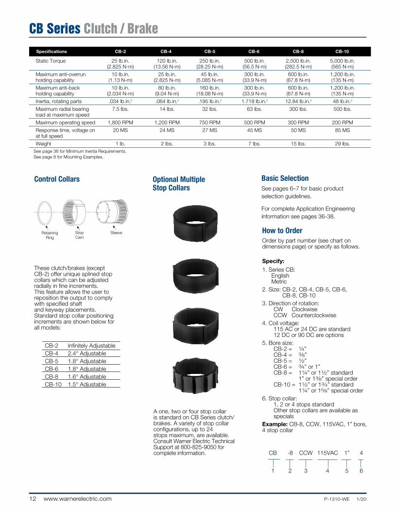
These clutch/brakes (except CB-2) offer unique splined stop collars which can be adjusted radially in fine increments. This feature allows the user to reposition the output to comply with specified shaft and keyway placements. Standard stop collar positioning increments are shown below for all models:
CB-2 Infinitely Adjustable CB-4 2.4° Adjustable CB-5 1.8° Adjustable CB-6 1.8° Adjustable CB-8 1.6° Adjustable CB-10 1.5° Adjustable
Basic SelectionSee pages 6–7 for basic product selection guidelines.
For complete Application Engineering information see pages 36-38.
Control Collars
A one, two or four stop collar is standard on CB Series clutch/brakes. A variety of stop collar config ura tions, up to 24 stops maximum, are available. Consult Warner Electric Technical Support at 800-825-9050 for complete information.
Optional Multiple Stop Collars
Order by part number (see chart on dimensions page) or specify as follows.
Specify:1. Series CB:
English Metric
2. Size: CB-2, CB-4, CB-5, CB-6, CB-8, CB-10
3. Direction of rotation: CW Clockwise CCW Counterclockwise4. Coil voltage: 115 AC or 24 DC are standard 12 DC or 90 DC are options5. Bore size: CB-2 = 1⁄4” CB-4 = 3⁄8” CB-5 = 1⁄2” CB-6 = 3⁄4” or 1” CB-8 = 11⁄4” or 11⁄2” standard
1” or 13⁄8” special order CB-10 = 11⁄2” or 13⁄4” standard
11⁄4” or 15⁄8” special order6. Stop collar: 1, 2 or 4 stops standard Other stop collars are available as
specialsExample: CB-8, CCW, 115VAC, 1” bore, 4 stop collar
How to Order
RetainingRing
DriveSleeve
StopCam
CouplingSleeve
BrakeSleeve
RetainingRing
StopCam
Sleeve
CB -8 CCW 115VAC 1” 4
1 2 3 4 5 6
CB Series Clutch / Brake Specifications CB-2 CB-4 CB-5 CB-6 CB-8 CB-10
Static Torque 25 lb.in. 120 lb.in. 250 lb.in. 500 lb.in. 2,500 lb.in. 5,000 lb.in. (2.825 N-m) (13.56 N-m) (28.25 N-m) (56.5 N-m) (282.5 N-m) (565 N-m)
Maximum anti-overrun 10 lb.in. 25 lb.in. 45 lb.in. 300 lb.in. 600 lb.in. 1,200 lb.in. holding capability (1.13 N-m) (2.825 N-m) (5.085 N-m) (33.9 N-m) (67.8 N-m) (135 N-m)
Maximum anti-back 10 lb.in. 80 lb.in. 160 lb.in. 300 lb.in. 600 lb.in. 1,200 lb.in. holding capability (2.034 N-m) (9.04 N-m) (18.08 N-m) (33.9 N-m) (67.8 N-m) (135 N-m)
Inertia, rotating parts .034 lb.in.2 .064 lb.in.2 .195 lb.in.2 1.718 lb.in.2 12.84 lb.in.2 48 lb.in.2
Maximum radial bearing 7.5 lbs. 14 lbs. 32 lbs. 63 lbs. 300 lbs. 500 lbs. load at maximum speed
Maximum operating speed 1,800 RPM 1,200 RPM 750 RPM 500 RPM 300 RPM 200 RPM
Response time, voltage on 20 MS 24 MS 27 MS 45 MS 50 MS 85 MS at full speed
Weight 1 lb. 2 lbs. 3 lbs. 7 lbs. 15 lbs. 29 lbs.See page 36 for Minimum Inertia Requirements.See page 8 for Mounting Examples.
13P-1310-WE 1/20 www.warnerelectric.com
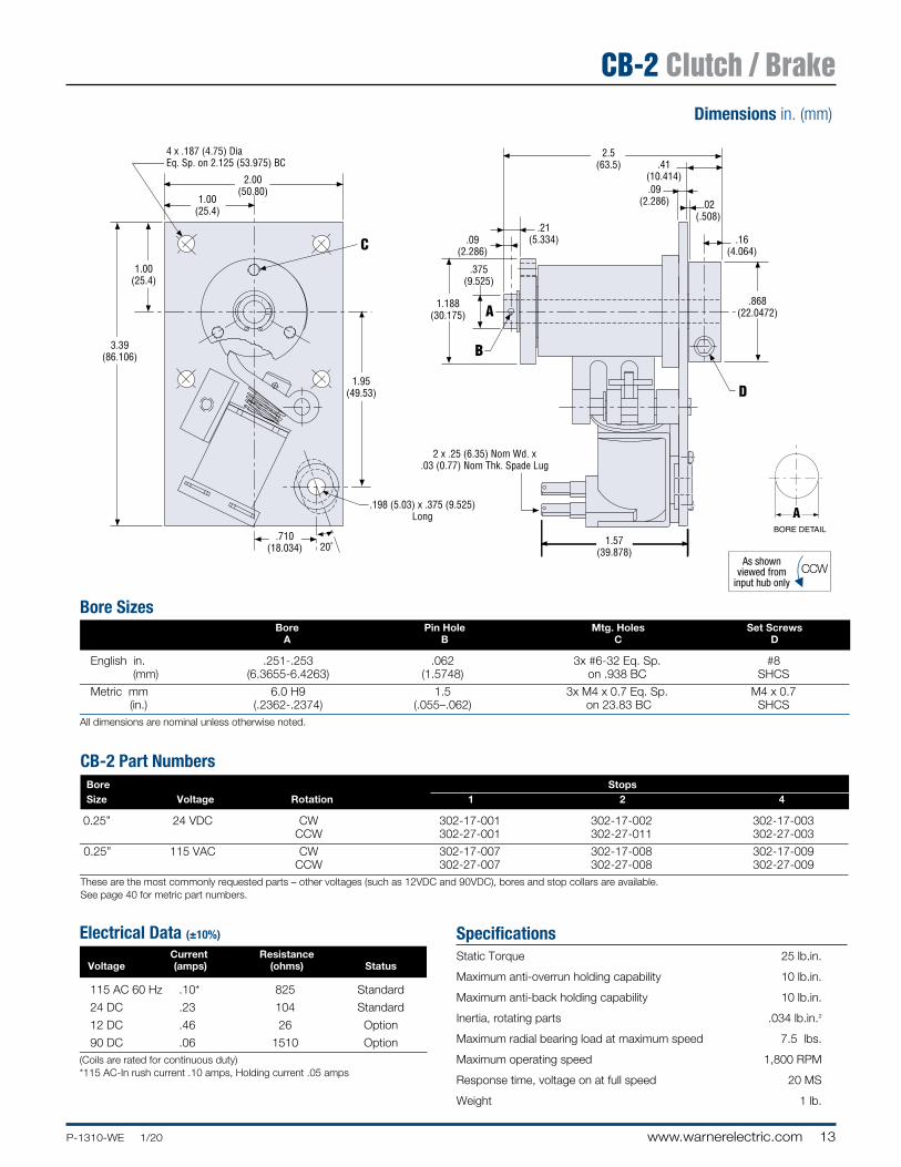
Bore Sizes Bore Pin Hole Mtg. Holes Set Screws A B C D
English in. .251-.253 .062 3x #6-32 Eq. Sp. #8 (mm) (6.3655-6.4263) (1.5748) on .938 BC SHCS
Metric mm 6.0 H9 1.5 3x M4 x 0.7 Eq. Sp. M4 x 0.7 (in.) (.2362-.2374) (.055–.062) on 23.83 BC SHCS
All dimensions are nominal unless otherwise noted.
SpecificationsStatic Torque 25 lb.in.
Maximum anti-overrun holding capability 10 lb.in.
Maximum anti-back holding capability 10 lb.in.
Inertia, rotating parts .034 lb.in.2
Maximum radial bearing load at maximum speed 7.5 lbs.
Maximum operating speed 1,800 RPM
Response time, voltage on at full speed 20 MS
Weight 1 lb.
As shownviewed from
input hub onlyCCW
As shownviewed from
input. (May be shaft or hub input.)
As shownviewed fromlug drive end
CCW
CCW
Electrical Data (±10%)
Current Resistance Voltage (amps) (ohms) Status
115 AC 60 Hz .10* 825 Standard
24 DC .23 104 Standard
12 DC .46 26 Option
90 DC .06 1510 Option(Coils are rated for continuous duty)* 115 AC- In rush current .10 amps, Holding current .05 amps
CB-2 Part Numbers Bore Stops Size Voltage Rotation 1 2 4
0.25” 24 VDC CW 302-17-001 302-17-002 302-17-003 CCW 302-27-001 302-27-011 302-27-003
0.25” 115 VAC CW 302-17-007 302-17-008 302-17-009 CCW 302-27-007 302-27-008 302-27-009These are the most commonly requested parts – other voltages (such as 12VDC and 90VDC), bores and stop collars are available.See page 40 for metric part numbers.
Dimensions in. (mm)
CB-2 Clutch / Brake
14 www.warnerelectric.com P-1310-WE 1/20
Dimensions in. (mm)
As shownviewed from
input hub onlyCW
As shownviewed from
input. (May be shaft or hub input.)
CW
As shownviewed fromlug drive end
CW
As shownviewed from
this endCW
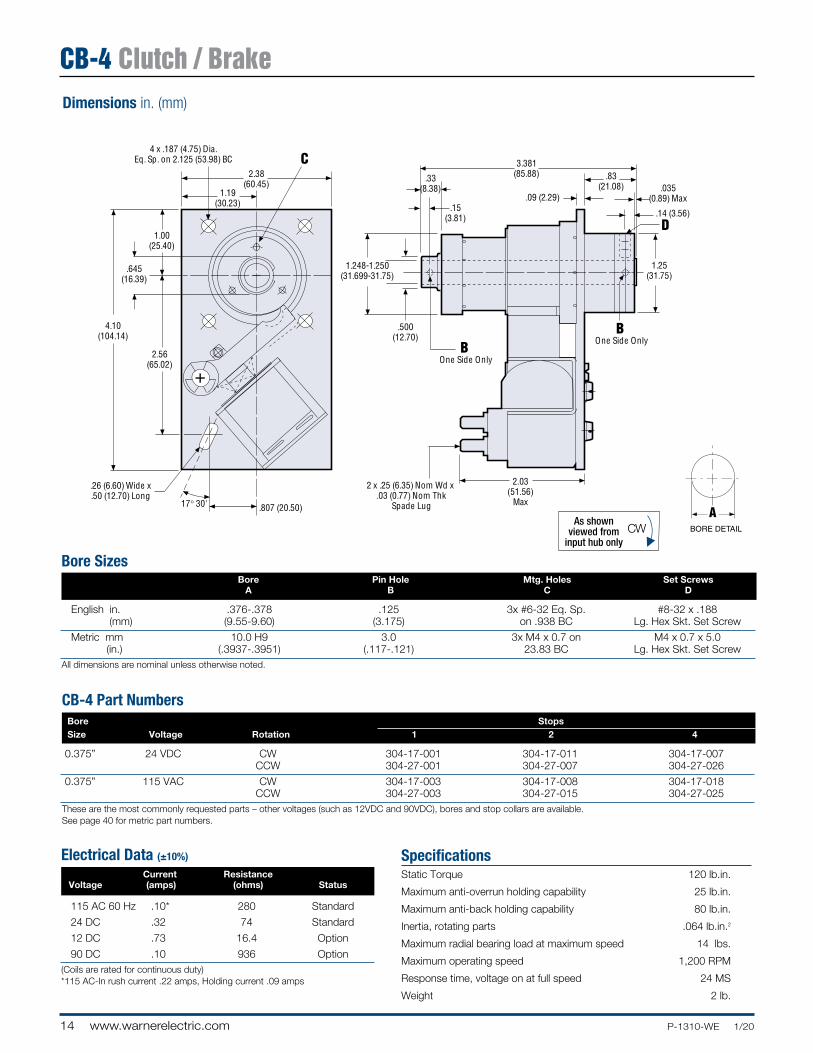
Bore Sizes Bore Pin Hole Mtg. Holes Set Screws A B C D
English in. .376-.378 .125 3x #6-32 Eq. Sp. #8-32 x .188 (mm) (9.55-9.60) (3.175) on .938 BC Lg. Hex Skt. Set Screw
Metric mm 10.0 H9 3.0 3x M4 x 0.7 on M4 x 0.7 x 5.0 (in.) (.3937-.3951) (.117-.121) 23.83 BC Lg. Hex Skt. Set Screw
All dimensions are nominal unless otherwise noted.
SpecificationsStatic Torque 120 lb.in.
Maximum anti-overrun holding capability 25 lb.in.
Maximum anti-back holding capability 80 lb.in.
Inertia, rotating parts .064 lb.in.2
Maximum radial bearing load at maximum speed 14 lbs.
Maximum operating speed 1,200 RPM
Response time, voltage on at full speed 24 MS
Weight 2 lb.
Electrical Data (±10%)
Current Resistance Voltage (amps) (ohms) Status
115 AC 60 Hz .10* 280 Standard
24 DC .32 74 Standard
12 DC .73 16.4 Option
90 DC .10 936 Option(Coils are rated for continuous duty)* 115 AC-In rush current .22 amps, Holding current .09 amps
CB-4 Part Numbers Bore Stops Size Voltage Rotation 1 2 4
0.375” 24 VDC CW 304-17-001 304-17-011 304-17-007 CCW 304-27-001 304-27-007 304-27-026
0.375” 115 VAC CW 304-17-003 304-17-008 304-17-018 CCW 304-27-003 304-27-015 304-27-025These are the most commonly requested parts – other voltages (such as 12VDC and 90VDC), bores and stop collars are available.See page 40 for metric part numbers.
CB-4 Clutch / Brake
15P-1310-WE 1/20 www.warnerelectric.com
One Side OnlyOne Side Only
As shownviewed from
input hub onlyCCW
As shownviewed from
input. (May be shaft or hub input.)
As shownviewed fromlug drive end
CCW
CCW
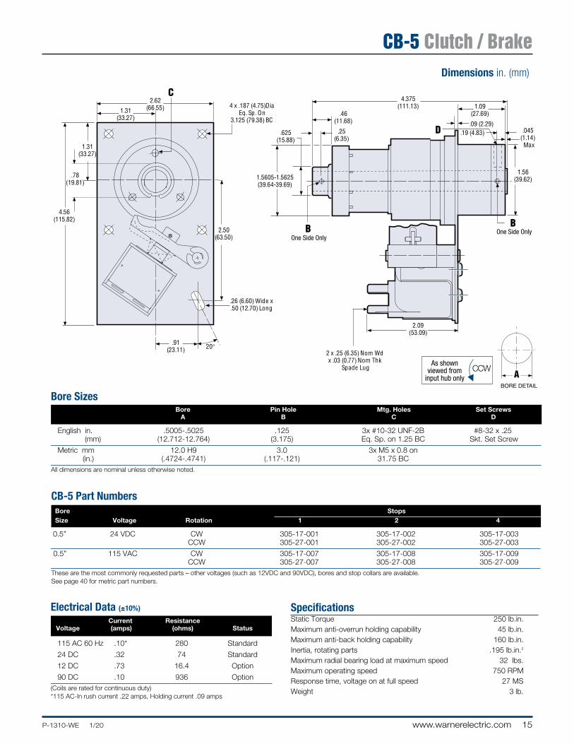
Bore Sizes Bore Pin Hole Mtg. Holes Set Screws A B C D
English in. .5005-.5025 .125 3x #10-32 UNF-2B #8-32 x .25 (mm) (12.712-12.764) (3.175) Eq. Sp. on 1.25 BC Skt. Set Screw
Metric mm 12.0 H9 3.0 3x M5 x 0.8 on (in.) (.4724-.4741) (.117-.121) 31.75 BC
All dimensions are nominal unless otherwise noted.
SpecificationsStatic Torque 250 lb.in.Maximum anti-overrun holding capability 45 lb.in. Maximum anti-back holding capability 160 lb.in. Inertia, rotating parts .195 lb.in.2
Maximum radial bearing load at maximum speed 32 lbs.Maximum operating speed 750 RPMResponse time, voltage on at full speed 27 MSWeight 3 lb.
Electrical Data (±10%)
Current Resistance Voltage (amps) (ohms) Status
115 AC 60 Hz .10* 280 Standard
24 DC .32 74 Standard
12 DC .73 16.4 Option
90 DC .10 936 Option(Coils are rated for continuous duty)* 115 AC- In rush current .22 amps, Holding current .09 amps
CB-5 Part Numbers Bore Stops Size Voltage Rotation 1 2 4
0.5” 24 VDC CW 305-17-001 305-17-002 305-17-003 CCW 305-27-001 305-27-002 305-27-003
0.5” 115 VAC CW 305-17-007 305-17-008 305-17-009 CCW 305-27-007 305-27-008 305-27-009These are the most commonly requested parts – other voltages (such as 12VDC and 90VDC), bores and stop collars are available.See page 40 for metric part numbers.
Dimensions in. (mm)
CB-5 Clutch / Brake
16 www.warnerelectric.com P-1310-WE 1/20
++�
+
� +
�+
�+��
4.312(109.53)
.517-.537(13.132-13.640) .125 (3.175)
.22 (5.59)
.36 (9.144).19 (4.83)
2.50(63.50)
1.559-1.562(39.59-39.68)
1.25(31.75)
2.25(57.15)
2.92(74.17)
5.75(146.05)
2.12(53.85)
4.25(107.95)
1.38(35.05)
2.12(53.85)
4 x .279-.288 (7.087-7.315) DiaEq. Sp. on 5.0 (127.0) BC
20�2 x .25 (6.35) Nom Wd x
.03 (0.77) Nom ThkSpade Lug
.386 (9.80) Wide x.80 (20.32) Long
Dimensions in. (mm)
As shownviewed from
input hub onlyCW
As shownviewed from
input. (May be shaft or hub input.)
CW
As shownviewed fromlug drive end
CW
As shownviewed from
this endCW
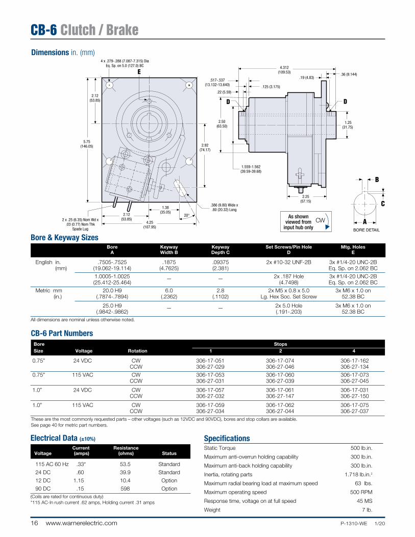
Bore & Keyway Sizes Bore Keyway Keyway Set Screws/Pin Hole Mtg. Holes A Width B Depth C D E
English in. .7505-.7525 .1875 .09375 2x #10-32 UNF-2B 3x #1/4-20 UNC-2B (mm) (19.062-19.114) (4.7625) (2.381) Eq. Sp. on 2.062 BC
1.0005-1.0025 2x .187 Hole 3x #1/4-20 UNC-2B (25.412-25.464)
— — (4.7498) Eq. Sp. on 2.062 BC
Metric mm 20.0 H9 6.0 2.8 2x M5 x 0.8 x 5.0 3x M6 x 1.0 on (in.) (.7874-.7894) (.2362) (.1102) Lg. Hex Soc. Set Screw 52.38 BC
25.0 H9 2x 5.0 Hole 3x M6 x 1.0 on (.9842-.9862)
— — (.191-.203) 52.38 BC
All dimensions are nominal unless otherwise noted.
SpecificationsStatic Torque 500 lb.in.
Maximum anti-overrun holding capability 300 lb.in.
Maximum anti-back holding capability 300 lb.in.
Inertia, rotating parts 1.718 lb.in.2
Maximum radial bearing load at maximum speed 63 lbs.
Maximum operating speed 500 RPM
Response time, voltage on at full speed 45 MS
Weight 7 lb.
Electrical Data (±10%)
Current Resistance Voltage (amps) (ohms) Status
115 AC 60 Hz .33* 53.5 Standard
24 DC .60 39.9 Standard
12 DC 1.15 10.4 Option
90 DC .15 598 Option(Coils are rated for continuous duty)* 115 AC- In rush current .62 amps, Holding current .31 amps
CB-6 Part Numbers Bore Stops Size Voltage Rotation 1 2 4
0.75” 24 VDC CW 306-17-051 306-17-074 306-17-162 CCW 306-27-029 306-27-046 306-27-134
0.75” 115 VAC CW 306-17-053 306-17-060 306-17-073 CCW 306-27-031 306-27-039 306-27-045
1.0” 24 VDC CW 306-17-057 306-17-061 306-17-031 CCW 306-27-032 306-27-147 306-27-150
1.0” 115 VAC CW 306-17-059 306-17-062 306-17-075 CCW 306-27-034 306-27-044 306-27-037These are the most commonly requested parts – other voltages (such as 12VDC and 90VDC), bores and stop collars are available.See page 40 for metric part numbers.
CB-6 Clutch / Brake
17P-1310-WE 1/20 www.warnerelectric.com
++
4.00(101.60)
2.372-2.374(60.24-60.30)
+
++
+
++
30°
++
++
+
7.00(177.80)
5.0(127)
2.50(63.50)
2.50(63.50)
3.118(79.20)
1.80(45.72)
6.125(155.58)
.40(10.16)
.698 (17.73)
.25 (6.35).188 (4.78)
.427 (10.85)
1.967(49.96)
2.31(58.68)
Max
.25(6.35)
+
4 x .394 (10.0) Dia Sp. @ 90°on 5.875 (149.225) BC
.386 (9.80) Wide x
.80 (20.32) Long
As shownviewed from
input hub onlyCW
As shownviewed from
input. (May be shaft or hub input.)
CW
As shownviewed fromlug drive end
CW
As shownviewed from
this endCW
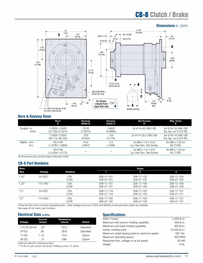
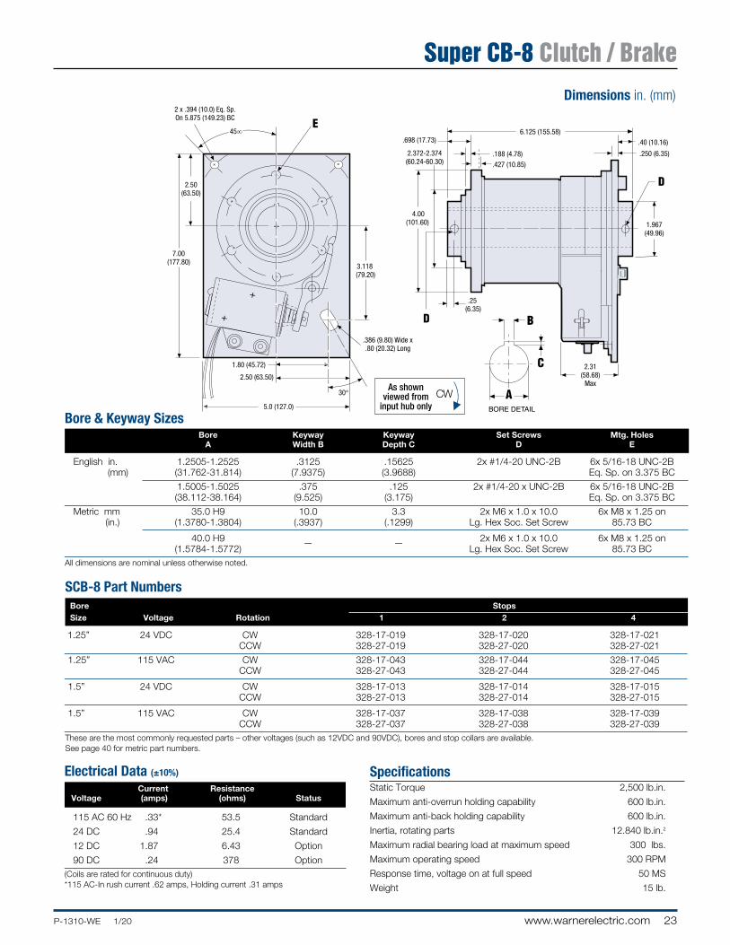
Bore & Keyway Sizes Bore Keyway Keyway Set Screws Mtg. Holes A Width B Depth C D E
English in. 1.2505-1.2525 .3125 .15625 2x #1/4-20 UNC-2B 6x 5/16-18 UNC-2B (mm) (31.762-31.814) (7.9375) (3.9688) Eq. Sp. on 3.375 BC
1.5005-1.5025 .375 .125 2x #1/4-20 x UNC-2B 6x 5/16-18 UNC-2B (38.112-38.164) (9.525) (3.175) Eq. Sp. on 3.375 BC
Metric mm 35.0 H9 10.0 3.3 2x M6 x 1.0 x 10.0 6x M8 x 1.25 on (in.) (1.3780-1.3804) (.3937) (.1299) Lg. Hex Soc. Set Screw 85.73 BC
40.0 H9 2x M6 x 1.0 x 10.0 6x M8 x 1.25 on (1.5784-1.5772)
— — Lg. Hex Soc. Set Screw 85.73 BC
All dimensions are nominal unless otherwise noted.
SpecificationsStatic Torque 2,500 lb.in.Maximum anti-overrun holding capability 600 lb.in. Maximum anti-back holding capability 600 lb.in. Inertia, rotating parts 12.840 lb.in.2
Maximum radial bearing load at maximum speed 300 lbs.Maximum operating speed 300 RPMResponse time, voltage on at full speed 50 MSWeight 15 lb.
Electrical Data (±10%)
Current Resistance Voltage (amps) (ohms) Status
115 AC 60 Hz .33* 53.5 Standard
24 DC .60 39.8 Standard
12 DC 1.15 10.4 Option
90 DC .15 598 Option(Coils are rated for continuous duty)* 115 AC- In rush current .62 amps, Holding current .31 amps
CB-8 Part Numbers Bore Stops Size Voltage Rotation 1 2 4
1.25” 24 VDC CW 308-17-101 308-17-102 308-17-103 CCW 308-27-101 308-27-102 308-27-103
1.25” 115 VAC CW 308-17-107 308-17-108 308-17-109 CCW 308-27-107 308-27-108 308-27-109
1.5” 24 VDC CW 308-17-119 308-17-120 308-17-121 CCW 308-27-119 308-27-120 308-27-121
1.5” 115 VAC CW 308-17-125 308-17-126 308-17-127 CCW 308-27-125 308-27-126 308-27-127These are the most commonly requested parts – other voltages (such as 12VDC and 90VDC), bores and stop collars are available.See page 40 for metric part numbers.
Dimensions in. (mm)
CB-8 Clutch / Brake
18 www.warnerelectric.com P-1310-WE 1/20
o
(3) .406 (10.31) Holes 90° apart on a 7.00 (177.8) B.C.
25
Pilot
Bore
Key
25o
6.0(152.4)
.82(20.828)
.220(5.588)
.25 (6.35) .25 (6.35)
.19 (4.826)3.0
(76.2)
3.0(76.2)
8.88(225.55)
12.0 (304.8) Lead Wires
.635 (16.12) Wide X 1.25 (31.75) Long
.635 (16.12) Wide X 1.25 (31.75) Long
2.0(50.8)
2.0(50.8)
2.362(59.995)
.63(16.002)
7.750(196.85)
Max2.55 (64.77)
Max2.55 (64.77)
4.25(107.95)
4.94(125.476)
2.935(74.549)
Dimensions in. (mm)
As shownviewed from
input hub onlyCW
As shownviewed from
input. (May be shaft or hub input.)
CW
As shownviewed fromlug drive end
CW
As shownviewed from
this endCW
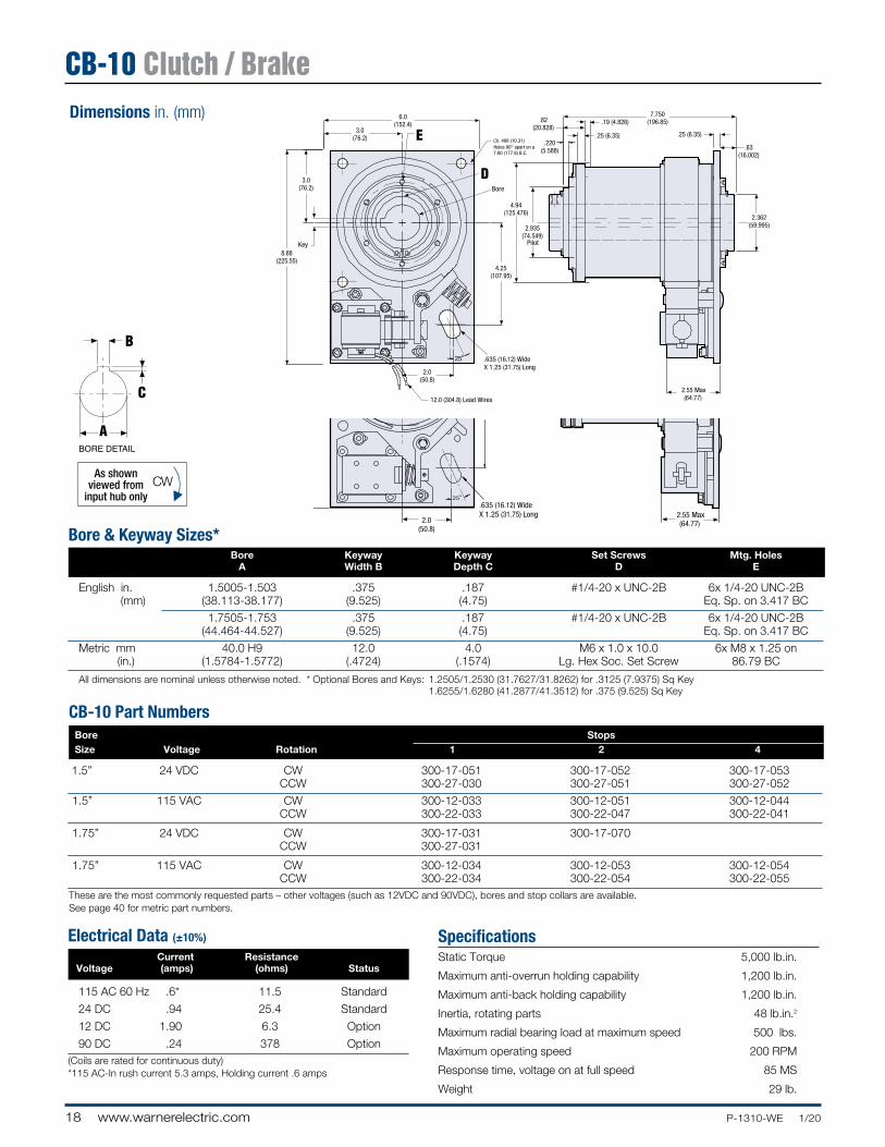
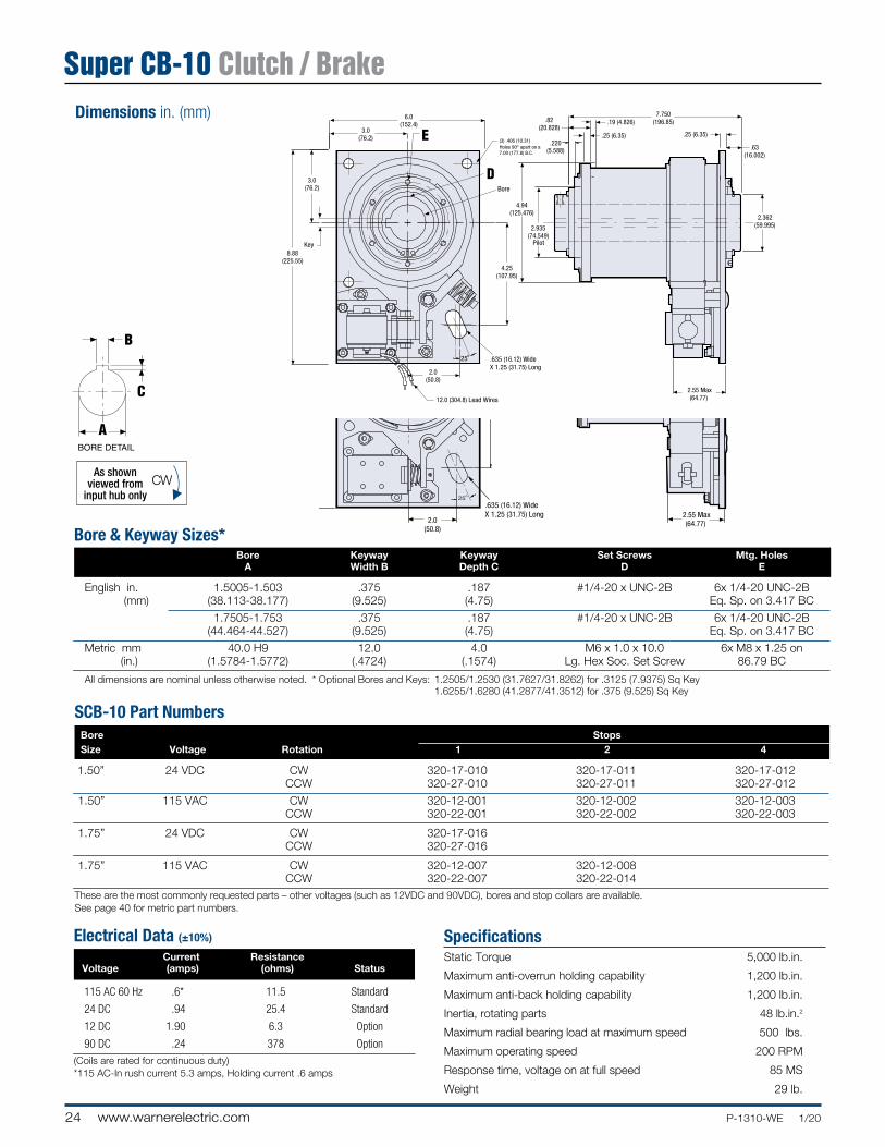
Bore & Keyway Sizes* Bore Keyway Keyway Set Screws Mtg. Holes A Width B Depth C D E
English in. 1.5005-1.503 .375 .187 #1/4-20 x UNC-2B 6x 1/4-20 UNC-2B (mm) (38.113-38.177) (9.525) (4.75) Eq. Sp. on 3.417 BC
1.7505-1.753 .375 .187 #1/4-20 x UNC-2B 6x 1/4-20 UNC-2B (44.464-44.527) (9.525)
(4.75) Eq. Sp. on 3.417 BC
Metric mm 40.0 H9 12.0 4.0 M6 x 1.0 x 10.0 6x M8 x 1.25 on (in.) (1.5784-1.5772) (.4724) (.1574) Lg. Hex Soc. Set Screw 86.79 BC
All dimensions are nominal unless otherwise noted. * Optional Bores and Keys: 1.2505/1.2530 (31.7627/31.8262) for .3125 (7.9375) Sq Key 1.6255/1.6280 (41.2877/41.3512) for .375 (9.525) Sq Key
SpecificationsStatic Torque 5,000 lb.in.
Maximum anti-overrun holding capability 1,200 lb.in.
Maximum anti-back holding capability 1,200 lb.in.
Inertia, rotating parts 48 lb.in.2
Maximum radial bearing load at maximum speed 500 lbs.
Maximum operating speed 200 RPM
Response time, voltage on at full speed 85 MS
Weight 29 lb.
Electrical Data (±10%)
Current Resistance Voltage (amps) (ohms) Status
115 AC 60 Hz .6* 11 .5 Standard
24 DC .94 25.4 Standard
12 DC 1.90 6.3 Option
90 DC .24 378 Option(Coils are rated for continuous duty)* 115 AC- In rush current 5.3 amps, Holding current .6 amps
CB-10 Part Numbers Bore Stops Size Voltage Rotation 1 2 4
1.5” 24 VDC CW 300-17-051 300-17-052 300-17-053 CCW 300-27-030 300-27-051 300-27-052
1.5” 115 VAC CW 300-12-033 300-12-051 300-12-044 CCW 300-22-033 300-22-047 300-22-041
1.75” 24 VDC CW 300-17-031 300-17-070 CCW 300-27-031
1.75” 115 VAC CW 300-12-034 300-12-053 300-12-054 CCW 300-22-034 300-22-054 300-22-055These are the most commonly requested parts – other voltages (such as 12VDC and 90VDC), bores and stop collars are available.See page 40 for metric part numbers.
CB-10 Clutch / Brake
19P-1310-WE 1/20 www.warnerelectric.com
Long Life, High Performance Design
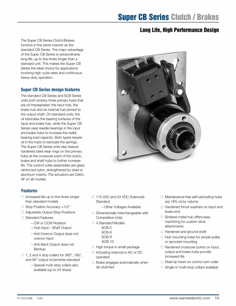
The Super CB Series Clutch/Brakes function in the same manner as the standard CB Series. The major advantage of the Super CB Series is extraordinarily long life, up to five times longer than a standard unit. This makes the Super CB Series the ideal choice for applications involving high cycle rates and continuous heavy-duty operation.
Super CB Series design featuresThe standard CB Series and SCB Series units both employ three primary hubs that are oil impregnated; the input hub, the brake hub and an internal hub pinned to the output shaft. On standard units, the oil lubricates the bearing surfaces of the input and brake hub, while the Super CB Series uses needle bearings in the input and brake hubs to increase the radial bearing load capacity. Both types require oil in the hubs to lubricate the springs. The Super CB Series units also feature hardened steel wear rings on the primary hubs at the crossover point of the clutch, brake and shaft hubs to further increase life. The control collar assemblies are glass reinforced nylon, strengthened by steel or aluminum inserts. The actuators are Delrin‚ AF on all models.
Featuresn Increased life-up to five times longer
than standard models
n Stop Position Accuracy +1/2°
n Adjustable Output Stop Positions
n Standard Features
– CW or CCW Rotation – Hub Input – Shaft Output
– Anti-Overrun Output does not overrun Input
– Anti-Back Output does not Backup
n 1, 2 and 4 stop collars for 360°, 180°, and 90° output increments standard
– Special multi-stop collars also available (up to 24 stops)
n 115 VAC and 24 VDC Solenoids Standard
– Other Voltages Available
n Dimensionally Interchangeable with Competitive Units
n 4 Standard Models SCB-5 SCB-6 SCB-8 SCB-10
n High torque in small package
n Actuating solenoid is AC or DC operated
n Brake engages automatically when de-clutched
n Maintenance-free self-lubricating hubs are 18% oil by volume
n Hardened thrust washers on input and brake end
n Sintered metal hub offers easy machining for custom drive attachments
n Hardened and ground shaft
n Hub mounting holes for simple pulley or sprocket mounting
n Hardened crossover points on input, output and brake hubs provide increased life
n Steel tip insert on control cam collar
n Single or multi-stop collars available
Super CB Series Clutch / Brakes
20 www.warnerelectric.com P-1310-WE 1/20
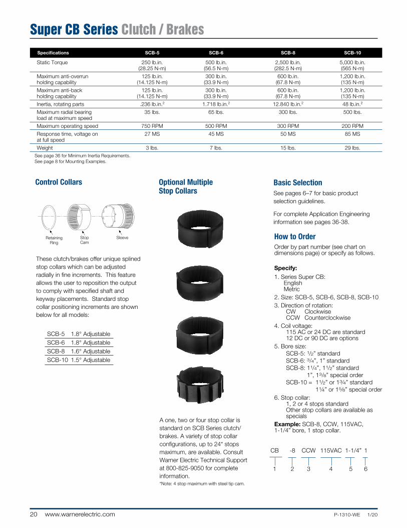
These clutch/brakes offer unique splined stop collars which can be adjusted radially in fine increments. This feature allows the user to reposition the output to comply with specified shaft and keyway placements. Standard stop collar positioning increments are shown below for all models:
SCB-5 1.8° Adjustable SCB-6 1.8° Adjustable SCB-8 1.6° Adjustable SCB-10 1.5° Adjustable
Control Collars
RetainingRing
DriveSleeve
StopCam
CouplingSleeve
BrakeSleeve
RetainingRing
StopCam
Sleeve
A one, two or four stop collar is standard on SCB Series clutch/brakes. A variety of stop collar config ura tions, up to 24* stops maximum, are available. Consult Warner Electric Technical Support at 800-825-9050 for complete information.*Note: 4 stop maximum with steel tip cam.
Optional Multiple Stop Collars
Basic SelectionSee pages 6–7 for basic product selection guidelines.
For complete Application Engineering information see pages 36-38.
Order by part number (see chart on dimensions page) or specify as follows.
Specify:1. Series Super CB:
English Metric
2. Size: SCB-5, SCB-6, SCB-8, SCB-10 3. Direction of rotation: CW Clockwise CCW Counterclockwise4. Coil voltage: 115 AC or 24 DC are standard 12 DC or 90 DC are options5. Bore size: SCB-5: 1/2” standard SCB-6: 3/4”, 1” standard SCB-8: 11/4”, 11/2” standard
1”, 13/8” special order SCB-10 = 11/2” or 13⁄4” standard
11⁄4” or 15⁄8” special order6. Stop collar: 1, 2 or 4 stops standard Other stop collars are available as
specialsExample: SCB-8, CCW, 115VAC, 1-1/4” bore, 1 stop collar.
How to Order
CB -8 CCW 115VAC 1-1/4” 1
1 2 3 4 5 6
Super CB Series Clutch / Brakes Specifications SCB-5 SCB-6 SCB-8 SCB-10
Static Torque 250 lb.in. 500 lb.in. 2,500 lb.in. 5,000 lb.in. (28.25 N-m) (56.5 N-m) (282.5 N-m) (565 N-m)
Maximum anti-overrun 125 lb.in. 300 lb.in. 600 lb.in. 1,200 lb.in. holding capability (14.125 N-m) (33.9 N-m) (67.8 N-m) (135 N-m)
Maximum anti-back 125 lb.in. 300 lb.in. 600 lb.in. 1,200 lb.in. holding capability (14.125 N-m) (33.9 N-m) (67.8 N-m) (135 N-m)
Inertia, rotating parts .236 lb.in.2 1.718 lb.in.2 12.840 lb.in.2 48 lb.in.2
Maximum radial bearing 35 lbs. 65 lbs. 300 lbs. 500 lbs. load at maximum speed
Maximum operating speed 750 RPM 500 RPM 300 RPM 200 RPM
Response time, voltage on 27 MS 45 MS 50 MS 85 MS at full speed
Weight 3 lbs. 7 lbs. 15 lbs. 29 lbs.See page 36 for Minimum Inertia Requirements.See page 8 for Mounting Examples.
21P-1310-WE 1/20 www.warnerelectric.com
4 x .187 (4.75) Dia.Eq. Sp. On
3.125 (79.38) BC
2.62(66.55)
1.31(33.27)
1.31(33.27)
45˚
2.50(63.50)
4.56(115.82)
20˚
.91 (23.11)
.44(11.18)
.25(6.35)
4.375(111.13)
.09(2.29)
1.07(27.18)
.25(6.35)
1.88(47.75)
2.15(54.61)
.625(15.88)
1.56(39.62)
Thru HolesTwo Sides
Thru HolesTwo Sides
.26 (6.60) Wide x.50 (12.70) Long
2 x .25 (6.35) Nom Wdx .03 (0.77) Nom Thk
Spade Lug
.44(11.18)
As shownviewed from
input hub onlyCW
As shownviewed from
input. (May be shaft or hub input.)
CW
As shownviewed fromlug drive end
CW
As shownviewed from
this endCW
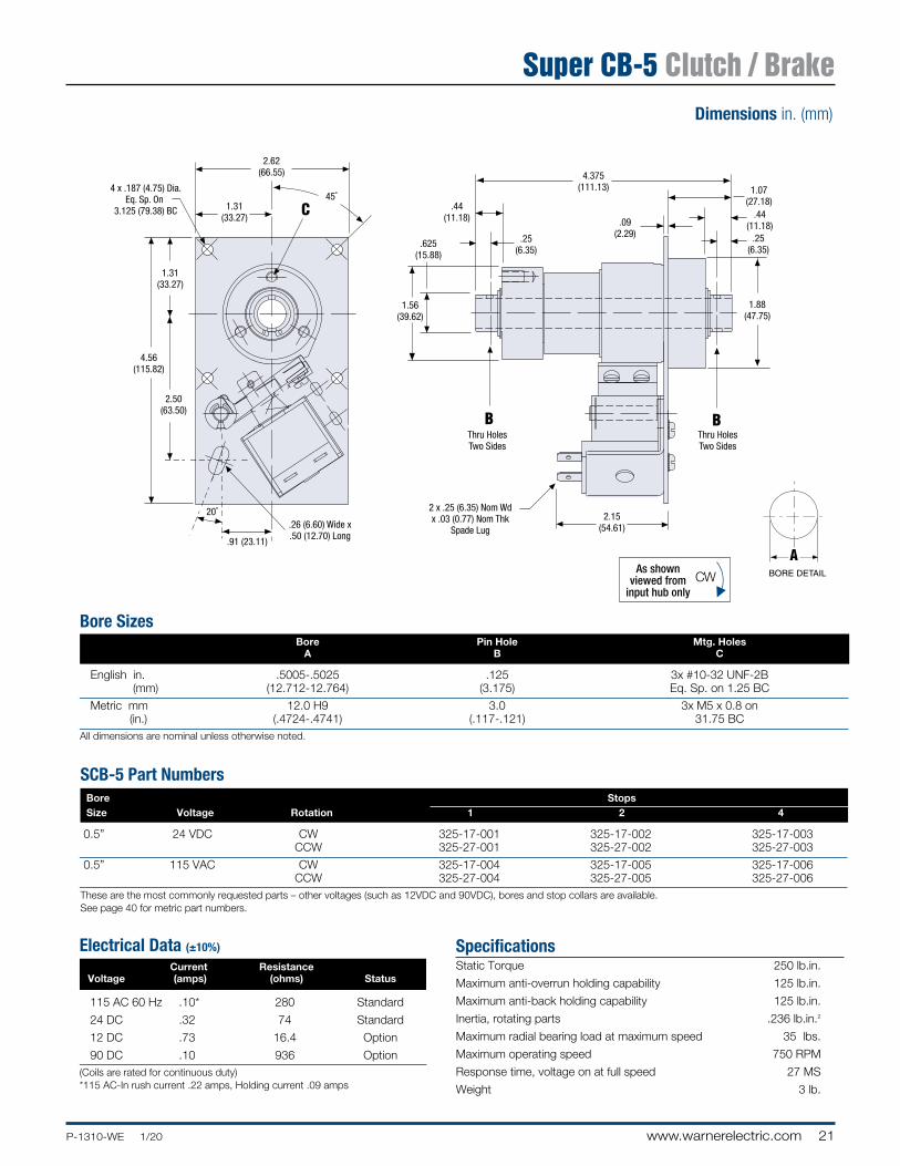
Bore Sizes Bore Pin Hole Mtg. Holes A B C
English in. .5005-.5025 .125 3x #10-32 UNF-2B (mm) (12.712-12.764) (3.175) Eq. Sp. on 1.25 BC
Metric mm 12.0 H9 3.0 3x M5 x 0.8 on (in.) (.4724-.4741) (.117-.121) 31.75 BC
All dimensions are nominal unless otherwise noted.
SpecificationsStatic Torque 250 lb.in.
Maximum anti-overrun holding capability 125 lb.in.
Maximum anti-back holding capability 125 lb.in.
Inertia, rotating parts .236 lb.in.2
Maximum radial bearing load at maximum speed 35 lbs.
Maximum operating speed 750 RPM
Response time, voltage on at full speed 27 MS
Weight 3 lb.
Electrical Data (±10%)
Current Resistance Voltage (amps) (ohms) Status
115 AC 60 Hz .10* 280 Standard
24 DC .32 74 Standard
12 DC .73 16.4 Option
90 DC .10 936 Option(Coils are rated for continuous duty)* 115 AC-In rush current .22 amps, Holding current .09 amps
SCB-5 Part Numbers Bore Stops Size Voltage Rotation 1 2 4
0.5” 24 VDC CW 325-17-001 325-17-002 325-17-003 CCW 325-27-001 325-27-002 325-27-003
0.5” 115 VAC CW 325-17-004 325-17-005 325-17-006 CCW 325-27-004 325-27-005 325-27-006These are the most commonly requested parts – other voltages (such as 12VDC and 90VDC), bores and stop collars are available.See page 40 for metric part numbers.
Dimensions in. (mm)
Super CB-5 Clutch / Brake
22 www.warnerelectric.com P-1310-WE 1/20
2.92(74.17)
2.12 (53.85)1.38
(35.05)
4.25 (107.95)
5.75(146.05)
2.12(53.85)
20˚
4 x .284 (7.21) Dia Eq. Sp.On 5.00 (127.0) BC
2 x .25 (6.35) Nom Wd x .03 (0.77) Nom Thk
Spade Lug
.386 (9.80) Wide x.80 (20.32) Long
4.312(109.53)
.517-.537(13.132-13.640) .125 (3.175)
.22 (5.59)
.36 (9.144).19 (4.83)
2.50(63.50)
1.559-1.562(39.59-39.68)
1.25(31.75)
2.25(57.15)
Dimensions in. (mm)
As shownviewed from
input hub onlyCW
As shownviewed from
input. (May be shaft or hub input.)
CW
As shownviewed fromlug drive end
CW
As shownviewed from
this endCW
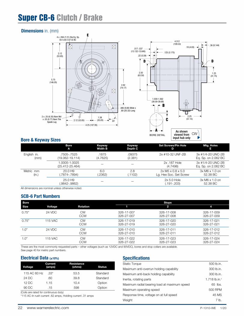
Bore & Keyway Sizes Bore Keyway Keyway Set Screws/Pin Hole Mtg. Holes A Width B Depth C D E
English in. .7505-.7525 .1875 .09375 2x #10-32 UNF-2B 3x #1/4-20 UNC-2B (mm) (19.062-19.114) (4.7625) (2.381) Eq. Sp. on 2.062 BC
1.0005-1.0025 2x .187 Hole 3x #1/4-20 UNC-2B (25.412-25.464)
— — (4.7498) Eq. Sp. on 2.062 BC
Metric mm 20.0 H9 6.0 2.8 2x M5 x 0.8 x 5.0 3x M6 x 1.0 on (in.) (.7874-.7894) (.2362) (.1102) Lg. Hex Soc. Set Screw 52.38 BC
25.0 H9 2x 5.0 Hole 3x M6 x 1.0 on (.9842-.9862)
— — (.191-.203) 52.38 BC
All dimensions are nominal unless otherwise noted.
SpecificationsStatic Torque 500 lb.in.
Maximum anti-overrun holding capability 300 lb.in.
Maximum anti-back holding capability 300 lb.in.
Inertia, rotating parts 1.718 lb.in.2
Maximum radial bearing load at maximum speed 65 lbs.
Maximum operating speed 500 RPM
Response time, voltage on at full speed 45 MS
Weight 7 lb.
Electrical Data (±10%)
Current Resistance Voltage (amps) (ohms) Status
115 AC 60 Hz .33* 53.5 Standard
24 DC .60 39.8 Standard
12 DC 1.15 10.4 Option
90 DC .15 598 Option(Coils are rated for continuous duty)* 115 AC- In rush current .62 amps, Holding current .31 amps
SCB-6 Part Numbers Bore Stops Size Voltage Rotation 1 2 4
0.75” 24 VDC CW 326-17-007 326-17-008 326-17-009 CCW 326-27-007 326-27-008 326-27-009
0.75” 115 VAC CW 326-17-019 326-17-020 326-17-021 CCW 326-27-019 326-27-020 326-27-021
1.0” 24 VDC CW 326-17-010 326-17-011 326-17-012 CCW 326-27-010 326-27-011 326-27-012
1.0” 115 VAC CW 326-17-022 326-17-023 326-17-024 CCW 326-27-022 326-27-023 326-27-024These are the most commonly requested parts – other voltages (such as 12VDC and 90VDC), bores and stop collars are available.See page 40 for metric part numbers.
Super CB-6 Clutch / Brake
23P-1310-WE 1/20 www.warnerelectric.com
+
+
+
+ +
+
+ +
++ +
+
2 x .394 (10.0) Eq. Sp.On 5.875 (149.23) BC
3.118 (79.20)
2.50(63.50)
7.00(177.80)
1.80 (45.72)
5.0 (127.0)
2.50 (63.50)
30�
45� 6.125 (155.58)
.427 (10.85)
.698 (17.73)
.188 (4.78)
.40 (10.16)
.250 (6.35)
1.967 (49.96)
.25 (6.35)
4.00(101.60)
2.372-2.374(60.24-60.30)
2.31(58.68)
Max
.386 (9.80) Wide x.80 (20.32) Long
Dimensions in. (mm)
As shownviewed from
input hub onlyCW
As shownviewed from
input. (May be shaft or hub input.)
CW
As shownviewed fromlug drive end
CW
As shownviewed from
this endCW
Bore & Keyway Sizes Bore Keyway Keyway Set Screws Mtg. Holes A Width B Depth C D E
English in. 1.2505-1.2525 .3125 .15625 2x #1/4-20 UNC-2B 6x 5/16-18 UNC-2B (mm) (31.762-31.814) (7.9375) (3.9688) Eq. Sp. on 3.375 BC
1.5005-1.5025 .375 .125 2x #1/4-20 x UNC-2B 6x 5/16-18 UNC-2B (38.112-38.164) (9.525) (3.175) Eq. Sp. on 3.375 BC
Metric mm 35.0 H9 10.0 3.3 2x M6 x 1.0 x 10.0 6x M8 x 1.25 on (in.) (1.3780-1.3804) (.3937) (.1299) Lg. Hex Soc. Set Screw 85.73 BC
40.0 H9 2x M6 x 1.0 x 10.0 6x M8 x 1.25 on (1.5784-1.5772)
— — Lg. Hex Soc. Set Screw 85.73 BC
All dimensions are nominal unless otherwise noted.
SpecificationsStatic Torque 2,500 lb.in.
Maximum anti-overrun holding capability 600 lb.in.
Maximum anti-back holding capability 600 lb.in.
Inertia, rotating parts 12.840 lb.in.2
Maximum radial bearing load at maximum speed 300 lbs.
Maximum operating speed 300 RPM
Response time, voltage on at full speed 50 MS
Weight 15 lb.
Electrical Data (±10%)
Current Resistance Voltage (amps) (ohms) Status
115 AC 60 Hz .33* 53.5 Standard
24 DC .94 25.4 Standard
12 DC 1.87 6.43 Option
90 DC .24 378 Option(Coils are rated for continuous duty)* 115 AC- In rush current .62 amps, Holding current .31 amps
SCB-8 Part Numbers Bore Stops Size Voltage Rotation 1 2 4
1.25” 24 VDC CW 328-17-019 328-17-020 328-17-021 CCW 328-27-019 328-27-020 328-27-021
1.25” 115 VAC CW 328-17-043 328-17-044 328-17-045 CCW 328-27-043 328-27-044 328-27-045
1.5” 24 VDC CW 328-17-013 328-17-014 328-17-015 CCW 328-27-013 328-27-014 328-27-015
1.5” 115 VAC CW 328-17-037 328-17-038 328-17-039 CCW 328-27-037 328-27-038 328-27-039These are the most commonly requested parts – other voltages (such as 12VDC and 90VDC), bores and stop collars are available.See page 40 for metric part numbers.
Super CB-8 Clutch / Brake
24 www.warnerelectric.com P-1310-WE 1/20
Dimensions in. (mm)
Bore & Keyway Sizes* Bore Keyway Keyway Set Screws Mtg. Holes A Width B Depth C D E
English in. 1.5005-1.503 .375 .187 #1/4-20 x UNC-2B 6x 1/4-20 UNC-2B (mm) (38.113-38.177) (9.525) (4.75) Eq. Sp. on 3.417 BC
1.7505-1.753 .375 .187 #1/4-20 x UNC-2B 6x 1/4-20 UNC-2B (44.464-44.527) (9.525)
(4.75) Eq. Sp. on 3.417 BC
Metric mm 40.0 H9 12.0 4.0 M6 x 1.0 x 10.0 6x M8 x 1.25 on (in.) (1.5784-1.5772) (.4724) (.1574) Lg. Hex Soc. Set Screw 86.79 BC
All dimensions are nominal unless otherwise noted. * Optional Bores and Keys: 1.2505/1.2530 (31.7627/31.8262) for .3125 (7.9375) Sq Key 1.6255/1.6280 (41.2877/41.3512) for .375 (9.525) Sq Key
SpecificationsStatic Torque 5,000 lb.in.
Maximum anti-overrun holding capability 1,200 lb.in.
Maximum anti-back holding capability 1,200 lb.in.
Inertia, rotating parts 48 lb.in.2
Maximum radial bearing load at maximum speed 500 lbs.
Maximum operating speed 200 RPM
Response time, voltage on at full speed 85 MS
Weight 29 lb.
Electrical Data (±10%)
Current Resistance Voltage (amps) (ohms) Status
115 AC 60 Hz .6* 11 .5 Standard
24 DC .94 25.4 Standard
12 DC 1.90 6.3 Option
90 DC .24 378 Option
(Coils are rated for continuous duty)* 115 AC- In rush current 5.3 amps, Holding current .6 amps
SCB-10 Part Numbers Bore Stops Size Voltage Rotation 1 2 4
1.50” 24 VDC CW 320-17-010 320-17-011 320-17-012 CCW 320-27-010 320-27-011 320-27-012
1.50” 115 VAC CW 320-12-001 320-12-002 320-12-003 CCW 320-22-001 320-22-002 320-22-003
1.75” 24 VDC CW 320-17-016 CCW 320-27-016
1.75” 115 VAC CW 320-12-007 320-12-008 CCW 320-22-007 320-22-014 These are the most commonly requested parts – other voltages (such as 12VDC and 90VDC), bores and stop collars are available.See page 40 for metric part numbers.
As shownviewed from
input hub onlyCW
As shownviewed from
input. (May be shaft or hub input.)
CW
As shownviewed fromlug drive end
CW
As shownviewed from
this endCW
o
(3) .406 (10.31) Holes 90° apart on a 7.00 (177.8) B.C.
25
Pilot
Bore
Key
25o
6.0(152.4)
.82(20.828)
.220(5.588)
.25 (6.35) .25 (6.35)
.19 (4.826)3.0
(76.2)
3.0(76.2)
8.88(225.55)
12.0 (304.8) Lead Wires
.635 (16.12) Wide X 1.25 (31.75) Long
.635 (16.12) Wide X 1.25 (31.75) Long
2.0(50.8)
2.0(50.8)
2.362(59.995)
.63(16.002)
7.750(196.85)
Max2.55 (64.77)
Max2.55 (64.77)
4.25(107.95)
4.94(125.476)
2.935(74.549)
o
(3) .406 (10.31) Holes 90° apart on a 7.00 (177.8) B.C.
25
Pilot
Bore
Key
25o
6.0(152.4)
.82(20.828)
.220(5.588)
.25 (6.35) .25 (6.35)
.19 (4.826)3.0
(76.2)
3.0(76.2)
8.88(225.55)
12.0 (304.8) Lead Wires
.635 (16.12) Wide X 1.25 (31.75) Long
.635 (16.12) Wide X 1.25 (31.75) Long
2.0(50.8)
2.0(50.8)
2.362(59.995)
.63(16.002)
7.750(196.85)
Max2.55 (64.77)
Max2.55 (64.77)
4.25(107.95)
4.94(125.476)
2.935(74.549)Super CB-10 Clutch / Brake
25P-1310-WE 1/20 www.warnerelectric.com
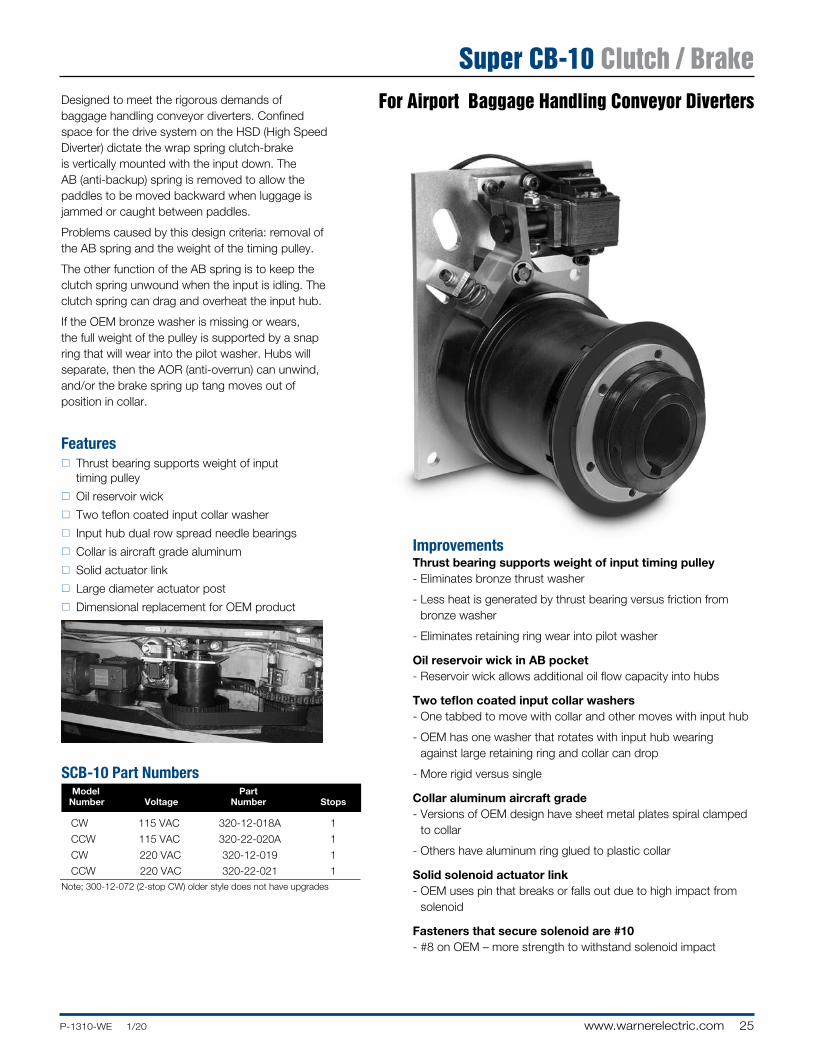
Designed to meet the rigorous demands of baggage handling conveyor diverters. Confined space for the drive system on the HSD (High Speed Diverter) dictate the wrap spring clutch-brake is vertically mounted with the input down. The AB (anti-backup) spring is removed to allow the paddles to be moved backward when luggage is jammed or caught between paddles.
Problems caused by this design criteria: removal of the AB spring and the weight of the timing pulley.
The other function of the AB spring is to keep the clutch spring unwound when the input is idling. The clutch spring can drag and overheat the input hub.
If the OEM bronze washer is missing or wears, the full weight of the pulley is supported by a snap ring that will wear into the pilot washer. Hubs will separate, then the AOR (anti-overrun) can unwind, and/or the brake spring up tang moves out of position in collar.
Featuresn Thrust bearing supports weight of input
timing pulley
n Oil reservoir wick
n Two teflon coated input collar washer
n Input hub dual row spread needle bearings
n Collar is aircraft grade aluminum
n Solid actuator link
n Large diameter actuator post
n Dimensional replacement for OEM product
ImprovementsThrust bearing supports weight of input timing pulley- Eliminates bronze thrust washer
- Less heat is generated by thrust bearing versus friction from bronze washer
- Eliminates retaining ring wear into pilot washer
Oil reservoir wick in AB pocket- Reservoir wick allows additional oil flow capacity into hubs
Two teflon coated input collar washers- One tabbed to move with collar and other moves with input hub
- OEM has one washer that rotates with input hub wearing against large retaining ring and collar can drop
- More rigid versus single
Collar aluminum aircraft grade- Versions of OEM design have sheet metal plates spiral clamped
to collar
- Others have aluminum ring glued to plastic collar
Solid solenoid actuator link- OEM uses pin that breaks or falls out due to high impact from
solenoid
Fasteners that secure solenoid are #10- #8 on OEM – more strength to withstand solenoid impact
SCB-10 Part Numbers Model Part Number Voltage Number Stops
CW 115 VAC 320-12-018A 1
CCW 115 VAC 320-22-020A 1
CW 220 VAC 320-12-019 1
CCW 220 VAC 320-22-021 1Note; 300-12-072 (2-stop CW) older style does not have upgrades
For Airport Baggage Handling Conveyor Diverters
Super CB-10 Clutch / Brake
26 www.warnerelectric.com P-1310-WE 1/20
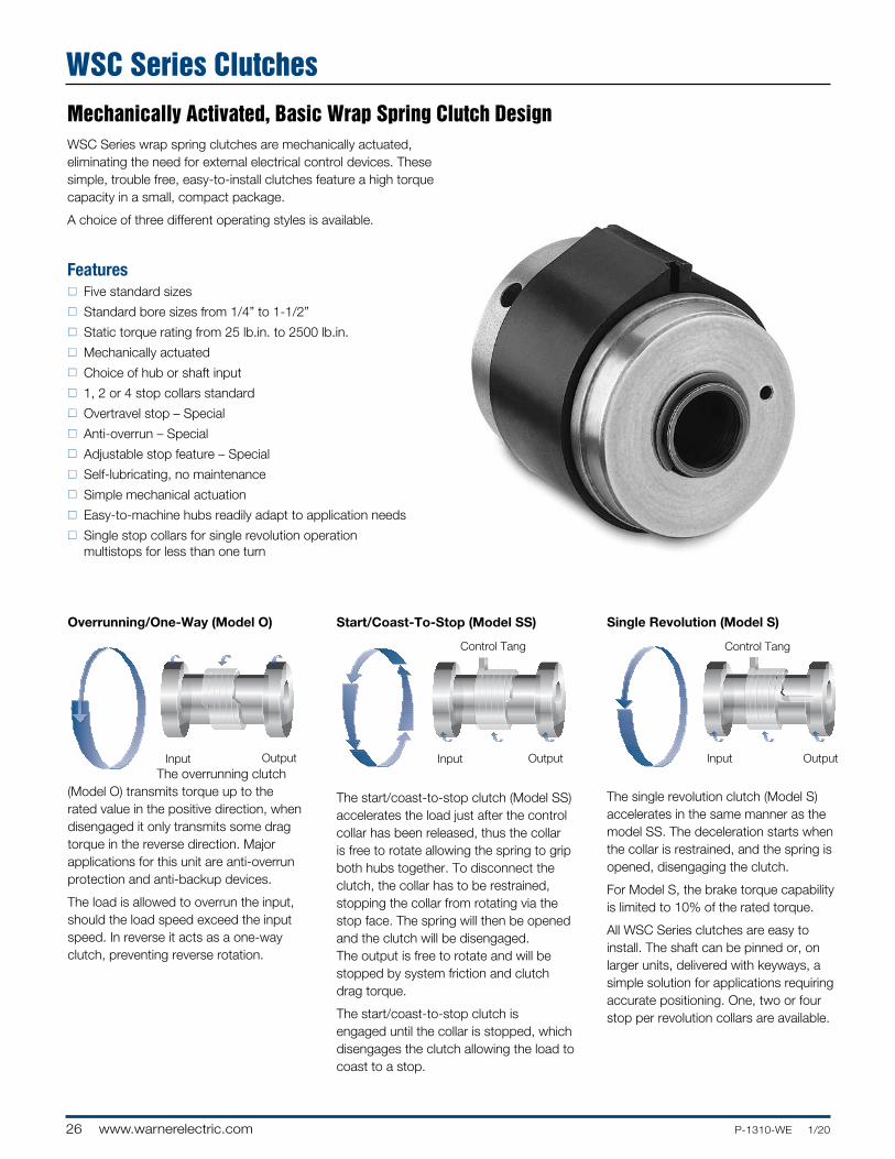
Overrunning/One-Way (Model O)
The overrunning clutch (Model O) transmits torque up to the rated value in the positive direc tion, when disengaged it only transmits some drag torque in the reverse direction. Major applications for this unit are anti-overrun protection and anti-backup devices.
The load is allowed to overrun the input, should the load speed exceed the input speed. In reverse it acts as a one-way clutch, preventing reverse rotation.
WSC Series wrap spring clutches are mechanically actuated, eliminating the need for external electrical control devices. These simple, trouble free, easy-to-install clutches feature a high torque capacity in a small, compact package.
A choice of three different operating styles is available.
Featuresn Five standard sizes
n Standard bore sizes from 1/4” to 1-1/2”
n Static torque rating from 25 lb.in. to 2500 lb.in.
n Mechanically actuated
n Choice of hub or shaft input
n 1, 2 or 4 stop collars standard
n Overtravel stop – Special
n Anti-overrun – Special
n Adjustable stop feature – Special
n Self-lubricating, no maintenance
n Simple mechanical actuation
n Easy-to-machine hubs readily adapt to application needs
n Single stop collars for single revolution operation multistops for less than one turn
Mechanically Activated, Basic Wrap Spring Clutch Design
Single Revolution (Model S)
Input Output
Control Tang
Input Output
Start/Coast-To-Stop (Model SS)
Input Output
Control Tang
The start/coast-to-stop clutch (Model SS) accel erates the load just after the control collar has been released, thus the collar is free to rotate allowing the spring to grip both hubs together. To disconnect the clutch, the collar has to be restrained, stopping the collar from rotating via the stop face. The spring will then be opened and the clutch will be disengaged. The output is free to rotate and will be stopped by system friction and clutch drag torque.
The start/coast-to-stop clutch is engaged until the collar is stopped, which disengages the clutch allowing the load to coast to a stop.
The single revolution clutch (Model S) accelerates in the same manner as the model SS. The deceleration starts when the collar is restrained, and the spring is opened, dis en gaging the clutch.
For Model S, the brake torque capability is limited to 10% of the rated torque.
All WSC Series clutches are easy to install. The shaft can be pinned or, on larger units, delivered with keyways, a simple solution for applications requiring accurate positioning. One, two or four stop per revolution collars are available.
WSC Series Clutches
27P-1310-WE 1/20 www.warnerelectric.com
WSC -6 S CCW HI 1” 4
1 2 3 4 5 6 7
Basic SelectionSee pages 6–7 for basic product selection guidelines.
For complete Application Engineering information see pages 36–38.
Specifications WSC-2 WSC-4 WSC-5 WSC-6 WSC-8
Static Torque (lb.in.) 25 120 250 500 2500
Inertia, shaft input 0.006 0.015 0.059 0.570 4.99 rotating parts (lb.in.2)
Inertia, hub input 0.008 0.023 0.069 0.73 (0.75” Bore) 11.91 (1.25” Bore) rotating parts (lb.in.2) 0.68 (1.00” Bore) 11.60 (1.50” Bore)
Maximum radial bearing 6.75 13.5 31.5 63.0 300.0 load at maximum speed (lbs.)
Maximum operating speed (RPM) 1800 1200 750 500 300
Weight (lbs.) 0.13 0.22 0.62 2.60 8.25
See page 36 for Minimum Inertia Requirements. See page 8 for Mounting Examples.
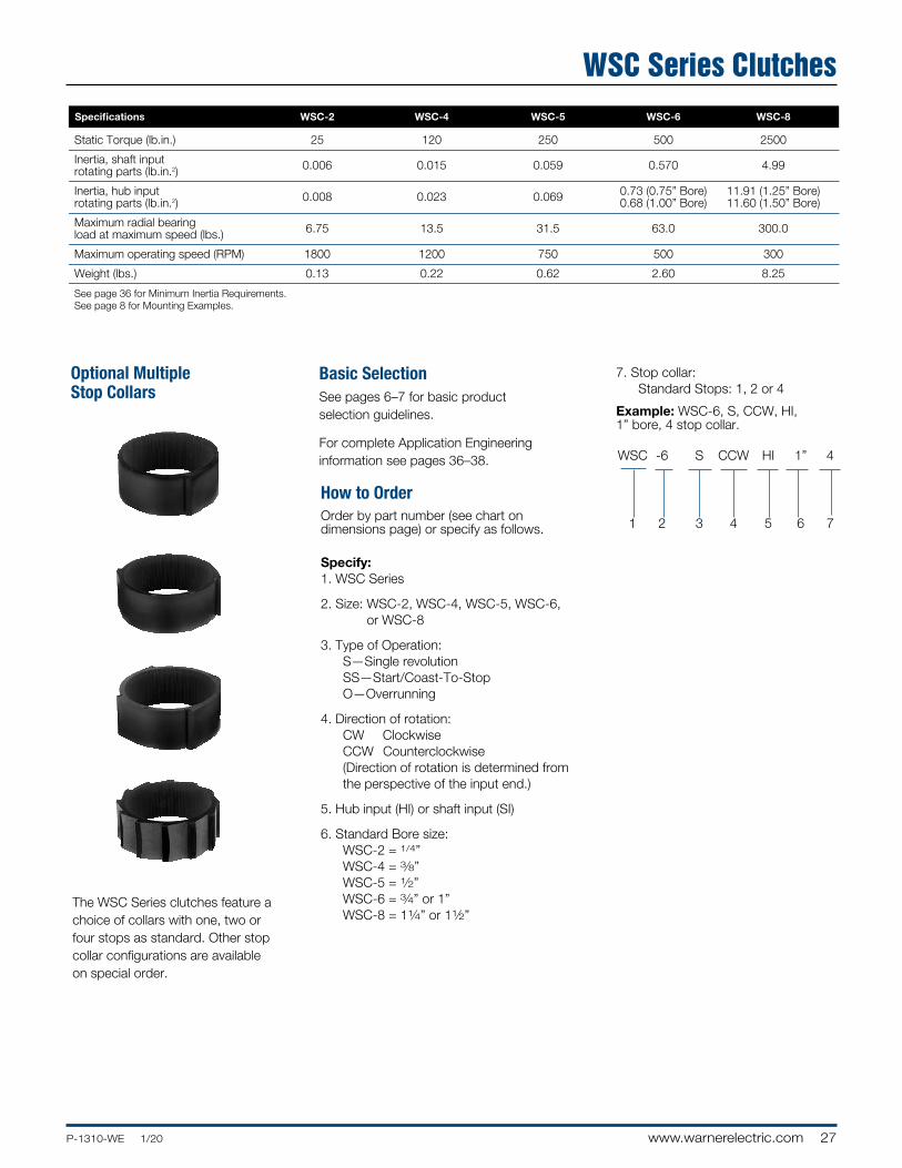
The WSC Series clutches feature a choice of collars with one, two or four stops as standard. Other stop collar configurations are available on special order.
Optional Multiple Stop Collars
Order by part number (see chart on dimensions page) or specify as follows.
Specify:1. WSC Series
2. Size: WSC-2, WSC-4, WSC-5, WSC-6, or WSC-8
3. Type of Operation: S—Single revolution SS—Start/Coast-To-Stop O—Overrunning
4. Direction of rotation: CW Clockwise CCW Counterclockwise
(Direction of rotation is determined from the perspective of the input end.)
5. Hub input (HI) or shaft input (SI)
6. Standard Bore size: WSC-2 = 1/4” WSC-4 = 3⁄8” WSC-5 = 1⁄2” WSC-6 = 3⁄4” or 1” WSC-8 = 11⁄4” or 11⁄2”
How to Order
7. Stop collar: Standard Stops: 1, 2 or 4
Example: WSC-6, S, CCW, HI, 1” bore, 4 stop collar.
WSC Series Clutches
28 www.warnerelectric.com P-1310-WE 1/20
Model PSI 2,4,5.AI5
1.25(31.75)
.94(23.9)
.94(23.9)
.33 (8.4)
.25 (6.35) .16(4.1)
.57 (14.79)
1.00 (25.4)
.49(12.4)
.34(8.6)
.64*(16.51)
.8765-.8775(22.263-22.289)
Model PSI 2,4,5.AI5
1.375(34.93)
1.25(31.75)
1.25(31.75)
.365 (9.27)
.25 (6.35) .14(3.56)
.72 (18.29)
1.25 (31.75)
.67(17.02)
.28(7.1)
.63*(16.00)
1.1275-1.1280(28.639-28.651)
Model PSI 2,4,5.AI5
1.875(47.63)
1.56(39.6)
1.56(39.6)
.375 (9.525)
.25 (6.35) .14(3.556)
.85 (21.59)
1.56 (39.62)
1.00(25.4)
.38(9.7)
.78*(19.81)
1.5020-1.5035(38.15-38.19)
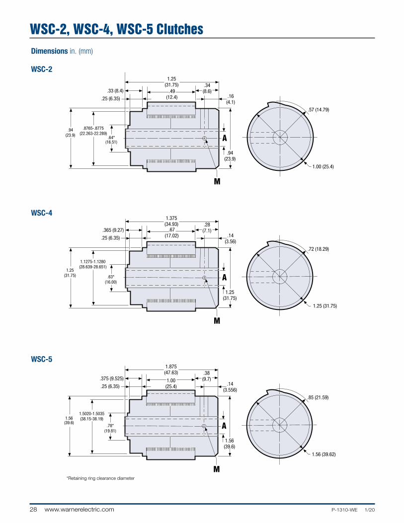
WSC-2
WSC-4
WSC-5
Dimensions in. (mm)
* Retaining ring clearance diameter
WSC-2, WSC-4, WSC-5 Clutches
29P-1310-WE 1/20 www.warnerelectric.com
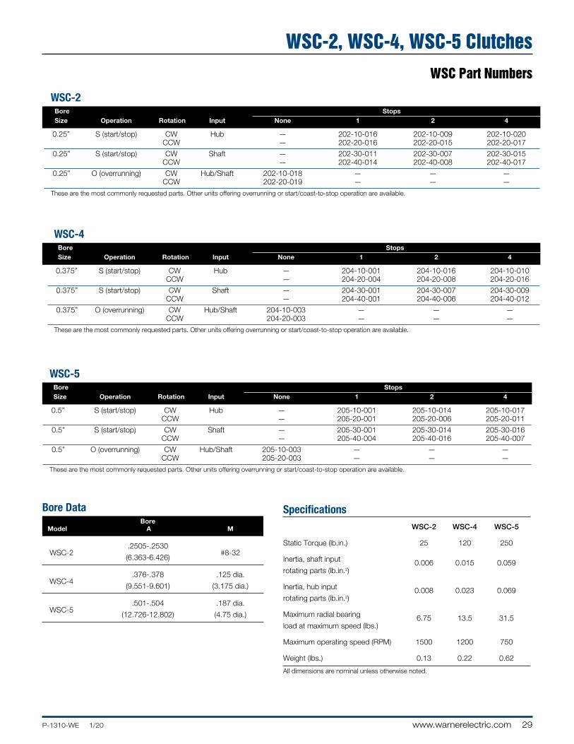
WSC Part Numbers
Specifications WSC-2 WSC-4 WSC-5
Static Torque (lb.in.) 25 120 250
Inertia, shaft input 0.006 0.015 0.059
rotating parts (lb.in.2)
Inertia, hub input 0.008 0.023 0.069
rotating parts (lb.in.2)
Maximum radial bearing 6.75 13.5 31.5
load at maximum speed (lbs.)
Maximum operating speed (RPM) 1500 1200 750
Weight (lbs.) 0.13 0.22 0.62
All dimensions are nominal unless otherwise noted.
Bore Data Bore Model A M
.2505-.2530
WSC-2
(6.363-6.426) #8-32
.376-.378 .125 dia.
WSC-4
(9.551-9.601) (3.175 dia.)
.501-.504 .187 dia.
WSC-5
(12.726-12.802) (4.75 dia.)
WSC-5 Bore Stops Size Operation Rotation Input None 1 2 4
0.5” S (start/stop) CW Hub — 205-10-001 205-10-014 205-10-017 CCW — 205-20-001 205-20-006 205-20-011
0.5” S (start/stop) CW Shaft — 205-30-001 205-30-014 205-30-016 CCW — 205-40-004 205-40-016 205-40-007
0.5” O (overrunning) CW Hub/Shaft 205-10-003 — — — CCW 205-20-003 — — —
These are the most commonly requested parts. Other units offering overrunning or start/coast-to-stop operation are available.
Packaged Performance ProductsWSC Series ClutchesWSC-2, WSC-4, WSC-5 Clutches
WSC-2 Bore Stops Size Operation Rotation Input None 1 2 4
0.25” S (start/stop) CW Hub — 202-10-016 202-10-009 202-10-020 CCW — 202-20-016 202-20-015 202-20-017
0.25” S (start/stop) CW Shaft — 202-30-011 202-30-007 202-30-015 CCW — 202-40-014 202-40-008 202-40-017
0.25” O (overrunning) CW Hub/Shaft 202-10-018 — — — CCW 202-20-019 — — —
These are the most commonly requested parts. Other units offering overrunning or start/coast-to-stop operation are available.
WSC-4 Bore Stops Size Operation Rotation Input None 1 2 4
0.375” S (start/stop) CW Hub — 204-10-001 204-10-016 204-10-010 CCW — 204-20-004 204-20-008 204-20-016
0.375” S (start/stop) CW Shaft — 204-30-001 204-30-007 204-30-009 CCW — 204-40-001 204-40-006 204-40-012
0.375” O (overrunning) CW Hub/Shaft 204-10-003 — — — CCW 204-20-003 — — —
These are the most commonly requested parts. Other units offering overrunning or start/coast-to-stop operation are available.
30 www.warnerelectric.com P-1310-WE 1/20
.774 (19.66)
.124 (3.15)
2.311(58.70).866
(22.00).280 (7.11).671 (17.04)
1.559-1.562(39.60-39.67)
2.437(61.90)
2.696(68.48)
1.500(38.10)
.286 (7.26)
+
++
+
++ 3.75(95.25)
2.00(50.8)
1.98(50.3)
3.5(88.9)
.30(7.62)
.522 (13.26) .18(4.57)
4.00(101.6)
2.3755-2.3770(60.377-60.391)
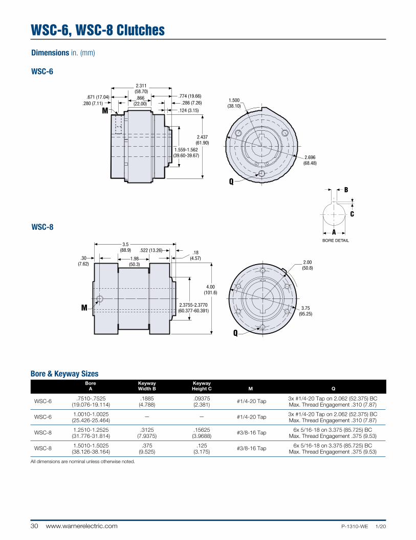
WSC-6
WSC-8
Dimensions in. (mm)
Bore & Keyway Sizes Bore Keyway Keyway A Width B Height C M Q
.7510-.7525 .1885 .09375 3x #1/4-20 Tap on 2.062 (52.375) BC
WSC-6 (19.076-19.114) (4.788) (2.381)
#1/4-20 Tap Max. Thread Engagement .310 (7.87)
1.0010-1.0025 3x #1/4-20 Tap on 2.062 (52.375) BC
WSC-6 (25.426-25.464)
— —
#1/4-20 Tap Max. Thread Engagement .310 (7.87)
1.2510-1.2525 .3125 .15625 #3/8-16 Tap 6x 5/16-18 on 3.375 (85.725) BC
WSC-8 (31.776-31.814) (7.9375)
(3.9688) Max. Thread Engagement .375 (9.53)
1.5010-1.5025 .375 .125 #3/8-16 Tap 6x 5/16-18 on 3.375 (85.725) BC
WSC-8 (38.126-38.164) (9.525)
(3.175) Max. Thread Engagement .375 (9.53)
All dimensions are nominal unless otherwise noted.
WSC-6, WSC-8 Clutches
31P-1310-WE 1/20 www.warnerelectric.com
Part Numbers
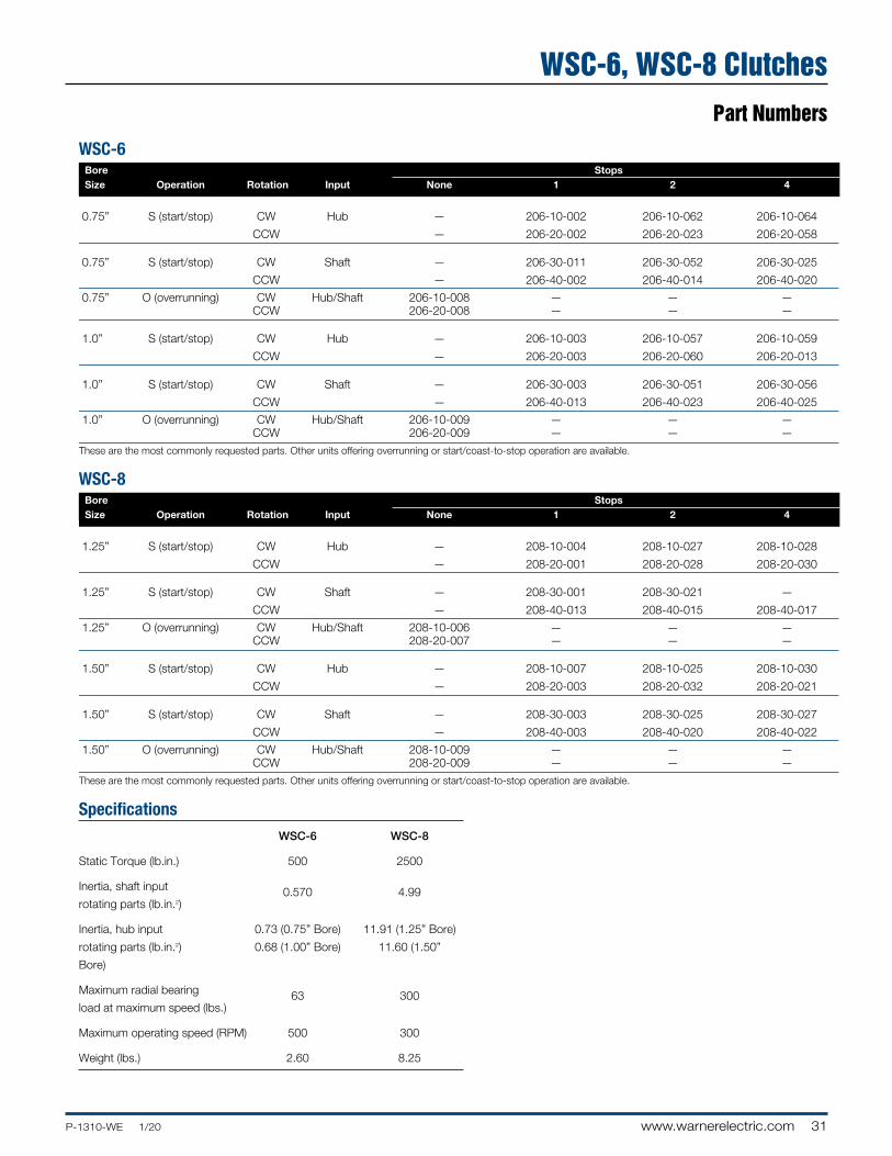
WSC-6 Bore Stops Size Operation Rotation Input None 1 2 4
0.75” S (start/stop) CW Hub — 206-10-002 206-10-062 206-10-064
CCW — 206-20-002 206-20-023 206-20-058
0.75” S (start/stop) CW Shaft — 206-30-011 206-30-052 206-30-025
CCW — 206-40-002 206-40-014 206-40-020
0.75” O (overrunning) CW Hub/Shaft 206-10-008 — — — CCW 206-20-008 — — —
1.0” S (start/stop) CW Hub — 206-10-003 206-10-057 206-10-059
CCW — 206-20-003 206-20-060 206-20-013
1.0” S (start/stop) CW Shaft — 206-30-003 206-30-051 206-30-056
CCW — 206-40-013 206-40-023 206-40-025
1.0” O (overrunning) CW Hub/Shaft 206-10-009 — — — CCW 206-20-009 — — —
These are the most commonly requested parts. Other units offering overrunning or start/coast-to-stop operation are available.
WSC-8 Bore Stops Size Operation Rotation Input None 1 2 4
1.25” S (start/stop) CW Hub — 208-10-004 208-10-027 208-10-028
CCW — 208-20-001 208-20-028 208-20-030
1.25” S (start/stop) CW Shaft — 208-30-001 208-30-021 —
CCW — 208-40-013 208-40-015 208-40-017
1.25” O (overrunning) CW Hub/Shaft 208-10-006 — — — CCW 208-20-007 — — —
1.50” S (start/stop) CW Hub — 208-10-007 208-10-025 208-10-030
CCW — 208-20-003 208-20-032 208-20-021
1.50” S (start/stop) CW Shaft — 208-30-003 208-30-025 208-30-027
CCW — 208-40-003 208-40-020 208-40-022
1.50” O (overrunning) CW Hub/Shaft 208-10-009 — — — CCW 208-20-009 — — —
These are the most commonly requested parts. Other units offering overrunning or start/coast-to-stop operation are available.
Specifications WSC-6 WSC-8
Static Torque (lb.in.) 500 2500
Inertia, shaft input 0.570 4.99 rotating parts (lb.in.2)
Inertia, hub input 0.73 (0.75” Bore) 11.91 (1.25” Bore)
rotating parts (lb.in.2) 0.68 (1.00” Bore) 11.60 (1.50”
Bore)
Maximum radial bearing 63 300
load at maximum speed (lbs.)
Maximum operating speed (RPM) 500 300
Weight (lbs.) 2.60 8.25
WSC-6, WSC-8 Clutches
32 www.warnerelectric.com P-1310-WE 1/20
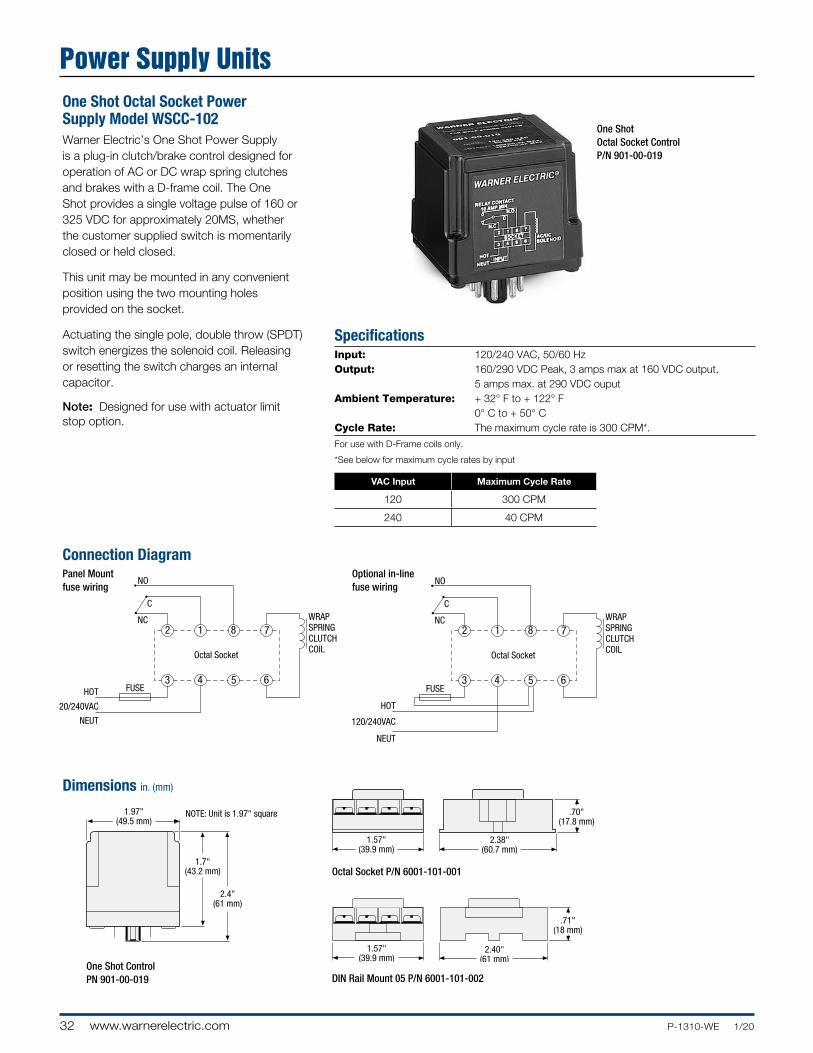
SpecificationsInput: 120/240 VAC, 50/60 Hz Output: 160/290 VDC Peak, 3 amps max at 160 VDC output, 5 amps max. at 290 VDC ouputAmbient Temperature: + 32° F to + 122° F 0° C to + 50° C Cycle Rate: The maximum cycle rate is 300 CPM*.
For use with D-Frame coils only.
*See below for maximum cycle rates by input
VAC Input Maximum Cycle Rate
120 300 CPM
240 40 CPM
One Shot Octal Socket Power Supply Model WSCC-102Warner Electric’s One Shot Power Supply is a plug-in clutch/brake control designed for operation of AC or DC wrap spring clutches and brakes with a D-frame coil. The One Shot provides a single voltage pulse of 160 or 325 VDC for approximately 20MS, whether the customer supplied switch is momentarily closed or held closed.
This unit may be mounted in any convenient position using the two mounting holes provided on the socket.
Actuating the single pole, double throw (SPDT) switch energizes the solenoid coil. Releasing or resetting the switch charges an internal capacitor.
Note: Designed for use with actuator limit stop option.
Dimensions in. (mm)
Connection Diagram
Octal Socket P/N 6001-101-001
One Shot ControlPN 901-00-019 DIN Rail Mount 05 P/N 6001-101-002
One Shot Octal Socket ControlP/N 901-00-019
1.97"(49.5 mm)
1.7"(43.2 mm)
2.4"(61 mm)
1.57"(39.9 mm)
2.38"(60.7 mm)
.70"(17.8 mm)
1.57"(39.9 mm)
2.40"(61 mm)
.71"(18 mm)
1 Shot Controls Dim.AL51 Shot Controls Dim.AL5
NOTE: Unit is 1.97" square
1.97"(49.5 mm)
1.7"(43.2 mm)
2.4"(61 mm)
1.57"(39.9 mm)
2.38"(60.7 mm)
.70"(17.8 mm)
1.57"(39.9 mm)
2.40"(61 mm)
.71"(18 mm)
1 Shot Controls Dim.AL51 Shot Controls Dim.AL5
NOTE: Unit is 1.97" square1.97"
(49.5 mm)
1.7"(43.2 mm)
2.4"(61 mm)
1.57"(39.9 mm)
2.38"(60.7 mm)
.70"(17.8 mm)
1.57"(39.9 mm)
2.40"(61 mm)
.71"(18 mm)
1 Shot Controls Dim.AL51 Shot Controls Dim.AL5
NOTE: Unit is 1.97" square
Power Supply Units
1
4 5
8
6
7
3
2
Octal Socket
NO
NC
C
HOT
NEUT
120/240VAC
FUSE
WRAPSPRINGCLUTCHCOIL
1
4 5
8
6
7
3
2
Octal Socket
NO
NC
C
HOT
FUSE
NEUT
120/240VAC
WRAPSPRINGCLUTCHCOIL
Panel Mountfuse wiring
Optional in-linefuse wiring
33P-1310-WE 1/20 www.warnerelectric.com
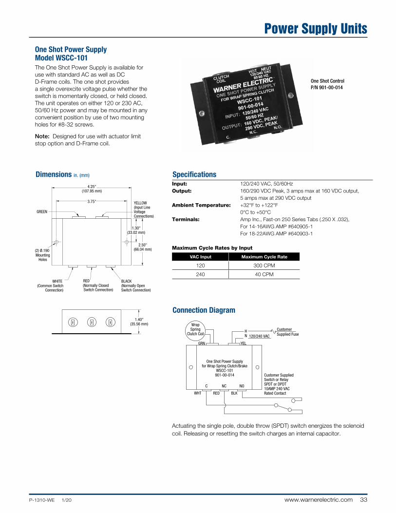
One Shot Power Supply Model WSCC-101The One Shot Power Supply is available for use with standard AC as well as DC D-Frame coils. The one shot provides a single overexcite voltage pulse whether the switch is momentarily closed, or held closed. The unit operates on either 120 or 230 AC, 50/60 Hz power and may be mounted in any convenient position by use of two mounting holes for #8-32 screws.
Note: Designed for use with actuator limit stop option and D-Frame coil.
Dimensions in. (mm) Specifications
Actuating the single pole, double throw (SPDT) switch energizes the solenoid coil. Releasing or resetting the switch charges an internal capacitor.
Connection Diagram
One Shot ControlP/N 901-00-014
Input: 120/240 VAC, 50/60Hz Output: 160/290 VDC Peak, 3 amps max at 160 VDC output, 5 amps max at 290 VDC outputAmbient Temperature: +32°F to +122°F
0°C to +50°CTerminals: Amp Inc., Fast-on 250 Series Tabs (.250 X .032), For 14-16AWG AMP #640905-1 For 18-22AWG AMP #640903-1
Maximum Cycle Rates by Input
VAC Input Maximum Cycle Rate
120 300 CPM
240 40 CPM
Packaged Performance ProductsWSC Series ClutchesPower Supply Units
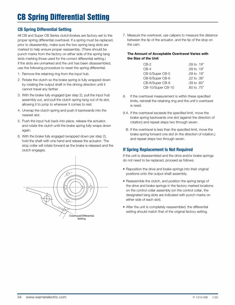
34 www.warnerelectric.com P-1310-WE 1/20
7. Measure the overtravel, use calipers to measure the distance between the tip of the actuator, and the tip of the stop on the cam. The Amount of Acceptable Overtravel Varies with the Size of the Unit
CB-2 .09 to .19” CB-4 .09 to .19” CB-5/Super CB-5 .09 to .19” CB-6/Super CB-6 .22 to .38” CB-8/Super CB-8 .39 to .60” CB-10/Super CB-10 .60 to .75”
8. If the overtravel measurement is within these specified limits, reinstall the retaining ring and the unit’s overtravel is reset.
9 A. If the overtravel exceeds the specified limit, move the brake spring backwards one slot (against the direction of rotation) and repeat steps two through seven.
B. If the overtravel is less than the specified limit, move the brake spring forward one slot (in the direction of rotation,) and repeat steps two through seven.
If Spring Replacement Is Not RequiredIf the unit is disassembled and the drive and/or brake springs do not need to be replaced, proceed as follows:
• Reposition the drive and brake springs into their original positions onto the output shaft assembly.
• Reassemble the clutch, and position the spring tangs of the drive and brake springs in the factory marked locations on the control collar assembly (on the control collar, the designated tang slots are indicated with punch marks on either side of each slot).
• After the unit is completely reassembled, the differential setting should match that of the original factory setting.
CB Spring Differential SettingAll CB and Super CB Series clutch/brakes are factory-set to the proper spring differential overtravel. If a spring must be replaced, prior to disassembly, make sure the two spring tang slots are marked to help ensure proper reassembly. (There should be punch marks from the factory on either side of the spring tang slots marking those used for the correct differential setting.) If the slots are unmarked and the unit has been disassembled, use the following procedure to reset the spring differential.
1. Remove the retaining ring from the input hub.
2. Rotate the clutch so the brake spring is fully wrapped down by rotating the output shaft in the driving direction until it cannot travel any farther.
3. With the brake fully engaged (per step 2), pull the input hub assembly out, and pull the clutch spring tang out of its slot, allowing it to jump to wherever it comes to rest.
4. Unwrap the clutch spring and push it backwards into the nearest slot.
5. Push the input hub back into place, release the actuator, and rotate the clutch until the brake spring fully wraps down again.
6. With the brake fully engaged (wrapped down per step 2), hold the shaft with one hand and release the actuator. The stop collar will rotate forward as the brake is released and the clutch engages.
CB Spring Differential Setting
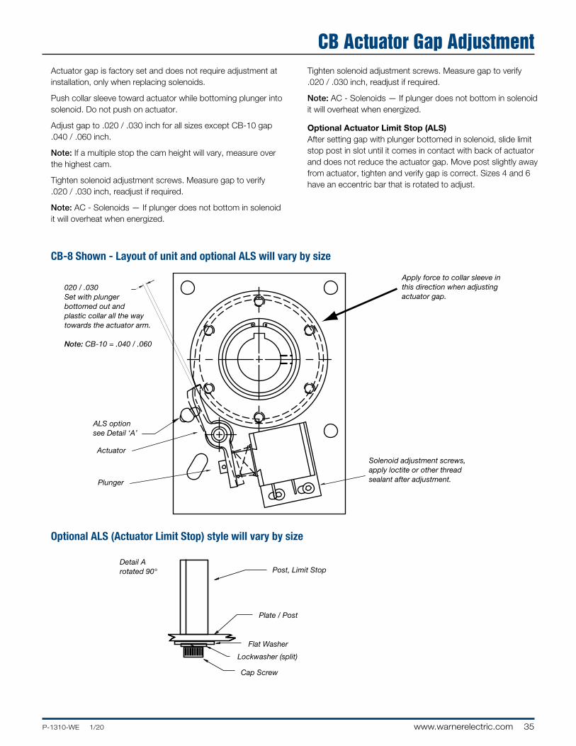
35P-1310-WE 1/20 www.warnerelectric.com
Actuator gap is factory set and does not require adjustment at installation, only when replacing solenoids.
Push collar sleeve toward actuator while bottoming plunger into solenoid. Do not push on actuator.
Adjust gap to .020 / .030 inch for all sizes except CB-10 gap .040 / .060 inch.
Note: If a multiple stop the cam height will vary, measure over the highest cam.
Tighten solenoid adjustment screws. Measure gap to verify .020 / .030 inch, readjust if required.
Note: AC - Solenoids — If plunger does not bottom in solenoid it will overheat when energized.
Tighten solenoid adjustment screws. Measure gap to verify .020 / .030 inch, readjust if required.
Note: AC - Solenoids — If plunger does not bottom in solenoid it will overheat when energized.
Optional Actuator Limit Stop (ALS)After setting gap with plunger bottomed in solenoid, slide limit stop post in slot until it comes in contact with back of actuator and does not reduce the actuator gap. Move post slightly away from actuator, tighten and verify gap is correct. Sizes 4 and 6 have an eccentric bar that is rotated to adjust.
020 / .030Set with plungerbottomed out andplastic collar all the waytowards the actuator arm.
Note: CB-10 = .040 / .060
Apply force to collar sleeve in this direction when adjusting actuator gap.
Solenoid adjustment screws, apply loctite or other thread sealant after adjustment.
ALS optionsee Detail ‘A’
Actuator
Plunger
CB-8 Shown - Layout of unit and optional ALS will vary by size
Optional ALS (Actuator Limit Stop) style will vary by size
Detail Arotated 90°
Packaged Performance ProductsWSC Series ClutchesCB Actuator Gap Adjustment
Post, Limit Stop
Plate / Post
Flat Washer
Lockwasher (split)
Cap Screw
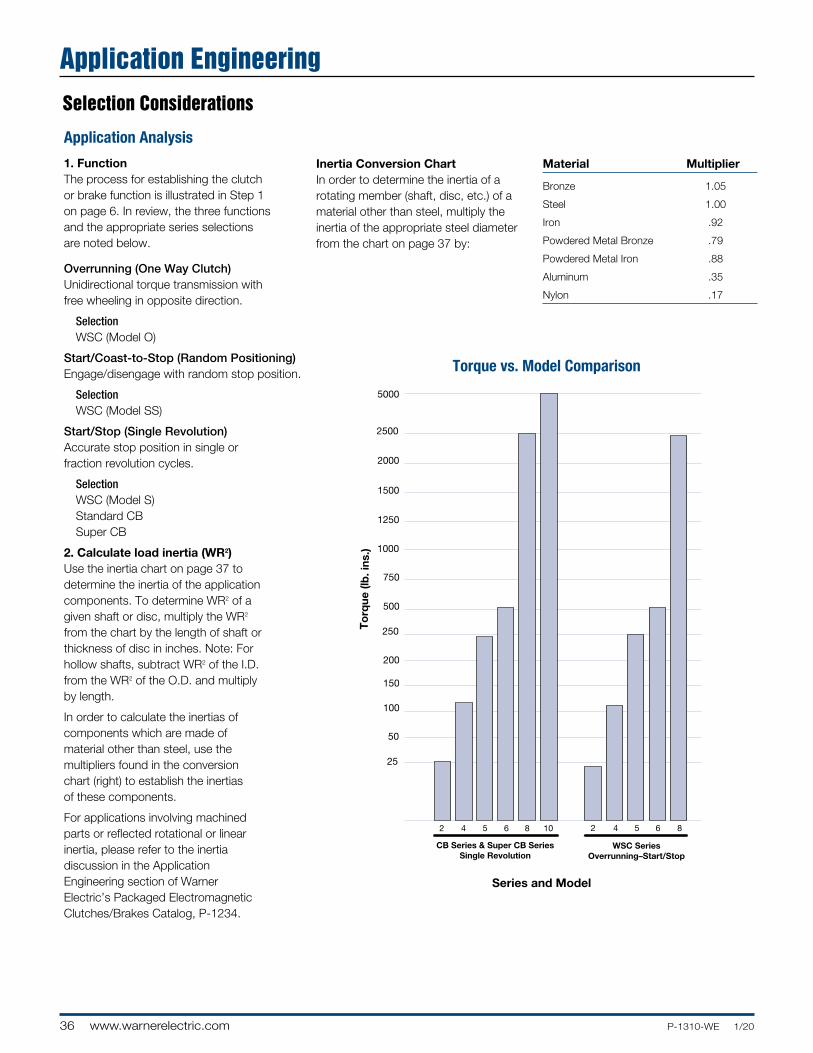
36 www.warnerelectric.com P-1310-WE 1/20
Selection Considerations
Application Analysis
1. FunctionThe process for establishing the clutch or brake function is illustrated in Step 1 on page 6. In review, the three functions and the appropriate series selections are noted below.
Overrunning (One Way Clutch)Unidirectional torque transmission with free wheeling in opposite direction.
Selection WSC (Model O)
Start/Coast-to-Stop (Random Positioning)Engage/disengage with random stop position.
Selection WSC (Model SS)
Start/Stop (Single Revolution)Accurate stop position in single or fraction revolution cycles.
Selection WSC (Model S) Standard CB Super CB
2. Calculate load inertia (WR2)Use the inertia chart on page 37 to de ter mine the inertia of the application compo nents. To determine WR2 of a given shaft or disc, multiply the WR2 from the chart by the length of shaft or thickness of disc in inches. Note: For hollow shafts, subtract WR2 of the I.D. from the WR2 of the O.D. and multiply by length.
In order to calculate the inertias of com ponents which are made of material other than steel, use the multipliers found in the conversion chart (right) to establish the inertias of these components.
For applications involving machined parts or reflected rotational or linear inertia, please refer to the inertia discussion in the Application Engineering section of Warner Electric’s Packaged Electromagnetic Clutches/Brakes Catalog, P-1234.
Inertia Conversion ChartIn order to determine the inertia of a rotating member (shaft, disc, etc.) of a material other than steel, multiply the inertia of the appropriate steel diameter from the chart on page 37 by:
Material Multiplier
Bronze 1.05
Steel 1.00
Iron .92
Powdered Metal Bronze .79
Powdered Metal Iron .88
Aluminum .35
Nylon .17
25
50
100
150
200
250
500
750
1000
1250
1500
2000
2500
5000
To
rque
(lb
. ins
.)
2 4 5 6 8 10
CB Series & Super CB SeriesSingle Revolution
2 4 5 6 8
WSC SeriesOverrunning–Start/Stop
Series and Model
Torque vs. Model Comparison
Application Engineering
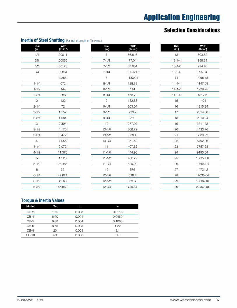
37P-1310-WE 1/20 www.warnerelectric.com
Packaged Performance Products
Selection Considerations
Inertia of Steel Shafting (Per Inch of Length or Thickness)
Dia. WR2
(in.) (lb.in.2)
1⁄4 .00011
3⁄8 .00055
1⁄2 .00173
3⁄4 .00864
1 .0288
1-1⁄4 .072
1-1⁄2 .144
1- 3⁄4 .288
2 .432
2-1⁄4 .72
2-1⁄2 1.152
2-3⁄4 1.584
3 2.304
3-1⁄2 4.176
3-3⁄4 5.472
4 7.056
4-1⁄4 9.072
4-1⁄2 11.376
5 17.28
5-1⁄2 25.488
6 36
6-1⁄4 42.624
6-1⁄2 49.68
6-3⁄4 57.888
Dia. WR2
(in.) (lb.in.2)
7 66.816
7-1⁄4 77.04
7-1⁄2 87.984
7-3⁄4 100.656
8 113.904
8-1⁄4 128.88
8-1⁄2 144
8-3⁄4 162.72
9 182.88
9-1⁄4 203.04
9-1⁄2 223.2
9-3⁄4 252
10 277.92
10-1⁄4 306.72
10-1⁄2 338.4
10-3⁄4 371.52
11 407.52
11-1⁄4 444.96
11-1⁄2 486.72
11-3⁄4 529.92
12 576
12-1⁄4 626.4
12-1⁄2 679.68
12-3⁄4 735.84
Dia. WR2
(in.) (lb.in.2)
13 803.52
13-1⁄4 858.24
13-1⁄2 924.48
13-3⁄4 995.04
14 1068.48
14-1⁄4 1147.68
14-1⁄2 1229.75
14-3⁄4 1317.6
15 1404
16 1815.84
17 2314.08
18 2910.24
19 3611.52
20 4433.76
21 5389.92
22 6492.96
23 7757.28
24 9195.84
25 10827.36
26 12666.24
27 14731.2
28 17036.64
29 19604.16
30 22452.48
Model Tc t Ic
CB-2 1.65 0.003 0.0116
CB-4 6.60 0.004 0.0450
CB-5 6.88 0.004 0.1663
CB-6 8.75 0.005 1.22
CB-8 20 0.005 8.1
CB-10 50 0.006 30
Torque & Inertia Values
Packaged Performance ProductsWSC Series ClutchesApplication Engineering
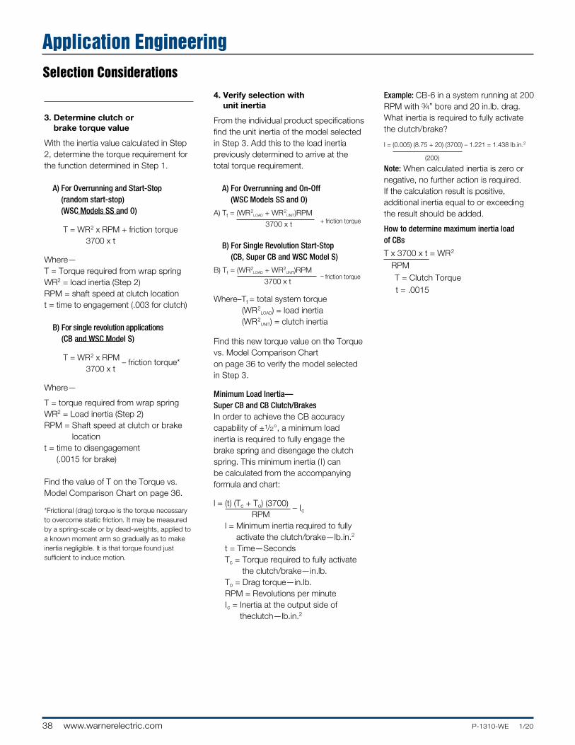
38 www.warnerelectric.com P-1310-WE 1/20
Packaged Performance Products
3. Determine clutch or brake torque value
With the inertia value calculated in Step 2, determine the torque requirement for the function determined in Step 1.
A) For Overrunning and Start-Stop (random start-stop) (WSC Models SS and O)
T = WR2 x RPM + friction torque 3700 x t
Where—T = Torque required from wrap springWR2 = load inertia (Step 2)RPM = shaft speed at clutch locationt = time to engagement (.003 for clutch)
B) For single revolution applications (CB and WSC Model S)
T = WR2 x RPM – friction torque* 3700 x t
Where—
T = torque required from wrap springWR2 = Load inertia (Step 2)RPM = Shaft speed at clutch or brake
locationt = time to disengagement
(.0015 for brake)
Find the value of T on the Torque vs. Model Comparison Chart on page 36.
*Frictional (drag) torque is the torque necessary to overcome static friction. It may be measured by a spring-scale or by dead-weights, applied to a known moment arm so gradually as to make inertia negligible. It is that torque found just sufficient to induce motion.
4. Verify selection with unit inertia
From the individual product specifications find the unit inertia of the model selected in Step 3. Add this to the load inertia previously determined to arrive at the total torque requirement.
A) For Overrunning and On-Off (WSC Models SS and O)
A) Tt = (WR2LOAD + WR2
UNIT)RPM 3700 x t
B) For Single Revolution Start-Stop (CB, Super CB and WSC Model S)
B) Tt = (WR2LOAD + WR2
UNIT)RPM 3700 x t
Where–Tt = total system torque (WR2
LOAD) = load inertia (WR2
UNIT) = clutch inertia
Find this new torque value on the Torque vs. Model Comparison Chart on page 36 to verify the model selected in Step 3.
Minimum Load Inertia—Super CB and CB Clutch/Brakes In order to achieve the CB accuracy capability of ±1/2°, a minimum load inertia is required to fully engage the brake spring and disengage the clutch spring. This minimum inertia ( l ) can be calculated from the accompanying formula and chart:
l = (t) (Tc + To) (3700) – Ic RPM l = Minimum inertia required to fully
activate the clutch/brake—lb.in.2
t = Time—Seconds Tc = Torque required to fully activate
the clutch/brake—in.lb. To = Drag torque—in.lb. RPM = Revolutions per minute Ic = Inertia at the output side of
theclutch—lb.in.2
Example: CB-6 in a system running at 200 RPM with 3⁄4” bore and 20 in.lb. drag. What inertia is required to fully activate the clutch/brake?
I = (0.005) (8.75 + 20) (3700) – 1.221 = 1.438 lb.in.2
(200)
Note: When calculated inertia is zero or negative, no further action is required. If the calculation result is positive, additional inertia equal to or exceeding the result should be added.
How to determine maximum inertia load of CBs
T x 3700 x t = WR2
RPM T = Clutch Torque t = .0015
+ friction torque
– friction torque
Application EngineeringSelection Considerations
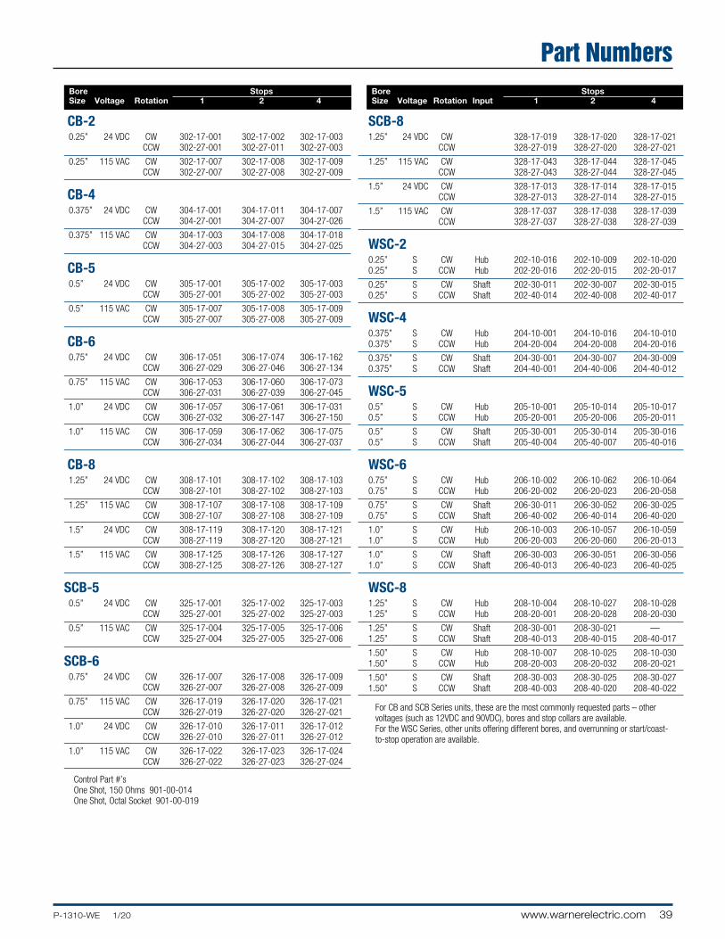
39P-1310-WE 1/20 www.warnerelectric.com
Packaged Performance Products Bore Stops Size Voltage Rotation 1 2 4
CB-2 0.25” 24 VDC CW 302-17-001 302-17-002 302-17-003 CCW 302-27-001 302-27-011 302-27-003
0.25” 115 VAC CW 302-17-007 302-17-008 302-17-009 CCW 302-27-007 302-27-008 302-27-009
CB-4 0.375” 24 VDC CW 304-17-001 304-17-011 304-17-007 CCW 304-27-001 304-27-007 304-27-026
0.375” 115 VAC CW 304-17-003 304-17-008 304-17-018 CCW 304-27-003 304-27-015 304-27-025
CB-5 0.5” 24 VDC CW 305-17-001 305-17-002 305-17-003 CCW 305-27-001 305-27-002 305-27-003
0.5” 115 VAC CW 305-17-007 305-17-008 305-17-009 CCW 305-27-007 305-27-008 305-27-009
CB-6 0.75” 24 VDC CW 306-17-051 306-17-074 306-17-162 CCW 306-27-029 306-27-046 306-27-134
0.75” 115 VAC CW 306-17-053 306-17-060 306-17-073 CCW 306-27-031 306-27-039 306-27-045
1.0” 24 VDC CW 306-17-057 306-17-061 306-17-031 CCW 306-27-032 306-27-147 306-27-150
1.0” 115 VAC CW 306-17-059 306-17-062 306-17-075 CCW 306-27-034 306-27-044 306-27-037
CB-8 1.25” 24 VDC CW 308-17-101 308-17-102 308-17-103 CCW 308-27-101 308-27-102 308-27-103
1.25” 115 VAC CW 308-17-107 308-17-108 308-17-109 CCW 308-27-107 308-27-108 308-27-109
1.5” 24 VDC CW 308-17-119 308-17-120 308-17-121 CCW 308-27-119 308-27-120 308-27-121
1.5” 115 VAC CW 308-17-125 308-17-126 308-17-127 CCW 308-27-125 308-27-126 308-27-127
SCB-5 0.5” 24 VDC CW 325-17-001 325-17-002 325-17-003 CCW 325-27-001 325-27-002 325-27-003
0.5” 115 VAC CW 325-17-004 325-17-005 325-17-006 CCW 325-27-004 325-27-005 325-27-006
SCB-6 0.75” 24 VDC CW 326-17-007 326-17-008 326-17-009 CCW 326-27-007 326-27-008 326-27-009
0.75” 115 VAC CW 326-17-019 326-17-020 326-17-021 CCW 326-27-019 326-27-020 326-27-021
1.0” 24 VDC CW 326-17-010 326-17-011 326-17-012 CCW 326-27-010 326-27-011 326-27-012
1.0” 115 VAC CW 326-17-022 326-17-023 326-17-024 CCW 326-27-022 326-27-023 326-27-024
Bore Stops Size Voltage Rotation Input 1 2 4
SCB-81.25” 24 VDC CW 328-17-019 328-17-020 328-17-021 CCW 328-27-019 328-27-020 328-27-021
1.25” 115 VAC CW 328-17-043 328-17-044 328-17-045 CCW 328-27-043 328-27-044 328-27-045
1.5” 24 VDC CW 328-17-013 328-17-014 328-17-015 CCW 328-27-013 328-27-014 328-27-015
1.5” 115 VAC CW 328-17-037 328-17-038 328-17-039 CCW 328-27-037 328-27-038 328-27-039
WSC-2 0.25” S CW Hub 202-10-016 202-10-009 202-10-020 0.25” S CCW Hub 202-20-016 202-20-015 202-20-017
0.25” S CW Shaft 202-30-011 202-30-007 202-30-015 0.25” S CCW Shaft 202-40-014 202-40-008 202-40-017
WSC-4 0.375” S CW Hub 204-10-001 204-10-016 204-10-010 0.375” S CCW Hub 204-20-004 204-20-008 204-20-016
0.375” S CW Shaft 204-30-001 204-30-007 204-30-009 0.375” S CCW Shaft 204-40-001 204-40-006 204-40-012
WSC-5 0.5” S CW Hub 205-10-001 205-10-014 205-10-017 0.5” S CCW Hub 205-20-001 205-20-006 205-20-011
0.5” S CW Shaft 205-30-001 205-30-014 205-30-016 0.5” S CCW Shaft 205-40-004 205-40-007 205-40-016
WSC-6 0.75” S CW Hub 206-10-002 206-10-062 206-10-064 0.75” S CCW Hub 206-20-002 206-20-023 206-20-058
0.75” S CW Shaft 206-30-011 206-30-052 206-30-025 0.75” S CCW Shaft 206-40-002 206-40-014 206-40-020
1.0” S CW Hub 206-10-003 206-10-057 206-10-059 1.0” S CCW Hub 206-20-003 206-20-060 206-20-013
1.0” S CW Shaft 206-30-003 206-30-051 206-30-056 1.0” S CCW Shaft 206-40-013 206-40-023 206-40-025
WSC-8 1.25” S CW Hub 208-10-004 208-10-027 208-10-028 1.25” S CCW Hub 208-20-001 208-20-028 208-20-030
1.25” S CW Shaft 208-30-001 208-30-021 — 1.25” S CCW Shaft 208-40-013 208-40-015 208-40-017
1.50” S CW Hub 208-10-007 208-10-025 208-10-030 1.50” S CCW Hub 208-20-003 208-20-032 208-20-021
1.50” S CW Shaft 208-30-003 208-30-025 208-30-027 1.50” S CCW Shaft 208-40-003 208-40-020 208-40-022
For CB and SCB Series units, these are the most commonly requested parts – other voltages (such as 12VDC and 90VDC), bores and stop collars are available. For the WSC Series, other units offering different bores, and overrunning or start/coast- to-stop operation are available.
Control Part #’s One Shot, 150 Ohms 901-00-014 One Shot, Octal Socket 901-00-019
Packaged Performance ProductsPackaged Performance ProductsWSC Series ClutchesPart Numbers
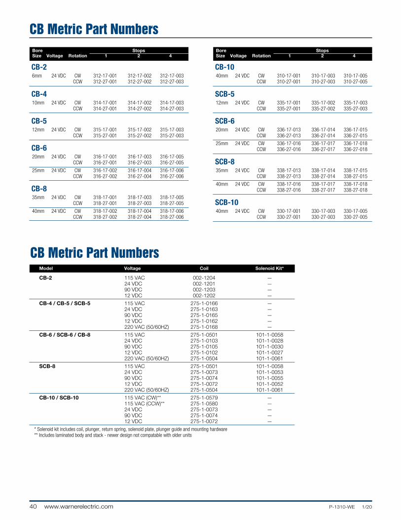
40 www.warnerelectric.com P-1310-WE 1/20
Bore Stops Size Voltage Rotation 1 2 4
CB-2 6mm 24 VDC CW 312-17-001 312-17-002 312-17-003 CCW 312-27-001 312-27-002 312-27-003
CB-4 10mm 24 VDC CW 314-17-001 314-17-002 314-17-003 CCW 314-27-001 314-27-002 314-27-003
CB-5 12mm 24 VDC CW 315-17-001 315-17-002 315-17-003 CCW 315-27-001 315-27-002 315-27-003
CB-6 20mm 24 VDC CW 316-17-001 316-17-003 316-17-005 CCW 316-27-001 316-27-003 316-27-005
25mm 24 VDC CW 316-17-002 316-17-004 316-17-006 CCW 316-27-002 316-27-004 316-27-006
CB-8 35mm 24 VDC CW 318-17-001 318-17-003 318-17-005 CCW 318-27-001 318-27-003 318-27-005
40mm 24 VDC CW 318-17-002 318-17-004 318-17-006 CCW 318-27-002 318-27-004 318-27-006
Bore Stops Size Voltage Rotation 1 2 4
CB-10 40mm 24 VDC CW 310-17-001 310-17-003 310-17-005 CCW 310-27-001 310-27-003 310-27-005
SCB-5 12mm 24 VDC CW 335-17-001 335-17-002 335-17-003 CCW 335-27-001 335-27-002 335-27-003
SCB-6 20mm 24 VDC CW 336-17-013 336-17-014 336-17-015 CCW 336-27-013 336-27-014 336-27-015
25mm 24 VDC CW 336-17-016 336-17-017 336-17-018 CCW 336-27-016 336-27-017 336-27-018
SCB-8 35mm 24 VDC CW 338-17-013 338-17-014 338-17-015 CCW 338-27-013 338-27-014 338-27-015
40mm 24 VDC CW 338-17-016 338-17-017 338-17-018 CCW 338-27-016 338-27-017 338-27-018
SCB-10 40mm 24 VDC CW 330-17-001 330-17-003 330-17-005 CCW 330-27-001 330-27-003 330-27-005
Model Voltage Coil Solenoid Kit*
CB-2 115 VAC 002-1204 — 24 VDC 002-1201 — 90 VDC 002-1203 — 12 VDC 002-1202 —
CB-4 / CB-5 / SCB-5 115 VAC 275-1-0166 — 24 VDC 275-1-0163 — 90 VDC 275-1-0165 — 12 VDC 275-1-0162 — 220 VAC (50/60HZ) 275-1-0168 —
CB-6 / SCB-6 / CB-8 115 VAC 275-1-0501 101-1-0058 24 VDC 275-1-0103 101-1-0028 90 VDC 275-1-0105 101-1-0030 12 VDC 275-1-0102 101-1-0027 220 VAC (50/60HZ) 275-1-0504 101-1-0061
SCB-8 115 VAC 275-1-0501 101-1-0058 24 VDC 275-1-0073 101-1-0053 90 VDC 275-1-0074 101-1-0055 12 VDC 275-1-0072 101-1-0052 220 VAC (50/60HZ) 275-1-0504 101-1-0061
CB-10 / SCB-10 115 VAC (CW)** 275-1-0579 — 115 VAC (CCW)** 275-1-0580 — 24 VDC 275-1-0073 — 90 VDC 275-1-0074 — 12 VDC 275-1-0072 —
* Solenoid kit includes coil, plunger, return spring, solenoid plate, plunger guide and mounting hardware ** Includes laminated body and stack - newer design not compatable with older units
CB Metric Part Numbers
CB Metric Part Numbers
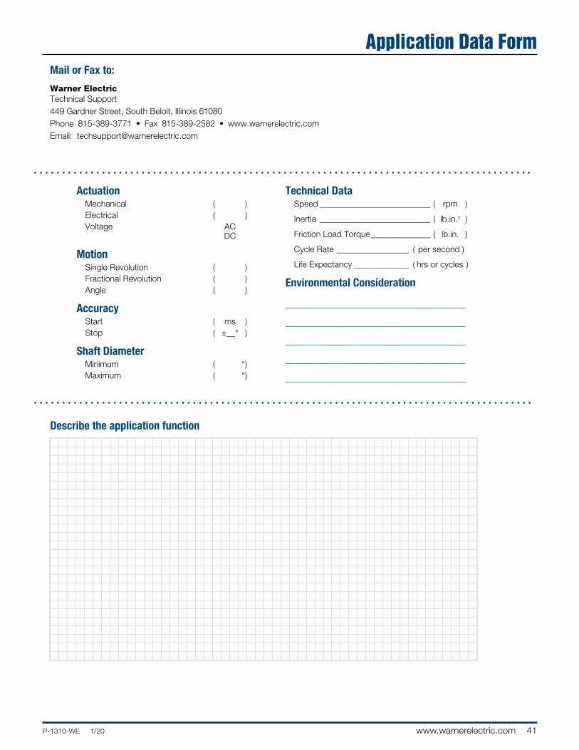
41P-1310-WE 1/20 www.warnerelectric.com
Mail or Fax to:
Warner ElectricTechnical Support449 Gardner Street, South Beloit, Illinois 61080Phone 815-389-3771 • Fax 815-389-2582 • www.warnerelectric.comEmail: [email protected]
ActuationMechanical ( )Electrical ( )Voltage AC DC
MotionSingle Revolution ( )Fractional Revolution ( )Angle ( )
AccuracyStart ( ms )Stop ( ±__° )
Shaft DiameterMinimum ( “)Maximum ( “)
Technical DataSpeed __________________________ ( rpm )
Inertia __________________________ ( lb.in.2 )
Friction Load Torque ______________ ( lb.in. )
Cycle Rate _________________ ( per second )
Life Expectancy _____________ ( hrs or cycles )
Environmental Consideration
______________________________________
______________________________________
______________________________________
______________________________________
______________________________________
Describe the application function
Application Data Form
Altra Motion
www.warnerelectric.com
The Brands of Altra Motion
Couplings
Ameridriveswww.ameridrives.com
Bibby Turbofl ex www.bibbyturbo� ex.com
Guardian Couplingswww.guardiancouplings.com
Hucowww.huco.com
Lamifl ex Couplingswww.lami� excouplings.com
Stromag www.stromag.com
TB Wood’swww.tbwoods.com
Linear Systems
Thomsonwww.thomsonlinear.com
Geared Cam Limit Switches
Stromagwww.stromag.com
Engineered Bearing Assemblies
Kilianwww.kilianbearings.com
Electric Clutches & Brakes
Matrixwww.matrix-international.com
Stromagwww.stromag.com
Warner Electricwww.warnerelectric.com
Deltranwww.thomsonlinear.com
Belted DrivesTB Wood’s www.tbwoods.com
Heavy Duty Clutches & Brakes
Twifl exwww.twi� ex.com
Stromagwww.stromag.com
Svendborg Brakeswww.svendborg-brakes.com
Wichita Clutchwww.wichitaclutch.com
Gearing & Specialty Components
Bauer Gear Motorwww.bauergears.com
Boston Gearwww.bostongear.com
Delevanwww.delevan.com
Delroyd Worm Gearwww.delroyd.com
Nuttall Gearwww.nuttallgear.com
Engine Braking Systems
Jacobs Vehicle Systemswww.jacobsvehiclesystems.com
Precision Motors & Automation
Kollmorgenwww.kollmorgen.com
Miniature Motors
Portescapwww.portescap.com
Overrunning Clutches
Formsprag Clutchwww.formsprag.com
Marland Clutchwww.marland.com
Stieberwww.stieberclutch.com
Warner Electric Facilities
North America
USA31 Industrial Park RoadNew Hartford, CT 06057 - USA860-379-1252
Electromagnetic Clutches and Brakes
449 Gardner StreetSouth Beloit, IL 61080 - USA815-389-3771
4578 East Park 30 DriveColumbia City, IN 46725 - USA260-244-6183
Precision Electric Coils and Electromagnetic Clutches and Brakes
Customer Service1-800-825-6544
Application Support1-800-825-9050
Europe
France7, rue Champ� eur, B.P. 20095St Barthelemy d’Anjou - France+33 (0)2 41 21 24 24
Electromagnetic Clutches and Brakes
Customer Service+33 (0)2 41 21 24 76
Application Support+33 (0) 2 41 21 24 24
Asia Pacifi c
Australia +61 2 9894 0133
China+86 21 5169-9255
Hong Kong +852 2615 9313
Singapore +65 6487 4464
Taiwan +886 2 2577 8156
Thailand +66 2322 5527
Neither the accuracy nor completeness of the information contained in this publication is guaranteed by the company and may be subject to change in its sole discretion. The operating and performance characteristics of these products may vary depending on the application, installation, operating conditions and environmental factors. The company’s terms and conditions of sale can be viewed at http://www.altramotion.com/terms-and-conditions/sales-terms-and-conditions. These terms and conditions apply to any person who may buy, acquire or use a product referred to herein, including any person who buys from a licensed distributor of these branded products.
©2020 by Warner Electric LLC. All rights reserved. All trademarks in this publication are the sole and exclusive property of Warner Electric LLC or one of its af� liated companies.
P-1310-WE 1/20
Related Documents