Water Rights Analysis Package (WRAP) Programming Manual Ralph A. Wurbs and Richard J. Hoffpauir Texas A&M University Texas Water Resources Institute TR-388, 2nd Edition August 2012

Welcome message from author
This document is posted to help you gain knowledge. Please leave a comment to let me know what you think about it! Share it to your friends and learn new things together.
Transcript

Water Rights Analysis Package (WRAP) Programming ManualRalph A. Wurbs and Richard J. HoffpauirTexas A&M University
Texas Water Resources Institute TR-388, 2nd EditionAugust 2012

Water Rights Analysis Package (WRAP) Programming Manual
TR-388 Texas Water Resources Institute College Station, Texas August 2012
by Ralph A. Wurbs and Richard J. Hoffpauir
Texas A&M University

Water Rights Analysis Package (WRAP)
Programming Manual
by
Ralph A. Wurbs and Richard J. Hoffpauir Texas A&M University
for the
Texas Commission on Environmental Quality Austin, Texas 78711-3087
under
Contract 582-9-89809 (2008-2011) Contract 582-12-10220 (2011-2013)
Technical Report 388 Texas Water Resources Institute
The Texas A&M University System College Station, Texas 77843-2118
Second Edition August 2012


iii
TABLE OF CONTENTS Chapter 1 Introduction ................................................................................................................. 1
WRAP Modeling System ......................................................................................................... 1 Compilers and Integrated Development Environments ........................................................... 2 HEC-DSS Data Storage System ............................................................................................... 8 Fortran Language ...................................................................................................................... 9
Chapter 2 SIM ............................................................................................................................... 19
Organization of SIM ................................................................................................................. 19 Input and Output Files .............................................................................................................. 23 Subroutines ............................................................................................................................... 24 HECLIB Subroutines ................................................................................................................ 27 Variables for Defining Array Sizes .......................................................................................... 28 Definition of Variables ............................................................................................................. 29
Chapter 3 SIMD ............................................................................................................................ 65
Organization of SIMD .............................................................................................................. 68 Input and Output Files .............................................................................................................. 68 Subroutines ............................................................................................................................... 69 Definition of Variables ............................................................................................................. 71 Information for Tracking Changes to Flow in the Routing Arrays ........................................ 83 Information for Tracking Reverse Routing in Water Availability …...................................... 87
Chapter 4 SALT ............................................................................................................................ 91
Organization of SALT .............................................................................................................. 91 Input and Output Files .............................................................................................................. 92 Subroutines ............................................................................................................................... 93 Definition of Variables ............................................................................................................. 93
Chapter 5 TABLES ...................................................................................................................... 103
Organization of TABLES ......................................................................................................... 103 Input and Output Files .............................................................................................................. 105 Subroutines ............................................................................................................................... 107 HECLIB Subroutines ............................................................................................................... 112 Definition of Variables ............................................................................................................. 112 Variables Exclusive of Those in the CRM Subroutines .......................................................... 112 Definition of Variables in the Conditional Reliability Modeling (CRM) Subroutines ........... 135
Chapter 6 HYD ............................................................................................................................. 143
Organization of HYD ............................................................................................................... 143 Input and Output Files .............................................................................................................. 147 Subroutines ............................................................................................................................... 148 Definition of Variables ............................................................................................................ 151

iv
Definition of Variables Excluding Subroutines EXTEND, CRITERIA, and EFFLOW ....... 151 Variables in Subroutines EXTEND, CRITERIA, and EFFLOW ........................................... 160
Chapter 7 DAY ............................................................................................................................ 171
Organization of DAY ….......................................................................................................... 171 Input and Output Files ............................................................................................................ 171 Subroutines ............................................................................................................................. 172 Functions .................................................................................................................................. 174 Definition of Variables ............................................................................................................ 176
Chapter 8 WinWRAP .................................................................................................................. 183
Compaq/Intel Visual Fortran Features for Developing Graphical User Interfaces ................ 184 Differences between WinWRAP and the Other WRAP Programs ........................................ 184 Organization of WinWRAP .................................................................................................... 185
LIST OF FIGURES 2.1 Outline of SIM Simulation ....................................................................................................... 20 3.1 Outline of SIMD Simulation .................................................................................................... 66 4.1 Organization of SALT .............................................................................................................. 92
LIST OF TABLES 1.1 WRAP Programs ...................................................................................................................... 2 1.2 Project Configuration Properties Menu for the Intel Compiler ................................................ 6 1.3 Fortran Statements .................................................................................................................... 12 1.4 Fortran Example ....................................................................................................................... 18 2.1 SIM Input and Output Files ...................................................................................................... 24 3.1 Additional SIMD Input and Output Files Not Included in SIM .............................................. 68 4.1 SALT Input and Output Files ................................................................................................... 93 5.1 Organization of TABLES by TIN File Input Record Types .................................................. 104 5.2 TABLES Input and Output Files .............................................................................................. 105 5.3 Features that Result in Files Being Opened ............................................................................. 106 5.4 TABLES Subprograms ............................................................................................................ 108 6.1 HYD Input and Output Files .................................................................................................... 147 6.2 HYD Subroutines .................................................................................................................... 148 7.1 Day Input and Output Files ..................................................................................................... 171 8.1 WinWRAP Interface ............................................................................................................... 183 8.2 WinWRAP Files ..................................................................................................................... 185
1
CHAPTER 1 INTRODUCTION
The Water Rights Analysis Package (WRAP) executable programs are applied by model users without being concerned with the Fortran code. The Reference, Users, Hydrology, Salinity, and Daily Manuals provide all the information required to apply the modeling system, without reference to the Fortran code. However, this Programming Manual is designed for people interested in understanding the Fortran code. The information provided here is essential for programmers working on improving and expanding the programs. Reviewing the Fortran programs can also be useful to model users as an aid in better understanding the modeling system. Simulation methods of concern in a particular application can be examined in detail by studying the Fortran code. This Programming Manual is designed to facilitate reading and understanding the WRAP Fortran programs by both programmers and non-programmer model users.
WRAP Modeling System This Programming Manual is written assuming readers are familiar with the WRAP programs as described in the basic Reference and Users Manuals and other auxiliary manuals. WRAP includes the following computer programs which are each covered by a separate chapter of this programming manual. Executable files are distributed for use on desktop computers operating under Microsoft Windows. Recent versions of the Fortran programs have been compiled with Compaq and Intel Visual Fortran compilers within the Microsoft Visual Studio Integrated Development Environment. The code conforms to both Fortran 95 and Fortran 2003 standards. The WinWRAP interface program was developed as a Fortran QuickWin application.
SIM simulates the river/reservoir water allocation/management/use system for input sequences of monthly naturalized flows and net evaporation rates. (Chapter 2)
SIMD (D for daily) is an expanded version of SIM that includes features for sub-monthly time steps, flow forecasting and routing, and flood control operations along with all of the capabilities of SIM. (Chapter 3)
SALT reads a SIM or monthly SIMD output file and a salinity input file and tracks salt constituents through the river/reservoir system. (Chapter 4)
TABLES develops frequency relationships, reliability indices, and various user-specified tables for organizing and summarizing simulation results. (Chapter 5)
HYD assists in developing monthly naturalized stream flow and reservoir net evaporation rate data for the SIM hydrology input files. (Chapter 6)
DAY assists in developing sub-monthly (daily) time step hydrology input for SIMD including disaggregating monthly flows to sub-monthly time intervals and determining routing parameters. (Chapter 7)
WinWRAP facilitates execution of the WRAP programs within the Microsoft Windows environment along with Microsoft programs and HEC-DSSVue. (Chapter 8)
The chapter of this manual covering each program outlines the overall organization of the Fortran code, describes the functions of the main program and each subroutine, defines the variables, and discusses various features. This information is designed to be referenced by the

2
reader as the Fortran code is examined. The remainder of this introductory Chapter 1 provides general information that is pertinent to all of the WRAP Fortran programs. All interactions between the WRAP programs are through data files. Some of the programs read input files that were created by other programs as output files. Otherwise, each separate program is independent of the others. However, the Fortran programs are organized similarly with consistent programming conventions, with the exception of the interface program WinWRAP.
Table 1.1
WRAP Programs
Manual Filename Chapter Program Source Code Executable Function
2 SIM SIM.for SIM.exe Monthly simulation model
3 SIMD SIMD.for SIMD.exe Simulation model with monthly or sub-monthly time intervals
4 SALT SALT.for SALT.exe Salinity simulation model
5 TABLES TAB.for TAB.exe Post-simulation summary tables, reliability indices, frequency tables
6 HYD HYD.for HYD.exe Monthly hydrology data
7 DAY DAY.for DAY.exe Sub-monthly hydrology data
8 WinWRAP WinWRAP.for WinWRAP.exe Microsoft Windows interface
Compilers and Integrated Development Environments Beginning in August 2012, the released executable WRAP programs, except WinWRAP, are being compiled with the Intel Visual Fortran Composer XE 2011, which is implemented within Microsoft Visual Studio and Microsoft Windows. Prior to July 2012, publicly released versions of the WRAP programs have been compiled with the 2000 Compaq Visual Fortran Version 6.5 or its predecessors. During 2007 to 2012, the WRAP programs were also compiled with the Intel Visual Fortran Versions 9, 10, and 11 for testing and comparative analyses even though the 2000 Compaq Visual Fortran Version 6.5 was consistently used to create the final released executables.
A compiler converts a Fortran program, with a filename extension FOR or variation thereof, to an executable program with filename extension EXE, static library with filename extension LIB, or dynamic library with extension DLL, and also links the program with library routines. Compilers are typically applied within an Integrated Development Environment (IDE) which provides editing, file management, and other utility functions. Many different Fortran compiler/IDE packages are sold by various companies. The WRAP programs are in standard Fortran that can be compiled with the various compilers. The compiler, linker, and development environment used with WRAP since the mid-1990's is a popular Fortran software development package that has evolved through various versions as ownership passed from Microsoft to Digital to Compaq to Intel as follows.

3
• Digital Visual Fortran combined with a version of the Microsoft Visual Studio IDE replaced Microsoft Power Station in the early 1990's.
• Compaq acquired Digital Visual Fortran in 1997. The software package was similar under ownership of the two different companies (Digital and Compaq) and continued to combine the compiler/linker with its own version of the Microsoft IDE.
• Intel acquired Compaq Visual Fortran in 2005 and marketed its Intel version of the 2000 Compaq Visual Fortran 6.5, still combined with the Microsoft Visual Studio IDE.
• Intel Visual Fortran 9 released in 2006 replaced Compaq Visual Fortran. Versions 10 and 11 were released by Intel in 2007 and 2009. Version 11 was updated during 2010 and 2011. The Intel Visual Fortran compiler is applied within Microsoft Visual Studio.
• Intel Visual Fortran Composer XE 2011 was released in 2011 replacing the Intel Visual Fortran Compiler Professional Edition. Several updates were released during 2011 and 2012. The Intel Visual Fortran Composer XE 2011 is applied in combination with Microsoft Visual Studio 2008 or 2010.
As the Fortran compiler/linker software transferred between companies from Microsoft to
Digital to Compaq to Intel, it has continued to be applied within the Microsoft Integrated Development Environment (IDE). The Digital and Compaq software products were sold as integrated packages that included current versions of the Microsoft IDE with the compiler/linker software. The Microsoft IDE was significantly expanded in 2002 and subsequently progressed through other versions in its transformation to Microsoft Visual Studio 2005, 2008, and 2010. The Microsoft Visual Studio IDE is used to develop programs in Visual Basic, C#, J#, C++, Fortran, and/or other programming languages. Components of a program may be written in different languages. Intel Visual Fortran requires and is implemented within Microsoft Visual Studio IDE. Compaq Visual Fortran 6.5 works with previous versions of Microsoft Windows but will not install directly under Windows 7. The Microsoft Windows Virtual Machine add-on software will allow Compaq Visual Fortran to run via Windows XP mode on a computer otherwise operating under Windows 7. The Intel compiler/linker/IDE software is compatible with Microsoft Windows 7, Microsoft Windows Vista, Microsoft Windows XP, and Microsoft Windows Server versions. Compaq Visual Fortran is no longer being marketed by either the Intel or Compaq Companies. The new Intel/Microsoft package provides improvements in organization of configuration options, debugging features, and documentation. The Intel compiler implements features of Fortran 2003 that were not in Fortran 95 implemented in the Compaq compiler. All versions fully implement Fortran 90 and 95 along with various extensions. Both the Intel Visual Fortran compiler and Microsoft Visual Studio are designed to improve integration of components coded in multiple programming languages (Visual Basic, J#, C#, C++, Fortran) into the software products (exe, lib, and dll files) being developed. Compilation of the WRAP Programs The WRAP programs are written and read by people in the Fortran language which cannot be read by computers. Fortran source code in a file with the filename extension FOR is converted by compiler software to an executable file with filename extension EXE which is in a machine

4
language read by computers but not by people. Library routines are also linked to the Fortran programs in the process of creating executable files. Compiler/linker/IDE software is marketed by various companies for use with a variety of computers and operating systems. The various versions of the software package sold by the Digital, Compaq, and Intel companies cited in the preceding discussion have been used on personal computers with the various versions of the Microsoft Windows operating system in the development of the WRAP programs since the 1990’s. Earlier programming of WRAP was performed on a VAX computer with its own Fortran compiler. As of July 2012, the released executable WRAP programs are compiled with the Intel Visual Fortran Composer XE 2011. Floating point preciseness consistency is an issue in changing compilers. This issue is discussed in a 2009 paper by Martyn Corden and David Kreitzer of the Intel Corporation posted at the Intel website and entitled:
Consistency of Floating-Point Results Using the Intel Compiler or Why doesn’t my application always give the same answer?
Floating point preciseness consistency has been found to be a concern in comparative analyses of the results of the WRAP programs SIM and SIMD compiled with the different versions of the compiler and with different compiler settings. Floating point arithmetic with real numbers is structured differently between the Compaq and Intel compilers. The 2000 Compaq Version 6.5 and the 2011 Intel Composer and preceding Intel versions all have differences in optimization features for balancing tradeoffs between run-time, memory requirements, consistent reproducibility, and preciseness controlled by setting options that affect WRAP-SIM/SIMD simulation results in some cases. The new Intel Visual Fortran, then version 9, was first explored for use with WRAP in 2007. The WRAP program SIM was found to require significant updating for compatibility with the new Intel complier. Several minor initial changes to the Fortran code were necessary for SIM to compile with the Intel compiler without compilation or run-time errors. However, the 2007 version of SIM compiled with the new Intel compiler was found to yield small differences in simulation results for several of the TCEQ WAM System datasets than if compiled with the old Compaq compiler. Simulation results were also affected by whether the old SIM was compiled by the new Intel compiler in debug or release mode. The variations were found to be caused primarily by problems occurring with the new Intel compiler applied in the release mode with its advanced optimization features. The Compaq compiler appeared to be somewhat more robust, with results not being sensitive to coding choices and compiler settings. The Intel problems were corrected in SIM primarily with Fortran code changes supplemented with use of compiler setting options. A majority of the problems perhaps could have been handled solely with optional compiler settings. However, code changes allow the Fortran program to be compiled with either default or other settings with either the Compaq or Intel compilers, minimizing the need to deal with compiler settings. The rules of Fortran were followed correctly with or without the modifications. The issues were related to the manner in which the alternative compilers implemented Fortran and defined default configuration property settings. The problems involved several issues ranging from simple to complex that were solved with various code revisions. The root causes of the more significant
5
problems were very subtle. The greatest culprit was found to be problems with the new Intel compiler in release mode caused by the effects on conditional if statements of preciseness inconsistencies associated with floating point real number operations within the computer. These problems were corrected with several Fortran code revisions along with adoption of the improve preciseness consistency setting in the configuration properties which deactivates certain memory and run-time optimizations. The now-corrected preciseness consistency problems occurred in the old 2007 version of SIM primarily within iterative reservoir and hydropower simulation routines. Further comparative analyses of SIM and SIMD results with the programs compiled with Intel Visual Fortran Composer XE 2011 versus the 2000 Compaq Visual Fortran Version 6.5 were performed during 2012 resulting in additional minor code revisions to deal with floating point preciseness and as a safeguard against other computational issues. The Intel Visual Fortran Composer XE 2011 was adopted as the standard compiler to use with the WRAP programs.
The examples in the WRAP manuals and most of the TCEQ WAM System datasets yield the same results with SIM/SIMD compiled with either version of the Compaq or Intel compilers. However, the results for several of the larger WAM System datasets vary a little depending on the version of the compiler used to compile SIM and SIMD. Simulation results with SIM and SIMD compiled with the Intel compiler but with different setting options vary slightly in some cases. Compiler Settings The following discussion of compiler settings is relevant to readers who are interested in developing and/or modifying the Fortran source code for the WRAP programs and converting the programs to executable files within the Microsoft Windows operating system using either of the following Compaq or Intel versions of the compiler/linker/IDE software.
• Compaq Visual Fortran 6.5 and Microsoft IDE with copyright date of 2000. This is the Intel Version of the Compaq Visual Fortran Professional Edition Version 6.5.
• Intel Visual Fortran Composer XE 2011 combined with the Microsoft Visual Studio 2008 or 2010 Integrated Development Environment (IDE).
Other compiler software products marketed by other companies not discussed here have their own different systems of settings. The user interface and configuration properties settings are organized much differently in the Intel software than in the previous Compaq and Digital versions. Compaq Visual Fortran 6.5 and preceding versions have essentially the same interface and settings. Intel Visual Fortran Versions 9 and later have basically the same settings but with some differences. All Compaq and Intel compiler versions have two modes called debug and release configurations, with different defaults for the various configuration properties options. The debug mode is designed for writing code and detecting and correcting errors and problems. The release mode is designed for producing an efficient final executable for actual application. An executable program compiled in release mode executes faster and is much smaller. Debug mode compiles faster and provides better capabilities for detecting errors and potential problems. Default compiler settings work fine for all of the WRAP programs when compiled with the 2000 Compaq compiler in either debug or release mode. No special settings are required when

6
compiling the WRAP programs with the 2000 Compaq compiler. However, certain non-default settings are required when compiling the WRAP programs with the Intel compiler.
A different version of the HEC-DSS static library, is required for the old Compaq versus newer Intel compilers. A static library is a file with filename extension lib (such as filename heclib.lib) stored in any directory. Compiler settings are required to link the HEC-DSS static library with the WRAP programs using the Intel compiler/linker. With the 2000 Compaq compiler, the HEC-DSS static library is linked with the WRAP programs with the following menu selections, followed by browsing and clicking the heclib.lib file, without needing other special compiler settings.
Project − Add to Project − Files
The first level of menu topics for the configuration properties of the Project pull-down menu of the Intel compiler is shown in Table 1.2. Each heading has a number of sub-headings with multiple setting options. The settings may vary between debug and release configurations. All settings have defaults for the debug and release configurations which are in effect unless changed by the programmer. The menu options listed in Table 1.2 are the same in the 2011 and preceding Intel versions but other sub-menu options differ somewhat between the Intel compiler versions. Fortran and linker settings include options pertinent to the WRAP programs. The settings are used primarily in conjunction with linking the HEC-DSS static library to the WRAP programs but serve other purposes as well. Subcategories of setting options under Fortran are also listed in Table 1.2. Each of the Fortran settings has a number of options.
Table 1.2 Project Configuration Properties Menu for the Intel Compiler
Configuration Properties General General Optimization Debugging Debugging Fortran Preprocessor Linker Code Generation Resources Language MIDL Compatibility Build Events Diagnostics Custom Build Step Data Calling Convention Floating Point Name Case Interpretation External Procedures String Length Argument Output Files Passing Run-Time Append Underscore to Libraries External Names Command Line
The following configuration property settings are activated when any program is linked to the HEC-DSS static library with the Intel compiler in either debug or release mode. These settings are needed primarily due to the HEC-DSS static library though they do have general applicability.

7
Fortran − External Procedures − Calling Convention − STDCALL, REFERENCE Fortran − External Procedures − Name Case Interpretation − Lower Case Fortran − External Procedures − Append Underscore to External Names − Yes Fortran − Data − Local Variable Storage − All Variables SAVE Fortran − Data − Initialize Local Saved Scalars to Zero − Yes Linker − Input − Additional Dependencies − C:\WRAP\heclib\heclibd.lib (debug) − C:\WRAP\heclib\heclibr.lib (release) Linker − Input − Ignore All Default Libraries − No Linker − Input − Ignore Specific Library − LIBCMT The following floating-point speculation setting is also activated when compiling/linking with the Intel compiler in release mode as a safeguard against possible floating-point precision concerns. The choices are fast or safe. Input/output buffering is also activated, particularly with SIMD, to allow the program to run faster. Runtime is decreased a little, but computational results are not affected.
Fortran – Floating-Point − Speculation − Safe Fortran – Optimization – I/O Buffering − Yes Programmers may choose to activate various other optional compiler settings that are useful but not required. For example, all variables used in the WRAP programs are declared in type statements. Likewise, the WRAP programs contain no variables that are defined in type statements but are never actually used. These conditions are not necessarily required for the programs to execute correctly, but rather are maintained as safeguards to better organize the code. Compiler settings are set to activate warning messages if these conditions are not met. The settings in the 2000 Compaq compiler are as follows. Project − Settings − Fortran − Compilation Diagnostics − Undeclared Symbols Project − Settings − Fortran − Compilation Diagnostics − Unused Variables The comparable settings in the Intel compiler are as follows. Fortran − Diagnostics − Warn for Undeclared Symbols Fortran − Diagnostics − Warn for Unused Variables Viewing the Fortran Programs Microsoft Visual Studio and other integrated development environments (IDE) combined with the compiler/linker software marketed by various companies allow programmers to create and edit computer programs. However, model users can read the WRAP computer programs without purchasing IDE/compiler/linker software. The programs can be read with any editor such as Microsoft WordPad or Notepad. However, Notepad++ is a particularly convenient editor for reading computer programs coded in Fortran or other programming languages.
Notepad++ is an enhanced editor that is similar to Microsoft Notepad but with additional features for editing computer programs. The editor recognizes Fortran and highlights various features of the code in color for convenient viewing. Notepad++ is available free-of-charge at:
http://notepad-plus-plus.org or http://portableapps.com/apps/development/notepadpp_portable

8
HEC-DSS Data Storage System The Hydrologic Engineering Center (HEC) of the U.S. Army Corps of Engineers maintains a suite of generalized hydrologic, hydraulic, and water management simulation models that are applied extensively by numerous agencies and consulting firms throughout the United States and abroad. The HEC-DSS (Data Storage System) is used routinely with HEC simulation models and can be used with other non-HEC modeling systems as well. Multiple simulation models share the same graphics and data management software. Data is stored in DSS files in a direct access binary format. DSS files can be created, written to, and read only with software with DSS capabilities. DSS capabilities are added to software such as the WRAP programs by linking during compilation to routines in a static library file available from the Hydrologic Engineering Center. HEC-DSS dates back to 1979, but its utility was greatly enhanced with the initial and update releases of HEC-DSSVue in 2003, 2005, and 2009. The HEC-DSS Visual Utility Engine (HEC-DSSVue) is a graphical user interface program for viewing, editing, graphing, and mathematically manipulating data stored in HEC-DSS files. Database management capabilities provided by the HEC-DSS are oriented particularly toward voluminous sets of sequential time series data. HEC-DSS is developed in Fortran. HEC-DSSVue is written in the Java programming language. The primary purpose of incorporating routines in the WRAP programs that create and access DSS files is to facilitate the use of HEC-DSSVue for graphing and otherwise analyzing WRAP simulation results. The WRAP simulation programs write time sequences of simulation results optionally as either text files and/or DSS files. Hydrology input data can also be read from DSS files. The WRAP programs include Fortran code that create, write to, and read from DSS files.
DSS-related Fortran code in the WRAP programs, like other HEC or non-HEC programs, allows the programs to link during compilation to routines from a static library called HECLIB developed by the Hydrologic Engineering Center, which was developed in Fortran and is distributed as a static library file in machine language. A standard HEC-DSS static library file with filename heclib50d.lib has been available for many years and continues to be used with the Compaq compiler/linker. During 2006-2007, the Hydrologic Engineering Center updated the HEC-DSS library for compatibility with the 2006/2007 Intel Visual Fortran compiler/linker. Static libraries with filenames heclibd.lib and heclibr.lib are linked to Fortran programs with the debug and release versions, respectively, of Intel Visual Fortran. Compiler settings that are activated to support the DSS routines are listed in the preceding section.
The following manual available from the Hydrologic Engineering Center provides
instructions for writing the code required to interface Fortran applications programs like the WRAP programs with the HEC-DSS Data Storage System.
HECLIB Volume 2: HECDSS Subroutines, Programmer's Manual, CPD-57, USACE Hydrologic Engineering Center, Davis, California, May 1991.
The WRAP programs call HEC-DSS subroutines from the Hydrologic Engineering Center library HECLIB using the following statements described in the manual cited above. These Z statements require that the HECLIB static library be available during compilation. However, these statements can be easily removed or deactivated in the Fortran code of the WRAP programs. Without these

9
statements, the HECLIB is no longer needed and the optional DSS features of the WRAP programs are no longer available, but the WRAP programs otherwise still work fine without the DSS features. ZSET − Sets DSS parameters. ZOPEN − Opens a DSS file. ZCLOSE − Closes a DSS file. ZPATH − Constructs a pathname. ZCHKPN − Checks a pathname. ZSRTS − Stores regular-interval time series data. ZRRTS − Retrieves regular-interval time series data. The Fortran code associated with the DSS features of the WRAP programs performs the following tasks.
1. building arrays of time series variables in the proper format for storage in DSS files
2. assigning record pathnames in the proper /A/B/C/D/E/F format
3. linking to the appropriate subroutines in HECLIB using the Z statements listed above along with various parameters outlined in the previously cited HECLIB Manual
HEC-DSS software references data records by their pathnames, which consist of six parts in the format /A/B/C/D/E/F. In the WRAP programs, the data records are time series of either hydrology input variables or essentially all of the variables in the simulation results. The pathnames are set automatically by the WRAP programs rather than by model users. The HEC-DSS (Data Storage System) features of the WRAP programs SIM, SIMD, and HYD provide optional capabilities for (1) reading hydrology input data from DSS files and (2) storing simulation results in DSS files. The WRAP program TABLES includes options to write SIM, SIMD, and SALT simulation results to DSS files to be read by HEC-DSSVue.
Fortran Language
Standard versions of the Fortran programming language are officially approved by the American National Standards Institute (ANSI). Fortran dates back to the 1950s with the more recent versions reflecting major improvements formally adopted in 1977, 1990, 1995, 2003, and 2008. Fortran 2003 contains all of Fortran 95 while adding new features. Likewise, Fortran 2008 incorporates all of Fortran 2003 plus additional enhancements. Fortran 2008 was first published in October 2010. Marketing of compiler software implementing the improved versions of the Fortran language typically lags some time behind official ANSI approval of the language standard.
Both the Compaq Visual Fortran 6.5 and Intel Visual Fortran compilers fully implement
Fortran 90 and 95 and various extensions. Intel Visual Fortran is updated to include new features added with Fortran 2003. The WRAP programs are fully compatible with both the 1995 and 2003 Fortran standards. The WinWRAP interface additionally uses QuickWin as discussed in Chapter 8. The following recent books are among the many Fortran programming textbooks and manuals that have been published. All five books cover the 1995 and 2003 standard versions of Fortran. The first two books listed also include the 2008 version along with Fortran 95 and 2003.

10
Modern Fortran: Style and Usage by Norman S. Clerman and Walter Spector, Cambridge University Press, 2012.
Modern Fortran Explained, by Michael Metcalf, John Reid, and Malcolm Cohen, Oxford University Press, 2011.
Classical Fortran: Programming for Engineering and Scientific Applications, by Michael Kupferschmid, 2nd Edition, CRC Press, 2009.
Fortran 95/2003 for Scientists and Engineers, by Stephen J. Chapman, 3rd Edition, McGraw-Hill Book Company, 2008.
Introduction to Programming with Fortran With Coverage of Fortran 90, 95, and 2003, by Ian Chivers and Jane Sleightholme, Springer Science Publisher, 2006.
The WRAP programs SIM, SIMD, TABLES, HYD, DAY, and SALT are all coded in a consistent programming style as outlined in the remainder of this chapter. However, the interface program WinWRAP is very different. WinWRAP is developed using the QuickWin features of the Compaq and Intel compilers. QuickWin provides access to a library of routines including many standard Windows APIs (Application Programming Interface) used to develop user interfaces along with using Fortran statements. Fortran is a programming language designed for engineering and scientific applications that include development of complex computational and data intensive simulation models such as the WRAP programs. Experience in developing and applying WRAP supports the conclusion that Fortran is the optimal language for the WRAP computational programs SIM, SIMD, TABLES, HYD, DAY, and SALT. However, the WinWRAP interface program is difficult to modify and expand. Although QuickWin is a part of the Compaq and Intel Visual Fortran software, other languages such as Visual Basic, Java, J#, C#, C++, and C provide better features for developing graphical user interfaces than the Fortran-based QuickWin. A user interface developed in another programming language could be readily combined with the WRAP Fortran program executable files. Computer programming languages are complex due to inclusion in a particular language of multiple programming styles and optional methods for performing the same tasks. Changes occur as the language expands over time through different versions. Fortran, like other programming languages, is complex because of its flexible comprehensive options for writing code many different ways. Different programmers have different styles and prefer different optional methods.
The WRAP programs are greatly simplified by consistent adoption of only selected Fortran capabilities. The following introduction to the basics of Fortran is designed to provide sufficient information for readers who have never studied Fortran programming to be able to read the Fortran code of the WRAP programs. The discussion is limited to only those features of Fortran that are adopted in the WRAP programs. The QuickWin tools used in WinWRAP are not discussed.
Conventions Adopted for the WRAP Programs Fortran provides flexibility for different programming styles. The following conventions are adopted in the WRAP programs to make the code uniform and easier for people to read though not actually required by the Fortran language.

11
An optional fixed format with a maximum line length of 72 characters or spaces is adopted. The first five spaces on each line are reserved for Fortran statement numbers. The sixth space is reserved for a line continuation flag. The Fortran statement is placed in spaces 7 through 72. Most of the statements in the WRAP programs are short enough to fit on a single 72-space line. However, if two or more lines are required for a single statement a + sign is placed in the sixth space of the continuation lines to flag them as being a continuation of the statement. Indentations are used to improve readability. The statements contained in conditional If structures and Do loops are indented three spaces. The indentation convention is maintained as If structures and Do loops are embedded within other If structures and Do loops. Indentations do not affect the computer. The objective of indenting the statements is simply to allow the reader to more conveniently follow which statements are contained within each of the If structures and Do loops. Fortran is not case sensitive, thus allowing the use of both lower or upper case letters. In the WRAP programs, Fortran commands are always written with a capital first letter followed by lower case letters, and the programmer-assigned names of variables and subroutines are written in all upper case letters. Comments are in normal English case, format, and punctuation. Comments explaining sections of code are inserted liberally throughout the programs. The computer does not read information on the remainder of a line after the ! character. The comment lines beginning with a ! provide comments or notes describing the subsequent lines of code solely for information for people, not the computer. Comments separated by a ! may also follow to the right of a Fortran statement. Organization of the Computer Programs The types of Fortran statements listed in Table 1.3 along with the normal arithmetic operations account for most of the code in the WRAP programs. The lines in Table 1.3 are numbered for convenient reference in the following discussion. Each numbered line represents a particular type of Fortran statement followed by an explanation defining the statement type. Each of the WRAP programs has a main program and multiple subroutines. A module named COMVAR placed at the beginning of the program lists variables used in common by the main program and at least one subroutine or by two or more subroutines. Module COMVAR assigns a type (integer, real, character) to the variables, and arrays are declared to be one, two, or three dimensional. The Fortran statements that begin the Module COMVAR, main program, and subroutines are listed as lines 1, 2, and 3, respectively, in Table 1.3. The Use statement (line 4) allows the main program or a subroutine to use the variables listed in Module COMVAR. Variables that are used in only the main program or only one subroutine are listed by type and dimension at the beginning of that particular subprogram (subroutine or main program). Subroutines function as essentially mini Fortran programs contained as components within the overall program that help organize Fortran code in a modular fashion. Subroutines are designed by the programmer to perform particular tasks and are called from the main program or another subroutine whenever that task is needed. The goal is efficient systematic organization of a program. The subroutines contained in each WRAP program are listed and briefly described in this manual in the chapters covering the individual programs.

12
Table 1.3 Fortran Statements
! Lines beginning with ! are notes or comments that are not read by the computer.
1 Module MODULE NAME IS COMVAR Initial module listing common variables. 2 Program PROGRAM NAME Beginning of the main program. 3 Subroutine SUBROUTINE NAME Beginning of a subroutine. 4 Use MODULE NAME IS COMVAR Use variables listed in Module COMVAR. 5 Call SUBROUTINE NAME Activate a subroutine; go to the subroutine. 6 Stop Stop progression of statement execution. 7 Return Return from subroutine to the Call statement. 8 End End of execution of the program. 9 Backspace(FILE UNIT NUMBER) Backup one line in reading or writing a file.
Type of Variable or Variable Array
10 Integer LIST OF VARIABLES Variables are integers. 11 Real LIST OF VARIABLES Variables are real numbers. 12 Character(len=_) LIST OF VARIABLES Character variables of specified length.
Array Dimensioning and Allocation
13 Integer,Allocatable,Dimension(:):: Integer array dimensions, allocation later. 14 Real,Allocatable,Dimension(:):: Real array dimensions, allocation later. 15 Character(len=_),Allocatable,Dimension Character array dimensions, allocation later.
16 Allocate(LIST OF ARRAYS) Allocation of previously dimensioned arrays. 17 Deallocate(LIST OF ARRAYS) Optional deallocation of allocated arrays.
Reading and Writing Records to and from Files
18 Open(SPECIFICATIONS) Open or activate a file with identifier UNIT. 19 Read(UNIT,FORMAT) LIST OF VARIABLES Read from sequential file UNIT. 20 Write(UNIT,FORMAT) LIST OF VARIABLES Write to sequential file UNIT. 21 Read(UNIT,FORMAT,RECORD) VARIABLES Read from direct access file UNIT. 22 Write(UNIT,FORMAT,RECORD) VARIABLES Write to direct access file UNIT. 23 FORMAT Format(SPECIFICATIONS) Format for read or write statements.
Control Structures
24 If(CONDITIONS) STATEMENT Conditional if with a single statement.
25 If(CONDITIONS) Then If these conditions are satisfied then OTHER FORTRAN STATEMENTS these statements are executed.
26 Elseif(CONDITIONS) If these conditions are satisfied then OTHER FORTRAN STATEMENTS these statements are executed.
27 Endif
28 Do I=J,K Do loop repeated with I going from J to K OTHER FORTRAN STATEMENTS and these statements being executed in each
29 End Do repetitive loop. Statement number optional.
30 Goto STATEMENT NUMBER Sequencing jumps to specified statement.
13
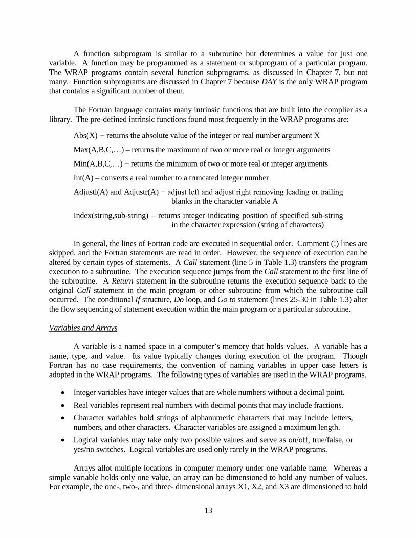
A function subprogram is similar to a subroutine but determines a value for just one variable. A function may be programmed as a statement or subprogram of a particular program. The WRAP programs contain several function subprograms, as discussed in Chapter 7, but not many. Function subprograms are discussed in Chapter 7 because DAY is the only WRAP program that contains a significant number of them. The Fortran language contains many intrinsic functions that are built into the complier as a library. The pre-defined intrinsic functions found most frequently in the WRAP programs are:
Abs(X) − returns the absolute value of the integer or real number argument X
Max(A,B,C,…) – returns the maximum of two or more real or integer arguments
Min(A,B,C,…) − returns the minimum of two or more real or integer arguments
Int(A) – converts a real number to a truncated integer number
Adjustl(A) and Adjustr(A) − adjust left and adjust right removing leading or trailing blanks in the character variable A
Index(string,sub-string) – returns integer indicating position of specified sub-string in the character expression (string of characters)
In general, the lines of Fortran code are executed in sequential order. Comment (!) lines are
skipped, and the Fortran statements are read in order. However, the sequence of execution can be altered by certain types of statements. A Call statement (line 5 in Table 1.3) transfers the program execution to a subroutine. The execution sequence jumps from the Call statement to the first line of the subroutine. A Return statement in the subroutine returns the execution sequence back to the original Call statement in the main program or other subroutine from which the subroutine call occurred. The conditional If structure, Do loop, and Go to statement (lines 25-30 in Table 1.3) alter the flow sequencing of statement execution within the main program or a particular subroutine. Variables and Arrays A variable is a named space in a computer’s memory that holds values. A variable has a name, type, and value. Its value typically changes during execution of the program. Though Fortran has no case requirements, the convention of naming variables in upper case letters is adopted in the WRAP programs. The following types of variables are used in the WRAP programs.
• Integer variables have integer values that are whole numbers without a decimal point. • Real variables represent real numbers with decimal points that may include fractions. • Character variables hold strings of alphanumeric characters that may include letters,
numbers, and other characters. Character variables are assigned a maximum length. • Logical variables may take only two possible values and serve as on/off, true/false, or
yes/no switches. Logical variables are used only rarely in the WRAP programs. Arrays allot multiple locations in computer memory under one variable name. Whereas a simple variable holds only one value, an array can be dimensioned to hold any number of values. For example, the one-, two-, and three- dimensional arrays X1, X2, and X3 are dimensioned to hold

14
ten, one-hundred, and one-thousand values, respectively, by the following Fortran statement, where X1(I), X2(I,J), and X3(I,J,K) are real numbers with integer indices I, J, and K defining the elements of the arrays.
Real X1(10), X2(10,10), X3(10,10,10) The Integer, Real, and Character statements shown as lines 10, 11, and 12 in Table 1.3 are used to assign a type to each variable, including both arrays and simple single variables. Character variables are assigned a maximum length as well as type. For example, the statements
Character(len=6) CPID, RESID Integer CP,K,L,M,YR
defines CPID and RESID as character variables with lengths that cannot exceed six characters and denotes the five variables CP, K, L, M, and YR are being integers.
The Integer, Real, and Character statements may also be used to dimension arrays of a fixed size such as:
Real X(12), Y(3000,12), Z(5,5,2)
where the one dimensional array X contains 12 real numbers and the two-dimensional and three-dimensional arrays Y and Z contain 36,000, and 50 real numbers. However, dynamic dimensioning and allocation is applied to most of the arrays in the WRAP programs. Dynamic dimensioning statements illustrated by lines 13, 14, and 15 of Table 1.3 assign arrays a type (integer, real, or character) and also indicate whether the arrays are one, two, or three dimensional. The arrays are also defined as being allocatable, meaning the actual size will be assigned later by an Allocate (line 16) statement. The Allocate statement assigns memory for a certain array size. In the WRAP programs, most of the arrays are first declared and then later allocated after reading input files that provide information regarding how large the arrays should be. This dynamic dimensioning allows memory requirements to vary depending on the size of the input dataset. Arrays can optionally also be deallocated (line 17) if no longer needed. The variables are declared in Real, Integer, and Character statements in Module COMVAR or at the beginning of the main program or a subroutine. In the WRAP programs, variables that are used only in the main program or a particular subroutine are declared at the beginning of the main program or subroutine. Variables used in two or more subprograms are declared in Module COMVAR. A Use statement (line 4 in Table 1.3) is placed at the beginning of the main program and subroutines to access variables declared in Module COMVAR. Reading and Writing Files Input data are read from files, and simulation results are written to files. Each file is activated with an Open statement (line 18). Existing files are accessed, and new files are created in accordance with specifications in their Open statements. A unit number is assigned to each file by its Open statement. The unit is an integer identifier referenced by Read and Write statements (lines 19-22). Read and Write statements specify the unit number of the file and the statement number of the Format statement (line 23) that provides format specifications in parenthesis followed by a list of variables to be read from or written to the file. Files may be either sequential (lines 19 and 20) or direct access (lines 21 and 22) as specified by their Open statements (line 18 of Table 1.3).

15
Most of the WRAP files are read or written sequentially beginning with the first line of the file and proceeding downward like reading a book. Backspace statements (line 9 of Table 1.3) are used to backup to the preceding record (line of data) of a sequential file. A Rewind statement takes the flow sequencing back to the beginning of the file.
The simulation programs also create direct access output files that are read by the program TABLES. With direct access, the file record is specified as a third parameter in the Read or Write statement (lines 21 and 22). The program computes or assigns the record number of the record to be read or written. Files consist of records or lines of data. If values scattered throughout the file are to be read, direct access files can be more efficient than sequential files. The Format statement specifies the format in which each variable is to be read or written. Alternative formats are shown below, with the field width w representing the maximum number of characters in the field. A Format statement for a Write statement may also include any expression enclosed within quotations that will be reproduced verbatim in the output file. Aw − Alphanumeric label in a field that is w characters wide. For example, a character
variable with the format A6 is limited to a maximum of 6 characters.
wX − Fields with the spacing descriptor X are not read or written. 3x skips 3 spaces.
Fw.d − Real number with maximum of w characters. With a Read statement, there can be any number of digits d to the right of the decimal as long as the entire number including the decimal does not exceed w digits. Thus, the d in Fw.d is usually specified as zero for read statements. With a Write statement, the format Fw.d specifies d digits to the right of the decimal. For example, F8.2 specifies a maximum of 8 characters with 2 digits to the right of the decimal. The format specification 12F8.2 is for 12 real numbers with each having a F8.2 specification.
Iw − Integer number with a maximum of w digits. Decimal is not allowed. For example, an I8 format is for an integer with up to 8 digits, and 3I8 means three such integers.
The type statement and format specification for a character variable include a maximum limit on the number of characters that many be contained in values for the variable. For values with less than the maximum number of characters, leading or trailing blanks can be removed with the Fortran function statements Adjustl and Adjustr (adjust left or adjust right). Most of the Read statements in the WRAP programs contain the optional IOSTAT Fortran error check. Several Read statements contain the End command. The following example Read statement reads values for the real variables X, Y, and Z from a file identified as unit number 3.
Read(3,20,IOSTAT=STATUS,End=100) X,Y,Z 20 Format(3F8.0)
As discussed in Chapter 8 of the Reference Manual, the optional Fortran IOSTAT feature checks for problems in input data files. Integer values are assigned to the variable STATUS by the IOSTAT error check. A zero means that X, Y, and Z were read from unit 3 with no problems encountered. An IOSTAT code of 64 assigned to STATUS means data are not in the correct format

16
(3F8.0). Other IOSTAT codes are noted in Reference Manual Chapter 7. The WRAP programs call Subroutine ERROR whenever IOSTAT errors or other types of input data errors are encountered. An End command (line 8 in Table 1.3) transfers control to the statement specified if the end of the file is reached without finding the data. In this example, the program goes to the statement with statement number 100 if the end of the file is reached when attempting to read X, Y, and Z. Arithmetic Operations The Fortran assignment statement sets the variable on the left of an equal sign equal to the expression on the right of the equal sign. The left side of the equal sign must be a variable to which an initial or updated value is assigned. The fundamental concept of the Fortran assignment statement is different from the concept of solving an equation in normal algebra in that the values of a variable may be updated by an expression that contains that same variable. For example, consider the following Fortran assignment statements in which the integer variable I is assigned a value equal to the previous value of I plus one, and the real number X is assigned a value equal to two times the absolute value of its previous value plus the product of 5.8 times Y.
I = I + 1
X = 2.0*Abs(X)+5.8*Y The function Abs(X) takes the absolute value of X. The five arithmetic operators in Fortran are equivalent to normal arithmetic.
+ addition − subtraction / division * multiplication ** exponentiation Control Structures Several types of control structures are shown in Table 1.3. The conditional If statements shown in line 24 and lines 25-27 execute statements only if specified conditions are met. A Do loop repeats a set of statements a specified number of times. The Goto statement circumvents the normal sequential execution by jumping to some other specified statement. The conditional If statement is illustrated by the following example. If (X.GT.0.0.and.Y.GT.0.0) Then Y=X/Y J=J+1 Endif If X and Y are both greater than 0.0, then Y is X divided by Y and J = J+1. Any number of conditions separated by .and. or .or. can be specified using the following conditional operators. .EQ. equal .NE. not equal .GE. greater than or equal .LE. less than or equal .GT. greater than .LT. less than
17
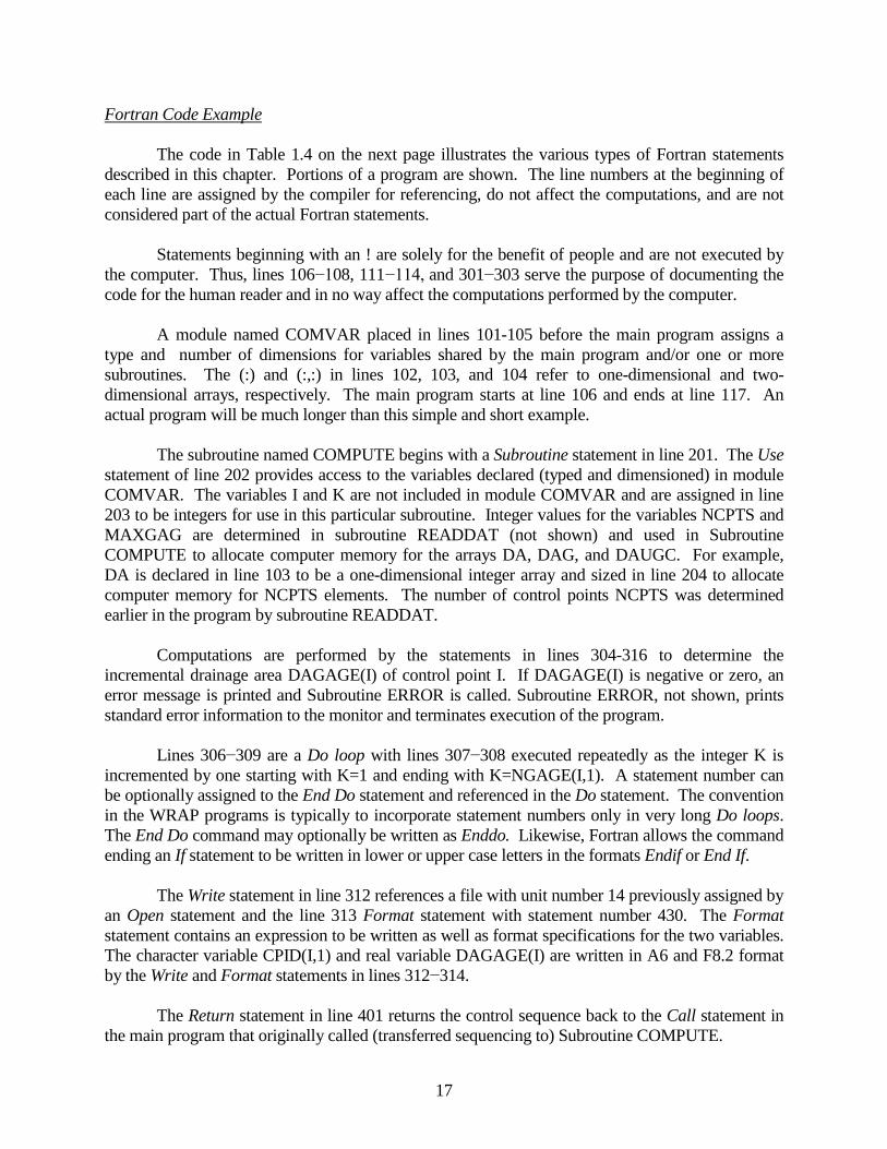
Fortran Code Example The code in Table 1.4 on the next page illustrates the various types of Fortran statements described in this chapter. Portions of a program are shown. The line numbers at the beginning of each line are assigned by the compiler for referencing, do not affect the computations, and are not considered part of the actual Fortran statements. Statements beginning with an ! are solely for the benefit of people and are not executed by the computer. Thus, lines 106−108, 111−114, and 301−303 serve the purpose of documenting the code for the human reader and in no way affect the computations performed by the computer. A module named COMVAR placed in lines 101-105 before the main program assigns a type and number of dimensions for variables shared by the main program and/or one or more subroutines. The (:) and (:,:) in lines 102, 103, and 104 refer to one-dimensional and two-dimensional arrays, respectively. The main program starts at line 106 and ends at line 117. An actual program will be much longer than this simple and short example.
The subroutine named COMPUTE begins with a Subroutine statement in line 201. The Use statement of line 202 provides access to the variables declared (typed and dimensioned) in module COMVAR. The variables I and K are not included in module COMVAR and are assigned in line 203 to be integers for use in this particular subroutine. Integer values for the variables NCPTS and MAXGAG are determined in subroutine READDAT (not shown) and used in Subroutine COMPUTE to allocate computer memory for the arrays DA, DAG, and DAUGC. For example, DA is declared in line 103 to be a one-dimensional integer array and sized in line 204 to allocate computer memory for NCPTS elements. The number of control points NCPTS was determined earlier in the program by subroutine READDAT. Computations are performed by the statements in lines 304-316 to determine the incremental drainage area DAGAGE(I) of control point I. If DAGAGE(I) is negative or zero, an error message is printed and Subroutine ERROR is called. Subroutine ERROR, not shown, prints standard error information to the monitor and terminates execution of the program. Lines 306−309 are a Do loop with lines 307−308 executed repeatedly as the integer K is incremented by one starting with K=1 and ending with K=NGAGE(I,1). A statement number can be optionally assigned to the End Do statement and referenced in the Do statement. The convention in the WRAP programs is typically to incorporate statement numbers only in very long Do loops. The End Do command may optionally be written as Enddo. Likewise, Fortran allows the command ending an If statement to be written in lower or upper case letters in the formats Endif or End If. The Write statement in line 312 references a file with unit number 14 previously assigned by an Open statement and the line 313 Format statement with statement number 430. The Format statement contains an expression to be written as well as format specifications for the two variables. The character variable CPID(I,1) and real variable DAGAGE(I) are written in A6 and F8.2 format by the Write and Format statements in lines 312−314.
The Return statement in line 401 returns the control sequence back to the Call statement in the main program that originally called (transferred sequencing to) Subroutine COMPUTE.

18
Table 1.4 Fortran Example
101 Module COMVAR 102 Integer NCPTS, MAXGAG 103 Real,Allocatable,Dimension(:)::DA 104 Real,Allocatable,Dimension(:,:)::DAG,DAUGC 105 End Module COMVAR 106 ! 107 ! Main program of Program EXAMPLE 108 ! 109 Program EXAMPLE 110 Use COMVAR 111 ! 112 ! Subroutines READDAT and COMPUTE are called to read an 113 ! input file and to perform certain computations. 114 ! 115 Call READDAT 116 Call COMPUTE
Other statements are omitted here.
117 End Program EXAMPLE
The beginning and end along with one other portion of Subroutine COMPUTE are shown.
201 Subroutine EXAMPLE 202 Use COMVAR 203 Integer I,K 204 Allocate(DA(NCPTS),DAG(NCPTS,MAXGAG),DAUGC(NCPTS,MAXGAG))
Other statements are omitted here.
301 ! 302 ! Incremental drainage area above gaged control point. 303 ! 304 DAGAGE(I)=DA(IDSG(I)) 305 If(NGAGE(I,1).GE.1) Then 306 Do K=1,NGAGE(I,1) 307 DAG(I,K)=DA(IGAGE(I,K)) 308 DAGAGE(I)=DAGAGE(I)-DAG(I,K) 309 End Do 310 Endif 311 If(DAGAGE(I).LE.0.0) Then 312 Write(14,430) CPID(I,1),DAGAGE(I) 313 430 Format(' ERROR: The incremental drainage area for CP ', 314 + A6,' is zero or negative:',F8.2) 315 Call ERROR 316 Endif
Other statements are omitted here.
401 Return 402 End Subroutine COMPUTE
SIM
Chapter 2 SIM
19
CHAPTER 2 SIM This chapter provides information to facilitate reading and understanding the Fortran program SIM. The organization of the program is outlined, and the purposes of each component are described. Input and output files are listed in Table 2.1. The list of variable definitions provided later in the chapter is essential information for anyone interested in deciphering the code. The chapter is essential to programmers working on improving or expanding the code. Examining the code can also be beneficial in enhancing understanding of SIM from an applications perspective. The Reference and Users Manuals provide information needed to apply the WRAP programs SIM, HYD, and TABLES. This Programming Manual supplements these manuals from the perspective of understanding the Fortran source code from which the executable programs are compiled. This chapter assumes a familiarity with pertinent information from these other manuals.
Water Rights Analysis Package (WRAP) Modeling System Reference Manual, TR-255, 9th Edition, Texas Water Resources Institute, August 2012.
Water Rights Analysis Package (WRAP) Modeling System Users Manual, TR-256, 9th Edition, Texas Water Resources Institute, August 2012.
SIM capabilities and methodologies are described in Chapters 2 and 3 of the Users Manual and throughout the Reference Manual. The SIM input variables are defined in Chapter 3 of the Users Manual in greater detail than here in the Programmers Manual. The variables included in the simulation results are described in detail in Chapter 5 of the Reference Manual.
Organization of SIM Module COMVAR located at the beginning of the program specifies the type and array shape for variables used in common by the main program and subroutines. Subroutine READDAT is called by the main program to read the DAT file. Subroutine READDAT reads the DAT file twice. The first time is to count records and read parameters needed to set dimension limits. After setting dimension limits, the DAT file is read a second time to actually read all of the data. Various tasks are performed within Subroutine READDAT to organize the data. The other input data files are read by other subroutines either before or at the beginning of the annual loop. The simulation computations are organized around nested annual, monthly, and water rights loops shown in Figure 2.1. Certain computations are performed within the main program. Simulation results are written from the main program. The subroutines perform specific computational and data management tasks. The majority of the subroutines are called one or more times from the main program. Subroutines are also called by other subroutines. Within the water rights loop, the computations may be repeated a second time as specified by the instream flow IF record parameter IFMETH. The entire simulation may be repeated a second time by the dual simulation options activated by the JO, SO or PX records. The simulation may be repeated a second time with beginning storages set equal to ending storages if certain BES options are activated by the JO record. Certain CR record conditional reliability modeling options involve cycling through the annual and monthly loops multiple times. The simulation may be repeated many times to perform a yield–reliability analysis as specified by the FY record.

SIM
Chapter 2 SIM 20
• Input data are read and organized and files are opened. - DAT and MSS files are opened (activated) by Subroutine FILES1. - DAT file record counts are performed and array dimensions are set by Subroutine READDAT. - Subroutine READDAT reads the DAT file which includes all input except that related to hydrology. - Various input data manipulations are performed by Subroutine READDAT. - Pertinent optional files are selected and opened by Subroutine FILES2. - Dimensions for some arrays are set in main program after Subroutine READDAT has finished. - Watershed parameters are read and organized by Subroutine IACNP for use by Subroutine FLDIST. - IN and EV records may be read by Subroutine INEV1 depending on parameter INEV on JO record. - Water rights are ranked in priority order by Subroutine RANKWR or Subroutine NATURAL.
• Yield-reliability analysis (FY record), beginning-ending-storage options (JO record), and dual simulation options (SO or PX record) involve iterative repetition of the entire simulation outlined below.
• Annual Loop Repeated for Each Year of Simulation ──────────────────────────│ │ - IN and EV records are read by Subroutine INEVYR or the flow array previously read by │ Subroutine INEV1 is accessed by Subroutine INEV2 depending on JO record INEV option. │ - Flows are distributed from gaged to ungaged sites by Subroutine FLDIST. │ - Net evaporation-precipitation adjustments may also be performed by Subroutine FLDIST. │ - Flows are adjusted by adjustments from FAD file by Subroutine FLOWADJ. │ - Incremental negative inflow adjustment array is developed by Subroutine INCREM. │ - Flows for January are adjusted for return flows from prior December within main program. │ │
• Monthly Loop Repeated for Each Month of Simulation * * * * * * * * * * * * * * * * * * * * * * │ * │ - Spills associated with monthly varying storage capacity option within main program. * │ - Flow adjustments for CI record constant inflows within main program. * │ * │
• Water Right Loop Repeated for Each Right in Priority Order + + + + + + + + + + + + + + + + * │ (First and second pass through loop for IF record dual-pass instream flow options) + * │
+ * │ 1. The diversion, instream flow, or hydropower target is set within main program + * │ based on options specified by WR, IF, SO, TO, TS, FS, WS, and HP records. + * │ 2. The amount of water available to right is determined by Subroutine AVALB. + * │ (Channel losses are considered in checking flows.) + * │ 3. Diversions, reservoir releases, and return flows are determined in main program + * │ along with Subroutine RESCAL iterative reservoir water balance computations + * │ and Subroutine POWER iterative hydropower computations. + * │ 4. Available streamflow at all control points is adjusted by Subroutine ADJUST. + * │ (Channel losses are considered in adjusting available flows.) + * │ Water right output records are developed and written to OUT file. + + + + + + + + + + + + + * │
* │ • Control point and reservoir output records are developed and written to OUT file. * * * * * * * * │ ───────────────────────────────────────── ─────────────────│
• Simulation results may be written to optional DSS and SOU output files at the end of the simulation from DSSWR, DSSCP, and DSSRE arrays developed during the water rights and monthly loops.
Figure 2.1 Outline of SIM Simulation

SIM
Chapter 2 SIM
21
SIM Simulation Input/Output and Computation Tasks The SIM simulation process is outlined in Figure 2.1. The simulation is organized and controlled within the Main Program. Many computations are performed by the Main Program, and many are performed by the subroutines. Simulation results are written to files by the Main Program. SIM data management and computational algorithms proceed through the following tasks. At the beginning of the simulation, the Main Program calls Subroutines FILES1, READDAT, and FILES2 as follows. Subroutine FILES1 conducts an interactive session to assign filenames and opens the DAT and MSS files. Subroutine READDAT performs an initial abbreviated pass through the DAT file to obtain information needed to allocate array sizes and determine which files to open. Arrays are allocated in both Subroutine READDAT and the Main Program. Subroutine FILES2 opens the remaining files. Subroutine READDAT is organized by input record type, reading the records sequentially from the DAT file. Subroutine READDAT is called once but reads the DAT file twice. As noted in the preceding paragraph, the initial pass through the DAT file is to count the number of various types of records and read parameters needed to set dimension limits and determine files to be opened. READDAT performs a second pass through the DAT file to actually read all of the data. Various manipulations are performed to organize the data in preparation for the simulation. Either Subroutine RANKWR (rank water rights) or Subroutine NATURAL (natural priority option) develops the array RANK(WR) where WR = 1, 2, 3, to NWRTS in ranked order and RANK(WR) is the order in which the rights are read from the DAT file. NWRTS is the total number of water rights (WR and IF records) counted by Subroutine READDAT. RANK(WR) equals 1 for the first right read and NWRTS for the last right read. With the Subroutine RANKWR priority ranking system, WR = 1 refers to the most senior right in the model, and WR = NWRTS refers to the most junior right. Subroutine IACNP (Incremental Area, Curve Number, and Precipitation) reads the DIS file which contains the flow distribution FD, coefficient FC, and watershed parameter WP records. Incremental watershed areas, curve numbers, and mean precipitation are determined. The watershed parameters read and organized by Subroutine IACNP are used later by Subroutine FLDIST to distribute naturalized flows from primary to secondary control points. As shown in Figure 2.1, the simulation computations are performed within a water rights priority loop that is embedded within a monthly loop, nested within an annual loop. The loops are controlled by the Main Program with subroutines being called to perform specific tasks. At the beginning of the annual loop, for JO record INEV options 1, 3, and 5, Subroutine INEVYR reads the IN and EV records (inflows and evaporation-precipitation depths) for all control points for that year from either INF and EVA files (units 1 and 2), the DAT file (unit 3), or a HYD file (unit 12). Subroutine INEVYR performs various manipulations to organize the naturalized stream flows [INFLOWS(cp,mt)] and evaporation–precipitation rates [EVAPR(cp,mt)] including placing them in the same order as the CP records. With JO record INEV options 2 and 4, Subroutine INEV1 reads all of the IN and EV records prior to the beginning of the annual loop. With JO record INEV option 6, Subroutine DSSINPUT reads all of the flows and net evaporation

SIM
Chapter 2 SIM 22
depths prior to the beginning of the annual loop. Within the annual loop, Subroutine INEV2 determines naturalized flows and net evaporation depths for the year from an array previously created by either Subroutine INEV1 or Subroutine DSSINPUT. Subroutine FLDIST (flow distribution) distributes flows [INFLOWS(cp,mt)] from known–flow [INMETHOD(cp)=1] to unknown flow [INMETHOD(cp)>2] control points. Subroutine FLDIST also optionally adjusts net evaporation–precipitation depths [EVAPR(cp,mt)] for the runoff from land covered by reservoirs which is conceptually already reflected in naturalized flows. If pertinent negative incremental inflow adjustment options are specified, the Main Program calls Subroutine INCREM (incremental naturalized flows) to develop a flow adjustment array [CPFLOW(cp,mt,1)] which is applied later in the simulation. The flows at secondary control points synthesized by Subroutine FLDIST optionally may be included or excluded in the negative incremental flow adjustments. The water management/use simulation computations are then performed within the water rights priority loop nested within the monthly loop. In each month, for each water right in priority sequence:
1. the target amount [AMT] is set, 2. water availability [AVAIL] is determined based on flows [CPFLOW(cp,mt,2)]
at its control point and all downstream control points, 3. water allocation computations are performed to meet the target, and 4. flows [CPFLOW(cp,mt,2)] are adjusted at that and all downstream control
points for the effects of the water right.
The repetitive loops are controlled within the Main Program. The subroutines cited in the next paragraph are called by the Main Program and by each other to perform specific computations. Reservoir operation and hydropower computations are performed in the Main Program and Subroutines RELEASE, RESCAL, and POWER. The Main Program organizes the computational procedures based on the water right type specified on the WR record. Subroutine RELEASE is called for multiple-reservoir system rights to determine releases following multiple-reservoir operating rules defined by WS and OR records. Subroutine POWER is called for hydropower computations. The Main Program and Subroutines RELEASE and POWER call Subroutine RESCAL to perform reservoir calculations. Subroutine RESCAL computes end-of-month storage, net evaporation, and outflow volumes for each water right that has reservoir storage. Evaporation volume is calculated as a function of end-of-month storage. Vice versa, end-of-month storage depends upon evaporation. Outflow volume during the month depends on both storage and evaporation which depend on outflow. Thus, an iterative algorithm is required. A minimum of two iterations is always performed. The algorithm stops at a maximum of 50 iterations if the stop criteria are not satisfied. These criteria are that the difference in end-of-month storage volume between two successive iterations be less than the minimum of 0.1 unit (such as acre-foot) or 0.01 percent of the storage volume. Subroutine RESCAL performs computations for one reservoir. Multiple-reservoir release decisions are made within Subroutine RELEASE, which calls Subroutine RESCAL one or multiple times as each system water right is considered.

SIM
Chapter 2 SIM
23
Hydroelectric energy production depends upon both discharge and head. Discharge through the hydropower turbines is a function of releases by this and prior water rights. Head is a function of storage contents. However, storage volume is a function of hydropower releases as well as net evaporation. Thus, Subroutine POWER implements an iterative hydropower algorithm which, for given iteratively changing outflows, calls the iterative Subroutine RESCAL. Thus, an iterative reservoir calculation algorithm is embedded within an iterative hydropower release algorithm. Options on the IF record for instream flow computations may cause a second pass through the water rights loop. The second pass occurs if (a) the second–pass instream flow option is used and (b) instream flow targets are not met in a particular month. The JO record PASS2 parameter provides an option that activates the second pass in all months regardless. The output is written from the Main Program. At the end of the water rights loop, data listed in Table 5.3 of the Reference Manual are written to the OUT file (unit 4). The optional HRR file (unit 13) is also written. If the optional ZZ record feature is activated, subroutine ZZFLOW records flows in a ZZZ file (unit 17) at the end of the water rights loop. Data listed in Tables 5.4 and 5.5 of the Reference Manual are written to the OUT file (unit 4) at the end of the monthly loop. With the optional output file OF record options in effect, the simulation results are stored in the three-dimensional arrays DSSCP, DSSWR, and DSSRE and written to the SOU (unit 10) and/or DSS (unit 26) files at the completion of the simulation. Since these arrays may be relatively large, computer memory requirements may be dramatically increased with these options. The simulation may be automatically repeated by beginning–ending storage options activated by the JO record field 5 or by dual simulation options activated by PX record field 2 or SO record field 14. The simulation is repeated any number of times to perform a yield–reliability analysis activated by the FY record, with results written to the YRO file at the completion of each iteration. BES, dual simulation, and yield–analysis iterations are managed by the Main Program. The conditional reliability modeling features activated by the CR record are described in Chapter 7 of the Reference Manual. The hydrologic simulation period is subdivided into multiple short simulation periods, using optional organization strategies controlled by parameters on the CR record. Simulation results are written to a CRM file rather than the conventional OUT file.
Input and Output Files SIM input and output files are listed in Table 2.1. The required DAT and MSS files are opened in Subroutine FILES1. The two DSS files are opened in Subroutines DSSINPUT and DSSOUT. All other files are opened in Subroutine FILES2.
The hydrology input file with filename rootHYD.DSS and the output file root.DSS are binary files designed for the Hydrologic Engineering Center (HEC) Data Storage System (DSS). The OUT and CRM files are written as text files by default but optionally (JD record field 7) can be written as an unformatted binary file designed to be read only by TABLES. All other SIM files are text files. The OUT and CRM files are direct access, and all others are sequential. Either an OUT or CRM file is activated but not both. Unit 4 is assigned to the OUT or CRM file.

SIM
Chapter 2 SIM 24
Table 2.1 SIM Input and Output Files
Filename Input or Feature Indicating
Unit Extension Output Activation of File File Contents 1 FLO input JO record INEV, F1 IN records with stream inflows 2 EVA input JO record INEV, F2 EV records with net evap depths 3 DAT input required main input file 4 OUT output CR record CR1 = 0 simulation results 4 CRM output CR record CR1 > 0 CRM simulation results 8 DIS input FD record, F3 FD, FC, WP records 10 SOU output OF record DSS(2) = 1 simulation results 11 YRO output FY record, F8 yield–reliability output table 12 HYD input JO record INEV, F4 IN and EV records 13 HRR output JO record SYSOUT, F7 hydropower & reservoir releases 14 MSS output required error and trace messages 15 BES output/input JO record BES, F9 beginning–ending storage 16 BRS output JO record BRS = 1 beginning reservoir storage 17 ZZZ output ZZ record priority sequence flows 18 RUF input RU record regulated-unappropriated adjust 19 HIS input HI record index sequence on HI records 21 FAD input JO record FAD, F5 FA records with flow adjustments 25 DSS input OF record DSS(5) = 1 naturalized flows and net evap 26 DSS output OF record DSS(3) = 1 simulation results
The first column of Table 2.1 lists the unit numbers which are assigned in Open statements and referenced in Read and Write statements. For example, the following statement reads input values for variables X, Y, and Z from the DAT file which has been opened as unit 3. Read (3,160) X, Y, Z 160 Format (3F8.0)
Files are referenced by the filename extensions listed in the second column of Table 2.1. The last two columns show the parameters that activate the files and describe contents of the files.
Subroutines
Program SIM consists of a module named COMVAR (lines 14−99), the main program (lines 100−4,058), and 33 subroutines (lines 4,059−14,845). Module COMVAR (COMmon VARiables) located at the beginning of the program specifies the type and array shape for variables used in common by two or more subprograms (main program and subroutines). The main program follows module COMVAR. The 33 subroutines follow after the main program. Module COMVAR combined with Use COMVAR statements is the primary means of transferring the values of variables determined in one subprogram module (main program or

SIM
Chapter 2 SIM
25
subroutine) to one or more other modules. The alternative approach used occasionally is to list variables in parenthesis as arguments in the Call and Subroutine statements. For example, a subroutine Call statement from Subroutine CURNUM is reproduced below along with the first statement in Subroutine BISECT.
Call BISECT(S1,Q1,P) Subroutine BISECT(S1,Q,XR) Values for the variables S1=S1, Q=Q1, and XR=P are passed between Subroutines CURNUM and BISECT. Variables can not be passed thusly and also be included in Module COMVAR. Six of the 32 subroutines adopt this approach with certain variables to be transferred listed in parenthesis following the subroutine name. The other 26 subroutines rely solely upon Module COMVAR.
The 33 subroutines are listed below in the same order in which they are found in the code. ERROR – Called in conjunction with error messages by the main program and all subroutines
that contain error checks. A standard error message is written to the monitor, and execution of the program is terminated. (lines 4059−4102)
FILES1 – Called by main program to write banner to the monitor and open the DAT and MSS files. Subroutine CHECK is called as each file is opened. Parameters controlling opening of other files later by Subroutine FILES2 are initialized. (lines 4103−4172)
FILES2 – Called by main program after reading of DAT file to open all files except the DAT and MSS files which are already opened by Subroutine FILES1 and DSS files which are opened by Subroutines DSSINPUT and DSSOUT. Parameters read by Subroutine READDAT from DAT file JO, OF, CR, and FY records control which files to open. The dimension limit MAXGAG is set if DIS file is opened. Subroutine check is called as each file is opened. (lines 4173−4398)
CHECK – Called by Subroutines FILES1 and FILES2 to check whether input and output files exist and write messages to monitor as appropriate. (lines 4399−4485)
READDAT – Called by main program to read and organize the input data from the DAT file. Reads all data except for the data in the hydrology files, which means reading all records except IN, EV, FD, FC, WP, FA, RU records. An abbreviated initial reading of the DAT file provides information required to set dimension limits for arrays. All of the information in the DAT files is then read and organized during a second reading. The subroutine is organized by type of input record. (lines 4486−9021)
DROUGHT – Called by main program to compute the drought index as a function of reservoir storage for water rights associated with DI/IS/IP input records. (lines 9022−9120)
CONFLU(K) – Called by Subroutine READDAT to determine the first downstream control point common to a water right and secondary reservoir and to specify whether reservoir releases are limited to diversions at downstream locations. The argument K is the integer water right identifier. (lines 9121−9175
RANKWR – Called by main program to develop the array RANK(WR) which identifies the water rights in priority order. (lines 9176-9219)
NATURAL – Called by main program to develop the array RANK(WR) which identifies the water

SIM
Chapter 2 SIM 26
rights in ranked order from upstream to downstream, if natural priority option is activated by JO record parameter NPOPT. (lines 9220−9314)
INEVYR – Called by main program within the annual loop to read the stream flow IN and evaporation EV records grouped by years and arrange the data in the same order as the control points for JO record INEV options 1, 3, and 5. (lines 9315−9825)
INEV1 – Called by main program for JO record INEV options 2 and 4 before annual loop to read the stream flow IN and evaporation EV records grouped by control points and arrange the data array in the same order as the control points. (lines 9826−10103)
INEV2 – Called by main program for JO record INEV options 2, 4, and 6 within the annual loop to assign the stream flow and evaporation data for the year from the array created by Subroutine INEV1. (lines 10104−10241)
DSSINPUT – Called by main program to read the file rootHYD.DSS if specified by JO record INEV option 6 or to create the file rootHYD.DSS if specified by OF record DSS(5). (lines 10242−10595)
DSSOUT – Called by main program to write simulation results to a DSS file at the completion of the simulation if specified by OF record parameters. (lines 10596−10926)
SIMOUT – Called by main program to write simulation results to a SOU file at the completion of the simulation if specified by OF record parameters. (lines 10927−11404)
INCREM – Called by main program to determine negative incremental stream flows and to adjust the flows in accordance with the JD record ADJINC option. (11145−11357)
AVALB – Called by main program to determine the amount of stream flow available for each water right for all negative incremental flow options except option 5. (lines 11405−11669)
AVALB_2 – Called by main program to determine the amount of stream flow available for each water right for negative incremental flow option 5. (lines 11670−11899)
RELEASE – Called by main program to determine releases from secondary reservoirs for system water rights. (lines 11900−12217)
ADJUST – Called by main program to reduce and increase the available streamflow at a control point and all downstream control points by the streamflow depletion and return flow, respectively. (lines 12218−12361)
CUMREL(LOC,REL) – Called by Subroutine RELEASE to accumulate releases from secondary reservoirs to downstream water rights. Subroutine CUMREL is used by Subroutine RELEASE in release decisions that consider other reservoirs at locations preventing direct releases for a system water right. The arguments LOC and REL are the control point identifier and reservoir release volume. (lines 12362−12393)
RESCAL(IDNUM,LOSTOR,HISTOR,IN,OUT,ESY,EVAPY) – Called by main program and Subroutines RELEASE and POWER to perform the iterative calculations to determine reservoir net evaporation–precipitation and end–of–period storage volumes. The arguments are the reservoir integer identifier (IDNUM), cumulative storage capacity at the bottom and top of active pool (LOSTOR and HISTOR),

SIM
Chapter 2 SIM
27
reservoir inflow available to water right (IN), outflow required for right (OUT), end-of-month storage (ESY), and net evaporation (EVAPY). (lines 12394−12618)
LINEAR(GIVEN,YFIND,NUM,DUMMY) – Called by main program and Subroutines RESCAL, and POWER to perform linear interpolation of SV/SA, PV/PE, and TQ/TE record tables. The arguments are the given storage or flow volume (GIVEN), area or elevation to be computed by interpolation (YFIND), identifier of SV/SA, PV/PE, or TQ/TE record table, and the array of values in the table. (lines 12619−12702)
POWER – Called by main program to perform hydroelectric power calculations for hydropower (types 5 and 6) water rights. (lines 12703−13060)
FLOWADJ– Called by main program for JO record FAD option 1 to adjust naturalized stream flows by adding flows read from flow adjustment FA records in the FAD file. The flow adjustments are cascaded downstream accounting for channel losses. (lines 13061−13215)
FADFILE – Called by main program to read flow adjustment FA records from FAD file for JO record FAD options 2 and 3. The flows are adjusted in the main program along with CI record constant inflows with cascading downstream accounting for channel losses. (lines 13216−13475)
IACNP – Called by main program to read the flow distribution DIS file and determine the parameters (drainage area, CN, mean precipitation) for the total and/or incremental watersheds which are used by Subroutine FLDIST. (lines 13476−14026)
FLDIST – Called by main program to distribute flows from gaged (known flow) to ungaged (unknown flow) control points. FLDIST also has a reservoir evaporation–precipitation rate adjustment routine. (lines 14027−14376)
CURNUM(DA1,CN1,MP1,DA2,CN2,MP2) – Called by Subroutine FLDIST to transfer naturalized flows from gaged to ungaged control points using the modified NRCS curve number CN method based on the parameters drainage area (DA1 and DA2), curve number (CN1 and CN2), and mean precipitation (MP1 and MP2) for the gaged and ungaged watersheds. (lines 14377−14405)
BISECT(S1,Q,XR) – Called by Subroutine CURNUM to solve the NRCS curve number equation for P given Q using the iterative bisection method. The arguments are the retention parameter (S1), flow (Q), and precipitation (XR). (lines 14406−14551)
READRUF – Called by main program to read RU record adjustments from a RUF file to convert unappropriated to regulated flows in a condensed dataset. (lines 14452−14544)
ZZFLOW – Called by main program to develop a table of reservoir releases, regulated flows, and available flows as specified by the ZZ record. The flows are written to the ZZZ file during each month of the simulation at the beginning of the priority loop and after each water right is considered in the loop. (lines 14545−14670)
READHIS –Called by main program to read HI records from a HIS file to populate the
HIS(cp,yr,m) array that is used by FS, CV, and TO record operations controlled by FSI(FS,1) option 12 or TOTARGET option 16. (lines 14671−14845)

SIM
Chapter 2 SIM 28
HECLIB Subroutines The SIM subroutines DSSINPUT and DSSOUT include the following HEC-DSS Z statements that call the HEC-DSS subroutines from the Hydrologic Engineering Center static library HECLIB as discussed in Chapter 1.
ZSET − Sets DSS parameters. ZOPEN − Opens a DSS file. ZCLOSE − Closes a DSS file. ZPATH − Constructs a pathname. ZCHKPN − Checks a pathname. ZSRTS − Stores regular-interval time series data. ZRRTS − Retrieves regular-interval time series data.
Variables for Defining Array Sizes
The arrays in the Fortran code are assigned a type (integer, real, character, or logical) and shape (1, 2, or 3 dimensions) either in Module COMVAR or at the beginning of the main program or subroutines. Arrays shared by the main program and subroutines are listed in Module COMVAR and those used in only one subprogram module are listed at the beginning of that module. The arrays are declared allocatable. Dimension limits are assigned by Allocate statements after Subroutine READDAT performs a count of the different types of records and reads parameters as needed to determine the required array sizes. Most of the array dimension limits are set by the following variables, which are declared integers as the first statement of Module COMVAR. MAXCI – maximum number of control points with constant inflows from CI records (number
of CI records counted by Subroutine READDAT) MAXCP – maximum number of control points (number of CP records counted by READDAT) MAXDI – maximum number of drought indices (number of DI records counted by Subroutine
READDAT) MAXDU – maximum number of water rights with dual simulation options 3 or 4 activated
(based on dual simulation parameters on JO, SO, and PX records read by Subroutine READDAT)
MAXEA – maximum number of reservoirs with evaporation allocation (number of EA records counted by Subroutine READDAT)
MAXFS – maximum number of water rights with FS and CV record options activated (number of FS and CV records counted by Subroutine READDAT)
MAXFSP – maximum length in months of flow summation period for all rights with flow switch FS record or cumulative volume CV record options activated (maximum of FS or CV record FSI(FS,1) read by Subroutine READDAT)
MAXFY – maximum number of water rights associated with the yield in a FY record yield–reliability analysis (FY record)
MAXGAG – maximum number of upstream gages on the FD records in the flow distribution DIS input file (set by Subroutine FILES2 as maximum value for NG read from FD records field 4)

SIM
Chapter 2 SIM
29
MAXGP – maximum number of water rights on WO records, groups on GO records, or control points on CO records set by Subroutine READDAT as the maximum of number of either CO, WO or GO records divided by five
MAXML – maximum number of rights with monthly varying limits on streamflow depletions (number of ML records counted by Subroutine READDAT)
MAXMON – 12 months in a year MAXMS – maximum number of reservoirs with monthly varying storage capacities (number of
MS records counted by Subroutine READDAT) MAXOS – number of observed storage OS records as counted by Subroutine READDAT MAXOS – number of months for which storage capacity limits are provided on OS records
which is the number of months in the hydrologic period-of-analysis MAXPOW – maximum number of hydropower reservoirs (number of WR records with right types
5 or 6) MAXPX – maximum number of water rights with certain PX record options activated MAXRES – maximum number of reservoirs which may be more than the actual number of
reservoirs NRES (number of WS records) MAXRF – maximum number of sets of monthly varying return flow factors (number of RF
records counted by Subroutine READDAT) MAXRO – maximum number of reservoirs on RO records set by Subroutine READDAT as the
number of RO records divided by five MAXSWR – maximum number of system water rights set by Subroutine READDAT as the
number of rights that are not type 1 or are type 1 with more than one reservoir MAXSYS – maximum number of reservoirs associated with a system water right set by
Subroutine READDAT MAXTAB – maximum of the maximum number of storage–area tables (SV/SA records) and
maximum number of storage–elevation tables (PV/PE records) counted by Subroutine READDAT
MAXTO – maximum number of TO records plus backup rights on SO or BU records counted by Subroutine READDAT
MAXTS – maximum number of TS records set by Subroutine READDAT as NYRS from JD record
MAXTSWR – maximum number of water rights with TS records counted by Subroutine READDAT
MAXUSE – maximum number of use types defined by UC records plus defaults MAXWR – number of water rights (number of WR and IF records counted by Subroutine
READDAT) MAXWS – number of WS records counted by Subroutine READDAT. MAXRES is set equal
to MAXWS and used as a dimension limit (array size). Unlike the other variables listed above, MAXWS is used for other purposes with MAXRES being the maximum dimension limit.
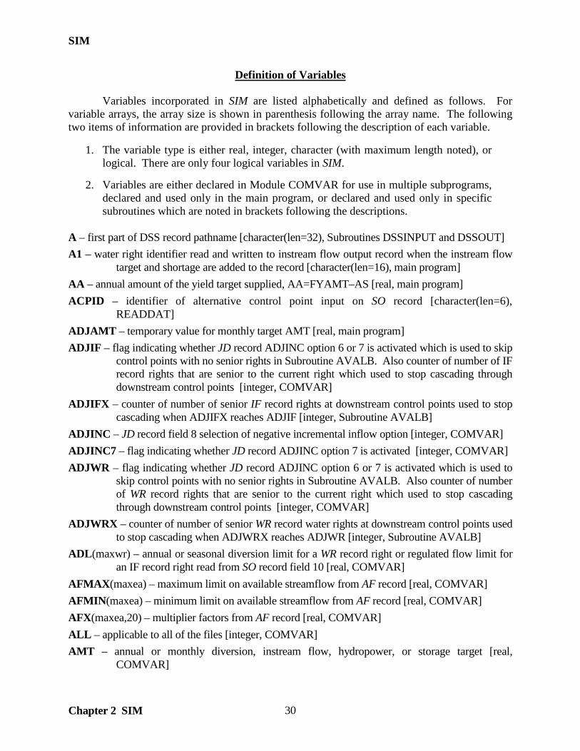
SIM
Chapter 2 SIM 30
Definition of Variables Variables incorporated in SIM are listed alphabetically and defined as follows. For variable arrays, the array size is shown in parenthesis following the array name. The following two items of information are provided in brackets following the description of each variable.
1. The variable type is either real, integer, character (with maximum length noted), or logical. There are only four logical variables in SIM.
2. Variables are either declared in Module COMVAR for use in multiple subprograms,
declared and used only in the main program, or declared and used only in specific subroutines which are noted in brackets following the descriptions.
A – first part of DSS record pathname [character(len=32), Subroutines DSSINPUT and DSSOUT] A1 – water right identifier read and written to instream flow output record when the instream flow
target and shortage are added to the record [character(len=16), main program] AA – annual amount of the yield target supplied, AA=FYAMT–AS [real, main program] ACPID – identifier of alternative control point input on SO record [character(len=6),
READDAT] ADJAMT – temporary value for monthly target AMT [real, main program] ADJIF – flag indicating whether JD record ADJINC option 6 or 7 is activated which is used to skip
control points with no senior rights in Subroutine AVALB. Also counter of number of IF record rights that are senior to the current right which used to stop cascading through downstream control points [integer, COMVAR]
ADJIFX – counter of number of senior IF record rights at downstream control points used to stop cascading when ADJIFX reaches ADJIF [integer, Subroutine AVALB]
ADJINC – JD record field 8 selection of negative incremental inflow option [integer, COMVAR] ADJINC7 – flag indicating whether JD record ADJINC option 7 is activated [integer, COMVAR] ADJWR – flag indicating whether JD record ADJINC option 6 or 7 is activated which is used to
skip control points with no senior rights in Subroutine AVALB. Also counter of number of WR record rights that are senior to the current right which used to stop cascading through downstream control points [integer, COMVAR]
ADJWRX – counter of number of senior WR record water rights at downstream control points used to stop cascading when ADJWRX reaches ADJWR [integer, Subroutine AVALB]
ADL(maxwr) – annual or seasonal diversion limit for a WR record right or regulated flow limit for an IF record right read from SO record field 10 [real, COMVAR]
AFMAX(maxea) – maximum limit on available streamflow from AF record [real, COMVAR] AFMIN(maxea) – minimum limit on available streamflow from AF record [real, COMVAR] AFX(maxea,20) – multiplier factors from AF record [real, COMVAR] ALL – applicable to all of the files [integer, COMVAR] AMT – annual or monthly diversion, instream flow, hydropower, or storage target [real,
COMVAR]

SIM
Chapter 2 SIM
31
AMT1, AMT2, AMT3, AMT4, AMT5, AMT6, AMT7, AMT8 – intermediate monthly target amounts written to output file as specified by ISHT(wr) from SO record field 9 [real, main program]
AMTIF(maxwr) – computed monthly instream flow target used to compute shortage IFSHORT [real, main program]
AMTRF – return flow amount computed for a type 4 water right [real, main program] ANNDEP(maxwr) – annual or seasonal streamflow depletion limit specified on SO record [real,
COMVAR] ANNDIV(maxwr) – cumulative streamflow depletion since first month of ANNDEP(wr)
accumulation season or year [real, main program] ANNREG(maxwr) – cumulative regulated flow since first month of ADL(wr) accumulation season
or year [real, main program] ANNRES(maxwr) – annual or seasonal accumulative amount withdrawn from reservoir;
accumulation of RESW(wr) constrained by ARW(wr) [real, main program] ANNWSD(maxwr) – annual or seasonal accumulative amount withdrawn from reservoir;
accumulation of WSD(wr) constrained by ADL(wr) [real, main program] AREAVE – average reservoir surface area [real, Subroutine RESCAL] ARRAYS(maxcp) – array of control point identifiers used in upstream-to-downstream sort [integer,
Subroutine NATURAL] ARW(maxwr) – annual limit on withdrawals from reservoir storage from SO record [real
COMVAR] AS – annual shortage computed in yield–reliability routine [real, main program] ASF – amount available from streamflow after reservoir evaporation–precipitation [real, main
program] AVAMT – available streamflow at a control point [real, COMVAR] AVFLAG – flag used in Subroutine AVALB to specify skipping certain computations.
AVFLAG=9 if Subroutine AVALB is called by Subroutine INCREM. AVFLAG=99 if final unappropriated flows are being determined at completion of water rights loop. [integer, COMVAR]
B – second part of DSS record pathname [character(len=32), Subroutines DSSINPUT and DSSOUT]
BACKUP – SO record entry specifying backup right [character(len=6), Subroutine READDAT] BEGIN – beginning of simulation reservoir storage from WS record [real, Subroutine READDAT] BEGSTO – beginning–of–period reservoir storage [real, Subroutine RESCAL] BES – beginning–ending storage option from JD record [integer, COMVAR] BESFLAG – flag indicating whether in first or second simulation for BES options 2, 3,4 and 5. For
BES options 4 and 5, BESFLAG is set at –9 for first simulation. For BES options 2 and 3, BESFLAG is set at –99 for first simulation. [integer, main program]
BESID – reservoir identifier used with BES file [character(len=6), main program] BPAREA – beginning–of–period reservoir surface area [real, Subroutines RESCAL, POWER]

SIM
Chapter 2 SIM 32
BPELEV – beginning–of–period reservoir surface elevation [real, Subroutine POWER] BPSTOR – beginning–of–period storage [real, main program] BRS – beginning reservoir storage switch from JO record field 6 [integer, COMVAR] BSFLAG – flag to set beginning of simulation storage contents only once [integer, main program] BSY – beginning–of–period storage [real, Subroutine RESCAL] BSZ – beginning–of–period storage [real, Subroutine POWER] BU – parameter from BU record specifying the step to set backup right [integer, READDAT] BUG(maxto) – backup right group identifier from BU record field 5 [character(len=8), COMVAR] BUGROUP – backup right group identifier from BU record field 5 [character(len=8), READDAT] BUID(maxto) – backup right identifier from BU record field 4 [character(len=16), READDAT] BUWR(maxto) – backup right identifier [integer, COMVAR] BUWRID – backup right identifier from BU record field 4 [character(len=16), READDAT] BUX(maxto) – multiplier factor from BU record [real, Subroutine READDAT] C – third part of DSS record pathname [character(len=32), Subroutines DSSINPUT and DSSOUT] CD – record identifier [character(len=2), COMVAR] CDATE – starting date of time series in DSS file [character(len=9), Subroutines DSSINPUT and
DSSOUT] CHANGE – checks current pass through control point system to check if an accumulated negative
incremental has changed from previous pass [logical, Subroutine INCREM] CHCKST – flag enabling release decisions to be made with either end–of–period or beginning–of–
period storage [integer, Subroutine RELEASE] CHR – interactive user input to control program execution [character(len=1), Subroutine CHECK] CI(12) – constant monthly inflows/outflows from CI record [real, Subroutine READDAT] CIID – constant inflow control point identifier read from CI record [character(len=6),
READDAT] CIN – constant monthly inflow/outflow applied at the control point specified on the CI record and
at all downstream control points [real, main program] CINF(maxcp,12) – flows read from CI records to be added to the naturalized streamflows [real,
COMVAR] CIX – multiplier from XL record applied to flows on CI records [real, Subroutine READDAT] CL(maxcp) – channel loss factors read from CP records [real, COMVAR] CLAD – divisor used in subroutine AVALB to adjust the amount of water available at a control
point to reflect channel losses in successive reaches between that control point and a water right located upstream, CLAD=CLAD*(1–CL(cp)) [real, Subroutines AVAIL, AVAIL_2]
CLFLAG – number of control points with channel losses (nonzero CL(cp)) [integer, main program]
CLOSS(maxcp,1) – total channel loss credits associated with adjusting downstream flows, in response to streamflow depletions for diversions and refilling storage [real, COMVAR]

SIM
Chapter 2 SIM
33
CLOSS(maxcp,2) – total channel losses computed for the reach below the control point [real, COMVAR]
CLX – multiplier to adjust streamflows for channel losses for each successive downstream reach CLX = CLX*(1–CL(I)) [real, main program, Subroutines CUMREL, ADJUST, RELEASE]
CLX1 – cumulative delivery factor between water right location and confluence [real, RELEASE] CLX2 – cumulative delivery factor between confluence and basin outlet [real, Subroutine
RELEASE] CLX3 – cumulative delivery factor between reservoir and confluence [real, Subroutine RELEASE] CN(maxcp) – curve number in NRCS precipitation-runoff equation[real, Subroutine IACNP] CN1 – curve number from WP record [real, IACNP, Subroutine CURNUM] CN2 – curve number of ungaged watershed [real, Subroutine CURNUM] CNGAGE(maxcp) – curve number of incremental gaged watershed [real, Subroutines IACNP,
FLDIST] CNLB – lower bound on curve number from XL record [real, COMVAR] CNUB – upper bound on curve number from XL record [real, COMVAR] CNUG(maxcp) – curve number of incremental ungaged watershed [real, Subroutines IACNP,
FLDIST] COEF(maxcp,1) – COEF1 for flow distribution equation [real, Subroutines IACNP, FLDIST] COEF(maxcp,2) – COEF2 for flow distribution equation [real, Subroutines IACNP, FLDIST] COEF(maxcp,3) – COEF3 for flow distribution equation [real, Subroutines IACNP, FLDIST] COEF1 – coefficient in flow distribution equation read from FD record [real, Subroutine IACNP] COEF2 – coefficient in flow distribution equation read from FD record [real, Subroutine IACNP] COEF3 – coefficient in flow distribution equation read from FD record [real, Subroutine IACNP] CONFL – index of first downstream control point common to both water right and secondary
reservoir which is not upstream of the water right site if CONFL is a positive integer. CONFL=SN2=–1 from OR record means means lakeside withdrawals. CONFL of zero means the reservoir is upstream of the diversion site. [integer, Subroutine RELEASE]
CP – control point identifier [integer, Subroutines DSSINPUT and DSSOUT] CP – control point identifier [character(len=6), Subroutines FILES2, READDAT] CP2 – control point identifier in IF record field 12 defining downstream end of the reach
[character(len=6), Subroutine READDAT] CPATH – DSS pathname [character(len=80), Subroutines DSSINPUT, DSSOUT] CPDT(maxcp,1) – inflow multiplication factor from CP record [real, COMVAR] CPDT(maxcp,2) – evaporation multiplication factor from CP record [real, COMVAR] CPEV(maxcp) – method for obtaining evaporation depths read from CP record [character(len=6),
COMVAR] CPFLOW(maxcp,maxmon,2) – monthly streamflows and streamflow adjustments at each of the
control points [real, COMVAR]

SIM
Chapter 2 SIM 34
CPFLOW(cp,mt,1) – negative incremental flow adjustment to be added to CPFLOW(cp,mt,2) in conjunction with negative incremental flow options 3 and 4 CPFLOW(cp,mt,2) – flows associated with each control point used to determine flow amounts available to water rights during the water rights computation loop and final regulated and unappropriated flows at the end of the water right sequence computations
CPID(maxcp,1) – identifier of this control point [character(len=6), COMVAR] CPID(maxcp,2) – identifier of next downstream control point from CP record [character(len=6),
COMVAR] CPIN(maxcp) – CP record field 7 input variable indicating no flows or specifying control point
identifier for repeating flows [character(len=6), COMVAR] CPNXT(maxcp) – indices of the next downstream control point for each control point [integer,
COMVAR] CPNXTAUX(maxcp) – a copy of CPNXT(maxcp) in which the next control point is changed to –
99 when a control point is ranked [integer, Subroutine NATURAL] CPO – array index used in checking control points to include in the output files [integer, main
program] CPOUID(maxgp) – identifiers from CO records of control points to include in output file
[character(len=6), COMVAR] CPOUT – input flag on JD record related to specifying which control points to output [integer,
COMVAR] CPRANK(maxcp) – control point ranking from upstream to downstream [integer, NATURAL] CPRET(maxcp) – summation of return flows returned to each control point [real, main program] CPSUM(maxcp,4) – monthly control point summary data [real, main program]
CPSUM(cp,1) – total diversion shortages for all water rights at control point CPSUM(cp,2) – total diversion targets for all water rights at control point CPSUM(cp,3) – total reservoir net evaporation volume CPSUM(cp,4) – total end–of–month reservoir storage volume
CPTID(maxcp) – control point identifier read from IN record [character(len=6), Subroutine INEVYR]
CRANK – current rank of the control points in the sorting from upstream to downstream [integer, Subroutine NATURAL]
CR1, CR2, CR3 – conditional reliability modeling parameters read from CR record [integer, COMVAR]
CR1 – length of simulation period in months from the CR record [integer, COMVAR] CR2 – starting month for annual cycle option or to activate the monthly cycle option [integer,
COMVAR] CR3 – defines if months excluded from output file are still simulated or only the months written to
the output file are simulated [integer, COMVAR] CR4 – multiplier factor from CR record field 5 by which all starting storages are multiplied [real,
COMVAR]

SIM
Chapter 2 SIM
35
CRI – conditional reliability month counted from beginning of sequence [integer, main program] CRBEGIN – ending month for conditional reliability sequence [integer, main program] CRDDEP(maxdu,nyrs,nprds,cr1) – streamflow depletion array for conditional reliability monthly
option that replaces DDEP [real, main program] CREND – ending month for conditional reliability sequence [integer, main program] CRLOOP – conditional reliability cycle counter [integer, main program] CRM – conditional reliability month counted from beginning of simulation [integer, main program] CRMN – conditional reliability counter parameter for tracking months [integer, main program] CRSIM – conditional reliability simulation counter [integer, main program] CRSKIP – conditional reliability flag keeping track of months to skip [integer, main program] CRWRITE – conditional reliability flag controlling writing of simulation results to output files.
Results are not written if CRWRITE = −99 [integer, main program] CRWRITEN – conditional reliability flag that trace messages have been written [integer, main
program] CTIME – beginning time for time series in DSS file [character(len=4), Subroutines DSSINPUT
and DSSOUT] CTYPE – variable type for time series in DSS file [character(len=12), Subroutines DSSINPUT and
DSSOUT] CUMBEG(maxea) – cumulative beginning–of–period storage for EA record reservoirs [real,
COMVAR] CUMEND(maxea) – cumulative end–of–period storage for EA record reservoirs [real, COMVAR] CUMEV(maxea) – cumulative net evaporation–precipitation associated with senior rights used in
the EA record allocation method 1 [real, COMVAR] CUNITS – units of measure for time series in DSS file [character(len=12), Subroutines DSSINPUT
and DSSOUT] D – fourth part of DSS record pathname [character(len=32, Subroutines DSSINPUT and DSSOUT) DA(maxcp) – watershed drainage area [real, Subroutine IACNP] DA1 – watershed drainage area from WP record [real, Subroutines IACNP, CURNUM] DA2 – drainage area for ungaged watershed [real, Subroutine CURNUM] DAF – drainage area multiplier factor from WP record [real, Subroutine IACNP] DAF2 – drainage area multiplier used in applying DAF from previous WP record [real, IACNP] DAG(maxcp,maxgag) – drainage area of upstream gage [real, Subroutine IACNP] DAGAGE(maxcp) – incremental drainage area of source gage [real, Subroutines IACNP, FLDIST] DAR – drainage area ratio, DAR=DAUG(cp)/DAGAGE(cp) [real, Subroutine FLDIST] DAUG(maxcp) – incremental drainage area of ungaged site [real, Subroutines IACNP, FLDIST] DAUGC(maxcp,maxgag) – drainage area of gages above ungaged control point [real, COMVAR] DD(maxwr) – identifier or index of dual simulation streamflow depletion array
DDEP(DD(wr),yr,mt) [integer, COMVAR]
SIM
Chapter 2 SIM 36
DDEP(maxdu,nyrs,nprds) – streamflow depletion array computed during initial simulation with the dual simulation option [real, COMVAR]
DDEPX(maxdu) – cumulative total streamflow depletions computed in conjunction with DUAL(wr) dual simulation options 33, 333, 55, 555 [real, COMVAR]
DELF – delivery factor = 1–CL(cp) [real, Subroutine FLDIST] DELTA – change in available flow [real, Subroutine AVAIL2] DELTA – change in streamflow depletion [real, Subroutine ADJUST] DEP – streamflow depletion [real, COMVAR] DEPLIM – maximum limit on the streamflow depletion for a water right [real, main program] DEPSUM(maxcp) – summation of streamflow depletions [real, main program] DEPTHX – multiplier factor from XL record for runoff depth in CN method flow distribution
computations [real, COMVAR] DF – downstream flows from reservoir releases made to maintain seasonally varying storage
capacity [real, main program] DF(maxgag) – cumulative delivery factor reflecting channel losses [real, Subroutine FLDIST] DI – integer identifier of drought index [integer, Subroutine DROUGHT] DIFACT(maxdi) – drought index multiplier factor computer by Subroutine DROUGHT [real,
COMVAR] DIFLAG – counter of the number of drought indices [integer, COMVAR] DINDEX(maxwr) – identifier assigning drought index to a water right [integer, COMVAR] DINUM(maxdi) – number of reservoirs used to define drought index [integer, COMVAR] DIPER(maxdi, 12) – drought index in percent corresponding to DISTO(maxdi,12) [real,
COMVAR] DIRES(maxdi,12) – reservoirs used for drought index [character(len=6), COMVAR] DISTO(maxdi,12) – drought index in percent corresponding to DIPER(maxdi,12) [real,
COMVAR] DISUM(maxdi) – sum of beginning–of–period storage of reservoirs included with drought index
[real, Subroutine READDAT] DIVLOC – control point location of water right [integer, Subroutine CONFLU] DMRSUM(maxcp) – summation of streamflow depletions minus summation of releases [real,
COMVAR] DRAWDOWN – reservoir storage capacity minus either beginning–of–period or end–of–period
storage used to set targets as specified by TO record [real, main program] DSG – downstream gage identifier on FD record [character(len=6), Subroutine IACNP] DSS(7) – parameters read from optional output files OF record [integer, COMVAR] DSS(1) − switch that activates/deactivates OUT output file DSS(2) − switch that activates/deactivates SOU output file DSS(3) − switch that activates/deactivates DSS output file DSS(4) − switch that specifies full or reduced list of variables stored in DSS or SOU file

SIM
Chapter 2 SIM
37
DSS(5) − switch that activates creation of DSS hydrology input file DSS(6) − selection of DSS message file options DSS(7) − not on OF record but used in combination with DSS(4) when DSS(4) ≥ 2 DSSCP(ncpo, 12*nyrs, 6 or 12) – simulation results consisting of 6 or 12 monthly time series
variables depending on OF record DSS(4) associated with control points are stored as this array during the computations and written to the DSS and/or SOU output files at the completion of the simulation. These are the same simulation results found in the OUT file but are stored as arrays to be written at the end of the simulation in the format of DSS and/or SOU files. [real, COMVAR]
DSSRE(nreout, 12*nyrs, 4 or 11) – simulation results consisting of 4 or 11 monthly time series variables depending on OF record DSS(4) associated with reservoirs are stored as this array during the computations and written to the DSS and/or SOU output files at the completion of the simulation. These are the same simulation results found in the OUT file but are stored as arrays to be written at the end of the simulation in the format of DSS and/or SOU files. [real, COMVAR]
DSSCPI(ncpo) – control point identifiers connected to DSSCP array [integer, COMVAR] DSSCPJ – control point counter and index for arrays DSSCP(DSSCPJ, , ) and DSSCPI(DSSCPJ)
[integer, main program] DSSREI(nreout) – reservoir identifiers connected to DSSRE array [integer, COMVAR] DSSREJ – reservoir counter and index for arrays DSSRE(DSSREJ, , ) and DSSREI(DSSREJ)
[integer, main program] DSSWR(nwrout, 12*nyrs, 4 or 9) – simulation results consisting of 4 or 9 monthly time series
variables depending on OF record DSS(4) associated with water rights are stored as this array during the computations and written to the DSS and/or SOU output files at the completion of the simulation. These are the same simulation results found in the OUT file but are stored as arrays to be written at the end of the simulation in the format of DSS and/or SOU files. [real, COMVAR]
DSSWRI(nwrout) – water right identifiers connected to DSSWR array [integer, COMVAR] DSSWRJ – water right counter and index for arrays DSSWR(dsswrj, , ) and DSSWRI(dsswrj)
[integer, main program] DSSMONTH – beginning month of time series in DSS file from OF record [character(len=3),
COMVAR] DSSYEAR – beginning year of time series in DSS file from JD record field 3 [character(len4),
COMVAR] DUAL(maxwr) – dual simulation option from PX record field 2 or SO field 14 [integer, COMVAR] DUALD – default dual simulation option from JD record field 11 [integer, COMVAR] DUALFLAG – counter that controls the repetition of the simulation for the dual simulation option
and beginning–ending storage option [integer, main program] DUALX(maxdu) – DUAL(wr) for rights with dual simulation options 33, 333, 55, or 555 selected
in PX record field 2 [integer, COMVAR] DUMMY(maxcp,maxmon) – temporary array of values [real, Subroutine INEVYR]
SIM
Chapter 2 SIM 38
DUMMY(maxtab,tld) – interpolation table [real, Subroutine LINEAR] E – fifth part of DSS record pathname [character(len=32), Subroutines DSSINPUT and DSSOUT] EA – variable used in determining when to stop iterations [real, Subroutine BISECT] EACOUNT(maxea) – counter or index of sets of EA record water rights [integer, COMVAR] EAF(maxea,10) – multiplier factors from EF record [real, COMVAR] EAFACT – multiplier factor used in EA record evaporation allocation computations that may be
provided on an EF record or computed as a beginning-of-month storage ratio [real, COMVAR]
EAFLAG – counter of the number of EA records [integer, COMVAR] EAI(maxea,20) – integer identifiers of reservoirs listed on EA records [integer, COMVAR] EAL(maxea) – fractional storage limit switch from EF record [real, COMVAR] EAO(maxea) – parameter from EF record field 2 [integer, COMVAR] EAR(maxres) – index from WS record connecting reservoir to EA record [integer, COMVAR] EARES(maxea,20) – component reservoirs on a EA record [character(len=6), COMVAR] EASBEG – total beginning-of-month storage in EA record reservoirs [real, COMVAR] EASCAP – total storage capacity in EA record reservoirs [real, main program] EASEND – total end-of-month storage in EA record reservoirs [real, COMVAR] EAX(maxea) – flag set at −9 to indicate that NEAF allocation option 22 or 33 has been activated in
EA record field 3 [integer, COMVAR] EAZERO – flag for switching EAL storage limit switch on EF record [integer, main program] EFLAG – flag indicating that the evaporation adjustment option is activated for at least one control
point [integer, COMVAR] ELAVE – average reservoir surface elevation [real, Subroutine POWER] EMPTY(maxdi) – switch from DI record causing DI reservoir(s) to empty at beginning of month
after the drought index is set [integer, COMVAR] ENDSTO – end–of–period reservoir storage [real, main program, Subroutine RESCAL] ENERGY – maximum limit on hydroelectric energy to be produced read from HP record field 6
[real, Subroutine READDAT] EPADJ – JD record field 10 parameter specifying application of evaporation–precipitation
adjustments [integer, Subroutine READDAT] EPAREA – end–of–period reservoir surface area [real, Subroutines RESCAL, POWER] EPELEV – end–of–period reservoir surface elevation [real, COMVAR] EPST1, EPST2 – subsequent estimates of end–of–period storage [real, Subroutine RESCAL] EPSTOR – end–of–period storage [real, main program] EPWL – warning limit from XL record on runoff evaporation–precipitation adjustment [real,
COMVAR] ERR – difference between subsequent approximations [real, Subroutines INCREM, POWER,
RESCAL]

SIM
Chapter 2 SIM
39
ERRMAX – maximum allowable difference between subsequent end–of–period storage convergence criteria [real, Subroutines POWER, RESCAL]
ES – variable used in determining when to stop iterations [real, Subroutine BISECT] ESX – end-of-month storage volume [real, Subroutine RELEASE] ESY – end-of-month storage volume [real, Subroutine RESCAL] ESZ – end-of-month storage volume [real, Subroutine POWER] EUNIT – file unit from which EV records are read [integer, Subroutine INEVYR] EV(maxres,12) – evaporation-precipitation depths from EV records or DSS file [real, main
program] EVACST – evaporation depth [real, Subroutine RESCAL] EVAP(nevcp,nyrs,12) – evaporation-precipitation depths from EV records read by Subroutine
INEV1 [real, COMVAR] EVAPR(maxcp,maxmon) – net evaporation rates with adjustments at each control point for each
month of a year [real, COMVAR] EVAPX – net reservoir evaporation-precipitation volume [real, Subroutine RELEASE] EVAPY – net reservoir evaporation-precipitation volume [real, Subroutine RESCAL] EVAPZ – net reservoir evaporation-precipitation volume [real, Subroutine POWER] EVCFA – coefficient from WS record for reservoir storage–area equation [real, COMVAR] EVCFB – coefficient from WS record for reservoir storage–area equation [real, COMVAR] EVCFC – coefficient from WS record for reservoir storage–area equation [real, COMVAR] EVCURV(maxtab,tld) – storage–area tables for evaporation computations [real, COMVAR] EVLYR(maxcp) – year corresponding to evaporation-precipitation depths being read [integer,
COMVAR] EVOL – evaporation volume [real, main program] EVX – multiplier from XL records applied to EV records [real, COMVAR] EWA(maxcp) – watershed area from CP record used to adjust net evaporation–precipitation for
runoff from land covered by reservoir [real, COMVAR] EXIT – user response to stop program execution [character(len=2), Subroutine ERROR] F – sixth part of DSS record pathname [character(len=32), Subroutines DSSINPUT and DSSOUT] F1 – switch specifying whether to open FLO file [integer, COMVAR] F2 – switch specifying whether to open EVA file [integer, COMVAR] F3 – switch specifying whether to open DIS file [integer, COMVAR] F4 – switch specifying whether to open HYD file [integer, COMVAR] F5 – switch specifying whether to open FAD file [integer, COMVAR] F6 – switch specifying whether to open MSS file [integer, COMVAR] F7 – switch specifying whether to open HRR file [integer, COMVAR] F8 – switch specifying whether to open YRO file [integer, COMVAR] F9 – switch specifying whether to open BES file [integer, COMVAR]

SIM
Chapter 2 SIM 40
F10 – switch specifying whether to open HIS file [integer, COMVAR] FACT(maxto) – streamflow multiplier factor read from SO record to set targets [real, COMVAR] FAD – flag from JO record field 3 indicating that a FAD file is to be opened [integer, COMVAR] FAF(maxcp,maxmon) – flow adjustments FAFLOW(nfacp,nyrs,12) read from FA records in FAD
file for FAD options 2 and 3 [real, COMVAR] FDFLAG – flag indicating whether the flow distribution subroutines IACNP and FLDIST are
called [integer, COMVAR] FAFLOW(nfacp,nyrs,12) – flow adjustments read from FA records in FAD file for FAD options 2
and 3 [real, COMVAR] FIND – interpolated value [real, Subroutine LINEAR] FIRST – flag of first secondary reservoir in system list. FIRST is 2 for type 1 and hydropower
rights and 1 for all other types of rights. [integer, Subroutine RELEASE] FLAG – flag used in counts to set dimension limits [integer, Subroutine READDAT] FLAMT – proportion of control point inflow that is accessible at watershed location of right as
limited by WSHED(wr) option from SO record [real, Subroutine AVALB] FLOW(nincp,nyrs,12) – naturalized flows read by Subroutine INEV1 [real, COMVAR] FLOWCL – available flow at a control point adjusted to reflect channel losses between that
control point and an upstream water right [real, Subroutine AVALB] FLOWDS – available flow at a downstream control point [real, Subroutine AVALB] FS – counter or index for CV and FS records [integer, main program, Subroutine READDAT] FSCP – control point identifier from flow switch FS record or cumulative volume CV record
[character(len=6), Subroutine READDAT] FSC – count of FS and CV records [integer, Subroutine READDAT] FSFLAG – flag that flow switch FS or cumulative volume CV records have been read and count of
total number of FS and CV records [integer, COMVAR] FSI(maxfs,12) – ten parameters read from FS and CV records [FSI(FS,1-9,14)] plus five other
variables [FSI(FS,10-13] determined within the SIM simulation [integer, COMVAR] FSI(fs,1) – flow variable selection parameter FSV from FS or CV record field 3 FSI(fs,2) – options for applying flow volume bounds from FS or CV record field 9 FSI(fs,3) – lower count bounds from FS record field 10 or option from CV record field 10 FSI(fs,4) – upper count bounds from FS record field 11 FSI(fs,5)– number of time steps not counting current period from FS or CV record FSI(fs,6)– beginning month for annual cycle from FS record field 13 or CV record field 12 FSI(fs,7) – ending month for annual cycle summation period from FS or CV record FSI(fs,8) – input parameter from FS record field 15 or CV record field 14 FSI(fs,9) – message file input switch from FS record field 16 or CV record field 15 FSI(fs,10) – integer control point identifier for FSCP from FS record field 4 FSI(fs,11) – count JJ of number of times flow volume is within bounds FSI(fs,12) – indicator of whether or not flow switch criterion was met

SIM
Chapter 2 SIM
41
FSI(fs,13) – indicator of FS record (FSI(FS,13)=0) versus CV record (FSI(FS,13)=9) FSI(fs,14) – month read from last field of FS or CV record. The volume accumulation is set
to zero at the beginning of the month FSI(FS,14) each year FSJ(maxfs,maxfsp) – count of times flow was within FS record criterion bounds which is updated
each month [integer, main program] FSJJ – count of number of times FS record count criterion is met which is written to IF output
record and tabulated with TABLES 2FSC record [integer, main program] FSM – maximum number of flow switch FS or cumulative volume CV records connected to a water
right [integer, COMVAR] FSN(maxwr,fsm) – integer identifiers of flow switch FS or cumulative volume CV records assigned
to a water right [integer, COMVAR] FSOR(maxsys) cumulative volume CV identifier of FS record read from operating rules OR record
field 10 that connects flow switch to maximum reservoir release capacity [integer, COMVAR]
FSREG(maxfs,maxfsp) – computed volume of cumulative flow variable defined by FSV in flow switch FS or cumulative volume CV record field 3 [real, main program]
FSREGX(maxfs) – summation of FSV cumulative flow variable in the CV and FS record computations [real, main program]
FSWR(maxfs) – water right identifiers from FS and CV records [character(len=16), READDAT] FSWI(maxfs) – integer water right identifiers/index for FSWR(maxfs) from FS and CV records
[integer, COMVAR] FSV – cumulative flow variable from FS and CV record field 3 [integer, Subroutine READDAT] FSVX – cumulative volume defined by FS record which is written to IF output record and tabulated
with TABLES 2FSV record [integer, main program] FSX(maxfs,5) – FSX(FS,1-4) are the flow switch bounds and multiplier factors from FS record
fields 5-8 or factors and bounds from CV record fields 5-8. FSX(FS,5) is the computed ratio FSREG(FS,J)/FSREGX(FS) [real, COMVAR]
FUNCTION STILL_UNRANKED – Stop criteria for the NATURAL subroutine. The function returns a true value if there is at least one control point left to assign a rank number using the natural priority option. A control point is considered unranked if CPNXTAUX(cp) is different from –99. [logical, Subroutine NATURAL]
FXL – value of function for lower limit XL in bisection method [real, Subroutine BISECT] FXR – value of function for root estimate XR in bisection method [real, Subroutine BISECT] FYAA – cumulative portion of the FYAMT target as the allocation to remaining water rights is
determined [real, main program] FYAMT – annual yield amount adjusted cyclically in the yield analysis routine activated by the FY
record [real, main program] FYEAR – year [integer, Subroutine FLOWADJ] FYFACT(maxfy) – multiplier factors used in FY record option 1 for allocating year between water
rights [real, COMVAR]

SIM
Chapter 2 SIM 42
FYGROUP – group identifier from FY record of water rights sharing yield [character(len=8), Subroutine READDAT]
FYIN(5) – input parameters read from FY record that control the adjustments in yield during the cyclic yield analysis routine [real, COMVAR]
FYLEVEL – cycle identifier or counter for the FY record computations that increments as the level of yield adjustments change [integer, COMVAR]
FYN – number of water rights sharing the yield in the FY record routine [integer, COMVAR] FYNCOUNT – counter of how many of the FYN rights have been considered [integer, main
program] FYWR(maxfy) – WR identifier of each of the water rights sharing the yield in the FY record routine
[integer, COMVAR] FYWRID – water right identifier from FY record [character(len=16), Subroutine READDAT] GIVEN – given value entering the table in the liner interpolation routine [real, Subroutine
LINEAR] GPNUM – index of group identifier for each water right [integer, COMVAR] GROUP(maxgp) – identifiers of water rights to output specified on GO record [character(len=8),
COMVAR] HEAD – hydropower head = ELAVE–TWATER [real, Subroutine POWER] HICP(maxcp) – array holding a positive value for control points that have a HI record hydrologic
index series associated with them. HICP(cp) is zero if no HI data at the control point, or set to the MAXHI array index which is used to access the correct data in array HIS [integer, COMVAR]
HILO – flag to determine which reservoir storage zone to check. HILO of 1 and 2 refers to lower and upper zones, respectively. [integer, Subroutine RELEASE]
HIS(maxhi,nyrs,12) – array holding HI record data for each control point that was included in the HIS file [real, COMVAR]
HISTOR – top of active pool [real, Subroutines POWER, RESCAL] HIVALS(12) – array that temporarily holds HI record data prior to loading the data into the correct
position in array HIS [integer, COMVAR] HIYR(maxcp,nyrs) – array used to flag the years for which HI data was read in the HIS file per
control point [integer, Subroutine READHIS] I – miscellaneous index [integer, main program and most subroutines] I1 – month read and written to IF output record when the instream flow target and shortage are
added to the record [integer, main program] I2FS – FSJJ count of number of times FS record count criterion is met which is read and written to
IF output record when the instream flow target and shortage are added to the record [integer, main program]
IBACKUP – flag controlling insertion of backup right in water rights computational loop [integer, main program]
IBES – integer identifier of reservoirs written and/or read from BES file that reflects the order in which the reservoirs are encountered in the DAT file [integer, main program]

SIM
Chapter 2 SIM
43
IC – counter of iterative computations that call Subroutine CURNUM. Iterations stop and a warning message is printed if IC exceeds 100. [integer, Subroutine FLDIST]
ICHECK – JD record parameter that controls which error checks are performed [integer, COMVAR]
ICP – index used is controlling which control points are included in output file [integer, COMVAR] ICP(maxgag) – integer identifier or index of upstream gage [integer, Subroutines IACNP, FLDIST] ID – control point identifier on FA record [character(len=6), Subroutine FLOWADJ] ID – control point identifier on FD record [character(len=6), Subroutine IACNP] IDCP – control point identifier [character(len=6), Subroutine INEV1] IDCPEV(nevcp) – control point identifier for net evaporation depths [integer, COMVAR] IDCPFA(nfacp) – integer identifiers of control points for FA records in FAD file [integer,
COMVAR] IDCPIN(nincp) – control point identifiers for naturalized flows [integer, COMVAR] IDCPX – control point identifier [character(len=6), Subroutine INEV1] IDNUM – primary reservoir identifier index [integer, Subroutines POWER, RESCAL] IDSET – input variable on JD record that selects between the two alternative sets of water rights
identifiers [integer, Subroutine READDAT] IDSG(maxcp) – identifier for source gage from which flows are distributed [integer, COMVAR] IEAR – EA record identifier read from WS record field 14 [integer, Subroutine READDAT] IFCM – counter of the number of months for which second IF pass was activated. If non-zero, the
IFCM count is included in the MSS file. IFCM is not otherwise used in the computations. [integer, main program].
IFCT – counter of the number of instream flow targets, which are not met. For IFFLAG=2, a nonzero value of ICFT during the first pass triggers a second pass through the water rights loop. [integer, main program]
IFFLAG – type of instream flow computations specified on an IF record. IFFLAG is stored as RFMETH(wr) for IF record rights. [integer, COMVAR]
IFFLAG2 – parameter from IF record that prevents crediting of reservoir releases in meeting instream flow requirements [integer, Subroutine READDAT]
IFLIMIT – limit on water availability resulting from instream flow requirement. The amount of water available to a right is the lesser of AVAMT or IFLIMIT. [real, Subroutines AVAIL, AVAIL2]
IFMETH(maxwr) – instream flow method from IF record field 6 [integer, COMVAR] IFPASS – flag used with second pass through the water rights loop option used in conjunction with
instream flow routine. IFPASS is 1 or 2 for the first and second pass. IFPASS is negative until the first nonzero IF right is reached in the priority loop. [integer, COMVAR]
IFRESREL(maxcp) – flags that prevents crediting of reservoir releases in meeting instream flow requirements as specified by IFFLAG2 [integer, COMVAR]
IFSHORT – monthly instream flow shortage [real, main program]

SIM
Chapter 2 SIM 44
IFTAB(600) – array containing parameters that manage a DSS file [integer, Subroutines DSSINPUT and DSSOUT]
IFTARGET(maxcp) – monthly instream flow target [real, COMVAR] IFY – index or iteration counter in the yield analysis routine activated by FY record [integer, main
program] IGAGE(maxcp,maxgag) – identifier for upstream gages [integer, COMVAR] II – miscellaneous loop counter and array index [integer, Subroutines FLDIST, IACNP,
RANKWR, NATURAL] IN – inflow into reservoir made available to the current right [real, Subroutine RESCAL] INACT – inactive storage capacity entered on WS record [real, Subroutine READDAT] INEST – estimate of stream inflow to reservoir made available to right [real, Subroutine RESCAL] INEV – parameter from JO record field 2 defining file option and sequencing option of IN and EV
records [integer, COMVAR] INEVN – flag used with INEV to exclude opening an EVA file [integer, COMVAR] INFLOW(maxcp,maxmon) – IN record inflows at each control point for each month of a year [real,
COMVAR] INLYR(maxcp) – last year of naturalized flow series from IN records [integer, COMVAR] INMETHOD(maxcp) – method for providing naturalized flows for control point [integer,
COMVAR] INRES – inflow into a reservoir associated with a water right [real, COMVAR] INWS(maxcp) – flag from CP record indicating whether parameters are for total or incremental
watershed [integer, COMVAR] INX – multiplier from XL record applied to flows on IN records [real, COMVAR] IOUNIT – file unit identifier [integer, Subroutines INEVYR, INEV1] IPLAN – HEC-DSS parameter set at zero in SIM representing time offset on ZSRTS call statement
and write over existing data on ZRRTS call statement [integer, Subroutines DSSINPUT and DSSOUT]
IQ – identifier of upstream gage [integer, COMVAR] IR – counter and array index for reservoirs with particular features [integer, main program] IRF(maxwr) – integer identifier of the set of 12 monthly return flow factors for a water right
[integer, COMVAR] IRO – iteration counter for runoff adjustments to evaporation–precipitation depths [integer,
COMVAR] ISHT(maxwr) – switch on SO record controlling which shortage and target to write to output file
[integer, COMVAR] ISO –counter and array index for variables on TO, LO, and BU records, ISO=WRTO(wr) [integer,
Subroutine READDAT] ISTAT – status parameter indicating success of DSS operations with non-zero values indicating
problems [integer, Subroutines DSSINPUT and DSSOUT] ITER – iteration counter in bisection method [integer, Subroutine BISECT]

SIM
Chapter 2 SIM
45
ITS – ITS = TSCOUNT = SERIES(wr) is an array index for QTS(YR,ITS,MT) of the set of TS records associated with the water right [integer, main program]
IUNIT – file unit identifier [integer, COMVAR] IWR – water right index used in target setting computations [integer, main program] J – miscellaneous array index and loop counter [integer, main program and most subroutines] J1 – integer identifier of SV/SA table for EA record reservoirs; J1=RESNUM(I,2) [integer,
Subroutine READDAT] JFY – index of water rights sharing yield, JFY=1,FYN [integer, main program] JJ – miscellaneous index and counter [integer, main program] JRES – reservoir index [integer, COMVAR] K – miscellaneous array index and loop counter [integer, main program and most subroutines] KCOUNT – counter of number of control points for which runoff adjustment is applied to
evaporation–precipitation depths [integer, Subroutine FLOWADJ] KGA – counter of upstream gages [integer, Subroutine IACNP] KK – miscellaneous index and counter [integer, main program] KUG – counter of ungaged control points [integer, Subroutine IACNP] L – miscellaneous array index and loop counter [integer, main program and several subroutines] LAKESD – parameter from WS record field 11 specifying whether water supply releases are
available to pass through turbines to also generate hydropower [integer, Subroutine READDAT]
LIMIT – regulated flow minus instream flow target [real, main program] LIMIT – component of IFLIMIT associated with a downstream control point [real, Subroutine
AVALB] LM(maxwr,2) – limit months from SO record that define seasons for limits ANNDEP(wr),
ARW(wr), and ADL(wr) from SO record and TOTARGET(n) from TO record [integer, COMVAR]
LOC – control point location index [integer, Subroutines AVALB, AVAIL2, CUMREL] LOCNUM – index of control point [integer, COMVAR] LOLIM – lower limit on storage [real, Subroutine POWER] LOSS – channel loss [real, main program, Subroutine ADJUST] LOSTOR, HISTOR – bottom and top of active pool [real, Subroutine RESCAL] LYR – year in hydrology time series input [integer, Subroutines INEVYR, INEV1] M – miscellaneous array index and loop counter [integer, main program and several subroutines] MAKEUP – amount that needs to be released from reservoirs after streamflow depletion is made to
meet target [real, COMVAR] MATCH – counter used in several error checks to flag whether certain conditions have been met
[integer, main program, Subroutine READDAT] MAXIT – maximum number of iterations in iterative solution algorithms [integer, Subroutine
BISECT, INCREM, LINEAR, POWER, RESCAL]

SIM
Chapter 2 SIM 46
MAXIT – maximum number of passes through the control point system accumulating negative incrementals, MAXIT=MAXCP+1 [integer, Subroutine INCREM]
MAXHI – the number of TS, FS, and CV records with the HI record index option activated, recalculated to represent the number of control points in the HIS file, serves as a flag to open the HIS file [integer, COMVAR]
MCP – flag of whether simulation results for this control point are included in output file. MCP=0 means the control point not included, and ≥1 means it is included . [integer, main program]
MCPO – counter of total number of control points that are included in output file [integer, main program]
MD – index of downstream gage [integer, Subroutine IACNP] MERROR – counter used in error check reading TQ/TE records [integer, Subroutine READDAT] MFY – option from FY record field 9 for allocating yield between water rights [integer, COMVAR] MIN – table value index [integer, Subroutine LINEAR] MINLEVEL – minimum level of storage [real, Subroutine POWER] MINSTOR – minimum storage [real, Subroutine POWER] ML – index and counter of ML records read [integer, Subroutine READDAT] MMT – parameter flagging conditions for restarting (zeroing) variables being accumulated for
comparison with seasonal limits [integer, main program] MONDEP(maxwr) – constant monthly streamflow depletion limit specified on SO record [real,
COMVAR] MONTH – month in which to place return flows [integer, Subroutine ADJUST] MP(maxcp) – mean precipitation from WP records [real, Subroutine IACNP] MP1 – mean precipitation read from WP record [real, Subroutines CURNUM, IACNP] MP2 – mean precipitation of ungaged watershed [real, Subroutine CURNUM] MPGAGE(maxcp) – mean precipitation of incremental gaged watershed [real, COMVAR] MPLB – lower bound on curve number from XL record [real, COMVAR] MPUB – upper bound on curve number from XL record [real, COMVAR] MPUG(maxcp) – mean precipitation of incremental ungaged watershed [real, COMVAR] MRW(maxwr) – monthly limit on withdrawals from reservoir storage from SO record [real,
COMVAR] MSD(maxml,12) – monthly–varying streamflow depletion limit specified on ML record [real,
COMVAR] MSFLAG – number of reservoirs with monthly varying (MS record) limits on storage [integer,
COMVAR] MSRES(maxms) – reservoir identifier for reservoirs with monthly varying (MS record) storage
limits. [integer, COMVAR] MT – current month of simulation [integer, COMVAR] MT1 – first month [integer, main program]
SIM
Chapter 2 SIM
47
MU – index of upstream gage [integer, Subroutine IACNP] N – miscellaneous array index and loop counter [integer, main program and several subroutines] NAME – file name [character(len=50), COMVAR] NATSUM – summation of naturalized flows in the JD record NEGINC option 4 and 5 negative
incremental flow summary table created by Subroutine INCREM [real, COMVAR] NCP – index of control point or next downstream control point [integer, main program, Subroutines
IACNP, INCREM] NCPO – number of control points for which results are included in output file [integer, main
program] NCPOUT – number of control points to output specified on CO record [integer, COMVAR] NCPTS – number of control points [integer, COMVAR] NDD – counter and total number of dual simulation rights DD(WR)=NDD with DUAL options 3 or
4 [integer, COMVAR] NDELTA(maxcp,maxmon) – adjustments to naturalized streamflows [real, Subroutine
FLOWADJ] NDI – drought index identifier from DI record [integer, Subroutine READDAT] NDS – counter and total number of dual simulation rights with DUAL options 3 or 5. Simulation is
repeated if NDS is greater than zero. [integer, COMVAR] NDT – counter and total number of dual simulation rights [integer, COMVAR] NEA – EA record counter or index. NEA from EA record must equal EAFLAG [integer,
Subroutine READDAT] NEAF(maxea) – net evaporation–precipitation allocation method specified on EA record [integer,
COMVAR] NEGCP(maxcp) – counter of number of control points with negative incremental flows used in
creating JD record NEGINC option 4 and 5 [integer, COMVAR] NEGFLAG – flag used in conjunction with the NEGINC option 4 and 5 negative incremental flow
summary table created by Subroutine INCREM to prevent creation of the table a second time when the dual simulation option is activated [integer, COMVAR]
NEGI(5) – count of occurrences of negative incremental flows exceeding volumes of 0.0001, 1.0, 10.0, 100.0, and 10,000 units (acre-feet) recorded the NEGINC negative incremental flow summary table created by Subroutine INCREM [integer, COMVAR]
NEGINC – entry on JD record specifying writing negative incremental flows to MSS file [integer, COMVAR]
NEGMAX – maximum negative incremental flow in the JD record NEGINC option 4 and 5 summary table created by Subroutine INCREM [real, COMVAR]
NEGSUM – summation of negative incremental flows in the JD record NEGINC option 4 and 5 summary table created by Subroutine INCREM [real, COMVAR]
NEV – number of EV records read [integer, COMVAR] NFA – number of flow adjustment FA records in FAD file [integer, Subroutine FADFILE] NFACP – number of control points in the FAD file [integer, COMVAR]

SIM
Chapter 2 SIM 48
NFD – index and counter of FD records read [integer, Subroutine IACNP] NG – number of upstream gages above ungaged site [integer, COMVAR] NGAGE(maxcp,1) – number of gages entered on FD records [integer, COMVAR] NGAGE(maxcp,2) – number of upstream gages above ungaged site, NGAGE(cp,2)=NG [integer,
COMVAR, used in Subroutines IACNP, FLDIST] NGOUT – number of water rights groups to output specified on WO record [integer, COMVAR] NICP(maxcp.2) – integer identifiers of first and last control points on list of control points located
immediately upstream of the particular control point for which incremental flow adjustments are being computed in Subroutine INCREM [integer, COMVAR]
NIFLAG – negative incremental flow flag set by ADJINC on JD record [integer, COMVAR] NIFLAG2 – flag that indicates the iterative loop in Subroutine INCREM to determine NICP(cp,1)
and NICP(cp,2) has already been completed once and thus does not need to be repeated [integer, COMVAR]
NIN – number of IN records read [integer, COMVAR] NOTF(maxwr) – integer identifier of NOTFLAG entered on SO record field 13. The following
values for NOTF are assigned to NOTFLAG entered on SO record: NOCLWR (999), NORCL (99), IFNOTA (-9), NONSFD -8), and NEGSFD (-88) [integer, COMVAR]
NOTFLAG – option specified in SO record field 13 to not apply selected feature for this water right [character(len=6), Subroutine READDAT]
NP – number of control points for which watershed parameters are determined [integer, COMVAR] NPOPT – natural priority option entered on JO record field 9 [integer, COMVAR] NPRDS – number of months in a year is 12 [integer, COMVAR] NPT – index of next downstream control point [integer, COMVAR] NPTABL – number of storage–elevation tables [integer, COMVAR] NR – number of reservoirs included in a drought index as specified on DI record [integer,
Subroutine READDAT] NREOUT – number of reservoirs for output specified on RO record [integer, COMVAR] NRES – total number of reservoirs [integer, COMVAR] NRFS – counter of number of RF records [integer, Subroutine READDAT] NSHT – number of periods in which shortage occurred in FY record computations [integer, main
program] NSR(maxswr) – total number of reservoirs associated with a system water right. Can not exceed
MAXSYS. [integer, COMVAR] NTABLE – number of storage–area tables read on SV/SA records [integer, COMVAR] NTORES – TORI(N) index of last reservoir or total number of reservoirs read on TO records
[integer, Subroutine READDAT] NTOWR – number of water rights assigned TO record features or the SO record backup option
[integer, Subroutine READDAT] NTWTABL – number of tail-water discharge-elevation TQ/TE record tables [integer, COMVAR]

SIM
Chapter 2 SIM
49
NUM – table identifier index [integer, Subroutine LINEAR] NUMBERCP – control point counter [integer, Subroutine IACNP] NUMPOW – number of hydropower rights in data set [integer, COMVAR] NUSCP – identifier of the control point of the upstream end of a channel reach for which channel
losses are being computed [integer, main program, Subroutines AVAIL, AVAIL2, ADJUST, RELEASE, FLOWADJ]
NUSES – number of water use types [integer, COMVAR] NWOUT – number of water rights to output specified on WO record [integer, READDAT] NWP – total number of WP records [integer, Subroutine IACNP] NVALS – number of values in time series stored in DSS file. NVALS=12*NYRS [integer,
Subroutines DSSINPUT and DSSOUT] NWROUT – number of water rights selected for inclusion in output file [integer, COMVAR] NWRREC – counter of the number of water rights written to output file [integer, main program] NWRTS – number of water rights in data set [integer, COMVAR] NXCP – counter used in PX record control point limit option [integer, Subroutine ADJUST] NYRS – number of years in the simulation [integer, COMVAR] OS(maxoss) – observed end-of-month storage capacity limits from OS records [real, COMVAR] OUT – water required from the current right [real, Subroutine RESCAL] OUTFILE – JD record field 7 parameter specifying formatted text (OUTFILE=1) versus
unformatted (OUTFILE=2) output OUT file [integer, COMVAR] OUTEST – estimate of reservoir outflow to meet diversion and release requirements [real,
RESCAL] OUTPT – flag to output right, same as WRNUM( ,6) [integer, COMVAR] OUTRES – outflow from a reservoir [real, COMVAR] OUTWR – number of water rights to output entered on JD record field 6 [integer, COMVAR] P – precipitation depth [real, Subroutine CURNUM] P – index used in character data manipulation to attach extension to filename root [integer,
Subroutines CHECK, FILINI, DSSINPUT and DSSOUT] P1 – index used in attaching extension to filename root [integer, COMVAR] P2 – index used in attaching extension to filename root [integer, COMVAR] P3 – index used in attaching extension to filename root [integer, Subroutine CHECK] PASS2 – parameter entered on JD record to force second pass through water rights computational
loop [integer, COMVAR] PASSNC – amount of stream flow that a right passed above the first common downstream control
point [real, Subroutine RELEASE] PDUSCF(maxuse,maxmon) – water use factors for distributing annual targets over the 12 months
of the year [real, COMVAR] PERCENT – percentage of yield allocated to a water right in FY record computations for first
MFY option in FY record field 9 [real, main program]

SIM
Chapter 2 SIM 50
PFLOW(maxto) – flow in previous month used to set target as specified by TO record [real, main program]
POWFCT – multiplier factor entered on XL record for hydroelectric energy computations [real, COMVAR]
POWPRO – hydroelectric energy produced [real, COMVAR] PR – period reliability in FY record computations [real, main program] PREIN, PREOUT – water previously released and made available by senior rights [real,
Subroutine RESCAL] PREPASS – flows passed through to honor downstream senior rights not associated with reservoir
[real, Subroutine POWER] PREREL – previous releases through turbines for water rights associated with reservoir [real,
Subroutine POWER] PRIREL(maxsys) – indices of secondary reservoirs in priority order [integer, RELEASE] PRTY(maxsys) – priority numbers of reservoirs [real, Subroutine RELEASE] PT – control point index [integer, Subroutines CUMREL, RELEASE] PVCURV(maxpow,tld) – the storage–elevation tables used in hydropower computations [real,
COMVAR] Q – flow volume as depth equivalent in CN equation [real, Subroutine BISECT] Q1 – runoff volume from gaged watershed [real, Subroutine CURNUM] Q2 – runoff volume from ungaged watershed [real, Subroutine CURNUM] QADJ – adjusted flow at gage [real, Subroutine FLDIST] QGAGE(maxcp,12) – incremental flows at gage [real, Subroutine FLDIST] QQ(maxgag) – flow at an upstream control point that is removed to obtained incremental flow [real,
Subroutine FLDIST] QQSUM – sum of flows at multiple upstream control points that is removed to obtain incremental
flow [real, Subroutine FLDIST] QREL – releases from upstream reservoirs [real, Subroutine POWER] QT – total release from the reservoir required to meet hydropower requirement [real, subroutine
POWER] QTOTAL(maxcp,12) – total cumulative flows at ungaged site [real, Subroutine FLDIST] QTS(maxts,maxtswr,12) – diversion, instream flow, or hydropower targets read from TS record
[real, COMVAR] QUG(maxcp,12) – incremental flows at ungaged site [real, Subroutine FLDIST] QUGADJ – adjusted flow at ungaged site [real, Subroutine FLDIST] R1, R2, R3, R4, R5, R6, R7, R8 – previously recorded values read and written back to instream
flow output record in OUT file when the instream flow target and shortage are added [real, main program]
RANK(maxwr) – the array index is an index of water rights in priority order and RANK(maxwr) are the integer identifiers of the rights in the order that their WR or IF records are read in the DAT file [integer, COMVAR]

SIM
Chapter 2 SIM
51
RANKTEMP(maxwr) – temporary array for the natural ranking of water rights using the ranking of control points CPRANK [integer, Subroutine NATURAL]
RCP – return flow control point identifier from WR record [character(len=6), COMVAR] RE – number of reservoirs associated with a water right, RE=NSR(SWR) for system water rights
and zero or 1 for non–system water rights [integer, main program] RECD – index of current record of direct access output file [integer, main program] REGFLOW(maxcp) – regulated flows computed at the completion of the first pass through the
water rights loop reflecting the effects of all rights [real, COMVAR] REL – reservoir release [real, Subroutine CUMREL] RELS – summation of releases from secondary reservoirs for a right [real, COMVAR] RELS1 – releases from system reservoirs [real, Subroutine POWER] REOUID(maxrso) – identifiers of reservoirs to output specified on RO records
[character(len=6), COMVAR] REPEAT – identifier of control point from which to repeat data [character(len=6), Subroutine
INEVYR] RES – reservoir identifier from WS, SV, PV, and TQ records [character(len=6), Subroutine
READDAT] RESCAP – reservoir storage capacity for current type 1 or 7 water right which is WRSYS(1,3) for
type 1 right or AMT for type 7 right [real, main program] RESDAT(maxres,14) – reservoir data [real, COMVAR] RESDAT(res,1) – maximum storage capacity of types 1, 5, or 7 rights in SIM or SIMD
and types 8 and 9 flood control rights in SIMD RESDAT(res,2) – EVCFA coefficient from WS record for storage–area equation RESDAT(res,3) – EVCFB coefficient from WS record for storage–area equation RESDAT(res,4) – EVCFC coefficient from WS record for storage–area equation RESDAT(res,5) – beginning–of–month storage volume RESDAT(res,6) – end–of–month storage volume RESDAT(res,7) – net evaporation-precipitation volume RESDAT(res,8) – summation of streamflow depletion volumes into a reservoir RESDAT(res,9) – releases through outlet works (turbines) accessible to hydropower RESDAT(res,10) – lakeside withdrawals from reservoir not accessible to hydropower RESDAT(res,11) – releases from system reservoirs RESDAT(res,12) – hydroelectric energy produced RESDAT(res,13) – highest hydroelectric energy target of all rights at the reservoir RESDAT(res,14) – beginning–of–simulation storage saved for the second and
subsequent iterations of the FY record, dual, and BES analyses that repeat the simulation more than once
RESDAT(res,15) – storage capacity limit set by OS record RESID(maxres) – reservoir identifiers [character(len=6), COMVAR]
SIM
Chapter 2 SIM 52
RESINT – reservoir index [integer, Subroutine RELEASE] RESNUM(maxres,5) – various indices pertaining to a reservoir [integer, COMVAR] RESNUM(res,1) – index of control point location RESNUM(res,2) – index of storage–area SV/SA record table RESNUM(res,3) – flag to include reservoir in simulation results in OUT file RESNUM(res,4) – index of storage–elevation PV/PE record table
RESNUM(res,5) – index of tailwater elevation–discharge TQ/TE record table RESPT – reservoir location index [integer, Subroutine CONFLU] RESREL(maxcp) – the portion of the regulated flow at a control point that came from releases
from reservoirs at that control point and upstream control points for water rights located further downstream [real, COMVAR]
RESW(maxwr) – amount withdrawn from reservoir to meet target [real, main program] RET – return flow volume [real, COMVAR] RETNUM – index of control point for return flows [integer, COMVAR] RETSUM(maxcp,maxmon) – summation of return flows [real, main program] RF(maxrf,12) – monthly return flow factors read from RF records [real, COMVAR] RFAC – return flow factor read from WR record [real, COMVAR] RFID(maxrf) – return flow identifiers read from RF record [character(len=6), Subroutine
READDAT] RFIDWR – return flow identifier read from WR record. RFIDWR is matched with RF(maxrf) to
assign a set of monthly return flow factors to a water right. [character(len=6), Subroutine READDAT]
RFLOW – intermediate value of regulated flow [real, main program, AVAIL, AVAIL2] RFMETH(maxwr) – return flow method read from WR record [integer, COMVAR]
0,1 – constant factor, same month 2 – constant factor, next month 3 – monthly factor, same month 4 – monthly factor, next month
RFOUT – return flow written to WR output record [real, main program] RG1 – first group identifier of RG record water right written to MSS file [character(len=8),
Subroutine READDAT] RG2 – second group identifier of RG record water right written to MSS file [character(len=8),
Subroutine READDAT] RGA(numrg,2) – parameters from water right group RG record [real, Subroutine READDAT] RGA(I,1) – limit on target AMT from RG record field 9 RGA(I,2) – limit on reservoir storage capacity from RG record field 10 RGCP(numrg,12) – control point identifiers from RG record fields 6 and 14 and RG2 record fields
5-14 [character(len=6), Subroutine READDAT]

SIM
Chapter 2 SIM
53
RGFLAG1 – RGFLAG1 is set at 99 during initial record count to indicate that DUAL(wr) is entered in field 4 of a RG record [integer, Subroutine READDAT]
RGFLAG2 – RGFLAG2 is set at 99 during initial record count to indicate that XCP(px) is entered in field 5 of a RG record [integer, Subroutine READDAT]
RGI(numrg,9) – six input parameters from water right group RG record and three parameters from RG2 record [integer, Subroutine READDAT]
RGI(I,1) – message file switch from RG record field 2 RGI(I,2) – PX record dual parameter from RG record field 2 RGI(I,3) – PX record XCP(px) from RG record field 4 RGI(I,4) – criterion to include WR or IF record rights from RG record field 7 RGI(I,5) – water right type criterion from RG record field 8 RGI(I,6) – priority criterion from RG record field 11 RGI(I,7) – number of downstream limits from RG2 record field 2 RGI(I,8) – number of upstream limits that water right can not be above from RG2 field 3 RGI(I,9) – number of upstream limits that water right must be below from RG2 field 4
RGID(numrg,3) – water right group identifiers from RG record fields 3, 11, and 12 [character(len=8), Subroutine READDAT]
RGN – number of right group RG records read from the DAT file [integer, Subroutine READDAT] RGWR(maxwr) – indicator of whether or not a water right meets RG record criteria with
RGWR(wr) of −1 indicating one or more criteria are violated [integer, Subroutine READDAT]
RGWRID – identifier of RG record water right written to MSS file [character(len=16), Subroutine READDAT]
RI – integer identifier of the reservoir associated with a water right [integer, COMVAR] ROOT – root of file name [character(len=46), COMVAR] ROOTH – filename root of hydrology input file [character(len=46), COMVAR] RUF – parameter from JO record field 13 that activates and specifies option for RU record
adjustments from RUF file [integer, COMVAR] RUFA(maxcp,nyrs,12) – regualated-unappropriated flow adjustments read by Subroutine
READRUF from RU records in the optional RUF file [real, COMVAR] RUFIN – parameter from JO record field 12 that specifies whether RU record adjustments from
RUF file are added at beginning or end of simulation [integer, COMVAR] RUNOFF – precipitation runoff from land covered by reservoir used to adjust evaporation–
precipitation depths [real, FLDIST] S1 – maximum potential retention term in CN equation for gaged (known flow) watershed [real,
Subroutines BISECT, CURNUM] S2 – maximum potential retention term in CN equation for ungaged watershed [real, Subroutine
CURNUM] SA – switch read from WS record indicating whether SV/SA records are provided for each individual
EA record reservoir [integer, Subroutine READDAT]

SIM
Chapter 2 SIM 54
SAX – multiplier from XL record applied to SA records [real, Subroutine READDAT] SCOUNT – flag of first time Subroutine FLOWADJ is called for flow adjustments [integer,
COMVAR] SDELTA(maxmon) – flow adjustments [real, Subroutine FLOWADJ] SEASON – on/off switch to deal with seasons that start in one year and end in the next year
[integer, main program] SERIES(maxwr) – controls use of targets from TS records serving as integer identifier
(Abs(SERIES(wr)) of the set of TS records associated with a water right and whether to select maximum (+) or minimum (–) or add (SERIES*10000 flag) [integer, COMVAR]
SFD(maxwr) – streamflow depletion [real, main program] SFLOW(maxcp) – flows saved to start second pass through water rights computational loop,
SFLOW(cp)=CPFLOW(cp,mt,2) [real, main program] SHT – diversion shortage for a diversion right or energy shortage (+) or secondary energy (–) for a
hydropower right [real, COMVAR] SHTBACK(maxwr) – diversion shortage from previous right that is added to target of backup right
[real, main program] SIM2 – flag specifying that output is written to the OUT and HRR files during the second but not
the initial simulation for dual simulation and beginning–ending storage option simulations. SIM2=9 means that the dual simulation (PX record field 2 or SO record field 14) and/or BES (JD record field 15) features are activated. [integer, COMVAR]
SIM3 – flag from FY record field 10 controlling writing output to the OUT and HRR files. Output is not written during the iterative yield–reliability simulations. After the iterative simulations, a final simulation is perform to write the OUT file if SIM3=99. [integer, COMVAR]
SINDEX(maxcp) – index of control points in Subroutine FLOWADJ flow adjustment [integer, COMVAR]
SN1(maxswr,maxsys) – integer reservoir identifiers of the reservoirs associated with a system water right. [integer, COMVAR]
SN2(maxswr,maxsys) – off–stream withdrawal versus in–stream release switch in OR record field 6 that may be converted by subroutine CONFLU to the integer control point identifier of the first control point located downstream of the water right location and the reservoir location. SN2 = –1 from OR record means that reservoir withdrawals are conveyed through pipelines/canals without entering stream below dam. CONFLU assigns SN2=0 if the reservoir is upstream of water right. Otherwise, CONFLU makes SN2 the control point identifier of the first control point located downstream of the water right location and the reservoir location where the release can mitigate the effects of downstream senior rights. Replaced SYSNUM(2 to maxsys+1,2) used in early versions of the program. [integer, COMVAR]
SN3(maxswr,maxsys) – flag entered in WS record field 11 as variable LAKESD with a negative value meaning that releases are lakeside and thus can not generate hydropower. Otherwise, releases may contribute to meeting hydropower requirements of other junior rights. [integer, COMVAR]

SIM
Chapter 2 SIM
55
SPILL – a decrease in reservoir storage and corresponding increase in streamflow when end–of–period storage in the previous month exceeds the monthly varying storage limit from a MS record [real, main program]
SPYR – year read from FA records in FAD file [integer, Subroutine FLOWADJ] SR – index or counter of number of reservoirs associated with a water right (SWR). SR = 1,2,3,...,
NSR(maxswr) and must not exceed the dimension limit MAXSYS. The SR count is zero or 1 for a non–system water right. [integer, READDAT]
SRETURN(maxcp) – return flows saved to start second pass through water rights computational loop, SRETURN(cp)=RETSUM(maxcp,maxmon) [real, main program]
STATUS – IOSTAT=STATUS in read statements, STATUS=0 if no Fortran format error, non–zero STATUS indicates an error in the data read [integer, COMVAR]
STEP – step increment of flow in iterative algorithm [real, Subroutine POWER] STILL – flag of whether control points remain unranked [logical, Subroutine NATURAL] STMON(maxms,maxmon+1) – monthly limits on reservoir storage capacity for 12 months and
monthly maximum release volume from MS records [real, COMVAR] STODI – parameter from JO record field 8 specifying use of beginning–of–period versus end–of–
period storage for drought index computations [integer, COMVAR] STOFLG – JO record field 7 flag to use either beginning–of–period or end–of–period storage when
making reservoir release decisions [integer, COMVAR] STOINV – reservoir storage at outlet invert elevation [real, Subroutine POWER] STOP – stop criteria parameter [real, Subroutine FLDIST] STOP1 – stop criteria parameter [real, Subroutine RESCAL] STOP2 – stop criteria parameter [real, Subroutine RESCAL] STORAGE – reservoir storage used to determine surface area [real, main program, Subroutine
RESCAL] STX – multiplier from XL record applied to storage volumes [real, Subroutine READDAT] SUM – monthly negative increment flows used to obtain annual total [real, main program] SUMAMT – sum of the target amounts of water rights associated with FY record yields [real, main
program] SUMCNDA – incremental drainage area used in computation of curve number for incremental
watershed [real, Subroutine IACNP] SUMMPDA – incremental drainage area used in computation of mean precipitation for incremental
watershed [real, Subroutine IACNP] SUMQ – sum of flows at upstream gages [real, Subroutine FLDIST] SUMWSD – sum of the water supply diversions of water rights associated with FY record yields
[real, main program] SWR – integer identifier or index of a system water right, which is a water right with multiple
reservoirs, a reservoir at a location different than its diversion or instream flow target, hydropower, or type 2, 3, or 4. A system water right has either one or more OR records, multiple reservoirs (WS records), hydropower (type = 5, 6, –1, –3), or is type 2, 3, or 4.

SIM
Chapter 2 SIM 56
SWR = –WRNUM(wr,9) SWR = 1, 2, 3, ... and can not exceed the dimension limit MAXSWR. [integer, COMVAR]
SWRCNT – system water right counter [integer, Subroutine READDAT] SWRFLAG – flag to assign system water right status to a right for the various conditions described
for SWR above defining a system right without incrementing SWR by more than one for any water right [integer, Subroutine READDAT]
SYSOUT – parameter in JO record field 4 that activates HRR output file [integer, COMVAR] SYSREL(maxsys) – release by a reservoir for a multiple–reservoir system water right. [real,
COMVAR] SYSRES – reservoir index [integer, Subroutine RELEASE] SYSTEM(maxswr,maxsys,10) – array of the WRSYS data read for individual water rights in
Subroutine READDAT and retrieved in the water rights loop of the main program [real, COMVAR]
SYSTEM(maxswr,maxsys,1) = WRSYS(sr,1) – storage at top of inactive zone which is INACT from WS record field 10
SYSTEM(maxswr,maxsys,2) = WRSYS(sr,2) – storage capacity at top of zone 2 if secondary reservoir, bottom of power pool if hydropower
SYSTEM(maxswr,maxsys,3) = WRSYS(sr,3) – storage capacity at top of zone 1 or power pool
SYSTEM(maxswr,maxsys,4) = WRSYS(sr,4) – OR record zone 2 multiplier factor for multiple–reservoir release rules from OR record field 5
SYSTEM(maxswr,maxsys,5) = WRSYS(sr,5) – OR record zone 1 multiplier factor for multiple–reservoir release rules
SYSTEM(maxswr,maxsys,6) = WRSYS(sr,6) – OR record zone 1 addition factor for multiple–reservoir release rules
SYSTEM(maxswr,maxsys,7) = WRSYS(sr,7) – OR record zone 2 addition factor for multiple–reservoir release rules
SYSTEM(maxswr,maxsys,8) = WRSYS(maxsys,8) – OR record reservoir release limit
SYSTEM(maxswr,maxsys,9) = WRSYS(sr,9) – hydropower efficiency from HP record field 2
SYSTEM(maxswr,maxsys,10) = WRSYS(maxsys,10) – constant tailwater from HP record field 3
T7AMT – target storage volume for type 7 water right [real, main program] TAILWT – constant tailwater elevation from HP record field 3. If TAILWT=0, a tailwater rating
curve rate is provided on TQ/TE records. [real, Subroutine READDAT] TAR – target streamflow depletion [real, main program, Subroutine POWER] TARA(tld), TARB(tld) – reservoir storage–area, storage–elevation, tailwater flow–elevation tables
read from SV/SA, PV/PE, and TQ/TE records [real, Subroutine READDAT]
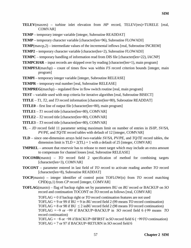
SIM
Chapter 2 SIM
57
TELEV(maxres) – turbine inlet elevation from HP record, TELEV(res)=TURELE [real, COMVAR]
TEMP – temporary integer variable [integer, Subroutine READDAT] TEMP – temporary character variable [character(len=96), Subroutine FLOWADJ] TEMP(maxcp,2) – intermediate values of the incremental inflows [real, Subroutine INCREM] TEMP2 – temporary character variable [character(len=2), Subroutine FLOWADJ] TEMPC – temporary handling of information read from DIS file [character(len=22), IACNP] TEMPCHAR – input records are skipped over by reading [character(len=1), main program] TEMPFSJ(maxfsp) – count of times flow was within FS record criterion bounds [integer, main
program] TEMPI – temporary integer variable [integer, Subroutine RELEASE] TEMPR – temporary real number [real, Subroutine RELEASE] TEMPREG(maxfsp) – regulated flow in flow switch routine [real, main program] TEST – variable used with stop criteria for iterative algorithm [real, Subroutine BISECT] TITLE – T1, T2, and T3 record information [character(len=80), Subroutine READDAT] TITLE0 – first line of output file [character(len=80), main program] TITLE1 – T1 record title [character(len=80), COMVAR] TITLE2 – T2 record title [character(len=80), COMVAR] TITLE3 – T3 record title [character(len=80), COMVAR] TL – JD record field 11 parameter setting maximum limit on number of entries in IS/IP, SV/SA,
PV/PE, and TQ/TE record tables with default of 12 [integer, COMVAR] TLD – since one-dimension arrays hold two-variable SV/SA, PV/PE, and TQ/TE record tables, the
dimension limit is TLD = 2(TL) + 1 with a default of 25 [integer, COMVAR] TMPREL – amount that reservoir has to release to meet target which may include an extra amount
to compensate for channel losses [real, Subroutine RELEASE] TOCOMB(maxto) – TO record field 2 specification of method for combining targets
[character(len=3), COMVAR] TOCONT – parameter entered in last field of TO record to activate reading another TO record
[character(len=8), Subroutine READDAT] TOCP(maxto) – integer identifier of control point TOFLOW(n) from TO record matching
CPID(cp,1) from CP record [integer, COMVAR] TOFLAG(maxto) – flag of backup rights set by parameters BU on BU record or BACKUP on SO
record and continuation TOCONT on TO record as follows [real, COMVAR] TOFLAG = 0 if backup right or TO record continuation features are not used TOFLAG = 9 or 99 if BU = 9 in BU record field 2 (99 means TO record continuation) TOFLAG = 8 or 98 if BU ≤ 2 in BU record field 2 (98 means TO record continuation) TOFLAG = −9 or −99 if BACKUP=BACKUP in SO record field 6 (−99 means TO
record continuation) TOFLAG = −8 or −98 if BACKUP=BFIRST in SO record field 6 ( −99 TO continuation) TOFLAG = 7 or 97 if BACKUP=RETURN in SO record field 6

SIM
Chapter 2 SIM 58
TOFLOW – TO record field 7 entry that specifies which control point to use in setting target [character(len=6), Subroutine READDAT]
TOLIM(maxto,2) – TO record lower and upper limits on target [real, COMVAR] TORES(maxto) – reservoir identifier from TO record field 8 [character(len=6), Subroutine
READDAT] TORI(maxto) – integer identifier of reservoir TORES(n) from TO record matching RESID(res)
from WS record [integer, COMVAR] TOTAL – used to sum monthly use distribution factors to convert to decimal fractions [real,
Subroutine READDAT] TOTARGET(maxto) – TO record entry specifying variable to use in target setting [integer,
COMVAR] TOTAVAIL – total water amount available to generate hydropower [real, Subroutine POWER] TOTCAP – total storage capacity of the EA record reservoirs [real, main program, RESCAL] TOTSHT – total shortage associated with yields in FY record yield analysis [real, main program] TOWI(maxto) – integer identifiers of water rights with TO records [integer, COMVAR] TOWR(maxto) – identifiers of water rights entered on TO records [character(len=16), READDAT] TPCAP(maxres) – hydroelectric energy capacity or limit from HP record field 6,
TPCAP(res)=ENERGY [real, COMVAR] TQCAP(maxres) – turbine discharge capacity from HP record field 5, TQCAP(res)=TURCAP
[real, COMVAR] TRY – flag indicating if file exists [logical, Subroutine CHECK] TSA –multiplier factor in TSR record field 4 [real, Subroutine READDAT] TSB – addition factor in TSR record field 5 [real, Subroutine READDAT] TSC – third character R for repeat in record identifier TSR [character(len=1), Subroutine
READDAT] TSCOM(maxts) – TSL from TS record specifying manner in which target from TS record is
combined with preceding target. TSCOM(ITS) = TSL = MAX, MIN, ADD, SUB, MUL from TS record. [character(len=3), COMVAR]
TSCOUNT – ITS = TSCOUNT = integer identifier of the set of TS records read for a water right, counter of number of water rights with TS records [integer, Subroutine READDAT]
TSFLAG – flag used in setting dimension limits based on TS records [integer, Subroutine READDAT]
TSL – TS record entry specifying combining of targets which is transferred to main program through TSCOM(ITS) [character(len=3), Subroutine READDAT]
TSYR1 – beginning year on TS record [integer, Subroutine READDAT] TSYR2 – ending year on TS record [integer, Subroutine READDAT] TURCAP – turbine discharge capacity entered on WS record [real, Subroutine READDAT] TURELE – turbine inlet elevation entered on HP record [real, Subroutine READDAT] TWATER – tailwater elevation used in hydropower computations. TWATER = WRSYS(1,10)
set by HP record field 3 [real, COMVAR]

SIM
Chapter 2 SIM
59
TWATER1 – tailwater elevation [real, Subroutine POWER] TWCURV(maxpow,tld) – tailwater elevation–flow curves [real, COMVAR] UGID(maxgag) – upstream gage control point identifier from FD record [character(len=6), IACNP] UPFLAG(maxuse) – flag indicating that adjustment factors from the use priority adjustment UP
record are to be applied to adjust priorities [integer, Subroutine READDAT] UPLIM – upper limit on storage [real, Subroutine POWER] USEADD(maxuse) – addition factor from the water use priority adjustment UP record field 4
[integer, Subroutine READDAT] USEFAC(maxuse) – factor from UP record field 6 by which target amounts are multiplied [real,
Subroutine READDAT] USEID(maxuse) – use type identifiers [character(len=6), COMVAR] USEMUL(maxuse) – multiplier factor from the water use priority adjustment UP record field 5
[real, Subroutine READDAT] USEP(maxuse) – priority from UP record field 3 [integer, Subroutine READDAT] USETYPE – type of water use for a right that connect UC and UP records with WR, and IF records
[character(len=6), Subroutine READDAT] VALUES(nvals) – values of time series variables stored in DSS file [real, DSSINPUT and
DSSOUT] VR – volume reliability in FY record computations [real, main program] WR – integer identifier of water right [integer, COMVAR] WRCP(maxcp) – flag used in Subroutine AVALB with ADJINC options 6 and 7 that identifies
whether senior water rights are located at each control point [integer, COMVAR] WRDAT(maxwr,4) – water right data [real, COMVAR] WRDAT(wr,1) – annual diversion or hydroelectric energy target WRDAT(wr,2) – return flow factor WRDAT(wr,3) – bottom of active pool if only reservoir associated with water right WRDAT(wr,4) – top of active pool if only reservoir associated with water right WRID(maxwr) – water right identifiers input on WR and IF records [character(len=16),
COMVAR] WRIDS(maxwr,2) – two water right group identifiers from WR record [character(len=8),
COMVAR] WRIDS(maxwr,1) – second water right identifier (first group identifier) input on WR record. IF
records do not have group identifiers like WR records. As IF records are read, Subroutine READDAT sets WRIDS(wr,1) equal to IF#IF*IF as a flag used by the main program to identify rights as being instream flow rights. [character(len=8), COMVAR]
WRIDS(maxwr,2) – third water right identifier (second group identifier) [character(len=8), COMVAR]
WRID1(maxpx), WRID2(maxpx), WRID3(maxpx) – water right and water right group identifiers from PX record fields 10, 11, 12 [character(len=16,8,8), READDAT]
WRNUM(maxwr,12) – various water right flags and indices [integer, COMVAR]

SIM
Chapter 2 SIM 60
WRNUM(wr,1) – control point integer identifier or index WRNUM(wr,2) – use type integer identifier or index WRNUM(wr,3) – return control point integer identifier or index WRNUM(wr,4) – index or identifier of monthly limit ML record data WRNUM(wr,5) – water right types 1 through 7 from WR record field 6. WRNUM(wr,5)
of 11 or 12 indicates that XP(px) options 1 and 2 are activated on PX record. In SIMD, WRNUM(wr,5) is 8 for a flood control right or 9 for a flood control release right.
WRNUM(wr,6) – flag to include simulation results for water right in output file WRNUM(wr,7) – priority from WR or IF record field 5 subject to UP record
adjustments WRNUM(wr,8) – identifying index for transient water rights data from PX records WRNUM(wr,9) – integer identifier or index of either a reservoir or a system water right.
A positive WRNUM(wr,9) is the reservoir identifier for a regular non–system water right. A negative WRNUM(wr,9) flags a system water right, which is a right with either one or more OR records, hydropower (type = 5,6,–1,–3), or is right type 2, 3, or 4. The absolute value of WRNUM(wr,9) is the index of system water rights. SWR = –WRNUM(wr,9)
WRNUM(wr,10) – control point index for alternate control point ACPID entered on SO record for a WR record right and instream flow target parameter IFFLAG2 from an IF record right
WRNUM(wr,11) – parameter LAKESD from WS record field 11 indicates whether water supply diversions are accessible to turbines for hydropower generation
WRNUM(wr,12) – control point index for the control point CP2 entered in IF record field 12 defining downstream end of reach
WROUT(maxgp) – identifiers of water rights to output specified on WO record [character(len=16), COMVAR]
WRPT – water right location index [integer, Subroutine CONFLU(K)] WRSYS(maxsys,10) – hydropower and reservoir data for a system water right, which is a water
right with hydropower (WR record field 6), OR records, or multiple reservoirs. [real, COMVAR] WRSYS(maxsys,1) – storage at top of inactive zone which is INACT from WS record field 7 WRSYS(maxsys,2) – storage capacity at the top of zone 2 (OR record field 3) if a secondary reservoir or the bottom of power (INACT from WS record field 7) pool if a hydropower right WRSYS(maxsys,3) – top of zone 1 storage capacity (non–hydropower) or storage capacity at top of power pool (hydropower) which are both the capacity from WS field 3 WRSYS(maxsys,4) – zone 2 multiplier factor from OR record field 5
WRSYS(maxsys,5) – zone 1 multiplier factor from OR record field 4 for multiple–reservoir system release rules
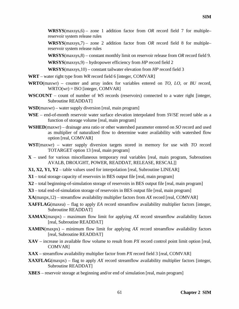
SIM
Chapter 2 SIM
61
WRSYS(maxsys,6) – zone 1 addition factor from OR record field 7 for multiple–reservoir system release rules
WRSYS(maxsys,7) – zone 2 addition factor from OR record field 8 for multiple–reservoir system release rules
WRSYS(maxsys,8) – constant monthly limit on reservoir release from OR record field 9. WRSYS(maxsys,9) – hydropower efficiency from HP record field 2 WRSYS(maxsys,10) – constant tailwater elevation from HP record field 3 WRT – water right type from WR record field 6 [integer, COMVAR] WRTO(maxwr) – counter and array index for variables entered on TO, LO, or BU record,
WRTO(wr) = ISO [integer, COMVAR] WSCOUNT – count of number of WS records (reservoirs) connected to a water right [integer,
Subroutine READDAT] WSD(maxwr) – water supply diversion [real, main program] WSE – end-of-month reservoir water surface elevation interpolated from SV/SE record table as a
function of storage volume [real, main program] WSHED(maxwr) – drainage area ratio or other watershed parameter entered on SO record and used
as multiplier of naturalized flow to determine water availability with watershed flow option [real, COMVAR]
WST(maxwr) – water supply diversion targets stored in memory for use with TO record TOTARGET option 13 [real, main program]
X – used for various miscellaneous temporary real variables [real, main program, Subroutines AVALB, DROUGHT, POWER, READDAT, RELEASE, RESCAL]]
X1, X2, Y1, Y2 – table values used for interpolation [real, Subroutine LINEAR] X1 – total storage capacity of reservoirs in BES output file [real, main program] X2 – total beginning-of-simulation storage of reservoirs in BES output file [real, main program] X3 – total end-of-simulation storage of reservoirs in BES output file [real, main program] XA(maxpx,12) – streamflow availability multiplier factors from AX record [real, COMVAR] XAFFLAG(maxea) – flag to apply EA record streamflow availability multiplier factors [integer,
Subroutine READDAT] XAMAX(maxpx) – maximum flow limit for applying AX record streamflow availability factors
[real, Subroutine READDAT] XAMIN(maxpx) – minimum flow limit for applying AX record streamflow availability factors
[real, Subroutine READDAT] XAV – increase in available flow volume to result from PX record control point limit option [real,
COMVAR] XAX – streamflow availability multiplier factor from PX record field 3 [real, COMVAR] XAXFLAG(maxpx) – flag to apply AX record streamflow availability multiplier factors [integer,
Subroutine READDAT] XBES – reservoir storage at beginning and/or end of simulation [real, main program]

SIM
Chapter 2 SIM 62
XCP(maxpx) – downstream control point flow availability limit option from PX record field 4 [integer, COMVAR]
XCPAV – temporary holder for XCPAV1 [real, main program] XCPAV1 – volume of available streamflow for water right computed applying PX record
downstream control point flow availability limit feature [real, Subroutine ADJUST, AVALB]
XCPCLAD – deliver factor considering channel losses in computations applying the PX record downstream control point flow availability limit feature [real, COMVAR]
XCPFLAG – XCPFLAG of 1 and 2 is a flag or counter of dual passes through the Subroutines AVALB and AVALB_2 routines applying the PX record downstream control point flow availability limit feature [integer, Subroutine AVALB]
XCPI(maxpx) – integer identifier for control point XCPID in PX record field 5 for downstream control point flow availability limit feature [integer, Subroutine READDAT]
XCPID – control point identifier in PX record field 5 for downstream control point flow availability limit feature [character(len=6), Subroutine READDAT]
XDEP – streamflow depletion [real, Subroutine ADJUST] XL – lower limit on X in bisection method [real, Subroutine BISECT] XMAX – maximum value of X in SV/SA, PV/PE, or TE/TQ record table in linear interpolation
routine [real, Subroutine LINEAR] XP(maxhi) – transient priority option from PX record field 6 [integer, COMVAR] XPCOUNT – counter index for transient priority option water rights activated by PX records
[integer, Subroutine READDAT] XPOUT(maxxp) – parameter from PX record field 9 specifying whether transient priority rights are
output with other rights [integer, COMVAR] XPR(maxxp) – transient priority reservoir storage option from PX record field 7 [integer,
COMVAR] XPRESDAT – beginning–of–period reservoir storage RESDAT(RI,5) saved in order to reset for a
transient priority right [real, main program] XPRET(maxpx) – return flow for PX record transient priority right [real, main program] XPRIORITY(maxxp) – transient priority from PX record field 8 [integer, COMVAR] XPSFD(maxpx) – streamflow depletion for PX record transient priority right [real, main program] XPX – counter or index for PX record rights with either streamflow availability multiplier factor or
transient priority features activated [integer, Subroutine READDAT] XR – root X in bisection method [real, Subroutine BISECT] XRES – amount of target that is not available from streamflow [real, main program] XU – upper limit on X in bisection method [real, Subroutine BISECT] Y – miscellaneous index [integer, Subroutine INEVYR] Y1, Y2, X1, X2 – values in SV/SA, PV/PE, or TE/TQ record tables used in linear interpolation
routine [real, Subroutine LINEAR] YEAR – current year in simulation [integer, COMVAR]

SIM
Chapter 2 SIM
63
YEAR1 – first year of simulation [integer, main program] YES – indicator of whether file is open [logical, Subroutine INEVYR] YMAX – maximum value of Y in SV/SA, PV/PE, or TE/TQ record table in linear interpolation
routine [real, Subroutine LINEAR] YR – year index, YR=1,NYRS [integer, Subroutine READDAT] YRLAST – last year of simulation [integer, Subroutine READDAT] YRST – first year of simulation [integer, COMVAR] YRSUM – yearly summation of negative incremental flows [real, main program] Z – index of data for reservoirs associated with a multi–reservoir water right [integer, main
program] Z – miscellaneous index [integer, Subroutines INCREM, READDAT] ZONE – counts the number of reservoirs eligible to release from a storage zone [integer, Subroutine
RELEASE] ZZ − number of control points specified by ZZ record [integer, COVAR] ZZCALL − counter of whether subroutine ZZFLOW has been called more than once used to signal
writing the table headings only the first time the subroutine is called [integer, COMVAR] ZZCP(zz) − identifiers from ZZ record of control points included in ZZZ output file
[character(len=6), COMVAR] ZZF(zz,3) − reservoir releases, regulated flow, and available flow tabulated in the ZZZ file output
table activated by ZZ record [real, ZZFLOW] ZZFLAG − switch of whether or not to include a water right in the ZZZ file output table activated
by ZZ record [integer, ZZFLOW] ZZFX(zz,3) − a reproduction of ZZF(zz,3) used to compare with the next values for ZZF(zz,3) in
applying the ZZX criteria to determine whether a particular water right is included in the ZZZ file table [real, ZZFLOW]
ZZI(zz) − integer identifier of control points ZZCP(zz) listed on ZZ record [integer, COMVAR] ZZR − integer identifier of water rights in priority order with 1 and 2 being the first and second
most senior rights [integer, COMVAR] ZZWR − most junior water right considered in determining flows for the ZZZ file table as specified
on ZZ record [character(len=16), COMVAR] ZZX − criteria from ZZ record of the flow volume change that results in a water right being
included in the ZZZ file output table [real, COMVAR]

SIM
Chapter 2 SIM 64

SIMD
Chapter 3 SIMD 65
CHAPTER 3 SIMD
The WRAP simulation program SIMD is an expanded version of SIM that includes additional features for:
• adopting a sub-monthly simulation time step such as daily • disaggregation of monthly naturalized flows to the sub-monthly time step • flow forecasting allowing reservoir/river/use system operating decisions to
consider estimated future flows over a user-specified forecast period • alternative routing methods applied to flow adjustments • simulation of flood control reservoir operations
SIMD provides all of the modeling capabilities of SIM and duplicates simulation results for datasets prepared for SIM. The preceding Chapter 2 covering SIM is also applicable to SIMD. Chapter 3 covers the additions to SIM that are reflected in SIMD. The files, subroutines, and variables covered in Chapter 2 are contained in both SIM and SIMD. Additional files, subroutines, and variables contained in only SIMD are described in the present Chapter 3.
The reference and users manual cited below documents the additional modeling capabilities of SIMD that not incorporated in SIM.
Water Rights Analysis Package (WRAP) Daily Modeling System, Texas Water Resources Institute, Technical Report 430, August 2012.
Whereas SIM is limited to a monthly time step, any sub-monthly time step may be adopted in applying SIMD as long as an integer number of time steps fit into each of the 12 months of the year. For example, exactly 28, 29, 30, or 31 days are contained in each of the 12 months. SIMD accounts for February having a different number of days in leap year. The D in SIMD stands for daily since the day is the default sub-monthly time step expected to be adopted most often. For brevity, the term daily is used throughout this chapter to imply any sub-monthly time step. SIMD was developed by adding the following modeling capabilities to SIM.
• optional daily or other sub-monthly computational time step with various methods for subdividing different types of monthly variables into sub-monthly intervals
• several optional methods for disaggregation of monthly naturalized flows to the sub-monthly time step as well as simply reading sub-monthly naturalized flows as input
• flow forecasting allowing streamflow availability governing system operations to reflect future conditions extending over a user-specified forecast period
• routing of flow adjustments for streamflow depletions, return flows, constant inflows, and other actions affecting flows using two alternative routing approaches with either option allowing separate sets of parameters for flood flows and normal flows
• simulation of operation of gated flood control pools based on downstream flow limits and ungated flood control pools based on a storage-outflow relationship
• simulation of pulse flow environmental instream flow requiremenrs
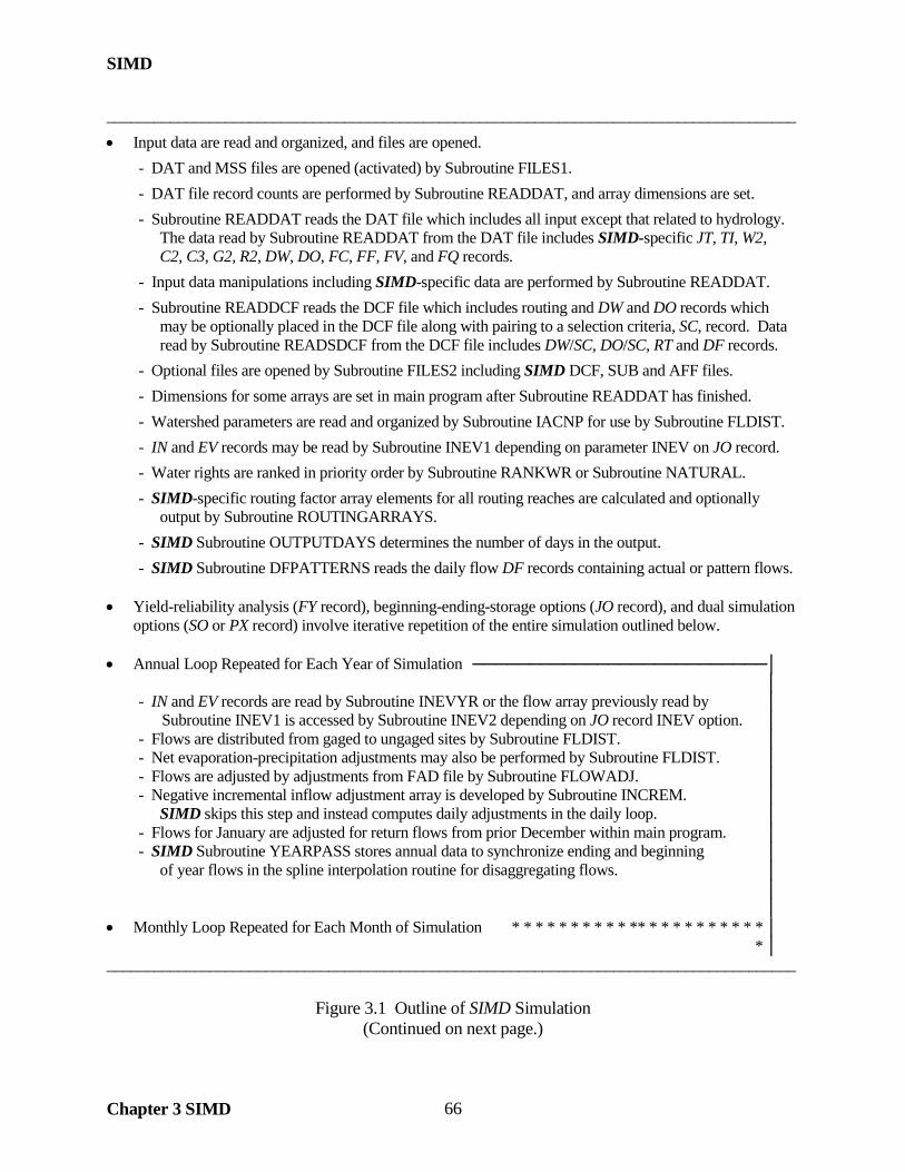
SIMD
Chapter 3 SIMD 66
_______________________________________________________________________________________
• Input data are read and organized, and files are opened.
- DAT and MSS files are opened (activated) by Subroutine FILES1.
- DAT file record counts are performed by Subroutine READDAT, and array dimensions are set.
- Subroutine READDAT reads the DAT file which includes all input except that related to hydrology. The data read by Subroutine READDAT from the DAT file includes SIMD-specific JT, TI, W2, C2, C3, G2, R2, DW, DO, FC, FF, FV, and FQ records.
- Input data manipulations including SIMD-specific data are performed by Subroutine READDAT.
- Subroutine READDCF reads the DCF file which includes routing and DW and DO records which may be optionally placed in the DCF file along with pairing to a selection criteria, SC, record. Data read by Subroutine READSDCF from the DCF file includes DW/SC, DO/SC, RT and DF records.
- Optional files are opened by Subroutine FILES2 including SIMD DCF, SUB and AFF files.
- Dimensions for some arrays are set in main program after Subroutine READDAT has finished.
- Watershed parameters are read and organized by Subroutine IACNP for use by Subroutine FLDIST.
- IN and EV records may be read by Subroutine INEV1 depending on parameter INEV on JO record.
- Water rights are ranked in priority order by Subroutine RANKWR or Subroutine NATURAL.
- SIMD-specific routing factor array elements for all routing reaches are calculated and optionally output by Subroutine ROUTINGARRAYS.
- SIMD Subroutine OUTPUTDAYS determines the number of days in the output.
- SIMD Subroutine DFPATTERNS reads the daily flow DF records containing actual or pattern flows. • Yield-reliability analysis (FY record), beginning-ending-storage options (JO record), and dual simulation
options (SO or PX record) involve iterative repetition of the entire simulation outlined below. • Annual Loop Repeated for Each Year of Simulation ──────────────────────────│
│ - IN and EV records are read by Subroutine INEVYR or the flow array previously read by │ Subroutine INEV1 is accessed by Subroutine INEV2 depending on JO record INEV option. │ - Flows are distributed from gaged to ungaged sites by Subroutine FLDIST. │ - Net evaporation-precipitation adjustments may also be performed by Subroutine FLDIST. │ - Flows are adjusted by adjustments from FAD file by Subroutine FLOWADJ. │ - Negative incremental inflow adjustment array is developed by Subroutine INCREM. │ SIMD skips this step and instead computes daily adjustments in the daily loop. │ - Flows for January are adjusted for return flows from prior December within main program. │ - SIMD Subroutine YEARPASS stores annual data to synchronize ending and beginning │ of year flows in the spline interpolation routine for disaggregating flows. │ │ │
• Monthly Loop Repeated for Each Month of Simulation * * * * * * * * * * ** * * * * * * * * * * │ * │ _______________________________________________________________________________________
Figure 3.1 Outline of SIMD Simulation (Continued on next page.)

SIMD
Chapter 3 SIMD 67
• SIMD Forecast Loop f f f f f f f f f f f f f f f f f f f f f f f f f f f f f f f f f f f f f f f f f f f f f f f f f f f f f f f f * │ f * │
- SIMD Subroutine FCSTDATAMNGR prepares for forecast cycle and sets forecast flag. f * │ - SIMD Subroutine DFLOWS disaggregates monthly naturalized flows to daily flows. f * │ - Subroutine INCREM optionally develops negative incremental flow adjustment array. f * │
f * │ • SIMD Sub-Monthly (Daily) Loop Repeated for Each Sub-Monthly Time Step of Month d d d f * │ d f * │
- Spills associated with monthly varying storage capacity option within main program. d f * │ SIMD routs the spills in the main program. d f * │ - SIMD routs next-day return flows from previous day within the main program. d f * │ - Flow adjustments for CI record constant inflows within main program. d f * │ SIMD routs the CI record constant inflows within the main program. d f * │ - SIMD applies routed changes to flow from the previous day to the CPFLOW array. d f * │ - SIMD Subroutine FLOODCONTROLSYSTEMS sets flood control rankings. d f * │ d f * │
• Water Right Loop Repeated for Each Right in Priority Order + + + + + + + + + + + + + + + + d f * │ (First and second pass through loop for IF record dual-pass instream flow options) + d f * │
+ d f * │ SIMD applies routed changes to flow from the previous day to the CPFLOW array + d f * │
within the water right loop. + d f * │ 1. The diversion, instream flow, or hydropower target is set within main program + d f * │ based on options specified by WR, IF, SO, TO, TS, FS, WS, and HP records. + d f * │ SIMD options for converting monthly targets to daily targets are applied. + d f * │ SIMD also applies the normal target setting features to daily targets. + d f * │ SIMD sets FF record flood flow limits for flood control operations. + d f * │ 2. The amount of water available to right is determined by Subroutine AVALB. + d f * │ (Channel losses are considered in checking flows.) + d f * │ SIMD Subroutine AVALB optionally determines records streamflow + d f * │ availability based on iterative forecast cycle. + d f * │ 3. Diversions, reservoir releases, and return flows are determined in main program + d f * │ along with Subroutine RESCAL iterative reservoir water balance computations + d f * │ and Subroutine POWER iterative hydropower computations. + d f * │ SIMD Subroutines UNCONTROLLEDRELEASE, CHANNELCAPACITY, and + d f * │ and ADJUSTCAPACITY contribute to flood control reservoir release decisions. + d f * │ 4. Available streamflow at all control points is adjusted by Subroutine ADJUST. + d f * │ (Channel losses are considered in adjusting available flows.) + d f * │ SIMD routs the flow adjustments. + d f * │
+ d f * │ Monthly and/or daily simulation results are written as water right output records. + + + + + + d f * │ The SIMD forecast month FM parameter controlling the forecast cycle is updated. d f * │ SIMD Subroutine FLOODFREQ develops the AFF file of annual peak flows and storage. d f * │
d f * │ d f d f d f d f d f d f d f d f d f d f d f d f d f d f d f d f d f d f d f d f d f d f d f d f d f d f d f d f d f d f d f * │ * │ • Monthly and/or daily simulation results are written as control point and reservoir output. * * * * * * │ ──────────────────────────────────────────── ─────────────────│ • Optional DSS and SOU output files with monthly or daily simulation results are written at the end of the
simulation from arrays developed during the water rights, sub-monthly, and monthly loops.
Figure 3.1 Outline of SIMD Simulation (Continued from previous page.)

SIMD
Chapter 3 SIMD 68
Organization of SIMD
The organization of SIM is outlined in Figure 2.1 of the preceding Chapter 2 of this Programming Manual. Figure 3.1 on the preceding two pages is an expanded version of Figure 2.1 with SIMD features added. SIMD was developed by expanding SIM. Essentially all of the SIM Fortran code is also contained in SIMD though some statements have been revised. The numerous lines of code that are added to the main program and shared SIM subroutines as well as revised lines are identified by the addition of the notation ! day to the right of each Fortran statement. Module DAILY is added at the beginning of SIMD. The additional SIMD subroutines that are not found in SIM are described later in this chapter.
The main program of SIM and SIMD organizes and directs the simulation. The
computational loops shown in Figures 2.1 and 3.1 are organized within the main program. Various data management tasks and computations are performed within the main program. Simulation results are written to files from the main program. The individual subroutines are called by the main program to perform their particular tasks as the simulation progresses.
Variables shared by two or more subprogram units in both SIM and SIMD are declared in
Module COMVAR (COMmon VARiables). Module DAILY (lines 19−148) at the beginning of SIMD supplements Module COMVAR (lines 152−243) by declaring with type and array dimension the additional common variables that are used in SIMD but not SIM.
Input and Output Files
SIMD uses all of the files used by SIM plus the one additional input file and two additional output files listed in Table 3.1. The DCF file is opened in Subroutine READDAT and the SUB or conditional reliability CRD and AFF files are opened in Subroutine FILES2. The SUB output file is a daily version of the SIM OUT and CRM file and is direct access. Sub-monthly simulation results for a conventional long-term simulation are recorded in a SUB file. Sub-monthly simulation results for conditional reliability modeling are recorded in the CRM file in the same manner as with SIM. The DCF (daily control and flow data) input file and AFF (annual flood frequency) output file are read and written sequentially. The optional SMM file contains SIMD specific reports, tables, and data series that are activated by the JT and PF records.
Table 3.1 Additional SIMD Input and Output Files Not Included in SIM
Unit Extension In/Out Activation Parameter File Contents
UDCF=201 DCF input JT record, SIMD = 1 daily control point data and flows USUB=202 SUB output JT record, SUBOUT = 1 daily version of OUT and CRM files UAFF=203 AFF output JT record, AFF ≥ 1 flood frequency analyses annual peaks
USMM=204 SMM output JT and PF records SIMD specific reports, tables, and data

SIMD
Chapter 3 SIMD 69
Subroutines SIMD contains all of the subroutines contained in SIM plus the following additional subroutines and functions found at the end of SIMD beginning at line 21700 of the program. The subroutines are listed below in the order of appearance. READDCF - Called by Main Program to read RT, DW/SC and DO/SC records from the DCF file.
WRSELECTION - Called by Subroutine READDCF to select WR, IF or FF records based on selection criteria provided on the SC records.
DFPATTERNS − Called by the Main Program before the computational loops to read the daily flows from the DF records. The flows can be either actual daily naturalized flow volumes or amounts used to define a pattern for the flow disaggregation options.
INDF − Called by Subroutines INEVYR and INEV2 to assign flows INFLOW(cp,month) each year by aggregating the daily flows from the array DFPATTERN(ndays,nunique) which was populated by Subroutine DFPATTERNS.
DFLOWS − Called by the Main Program at the beginning of the monthly loop to read the DF records and compute daily naturalized flows INFLOWS(cp,dt) and initial available flows CPFLOW(cp,dt,2)
SPLINEINTERP(INFLOW,DCOUNT,DFLOW) − Called by Subroutine DFLOWS to interpolate a daily time series of naturalized flow volumes from monthly volumes covering a year. Unlike Subroutine MT2DINTERP, Subroutine MT2DINTERP2 requires the number of data points in the interpolation.
LEAP(YEAR) - Function which returns a logical value if the value passed to it is a leap year. The function is called from Subroutine DFLOWS and Subroutine OUTPUTDAYS.
ROUTINGARRAYS − Called by the Main Program before the annual loop to determine the length of the maximum length MAXREACH in the stream network in terms of the number of routing control points in the reach for use in allocating the size of the routing arrays. The subroutine also allocates the size of the routing arrays, assigns values to the routing factor arrays RFA and RFAF, and computes the forecasting periods for water rights using automatically set periods.
FLOODFREQ − Called by Main Program at the end of the computational loops to record annual daily naturalized flows, regulated flows, and end-of-period reservoir storage in the AFF file that can be read by Program TABLES to perform flood frequency analyses.
RTGADJUSTMENTS − Called by the Main Program at the end of the year at the end of the daily
loop. The subroutine writes the values stored in array RTGMT(maxcp,maxmon) to the SMM file for each year of the simulation.
FCSTDATAMNGR(CPRET2,RETSUM2) − Called by the Main Program at the beginning of the daily forecast, which is at the beginning of the monthly loop and before the call to Subroutine DFLOWS, to set the forecasting flag FORECAST indicating whether to activate the forecasting procedure and to prepare the arrays used in the forecasting.
The following subroutines are contained within Subroutine FCSTDATAMNGR.

SIMD
Chapter 3 SIMD 70
BACKUP_ROUTING_ARRAYS − Keeps a copy of the routing arrays so that they can be restored after the forecasting is complete.
RESTORE_ROUTING_ARRAYS − Restores routing arrays to state before forecasting.
BACKUP_TARGET_ARRAYS − Keeps a copy of the target building arrays so that they can be restored after the forecasting is complete.
RESTORE_TARGET_ARRAYS − Restores the target building arrays to the state before forecasting.
BACKUP_RESERVOIR_ARRAYS − Keeps a copy of the reservoir array so it they can be restored after the forecasting is complete.
RESTORE_RESERVOIR_ARRAYS − Restores the reservoir array to the state before forecasting.
BACKUP_MONTHL_LIMIT_ARRAYS − Keeps a copy of the monthly limit arrays so that they can be restored after the forecasting is complete.
RESTORE_MONTHLY_LIMIT_ARRAYS − Restores the monthly limits arrays to the state before forecasting.
BACKUP_ANNUAL_LIMIT_ARRAYS − Keeps a copy of the annual limit arrays so that they can be restored after the forecasting is complete.
RESTORE_ANNUAL_LIMIT_ARRAYS − Restores the annual limits arrays to the state before forecasting.
BACKUP_OUTPUT_ARRAYS − Keeps a copy of the output arrays so that they can be restored after the forecasting is complete.
RESTORE_OUTPUT_ARRAYS − Restores output arrays to the state before forecasting.
FORECASTINGARRAYS − allocates and initializes arrays used in forecasting procedure.
SUMDSHTBACK − Called by the Main Program at the end of the daily loop to compute the end of month summation of water right shortages that are used in target building steps 2 and 10. These shortages cannot be computed during the month since water rights can roll shortages until the last day of the month.
FLOODCONTROLSYSTEMS − Called by the Main Program before the beginning of the water rights loop to rearrange the water right rankings in array RANK(wr) for storage and releases in flood control reservoir systems. The priority rank is based on beginning- of-period storage.
CHANNELCAPACITY(CPINDEX,FFNUM,CAPACITY,FLAG) − Called by the Main Program and Subroutine ROUTING to determine the available channel capacity for flood control reservoir release decisions. Given a control point location, CPINDEX, and the number of FF record control points to consider, the subroutine proceeds down the control point network until FFNUM is reached or the outlet is reached. CAPACITY will equal the minimum stream capacity available to flood control releases. If CAPACITY is negative, the available capacity has been exceeded by regulated flows. This indicates a flood is in progress.
SIMD
Chapter 3 SIMD 71
ADJUSTCAPACITY(CPINDEX,SPILL) − Called by the Main Program to reduce the available channel capacity for all downstream flood flow FF record rights after a controlled release has been made from a reservoir.
UNCONTROLLEDRELEASE(BOTTOM,STORAGE,IDNUM,DISCHARGE) − Called by the Main Program to determine the release from an uncontrolled zone of a flood control reservoir. An iterative algorithm determines the ending storage and outflow.
Definition of Variables
Variables incorporated in both SIM and SIMD are defined in the preceding Chapter 2. Some arrays sized based on number of time steps are revised in SIMD to reflect a sub-monthly interval. Additional variables incorporated in SIMD that are not in SIM are listed and defined as follows. Arrays are indicated by the array size in parenthesis following the name. Two items of information are provided in brackets following the description of each variable.
1. variable type of real, integer, character(maximum length), or logical 2. whether the variable is declared in module DAILY, the main program, or specific
subroutines
AFF – flag used to signal the AFF file was selected on the JT record. [integer, DAILY] AMTANN – value of the annual demand from the WR/IF record or from the FY record
computation [real, main program] APERIOD(MAXWR) – number of forecast time steps for each water right plus 1 to advance
beyond the current time step. [integer, DAILY] APERIOD2 – used as a flag in Subroutine AVALB to indicate the value of APERIOD(wr) when
the call to the subroutine comes from within the water right loop, or set equal to the minimum of FPRD or the maximum value of MAXTED when the call to the subroutine is made from outside the water right loop. [integer, DAILY]
AVAFLAG1 – flag that is set prior to each call to Subroutine AVALB that indicates which availability arrays, FAVAMT, will be utilized for recording or implementing a constraint on water availability. See the notes in this chapter after the definition of variables regarding the use of AVAFLAG1, AVAFLAG2, and the FAVAMT arrays. [integer, DAILY]
AVAFLAG2 – flag that is indicates which array element to access in the availability arrays, FAVAMT, when the call to Subroutine AVALAB is made for a TO, FS, CV, PF, or ZZ record. [integer, DAILY]
BEGMON − beginning month for daily output entered on JT record [integer, DAILY] BEGYR − beginning year for daily output entered on JT record [integer, DAILY] CAPACITY – channel capacity as computed from the FF rights. Channel capacity is equal to
LIMMFF minus the regulated flows at the control point. [real, main program] CPFFINDEX(MAXCP,NUMFF) –water right subscripts of the FF rights associated with each
control point. NUMFF is the maximum number of FF records associated with any control point. CPFFINDEX is used in Subroutine CHANNELCAPACITY to

SIMD
Chapter 3 SIMD 72
efficiently access the FF rights with respect to their control point association. [integer, DAILY]
CPOUID2(MAXCP2) – identifiers of control points specified on C2 records to output to the SUB file [character, DAILY]
CPOUID3(MAXCP2) – identifiers of control points specified on C3 records to output to the SUB file [character, DAILY]
CPOUT2 – parameter on JT record for specifying which control points are to be included in SUB file. CPOUT2 is a counterpart to CPOUT. [integer, DAILY]
CPRFA(NRT,3) – array indices of the normal flow routing control points and the next downstream normal flow routing control point. CPRFA is used in Subroutine ROUTINGARRAYS for constructing and populating the RFA array. [integer, DAILY]
CPRFA(:,1) – array index of each routing control point in NCPTS space CPRFA(:,2) – array index of the next downstream routing control point in NCPTS
space CPRFA(:,3) – array index of the next downstream routing control point in NRT
space CPRFAF(NRT,3) – array indices of the flood flow routing control points and the next downstream
flood flow routing control point. CPRFAF is used in Subroutine ROUTINGARRAYS for constructing and populating the RFAF array. [integer, DAILY]
CPRFA(:,1) – array index of each routing control point in NCPTS space CPRFA(:,2) – array index of the next downstream routing control point in NCPTS
space CPRFA(:,3) – array index of the next downstream routing control point in NRT
space CLOSS1(I,MAXCP,2) – array to store channel losses associated with routed stream flow depletions
and return flow. ROUT1 is allocated in Subroutine ROUTINGARRAYS along with the companion array SROUT1 for use with preserving array values during the second pass for instream flows. [real, DAILY]
I = Max(Maxval(MAXTED),Maxval(MAXTEDF)) DAYDEP(MAXWR) − array for storing DAYDEP values from the DO record [real, DAILY] DAYS – number of time steps to be written to the SUB file. DAYS is written to the 5th line in
the SUB file header. [integer, main program] DBU(MAXWR) − array for storing DBU values from the DO record [integer, DAILY] DCID(MAXCP) – control point identifiers read from DC records in DCF file [character, DAILY] DDI(MAXWR) − array for storing DDI values from the DO record [integer, DAILY] DF_LAG(NCPTS) − number of time steps to shift the pattern taken from the DF records [integer,
DAILY] DFDATES(NCPTS,4) − array to hold the values of DF_BEGYR, DF_BEGMT, DF_ENDYR, and
DF_ENDMT that are read from the DF records [integer, DAILY]

SIMD
Chapter 3 SIMD 73
DFDRAINAGE(MAXCP,2) − drainage area for the control point and the ratio of the drainage area of the control point and that at DFID used for DFMETH option 3 [real, DAILY]
DFEQUATION(NCPTS,3) − array to hold the values of DF_X, DF_M, and DF_A that are read from the DF records [real, DAILY]
DEMETHOD(MAXCP) − parameter on the DE record specifying the method for obtaining the daily net evaporation-precipitation depths [integer, DAILY]
DFID(MAXCP) − control point identifiers read from DC records in DCF file corresponding to the name of the pattern to scan for in the DF records. [character, DAILY]
DFLOW(MAXDAY) − normalized daily flow multipliers developed from the pattern taken from DF records [real, DFLOWS]
DFMETH − default pattern disaggregation method entered on the JT record [integer, DAILY] DFMETHOD(MAXCP) − parameter on the DC record specifying the method for obtaining the
daily flow volumes [integer, DAILY] DFMULT − multiplication factor for DF record data. DFMULT is entered on the JT record. [real,
DAILY] DFONLY − flag that indicates all gaged control points have a DFMETHOD equal to 9. No IN
records are read for this simulation. [logical, DAILY] DFPATTERN(NDAYS,:) − patterns for monthly to daily flow disaggregation read from the DF
records [real, DAILY] DFPATTERNSUBS(MAXCP) − array subscripts that identify which pattern in DFPATTERN
belong to each control point with a corresponding DFMETHOD > 3 [integer, DAILY]
DHMETHOD(MAXCP) − parameter on the DX record specifying the method for obtaining the daily HIS data [integer, DAILY]
DPFLOW(MAXTO) − equivalent to SIM array DPFLOW(maxto). DPFLOW stores the monthly values of naturalized, regulated or unappropriated water. [real, DAILY]
DSHTBACK(MAXWR) − equivalent to SIM array SHTBACK(maxwr). DSHTBACK stores the total monthly shortage. [real, DAILY]
DSROUT(MAXCP,2) – array indices of the first downstream normal flow routing control point. DSROUT is used in the main program and Subroutine ADJUST for accessing the RFA array and conducing routing calculations. [integer, DAILY]
DSROUT(:,1) – array index of the next downstream routing control point in NCPTS space
DSROUT(:,2) – array index of the next downstream routing control point in NRT space
DSROUTF(MAXCP,2) – array indices of the first downstream flood flow routing control point. DSROUTF is used in the main program and Subroutine ADJUST for accessing the RFAF array and conducing routing calculations. [integer, DAILY]
DSROUTF(:,1) – array index of the next downstream routing control point in NCPTS space

SIMD
Chapter 3 SIMD 74
DSROUTF(:,2) – array index of the next downstream routing control point in NRTF
space DT − daily or other sub-monthly time interval counter [integer, DAILY] DTAR(MAXWR) − stores the value of the monthly target that is built on the first day of the month.
[real, DAILY] DTO(MAXWR) − array for storing DTO values from the DO record [integer, DAILY] DTRESTORE – value of DT when the forecast loop is initiated. DTRESTORE is used to reset the
value of DT when the real simulation begins again after the first day of the month. [integer, DAILY]
ENDMON − ending month for daily output entered on JT record [integer, DAILY] ENDYR − ending year for daily output entered on JT record [integer, DAILY] EOPS(MAXDAY,MAXRES) – daily end-of-period storage. Because the AFF file subroutine is
called at the end of the month, the daily EOPS values are needed to determine the maximum encountered during the month to be used for populating FLOOD(3,:). [real, DAILY]
FAVAMT1(FPRD,MAXWR) – stores the values of water availability for each water right in each day during the forecast period. See the notes in this chapter after the definition of variables regarding the use of AVAFLAG1, AVAFLAG2, and the FAVAMT arrays. [real, DAILY]
FAVAMT2(FPRD,MAXWR) – stores the values of water availability for each water right in each day during the forecast period. [real, DAILY]
FAVAMT3(FPRD,MAXCP) – stores the values of water availability for each control point, as determined after the water rights loop, in each day of the forecast period. [real, DAILY]
FAVAMT4(FPRD,MAXCP) – stores the values of water availability for each control point, as determined after the water rights loop, in each day of the forecast period. [real, DAILY]
FAVAMT4CP(MAXCP) – flag used in conjunction with AVAFLAG1 equal to -4 to determine which control points will call Subroutine AVALB to determine unappropriated flow after the water right loop. [integer, DAILY]
FAVAMT5(FPRD,MAXTO) – stores the values of water availability in each day of the forecast period for each TO record that makes a call to Subroutine AVALAB. [real, DAILY]
FAVAMT6(FPRD,MAXTO) – stores the values of water availability in each day of the forecast period for each TO record that makes a call to Subroutine AVALAB. [real, DAILY]
FAVAMT7(FPRD,MAXFS) – stores the values of water availability in each day of the forecast period for each FS/CV/PF record that makes a call to Subroutine AVALAB. [real, DAILY]
FAVAMT8(FPRD,MAXFS) – stores the values of water availability in each day of the forecast period for each FS/CV/PF record that makes a call to Subroutine AVALAB. [real, DAILY]

SIMD
Chapter 3 SIMD 75
FAVAMT9(FPRD,ZZ,MAXWR) – stores the values of water availability in each day of the forecast period for each ZZ record that makes a call to Subroutine AVALAB. [real, DAILY]
FAVAMT10(FPRD,ZZ,MAXWR) – stores the values of water availability in each day of the forecast period for each ZZ record that makes a call to Subroutine AVALAB. [real, DAILY]
FCAPFF(FPRD,MAXRES) – stores values of channel capacity during the forecast simulation. The values in FCAPFF are used in Subroutine CHANNELCAPACITY along with the current day values of channel capacity to determine if a flood is in progress. [real, DAILY]
FCBOTTOM - value from FR record defining the bottom capacity of the flood control pool. FCBOTTOM is used to set the value of WRDAT( ,3). Controlled or uncontrolled flood releases are not made when the storage contents of the reservoir fall below the level of FCBOTTOM. [real, Subroutine READDAT]
FCCONSRV(MAXRES) – last value of top of conservation read from WR records, or -1.0 indicating no conservation storage at this reservoir. [real, DAILY]
FCDAT(MAXWR,5) – flood control reservoir data [real, DAILY] FCDAT (wr ,1) – value of FCGATE from FR record FCDAT (wr ,2) – value of FCMUL from FR record FCDAT (wr ,3) – value of FCADD from FR record FCDAT (wr ,4) – value of FCMAX from FR record FCDAT (wr ,5) – amount of water depleted by an uncontrolled pool in any time step which sets the top of the pool above FCTOP FCDAT (wr ,6) – annual cumulative excess water for output by Subroutine FLOODFREQ FCFLAG – flag to control reading and processing of FR records in Subroutine READDAT
[integer, READDAT] FCGATE - value from FR record that defines a level between FCTOP and FCBOTTOM. Storage
between FCBOTTOM and FCGATE is released by controlled releases. Storage between FCGATE and FCTOP is released by uncontrolled releases according to FV/FQ relationships. The value of FCGATE is used to set the value of FCDAT( ,1). [real, Subroutine READDAT]
FCINIT(MAXRES) - value of BEGIN from FR record or -1.0 if no flood control for this reservoir. [real,DAILY]
FCMAX(MAXRES) - value from FR record defining the maximum release volume per time step. FCMAX is used in Subroutine READDAT to set the value of FCDAT( ,4). FCDAT( ,4) is ignored for Type 8 uncontrolled release rights. FCDAT( ,4) equals FCMAX for all Type 9 controlled release rights. If there are more than one controlled release reservoirs at the same reservoir, then FCMAX( ) will equal the minimum FCMAX value from the FR records. [real, DAILY]
FCNUM(MAXWR,4) – various indices pertaining to a flood control reservoir [integer, DAILY] FCNUM (wr ,1) – value of FFNUM from FR record FCNUM (wr ,2) – index identifier of the flood control storage system FCNUM (wr ,3) – index identifier of the flood control release system

SIMD
Chapter 3 SIMD 76
FCNUM (wr ,4) – original water right rankings from array RANK( ) before the first call to Subroutine FLOODCONTROLSYSTEMS. The original value of RANK for each water right in the flood control system will need to be restored when there is a tie in the indexing score of Subroutine FLOODCONTROLSYSTEMS.
FCNUM (wr ,5) – value of FCDEP from FR record FCNUM (wr ,6) – flag set to indicate accumulation of excess water in FCDAT(wr,6)
for a controlled flood control pool FCST – entered on the JU record and is used to as a switch to engage flow forecasting for the
simulation. [integer, DAILY] FCTOP – value from FR record used to set value of RESDAT( ,1) and WRDAT( ,1). [real,
Subroutine READDAT] FDTCOUNT – number of time steps that have elapsed during the forecast loop. The forecast loop
terminates when FDTCOUNT equals FPRD. [integer, DAILY] FFPERIOD(MAXRES,MAXFF,2) – array to hold the forecast period from each upstream
reservoir to each downstream flood flow limit right, FF record. The forecast periods are computed for normal flow and flood flow routing coefficients (two elements in the third dimension of the array). [integer, DAILY]
FLOOD(MAXCP,4) – annual maximum values of naturalized flow, regulated flow, storage contents, and excess flow. Results in FLOOD are written to the AFF file from Subroutine FLOODFREQ at the end of each year. [real, DAILY]
FM – integer flag to advance MT by 1 when the forecast simulation has run into the next month within the same year, or by -11 when the forecast simulation has run into the next January. [integer, DAILY]
FPRD – default number of time steps of forecasting for each water right. FPRD is entered on the JU record. Unless the forecast period for an individual water right is specified by a DW record, the value of FPRD is used to set the value of APERIOD(MAXWR) for all WR record rights. FPRD set equal to zero on the JU record engages automatic forecast period calculation. [integer, DAILY]
FRMETH – flag to signal if routed flood control changes (+/–) are in priority or at the beginning of the priority loop. FRMETH is entered on the JU record [integer, DAILY]
FSI(MAXFS,19) – increased the second dimension to 19 [integer, COMVAR] FSWR(MAXFS,3) – added a second dimension of size 3 [character, READDAT] FSWI(MAXFS,3) – added a second dimension of size 3 [integer, COMVAR] FTABLE – index for FV/FQ table [integer, READDAT] FVCURV(MAXFTAB,25) – FV/FQ storage-discharge tables used for uncontrolled flood releases
[real, DAILY] GROUP2(MAXGP2) − identifiers of water rights specified on G2 records to output to the SUB file
[character, DAILY] LAFLOWS(RVALUES+1) – used to store flows during the lag and attenuation routing process.
[real, Subroutine ROUTINGARRAYS] LAFLOWS(1) - change in flow to pass downstream immediately in the current day
SIMD
Chapter 3 SIMD 77
LAFLOWS(2:RVALUES+1) - change in flow to downstream in the next and subsequent days, up to RVALUES days in the future.
LENGTHROUT − maximum of number of normal flow routing reaches connected sequentially from headwater to outlet. The value of LENGTHROUT is used allocate routing arrays. [integer, ROUTINGARRAYS]
LENGTHROUTF − maximum of number of flood flow routing reaches connected sequentially from headwater to outlet. The value of LENGTHROUTF is used allocate routing arrays used specifically for flood control. [integer, ROUTINGARRAYS]
LIMFF(MAXWR) – stores the channel capacity developed by FF rights. Used in Subroutine CHANNELCAPACITY to compute the current channel capacity for a flood control reservoir, and used in the main program after the WR Loop during a forecast simulation to compute the forecasted channel capacity, FCAPFF. [real, DAILY]
MAXDAY − maximum number of daily periods per month, set to 31. MAXREACH – length, in units of control points, of the longest series from headwater to outlet
[integer, ROUTINGARRAYS] MAXGP2 – number of group identifiers that are read from the G2 record. [integer, DAILY] MAXR2 – number of reservoir identifiers that are read from the R2 record. [integer, DAILY] MAXFF – number of FF records read in Subroutine READDAT. [integer, DAILY] MAXPF – number of PF records read in Subroutine READDAT. [integer, DAILY] MAXPFP – number of time steps in the longest tracking period of any PF record. [integer,
DAILY] MAXTED(NRT) – number of trailing edge days from each normal flow routing control points to
the basin outlet. Trailing edge days are the number of days for the last routed change to flow to pass through the outlet. [real, DAILY]
MAXTEDF(NRTF) – number of trailing edge days from each flood flow routing control points to the basin outlet. Trailing edge days are the number of days for the last routed change to flow to pass through the outlet. [real, DAILY]
MCPO2 − index for counting daily output data. MCPO2 is a counterpart to MCPO for monthly output. [integer, DAILY]
MTFLOW(MAXCP,MAXMON) – array for storing the unappropriated flow for each month from to CPFLOW( ,MAXMON, 2) [real, DAILY]
MTINFL(MAXCP,MAXMON) – array for storing the naturalized flow for each month from INFLOW(MAXCP,MAXMON) [real, DAILY]
NCPO2 − index for counting daily output data. NCPO2 is a counterpart to NCPO for monthly output. [integer, DAILY]
NCPOUT2 − number of control points to output specified on C2 records [integer, DAILY] NCPOUT3 − number of control points to output specified on C3 records [integer, DAILY] ND(MAXWR) − array for storing ND values from DW record [integer, DAILY] NDAY(MAXMON) − integer number of time intervals in each month [integer, DAILY] NDAYS − total number of sub-monthly time steps for the entire simulation [integer, DAILY] NDC − number of DC records read [integer, DAILY]
SIMD
Chapter 3 SIMD 78
NDSBU(MAXWR) - array for storing NDSBU values from DW record [integer, DAILY] NEXTYEAR(NCPTS,MAXMON,3) − hydrology data for the next year that are allocated in
Subroutine YEARPASS [real, DAILY] NEXTYEAR( , , 1) – CPFLOW( , , 2) NEXTYEAR( , , 2) – INFLOW( , ) NEXTYEAR( , , 3) – EVAPR( , ) NGOUT2 − parameter on the G2 record for specifying the number of identifiers on the G2 record
[integer, DAILY] NMONTHS − total number of monthly time steps for the entire simulation [integer, DAILY] NREOUT2 − parameter on the R2 record for specifying the number of identifiers on the R2 record
[integer, DAILY] NRT − number of RT records with normal flow routing parameters [integer, DAILY] NRTF − number of RT records with flood flow routing parameters [integer, DAILY] NTI − parameter on JT record for setting the number of time intervals in each month
[integer, DAILY] NWOUT2 − parameter on the W2 record for specifying the number of identifiers on the W2
record [integer, DAILY] NWRREC2 − counter of the number of water rights written to the daily output file. NWRREC2 is a
counterpart to NWRREC for monthly output. [integer, DAILY] OUTWR2 – parameter on the JT record for specifying which water rights are to be included in
SUB file. OUTWR2 is a counterpart to the monthly OUTWR. [integer, DAILY] PASTYEAR(MAXCP,MAXMON,2) – hydrology data for the previous year that are allocated in
Subroutines YEARPASS and MT2DINTERP [real, DAILY] PASTYEAR( , , 1) – CPFLOW( , , 2) PASTYEAR( , , 2) – INFLOW( , ) PF – counter used to access the arrays allocated with MAXPF [integer, main program] PFCOUNT(MAXPFP,2,MAXPF) – holds time series of flags covering the current time step to the
end of the pulse tracking period [integer, DAILY] PFCOUNT(:, 1, :) – array for recording the number of pulse initiations that are
eligible to satisfy the frequency requirement. The array elements are set to 1 for time steps when a pulse is initiated, zero otherwise.
PFCOUNT(:, 2, :) – array for recording time steps when a pulse target is set. The array elements are set to 1 for time steps when a target is set, zero otherwise.
PFI(MAXPF,7) – holds flags or counters for pulse flow tracking [integer, DAILY] PFI(PF,1) – set to 1 when a pulse event is engaged, zero otherwise PFI(PF,2) – count of the number of time steps that a pulse has been engaged PFI(PF,3) – number of days since the start of a season cycle PFI(PF,4) – flag for controlling reset of variables at end of the seasonal cycle PFI(PF,5) – flag indicating if the PF record set the demand target variable AMT PFI(PF,6) – sum of PFCOUNT(1:N,1,PF) is the number of pulse events during the

SIMD
Chapter 3 SIMD 79
tracking period, where N is the number of days since the start of the seasonal cycle or the number of days in the continuous tracking period. If (PF,4) exceeds FSI(FS,4), there are excess events.
PFI(PF,7+) – number of excess pulse events only from the previous seasonal cycle if FSI(FS,17) is equal to 1, or total number of events from previous seasons if
FSI(FS,17) is greater than 1. PFI(PF,7) is not used if continuous tracking utilized.
PFN(MAXFS) – set equal to the identifier of the PF records, otherwise set equal to zero for FS/CV records [integer, DAILY]
PFREGX(MAXPF,3) – flow volumes for the pulse event [real, DAILY] PFREGX(PF,1) – regulated flow considered at the priority of the PF record that is
used in the next time step to evaluate FSX(FS,5) optional termination criterion. PFREGX(PF,1) is updated if necessary by PO record field 2 at the end of the time step
PFREGX(PF,2) – accumulated flow volume during the pulse event, and updated if necessary by PO record field 2 at the end of the time step PFREGX(PF,3) – daily pulse target PFSMS(MAXPF,2,NYRS,MAXMON) – count of the pulse event initiations and pulse events
failing to meet the event volume criterion per month for output to the PFSMS file at the end of the simulation[integer, main Program]
RDAY(MAXMON) − real number form of NDAY for floating point computations [real, DAILY] RECORD2 − index of current record of direct access in the daily output file [integer, DAILY] REGFLOWAFF(MAXCP,MAXDAY) – daily end-of-day regulated flow. Because RESREL is
overwritten every day, these values are lost daily. REGFLOWAFF preserves the daily regulated flows so that the maximum daily regulated flow can be determined at the end of the month. [real,DAILY]
REOUID2(MAXR2) – reservoir identifiers of water rights specified on G2 records to output to the SUB file [character, DAILY]
RESDAT(res,15) – value of the flood control stream flow depletion. If the depletion is positive, then the reservoir does not make a controlled release from flood control storage during that time step. Because controlled depletions occur in priority order before controlled releases, it is possible that a flood was in progress and a massive depletion is made, thereby seemingly opening up channel capacity for releases. RESDAT(res,15) ensures a controlled release is not made during time steps when controlled depletions have occurred for a particular reservoir. [integer, COMVAR]
RESNUM(res,6) – flag to output daily reservoir data in the SUB file. RESUM( ,3) remains the flag for monthly output to the OUT file. [integer, COMVAR]
RESNUM(res,7) – index of FV/FQ flood control storage-discharge table [integer, COMVAR] RFA(NRT,LENGTHROUT,Maxval(MAXTED)) – routing factor array for each routing control
point down to the outlet. RFA is developed for all normal flow routing control points. [real, DAILY]
SIMD
Chapter 3 SIMD 80
RFAF(NRTF,LENGTHROUTF,Maxval(MAXTEDF)) – routing factor array for each routing control point down to the outlet. RFAF is developed for all flood flow routing control points. [real, DAILY]
RFASMM - flag to write values in array RFA and RFAF to the SMM file. [integer, DAILY] RFLAG1/2/3/44/5 – flag used to signal when to store information in a routing array. RFLAG1/2/3
are used in Subroutine ADJUST. RFALG44 is used in the main program. RFLAG5 is used in Subroutine RELEASE. [integer, main program, ADJUST, RELEASE]
RFLAG1 = 1, changes to flow are stored in array ROUT RFLAG2 = 1, changes to flow are stored in array ROUT2 RFLAG3 = 1, changes to flow are stored in array ROUT3 RFLAG44 = 1, changes to flow are stored in array ROUT44 RFLAG5 = 1, changes to flow are stored in array ROUT5 ROUT(Max(NRT,NRTF),4) – array to hold routed steam flow depletions and return flows during
the water right loop to be applied to array ROUT1 after the water right loop. Array ROUT allows for aggregation of changes to flow that are to be applied beyond the current day to save computational time during the water right loop. [real, DAILY]
ROUT(:,1) – return flow from WR records ROUT(:,2) – return flow from FR records ROUT(:,3) – stream flow depletions from WR records ROUT(:,4) – stream flow depletions from FR records ROUT1(MAXCP,I) – array to store routed stream flow depletions and return flow to be applied
outside of the water right loop. JU record options WRMETH = 1 and FRMETH = 1, or any MS record or CI record can invoke the use of array ROUT1. ROUT1 is allocated in Subroutine ROUTINGARRAYS along with the companion arrays SROUT1 and FROUT1 for use with preserving array values during the second pass for instream flows or forecasting, respectively. [real, DAILY]
I = Max(Maxval(MAXTED),Maxval(MAXTEDF)) ROUT2(MAXWR,L,I) – array to store routed stream flow depletions to be applied within the water
right loop. JU record options WRMETH = 2 and FRMETH = 2 can invoke the use of array ROUT2. ROUT2 is allocated in Subroutine ROUTINGARRAYS along with the companion arrays SROUT2 and FROUT2 for use with preserving array values during the second pass for instream flows or forecasting, respectively. [real, DAILY]
L = Max(LENGTHROUT,LENGTHROUTF) I = Max(Maxval(MAXTED),Maxval(MAXTEDF)) ROUT3(K,L,I) – array to store routed return flow to be applied within the water right loop. JU
record options WRMETH = 2 and FRMETH = 2 can invoke the use of array ROUT3. ROUT3 is allocated in Subroutine ROUTINGARRAYS along with the companion arrays SROUT3 and FROUT3 for use with preserving array values during the second pass for instream flows or forecasting, respectively. [real, DAILY]
SIMD
Chapter 3 SIMD 81
K = maximum number of water rights that require return flow routing within the water right loop. The count of K is used instead of MAXWR since many
rights will not generate returns flow. The determination of K is made in Subroutine ROUTINGARRAYS.
L = Max(LENGTHROUT,LENGTHROUTF) I = Max(Maxval(MAXTED),Maxval(MAXTEDF)) ROUT4(MAXWR,Maxval(MAXTED)) – array to store routed reservoir releases to be applied
outside of the water right loop. JU record option WRMETH = 1 invokes the use of array ROUT4. ROUT4 is allocated in Subroutine ROUTINGARRAYS along with the companion arrays SROUT4 and FROUT4 for use with preserving array values during the second pass for instream flows or forecasting, respectively. [real, DAILY]
ROUT44(MAXCP,MAXSYS,L,I) – array to store routed reservoir releases to be applied within the water right loop. JU record option WRMETH = 2 invokes the use of array ROUT44. ROUT44 is allocated in Subroutine ROUTINGARRAYS along with the companion arrays SROUT44 and FROUT44 for use with preserving array values during the second pass for instream flows or forecasting, respectively. [real, DAILY]
L = Max(LENGTHROUT,LENGTHROUTF) I = Max(Maxval(MAXTED),Maxval(MAXTEDF)) ROUT5(MAXSWR,MAXSYS,L,I) – array to store routed stream flow depletions to a downstream
system confluence location to be applied within the water right loop. JU record option WRMETH = 2 invokes the use of array ROUT5. ROUT5 is allocated in Subroutine ROUTINGARRAYS along with the companion arrays SROUT5 and FROUT5 for use with preserving array values during the second pass for instream flows or forecasting, respectively. [real, DAILY]
L = Max(LENGTHROUT,LENGTHROUTF) I = Max(Maxval(MAXTED),Maxval(MAXTEDF)) ROUTCOEF(MAXCP,3) – Routing coefficients computed from the routing parameters entered on
the RT record. [real, DAILY] ROUTFLAG1/2/3/4/44/5 – flag set in Subroutine ROUTINGARRAYS to signal that certain
routing arrays have been allocated. Only when the flag is set to 1 will the simulation consider usage of the associated routing array. When the flag is set equal to the default zero, the simulation can proceed past the code related to the associated routing array. [integer, DAILY]
ROUTFLAG1 = 1, array ROUT1 is allocated ROUTFLAG2 = 1, array ROUT2 is allocated ROUTFLAG3 = 1, array ROUT3 is allocated ROUTFLAG4 = 1, array ROUT4 is allocated ROUTFLAG44 = 1, array ROUT44 is allocated ROUTFLAG5 = 1, array ROUT5 is allocated RPARAMS(4,MAXCP) – values of the routing parameters from the RT records. Lag or
Muskingum K go into RPARAMS(1, ) or RPARAMS(3, ) respectively. If these array
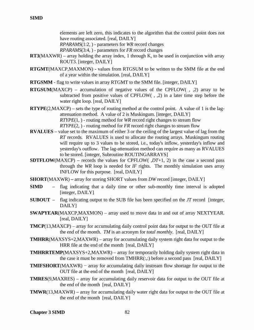
SIMD
Chapter 3 SIMD 82
elements are left zero, this indicates to the algorithm that the control point does not have routing associated. [real, DAILY]
RPARAMS(1:2, ) - parameters for WR record changes RPARAMS(3:4, ) - parameters for FR record changes RT3(MAXWR) – array holding the array index, 1 through K, to be used in conjunction with array
ROUT3. [integer, DAILY] RTGMT(MAXCP,MAXMON) - values from RTGSUM to be written to the SMM file at the end
of a year within the simulation. [real, DAILY] RTGSMM - flag to write values in array RTGMT to the SMM file. [integer, DAILY] RTGSUM(MAXCP) – accumulation of negative values of the CPFLOW( , ,2) array to be
subtracted from positive values of CPFLOW( , ,2) in a later time step before the water right loop. [real, DAILY]
RTYPE(2,MAXCP) – sets the type of routing method at the control point. A value of 1 is the lag-attenuation method. A value of 2 is Muskingum. [integer, DAILY]
RTYPE(1, ) - routing method for WR record right changes to stream flow RTYPE(2, ) - routing method for FR record right changes to stream flow RVALUES – value set to the maximum of either 3 or the ceiling of the largest value of lag from the
RT records. RVALUES is used to allocate the routing arrays. Muskingum routing will require up to 3 values to be stored, i.e., today's inflow, yesterday's inflow and yesterday's outflow. The lag-attenuation method can require as many as RVALUES to be stored. [integer, Subroutine ROUTINGARRAYS]
SDTFLOW(MAXCP) – records the values for CPFLOW( ,DT+1, 2) in the case a second pass through the WR loop is needed for IF rights. The monthly simulation uses array INFLOW for this purpose. [real, DAILY]
SHORT(MAXWR) – array for storing SHORT values from DW record [integer, DAILY] SIMD – flag indicating that a daily time or other sub-monthly time interval is adopted
[integer, DAILY] SUBOUT – flag indicating output to the SUB file has been specified on the JT record [integer,
DAILY] SWAPYEAR(MAXCP,MAXMON) – array used to move data in and out of array NEXTYEAR.
[real, DAILY] TMCP(13,MAXCP) – array for accumulating daily control point data for output to the OUT file at
the end of the month. TM is an acronym for total monthly. [real, DAILY] TMHRR(MAXSYS+2,MAXWR) – array for accumulating daily system right data for output to the
HRR file at the end of the month [real, DAILY] TMHRRTEMP(MAXSYS+2,MAXWR) – array for temporarily holding daily system right data in
the case it must be removed from TMHRR(:,:) before a second pass [real, DAILY] TMIFSHORT(MAXWR) − array for accumulating daily instream flow shortage for output to the
OUT file at the end of the month [real, DAILY] TMRES(9,MAXRES) – array for accumulating daily reservoir data for output to the OUT file at
the end of the month [real, DAILY] TMWR(13,MAXWR) – array for accumulating daily water right data for output to the OUT file at
the end of the month [real, DAILY]

SIMD
Chapter 3 SIMD 83
TMWRTEMP(12,MAXWR) – array for temporarily holding daily water right data in the case it must be removed from TMWR(:,:) before a second pass to consider instream flow shortages [real, DAILY]
UAFF – parameter that stores the file unit number for the AFF file [integer, DAILY] UDCF – parameter that stores the file unit number for the DCF file [integer, DAILY] USMM – parameter that stores the file unit number for the SMM file [integer, DAILY] USUB – parameter that stores the file unit number for the SUB file [integer, DAILY] VR(NDAY(MT) – variability ratio used in disaggregation method 3 [DFLOWS, DAILY] VRL – upper limit of the variability ratio used in disaggregation method 3, entered on the JT record
[real, DAILY] WRMETH - parameter on JU record for setting the method of adding the routed changes to flow to
the stream network. These changes to flow were created by WR record rights. [integer, DAILY]
WRNUM(MAXWR,5) – water right type. Flood control storage rights, FR records, are set to type 20. Flood control release rights, FR records, are set to type 21. Flood flow limit rights, FF records, are set to type 22. [integer, COMVAR]
WRNUM(MAXWR,13) – flag to output daily water right data. The monthly equivalent is WRNUM( ,6) [integer, COMVAR]
WROUT2(MAXGP2) – identifiers of water rights specified on W2 records to output to the SUB file [character, DAILY]
XDAY(MAXWR) - array for storing XDAY values from the DW record [integer, DAILY] YEARFLAG – indicates status of current pass through the beginning of the annual loop to the main
program’s annual loop and to Subroutine YEARPASS [integer, DAILY] YEARFLAG = 0, YEAR = YRST YEARFLAG = 1, YEAR = YRST+1 YEARFLAG = 2, YEAR ≤ NYRS
Information for Tracking Changes to Flow in the Routing Arrays
Changes to flow must be routed downstream when one or more RT records are provided in the DCF file. Stream flow depletions, return flow, and reservoir releases are the three types of changes to flow that are routed. Changes to flow associated with WR records are routed using the RFA values developed from the normal flow routing parameters of the RT record. Changes to flow associated with FR records are routed using the RFAF values developed from the flood flow routing parameters of the RT record. The routing arrays described below are used to store values of routed changes to flow that are to be applied to the CPFLOW or RESREL array in future days. Routing Outside of Water Right Priority Sequence ROUT1(maxcp,I) – used to record next-month changes to flow that are applied outside of the water right priority sequence, also known as the water right loop. Depletions routed according to JU record options WRMETH 1, depletions and returns routed according to FRMETH 1, returns for WR record options RFMETH 2 and 4, and depletions to a confluence for a system right (see ROUT5

SIMD
Chapter 3 SIMD 84
array description) are applied directly to CPFLOW(,,2) for the current day. When those future downstream changes to flow must be applied in days beyond those remaining in the current month, the changes to flow are stored in array ROUT1(,) and applied before the priority sequence on the first day of the next month.
I = Max(Maxval(MAXTED),Maxval(MAXTEDF)) SROUT1 – array for storing/restoring ROUT1 for the second pass IF loop FROUT1 – array for storing/restoring ROUT1 for the forecast loop
ROUT1 is applied to CPFLOW(,,2) and then zero’d at the start of each month, i.e., DT = 1 in the real simulation and in the forecast simulation. The values in ROUT1 do not have to be shifted down after each day of simulation as is required for the arrays which apply routed changes to flow within the priority sequence. Allocation ROUT1 occurs in Subroutine ROUTINGARRAYS if any of the following are true:
• WRMETH =1 • FRMETH = 1 • RFMETH =2 or 4 and non-zero return flow coefficients • CI records present • MS records present • FA record adjustments are being applied using FAD options 2 or 3
ROUT(Max(NRT,NRTF),4) – used in Subroutine ADJUST to aggregate all changes to flow that will not be applied to CPFLOW in the current day. Since these changes to flow will not be applied to CPFLOW in the current day, they will have no effect on water availability if they are not applied to CPFLOW until after the water right loop is complete. Subroutine ADJUST aggregates all changes to flow in array ROUT at the first routing control point and does not rout these changes any further. Only those changes to flow that can be applied to CPFLOW in the current day are applied to CPFLOW in Subroutine ADJUST. The flag RFLAG1 designates when array ROUT is to be used in Subroutine ADJUST. Water rights using the PX record field 4 options and water rights using the SO record field 13 options do not use array ROUT. RFLAG1 is set to zero and all next-day changes to flow for these water rights are loaded into array ROUT1. Use of RFLAG1 in Subroutine ADJUST not only serves as a flag to store values in array ROUT, but it also serves as a flag to exit the adjustment loop when no more same-day changes to flow are made. In essence, when no more same-day changes to flow are being made, then all changes to flow are to be applied in future days and exiting the adjustment loop will save computational time. Array ROUT is loaded with values that have not been routed beyond the first routing control point encountered in Subroutine ADJUST. These pre-routed values are aggregated and the routing is completed after the water right loop. The post-routed values from array ROUT are loaded into array ROUT1. ROUT1/2/3/4/44/5 contain post-routed values that are ready to be applied to the CPFLOW array. Depletions Within the Priority Sequence ROUT2(MAXWR,L,I) – used to record changes to flow that are applied within the water right priority sequence. Depletions according to JU record options WRMETH 2 and depletions and

SIMD
Chapter 3 SIMD 85
returns according to FRMETH 2 are applied directly to CPFLOW(,,2) for the current day. When those future downstream changes to flow must be applied in days beyond those remaining in the current month, the changes to flow are stored in array ROUT2 and applied to CPFLOW within the priority sequence when the respective right is considered in priority order.
L = Max(LENGTHROUT,LENGTHROUTF) I = Max(Maxval(MAXTED),Maxval(MAXTEDF)) SROUT2 – array for storing/restoring ROUT2 for the second pass IF loop FROUT2 – array for storing/restoring ROUT2 for the forecast loop
The values in ROUT2 are shifted down after each day of simulation so that the first element in the array’s third dimension corresponds to the current day when array ROUT2 is applied to CPFLOW at the start of the water right priority sequence. Allocation ROUT2 occurs in Subroutine ROUTINGARRAYS if any of the following are true:
• WRMETH =2 • FRMETH = 2
LENGTHROUT and LENGTHROUTF are the number of control points below the water right location, LOCNUM. Therefore, ROUT2 only contains routed changes below LOCNUM for future days. Therefore, element 1 in the second dimension of ROUT2 is the first control point downstream of LOCNUM. Since WR record return flows can have a different location than the stream flow depletion for the same water right, return flows for RFMETH 1 and 3 are recorded in ROUT3. FR records always produce their stream flow depletions and returns at the same location. Returns Within the Priority Sequence ROUT3(maxwr,L,I) – used in the same manner as ROUT2 except it is for recording WR record returns to be applied within the priority sequence. WR record return flows can have a different location, RETNUM, than the stream flow depletion, LOCNUM, for the same water right. Therefore, RETNUM to the outlet can be a different sequence of control points than LOCNUM to the outlet.
SROUT3 – array for storing/restoring ROUT3 for the second pass IF loop FROUT3 – array for storing/restoring ROUT3 for the forecast loop
The values in ROUT2 are shifted down after each day of simulation so that the first element in the array’s third dimension corresponds to the current day when array ROUT2 is applied to CPFLOW at the start of the water right priority sequence. Allocation ROUT3 only if the following is true:
• RFMETH =1 or 3 and non-zero return flow coefficients Reservoir Releases Outside of or Within the Priority Sequence
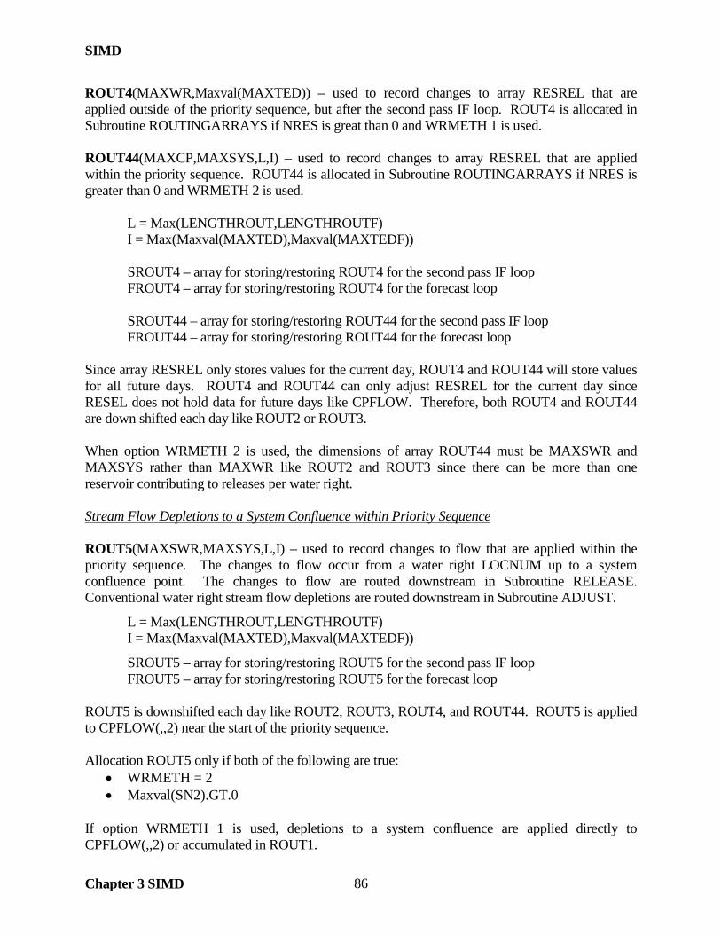
SIMD
Chapter 3 SIMD 86
ROUT4(MAXWR,Maxval(MAXTED)) – used to record changes to array RESREL that are applied outside of the priority sequence, but after the second pass IF loop. ROUT4 is allocated in Subroutine ROUTINGARRAYS if NRES is great than 0 and WRMETH 1 is used. ROUT44(MAXCP,MAXSYS,L,I) – used to record changes to array RESREL that are applied within the priority sequence. ROUT44 is allocated in Subroutine ROUTINGARRAYS if NRES is greater than 0 and WRMETH 2 is used.
L = Max(LENGTHROUT,LENGTHROUTF) I = Max(Maxval(MAXTED),Maxval(MAXTEDF))
SROUT4 – array for storing/restoring ROUT4 for the second pass IF loop FROUT4 – array for storing/restoring ROUT4 for the forecast loop
SROUT44 – array for storing/restoring ROUT44 for the second pass IF loop FROUT44 – array for storing/restoring ROUT44 for the forecast loop
Since array RESREL only stores values for the current day, ROUT4 and ROUT44 will store values for all future days. ROUT4 and ROUT44 can only adjust RESREL for the current day since RESEL does not hold data for future days like CPFLOW. Therefore, both ROUT4 and ROUT44 are down shifted each day like ROUT2 or ROUT3. When option WRMETH 2 is used, the dimensions of array ROUT44 must be MAXSWR and MAXSYS rather than MAXWR like ROUT2 and ROUT3 since there can be more than one reservoir contributing to releases per water right. Stream Flow Depletions to a System Confluence within Priority Sequence ROUT5(MAXSWR,MAXSYS,L,I) – used to record changes to flow that are applied within the priority sequence. The changes to flow occur from a water right LOCNUM up to a system confluence point. The changes to flow are routed downstream in Subroutine RELEASE. Conventional water right stream flow depletions are routed downstream in Subroutine ADJUST.
L = Max(LENGTHROUT,LENGTHROUTF) I = Max(Maxval(MAXTED),Maxval(MAXTEDF))
SROUT5 – array for storing/restoring ROUT5 for the second pass IF loop FROUT5 – array for storing/restoring ROUT5 for the forecast loop
ROUT5 is downshifted each day like ROUT2, ROUT3, ROUT4, and ROUT44. ROUT5 is applied to CPFLOW(,,2) near the start of the priority sequence. Allocation ROUT5 only if both of the following are true:
• WRMETH = 2 • Maxval(SN2).GT.0
If option WRMETH 1 is used, depletions to a system confluence are applied directly to CPFLOW(,,2) or accumulated in ROUT1.

SIMD
Chapter 3 SIMD 87
Miscellaneous Notes Related to Routing Arrays Return flows are added to the ROUT arrays. Stream flow depletions are subtracted from the ROUT arrays. The ROUT arrays are therefore always added to CPFLOW when making adjustments. RFLAG2/3/44/5 are used to flag a routing control point and to accumulate the routed values into the respective routing array. Unlike the use of RFLAG1 and array ROUT, arrays ROUT2/3/44/5 accumulate values already routed and can be applied to CPFLOW after the channel loss adjustment. Array ROUT values must be routed downstream before accumulating into array ROUT1. SIMD could check if a routing array exists with the Allocated function. However, it is easier to set flags for ease of coding. ROUTFLAG1/2/3/4/44/5 are integer variables that are set to a value of 1 if the respective routing array is allocated. The CLOSS1 array is always allocated if NRT or NRTF are greater than zero, so no ROUTFLAG variable is set for this array. Channel Losses Associated with Depletions and Returns CLOSS1(I,MAXCP,2) – used to record channel losses associated with depletions and return flows for future days. Future depletion losses are placed into element 1 in the third dimension. Future return flow losses are placed into element 2 in the third dimension. Array CLOSS(MAXCP,2) holds present day channel losses only. I = Max(Maxval(MAXTED),Maxval(MAXTEDF))
SCLOSS1 – array for storing/restoring SCLOSS1 for the second pass IF loop There is no forecasting array, FCLOSS1, since values are not accumulated in array CLOSS1 during the forecast simulation. CLOSS1 is downshifted each day like ROUT2, ROUT3, ROUT4, ROUT44 and ROUT5.
Information for Tracking Reverse Routing in Water Availability The standard “look downstream” is performed in Subroutine AVALB for each control point downstream of the water right stream flow depletion point, LOCNUM. Downstream values of the CPFLOW(,,2) array are divided by the cumulative delivery factor for reverse channel loss consideration. If the present-day RFA value, RFA(,,1), for any control point is zero, then the CPFLOW array at that control point is not considered. If the present day value of the RFA(,,1) is non-zero, then this control point is considered for constraint on present day availability. Reverse routing is performed by dividing the reverse channel loss adjusted CPFLOW(,,2) value by the RFA(,,1) value. The algorithm cannot skip the remaining downstream control points once the present day RFA values become zero. Future RFA values, RFA(,,2) to RFA(,,FPRD), must be considered for their constrain on forecasted water availability. During the forecast simulation, store the forecasted values of water availability in the even numbered FAVAMT arrays. Though the odd numbered forecasting arrays are populated by old

SIMD
Chapter 3 SIMD 88
forecast values during the forecast simulation, the odd numbered arrays are still being used for forecasting within the forecast simulation. Therefore, the odd number arrays cannot be altered during the forecast simulation. At the conclusion of the forecast simulation, move all newly recorded values from the even numbered FAVAMT arrays into the odd numbered FAVAMT arrays for use in the real-day and within next forecast simulation. In any real-day, water availability for a WR record is conditioned by the control points with positive values in RFA(LOCNUM, : ,1) and by FAVAMT1(1, WR). In any day during the forecast simulation, availability for a WR record is conditioned by control points with positive values in RFA(LOCNUM, : ,1) and by FAVAMT1(FDTCOUNT, WR) when FDTCOUNT is the number of future days beyond the real-day. At the end of each forecasting simulation, the results of the even numbered FAVAMT arrays are transferred into the odd numbered FAVAMT arrays. A real-day of simulation is conducted using the odd numbered FAVAMT arrays as a constraint on present day water availability. At the end of each real-day, the values in the odd numbered arrays are down shifted by 1 day. The next time step will be a forecasting day that is +1 time steps ahead of the current end-of-day. The down shift will allow for proper temporal alignment of the old forecasted availability during the forecast simulation. Within Subroutine AVALB, only reverse routing adjusted availability for time steps 2 through APERIOD are recorded. These future CPFLOW(,,2) values are potential constraints on water availability at the upstream LOCNUM in days prior to the current day in the forecast simulation. The LOCNUM and downstream CPFLOW(,,2) values that have positive RFA(,,1) will always be considered in the computation of variable AVAMT for the current day (1). Each single value in an even numbered FAVAMT array is the minimum reverse routing value encountered in the future in forecast days 2 through APERIOD. The real-day that will be simulated immediately after the forecast simulation is denoted as FAVAMT array element 1 in the first dimension. Availability values recorded in the even numbered arrays are updated completely during the forecast simulation. Odd numbered FAVAMT arrays contain forecasted availability used within the forecast simulation. However, the data in the odd numbered arrays are not updated as the forecast simulation progresses. In other words, choices by water rights in forecast days A and B do no alter the forecasted availability contained in the odd numbered FAVAMT arrays for forecast days C and D. FAVAMT Array Flags The FAVAMT arrays are specific to the location, LOCNUM, and the priority date of the call to Subroutine AVALB. Calls to Subroutine AVALB are made within and outside of the water right loop. AVAFLAG1 is positive if the simulation is conducting a real-day. AVAFLAG1 is negative is the simulation is in forecast mode. If the simulation is in forecast mode, values of future downstream availability are accumulated into the even numbered arrays, e.g., FAVAMT2, FAVAMT6. Only the odd numbed arrays are used to adjusted water availability. AVAFLAG2 is set equal to the index value of either a TO, FS/CV/PF, or ZZ record when the appropriate call to Subroutine AVALB is made.

SIMD
Chapter 3 SIMD 89
The following values are applied to AVAFLAG1 and AVAFLAG2 based on the call to Subroutine AVALB and the forecast status:
• AVAFLAG1 = +/- 2, AVAFLAG2 = 0: Call AVALB within the water rights loop after target building is complete
• AVAFLAG1 = +/- 4, AVAFLAG2 = 0: Call AVALB after the water rights loop for the RUF option, FS/CV end-of-period update, or for generating CP record output
• AVAFLAG1 = +/- 6, AVAFLAG2 = TO record index: Call AVALB for consideration of TOTARGET option 3. Since TO records can specify a different control point than the WR record, there must be a separate set of FAVAMT arrays for recording availability for TO records.
• AVAFLAG1 = +/- 8, AVAFLAG2 = FS/CV/PF record index: Call AVALB from within the water rights loop for consideration of FS/CV/PF record control point availability option. Since FS/CV/PF records can specify a different control point than the WR record, there must be a separate set of FAVAMT arrays for recording availability.
• AVAFLAG1 = +/- 10, AVAFLAG2 = ZZ record index: Call to AVALB for consideration of ZZ records. AVAFLAG2 = +ZZ record index if call to Subroutine AVALB comes from within water right loop. AVAFLAG2 = -1 if call to Subroutine AVALB comes before water right loop. If calling Subroutine AVALB within the water right loop, use WR+1 for accessing the third dimension of arrays FAVAMT9/10. If calling Subroutine AVALB before the water right loop, access element 1 of the third dimension of arrays FAVAMT9/10.
Calls to Subroutine AVALB from Subroutine INCREM never use forecasted water availability. The calls to Subroutine AVALB from Subroutine INCREM will first reset the value of FCST to zero so that water availability is determined with the standard method of looking at all control points down to the outlet. FCST is restored to its appropriate value after returning from Subroutine AVALB. Calls to Subroutine AVALB from Subroutine RELEASE use AVAFLAG equal to 2 because these calls originate from within the water right priority sequence or from within Subroutine POWER which itself originates within the priority sequence. Water availability has already been computed and loaded into FAVAMT2 with AVAFLAG equal to -2 at the top of the water right priority sequence. AVAFLAG1 is set to -4 from only one place after the water right priority sequence even though there are multiple locations where calls to Subroutine AVALB are made for control point availability. During the forecast simulation and immediately after the water right priority sequence, a call to Subroutine AVALB is made for all control points to load values of availability into array FAVAMT4. Subsequent calls to Subroutine AVALB after the water right priority sequence do not need to re-load the same data into FAVAMT4 during the forecast simulation. Therefore, these calls to Subroutine AVALB will use AVAFLAG1 equal to 4. These calls for control point availability after the water right priority sequence include the RUF option and updates to the FS/CV record accounting. Control point output records are not generated during the forecast simulation.

SIMD
Chapter 3 SIMD 90

SALT
Chapter 4 SALT 91
CHAPTER 4 SALT The Fortran variable names are used in the Salinity Manual in explaining the equations and computational algorithms incorporated in the program SALT. This direct reference to the Fortran variables connects the explanations of the SALT simulation procedures in the Salinity Manual closer to the actual Fortran code than the coverage of the other WRAP programs and their manuals. The Salinity Manual is referenced as follows.
Salinity Simulation with WRAP, TWRI TR-317, July 2009.
A salinity simulation is performed in three steps.
1. A SIM or SIMD simulation is performed to determine water quantities for all control points which are stored in the OUT output file (filename extension OUT).
2. A SALT salinity tracking simulation is performed that combines salinity data from the SALT SIN and BRC input files with the SIM/SIMD OUT file simulation results.
3. TABLES is used to develop tables that organize and summarize SALT SAL file simulation results. The simulation results may also be plotted using HEC-DSSVue.
SALT combines the monthly time series of water quantities from the SIM or aggregated monthly SIMD simulation results output OUT file with concentrations or loads of inflows from a salinity input SIN file. Loads and concentrations of salinity constituents are computed for regulated stream flows, reservoir storage, and diversions throughout the river/reservoir system.
Organization of SALT The Module COMVAR assigns the type (integer, real, character) and number of array dimensions (one or two dimensional) for the variables used in common by the main program and/or subroutines. Other variables declared at the beginning of the main program or a particular subroutine are used solely in that subprogram.
Input data other than time series are read by Subroutine READIN from the SIN and DAT files. The monthly water quality and quantity time series data are read within the main program from the SIN and OUT files.
The salinity tracking computations proceed by control point in upstream-to-downstream sequence. If the control points are not already ordered from upstream to downstream by the sequence in which the CP records are entered in the DAT file, Subroutine CONPTS must be called to establish the required sequencing internally within SALT. Ordering of control points is specified by the array OCP(I), where OCP(I) is the CP record sequence and the index I is the upstream-to-downstream sequence.
The salinity simulation computations are performed within the main program as outlined in Figure 4.1. In a given month, the computations are performed for each individual control point in turn. First, flow volumes and loads entering the control point are determined. Then volumes and loads leaving the control point and the load in storage are determined. The equations and computational algorithms are explained in the Salinity Manual.

SALT
Chapter 4 SALT 92
________________________________________________________________________________________________________
• Subroutine FILEIN is called to open the five required files. • Subroutine READIN is called to read all input data except the time series data. • Subroutine CONPTS is called to sequence control points in upstream-to-
downstream order with the OCP(cp) array. • Dimension limits are set. • The index IS(cp) is established which assigns each control point a set of
salinity data. • An option activated by MF entered in SC record field 5 allows a table of
control point information to the written to the message SMS file. • The salinity tracking computations are performed within nested loops
illustrated below with the inflow and outflow volumes, loads, and concentrations being computed within the inner control point loop following methods outlined in the Salinity Manual.
Constituent Loop
S record concentrations or loads are read from SIN file. Constant concentrations from CC records are assigned.
Annual and Monthly Loops
Control Point Loop
Inflow and outflow volumes, loads, and concentrations are computed as explained in the Salinity Manual.
Salinity simulation results are recorded in the SAL file by control point and detailed control point data are written
to SMS file as specified by SC record fields 12 and 13.
The volume and load summary table is
developed and written to the SMS file.
Figure 4.1 Organization of SALT
Input and Output Files The first column of Table 4.1 lists the unit numbers of the files which are assigned by open statements and referenced in read and write statements. The second column shows the filename extensions. The required SIN, DAT, OUT, SAL, and SMS files are opened by Subroutine FILEIN. The optional BRS and BRC files are opened within Subroutine READIN if selected by the parameters BEGSTO and BEGCON entered in SC record fields 8 and 9. The third column of Table 4.1 indicates whether input data are read from the file or output data is recorded in the file. File contents are described in the last column. The SAL output file is direct access. The others are read or written sequentially.
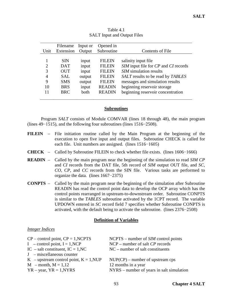
SALT
Chapter 4 SALT 93
Table 4.1 SALT Input and Output Files
Filename Input or Opened in
Unit Extension Output Subroutine Contents of File
1 SIN input FILEIN salinity input file 2 DAT input FILEIN SIM input file for CP and CI records 3 OUT input FILEIN SIM simulation results 4 SAL output FILEIN SALT results to be read by TABLES 9 SMS output FILEIN messages and simulation results 10 BRS input READIN beginning reservoir storage 11 BRC both READIN beginning reservoir concentration
Subroutines Program SALT consists of Module COMVAR (lines 18 through 48), the main program (lines 49−1515), and the following four subroutines (lines 1516−2508). FILEIN – File initiation routine called by the Main Program at the beginning of the
execution to open five input and output files. Subroutine CHECK is called for each file. Unit numbers are assigned. (lines 1516−1605)
CHECK – Called by Subroutine FILEIN to check whether file exists. (lines 1606−1666)
READIN – Called by the main program near the beginning of the simulation to read SIM CP and CI records from the DAT file, 5th record of SIM output OUT file, and SC, CO, CP, and CC records from the SIN file. Various tasks are performed to organize the data. (lines 1667−2375)
CONPTS – Called by the main program near the beginning of the simulation after Subroutine READIN has read the control point data to develop the OCP array which has the control points rearranged in upstream-to-downstream order. Subroutine CONPTS is similar to the TABLES subroutine activated by the 1CPT record. The variable UPDOWN entered in SC record field 7 specifies whether Subroutine CONPTS is activated, with the default being to activate the subroutine. (lines 2376−2508)
Definition of Variables
Integer Indices CP – control point, CP = 1,NCPTS NCPTS – number of SIM control points I – control point, I = 1,NCP NCP – number of salt CP records IC – salt constituent, IC = 1,NC NC – number of salt constituents J – miscellaneous counter K – upstream control point, K = 1,NUP NUP(CP) – number of upstream cps M – month, M = 1,12 12 months in a year YR – year, YR = 1,NYRS NYRS – number of years in salt simulation

SALT
Chapter 4 SALT 94
ICP(CP) – index assigning SALT CP/CC/S record data to SIM control points ICP(CP) = 0 if no SALT CP record is read for control point CP ICP(CP) = I if a SALT CP record is read for control point CP, I = 1,NCP
IS(CP) – index that assigns a set of salt data to each of the NCPTS control points IS(CP) = ICP(CP) if a SALT CP record is read for control point CP IS(CP) = ICP(CP-1) otherwise, CP = 1,NCPTS
CPUS(CP,K) – integer identifiers of control points K=1,NUP(CP) located upstream of CP
OCP(I) – OCP(I) is the order in which CP records are sequenced in the DAT file. The array index I represents the upstream-to-downstream order required by the SALT computations. Subroutine CONPTS develops the OCP(I) array for rearranging the control points in upstream-to-downstream sequence. Character identifiers CD – record identifier (A2) ID – temporary control point identifier on input records (A6) CPID(CP,1) – control point identifier from SIM DAT input file (A6) CPID(CP,2) – identifier of next downstream control point from SIM input file (A6) CPSALT(I) – control point identifier from SALT CP and S records (A6) CPOID(J) – identifiers from CO records of control points to be included in output (A6) Integers read in Subroutine READIN from 5th record of SIM output file YRSTART – starting year of SIM simulation MAXYRS – number of years in SIM simulation MAXCP – number of control points in SIM simulation, MAXCP = NCPTS NWR – number of water rights included in SIM simulation output file NRES – number of reservoirs included in SIM simulation output file Time series of volumes from SIM results read in main program from SIM output file. DS(CP) – diversion shortage DT(CP) – diversion target DIV – diversion computed as DT(CP) – DS(CP) EVAP(CP) – net evaporation less evaporation STO(CP) – reservoir storage content RET(CP) – return flow returned to the control point NAT(CP) – naturalized flow REG(CP) – regulated flow CLC(CP) – channel loss credits CL(CP) – channel losses
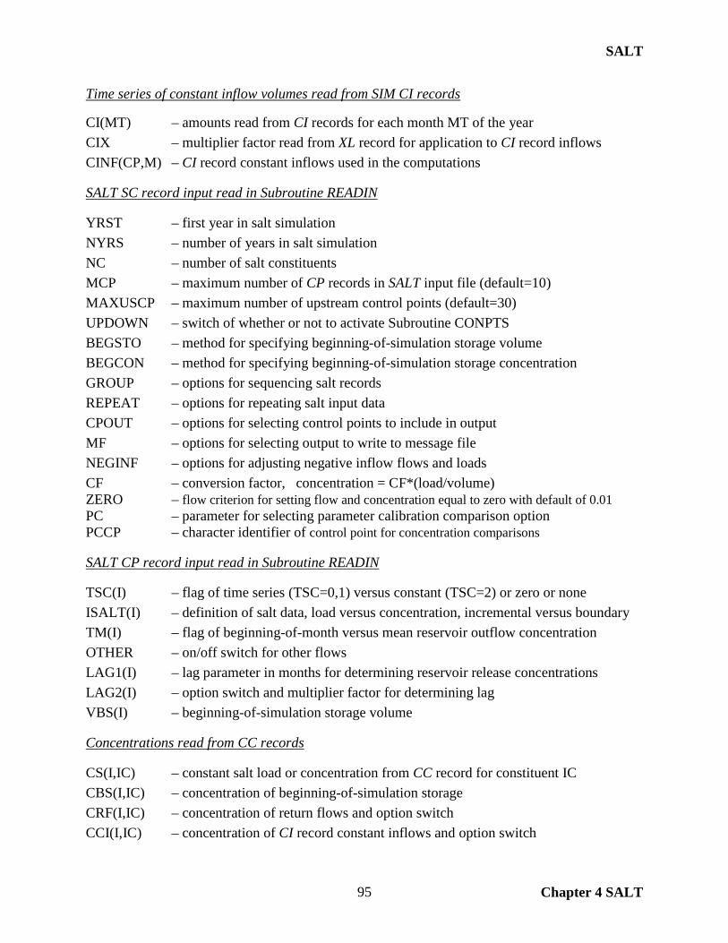
SALT
Chapter 4 SALT 95
Time series of constant inflow volumes read from SIM CI records CI(MT) – amounts read from CI records for each month MT of the year CIX – multiplier factor read from XL record for application to CI record inflows CINF(CP,M) – CI record constant inflows used in the computations SALT SC record input read in Subroutine READIN YRST – first year in salt simulation NYRS – number of years in salt simulation NC – number of salt constituents MCP – maximum number of CP records in SALT input file (default=10) MAXUSCP – maximum number of upstream control points (default=30) UPDOWN – switch of whether or not to activate Subroutine CONPTS BEGSTO – method for specifying beginning-of-simulation storage volume BEGCON – method for specifying beginning-of-simulation storage concentration GROUP – options for sequencing salt records REPEAT – options for repeating salt input data CPOUT – options for selecting control points to include in output MF – options for selecting output to write to message file NEGINF – options for adjusting negative inflow flows and loads CF – conversion factor, concentration = CF*(load/volume) ZERO – flow criterion for setting flow and concentration equal to zero with default of 0.01 PC – parameter for selecting parameter calibration comparison option PCCP – character identifier of control point for concentration comparisons SALT CP record input read in Subroutine READIN TSC(I) – flag of time series (TSC=0,1) versus constant (TSC=2) or zero or none ISALT(I) – definition of salt data, load versus concentration, incremental versus boundary TM(I) – flag of beginning-of-month versus mean reservoir outflow concentration OTHER – on/off switch for other flows LAG1(I) – lag parameter in months for determining reservoir release concentrations LAG2(I) – option switch and multiplier factor for determining lag VBS(I) – beginning-of-simulation storage volume Concentrations read from CC records CS(I,IC) – constant salt load or concentration from CC record for constituent IC CBS(I,IC) – concentration of beginning-of-simulation storage CRF(I,IC) – concentration of return flows and option switch CCI(I,IC) – concentration of CI record constant inflows and option switch
SALT
Chapter 4 SALT 96
ZC((I,IC) – Concentration that replaces zero concentration return flows, CI record inflows, and channel losses/credits
MINOC(I,IC) – minimum limit on upstream control point outflow concentrations used to assign concentrations to return flows, CI record constant inflows, channel loss credits, and channel losses
MAXOC(I,IC) – maximum limit on upstream control point outflow concentrations used to assign concentrations to return flows, CI record constant inflows, channel loss credits, and channel losses
MINSC(I,IC) – minimum storage concentration limit that controls the maximum concentration of reservoir outflows
MAXROC(I,IC) – maximum limit on reservoir outflow concentrations CLF(I,IC) – multiplier factor for loads of channel losses and channel loss credits Reservoir outflow concentration parameters read from RC record RCF1(I,IC) – regulated flow concentration adjustment factor RCF2(I,IC) – regulated flow concentration adjustment factor RCD1(I,IC) – diversion concentration adjustment factor RCD2(I,IC) – diversion concentration adjustment factor RCVOL(I,IC) – storage volume capacity Concentration or load data read from S records SM(M) – 12 monthly values read from a S record Reorganized concentration and load input data from CC and S records SI(YR,M,I) – values read from S or CC records for NCP control points S(CP) – values from SI array or repeats thereof in time step loop Beginning volumes, loads, and concentrations BPSTX – beginning-of-simulation storage read from BRS file for an individual reservoir BSS(CP) – beginning-of-simulation storage volume for control points BRC(CP,IC) – beginning-of-simulation concentrations read from BRC file BSTO(CP) – beginning-of-period storage volume BSL(CP) – beginning-of-period storage load BPC(CP) – beginning-of-period storage concentration BSLLAG(CP) – beginning-of-period storage load in computational reservoir lag load balance Integer control point indexes in Subroutine CONPTS IORDER – control point counter NUPC(CP) – counter of the number of upstream control points already ordered NUP(CP) – number of control points located immediately upstream of control point CP
SALT
Chapter 4 SALT 97
ORDER(CP) – integer array for intermediate ordering of control points OCP(I) – integer array connecting upstream-to-downstream sequence to the order in
which CP records are found in DAT file. OCP(I) is the order in which CP records are sequenced in DAT file. The array index I represents upstream- to-downstream order.
Computed volumes and loads entering a control point during a time step FNAT – incremental naturalized flow volume LNAT – load of incremental naturalized flow FREG – sum of regulated flow volumes at upstream control points LREG – sum of loads of regulated flows at upstream control points LRET – load of return flow LDIV – load of diversions LCIN – load of CI record constant inflows FCL – sum of channel loss volumes from upstream control points LCL – sum of loads of channel losses from upstream control points FCLC – sum of channel loss credit volumes from upstream control points LCLC – sum of loads of channel loss credits from upstream control points FIN – total inflow flow entering a control point LIN – total inflow flow entering a control point CIN – concentration of total inflows = (LIN/FIN)*CF FIN2 – total outflows plus the change in storage which should equal total inflows Computed loads and concentration of outflows and ending storage STOL(CP) – load of the end-of-period storage at the control point STOC(CP) – concentration of the end-of-period storage at the control point MC(CP) – mean concentration of storage during the month FOUT(CP) – total outflow volume leaving control point is summation of REG(CP), DIV,
and FOTH LOUT(CP) – total outflow load from control point is summation of REGL(CP), LDIV, LOTH COUT – outflow concentration associated with FOUT(CP) and LOUT(CP)
REGC(CP) = CDIV = COTH = COUT REGL(CP) – load of the regulated flow leaving the control point REGC(CP) – concentration of the regulated flow leaving the control point DIV – volume of diversion LDIV – load of diversion CDIV – concentration of diversion FOTH – reservoir releases for hydropower and instream flow requirements are not
included in the SIM output file and thus are computed within SALT

SALT
Chapter 4 SALT 98
LOTH – load associated with FOTH COTH – concentration associated with FOTH XCOUT – concentration of outflow from upstream control points used in the computation
of LCLC, LCL, LRET, and LCIN XFOUT – upstream control point outflow flow corresponding with XCOUT XLOUT – upstream control point outflow load corresponding with XCOUT MINSL – minimum limit on the end-of-month storage load set by MINSC(I,IC)
from CC record MAXOUT – maximum reservoir outflow load limit MAXCON – maximum reservoir outflow concentration limit MINOC(I,IC) and MAXOC(I,IC) – CC record minimum and maximum concentration limits Variables related to lag options for setting reservoir outflow concentrations TM(I) – parameter from CP record indicating whether beginning-of-month versus mean
reservoir release concentration is used LAG1(I) – maximum lag limit from CP record LAG2(I) – parameter from CP record that serves as the multiplier in the flow retention.
A LAG2(I) of -1.0 switches to option setting LAG = LAG1(I) MAXL – largest LAG(I) read on any CP record that is used to set certain limits LAG – lag time in months determined based on parameters LAG1(I) and LAG2(I) LAGFLAG – LAGFLAG is either 0 or 99 indicating that lag feature is not activated (0) or is
activated (99) for the current control point ZLAG – flow retention times (=storage volume/flow rate) for various lengths L of time
extending back from the current month that are used to compute LAG
ZAVG – average storage volume during the period of L months extending back from the current month that is used in computation of ZLAG
ZBST – summation of beginning-of-month storage volume during the L months ZFOUT – summation of reservoir outflow volume during the period of L months
extending back from the current month used in computation of ZLAG
ZMONTH – the starting month of the preceding time period defined by lag that is used to indicate whether the lag extends back before first month of simulation. A negative ZMONTH means that lag extends back before time zero.
ZLIN – Inflow load to reservoir during current months based on lagged load inflow from LAG month ago and months preceding LAG month ago
STOCLAG – end-of-month storage concentration of lagged load-balance reservoir. This is a conceptual reservoir used solely to compute outflow concentrations.
BPCLAG(CP) – beginning -of-month storage concentration of lagged load-balance reservoir BSLLAG(CP) – beginning -of-month storage load of lagged load-balance reservoir STOLLAG(CP) – end-of-month storage load of lagged load-balance reservoir LINLAG(CP,L) – inflow loads in each of the MAXL preceding months L

SALT
Chapter 4 SALT 99
BSTOLAG(CP,L) – beginning -of-month storage in each of the MAXL preceding months L used to compute ZLAG
FOUTLAG(CP,L) – outflow volume during each of the MAXL preceding months L used to compute ZLAG
TEMPLOAD(L) – temporary memory of LINLAG(CP,L) while adjusting month index to increment one month
TEMPBSTO(L) – temporary memory of BSTOLAG(CP,L) while adjusting month index to increment one month
TEMPFOUT(L) – temporary memory of FOUTLAG(CP,L) while adjusting month index to increment one month
Total Flow and Load Summary Table Written to SMF File TOTFLOW(1) – total volume of naturalized flow (sum of FNAT)) TOTLOAD(1) – total load of naturalized flow (sum of LNAT) TOTFLOW(2) – total volume of return flows (sum of RET(CP)) TOTLOAD(2) – total load of return flows (sum of LRET) TOTFLOW(3) – total volume of CI record constant inflows (sum of CINF(CP,M)) TOTLOAD(3) – total load of CI record constant inflows (sum of LCIN TOTFLOW(4) – total volume of channel loss credits (sum of FCLC) TOTLOAD(4) – total load of channel loss credits (sum of LCLC) TOTFLOW(5) – total volume of channel losses (sum of FCL) TOTLOAD(5) – total load of channel losses (sum of LCL) TOTFLOW(6) – total volume of regulated flow (sum of REG) TOTLOAD(6) – total load of regulated flow (sum of REGL) TOTFLOW(7) – total volume of diversions (sum of DIV) TOTLOAD(7) – total load of diversions (sum of LDIV) TOTFLOW(8) – total volume of net evaporation (sum of EVAP(CP)) TOTFLOW(9) – total volume of beginning-of-simulation storage (sum of BPSTO(CP)) TOTLOAD(9) – total load of beginning-of-simulation storage (sum of BPL(CP)) TOTFLOW(10) – total volume of end-of-simulation storage (sum of STO(CP)) TOTLOAD(10) – total load of end-of-simulation storage (sum of STOL(CP)) TOTFLOW(11) – total change in storage volume = TOTFLOW(10)-TOTFLOW(9) TOTLOAD(11) – total change in storage load = TOTLOAD(10)-TOTLOAD(9) TOTFLOW(12) – total inflow volume minus total outflow volume TOTLOAD(12) – total inflow load minus total outflow load TOTFLOW(13) – total negative incremental naturalized flows TOTFLOW(14) – total negative flow inflows at a control point (sum of FINNEG) TOTLOAD(14) – total negative load inflows at a control point (sum of LINNEG) TOTFLOW(15) – volume balance difference (TOTFLOW(12)-TOTFLOW(11))
SALT
Chapter 4 SALT 100
TOTLOAD(15) – load balance difference (TOTLOAD(12)-TOTLOAD(11)) TOTFLOW(16) – regulated flows at an upstream boundary (sum of REG(CP)) TOTLOAD(16) – regulated flows at an upstream boundary (sum of REGL(CP)) TOTFLOW(17) – total volume of releases for hydropower and instream flows (sum of FOTH) TOTLOAD(17) – total load of reservoir releases for hydropower and IF (sum of LOTH) TOTFLOW(18) – cumulative naturalized flows at the one or more outlet control points XSTO – change in storage volume written to SMF file intermediate results table XSTOL – change in storage load written to SMF file intermediate results table XSUM – sum of inflow minus outflow volumes in intermediate results table XSUML – sum of inflow minus outflow loads in intermediate results table Variables Used in Parameter Calibration Criteria Routines PC – parameter calibration switch in SC record field 15 PCCP – control point identifier in SC record field 16 CCP – control point identifier on C1 and C2 records CFYR(K1) – year on C1 records CSYR(K1) – year on C2 records CFX(K1,J) – stream flow concentrations on C1 records CSX(K1,J) – reservoir storage concentrations on C2 records K1 – index and counter of number of C1 records K2 – index and counter of number of C2 records CXFN – counter of number of months of flow concentrations CXSN – counter of number of months of storage concentrations CX(1) – cumulative summation of computed regulated flow concentrations and mean of regulated flow concentrations CX(2) – cumulative summation of flow concentrations from C1 records and also mean of flow concentrations from C1 records X – computed flow concentration minus C1 record flow concentration CX(3) – cumulative summation of X between computed flow and also mean X CX(4) – cumulative summation of positive differences X between computed flow
concentration less C1 record flow concentration CX(5) – cumulative summation of negative differences X between computed flow
concentration less C1 record flow concentration CX(6) – cumulative summation of X squared and also mean of X squared CX(7) – maximum flow concentration difference X CX(8) – minimum flow concentration difference X X – computed flow concentration minus C2 record flow concentration CX(9) – cumulative summation of X and also mean X CX(10) – cumulative summation of computed storage concentrations and also mean of storage concentrations CX(11) – cumulative summation of storage concentrations from C2 records and also mean of storage concentrations from C2 records CX(12) – cumulative summation of positive differences X between computed storage concentration less C2 record storage concentration
SALT
Chapter 4 SALT 101
CX(13) – cumulative summation of negative differences X between computed storage concentration less C2 record storage concentration CX(14) – cumulative summation of X squared and also mean of X squared CX(15) – maximum positive storage concentration difference X CX(16) – absolute value of maximum negative storage concentration difference X Other Switches and Counters NSCP – number of control points with TSC indicating S records, used in an error check N – count of number of control points with S records read, used in an error check HEADING – flag of when to print headings for output tables OUTPUT(CP) – flag of control points to include in salt output files NWRITE – total number of control points in salt output files CIRECORD – counter of number of CI records read from SIM input file Variables Used by Subroutines FILEIN and CHECK in Initializing Files ALL – apply to all files NAME – file name ROOT – root of file name

SALT
Chapter 4 SALT 102

TABLES
Chapter 5 TABLES 103
CHAPTER 5 TABLES The post-simulation program TABLES provides capabilities for computing frequency and reliability indices and otherwise organizing, summarizing, analyzing, and displaying SIM, SIMD, and SALT simulation results. Though designed primarily for working with simulation results, simulation input may also be organized in tables with TABLES. The tabulations created with TABLES are typically stored in text files. TABLES can also convert time series of simulation results to records in a direct access binary DSS file that can be read by HEC-DSSVue. TABLES provides routines from performing frequency and reliability analyses as well as various other data manipulations, summaries, and tabulations.
Organization of TABLES Program TABLES is organized based on the input records in the TABLES input TIN file. The input records entered in the TIN file control the tables to be build by the various subroutines of TABLES. The input records are cited in the descriptions of the subroutines presented later in this chapter. The input records and resulting tables are categorized as types 1, 2, 3, 4, 5, 6, 7, and 8 as outlined in Table 5.1. Program TABLES is applied to organize, summarize, analyze, and display results from the WRAP simulation models which are listed below along with the associated TABLES input record types defined in Table 5.1.
• Program SIM covered in the basic Reference and Users Manuals (Types 1, 2, 3, 4, 5) • Daily features of SIMD covered in the Daily Manual (Types 6 and 7) • Program SALT covered in the Salinity Manual (Type 8)
After opening the TIN input file, TOU output file, and TMS message file, the Main Program of TABLES performs a preliminary reading of the identifiers of all records in the TIN file to count the various types of input records. This information is used to perform preliminary error checks and determine which other files to open. The Main Program then performs the following tasks, with the information read from the files being shared later by multiple subroutines.
• Files other than the already-opened TIN, TOU, and TMS files are opened. • Title records, if any, are read from the TIN file. • Parameters are read from the fifth line of the OUT file, fifth and sixth lines of
the SUB file, and second line of the SAL file if these files are opened. After completing these preliminaries, the Main Program reads the record identifiers of each record in the TIN file a second time starting at the beginning of the file. As each record identifier is read, the Main Program calls the appropriate subroutine to build tables as specified on that particular TIN file input record. After the tables are completed for a particular input record, the subroutine returns control back to the Main Program. The next record is read from the TIN file by the Main Program, and the appropriate subroutine is called. The primary individual subroutines that build the various types of tables are essentially self-contained independent programs, though most of them call the shared Subroutine ERROR and several call Subroutines IDEN and TITLES which play auxiliary supporting tasks.

TABLES
Chapter 5 TABLES 104
Table 5.1 Organization of TABLES by TIN File Input Record Types
Miscellaneous: TITL, PAGE, TEST input records in TIN file Subroutines TITLES, CVPAGE, TEST
Type 1 − Tables developed from SIM input DAT file: 1REC, 1SUM, 1SRT, 1CPT, 1LEN input records in TIN file Subroutines SUMDAT ,CONPTS, LENGTH
Type 2 − Tables developed from SIM output OUT file.
Time series in optional text file formats or DSS file: 33 time series records such as 2NAT, 2REG, 2UNA, 2CLO, 2CLC, 2URR, 2STO, 2EVA Subroutine SERIES which calls Subroutine IDEN
Reliability and frequency tables: 2REL, 2FRE, 2FRQ, 2RES records Subroutines RELIAB, FREQ, STORAGE
Summary tables: 2SCP, 2SWR, 2SGP, 2SBA records Subroutine SUMTAB which calls Subroutine IDEN
Water budget tables: 2BUD record, Subroutine Budget
Type 3 − Input records developed from SIM output OUT file: 3REG, 3NAT, 3UNA, 3DEP, 3EPD records Subroutine FLOWREC
Type 4 − Tables developed from SIM hydropower/reservoir release HRR file or SIM priority sequence flow ZZZ file: 4HRR record, Subroutine SYSTAB 4ZZZ, 4ZZF records, Subroutines ZZZZ, ZZFLOW, ZZFREQ
Type 5 − Conditional reliability modeling results from SIM output CRM file: 5CRM, 5CR1, 5COR, 5CR2 records Subroutines RELIAB, FREQ, STORAGE, CRMSFF, CRMIPA, REGRESSION, LOGNORMAL, LINEAR, SORT, SORT3
Type 6 − Daily time step reliability and frequency tables from SIMD SUB file:
Time series in optional text file formats or DSS file: 33 time series records such as 6NAT, 6REG, 6UNA, 6CLO, 6CLC, 6URR, 6STO, 6EVA Subroutine SERIES which calls Subroutine IDEN
Reliability and frequency tables: 6REL, 6FRE, 6FRQ, 6RES records Subroutines RELIAB, FREQ, STORAGE
Type 7 − Flood frequency analysis from SIMD AFF file: 7FFA, SKEW, 7VOL, 7DAM records Subroutine FFA
Type 8 − Salinity simulation results from SALT SAL file: 8SAL, 8FRE, 8FRQ, 8SUM, 8REL, 8CON records Subroutines SALT, SALTFREQ, SALTSUM, SALTREL
_______________________________________________________________________________________

TABLES
Chapter 5 TABLES 105
Program TABLES is an assortment of essentially independent individual subroutines that build different types of tabulations that organize, summarize, analyze, and display SIM/SIMD input data (type 1), SIM/SIMD simulation results (types 2, 3, 4, 5), SIMD simulation results (types 6, 7), and SALT simulation results (type 8) in various ways. The different types of TABLES input records and resulting tabulations are outlined in Table 5.1 along with the corresponding subroutines. The TABLES Fortran code includes Modules COMVAR and CRMVAR, the Main Program, and a number of subroutines. The Module COMVAR in TABLES assigns the type and number of dimensions for common variables in the same manner as the Module COMVAR of the other WRAP programs. The Module CRMVAR serves the same purpose but contains only the variables shared by the conditional reliability modeling (CRM) subroutines CRMSFF, CRMIPA, and LOGNORMAL. Since the main program and subroutines are less interconnected and less dependent on each other, Modules COMVAR and CRMVAR contain a smaller proportion of the total number of variables in TABLES than in the other WRAP programs.
Input and Output Files The unit numbers assigned by open statements and referenced by read and write statements are listed in the first column of Tables 5.2 and 5.3. The filename extension is listed in the second column. As indicated in the third column of Tables 5.2 and 5.3, SIM, SIMD, and SALT output files serve as TABLES input files along with other files. The last column of Table 5.2 references the manuals that cover the modeling features associated with each of the files.
Table 5.2 TABLES Input and Output Files
Filename Input or
Unit Extension Output File Description Documentation 1 TIN input TABLES table-building specifications Users Manual 2 TOU output TABLES main output file Users Manual 3 DAT input SIM/SIMD basic DAT input file Users Manual 4 OUT input SIM/SIMD simulation results output file Users Manual 4 CRM input conditional reliability modeling output Users Manual 5 HRR input SIM/SIMD HRR output file Users Manual 6 DIS input SIM/SIMD flow distribution input file Users Manual 7 OUT input SIM/SIMD simulation results output Daily Manual 8 SFF in/out TABLES CRM storage-flow-frequency Users Manual 9 BRS input SIM/SIMD beginning reservoir storage Users Manual 10 SUB input SIMD sub–monthly simulation results Daily Manual 11 AFF input SIMD annual flood frequency analysis Daily Manual 12 SAL input SALT simulation results output file Salinity Manual 17 ZZZ input SIM/SIMD water right loop stream flows Users Manual 20 TMS output TABLES message file Users Manual 25 DSS output Time series of simulation results Users Manual

TABLES
Chapter 5 TABLES 106
Table 5.3 Features that Result in Files Being Opened
Unit Name In/Out Activation Feature
1 TIN input TABLES input specifications TIN file is always opened. 2 TOU output TABLES output TOU file is always opened (activated). 3 DAT input One or more type 1 input records and/or a 2BUD record. 4 OUT input Monthly SIM simulation results for Types 2 and 3 records. 4 CRM input Conditional reliability 5CRM, 5CR1, or 5CR2 records. 5 HRR input Hydropower and reservoir release 4HRR record. 6 DIS input 1CPT record field 2 KK options 5 or 6 (KK1CPT = 5, 6). 7 OUT input Long-term simulation results for 5CR1 and 5COR records. 8 SFF input &
output Storage-frequency-flow table created as an output file by 5CR1 record FILE1 options 1, 3, 4 and read as an input file by 5CR2 FILE2 option 2. Opened in Subroutines CRMSFF or CRMIPA.
9 BRS input Beginning reservoir storage (BRS) file opened in the main program for 2BUD record BEGSTO option 1 and opened in Subroutine CRMIPA if specified by 5CR2 record READINI.
10 SUB input SIMD sub-monthly simulation results for Type 6 records. 11 AFF input SIMD annual flood frequency data series for Type 7 records. 12 SAL input SALT simulation results output file for Type 8 records. 17 ZZZ input ZZ record water right loop flows for 4ZZZ and 4ZZF records. 20 TMS output TABLES message file is always opened. 25 DSS output Data Storage System file is opened in Main Program in response
to FILE record or in Subroutines SERIES, ZZFLOW, or SALT if specified on time series, 4ZZZ, or 8SAL records.
SIM and SIMD create an OUT or CRM output file in either text format or as an unformatted binary machine language file. Real and integer numbers are stored and written/read more efficiently in binary form. The SOUT input record tells TABLES that the OUT, CRM, and SUB files are unformatted binary. DSS files are in a DSS binary format. All other files are text files readable with any editor. The SIM and SIMD output files OUT, CRM, and SUB opened (activated) as units 4, 7, and 10, SALT output file SAL file (unit 12), and DSS file (unit 25) are direct access, and all other files are written or read sequentially.
The required TIN, TMS, and TOU files are always opened. The other files are opened only as specified by the TABLES TIN file input records as noted in Table 5.3. SIM simulation results (and SIMD monthly simulation results) are stored in an output file with filename extension OUT for a conventional simulation and CRM for a conditional reliability modeling simulation and read by TABLES as unit 4. CRM options specified on 5CR1 and 5CR2 records require reading a conventional simulation results OUT file as unit 7 along with the CRM file read as unit 4. All files are opened in the main program with the following exceptions.
• SFF file (unit 8) is opened in Subroutines CRMSFF or CRMIPA • BRS file (unit 9) is opened in Subroutine CRMIPA or the main program. • DSS file (unit 25) in main program or Subroutines SERIES, ZZFLOW, or SALT.

TABLES
Chapter 5 TABLES 107
Subroutines The main program reads the input records from the TABLES input TIN file and calls the appropriate subroutine as each individual record is read as outlined in Table 5.1. For some of the TIN file input records, one record corresponds to one subroutine and vice versa. For example, the PAGE, TEST, and 8SAL input records activate Subroutines CVPAGE, TEST, and SALT. Subroutine BUDGET is activated by the 2BUD record. Most subroutines are associated with one or several different records of the same numbered type (Types 1, 2, 3, 4, 5, 6, 7, and 8). For example, Subroutine SUMDAT is activated by three different Type 1 records (1REC, 1SUM, 1SRT), and Subroutine FFA is activated by either of the four Type 7 records. Subroutines RELIAB, FREQ, and STORAGE create reliability and frequency tables for:
• monthly SIM or SIMD results from an OUT file as specified by 2REL, 2FRE, 2FRQ, and 2RES records,
• sub-monthly SIMD results from a SUB file as specified by 6REL, 6FRE, 6FRQ, and 6RES records, and
• monthly SIM or SIMD conditional reliability results from an CRM file as specified by 5CRM, 5CR1, and 5CR2 records.
Subroutines RELIAB, FREQ, and STORAGE were originally developed for monthly SIM simulation results controlled by 2REL, 2FRE, 2FRQ, and 2RES records. The comment !day is attached to the right of most of the statements that were added to these subroutines to deal with sub-monthly (daily) data from a SUB file as specified by 6REL, 6FRE, 6FRQ, and 6RES records. Many of the statements associated specifically with conditional reliability modeling are easily recognized because they contain variables with names containing the three-character phrase CRM. Conditional reliability modeling (CRM) analyses may be based on either the equal-weight option activated with the 5CRM record or the probability array option controlled by 5CR1 and 5CR2 records. CRM based on either the equal-weight or probability array approaches is incorporated in Subroutines RELIAB, FREQ, and STORAGE along with the conventional non-CRM reliability and frequency analyses. There are no additional subroutines for the equal-weight CRM option. However, Subroutines CRMSFF, CRMIPA, REGRESSION, SORT, LOGNORMAL, LINEAR, and SORT3 are incorporated in TABLES specifically to develop the storage-flow-frequency (SFF) relationship and incremental probability array (IPA) used in performing computations associated with the probability array option controlled by 5CR1 and 5CR2 records. The first 12 lines of the Fortran program TABLES consists of a heading composed of comment statements. Modules COMVAR (lines 13 − 5 1) and CRMVAR (lines 52 − 69) are located before the Main Program (lines 70 − 1178). The 33 subroutines follow after the Main Program in the order listed in Table 5.4. The number of the first line and the total number of lines contained in each of the 37 subprograms (two modules, main program, and 34 subroutines) are shown in the second and third columns of Table 5.4. Modules COMVAR and CRMVAR are accessed by Use statements in the Main Program and subroutines. The subroutines are activated by Call statements in the main program and other subroutines. The last column of Table 5.4 indicates that the subroutines, as listed in the first column, are called from the main program and/or certain subroutines. The purpose served by each of the 34 subroutines is briefly described on the pages following after Table 5.4. The subroutines are grouped by type as defined in Table 5.1.
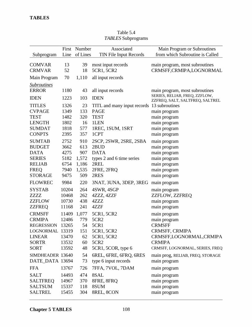
TABLES
Chapter 5 TABLES 108
Table 5.4 TABLES Subprograms
First Number Associated Main Program or Subroutines
Subprogram Line of Lines TIN File Input Records from which Subroutine is Called COMVAR 13 39 most input records main program, most subroutines CRMVAR 52 18 5CR1, 5CR2 CRMSFF,CRMIPA,LOGNORMAL
Main Program 70 1,110 all input records
Subroutines ERROR 1180 43 all input records main program, most subroutines IDEN 1223 103 IDEN SERIES, RELIAB, FREQ, ZZFLOW,
ZZFREQ, SALT, SALTFREQ, SALTREL TITLES 1326 23 TITL and many input records 13 subroutines CVPAGE 1349 133 PAGE main program TEST 1482 320 TEST main program LENGTH 1802 16 1LEN main program SUMDAT 1818 577 1REC, 1SUM, 1SRT main program CONPTS 2395 357 1CPT main program
SUMTAB 2752 910 2SCP, 2SWR, 2SRE, 2SBA main program BUDGET 3662 613 2BUD main program DATA 4275 907 DATA main program SERIES 5182 1,572 types 2 and 6 time series main program RELIAB 6754 1,186 2REL main program FREQ 7940 1,535 2FRE, 2FRQ main program STORAGE 9475 509 2RES main program
FLOWREC 9984 220 3NAT, 3UNA, 3DEP, 3REG main program
SYSTAB 10204 264 4SWR, 4SGP main program ZZZZ 10468 262 4ZZZ, 4ZZF ZZFLOW, ZZFREQ ZZFLOW 10730 438 4ZZZ main program ZZFREQ 11168 241 4ZZF main program
CRMSFF 11409 1,077 5CR1, 5CR2 main program CRMIPA 12486 779 5CR2 main program REGRESSION 13265 54 5CR1 CRMSFF LOGNORMAL 13319 151 5CR1, 5CR2 CRMSFF, CRMIPA LINEAR 13470 62 5CR1, 5CR2 CRMSFF,LOGNORMAL,CRMIPA SORTR 13532 60 5CR2 CRMIPA SORT 13592 48 5CR1, 5COR, type 6 CRMSFF, LOGNORMAL, SERIES, FREQ
SIMDHEADER 13640 54 6REL, 6FRE, 6FRQ, 6RES main prog, RELIAB, FREQ, STORAGE DATE_DATA 13694 73 type 6 input records main program
FFA 13767 726 7FFA, 7VOL, 7DAM main program
SALT 14493 474 8SAL main program SALTFREQ 14967 370 8FRE, 8FRQ main program SALTSUM 15337 118 8SUM main program SALTREL 15455 304 8REL, 8CON main program

TABLES
Chapter 5 TABLES 109
Miscellaneous Subroutines ERROR – Subroutine ERROR is called in conjunction with error messages by the main
program and all subroutines that contain error checks, which is most of the subroutines. A standard error message is written to the monitor, and execution of the program is terminated.
IDEN – Called by the main program and Subroutines SERIES, RELIAB, FREQ,
ZZFLOW, ZZFREQ, SALT, SALTFREQ, and SALTREL to read identifiers from IDEN records of control points, water rights, reservoirs, or water right groups.
TITLES – Called by 13 subroutines to write the titles provided by TITL records at the top of
the tables created for certain TABLES input records. CVPAGE – Called by the main program to write a cover page for the output tables. Activated
by the PAGE record. TEST – Checks a SIM output OUT file for errors and problems. Activated by TEST record. DATA – Develops a daily, monthly, or annual series dataset from SIM/SIMD output.
Subroutines Activated by Type 1 Input Records to Deal with SIM Input Data LENGTH – Truncates SIM DAT file input records to 128 characters, removing extra comments
that are sometimes added to the right. Activated by 1LEN record. SUMDAT – Develops a listing of selected records; develops a water rights summary; and sorts
water rights in priority order by control point, use, type, or group. Activated by 1REC, 1SUM, or 1SRT records.
CONPTS – Develops listings of control point information in upstream-to-downstream order
from a SIM input file. A similar routine is incorporated in program SALT. Called from main program when activated by 1CPT record. Can also be called by subroutine BUDGET as a 2BUD record option.
Subroutines for Type 2 Input Records that Summarize SIM Simulation Results
SUMTAB – Develops summary tables of monthly and/or annual SIM output data for a control
point, water right, reservoir, or the entire river basin (sum of control points). Activated by 2SCP, 2SWR, 2SRE, or 2SBA record.
BUDGET – Develops a water volume budget for an overall river basin and/or individual control
points. The computations are similar to the volume budget computations in Program SALT. Activated by 2BUD record.
Subroutines for Types 2 and 6 Records Dealing with SIM or SIMD Simulation Results
SERIES – Develops tables of monthly, sub-monthly, or annual data and/or DSS records for
control points, water rights, or reservoirs from the simulation results recorded in a SIM or SIMD output file. Activated by the 33 type 2 time series records such as 2NAT, 2REG, 2UNA, 2DIV, 2SHT, 2TAR, 2STO, 2IFS, 2IFT, 2CLO, and 2CLO records and the analogous type 6 time series records.

TABLES
Chapter 5 TABLES 110
RELIAB – Develops a summary table of water supply diversion or hydropower reliabilities for specified control points, water rights, or hydroelectric power reservoirs. Also creates an optional shortage metrics table. Activated by 2REL or 6REL records.
FREQ – Develops frequency tables for naturalized flow, regulated flow, unappropriated flow,
storage, reservoir water surface elevation, and instream flow shortage. Activated by 2FRE, 2FRQ, 6FRE, or 6FRQ records.
STORAGE – Develops a table of monthly end-of-period storages expressed as a percentage of
capacity and reliability tables for reservoir draw-downs similar to tables developed by Subroutine RELIAB. Activated by 2RES or 6RES records.
Subroutine Activated by Type 3 Input Records to Develop SIM Input Records
FLOWREC – Develops flow records in IN or TS record format from naturalized flows, regulated
flows, unappropriated flows, and/or streamflow depletions read from a SIM output file. Activated by 3NAT, 3UNA, 3DEP, or 3REG records.
Subroutines Activated by Type 4 Input Records Associated with SIM HRR or ZZZ Output Files
SYSTAB – Develops monthly and annual tables of hydropower production and multiple-
reservoir system releases for water rights. Activated by 4HRR record. ZZZZ – Called by Subroutines ZZFLOW and ZZFREQ to read and store the information
from the ZZZ file generated by a SIM ZZ record. Subroutine ZZZ is called only once, and the ZZZ file data is stored in memory for shared use by any number of 4ZZZ and 4ZZF records.
ZZFLOW – Develops TOU file tables or DSS file records for priority loop available flows,
regulated flows, and reservoir releases read from a ZZZ file generated by a SIM ZZ record. The ZZZ file is read by Subroutine ZZZZ which is called by Subroutines ZZFLOW and ZZFREQ. Activated by 4ZZZ record.
ZZFREQ – develops frequency tables for priority loop flows generated by SIM with a ZZ
record and stored in a ZZZ file. The ZZZ file is read by Subroutine ZZZZ which is called by Subroutines ZZFLOW and ZZFREQ. Activated by 4ZZF record.
Subroutines Employed with Type 5 Conditional Reliability Modeling (CRM) Records
CRMSFF – develops a storage-flow-frequency (SFF) array for ratios of simulated-to-predicted
flows to be used later in Subroutine CRMIPA. The SFF array can be stored in a SFF file or as array SFFARR. Activated by 5CR1 record.
CRMIPA – called by main program to develop an incremental probability array (IPA) based on a
storage-flow-frequency (SFF) array developed by Subroutine CRMSFF. The expected probability array EXPP assigns incremental probabilities to the CRM hydrologic sequences which sum to 1.0. Subroutines RELIAB, FREQ, and STORAGE use the array EXPP for conditional reliability modeling (CRM).
REGRESSION (N,X,Y,XA,XB,RR,INTZERO) – called by Subroutine CRMSFF (5CR1 record)
to perform a linear regression between arrays X and Y.

TABLES
Chapter 5 TABLES 111
LOGNORMAL – called by Subroutines CRMSFF and CRMIPA (activated by 5CR1 and 5CR2 records) to develop the frequency distribution of the array QARRAY using the lognormal probability distribution.
LINEAR (GIVEN,FIND,X,Y,NUM) – performs linear interpolation. LINEAR is called from
Subroutine CRMSFF for Weibull computations, from Subroutine LOGNORMAL to read the normal probability table, and from Subroutine CRMIPA.
SORTR (N,X,Y,Z,ORDER) – is called at two locations in Subroutine CRMIPA to sort the array X
in descending (ORDER=1) or ascending (ORDER=0) order while maintaining the rank of corresponding values in the arrays Y and Z.
SORT (N,X,ORDER) – called by Subroutines CRMSFF (5CR1 record) and LOGNORMAL to sort
the array X in either descending or ascending order. Subroutine SORT is also called by Subroutines SERIES and FREQ to sort daily (sub-monthly) data from SIMD simulation results (type 6).
Subroutines Activated by Type 6 Sub-Monthly Time Step Input Records
SIMDHEADER – Called by the main program and Subroutines RELIAB, FREQ, and
STORAGE to write a header to identify the table as being for sub-monthly time step data (SUB File) and also provides the range of the data. Activated by 6REL, 6FRE, 6FRQ, and 6RES records.
DATE_DATA – Called by main program to populate a 2-dimensional array DDATA with the
year, month, and day of each time step from the SIMD daily output file. Since the daily output file can contain any subset of the entire simulation, the date data must be computed month by month using the information on the 5th and 6th records of the daily output file. Activated by type 6 input records.
Subroutine Activated by Type 7 Flood Frequency Analysis Input Records
FFA – Develops an annual flood frequency analysis table for annual series read from a
SIMD AFF file of peak naturalized flow, regulated flow, and reservoir storage. Economic damages may also be included in the table. Activated by 7FFA, 7VOL, and 7DAM records.
Subroutines Activated by Type 8 Salinity Simulation Input Records
SALT – Develops tables of monthly or annual series of volumes, loads, or concentrations
of control point inflow, storage, and outflow. 8SAL record. SALTFREQ – Develops frequency tables for volumes, loads, and concentrations of control
point inflows, storage, and outflows. Activated by 8FRE or 8FRQ record. SALTSUM – Develops a control point salinity summary table. Activated by 8SUM record. SALTREL – Develops for specified control points a table of diversion reliabilities with and
without salinity constraints. 8REL or 8CON record.

TABLES
Chapter 5 TABLES 112
HECLIB Subroutines The TABLES subroutines SERIES and SALT call the following HEC-DSS Data Storage System subroutines from the Hydrologic Engineering Center static library HECLIB discussed in Chapter 1.
ZSET − Sets DSS parameters. ZOPEN − Opens a DSS file. ZCLOSE − Closes a DSS file. (Found in TABLES Main Program.) ZPATH − Constructs a pathname. ZCHKPN − Checks a pathname. ZSRTS − Stores regular-interval time series data. ZRRTS − Retrieves regular-interval time series data.
Definition of Variables Variables incorporated in TABLES are listed alphabetically and defined in two groups. The first group includes all variables except those in the seven conditional reliability modeling (CRM) subroutines. The second group of definitions placed as the last section of this chapter consists of those variables included in the conditional reliability modeling (CRM) subroutines, which are Subroutines CRMSFF, CRMIPA, REGRESSION, LOGNORMAL, LINEAR, SORT, and SORTR. These are the last seven subroutines in TABLES. All of the variables listed in Module CRMVAR are shared by Subroutines CRMSFF, CRMIPA, and LOGNORMAL and included in the CRM group. Other variables are unique to particular subroutines. Ten variables found in Module COMVAR are related to CRM and included in both groups. Array size is shown in parenthesis following the array name. The following items of information are provided in brackets following the description of each variable.
1. The variable type is either real, integer, character (with maximum length noted), or logical. There are only a few logical variables in TABLES.
2. Variables are either declared in Modules COMVAR or CRMVAR for use in multiple subprograms, declared and used only in the main program, or declared and used only in specific subroutines which are noted in brackets following the descriptions.
3. The main program and several subroutines originally developed for working with monthly SIM simulation results were later expanded to also perform the same analyses for sub-monthly SIMD simulation results. The term daily added as the last term in the brackets highlights a variable as being used specifically for dealing with SIMD sub-monthly simulation results.
Variables Exclusive of Those in the CRM Subroutines
A – coefficient in mean square error equation used in computing weighted skew coefficient [real,
Subroutine FFA] A – first part of DSS pathname [character(len=32), Subroutines SERIES and SALT] A(136) – characters of record read from SIM OUT file [character(len=1), Subroutine TEST]
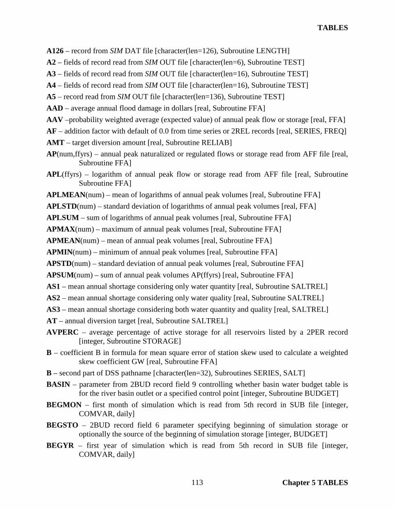
TABLES
Chapter 5 TABLES 113
A126 – record from SIM DAT file [character(len=126), Subroutine LENGTH] A2 – fields of record read from SIM OUT file [character(len=6), Subroutine TEST] A3 – fields of record read from SIM OUT file [character(len=16), Subroutine TEST] A4 – fields of record read from SIM OUT file [character(len=16), Subroutine TEST] A5 – record read from SIM OUT file [character(len=136), Subroutine TEST] AAD – average annual flood damage in dollars [real, Subroutine FFA] AAV –probability weighted average (expected value) of annual peak flow or storage [real, FFA] AF – addition factor with default of 0.0 from time series or 2REL records [real, SERIES, FREQ] AMT – target diversion amount [real, Subroutine RELIAB] AP(num,ffyrs) – annual peak naturalized or regulated flows or storage read from AFF file [real,
Subroutine FFA] APL(ffyrs) – logarithm of annual peak flow or storage read from AFF file [real, Subroutine
Subroutine FFA] APLMEAN(num) – mean of logarithms of annual peak volumes [real, Subroutine FFA] APLSTD(num) – standard deviation of logarithms of annual peak volumes [real, FFA] APLSUM – sum of logarithms of annual peak volumes [real, Subroutine FFA] APMAX(num) – maximum of annual peak volumes [real, Subroutine FFA] APMEAN(num) – mean of annual peak volumes [real, Subroutine FFA] APMIN(num) – minimum of annual peak volumes [real, Subroutine FFA] APSTD(num) – standard deviation of annual peak volumes [real, Subroutine FFA] APSUM(num) – sum of annual peak volumes AP(ffyrs) [real, Subroutine FFA] AS1 – mean annual shortage considering only water quantity [real, Subroutine SALTREL] AS2 – mean annual shortage considering only water quality [real, Subroutine SALTREL] AS3 – mean annual shortage considering both water quantity and quality [real, SALTREL] AT – annual diversion target [real, Subroutine SALTREL] AVPERC – average percentage of active storage for all reservoirs listed by a 2PER record
[integer, Subroutine STORAGE] B – coefficient B in formula for mean square error of station skew used to calculate a weighted
skew coefficient GW [real, Subroutine FFA] B – second part of DSS pathname [character(len=32), Subroutines SERIES, SALT] BASIN – parameter from 2BUD record field 9 controlling whether basin water budget table is
for the river basin outlet or a specified control point [integer, Subroutine BUDGET] BEGMON – first month of simulation which is read from 5th record in SUB file [integer,
COMVAR, daily] BEGSTO – 2BUD record field 6 parameter specifying beginning of simulation storage or
optionally the source of the beginning of simulation storage [integer, BUDGET] BEGYR – first year of simulation which is read from 5th record in SUB file [integer,
COMVAR, daily]

TABLES
Chapter 5 TABLES 114
BLANK – count of blank identifier fields on IDEN record [integer, Subroutine IDEN] bMONTH – beginning month for sub-monthly time step data [character(len=10), Subroutine
SIMDHEADER, daily] BPSTX – beginning of simulation storage from BRS file [real, Subroutine BUDGET] BRSID – reservoir identifier from BRS file [character(len=6), Subroutine BUDGET] BSTO(ncpts) – summation of beginning of simulation storage for all reservoirs at the control
point [real, Subroutine BUDGET] BUD – parameter in Main Program associated with 2BUD record. BUD is zero unless one or
more 2BUD records are read. BUD=9 means DAT file is required. BUD=BEGSTO=1 means DAT and BRS files are required. [integer, main program]
bYEAR – beginning year for sub-monthly time step data [character(len=4), Subroutine SIMDHEADER, daily]
C – third part of DSS pathname [character(len=32), Subroutines SERIES, SALT] C1 – control point and reservoir identifiers read from an unformatted binary SIM output file that
may include variables that must be read though not actually used as well as variables needed [character(len=6), COMVAR]
C2, C3 – water right group identifiers read from an unformatted binary SIM output file that may include variables that must be read though not actually used as well as variables needed [character(len=8), COMVAR]
C4 – water right identifiers read from an unformatted binary SIM output file that may include identifiers that must be read though not actually used [character(len=16), COMVAR]
CAP(20,2) – top and bottom of active storage of reservoirs listed by a 2PER record [real, Subroutine STORAGE]
CC – 8FRE and 8FRQ record field 4 parameter specifying whether months with zero volume are counted in frequency analyses [integer, Subroutine SALTFREQ]
CD – record identifier found in first four characters of each record of a TABLES input file [character(len=4), main program and most of the subroutines]
CD – record identifier read from SIM DAT file[character(len=2), CONPTS, LENGTH] CDATE – starting date of time series in DSS file[character(len=9), SERIES, SALT] CDOUT – record identifier on records output by Subroutine FLOWREC [character(len=2),
FLOWREC] CF – concentration conversion factor [real, COMVAR] CHAR – yes or no response in sequence in which user names files [character(len=1), main
program] CHAR –character variable used in reading identifiers from OUT file records [character(len=6),
SUMTAB, RELIAB, SALTREL] CHAR1 – water right identifiers read from OUT file records [character(len=16), SUMTAB] CHARID – control point, water right, or reservoir identifier used in reading data for shortage
metrics table [character(len=16), RELIAB] CHR – dummy variable used to skip over lines in reading file [character(len=1), SYSTAB]

TABLES
Chapter 5 TABLES 115
CI(12) – constant inflows from CI records [real, BUDGET] CIID – control point identifier from CI record [character(len=6), BUDGET] CINF(ncpts,12) – flow adjustments from constant inflow CI records [real, BUDGET] CIRECORD – counter of CI records [integer, BUDGET] CIX – constant inflow multiplier factor read from XL record with default of 1.0 [real, BUDGET] CL(maxcp) – channel loss factors from CP records [real, CONPTS] CL(ncpts) – channel loss volumes [real, BUDGET] CLC(ncpts) – channel loss credit volumes [real, BUDGET] CNAME – filename root for DSS file [character(len=64), SERIES, SALT] CONC(10) – maximum allowable concentration limit for each water quality constituent from
8REL record field 5 and 8CON record [real, SALTREL] CONC(3) – concentrations of control point inflow, storage, and outflow [real, SALTSUM] CONSECMAXARR(count) – maximum number of consecutive shortage in months tabulated in
shortage metrics table [integer, RELIAB] CONPT – control point counter [integer, FLOWREC] COUNT – counter of the number of control points for which to develop tables or to include in
the tables [integer, SALT, SALTFREQ, SALTREL] COUNT – counter of the number of either control points, water rights, or reservoirs for which to
develop tables or to include in the tables [integer, SUMTAB, SERIES, RELIAB, FREQ]
COUNT – counter of the number of reservoirs for which to develop tables or to include in the tables [integer, STORAGE, SYSTAB]
CP – control point identifier [character(len=6), SUMDAT] CP – control point index [integer, CONPTS, BUDGET, FFA, SALTSUM] CP(5000) – control point identifiers [character(len=6), TEST] CPATH – DSS pathname [character(len=64), SERIES, SALT] CPBUD – control point identifier specified in 2BUD record field 2 [character(len=6), BUDGET] CPFF(ffcps)– integer index that connects the NUM control points on the 7FFA record to control
points in the SIMD AFF output file. If NUM is not zero, CPFF(cp) is the index ranging from 1 to NUM of the control point from the 7FFA record assigned to each of the FFCPS control points in the AFF file, with a value of zero for CPFF(cp) for control points not included on the 7FFA record. If NUM is zero, CPFF(cp) is the index of the FFCPS control points in the AFF file ranging from 1 to FFCPS. For ID of 3 (reservoir storage), a CPFF(cp) of -99 flags control points with no reservoir storage. [integer, Subroutine FFA]
CPFLAG – flag indicated whether the outlet control point has been reached [integer, BUDGET] CPID – control point identifier [character(len=6), FLOWREC] CPID(maxcp) – control point identifier [character(len=6), SUMDAT, SALTSUM] CPID(maxcp,2) – identifiers of control point and next downstream control point from CP
records [character(len=6), CONPTS, BUDGET]

TABLES
Chapter 5 TABLES 116
CPIDFF(ffcps) – control point identifiers for flood frequency analyses [character(len=6), FFA] CPLIM – control point identifier in 1CPT record field 5 that specifies which control points to
include in sequencing [character(len=6), CONPTS] CPNAME(count) – identifiers of control points, water rights, reservoirs, or water right groups
included in shortage metrics table [character(len=16), RELIAB] CPOUT – output control parameter in 2BUD record field 8 [integer, BUDGET] CPUS(70) – identifiers of control points located upstream of a particular control point
[character(len=6), CONPTS] CPUS(ncpts,40) – integer identifiers of control points located upstream of a particular control
point [integer, BUDGET] CPWP – control point identifier read from WP record [character(len=6), CONPTS] CR1 – conditional reliability modeling parameter from 5th record of CRM file is the length of
the simulation period in months [integer, COMVAR] CR2 – conditional reliability modeling parameter from 5th record of CRM file which activates
the annual cycle [integer, COMVAR] CR4 – conditional reliability modeling parameter from 5th record of CRM file is a factor by
which all storages are multiplied with default of 1.0 [real, COMVAR] CREC – record counter used to go to the next block of monthly control point data in reading the
SALT SAL output file [integer, DATA, SERIES, SALT, SALTFREQ, SALTREL] CREC – record counter used to go to the next block of monthly data in reading the direct access
SIM OUT output file CREC = NWROUT + NCPTS + NREOUT [integer, SUMTAB, SERIES, FREQ, RELIAB, STORAGE, FLOWREC]
CRHEAD – flag to write conditional reliability modeling headings [integer, COMVAR] CRMF – flag to open CRM file instead of OUT file [integer, COMVAR] CRSFF – flag that a 5CR2 record has been read and is in effect and thus the conditional
reliability modeling (CRM) probability array option is activated [integer, COMVAR] CRMF7 – flag in main program indicating that unit 7 is to be opened if a 5CR1 or 5COR record
is read [integer, COMVAR] CTIME – beginning time for time series in DSS file [character(len=4), SERIES, SALT] CTYPE – variable type for time series in DSS file [character(len=4), SERIES, SALT] CUNITS – units of measure for data is DSS file [character(len=5), SERIES, SALT] D – counter and index of days [integer, DATE_DATA, daily] D – fourth part of DSS pathname [character(len=32), SERIES, SALT] D(10) – economic damage in dollars D(K) associated with each probability PROB(K)
determined by applying Q(K) to linearly interpolate from the DV(J) versus DAM(J) relationship read from 7VOL and 7DAM records [real, FFA]
DA(maxcp) – drainage area [real, CONPTS] DAM(20) – economic flood damages from 7DAM record [real, FFA] DAMQ(10) – economic flood damages determined by interpolation [real, FFA] DATA(12) – monthly data read from OUT file [real, FLOWREC]

TABLES
Chapter 5 TABLES 117
DATEX – date provided by computer and recorded in message TMS file [character(len=9), main program]
DAWP – drainage area from WP record [real, CONPTS] DAY –sub-monthly time period (day) counter and index [integer, SERIES, daily] DAYS – number of sub-monthly time periods (days) [integer, COMVAR, daily] DC(7) – sub-monthly time period (daily) amounts [integer, RELIAB, daily] DC(nm,nc) – diversion concentration [real, SALTREL] DDATA(days,3) – year, month, and day of the records in the daily output file [integer,
COMVAR, daily] DECIMAL – number of digits to right of decimal set by field 7 of time series records
[character(len=1), SERIES] DEP – streamflow depletion from OUT file [real, BUDGET] DIV – diversion amount from OUT file [real, BUDGET] DS(ncpts) – diversion shortage [real, BUDGET] DS(nm,nc) – diversion shortage [real, SALTREL] DSS – diversion shortage used to estimate beginning storage [real, BUDGET] DSSDAY – starting day for DSS record [character(len=2), SERIES, SALT] DT – sub-monthly time step (day) index [integer, DATE_DATA, daily] DT(ncpts) – diversion target [real, BUDGET] DT(nm,nc) – diversion target [real, SALTREL] DTS – diversion target used to estimate beginning storage [real, BUDGET] DV(20) – flow or storage volume from 7VOL record [real, FFA] DVALS – count or number of sub-monthly time steps [integer, RELIAB, FREQ, STORAGE,
daily] DVV – flow or storage volume associated with flood damage [real, FFA] DX(days) – daily data summed in computing moving averages or moving totals [real, SERIES,
daily] DXF – fractional part of number of months FX [real, FREQ, SALTFREQ] DZERO – number of days with zero or negative amounts [integer, RELIAB, daily] E – fifth part of DSS pathname [character(len=32), SERIES, SALT] eMONTH – ending month for daily simulation results [character(len=10), Subroutine
SIMDHEADER, daily] ENDMON – ending month for daily simulation results which is read from fifth record of SUB
output file [integer, COMVAR, daily] ENDYR – ending year for daily simulation results which is read from fifth record of SUB output
file [integer, COMVAR, daily] EP – net evaporation-precipitation volume [real, BUDGET] EPI(9) – expected probability increment [real, FFA]

TABLES
Chapter 5 TABLES 118
EVAP(ncpts) – net evaporation-precipitation volume from SIM OUT file [real, BUDGET] EXIST – logical switch of whether or not a file exists [logical, main program] EXIT – entry from keyboard signaling termination of program execution [character(len=2),
ERROR] EXPP(np) – the expected probability array EXPP(np) developed by Subroutine CRMIPA as
specified by a 5CR2 record assigns incremental probabilities to the CRM hydrologic sequences which sum to 1.0. Subroutines RELIAB, FREQ, and STORAGE use the array EXPP for conditional reliability modeling (CRM). [real, COMVAR]
EXPPT(np) – temporary values of expected probability array [real, FREQ] eYEAR – ending year for daily simulation results [character(len=4), SIMDHEADER, daily] F – sixth part of DSS pathname [character(len=32), SERIES, SALT] F(10) – set frequencies for which amounts are computed [real, FREQ, SALTFREQ] FACTOR(9) – Pearson type III frequency factor [real, FFA] FCL – computed upstream channel losses [real, BUDGET] FCLC – computed upstream channel loss credits [real, BUDGET] FFCPID(ffcps) – control point identifiers read from AFF file [character(len=6), FFA] FFCPS – total number of control points in AFF file [integer, FFA] FFYRS – total number of years in AFF file [integer, FFA] FILEN – filename [character(len=50), COMVAR] FIN – total inflows to control point computed by summing inflows [real, BUDGET] FIN2 – total inflows to control point computed as outflow plus storage change [real, BUDGET] FINNEG – negative inflows to control point [real, BUDGET] FK(31,9) – table of Pearson III frequency factors for 9 selected exceedance probabilities for 31
different values for skew coefficients GK(31) [real, FFA] FLAG – flag indicating the non-numeric data was read that should be numeric [integer, TEST] FNAT – computed incremental naturalized flows [real, BUDGET] FOTH – other releases for hydropower and instream flow [real, BUDGET] FOUT(ncpts) – flow volume leaving the control point [real, BUDGET] FQ(7) – the frequency computed for the amounts QF(7) entered on 2FRQ record [real, FREQ] FQ(7) – the frequency computed for the amounts QF(7) entered on 8FRQ record [real,
SALTFREQ] FREG – computed regulated flows entering the control point [real, BUDGET] FX – number of months corresponding to F(I) as a real number [real, FREQ] G(num) – skew coefficient adopted to apply the log-Pearson type III distribution [real, FFA] GC(num) – skew coefficient of APL(ffyrs) computed from skew coefficient formula [real, FFA] GK(31) – skew coefficient values associated with FK(31,9) [real, FFA] GP – water right group identifier [character(len=8), SUMDAT, SERIES] GP1 – first water right group identifier [character(len=8), SUMDAT, SERIES]

TABLES
Chapter 5 TABLES 119
GP2 – second water right group identifier [character(len=8), SUMDAT, SERIES] GPID1 – first water right group identifier [character(len=8), SERIES] GPID2 – first water right group identifier [character(len=8), SERIES] GR – regional skew coefficient input on SKEW record as SC(I) and used to calculate a weighted
skew coefficient GW [real, FFA] GROUP(300) – water right group identifiers [character(len=8), SUMDAT] GW(num) – weighted skew coefficient combining GC and GR [real, FFA] HEAD(100,2) – headings for column tabulations [character(len=8) , SERIES, SALT] HEADING – flag indicating whether or not headings have already been written [integer,
BUDGET] HEC – input parameter of whether streamflow records output are grouped by years or by control
point [integer, FLOWREC] HECDSS – flag indicated whether Hydrologic Engineering Center Data Storage System (DSS)
files are activated with HECDSS = 0 meaning no DSS file [integer, COMVAR] I – miscellaneous counter [integer, main program and most subroutines] IC – counter or index of water quality constituents [integer, SALTREL] ICP(maxcp) – array to connect read-in sequence of control points in upstream-to-downstream
order created by Subroutine CONPTS (1CPT record) and used by Subroutine BUDGET (2BUD record) [integer, COMVAR]
ICPI – control point sequencing option flag. If ICPI=0, sequence array ICP created by 1CPT record sets sequencing. Otherwise, control points must be entered in SIM input file in upstream-to-downstream order. [integer, BUDGET]
ID – 7FFA record field 2 selection of naturalized flows, regulated flows, or storage [integer, FFA]
ID – indicates either a control point (ID=0), water right (ID=1), reservoir (ID=2), or water right group (ID=3) [integer, SERIES, RELIAB, FREQ]
ID – indicates either a control point (ID=0), water right (ID=1), reservoir (ID=2), or water right group (ID=3) [integer, SUMTAB]
ID – record identifier of records read from SIM DAT input file [character(len=2), BUDGET] ID – variable selected in 8SAL record field 5 or 8FRE record field 2 [integer, SALT,
SALTFREQ] ID16 – water right identifier [character(len=16), SERIES] ID6 – control point identifier [character(len=6), SALT] ID6 – control point or reservoir identifier [character(len=6), SERIES] IDCP(80) – control point identifiers that may be entered on several types of input records
[character(len=6), COMVAR] IDEN(20) – identifiers for reservoirs in Subroutine STORAGE [character(len=6), STORAGE] IDEN16(80) – water right identifiers [character(len=16), COMVAR] IDEN8(80) – water right group identifiers [character(len=8) , COMVAR]
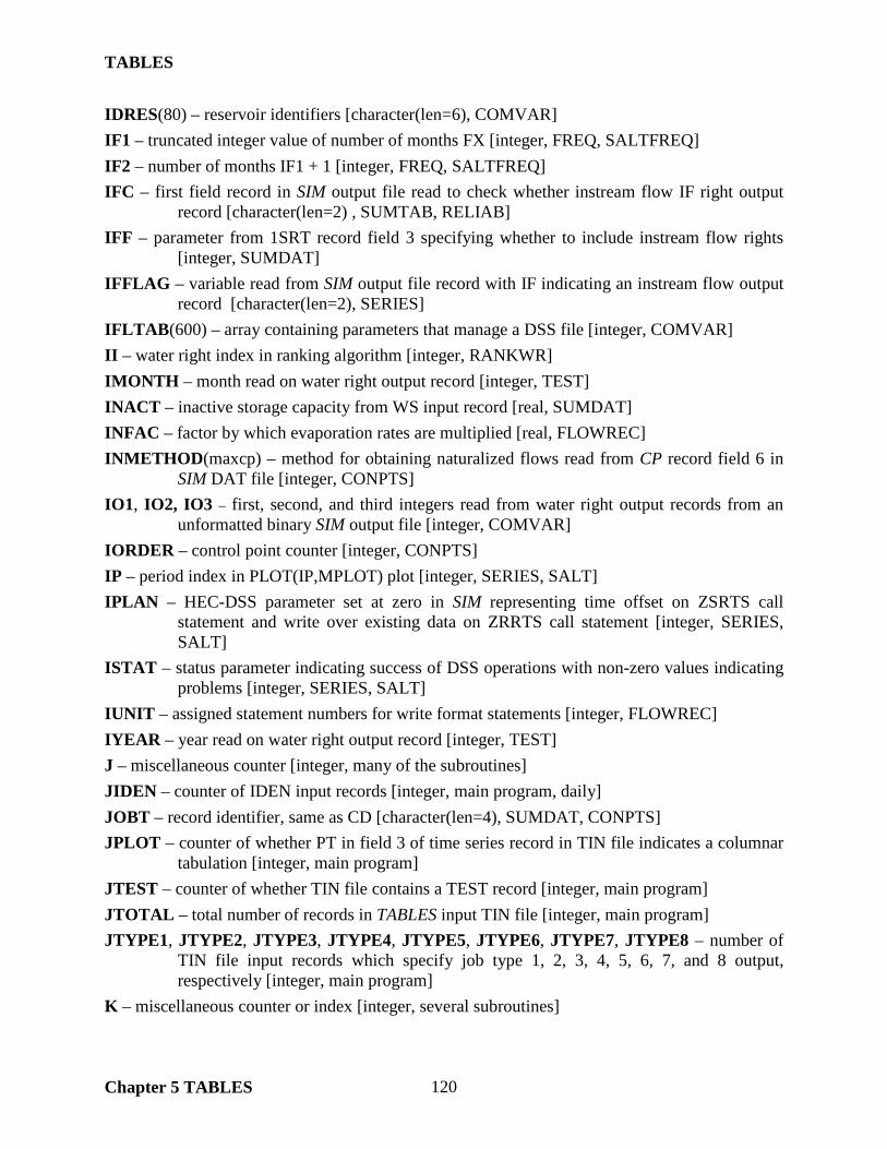
TABLES
Chapter 5 TABLES 120
IDRES(80) – reservoir identifiers [character(len=6), COMVAR] IF1 – truncated integer value of number of months FX [integer, FREQ, SALTFREQ] IF2 – number of months IF1 + 1 [integer, FREQ, SALTFREQ] IFC – first field record in SIM output file read to check whether instream flow IF right output
record [character(len=2) , SUMTAB, RELIAB] IFF – parameter from 1SRT record field 3 specifying whether to include instream flow rights
[integer, SUMDAT] IFFLAG – variable read from SIM output file record with IF indicating an instream flow output
record [character(len=2), SERIES] IFLTAB(600) – array containing parameters that manage a DSS file [integer, COMVAR] II – water right index in ranking algorithm [integer, RANKWR] IMONTH – month read on water right output record [integer, TEST] INACT – inactive storage capacity from WS input record [real, SUMDAT] INFAC – factor by which evaporation rates are multiplied [real, FLOWREC] INMETHOD(maxcp) – method for obtaining naturalized flows read from CP record field 6 in
SIM DAT file [integer, CONPTS] IO1, IO2, IO3 – first, second, and third integers read from water right output records from an
unformatted binary SIM output file [integer, COMVAR] IORDER – control point counter [integer, CONPTS] IP – period index in PLOT(IP,MPLOT) plot [integer, SERIES, SALT] IPLAN – HEC-DSS parameter set at zero in SIM representing time offset on ZSRTS call
statement and write over existing data on ZRRTS call statement [integer, SERIES, SALT]
ISTAT – status parameter indicating success of DSS operations with non-zero values indicating problems [integer, SERIES, SALT]
IUNIT – assigned statement numbers for write format statements [integer, FLOWREC] IYEAR – year read on water right output record [integer, TEST] J – miscellaneous counter [integer, many of the subroutines] JIDEN – counter of IDEN input records [integer, main program, daily] JOBT – record identifier, same as CD [character(len=4), SUMDAT, CONPTS] JPLOT – counter of whether PT in field 3 of time series record in TIN file indicates a columnar
tabulation [integer, main program] JTEST – counter of whether TIN file contains a TEST record [integer, main program] JTOTAL – total number of records in TABLES input TIN file [integer, main program] JTYPE1, JTYPE2, JTYPE3, JTYPE4, JTYPE5, JTYPE6, JTYPE7, JTYPE8 – number of
TIN file input records which specify job type 1, 2, 3, 4, 5, 6, 7, and 8 output, respectively [integer, main program]
K – miscellaneous counter or index [integer, several subroutines]

TABLES
Chapter 5 TABLES 121
K1 – format specifications for reading control point and reservoir records from a formatted SIM output file [character(len=32), Subroutines SERIES and DATA]
K2 – format specifications for reading water right records from a formatted SIM output file [character(len=32), Subroutines SERIES and DATA]
KK – miscellaneous integer variable [integer, SUMDAT, CONPTS, SERIES] KK1CPT – parameter KK read from 1CPT record field 2 [integer, main program, daily] KKK – assigned statement numbers for write format statements [integer, FREQ] KO – index for the element of the array XO(12) read from unformatted binary SIM output file
that is actually used [integer, Subroutine SERIES] L – miscellaneous counter or index [integer, several subroutines] L1 – length of beginning month in number of characters [integer, SIMDHEADER, daily] L2 – length of ending month in number of characters [integer, SIMDHEADER, daily] LA – position index [integer, QUICKSORT, daily] LAST – number of reservoirs [integer, SYSTAB] LEAP(YEAR) – indicator of whether year is a leap year [logical function, DATE_DATA, daily] LEFT – index of the left end of the partition to be sorted [integer, QUICKSORT, daily] LIM – output control parameter from 1CPT record field 4 [integer, CONPTS] LINE – line of data read from SIM input file [character(len=126), SUMDAT] LINE(maxcp) – data read from CP records from SIM input file [character(len=64), CONPTS] LLEFT – optional index of the left end of the partition to be sorted [integer, SERIES, FREQ,
QUICKSORT, daily] LOCPERAVG – average of sum of consecutive shortages in shortage metrics table
computations [real, RELIAB] LOCSEV – average of sum of shortages in shortage metrics table computations [real, RELIAB] LOCSUMAMT – summation of diversion targets [real, RELIAB] LOCSUMSHT – summation of shortages in shortage metrics table computations [real,
RELIAB] LOOP – counter for the computational loops repeated for each of the COUNT control points
(ID=0), water rights (ID=1), or reservoirs (ID=2) [integer, SUMTAB, SERIES, RELIAB, FREQ, STORAGE, SYSTAB, SALT, SALTFREQ, SALREL]
M – month, M = 1, 12 [integer, TEST, BUDGET] M – number of months [integer, RELIAB, SALTSUM] M – total number of months in the data array Q(I) that are sorted [integer, FREQ] M(23) – month [character(len=3), SERIES, SALT] MAM – month index used in accumulating moving averages and moving totals [integer,
SERIES] MAN – number of months accumulated in computing moving averages and moving totals
[integer, SERIES, FREQ]
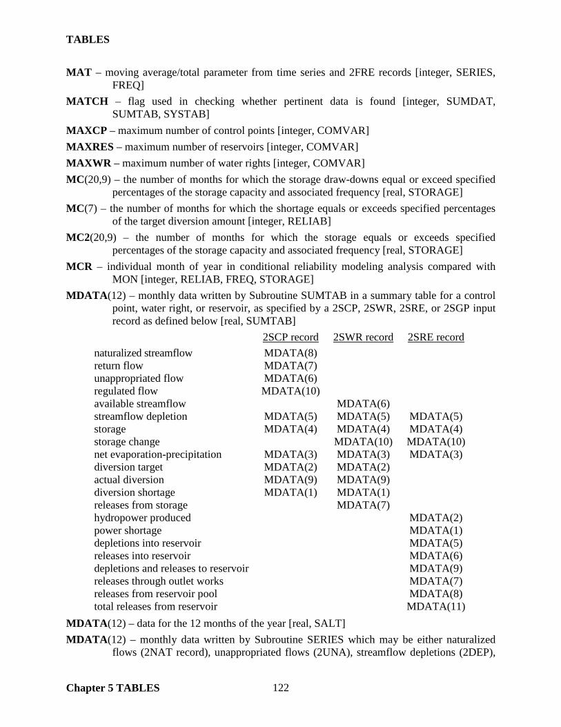
TABLES
Chapter 5 TABLES 122
MAT – moving average/total parameter from time series and 2FRE records [integer, SERIES, FREQ]
MATCH – flag used in checking whether pertinent data is found [integer, SUMDAT, SUMTAB, SYSTAB]
MAXCP – maximum number of control points [integer, COMVAR] MAXRES – maximum number of reservoirs [integer, COMVAR] MAXWR – maximum number of water rights [integer, COMVAR] MC(20,9) – the number of months for which the storage draw-downs equal or exceed specified
percentages of the storage capacity and associated frequency [real, STORAGE] MC(7) – the number of months for which the shortage equals or exceeds specified percentages
of the target diversion amount [integer, RELIAB] MC2(20,9) – the number of months for which the storage equals or exceeds specified
percentages of the storage capacity and associated frequency [real, STORAGE] MCR – individual month of year in conditional reliability modeling analysis compared with
MON [integer, RELIAB, FREQ, STORAGE] MDATA(12) – monthly data written by Subroutine SUMTAB in a summary table for a control
point, water right, or reservoir, as specified by a 2SCP, 2SWR, 2SRE, or 2SGP input record as defined below [real, SUMTAB]
2SCP record 2SWR record 2SRE record
naturalized streamflow MDATA(8) return flow MDATA(7) unappropriated flow MDATA(6) regulated flow MDATA(10) available streamflow MDATA(6) streamflow depletion MDATA(5) MDATA(5) MDATA(5) storage MDATA(4) MDATA(4) MDATA(4) storage change MDATA(10) MDATA(10) net evaporation-precipitation MDATA(3) MDATA(3) MDATA(3) diversion target MDATA(2) MDATA(2) actual diversion MDATA(9) MDATA(9) diversion shortage MDATA(1) MDATA(1) releases from storage MDATA(7) hydropower produced MDATA(2) power shortage MDATA(1) depletions into reservoir MDATA(5) releases into reservoir MDATA(6) depletions and releases to reservoir MDATA(9) releases through outlet works MDATA(7) releases from reservoir pool MDATA(8) total releases from reservoir MDATA(11)
MDATA(12) – data for the 12 months of the year [real, SALT] MDATA(12) – monthly data written by Subroutine SERIES which may be either naturalized
flows (2NAT record), unappropriated flows (2UNA), streamflow depletions (2DEP),

TABLES
Chapter 5 TABLES 123
shortages (2SHT), storage (2STO), and other SIM simulation results variables [real, SERIES]
MEAN – mean of the for which frequency analysis is performed [real, FREQ, SALTFREQ] MEAN(13) – means for the 12 months and annual columns [real, SERIES, SALT] MEAN(9) – means of the variables included in summary tables [real, SUMTAB] MEANLOG – mean of logarithms [real, FREQ] METHOD – frequency analysis method selected in 2FRE record field 6 [integer, FREQ] MID – midway between or average of LEFT and RIGHT [integer, QUICKSORT, daily] MM – counter of months [integer, SERIES, SALT] MNAN – input parameter which specifies whether monthly or annual summary tables are to be
developed [integer, SUMTAB] MON – individual month from 2FRE, 2FRQ, 2REL, 2RES record selected for analysis [integer,
RELIAB, FREQ, STORAGE] MONTH – current month (1, 2, 3, ... ,12) [integer, SUMTAB, SERIES, RELIAB, STORAGE,
FLOWREC, SALT, SALTREL] MONTH1 – first month in TABLES output tables with default of JAN [character(len=5),
COMVAR] MONTHMEAN(100) – monthly means [real, SERIES, daily] MONTHS – number of months = NPRDS*NYRS from main program [integer, COMVAR] MORE – parameter from field 4 of time series records and 8SAL record controlling the addition
of columns to the table being created [integer, SERIES, SALT] MPLOT – column counter used in building columnar output tables [integer, COMVAR] MR – month read from water right output records [integer, TEST] MS – total number of months of data in the data array Q(I) after the sorting routine which may
be adjusted for conditional reliability 2SFF probabilities [integer, FREQ] MSER – mean square error of the regional skew set equal to 0.302 from Bulletin 17B [real,
FFA] MSES – mean square error of the station skew used in computing a weighted skew coefficient
[real, FFA] MT – index of month [integer, Subroutines SERIES, BUDGET, SYSTAB, SALT, SALTREL,
DATE_DATA] MVALS – counter of number of monthly values [integer, RELIAB, daily] MX(months) – monthly data summed in computing moving averages or moving totals [real,
SERIES, FREQ] MYR – counter or index of years [integer, SERIES, SALT] MZERO – counter of amounts that are less than or equal to zero [integer, RELIAB, daily] N – miscellaneous counter or index [integer, several subroutines] N − total number of years FFYRS [integer, FFA] NAME2 – filename root [character(len=50), main program]

TABLES
Chapter 5 TABLES 124
NAT(ncpts) – naturalized flows from SIM output file [real, BUDGET] NC – number of salinity constituents [integer, COMVAR] NCONSECEVENTS – number of consecutive sequences with shortages [integer, RELIAB] NCP – control point counter and index [integer, CONPTS, BUDGET] NCPO2 – number of control points included in SIM SUB output file [integer, COMVAR, daily] NCPTS – number of control points included in the SIM output file [integer, COMVAR,
FLOWREC] NDAY(12) – number of days in each of the 12 months [integer, COMVAR, daily] NDSS – counter and index of values in DSS file [integer, SERIES, SALT] NEGINF – 2BUD record field 7 options for adjusting negative inflow [integer, BUDGET] NERROR – counter of number of errors found [integer, TEST] NEWPAGE – parameter controlling whether to start a new page for next table [integer,
COMVAR] NEWPAGE2 – parameter controlling whether to start a new page for next table [integer,
COMVAR] NFAILARR(count) – mean number of failures per sequence tabulated in shortage metrics table
[real, RELIAB] NGOUT – number of groups listed in a SIM input file for output [integer, SUMDAT] NID – number of identifiers [integer, COMVAR] NM – number of months covered by flows in ZZZ file [integer, ZZZZ, ZZFLOW, ZZFREQ] NM – number of values read from DVOL and $DAM records [integer, FFA] NM – parameter on 2FRQ and 8FRQ records specifying the number of quantities entered for
which to determine frequencies [integer, FREQ, SALTFREQ] NO_SWAPS – counter of number of swaps in sort algorithm [integer, QUICKSORT, daily] NP – number of elements in EXPP array [integer, FREQ] NPATH – number of characters in DSS pathname [integer, SERIES, SALT] NPRDS – 12 months per year [integer, FLOWREC] NPRDS – number of periods per year. NPRDS is 12 for a conventional simulation with monthly
time step. NRPDS may be CR1 for a conditional reliability modeling analysis [integer, COMVAR]
NR – total number of records [integer, TEST] NREOUT – number of reservoirs included in the SIM output OUT file [integer, COMVAR,
FLOWREC] NREOUT2 – number of reservoirs included in the SIMD output SUB file [integer, COMVAR,
daily] NRES – number of reservoirs included in a SIM input DAT file [integer, SUMDAT] NRIGHT – number of rights included in a SIM input DAT file [integer, SUMDAT] NSEQWSHT – counter of number of sequences [integer, RELIAB] NSHTEVENTS – number of sequences with shortages [integer, RELIAB]

TABLES
Chapter 5 TABLES 125
NTI – parameter from JT record recorded on sixth record of SUB file controlling the setting of the number of time intervals in each of the 12 months [integer, COMVAR, daily]
NTITLE – number of title records included in the TABLES input TIN file [integer, COMVAR] NUM – parameter used in several input records to specify the number of values of a variable to
follow in the remaining fields of the input record [integer, SUMTAB, SUMDAT, SERIES, RELIAB, FREQ, STORAGE, SYSTAB, FFA, SALT, SALTFREQ, SALTREL]
NUMC – 8REL record field 2 parameter specifying number of water quality constituents [integer, SALTREL]
NUMCP – number of control points in a SIM input DAT file [integer, SUMDAT] NUMRES – number of reservoirs [integer, SYSTAB] NUP(maxcp) – number of control points located immediately upstream of this control point
[integer, CONPTS, BUDGET] NUPC(maxcp) – counter of number of upstream control points already ordered [integer,
CONPTS] NUSES – number of uses listed in a SIM input DAT file [integer, SUMDAT] NVALS – number of values in time series recorded in DSS record [integer, SERIES, SALT] NWR – number of water rights in the DAT file for the dataset from which a ZZZ file is created
as read from the fourth record of the ZZZ file [integer, COMVAR] NWROUT – number of water rights included in the SIM output OUT file [integer, COMVAR] NWROUT2 – number of water rights included in the SIMD output SUB file [integer,
COMVAR, daily] NWRTS – number of water rights [integer, RANKWR] NYRS – number of years in the simulation [integer, COMVAR, FLOWREC] NZERO – number of periods in which amount is less than or equal to zero [integer, RELIAB] ONE – integer equal to one [integer, QUICKSORT, daily] OO – option from 1CPTS record for defining upstream–to–downstream order [integer,
CONPTS] ORDER(maxcp) – index of control points listed in upstream–to–downstream order [integer,
CONPTS] OROOT – filename root for TOU and TMS files [character(len=50), COMVAR] OUTFILE – logical variable indicating whether OUT file has been opened [logical, CVPAGE,
daily] OUTFORM – switch set at 1 by SOUT record indicating whether SIM/SIMD OUT, CRM, SUB
output file is formatted (default OUTFORM = 0) or unformatted binary (OTFORM = 1) [integer, COMVAR]
P – character index used in combining filename root and extension [integer, main program, CVPAGE]
P – number of periods [integer, STORAGE, daily]
TABLES
Chapter 5 TABLES 126
P3 – character index used in combining filename root and extension [integer, main program, daily]
PERC(20) – end–of–period storage as percentage of active storage capacity for reservoirs listed by a 2PER record [integer, STORAGE]
PERIOD – current month [integer, SUMTAB, SERIES, RELIAB, STORAGE, SALT] PERREL – period reliability [real, RELIAB] PERREL1 – period reliability considering only water quantity [real, SALTREL] PERREL2 – period reliability considering only water quality [real, SALTREL] PERREL3 – period reliability considering both water quantity and quality [real, SALTREL] PLOT(months,100) – monthly data array written in columns by Subroutines SERIES and SALT
[real, COMVAR] PLOTD(months,mplot) – daily data array written in columns by Subroutine SERIES [real,
COMVAR, daily] PP – character index used in combining filename root and extension [integer, main program,
daily] PRHI, PRLO – highest and lowest priority numbers listed for a control point, type, use type, or
water right group [integer, SUMDAT] PROB(10) – specified exceedance probabilities adopted for frequency table and used in
computation of average annual damage [real, FFA] PROBA(10) – exceedance frequencies [real, FFA] PS1 – number of months with shortages considering only water quantities [integer, SALTREL] PS2 – number of months with shortages considering only water quality [integer, SALTREL] PS3 – number of months with shortages considering both water quantity and quality [integer,
SALTREL] PT – Field 3 of time series records and 8SAL record parameter control format of table created
[integer, main program, SERIES, SALT] PT1 – number of months with non-zero targets [integer, SALTREL] Q(9) – the nine naturalized flow, regulated flow, or storage volumes associated with specified
probabilities that are recorded in flood frequency table [real, FFA] Q(months or months/nprds or dvals) – data array of naturalized flow (ID=1), regulated flow
(ID=2), unappropriated flow (ID=3), storage (ID=4,5,6), elevation (ID=7), or instream shortage (ID=8). The allocated dimension of Q depends upon conventional versus conditional reliability modeling options, monthly versus sub-monthly time step, and MON entered on 2FRE or 2FRQ record. [real, FREQ]
Q(months) – data array read from SALT output file consisting of inflow volume (ID=1), load (ID=2), concentration (ID=3), storage volume (ID=4), load (ID=5), concentration (ID=6), outflow volume (ID=7), load (ID=8), concentration (ID=9) [real, SALTFREQ]
QF(7) – amounts entered on 2FRQ or 6FRQ record for which frequencies FQ(7) are computed [real, FREQ, SALTFREQ]

TABLES
Chapter 5 TABLES 127
QFREQ(10) – amounts computed for specified frequencies by 2FRE or 6FRE record [real, FREQ, SALTFREQ]
QT(months or months/nprds or dvals) – Q(I) array increased by TOTREP times with each Q(I) being entered multiple times in proportion to the 2SFF record probabilities. [real, FREQ]
QTOTAL(months or months/nprds or dvals) – cumulative total of Q data array [real, FREQ] R – counter of SIM output file records being read [integer, TEST] R – subscript index for searching right [integer, QUICKSORT, daily] RANK – 7FFA record field 4 switch for developing tabulation of ranked AP(ffyrs) with
exceedance probabilities computed with Weibull formula [integer, FFA] RANK(maxwr) – listing of water right indices in priority order [integer, SUMDAT, RANKWR] RD – record identifier of records in SIM input file [character(len=2), SUMDAT] RD(7) – percentages of time periods with diversions equaling or exceeding specified percentages
of target recorded in reliability table [real, RELIAB, daily] REC(50) – two-character identifiers of SIM input DAT data records to be listed, or not listed, by
Subroutine SUMDAT [character(len=4, SUMDAT] REC1 – record counter used to locate the first control point, water right, or reservoir/hydropower
record to be read from the direct access SIM output OUT file [integer, SUMTAB, SERIES, RELIAB, FREQ, STORAGE, FLOWREC, SALT, SALTFREQ, SALTREL]
RECD – record counter for reading direct access SIM output file (unit=4) [integer, COMVAR, FLOWREC]
REF – reference element [real, QUICKSORT, daily] REG(ncpts) – regulated flows from SIM output file [real, BUDGET] REL – volume reliability of total diversion [real, RELIAB] REL1 – volume reliability of total diversion considering only water quantity [real, SALTREL] REL2 – volume reliability of total diversion considering only water quality [real, SALTREL] REL3 – volume reliability of total diversion considering both water quantity and quality [real,
SALTREL] RELMON(50) – monthly releases for a water right or water right group [real, SYSTAB] RELYR(50) – annual releases for a water right or water right group [real, SYSTAB] RES – reservoir identifier [character(len=6), SUMDAT] RES(1500) – reservoir identifiers [character(len=6), TEST] RESDAT(maxwr) – storage capacities of all reservoirs listed in a SIM input DAT file [real,
SUMDAT] RESFLG – flag used to count reservoirs associated with a water right [integer, SUMDAT] RESID(maxres) – reservoir identifiers [character(len=6), SUMDAT] RESILARR(count) – resiliency tabulated in shortage metrics table [real, RELIAB] RESNUM(maxres) – reservoir location control point indices [integer, SUMDAT]

TABLES
Chapter 5 TABLES 128
RESSEC(maxwr) – integer identifier of reservoir associated with a water right [integer, SUMDAT]
RET(ncpts) – return flows from SIM output file [real, BUDGET] RFLAG – 2REL and 8REL record field 3 parameter specifying whether to include months with
zero target amount in period reliability computations [integer, RELIAB, SALTREL] RIGHT – index of the right end of the partition to be sorted [integer, QUICKSORT, daily] RIGHT – water right identifier entered in 4ZZZ record field 7 [character(len=16, ZZFLOW] RM(7) – percentages of months with diversions equaling or exceeding specified percentages of
target recorded in reliability table [real, RELIAB] RMON – index of month before first month of CRM sequence for annual cycle CRM option
used in shortage metrics table computations [integer, RELIAB] RRIGHT – optional index of the right end of the partition to be sorted [integer, SERIES, FREQ,
QUICKSORT, daily] RY(7) – percentages of years with diversions equaling or exceeding specified percentages of
target recorded in reliability table [real, RELIAB] SAMT(7) – a specified percentage of the target diversion amount for the current month [real,
RELIAB] SC – 8SAL, 8FRE, 8FRQ, 8SUM record parameter specifying which salinity constituent to
include in output table [integer, SALT, SALTFREQ, SALTSUM] SC(ffcps) – skew coefficients read from SKEW record [real, FFA] SC1 – skew coefficient for all control points entered in 7FFA record field 7 [real, FFA] SCRIPTS(days) – row subscripts that corresponds to the number of rows in the data arrays
DDATA and PLOTD [integer, SERIES, RELIAB, daily] SCRNUM – flag variable to determine type of table to be built [integer, SUMDAT] SDATA(10) – sum of the monthly data, MDATA, for all the control points [real, SUMDAT] SDLOG – standard deviation of logarithms [real, FREQ] SEQN – sequence index [integer, RELIAB] SEVERARR(count) – average severity tabulated in shortage metrics table [real, RELIAB] SHT – diversion shortage [real, RELIAB] SHTCONSEC – summation of consecutive shortages in shortage metrics table computations
[integer, RELIAB] SHTCONSECMAX – maximum consecutive shortage in shortage metrics table computations
[integer, RELIAB] SHTLOCMAX – maximum shortage in shortage metrics table computations [real, RELIAB] SHTMAX – maximum shortage in shortage metrics table computations [real, RELIAB] SHTMAXARR(count) – maximum shortage tabulated in shortage metrics table [real, RELIAB] SIMD – flag of whether data from a SIMD sub-monthly SUB output file is used. The variable
SIMD indicates SUB file output either is not (SIMD=0) or is (SIMD=1) used depending on whether type 6 records are found in TIN file. [integer, COMVAR, daily]

TABLES
Chapter 5 TABLES 129
SKEW – skew coefficient option specified 7FFA record field 6 [integer, FFA] SKIP – counter variables used to move between records in a SIM output file [integer, SUMTAB,
RELIAB, FREQ, SALT, SALTFREQ, SALTREL] SORTED – logical variable used in sort routine to indicate completion of sort [logical, , FREQ,
SALTFREQ, FFA] SROOT – filename root for SIM, SIMD, and SALT files [character(len=50), COMVAR] ST – reservoir storage read from SIM output file [real, BUDGET] STATUS – Fortran IOSTAT error check parameter in read statements. A non-zero value for
STATUS indicates an error was detected in reading an input record [integer, COMVAR, FLOWREC]
STDDEV – standard deviation [real, FREQ, SALTFREQ] STO(20) – end–of–period storage for reservoirs listed by a 2RES record [real, STORAGE] STO(NCPTS) – end-of-month storage from SIM output file [real, BUDGET] STOAVE(20) – average end–of–period storage for reservoirs listed by a 2RES record [real,
STORAGE] STOFLAG – with ID specified as -4 , -5, or -6 in 2FRE record field 2, STOFLAG=9 and only
the total line is included in the storage-frequency table [integer, FREQ] STOR – miscellaneous variable summing storage in SIM input DAT file [real, SUMDAT] SUBFILE – logical variable indicating whether SUB file has been opened [logical, CVPAGE,
daily] SUM – sum of data used to compute means [real, FREQ, SALTFREQ] SUM(13) – sum of monthly and annual data [real, SERIES, SALT] SUM(9) – sum of monthly data MDATA and annual data YDATA used to compute means [real,
SUMTAB] SUMAS1 – sum of annual shortage considering only water quantity [real, SALTREL] SUMAS2 – sum of annual shortage considering only water quality [real, SALTREL] SUMAS3 – sum of annual shortage considering both water quantity and quality [real,
SALTREL] SUMAT – sum of annual diversion target [real, SALTREL] SUMDIV – summation of annual diversion amounts listed for a control point, type, use type, or
water right group in a SIM input DAT file [real, SUMDAT] SUMLOCMAX – summation of maximum shortage in shortage metrics table computations
[real, RELIAB] SUMQUO – sum of quotient in short index computations [real, RELIAB] SUMQUOARR(count) – shortage index tabulated in shortage metrics table [real, RELIAB] SUMRES – total number of reservoirs listed for a control point, type, use type, or group as
grouped on a 2SRT record [real, SUMDAT] SUMSD – sum of deviations squared used in computing standard deviation [real, FREQ,
SALTFREQ]
TABLES
Chapter 5 TABLES 130
SUMSHT – summation of shortages in shortage metrics table computations [real, RELIAB] SUMSHTCONSEC – counter of sequences with shortages used in computation of resiliency
[integer, RELIAB] SUMSTO – summation of storage listed for a control point, type, use type, or water right group
in a SIM input DAT file [real, SUMDAT] SUMWRT – total number of water rights listed for a control point, type, use type, or group as
grouped on a 2SRT record [real, SUMDAT] SYAMT(7) – a specified percentage of the annual target diversion amount [real, RELIAB] SYSRES(30) – identifiers of reservoirs listed for a water right in system file [character(len=6),
SYSTAB] TA – parameter entered in field 2 of time series and 8SAL records specifying whether to develop
annual row and monthly column table [integer, SERIES, SALT] TA – total annual diversion target [real, RELIAB] TAB – 7FFA record field 3 selection of frequency/damage table and statistics table options
[integer, FFA] TABLE – 2FRE and 2RES record entry selecting type of table to be created [integer, FREQ,
STORAGE] TAMT – temporary variable summing diversion amounts [real, RELIAB] TAR – diversion target in optional totals table [real, RELIAB] TD – total annual diversion [real, RELIAB] TDATA – data read from SIM output file [real, SERIES] TDATA1 – data read from SIM output file [real, SERIES] TDATA2 – data read from SIM output file [real, SERIES] TDATA3 – data read from SIM output file [real, SERIES] TEMP – temporarily holds values of a variable until a later stage of the computations. The
temporary holder is used for various variables in different routines [integer, SERIES, FREQ, SALTFREQ, LEAP, QUICKSORT]
TEMP – temporary holder of values from array APL(ffyrs) used in sort routine [real, FFA] TEMP2 – temporary holder of values from array EXPPT(np) [real, FREQ] TID – IDEN record field 2 entry of type of identifiers on IDEN record [integer, COMVAR] TIME – number of months for moving averages/totals specified in time series or 2FRE records
[integer, SERIES, FREQ] TIMEX – time provided by computer and recorded in message TMS file [character(len=8), main
program] TITLE(5) – title records from a TABLES input TIN file [character (len=76), COMVAR] TITLE1, TITLE2, TITLE3 – title records from a SIM input DAT file read by Subroutine
CVPAGE to write as title information [character(len=80)] TMPREL(50) – temporary array of reservoir releases [real SYSTAB]
TABLES
Chapter 5 TABLES 131
TMPRES(50) – temporary array of reservoir identifiers in Subroutine SYSTAB [character(len=6), SYSTAB]
TOTAMT – total volume of the target diversion amount over the entire simulation period [real, RELIAB]
TOTDIV –sum of annual diversion amounts in a SIM input DAT file [real, SUMDAT] TOTFLOW(18) – totals for the variables included in the basin water budget summary table
[real, BUDGET] TOTREP – total number of repetitions for conditional reliability modeling [integer, RELIAB,
FREQ] TOTSHT – total volume of the shortages over the entire simulation period [real, RELIAB] TOTSTO –sum of storage in a SIM input DAT file [real, SUMDAT] TPRHI, TPRLO – highest and lowest priority numbers listed in a data set [integer, SUMDAT] TROOT – filename root for TIN file [character(len=50), COMVAR] TS – total diversion shortage [real, RELIAB] TS1 – total diversion shortage considering only water quantity [real, SALTREL] TS2 – total diversion shortage considering only water quality [real, SALTREL] TS3 – total diversion shortage considering both water quantity and quality [real, SALTREL] TSHT – temporary variable summing diversion shortages [real, RELIAB] TT1 – total target amount [real, SALTREL] TUSE – use type read from UC record [character(len=6), SUMDAT] UDATA – summation of unappropriated flows and streamflow depletions [real, FLOWREC] UNC – unit label for salinity concentration for table heading with a default of MG/L
[character(len=5), COMVAR] UNHP – unit label for hydroelectric energy for table heading with a default of MW-HR
[character (len=5), COMVAR] UNIT – unit label for volume for time series table heading with a default of AC-FT [character
(len=5), COMVAR] UNL – unit label for salinity load for table heading with a default of TONS [character(len=5),
COMVAR] UO – SIM (UO=4) or SIMD (UO=10) output file unit number in read statements [integer,
COMVAR] USEID(300) – water use type identifiers [character(len=6), SUMDAT] VALUES(months) – simulation results time series stored as a DSS record [real, COMVAR] VAR – variable identifier entered in 4ZZF record field 2 and 4ZZZ record field 5 (VAR=1 for
reservoir releases, VAR= 2 for regulated flows, and VAR=3 for available flows) [integer, Subroutines ZZFLOW and ZZFREQ]
VCOUNT – number of months with zero storage [integer, SALTFREQ] VMONTH – number of months with non-zero storage [integer, SALTFREQ] VOLREL – volume reliability [real, RELIAB]

TABLES
Chapter 5 TABLES 132
VOLREL1 – volume reliability considering only water quantity [real, SALTREL] VOLREL2 – volume reliability considering only water quality [real, SALTREL] VOLREL3 – volume reliability considering both water quantity and quality [real, SALTREL] VOLUME – inflow, storage, or outflow volume read from SAL file [real, SALTFREQ] VUL – parameter entered in 2REL record field with positive value activating the option to create
a shortage metrics table [integer, RELIAB] VULNERARR(count) – vulnerability tabulated in shortage metrics table [real, RELIAB] WP – exceedance probability from Weibull formula [real, FFA] WR – water right index in sequence of WR records in DAT file [integer, SUMDAT] WRAP – first portion of the first line of a SIM output OUT file is reproduced on the TABLES
cover page [character(len=35), CVPAGE] WRAPD – first portion of the first line of a SIM output SUB file is reproduced on the TABLES
cover page [character(len=35), CVPAGE, daily] WRAPID – control point identifier found in the SALT output SAL file [character(len=6),
SALTFREQ, SALTREL] WRAPID – control point or reservoir identifier found in the SIM output OUT file
[character(len=6), SUMTAB, RELIAB, FREQ, STORAGE, SYSTAB] WRAPID16 – water right identifier found in the SIM output OUT file [character(len=16),
FREQ] WRAPIDG – water right group identifier found in the SIM output OUT file [character(len=8),
RELIAB] WRDAT(maxwr,4) – array of water right storage capacities and annual diversion amounts [real,
SUMDAT] WRID(maxwr) – water right identifier [character(len=16), SUMDAT] WRID1 – water right identifier [character(len=16), SUMTAB, RELIAB] WRID2 – water right group identifier [character(len=8), SUMTAB, RELIAB] WRID3 – water right group identifier [character(len=8), SUMTAB, RELIAB] WRNUM(maxwr,6) – array of index numbers for reservoirs, control points, use type, etc. for
each right listed in a SIM input DAT file [integer, SUMDAT, RANKWR] WRZ – water right index [integer, Subroutine ZZZZ] X – miscellaneous variable [real, SERIES, RELIAB] X(6) – variables read from SALT output SAL file are inflow volume X(1), inflow load X(2),
storage volume X(3), storage load X(4), outflow volume X(5), and outflow load X(6) [real, SALTSUM]
X(ffyrs) – annual peak flow or storage volume array of APL(ffyrs) used in sort routine [real, FFA]
XAP – storage read from AFF file to test whether a control point has storage [real, FFA] XDIV – diversion target of WRDAT(wr,1) for diversion rights and zero for hydropower rights
[real, SUMDAT]

TABLES
Chapter 5 TABLES 133
XF – multiplier factor with default of 1.0 from time series or 2REL or SALTFREQ records [real, SERIES, FREQ]
XHP – hydropower target of WRDAT(wr,1) for hydropower rights and zero for diversion rights [real, SUMDAT]
XMEAN(6) – means of volumes and loads for inflow, storage, and outflow [real, SALTSUM] XO(12) – real variables read from an unformatted binary SIM output file for that includes
variables that must be read though not actually used as well as variables needed [real, COMVAR]
XROOT – filename for TABLES output file if user supplies both filename root and extension [character(len=50), main program]
XSTO – change in reservoir storage contents [real, BUDGET] XSUM – last entry in control point water budget table is summation of all water budget
components which normally should be zero [real, BUDGET] XSUM(NCPTS,6) – sum of inflow volume X(1), inflow load X(2), storage volume X(3), storage
load X(4), outflow volume X(5), and outflow load X(6) for each control point [real, SALTSUM]
Y – index for year [integer, DATE_DATA, daily] YAMT – [real, RELIAB] YAMTA – annual target diversion amount used for the yearly reliability table [real, RELIAB] YC(7) – the number of years for which the shortage equals or exceeds specified percentages of
the target diversion amount [integer, RELIAB] YDATA(11) – yearly total of the control point sums, SDATA [real, SUMTAB] YEAR – current year [integer, several subroutines] YEARMEAN(100) – annual mean of simulation results tabulated in columns [real, SERIES] YR – year counter or index [integer, TEST, BUDGET, FFA] YREND – last year of the simulation [integer, BUDGET] YRFIRST – first year of water budget computations from 2BUD record field 2 [integer,
BUDGET] YRLAST – last year of the simulation [integer, FLOWREC] YRLAST – last year of water budget computations from 2BUD record field 3 [integer,
BUDGET] YRST – first year in the simulation [integer, COMVAR, FLOWREC] YRSTDSS – starting year for time series on DSS record [character(len=4), SERIES, SALT] YSHT – total of monthly diversion shortages [real, RELIAB] YSHTA – total of annual diversion shortages [real, RELIAB] YTOTAL – yearly total of monthly data, MDATA [real, SERIES, SALT] YVALS – number of whole years of sub-monthly data [integer, RELIAB, daily] ZC – counter of number of months with zero concentration [integer, SALTREL]
TABLES
Chapter 5 TABLES 134
ZPLOT(nm,100) – the data read from the ZZZ file that is being tabulated in columnar format as specified by PT = 1, 2, 3 entered on 4ZZZ record [real, COMVAR]
ZZ – number of control points included in ZZZ file as read from the fourth record of ZZZ file [integer, COMVAR]
ZZCP(zz) – identifiers of control points read from ZZZ file [character(len=6), COMVAR] ZZF(nm,zzwrnum,zz,3) – reservoir releases, regulated flows, and available flows read from the
ZZZ file for the NM months, ZZWRNUM water rights, and ZZ control points [real, COMVAR]
ZZFLAG – the array ZPLOT is allocated if ZZFLAG is non-zero meaning that columnar format is specified by PT of 1, 2, or 3 in 4ZZZ record field 3 [integer, COMVAR]
ZZIDZ – water right identifier read from ZZZ file [character(len=16), Subroutine ZZZZ] ZZIDZZ – water right identifier read from ZZZ file. The number of water rights ZZWRNUM
found in the ZZZ file is usually less than the number NWR in the SIM DAT file. Integer identifiers WR for water rights found in the ZZZ file are recorded as array ZZCOUNT(NWR) and 16-character identifiers WRIDZ are recorded as WRIDZZZ(NWR). [character(len=16), Subroutine ZZZZ]
ZZWR(zz) – identifiers of water rights read from ZZZ file [character(len=16), COMVAR] ZZWRI(nwr) – integer index of water rights in ZZZ file. Water right identifiers are initially read
from the ZZZ file as WRCOUNT(NWR) and WRIDZZZ(NWR). ZZWRI(NWR) connects the new integer identifiers (sequenced from 1 to ZZWRNUM) to the original integer identifiers WR read from the ZZZ file and stored as WRCOUNT(NWR). [integer, COMVAR]
ZZWRNUM – number of water rights found in the ZZZ file. The counter ZZWRNUM includes the number of water rights found in one or more months in the ZZZ file plus one representing the beginning. [integer, COMVAR]
ZZZ – flag set when a 4ZZZ or 4ZZF record is read to open a ZZZ file [integer, main program] ZZZFILE – flag to prevent ZZZ file from being read more than once [integer, COMVAR]

TABLES
Chapter 5 TABLES 135
Definition of Variables in the Conditional Reliability Modeling (CRM) Subroutines (Subroutines CRMSFF, CRMIPA, REGRESSION,
LOGNORMAL, LINEAR, SORTR, and SORT) A – component of the regression equation developed by Subroutines CRMIPA and
REGRESSION [real, CRMVAR] A2 – the linear correlation coefficient is 1.0 if A2 is zero [real, CRMSFF] AA – coefficient A in regression equation entered in 5CR1 record field 9 or 5CR2 record field
10 [real, CRMVAR] ASCENDING – test of whether values in array X(NUM) are in ascending or descending order
[logical, LINEAR] B – coefficient in the regression equation developed by Subroutines CRMIPA and
REGRESSION [real, CRMVAR] BB – coefficient B in regression equation entered in 5CR1 record field 10 or 5CR2 record field
11 [real, CRMVAR] C – exponent in the regression equation developed by Subroutines CRMIPA and REGRESSION
[real, CRMVAR] CC – exponent C in regression equation entered in 5CR1 record field 11 or 5CR2 record field 12
[real, CRMVAR] CD – input record identifier [character(len=4), CRMSFF, CRMIPA] CD1, CD2 – temporary variables used in error checks in reading supplemental 5CR1, 5CR2, and
5COR records [character(len=4), CRMSFF] CD2 – parameter in field 2 of supplemental 5CR1, 5CR2, and 5COR records that defines CPS(I)
or CPF(I) which are entered in 5CR1, 5CR2, and 5COR record fields 3-17 [character(len=4), CRMSFF]
CD3 – heading read from SFF file [character(len=17), CRMIPA] CORREL(2) – Spearman and standard linear correlation coefficients for storage versus flow
[real, CRMVAR] COUNT – index for counting lines in SFF file [integer, CRMIPA] COUNT2 – count of number of repetitions of the same value of RQ [integer, CRMIPA] CPF(15) – NFLOW control point identifiers entered on supplemental 5CR1, 5CR2, and 5COR
records for which naturalized flows are summed in developing a SFF or FF relationship in Subroutine CRMSFF or the incremental probability array in Subroutine CRMIPA [character(len=6), CRMVAR]
CPS(15) – NFLOW or NSTOR control point or reservoir identifiers entered on supplemental 5CR1, 5CR2, and 5COR records for which storage contents are summed in developing a SFF or FF relationship in Subroutine CRMSFF or the incremental probability array in Subroutine CRMIPA [character(len=6), CRMVAR]
CR1 – conditional reliability modeling parameter from 5th record of CRM file is the length of the simulation period in months [integer, COMVAR]

TABLES
Chapter 5 TABLES 136
CR1F – flag used to differentiate between 5CR1 and 5COR record operations in Subroutine CRMSFF. CR1F is set equal to 9 when a 5CR1 record is read and set equal to zero when a 5COR (correlation computations) record is read in the main program in order to select pertinent computations in Subroutine CRMSFF. [integer, COMVAR]
CR2 – conditional reliability modeling parameter from 5th record of CRM file which is the starting month for the annual cycle option or zero for the monthly cycle option. A non-zero CR2 activates the annual cycle option. [integer, COMVAR]
CR3 – CR record parameter that specifies whether months excluded from output file are still simulated or only the months written to the output file are simulated [integer, COMVAR]
CR4 – conditional reliability modeling parameter from 5th record of CRM file is a factor by which all storages are multiplied with default of 1.0 [real, COMVAR]
CREC – record counter CREC=NWROUT+NCPTS+NREOUT used in reading direct access SIM output file [integer, CRMIPA]
CRHEAD – parameter in 5CRM record field 2 that selects whether CRM headings are placed at the top of each table with the default (CRHEAD=0) of including the table headings [integer, COMVAR]
CRMF – CRM flag to identify if the analysis is for CRM or for a long term simulation [integer, COMVAR]
CRMF7 – flag in main program indicating that unit 7 is to be opened if a 5CR1 or 5COR record is read [integer, COMVAR]
CRSFF – flag that a 5CR2 record has been read and is in effect [integer, COMVAR] CYCLEN – cycle counter as data is read from SIM output CRM file [integer, CRMIPA] DIST – parameter entered in 5CR1 record field 6 that selects between the log-normal probability
distribution (DIST=0,1) and Weibull formula (DIST=2) [integer, CRMVAR] EXCP(NN) – exceedance probabilities array from which the incremental probabilities
EXPP(NN) array is developed [real, CRMIPA] EXPP(NN) – the expected probability array EXPP(NN) developed by Subroutine CRMIPA as
specified by a 5CR2 record assigns incremental probabilities to the CRM hydrologic sequences which sum to 1.0. Creation of the array EXPP(NN) is the sole purpose of Subroutine CRMIPA and the 5CR2 record. Subroutines RELIAB, FREQ, and STORAGE use the array EXPP(NN) for conditional reliability modeling (CRM). [real, COMVAR]
EXIST – whether or not a file is found to exist [logical, CRMVAR] FILE1 – parameter entered in 5CR2 record field 7 that indicates whether the FF or SFF
relationship is created with preceding 5CR1 record and is still in memory (FILE1=0,1) or read from a SFF file (FILE1=2) [integer, CRMVAR]
FILE2 – parameter entered in 5CR2 record field 7 that indicates whether the probability array created by Subroutine CRMIPA is written to the SFF file [integer, CRMVAR]
FIND – value determined by linear interpolation [real, LINEAR] FIT – parameter entered in 5CR1 field 7 or 5CR2 record field 6 that selects the form of the
regression equation used to relate naturalized flow to reservoir storage in developing a
TABLES
Chapter 5 TABLES 137
SSF array (FIT options 1 and 2). FIT=0 means a FF array rather than SFF array is developed. [integer, CRMVAR]
FLOWP(NN) – naturalized flow volumes predicted with a regression equation as a function of preceding storage volume [real, CRMSFF]
FLOWS(NN) – monthly naturalized flows summed for one or more control points [real, CRMIPA]
FLOWSPER(NN) – flows as a percentage of predicted flows are stored in the SFFARR array [real, CRMSFF]
FLOWT(NN) – logarithms of naturalized flows used in the storage-flow regression computations for FIT options 1, 2, and 4 [real, CRMSFF]
FLOWX – naturalized flow volumes extracted from SIM output OUT file and summed as the array TOTAL_FLOW(NN) [real, CRMSFF]
FM – number of months entered in 5CR1, 5CR2, or 5COR record field 5 with a default of simulation length CR1 from SIM CR record if a CRM file is opened. The storage and flow volumes are summed for the first FM months of each simulation sequence. [integer, CRMVAR]
GIVEN – given value in linear interpolation [real, LINEAR] INBRS – filename for beginning reservoir storage (BRS) file [character(len=50), CRMVAR] INISTOR – initial storage volume read from BRS file [real, CRMVAR] INPUTSFF – filename of SFF file from which flow percentage versus exceedance frequency
table is read [character(len=50), CRMIPA] INTZERO – parameter entered in 5CR1 record field 8 that controls the option of setting the
intercept to zero in the regression [integer, CRMVAR, REGRESSION] IS(15) – initial storage volumes read from supplemental 5CR1 or 5CR2 record [real, CRMVAR] JUMP – counter of number of records to skip in reading direct access SIM output CRM file
[integer, CRMIPA] KX – counter used in computing Spearman rank correlation coefficient [integer, CRMSFF] KY – counter used in computing Spearman rank correlation coefficient [integer, CRMSFF] LOWLIM – lower storage limit entered in 5CR1 record field 12 used in defining the range of
reservoir storage contents from which the corresponding naturalized flow sequences are adopted in developing a FF or SFF relationship [real, CRMVAR]
MAXF – statistics table entry of maximum naturalized flow volume in the adopted dataset [real, CRMSFF]
MAXP – statistics table entry of maximum value of FLOWSPER(NN) [real, CRMSFF] MAXS – statistics table entry of maximum storage volume in the adopted dataset [real,
CRMSFF] MEANCRM – mean of QARRAY(NUMVAL) [real, CRMVAR] MEANF – statistics table entry of mean flow volume in the adopted dataset [real, CRMSFF] MEANP – statistics table entry of mean value of FLOWSPER(NN) [real, CRMSFF] MEANS – statistics table entry of mean storage volume in the adopted dataset [real, CRMSFF]

TABLES
Chapter 5 TABLES 138
MFACTOR – multiplier factor entered in 5CR2 record field 9 that is applied to stating storage volumes. MFACTOR serves the same function as CR4 on the SIM CR record. [real, CRMVAR]
MINF – statistics table entry of minimum naturalized flow volume in the adopted dataset [real, CRMSFF]
MINP – statistics table entry of minimum value of FLOWSPER(NN) [real, CRMSFF] MINS – statistics table entry of minimum storage volume in the adopted dataset [real, CRMSFF] N – size of the array [integer, SORT3] N2 – record counter used in reading SIM output CRM file [integer, CRMIPA] NAME2 – control point or reservoir identifier read from SIM output file [character(len=6),
CRMSFF, CRMIPA] NATFLO – naturalized flow volume read from SIM output CRM file [real, CRMIPA] NCOUNT – array size may be increased from NUMVAL to NCOUNT [integer,
LOGNORMAL] NCPTS7 – number of control points in the simulation read on 5th record of OUT file [integer,
CRMSFF] NFLOW – parameter entered in 5CR1 and 5CR2 record field 2 indicating the number of control
points for which naturalized flows are summed in developing the FF of SFF relationship (5CR1) or incremental probability array (5CR2). The naturalized flows at all control points in the OUT file are summed if NFLOW is zero. [integer, CRMVAR]
NN – number of hydrologic sequences in the conditional reliability analysis [integer, CRMSFF, CRMIPA]
NREOUT7 – number of reservoirs in the simulation read on 5th record of the unit 7 OUT file [integer, CRMSFF]
NSTOR – parameter entered in 5CR1 or 5CR2 record field 3 indicating the number of reservoirs for which storages are summed in developing the SFF relationship (5CR1) or incremental probability array (5CR2). The storage at all control points in the OUT file are summed if NSTOR is zero. A –1 means that storage from reservoir output records is used rather than control point output records. [integer, CRMVAR]
NUM – number of control points or reservoirs for which storage volumes are being added to obtain a combined total volume [integer, CRMSFF, CRMIPA]
NUM – size of the arrays X(NUM) and Y(NUM) [integer, LINEAR] NUMFQ – number of flows in SFFARR array [integer, CRMIPA] NUMVAL – number of elements in the QARRAY(NUMVAL) array used to develop the SFF or
FF arrays [integer, CRMVAR] NWROUT7 – number of water rights from 5th record of unit 7 OUT file [integer, CRMSFF] NYRS7 – number of years of the simulation read on 5th record of unit 7 OUT file and changed
in computations to the number of CRM hydrologic sequences [integer, CRMSFF] ORDER – order in which the array X is sorted with ORDER of 0 and 1 meaning ascending and
descending [integer, SORT, SORT3]

TABLES
Chapter 5 TABLES 139
OUTPUTSFF – filename of SFF file [character(len=50), CRMVAR] P – index used in defining a filename [integer, CRMSFF, CRMIPA] PI – cumulative probability determined from normal probability table [real, LOGNORMAL] POS – index of array element used in linear interpolation [integer, LINEAR] POS – counter used in defining records to be read from a direct access file [integer, CRMSFF,
CRMIPA] POS2 – counter used in defining records to be read from a direct access file [integer, CRMIPA] PZ(420) – cumulative probabilities in the normal probability table [real, LOGNORMAL] QARRAY(NN) – array of naturalized flow volumes for developing a FF table or flow volumes
as a percentage of predicted flows for developing a SFF table with either the final flow-frequency (FF) or storage-flow-frequency (SFF) tables stored as the SFFARR array [real, CRMVAR]
QFREQ2(NN+,2) – two-dimensional array of flow volumes or flow percentages from QARRAY(NN) array versus exceedance frequency [real, CRMSFF]
QP – predicted naturalized stream flow volume computed in Subroutine CRMIPA [real, CRMVAR]
R – coefficient of determination which is the correlation coefficient squared [real, CRMSFF] RANK(NN) – rank of elements in exceedance probability array EXCP(NN) [real, CRMIPA] RANKX(NN) – rank of storage in computation of Spearman correlation coefficient for storage
versus flow volume [real, CRMSFF] RANKY(NN) – rank of flow in computation of Spearman correlation coefficient for storage
versus flow volume [real, CRMSFF] RC – correlation coefficient for storage versus flow [real, CRMSFF] READINI – parameter entered in 5CR2 record field 4 indicating whether initial storage contents
are read from a 5CR2INIT record (READINI=0) or a beginning reservoir storage (BRS) file (READINI = positive integer) [integer, CRMVAR]
REC – record counter for reading direct access SIM output file [integer, CRMSFF, CRMIPA] REC2 – component of record count for reading direct access SIM output file [integer, CRMIPA]
REC2 = 5+NWROUT+POS2 RECORD1 – record counter for reading direct access SIM output file [integer, CRMIPA] RESFLAG – flag used to identify if storage is defined based on control points or reservoirs
[integer, CRMVAR] RESIDBRS – reservoir identifier read from beginning reservoir storage (BRS) file
[character(len=6), CRMVAR] RQ(NN) – naturalized flow volume as a percentage of predicted naturalized flow volume [real,
CRMIPA] RR – Spearman and linear correlation coefficients [real, CRMSFF, REGRESSION] RX(NN) – storage array in computation of Spearman correlation coefficient [integer, CRMSFF] RY(NN) – flow array in computation of Spearman correlation coefficient [integer, CRMSFF] SDF – standard deviation of flow volume in the adopted dataset [real, CRMSFF]

TABLES
Chapter 5 TABLES 140
SDP – standard deviation of flow as percentage of predicted FLOWSPER(NN) [real, CRMSFF] SDS – standard deviation of flow volume in the adopted dataset [real, CRMSFF] SFFARR(NN+,2) – storage-flow-frequency array of ratios of simulated-to-predicted flows
(FIT≥1, SFF array) or flows (Fit=0, FF array) and corresponding exceedance probabilities developed by Subroutine CRMSFF for use by Subroutine CRMIPA in developing the incremental probability array. The array dimension NN+ may exceed the number NN of hydrologic sequences due to addition of addition points to extend the exceedance frequency range covered. The SFFARR array is the primary final product of the 5CR1 record and Subroutine CRMSFF. [real, COMVAR]
SFFARRAYF – flag indicating whether or not Subroutine CRMSFF has created a SFF array. SFFARRAYF of 0 and 1 means the SFF array has not versus has been created. [integer, CRMVAR]
SKIP – number of records to skip in reading SIM output CRM file [integer, CRMIPA] SORTED – flag indicating completion of the sorting operation [logical, SORT, CRMIPA
SORT3] SR – component of linear correlation coefficient computation [real, REGRESSION] ST – component of linear correlation coefficient computation [real, REGRESSION] STDCRM – standard deviation of QARRAY(NUMVAL) [real, CRMVAR] STORAGEP(NN) – transformed storage for power (FIT=2) regression computations [real,
CRMSFF] STORAGET(NN) – logarithm of storage for power (FIT=2,4) regression computations [real,
CRMSFF] STORE – beginning-of-month storage volumes for individual reservoirs extracted from the SIM
output OUT file and added to TOTAL_STORAGE(NN) [real, CRMSFF] SUMX – cumulative sum used in summation operation [real, CRMSFF, LOGNORMAL,
CRMIPA] SX – cumulative sum used in summation operation in regression computations. SX=∑X(I)
[real, REGRESSION] SX – cumulative sum used in summation of RANKX(I) operation in Spearman correlation
coefficient computations [real, CRMSFF] SXX – cumulative sum used in summation operation in regression computations.
SXX=∑X(I)**2 [real, REGRESSION] SXX – cumulative sum used in summation of RANKX(I)**2 operation in Spearman correlation
coefficient computations [real, CRMSFF] SXY – cumulative sum used in summation operation in regression computations.
SXY=∑(X(I)*Y(I)) [real, REGRESSION] SXY – cumulative sum used in summation of RANKX(I) *RANKY(I) operation in Spearman
correlation coefficient computations [real, CRMSFF] SY – cumulative sum used in summation operation in regression computations. SY=∑Y(I)
[real, REGRESSION]

TABLES
Chapter 5 TABLES 141
SY – cumulative sum used in summation of RANKY(I) operation in Spearman correlation coefficient computations [real, CRMSFF]
SYY – cumulative sum used in summation operation in regression computations. SYY=∑Y(I)**2 [real, REGRESSION]
SYY – cumulative sum used in summation of RANKY(I)**2 operation in Spearman correlation coefficient computations [real, CRMSFF]
TCR1 – cycling specification variable. TCR1=FM in Subroutine CRMSFF and TCR1 is either CR1 (if SFFARRAYF=0 meaning SFF array has not been created by Subroutine CRMSFF) or FM in Subroutine CRMIPA. [integer, CRMVAR]
TCR2 – starting month entered in 5CR1 record field 4 which activates the annual cycle option [integer, CRMVAR]
TEMP – temporary holder of an element from the array SFFARR(I+1,1) being sorted [real, CRMIPA]
TEMP – temporary holder of an element from an array being sorted [real, SORT] TEMP – temporary values of X(N) during sort [real, SORT3] TEMP_ID – reservoir identifier read from SIM output file [character(len=6), CRMSFF] TEMP_RES – reservoir identifier [character(len=6), CRMIPA] TEMP2 – temporary holder of an element from the array SFFARR(I+1,2) being sorted [real,
CRMIPA] TEMP2 – temporary values of Y(N) during sort [real, SORT3] TEMP3 – temporary values of Z(N) during sort [real, SORT3] TNYRS – the number of years in the SIM simulation [integer, CRMSFF] TOT_INISTOR – total summation of initial reservoir storage contents [real, CRMVAR] TOTAL_FLOW(NN) – naturalized flow volumes are extracted from SIM output OUT file and
summed as the array TOTAL_FLOW(NN) [real, CRMSFF, CRMIPA] TOTAL_STORAGE(NN) – storage volumes STORE are extracted from SIM output OUT file
and summed as the array TOTAL_STORAGE(NN) [real, CRMSFF] TOTALP – sum of the incremental probability array (TOTALP=SUM(EXPP)) which should
always sum to 1.0 [real, CRMIPA] TYPEP – identifier of whether Subroutine LOGNORMAL is called from Subroutine CRMSFF
(TYPEP=0) Subroutine CRMIPA (TYPEP=1) [integer, CRMVAR] UPLIM – upper storage limit entered in 5CR1 record field 13 used in defining the range of
reservoir storage contents from which the corresponding naturalized flow sequences are adopted in developing a FF or SFF relationship [real, CRMVAR]
X – intermediate value used in computations [real, CRMSFF] X(N) – data array for linear regression to determine XA and XB in equation Y=XA+XB*X
[real, REGRESSION] X(N) – array that is sorted [real, SORT] X(N) – the array X(N) is sorted while maintaining the rank of the corresponding values in arrays
Y(N) and Z(N). Subroutine SORT3 is called by Subroutine CRMIPA. [real, SORT3]

TABLES
Chapter 5 TABLES 142
X(NUM) – X array in X-Y linear interpolation [real, LINEAR] X1 – bordering X from X(NUM) array in linear interpolation [real, LINEAR] X2 – bordering X from X(NUM) array in linear interpolation [real, LINEAR] XA – coefficient in linear regression equation Y=XA+XB*X [real, REGRESSION] XB – coefficient in linear regression equation Y=XA+XB*X [real, REGRESSION] XC – intermediate value used in computations [real, CRMSFF] XFREQ(NN+,2) – two-dimensional array of flow volumes or flow percentages from QARRAY
versus exceedance frequency [real, CRMVAR] XFREQ2(NUMVAL+1,2) – temporary storage of XFREQ array. XFREQ2=XFREQ [real,
LOGNORMAL] XMEAN – mean of storage volumes [real, CRMSFF] Y(N) – data array for linear regression to determine XA and XB in equation Y=XA+XB*X
[real, REGRESSION] Y(N) – the array X(N) is sorted while maintaining the rank of the corresponding values in arrays
Y(N) and Z(N). Subroutine SORT3 is called by Subroutine CRMIPA. [real, SORT3] Y(NUM) – Y array in X-Y linear interpolation [real, LINEAR] Y1 – bordering Y from Y(NUM) array in linear interpolation [real, LINEAR] Y2 – bordering Y from Y(NUM) array in linear interpolation [real, LINEAR] YM – mean of Y(N) [real, REGRESSION] YMEAN – mean of naturalized flow volumes [real, CRMSFF] Z(N) – the array X(N) is sorted while maintaining the rank of the corresponding values in arrays
Y(N) and Z(N). Subroutine SORT3 is called by Subroutine CRMIPA. [real, SORT3] Z(420) – standard normal variants in normal probability table [real, LOGNORMAL] ZI – frequency factor for which probability is read from normal probability table [real,
LOGNORMAL]
HYD
Chapter 6 HYD 143
CHAPTER 6 HYD
The program HYD is a set of routines designed for use in developing hydrology input data for the program SIM. Program HYD reads, modifies, and creates sequences of naturalized or otherwise adjusted monthly stream flow volumes and net reservoir surface evaporation less precipitation depths. HYD contains several subroutines that are also found in SIM as well as other subroutines that are unique to HYD.
Organization of HYD
The Fortran program HYD is organized as follows.
• Module COMVAR (COMmon VARiables) located at the beginning of the program specifies the type and dimensions for variables used in common by the main program and subroutines.
• Module COMOPT specifies the type and dimensions for variables used in common by subroutines EXTEND, CRITERIA, and FEFLOW.
• The main program controls the selection of tasks to be performed based on input from the
HIN file, calls the appropriate subroutines to perform each task, and writes the results to FLO, EVA, HOT, and DSS files. Monthly evaporation-precipitation depth combining operations activated by the EP record are performed within the main program. Operations activated by the other input records in the HIN file are performed by the subroutines, which are called by the main program.
• The subroutines read the input files and perform specific computational and data
management tasks. Most of the subroutines are called from the main program. Some subroutines are also called by other subroutines.
Main Data Arrays HYD consists of a set of procedures for creating, adjusting, and writing data arrays. Most HYD data management and computational operations work with the stream flow FLOW(cp,yr,m) and evaporation-precipitation EP(cp,yr,m) arrays. The FLOW array contains monthly flow volumes. The EP array contains monthly evaporation, precipitation, or net evaporation less precipitation depths. Most subroutines in HYD consist of algorithms for initially populating the FLOW and EP arrays or modifying the values stored in the FLOW and EP arrays. The arrays are written to the output files by the main program near the completion of a HYD execution.
The three dimensional FLOW and EP arrays are indexed as follows.
FLOW ( control point, year, month ) EP ( control point, year, month )
The control points are sequenced in the order in which the CP records are placed in the HIN file. The total number of control points NCPTS is the number of CP records in the HIN file. The arrays hold data for all of the months in the hydrologic period-of-analysis defined by YRST and NYRS from the JC record. NYRS is the number of years. There are 12 months in each year.
HYD
Chapter 6 HYD 144
The FLOW(cp,yr,m) and EP(cp,yr,m) arrays initially are partially or completely populated with data read by HYD from input files in accordance with specifications on the JC record. JC record parameters also specify the format and organization of the output files to which the arrays are written near the end of the HYD execution. Modifications to the FLOW(cp,yr,m) and EP(cp,yr,m) arrays during an execution of HYD are specified by CP, CI, FD, EP, AN, AS, RS, and EQ records or FE, EE, FP, QD, QA, UB, BM, and XP input records. Control point identifiers CPID(cp,1) and CPID(cp,2) entered in CP record fields 2 and 3 are defined as follows for both HYD and SIM. CPID(cp,1) – six-character identifier of the control point CPID(cp,2) – identifier of the next downstream control point Computations are performed and the FLOW(cp,yr,m) and EP(cp,yr,m) array data are written to HYD output files in the sequential control point order in which the CP records are entered in the HIN file. Flow adjustment specification AS record cascading computations require the next downstream control points CPID(cp,2) entered on the CP records to define spatial connectivity. Other entries on the CP record define various adjustments to the FLOW and EP array data. CP record information is not needed if only OI record operations are being performed, since OI record operations do not affect the FLOW or EP arrays. Subroutine OUTIN reads data from a SIM output OUT file into the following arrays. OUTCP ( control point, variable, year, month ) OUTWR ( water right, variable, year, month ) OUTRES ( reservoir, variable, year, month ) OUTCPID(control point) OUTWRID(water right) OUTRESID(reservoir) The number of control points NCPO, water rights NWRTS, and reservoirs NRES included in an OUT file are read from parameters recorded in the fifth record of the OUT file. The total number of control points NCPO in the OUT file is not necessarily the same as the total number of control points NCPTS in the HIN file. The OUTCPID, OUTCPID, and OUTCPID character arrays contain the identifiers for the control points, water rights, and reservoirs. The OUTCP, OUTWR, and OUTRES data arrays read from the OUT file are used within HYD in three different alternative ways.
1. An OI record writes any of the variables from the OUT file directly to the HOT output file as records in a specified format without involving the FLOW or EP arrays.
2. JC(1) and JC(2) option 7 entered on the JC record directs that the initial population of
the FLOW and/or EP arrays be from the data in the OUTCP and/or OUTRES arrays which are accessible to the various routines including EP and AN record operations.
3. AS record AS(4) and AS(5) options control use of OUT file data for flow adjustments.

HYD
Chapter 6 HYD 145
Organization of Main Program The main program performs the following tasks in sequential order as listed below. The primary functions of the main program are to call the appropriate subroutines in accordance with input parameters from the HIN file and to write the final results to files at the end. Subroutines called by the main program carry out the operations specified by the records read from the HYD input HIN file. Most of the operations are optional. The job control JC record in the HIN file provides the majority of the information controlling which subroutines are activated by the main program. The main program activates HYD operations in the following sequential order. 1. Subroutine FILES1 is called to read the filename roots and open the HYD input HIN and
message HMS files. 2. Subroutine READHIN is called to read and manipulate the input data in the HIN file through
the OI, EP, and AN records. AS and EQ records are read from the HIN file later by Subroutines FLOWADJ and EQUATION.
3. Subroutine FILES2 is called to open the remaining files except for the DSS files. The
optional DSS files are opened later by Subroutines DSSINPUT and DSSOUT. 4. Record counts are written by the main program to the monitor and message HMS file. 5. Subroutine HYDCHECK is called to perform certain IN and EV record warning checks if
ICHECK option 2 is specified in JC record field 4. Subroutine HYDCHECK reads the IN and EV records from FLO and EVA files and checks for consistency with CP records previously read by Subroutine READHIN from the HIN file and for various other errors.
6. One of five alternative subroutines is called to read the monthly stream flow volumes and
evaporation-precipitation rates from the FLO, EVA, HYD, and/or DSS input files to initially populate the FLOW and EP arrays. The data are stored in the FLOW and EP arrays in the same manner regardless of which option is used to read input files. Monthly stream flow volumes may be read by either the same option or a different option than the evaporation-precipitation depths. Control point sequencing is based on the order that the CP records were previously read from the HIN file. One of the following five options for reading the stream flow data and one of the following options for reading the evaporation-precipitation data is selected based on parameters JC(1) and JC(2) read from the JC record.
• Subroutine INEVYR is called to read IN and/or EV records from FLO and EVA files or a
HYD file if JC(1) or JC(2) options 1, 3, or 4 are specified on the JC record.
• Subroutine INEVCP is called to read IN and/or EV records from FLO and EVA files if the JC(1) or JC(2) option 2 is specified.
• Subroutine COLUMN is called to read stream flows and/or evaporation-precipitation
depths in columnar format in FLO and EVA files if JC(1) or JC(2) option 5 is specified.
• Subroutine DSSINPUT is called to read stream flows and/or evaporation precipitation depths in binary format from a Hydrologic Engineering Center Data Storage System DSS file if the JC(1) or JC(2) option 6 is specified on the JC record.
HYD
Chapter 6 HYD 146
• Subroutine OUTIN is called to read data from a SIM OUT output file to initially populate the FLOW and EP arrays if specified by JC(1) or JC(2) option 7. JC(6) also allows an OUT file to be opened and read for use later by AS record flow adjustments.
7. Subroutine OUTIN is called to read the SIM output OUT file if specified by JC record
parameters JC(1), JC(2), and/or JC(6) or if one or more OI records are found in the HIN file. The data from the OUT file is initially read into the OUTCP, OUTWR, and OUTRES arrays. For OI records, Subroutine OUTIN writes the data directly to the HOT file in a specified format. If specified by JC record JC(1) and JC(2), subroutine OUTIN uses the data in the OUTCP and/or OUTRES arrays to initially populate the FLOW and/or EP arrays. If specified by AS record parameter AS(4), subroutine FLOWADJ uses the data from the OUTCP and/or OUTWR arrays to adjust stream flow volumes in the FLOW array.
8. Subroutine ANNUAL is called to synthesize flow or net evaporation rates for the FLOW and
EP arrays as means or values associated with a specified exceedance frequency if activated by one or more AN records in the HIN file.
9. Combining operations for the evaporation-precipitation depths in the EP array are performed
within the main program as specified by EP records. 10. Subroutine FLOWADJ is called to adjust stream flows in the FLOW array if specified by
JC(3) on the JC record. Subroutine FLOWADJ performs a variety of optional flow adjustment computations controlled by adjustment specifications AS records and accompanying FA and RS records. Subroutine FLOWADJ calls Subroutine EQUATION to perform EQ record operations. Subroutine FLOWADJ also creates a reservoir adjustments table if specified by parameters JC(9) and RS(5) on the JC and RS records.
11. Subroutines IACNP and FLDIST are called to distribute flows in the FLOW array from
gaged to ungaged control points if opening of a DIS file is specified by JC(7). Subroutine IACNP also creates an optional watershed parameter table if specified by JC(10).
12. Subroutine INCREM is called to perform negative incremental flow adjustments for the
flows in the FLOW array as specified by ADJINC and NEGINC from the JC record. 13. Negative incremental flows are written to the HOT file from the main program if specified
by NEGINC from the JC record. 14. Subroutine EXTEND is called to extend flows and evaporation-precipitation rates based on
TWDB precipitation and evaporation datasets as specified by FE, EE, FP, QD, QA, UB, BM, XP, and other auxiliary records. Subroutine EXTEND calls Subroutines CRITERIA and FEFLOW. These three subroutines function as an essentially independent unit.
15. Stream flows in the FLOW array and evaporation-precipitation depths in the EP array are
written by the main program to the FLO, EVA, and/or HOT output files as specified by JC(8), JC(9), and JC(10) from the JC record. The FLOW and EP array data are written to a DSS file by Subroutine DSSOUT if activated by JC(8) and JC(9) option 6.
• IN and EV records are written from the main program to FLO and EVA files or
the HOT file grouped by years for JC(8) and JC(9) options 1 or 3.

HYD
Chapter 6 HYD 147
• IN and EV records are written from the main program to FLO and EVA files or the HOT file grouped by control points for JC(8) and JC(9) options 2 or 4.
• Flows and evaporation-precipitation depths are written from the main program to FLO and EVA files in columnar format if specified by JC(8) and JC(9) option 5.
• Subroutine DSSOUT is called to write flows and evaporation-precipitation depths
to a DSS file if specified by JC(8) and JC(9) option 6.
Input and Output Files File types are listed in Table 6.1. The HIN and HMS files are opened in Subroutine FILES1. DSS files are opened in subroutines DSSINPUT and DSSOUT. All other files are opened in Subroutine FILES2. The HIN and HMS files are opened automatically. The others are optional. The DSS files are in a direct access binary format required for the Hydrologic Engineering Center (HEC) Data Storage System (DSS). The OUT file is by default a sequentially read text file but may optionally be a unformatted binary file as specified by JC(6) from the JC record. All other files are text files that are read or written sequentially. HYD input files are all assigned the same filename root denoted as root1 in Table 6.1. Output files are assigned a different filename root denoted as root2. The HYD output files root2.FLO, root2.EVA, and root2.DSS files are designed to serve typically as SIM input files. For JC(1) and JC(2) options 1 and 2, the FLO and EVA input files are in the same format for either HYD or SIM. The DSS and DIS files are also in the same format for either HYD or SIM.
Table 6.1
HYD Input and Output Files
Unit Filename Contents
Input Files
1 Root1.HIN HYD input file with data controlling operations 2 Root1.FLO monthly stream flow volumes on IN records 3 Root1.EVA evaporation-precipitation rates on EV records 4 Root1.DIS flow distribution data on FD, FC, WP records 5 Root1.HYD hydrology data on IN and EV records 6 Root1.OUT SIM simulation results output OUT file 7 Root1.DSS stream flows and evaporation-precipitation rates
Output Files
8 Root2.HMS message file with error and trace messages 9 Root2.HOT all output not included in the following files 10 Root2.FLO IN records with naturalized stream flows 11 Root2.EVA EV records with evaporation-precipitation rates 12 Root2.DSS stream flows and evaporation-precipitation rates

HYD
Chapter 6 HYD 148
Subroutines Consistency between the WRAP-HYD and WRAP-SIM subroutines that perform similar computations has been maintained to the extent possible. The main programs of HYD and SIM and many major subroutines in the two programs are totally different. However, the subroutines listed in the last column of Table 6.2 are essentially the same in both programs. The few minor differences between the two programs in these shared subroutines include the file unit numbers listed in Table 6.2. The HYD subroutines listed in the middle column of Table 6.2 are similar to corresponding SIM subroutines but contain significant differences to accommodate the different purposes of the two programs. The subroutines listed in the first column of Table 6.2 are unique to HYD.
Table 6.2 HYD Subroutines
Subroutines Somewhat Similar Almost the Same
Unique to HYD in HYD and SIM in HYD and SIM
READHIN ERROR INCREM COLUMN FILES1 IACNP
HYDCHECK FILES2 FLDIST OUTIN CHECK CURNUM
ANNUAL INEVYR BISECT FLOWADJ INEVCP EQUATION DSSINPUT
EXTEND DSSOUT CRITERIA ADJUST FEFLOW AVALB
Program HYD begins with a comment banner (lines 1−13) and Modules COMVAR and COMOPT (lines 14−85) followed by the main program (lines 86−617) and 25 subroutines (lines 618−9,790). The subroutines are listed below in the order in which they are found in the code.
ERROR – Subroutine ERROR is called in conjunction with error messages by the main
program and subroutines. A standard error message is written to the monitor, and execution of the program is terminated. All of the WRAP programs have similar ERROR subroutines. (lines 618-681)
FILES1 – File initiation routine called by main program to open the HIN and HMS files.
Subroutine CHECK is called as each file is opened. A banner is printed to the monitor. (lines 682−744)
FILES2 – File initiation routine called by main program to open all input and output files
except the HIN and HMS files opened earlier by Subroutine FILES1 and the DSS files opened by Subroutines DSSINPUT and DSSOUT. Subroutine CHECK is called as each file is opened. (lines 745−912)

HYD
Chapter 6 HYD 149
CHECK – Called by Subroutines FILES1 and FILES2 to check whether files exist. (lines 913−966)
READHIN – Called by main program to read and organize the basic input data from the HIN
file. Subroutine READHIN reads the HIN file through the JC, XL, CP, CI, SV/SA, OI, EP, and AN records and performs various tasks organizing these data. The remainder of the HIN file is read by Subroutines FLOWADJ and EXTEND. The following 5 subroutines read flow and evaporation-precip. (lines 967−1781)
INEVYR – Called by main program to read the stream flow IN and evaporation–precipitation
depth EV records grouped by year from FLO and EVA files or the HOT file. Subroutine INEVYR is activated by JC(1) and/or JC(2) options 1, 3, and 4. (lines 1782−2174)
INEVCP – Called by main program to read IN and/or EV records grouped by control point
from FLO and EVA files as activated by JC(1) and/or JC(2) option 2. (lines 2175−2395)
COLUMN – Called by main program to read the stream flows and/or evaporation–precipitation
depths from the FLO and EVA files when the data are in a columnar table rather than IN and/or EV records. Subroutine COLUMN is activated by JC(1) and/or JC(2) option 5. (lines 2396−2573)
HYDCHECK – Called by main program to perform warning and error checks described in
Chapter 8 of the Reference Manual for the IN and EV records in the FLO and EVA files activated by ICHECK option 2 entered on the JC record. Most of the checks result in warning messages without termination of program execution if problems are detected. Some types of problems result in error messages with program termination from Subroutine ERROR. Some but not all of the checks are also included in the other subroutines that read FLO and EVA files. (2574−2728)
DSSINPUT – Called by main program to read the stream flows and/or evaporation–precipitation
depths from a DSS input file for JC(1) and JC(2) option 6. DSS files are in a binary format designed for the Hydrologic Engineering Center (HEC) Data Storage System (DSS). (lines 2729−2920)
DSSOUT – Called by main program to write the FLOW and EP array data to a DSS file for
JC(8) and JC(9) option 6. (lines 2921−3122) OUTIN – Called by main program to read the SIM output OUT file. The data is recorded in
alternative ways. Subroutine OUTIN reads data from a SIM OUT output file to initially populate the FLOW and EP arrays if specified by JC(1) or JC(2) option 7. JC(6) also allows an OUT file to be opened and read for use later by Subroutine FLOWADJ for flow adjustments if flagged by AS(4) on individual AS records. Subroutine OUTIN is called to read the OUT file and directly write selected data to the HOT file if the HIN file contains one or more OI records. (lines 3123−3646)
ANNUAL – Called by the main program as activated by one or more AN input records to
compute flow volumes or evaporation-precipitation depths as 12 monthly means

HYD
Chapter 6 HYD 150
or as values for a specified exceedance frequency. Subroutine ANNUAL uses data from the FLOW or EP arrays for a specified period of years to compute flow or evaporation-precipitation values for each of the 12 months of the year. These 12 values can be repeated for other years with the results stored in the FLOW or EP array. Input records are written to the HOT file with these 12 values repeated for each year of a specified period of years. The 12 computed amounts may also be written to the HOT file as IN or EV records. (lines 3647−3864)
FLOWADJ – Called by main program to adjust flows as specified by AS and EQ records.
Subroutine FLOWADJ adjusts flows in the FLOW array by adding adjustments either read as CI records from the HIN file, read as FA records from the HIN or FLO files, read from the OUT file, or computed as specified by RS and SC records as reservoir adjustments. Each set of adjustments is activated by reading an adjustment specifications AS record. Subroutine FLOWADJ calls Subroutine EQUATION to perform EQ record operations. Subroutine FLOWADJ also creates a reservoir adjustments table if specified by parameters JC(9) and RS(5) on the JC and RS records. (lines 3865−4508)
ADJUST – Called by subroutines FLOWADJ and EQUATION to adjust the flows at a
control point and optionally at all downstream control points considering channel losses and options for handling negative flows. (lines 4509−4593)
EQUATION – Called by subroutine FLOWADJ to adjust flows and evaporation–precipitation
depths based on a regression equation. (lines 4594−4726) INCREM – Called by main program to determine negative incremental flows and to adjust the
streamflows in accordance with the option specified on the JC record. Subroutine INCREM is essentially the same in both HYD and SIM. (lines 4727−4855)
AVALB – Called by subroutine INCREM in conjunction with negative incremental flow
adjustment option 2. Subroutine INCREM is similar in programs HYD and SIM. (lines 4856−4883)
IACNP – Called by main program to read the flow distribution DIS file and determine the
parameters (drainage area, curve number, mean precipitation) for the total and/or incremental watersheds. These parameters are used by Subroutine FLDIST to distribute flows and also adjust evap-precip depths. Subroutine IACNP is essentially the same in both programs HYD and SIM. (lines 4884−5481)
FLDIST – Called by main program to distribute flows from gaged (known flow) to ungaged
(unknown flow) control points. FLDIST also has a reservoir site runoff adjustment routine. Subroutine FLDIST is essentially the same in both programs HYD and SIM. (lines 5482−5831)
CURNUM – Called by subroutine FLDIST to transfer flows using the modified NRCS CN
method. Subroutine CURNUM is the same in HYD and SIM. (5832−5859) BISECT – Called by subroutine CURNUM to solve the NRCS CN equation for P given Q
using the iterative bisection method. Subroutine BISECT is the same in both programs HYD and SIM. (lines 5860−5905)
HYD
Chapter 6 HYD 151
EXTEND – Called by main program to extend naturalized stream flows and reservoir net evaporation less precipitation rates based on TWDB datasets of precipitation and evaporation depths by one-degree quadrangles. Flows are extended with a flow model as specified by FE and auxiliary records. Evaporation-precipitation depths are compiled as specified by EE and auxiliary records. Subroutine EXTEND reads HIN file input records, performs calibration and extension computations, and calls subroutines CRITERIA and FEFLOW. (lines 5906−9115)
CRITERIA – Called by subroutine EXTEND to compute objective function values in
determination of parameter values for the flow equation activated by the FE record. Subroutine CRITERIA is called by subroutine EXTEND many thousands of times in a typical set of calibration computations. (lines 9116−9467)
FEFLOW – Called by subroutines EXTEND and CRITERIA to compute flows with the flow
equation using rules for developing and combining separate models for low, medium, high, and flood flow zones. (lines 9468−9788)
Definition of Variables
The shared common variables declared in Modules COMVAR and COMOPT, the variables used only in the main program and thus declared in the main program, and the subroutine-specific variables declared in the subroutines that are unique to HYD are included in the following two lists. The second list of variable definitions consists of the variables included in subroutines EXTEND, CRITERIA, and FEFLOW. The first list includes all other variables. Subroutines EXTEND, CRITERIA, and FEFLOW function as an essentially separate unit with its own variables. Module COMOPT contains the common variables for subroutines EXTEND, CRITERIA, and FEFLOW. Variables contained in program SIM are defined in Chapter 2. The subroutines listed in the last column of Table 6.2 are almost identical in both programs HYD and SIM with the same variables. Most of the variables in the subroutines listed in the middle column of Table 6.2 are also contained in SIM. Some of the variables in the subroutines shared by programs SIM and HYD and already defined in Chapter 2 are omitted in the following listing of definitions. Two items of information are provided in brackets following the description of each variable:
1. variable type (real, integer, character)
2. location specified as either the main program, module COMVAR, or specific subroutines
Definition of Variables
Excluding Subroutines EXTEND, CRITERIA, and FEFLOW A, B, C – regression equation coefficients from EQ record [real, subroutine EQUATION]
ADJ(12) – adjustments to streamflows for each month of the year [real, subroutines EQUATION and FLOWADJ]

HYD
Chapter 6 HYD 152
ADJINC – JC record parameter defining negative incremental inflow option to be used [integer, COMVAR]
ADJRUN – runoff volume from reservoir site used to compute streamflow adjustment [real, subroutine FLOWADJ]
AN(nan,7) – the seven integer input data parameters entered on AN record [integer, COMVAR]
ANA(nan,12) – the 12 monthly stream flow volumes or evaporation-precipitation rates entered on supplemental AN record [real, COMVAR]
ANCP(nan) – integer identifier of the control point entered as character identifier ID in AN record field 2 [integer, COMVAR]
ANF(nan) – exceedance frequency entered in AN record field 5 [real, COMVAR]
ANX(cp,month) – array that stores the 12 flow volumes or evaporation-precipitation depths for a control point consisting of the computed monthly means XMEAN, amount XFREQ associated with frequency ANF(I), or amounts ANA(I,12) from a supplemental AN record [real, subroutine ANNUAL]
AREA – average reservoir water surface area during the month [real, subroutine FLOWADJ]
AS(7) – the seven integer input data parameters entered on the AS record (all seven parameters) or EQ (five of the parameters) record providing stream flow adjustment specifications [integer, subroutines EQUATION and FLOWADJ]
AS8 – multiplier factor specified in the AS or EQ records by which the flow adjustments are multiplied [real, subroutine EQUATION, FLOWADJ]
AS9 – constant flow adjustment from AS record [real, subroutine FLOWADJ]
AS10 – control point identifier from AS record field 12 with default being control point ID from AS record field 2 [character(len=6), subroutine FLOWADJ]
AS11 – water right identifier from AS record field 13 [character(len=16), subroutine FLOWADJ]
ASTOR – average storage volume during month [real, subroutine FLOWADJ]
AUNIT – file unit number controlling which input file is read [integer, subroutine EQUATION, FLOWADJ]
AVAMT – available streamflow at a control point [real, COMVAR]
AVFALG – flag used in subroutine AVALB to specify skipping certain computations. AVFLAG=9 if subroutine AVALB is called by subroutine INCREM [integer, COMVAR]
BLANK – portion of line read from columnar input file to test whether the line is blank [character(len=40), subroutine COLUMN]
BS – beginning reservoir storage volume [real, subroutine FLOWADJ]
CAP – reservoir storage capacity from RS record [real, subroutine FLOWADJ]
CD – record identifier [character(len=2), COMVAR]
CI(12) – constant monthly inflows/outflows from CI record [real, COMVAR]

HYD
Chapter 6 HYD 153
CIID – constant inflow control point identifier read from CI record [character(len=6), COMVAR]
CINF(maxcp,12) – flows read from CI records to be added to the naturalized streamflows [real, COMVAR]
CIX – multiplier from XL record applied to flows on CI records [real, subroutine READHIN]
CL(maxcp) – channel loss factors read from CP records [real, COMVAR]
CNGAGE(ncpts) – curve number CN of incremental gaged watershed [real, COMVAR]
CNLB – lower bound from XL record on curve number from WP records used in subroutines IACNP and FLDIST flow distribution computations [real, COMVAR]
CNUB – upper bound from XL record on curve number from WP records used in subroutines IACNP and FLDIST flow distribution computations [real, COMVAR]
CNUG(ncpts) – curve number CN of incremental ungaged watershed [real, COMVAR]
COEF(ncpts,3) – flow distribution equation coefficients from FC records [real, COMVAR] COEF(ncpts,1) – COEF1 for flow distribution equation [real, COMVAR]
COEF(ncpts,2) – COEF2 for flow distribution equation [real, COMVAR]
COEF(ncpts,3) – COEF3 for flow distribution equation [real , COMVAR]
COUNT – count of IN and EV records written to HMS file [integer, subroutine HYDCHECK]
CP – control point index [integer, main program, subroutines ANNUAL, COLUMN, EQUATION, FLOWADJ, HYDCHECK, OUTIN]
CPDT(maxcp,2) – multiplier factors from control point CP record applied to stream flow volumes and evaporation-precipitation depths [real, COMVAR]
CPEV(maxcp) – control point from which to repeat evaporation-precipitation depths read from EV records [character(len=6), COMVAR]
CPFLOW(maxcp,12,2) – monthly stream flow volumes and stream flow adjustments at each of the control points [real, COMVAR]
CPFLOW(cp,mt,1) – negative incremental flow adjustment to be added to CPFLOW(cp,mt,2) in conjunction with negative incremental flow options 3 and 4
CPFLOW(cp,mt,2) – intermediate stream flow volume associated with each control point used to determine available and regulated flows
CPID(maxcp,2) – control point and next downstream control point identifiers from CP record [character(len=6), COMVAR]
CPID(maxcp,1) – identifier of this control point CPID(maxcp,2) – identifier of next downstream control point
CPIN(maxcp) – control point identifiers [character(len=6), COMVAR]
CPNXT(maxcp) – indices of the next downstream control point for each control point [integer, COMVAR]
CPTID(maxcp) – control point identifier [character(len=6), subroutine COLUMN]
HYD
Chapter 6 HYD 154
CSTOR – change in reservoir storage content [real, subroutine FLOWADJ]
DAGAGE(ncpts) – incremental drainage area of downstream gage [real, COMVAR]
DAUG(ncpts) – incremental drainage are of ungaged site [real, COMVAR]
DEPTHX – multiplier factor from XL record for runoff depth in CN method flow distribution computations [real, COMVAR]
DSSMONTH – beginning month of time series in DSS file [character(len=3), COMVAR)
DSSYEAR – beginning year of time series in DSS file [character(len=4), COMVAR]
DXF – fractional part of number of months FX [real, subroutine ANNUAL] EMUNIT – unit number for file being read recorded to allow subroutine ERROR to read the file
in developing error message [integer, COMVAR] EP(maxcp,maxyrs,12) – monthly evaporation–precipitation depths at each control point for each
month of each year that are being adjusted by the various HYD operations [real, COMVAR]
EPA – monthly volume adjustment for evaporation–precipitation [real, subroutine FLOWADJ]
EPADJ – evaporation–precipitation adjustment added to the streamflow [integer, COMVAR]
EPCP(nep) – integer identifier of control point from EP record field 2 [integer, COMVAR] EPCP4(nep,4) – integer identifiers of control points from EP record fields 3, 5, 7, and 9 [integer,
COMVAR] EPID(4) – control point identifiers from EP record [character(len=6), COMVAR]
EPM(nep,4) – multiplier factors from EP record [real, COMVAR]
EPWL – warning limit from XL record on runoff evaporation-precipitation adjustment [real, COMVAR]
EVAPR(MAXCP,12) – net evaporation rates at each control point each month of a year [real, COMVAR]
EVCFA – first coefficient from RS record for reservoir storage–area equation [real, subroutine FLOWADJ]
EVCFB – second coefficient from RS record for reservoir storage–area equation [real, subroutine FLOWADJ]
EVCFC – third coefficient from RS record for reservoir storage–area equation [real, subroutine FLOWADJ]
EVFACT(maxcp,12) – evaporation-precipitation multiplier factors from MF record [real, COMVAR]
EVUNIT – unit number of file to which EV records are written [integer, main program]
EVX – multiplier from XL records applied to EV records [real, subroutine READHIN] EWA(maxcp) – watershed area from CP record used to adjust net evaporation–precipitation for
runoff from land covered by reservoir [real, COMVAR]
F(12) – file unit numbers to identify input and output files [integer, COMVAR]

HYD
Chapter 6 HYD 155
FA(12) – stream flow adjustments for each month of the year [real, subroutine FLOWADJ]
FLOW(maxcp,maxyrs,12) – the flow at each control point for each month of each year that is being adjusted by the various HYD operations [real, COMVAR]
FREQ – exceedance frequency used in frequency computations set equal to ANF(I) from AN record field 5 [real, subroutine ANNUAL]
I – miscellaneous index [integer, main program, subroutines ANNUAL, FLOWADJ, OUTIN, READHIN]
I1, I2 – integer placeholder variables used in reading binary OUT file [integer, OUTIN] ICHECK – parameter from JC record field 4 setting level of error checks and warning messages
[integer, COMVAR]
ICP(maxcp) – integer identifier or index of upstream gage [integer, COMVAR]
ID – control point identifier on several different input records [character(len=6), COMVAR]
IDSG(ncpts) – identifier for downstream gage [integer, COMVAR]
IF1 – first entry read on water right record in OUT file indicating IF versus WR right [integer, subroutine OUTIN]
IF1 – truncated integer value of number of months FX [integer, subroutine ANNUAL]
IF2 – number of months IF1 + 1 [integer, subroutine ANNUAL]
IGAGE(ncpts,maxgag) – identifier for upstream gage [integer, COMVAR]
INEV(maxcp) – CP record entry controlling omission of specified control points from the output [integer, COMVAR]
INFACT(maxcp,12) – stream flow multiplier factors from MF record [real, COMVAR]
INFLOW(maxcp,12) – stream flow volume at each control point each month of a year provided as input on inflow IN records [real, COMVAR]
INMETHOD(maxcp) – method for providing stream flows for control point specified on CP record [integer, COMVAR]
INUNIT – unit number of file to which IN records are written [integer, main program]
INWS(maxcp) – flag from CP record indicating whether parameters are for total or incremental watershed [integer, COMVAR]
INX – multiplier from XL record applied to flows on IN records [real, subroutine READHIN] IQ – identified of upstream gage [integer, COMVAR] IRO– iteration counter for runoff adjustments to evaporation-precipitation depths [integer,
COMVAR] J – miscellaneous array index and loop counter [integer, main program, subroutines ANNUAL,
COLUMN, FLOWADJ, OUTIN, READHIN]
JC(12) – twelve integer parameters entered on the job control JC record [integer, COMVAR]
K – miscellaneous array index and counter [integer, main program, subroutine COLUMN, OUTIN, READHIN]

HYD
Chapter 6 HYD 156
KK – miscellaneous array index and counter [integer, main program]
L – miscellaneous array index and loop counter [integer, subroutine COLUMN, FLOWADJ]
LINE – character variable set equal to blank used with variable BLANK to test whether the line read from input file is blank [character(len=40), subroutine COLUMN]
LOCNUM – index of control point [integer, COMVAR]
M – counter of the current month in the computations [integer, main program, subroutines ANNUAL, COLUMN, EQUATION, FLOWADJ, HYDCHECK, OUTIN]
MAXCP – maximum number of control points setting array dimensions determined by counting the number of CP records in the HIN file [integer, COMVAR]
MAXGAG – maximum number of upstream gages on the FD records in the flow distribution DIS input file [integer, COMVAR]
MAXYRS – maximum number of years in period-of-analysis setting array dimensions defined by NYRS from JC record [integer, COMVAR]
MEAN(5) – means of adjustments written to reservoir component adjustments table activated by RS(6) on RS record [real, subroutine FLOWADJ]
MPGAGE(ncpts) – mean precipitation of incremental gaged watershed [real, COMVAR]
MPLB – lower bound from XL record on mean precipitation from WP records used in subroutines IACNP and FLDIST flow distribution computations [real, COMVAR]
MPUB – upper bound from XL record on mean precipitation from WP records used in subroutines IACNP and FLDIST flow distribution computations [real, COMVAR]
MPUG(ncpts) – mean precipitation of incremental ungaged watershed [real, COMVAR]
MT – current month of computations [integer, COMVAR]
N – miscellaneous array index and loop counter [integer, subroutine OUTIN]
NAME – file name [character(len=50), COMVAR]
NAN – count of the total number of AN records counted as the HIN file is initially read [integer, COMVAR]
NAN2 – an array index for variables read from each AN record [integer, subroutine READHIN] NAS – a counter for the number of AS records [integer, COMVAR] NC – number of control points set as ANCP(I) or as NCPTS if ID is blank in AN record field 2
[integer, subroutine ANNUAL]
NCP(maxcp) – control point index [integer, COLUMN]
NCPO – number of control points for which results are included in output file [integer, COMVAR]
NCPTS – number of control points [integer, COMVAR]
NCPTS1 – index of first control point included in output file as set by INEV(cp) on CP records [integer, COMVAR]
HYD
Chapter 6 HYD 157
NCPTS2 – index of last control point included in output file as set by INEV(cp) on CP records [integer, COMVAR]
NCPEV – total number of control points with blank CPEV(cp) on CP record meaning EV records are read [integer, subroutine COLUMN]
NECP – number of control points with evaporation-precipitation read as input [integer, COMVAR]
NEGINC – JC record parameter controlling writing of negative incremental flow adjustments to HOT file [integer, COMVAR]
NEP – count of the total number of EP records counted as the HIN file is initially read [integer, COMVAR]
NEP2 – an array index for variables read from each EP record [integer, subroutine READHIN]
NEQ – count of the total number of EQ records read in HIN file [integer, COMVAR]
NEV – number of EV records read [integer, COMVAR]
NG – number of upstream gages above ungaged site [integer, COMVAR]
NGAGE(ncpts,2) – number of gages located above the ungaged site [integer, COMVAR]
NICP(ncpts,2) – integer identifiers of first and last control points on list of control points located immediately upstream of the particular control point for which incremental flow adjustments are being computed in Subroutine INCREM [integer, COMVAR]
NIFLAG – negative incremental flow flag set by ADJINC on JC record [integer, COMVAR]
NIFALG2 – flag that indicates the iterative loop in Subroutine INCREM to determine NICP(cp,1) and NICP(cp,2) has already been completed once and thus does not need to be repeated [integer, COMVAR]
NIN – number of IN records read [integer, COMVAR]
NOI – count of the total number of OI records counted as the HIN file is initially read [integer, COMVAR]
NOI2 – an array index for variables read from each OI record [integer, subroutine READHIN]
NP – number of control points for which watershed parameters are determined [integer, COMVAR]
NPCP – number of control points with streamflow read as input [integer, COMVAR] NPT – index of next downstream control point [integer, COMVAR]
NRES – total number of reservoirs in dataset [integer, COMVAR]
NSVSA – number of SV and SA records read [integer, COMVAR]
NT – index of reservoir storage volume versus area (SV-SA records) tables [integer, subroutine FLOWADJ]
NWRTS – total number of water rights [integer, COMVAR] NY – number of years defined by AN(I,6) and AN(I,7) from AN record [integer, subroutine
ANNUAL]

HYD
Chapter 6 HYD 158
NYEARS – number of years in OUT file [integer, subroutine OUTIN]
NYR – first year on IN and EV records [integer, COMVAR]
NYRS – total number of years in the period-of-analysis [integer, COMVAR]
OCD(noi) – record identifier entered on OI record to be written on records written to HOT file [character(len=2), COMVAR]
OG(noi) – parameter on OI record specifying organizational grouping of records written to HOT file [integer, COMVAR]
OCP(noi) – integer identifier of OID(noi) control points or reservoirs [integer, COMVAR]
OID(noi) – identifier of control point or reservoir specified on OI record for inclusion in the records written to HOT file with blank defaulting to all [character(len=6), COMVAR]
OUTCP(ncpo,5,nyears,12) – variables read from control point output records in an OUT file [real, COMVAR]
OUTCPID(ncpo) – control point identifiers for data read from OUT file [character(len=6), COMVAR]
OUTFORM – OUT file format as specified by JC record JC(6) with OUTFORM=JC(6)=1 indicating a text file and 2 indicating an unformatted binary file [integer, COMVAR]
OUTRES(nres,2,nyears,12) – variables read from reservoir output records in an OUT file [real, COMVAR]
OUTRESID(nres) – reservoir identifiers for data read from OUT file [character(len=6), COMVAR]
OUTWR(nwrts,3,nyears,12) – variables read from water right output records in an OUT file [real, COMVAR]
OUTWRID(nwrts) – water right identifiers for data read from OUT file [character(len=16), COMVAR]
OVAR(noi) – OI record field 2 specification of OUT file variable [integer, COMVAR]
OWRID(noi) – identifier of water right specified on OI record for inclusion in the records written to HOT file with blank defaulting to all [character(len=16), COMVAR]
P – index used in character data manipulation [integer, main program]
PCP – array control point index used in reading MF record [integer, subroutine READHIN]
PYR – year on IN and EV records [integer, COMVAR]
Q(maxcp,12) – stream flow volumes read from IN records [real, COMVAR]
QE – EQ record specification of adjustment method option [integer, subroutine EQUATION]
RE – reservoir index [integer, subroutine OUTIN]
RECD – index of current record of direct access output file [integer, subroutine OUTIN]
RES – reservoir identifier from SV/SA records [character(len=6),COMVAR]
RESA(50,25) – reservoir water surface area from SA records [real, COMVAR]
HYD
Chapter 6 HYD 159
RESID(maxcp) – reservoir identifiers [character(len=6), COMVAR]
ROOT1 – filename root of input files [character(len=46), COMVAR]
ROOT2 – filename root of output files [character(len=46), COMVAR] RS(6) – six integer parameters from RS record providing specifications for adjusting stream
flows for the effects of reservoirs [integer, subroutine FlOWADJ]
RS5FLAG – flag of whether subroutine FLOWADJ has previously called subroutine IACNP [integer, subroutine FLOWADJ]
RS7 – storage of a reservoir at the beginning of the first month from RS record [real, subroutine FLOWADJ]
RS8 – multiplier factor from RS record by which reservoir storage volume is multiplied [real, subroutine FlOWADJ]
RSRO(maxcp,12) – reservoir site runoff which computed as a watershed depth equivalent of stream flow volume for the precipitation runoff adjustment specified by RS(5) from a RS record [real, COMVAR]
SAX – multiplier from XL record applied to SA record [real, subroutine READHIN]
SC(12) – monthly storage contents of a reservoir from SC record [real, subroutine FLOWADJ]
SHT – diversion shortage for a diversion right or energy shortage (+) or secondary energy (–) for a hydropower right [real, subroutine OUTIN]
SORTED – a flag to determine when the sorting algorithm has completed the rearranging of amounts in order of magnitude [integer, subroutine ANNUAL]
SPILL – decrease in storage in the pool above the specified conservation capacity [real, subroutine FLOWADJ]
STATUS – IOSTAT=STATUS in read statements, STATUS=0 if no Fortran format error, non-zero STATUS indicates an error in the data read [integer, COMVAR]
STOR(50,25) – reservoir storage volume from SV records [real, COMVAR]
STX – multiplier from XL record applied to storage volume [real, subroutine READHIN]
SUM – summation of amounts [real, main program, subroutine ANNUAL]
TAR – target streamflow depletion [real, subroutine OUTIN] TARA(25), TARB(25) – temporary arrays storing reservoir storage volume versus surface area
table from SV and SA records [real, COMVAR]
TEMP – temporary real variable [real, subroutine ANNUAL]
TOTAL(5) – totals written as last line of reservoir adjustments table activated by RS record [real, subroutine FLOWADJ]
WR – integer identified of water rights [integer, subroutine OUTIN]
X – used for various miscellaneous temporary real variables [real, subroutine FLOWADJ]
X(12) – monthly flow volumes read from IN records [real, subroutine HYDCHECK]

HYD
Chapter 6 HYD 160
X(12*NYRS) – flow volumes from FLOW array or evaporation-precipitation depths from EP array [real, subroutine READHIN]
X1, X2, X3, X4, X5, X6, X7, X8 –real numbers read from unformatted file as placeholders that are never used [real, subroutine OUTIN]
XF – number of years associated with specified frequency [real, subroutine ANNUAL]
XFREQ – stream flow volume or evaporation-precipitation depth associated with annual exceedance frequency ANF(I) from AN record [real, subroutine ANNUAL]
XMEAN – mean stream flow volume or evaporation-precipitation depth [real, subroutine ANNUAL]
XRS(5) – multiplier factors of 1.0 or –1.0 used to implement addition versus subtraction specified by RS(5) on RS record [real, subroutine FLOWADJ]
YEAR – current year in simulation [integer, COMVAR]
YEAREND – ending year of period-of-analysis [integer, subroutines HYDCHECK and ANNUAL]
YFIRST – first year of simulation in OUT file [integer, subroutine OUTIN] YR – the current year in the simulation [integer, main program, subroutine ANNUAL,
COLUMN, EQUATION, FLOWADJ, OUTIN]
YR1 – integer counter of the first year of the flow adjustment [integer, subroutines EQUATION, FLOWADJ]
YR1 – first year on IN and EV records [integer, subroutine HYDCHECK]
YR2 – second year on IN and EV records [integer, subroutine HYDCHECK]
YRC – year index [integer, subroutine ANNUAL]
YRLAST – integer counter of the last year of the flow adjustment [integer, subroutine EQUATION, FLOWADJ]
YRST – first year in simulation [integer, COMVAR]
YRSUM – yearly summation of negative incremental flows [real, main program]
Variables in Subroutines EXTEND, CRITERIA, and FEFLOW
AA – parameter on QA record indicating whether watershed areas are fractions of quadrangle or
actual areas in square miles [real, subroutine EXTEND]
AC(2) – linear and nonlinear regression coefficients recorded in HMS file table and on RC record [real, subroutine EXTEND]
BBM(12) – change in BM(M) between cycles used with gradient search stop criteria [real, subroutine EXTEND]
– (2) – linear and nonlinear regression coefficients recorded in HMS file table and on RC record [real, subroutine EXTEND]

HYD
Chapter 6 HYD 161
BDD – change in BM(M) between cycles as a fraction of BM(M) used with gradient search stop criteria [real, subroutine EXTEND]
BF – constant baseflow or maximum limit on baseflow from FE record [real, subroutine EXTEND]
BFE – evaporation summation for current and preceding months used in drought index [real, subroutines CRITERIA and FEFLOW]
BFF(12) – baseflow parameter in acre-feet/month for each of 12 months calibrated and recorded on B4 record for flood flow zone [real, COMOPT]
BFP – precipitation summation for current and preceding months used in drought index [real, subroutines CRITERIA and FEFLOW]
BHF(12) – baseflow parameter in acre-feet/month on B3 record for high flow zone [real, COMOPT]
BLF(12) – baseflow parameter in acre-feet/month for each of 12 months calibrated and recorded on B1 record for low flow zone [real, COMOPT]
BM(12) – baseflow parameter in acre-feet/month for each of 12 months calibrated and recorded on BM record [real, COMOPT]
BMF(12) – baseflow parameter in acre-feet/month for each of 12 months calibrated and recorded on B2 record for medium flow zone [real, COMOPT]
BX(4) – dimensionless baseflow multiplier factors calibrated and recorded on UB record for the four flow zones [real, COMOPT]
BXFLAG – flag set by FE(9) on FE record. BXFLAG 0 means BX is set at default of 1.0. BXFLAG 1 means BX is optimized. [integer, subroutine EXTEND]
BXX – dimensionless baseflow multiplier factor [real, COMOPT]
BXX1 – temporary holder for BXX in enumeration algorithm [real, subroutine EXTEND]
BXX2 – temporary holder for latest optimum value of BXX in enumeration algorithm [real, subroutine EXTEND]
BXXD – change in BXX between cycles used with gradient search stop criteria [real, subroutine EXTEND]
CP – control point index [integer, subroutine EXTEND]
CPFLAG – flag that switches from 0 to 1 when a FE record with a different control point is read [integer, subroutine EXTEND]
CYCLEC – counter of cycles in the cyclic univariate gradient search optimization algorithm [integer, subroutine EXTEND]
CYCLEX – flag of the two groups of cycles in the univariate gradient search procedure. CYCLEX = 1 denotes the preliminary set of cycles and CYCLEX = 2 denotes the second and final set of cycles in the cyclic search optimization algorithm. The changes in CYCLEX occur after ten cycles or when stop criteria met, signaling a change in step size for the X(i,j) optimization. [integer, subroutine EXTEND]
DD(N,5) – changes in X(I,J) between cycles used with stop criteria [real, subroutine EXTEND]

HYD
Chapter 6 HYD 162
DF1 – first derivative used in Newton formula [real, subroutine EXTEND]
DF2 – second derivative used in Newton formula [real, subroutine EXTEND]
DI – drought index used in computing baseflow [real, COMOPT]
DX – drought index multiplier factor used in computing baseflow [real, COMOPT]
DXFLAG – options for setting DX multiplier factor which are controlled by parameter DXX on FE record [integer, COMOPT]
DXM – drought index multiplier factor DX in computer memory from preceding FE record [real, subroutine EXTEND]
DXX – parameter from FE record specifying option for setting the drought index multiplier factor [real, subroutine EXTEND]
DXZ – quantities used in setting objective function in DX calibration computations [real, subroutine EXTEND]
DXZ1 – temporary holder of objective function values in DX calibration computations [real, subroutine EXTEND]
DXZ2 – temporary holder of objective function values in DX calibration computations [real, subroutine EXTEND]
E(N,MAXYRS,12) – evaporation volumes from each of the N quadrangles [real, COMOPT]
EE – option switch in EE record field 6 [integer, subroutine EXTEND]
EEHMS – option switch in EE record field 5 to record results in MSS file [integer, subroutine EXTEND]
EEX – multiplier from EE record field 8 [real, subroutine EXTEND]
EP(MAXCP,MAXYRS,12) – the basic array containing evaporation, precipitation, or evaporation-precipitation that is used throughout HYD [real, COMVAR]
EXT – options for extending flows. EXT=0 means calibration. EXT=1 means no flow zones with parameters entered on BM and XP records. EXT=2 means two flow zones with extension based on BM, B4, XP, and X4 records. EXT=3 means four flow zones with extension based on B1,B2,B3,B4 and X1,X2,X3,X4
records. [integer, COMOPT]
FE(13) – 13 parameters entered in FE record fields 7-15, FP record fields 20-22, and FZ record field 2. FE(1) controls the HMS file output. FE(2)-FE(12) control the level 1 calibration options. FE(13) on the FZ record selects between options for defining flow zones. [integer, COMOPT]
FEEE – indicator of which operations are specified on a FE or EE record [integer, COMVAR] FEEE = 1 FE record parameter optimization only. FEEE = 2 FE record parameter optimization and flow extension.. FEEE = 3 FE record flow extension only. FEEE = 4 EE record evaporation-precipitation extension. FEEE = 5 P&EDSS option activated in EE record field 2
FEFLAG – flag set by FE(2) on FE record controlling level 1 calibration [integer, COMOPT]

HYD
Chapter 6 HYD 163
FEFLAG = 0 if FE(2)= 0 (calibration) FEFLAG = 1 for FE(2) calibration options 1, 2, 3, 4 FEFLAG = 2 for FE(2) calibration options 5, 6, 7, 8 FEFLAG = 3 for FE(2) calibration options 9, 10
FEX(2) – step sizes Δx entered in FP record fields 8 and 9 for use in computing derivatives for the Newton equation [real, COMOPT]
FL – lower limit of flood flow zone from FZ record [real, COMOPT]
FLOOD – count of number of X4 records read used to activate use of the X4 record parameters [integer, subroutine EXTEND]
FLOW(MAXCP,MAXYRS,12) – the basic array containing flows that is used throughout HYD [real, COMVAR]
FLOW1(NYRS,12) – the computed monthly stream flow volume temoparily stored during the FX adjustment [real, subroutine EXTEND]
FLOWC(NYRS,12) – the computed monthly stream flow volumes [real, COMOPT]
FLOWF – the computed monthly stream flow volume for the flood flow zone [real, subroutine FEFLOW]
FLOWH – the computed monthly stream flow volume for the high flow zone [real, subroutine FEFLOW]
FLOWL – the computed monthly stream flow volume for the low flow zone [real, subroutine FEFLOW]
FLOWM – the computed monthly stream flow volume for the medium flow zone [real, subroutine FEFLOW]
FLOWX – the computed monthly stream flow volume [real, subroutines EXTEND and CRITERIA, and FEFLOW]
FR(12) – flow ratios for 12 ranges computed by dividing mean of known flows by mean of computed flows [real, subroutine EXTEND]
FX(13) – multiplier factors from FX record [real, subroutine EXTEND]
FX1 – fraction of precipitation that becomes the initial estimate of X(I,1) in the FE(10) option 5 initial estimate [real, subroutine EXTEND]
FX2 – fraction of evaporation that becomes the initial estimate of X(I,3) in the FE(10) option 5 initial estimate [real, subroutine EXTEND]
FXX(13) – the values of the multiplier factors FX(13) read from the FX record which allows factors from multiple FX records to be applied in combination [real, subroutine EXTEND]
HIGH – counter of number of B3 and X3 records read [integer, subroutine EXTEND]
HL – lower limit of high flow range from FZ record [real, COMOPT]
HU – upper of high flow range from FZ record [real, COMOPT]

HYD
Chapter 6 HYD 164
I – index for the N quadrangles where I = 1 to N [integer, subroutines EXTEND, CRITERIA, and FEFLOW]
I1 – quadrangle index used in optimizing X(i,1) in the enumeration algorithm [integer, subroutine EXTEND]
I3 – quadrangle index used in optimizing X(i,3) in the enumeration algorithm [integer, subroutine EXTEND]
I4 – quadrangle index used in optimizing X(i,4) in the enumeration algorithm [integer, subroutine EXTEND]
IDCP – integer identifier of the control point [integer, COMOPT]
J – index for the 5N parameters X(i,j) of the flow equation where J = 1 to 5 [integer, subroutine EXTEND and CRITERIA]
J1 – index used in optimizing X(i,1) in the enumeration algorithm [integer, EXTEND]
J3 – index used in optimizing X(i,3) in the enumeration algorithm [integer, EXTEND]
J4 – index used in optimizing X(i,4) in the enumeration algorithm [integer, EXTEND]
JA – number of increments in the enumeration algorithm [integer, subroutine EXTEND]
JB –increment size in the enumeration algorithm [real, subroutine EXTEND]
JD – starting value in the enumeration algorithm [real, subroutine EXTEND]
JOF – latest optimum value of the objective function [real, subroutine EXTEND]
K – miscellaneous integer index or counter [integer, subroutines EXTEND, CRITERIA, and FEFLOW]
KK – index for parameters U(1) and U(2) [integer, subroutine EXTEND]
L – miscellaneous integer index or counter [integer, subroutines EXTEND, CRITERIA, and FEFLOW]
LIM(N,5,2) – lower and upper limits on X(i,j) [real, subroutine EXTEND]
LMHF – identifier 1, 2, 3, and 4 for low, medium, high, and flood flow zones [integer, subroutine FEFLOW]
LMHT – identifier of cases for combining models for low, medium, high, and flood flow zones [integer, subroutine FEFLOW]
LOOP – loop index where tables are created with limits referenced to computed and known flows, respectively, in loops 1 and 2 [integer, subroutine EXTEND]
LOW – flag indicating that one or more B1 or X1 records are read from the HIN file [integer, subroutine EXTEND]
LU – upper limit on low flow zone from FZ record [real, COMOPT]
M – index for months where M = 1 to 12 [integer, subroutines EXTEND, CRITERIA, and FEFLOW]

HYD
Chapter 6 HYD 165
MAXYRS – the total number of years including the analysis years and extension years for which the FLOW, EP, P and E arrays are dimensioned and precipitation and evaporation depths are read from the PPP and EEE files [integer, COMVAR]
MCF(12) – mean of computed flows in 12 zones [real, subroutine EXTEND]
MEANP1 – mean precipitation volume during low flow months [real, subroutine EXTEND]
MEANP2 – mean precipitation volume during medium flow months [real, subroutine EXTEND]
MEANP3 – mean precipitation volume during high flow months [real, subroutine EXTEND]
MEANE – mean evaporation volume [real, subroutine EXTEND]
MEANF – period-of-analysis mean of the known naturalized flows in acre-feet/month [integer, COMOPT]
MEANM – mean of the 12 BM(M) volumes [real, subroutine EXTEND]
MEANP – mean precipitation volume [real, subroutine EXTEND]
MEANQ – period-of-analysis mean of the computed naturalized flows in acre-feet/month [integer, COMOPT]
MED – flag indicating that one or more C2 or X2 records are read from the HIN file that activates the three stage computation of low medium and high flows [integer, COMOPT]
MFF – mean of flood flows for the computed flows [real, COMOPT]
MFF1 – mean of flood flows for the known flows [real, COMOPT]
MFFK – mean of flood flows for the known flows [real, COMOPT]
MFX – mean of flood flows for computed flows [real, subroutine EXTEND]
MH – limit from FE record in acre-feet/month differentiating between medium flows and high flows [real, COMOPT]
MHF – mean of high flows for the computed flows [real, COMOPT]
MHF1 – mean of high flows for the known flows [real, COMOPT]
MHFK – mean of high flows for the known flows [real, COMOPT]
MHX – mean of high flows for computed flows [real, subroutine EXTEND]
MIN1 – lowest monthly flow volume during period-of-analysis [real, subroutine EXTEND]
MIN2 – second lowest monthly flow volume during period-of-analysis [real, EXTEND]
MIN3 – third lowest monthly flow volume during period-of-analysis [real, EXTEND]
MIN4 – fourth lowest monthly flow volume during period-of-analysis [real, EXTEND]
MIN5 – fifth lowest monthly flow volume during period-of-analysis [real, subroutine EXTEND]
MIN6 – sixth lowest monthly flow volume during period-of-analysis [real, EXTEND]
MINC(5) – set of five smallest computed flows [real, subroutine EXTEND]
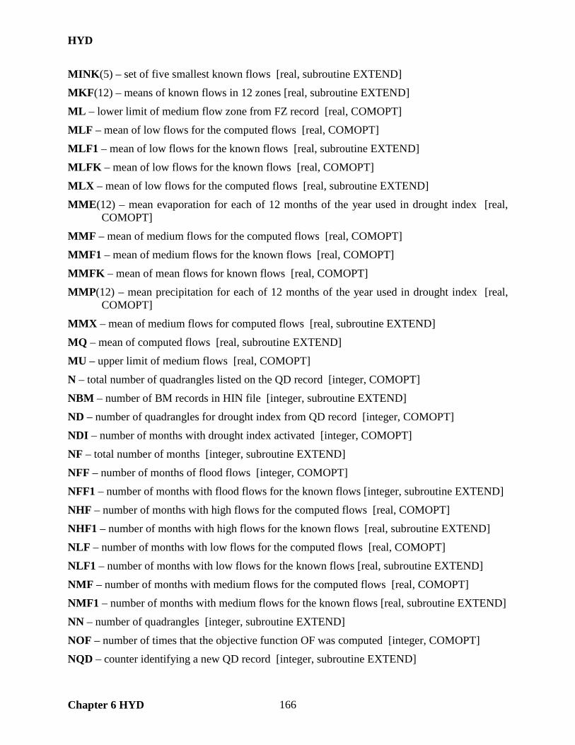
HYD
Chapter 6 HYD 166
MINK(5) – set of five smallest known flows [real, subroutine EXTEND]
MKF(12) – means of known flows in 12 zones [real, subroutine EXTEND]
ML – lower limit of medium flow zone from FZ record [real, COMOPT]
MLF – mean of low flows for the computed flows [real, COMOPT]
MLF1 – mean of low flows for the known flows [real, subroutine EXTEND]
MLFK – mean of low flows for the known flows [real, COMOPT]
MLX – mean of low flows for the computed flows [real, subroutine EXTEND]
MME(12) – mean evaporation for each of 12 months of the year used in drought index [real, COMOPT]
MMF – mean of medium flows for the computed flows [real, COMOPT]
MMF1 – mean of medium flows for the known flows [real, COMOPT]
MMFK – mean of mean flows for known flows [real, COMOPT]
MMP(12) – mean precipitation for each of 12 months of the year used in drought index [real, COMOPT]
MMX – mean of medium flows for computed flows [real, subroutine EXTEND]
MQ – mean of computed flows [real, subroutine EXTEND]
MU – upper limit of medium flows [real, COMOPT]
N – total number of quadrangles listed on the QD record [integer, COMOPT]
NBM – number of BM records in HIN file [integer, subroutine EXTEND]
ND – number of quadrangles for drought index from QD record [integer, COMOPT]
NDI – number of months with drought index activated [integer, COMOPT]
NF – total number of months [integer, subroutine EXTEND]
NFF – number of months of flood flows [integer, COMOPT]
NFF1 – number of months with flood flows for the known flows [integer, subroutine EXTEND]
NHF – number of months with high flows for the computed flows [real, COMOPT]
NHF1 – number of months with high flows for the known flows [real, subroutine EXTEND]
NLF – number of months with low flows for the computed flows [real, COMOPT]
NLF1 – number of months with low flows for the known flows [real, subroutine EXTEND]
NMF – number of months with medium flows for the computed flows [real, COMOPT]
NMF1 – number of months with medium flows for the known flows [real, subroutine EXTEND]
NN – number of quadrangles [integer, subroutine EXTEND]
NOF – number of times that the objective function OF was computed [integer, COMOPT]
NQD – counter identifying a new QD record [integer, subroutine EXTEND]

HYD
Chapter 6 HYD 167
NQDE – counter identifying a new EE record that uses the QD1 option instead of a QD record. NQDE is used as an indicator of whether array deallocation is required. [integer, subroutine EXTEND]
NXP – number of XP records in HIN file [integer, subroutine EXTEND]
NYRSA – number of years in the parameter calibration analysis entending from YRBEG through YREND [integer, COMOPT]
NYRSEX – number of years in the extension period from YRBEGEX to YRENDEX [integer, COMOPT]
NZ(12) – number of flows in each of the 12 zones [integer, subroutine EXTEND]
OF – objective function used in the optimization algorithm [real, COMOPT]
P(N,MAXYRS,12) – precipitation volumes from each of the N quadrangles [real, COMOPT]
PF – precipitation PP not contributing to flow in current month in computations for flood flow zone [real, subroutine FEFLOW]
PH – precipitation PP not contributing to flow in current month in computations for high flow zone [real, subroutine FEFLOW]
PL – precipitation PP not contributing to flow in current month in computations for low flow zone [real, subroutine FEFLOW]
PM – precipitation PP not contributing to flow in current month in computations for medium flow zone [real, subroutine FEFLOW]
PP(N,NYRS,12) – precipitation not contributing to flow in current month [real, COMOPT]
QA(N) – quadrangle areas from QA record [real, subroutine EXTEND]
QD(N) – indentifiers of the N quadrangles on the FE or EE records [integer, EXTEND]
QD1 – quadrangle identifier in EE record field 7 [real, subroutine EXTEND]
QDA(168) – known areas of the quandrangles in square miles stored in DATA statement [real, subroutine EXTEND]
QDI(N) – quadrangle index ranging between 1 and 168 assigned to the N quadrangles in order to connect to the areas QDA(N) from data statement [integer, subroutine EXTEND]
QI(168) – quadrangle identifers assigned by the TWDB and contained in the PPP and EEE files [integer, subroutine EXTEND]
QID – quadrangle identifer read from PPP or EEE files [integer, subroutine EXTEND]
RBF – regression boundary flow differentiating between linear and nonlinear regression zones [integer, subroutine EXTEND]
RP – precipitation runoff component of flow equation [real, COMOPT]
RPP – precipitation not contributing to flow in current month [real, COMOPT]
RR(2) – correlation coefficient for linear and nonlinear regression [real, subroutine EXTEND]
SOF(4) – last four values of the objective function OF which are used with the stop criteria [real, subroutine EXTEND]

HYD
Chapter 6 HYD 168
SR – sum of residuals squared used in correlation analysis computations [real, EXTEND]
ST – quantity in correlation analysis computations [real, subroutine EXTEND]
STOPFLAG – flag used in applying stop criteria in the cyclic search [integer, EXTEND]
TAREA – total watershed area in the N quadrangles [real, subroutine EXTEND]
TF – number of months with flood flows [integer, COMOPT]
TH – number of months with high flows [integer, COMOPT]
TL – number of months with low flows [integer, COMOPT]
TM – number of months with medium flows [integer, COMOPT]
U(2) – flow equation parameters from UB record [real, COMOPT]
U1 – multiplier factor U(1) in flow equation which is calibrated and recorded on UB record [real, subroutine EXTEND]
U2 – exponent U(2) in flow equation which is calibrated and recorded on UB record [real, subroutine EXTEND]
UFLAG1 – flag indicating whether U(1) is calibrated in optimization [integer, EXTEND]
UFLAG2 – flag indicating whether U(2) is calibrated in optimization [integer, EXTEND]
W(16) – objective function weighting factors from FP record [real, COMOPT]
X(N,5) – flow equation rainfall-runoff parameters for the N quadrangles [real, COMOPT]
X1 – initial value of the decision variable BM(M) or X(I,J) used in computing derivatives for the Newton equation [real, subroutine EXTEND]
X2 – x+Δx of the decision variable CM(M) or X(I,J) used in computing derivatives for the Newton equation [real, subroutine EXTEND]
X3 – x-Δx of the decision variable CM(M) or X(I,J) used in computing derivatives for the Newton equation [real, subroutine EXTEND]
XC(40,5) – parameters X(I,J) in flow equation [real, subroutine FEFLOW]
XD – current value of BM(M) or X(I,J) for which an improved value is to be found in the cycle univariate gradient search [real, subroutine EXTEND]
XF – known monthly stream flow [real, subroutine EXTEND]
XFF(N,5) – parameters X(I,J) recorded in X4 record for flood flow zone [real, COMOPT]
XHF(N,5) – parameters X(I,J) recorded in X3 record for high flow zone [real, COMOPT]
XJ1(N,5) − parameters X(I,J) optimized in enumeration [real, subroutine EXTEND]
XJ2(N,5) – parameters X(I,J) optimized in enumeration [real, subroutine EXTEND]
XLF(N,5) – parameters X(I,J) recorded in X1 record for low flow zone [real, COMOPT]
XMF(N,5) – parameters X(I,J) recorded in X2 record for medium flow zone [real, COMOPT]
XS – summation of computed flows in regression and correlation [real, subroutine EXTEND]
XSS – summation of computed flows squared in regression and correlation [real, EXTEND]

HYD
Chapter 6 HYD 169
XT – step sized in final calibration algorithm [real, subroutine EXTEND]
XX – step sizes Δx used in computing derivatives for the Newton equation [real, EXTEND]
XXM – mean of computed flows in regression [real, subroutine EXTEND]
XXX – miscellaneous temporary variable [real, subroutines EXTEND and CRITERIA]
XY(12*MAXYRS) – computed flows in regression and correlation analyses [real, EXTEND]
XYS – summation of flows squared in regression [real, subroutine EXTEND]
Y – year read from PPP or EEE files [integer, subroutine EXTEND]
YP – preceding year [integer, subroutines CRITERIA and FEFLOW]
YR – index for years [integer, subroutines EXTEND, CRITERIA, FEFLOW]
YR1 – index of beginning year of extension [integer, subroutines EXTEND and FEFLOW]
YR2 – index of ending year of extension [integer, subroutines EXTEND and FEFLOW]
YRBEG – beginning year of analysis from FE record [integer, subroutine EXTEND]
YRBEGEX – beginning year of extension from FE or EE record [integer, subroutine EXTEND]
YREND – ending year of analysis from FE record [integer, subroutine EXTEND]
YRENDEX – ending year of extension from FE or EE record [integer, COMOPT]
YS – summation of known flows in regression and correlation [real, subroutine EXTEND]
YSS – summation of known flows squared in regression and correlation [real, EXTEND]
YY(12*MAXYRS) – known flows in regression and correlation analyses [real, EXTEND]
YYM – mean of known flows in regression [real, subroutine EXTEND]
YYY – largest of computed versus known flow [real, subroutines EXTEND, CRITERIA]
Z(17) – eight criterion metrics optionally included in OF and written to MSS file [real, COMOPT]
Z1 – objective function value for X1 or XD [real, subroutine EXTEND]
Z2 – objective function value for X2 [real, subroutine EXTEND]
Z3 – objective function value for X3 [real, subroutine EXTEND]
ZE1 – objective function exponent from FP record with default of 2 [real, COMOPT]
ZE2 – objective function exponent from FP record with default of 2 [real, COMOPT]
ZEROS(2) – number of zero computed and known flows [integer, subroutine EXTEND]
ZF(2) – parameters from UB record related to zero and near-zero flows [real, EXTEND]
ZN – count of months with computed flows below limit ZU [integer, COMOPT]
ZNK – count of months with known flows below limit ZU [integer, COMOPT]
ZS(4) – indicator of whether criteria metrics for each of the four flow zones are included in the objective function. ZS(I)=ZZS(I)=9 means one or more Z metrics for the flow zone is included in the OF. [integer, COMOPT]

HYD
Chapter 6 HYD 170
ZU – first limit on FZ record used in ZN and ZNK counts [real, COMOPT]
ZZS(4) – indicator of whether criteria metrics for each of the four flow zones are included in the objective function. ZS(I)=ZZS(I)=9 means one or more Z metrics for the flow zone is included in the OF. [integer, subroutine EXTEND]
ZZZ – miscellaneous temporary variable [real, subroutines EXTEND, CRITERIA]

DAY
Chapter 7 DAY 171
CHAPTER 7 DAY Program DAY is a set of routines for developing sub-monthly (daily) naturalized stream flow sequences and routing parameters for input to SIMD. DAY performs the following tasks.
• disaggregation of monthly naturalized flows to sub-monthly time steps and associated conversion of flow data in various formats to the standard format of DF records (JOBDIS record)
• calibration of parameters for routing flow changes (JOBRTG record)
The naturalized flow disaggregation routines in DAY are also incorporated in SIMD. Parameters are determined for the lag and attenuation routing method and the Muskingum routing method.
Organization of DAY WRAP-DAY is organized for disaggregation jobs activated by a JOBDIS record and calibration jobs activated by a JOBRTG record. The DAY input DIN file may contain any number of JOBDIS and JOBRTG records and their auxiliary supporting records. Computations are performed for each job in the order that the JOBDIS and JOBRTG records are read from the DIN file. Subroutines JOBDIS and JOBRTG provide frameworks for the flow disaggregation and parameter calibration procedures. The main program opens the DIN input file and output files, reads the record identifier of records in the DIN file, and calls either Subroutine JOBDIS or Subroutine JOBRTG depending on job type. Subroutines JOBDIS and JOBRTG control the flow disaggregation and calibration procedures, which involve a variety of alternative user-selected computational options, and call the other subroutines as appropriate. Control returns to the main program upon completion of each JOBDIS record or JOBRTG record job.
Input and Output Files DAY has a main input file with the filename extension DIN that contains records controlling each flow disaggregation or calibration task. The DIN file input records are described in Appendix B of the Daily Manual. DAY reads monthly and daily flows from the same FLO and DCF files read by SIMD. Results of the DAY computations are written to an output file with the filename extension DAY. The DAY output file can be renamed with the DCF extension for use as a DAY or SIMD input file. The DAY message file has the filename extension DMS.
Table 7.1 DAY Input and Output Files
File Filename Input or Unit Extension Output Contents of File Opened in
UDIN=100 DIN input main input file main program UDCF=110 DCF input daily flow volumes Subroutine OPENDCF UFLO=120 FLO input monthly flow volumes Subroutine OPENFLO UDAY=130 DAY output main output file main program UDMS=140 DMS output message file main program

DAY
Chapter 7 DAY 172
Subroutines
The program begins with Module COMVAR which specifies the type and array shape for variables used in common by two or more subprograms. The main program follows after Module COMVAR. The main program reads the record identifier of the records in the input DIN file, calls Subroutine JOBDIS for flow disaggregation jobs (JOBDIS record in DIN file), and calls Subroutine JOBRTG for routing parameter calibration jobs (JOBRTG record in DIN file). Subroutines JOBDIS and JOBRTG call other subroutines as appropriate depending on options specified on the input records read from the DIN file. Control returns to the main program upon completion of each flow distribution (JOBDIS record) or routing parameter calibration (JOBRTG record) job.
The 22 subroutines are listed below in the order in which they are found in the program. The 16 function subprograms are described following the description of the subroutines. ERROR − called in conjunction with error messages to write a message to the monitor and stop
execution of the program. JOBDIS − called by the main program if a JOBDIS record is read from the DIN file to activate
the naturalized flow disaggregation process. Subroutine JOBDIS reads the relevant block of records (JOBDIS, NUMDAY, and DFLOWS records) from the DIN file, allocates variable arrays, calls Subroutines ReadFlowPatterns, DISAGGREGATION, and MT2DINTERP, and creates the formatted output file.
DISAGGREGATION − called by Subroutine JOBDIS to perform the disaggregation of monthly naturalized flow volumes into sub-monthly (such as daily) components based on the method METH specified in the JOBDIS record field 3.
SPLINEINTERP(DATES,NTI,NDAY,DAILYFLOW,MONTHLY) − called by Subroutine JOBDIS to perform the computations for creating synthetic daily flows by linear spline interpolation of the monthly flow volumes.
READFLOWPATTERNS − called by Subroutine JOBDIS to open and read the input file containing the monthly flow values and optional daily flow pattern.
OPENFLO − contained in Subroutine ReadFlowPatterns to open FLO file.
OPENDCF − contained in Subroutine ReadFlowPatterns to open DCF file.
JOBRTG − called by the main program if a JOBRTG record is read from the DIN file to activate the process of calibrating parameters for routing flow changes. Parameters are determined for either the lag and attenuation routing method or Muskingum routing method. Subroutine JOBRTG reads the JOBRTG record and associated records from the DIN file, allocates variable arrays, and calls Subroutines ReadHydrographs, CountTimeSteps(N), LateralAdjustment, GeneticAlgorithm, and RoutingResults to perform the calibration procedures.
ROUTINGRESULTS − called by Subroutine JOBRTG to record the calibration results and related information as tables in the output file.

DAY
Chapter 7 DAY 173
READHYDROGRAPHS − called by Subroutine JOBRTG to read hydrographs from a DCF file which may in either a DF record or columnar format. Subroutine ReadHydrographs determines the number DAY of time steps in the DCF file, reads the file, and populates the INFLOW and OUTFLOW arrays.
COUNTTIMESTEPS(N) − called by Subroutine JOBRTG to counts the number of time steps that conform to the range of flows in QMIN and QMAX. An array mask VALID is assigned a value of 1 for valid steps. The total inflow and outflow volume over the valid time steps is also computed for use with objective functions 3, 4, and 5 defined in JOBRTG record field 4.
LATERALAADJUSTMENT − called by Subroutine JOBRTG to determine volume of incremental lateral inflows entering the river reach between control points. The naturalized flows at upstream and downstream control points are summed the average difference is determined.
DIRECTSOLUTION(J,MX,MK,CORR) − called by Subroutine RoutingResults to compute the value of Muskingum K using the "direct solution" method. Storage and weighted discharge are computed for every time step. Linear regression is performed for those time steps conforming to the flow limits defined by QMIN and QMAX. Muskingum K is the slope of the line computed in the regression. The linear correlation coefficient CORR is returned along with K. Muskingum X is given as an input parameter to the subroutine.
MATINV(A) − matrix inverse subroutine is not used and thus should be removed
GENETICALGORITHM − called by Subroutine JOGRTG to apply a genetic algorithm methodology to calibrate routing parameters as specified by CALIB in JOBRTG record field 2.
PRINTSTATS − called from several points in Subroutine GeneticAlgorithm to display statistics for the current generation in the genetic algorithm computations.
CROSSOVER(OLDCHROM1,OLDCHROM2,pCROSS,pMUTATE,LEN,NEWCHROM1,NEWCHROM2) − called at several places in Subroutine GeneticAlgorithm to accept two parent chromosomes (binary 1-D arrays) of length LEN and produce two new "children" chromosomes by exchanging their alleles (binary values) at a cross over location. Cross over occurs with the probability pCROSS. Mutation occurs as the alleles are exchanged with the probability of pMUTATE.
SUS(FITNESS,nSELECT,SELECTED) − called by Subroutine GeneticAlgorithm to select nSelect number of individuals using their fitness values based on Stochastic Universal Sampling (SUS). The subroutine returns an array of subscripts of length nSelect.
RANKSCALING(RAW,SCALED) − called by Subroutine to GeneticAlgorithm take in an input array of raw real values and scale them between N and 1.0 based on their rank in ascending order.
LAROUTING(LAGG,ATT,J,HYDROGRAPH) − called by Subroutines RoutingResults and GeneticAlgorithm to develop an outflow hydrograph using the Lag-Attenuation routing method. Today’s upstream flow volume is distributed into pieces to be passed to the downstream control points using the lag-attenuation routing method.
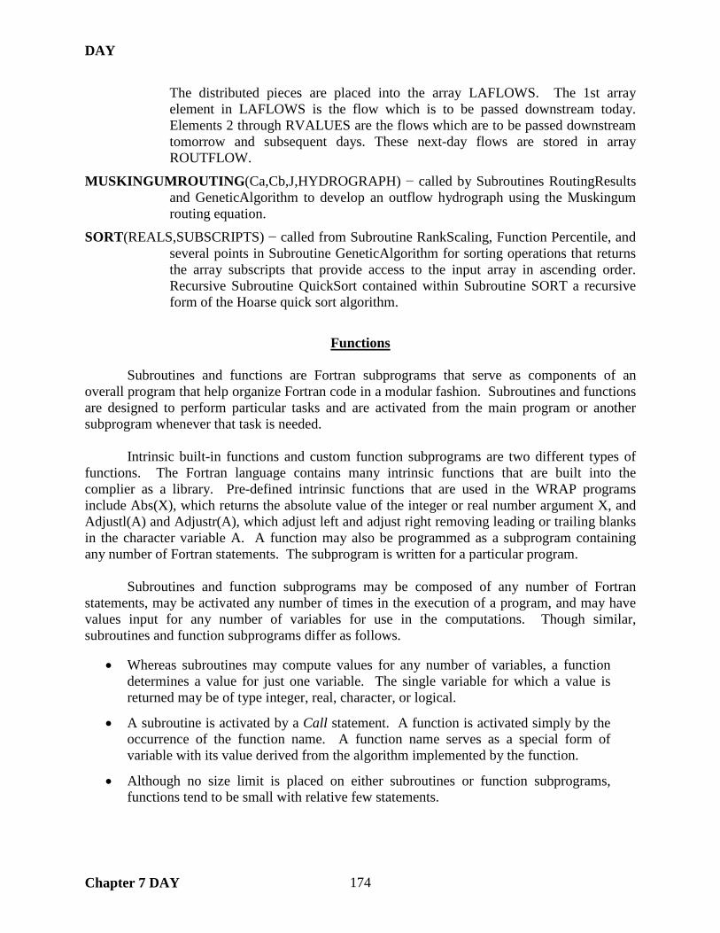
DAY
Chapter 7 DAY 174
The distributed pieces are placed into the array LAFLOWS. The 1st array element in LAFLOWS is the flow which is to be passed downstream today. Elements 2 through RVALUES are the flows which are to be passed downstream tomorrow and subsequent days. These next-day flows are stored in array ROUTFLOW.
MUSKINGUMROUTING(Ca,Cb,J,HYDROGRAPH) − called by Subroutines RoutingResults and GeneticAlgorithm to develop an outflow hydrograph using the Muskingum routing equation.
SORT(REALS,SUBSCRIPTS) − called from Subroutine RankScaling, Function Percentile, and several points in Subroutine GeneticAlgorithm for sorting operations that returns the array subscripts that provide access to the input array in ascending order. Recursive Subroutine QuickSort contained within Subroutine SORT a recursive form of the Hoarse quick sort algorithm.
Functions
Subroutines and functions are Fortran subprograms that serve as components of an overall program that help organize Fortran code in a modular fashion. Subroutines and functions are designed to perform particular tasks and are activated from the main program or another subprogram whenever that task is needed. Intrinsic built-in functions and custom function subprograms are two different types of functions. The Fortran language contains many intrinsic functions that are built into the complier as a library. Pre-defined intrinsic functions that are used in the WRAP programs include Abs(X), which returns the absolute value of the integer or real number argument X, and Adjustl(A) and Adjustr(A), which adjust left and adjust right removing leading or trailing blanks in the character variable A. A function may also be programmed as a subprogram containing any number of Fortran statements. The subprogram is written for a particular program.
Subroutines and function subprograms may be composed of any number of Fortran statements, may be activated any number of times in the execution of a program, and may have values input for any number of variables for use in the computations. Though similar, subroutines and function subprograms differ as follows.
• Whereas subroutines may compute values for any number of variables, a function determines a value for just one variable. The single variable for which a value is returned may be of type integer, real, character, or logical.
• A subroutine is activated by a Call statement. A function is activated simply by the occurrence of the function name. A function name serves as a special form of variable with its value derived from the algorithm implemented by the function.
• Although no size limit is placed on either subroutines or function subprograms, functions tend to be small with relative few statements.

DAY
Chapter 7 DAY 175
All of the WRAP programs contain multiple subroutines. However, with the exception of Program DAY, only a very few custom function subprograms have been coded into the WRAP programs. The 16 function subprograms included in DAY are listed below. Function CountDays(BEGYR,BEGMT,ENDYR,ENDMT,NTI,NDAY) − determines the integer
number of daily (or other sub-monthly) periods for a range of years and months. Used in Subroutine JOBDIS.
Logical Function Leap(YEAR) − returns a logical value of true or false indicating whether the integer YEAR passed to the function corresponds to a calendar leap year (true) or not (false). Used in Subroutines JOBDIS, DISAGGREGATION, MT2DINTERP, ReadFlowPatterns, and ReadHydrographs, and Function CountDays.
Function CountMonths(BEGYR,BEGMT,ENDYR,ENDMT) − returns the integer number of months for a range of years and months. Used in Subroutine JOBDIS.
Real Function ArithMean(VALUES) − computes the arithmetic mean of an array of numbers. Used in Subroutine RoutingResults and Functions StDev and Correlate.
Real Function StDev(VALUES) − computes the standard deviation of an array of numbers. Used in Subroutine RoutingResults and Function PrintStats.
Real Function Correlate(X,Y,LAG) − computes the linear correlation coefficient between two arrays of numbers. Used in Subroutine RoutingResults.
Integer Function Mutate(ALLELE,pMUTATE) − randomly mutates (changes) a binary coded allele (the actual binary value) based on random chance with the probability of pMUTATE in the genetic algorithm computations in the parameter calibration. Used in Subroutines GeneticAlgorithm and CrossOver.
Real Function ObjFunc(HYDROGRAPH) − evaluates the objective function used in the parameter calibration. Subroutines RoutingResults and GeneticAlgorithm.
Integer Function RoundInt(NUMBER) − rounds a real number to an integer. Used in Subroutine GeneticAlgorithm.
Real Function DecodeChrom(ARRAY,LOWER,UPPER) − decodes a binary array (chromosome) into an unsigned integer and then into a floating point mapped between the range of LOWER and UPPER. The binary array prepresent powers of 2 with respect to it's array subscript. Thus array[0] is 2^0, array[1] is 2^1, etc. This function is used the genetic algorithm methodology for parameter calibration. Used in Subroutine GeneticAlgorithm.
Integer Function RandInt(LOWER,UPPER) − selects a random integer between the range of LOWER to UPPER. Used in Subroutines GeneticAlgorithm and CrossOver.
Logical Function Flip(PROBABILITY) − flip a coin biased towards a TRUE result by the variable probability. Used in Subroutine CrossOver and Function Mutate.
Integer Function Locate(Values,X) − locates the array index I such that the value of X is between Values(I) and Values(I+1) using the bisection method. Values must be a sorted array in either monotonically increasing or descending order. Used in Function Percentile.

DAY
Chapter 7 DAY 176
Real Function LinearInterp(X1,Y1,X2,Y2,X) − computes Y for an X, given the pairs (X1,Y1) and (X2,Y2). Used in Function Percentile.
Real Function Percentile(VALUES,K) − applies linear interpolation to determine the value with percentile K, where 0 ≤ K ≤ 100. Used in Subroutine RoutingResults.
Definition of Variables
AFIX(NGAGES-1) – fixed value of attenuation read from RFIXED record [real, JOBRTG,
COMVAR] ALLELE – an individual 0 or 1 element of a chromosome [integer, MUTATE] AMAX(NGAGES-1) – maximum value of attenuation read from RUPPER record [real,
JOBRTG, COMVAR] AMIN(NGAGES-1) – minimum value of attenuation read from RLOWER record [real,
JOBRTG, COMVAR] BEGMT – beginning month read from RFLOWS record [integer, JOBRTG, COMVAR] BEGYR – beginning year read from RFLOWS record [integer, JOBRTG, COMVAR] CA(nUPSTR,sPOP) – value of the routing coefficient Ca for each nUPSTR gage and sPOP
number of individuals [real, GENETICALGORITHM] CALIB – calibration method read from JOBRTG record [integer, JOBRTG, COMVAR] CALOWER – lower bound for decoding routing coefficient Ca [real, GENETICALGORITHM] CAUPPER – upper bound for decoding routing coefficient Ca [real, GENETICALGORITHM] CB(nUPSTR,sPOP) – value of the routing coefficient Cb for each NUPSTR locations and SPOP
number of individuals [real, GENETICALGORITHM] CBLOWER – lower bound for decoding routing coefficient Cb [real, GENETICALGORITHM] CBUPPER – upper bound for decoding routing coefficient Cb [real, GENETICALGORITHM] CD – first six characters read from records in DIN file [character(len=6), COMVAR] CHAR – input and output root name read from console screen [character(len=256), main
program] CHECKS(2) – values of C1 and C2 read from CHECKS record [integer, COMVAR] CPDF – identifier of DF records read from DFLOWS record [character(len=6), JOBDIS,
COMVAR] CPIN – identifier of IN records read from DFLOWS record [character(len=6), JOBDIS,
COMVAR] CPNUM – character variable derived from the integer count of the control points read on the
JOBDIS record. CPNUM used for automatic control point output name assignment. [character(len=20), JOBDIS]
DAILY(DAYS,I) – array holding the daily disaggregated flows, where I is equal to the number of time series to be disaggregated [integer, JOBDIS, COMVAR]
DAILY2(DAYS) – second daily time series used in the variability adjustment option as selected on the JOBDIS record [real, DISAGREGGATION]

DAY
Chapter 7 DAY 177
DATES(8) – array holding values of mBEGYR, mBEGMT, mENDYR, mENDMT, dBEGYR, dBEGMT, dENDYR, dENDMT read from DFLOWS record [integer, DISAGREGGATION]
DAYS – number of days returned from Function CountDays [integer, JOBRTG, COMVAR] dBEGMT – read from DFLOWS record [integer, JOBDIS, COMVAR] dBEGYR − read from DFLOWS record [integer, JOBDIS, COMVAR] dENDMT − read from DFLOWS record [integer, JOBDIS, COMVAR] dENDYR − read from DFLOWS record [integer, JOBDIS, COMVAR] DFLOWS(DAYS)− array holding daily flow values from disaggregation process [real, JOBDIS,
COMVAR] DFLOWS2(DAYS) − array holding daily flow values used in the variability ratio method of
disaggregation [real, DISAGREGGATION] DT – counter of days within the month [integer, DISAGREGGATION, JOBDIS] ENDMT – read from RFLOWS record [integer, JOBRTG, COMVAR] ENDYR − read from RFLOWS record [integer, JOBRTG, COMVAR] EXIST – logical variable used to check the existence status of files being read from or written to
[logical, main program, ERROR, JOBDIS] EXITCHAR – character read from console scree prior to program termination [character(len=2),
ERROR] FACTOR – value of the penalization function to reduce the fitness function of individuals with
values that fall outside of the user defined constraints [real, GENETICALGORITHM]
FITNESS(sPOP) – value of the fitness function for each individual of the population sPOP [real, GENETICALGORITHM, SUS, RANKSCALING]
FUNC – objective function method read from JOBRTG record [integer, JOBRTG, COMVAR] GNAMES(NGAGES) – gage names read from JOBRTG record [character(len=6), JOBRTG,
COMVAR] HYDROGRAPH(DAYS) – hydrograph at the outflow location resulting from the addition of all
routed inflows [real, GENETICALGORITHM] ID(I) – array holding the names of daily flow patterns read from JOBDIS record where I equals 1
or the absolute value of METH when METH is less than zero [character(len=6), JOBDIS, COMVAR]
INFLOW(DAYS,nUPSTR) – time series of daily flows at gages upstream of the OUTFLOW time series used in the routing calibration process [real, JOBRTG, COMVAR]
INFORM – time series input format from DFLOWS record [integer, JOBDIS, COMVAR] INITIAL – initialization value of the routed outflow hydrograph for use in the Muskingum
method [real, MUSKINGUMROUTING] INPUT – input root name read from console screen [character(len=256), main program] KFIX(NGAGES-1) – fixed value of Muskingum K read from RFIXED record [real, JOBRTG,
COMVAR]
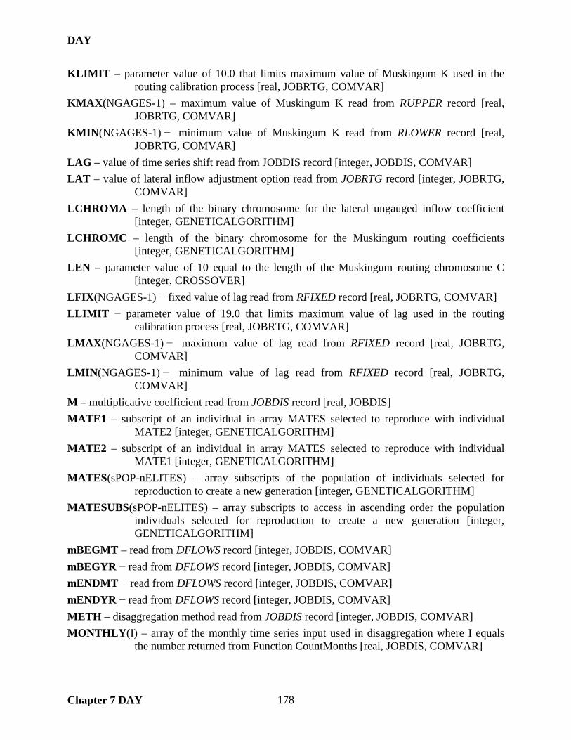
DAY
Chapter 7 DAY 178
KLIMIT – parameter value of 10.0 that limits maximum value of Muskingum K used in the routing calibration process [real, JOBRTG, COMVAR]
KMAX(NGAGES-1) – maximum value of Muskingum K read from RUPPER record [real, JOBRTG, COMVAR]
KMIN(NGAGES-1) − minimum value of Muskingum K read from RLOWER record [real, JOBRTG, COMVAR]
LAG – value of time series shift read from JOBDIS record [integer, JOBDIS, COMVAR] LAT – value of lateral inflow adjustment option read from JOBRTG record [integer, JOBRTG,
COMVAR] LCHROMA – length of the binary chromosome for the lateral ungauged inflow coefficient
[integer, GENETICALGORITHM] LCHROMC – length of the binary chromosome for the Muskingum routing coefficients
[integer, GENETICALGORITHM] LEN – parameter value of 10 equal to the length of the Muskingum routing chromosome C
[integer, CROSSOVER] LFIX(NGAGES-1) − fixed value of lag read from RFIXED record [real, JOBRTG, COMVAR] LLIMIT − parameter value of 19.0 that limits maximum value of lag used in the routing
calibration process [real, JOBRTG, COMVAR] LMAX(NGAGES-1) − maximum value of lag read from RFIXED record [real, JOBRTG,
COMVAR] LMIN(NGAGES-1) − minimum value of lag read from RFIXED record [real, JOBRTG,
COMVAR] M – multiplicative coefficient read from JOBDIS record [real, JOBDIS] MATE1 – subscript of an individual in array MATES selected to reproduce with individual
MATE2 [integer, GENETICALGORITHM] MATE2 – subscript of an individual in array MATES selected to reproduce with individual
MATE1 [integer, GENETICALGORITHM] MATES(sPOP-nELITES) – array subscripts of the population of individuals selected for
reproduction to create a new generation [integer, GENETICALGORITHM] MATESUBS(sPOP-nELITES) – array subscripts to access in ascending order the population
individuals selected for reproduction to create a new generation [integer, GENETICALGORITHM]
mBEGMT – read from DFLOWS record [integer, JOBDIS, COMVAR] mBEGYR − read from DFLOWS record [integer, JOBDIS, COMVAR] mENDMT − read from DFLOWS record [integer, JOBDIS, COMVAR] mENDYR − read from DFLOWS record [integer, JOBDIS, COMVAR] METH – disaggregation method read from JOBDIS record [integer, JOBDIS, COMVAR] MONTHLY(I) – array of the monthly time series input used in disaggregation where I equals
the number returned from Function CountMonths [real, JOBDIS, COMVAR]

DAY
Chapter 7 DAY 179
MONTHLY2(I) − array of the aggregated monthly flows from the DAILY2 array used in disaggregation where I equals the number returned from Function CountMonths [real, DISAGREGGATION]
MT – calendar month per year [integer, DISAGREGGATION, JOBDIS] NDAY(12) – number of days per month [integer, JOBDIS, COMVAR] nELITES – number of individuals with the highest fitness function value. These individuals are
unchanged from the previous generation and used to carry over their information to the next generation. [integer, GENETICALGORITHM, SUS]
NEWCHROM1(Max(LCHROMC,LCHROMLAG)) – binary chromosome sent to Subroutine CROSSOVER to receive the child chromosome [integer, CROSSOVER]
NEWCHROM2(Max(LCHROMC,LCHROMLAG)) – binary chromosome sent to Subroutine CROSSOVER to receive the child chromosome [integer, CROSSOVER]
NEWCHROMCA(Max(LCHROMC,LCHROMLAG),nUPSTR,sPOP) – binary chromosomes of the current generation for nUPSTR inflows and sPOP number of individuals corresponding to the routing coefficient Ca [integer, GENETICALGORITHM, DECODECHROM]
NEWCHROMCB(Max(LCHROMC,LCHROMLAG),nUPSTR,sPOP) – binary chromosomes of the current generation for NUPSTR inflows and SPOP number of individuals corresponding to the routing coefficient Cb [integer, GENETICALGORITHM, DECODECHROM]
NGAGES – number of inflow plus outflow time series, where each time series is referenced by its gage identifier, used in the routing parameter calibration [integer, JOBRTG, COMVAR]
nGENS – maximum number of generations to simulate unless convergence is satisfied beforehand. nGENS is set equal to 100 times nUPSTR. [integer, GENETICALGORITHM]
NTI – submonthly time intervals red from JOBDIS record [integer, JOBDIS, COMVAR] nUPSTR – number of inflow gauges equal to NGAGUES-1 [integer, GENETICALGORITHM] OLDCHROM1(Max(LCHROMC,LCHROMLAG)) – binary chromosome sent to Subroutine
CROSSOVER to serve as a parent chromosome [integer, CROSSOVER] OLDCHROM2(Max(LCHROMC,LCHROMLAG)) – binary chromosome sent to Subroutine
CROSSOVER to serve as a parent chromosome [integer, CROSSOVER] OLDCHROMCA(Max(LCHROMC,LCHROMLAG),nUPSTR,sPOP) – binary chromosomes
of the previous generation for nUPSTR inflows and sPOP number of individuals corresponding to the routing coefficient Ca [integer, GENETICALGORITHM, DECODECHROM]
OLDCHROMCB(Max(LCHROMC,LCHROMLAG),nUPSTR,sPOP) – binary chromosomes of the previous generation for nUPSTR inflows and sPOP number of individuals corresponding to the routing coefficient Cb [integer, GENETICALGORITHM, DECODECHROM]

DAY
Chapter 7 DAY 180
ORIGIN – average fitness function value of the top 75% of individuals in the population after initialization and before the first generation is allowed to reproduce [real, GENETICALGORITHM]
OUTFILE – name of the output file equal to root name with the appropriate file extension [character(len=256), COMVAR]
OUTFLOW(DAYS) – time series of daily flows at gages downstream of the INFLOW gages used in routing calibration process [real, JOBRTG, COMVAR]
OUTFORM – output format variable read from JOBDIS record [integer, JOBDIS, COMVAR] PARAMS(3) – array holding values of X, M, A as read from JOBDIS record [integer, JOBDIS,
COMVAR] pCROSS – probability between 0.0 and 1.0 for cross over reproduction to occur. pCROSS is a
parameter value set to 0.90. [real, GENETICALGORITHM, CROSSOVER] pELITE – percentage between 0 and 1.0 of the total population to store unchanged as elites
between generations. pELITE is a parameter value set to 0.01. [real, GENETICALGORITHM]
PERFECTFIT – maximum theoretical value of the objective function. The genetic algorithm is coded to maximum fitness. Maximum occurs for the value of PERFECTFIT minus the objective function. [real, GENETICALGORITHM]
pMUTATE – probability between 0.0 and 1.0 for mutation to occur. pMUTATE is a parameter value set to 0.01. [real, GENETICALGORITHM, CROSSOVER, MUTATE]
POPSUBS(sPOP) – array subscripts of the population individuals ranked in ascending order [integer, GENETICALGORITHM, SORT]
PROGRESS(10) – average fitness function value of the top 75% of individuals of the previous ten generations used to test of optimization convergence [real, GENETICALGORITHM]
QLIMIT – parameter value of 1,000,000,000.0 used to limit maximum flow generated in flow routing process [real, JOBRTG, COMVAR]
QMAX(NGAGES-1) – maximum value of flow read from QUPPER record [real, JOBRTG, COMVAR]
QMIN(NGAGES-1) – minimum value of flow read from QLOWER record [real, JOBRTG, COMVAR]
READ_JOB – variable used to signify a JOBRTG or JOBDIS record has been read from the DIN file [logical, JOBDIS]
READ_NUMDAY – variable used to signify a NUMDAY record has been read from the DIN file [logical, JOBDIS]
REPLACE – selection read from console screen regarding replacement of existing output files [logical, COMVAR]
RESULTS(2,NGAGES-1) – values of optimized routing parameters per upstream gage [real, JOBRTG, COMVAR]
ROOT – root of input data file name read from console screen [character(len=256), COMVAR]

DAY
Chapter 7 DAY 181
ROOT2 – root of input hydrology file name read from console screen [character(len=256), COMVAR]
RTYPE(NGAGES-1) – value of routing method read from RTYPES record [integer, JOBRTG, COMVAR]
SCALED(sPOP) – rank-based scaled values of the fitness function for each individual of the population [real, GENETICALGORITHM, RANKSCALING, SORT]
SERIES(DAYS) – hydrograph at the outflow gage that is generate by routing a single inflow gage time series [real, GENETICALGORITHM]
SIMULATION – number of the optimization pass through the genetic algorithm. Multiple optimizations are initialized and conducted in the case of multiple inflow gauges to insure the entire parameter space is explored. The number of optimization passes are equal to nUPSTR. [integer, GENETICALGORITHM]
sPOP – size of the population of individuals. sPOP is set equal to 100 times nUPSTR. [integer, GENETICALGORITHM, SUS]
TOTALIN – total value of INFLOW for each upstream gage [real, JOBRTG, COMVAR] TOTALOUT – total value of OUTFLOW at the downstream gage [real, JOBRTG, COMVAR] UDAY − variable that stores the file unit number for the DAY file [integer, COMVAR] UDCF − variable that stores the file unit number for the DCF file [integer, COMVAR] UDIN − variable that stores the file unit number for the DIN file [integer, COMVAR] UDMS − variable that stores the file unit number for the DMS file [integer, COMVAR] UFLO − variable that stores the file unit number for the FLO file [integer, COMVAR] UNADJUSTED(DAYS) – array holding value of OUTFLOW prior to adjustment for lateral
inflows [real, JOBRTG, COMVAR] VALID(DAYS) – array holding value of 1 for time steps conforming to the QMIN and QMAX
range for computing the objective function [integer, JOBRTG, COMVAR] VOL – value read from JOBDIS record [integer, JOBDIS, COMVAR] VR(DAYS) – variability ratio computed for each time step [real, DISAGREGGATION] VRL – parameter value of 0.10 used in disaggregation process [real, parameter,
DISAGREGGATION] WEIGHT – weighting factor read from JOBRTG record [real, JOBRTG, COMVAR] X – exponent read from JOBDIS record [real, JOBDIS] XFIX(NGAGES-1) − fixed value of Muskingum X read from RFIXED record [real, JOBRTG,
COMVAR] XMAX(NGAGES-1) − maximum value of Muskingum X read from RFIXED record [real,
JOBRTG, COMVAR] XMIN(NGAGES-1) − minimum value of Muskingum X read from RFIXED record [real,
JOBRTG, COMVAR] YRMT(I,2) – array holding year and month pairs for each month during the routing calibration
process where I equals the number of months returned from Function CountMonths [integer, JOBRTG, COMVAR]

DAY
Chapter 7 DAY 182
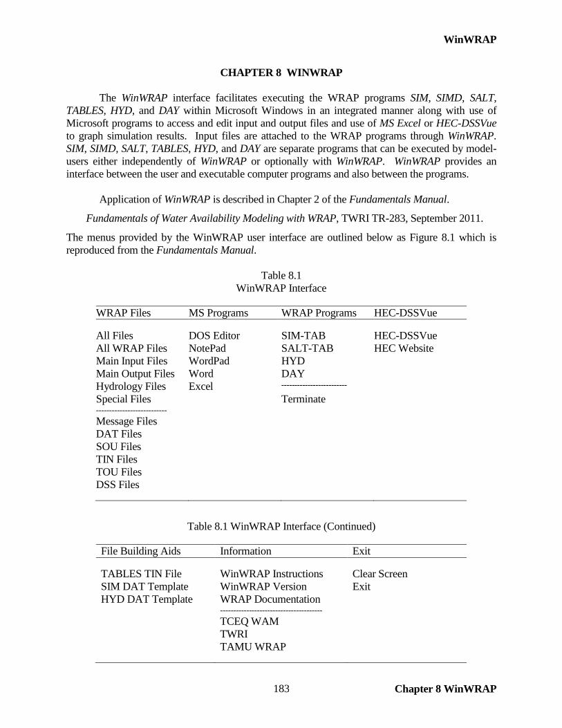
WinWRAP
Chapter 8 WinWRAP 183
CHAPTER 8 WINWRAP
The WinWRAP interface facilitates executing the WRAP programs SIM, SIMD, SALT, TABLES, HYD, and DAY within Microsoft Windows in an integrated manner along with use of Microsoft programs to access and edit input and output files and use of MS Excel or HEC-DSSVue to graph simulation results. Input files are attached to the WRAP programs through WinWRAP. SIM, SIMD, SALT, TABLES, HYD, and DAY are separate programs that can be executed by model-users either independently of WinWRAP or optionally with WinWRAP. WinWRAP provides an interface between the user and executable computer programs and also between the programs.
Application of WinWRAP is described in Chapter 2 of the Fundamentals Manual.
Fundamentals of Water Availability Modeling with WRAP, TWRI TR-283, September 2011.
The menus provided by the WinWRAP user interface are outlined below as Figure 8.1 which is reproduced from the Fundamentals Manual.
Table 8.1 WinWRAP Interface
WRAP Files MS Programs WRAP Programs HEC-DSSVue All Files DOS Editor SIM-TAB HEC-DSSVue All WRAP Files NotePad SALT-TAB HEC Website Main Input Files WordPad HYD Main Output Files Word DAY Hydrology Files Excel ------------------------- Special Files Terminate --------------------------- Message Files DAT Files SOU Files TIN Files TOU Files DSS Files
Table 8.1 WinWRAP Interface (Continued)
File Building Aids Information Exit TABLES TIN File WinWRAP Instructions Clear Screen SIM DAT Template WinWRAP Version Exit HYD DAT Template WRAP Documentation --------------------------------------- TCEQ WAM TWRI TAMU WRAP

WinWRAP
Chapter 8 WinWRAP 184
Compaq/Intel Visual Fortran Features for Developing Graphical User Interfaces
The Compaq and Intel Visual Fortran software includes QuickWin as well as other alternative features for developing graphical user interfaces (GUIs). WinWRAP is compiled and linked by Compaq Visual Fortran version 6.6 or the Intel Visual Fortran software using QuickWin. The QuickWin feature allows development of GUI programs, such as WinWRAP, using Visual Fortran with a simplified version of the library of Windows interface routines. The QuickWin library provides an extensive set of Windows features, but it does not include the complete Windows Applications Programming Interface (IPA). The Compaq and Intel Visual Fortran software also allows accessing the full Windows IPA directly, without QuickWin, but programming is more complex. QuickWin simplifies Windows programming with Fortran.
WinWRAP and the other WRAP programs are separate individual executable (.EXE) files. Thus, WinWRAP could be developed in other programming languages using the same or other compiler/linker/IDE software products without affecting the other WRAP programs which are written in Fortran. Another alternative programming strategy that can be implemented within the Compaq and Intel Visual Fortran and Microsoft Visual Studio IDE system is to develop a graphical user interface (GUI) in either Visual Basic, C++, or another programming language that calls other components of a modeling system which are coded in Fortran.
The Windows Applications Programming Interface (IPA) is a standard library of routines accessed by many different software tools used to develop GUIs. The QuickWin library is a wrapper around a subset of the Windows IPA designed for implementation within Fortran. All QuickWin applications include creation of an application or frame window. Child windows can also be created. The name of the created executable program appears in the title bar of the frame window. Menus, edit boxes, check boxes, drop-down boxes, buttons, and scroll bars, along with pictures and graphics, are created in standard Microsoft Windows format. Various features of the GUI are created by calling standard Windows library routines from the Fortran code. WinWRAP is compiled and linked by Compaq Visual Fortran version 6.6 or the Intel Visual Fortran software using QuickWin. Versions of Compaq Visual Fortran prior to version 6.6 should not be used for compiling and linking WinWRAP. Versions 6.5 and prior contain errors related to QuickWin graphical user interface programming that were corrected in version 6.6. However, version 6.6 introduced errors which resulted in unstable numerical results with the WRAP programs SIM, SIMD, TABLES, HYD, DAY, and SALT. Therefore, Compaq Visual Fortran version 6.5 is the last version of the Compaq software that may be used for compiling and linking all non-QuickWin WRAP simulation and computational programs. In the transition process of Intel acquiring the Visual Fortran compiler/linker software from Compaq during 2005-2006, the software skipped from Compaq version 6.6 to Intel version 9.0.
Differences between WinWRAP and the Other WRAP Programs WinWRAP is very different than SIM, SIMD, SALT, TABLES, HYD, and DAY. WinWRAP is a graphical user interface (GUI). The other WRAP programs are simulation models based on computations and managing arrays of numerical data. WinWRAP is coded in Fortran, but calling
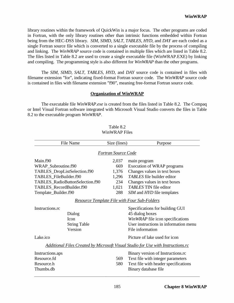
WinWRAP
Chapter 8 WinWRAP 185
library routines within the framework of QuickWin is a major focus. The other programs are coded in Fortran, with the only library routines other than intrinsic functions embedded within Fortran being from the HEC-DSS library. SIM, SIMD, SALT, TABLES, HYD, and DAY are each coded as a single Fortran source file which is converted to a single executable file by the process of compiling and linking. The WinWRAP source code is contained in multiple files which are listed in Table 8.2. The files listed in Table 8.2 are used to create a single executable file (WinWRAP.EXE) by linking and compiling. The programming style is also different for WinWRAP than the other programs.
The SIM, SIMD, SALT, TABLES, HYD, and DAY source code is contained in files with
filename extension ″for″, indicating fixed-format Fortran source code. The WinWRAP source code is contained in files with filename extension ″f90″, meaning free-format Fortran source code.
Organization of WinWRAP
The executable file WinWRAP.exe is created from the files listed in Table 8.2. The Compaq or Intel Visual Fortran software integrated with Microsoft Visual Studio converts the files in Table 8.2 to the executable program WinWRAP.
Table 8.2
WinWRAP Files
File Name Size (lines) Purpose
Fortran Source Code
Main.f90 2,037 main program WRAP_Subroutine.f90 669 Execution of WRAP programs TABLES_DropListSelection.f90 1,376 Changes values in text boxes TABLES_FileBuilder.f90 1,296 TABLES file builder editor TABLES_RadioButtonSelection.f90 234 Changes values in text boxes TABLES_RecordBuilder.f90 1,021 TABLES TIN file editor Template_Builder.f90 288 SIM and HYD file templates
Resource Template File with Four Sub-Folders
Instructions.rc Specifications for building GUI Dialog 45 dialog boxes Icon WinWRAP file icon specifications String Table User instructions in information menu Version File information
Lake.ico Picture of lake used for icon
Additional Files Created by Microsoft Visual Studio for Use with Instructions.rc
Instructions.aps Binary version of Instructions.rc Resource.fd 569 Text file with integer parameters Resource.h 580 Text file with header specifications Thumbs.db Binary database file
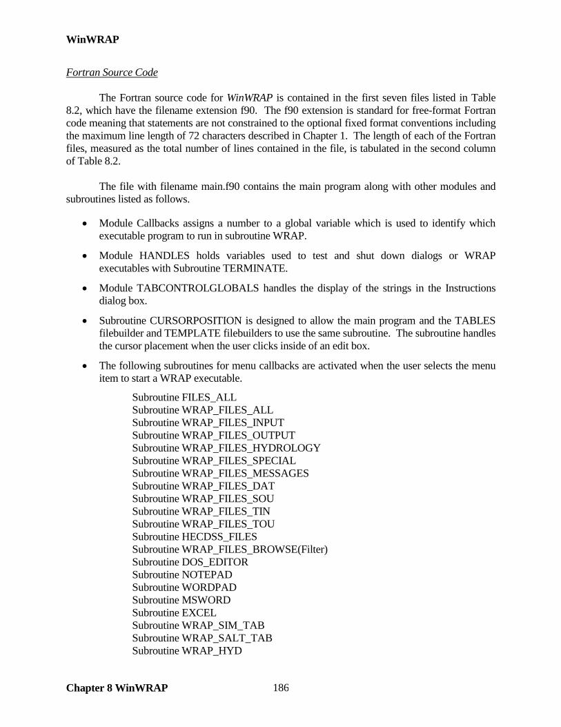
WinWRAP
Chapter 8 WinWRAP 186
Fortran Source Code The Fortran source code for WinWRAP is contained in the first seven files listed in Table 8.2, which have the filename extension f90. The f90 extension is standard for free-format Fortran code meaning that statements are not constrained to the optional fixed format conventions including the maximum line length of 72 characters described in Chapter 1. The length of each of the Fortran files, measured as the total number of lines contained in the file, is tabulated in the second column of Table 8.2. The file with filename main.f90 contains the main program along with other modules and subroutines listed as follows.
• Module Callbacks assigns a number to a global variable which is used to identify which executable program to run in subroutine WRAP.
• Module HANDLES holds variables used to test and shut down dialogs or WRAP executables with Subroutine TERMINATE.
• Module TABCONTROLGLOBALS handles the display of the strings in the Instructions dialog box.
• Subroutine CURSORPOSITION is designed to allow the main program and the TABLES filebuilder and TEMPLATE filebuilders to use the same subroutine. The subroutine handles the cursor placement when the user clicks inside of an edit box.
• The following subroutines for menu callbacks are activated when the user selects the menu item to start a WRAP executable.
Subroutine FILES_ALL Subroutine WRAP_FILES_ALL Subroutine WRAP_FILES_INPUT Subroutine WRAP_FILES_OUTPUT Subroutine WRAP_FILES_HYDROLOGY Subroutine WRAP_FILES_SPECIAL Subroutine WRAP_FILES_MESSAGES Subroutine WRAP_FILES_DAT Subroutine WRAP_FILES_SOU Subroutine WRAP_FILES_TIN Subroutine WRAP_FILES_TOU Subroutine HECDSS_FILES Subroutine WRAP_FILES_BROWSE(Filter) Subroutine DOS_EDITOR Subroutine NOTEPAD Subroutine WORDPAD Subroutine MSWORD Subroutine EXCEL Subroutine WRAP_SIM_TAB Subroutine WRAP_SALT_TAB Subroutine WRAP_HYD
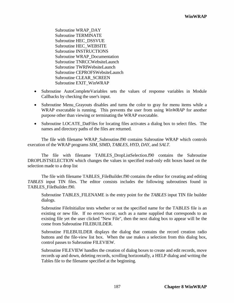
WinWRAP
Chapter 8 WinWRAP 187
Subroutine WRAP_DAY Subroutine TERMINATE Subroutine HEC_DSSVUE Subroutine HEC_WEBSITE Subroutine INSTRUCTIONS Subroutine WRAP_Documentation Subroutine TNRCCWebsiteLaunch Subroutine TWRIWebsiteLaunch Subroutine CEPROFSWebsiteLaunch Subroutine CLEAR_SCREEN Subroutine EXIT_WinWRAP
• Subroutine AutoCompleteVariables sets the values of response variables in Module Callbacks by checking the user's input.
• Subroutine Menu_Grayouts disables and turns the color to gray for menu items while a WRAP executable is running. This prevents the user from using WinWRAP for another purpose other than viewing or terminating the WRAP executable.
• Subroutine LOCATE_DatFiles for locating files activates a dialog box to select files. The names and directory paths of the files are returned.
The file with filename WRAP_Subroutine.f90 contains Subroutine WRAP which controls execution of the WRAP programs SIM, SIMD, TABLES, HYD, DAY, and SALT. The file with filename TABLES_DropListSelection.f90 contains the Subroutine DROPLISTSELECTION which changes the values in specified read-only edit boxes based on the selection made to a drop list The file with filename TABLES_FileBuilder.f90 contains the editor for creating and editing TABLES input TIN files. The editor consists includes the following subroutines found in TABLES_FileBuilder.f90.
Subroutine TABLES_FILENAME is the entry point for the TABLES input TIN file builder dialogs.
Subroutine FileInitialize tests whether or not the specified name for the TABLES file is an existing or new file. If no errors occur, such as a name supplied that corresponds to an existing file yet the user clicked "New File", then the next dialog box to appear will be the come from Subroutine FILEBUILDER.
Subroutine FILEBUILDER displays the dialog that contains the record creation radio buttons and the file-view list box. When the use makes a selection from this dialog box, control passes to Subroutine FILEVIEW.
Subroutine FILEVIEW handles the creation of dialog boxes to create and edit records, move records up and down, deleting records, scrolling horizontally, a HELP dialog and writing the Tables file to the filename specified at the beginning.
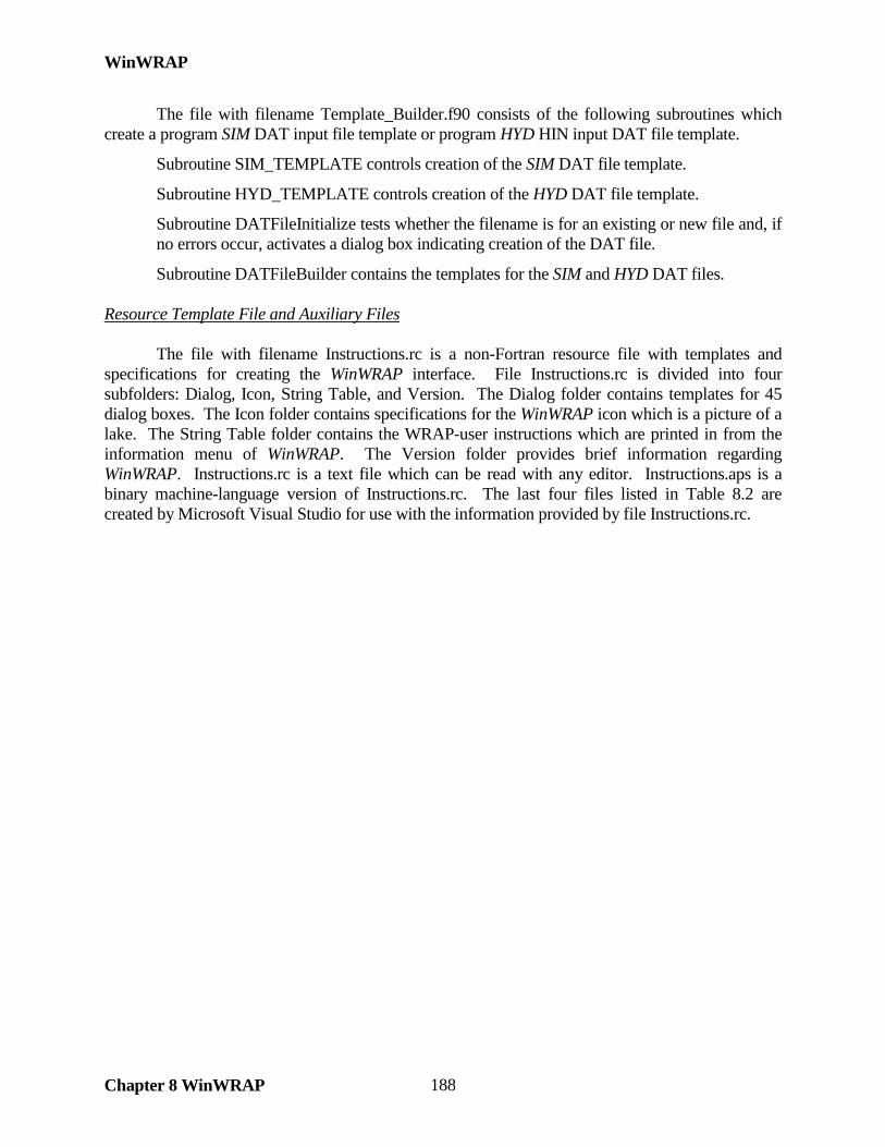
WinWRAP
Chapter 8 WinWRAP 188
The file with filename Template_Builder.f90 consists of the following subroutines which create a program SIM DAT input file template or program HYD HIN input DAT file template.
Subroutine SIM_TEMPLATE controls creation of the SIM DAT file template.
Subroutine HYD_TEMPLATE controls creation of the HYD DAT file template.
Subroutine DATFileInitialize tests whether the filename is for an existing or new file and, if no errors occur, activates a dialog box indicating creation of the DAT file.
Subroutine DATFileBuilder contains the templates for the SIM and HYD DAT files. Resource Template File and Auxiliary Files The file with filename Instructions.rc is a non-Fortran resource file with templates and specifications for creating the WinWRAP interface. File Instructions.rc is divided into four subfolders: Dialog, Icon, String Table, and Version. The Dialog folder contains templates for 45 dialog boxes. The Icon folder contains specifications for the WinWRAP icon which is a picture of a lake. The String Table folder contains the WRAP-user instructions which are printed in from the information menu of WinWRAP. The Version folder provides brief information regarding WinWRAP. Instructions.rc is a text file which can be read with any editor. Instructions.aps is a binary machine-language version of Instructions.rc. The last four files listed in Table 8.2 are created by Microsoft Visual Studio for use with the information provided by file Instructions.rc.
Related Documents