Vacuum Training-Set Manual World of vacuum technology 30.30.01.00961-00_EN / 11.2016

Welcome message from author
This document is posted to help you gain knowledge. Please leave a comment to let me know what you think about it! Share it to your friends and learn new things together.
Transcript

Vacuum Training-Set Manual
World of vacuum technology
30.30.01.00961-00_EN / 11.2016

© J. Schmalz GmbH
Intended use
This learning system was designed and developed by the J. Schmalz GmbH for application in educa-
tional institutions. The educational institution and/or the instructor has to ensure that the safety ar-
rangements that are defined in the instruction manual, on the data sheets and on CD-ROM in this
manual attract interest by the trainees using this learning system.
The J. Schmalz GmbH excludes liability in any kind for injury of trainee, instructor and/or other people
that occur beyond the training or wrong handling.
Article no.: 10.02.02.03043
Type: Schmalz Vacuum Training-Set
The Vacuum Training-Set consists of in hand training manual, a CD-ROM and a corresponding parts
kit in the product case.
© J. Schmalz GmbH, D-72293 Glatten, 2008
Internet: www.schmalz.com
Email: [email protected]
Transmission as well as duplication – also digital –, application and communication of content are
strictly prohibited. Exceptions have to be made in writing by the J. Schmalz GmbH.
Parts of this documentation are allowed to be copied for teaching purpose only.

Table of content
© J. Schmalz GmbH
Content Page
Part 1 General information .................................................................................................................... I
Preface ..................................................................................................................................................... I
Introduction .............................................................................................................................................. II
General safety- and working instructions ............................................................................................... III
Composition of tutorials .......................................................................................................................... IV
Parts kit ................................................................................................................................................... VI
Circuit diagram symbols ........................................................................................................................ XII
Classification of components and tasks ............................................................................................... XIII
Part 2 – Exercises ................................................................................................................................ 15
List of exercises ..................................................................................................................................... 15
Part 3 – Solutions ................................................................................................................................ 68
Table of solutions .................................................................................................................................. 68
Part 4 - Attachment .............................................................................................................................. 94
List of appendices .................................................................................................................................. 94

Part 1 General information
© J. Schmalz GmbH Page I
Part 1 General information
Preface
Nowadays vacuum plays a decisive role in many application areas and it is not possible to image our
workday life without vacuum.
Wherever items, parts and packaging have to be lifted, hold, rotated or handled similarly, vacuum-
technology offers solutions for implementations of automation process.
An easy theoretical definition of vacuum shows the operating mode of vacuum-systems. Vacuum is a
state of a gas within a system whose pressure is lower than the atmospheric pressure or a state of a
gas whose number of molecules is lower than the number of molecules in the atmosphere at the
earth’s surface. The pressure difference that affects a defined area causes the force necessary for
handling operation. The experiment “Magdeburg’s hemispheres” by Otto von Guericke from 1654 is
one of the most impressive experiments in the history of vacuum.
The use of vacuum technology boosted enormously in the last decades in different areas and branch-
es and will gain in importance in the future when levels of automation are rising.
At this juncture the metal and sheet fabricating industry as well as the packaging, wood, CD/DVD and
plastics industry are to accentuate. Glass handling, logistics, electronics and the solar branch exhibit
further application areas.
Through widespread use of vacuum technology there is a huge necessity for basic knowledge and
practical experience in the vacuum technology already in education. The J. Schmalz GmbH, a leading
provider of vacuum-technology, developed present Vacuum Training-Set to fulfill these requirements.
The structural composition enables the user to learn more about vacuum-technology stepwise via
theoretical and practical exercises. Thereby the user gains a substantiated basis to meet all require-
ments in working life.

© J. Schmalz GmbH Page II
Introduction
The manual of the Vacuum Training-Set is part of the learning system vacuum-technology of the J.
Schmalz GmbH. As a company that acts globally and offers innovative products and services, we
provide our customers with efficient solutions tailored precisely to their particular applications' re-
quirements. We inspire our customers everywhere where production processes are designed more
efficiently through the use of vacuum technology. The variety of workpieces that can be handled by
the use of vacuum range from sensitive and small items such as electronic parts or CDs to parts of
furniture or heavy sheet metal. Schmalz offers solutions for a wide range of industries such as auto-
mobile, CD/DVD, chemical, glass, wood, packaging, plastics and metal industry.
The present learning system tries to give an understanding of vacuum technology to the user. It is
geared to different educational options and professional demands of user. The user gains basic
knowledge regarding vacuum as well as basic functions due to the modular composition of the train-
ing-set including three tutorials. The most important topics of vacuum-technology are mentioned and
important types of problems can be realized stepwise by means of this learning system.
Skills about physical basics of vacuum-technology as well as functions and application of different
vacuum components are mediated.
Posed questions can be carried out practically due to creation of simple vacuum systems by dint of a
parts kit.
A work station fitted up with compressed-air and electrical power supply displays an important re-
quirement for the installation and operation of the Training-Set.
The present manual contains setting of tasks for each tutorial. There is no need for additional compo-
nents. Furthermore manuals and data sheets for several components are available that should be
examined before practical solution and installation of the systems.

© J. Schmalz GmbH page III
General safety- and working instructions
General safety instructions
Any kind of work at the test preparation is only allowed supervised by an authorised and teached person!
Any kind of work at the test preparation is only allowed when power supply is switched off (compressed-air, supply voltage)!
General safety instructions, EN norms and the VDE guidelines have to be considered and followed!
The data sheets and operation manuals are to be considered necessarily! The operation of components is only acceptable within specified capacity! Malfunctions
as well as demolution can be the consequence! Opening of components is not allowed! Components are not to be used for security-relevant functions!
The operation in explosive surroundings is not allowed. Fire and explosion hazards!
Danger of compressed-air
Disconnect the compressed-air supply and vent the system before working at the test preparation!
Closed containers can explode by compressed-air! The maximum operation pressure of components (6 bar) is not to be exceeded! If a hose detaches the compressed-air supply has to be switched off! Risk of injury! Never look into the compressed-air or exhaust-air flow!
Risk of injury for eyes !
Danger of vacuum
Disconnect the compressed-air supply and vent the system before working at the test preparation!
Closed containers can explode by vacuum! Ejectors create heavy suction that can absorb hair and clothes. Never look into the suction connection if ejector is switched on! Eyes could be ab-
sorbed! If dust, oil mist, fumes, aerosols and so on are extracted against the intended use, these
attain to the exhaust air and causes poisoning!
Ejectors do not act for transportation of liquids.
SELV
Danger of electricity
Disconnect electrical supply before working at the test preparation! Operation of the whole test preparation and all components only via power pack with
safety extra-low voltage (SELV) and safe electrical disconnection according to EN60204

© J. Schmalz GmbH Page IV
Composition of tutorials
Diverse educational aims are traced by modular construction and exercises that have to be carried
out.
For this reason the Vacuum Training-Set is subdivided into three tutorials with four exercises each.
Main educational aims of the tutorials are as follows:
Tutorial I:
Combination of several vacuum components to establish an entire
vacuum gripping system
Tutorial II:
Gripping system modification to minimize cycle times
Tutorial III:
Reduction of air consumption by integration of an automatic air-saving
function within the vacuum generator
Each tutorial is arranged in such a way that the test preparation required for the tasks is explained
initially.
Hence, this test preparation can be used mainly for an entire tutorial. First of all the topic of the tutorial
is treated calculative before the calculated results can be compared and confirmed by a test with the
gripping system.
The structure of the tasks of each tutorial is as follows:
Tutorial
o Task
Description of educational aims
Background knowledge
Setting of task
Attachments, hints and/or basic conditions
o Test evaluation

© J. Schmalz GmbH Page V
Following educational aims are traced by the learning system:
Appropriate handling of compressed air and vacuum
Acquisition of theoretical background of vacuum-technology
Acquisition of basis for calculation of vacuum-systems
Getting to know the components of a vacuum-system it’s characters and application areas
Programming of vacuum-components to adapt them to the handling task
Combination of several components to an entire vacuum gripping system
Selection of suitable components for certain applications
Coordination of individual, interactive components
Improvement and economic design of vacuum-systems
Insertion of an automatic air-saving for individual application

© J. Schmalz GmbH Page VI
Parts kit
The parts kit conduces to practical combination of vacuum-systems. It is essential for the given tasks
and educational aims and covers all important components of vacuum-technology. In addition, a com-
pressed-air supply (5 bar) as well as a power supply is required for the construction of functional vac-
uum-systems.
A gripper system and a workplate equipped with components provide the basis for the practical treat-
ment of tasks. These parts are arranged pre-assembled in the case. Therefore, the following parts kit
is integrated into the gripper system and the workplate.
Gripper system
Type Article no. Picture Quantity
Gripper system (pre-assembled) 10.01.10.03616
1
Flat suction pad (round) PFYN 10.0 NBR 10.01.01.00279
4
Flat suction pad (round) PFYN 15.0 SI 10.01.01.00155
4
Flat suction pad (round) PFYN 20.0 HT1 10.01.01.11136
4
Bellows suction pad (round, 1.5 folds) FSGA 20.0 NBR
10.01.06.00390
4
Bellows suction pad (round, 1.5 folds) FSGA 25.0 SI
10.01.06.00402
4
Bellows suction pad (round, 1.5 folds) FSGA 33.0 HT1
10.01.06.00957
4
Bellows suction pad (round, 2.5 folds) FSG 18.0 NBR
10.01.06.00026
4

© J. Schmalz GmbH Page VII
Type Article no. Picture Quantity
Bellows suction pad (round, 2.5 folds) FSG 25.0 SI
10.01.06.00337
4
Bellows suction pad (round, 2.5 folds) FSG 32 HT160
10.01.06.01246
4
Reduction nipple RED-NIP G1/4“-G1/8“ 10.08.05.00139
4
Sealing ring DR G1/8 10.07.08.00020
16
Sealing ring DR G1/4 10.07.08.00021
6
Bulkhead connector SVS 10.08.03.00181
4
Plug-in connector STV-GE-G1/8-AG-6-4 10.08.02.00204
4
Plug-in connector G1/8“-IG 10.08.02.00150
1
Plug-in connector-T SVB-T 6 10.09.02.00021
1
Plug-in connector-T SVB-T 8 10.09.02.00022
1
Vacuum manifold VTR 10.09.03.00058
1

© J. Schmalz GmbH Page VIII
Type Article no. Picture Quantity
Vacuum switch VS-V-D-PNP 10.06.02.00049
1
Choke valve 10.05.05.00090
1
Plug-in screw union VRS-STEC 8x38,4 10.08.06.00013
1
Plug-in union angle STV-W-G1/8-AG-6-4
10.08.02.00158
4
Plug-in union angle STV-W-G1/8-AG-8-6
10.08.02.00160
1
Vacuum- / compressed-air hose VSL 6-4 PU 10.07.09.00002
4x280mm
2x50mm
Vacuum- / compressed-air hose VSL 8-6 PU 10.07.09.00003
2x80mm

© J. Schmalz GmbH Page IX
Workingplate
Type Article no. Picture Quantity
Workingplate (pre-assembled) 10.02.02.03040
1
Compressed-air hose 1m 30.02.03.00228
1
Pressure reduction valve DM 0,5…10 bar 10.07.11.00019
1
Nipple 10.08.01.00027
1
Sealing ring DR G1/4 PA 10.07.08.00118
2
Double nipple DOP-NIP G1/4-AG 10.08.05.00133
1
Hand slide valve HSV 10.05.07.00034
1
Reduction nipple RED-NIP G1/4-G1/8“-AG 10.08.05.00139
1
Volume storage (1 Liter) 10.03.03.00132
1

© J. Schmalz GmbH Page X
Type Article no. Picture Quantity
L-PROF-40x50x5x62 for mounting of pressure reduction valve
12.02.01.13061
1
Evacuation time counter 10.07.02.00043
1
Power pack for evacuation time counter 10.02.02.01581
1
Electromagnetic valve 3/2 NC 10.05.06.00052
1
Silencer SD 10.07.07.00002
1
Connection for electromagnetic valve 10.02.02.03250
1
Basic ejector SBP 10 10.02.01.00601
1
Basic ejector SBP 15 10.02.01.00602
1
Basic ejector SBP 20 10.02.01.00603
1
Compact ejector SCP 10 NC AS RD 10.02.02.00781
1
Insert for compact ejector 10.02.02.03251
1

© J. Schmalz GmbH Page XI
Type Article no. Picture Quantity
Sealing ring DR G1/8 10.07.08.00020
8
Sealing ring DR G1/4 10.07.08.00118
6
Plug-in connector STV-GE-G1/8-AG-8-6 10.08.02.00206
2
Plug-in connector STV-GE-G1/4-AG-8-6 10.08.02.00207
2
Plug-in connector angle STV-W-G1/8-AG-8-6
10.08.02.00160
7
Plug-in connector angle STV-W-G1/4-AG-8-6
10.08.02.00161
1
Plug-in connector angle STV-W-G3/8-AG-8-6
10.08.02.00236
1
Vacuum- / compressed-air hose VSL 8-6 PU 10.07.09.00003
1x1100mm
1x470mm
1x300mm
1x280mm
1x260mm
1x240mm
Samples / workpieces each
250x250 mm
1x steel plate 1x cardboard (single-layer) 1x softwood 1x tile 1x chipboard

© J. Schmalz GmbH Page XII
Circuit diagram symbols
Type
Symbol
Type
Symbol
Flat suction pad
Vacuum pressure switch
Bellows suction pad
Filter
Manometer
Pressure control valve
Flexolink
Flow resistance
Vacuum-controller
Basic ejector SBP 10/15/20
Silencer
Storage
Hose line
2
3
1

© J. Schmalz GmbH Page XIII
Classification of components and tasks
Following overview demonstrates which components are used in which quantity for particular tasks.
Hereby it is differentiated between components for the gripper system respectively for the workplate.
Gripper system
Exercises 1 2 3 4 5 6 7 8 9 10 11 12
Components
Flat suction pad (round) PFYN 10.0 NBR 4 4
Flat suction pad (round) PFYN 15.0 SI 4 4
Flat suction pad (round) PFYN 20.0 HT1 4 4 4
Bellows suction pad (round, 1.5 folds) FSGA 20.0 NBR
4 4 4 4
Bellows suction pad (round, 1.5 folds) FSGA 25.0 SI
4 4 4
Bellows suction pad (round, 1.5 folds) FSGA 33.0 HT1
4 4
Bellows suction pad (round, 2.5 folds) FSG 18.0 NBR
4 4
Bellows suction pad (round, 2.5 folds) FSG 25.0 SI
4 4
Bellows suction pad (round, 2.5 folds) FSG 32.0 HT1
4 4
Reduction nipple RED-NIP 4 4
Bulkhead connector SVS 4 4 4 4 4 4
Manifold VTR with vacuum manometer VAM 1 1 1 1 1 1
T-manifold T-STK with vacuum switch VS-V-D-PNP 1 1 1 1 1 1
Connection (for compact ejector) 1 1
Electromagnetic valve 3/2 NC 1 1 1 1
Connection (for valve) 1 1 1 1
Plug-in connector SVB-T 8 1 1
Choke valve 1

© J. Schmalz GmbH Page XIV
Exercises 1 2 3 4 5 6 7 8 9 10 11 12
Components
Plug VRS-STEC 8x38,4 1
Vacuum hose VSL 6-4 50 mm 1 2
Vacuum hose VSL 8-6 80 mm 2 2
Workingplate
Exercises 1 2 3 4 5 6 7 8 9 10 11 12
Components
Compressed-air distributor 1 1 1 1 1 1 1
Reduction nipple RED-NIP 4 4
Manifold VTR with vacuum manometer VAM 1 1 1 1 1 1 1
Volume storage (1l) 1 1 1 1 1 1 1
Basic ejector SBP 10 1 1
Basic ejector SBP 15 1 1
Basic ejector SBP 20 1 1 1 1 1
Compact ejector SCP 10 NC AS RD 1 1
Connection (for compact ejector) 1 1
Electromagnetic valve 3/2 NC 1 1 1 1 1
Silencer SD 1 1 1 1 1
Connection (for valve) 1 1 1 1 1

Part 2 – Exercises
© J. Schmalz GmbH
Part 2 – Exercises
List of exercises
TUTORIAL I:
Construction of a vacuum-system
- Combination of several components to establish an entire vacuum-gripping -
Exercise 1 ............................................................................................................................................... 2
Construction of a vacuum-system ........................................................................................................... 2
Exercise 2: ............................................................................................................................................ 11
Theoretical calculation of holding force for suction pad selection ......................................................... 11
Test evaluation for exercise 2: .............................................................................................................. 16
Exercise 3: ............................................................................................................................................ 19
Evaluation of vacuum levels .................................................................................................................. 19
Exercise 4: ............................................................................................................................................ 22
Test evaluation exercise ........................................................................................................................ 25
Theoretical calculation of holding forces for suction pad selection ....................................................... 70

Part 2 – Exercises
© J. Schmalz GmbH
TUTORIAL II:
Measuring of suction time and improvement of system
- Gripping-system modification to minimize cycle times
Exercise 5: ............................................................................................................................................ 28
Construction and configuration of a gripping system ............................................................................ 28
Exercise 6: ............................................................................................................................................ 30
Calculation of evacuation times and theoretical compressed-air consumption .................................... 30
Test evaluation exercise 6: .................................................................................................................... 35
Exercise 7: ............................................................................................................................................ 39
Measuring of evacuation time ............................................................................................................... 39
Test evaluation exercise 7: .................................................................................................................... 41
Exercise 8: ............................................................................................................................................ 44
Cost analysis ......................................................................................................................................... 44
Test evaluation exercise 8 ..................................................................................................................... 48

Part 2 – Exercises
© J. Schmalz GmbH
TUTORIAL III:
Construction of a vacuum-system III
- Reduction of air consumption by integration of an automatic air-saving func-
tion within the vacuum generator -
Exercise 9 ............................................................................................................................................. 52
Construction and implementation of a gripper-system with automatic air-saving function ................... 52
Exercise 10 ........................................................................................................................................... 59
Calculation of evacuation time and compressed-air consumption ........................................................ 59
Test evaluation exercise 10 a) .............................................................................................................. 60
Test evaluation exercise 10 b): ............................................................................................................. 61
Exercise 11 ........................................................................................................................................... 62
Calculation of evacuation times ............................................................................................................. 62
Test evaluation exercise 11 ................................................................................................................... 64
Exercise 12 ........................................................................................................................................... 65
Cost analysis and comparison of SCP and SBP ................................................................................... 65
Test evaluation exercise 12 ................................................................................................................... 66

© J. Schmalz GmbH A 1 - 1
Tutorial I
Tutorial I serves to give an introduction to vacuum-technology and to establish a general understand-
ing for vacuum. Moreover main attention is on proper handling of commonly used vacuum compo-
nents.
Tutorial I occupies the thematic frame of combination of several components to establish an entire
vacuum gripping system. This tutorial is subdivided into four individual exercises.
At first a whole vacuum gripping system has to be set up. Several components are in attendance for
the construction of a functional vacuum gripping system.
Afterwards the user can choose from a number of suction pads and workpieces. Particular holding and
suction forces should be determined on the basis of calculations. These holding and suction forces
assist to choose the accurate combination of suction pad and workpiece.
The chosen combinations should be proven with a test in practice subsequently.
With the last exercise of this tutorial the user is asked to determine a suction pad on the basis of crite-
ria such as material, surface texture and stability of workpiece to guarantee an ideal handling within a
production process.
At the end of tutorial I the user is in a position to design a vacuum-system with components neces-
sary. The user is able to adjust to occurrences of the workpiece and to adapt the vacuum-system ap-
propriate.

Exercise 1: Construction of a vacuum-system
Name: Date:
T I: Construction of a vacuum-system Page 1 of 9
© J. Schmalz GmbH A 1 - 2
Exercise 1:
Construction of a vacuum-system
Educational aims:
Proper construction of a vacuum gripping system with all associated components
Knowledge about interaction of individual components within a gripping system
Acquisition of functionality of several components within a gripping system
Parts: following parts are necessary for construction according to this exercise:
Gripper system Workingplate
Part Quantity Part Quantity
Gripper system (pre-assembled) 1 Workingplate (pre-assembled) 1
Bellows suction pad (round, 1.5 folds) FSGA 20.0 NBR
4 Compressed-air hose 1
Pressure reducing valve 1
Plug-in connection straight STVI-GE G1/8“-IG 6
1 Double nipple G1/4’’ AG 1
Reduction nipple G1/4“-G1/8“ AG 1
Plug-in connection STV-GE-G1/8-AG-6-4
4 Hand slide valve HSV 1
Plug-in connector compressed-air 1
Bulkhead connector SVS 4 Sealing ring DR G1/8“ 1
Vacuum/compressed-air hose VSL 6-4 1x 700 mm Sealing ring DR G1/4“ 1
4x 280 mm Sealing ring DR G1/4“ PA (red) 2
Sealing ring DR G1/8“ 4 Evacuation time counter 1
Electric power supply / power pack 1
Plug-in connector STV-GE-G1/8-AG-8-6
2
Plug-in connector STV-GE-G1/4-AG-8-6
2
Plug-in connector STV-W-G1/8-AG-8-6
7
Plug-in connector STV-W-G3/8-AG-8-6
1
Plug-in connector STV-W-G1/4-AG-8-6
1
Electromagnetic valve 3/2 NC 1
Silencer SD (for electromagnetic valve)
1
Insert for electromagnetic valve 1
SBP-10-G2-SDA 1
SBP-15-G2-SDA 1
SBP-20-G3-SDA 1
Vacuum/compressed-air hose VSL 8-6
1x1100 mm
1x260 mm
1x470 mm
1x280 mm
Volume VOL 1

Exercise 1: Construction of a vacuum-system
Name: Date:
T I: Construction of a vacuum-system Page 3 of 9
© J. Schmalz GmbH A 1 - 3
Background knowledge:
A vacuum gripping system, also called gripping system, is used for handling activities such as lifting,
transportation, holding or turning of all types of items. A complete gripping system consists of different
components. The gripping system considered in this exercise is a total operative vacuum system for
automatic handling of workpieces included in this training-set.
Suction pads are the direct connection between the item that should be handled and the vacuum-
system. Suction pads are vitally important for the functional capability of a vacuum-system. This cir-
cumstance will be deepened in tutorial I. The number of suction pads used is affected by attributes of
the workpiece such as weight, inherent stability as well as parameters of the process such as acceler-
ation. Type, size and material of the suction pads are chosen by different specifications that will be
considered in exercise 2 and 3 of tutorial I. Four suction pads are suggested to use for the predeter-
mined workpieces.
Suction pads are staked to the automation facility via mounting elements including fixed or flexible
elements. Flexible elements are realized by ball joints or spring plungers for example. Fixed elements
like profiles or holders are used for the direct adaptation of suction pads or other flexible elements. In
this case only fixed elements are used.
Apart from the suction pads, vacuum generators are another essential component in a vacuum-
system. It can be distinguished between electric and pneumatic vacuum-generators. Electric vacuum
–generators are for example pumps and blowers that generate vacuum using electric energy. Pneu-
matic vacuum-generators operate with compressed-air exclusively and are also called ejectors, in
narrower sense basic ejectors. They generate a vacuum on the basis of the so-called Venturi princi-
ple. Functions and physical background will be catered in tutorial II in detail. Furthermore ejectors can
be fitted with additional functions; in this case they are called compact ejectors.
For the system available, a basic ejector is used. The ideal inlet pressure of the basic ejector can be
adjusted via pressurestat. The ejector’s supply pressure can be read off the manometer of the pres-
surestat.
To monitor and regulate the status of the vacuum-system, different components for system monitoring
are in use. A manometer is used for system monitoring in present exercise.
For further exercises in tutorial II and III the adoption of a vacuum switch will be necessary.
Valves are used to control several functions of a vacuum-system. Therefore the compressed-air sup-
ply of an ejector can be interrupted and the vacuum-generation can be controlled consequently.
Valves are also embedded directly into the vacuum-circuit so that individual suction pads or suction
circuits can be actuated. If for example absorbed items should be laid down, the vacuum-connection
of the suction pads can be interrupted and the suction pads can be vented. Electromagnetic valves
that can be opened or closed via electric signals are widely used.

Exercise 1: Construction of a vacuum-system
Name: Date:
T I: Construction of a vacuum-system Page 3 of 9
© J. Schmalz GmbH A 1 - 4
To control a basic ejector we will use an electromagnetic valve that is activated by the evacuation time
counter.
Another kind of valves are those that are controlled manually. A hand slide valve can be used to con-
trol the compressed-air supply.
Vacuum hoses provide the connection between the vacuum-generator and the suction pads. As in the
matter in hand one ejector and four suction pads are adopted, and a distributor is used to establish a
connection between ejector and suction pads. Volume storages are attached to vacuum-systems to
increase process reliability and to be able to realize energy saving control. They build up vacuum
stocks, analogue to a compressed-air store. The volume storage is assembled among the vacuum-
generator and the distributor in the system available.
Adjoining figure is one example for a simple vac-
uum-system. It is about a basic ejector which is
directly connected to the compressed-air supply.
Ejectors are endued with a silencer to reduce
sound level. An additional filter is adopted to the
connection to the suction pad to defend the ejec-
tor from pollution. The vacuum level can be read
off the manometer.

Exercise 1: Construction of a vacuum-system
Name: Date:
T I: Construction of a vacuum-system Page 4 of 9
© J. Schmalz GmbH A 1 - 5
Setting of task:
Please arrange the vacuum-system described below with the aid of the description in the basic
knowledge and the circuit diagram. The hints listed in the attachment display assistance.
Circuit diagram:
Compressed-air supply
Hand slide valve
Pressurestat with manometer
Evacuation time counter
Basic ejector
Volume storage Manometer
Manifold
Suction pads
3-port/2-way valve

Exercise 1: Construction of a vacuum-system
Name: Date:
T I: Construction of a vacuum-system Page 5 of 9
© J. Schmalz GmbH A 1 - 6
Attachment:
The gripper system is arranged pre-assembled in the product case. This exercise should be for com-
pletion of the gripper system. Besides the workplate needed should be equipped.
The workplate will be inserted individually in the following exercises. That means all components will
be assembled via hose connectors to a whole vacuum-system. In this exercise, the workplate will be
equipped in such a way that it is preparatory work for further exercises.
For completion of the gripper system please follow the assembly instruction.
Adjoining figure shows the gripper systems’
original state how you will find it in the product
case.
Please fix the bulkhead connectors (SVS-GE)
to the holder with the aid of hex-nuts.
The bulkhead connectors are cavity for the
plug-in connectors (STV-GE) and the suction
pads at the same time. Please attach them,
too.
STV-GE G1/8-AG 6 (4x)
SVS-GE M16x1-AG (4x)
Sealing ring (4x)
FSGA 20.0 NBR (4x)

Exercise 1: Construction of a vacuum-system
Name: Date:
T I: Construction of a vacuum-system Page 6 of 9
© J. Schmalz GmbH A 1 - 7
A vacuum distributor is used to realize the distribution of vacuum to the suction pads.
The suction pads are supplied with vacuum via clipped hoses from the distributor to the plug-in con-
nectors on the bulkhead connectors. The bulkhead connector therefore displays the mounting of suc-
tion pads and is cavity for the hoses of the vacuum distributor at the same time.
Please connect all hoses VSL 6/4 (4x 280 mm
length) with the plug-in connectors intended
as the adjoining figure shows.
Please connect the hose VSL 8/6 (1x 1100
mm length) wit the plug-in connector intended
to realize the vacuum connection for the grip-
per system.
The present suction pads (FSGA 20.0 NBR)
can be attached via pinning on the nipples.
You will also need a reduction nipple for fur-
ther exercises for the suction pads FSGA 32
HT1 and FSGA 33 HT1 to reduce the connec-
tion of the suction pad from G1/4-AG to G1/8-
AG (see figure).

Exercise 1: Construction of a vacuum-system
Name: Date:
T I: Construction of a vacuum-system Page 7 of 9
© J. Schmalz GmbH A 1 - 8
Please follow the assembly construction for completion of the workplate:
The workplate included is already mounted
with all fixings for the components (see fig-
ure).
Please arrange the pressure reduction valve
(see figure):
Plug-in connector G1/4“ (1x)
Sealing ring PA G1/4“ (2x) (rot)
Double nipple G1/4“ (1x)
Hand slide valve HSV (1x)
Reduction nipple G1/4“-G1/8“-AG
Pressure reduction valve DM (1x)
Please mount the pressure reduction valve on
top of the workplate afterwards (hole pattern
top left). Use appositive L-profile and two
M6x12 head screws for it. The pressure re-
duction valve can be connected to the L-
profile via hex-nut (M30) afterwards.
Please fix the evacuation time counter to the workplate by sticking it to the four bolts. That applies to
the electromagnetic valve (EMV) likewise.

Exercise 1: Construction of a vacuum-system
Name: Date:
T I: Construction of a vacuum-system Page 8 of 9
© J. Schmalz GmbH A 1 - 9
Please fix the basic ejectors (SBP) to the fas-
tening plate that is destined for it (top right).
Please stick the vacuum storage (VOL) to the
aluminum rails (bottom right).
For completion of the workplate please mount
plug-in connectors (STV) to the components.
There are two different plug-in connectors:
STV-GE (straight)
STV-W (with angle of 90°)
Those are available with G1/8“, G1/4“ or ra-
ther G3/8“ connectors.
The image should be help.
The electromagnetic valve (EMV) is activated by the evacuation time counter. Please connect the
plugs of each color (correct polarity). The electromagnetic valve is closed in passive state (NC). By
moving the switch of the evacuation time counter (“valve on”) the EMV will be opened and com-
pressed-air will channel to the basic ejectors.
The evacuation time counter is energized by a power pack (24 DC).
The compatible components have to be connected with each other to be able to treat with the follow-
ing tasks. There is a variation in length of the hoses of VSL 8/6.
1100 mm (volume storage VOL with gripper system)
470 mm (electromagnetic valve EMV connection 2 with one ejector SBP)
280 mm (ejector SBP with VOL)
260 mm (pressure reduction valve with EMV connection 1) connect the silencer to
connection 3 of EMV

Exercise 1: Construction of a vacuum-system
Name: Date:
T I: Construction of a vacuum-system Page 9 of 9
© J. Schmalz GmbH A 1 - 10
Please link following components for a first configuration of the workplate:
Pressure reduction valve Electromagnetic valve EMV Basic ejector SBP 20 Volume
storage VOL
The collocation of gripper system and workplate is the basic configuration for following exercises in
tutorial I. This collocation is adjusted if required. Adaptations take the existing configuration as a basis.
If you followed the manual step-by-step the gripper system can be linked to the workplate now. Link
the volume storage and the t-plug-in-connector at the vacuum distributor by the help of the vacuum
hose (VSL 8/6).
The suction pads can be provided with vacuum when vacuum is generated. Therefore it is possible to
suck workpieces with the gripper system.
Please check the assembly of your system by activating the compressed-air supply (5 bar) and turning
the switch of the evacuation time to “valve ON”. The electromagnetic valve now let pass the com-
pressed-air to the basic ejector SBP.
Try to suck enclosed steel plate and prove by the help of the manometer if a vacuum is generated.
The display at the time measuring unit starts to run. For now don’t pay attention to time measuring and
interrupt the power supply after successful test by turning the switch to “valve OFF” and closing the
hand slide valve.
Inspect your system with the help of following points if the vacuum level of about 600 mbar isn’t
reached:
Prove all fittings, plug-in connectors and connections initiating at the suction pads
Are the vacuum hoses linked close to the plug-in connectors?
Is the choke valve at the gripper system closed and is the vacuum plug situated at the out-
come of the valve?
Ends enough compressed-air (5 bar) up from the pressure reduction valve at the ejector?
WARNING:
Alterations at the connections are only to be carried out if the compressed-air supply is dis-
connected!
If no vacuum can be generated by the vacuum generator please check the connections of compo-
nents and whether valves are opened (hand slide valve as well).

Exercise 2: Theoretical calculation of holding force for suction pad selection
Name: Date:
T I: Construction of a vacuum-system Page 1 of 5
© J. Schmalz GmbH A 1 - 11
Exercise 2:
Theoretical calculation of holding force for suction pad selection
Educational aims:
To get to know occurring load cases in automated handling processes
Calculation of holding forces of suction pads for different load cases
Choice of suitable suction pads on the basis of calculation according to different load cases
Background knowledge:
It is important for an adequate choice of suction pads to determine characters of workpieces such as
weight, kind of surface and ability to suck through the workpiece. Hence holding and suction forces
that are needed can be calculated.
In vacuum-technology the user can differentiate between three different load cases that are consulted
to calculate holding forces. You are supposed to determine a suitable combination of suction pad and
workpiece with the help of technical descriptions for each suction pad and the characters of the work-
piece. Initially the principle and functional mode of a suction gripper is exemplified and the formulas for
calculation of each load case are illustrated afterwards.
Why does a suction pad hold a workpiece tightly?
A suction pad does not attach itself to the surface of a
workpiece. Instead, the ambient air pressure (atmos-
pheric pressure) presses the suction pad against the
workpiece as soon as the ambient pressure (PA) is
greater than the pressure between the suction pad and
the workpiece (PU). The bigger the pressure difference
between ambient air pressure and pressure between
suction pad and the workpiece the greater the resulting
holding force.
PU < PA

Exercise 2: Theoretical calculation of holding force for suction pad selection
Name: Date:
T I: Construction of a vacuum-system Page 2 of 5
© J. Schmalz GmbH A 1 - 12
Calculation of holding and suction forces:
An adequate selection of suction pads is addicted to the holding forces of the suction pads.
In order to determine the holding forces it is important to know the mass m of the workpieces.
The mass m can be calculated with following formula:
In order to determine the holding forces required, we need to know the mass calculated above. In
addition, the suction pads must be able to handle with the acceleration forces which, in a fully auto-
matic system, are by no means negligible. In order to simplify the calculation, the three most important
and most frequent load cases are shown graphically and described below. The theoretical holding
force is the force necessary to hold the workpiece safely. A sufficient safety factor is included.
Load case I – Suction pads horizontal, force vertical
SagmFTH )(
FTH = theoretical holding force [N]
m = mass [kg]
g = acceleration du to gravity [9.81 m/s2]
a = system acceleration [5 m/s2]
S = safety factor (minimum value 1.5; for critical, inhomogeneous or porous materials or rough surfaces 2.0 or higher)
L = Length [m]
W = Width [m]
H = Height [m]
ρ = Density [kg / m3]
m = L ∙ W ∙ H ∙ ρ

Exercise 2: Theoretical calculation of holding force for suction pad selection
Name: Date:
T I: Construction of a vacuum-system Page 3 of 5
© J. Schmalz GmbH A 1 - 13
Load case II – Suction pads horizontal, force horizontal
Sa
gmFTH )(
µ = coefficient of friction
= 0.1 for oily surfaces
= 0.2...0.3 for wet surfaces
= 0.5 for wood, metal, glass, stone
= 0.6 for rough surfaces
S = see load case I
Load case III – Suction pads vertical, force vertical
Sagm
FTH )()(
S = safety factor (minimum value 2.0; higher for critical, inhomogeneous or porous materials or rough surfaces)
Calculation of suction force FS for each load case:
n
FF TH
S FS = Suction force per suction pad [N]
n = number of suction pads [n=4]

Exercise 2: Theoretical calculation of holding force for suction pad selection
Name: Date:
T I: Construction of a vacuum-system Page 4 of 5
© J. Schmalz GmbH A 1 - 14
Definition of suction pad type:
Another aspect for the selection of the suction pad is the definition of type of suction pad. Depending
on kind of surface specific types of suction pads are recommended. There are flat suction pads or
bellows suction pads in principle.
Bellows suction pad Flat suction pad
Flat suction pads are particularly suitable for handling of objects with flat or only slightly curved surfac-
es. For example sheet metal boards, cardboards, glass panels, plastic parts or wooden plates.
Bellows suction pads in contrast are used to handle parts with uneven or curved surfaces such as car
body sheet, pipes and cardboards. Sensitive workpieces such as electronic components, injection
molding parts or wrapped respectively shrink-wrapped items.
Setting of task:
Please calculate mass m for each workpiece given in the attachment as well as the theoretical holding
force FTH and resulting suction force FS for each load case. Choose adequate suction pads afterwards.
Following information is available:
Characters of workpieces
Technical data of suction pads
Please consider indications on product data sheets (page XIII)!
Results are always to be rounded up. The next higher value is always to be used.

Exercise 2: Theoretical calculation of holding force for suction pad selection
Name: Date:
T I: Construction of a vacuum-system Page 5 of 5
© J. Schmalz GmbH A 1 - 15
Attachment:
You need indications concerning material property for calculation of mass m which are listed in the
table below:
Material property
Type Length [mm] Width [mm] Height [mm] Density ρ [kg / m³]
Sheet metal 250 250 1.5 8000
Cardboard (single-layer) 250 250 3 145
Softwood 250 250 10 510
Ceramic 240 240 10 1940
Chipboard 250 250 10 670
You will need information on suction forces of the suction pads. These forces are listed in following
table:
Technical data suction pads
Type Suction force FS [N] Outside-Ø [mm] Inner-Ø [mm]
PFYN 10.0 4.00 10.7 10.0
PFYN 15.0 9.00 15.8 15.0
PFYN 20.0 15.50 21.2 20.0
FSGA 20.0 4.70 18.3 18.1
FSGA 25.0 5.30 23.7 22.5
FSGA 33.0 13.60 33.0 30.0
FSG 18.0 2.30 18.5 17.2
FSG 25.0 4.50 24.7 23.0
FSG 32.0 12.00 32.6 32.0
Note:
- Attention! All coefficients of friction denoted are averaged and have to be proofed for each
workpiece.
- Choice of adequate suction pads is arranged depending on load case
- Please enter calculated values concerning mass of workpiece, holding and suction forces as
well as suction pad types to sheet enclosed.

Test evaluation exercise 2
Name: Date:
T I: Construction of a vacuum-system Page 1 of 3
© J. Schmalz GmbH V 1 - 16
Test evaluation for exercise 2:
Theoretical calculation of holding force for suction pad selection
Calculation of mass of workpieces:
m Sheet metal: kg
m Cardboard: kg
m Softwood: kg
m Ceramic: kg
m Chipboard: kg
Calculation of theoretical holding forces FTH:
Load case I II III
Workpiece
Sheet metal S: N µ:
N µ:
N S: S:
Cardboard S: N µ:
N µ:
N S: S:
Softwood S: N µ:
N µ:
N S: S:
Ceramic S: N µ:
N µ:
N S: S:
Chipboard S: N µ:
N µ:
N S: S:

Test evaluation exercise 2
Name: Date:
T I: Construction of a vacuum-system Page 2 of 3
© J. Schmalz GmbH V 1 - 17
Calculation of suction force FS for each load case:
Load case I II III
Workpiece
Sheet metal N N N
Cardboard N N N
Softwood N N N
Ceramic N N N
Chipboard N N N
Definition of suction pads on the basis of the calculations:
Chosen suction pad
Load case I II III
Workpiece
Sheet metal
Cardboard
Softwood
Ceramic
Chipboard

Test evaluation exercise 2
Name: Date:
T I: Construction of a vacuum-system Page 3 of 3
© J. Schmalz GmbH V 1 - 18
Questions:
Question 1:
Why is the holding/suction force of a flat suction pad (i. e. PFYN 20.0) higher than the holding/suction
force of a bellows suction pad (i.e. FSGA 20.0) although the external diameter of the sealing lip of both
suction pads is the same?
Answer:

Exercise 3: Evaluation of vacuum values
Name: Date:
T I: Construction of a vacuum-system Page 1 of 2
© J. Schmalz GmbH A 1 - 19
Exercise 3:
Evaluation of vacuum levels
Educational aims:
Ideal use of the gripper system
Evaluation of a real achievable vacuum level of a system
Handling and adjustment of working parameters (operating pressure, vacuum, …)
Following components are necessary for construction and measuring of the vacuum-system in addi-
tion:
Components:
Several suction pads can be attached to the gripper system. The reduction nipples listed above are
used to mount FSGA 33 HT1 and FSGA 32 HT1. Furthermore five different workpieces come into
operation to carry out suction tests for workpiece handling.
By the help of a calculation the theoretical holding and suction forces are already determined before
and hereupon adequate suction pads are chosen.
Component Quantity
Flat suction pad (round) PFYN 15.0 SI 4
Flat suction pad (round) PFYN 20.0 HT1 4
Bellows suction pad (round, 1.5 folds) FSGA 20.0 NBR 4
Bellows suction pad (round, 1.5 folds) FSGA 25.0 SI 4
Bellows suction pad (round, 1.5 folds) FSGA 33.0 HT1 4
Bellows suction pad (round, 2.5 folds FSG 18.0 NBR 4
Bellows suction pad (round, 2.5 folds) FSG 25.0 SI 4
Bellows suction pad (round, 2.5 folds) FSG 32.0 HT1 4
Reduction nipple RED-NIP 4
Samples / Workpieces 5

Exercise 3: Evaluation of vacuum values
Name: Date:
T I: Construction of a vacuum-system Page 2 von 2
© J. Schmalz GmbH A 1 - 20
Setting of task:
Please scale the real achievable vacuum level for the load case by the help of combination of suction
pad and workpiece determined in exercise two. Assure that the basic ejector SBP 20 is linked as vac-
uum-generator and that the operating pressure is 5 bar (adjustment via pressure regulator). The vacu-
um level can be read off the manometer now. The manometer has a break-up of 0.02 bar (20 mbar)
and is subdivided into a green and a red block. Once the green block is reached a save handling is
warranted. Please lift the gripper system not until this point in time for safety reasons.
Please enter the ascertained vacuum level into the table destined and evaluate the combination cho-
sen in exercise 2 concerning the safety aspect of the handling process.
A vacuum level of at least -600 mbar is necessary for a save handling (green block).
Note:
- Please mind the indications in the operations manual for correct adjustment
- The workpieces are to test on the marked side only
- Check at different positions on the workpiece especially if the workpiece’s surface is inhomo-
geneous
- Please enter the lowest value into the table if there is diverse measuring

Test evaluation exercise 3
Name: Date:
T I: Construction of a vacuum-system Page 1 of 1
© J. Schmalz GmbH V 1 - 21
Test evaluation exercise 3:
Evaluation of vacuum levels:
Load case I
Workpiece Suction pad chosen
Vacuum level measured
Sheet metal bar
Cardboard bar
Softwood bar
Ceramic bar
Chipboard bar

Exercise 4: Choice of adequate suction pads
Name: Date:
T I: Construction of a vacuum-system Page 1 of 3
© J. Schmalz GmbH A 1 - 22
Exercise 4:
Choice of adequate suction pads
Educational aims:
Actual-theoretical-comparison of theoretical values and measured values
Critical reflection of measured values by help of failure analysis
Following components are available:
It is the same test preparation of workplate as in exercise 3. A SBP 20 is used as vacuum-generator
as in the exercise before.
Components:
Setting of task:
A final inspection should be done to complete tutorial I. Again a test should verify the combination of
suction pad and workpiece. Vacuum levels that can be reached with the suction pad and the work-
piece should be measured.
Read off vacuum levels and enter them into the table intended. What attracts your attention when
looking at your results? Why is the combination of workpiece and suction pad with the highest vacuum
level not the ideal handling solution?
Component Quantity
Flat suction pad (round) PFYN 15.0 SI 4
Flat suction pad (round) PFYN 20.0 HT1 4
Bellows suction pad (round, 1.5 folds) FSGA 20.0 NBR 4
Bellows suction pad (round, 1.5 folds) FSGA 25.0 SI 4
Bellows suction pad (round, 1.5 folds) FSGA 33.0 HT1 4
Bellows suction pad (round, 2.5 folds FSG 18.0 NBR 4
Bellows suction pad (round, 2.5 folds) FSG 25.0 SI 4
Bellows suction pad (round, 2.5 folds) FSG 32.0 HT1 4
Reduction nipple RED-NIP 4
Samples / Workpieces 5

Exercise 4: Choice of adequate suction pads
Name: Date:
T I: Construction of a vacuum-system Page 2 of 3
© J. Schmalz GmbH A 1 - 23
Questions:
Question 1:
In some cases a higher vacuum level is reached with a smaller suction pad than with a bigger one.
What are possible reasons therefore?
Question 2:
A vacuum level of at least -600 mbar is necessary for safe handling.
What kind of activities have to be undertaken that a porous workpiece with a vacuum level of about
the -400 mbar can be handled securely?

Exercise 4: Choice of adequate suction pads
Name: Datum:
T I: Construction of a vacuum-system Page 3 von 3
© J. Schmalz GmbH A 1 - 24
Note:
- Vacuum level:
o No further tests are essential if a vacuum level of -600 mbar or more is hit. The vacuum
level is high enough to warrant a safe handling. For that purpose the vacuum level should
be gauged as close to the suction pad as possible (see test preparation).
- Shore hardness of suction pad:
o The molding of the sealing lip has to fit to the surface of the material. That means a suc-
tion pad with soft sealing lip has to be chosen for textured workpieces.
- Further important criteria:
o An unevenness of the workpiece affects the suction pad and causes abrasion
o The suction pads’ range of spring and flexibility as well as sealing attributes have to be ad-
justed to surface condition and structure consequently
o Inherent stability affects adaptability of the suction pad
o The diameter of a suction pad is determined by dimensions and weight of workpiece
o Workpiece temperature influences material selection of suction pad (see catalogue of
vacuum components in chapter 2 for it)
o The acceleration of a facility has to be kept in mind when calculating theoretical holding
forces

Test evaluation exercise 4
Name: Date:
T I: Construction of a vacuum-system Page 1 of 1
© J. Schmalz GmbH V 1 - 25
Test evaluation exercise 4:
Choice of adequate suction pads
Answers:
Answer question 1:
Answer question 2:
Evaluation of ideal suction pads:
Vacuum level measured in bar:
Suction pad PFYN 10.0
PFYN 15.0
PFYN 20.0
FSGA 20.0
FSGA 25.0
FSGA 33.0
FSG 18.0
FSG 25.0
FSG 32.0
Workpiece / Material NBR SI HT1 NBR SI HT1 NBR SI HT1
Sheet metal
Cardboard
Softwood
Ceramic
Chipboard

© J. Schmalz GmbH A 2 - 26
List of exercises
TUTORIAL II:
Measuring of suction time and improvement of system
- Gripping-system modification to minimize cycle times
Exercise 5: ............................................................................................................................................ 28
Construction and configuration of a gripping system ............................................................................ 28
Exercise 6: ............................................................................................................................................ 30
Calculation of evacuation times and theoretical compressed-air consumption .................................... 30
Test evaluation exercise 6: .................................................................................................................... 35
Exercise 7: ............................................................................................................................................ 39
Measuring of evacuation time ............................................................................................................... 39
Test evaluation exercise 7: .................................................................................................................... 41
Exercise 8: ............................................................................................................................................ 44
Cost analysis ......................................................................................................................................... 44
Test evaluation exercise 8 ..................................................................................................................... 48

© J. Schmalz GmbH A 2 - 27
Tutorial II
Alongside suction pads, vacuum-generators are other vital components for a vacuum-system. Electri-
cal vacuum-generators distinguish from pneumatic vacuum generators. Pumps and blowers are elec-
trical vacuum-generators that excite vacuum using electrical energy. Pneumatic vacuum-generators in
contrast operate with compressed-air exclusively.
These are ejectors that offer a compact design in contrast to electrical vacuum-generators. Moreover
they are more cost-effective and considerably light due to their compact design. This is only one rea-
son for using compact ejectors in automation nearly exclusively.
In addition to the determination of the suction pads required a proper functionality and choice of ejec-
tor is essential. This tutorial caters to the vacuum generation by using ejectors.
The heading of tutorial II is modification of a gripping system to minimize cycle times in a pro-
cess. Components out of the vacuum-system of previous task are available. In addition there are dif-
ferent types of basic ejectors that are already mounted to the workplate (exercise 1). Firstly you are
asked to calculate the corresponding evacuation times as well as the compressed-air consumption of
various types of basic ejectors. The evacuation time is the time that is needed by an ejector to evacu-
ate a suction pad to a defined vacuum level. As pneumatic vacuum-generators need compressed-air
for vacuum generation the compressed-air consumption is named. An economic feasibility study can
be carried out with these two values.
Afterwards the calculated values will be verified analogue to tutorial I by testing. A cost analysis of an
automated handling process should be done to review the profitability of the basic ejectors in practice.
Though a regulated basic ejector should be chosen on the basis of an exemplary process to make the
most cost-effective and safest choice.

Exercise 5: Construction and configuration of a gripping system
Name: Date:
T II: Measuring of suction time + improvement Page 1 of 2
© J. Schmalz GmbH A 2 - 28
Exercise 5:
Construction and configuration of a gripping system
The basic system of tutorial I is necessary for tutorial II. However the gripper system has to be diversi-
fied. A digital vacuum switch is used for the first time. Known elements such as a manometer and
vacuum switches are used in automated facilities mainly. They convert pressure signals into electrical
signals which can be appraised by the control unit of the facility.
Components:
Background knowledge:
Digital vacuum-switches are used in all areas of automated handling such as in feeder systems in the
automobile industry, in the plastics industry as well as other applications for raise of process safety.
Digital vacuum-switches monitor the vacuum level in the system and display a digital or analogue sig-
nal when predetermined (free programmable) levels are reached.
The VS-V-D has got two digital switching outputs. These are used to realize the air-saving function on
the one hand and to guarantee an automated operation on
the other hand. Therefore the vacuum-switch channels a re-
lease signal to the control to communicate the point of time
for get-off to the gripper system.
Please find enclosed the operation instruction for further in-
formation as well as technical data.
Component Quantity
Vacuum switch VS-V-D-PNP 1
Vacuum/compressed-air hose VSL 6-4 50mm 2
Flat suction pad (round) PFYN 20.0 HT1 4
Bellows suction pad (round, 1.5 folds) FSGA 20.0 NBR 4
Bellows suction pad (round, 1.5 folds) FSGA 25.0 SI 4
Bellows suction pad (round, 1.5 folds) FSGA 33.0 HT1 4
Bellows suction pad (round, 2.5 folds) FSG 18.0 NBR 4
Bellows suction pad (round, 2.5 folds) FSG 25.0 SI 4
Bellows suction pad (round, 2.5 folds) FSG 32.0 HT1 4
T-distributor SVB-T6 (for vacuum hoses 6-4) 1

Exercise 5: Construction and configuration of a gripping system
Name: Date:
T II: Measuring of suction time + improvement Page 2 of 2
© J. Schmalz GmbH A 2 - 29
Test preparation:
Affiliate the vacuum switch VS-V-D to one of the four suction pads to arrange a measuring as accurate
as possible. Make use of the T-distributor (for VSL 6/4).
In addition you will need:
A plug-in connector to connect the vacuum hose
to the vacuum switch STVI-GE (1x)
VSL 50mm (2x) for connection of T-piece to suc-
tion pad
Link the evacuation time counter to the vacuum switch at the suction pad.
The construction of the workplate will be retained unchanged.

Exercise 6: Calculation of evacuation times and theoretical compressed-air con-sumption
Name: Date:
T II: Measuring of suction time + improvement Page 1 of 5
© J. Schmalz GmbH A 2 - 30
Exercise 6:
Calculation of evacuation times and theoretical compressed-air
consumption
Educational aims:
General understanding about the operation mode of basic ejectors
Gather relationship between nozzle size and exhaustion rate respectively evacuation time
Gather relationship between evacuation time and compressed-air consumption
Choice of an adequate basic ejector
Background knowledge:
Each company strives to keep processes and cycle times as short as possible to minimize operation
costs. It has to be enlarged upon costs for a vacuum-system in order to be able to perform efficient
with handling equipment. As not only purchase costs are decisive for the choice of an ejector it is im-
portant to find out the compressed-air consumption. These emerging costs have to be considered
while looking at efficiency. An ejector’s compressed-air consumption has to be kept low to minimize
operation costs of the process. To minimize cycle times, evacuation time has to be minimized.
Evacuation time and compressed-air consumption have to be calculated and active influencing factors
have to be inspected in this tutorial.
Ejectors are purely pneumatic vacuum generators which operate on the Venturi principle. A venturi
nozzle consists of two cones directed against each other and unite in the middle at the smallest diam-
eter. Liquids or gases pass through the nozzle; depression arises as well as a raise in flow velocity at
the narrowest point of the tube (Bernoulli’s law) without any additional and active impact. This law
indicates that the velocity of the gas is the biggest where the profile is the smallest. According to the
law of consistency for incompressible fluids the same amount of fluid escapes the tube that is inserted
at the beginning. The bottleneck is passed by the same flow rate as the rest of the tube. Therefore the
velocity has to increase at the bottleneck compulsory.

Exercise 6: Calculation of evacuation times and theoretical compressed-air con-sumption
Name: Date:
T II: Measuring of suction time + improvement Page 2 of 5
© J. Schmalz GmbH A 2 - 31
Hence the operation principle is as follows: Compressed air enters the ejector through the inlet (A) and
flows through the Venturi nozzle (B). This accelerates and compresses the air. After leaving the noz-
zle, the air expands again, creating a partial vacuum. Air enters the ejector through the vacuum con-
nection (D) and is ejected, together with the compressed air, through the outlet and the silencer (C).
Advantages of ejectors:
• No moving parts, which means little maintenance and wear
• Compact construction
• No heat
• Low weight
• Fast generation of a vacuum
• Suitable for installation in any orientation
Note:
The nozzle diameter of the chosen ejector can be read off the appropriate indication in the table at-
tached. Thus the nozzle of a SBP 15 has a diameter of 1.5 mm for example.
Following information is available for calculation of evacuation time and theoretical compressed-air
consumption:
Technical data and characters of three basic ejectors SBP 10/15/20
Technical data for suction pads
Characters of workpieces

Exercise 6: Calculation of evacuation times and theoretical compressed-air con-sumption
Name: Date:
T II: Measuring of suction time + improvement Page 3 of 5
© J. Schmalz GmbH A 2 - 32
Setting of task:
First of all calculate the evacuation time for the basic ejectors with the help of following formula:
Ejector
e
a
EVV
P
PV
t
3,1)ln(
tEV = evacuation time [h]
ln = natural logarithm
V = volume to be evacuated [m3]
Pa = initial absolute pressure [1013 mbar]
Pe = final absolute pressure [mbar]
VEjector = suction capacity of the vacuum generator [m3/h]
Emanate from the volume that has to be evacuated in the system. Please calculate the evacuation
time for one liter in the unit [s/l] on the basis of your results.
Enter your results in the destined table. Enter the calculated values for tEV [in s/l] in a diagram (see
attachment). Use steel sheet as workpiece with the suction pad type PFYN 20.0 HT1.
It is advisable to do the calculations with the help of a Microsoft Excel based spreadsheet.
Compare your calculated values to the values out of our catalogue. What do you notice? Whereby can
optionally arising deviations be justified? (Compare diagrams out of catalogue for this!)
Note that all values indicated in the catalogue are measured values because we provide our custom-
ers with real values out of practice corresponding to ejectors. Due to almost unavoidable deviations
between theory and practice we try to avoid mistakes in system configuration that emerge from such
deviations.
Please calculate the theoretical compressed-air consumption [in l] for an evacuation process by use of
your calculated values for tEV. Enter your results in the table.

Exercise 6: Calculation of evacuation times and theoretical compressed-air con-sumption
Name: Date:
T II: Measuring of suction time + improvement Page 4 of 5
© J. Schmalz GmbH A 2 - 33
Attachment:
You will need those technical indications for different types of ejectors to calculate the evacuation time
and the theoretical compressed-air consumption:
Technical data basic ejector SBP
Type Nozzle-Ø [mm]
Degree of evacuation [%]
Max. suction rate [l/min]
Max. suction rate [m³/h]
Air consump-tion during evacuation [l/min]
Air consump-tion during evacuation [m³/h]
SBP 10 SDA 1.0 85 37.7 2.3 48 2.9
SBP 15 SDA 1.5 85 71.0 4.3 105 6.3
SBP 20 SDA 2.0 85 127.0 7.6 197 11.8
Values out of catalogue for evacuation times for different vacuum levels s/l
Type Degree of evacuation in mbar
-50 -100 -200 -300 -400 -500 -600 -700 -800
SBP 10 SDA 0.06 0.14 0.30 0.52 0.82 1.30 1.98 3.26 6.56
SBP 15 SDA 0.05 0.08 0.16 0.26 0.40 0.60 0.86 1.30 2.54
SBP 20 SDA 0.03 0.05 0.09 0.16 0.24 0.34 0.49 0.80 1.74
Diagrams out of catalogue:
Suction capacity at various degrees of evacuation in l/min
Type Degree of evacuation in mbar
0 -50 -100 -200 -300 -400 -500 -600 -700
SBP 10 SDA 37.70 33.20 30.10 26.70 23.00 18.60 14.90 9.80 5.20
SBP 15 SDA 71.00 65.00 60.10 52.00 44.00 36.50 29.00 20.50 11.40
SBP 20 SDA 127.00 117.80 106.00 94.20 79.10 65.30 49.87 35.99 23.00

Exercise 6: Calculation of evacuation times and theoretical compressed-air con-sumption
Name: Date:
T II: Measuring of suction time + improvement Page 5 of 5
© J. Schmalz GmbH A 2 - 34
Note:
Note the contents in the volume storage, in the hoses and suction pads when calculating the evacua-
tion time. The volume of plug-in connectors as well as electromagnetic valve is to be disregarded. The
lengths of all relevant hoses are indicated in exercise 1. If there is an adaptation of hose length, the
hoses should be measured again.
Volume of suction pads
Type PFYN 10.0
PFYN 15.0
PFYN 20.0
FSGA 20.0
FSGA 25.0
FSGA 33.0
FSG 18.0
FSG 25.0 FSG 32.0
Volume [cm³] 0.07 0.40 0.80 1.15 3.15 4.75 1.35 5.40 10.00
Further designations:
Length of profile (volume storage): l = 250 mm
Cross sectional area hole (volume storage): A = 4000 mm2

Test evaluation: exercise 6
Name: Date:
T II: Measuring of suction time + improvement Page 1 of 4
© J. Schmalz GmbH V 2 - 35
Test evaluation exercise 6:
Calculation of evacuation time and theoretical compressed-air con-
sumption
Volume suction pad (type: PFYN 20.0 HT1): cm
3
(See designations in product sheets and table):
Volume hose (6/4): cm3
Length: cm
Formula: lr 2
Volume hose (8/6): cm3
Length: cm
Formula: lr 2
Volume storage: cm3
Total volume*: cm³
*Please mind that the total volume arises out of sum of suction pads, the hoses (only hoses to be
evacuated) and the volume storage.

Test evaluation: exercise 6
Name: Date:
T II: Measuring of suction time + improvement Page 2 of 4
© J. Schmalz GmbH V 2 - 36
Calculation of evacuation time:
Basic ejector type SBP 10:
Calculation of evacuation time
Degree of evacuation
[mbar]
-50
mbar
-100
mbar
-200
mbar
-300
mbar
-400
mbar
-500
mbar
-600
mbar
-700
mbar
-800
mbar
Evacuation time for
system volume [s]
Evacuation time for 1
liter in [s/l]
Evacuation time (out of
catalogue) in [s/l] 0.06 0.14 0.30 0.52 0.82 1.30 1.98 3.26 6.56
Deviance
Basic ejector type SBP 15:
Calculation of evacuation time
Degree of evacuation
[mbar]
-50
mbar
-100
mbar
-200
mbar
-300
mbar
-400
mbar
-500
mbar
-600
mbar
-700
mbar
-800
Mbar
Evacuation time for
system volume [s]
Evacuation time for 1
liter in [s/l]
Evacuation time (out
of catalogue) in [s/l] 0.05 0.08 0.16 0.26 0.40 0.60 0.86 1.30 2.54
Deviance
Basic ejector type SBP 20:
Calculation of evacuation time
Degree of evacuation
[mbar]
-50
mbar
-100
mbar
-200
mbar
-300
mbar
-400
mbar
-500
mbar
-600
mbar
-700
mbar
-800
mbar
Evacuation time for
system volume [s]
Evacuation time for 1
liter in [s/l]
Evacuation time (out of
catalogue) in [s/l] 0.03 0.05 0.09 0.16 0.24 0.34 0.49 0.80 1.74
Deviance

Test evaluation: exercise 6
Name: Date:
T II: Measuring of suction time + improvement Page 3 of 4
© J. Schmalz GmbH V 2 - 37
Diagram of evacuation time for basic ejector SBP 15
Evacuation t
ime [s/l]
Vacuu
m [m
bar]

Test evaluation: exercise 6
Name: Date:
T II: Measuring of suction time + improvement Page 4 of 4
© J. Schmalz GmbH V 2 - 38
Calculation of theoretical compressed-air consumption for evacuation process:
Basic ejector type SBP 10:
(Air consumption during evacuation 48 l/min)
Calculation of theoretical compressed-air consumption [l]
Degree of evacua-
tion [mbar]
-50
mbar
-100
mbar
-200
mbar
-300
mbar
-400
mbar
-500
mbar
-600
mbar
-700
mbar
-800
mbar
Compressed-air
consumption [l]
Basic ejector type SBP 15:
(Air consumption during evacuation 105 l/min)
Calculation of theoretical compressed-air consumption [l]
Degree of evacuation
[mbar]
-50
mbar
-100
mbar
-200
mbar
-300
mbar
-400
mbar
-500
mbar
-600
mbar
-700
mbar
-800
mbar
Compressed-air con-
sumption [l]
Basic ejector type SBP 20:
(Air consumption during evacuation 197 l/min)
Calculation of theoretical compressed-air consumption [l]
Degree of evacuation
[mbar]
-50
mbar
-100
mbar
-200
mbar
-300
mbar
-400
mbar
-500
mbar
-600
mbar
-700
mbar
-800
mbar
Compressed-air con-
sumption [l]

Exercise 7: Measuring of evacuation time
Name: Date:
T II: Measuring of suction time + improvement Page 1 of 2
© J. Schmalz GmbH A 2 - 39
Exercise 7:
Measuring of evacuation time
Educational aims:
Verification of calculated parameters via tests
Assembly of arrangements for system monitoring
Execution of check measurements respectively system analysis that are common in practice
Become acquainted with functional principle of vacuum switches
Setting of task:
The theoretical compressed-air consumption and the evacuation time for each ejector have been cal-
culated arithmetically in the anterior exercise. In this exercise you are asked to measure the evacua-
tion time by the help of a test.
The test preparation has already been established in exercise 5. The evacuation time counter should
be used for the measurement of the evacuation time. As soon as the switch is at “valve ON” the evac-
uation time counter starts the measurement of time. Please ascertain that the display shows “0.000”
before the measuring starts. For detailed information please read the operation manual of measuring
instrument enclosed.
The measuring device needs a stop signal when a defined degree of evacuation is reached to meas-
ure the evacuation time. Digital vacuum switches are able to provide an electrical signal at a defined
vacuum level (see exercise 5). This signal is named as H1 and the second signal is named as H2 in
the menu of the vacuum switch. The switch-point H1 should give the signal to the evacuation time
counter.
Consequently, three different degrees of evacuation have to be determined by the help of the switch
for H1. Please read the operation manual enclosed for further information on programming of switch.
If the system is assembled in the right way and the programming is done well you are able to measure
the time needed to evacuate the system now (various degrees of evacuation). For that purpose please
regulate the degree of evacuation at switch-point H1 at the vacuum switch and read off die evacuation
time.
Start your measuring with the ejector SBP 10 initially and carry out this test with two more ejectors
SBP 15 and 20.

Exercise 7: Measuring of evacuation time
Name: Date:
T II: Measuring of suction time + improvement Page 2 of 2
© J. Schmalz GmbH V 2 - 40
Use steel plate as workpiece and four suction pads type PFYN 20.0 HT1 for measuring. Enter your
results into the table. Draw your results for ejector SBP 15 in a diagram (ordinate: evacuation time [s/l];
abscissa: degree of evacuation [mbar]. Compare your measurement to the theoretical value calculated
before respectively to the values out of catalogue afterwards.
Compare the three diagrams of evacuation time as well. Where are the differences and why do they
come out?
Arrange all measurements of evacuation time always three times and average over these measure-
ments.

Test evaluation exercise 7
Name: Date:
T II: Measuring of suction time + improvement Page 1 of 3
© J. Schmalz GmbH V 2 - 41
Test evaluation exercise 7:
Measuring of evacuation times
Basic ejector type SBP 10:
Measuring of evacuation time
Degree of evacuation
[mbar]
-50
mbar
-100
mbar
-200
mbar
-300
mbar
-400
mbar
-500
mbar
-600
mbar
-700
mbar
-800
mbar
Evacuation time for system volume in
[s]
Evacuation time for 1l in [s/l] (calcula-
tion with measured values)
Evacuation time (values out of cata-
logue) in [s/l] 0.06 0.14 0.30 0.52 0.82 1.30 1.98 3.26 6.56
Evacuation times calculated in
exercise 5
Basic ejector type SBP 15:
Measuring of evacuation time
Degree of evacuation
[mbar]
-50
mbar
-100
mbar
-200
mbar
-300
mbar
-400
mbar
-500
mbar
-600
mbar
-700
mbar
-800
mbar
Evacuation time for system volume in
[s]
Evacuation time for 1l in [s/l] (calcula-
tion with measured values)
Evacuation time (values out of cata-
logue) in [s/l] 0.05 0.08 0.16 0.26 0.40 0.60 0.86 1.30 2.54
Evacuation times calculated in
exercise 5
Basic ejector type SBP 20:
Measuring of evacuation time
Degree of evacuation
[mbar]
-50
mbar
-100
mbar
-200
mbar
-300
mbar
-400
mbar
-500
mbar
-600
mbar
-700
mbar
-800
mbar
Evacuation time for system volume in
[s]
Evacuation time for 1l in [s/l] (calcula-
tion with measured values)
Evacuation time (values out of cata-
logue) in [s/l] 0.03 0.05 0.09 0.16 0.24 0.34 0.49 0.80 1.74
Evacuation times calculated in
exercise 5

Test evaluation exercise 7
Name: Date:
T II: Measuring of suction time + improvement Page 2 of 3
© J. Schmalz GmbH V 2 - 42
Diagram of evacuation time for basic ejector SBP 15
Ordinate: Evacuation time [s/l]
Abscissa: Vacuum [mbar]
Evacuation t
ime [s/l]
Vacuu
m [m
bar]

Test evaluation exercise 7
Name: Date:
T II: Measuring of suction time + improvement Page 3 of 3
© J. Schmalz GmbH V 2 - 43
Comparison of results
Differences to values calculated:
Reasons:

Exercise 8: Cost analysis
Name: Date:
T II: Measuring of suction time + improvement Page 1 of 4
© J. Schmalz GmbH A 2 - 44
Exercise 8:
Cost analysis
Educational aims:
To get to know motion-sequence of an industrial robot in an automated handling process
Evaluation of operating costs of a vacuum gripping system
Setting of task
A metal-working company decided in favor of a vacuum-handling system. There are three basic
ejectors available to generate vauum. The most cost-effective ejector should be chosen by a cost
comparison.
Stamping parts are produced in the company in double shifts of 8 hours per shift. You already dealed
with the evacuation times of the ejecotrs in previous exercise.
The cycle of an automated handling process should start with the evacuatin of the gripper system (the
gripper system should already be placed on the workpiece). The workpiece will be lifted as soon as
the required degree of evacuation of -600 mbar is reached. The lifting process will last one second.
The workpiece won’t be accelerated by the dynamic of the robot and transported to its destination until
the required degree of evacuation of -700 mbar is reached (in this case -700 mbar are estimated as
essential depression for application with horizontal acceleration). The transportation process should
last 6 second. Afterwards the robot needs one second to bring the workpiece down (vertically).
To bring the workpiece down on its destination the vacuum-generation is interrupted and the pressure
in the system adapts to the atmospheric pressure (simplified description). Two seconds will pass until
the workpiece is laid down safely. The robot reverts to its starting point afterwards (simplified directly
to the next stamping part). Therefore it will need another two seconds.

Exercise 8: Cost analysis
Name: Date:
T II: Measuring of suction time + improvement Page 2 of 4
© J. Schmalz GmbH A 2 - 45
600
700
Max. Vacuum
Vacuum [-mbar]
Liftin
g
Saggin
g
Transportation
V
t
Velocity
Reverse
Time [s]
Following diagram shows the procedure of the handling process of an industrial robot once
more:
The horizontal motion-sequence of the robot should be explained by a v,t-diagram (velocity-time-
diagram). The vertical movement of lifting respectively sagging of the workpiece is not demonstrated.
a) Determine the total cycle time for each ejector and the number of possible cycles on a workday out
of it.
b) Calculate the total air-consumption for each ejector and the costs that accumulate for one workday
in the company. Emanate from costs for compressed-air of about 3 ct/m3. Include the evacuation time
until a vacuum level of -700 mbar is reached for calculation of operation costs.
c) Let’s assume that the robot would be able to transport the workpiece already at low degrees of
evacuation how much would be the costs for compressed-air for the evacuatuion process per workday
then? Act on the assumption of 10.800 cycles a day uniformly and costs of compressed-air of about 3
ct/m³.
Enter your resluts into the table and calculate the values for remaining degrees of evacuation
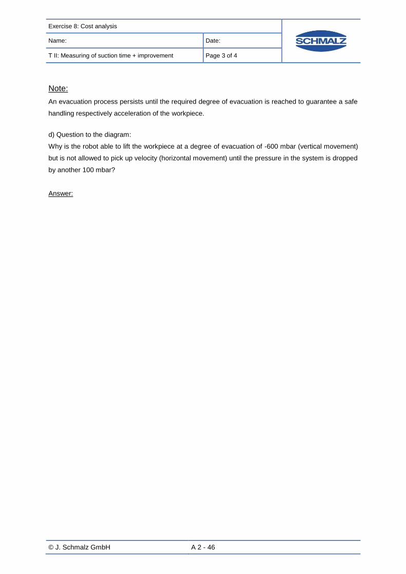
Exercise 8: Cost analysis
Name: Date:
T II: Measuring of suction time + improvement Page 3 of 4
© J. Schmalz GmbH A 2 - 46
Note:
An evacuation process persists until the required degree of evacuation is reached to guarantee a safe
handling respectively acceleration of the workpiece.
d) Question to the diagram:
Why is the robot able to lift the workpiece at a degree of evacuation of -600 mbar (vertical movement)
but is not allowed to pick up velocity (horizontal movement) until the pressure in the system is dropped
by another 100 mbar?
Answer:

Exercise 8: Cost analysis
Name: Date:
T II: Measuring of suction time + improvement Page 4 of 4
© J. Schmalz GmbH A 2 - 47
Attachment:
You will need following technical data of basic ejectors for the cost analysis:
Technical data basic ejector SBP
Type Air consumption during suction process [l/min]
Air consumption during suction process [m³/h]
SBP 10 SDA 48 2.9
SBP 15 SDA 105 6.3
SBP 20 SDA 197 11.8

Test evaluation: Cost analysis
Name: Date:
T II: Measuring of suction time + improvement Page 1 of 2
© J. Schmalz GmbH V 2 - 48
Test evaluation exercise 8
Cost analysis
a) Total cycle time _________ [s]
Possible cycles per day _________ [cycles]
b)
Basic ejector SBP 10:
Operation costs
Degree of evacuation [mbar]
-50 mbar
-100 mbar
-200 mbar
-300 mbar
-400 mbar
-500 mbar
-600 mbar
-700 mbar
Cycle time in [s]
Possible cycles per day
Air consumption per
cycle in [l]
Air consumption per day in [l]
Operation costs per day in [ct.]
Basic ejector SBP 15:
Operation costs
Degree of evacuation [mbar]
-50 mbar
-100 mbar
-200 mbar
-300 mbar
-400 mbar
-500 mbar
-600 mbar
-700 mbar
Cycle time in [s]
Possible cycles per day
Air consumption per cycle in [l]
Air consumption per day in [l]
Operation costs per day in [ct.]

Test evaluation: Cost analysis
Name: Datum:
T II: Measuring of suction time + improvement Page 2 von 2
© J. Schmalz GmbH V 2 - 49
Basic ejector SBP 20:
Operation costs
Degree of evacuation [mbar]
-50 mbar
-100 mbar
-200 mbar
-300 mbar
-400 mbar
-500 mbar
-600 mbar
-700 mbar
Degree of evacuation [mbar]
Cycle time in [s]
Possible cycles per day
Air consumption per cycle in [l]
Air consumption per day in [l]
c)
SBP 10
Costs [ct]
Degree of evacuation [mbar]
-50 mbar
-100 mbar
-200 mbar
-300 mbar
-400 mbar
-500 mbar
-600 mbar
-700 mbar
-800 mbar
SBP 15
Costs [ct]
Degree of evacuation [mbar]
-50 mbar
-100 mbar
-200 mbar
-300 mbar
-400 mbar
-500 mbar
-600 mbar
-700 mbar
-800 mbar
SBP 20
Costs [ct]
Degree of evacuation [mbar]
-50 mbar
-100 mbar
-200 mbar
-300 mbar
-400 mbar
-500 mbar
-600 mbar
-700 mbar
-800 mbar

© J. Schmalz GmbH A 3 - 50
List of exercises
TUTORIAL III:
Construction of a vacuum-system III
- Reduction of air consumption by integration of an automatic air-saving func-
tion within the vacuum generator -
Exercise 9 ............................................................................................................................................. 52
Construction and implementation of a gripper-system with automatic air-saving function ................... 52
Exercise 10 ........................................................................................................................................... 59
Calculation of evacuation time and compressed-air consumption ........................................................ 59
Test evaluation exercise 10 a) .............................................................................................................. 60
Test evaluation exercise 10 b): ............................................................................................................. 61
Exercise 11 ........................................................................................................................................... 62
Calculation of evacuation times ............................................................................................................. 62
Test evaluation exercise 11 ................................................................................................................... 64
Exercise 12 ........................................................................................................................................... 65
Cost analysis and comparison of SCP and SBP ................................................................................... 65
Test evaluation exercise 12 ................................................................................................................... 66

© J. Schmalz GmbH A 3 - 51
Tutorial III
There is a multitude of possibilities to generate vacuum. Ejectors as pneumatic vacuum-generator
represents a wide spread possibility. A distinction is drawn between basic, inline, multi-stage and
compact ejectors. Each of these ejectors features specific characters.
Basic ejectors are the simplest type of ejectors (see tutorial I and II). They consist of a compact body
with integrated Venturi nozzle basically. By connecting to compressed-air they generate vacuum per-
manently that can be controlled by interrupting the compressed-air supply.
On the contrary compact ejectors stand out for a variety of additional functions. They offer system
monitoring, that is very convenient with extremely high cycle times. Integrated valve technology ena-
bles fast and safe blow-off by a blow-off impulse. Compact ejectors have an automatic air-saving func-
tion compared to basic ejectors. This function allows to control the compressed-air consumption within
a process. If a desired vacuum level is reached the compressed-air supply is interrupted and thus
there are no additional costs for compressed-air.
Compressed-air consumption is a very important expense factor in companies and especially in vacu-
um technology. Companies always try to boost their productivity by shorter cycle times and lower op-
eration costs. On the one hand this happens by shorter evacuation times, by compressed-air savings
on the other hand.
This can be reached to the compact ejector mentioned with automatic air—saving function. Due to the
automatic air-saving function the compressed-air consumption can be interrupted if a freely pro-
grammed vacuum level is reached. Therefore a safe handling can be guaranteed nevertheless. If a
minimum level is achieved the ejector readjusts so that the vacuum level required is generated again.
The compressed-air consumption and therefore the operation costs can be reduced considerably by
the use of an automatic air-saving function in automated processes.
The named character should be implemented in tutorial III reduction of compressed-air by integration
of an air-saving control within the vacuum generator. At first a vacuum-system with a compact ejector
should be constructed. To define the differences between a basic ejector and a compact ejector with
automatic air-saving in detail, a comparison (by calculation and test) is to be done.

Exercise 9: Construciton and implementation of a gripper-system with automatic air-saving
Name: Date:
T III: Construction of a vacuum-system Page 1 of 7
© J. Schmalz GmbH A 3 - 52
Exercise 9:
Construction and implementation of a gripper system with automat-
ic air-saving function
Educational aims
Construction of a gripper system with air-saving function
Adoption to function of an automatic air-saving function of a compact ejector
Programming and ideal application of a digital vacuum switch
Components
Following components are necessary for this exercise:
Components Quantity
Flat suction pad (round) PFYN 20.0 HT1 4
Choke valve 1
Plug VRS-STEC (for choke valve) 1
Vacuum-generator compact ejector SCP 10 NC AS RD 1
Connection hose (for compact ejector) 1
Vacuum-/compressed-air hose VSL 8-6 (80 mm) 2
Vacuum-/compressed-air hose VSL 8-6 (260 mm) 1
Vacuum-/compressed-air hose VSL 8-6 (240 mm) 1
Samples / workpieces: steel plate 1
T-connector SVB-T 8 1

Exercise 9: Construciton and implementation of a gripper-system with automatic air-saving
Name: Date:
T III: Construction of a vacuum-system Page 2 of 7
© J. Schmalz GmbH A 3 - 53
Background knowledge:
Anterior exercises are all carried out with unregulated vacuum-generators. Basic ejectors expend on-
going compressed-air during operation and generate a continuous vacuum. The control function re-
sults from the control of compressed-air supply.
The already existing gripper system with unregulated vacuum-generator should be modified into a
regulated vacuum-system. A compact ejector type SCP 10 NC AS RD is available for this modification.
The indication ND refers to the position of the valve “normally closed”. Compared to NO (“normally
open”) no vacuum is generated if the ejector is connected to compressed-air. AS means that the ejec-
tor is arranged with a bleed valve and a safety check valve. Therefore it is possible to channel the
compressed-air to the connected suction pads. Safety check valve enables that the generated vacuum
is held during automatic air-saving. The term RD means that there is an automatic air-saving with a
digital vacuum-switch included.
Following figure shows the schematic construction of a compact ejector SCP. The main difference to a
basic ejector consists in the components such as vacuum switch, bleed and suction valve.
This compact ejector consists of automatic air-saving to save compressed-air and therefore to save
costs during operation. Another attribute is the blow-off function. Hereby compressed-air is channeled
well-directed to each suction pad to accelerate the repositioning. Therefore the repositioning process
of workpieces can be minimized and the whole handling process can be accelerated. To be able to
realize this, compact ejectors have an integrated valve technology. Two valves control grip and blow-
off impulse. Those valves can be controlled directly or independently. That happens due to the inte-
grated vacuum-switch, respectively due to an external control function.

Exercise 9: Construciton and implementation of a gripper-system with automatic air-saving
Name: Date:
T III: Construction of a vacuum-system Page 3 of 7
© J. Schmalz GmbH A 3 - 54
The function „suction“ is activated if the ejector is switched-on until a preset value is reached. The air-
saving automatic begins afterwards by switching-on the function “no suction” via valve. This function
lasts until a preset area is under-run. This is called “hysteresis”. If this area is abandoned the vacuum-
generation is switched-on again. The compact ejector readjusts, that means it recovers the original
value. In this way, the compressed-air consumption can be kept little compared to a basic ejector.
Following figure shows the comparison of two ejectors.
According to this, the course of vacuum level could look like this:
H1: Switching point 1 (switching point of automatic air-saving function; function “suction-off” is
activated)
h1: Hysteresis (preprogrammed range where vacuum level can increase without readjustment of
compact ejector)
H1-h1: Stop position of automatic air-saving function (“suction on” is activated when reaching this
value; the ejector readjusts)
with automatic air-saving function
without automatic air-saving
function
t
Compressed-air con-sumption
Vacuum

Exercise 9: Construciton and implementation of a gripper-system with automatic air-saving
Name: Date:
T III: Construction of a vacuum-system Page 4 of 7
© J. Schmalz GmbH A 3 - 55
Setting of task:
This task is about to alter the existing gripping-system into a regulated vacuum-system. The basic
ejectors that were used so far and the valve 3/2 NC aren’t necessary anymore to fulfill this task. They
are replaced by the compact ejector SCO 10 NC AS RD which has an integrated blow-off and suction
valve. Furthermore the appropriate connection cable for the compact ejector is necessary.
The workpiece to be handled is a steel plate. Four PFYN 20.0 HT1 are to be used as suction pads.
Following table serves to connect the compact ejector SCP 10 NC AS RD and to reconstruct the grip-
ping-system:
Link the cable for the control to the com-
pact ejector as follows:
Connect the shorter cable of the
grey ones (c) to the bleed valve
(c).
The longer cable (b) is for control
of suction valve and has to be
linked to connection b.
The valves have to be controlled
to adopt the automatic air-saving.
This can be realized by linking
the M8-connection (a) to the
vacuum-switch of the SCP (con-
nection a).
The vacuum-switch that is con-
nected to the gripper system
should still be linked to the time
measuring unit.

Exercise 9: Construciton and implementation of a gripper-system with automatic air-saving
Name: Date:
T III: Construction of a vacuum-system Page 6 of 7
© J. Schmalz GmbH A 3 - 56
Link the pressure reduction valve and the compact ejector SCP (connection on side of silencer) to the
compressed-air hose with a length of 260 mm.
The SCP and the vacuum storage (VOL) are connected by a vacuum hose with a length of 240 mm.
The present hose with a length of 1100 mm remains as connection of vacuum-storage and gripper sys-
tem.
The completed workplate differs from the original one now as follows: The compact ejector SCP is in-
between of the pressure reduction valve 3/2 NC and the vacuum-storage instead of the basic ejector.
The compact ejector SCP has two connections and
is normally closed (NC); that means no vacuum is
generated during compressed-air supply.
The suction valve has to be activated (24 V DC) to
generate a vacuum. This is realized by the evacua-
tion time counter.
The SCP is necessary for tutorial III.
Affiliate a choke valve in-between the volume storage and the gripper system as shown in the picture
below. An artificial leakage can be simulated by the help of the choke valve.
Conjoin the choke valve to the T-plug-in-connector
and the hose system at the gripper system. It is
necessary to simulate a leakage in exercise 11.
Affix the closing plug to the choke valve.
To use the automatic air-saving function ideally it is important to determine adequate switch-points
and values for hysteresis. A value of about -700 mbar is suggestive as switch-point H1. This value has
to be entered to the vacuum-switch with 0.7. An adequate hysteresis h1 would be -50 mbar (shown as
0.05 on the vacuum-switch). You have to enter these values into the vacuum-switch that is directly
assembled to the compact ejector SCP. Therefore please read the operations manual of the switch.
To be able to measure the evacuation time the vacuum-switch have to be programmed with the same
switch-point H1 as the vacuum-switch of the compact ejector SCP.

Exercise 9: Construciton and implementation of a gripper-system with automatic air-saving
Name: Date:
T III: Construction of a vacuum-system Page 6 of 7
© J. Schmalz GmbH A 3 - 57
Check the functionality of the whole system with the steel plate. Please care for that the choke valve is
closed completely. The vacuum-generation should stop at -700 mbar now. As the workpiece is very
leak-proof, the vacuum level won’t decline.
You may open the throttle screw bit by bit now so as to reduce the vacuum level. As soon as the vac-
uum-level is about -650 mbar the vacuum-generation should start automatically. Depending on how
wide the throttle screw is opened, the ejector readjusts shortly or after a short period of time.
If the automatic air-saving is tested successfully you can blow-off the steel plate now. During the blow
process of workpieces the compressed-air is channeled directly to the suction pads to accelerate the
blow-off of the workpieces in a handling process.
The activity of blowing can be realized by activating the bleed valve of the compact ejector SCP. The
upcoming compressed-air is channeled directly to the exit of the ejector.
Install the plug of the connection cable for the SCP as follows:
By connecting the green plug to +24 V (positive pole, red) the vacuum-generation is deactivated at
pointed condition.

Exercise 9: Construciton and implementation of a gripper-system with automatic air-saving
Name: Date:
T III: Construction of a vacuum-system Page 7 of 7
© J. Schmalz GmbH A 3 - 58
By connecting the yellow plug to +24 V the blow-off is activated. The upcoming compressed-air is
conducted to the suction pads so that the workpiece can be blown-off.
The configuration of the electrical connections is as follows:
Red = Positive pole +24 V DC Blue = Negative pole (ground) Green = „Suction OFF“ Yellow = „Blow-off ON“ Black = digital output (+24 V)

Exercise 10: Calculation of evacuation time and compressed-air consumption
Name: Date:
T III: Construction of a vacuum-system Page 1 of 1
© J. Schmalz GmbH A 3 - 59
Exercise 10:
Calculation of evacuation time and compressed-air consumption
Educational aims:
Calculation of the evacuation time of a compact ejector
Verification of measured values
Calculation of compressed-air consumption of a regulated vacuum-system
Setting of task
a) The automatic air-saving function should begin ideal. An applicable switch-point as well as hystere-
sis has to be determined so that the compact ejector readjusts one time in process. Moreover, please
calculate the evacuation time and the theoretical compressed-air consumption. Act on the assumption
that the time required for readjustment is about 0.8 seconds.
b) Calculate the evacuation times for those degrees of evacuation that are given and enter them into
the table.
Calculate the times needed for readjustment by the help of the appropriate formula.
The compressed-air consumption for the evacuation process and the readjustment should be deter-
mined as well. Calculate with the already determined evacuation times.

Test evaluation: exercise 10
Name: Date:
T III: Construction of a vacuum-system Page 1 of 2
© J. Schmalz GmbH V 3 - 60
Test evaluation exercise 10 a):
The essential technical indications of the compact ejector can be taken out of the table below.
Evacuation time for different vacuum levels in s/l
Degree of evacuation [mbar]
Type
-50
mbar
-100
mbar
-200
mbar
-300
mbar
-400
mbar
-500
mbar
-600
mbar
-700
mbar
-800
mbar
SCP 10 …
Suction capacity at different levels of evacuation in l/min
Degree of evacuation [mbar]
Type
-50
mbar
-100
mbar
-200
mbar
-300
mbar
-400
mbar
-500
mbar
-600
mbar
-700
mbar
-800
mbar
SCP 10 …
Technical data compact ejector SCP 10
Degree of evacuation [mbar]
Type
-50
mbar
-100
mbar
-200
mbar
-300
mbar
-400
mbar
-500
mbar
-600
mbar
-700
mbar
-800
mbar
SCP 10 …
Chosen switch-point H1: mbar
Chosen hysteresis h1: mbar
Calculation of theoretical compressed-air consumption:
Compressed-air consumption [l]
Degree of evacuation [mbar] 1. Regulation Readjustment Total
Evacuation time [s]
Compressed-air consumption [l]

Test evaluation: exercise 10
Name: Date:
T III: Construction of a vacuum-system Page 2 of 2
© J. Schmalz GmbH V 3 - 61
Test evaluation exercise 10 b):
Calculation of evacuation times
Calculation of evacuation time
Degree of evacuation [mbar] -200 mbar -300 mbar -400 mbar -500 mbar -600 mbar -700 mbar
Evacuation time for system volume in [s]
Evacuation time for 1l in [s/l]
Evacuation time for readjustment [s]]
Calculation of compressed-air consumption
Calculation of compressed-air consumption
Degree of evacuation [mbar] -200 mbar -300 mbar -400 mbar -500 mbar -600 mbar -700 mbar
Compressed-air consumption evacuation in [l]
Compressed-air consumption readjustment[l]
Total compressed-air consumption [l]

Exercise 11: Calculation of evacuation times
Name: Date:
T III: Construction of a vacuum-system Page 1 of 2
© J. Schmalz GmbH A 3 - 62
Exercise 11:
Calculation of evacuation times
Educational aims:
Measuring of evacuation time of a regulated vacuum-system
Measuring of time for readjustment of a compact ejector
Setting of task
The test preparation of exercise 9 is used for this exercise. However bellows suction pads FSGA 25
NBR are used. The functionality of the automatic air-saving of a compact ejector is discussed in tutori-
al III. Now the evacuation times that are necessary to reach different degrees of evacuation are to be
measured. Furthermore, an approximate time should be determined that is necessary for readjust-
ment.
At first please ensure that your system is dense. If this is the case you are able to simulate a leakage
by the help of the choke valve. Open the screw of the choke valve carefully once the switch-point H1
is reached. The vacuum level of the whole system decreases as long as the lower switch-point (H1-
h1) is reached and the ejector switches on again and starts to readjust.
If your system is a bit leaky the degree of evacuation will sink of its own volition. The simulation of
leakage by a choke valve is not necessary.
Mind that the switch-point H1 is set on both vacuum-switches when measuring the degrees of evacua-
tion. Elsewise a significant time measurement is impossible. The hysteresis should always be
200 mbar in this exercise.
The measurement of the evacuation time occurs as in the unregulated system in exercise 6.
To measure the time that is necessary for readjustment, please ensure that the time measuring device
is adjusted to zero after measurement. There is a red button below the display that sets the display to
zero automatically by pushing it. Please wait until the compact ejector has readjusted and turn the
switch of the time measuring device to “valve OFF”. Thus the compact ejector is switched off. Look at
the display of the vacuum-switch at the gripper system and wait until the hysteresis is overspent. Turn
the switch to “valve on” as soon as possible (the SCP is switched on again and readjusts!). The time
measuring device measures the time that is necessary for readjustment. Repeat this measuring a few
times to ensure that the value is accurate.

Exercise 11: Calculation of evacuation times
Name: Date:
T III: Construction of a vacuum-system Page 2 of 2
© J. Schmalz GmbH A 3 - 63
The circumstances described above should be clarified by following figure:
t
H1-switch-point: time counter stops
Reset the evacuation time counter (red button), set in-strument to „Valve OFF“
The compact ejector readjusts: The instrument has to be set to „Valve ON“.
Vacuum

Test evaluation exercise 11
Name: Date:
T III: Construction of a vacuum-system Page 1 of 1
© J. Schmalz GmbH V 3 - 64
Test evaluation exercise 11:
Calculation of evacuation times
Calculation of evacuation times
Degree of evacuation [mbar] -200 mbar -300 mbar -400 mbar -500 mbar -600 mbar -700 mbar
Evacuation time for system volume in [s]
Evacuation time for 1l in [s/l]
Evacuation time for readjustment of system
volume in [s]

Exercise 12: Cost analysis and comparison of SCP and SBP
Name: Date:
T III: Construction of a vacuum-system Page 1 of 1
© J. Schmalz GmbH A 3 - 65
Exercise 12:
Cost analysis and comparison of SCP and SBP
Educational aims:
Calculation of operation costs for compact and basic ejectors
Cost comparison for compact and basic ejectors
Identification of advantages of compact ejectors
Setting of task
The operation costs for the gripping system have been calculated in exercise 7 (tutorial II). This grip-
ping system demonstrates an exemplary application where a press is to be assembled with stamping
parts out of metal.
This exercise responds to this exemplary application. Vacuum-generators are to be chosen for this
application that are ideal not only out of production-related sight but also out of economic sight. Re-
gard the calculated values for this task exclusively. Act again on the assumption that the compact
ejector has to readjust one time within an entire cycle. In addition to the automatic air-saving there is
the other advantage of a compact ejector that the blow-off process can be accelerated due to a blow-
off impulse. Act on the assumption that the blow-off process can be reduced to 0.2 second when using
the SCP 10.
Two vacuum-generators are available:
SBP 10 : Purchase costs: 25 €
SCP 10: Purchase costs: 480 €
Other variable unit costs (without compressed-air) amount to 0.51 € and the monthly fixed costs to
11,500 € as the calculation shows. The selling price of the completely pierced product adds up to
1.49 €. All components are expected to be distributed.
Please undertake a cost calculation on basis of present table for both kind of ejector. Determine the
possible profit when using both vacuum-generators and decide in favor of a profit ideal option on basis
of your results.

Exercise 12: Cost analysis and comparison of SCP and SBP
Name: Date:
T III: Construction of a vacuum-system Page 1 of 2
© J. Schmalz GmbH V 3 - 66
Test evaluation exercise 12:
Cost analysis and –comparison of SBP and SCP
SBP 10 SCP 10
Duration of production cycle [s]
Possible cycles per day
Compressed-air consumption per cycle [l]
Air consumption per day [l]
Costs for compressed-air per day [€]
Working days per year
Possible pieces per year
Annual fixed costs [€]
Annual costs for compressed-air [€]
Total costs per year [€]
Price [€]
Annual revenue [€]
Annual profit [€]

Test evaluation: Exercise 12
Name: Date:
T III: Construction of a vacuum-system Page 2 of 2
© J. Schmalz GmbH V 3 - 67
With which application the use of a compact ejector make sense?
In your opinion, in which sector of industry are most of the compact ejectors used?

Part 3 - Solutions
© J. Schmalz GmbH T - 68
Part 3 – Solutions
Table of solutions
Solution for exercise 2 ........................................................................................................................ 70
Solution for exercise 3 ........................................................................................................................ 73
Solution for exercise 4 ........................................................................................................................ 74
Solution for exercise 6 ........................................................................................................................ 76
Solution for exercise 7 ........................................................................................................................ 80
Solution for exercise 8 ........................................................................................................................ 83
Solution for exercise 10 ...................................................................................................................... 87
Solution for exercise 11 ...................................................................................................................... 89
Solution for exercise 12 ...................................................................................................................... 90

© J. Schmalz GmbH T - 69
Solutions
All solutions for the exercises posed in this Vacuum Training-Set are arranged in this chapter. Devia-
tions to measured values listed in this chapter can be emerge because of different environmental con-
ditions respectively test preparations. The length and the diameter of the hoses for example, the kind
of compressed-air supply or power supply of valves of ejectors exert influence on measured values.
Please be always aware of the exact description of task. Besides the measured values are to be
rounded up with sufficient correctness. The solutions refer to the described test evaluation with a
compressed-air supply of 5 bar (adjustable at the pressure reduction valve).

Solution: Theoretical calculation of holding forces for suction pad selection (exercise 2)
Name: Date:
T II: Measuring of suction time + improvement Page 1 of 3
© J. Schmalz GmbH T 1 - 70
Solution for exercise 2:
Theoretical calculation of holding forces for suction pad selection
Calculation of masses of workpieces:
m Steel plate: 0.75 kg
m Cardboard: 0.027 kg
m Softwood: 0.320 kg
m Ceramic : 1.117 kg
m Chipboard: 0.419 kg
Calculation of theoretical holding forces:
(For defined basic conditions and characters of workpieces; deviations can appear by variation in
these values)
Load case
Workpiece I II III
Steel plate S:1.5 16.66 N µ:0.5
22.29 N µ:0.5
44.43 N S:1.5 S:2
Cardboard S:2 0.81 N µ:0.6 0.99 N µ:0.6 1.68 N S:2 S:2.5
Softwood S:2 9.44 N µ:0.5 12.63 N µ:0.5 23.60 N S:2 S:2.5
Ceramic S:1.5 24.82 N µ:0.5 33.20 N µ:0.5 66.20 N S:1.5 S:2
Chipboard S:2 12.40 N µ:0.5
16.59 N µ:0.5
31.01 N S:2 S:2,5
S:2 S:2,5

Solution: Theoretical calculation of holding forces for suction pad selection (exercise 2)
Name: Date:
T II: Measuring of suction time + improvement Page 2 of 3
© J. Schmalz GmbH T 1 - 71
Calculation of suction force FS for each load case:
Load case
Workpiece I II III
Steel plate 4.17 N 5.57 N 11.11 N
Cardboard 0.20 N 0.25 N 0.42 N
Softwood 2.36 N 3.16 N 5.90 N
Ceramic 6.21 N 8.30 N 16.55 N
Chipboard 3.10 N 4.15 N 7.75 N
Determined suction pads by use of calculations:
Chosen suction pad
Load case
Workpiece I II III
Steel plate (Flat suction pad) PFYN 15 PFYN 15 PFYN 20
Cardboard (Flat suction pad) PFYN 10 PFYN 10 PFYN 10
Softwood (Bellows suction pad)
FSG 25 or FSGA 20 FSG 18 or FSGA 20 FSG 32 or FSGA 33
Ceramic (Flat suction pad)
PFYN 15 PFYN 15
There are no suitable suction
pads in the parts kit for this
load case. At least a PFYN
25 is necessary (see cata-
logue p. 2/18)
Chipboard (Flat suction pad) PFYN 10 PFYN 15 PFYN 15
Note: In some cases both a flat suction pad and a bellows suction pad can be used. But it has to be mentioned that a more
precise positioning can be realized using a flat suction pad.

Solution: Theoretical calculation of holding forces for suction pad selection (exercise 2)
Name: Date:
T II: Measuring of suction time + improvement Page 3 of 3
© J. Schmalz GmbH T 1 - 72
Questions:
Question 1:
Why is the holding/suction force of a flat suction pad (i. e. PFYN 20.0) higher than the holding/suction
force of a bellows suction pad (i.e. FSGA 20.0) although the external diameter of the sealing lip of both
suction pads is the same?
Answer:
The effective suction area/-diameter is used to calculate holding and suction forces. As the effective
suction diameter and therefore the effective suction area of a flat suction pad is bigger than the suction
are of bellows suction pads the holding force is higher according to the formula ApF (see figure
below).
Bellows scution pad Flat suction pad
deff
deff

Solution: Calculation of vacuum levels (Exercise 3)
Name: Date:
T II: Measuring of suction time + improvement Page 1 of 1
© J. Schmalz GmbH T 1 - 73
Solution for exercise 3:
Calculation of vacuum levels
Calculation of vacuum level:
Workpiece
Load case I
Chosen suction pad Measured vacuum level
Steel plate PFYN 15 -0.85 bar
Cardboard PFYN 10 -0.80 bar
Softwood FSG 25 -0.81 bar
Ceramic PFYN 15 -0.83 bar
Chipboard PFYN 10 -0.82 bar
The results show that all workpieces can be handled safely with the dedicated suction pads as a vac-
uum level isn’t below -0.60 bar.
Note:
The calculation of the vacuum level has been carried out at an operation pressure of 5 bar. Little devi-
ations are likely.

Solution: Choice of adequate suction pads (exercise 4)
Name: Date:
T II: Measuring of suction time + improvement Page 1 of 2
© J. Schmalz GmbH T 1 - 74
Solution for exercise 4:
Choice of adequate suction pads
Determination of ideal suction pads:
Measured vacuum level:
PFYN 10.0
PFYN 15.0
PFYN 20.0
FSGA 20.0
FSGA 25.0
FSGA 33.0
FSG 18.0 FSG 25.0 FSG 32.0
Material NBR SI HT1 NBR SI HT1 NBR SI HT1
Steel plate 0.85 0.85 0.85 0.85 0.85 0.85 0.85 0.85 0.85
Cardboard 0.83 0.83 0.77 0.83 0.83 0.76 0.82 0.82 0.77
Softwood 0.81 0.79 0.80 0.82 0.80 0.78 0.73 0.71 0.70
Ceramic 0.84 0.84 0.83 0.83 0.83 0.83 0.83 0.83 0.83
Chipboard 0.83 0.82 0.76 0.82 0.82 0.79 0.82 0.82 0.80
The results of measurements backs up the thesis of previous exercise that the vacuum level sinks if
the workpiece is porous and the diameter of the suction bet gets bigger. A reason for this is the growth
of infiltrated air that is sucked through the porous material.
The maximum attainable vacuum level is not the appropriate factor to determine the correct combina-
tion of suction pad and workpiece because not only the reached depression but also the effective suc-
tion area has to be considered when calculating suction forces. Therefore the diameter of the suction
pad has to be considered in particular. Also other criteria act a part that have to be distinguished as
the case arises. One example is the flexural strength of a workpiece.
Note:
The vacuum levels in this exercise have been determined at an operation pressure of 5 bar. Firstly the
safe handling should be used as criteria for the choice of an adequate suction pad and the most cost-
effective alternative is to be chosen if there arise several possibilities.

Solution: Choice of adequate suction pads (exercise 4)
Name: Datum:
T II: Measuring of suction time + improvement Page 2 von 2
© J. Schmalz GmbH T 1 - 75
Questions:
Question 1:
In some cases a higher vacuum level is reached with a smaller suction pad than with a bigger one.
What are possible reasons therefore?
Answer:
Diameter of suction pad
The smaller the diameter of the suction pad the higher is the achievable vacuum level be-
cause:
o The effective area of a possibly porous workpiece and therefore the amount of infiltrated
air is smaller
o The suction pad’s outline is smaller and therefore there is less leakage when handling
structured workpieces
Question 2:
A vacuum level of at least -600 mbar is necessary for safe handling.
What kind of activities have to be undertaken that a porous workpiece with a vacuum level of about
-400 mbar can be handled securely?
Answer:
Correlation of pressure and suction area:
The suction force can be calculated by the use of following formula:
F = p X A
F = Suction force
p = Pressure
A = Area of the suction pad
An increase in depression is technical not feasible or only with a lot of effort when handling po-
rous workpieces. The suction force can only be increased by the area of the suction pad re-
spectively the gripper-system. Therefore bigger suction pads can be chosen but this is not
suggestive because of infiltrated air. It is beneficial to increase the number of suction pads.
.

Solution: Calculation of evacuation time and theoretical compressed-air consumption (exercise 6)
Name: Date:
T II: Measuring of suction time + improvement Page 1 of 4
© J. Schmalz GmbH T 2 - 76
Solution for exercise 6:
Calculation of evacuation time and theoretical compressed-air con-
sumption
Volume suction pad: 4x 0.80 cm3
(see indications on data sheets and in table):
Volume hoses: (VSL 6/4) 4x 280 mm V = 14.074 cm3
2x 50 mm V = 1.2567 cm3
Volume hoses: (VSL 8/6) 1x 280 mm V = 7.917 cm3
1x 1100 mm V = 31.1 cm3
Formula: lr 2
Volume storage: 1000 cm3
Total volume*: 1057.54 cm³
*Please keep in mind that the total volume results from addition of suction pad, hoses and volume
storage.
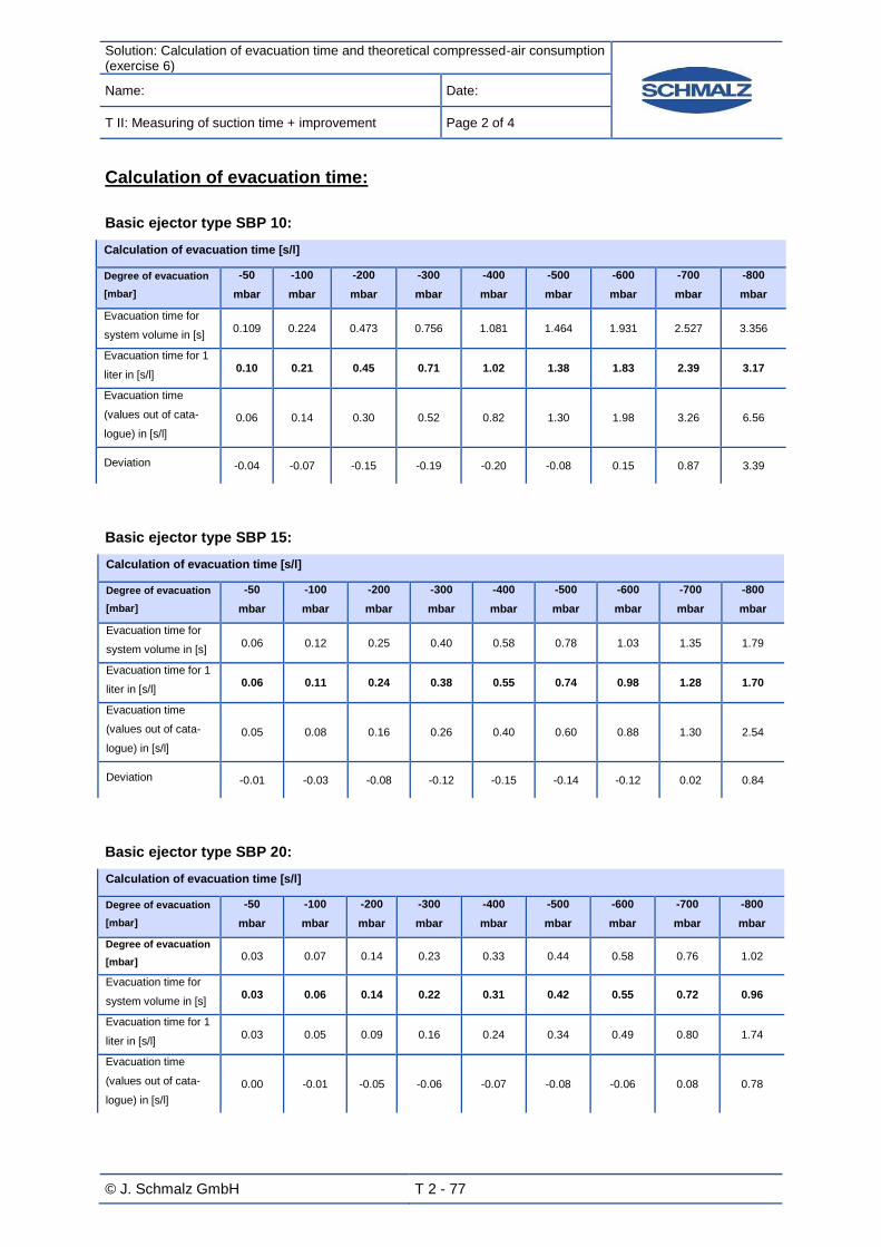
Solution: Calculation of evacuation time and theoretical compressed-air consumption (exercise 6)
Name: Date:
T II: Measuring of suction time + improvement Page 2 of 4
© J. Schmalz GmbH T 2 - 77
Calculation of evacuation time:
Basic ejector type SBP 10:
Calculation of evacuation time [s/l]
Degree of evacuation
[mbar]
-50
mbar
-100
mbar
-200
mbar
-300
mbar
-400
mbar
-500
mbar
-600
mbar
-700
mbar
-800
mbar
Evacuation time for
system volume in [s] 0.109 0.224 0.473 0.756 1.081 1.464 1.931 2.527 3.356
Evacuation time for 1
liter in [s/l] 0.10 0.21 0.45 0.71 1.02 1.38 1.83 2.39 3.17
Evacuation time
(values out of cata-
logue) in [s/l]
0.06 0.14 0.30 0.52 0.82 1.30 1.98 3.26 6.56
Deviation -0.04 -0.07 -0.15 -0.19 -0.20 -0.08 0.15 0.87 3.39
Basic ejector type SBP 15:
Calculation of evacuation time [s/l]
Degree of evacuation
[mbar]
-50
mbar
-100
mbar
-200
mbar
-300
mbar
-400
mbar
-500
mbar
-600
mbar
-700
mbar
-800
mbar
Evacuation time for
system volume in [s] 0.06 0.12 0.25 0.40 0.58 0.78 1.03 1.35 1.79
Evacuation time for 1
liter in [s/l] 0.06 0.11 0.24 0.38 0.55 0.74 0.98 1.28 1.70
Evacuation time
(values out of cata-
logue) in [s/l]
0.05 0.08 0.16 0.26 0.40 0.60 0.88 1.30 2.54
Deviation -0.01 -0.03 -0.08 -0.12 -0.15 -0.14 -0.12 0.02 0.84
Basic ejector type SBP 20:
Calculation of evacuation time [s/l]
Degree of evacuation
[mbar]
-50
mbar
-100
mbar
-200
mbar
-300
mbar
-400
mbar
-500
mbar
-600
mbar
-700
mbar
-800
mbar
Degree of evacuation
[mbar] 0.03 0.07 0.14 0.23 0.33 0.44 0.58 0.76 1.02
Evacuation time for
system volume in [s] 0.03 0.06 0.14 0.22 0.31 0.42 0.55 0.72 0.96
Evacuation time for 1
liter in [s/l] 0.03 0.05 0.09 0.16 0.24 0.34 0.49 0.80 1.74
Evacuation time
(values out of cata-
logue) in [s/l]
0.00 -0.01 -0.05 -0.06 -0.07 -0.08 -0.06 0.08 0.78

Solution: Calculation of evacuation time and theoretical compressed-air consumption (exercise 6)
Name: Date:
T II: Measuring of suction time + improvement Page 3 of 4
© J. Schmalz GmbH T 2 - 78
Diagram of evacuation time for basic ejector SBP 15
Evacuation times at various degrees of evacuation
0
0,1
0,2
0,3
0,4
0,5
0,6
0,7
0,8
0,9
1
1,1
1,2
1,3
1,4
1,5
1,6
1,7
1,8
1,9
2
0 100 200 300 400 500 600 700 800
Vacuum [mbar]
Evacu
ati
on
tim
e [
s/l]
- - - - - - - -

Solution: Calculation of evacuation time and theoretical compressed-air consumption (exercise 6)
Name: Date:
T II: Measuring of suction time + improvement Page 4 of 4
© J. Schmalz GmbH T 2 - 79
Calculation of compressed-air consumption by the help of technical data:
Basic ejector type SBP 10:
Calculation of theoretical compressed-air consumption:
(For the calculated evacuation time of system volume see above)
Compressed-air consumption [l]
Degree of evac-
uation [mbar]
-50
mbar
-100
mbar
-200
mbar
-300
mbar
-400
mbar
-500
mbar
-600
mbar
-700
mbar
-800
mbar
PFYN 20.0 HT1 0.09 0.18 0.38 0.60 0.86 1.17 1.54 2.02 2.68
Basic ejector type SBP 15:
Calculation of theoretical compressed-air consumption:
(For the calculated evacuation time of system volume see above)
Compressed-air consumption [l]
Degree of evac-
uation [mbar]
-50
mbar
-100
mbar
-200
mbar
-300
mbar
-400
mbar
-500
mbar
-600
mbar
-700
mbar
-800
mbar
PFYN 20.0 HT1 0.10 0.21 0.44 0.71 1.01 1.37 1.81 2.37 3.14
Basic ejector type SBP 20:
Calculation of theoretical compressed-air consumption:
(For the calculated evacuation time of system volume see above)
Compressed-air consumption [l]
Degree of evacua-
tion [mbar]
-50
mbar
-100
mbar
-200
mbar
-300
mbar
-400
mbar
-500
mbar
-600
mbar
-700
mbar
-800
mbar
PFYN 20.0 HT1 0.11 0.22 0.47 0.75 1.07 1.45 1.92 2.51 3.33

Lösung: Messung der Ansaugzeiten (Aufgabe 7)
Name: Date:
T II: Measuring of suction time + improvement Page 1 of 3
© J. Schmalz GmbH T 2 - 80
Solution for exercise 7:
Measuring of evacuation times
Basic ejector type SBP 10:
Measured evacuation time:
Measuring of evacuation time
Degree of evacuation [mbar] -50
mbar -100 mbar
-200 mbar
-300 mbar
-400 mbar
-500 mbar
-600 mbar
-700 mbar
-800 mbar
Evacuation time for system volume in [s]
0.09 0.18 0.40 0.68 1.06 1.60 2.35 4.05 8.10
Evacuation time for 1l in [s/l] (calcu-lation with measured values)
0.085 0.170 0.378 0.643 1.00 1.51 2.22 3.83 7.66
Evacuation time (values out of catalogue) in [s/l]
0.06 0.14 0.30 0.52 0.82 1.30 1.98 3.26 6.56
Calculated evacuation time in exercise 6
0.10 0.21 0.45 0.71 1.02 1.38 1.83 2.39 3.17
Basic ejector type SBP 15:
Measured evacuation time:
Measuring of evacuation time
Degree of evacuation [mbar] -50
mbar -100 mbar
-200 mbar
-300 mbar
-400 mbar
-500 mbar
-600 mbar
-700 mbar
-800 mbar
Evacuation time for system volume in [s]
0.06 0.1 0.21 0.34 0.52 0.76 1.08 1.65 3.57
Evacuation time for 1l in [s/l] (calcula-tion with measured values)
0.06 0.09 0.20 0.32 0.49 0.72 1.02 1.56 3.38
Evacuation time (values out of cata-logue) in [s/l]
0.05 0.08 0.16 0.26 0.40 0.60 0.86 1.30 2.54
Calculated evacuation time in exercise 6
0.06 0.11 0.24 0.38 0.55 0.74 0.98 1.28 1.70

Solution: Measuring of suction time (Exercise 7)
Name: Date:
T II: Measuring of suction time + improvement Page 2 of 3
© J. Schmalz GmbH T 2 - 81
Basic ejector type SBP 20:
Measured evacuation time:
Measuring of evacuation time
Degree of evacuation [mbar] -50
mbar -100 mbar
-200 mbar
-300 mbar
-400 mbar
-500 mbar
-600 mbar
-700 mbar
-800 mbar
Evacuation time for system volume in [s]
0.04 0.07 0.13 0.2 0.3 0.42 0.6 0.93 1.96
Evacuation time for 1l in [s/l] (calculation with measured values)
0.04 0.07 0.12 0.19 0.28 0.40 0.57 0.88 1.85
Evacuation time (values out of catalogue) in [s/l]
0.03 0.05 0.09 0.16 0.24 0.34 0.49 0.80 1.74
Calculated evacuation time in exercise 6
0.03 0.06 0.14 0.22 0.31 0.42 0.55 0.72 0.96

Solution: Measuring of suction time (Exercise 7)
Name: Date:
T II: Measuring of suction time + improvement Page 3 of 3
© J. Schmalz GmbH T 2 - 82
Diagram of evacuation times for basic ejectors SBP
Evakuierungszeit SBP 10-20
0
0,3
0,6
0,9
1,2
1,5
1,8
2,1
2,4
2,7
3
3,3
3,6
3,9
4,2
4,5
-50mbar -200mbar -400mbar -600mbar -800mbar
SBP 15 SBP 10 SBP 20
Evacuation time SBP 10-20

Solution: Cost analysis (exercise 8)
Name: Date:
T II: Measuring of suction time + improvement Page 1 of 4
© J. Schmalz GmbH T 2 - 83
Solution for exercise 8:
Cost analysis
a) Total time of production cycle
Number Process Duration Annotation
1. Evacuation variable Up to -600 mbar
2. Holding 1 s (If the difference of evacuation time from -600 mbar to -700 mbar is > 1 s the evacuation time is used), because there is the evacua-
tion process during handling process Up to -700 mbar
3. Transportation 6 s
4. Sagging 1 s
5. Blow-off 2 s
6. Reverse 2 s Back to the initial position:
Gripper system is directly on the next stamping part
Duration of total process using the example of SBP 10:
2 shifts with 8 hours each 16 hours 960 min 57,600 s
Duration of one cycle:
Evacuation (up to -600 mbar) 2.35 s
Holding vertical (-600 mbar up to -700 mbar) 1.7 s
Transportation 6 s
Sagging 1 s
Depositing 2 s
Reverse to initial position 2 s
From this follows:
(2.35 + 1.7 + 6 + 1 +2 + 2)s = 15.05 s daypercycles
cycle
s
s827.3
05,15
600.57

Solution: Cost analysis (exercise 8)
Name: Date:
T II: Measuring of suction time + improvement Page 2 of 4
© J. Schmalz GmbH T 2 - 84
b) Total compressed-air consumption and theoretical costs using the example of SBP
10
Duration of air consumption per cycle:
Evacuation 2.35 s
Holding 1.7 s
Transportation 6 s
Sagging 1 s
(2.35 + 1.7 + 6 + 1)s = 11.05 s (Time when compressed-air is used by the ejector)
Total duration of air consumption on a workday:
sscycles 35.288,4205.11827,3 min81.70460
35.288,42
s
s
Costs for compressed-air on a working day: (Air consumption suction 48 l/min)
ll
88.830,33min
48min81.704
³83.33100088.33830 ml
€015.1€03.0³83.33 m
For SBP 15: 2.10 € per working day
For SBP 20: 3.87 € per working day
SBP 10:
Operation costs
Degree of evacuation [mbar]
-50 mbar -100 mbar -200 mbar
-300 mbar
-400 mbar
-500 mbar
-600 mbar
-700 mbar
Cycle time in [s]
15.05
Possible cycles per day
3827
Air consumption per cycle in [l]
8.84
Air consumption per day in [l]
33830.88
Operation costs per day in [€]
1.015

Solution: Cost analysis (exercise 8)
Name: Date:
T II: Measuring of suction time + improvement Page 3 of 4
© J. Schmalz GmbH T 2 - 85
SBP 15
Operation costs
Degree of evacuation [mbar]
-50 mbar
-100 mbar
-200 mbar
-300 mbar
-400 mbar
-500 mbar
-600 mbar
-700 mbar
Cycle time in [s]
13.08
Possible cycles per day
4404
Air consumption per cycle in [l]
15.89
Air consumption per day in [l]
69.979
Operation costs per day in [€]
2.10
SBP 20
Operation costs
Degree of evacuation [mbar]
-50 mbar
-100 mbar
-200 mbar
-300 mbar
-400 mbar
-500 mbar
-600 mbar
-700 mbar
Cycle time in [s]
12.6
Possible cycles per day 4571
Air consumption per cycle in [l]
28.4
Air consumption per day in [l]
129.069.8
Operation costs per day in [€]
3.87
No transportation is possible at degrees of evacuation of -50 mbar up to -500 mbar. From -600 mbar
depression the robot is able to handle the workpiece vertically.
Once a degree of evacuation of -700 mbar is reached the workpiece can also be handled horizontally.
.
c) Costs at low degrees of evacuation:
Example for degree of evacuation of -50 mbar:
dayperhoursday
s
cycle
s
day
cycles27.097209.0800,10
day
ct
m
ct
h
m
day
h35.2
³3
³9.227.0

Solution: Cost analysis (exercise 8)
Name: Date:
T II: Measuring of suction time + improvement Page 4 of 4
© J. Schmalz GmbH T 2 - 86
Basic ejector SBP 10:
Costs
Degree of evacu-ation [mbar]
-50 mbar -100 mbar
-200 mbar
-300 mbar
-400 mbar
-500 mbar
-600 mbar
-700 mbar
-800 mbar
2.35ct 4.70ct 10.44ct 17.75ct 27.67ct 41.76ct 61.34ct 105.71ct 211.41ct
Basic ejector SBP 15:
Costs
Degree of evacu-ation [mbar]
-50 mbar -100 mbar
-200 mbar
-300 mbar
-400 mbar
-500 mbar
-600 mbar
-700 mbar
-800 mbar
3.40ct 5.67ct 11.91ct 19.28ct 29.48ct 43.09ct 61.24ct 93.56ct 202.42ct
Basic ejector SBP 20:
Costs
Degree of evacu-ation [mbar]
-50 mbar
-100 mbar
-200 mbar
-300 mbar
-400 mbar
-500 mbar
-600 mbar
-700 mbar
-800 mbar
4.25ct 7.43ct 13.81ct 21.24ct 31.86ct 44.60ct 63.72ct 98.77ct 208.15ct
d) Question about diagram:
Because a lower theoretical holding force is necessary for handling vertically (load case I) than for
horizontal handling of workpieces (load case II). (See tutorial I exercise 2)

Solution: Calculation of theoretical compressed-air consumption (exercise 10)
Name: Date:
T III: Construction of a vacuum-system Page 1 of 2
© J. Schmalz GmbH T 3 - 87
Solution for exercise 10 a):
Calculation of theoretical compressed-air consumption
Switch-point H1: A handling of workpiece is possible from a value of -600 mbar.
Hysteresis h1: Hysteresis of 100 mbar
The hysteresis h1 can reach a value between -150 mbar and -100 mbar.
Calculation of evacuation time:
Total volume of system: 1.0575 l (working-out see exercise 6)
³0010575.00575.1 ml
Ejector
e
a
EVV
P
PV
t
3.1)ln(
→ stEV 018.236002.2
3.1)413
1013ln(0010575.0
Calculation of theoretical compressed-air consumption during the first evacuation:
ls
l
s 783.160
min53
018.2
Calculation of theoretical compressed-air consumption during readjustment:
ls
l
s 707.060
min53
8.0
Compressed-air consumption [l]
Degree of evacuation [mbar] 1. adjustment readjustment total
Evacuation time [s] 2.018 0.8 2.818
Compressed-air consumption [l] 1.783 0.707 2.49

Solution: Calculation of theoretical compressed-air consumption (exercise 10)
Name: Date:
T III: Construction of a vacuum-system Page 2 of 2
© J. Schmalz GmbH T 3 - 88
Solution for exercise 10 b):
Calculation of evacuation times and compressed-air consumption
These values can deviate from your measured values depending on the impermeability of the system.
Calculation of evacuation time
Degree of evacuation [mbar] -200 mbar
-300 mbar
-400 mbar
-500 mbar
-600 mbar
-700 mbar
Evacuation time for system volume in [s]
0.495
0.790
1.130
1.531
2.018
2.642
Evacuation time for 1l in [s/l]
0.47
0.75
1.07
1.45
1.91
2.50
Evacuation time for readjustment [s]
0.28
0.32
0.38
0.46
0.59
0.82
Calculation of compressed-air consumption
Degree of evacuation [mbar] -200 mbar
-300 mbar
-400 mbar
-500 mbar
-600 mbar
-700 mbar
Compressed-air consumption evacuation in [l]
0.43
0.69
0.98
1.33
1.75
2.30
Compressed-air consumption readjustment [l]
0.26
0.30
0.35
0.43
0.55
0.76
Total compressed-air consumption [l] 0.69 0.99 1.33 1.76 2.30 3.06

Solution: Calculation of evacuation times (exercise 11)
Name: Date:
T III: Construction of a vacuum-system Page 1 of 1
© J. Schmalz GmbH T 3 - 89
Solution for exercise 11:
Calculation of evacuation times
Measuring of times for evacuation and readjustment:
Calculation of evacuation time
Degree of evacuation [mbar]
-250
mbar
-300
mbar
-400
mbar
-500
mbar
-600
mbar
-700
mbar
Evacuation time system volume in [s] 0.55 0.,83 1.33 1.96 2.95 4.67
Evacuation time for 1l in [s/l] 0.52 0.78 1.26 1.85 2.79 4.42
Evacuation time readjustment for system
volume in [s] 0.2 0.5 0.7 1.0 1.2 2.6

Solution: Cost analysis and comparison of SCP 10 and SBP 10 (exercise 12)
Name: Date:
T III: Construction of a vacuum-system Page 1 of 4
© J. Schmalz GmbH T 3 - 90
Solution for exercise 12:
Cost analysis and comparison of SCP 10 and SBP 10
Calculation using the example of SCP 10
Possible cycles per day:
2 shifts per day with 8 hours each 16 hours 960 min 57,600 s
Duration of a cycle:
Evacuation (up to -600 mbar) 1.99 s
Holding (-600 mbar up to -700 mbar) 1s
Transportation 6 s
Sagging 1 s
Blow-off 0.2 s
Reverse to initial position 2 s
From this it follows:
(2.35+1 +6+1+0.2+ 2)s = 12.19 s daypercycles
cycle
s
s4725
19.12
57600
Duration air consumption per cycle:
Evacuation (up to -700 mbar) 2.6 s
Readjustment 0.8 s
Blow-off 0.2 s
From this it follows:
(2.35+1+6+1+0.2+2) s = 3.6 s
Air consumption per cycle:
l
sl
18.360
6.3min
53
Air consumption per day: 4,725 cycles per day * 3.18 l = 15,025.5 l
yearpercyclespossible700,190,14725252

Solution: Cost analysis and comparison of SCP 10 and SBP 10 (exercise 12)
Name: Date:
T III: Construction of a vacuum-system Page 2 of 4
© J. Schmalz GmbH T 3 - 91
Costs compressed-air per day:
ctm
ctl54
³3
1000
472518.3
Possible units per year:
700,190,14725252 daypercyclesdays
Annual fixed costs:
€480,138€48012€500,11
Annual variable costs:
607,257€ 700,190,1€51.0
Annual costs for compressed-air:
€59.113³
31000
700,190,118.3
m
ctl
Total costs per year: (138,480+607,257+113.59) € = 745,850.59 €
Total profit:
00€1,774,143. 700,190,1€49.1
Total benefit (using SCP10):
€ ,292.41028,1€59.850,745€00.143,774,1

Solution: Cost analysis and comparison of SCP 10 and SBP 10 (exercise 12)
Name: Date:
T III: Construction of a vacuum-system Page 3 of 4
© J. Schmalz GmbH T 3 - 92
SBP 10 SCP 10
Duration of production cycle [s] 15.05 12.19
Possible cycles per day 3,827 4,725
Compressed-air consumption per cycle [l] 8.84 3.18
Air consumption per day [l] 33,830.68 15,025.5
Costs for compressed-air per day [€] 1.01 0.45
Working days per year 252 252
Possible pieces per year 964,404
1,190,700
Annual fixed costs [€] 138,025 € 138,480 €
Annual costs for compressed-air [€]
255.76 €
113.59 €
Total costs per year [€]
630,126.80 €
745,850.59 €
Price [€] 1.49 € 1.49 €
Annual revenue [€]
1,436,961.96 €
1,774,143.00 €
Annual profit [€]
806,835.16 €
1,028,292.41 €
Excess profit SPC: 221,457.25 € per year.

Solution: Cost analysis and comparison of SCP 10 and SBP 10 (exercise 12)
Name: Date:
T III: Construction of a vacuum-system Page 4 of 4
© J. Schmalz GmbH L 3 - 93
With which application the use of a compact ejector make sense?
-The application of compact ejectors is only suggestive if the workpieces are airtight because only in
this case the automatic air-saving function can operate. As the vacuum decreases very fast when
porous workpieces are handled and therefore the compact ejector has to switch on again immediately
the cost advantage is considerably low.
In your opinion, in which sector of industry are most of the compact ejectors used?
-Compact ejectors are often used for handling of metals and plastics. A possible sector or industry can
be the automotive industry for example.

Part 4 – Attachment
© J. Schmalz GmbH 94
Part 4 - Attachment
List of appendices
Content of CD-ROM ............................................................................................................................. XII
Product data sheets ........................................................................................................................... XIII
Flat suction pad (round) PFYN ............................................................................................................. XIII
Bellows suction pad (round, 1.5 folds) FSGA........................................................................................XV
Bellows suction pad (round, 2.5 folds) FSG ........................................................................................XVII
Operating instructions basic ejector SLP/SBP ...............................................................................XIX
Operating instructions ejector SCP / SMP .......................................................................................XXI
Operation instructions vacuum switch ....................................................................................... XXXVI
Brief Operating Instructions Vacuum Switch ................................................................................... XL
Operation instructions evacuation time counter ........................................................................... XLII

© J. Schmalz GmbH Page XII
Content of CD-ROM
The CD-Rom contains additional media. It comprises both exercises of the tutorials and solutions in
terms of PDF files.
Further topics of the CD-ROM are:
Operation manual
Data sheets
VacuCalculator
Application examples out of practice
Schmalz catalogue
Exercises
Operation manual: The operation manual for several components such as ejectors or
switches should assist by using and implementing these devices and
should be regarded previously.
Data sheets: The data sheets contain technical data for the suction pads available.
They are available as PDF-files.
VacuCalculator: The VacuCalculator is a software-tool to convert parameters and to
configure vacuum-systems simple and fast.
Application examples out
of practice:
The application examples show possible operational areas of vacuum-
technology and successful implemented concepts in industry.
Schmalz catalogue: You get the main catalogue of the J. Schmalz GmbH. It contains both
components that are used in the tutorials and the entire product pro-
gram of the vacuum components.
Exercises The exercises are available electronically.

© J. Schmalz GmbH
Page XIII
Product data sheets
Flat suction pad (round) PFYN
Circuit symbol
Construction The flat suction pad PFYN is a robust and imperishable suction pad
with single sealing lip. The suction pads’ components are the suction
pad PFG and the nipple for connection.
Application Due to ideal design and light volume the flat suction pad is suitable
for handling of even and slightly curved workpieces with plain or
lightly rough surface. Besides it is possible to have high suction forc-
es with small dimensions. This enables fast cycle times of workpiec-
es in turn.
Flat suction pad (round) PFYN 10.0
Illustration Technical drawing
Technical data Material Perbunan NBR 55 5
Suction force [N] 4.0
Volume [cm3] 0.07
Recommend inner diameter of
hose [mm] 2.0
Min. workpiece radius [mm]
(convex) 13

© J. Schmalz GmbH
Page XIV
Flat suction pad (round) PFYN 15.0
Illustration Technical drawing
Technical data Material Silicone SI 55±5
Suction force [N] 9.0
Volume [cm3] 0.4
Recommend inner diameter of
hose [mm] 4.0
Min. workpiece radius [mm]
(convex) 13
Flat suction pad (round) PFYN 20.0
Illustration Technical drawing
Technical data Material High temp. material HT1 60±5
Suction force [N] 15.5
Volume [cm3] 0.8
Recommend inner diameter of
hose [mm] 4.0
Min. workpiece radius [mm]
(convex) 20.0

© J. Schmalz GmbH
Page XV
Bellows suction pad (round, 1.5 folds) FSGA
Circuit symbol
Construction The bellows suction pad FSGA is a robust and imperishable suc-
tion pad with soft and tapered sealing lip. It consists of the suction
pad FGA with 1.5 folds and the connection nipple.
Application The bellows suction pad is suitable for handling extremely sensitive
workpieces. Due to folds it is able to adapt to curved surfaces (ide-
al adaptation to free-forming surfaces) or unevenness of work-
piece. In addition ideal absorbability can be achieved. Inner sup-
port surfaces avoid tapering.
Bellows suction pad
(round, 1.5 folds)
FSGA 20.0
Illustration Technical drawing
Technical data Material Perbunan NBR 55±5
Suction force [N] 4.7
Tear-off force [N] 10.7
Volume [cm3] 1.15
Recommended inner diameter
d [mm] 4.0
Min. workpiece radius [mm]
(convex) 30.0

© J. Schmalz GmbH
Page XVI
Bellows suction pad
(round, 1.5 folds)
FSGA 25.0
Illustration Technical drawing
Technical data Material Silicone SI 55±5
Suction force [N] 5.3
Tear-off force [N] 17.3
Volume [cm3] 3.15
Recommended inner diameter
d [mm] 4.0
Min. workpiece radius [mm]
(convex) 20.0
Bellows suction pad
(round, 1.5 folds)
FSGA 33.0
Illustration Technical drawing
Technical data Material High temp. material HT1 60±5
Suction force [N] 13.6
Tear-off force [N] 39.6
Volume [cm3] 4.75
Recommended inner diameter
d [mm] 6.0
Min. workpiece radius [mm]
(convex) 40.0

© J. Schmalz GmbH
Page XVII
Bellows suction pad (round, 2.5 folds) FSG
Circuit symbol
Construction The bellows suction pad FSG with 2.5 folds consists of a suction
pad FG and the connection nipple.
Application It is very suitable for handling of extremely sensitive workpieces
(ideal absorbability due to folds, inner support surfaces avoid ta-
pering) or extremely uneven or curved workpieces such as tubes
(ideal adaptation to free-forming surfaces due to 2.5 folds).
Bellows suction pad
(round, 2.5 folds)
FSG 18
Illustration Technical drawing
Technical data Material Perbunan NBR 55 5
Suction force [N] 2.3
Tear-off force [N] 8.5
Volume [cm3] 1.35
Recommended inner diameter
d [mm] 4.0
Min. workpiece radius [mm]
(convex) 20.0

© J. Schmalz GmbH
Page XVIII
Bellows suction pad
(round, 2.5 folds)
FSG 25
Illustration Technical drawing
Technical data Material Silicone SI 55±5
Suction force [N] 4.5
Tear-off force [N] 19
Volume [cm3] 5,4
Recommended inner diameter
d [mm] 4.0
Min. workpiece radius [mm]
(convex) 30.0
Bellows suction pad
(round, 2.5 folds)
FSG 32
Illustration Technical drawing
Technical data Material High temp. material HT1 60±5
Suction force [N] 12.0
Tear-off force [N] 36.9
Volume [cm3] 10.0
Recommended inner diameter
d [mm] 6.0
Min. workpiece radius [mm]
(convex) 35.0
Operating instructions basic ejector SLP/SBP
Bedienungsanleitung DE Ejektor SLP/SBP
Operating instructions EN Ejector SLP/SBP
Instructions de service pour l’ FR Éjecteur SLP/SBP
Sicherheit
Diese Bedienungsanleitung enthält wichtige Informationen zum Umgang mit dem Vakuum-Erzeuger. Bitte lesen Sie die Be-dienungsanleitung sorgfältig durch und bewahren Sie diese für spätere Zwecke auf.
Unter Druckluft stehende Geräte können Personen- und Sach-schäden verursachen.
Anschlüsse unbedingt richtig anschließen und niemals ver-schließen – Berstgefahr!
Schalten Sie vor Installations- und Wartungsarbeiten die Druck-luftversorgung aus.
Das erzeugte Vakuum sollte überwacht werden um evtl. Störungen der Vakuum-Erzeugung zu erkennen
Bei Betrieb ohne Schalldämpfer ist unbedingt ein Gehörschutz zu tragen
Niemals in den Luftstrom sehen
Safety
These operating instructions contain important information on using the vacuum generator. Please read the operating instruc-tions thoroughly and keep them for later reference.
Devices with compressed air can cause harm to people and damage property.
Ensure that you make all connections correctly and never close them off – danger of bursting!
Before installation and maintenance work, switch the supply of compressed air off.
The vacuum created should be monitored to detect possible faults in vacuum generation.
If run without a sound absorber, ear protection must be worn.
Never look into the air flow.
Sécurité
Ces instructions de service contiennent des informations importantes concernant l’utilisation du générateur de vide. Veuillez les lire attentivement et les conserver en lieu sûr pour consultation ultérieure.
Les appareils sous air comprimé sont susceptibles d’entraîner des dommages corporels et matériels.
Contrôlez impérativement les raccords et veillez à ce qu’aucune conduite ne soit obstruée – risque d’éclatement.
Avant de commencer les travaux d’installation ou d’entretien, désactivez l’alimentation d’air comprimé
Le vide généré doit être contrôlé afin de détecter des pannes éventuelles de la génération du vide.
Portez impérativement une protection auditive lorsque l’appareil est utilisé sans silencieux.
Ne regardez en aucun cas dans le courant d’air.
Bestimmungsgemäße Verwendung
Das Gerät dient zur Vakuum-Erzeugung das heißt zum Evakuieren von z. B. Sauggreifern zwecks Festhalten von Nutzlasten oder zum Evakuieren anderer Volumina. Als zu evakuierendes Medium sind Luft oder andere neutrale Gase gemäß ISO 8573-1 zugelassen. Das Gerät dient nicht zum Transport (Durchsaugen) von Flü-ssigkeiten, Gasen und oder Granulaten.
Intended use
The device is designed to generate a vacuum, i.e. to evacuate suction pads for holding payloads or to evacuate other volumes. Air or other neutral gases in accordance with ISO 8573-1 are approved as media for evacuation.
The device is not suitable for transporting (through-suction) of liquids, gases and/or granulates.
Utilisation conforme
L’appareil sert à générer le vide, c.-à-d. à évacuer l’air de ventous-es afin de tenir des charges ou à l’évacuer d’autres volumes. Le moyen autorisé pour l’évacuation est l’air ou des gaz neutres conformément à la directive ISO 8573-1.
L’appareil ne sert pas au transport (à pomper) des liquides, des gaz ou des granulés.
Installation
Bei starken Verschmutzungen ist ein entsprechender Filter zu verwenden
Anschluss laut Aufdruck Ejektor Druckanschluss P (1) / Vakuumanschluss V (2) Abluftanschluss / Schalldämpfer R (3) nicht verschließen
Unbedingt maximales Anzugsmoment bei der Befestigung mit M4-Schrauben von 0,7 Nm beachten!
Optionale Clipleiste entsprechend Anzahl Ejektoren ablängen
Installation
An appropriate filter must be used for heavy soiling.
Connection in accordance with the label on the ejector Printing connection P (1) / vacuum connection V (2) Do not close off exhaust air connection / sound absorber R (3)
Observe the maximum starting torque of 0.7 Nm when fastening using M4 screws!
Cut the optional clip strip in accordance with the number of ejectors
Installation
Un filtre adapté doit être installé en cas de fort encrassement.
Raccord conformément à l’étiquette de l’éjecteur Raccord de la pression P (1) / raccord du vide V (2) Raccord de l’air d’échappement / ne pas obstruer le silencieux R (3)
Respectez impérativement le couple de serrage maximal lors de la fixation à l’aide de vis M4 de 0,7 Nm !
Suspendez la baguette à agrafes en option selon le nombre d’éjecteurs
Technische Daten / Specifications / Données techniques
Typ / Model / Type SLP 05 SLP 07 SBP 05 SBP 07 SBP 10 SBP 15 SBP 20 SBP 25
Düse / Nozzle / Buse 0.5 0.7 0.5 0.7 1.0 1.5 2.0 2.5
Max. Vakuum / Max. vacuum / Vide max. [mbar] 830 850 840 850 850 850 850 850
Saugvermögen / Suction capacity / Capacité d’aspiration [l/min] 8 15 7 16 37 70 124 215
Luftverbrauch / Air consumption / Consommation d’air [l/min] 13 25 13 25 48 118 186 311
Betriebsdruck / Operating pressure / Pression de service [bar] 3-6
Opt. Betriebsdruck / Opt. operating pressure / Pression de service optimale [bar] 4.5
Gewicht / Weight / Poids [g] 5 5 8 8 22 22
Einbaulage / Installation position / Position d’installation Beliebig / Any / Indifférente
Empfohlener Schlauchinnendurchmesser P/V / Recommended internal hose diameter P/V / [mm]
1
Diamètre de tuyau intérieur recommandé P/V / 2/2 2/2 2/2 2/2 4/6 4/6 6/8 6/8
Max. Anzugsdrehmoment / Max. starting torque / Couple de serrage max. [Nm] - 0,7
Temperaturbereich / Temperature range / Plage de température [°C] 0...+50
Betriebsmedium / Operating medium / Moyen de fonctionnement Druckluft, ungeölt oder geölt nach ISO 8573-1:2001, Klasse 7
2-4-4
3 / Compressed air, oiled or non-oiled in accord-
ance with ISO 8573-1:2001, class 72-4-4
3 / Air comprimé huilé ou non conf. à ISO 8573-1:2001, classe 7
2-4-4
3
Verwendete Werkstoffe / Materials used / Matériaux utilisés PA6 GF30, Aluminium, Messing, POM, NBR, PE / PA6 GF30, aluminium, brass, POM, NBR, PE /
PA6 GF30, aluminium, laiton, POM, NBR, PE
Ejektoren pro Clipleiste / Ejectors per clip strip / Ejecteurs par baguette à agrafes - 11 7 5 1 Die angegebenen Werte beziehen sich auf eine Schlauchlänge
von max. 2m. Bei größeren Leitungslängen jeweils den nächst höheren Schlauchdurchmesser wählen 2 Empfehlung Klasse 6 (5µm)
3 Max. 30 mg/m³ (2 Tropfen) bei einem Nenndurchlass von
qv=1000 l/min
1 The values specified refer to a hose length of max. 2m.
Select the next largest hose diameter for longer hose lengths. 2 Recommendation for class 6 (5µm)
3 Max. 30 mg/m³ (2 drops) for a nominal throughput of qv=1000
l/min
1 Le valeurs indiquées se basent sur une longueur de tuyau
maximale de 2 m Pour des tuyaux de plus grandes longueurs, utilisez le type supérieur correspondant 2 Recommandation classe 6 (5µm)
3 Au maximum 30 mg/m³ (2 gouttes) pour un débit nominal de
qv=1000 l/min
Zubehör / Accessories / Accessoires
Typ / Model / Type SBP 05/07... SBP 10/15... SBP 20/25...
Schalldämpfer / Sound absorber / Silencieux 10.02.01.00539 10.02.01.00540 10.02.01.00719
Clipleiste / Clip strip / Baguette à agrafes 10.02.01.00511
Abmessungen / Dimensions / Dimensions [mm]
SLP... SBP...S... Schlauchanschluss / Hose connection / Raccord de tuyau
SBP…G... Gewindeanschluss / Threaded connection / Raccord fileté
Clipleiste / Clip strip / Baguette à agrafes
Type B D D1 d1 d2 d3 G1 G2 G3 H H1 H2 L L1 L2 L3 L4 L5 SW1 SW2 X1 Y1
SLP 05/07... - 10 - 4 4 - - - - - - - 57 - - - - - - -
SBP 05/07...S... 10 - 9 4 4 4,2 - - - 28 12 5,2 45 69 18,2 - 12,5 32,5 - -
SBP 05/07...G… 10 - 9 - - 4,2 M5 M5 M5 31 23 5,2 45 69 18,2 5 12,5 32,5 8 8
SBP 10/15...S... 15 - 13,5 6 8 4,2 - - - 40 14 5,2 51,5 91,5 22 - 12,5 32,5 - -
SBP 10/15...G... 15 - 13,5 - - 4,2 G1/8” G1/8” G1/8” 42 14 5,2 51,5 91,5 22 10 12,5 32,5 14 14
SBP 20/25...S... 20 - 8 10 4,2 - - - 5,2 - 12,5 32,5 - -
SBP 20/25...G... 20 - - - 4,2 G1/4” G3/8” G3/8” 5,2 12,5 32,5
Leiste / Leiste / Baguette
45 - - - - 2,1 - - - - - - 111,1 - - - - - - - 10,1 30
Technische Änderungen und Druckfehler vorbehalten We reserve the right to make technical changes. No responsibility is taken for printing or other types of errors.
Sous réserve de modifications techniques ou de fautes d’impression !
30.10.02.00123 Status 11.2006 Index 02 Page XIX
Copyright
J. Schmalz GmbH Förder- u. Handhabungstechnik Aacher Straße 29, D 72293 Glatten Tel.: 07443/2403-0 Fax.: 07443/2403-259
[email protected] www.schmalz.de www.vacuworld.com

Instrucciones de manejo del ES Eyector SLP/SBP
Istruzioni per l’uso IT Eiettore SLP/SBP
Handleiding NL Ejector SLP/SBP
Seguridad
Estas instrucciones de manejo contienen importantes infor-maciones relativas al trabajo con el generador de vacío. Léase estas instrucciones cuidadosamente y guárdelas para su uso posterior.
Los aparatos con aire comprimido pueden causar daños personales y materiales.
Conecte sin falta correctamente las conexiones y no las cierre nunca – ¡peligro de reventón!
Desconecte la alimentación de aire comprimido antes de efectuar trabajos de instalación y mantenimiento.
El vacío generado deberá vigilarse para detectar posibles fallos en la generación de vacío.
En caso del funcionamiento sin silenciador se debe llevar imprescindiblemente protección auditiva.
No mire nunca hacia la corriente de aire.
Sicurezza
Ueste istruzioni per l'uso contengono informazioni importanti per l'utilizzo del produttore di vuoto. Leggere attentamente le pre-senti istruzioni e conservarle per un utilizzo futuro.
Gli apparecchi ad aria compressa possono causare danni a persone e cose.
Collegare correttamente gli attacchi e non chiuderli mai – pericolo di scoppio!
Prima di effettuare i lavori di installazione e manutenzione, disinserire la produzione di vuoto.
Il vuoto prodotto dovrebbe essere sorvegliato per riconoscere eventuali disturbi della produzione di vuoto
In caso di esercizio senza silenziatore, indossare le apposite cuffie di protezione
Non guardare mai il flusso d'aria
Veiligheid
Deze handleiding bevat belangrijke informatie voor het gebruik van de vacuümgenerator. Lees de handleiding zorgvuldig door en bewaar deze voor later.
Toestellen die onder druk staan kunnen letselschade en mate-riële schade veroorzaken.
Aansluitingen goed aansluiten en nooit afsluiten – gevaar van barsten!
Schakel voor installatie- en onderhoudswerkzaamheden de persluchttoevoer uit.
Het opgebouwde vacuüm moet bewaakt worden om evt. storingen in de vacuümopwekking te herkennen
Als er geen geluiddemper wordt gebruikt, dient er altijd ge-hoorbescherming gedragen te worden
Kijk nooit in de luchtstroom
Uso apropiado
El aparato sirve para la generación de vacío, es decir, para evacuar, por ejemplo, ventosas con el objeto de que puedan sujetar cargas útiles o para evacuar otros volúmenes. Los medios a evacuar permitidos en conformidad con ISO 8573-1 son aire u otros gases neutros.
El aparato no sirve para transportar (mediante aspiración) líquidos, gases o granulados.
Utilizzo conforme alle istruzioni
L’apparecchio serve per la produzione di vuoto, ovvero per l’evacuazione ad es. di ventose al fine di tenere fermi carichi di servizio o per l’evacuazione di altri volumi. Come mezzo di evacuazione sono ammessi l’aria o altri gas neutri secondo ISO 8573-1. L’apparecchio non serve per il trasporto (aspirazione) di liquidi, gas e/o granulati.
Reglementair gebruik
Het toestel is bestemd voor vacuümopwekking, d.w.z. voor het evacueren van bijv. vacuümgrijpers met als doel het vasthouden van lasten of het evacueren van andere elementen. Het apparaat mag worden toegepast om lucht en andere neutrale gassen conform ISO 8573-1 te evacueren. Het toestel mag niet worden gebruikt voor het transport (pompen) van vloeistoffen, gassen of granulaat.
Instalación
En caso de mucha suciedad hay que utilizar un filtro corre-spondiente.
Conexión conforme a impresión en el eyector Conexión de presión P (1) / conexión de vacío V (2) No cerrar la conexión de aire de salida / silenciador R (3)
¡Respete sin falta el par de apriete máximo de 0,7 Nm en caso de usar tornillos M4 para la fijación!
Corte a medida la barra de clips opcional en función del número de eyectores.
Installazione
In presenza di forte sporco, utilizzare l’apposito filtro.
Non chiudere l’attacco secondo la scritta eiettore attacco a pressione P (1) / attacco vuoto V (2) raccordo di scarico / silenziatore R (3)
Osservare la coppia di serraggio massima di 0,7 Nm per il fissaggio con viti M4!
Regolare la lunghezza della barra a clip opzionale in base al numero degli eiettori
Installatie
Bij sterke vervuiling dient er een overeenkomstig filter gebruikt te worden
Aansluiting opwaartse druk ejector Persluchtaansluiting P (1) / vacuümaansluiting V (2) Uitlaatluchtaansluiting / geluiddemper R (3) niet afsluiten
Altijd het maximale aandraaimoment bij de bevestiging met M4-schroeven van 0,7 Nm aanhouden!
Optionele kliklijst overeenkomstig het aantal ejectoren op lengte maken
Características técnicas / Dati tecnici / Technische specificaties
Tipo / Tipo / Type SLP 05 SLP 07 SBP 05 SBP 07 SBP 10 SBP 15 SBP 20 SBP 25
Tobera / Ugello / Sproeier 0.5 0.7 0.5 0.7 1.0 1.5 2.0 2.5
Vacío máx. / Vuoto max. / Max. vacuüm [mbar] 830 850 840 850 850 850 850 850
Capacidad de aspiración / Capacità di aspirazione / Zuigvermogen [l/min] 8 15 7 16 37 70 124 215
Consumo de aire / Consumo d'aria / Luchtverbruik [l/min] 13 25 13 25 48 118 186 311
Consumo de aire / Pressione d’esercizio / Bedrijfsdruk [bar] 3-6
Pres. de servicio ópt / pressione d’esercizio ott. / Opt. bedrijfsdruk [bar] 4.5
Peso / Peso / Gewicht [g] 5 5 8 8 22 22
Posición de montaje / Posizione di montaggio / Montagepositie Opcional / A scelta / Willekeurig
Diám. int. de tubo recomendado P/V / Diametro interno tubo flessibile consigliato P/V / [mm]
1
Aanbevolen binnendiameter slang P/V 2/2 2/2 2/2 2/2 4/6 4/6 6/8 6/8
Par de apriete máx. / Max. coppia di servaggio / Max. aandraaimoment [Nm] - - 0,7
Margen de temperatura / Campo di temperatura / Temperatuurbereik [°C] 0...+50
Medio de servicio / Mezzo di esercizio / Bedrijfsmiddel Aire comprimido, sin aceitar o aceitado conforme a ISO 8573-1:2001, clase 7
2-4-4
3 / Aria compressa non oliata o oliata
secondo ISO 8573-1:2001, classe 72-4-4
3 / Perslucht, olievrij of oliehoudend conform ISO 8573-1:2001, klasse 7
2-4-4
3
Materiales utilizados / Materiali impiegati / Toegepaste materialen PA6 GF30, alluminio, latón, POM, NBR, PE / PA6 GF30, alluminio, ottone, POM, NBR, PE /
PA6 GF30, aluminium, messing, POM, NBR, PE
Eyectores por barra de clips / Eiettori per barra a clip / Ejectoren per kliklijst - 11 7 5 1 Los datos indicados se refieren a una longitud de tubo flexible
máx. de 2 m. Si las longitudes de los tubos flexibles son mayores, se debe utilizar el diámetro de tubo al eyector con el tamaño mayor siguiente.(recomendado) / 2 Recomendación clase 6 (5µm)
3 Máx. 30 mg/m³ (2 gotas) con un paso nominal de qv=1000 l/min
1 I valori dati si riferiscono a una lunghezza del tubo flessibile
di max. 2m. Per lunghezze tubo maggiori, selezionare il diametro maggiore corrispondente. 2 Suggerimento classe 6 (5µm)
3 Max. 30 mg/m³ (2 gocce) per una portata nominale di
qv=1000 l/min
1 De aangegeven waarden gelden voor een slanglengte
van max. 2 m. Gebruik voor langere slangen de slangdiameter die een maat groter is 2 Aanbeveling klasse 6 (5µm)
3 Max. 30 mg/m³ (2 druppels) bij een nominale doorlaat van
qv=1000 l/min
Accesorios / Accessori / Toebehoren
Tipo / Tipo / Type SBP 05/07... SBP 10/15... SBP 20/25...
Silenciador / Silenziatore / Geluiddemper 10.02.01.00539 10.02.01.00540 10.02.01.00719
Barra de clips / Barra a clip / Kliklijst 10.02.01.00511
Dimensiones / Dimensioni / Afmetingen [mm]
SLP... SBP...S... Conexión de tubo flexible / Raccordo tubo / Slangaansluiting
SBP…G... Conexión de rosca / Attacco filettatura / Schroefdraadaansluiting
Barra de clips / Barra a clip / Kliklijst
Type B D D1 d1 d2 d3 G1 G2 G3 H H1 H2 L L1 L2 L3 L4 L5 SW1 SW2 X1 Y1
SLP 05/07... - 10 - 4 4 - - - - - - - 57 - - - - - - -
SBP 05/07...S... 10 - 9 4 4 4,2 - - - 28 12 5,2 45 69 18,2 - 12,5 32,5 - -
SBP 05/07...G… 10 - 9 - - 4,2 M5 M5 M5 31 23 5,2 45 69 18,2 5 12,5 32,5 8 8
SBP 10/15...S... 15 - 13,5 6 8 4,2 - - - 40 14 5,2 51,5 91,5 22 - 12,5 32,5 - -
SBP 10/15...G... 15 - 13,5 - - 4,2 G1/8” G1/8” G1/8” 42 14 5,2 51,5 91,5 22 10 12,5 32,5 14 14
SBP 20/25...S... 20 - 8 10 4,2 - - - 5,2 - 12,5 32,5 - -
SBP 20/25...G... 20 - - - 4,2 G1/4” G3/8” G3/8” 5,2 12,5 32,5
Barra / Barra / lijst
45 - - - - 2,1 - - - - - - 111,1 - - - - - - - 10,1 30
Reservado el derecho a realizar modificaciones por causas técnicas. No nos responsabilizamos de fallos en la impresión.
Con riserva di errori e modifiche tecniche Technische wijzigingen en drukfouten voorbehouden
30.10.02.00123 Status 11.2006 Index 02 Page XX
Copyright
J. Schmalz GmbH Förder- u. Handhabungstechnik Aacher Straße 29, D 72293 Glatten Tel.: 07443/2403-0 Fax.: 07443/2403-259
[email protected] www.schmalz.de www.vacuworld.com

Bedienungsanleitung Ejektor SCP / SMP Operating Instructions for Ejectors SCP / SMP BA 30.10.02.00049 Status 06.2006 / Index 00 Page / Page XXI
J. Schmalz GmbH Aacher Straße 29 D - 72293 Glatten Tel +49 +7443 / 2403 - 0 Fax +49 +7443 / 2403 - 259 http://www.schmalz.de e-mail: [email protected]
BA 30.10.02.00049 Status 06.2006 / Index 00 Page / Page XXI
Operating instructions ejector SCP /
SMP
1. Technische Daten Funktionsprinzip: Vakuum-Erzeugung mittels gesteuerter Druckluft nach dem Venturiprinzip.
Verwendung: Das Gerät dient zur Vakuum-Erzeugung das heißt zum Evakuieren von z. B. Sauggreifern zwecks Festhalten von Nutzlasten oder zum Evakuieren anderer Volumina. Als zu evakuierendes Medium sind Luft oder andere neutrale Gase gemäß EN 983 zugelassen. Das Gerät dient nicht zum Transport (Durchsaugen) von Flüssigkeiten und oder Granulaten.
Medium: gefilterte (SCP 10/15: max. 20 µm, SCP 20-30 und SMP 15-30: max. 40 µm) und geölte oder nicht geölte Druckluft oder neu-trale Gase gemäß EN 983. Ölempfehlung: Öl der Klasse H, (HM 32/HG 32) - ISO 3498 Viskositätenklasse: VG 32 - ISO 3448 zum Beispiel HYSPIN SP 32, MAGNAGLIDE D 32 (Castrol) zulässiger Betriebsdruck: 4 ... 6 bar (opt. Betriebsdruck am Ejektoreingang: 5 ... 6 bar )
Einbaulage
Beliebig. Unter bestimmten Bedingungen (Staub; Öl o. a. Flüssigkeiten saugseitig) kann eine Einbaulage mit senkrecht nach unten gerichtetem Filter empfehlenswert sein.
Versorgungsspannung (Schutzkleinspannung PELV) Magnetventile: +24 V DC -5% / +10% Vakuum-Schalter: +10.8 ... 30 V DC
Zul. Temperaturbereich
Umgebung: 0°C ... +45°C zu evakuierendes Medium: 0°C ... +60°C
1. Technical Data Principle of operation: vacuum generation by means of controlled com-pressed air (Venturi principle).
Application: the unit is intended for vacuum generation, i.e. for evacuation of suction pads in order to secure loads, or for evacuation of other contain-ers. It may be used for removal of air or other neutral gases in accordance with EN 983. The unit is not intended for the transport (pumping) of liquids or granulates.
Medium: filtered (SCP 10/15: max. 20 µm, SCP 20-30 and SMP 15-30: max. 40 µm), oily or oil-free compressed air or neutral gases in accordance with EN 983. Recommended oil: oil of class H, (HM 32/HG 32) - ISO 3498 Viscosity class: VG 32 - ISO 3448, such as HYSPIN SP 32, MAGNAGLIDE D 32 (Castrol) Permissible operating pressure: 4.....6 bar (optimum pressure at ejector inlet: 5 ... 6 bar )
Installation orientation
Any. Under certain conditions (dust; oil or similar liquids on the inlet side) it may be advisable to install with the filter pointing vertically downwards.
Supply voltage (Protected extra-low voltage PELV) Solenoid valves: +24 V DC -5% / +10% Vacuum switches: +10.8 ... 30 V DC
Permissible temperature range
Ambient temperature: 0°C ... +45°C Medium to be evacuated: 0°C ... +60°C
Verwendete Werkstoffe Materials
Grundkörper Aluminiumlegierung eloxiert Body Aluminium alloy, anodised
Filtergehäuse PC Filter casing PC
Filtereinsatz Poroplast (PE-porös); Porenweite 50 µm Filter insert Poroplast (porous PE); pore size 50 µm
Schalldämpfer Poroplast (PE-porös) Silencer Poroplast (porous PE)
Deckel Schalldämpfer POM Silencer cover POM
Schrauben Stahl schwarz chromatisiert / verzinkt Screws Steel, black-chromated / galvanized
Innenteile Messing; POM; Edelstahl; Al Internal parts Brass; POM; stainless steel; aluminium
Dichtungen NBR Gaskets NBR
Schmierung Silikonfrei Lubrication Silicone-free
Magnetventile
Gerät Spannung / Toleranz Leistung ED Schaltzeit E/A Handbetätigung Schutzbeschaltung Schaltzustand Schutzart
SCP 10-15 24 V DC -5/+10% 1.3 W 100 % 8 ms / 10 ms tastend Z-Diode (im Ventil) LED - rot IP 40 (m. Stecker)
SMP / SCP 20-30 24 V DC -5/+10% 2.5 W 100 % 10 ms / 12 ms tastend Varistor (im Stecker) LED - rot IP 65 (m. Stecker)
Solenoid Valves
Unit Voltage / Tolerance Power Duty cycle Switching time on/off Manual actuation Protective circuit Status indicator Enclosure type
SCP 10-15 24 V DC -5/+10% 1.3 W 100 % 8 ms / 10 ms Push button Z diode (in valve) LED – red IP 40 (with plug)
SMP / SCP 20-30 24 V DC -5/+10% 2.5 W 100 % 10 ms / 12 ms Push button Varistor (in plug) LED - red IP 65 (with plug)
Typbezeichnungen Type Designations
SCP Schmalz Compact Pump SCP Schmalz Compact Pump
SMP Schmalz Mega Pump SMP Schmalz Mega Pump
10 ... 30 Düsendurchmesser=1.0 .... 3.0 mm 10 ... 30 Nozzle diameter = 1.0 ... 3.0 mm
NO / NC Ruhestellung Saugventil (Magnetventil), NO = Stromlos offen , NC= stromlos geschlossen
NO / NC Idle position of suction valve (solenoid valve), NO = normally open, NC = normally closed
FS ohne Magnetventile, geeignet für Fremdsteuerung FS without solenoid valves, suitable for external control
AS mit Abblasventil und Sicherheitsrückschlagventil AS with blow-off valve and non-return valve
V ... mit Vakuum-Schalter V ... with vacuum switch
R ... mit interner Regelung (Luftsparautomatik) R ... with internal regulation (automatic air-saving)

BA 30.10.02.00049 Status 06.2006 / Index 00 Page / Page XXII
Ejector SCP 10 - 15 (auch geregelte Version ...RD/RE / also regulated version ...RD/RE)
Ejectors SMP 15 - 30 and SCP 20 – 30 (auch geregelte Version ...RD/RE / also regulated version ...RD/RE)
Ejectors SCP 10 – 15 ...FS (mit Fremdsteuerung / with external control)
Ejectors SMP 15 - 30 ... / SCP 20 – 30 (mit Fremdsteuerung / with external control)
Ejectors SCP 10 – 15 ...FS-RP (mit Fremdsteuerung, pneumatisch geregelt / with external control, pneumatically regulated)
Ejectors SMP 15 - 30 ... / SCP 20 – 30 ... FS-RP (mit Fremdsteuerung, pneumatisch geregelt / with external control, pneumatically regulated)
1 Befestigungsbohrungen des Ejektors
SCP 10-15: Durchmesser 4,5 mm SMP / SCP 20-30: Durchmesser 5,5 mm
2 Vakuumanschluss SCP 10-15: Anschlussgewinde G1/8“ SMP / SCP 20-30: Anschlussgewinde G3/8“
3 Druckluftanschluss SCP 10-15: Anschlussgewinde G1/8“ SMP / SCP 20-30: Anschlussgewinde G1/4“
4 Filtergehäuse 5 Filterelement 6 Schalldämpfer 7 Vakuum-Schalter 8 Elektrischer Anschluss Vakuum-Schalter (außer ... VPM)
Bei allen Geräten: M8 x 1 9 Elektrischer Anschluss Pilotventil „Saugen“
SCP 10-15: formschlüssig rastend; nicht genormt SMP / SCP 20-30: Steckanschluss nach DIN 43650 Form C
10 Handhilfsbetätigung (tastend) Pilotventil „Saugen“ 11 Elektrischer Anschluss Pilotventil „Abblasen“ 12 Handhilfsbetätigung (tastend) Pilotventil „Abblasen“ 13 Drosselschraube Abwurfimpuls (nur bei SMP...) 14 Steuerluftanschluss „Saugen“ Anschlussgewinde M5 15 Steuerluftanschluss „Abblasen“ Anschlussgewinde M5 16 Druckluftversorgung pneumatischer Vakuum-Schalter
(nur bei Version ... FS-RP) 17 Steuerleitung „Saugen“ (nur bei Version ... FS-RP)
1 Mounting holes for ejector SCP 10-15: Diameter 4.5 mm SMP / SCP 20-30: Diameter 5.5 mm
2 Vacuum connector SCP 10-15: Thread G1/8“ SMP / SCP 20-30: Thread G3/8“
3 Compressed-air connector SCP 10-15: Thread G1/8“ SMP / SCP 20-30: Thread G1/4“
4 Filter housing 5 Filter element 6 Silencer 7 Vacuum switch 8 Electrical connector for vacuum switch (except ... VPM)
On all versions: M8 x 1 9 Electrical connector for pilot valve "Suction"
SCP 10-15: positive locking, not standardized SMP / SCP 20-30: connector to DIN 43650, shape C
10 Auxiliary manual actuation (push button) for pilot valve "Suction" 11 Electrical connector for pilot valve "Blow off" 12 Auxiliary manual actuation (push button) for pilot valve "Blow off" 13 Throttle screw for blow-off pulse (SMP... only) 14 Control air connection „Suction“ Thread M5 15 Control air connection „Blow off“ Thread M5 16 Compressed air for pneumatic vacuum switch
(only on version ... FS-RP) 17 Control line "Suction" (only on version ... FS-RP)

BA 30.10.02.00049 Status 06.2006 / Index 00 Page / Page XXIII
1.1 Ejector SMP
Saugvermögen / Suction capacity Vakuum / Vacuum Luftverbrauch / Air consumption
Technische Daten / Technical Data
Typ / Type
Düsen- /
Nozzle
Max. Vakuum Max. vacuum
Max. Saugvermögen Max. suction capacity
Betriebsdruck Operating pressure
Gesamtgewicht / Total weight
SMP 15 1.5 mm 85 % 65 l/min 5 ... 6 bar 0,465 kg
SMP 20 2 mm 85 % 116 l/min 5 ... 6 bar 0,465 kg
SMP 25 2.5 mm 85 % 161 l/min 5 ... 6 bar 0,485 kg
SMP 30 3 mm 85 % 200 l/min 5 ... 6 bar 0,485 kg
Saugvermögen bei verschiedenen Evakuierungsgraden in l/min / Suction capacity at various degrees of evacuation in l/min
Typ -50 -100 -200 -300 -400 -500 -600 -700 -800
SMP 15 62 58 50 41 32 21 16 9 4
SMP 20 108 101 90 78 63 48 36 18 5
SMP 25 149 136 123 107 86 66 49 25 7
SMP 30 184 168 153 132 107 82 61 31 9
Luftverbrauch und Schallpegel / Air consumption and noise level
Luftverbrauch in Nl/min bei 5 bar Speisedruck / Air consumption in Nl/min at a supply pressure of 5 bar
Schallpegel bei Saugen / Noise level during suction
Typ / Type Saugen / Evacuating
Abblasen min. / Blowing off, min.
Abblasen max. / Blowing off, max.
frei / Without load
angesaugt / With load attached
SMP 15 117 170 250 74 74
SMP 20 190 170 250 78 76
SMP 25 310 170 250 82 72
SMP 30 420 170 250 82 82
1.2 Ejector SCP
Saugvermögen / Vacuum Flow Vakuum / Vacuum Luftverbrauch / Air consumption

BA 30.10.02.00049 Status 06.2006 / Index 00 Page / Page XXIV
Technische Daten / Technical Data
Typ / Type Düsen- /
Nozzle
Max. Vakuum Max. vacuum
Max. Saugvermögen Max. Suction capacity
Betriebsdruck Operating pressure
Gesamtgewicht / Total weight
SCP 10 1 mm 85 % 37 l/min 5 ... 6 bar 0,275 kg
SCP 15 1,5 mm 85 % 65 l/min 5 ... 6 bar 0,275 kg
SCP 20 2 mm 85 % 116 l/min 5 ... 6 bar 0,465 kg
SCP 25 2,5 mm 85 % 161 l/min 5 ... 6 bar 0,485 kg
SCP 30 3 mm 85 % 200 l/min 5 ... 6 bar 0,485 kg
Saugvermögen bei verschiedenen Evakuierungsgraden in l/min / Suction capacity at various degrees of evacuation in l/min
Typ -50 -100 -200 -300 -400 -500 -600 -700 -800
SCP 10 35,4 33,2 28,8 24 19,4 16 11,2 6 1,4
SCP 15 62 58 50 41 32 21 16 9 4
SCP 20 108 101 90 78 63 48 36 18 5
SCP 25 149 136 123 107 86 66 49 25 7
SCP 30 184 168 153 132 107 82 61 31 9
Luftverbrauch und Schallpegel / Air consumption and noise level
Luftverbrauch in Nl/min bei 5 bar Speisedruck / Air consumption in Nl/min at a supply pressure of 5 bar
Schallpegel bei Saugen / Noise level during suction
Typ / Type Saugen / Evacuating
Abblasen min. / Blowing off, min.
Abblasen max. / Blowing off, max.
frei / Without load
angesaugt / With load attached
SCP 10 53 200 68 66
SCP 15 117 200 68 68
SCP 20 190 200 78 76
SCP 25 310 200 82 72
SCP 30 420 200 82 82
2. Inbetriebnahme / Commissioning
Voraussetzungen: Lesen Sie gründlich die Benutzer- und Sicherheitshinweise
ausreichend gewartete Druckluft verwenden (siehe Tech-nische Daten) (Qualität der Druckluft ist von ausschlaggebender Bedeutung für eine optimale Lebens-dauer des Gerätes)
Bei Verwendung von geölter Druckluft, diese immer beibehalten, da das Öl die Initialschmierung im Gerät ent-fernt hat (kein Wechsel auf nicht geölte Druckluft vorneh-men!)
Prerequisites: read the user and safety instructions care-fully
Use correctly processed compressed air (see the Tech-nical Data) (the quality of the compressed air is of decisive importance for achieving an optimum operating lifetime).
If oily compressed air is used, it must always be used, since the oil removes the initial lubrication from the unit. Do not change to oil-free compressed air later!
2.1 Einbau
Ein-/ Ausbauräume
Beachten Sie die Ein-/ Ausbauräume entsprechend Zeichnungen
zum einfachen Filterwechsel
zur knickfreien Verlegung der elektrischen Anschlusskabel
zum quetschfreien Verlegen der pneumatischen Leitungen/Schläuche
2.1 Installation
Space for installation and removal
Please note the installation / removal spaces shown in the drawings, since these
simplify changing of the filter,
permit laying the electrical cables without kinks,
permit laying of the pneumatic hoses without pinching them.
SCP 10 ... 15 SMP / SCP 20 ... 30

BA 30.10.02.00049 Status 06.2006 / Index 00 Page / Page XXV
2.2 Elektrischer Anschluss Befestigen Sie die zugehörigen Stecker bzw. Kabel an den Magnetventilen und dem Vakuum-Schalter (sofern vorhanden).
Die zum jeweiligen Gerät passenden Stecker bzw. Kabel entnehmen Sie bitte der nachfolgenden Zubehörtabelle (Pkt.5)
2.2 Electrical Connections Connect the related plugs and/or cables to the solenoid valves and the vacuum switch (if fitted).
See the table of accessories in Section 5 for the correct plug and/or cable for each unit:
SCP 10/15
Stecker für Magnetventile werden gesteckt bis zum Einrasten. Zur Demontage Rasthebel betätigen. Achtung! Beim Anlegen von +24 V DC auf richtige Polarität achten! Es besteht kein Verpolungsschutz!
SCP 10/15
Snap the plugs into the sockets on the solenoid valves. To remove them, press down on the locking levers. Caution!: when connecting +24 V DC, ensure that the polarity is correct, since there is no protection against reverse polarity!
SMP/SCP 20-30
Stecker für Ventile werden mit Schraube befestigt. Beim Anlegen von +24 V DC muss keine Polarität beachtet werden.
SMP/SCP 20-30
Valve plugs are secured with screws. The +24 V DC supply voltage may be connected with either polarity.
SCP/SMP mit Vakuum-Schalter (außer ... VPM)
Stecker werden formschlüssig aufgesteckt und mit Überwurfmutter schraubgesichert. Anschlüsse für Betriebsspannung sind verpolungsgeschützt.
SCP/SMP with vacuum switch (except ... VPM)
Snap the plugs into the sockets and secure them with the union nut. The supply voltage connections have reverse-polarity protection.
SCP/SMP ... RE/RD (elektr. geregelte Version)
Kabel vom Anschlussverteiler (Zuordnung (a) (b) (c) beachten)
SCP/SMP ... RE/RD (electrically regulated versions)
Cable to distributor (note the positions of cables (a) (b) (c))
WH: Analogausgang (+1 ... +5 V) nur bei RE Digitalausgang 2 (+24 V) nur bei RD * Analog output (+1 ... +5 V) for RE only Digital output 2 (+24 V) for RD only * BN: Pluspol / Positive pole GY: Minuspol / Negative pole YE: Blasen / EIN / Blow-off / ON GN: Saugen / AUS / Suction / OFF
Achtung: Am Anschluss (WH) darf keine Spannung angelegt werden! Caution: do not connect any voltage to (WH)! * Digitalausgang 2 unabhängig von interner Regelung * Digital output 2 independent of internal control loop (Digitalausgang 1 wird für interne Regelung verwendet) (Digital output 1 is used for internal adjustment)
Kabelfarben / Cable colours
BN = braun GY = grau YE = gelb GN = grün WH = weiß RD = rot BK = schwarz
BN = brown GY = grey YE = yellow GN = green WH = white RD= red BK = black
2.3 Pneumatischer Anschluss
Verwenden Sie für das jeweilige Gerät nur die empfohlenen Schlauch- bzw. Rohrinnendurchmesser (siehe nachfolgende Tabelle)
Sorgen Sie dafür, dass sich keine Schmutzpartikel oder Fremdkörper in den Anschlüssen des Gerätes bzw. in den Schlauchleitungen befinden.
Ein zu klein gewählter Innendurchmesser druckluftseitig 3 bewirkt, dass dem Gerät nicht genügend Druckluft für die optimale Leistung zugeführt wird.
Ein zu klein gewählter Innendurchmesser vakuumseitig 2 bewirkt einen zu hohen Strömungswiderstand entlang der Schlauchwandung, was sich negativ auf die Saugleistung und damit auf die Ansaugzeiten auswirkt, gleichzeitig bewirkt der hohe Strömungswiderstand auch eine Verlänger-ung der Abblaszeiten.
Schlauchleitungen sollten möglichst kurz verlegt werden, um die Reak-tionszeiten möglichst klein zu halten.
Schlauchleitungen knick- und quetschfrei verlegen.
2.3 Pneumatic Connections
Use only hoses or pipes with the recommended internal diameter for the unit being connected (see the table below).
Ensure that there are no particles of dirt or other foreign objects in the connectors and hoses.
If the internal diameter on the compressed-air side 3 is too small, the unit will receive insufficient air for optimum operation.
If the internal diameter on the vacuum side 2 is too small, the flow resistance will be too high, reducing the suction capacity and increasing the pick-up times and the blow-off times.
Hoses should be kept as short as possible in order to minimize the reaction times.
Ensure that hoses are not kinked or pinched.
Pluspol (RD) Minuspol (BK) Positive Pol (RD)
Negative Pol (BK)
Interne Regelung / Internal control loop
SMP / SCP 20-30 ... RE/RD SCP 10-15 ... RE/RD

BA 30.10.02.00049 Status 06.2006 / Index 00 Page / Page XXVI
Empfohlene Schlauchdurchmesser Recommended hose diameters
Gerät Druckluftseitig
Innen-
Vakuumseitig
Innen-
Fremdsteuerung
steuerluftseitig Innen-
Unit Internal on pressure side
Internal on vacuum side
External control control air side
internal -
SCP 10... 2 mm 4 mm 2 mm SCP 10... 2 mm 4 mm 2 mm
SCP 15... 4 mm 6 mm 2 mm SCP 15... 4 mm 6 mm 2 mm
SMP 15... 4 mm 6 mm 2 mm SMP 15... 4 mm 6 mm 2 mm
SMP 20/SCP 20... 6 mm 9 mm 2 mm SMP 20/SCP 20... 6 mm 9 mm 2 mm
SMP 25/SCP 25... 9 mm 9 mm 2 mm SMP 25/SCP 25... 9 mm 9 mm 2 mm
SMP 30/SCP 30... 9 mm 12 mm 2 mm SMP 30/SCP 30... 9 mm 12 mm 2 mm
Der empfohlene Innendurchmesser bezieht sich auf eine max. Länge von
2 m. Bei größeren Längen den nächst größeren Querschnitt verwenden
2.4 Funktionskontrolle (gilt nicht für geregelte Version
... RE/RD/RP)
2.4.1 Geräte mit integrierten Elektromagnetventilen Nach dem Herstellen aller elektrischen und pneumatischen Verbindungen beaufschlagen Sie das entsprechende Gerät mit Druckluft.
SMP/SCP... NO...: Gerät wird in den Zustand „Saugen“ versetzt.
SMP/SCP... NC...: Gerät bleibt im Zustand „Nicht Saugen“.
Legen Sie am Magnetventil „Saugen“ 9 die Versorgungsspannung an.
SMP/SCP... NO...: Gerät wird in den Zustand „Nicht Saugen“ versetzt
SMP/SCP... NC...: Gerät wird in den Zustand „Saugen“ versetzt.
Legen Sie am Magnetventil „Abblasen“ 11 die Versorgungsspannung an.
SMP/SCP... NO...: Gerät wird in den Zustand „Abblasen“ versetzt
(gleichzeitig die Versorgungsspannung an 9 anstehen lassen, da sich
sonst die Zustände „Saugen“ und „Abblasen“ überlagern).
SMP/SCP... NC...: Gerät wird in den Zustand „Abblasen“ versetzt. (gleichzeitig Magnetventil 9 spannungsfrei schalten, da sich sonst die Zustände „Saugen“ und „Abblasen“ überlagern).
These diameters are for a maximum hose length of 2 m.
For longer hoses, select the next larger diameter.
2.4 Operational Check (does not apply to regulated versions
... RE/RD/RP)
2.4.1 Units with integrated solenoid valves After making all electrical and pneumatic connections, connect compressed air to the unit.
SMP/SCP... NO...: unit is switched to the state "Suction".
SMP/SCP... NC...: unit remains in the state "No suction".
Connect the supply voltage to the solenoid valve "Suction" 9.
SMP/SCP... NO...: The unit switches to the state "No suction".
SMP/SCP... NC...: The unit switches to the state "Suction".
Connect the supply voltage to the solenoid valve "Blow off" 11.
SMP/SCP... NO...: The unit switches to the state "Blow off".
(Leave the supply voltage connected to 9, since the states "Suction"
and "Blow off" will be superimposed on each other and neither will be
fully active.)
SMP/SCP... NC...: The unit switches to the state "Blow off". (Switch the solenoid valve 9 in idle status, since the states "Suction" and "Blow off" will be superimposed on each other)
2.4.2 Geräte mit Fremdsteuerung (gilt nicht für Version ... FS
RP) Beaufschlagen Sie das Gerät am Anschluss 3 sowie an den Anschlüssen 14 und 15 mit Druckluft (über bauseits erforderliche externe Steuerventile).
Achtung: An allen Anschlüssen muss identisches Druckniveau anliegen (siehe Pneumatikpläne im Kapitel 8 und 9)
Gerät wird in den Ruhezustand „Nicht Saugen“ versetzt.
Unterbrechen Sie die Druckluftzufuhr am Anschluss 14
Gerät wird in den Zustand „Saugen“ versetzt.
Unterbrechen Sie die Druckluftzufuhr am Anschluss 15. Beaufschlagen Sie gleichzeitig Anschluss 14 wieder mit Druckluft.
Gerät wird in den Zustand „Abblasen“ versetzt.
2.4.2 Units with external control (does not apply to versions ...
FS RP) Apply compressed air to the unit (via locally provided control valves) to connector 3 and to connectors 14 and 15.
Caution: the same pressure must be applied to all three connectors (see pneumatic diagrams in Sections 8 and 9).
The unit is now in the state "No suction".
Disconnect the compressed air supply from connector 14.
The unit switches to the state "Suction".
Disconnect the compressed air supply from connector 15 and connect the compressed air supply to connector 14 again.
The unit switches to the state "Blow off".
2.5 Vakuum-Schalter einstellen Legen Sie am Vakuum-Schalter die Versorgungsspannung an (Bei der Version mit pneumatischem Vakuum-Schalter .VPM Druckluft anlegen).
SMP/SCP... VM/VE/VEH/VPM: Durch Drehen der Stellschraube (7.1) stellen Sie den Schaltpunkt auf den gewünschten Wert (Kontrolle mittels Vakuummanometer empfehlenswert z. Bsp. Type: VAM 63/1 U (Best-Nr.: 10.07.02.00004) Das Erreichen des Schaltpunktes wird signalisiert bei: - ... VE/VEH/RE/RD durch Aufleuchten der LED (7.2) - ... VM/VD-NO (Schließer) durch Aufleuchten der LED (7.2) - ... VM/VD-NC (Öffner) durch Erlöschen der LED (7.2) - ... VPM-NO durch Sperren der Druckluft am Ausgang (7.6) - ... VPM-NC durch Freischalten der Druckluft am Ausgang (7.6)
SMP/SCP... VEH: Durch Drehen der Stellschraube (7.3) stellen Sie die Hysterese auf den gewünschten Wert. (Kontrolle mittels Vakuummanometer empfehlenswert)
SMP/SCP... VD: Programmieren Sie mittels Folientastatur (7.1/7.3) Schaltpunkt und Hysterese nach Ihren Anforderungen mit gleichzeitiger Kontrolle der programmierten und der gemessenen Werte am LED-Display (7.4)
2.5 Adjust Vacuum Switch Connect the supply voltage to the vacuum switch (on the version with pneumatic vacuum switch .VPM, connect compressed air).
SMP/SCP... VM/VE/VEH/VPM: Turn the adjusting screw (7.1) to set the switching point to the desired value (we recommend checking the setting with a vacuum gauge such as Type VAM 63/1 U, Order No.: 10.07.02.00004). The fact that the switching point has been reached is indicated as fol-lows: - ... VE/VEH/RE/RD: the LED (7.2) lights - ... VM/VD-NO (normally open): the LED (7.2) lights - ... VM/VD-NC (normally closed): the LED (7.2) is extinguished - ... VPM-NO: the compressed air at the output (7.6) is switched off - ... VPM-NC: the compressed air at the output (7.6) is switched on
SMP/SCP... VEH: Turn the adjusting screw (7.3) to set the hysteresis to the desired value (we recommend checking the setting with a vacuum gauge).
SMP/SCP... VD: Programming the switching point and the hysteresis as desired with the membrane keypad (7.1/7.3). The programmed and measured (actual) values are shown on the LED display (7.4)

BA 30.10.02.00049 Status 06.2006 / Index 00 Page / Page XXVII
Vakuum-Schalter (7) für Ejektor SMP / SCP Vacuum switch (7) for ejector SMP / SCP...
... VM ... VE ... VEH / RE ... VD / RD ... VPM
Vakuum-Schalter Typ
VS-V-A-EM-M8 VS-V-A-PNP-S VS-V-PNP VS-V-D-PNP VS-V-PM
7.1 Potentiometer für Schaltpunkteinstellung bzw. Folientastatur für Schaltpunktprogrammierung (bei Version ... VD/RD)
7.2 LED für Schaltzustandsanzeige 7.3 Potentiometer für Hystereseeinstellung bzw. Folientastatur für Hys-
tereseprogrammierung (bei Version ... VD/RD) 7.4 LED- Display (bei Version ... VD/RD) 7.5 Pneumatischer Eingang (bei Version ... VPM) 7.6 Pneumatischer Ausgang (bei Version ... VPM)
Beachten Sie auch die separaten Bedienungsanleitungen der jeweili-gen Vakuum-Schalter.
2.6 Geräte mit interner Regelung (Luftsparautomatik)
(Serie ... RE/RD/RP)
2.6.1 Regelung elektrisch (... RE/RD) Legen Sie an den Anschlüssen BN(+) und GY(-) die Versorgungsspannung an (permanent). Setzen Sie das Gerät mit einem angeschlossenen Sauggreifer auf das anzusaugende möglichst dichte Werkstück oder eine andere geeignete glatte und dichte Oberfläche.
7.1 Potentiometer switching point adjustment or membrane keypad for programming the switching point (on versions ...VD/RD )
7.2 LED for switching status indication 7.3 Potentiometer for hysteresis adjustment or membrane keypad for
programming the hysteresis (on versions ... VD/RD) 7.4 LED display (on versions ... VD/RD) 7.5 Pneumatic input (on version ... VPM) 7.6 Pneumatic output (on version ... VPM)
See also the separate Operating Instructions for the vacuum switch being used.
2.6 Units with internal regulation (automatic air-saving)
(Serie ... RE/RD/RP)
2.6.1 Electrical regulation... RE/RD) Connect the supply voltage (permanently) to the terminals BN (+) and GY (-). Connect a suction pad to the unit and place the pad on the work piece to be picked up (which should be as air-tight as possible) or on some other suitably flat and air-tight surface.
SMP/SCP...NO ...: Gerät wird durch das Ansprechen der internen Rege-lung in den Zustand „Nicht Saugen“ versetzt. Das eingebaute Rückschlagventil hält je nach Dichtheit der Verschlauchung und des Werkstückes diesen Zustand so lange aufrecht, bis das Vakuumniveau unter den voreingestellten Regelbereich (Hysterese vom Vakuum-Schalter) fällt und damit der Vorgang „Saugen“ wieder aktiviert wird, bis das Vakuumniveau wieder den voreingestellten Schaltpunkt erreicht und der Vorgang „Saugen“ unterbrochen wird.
SMP/SCP... NC ...: Vorgang „Saugen“ wird aktiviert, anschließend wird das Gerät durch das Ansprechen der internen Regelung in den Zustand „Nicht Saugen“ versetzt. (weiterer Ablauf siehe oben)
SMP/SCP...NO ...: the internal control loop sets the unit to the state "No suction". The built-in non-return valve maintains this state, depending on the porosity of the hoses and work piece, until the vacuum drops be-low the preset lower limit (hysteresis of the vacuum switch), when the function "Suction" is again activated until the vacuum reaches the up-per limit value, when it is again switched off.
SMP/SCP...NC ...: "Suction" is activated and the internal control loop then switches to the state "No suction“. Further operations are then as described above.
Legen Sie am Anschluss GN +24 VDC an.
Vorgang „Saugen“ wird unterbrochen, unabhängig vom Schaltzustand der internen Regelung.
Legen Sie am Anschluss YE +24 V DC an.
Vorgang „Abblasen“ wird aktiviert, bei gleichzeitiger Unterbrechung vom Vorgang „Saugen“, unabhängig vom Schaltzustand der internen Regelung. Anschluss GN braucht hierbei nicht belegt zu werden!
Connect +24 VDC to the terminal GN.
The function "Suction" is deactivated, regardless of the switching status of the internal control loop.
Connect +24 VDC to the terminal YE.
The function "Blow off" is activated and the function "Suction" is deactivated simultaneously, regardless of the switching status of the internal control loop. Terminal GN does not need to be connected in this case!
2.6.2 Regelung pneumatisch ( ... RP) Beaufschlagen Sie das Gerät am Anschluss 3 und über das bauseits er-forderliche externe Steuerventil „Abblasen“ am Anschluss 15 mit Druckluft.
Achtung: An beiden Anschlüssen muss identisches Druckniveau anliegen (siehe Pneumatikplan im Kapitel 8 und 9). Setzen Sie das Gerät mit einem angeschlossenen Sauggreifer auf das anzusaugende möglichst dichte Werkstück oder eine andere geeignete glatte und dichte Oberfläche.
Gerät wird durch das Ansprechen der internen Regelung in den Zustand „Nicht Saugen“ versetzt. Das eingebaute Rückschlagventil hält je nach Dichtheit der Verschlauchung und des Werkstückes diesen Zustand so lange aufrecht, bis das Vakuumniveau unter den voreingestellten Regel-bereich (Hysterese vom Vakuum-Schalter) fällt und damit der Vorgang „Saugen“ wieder aktiviert wird, bis das Vakuumniveau wieder den voreingestellten Schaltpunkt erreicht und der Vorgang „Saugen“ unter-brochen wird.
Sperren Sie über das bauseitig erforderliche externe Steuerventil „Abblasen“ die Druckluftzufuhr am Anschluss 15.
Vorgang „Abblasen“ wird aktiviert.
2.6.2 Pneumatic Regulation (... RP) Connect compressed air directly to connector 3 and via a locally provided control valve to connector 15. Caution: the same pressure must be connected to both connectors (see pneumatic diagram in Sections 8 and 9). Connect a suction pad to the unit and place the pad on the work piece to be picked up (which should be as air-tight as possible) or on some other suitably flat and air-tight surface.
the internal control loop sets the unit to the state "No suction". The built-in non-return valve maintains this state, depending on the porosity of the hoses and work piece, until the vacuum drops below the preset lower limit (hysteresis of the vacuum switch), when the function "Suc-tion" is again activated until the vacuum reaches the upper limit value, when it is again switched off.
Disconnect the compressed air supply from 15 with the locally provided control valve.
The "Blow off" function is activated.

BA 30.10.02.00049 Status 06.2006 / Index 00 Page / Page XXVIII
2.7 Einstellen des Abblasimpulses (nur SMP) Die Geräte besitzen eine Stellschraube 13 zum Einstellen der Intensität des Abblasimpulses
2.7 Adjusting the Blow-Off Pulse (SMP only) This unit has an adjusting screw 13 for adjustment of the blow-off pulse strength.
MIN MAX (Grundeinstellung) / MAX (factory setting)
Über einen Einstellwinkel von 90° (ohne Festanschlag) kann die Intensität von Min. nach Max. (Lieferzustand) verändert werden, entsprechend schnel-ler bzw. langsamer kann das vorher erzeugte Vakuum abgebaut werden. Diese Geräte besitzen auch eine Zusatzfunktion, die es ermöglicht, dass beim Abblasen der gesamte Druckluftvolumenstrom in den Saugkanal ge-presst wird, was sich vor allem bei langen Saugleitungen hinsichtlich der Abblaszeit positiv auswirkt. Achtung! Die Geräte der SMP-Baureihe dürfen nicht mit verschlossenem Vakuumanschluss 2 und kleineren als den angegebenen Schlauchinnen-durchmesser (vakuumseitig (s.o.)) im Abblasmodus betrieben werden, was sonst zu unzulässigen Druckverhältnissen im System führen würde und die Beschädigung bzw. Zerstörung von Bauelementen nach sich ziehen könnte. Des weiteren dürfen diese Geräte nicht zum Befüllen von Druckbehältern; zum Antrieb von Zylindern; Ventilen o.ä. druckbetriebenen Funktionselemen-ten eingesetzt werden, was eine „Nicht bestimmungsgemäße Ver-wendung“ bedeuten würde.
Turning the screw through 90° (it has no stops) varies the strength of the pulse from Min. to Max. (factory setting), and the previously generated vacuum is reduced more slowly or quickly. These units have an additional function which permits the volume of compressed air to be blown into the suction channel; this has a positive effect on the blow-off time, particularly if long suction hoses are being used.
Caution! The units of the SMP Series may not be operated in blow-off
mode with the vacuum connector 2 closed and with hoses with less than
the recommended internal diameter (see above) on the vacuum side, since
this would result in unpermissible pressure conditions and could cause
damage to, or destruction of, internal components. Furthermore, these
units may not be used for filling pressure reservoirs or for driving pneumat-
ic cylinders, valves or other pressure-operated functional elements. Their
use for such purposes would constitute "use for other than the intended
purpose".
3. Bedienung und Betrieb
Achtung! : Im Transportbereich der Nutzlast, die mittels des vom Gerät erzeugten Vakuums angesaugt wurde, dürfen sich keine Personen unter der Nutzlast aufhalten. Bei Ausfall der elektrischen Energie verhindert ein eingebautes Rückschlagventil einen schnellen Abbau des Vakuums und damit ein plötzliches Lösen der Nutzlast. Leckagen in der Verschlauchung oder rauhe oder durchsaugende Oberflächen können trotzdem zum mehr oder weniger schnellen Abbau des Vakuums bei Energieausfall führen.
3. Operation
Caution!: no persons may enter the area below the suspended load which is held by the vacuum. In the case of failure of electricity, a built-in non-return valve prevents rapid loss of the vacuum and sudden release of the load. Nevertheless, leaks in the hoses or rough or porous surfaces on the load can cause the vacuum to drop more or less quickly if the power fails.
3.1 SMP/SCP... NO ...
Bitte beachten Sie, dass zum Erreichen des Zustandes „Abblasen“ beide Magnetventile gleichzeitig mit der Versorgungsspannung beaufschlagt werden müssen, um ein uneffizientes „Abblasen“ bei gleichzeitigem „Sau-gen“ zu verhindern.
3.1 SMP/SCP... NO...
Please note that both solenoid valves must receive the supply voltage simultaneously in order to switch the unit to the "Blow off" state. Other-wise, blowing off will less efficient, as the suction function will hinder blow-ing off.
3.2 SMP/SCP... NC ... Versorgungsspannung für die Magnetventile immer im Wechsel anlegen, damit ein überschneidungsfreies „Saugen“ bzw. „Abblasen“ gewährleistet werden kann.
3.2 SMP/SCP... NC...
The supply voltage must always be connected to either one solenoid valve or the other at any time in order to avoid simultaneous activation of the "Suction" and "Blow off" functions.

BA 30.10.02.00049 Status 06.2006 / Index 00 Page / Page XXIX
3.3 SMP/SCP... mit interner Regelung (Versionen ... RE/RD/RP)
Die Schalthäufigkeit und damit der Lufteinspareffekt sind abhängig von der Oberfläche und der Dichtheit des anzusaugenden Werkstückes bzw. des zu evakuierenden Raumes. Bei sehr porösen Werkstücken kann es zu einer relativ hohen Schalthäufigkeit kommen, die nur unwesentlich zur Luftein-sparung beiträgt, dafür aber zu einer erhöhten Verschleißbeanspruchung des Gerätes führen kann.
Die Geräte werden mit einer Voreinstellung der Vakuum-Schalter und damit einer Voreinstellung des internen Regelbereiches ausgeliefert. Vorein-stellwerte:
3.3 SMP/SCP... mit interner Regelung (Version ... RE/RD/RP)
The switching frequency, and thus the air-saving effect, depends on the surface of the load and is air-tightness or on the volume to be evacuated. Very porous work pieces can result in relatively high switching frequencies; these save little air but cause increased wear on the unit.
The vacuum switch, and thus the regulation range, is set in the factory to the following values:
Version ... RD Version ... RE
Ausgang 1 Schaltfunktion NO Schaltpunkt S 750 mbar
Modus Hysterese Hysterese H 150 mbar
Schaltpunkt H 750 mbar
Hysterese h 150 mbar Version ... RP
Ausgang 2 Schaltfunktion NO Schaltpunkt S 750 mbar
Modus Hysterese Hysterese H 50 .. 100
Schaltpunkt H 550 mbar mbar
Hysterese h 10 mbar
Bei einer Änderung des Regelbereiches ist darauf zu achten, dass die Hysterese nicht zu klein gewählt wird, was zu einer höheren Schalthäufigkeit führt bzw. nicht zu groß gewählt wird, was zu einer Minderung der Tragsicherheit führen kann, wenn z.B. der untere Einschalt-punkt der Regelung unterhalb des für die Systemauslegung mindestens erforderlichen Vakuumniveaus liegt.
If these settings are changed, care must be taken that the hysteresis is not made too small, since this can cause increased switching frequencies, or too large, since this can reduce the safety function if, for example, the lower limit of the range lies below the minimum vacuum level required on which the system design is based.
3.3.1 SMP/SCP... RD
Das Gerät liefert ein digitales Zusatzsignal zur Verarbeitung in einer ex-ternen Steuerung (z.B. SPS) welches als Überwachung des internen Re-gelkreises eingesetzt werden kann. Es ist unabhängig vom internen Re-gelkreis programmierbar. Bei einer Änderung der Voreinstellung ist darauf zu achten, dass das Zusatzsignal als Überwachungsfunktion immer knapp unterhalb des un-teren Einschaltpunktes des internen Regelkreises liegen sollte (Schalt-punkt “H“ abzüglich Hysterese “h“).
3.3.2 SMP/SCP... RE
Das Gerät liefert ein analoges Zusatzsignal im Bereich von +1......+5V, welches nicht unabhängig vom internen Regelkreis eingestellt werden kann. Die Höhe der ausgegebenen Spannung ist druckproportional dem eingestellten internen Regelbereich. Zu beachten ist, dass die Signalaus-gabe nur während der Luftsparpausen erfolgt.
3.3.3 SMP/SCP... RP
Das Gerät liefert kein Zusatzsignal.
3.3.1 SMP/SCP... RD
These units deliver an additional digital signal for use in an external con-troller (such as a PLC). This can be used for monitoring the internal control loop. The signal can be programmed independently of the internal control loop. If the default setting is changed, it should be noted that this signal, if used for monitoring, should be generated just below the point at which the inter-nal control loop switches on the vacuum generator (switching point “H” – the hysteresis “h”).
3.3.2 SMP/SCP... RE
These units deliver an additional analogue signal in the range +1...+5 V which is not independent of the internal control loop. The output voltage is proportional by pressure to the internal control loop setting. Note that this signal is output only when the vacuum generator is switched off.
3.3.3 SMP/SCP... RP
This unit does not deliver an additional signal.
4. Wartung
4.1 Allgemein
Bei äußerer Verschmutzung mit weichem Lappen und Seifenlauge max. 60° C) reinigen. Darauf achten, dass der Schalldämpfer nicht mit Seifenlauge getränkt wird!
4.2 Filter
Kontrollieren Sie regelmäßig den Verschmutzungsgrad des angebauten
Vakuumfilters. Starke Verschmutzung führt zur Leistungsminderung (längere
Ansaugzeiten; niedrigeres Vakuum). Bei starker Verschmutzung sollte der
Filter gereinigt bzw. ausgetauscht werden. Entfernen Sie dazu die Befes-
tigungsschrauben am Filtergehäuse 4.Entnehmen Sie den Filtereinsatz 5 -
trockene Stäube können von innen nach außen ausgeblasen werden, bei
feuchtem oder öligem Schmutz ist nur ein Austausch empfehlenswert.
4. Maintenance
4.1 Introduction
Clean the outside of the unit as necessary with a soft cloth and soap solu-tion (max. 60° C). Take care that the silencer does not become saturated with soap solution!
4.2 Filter
Check the contamination level of the vacuum filter at regular intervals.
Excessive dirt in the filter reduces the performance (longer suction times,
lower vacuum). The filter should be cleaned or replaced when it is dirty. To
do this, remove the securing screws from the filter housing 4 and take out
the filter insert 5. Dry dust can be blown out with compressed air from the
inside outwards. If the dirt is damp or oily, we recommend replacing the
filter insert.
Das Filtergehäuse selbst darf nur mit Seifenlauge (max. 60° C) gereinigt werden. Die Formdichtung am Filtergehäuse kann mit Seifenlauge oder Waschbenzin gereinigt werden.
Achtung: Bei Montage des Filtergehäuses nach Reinigung
Einlegen der Dichtung nicht vergessen!
Alle Schrauben einsetzen und gleichmäßig anziehen!
Drehmoment der Befestigungsschrauben für das Filtergehäuse: 0,8 Nm.
Das Filtergehäuse darf nicht mit Cyancrylatkleber in Kontakt kommen.
The filter housing may be cleaned only with soap solution
(max. 60° C). The shaped gasket in the filter housing may be cleaned with
soap solution or benzene.
Caution: when mounting the filter housing after cleaning:
remember to fit the gasket!
insert all screws and tighten them equally!
Tightening torque for the securing screws of the filter housing: 0.8 Nm
Do not allow the filter housing to come into contact with cyanoacrylate adhesives.
4.3 Schalldämpfer
Der Schalldämpfer 6 kann im Laufe der Zeit mit Staub, Öl usw. verschmutzt werden, so dass sich die Saugleistung verringert. Er sollte dann ausgetauscht werden. Eine Reinigung ist auf Grund der Kapillarwir-kung des porösen Materiales nicht empfehlenswert.
4.3 Silencer The silencer 6 can become filled with dust, oil, etc. in the course of time. This will cause the suction capacity to be reduced. When this occurs, the silencer should be replaced, since the capillary effect of the porous materi-al used in it makes cleaning difficult or even impossible.
Version ... RD Version ... RE
Output 1 Switch function NO Switching point S 750 mbar
Mode Hysteresis Hysteresis H 150 mbar
Switching point H 750 mbar
Hysteresis h 150 mbar Version ... RP
Output 2 Switch function NO Switching point S 750 mbar
Mode Hysteresis Hysteresis H 50 .. 100
Switching point H 550 mbar mbar
Hysteresis h 10 mbar

BA 30.10.02.00049 Status 06.2006 / Index 00 Page / Page XXX
5. Zubehör 5. Accessories Stecker für Magnetventile Plugs for solenoid valves
Steckertyp Für SCP 10 / 15 Plug type for SCP 10 / 15
Stecker mit 3 m Kabel 21.04.06.00086 Plug with 3 m cable 21.04.06.00086
Steckertyp für SMP / SCP 20...30 Plug type for SMP / SCP 20...30
Stecker mit Schutzbeschaltung und 5 m Kabel 21.04.06.00084 Plug with protective circuit and 5 m cable 21.04.06.00084
Stecker mit Schutzbeschaltung ohne Kabel 21.04.06.00085 Plug with protective circuit, without cable 21.04.06.00085
Stecker für Vakuum-Schalter Plugs for vacuum switches
Steckertyp Art.No. Plug type Article No.
Stecker; gerade mit 5 m Kabel 10.06.02.00031 Plug, straight, with 5 m cable
10.06.02.00031
Stecker; 90° mit 5 m Kabel 10.06.02.00032 Plug; 90° with 5 m cable
10.06.02.00032
Staubfilter Bei starkem Schmutzanfall saugseitig oder feinem Staub <50 µm ist ein separater Staubfilter dem Gerät vorzuschalten
Dust filters In very dusty operating conditions, or in the case of fine dust <50 µm, a separate dust filter must be fitted on the inlet side.
Filtertyp Art.No. Geeignet für Ejektor Filter type Article No. Suitable for ejector
F 1/4 10.07.01.00003 SMP / SCP 10-15 ... F 1/4 10.07.01.00003 SMP / SCP 10-15 ...
F3/8 10.07.01.00004 SMP / SCP 20 ... F3/8 10.07.01.00004 SMP / SCP 20 ...
STF 3/4 10.07.01.00007 SMP / SCP 25-30 ... STF 3/4 10.07.01.00007 SMP / SCP 25-30 ...
6. Fehlersuche Störung mögliche Ursache Abhilfe
Vakuumniveau wird nicht erreicht oder
Filter verschmutzt Filter reinigen bzw. aus-tauschen
Vakuum wird zu langsam aufgebaut
Schalldämpfer verschmutzt
Schalldämpfer aus-tauschen
Leckage in Schlauchlei-tung
Schlauchverbindungen überprüfen
Leckage am Sauggreif-er
Sauggreifer überprüfen
Betriebsdruck zu gering Betriebsdruck erhöhen (siehe Kennlinien)
Innen- der Schlauch-leitungen zu klein
Siehe Empfehlungen für
Schlauch-
Nutzlast kann nicht festgehalten werden
Vakuumniveau zu ger-ing
Bei Luftsparschaltung erhöhen Sie den Regel-bereich
Sauggreifer zu klein Größeren Sauggreifer auswählen
Interner Regelkreis schaltet nicht ab
Schaltpunkt höher als max. mögliches Vaku-um eingestellt
Schaltpunkt zurückset-zen
Interner Regelkreis schaltet nicht ein
Hysterese größer als Schaltpunkt
Hysterese verkleinern oder Schaltpunkt ver-größern
Regelung funktion-iert nicht
Kabel am Elektromag-netventil vertauscht
Kabel richtig anschließen (siehe Pkt. 2.2)
6. Fault-Finding Symptom Possible cause Remedy
Vacuum to low or Filter dirty Clean or replace filter
vacuum generation Silencer dirty Replace silencer
takes too long Leaks in hoses Check hose connectors
Leaks on suction pad Check suction pads
Operating pressure too low
Increase the pressure (see technical data)
Internal diameter of hoses too small
See recommended hose diameters
Load cannot be held Vacuum too low If air-saving is used, increase the hysteresis
Suction pad too small Use a larger suction pad
Internal control loop does not switch vac-uum generator off
Switching point higher than the maximum pos-sible vacuum
Reduce the upper limit value
Internal control loop does not switch vac-uum generator on
Hysteresis greater than switching point
Reduce the hysteresis or increase the switching point
Regulation does not work
Cables connected to wrong solenoid valves
Connect cables to cor-rect valves (see Chapter 2.2)

BA 30.10.02.00049 Status 06.2006 / Index 00 Page / Page XXXI
7. Ersatz- und Verschleißteile / Spare and consumable parts Ejector SCP 10 - 15
(auch geregelte Version ...RD/RE / also regulated version ...RD/RE) Ejectors SMP 15 - 30 and SCP 20 – 30
(auch geregelte Version ...RD/RE / also regulated version ...RD/RE)
Ejector SCP 10 – 15 ...FS
(mit Fremdsteuerung / with external control) Ejectors SMP 15 - 30 ... / SCP 20 – 30
(mit Fremdsteuerung / with external control)
Ejector SCP 10 – 15 ...FS-RP (mit Fremdsteuerung, pneumatisch
geregelt / with external control, pneumatically regulated) Ejectors SMP 15 - 30 ... / SCP 20 – 30 ... FS-RP (mit Fremdsteuerung,
pneumatisch geregelt / with external control, pneumatically regulated)
Pos. Stk. Benennung Designation Gerät / Unit Art.-No. Anzugsmoment beachten / Note torque
Legende
4 1 Filtergehäuse kpl. Filter housing cpl. SCP 10-15 10.02.02.00809 0,8 Nm VB
1 Filtergehäuse kpl. Filter housing cpl. SMP / SCP 20-30... 10.02.02.00808 0,8 Nm VB
5 1 Filterelement Filter element SCP 10-15 10.02.02.00655 V
1 Filterelement Filter element SMP / SCP 20-30 10.02.02.00654 V
6 1 Schalldämpfer Silencer SCP 10-15 10.02.02.00653 V
1 Schalldämpfer Silencer SMP 15-20 / SCP 20... 10.02.02.00651 V
1 Schalldämpfer Silencer SMP 25-30 / SCP 25-30... 10.02.02.00652 V
1 Schalldämpfer geschlitzt Silencer with slit SMP 25-30 / SCP 25-30... 10.02.02.01318 V
1 Schalldämpfer geschlitzt Silencer with slit SCP 10-15 10.02.02.01497 V
1 Schalldämpfer geschlitzt Silencer with slit SMP 15-20 / SCP 20 10.02.02.01533 V
7 1 VS-V-A-EM-M8-kpl VS-V-A-EM-M8-kpl SMP/SCP...VM 10.06.02.00095 1 Nm E
1 VS-V-A-PNP-S-M8-kpl VS-V-A-PNP-S-M8-kpl SMP/SCP...VE 10.06.02.00096 1,4 Nm E
1 VS-V-PNP VS-V-PNP SMP/SCP...VEH/RE 10.06.02.00027 0,8 Nm E
1 VS-V-D-PNP VS-V-D-PNP SMP/SCP...VD/RD 10.06.02.00049 1 Nm E
1 VS-V-PM-NC VS-V-PM-NC SMP/SCP...FS 10.06.02.00118 1 Nm E
SMP/SCP...FS RP-NO 10.06.02.00118 1 Nm E
1 VS-V-PM-NO VS-V-PM-NO SMP/SCP...FS 10.06.02.00117 1 Nm E
9 1 Elektromagnetventil (1)* Solenoid valve (1)* SCP 10-15 NO... 10.05.01.00195 0,2 Nm E
1 Elektromagnetventil (1)* Solenoid valve (1)* SCP 10-15 NC... 10.05.01.00196 0,2 Nm E
1 Elektromagnetventil (1)* Solenoid valve (1)* SMP/SCP 20-30 NO... 10.05.01.00107 0,8 Nm E
1 Elektromagnetventil (1)* Solenoid valve (1)* SMP/SCP 20-30 NC... 10.05.01.00106 0,8 Nm E
11 1 Elektromagnetventil (2)* Solenoid valve (2)* SCP 10-15 NO/NC... 10.05.01.00196 0,2 Nm E
1 Elektromagnetventil (2)* Solenoid valve (2)* SMP/SCP 20-30 NO/NC... 10.05.01.00106 0,8 Nm E
14 1 Rückschlagventil Check valve SCP 10-15 10.02.02.01665 E
1 Rückschlagventil Check valve SCP 20-30 / SMP 15-30…FS 10.02.02.01295 E
*Funktion des Ventils / Functions of the valve: (1) Funktion „Saugen“ / Function „Suction“ (2) Funktion „Abblasen“ / Function „Blow-Off“
E= Ersatzteil, V= Verschleißteil, VB= Verschleißteilbaugruppe, enthält Verschleißteile E= Spare part, V= Consumable part, VB= Consumable-part assembly, contains consumable parts

BA 30.10.02.00049 Status 06.2006 / Index 00 Page / Page XXXII
8. Pneumatikschaltpläne SCP / Pneumatic Circuit Diagrams SCP
SCP... NO AS ... SCP... NC AS ... SCP... NO ASV ...
SCP... NC ASV ... SCP... NO AS RE/RD SCP... NC AS RE/RD
SCP... FS mit bauseitiger NO-Ansteuerung / SCP... FS with customer-provided NO control
SCP... FS mit bauseitiger NC-Ansteuerung, Variante 1 / SCP... FS with customer-provided NC control, version 1
SCP... FS mit bauseitiger NC-Ansteuerung, Variante 2 / SCP... FS with customer-provided NC control, version 2
SCP... RP (pneumatisch geregelt) / SCP... RP (pneumatically regulated)
externes Steuerventil „Saugen“ (bauseits) /
external control valve (provided by customer)
externes Steuerventil „Abblasen“ (bauseits) /
external control valve „Blow off“ (provided by customer)
externes Steuerventil (bauseits), Grundstellung belüftet /
external control valve „Blow off“ (provided by customer), idle position vented
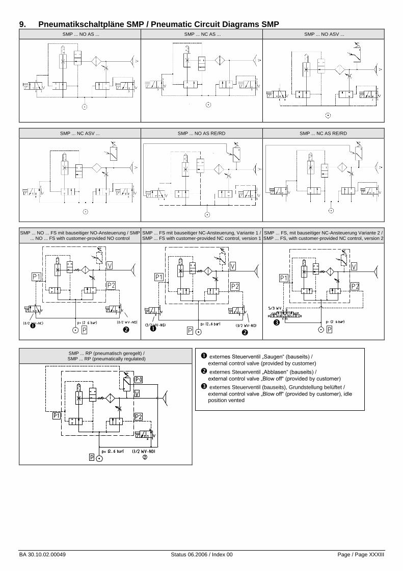
BA 30.10.02.00049 Status 06.2006 / Index 00 Page / Page XXXIII
9. Pneumatikschaltpläne SMP / Pneumatic Circuit Diagrams SMP SMP ... NO AS ... SMP ... NC AS ... SMP ... NO ASV ...
SMP ... NC ASV ... SMP ... NO AS RE/RD SMP ... NC AS RE/RD
SMP ... NO ... FS mit bauseitiger NO-Ansteuerung / SMP ... NO ... FS with customer-provided NO control
SMP ... FS mit bauseitiger NC-Ansteuerung, Variante 1 / SMP ... FS with customer-provided NC control, version 1
SMP ... FS, mit bauseitiger NC-Ansteuerung Variante 2 / SMP ... FS, with customer-provided NC control, version 2
SMP ... RP (pneumatisch geregelt) / SMP ... RP (pneumatically regulated)
externes Steuerventil „Saugen“ (bauseits) /
external control valve (provided by customer)
externes Steuerventil „Abblasen“ (bauseits) /
external control valve „Blow off“ (provided by customer)
externes Steuerventil (bauseits), Grundstellung belüftet /
external control valve „Blow off“ (provided by customer), idle position vented

BA 30.10.02.00049 Status 06.2006 / Index 00 Page / Page XXXIV
10. Benutzer- und Sicherheitsanweisungen Unzulässiger Betrieb mit anderen Medien kann zu Funktionsstörungen, Schäden und Verletzungen – auch Lebensgefahr – führen.
Montage / Demontage Nur im spannungslosem und drucklosem Zustand zulässig ! Die Bauteile dürfen nur von zuverlässigem Fachpersonal eingesetzt werden, das unter anderem geschult und vertraut ist mit: den neuesten geltenden Sicherheitsregeln und Anforderungen beim
Einsatz der Bauteile und deren Steuerungen in Geräten, Maschinen und Anlagen (für Magnetventile, Druckschalter, elektronischen Steuerungen etc.)
und deren erforderlicher elektrischer Ansteuerung, z.B. Redundanzen und ggf. Rückmeldungen (für Elektromagnetventile, Druckschalter, el-ektronischen Steuerungen etc.)
und dem sachgerechtem Umgang mit Bauteilen und Produkten für deren Zweckbestimmung
und deren sachgerechtem Einsatz mit dem Betriebsmedium und den jeweils erforderlichen, neuesten geltenden EG-Richtlinien,
Gesetzen, Verordnungen und Normen und den jeweils neuesten Stand der Technik.
Der unsachgemäße Betrieb der Bauteile, u.a. mit anderen als den zu-lässigen Betriebsmedien, angegebenen Spannung und zulässigen Um-weltbedingungen kann zu Funktionsstörungen, Schäden, Verletzungen führen. Diese Aufstellung soll Hilfestellung geben und erhebt keinen Anspruch auf Vollständigkeit. Sie ist bedarfsweise durch den Anwender zu ergänzen.
Sicherheitshinweise Für sichere Installation und störungsfreien Betrieb sind weiterhin u.a. folgende Verhaltensweisen nebeneinander zu beachten und einzuhalten:
die Bauteile sind den Verpackungen sorgfältig zu entnehmen. Die Bauteile sind generell vor Beschädigungen jeglicher Art zu
schützen Bei Installation und Wartung: Bauteil, Gerät spannungs- und
druckfrei schalten und gegen unbefugtes Wiedereinschalten sichern.
Betrieb des Gerätes ausschließlich über Netzgeräte mit Schutz-kleinspannung (PELV) und sicherer elektrischer Trennung der Be-triebsspannung, gemäß EN60204.
Es dürfen keine Veränderungen an den Bauteilen vorgenommen werden.
Sauberkeit im Umfeld und am Einsatzort Anschlusssymbole und –bezeichnungen befinden sich auf den
Bauteilen und sind entsprechend zu beachten Nur die vorgesehenen Anschlussmöglichkeiten sind zu benutzen. Zur Installation sind nur für den Einsatz des Betriebsmediums
geeignete Armaturen und Schläuche / Rohre fachgerecht einzusetzen (sich lösende Schläuche oder elektrische Anschlussleitungen bedeuten extrem großes Unfallrisiko – auch Lebensgefahr!)
Spannungs- und stromführende Leitungen müssen über ausreichen-de Isolierung und Leitungsquerschnitte verfügen und sind fachgerecht zu installieren
Pneumatische und elektrische Leitungsverbindungen müssen dauer-haft mit dem Bauteil verbunden und gesichert sein.
Für ausreichenden Berührungsschutz der elektrischen Anschlüsse und installierten Bauteile sorgen.
Nur die vorgesehenen Befestigungsbohrungen bzw. Befestigungs-mittel benutzen
Es sind stets alle für den Verwendungszweck erforderlichen neuesten und gültigen Richtlinien, Gesetze, Verordnungen, Normen und der neuste Stand der Technik einzuhalten.
Erforderlichenfalls sind pagens des Anwenders besondere Maßnah-men zu ergreifen, um Forderungen einzuhaltender Richtlinien, Gesetze, Verordnungen, Normen und den neuesten Stand der Technik zu erfül-len.
Nichtbeachtung dieser vorgenannten Verhaltensweisen kann zu Funk-tionsstörungen, Schäden und Verletzungen –auch Lebensgefahr- führen. Die Bauteile sind bei Außerbetriebstellung des Gerätes umweltgerecht zu entsorgen!
Hinweis zur elektromagnetischen Verträglichkeit Physikalisch bedingt weist jeder Elektromagnet, jedes Magnetventil und Relais eine Spule auf, die eine Induktivität darstellt. Bei elektrischem Ab-schalten einer Induktivität ergibt sich durch das abbauende Magnetfeld zwangsläufig ein Überspannungsimpuls, der in seinem Umfeld eine el-ektromagnetische Störung verursachen kann. Störende Impulse lassen sich bei diesen Bauteilen nur anwenderseits durch entsprechende Dämp-fungsglieder unterdrücken. Hierzu zählen Z-Dioden und Varistoren.
10. Safety instructions for operation and maintenance Operation with other than the specified media can result in incorrect func-tion, damage to the components and (possibly fatal) injuries to persons.
Assembly and disassembly This may be done only with the electrical and compressed-air sup-plies switched off! The components may be installed only by reliable and trained persons who have been instructed in and are familiar with: the current safety regulations and the requirements for the use of
the components and their controllers in devices, machines and plants (applies to solenoid valves, pressure switches, electronic con-trollers, etc.);
the necessary electrical controls such as redundancy and, if appli-cable, feedback signals (applies to solenoid valves, pressure switches, electronic controllers, etc.);
the correct handling of components and products for the intended purpose;
the correct use of the components with the operating medium being used;
the current editions of the applicable EU guidelines, laws and stand-ards;
and the state of the art.
Incorrect use of the components, such as their with other than the specified operating media, specified voltages and permissible ambient conditions, can result in incorrect function, damage to equipment and injuries to persons. This information is intended as an aid and is not necessarily complete. If necessary, it must be supplemented by the company operating the
equipment.
Safety notes For safe installation and trouble-free operation, the following instructions must be observed and complied with:
Remove the components carefully from their packing materials. Handle the components carefully to avoid damaging them. For installation and maintenance, switch off the electrical and
compressed-air supplies to the component or equipment and ensure that they cannot be switched on inadvertently.
The unit may only be run via power supply units with protected extra-low voltage and safe electrical cut-off of the operating voltage, in accordance with EN60204.
The components may not be modified in any manner. Keep the components and the work are clean. The connections are clearly marked on the components and must
be connected accordingly. Only the connection facilities provided may be used. Only fittings and pipes/hoses suitable for the operating medium
being used may be used for installation and must be connected cor-rectly (hoses or power cables which are not securely connected are a major cause of accidents, which may even result in fatal injuries to persons in the vicinity!).
Electric cables must be suitably insulated and have a cross-section suitable for the current they are to carry. They must be installed se-curely and correctly.
Pneumatic pipes/hoses and electric cables must be permanently connected to the component and secured to prevent them from be-coming loose.
All electrical terminals and components must be suitably covered to prevent accidental contact.
Only the mounting holes and brackets provided may be used for mounting the components.
All applicable regulations, guidelines, laws and standards must be observed at all times. All work must comply with the state of the art.
If necessary, the company operating the equipment must implement additional measures to ensure compliance with the applicable regu-lations, guidelines, laws and standards.
Non-compliance with the above can result in incorrect function, damage to equipment and (possible fatal) injuries to persons. Any components removed from the equipment must be disposed of in accordance with the local environmental regulations.
Note on electromagnetic compatibility (EMC) Every electromagnet, solenoid valve and relay contains a coil, which acts as an electrical inductance. When the current through such an inductance is switched off, the decaying magnetic field generates an over voltage pulse which can cause electromagnetic disturbances in the vicinity. Such pulses can be suppressed only locally by the connection of suitable damp-ing components, such as Zener diodes or varistors.


Operation instructions vacuum switch pressure switch
VS-D Series
BA 30.10.06.00010_D Status 12.2005 / Index 01
Page XXXVI
J. Schmalz GmbH, Aacher Straße 29, D-72293 Glatten Tel 07443/2403-0, Fax -259
Operation instructions
vacuum switch
1. Front panel
LED Output 1
LED Output 2 Up
Mode Display Down
Display: Preset values in setting mode. Vacuum level in measurement mode.
The minus sign is not dis-played when pressure unit bar, inHg or mmHg is selected (VS-V-D).
Mode Button to select the different modes.
Up & Down Buttons to change settings.
LED Output 1 and Output 2
Switching indicator, Output 1 = red, Output 2 = green.
2. Connecting power supply in normal operation
After connecting the power supply, in the display panel you can see the presetted values. When connecting the power supply do not push any key.
Type Selected pressure unit
Display Measured pressure
3. Zero-point adjustment
Adjust the zero-point only when the vacuum/pressure line is not connected. To adjust the zero-point, push the ”Mode“-key at least 3 seconds.
Display Measured patm
Hold for min. 3 sec
Zero-point adjusted
4. Clear All
If the switch was wrongly programmed, it can be set back in to the factory settings.
All stored values are cleared. To accomplish this function, disconnect the switch from the power supply. Whilst pushing the ”Mode“-key” and the ”Up“-key, connect the power supply again.
Push and hold both keys simultaneous
After connecting the power supply, the display shows “CLA“. When you release the buttons, the presetted pressure unit is displayed by “ -bA” resp. ”bA”.
When pushing the ”Mode“-key one time, the selected pressure unit is confirmed and stored.
1x
To adjust an other pressure unit see paragraph 6.3
5. Factory settings
The switch is delivered with following factory settings
Unit Output 1 Output 2
bar HYS, N.O. HYS, N.O.
This setting can be changed (programmed). The programming is described in the following paragraph.
A built-in EEPROM retains data for a period of min. 10 years. The data are min. 10.000 times rewritable.
N.O = normally open, N.C. = normal closed,
HYS = operating mode „Hysteresis mode“
The initial settings of the operating mode is shown in the table in paragraph 8.
6. Setting of output configuration (N.O. or N.C.) and pressure unit (e.g. bar).
To adjust the output configuration and the pressure unit, push and hold the ”Mode”-key, the push the “Up“-key.
hold
The display is alternating between “ou I“ and ”n.o.”
6.1 Selection N.O. or N.C. of output 1
To change the setting, push ”Up”- or “Down”-key.
Store the settings with the “Mode”-key
1x
Now the display switches to the selection of output 2, the display changes from ”ou 2” to ”n.o.”
6.2 Selection N.O. or N.C. of output 2
To change the setting, push ”Up”- or “Down”-key.
Store the settings with the “Mode”-key.
1x
bar
Now the display switches to the selection of the pressure unit.
6.3 Adjust the pressure unit
To change the setting, push ”Up”- or “Down”-key.
mmHg
kPa
inHg
Store the settings with the “Mode”-key.
1x
Possible pressure units for VS-V-D
Unit bar mmHg inHg kPa
Symbol
Possible pressure units for VS-P10-D
Unit psi kgf/cm² MPa bar
Symbol
7. Adjusting the operating mode
7.1 Adjusting output 1
Example: Switch VS-V-D, output 1 has the operating mode “Hysteresis-mode“.
switching point: -0,6 bar hysteresis: 0,15 bar
Further information to the modes see paragraph 8.
Adjusting the operating mode
To select output 1, push ”Mode”-key 2x.
2x
wait 2 sec
After 2 seconds, the display is alternating between “ou I“ and the preadjusted operating mode.
Push the ”Up”- or “Down”-key until “HYS“ for the desired switching mode „Hysteresis-mode“ is displayed.
Store the settings with the “Mode”-key.
1x
Setting switching point and hysteresis
To select the switching point of output 1 push ”Mode”-key 1x.
1x
wait 2 sec
After 2 seconds, the display is alternating between “H-1“
and the preadjusted value.
To adjust the switching point, push the ”Up”- or “Down”-key until the desired value is displayed.
Store the settings with the “Mode”-key.
1x
Now the display switches to the selection of the hysteresis. The display is alternating between “h-1“ and the preadjusted value.
To adjust the hysteresis, push the ”Up”- or “Down”-key until the desired value is displayed.
Store the settings with the “Mode”-key
1x
7.2 Adjusting output 2
Example: Switch VS-V-D, output 2 has the operating mode
“Window comparator mode“
Switching points are between -0,57 bar and -0,83 bar
(lower margin A=-0,57, upper margin b = -0,83)
Further information to the modes see paragraph 8.
Adjusting the operating mode
To select output 2, push ”Mode”-key 4x
4x
wait 2 sec
After 2 seconds, the display is alternating between “ou 2“ and “HYS“.
Push the ”Up”- or “Down”-key until “CnP“ for the desired switching mode “Window Comparator Mode“ is dis-played.
Store the settings with the “Mode”-key.
1x
Adjusting the lower and the upper margin
To select the lower margin of output 2, push ”Mode”-key 3x
3x
wait 2 sec
After 2 seconds, The display is alternating between “A-2“ and the preadjusted value.
Push the ”Up”- or “Down”-key until the desired value is displayed.
Store the settings with the “Mode”-key.
1x
Now the display switches to the adjustment of the upper mar-gin. The display is alternating between “b-2“ and the pread-justed value.
To adjust the upper margin, push ”Up”- or “Down”-key.

Operation instructions vacuum switch pressure switch
VS-D Series
BA 30.10.06.00010_D Status 12.2005 / Index 01
Page XXXVII
J. Schmalz GmbH, Aacher Straße 29, D-72293 Glatten Tel 07443/2403-0, Fax -259
Store the settings with the “Mode”-key.
1x
8. Operating modes of the outputs The outputs can be operated in two different modes. Each output can be adjusted independent of the other. The modes are described in the following.
8.1 Hysteresis mode Settings are switching point H and hysteresis h. Example: VS-V-D H = -0.60 bar h = 0.15 bar
N.O. (Normally Open)
0 bar
h off on off
H
-1 bar
At 0 bar, the digital output is off. When the vacuum level increases up to the switching point H, the
digital output switches on. As long as the vacuum is higher than -0.45 bar ( = 0.6 bar - 0.15 bar), the digital output stays on. When the vacuum decreases and passes -0.45 bar, the digital output switches off. For the configuration of N.C. (Normally Closed), the output switches reverse ( off > H, on < H-h).
Factory setting: Output 1 & 2 in Hysteresis mode
VS-V-D mmHg inHg kPa bar
H - 1 345 13.6 -46 0.46
h - 1 50 2.0 -7 0.07
H - 2 595 23.4 -79 0.79
h - 2 50 2.0 -7 0.07
VS-P10-D psi kgf/cm² MPa bar
H – 1 67 4.75 0.46 4.6
h - 1 10 0,70 0.07 0.7
H - 2 115 8.2 0.79 7.9
h - 2 10 0.7 0.07 0.7
8.2 Window Comparator mode Settings are lower margin A and upper margin b.
Example: VS-V-D
A = -0.45 bar b = -0.60 bar
N.O. (Normally Open)
0 bar
A off
w on on on
b
-1 bar off off
At 0 bar, the digital output is off. When the vacuum level increases up to the lower margin A, the
digital output switches on. As long as the vacuum level is in the ”window” between the lower margin A and the upper margin b,
the digital output stays on. When the vacuum level becomes higher than the upper margin b, the digital output switches off. For the configuration of N.C. (Normally Closed), the output switches reverse (A < off < b, A < on > b).
Factory setting: Output 1 & 2 in Window Comparator mode
VS-V-D mmHg inHg kPa bar
A - 1 195 7.6 -26 0.26
b- 1 400 15.6 -53 0.53
A - 2 495 19.4 -66 0.66
b - 2 645 25.4 -86 0.86
VS-P10-D psi kgf/cm² MPa bar
A - 1 38 2.7 0.26 2.6
b- 1 77 5.5 0.53 5.3
A - 2 96 6.85 0.66 6.6
b - 2 125 8.90 0.86 8.6
9. Display of Peak and Bottom values
The built-in memory stores in normal operation the peak value and bottom value since the switch was connected to the power supply. These will be displayed as follow: To display the peak valve, push the ”Up”-key
1x
Peak value
To display the bottom valve, push the ”Down”-key
1x
bottom value
10. Rotate display
If the mounting position is twisted (rotated on head), the display can be rotated . When connecting the power supply, push and hold the buttons “Up” and “Down”. Note that the decimal point lights up now at the upper margin of the display. The functions keys retain their function , that means that the “Up“-key shows downwards in twisted mount-ing position !
11. Locking the set values
11.1 Standard versions
Whilst pushing the ”Mode“-key, push the ”Down“-key. The switch is locked, which means that the set values can’t be changed. On the display appears ”LoC”, the switch is locked.
hold
When doing this once more, the switch gets unlocked and the settings can be changed again. On the display appears ”UnC”, the switch is unlocked.
hold
11.2 Version with PIN code (VS-...-C)
The lock prevents unauthorised persons changing the settings. A 3-digit number combination (PIN code) guarantees that only people who know the PIN code (set by the operator) can change the settings.
Activating the lock: To activate the lock, press and hold the “Mode” button, then press the “Down” button.
hold
Press the “Up” or “Down” button to change the right digit.
The value for the right digit is saved when you press the “Mode” button. The centre digit flashes.
1x
The centre digit can now be changed. Press the “Mode” but-ton again to change the left digit.
When the “Mode” button is pressed again, the PIN code en-tered is saved. “LoC” appears on the display and the lock is activated.
1x
Deactivating the lock: To deactivate the lock, press and hold the “Mode” button, then press the “Down” button.
“000” appears on the display and the right digit flashes.
hold
The saved PIN code must be entered as described above for locking. If the PIN code is correct, “UnC” is displayed and the switch is unlocked.
1x
If the PIN code is incorrect, “LoC” is displayed and the switch remains locked.
1x
If you forget the PIN code saved, the switch can be un-locked in the SCHMALZ factory.
12. Error messages
Error Message Solution
Pressure during Zero-point adjustment was higher than ±3% F.S.
Make Zero-point adjustment again at environment pressure.
Overcurrent at Output 1
Loaded current exceeds rated power
Overcurrent at Output 2
of 180mA max. Check output.
*
Applied pressure exceeds measuring range.
Apply pressure within the measuring range.
EEPROM defective, calibration storage could not be read anymore
Switch defective, replace it
*A display change from 0.00 to –FF or e.g. 0.01 at a tmospheric pressure is not an error, but caused by fluctuations in the air pressure.
This can be rectified by setting the zero point.
The zero point must also be set after performing a “Clear all” (CLA).

Vacuum Switch Pressure Switch
Vakuum-Schalter Druckschalter
Vacuostat Pressostat
Conmutadores de vacío Conmutadores de presión
VS-D Series
BA 30.10.06.00010_T Status 10.2005 / Index 00
Page XXXVIII
J. Schmalz GmbH, Aacher Straße 29, D-72293 Glatten Tel 07443/2403-0, Fax -259
VS-V-D-
PNP
VS-V-D-
PNP-C
VS-V-D-
NPN
VS-P10-D-PNP VS-P10-D-NPN
Art. # / Artikel-Nr. / No. de réf / Ref. Nº 10.06.02.00049 10.06.02.00270 10.06.02.00055 10.06.02.00056 10.06.02.00125
Pressure range / Druckbereich / Plage de pression / Margen de presión
0 -1 bar
(0 -29.5 inHg)
0 -1 bar
(0 -29.5 inHg)
0 -1 bar
(0 -29.5 inHg)
0 10 bar
(0 145 psi)
0 10 bar
(0 145 psi)
Overpressure / Überdruck / Suppression / Sobrepresión
5 bar (72.5 psi)
5 bar (72.5 psi)
5 bar (72.5 psi)
16 bar (232 psi)
16 bar (232 psi)
Circuits Schaltpläne Schémas Esquemas
1.1
Pin Connection Pinbelegung
1 V+
2 Switch Output 2
3 V-
4 Switch Output 1
1 V+
2 Schaltausgang 2
3 V-
4 Schaltausgang 1
2 4
1 3
Connection Conexiones
1 V+
2 Sortie contact 2
3 V-
4 Sortie contact 1
1 V+
2 Salida de contactos 2
3 V-
4 Salida de contactos 1
Dimension Abmessung Dimensions Dimensiones
Colour codes of Schmalz cables / Farbkennung von Schmalz-Kabeln /
Marquage en couleur des câbles de Schmalz / Identificación de colores de los cables Schmalz
If the switch is used in a moist environment, the reference con-nection (for ambient or reference pressure) must be connected to a
deaeration hose (i 3 mm) which leads to a dry environment.
Wird der Schalter in feuchter Umgebung eingesetzt, muss der Referenzanschluss (für Umge-bungs- oder Referenzdruck) mit
einem Entlüftungsschlauch (i 3 mm) verbunden sein, der in trock-ener Umgebung endet.
Dans le cas d’une utilisation du commutateur en milieu humide, le raccordement de référence (pour pression de référence ou d’environnement) doit être branché
à l’aide d’un tuyau de purge ( int. 3 mm) se terminant dans un envi-ronnement sec.
Si el interruptor se utiliza en entor-nos húmedos, la conexión de ref-erencia (para la presión ambiental o la presión de referencia) debe estar conectada a una manguera
de purga (i 3 mm) que desem-boque en un entorno seco.
bn = 1
wh = 2
bu = 3
bk = 4
1 Vacuum connection / Vakuumanschluss
Raccord de vide / Conexión de vacío 2 Reference connection / Referenzanschluss
Raccord de référence / Conexión de referencia 3 M8 electrical connection / Elektrischer Anschluss M8
Connexion électrique M8 / Conexión eléctrica M8
1 2
3

Vacuum Switch Pressure Switch
Vakuum-Schalter Druckschalter
Vacuostat Pressostat
Conmutadores de vacío Conmutadores de presión
VS-D Series
BA 30.10.06.00010_T Status 10.2005 / Index 00
Page XXXIX
J. Schmalz GmbH, Aacher Straße 29, D-72293 Glatten Tel 07443/2403-0, Fax -259
f
Technical Data Technische Daten
Media Non corrosive gases and non lubricated air Meßmedium Nicht aggressive Gase und trockene ölfreie Luft
Power supply 10.8 30 VDC (Protected extra-low voltage PELV), Max. 10% ripple (P-P), Reverse voltage protection
Betriebsspannung 10,8 30 VDC (Schutzkleinspannung PELV), Max. 10% Welligkeit (P-P), Anschlüsse verpolungssicher
2 Switch Output N.O, or N.C. separate selective, max. 180 mA, LED-indication on display, short circuit-proof, PNP or NPN version
2 Schaltausgänge Wahlweise einstellbar N.O. oder N.C., max. 180 mA, LED-Anzeige, Kurzschlussfest, p-schaltend (PNP) oder n-schaltend (NPN)
Output resistance NPN 780 K in open state Ausgangswiderstand NPN 780 K im offenen Zustand
Display 3-digit 7- segment LED Anzeige 3-digit 7-segment LED
Pressure units VS-V-D: bar, mmHg, inHg, kPa VS-P10-D: bar, psi, kgf/cm² ,Mpa
Anzeige- optionen
VS-V-D: bar, mmHg, inHg, kPa VS-P10-D: bar, psi, kgf/cm², Mpa
Display resolution VS-V-D: 0.01 bar, 5 mmHg, 0.2 inHg, 1 kPa VS-P10-D: 0.1 bar, 1 psi, 0.05 kgf/cm², 0.01 Mpa
Anzeige Auflösung VS-V-D: 0,01 bar, 5 mmHg, 0,2 inHg, 1 kPa VS-P10-D: 0,1 bar, 1 psi, 0,05 kgf/cm², 0,01 Mpa
Hysteresis Hysteresis mode (0-100%) or Windows Compara-tor mode separate selective
Hystereseeinstellung Hysterese Modus einstellbar von 0 bis 100% der eingestellten Schaltpunkte oder Komparator Modus
Electrical connection Connector M8, 4-pin Elektrischer Anschluss Steckanschluss M8, 4-pin
Air connection M5F and G1/8” M Anschluss Meßmedium M5 IG und G1/8” AG
Protection IP 65 (without venting tube IP40) Schutzklasse IP 65 (ohne Entlüftungsschlauch IP40)
Operation accuracy 1% F.S. Wiederholgenauigkeit 1 % vom Meßbereich
Thermal error 3% F.S. in range 0 50 °C (32 122 °F) Temperatureinfluss 3 % vom Meßbereich im Bereich 0 bis 50 °C
Response time < 5 ms Ansprechzeit < 5 ms
Current consumption < 55 mA Eigenstromaufnahme < 55 mA
Dielectric strength 1,000 VDC 1 min Prüfspannung 1.000 VDC 1 min
Insulation resistance > 100 M at 500 VDC Isolationswiderstand > 100 M bei 500 VDC
Interference emission As per DIN EN 50081-1 Störaussendung Geprüft nach DIN EN 50081-1
Immunity to interference As per DIN EN 50082-2 Störfestigkeit Geprüft nach DIN EN 50082-2
Operating temperature range
0 50 °C (32 122 °F) Arbeitstemperatur 0 bis 50 °C
Storage temperature range -10 60 °C (14 140 °F) Lagertemperatur -10 bis 60 °C
Operating humidity range 10 ~ 90 % RH Zul. Luftfeuchtigkeit 10 ~ 90 % RH
Vibration resistance 1055 Hz 1.5 mm (0.06”), XYZ, 2hrs Schwingungsfestigkeit 10 bis 55 Hz 1,5 mm, XYZ, 2 Std.
Shock resistance 10 G XYZ Schockfestigkeit 10 G XYZ
Mass 25 g (0.88 oz) Gewicht 25 g
Immunity to interference: The following minimum operating quality is guaran-teed when there is interference from electromagnetic HF-Fields as per ENV 50140 and ENV 50141: The switch point can be modified by max. 10 %.
Störfestigkeit: Bei Einstrahlung elektromagnetischer HF-Felder nach ENV 50140 und Hochfrequenz nach ENV 50141 gilt folgende minimale Betriebsqualität: Der Schaltpunkt kann sich um max. 10 % verschieben.
Données techniques Características técnicas
Fluides Gaz non corrosifs et air filtré non lubrifié Medio de medida Gases no agresivos y aire seco y sin aceite
Alimentation 10,8 30 VDC (Très basse tension de protection PELV), Max. 10% ondulation (P-P), Protection inversion de polarité
Tensión de alimentación 10,8 - 30 VDC (Baja tensión de protección PELV), Máxima 10% ondulación (P-P), Protección contra inversiones de polaridad
2 Sortie contact N.O. / N.F. (sélectif.), max. 180 mA, visualisation par LED, Protection contre surinten-sité, version PNP ou NPN
Dos salidas de conmutación Posibilidad de configuración a NC o NO, conmutación p (PNP) o conmutación n (NPN), capacidad de conmutación máxima 180 mA señalización LED
Résistance sortie NPN 780 K dans l'état ouvert Resistencia salida NPN 780 K en abierto estado
Affichage 3-digit 7-segment LED Indicación 3-digit 7-segment LED
Unité de pression VS-V-D: bar, mmHg, inHg, kPa VS-P10-D: bar, psi, kgf/cm² ,Mpa
Opciones de indicación VS-V-D: bar, mmHg, inHg, kPa VS-P10-D: bar, psi, kgf/cm² ,Mpa
Résolution affichage VS-V-D: 0.01 bar, 5 mmHg, 0.2 inHg. 1 kPa VS-P10-D: 0.1 bar, 1 psi, 0.05 kgf/cm², 0.01 Mpa
Precisión de indicación VS-V-D: 0.01 bar, 5 mmHg, 0.2 inHg, 1 kPa VS-P10-D: 0.1 bar, 1 psi, 0.05 kgf/cm², 0.01 MPa
Hystérésis Sélection mode Hystérésis (0-100%) ou mode Com-parateur à fenêtre
Histéresis de conmutación Ajustable entre 0% y 100% de los puntos de conmutación o del modo de comparador seleccionado
Connection électrique Connecteur M8, 4-broches Alimentación eléctrica Conector macho M8 (4 polos)
Raccordement M5F et G1/8” M Conexión de vacío Rosca interna M5, rosca exterior 1/8”
Protection IP 65 (sans flexible IP40) Clase de protección IP 65 (sin tubo de salida de aire, IP 40)
Précision 1% E.M. Precisión de repetición ± 1% del margen de medida
Erreur thermique 3% E.M., entre 0 50°C Influencia de la temperatura ± 3 % del margen de medida (0 - 50 °C)
Temps de réponse < 5 ms Tiempo de activación < 5 ms
Courant consommé < 55 mA Consumo de corriente < 55 mA
Résistance diélectrique 1.000 VDC 1 min Tensión de prueba 1000V AC, 1 min
Résistance d’isolation > 100 M á 500 VDC Resistencia de aislamiento > 100 M á 500 VDC
Emission Selon DIN EN 50081-1 Emisión de interferencias controladas Según DIN EN 50081-1
Immunité Selon DIN EN 50082-2 Resistencia a las interferencias Según DIN EN 50082-2
Température d’utilisation 0 50 °C Temperatura de trabajo 0 a 50 °C
Température de stockage -10 60 °C Temperatura de almacenamiento -10 a 60 °C
Humidité 10 ~ 90 % RH Grado de humedad del aire 10 ~ 90 %, humedad relativa
Résistance aux vibrations 10 55 Hz 1,5 mm, XYZ, 2 hrs Resistencia avibraciones 10 a 55 Hz, 1,5 mm, XYZ, 2 horas
Résistance aux chocs 10 G XYZ Resistencia a impactos 10 G XYZ
Masse 25 g Peso 25 g
Immunité : Qualité de fonctionnement minimum garantie en présence de champs électromagnétiques HF selon ENV 50140 et haute fréquence selon ENV 50141:Le point de commutation varie de max. 10%.
Resistencia a las interferencias : En caso de irradiación de campos magnéticos de alta frecuancia según ENV 50140 y ENV 50141, tiene validez la siguiente calidad de fun-cionamiento mínima: La punto de conmutación máximo varía en 10%.

Brief Operating Instructions Vacuum Switch
VS-V-D-PNP
BA 30.10.06.00010_kurz Status: 08.2001 Page XL
J. Schmalz GmbH Aacher Straße 29 D-72293 Glatten
Tel.: +49 +7443/2403-0 Fax +49 +7443/2403-259
http:/www.schmalz.de e-mail: [email protected]
Brief Operating Instructions Vacuum Switch
1 Display ”Mode” key Used to select the various setting procedures
Function keys ”Up”/”Down” Used to change the settings
LED Output 1 Indicate the switching states: Output 1 = red,
and Output 2 Output 2 = green
2 Setting the Zero Point
The zero point is set with the air and pressure hoses disconnected by pressing and holding the "Mode" key for at least 3 seconds.
Display of meas-ured patm
Hold for at least. 3 seconds
Zero point is set
3 Setting the Switching Point and Hysteresis
3.1 Output 1
To set the switching point of Output 1, press the ”Mode” key once.
1x
Wait 2 sec
After two seconds, the display starts to alternate between "H-1" and the current setting.
To change the setting, press the function key "Up" or "Down" until the desired value is displayed.
Store the new setting by pressing the "Mode" key
1x
The display now changes to the hysteresis value, alternating between "h-1" and the current setting.
To change the setting, press the function key "Up" or "Down" until the desired value is displayed.
Store the new setting by pressing the "Mode" key
1x
3.2 Output 2
To set the switching point of Output 2, press the ”Mode” key three times.
3x
Wait 2 sec
After two seconds, the display starts to alternate between "H-2" and the current setting.
To change the setting, press the function key "Up" or "Down" until the desired value is displayed.
Store the new setting by pressing the "Mode" key
1x
The display now changes to the hysteresis value, alternating between "h-1" and the current setting.
To change the setting, press the function key "Up" or "Down" until the desired value is displayed.
Store the new setting by pressing the "Mode" key
1x
LED Output 1
LED Output 2 Up
Mode Display Down

Brief Operating Instructions Vacuum Switch
VS-V-D-PNP
BA 30.10.06.00010_kurz Status: 08.2001 Page XLI
J. Schmalz GmbH Aacher Straße 29 D-72293 Glatten
Tel.: +49 +7443/2403-0 Fax +49 +7443/2403-259
http:/www.schmalz.de e-mail: [email protected]
4 Operating Mode "Hysteresis" For each output, there is a switching point H and a Hysteresis h.
Example: H1 = -0.46 bar, h = 0.07 bar, NO (Normally Open)
At 0 bar, the digital output is off.
When the vacuum reaches the switching point H, the digital output switches to on and remains on as long as the vacuum is greater than -0.39 bar ( = 0.46 bar - 0.07 bar). If the vacuum drops below -0.39 bar, the digital output switches to off.
If the setting NC (Normally Closed) is selected, the signals at the digital output are inverted (off at vacuum > H, on at vacuum < H-h).
h
-1 bar
H= -0,46 bar
-0,39 bar
0 bar
off on off
5 Locking the Settings The locking function prevents inadvertent changing of the se-lected settings. To lock the settings, press and hold the "Mode" key and press
the "Down" key. The display then shows to indicated that the settings are locked.
Hold
To deactivate the lock, press and hold the "Mode" key and press the "Down" key. The display then shows "UnC" to indicate that the set-tings are unlocked.
Hold
Notes This document is an abbreviated summary of the standard documentation. Please consult the standard documentation if you need to change any set-tings not described here.
Default settings Switching
point 1 Hysteresis Switching
point 2 Hysteresis
H - 1 h - 1 H - 2 h - 2
0.46 bar 0.07 bar 0.79 bar 0.07 bar

© J. Schmalz GmbH
Page XLII
Operation instructions evacuation time counter
Programming
Access to programming mode
A. Press both buttons at the front and switch on the power supply, or press both buttons for five
seconds if power supply is already switched on.
B. The display shows
C. If the buttons are released the display shows By pressing the right button the dislpay shows D. Switch to the first parameter by pressing left button and actuate right button. E. As soon as the button is released, the title of the menu as well as the current adjustment of the
menu is displayed in exchange. F. By pressing the right button the the next adjustment of the menu is shown. If numerical values
have to be entered, the decade is chosen with the left button and the value is adjusted with the right button.
G. Switching to the next menu item by pressing left button and activating right button. H. The last menu item “EndPro” enables leaving of the menu and storing of new values by chosing
“Yes”. If “No” is chosen, the programming process starts again and the at last adjusted values are preserved. These can be altered and controlled again.

© J. Schmalz GmbH
Page XLIII
Necessary Adjustments
Menu item Adjustment
Related Documents