KDW 1603 - 2204 - 2204/T WORKSHOP MANUAL

Welcome message from author
This document is posted to help you gain knowledge. Please leave a comment to let me know what you think about it! Share it to your friends and learn new things together.
Transcript
KDW 1603 - 2204 - 2204/T
WORKSHOP MANUAL

- 3 -
KDW 1603-2204-2204/T
PREFACE
- Every attempt has been made to present within this service manual, accurate and up to date technicalinformation.
However,developmentontheKOHLERseriesiscontinuous. Therefore,theinformationwithinthismanualissubjecttochangewithoutnoticeandwithoutobligation.
- TheinformationcontainedwithinthisservicemanualisthesolepropertyofKOHLER. As such, no reproduction or replication in whole or part is allowed without the express written permission of
KOHLER.
Informationpresentedwithinthismanualassumesthefollowing:
1- ThepersonorpeopleperformingserviceworkonKOHLERseriesenginesisproperlytrainedandequippedtosafelyandprofessionallyperformthesubjectoperation;
2- The person or people performing service work onKOHLER series engines possesses adequate hand andKOHLERspecialtoolstosafelyandprofessionallyperformthesubjectserviceoperation;
3- ThepersonorpeopleperformingserviceworkonKOHLERseriesengineshasreadthepertinentinformationregardingthesubjectserviceoperationsandfullyunderstandstheoperationathand.
- ThismanualwaswrittenbythemanufacturertoprovidetechnicalandoperatinginformationtoauthorisedKOHLERafter-salesservicecentrestocarryoutassembly,disassembly,overhauling,replacementandtuningoperations.
- Aswellasemployinggoodoperatingtechniquesandobservingtherighttimingforoperations,operatorsmustreadtheinformationverycarefullyandcomplywithitscrupulously.
- Timespentreadingthisinformationwillhelptopreventhealthandsafetyrisksandfinancialdamage. Writteninformationisaccompaniedbyillustrationsinordertofacilitateyourunderstandingofeverystepofthe
operatingphases.
Workshop Manual KDW 1603_2204_2204/T _ cod. ED0053029180 - 1° ed_rev. 00

CUSE/ATLO
- 4 - - 4 -
02_15_201102_15_20111° 0
REGISTRATION OF MODIFICATIONS TO THE DOCUMENT
Anymodificationstothisdocumentmustberegisteredbythedraftingbody,bycompletingthefollowingtable.
Drafting body
Document code Edition Issue date
Review date
ModelN° Revision Endorsed
Workshop Manual KDW 1603_2204_2204/T _ cod. ED0053029180 - 1° ed_rev. 00
0053029180 51223
-
- 5 - - 5 -
CHAPTER INDEX
CHAPTER INDEX
1 - MANUFACTURER AND MOTOR IDENTIFICATION DATA .............................................................................. 10
Theidentificationplateshowninthefigurecanbefounddirectlyontheengine..............................................................10Approvaldata.....................................................................................................................................................................10NameplateforEPArulesappliedonrocker-armcap.......................................................................................................11Compilationexample.........................................................................................................................................................11
2 - GENERAL REMARKS AND SAFETY INFORMATION .................................................................................... 12
Generalremarksandsafetyinformation...........................................................................................................................12Californiaemissioncontrolwarrantystatement................................................................................................................13Yourwarrantyrightsandobligations.................................................................................................................................13Safety.................................................................................................................................................................................14Limited3yearkohler
dieselenginewarranty.....................................................................................................................15
Generalservicemanualnotes...........................................................................................................................................15Glossaryandterminology..................................................................................................................................................15Safetyregulations..............................................................................................................................................................16Generalsafetyduringoperatingphases...........................................................................................................................17Safetyandenvironmentalimpact.....................................................................................................................................17
3 - TECHNICAL INFORMATION .............................................................................................................................18
Possiblecausesandtroubleshooting...............................................................................................................................18Technicaldata....................................................................................................................................................................21Performancediagrams..................................................................................................................................................... 22Overalldimensions........................................................................................................................................................... 25
4 - MAINTENANCE - RECOMMENDED OIL TYPE - REFILLING ......................................................................... 28
Routineenginemaintenance............................................................................................................................................ 28Ordinarymaintenance...................................................................................................................................................... 28Extraordinarymaintenance.............................................................................................................................................. 28Lubricant........................................................................................................................................................................... 29Prescribedlubricant.......................................................................................................................................................... 30Coolant...............................................................................................................................................................................31Specificationsfuel..............................................................................................................................................................31
5 - REGULATIONS FOR LIFTING THE ENGINE ................................................................................................... 32
Regulationsforliftingtheengine...................................................................................................................................... 32
6 - DISASSEMBLY/REASSEMBLY .........................................................................................................................34
Recommendationsfordisassemblingandassembling.................................................................................................... 34Recommendationsforoverhaulsandtuning.................................................................................................................... 34Oil-bathaircleaner.......................................................................................................................................................... 35Oil-bathaircleanercomponents...................................................................................................................................... 35Dryaircleaner.................................................................................................................................................................. 35Dryaircomponents.......................................................................................................................................................... 36Airfiltercloggingindicator................................................................................................................................................ 36Intakemanifold.................................................................................................................................................................. 37Exhaustmanifold.............................................................................................................................................................. 37"V"belt.............................................................................................................................................................................. 37Coolingfan........................................................................................................................................................................ 37Drivingpulley(2aP.T.O.)................................................................................................................................................... 38Tank.................................................................................................................................................................................. 38Flywheel............................................................................................................................................................................ 38Rockerarmcoverwithventintotheair............................................................................................................................ 39
Workshop Manual KDW 1603_2204_2204/T _ cod. ED0053029180 - 1° ed_rev. 00
-
- 6 - - 6 -
Chapter index
Rockerarmcoverwithventintotheair............................................................................................................................ 39Rockerarmcoverforengineswithrecirculatingvent....................................................................................................... 39Rockerarmassemly......................................................................................................................................................... 40Cylinderhead.................................................................................................................................................................... 40Valveremoval................................................................................................................................................................... 40Valvespring-Check..........................................................................................................................................................41Valvespring-checkunderload........................................................................................................................................41Valvematerial....................................................................................................................................................................41Valveguidesandcylinderhead.........................................................................................................................................41Valveguideinsertion,afterdriving....................................................................................................................................42Oilsealinthevalvesguides,(intakeandexhaust)............................................................................................................42Valveseatsandbore........................................................................................................................................................ 43Valverecessandsealingsurfaces................................................................................................................................... 43Precombustionchamber................................................................................................................................................... 44Hydraulictappetvalvecontrol........................................................................................................................................... 44Hydraulicdiagramforfeedingthetappets........................................................................................................................ 44Hydraulictappetcomponents:.......................................................................................................................................... 44Hydraulictappetoperation................................................................................................................................................ 45Injectionpumpfollower..................................................................................................................................................... 45Cylinders........................................................................................................................................................................... 46Cylinderroughness........................................................................................................................................................... 46Piston................................................................................................................................................................................ 46Pistonavailability.............................................................................................................................................................. 46Pistonweight......................................................................................................................................................................47Pistonrings-Endgaps....................................................................................................................................................47Pistonrings-Clearancebetweengrooves........................................................................................................................47Pistonrings-Fittingsequence..........................................................................................................................................47Piston-Refitting............................................................................................................................................................... 48Pistonpositionandclearance........................................................................................................................................... 48Cylinderheadgasket........................................................................................................................................................ 48Cylinderheadtighteningforengineswithouthydraulictappets....................................................................................... 49Cylinderheadtighteningsteps......................................................................................................................................... 49Assemblingandtighteningthecylinderheadonengineswithhydraulictappets............................................................ 49Connectingrod................................................................................................................................................................. 50Connectingrodweights.................................................................................................................................................... 50Connectingrodandpistonpin.......................................................................................................................................... 50Connectingrodalignment..................................................................................................................................................51Pistoncoolingsprayer.......................................................................................................................................................51Connectingrod/pistonassemblies....................................................................................................................................51Centermainbearings....................................................................................................................................................... 52Mainbearingcapstimingside-flywheelside.................................................................................................................. 52Checkclearancebetweenmainbearingsandjournals................................................................................................... 53Thrustbearing,oversizes................................................................................................................................................. 54Crankshaftendplay.......................................................................................................................................................... 54Crankshaftfrontandrearoilseal..................................................................................................................................... 55Crankshafttiminggear...................................................................................................................................................... 55Crankshaftlubricationducts............................................................................................................................................. 55Checkingmainjournalsandcrankpins............................................................................................................................ 56Mainbearingandconnectingrodbigbearinginsidediameter(mm)............................................................................... 56Crankshaftforengineswithdynamicequalizer(onlyfour-cylinderengines).................................................................. 57Dynamicbalancer(onrequest)-AdjustmentofclearancebetweenteethDandringgearA........................................ 57Frontcover(beforetheserialnumber7366305).............................................................................................................. 58Frontcover(aftertheserialnumber7366306)................................................................................................................. 58Idlergearandhub............................................................................................................................................................. 58Speedgovernor................................................................................................................................................................ 59Dimensionsforinjectionpumpdeliverycontrolyokeadjustement.................................................................................. 59Camshaftgear-Speedgovernorcounterweights.......................................................................................................... 60Speedgovernorcountersprings...................................................................................................................................... 60Framewithidlingspeedgovernorspring.......................................................................................................................... 60Summarytablesofthegovernorequipmentaccordingtothespeedvariation.................................................................61Springforextrafuelsupplyatstarting...............................................................................................................................61Camshaft............................................................................................................................................................................61Camshaftremoval..............................................................................................................................................................61Checkingcamshaftbushinginternaldiameter................................................................................................................. 62CamshaftjournalsandbushingsinmodelKDW1603..................................................................................................... 62CamshaftjournalsandbushingsinmodelsKDW2204-2204/T...................................................................................... 62
Workshop Manual KDW 1603_2204_2204/T _ cod. ED0053029180 - 1° ed_rev. 00
-
- 7 - - 7 -
Chapter index
Camshaftbushingreplacement........................................................................................................................................ 62Intake,exhaustandinjectioncamheightforenginewithhydraulictappets.................................................................... 63Camshafttiming................................................................................................................................................................ 64Valvetimingwithoutconsideringtimingmarks................................................................................................................. 64Valvetimingcheck............................................................................................................................................................ 64Engineswithhydraulictappets......................................................................................................................................... 65Camshaftendplay............................................................................................................................................................ 66HydraulicpumpP.T.O........................................................................................................................................................ 66GR1andGR2hydraulicpump3rdP.T.O........................................................................................................................ 66
7 - TURBOCHARGER ............................................................................................................................................. 68
Turbocharger..................................................................................................................................................................... 68Turbochargercomponents................................................................................................................................................ 68TurbochargerTesting........................................................................................................................................................ 68Checkingactuatorsetting-"WasteGate"valvecontrolrodstrokeadjustment............................................................... 69
8 - LUBRICATION SYSTEM .................................................................................................................................... 70
Oilpump.............................................................................................................................................................................71Oilpumprotorclearance...................................................................................................................................................71Oilpressureadjustingvalve...............................................................................................................................................71Oilfiltercartridge...............................................................................................................................................................71Oilpressurecheck............................................................................................................................................................ 72OilpressurecurveforKDW1603.................................................................................................................................... 72OilpressurecurveforKDW2204.................................................................................................................................... 72OilpressurecurveforKDW2204/T................................................................................................................................ 72
9 - COOLING SYSTEM ............................................................................................................................................ 74
Expansiontankandcap....................................................................................................................................................75Checkingforcoolingsystemleaks....................................................................................................................................75Coolantcirculatingpump...................................................................................................................................................75Thermostat.........................................................................................................................................................................75
10 - FUEL SYSTEM ................................................................................................................................................. 76
Fuelfilter........................................................................................................................................................................... 77Fuelfeedingpump............................................................................................................................................................ 77Fuelfeedingpumpdriverodprotrusion............................................................................................................................ 77Electricfuelpump(24V)................................................................................................................................................... 78Injectionpump.................................................................................................................................................................. 78Injectionpumpdisassembly............................................................................................................................................. 78Howtoreassembleinjectionpumpcomponents.............................................................................................................. 79Injectionpumpnon-returnvalve....................................................................................................................................... 79Injectionpumpcontrolrod................................................................................................................................................ 79Howtoremoveinjectionpumpfeedingtubes................................................................................................................... 79Howtoreassembleinjectionpumpfeedingtubes............................................................................................................ 80Instrumentforequalizinginjectionpumpdelivery-PartNo.7104-1460-090.................................................................. 80Injectionpumpdeliveryequalization................................................................................................................................ 80Testdataofinjectionpump...............................................................................................................................................81InjectionpumpP.No.6590-249-Plungerandbarrelassembly.......................................................................................81Checkinginjectionpumpdelivery......................................................................................................................................81Checkinglowpressureinjectiontimingforengineswithhydraulictappets.................................................................... 82Checkinglowpressureinjectiontimingforengineswithmechanicaltappets................................................................. 83Injectiontimingcorrectionbychangingthepadthickness............................................................................................... 83Injector(pintype).............................................................................................................................................................. 84Injectorsetting.................................................................................................................................................................. 84
Workshop Manual KDW 1603_2204_2204/T _ cod. ED0053029180 - 1° ed_rev. 00
-
- 8 - - 8 -
Chapter index
11 - ELECTRIC SYSTEM ......................................................................................................................................... 86
Wiringdiagramwithalternator12V45A/65A/80A........................................................................................................ 86Recommendedbatteries.................................................................................................................................................. 87AlternatortypeMarelliAA125R14V45A...................................................................................................................... 88CharacteristiccurvesforalternatortypeMarelliAA125R14V45A............................................................................... 88CharacteristicvoltagecurveforregulatortypeRTT119AC............................................................................................ 88AlternatortypeMarelliAA125R14V65A...................................................................................................................... 89CharacteristiccurvesforalternatortypeMarelliAA125R14V65A............................................................................... 89CharacteristicvoltagecurveforregulatortypeRTT119AC............................................................................................ 89AlternatortypeIskra,AAK313914V80A...................................................................................................................... 90CharacteristiccurvesforalternatortypeIskra,AAK313914V80A.............................................................................. 90CharacteristicvoltagecurveforregulatortypeAER1528............................................................................................... 90StartingMotor12V.............................................................................................................................................................91CharacteristiccurvesforstartingmotortypeBoschEV12V2.2kW................................................................................91Wiringdiagram24Vwithalternator35A........................................................................................................................... 92Recommendedbatteries.................................................................................................................................................. 93AlternatortypeIskra,typeAAK357028V35A-(for24Voutfits)................................................................................... 94CharacteristiccurvesforalternatortypeAAK357028V35A(for24Voutfits)............................................................... 94CharacteristicvoltagecurveforregulatortypeAER1528............................................................................................... 94StartingMotor24V............................................................................................................................................................ 95CharacteristiccurvesforstartingmotorIskratypeAZE459824V3kW....................................................................... 95Spacerflangeforstartermotor......................................................................................................................................... 95Connectiondiagramforpreheatingcontrolunit............................................................................................................... 96Glowplugcontrollerrelaywithcoolanttemperaturesensor............................................................................................ 96Pre-heatingglowplug....................................................................................................................................................... 96Temperaturesensor(Thermistor)..................................................................................................................................... 97Coolanthightemperaturelampswitch............................................................................................................................. 97Thermistorforelectricthermometer................................................................................................................................. 98Thermistorforpreheatingwatertemperature-Thermalcontactforwatertemperatureindicatorlight........................... 98
12 - SETTINGS ...................................................................................................................................................... 100
Idlingspeedsettinginno-loadconditions(standard)..................................................................................................... 100Fullspeedsettinginno-loadconditions(standard)........................................................................................................ 100Standardinjectionpumpdeliverysettingwithouttorquedynamometer........................................................................ 100Injectionpumpdeliverylimitingandtorqueadjustingdevice......................................................................................... 100Fuellimitingdevice(fig.208-209)....................................................................................................................................101Fuellimitingdeviceadjustment(fig.208-209).................................................................................................................101Stopsetting......................................................................................................................................................................101ApplicationdiagramfortamperingsystemadjustmentscrewandtorquegearingdeviceforEPA-approvedengines..101
13 - ENGINE STORAGE ...................................................................................................................................... 103
Enginestorage................................................................................................................................................................103Protectivetreatment.........................................................................................................................................................103Preparingtheengineforoperationafterprotectivetreatment........................................................................................103
14 - TORQUE SPECIFICATIONS AND USE OF SEALANT ................................................................................ 104
Maintorquespecifications.............................................................................................................................................. 104Tableoftighteningtorquesforstandardscrews(coarsethread)................................................................................... 105Tableoftighteningtorquesforstandardscrews(finethread)........................................................................................ 105
15 - SPECIAL TOOLS ........................................................................................................................................... 106
Workshop Manual KDW 1603_2204_2204/T _ cod. ED0053029180 - 1° ed_rev. 00

-
- 9 - - 9 - Workshop Manual KDW 1603_2204_2204/T _ cod. ED0053029180 - 1° ed_rev. 00

1
- 10 - - 10 -
C
A
F
D
E
B
MANUFACTURER AND MOTOR IDENTIFICATION DATA
The identification plate shown in the figure can be found directly on the engine.
Itcontainsthefollowinginformation:
A)Manufacturer’sidentityB)EnginetypeC)EngineserialnumberD) MaximumoperatingspeedE) Numberofthecustomerversion(formK)F)Approvaldata
Approval data
TheapprovalreferencedirectivesECareontheengineplate(F ).
Workshop Manual KDW 1603_2204_2204/T _ cod. ED0053029180 - 1° ed_rev. 00

1
- 11 - - 11 -
6
1
USE IN CONSTANT-SPEED APPLICATIONS ONLY
3 10
5
78
9
2 4
Name plate for EPA rules applied on rocker-arm cap
Compilation example
1)Modelyear.
2)Enginedisplacement.
3)Powercategory,kW.
4)Particulateemissionlimit(g/kWh).
5)EnginefamilyID.
6)Kindofapplicationi.e.
7)Injectiontiming(BTDC).
8)Injectoropeningpressure(bar).
9)Productiondate(example2012_Jan).
10) EmissionControlSystem=ECS.
Manufacturer and motor identification data
Workshop Manual KDW 1603_2204_2204/T _ cod. ED0053029180 - 1° ed_rev. 00
2
- 12 - - 12 -
GENERAL REMARKS AND SAFETY INFORMATION
DANGER DANGER DANGER
DANGER DANGER DANGER
SAFETY REGULATIONS
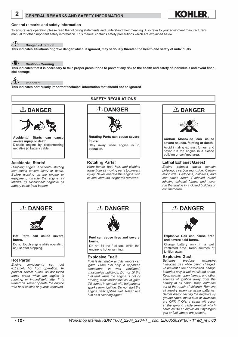
Toensuresafeoperationpleasereadthefollowingstatementsandunderstandtheirmeaning.Alsorefertoyourequipmentmanufacturer'smanualforotherimportantsafetyinformation.Thismanualcontainssafetyprecautionswhichareexplainedbelow.
Danger – Attention This indicates situations of grave danger which, if ignored, may seriously threaten the health and safety of individuals.
Caution – WarningThis indicates that it is necessary to take proper precautions to prevent any risk to the health and safety of individuals and avoid finan-cial damage.
ImportantThis indicates particularly important technical information that should not be ignored.
Hot Parts can cause severe burns.Donottouchenginewhileoperatingorjustafterstopping.
Hot Parts!Engine components can get extremely hot from operation. To prevent severe burns, do not touch these areas while the engine is running, or immediately after it is turned off. Never operate the engine with heat shields or guards removed.
Rotating Parts can cause severe injury.Stay away while engine is inoperation.
Rotating Parts!Keep hands, feet, hair, and clothing away from all moving parts to prevent injury. Never operate the engine with covers, shrouds, or guards removed.
Carbon Monoxide can cause severe nausea, fainting or death.Avoid inhalingexhaust fumes,andnever run the engine in a closedbuildingorconfinedarea.
Lethal Exhaust Gases!Engine exhaust gases contain poisonous carbon monoxide. Carbon monoxide is odorless, colorless, and can cause death if inhaled. Avoid inhaling exhaust fumes, and never run the engine in a closed building or confined area.
Accidental Starts can cause severe injury or death.Disable engine by disconnectingnegative(-)batterycable.
Accidental Starts!Disabling engine. Accidental starting can cause severe injury or death. Before working on the engine or equipment, disable the engine as follows: 1) Disconnect negative (-) battery cable from battery.
Explosive Gas can cause fires and severe acid burns.Charge battery only in a wellventilated area. Keep sources ofignitionaway.
Explosive Gas!Batteries produce explosive hydrogen gas while being charged. To prevent a fire or explosion, charge batteries only in well ventilated areas. Keep sparks, open flames, and other sources of ignition away from the battery at all times. Keep batteries out of the reach of children. Remove all jewelry when servicing batteries. Before disconnecting the negative (-) ground cable, make sure all switches are OFF. If ON, a spark will occur at the ground cable terminal which could cause an explosion if hydrogen gas or fuel vapors are present.
Fuel can cause fires and severe burns.Do not fill the fuel tank while theengineishotorrunning.
Explosive Fuel!Fuel is flammable and its vapors can ignite. Store fuel only in approved containers, in well ventilated, unoccupied buildings. Do not fill the fuel tank while the engine is hot or running, since spilled fuel could ignite if it comes in contact with hot parts or sparks from ignition. Do not start the engine near spilled fuel. Never use fuel as a cleaning agent.
General remarks and safety information
Workshop Manual KDW 1603_2204_2204/T _ cod. ED0053029180 - 1° ed_rev. 00
2
- 13 - - 13 -
General remarks and safety information
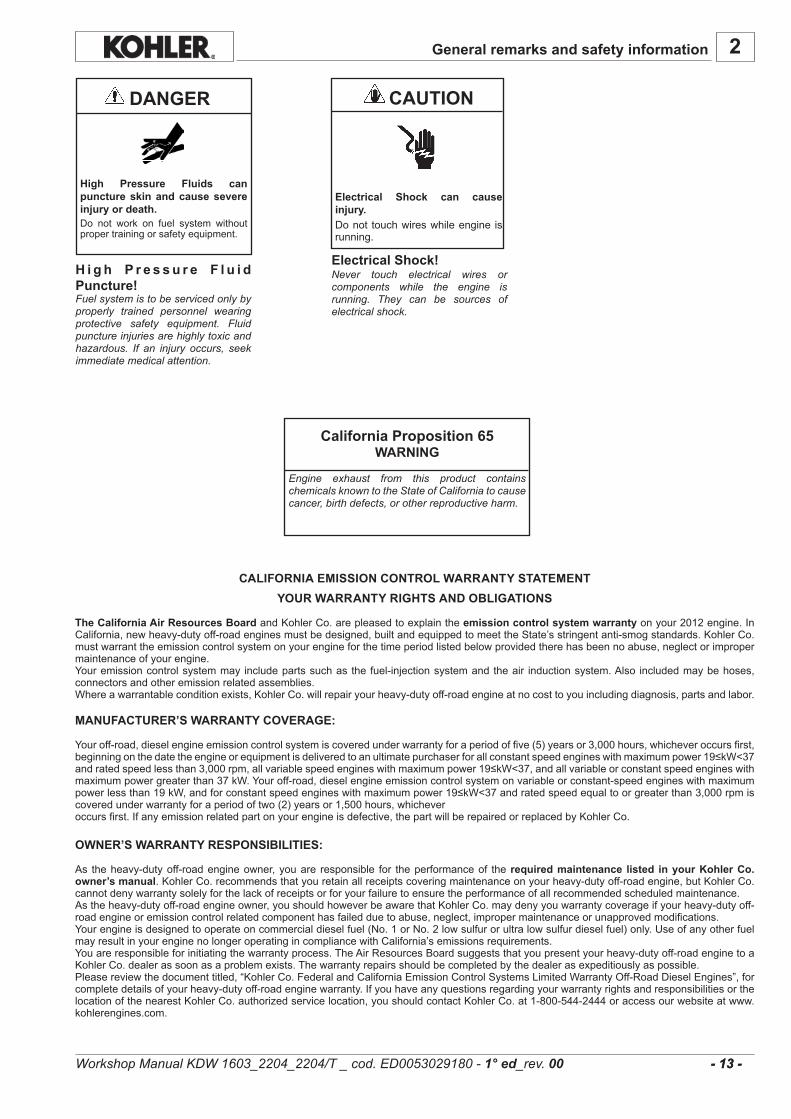
CAUTION DANGER
Electrical Shock can cause injury.Donot touchwireswhileengine isrunning.
Electrical Shock!Never touch electrical wires or components while the engine is running. They can be sources of electrical shock.
California Proposition 65WARNING
Engine exhaust from this product contains chemicals known to the State of California to cause cancer, birth defects, or other reproductive harm.
High Pressure Fluids can puncture skin and cause severe injury or death.Do not work on fuel system withoutpropertrainingorsafetyequipment.
H i g h P r e s s u r e F l u i d Puncture!Fuel system is to be serviced only by properly trained personnel wearing protective safety equipment. Fluid puncture injuries are highly toxic and hazardous. If an injury occurs, seek immediate medical attention.
Workshop Manual KDW 1603_2204_2204/T _ cod. ED0053029180 - 1° ed_rev. 00
CALIFORNIA EMISSION CONTROL WARRANTY STATEMENTYOUR WARRANTY RIGHTS AND OBLIGATIONS
The California Air Resources Board andKohlerCo.arepleasedtoexplaintheemission control system warrantyonyour2012engine.InCalifornia,newheavy-dutyoff-roadenginesmustbedesigned,builtandequippedtomeettheState’sstringentanti-smogstandards.KohlerCo.mustwarranttheemissioncontrolsystemonyourengineforthetimeperiodlistedbelowprovidedtherehasbeennoabuse,neglectorimpropermaintenanceofyourengine.Youremissioncontrolsystemmay includepartssuchasthefuel-injectionsystemandtheair inductionsystem.Also includedmaybehoses,connectorsandotheremissionrelatedassemblies.Whereawarrantableconditionexists,KohlerCo.willrepairyourheavy-dutyoff-roadengineatnocosttoyouincludingdiagnosis,partsandlabor.
MANUFACTURER’S WARRANTY COVERAGE:
Youroff-road,dieselengineemissioncontrolsystemiscoveredunderwarrantyforaperiodoffive(5)yearsor3,000hours,whicheveroccursfirst,beginningonthedatetheengineorequipmentisdeliveredtoanultimatepurchaserforallconstantspeedengineswithmaximumpower19≤kW<37andratedspeedlessthan3,000rpm,allvariablespeedengineswithmaximumpower19≤kW<37,andallvariableorconstantspeedengineswithmaximumpowergreaterthan37kW.Youroff-road,dieselengineemissioncontrolsystemonvariableorconstant-speedengineswithmaximumpowerlessthan19kW,andforconstantspeedengineswithmaximumpower19≤kW<37andratedspeedequaltoorgreaterthan3,000rpmiscoveredunderwarrantyforaperiodoftwo(2)yearsor1,500hours,whicheveroccursfirst.Ifanyemissionrelatedpartonyourengineisdefective,thepartwillberepairedorreplacedbyKohlerCo.
OWNER’S WARRANTY RESPONSIBILITIES:
As theheavy-dutyoff-roadengineowner,youare responsible for theperformanceof the required maintenance listed in your Kohler Co. owner’s manual.KohlerCo.recommendsthatyouretainallreceiptscoveringmaintenanceonyourheavy-dutyoff-roadengine,butKohlerCo.cannotdenywarrantysolelyforthelackofreceiptsorforyourfailuretoensuretheperformanceofallrecommendedscheduledmaintenance.Astheheavy-dutyoff-roadengineowner,youshouldhoweverbeawarethatKohlerCo.maydenyyouwarrantycoverageifyourheavy-dutyoff-roadengineoremissioncontrolrelatedcomponenthasfailedduetoabuse,neglect,impropermaintenanceorunapprovedmodifications.Yourengineisdesignedtooperateoncommercialdieselfuel(No.1orNo.2lowsulfurorultralowsulfurdieselfuel)only.UseofanyotherfuelmayresultinyourenginenolongeroperatingincompliancewithCalifornia’semissionsrequirements.Youareresponsibleforinitiatingthewarrantyprocess.TheAirResourcesBoardsuggeststhatyoupresentyourheavy-dutyoff-roadenginetoaKohlerCo.dealerassoonasaproblemexists.Thewarrantyrepairsshouldbecompletedbythedealerasexpeditiouslyaspossible.Pleasereviewthedocumenttitled,“KohlerCo.FederalandCaliforniaEmissionControlSystemsLimitedWarrantyOff-RoadDieselEngines”,forcompletedetailsofyourheavy-dutyoff-roadenginewarranty.IfyouhaveanyquestionsregardingyourwarrantyrightsandresponsibilitiesorthelocationofthenearestKohlerCo.authorizedservicelocation,youshouldcontactKohlerCo.at1-800-544-2444oraccessourwebsiteatwww.kohlerengines.com.

2
- 14 - - 14 -
General remarks and safety information
Read theOperation andMaintenance handbook beforeperforminganyoperationontheengine
Hightemperaturecomponents-Dangerofscalding
Presenceofrotatingparts-Dangerofentanglingandcutting
Presenceofexplosivefuel-Dangeroffireorexplosion
Presenceofsteamandpressurizedcoolant-Dangerofscalding
ExplanationofthesafetypictogramsthatcanbefoundontheengineorintheOperationandMaintenancehandbook
Useprotectiveglovesbeforecarryingouttheoperation
Useprotectiveglassesbeforecarryingouttheoperation
Usesoundabsorbingprotectionsbeforecarryingouttheoperation
Electricshock-Dangerofseverescaldingordeath
Fluidsunderhighpressure-Dangeroffluidspenetration
Lethalexhaustgas-Dangerofpoisoningordeath
Indicationsregardingthepointsontheenginewherethesafetypictogramsareplaced
Safety
Workshop Manual KDW 1603_2204_2204/T _ cod. ED0053029180 - 1° ed_rev. 00
2
- 15 - - 15 -
GLOSSARY AND TERMINOLOGY
Forclarity,herearethedefinitionsofanumberoftermsusedrecurrentlyinthemanual.
- Cylinder number one: isthepistontimingbeltside«viewedfromtheflywheelsideoftheengine».
- Rotation direction: anticlockwise«viewedfromtheflywheelsideoftheengine».
General remarks and safety information
Workshop Manual KDW 1603_2204_2204/T _ cod. ED0053029180 - 1° ed_rev. 00
GENERAL SERVICE MANUAL NOTES
1 - UseonlygenuineKohlerrepairparts. Failure tousegenuineKohler parts could result in sub-
standardperformanceandlowlongevity.
2 - Alldatapresentedareinmetricformat.Thatis,dimensionsare presented in millimeters (mm), torque is presented inNewton-meters (Nm), weight is presented in kilograms(Kg),volumeispresentedinlitersorcubiccentimeters(cc)andpressureispresentedinbarometricunits(bar).
LIMITED 3 YEAR KOHLER® DIESEL ENGINE WARRANTY
KohlerCo.warrantstotheoriginalretailconsumerthateachnewKOHLERDieselenginesoldbyKohlerCo.willbefreefrommanufacturingdefects inmaterialsorworkmanship innormal service for aperiodof three (3) yearsor2000hourswhicheveroccurs first from thedateofpurchase,provideditisoperatedandmaintainedinaccordancewithKohlerCo.’sinstructionsandmanuals.Ifnohourmeterisinstalledasoriginalequipmentthen8hoursofuseperdayand5daysperweekwillbeusedtocalculatehoursused.
Ourobligationunderthiswarrantyisexpresslylimited,atouroption,tothereplacementorrepairatKohlerCo.,Kohler,Wisconsin53044,orataservicefacilitydesignatedbyusofsuchpartsasinspectionshalldisclosetohavebeendefective.
Thiswarrantydoesnotapplytodefectscausedbyunreasonableuse,includingfaultyrepairsbyothersandfailuretoprovidereasonableandnecessarymaintenance.
Thefollowingitemsarenotcoveredbythiswarranty:Engineaccessoriessuchasfueltanks,clutches,transmissions,power-driveassembliesandbatteries,unlesssuppliedorinstalledbyKohlerCo.Thesearesubjecttothewarranties,ifany,oftheirmanufacturers.
KOHLERCO.AND/ORTHESELLERSHALLNOTBELIABLEFORSPECIAL,INDIRECT,INCIDENTIALORCONSEQUENTIALDAMAGESOFANYKIND,includingbutnotlimitedtolaborcostsortransportationchargesinconnectionwiththerepairorreplacementofdefectiveparts.
IMPLIEDORSTATUTORYWARRANTIES,INCLUDINGWARRANTIESOFMERCHANTABILITYORFITNESSFORAPARTICULARPURPOSE,AREEXPRESSLYLIMITEDTOTHEDURATIONOFTHISWRITTENWARRANTY.Wemakenootherexpresswarranty,norisanyoneauthorizedtomakeanyonourbehalf.
Somestatesdonotallowlimitationsonhowlonganimpliedwarrantylasts,ortheexclusionorlimitationofincidentalorconsequentialdamages,sotheabovelimitationorexclusionmaynotapplytoyou.
Thiswarrantygivesyouspecificlegalrights,andyoumayalsohaveotherrights,whichvaryfromstatetostate.
Toobtainwarrantyservice
PurchasermustbringtheenginetoanauthorizedKohlerservicefacility.Tolocatethenearestfacility,visitourwebsite,www.kohlerengines.com,andusethelocatorfunction,consultyourYellowPagesortelephone1-800-544-2444.
ENGINEDIVISION,KOHLERCO.,KOHLER,WISCONSIN53044
2
- 16 - - 16 -
General remarks and safety information
Workshop Manual KDW 1603_2204_2204/T _ cod. ED0053029180 - 1° ed_rev. 00
GENERAL NOTES
. Kohler engines are built to provide safe and longlastingperformances, but in order to obtain these results it isessential that the maintenance requirements described inthe manual are observed along with the following safetyrecommendations.
. The engine has been built to the specifications of amachinemanufacturer,anditishisresponsibilitytoensurethat all necessary action is taken to meet the essentialand legally prescribed health and safety requirements.Any use of themachine other than that described cannotbe considered as complying with its intended purposeas specified by Kohler, which therefore declines allresponsibilityforaccidentscausedbysuchoperations.
. The following instructions are intended for the user of themachine in order to reduce or eliminate risks, especiallythoseconcerning theoperationandstandardmaintenanceoftheengine.
. The user should read these instructions carefully and gettoknowtheoperationsdescribed.Bynotdoingsohemayplaceatriskhisownhealthandsafetyandthatofanyoneelseinthevicinityofthemachine.
. The enginemay be used ormounted on amachine onlybypersonnelsuitably trained in itsoperationandawareofthedangers involved.This is particularly true for standardand, above all, special maintenance work. For specialmaintenance contact personnel trained specifically byKohler.Thisworkshouldbecarriedoutinaccordancewithexistingliterature.
. Kohlerdeclinesallresponsibilityforaccidentsorforfailuretocomplywiththerequirementsoflawifchangesaremadetotheengine’sfunctionalparametersortothefuelflowrateadjustments and speed of rotation, if seals are removed,or ifpartsnotdescribed in theoperatingandmaintenancemanual are removed and reassembled by unauthorizedpersonnel.
WARNING
. Inaddition toall othermachinespecifications,ensure thattheengine is inanearhorizontalpositionwhenstarting. lfstarting manually, ensure that the necessary operationscanbeperformedwithoutanyriskofstrikingagainstwallsordangerousobjects.Ropestarting(exceptforrecoilropestarting)isnotpermittedeveninemergencies.
. Checkthatthemachineisstablesothatthereisnoriskofitoverturning.
. Get to know the engine speed adjustment and machinestopoperations.
. Do not start the machine in closed or poorly ventilatedenvironments.The internal combustion process generatescarbon monoxide, an odourless and highly toxic gas, sospending too long a time in an environment where theengine discharges its exhaust products freely can lead tolossofconsciousnessandevendeath.
. The engine may not be used in environments containingflammable materials, explosive atmospheres or easilycombustible powders, unless adequate and specificprecautions have been taken and are clearly stated andcertifiedforthemachine.
. Topreventtheriskoffire,keepthemachineatadistanceofatleastonemetrefrombuildingsorothermachines.
SAFETY REGULATIONS
. Children and animals must be kept at a sufficient distancefrom the machine to prevent any danger resulting from itsoperation.
. Fuel is flammable, so the tankmust be filled only when theengine is turned off. Dry carefully any fuel that may havespilled, remove the fuel container and any cloths soakedin fuel or oil, check that any sound-absorbing panels madeofporousmaterial arenot soakedwith fueloroil, andmakesurethatthegroundonwhichthemachineislocatedhasnotabsorbedfueloroil.
. Before starting, remove any tools that have been used forcarrying out maintenance work to the engine and/or themachine and check that any guards removed have beenreplaced. Incoldclimates it ispossible tomixkerosenewiththediesel fuel tomaketheengineeasier tostart.Theliquidsmust be mixed in the tank by pouring in first the keroseneand then the diesel fuel. ConsultKohler technical office formixture proportions. Petrolmay not be used because of theriskofitformingflammablevapours.
. During operation the surface of the engine reachestemperatures thatmaybe dangerous. Avoid in particular allcontactwiththeexhaustsystem.
. The liquid cooling circuit is underpressure.Donot carryoutany checks before the engine has cooled down, and eventhenopen the radiator capor theexpansion tank cautiously.Wear protective clothing and glasses. lf there is an electricfan,donotapproachtheenginewhile it isstillhotasthefanmaycomeonevenwhentheengineisnotrunning.Cleanthecoolingsystemwiththeengineturnedoff.
. While cleaning the oil bath air filter, check that the oil isdisposed of in such a way as not to harm the environment.Any filtering sponges in the oil bath air filter should not besoakedwithoil. Thecyclonepre-filtercupmustnotbefilledwithoil.
. Sincetheoilmustbeemptiedoutwhiletheengineisstillhot(approx. 80°C), particular care should be taken in order toavoid burns. In any casemake sure that oil does not comeinto contact with your skin because of the health hazardsinvolved.
. Fuelvapoursarehighlytoxic,sofilluponlyintheopenairorinwellventilatedenvironments.
. During operations which involve access to moving parts ofthe engine and/or removal of the rotary guards, disconnectandinsulatethepositivecableofthebatterysoastopreventaccidentalshortcircuitsandactivationofthestartermotor.
. Checkthebelttensiononlywhentheengineisturnedoff.
IMPORTANT
. To start the engine follow the specific instructions providedin the engine and/or machine operating manual. Do notuse auxiliary starting devices not originally installed on themachine(e.g.Startpilotsystemswhichutiliseetheretc.)
. Before carrying out any work on the engine, turn it off andallowittocooldown.Donotperformanyoperationwhiletheengineisrunning.
. Check that the discharged oil, the oil filter and the oilcontainedintheoilfilteraredisposedofinsuchawayasnottoharmtheenvironment.
. Close the fuel tank filler cap carefully after each fíllingoperation. Do not fill the tank right up to the top, but leavesufficientspacetoallowforanyexpansionofthefuel.
. Donotsmokeorusenakedflameswhilefilling.

2
- 17 - - 17 -
GENERAL SAFETY DURING OPERATING PHASES
– Theprocedurescontainedinthismanualhavebeentestedandselectedbythemanufacturer’stechnicalexperts,andhencearetoberecognisedasauthorisedoperatingmethods.
– Sometoolsarenormalworkshopones,whileothersarespecialtoolsdesignedbytheManufactureroftheengine.
– Alltoolsmustbeingoodworkingconditionsothatenginecomponentsarenotdamagedandthatoperationsarecarriedoutproperlyandsafely.
– Itisimportanttowearthepersonalsafetydevicesprescribedbyworksafetylawsandalsobythestandardsofthismanual.
– Holesmustbelinedupmethodicallyandwiththeaidofsuitableequipment.Donotuseyourfingerstocarryoutthisoperationtoavoidtheriskofamputation.
SAFETY AND ENVIRONMENTAL IMPACT
Everyorganisationhasadutytoimplementprocedurestoidentify,assessandmonitortheinfluenceofitsownactivities(products,services,etc.)ontheenvironment.Proceduresforidentifyingtheextentoftheimpactontheenvi-ronmentmustconsiderthefollowingfactors:
- Liquidwaste; - Wastemanagement; - Soilcontamination; - Atmosphericemissions; - Useofrawmaterialsandnaturalresources; - Regulationsanddirectivesregardingenvironmentalimpact.
Inordertominimisetheimpactontheenvironment,themanufacturernowprovidesanumberofindicationstobefollowedbyallpersonshandlingtheengine,foranyreason,duringitsexpectedlifetime.
- Allpackagingcomponentsmustbedisposedofinaccordancewiththelawsofthecountryinwhichdisposalistakingplace.
- Keep the fuel and engine control systems and the exhaustpipesinefficientworkingordertolimitenvironmentalandnoisepollution.
- Whendiscontinuinguseoftheengine,selectallcomponentsaccordingtotheirchemicalcharacteristicsanddisposeofthemseparately.
– Somephasesmayrequiretheassistanceofmorethanoneoperator.Ifso,itisimportanttoinformandtrainthemregardingthetypeofactivitytheywillbeperforminginordertopreventriskstothehealthandsafetyofallpersonsinvolved.
– Donotuseflammableliquids(petrol,diesel,etc.)todegreaseorwashcomponents.Usespecialproducts.
– Usetheoilsandgreasesrecommendedbythemanufacturer. Donotmixdifferentbrandsorcombineoilswithdifferent
characteristics.– Discontinueuseoftheengineifanyirregularitiesarise,
particularlyinthecaseofunusualvibrations.– Donottamperwithanydevicestoalterthelevelof
performanceguaranteedbythemanufacturer.
General remarks and safety information
Workshop Manual KDW 1603_2204_2204/T _ cod. ED0053029180 - 1° ed_rev. 00
. Takecarewhenremovingtheoilfilterasitmaybehot.
. The operations of checking, filling up and replacing thecoolingliquidmustbecarriedoutwiththeengineturnedoffandcold. Takeparticular care if liquids containingnitritesare mixed with others not containing these compoundsas this may give rise to the formation of nitrosamineswhichareahealthhazard. Thecooling liquid ispolluting,so dispose of in a manner that does not damage theenvironment.
. In order to move the engine simultaneously use theeyebolts fitted for this purpose by Kohler. These liftingpointsarehowevernotsuitable for theentiremachine,sointhiscaseusetheeyeboltsfittedbythemanufacturer.
3
- 18 - - 18 -
TECHNICAL INFORMATION
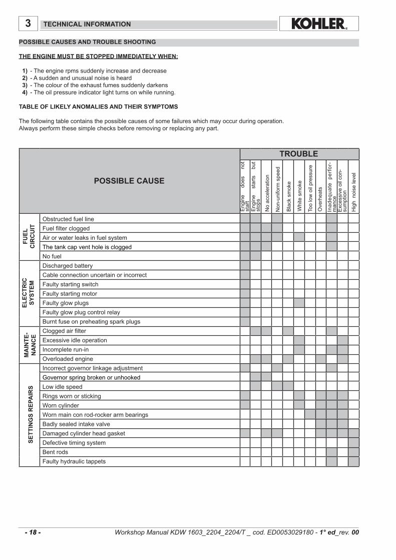
POSSIBLE CAUSES AND TROUBLE SHOOTING
THE ENGINE MUST BE STOPPED IMMEDIATELY WHEN:
1) -Theenginerpmssuddenlyincreaseanddecrease 2) -Asuddenandunusualnoiseisheard 3) -Thecolouroftheexhaustfumessuddenlydarkens 4) -Theoilpressureindicatorlightturnsonwhilerunning.
TABLE OF LIKELY ANOMALIES AND THEIR SYMPTOMS
Thefollowingtablecontainsthepossiblecausesofsomefailureswhichmayoccurduringoperation.Alwaysperformthesesimplechecksbeforeremovingorreplacinganypart.
FUEL
CIR
CU
ITEL
ECTR
ICSY
STEM
MA
INTE
-N
AN
CE
SETT
ING
S R
EPA
IRS
ObstructedfuellineFuelfiltercloggedAirorwaterleaksinfuelsystemThetankcapventholeiscloggedNofuelDischargedbatteryCableconnectionuncertainorincorrectFaultystartingswitchFaultystartingmotorFaultyglowplugsFaultyglowplugcontrolrelayBurntfuseonpreheatingsparkplugsCloggedairfilterExcessiveidleoperationIncompleterun-inOverloadedengineIncorrectgovernorlinkageadjustmentGovernorspringbrokenorunhookedLowidlespeedRingswornorstickingWorncylinderWornmainconrod-rockerarmbearingsBadlysealedintakevalveDamagedcylinderheadgasketDefectivetimingsystemBentrodsFaultyhydraulictappets
POSSIBLE CAUSE
Inad
equa
tep
erfor-
mance
Highnoiselevel
Overheats
TROUBLE
Engine
does
not
start
Engine
starts
but
stops
Noacceleration
Non-uniformspeed
Blacksmoke
Whitesmoke
Toolowoilpressure
Excessiveoilcon-
sumption
Workshop Manual KDW 1603_2204_2204/T _ cod. ED0053029180 - 1° ed_rev. 00
3
- 19 - - 19 -
Technical information
INJE
CTI
ON
LUB
RIC
ATIO
NC
IRC
UIT
CO
OLI
NG
C
IRC
UIT
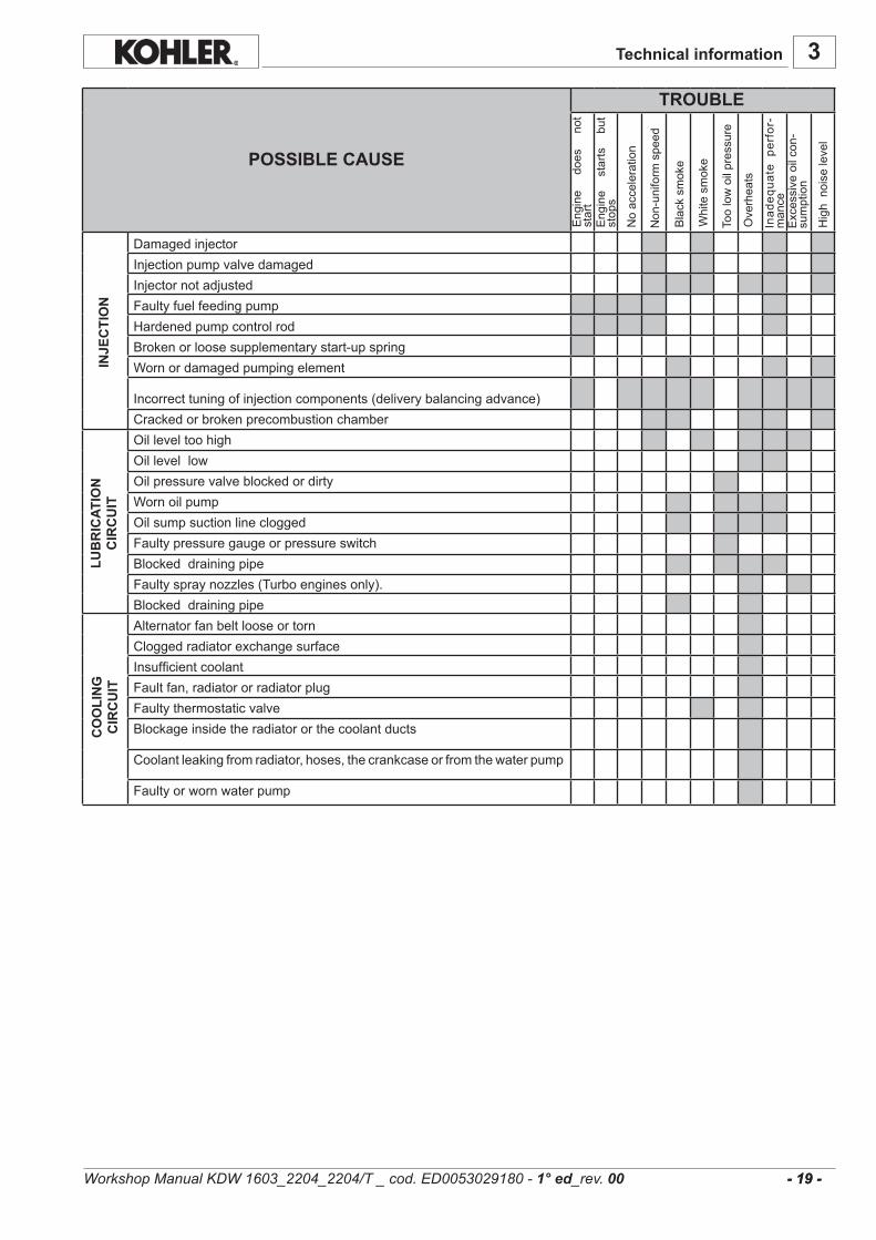
DamagedinjectorInjectionpumpvalvedamagedInjectornotadjustedFaultyfuelfeedingpumpHardenedpumpcontrolrodBrokenorloosesupplementarystart-upspringWornordamagedpumpingelement
Incorrecttuningofinjectioncomponents(deliverybalancingadvance)CrackedorbrokenprecombustionchamberOilleveltoohighOillevellowOilpressurevalveblockedordirtyWornoilpumpOilsumpsuctionlinecloggedFaultypressuregaugeorpressureswitchBlockeddrainingpipeFaultyspraynozzles(Turboenginesonly).BlockeddrainingpipeAlternatorfanbeltlooseortornCloggedradiatorexchangesurfaceInsufficientcoolantFaultfan,radiatororradiatorplugFaultythermostaticvalveBlockageinsidetheradiatororthecoolantducts
Coolantleakingfromradiator,hoses,thecrankcaseorfromthewaterpump
Faultyorwornwaterpump
POSSIBLE CAUSE
Inad
equa
tep
erfor-
mance
Highnoiselevel
Overheats
TROUBLE
Engine
does
not
start
Engine
starts
but
stops
Noacceleration
Non-uniformspeed
Blacksmoke
Whitesmoke
Toolowoilpressure
Excessiveoilcon-
sumption
Workshop Manual KDW 1603_2204_2204/T _ cod. ED0053029180 - 1° ed_rev. 00

3
- 20 - - 20 -
.........................................................................................................................................................................
.........................................................................................................................................................................
.........................................................................................................................................................................
.........................................................................................................................................................................
.........................................................................................................................................................................
.........................................................................................................................................................................
.........................................................................................................................................................................
.........................................................................................................................................................................
.........................................................................................................................................................................
.........................................................................................................................................................................
.........................................................................................................................................................................
.........................................................................................................................................................................
.........................................................................................................................................................................
.........................................................................................................................................................................
.........................................................................................................................................................................
.........................................................................................................................................................................
.........................................................................................................................................................................
.........................................................................................................................................................................
.........................................................................................................................................................................
.........................................................................................................................................................................
.........................................................................................................................................................................
.........................................................................................................................................................................
.........................................................................................................................................................................
.........................................................................................................................................................................
.........................................................................................................................................................................
.........................................................................................................................................................................
.........................................................................................................................................................................
.........................................................................................................................................................................
.........................................................................................................................................................................
.........................................................................................................................................................................
.........................................................................................................................................................................
.........................................................................................................................................................................
.........................................................................................................................................................................
.........................................................................................................................................................................
.........................................................................................................................................................................
.........................................................................................................................................................................
.........................................................................................................................................................................
Technical information
Workshop Manual KDW 1603_2204_2204/T _ cod. ED0053029180 - 1° ed_rev. 00
3
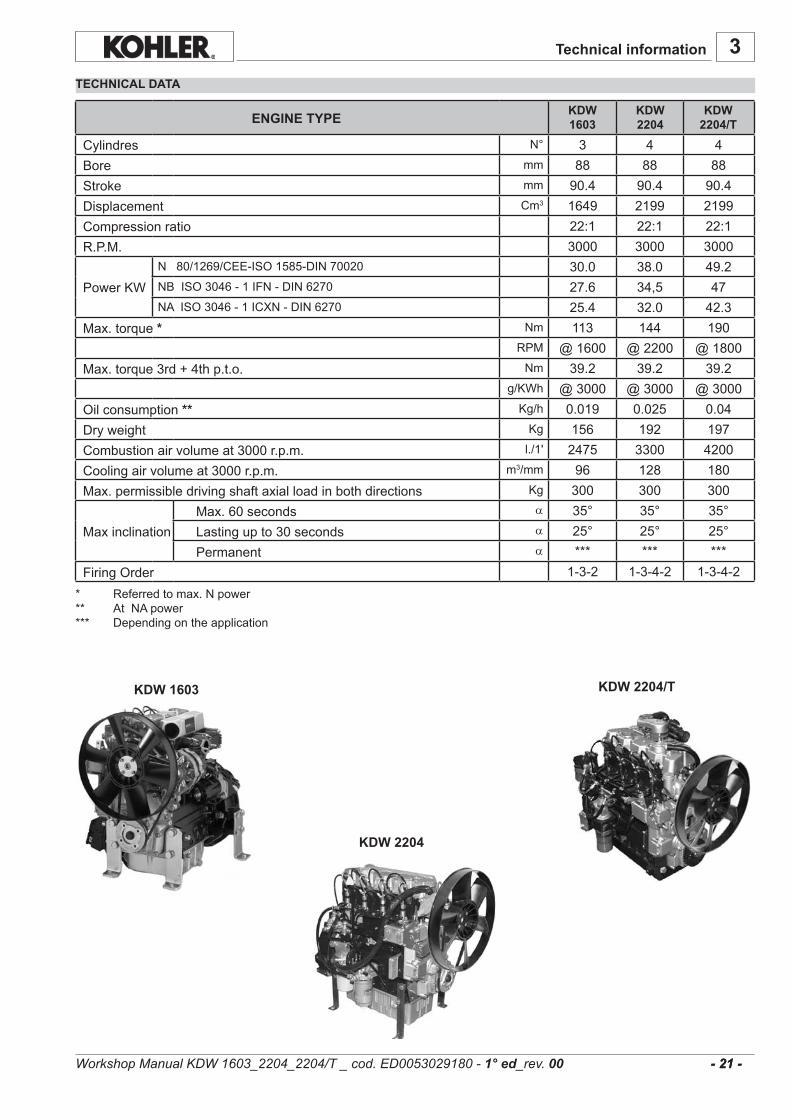
N° 3 4 4mm 88 88 88mm 90.4 90.4 90.4Cm3 1649 2199 2199
22:1 22:1 22:13000 3000 3000
N80/1269/CEE-ISO1585-DIN70020 30.0 38.0 49.2NBISO3046-1IFN-DIN6270 27.6 34,5 47NAISO3046-1ICXN-DIN6270 25.4 32.0 42.3
Nm 113 144 190RPM @1600 @2200 @1800Nm 39.2 39.2 39.2
g/KWh @3000 @3000 @3000Kg/h 0.019 0.025 0.04Kg 156 192 197l./1' 2475 3300 4200
m3/mm 96 128 180Kg 300 300 300
a 35° 35° 35°a 25° 25° 25°a *** *** ***
1-3-2 1-3-4-2 1-3-4-2
- 21 - - 21 -
KDW 2204/T
KDW 1603
KDW 2204
KDW 1603
KDW 2204
KDW 2204/T
Technical information
* Referredtomax.Npower** AtNApower*** Dependingontheapplication
CylindresBoreStrokeDisplacementCompressionratioR.P.M. PowerKW Max.torque*
Max.torque3rd+4thp.t.o.
Oilconsumption**DryweightCombustionairvolumeat3000r.p.m.Coolingairvolumeat3000r.p.m.Max.permissibledrivingshaftaxialloadinbothdirections Max.60secondsMaxinclination Lastingupto30seconds PermanentFiringOrder
ENGINE TYPE
TECHNICAL DATA
Workshop Manual KDW 1603_2204_2204/T _ cod. ED0053029180 - 1° ed_rev. 00

3
- 22 - - 22 -
KDW 1603
CHARACTERISTICS POWER, TORQUE AND SPECIFIC FUEL CONSUMPTION CURVES
PERFORMANCE DIAGRAMS
N (80/1269/CEE - ISO 1585) AUTOMOTIVE RATING: intermittentoperationwithvariablespeedandvariableload.NB (ISO 3046 - 1 IFN) RATING WITH NO OVERLOAD CAPABILITY:Continuouslightdutyoperationwithconstandspeedand
variableload.NA (ISO 3046 - 1 ICXN) CONTINUOUS RATING WITH OVERLOAD CAPABILITY:continuousheavydutywithconstantspeed
andconstantload.MN Torque curve (N curve) - MB (NB curve) - MA (NA curve) - C: Specificfuelconsumptioncurve(NB curve)Max.powertoleranceis5%.Powerdecreasesbyapproximately1%every100maltitudeandby2%every5°Cabove25°C.Enginepowercanbeinfluencedbythetypeofcouplingusedwiththecoolingfan.
Technical information
Workshop Manual KDW 1603_2204_2204/T _ cod. ED0053029180 - 1° ed_rev. 00
3
- 23 - - 23 -
KDW 2204/TKDW 2204
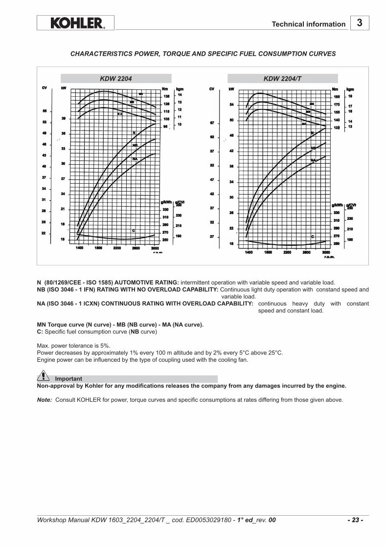
CHARACTERISTICS POWER, TORQUE AND SPECIFIC FUEL CONSUMPTION CURVES
Technical information
Workshop Manual KDW 1603_2204_2204/T _ cod. ED0053029180 - 1° ed_rev. 00
N (80/1269/CEE - ISO 1585) AUTOMOTIVE RATING: intermittentoperationwithvariablespeedandvariableload.NB (ISO 3046 - 1 IFN) RATING WITH NO OVERLOAD CAPABILITY:Continuouslightdutyoperationwithconstandspeedand
variableload.NA (ISO 3046 - 1 ICXN) CONTINUOUS RATING WITH OVERLOAD CAPABILITY: continuous heavy duty with constant
speedandconstantload.
MN Torque curve (N curve) - MB (NB curve) - MA (NA curve).C: Specificfuelconsumptioncurve(NB curve)
Max.powertoleranceis5%.Powerdecreasesbyapproximately1%every100maltitudeandby2%every5°Cabove25°C.Enginepowercanbeinfluencedbythetypeofcouplingusedwiththecoolingfan.
ImportantNon-approval by Kohler for any modifications releases the company from any damages incurred by the engine.
Note: ConsultKOHLERforpower,torquecurvesandspecificconsumptionsatratesdifferingfromthosegivenabove.

3
- 24 - - 24 -
.........................................................................................................................................................................
.........................................................................................................................................................................
.........................................................................................................................................................................
.........................................................................................................................................................................
.........................................................................................................................................................................
.........................................................................................................................................................................
.........................................................................................................................................................................
.........................................................................................................................................................................
.........................................................................................................................................................................
.........................................................................................................................................................................
.........................................................................................................................................................................
.........................................................................................................................................................................
.........................................................................................................................................................................
.........................................................................................................................................................................
.........................................................................................................................................................................
.........................................................................................................................................................................
.........................................................................................................................................................................
.........................................................................................................................................................................
.........................................................................................................................................................................
.........................................................................................................................................................................
.........................................................................................................................................................................
.........................................................................................................................................................................
.........................................................................................................................................................................
.........................................................................................................................................................................
.........................................................................................................................................................................
.........................................................................................................................................................................
.........................................................................................................................................................................
.........................................................................................................................................................................
.........................................................................................................................................................................
.........................................................................................................................................................................
.........................................................................................................................................................................
.........................................................................................................................................................................
.........................................................................................................................................................................
.........................................................................................................................................................................
.........................................................................................................................................................................
.........................................................................................................................................................................
.........................................................................................................................................................................
Technical information
Workshop Manual KDW 1603_2204_2204/T _ cod. ED0053029180 - 1° ed_rev. 00
3
B CD
A
G HF
E
JK
L
MNO
PQ
R
S
TU
Z
YW
XV
C1 D1B1
E1
A1
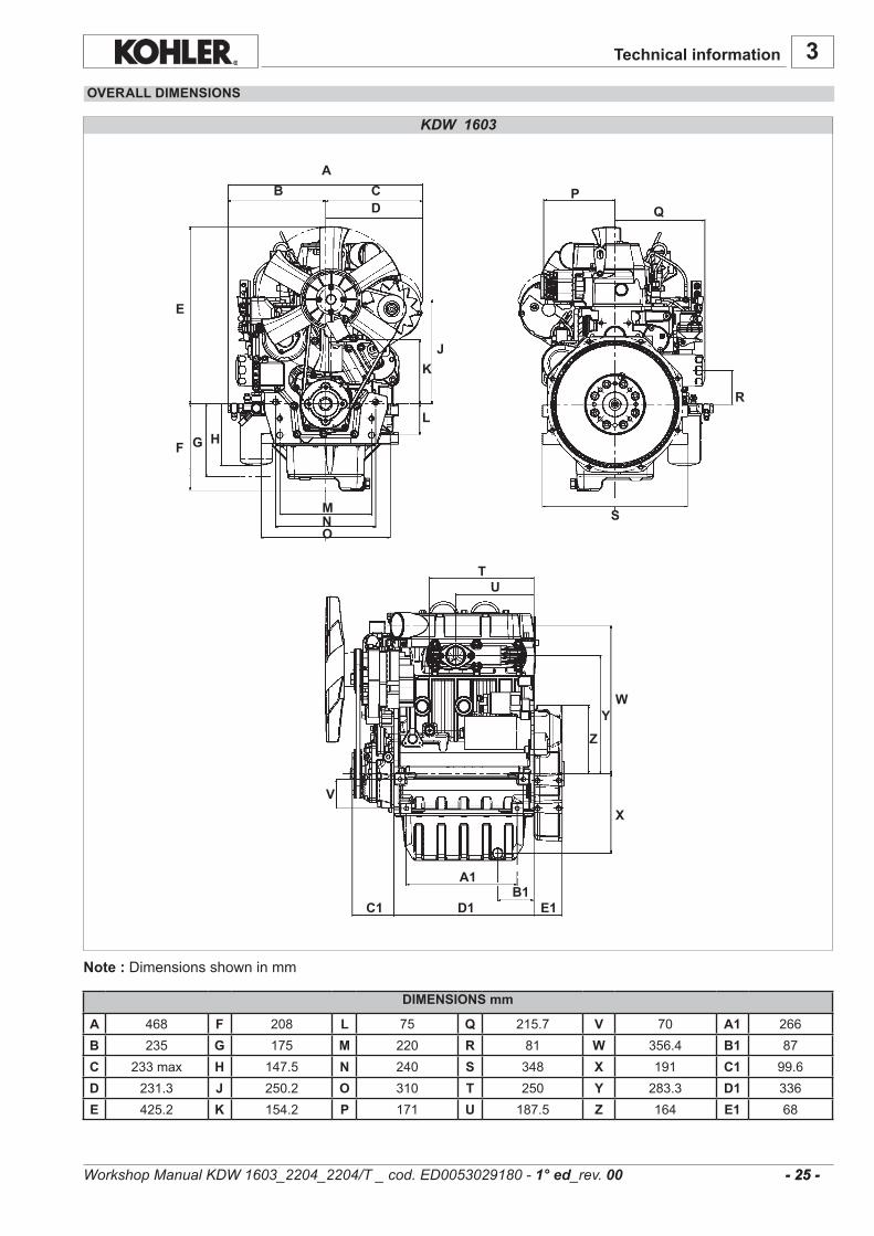
A 468 F 208 L 75 Q 215.7 V 70 A1 266B 235 G 175 M 220 R 81 W 356.4 B1 87C 233max H 147.5 N 240 S 348 X 191 C1 99.6D 231.3 J 250.2 O 310 T 250 Y 283.3 D1 336E 425.2 K 154.2 P 171 U 187.5 Z 164 E1 68
- 25 - - 25 -
KDW 1603
OVERALL DIMENSIONS
Technical information
Note :Dimensionsshowninmm
DIMENSIONS mm
Workshop Manual KDW 1603_2204_2204/T _ cod. ED0053029180 - 1° ed_rev. 00
3
B CD
A
E
F G H
J
K
ML
NO
P
QR
US
T
V
WX
Y Z A1
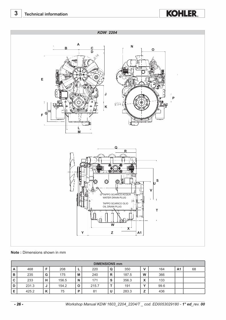
TAPPO SCARICO ACQUAWATER DRAIN PLUG
TAPPO SCARICO OLIOOIL DRAIN PLUG
A 468 F 208 L 220 Q 350 V 164 A1 68B 235 G 175 M 240 R 187.5 W 366C 233 H 156.5 N 171 S 356.3 X 133D 231.3 J 154.2 O 215.7 T 191 Y 99.6E 425.2 K 75 P 81 U 283.3 Z 436
- 26 - - 26 -
KDW 2204
Technical information
Note :Dimensionsshowninmm
DIMENSIONS mm
Workshop Manual KDW 1603_2204_2204/T _ cod. ED0053029180 - 1° ed_rev. 00

3
A
B
C
DE
GF
H
J
K
M NO
L
T
W
V
U
Q R
X
Y
SP
A1Z
B1
A 166.7 F 350 L 186.3 Q 235 V 224.8 A1 210B 195 G 210 M 366 R 233.1 W 156.5 B1 310C 153.5 H 386.1 N 68 S 168.7 X 373.2D 160 J 164 O 133 T 452.5 Y 133.5E 348 K 190.5 P 468.1 U 208 Z 220
- 27 - - 27 -
KDW 2204/T
Note :Dimensionsshowninmm
DIMENSIONS mm
Technical information
Workshop Manual KDW 1603_2204_2204/T _ cod. ED0053029180 - 1° ed_rev. 00

10 200 300 600 1200 5000 10000
(***)
(*)
(*)(**)
(*) (°)(*)(*)(**)(**)
(**)(**)
(**)(***)
(***)
4
- 28 - - 28 -
Caution – WarningFailure to carry out the operations described in the table may lead to technical damage to the machine and/or system.
ROUTINE ENGINE MAINTENANCE
MAINTENANCE - RECOMMENDED OIL TYPE - REFILLING
Engine oilreplacement. Oil filter replacement.AFTER THE FIRST 50 WORKING HOURS
ORDINARY MAINTENANCE
300 ENHANCED OIL SUMP
200 STANDARD OIL SUMP (*) - In case of low use: every year.(**) - In case of low use: every 2 years.(***) - The period of time that must elapse before cleaning or replacing the filter element depends
on the environment in which the engine operates. The air filter must be cleaned and replaced more frequently in very dusty conditions.
(°) - If you are using oil of a quality lower than the prescribed one then you will have to replace it every 125 hours for the standard sump and every 150 hours for the enhanced sump.
AFTER 6 CHECKS WITH CLEANING
AFTER 3 CHECKS WITH CLEANING
LEVELENGINELUBRICANTCOOLANTLEVELDRYAIRCLEANEROILBATHAIRCLEANERRADIATOREXCHANGESURFACEBELTFAN/ALTERNATORSTRETCH
SLEEVESSETTINGANDINJECTORSCLEANINGFUELPIPESRUBBER INTAKEHOSE (AIRFILTER– INTAKEMANIFOLD)INTERIORRADIATORCLEANINGALTERNATORANDSTARTERMOTORENGINELUBRICANTOILFILTERFUELFILTERALTERNATORFANBELTCOOLANTLEVELPARTIALOVERHAULTOTALOVERHAULFUELPIPESRUBBER INTAKEHOSE (AIRFILTER– INTAKEMANIFOLD)SLEEVESDRYAIRCLEANEREXTERNALCARTRIDGE
DRYAIRCLEANERINTERNALCARTRIDGE
CH
ECK
REP
LAC
EMEN
T
EXTRAORDINARY MAINTENANCE
Workshop Manual KDW 1603_2204_2204/T _ cod. ED0053029180 - 1° ed_rev. 00
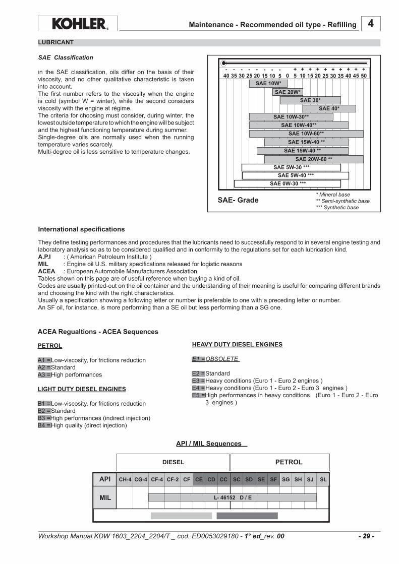
4
SAE 20W*SAE 30*
SAE 40*SAE 10W-30**
SAE 10W-40**SAE 10W-60**SAE 15W-40 **
SAE 15W-40 **SAE 20W-60 **
SAE 5W-30 ***
SAE 0W-30 ***
-30
-25
-20
-15
-10
-5 0
+5
+10
+15
+20
+25
+30
+35
+40
+45
SAE 10W*
+50
-35
-40
SAE 5W-40 ***
CF CE CD CC SC SD SE SF SG
L- 46152 D / E
SHAPI SJ SLCH-4 CG-4 CF-4
MIL
CF-2
DIESEL
- 29 - - 29 -
Maintenance - Recommended oil type - Refilling
LUBRICANT
SAE Classification
In the SAE classification, oils differ on the basis of theirviscosity, and no other qualitative characteristic is takenintoaccount.The first number refers to the viscositywhen theengineis cold (symbolW=winter),while the second considersviscositywiththeengineatrégime.Thecriteriaforchoosingmustconsider,duringwinter,thelowestoutsidetemperaturetowhichtheenginewillbesubjectandthehighestfunctioningtemperatureduringsummer.Single-degree oils are normally used when the runningtemperaturevariesscarcely.Multi-degreeoilislesssensitivetotemperaturechanges.
* Mineral base** Semi-synthetic base*** Synthetic base
SAE- Grade
International specifications
Theydefinetestingperformancesandproceduresthatthelubricantsneedtosuccessfullyrespondtoinseveralenginetestingandlaboratoryanalysissoastobeconsideredqualifiedandinconformitytotheregulationssetforeachlubricationkind.A.P.I :(AmericanPetroleumInstitute)MIL :EngineoilU.S.militaryspecificationsreleasedforlogisticreasonsACEA :EuropeanAutomobileManufacturersAssociationTablesshownonthispageareofusefulreferencewhenbuyingakindofoil.Codesareusuallyprinted-outontheoilcontainerandtheunderstandingoftheirmeaningisusefulforcomparingdifferentbrandsandchoosingthekindwiththerightcharacteristics.Usuallyaspecificationshowingafollowingletterornumberispreferabletoonewithaprecedingletterornumber.AnSFoil,forinstance,ismoreperformingthanaSEoilbutlessperformingthanaSGone.
API / MIL Sequences
PETROL
A1=Low-viscosity,forfrictionsreductionA2=StandardA3=Highperformances
LIGHT DUTY DIESEL ENGINES
B1=Low-viscosity,forfrictionsreductionB2=StandardB3=Highperformances(indirectinjection)
B4=Highquality(directinjection)
HEAVY DUTY DIESEL ENGINES
E1 = OBSOLETE
E2=StandardE3=Heavyconditions(Euro1-Euro2engines)E4=Heavyconditions(Euro1-Euro2-Euro3engines)E5=Highperformancesinheavyconditions(Euro1-Euro2-Euro
3engines)
ACEA Regualtions - ACEA Sequences
PETROL
Workshop Manual KDW 1603_2204_2204/T _ cod. ED0053029180 - 1° ed_rev. 00

4.4
7.1
3.8
6.4
6.4 - 5.3*
9.5
5.7 - 4.5*
8.8
4
AGIP SINT 2000 TURBODIESEL 5W40API CF - SH
ACEA B3-B4 MIL - L-2104 CMIL-L-46152 D
- 30 - - 30 -
KDW 2204 - 2204/TKDW 1603
specifications
PRESCRIBED LUBRICANT
Maintenance - Recommended oil type - Refilling
InthecountrieswhereAGIPproductsarenotavailable,useoilAPICF/SHforDieselenginesoroilcorrespondingtothemilitaryspecificationMIL-L-2104C/46152D.
CHD ENGINES OIL CAPACITY
OIL VOLUME AT MAX LEVEL(OIL FILTER INCLUDED)
OIL VOLUME AT MAX LEVEL (WITHOUT OIL FILTER)
Litres
Litres
SheetSTDoilsump.
ENHANCEDaluminiumoilsump.
SheetSTDoilsump.
ENHANCEDaluminiumoilsump.
* With dynamic balancer
ImportantIf you are using oil of a quality lower than the prescribed one then you will have to replace it every 125 hours for the standard sump and every 150 hours for the enhanced sump.
Danger – Attention- The engine may be damaged if operated with insufficient lube oil. It is also dangerous to supply too much lube oil to
the engine because a sudden increase in engine rpm could be caused by its combustion.
- Use proper lube oil preserve your engine. Good quality or poor quality of the lubricating oil has an affect on engine performance and life.
- If inferior oil is used, or if your engine oil is not changed regularly, the risk of piston seizure, piston ring sticking, and accelerated wear of the cylinder liner, bearing and other moving components increases significantly.
- Always use oil with the right viscosity for the ambient temperature in which your engine is being operated.
Danger – Attention- The used engine oil can cause skin-cancer if kept frequently in contact for prolonged periods.
- If contact with oil cannot be avoided, wash carefully your hands with water and soap as soon as possible.
- Do not disperse the oil in the ambient, as it has a high pollution power.
Workshop Manual KDW 1603_2204_2204/T _ cod. ED0053029180 - 1° ed_rev. 00

4.00 5.705.50
4
API CF4 - CG4
API CF
SPECIFICATIONS FUEL
- 31 - - 31 -
KDW 1603
KDW 2204/T
KDW 2204
Maintenance - Recommended oil type - Refilling
COOLANT
Danger – Attention- The fluid coolant circuit is pressurized. Inspections must only be made when the engine has cooled and even in this
case, the radiator or expansion chamber plug must be unscrewed with the utmost caution.- If an electric fan is installed, do not approach a hot engine since the fan itself could start up even when the engine is
at a standstill.- Coolant fluid is polluting, it must therefore be disposed of in the correct way. Do not litter.
Theanti-freezeprotection liquid (AGIP ANTIFREEZE SPEZIAL)must beusedmixedwithwater, preferably decalcified.Thefreezingpointofthecoolingmixturedependsontheproductconcentrationinwater,itisthereforerecommendedtousea50%dilutedmixturewhichguaranteesacertaindegreeofoptimalprotection.Aswellasloweringthefreezingpoint,thepermanentliquidalsoraisestheboilingpoint.
Prescribed coolant. Coolant refueling
Purchasedieselfuelinsmallquantitiesandstoreinclean,approvedcontainers.Cleanfuelpreventsthedieselfuelinjectorsandpumpsfromclogging.Donotoverfillthefueltank.Leaveroomforthefueltoexpand.Immediatelycleanupanyspillageduringrefueling.
Neverstoredieselfuelingalvanizedcontainers;dieselfuelandthegalvanizedcoatingreactchemicallytoeachother,producingflakingthatquicklyclogsfiltersorcausesfuelpumporinjectorfailure.
Highsulfurcontentinfuelmaycauseenginewear.Inthosecountrieswheredieselhasahighsufurcontent,itsisadvisabletolubricatetheenginewithahighalkalineoiloralternativelytoreplacethelubricatingoilrecommendedbythemanufacturermorefrequently.TheregionsinwhichdieselnormallyhasalowsulfurcontentareEurope,NorthAmerica,andAustralia.
FUEL TYPEForbestresults,useonlyclean,fresh,commercial-gradedieselfuel.Dieselfuelsthatsatisfythefollowingspecificationsaresuitableforuseinthisengine:ASTMD-975-1Dor2D,EN590,orequivalent.
FUELS FOR LOW TEMPERATURES
Itispossibletoruntheengineattemperaturesbelow0°Cusingspecialwinterfuels.Thesefuelsreducetheformationofparaffinindieselatlowtemperatures.Ifparaffinformsinthediesel,thefuelfilterbecomesblockedinterruptingtheflowoffuel.
Fuelcanbe: -Summer upto 0°C -Winter upto -10°C -Alpine upto -20°C -Arctic upto -30°C
BIODIESEL FUELFuelscontaininglessthan20%methylesterorB20,aresuitableforuseinthisengine.Biodiesel fuelsmeeting thespecificationofBQ-9000orequivalentarerecommended.DONOTusevegetableoilasabiofuelforthisengine.Anyfailuresresultingfromtheuseoffuelsotherthanrecommendedwillnotbewarranted.
AVIATION FUELAviationfuelssuitableforuseinthisengineincludeJP5,JP4,JP8and,JET-A(if5percentoilisadded).
PRESCRIBED LUBRICANT
Fuelwithlowsulphurcontent
Fuelwithhighsulphurcontent
EMISSION CONTROL INFORMATION
LOW SULFUR FUEL OR ULTRA LOW SULFUR FUEL ONLY
EPA /CARB emission label must be attached near the fuel inlet.
ENGINE TYPE
CAPACITY (Litres)Without radiator
50% AGIP ANTIFREEZESPEZIAL
50% Water
Workshop Manual KDW 1603_2204_2204/T _ cod. ED0053029180 - 1° ed_rev. 00
ForinformationconcerningthecapacityofKohlerradiators,pleasecontactKohlerdirectly.Thetotalvolumeforrefillingthecoolingliquidvariesaccordingtothetypeofengineandradiator.

5
- 32 - - 32 -
Useprotectivegloveswhenhandlingtheengine
Important
- Before removing the engine from the vehicle on which it is installed, disconnect the power supply, detach the fuel and coolant supply, and all connections including the mechanical ones.
- Attach the engine to a suitable lifting device (lifting beam).- Hook the lifting device in the engine lifting points, as shown in the figure.- Before lifting, make sure the weight is correctly balanced by checking its barycentre.- Close all engine openings accurately (exhaust, intake, etc.), then wash the outside and dry with a jet of compressed
air.
ImportantThe bracket of the lifting points have been designed to lift the engine only. They are not intended nor approved to lift additional weights.Do not use different methods to lift the engine than those described herein. In case different methods are used, no warranty shall be granted for any consequential damage.
REGULATIONS FOR LIFTING THE ENGINE
Regulations for lifting the engine
Workshop Manual KDW 1603_2204_2204/T _ cod. ED0053029180 - 1° ed_rev. 00

5
- 33 - - 33 -
.........................................................................................................................................................................
.........................................................................................................................................................................
.........................................................................................................................................................................
.........................................................................................................................................................................
.........................................................................................................................................................................
.........................................................................................................................................................................
.........................................................................................................................................................................
.........................................................................................................................................................................
.........................................................................................................................................................................
.........................................................................................................................................................................
.........................................................................................................................................................................
.........................................................................................................................................................................
.........................................................................................................................................................................
.........................................................................................................................................................................
.........................................................................................................................................................................
.........................................................................................................................................................................
.........................................................................................................................................................................
.........................................................................................................................................................................
.........................................................................................................................................................................
.........................................................................................................................................................................
.........................................................................................................................................................................
.........................................................................................................................................................................
.........................................................................................................................................................................
.........................................................................................................................................................................
.........................................................................................................................................................................
.........................................................................................................................................................................
.........................................................................................................................................................................
.........................................................................................................................................................................
.........................................................................................................................................................................
.........................................................................................................................................................................
.........................................................................................................................................................................
.........................................................................................................................................................................
.........................................................................................................................................................................
.........................................................................................................................................................................
.........................................................................................................................................................................
.........................................................................................................................................................................
.........................................................................................................................................................................
Regulations for lifting the engine
Workshop Manual KDW 1603_2204_2204/T _ cod. ED0053029180 - 1° ed_rev. 00

6
- 34 - - 34 -
DISASSEMBLY/REASSEMBLY
RECOMMENDATIONS FOR DISASSEMBLING AND ASSEMBLING
RECOMMENDATIONS FOR OVERHAULS AND TUNING
ImportantTo locate specific topics, the reader should refer to the index.
– Beforeanyintervention,theoperatorshouldlayoutallequipmentandtoolsinsuchawayastoenablehimtocarryoutoperationscorrectlyandsafely.
– Theoperatormustcomplywiththespecificmeasuresdescribedinordertoavoiderrorsthatmightcausedamagetotheengine.
– Beforecarryingoutanyoperation,cleantheassembliesand/orcomponentsthoroughlyandeliminateanydepositsorresidualmaterial.
– Washthecomponentswithspecialdetergentanddonotusesteamorhotwater.
– Donotuseflammableproducts(petrol,diesel,etc.)todegreaseorwashcomponents.Usespecialproducts.
– Dryallwashedsurfacesandcomponentsthoroughlywithajetofairorspecialclothsbeforereassemblingthem.
– Applyalayeroflubricantoverallsurfacestoprotectthemagainstoxidation.
– Checkallcomponentsforintactness,wearandtear,seizure,cracksand/orfaultstobesurethattheengineisingoodworkingcondition.
– Somemechanicalpartsmustbereplaceden bloc,togetherwiththeircoupledparts(e.g.valveguide/valveetc.)asspecifiedinthesparepartscatalogue.
Danger - AttentionDuring repair operations, when using compressed air, wear eye protection.
Workshop Manual KDW 1603_2204_2204/T _ cod. ED0053029180 - 1° ed_rev. 00
ImportantTo locate specific topics, the reader should refer to the index.
– Besidesdisassemblyandreassemblyoperationsthischapteralsoincludescheckingandsettingspecifications,dimensions,repairandoperatinginstructions.
– AlwaysuseoriginalKOHLERsparepartsforproperrepairoperations.
– Theoperatormustwash,cleananddrycomponentsandassembliesbeforeinstallingthem.
– Theoperatormustmakesurethatthecontactsurfacesareintact,lubricatethecouplingpartsandprotectthosethatarepronetooxidation.
– Beforeanyintervention,theoperatorshouldlayoutallequipmentandtoolsinsuchawayastoenablehimtocarryoutoperationscorrectlyandsafely.
– Forsafetyandconvenience,youareadvisedtoplacetheengineonaspecialrotatingstandforengineoverhauls.
– Beforeproceedingwithoperations,makesurethatappropriatesafetyconditionsareinplace,inordertosafeguardtheoperatorandanypersonsinvolved.
– Inordertofixassembliesand/orcomponentssecurely,theoperatormusttightenthefasteningpartsinacriss-crossoralternatingpattern.
– Assembliesand/orcomponentswithaspecifictighteningtorquemustinitiallybefastenedatalevellowerthantheassignedvalue,andthensubsequentlytightenedtothefinaltorque.
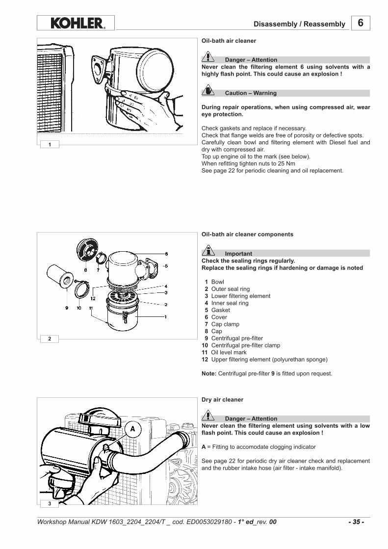
3
2
1
6
- 35 - - 35 -
Disassembly / Reassembly
Oil-bath air cleaner
Danger – AttentionNever clean the filtering element 6 using solvents with a highly flash point. This could cause an explosion !
Caution – Warning
During repair operations, when using compressed air, wear eye protection.
Checkgasketsandreplaceifnecessary.Checkthatflangeweldsarefreeofporosityordefectivespots.Carefully clean bowl and filtering element with Diesel fuel anddrywithcompressedair.Topupengineoiltothemark(seebelow).Whenrefittingtightennutsto25NmSeepage22forperiodiccleaningandoilreplacement.
Oil-bath air cleaner components
ImportantCheck the sealing rings regularly.Replace the sealing rings if hardening or damage is noted
1Bowl2 Outersealring3 Lowerfilteringelement 4Innersealring 5 Gasket 6 Cover 7Capclamp8 Cap 9Centrifugalpre-filter10 Centrifugalpre-filterclamp11 Oillevelmark12 Upperfilteringelement(polyurethansponge)
Note:Centrifugalpre-filter9isfitteduponrequest.
Dry air cleaner
Danger – AttentionNever clean the filtering element using solvents with a low flash point. This could cause an explosion !
A =Fittingtoaccomodatecloggingindicator
Seepage22forperiodicdryaircleanercheckandreplacementandtherubberintakehose(airfilter-intakemanifold).
Workshop Manual KDW 1603_2204_2204/T _ cod. ED0053029180 - 1° ed_rev. 00
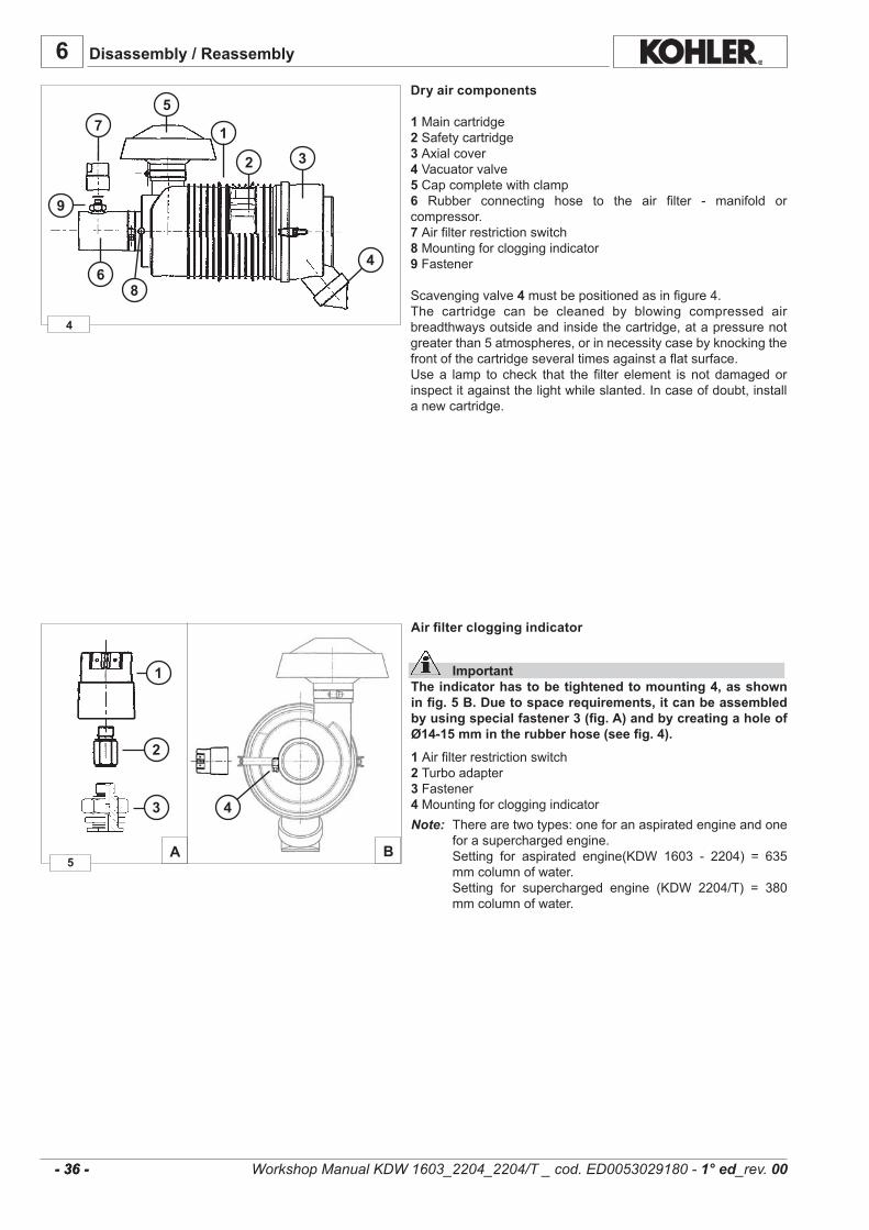
4
1
2
5
3
46
7
8
5BA
1
2
3 4
9
6
- 36 - - 36 -
Disassembly / Reassembly
Dry air components
1Maincartridge 2Safetycartridge 3 Axialcover 4Vacuatorvalve 5Capcompletewithclamp6 Rubber connecting hose to the air filter - manifold orcompressor.7 Airfilterrestrictionswitch8Mountingforcloggingindicator9Fastener Scavengingvalve4mustbepositionedasinfigure4.The cartridge can be cleaned by blowing compressed airbreadthwaysoutsideandinsidethecartridge,atapressurenotgreaterthan5atmospheres,orinnecessitycasebyknockingthefrontofthecartridgeseveraltimesagainstaflatsurface.Usea lamp to check that the filter element is not damagedorinspectitagainstthelightwhileslanted.Incaseofdoubt,installanewcartridge.
Workshop Manual KDW 1603_2204_2204/T _ cod. ED0053029180 - 1° ed_rev. 00
Air filter clogging indicator
ImportantThe indicator has to be tightened to mounting 4, as shown in fig. 5 B. Due to space requirements, it can be assembled by using special fastener 3 (fig. A) and by creating a hole of Ø14-15 mm in the rubber hose (see fig. 4).
1 Airfilterrestrictionswitch2 Turboadapter3 Fastener4 MountingforcloggingindicatorNote: Therearetwotypes:oneforanaspiratedengineandone
forasuperchargedengine. Setting for aspirated engine(KDW 1603 - 2204) = 635
mmcolumnofwater. Setting for supercharged engine (KDW 2204/T) = 380
mmcolumnofwater.
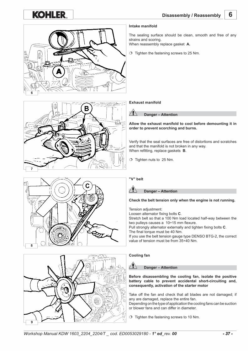
7
6
6
8
9
- 37 - - 37 -
Exhaust manifold
Danger – Attention
Allow the exhaust manifold to cool before demounting it in order to prevent scorching and burns.
Verifythatthesealsurfacesarefreeofdistortionsandscratchesandthatthemanifoldisnotbrokeninanyway.Whenrefitting,replacegasketsB.
Tightennutsto25Nm.
Intake manifold
The sealing surface should be clean, smooth and free of anystrainsandscoring.WhenreassemblyreplacegasketA.
Tightenthefasteningscrewsto25Nm.
Disassembly / Reassembly
"V" belt
Danger – Attention
Check the belt tension only when the engine is not running.
Tensionadjustment:LoosenalternatorfixingboltsC.Stretchbeltsothata100Nmloadlocatedhalf-waybetweenthetwopulleyscausesa10÷15mmflexure.PullstronglyalternatorexternallyandtightenfixingboltsC.Thefinaltorquemustbe40Nm.IfyouusethebelttensiongaugetypeDENSOBTG-2,thecorrectvalueoftensionmustbefrom35÷40Nm.
Cooling fan
Danger – Attention
Before disassembling the cooling fan, isolate the positive battery cable to prevent accidental short-circuiting and, consequently, activation of the starter motor
Takeoff the fanand check that all bladesarenot damaged; ifanyaredamaged,replacetheentirefan.Dependingonthetypeofapplicationthecoolingfanscanbesuctionorblowerfansandcandifferindiameter.
Tightenthefasteningscrewsto10Nm.
Workshop Manual KDW 1603_2204_2204/T _ cod. ED0053029180 - 1° ed_rev. 00
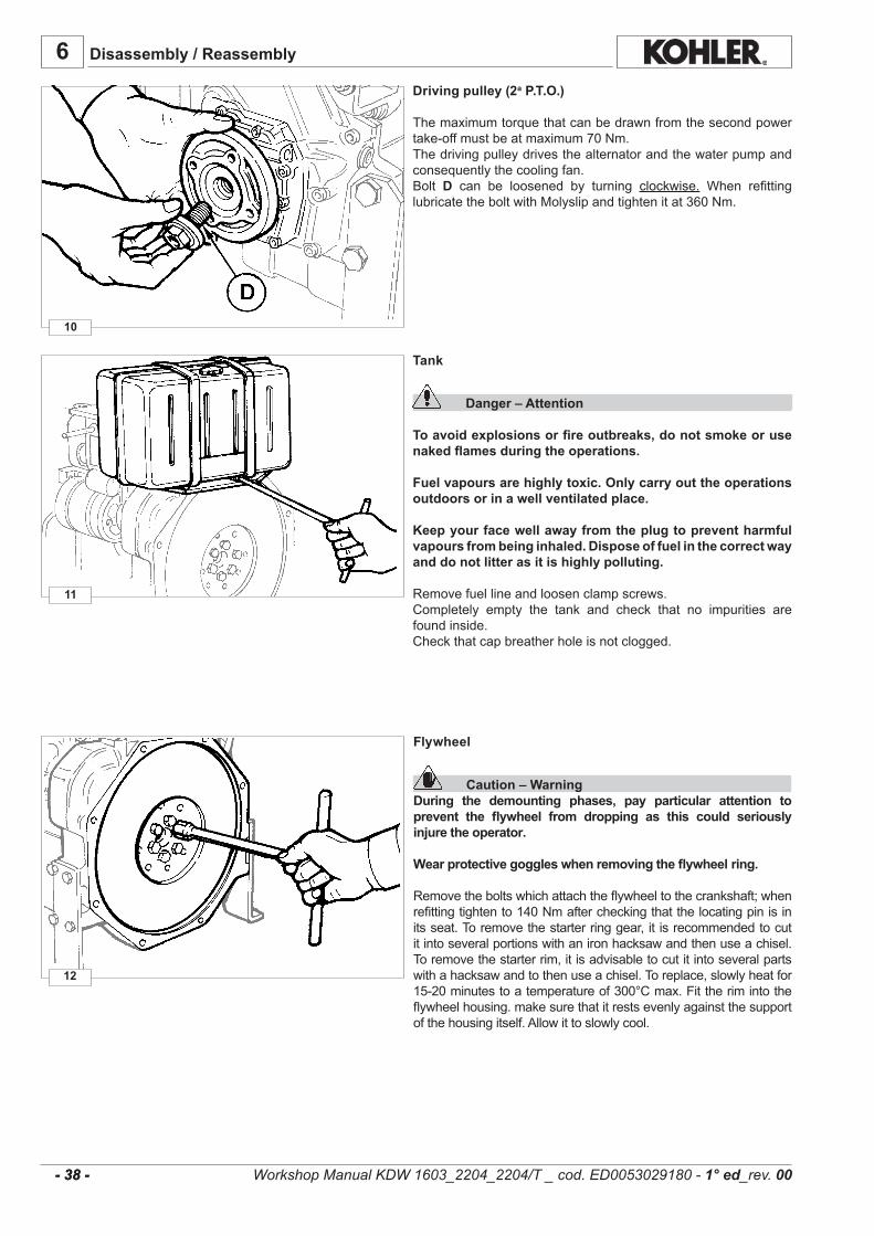
10
11
6
12
- 38 - - 38 -
Driving pulley (2a P.T.O.)
Themaximumtorquethatcanbedrawnfromthesecondpowertake-offmustbeatmaximum70Nm.Thedrivingpulleydrivesthealternatorandthewaterpumpandconsequentlythecoolingfan.Bolt D can be loosened by turning clockwise. When refittinglubricatetheboltwithMolyslipandtightenitat360Nm.
Tank
Danger – Attention To avoid explosions or fire outbreaks, do not smoke or use naked flames during the operations.
Fuel vapours are highly toxic. Only carry out the operations outdoors or in a well ventilated place.
Keep your face well away from the plug to prevent harmful vapours from being inhaled. Dispose of fuel in the correct way and do not litter as it is highly polluting.
Removefuellineandloosenclampscrews.Completely empty the tank and check that no impurities arefoundinside.Checkthatcapbreatherholeisnotclogged.
Disassembly / Reassembly
Flywheel
Caution – WarningDuring the demounting phases, pay particular attention to prevent the flywheel from dropping as this could seriously injure the operator.
Wear protective goggles when removing the flywheel ring.
Removetheboltswhichattachtheflywheeltothecrankshaft;whenrefittingtightento140Nmaftercheckingthatthelocatingpinisinitsseat.Toremovethestarterringgear,it isrecommendedtocutitintoseveralportionswithanironhacksawandthenuseachisel.Toremovethestarterrim,itisadvisabletocutitintoseveralpartswithahacksawandtothenuseachisel.Toreplace,slowlyheatfor15-20minutestoatemperatureof300°Cmax.Fittherimintotheflywheelhousing.makesurethatitrestsevenlyagainstthesupportofthehousingitself.Allowittoslowlycool.
Workshop Manual KDW 1603_2204_2204/T _ cod. ED0053029180 - 1° ed_rev. 00

6
14
13
1 2
3
67
54
15
1
2
- 39 - - 39 -
Disassembly / Reassembly
Rocker arm cover for engines with recirculating vent
Components:
1 -Recirculatingventsystem2-Oilrefillingplug3-Rubberhoseforthepassageoftheoilvapours4-Intakemanifold
Intherockerarmcapwefindmostoftherecirculatingventsystem1.Thisdeviceisusedtoseparatetheoilvapoursandtoconveythem,viaarubberhose3,intotheintakemanifold4.Thevapoursarethenrecirculatedinsidetheengineandnotreleasedintotheairastheycanbepolluting.
Acloggedupairfilterandaconsequentincreaseinsuctionvacuumcouldcausetheoiltobesuckedintothecombustionchamberandtheengineover-revving.Thisisinanycaseavoidedasthediaphragmvalve7 bywinningtheresistanceofspring6-properlycalibrated-closesduct5andstopstheoilfromreachingmanifold4viahose3.
Rocker arm cover with vent into the air
Components:
1 -Decantingdevice2-Oilfillcap3-Gasket
Inside thedecantingdevice 1 there isasmallmetal skein thatseparatestheoilfromthebledvapours;beforereassemblingit,cleanitandverifyitsintactness.
ImportantEvery time the rocker arm cap is removed replace the gasket 3.
Rocker arm cover with vent into the air
Components:
1-Oilfillcap2-Gasket
ImportantEvery time the rocker arm cap is removed replace the gasket 2.
Workshop Manual KDW 1603_2204_2204/T _ cod. ED0053029180 - 1° ed_rev. 00

19
18
17
16
20
ØA* 14,032÷14,050 ØA-ØB=0,043÷0,050 0,014
ØB 13,989÷14,000
6
- 40 - - 40 -
Disassembly / Reassembly
Tocheckthepinandtherocker-armpinbearingsforwearcomparethemeasuredvalueswiththeparametersinthetablebelow.
Table of pin-rocker arm dimensions
* Withbushingfittedtotherockerarmandreamed.
Clearance (mm) Limit value (mm)
Dimensions (mm)Ref.
Cylinder head
Caution – WarningDo not demount when hot or the part could become deformed.
Donotremovewhenhottoavoiddeformation.Check cylinder head plane using a metal straight edge andthickness gauge; if warpage exceeds 0.10 mm, level off byremovingamaximum0.20mm.
See pictures 56÷59 (pages 39÷40) for cylinder headtightening.
Valve removal
Components:
1-Valve2-Lowerspringseat3-Valveguideseal(forintakeonly)4-Spring5-Springcap6-Cotters
Toremovethecottersfirmlypressdownasshowninthefigure20.
Rocker arm assemly
Loosenthescrewswhichfastentheassemblytothehead.
WhenrefittingapplyadropofLoctite270ontothethreads.
Whenrefittingtightento50Nm.
Insidetherockerarmpinflowstheoilthatlubricatestherockerarmsandfeedsthehydraulictappets.To clean the rocker-arm pin inside, remove the two tighteningscrewsC attheends(fig.17).
Workshop Manual KDW 1603_2204_2204/T _ cod. ED0053029180 - 1° ed_rev. 00
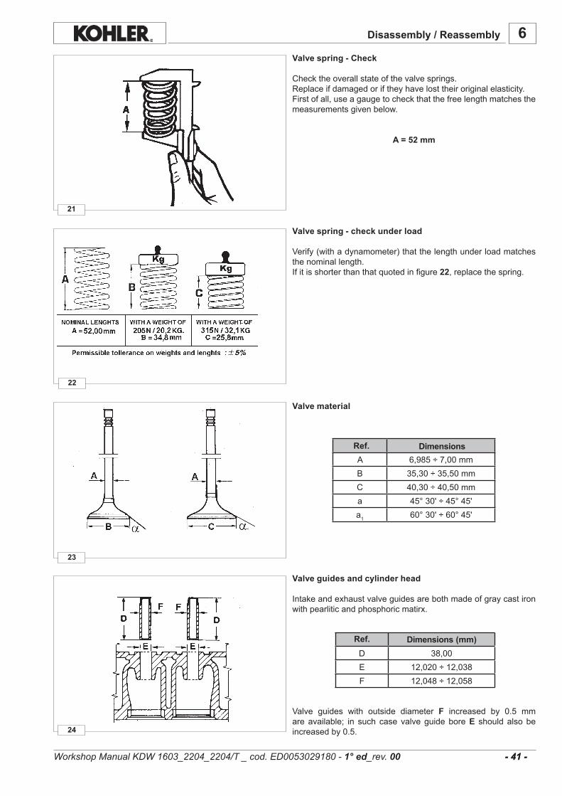
6
24
23
22
21
A 6,985÷7,00mmB 35,30÷35,50mmC 40,30÷40,50mma 45°30'÷45°45'a1 60°30'÷60°45'
D 38,00E 12,020÷12,038F 12,048÷12,058
- 41 - - 41 -
Disassembly / Reassembly
Valve spring - Check
Checktheoverallstateofthevalvesprings.Replaceifdamagedoriftheyhavelosttheiroriginalelasticity.Firstofall,useagaugetocheckthatthefreelengthmatchesthemeasurementsgivenbelow.
A = 52 mm
Valve spring - check under load
Verify(withadynamometer)thatthelengthunderloadmatchesthenominallength.Ifitisshorterthanthatquotedinfigure22,replacethespring.
Valve material
DimensionsRef.
Valve guides and cylinder head
Intakeandexhaustvalveguidesarebothmadeofgraycastironwithpearliticandphosphoricmatirx.
Valve guides with outside diameter F increased by 0.5 mmareavailable; in such case valveguideboreE should also beincreasedby0.5.
Dimensions (mm)Ref.
Workshop Manual KDW 1603_2204_2204/T _ cod. ED0053029180 - 1° ed_rev. 00
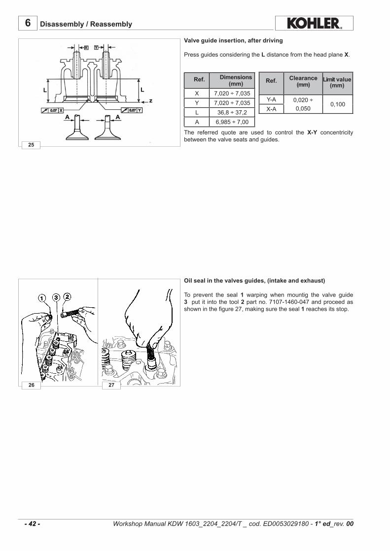
26
25
27
X 7,020÷7,035Y 7,020÷7,035L 36,8÷37,2A 6,985÷7,00
Y-A 0,020÷0,050
0,100X-A
6
- 42 - - 42 -
Disassembly / Reassembly
Valve guide insertion, after driving
PressguidesconsideringtheLdistancefromtheheadplaneX.
The referred quote are used to control the X-Y concentricitybetweenthevalveseatsandguides.
Oil seal in the valves guides, (intake and exhaust)
To prevent the seal 1 warping when mountig the valve guide3 put it intothetool2partno.7107-1460-047andproceedasshowninthefigure27,makingsuretheseal1 reachesitsstop.
Clearance (mm)
Limit value (mm)
Dimensions (mm)
Ref. Ref.
Workshop Manual KDW 1603_2204_2204/T _ cod. ED0053029180 - 1° ed_rev. 00

29
28
30
A 41,500÷41,520mmB 41,575÷41,590mmC 36,500÷36,520mmD 36,575÷36,590α 44°53'÷45°α1 59°53'÷60°
Ss* 1,27÷1,552,00
Sa* 1,20÷1,60H 0,75÷1,00 1,30
6
- 43 - - 43 -
Valve seats and bore
DimensionsRef.
Valve recess and sealing surfaces
Ss*=SealingsurfacewidthonexhaustsideSa*=SealingsurfacewidthonintakesideH=Valverecesswithreferencetotheheadplane
Limit value (mm)
Dimensions (mm)Ref.
Workshop Manual KDW 1603_2204_2204/T _ cod. ED0053029180 - 1° ed_rev. 00
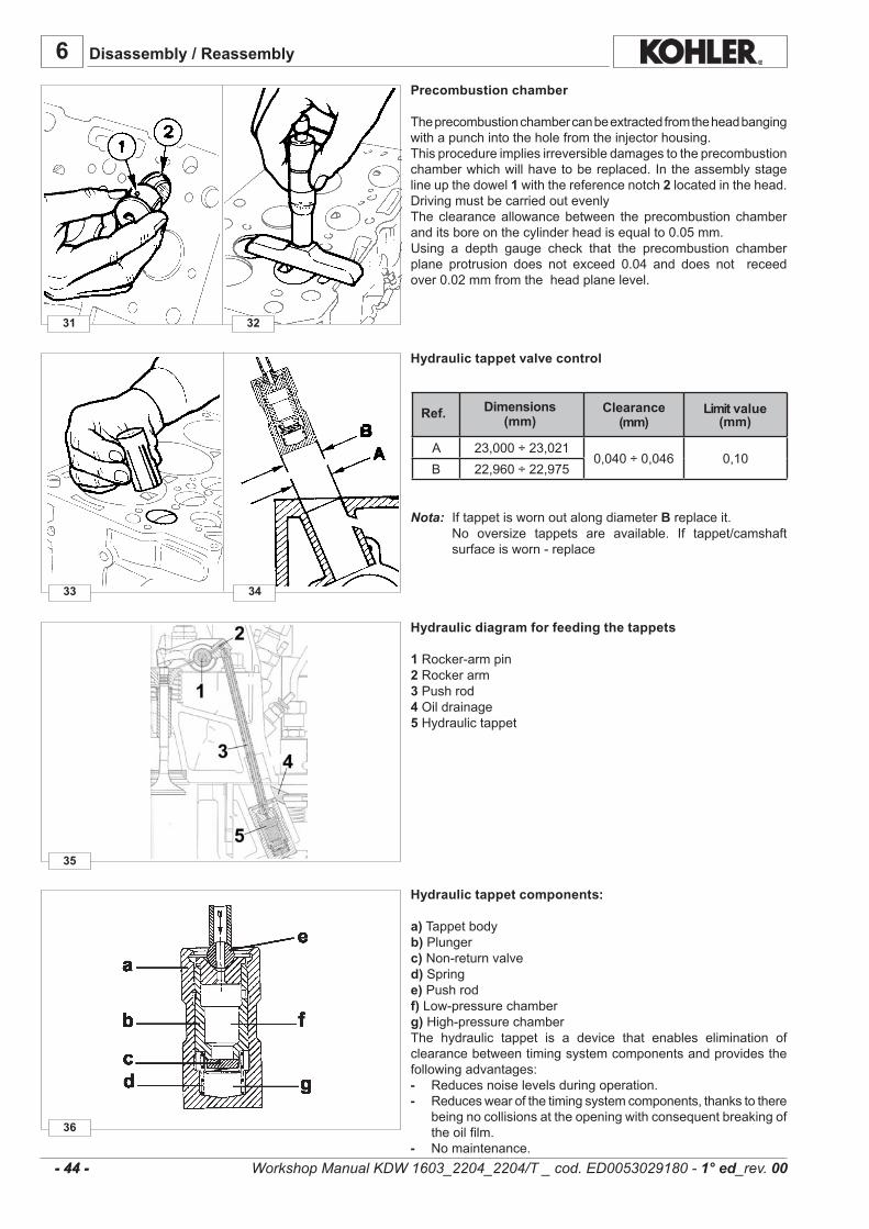
36
35
33
31
34
32
A 23,000÷23,0210,040÷0,046 0,10
B 22,960÷22,975
6
- 44 - - 44 -
Disassembly / Reassembly
Hydraulic tappet valve control
Nota: IftappetiswornoutalongdiameterBreplaceit. No oversize tappets are available. If tappet/camshaft
surfaceisworn-replace
Clearance (mm)
Limit value (mm)
Dimensions (mm)Ref.
Hydraulic diagram for feeding the tappets
1 Rocker-armpin2 Rockerarm3 Pushrod4 Oildrainage5 Hydraulictappet
Hydraulic tappet components:
a)Tappetbody b) Plunger c)Non-returnvalve d)Springe)Pushrodf)Low-pressurechamberg)High-pressurechamberThe hydraulic tappet is a device that enables elimination ofclearancebetweentimingsystemcomponentsandprovidesthefollowingadvantages:- Reducesnoiselevelsduringoperation.- Reduceswearofthetimingsystemcomponents,thankstothere
beingnocollisionsattheopeningwithconsequentbreakingoftheoilfilm.
- Nomaintenance.Workshop Manual KDW 1603_2204_2204/T _ cod. ED0053029180 - 1° ed_rev. 00
Precombustion chamber
Theprecombustionchambercanbeextractedfromtheheadbangingwithapunchintotheholefromtheinjectorhousing.Thisprocedureimpliesirreversibledamagestotheprecombustionchamberwhichwillhavetobereplaced.Intheassemblystagelineupthedowel1 withthereferencenotch2locatedinthehead.DrivingmustbecarriedoutevenlyTheclearanceallowancebetween theprecombustion chamberanditsboreonthecylinderheadisequalto0.05mm.Using a depth gauge check that the precombustion chamberplane protrusion does not exceed 0.04 and does not receedover0.02mmfromtheheadplanelevel.
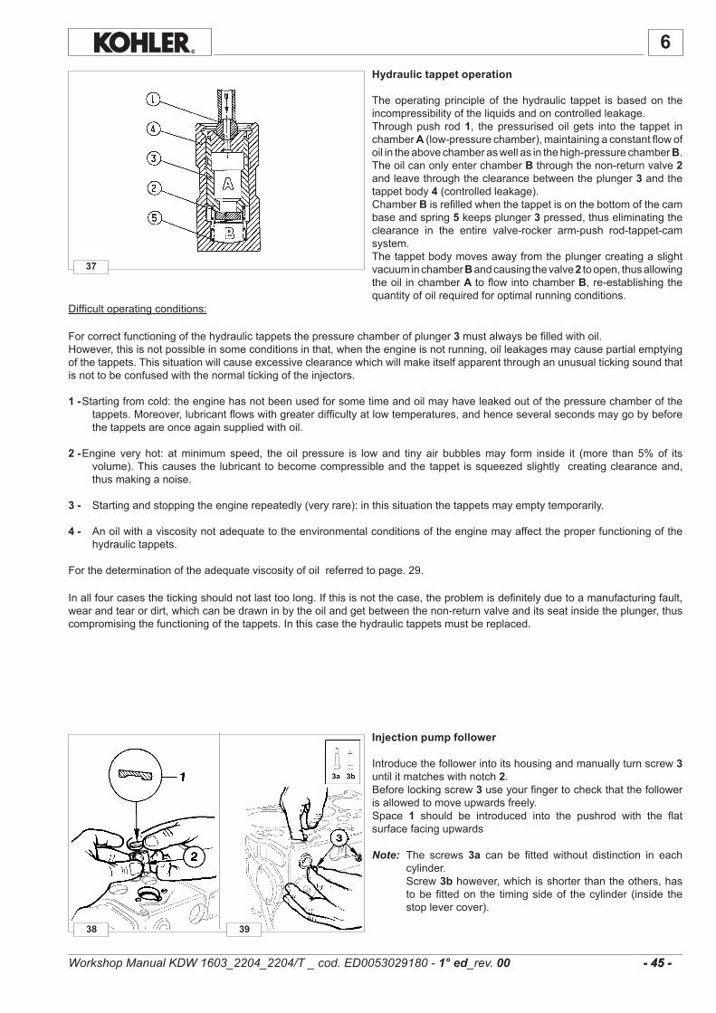
38
37
39
6
- 45 - - 45 -
Hydraulic tappet operation
Theoperatingprincipleof thehydraulic tappet isbasedon theincompressibilityoftheliquidsandoncontrolledleakage.Throughpush rod1, thepressurisedoil gets into the tappet inchamberA(low-pressurechamber),maintainingaconstantflowofoilintheabovechamberaswellasinthehigh-pressurechamberB.TheoilcanonlyenterchamberBthroughthenon-returnvalve2andleavethroughtheclearancebetweentheplunger3andthetappetbody4(controlledleakage).ChamberB isrefilledwhenthetappetisonthebottomofthecambaseandspring5 keepsplunger3 pressed,thuseliminatingtheclearance in the entire valve-rocker arm-push rod-tappet-camsystem.ThetappetbodymovesawayfromtheplungercreatingaslightvacuuminchamberB andcausingthevalve2 toopen,thusallowingtheoil inchamberA toflowintochamberB,re-establishingthequantityofoilrequiredforoptimalrunningconditions.
Difficultoperatingconditions:
Forcorrectfunctioningofthehydraulictappetsthepressurechamberofplunger 3mustalwaysbefilledwithoil.However,thisisnotpossibleinsomeconditionsinthat,whentheengineisnotrunning,oilleakagesmaycausepartialemptyingofthetappets.Thissituationwillcauseexcessiveclearancewhichwillmakeitselfapparentthroughanunusualtickingsoundthatisnottobeconfusedwiththenormaltickingoftheinjectors.
1 -Startingfromcold:theenginehasnotbeenusedforsometimeandoilmayhaveleakedoutofthepressurechamberofthetappets.Moreover,lubricantflowswithgreaterdifficultyatlowtemperatures,andhenceseveralsecondsmaygobybeforethetappetsareonceagainsuppliedwithoil.
2 - Engine very hot: atminimumspeed, the oil pressure is lowand tiny air bubblesmay form inside it (more than 5%of itsvolume).Thiscausesthe lubricant tobecomecompressibleandthetappet issqueezedslightly creatingclearanceand,thusmakinganoise.
3 - Startingandstoppingtheenginerepeatedly(veryrare):inthissituationthetappetsmayemptytemporarily.
4 - Anoilwithaviscositynotadequatetotheenvironmentalconditionsoftheenginemayaffecttheproperfunctioningofthehydraulictappets.
Forthedeterminationoftheadequateviscosityofoilreferredtopage.29.
Inallfourcasesthetickingshouldnotlasttoolong.Ifthisisnotthecase,theproblemisdefinitelyduetoamanufacturingfault,wearandtearordirt,whichcanbedrawninbytheoilandgetbetweenthenon-returnvalveanditsseatinsidetheplunger,thuscompromisingthefunctioningofthetappets.Inthiscasethehydraulictappetsmustbereplaced.
Injection pump follower
Introducethefollowerintoitshousingandmanuallyturnscrew3untilitmatcheswithnotch2.Beforelockingscrew3useyourfingertocheckthatthefollowerisallowedtomoveupwardsfreely.Space 1 should be introduced into the pushrod with the flatsurfacefacingupwards
Note: The screws 3a can be fitted without distinction in eachcylinder.
Screw3b however,whichisshorterthantheothers,hastobefittedon the timingsideof thecylinder (inside thestoplevercover).
Workshop Manual KDW 1603_2204_2204/T _ cod. ED0053029180 - 1° ed_rev. 00

45
43
42
40 41
46
44
D(mm)
88,00÷88,01 88,100
A 88,00÷88,01 87,960÷87,967 0,033÷0,050
6
- 46 - - 46 -
Disassembly / Reassembly
Cylinders
Resetdialgaugewithacalibratedring.CheckdiametersizeDat1,2and3;repeatthesameoperationatthesameplacesafterturningthedialgaugeby90°.CheckforwearintheXareawherepistonringsarelocated.
To check clearance with the matching piston measure thediametersizeatZalong theaxiswhich runsat rightangles tothedrivingshaft.
Limit value (mm)
Cylinder roughness
ImportantDo not manually hone the cylinder bore surfaces with emery cloth or other means.
The inclination of the cross-hatched marks left by machiningshould range between 115°-140°; they should be uniform andclearlyvisibleinbothdirections.Averageroughnessshouldrangebetween0.5and1mm.The cylinder surfacewhich comes into contact with the pistonringsshouldbemachinehonedwiththeplateausystem.
Piston
Removecirclipsandpistonpin.Removepistonringsandcleangrooves.Measure diameterQ at theA distance from the bottomof theskirt(A=12mm)In case of diameterwear exceeding 0.05mmof theminimumgivenvaluereplacepistonandrings.
Nota:Theoversizesare0.50and1.00mm.TheTURBOpistondiffers from that of the NATURALLYASPIRATED in itscoolingsprayerpassagenicheandaninsertintheslotofthefirstring.
Piston availability
Thepistonsoversizedby0.5and1.0mmhavetheupratingreferenceonthecrown,fig.45-46.
Class Ø Cylinder(mm)
Ø Piston(mm)
Clearance (mm)
Workshop Manual KDW 1603_2204_2204/T _ cod. ED0053029180 - 1° ed_rev. 00
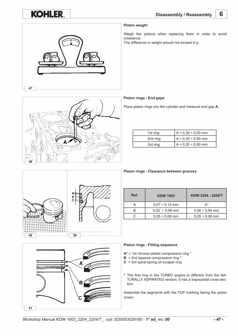
51
49
48
47
49 4950
A=0,30÷0,50mmA=0,30÷0,50mmA=0,20÷0,50mm
Ref.
A 0,07÷0,12mm A*B 0,02÷0,08mm 0,06÷0,95mmC 0,05÷0,08mm 0,05÷0,08mm
6
- 47 - - 47 -
KDW 2204 - 2204/TKDW 1603
Piston weight
Weigh the pistons when replacing them in order to avoidunbalance.Thedifferenceinweightshouldnotexceed6g.
Piston rings - End gaps
PlacepistonringsintothecylinderandmeasureendgapA.
1string2ndring3rdring
Piston rings - Clearance between grooves
Piston rings - Fitting sequence
A*=1stchromeplatedcompressionring*B=2ndtaperedcompressionring*C=3rdspiralspringoilscraperring
* The first ring in theTURBOengine is different from theNA-TURALLYASPIRATEDversion,ithasatrapezoidalcross-sec-tion.
AssemblethesegmentswiththeTOPmarkingfacingthepistoncrown.
Disassembly / Reassembly
Workshop Manual KDW 1603_2204_2204/T _ cod. ED0053029180 - 1° ed_rev. 00
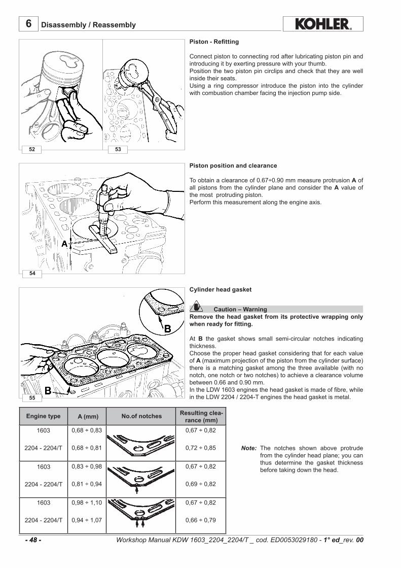
55
54
52 53
0,68÷0,83
0,68÷0,81
0,67÷0,82
0,72÷0,85
0,83÷0,98
0,81÷0,94
0,67÷0,82
0,69÷0,82
0,98÷1,10
0,94÷1,07
0,67÷0,82
0,66÷0,79
A (mm)
6
- 48 - - 48 -
1603
2204-2204/T
1603
2204-2204/T
1603
2204-2204/T
Disassembly / Reassembly
Piston - Refitting
Connectpistontoconnectingrodafterlubricatingpistonpinandintroducingitbyexertingpressurewithyourthumb.Positionthetwopistonpincirclipsandcheckthattheyarewellinsidetheirseats.Using a ring compressor introduce the piston into the cylinderwithcombustionchamberfacingtheinjectionpumpside.
Piston position and clearance
Toobtainaclearanceof0.67÷0.90mmmeasureprotrusionAofallpistons from thecylinderplaneandconsider theA valueofthemostprotrudingpiston.Performthismeasurementalongtheengineaxis.
Engine type No.of notches Resulting clea-rance (mm)
Workshop Manual KDW 1603_2204_2204/T _ cod. ED0053029180 - 1° ed_rev. 00
Cylinder head gasket
Caution – WarningRemove the head gasket from its protective wrapping only when ready for fitting.
At B the gasket shows small semi-circular notches indicatingthickness.ChoosetheproperheadgasketconsideringthatforeachvalueofA (maximumprojectionofthepistonfromthecylindersurface)there is amatchinggasket among the threeavailable (with nonotch,onenotchortwonotches)toachieveaclearancevolumebetween0.66and0.90mm.IntheLDW1603enginestheheadgasketismadeoffibre,whileintheLDW2204/2204-Tenginestheheadgasketismetal.
Note: The notches shown above protrudefromthecylinderheadplane;youcanthus determine the gasket thicknessbeforetakingdownthehead.
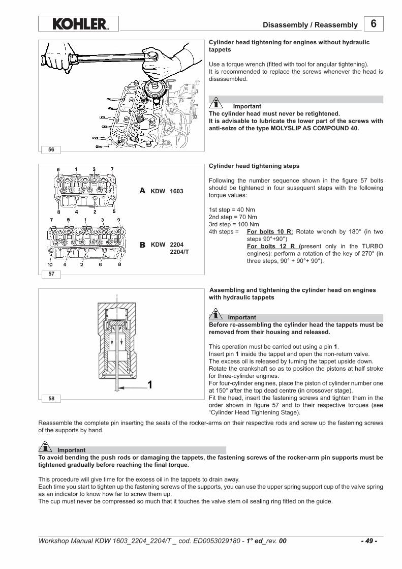
58
57
56
6
- 49 - - 49 -
KDW 1603
KDW 2204 2204/T
Disassembly / Reassembly
Cylinder head tightening for engines without hydraulic tappets
Useatorquewrench(fittedwithtoolforangulartightening).It isrecommendedtoreplacethescrewswhenevertheheadisdisassembled.
ImportantThe cylinder head must never be retightened.It is advisable to lubricate the lower part of the screws with anti-seize of the type MOLYSLIP AS COMPOUND 40.
Cylinder head tightening steps
Following the number sequence shown in the figure 57 boltsshould be tightened in four susequent stepswith the followingtorquevalues:
1ststep=40Nm2ndstep=70Nm3rdstep=100Nm4thsteps= For bolts 10 R: Rotate wrench by 180° (in two
steps90°+90°) For bolts 12 R (present only in the TURBO
engines):performarotationofthekeyof270°(inthreesteps,90°+90°+90°).
Assembling and tightening the cylinder head on engines with hydraulic tappets
ImportantBefore re-assembling the cylinder head the tappets must be removed from their housing and released.
Thisoperationmustbecarriedoutusingapin1.Insertpin1 insidethetappetandopenthenon-returnvalve.Theexcessoilisreleasedbyturningthetappetupsidedown.Rotatethecrankshaftsoastopositionthepistonsathalfstrokeforthree-cylinderengines.Forfour-cylinderengines,placethepistonofcylindernumberoneat150°afterthetopdeadcentre(incrossoverstage).Fitthehead,insertthefasteningscrewsandtightenthemintheorder shown in figure 57 and to their respective torques (see“CylinderHeadTighteningStage).
Reassemblethecompletepininsertingtheseatsoftherocker-armsontheirrespectiverodsandscrewupthefasteningscrewsofthesupportsbyhand.
ImportantTo avoid bending the push rods or damaging the tappets, the fastening screws of the rocker-arm pin supports must be tightened gradually before reaching the final torque.
Thisprocedurewillgivetimefortheexcessoilinthetappetstodrainaway.Eachtimeyoustarttotightenupthefasteningscrewsofthesupports,youcanusetheupperspringsupportcupofthevalvespringasanindicatortoknowhowfartoscrewthemup.Thecupmustneverbecompressedsomuchthatittouchesthevalvestemoilsealingringfittedontheguide.
Workshop Manual KDW 1603_2204_2204/T _ cod. ED0053029180 - 1° ed_rev. 00

64
62
59
63
6
60 61
A
B
C
KDW1603-2204-2204/T
KDW2204/T
DE
KDW 1603-2204
DE
- 50 - - 50 -
KDW 1603
KDW 2204 2204/T
Disassembly / Reassembly
Tighteningmustbecarriedoutasshowninfigure59.Oncethefinaltorque50Nmisreached,waitthirtyminutesbeforemanuallyrotatingtheenginetoverifythatthepistonsdonotcollidewiththevalves,iftheengineturnsfreelystarttheenginenormally,otherwisewaitanother30minutesbeforerepeatingtheoperation.At first start-up the engine may run irregularly until all the aircontainedinthetappetshasbeendrained.
Connecting rod
ImportantWhen remounting the big-end bearings, remember to thoroughly clean the parts and generously lubricate them to prevent seizure when the engine is started up for the first time.
Removeoilpanandoilpumpsuctionpipe.Disconnect the connecting rod from the engine shaft andperformthesubsequentchecks.When refitting both centering notches A and B should belocatedonthesameside.
Tightentheconnectingrodbigendboltsto70Nm.
Connecting rod weights
Connecting rod, piston and piston pin can also beweighed ina preassembled state but the difference in weigt should notexceed14ginordertoavoidunbalance.
Connecting rod and piston pin
Theconnectingrodbigendshellbearingsaresuppliedineitherstandard or with this value decreased by 0.25 and 0.50 mmrespectively.
ImportantThe fastening screws must be tightened by hand until the beginning of the tightening stage and then pre-tightened to 10÷15 Nm.
Finaltighteningisto70Nm.
Workshop Manual KDW 1603_2204_2204/T _ cod. ED0053029180 - 1° ed_rev. 00
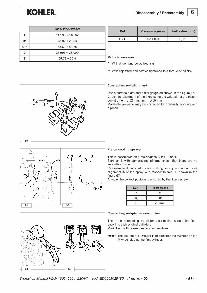
68
66
65
69
67
B-D 0,02÷0,03 0,06
α 3°α1 28°D 28mm
6
1603-2204-2204/T
A 147.98÷148.02
B* 28.02÷28.03
C** 53.62÷53.78
D 27.995÷28.000
E 65.78÷65.8
- 51 - - 51 -
Disassembly / Reassembly
Clearance (mm) Limit value (mm)Ref.
* Withdrivenandboredbearing.
** Withcapfittedandscrewstightenedtoatorqueof70Nm.
Connecting rod alignment
Useasurfaceplateandadialgaugeasshowninthefigure65.Checkthealignmentoftheaxesusingthewristpinofthepiston;deviationA=0.02mm;limit=0.05mmModeratewarpagemaybecorrectedbygraduallyworkingwithapress.
Dimensions Ref.
Value to measure
Workshop Manual KDW 1603_2204_2204/T _ cod. ED0053029180 - 1° ed_rev. 00
Connecting rod/piston assemblies
The three connecting rod/piston assemblies should be fittedbackintotheiroriginalcylinders.Markthemwithreferencestoavoidmistake.
Note: ThecustomatKOHLERistoconsiderthecylinderontheflywheelsideasthefirstcylinder.
Piston cooling sprayer
ThisisassembledonturboenginesKDW2204/T.Blow on it with compressed air and check that there are noimpuritiesinside.Reassemble it back into placemaking sure youmaintain axisalignmentA of the spraywith respect to axis B shown in thefigure67.Anywaythecorrectpositionisensuredbythefixingscrew.

71 72
70
6
- 52 - - 52 -
Disassembly / Reassembly
Workshop Manual KDW 1603_2204_2204/T _ cod. ED0053029180 - 1° ed_rev. 00
Center main bearings
Themainbearingcapsandthecrankcasehavereferenceholesmarkedonthem(one,twoorthree).
ImportantIn the assembly stage make sure that the number of holes on the bearings matches those on the crankcase and that they are on the same side.
Main bearing caps timing side - flywheel side
When refitting rear flywheel side main bearing cap 1, replacetherubbergaskets2considering thatAandBshouldprotrude0.5÷1.0mmfromthecrankase;cutanyexcessportion.Followthesameprocedureforthetimingsidemainbearingcap.Tointroducethesupportscompletewithsiliconerubberseals2intothecrankcaseplacetwoplatesCandDmeasuring0.1mminthicknessbetweenthesurfaces. Tightenthescrewsto120Nm.
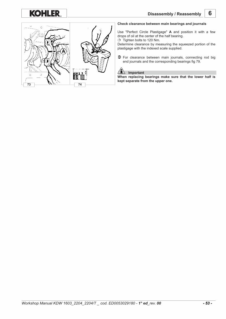
73 74
6
- 53 - - 53 -
Disassembly / Reassembly
Check clearance between main bearings and journals
Use "Perfect Circle Plastigage" A and position it with a fewdropsofoilatthecenterofthehalfbearing. Tightenboltsto120Nm.Determineclearancebymeasuringthesqueezedportionoftheplastigagewiththeindexedscalesupplied.
For clearance between main journals, connecting rod bigendjournalsandthecorrespondingbearingsfig79.
ImportantWhen replacing bearings make sure that the lower half is kept separate from the upper one.
Workshop Manual KDW 1603_2204_2204/T _ cod. ED0053029180 - 1° ed_rev. 00
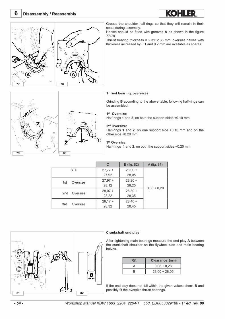
77
81
79
78
80
82
C B(fig.82) A(fig.81)STD 27,77÷
27,9228,00÷28,05
0,08÷0,28
27,97÷28,12
28,20÷28,25
28,07÷28,22
28,30÷28,35
28,17÷28,32
28,40÷28,45
6
Rif.A 0,08÷0,28B 28,00÷28,05
- 54 - - 54 -
Disassembly / Reassembly
Grease the shoulder half-rings so that theywill remain in theirseatsduringassembly.Halves should be fittedwith groovesA as shown in the figure77-78.Thrustbearingthickness=2.31÷2.36mm;oversizehalveswiththicknessincreasedby0.1and0.2mmareavailableasspares.
Thrust bearing, oversizes
GrindingBaccordingtotheabovetable,followinghalf-ringscanbeassembled:
1st Oversize:Half-rings1and2,onboththesupportsides+0.10mm.
2nd Oversize:Half-rings1 and2, ononesupport side+0.10mmandon theotherside+0.20mm.
3rd Oversize:Half-rings1and2,onboththesupportsides+0.20mm.
Crankshaft end play
AftertighteningmainbearingsmeasuretheendplayA betweenthe crankshaft shoulderon the flywheel sideandmainbearinghalves.
Iftheendplaydoesnotfallwithinthegivenvaluescheck Bandpossiblyfittheoversizethrustbearings.
Clearance (mm)
1stOversize
2ndOversize
3rdOversize
Workshop Manual KDW 1603_2204_2204/T _ cod. ED0053029180 - 1° ed_rev. 00
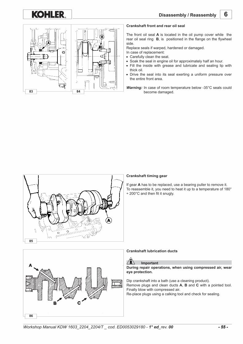
85
83 84
86
6
- 55 - - 55 -
Disassembly / Reassembly
Crankshaft front and rear oil seal
The frontoil seal A is located in theoil pumpcoverwhile therearoilsealring B, ispositionedintheflangeontheflywheelside.Replacesealsifwarped,hardenedordamaged.Incaseofreplacement:• Carefullycleantheseat.• Soakthesealinengineoilforapproximatelyhalfanhour.• Fill the inside with grease and lubricate and sealing lip withthickoil.
• Drive the seal into its seal exerting a uniform pressure overtheentirefrontarea.
Warning: Incaseofroomtemperaturebelow-35°Csealscouldbecomedamaged.
Crankshaft timing gear
IfgearAhastobereplaced,useabearingpullertoremoveit.Toreassembleit,youneedtoheatituptoatemperatureof180°÷200°Candthenfititsnugly.
Crankshaft lubrication ducts
ImportantDuring repair operations, when using compressed air, wear eye protection.
Dipcrankshaftintoabath(useacleaningproduct).RemoveplugsandcleanductsA,BandCwithapointedtool.Finallyblowwithcompressedair.Re-placeplugsusingacalkingtoolandcheckforsealing.
Workshop Manual KDW 1603_2204_2204/T _ cod. ED0053029180 - 1° ed_rev. 00
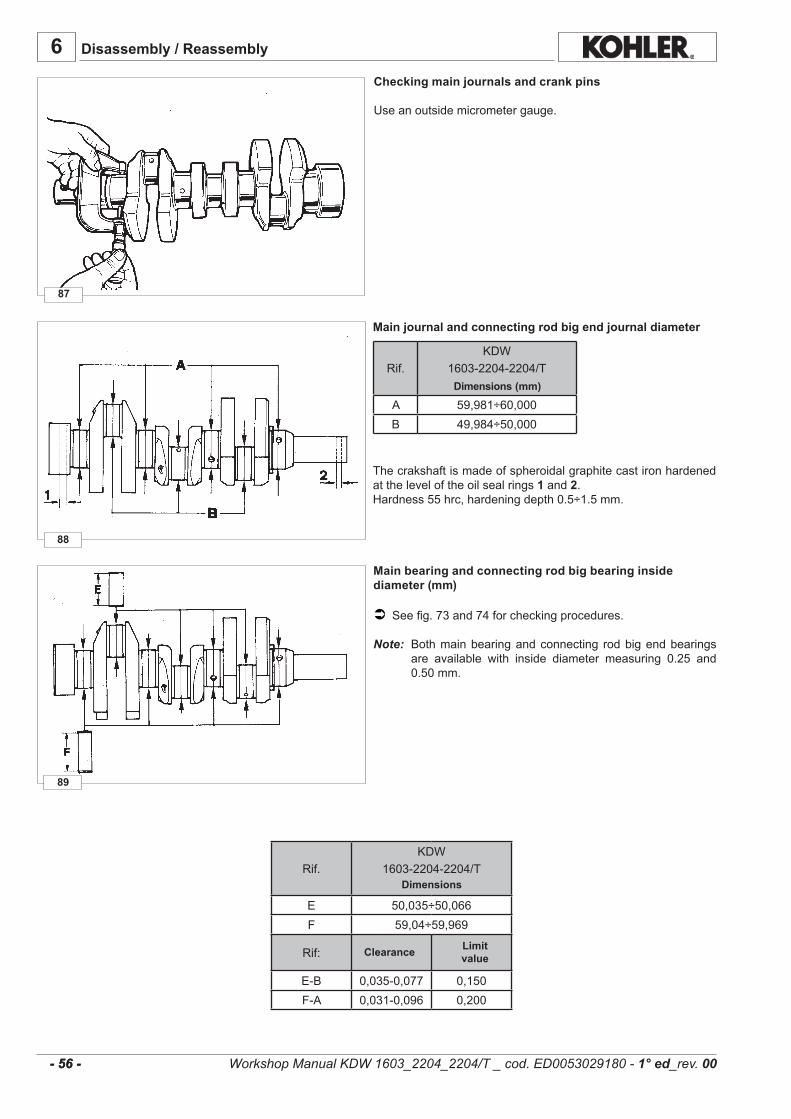
89
88
87
6
- 56 - - 56 -
Rif.KDW
1603-2204-2204/T
A 59,981÷60,000B 49,984÷50,000
Rif.KDW
1603-2204-2204/T
E 50,035÷50,066F 59,04÷59,969
Rif:
E-B 0,035-0,077 0,150F-A 0,031-0,096 0,200
Disassembly / Reassembly
Main journal and connecting rod big end journal diameter
Thecrakshaftismadeofspheroidalgraphitecastironhardenedattheleveloftheoilsealrings1and2.Hardness55hrc,hardeningdepth0.5÷1.5mm.
Main bearing and connecting rod big bearing inside diameter (mm)
Seefig.73and74forcheckingprocedures.
Note: Bothmainbearingandconnecting rodbigendbearingsare available with inside diameter measuring 0.25 and0.50mm.
Workshop Manual KDW 1603_2204_2204/T _ cod. ED0053029180 - 1° ed_rev. 00
Dimensions (mm)
Clearance Limit value
Dimensions
Checking main journals and crank pins
Useanoutsidemicrometergauge.
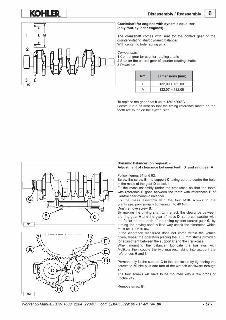
90
92
91
L 132,00÷132,03M 132,07÷132,09
6
1
3
2
L M
- 57 - - 57 -
Disassembly / Reassembly
Crankshaft for engines with dynamic equalizer (only four-cylinder engines).
The crankshaft comes with seat for the control gear of thecounter-rotatingshaftdynamicbalancer.Withcenteringhole(springpin).
Components:1Controlgearforcounter-rotatingshafts2Seatforthecontrolgearofcounter-rotatingshafts3Dowelpin
Toreplacethegearheatitupto180°÷200°C.Locate it into itsseatsothat thetimingreferencemarksontheteetharefoundontheflyweelside.
Ref. Dimensions (mm)
Dynamic balancer (on request) - Adjustment of clearance between teeth D and ring gear A
Followfigures91and92.ScrewthescrewBintosupportCtakingcaretocentretheholeinthemassofthegearDtolockit.Fit the mass assembly under the crankcase so that the toothwith referenceE goes between the teeth with referencesF ofControlgeardynamicbalancer.Fix the mass assembly with the four M10 screws to thecrankcase,provisionallytighteningitto40Nm.Don'tremovescrewB.Bymaking thedrivingshaft turn,check theclearancebetweentheringgearAandthegearofmassD;setacomparatorwiththe feelerononetoothof the timingsystemcontrolgearG;byturning thedrivingshafta littlewaycheck theclearancewhichmustbe0.026÷0.067.If the clearance measured does not come within the valuesgiven,repeattheoperationplacingthe0.05mmshimsprovidedforadjustmentbetweenthesupport Candthecrankcase.When mounting the balancer, lubricate the bushings withMolikote then couple the twomasses, taking into account thereferencesHandI.
PermanentlyfixthesupportCtothecrankcasebytighteningthescrewsto50Nmplusoneturnofthewrenchclockwisethrough45°.The four screws will have to bemounted with a few drops ofLoctite242.
RemovescrewB.
Workshop Manual KDW 1603_2204_2204/T _ cod. ED0053029180 - 1° ed_rev. 00
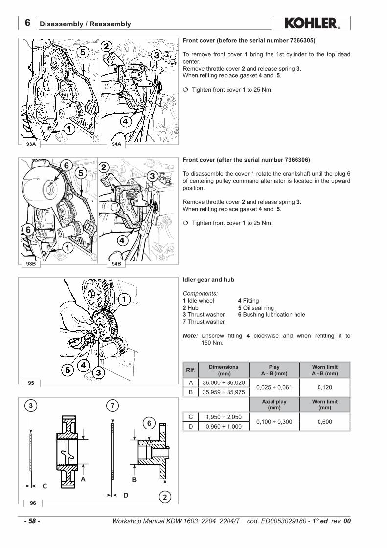
6
93A
93B
94A
94B
95
96
CD
A B
6
73
2
6
6
- 58 - - 58 -
Disassembly / Reassembly
Front cover (before the serial number 7366305)
To remove front cover1 bring the1st cylinder to the topdeadcenter.Removethrottlecover2 andreleasespring 3.Whenrefitingreplacegasket 4and5.
Tightenfrontcover1to25Nm.
Front cover (after the serial number 7366306)
Todisassemblethecover1rotatethecrankshaftuntiltheplug6ofcenteringpulleycommandalternatorislocatedintheupwardposition.
Removethrottlecover2 andreleasespring 3.Whenrefitingreplacegasket 4and5.
Tightenfrontcover1to25Nm.
Idler gear and hub
Components:1 Idlewheel 4 Fitting2Hub 5 Oilsealring3Thrustwasher 6 Bushinglubricationhole7Thrustwasher
Note: Unscrew fitting 4 clockwise and when refitting it to150Nm.
Rif. Dimensions (mm)
PlayA - B (mm)
Worn limitA - B (mm)
A 36,000÷36,0200,025÷0,061 0,120
B 35,959÷35,975Axial play
(mm)Worn limit
(mm)
C 1,950÷2,0500,100÷0,300 0,600
D 0,960÷1,000
Workshop Manual KDW 1603_2204_2204/T _ cod. ED0053029180 - 1° ed_rev. 00

99
97
98
A 10,8mmC 13,4mmD 88mm
6
- 59 - - 59 -
Disassembly / Reassembly
Speed governor
ImportantDuring reassembly, make sure the components are undamaged and verify they work properly.Malfunctioning of the speed governor can cause serious damage to the engine and to people in the vicinity of it.
Components: 1 Gear 2 Bell 3 Counterweights 4 Bolt 5 Throttlecontrolrod 6 Governorspring 7 Injectionpumpdeliveryrod 8 Yoke9 adjustementeccentric 9 Controlyokeforinjectionpumpdeliveryrod10 Bushing11 Lever12 Adjustingscrew.
Yoke 9 ispre-setthroughscrew 12 andeccentric 8.Donotunscrew.
Whenrefittingcamshatgear 1 tightenbolt4to100Nm.
Dimensions for injection pump delivery control yoke adjustement
Components: 9Controlyokeforinjectionpumpdeliveryrod10Bushing11 Lever12 Adjustingscrew13Referenceandmountingplaneforsupport1414 LeverSupport
Note: If, when adjusting, screw 12 is unintentionally loosenedadjustyoke 9 consideringthedimensionsA, C andD.
Incaseofreplacementlever11issuppliedcompletewithpresetyoke9.
Dimensions (mm)Ref.
Workshop Manual KDW 1603_2204_2204/T _ cod. ED0053029180 - 1° ed_rev. 00
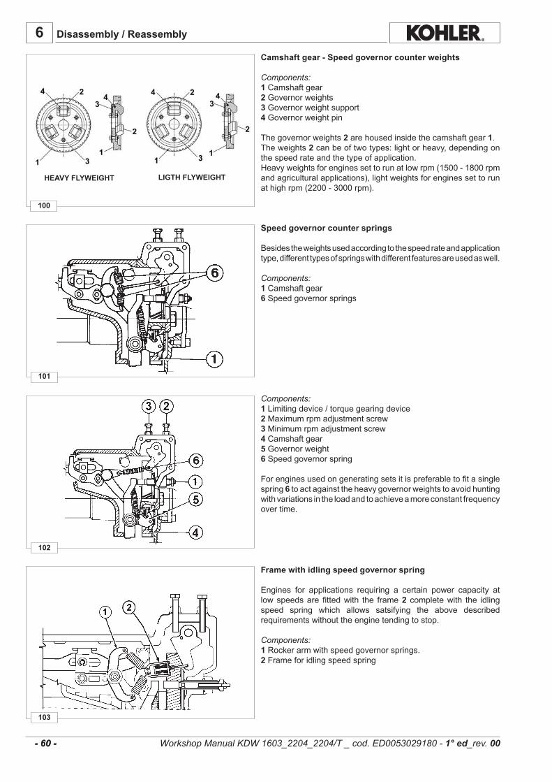
103
102
101
100
6
- 60 - - 60 -
Disassembly / Reassembly
Camshaft gear - Speed governor counter weights
Components:1Camshaftgear2Governorweights3Governorweightsupport4Governorweightpin
Thegovernorweights2arehousedinsidethecamshaftgear1.Theweights2canbeoftwotypes:lightorheavy,dependingonthespeedrateandthetypeofapplication.Heavyweightsforenginessettorunatlowrpm(1500-1800rpmandagriculturalapplications),lightweightsforenginessettorunathighrpm(2200-3000rpm).
Speed governor counter springs
Besidestheweightsusedaccordingtothespeedrateandapplicationtype,differenttypesofspringswithdifferentfeaturesareusedaswell.
Components:1Camshaftgear6 Speedgovernorsprings
Components:1Limitingdevice/torquegearingdevice2 Maximumrpmadjustmentscrew3Minimumrpmadjustmentscrew4Camshaftgear5 Governorweight6 Speedgovernorspring
Forenginesusedongeneratingsetsitispreferabletofitasinglespring6 toactagainsttheheavygovernorweightstoavoidhuntingwithvariationsintheloadandtoachieveamoreconstantfrequencyovertime.
Frame with idling speed governor spring
Engines for applications requiring a certain power capacity atlowspeedsarefittedwith the frame2 completewith the idlingspeed spring which allows satsifying the above describedrequirementswithouttheenginetendingtostop.
Components:1Rockerarmwithspeedgovernorsprings.2 Frameforidlingspeedspring
HEAVY FLYWEIGHT LIGTH FLYWEIGHT
Workshop Manual KDW 1603_2204_2204/T _ cod. ED0053029180 - 1° ed_rev. 00
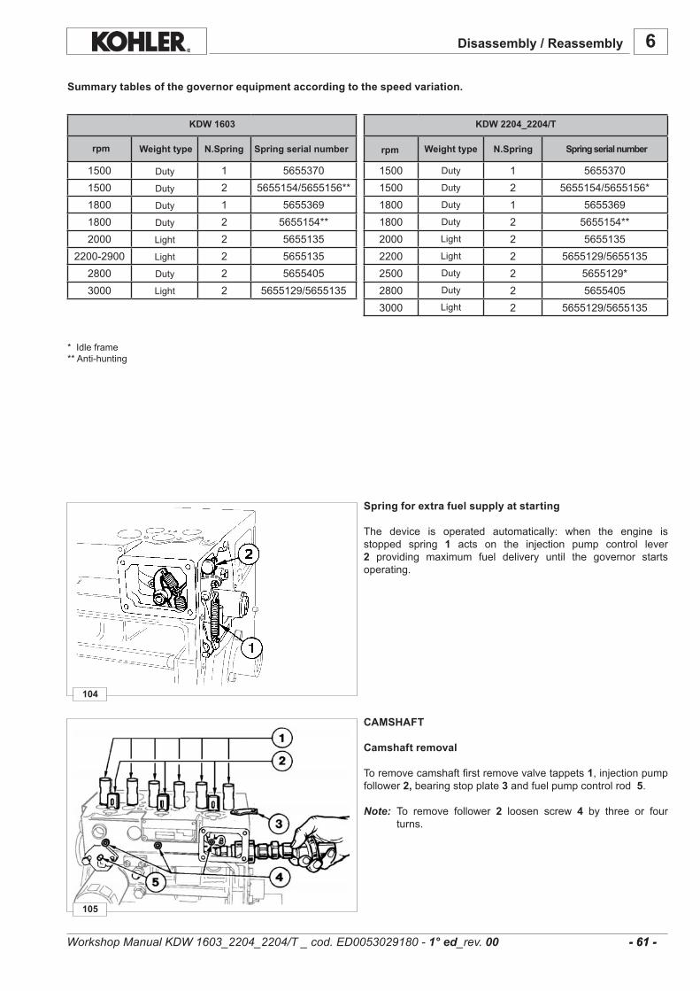
105
104
6
- 61 -
1500 1 56553701500 2 5655154/5655156*1800 1 56553691800 2 5655154**2000 2 56551352200 2 5655129/56551352500 2 5655129*2800 2 56554053000 2 5655129/5655135
1500 1 56553701500 2 5655154/5655156**1800 1 56553691800 2 5655154**2000 2 5655135
2200-2900 2 56551352800 2 56554053000 2 5655129/5655135
- 61 -
KDW 2204_2204/TKDW 1603
Disassembly / Reassembly
Summary tables of the governor equipment according to the speed variation.
rpm Weight type N.Spring Spring serial number rpm Weight type N.Spring Spring serial number
Duty
Duty
Duty
Duty
Light
Light
Duty
Duty
Light
Duty
Duty
Duty
Duty
Light
Light
Duty
Light
*Idleframe**Anti-hunting
Spring for extra fuel supply at starting
The device is operated automatically: when the engine isstopped spring 1 acts on the injection pump control lever2 providing maximum fuel delivery until the governor startsoperating.
CAMSHAFT
Camshaft removal
Toremovecamshaftfirstremovevalvetappets1,injectionpumpfollower2,bearingstopplate3 andfuelpumpcontrolrod5.
Note: To remove follower 2 loosen screw 4 by three or fourturns.
Workshop Manual KDW 1603_2204_2204/T _ cod. ED0053029180 - 1° ed_rev. 00
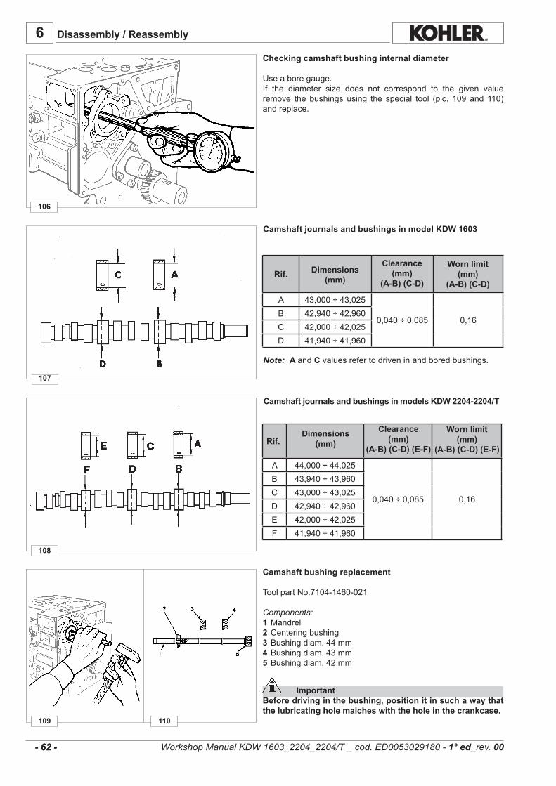
109
108
107
106
110
Rif.
A 44,000÷44,025
0,040÷0,085 0,16
B 43,940÷43,960C 43,000÷43,025D 42,940÷42,960E 42,000÷42,025F 41,940÷41,960
6
Rif.
A 43,000÷43,025
0,040÷0,085 0,16B 42,940÷42,960C 42,000÷42,025D 41,940÷41,960
- 62 - - 62 -
Disassembly / Reassembly
Checking camshaft bushing internal diameter
Useaboregauge.If the diameter size does not correspond to the given valueremove the bushings using the special tool (pic. 109 and 110)andreplace.
Dimensions (mm)
Clearance(mm)
(A-B) (C-D) (E-F)
Worn limit(mm)
(A-B) (C-D) (E-F)
Camshaft bushing replacement
ToolpartNo.7104-1460-021
Components:1 Mandrel2Centeringbushing3 Bushingdiam.44mm4Bushingdiam.43mm5Bushingdiam.42mm
ImportantBefore driving in the bushing, position it in such a way that the lubricating hole maiches with the hole in the crankcase.
Dimensions (mm)
Clearance (mm)
(A-B) (C-D)
Worn limit (mm)
(A-B) (C-D)
Workshop Manual KDW 1603_2204_2204/T _ cod. ED0053029180 - 1° ed_rev. 00
Camshaft journals and bushings in model KDW 1603
Note: A andCvaluesrefertodriveninandboredbushings.
Camshaft journals and bushings in models KDW 2204-2204/T
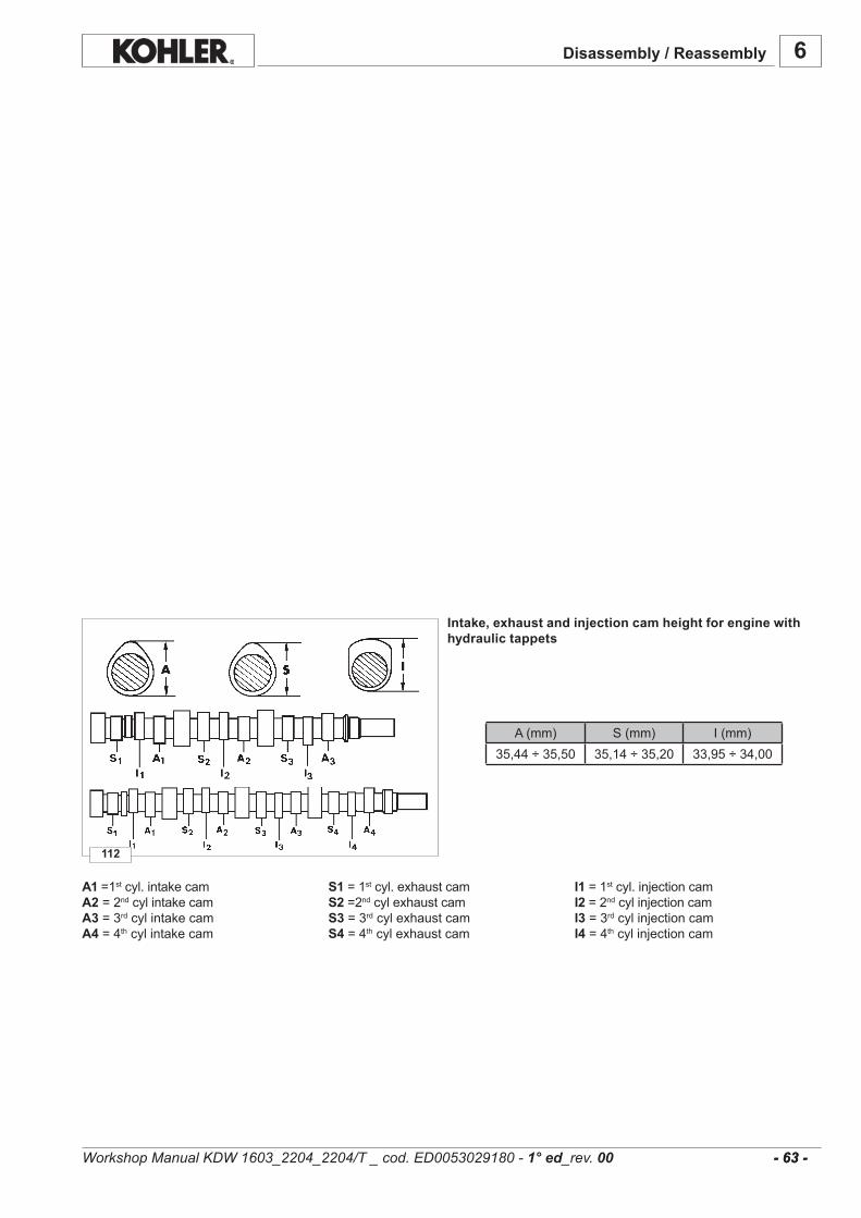
112
A(mm) S(mm) I(mm)35,44÷35,50 35,14÷35,20 33,95÷34,00
6
- 63 - - 63 -
Disassembly / Reassembly
A1=1stcyl.intakecam S1=1stcyl.exhaustcam I1=1stcyl.injectioncamA2=2ndcylintakecam S2=2ndcylexhaustcam I2=2ndcylinjectioncamA3=3rdcylintakecam S3=3rdcylexhaustcam I3=3rdcylinjectioncamA4 =4thcylintakecam S4 =4thcylexhaustcam I4 =4thcylinjectioncam
Intake, exhaust and injection cam height for engine with hydraulic tappets
Workshop Manual KDW 1603_2204_2204/T _ cod. ED0053029180 - 1° ed_rev. 00
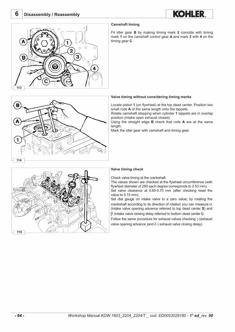
114
113
115
6
- 64 - - 64 -
Disassembly / Reassembly
Valve timing without considering timing marks
Locatepiston1(onflywheel)atthetopdeadcenter.PositiontwosmallrodsAofthesamelengthontothetappets.Rotatecamshaftstoppingwhencylinder1tappetsareinoverlapposition(intakeopenexhaustclosed).Using the straight edgeB check that rodsA are at the samelength.Marktheidlergearwithcamshaftandtiminggear.
Camshaft timing
Fit idler gearB by making timing mark 2 coincide with timingmark1onthecamshaftcontrolgearA andmark3 with 4onthetiminggearC.
Valve timing check
Checkvalvetimingatthecrankshaft.Thevaluesshownarecheckedattheflywheelcircumference(withflywheeldiameterof290eachdegreecorrespondsto2.53mm).Set valve clearance at 0.65-0.70 mm (after checking reset thevalueto0.15mm).Set dial gauge on intake valve to a zero value; by rotating thecrankshaftaccordingtoitsdirectionofrotationyoucanmeasurea (intakevalveopeningadvancereferredtotopdeadcenter S)andβ (intakevalveclosingdelayreferredtobottomdeadcenter I).Followthesameprocedureforexhaustvalvescheckingγ (exhaustvalveopeningadvance)andδ (exhaustvalveclosingdelay).
Workshop Manual KDW 1603_2204_2204/T _ cod. ED0053029180 - 1° ed_rev. 00
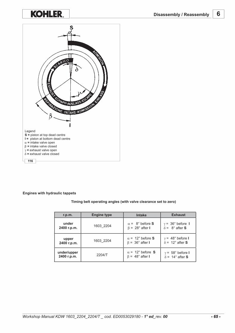
6
116
- 65 - - 65 -
1603_2204
1603_2204
2204/T
Disassembly / Reassembly
Engine typer.p.m. Intake Exhaust
a =8°beforeS β =28°after I
under2400 r.p.m.
upper2400 r.p.m.
γ =36°beforeI δ =8°after S
a =12°beforeS β =36°after I
γ =48°beforeI δ =12°after S
under/upper2400 r.p.m.
a =12°beforeS β =48°after I
γ =58°beforeI δ =14°after S
Engines with hydraulic tappets
Timing belt operating angles (with valve clearance set to zero)
LegendS = pistonattopdeadcentrel = pistonatbottomdeadcentrea = intakevalveopenβ=intakevalveclosedγ= exhaustvalveopenδ = exhaustvalveclosed
Workshop Manual KDW 1603_2204_2204/T _ cod. ED0053029180 - 1° ed_rev. 00

119
118
117
6
- 66 - - 66 -
Disassembly / Reassembly
Camshaft end play
Checkcamshaftendplayafter removing thecylinderhead, theinjectionandthefuelpumpsfromtheengine.Checkthatplate1istightened.Positionthedialgaugeonthecamshaftfrontsurface;pushandpullthecamshaft.Maximumendplayshouldbe0,008mm(ballbearingendplay).
GR 1 and GR 2 hydraulic pump 3rd p.t.o.
1 O-R 2 O-R 3 Centerring 4 Circlip 5 Thrustwasher 6 GR2hydraulicpumpflange 7 GR1hydraulicpumpflange 8 Bushing 9 Trustwasher10 GR2hydraulicpumpdrivegear11 GR1hydraulicpumpdrivegear12 Controlgear
Hydraulic pump p.t.o.
A =3rdp.t.o.withhydraulicpumpGr2.B=4thp.t.o.withhydraulicpumpGr1
HydraulicpumpsofeitherGR1orGR2typecanbefitted,evensimultaneously,on theerdand4thp.t.o.provided the resultingtorquedoesnotexceed40Nm.Thegear ratio betweenengine r.p.m. and3rdand4th p.t.o. is1:1.
Workshop Manual KDW 1603_2204_2204/T _ cod. ED0053029180 - 1° ed_rev. 00

.........................................................................................................................................................................
.........................................................................................................................................................................
.........................................................................................................................................................................
.........................................................................................................................................................................
.........................................................................................................................................................................
.........................................................................................................................................................................
.........................................................................................................................................................................
.........................................................................................................................................................................
.........................................................................................................................................................................
.........................................................................................................................................................................
.........................................................................................................................................................................
.........................................................................................................................................................................
.........................................................................................................................................................................
.........................................................................................................................................................................
.........................................................................................................................................................................
.........................................................................................................................................................................
.........................................................................................................................................................................
.........................................................................................................................................................................
.........................................................................................................................................................................
.........................................................................................................................................................................
.........................................................................................................................................................................
.........................................................................................................................................................................
.........................................................................................................................................................................
.........................................................................................................................................................................
.........................................................................................................................................................................
.........................................................................................................................................................................
.........................................................................................................................................................................
.........................................................................................................................................................................
.........................................................................................................................................................................
.........................................................................................................................................................................
.........................................................................................................................................................................
.........................................................................................................................................................................
.........................................................................................................................................................................
.........................................................................................................................................................................
.........................................................................................................................................................................
.........................................................................................................................................................................
.........................................................................................................................................................................
6
- 67 - - 67 -
Disassembly / Reassembly
Workshop Manual KDW 1603_2204_2204/T _ cod. ED0053029180 - 1° ed_rev. 00
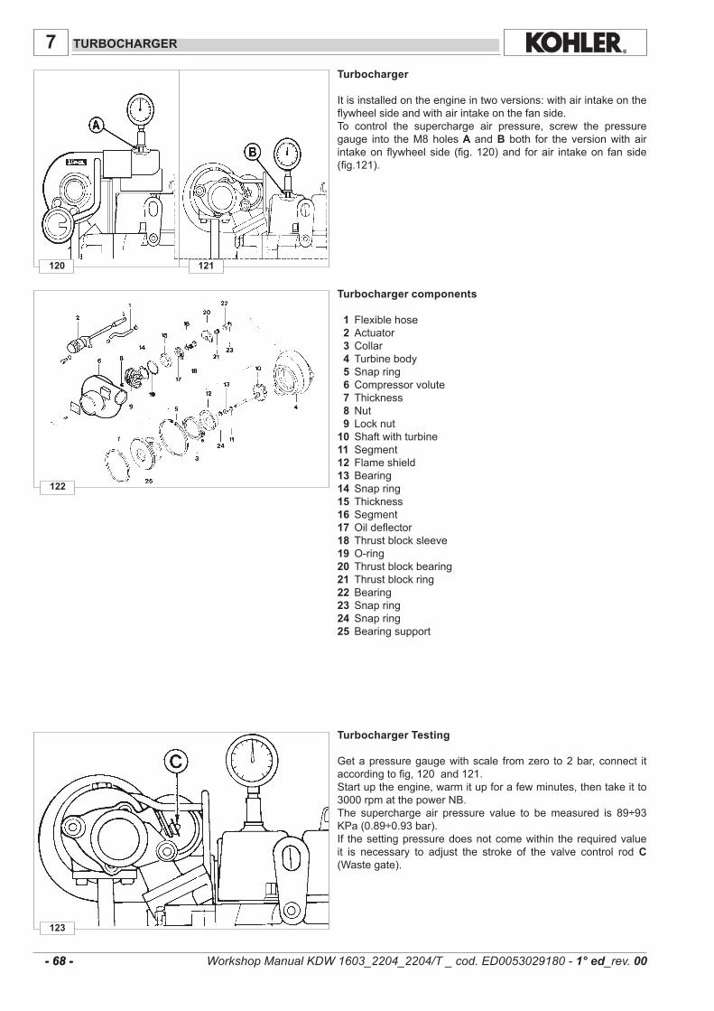
123
122
120 121
7
- 68 - - 68 -
TURBOCHARGER
Turbocharger
Itisinstalledontheengineintwoversions:withairintakeontheflywheelsideandwithairintakeonthefanside.To control the supercharge air pressure, screw the pressuregauge into theM8holes A andB both for the versionwith airintakeonflywheelside (fig.120)and forair intakeon fanside(fig.121).
Turbocharger Testing
Getapressuregaugewithscale fromzero to2bar,connect itaccordingtofig,120and121.Startuptheengine,warmitupforafewminutes,thentakeitto3000rpmatthepowerNB.The supercharge air pressure value to bemeasured is 89÷93KPa(0.89÷0.93bar).If thesettingpressuredoesnotcomewithin therequiredvalueit is necessary to adjust the stroke of the valve control rodC(Wastegate).
Turbocharger components 1 Flexiblehose 2 Actuator 3 Collar 4 Turbinebody 5 Snapring 6 Compressorvolute 7 Thickness 8 Nut 9 Locknut10 Shaftwithturbine11 Segment12 Flameshield13 Bearing14 Snapring15 Thickness16 Segment17 Oildeflector18 Thrustblocksleeve19 O-ring20 Thrustblockbearing21 Thrustblockring22 Bearing23 Snapring24 Snapring25 Bearingsupport
Workshop Manual KDW 1603_2204_2204/T _ cod. ED0053029180 - 1° ed_rev. 00
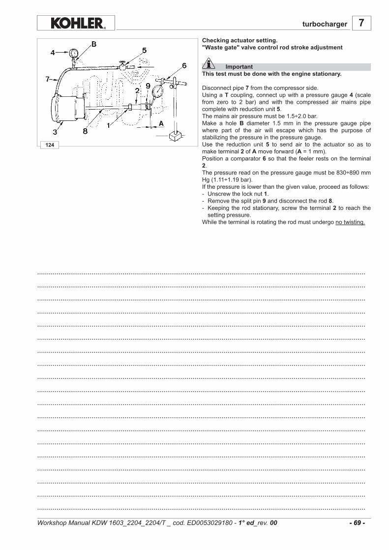
124
.........................................................................................................................................................................
.........................................................................................................................................................................
.........................................................................................................................................................................
.........................................................................................................................................................................
.........................................................................................................................................................................
.........................................................................................................................................................................
.........................................................................................................................................................................
.........................................................................................................................................................................
.........................................................................................................................................................................
.........................................................................................................................................................................
.........................................................................................................................................................................
.........................................................................................................................................................................
.........................................................................................................................................................................
.........................................................................................................................................................................
.........................................................................................................................................................................
.........................................................................................................................................................................
.........................................................................................................................................................................
.........................................................................................................................................................................
.........................................................................................................................................................................
7
- 69 - - 69 -
Checking actuator setting."Waste gate" valve control rod stroke adjustment
ImportantThis test must be done with the engine stationary.
Disconnectpipe7fromthecompressorside.UsingaTcoupling,connectupwithapressuregauge4 (scalefrom zero to 2 bar) and with the compressed air mains pipecompletewithreductionunit5.Themainsairpressuremustbe1.5÷2.0bar.Make a holeB diameter 1.5 mm in the pressure gauge pipewhere part of the air will escape which has the purpose ofstabilizingthepressureinthepressuregauge.Use the reduction unit 5 to send air to the actuator so as tomaketerminal2ofAmoveforward(A=1mm).Positionacomparator6 sothat thefeelerrestsontheterminal2.Thepressurereadonthepressuregaugemustbe830÷890mmHg(1.11÷1.19bar).Ifthepressureislowerthanthegivenvalue,proceedasfollows:- Unscrewthelocknut1.- Removethesplitpin9 anddisconnecttherod8.- Keeping therodstationary,screwthe terminal2 to reach thesettingpressure.
Whiletheterminalisrotatingtherodmustundergonotwisting.
turbocharger
Workshop Manual KDW 1603_2204_2204/T _ cod. ED0053029180 - 1° ed_rev. 00
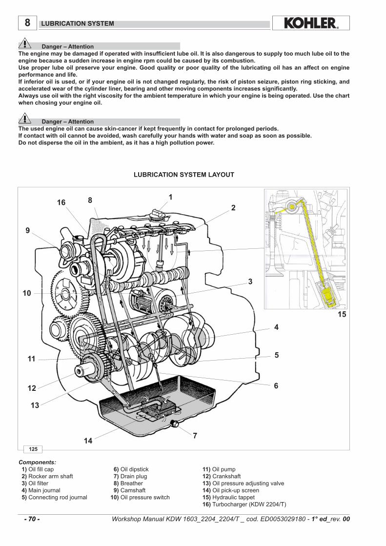
1
6
7
8
9
4
5
3
2
13
14
12
11
16
10
15
125
8
- 70 - - 70 -
LUBRICATION SYSTEM
LUBRICATION SYSTEM LAYOUT
Danger – AttentionThe engine may be damaged if operated with insufficient lube oil. It is also dangerous to supply too much lube oil to the engine because a sudden increase in engine rpm could be caused by its combustion.Use proper lube oil preserve your engine. Good quality or poor quality of the lubricating oil has an affect on engine performance and life.If inferior oil is used, or if your engine oil is not changed regularly, the risk of piston seizure, piston ring sticking, and accelerated wear of the cylinder liner, bearing and other moving components increases significantly. Always use oil with the right viscosity for the ambient temperature in which your engine is being operated. Use the chart when chosing your engine oil.
Danger – AttentionThe used engine oil can cause skin-cancer if kept frequently in contact for prolonged periods.If contact with oil cannot be avoided, wash carefully your hands with water and soap as soon as possible.Do not disperse the oil in the ambient, as it has a high pollution power.
Workshop Manual KDW 1603_2204_2204/T _ cod. ED0053029180 - 1° ed_rev. 00
Components:1)Oilfillcap 6)Oildipstick 11)Oilpump2)Rockerarmshaft 7)Drainplug 12)Crankshaft3)Oilfilter 8)Breather 13)Oilpressureadjustingvalve4)Mainjournal 9)Camshaft 14)Oilpick-upscreen5)Connectingrodjournal 10)Oilpressureswitch 15)Hydraulictappet 16)Turbocharger(KDW2204/T)
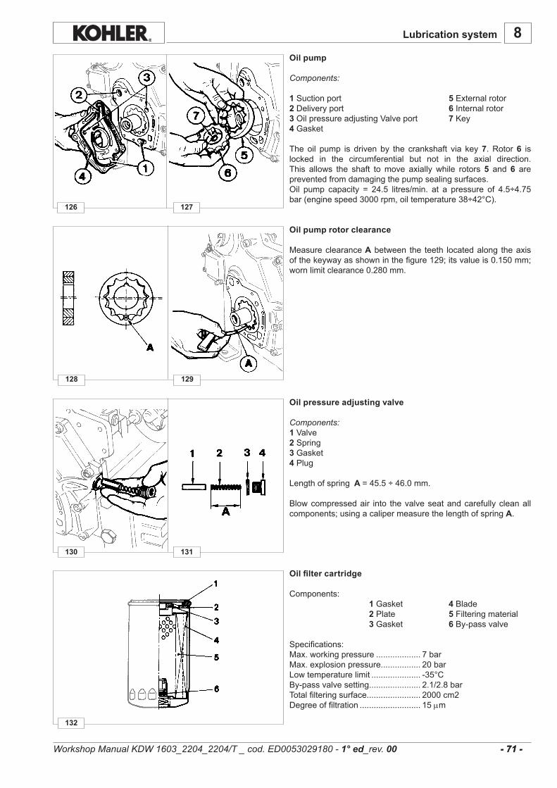
132
130
128
126 127
131
129
8
- 71 - - 71 -
Lubrication system
Oil pump
Components:
1Suctionport 5Externalrotor 2Deliveryport 6 Internalrotor3OilpressureadjustingValveport 7Key4 Gasket
The oil pump is driven by the crankshaft via key7.Rotor6 islocked in the circumferential but not in the axial direction.This allows the shaft tomove axially while rotors5 and6 arepreventedfromdamagingthepumpsealingsurfaces.Oil pump capacity = 24.5 litres/min. at a pressure of 4.5÷4.75bar(enginespeed3000rpm,oiltemperature38÷42°C).
Oil filter cartridge
Components: 1Gasket 4Blade 2Plate 5Filteringmaterial 3Gasket 6 By-passvalve
Specifications:Max.workingpressure................... 7barMax.explosionpressure................. 20barLowtemperaturelimit..................... -35°CBy-passvalvesetting...................... 2.1/2.8barTotalfilteringsurface....................... 2000cm2Degreeoffiltration.......................... 15µm
Oil pressure adjusting valve
Components:1Valve2Spring3Gasket4Plug
Lengthofspring A =45.5÷46.0mm.
Blowcompressedair into thevalveseatandcarefullycleanallcomponents;usingacalipermeasurethelengthofspringA.
Oil pump rotor clearance
Measureclearance Abetween the teeth locatedalong theaxisofthekeywayasshowninthefigure129;itsvalueis0.150mm;wornlimitclearance0.280mm.
Workshop Manual KDW 1603_2204_2204/T _ cod. ED0053029180 - 1° ed_rev. 00
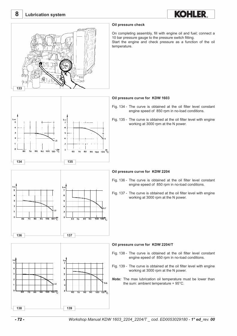
138
136
134
133
137
135
139
8
- 72 - - 72 -
Lubrication system
Oil pressure check
Oncompletingassembly,fillwithengineoilandfuel;connecta10barpressuregaugetothepressureswitchfitting.Start the engine and check pressure as a function of the oiltemperature.
Workshop Manual KDW 1603_2204_2204/T _ cod. ED0053029180 - 1° ed_rev. 00
Oil pressure curve for KDW 2204/T
Fig.138- The curve is obtained at the oil filter level constantengineepeedof850rpminno-loadconditions.
Fig.139- Thecurveisobtainedattheoilfilterlevelwithengineworkingat3000rpmattheNpower.
Note: Themax lubricationoil temperaturemust be lower thanthesum:ambienttemperature+95°C.
Oil pressure curve for KDW 2204
Fig.136- The curve is obtained at the oil filter level constantengineepeedof850rpminno-loadconditions.
Fig.137- Thecurveisobtainedattheoilfilterlevelwithengineworkingat3000rpmattheNpower.
Oil pressure curve for KDW 1603
Fig.134- The curve is obtained at the oil filter level constantenginespeedof850rpminno-loadconditions.
Fig.135- Thecurveisobtainedattheoilfilterlevelwithengineworkingat3000rpmattheNpower.

........................................................................................................................................................................
........................................................................................................................................................................
........................................................................................................................................................................
........................................................................................................................................................................
........................................................................................................................................................................
........................................................................................................................................................................
........................................................................................................................................................................
........................................................................................................................................................................
........................................................................................................................................................................
........................................................................................................................................................................
........................................................................................................................................................................
........................................................................................................................................................................
........................................................................................................................................................................
........................................................................................................................................................................
........................................................................................................................................................................
........................................................................................................................................................................
........................................................................................................................................................................
........................................................................................................................................................................
........................................................................................................................................................................
........................................................................................................................................................................
........................................................................................................................................................................
........................................................................................................................................................................
........................................................................................................................................................................
........................................................................................................................................................................
........................................................................................................................................................................
........................................................................................................................................................................
........................................................................................................................................................................
........................................................................................................................................................................
........................................................................................................................................................................
........................................................................................................................................................................
........................................................................................................................................................................
........................................................................................................................................................................
........................................................................................................................................................................
........................................................................................................................................................................
........................................................................................................................................................................
........................................................................................................................................................................
........................................................................................................................................................................
8
- 73 - - 73 -
Lubrication systemNotes:
Workshop Manual KDW 1603_2204_2204/T _ cod. ED0053029180 - 1° ed_rev. 00

1
6
7
8
9
4
5
3
2
10
140
9
- 74 - - 74 -
Danger – Attention- The fluid coolant circuit is pressurized.- Inspections must only be made when the engine has cooled and even in this case, the radiator or expansion
chamber plug must be unscrewed with the utmost caution.- If an electric fan is installed, do not approach a hot engine since the fan itself could start up even when the engine is
at a standstill.- Coolant fluid is polluting, it must therefore be disposed of in the correct way. Do not litter.
COOLING SYSTEM
COOLING SYSTEM LAYOUT
Workshop Manual KDW 1603_2204_2204/T _ cod. ED0053029180 - 1° ed_rev. 00
Components:
1)Coolantfillcap 6)Thermostat2)Expansiontank 7)Fan3)Cylinderblock 8)Radiator4)Circulatingpump 9)Temperaturesensor5)Coolanttemperaturewarninglamp 10)Heatexchanger(KDW2204T).
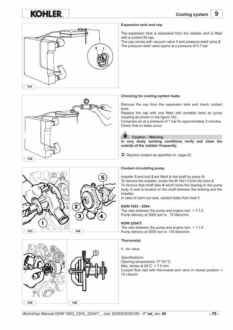
145
143
142
141
146
144
9
- 75 - - 75 -
Expansion tank and cap
Theexpansion tank isseparated from the radiatorand isfittedwithacoolantfillcap.Thecapcomeswithvacuumvalve1andpressurereliefvalve2.Thepressurereliefvalveopensatapressureof0.7bar.
Thermostat
1-Airvalve
Specifications:Openingtemperature:77°/81°CMax.strokeat94°C=7.5mmCoolantflowratewiththermostatandvalveinclosedposition=15Liters/h.
Checking for cooling system leaks
Remove the cap from the expansion tank and check coolantlevel.Replace the cap with one fitted with portable hand air pumpcouplingasshowninthefigure142.Compressairatapressureof1barforapproximately2minutes.Checkthatnoleaksoccur.
Caution – WarningIn very dusty working conditions verify and clean the outside of the radiator frequently.
Replacecoolantasspecifiedonpage22.
Cooling system
Workshop Manual KDW 1603_2204_2204/T _ cod. ED0053029180 - 1° ed_rev. 00
Coolant circulating pump
Impeller3andhub5arefittedtotheshaftbypressfit.Toremovetheimpeller,screwtheM18x1.5boltintobore2.Toremovethatshafttake4whichlocksthebearingtothepumpbody.Asealislocatedontheshaftbetweenthebearingandtheimpeller.Incaseofworn-outseal,coolantleaksfromhole1.
KDW 1603 - 2204:Theratiobetweenthepumpandenginerpm=1:1.2Pumpdeliveryat3000rpmis70liters/min.
KDW 2204/T:Theratiobetweenthepumpandenginerpm=1:1.5Pumpdeliveryat3000rpmis116liters/min.
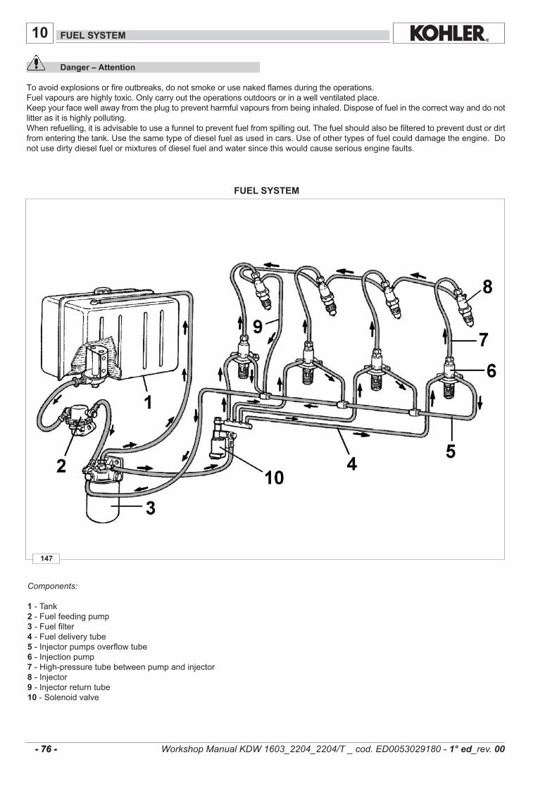
147
10
- 76 - - 76 -
Components:
1-Tank2-Fuelfeedingpump3-Fuelfilter4-Fueldeliverytube5 -Injectorpumpsoverflowtube6-Injectionpump7 -High-pressuretubebetweenpumpandinjector8 -Injector9 -Injectorreturntube10-Solenoidvalve
FUEL SYSTEM
FUEL SYSTEM
Danger – Attention
Toavoidexplosionsorfireoutbreaks,donotsmokeorusenakedflamesduringtheoperations.Fuelvapoursarehighlytoxic.Onlycarryouttheoperationsoutdoorsorinawellventilatedplace.Keepyourfacewellawayfromtheplugtopreventharmfulvapoursfrombeinginhaled.Disposeoffuelinthecorrectwayanddonotlitterasitishighlypolluting.Whenrefuelling,itisadvisabletouseafunneltopreventfuelfromspillingout.Thefuelshouldalsobefilteredtopreventdustordirtfromenteringthetank.Usethesametypeofdieselfuelasusedincars.Useofothertypesoffuelcoulddamagetheengine.Donotusedirtydieselfuelormixturesofdieselfuelandwatersincethiswouldcauseseriousenginefaults.
Workshop Manual KDW 1603_2204_2204/T _ cod. ED0053029180 - 1° ed_rev. 00
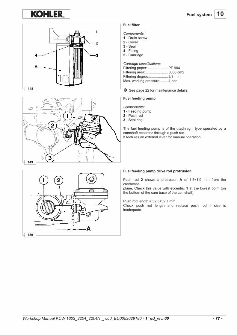
10
150
148
149
- 77 - - 77 -
Fuel system
Fuel feeding pump drive rod protrusion
Push rod 2 shows a protrusion A of 1.5÷1.9 mm from thecrankcaseplane.Checkthisvaluewitheccentric1at the lowestpoint(onthebottomofthecambaseofthecamshaft).
Pushrodlength=32.5÷32.7mm.Check push rod length and replace push rod if size isinadequate.
Fuel feeding pump
Components:1-Feedingpump2-Pushrod3 -Sealring
The fuel feedingpump isof thediaphragm typeoperatedbyacamshafteccentricthroughapushrod.Iffeaturesanexternalleverformanualoperation.
Fuel filter
Components:1 -Drainscrew2-Cover3-Seal4-Fitting5 -Cartridge
Cartridge specificationsFilteringpaper:.....................PF904Filteringarea:.......................5000cm2Filteringdegree:...................2/3mMax.workingpressure:.......4bar
Seepage22formaintenancedetails.
Workshop Manual KDW 1603_2204_2204/T _ cod. ED0053029180 - 1° ed_rev. 00
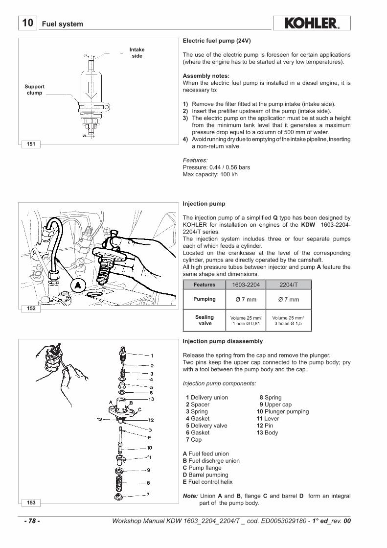
152
151
153
10
- 78 - - 78 -
1603-2204 2204/T
Ø7mm Ø7mm
Electric fuel pump (24V)
Theuseoftheelectricpumpisforeseenforcertainapplications(wheretheenginehastobestartedatverylowtemperatures).
Assembly notes:Whentheelectric fuelpump is installed inadieselengine, it isnecessaryto:
1) Removethefilterfittedatthepumpintake(intakeside).2) Inserttheprefilterupstreamofthepump(intakeside).3) Theelectricpumpontheapplicationmustbeatsuchaheight
from the minimum tank level that it generates a maximumpressuredropequaltoacolumnof500mmofwater.
4) Avoidrunningdryduetoemptyingoftheintakepipeline,insertinganon-returnvalve.
Features:Pressure:0.44/0.56barsMaxcapacity:100l/h
Features
Pumping
Sealing valve
Injection pump disassembly
Releasethespringfromthecapandremovetheplunger.Twopinskeeptheuppercapconnectedtothepumpbody;prywithatoolbetweenthepumpbodyandthecap.
Injection pump components: 1Deliveryunion 8 Spring 2Spacer 9 Uppercap 3Spring 10Plungerpumping 4Gasket 11Lever 5Deliveryvalve 12Pin 6Gasket 13Body 7 Cap
AFuelfeedunionBFueldischrgeunionCPumpflangeDBarrelpumpingEFuelcontrolhelix
Note:UnionA andB, flangeC andbarrelD forman integralpartofthepumpbody.
Support clump
Intake side
Fuel system
Workshop Manual KDW 1603_2204_2204/T _ cod. ED0053029180 - 1° ed_rev. 00
Injection pump
Theinjectionpumpofasimplified QtypehasbeendesignedbyKOHLER for installation on engines of theKDW 1603-2204-2204/Tseries.The injection system includes three or four separate pumpseachofwhichfeedsacylinder.Located on the crankcase at the level of the correspondingcylinder,pumpsaredirectlyoperatedbythecamshaft.AllhighpressuretubesbetweeninjectorandpumpA featurethesameshapeanddimensions.
Volume25mm3
1holeØ0,81Volume25mm3
3holesØ1,5

10
157
155
154
158
156
160159
- 79 - - 79 -
Fuel system
How to reassemble injection pump components
FittheplungerwithhelixE directedtowardsthedischargeunionB; if it iserroneouslyfittedwithspiralfacingthefuelfeedunion A theinjectionpumpwillnotoperate(thusthepossibilityoftheengine overspeeding is completely ruled out); complete reas-semblyfollowingfig.154
Tightendeliveryunionto35Nm;itisessentialtouseatorquewrench.
Tool serial number 7107.1460.212
How to remove injection pump feeding tubes
Caution – WarningCutting the pipe in the opposite direction to the arrow A (horizontally) damages the pump coupling with consequent leakage of fuel.
CutthenylontubeatA.Removetheportionleftinsidetheunionusingpliers.Remove the nylon tube without damaging the union seals asshowninthefigure159.
Injection pump control rod
Caution – WarningDo not unscrew ring nut 2 before removing rod 1.
Controlrod1,operatedbythethrottleandgovernedbythespeedgovernor,controlstheinjectionpump.Ring nut 2 keeps rod 1 in the required position by means ofgroove3.
Injection pump non-return valve
The discharge union is fitted with a non-return valve A; thisvalve improves injectionbybleeding theair inside the fuelandstopstheengineimmediatelyafterthestopdeviceisoperated.Toreplacetheoutletunionwithnon-returnballvalveonQLCtypeinjectionpumps(havinginletandoutletunionspressure-fittedonthepumpcase)usethespecialtoolserialnumber7107.1460.212.ToolB isrequiredforremovalofvalveA,toolCfordriving.
Workshop Manual KDW 1603_2204_2204/T _ cod. ED0053029180 - 1° ed_rev. 00
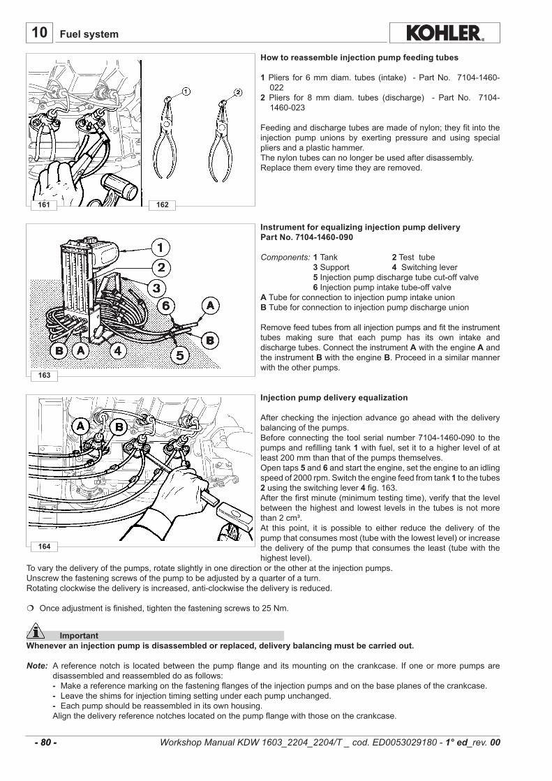
163
161
164
162
10
- 80 - - 80 -
Fuel system
How to reassemble injection pump feeding tubes
1Pliers for6mmdiam. tubes (intake) -PartNo. 7104-1460-022
2 Pliers for 8 mm diam. tubes (discharge) - Part No. 7104-1460-023
Feedinganddischargetubesaremadeofnylon;theyfitintotheinjection pump unions by exerting pressure and using specialpliersandaplastichammer.Thenylontubescannolongerbeusedafterdisassembly.Replacethemeverytimetheyareremoved.
Instrument for equalizing injection pump deliveryPart No. 7104-1460-090
Components: 1 Tank 2Testtube 3Support 4 Switchinglever 5Injectionpumpdischargetubecut-offvalve 6Injectionpumpintaketube-offvalveATubeforconnectiontoinjectionpumpintakeunionB Tubeforconnectiontoinjectionpumpdischargeunion
Removefeedtubesfromallinjectionpumpsandfittheinstrumenttubes making sure that each pump has its own intake anddischargetubes.ConnecttheinstrumentAwiththeengine Aandtheinstrument BwiththeengineB.Proceedinasimilarmannerwiththeotherpumps.
Injection pump delivery equalization
Aftercheckingtheinjectionadvancegoaheadwiththedeliverybalancingofthepumps.Beforeconnecting the toolserialnumber7104-1460-090 to thepumpsandrefillingtank1withfuel,setittoahigherlevelofatleast200mmthanthatofthepumpsthemselves.Opentaps5 and6 andstarttheengine,settheenginetoanidlingspeedof2000rpm.Switchtheenginefeedfromtank 1 tothetubes2 usingtheswitchinglever 4fig.163.Afterthefirstminute(minimumtestingtime),verifythatthelevelbetween thehighestand lowest levels in the tubes isnotmorethan2cm³.At this point, it is possible to either reduce the delivery of thepumpthatconsumesmost(tubewiththelowestlevel)orincreasethedeliveryofthepumpthatconsumestheleast(tubewiththehighestlevel).
Tovarythedeliveryofthepumps,rotateslightlyinonedirectionortheotherattheinjectionpumps.Unscrewthefasteningscrewsofthepumptobeadjustedbyaquarterofaturn.Rotatingclockwisethedeliveryisincreased,anti-clockwisethedeliveryisreduced.
Onceadjustmentisfinished,tightenthefasteningscrewsto25Nm.
ImportantWhenever an injection pump is disassembled or replaced, delivery balancing must be carried out.
Note: A referencenotch is locatedbetween thepumpflangeand itsmountingon thecrankcase. Ifoneormorepumpsaredisassembledandreassembleddoasfollows:
- Makeareferencemarkingonthefasteningflangesoftheinjectionpumpsandonthebaseplanesofthecrankcase. - Leavetheshimsforinjectiontimingsettingundereachpumpunchanged. - Eachpumpshouldbereassembledinitsownhousing. Alignthedeliveryreferencenotcheslocatedonthepumpflangewiththoseonthecrankcase.
Workshop Manual KDW 1603_2204_2204/T _ cod. ED0053029180 - 1° ed_rev. 00
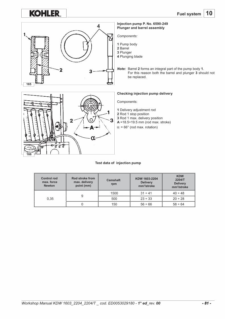
10
166
165
- 81 - - 81 -
0,359
1500 31÷41 40÷48500 23÷33 20÷28
0 150 56÷66 58÷64
Fuel system
Injection pump P. No. 6590-249Plunger and barrel assembly
Components:
1Pumpbody2 Barrel3Plunger4Plungingblade
Note: Barrel2formsanintegralpartofthepumpbody1. Forthisreasonboththebarrelandplunger3shouldnot
bereplaced.
Test data of injection pump
Checking injection pump delivery
Components:
1Deliveryadjustmentrod2Rod1stopposition3 Rod1max.deliverypositionA =18.5÷19.5mm(rodmax.stroke)a =66°(rodmax.rotation)
Workshop Manual KDW 1603_2204_2204/T _ cod. ED0053029180 - 1° ed_rev. 00
KDW 1603-2204Delivery
mm3/stroke
KDW 2204/T
Deliverymm3/stroke
Control rod max. force
Newton
Rod stroke from max. delivery
point (mm)
Camshaft rpm
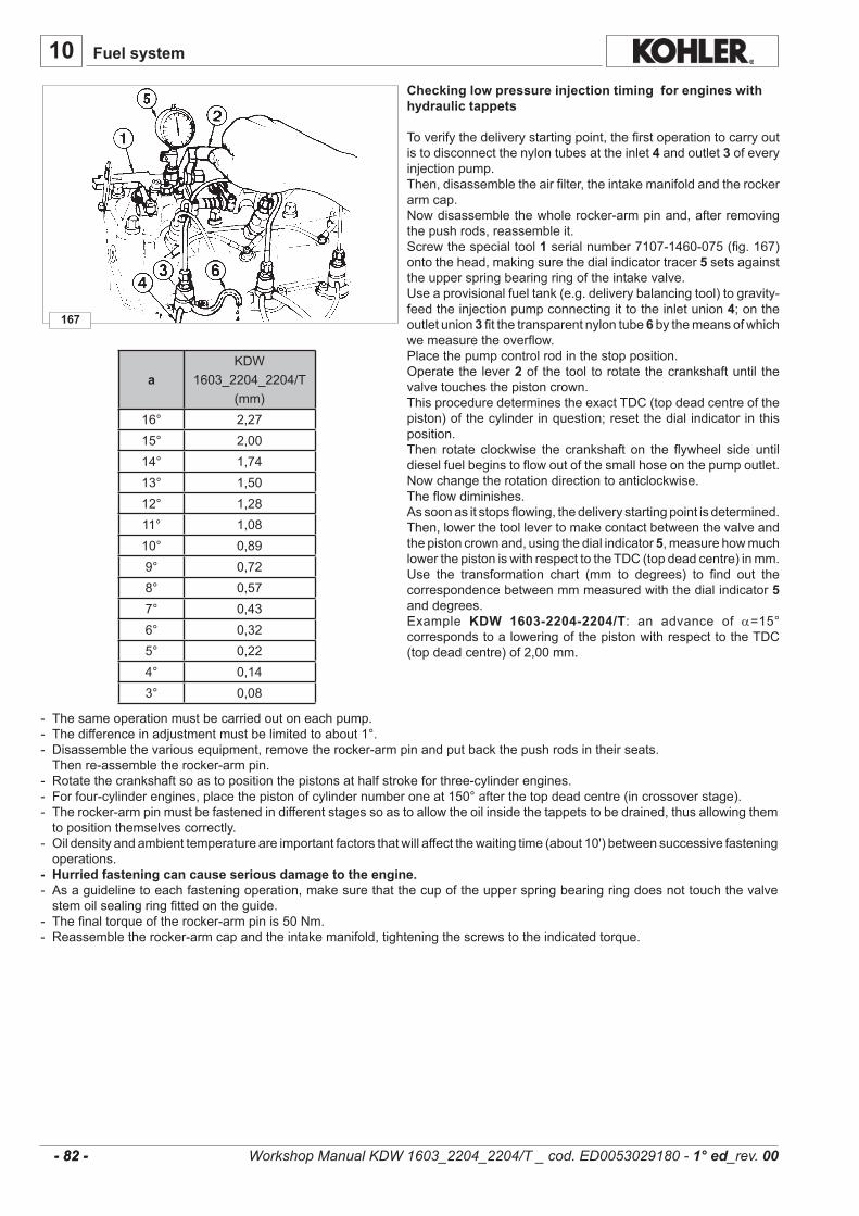
167
10
- 82 - - 82 -
aKDW
1603_2204_2204/T(mm)
16° 2,2715° 2,0014° 1,7413° 1,5012° 1,2811° 1,0810° 0,899° 0,728° 0,577° 0,436° 0,325° 0,224° 0,143° 0,08
Fuel system
- Thesameoperationmustbecarriedoutoneachpump.- Thedifferenceinadjustmentmustbelimitedtoabout1°.- Disassemblethevariousequipment,removetherocker-armpinandputbackthepushrodsintheirseats. Thenre-assembletherocker-armpin.- Rotatethecrankshaftsoastopositionthepistonsathalfstrokeforthree-cylinderengines.- Forfour-cylinderengines,placethepistonofcylindernumberoneat150°afterthetopdeadcentre(incrossoverstage).- Therocker-armpinmustbefastenedindifferentstagessoastoallowtheoilinsidethetappetstobedrained,thusallowingthem topositionthemselvescorrectly.- Oildensityandambienttemperatureareimportantfactorsthatwillaffectthewaitingtime(about10')betweensuccessivefastening operations.- Hurried fastening can cause serious damage to the engine.- Asaguidelinetoeachfasteningoperation,makesurethatthecupoftheupperspringbearingringdoesnottouchthevalve stemoilsealingringfittedontheguide.- Thefinaltorqueoftherocker-armpinis50Nm.- Reassembletherocker-armcapandtheintakemanifold,tighteningthescrewstotheindicatedtorque.
Workshop Manual KDW 1603_2204_2204/T _ cod. ED0053029180 - 1° ed_rev. 00
Checking low pressure injection timing for engines with hydraulic tappets
Toverifythedeliverystartingpoint,thefirstoperationtocarryoutistodisconnectthenylontubesattheinlet4 andoutlet3ofeveryinjectionpump.Then,disassembletheairfilter,theintakemanifoldandtherockerarmcap.Nowdisassemblethewholerocker-armpinand,afterremovingthepushrods,reassembleit.Screwthespecialtool1serialnumber7107-1460-075(fig.167)ontothehead,makingsurethedialindicatortracer5setsagainsttheupperspringbearingringoftheintakevalve.Useaprovisionalfueltank(e.g.deliverybalancingtool)togravity-feedtheinjectionpumpconnectingittotheinletunion4;ontheoutletunion3fitthetransparentnylontube6bythemeansofwhichwemeasuretheoverflow.Placethepumpcontrolrodinthestopposition.Operatethe lever2of thetool torotatethecrankshaftuntil thevalvetouchesthepistoncrown.ThisproceduredeterminestheexactTDC(topdeadcentreofthepiston)ofthecylinderinquestion;resetthedialindicatorinthisposition.Then rotate clockwise the crankshaft on the flywheel sideuntildieselfuelbeginstoflowoutofthesmallhoseonthepumpoutlet.Nowchangetherotationdirectiontoanticlockwise.Theflowdiminishes.Assoonasitstopsflowing,thedeliverystartingpointisdetermined.Then,lowerthetoollevertomakecontactbetweenthevalveandthepistoncrownand,usingthedialindicator5,measurehowmuchlowerthepistoniswithrespecttotheTDC(topdeadcentre)inmm.Use the transformation chart (mm to degrees) to find out thecorrespondencebetweenmmmeasuredwiththedialindicator5anddegrees.Example KDW 1603-2204-2204/T: an advance of a=15°correspondstoaloweringofthepistonwithrespecttotheTDC(topdeadcentre)of2,00mm.
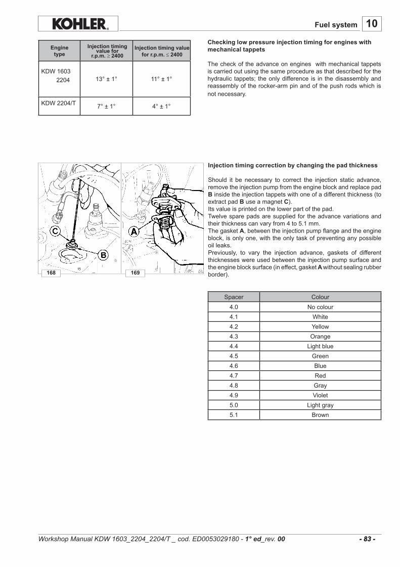
13°±1° 11°±1°
7°±1° 4°±1°
10
168 169
- 83 - - 83 -
KDW16032204
KDW2204/T
Fuel system
Checking low pressure injection timing for engines with mechanical tappets
Thecheckoftheadvanceonengineswithmechanicaltappetsiscarriedoutusingthesameprocedureasthatdescribedforthehydraulic tappets; theonlydifference is in thedisassemblyandreassemblyoftherocker-armpinandofthepushrodswhichisnotnecessary.
Injection timing value for
r.p.m. ≥ 2400Engine
typeInjection timing value
for r.p.m. ≤ 2400
Injection timing correction by changing the pad thickness
Should it be necessary to correct the injection static advance,removetheinjectionpumpfromtheengineblockandreplacepadBinsidetheinjectiontappetswithoneofadifferentthickness(toextractpadBuseamagnetC).Itsvalueisprintedonthelowerpartofthepad.Twelvesparepadsaresuppliedfor theadvancevariationsandtheirthicknesscanvaryfrom4to5.1mm.ThegasketA,betweentheinjectionpumpflangeandtheengineblock,isonlyone,withtheonlytaskofpreventinganypossibleoilleaks.Previously, to vary the injection advance, gaskets of differentthicknesseswereusedbetweentheinjectionpumpsurfaceandtheengineblocksurface(ineffect,gasketA withoutsealingrubberborder).
Spacer Colour4.0 Nocolour4.1 White4.2 Yellow4.3 Orange4.4 Lightblue4.5 Green4.6 Blue4.7 Red4.8 Gray4.9 Violet5.0 Lightgray5.1 Brown
Workshop Manual KDW 1603_2204_2204/T _ cod. ED0053029180 - 1° ed_rev. 00

172
171
10
170
- 84 - - 84 -
Injector setting
Connecttheinjectortoainjectionteststandandcheckthatthepressuresettingis140/150bar.Addingtheshims9increasesthepressuresetting,reducingtheirnumberlowersit.Eleven spare setting shims are included, their measurementsrangefrom1to2mm.Whenspring10isreplaced,calibrationmustbecarriedoutatapressure10barshigherthanthenominalpressure(160bar)tocounterbalancebeddingintheoperation.Check needle valve sealing by slowly moving the hand pumpuntilapproximately120barper10seconds.Replacenozzle12incaseofdripping.
Thetorqueoftheinjectorringnutis70÷90Nm.
Whenever maintenance operations are carried out on theinjectorreplacethesealring1.Introduce seal ring1 into the injector housingwith the sealingsurfacefacingupwards(seefigure171).
Seepage22formaintenanceintervals.
Fixinjectortotheheadtighteningto70Nm.
Fuel system
Injector (pin type)
Components:
1Fuelinlet 7Deliveryunion2 Filter 8Backflowunion3Body 9Settingshims4Deliveryduct 10Pressurespring5Pad 11Pressurepin6Clampingringnut 12Nozzle 13Fireproofbulkhead
Workshop Manual KDW 1603_2204_2204/T _ cod. ED0053029180 - 1° ed_rev. 00

10........................................................................................................................................................................
........................................................................................................................................................................
........................................................................................................................................................................
........................................................................................................................................................................
........................................................................................................................................................................
........................................................................................................................................................................
........................................................................................................................................................................
........................................................................................................................................................................
........................................................................................................................................................................
........................................................................................................................................................................
........................................................................................................................................................................
........................................................................................................................................................................
........................................................................................................................................................................
........................................................................................................................................................................
........................................................................................................................................................................
........................................................................................................................................................................
........................................................................................................................................................................
........................................................................................................................................................................
........................................................................................................................................................................
........................................................................................................................................................................
........................................................................................................................................................................
........................................................................................................................................................................
........................................................................................................................................................................
........................................................................................................................................................................
........................................................................................................................................................................
........................................................................................................................................................................
........................................................................................................................................................................
........................................................................................................................................................................
........................................................................................................................................................................
........................................................................................................................................................................
........................................................................................................................................................................
........................................................................................................................................................................
........................................................................................................................................................................
........................................................................................................................................................................
........................................................................................................................................................................
........................................................................................................................................................................
........................................................................................................................................................................- 85 - - 85 -
Fuel system
Workshop Manual KDW 1603_2204_2204/T _ cod. ED0053029180 - 1° ed_rev. 00
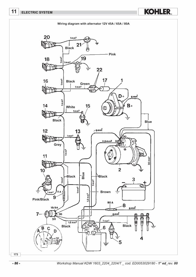
11
173
- 86 - - 86 -
ELECTRIC SYSTEM
Wiring diagram with alternator 12V 45A / 65A / 80A
Black
Black
Black
Black Black
BlackBlack
Brown
Blu
e
Blue
Pink
Green
White
Grey
Pink/Black
Workshop Manual KDW 1603_2204_2204/T _ cod. ED0053029180 - 1° ed_rev. 00
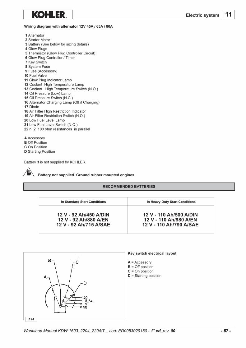
11
174
12 V - 92 Ah/450 A/DIN12 V - 92 Ah/880 A/EN
12 V - 92 Ah/715 A/SAE
12 V - 110 Ah/500 A/DIN12 V - 110 Ah/980 A/EN
12 V - 110 Ah/790 A/SAE
- 87 - - 87 -
Wiring diagram with alternator 12V 45A / 65A / 80A1Alternator2StarterMotor3Battery(Seebelowforsizingdetails)4 GlowPlugs5Thermistor(GlowPlugControllerCircuit) 6 GlowPlugController/Timer7KeySwitch 8 SystemFuse 9 Fuse(Accessory)10 FuelValve11 GlowPlugIndicatorLamp12CoolantHighTemperatureLamp13CoolantHighTemperatureSwitch(N.O.)14 OilPressure(Low)Lamp15OilPressureSwitch(N.C.)16 AlternatorChargingLamp(OffifCharging)17 Diode18 AirFilterHighRestrictionIndicator19 AirFilterRestrictionSwitch(N.O.)20 LowFuelLevelLamp21LowFuelLevelSwitch(N.O.)22 n.2100ohmresistancesinparallelA AccessoryBOffPositionC OnPositionD StartingPosition
Electric system
Key switch electrical layout
A =AccessoryB=OffpositionC=OnpositionD=Startingposition
Battery not supplied. Ground rubber mounted engines.
RECOMMENDED BATTERIES
In Standard Start Conditions In Heavy-Duty Start Conditions
Workshop Manual KDW 1603_2204_2204/T _ cod. ED0053029180 - 1° ed_rev. 00
Battery3 isnotsuppliedbyKOHLER.

177
176
175
11
- 88 - - 88 -
Alternator type Marelli AA 125 R 14V 45A
Characteristics:Ratedvoltage............................14VRatedcurrent.............................45AMax.speed................................14000giri/1'Peakspeed(max15min)..........15000rpmBearingoncontrolside..............6203.2zBearingonmanifoldside...........6201-2z/C3Voltageregulator.......................RTT119ACRHdirectionofrotation.
Tightenthenut1 to60Nm.
Note: Lubethetwobearingswithhightemperaturegrease. ThealternatorhasaWterminalforaspeedindicator.
Characteristic voltage curve for regulator type RTT 119 AC
Theelectronicvoltageregulatorisbuiltintothealternator.Thecurvechangesdependingontemperature.A=Max.voltagecurveB=Min.voltagecurve
Characteristic curves for alternator type Marelli AA 125 R 14V 45A
Thecurveshavebeendetectedwithelectronicvoltageregulatorafterthermalstabilizationat25°C;testvoltage13.5V.
P1=PowerinkWI =CurrentinAmpereη =Alternatorefficiency
Note: The alternator rpm is equal to to the rpm shown in thetablemultipliedby1000.
Ratiobetweenengine/alternatorrpm=1:1.8
Electric system
Workshop Manual KDW 1603_2204_2204/T _ cod. ED0053029180 - 1° ed_rev. 00
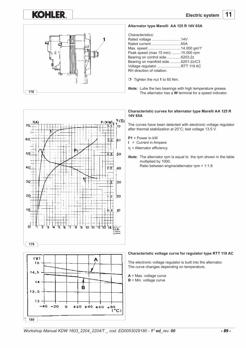
11
180
179
178
- 89 - - 89 -
Alternator type Marelli AA 125 R 14V 65A
Characteristics:Ratedvoltage............................14VRatedcurrent.............................65AMax.speed................................14.000giri/1'Peakspeed(max15min).........15.000rpmBearingoncontrolside..............6203.2zBearingonmanifoldside...........6201-2z/C3Voltageregulator.......................RTT119ACRHdirectionofrotation.
Tightenthenut1 to60Nm.
Note: Lubethetwobearingswithhightemperaturegrease. ThealternatorhasaWterminalforaspeedindicator.
Characteristic voltage curve for regulator type RTT 119 AC
Theelectronicvoltageregulatorisbuiltintothealternator.Thecurvechangesdependingontemperature.
A=Max.voltagecurveB=Min.voltagecurve
Characteristic curves for alternator type Marelli AA 125 R 14V 65A
Thecurveshavebeendetectedwithelectronicvoltageregulatorafterthermalstabilizationat25°C;testvoltage13.5V.
P1=PowerinkWI =CurrentinAmpereη =Alternatorefficiency
Note: Thealternatorrpmisequaltotherpmshowninthetablemultipliedby1000.
Ratiobetweenengine/alternatorrpm=1:1.8
Electric system
Workshop Manual KDW 1603_2204_2204/T _ cod. ED0053029180 - 1° ed_rev. 00

11
183
182
181
- 90 - - 90 -
Electric system
Alternator type Iskra, AAK3139 14V 80A
Characteristics:Ratedvoltage...................................................14VRatedcurrent....................................................80ASpeedoftheloadstartingpoint........................1350rpmMaximumpermanentintermittentspeed(max.15')............................13000-15000rpmFrontbearing....................................................6303-2RS-C3Rearbearing.....................................................6201-2RS-C3Max.forceonthebearing................................600NVoltageregulator..............................................AER1528RHdirectionofrotation. Tightenthenut1 to60÷70Nm.Note: Lubethetwobearingswithhightemperaturegrease. ThealternatorhasaWterminalforaspeedindicator.
Characteristic voltage curve for regulator type AER 1528
Theelectronicvoltageregulatorisbuiltintothealternator.Thecurvechangesdependingontemperature.
A=Max.voltagecurveB=Min.voltagecurve
Characteristic curves for alternator type Iskra, AAK3139 14V 80A
Thecurveshavebeendetectedwithelectronicvoltageregulatorafterthermalstabilizationat23±5°C;testvoltage13V.
I =CurrentinAmpere
Note: Thealternatorrpmisequaltotherpmshowninthetablemultipliedby1000.
Ratiobetweenengine/alternatorrpm=1:1.8
Workshop Manual KDW 1603_2204_2204/T _ cod. ED0053029180 - 1° ed_rev. 00

11
185
184
- 91 - - 91 -
Electric system
Starting Motor 12V
BoschtypeEV12V2.2KwRHdirectionofrotation.
Note:ApplytoaBoschservicecenterforanytipeofrepair.
Characteristic curves for starting motor type Bosch EV 12V 2.2 kW
The solid lines were obtained at a temperature of +20°C; thedotted lines were obtained at a temperature of -20°C.Batterytype110Ah450A.
U=MotorterminalvoltageinVoltn=Motorspeedinrpm.A=AbsorbedcurrentinAmpereP=PowerinkWM =TorqueinNm
Workshop Manual KDW 1603_2204_2204/T _ cod. ED0053029180 - 1° ed_rev. 00
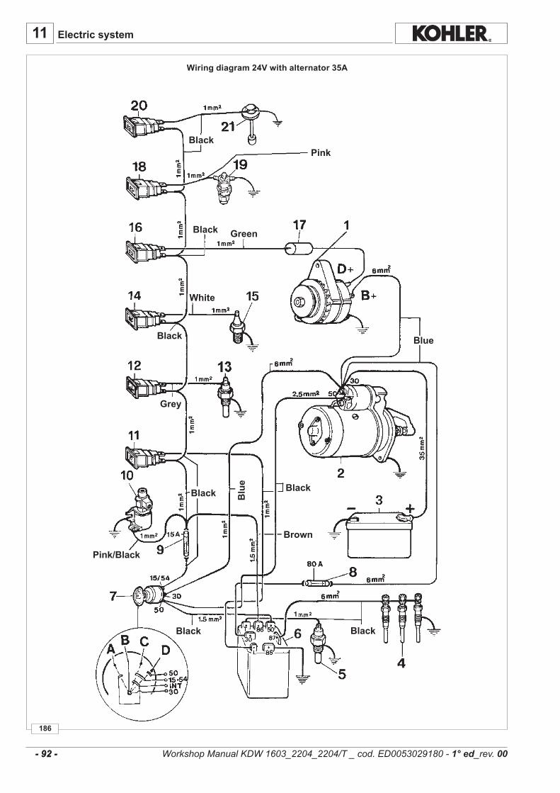
11
186
- 92 - - 92 -
Electric system
Wiring diagram 24V with alternator 35A
Black
Black
Black
Black Black
BlackBlack
Brown
Blu
e
Blue
Pink
Green
White
Grey
Pink/Black
Workshop Manual KDW 1603_2204_2204/T _ cod. ED0053029180 - 1° ed_rev. 00

11
187
12 V - 92 Ah/450 A/DIN12 V - 92 Ah/880 A/EN
12 V - 92 Ah/715 A/SAE
12 V - 110 Ah/500 A/DIN12 V - 110 Ah/980 A/EN
12 V - 110 Ah/790 A/SAE
- 93 - - 93 -
Wiring diagram 24 V with alternator 35A1Alternator2StarterMotor3Battery(Seebelowforsizingdetails)4 GlowPlugs5Thermistor(GlowPlugControllerCircuit) 6 GlowPlugController/Timer7KeySwitch 8 SystemFuse 9 Fuse(Accessory)10 FuelValve11 GlowPlugIndicatorLamp12CoolantHighTemperatureLamp13CoolantHighTemperatureSwitch(N.O.)14 OilPressure(Low)Lamp15OilPressureSwitch(N.C.)16 AlternatorChargingLamp(OffifCharging)17 Diode18 AirFilterHighRestrictionIndicator19 AirFilterRestrictionSwitch(N.O.)20 LowFuelLevelLamp21LowFuelLevelSwitch(N.O.)
A AccessoryBOffPositionC OnPositionD StartingPosition
Electric system
Key switch electrical layout
A =AccessoryB=OffpositionC=OnpositionD=Startingposition
Battery not supplied. Ground rubber mounted engines.
RECOMMENDED BATTERIES
In Standard Start Conditions In Heavy-Duty Start Conditions
Workshop Manual KDW 1603_2204_2204/T _ cod. ED0053029180 - 1° ed_rev. 00
Battery3 isnotsuppliedbyKOHLER.
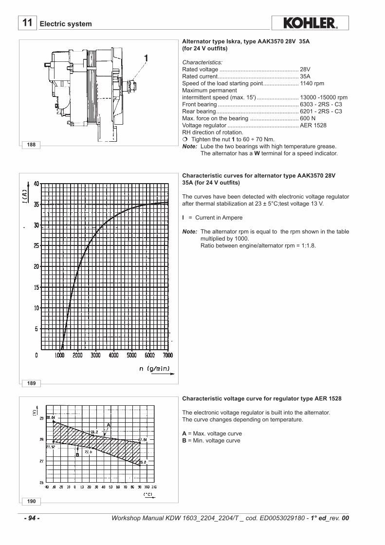
11
190
189
188
- 94 - - 94 -
Electric system
Alternator type Iskra, type AAK3570 28V 35A(for 24 V outfits)
Characteristics:Ratedvoltage................................................. 28VRatedcurrent.................................................. 35ASpeedoftheloadstartingpoint...................... 1140rpmMaximumpermanentintermittentspeed(max.15').......................... 13000-15000rpmFrontbearing.................................................. 6303-2RS-C3Rearbearing................................................... 6201-2RS-C3Max.forceonthebearing.............................. 600NVoltageregulator............................................ AER1528RHdirectionofrotation. Tightenthenut1 to60÷70Nm.Note: Lubethetwobearingswithhightemperaturegrease. ThealternatorhasaWterminalforaspeedindicator.
Characteristic voltage curve for regulator type AER 1528
Theelectronicvoltageregulatorisbuiltintothealternator.Thecurvechangesdependingontemperature.
A=Max.voltagecurveB=Min.voltagecurve
Characteristic curves for alternator type AAK3570 28V 35A (for 24 V outfits)
Thecurveshavebeendetectedwithelectronicvoltageregulatorafterthermalstabilizationat23±5°C;testvoltage13V.
I =CurrentinAmpere
Note: Thealternatorrpmisequaltotherpmshowninthetablemultipliedby1000.
Ratiobetweenengine/alternatorrpm=1:1.8.
Workshop Manual KDW 1603_2204_2204/T _ cod. ED0053029180 - 1° ed_rev. 00
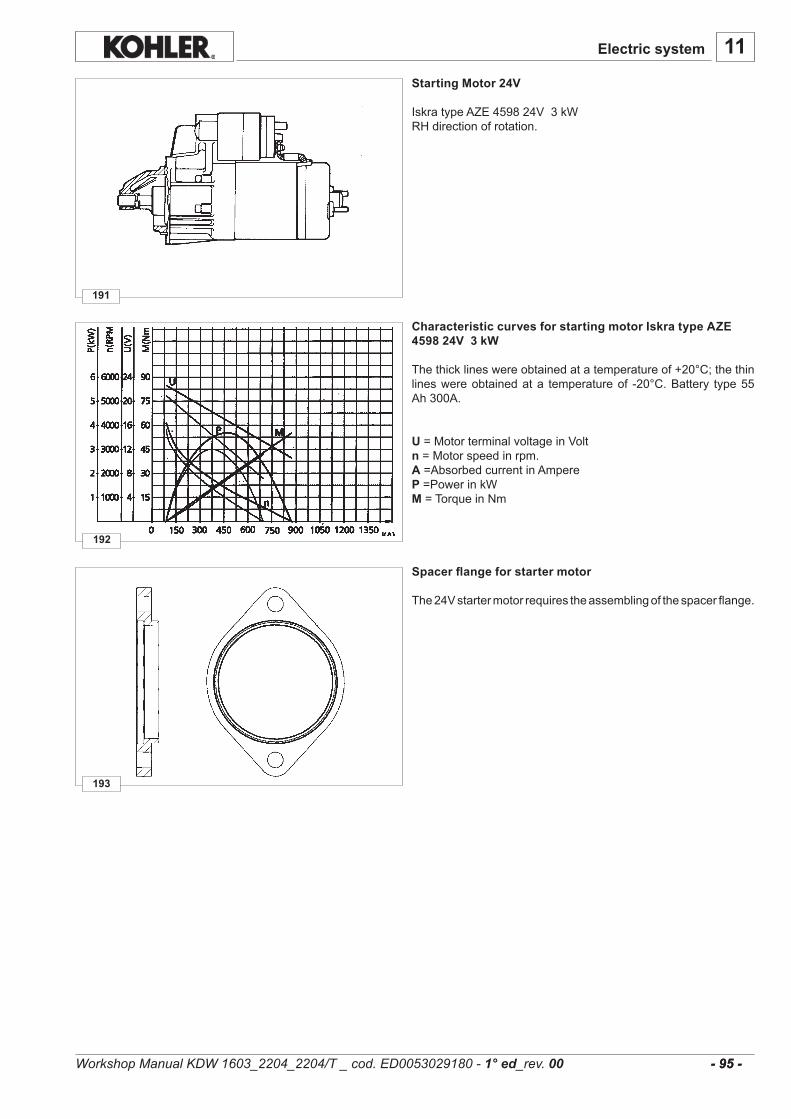
11
193
192
191
- 95 - - 95 -
Electric system
Starting Motor 24V
IskratypeAZE459824V3kWRHdirectionofrotation.
Spacer flange for starter motor
The24Vstartermotorrequirestheassemblingofthespacerflange.
Characteristic curves for starting motor Iskra type AZE 4598 24V 3 kW
Thethicklineswereobtainedatatemperatureof+20°C;thethinlineswereobtainedata temperatureof -20°C.Battery type55Ah300A.
U=MotorterminalvoltageinVoltn=Motorspeedinrpm.A=AbsorbedcurrentinAmpereP=PowerinkWM =TorqueinNm
Workshop Manual KDW 1603_2204_2204/T _ cod. ED0053029180 - 1° ed_rev. 00
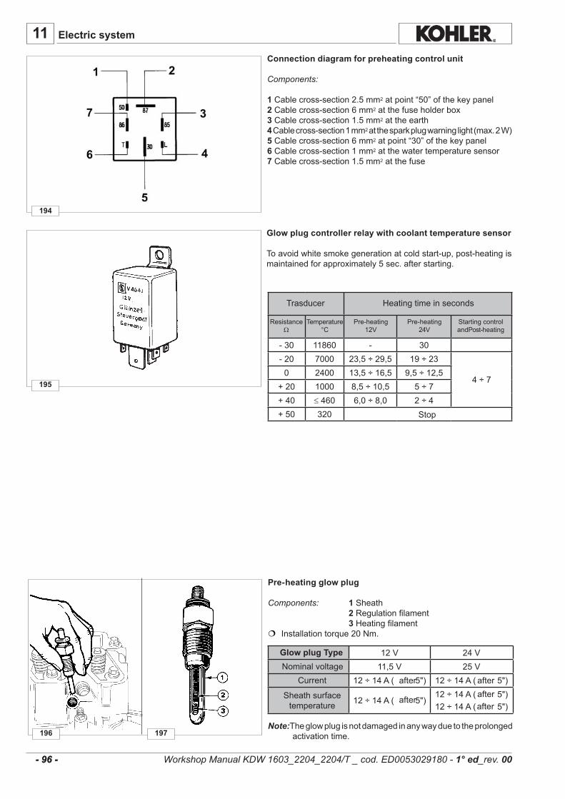
11
195
196 197
-30 11860 - 30-20 7000 23,5÷29,5 19÷23
4÷70 2400 13,5÷16,5 9,5÷12,5
+20 1000 8,5÷10,5 5÷7+40 ≤ 460 6,0÷8,0 2÷4+50 320
12V 24V11,5V 25V
12÷14A(5") 12÷14A(5")
12÷14A(5")12÷14A(5")12÷14A(5")
194
- 96 - - 96 -
Pre-heating glow plug
Components: 1Sheath 2Regulationfilament 3Heatingfilament Installationtorque20Nm.
Note:Theglowplugisnotdamagedinanywayduetotheprolongedactivationtime.
NominalvoltageCurrent
Sheathsurfacetemperature
Glow plug Type
afterafterafter
after
after
Glow plug controller relay with coolant temperature sensor
Toavoidwhitesmokegenerationatcoldstart-up,post-heatingismaintainedforapproximately5sec.afterstarting.
Trasducer Heatingtimeinseconds
ResistanceΩ
Temperature°C
Pre-heating12V
Pre-heating24V
StartingcontrolandPost-heating
Stop
Connection diagram for preheating control unit
Components:
1Cablecross-section2.5mm2atpoint“50”ofthekeypanel2Cablecross-section6mm2atthefuseholderbox3Cablecross-section1.5mm2attheearth4Cablecross-section1mm2atthesparkplugwarninglight(max.2W)5Cablecross-section6mm2atpoint“30”ofthekeypanel6Cablecross-section1mm2atthewatertemperaturesensor7Cablecross-section1.5mm2atthefuse
Electric system
Workshop Manual KDW 1603_2204_2204/T _ cod. ED0053029180 - 1° ed_rev. 00

11
198
+37.7 1125+65.5 405+93.3 170+100 140+121.1 80
-30 9790÷13940-20 6300÷7700-10 4900÷3600-0 2160÷2640+20 900÷1100+37.7 448÷672+65.5 180÷270+93.3 80÷120+100 75÷95+121.1 45÷55
199 200
- 97 - - 97 -
Temperature sensor (Thermistor)
Thethermistorislocatedonthethermostathousing,adjacenttothehighcoolanttemperatureswitch.Thethermistormustbeinstalledinthethermostathousingintheport locatednearesttothecylinderhead.(Seethefiguretotheleft).
Characteristic:Voltage:6/24VMax.installationtorque:30Nm. Features of standard sensor
Temperature°C
Features of heavy-duty start sensor
ResistanceΩTemperature°C
ResistanceΩ
Coolant high temperature lamp switch
Characteristics:Single-polecircuit,normallyopenSupplyvoltage...........................6÷24VAbsorbedpower........................3WCircuitclosingtemperature........107÷113°C
Whenrefittingtightento25Nm.
Electric system
Workshop Manual KDW 1603_2204_2204/T _ cod. ED0053029180 - 1° ed_rev. 00
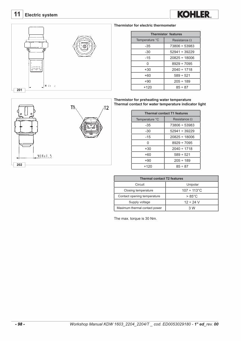
202
201
-35 73806÷53983-30 52941÷39229-15 20825÷180060 8929÷7095+30 2040÷1718+60 589÷521+90 205÷189+120 85÷87
-35 73806÷53983-30 52941÷39229-15 20825÷180060 8929÷7095+30 2040÷1718+60 589÷521+90 205÷189+120 85÷87
107÷113°C>85°C
12÷24V3W
11
- 98 - - 98 -
Thermal contact T1 features
ResistanceΩTemperature°C
Thermistor features
ResistanceΩTemperature°C
Thermistor for preheating water temperatureThermal contact for water temperature indicator light
Thermistor for electric thermometer
Thermal contact T2 features
Circuit Unipolar
ClosingtemperatureContactopeningtemperature
Supplyvoltage
Maximumthermalcontactpower
Themax.torqueis30Nm.
Electric system
Workshop Manual KDW 1603_2204_2204/T _ cod. ED0053029180 - 1° ed_rev. 00

11........................................................................................................................................................................
........................................................................................................................................................................
........................................................................................................................................................................
........................................................................................................................................................................
........................................................................................................................................................................
........................................................................................................................................................................
........................................................................................................................................................................
........................................................................................................................................................................
........................................................................................................................................................................
........................................................................................................................................................................
........................................................................................................................................................................
........................................................................................................................................................................
........................................................................................................................................................................
........................................................................................................................................................................
........................................................................................................................................................................
........................................................................................................................................................................
........................................................................................................................................................................
........................................................................................................................................................................
........................................................................................................................................................................
........................................................................................................................................................................
........................................................................................................................................................................
........................................................................................................................................................................
........................................................................................................................................................................
........................................................................................................................................................................
........................................................................................................................................................................
........................................................................................................................................................................
........................................................................................................................................................................
........................................................................................................................................................................
........................................................................................................................................................................
........................................................................................................................................................................
........................................................................................................................................................................
........................................................................................................................................................................
........................................................................................................................................................................
........................................................................................................................................................................
........................................................................................................................................................................
........................................................................................................................................................................
........................................................................................................................................................................- 99 - - 99 -
Electric system
Workshop Manual KDW 1603_2204_2204/T _ cod. ED0053029180 - 1° ed_rev. 00
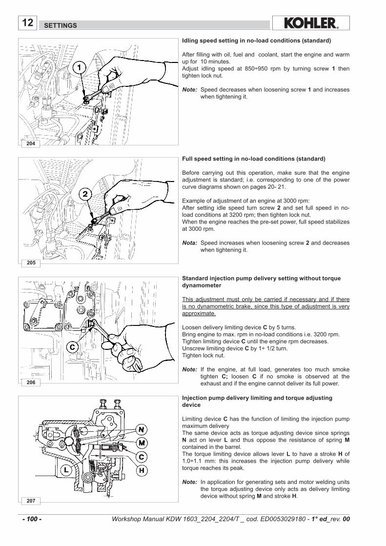
207
206
205
204
12
- 100 - - 100 -
SETTINGS
Idling speed setting in no-load conditions (standard)
Afterfillingwithoil,fuelandcoolant,starttheengineandwarmupfor10minutes.Adjust idling speed at 850÷950 rpm by turning screw 1 thentightenlocknut.Note: Speeddecreaseswhenlooseningscrew 1andincreases
whentighteningit.
Injection pump delivery limiting and torque adjusting device
LimitingdeviceChasthefunctionoflimitingtheinjectionpumpmaximumdeliveryThesamedeviceactsas torqueadjustingdevicesincespringsN act on lever L and thus oppose the resistance of springMcontainedinthebarrel.The torque limitingdeviceallows lever L tohaveastrokeHof1.0÷1.1 mm: this increases the injection pump delivery whiletorquereachesitspeak.
Note: Inapplicationforgeneratingsetsandmotorweldingunitsthe torqueadjustingdeviceonlyactsasdelivery limitingdevicewithoutspring MandstrokeH.
Standard injection pump delivery setting without torque dynamometer
This adjustmentmust only be carried if necessary and if thereisnodynamometricbrake,sincethistypeofadjustment isveryapproximate.
LoosendeliverylimitingdeviceCby5turns.Bringenginetomax.rpminno-loadconditionsi.e.3200rpm.Tightenlimitingdevice Cuntiltheenginerpmdecreases.UnscrewlimitingdeviceCby1÷1/2turn.Tightenlocknut.
Note: If the engine, at full load, generates too much smoketighten C; loosen C if no smoke is observed at theexhaustandiftheenginecannotdeliveritsfullpower.
Full speed setting in no-load conditions (standard)
Before carrying out this operation, make sure that the engineadjustment is standard; i.e. corresponding to oneof thepowercurvediagramsshownonpages20-21.
Exampleofadjustmentofanengineat3000rpm:After setting idle speed turn screw2 and set full speed in no-loadconditionsat3200rpm;thentightenlocknut.Whentheenginereachesthepre-setpower,fullspeedstabilizesat3000rpm.
Nota: Speedincreaseswhenlooseningscrew2anddecreaseswhentighteningit.
Workshop Manual KDW 1603_2204_2204/T _ cod. ED0053029180 - 1° ed_rev. 00
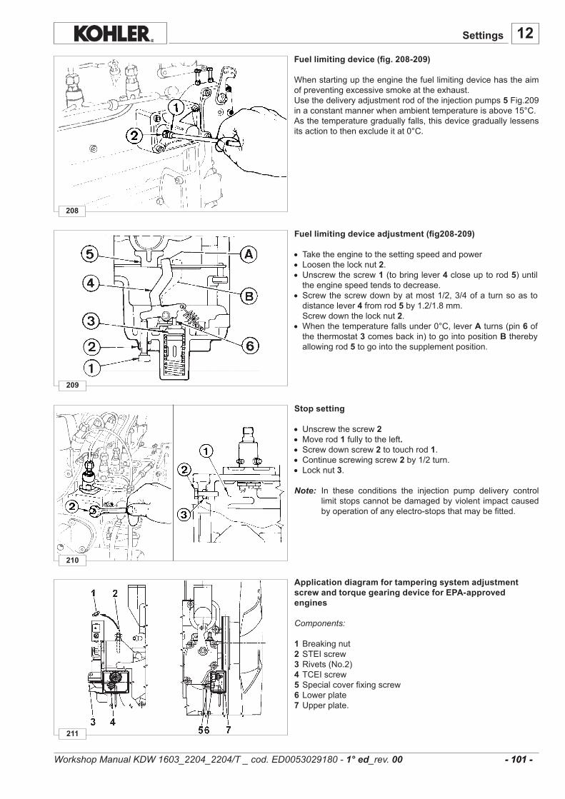
12
211
210
209
208
- 101 - - 101 -
Fuel limiting device (fig. 208-209)
Whenstartinguptheenginethefuellimitingdevicehastheaimofpreventingexcessivesmokeattheexhaust.Usethedeliveryadjustmentrodoftheinjectionpumps5Fig.209inaconstantmannerwhenambienttemperatureisabove15°C.Asthetemperaturegraduallyfalls,thisdevicegraduallylessensitsactiontothenexcludeitat0°C.
Application diagram for tampering system adjustment screw and torque gearing device for EPA-approved engines
Components:
1 Breakingnut2STEIscrew3 Rivets(No.2)4TCEIscrew5Specialcoverfixingscrew6Lowerplate7Upperplate.
Stop setting• Unscrewthescrew2• Moverod1 fullytotheleft.• Screwdownscrew2totouchrod1.• Continuescrewingscrew2 by1/2turn.• Locknut3.
Note: In these conditions the injection pump delivery controllimitstopscannotbedamagedbyviolent impactcausedbyoperationofanyelectro-stopsthatmaybefitted.
Fuel limiting device adjustment (fig208-209)
• Taketheenginetothesettingspeedandpower• Loosenthelocknut2.• Unscrewthescrew1 (tobringlever4 closeuptorod5)untiltheenginespeedtendstodecrease.
• Screwthescrewdownbyatmost1/2,3/4ofaturnsoastodistancelever4fromrod5by1.2/1.8mm.
Screwdownthelocknut2.• Whenthetemperaturefallsunder0°C,leverAturns(pin6 ofthethermostat3comesbackin)togointopositionB therebyallowingrod5 togointothesupplementposition.
Settings
Workshop Manual KDW 1603_2204_2204/T _ cod. ED0053029180 - 1° ed_rev. 00

12........................................................................................................................................................................
........................................................................................................................................................................
........................................................................................................................................................................
........................................................................................................................................................................
........................................................................................................................................................................
........................................................................................................................................................................
........................................................................................................................................................................
........................................................................................................................................................................
........................................................................................................................................................................
........................................................................................................................................................................
........................................................................................................................................................................
........................................................................................................................................................................
........................................................................................................................................................................
........................................................................................................................................................................
........................................................................................................................................................................
........................................................................................................................................................................
........................................................................................................................................................................
........................................................................................................................................................................
........................................................................................................................................................................
........................................................................................................................................................................
........................................................................................................................................................................
........................................................................................................................................................................
........................................................................................................................................................................
........................................................................................................................................................................
........................................................................................................................................................................
........................................................................................................................................................................
........................................................................................................................................................................
........................................................................................................................................................................
........................................................................................................................................................................
........................................................................................................................................................................
........................................................................................................................................................................
........................................................................................................................................................................
........................................................................................................................................................................
........................................................................................................................................................................
........................................................................................................................................................................
........................................................................................................................................................................
........................................................................................................................................................................- 102 - - 102 - Workshop Manual KDW 1603_2204_2204/T _ cod. ED0053029180 - 1° ed_rev. 00

13
- 103 - - 103 -
ENGINE STORAGE
ENGINE STORAGE
- When the engines are not for more than 6 months, they have to be protected performing the operations described in the following pages.
- Iftheengineisnottobeusedforextensiveperiods,checkthestorageareaconditionsandthetypeofpackagingandmakesurethatthesearesuitableforcorrectstorage.
Ifnecessary,covertheenginewithaproperprotectivesheet.- Avoidstoringtheengineindirectcontactwiththeground,inenvironmentsthatarehumidandexposedtobadweather,
nearhighvoltageelectriclines,etc.
ImportantIf, after the first 6 months, the engine is still not used, it is necessary to carry out a further measure to extend the pro-tection period (see “Protective treatment”).
1 - PourintheenginehousingAGIPRUSTIACprotectiveoiluptothemaximumlevel.
2 - Fillupwithfuelcontaining10%AGIPRUSTIANT.3 - Makesurethatthecoolantisuptothemaximumlevel.4 - Starttheengineandkeepitidleatminimumspeedfor
someminutes.5 - Bringtheengineto¾ofthemaximumspeedfor5÷10
minutes.6 - Turnofftheengine.7 - Emptyoutcompletelythefueltank.8 - SpraySAE10Wontheexhaustandintakemanifolds.9 - Sealtheexhaustandintakeductstopreventforeign
bodiesfromentering.10 - Thoroughlycleanallexternalpartsoftheengineusing
suitableproducts.
11 - Treatnon-paintedpartswithprotectiveproducts(AGIPRUSTIANT).
12 - Loosenthealternator/fanbelt.13 - Covertheenginewithaproperprotectivesheet.
Caution - WarningIn countries in which AGIP products are not available, find an equivalent product (with specifications: MIL-L-21260C).
ImportantMaximum every 24 months of inactivity, the engine must be started up by repeating all “Engine Storage” operations.
Afterthestorageperiodandbeforestartinguptheengineandpreparingitforoperation,youneedtoperformcertainopera-tionstoensuremaximalefficiencyconditions.
1 - Removetheprotectivesheet.2 - Removeanysealingdevicesfromtheexhaustandinta-
keducts.3 - Useaclothsoakedindegreasingproducttoremovethe
protectivetreatmentfromtheexternalparts.5 - Injectlubricatingoil(nomorethan2cm3)intotheintake
ducts.6 - Adjustthealternator/fanbelttension.7 - Turntheenginemanuallytocheckthecorrectmovement
andsmoothnessofthemechanicalparts.8 - Refillthetankwithfreshfuel.9 - Makesurethattheoilandthecoolantareuptothema-
ximumlevel.10 - Starttheengineandaftersomeminutesbringitto¾of
themaximumspeedfor5-10minutes.11 - Turnofftheengine.12 - Removetheoildrainplug(see“Oilreplacement”)and
dischargetheAGIPRUSTIANTprotectiveoilwhiletheengineishot.
13 - Pournewoil(see“Tableoflubricants”)uptothemaxi-mumlevel.
14 - Replacethefilters(air,oil,fuel)withoriginalspareparts.15 - Empty the cooling circuit completely andpour in thenew
coolantuptothemaximumlevel.
Caution - WarningOver time, a number of engine components and lubricants lose their properties, so it is important considering whether they need replacing, also based on age (see Replacement table).
ImportantMaximum every 24 months of inactivity, the engine must be started up by repeating all “Engine Storage” operations.
PREPARING THE ENGINE FOR OPERATION AFTER PROTECTIVE TREATMENT
PROTECTIVE TREATMENT
Workshop Manual KDW 1603_2204_2204/T _ cod. ED0053029180 - 1° ed_rev. 00
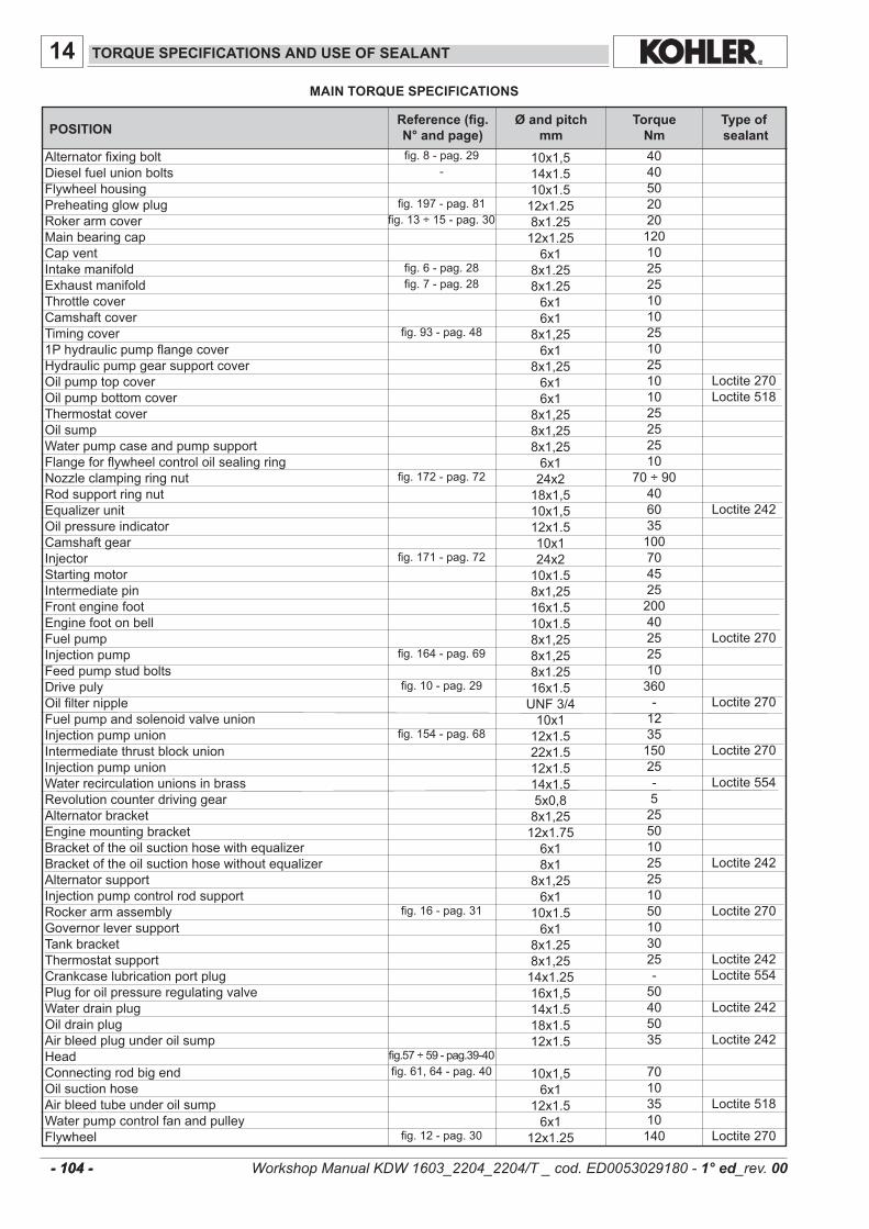
10x1,514x1.510x1.512x1.258x1.2512x1.256x1
8x1.258x1.256x16x1
8x1,256x1
8x1,256x16x1
8x1,258x1,258x1,256x124x218x1,510x1,512x1.510x124x210x1.58x1,2516x1.510x1.58x1,258x1,258x1.2516x1.5UNF3/410x112x1.522x1.512x1.514x1.55x0,88x1,2512x1.756x18x1
8x1,256x1
10x1.56x1
8x1.258x1,2514x1.2516x1,514x1.518x1.512x1.5
10x1,56x1
12x1.56x1
12x1.25
40405020201201025251010251025101025252510
70÷9040603510070452520040252510360-123515025-525501025251050103025-50405035
70103510140
Loctite270Loctite518
Loctite242
Loctite270
Loctite270
Loctite270
Loctite554
Loctite242
Loctite270
Loctite242Loctite554
Loctite242
Loctite242
Loctite518
Loctite270
14
fig.8-pag.29-
fig.197-pag.81fig.13÷15-pag.30
fig.6-pag.28fig.7-pag.28
fig.93-pag.48
fig.172-pag.72
fig.171-pag.72
fig.164-pag.69
fig.10-pag.29
fig.154-pag.68
fig.16-pag.31
fig.57÷59-pag.39-40fig.61,64-pag.40
fig.12-pag.30
- 104 - - 104 -
MAIN TORQUE SPECIFICATIONS
TORQUE SPECIFICATIONS AND USE OF SEALANT
AlternatorfixingboltDieselfuelunionboltsFlywheelhousingPreheatingglowplugRokerarmcoverMainbearingcapCapventIntakemanifoldExhaustmanifoldThrottlecoverCamshaftcoverTimingcover1PhydraulicpumpflangecoverHydraulicpumpgearsupportcoverOilpumptopcoverOilpumpbottomcoverThermostatcoverOilsumpWaterpumpcaseandpumpsupportFlangeforflywheelcontroloilsealingringNozzleclampingringnutRodsupportringnutEqualizerunitOilpressureindicatorCamshaftgearInjectorStartingmotorIntermediatepinFrontenginefootEnginefootonbellFuelpumpInjectionpumpFeedpumpstudboltsDrivepulyOilfilternippleFuelpumpandsolenoidvalveunionInjectionpumpunionIntermediatethrustblockunionInjectionpumpunionWaterrecirculationunionsinbrassRevolutioncounterdrivinggearAlternatorbracketEnginemountingbracketBracketoftheoilsuctionhosewithequalizerBracketoftheoilsuctionhosewithoutequalizerAlternatorsupportInjectionpumpcontrolrodsupportRockerarmassemblyGovernorleversupportTankbracketThermostatsupportCrankcaselubricationportplugPlugforoilpressureregulatingvalveWaterdrainplugOildrainplugAirbleedplugunderoilsumpHeadConnectingrodbigendOilsuctionhoseAirbleedtubeunderoilsumpWaterpumpcontrolfanandpulleyFlywheel
POSITIONØ and pitch
mm Torque
NmType of sealant
Reference (fig. N° and page)
Workshop Manual KDW 1603_2204_2204/T _ cod. ED0053029180 - 1° ed_rev. 00
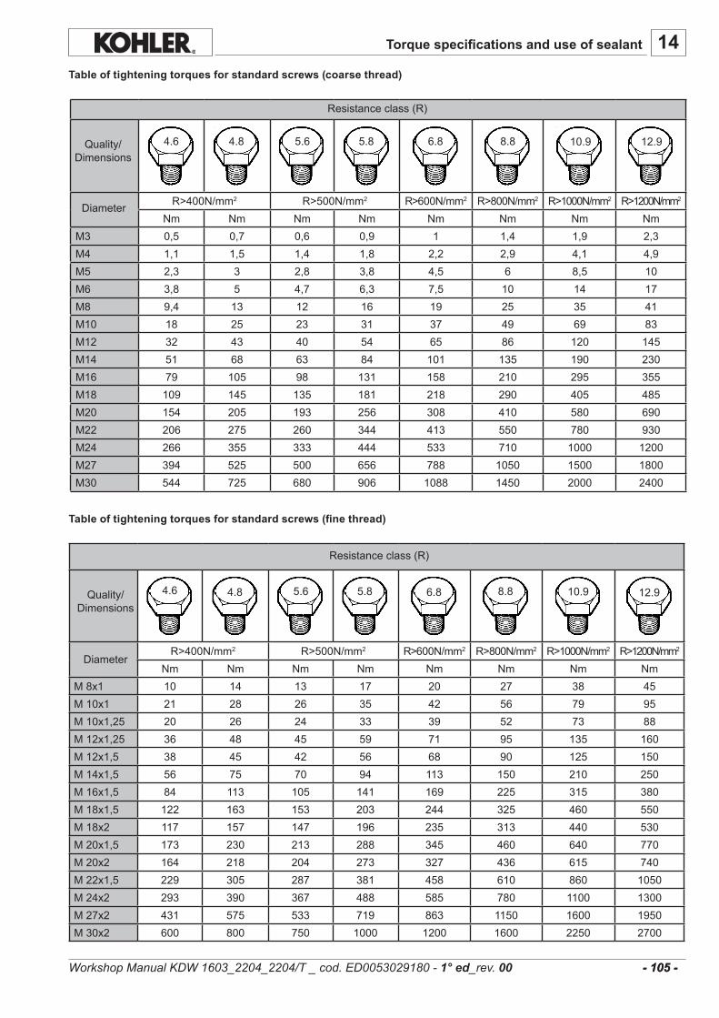
14
R>400N/mm2 R>500N/mm2 R>600N/mm2 R>800N/mm2 R>1000N/mm2 R>1200N/mm2
Nm Nm Nm Nm Nm Nm Nm NmM3 0,5 0,7 0,6 0,9 1 1,4 1,9 2,3M4 1,1 1,5 1,4 1,8 2,2 2,9 4,1 4,9M5 2,3 3 2,8 3,8 4,5 6 8,5 10M6 3,8 5 4,7 6,3 7,5 10 14 17M8 9,4 13 12 16 19 25 35 41M10 18 25 23 31 37 49 69 83M12 32 43 40 54 65 86 120 145M14 51 68 63 84 101 135 190 230M16 79 105 98 131 158 210 295 355M18 109 145 135 181 218 290 405 485M20 154 205 193 256 308 410 580 690M22 206 275 260 344 413 550 780 930M24 266 355 333 444 533 710 1000 1200M27 394 525 500 656 788 1050 1500 1800M30 544 725 680 906 1088 1450 2000 2400
4.6 4.8 5.6 5.8 6.8 8.8 10.9 12.9
R>400N/mm2 R>500N/mm2 R>600N/mm2 R>800N/mm2 R>1000N/mm2 R>1200N/mm2
Nm Nm Nm Nm Nm Nm Nm NmM8x1 10 14 13 17 20 27 38 45M10x1 21 28 26 35 42 56 79 95M10x1,25 20 26 24 33 39 52 73 88M12x1,25 36 48 45 59 71 95 135 160M12x1,5 38 45 42 56 68 90 125 150M14x1,5 56 75 70 94 113 150 210 250M16x1,5 84 113 105 141 169 225 315 380M18x1,5 122 163 153 203 244 325 460 550M18x2 117 157 147 196 235 313 440 530M20x1,5 173 230 213 288 345 460 640 770M20x2 164 218 204 273 327 436 615 740M22x1,5 229 305 287 381 458 610 860 1050M24x2 293 390 367 488 585 780 1100 1300M27x2 431 575 533 719 863 1150 1600 1950M30x2 600 800 750 1000 1200 1600 2250 2700
4.6 4.8 5.6 5.8 6.8 8.8 10.9 12.9
- 105 - - 105 -
Table of tightening torques for standard screws (coarse thread)
Resistanceclass(R)
Quality/Dimensions
Diameter
Resistanceclass(R)
Quality/Dimensions
Diameter
Table of tightening torques for standard screws (fine thread)
Torque specifications and use of sealant
Workshop Manual KDW 1603_2204_2204/T _ cod. ED0053029180 - 1° ed_rev. 00

7104-1460-021
7104-1460-072
7104-1460-090
7271-1460-024
17104-1460-0222 7104-1460-023
7107-1460-075
7107-1460-212
15
- 106 - - 106 -
SPECIAL TOOLS DESCIPTION Part No.
Fueldeliveryequalizationtool.Allowstheadjustmentofindividualunitinjectorfueldelivery.
Glasscolumnforfueldeliveryequalizationtool.
Camshaftbushingreplacementtool
Statictimingtool
T.D.C.determinationfixture.
Pliersforinjectionpumpfeedingtubes
1Fortubediam.6mm2Fortubediam.8mm
Tool for replacement of injectionpumpoutletunion:
1Forextraction2 Fordriving
SPECIAL TOOLS
Workshop Manual KDW 1603_2204_2204/T _ cod. ED0053029180 - 1° ed_rev. 00

........................................................................................................................................................................
........................................................................................................................................................................
........................................................................................................................................................................
........................................................................................................................................................................
........................................................................................................................................................................
........................................................................................................................................................................
........................................................................................................................................................................
........................................................................................................................................................................
........................................................................................................................................................................
........................................................................................................................................................................
........................................................................................................................................................................
........................................................................................................................................................................
........................................................................................................................................................................
........................................................................................................................................................................
........................................................................................................................................................................
........................................................................................................................................................................
........................................................................................................................................................................
........................................................................................................................................................................
........................................................................................................................................................................
........................................................................................................................................................................
........................................................................................................................................................................
........................................................................................................................................................................
........................................................................................................................................................................
........................................................................................................................................................................
........................................................................................................................................................................
........................................................................................................................................................................
........................................................................................................................................................................
........................................................................................................................................................................
........................................................................................................................................................................
........................................................................................................................................................................
........................................................................................................................................................................
........................................................................................................................................................................
........................................................................................................................................................................
........................................................................................................................................................................
........................................................................................................................................................................
........................................................................................................................................................................
........................................................................................................................................................................
-
- 107 - - 107 -
Notes:
Workshop Manual KDW 1603_2204_2204/T _ cod. ED0053029180 - 1° ed_rev. 00

ENGINEDIVISION,KOHLERCO.,KOHLER,WISCONSIN53044
FORSALESANDSERVICEINFORMATIONINU.S.ANDCANADA,CALL 1-800-544-2444KohlerEngines.com
FORMNO. ED0053029180
ISSUED 02/15/2011
REVISED 00 DATE 02/15/2011
Translated from the original manual in Italian language.
Data reported in this issue can be modified at any time by KOHLER.
Related Documents