101 89 44-26 335 XPT Workshop Manual For Husqvarna Parts Call 606-678-9623 or 606-561-4983 www.mymowerparts.com

Welcome message from author
This document is posted to help you gain knowledge. Please leave a comment to let me know what you think about it! Share it to your friends and learn new things together.
Transcript

101 89 44-26
335 XPT
Workshop Manual
For Husqvarna Parts Call 606-678-9623 or 606-561-4983
www.mymowerparts.com

2 – English
CONTENTS
Introduction ....................................................3Safety instructions .........................................4Key to symbols ...............................................5Technical data.................................................6Tools ................................................................8Trouble shooting ..........................................10Service data ..................................................12Safety equipment .........................................14Starter ............................................................19Ignition system .............................................21Centrifugal clutch .........................................23Carburettor....................................................25Tank unit ........................................................33AV-System .....................................................37Crankshaft, Piston and Cylinder ................ 38Bar bolt ..........................................................42Oil pump........................................................43
Eng 02-09 97-12-03, 16.262
For Husqvarna Parts Call 606-678-9623 or 606-561-4983
www.mymowerparts.com
English – 3
INTRODUCTION
Layout
This workshop manual can be used in two different ways:
• Reparation of a particular system on the chain saw.• Dismantling and Assembling the entire chain saw.
General
This workshop manual describes in detail how trouble shooting,repairs and testing of the chain saw should be carried out. Thedifferent safety precautions that must be taken when carryingout repairs are also described.
Dismantling and assembling theentire chain saw
When the entire chain saw shall be stripped and rebuilt proceedas follows:
1. Turn to page 19, which deals with the Starter and carry outthe instructions under the heading Dismantling.
2. Go forward in the manual and carry out Dismantling in theorder the sections appear.
3. Return to the Starter on page 19 and carry out the instruc-tions under Cleaning and inspection.
4. Work forward in the manual and carry out Cleaning andinspection in the order the sections appear.
5. Order or collect all requisite spare parts from the spareparts store.
6. Turn to page 44 that deals with the Oil pump and carry outthe instructions under Assembly .
7. Work towards the beginning of the manual and carry outAssembly in the order the sections appear.
To broaden understanding some sections are introduced by aDescription of the unit in question.
Safety
Note!The section dealing with safety should be read andunderstood by all persons repairing or servicing thechain saw.
Warning signs are displayed in the workshop manual and onthe chain saw. See page 5. If any of the warning symbols on thechain saw have be damaged or are missing a new symbolshould be fitted as soon as possible so that the greatest level ofsafety is attained when the chain saw is used.
Reparation of a particular system
When a particular system on the chain saw must be repairedproceed as follows:
1. Look up the page for the system.
2. Carry out the sections:• Dismantling• Cleaning and inspection• Assembly
Numbering
Positioning indicators to components within the figures aredenoted by A, B etc.Positioning indicators start again from A in each new section.
Tools
Special tools must be used during certain procedures. Allservice tools are listed in this workshop manual. Usage isevident from respective sections.
Always use Husqvarna's original:• Spare parts• Service tools• Accessories
Target group
The workshop manual has been written for persons assumed tohave a general knowledge of the repair and service to smallengines.
The workshop manual should be read and understood by thosepersons who carry out repairs and service to the chain saw. Themanual is also suitable for use during the training of newemployees.
Modifications
Modifications to the chain saw will be successively introducedduring production. When these modifications affect servicingand/or spare parts special service bulletins will be sent out oneach occasion. This means that this workshop manual in timewill be out-of-date. To prevent this the manual should be readwith all service bulletins regarding the chain saw in question.
Eng 02-09 97-12-03, 16.263
For Husqvarna Parts Call 606-678-9623 or 606-561-4983
www.mymowerparts.com

4 – English
SAFETY INSTRUCTIONS
Special instructions
The fuel used in the chain saw has the following dangerouscharacteristics:
• The liquid and its vapours are poisonous.• Can cause skin irritation.• Is extremely inflammable.
The bar, chain and clutch cover (chain brake) must be fittedbefore the saw is started otherwise the clutch can come looseand cause personal injury.
Use ear protection when test running.
Do not use the saw before it is adjusted so that the chain doesnot rotate when idling.
Do not touch the muffler after test running until it has cooled.Risk of burn injuries.
Inadequate chain lubrication can result in the chain breaking,which can cause serious, even fatal injury.
Make sure the starter recoil spring does not fly out and causepersonal injury.The spring can fly out and cause personal injury, if the springtension is activated on the cord pulley when removed.
Check that the brake is in the braking position when thepressure springs on the chain brake shall be removed. Other-wise the pressure spring can fly out and cause personal injury.
When using compressed air, the air jet should never be pointedtowards the body. Air can be forced into the blood stream,which can cause fatality.
General instructions
Workshops where chain saws are to be repaired must beequipped with safety equipment as set out in local directives.
No one may repair the chain saw without first reading andunderstanding the contents of this workshop manual.
The boxes shown below can be found in appropriate places inthis workshop manual. Warning boxes are positioned before theprocedures they refer to.
WARNING!Warning boxes warn for the risk of personalinjuries if the instructions are not followed.
NOTE!This box warns of damage to material if the instructionsare not followed.
!
Eng 02-09 97-12-03, 16.264
For Husqvarna Parts Call 606-678-9623 or 606-561-4983
www.mymowerparts.com

English – 5
KEY TO SYMBOLS
Symbols
CAUTION! Chain saws can be dangerous!Careless or incorrect use can result inserious or fatal injury to the operator orothers.
Please read the instructions carefully andmake sure you understand them beforeusing the saw.
Always wear:• Approved protective helmet• Approved hearing protection• Protective glasses or visor
Where possible, always use both handswhen operating the chain saw.
Avoid contact between the guide bar tip andany object.
Contact with the guide bar tip can cause thesaw to be thrown violently upwards andbackwards (kickback), which can result inserious injury.
Switch off the engine by moving the stopswitch to the STOP position before carryingout any checks or maintenance.
Operating position.
Choke.
Always wear approved protective gloves.
Regular cleaning is required.
Visual check.
Protective glasses or a visor must be worn.
Refuelling.
Chain oil and chain oil flow adjustment.
This saw should only be used bypersons who are specially trainedin tree maintenance work.See the Operator's manual!
Eng 02-09 97-12-03, 16.265
For Husqvarna Parts Call 606-678-9623 or 606-561-4983
www.mymowerparts.com
6 – English
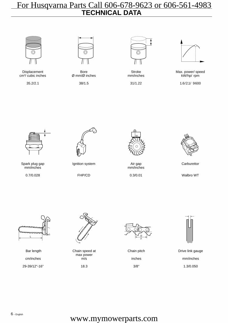
TECHNICAL DATA
Spark plug gap Ignition system Air gap Carburettormm/inches mm/inches
0.7/0.028 FHP/CD 0.3/0.01 Walbro WT
Bar length Chain speed at Chain pitch Drive link gaugemax power
cm/inches m/s inches mm/inches
29-39/12"-16" 18.3 3/8" 1.3/0.050
Displacement Bore Stroke Max. power/ speedcm3/ cubic inches Ø mm/Ø inches mm/inches kW/hp/ rpm
35.2/2.1 38/1.5 31/1.22 1.6/2.1/ 9 600
Eng 02-09 97-12-03, 16.266
For Husqvarna Parts Call 606-678-9623 or 606-561-4983
www.mymowerparts.com

English – 7
TECHNICAL DATA
Fuel tank volume Oil pump capacity Oil tank volume Automatic oil pumpLitres/US. pint cm3/min Litres/US. pint
0.3/0.63 3-7 0.16/0.34 Yes
Weight without bar and chain Weight with bar and chain Handle heaterkg/lbs kg/lbs Watt/ rpm
3.4/7.5 4.0/8.8 - / -
Idling speed Engagement speed Max. speed Spark plugrpm rpm rpm
2 800 4 100 13 800 ChampionNGK BPMR 7A
Eng 02-09 97-12-03, 16.277
For Husqvarna Parts Call 606-678-9623 or 606-561-4983
www.mymowerparts.com

8 – English
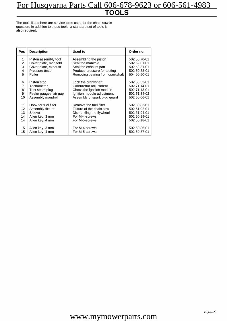
TOOLS
1 2 3 4
5 6 7
8 9 10 11
12 13 14 15
Eng 02-09 97-12-03, 16.278
For Husqvarna Parts Call 606-678-9623 or 606-561-4983
www.mymowerparts.com
English – 9
TOOLS
Pos Description Used to Order no.
1 Piston assembly tool Assembling the piston 502 50 70-012 Cover plate, manifold Seal the manifold 502 52 01-013 Cover plate, exhaust Seal the exhaust port 502 52 31-014 Pressure tester Produce pressure for testing 502 50 38-015 Puller Removing bearing from crankshaft 504 90 90-01
6 Piston stop Lock the crankshaft 502 50 33-017 Tachometer Carburettor adjustment 502 71 14-018 Test spark plug Check the ignition module 502 71 13-019 Feeler gauges, air gap Ignition module adjustment 502 51 34-0210 Assembly mandrel Assembly of spark plug guard 502 50 06-01
11 Hook for fuel filter Remove the fuel filter 502 50 83-0112 Assembly fixture Fixture of the chain saw 502 51 02-0113 Sleeve Dismantling the flywheel 502 51 94-0114 Allen key, 3 mm For M-4-screws 502 50 19-0114 Allen key, 4 mm For M-5-screws 502 50 18-01
15 Allen key, 3 mm For M-4-screws 502 50 86-0115 Allen key, 4 mm For M-5-screws 502 50 87-01
The tools listed here are service tools used for the chain saw inquestion. In addition to these tools a standard set of tools isalso required.
Eng 02-09 97-12-03, 16.279
For Husqvarna Parts Call 606-678-9623 or 606-561-4983
www.mymowerparts.com

10 – English
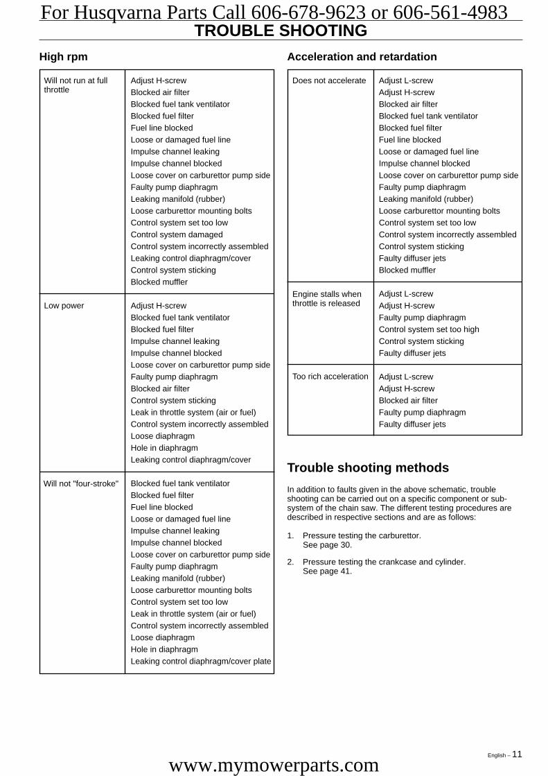
TROUBLE SHOOTING
Difficult starting
Carburettor leakingfuel
Idling (low rpm) (cont.)Trouble shooting schematic
Faults that can develop on the chain saw are divided into fourgroups as follows. In each category, possible malfunctions areshown on the left, with a list of possible faults on the right. Themost probable fault is given first and so on.
Adjust L-screwAir filter blockedChoke not workingWorn choke shaftWorn choke valveFuel filter blockedFuel line blockedPiston ring seizedBlocked impulse channel
Loose or faulty fuel pipeHole in diaphragmWorn needle valve/needleControl system stickingControl system set too highLeak in control system (air or fuel)Loose cover on carburettorpump side
Worn needle valveControl system set too highControl system sticking
Flooding when theengine is not running
Starting
Idles when L-screwis closed
Worn needle valve/needleLeaking control diaphragm/cover plateControl system stickingWorn throttle lever in control systemFaulty diffuser jets
Fuel filter blockedFuel line blockedLeaking manifold (rubber)Loose carburettor mounting boltsWorn throttle valve shaftLoose throttle valve screwWorn throttle valveControl system stickingLeak in throttle system (air or fuel)Control diaphragm centre knob iswornHole in diaphragmLeaking control diaphragm/cover plateCrankcase leaking
Fuel line blockedControl system set too highControl system stickingControl system (air or fuel)Leaking control diaphragm/cover plateFaulty diffuser jetsCrankcase leaking
Control system set too highControl system stickingControl system damagedWorn needle valveLeaking control diaphragm/cover plateControl system incorrectly assembled
L-screw requiresconstant adjustment
Idling uneven
Too much fuel whenidling
Adjust L-screwLeaking manifold (rubber)Loose carburettor mounting boltsLoose or faulty fuel pipeFuel filter blockedFuel line blockedFuel tank ventilator blockedThrottle lever shaft stiffThrottle cable stickingDefective throttle return springBent throttle lever shaft stopFaulty diffuser jets
Adjust L-screwWorn needle valve/needleControl system set too highWorn throttle lever in control systemLeaking control diaphragm/cover plateControl system sticking
Will not idle
Idling too rich
Idling (low rpm)
Eng 10-18 97-12-08, 17.3710
For Husqvarna Parts Call 606-678-9623 or 606-561-4983
www.mymowerparts.com
English – 11
TROUBLE SHOOTINGHigh rpm Acceleration and retardation
Adjust L-screwAdjust H-screwBlocked air filterBlocked fuel tank ventilatorBlocked fuel filterFuel line blockedLoose or damaged fuel lineImpulse channel blockedLoose cover on carburettor pump sideFaulty pump diaphragmLeaking manifold (rubber)Loose carburettor mounting boltsControl system set too lowControl system incorrectly assembledControl system stickingFaulty diffuser jetsBlocked muffler
Adjust L-screwAdjust H-screwFaulty pump diaphragmControl system set too highControl system stickingFaulty diffuser jets
Adjust L-screwAdjust H-screwBlocked air filterFaulty pump diaphragmFaulty diffuser jets
Does not accelerateWill not run at fullthrottle
Adjust H-screwBlocked air filterBlocked fuel tank ventilatorBlocked fuel filterFuel line blockedLoose or damaged fuel lineImpulse channel leakingImpulse channel blockedLoose cover on carburettor pump sideFaulty pump diaphragmLeaking manifold (rubber)Loose carburettor mounting boltsControl system set too lowControl system damagedControl system incorrectly assembledLeaking control diaphragm/coverControl system stickingBlocked muffler
Adjust H-screwBlocked fuel tank ventilatorBlocked fuel filterImpulse channel leakingImpulse channel blockedLoose cover on carburettor pump sideFaulty pump diaphragmBlocked air filterControl system stickingLeak in throttle system (air or fuel)Control system incorrectly assembledLoose diaphragmHole in diaphragmLeaking control diaphragm/cover
Blocked fuel tank ventilatorBlocked fuel filterFuel line blockedLoose or damaged fuel lineImpulse channel leakingImpulse channel blockedLoose cover on carburettor pump sideFaulty pump diaphragmLeaking manifold (rubber)Loose carburettor mounting boltsControl system set too lowLeak in throttle system (air or fuel)Control system incorrectly assembledLoose diaphragmHole in diaphragmLeaking control diaphragm/cover plate
Low power
Will not "four-stroke"
Engine stalls whenthrottle is released
Too rich acceleration
Trouble shooting methods
In addition to faults given in the above schematic, troubleshooting can be carried out on a specific component or sub-system of the chain saw. The different testing procedures aredescribed in respective sections and are as follows:
1. Pressure testing the carburettor.See page 30.
2. Pressure testing the crankcase and cylinder.See page 41.
Eng 10-18 97-12-08, 17.3711
For Husqvarna Parts Call 606-678-9623 or 606-561-4983
www.mymowerparts.com

12 – English
SERVICE DATA
Character key
Numbers by components that are bolted refer tothe tightening torque in Nm.
▲ = Lubricate using two-stroke oil.■ = Lubricate using engine oil.● = Lubricate using grease.❑ = Glued using 2-component adhesive.❍ = Sealed using silicone.
●
▲
▲
▲●
❑
■
❍
8-10 8-10
2-3
20-26
15
Eng 10-18 97-12-03, 16.2712
For Husqvarna Parts Call 606-678-9623 or 606-561-4983
www.mymowerparts.com

English – 13
1-22,5-4
2-3
8-10
10-15
2-3
2-3
2,5-4
20-26
2-3
6-7
2,5-4
▲
▲
❍
▲
SERVICE DATA
Eng 10-18 97-12-03, 16.2713
For Husqvarna Parts Call 606-678-9623 or 606-561-4983
www.mymowerparts.com
14 – English
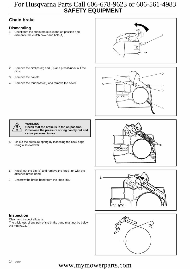
SAFETY EQUIPMENT
InspectionClean and inspect all parts.The thickness of any part of the brake band must not be below0.8 mm (0.031").
A
D
D
D
D
B
C
E
2. Remove the circlips (B) and (C) and press/knock out thepins.
3. Remove the handle.
4. Remove the four bolts (D) and remove the cover.
Chain brake
Dismantling1. Check that the chain brake is in the off position and
dismantle the clutch cover and bolt (A).
6. Knock out the pin (E) and remove the knee link with theattached brake band.
7. Unscrew the brake band from the knee link.
!5. Lift out the pressure spring by loosening the back edge
using a screwdriver.
WARNING!Check that the brake is in the on position.Otherwise the pressure spring can fly out andcause personal injury.
Eng 10-18 97-12-03, 16.2714
For Husqvarna Parts Call 606-678-9623 or 606-561-4983
www.mymowerparts.com

English – 15
SAFETY EQUIPMENTAssemblyAssemble the chain brake as follows:
1. Screw together the brake band and knee link.
2. Grease the moving parts on the knee link and assemble theunit in the cover and knock in pin (E).
B
C
E
D
D
D
D
5. Fit the cover and tighten the four bolts (D).
6. Move the brake to the off position and fit the clutch cover onthe chain saw. Adjust the chain tension, see the Operator'smanual. Tighten the nut to 15 Nm.
4. Put the brake in the on position and fit the spring. Press itdown by using a screwdriver on the back edge.
3. Fit the kickback guard, insert the two pins and fit the circlips(B) and (C).
Eng 10-18 97-12-03, 16.2715
For Husqvarna Parts Call 606-678-9623 or 606-561-4983
www.mymowerparts.com

16 – English
SAFETY EQUIPMENT
Chain catcherRemove the chain and bar. See Operator's manual.Check the spike (J) and chain catcher (K). Replace if the partsare damaged. Bolts shall be tightened to 6 Nm.
Fit the chain and bar. See Operator's manual.
InspectionClean all parts and check the following:
1. That the spark arrester (C) is OK.
2. That the muffler and muffler mountings are not cracked orshow signs of other defects.
3. That the gasket (D) is OK.
Assembly1. Place the chain saw in the fixture (see service tools) or in a
vice so that the muffler's contact surface on the cylinder ispositioned horizontally.
2. Place gasket (D) in position on the cylinder.
3. Carefully slide in the muffler without dislodging the gasket.
4. Press the muffler down onto the cylinder when the holes inthe muffler, gasket and cylinder are aligned. The gasketcan be adjusted using a small screwdriver.
5. Tighten the muffler's bolts to 8-10 Nm.
6. Fit the muffler guard.
A
A
D
C
B
BB
D
K
J
DismantlingDismantle the muffler as follows:
1. Dismantle the muffler guard by unscrewing the two bolts(A).
Muffler
!
2. Turn the saw and unscrew the three bolts (B) that hold themuffler in position.
3. Lift out the muffler to the side.
4. Remove the gasket.
WARNING!Do not touch the muffler until it has cooled.Risk of burns.
Eng 10-18 97-12-03, 16.2716
For Husqvarna Parts Call 606-678-9623 or 606-561-4983
www.mymowerparts.com

English – 17
SAFETY EQUIPMENT
Throttle lock and stop function
DismantlingDismantle the throttle lock as follows:
1. Dismantle the clutch cover and carburettor cover.
2. Knock out the pins (B) and (C) from the left-hand side andunscrew the bolt (D) and pull up the throttle lock (A).
InspectionClean all parts and check the following:
1. That the throttle lock's activation mechanism (K) is notworn.
2. That the heel (L) on the choke lever/stop button is notworn.
3. Check that the groove (M) and spring (N) on the lock plateare OK.
I
H
J E
M K
L K
N
B
C
D
A
E
F
G
6. Disconnect the electrical connection on the lock plate (E)and choke lever/stop button (J).
3. Disconnect the choke rod (G) from the carburettor using ascrewdriver and dismantle the choke lever/stop button.
4. Use a pair of thin-nosed pliers and dismantle the lock plate(E).
5. Disconnect the throttle's bearing (F).
6. Lift out the throttle (H). When the throttle is halfway outpush away the throttle rod (I) from the fastening in thethrottle.
Eng 10-18 97-12-03, 16.2717
For Husqvarna Parts Call 606-678-9623 or 606-561-4983
www.mymowerparts.com
18 – English
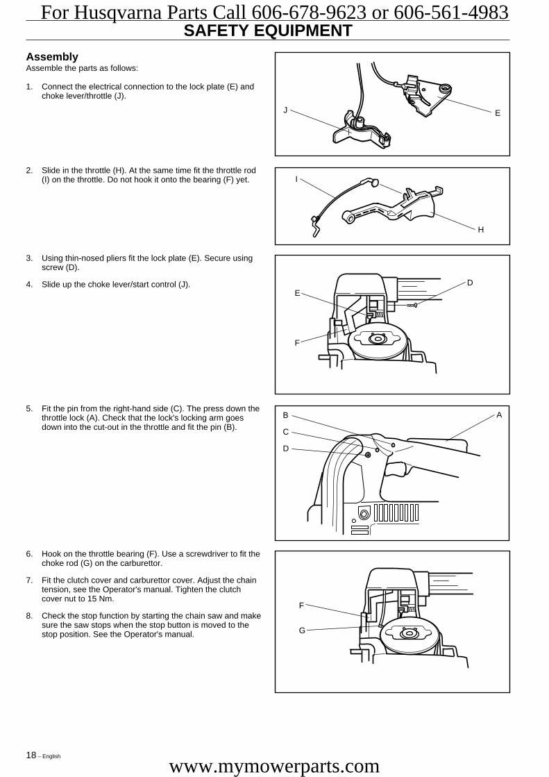
SAFETY EQUIPMENTAssemblyAssemble the parts as follows:
1. Connect the electrical connection to the lock plate (E) andchoke lever/throttle (J).
I
H
J E
F
G
DE
F
B
C
D
A
6. Hook on the throttle bearing (F). Use a screwdriver to fit thechoke rod (G) on the carburettor.
7. Fit the clutch cover and carburettor cover. Adjust the chaintension, see the Operator's manual. Tighten the clutchcover nut to 15 Nm.
8. Check the stop function by starting the chain saw and makesure the saw stops when the stop button is moved to thestop position. See the Operator's manual.
5. Fit the pin from the right-hand side (C). The press down thethrottle lock (A). Check that the lock's locking arm goesdown into the cut-out in the throttle and fit the pin (B).
3. Using thin-nosed pliers fit the lock plate (E). Secure usingscrew (D).
4. Slide up the choke lever/start control (J).
2. Slide in the throttle (H). At the same time fit the throttle rod(I) on the throttle. Do not hook it onto the bearing (F) yet.
Eng 10-18 97-12-03, 16.2718
For Husqvarna Parts Call 606-678-9623 or 606-561-4983
www.mymowerparts.com

English – 19
STARTER
! WARNING!
• The recoil spring is under tension when in its housingin the starter and can, with careless handling, fly outand cause personal injury.
• Care should be exercised when replacing the recoilspring or starter cord. Wear protective glasses.
Dismantling1. Unscrew the four bolts that hold the starter (A) and cooling
air guide (B) in position.
A
B
4. Carefully lift up the spring housing so that the spring doesnot fly out and cause personal injury.
5. If the starter cord is to be replaced, cut it off and pull out theends, using a pair of thin-nosed pliers, from the handle andstarter pulley.
2. Pull out the handle 20-30 cm (8-12") and lift up the cordfrom the cut-out in the starter pulley.
3. Unscrew the centre bolt and lift out the washer and starterpulley.
Eng 19-24 97-12-03, 16.2719
For Husqvarna Parts Call 606-678-9623 or 606-561-4983
www.mymowerparts.com
20 – English
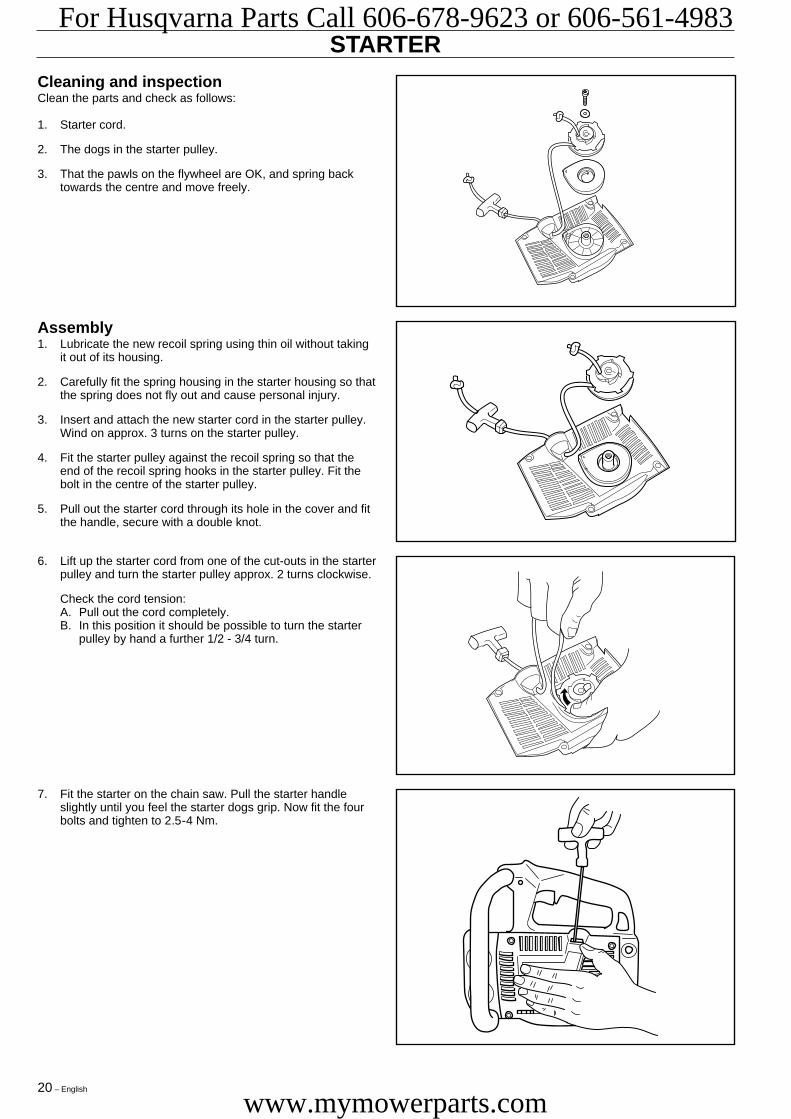
STARTERCleaning and inspectionClean the parts and check as follows:
1. Starter cord.
2. The dogs in the starter pulley.
3. That the pawls on the flywheel are OK, and spring backtowards the centre and move freely.
Assembly1. Lubricate the new recoil spring using thin oil without taking
it out of its housing.
2. Carefully fit the spring housing in the starter housing so thatthe spring does not fly out and cause personal injury.
3. Insert and attach the new starter cord in the starter pulley.Wind on approx. 3 turns on the starter pulley.
4. Fit the starter pulley against the recoil spring so that theend of the recoil spring hooks in the starter pulley. Fit thebolt in the centre of the starter pulley.
5. Pull out the starter cord through its hole in the cover and fitthe handle, secure with a double knot.
7. Fit the starter on the chain saw. Pull the starter handleslightly until you feel the starter dogs grip. Now fit the fourbolts and tighten to 2.5-4 Nm.
6. Lift up the starter cord from one of the cut-outs in the starterpulley and turn the starter pulley approx. 2 turns clockwise.
Check the cord tension:A. Pull out the cord completely.B. In this position it should be possible to turn the starter
pulley by hand a further 1/2 - 3/4 turn.
Eng 19-24 97-12-03, 16.2720
For Husqvarna Parts Call 606-678-9623 or 606-561-4983
www.mymowerparts.com

English – 21
IGNITION SYSTEMDismantling1. Dismantle the starter (A) and cooling air guide (B).
2. Remove the spark plug and fit the piston stop (C) in thespark plug hole. See service tools. It is important that thepiston stop is screwed in completely.
A
B
C
D
E
E
FH
I
8. Dismantle the starter pawls by pressing out the pawls'bearing studs with a suitable punch (ø 3 mm/ 0.12").
6. Fit the sleeve 502 51 94-01 on the shaft. Do not screw it ontoo far, a gap of 2-3 mm (0.08-0.12") must remain.
7. Grip the flywheel and lift the saw. Hit the sleeve with ahammer until the flywheel becomes loose.
3. Loosen the cable (D) from the ignition module. Unscrew thetwo M4 bolts (E) and lift out the ignition module (F).
4. If the ignition module shall be replaced, pull up the contactspring from spark plug cover and dismantle the parts.
5. Use a 13 mm spanner and dismantle the nut (H) andcounterbalance washer (I) from the flywheel.
Eng 19-24 97-12-03, 16.2721
For Husqvarna Parts Call 606-678-9623 or 606-561-4983
www.mymowerparts.com

22 – English
Cleaning and inspectionClean all the parts, especially the flywheel and the shaft taper.Check that the flywheel is not cracked or damaged in any otherway.
Fitting the spark plug cover1. Push the HT cable through the spark plug cover.
2. Make a hole in the HT cable for the contact spring using thepliers 502 50 06-01.
3. Fit the contact spring using the pliers.
NOTE!It is important that the tip of the contact spring comes inthe centre of the HT cable to prevent sparking.
IGNITION SYSTEM
A
B
D
F
G
G
H
I
7. Fit the cooling air guide (B) and starter (A).
Assembly1. Fit the starter pawls (G).
2. Fit the flywheel on crankshaft. Rotate lightly so that theflywheel's key aligns with keyway on the crankshaft.
3. Fit counterbalance washer (I) in the groove located onflywheel. Use a 13 mm spanner and tighten the nut (H) to20-26 N.
4. Remove the piston stop, fit the spark plug and rotate theflywheel so that its magnet is beside one of the ignitionmodule's bolt holes.
5. Fit ignition module (F). Connect the cable (D) to the ignitionmodule.
6. Insert a feeler gauge (0.3 mm/ 0.012") between flywheelmagnet and the ignition module. See service tools. Tightenthe ignition module's bolts to 2.5-4 Nm.NOTE! When fitting the ignition module the gap shallbe set between both upper arms.
0.3 mm/ 0.012"
Eng 19-24 97-12-03, 16.2822
For Husqvarna Parts Call 606-678-9623 or 606-561-4983
www.mymowerparts.com

English – 23
Dismantling1. Dismantle the clutch cover.
2. Dismantle the spark plug and fit the piston stop (A). It isimportant that the piston stop is screwed in completely.
3. Use a 19 mm spanner and dismantle the clutch hub.NOTE! Left-hand thread.
Cleaning and inspectionClean all parts and check the following:
1. That the outside diameter of the clutch hub is no less than58 mm/ 2.28" at the most worn point.
2. That there is no play between the clutch shoes and theirbearings in the shoe holder.
3. When a spring breaks both springs must be replaced.
4. A complete clutch or springs are available as spare parts.
5. Wear on the chain sprocket.
6. That the needle bearing is OK and that the bearing surfaceon the crankshaft is not damaged.
7. That the clutch drum friction surface is OK and that thebearing surface is not damaged.
A
B
CD
5. If necessary, dismantle the clutch shoes as follows:
A. Put the clutch hub in a vice.
B. Using a screwdriver, press out the shoe holder.
C. Dismantle the shoes and springs.
4. Remove the washer (B), clutch drum (C) and needlebearing (D).
58 mm/ 2.28"
CENTRIFUGAL CLUTCH
Eng 19-24 97-12-03, 16.2823
For Husqvarna Parts Call 606-678-9623 or 606-561-4983
www.mymowerparts.com
24 – English
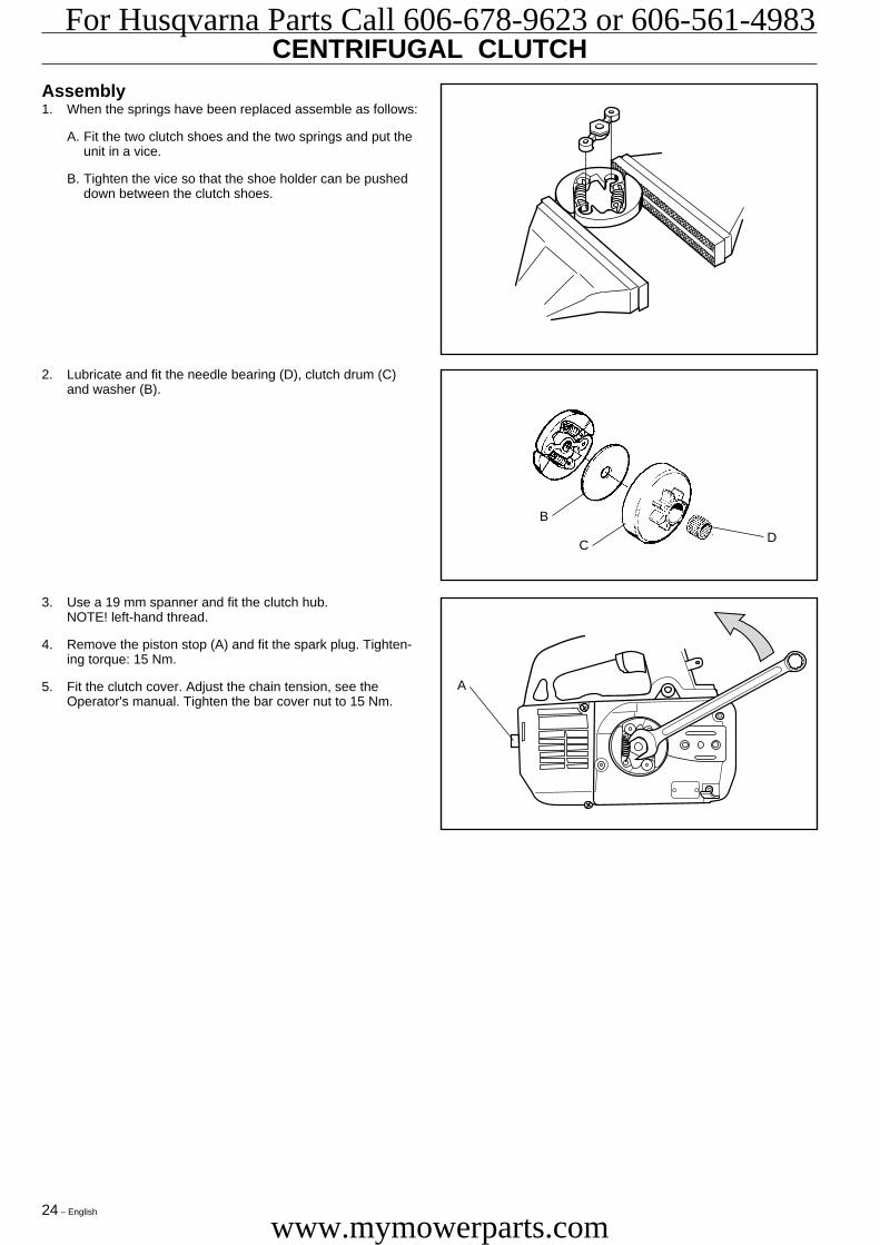
CENTRIFUGAL CLUTCHAssembly1. When the springs have been replaced assemble as follows:
A. Fit the two clutch shoes and the two springs and put theunit in a vice.
B. Tighten the vice so that the shoe holder can be pusheddown between the clutch shoes.
A
B
CD
3. Use a 19 mm spanner and fit the clutch hub.NOTE! left-hand thread.
4. Remove the piston stop (A) and fit the spark plug. Tighten-ing torque: 15 Nm.
5. Fit the clutch cover. Adjust the chain tension, see theOperator's manual. Tighten the bar cover nut to 15 Nm.
2. Lubricate and fit the needle bearing (D), clutch drum (C)and washer (B).
Eng 19-24 97-12-03, 16.2824
For Husqvarna Parts Call 606-678-9623 or 606-561-4983
www.mymowerparts.com
English – 25
CARBURETTOR
Description
! WARNING!The fuel used in the chain saw poses thefollowing hazards:• The fluid and its vapours are poisonous.• Can cause skin irritation.• Is highly inflammable.
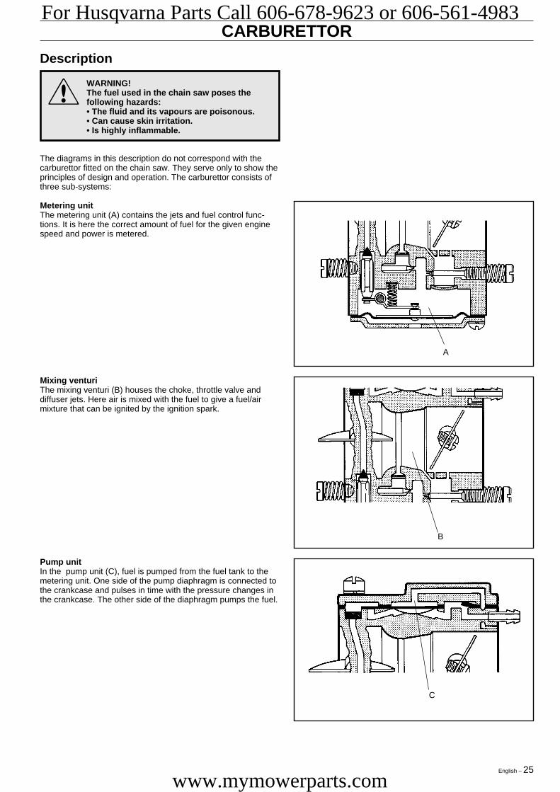
The diagrams in this description do not correspond with thecarburettor fitted on the chain saw. They serve only to show theprinciples of design and operation. The carburettor consists ofthree sub-systems:
Metering unitThe metering unit (A) contains the jets and fuel control func-tions. It is here the correct amount of fuel for the given enginespeed and power is metered.
A
B
C
Pump unitIn the pump unit (C), fuel is pumped from the fuel tank to themetering unit. One side of the pump diaphragm is connected tothe crankcase and pulses in time with the pressure changes inthe crankcase. The other side of the diaphragm pumps the fuel.
Mixing venturiThe mixing venturi (B) houses the choke, throttle valve anddiffuser jets. Here air is mixed with the fuel to give a fuel/airmixture that can be ignited by the ignition spark.
Eng 25-32 97-12-03, 16.2825
For Husqvarna Parts Call 606-678-9623 or 606-561-4983
www.mymowerparts.com
26 – English
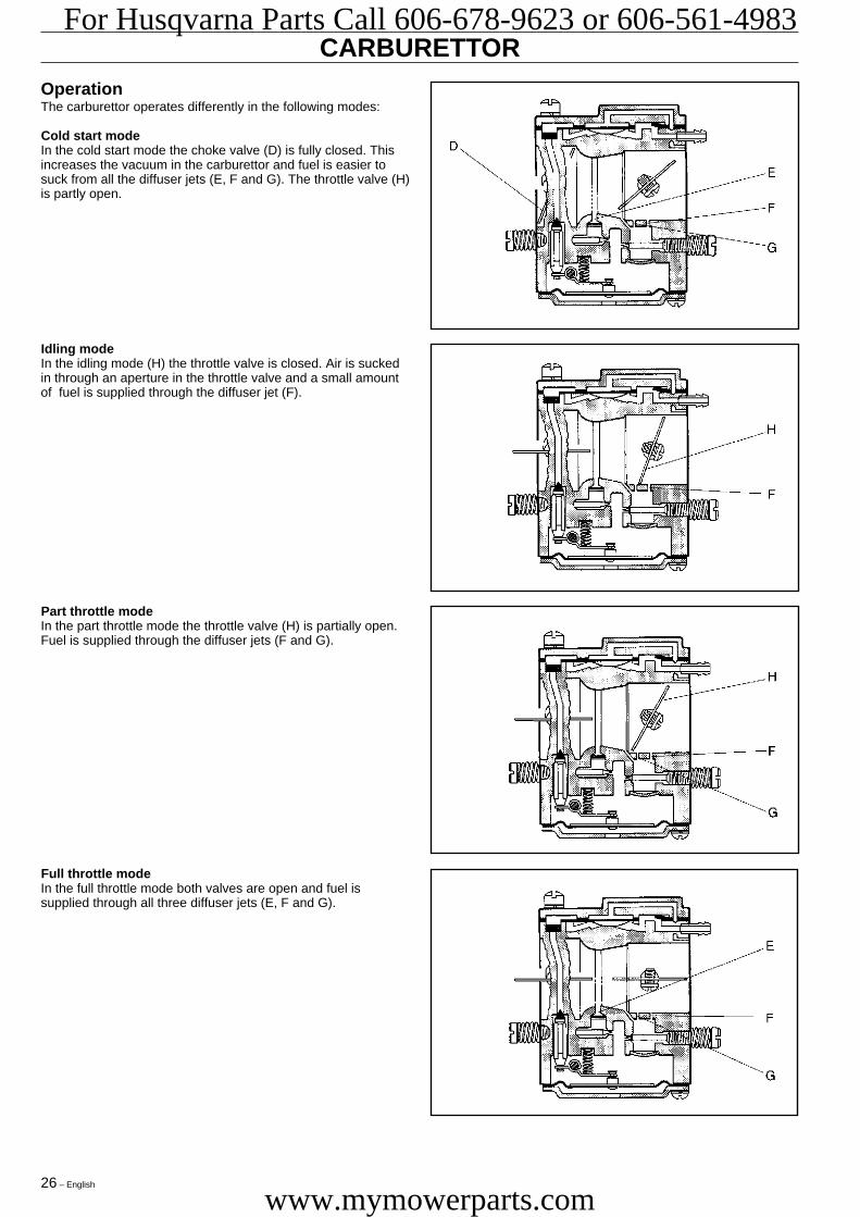
OperationThe carburettor operates differently in the following modes:
Cold start modeIn the cold start mode the choke valve (D) is fully closed. Thisincreases the vacuum in the carburettor and fuel is easier tosuck from all the diffuser jets (E, F and G). The throttle valve (H)is partly open.
Full throttle modeIn the full throttle mode both valves are open and fuel issupplied through all three diffuser jets (E, F and G).
Part throttle modeIn the part throttle mode the throttle valve (H) is partially open.Fuel is supplied through the diffuser jets (F and G).
Idling modeIn the idling mode (H) the throttle valve is closed. Air is suckedin through an aperture in the throttle valve and a small amountof fuel is supplied through the diffuser jet (F).
CARBURETTOR
Eng 25-32 97-12-03, 16.2826
For Husqvarna Parts Call 606-678-9623 or 606-561-4983
www.mymowerparts.com
English – 27
R
U
S
X
Y
V
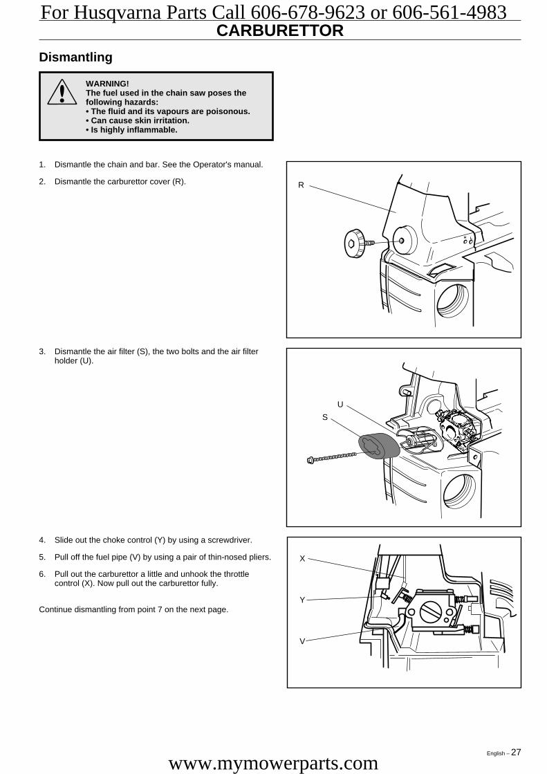
4. Slide out the choke control (Y) by using a screwdriver.
5. Pull off the fuel pipe (V) by using a pair of thin-nosed pliers.
6. Pull out the carburettor a little and unhook the throttlecontrol (X). Now pull out the carburettor fully.
Continue dismantling from point 7 on the next page.
3. Dismantle the air filter (S), the two bolts and the air filterholder (U).
1. Dismantle the chain and bar. See the Operator's manual.
2. Dismantle the carburettor cover (R).
CARBURETTOR
Dismantling
! WARNING!The fuel used in the chain saw poses thefollowing hazards:• The fluid and its vapours are poisonous.• Can cause skin irritation.• Is highly inflammable.
Eng 25-32 97-12-03, 16.2827
For Husqvarna Parts Call 606-678-9623 or 606-561-4983
www.mymowerparts.com
28 – English
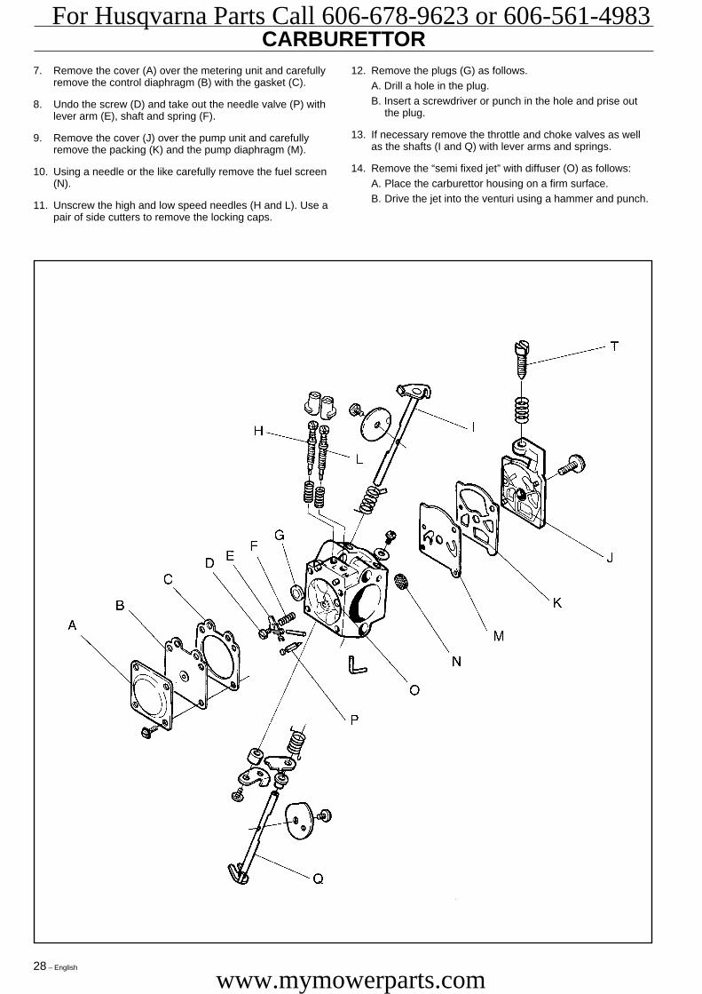
CARBURETTOR12. Remove the plugs (G) as follows.
A. Drill a hole in the plug.B. Insert a screwdriver or punch in the hole and prise out
the plug.
13. If necessary remove the throttle and choke valves as wellas the shafts (I and Q) with lever arms and springs.
14. Remove the “semi fixed jet” with diffuser (O) as follows:A. Place the carburettor housing on a firm surface.B. Drive the jet into the venturi using a hammer and punch.
7. Remove the cover (A) over the metering unit and carefullyremove the control diaphragm (B) with the gasket (C).
8. Undo the screw (D) and take out the needle valve (P) withlever arm (E), shaft and spring (F).
9. Remove the cover (J) over the pump unit and carefullyremove the packing (K) and the pump diaphragm (M).
10. Using a needle or the like carefully remove the fuel screen(N).
11. Unscrew the high and low speed needles (H and L). Use apair of side cutters to remove the locking caps.
Eng 25-32 97-12-03, 16.2828
For Husqvarna Parts Call 606-678-9623 or 606-561-4983
www.mymowerparts.com

English – 29
Cleaning and inspection
WARNING!Petrol has the following hazardous properties:• The fluid and its vapours are poisonous.• Can cause skin irritation.• Is highly inflammable.
Clean all components in pure petrol.
WARNING!Never direct the compressed air jet towardsthe body. Air can be forced into the bloodstream and can cause fatality.
Use compressed air to dry the petrol on all components. Directthe air through all channels in the carburettor housing andensure that they are not blocked.
Check the following:
1. That the packing and pump and control diaphragms areundamaged.
2. That there is no play on the throttle and choke valve shafts.
3. That the needle valve (P) and its lever (E) are not worn.
4. That the fuel screen is undamaged
5. That the tips of the high and low speed needles (H and L)are not damaged.
6. That the air intake manifold is not cracked.
P
H
E
L
!
!
CARBURETTOR
AssemblyMaintain a high level of cleanliness when reassembling thecarburettor. Even small particles of dirt can cause operatingproblems.Please refer to the exploded diagram on page 28 for the letterswithin brackets that are not shown in the adjacent diagrams.
1. If the throttle and choke valves, shafts, lever arms andsprings have been dismantled these must be reassembled.Lubricate the shaft bearings using a light oil.
2. Fit the plugs (G) as follows:
A. Place the plug in the hole with the convex side facingupwards.
B. Expand the plug using a punch on the top side.
3. Fit the “semi fixed jet” (O) in the carburettor using a punch.
4. Fit the fuel screen (N) by using the handle of a smallscrewdriver.
Eng 25-32 97-12-03, 16.2829
For Husqvarna Parts Call 606-678-9623 or 606-561-4983
www.mymowerparts.com

30 – English
CARBURETTOR5. Fit the high speed needle (H) as follows:
A. Screw in the new H-needle clockwise until it bottoms.Thereafter counter-clockwise 3 1/2 turns.
B. Press on a new locking cap on the H-needle until thefirst stop, i.e. the locking cap should not be fixed.
6. Fit the low speed needle (L) as follows:
A. Screw in the new L-needle clockwise until it bottoms.Thereafter counter-clockwise 1 3/4 turns.
B. Press on a new locking cap on the L-needle until the firststop, i.e. the locking cap should not be fixed.
7. Fit the pump diaphragm (M), packing (K) and cover (J) onthe pump unit.
8. Fit the needle valve (P) with lever arm (E), shaft and springand tighten screw (D).
9. Check using or a ruler or the like that the lever arm (E) islevel with the heels next to the lever arm. The lever arm canbe bent if necessary.
10. Fit the control diaphragm (B) with packing and cover (A) onthe metering unit.
11. Carry out a pressure test.
Pressure testingPressure testing should be carried out with the carburettor fullyassembled. Testing should always be carried out after thecarburettor has been repaired, but a test can also be made fortrouble shooting before dismantling.Check the carburettor as follows:
1. Connect pressure tester 502 50 38-01 to the carburettor'sfuel intake.
2. Lower the carburettor into a beaker of water.
3. Pump up the pressure to 50 kPa (0.5 bar) and clamp thepump tube.
4. No leakage is permitted. With leakage refer to the tablebelow.
Leakage from Fault with
Diffuser jets Needle valve
Leakage on the pulse tube Pump diaphragm
Ventilation hole above Control diaphragm the metering unit
Eng 25-32 97-12-03, 16.2830
For Husqvarna Parts Call 606-678-9623 or 606-561-4983
www.mymowerparts.com
English – 31
!
CARBURETTOR
Assembly (continued)
WARNING!The fuel used in the chain saw poses thefollowing hazards:• The fluid and its vapours are poisonous.• Can cause skin irritation.• Is highly inflammable.
After the carburettor has been pressure tested, continueassembly as follows:
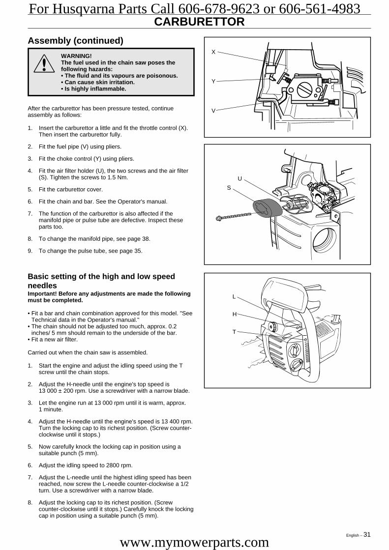
1. Insert the carburettor a little and fit the throttle control (X).Then insert the carburettor fully.
2. Fit the fuel pipe (V) using pliers.
3. Fit the choke control (Y) using pliers.
4. Fit the air filter holder (U), the two screws and the air filter(S). Tighten the screws to 1.5 Nm.
5. Fit the carburettor cover.
6. Fit the chain and bar. See the Operator's manual.
7. The function of the carburettor is also affected if themanifold pipe or pulse tube are defective. Inspect theseparts too.
8. To change the manifold pipe, see page 38.
9. To change the pulse tube, see page 35.
X
Y
V
U
S
L
H
T
Basic setting of the high and low speedneedlesImportant! Before any adjustments are made the followingmust be completed.
• Fit a bar and chain combination approved for this model. "SeeTechnical data in the Operator's manual."
• The chain should not be adjusted too much, approx. 0.2inches/ 5 mm should remain to the underside of the bar.
• Fit a new air filter.
Carried out when the chain saw is assembled.
1. Start the engine and adjust the idling speed using the Tscrew until the chain stops.
2. Adjust the H-needle until the engine's top speed is13 000 ± 200 rpm. Use a screwdriver with a narrow blade.
3. Let the engine run at 13 000 rpm until it is warm, approx.1 minute.
4. Adjust the H-needle until the engine's speed is 13 400 rpm.Turn the locking cap to its richest position. (Screw counter-clockwise until it stops.)
5. Now carefully knock the locking cap in position using asuitable punch (5 mm).
6. Adjust the idling speed to 2800 rpm.
7. Adjust the L-needle until the highest idling speed has beenreached, now screw the L-needle counter-clockwise a 1/2turn. Use a screwdriver with a narrow blade.
8. Adjust the locking cap to its richest position. (Screwcounter-clockwise until it stops.) Carefully knock the lockingcap in position using a suitable punch (5 mm).
Eng 25-32 97-12-03, 16.2831
For Husqvarna Parts Call 606-678-9623 or 606-561-4983
www.mymowerparts.com

32 – English
Carburettor
Your Husqvarna product has been designed and manufacturedto specifications that reduce harmful emissions.After your unit has been run 8-10 tanks of fuel the engine hasbroken in. To ensure that your unit is at peak performance andproducing the least amount of harmful emissions after break in,have your authorized servicing dealer, who has a revolutioncounter at his disposal, to adjust your carburetor for optimumoperating conditions.
Conditions• Before any adjustments are made the air filter should be clean
and the cylinder cowling fitted. Adjusting the carburettor whilea dirty air filter is in use will result in a leaner mixture when thefilter is finally cleaned. This can give rise to serious enginedamage.
• Carefully turn the L and H needles to the mid-point betweenfully in and fully out.
• Do not attempt to adjust the needles past their stops asthis can cause damage.
• Now start the saw according to the starting instructions andrun it warm for 10 minutes. NOTE! If the chain rotates the Tscrew should be turned counter-clockwise until the chainstops.
• Place the saw on a flat surface so that the bar points awayfrom you and so that the bar and chain do not come intocontact with the surface or other objects.
WARNING! Do not start the saw without thebar, chain and clutch cover (chain brake)assembled. If you do, the clutch might comeloose and cause severe injuries.
Operation, Basic setting, Final setting
CARBURETTOR
Low speed needle LTurn the L needle clockwise to the stop. If the engine acceler-ates poorly or idles unevenly turn the L needle counter-clock-wise until good acceleration and idling are achieved.NOTE! If the chain rotates in the idling position, turn theidling speed screw counter-clockwise until the chain stops.
Final setting of the idling speed TAdjust the idling speed with the screw T. If it is necessary to re-adjust, first turn the idle speed adjusting screw T clockwise, untilthe chain starts to rotate. Then turn, counter-clockwise until thechain stops. A correctly adjusted idle speed setting occurs whenthe engine runs smoothly in every position. It should also begood margin to the rpm when the chain starts to rotate.
High speed needle HThe high speed needle Haffects the power and enginespeed of the saw. Too lean asetting of the high speedneedle (H-needle is screwedin too far) causes over-revving with subsequentdamage to the saw. Turn thehigh speed needle counter-clockwise to its stop. If theengine runs unevenly, turnthe high speed needleclockwise until the engineruns evenly.
The H-needle is correctly adjusted when the saw “4-strokes”slightly. If the saw “screams”, it is set too lean. If smoke comesfrom the muffler while the saw is “4-stroking”, it is set too rich.Turn the H-needle clockwise to achieve a setting which soundsright. NOTE! For optimal adjustment, contact a qualifiedservice agent with access to a tachometer.
Correctly adjusted carburettorA correctly adjusted carburettor means that the saw accelerateswithout hesitation and the saw four strokes a little at max speed.Furthermore, the chain must not rotate while idling. A too leanadjusted low speed needle L may cause starting difficulties andbad acceleration. A too lean adjusted high speed needle Hgives lower power = less capacity, bad acceleration and/ordamage to the engine. A too rich adjustment of the two speedneedles L and H gives acceleration problems or too low workingspeed.
WARNING! Contact your servicing dealer, ifthe idle speed setting cannot be adjusted sothat the chain stops. Do not use the saw untilit has been properly adjusted or repaired.
!
H
!Operation• The carburettor governs the engine speed via the throttle. Air/
fuel are mixed in the carburettor. The air/fuel mixture isadjustable. To take advantage of the saw’s maximum outputthe setting must be correct.
• Adjusting the carburettor means the engine is adapted to localoperating conditions, e.g. climate, altitude, petrol and the typeof 2-stroke oil used.
• The carburettor has threeadjustment possibilities:
L = Low speed jet.H = High speed jet.T = Adjusting screw for
idling.
• The fuel quantity required in relation to the air flow, providedby opening the throttle, is adjusted by the L and H-jets. If theyare screwed clockwise the air/fuel ratio becomes leaner (lessfuel) and if they are turned counter-clockwise the ratiobecomes richer (more fuel). A leaner mixture gives a higherengine speed and a richer mixture give a lower engine speed.
• The T screw regulates the idling speed. If the screw T isturned clockwise this gives a higher idling speed; counter-clockwise a lower idling speed.
Basic setting and running inThe carburettor is set to its basic setting when test run at thefactory. The basic setting is richer than the optimal setting andshould be kept so during the machine‘s first working hours.Thereafter the carburettor should be finely adjusted. Fineadjustment should be carried out by a skilled technician.
NOTE! If the chain rotates while idling the T screw should beadjusted counter-clockwise until it stops.Recommended idling speed: 2 800 rpm.
H L
T
Fine adjustment• When the saw has been “run-in” the carburettor should be
finely adjusted. The fine adjustment should be carried outby qualified person. First adjust the L-jet, then the idlingscrew T and then the H-jet.
WARNING! Contact your servicing dealer, ifthe idle speed setting cannot be adjusted sothat the chain stops. Do not use the saw untilit has been properly adjusted or repaired.
!
Eng 25-32 97-12-03, 16.2832
For Husqvarna Parts Call 606-678-9623 or 606-561-4983
www.mymowerparts.com
English – 33
TANK UNIT
DismantlingDismantle the following parts:
1. Chain and bar. See the Operator's manual.
2. Centrifugal clutch. See page 23.
3. Muffler. See page 16.
4. Carburettor. See page 27.
5. Starter. See page 19.
6. Ignition system and spark plug. See page 21.
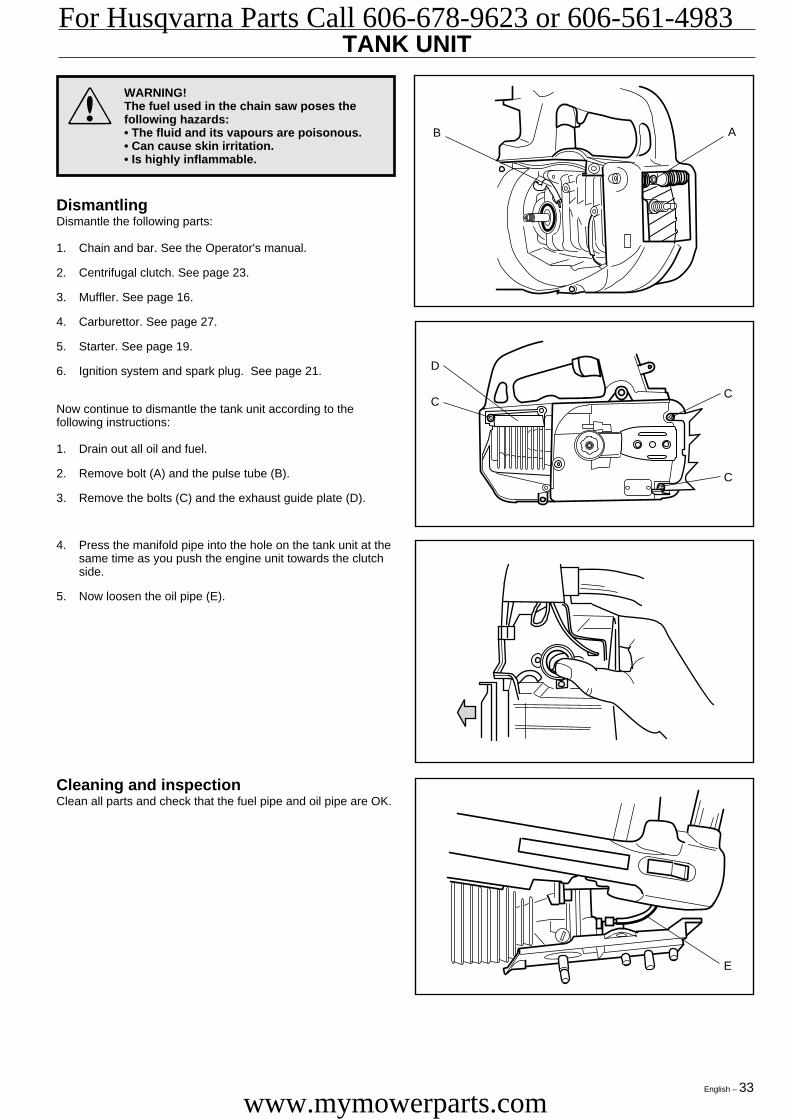
Now continue to dismantle the tank unit according to thefollowing instructions:
1. Drain out all oil and fuel.
2. Remove bolt (A) and the pulse tube (B).
3. Remove the bolts (C) and the exhaust guide plate (D).
Cleaning and inspectionClean all parts and check that the fuel pipe and oil pipe are OK.
E
AB
4. Press the manifold pipe into the hole on the tank unit at thesame time as you push the engine unit towards the clutchside.
5. Now loosen the oil pipe (E).
D
CC
C
WARNING!The fuel used in the chain saw poses thefollowing hazards:• The fluid and its vapours are poisonous.• Can cause skin irritation.• Is highly inflammable.
!
Eng 33-44 97-12-03, 16.2933
For Husqvarna Parts Call 606-678-9623 or 606-561-4983
www.mymowerparts.com

34 – English
TANK UNITReplacing the fuel pipe and fuel filter1. Remove the fuel filter and attached pipe using hook
502 50 83-01.
2. Pull the pipe out through the rubber grommet.
3. Remove the rubber grommet.
4. Fit a new rubber grommet on the pipe so that the pipeprotrudes approx. 80 mm/ 3.15".
5. Insert the pipe from the outside and push the rubbergrommet in so it is secured in the hole.
6. Pull out the pipe from the tank using hook 502 50 83-01, cutoff the end and fit the filter.
7. Push the other pipe end up through the hole in the tankunit. Adjust so that the pipe sticks out approx. 35 mm/ 1.40".The pipe may need to be shifted in the rubber grommet.
Replacing the oil pipe and screen1. Remove the screen and attached pipe using hook
502 50 83-01.
2. Pull out the pipe through the oil tank.
3. If necessary dismantle the screen and clean.
4. Fit a new pipe from the outside through the hole in the oiltank. Let the pipe protrude 40 mm/1.60" above the flatsurface. The total length of the pipe should be165 mm/6.50".
6. Pull the pipe out through the tank using hook 502 50 83-01,cut off the end and fit the screen.
Replacing the tank ventilator, fuel tank1. Push a screwdriver into the ventilator, turn and dismantle
the ventilator.
2. Push in a new ventilator by using the handle of the screw-driver.
L = 40 mm/ 1.60"
L = 35 mm/ 1.40"
80 mm/ 3.15"
Eng 33-44 97-12-03, 16.2934
For Husqvarna Parts Call 606-678-9623 or 606-561-4983
www.mymowerparts.com
English – 35
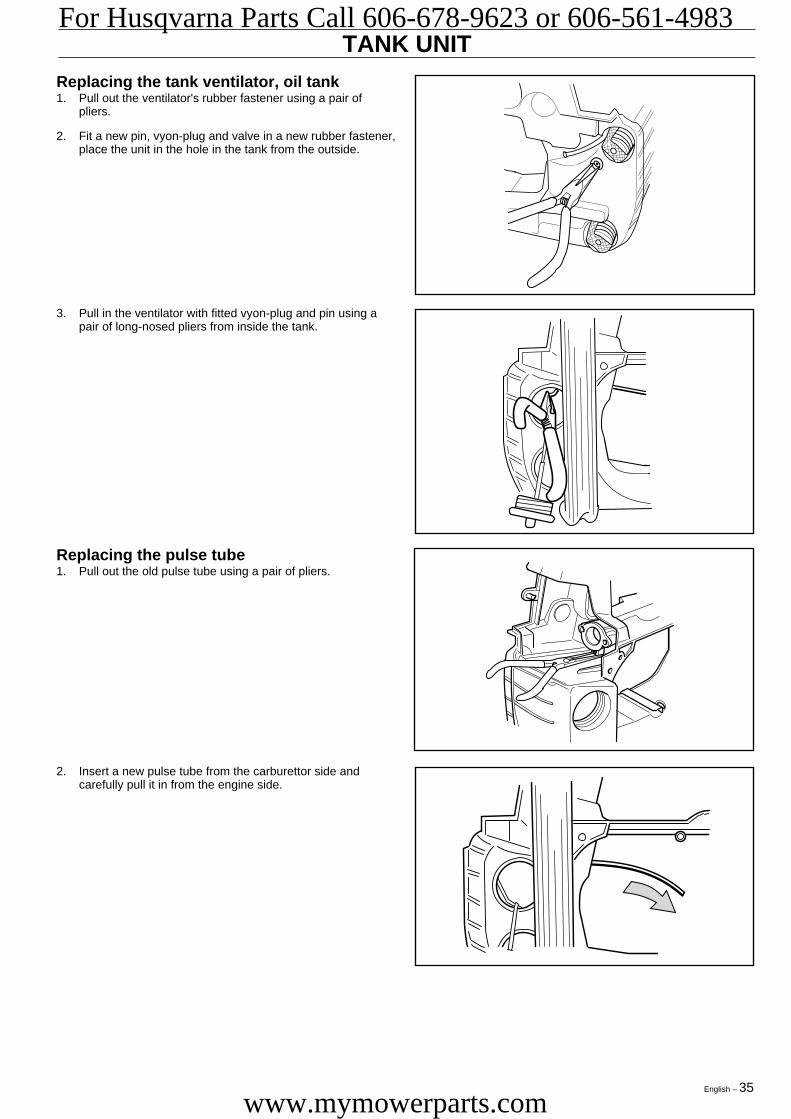
TANK UNITReplacing the tank ventilator, oil tank1. Pull out the ventilator's rubber fastener using a pair of
pliers.
2. Fit a new pin, vyon-plug and valve in a new rubber fastener,place the unit in the hole in the tank from the outside.
Replacing the pulse tube1. Pull out the old pulse tube using a pair of pliers.
3. Pull in the ventilator with fitted vyon-plug and pin using apair of long-nosed pliers from inside the tank.
2. Insert a new pulse tube from the carburettor side andcarefully pull it in from the engine side.
Eng 33-44 97-12-03, 16.2935
For Husqvarna Parts Call 606-678-9623 or 606-561-4983
www.mymowerparts.com
36 – English
TANK UNIT
!
E
D
CC
C
WARNING!The fuel used in the chain saw poses thefollowing hazards:• The fluid and its vapours are poisonous.• Can cause skin irritation.• Is highly inflammable.
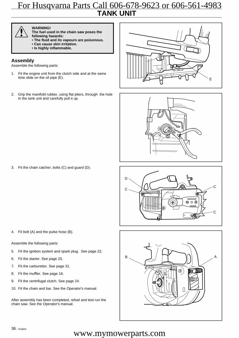
4. Fit bolt (A) and the pulse hose (B).
Assemble the following parts:
5. Fit the ignition system and spark plug. See page 22.
6. Fit the starter. See page 20.
7. Fit the carburettor. See page 31.
8. Fit the muffler. See page 16.
9. Fit the centrifugal clutch. See page 24.
10. Fit the chain and bar. See the Operator's manual.
After assembly has been completed, refuel and test run thechain saw. See the Operator's manual.
3. Fit the chain catcher, bolts (C) and guard (D).
2. Grip the manifold rubber, using flat pliers, through the holein the tank unit and carefully pull it up.
AB
AssemblyAssemble the following parts:
1. Fit the engine unit from the clutch side and at the sametime slide on the oil pipe (E).
Eng 33-44 97-12-03, 16.2936
For Husqvarna Parts Call 606-678-9623 or 606-561-4983
www.mymowerparts.com
English – 37
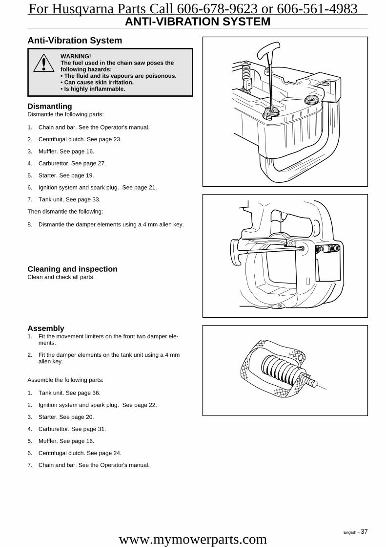
ANTI-VIBRATION SYSTEM
!
Assembly1. Fit the movement limiters on the front two damper ele-
ments.
2. Fit the damper elements on the tank unit using a 4 mmallen key.
Assemble the following parts:
1. Tank unit. See page 36.
2. Ignition system and spark plug. See page 22.
3. Starter. See page 20.
4. Carburettor. See page 31.
5. Muffler. See page 16.
6. Centrifugal clutch. See page 24.
7. Chain and bar. See the Operator's manual.
Anti-Vibration System
WARNING!The fuel used in the chain saw poses thefollowing hazards:• The fluid and its vapours are poisonous.• Can cause skin irritation.• Is highly inflammable.
DismantlingDismantle the following parts:
1. Chain and bar. See the Operator's manual.
2. Centrifugal clutch. See page 23.
3. Muffler. See page 16.
4. Carburettor. See page 27.
5. Starter. See page 19.
6. Ignition system and spark plug. See page 21.
7. Tank unit. See page 33.
Then dismantle the following:
8. Dismantle the damper elements using a 4 mm allen key.
Cleaning and inspectionClean and check all parts.
Eng 33-44 97-12-03, 16.2937
For Husqvarna Parts Call 606-678-9623 or 606-561-4983
www.mymowerparts.com

38 – English
CRANKSHAFT, PISTON AND CYLINDERDismantlingDismantle the following parts:
1. Chain and bar. See the Operator's manual.
2. Centrifugal clutch. See page 23.
3. Muffler. See page 16.
4. Carburettor. See page 27.
5. Starter. See page 19.
6. Ignition system and spark plug. See page 21.
7. Tank unit. See page 33.
A
AA A
B
C C14. Dismantle the bearing (C) using the puller 504 90 90-01.
NOTE!Ensure that no dirt or other foreign particles fall into thedismantled components.
Continue to dismantle the piston and cylinder as follows:
8. Dismantle the four bolts (A)
9. Dismantle the cylinder.
10. Dismantle the crankshaft from the crankcase.
11. Remove one of the piston's circlips, press out the gudgeonpin and remove the piston.
12. Remove the needle bearing from the little end on theconnecting rod.
13. Dismantle the manifold pipe (B) from the cylinder.
Eng 33-44 97-12-03, 16.2938
For Husqvarna Parts Call 606-678-9623 or 606-561-4983
www.mymowerparts.com

English – 39
Cleaning and inspectionClean all parts, scrape off any gasket residue from the crank-case and cylinder contact surfaces. Remove carbon depositsfrom the following areas:
1. The top of the piston.
2. The top of the cylinder (bore).
3. The cylinder exhaust port.
Check the following:
1. That the cylinder’s surface coating is not worn, especiallythe upper part of the cylinder.
2. That the cylinder is free of score marks.
3. That the piston is free of score marks. Small scratches canbe polished off using fine emery paper.
4. That the piston ring is not burnt into its groove.
5. Measure the piston ring wear by placing it in the bottom ofthe cylinder bore and measuring the play. Play should notexceed 1 mm/ 0.039".
6. That the intake manifold is undamaged.
7. That the needle bearing and its rubber seals are notdamaged.
CRANKSHAFT, PISTON AND CYLINDER
Faults and causes
Score marks on the piston1. Incorrect carburettor setting. Max. speed too high.
2. Too low octane fuel.
3. Too little or incorrect oil in the fuel.
Carbon build-up1. Incorrect carburettor setting. Max. speed too low.
2. Too much or incorrect oil in the fuel.
Piston ring breakage1. Excessive engine speed.
2. Piston ring worn out.
3. Oversized piston ring groove.
8. That the big end bearing does not have any radial play.Axial play is acceptable.
9. That the big end bearing does not have any score marks ordiscoloration on the sides.
10. That the little end bearing surfaces are not scored ordiscoloured.
11. The crankshaft cannot be renovated . In the event ofdamage the entire crankshaft should be replaced.
12. That the crankcase is not cracked.
Eng 33-44 97-12-03, 16.2939
For Husqvarna Parts Call 606-678-9623 or 606-561-4983
www.mymowerparts.com

40 – English
CRANKSHAFT, PISTON AND CYLINDER
B
C CAssemblyAssemble the piston and cylinder as follows:
9. Insert the four bolts (A) and tighten crosswise. Finallytighten to a torque of 8-10 Nm.
10. Pressure test the crankcase as described on the next page.
Assemble the following parts:
11. Tank unit. See page 36.
12. Ignition system and spark plug. See page 22.
13. Starter. See page 20.
14. Carburettor. See page 31.
15. Muffler. See page 16.
16. Centrifugal clutch. See page 24.
17. Chain and bar. See the Operator's manual.
6. Fit the crankshaft with piston in the crankcase.
7. Apply silicone rubber 504 98 26-01 to the contact surfacesof the crankcase halves.
8. Press together the piston rings, either by hand or by usingthe piston assembly set 502 50 70-01. Carefully slide onthe cylinder.
3. Oil the needle bearing and fit into the connecting rod littleend.
4. Fit the piston with the arrow facing towards the exhaustport. Slide in the gudgeon pin and fit the circlip.
5. Oil the piston ring and sides of the piston.
2. Fit the intake manifold (B) on the cylinder. Make sure theintake manifold is turned as shown in the figure.
NOTE!Ensure that no dirt or other foreign particles fall into thedismantled components.
1. Fit the bearing (C) using a suitable punch.
A
AA A
Eng 33-44 97-12-03, 16.2940
For Husqvarna Parts Call 606-678-9623 or 606-561-4983
www.mymowerparts.com
English – 41
CRANKSHAFT, PISTON AND CYLINDER
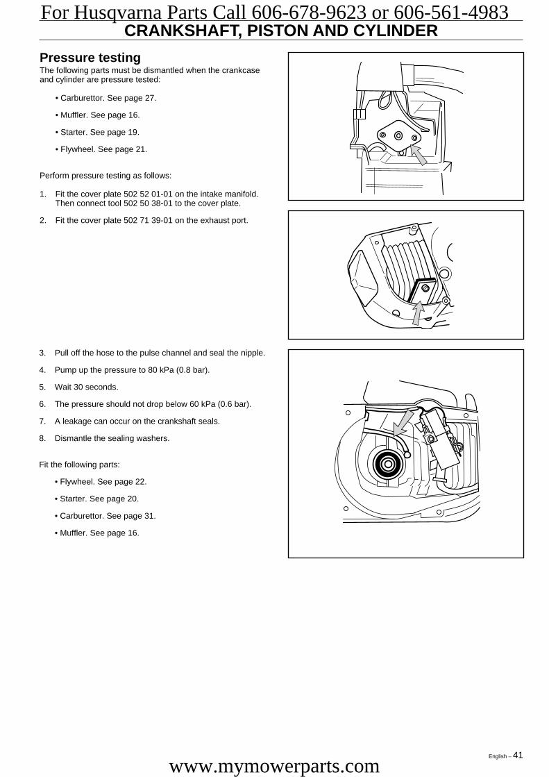
3. Pull off the hose to the pulse channel and seal the nipple.
4. Pump up the pressure to 80 kPa (0.8 bar).
5. Wait 30 seconds.
6. The pressure should not drop below 60 kPa (0.6 bar).
7. A leakage can occur on the crankshaft seals.
8. Dismantle the sealing washers.
Fit the following parts:
• Flywheel. See page 22.
• Starter. See page 20.
• Carburettor. See page 31.
• Muffler. See page 16.
Pressure testingThe following parts must be dismantled when the crankcaseand cylinder are pressure tested:
• Carburettor. See page 27.
• Muffler. See page 16.
• Starter. See page 19.
• Flywheel. See page 21.
Perform pressure testing as follows:
1. Fit the cover plate 502 52 01-01 on the intake manifold.Then connect tool 502 50 38-01 to the cover plate.
2. Fit the cover plate 502 71 39-01 on the exhaust port.
Eng 33-44 97-12-03, 16.2941
For Husqvarna Parts Call 606-678-9623 or 606-561-4983
www.mymowerparts.com

42 – English
BAR BOLTDismantlingDismantle the following parts:
1. Chain and bar. See the Operator's manual.
2. Centrifugal clutch. See page 23.
3. Muffler. See page 16.
4. Carburettor. See page 27.
5. Starter. See page 19.
6. Ignition system and spark plug. See page 21.
7. Tank unit. See page 33.
Continue dismantling as follows:
8. Put the engine unit in a vice and knock out the bar bolt (A)using a hammer.
Assembly1. Insert the new bar bolt (A) in its hole in the engine unit.
Make sure the bolt's square head fits in the square hole inthe engine unit.
A
2. Pull the bolt in the right position by using the sleeve andnut.
Now assemble the following parts:
3. Tank unit. See page 36.
4. Ignition system and spark plug. See page 22.
5. Starter. See page 20.
6. Carburettor. See page 29.
7. Muffler. See page 16.
8. Centrifugal clutch. See page 24.
9. Chain and bar. See the Operator's manual.
A
Eng 33-44 97-12-03, 16.2942
For Husqvarna Parts Call 606-678-9623 or 606-561-4983
www.mymowerparts.com

English – 43
OIL PUMPDismantlingDismantle the following parts:
1. Chain and bar. See the Operator's manual.
2. Centrifugal clutch. See page 23.
3. Muffler. See page 16.
4. Carburettor. See page 27.
5. Starter. See page 19.
6. Ignition system and spark plug. See page 21.
7. Tank unit. See page 33.
8. Cylinder and crankshaft. See page 38.
Continue dismantling the oil pump as follows:
9. Unscrew the adjuster screw (A) and dismantle the pumppiston (B), spring and washer.
10. Dismantle the cover plate (D).
Cleaning and inspectionClean all parts and check the following:
1. That the oil pump drive's worm gear (E) is undamaged.
2. That the taper on the adjuster screw (A) shows no signs ofwear.
3. That the guide (C) is undamaged.
4. That the pump piston (B) is undamaged.
5. That the oil pipe and screen are undamaged.
6. Clean all channels.
E
C
A
B
D
A
B
C11. Dismantle the guide (C).
Eng 33-44 97-12-03, 16.2943
For Husqvarna Parts Call 606-678-9623 or 606-561-4983
www.mymowerparts.com

44 – English
Assembly
Assemble as follows:
1. Oil and fit the pump piston (B), spring and washer. Press inthe unit and screw in the adjuster screw (A) and spring atthe same time.
OIL PUMP
2. Fit the guide (C).
3. Fit the cover plate (D).
Now assemble the following parts:
4. Cylinder and crankshaft. See page 40.
5. Tank unit. See page 36.
6. Ignition system and spark plug. See page 22.
7. Starter. See page 20.
8. Carburettor. See page 31.
9. Muffler. See page 16.
10. Centrifugal clutch. See page 24.
11. Chain and bar. See the Operator's manual.
12. Test run the saw and check the oil flow. See the Operator'smanual.
D
C
A
B
Eng 33-44 97-12-03, 16.2944
For Husqvarna Parts Call 606-678-9623 or 606-561-4983
www.mymowerparts.com


HusqvarnaPrinted in U.S.A.
For Husqvarna Parts Call 606-678-9623 or 606-561-4983
www.mymowerparts.com
Related Documents