(i) WORKSHOP CALCULATION & SCIENCE (As Per NSQF) 2 nd Year Common for All Engineering Trades under CTS NATIONAL INSTRUCTIONAL MEDIA INSTITUTE, CHENNAI Post Box No. 3142, CTI Campus, Guindy, Chennai - 600 032 MINISTRY OF SKILL DEVELOPMENT & ENTREPRENEURSHIP GOVERNMENT OF INDIA DIRECTORATE GENERAL OF TRAINING (For all 2 Year Trades) Copyright free, under CC BY Licence

Welcome message from author
This document is posted to help you gain knowledge. Please leave a comment to let me know what you think about it! Share it to your friends and learn new things together.
Transcript
(i)
WORKSHOP CALCULATION& SCIENCE
(As Per NSQF)
2nd Year
Common for All Engineering Trades under CTS
NATIONAL INSTRUCTIONALMEDIA INSTITUTE, CHENNAI
Post Box No. 3142, CTI Campus, Guindy, Chennai - 600 032
MINISTRY OF SKILL DEVELOPMENT & ENTREPRENEURSHIPGOVERNMENT OF INDIA
DIRECTORATE GENERAL OF TRAINING
(For all 2 Year Trades)
Copyright free, under CC BY Licence
(ii)
Workshop Calculation & Science (NSQF) - 2nd Year
Common for All Engineering Trades Under CTS
(For All 2 year Trades)
Copyright © 2018 National Instructional Media Institute, Chennai
First Edition : September 2019 Copies :
Rs. /-
All rights reserved.
No part of this publication can be reproduced or transmitted in any form or by any means, electronic or mechanical,including photocopy, recording or any information storage and retrieval system, without permission in writing from theNational Instructional Media Institute, Chennai.
Published by:
NATIONAL INSTRUCTIONAL MEDIA INSTITUTE
P. B. No.3142, CTI Campus, Guindy Industrial Estate,
Guindy, Chennai - 600 032.
Phone : 044 - 2250 0248, 2250 0657, 2250 2421
Fax : 91 - 44 - 2250 0791
email : [email protected]
Website: www.nimi.gov.in
Copyright free, under CC BY Licence
(iii)
FOREWORD
The Government of India has set an ambitious target of imparting skills to 30 crores people, one out of every
four Indians, by 2020 to help them secure jobs as part of the National Skills Development Policy. Industrial
Training Institutes (ITIs) play a vital role in this process especially in terms of providing skilled manpower.
Keeping this in mind, and for providing the current industry relevant skill training to Trainees, ITI syllabus
has been recently updated with the help of comprising various stakeholder's viz. Industries, Entrepreneurs,
Academicians and representatives from ITIs.
The National Instructional Media Institute (NIMI), Chennai, has now come up with instructional material to
suit the revised curriculum for Workshop Calculation & Science 2nd Year NSQF Commom for all 2 year
engineering trades under CTS will help the trainees to get an international equivalency standard where their
skill proficiency and competency will be duly recognized across the globe and this will also increase the
scope of recognition of prior learning. NSQF trainees will also get the opportunities to promote life long
learning and skill development. I have no doubt that with NSQF the trainers and trainees of ITIs, and all
stakeholders will derive maximum benefits from these IMPs and that NIMI's effort will go a long way in
improving the quality of Vocational training in the country.
The Executive Director & Staff of NIMI and members of Media Development Committee deserve appreciation
for their contribution in bringing out this publication.
Jai Hind
RAJESH AGGARWALDirector General/ Addl. Secretary
Ministry of Skill Development & Entrepreneurship,Government of India.
New Delhi - 110 001
Copyright free, under CC BY Licence
(iv)
PREFACE
The National Instructional Media Institute(NIMI) was set up at Chennai, by the Directorate General of Training,Ministry of skill Development and Entrepreneurship, Government of India, with the technical assistancefrom the Govt of the Federal Republic of Germany with the prime objective of developing and disseminatinginstructional Material for various trades as per prescribed syllabus and Craftsman Training Programme(CTS)under NSQF levels.
The Instructional materials are developed and produced in the form of Instructional Media Packages (IMPs),consisting of Trade Theory, Trade Practical, Test and Assignment Book, Instructor Guide, Wall charts,Transparencies and other supportive materials. The above material will enable to achieve overall improvementin the standard of training in ITIs.
A national multi-skill programme called SKILL INDIA, was launched by the Government of India, through aGazette Notification from the Ministry of Finance (Dept of Economic Affairs), Govt of India, dated 27thDecember 2013, with a view to create opportunities, space and scope for the development of talents ofIndian Youth, and to develop those sectors under Skill Development.
The emphasis is to skill the Youth in such a manner to enable them to get employment and also improveEntrepreneurship by providing training, support and guidance for all occupation that were of traditionaltypes. The training programme would be in the lines of International level, so that youths of our Country canget employed within the Country or Overseas employment. The National Skill Qualification Framework(NSQF), anchored at the National Skill Development Agency(NSDA), is a Nationally Integrated Educationand competency-based framework, to organize all qualifications according to a series of levels of Knowledge,Skill and Aptitude. Under NSQF the learner can acquire the Certification for Competency needed at anylevel through formal, non-formal or informal learning.
The Workshop Calculation & Science 2nd Year (Comon for All 2 year Engineering Trades under CTS) isone of the book developed by the core group members as per the NSQF syllabus.
The Workshop Calculation & Science (Common for All 2 year Engineering Trades under CTS as perNSQF) 2nd Year is the outcome of the collective efforts of experts from Field Institutes of DGT, ChampionITI’s for each of the Sectors, and also Media Development Committee (MDC) members and Staff of NIMI.NIMI wishes that the above material will fulfill to satisfy the long needs of the trainees and instructors andshall help the trainees for their Employability in Vocational Training.
NIMI would like to take this opportunity to convey sincere thanks to all the Members and Media DevelopmentCommittee (MDC) members.
R. P. DHINGRA
Chennai - 600 032 EXECUTIVE DIRECTOR
Copyright free, under CC BY Licence
(v)
ACKNOWLEDGEMENT
The National Instructional Media Institute (NIMI) sincerely acknowledge with thanks the co-operation andcontribution of the following Media Developers to bring this IMP for the course Workshop Calculation & Science
(2nd Year) as per NSQF.
MEDIA DEVELOPMENT COMMITTEE MEMBERS
Shri. M. Sangara pandian - Training Officer (Retd.)CTI, Guindy, Chennai.
Shri. G. Sathiamoorthy - Jr.Training Officer (Retd.)Govt I.T.I, DET - Tamilnadu.
NIMI CO-ORDINATORS
Shri. Nirmalya nath - Deputy General Manager,NIMI, Chennai - 32.
Shri. G. Michael Johny - Assistant Manager,NIMI, Chennai - 32.
NIMI records its appreciation of the Data Entry, CAD, DTP Operators for their excellent and devoted services inthe process of development of this IMP.
NIMI also acknowledges with thanks, the efforts rendered by all other staff who have contributed for the develop-
ment of this book.
Copyright free, under CC BY Licence
(vi)
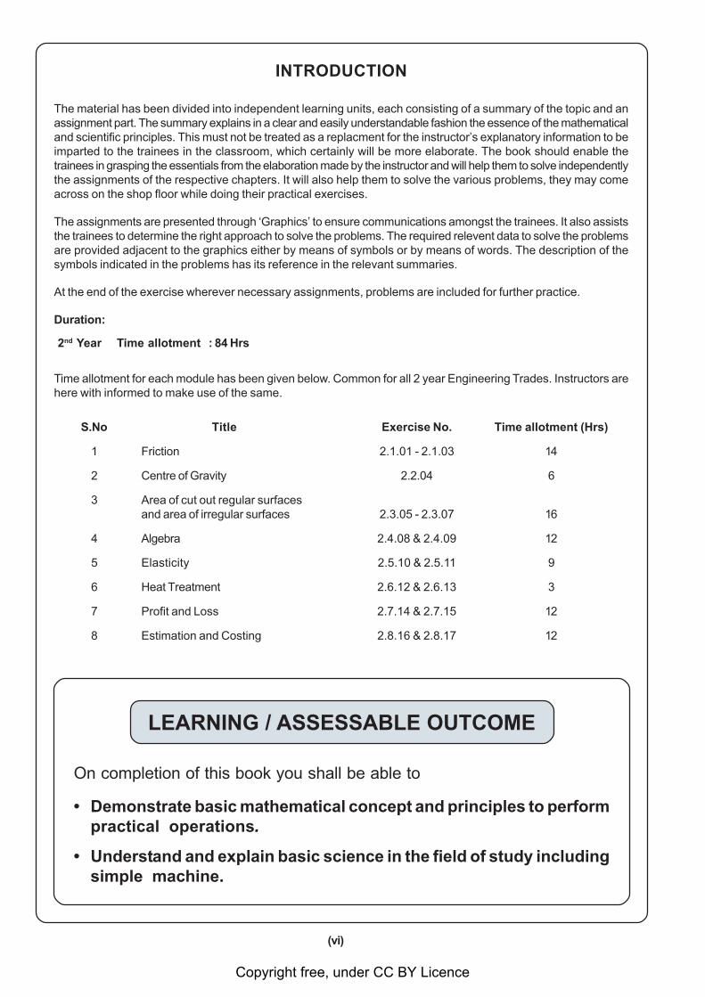
INTRODUCTION
The material has been divided into independent learning units, each consisting of a summary of the topic and anassignment part. The summary explains in a clear and easily understandable fashion the essence of the mathematicaland scientific principles. This must not be treated as a replacment for the instructor’s explanatory information to beimparted to the trainees in the classroom, which certainly will be more elaborate. The book should enable thetrainees in grasping the essentials from the elaboration made by the instructor and will help them to solve independentlythe assignments of the respective chapters. It will also help them to solve the various problems, they may comeacross on the shop floor while doing their practical exercises.
The assignments are presented through ‘Graphics’ to ensure communications amongst the trainees. It also assiststhe trainees to determine the right approach to solve the problems. The required relevent data to solve the problemsare provided adjacent to the graphics either by means of symbols or by means of words. The description of thesymbols indicated in the problems has its reference in the relevant summaries.
At the end of the exercise wherever necessary assignments, problems are included for further practice.
Duration:
2nd Year Time allotment : 84 Hrs
Time allotment for each module has been given below. Common for all 2 year Engineering Trades. Instructors arehere with informed to make use of the same.
S.No Title Exercise No. Time allotment (Hrs)
1 Friction 2.1.01 - 2.1.03 14
2 Centre of Gravity 2.2.04 6
3 Area of cut out regular surfacesand area of irregular surfaces 2.3.05 - 2.3.07 16
4 Algebra 2.4.08 & 2.4.09 12
5 Elasticity 2.5.10 & 2.5.11 9
6 Heat Treatment 2.6.12 & 2.6.13 3
7 Profit and Loss 2.7.14 & 2.7.15 12
8 Estimation and Costing 2.8.16 & 2.8.17 12
LEARNING / ASSESSABLE OUTCOME
On completion of this book you shall be able to
• Demonstrate basic mathematical concept and principles to performpractical operations.
• Understand and explain basic science in the field of study includingsimple machine.
Copyright free, under CC BY Licence
(vii)
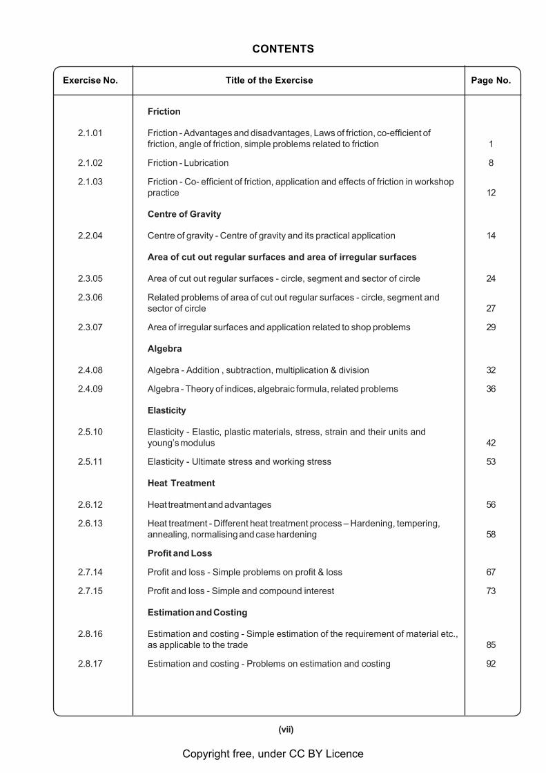
Exercise No. Title of the Exercise Page No.
Friction
2.1.01 Friction - Advantages and disadvantages, Laws of friction, co-efficient offriction, angle of friction, simple problems related to friction 1
2.1.02 Friction - Lubrication 8
2.1.03 Friction - Co- efficient of friction, application and effects of friction in workshoppractice 12
Centre of Gravity
2.2.04 Centre of gravity - Centre of gravity and its practical application 14
Area of cut out regular surfaces and area of irregular surfaces
2.3.05 Area of cut out regular surfaces - circle, segment and sector of circle 24
2.3.06 Related problems of area of cut out regular surfaces - circle, segment andsector of circle 27
2.3.07 Area of irregular surfaces and application related to shop problems 29
Algebra
2.4.08 Algebra - Addition , subtraction, multiplication & division 32
2.4.09 Algebra - Theory of indices, algebraic formula, related problems 36
Elasticity
2.5.10 Elasticity - Elastic, plastic materials, stress, strain and their units andyoung’s modulus 42
2.5.11 Elasticity - Ultimate stress and working stress 53
Heat Treatment
2.6.12 Heat treatment and advantages 56
2.6.13 Heat treatment - Different heat treatment process – Hardening, tempering,annealing, normalising and case hardening 58
Profit and Loss
2.7.14 Profit and loss - Simple problems on profit & loss 67
2.7.15 Profit and loss - Simple and compound interest 73
Estimation and Costing
2.8.16 Estimation and costing - Simple estimation of the requirement of material etc.,as applicable to the trade 85
2.8.17 Estimation and costing - Problems on estimation and costing 92
CONTENTS
Copyright free, under CC BY Licence
(viii)
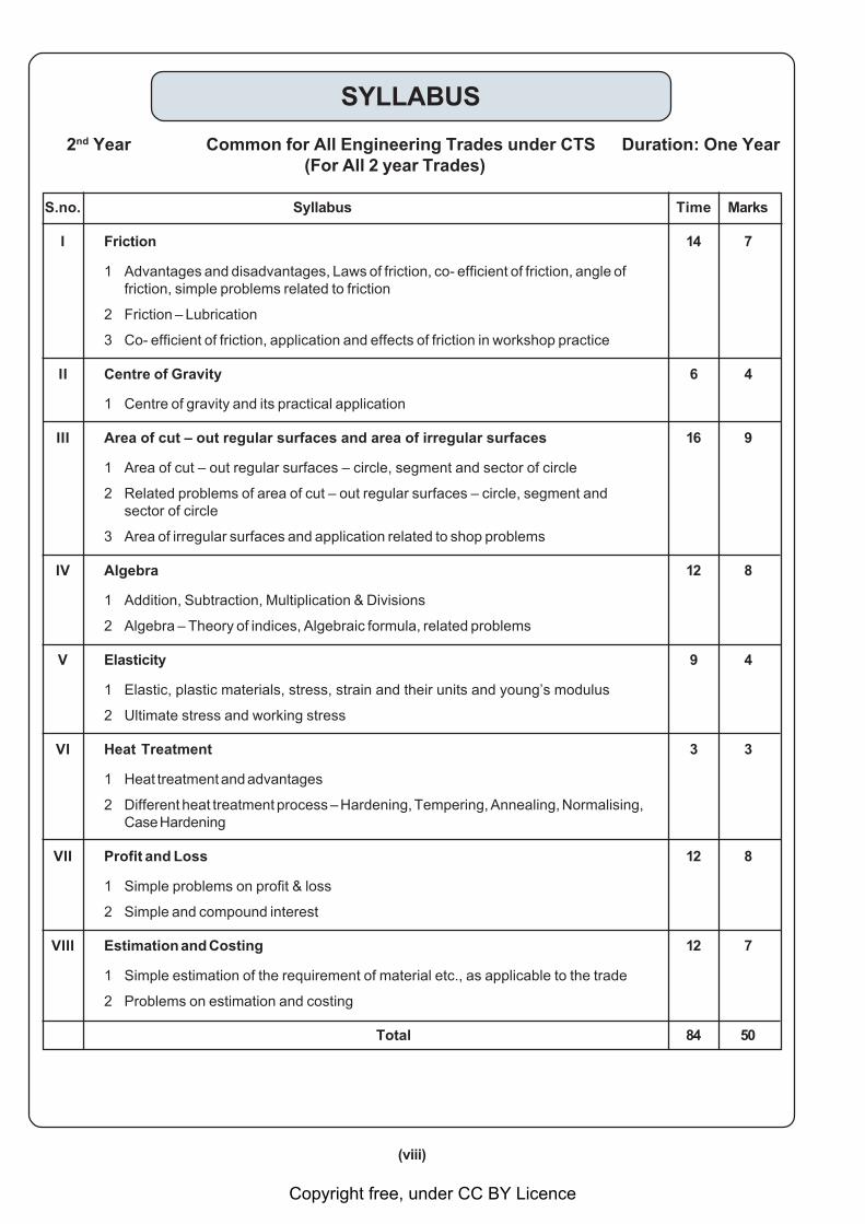
SYLLABUS
2nd Year Common for All Engineering Trades under CTS Duration: One Year(For All 2 year Trades)
S.no. Syllabus Time Marks
I Friction 14 7
1 Advantages and disadvantages, Laws of friction, co- efficient of friction, angle offriction, simple problems related to friction
2 Friction – Lubrication
3 Co- efficient of friction, application and effects of friction in workshop practice
II Centre of Gravity 6 4
1 Centre of gravity and its practical application
III Area of cut – out regular surfaces and area of irregular surfaces 16 9
1 Area of cut – out regular surfaces – circle, segment and sector of circle
2 Related problems of area of cut – out regular surfaces – circle, segment andsector of circle
3 Area of irregular surfaces and application related to shop problems
IV Algebra 12 8
1 Addition, Subtraction, Multiplication & Divisions
2 Algebra – Theory of indices, Algebraic formula, related problems
V Elasticity 9 4
1 Elastic, plastic materials, stress, strain and their units and young’s modulus
2 Ultimate stress and working stress
VI Heat Treatment 3 3
1 Heat treatment and advantages
2 Different heat treatment process – Hardening, Tempering, Annealing, Normalising,Case Hardening
VII Profit and Loss 12 8
1 Simple problems on profit & loss
2 Simple and compound interest
VIII Estimation and Costing 12 7
1 Simple estimation of the requirement of material etc., as applicable to the trade
2 Problems on estimation and costing
Total 84 50
Copyright free, under CC BY Licence
1
Friction - Advantages and disadvantages, Laws of friction, co-efficient offriction, angle of friction, simple problems related to friction Exercise 2.1.01
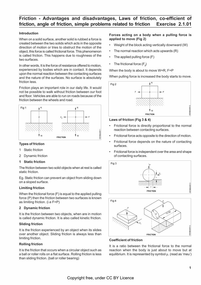
Introduction
When on a solid surface, another solid is rubbed a force iscreated between the two solids which acts in the oppositedirection of motion or tries to obstruct the motion of theobject, this force is called frictional force. This phenomenonis called friction. This happens due to roughness of thetwo surfaces.
In other words, It is the force of resistance offered to motion,experienced by bodies which are in contact. It dependsupon the normal reaction between the contacting surfacesand the nature of the surfaces. No surface is absolutelyfriction less.
Friction plays an important role in our daily life. It wouldnot be possible to walk without friction between our footand floor. Vehicles are able to run on roads because of thefriction between the wheels and road.
Types of friction
1 Static friction
2 Dynamic friction
1 Static friction
The friction between two solid objects when at rest is calledstatic friction.
Eg. Static friction can prevent an object from sliding downon a sloped surface.
Limiting friction
When the frictional force (F) is equal to the applied pullingforce (P) then the friction between two surfaces is knownas limiting friction. (i.e F=P)
2 Dynamic friction
It is the friction between two objects, when are in motionis called dynamic friction. It is also called kinetic friction.
Sliding friction
It is the friction experienced by an object when its slidesover another object. Sliding friction is always less thanlimiting friction.
Rolling friction
It is the friction that occurs when a circular object such asa ball or roller rolls on a flat surface. Rolling friction is lessthan sliding friction. (ball or roller bearing)
Forces acting on a body when a pulling force isapplied to move (Fig 2)
• Weight of the block acting vertically downward (W)
• The normal reaction which acts upwards (R)
• The applied pulling force (F)
• The frictional force (Ff)
When the body is about to move W=R, F=P
When pulling force is increased the body starts to move.
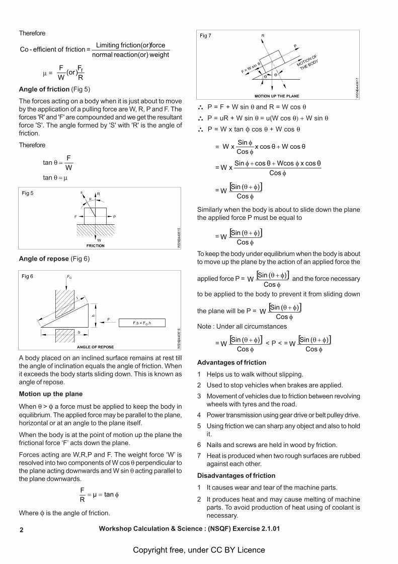
Laws of friction (Fig 3 & 4)
• Frictional force is directly proportional to the normalreaction between contacting surfaces.
• Frictional force acts opposite to the direction of motion.
• Frictional force depends on the nature of contactingsurfaces.
• Frictional force is independent over the area and shapeof contacting surfaces.
Coefficient of friction
It is a ratio between the frictional force to the normalreaction when the body is just about to move but atequilibrium. It is represented by symbol . (read as ‘meu’)
Copyright free, under CC BY Licence
2
Therefore
weightr)reaction(o normalforcer)friction(o Limiting = friction of efficient-Co
= RF)or(
WF f
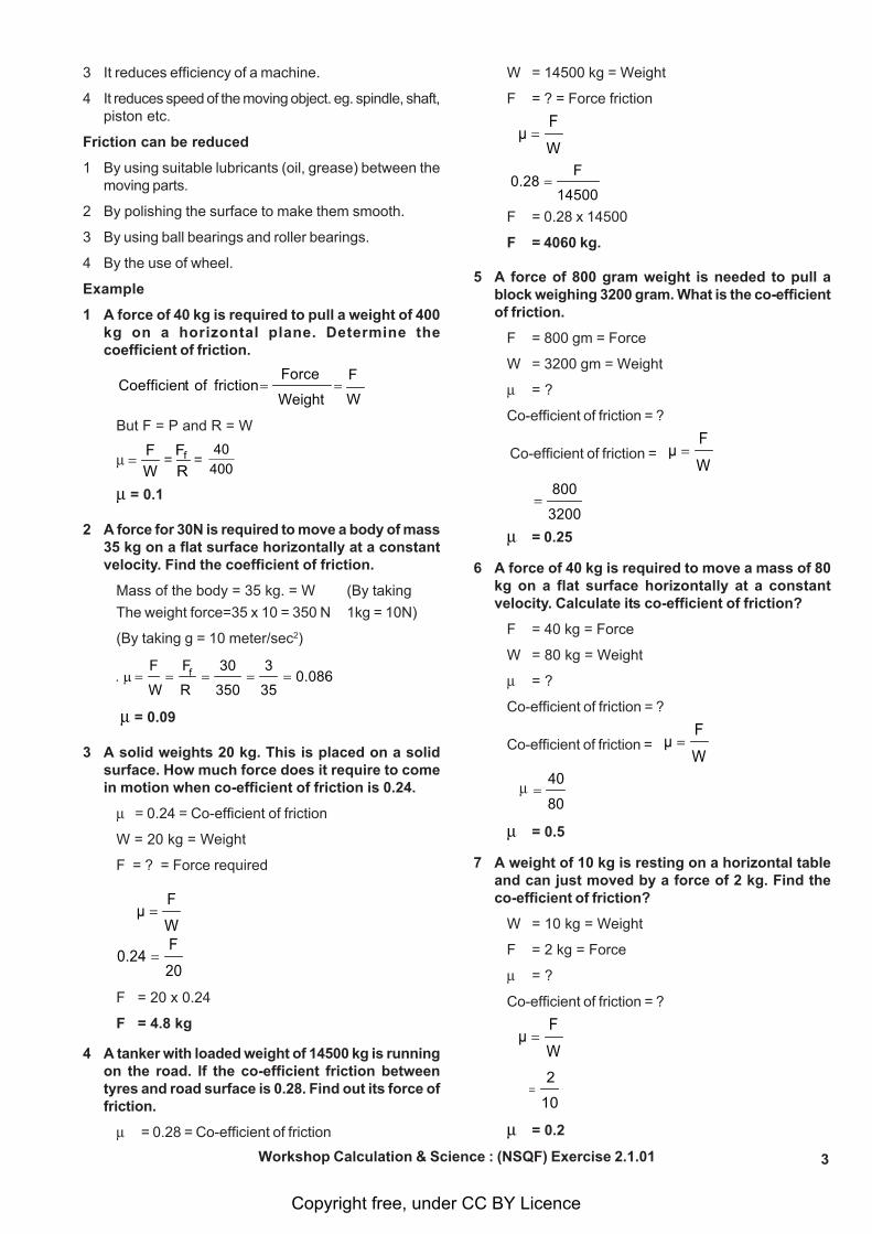
Angle of friction (Fig 5)
The forces acting on a body when it is just about to moveby the application of a pulling force are W, R, P and F. Theforces 'R' and 'F' are compounded and we get the resultantforce 'S'. The angle formed by 'S' with 'R' is the angle offriction.
Therefore
tan WF
tan
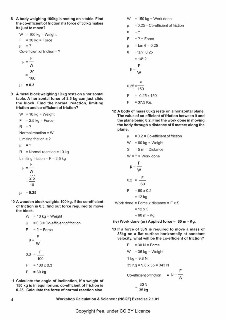
Angle of repose (Fig 6)
A body placed on an inclined surface remains at rest tillthe angle of inclination equals the angle of friction. Whenit exceeds the body starts sliding down. This is known asangle of repose.
Motion up the plane
When > a force must be applied to keep the body inequilibrium. The applied force may be parallel to the plane,horizontal or at an angle to the plane itself.
When the body is at the point of motion up the plane thefrictional force ‘F’ acts down the plane.
Forces acting are W,R,P and F. The weight force ‘W’ isresolved into two components of W cos perpendicular tothe plane acting downwards and W sin acting parallel tothe plane downwards.
φ== tanμRF
Where is the angle of friction.
P = F + W sin and R = W cos
P = uR + W sin = u(W cos W sin
P = W x tan cos + W cos
= +φφ θ cos Wθ cosx Cos Sin x W
=φ
φ++φ Cos
θ cos x Wcosθ cos Sin x W
= [ ]φφ+θ
Cos)( Sin W
Similarly when the body is about to slide down the planethe applied force P must be equal to
= [ ]φφ+θ
Cos)( Sin W
To keep the body under equilibrium when the body is aboutto move up the plane by the action of an applied force the
applied force P = [ ]φφ+θ
Cos)( Sin W and the force necessary
to be applied to the body to prevent it from sliding down
the plane will be P = [ ]φφ+θ
Cos)( Sin W
Note : Under all circumstances
= [ ]φφ+θ
Cos)( Sin W < P < = [ ]
φφ+θ
Cos)( Sin W
Advantages of friction
1 Helps us to walk without slipping.
2 Used to stop vehicles when brakes are applied.
3 Movement of vehicles due to friction between revolvingwheels with tyres and the road.
4 Power transmission using gear drive or belt pulley drive.
5 Using friction we can sharp any object and also to holdit.
6 Nails and screws are held in wood by friction.
7 Heat is produced when two rough surfaces are rubbedagainst each other.
Disadvantages of friction
1 It causes wear and tear of the machine parts.
2 It produces heat and may cause melting of machineparts. To avoid production of heat using of coolant isnecessary.
Workshop Calculation & Science : (NSQF) Exercise 2.1.01
Copyright free, under CC BY Licence
3
3 It reduces efficiency of a machine.
4 It reduces speed of the moving object. eg. spindle, shaft,piston etc.
Friction can be reduced
1 By using suitable lubricants (oil, grease) between themoving parts.
2 By polishing the surface to make them smooth.
3 By using ball bearings and roller bearings.
4 By the use of wheel.
Example
1 A force of 40 kg is required to pull a weight of 400kg on a horizontal plane. Determine thecoefficient of friction.
Weight
Force frictionoftCoefficien =
W
F=
But F = P and R = W
WF
= RFf =
400
40
= 0.1
2 A force for 30N is required to move a body of mass35 kg on a flat surface horizontally at a constantvelocity. Find the coefficient of friction.
Mass of the body = 35 kg. = W (By taking
The weight force=35 x 10 = 350 N 1kg = 10N)
(By taking g = 10 meter/sec2)
0.08635
3
350
30
R
F
W
F=====μ∴ f
= 0.09
3 A solid weights 20 kg. This is placed on a solidsurface. How much force does it require to comein motion when co-efficient of friction is 0.24.
= 0.24 = Co-efficient of friction
W = 20 kg = Weight
F = ? = Force required
W
Fμ =
20
F0.24 =
F = 20 x 0.24
F = 4.8 kg
4 A tanker with loaded weight of 14500 kg is runningon the road. If the co-efficient friction betweentyres and road surface is 0.28. Find out its force offriction.
= 0.28 = Co-efficient of friction
W = 14500 kg = Weight
F = ? = Force friction
W
Fμ =
14500
F0.28 =
F = 0.28 x 14500
F = 4060 kg.
5 A force of 800 gram weight is needed to pull ablock weighing 3200 gram. What is the co-efficientof friction.
F = 800 gm = Force
W = 3200 gm = Weight
= ?
Co-efficient of friction = ?
Co-efficient of friction =
W
Fμ =
3200
800=
= 0.25
6 A force of 40 kg is required to move a mass of 80kg on a flat surface horizontally at a constantvelocity. Calculate its co-efficient of friction?
F = 40 kg = Force
W = 80 kg = Weight
= ?
Co-efficient of friction = ?
Co-efficient of friction =
W
Fμ =
80
40=
= 0.5
7 A weight of 10 kg is resting on a horizontal tableand can just moved by a force of 2 kg. Find theco-efficient of friction?
W = 10 kg = Weight
F = 2 kg = Force
= ?
Co-efficient of friction = ?
W
Fμ =
10
2=
= 0.2
Workshop Calculation & Science : (NSQF) Exercise 2.1.01
Copyright free, under CC BY Licence
4
8 A body weighing 100kg is resting on a table. Findthe co-efficient of friction if a force of 30 kg makesits just to move?
W = 100 kg = Weight
F = 30 kg = Force
= ?
Co-efficient of friction = ?
W
Fμ =
100
30=
= 0.3
9 A metal block weighing 10 kg rests on a horizontaltable. A horizontal force of 2.5 kg can just slidethe block. Find the normal reaction, limitingfriction and co-efficient of friction?
W = 10 kg = Weight
F = 2.5 kg = Force
R = ?
Normal reaction = W
Limiting friction = ?
= ?
R = Normal reaction = 10 kg
Limiting friction = F = 2.5 kg
W
Fμ =
100
10
2.5=
= 0.25
10 A wooden block weights 100 kg. If the co-efficientof friction is 0.3, find out force required to movethe block.
W = 10 kg = Weight
= 0.3 = Co-efficient of friction
F = ? = Force
W
Fμ =
0.3 = 100
F
F = 100 x 0.3
F = 30 kg
11 Calculate the angle of inclination, if a weight of150 kg is in equilibrium, co-efficient of friction is0.25. Calculate the force of normal reaction also.
W = 150 kg = Work done
= 0.25 = Co-efficient of friction
F = ? = Force
= tan = 0.25
tan-1 0.25
= 14º 2’
W
Fμ =
0.25=150
F
F = 0.25 x 150
F = 37.5 Kg.
12 A body of mass 60kg rests on a horizontal plane.The value of co-efficient of friction between it andthe plane being 0.2. Find the work done in movingthe body through a distance of 5 meters along theplane.
= 0.2 = Co-efficient of friction
W = 60 kg = Weight
S = 5 m = Distance
W = ? = Work done
W
Fμ =
0.2 = 60
F
F = 60 x 0.2
= 12 kg
Work done = Force x distance = F x S
= 12 x 5
= 60 m - Kg.
(ie) Work done (or) Applied force = 60 m - Kg.
13 If a force of 30N is required to move a mass of35kg on a flat surface horizontally at constantvelocity, what will be the co-efficient of friction?
F = 30 N = Force
W = 35 kg = Weight
1 kg = 9.8 N
35 Kg = 9.8 x 35 = 343 N
Co-efficient of friction =
W
Fμ =
kg 35N 30
=
Workshop Calculation & Science : (NSQF) Exercise 2.1.01
Copyright free, under CC BY Licence
5
N 9.8 x 35
N 30=
= 0.087
14 A block of ice weighing one quintal rests inequilibrium on a wooden plank inclined at 30º.Find the coefficient of friction between the ice andwood.
W = 1 quintal = 100 kg = Weight
= 30º tan W
F
= tan tan 30º
= 0.5774
15 Calculate the force that is required to slide a massof 980 kg on a guide, when the coefficient offriction between the surfaces is 0.09.
W = 980 kg = Weight
= 0.09 = Co-efficient of friction
F = Force = ?
Co-efficient of friction =
W
Fμ =
0.09= kg 980F
F = 0.09 x 980 kg
Required force(F) = 88.2 kg
16 A metal block weighing 10kg rests on a horizontalboard and the coefficient of friction between thesurfaces is 0.22. Find (a) the horizontal force whichwill just move the block and (b) the force actingat an angle of 30º with the horizontal, which willjust move the block.
W = 10 kg = Weight
Co-efficient of friction = = 0.22
(a) F = ?
(b) Force acting at an angle of 30º with the horizontal?
(a)
W
Fμ =
0.22= kg 10
F
F = 2.2 Kg.
(b) Force acting at an angle of 30º=
θ Cos
F
= 2.2/cos 30º
= 2.2/0.8660
= 2.54 kg
17 Calculate the angle of inclination, if a weight of150 kg is in equilibrium. Coefficient of friction is0.25. Calculate the force of normal reaction also.
= ? = angle of inclination
W = 150kg = Weight
= 0.25
F = ? = Force
tan =
tan = 0.25
= 14º 2'20"
W
Fμ =
0.25 = 150 Kg
F
F = 0.25 x 150 kg
F = 37.5 kg.
18 A body of mass 10 kg rests on a horizontal plane.The co-efficient of friction between the body andplane is 0.15. Find the work done in moving thebody through a distance of 10 meter.
W = 10kg = Weight
= 0.15 = Co-efficient of friction
S = 10 meter = distance
W = Work done = ?
W
Fμ =
0.15 = 10 Kg
F
F = 0.15 x 10 kg
F = 1.5 kg
Work done = W = F x S
= 1.5 kg x 10 m
= 15 m - kg
Workshop Calculation & Science : (NSQF) Exercise 2.1.01
Copyright free, under CC BY Licence
6
1 A force 50N is required to move a mass of 40kg on aflat surface horizontally at a constant velocity. Find thecoefficient of friction. (9.8N = 1kg)
2 A vehicle having a weight of 800kg is moving on theroad. If the coefficient of friction between the tyres androad surface is 0.3, then calculate the force of friction.
3 A solid weighing 50kg is place on a solid surface. Howmuch force is required to move the block whencoefficient of friction is 0.25 between the block and thesurface.
4 A railway wagon weighs 1250 tonnes. If the coefficientof friction between it and the rails is 0.003, find theforce required to move the wagon.
5 A body of mass 100kg rests on a horizontal plane. Theangle of friction between the body and the plane being0.025. Find the work done is moving the body througha distance of 16m along the plane.
6 A body of mass 20kg rests on a horizontal plane theco-efficient of friction between the body and plane is0.3. Find the work done in moving the body through adistance of 10 meters.
7 A body of mass 2000 kg moves a distance of 10 metersin 5 sec. If the co-efficient of friction between the bodyand floor is 0.3 find the horizontal force required to movethe body and horsepower absorbed against friction.
8 A vehicle is moving at 50kmph and the load on thevehicle is 5000 kg. Find the H.P. required to move thevehicle if = 0.2.
9 Find out the power lost due to friction by a planer underthe following conditions.
Mass of the planer table = 3500 kg
Rate of moment of the table=0.5 m/sec
Co-efficient friction between the table and theways=0.06
10 A truck having weight 12000 kg is moving on the road.If the co-efficient of friction between the tyres and theroad surface is 0.3, then calculate the force of friction.
Assignment B
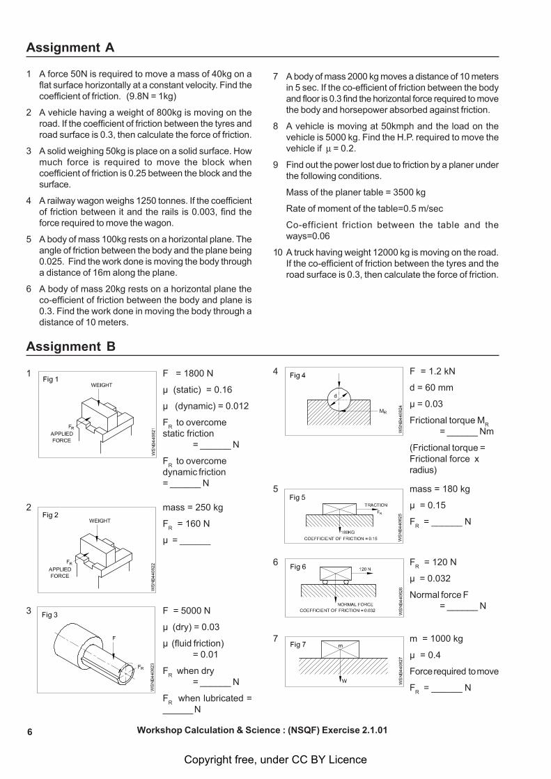
1 F = 1800 N
μ (static) = 0.16
μ (dynamic) = 0.012
FR to overcome
static friction= ______ N
FR to overcome
dynamic friction= ______ N
2 mass = 250 kg
FR = 160 N
μ = ______
3 F = 5000 N
μ (dry) = 0.03
μ (fluid friction)= 0.01
FR when dry
= ______ N
FR when lubricated =
______ N
4 F = 1.2 kN
d = 60 mm
μ = 0.03
Frictional torque MR
= ______ Nm
(Frictional torque =Frictional force xradius)
5 mass = 180 kg
μ = 0.15
FR = ______ N
6 FR = 120 N
μ = 0.032
Normal force F= ______ N
7 m = 1000 kg
μ = 0.4
Force required to move
FR = ______ N
Workshop Calculation & Science : (NSQF) Exercise 2.1.01
Assignment A
Copyright free, under CC BY Licence
7
1 Which one of the following is useful friction
A Rings in cylinders B Crankshaft bearings
C Brake shoe linings D Wheel hole bearings
2 Which is in between the wheels and road, if vehiclesare able to run on roads.
A erosion B motion
C corrosion D friction
3 Which direction of motion frictional force acts.
A equal B opposite
C inclined D forward
4 What is the formula of angle of friction, if ‘F’ is thefrictional force, R is the normal reaction and q is theangle of friction.
A Tan q = RF
B Cot q = RF
C Sin q = RF
D Cos q = RF
5 What is the formula for Co-efficient of friction (m).
A FR B
RF
C F x R D F + R
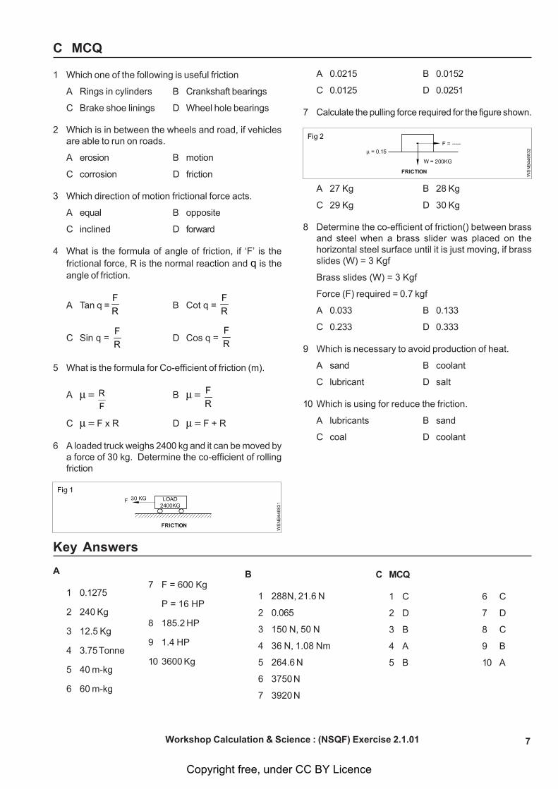
6 A loaded truck weighs 2400 kg and it can be moved bya force of 30 kg. Determine the co-efficient of rollingfriction
Workshop Calculation & Science : (NSQF) Exercise 2.1.01
C MCQ
A 0.0215 B 0.0152
C 0.0125 D 0.0251
7 Calculate the pulling force required for the figure shown.
A 27 Kg B 28 Kg
C 29 Kg D 30 Kg
8 Determine the co-efficient of friction() between brassand steel when a brass slider was placed on thehorizontal steel surface until it is just moving, if brassslides (W) = 3 Kgf
Brass slides (W) = 3 Kgf
Force (F) required = 0.7 kgf
A 0.033 B 0.133
C 0.233 D 0.333
9 Which is necessary to avoid production of heat.
A sand B coolant
C lubricant D salt
10 Which is using for reduce the friction.
A lubricants B sand
C coal D coolant
Key Answers
A
1 0.1275
2 240 Kg
3 12.5 Kg
4 3.75 Tonne
5 40 m-kg
6 60 m-kg
7 F = 600 Kg
P = 16 HP
8 185.2 HP
9 1.4 HP
10 3600 Kg
B
1 288N, 21.6 N
2 0.065
3 150 N, 50 N
4 36 N, 1.08 Nm
5 264.6 N
6 3750 N
7 3920 N
C MCQ
1 C 6 C
2 D 7 D
3 B 8 C
4 A 9 B
5 B 10 A
Copyright free, under CC BY Licence
8
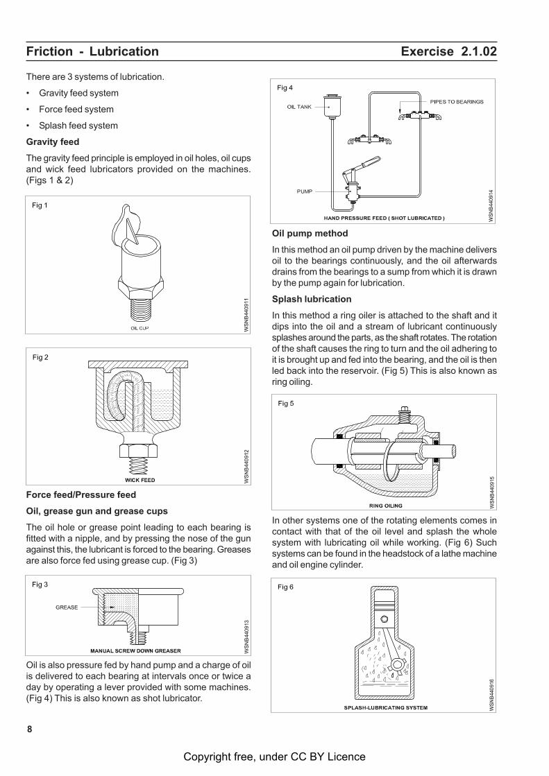
There are 3 systems of lubrication.
• Gravity feed system
• Force feed system
• Splash feed system
Gravity feed
The gravity feed principle is employed in oil holes, oil cupsand wick feed lubricators provided on the machines.(Figs 1 & 2)
Friction - Lubrication Exercise 2.1.02
Oil pump method
In this method an oil pump driven by the machine deliversoil to the bearings continuously, and the oil afterwardsdrains from the bearings to a sump from which it is drawnby the pump again for lubrication.
Splash lubrication
In this method a ring oiler is attached to the shaft and itdips into the oil and a stream of lubricant continuouslysplashes around the parts, as the shaft rotates. The rotationof the shaft causes the ring to turn and the oil adhering toit is brought up and fed into the bearing, and the oil is thenled back into the reservoir. (Fig 5) This is also known asring oiling.
Force feed/Pressure feed
Oil, grease gun and grease cups
The oil hole or grease point leading to each bearing isfitted with a nipple, and by pressing the nose of the gunagainst this, the lubricant is forced to the bearing. Greasesare also force fed using grease cup. (Fig 3)
Oil is also pressure fed by hand pump and a charge of oilis delivered to each bearing at intervals once or twice aday by operating a lever provided with some machines.(Fig 4) This is also known as shot lubricator.
In other systems one of the rotating elements comes incontact with that of the oil level and splash the wholesystem with lubricating oil while working. (Fig 6) Suchsystems can be found in the headstock of a lathe machineand oil engine cylinder.
Copyright free, under CC BY Licence
9
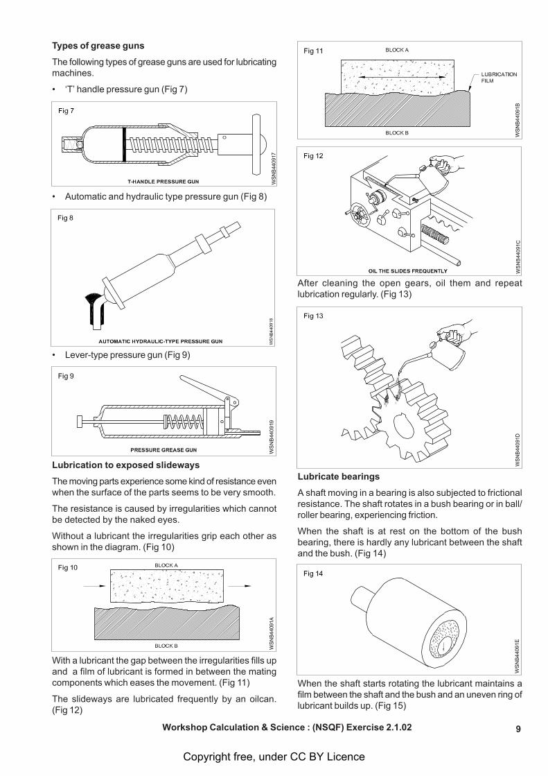
Types of grease guns
The following types of grease guns are used for lubricatingmachines.
• ‘T’ handle pressure gun (Fig 7)
• Automatic and hydraulic type pressure gun (Fig 8)
• Lever-type pressure gun (Fig 9)
Lubrication to exposed slideways
The moving parts experience some kind of resistance evenwhen the surface of the parts seems to be very smooth.
The resistance is caused by irregularities which cannotbe detected by the naked eyes.
Without a lubricant the irregularities grip each other asshown in the diagram. (Fig 10)
With a lubricant the gap between the irregularities fills upand a film of lubricant is formed in between the matingcomponents which eases the movement. (Fig 11)
The slideways are lubricated frequently by an oilcan.(Fig 12)
After cleaning the open gears, oil them and repeatlubrication regularly. (Fig 13)
Lubricate bearings
A shaft moving in a bearing is also subjected to frictionalresistance. The shaft rotates in a bush bearing or in ball/roller bearing, experiencing friction.
When the shaft is at rest on the bottom of the bushbearing, there is hardly any lubricant between the shaftand the bush. (Fig 14)
When the shaft starts rotating the lubricant maintains afilm between the shaft and the bush and an uneven ring oflubricant builds up. (Fig 15)
Workshop Calculation & Science : (NSQF) Exercise 2.1.02
Copyright free, under CC BY Licence
10
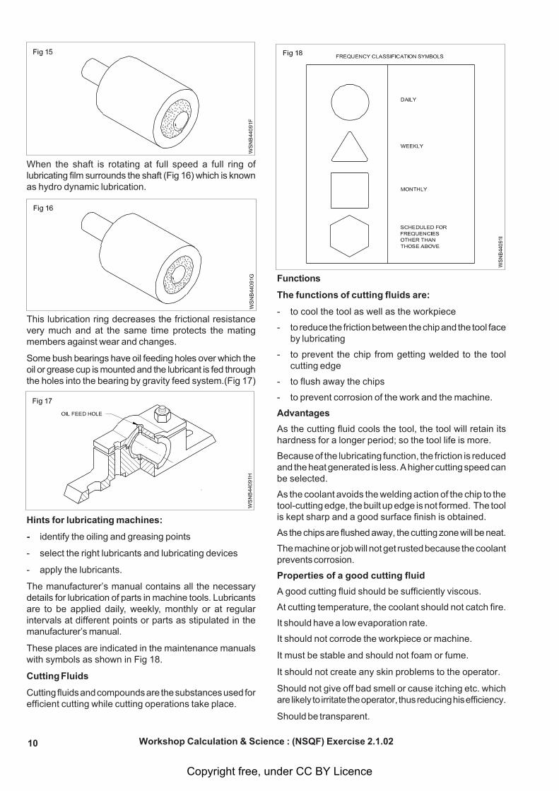
When the shaft is rotating at full speed a full ring oflubricating film surrounds the shaft (Fig 16) which is knownas hydro dynamic lubrication.
This lubrication ring decreases the frictional resistancevery much and at the same time protects the matingmembers against wear and changes.
Some bush bearings have oil feeding holes over which theoil or grease cup is mounted and the lubricant is fed throughthe holes into the bearing by gravity feed system.(Fig 17)
Hints for lubricating machines:
- identify the oiling and greasing points
- select the right lubricants and lubricating devices
- apply the lubricants.
The manufacturer’s manual contains all the necessarydetails for lubrication of parts in machine tools. Lubricantsare to be applied daily, weekly, monthly or at regularintervals at different points or parts as stipulated in themanufacturer’s manual.
These places are indicated in the maintenance manualswith symbols as shown in Fig 18.
Cutting Fluids
Cutting fluids and compounds are the substances used forefficient cutting while cutting operations take place.
Functions
The functions of cutting fluids are:
- to cool the tool as well as the workpiece
- to reduce the friction between the chip and the tool faceby lubricating
- to prevent the chip from getting welded to the toolcutting edge
- to flush away the chips
- to prevent corrosion of the work and the machine.
Advantages
As the cutting fluid cools the tool, the tool will retain itshardness for a longer period; so the tool life is more.
Because of the lubricating function, the friction is reducedand the heat generated is less. A higher cutting speed canbe selected.
As the coolant avoids the welding action of the chip to thetool-cutting edge, the built up edge is not formed. The toolis kept sharp and a good surface finish is obtained.
As the chips are flushed away, the cutting zone will be neat.
The machine or job will not get rusted because the coolantprevents corrosion.
Properties of a good cutting fluid
A good cutting fluid should be sufficiently viscous.
At cutting temperature, the coolant should not catch fire.
It should have a low evaporation rate.
It should not corrode the workpiece or machine.
It must be stable and should not foam or fume.
It should not create any skin problems to the operator.
Should not give off bad smell or cause itching etc. whichare likely to irritate the operator, thus reducing his efficiency.
Should be transparent.
Workshop Calculation & Science : (NSQF) Exercise 2.1.02
Copyright free, under CC BY Licence
11
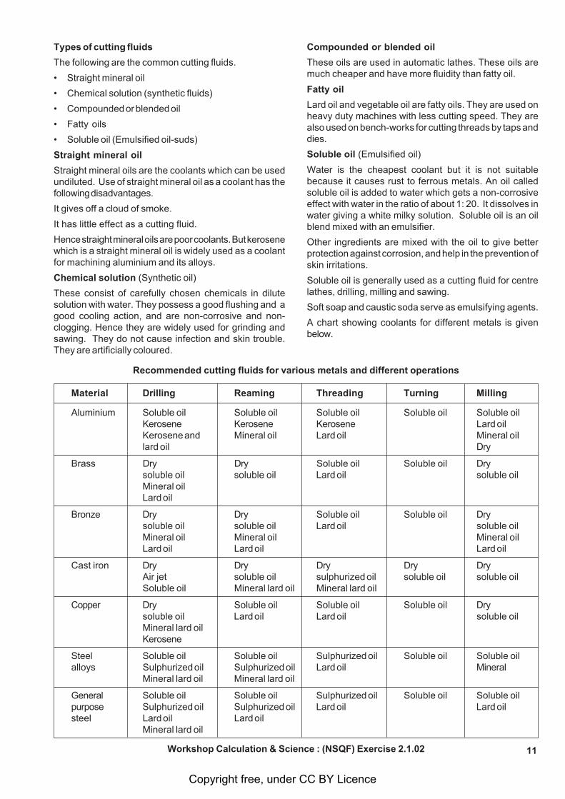
Recommended cutting fluids for various metals and different operations
Material Drilling Reaming Threading Turning Milling
Aluminium Soluble oil Soluble oil Soluble oil Soluble oil Soluble oilKerosene Kerosene Kerosene Lard oilKerosene and Mineral oil Lard oil Mineral oillard oil Dry
Brass Dry Dry Soluble oil Soluble oil Drysoluble oil soluble oil Lard oil soluble oilMineral oilLard oil
Bronze Dry Dry Soluble oil Soluble oil Drysoluble oil soluble oil Lard oil soluble oilMineral oil Mineral oil Mineral oilLard oil Lard oil Lard oil
Cast iron Dry Dry Dry Dry DryAir jet soluble oil sulphurized oil soluble oil soluble oilSoluble oil Mineral lard oil Mineral lard oil
Copper Dry Soluble oil Soluble oil Soluble oil Drysoluble oil Lard oil Lard oil soluble oilMineral lard oilKerosene
Steel Soluble oil Soluble oil Sulphurized oil Soluble oil Soluble oilalloys Sulphurized oil Sulphurized oil Lard oil Mineral
Mineral lard oil Mineral lard oil
General Soluble oil Soluble oil Sulphurized oil Soluble oil Soluble oilpurpose Sulphurized oil Sulphurized oil Lard oil Lard oilsteel Lard oil Lard oil
Mineral lard oil
Types of cutting fluids
The following are the common cutting fluids.
• Straight mineral oil
• Chemical solution (synthetic fluids)
• Compounded or blended oil
• Fatty oils
• Soluble oil (Emulsified oil-suds)
Straight mineral oil
Straight mineral oils are the coolants which can be usedundiluted. Use of straight mineral oil as a coolant has thefollowing disadvantages.
It gives off a cloud of smoke.
It has little effect as a cutting fluid.
Hence straight mineral oils are poor coolants. But kerosenewhich is a straight mineral oil is widely used as a coolantfor machining aluminium and its alloys.
Chemical solution (Synthetic oil)
These consist of carefully chosen chemicals in dilutesolution with water. They possess a good flushing and agood cooling action, and are non-corrosive and non-clogging. Hence they are widely used for grinding andsawing. They do not cause infection and skin trouble.They are artificially coloured.
Compounded or blended oil
These oils are used in automatic lathes. These oils aremuch cheaper and have more fluidity than fatty oil.
Fatty oil
Lard oil and vegetable oil are fatty oils. They are used onheavy duty machines with less cutting speed. They arealso used on bench-works for cutting threads by taps anddies.
Soluble oil (Emulsified oil)
Water is the cheapest coolant but it is not suitablebecause it causes rust to ferrous metals. An oil calledsoluble oil is added to water which gets a non-corrosiveeffect with water in the ratio of about 1: 20. It dissolves inwater giving a white milky solution. Soluble oil is an oilblend mixed with an emulsifier.
Other ingredients are mixed with the oil to give betterprotection against corrosion, and help in the prevention ofskin irritations.
Soluble oil is generally used as a cutting fluid for centrelathes, drilling, milling and sawing.
Soft soap and caustic soda serve as emulsifying agents.
A chart showing coolants for different metals is givenbelow.
Workshop Calculation & Science : (NSQF) Exercise 2.1.02
Copyright free, under CC BY Licence
12
Friction - Co -efficient of friction, application and effects of friction in workshoppractice Exercise 2.1.03
Co-efficient of friction
The ratio between the limiting frictional force and the normalreaction is called co-efficient of friction.
Suppose, by applying a force P kg, the object is just fit tomove, then limiting frictional force will be produced inbetween the two surfaces. The limiting frictional force willbe equal to external force applied and will work in theopposite direction.
F = P kg
According to the second law of limiting frictional force, thefrictional force will be proportional to normal reaction.
F R (sign is proportional to)
F = R x constant
orR
F = constant
This constant between objects is called co-efficient offriction. This is represented by .
RF orR
F.
Co-efficient of friction = reaction Normal
force frictional Limiting
Co-efficient of friction is always constant for any two objectsand it has no unit.
Example
1 The sliding valve of a steam engine has dimensions25cm by 45 cm and the steam pressure on the backof the valve is 25 kg/cm2. If the co-efficient of frictionis 0.13. Calculate the force required to move thevalve. Dimension of steam valve = 25 cm x 45 cm.
Steam pressure = 25 kg/cm2
Co-efficient of friction = 0.13
Force required to move the valve = ?
F = ?
Force of the steam = Pressure x Area
= 25 x 25 x 45
45cm25cmcm
25kg2
= 28125 kg.
Force acts on the valve = 28125 kg
W
Fμ =
0.13 =28125
F
F = 0.13 x 2812
Force required to move the valves = 3656.25 Kg
2 An empty drum weighing 50kg is resting on a shopfloor. Find the coefficient of friction if a force of15kg makes it just move.
W = 50 kg = Weight
F = 15 kg = Force
Co-efficient of friction =
W
Fμ =
kg 50kg 15
=
= 0.3
3 A machine crate weighing 1000kg moves distanceof 5m in 5 sec. If the coefficient of friction betweenthe crate and floor is 0.3, calculate the horizontalforce required to move the crate and horse powerabsorbed against friction.
Weight (W) = 1000 kg
Distance (S) = 5 meter
Time (t) = 5 second
i Co-efficient of friction () = 0.3
ii Force (F) = ?
Horse power (H.P.) = ?
iW
Fμ =
0.3 = 1000 KgF
F = 0.3 x 1000 kg
F = 300 kg (1 HP = 75 m.kg/sec)
ii
tS x FH.P= x
75 1
H.P
55 x 300
= x 75 1 = 4 H.P
Horse power absorbed against friction = 4.H.P.
4 A weight of 600 kg is kept on the inclined planeat 300. Calculated the normal reaction and forcerolling downwards.
Solution:
Weight kept on the inclined plane (W) = 600kg
Angle of the inclined plane () = 300
Normal reaction (R) = W . cos
Copyright free, under CC BY Licence
13
= 600 x cos 300
= 600 (0.8660)
= 519.6 kg
Force rolling downwards = W . sin
= 600 x sin 300
= 600 (0.5000)
= 300 kg
Normal reaction = 519.6 kg
Force rolling downwards = 300 kg
5 Find out the power lost due to friction by a plannerunder the following conditions.
Mass of the planer table = 3500 kg
Rate of movement of the table = 0.5m/sec
Co-efficient of friction betweenthe table and the ways = 0.06
Solution:
Weight of planer (W) = 3500 kg
Distance moved (d) = 0.5 m/sec
Co-efficient of friction () = 0.06
Co-efficient of friction =
W
Fμ =
0.06 = 3500
F
F = 0.06 x 3500 = 210 kg
Workdone = F x distance moved
= 210 x 0.5 = 105 kgm/sec
75 kgm/sec = 1 H.P
105 kgm/sec = 75
1 105 = 1.4 H.P
Power lost due to friction = 104 H.P
6 A planner table weighting 800 kg moves adistance of 2 metres in seconds on its bed. If co-efficient of friction between bed and table is 0.30find the power required to move the table aganistthe friction.
7 On a milling machine table a component of 20kgf is clamped with the help of three equidistantclamps. What force must be exerted by eachclamp to avoid slipping of the component whenthe horizontal cutting force is 60 kgf and thecoefficient of friction is equal to 0.2.
8 A machine weight of 14500 kg moving on thefloor.If the co-efficient of friction between themachine and floor surface is 0.28 then calculatethe force of friction.
9 A tail stock of a lathe has a mass of 21.5 kg andco-efficient of friction at the slides is 0.122. Whathorizontal force will be required to slide the tailstock?
10 An inclined surface makes an angle of 30 degreeswith the horizontal. An object weigting 5 tons isplaced on the surface. Find out the normalreaction at the object and also the effective forcerequired to bring the object downwards.
11 A glass block of 400 grams has been placed onthe table. The glass is commuted by a string to a40 grams scale pan. The string passes over pulley.When a weight of 60 grams is placed on the scalepan, the block starts sliding. Find out the co-effiecient of friction between wood and glass.
Workshop Calculation & Science : (NSQF) Exercise 2.1.03
Copyright free, under CC BY Licence
14
Centre of gravity - Centre of gravity and its practical applicationExercise 2.2.04
Any object comprises of a large number of particles. Eachparticle is pulled towards the earth due to the force ofgravity. Thus, the forces on the particles are equal, paralleland act in the same direction. These forces will have aresultant which acts through a particular point ‘G’. Thisfixed point ‘G’ is called the centre of gravity.
Concept of Centre of gravity
In physics, an imaginary point in a body of matter where,for convenience in certain calculations, the total weight ofthe body may be thought to be concentrated. The conceptis sometimes useful in designing static structures (e.g.,buildings and bridges) or in predicting the behaviour of amoving body when it is acted on by gravity.
In a uniform gravitational field the centre of gravity isidentical to the centre of mass, a term preferred byphysicists.
Gravitation
The mutual attractive force of bodies due to which theyattract each other is called gravitation.
1 Gravity
The attractive force of the earth due to which it attracts allbodies towards its centre is called gravity.
The value of gravity varies from place to place on the groundsurface. Its general value is 9.81 m/s2.
Centroid
Different geometrical shapes such as the circle, triangleand rectangle are plane figures having only 2-dimensions.They are also known as laminas. They have only area, butno mass. The centre of gravity of these plane figures iscalled as the Centroid. It is also known as the geometricalcentre. The method of finding out the centroid of a planefigure is the same as that of finding out the centre of gravity
of a body. If the lamina is assumed to have uniform massper unit area, then the centroid is also the centre of gravityin a uniform gravitational field.
Methods to calculate centre of gravity
1 By geometrical consideration.
2 By moments.
Principle : The total moment of a weight about any axis= The sum of the moments of the various parts about thesame axis.
3 By graphical method.
The first two methods are generally used to find out thecentre of gravity or centroid, as the third method canbecome tedious.
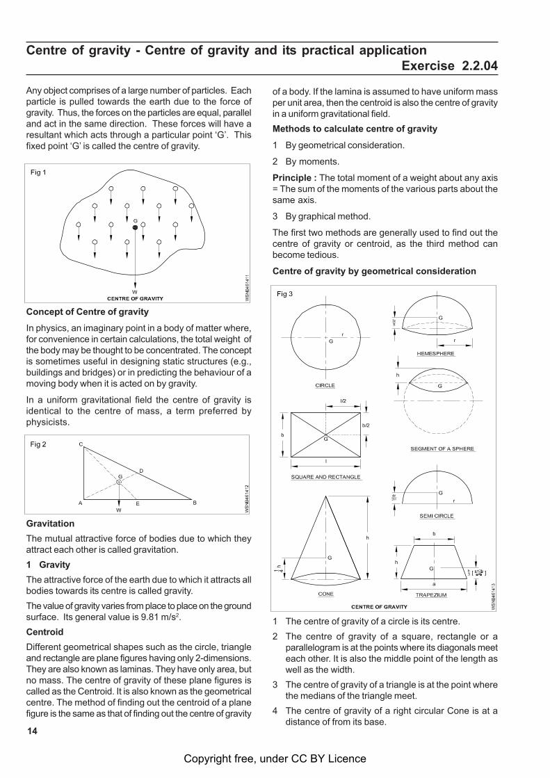
Centre of gravity by geometrical consideration
1 The centre of gravity of a circle is its centre.
2 The centre of gravity of a square, rectangle or aparallelogram is at the points where its diagonals meeteach other. It is also the middle point of the length aswell as the width.
3 The centre of gravity of a triangle is at the point wherethe medians of the triangle meet.
4 The centre of gravity of a right circular Cone is at adistance of from its base.
Copyright free, under CC BY Licence
15
5 The centre of gravity of a hemisphere is at a distanceof from its base.
6 The centre of gravity of a segment of a sphere of radiush is at a perpendicular distance of from the centre ofthe sphere.
7 The centre of gravity of a semicircle is at a perpendiculardistance of from its centre.
8 The centre of gravity of a trapezium with parallel side'a' and 'b' is at a distance of measured from the base'b'.
9 The centre of gravity of a cube of side L is at a distanceof from every face.
10 The centre of gravity of a Sphere of diameter 'd' is at adistance of from every point.
Centre of gravity; An experiment
• Number of 2 pencil
• A fine edge like a ruler or a credit card
• A permanent marker
• A ruler
Step 1
Attempt to balance the pencil on the edge you haveselected
Balancing the pencil may take some trial and error. Thepoint at which the pencil balances may not be where youfirst thought. If it begins to tip in one direction, move thepencil back slowly in the opposite direction until it willstay there on its own.
Step 2
Once the pencil is balanced, mark the location of thebalancing point with a permanent marker.
Step 3
Measure the distance between the ends of the pencil andthe balancing point you have marked. Are the two lengthsequal? On my pencil, the length from the eraser to thebalancing point was actually 1.25 inches less than thelength from the pencil tip to the balancing point. Whywould this be the case?
In our experiment, the balancing point was another wordfor the centre of gravity of this pencil. In other words, if wecut the pencil in two at the mark we made in the experiment,the two parts would be equal in weight. However, they arenot equal in length. As you may have already figured out,the metal piece that houses the eraser contributes moreto the weight of the pencil, so the CG is closer to that sideof the pencil.
Keeping up with that centre
The centre of gravity is an important concept in determiningthe stability of a structure. It’s the reason why a goodhomeowner will keep the top branches of his trees trimmed.It’s also the reason why a pick-up truck might not be thebest vehicle choice for a first time driver. Stability ismaximized in objects with a lower centre of gravity and awide base. The taller and more top-heavy an object, the
more likely it is to tip over when it is tilted by a force. Thisfigure demonstrates a bus driving on two different grades;the second one is steep enough to cause the centre ofgravity to fall outside of the base of the vehicle, which willcause it to topple over.
Equilibrium
A body is said to be in equilibrium if the resultant of all theforces acting on a body is zero and if there is no turningmoment.
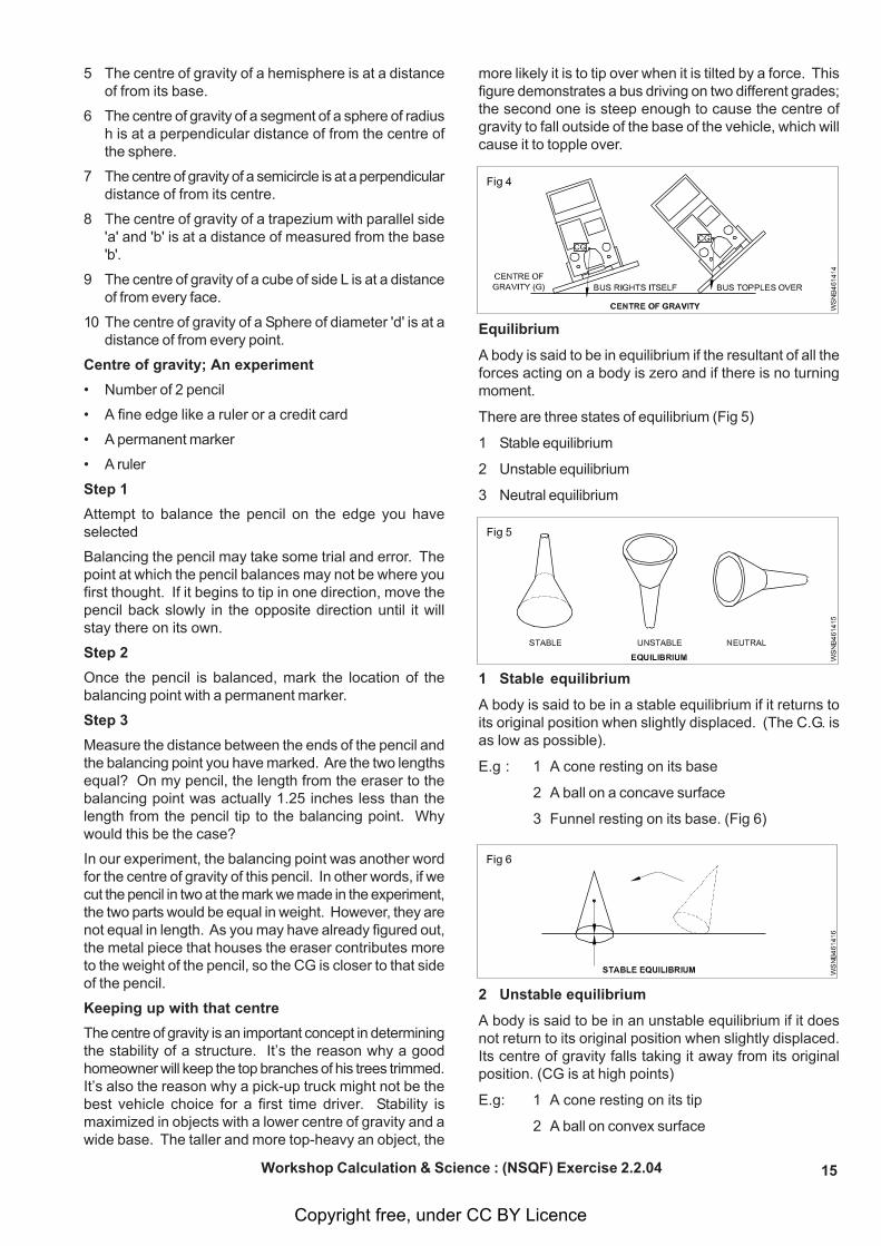
There are three states of equilibrium (Fig 5)
1 Stable equilibrium
2 Unstable equilibrium
3 Neutral equilibrium
1 Stable equilibrium
A body is said to be in a stable equilibrium if it returns toits original position when slightly displaced. (The C.G. isas low as possible).
E.g : 1 A cone resting on its base
2 A ball on a concave surface
3 Funnel resting on its base. (Fig 6)
2 Unstable equilibrium
A body is said to be in an unstable equilibrium if it doesnot return to its original position when slightly displaced.Its centre of gravity falls taking it away from its originalposition. (CG is at high points)
E.g: 1 A cone resting on its tip
2 A ball on convex surface
Workshop Calculation & Science : (NSQF) Exercise 2.2.04
Copyright free, under CC BY Licence
16
3 Funnel standing on its tube end. (Fig 7)
3 Neutral equilibrium
A body is said to be in a neutral equilibrium if on beingslightly displaced, it takes a new position similar to itsoriginal one. The centre of gravity remains undisturbed.(CG is neither raised or lowered)
Eg: 1 A cone resting on its side
2 A ball on flat surface
3 Funnel resting on its side (Fig 8)
Model 1
Conditions for stable equilibrium
• The CG should be as low as possible.
• It should have a broad base.
• The vertical line passing through the CG should fallwithin the base.
Conditions of equilibrium
A body is said to be in a state of equilibrium under theaction of forces when there is no motion of rotation ortranslation of the body. There are three conditions ofequilibrium of a body which are given below:
i Algebraic sum of the horizontal components of all theforces acting on the body must be zero.
H = 0
ii Algebraic sum of the vertical components of all theforces acting on the body must be zero.
V = 0
iii Algebraic sum of the moments of all the forces actingon the body must be zero.
M = 0
Torque or twisting moment of a couple is givenby the product of force applied and the arm ofthe couple (i.e. Radius). In fact, moment meansthe product of “force applied” and the“perpendicular distance of the point and theline of the force”.
Some example of equilibrium in daily life
1 The lower decks of the ships are loaded with heavycargoes. This makes the centre of gravity of the wholeship lower and its equilibrium becomes more stable.
2 A man carrying a bucket full of water in one hand extendshis opposite arm and bends his body towards it.
3 While carrying load on back the man bends forward sothat his and the load’s centre of gravity falls on hisfeet, if he walks erect, he will fall backward.
4 While climbing a mountain, a man bends forward andbends backward while descending so that the centreof gravity of his load falls on his feet.
5 In a double-decker, more passengers areaccommodated in the lower deck and less on the upperso that the centre of gravity of the bus and thepassengers is kept low to eliminate any chance ofturning.
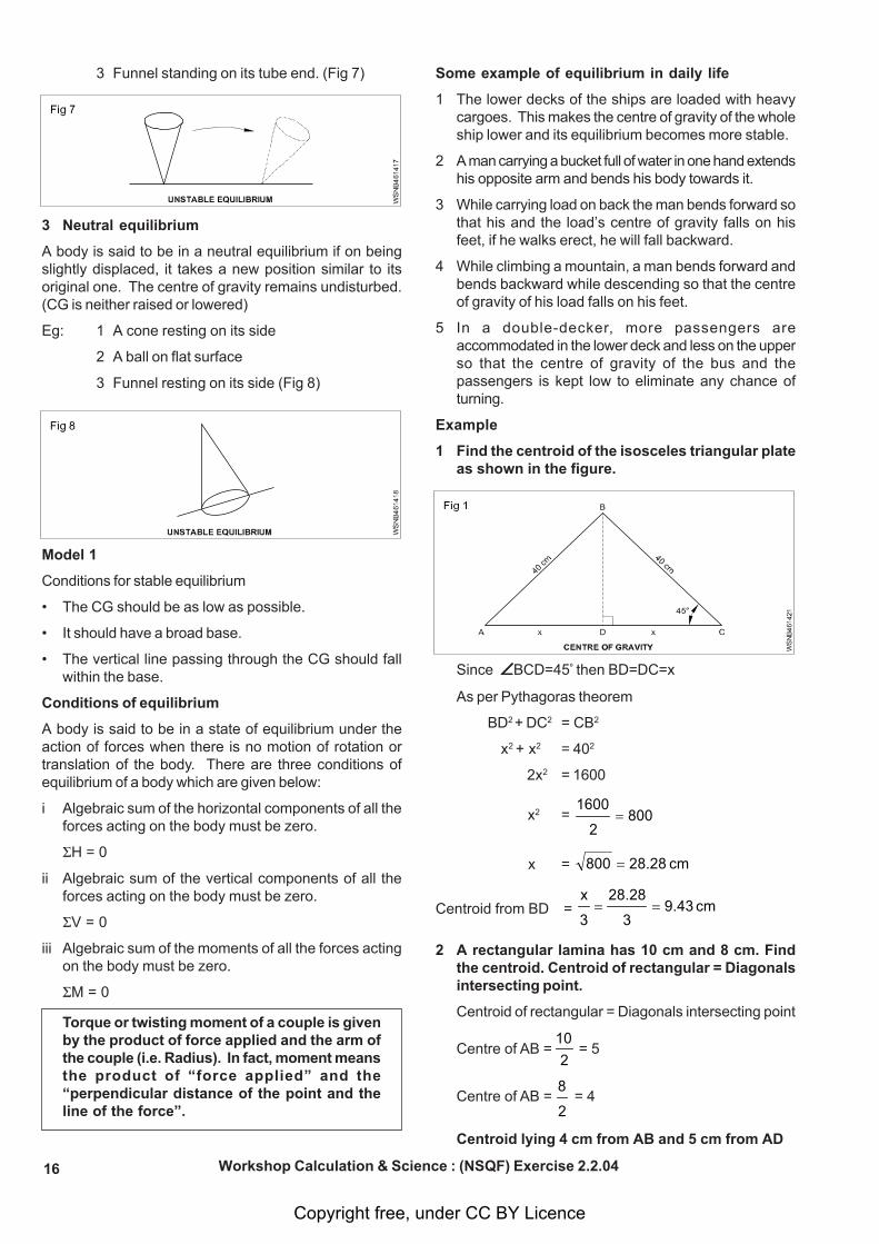
Example
1 Find the centroid of the isosceles triangular plateas shown in the figure.
Since BCD=45º then BD=DC=x
As per Pythagoras theorem
BD2 + DC2 = CB2
x2 + x2 = 402
2x2 = 1600
x2 = 8002
1600=
x = cm 28.28800 =
Centroid from BD =
cm9.433
28.28
3
x==
2 A rectangular lamina has 10 cm and 8 cm. Findthe centroid. Centroid of rectangular = Diagonalsintersecting point.
Centroid of rectangular = Diagonals intersecting point
Centre of AB = 2
10 = 5
Centre of AB = 2
8 = 4
Centroid lying 4 cm from AB and 5 cm from AD
Workshop Calculation & Science : (NSQF) Exercise 2.2.04
Copyright free, under CC BY Licence
17
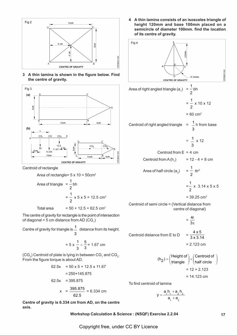
3 A thin lamina is shown in the figure below. Findthe centre of gravity.
Centroid of rectangle
Area of rectangle= 5 x 10 = 50cm2
Area of triangle = 2
1bh
= 2
1 x 5 x 5 = 12.5 cm2
Total area = 50 + 12.5 = 62.5 cm2
The centre of gravity for rectangle is the point of intersectionof diagonal = 5 cm distance from AD (CG
1)
Centre of gravity for triangle is 3
1 distance from its height.
= 5 x 35
3
1= = 1.67 cm
(CG2) Centroid of plate is lying in between CG
1 and CG
2.
From the figure torque is about AD.
62.5x = 50 x 5 + 12.5 x 11.67
= 250+145.875
62.5x = 395.875
x = 62.5
395.875 = 6.334 cm
Centre of gravity is 6.334 cm from AD, on the centreaxis.
4 A thin lamina consists of an isosceles triangle ofheight 120mm and base 100mm placed on asemicircle of diameter 100mm. find the locationof its centre of gravity.
Area of right angled triangle (a1) =
2
1bh
= 2
1 x 10 x 12
= 60 cm2
Centroid of right angled triangle = 3
1h from base
= 3
1 x 12
Centroid from E = 4 cm
Centroid from A (h1) = 12 - 4 = 8 cm
Area of half circle (a2) =
2
1 r2
=2
1 x 3.14 x 5 x 5
= 39.25 cm2
Centroid of semi circle = (Vertical distance from centre of diagonal)
= 3
r4π
Centroid distance from E to D = 3.14 x 35 x 4
= 2.123 cm
circle half of Centroid
triangleof Height
)2(h ⎟⎟⎠
⎞⎜⎜⎝
⎛+⎟⎟⎠
⎞⎜⎜⎝
⎛=
= 12 + 2.123
= 14.123 cm
To find centroid of lamina
2
a1
a2
h2
a1
h1
ay
+
+=
Workshop Calculation & Science : (NSQF) Exercise 2.2.04
Copyright free, under CC BY Licence
18
= 39.2560
14.123 x 39.258 x 60+
+
= 99.25
328.554480 +
= 99.25
328.1034
= 10.421 cm
Centroid is lying at 10.421 cm from point A
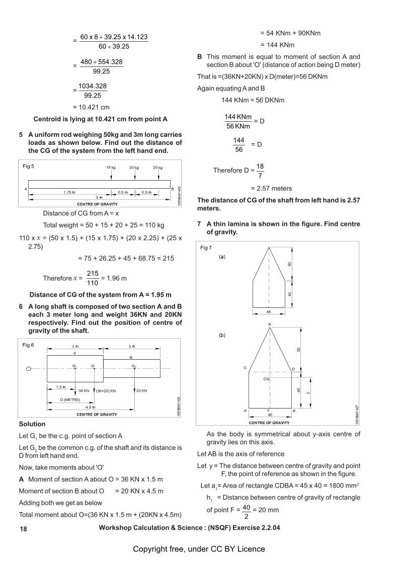
5 A uniform rod weighing 50kg and 3m long carriesloads as shown below. Find out the distance ofthe CG of the system from the left hand end.
Distance of CG from A = x
Total weight = 50 + 15 + 20 + 25 = 110 kg
110 x x = (50 x 1.5) + (15 x 1.75) + (20 x 2.25) + (25 x2.75)
= 75 + 26.25 + 45 + 68.75 = 215
Therefore x = 110215
= 1.96 m
Distance of CG of the system from A = 1.95 m
6 A long shaft is composed of two section A and Beach 3 meter long and weight 36KN and 20KNrespectively. Find out the position of centre ofgravity of the shaft.
Solution
Let G1 be the c.g. point of section A
Let G2 be the common c.g. of the shaft and its distance is
D from left hand end.
Now, take moments about 'O'
A Moment of section A about O = 36 KN x 1.5 m
Moment of section B about O = 20 KN x 4.5 m
Adding both we get as below
Total moment about O=(36 KN x 1.5 m + (20KN x 4.5m)
= 54 KNm + 90KNm
= 144 KNm
B This moment is equal to moment of section A andsection B about 'O' (distance of action being D meter)
That is =(36KN+20KN) x D(meter)=56 DKNm
Again equating A and B
144 KNm = 56 DKNm
KNm 56KNm 144
= D
56
144 = D
Therefore D = 7
18
= 2.57 meters
The distance of CG of the shaft from left hand is 2.57meters.
7 A thin lamina is shown in the figure. Find centreof gravity.
As the body is symmetrical about y-axis centre ofgravity lies on this axis.
Let AB is the axis of reference
Let y = The distance between centre of gravity and pointF, the point of reference as shown in the figure.
Let a1= Area of rectangle CDBA = 45 x 40 = 1800 mm2
h1 = Distance between centre of gravity of rectangle
of point F = 2
40 = 20 mm
Workshop Calculation & Science : (NSQF) Exercise 2.2.04
Copyright free, under CC BY Licence
19
Let a2= Area of triangle ECD=1/2 x base x height
=1/2 x 45 x 50 = 1125 square mm
h2 = distance between centre of gravity of triangle of
point F.
=1/3rd height of triangle +width of rectangle
= 3
1(50) + 40 =
350
+ 40 = 3
170 mm
Applying formula
2a
1a
2h
2a
1h
1a
y+
+=
=11251800
31701125)20(1800
+
⎟⎠⎞
⎜⎝⎛+
= 292563753.7536000
5800+
= 292599753.75
y = 34.10 mm
The CG is at a distance of 34.1mm from point Fthe point of reference in the line AB.
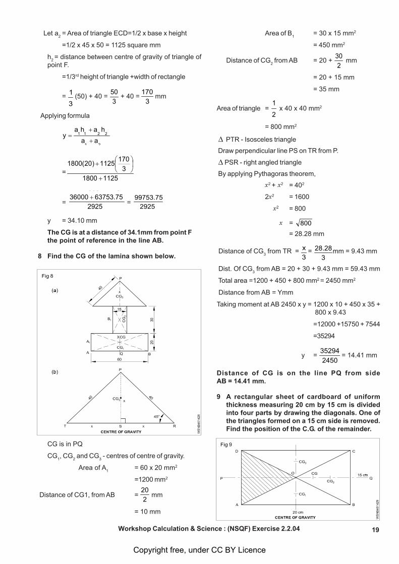
8 Find the CG of the lamina shown below.
CG is in PQ
CG1, CG
2 and CG
3 - centres of centre of gravity.
Area of A1
= 60 x 20 mm2
=1200 mm2
Distance of CG1, from AB = 2
20 mm
= 10 mm
Area of B1
= 30 x 15 mm2
= 450 mm2
Distance of CG2 from AB = 20 +
230
mm
= 20 + 15 mm
= 35 mm
Area of triangle = 2
1 x 40 x 40 mm2
= 800 mm2
PTR - Isosceles triangle
Draw perpendicular line PS on TR from P.
PSR - right angled triangle
By applying Pythagoras theorem,
x2 + x2 = 402
2x2 = 1600
x2 = 800
x = 800= 28.28 mm
Distance of CG3 from TR =
3x =
328.28 mm = 9.43 mm
Dist. Of CG3 from AB = 20 + 30 + 9.43 mm = 59.43 mm
Total area =1200 + 450 + 800 mm2 = 2450 mm2
Distance from AB = Ymm
Taking moment at AB 2450 x y = 1200 x 10 + 450 x 35 + 800 x 9.43
=12000 +15750 + 7544
=35294
y = 2450
35294 = 14.41 mm
Distance of CG is on the line PQ from sideAB = 14.41 mm.
9 A rectangular sheet of cardboard of uniformthickness measuring 20 cm by 15 cm is dividedinto four parts by drawing the diagonals. One ofthe triangles formed on a 15 cm side is removed.Find the position of the C.G. of the remainder.
Workshop Calculation & Science : (NSQF) Exercise 2.2.04
Copyright free, under CC BY Licence
20
ABCD - rectangle hard board
AC, BD - diagonals
O - meeting point
AOD - removed portion
AOB = CG1
BOC = CG2
COD = CG3
C.G = Centre of gravity of the hard board
Take CG is on PQ
Area of AOB = 1/2 bh unit2
= 1/2 x 20 x 7.5 cm2
= 75 cm2
Area of BOC = 1/2 x 15 x 10 cm2
= 75 cm2
Area of COD = 1/2 x 20 x 7.5 cm2
= 75 cm2
Total area = 75 + 75 + 75 cm2
= 225 cm2
Taking moment at side BC
Distance of CG1 =
220
in = 10 cm
Distance of CG2 =
310
in = 3.33 cm
Distance of CG3 =
220
in = 10 cm
Distance of C.G = x
225 x x = 75 x 10 + 75 x 3.33 + 75 x 10
= 750 + 249.75 + 750
= 1749.75
x = 225
1749.75 = = 7.777
= 7.777
Distance of CG is on the line PQ from side BC=7.78cm
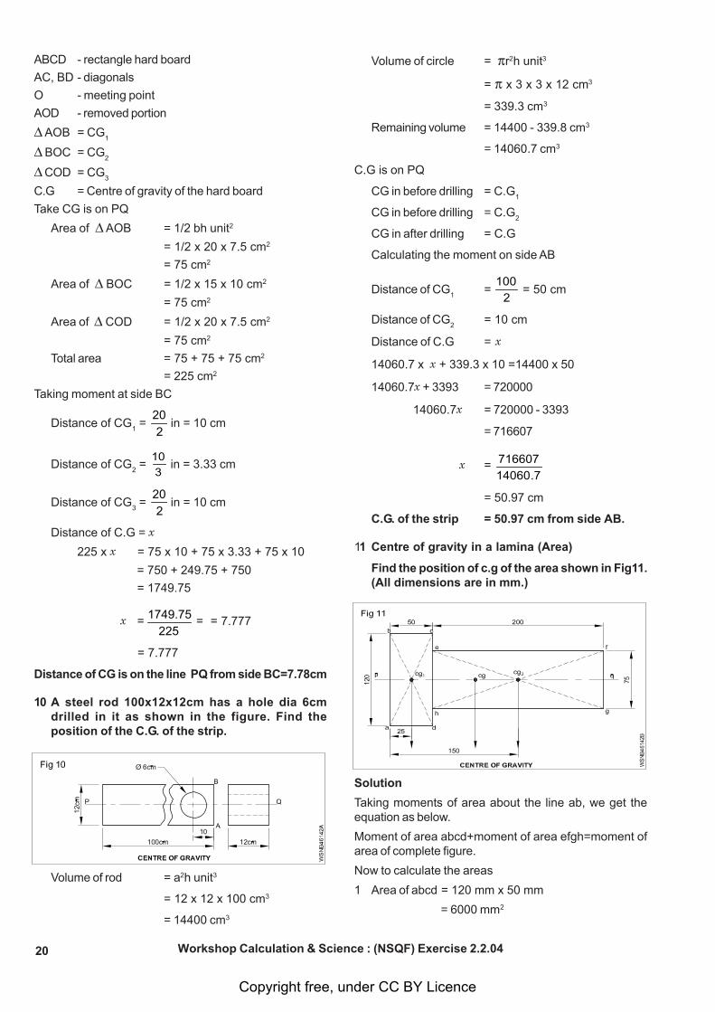
10 A steel rod 100x12x12cm has a hole dia 6cmdrilled in it as shown in the figure. Find theposition of the C.G. of the strip.
Volume of rod = a2h unit3
= 12 x 12 x 100 cm3
= 14400 cm3
Volume of circle = r2h unit3
= x 3 x 3 x 12 cm3
= 339.3 cm3
Remaining volume = 14400 - 339.8 cm3
= 14060.7 cm3
C.G is on PQ
CG in before drilling = C.G1
CG in before drilling = C.G2
CG in after drilling = C.G
Calculating the moment on side AB
Distance of CG1
= 2
100 = 50 cm
Distance of CG2
= 10 cm
Distance of C.G = x
14060.7 x x + 339.3 x 10 =14400 x 50
14060.7x + 3393 = 720000
14060.7x = 720000 - 3393
= 716607
x = 7.14060
716607
= 50.97 cm
C.G. of the strip = 50.97 cm from side AB.
11 Centre of gravity in a lamina (Area)
Find the position of c.g of the area shown in Fig11.(All dimensions are in mm.)
Solution
Taking moments of area about the line ab, we get theequation as below.
Moment of area abcd+moment of area efgh=moment ofarea of complete figure.
Now to calculate the areas
1 Area of abcd = 120 mm x 50 mm
= 6000 mm2
Workshop Calculation & Science : (NSQF) Exercise 2.2.04
Copyright free, under CC BY Licence
21
Area of efgh = 200 x 75 mm2
= 15000 mm2
Total area = (6000+15000) mm2
(abcd+efgh) = 21000 mm2
2 (6000 m2 x 25) + (15000 mm2 + 150 mm)
= (21000mm2) x (x mm)
150000mm2 + 2250000mm2 = (21000 mm2) x (x mm)
240000mm2 = (21000 mm2) x (x mm)
Therefore x = mm 21000
mm 24000002
2
= mm 21 2400
= mm 7
800
= 114.3 mm
Hence c.g. point of composite figure is 114.3 mm fromA on the line ab.
12 Centre of gravity point of a composite body canbe found out by using a variation of principle ofmoments.
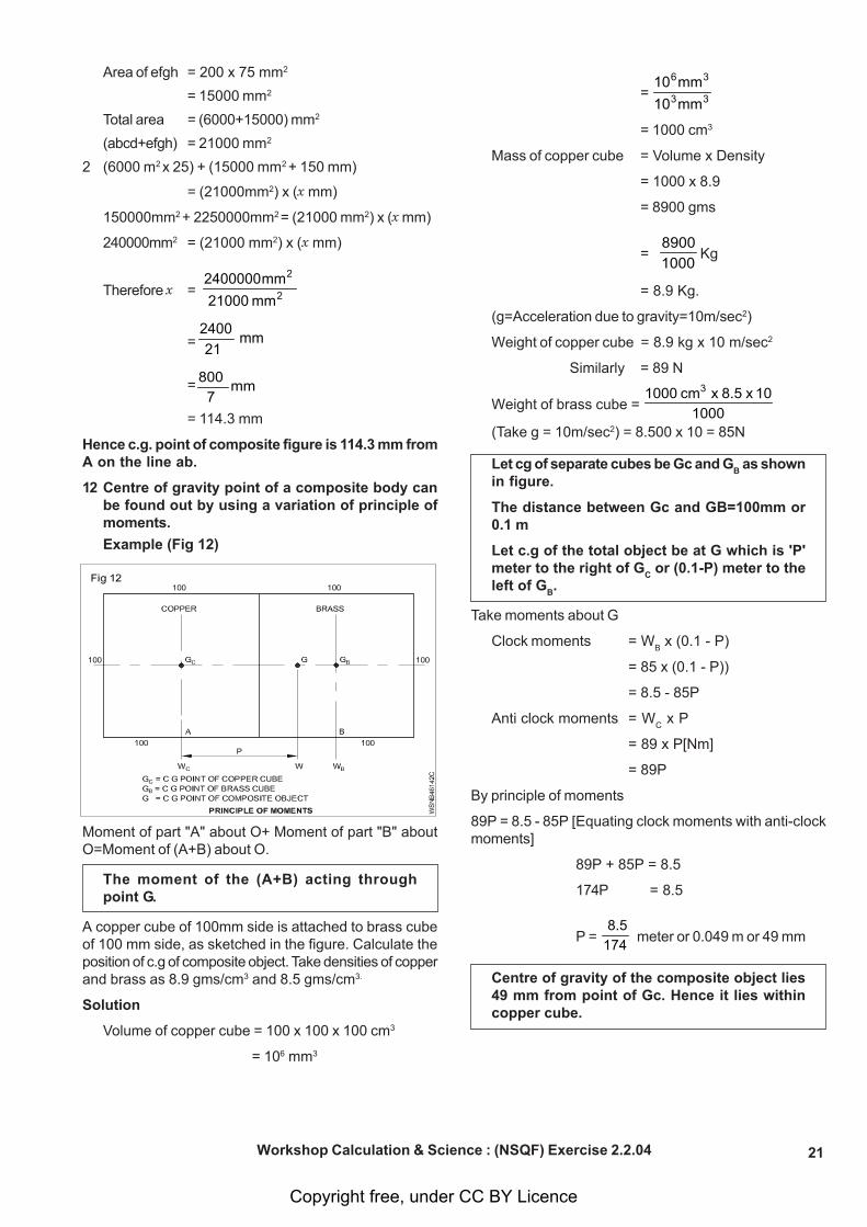
Example (Fig 12)
Moment of part "A" about O+ Moment of part "B" aboutO=Moment of (A+B) about O.
The moment of the (A+B) acting throughpoint G.
A copper cube of 100mm side is attached to brass cubeof 100 mm side, as sketched in the figure. Calculate theposition of c.g of composite object. Take densities of copperand brass as 8.9 gms/cm3 and 8.5 gms/cm3.
Solution
Volume of copper cube = 100 x 100 x 100 cm3
= 106 mm3
= mm10mm10
33
36
= 1000 cm3
Mass of copper cube = Volume x Density
= 1000 x 8.9
= 8900 gms
= 10008900
Kg
= 8.9 Kg.
(g=Acceleration due to gravity=10m/sec2)
Weight of copper cube = 8.9 kg x 10 m/sec2
Similarly = 89 N
Weight of brass cube = 100010 x 8.5 x cm 1000 3
(Take g = 10m/sec2) = 8.500 x 10 = 85N
Let cg of separate cubes be Gc and GB as shown
in figure.
The distance between Gc and GB=100mm or0.1 m
Let c.g of the total object be at G which is 'P'meter to the right of G
C or (0.1-P) meter to the
left of GB.
Take moments about G
Clock moments = WB x (0.1 - P)
= 85 x (0.1 - P))
= 8.5 - 85P
Anti clock moments = WC x P
= 89 x P[Nm]
= 89P
By principle of moments
89P = 8.5 - 85P [Equating clock moments with anti-clockmoments]
89P + 85P = 8.5
174P = 8.5
P = 1748.5
meter or 0.049 m or 49 mm
Centre of gravity of the composite object lies49 mm from point of Gc. Hence it lies withincopper cube.
Workshop Calculation & Science : (NSQF) Exercise 2.2.04
Copyright free, under CC BY Licence
22
Assignment A
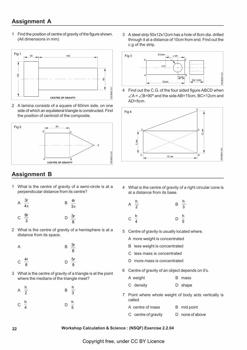
1 Find the position of centre of gravity of the figure shown.(All dimensions in mm)
2 A lamina consists of a square of 60mm side, on oneside of which an equilateral triangle is constructed. Findthe position of centroid of the composite.
3 A steel strip 50x12x12cm has a hole of 8cm dia. drilledthrough it at a distance of 10cm from end. Find out thec.g of the strip.
4 Find out the C.G. of the four sided figure ABCD whenA = B=90º and the side AB=15cm, BC=12cm andAD=5cm.
Assignment B
1 What is the centre of gravity of a semi-circle is at aperpendicular distance from its centre?
A4
r3π
B3
r4π
C3r8
D8r3
2 What is the centre of gravity of a hemisphere is at adistance from its space.
A B8r3
C8
4rD
8
5r
3 What is the centre of gravity of a triangle is at the pointwhere the medians of the triangle meet?
A2
hB
3
h
C4
hD
5
h
4 What is the centre of gravity of a right circular cone isat a distance from its base.
A2
hB
3
h
C4
hD
5
h
5 Centre of gravity is usually located where.
A more weight is concentrated
B less weight is concentrated
C less mass is concentrated
D more mass is concentrated
6 Centre of gravity of an object depends on it's.
A weight B mass
C density D shape
7 Point where whole weight of body acts vertically iscalled.
A centre of mass B mid point
C centre of gravity D none of above
Workshop Calculation & Science : (NSQF) Exercise 2.2.04
Copyright free, under CC BY Licence
23
8 A simple method to find centre of gravity of a body isusage of.
A stop watch B plumbline
C pendulum D screw gauge
9 If a material has no uniform density throughout the body,then the position of centroid and centre of mass are.
A identical
B not identical
C independent upon the density
D unpredictable
10 Which of the following laminas do not have centroid atits geometrical centre?
A Circle B Equilateral triangle
C Right angled triangle D Isosceles triangle
Key Answers
A
1 90.6 mm
2 44.3 mm
3 26.3 cm
4 The C.G. lies at a point at a distance of 4.49 cm, fromthe line AB and at a distance of 6.47 from the line BC.
B
1 B
2 B
3 B
4 C
5 D
6 B
7 C
8 B
9 B
10 C
Workshop Calculation & Science : (NSQF) Exercise 2.2.04
Copyright free, under CC BY Licence
24
Area of cut out regular surfaces - circle, segment and sector of circleExercise 2.3.05
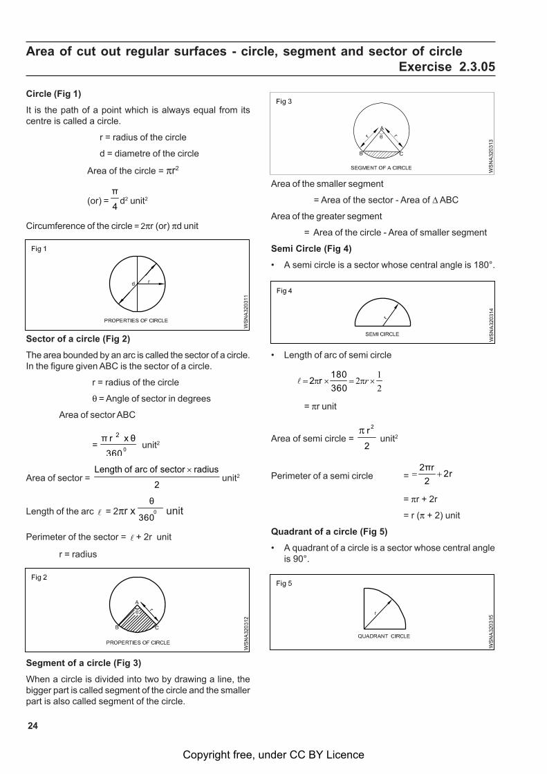
Circle (Fig 1)
It is the path of a point which is always equal from itscentre is called a circle.
r = radius of the circle
d = diametre of the circle
Area of the circle = r2
(or) = 4
πd2 unit2
Circumference of the circle = 2r (or) d unit
• Length of arc of semi circle
21
2 ×=×= rππ360180
r2l
= r unit
Area of semi circle = 2
r 2 unit2
Perimeter of a semi circle = 2r2
2πr+=
= r + 2r
= r ( + 2) unit
Quadrant of a circle (Fig 5)
• A quadrant of a circle is a sector whose central angleis 90°.
Sector of a circle (Fig 2)
The area bounded by an arc is called the sector of a circle.In the figure given ABC is the sector of a circle.
r = radius of the circle
= Angle of sector in degrees
Area of sector ABC
= 0 360
θ x 2 r π unit2
Area of sector = 2
radius sector ofarc of Length unit2
Length of the arc = 2r x 0 360
θ unit
Perimeter of the sector = + 2r unit
r = radius
Segment of a circle (Fig 3)
When a circle is divided into two by drawing a line, thebigger part is called segment of the circle and the smallerpart is also called segment of the circle.
Area of the smaller segment
= Area of the sector - Area of ABC
Area of the greater segment
= Area of the circle - Area of smaller segment
Semi Circle (Fig 4)
• A semi circle is a sector whose central angle is 180°.
Copyright free, under CC BY Licence
25
• Length and area of a quadrant of a circle
2
41
2
36090
2
r
r
r
π
π
π
=
×=
×=l
Area of quadrant of a circle = 4
2πr unit2
Perimeter of a quadrant = + 2r42πr
⎟⎠⎞
⎜⎝⎛ +=
+=
22π
r
2r2πr
unit
Examples :
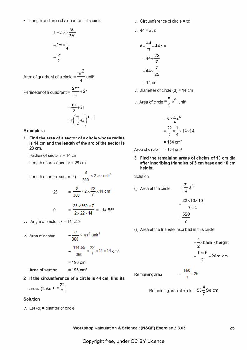
1 Find the area of a sector of a circle whose radiusis 14 cm and the length of the arc of the sector is28 cm.
Radius of sector r = 14 cm
Length of arc of sector = 28 cm
Length of arc of sector () =
28 =
= = 114.550
Angle of sector = 114.550
Area of sector =
= cm2
= 196 cm2
Area of sector = 196 cm2
2 If the circumference of a circle is 44 cm, find its
area. (Take 722
π = )
Solution
Let (d) = diamter of circle
Circumference of circle = d
44 = d
227
44
722
44
π44π44
d
×=
÷=
÷==
= 14 cm
Diameter of circle (d) = 14 cm
Area of circle 42= dπ
unit2
141441
72241 2
×××=
×= dπ
= 154 cm2
Area of circle = 154 cm2
3 Find the remaining areas of circles of 10 cm diaafter inscribing triangles of 5 cm base and 10 cmheight.
Solution
(i) Area of the circle 42= dπ
7
55047
101022
=
×
××=
(ii) Area of the triangle inscribed in this circle
sq.cm252
510
heightbase2
1
=×
=
××=
Remaining area =
Remaining area of circle Sq.cm7
453=
Workshop Calculation & Science : (NSQF) Exercise 2.3.05
Copyright free, under CC BY Licence
26
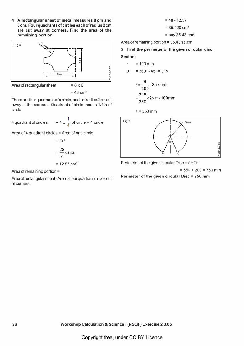
4 A rectangular sheet of metal measures 8 cm and6 cm. Four quadrants of circles each of radius 2 cmare cut away at corners. Find the area of theremaining portion.
= 48 - 12.57
= 35.428 cm2
= say 35.43 cm2
Area of remaining portion = 35.43 sq.cm
5 Find the perimeter of the given circular disc.
Sector :
r = 100 mm
= 360° - 45° = 315°
mm100π2360
315
unit2π360
θ
×××=
×= r l
= 550 mm
Perimeter of the given circular Disc = + 2r
= 550 + 200 = 750 mm
Perimeter of the given circular Disc = 750 mm
Workshop Calculation & Science : (NSQF) Exercise 2.3.05
Area of rectangular sheet = 8 x 6
= 48 cm2
There are four quadrants of a circle, each of radius 2 cm cutaway at the corners. Quadrant of circle means 1/4th ofcircle.
4 quadrant of circles = 4 x of circle = 1 circle
Area of 4 quadrant circles = Area of one circle
= r2
= 227
22××
= 12.57 cm2
Area of remaining portion =
Area of rectangular sheet - Area of four quadrant circles cutat corners.
Copyright free, under CC BY Licence
27
Related problems of area of cut out regular surfaces - circle, segment andsector of circle Exercise 2.3.06
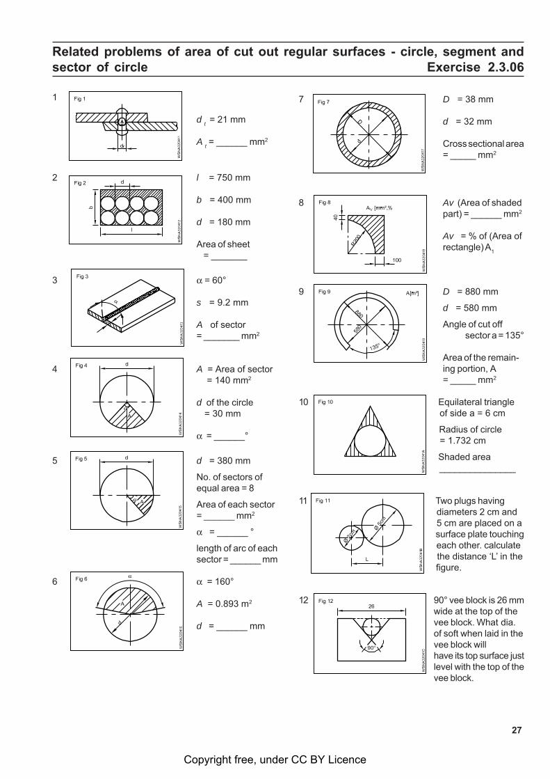
1
d t = 21 mm
A t = ______ mm2
2 l = 750 mm
b = 400 mm
d = 180 mm
Area of sheet = _______
3 = 60°
s = 9.2 mm
A of sector= _______ mm2
4 A = Area of sector = 140 mm2
d of the circle = 30 mm
= ______°
5 d = 380 mm
No. of sectors ofequal area = 8
Area of each sector= ______ mm2
= ______ °
length of arc of eachsector = ______ mm
6 = 160°
A = 0.893 m2
d = ______ mm
7 D = 38 mm
d = 32 mm
Cross sectional area= _____ mm2
8 Av (Area of shadedpart) = ______ mm2
Av = % of (Area ofrectangle) A
1
9 D = 880 mm
d = 580 mm
Angle of cut offsector a = 135°
Area of the remain-ing portion, A= _____ mm2
10 Equilateral triangle of side a = 6 cm
Radius of circle = 1.732 cm
Shaded area _______________
11 Two plugs having diameters 2 cm and 5 cm are placed on a surface plate touching each other. calculate the distance ‘L’ in the figure.
12 90° vee block is 26 mmwide at the top of thevee block. What dia.of soft when laid in thevee block willhave its top surface justlevel with the top of thevee block.
Copyright free, under CC BY Licence
28
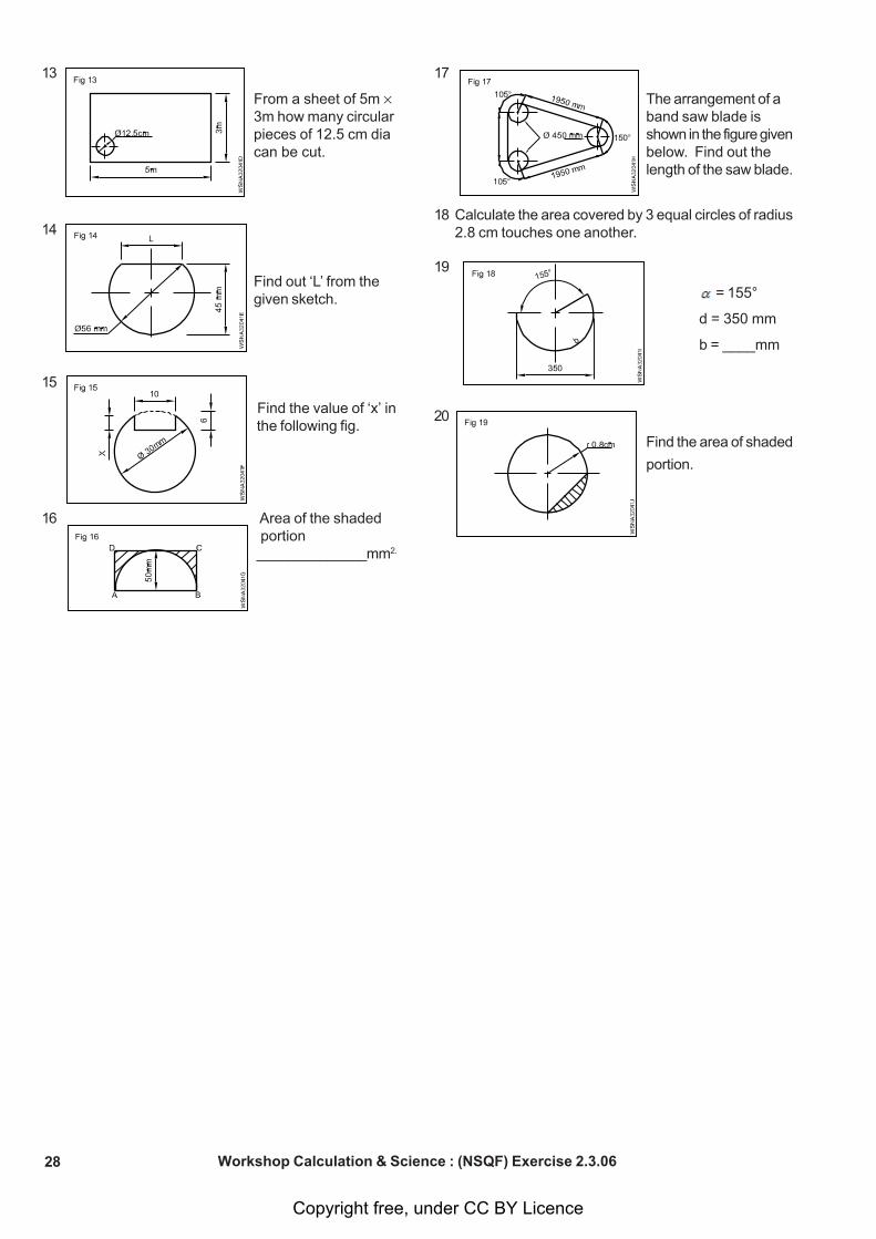
13
From a sheet of 5m 3m how many circularpieces of 12.5 cm diacan be cut.
14
Find out ‘L’ from thegiven sketch.
15
Find the value of ‘x’ in the following fig.
16 Area of the shaded portion ______________mm2.
17
The arrangement of aband saw blade isshown in the figure givenbelow. Find out thelength of the saw blade.
18 Calculate the area covered by 3 equal circles of radius2.8 cm touches one another.
19
= 155°
d = 350 mm
b = ____mm
20
Find the area of shaded
portion.
Workshop Calculation & Science : (NSQF) Exercise 2.3.06
Copyright free, under CC BY Licence
29
Area of irregular surfaces and application related to shop problemsExercise 2.3.07
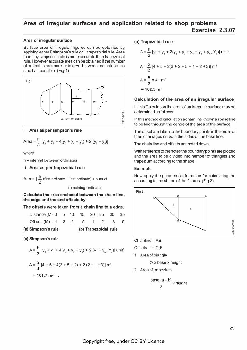
Area of irregular surface
Surface area of irregular figures can be obtained byapplying either i) simpson’s rule or ii) trapezoidal rule. Areafound by simpson’s rule is more accurate than trapezoidalrule. However accurate area can be obtained if the numberof ordinates are more i.e interval between ordinates is sosmall as possible. (Fig 1)
(b) Trapezoidal rule
A = 3h [y
1 + y
8 + 2(y
2 + y
3 + y
4 + y
5 + y
6 + Y
7)] unit2
A = 25 [4 + 5 + 2(3 + 2 + 5 + 1 + 2 +
3)] m2
A = 25 x 41 m2
= 102.5 m2
Calculation of the area of an irregular surface
In this Calculation the area of an irregular surface may bedetermined as follows.
In this method of calculation a chain line known as base lineto be laid through the centre of the area of the surface.
The offset are taken to the boundary points in the order oftheir chainages on both the sides of the base line.
The chain line and offsets are noted down.
With reference to the notes the boundary points are plottedand the area to be divided into number of triangles andtrapezium according to the shape.
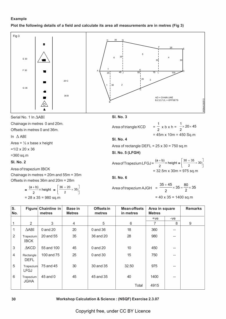
Example
Now apply the geometrical formulae for calculating theaccording to the shape of the figures. (Fig 2)
i Area as per simpson’s rule
Area = 3h [y
1 + y
7 + 4(y
2 + y
4 + y
6) + 2 (y
3 + y
5)]
where
h = interval between ordinates
ii Area as per trapezoidal rule
Area= [ 2h (first ordinate + last ordinate) + sum of
remaining ordinate]
Calculate the area enclosed between the chain line,the edge and the end offsets by
The offsets were taken from a chain line to a edge.
Distance (M) 0 5 10 15 20 25 30 35
Off set (M) 4 3 2 5 1 2 3 5
(a) Simpson’s rule (b) Trapezoidal rule
(a) Simpson’s rule
A = 3h [y
1 + y
8 + 4(y
2 + y
4 + y
6) + 2 (y
3 + y
5 + Y
7)] unit2
A = 35 [4 + 5 + 4(3 + 5 + 2) + 2 (2 + 1
+
3)] m2
= 101.7 m2 .
Chainline = AB
Offsets = C,E
1 Area of triangle
½ x base x height
2 Area of trapezium
height2
b) (a base
Copyright free, under CC BY Licence
30
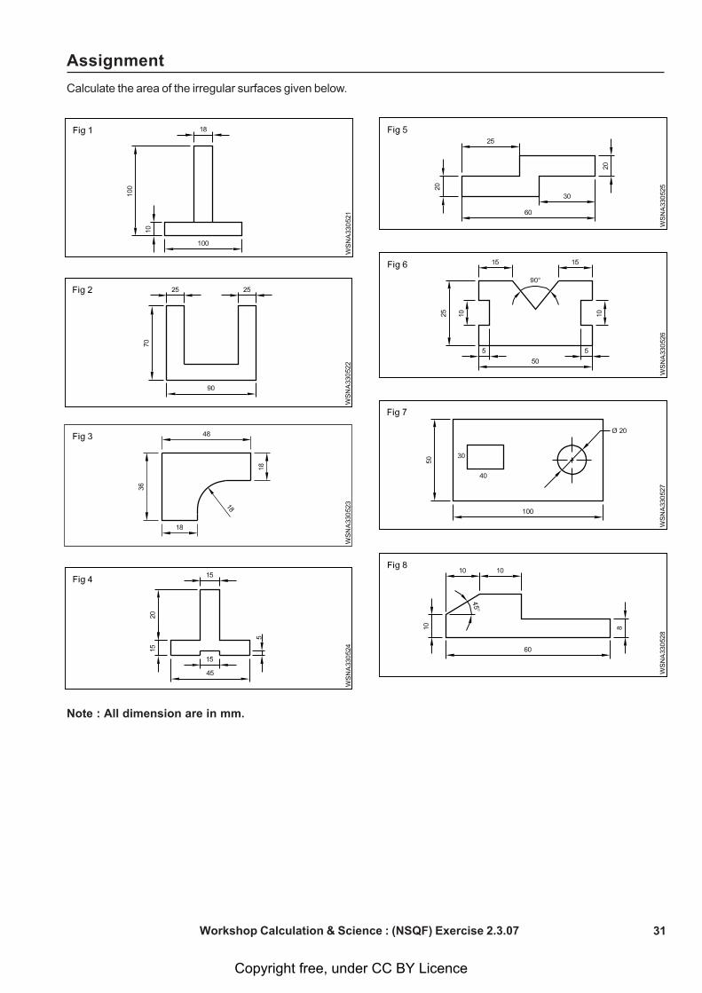
Serial No. 1 In ABI
Chainage in metres 0 and 20m.
Offsets in metres 0 and 36m.
In ABI
Area = ½ x base x height
=1/2 x 20 x 36
=360 sq.m
SI. No. 2
Area of trapezium IBCK
Chainage in metres = 20m and 55m = 35m
Offsets in metres 36m and 20m = 28m
= height2
b) (a
=
352
20 36
= 28 x 35 = 980 sq.m
Example
Plot the following details of a field and calculate its area all measurements are in metres (Fig 3)
S. Figure Chainline in Base in Offsets in Mean offsets Area in square RemarksNo. metres Metres metres in metres Metres
1 ABI 0 and 20 20 0 and 36 18 360 --
2 Trapezium 20 and 55 35 36 and 20 28 980 -- IBCK
3 KCD 55 and 100 45 0 and 20 10 450 --
4 Rectangle 100 and 75 25 0 and 30 15 750 -- DEFL
5 Trapezium 75 and 45 30 30 and 35 32.50 975 --LFGJ
6 Trapezium 45 and 0 45 45 and 35 40 1400 -- JGHA
+ve -ve 1 2 3 4 5 6 7 8 9
Total 4915
Sl. No. 3
Area of triangle KCD = 2
1 x b x h = 4520
2
1
= 45m x 10m = 450 Sq.mSl. No. 4
Area of rectangle DEFL = 25 x 30 = 750 sq.m
Sl. No. 5 (LFGH)
Area of Trapezium LFGJ = height2
b) (a
=
302
35 30
= 32.5m x 30m = 975 sq.m
Sl. No. 6
Area of trapezium AJGH = 352
80 35
2
45 35
= 40 x 35 = 1400 sq.m
Workshop Calculation & Science : (NSQF) Exercise 2.3.07
Copyright free, under CC BY Licence
31
Assignment
Calculate the area of the irregular surfaces given below.
Note : All dimension are in mm.
Workshop Calculation & Science : (NSQF) Exercise 2.3.07
Copyright free, under CC BY Licence
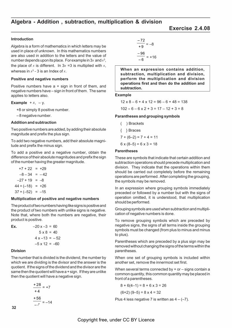
32
Introduction
Algebra is a form of mathematics in which letters may beused in place of unknown. In this mathematics numbersare also used in addition to the letters and the value ofnumber depends upon its place. For example in 3x and x3,the place of x is different. In 3x =3 is multiplied with x,
whereas in x3 - 3 is an Index of x.
Positive and negative numbers
Positive numbers have a + sign in front of them, andnegative numbers have – sign in front of them. The sameapplies to letters also.
Example + x, – y.
+8 or simply 8 positive number.
– 8 negative number.
Addition and subtraction
Two positive numbers are added, by adding their absolutemagnitude and prefix the plus sign.
To add two negative numbers, add their absolute magni-tude and prefix the minus sign.
To add a positive and a negative number, obtain thedifference of their absolute magnitudes and prefix the signof the number having the greater magnitude.
+7 + 22 = +29
–8 – 34 = – 42
–27 + 19 = –8
44 + (–18) = +26
37 + (–52) = –15
Multiplication of positive and negative numbers
The product of two numbers having like signs is positive andthe product of two numbers with unlike signs is negative.Note that, where both the numbers are negative, theirproduct is positive.
Ex. –20 x –3 = 60
5 x 8 = 40
4 x –13 = – 52
–5 x 12 = –60
Division
The number that is divided is the dividend, the number bywhich we are dividing is the divisor and the answer is thequotient. If the signs of the dividend and the divisor are thesame then the quotient will have a + sign. If they are unlikethen the quotient will have a negative sign.
4+
28+ = +7
4–
56+ = –14
9+
72– = –8
6–
96– = +16
When an expression contains addition,subtraction, multiplication and division,perform the multiplication and divisionoperations first and then do the addition andsubtraction.
Example
12 x 8 – 6 + 4 x 12 = 96 – 6 + 48 = 138
102 6 – 6 x 2 + 3 = 17 – 12 + 3 = 8
Parantheses and grouping symbols
( ) Brackets
{ } Braces
7 + (6–2) = 7 + 4 = 11
6 x (8–5) = 6 x 3 = 18
Parentheses
These are symbols that indicate that certain addition andsubtraction operations should precede multiplication anddivision. They indicate that the operations within themshould be carried out completely before the remainingoperations are performed. After completing the grouping,the symbols may be removed.
In an expression where grouping symbols immediatelypreceded or followed by a number but with the signs ofoperation omitted, it is understood, that multiplicationshould be performed.
Grouping symbols are used when subtraction and multipli-cation of negative numbers is done.
To remove grouping symbols which are preceded bynegative signs, the signs of all terms inside the groupingsymbols must be changed (from plus to minus and minusto plus).
Parentheses which are preceded by a plus sign may beremoved without changing the signs of the terms within theparentheses.
When one set of grouping symbols is included withinanother set, remove the innermost set first.
When several terms connected by + or – signs contain acommon quantity, this common quantity may be placed infront of a parentheses.
8 + 6(4–1) = 8 + 6 x 3 = 26
(6+2) (9–5) = 8 x 4 = 32
Plus 4 less negative 7 is written as 4 – (–7).
Algebra - Addition , subtraction, multiplication & divisionExercise 2.4.08
Copyright free, under CC BY Licence
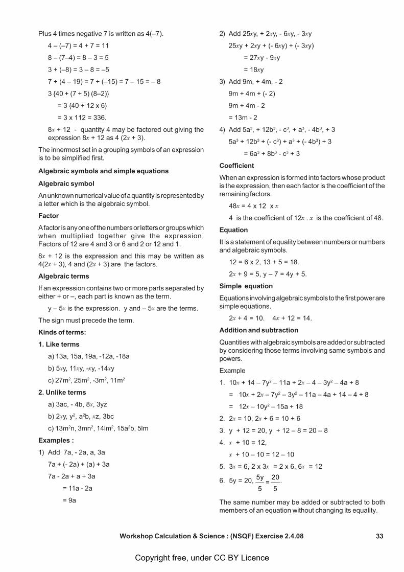
33
Plus 4 times negative 7 is written as 4(–7).
4 – (–7) = 4 + 7 = 11
8 – (7–4) = 8 – 3 = 5
3 + (–8) = 3 – 8 = –5
7 + (4 – 19) = 7 + (–15) = 7 – 15 = – 8
3 {40 + (7 + 5) (8–2)}
= 3 {40 + 12 x 6}
= 3 x 112 = 336.
8x + 12 - quantity 4 may be factored out giving theexpression 8x + 12 as 4 (2x + 3).
The innermost set in a grouping symbols of an expressionis to be simplified first.
Algebraic symbols and simple equations
Algebraic symbol
An unknown numerical value of a quantity is represented bya letter which is the algebraic symbol.
Factor
A factor is any one of the numbers or letters or groups whichwhen multiplied together give the expression.Factors of 12 are 4 and 3 or 6 and 2 or 12 and 1.
8x + 12 is the expression and this may be written as4(2x + 3), 4 and (2x + 3) are the factors.
Algebraic terms
If an expression contains two or more parts separated byeither + or –, each part is known as the term.
y – 5x is the expression. y and – 5x are the terms.
The sign must precede the term.
Kinds of terms:
1. Like terms
a) 13a, 15a, 19a, -12a, -18a
b) 5xy, 11xy, -xy, -14xy
c) 27m2, 25m2, -3m2, 11m2
2. Unlike terms
a) 3ac, - 4b, 8x, 3yz
b) 2xy, y2, a2b, xz, 3bc
c) 13m2n, 3mn2, 14lm2, 15a2b, 5lm
Examples :
1) Add 7a, - 2a, a, 3a
7a + (- 2a) + (a) + 3a
7a - 2a + a + 3a
= 11a - 2a
= 9a
2) Add 25xy, + 2xy, - 6xy, - 3xy
25xy + 2xy + (- 6xy) + (- 3xy)
= 27xy - 9xy
= 18xy
3) Add 9m, + 4m, - 2
9m + 4m + (- 2)
9m + 4m - 2
= 13m - 2
4) Add 5a3, + 12b3, - c3, + a3, - 4b3, + 3
5a3 + 12b3 + (- c3) + a3 + (- 4b3) + 3
= 6a3 + 8b3 - c3 + 3
Coefficient
When an expression is formed into factors whose productis the expression, then each factor is the coefficient of theremaining factors.
48x = 4 x 12 x x
4 is the coefficient of 12x . x is the coefficient of 48.
Equation
It is a statement of equality between numbers or numbersand algebraic symbols.
12 = 6 x 2, 13 + 5 = 18.
2x + 9 = 5, y – 7 = 4y + 5.
Simple equation
Equations involving algebraic symbols to the first power aresimple equations.
2x + 4 = 10. 4x + 12 = 14.
Addition and subtraction
Quantities with algebraic symbols are added or subtractedby considering those terms involving same symbols andpowers.
Example
1. 10x + 14 – 7y2 – 11a + 2x – 4 – 3y2 – 4a + 8
= 10x + 2x – 7y2 – 3y2 – 11a – 4a + 14 – 4 + 8
= 12x – 10y2 – 15a + 18
2. 2x = 10, 2x + 6 = 10 + 6
3. y + 12 = 20, y + 12 – 8 = 20 – 8
4. x + 10 = 12,
x + 10 – 10 = 12 – 10
5. 3x = 6, 2 x 3x = 2 x 6, 6x = 12
6. 5y = 20, 5
20 =
5
5y .
The same number may be added or subtracted to bothmembers of an equation without changing its equality.
Workshop Calculation & Science : (NSQF) Exercise 2.4.08
Copyright free, under CC BY Licence
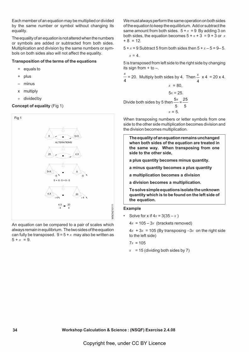
34
Each member of an equation may be multiplied or dividedby the same number or symbol without changing itsequality.
The equality of an equation is not altered when the numbersor symbols are added or subtracted from both sides.Multiplication and division by the same numbers or sym-bols on both sides also will not affect the equality.
Transposition of the terms of the equations
= equals to
+ plus
– minus
x multiply
divided by
Concept of equality (Fig 1)
We must always perform the same operation on both sidesof the equation to keep the equilibrium. Add or subtract thesame amount from both sides. 5 + x = 9 By adding 3 onboth sides, the equation becomes 5 + x + 3 = 9 + 3 or x+ 8 = 12.
5 + x = 9 Subtract 5 from both sides then 5 + x – 5 = 9– 5.
x = 4.
5 is transposed from left side to the right side by changingits sign from + to –.
4
x = 20. Multiply both sides by 4. Then
4
x x 4 = 20 x 4.
x = 80,
5x = 25.
Divide both sides by 5 then 5
25 =
5
5x
x = 5.
When transposing numbers or letter symbols from oneside to the other side multiplication becomes division andthe division becomes multiplication.
The equality of an equation remains unchangedwhen both sides of the equation are treated inthe same way. When transposing from oneside to the other side,
a plus quantity becomes minus quantity.
a minus quantity becomes a plus quantity
a multiplication becomes a division
a division becomes a multiplication.
To solve simple equations isolate the unknownquantity which is to be found on the left side ofthe equation.
Example
• Solve for x if 4x = 3(35 – x )
4x = 105 – 3x (brackets removed)
4x + 3x = 105 (By transposing –3x on the right sideto the left side)
7x = 105
x = 15 (dividing both sides by 7)
Workshop Calculation & Science : (NSQF) Exercise 2.4.08
An equation can be compared to a pair of scales whichalways remain in equilibrium. The two sides of the equationcan fully be transposed. 9 = 5 + x may also be written as5 + x = 9.
Copyright free, under CC BY Licence
35
ADD
1 14f - 2f + 5f - 7f + 9f
2 3xy + 5xy - 2xy + 8xy - 4xy
3 7a2 - 5a2 + a2 + 3a2
4 3m2n - 2m2n + 4m2n - m2n + 7m2n
5 18 + 13x2 - 13 + 2x2 - 15x2
6 17xy - 4xy + 13 - xy - 6
7 6l2m + 3lm2 - 2l2m - 17lm2 + 1
8 3a2b - 2ab - 2a2b - 3ab - 2a2b + ab
9 2a + a + 3a + 6a - 5b
10 8c + 5c + 3c + 2c
11 14d + 3d + 25e + 2e
12 5p + 3r - r - 2p
Workshop Calculation & Science : (NSQF) Exercise 2.4.08
Assignment
13 8t + 12u - t - 14u
14 x - z + y + z
15 15a + 13a - 37a
16 17a - 4b - 7a + 3b
17 9c - 15e + 4c + 3e
18 13f + 40g - 16f + 7f + 2g - 17g
19 30x + 45y - 17x - 16y
20 14.5k + 33.2 - 18.4k + 12.3
21 8a + 3c - 6b - 5c + 4a + 8b
22 27i + 17k - 5l + 12i - 31k + 19l
23 230m + 472P - 320n - 75m + 180n - 141p
24 17.5P + 12.4x - 29.2r - 7.6x - 12.1p + 31.4r
25 230m + 420s + 370y + 225m - 510y - 110s
Copyright free, under CC BY Licence
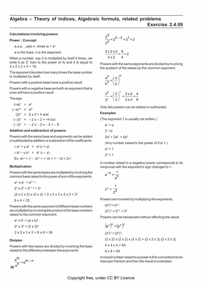
36
Algebra – Theory of indices, Algebraic formula, related problemsExercise 2.4.09
Calculations involving powers
Power : Concept
a.a.a... upto n times is = an
a is the base, n is the exponent.
When a number, say 2 is multiplied by itself 4 times, wewrite it as 24 (two to the power of 4) and it is equal to2 x 2 x 2 x 2 = 16.
The exponent denotes how many times the base numberis multiplied by itself.
Powers with a positive base have a positive result.
Powers with a negative base and with an exponent that iseven will have a positive result.
The sign
(+a) n = an
(– a) 2n = a2n
(2) 2 = 2 x 2 = 4 and
(– 2)2 = – 2 x – 2 = +4 but
(– 2)3 = – 2 x – 2 x – 2 = – 8
Addition and subtraction of powers
Powers with the same base and exponents can be addedor subtracted by addition or subtraction of the coefficients.
x.an + y.an = an (x + y)
x.an – y.an = an (x – y)
Ex .4x2 + x2 – 3x2 = x2 (4 + 1 – 3) = 2x2.
Multiplication
Powers with the same bases are multiplied by involving thecommon base raised to the power of sum of the exponents.
am x an = am + n.
23 x 22 = 23 + 2 = 25
(2 x 2 x 2) x (2 x 2) = 2 x 2 x 2 x 2 x 2 = 25
8 x 4 = 32.
Powers with the same exponent of different base numbersare multiplied by involving the product of the base numbersraised to the common exponent.
an x bn = (a x b)n
22 x 32 = (2 x 3)2
2 x 2 x 3 x 3 = 6 x 6 = 36
Division
Powers with like bases are divided by involving the baseraised to the difference between the exponents.
n – ma = na
ma
2 = 12 = 2 – 32 = 22
32
2 = 4
8 =
2 x 2
2 x 2 x 2
Powers with the same exponents are divided by involvingthe quotient of the bases by the common exponent.
n
b
a = nb
na⎟⎠⎞
⎜⎝⎛
9
4 =
3 x 3
2 x 2 =
2
3
2 =
23
22⎟⎠⎞
⎜⎝⎛
Only like powers can be added or subtracted.
Examples
(The exponent 1 is usually not written.)
a1 = a
21 =2
2a2 + 3a2 = 5a2
(Any number raised to the power of 0 is 1.)
a0 = 1
20 = 1
A number raised to a negative power corresponds to itsreciprocal with the exponent's sign changed to +.
na
1 = n–a
2–2 = 22
1
Powers are involved by multiplying the exponents.
(an)m = anm
(22) 3 = 22.3 = 26
Powers can be transposed without affecting the result.
nmmn a = a
(22) 3 = (23) 2
(2 x 2) x (2 x 2) x (2 x 2) = (2 x 2 x 2) (2 x 2 x 2)
4 x 4 x 4 = 64
8 x 8 = 64
A mixed number raised to a power is first converted into animproper fraction and then the result is evaluated.
Copyright free, under CC BY Licence
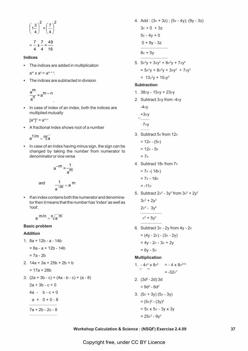
37
(-)
Workshop Calculation & Science : (NSQF) Exercise 2.4.09
2
4
7 =
2
4
31 ⎟
⎠⎞
⎜⎝⎛
⎟⎠⎞
⎜⎝⎛
= 16
49 =
4
7 x
4
7
Indices
• The indices are added in multiplication
am x an = am + n.
• The indices are subtracted in division
n – ma = na
ma
.
• In case of index of an index, both the indices aremultiplied mutually
[am]n = am.n
• A fractional index shows root of a number
m a1/ma =
• In case of an index having minus sign, the sign can bechanged by taking the number from numerator todenominator or vice versa
ma
1 = m–a
and m a ma
1 =−
• If an index contains both the numerator and denomina-tor then it means that the number has 'index' as well as'root'.
n m am/n a =
Basic problem
Addition
1. 8a + 12b - a - 14b
= 8a - a + 12b - 14b
= 7a - 2b
2. 14a + 3a + 25b + 2b + b
= 17a + 28b
3. (2a + 3b - c) + (4a - b - c) + (a - 8)
2a + 3b - c + 0
4a - b - c + 0
a + 0 + 0 - 8______________________
7a + 2b - 2c - 8______________________
4. Add : (3x + 3z) ; (5x - 4y); (9y - 3z)
3x + 0 + 3z
5x - 4y + 0
0 + 9y - 3z______________________
8x + 5y______________________
5. 5x2y + 3xy2 + 8x2y + 7xy2
= 5x2y + 8x2y + 3xy2 + 7xy2
= 13x2y + 10xy2
Subtraction
1. 38xy - 15xy = 23xy
2. Subtract 3xy from -4xy
-4xy
+3xy_______
-7xy_______
3. Subtract 5x from 12x
= 12x - (5x)
= 12x - 5x
= 7x
4. Subtract 18x from 7x
= 7x -( 18x)
= 7x - 18x
= -11x
5. Subtract 2x2 - 3y2 from 3x2 + 2y2
3x2 + 2y2
2x2 - 3y2
_________________
x2 + 5y2
_________________
6. Subtract 3x - 2y from 4y - 2x
= (4y - 2x) - (3x - 2y)
= 4y - 2x - 3x + 2y
= 6y - 5x
Multiplication
1. - 4x2 x 8x5 = - 4 x 8x2+5
= -32x7
2. (3d2 - 2d) 3d
= 9d3 - 6d2
3. (5x + 3y) (5x - 3y)
= (5x)2 - (3y)2
= 5x x 5x - 3y x 3y
= 25x2 - 9y2
(-) (+)
Copyright free, under CC BY Licence
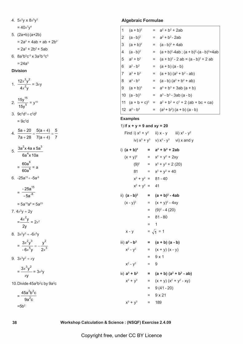
38 Workshop Calculation & Science : (NSQF) Exercise 2.4.09
4. 5x2y x 8x5y3
= 40x7y4
5. (2a+b) (a+2b)
= 2a2 + 4ab + ab + 2b2
= 2a2 + 2b2 + 5ab
6. 8a3b5c-5 x 3a2b-5c5
= 24a5
Division
1.y4
y122
23
x
x = 3xy
2. 5
15
15y
15y = y10
3. 9c5d3 c2d2
= 9c3d
4.7
5
)7(a
)5(a
287a
205a=
+
+=
+
+
4
4
5.10ax 6a
5a x 4ax 3a4
32
=
5
6
60a
60a = a
6. -25a15 -5a-8
=
8-
15
5a-
25a-
= 5a15a8 = 5a23
7. 4x2y 2y
=2y
y4 2x
= 2x2
8. 3x2y3 -6x5y
=
3
2
5
32
2
y
y6-
y3
xx
x−=
9. 3x3y2 xy
= y
y3 23
x
x = 3x2y
10.Divide 45a2b2c by 9a2c
= c9a
cb45a2
22
=5b2
Algebraic Formulae
1 (a + b)2 = a2 + b2 + 2ab
2 (a - b)2 = a2 + b2 - 2ab
3 (a + b)2 = (a - b)2 + 4ab
4 (a - b)2 = (a + b)2-4ab ; (a + b)2-(a - b)2=4ab
5 a2 + b2 = (a + b)2 - 2 ab = (a - b)2 + 2 ab
6 a2 - b2 = (a + b) (a - b)
7 a3 + b3 = (a + b) (a2 + b2 - ab)
8 a3 - b3 = (a - b) (a2 + b2 + ab)
9 (a + b)3 = a3 + b3 + 3ab (a + b)
10 (a - b)3 = a3 - b3 - 3ab (a - b)
11 (a + b + c)2 = a2 + b2 + c2 + 2 (ab + bc + ca)
12 a4 -- b4 = (a2 + b2) (a + b) (a - b)
Examples
1) If x + y = 9 and xy = 20
Find i) x2 + y2 ii) x - y iii) x2 - y2
iv) x3 + y3 v) x3 - y3 vi) x and y
i) (a + b)2 = a2 + b2 + 2ab
(x + y)2 = x2 + y2 + 2xy
(9)2 = x2 + y2 + 2 (20)
81 = x2 + y2 + 40
x2 + y2 = 81 - 40
x2 + y2 = 41
ii) (a - b)2 = (a + b)2 - 4ab
(x - y)2 = (x + y)2 - 4xy
= (9)2 - 4 (20)
= 81 - 80
= 1
x - y = 1 = 1
iii) a2 - b2 = (a + b) (a - b)
x2 - y2 = (x + y) (x - y)
= 9 x 1
x2 - y2 = 9
iv) a3 + b3 = (a + b) (a2 + b2 - ab)
x3 + y3 = (x + y) (x2 + y2 - xy)
= 9 (41 - 20)
= 9 x 21
x3 + y3 = 189
Copyright free, under CC BY Licence
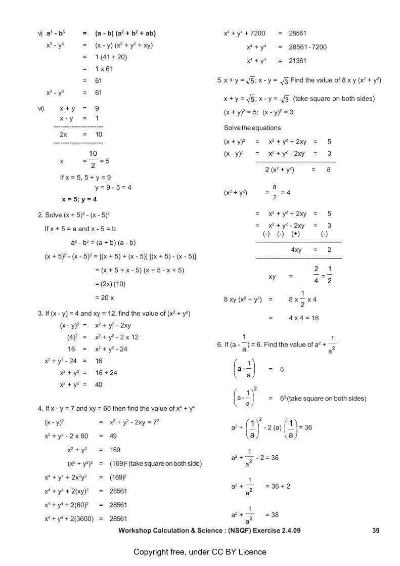
39Workshop Calculation & Science : (NSQF) Exercise 2.4.09
v) a3 - b3 = (a - b) (a2 + b2 + ab)
x3 - y3 = (x - y) (x2 + y2 + xy)
= 1 (41 + 20)
= 1 x 61
= 61
x3 - y3 = 61
vi) x + y = 9
x - y = 1 ----------------------
2x = 10 ----------------------
x = 2
10 = 5
If x = 5, 5 + y = 9
y = 9 - 5 = 4
x = 5; y = 4
2. Solve (x + 5)2 - (x - 5)2
If x + 5 = a and x - 5 = b
a2 - b2 = (a + b) (a - b)
(x + 5)2 - (x - 5)2 = [(x + 5) + (x - 5)] [(x + 5) - (x - 5)]
= (x + 5 + x - 5) (x + 5 - x + 5)
= (2x) (10)
= 20 x
3. If (x - y) = 4 and xy = 12, find the value of (x2 + y2)
(x - y)2 = x2 + y2 - 2xy
(4)2 = x2 + y2 - 2 x 12
16 = x2 + y2 - 24
x2 + y2 - 24 = 16
x2 + y2 = 16 + 24
x2 + y2 = 40
4. If x - y = 7 and xy = 60 then find the value of x4 + y4
(x - y)2 = x2 + y2 - 2xy = 72
x2 + y2 - 2 x 60 = 49
x2 + y2 = 169
(x2 + y2)2 = (169)2 (take square on both side)
x4 + y4 + 2x2y2 = (169)2
x4 + y4 + 2(xy)2 = 28561
x4 + y4 + 2(60)2 = 28561
x4 + y4 + 2(3600) = 28561
x4 + y4 + 7200 = 28561
x4 + y4 = 28561 - 7200
x4 + y4 = 21361
5. x + y = 5 ; x - y = 3 Find the value of 8 x y (x2 + y2)
x + y = 5 ; x - y = 3 (take square on both sides)
(x + y)2 = 5; (x - y)2 = 3
Solve the equations
(x + y)2 = x2 + y2 + 2xy = 5
(x - y)2 = x2 + y2 - 2xy = 3----------------------------------------
2 (x2 + y2) = 8
(x2 + y2) = 2
8 = 4
= x2 + y2 + 2xy = 5
= x2 + y2 - 2xy = 3 (-) (-) (+) (-)-------------------------------------------
4xy = 2-------------------------------------------
xy = 4
2 = 2
1
8 xy (x2 + y2) = 8 x 2
1 x 4
= 4 x 4 = 16
6. If (a - a
1) = 6. Find the value of a2 + 2a
1
⎟⎠⎞
⎜⎝⎛
a
1 - a = 6
2
a
1 - a ⎟⎠⎞
⎜⎝⎛
= 62 (take square on both sides)
a2 + 2
a1⎟⎠⎞
⎜⎝⎛ - 2 (a)
a1⎟⎠⎞
⎜⎝⎛ = 36
a2 + 2a
1 - 2 = 36
a2 + 2a
1= 36 + 2
a2 + 2a
1= 38
Copyright free, under CC BY Licence
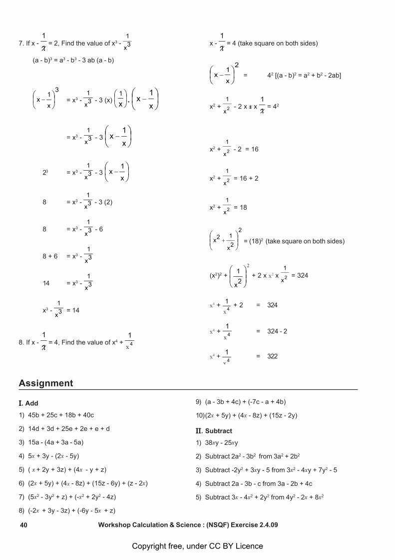
40 Workshop Calculation & Science : (NSQF) Exercise 2.4.09
7. If x - X
1 = 2, Find the value of x3 - 3x
1
(a - b)3 = a3 - b3 - 3 ab (a - b)
3
x
1x ⎟
⎠⎞
⎜⎝⎛
− = x3 - 3x
1 - 3 (x) ⎟
⎠⎞
⎜⎝⎛
x1
. ⎟⎠⎞
⎜⎝⎛
−x
1x
= x3 - 3x
1 - 3 ⎟
⎠⎞
⎜⎝⎛
−x
1x
23 = x3 - 3x
1 - 3 ⎟
⎠⎞
⎜⎝⎛
−x
1x
8 = x3 - 3x
1 - 3 (2)
8 = x3 - 3x
1 - 6
8 + 6 = x3 - 3x
1
14 = x3 - 3x
1
x3 - 3x
1= 14
8. If x - X
1 = 4, Find the value of x4 + 4x
1
x - X
1 = 4 (take square on both sides)
2
x
1x ⎟
⎠⎞
⎜⎝⎛
− = 42 [(a - b)2 = a2 + b2 - 2ab]
x2 + 2x
1 - 2 x xx X
1 = 42
x2 + 2x
1 - 2 = 16
x2 + 2x
1 = 16 + 2
x2 + 2x
1 = 18
2
2x
12x ⎟⎟⎠
⎞⎜⎜⎝
⎛+ = (18)2 (take square on both sides)
(x2)2 +
2
⎟⎟⎠
⎞⎜⎜⎝
⎛2x
1 + 2 x x2 x 2x
1 = 324
x4 + 4x
1 + 2 = 324
x4 + 4x1
= 324 - 2
x4 + 4x
1= 322
Assignment
IIIII. Add
1) 45b + 25c + 18b + 40c
2) 14d + 3d + 25e + 2e + e + d
3) 15a - (4a + 3a - 5a)
4) 5x + 3y - (2x - 5y)
5) ( x + 2y + 3z) + (4x - y + z)
6) (2x + 5y) + (4x - 8z) + (15z - 6y) + (z - 2x)
7) (5x2 - 3y2 + z) + (-x2 + 2y2 - 4z)
8) (-2x + 3y - 3z) + (-6y - 5x + z)
9) (a - 3b + 4c) + (-7c - a + 4b)
10)(2x + 5y) + (4x - 8z) + (15z - 2y)
IIIIIIIIII. Subtract
1) 38xy - 25xy
2) Subtract 2a2 - 3b2 from 3a2 + 2b2
3) Subtract -2y2 + 3xy - 5 from 3x2 - 4xy + 7y2 - 5
4) Subtract 2a - 3b - c from 3a - 2b + 4c
5) Subtract 3x - 4x2 + 2y2 from 4y2 - 2x + 8x2
Copyright free, under CC BY Licence
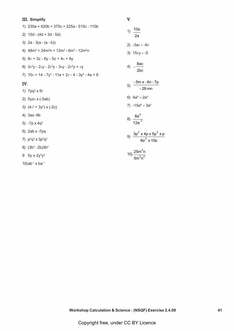
41Workshop Calculation & Science : (NSQF) Exercise 2.4.09
VVVVV.
1)
2a
10a
2) -3ax -6x
3) 15xy -5
4)
2bc
8ac−
5)mn 28-
7p- 6n- x 5m-
6) 4a8 2a3
7) -15a8 3a5
8) 7-
4
12a
8a
9)10p x 6p
p x 5p x 4p x 3p4
32
10)
23
2
n5m
n25m
IIIIIIIIIIIIIII. Simplify
1) 230a + 420b + 370c + 225a - 510c - 110b
2) 15d - (4d + 3d - 5d)
3) 2a - 3(a - (a - b))
4) 48m2 + 24m2n + 12m2 - 6m2 - 12m2n
5) 8x + 3z - 6y - 5z + 4x + 8y
6) 3x2y - 2xy - 2x2y - 3xy - 2x2y + xy
7) 10x + 14 - 7y2 - 11a + 2x - 4 - 3y2 - 4a + 8
IVIVIVIVIV.
1) 7pq2 x 5r
2) 5yzx x (-5ab)
3) (4x2 + 3y2) x (-2z)
4) 3ax -9b
5) -7p x 4q2
6) 2ab x -7pq
7) p2q3 x 3p3q2
8) (3b2 - 2b)3b2
9 5y x 2y3y2
10)ab-1 x ba-1
Copyright free, under CC BY Licence
42
Elasticity - Elastic, plastic materials, stress, strain and their units andyoung’s modulus Exercise 2.5.10
Elastic material
The Elastic materials are those materials that have theability to resist a distorting or deforming influence or force,and then return to their original shape and size when thesame force is removed.
Linear elasticity is widely used in the design and analysisof structures such as beams, plates and sheets.
Elastic materials are of great importance to society sincemany of them are used to make clothes, tires, automotivespare parts, etc.
Characteristics of elastic materials
When an elastic material is deformed with an externalforce, it experiences an internal resistance to thedeformation and restores it to its original state if theexternal force is no longer applied.
To a certain extent, most solid materials exhibit elasticbehavior, but there is a limit of the magnitude of the forceand the accompanying deformation within this elasticrecovery.
A material is considered as elastic if it can be stretchedup to 300% of its original length.
For this reason there is an elastic limit, which is thegreatest force or tension per unit area of a solid materialthat can withstand permanent deformation.
For these materials, the elasticity limit marks the end oftheir elastic behavior and the beginning of their plasticbehavior. For weaker materials, the stress or stress onits elasticity limit results in its fracture.
The elasticity limit depends on the type of solid considered.For example, a metal bar can be extended elastically upto 1% of its original length.
However, fragments of certain gummy materials mayundergo extensions of up to 1000%. The elastic propertiesof most solid intentions tend to fall between these twoextremes.
Maybe you might be interested How to Synthesize anElastolic Material?
Examples of elastic materials
1 Natural gum
2 Spandex or lycra
3 Butyl Rubber (GDP)
4 Fluoroelastomer
5 Elastomers
6 Ethylene-propylene rubber (EPR)
7 Resilin
8 Styrene-butadiene rubber (SBR)
9 Chloroprene
10 Elastin
11 Rubber Epichlorohydrin
12 Nylon
13 Terpene
14 Isoprene Rubber
15 Poilbutadiene
16 Nitrile Rubber
17 Vinyl stretch
18 Thermoplastic elastomer
19 Silicone rubber
20 Ethylene-propylene-diene rubber (EPDM)
21 Ethylvinylacetate (EVA or foamy gum)
22 Halogenated butyl rubbers (CIIR, BIIR)
23 Neoprene
Plastic Material
Plastic Material Classification
“Plastic material” is a term that refers to a large class ofpolymers, separated into various groups and sub-groups.Before starting the chapter on the uses and subsequentrecycling of plastic, let us establish a general classificationof these thermosetting resins or thermo-plastics (the twobig groups into which we include elastomers) by detailingtheir properties, their make-up, their aspect, and theirfinal uses, while explaining which ones are recyclable.
Thermoplastics
Remember that thermoplastic is a material whosestructure and viscosity can be modified both ways throughheating or cooling. This large family of materials iscommonly used by many industries and is easilyintegrated into France’s recycling cycles.
The following polymers are some examples of plasticmaterial:
1 Polyolefins
2 Vinyl polymers
3 Polystyrenes
4 Acrylate and methacrymate polymers
5 Polyamide
6 Polycarbonates
7 Celluloid
8 Linear polyesters
9 Polyfluorethane
10 Polyacetal
11 Polysulfone
12 Polyphenylene sulfide
13 Modified polyphenylene oxide (PPO)
Copyright free, under CC BY Licence
Related Documents