COMMISSION IV - WORKING GROUP 5 Joseph 0. Danko , Jr . President Kelsh Instrument Division Danko Arlington , Inc . 4800 East Wabash Avenue Baltimore , Maryland 21215 U.S.A. THE VERSATILITY OF THE KELSH K- 320 ORTHOSCAN WITH THE DTM CONVERTER ABSTRACT The Kelsh K- 320 ORTHOSCAN has been made into a substantially more powerful orthophoto instrument with the addition of the K- 320 DTM Converter . This new component includes a magnetic tape transport and formatter system along with PROM program- ming , all housed in a desk - top console . The magnetic tape transport replaces the paper tape punch and reader used on previous ORTHOSCANS , and permits faster orthophoto production . The PROM programming allows the K-320 scanning data to be con - verted i nto a DTM in either ASCII or EBCDIC computer language in another file on the same tape . An optional file permits the storage of discrete digitized points from the model to enhance the value of the DTM . The DTM Converter also allows the K- 320 to be utilized as an orthoprojector . Digitized profiling data from stereoplotters may be placed in the K- 320 format , and input through the Con - verter for the production of double model orthophotos on the ORTHOSCAN . I. THE ORTHOSCAN SINCE 1973 The Kelsh K- 320 ORTHOSCAN was recognized as a versatile ortho - photo instrument when the first production model was introduced in 1973 . The K- 320 was primarily designed as an off - line instrument , but an on - line capability was designed into the original system, and this option still exists today . A number of papers have been written describing the numerous features of the basic ORTHOSCAN (Danko , 1973, 1974) , and the unique operating characteristic which allows the model image to be transmitted orthographically to unexposed film by means of a flexible fiber optic conductor . The ORTHOSCAN incorporates a number of features which have made it a popular instrument for large scale orthophoto mapping . A full double model orthophoto can be produced to map scale within a 3 . 8 to 5. 8X magnification range from photo scale . The Joystick control permits the operator to climb 70° slopes over a 250mm range in Z, to generate orthophotography for almost any kind of terrain .

Welcome message from author
This document is posted to help you gain knowledge. Please leave a comment to let me know what you think about it! Share it to your friends and learn new things together.
Transcript
COMMISSION IV - WORKING GROUP 5
Joseph 0 . Danko , Jr . President
Kelsh Instrument Division Danko Arlington , Inc .
4800 East Wabash Avenue Baltimore , Maryland 21215
U. S . A.
THE VERSATILITY OF THE KELSH K- 320 ORTHOSCAN WITH THE DTM CONVERTER
ABSTRACT
The Kelsh K- 320 ORTHOSCAN has been made into a substantially more powerful orthophoto instrument with the addition of the K- 320 DTM Converter . This new component includes a magnetic tape transport and formatter system along with PROM programming , all housed in a desk- top console . The magnetic tape transport replaces the paper tape punch and reader used on previous ORTHOSCANS , and permits faster orthophoto production .
The PROM programming allows the K-320 scanning data to be converted i nto a DTM in either ASCII or EBCDIC computer language in another file on the same tape . An optional file permits the storage of discrete digitized points from the model to enhance the value of the DTM .
The DTM Converter also allows the K- 320 to be utilized as an orthoprojector . Digitized profiling data from stereoplotters may be placed in the K- 320 format , and input through the Converter for the production of double model orthophotos on the ORTHOSCAN .
I . THE ORTHOSCAN SINCE 1973
The Kelsh K- 320 ORTHOSCAN was recognized as a versatile orthophoto instrument when the first production model was introduced in 1973 . The K- 320 was primarily designed as an off- line instrument , but an on- line capability was designed into the original system, and this option still exists today .
A number of papers have been written describing the numerous features of the basic ORTHOSCAN (Danko , 1973, 1974) , and the unique operating characteristic which allows the model image to be transmitted orthographically to unexposed film by means of a flexible fiber optic conductor .
The ORTHOSCAN incorporates a number of features which have made it a popular instrument for large scale orthophoto mapping . A full double model orthophoto can be produced to map scale within a 3 . 8 to 5 . 8X magnification range from photo scale . The Joystick control permits the operator to climb 70° slopes over a 250mm range in Z, to generate orthophotography for almost any kind of terrain .

Dur i ng t he past seven years , t h e K- 320 ORTHOSCAN has deve l oped into an orthophoto sys t em (Dank o , 1 975) . Webster def i nes the word " system" as a " gr oup of objects o r units so combined as to form a who l e , and work , func t ion , o r move interdependent l y and harmoniou sly" (Webster , 1974) .
Some of the functions which have added to the system concept include the compl ete met rication of the ORTHOSCAN , and metr ic scal es on the projectors for a rapid set- up . Al so , the Target Marker has been incor porated into t he PPV p l aten assembl y , fo r marking state plane coordinate i ntersec t ions directly on the orthonegative . The recent addition of the new K- 320 DTM Converter has raised the standard ORTHOSCAN system to an even higher level of performance .
II . THE K- 320 DTM CONVERTER
The original ORTHOSCANS used a f an- folded paper tape punch and reader as the storage medium for the off- line operation . Each profile that was scanned would be f i rst stored in a memory so that the operator could examine it and re- scan i t if necessary . Once he was satisfied with the profile , the operator coul d command the memory to t ransfer the data to the punch , which then recorded the scan on a section of the paper tape . This system functioned well , but did not have the versati l ity to fully utilize the valuable profil i ng data .
This profiling data was , in fact , a Digital Terrain Model that was already in a gridded format . With the use of paper tape readers and subsequent software conversions , contour maps were produced of the scanned terrain which compared favorably with maps from stereoplotters that had been compiled with the same contour intervals . Consequently , a decision was made to develop a more flexible magnetic tape system for the K- 320 to replace the paper tape punch and reader . The new system was called the K- 320 DTM Converter , and several important features were designed into it with the use of PROM techn~logy (Programmable Read Only Memory) .
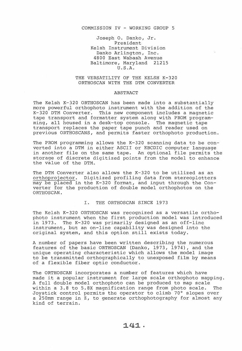
As shown in Figure 1 , the operation of the K- 320 ORTHOSCAN is now controlled from two consoles, one floor mounted and one desk mounted . A closer view of the desk mounted DTM Converter (which is shown on a cart) may be found in Figure 2 . The magnetic tape transport is located in the top of the cabi net, with a control panel in the center and the tape formatter on the bottom . The system utilizes a Digi- Data Model 1130 magnetic tape transport, which accepts 7 inch (178mm) reels of tape for a 9 track 800 bpi IBM compatible format.
The first important design feature of the DTM Converter is the capability of converting a "Front Scan/Back Scan" to a " SingleScan". Because of the large 5X nominal magnification, the K- 320 operator scans a full double model first in the front of the instrument, and then in the back (Front Scan/Back Scan) . Wi th the original paper tape system , such an orthonegative was exposed off- line as shown schematically in Figure 3 . The fiber optic conductor first cycled back and forth along the profiles
:1.£J:2.
Figure 1
The Kelsh K-320 ORTHOSCAN with the DTM Converter .
in the front of the instrument, and then automatically moved to the rear and along the profiles through the back scan area . The shutter of the ORTHOSCAN was programmed to function automatically at the theoretical 562mm center line . Because of the sensitivity of the orthonegative film, it was necessary to maintain close tolerances on the density of the diapositives and the quartz halogen illumination to make the center overlap or " chop- line" hard to find in the orthophoto .
In the DTM Converter , the primary Front Scan/Back Scan is stored in File 1 on the magnetic tape , and each scan may be edited as before . This data can then be joined together in File 2 on the same tape for a continuous " Single- Scan" profiling , from the extreme front limit to the back limit of the model . This Single-Scan is also shown schematically in Figure 3 .
::1.43.

- -~ '~
Figure 2
A closer view of the DTM Converter .
Note that in the Front Scan/Back Scan mode , the mating scans along the same Y profile go in the same direction . The PROM programming of the DTM Converter joins these scans together at the 562rnrn center line in File 2 for a Single- Scan tape replay , which is used for the off- line exposure . With the Single- Scan playback , the shutter remains open during the entire exposure of the orthonegative , eliminating the center " chop- line". The tolerances for diapositive density and i llumination are much broader , and the stop and start action of the photohead is reduced by one- half, speeding up orthophoto production .
It should be noted that the Single- Scan mode is often used as the primary scan . This mode provides a rapid method of gener-

!562mm
START
FRONT SCAN I BACK SCAN MODE
LEFT LIMIT
BACK LIMIT
FRONT LIMIT
START
RIGHT LIMIT
I
SINGLE SCAN MODE
Figure 3
STOP
A schematic drawing of the two scanning modes for the K- 320 ORTHOSCAN .
145.

ating strip orthophotos for power line or other utility maps , and for many other applications as well . In such cases , the DTM Converter automatically recognizes the primary File 1 scanning as also being File 2 .
III . THE THIRD FILE - A DIGITAL TERRAIN MODEL
The data that i s generated by the K- 320 ORTHOSCAN during offline digitizing is in a special binary code . This data is output in File 1 on the magnetic tape of the DTM Converter during the primary scan . The data registers command signals for positioning and direction in either the Single- Scan or Front Scan/Back Scan modes . Data is also recorded for an absolute position in Z at the beginning of each scan, and an incremental position in Z for every 1.6mm in Y throughout each scan . This incremental position is recorded on the tape to the nearest 0 . 04mm .
The X position for succeeding profiles may be controlled by the operator, and is usually fixed at a definite stepover value in X to the nearest 0 . 025mm . However, this profile width can be varied in the same model to suit the type of terrain being scanned .
Another design feature of the K-320 DTM Converter is the Digital Terrain Model conversion program . This function converts the binary coding of the K- 320 digitizing to either ASCII or EDCDIC computer language in the third file of the same tape . To accomplish this, the primary scanning in File 1 must first be converted to a Single-Scan in File 2 , if it is not already in this form . The Single-Scan may then be converted to the DTM in File 3 . A switch in the rear of the DTM Converter is used to select either the ASCII or EBCDIC language . During the conversion process, the tape transport cycles the tape reel back and forth until the conversion is complete . The time that it takes to perform this operation is almost solely a function of the number of scans in X. For example, 60 profiles in X would be converted to a DTM in about 30 minutes . This operation can be taking place while the next K- 320 model is being oriented, or after normal working hours, with the K-320 unattended . The DTM conversion cycle will automatically stop when it has been completed.
The form of the DTM data in the third file is as shown below :
EBCDIC or ASCII
9 track IBM compatible
800 bpi
DCB = (RECFM = FB, LRECL = 80, BLKSIZE = 640)
File #3
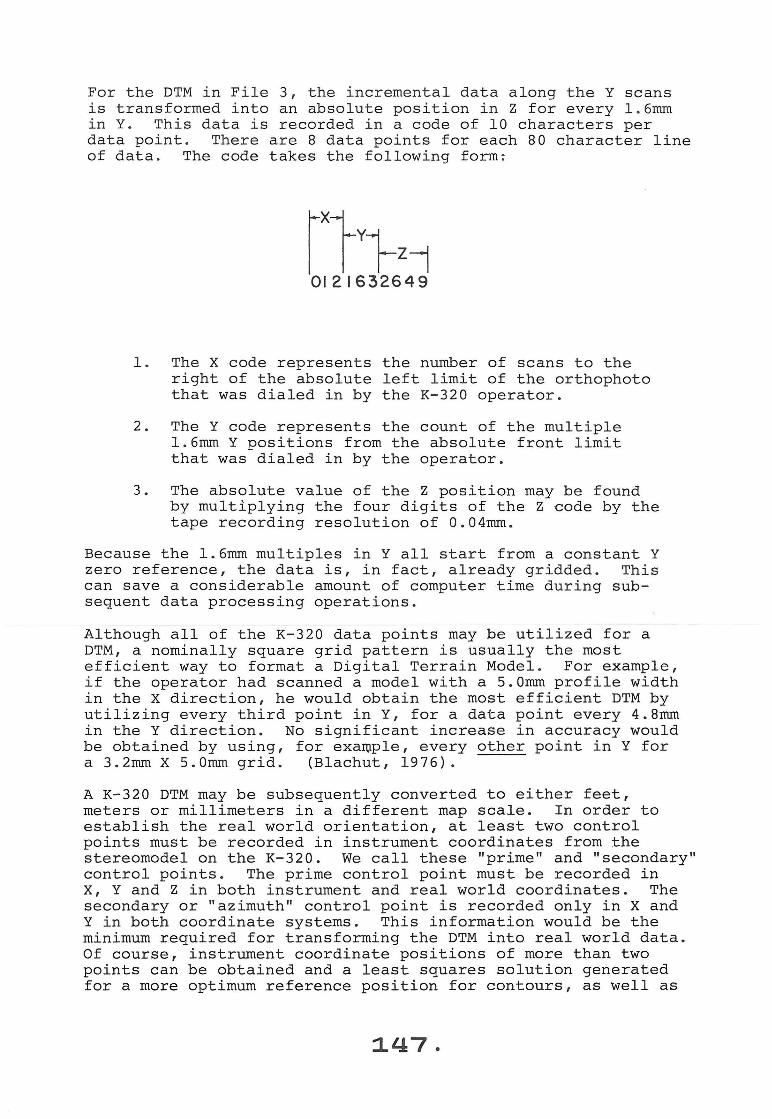
For the DTM in File 3 , the incremental data along the Y scans is transformed into an absolute position in Z for every 1.6mm in Y. This data is recorded in a code of 10 characters per data point . There are 8 data points for each 80 character line of data . The code takes the following form :
1 . The X code represents the number of scans to the right of the absolute left limit of the orthophoto that was dialed in by the K-320 operator .
2 . The Y code represents the count of the multiple 1.6mm Y positions from the absolute front limit that was dialed in by the operator .
3 . The absolute value of the Z position may be found by multiplying the four digits of the Z code by the tape recording resolution of 0.04mm .
Because the 1.6mrn multiples in Y all start from a constant Y zero reference, the data is , in fact , already gridded . This can save a considerable amount of computer time during subsequent data processing operations .
Although all of the K- 320 data points may be utilized for a DTM, a nominally square grid pattern is usually the most efficient way to format a Digital Terrain Model . For example, if the operator had scanned a model with a S . Omm profile width in the X direction , he would obtain the most efficient DTM by utilizing every third point in Y, for a data point every 4.8mm in the Y direction. No significant increase in accuracy would be obtained by using, for example, every other point in Y for a 3.2mm X S.Omm grid. (Blachut, 1976).
A K- 320 DTM may be subsequently converted to either feet, meters or millimeters in a different map scale. In order to establish the real world orientation, at least two control points must be recorded in instrument coordinates from the stereomodel on the K- 320 . We call these "prime" and " secondary" control points . The prime control point must be recorded in X, Y and Z in both instrument and real world coordinates. The secondary or "azimuth" control point is recorded only in X and Y in both coordinate systems . This information would be the minimum required for transforming the DTM into real world data . Of course, instrument coordinate positions of more than two points can be obtained and a least squares solution generated for a more optimum reference position for contours , as well as
the coordinate transformat i on .
Results obtained i n the field have proven that the scanning data alone from a K- 320 DTM can produce a contour plot of re markable accuracy . Contour maps produced from such dat a have approached , if not equalled Nationa l Map Accuracy Standards . (Gossard , 1976) .
A fourth f i le i s available as an option with the DTM Converter . This opt i on permits the operator to digitize discrete points in the stereomodel, a l ong such features such as ridges and dra i ns . A few hundred extra points digitized at these critical breaks in the terrain can greatly improve the accuracy and va l ue of the Digital Terrain Mode l. (Young , 1978) .
The DTM conversion routines of the K- 320 ORTHOSCAN allow the user to take advantage of this valuable spin- off from the orthophoto process . The DTM output provi des data for saleable products such as contour maps , slope maps , cross - section and perspect i ve maps . The routines are accomplished by computer functions wi thin the new system , without the need for addit i onal computer assistance . Let ' s take a look at what is possible with the ORTHOSCAN system when supplemental computer facilities are available .
IV . MODIFIED SLOPE CONTROL
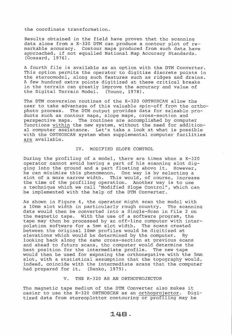
During the profi l ing of a model , there are times when a K- 320 operator cannot avoid having a part of his scanning slot digging i nto the ground and a part floating above it . However , he can minimi ze this phenomenon . One way is by se l ecting a slot of a more narrow width . This would , of course , increase the time of the profil i ng oper ation . Another way is to use a technique which we call "Mod i fied Slope Control ", which can be implemented with the he l p of the DTM Converter .
As shown in Figure 4 , the operator might scan the model with a lOmm slot width in particularly rough country . The scanning data wou l d then be converted into a Single- Scan in File 2 on the magnetic tape . With the use of a software program , the tape may then be processed by an off-line comput er with interpolation software for a 5mm s l ot width . The scans created between the original lOmm profiles would be digitized at elevations which would be determined by the computer . By looking back a l ong the same cross - section at previous scans and ahead to future scans , the computer would determine the best position for the i ntermediate profile . The new tape would then be used for expos i ng the orthonegative with the 5mm slot , with a statistical assumption that the topography wou l d , indeed , coinc i de wi t h the intermediate scans that the computer had prepared for i t. (Danko , 1 975) .
V. THE K- 320 AS AN ORTHOPROJECTOR
The magnetic tape med i um of the DTM Converter also makes it easier to use the K- 320 ORTHOSCAN as an orthoprojector . Digitized data from stereopl otter contouring or prof i l i ng may be
Figure 4 - Modified Slope Control
(1 ) Original scanning with a lOrnm profile width .
(2) Intermediate scans added by a computer for a Srnm profile width .
used as input to the K- 320 for the production of an orthophoto . First , a standard profile width in X would be se l ected that would be appropriate for the type of terrain that was digitized . Then, a software program would interpolate the optimum profiles for that scanning resolution in X, and would create a magnetic tape in the K- 320 Single- Scan format . Data points in Z would be provided on the tape for every 1 . 6rnm in Y, along with command signals for the positioning and direction of the photohead of the K- 320 . The software would also provide spatial data in instrument coordinates for at least three widely spaced control points . A fourth point would be desirable as a check . By using the standard K-320 single- projector orientation technique ; the operator would position the center diapositive so that the spatial points were properly intersected by the imagery . Film would then be loaded into the instrument , and the orthonegative produced from a single diaposit i ve on the center projector . (Danko, 1975) .
VI . CONCLUSION
At the Kelsh Division , we are extremel y optimistic about the future of orthophotography in the 1980 ' s . In the U. S . A., several states have recently moved toward specifying orthophotos

for new county mapping . The spin- off of useful DTM data without addi tional labor cost is being recognized as one of the most valuable benef i ts of orthophotography . The orthophoto and the DTM have become important components for the data- base mapping that is the wave of the future .
We have learned that the orthophotos that were produced for U. S . counties and cities during the 1970 ' s have had time to c i rculate among government leaders in other parts of the world . These leaders are finding that the weal th of information on a h i gh reso l ution orthophoto wi th a contour over l ay can be understood by the legal, po l itical , and judicial , as well as the technical professions . Consequent l y , these pub l ic servants are recommending such orthophotography for their own district s .
We firmly believe that the demand for orthophotos and DTM byproducts will expand dramatica l ly in the 1980 ' s , and that the new, versatile K- 320 ORTHOSCAN system is ready to meet this challenge .
References :
Bl achut , T . J ., and Van Wijk , M. C. , 1976 , " Resul ts of the International Orthophoto Experiment 1 972 - 76 ", publ i shed in the December 1976 issue of PHOTOGRAMMETRI C ENG I NEERING AND REMOTE SENSING , Vol . XLII , No . 1 2 , pp . 1 483 - 1498 .
Danko , J . 0 ., Jr . , 1 973, " The Ke l sh K- 320 ORTHOSCAN- A New Concept in Orthophotography", published in the November 1973 issue of PHOTOGRAMMETRIC ENGINEERING , Vol . XXXIX , No . 11 , pp . 1 161- 1170 .
Danko , J . 0 . , Jr ., 1974 , " Quick Orientation of the K- 320 ORTHOSCAN ", publ i shed in the September 1974 i ssue of PHOTOGRAMMETRIC ENGINEERING , Vol . XL, No . 9 , pp . 1071-1078 .
Danko , J . 0 ., Jr . , 1975 , " The Kelsh K- 320 ORTHOSCAN - An Orthophoto System" , published in Technical Papers - ASP ORTHOPHOTO WORKSHOP III , June 1975 , pp . 82 - 94 .
Gossard , T . W., 1976 , "Evaluation of Digital Terrain Generated for a 1 : 24,000 Data Base during Orthophoto Production", published as ENGINEERING MANAGEMENT REPORT EM- 7140 - 2 , 9 pages , by the Forest Service , U. S . Department of Agriculture , Washington , D. C. 20250 , U. S . A.
Webster , 1974 "Webster ' s New Student ' s Dict i onary" , published by G. and c . Merriam Co ., Springfield , Mass . , U. S . A.
Young , w. H. and Isbe l l , D. M., 1978 , " Production Mapping with Orthophoto Digital Terrain Models" , pub l ished in the December 1978 issue of PHOTOGRAMMETRIC ENGINEERING AND REMOTE SENSING , Vol . XLIV , No . 12 , pp . 1521 - 1536 .
:l.SO.
Related Documents