Workbook Air Brake Systems Video Training Part 1 - 4

Welcome message from author
This document is posted to help you gain knowledge. Please leave a comment to let me know what you think about it! Share it to your friends and learn new things together.
Transcript

WorkbookAir Brake Systems
Video Training
Part 1 - 4

IntroductionThis workbook is intended for use in conjunction with Parts1 through 4 of the Bendix video presentation covering theoperation of air brake systems and components. It can beused as an effective means of taking notes on the moreimportant points because the material presented is in thesame order as it is viewed. It can also be used as a quiz toindicate areas requiring further review. Sectional viewsand system schematics are taken from the video tape andall questions can be answered from the materialpresented.
For additional copies of this workbook contact your localBendix authorized parts outlet and order form BW1678.
The schematics, component drawings and description ofoperation presented in the video tapes and in this workbookare representative only and are presented for the purposeof training. This material should not be used for design orapplication of air brake systems or components withoutprior consultation with Bendix Engineering.

WorkbookAir Brake Systems
Video Training
Part 1
Air Generation System

1Compressor
1. Crankshaft2. Connecting Rods3. Rear End Cover4. Rear Main Bearing Journal5. Pistons6. Inlet Valves7. Discharge Valves
1. Reservoir Port2. Piston3. Inlet Exhaust Valve4. Pressure
Setting Spring5. Unloader Port
Governor
A.
C.
B.
D.
E.F.
G.
A.
B.
C.
D.E.

2
Compressor1. After pressurized oil flows to the connecting rod bearings, it is conducted through an internal oil
passage in the connecting rod to the piston wrist pin.True False
2. When the compressor piston begins the compression stroke, the inlet valve opens and the dischargevalve closes.
True False
3. Rapid build up of air pressure depends upon proper opening, closing and sealing of both the inletand discharge valving and the unobstructed flow of air into the cylinder bores.
True False
4. An obstruction on the air intake side of the compressor (ie; a dirty air filter) can cause compressoroil passing.
True False
5. An obstruction in the compressor discharge line can cause the compressor to run hot and buildcarbon deposits.
True False
6. A slight pressure above the piston causes the compressor inlet valve to open during the intake stroke.True False
7. Define the term “crankcase flooding” as it applies to the compressor.
Governor1. Reservoir air enters the governor unloader port and as pressure builds the piston moves down.
True False
2. Air from the governor’s reservoir port flows to the compressor’s unloader mechanism which causesthe compressor to speed up or slow down, depending upon the air requirements of the air system.
True False
3. When supply reservoir pressure drops to the “cut-in” pressure of the governor, typically100 psi, the governor will exhaust air from the compressor unloader mechanism and system airpressure will be replenished.
True False
4. The governor’s function in the air system can be summarized by stating that, “it is responsible formaintaining air brake system pressure between a pre-set maximum and minimum”.
True False
5. During the unloaded cycle of the compressor, with the compressor unloader mechanism pressurizedby the governor, air is “shuttled” from one cylinder of the compressor to the other. This occursbecause the compressor unloader pistons hold the inlet valves off their seats and because thecrankshaft has 180 degrees, opposed connecting rod journals.
True False
6. Describe what would occur if the governor failed to function.

3Safety Valve
1. Spring2. Stem3. Ball Valve4. Valve Seat
1. Supply or Inlet Port2. Inlet Valve3. Spring4. Valve Seat5. Delivery Port
Reservoirs and Check Valves
A.B.
C.
D.
A. B.
C.
D.E.

4
Safety Valve1. Safety valves can be obtained with various settings but are generally set to open and exhaust
at 150 psi.True False
2. The safety valve is installed in the compressor discharge line.True False
3. The exposed stem allows the safety valve it to be tested or checked periodically.True False
4. Working in conjunction with the governor, the safety valve exhausts the air from the discharge linewhen the compressor is in the unloaded state (not compressing air).
True False
Reservoirs and Check Valves1. The single check valve is intended to protect the air pressure in the supply reservoir (the first
reservoir that receives air) in the event air pressure in the service reservoir(s) is lost.True False
2. The single check valve is located in the discharge line, between the compressor and air dryer.True False
3. Air flow through a single check valve is in one direction only.True False
4. The single check valve got its name from the fact that only one is used in the air brake system.True False
5. A minimum of three reservoirs are generally used in a dual air brake system.True False
6. The supply reservoir supplies air to the service reservoirs.True False

5
Dash Gauge and Low Pressure Indicator
Reservoirs and Drain Cocks

6
Dash Gauge and Low Pressure Indicator1. The dash gauge is required by federal regulations.
True False
2. Connected to the supply reservoir, the dash gauge provides the driver with a continuous “read out”of air pressure available for braking.
True False
3. If a single dash gauge is installed, there will be two “hands” or needles on the gauge. One “hand”indicates available air pressure in the service reservoir and the other registers the air pressure in thesupply reservoir.
True False
4. The low pressure indicator switch is required by federal regulations.True False
5. A low pressure indicator switch, like the Bendix® LP-3™, is generally mounted on the vehicle dash.True False
6. When air pressure in the system falls to a preset safe minimum, the low pressure switch will “lightup” and/or begin to “buzz”.
True False
7. The minimum air pressure setting for a low pressure indicator switch is typically 60 psi.True False
8. If the low pressure indicator is set so that the electrical contacts close at/or below 60 psi, then theyshould open immediately when pressure rises above 60 psi.
True False
Reservoirs and Drain Cocks1. Oil, water and vapor are contained in the air discharged from the compressor and will condense in
the air lines and collect in the reservoirs.True False
2. The drain cock, installed in the bottom of the reservoir, is used to remove the accumulatedcontaminates.
True False
3. The drain cock can be used to test the operation of the low pressure indicator switch and the singlecheck valve.
True False
4. Once the contaminants are drained from the reservoir and the compressor stops “pumping” air, nofurther accumulation of water or contamination will occur.
True False

7Air Dryer
1. Supply Port2. End Cover3. End Cover Sump4. Oil Separator5. Desiccant Cartridge6. Drying Bed7. Check Valves8. Outer Shell9. Delivery Port10. Turbo-cut-off Valve11. Control Port12. Purge Valve Piston
A.
B. C. D.E.
F.
G.
H.I.L.
K.J.M.

8
Air Dryer1. The oil separator removes not only oil droplets, but also removes solid contaminants and remaining
water droplets.True False
2. The desiccant material in the air dryer removes water vapor in a process known as adsorption.True False
3. Water and contaminants are collected in the purge volume and are expelled during the purge cycleof the air dryer.
True False
4. The check valve above the desiccant cartridge prevents the loss of air brake system pressure duringthe purge cycle of the air dryer.
True False
5. The turbo cut-off-valve in the air dryer prevents the loss of engine turbo charger pressure throughthe open purge valve of the air dryer during the purge cycle.
True False
6. The air dryer requires about 25 seconds to complete the purge cycle.True False
7. Name the three air connections on the air dryer. Where and to what are they connected?
8. What is the purpose of the small orifice (hole) next to the check valve in the top of thedesiccant cartridge?
9. Give one reason why the air dryer would constantly “cycle” between the charge and purge.

Air Supply System1. Using the symbols shown in the schematic, draw the Low Pressure Indicator Switch, Safety Valve,
Single Check Valve(s) and Dash Gauge(s) in their correct positions.
2. Draw in the air lines that connect the Compressor, Air Dryer, Governor and Reservoirs.
3. Indicate with an arrow and the number “3” air line(s) NOT CONSTANTLY filled with air pressureduring normal vehicle operation.
9

WorkbookAir Brake Systems
Video Training
Part 2
Service Brake System

11Dual Brake Valve
1. Inlet Port2. Return Spring3. Diaphragm4. Push Plate5. Push Rod
Brake Chambers and Spring Brakes
A.B. C.
D.
E.
F.
G.
H.
I.
J.
K.
M.L.
N.O.P.
A.B. C.
D.E.
➔
1. Pedal or Treadle2. Plunger3. Roller4. Stop Button5. Fulcrum Pin6. Spring Seat7. Graduating Spring8. Primary Piston9. Primary Inlet and Exhaust Valve10. Secondary or Relay Piston11. Secondary Inlet and Exhaust Valve12. Primary Supply Port13. Secondary Supply Port14. Primary Delivery Port15. Secondary Delivery Port16. Exhaust Port

12
Dual Brake Valve1. Generally all dual brake valves function the same way. The method of mounting in the vehicle can
differ. The E-6™ dual brake valve is a fire wall mounted unit.True False
2. With the brakes released, both the primary and secondary inlet valves are __________ (openclosed) and both exhaust valves are __________ (open closed).
3. When a brake application is first made, the primary or rear axle service circuit begins to deliver airahead of the secondary or front axle service circuit.
True False
4. The secondary or front axle service circuit of the dual brake valve is controlled by the air deliveryfrom the primary circuit.
True False
5. In the balanced position, both the primary and secondary inlet valves are __________ (open closed)and both exhaust valves are __________ (open closed).
6. When the brake valve treadle is fully depressed, as in a “panic stop”, both the primary and second-ary inlet valves are held open mechanically and full reservoir pressure is delivered to the brakes.
True False
7. What is the function of the primary piston graduating spring?
Brake Chambers & Spring Brakes1. The number designation given to a brake chamber provides information about its “power” potential.
True False
2. What does the number designation given to a brake chamber actually mean?
3. The purpose of the brake chamber return spring is to “delay” or slightly reduce the force of the brakeapplication in order to help balance the vehicle brakes.
True False
4. The service section of a spring brake functions and operates the same as a standard brake cham-ber.
True False
5. What would the force be, (measured at the end of the push rod) if 30 psi air pressure was applied toa Type 20 brake chamber?
6. Spring Brakes can be used interchangeably with brake chambers, but are most often found on thefront axle of the vehicle.
True False
7. What is attached to the end of the brake chamber push rod?

13Slack Adjuster
1.Inlet or Supply Port2.Delivery Ports3.Diaphragm4.Exhaust Port
Quick Release
A.B.
E. D.
C.

14
Slack Adjuster1. Although most often used on “S” cam foundation brakes, the slack adjuster can also be found on the
less often encountered Wedge type foundation brakes.True False
2. Describe as many of the basic functions of the slack adjuster as you can.
3. The number designation of the slack adjuster indicates the brake chamber number that is used withit. For instance; a type 20 slack adjuster should always be used with a type 20 brake chamber.
True False
4. If you answered TRUE in question 3, explain why.
If you answered FALSE in question 3, then explain what the slack adjuster number designation means.
5. The Bendix® ASA-5™ is an automatic slack adjuster.True False
6. One important feature of the ASA-5™ automatic slack adjuster is that it constantly adjusts the brakesin very small increments each time the brakes are released.
True False
7. The ASA-5™ automatic slack adjuster monitors brake chamber stroke and will adjust the brakeswhen the stroke increases due to lining wear.
True False
Quick Release Valve1. As air line length increases and air pressure decreases, the time required for air to return to the
brake valve and exhaust to atmosphere will increase.True False
2. A quick release valve, such as the Bendix® QR-1™ or QR-N™, is used to increase the time it takes torelease the brakes.
True False
3. Quick release valves can be used in several locations on the vehicle, however, one of the mostcommon is on the front axle.
True False
4. In addition to increasing release times for the brakes, the quick release also speeds up theapplication of the brakes during emergency situations.
True False
15Relay Valve
1. Relay Piston2. Exhaust Port3. Inlet and Exhaust Valve Assembly4. Service or Control Port5. Delivery Port6. Supply Port
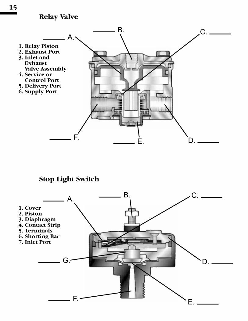
1. Cover2. Piston3. Diaphragm4. Contact Strip5. Terminals6. Shorting Bar7. Inlet Port
Stop Light Switch
A.B. C.
D.F. E.
A. B.
G.
F.
C.
D.
E.

16
Relay Valve1. Relay valves, such as the Bendix® R-12™, are usually installed on or near the rear axle(s), especially
on long wheel base vehicles. The function of the relay valve is to assure the simultaneous applica-tion and release of the brakes most distant from the brake valve.
True False
2. Brake application pressure from the foot brake valve enters the R-12™ relay valve supply port and isconducted directly to the under side of the piston.
True False
3. With the brakes released the inlet valve is __________ (open closed) and the exhaust valve is__________ (open closed).
4. In the Balanced position, the inlet valve is __________ (open closed) and the exhaust valve is__________ (open closed).
5. When the R-12™ relay valve is in the Holding or Balanced position, the foot brake valve is also in theHolding or Balanced position.
True False
6. It is best to replace a relay valve with the same or similar unit since different crack pressures aresometimes used. Different crack pressures can affect brake application timing.
True False
7. Crack pressure is the amount of control air pressure needed to open the inlet valve.True False
8. The standard R-12™ relay valve has a crack pressure of approximately 4 psi.True False
Stop Light Switch1. The Bendix® SL-5™ stop light switch will activate the vehicle stop lights when brake application
pressure reaches or exceeds;A 10 psiB 6 psiC 5 psiD 2 psi
2. The Bendix® SL-5™ stop light switch can be repaired using a maintenance kit, available from anyauthorized parts outlet.
True False

17
Service Brake System1. Using the symbols shown in the schematic, draw the Low Pressure Indicator Switch, Safety Valve,
Single Check Valve(s), Dash Gauges and Stop Light Switch, in their correct positions.
2. Draw in the air lines that connect the Compressor, Air Dryer, Governor, Reservoirs, BrakeChambers, Spring Brakes, Quick Release Valve, Brake Valve and Relay Valve.
3. Indicate with an arrow and the number “3”, the air lines that ARE NOT filled with air pressure whenthe brakes are released.
E-6“
BrakeValveASA-5“ Auto
Slack AdjusterR-12“
RelayValve
QR-1“
QuickRelease

WorkbookAir Brake Systems
Video Training
Part 3
Emergency and
Parking Brake System

19Double Check Valve
1. Shuttle2. Guide3. Body4. Inlet Ports5. Delivery Port
1. Control Button2. Plunger3. Spring4. Inlet & Exhaust Valve5. Body6. Supply Port7. Delivery Port8. Exhaust Port
PP-1™ Push Pull Control Valve
A.B.
C.
D.E.
F.
A.B. C.
D.
E.
F.G.
H.
➔

20
Double Check Valve1. Briefly explain the function and operation of the double check valve.
2. Double check valves can be used in a number of different ways in the air brake system. Describehow the double check shown in the video was used and what it was connected to.
3. In your own words, explain why the double check valve should be mounted horizontally (shuttlemoving back and forth rather than up and down) when the difference in air pressure at the inletports is minimal.
PP-1™ Push Pull Control Valve1. The PP-1™ push pull control valve button will automatically go in or pop out depending upon the
available system pressure supplied to it.True False
2. The PP-1™ is an on-off control valve, it does not modulate or graduate air pressure.True False
3. With the button IN (plunger into body as far as it will go) the PP-1™ valve is in the exhaust position.True False
4. The PP-1™ valve is available in a range of automatic settings, from about 20 psi to 60 psi.The typical setting is 40 psi.
True False
5. When supply pressure falls to the automatic setting of the PP-1™ valve, the valve will move to theEXHAUST position.
True False

21
Spring Brakes
1. Piggyback2. Service Diaphragm3. Push Plate4. Emergency Piston5. Emergency Diaphragm6. Emergency Spring7. Emergency Air Inlet Port8. Service Inlet Port
1. Delivery Port2. Service or
Control Port3. Supply Port4. Balance Port5. Inlet and
Exhaust Valve6. Relay Piston7. Diaphragm
R-14™ Spring Brake Relay Valve
A.B.
H.
G. F.
C.
D.
E.
A.B. C.
D.
E.
F.G.

22
Spring Brakes1. The spring brake performs three braking functions on the vehicle. In addition to performing the
normal service braking it also is the parking and __________ brake for the vehicle.
2. The two sections of the spring brake use air pressure in an opposite manner. Air pressure applied tothe emergency section applies the brakes, while air taken away from the service side releases thebrakes.
True False
3. A release bolt is used in the emergency, or “piggyback”, section to cage the large, emergencyspring.
True False
4. During a park or emergency application of the brakes, the expanding emergency spring supplies theforce necessary to apply the brakes and holds them applied regardless of loss of air pressure in thebrake system.
True False
R-14™ Spring Brake Relay Valve1. The bottom half (body) of Bendix® R-14™ relay valve is exactly like the R-12™ relay valve and is
interchangeable. The difference between the two valves is the cover.True False
2. Although it can be used as a service relay, the R-14™ relay valve is used primarily as a spring brakerelay. It provides rapid application and release of the parking and emergency brakes.
True False
3. The service or control port of the R-14™ spring brake relay valve is connected to the delivery of the__________ control valve.
4. In your own words describe what the term “anti-compounding” means.
5. The balance port of the R-14™ relay valve is connected to the delivery side of the R-12™ servicerelay valve.
True False

23SR-1™ Spring Brake Valve
1. Piston “A”2. Piston “B”3. Inlet/Exhaust Valve “A”4. Inlet/Exhaust Valve “B”5. Spring “A”6. Spring “B”7. Single Check Valve
A.B.
G. F.
C. D.
E.

24
SR-1™ Spring Brake Valve1. The primary function of the SR-1™ spring brake valve is to maintain modulated rear axle braking if
primary reservoir pressure is lost.True False
2. The SR-1™ spring brake valve is used on longer wheel base vehicles, but can be used on straighttrucks and tractors.
True False
3. The SR-1™ spring brake valve has four air connections, match the valve ports to the componentsconnected to them.No. 1 Reservoir Port _______ A. Supply ReservoirControl Port ______________ B. Rear Service ReservoirSupply Port ______________ C. Front Service ReservoirDelivery Port _____________ D. Rear Axle Delivery of Foot Valve
E. Front Axle Delivery of Foot ValveF. Spring BrakeG. Delivery of PP-1™ Push Pull Control ValveH. R-14™ Valve Control or Service Port
4. When rear axle service reservoir (primary reservoir) pressure is lost, the SR-1™ spring brake valvewill modulate the pressure in the spring brake emergency section and the rear brakes will be appliedwith spring force rather than air pressure.
True False
5. The SR-1™ spring brake valve allows the foot brake valve to apply and release (modulate) the springbrakes when primary reservoir pressure is lost.
True False

25
Emergency and Parking Brake System1. Using the symbols shown in the schematic, draw the Low Pressure Indicator Switch, Safety Valve,
Single Check Valve(s), Dash Gauge(s), Double Check Valve and Stop Light Switch, in their correctpositions.
2. Draw in the air lines that connect all the air devices.
3. Indicate with an arrow and the number “3” which air lines ARE NOT filled with air pressure when theservice brakes are released and the spring brakes are applied (vehicle parked, engine running).
4. Indicate with an arrow and the number “4” which air lines ARE FILLED with air pressure when boththe service and spring brakes are applied (vehicle parked, engine running, foot brake valvedepressed).
PP-1™
Push Pull Control ValveSR-1™ SpringBrake Valve
E-6™
BrakeValve
ASA-5™ AutoSlack Adjuster
QR-1™
QuickRelease
R-12™
RelayValve
R-14™
RelayValve

WorkbookAir Brake Systems
Video Training
Part - 4
Tractor/ Trailer
Brake System

F.
D.
G.
M.
B.
E. L.
C.K.H.
A.
TP-3™ Tractor Protection Valve
1. Plunger2. Service Valve3. Body4. Spring5. Tractor Service Port6. Tractor Supply Port7. Trailer Service Port8. Trailer Supply Port
H.
G.
B.
D.
A.E.
C.
27
PP-7™ Trailer Supply Valve
1. Plunger2. Spring3. Inlet & Exhaust Valve4. Piston5. Piston Return Spring6. Inlet & Exhaust Valve7. Valve Spring8. Exhaust Vent9. Supply Port10. Delivery Port11. Control Port12. Exhaust Port13. Control Button
F.
J.
N.

PP-7™ Trailer Supply Valve1. The PP-7™ trailer supply valve button will automatically go in or pop out depending upon the
available system pressure supplied to it.True False
2. The PP-7™ trailer supply valve has three (3) air connections. Put the letter of the correct connectionnext to the PP-7™ trailer supply valve port shown below.
PP-7™ trailer supply valve Supply port A. Double Check Valve OutletPP-7™ trailer supply valve Delivery port B. Tractor Service Port of Tractor ProtectionPP-7™ trailer supply valve Control port C. Tractor Supply Port of Tractor Protection
D. Delivery Port of Park Control ValveE. Rear Axle Delivery of Foot Valve
3. When the driver pulls the PP-7™ trailer supply valve’s control button, the tractor and trailer parkingbrakes apply.
True False
4. The PP-7™ trailer supply valve is responsible for charging the trailer air system and opening theservice valve in the TP-3™ tractor protection valve.
True False
5. When the “System Park Control Valve (yellow diamond shaped control button)” is pulled: (Choose asmany as are applicable)A. Only the tractor parking brakes are appliedB. The tractor and trailer parking brakes are appliedC. Only the Trailer parking brakes are appliedD. Neither A, B, or C above.
6. The PP-7™ trailer supply valve is actually two valves in a single housing. One of the valves is called a“synchro” or synchronizing valve and the other is:A. Relay ValveB. Brake ValveC. Push-Pull ValveD. SR-1™ Spring Brake Valve
7. The yellow, diamond shaped control button easily identifies the PP-7™ trailer supply valve on thevehicle dash.
True False
28
TP-3™ Tractor Protection Valve1. Briefly explain the function and operation of the tractor protection valve.
2. The TP-3™ tractor protection valve controls the flow of air through the two air lines that connect thetractor to the trailer.
True False
3. There are 2 separate valves in the TP-3™ tractor protection valve, one for each of the two air linesconnected to the body.
True False
4. The tractor protection valve is mounted on the dash and has a red control button.True False

E. F. C.
B.A.D.
B.
D.
E.A.
29
DS-2™ Double Check Valve and Stop Light Switch
1. Inlet Port2. Inlet Port3. Outlet Port4. Shuttle5. SL-5™ Stoplight Switch
BP-R1™ Bobtail Proportioning Relay Valve
1. Supply Port2. Delivery Ports3. Service or Control Port for the Relay4. Control Port for the Proportioning Valve5. Body6. Cover
C.

DS-2™ Double Check Valve and Stop Light Switch1. The DS-2™ double check valve has three (3) air connections on it. Put the letter of the correct
connection next to the PP-7™ trailer supply valve port shown below.
DS-2™ double check valve Inlet Port A. Delivery of the R-12™ service relay valveDS-2™ double check valve Inlet Port B. Delivery of the front axle circuit of the foot valveDS-2™ double check valve Outlet Port C. Delivery of the hand valve
D. Delivery of the rear axle circuit of the foot valveE. The inlet or supply port of the R-12™ relay valveF. The tractor supply port of the tractor protection valveG. The tractor service port of the tractor protection valve
2. The function of the Double Check Valve portion of the DS-2™ is;
30
BP-R1™ Bobtail Proportioning Relay Valve1. Explain briefly what function the BP-R1™ relay valve performs.
2. The BP-R1™ relay valve is the combination of two separate valves in one body; an R-12™ relay valveand a proportioning valve.
True False
3. The BP-R1™ relay valve replaces the standard service relay valve on the vehicle.True False
4. There are four “types of air connections” on the BP-R1™ relay valve. Put the letter of the correctconnection next to the PP-7™ trailer supply valve port shown below.BP-R1™ relay valve Supply Port A. The service brake chambersBP-R1™ relay valve Delivery Port B. The delivery of the PP-7™ trailer supply valveBP-R1™ relay valve Service Port C. The delivery of the Front Axle Circuit of the foot valveBP-R1™ relay valve Control Port D. The delivery of the Rear Axle Circuit of the foot valve
E. The Tractor Service Port of the tractor protection valveF. The inlet of the front axle proportioning valveG. Front axle Service ReservoirH. Rear axle Service Reservoir
5. The BP-R1™ relay valve can replace the standard service relay on any vehicle and will reduceapplication pressure to the front axle brakes during “panic stops”.
True False
6. During tractor - trailer operation the BP-R1™ relay valve reduces pressure to the tractor rear brakes andthereby stabilizes the entire combination during each stop. When operating in the “Bobtail” mode theBP-R1™ relay valve will allow full braking pressure to reach the tractor’s rear service brakes.
True False

K.
H.
E.
F. D.M.
L.G.
C.B.
31
SR-5™ Trailer Spring Brake Valve
1. Relay Piston2. Inlet and Exhaust Valve3. Single Check Valve4. Single Check Valve5. Single Check Valve6. Single Check Valve7. Pressure Protection Valve8. Service Reservoir Port9. Service Reservoir Mounting Stud10. Trailer Supply Port11. Trailer Service Port12. Delivery Ports
A.
J.

32
SR-5™ Trailer Spring Brake Valve1. The primary function of the SR-5™ trailer spring brake valve is to control the application and release
of trailer spring brakes.True False
2. If trailer reservoir pressure is lost, the SR-5™ trailer spring brake valve will automatically apply thetrailer brakes and prevent a run-away.
True False
3. The SR-5™ trailer spring brake valve allows the use of trailer supply line air pressure for trailerservice brake applications when all trailer reservoir pressure is lost.
True False
4. The SR-5™ trailer spring brake valve has five (5) air connections, match the valve ports to thecomponents connected to them.
Service Reservoir Port A. Trailer Supply LineReservoir Mounting Stud B. Trailer Service ReservoirTrailer Supply Port C. Trailer Service LineTrailer Service Port D. Service Side of the Trailer Spring BrakesDelivery Port E. Emergency Side of the Trailer Spring Brakes
F. Control Port on Trailer Service Relay ValveG. Delivery Port on Trailer Service Relay Valve
5. The SR-5™ trailer spring brake valve will automatically apply the trailer spring brakes in the event oftractor trailer break away.
True False
6. Like many of the valves presented, the SR-5™ trailer spring brake valve incorporates several indi-vidual valves in a single housing. In addition to the relay valve at the heart of the SR-5™ trailer springbrake valve, which of the following are also inside? Circle all that apply.
A. Single Check ValveB. Double Check ValveC. Synchro or Synchronizing ValveD. Pressure Protection ValveE. Foot Valve

33
Tractor Air Brake System1. Draw in the air lines that connect all the air devices.
2. Indicate with an arrow and the number “2” which air lines ARE NOT filled with air pressure when thetractor air system is fully charged to governor cut-out pressure and both the PP-1™ push pull controlvalve and the PP-7™ trailer supply valve are PUSHED IN.
3. Indicate with an arrow and the number “3” which air lines ARE FILLED with air pressure when thetractor air system is fully charged to governor cut-out pressure and the PP-1™ push pull controlvalve is PULLED OUT and the PP-7™ trailer supply valve is PUSHED IN.
DS-2™ Double Check &Stoplight Switch
TP-3™ TractorProtection
Service “Glad Hand”
Supply “Glad Hand”
PP-7™
TrailerSupply Valve
BrakeChamber
PP-1™ ControlValve
E-6™ BrakeValve
QR-1™
QuickRelease Air
Dryer
Governor
Compressor
BP-R1™
BobtailRelay
R-14™
RelayValve
SpringBrake

34
Trailer Air Brake System1. Draw in the air lines that connect all the air devices.
2. Indicate with an arrow and the number “2” which air lines ARE NOT filled with air pressure when thetractor air system is fully charged to governor cut-out pressure and both the PP-1™ push pull controlvalve and the PP-7™ trailer supply valve are PUSHED IN.
3. Indicate with an arrow and the number “3” which air lines ARE FILLED with air pressure when thetractor air system is fully charged to governor cut-out pressure and the PP-1™ push pull control valveis PULLED OUT and the PP-7™ trailer supply valve is PUSHED IN.
Service “Glad Hand”
Supply “Glad Hand”
SpringBrake
R-12™
RelayValve
SR-5™
Spring BrakeValve
SpringBrake

35
Tra
cto
r T
rail
er A
ir B
rak
e Sy
stem
1. C
onne
ct th
e ai
r lin
es to
all
air
brak
e co
mpo
nent
s on
the
trac
tor
trai
ler
air
brak
e sy
stem
.
PP
-7™
Tra
ile
rS
up
ply
Va
lve
PP
-1™
Co
ntr
ol
Va
lve
QR
-1™
Qu
ick
Re
lea
se
E-6
™ B
rak
eV
alv
e
DS
-2™
Do
ub
le C
he
ck
&S
top
ligh
t S
wit
chT
P-3
™ T
rac
tor
Pro
tec
tio
n
BP
-R1
™
Bo
bta
ilR
ela
y
R-1
4™
Re
lay
Va
lve
SR
-5™
Sp
rin
g B
rak
eV
alv
e
R-1
2™
Re
lay
Va
lve

WorkbookAir Brake Systems
Video Training
Answers Part 1 - 4

37
Answers for Part 1Compressor (Page 1)IllustrationA. 6B. 7C. 5D. 2E. 3F. 4G.11. False2. False3. True4. True5. True6. False7. Crankcase flooding is the
build-up of an oil level in thecompressor crankcase. It iscaused by the failure of oil torapidly return to the enginecrankcase from thecompressor crankcase.
Governor (Page 1)lllustrationA. 4B. 2C. 3D. 1E. 51. False2. False3. True4. True5. True6. System pressure would
continue to rise until the SafetyValve activated.
Safety Valve (Page 3)lllustrationA. 1B. 2C. 3D. 41. True2. False3. True4. False
Reservoirs and CheckValves (Page 3)lllustrationA. 4B. 2C. 5D. 3E. 11. False2. False3. True4. False5. True6. True
Dash Gauge & LowPressureIndicator (Page 5)lllustration1. True2. False3. False4. True5. False6. False7. True8. False
Reservoirs & Drain Cocks(Page 5)1. True2. True3. True4. False
Air Dryer (Page 7)lllustrationA. 8B. 6C. 7D. 5E. 4F. 3G.7H. 9I. 12J. 10K. 1L. 2M.111. True2. True3. False4. False
5. True6. True7. Supply (In from compressor),
Delivery (Out to supply res.),Control (From governorunloader port)
8. Allows purge air (dry air) toflow back through thedesiccant cartridge. OR Slowsthe flow of pressurized dry airback through the desiccantcartridge allowing it to expandto almost 0 psi.
9. Air pressure loss in generalanywhere in the system.Remember loss of pressure inthe Supply Reservoir whichincludes any device, line, orfitting up to the single checkvalve installed in the servicereservoirs, WILL NOT BEREGISTERED ON THE DASHGAUGES.
Answers for Part 2Dual Brake Valve (Page 11)lllustrationA. 10B. 2C. 3D. 5E. 1F. 6G.4H. 7I. 12J. 8K. 9L. 13M.16N. 11O.15P. 141. False2. Closed, Open3. True4. True5. Closed, Closed6. True7. The Graduating spring
modulates (graduates,feathers ) air delivery in the
primary or rear axle servicesystem.

38Brake Chambers & SpringBrakes (Page 11)lllustrationA. 2B. 4C. 3D. 1E. 51. True2. The brake chamber type
number indicates theeffective area of thediaphragm.
3. False4. True5. 600 pounds force6. False7. The clevis or yoke assembly.
The yoke assembly connectsthe brake chamber push rodto the slack adjuster.
Slack Adjuster (Page 13)1. False2. Convert linear stroke of
brake chamber into rotationalmotion. Multiplies forcedeveloped by brake chamber.Rotates the cam shaft of thefoundation brake.
3. False4. False - The number
designation of the slackadjuster indicates the amountof rotational torque the unitcan withstand; a Type 20slack adjuster can withstand20,000 pound inches oftorque.
5. True6. False - The ASA-5™ slack
adjuster adjusts on applica-tion, prior to the shoescontacting the drum.
7. False - The ASA-5™ slackadjuster monitors lining todrum clearance.
Quick Release Valve (Page 13)lllustrationA. 3B. 1C. 2D. 4E. 21. True2. False - The quick release
valve decreases release time.3. True4. False
Relay Valve (Page 15)IllustrationA. 1B. 4C. 3D. 5E. 2F. 61. True2. False3. Closed, Open4. Closed, Closed5. True6. True7. True8. True
Stop Light Switch (Page 15)lllustrationA. 4B. 5C. 6D. 1E. 3F. 7G.21. B - 6 psi2. False
Answers for Part 3Double Check Valve (Page 19)lllustrationA. 4B. 5C. 4D. 2E. 1F. 31. The double check valve is
a device that receives airpressure from two sourcesand delivers the higher ofthe two.
2. The double check in thevideo was used to maintaina constant source of airpressure for the parking oremergency brake system. Itsinlet ports were connected toeach of the two servicereservoirs and its deliverywas connected to the PP-1™
control valve and the R-14™
spring brake relay valve.
3. If mounted vertically, thelower inlet port air pressurewould have to be muchhigher than the pressure atthe top inlet port in order tolift the shuttle and seal thetop inlet. In the horizontalposition the weight of theshuttle rest on the guidesand a lower pressure differ-ence between the two inletports will allow it to move.
PP-1™ Push Pull Control (Page 19)lllustrationA. 5B. 1C. 2D. 3E. 7F. 8G. 4H. 61. False2. True3. False4. True5. True
Spring Brakes (Page 21)lllustrationA. 3B. 4C. 5D. 6E. 1F. 7G. 8H. 21. Emergency2. False - Air pressure applied
to the emergency sectionreleases the brake.
3. True4. True
R-14™ Spring Brake Relay(Page 21)lllustrationA. 6B. 4C. 7D. 2E. 1F. 5G. 3

391. True2. True3. Delivery port of the PP-1™ (push-
pull) control valve4. “Anti-Compounding” refers to a system that
prevents the service and parking(emergency) brakes from being applied atthe same time.
5. True
SR-1™ Spring Brake Valve (Page 24)A. 1B. 5C. 6D. 2E. 7F. 4G. 31. True2. True3. No. 1 Reservoir Port to B. Rear Service
Reservoir Control Port to E. Front AxleDelivery of Foot Valve Supply Port to G.Delivery of PP-1™ control valve Delivery Portto H. R-14™ relay valve Control or Service Port
4. True5. True
4. True5. B6. C7. False
DS-2™ Double Check Valve and StoplightSwitchA 4B 5C 1D 2E 31. DS-2™ double check valve Inlet Port B
DS-2™ double check valve Inlet Port DDS-2™ double check valve Outlet Port G
2. Allows operation of trailer brakes after a singlefailure of tractor service system has occurred
BP-R1™ Bobtail Proportioning Relay ValveA 6B 3C 5D 4E 1F 21. Reduces brake application pressure to rear
tractor brakes during “bobtail” operation2. True3. True4. BP-R1™ relay valve Supply Port H
BP-R1™ relay valve Delivery Port ABP-R1™ relay valve Service Port DBP-R1™ relay valve Control Port B
5. False6. False
SR-5™ Trailer Spring Brake ValveA 7 H 6B 4 J 8C 5 K 10D 12 L 9E 11 M 2F 1G 31. True2. False3. False4. Service Reservoir Port B
Reservoir Mounting Stud BTrailer Supply Port ATrailer Service Port CDelivery Port E
5. True6. A, D
Answers for Part 4TP-3™ Tractor ProtectionA 3B 1C 4D 8E 6F 5G 7H 21. Serves as ON-OFF control for Service or
Control line running between Tractor andTrailer
2. False3. False4. False
PP-7™ Trailer Supply ValveA 1 G 6B 12 H 8C 10 J 9D 3 K 7E 11 L 4F 2 M 5
N 131. False2. PP-7™ trailer supply valve Supply port A
PP-7™ trailer supply valve Delivery port CPP-7™ trailer supply valve Control port D
3. False

40
Part 1 Schematic (Page 9)
Part 2 Schematic (Page 17)

Part 4 Schematic (Page 33)
3
22
2
33
3
3
3
2
2
41
Part 3 Schematic (Page 25)

42
Part 4 Schematic (Page 34)
2
2
22
2
3

Par
t 4
Sch
emat
ic (
Pag
e 3
5)
43

BW1678 © Bendix Commercial Vehicle Systems LLC 11/2004 Printed in U.S.A. All rights reserved.
Related Documents