21 G 20 Overhaul and ‘trendable’ data gathering. 21 G 20 Overhaul and ‘trendable’ data gathering. Work carried out on 21G20 in March 2013 Following the work order 1017048 raised on 22/2/13; 21G20 pump body was removed from the casing out on site and brought to the main workshop.

Work carried out on 21G20 in March 2013 - Copy
Aug 07, 2015
Welcome message from author
This document is posted to help you gain knowledge. Please leave a comment to let me know what you think about it! Share it to your friends and learn new things together.
Transcript
21 G 20 Overhaul and ‘trendable’ data gathering.
21 G 20 Overhaul and ‘trendable’ data gathering.
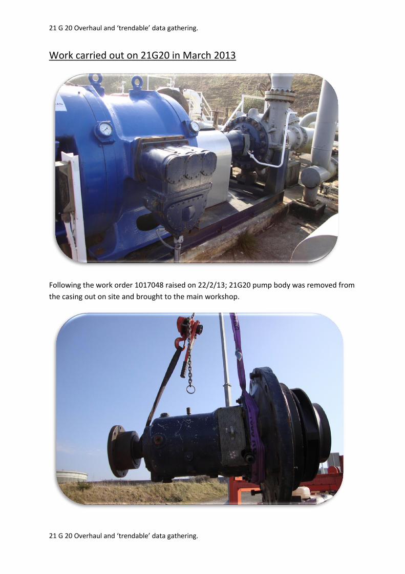
Work carried out on 21G20 in March 2013
Following the work order 1017048 raised on 22/2/13; 21G20 pump body was removed from
the casing out on site and brought to the main workshop.

21 G 20 Overhaul and ‘trendable’ data gathering.
21 G 20 Overhaul and ‘trendable’ data gathering.
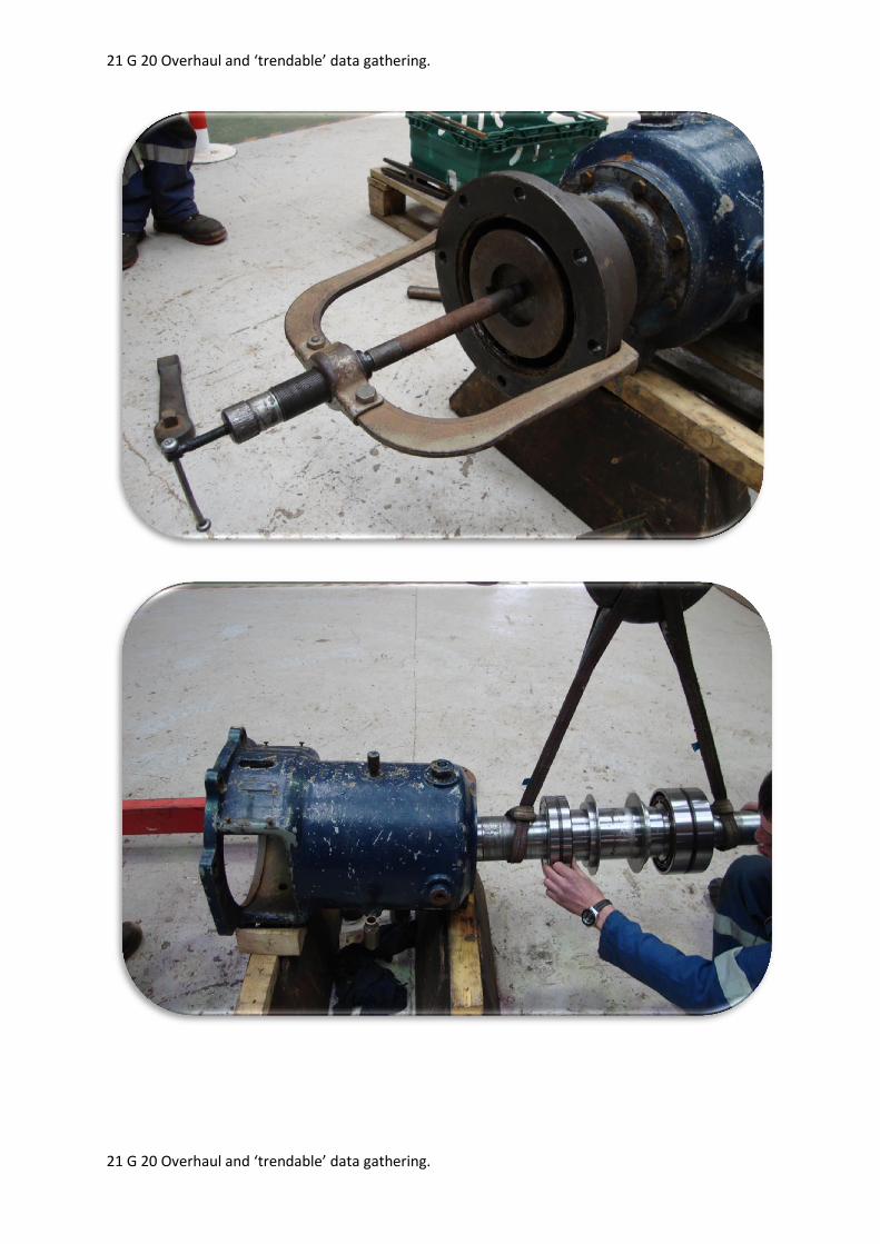
To improve the knowledge of ‘ageing plant’ condition monitoring, the pump was completely
stripped to assess condition of all internals.
21 G 20 Overhaul and ‘trendable’ data gathering.
21 G 20 Overhaul and ‘trendable’ data gathering.

21 G 20 Overhaul and ‘trendable’ data gathering.
21 G 20 Overhaul and ‘trendable’ data gathering.
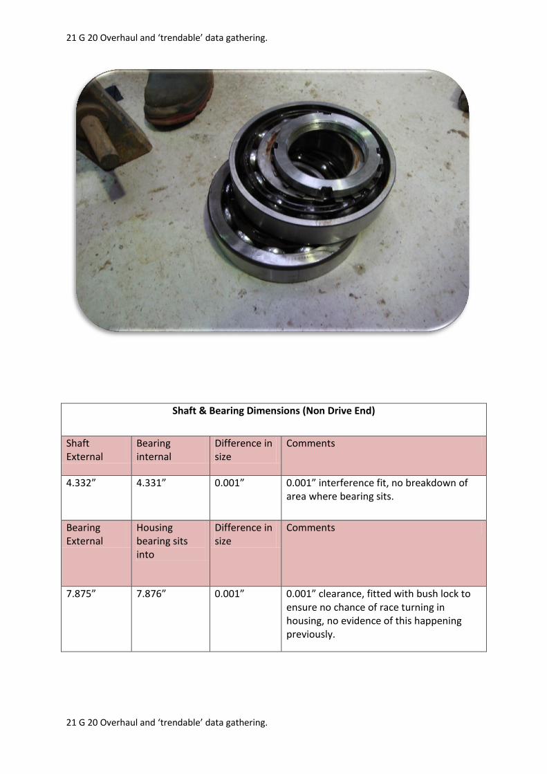
Once stripped the condition/dimensions of all pump internals were measured and assessed
as follows:
Shaft measured in all areas for any throw, less than 0.001” measured

21 G 20 Overhaul and ‘trendable’ data gathering.
21 G 20 Overhaul and ‘trendable’ data gathering.
Replacement bearing internal diameters measured, (drive end and non – drive end and
compared to external measurements of shaft, see tables below for measurements:
Shaft & Bearing Dimensions (Drive End)
Shaft External
Bearing internal
Difference in size
Comments
3.936” 3.935” 0.001” 0.001” interference fit, no breakdown of area where bearing sits.
Bearing External
Housing bearing sits into
Difference in size
Comments
8.468” 8.469” 0.001” 0.001” clearance, fitted with bush lock to ensure no chance of race turning in housing, no evidence of this happening previously.
21 G 20 Overhaul and ‘trendable’ data gathering.
21 G 20 Overhaul and ‘trendable’ data gathering.
Shaft & Bearing Dimensions (Non Drive End)
Shaft External
Bearing internal
Difference in size
Comments
4.332” 4.331” 0.001” 0.001” interference fit, no breakdown of area where bearing sits.
Bearing External
Housing bearing sits into
Difference in size
Comments
7.875” 7.876” 0.001” 0.001” clearance, fitted with bush lock to ensure no chance of race turning in housing, no evidence of this happening previously.
21 G 20 Overhaul and ‘trendable’ data gathering.
21 G 20 Overhaul and ‘trendable’ data gathering.
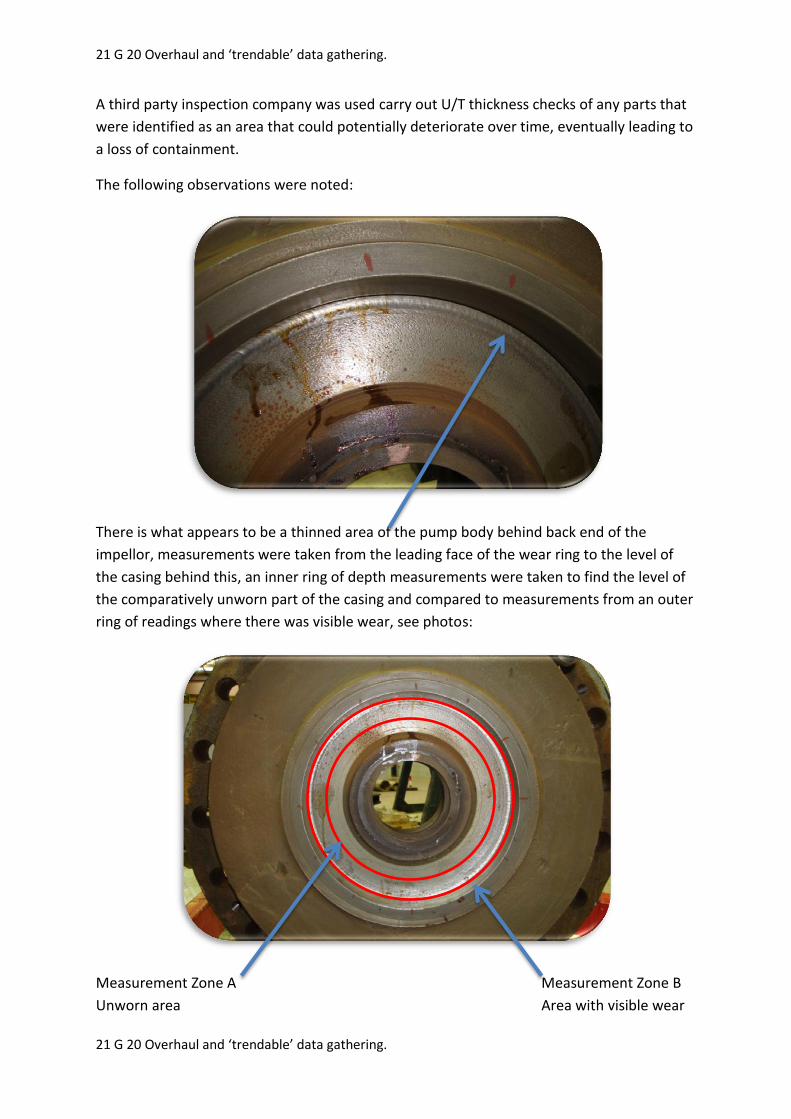
A third party inspection company was used carry out U/T thickness checks of any parts that
were identified as an area that could potentially deteriorate over time, eventually leading to
a loss of containment.
The following observations were noted:
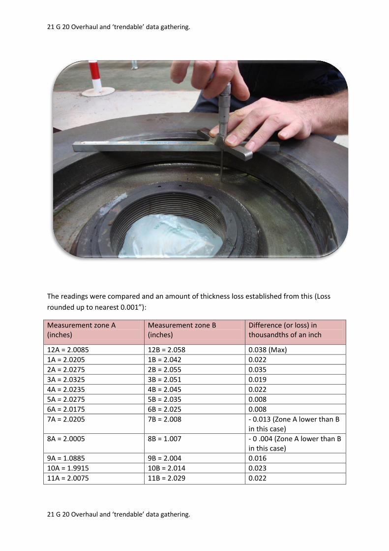
There is what appears to be a thinned area of the pump body behind back end of the
impellor, measurements were taken from the leading face of the wear ring to the level of
the casing behind this, an inner ring of depth measurements were taken to find the level of
the comparatively unworn part of the casing and compared to measurements from an outer
ring of readings where there was visible wear, see photos:
Measurement Zone A Measurement Zone B
Unworn area Area with visible wear
21 G 20 Overhaul and ‘trendable’ data gathering.
21 G 20 Overhaul and ‘trendable’ data gathering.
The readings were compared and an amount of thickness loss established from this (Loss
rounded up to nearest 0.001”):
Measurement zone A (inches)
Measurement zone B (inches)
Difference (or loss) in thousandths of an inch
12A = 2.0085 12B = 2.058 0.038 (Max)
1A = 2.0205 1B = 2.042 0.022
2A = 2.0275 2B = 2.055 0.035
3A = 2.0325 3B = 2.051 0.019
4A = 2.0235 4B = 2.045 0.022
5A = 2.0275 5B = 2.035 0.008
6A = 2.0175 6B = 2.025 0.008
7A = 2.0205 7B = 2.008 - 0.013 (Zone A lower than B in this case)
8A = 2.0005 8B = 1.007 - 0 .004 (Zone A lower than B in this case)
9A = 1.0885 9B = 2.004 0.016
10A = 1.9915 10B = 2.014 0.023
11A = 2.0075 11B = 2.029 0.022
21 G 20 Overhaul and ‘trendable’ data gathering.
21 G 20 Overhaul and ‘trendable’ data gathering.
From the above chart it can be seen that the maximum loss is 0.038” or 0.9652mm. If this is
compared to the inspection report carried out by Silverwing, ref Sem 20, it can be seen that
the thickness of the lesser worn part of the casing currently under scrutiny, (or
measurement zone A), is of average thickness 29.54mm.
The thinnest area of the pump body in measurement zone A is 28.7mm, even if the largest
measured loss was subtracted from the thinnest area this still gives a minimum thickness of
27.7mm remaining. Although an original thickness of this area is not available, if taken into
consideration that these pumps were designed to be capable of dealing with a working
pressure 4 times that of the pressures they are subjected to, (ref original datasheet), the
remaining thickness is more than sufficient in preventing uncontrolled release of the
process fluid.
With further reference to the Silverwing report Sem 20, there is also a table showing
thicknesses of areas of the pump casing out on site. It can be seen that the thinnest
scanned area of the pump casing is 33.5mm, these measurements can be taken again a year
from now without requiring the pump to be stripped or taken out of service, and if any loss
in thickness of the casing has occurred, used as a basis to determine whether the unit
should be stripped for internal thickness measurements to be taken again.
When the pump next comes out of service, whether that be for a seal change or due to an
internal inspection frequency brought about by the ageing plant study, these measurements
can be taken again and an inspection frequency worked out based on the further loss in
thickness, if any, versus time since last measurements taken.
The manufacturer’s recommendations state the following under the ‘Complete Overhaul’
section:
‘Frequency of a complete overhaul depends upon the hours of operation of the pump, the
severity of the conditions of service, the materials used in the pump construction, and the
care the pump receives in operation. It is not necessary to open your pump for inspection
unless there is definite evidence that the capacity has fallen off excessively or there is
indication of trouble inside the pump or in the bearings’.
Having taken into consideration the manufacturers recommended overhaul guidelines, it is
not intended that this pump will come out of service for another overhaul until there is any
evidence of the symptoms highlighted in the above paragraph, unless procedures brought in
to address the issue of ageing plant deem the manufacturers service recommendations
insufficient.
21 G 20 Overhaul and ‘trendable’ data gathering.
21 G 20 Overhaul and ‘trendable’ data gathering.
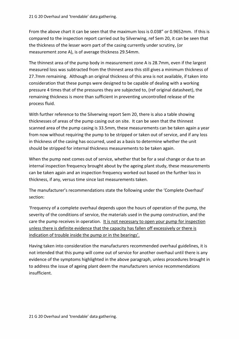
In addition to the measurement of the differences in pump body casing thickness loss and
bearing versus shaft dimensions detailed above, all other pump internals were inspected for
wear including wear rings, see below table:
Wear ring dimensions
Inner impellor wear ring (D.E)
Pump body wear ring
Diametrical clearance
Comments
13.198” 13.238” 0.040” Above process pump minimum tolerance, see below chart.
Outer impellor wear ring (N.D.E)
Pump casing wear ring
Diametrical clearance
Comments
14.185 14.228 0.043” Above process pump minimum tolerance, see below chart.
21 G 20 Overhaul and ‘trendable’ data gathering.
21 G 20 Overhaul and ‘trendable’ data gathering.
Wear Ring Diameter in Inches Minimum Diametrical Clearance Recommended by API 610 Standards, (in inches”)
1 - (Anything under 2” diameter has same minimum clearance by API 610 standards)
0.010
2 - (Anything under 2” diameter has same minimum clearance by API 610 standards)
0.010
2.000 – 2.499 0.011
2.500 – 2.999 0.012
3.000 – 3.499 0.014
3.500 - 3.999 0.014
4.000 - 4.999 0.016
5.000 - 5.999 0.016
6.000 - 6.999 0.017
7.000 - 7.999 0.018
8.000 - 8.999 0.019
9.000 - 9.999 0.020
10.000 - 10.999 0.021
11.000 - 11.999 0.022
12.000 -12.999 0.023
13.000 -13.999 0.024
14.000-14.999 0.025
If a comparison of the wear ring clearances is taken it can be seen that the minimum
diametrical clearances, D.E & N.D.E, adhering to API 610 are above the lowest tolerance:
D.E: Diametrical clearance = 0.040” (Min is 0.024” for this size wear ring)
N.D.E: Diametrical clearance = 0.043” (Min is 0.025” for this size wear ring)
Although there are no maximum wear ring tolerances documented, a ‘rule of thumb’ is to
change wear rings for new if diametrical clearance doubles the minimum, meaning that D.E.
& N.D.E. of this unit are currently within minimum and maximum tolerances.

21 G 20 Overhaul and ‘trendable’ data gathering.
21 G 20 Overhaul and ‘trendable’ data gathering.
The condition of the impellor was assessed to see if there were any cracks or distortion and
none were found:
In addition to the measuring and documenting of thicknesses, bearing interferences and
wear ring dimensions, additional work was carried out on the seal to pump casing joint, the
reason why this pump was taken out of service initially, see below:
It can be seen in the photograph below, there are signs of scoring and surface condition
breakdown, also previous repairs to this sealing face have been carried out using an epoxy
resin, (Belzona).

21 G 20 Overhaul and ‘trendable’ data gathering.
21 G 20 Overhaul and ‘trendable’ data gathering.
The seal housing was sent away for machining to bring it back to a smooth face for the seal
plate O-ring to sit against, but during this process further pits were found:
It is recommended to have the sealing face metal sprayed and machined back to its original
height:

21 G 20 Overhaul and ‘trendable’ data gathering.
21 G 20 Overhaul and ‘trendable’ data gathering.
All the pump internals have been inspected/measured, thickness checked and found to be
in good condition, the non – return valve was stripped and the moving/wearing parts
measured to enable ‘trendable’ data gathering to address the ageing plant
recommendations:
A
B
C
D

21 G 20 Overhaul and ‘trendable’ data gathering.
21 G 20 Overhaul and ‘trendable’ data gathering.
Sealing faces of NRV found to be in good condition:

21 G 20 Overhaul and ‘trendable’ data gathering.
21 G 20 Overhaul and ‘trendable’ data gathering.
Sizes of internals are as follows:
(A) Hinge pin O.D.
(B) Flap hinge I.D.
Clearance Comments
1.092” 1.118” 0.026” To be monitored periodically for any change in dimensions
(C) Clack central pin O.D.
(D) Central Clack hole I.D.
Clearance Comments
1.717” 1.800” 0.083” To be monitored periodically for any change in dimensions
The NRV was reassembled and a function and pressure test carried out, there is no
significant leakage under normal working pressures, (under 1 drip per second), although
there was a small amount of leakage when taken to 225PSI (1.5 times rated pressure of
NRV). The leakage under such pressure, (which is a significant amount above expected
working pressure of 150PSI), would not be anywhere near the flow needed to turn the
pump backwards, and under expected line pressures the NRV will provide a near 100% seal.

21 G 20 Overhaul and ‘trendable’ data gathering.
21 G 20 Overhaul and ‘trendable’ data gathering.
NRV on test:
The pump was reassembled and put back into the casing at pump station 24 with a new
casing gasket, alignment was carried out and the motor was shimmed to bring within
correct tolerances, a hard copy of the alignment report is available in the maintenance
records office and is also attached to the work order relating to this unit on Agility.
Holding
225 PSI

21 G 20 Overhaul and ‘trendable’ data gathering.
21 G 20 Overhaul and ‘trendable’ data gathering.
Conclusions
The pump has been refurbished to a high standard, taking into consideration condition of all
internals and measuring all areas that will be able to provide ‘trendable’ data. Further UT
thickness assessments of all areas checked in this write up will be carried out in line with the
pumps next annual maintenance and/or strip down of the unit, from this a thickness loss
rate can be established and a resulting inspection frequency.
Upon interpretation of the Silverwing reports, there are no areas where a significant loss in
thickness of isolation valves body/bonnet, NRV body/bonnet, pump casing and pump body
compared to the nominal thicknesses is a cause for concern. These measurements have
been taken in a repeatable manner to ensure meaningful ‘trendable’ data can be gathered
over time.
Hard copies of the Silverwing reports are available in the maintenance records office, also
electronic copies are attached to the work order on the maintenance scheduling system
‘Agility’.
Methods that will be used to monitor condition of this pump unit over time:
Condition monitoring to be carried out in line with annual PM:
UT thickness checks of inlet isolation valve body and bonnet
UT thickness checks of outlet isolation valve body and bonnet
UT thickness checks of non-return valve body and bonnet
UT thickness checks of pump casing
Strip down of internals of non-return valve and measurements taken to establish
whether there is a change in the tolerances since last measurements were taken,
also visual inspection of seats to identify any damage
Condition monitoring to be carried out upon strip down of unit:
Shaft dimensions
Condition of impellor
UT thickness checks of pump body behind impellor
Pressure test of non-return valve
Depth measurements from leading edge of pump body wear ring to worn part of
casing to determine further loss rate
Diametrical wear ring clearance measurements repeated
Related Documents


![Author's personal copy - unige.chs personal copy The reaction was carried out selectively in re uxing absolute EtOH, avoiding participation of the aromatic bromine[20,21].](https://static.cupdf.com/doc/110x72/5ace5be37f8b9aa1518e8ea9/authors-personal-copy-unigech-s-personal-copy-the-reaction-was-carried-out-selectively.jpg)