Work breakdown structure (WBS) development for underground construction Elnaz Siami-Irdemoosa a, ⁎, Saeid R. Dindarloo b , Mostafa Sharifzadeh c a Department of Geosciences and Geological and Petroleum Engineering, Missouri University of Science and Technology, Rolla, MO 65401, USA b Department of Mining and Nuclear Engineering, Missouri University of Science and Technology, Rolla, MO 65401, USA c Dept. of Mining and Metallurgical engineering, Amirkabir University of Technology, 424 Hafez Ave., Tehran, Iran abstract article info Article history: Received 8 January 2015 Received in revised form 3 June 2015 Accepted 20 July 2015 Available online 4 August 2015 Keywords: Work breakdown structure (WBS) Complex underground projects Construction Project management Planning Neural networks A work breakdown structure (WBS) can prove to be pivotal to successful project management planning. There are few published studies about the methodologies or tools to develop the appropriate WBS for a project, and those that are available are limited to the specific areas of construction such as apartment-building construction and boiler manufacturing. This research has an emphasis on developing a methodology with higher generaliz- ability, which has the capability to be customized to complex underground projects. To address this issue, a new methodology that employs hierarchical neural networks to develop the WBS of complex underground pro- jects is presented. This methodology has been applied to several tunnel case studies and it has been shown that for a real project, the model is able to generate the WBS and its activities that are comparable to those generated by a project planner. Consequently, it is concluded that these modeling methods have the capacity to significantly improve the WBSs for complex underground projects and improve key project tasks, such as workload planning, cost estimating and scheduling. © 2015 Elsevier B.V. All rights reserved. 1. Introduction A comprehensive efficient work breakdown structure (WBS) can prove pivotal within project management planning processes by partitioning projects into stages, deliverables and work packages. Con- sequently, it can positively impact other project management processes, such as activity definition, project schedule, risk analysis and response, control tools or project organization [1]. The planning of underground work and WBSs is different from other civil construction, when one considers the complexity, uncertainty and large number of activities involved [2]. An experienced complex under- ground project manager knows that despite detailed planning and exe- cution, there is always the possibility of errors, mishaps and unexpected outcomes on the horizon. Developing the work breakdown structure of a complex underground project in a systematic, thorough, and method- ological manner will decrease the potential for unwanted possibilities while providing a baseline for planning, estimating, scheduling and effective project management. Despite such significance and repercussions, there is a dearth of research concerning methodologies or tools for the development of appropriate work breakdown structures (WBSs) for a project. The avail- able research is mostly limited to a given range of construction projects, and therefore, the generalizability of the research remains limited to specific conditions. However, more recent research utilizing case-based reasoning (CBR) methods offers valuable material while providing a model for the acquisition and reuse of specific planning knowledge. FASTRAK-APT, which was developed by Lee et al. [3], offers an im- portant case- and constraint-based project planning tool for apartment construction. FASTRAK-APT relies on the fact that a human expert project planner uses previous cases for planning a new project. Despite the evident use of CBR methods for planning, the applicability of the system is limited; in contrast, the proposed methodology is applicable to domains that have available data and structured knowledge, such as apartment construction. Dzeng and Tommelein [4] proposed a case-based expert system, CasePlan, based on a product model that describes and reuses the existing boiler erection project in power plant construction for planning a new project. The researchers believe that CasePlan will prove viable for projects with distinct components; thus, it may not be applicable for complex underground projects, which have no distinct component. Ryu et al. [5] developed CONPLA-CBR, a case-based reasoning planning tool with greater applicability. However, its applicability has not been evaluated for complex underground projects. More recently, some researchers have emphasized the use of neural networks in the development of planning systems [6,7]. Hashemi and Emamizadeh [8] proposed a decision tool that employs a modular neural network to plan the WBS of a limited project domain. The author cited the vast amount of knowledge required in generating a work breakdown structure as the primary reason why the use of neural networks is a Automation in Construction 58 (2015) 85–94 ⁎ Corresponding author. E-mail address: [email protected] (E. Siami-Irdemoosa). http://dx.doi.org/10.1016/j.autcon.2015.07.016 0926-5805/© 2015 Elsevier B.V. All rights reserved. Contents lists available at ScienceDirect Automation in Construction journal homepage: www.elsevier.com/locate/autcon

Welcome message from author
This document is posted to help you gain knowledge. Please leave a comment to let me know what you think about it! Share it to your friends and learn new things together.
Transcript
Automation in Construction 58 (2015) 85–94
Contents lists available at ScienceDirect
Automation in Construction
j ourna l homepage: www.e lsev ie r .com/ locate /autcon
Work breakdown structure (WBS) development forunderground construction
Elnaz Siami-Irdemoosa a,⁎, Saeid R. Dindarloo b, Mostafa Sharifzadeh c
a Department of Geosciences and Geological and Petroleum Engineering, Missouri University of Science and Technology, Rolla, MO 65401, USAb Department of Mining and Nuclear Engineering, Missouri University of Science and Technology, Rolla, MO 65401, USAc Dept. of Mining and Metallurgical engineering, Amirkabir University of Technology, 424 Hafez Ave., Tehran, Iran
⁎ Corresponding author.E-mail address: [email protected] (E. Siami-Irdemoosa).
http://dx.doi.org/10.1016/j.autcon.2015.07.0160926-5805/© 2015 Elsevier B.V. All rights reserved.
a b s t r a c t
a r t i c l e i n f oArticle history:Received 8 January 2015Received in revised form 3 June 2015Accepted 20 July 2015Available online 4 August 2015
Keywords:Work breakdown structure (WBS)Complex underground projectsConstructionProject managementPlanningNeural networks
A work breakdown structure (WBS) can prove to be pivotal to successful project management planning. Thereare few published studies about the methodologies or tools to develop the appropriate WBS for a project, andthose that are available are limited to the specific areas of construction such as apartment-building constructionand boiler manufacturing. This research has an emphasis on developing a methodology with higher generaliz-ability, which has the capability to be customized to complex underground projects. To address this issue, anewmethodology that employs hierarchical neural networks to develop theWBS of complex underground pro-jects is presented. This methodology has been applied to several tunnel case studies and it has been shown thatfor a real project, the model is able to generate theWBS and its activities that are comparable to those generatedby a project planner. Consequently, it is concluded that thesemodelingmethods have the capacity to significantlyimprove theWBSs for complex underground projects and improve key project tasks, such asworkload planning,cost estimating and scheduling.
© 2015 Elsevier B.V. All rights reserved.
1. Introduction
A comprehensive efficient work breakdown structure (WBS) canprove pivotal within project management planning processes bypartitioning projects into stages, deliverables and work packages. Con-sequently, it can positively impact other projectmanagement processes,such as activity definition, project schedule, risk analysis and response,control tools or project organization [1].
The planning of undergroundwork andWBSs is different from othercivil construction, when one considers the complexity, uncertainty andlarge number of activities involved [2]. An experienced complex under-ground project manager knows that despite detailed planning and exe-cution, there is always the possibility of errors,mishaps and unexpectedoutcomes on the horizon. Developing the work breakdown structure ofa complex underground project in a systematic, thorough, andmethod-ological manner will decrease the potential for unwanted possibilitieswhile providing a baseline for planning, estimating, scheduling andeffective project management.
Despite such significance and repercussions, there is a dearth ofresearch concerning methodologies or tools for the development ofappropriate work breakdown structures (WBSs) for a project. The avail-able research is mostly limited to a given range of construction projects,and therefore, the generalizability of the research remains limited to
specific conditions. However, more recent research utilizing case-basedreasoning (CBR) methods offers valuable material while providing amodel for the acquisition and reuse of specific planning knowledge.
FASTRAK-APT, which was developed by Lee et al. [3], offers an im-portant case- and constraint-based project planning tool for apartmentconstruction. FASTRAK-APT relies on the fact that a human expertproject planner uses previous cases for planning a new project. Despitethe evident use of CBR methods for planning, the applicability of thesystem is limited; in contrast, the proposed methodology is applicableto domains that have available data and structured knowledge, suchas apartment construction.
Dzeng and Tommelein [4] proposed a case-based expert system,CasePlan, based on a product model that describes and reuses theexisting boiler erection project in power plant construction for planninga new project. The researchers believe that CasePlan will prove viablefor projects with distinct components; thus, it may not be applicablefor complex underground projects, which have no distinct component.Ryu et al. [5] developed CONPLA-CBR, a case-based reasoning planningtool with greater applicability. However, its applicability has not beenevaluated for complex underground projects. More recently, someresearchers have emphasized the use of neural networks in thedevelopment of planning systems [6,7]. Hashemi and Emamizadeh [8]proposed a decision tool that employs a modular neural network toplan the WBS of a limited project domain. The author cited the vastamount of knowledge required in generating a work breakdownstructure as the primary reason why the use of neural networks is a
86 E. Siami-Irdemoosa et al. / Automation in Construction 58 (2015) 85–94
preferable alternative; however, the proposedmethodology is applicableto small-scale projects. For large-scale complex underground projects,the number of possible work breakdown structures and activities can ex-pand rapidly and a bigger size of neural network should be employed.Therefore, designing and training of the neural network will be morecomplex and time consuming. Sharifzadeh et al. [9] formulated anapproach forWBSdevelopment in tunnel projects using neural networks.Large-scale tunnel projects were tested by their proposed model;however, their model had the similar disadvantage, and hence theaccuracy of the predicted WBS was decreased by increasing the numberof WBS elements.
There is not a good process to objectively determine the WBS ofcomplex underground projects and correlate them with the projectsnature. With this in mind, this paper is going to introduce a processwhich helps a planer to make a more informed choice of WBS compo-nents and structure regarding project attributes. The outcome of theprocess is a hierarchical neural network, which has been implementedto develop the WBS of complex underground projects. First, the mainconcepts, including the work breakdown structure of a complexunderground project and its attributes, are described, followed bydetailed description of the proposed methodology. Finally, the resultsof applying the proposed methodology to several case studies arediscussed.
2. Complex underground project attributes
Underground construction necessitates firm commitments and obli-gation to comprehensive and complicated procedures. Undergroundconstruction demands high management expertise to address complexand challenging eventualities. Lack of understanding of a number of sig-nificant factors, such as the unique contingent features and ensuing in-terrelated complexities, can increase the difficulties of undergroundconstruction endeavors [2]. Thus, complex underground constructionprojects are characterized by a large number of variables that can unfoldin various quantities and combinations, including participating partiesand individuals, a sundry ofwork packages at play, requirements, draw-ings, plans and reports, in addition to budget items and the time plan.Factors that affect project management may be enumerated as follow[2,10]:
1. Underground structures are a necessity of modern life, and suchnecessities cannot be disregarded.
2. Consideration of the needs of the general public as the majorstakeholders is critical to the success of such projects.
3. Urban underground projects are constructed in dense, complex, andrestrictive environments.
4. Public policy, public relations and the effective use of media canpositively impact the construction of tunnel projects.
5. Underground construction is capital intensive and reliant on a highinjection of initial capital expenditures.
6. Underground projects take considerable time to conclude.7. Underground construction is carried out under conditions of
geological uncertainty.8. Underground construction is risky.
It is important to understand the key attributes of an undergroundproject before the creation of the project WBS. Project stakeholders,for example, affect some of the main characteristics of the WBS suchas the level of details. In larger projects such as subway tunnels, politi-cians, owners, nearby resident and public might be the stakeholders.On the contrary, smaller projects such as a diversion tunnel mighthave only one or two stakeholders including themembers of the parlia-ment and environmental organizations. It should be noted that these at-tributes vary in different underground projects in different countries.Other factors have more or less similar effects on WBS development.However, the complexity arises from the variation of these attributesin different underground projects. Geological conditions might be
highly variable for a certain project while it is almost constant in anoth-er project. The expectation of an underground project client might betoo high so that weekly reporting is required, whereas a client of anoth-er project needs monthly reports. A few millimeters settlement duringthe construction of an urban tunnel might be the concern of the nearbyresidents and hold the project for months, while larger settlements areacceptable in other projects [11]. All of these attributes affect the maincharacteristics of the work breakdown structure and they should bewell understood before the development of the WBS.
3. Work breakdown structure (WBS) of complex undergroundprojects
Work breakdown structure (WBS) is the process of dividing aproject's overall work to several moremanageable hierarchy structuredtasks. The level of details should represent the overall scope of the pro-ject while keeping the tasksmanageable [1,12]. TheWBS is typically de-signed through a top-down procedure. The upper levels of theWBS aredecomposed into logical groupings of work, followed by the next leveldown and so on. Thus, the lowest-level component of WBS can bescheduled, and its cost can be estimated, monitored, and controlled.Fig. 1 illustrates thework breakdown structure of ametro tunnel projectas an example.
There are many different methods that can be employed to create aWBS.While there is general agreement that theWBS is the fundamentalmanagerial component upon which many project management pro-cesses are based, there is surprisingly little agreement on the bestmeth-od for creating the WBS [1]. One of the main questions in this regard ishow the optimalWBS can be identified from all possible structures. TheProject Management Institute [13] stipulated that “a quality WBS is aWBS constructed in such a way that it satisfies all of the requirementsfor its use in a project”. When applying this quality principle, the opti-mal WBS in a complex underground project is a high-quality workbreakdown structure, wherein specific content and the type of WBS el-ements appropriately address the full set of needs of the project. Exam-ples of a quality WBS characteristic in a complex underground projectare as follow:
• Contains specific types of WBS components necessary for a complexunderground project.
• Provides “sufficient” detail for communicating the scope of a complexunderground project.
• Achieves a “sufficient” level of decomposition for effective complexunderground project management.
Therefore the best method for creating the WBS of complex under-ground projects is a method that could find the optimal work break-down structure with all necessary components, sufficient details andsufficient level of decomposition. One might ask what the exact defini-tion of “sufficient” is in this context. Considering the varying attributesof a complex underground project, the real answer is that it depends.The attributes of a complex underground project entail the use ofproject-specific WBS characteristics. A specific WBS may prove highlyappropriate for one project while failing completely for another. Infact, considering the variability and complexities of underground pro-ject management, it is not surprising that specific standards for WBScharacteristics of complex underground projects are difficult to find.
4. Methodology
The overall process of the proposed methodology is presented inFig. 2 under the headings ‘State Problem’, ‘System Design’, ‘Verification’and ‘Validation’. The ‘State Problem’, ‘System Design’ and ‘Verification’steps are presented in the following sections, while the ‘Validation’step and results are discussed in Section 5.

Karaj Metro Tunnel
Delivery of Site Mobilization Construction
Access tunnel Excavation & InitialSupport
Final Lining
Crown Bench
Part1 Part2 Part1 Part2
Level 2
Level 3
Level 4
Level 1Demobilization
Instrument
Part3
Fig. 1. A metro tunnel project WBS.
State Problem
System Design
Tunnel Projects Data Collection
Artificial Neural Network(ANN) Modeling
Verification
Validation
Project WBS
Describing tunnel projects byattributes vector
Representing tunnel projectWBS by levels vector
Projects Attributes
Project related features
Characteristics of tunnel
Ground conditions
Acceptable
yes
No
Fig. 2. The overall procedure of proposed methodology.
87E. Siami-Irdemoosa et al. / Automation in Construction 58 (2015) 85–94
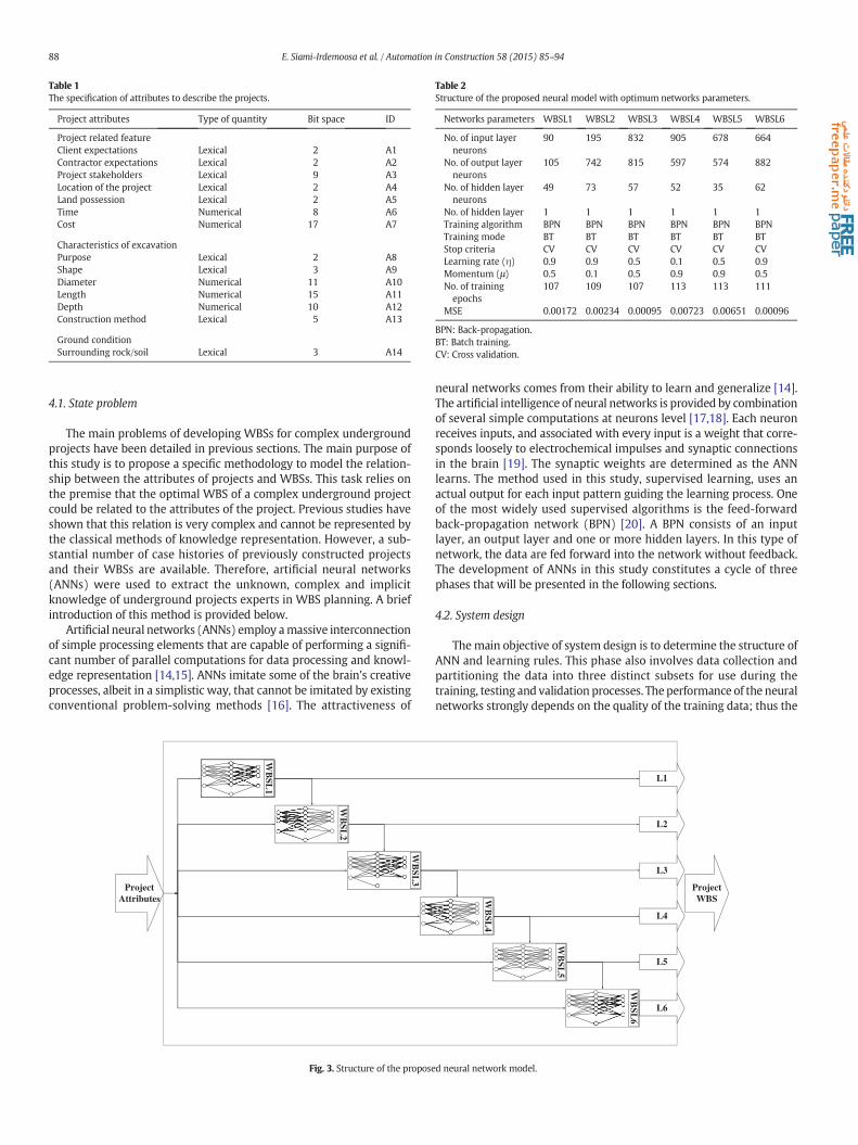
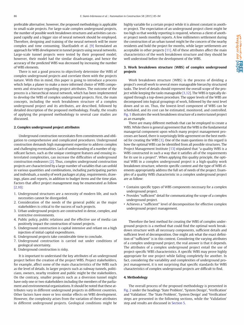
Table 2Structure of the proposed neural model with optimum networks parameters.
Networks parameters WBSL1 WBSL2 WBSL3 WBSL4 WBSL5 WBSL6
No. of input layerneurons
90 195 832 905 678 664
No. of output layerneurons
105 742 815 597 574 882
No. of hidden layerneurons
49 73 57 52 35 62
No. of hidden layer 1 1 1 1 1 1Training algorithm BPN BPN BPN BPN BPN BPNTraining mode BT BT BT BT BT BTStop criteria CV CV CV CV CV CVLearning rate (η) 0.9 0.9 0.5 0.1 0.5 0.9Momentum (μ) 0.5 0.1 0.5 0.9 0.9 0.5No. of trainingepochs
107 109 107 113 113 111
MSE 0.00172 0.00234 0.00095 0.00723 0.00651 0.00096
BPN: Back-propagation.BT: Batch training.CV: Cross validation.
Table 1The specification of attributes to describe the projects.
Project attributes Type of quantity Bit space ID
Project related featureClient expectations Lexical 2 A1Contractor expectations Lexical 2 A2Project stakeholders Lexical 9 A3Location of the project Lexical 2 A4Land possession Lexical 2 A5Time Numerical 8 A6Cost Numerical 17 A7
Characteristics of excavationPurpose Lexical 2 A8Shape Lexical 3 A9Diameter Numerical 11 A10Length Numerical 15 A11Depth Numerical 10 A12Construction method Lexical 5 A13
Ground conditionSurrounding rock/soil Lexical 3 A14
88 E. Siami-Irdemoosa et al. / Automation in Construction 58 (2015) 85–94
4.1. State problem
The main problems of developing WBSs for complex undergroundprojects have been detailed in previous sections. The main purpose ofthis study is to propose a specific methodology to model the relation-ship between the attributes of projects and WBSs. This task relies onthe premise that the optimal WBS of a complex underground projectcould be related to the attributes of the project. Previous studies haveshown that this relation is very complex and cannot be represented bythe classical methods of knowledge representation. However, a sub-stantial number of case histories of previously constructed projectsand their WBSs are available. Therefore, artificial neural networks(ANNs) were used to extract the unknown, complex and implicitknowledge of underground projects experts in WBS planning. A briefintroduction of this method is provided below.
Artificial neural networks (ANNs) employ amassive interconnectionof simple processing elements that are capable of performing a signifi-cant number of parallel computations for data processing and knowl-edge representation [14,15]. ANNs imitate some of the brain's creativeprocesses, albeit in a simplistic way, that cannot be imitated by existingconventional problem-solving methods [16]. The attractiveness of
ProjectAttributes
.
.
.
.
.
.
.
.
.
.
.
.
WB
SL2
.
.
.
.
.
.
.
.
.
.
.
.
WB
SL3
.
.
.
.
.
.
.
.
.
.
.
.
.
.
.
WB
SL1
Fig. 3. Structure of the propose
neural networks comes from their ability to learn and generalize [14].The artificial intelligence of neural networks is provided by combinationof several simple computations at neurons level [17,18]. Each neuronreceives inputs, and associated with every input is a weight that corre-sponds loosely to electrochemical impulses and synaptic connectionsin the brain [19]. The synaptic weights are determined as the ANNlearns. The method used in this study, supervised learning, uses anactual output for each input pattern guiding the learning process. Oneof the most widely used supervised algorithms is the feed-forwardback-propagation network (BPN) [20]. A BPN consists of an inputlayer, an output layer and one or more hidden layers. In this type ofnetwork, the data are fed forward into the network without feedback.The development of ANNs in this study constitutes a cycle of threephases that will be presented in the following sections.
4.2. System design
Themain objective of system design is to determine the structure ofANN and learning rules. This phase also involves data collection andpartitioning the data into three distinct subsets for use during thetraining, testing and validation processes. Theperformance of the neuralnetworks strongly depends on the quality of the training data; thus the
L6
.
.
.
.
.
.
.
.
.
WB
SL4
.
.
.
.
.
.
.
.
.
.
.
.
.
.
.
.
.
.
WB
SL5
.
.
.
.
.
.
.
.
.
.
.
.
WB
SL6
L5
L4
L3
L2
L1
ProjectWBS
d neural network model.
“Golabar” diversion tunnelproject
Project start
Mobilization
Diversion tunnels
Excavation
Consolidationgrouting & support
Diversion tunnelplug
Project delivery
Closing
Tunnel B input structure
Tunnel B outlet structure
Tunnel B lining
Tunnel A input structure
Tunnel A outlet structure
Tunnel A lining
Diversion tunnels outlet
Diversion tunnel
Tunnel A plug concrete
Tunnel B plug concrete
Level 1Level 2
Invalid component
Possible component
Valid component
Fig. 4. Developed project WBS for project 1.
89E. Siami-Irdemoosa et al. / Automation in Construction 58 (2015) 85–94
sufficient amount of data from previous successful complex under-ground projectswith a qualityWBS should be collected to train the neu-ral networks. A dataset of 20 tunnel projects (including 3433 activities)was accumulated. The selected projects are the most successful under-ground projects constructed in Iran according to tunneling experts,and the project WBSs are high quality. The maximum number of levelsin theWBSs of the selected projects is 6. Also the selectedWBSs (devel-oped by project contractor) contain 3433 activities in total. The datafrom 18 projects were used in the verification process, while datafrom 2 projects were used in the validation process.
The generalization of theANNmodels to unseen datawill be affectedby the size of database. Training data should be sufficiently large tocover the possible variation in the problem domain. Database size canbe expanded by obtaining new data. In this study data enrichmentwas not possible; hence, the leave-one-out method [21] was used for
Table 3The project attributes for validation datasets.
Attribute ID Project 1
Attribute value Input neuron valu
A1 High 00A2 High 00A3 Members of the parliament 100000010
Environmental organizations
A4 Neutral 10A5 Difficult 0A6 42 01010100A7 18820 001000011001001A8 Diversion tunnel 11A9 Horseshoe 010A10 830 01111100110A11 870 011001101100000A12 200 000100110A13 Drilling & Blasting 0000A14 Rock-Moderate 100
developing the neural networks. In this method, a network is trainedon M-1 (i.e. 18-1) example, and is tested on the one hold-out example.The process is repeated M times. The solution of M network is thenaveraged to obtain a solution with higher generalizability.
The projects data contain values for project attributes and theirworkbreakdown structures. Project attributes are a limited set of variablesthat should represent the general nature of a complex undergroundproject. To this end, three major sets of project attributes were defined.The first is the project-related features, which include the total amountof time, total budget and location of the project. The second set is thecharacteristics of the underground excavation, such as the size andconstruction method. The third set is ground conditions.
The attributes of project set can be defined by A = {Ai}, (0 b i b 14).The members of A are arranged in a column vector. Then, the values ofthe project attributes are assigned to the related rows of the resultingvector. Therefore, there are 20 column vectors that will be consideredas the inputs for the training, testing and validation patterns. Projectattributes are assigned by a combination of lexical and numerical values.As the inputs and outputs of a neural network should be numerical,binary code is assigned to each assignable lexical value. Furthermore,the equivalent binary forms of the project attributes are used for distinctquantities. Table 1 shows the specifications of the complex under-ground project attributes.
AWBS consists of elements fromdifferent levels. Regarding the largenumber ofWBS elements in complex underground projects, the collect-ed WBSs were decomposed into vectors according to the componentlevel to show WBS in the outputs. The vector of the WBS level can berepresented by Ll = {w1, w2, …, wnl}, where Ll is the level vector of theWBS at level l, l is the level ID, wi is the component and nl is the maxi-mum number of components at level l. Therefore, 20 level vectorswith the same size for each level of the WBS are created. Thesevectors will be considered as the outputs of the training, testing andvalidating examples.
This study employs feed-forward neural networks with back-propagation learning algorithms, also known as a back-propagationnetwork (BPN). The proposed model is a hierarchical neural networkconsisting of six different BPNs,which are used to establish the relation-ships between project attributes and their work breakdown structure.Six BPNs are used due to the hierarchical structure of WBSs. Each BPNhas a different configuration, which is used to infer the complex under-ground project WBS and activities from the project attributes. Fig. 3shows the structure of the proposed neural model. As shown in Fig. 3,the inputs of WBSL1 only consist of project attributes. This BPN shouldestablish which components should be implemented in the first levelof the WBS with respect to the project attributes. Therefore, the output
Project 2
e Attribute value Input neuron value
Low 01High 00Members of the parliament 110111000PoliticiansOwnersNearby residentsPublicPositive 00Difficult 011 01000000
000 22500 110000010100100000Metro 00Horseshoe 010830 011111001103070 01111111110100015 001100000NATM 10100Soil-Cohesive 001

90 E. Siami-Irdemoosa et al. / Automation in Construction 58 (2015) 85–94
of WBSL1 is a row vector whose columns are linked to the individualelements of the first level of the project's WBS. If any columns take avalue of 1, the related element can be employed in the first level ofthe project'sWBS. Next, the L1-vector and the vector of the complex un-derground project attributes are considered as the inputs of WBSL2.This network establishes which components should be implementedin the second level with respect to the project attributes and theupper level of the WBS. Therefore, the output of WBSL2 is representedin the second level of the project WBS. Similarly, WBSL3 establishesthe third level, WBSL4 establishes the fourth level and so on. Asshown in Fig. 3, a six-level complex underground project WBS can be
Karaj Metro
Delivery of site Drawings approval
Ramp A
Drawings approval
Soldier structure
Drawings approval
Excavation
Frame installation
Installation of wiremesh
Shotcrete
Ramp B
Drawings approval
Drawings app
Excavation & Initi
Excavation & Initiof crown
Excavation & Initiof bench
Final linin
Reinforced concre
Insulation of
Reinforced concr
Level 1
Level 2
Level 3
Shafts excavation
H-Piles construction
H-Piles installation
Shafts concrete
Drawings approval
Struts installation
Drawings aproval
Ramp excavation
Installation of wiremesh
Shotcrete
Drawings approval
Excavation
Installation of latticegriders
Shotcrete
Level 4
Access tunnelconstruction
T-shape structureinstallation
Level 3
H-Piles install
Shafts concr
Drawings app
Struts installa
Drawings apr
Ramp excava
Installation of wi
Shotcrete
Drawings app
Excavatio
Installation of latt
Installation of wi
Shotcrete
Drawings app
Excavatio
Frame installa
Installation of wi
Shotcrete
Level 4
Soldier structure
Access tunnel construction
T-shape structure installation
Main tunnel construction
Valid component
Possible component
Invalid component
Fig. 5. Developed WBS for p
realized through the learning process. Six networks are used for theidentification of the six levels because the maximum level number forthe collected WBSs is 6.
4.3. Verification
Verification involves training of the proposed neural model usingthe training and test subsets and simultaneously assessing the networkperformance by analyzing the mean squared error. The leave-one-outmethod [21], which is an extreme form of multifold cross-validation,was used to minimize the impact of data dependency on the result.
Tunnel
Mobilization Construction Demobilization
Type I&II tunnels
roval
al support
al support
al support
g
te invert
ring
ete ring
Instrument Temporarydelivery
Demobilization Closing
ation
ete
roval
tion
oval
tion
re mesh
roval
n
ice griers
re mesh
roval
n
tion
re mesh
Drawings approval
Shafts excavation
Shafts reinforced concrete
Excavation (floor to chainage)
Soldier structure
Roof reinforcement, casting& concrete
Roof insulation
Excavation (Chainage to roof)
Wall reinforcement, casting &concrete
Invert reinforcement, casting& concrete
Drawings approval
Shafts excavation
Shafts reinforced concrete
Excavation (floor to chainage)
Beam installation
Roof reinforcement, casting& concrete
Roof insulation
Excavation (Chainage to roof)
Wall reinforcement, casting &concrete
Invert reinforcement, casting& concrete
Drawings approval
Excavation (floor to chainage)
Wall reinforcement, casting &concrete
Invert reinforcement, casting& concrete
Level 3
Level 4
Tunnel type A
Tunnel type B
Tunnel type C
roject 2 — Levels 1 to 4.
91E. Siami-Irdemoosa et al. / Automation in Construction 58 (2015) 85–94
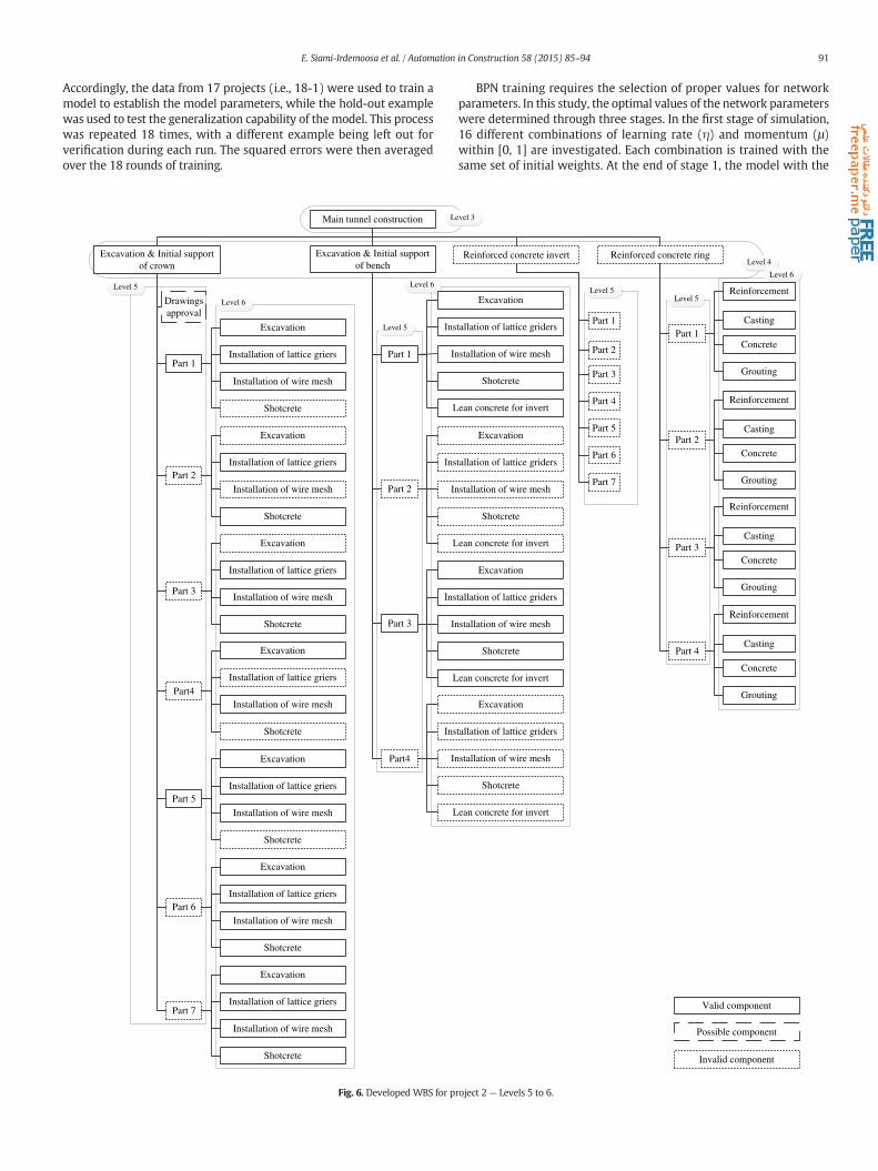
Accordingly, the data from 17 projects (i.e., 18-1) were used to train amodel to establish the model parameters, while the hold-out examplewas used to test the generalization capability of themodel. This processwas repeated 18 times, with a different example being left out forverification during each run. The squared errors were then averagedover the 18 rounds of training.
Main tunnel construction
Excavation & Initial supportof crown
Excavation & Initial supportof bench
Part 1
Part 2
Part 3
Part4
Part 5
Part 6
Part 7
Drawingsapproval
Excavation
Installation of lattice griers
Installation of wire mesh
Shotcrete
Excavation
Installation of lattice griers
Installation of wire mesh
Shotcrete
Excavation
Installation of lattice griers
Installation of wire mesh
Shotcrete
Excavation
Installation of lattice griers
Installation of wire mesh
Shotcrete
Excavation
Installation of lattice griers
Installation of wire mesh
Shotcrete
Excavation
Installation of lattice griers
Installation of wire mesh
Shotcrete
Excavation
Installation of lattice griers
Installation of wire mesh
Shotcrete
Part 1
Part 2
Part 3
Part4
Ins
In
L
Ins
In
L
Ins
In
L
Ins
In
L
L
Level 5
Level 6
Level 5
Level 6
Fig. 6. Developed WBS for p
BPN training requires the selection of proper values for networkparameters. In this study, the optimal values of the network parameterswere determined through three stages. In the first stage of simulation,16 different combinations of learning rate (η) and momentum (μ)within [0, 1] are investigated. Each combination is trained with thesame set of initial weights. At the end of stage 1, the model with the
Reinforced concrete invert Reinforced concrete ring
Excavation
tallation of lattice griders
stallation of wire mesh
Shotcrete
ean concrete for invert
Excavation
tallation of lattice griders
stallation of wire mesh
Shotcrete
ean concrete for invert
Excavation
tallation of lattice griders
stallation of wire mesh
Shotcrete
ean concrete for invert
Excavation
tallation of lattice griders
stallation of wire mesh
Shotcrete
ean concrete for invert
Part 1
Part 2
Part 3
Part 4
Part 5
Part 6
Part 7
Part 1
Part 2
Part 3
Part 4
Reinforcement
Casting
Concrete
Grouting
Reinforcement
Casting
Concrete
Grouting
Reinforcement
Casting
Concrete
Grouting
Reinforcement
Casting
Concrete
Grouting
evel 3
Level 4
Level 5Level 5
Valid component
Possible component
Invalid component
Level 6
roject 2 — Levels 5 to 6.

92 E. Siami-Irdemoosa et al. / Automation in Construction 58 (2015) 85–94
minimum error is selected for use in the following stages. In the secondstage of simulation, 10 independent models with different initial ran-dom weights are trained with the optimal learning parameters foundin the previous stage. Finally, the optimal size of the hidden layer isdetermined by a search of the possible structures. This search beginswith a certain number of nodes, which are the minimum value of acalculated hidden node number based on several rules of thumb thatare available in the literature [22–24]; in this manner, the model istrained and analyzed. Each time, the number of hidden nodes is in-creased by one. Again, cross-validationwas used to determine the prop-er size of the hidden layers. Table 2 illustrates the structure of theproposed neural model with the optimum network parameter values.
5. Validation and results
In verification, the proposed model was tested against the test dataduring the training process. Furthermore, for the purpose of enhancedrationale, the proposed model was validated for its generalizationcapability. In this phase, the capability of the proposedmodel to respondaccurately to projects that have not been used in network developmentis confirmed. Two tunnel projects were considered in the validationsubset. Their attributes and WBSs demonstrated that both projectswere substantially different from those used in the training and testingsubsets.
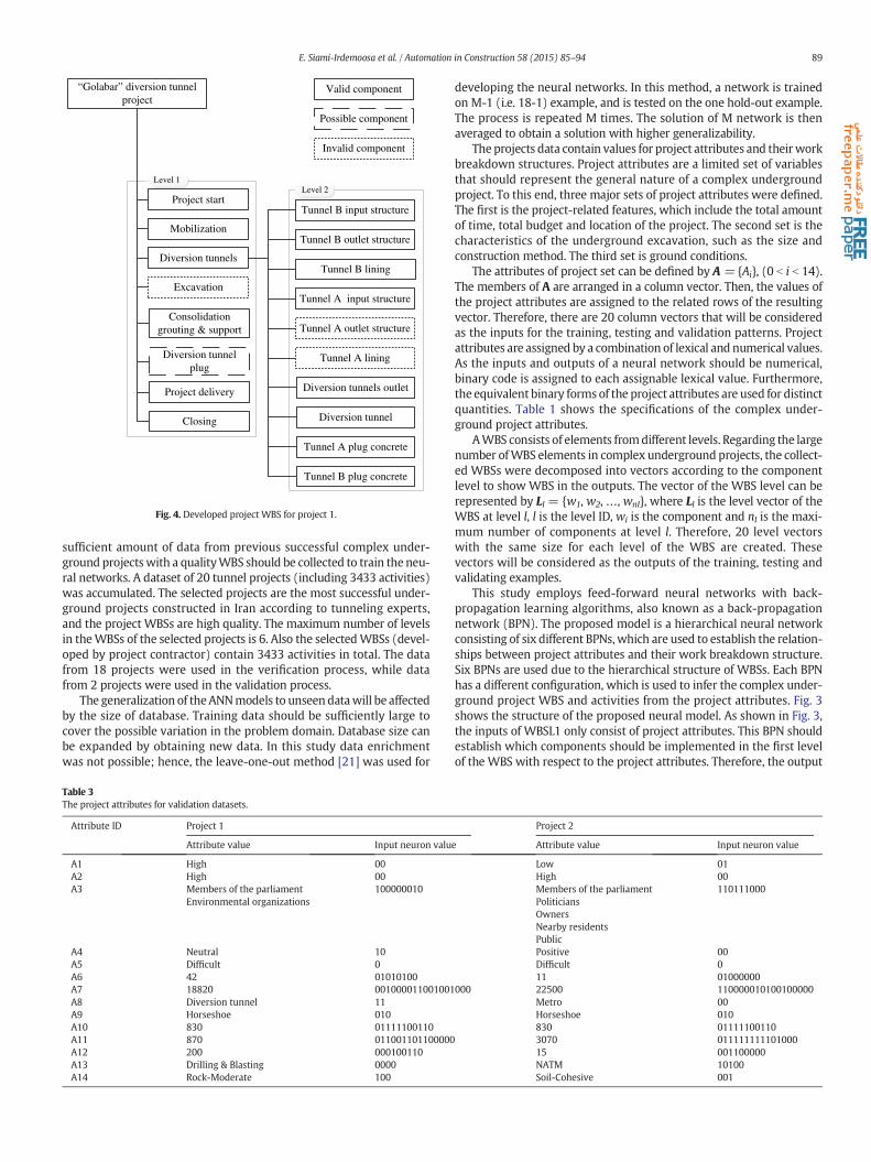
Fig. 4 shows the calculatedWBS for project 1 (Golabar diversion tun-nel, with attributes per Table 3). The attributes of project 1were enteredinto the model. The L1 vector from WBSL1 was calculated with respectto the project attributes. First level of theWBS in Fig. 4 represents the L1vector. The attributes of the project and the L1 vectorwere then enteredto theWBSL2, and the L2 vector was calculated. Second level of theWBSin Fig. 4 represents the L2 vector. Subsequently, the outputs of WBSL3,the L3 vector, were calculated, and a similar process was conductedfor L4, L5 and L6. In this case, the outputs for L3 to L6 vectors werezero. Thus, the calculated WBS has only two levels.
The same procedure was used to calculate the WBS of the project 2(Karaj Metro Tunnel). The attributes of the project (Table 3) wereentered into the model. The L1 vector from WBSL1 was calculatedwith respect to the project attributes. The attributes of the project andthe L1 vector were then entered to the WBSL2, and the L2 vector wascalculated. Subsequently, the outputs of WBSL3, the L3 vector, werecalculated, and a similar process was conducted for L4, L5 and L6.Figs. 5 and 6 show the calculated WBS for project 2. Developed WBS isillustrated in two individual Figures (Figs. 5 and 6) due to the large
Cons
Ramp A Ramp B Type I&II tunnels InstLevel 2
Project2, L2={1,1,1,1,1,1,1}
Cons
Ramp B Instrument Temdel
Level 2
Project2, L2={0,1,0,1,1,1,1}
a) Second level of the actual
b) Calculated level vector fo
Fig. 7. Second level of the calculated W
number of the WBS elements. Fig. 5 depicts levels 1 to 4 of the WBS,and levels 5 to 6 are presented in Fig. 6. Furthermore, in order to makea better representation of the whole WBS, several elements of thelevel 3 and 4 also are illustrated in Fig. 6.
Three types of element outlines can be recognized in Figs. 4 to 6.Each line dash type represents the validity of WBS element which willbe discussed further in the following.
The outputs were validated by comparing the calculated vectors andequivalent level vectors of the actual WBS of the project. The vectors ofthe WBSs were compared by the values of their elements. For this pur-pose, three validity indiceswere defined. Each element of the calculatedvectors (wi) was assigned to one of the following validity indices:
(1) Valid: the related component is a part of the actual WBS of theproject.
(2) Possible: the related component is not a part of the actualWBS ofthe project (or the component that should be a part of the projectWBS, while it is not been produced by themodel), but it could bevalid with respect to the judgment of experts.
(3) Invalid: the related component cannot be a part of the actualWBS of the project (or the component that should be a part ofthe project WBS, while it is not been produced by the model).
The second level of the calculated WBS and actual WBS of project 2are illustrated in Fig. 7. “Ramp B” in Fig. 7.b. is a valid component, be-cause it is a part of the real WBS of the project. “Ramp A” takes a valueof 0 in L2 vector (Fig. 7. b); hence, it is not a component of the calculatedWBS. However, the real WBS includes the “Ramp A” component in thesecond level. “Ramp A” is therefore an invalid component.
“Possible” index were assigned to the project's WBS elementsaccording to the tunneling project management experts. “Type I&II tun-nels” component in Fig. 7a, for example, was not calculated by themodel. However, this project specific component can be excludedfrom a tunnel project WBS according to the project manager's decision.“Valid”, “Possible”, and “Invalid” components of the calculated WBS ofprojects 1 and 2 are presented in Figs. 4 to 6. In Figs. 4 to 6, rectangularshapes with solid line represent the “Valid” elements, with dashed line“Possible” elements, and with dot line the “Invalid” elements.
The entire model and its networks were validated by calculating thestatistics of the validity indices that were assigned to the validation pro-cess outputs. The outputs of the networks were validated by dividingthe total number of calculated vector elements (wi) that were validated
truction
rument Temporarydelivery
Demobilization Closing
truction
poraryivery
Demobilization Closing
WBS and its equivalent vector
r the second level of the WBS
BS and actual WBS of project 2.

Table 4Validity of proposed model and its networks.
Network ID Validation projects Total number of elements Number of elements in validity index: Percentage of elements in validity index:
Valid Possible Invalid Valid Possible Invalid
WBSL1 Project 1 8 6 1 1 75 12.5 12.5Project 2 5 4 1 – 80 20 –
WBSL2 Project 1 10 8 – 2 80 – 20Project 2 7 5 – 2 71.43 – 28.57
WBSL3 Project 1 0 – – – – – –Project 2 12 9 – 3 75 – 25
WBSL4 Project 1 0 – – – – – –Project 2 71 40 3 28 56.33 4.22 39.44
WBSL5 Project 1 0 – – – – – –Project 2 28 4 17 7 14.29 60.71 25
WBSL6 Project 1 0 – – – – – –Project 2 64 47 11 6 73.43 17.19 9.38
Overall model 205 123 33 49 60 16.1 23.9
93E. Siami-Irdemoosa et al. / Automation in Construction 58 (2015) 85–94
by a particular index to the total number of elements of the calculatedvector (nl) for each project. Then, the average of the three validitypercentages within all projects was calculated to obtain the overallvalidity of each network. Table 4 shows the results of the average valid-ity percentages of the model and its networks.
The validity of the model was estimated with respect to the quanti-ties in Table 4. The valid and possible components of the calculatedWBSpercentages were found to be 60% and 16.1%, respectively. Therefore,after entering the attributes of a tunneling project, it is expected that76.1% of the WBS and resultant activities are certainly or possibly valid.
In addition to the relatively accurate recognition of the project WBSelements, several important characteristics of the project WBS weredetermined by the model. The correct number of WBS levels wasidentified (for example, two for project 1, and six for project 2). A com-bination of process-oriented and deliverable-oriented structure wasproduced for both projects by the model. Project 1, for instance, wasdecomposed to the processes in levele1, while the second level was adeliverable-oriented decomposition. The level of details for project 1was two, and levels were decomposed to 8–10 elements. Moreover,the model produced 6 levels for project 2, and several levels werecomposed of more than 60 elements. Furthermore, in the proposedmethodology, different management approaches can be employed todevelop the WBS of the project. For instance, the developed WBS bythe model for project 2 subdivides the tunnel bench and crown to sev-eral parts in level 6, then decomposes the parts into the processes inlevel 6 such as “Excavation” and “Shotcrete”. Alternatively, anothermanagement approach might subdivide the processes to parts in level6. Therefore, the proposed model was able to recognize the structureof the projects WBSs.
6. Conclusions
A new methodology was proposed to plan the WBS of complex un-derground projects, which assists a planer to make a more informedchoice of WBS components and structure regarding project attributes.A hierarchical neural model with 6 BPN networks was developed;each with a different configuration. The outputs of first 5 networkswere connected to the inputs of the others, to enable the inference ofproject structure with respect to the hierarchical structure of the WBS.The proposed methodology focused on two important requirementsof generating theWBS of a complex underground project: First, model-ing the relationship between the attributes of a project and WBS; andsecond, to minimize the complexity of the model. This was due to thelarge number of components of WBS in complex underground projectsand various possible structures.
Validation of the results revealed that the proposed neural networkmodel presents a powerful tool for modeling the complex relationshipbetween the attributes of complex underground projects and theirwork breakdown structures. The approach was demonstrated to be
capable of recognizing the components and structure of the WBS witha sufficient degree of validity that are comparable to those generatedby a project planner. Neural networks learn from examples; thus, theperformance of the proposed neural model strongly depends on thesize and quality of the training data. Due the vast amount of knowledgerequired for WBS planning in a complex underground project, the pro-posed model can foster effectiveness in WBS development. In otherwords, the greater the number of different underground projects thatare used to train the networks, the more extensive the data, and thehigher the quality of the data used to train the networks, the higherthe quality of the resultant overall WBS will be.
Although the neural models herein were developed for the purposeof planning theWBS of a complex underground project during the con-struction stage, the neural model concept can be extended, particularlyto preconstruction stages. The proposed methods for representing thevalues of project attributes and theWBS can also bemodified. Examina-tion of different neural networks structures, other than BPNs, is also apotential topic of future research.
References
[1] E.S. Norman, S.H.A. Bortherton, R.T. Fried, Work Breakdown Structures: The Founda-tion for Project Management Excellence, 1st ed. Jhon Wiley & Sons, Canada, 20081–25.
[2] A.M. Wood, Tunnelling: Management by Design, 1st ed. Taylor & Francis, USA, 2000.[3] K.J. Lee, H.W. Kim, J.K. Lee, T.H. Kim, Case- and constraint-based project planning for
apartment construction, AI Mag. 19 (1) (1998) 13–24.[4] R.J. Dzeng, I.D. Tommelein, Product modeling to support case-based construction
planning and scheduling, Autom. Constr. 13 (3) (2004) 341–360.[5] H.G. Ryu, H.S. Lee, M. Park, Construction planning method using case-based
reasoning (CONPLA-CBR), J. Comput. Civ. Eng. 21 (6) (2007) 410–422.[6] M. Chambers, C.A. Mount-Campbell, Process optimization via neural network
meta-modeling, Int. J. Prod. Econ. 79 (2) (2002) 93–100.[7] Hsu-Pin (Ben) Wang, Richard A. Wysk, Intelligent reasoning for process planning,
Comput. Ind. 8 (4) (1987) 293–309.[8] S.A. Hashemi, B. Emamaizadeh, Designing work breakdown structures using
modular neural network, Decis. Support. Syst. 44 (1) (2007) 202–222.[9] M. Sharifzadeh, M. Ataeepour, E. Siami, Designingwork breakdown structure (WBS)
in tunneling projects using neural networks, Proc., 45th US. Symp. on rock mechan-ics/Geomechanic, ARMA, San Francisco, CA, 2011.
[10] J.J. Reilly, The management process for complex underground and tunnellingprojects, Tunn. Undergr. Space Technol. 15 (1) (2000) 31–44.
[11] S.R. Dindarloo, E. Siami-Irdemoosa, Maximum surface settlement based classifica-tion of shallow tunnels in soft ground, Tunn. Undergr. Space Technol. 45 (2015)320–327, http://dx.doi.org/10.1016/j.tust.2015.04.021.
[12] Project management institute, A Guide to Project Management Body of Knowledge,4th ed. PMI Standards Committee, USA, 2008.
[13] Project management institute, Practice Standard for Work Breakdown Structures,2nd ed. PMI Standards Committee, USA, 2006.
[14] S. Haykin, Neural Networks: A Comprehensive Foundation, Macmillan, New York,1994.
[15] R.J. Schalkoff, Artificial Neural Networks, McGraw-Hill, New York, 1997.[16] S. Samarasinghe, Neural network for applied sciences and engineering: From
fundamentals to complex pattern recognition, Auerbach publications, New York,Taylor and Francis group, 2006.
[17] B.K. Bose, Expert system, Fuzzy logic and Neural networks in Power Electronics andDrives, Proc. Power Electronics and Variable Frequency Drives: Technology and

94 E. Siami-Irdemoosa et al. / Automation in Construction 58 (2015) 85–94
Applications. IEEE Press, Standard Publishers Distributors, New Delhi, India, 2000602–605.
[18] D.E. Rumelhart, J.L. McClelland, Parallel Distributed Processing, Vol. 1: Foundations,MIT Press, Cambridge, MA, 1986.
[19] E. Turban, J.E. Aronson, Decision Support Systems and Intelligent Systems, 6th ed.Prentice International Hall, Hong Kong, 2001.
[20] D.E. Rumelhart, G.E. Hinton, R.J. Williams, Learning internal representation by errorpropagation, in: D.E. Rumelhart, J.L. McClleland (Eds.), Proc. Parallel DistributedProcessing: Exploration in the Microstructure of Cognition, vol. 1, MIT Press,Cambridge, MA, 1986 (Chapter 8).
[21] S. Haykin, Neural Networks: A Comprehensive Foundation, 2nd ed. Prentice Hall,N.J. London, Upper Saddle River, 1999.
[22] G. Lachtermacher, J.D. Fuller, Backpropagation in time series forecasting, J. Forecast.14 (4) (1995) 381–393.
[23] T. Masters, Practical Neural Network Recipes in C11, Academic Press, MA. Boston,1994.
[24] B. Upadhaya, E. Eryureka, Application of neural network for sensory validation andplant monitoring, Neural Technol. 97 (1992) 170–176.
Related Documents