i Project Number: IQP - MQF 2841 Remotely Operated Aerial Vehicles and Their Applications An Interactive Qualifying Project Submitted to the Faculty of the WORCESTER POLYTECHNIC INSTITUTE in partial fulfillment of the requirements for the degree of Bachelor of Science by January 19, 2017 Approved by: Prof. M. S. Fofana, Advisor Mechanical Engineering Department

Welcome message from author
This document is posted to help you gain knowledge. Please leave a comment to let me know what you think about it! Share it to your friends and learn new things together.
Transcript
i
Project Number: IQP - MQF 2841
Remotely Operated Aerial Vehicles and Their Applications
An Interactive Qualifying Project
Submitted to the Faculty
of the
WORCESTER POLYTECHNIC INSTITUTE
in partial fulfillment of the requirements for the degree of
Bachelor of Science
by
January 19, 2017
Approved by:
Prof. M. S. Fofana, Advisor
Mechanical Engineering Department
ii
ABSTRACT
The development of drone technologies is growing rapidly. Various types of drones and
unmanned aerial vehicles are used in fields such as photography, transportation, military, and
most importantly in search and rescue situations. The objective of this project is to evaluate the
developments and applications of unmanned aerial vehicles (UAVs). The effort is mainly
focused on the role of UAVs in the application of emergency medical services. A comparison of
UAV designs is made in order to locate the most suitable UAV for emergency medical services.
A number of UAV designs and their analyses are also evaluated. The designs include
components such as UAV structures, flight control systems, instruments layout and applications
of UAV heat transfer systems. A survey of various UAV applications in the market and related
literature is also carried out. We compare UAV applications and functions in order to locate the
most beneficial UAV and component designs for emergency medical services. This comparison
provides us an opportunity to produce final design solutions. We use analytical methods such as
mathematical molding, static analysis, and computer aided flow simulations to select and verify
the design parameters. These methods are foundational for better understanding of UAV
technologies and design techniques. The societal impact of this IQP is that it will enhance the
quality of ambulatory care.
iii
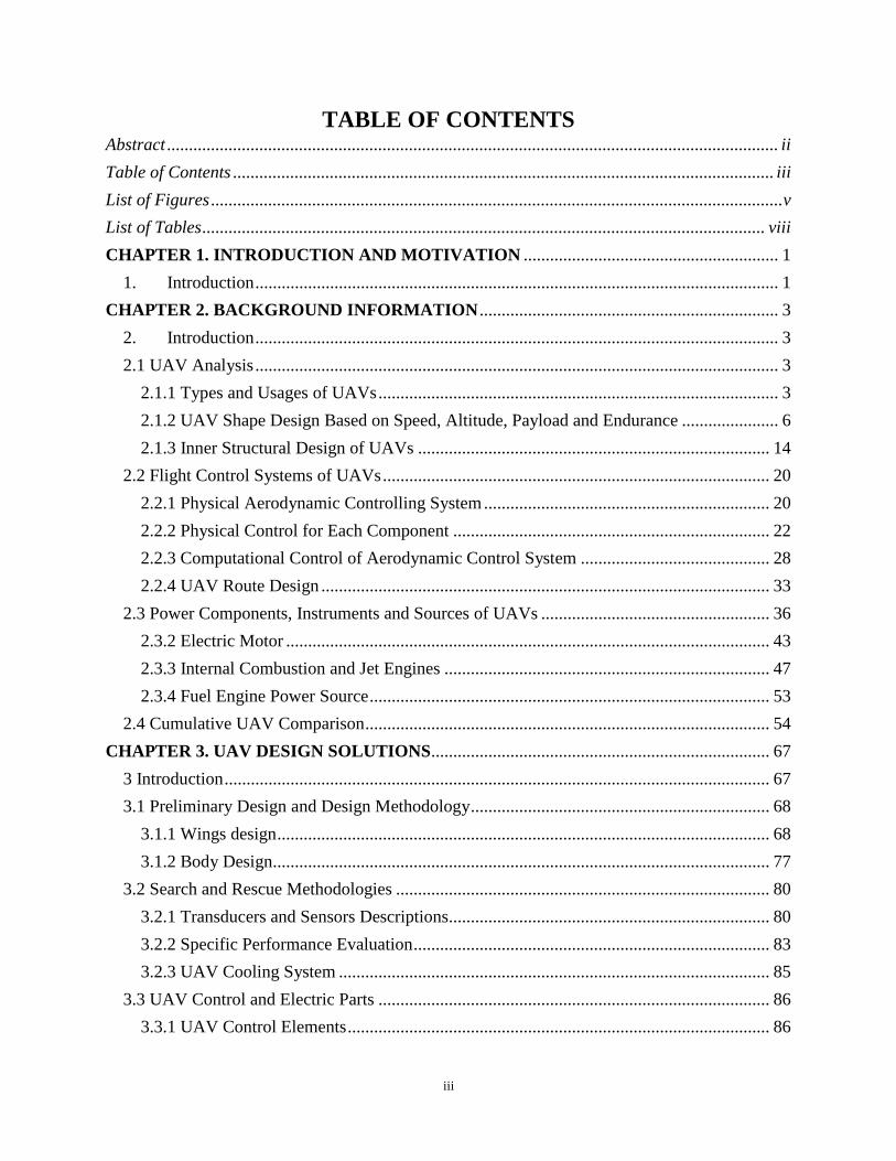
TABLE OF CONTENTS Abstract ........................................................................................................................................... ii
Table of Contents ........................................................................................................................... iii
List of Figures .................................................................................................................................. v
List of Tables ................................................................................................................................ viii
CHAPTER 1. INTRODUCTION AND MOTIVATION .......................................................... 1
1. Introduction ....................................................................................................................... 1
CHAPTER 2. BACKGROUND INFORMATION .................................................................... 3
2. Introduction ....................................................................................................................... 3
2.1 UAV Analysis ....................................................................................................................... 3
2.1.1 Types and Usages of UAVs ........................................................................................... 3
2.1.2 UAV Shape Design Based on Speed, Altitude, Payload and Endurance ...................... 6
2.1.3 Inner Structural Design of UAVs ................................................................................ 14
2.2 Flight Control Systems of UAVs ........................................................................................ 20
2.2.1 Physical Aerodynamic Controlling System ................................................................. 20
2.2.2 Physical Control for Each Component ........................................................................ 22
2.2.3 Computational Control of Aerodynamic Control System ........................................... 28
2.2.4 UAV Route Design ...................................................................................................... 33
2.3 Power Components, Instruments and Sources of UAVs .................................................... 36
2.3.2 Electric Motor .............................................................................................................. 43
2.3.3 Internal Combustion and Jet Engines .......................................................................... 47
2.3.4 Fuel Engine Power Source ........................................................................................... 53
2.4 Cumulative UAV Comparison ............................................................................................ 54
CHAPTER 3. UAV DESIGN SOLUTIONS ............................................................................. 67
3 Introduction ............................................................................................................................ 67
3.1 Preliminary Design and Design Methodology .................................................................... 68
3.1.1 Wings design ................................................................................................................ 68
3.1.2 Body Design................................................................................................................. 77
3.2 Search and Rescue Methodologies ..................................................................................... 80
3.2.1 Transducers and Sensors Descriptions......................................................................... 80
3.2.2 Specific Performance Evaluation ................................................................................. 83
3.2.3 UAV Cooling System .................................................................................................. 85
3.3 UAV Control and Electric Parts ......................................................................................... 86
3.3.1 UAV Control Elements ................................................................................................ 86

iv
3.3.2 UAV Control Analysis ................................................................................................. 93
3.4 UAV Data Transmission ..................................................................................................... 96
3.4.1 Long Range Remote Control Description.................................................................... 96
3.4.2 On Board Computational Systems ............................................................................. 101
3.4.3 UAV Data and Signal Transmission .......................................................................... 107
CHAPTER 4. CONCLUSION ................................................................................................. 108
REFERENCES .......................................................................................................................... 109
APPENDICE ............................................................................................................................. 114
Dijkstra Functions ................................................................................................................... 114

v
LIST OF FIGURES
Figure 1: Inspire3 created by DJI Company .................................................................................. 4
Figure 2: The motor motion analysis of a quadcopter (top view). ................................................. 4
Figure 3: The cross-section of wing and the air stream around .................................................... 5
Figure 4: An MQ-1B predator taxis at Creech air force base ....................................................... 5
Figure 5: Parkzone ® Ember modified with articulated wings ...................................................... 6
Figure 6: RoboBee, an insect-like flight built by Harvard ............................................................. 6
Figure 7: Examples of wing shapes ................................................................................................ 7
Figure 8: The overview of X-47A .................................................................................................... 8
Figure 9: The overview of Altair UAV ............................................................................................ 8
Figure 10: The overview of MQ-8 .................................................................................................. 9
Figure 11: The overview of talarion MALE ................................................................................... 9
Figure 12: The speed contrast of each shapes of UAV ................................................................. 10
Figure 13: The altitude contrast of each shapes of UAV .............................................................. 11
Figure 14: The payload contrast of each shapes of UAV ............................................................. 11
Figure 15: The endurance contrast of each shapes of UAV ......................................................... 12
Figure 16: The overview of qinetiq zephyr ................................................................................... 12
Figure 17: The overview of phantom 3 (UAV) ............................................................................. 13
Figure 18: The overview of Hobby King™ Bix3 Trainer ............................................................. 13
Figure 19: Aircraft Inner structural parts joined together ........................................................... 15
Figure 20: Stresses that the drone body experie nces .................................................................. 16
Figure 21: A general view of an airplane inner structure ............................................................ 17
Figure 22: Types of wings inner structures (cross section) .......................................................... 17
Figure 23: An airfoil shape in the XFLR5 airfoil design software ............................................... 18
Figure 24: Useful graphs can be plotted with the help of this software. ...................................... 18
Figure 25: Inner structure of wing (whole wing) ......................................................................... 19
Figure 26: The airplane control parts labeled ............................................................................. 20
Figure 27: Top view of a wing with aileron ................................................................................. 22
Figure 28: Section view of a wing with aileron ............................................................................ 23
Figure 29: Section view of plain flaps .......................................................................................... 24
Figure 30: Section view of split flaps ........................................................................................... 24
Figure 31: Section view of slotted flaps ........................................................................................ 24
Figure 32: Section view of fowler flaps ........................................................................................ 25
Figure 33: Best efficiency - for climbing, cruising, descent ......................................................... 25
Figure 34: Increased wing area - for take-off and initial climb ................................................... 25
Figure 35: Maximum lift and high drag - approach to landing ................................................... 26
Figure 36: Maximum drag and reduced lift - for braking on runway .......................................... 26
Figure 37: Directional control via rudder deflection (top view) .................................................. 27
Figure 39: Left is a swept rudder, Right is rectangular rudder (side view) ................................. 27
Figure 40: The section view of a horizontal stabilizer with elevator ........................................... 28
Figure 41: The top view of a horizontal stabilizer with elevator ................................................. 28
Figure 42: Negative feedback closed loop for transfer function .................................................. 29
Figure 43: PID simulation ............................................................................................................ 31
Figure 44: Damping ratio simulation ........................................................................................... 33
Figure 45: Relation between UAV and Back-End ........................................................................ 34
Figure 46: Example of UAV Orbit (red) ....................................................................................... 35

vi
Figure 47: Basic structure of solar power system ........................................................................ 37
Figure 48: Structure of MPPT algorithm ..................................................................................... 38
Figure 49: Contrast basic solar system(Left) and solar system with MMPT(Right) .................... 38
Figure 50: Fuel cell system construction...................................................................................... 39
Figure 51: Fuel cell system........................................................................................................... 39
Figure 52: TOF camera abstraction............................................................................................. 41
Figure 53: MESA imaging 3D TOF Camera SR4000 (ETH, 5m range) ...................................... 41
Figure 54: Effects of TOF camera ................................................................................................ 42
Figure 55: Camera function analysis ........................................................................................... 42
Figure 56: Fuel cell system construction...................................................................................... 44
Figure 57: The relationship between UAV motor’s torque and elements .................................... 45
Figure 58: The relationship between UAV power and altitude .................................................... 46
Figure 59: The relationship between UAV power and speed ....................................................... 46
Figure 60: The relationship between UAV power and payload ................................................... 47
Figure 61: The relationship between UAV power and weight ..................................................... 47
Figure 62: Full combustion engine diagram ................................................................................ 48
Figure 63: 2002 BMW 5-Series Inline-6 Engine .......................................................................... 49
Figure 64: Ferrari 360 3586cc Alloy V8 Engine.......................................................................... 49
Figure 65: Jabiru 3300cc Aircraft Engine ................................................................................... 50
Figure 66: Pratt & Whitney R-1340 Radial Engine ..................................................................... 50
Figure 67: Centrifugal Turbo Engine ........................................................................................... 51
Figure 68: Turbo-Thrust Engine .................................................................................................. 52
Figure 69: Turbo-Prop Engine ..................................................................................................... 52
Figure 70: Turbofan Engine ......................................................................................................... 53
Figure 71: The speed performance of each UAV ......................................................................... 63
Figure 72: The weight performance of each UAV ........................................................................ 63
Figure 73: The endurance performance of each UAV .................................................................. 64
Figure 74: The altitude performance of each UAV ...................................................................... 64
Figure 75: The range performance of each UAV ........................................................................ 65
Figure 76: Examples of wings with different aspect ratio. ........................................................... 68
Figure 77: Examples of the three different wing angle cases ....................................................... 69
Figure 78: The plot of aerospace materials with respect to strength and density ....................... 70
Figure 79: The XFLR5 analysis procedure for the given Reynolds and Mach numbers ............. 72
Figure 80: The lift coefficient to angle of attack graph for the four NACA airfoils ..................... 73
Figure 81: The lift to drag ratio for NACA 4412 and NACA 9412 UAVs .................................... 74
Figure 82: The cross sections of NACA 4412 and NACA 9412 in XFLR5 ................................... 74
Figure 83: The cross section of NACA 9412 in SolidWorks ......................................................... 76
Figure 84: The top back view of NACA 9412 and its wingspan length ........................................ 76
Figure 85: The bottom view of NACA 9412 and its wingspan length ......................................... 77
Figure 86: The top front view of NACA 9412 ............................................................................... 77
Figure 87: The design of UAV model .......................................................................................... 78
Figure 88: Our model seen from another angle ............................................................................ 79
Figure 89: Additional top and side views of the model ................................................................ 79
Figure 90: One Dimensional Structure of an Accelerometer ....................................................... 81
Figure 91: The cooling system in the UAV ................................................................................... 86
Figure 92: The relationship between each element in UAV ......................................................... 87

vii
Figure 93: The relationship between each device ........................................................................ 88
Figure 94: 3D angle of view of the UAV control board ............................................................... 88
Figure 95: Application of NVIDIA Jetson TK1 ............................................................................ 89
Figure 96: 3D angle of view of battery ........................................................................................ 90
Figure 97: Application of battery ................................................................................................. 90
Figure 98: The 3D angle of view of Arduino Mega ...................................................................... 91
Figure 99: 3D angle of view of the UAV camera ......................................................................... 92
Figure 100: The free body diagram of the UAV ........................................................................... 95
Figure 101: Basic sketch of MatLab Simulink for speed control ................................................. 96
Figure 102: 2.4GHz/5.8GHz frequency wireless communication structure................................. 97
Figure 103: Structure of UAV-Satellite Communication.............................................................. 98
Figure 104: Ranges for various radio frequency ......................................................................... 99
Figure 105: Speed for various radio solution............................................................................. 100
Figure 106: Power consumption for different frequency ........................................................... 101
Figure 107: Different weights for different components ............................................................ 102
Figure 108: Relations among components in UAV .................................................................... 103
Figure 109: Speed Comparison between CPU and GPU ........................................................... 104
Figure 110: Visual Representation of Power Flow[3333] ......................................................... 105
Figure 111: UAV signal transmission structure ......................................................................... 107

viii
LIST OF TABLES
Table 1: The performance of each large UAV .............................................................................. 10
Table 2: The performance of each small UAV.............................................................................. 14
Table 4: Feedback Controller and Gain ....................................................................................... 30
Table 5: The datasheet of Yeair .................................................................................................... 54
Table 6: The datasheet of MQ-8 ................................................................................................... 54
Table 7: The datasheet of MQ-9 ................................................................................................... 55
Table 8: The datasheet of CH-3 .................................................................................................... 56
Table 9: The datasheet of RQ-21 .................................................................................................. 56
Table 10: The datasheet of EHANG 184 ...................................................................................... 57
Table 11: The datasheet of Phantom3 .......................................................................................... 58
Table 12: The datasheet of S1000+ .............................................................................................. 58
Table 13: The datasheet of Precision hawk .................................................................................. 59
Table 14: The datasheet of Zephyr ............................................................................................... 59
Table 15: The datasheet of Helios ................................................................................................ 60
Table 16: The datasheet of Hale-D ............................................................................................... 61
Table 17: The datasheet of Penguin B .......................................................................................... 61
Table 18: The datasheet of Global Hawk ..................................................................................... 62
Table 19: Cumulative UAV chart ................................................................................................. 65
Table 20: The values of the maximum lift coefficients for selected airfoil ................................... 73
Table 21: Data description of onboard accelerometers of the UAV [64, 65, 66] ........................ 83
Table 22: Three kinds of gyroscopes that fit for the UAV [67, 68, 69] ........................................ 84
Table 23: NVIDIA Jetson TK1 kit content [76] ............................................................................ 89
Table 24: The datasheet of the battery of the UAV ....................................................................... 91
Table 25: The data contrast of two small electrical board ........................................................... 92
Table 26: Example code for PID speed and altitude controller in C programming .................... 93
Table 27: PID gain according to Ziegler-Nichols method ........................................................... 95
Table 28: The fight mode and speed of the UAV .......................................................................... 95
Table 29: List of components onboard the UAV ......................................................................... 102
Table 30: Functions used to control voltage in Linux ................................................................ 106

1
CHAPTER 1. INTRODUCTION AND MOTIVATION
1. Introduction
Throughout the course of human history, harmful accidents, unpredictable attacks, and
uncontrollable diseases have been a threat for citizens of the world. The value of human live has
increased dramatically in the last Century. Therefore, the need for stronger security is of great
concern for many societies around the world. Life expectancy in most of the Western World has
nearly doubled in the last 200 years, especially after the Second World War. Governments do
their best and spend enormous amounts of wealth to make sure that their citizens live in safe
environments. Huge proportions of National budgets go towards medical related research in
order to prevent the spread of diseases or find treatments for incurable illnesses. Substantial
resources are also spent on the modernization and enforcement of safety systems and rescuing
teams. This project focuses on incorporating UAVs into emergency medical services. The
advantages of using a UAV include efficiency in terms of search time, risk management and cost
reduction. These advantages increase the rate of survival and successful accomplishment of a
rescue mission.
The objectives of the IQP are to evaluate a number of UAVs and their applications. The
experienced gained from this evaluation is used to design a medical response UAV. The
proposed UAV needs to have the ability to provide sufficient information to rescue teams by
scanning the scene of an incident using sensors, cameras and other detection instruments. The
scanning instruments provide data from the scene to an onboard computer, which builds a 3D
image of the scene. Also, these instruments are able to distinguish between humans that need
help and those facing possible threats from the surrounding area of the scene. The proposed
UAV is capable of operating automatically, and carrying and delivering certain amount of
payload to the victims on the scene. To achieve this objective, the IQP team evaluates a number
of drones and UAV technologies, and then applies the knowledge gained to the designing of the
proposed UAV for emergency medical services. To be more specific, the design process of the
UAV involves several iterations. These iterations include, the detailed wing body design, power
source selection, onboard electronic devices layout, and flight control mechanisms. The problem
statement of the IQP is to evaluate various UAV technologies and their applications, and design
a UAV that is able to carry at least two kilograms of payload. This UAV should also have a

2
minimum operating time limit of thirty minutes, and is able to detect victims who are in danger
on the scene of an incident.
In the first Chapter of the report, the authors describe the motivation and the problem
statement. The second Chapter introduces a selected number of UAV technologies based on
UAV types, applications and capabilities. In order to provide an effective solution, our team
analyze the performance of both commercial and military UAVs. In the third Chapter, based on
the knowledge amassed in Chapters 1 and 2, the team presents design recommendations
including instrument selection criteria, structural design, and flight control theories. We are
hopeful that the proposed UAV will strengthen the work of emergency medical services. The
medical response UAV can be used to deliver medical supplies such as plasmas, both in a
crowded cities or facilities located faraway in the suburbs. In this case, people from different
classes or living in different locations and conditions are able to receive the same quality of
medical treatments and security. We believe that the proposed UAV design solutions will
improve emergency medical services.

3
CHAPTER 2: BACKGROUND INFORMATION
2. Introduction
As mentioned in Chapter 1, our goal is to evaluate applications and designs of UAVs. It
is essential to start with the analysis of UAV structures in order to understand the basic
operations and functions. In this Chapter we discuss the different types of existing UAVs and
what are the advantages and disadvantages in terms of applications and designs. Moreover, we
discuss how the selected UAVs are built, and more specifically, what their outer shapes are and
how they change relative to altitude, speed and load. Finally, we focus on the inner structure and
computational system design of the UAVs.
2.1 UAV Analysis
2.1.1 Types and Usages of UAVs
UAVs are becoming important applications for many fields and the market for UAVs is
growing globally as there is a strong drive to expand the use of UAVs. According to Teal
Group’s 2014 market study report, the estimate of UAV spending will double over the next
decade from current worldwide UAV expenditures of $6.4 billion annually to $11.5 billion. A
total of $91 billion is expected in the next ten years [2]. Under the huge amount of market
demand, different types of UAV are invented that can be used in different areas such as in
industry, commercial, military, searching and rescuing. UAVs have many different applications
and they can be categorized in three main kinds: quadcopters (include those with six or eight
rotors), fixed-wing aircraft and micro drones [3].
Figure 1 presents quadcopters, which are also called quadrotor helicopters or quadrotors
which are multi-rotor helicopters lifted and propelled by four rotors. Quadcopters are mostly
small, light weighted with medium speed and altitude. They are all powered by electrical powers.
Quadcopters use four motors with four propellers to create thrust and lift force. Figure 2 shows
two motors of quadcopters which rotate counter clockwise and the other two motors rotate
clockwise. This configuration causes the torque from each motor to cancel by the corresponding
motor rotating in the opposite direction. The features of the vertical takeoff and landing and as
well as horizontal flight avoiding obstacles, both with characteristics of low speed and high
precision, make the quadcopters able to complete missions which require high level of difficult
4
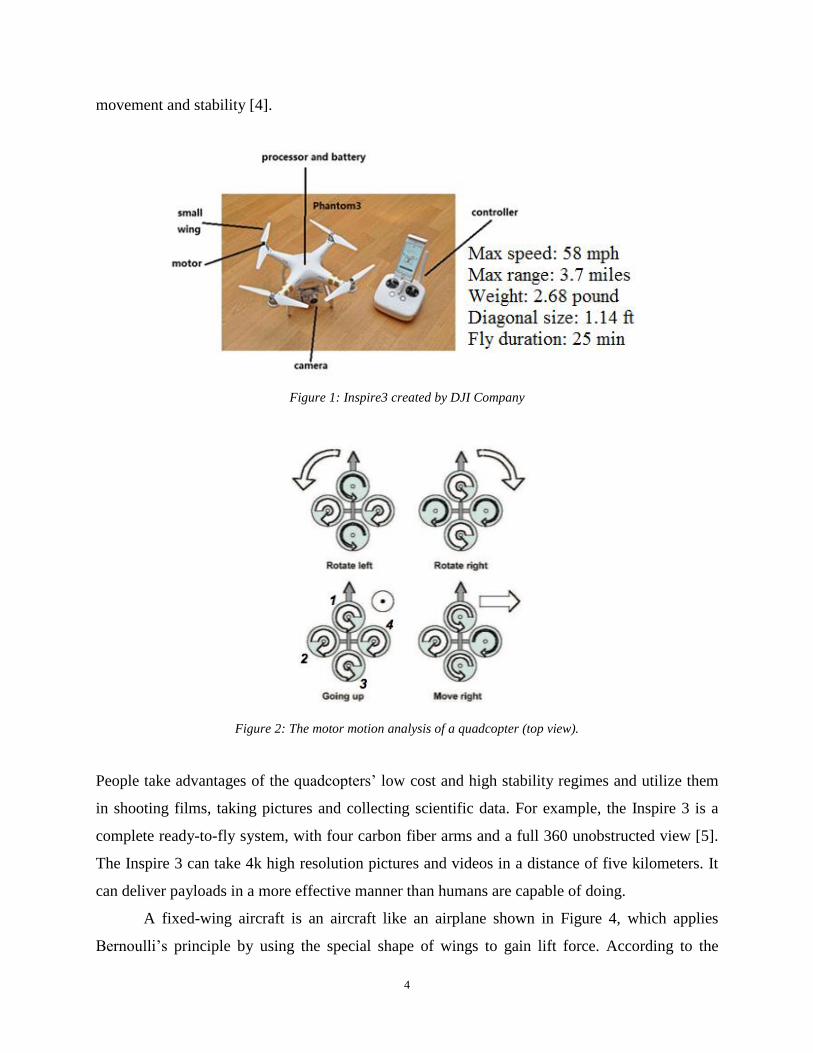
movement and stability [4].
Figure 1: Inspire3 created by DJI Company
Figure 2: The motor motion analysis of a quadcopter (top view).
People take advantages of the quadcopters’ low cost and high stability regimes and utilize them
in shooting films, taking pictures and collecting scientific data. For example, the Inspire 3 is a
complete ready-to-fly system, with four carbon fiber arms and a full 360 unobstructed view [5].
The Inspire 3 can take 4k high resolution pictures and videos in a distance of five kilometers. It
can deliver payloads in a more effective manner than humans are capable of doing.
A fixed-wing aircraft is an aircraft like an airplane shown in Figure 4, which applies
Bernoulli’s principle by using the special shape of wings to gain lift force. According to the

5
Bernoulli’s principle the pressure in a stream of fluid is reduced as the speed of the flow is
increased. In the air stream, the air flows relatively faster at the upper layer of the wing than the
lower layer. As a result, the pressure exerted on the upper surface of the wing is smaller than
pressure exerted on the lower surface, which pushes the wings upward and makes the aircraft to
fly [7].
Figure 3: The cross-section of wing and the air stream around
Even though a fixed-wing UAV is difficult to take off and land, yet it has the advantages
of flying faster, carrying more payload than quadcopters, staying in a relatively high altitude, and
sustaining longer endurance than some other UAVs in the market and relevant literature. Thus,
fixed-wing UAV can be used for long range detection, spraying pesticide for crops, providing
combat ability for high risk mission. For example, the predator as shown in Figure 4, is medium
altitude, long endurance, unmanned aerial vehicle which is used in risky areas where human life
may be in danger. The predator is an asset for reconnaissance, surveillance and target acquisition
in support of the Joint Force Commander of the United States Military [8].
Figure 4: An MQ-1B predator taxis at Creech air force base
6
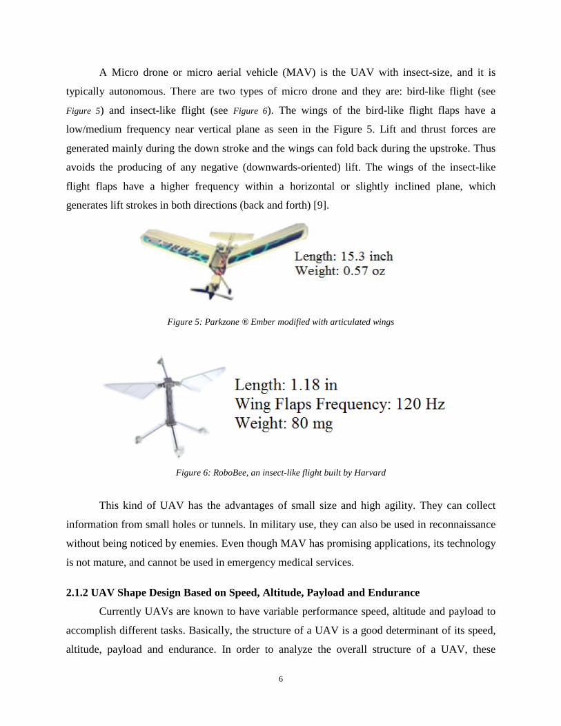
A Micro drone or micro aerial vehicle (MAV) is the UAV with insect-size, and it is
typically autonomous. There are two types of micro drone and they are: bird-like flight (see
Figure 5) and insect-like flight (see Figure 6). The wings of the bird-like flight flaps have a
low/medium frequency near vertical plane as seen in the Figure 5. Lift and thrust forces are
generated mainly during the down stroke and the wings can fold back during the upstroke. Thus
avoids the producing of any negative (downwards-oriented) lift. The wings of the insect-like
flight flaps have a higher frequency within a horizontal or slightly inclined plane, which
generates lift strokes in both directions (back and forth) [9].
Figure 5: Parkzone ® Ember modified with articulated wings
Figure 6: RoboBee, an insect-like flight built by Harvard
This kind of UAV has the advantages of small size and high agility. They can collect
information from small holes or tunnels. In military use, they can also be used in reconnaissance
without being noticed by enemies. Even though MAV has promising applications, its technology
is not mature, and cannot be used in emergency medical services.
2.1.2 UAV Shape Design Based on Speed, Altitude, Payload and Endurance
Currently UAVs are known to have variable performance speed, altitude and payload to
accomplish different tasks. Basically, the structure of a UAV is a good determinant of its speed,
altitude, payload and endurance. In order to analyze the overall structure of a UAV, these

7
characteristics and other variables such as the power of the engine should also be considered
[10]. We evaluate UAVs which have the same power source. The structure consists of a wing,
tail, fuselage and head. Since each UAV has several components and each component can be
shaped in many ways, it is difficult to define a specific shape for a UAV. Basically, the wing is
one of the most important shapes for the UAV. There are some basic wing shapes [11] as seen in
Figure 7. The shapes in Figure 7 are the bases for selecting the case studies in this report.
Figure 7: Examples of wing shapes
The first case study of current large UAV is the Northrop Grumman X-47, as shown in Figure 8,
which is now part of the United States Navy's UCAS-D program. The airframe is a stealthy
platform design. It is diamond-kite shaped with a 55° backward sweep on the leading edge and a
35° forward sweep on the trailing edge.
The X-47A has a wingspan of 8.47m and is 8.5m long. It uses a delta wing. The feature
of this shape design is that it allows the UAV to fly at high subsonic speeds (greater than
305m/s) and with perfect stealth. However it has limited payload, attitude and endurance.
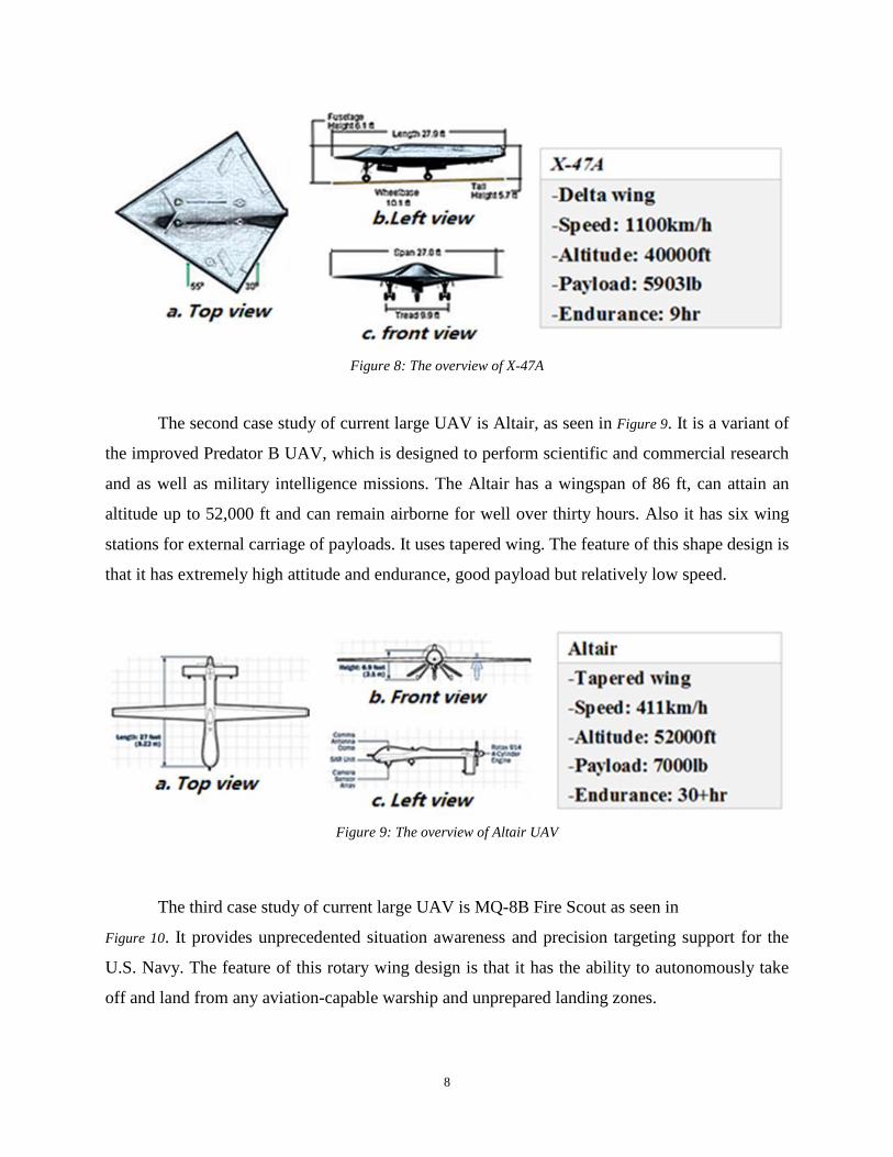
8
Figure 8: The overview of X-47A
The second case study of current large UAV is Altair, as seen in Figure 9. It is a variant of
the improved Predator B UAV, which is designed to perform scientific and commercial research
and as well as military intelligence missions. The Altair has a wingspan of 86 ft, can attain an
altitude up to 52,000 ft and can remain airborne for well over thirty hours. Also it has six wing
stations for external carriage of payloads. It uses tapered wing. The feature of this shape design is
that it has extremely high attitude and endurance, good payload but relatively low speed.
Figure 9: The overview of Altair UAV
The third case study of current large UAV is MQ-8B Fire Scout as seen in
Figure 10. It provides unprecedented situation awareness and precision targeting support for the
U.S. Navy. The feature of this rotary wing design is that it has the ability to autonomously take
off and land from any aviation-capable warship and unprepared landing zones.
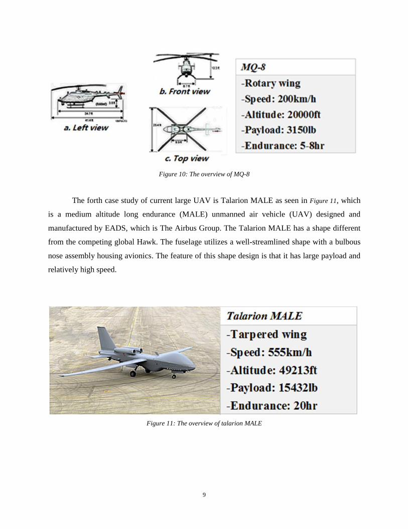
9
Figure 10: The overview of MQ-8
The forth case study of current large UAV is Talarion MALE as seen in Figure 11, which
is a medium altitude long endurance (MALE) unmanned air vehicle (UAV) designed and
manufactured by EADS, which is The Airbus Group. The Talarion MALE has a shape different
from the competing global Hawk. The fuselage utilizes a well-streamlined shape with a bulbous
nose assembly housing avionics. The feature of this shape design is that it has large payload and
relatively high speed.
Figure 11: The overview of talarion MALE

10
The data, found in Table 1 is the performance of a selected number of UAVs . By using
this table, our team obtain specific parameters contrast of differently shaped UAVshown in Figure
11. This graph is very useful for future selection of UAV shape. For example, if we want to have
a UAV with a good endurance and payload, we can read the chart in Table 1 and find what
matches the best to the specifications. The Talarion MALE is the best fit for the specifications. If
the UAV environment is rugged and a vertically takeoff and landing are needed, the shape design
of the MQ-8 is a good choice [12].
Table 1: The performance of each large UAV
UAV Speed Altitude Payload Endurance
X-47 1100 km/h 40,000 ft 5,903 lb 9 hr
Altair 411 km/h 52,000 ft 7,000 lb 30+ hr
MQ-8 200 km/h 20,000 ft 3,150 lb 5-8 hr
Talarion MALE 555 km /h 49,213 ft 15,432 lb 20 hr
Barracuda 1,041 km/h 20,000 ft 7,165 lb 4 hr
Figure 12 shows the speed contrast of each shapes of UAV. The shape of X-47 has better speed
ranges than the others. It is a good reference of future shape selection.
Figure 12: The speed contrast of each shapes of UAV

11
Figure 13 shows the altitude contrast of each shapes of UAV. The shape of Altair has an
advantage of altitude. It is a good reference of future shape selection.
Figure 13: The altitude contrast of each shapes of UAV
Figure 14 presents the payload contrast of each shapes of UAV. The shape of the Talarion Male
has an advantage of carrying large payload. It is a good reference of future shape selection.
Figure 14: The payload contrast of each shapes of UAV
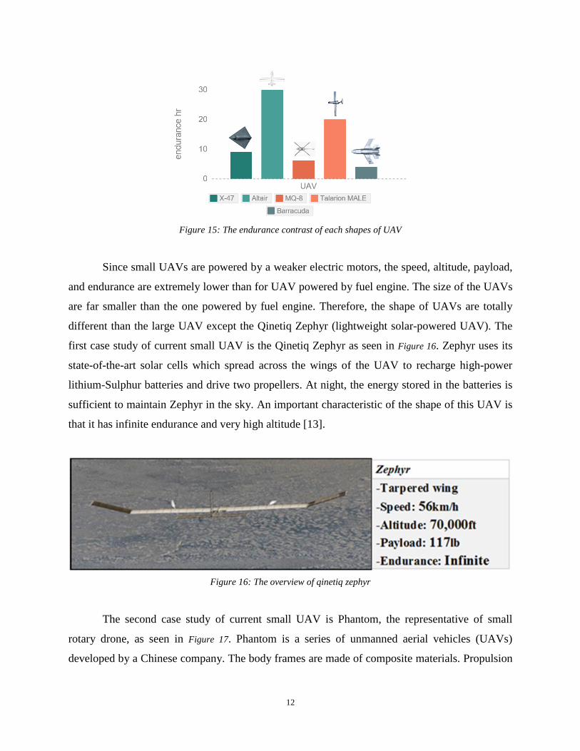
Figure 15 indicates the endurance contrast of each shapes of UAV. The shape of Altair has an
advantage of endurance. It is a good reference of future shape selection.
12
Figure 15: The endurance contrast of each shapes of UAV
Since small UAVs are powered by a weaker electric motors, the speed, altitude, payload,
and endurance are extremely lower than for UAV powered by fuel engine. The size of the UAVs
are far smaller than the one powered by fuel engine. Therefore, the shape of UAVs are totally
different than the large UAV except the Qinetiq Zephyr (lightweight solar-powered UAV). The
first case study of current small UAV is the Qinetiq Zephyr as seen in Figure 16. Zephyr uses its
state-of-the-art solar cells which spread across the wings of the UAV to recharge high-power
lithium-Sulphur batteries and drive two propellers. At night, the energy stored in the batteries is
sufficient to maintain Zephyr in the sky. An important characteristic of the shape of this UAV is
that it has infinite endurance and very high altitude [13].
Figure 16: The overview of qinetiq zephyr
The second case study of current small UAV is Phantom, the representative of small
rotary drone, as seen in Figure 17. Phantom is a series of unmanned aerial vehicles (UAVs)
developed by a Chinese company. The body frames are made of composite materials. Propulsion

13
is provided by four two-blade propellers driven by four electric engines mounted at the ends of
the x-shaped body. The feature of the shape of this UAV is that it requires very small take-off
and landing area and has good control mechanism.
Figure 17: The overview of phantom 3 (UAV)
The third case study of current UAV is the Hobby King™ Bix3 Trainer. This represents a
small fix-wing drone. It has 1550 mm large wing for better slow flight and weight capacity and
two piece wings for easy transportation. The feature of this shape is that it is very light and has
relatively low power and longer endurance. In addition it has higher speed than the shape of
rotary wing UAV [14].
Figure 18: The overview of Hobby King™ Bix3 Trainer

14
Table 2: The performance of each small UAV
UAV Speed Altitude Payload Endurance
Zephyr 56 km/h 70,000 ft 117 lb infinite
Phantom3 25.6km/h 1,640 ft 2.82 lb 0.41 hr
Hobby King™ Bix3 Trainer 45km/h 3,000 ft 1.96 lb 0.83 hr
The datasheet as seen in Table 2 is the performance of small shaped UAVs. This Table is
useful for the selection of the UAV shape and structure. For example, an electrically powered
UAV can reach high speeds seen in Table 2. A good choice is to use a similar shape as the
Hobby King™ Bix3 Trainer, which is a fixed-wing UAV [15].
2.1.3 Inner Structural Design of UAVs
To be able to craft a fully functional UAV, it is necessary to have a deep knowledge on
how aircrafts are structured. A drone’s structure differs from this of a conventional airplane as it
doesn’t carry people. The inner body of a drone is filled with equipment which are necessary for
the drone to fly, communicate and navigate itself. Detecting instruments will also be included in
the UAV, as detection of people is the main desirable operation. The main question to be
answered in this section is how UAV manufacturers decide to arrange all of the above equipment
in their vehicle’s body [16].
The methods of building an aircraft are similar. However, there is a huge difference
between the man-piloted aircrafts and UAVs. During the manufacturing process, a man-piloted
aircraft structure is designed to protect human and also provide additional comfort. More
specifically, the fuselage must provide a pressured environment with certain level of humidity,
and also absorbs vibration generated by the high speed air flow. An UAV fuselage contains
equipment and cargo, which means the inner frame is only required to handle stresses due to the
air pressure. There are several types of UAV fuselage that are commonly being used in the field.
They are high density foam fuselage, composite material hollow fuselage, composite material
with inner frame fuselage, and pure metal frame fuselage. The high density foam fuselage and
the composite material hollow fuselage are usually used for small remotely controlled aircrafts.
15
The composite material with inner frame fuselage and the pure metal frame fuselage are more
often used for larger fixed-wing UAVs, because they are able to handle more stress while in the
air, thereby allowing the aircraft to carry more weight and do high force load maneuvers [17].
For a small UAV, the main objective of body structure is lightweight. The material of
body structure is plastic or wood. For example, Balsa wood provided a solid and light base for
the access panels and tied the structure together, providing more strength than others. It is
efficient to use glue or screw, nut to combine the fuselage together. Basically, the glue has the
advantage of light, small space. The screw and net have the advantage of durable, stiffness. Both
of these UAVs can play a significant role in linkage connection. However, for a large UAV, the
material of fuselage becomes more complicated. In general, fuselage is built by metal frames
improved the strength, which can finally led all-metal aircraft with metal covering all surfaces.
On the other hand, some UAV fuselages are constructed with composite materials for main part.
It allows a higher pressurization levels and lower weight. Because of the complexity of fuselage,
the fuselage of a UAV should be constructed in basically three different methods and they are
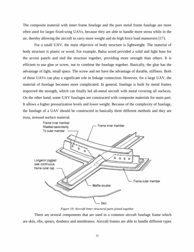
truss, stressed surface material.
Figure 19: Aircraft Inner structural parts joined together
There are several components that are used in a common aircraft fuselage frame which
are skin, ribs, spears, doubters and membranes. Aircraft frames are able to handle different types

16
of forces such as shear force, tension, bending force, compression force and torsion, shown in
Figure 20. Specifically, the skin is the outer surface of the aircraft, which allows the air to flow
through smoothly while distributing air pressure loads evenly onto the inner frame. Ribs and
spears are usually mounted vertically to each other and these two components are able to handle
stresses while the aircraft is in the air. A doubler is a reinforcement for the ribs and spears of the
aircraft. Additionally, it is able to amortize the air pressure load to the inner frame. A member is
usually a connection on the rib or spear, which connects different components together while
distributing the load evenly by either glue or rivets. Additionally, there are some areas of an
aircraft frame which need special reinforcements such as the connection between wings and
body structure, fuel tank and engines. There are several reinforcement methods for each case,
shown in Figure 21. For the connection between wings and body, composite materials are often
used to handle extra tension at the structure of the connections and also to reduce uncontrollable
vibrations caused by turbulences. Fire proof materials are often used to protect the fuel tank.
Heat resistant ceramics are often used to isolate heat generated components by the main engines
[18].
Figure 20: Stresses that the drone body experie nces

17
Figure 21: A general view of an airplane inner structure
The design of the wings are the most complicated portion of an UAV. There are several
types of wings that are used by a man-piloted aircraft such as vertical stabilizer, horizontal
stabilizer and two major wings. Aircraft wings may also include elevators, rudders, flaps,
ailerons, and speed brakes which handle most of the load of the aircraft and provide maneuver
abilities to the aircraft. There are several types of inner structures that designers are able to
choose from (see Figure 22). Four types of designs, which are commonly used in the field of
aircraft design are rib-spare structure, composite material structure, hollow wing structure, and
high density foam structure [19].
Figure 22: Types of wings inner structures (cross section)
In order to design heavy duty wings, the first step is to find the airfoil shape that is
preferred for the given specifications. Different airfoil shapes result to different lift and drag
forces. We first have to know what the total weight of the proposed UAV should be. With this
knowledge, we can calculate the lift force needed to get it in the air. XFLR5 is the software we
use to analyze airfoil types and shapes to find the one that matches the design specifications.
Using this software our team customize the shape of the airfoil of the UAV. An example of the

18
XFLR5 airfoil data processing is listed as follow. For the Boeing Commercial Airplane
Company model 737 airfoils, the software generates the following shape [20]:
Figure 23: An airfoil shape in the XFLR5 airfoil design software
For the specific airfoil chosen, we generate a variety of plots of the lift coefficient and angle of
attack for given Reynold’s numbers.
Figure 24: Useful graphs can be plotted with the help of this software.

19
Our first concern though, is the lift we want our wings to generate. To do so we will be
using two basic equations. The first and most basic equations used is related with the lift
coefficient. The inner structures of an UAV’s wings are similar to an actual airplane, which
include skin, ribs, spars, leading and trailing edges. More specifically, by analyzing each section
individually and assuming the direction the aircraft goes is the X axis which is horizontal to the
paper, the skin covers the entire inner structure of the wing, transforms the air pressure
difference into lift and drag, and spreads the road of air pressure difference onto the inner
structure of the wings. The ribs, which can be seen in Figure 25, handles most of the vertical loads
due to the air pressure differences, usually lie almost vertically towards the X axis. The ribs also
need to be patterned by the shape of the wings; specifically, no ribs that are in a wing structure
must be placed all the way from the base to the tip of the wing. Spares are usually mounted
vertical to the ribs of the aircraft and they must be placed perfectly perpendicular to the X axis.
They handle most of the load from the air pressure which comes from the front of the wing and
the turbulence generated at the tip of the wing. In another words, spars prevent the distortion of
the wing structure. The leading and trailing edges are placed at the front and back of the wing.
Specifically, the leading edge cuts through the air and spreads the load of front air flowing
pressure evenly to spars and ribs, and the trailing edge smoothness the airflow. The wings of an
aircraft not only handle the load due to the air pressure and also they carry multiple hydraulic
systems. Also, the wings mount aerodynamic controlling components (flaps, ailerons, and speed
brakes), and most commonly carrying fuel. The design of wings is indeed crucial for a high
performance aircraft [21].
Figure 25: Inner structure of wing (whole wing)

20
2.2 Flight Control Systems of UAVs
In the sections above, we describe some of the major functions of the components of
UAVs. In this section, we describe the relationship between each component and the actual flight
control mechanisms. There are three axes that an aircraft can rotate: x, y, z (Figure 26) [22].
Figure 26: The airplane control parts labeled
The ailerons control the rotation of the aircraft in y axis, elevators control the rotation in
x axis, and rudders control the rotation in z axis. In other words, ailerons control the row
rotation, elevators control the pitch rotation, and rudders control the yaw rotation. Additionally,
the Y axis is in the direction of the nose of the aircraft, X axis points alone with the wings.
2.2.1 Physical Aerodynamic Controlling System
The physical aerodynamic controlling system is involved in controlling the aircraft either
on the ground or while flying. The physical aerodynamic controlling components include flaps,
slats, elevators, ailerons, spoiler panel, vortex generators, thrust reverser, and the wing tip. Each
component plays a crucial role in controlling the aircraft. However, depending on the type of the
aircraft which involves the size and the weight, some of the components could be combined
together or even eliminated [23]. Specifically, two pairs of flaps can be combined as one. Flaps

21
are usually mounted at the end of the wings. The major role of the flaps is to increase the wing
surface area, which helps the aircraft generates the larger amount of upward lift while flying at a
lower speed. There are several types of flaps used on passenger planes, which are high-speed
flaps and low-speed flaps. They are both called ailerons. The high-speed flaps are used to adjust
aircraft’s position and direction. The low-speed flaps are generally used in the takeoff and
landing process. Additionally, there are at least two sets of high and low-speed flaps which are
installed into the main wing of an aircraft. High-speed flaps are able to maneuver upward and
downward the wing. In the contrast, the low-speed flaps are only eligible of bending downward
the aircraft. In other words, high-speed flaps can be used to reduce aircraft speed and generate
more lift. Low speed flaps cannot be used to adjust the aircraft position. There is a speed limit of
the low-speed flaps. If the low-speed flaps are extended under a high-speed flight condition, the
connection between the flaps and the wings may be damaged and even tear off from the wings.
The physical control theory of both types of the wings are the same. Once a set of flaps are
extended, it increases the wing surface area and creates a low-pressure area above the wing,
which pushes the aircraft maneuver towards that direction. Once a set of low-speed flaps of both
wings are extended to the same direction, with a high angle of attack, the flaps creates an airbag
above the aircraft. This generates a larger low pressure area above the wings and also allows the
aircraft to maneuver at a much lower speed [24]. Slats are similar to the flaps. The only
difference between them is that the slats are mounted at the front tip of the wings. Slats are often
used during takeoff and the final lending process. They increase the wing surface by extending
forward. The major difference between flaps and slats is only high-speed flaps can be used
during the high-speed maneuver. However, the slats can be used under various conditions,
especially for military aircraft during high-speed turning maneuver, slats are often extended to
increase the wing surface area and reduce surface vortices due to the high angle of attack.
There are usually two sets of wings on a single aircraft, the one mounted at the tail of the
aircraft are the elevators. The elevators act like a smaller version of the main wings. However,
elevators are able to rotate about the aircraft body in a certain angle no larger than 15 degrees.
The main purpose of the elevators is to stabilize the aircraft horizontally and also to distribute the
total gravitational force on the wings. The elevators allow the aircraft to handle sophisticated
airflow conditions while flying in the air. In other words, angled elevators allow the aircraft flies
with an angle of attack. This helps the wings to reduce to generate required lift in order to
22
maintain the altitude [25]. The vertical stabilizer is often used to balance the aircraft vertically,
which is known as the rudder. The vertical stabilizer operates similar to the wings. The vertical
stabilizer cuts through the air in a relevant speed and generate an equivalent amount of force to
each side of the stabilizer in order to hold the aircraft in a steady position. While the rudder is
being pushed to one direction, the vertical stabilizer generates a low-pressure area in the inverse
direction, which will force the aircraft to turn into the low-pressure zone. For some special cases,
the vertical stabilizer can be combined with the elevators in a smaller sized aircraft. One
significant point must being mentioned and that is the vertical stabilizer cannot be used
continuously back and force while flying. In the contrast, the tensile force exists on the
connection of the vertical stabilizer will increase. This may cause overloading on the connection
between the vertical stabilizer and the fuselage, which leads to mechanical failure [26].
The spoiler panels are known as speed brakes. They can either be mounted onto the
wings of the aircraft or the fuselage. The spoiler panels are used to increase the drag and
decrease the upward lift of aircraft. The spoiler panels are often used to decrease altitude while in
the air and increase the drag and downward force during the breaking process of the aircraft on
the ground. The spoiler panel guides the airflow upward the aircraft, which increases the front
surface area of the aircraft and generates a large amount of downward force to the aircraft. For a
lighter and smaller aircraft, the spoiler panel can be eliminated due to the lower momentum the
aircraft needs to handle.
2.2.2 Physical Control for Each Component
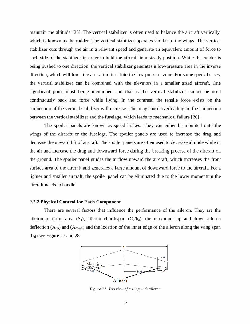
There are several factors that influence the performance of the aileron. They are the
aileron platform area (Sa), aileron chord/span (Ca/ba), the maximum up and down aileron
deflection (Aup) and (Adown) and the location of the inner edge of the aileron along the wing span
(bai) see Figure 27 and 28.
Figure 27: Top view of a wing with aileron
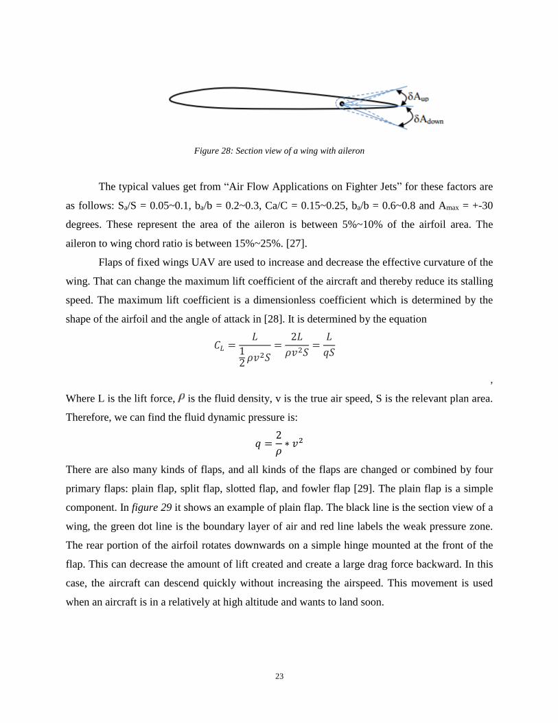
23
Figure 28: Section view of a wing with aileron
The typical values get from “Air Flow Applications on Fighter Jets” for these factors are
as follows: Sa/S = 0.05~0.1, ba/b = 0.2~0.3, Ca/C = 0.15~0.25, ba/b = 0.6~0.8 and Amax = +-30
degrees. These represent the area of the aileron is between 5%~10% of the airfoil area. The
aileron to wing chord ratio is between 15%~25%. [27].
Flaps of fixed wings UAV are used to increase and decrease the effective curvature of the
wing. That can change the maximum lift coefficient of the aircraft and thereby reduce its stalling
speed. The maximum lift coefficient is a dimensionless coefficient which is determined by the
shape of the airfoil and the angle of attack in [28]. It is determined by the equation
𝐶𝐿 =𝐿
12 𝜌𝑣2𝑆
=2𝐿
𝜌𝑣2𝑆=
𝐿
𝑞𝑆
,
Where L is the lift force, is the fluid density, v is the true air speed, S is the relevant plan area.
Therefore, we can find the fluid dynamic pressure is:
𝑞 =2
𝜌∗ 𝑣2
There are also many kinds of flaps, and all kinds of the flaps are changed or combined by four
primary flaps: plain flap, split flap, slotted flap, and fowler flap [29]. The plain flap is a simple
component. In figure 29 it shows an example of plain flap. The black line is the section view of a
wing, the green dot line is the boundary layer of air and red line labels the weak pressure zone.
The rear portion of the airfoil rotates downwards on a simple hinge mounted at the front of the
flap. This can decrease the amount of lift created and create a large drag force backward. In this
case, the aircraft can descend quickly without increasing the airspeed. This movement is used
when an aircraft is in a relatively at high altitude and wants to land soon.

24
Figure 29: Section view of plain flaps
The split flap is the rear portion of the lower surface of the airfoil which hinges
downwards from the leading edge of the flap, while the upper surface remains immobile shown
in figure 30. This can also create a large drag force toward backward but create a slightly more
lift than plain flaps [30]. This kind of flaps sometimes has the same function as a spoiler, but
pretty uncommon these days.
Figure 30: Section view of split flaps
In Figure 30, it is an example of slotted flap. The slotted flap has a gap between the flap
and the wing. This gap forces high pressure air from below the wing over the flap. It helps the
airflow remain attached to the flap, increases lift compare to the split flap and decreases the drag
force created by the hinging of the flaps.
Figure 31: Section view of slotted flaps
25
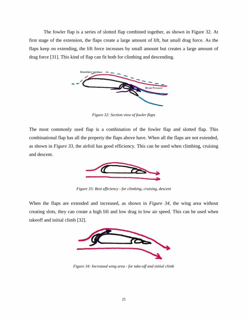
The fowler flap is a series of slotted flap combined together, as shown in Figure 32. At
first stage of the extension, the flaps create a large amount of lift, but small drag force. As the
flaps keep on extending, the lift force increases by small amount but creates a large amount of
drag force [31]. This kind of flap can fit both for climbing and descending.
Figure 32: Section view of fowler flaps
The most commonly used flap is a combination of the fowler flap and slotted flap. This
combinational flap has all the property the flaps above have. When all the flaps are not extended,
as shown in Figure 33, the airfoil has good efficiency. This can be used when climbing, cruising
and descent.
Figure 33: Best efficiency - for climbing, cruising, descent
When the flaps are extended and increased, as shown in Figure 34, the wing area without
creating slots, they can create a high lift and low drag in low air speed. This can be used when
takeoff and initial climb [32].
Figure 34: Increased wing area - for take-off and initial climb

26
When the flaps are fully extended, as shown in Figure 35, both the lift and drag forces reach
their maximum point. This is used for landing.
Figure 35: Maximum lift and high drag - approach to landing
The spoiler is a device intended to reduce the lift and increase the drag of an airfoil. This
is used when braking the aircraft on the runway and descending. When the aircraft flies in a
relatively high altitude and wants to decrease altitude quickly, the spoiler is extended normally
without exceeding 3-5 degrees. When the spoiler is fully extended, as shown in Figure 36, it can
create a large force downward and press the aircraft on the ground. In this case, the aircraft can
remain on the runway while decreasing its speed quickly [33].
Figure 36: Maximum drag and reduced lift - for braking on runway
Rudder is a moveable surface located at the end of vertical stabilizer, as shown in Figure
37. It is used to control rotation about the z axis. When the rudder is rotated, a lift force is created
and rotation of the aircraft around the center of gravity occurs.

27
Figure 37: Directional control via rudder deflection (top view)
There are two basic designs of the rudder. One is swept rudder, shown in Figure 38, another one
is rectangular rudder, shown in Figure 39. There are also many parameters that must be
determined when designing a rudder. The rudder area (Sr), rudder chord (Cr), rudder span (br),
the maximum rudder deflection (Rmax), and the location of inboard edge of the rudder (bri) are
some of these parameters.
Figure 38: Left is a swept rudder, Right is rectangular rudder (side view)
Elevators are normally hinge to the tail plane or horizontal stabilizer, shown in figure 40
and 41. Sometimes it can also be a stabilizer which means the whole horizontal stabilizer can
rotate as elevators. It controls the x axis rotation which is the angle of attack of the aircraft. For
the designing of the elevators, four parameters determine the performance of the elevators and
they are the elevator area (S), elevator chord (C), elevator span (bE), and maximum elevator

28
deflection (Emax). There are also several typical values for these parameters as follows: SE/S =
0.15 to 0.4, bE/b = 0.8-1, CE/C = 0.2-0.4, and 2 Emax_up = -25 degrees, Emax_down = +20 degrees
[34].
Figure 39: The section view of a horizontal stabilizer with elevator
Figure 40: The top view of a horizontal stabilizer with elevator
According to the values shown above, the area of the elevator is 15% ~ 40% of the horizontal
stabilizer. The length of span of the aircraft is 80% ~ 100% of the total span length. The
elevators’ cord is 0.2 ~ 0.4 multiplier relative to the total cord length. And the angle limits are 25
degrees to up and 20 degrees to down.
2.2.3 Computational Control of Aerodynamic Control System
For an UAV, the altitude and speed are two key elements in the control system. Figure 41
is an example of negative feedback system, which is described in the frequency domain. R(s) is
the input function, X(s) is the output function, H(s) is the transfer function in feedback path.
Since the UAVs may be powered by electro-motor or fuel engine, the input function can be unit
step input, unit impulse input, sinusoidal and cosine input, which can be a representative of
voltage supply or valve switch. The output function can be speed or altitude. In addition, height
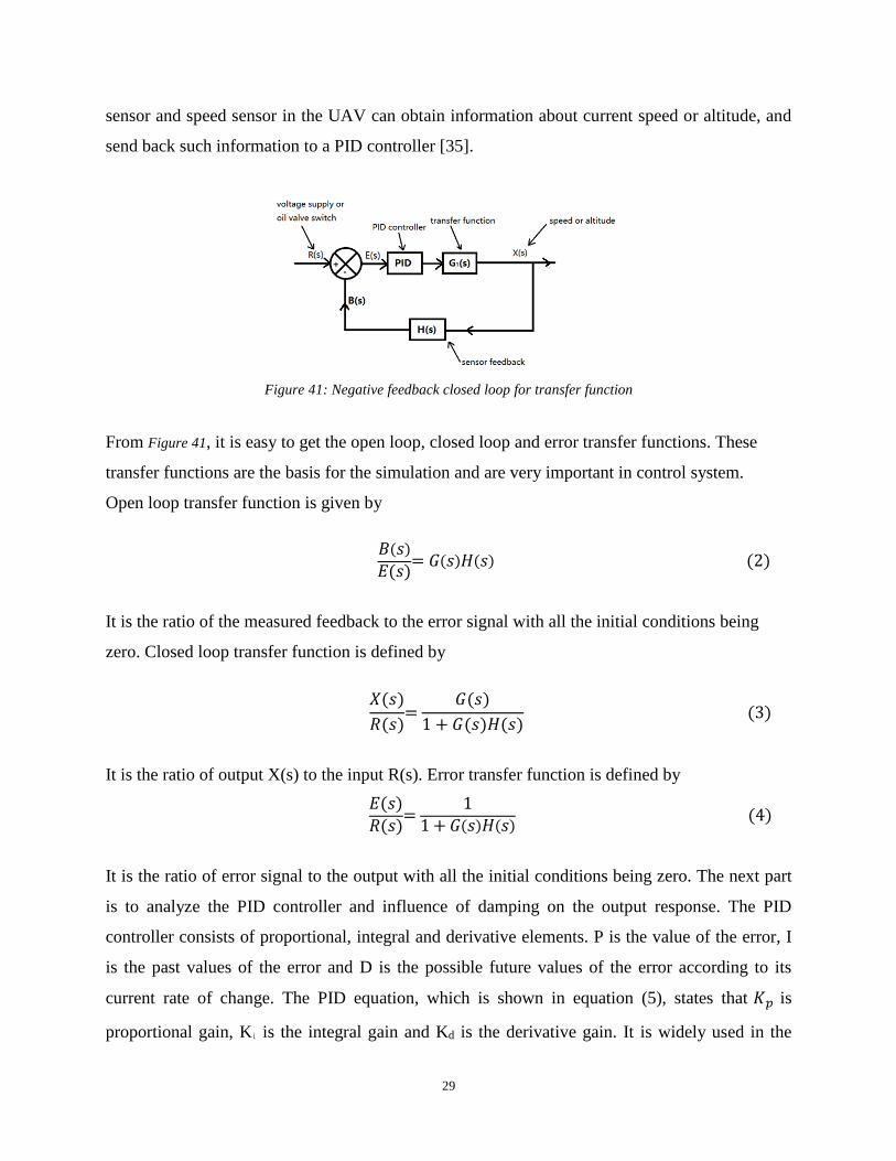
29
sensor and speed sensor in the UAV can obtain information about current speed or altitude, and
send back such information to a PID controller [35].
Figure 41: Negative feedback closed loop for transfer function
From Figure 41, it is easy to get the open loop, closed loop and error transfer functions. These
transfer functions are the basis for the simulation and are very important in control system.
Open loop transfer function is given by
𝐵(𝑠)
𝐸(𝑠)= 𝐺(𝑠)𝐻(𝑠) (2)
It is the ratio of the measured feedback to the error signal with all the initial conditions being
zero. Closed loop transfer function is defined by
𝑋(𝑠)
𝑅(𝑠)=
𝐺(𝑠)
1 + 𝐺(𝑠)𝐻(𝑠) (3)
It is the ratio of output X(s) to the input R(s). Error transfer function is defined by
𝐸(𝑠)
𝑅(𝑠)=
1
1 + 𝐺(𝑠)𝐻(𝑠) (4)
It is the ratio of error signal to the output with all the initial conditions being zero. The next part
is to analyze the PID controller and influence of damping on the output response. The PID
controller consists of proportional, integral and derivative elements. P is the value of the error, I
is the past values of the error and D is the possible future values of the error according to its
current rate of change. The PID equation, which is shown in equation (5), states that 𝐾𝑝 is
proportional gain, Ki is the integral gain and Kd is the derivative gain. It is widely used in the
30
feedback control study of systems. Some applications might require using only one or two terms
of the PID to provide the appropriate system control. This can be done by setting the other
parameters to zero. A PID controller may be called a PI, PD, P or I controller in the absence of
the respective control actions [37].
u(t) = 𝐾𝑝𝑒(𝑡) + 𝐾𝑖 ∫ 𝑒(𝜏)𝑑𝜏 + 𝐾𝑑𝑑𝑒(𝑡)
𝑑𝑡
𝑡
0 (5)
PID equation shown in equation (6) can be changed into transfer function, which can be used in
the control analysis:
𝐺𝑃𝐼𝐷(𝑠) = 𝑈(𝑠)
𝐸(𝑠)= 𝑘𝑝+
𝑘𝑖
𝑠 +𝑘𝑑𝑠 (6)
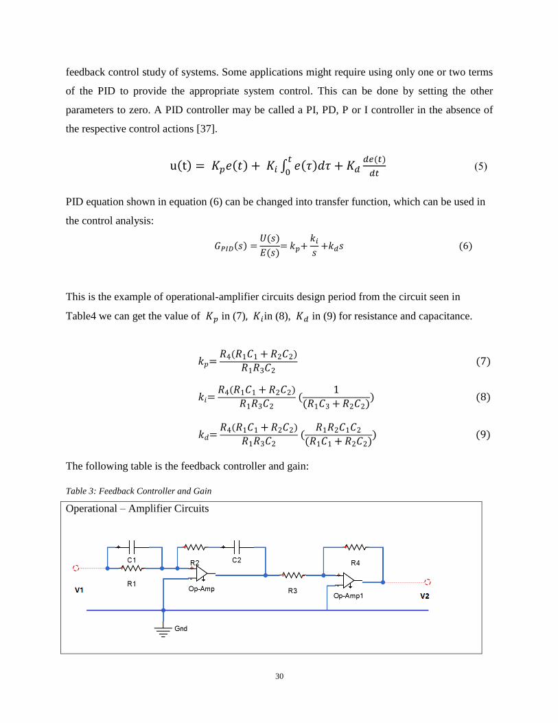
This is the example of operational-amplifier circuits design period from the circuit seen in
Table4 we can get the value of 𝐾𝑝 in (7), 𝐾𝑖in (8), 𝐾𝑑 in (9) for resistance and capacitance.
𝑘𝑝= 𝑅4(𝑅1𝐶1 + 𝑅2𝐶2)
𝑅1𝑅3𝐶2 (7)
𝑘𝑖= 𝑅4(𝑅1𝐶1 + 𝑅2𝐶2)
𝑅1𝑅3𝐶2 (
1
(𝑅1𝐶3 + 𝑅2𝐶2)) (8)
𝑘𝑑= 𝑅4(𝑅1𝐶1 + 𝑅2𝐶2)
𝑅1𝑅3𝐶2 (
𝑅1𝑅2𝐶1𝐶2
(𝑅1𝐶1 + 𝑅2𝐶2)) (9)
The following table is the feedback controller and gain:
Table 3: Feedback Controller and Gain
Operational – Amplifier Circuits

31
The UAV system can control the speed and altitude by adjusting values of 𝐾𝑝, 𝐾𝑖, 𝐾𝑑 The Figure
42 is an example of PID simulation. From this graph, amplitude performs underdamped,
undamped and overdamped by different value of 𝐾𝑝, 𝐾𝑖 , 𝐾𝑑. When 𝐾𝑝 = 100, 𝐾𝑖 =5, 𝐾𝑑 =
50, it is overdamped, which is a good example of controlling UAV at certain speed or altitude
[38].
Figure 42: PID simulation
The damping analysis can be therefore carried out. The equation in (10) is an example of a
second order transfer function. All the second order equations can be used by this model. It is a
basic analysis and model of control systems.
x ̈(t)+2ξω�̇�(𝑡) + 𝜔2𝑛𝑥(𝑡) = 𝜔2
𝑛𝑟(𝑡) (10)
There are several cases from this equation and they are: overdamping, critical damping,
underdamping and undamped. First one is underdamping case, from the calculation below, ξ
should be in the interval 0 and 1 to make the system stable.
32
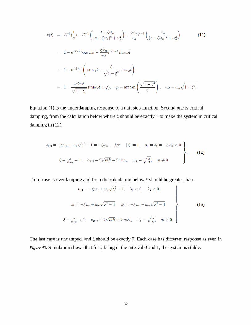
Equation (1) is the underdamping response to a unit step function. Second one is critical
damping, from the calculation below where ξ should be exactly 1 to make the system in critical
damping in (12).
Third case is overdamping and from the calculation below ξ should be greater than.
The last case is undamped, and ξ should be exactly 0. Each case has different response as seen in
Figure 43. Simulation shows that for ξ being in the interval 0 and 1, the system is stable.
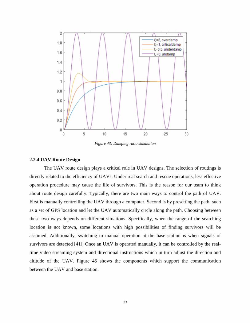
33
Figure 43: Damping ratio simulation
2.2.4 UAV Route Design
The UAV route design plays a critical role in UAV designs. The selection of routings is
directly related to the efficiency of UAVs. Under real search and rescue operations, less effective
operation procedure may cause the life of survivors. This is the reason for our team to think
about route design carefully. Typically, there are two main ways to control the path of UAV.
First is manually controlling the UAV through a computer. Second is by presetting the path, such
as a set of GPS location and let the UAV automatically circle along the path. Choosing between
these two ways depends on different situations. Specifically, when the range of the searching
location is not known, some locations with high possibilities of finding survivors will be
assumed. Additionally, switching to manual operation at the base station is when signals of
survivors are detected [41]. Once an UAV is operated manually, it can be controlled by the real-
time video streaming system and directional instructions which in turn adjust the direction and
altitude of the UAV. Figure 45 shows the components which support the communication
between the UAV and base station.

34
Figure 44: Relation between UAV and Back-End
There are several advantages of using manual mode. First of all, people can discover the
real-time situations through watching the video stream sent back from the UAV. Detailed
information can help the UAV operator and rescuers to make timely and effective decisions.
Second, the base station may notice some details that the sensors on the scene may not recognize.
The disadvantages of manual mode are the high cost of systems management and security. For
some manual operations, operating time could be several hours and weeks. Long time highly
concentrated working distribution would decrease the sensitivity of operators. This is critical to
rescuing missions. In order to minimize manual mode operations, auto mode, which is known to
have several features, is used. While an UAV is operated under automatic mode, there is no need
of operators to manage the operating procedures. The UAV will fly along the designed path and
keep searching for the survivors on the ground through many powerful sensors mounted on it.
On the other hand automatic operation requires user inputs and operating procedures such a path
information control the UAV [42]. Figure 46 presents the paths of the UAV of an accident scene
where the red points indicate the location of the UAV along the path.
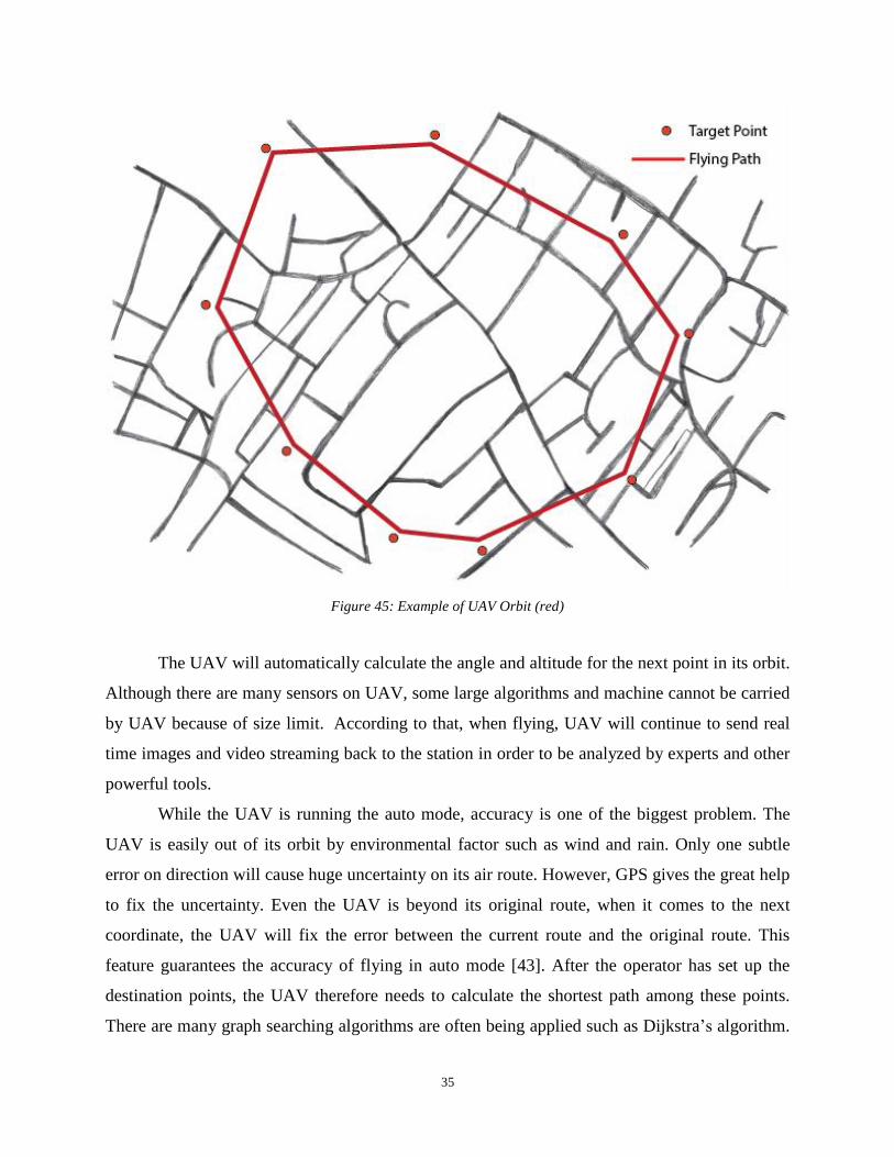
35
Figure 45: Example of UAV Orbit (red)
The UAV will automatically calculate the angle and altitude for the next point in its orbit.
Although there are many sensors on UAV, some large algorithms and machine cannot be carried
by UAV because of size limit. According to that, when flying, UAV will continue to send real
time images and video streaming back to the station in order to be analyzed by experts and other
powerful tools.
While the UAV is running the auto mode, accuracy is one of the biggest problem. The
UAV is easily out of its orbit by environmental factor such as wind and rain. Only one subtle
error on direction will cause huge uncertainty on its air route. However, GPS gives the great help
to fix the uncertainty. Even the UAV is beyond its original route, when it comes to the next
coordinate, the UAV will fix the error between the current route and the original route. This
feature guarantees the accuracy of flying in auto mode [43]. After the operator has set up the
destination points, the UAV therefore needs to calculate the shortest path among these points.
There are many graph searching algorithms are often being applied such as Dijkstra’s algorithm.
36
Specifically, given a graph with V, the number of nodes, and E, the number of edges. Dijkstra’s
algorithm has O(V^2) running time. Actually this complexity can be improved by using min-
priority queue structure. The implementation based on a min-priority queue implemented by a
Fibonacci heap and running in O(E + Vlog(V)) [44].
2.3 Power Components, Instruments and Sources of UAVs
The selection of electrical power source for an in-flight computer and operation depend
upon weight, efficiency, flexibility, quality, stability, and cost. Weight is a crucial factor when
considering a power system on UAV. The UAV, subtle difference on weight can lead significant
effects on efficiency. Especially, the power system mainly runs on battery, and weight can
decide the capacity of the whole power system. Efficiency is calculated by actual electrical
output divided by total electrical output. As a component of the whole system, improving
efficiency as much as possible can benefit system’s operation. Less redundant waste on transition
and rational power arrangement are two ways to improve whole system. Flexibility in power
system is regarded as an ability to respond to the change in demand. The UAV is a highly multi-
used vehicle. Electrical power source for the UAV should have ability to meet different
requirements in different environment. The quality of a power system is important for stability.
During an operation, unexpected collision or vibration caused by extreme weather conditions
may damage the physical structure. High quality structure material ensures the UAV working
properly in different environment so that support stable power to let every component in system
working. The cost of these materials are spread from several dollars to thousand dollars.
Different price of power source has different ways to use. However, our team chooses a power
source according to how much it is suitable for the UAV and related operation but no depending
on high cost [45].
Solar power system is not an ideal power solution for UAV. For capacity, while operating
in daytime, solar power system can use the sun to operate the UAV without limit. However, solar
energy is not available at all times. It ensures the operation of the UAV being executed without
additional fuel input. This kind of time limit will influence the utilization of an UAV. When the
emergency occurs in night time, power will be the biggest problem for the UAV. However, if the
solar system cooperate with the power system based on chemical battery, the problem can be
solved. Tradeoffs are the cost and weight. Using solar system means we should incorporate some

37
solar panels into the UAV. In order to get the maximum utilization of the sun, suitable solar
panels on top of the wings are required. The body area must be increased that the UAV can get
maximum irradiating area. The disadvantage of this is more solar panel will increase the weight
of the UAV. This means consumed rate of power will increasing so that operating time will be
decreasing. We have to make a tradeoff between the utilization and weight. So under limit
irradiating area to maximize the utilization of solar power is the problem we are facing.
Maximize the utility of solar power when it’s available is one way to improve efficiency of
power system, such as maximum receiving power from solar panel [46].
Figure 46: Basic structure of solar power system
According to the Figure 46, solar system is divided into three parts. First part is maximum
power point tricking, second part is communication between battery management and battery
modules. Third part is the transfer of the solar power to the electrical power in order to support
the whole system. Maximum power point tracking (MPPT) algorithm, can support help on
tracking the maximum power point. Detailed structure of the power system is shown as follows
[47]:

38
Figure 47: Structure of MPPT algorithm
The effects with basic solar system with MPPT is shown in Figure 49.
Figure 48: Contrast basic solar system(Left) and solar system with MMPT(Right)
As shown in Figure 48, the solar system with MMPT can produce large power output. Fuel
is a traditional and popular way to generate power. The use of fuel cell in UAVs can give UAV
stable and abundant power. Chemical generator has pretty high efficiency and utilization. It
allows UAV flying at much higher altitude, typically, five thousands meters. Strong power also
can support UAV carrying more heavy equipment such as high resolution camera, powerful
embedded system or sophisticating flying control devices. Another advantage is stability. Fuel
cell can sustain harsh environmental conditions such as cold, hot and humidity [48].
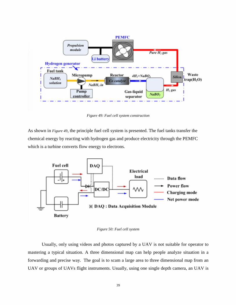
39
Figure 49: Fuel cell system construction
As shown in Figure 49, the principle fuel cell system is presented. The fuel tanks transfer the
chemical energy by reacting with hydrogen gas and produce electricity through the PEMFC
which is a turbine converts flow energy to electrons.
Figure 50: Fuel cell system
Usually, only using videos and photos captured by a UAV is not suitable for operator to
mastering a typical situation. A three dimensional map can help people analyze situation in a
forwarding and precise way. The goal is to scam a large area to three dimensional map from an
UAV or groups of UAVs flight instruments. Usually, using one single depth camera, an UAV is
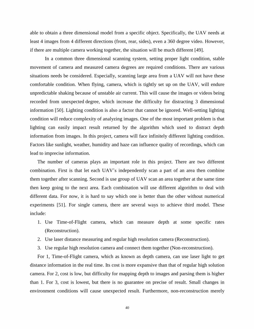
40
able to obtain a three dimensional model from a specific object. Specifically, the UAV needs at
least 4 images from 4 different directions (front, rear, sides), even a 360 degree video. However,
if there are multiple camera working together, the situation will be much different [49].
In a common three dimensional scanning system, setting proper light condition, stable
movement of camera and measured camera degrees are required conditions. There are various
situations needs be considered. Especially, scanning large area from a UAV will not have these
comfortable condition. When flying, camera, which is tightly set up on the UAV, will endure
unpredictable shaking because of unstable air current. This will cause the images or videos being
recorded from unexpected degree, which increase the difficulty for distracting 3 dimensional
information [50]. Lighting condition is also a factor that cannot be ignored. Well-setting lighting
condition will reduce complexity of analyzing images. One of the most important problem is that
lighting can easily impact result returned by the algorithm which used to distract depth
information from images. In this project, camera will face infinitely different lighting condition.
Factors like sunlight, weather, humidity and haze can influence quality of recordings, which can
lead to imprecise information.
The number of cameras plays an important role in this project. There are two different
combination. First is that let each UAV’s independently scan a part of an area then combine
them together after scanning. Second is use group of UAV scan an area together at the same time
then keep going to the next area. Each combination will use different algorithm to deal with
different data. For now, it is hard to say which one is better than the other without numerical
experiments [51]. For single camera, there are several ways to achieve third model. These
include:
1. Use Time-of-Flight camera, which can measure depth at some specific rates
(Reconstruction).
2. Use laser distance measuring and regular high resolution camera (Reconstruction).
3. Use regular high resolution camera and connect them together (Non-reconstruction).
For 1, Time-of-Flight camera, which as known as depth camera, can use laser light to get
distance information in the real time. Its cost is more expansive than that of regular high solution
camera. For 2, cost is low, but difficulty for mapping depth to images and parsing them is higher
than 1. For 3, cost is lowest, but there is no guarantee on precise of result. Small changes in
environment conditions will cause unexpected result. Furthermore, non-reconstruction merely
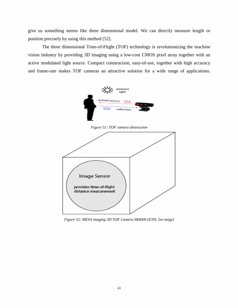
41
give us something seems like three dimensional model. We can directly measure length or
position precisely by using this method [52].
The three dimensional Time-of-Flight (TOF) technology is revolutionizing the machine
vision industry by providing 3D imaging using a low-cost CMOS pixel array together with an
active modulated light source. Compact construction, easy-of-use, together with high accuracy
and frame-rate makes TOF cameras an attractive solution for a wide range of applications.
Figure 51: TOF camera abstraction
Figure 52: MESA imaging 3D TOF Camera SR4000 (ETH, 5m range)
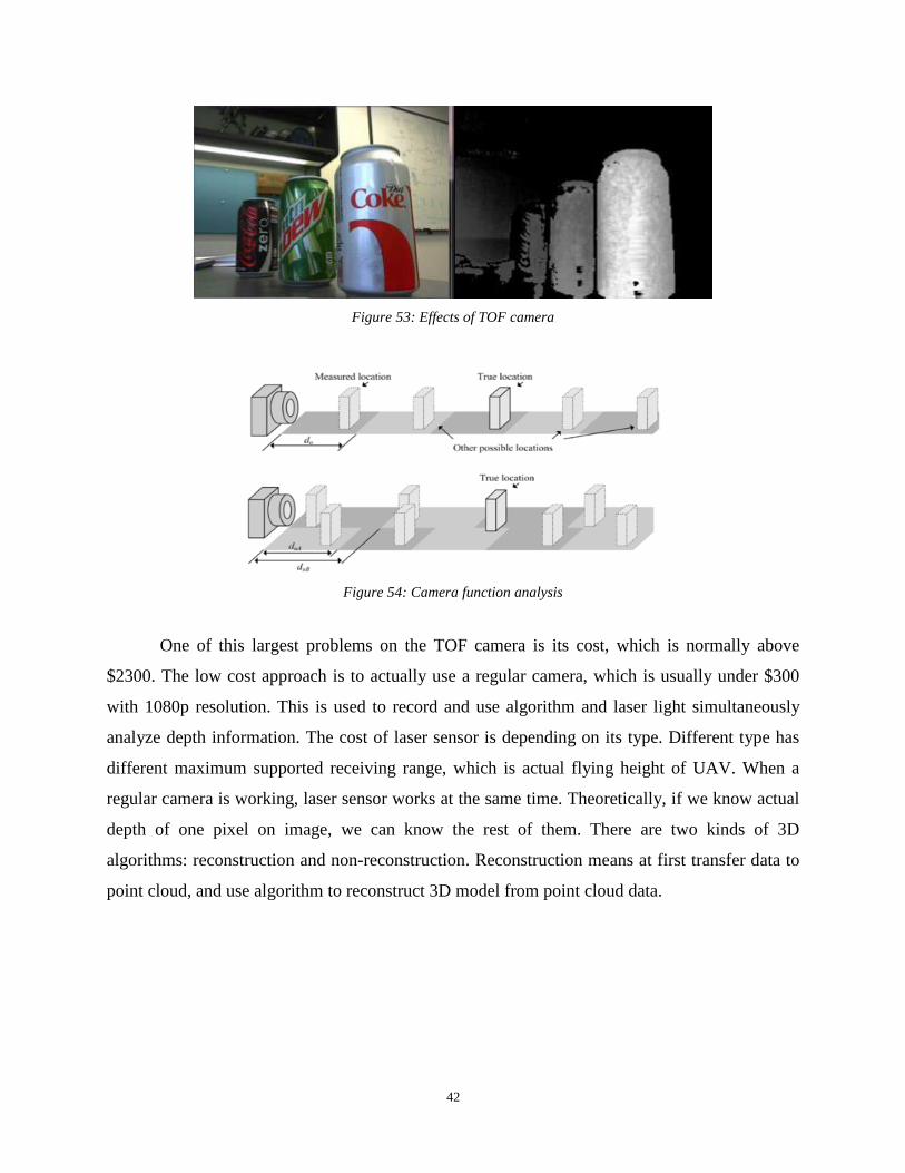
42
Figure 53: Effects of TOF camera
Figure 54: Camera function analysis
One of this largest problems on the TOF camera is its cost, which is normally above
$2300. The low cost approach is to actually use a regular camera, which is usually under $300
with 1080p resolution. This is used to record and use algorithm and laser light simultaneously
analyze depth information. The cost of laser sensor is depending on its type. Different type has
different maximum supported receiving range, which is actual flying height of UAV. When a
regular camera is working, laser sensor works at the same time. Theoretically, if we know actual
depth of one pixel on image, we can know the rest of them. There are two kinds of 3D
algorithms: reconstruction and non-reconstruction. Reconstruction means at first transfer data to
point cloud, and use algorithm to reconstruct 3D model from point cloud data.
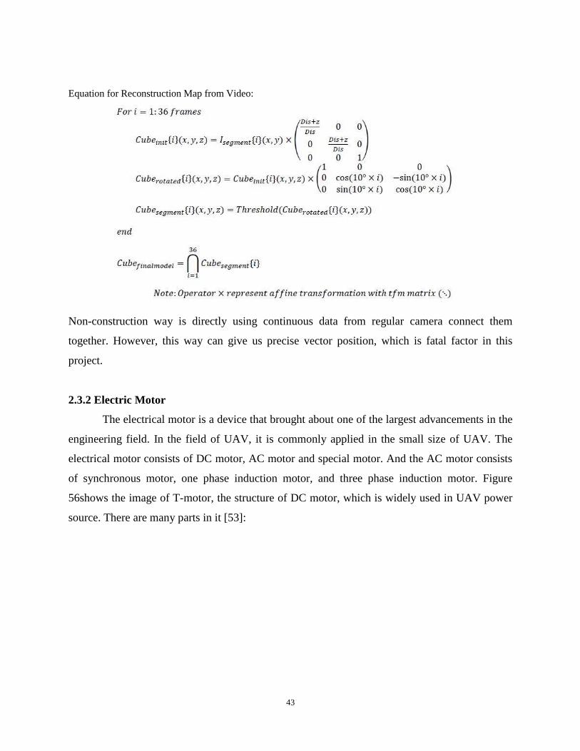
43
Equation for Reconstruction Map from Video:
Non-construction way is directly using continuous data from regular camera connect them
together. However, this way can give us precise vector position, which is fatal factor in this
project.
2.3.2 Electric Motor
The electrical motor is a device that brought about one of the largest advancements in the
engineering field. In the field of UAV, it is commonly applied in the small size of UAV. The
electrical motor consists of DC motor, AC motor and special motor. And the AC motor consists
of synchronous motor, one phase induction motor, and three phase induction motor. Figure
56shows the image of T-motor, the structure of DC motor, which is widely used in UAV power
source. There are many parts in it [53]:

44
Figure 55: Fuel cell system construction
The motor that used by UAV will be supplied by the DC power supply source. To the DC
motor we have a shaft which is attached to it. At the end of the shaft we have the pin which have
the rotor attached to it. It may or may not have the bearings to it. Let internal resistance of the
motor by 𝑅𝑎 . And 𝐾𝑡 torque constant, which is the ratio of motor output torque to input
current. Ka is back EMF constant, which is the ratio of voltage to angular speed. Vt is the
terminate voltage. The relationship is
𝜏𝑜𝑢𝑡= 𝐾𝑎𝐾𝑡
𝑅𝑎+
𝐾𝑡
𝑅𝑎𝑉𝑡 (14)
The total current with load is proportional to the output torque like equation (13).
𝐼𝑙𝑜𝑎𝑑= 𝜏𝑜𝑢𝑡
𝐾𝑡 (13)
The total torque is therefore
∑ 𝜉= 𝜉𝑚
−𝜉𝑑
− 𝜉𝑠 (14)
Where Td is the damping Torque, and where ζd = Ct , and ζs = Kt θ

45
So the equation is like equation (15)
J�̈� + 𝑐𝑡�̇� + 𝑘𝑡 = 𝐾𝑚𝑖 (15)
The motor torque has relationships with motor current, efficiency, speed and output power,
which is showing in the Figure 56. The torque is proportional to the current, inversely proportional
to speed. The output power is maximum at the mid of the torque. This graph can help us for the
future UAV motor selection. The axis represents the number of elements and torque output.
Figure 56: The relationship between UAV motor’s torque and elements
The power source is one of the most importance aspects for the UAV motor, so our team
did the case study and found that relationship between the UAV power and other performance.
The source of these data is collected from many datasheets of UAV. Figure 56 is the result of that.
Figure 57 is the relationship between UAV power and altitude. It is a good reference of the future
motor power selection base on the altitude.

46
Figure 57: The relationship between UAV power and altitude
Figure 58 is the relationship between UAV power and speed. It is a good reference of the future
motor power selection base on the speed.
Figure 58: The relationship between UAV power and speed
Figure 59 shows the relationship between UAV power and payload. It is a good reference of the
future motor power selection base on the payload.

47
Figure 59: The relationship between UAV power and payload
Figure 60 is the relationship between UAV power and weight. It is a good reference of the future
motor power selection base on the weight.
Figure 60: The relationship between UAV power and weight
2.3.3 Internal Combustion and Jet Engines
From the very beginning of aviation history, airplanes used internal combustion engines
to turn propellers and generate thrust. Internal combustion engines were used for the first flight
in human history, this of the Write brothers, and still in our days, many private airplanes and
general aviation aircrafts use the same principle. These engines are similar to the ones used in
automobiles and in this section I will be discussing the fundamentals of their function. When
studying such engines, we are interested in two kinds of operations, the mechanical and
thermodynamics. Both processes make the engines to produce the useful work we are looking
for. The mechanical design of these engines is similar to the ones that are used in automobile
industry, most widely known to engineers as four stroke or four cylinder engines. In order for
these engines to work, a mixture of fuel and air has to enter in the cylinder where the combustion
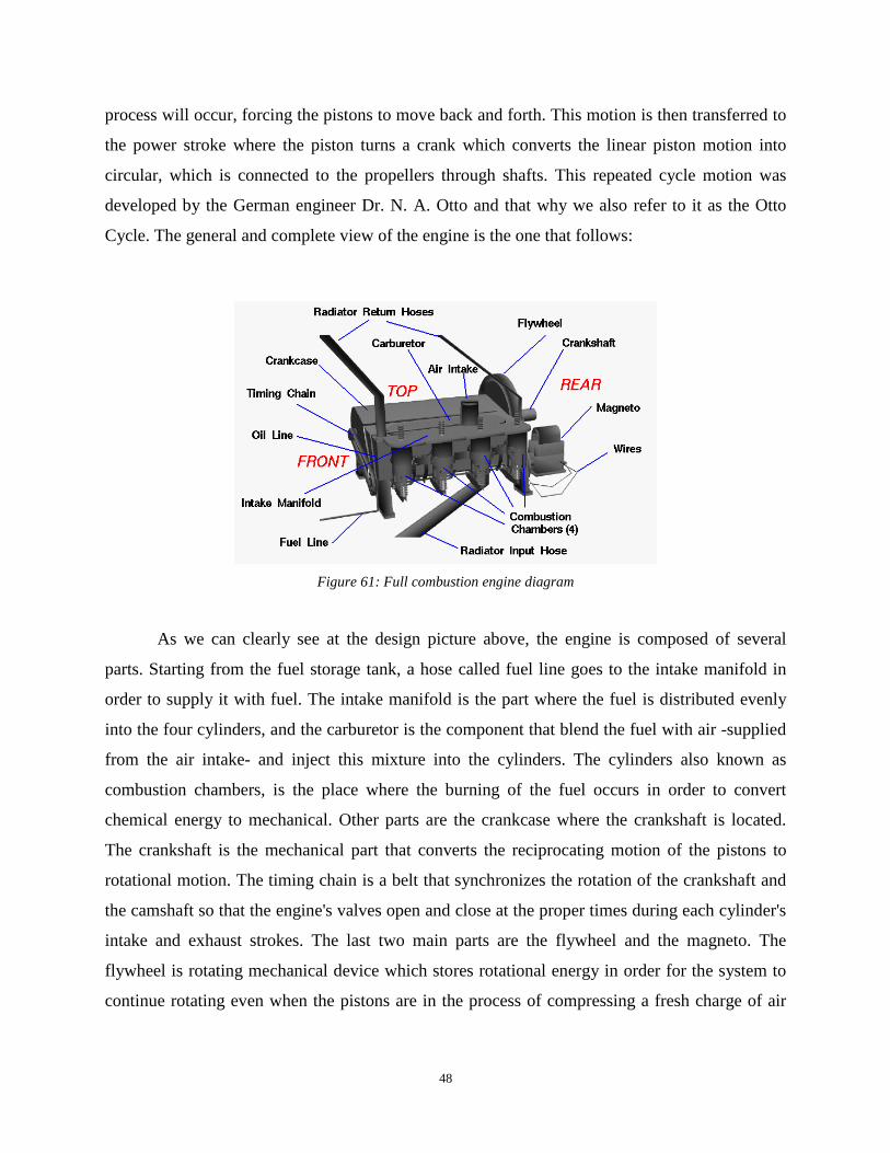
48
process will occur, forcing the pistons to move back and forth. This motion is then transferred to
the power stroke where the piston turns a crank which converts the linear piston motion into
circular, which is connected to the propellers through shafts. This repeated cycle motion was
developed by the German engineer Dr. N. A. Otto and that why we also refer to it as the Otto
Cycle. The general and complete view of the engine is the one that follows:
Figure 61: Full combustion engine diagram
As we can clearly see at the design picture above, the engine is composed of several
parts. Starting from the fuel storage tank, a hose called fuel line goes to the intake manifold in
order to supply it with fuel. The intake manifold is the part where the fuel is distributed evenly
into the four cylinders, and the carburetor is the component that blend the fuel with air -supplied
from the air intake- and inject this mixture into the cylinders. The cylinders also known as
combustion chambers, is the place where the burning of the fuel occurs in order to convert
chemical energy to mechanical. Other parts are the crankcase where the crankshaft is located.
The crankshaft is the mechanical part that converts the reciprocating motion of the pistons to
rotational motion. The timing chain is a belt that synchronizes the rotation of the crankshaft and
the camshaft so that the engine's valves open and close at the proper times during each cylinder's
intake and exhaust strokes. The last two main parts are the flywheel and the magneto. The
flywheel is rotating mechanical device which stores rotational energy in order for the system to
continue rotating even when the pistons are in the process of compressing a fresh charge of air
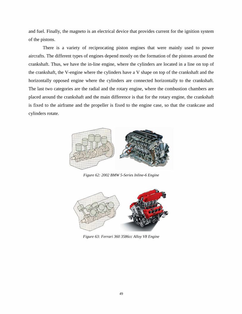
49
and fuel. Finally, the magneto is an electrical device that provides current for the ignition system
of the pistons.
There is a variety of reciprocating piston engines that were mainly used to power
aircrafts. The different types of engines depend mostly on the formation of the pistons around the
crankshaft. Thus, we have the in-line engine, where the cylinders are located in a line on top of
the crankshaft, the V-engine where the cylinders have a V shape on top of the crankshaft and the
horizontally opposed engine where the cylinders are connected horizontally to the crankshaft.
The last two categories are the radial and the rotary engine, where the combustion chambers are
placed around the crankshaft and the main difference is that for the rotary engine, the crankshaft
is fixed to the airframe and the propeller is fixed to the engine case, so that the crankcase and
cylinders rotate.
Figure 62: 2002 BMW 5-Series Inline-6 Engine
Figure 63: Ferrari 360 3586cc Alloy V8 Engine

50
Figure 64: Jabiru 3300cc Aircraft Engine
Figure 65: Pratt & Whitney R-1340 Radial Engine
Concluding, internal combustion engines were widely used in military and commercial
aviation, but when it comes into smaller aircrafts, their increased weight makes it difficult to be
carried by a drone, and so electrical engines are preferred. There has been an effort though to
supply drones with internal combustion engines. A team of German engineers recently launched
a project on the Kickstarter website, where they built a UAV which uses both an electrical motor
and small fuel combustion engines to power the aircraft. They claim that this innovation
increases air time, speed and payload [54].
There are four different kinds of turbo engines that are directly powered by the thermal
expansion of the fuel, which are turbofan, turbojet, turboprop, and ramjet engines. Based on the
internal structures and physical application of these four types of power sources, the turbofan,
turbojet, turboprop engines can be placed under the same category and the ramjet engine can be
placed in another. Although there are a large difference on the performances of these engines,
some engines can be combined in certain specific usage and application.
First and foremost, the turbofan, turbojet, turboprop engines are called turbo engines. All
turbo engines uses similar structure in order to provide the aircraft relevant thrust; specifically,
they all involve a compressor, combustion chambers, and turbines. The operation theories of

51
these components of any kind of turbo engine is equivalent as the cylinder engines. Specifically,
the gas chamber opening operation is equivalent as the front opening of a turbo engine; while the
piston moves upwards which compress the air is equivalent as the compressor; the firing
operation is equivalent as the fuel burning in the combustion chamber; and the piston moves
towards the center of the engine is equivalent as the high-temperature air pushes the turbine
blades.
On the other hand, there are several categories under the same engine type. Also, all three
types of turbo engines are applicable to UAVs based on the physical specifications. By only
looking at the active mechanical portion the engine, which are the compressor, combustion
chambers, and turbines. There are three main types of structures that are being used fairly often
in the field, which are centrifugal, single shaft, and double shaft. The centrifugal turbofan engine
is often used in the smaller aircraft with reverently slower air speed. As shown in Figure 66 the
airflow is being deviated to outside boundary of the engine by the centripetal force generated by
the compressor [55].
Figure 66: Centrifugal Turbo Engine
The advantage of this engine is this structure allows the engineers to design a shorter and
smaller engine with less mechanical components. However, due to the shape of the compressor
and the path of the airflow the engine has a chamber inside which has no use; in other words, this
structure may cause large air resistance and excessive space occupation inside of the aircraft. The
single and double shaft turbo engines both has a linear airflow, air enters straight to the engine,
compressed by the compressor, ignited in the combustion chamber, pushes the turbine blades and
exist the engine from the exit nozzle under maximum velocity. The difference between the single
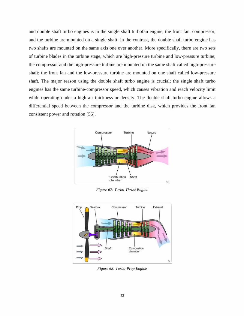
52
and double shaft turbo engines is in the single shaft turbofan engine, the front fan, compressor,
and the turbine are mounted on a single shaft; in the contrast, the double shaft turbo engine has
two shafts are mounted on the same axis one over another. More specifically, there are two sets
of turbine blades in the turbine stage, which are high-pressure turbine and low-pressure turbine;
the compressor and the high-pressure turbine are mounted on the same shaft called high-pressure
shaft; the front fan and the low-pressure turbine are mounted on one shaft called low-pressure
shaft. The major reason using the double shaft turbo engine is crucial; the single shaft turbo
engines has the same turbine-compressor speed, which causes vibration and reach velocity limit
while operating under a high air thickness or density. The double shaft turbo engine allows a
differential speed between the compressor and the turbine disk, which provides the front fan
consistent power and rotation [56].
Figure 67: Turbo-Thrust Engine
Figure 68: Turbo-Prop Engine

53
Figure 69: Turbofan Engine
2.3.4 Fuel Engine Power Source
There are multiple types of energy power supply. Fuel energy plays an essential role in
the energy field. With the same weight and size, fuel normally can provide more energy than
other kind of energy source. Fuel engine can transfer the chemical energy in the fuel to the
mechanical energy. By reacting with oxygen, liquid fuel can react violently and create
combustion. There are several types of liquid fuel: gasoline, diesel, and kerosene [57]. Gasoline
also known as petrol, is a transparent, petroleum-derived flammable liquid. When it is mixed
with air and ignited, it has the reaction:
2 C8H18 + 25 O2 → 16 CO2 + 18 H2O
Where both CO2 and H2O are in gaseous. Gasoline contains about 42.4MJ/kg with the density of
range from 0.71-0.77kg/L. Diesel fuel is widely used and can be categorized by the way it is
produced as petroleum diesel, synthetic diesel, and biodiesel. The diesel normally used for aerial
engine is petroleum diesel. This kind of diesel is the mixture of multiple components with mostly
of saturated hydrocarbons, also called alkane, and aromatic hydrocarbons. When it mixed with
air and compressed ignited, it produce gaseous carbon dioxide and water. Diesel has the heating
value of 43.1ML/kg with the density of 0.832kg/L. Kerosene is a thin, clear flammable liquid
formed from hydrocarbons obtained from fractional distillation of petroleum between 150C and
275C. This kind of fuel is widely used in airlines and can be categorized in several grades such
as Avtur, Jet A, Jet A-1, etc.The combustion reaction can be approximated as follows:
2 C12H26(l) + 37 O2(g) → 24 CO2(g) + 26 H2O(g); ∆H˚ = -7513 kJ
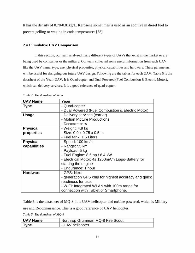
54
It has the density of 0.78-0.81kg/L. Kerosene sometimes is used as an additive in diesel fuel to
prevent gelling or waxing in code temperatures [58].
2.4 Cumulative UAV Comparison
In this section, our team analyzed many different types of UAVs that exist in the market or are
being used by companies or the military. Our team collected some useful information from each UAV,
like the UAV name, type, use, physical properties, physical capabilities and hardware. These parameters
will be useful for designing our future UAV design. Following are the tables for each UAV: Table 5 is the
datasheet of the Yeair UAV. It is Quad-copter and Dual Powered (Fuel Combustion & Electric Motor),
which can delivery services. It is a good reference of quad-copter.
Table 4: The datasheet of Yeair
UAV Name Yeair
Type - Quad-copter - Dual Powered (Fuel Combustion & Electric Motor)
Usage - Delivery services (carrier) - Motion Picture Productions - Documentaries
Physical properties
- Weight: 4.9 kg - Size: 0.9 x 0.75 x 0.5 m - Fuel tank: 1.5 Liters
Physical capabilities
- Speed: 100 km/h - Range: 55 km - Payload: 5 kg - Fuel Engine: 8.6 hp / 6.4 kW - Electrical Motor: 4s 1250mA/h Lippo-Battery for starting the engine - Endurance: 1 hour
Hardware - GPS: Next - generation GPS chip for highest accuracy and quick readiness for use. - WIFI: Integrated WLAN with 100m range for connection with Tablet or Smartphone.
Table 6 is the datasheet of MQ-8. It is UAV helicopter and turbine powered, which is Military
use and Reconnaissance. This is a good reference of UAV helicopter.
Table 5: The datasheet of MQ-8
UAV Name Northrop Grumman MQ-8 Fire Scout
Type - UAV helicopter

55
- Turbine/ Jet Fuel/ Biofuel
Use - Military use
- Reconnaissance
- Situational awareness
- Aerial fire support
- Precision targeting support
Physical properties
- Size: 7.3 x 1.9 x 2.9 m - Weight: 1,430 kg
Physical capabilities
- Payload: 272kg - Speed: 213 km/h - Range: 203.7 km - Endurance: 5-8 hours - Altitude: 6,100 m - Engine: Rolls-Royce 250, 313 kW / 420 hp
Hardware - Radar: Telephonics AN/ZPY-4 - Other Hardware: TSAR with Moving Target Indicator (MTI) capability, multispectral sensor, SIGINT module, Target Acquisition Minefield Detection System (ASTAMIDS), Tactical Common Data Link (TCDL)
Table 7 is the datasheet of MQ-9. It is Fixed Wing and powered by Turbine, which is Military
use and long-endurance. This is a good reference of fixed wing.
Table 6: The datasheet of MQ-9
UAV Name General Atomics MQ-9 Reaper (formerly named Predator B)
Type - Fixed Wing - Turbine/ Jet Engine
Use - Military Use
- Long-endurance
- High altitude surveillance
Physical properties
- Crew: 0 onboard, 2 in ground station
- Length: 36 ft 1 in (11 m)
- Wingspan: 65 ft 7 in (20 m)
- Height: 12 ft 6 in (3.81 m)
- Empty weight: 4,901 lb (2,223 kg)
- Max takeoff weight: 10,494 lb (4,760 kg)
- Fuel capacity: 4,000 lb (1,800 kg)
- Payload: 3,800 lb (1,700 kg) - Internal: 800 lb (360 kg)
Physical capabilities
- Power plant: 1 × Honeywell TPE331-10 turboprop, 900 hp (671 kW) with Digital Electronic Engine Control (DEEC)

56
- Maximum speed: 300 mph; 260 kn (482 km/h)
- Cruising speed: 194 mph; 169 kn (313 km/h)
- Range: 1,151 mi; 1,852 km (1,000 nmi)
- Endurance: 14 hours fully loaded
- Service ceiling: 50,000 ft (15,240 m)
- Operational altitude: 25,000 ft (7.5 km)
Hardware - AN/DAS-1 MTS-B Multi-Spectral Targeting System
- AN/APY-8 Lynx II radar
- Raytheon SeaVue Marine Search Radar (Guardian variants)
Table 8 is the datasheet of CH-3. It is mid-range and mid-altitude UAV, which is Military use
and farming use. It is a good reference of self-operation system.
Table 7: The datasheet of CH-3
UAV Name CH-3
Type - Capable of radio control and self-operation - Mid range - Mid altitude - Large size
Use - Military use (carry weapons, and investigation with
cameras)
- Farming
Physical properties
- 8m in wingspread - 5.5m in length - Piston engine with propeller - Three-pointed lending gear
Physical capabilities
- 2400 km non-return, with 12 hours operation time without refueling - Maximum payload 100 kg - Maximum takeoff weight 640kg - Altitude 3000m - 5000m, maximum altitude 6000m - Capable of takeoff both from runway and cat shot - Speed 220km/h - Remote range 200km
Hardware - Control panels are classified - AR-1 missile, high definition camera and investigation pot under both wings
Table 9 is the datasheet of RQ-21. It is mid-range and mid-altitude UAV, which is Military use
only. It is a good reference of radio control system.
Table 8: The datasheet of RQ-21
UAV Name RQ-21
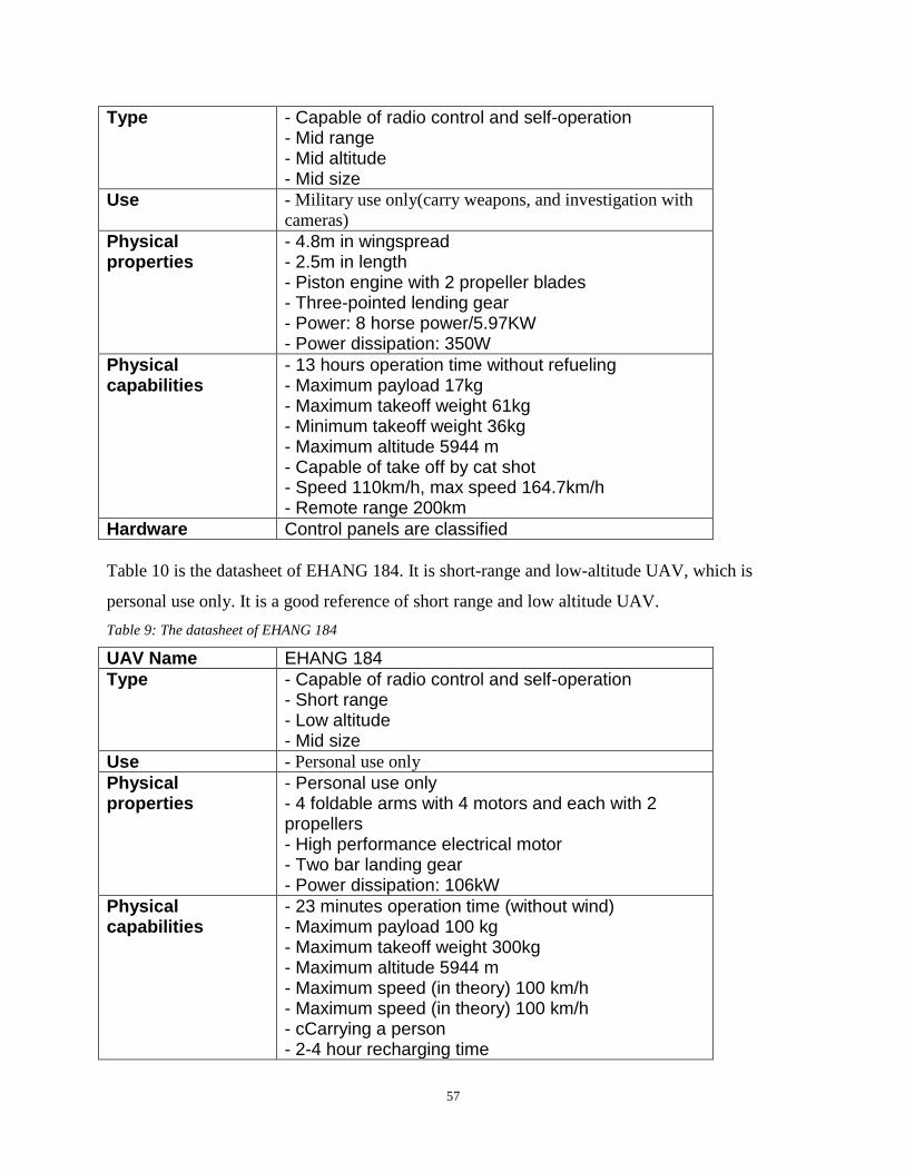
57
Type - Capable of radio control and self-operation - Mid range - Mid altitude - Mid size
Use - Military use only(carry weapons, and investigation with
cameras)
Physical properties
- 4.8m in wingspread - 2.5m in length - Piston engine with 2 propeller blades - Three-pointed lending gear - Power: 8 horse power/5.97KW - Power dissipation: 350W
Physical capabilities
- 13 hours operation time without refueling - Maximum payload 17kg - Maximum takeoff weight 61kg - Minimum takeoff weight 36kg - Maximum altitude 5944 m - Capable of take off by cat shot - Speed 110km/h, max speed 164.7km/h - Remote range 200km
Hardware Control panels are classified
Table 10 is the datasheet of EHANG 184. It is short-range and low-altitude UAV, which is
personal use only. It is a good reference of short range and low altitude UAV.
Table 9: The datasheet of EHANG 184
UAV Name EHANG 184
Type - Capable of radio control and self-operation - Short range - Low altitude - Mid size
Use - Personal use only
Physical properties
- Personal use only - 4 foldable arms with 4 motors and each with 2 propellers - High performance electrical motor - Two bar landing gear - Power dissipation: 106kW
Physical capabilities
- 23 minutes operation time (without wind) - Maximum payload 100 kg - Maximum takeoff weight 300kg - Maximum altitude 5944 m - Maximum speed (in theory) 100 km/h - Maximum speed (in theory) 100 km/h - cCarrying a person - 2-4 hour recharging time

58
Hardware N/A
Table 11 is the datasheet of Phantom3. It is short-range and low-altitude UAV, which is can be
used in recreational and commercial aerial cinematography and photography. It is a good
reference of electric Quad copters.
Table 10: The datasheet of Phantom3
UAV Name Phantom3
Type - Quad copters or drones - Powered by electric motor - Short range - Short altitude - Capable of radio control and self-operation
Use - Recreational and commercial aerial cinematography and
photography.
Physical properties
- Four electric motors mounted at the ends of the x-shaped body. - Rise speed: 5m/s - Fall speed: 3m/s - Maximum speed: 16m/s - Working environmental temperature: 0°C-40°C
Physical capabilities
- Endurance: 23mins - Weight: 1.28kg - Payload: 0kg - Maximum flying altitude: 6000m
Hardware - The body frames are made of composite materials. - Control a maximum range of 2,000 meters - Battery capacity: 4480 mAh
Table 12 is the datasheet of Spreading Wings S1000+. It is Octo-rotor UAV, which is can be
used in Professional aerial photography and cinematography. It is a good reference of electric
Octo-rotor UAV.
Table 11: The datasheet of S1000+
UAV Name Spreading Wings S1000+
Type - Octo-rotor Aircraft - Powered by electric motor - Short range - Short altitude - Capable of radio control and self-operation
Use - Professional aerial photography and cinematography.
Physical properties
- Frame Arm length
- Landing Gear Size:

59
460mm(length)*511mm(width)*305mm(height)
- Working environmental temperature: -10°C-40°C
Physical capabilities
- Takeoff weight : 6kg-11kg - Total weight: 4.4kg - Endurance: 15min
Hardware - Motor Max power: 500W - Weight of Motor :158g - A 40A electronic speed controller - 6S 15000mAh battery
Table 13 is the datasheet of Precision hawk. It is powered by single electric motor, which is can
be used in Agriculture. It is a good reference of electric UAV.
Table 12: The datasheet of Precision hawk
UAV Name Precision hawk
Type - Single electric motor(fixed wing) - Mid range - Mid altitude - Capable of radio control and self-operation
Use - Agriculture
- Energy & Mining
- Insurance & Emergency Response
- Environment Monitor
Physical properties
- Wingspan: 1.5m - Maximum speed: 22m/s - Max operating temperature: 40°C - Max operating altitude: 2500m - Communication range
Physical capabilities
- Takeoff weight : 3.55kg - Total weight: 2.4kg - Endurance: 45min
Hardware - Power source 7000 mA/ hr
Table 14 is the datasheet of Zephyr. It is High Altitude Pseudo-Satellite which is can be used in
Environmental surveillance and Maritime & Border surveillance. It is a good reference of solar
energy UAV.
Table 13: The datasheet of Zephyr
UAV Name Zephyr
Type - High Altitude Pseudo-Satellite (HAPS) UAS/UAV, running exclusively on solar power
Use - Maritime & Border surveillance - Environmental surveillance - In-theatre C4ISTAR relay - Missile detection

60
- Navigation - SIGINT - Ad-hoc communication bandwidth - Continuous imagery
Physical properties
- Capacity: 2.5 kg (5.5 lb) payload - Wingspan: 73 ft 10 in (22.50 m) - Gross weight: 117 lb (53 kg) - Power plant: 2 × Newcastle University custom permanent-magnet synchronous motor, 0.60 hp (0.45 kW) each
Physical capabilities
- Max altitude (ASL) : 21 562 m - Having already been airborne permanently for more than 14 days - Cruise speed: 30 kn (35 mph; 56 km/h) - Service ceiling: 70,000 ft (21,000 m)
Hardware - Stores solar energy collected during the day and - Uses it at night to keep the vehicle in the sky and the payload running. - Stay focused on a specific area of interest and - Provide satellite-like communications and earth observation services over long periods of time without interruption.
Table 14 is the datasheet of NASA Helios Prototype. It is solar electric- powered flying wing
designed to operate at high altitudes for long duration flight It is a good reference of solar energy
UAV.
Table 14: The datasheet of Helios
UAV Name NASA Helios Prototype
Type - Proof-of-concept solar electric- powered flying wing designed to operate at high altitudes for long duration flight - Ultra-lightweight flying wing aircraft
Use - Two different ways. First, designated HP01, focused on
achieving the altitude goals and powered the aircraft with
batteries and solar cells. The second configuration, HP03,
optimized the aircraft for endurance, and used a
combination of solar cells, storage batteries and a modified
commercial hydrogen–air fuel cell system for power at
night. In this configuration, the number of motors was
reduced from 14 to ten
Physical properties
- Wingspan: 247 ft
- Length: 12 ft
- Wing Chord: 8 ft
- Wing Thickness: 11.5 in. (12 percent of chord)

61
- Wing area: 1,976 sq. ft.
- Aspect Ratio: 30.9 to 1
- Empty Weight: 1,322 lb
- Gross Weight: Up to 2,048 lb, varies depending on
power availability and mission profile.
Physical capabilities
- Payload: Up to 726 lb, - Propulsion: 14 brushless direct-current electric motors, each rated at 2 hp. (1.5 kW) - 50,000 to 70,000 ft.,
Hardware N/A
Table 15 is the datasheet of Lockheed Martin Hale-D. It is High-Altitude Long Endurance
(HALE) and Re-usable. It is a good reference of solar energy UAV.
Table 15: The datasheet of Hale-D
UAV Name Lockheed Martin Hale-D
Type High-Altitude Long Endurance (HALE)
Use - Multi-payload, multi-mission platform,
- Reusable,
- Solar-based regenerative power system
Physical properties
- Length: 240 ft; Diameter: 70 ft - Volume: 500,000 ft3 - Demo duration goal: 5 days - 80 lb payload (commons & camera)
Physical capabilities
- 100’s kW – 200 kW solar - Developed and flew a very large 40 kw/hr lithium ion
Hardware - Solar Cell - Hull Materials - Regenerative - Fuel cell - Rechargeable batteries
Table 17 is the datasheet of Penguin B. It is fixed wing and high performance unmanned
airframe. It is a good reference of fixed wing UAV.
Table 16: The datasheet of Penguin B
UAV Name Penguin B
Type - Fixed Wing
Use - High performance unmanned airframe
Physical properties
- Length 2.27 m - Height 0.9 m - Stall Speed <13 m/s - Cruise Speed 22 m/s - Max Speed 36 m/s

62
Physical capabilities
- Empty Weight 10 kg - Endurance 26.5 hour - Payload 4 kg - Payload with fuel 11.5 kg - Takeoff Run 30 m
Hardware - Portable Ground Control Station - Fuel injected engine
Table 18 is the datasheet of Global Hawk. It is fixed wing and provides a broad overview and
systematic surveillance using high-resolution synthetic aperture radar. It is a good reference of
fixed wing UAV.
Table 17: The datasheet of Global Hawk
UAV Name Global Hawk
Type - Fixed Wing
Use - Provides a broad overview and systematic surveillance
using high-resolution synthetic aperture radar (SAR)
Physical properties
- Length 14.5 m - Height 4.7 m - Stall Speed <176km/h - Cruise Speed 310 km/h - Max Speed 629 km/h
Physical capabilities
- Empty Weight 6781 kg - Endurance 32+ hour - Payload 3000 lb - Takeoff Run 1128 m
Hardware N/A
From these tables, our team created useful tables that will help us compare the UAV
specs. The (Figure 70,Figure 71,Figure 72,Figure 73,Figure 74) are depicting the UAV comparisons on
speed, weight, endurance, altitude, and range. These charts will play a significant role in the
future UAV design, and it is a good reference point for us to start. For example, if our team
wants to design a high speed and endurance UAV for rescue operations, the global Hawk design
will be a good reference to start with. In addition, by reading these tables our team found that
there was no UAV that was good at all the parameters we studied. After deciding which design
fits our needs, we can move to Chapter 3 and start designing our own UAV. Figure 70 shows the
speed performance of each UAV, the highest speed of these UAVs is 629km/h. This chart can be
used in the future speed reference.

63
Figure 70: The speed performance of each UAV
Figure 71 is the weight performance of each UAV, the largest weight of these UAVs is 6781kg.
This chart can be used in the future weight reference.
Figure 71: The weight performance of each UAV
Figure 72 is the endurance performance of each UAV, the longest endurance of these UAVs is 32
hours. Some of UAVs are power by the solar energy, which is not listed above. This chart can be
used in the future endurance reference.
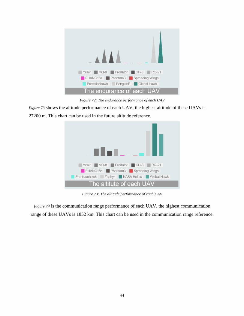
64
Figure 72: The endurance performance of each UAV
Figure 73 shows the altitude performance of each UAV, the highest altitude of these UAVs is
27200 m. This chart can be used in the future altitude reference.
Figure 73: The altitude performance of each UAV
Figure 74 is the communication range performance of each UAV, the highest communication
range of these UAVs is 1852 km. This chart can be used in the communication range reference.

65
Figure 74: The range performance of each UAV
Below is a cumulative chart of all the UAVs and their specs. Table 18: Cumulative UAV chart
UAV Application Payload Weight(kg)
Speed(km/h) Endurance(min) Altitude(m)
Precisionhawk Mid-range and mid altitude
3.55 79 45 2500
Zephyr High altitude pseudo-satellite UAV
2.5 56 20160(14 days) 21562
Spreading Wings S1000+
Short range and short altitude
11 - 15 -
NASA Helios Prototype
solar electric-powered flying operates at high altitude and long duration
334 - - 21000
Lockheed Martin Hale-D
High-altitude long endurance
36 - 7200 15240
Penguin B High performance unmanned airframe
4 130 1590 -
Global Hawk Provide a broad overview and systematic surveillance
1360 692 1920 -
Yeair Delivery services and motion picture productions
5 100 60 -
Northrop Grumman MQ-8 Fire Scout
Military, reconnaissance, Aerial fire support
272 213 480 6100
General Military, long 1700 313 840 7500

66
atomics MQ-9 Reaper
endurance and high altitude surveillance
CH-3 Military use(carry weapon) and farming
100 220 720 3000-5000
RQ-21 Military use only 17 160 780 5944
EHANG 184 Personal use 100 100 120-240 5944
Phantom 3 Recreational and commercial aerial cinematography
0 606 23 6000

67
CHAPTER 3. UAV DESIGN SOLUTIONS
3. Introduction
After having completed an extensive research on the topic of Unmanned Aerial Vehicles
and Remote Control Aerial Vehicles, it is time to select a type of UAV and based on that design
our vehicle. To do so, it is of high importance to define the details of its operation. As we
described at the introduction of Chapter 1, the purpose of our drone is to help on rescue
operations. To do that, we need it to be able to carry a sufficient amount of payload. This rescue
payload can be consisted by life detecting instruments, communication devices and the
propulsion systems that will make the vehicle able to fly. Since out team did not receive research
funding our design will not include complex detecting and expensive instruments. The team is
going to be working on a simplified version of the starting idea, in order to just fulfill the
objectives of an Interactive Qualifying Project.
More specifically, our team decided upon an aircraft-like drone, which will carry a
battery connected to the propulsion system, a camera with a resolution which will give operators
the capability to detect human like objects, and a communications system to transmit the video
data from the drone to the operators. The general specifications our team decided that should be
matched are the following. The aircraft will be flying in a low speed and altitude as we just need
it to scan a given area, and make it possible for operators to detect human life while watching the
video transmitted to them. On the other hand, we need a relatively high lift in respect with the
size of the UAV, as we want to mount on it instruments that are relatively heavy for the size and
power of our battery.
The team will be split in two sub-teams, one responsible for the inner part of the drone,
namely, the electrical and computer systems described above, and another team responsible for
the outer shape and configuration of the aircraft. In the chapter that follows, we will describe
extensively all of the above specifications and designs, as we will end up connecting all the parts
together to get our final drone design.

68
3.1 Preliminary Design and Design Methodology
3.1.1 Wings design
Wing Area: We decided to focus on a large wing area in order to generate enough lift for
carrying the payload consisted by the electronics and battery. This led to a total wing area of 0.2
m2 with a 0.6 m wingspan and 0.35 m chord length.
Aspect Ratio and Camber: The wing was designed with a fairly high aspect ratio of
approximately 1.8 in order to make for more efficient flight, while having a high camber to
increase the lift – to – drag ratio and get a higher lift coefficient. The formula to compute the
Aspect Ratio of a wing is the following shown in equation 16:
𝐴. 𝑅. = 𝑏2
𝐴
Where b is the wing span (the length of the wings) and A is the area of the wings. So in our case
we get an Aspect Ratio of:
𝐴. 𝑅. = (0.6 𝑚)2
0.2 𝑚2= 1.8
On the following picture we have two examples of the same wing with different Aspect Ratio.
Figure 75: Examples of wings with different aspect ratio.
The wing span at the two airplanes is the same, but the right design has a smaller wing
area, thus has a higher aspect ratio. Our design will look more like it the right sketch as we want
a high A.R. [59]. The cathedral or dihedral angle is the downward or upward angle of the wing
respectively. This angle influences the amount of roll moment on the aircraft when in turn, and is
an important stability factor. In our design, we will not take in consideration these effects as we
don’t need our aircraft to execute complex maneuvers, thus, we will design our wings with the
most simple angle configuration, the 0 degrees one.
(16)
(17)

69
Figure 76: Examples of the three different wing angle cases
On the left graph is an airplane design that has a dihedral wing angle, and on the right is a
design that has a configuration. Our design will be similar to the middle one where the angle is 0
degrees. As described above, we need our wing to have a large aspect ratio, which means that the
wings are going to be long. That means that in order to support not only the aircraft’s weight, but
also their own weight, they have to be made out of a material that is strong and light weighted at
the same time. Materials with these specifications are most of the times expensive, but in our
case, we can assume that our budget is big enough to include these materials. Using the Granta
CES Edu Pack materials software, we plotted all the available aerospace materials in respect
with the weight and tensile strength and we ended up selecting the Epoxy/aramid fiber as it is the
material that is less dense (1,380 kg/m3) but has a relatively high tensile strength (about 1.24*109
Pa). The only drawback is that the material is more expensive than other in market, as it costs
approximately 63.3 USD/kg [59].

70
Figure 77: The plot of aerospace materials with respect to strength and density
Our primary goal is to select the proper airfoil that is effective in low speeds and generate
enough lift force for the aircraft. For our research, we will use the standardized NACA airfoil
and I will modify it to meet our criteria. A key part to get the aircraft flying is our airfoil to
generate enough lift when in low speeds. As we will not use flaps and slats to control our
aircraft, we will be choosing a standard angle of attack for our airfoil. This is going to be
determined using the XFLR5 software. This is our most valuable tool for our airfoil analysis as it
simulates the airflow on the foil and it provides us with useful graphs for Lift Coefficient vs.
Drag Coefficient and Lift Coefficient vs. Angle of Attack. Based. To get started with our
calculations, we will assume and try to build our airplane having as given a -standard for RC
aircraft- cruise speed of 70 km/h or approximately 20 m/s.
The next step for our wing design is to figure out which airfoil we will use. Before we
model our airfoil in XFLR5 and get accurate measurements for the lift coefficient, we need to
calculate the proper Reynold’s number and Mach number which will be the inputs for the
software calculations. To do so we will use the equation in (2).

71
In order to provide an accurate lift coefficient (CL), the proper Reynold’s number and
Mach number are located. Before XFLR5 modeling could be completed, Reynold’s number and
Mach number are calculated using the equations 2 and 3:
𝑅𝑒 =𝑉𝑐
𝑣
where v is the flight speed, which in our case is 20 𝑚
𝑠), c is the chord length (in our case 0.35 m)
and the kinematic viscosity of the fluid which the airfoil operates, which is equal to
1.460×10⁻⁵ 𝑚2
𝑠 for air at the sea level (a good approximation for our design as we are looking on
low altitude flights). To calculate the Reynolds number, we chose a chord length of 0.35 m in
order to increase surface area, without making an exceedingly thick airfoil. Thin airfoils are
considered to be more effective at low speeds. [59]
𝑅𝑒 =20
𝑚𝑠 𝑥 0.35𝑚
1.4 x 10⁻⁵ 𝑚2
𝑠
= 5𝑥105
For the Mach number we have:
𝑀𝑎𝑐ℎ =𝑉
𝑐
Where V is the fight speed (in our case 20 m/s) and c is the speed of sound (343 m/s for
the air at 20 degrees Celsius), thus we get:
𝑀𝑎𝑐ℎ = 20
𝑚𝑠
343𝑚𝑠
= 0.0583
The Reynolds number and Mach number values are set as inputs to XFLR5 software. For
an angle of attack from -10 degrees to +20 degrees we run the software to get data for a variety
(18)
(19)
(20)

72
of NACA airfoils.
Figure 78: The XFLR5 analysis procedure for the given Reynolds and Mach numbers
We started with the NACA 4412 which is one of the best and most utilized airfoils in
aerospace. NACA airfoils are airfoil designs for wings developed by the National Advisory
Committee for Aeronautics and their shape is described using a series of digits, each representing
a different shape property. NACA 4412 means that the airfoil has a maximum camber of 4%
located 40% (0.4 chords) from the leading edge, with a maximum thickness of 12% of the chord.
These airfoil specifications work great for simple UAVs like ours, as they are the most standard
one is aerospace bibliography, so the only detail we looked on is the camber. As we discussed
above, higher camber results to higher Lift Coefficients as shown in the tables below.
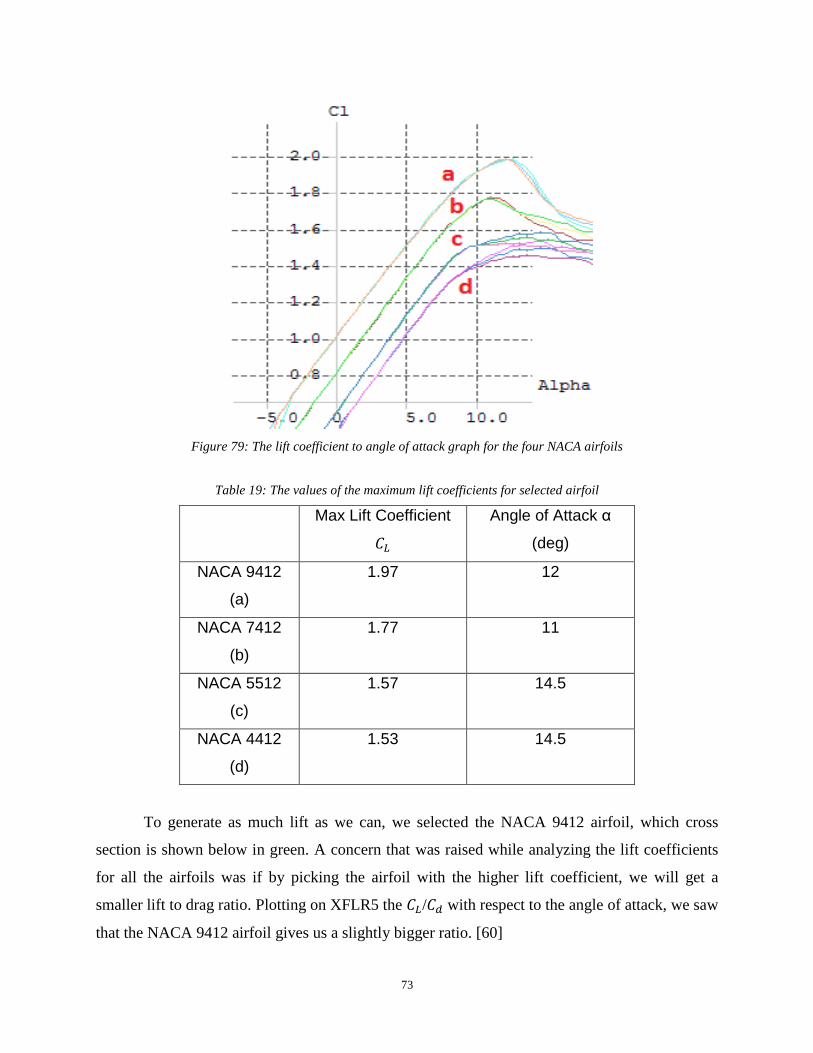
73
Figure 79: The lift coefficient to angle of attack graph for the four NACA airfoils
Table 19: The values of the maximum lift coefficients for selected airfoil
Max Lift Coefficient
𝐶𝐿
Angle of Attack α
(deg)
NACA 9412
(a)
1.97 12
NACA 7412
(b)
1.77 11
NACA 5512
(c)
1.57 14.5
NACA 4412
(d)
1.53 14.5
To generate as much lift as we can, we selected the NACA 9412 airfoil, which cross
section is shown below in green. A concern that was raised while analyzing the lift coefficients
for all the airfoils was if by picking the airfoil with the higher lift coefficient, we will get a
smaller lift to drag ratio. Plotting on XFLR5 the 𝐶𝐿/𝐶𝑑 with respect to the angle of attack, we saw
that the NACA 9412 airfoil gives us a slightly bigger ratio. [60]

74
Figure 80: The lift to drag ratio for NACA 4412 and NACA 9412 UAVs
Below is the cross sections of the NACA 4412 in red and the NACA 9412 is green. It is easy to
observe how significant the difference in camber for these two airfoils is.
Figure 81: The cross sections of NACA 4412 and NACA 9412 in XFLR5
As previously stated, the most important aspect of our project is our UAV to be able to
lift all the payload we want it to carry. As we will discuss further down, at the electronics and
communication part of our project, the weight estimate for all the devices on board is going to be
approximately 3.5 kg, and adding the weight of the wings and body itself, our UAV will not
weight more than 5 kg, so our lift calculations will be based on the assumption that our aircraft’s
maximum weight is 5kg. Thus, using Newton’s first Law (equations 21 and 22):
𝛴𝐹 = 0 (21)

75
𝑊 − 𝑚𝑔 = 0
𝑊 = 𝑚𝑔 = 5𝑘𝑔 𝑥 9.81𝑚
𝑠2= 49.05 𝑁
We need our wings to generate 49.06 Newtons of force in order to be able to fly. Using
the lift equation we can finally calculate the area of our wing and knowing the chord length we
can solve for the wingspan, and thus we can proceed to the next step, which is designing it. For
lift we have equation 6 [60]:
𝐿 =1
2 𝜌 𝑣 𝐶𝐿 𝐴
In this case, ρ is the air density which is 1.225 𝑘𝑔
𝑚3 for air at the sea level, v is the UAV’s speed
which we agreed to set as 20 𝑚
𝑠, 𝐶𝐿 is the lift coefficient which for the NACA 9412 at an angle of
attack of 12 degrees is 1.97 and A is the wing area, which is our unknown parameter. Thus, we
are solving for A:
𝐴 = 2 𝐿
𝜌 𝑣 𝐶𝐿=
2𝑥5 𝑁
1.225 𝑘𝑔𝑚3 𝑥 20
𝑚𝑠 𝑥 1.97
= 0.2 𝑚2
As we previously mentioned, our chord length is going to be 0.35 m and because we have a
rectangular wing, our area equation 25 is simply:
𝐴 = 𝑏𝑐
So our aircraft’s wingspan b will be shown in Equation 26:
𝑏 = 𝐴
𝑐=
0.2 𝑚2
0.35 𝑚= 0.6 𝑚
As soon as we defined all the parameters we needed, we exported the airfoil data to the
SolidWorks software, in order to get the cross section of our airfoil which is depicted below.
(22)
(23)
(24)
(25)
(26)

76
Figure 82: The cross section of NACA 9412 in SolidWorks
Using the Extruded Boss/Base feature in SolidWorks, we converted the 2D sketch into a
3D airfoil, with a wingspan of 600mm (0.6 meters as calculated above). This design has its real
dimensions, so it is ready to get assembled with the body. The format of the file allows us to 3D
print a sample airfoil. Below are 3 views of the airfoil, each one from a different angle.
Figure 83: The top back view of NACA 9412 and its wingspan length

77
Figure 84: The bottom view of NACA 9412 and its wingspan length
Figure 85: The top front view of NACA 9412
3.1.2 Body Design
Below is a fixed wing UAV model with a length of 46 cm and a width of 50 cm. It has
two engines and each has the power of 5W. This UAV can fly within a range of 50 km and have
average speed of 100km/h. It can deliver up to 3kg weight and drop 15m above the ground.
We put the engine above the wings because at the bottom of the UAV a payload box can be
mounted which can carry cameras and other medical supplies. At the front of the UAV it has a

78
tube shape device. That is a pitot tube used to measure the relative speed between UAV and wind.
Another function for that is to break the air and decrease the air resistance. The V shape elevator
design is to decrease the number of elevators from 3 to 2 in order to save materials and energy.
Figure 86: The design of UAV model
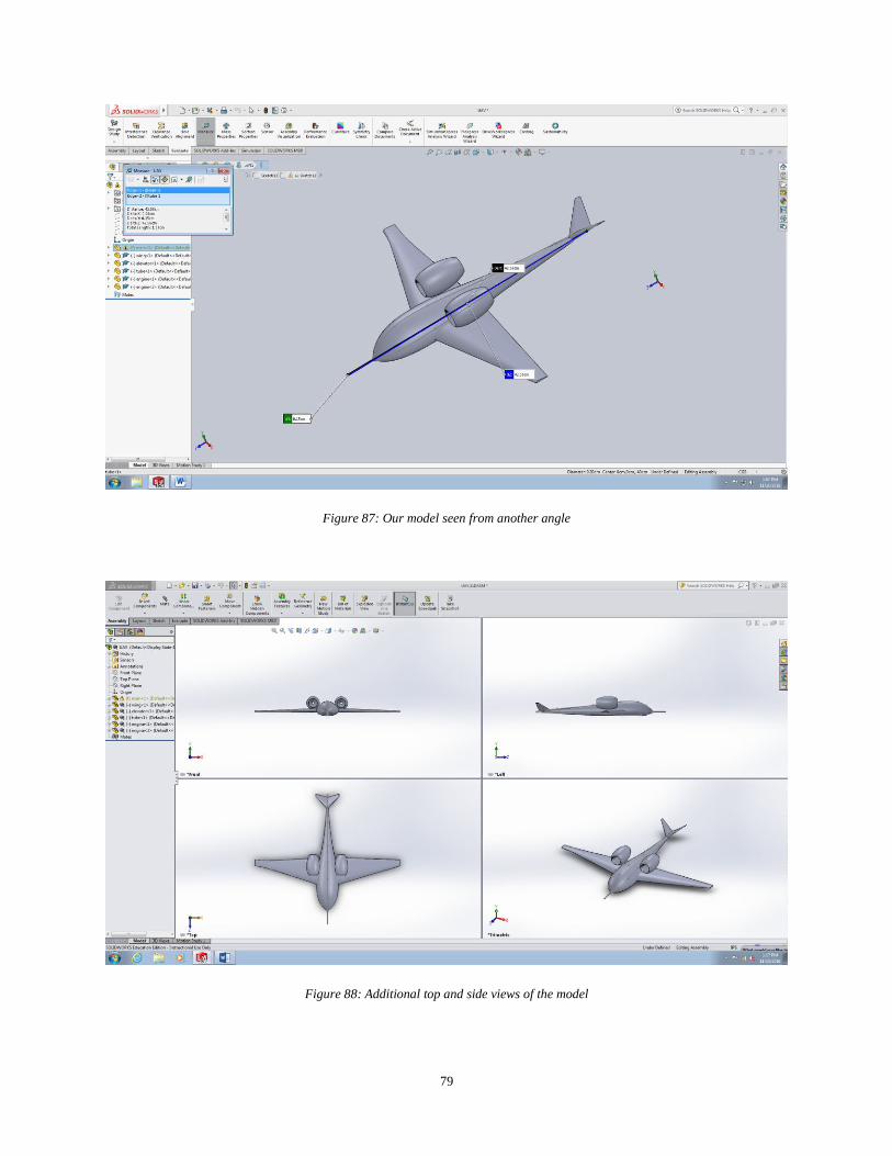
79
Figure 87: Our model seen from another angle
Figure 88: Additional top and side views of the model

80
3.2 Search and Rescue Methodologies
3.2.1 Transducers and Sensors Descriptions
In this section, sensors and transducers are discussed. In order to make the drone flies in a
stable manner, the drone needs to keep sensing the environment and its operating conditions.
Sensors such as encoders, potentiometers, oil scale are necessary; however, the exteroptive
sensors will be the main focus. It is very important to keep the drone sensing the environment
and take actions to different situations. The discussion of some specific sensors will be carried
out which are pitot tubes, weather sensors, GPS, accelerometer, gyroscope, and the specific
usages. An accelerometer is a device that measures the proper acceleration. That means when the
accelerometer is in stationary, the net acceleration is pointing up with the amount of 9.8 m/s^2.
When the accelerometer is in free fall state, the acceleration is 0 m/s^2. An accelerometer on a
UAV can helps it know in which direction is the ground. It also helps the onboard computer to
know the acceleration in X, Y, and Z axis. In real situation, the calculations of the actual
acceleration are needed especially during flying, raising, or landing. Because the acceleration is
proportional to the force, a close loop structural is reasonable to control the UAV and the
propeller.
For the structure of the accelerometer, the most common type is a 3D-MEMS (Three-
Dimensional Micro Electro Mechanical System) accelerometer. This make use of the
piezoelectricity. Piezoelectricity is when a force exerted on a crystal, a current can be created.
Inside the accelerometer it is a structure similar to Figure 89. When a force exerted, the mass in
the middle moves and each pair of green structure locates at top and bottom are charged and
have the same function as a capacitor. The ammeter senses the current and can calculate the
corresponding force.

81
Figure 89: One Dimensional Structure of an Accelerometer
Gyroscope is a devise to measure the angular velocity and angle displacement in X, Y,
and Z axis. While the UAV is flying, it is necessary to know the angle in each axis. For example,
the attack angle can be directly measured by gyroscope. When controlling the UAV, the UAV
must keep stable and remain in the same attack angle when it is flying in straight line.
The most common used gyroscope is also a MEMS [61] (Micro Electro Mechanical
System) which also takes advantages of the piezoelectricity. This kind of gyroscope is called
vibrating gyroscope. There is a drive arm that keeps a special designed (Double-T shape, tuning
fork, H-shape tuning fork) structure crystal keep on vibrating. When a rotational acceleration
exerted, the crystal will twist in different direction and amplitude. The crystal is in the middle of
a capacitor, so when the voltage potential changes, the current change will be sensed by the
ammeter connected with the capacitor.
A pitot tube [62] is a pressure measurement device that used to measure fluid flow
velocity. When a UAV is flying, it is important to know what is the velocity related to the air.
Sometimes, calculation of the velocity according the data is collected by accelerometer.
However, this is the velocity relative to the earth or ground. When the UAV is flying in a steady
velocity, most of the forces acting on the UAV is exerted on air. Therefore, in order to control
the UAV well, the relative velocity to the air is much more important compare to the ground
speed.
A pitot tube is a tube with one open end and one close end. Inside the tube, it cannot
measure the flow of the air. However, according to Bernoulli’s equations:
82
Stagnation pressure = static pressure + dynamic pressure
Equations are listed as follow:
𝑃𝑡 = 𝑃𝑠 +1
2𝜌𝑉2
Therefore the velocity is shown in Equation 28.
𝑉 = √2(𝑃𝑡 − 𝑃𝑠)
𝜌
Where V is flow velocity in m/s, Pt is the stagnation pressure in Pascal, Ps is static
pressure Pascal, and rho is the fluid density in kg/m. According to the equations above, the
velocity of the UAV reverent to the air can be easily retained.
GPS is known as Global Positioning System. It is a global navigation satellite system that
can provide location and time in all weather conditions. When the UAV flying by its own, it is
necessary to constantly report its precise locations. In addition, while searching for survivors, it
has high possibility to search in extreme environment such as heavily rain, extreme cold, and lots
of mountains or forest. It is necessary to find a reliable device to find the exact location. GPS just
fit for all these requirements. For a GPS receiver modular, crucial properties must be selected
such as, size, update rate, power requirement, channels, antennas, and accuracy. These will be
discussed more into detail in the next section.
Weather sensors include a lot of sensors. In order to search and save in most efficient
way, UAV need to know if the environment is out of its working limit. For example, if UAV
searching in polar zone, the temperature could lower than -40 C degrees. That can make the oil
freeze, and UAV can fly. Also, in order to save in most efficient way, UAV should report the
current weather, so people back at station can decided, when and how to save. Just as the
example raised above, UAV needs to check the environment temperature to keep itself safe.
Especially, when it is working in extreme cold or warm environment. A thermometer is normally
a thermoreceptor with an ammeter. As the resistance of the resistor changes with the
temperature, the current changes.
Humidity is the percentage of water in air. The amount of water in air can strongly affect
the performance of precise devices. Therefore, the humidity sensing is critical in order to keep
the UAV function well. If a UAV enters extreme high moisture zone the UAV should try its best
to exit that zone and try not enter next time to keep UAV in good performance. There are two
(27)
(28)
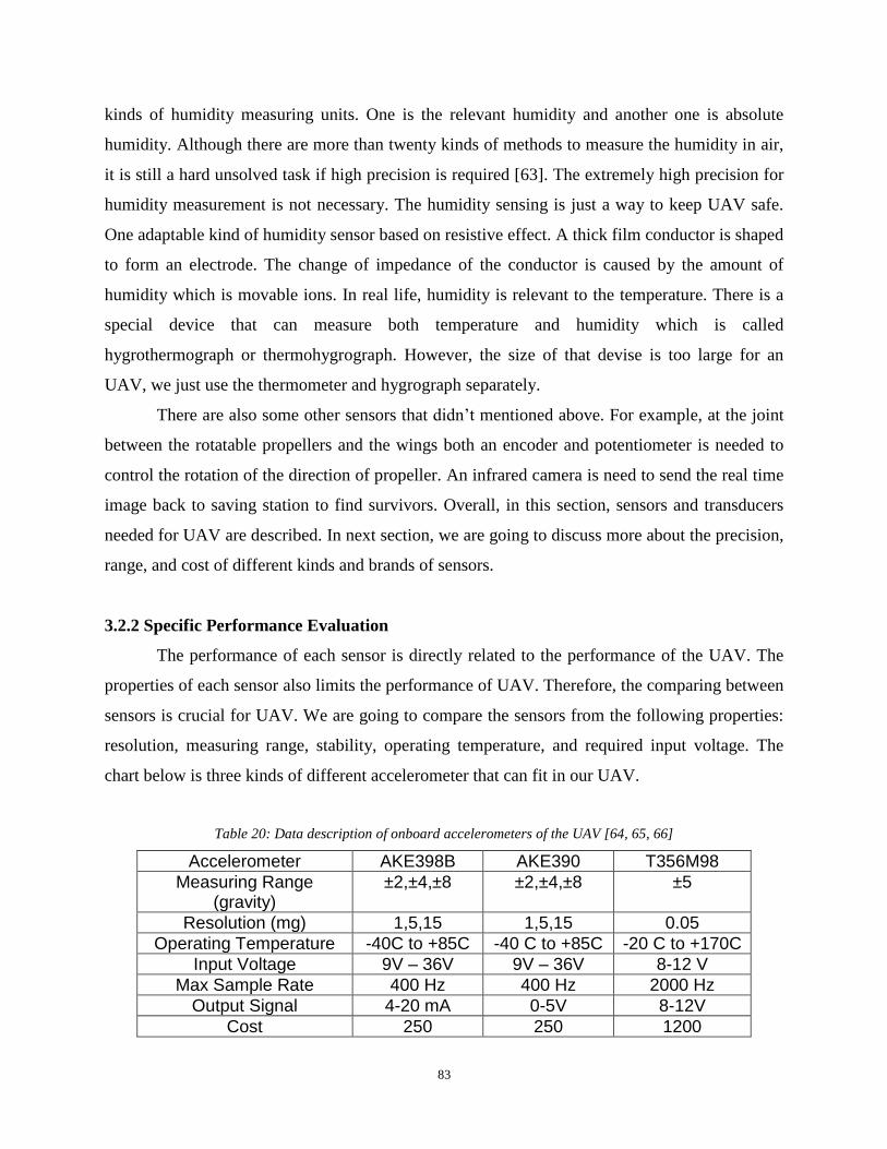
83
kinds of humidity measuring units. One is the relevant humidity and another one is absolute
humidity. Although there are more than twenty kinds of methods to measure the humidity in air,
it is still a hard unsolved task if high precision is required [63]. The extremely high precision for
humidity measurement is not necessary. The humidity sensing is just a way to keep UAV safe.
One adaptable kind of humidity sensor based on resistive effect. A thick film conductor is shaped
to form an electrode. The change of impedance of the conductor is caused by the amount of
humidity which is movable ions. In real life, humidity is relevant to the temperature. There is a
special device that can measure both temperature and humidity which is called
hygrothermograph or thermohygrograph. However, the size of that devise is too large for an
UAV, we just use the thermometer and hygrograph separately.
There are also some other sensors that didn’t mentioned above. For example, at the joint
between the rotatable propellers and the wings both an encoder and potentiometer is needed to
control the rotation of the direction of propeller. An infrared camera is need to send the real time
image back to saving station to find survivors. Overall, in this section, sensors and transducers
needed for UAV are described. In next section, we are going to discuss more about the precision,
range, and cost of different kinds and brands of sensors.
3.2.2 Specific Performance Evaluation
The performance of each sensor is directly related to the performance of the UAV. The
properties of each sensor also limits the performance of UAV. Therefore, the comparing between
sensors is crucial for UAV. We are going to compare the sensors from the following properties:
resolution, measuring range, stability, operating temperature, and required input voltage. The
chart below is three kinds of different accelerometer that can fit in our UAV.
Table 20: Data description of onboard accelerometers of the UAV [64, 65, 66]
Accelerometer AKE398B AKE390 T356M98
Measuring Range (gravity)
±2,±4,±8 ±2,±4,±8 ±5
Resolution (mg) 1,5,15 1,5,15 0.05
Operating Temperature -40C to +85C -40 C to +85C -20 C to +170C
Input Voltage 9V – 36V 9V – 36V 8-12 V
Max Sample Rate 400 Hz 400 Hz 2000 Hz
Output Signal 4-20 mA 0-5V 8-12V
Cost 250 250 1200
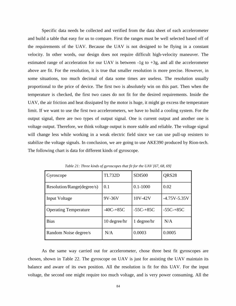
84
Specific data needs be collected and verified from the data sheet of each accelerometer
and build a table that easy for us to compare. First the ranges must be well selected based off of
the requirements of the UAV. Because the UAV is not designed to be flying in a constant
velocity. In other words, our design does not require difficult high-velocity maneuver. The
estimated range of acceleration for our UAV is between -1g to +3g, and all the accelerometer
above are fit. For the resolution, it is true that smaller resolution is more precise. However, in
some situations, too much decimal of data some times are useless. The resolution usually
proportional to the price of device. The first two is absolutely win on this part. Then when the
temperature is checked, the first two cases do not fit for the desired requirements. Inside the
UAV, the air friction and heat dissipated by the motor is huge, it might go excess the temperature
limit. If we want to use the first two accelerometers, we have to build a cooling system. For the
output signal, there are two types of output signal. One is current output and another one is
voltage output. Therefore, we think voltage output is more stable and reliable. The voltage signal
will change less while working in a weak electric field since we can use pull-up resisters to
stabilize the voltage signals. In conclusion, we are going to use AKE390 produced by Rion-tech.
The following chart is data for different kinds of gyroscope.
Table 21: Three kinds of gyroscopes that fit for the UAV [67, 68, 69]
Gyroscope TL732D SDI500 QRS28
Resolution/Range(degree/s) 0.1 0.1-1000 0.02
Input Voltage 9V-36V 10V-42V -4.75V-5.35V
Operating Temperature -40C-+85C -55C-+85C -55C-+85C
Bias 10 degree/hr 1 degree/hr N/A
Random Noise degree/s N/A 0.0003 0.0005
As the same way carried out for accelerometer, chose three best fit gyroscopes are
chosen, shown in Table 22. The gyroscope on UAV is just for assisting the UAV maintain its
balance and aware of its own position. All the resolution is fit for this UAV. For the input
voltage, the second one might require too much voltage, and is very power consuming. All the

85
working temperature is fit for UAV too. When it comes to bias and noise, even though the exact
price cannot be found on internet, it is not hard to get the conclusion that the more precise the
more expensive a device is. As I mentioned above, in order to reduce the cost of UAV, TL732D
is chosen for our application which is also produced by Rion-tech.
Most pitot tubes are similar and the main differences are size and range. It is fairly
reasonable to pick a pitot tube that is commonly used for UAV. It is produced by UAV factory
and called Heated Pitot – Static Probe [70]. This has the weight of 58 grams and length of
238mm with the working temperature of -50 C to +85 C. Because this is a digital pitot tube, the
operating voltage is 12V and signal output is 5V.
GPS is also an important sensor on UAV because it can send the location of the UAV
back to ground station. There are lots of GPS receiver modular selling on internet, the main
difference is the sample rate and the number of channels. The Venus GPS [71] produced by
SparkFun is selected. This modular has up to 20Hz update rate and precision of 2.5 meter. This is
a low power consuming device with only 3.3V required power supply.
The thermos sensor is very cheap and the only thing needs be considered is its operating
temperatures. The ideal range should be lower than -70C and higher than 200C. However, the
digital thermometers are also need for the electrical wire and chips. It is hard to find a
thermometer that works at a temperature lower than -40C. Therefore, temperature lower bound
can be assumed as 40C. We choose the cheapest one which is produced by SparkFun called
TMP36 [72].
The hydro sensor is a little bit complicated, and it is hard to find a small device that
measure precise humidity. The humidity sensor needed is just for protect the devices inside the
UAV. HH10D [73] is selected which also produced by SparkFun. It requires 2.7-3.3 volts and
with the accuracy of +-3%.
3.2.3 UAV Cooling System
The cooling system on the UAV is very important because all the electrical devices, the
motor and the air fraction all produce a lot of heat. It will be a problem that can burn all the chips
in UAV if there is a management issue. Therefore, our team decided to use a thermoelectric
cooling device that transfer the heat around the chip to the air that going to flow into the turbo
engine.
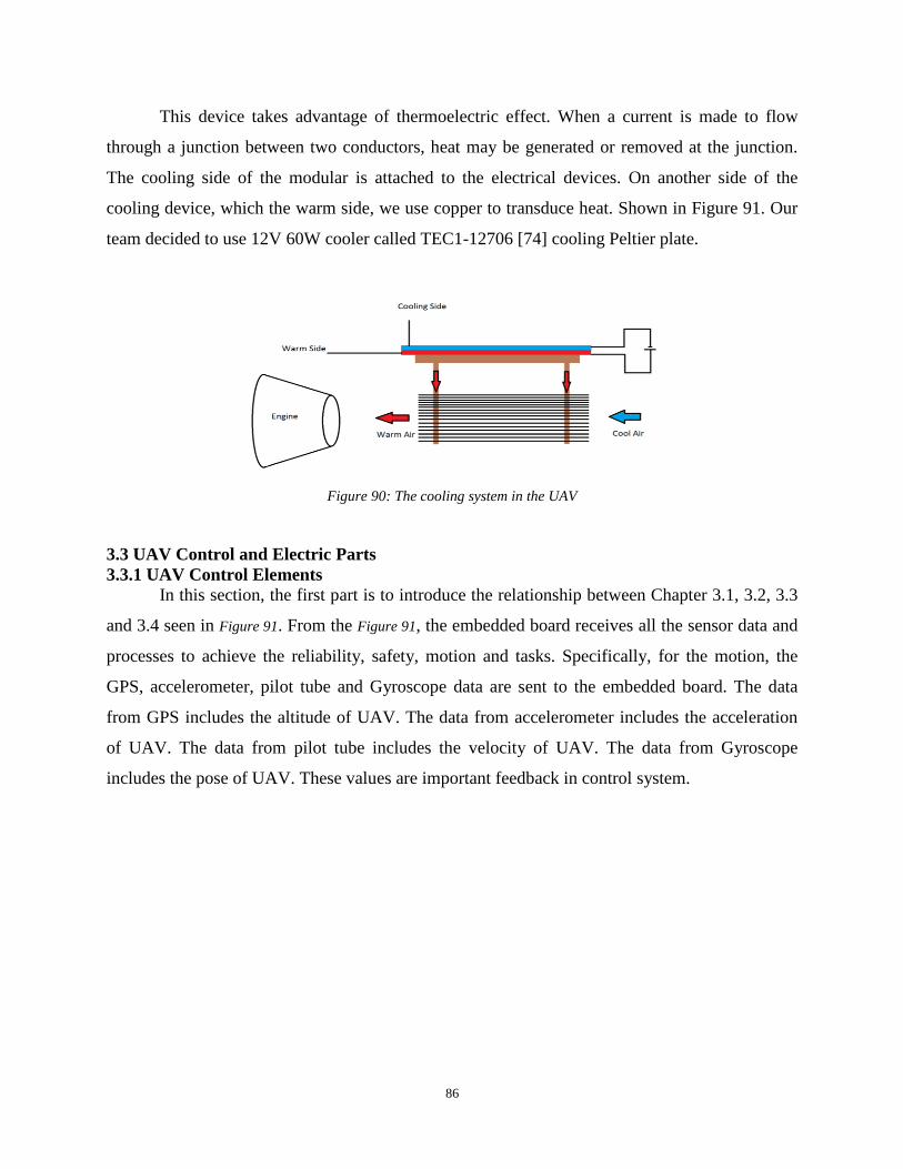
86
This device takes advantage of thermoelectric effect. When a current is made to flow
through a junction between two conductors, heat may be generated or removed at the junction.
The cooling side of the modular is attached to the electrical devices. On another side of the
cooling device, which the warm side, we use copper to transduce heat. Shown in Figure 91. Our
team decided to use 12V 60W cooler called TEC1-12706 [74] cooling Peltier plate.
Figure 90: The cooling system in the UAV
3.3 UAV Control and Electric Parts
3.3.1 UAV Control Elements
In this section, the first part is to introduce the relationship between Chapter 3.1, 3.2, 3.3
and 3.4 seen in Figure 91. From the Figure 91, the embedded board receives all the sensor data and
processes to achieve the reliability, safety, motion and tasks. Specifically, for the motion, the
GPS, accelerometer, pilot tube and Gyroscope data are sent to the embedded board. The data
from GPS includes the altitude of UAV. The data from accelerometer includes the acceleration
of UAV. The data from pilot tube includes the velocity of UAV. The data from Gyroscope
includes the pose of UAV. These values are important feedback in control system.
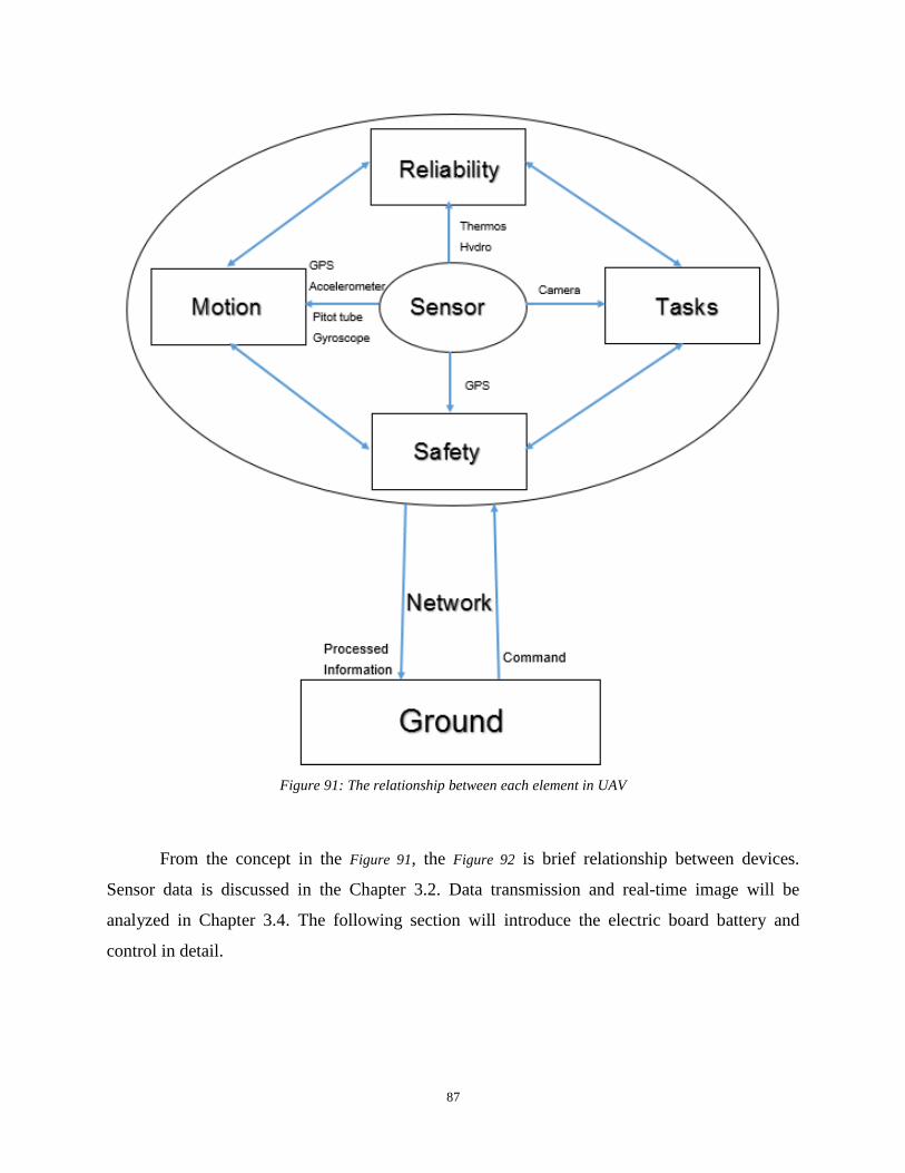
87
Figure 91: The relationship between each element in UAV
From the concept in the Figure 91, the Figure 92 is brief relationship between devices.
Sensor data is discussed in the Chapter 3.2. Data transmission and real-time image will be
analyzed in Chapter 3.4. The following section will introduce the electric board battery and
control in detail.

88
Figure 92: The relationship between each device
The second part is to introduce the electricity our team used in the UAV and discuss them
with model our team built. This is important to build 3D model of electrical parts, because these
electrical parts can be placed within the UAV in order.
Figure 93: 3D angle of view of the UAV control board
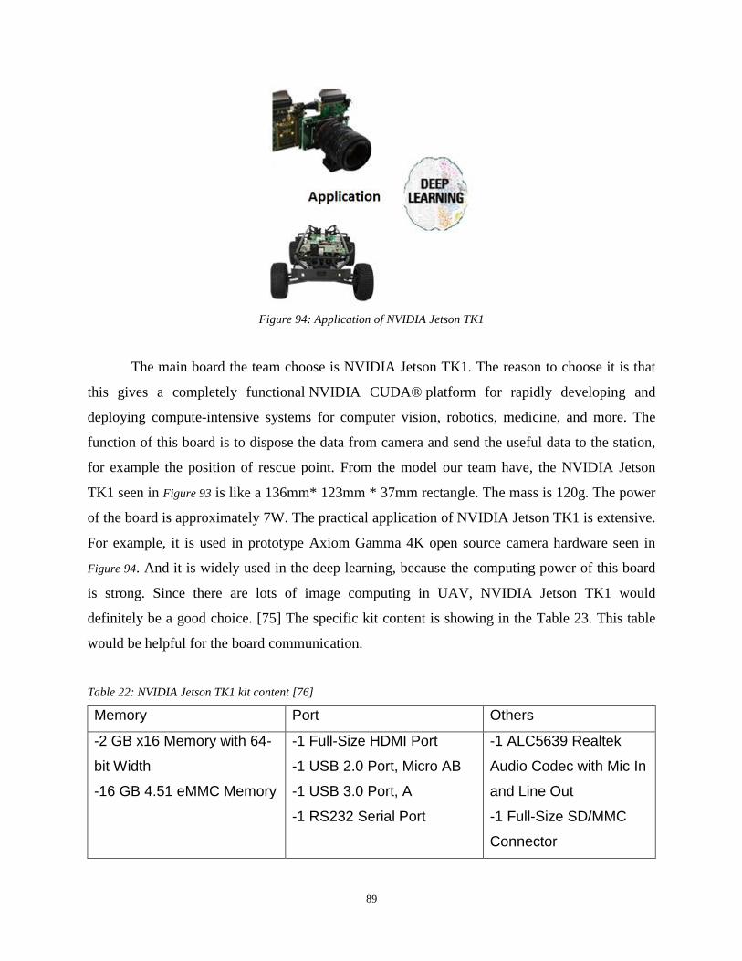
89
Figure 94: Application of NVIDIA Jetson TK1
The main board the team choose is NVIDIA Jetson TK1. The reason to choose it is that
this gives a completely functional NVIDIA CUDA® platform for rapidly developing and
deploying compute-intensive systems for computer vision, robotics, medicine, and more. The
function of this board is to dispose the data from camera and send the useful data to the station,
for example the position of rescue point. From the model our team have, the NVIDIA Jetson
TK1 seen in Figure 93 is like a 136mm* 123mm * 37mm rectangle. The mass is 120g. The power
of the board is approximately 7W. The practical application of NVIDIA Jetson TK1 is extensive.
For example, it is used in prototype Axiom Gamma 4K open source camera hardware seen in
Figure 94. And it is widely used in the deep learning, because the computing power of this board
is strong. Since there are lots of image computing in UAV, NVIDIA Jetson TK1 would
definitely be a good choice. [75] The specific kit content is showing in the Table 23. This table
would be helpful for the board communication.
Table 22: NVIDIA Jetson TK1 kit content [76]
Memory Port Others
-2 GB x16 Memory with 64-
bit Width
-16 GB 4.51 eMMC Memory
-1 Full-Size HDMI Port
-1 USB 2.0 Port, Micro AB
-1 USB 3.0 Port, A
-1 RS232 Serial Port
-1 ALC5639 Realtek
Audio Codec with Mic In
and Line Out
-1 Full-Size SD/MMC
Connector
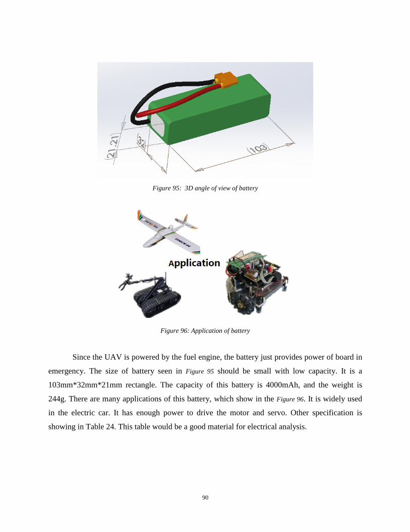
90
Figure 95: 3D angle of view of battery
Figure 96: Application of battery
Since the UAV is powered by the fuel engine, the battery just provides power of board in
emergency. The size of battery seen in Figure 95 should be small with low capacity. It is a
103mm*32mm*21mm rectangle. The capacity of this battery is 4000mAh, and the weight is
244g. There are many applications of this battery, which show in the Figure 96. It is widely used
in the electric car. It has enough power to drive the motor and servo. Other specification is
showing in Table 24. This table would be a good material for electrical analysis.

91
Table 23: The datasheet of the battery of the UAV
Minimum Capacity: 4000mAh
Configuration: 3S1P / 11.1V / 3Cell
Constant Discharge: 10C
Peak Discharge (10sec): 20C
Pack Weight: 244g
Charge Plug: JST-XH
Discharge Plug: XT60
Weight (g) 244
Figure 97: The 3D angle of view of Arduino Mega
The assistant board the research choose is Arduino Mega seen in Figure 97. The reason
selecting Arduino Mage is that it is light, small and easy to control the UAV. The main function
of this board is to control the UAV, like brain, getting the value from the sensors on the UAV
and outputting signal to the fuel engine and servo. The size of board is 102×54 mm from the
Figure 97. Weight is 37g, which is very light. The table 25 is contrast of two similar board. From
this table, Microcontroller ATmega2560 has more pin, better to control the servo and more serial
port, so ATmega2560 would be better.
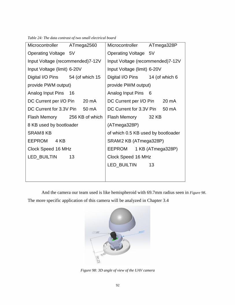
92
Table 24: The data contrast of two small electrical board
Microcontroller ATmega2560
Operating Voltage 5V
Input Voltage (recommended)7-12V
Input Voltage (limit) 6-20V
Digital I/O Pins 54 (of which 15
provide PWM output)
Analog Input Pins 16
DC Current per I/O Pin 20 mA
DC Current for 3.3V Pin 50 mA
Flash Memory 256 KB of which
8 KB used by bootloader
SRAM 8 KB
EEPROM 4 KB
Clock Speed 16 MHz
LED_BUILTIN 13
Microcontroller ATmega328P
Operating Voltage 5V
Input Voltage (recommended)7-12V
Input Voltage (limit) 6-20V
Digital I/O Pins 14 (of which 6
provide PWM output)
Analog Input Pins 6
DC Current per I/O Pin 20 mA
DC Current for 3.3V Pin 50 mA
Flash Memory 32 KB
(ATmega328P)
of which 0.5 KB used by bootloader
SRAM 2 KB (ATmega328P)
EEPROM 1 KB (ATmega328P)
Clock Speed 16 MHz
LED_BUILTIN 13
And the camera our team used is like hemispheroid with 69.7mm radius seen in Figure 98.
The more specific application of this camera will be analyzed in Chapter 3.4
Figure 98: 3D angle of view of the UAV camera

93
3.3.2 UAV Control Analysis
The importance and theory of PID is analyzed in the Chapter 2.2. In this chapter, it is
suggested that gain scheduling has a significant role in the PID controller. Gain scheduling is a
PID enhancement that helps the control of a process with gains and time constants that vary
according to the current value of the process variable.
A gain scheduler provides the best of both worlds. It allows the controller to be tuned for
any number of operating ranges so that an optimal set of tuning parameters can be downloaded
into the controller depending on the current value of the process variable [77]. All of the UAV
controls are processed by the Arduino Mega. Therefore, it is not allowed to apply the Matlab
algorithm directly, for example the PID controller. It supposes to have independent function and
library in the Arduino Mega. The Table 26 is an example of how to apply own control function
into UAV board.
Table 25: Example code for PID speed and altitude controller in C programming
// struct: pidData pid_Data; // functions: void setConst(char Mode, double Kp, double Ki, double Kd); double calcPID(char Mode, int setPoint, int actPos); void initPID(unsigned char Mode); void setConst(char Mode, double Kp, double Ki, double Kd){ // the function to update the gain settings if (Mode == 'A'){ // altitude PID pid_Data.Kp_H = Kp; pid_Data.Ki_H = Ki; pid_Data.Kd_H = Kd; } else if (Mode == 'S'){ // speed PID pid_Data.Kp_L = Kp; pid_Data.Ki_L = Ki; pid_Data.Kd_L = Kd; } } void initPID(unsigned char Mode){ // the function to initial the PID variable if (Mode == 'A') { // altitude PID
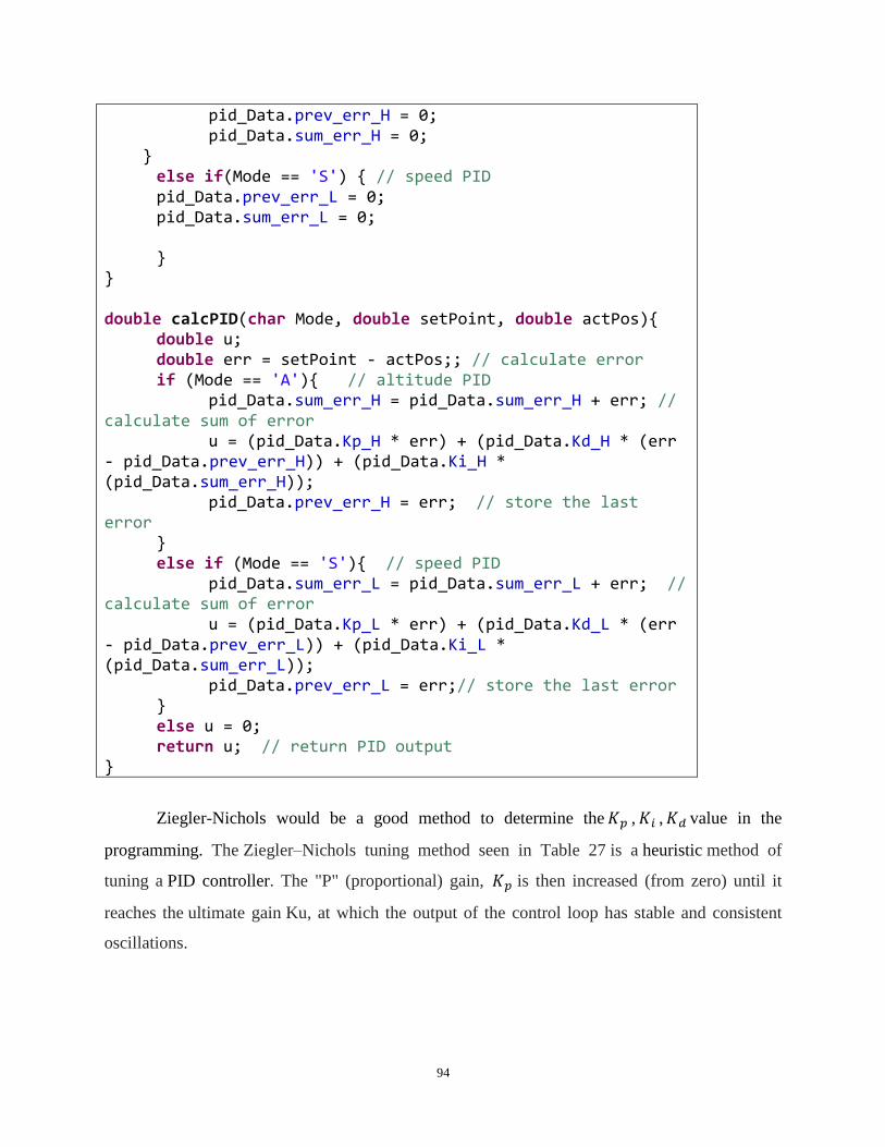
94
pid_Data.prev_err_H = 0; pid_Data.sum_err_H = 0; } else if(Mode == 'S') { // speed PID pid_Data.prev_err_L = 0; pid_Data.sum_err_L = 0; } } double calcPID(char Mode, double setPoint, double actPos){ double u; double err = setPoint - actPos;; // calculate error if (Mode == 'A'){ // altitude PID pid_Data.sum_err_H = pid_Data.sum_err_H + err; // calculate sum of error u = (pid_Data.Kp_H * err) + (pid_Data.Kd_H * (err - pid_Data.prev_err_H)) + (pid_Data.Ki_H * (pid_Data.sum_err_H)); pid_Data.prev_err_H = err; // store the last error } else if (Mode == 'S'){ // speed PID pid_Data.sum_err_L = pid_Data.sum_err_L + err; // calculate sum of error u = (pid_Data.Kp_L * err) + (pid_Data.Kd_L * (err - pid_Data.prev_err_L)) + (pid_Data.Ki_L * (pid_Data.sum_err_L)); pid_Data.prev_err_L = err;// store the last error } else u = 0; return u; // return PID output }
Ziegler-Nichols would be a good method to determine the 𝐾𝑝 , 𝐾𝑖 , 𝐾𝑑 value in the
programming. The Ziegler–Nichols tuning method seen in Table 27 is a heuristic method of
tuning a PID controller. The "P" (proportional) gain, 𝐾𝑝 is then increased (from zero) until it
reaches the ultimate gain Ku, at which the output of the control loop has stable and consistent
oscillations.

95
Table 26: PID gain according to Ziegler-Nichols method
PID parameter 𝐾𝑝 𝐾𝑝/𝐾𝑖 𝐾𝑑/𝐾𝑝
P Time/delay time infinite 0
PI 0.9TC/delay time Delay time/0.3 0
PID 1.2TC/delay time 2 delay time 0.5 delay time
There are three modes for this UAV: vertical, horizontal and transition seen in Table 28.
The horizontal flight mode is most efficient and UAV can take long term operations above a high
speed. The transition mode ensures stationary operation. Vertical mode is used to take off and
land.
Table 27: The fight mode and speed of the UAV
Fight Mode Horizontal speed
Vertical 0 – 1.4m/s
Transition 0- 16m/s
Horizontal 10m/s- 35m/s
Figure 99: The free body diagram of the UAV
The coordinate system of UAV is depicted in Figure 99. The adaptive control law is designed by
taking the pitch channel is
𝑢1̅̅ ̅ = 𝑘𝑟 + 𝑓0𝑦𝑝 + 𝑓1�̇�𝑝 (29)

96
In this case, k is the feedforward gain, r is the reference input, 𝑓0 and 𝑓1 are feedback gains. The
way is to adjust parameter k, 𝑓0 and 𝑓1 so that the system output can track the simulation. The
following is the differential equation
�̈� + 𝑎1�̇� + 𝑎0𝑧 = 𝑏𝑟 (30)
Coefficients 𝑎0 𝑎1 and b should be gotten bash on control performance index of pitch channel.
The equation below is the common two-order system:
φ(s) = 𝜔𝑛
2
𝑠2+2𝜀𝜔2+𝜔𝑛2 (31)
The damping analysis and simulation can be done after that
The MatLab Simulink seen in Figure 100 is very important in the UAV control analysis.
The reason is that the UAV flight system is complicated. There are a lot of elements
Figure 100: Basic sketch of MatLab Simulink for speed control
3.4 UAV Data Transmission
3.4.1 Long Range Remote Control Description
Different long range remote control systems are suitable for different scenarios. When the
required range is below 100 meters, 2.4/5 GHz RC(Radio Control) is the most common solution.
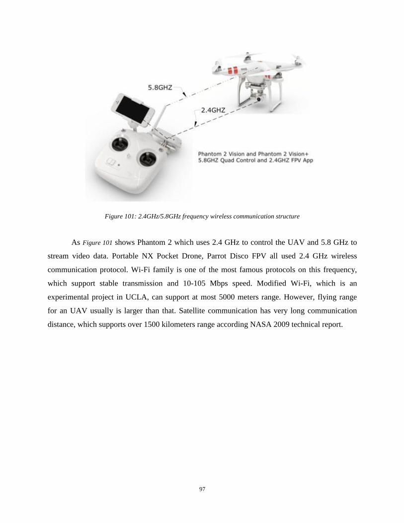
97
Figure 101: 2.4GHz/5.8GHz frequency wireless communication structure
As Figure 101 shows Phantom 2 which uses 2.4 GHz to control the UAV and 5.8 GHz to
stream video data. Portable NX Pocket Drone, Parrot Disco FPV all used 2.4 GHz wireless
communication protocol. Wi-Fi family is one of the most famous protocols on this frequency,
which support stable transmission and 10-105 Mbps speed. Modified Wi-Fi, which is an
experimental project in UCLA, can support at most 5000 meters range. However, flying range
for an UAV usually is larger than that. Satellite communication has very long communication
distance, which supports over 1500 kilometers range according NASA 2009 technical report.

98
Figure 102: Structure of UAV-Satellite Communication
Figure 102 shows the structure of UAV-Satellite communication. Safe UAV operation is
key to operations in shared airspace. Reliable communications between the control station and
the aircraft are essential for operators to have feedback control. The CNPC-1000 data link
implements the Control and Non-Payload Communications (CNPC) waveform in an optimized
package for the small to large unmanned aircraft. This technology is used and recommended by
NASA.

99
Figure 103: Ranges for various radio frequency
Shown in Figure 103, RF (Radio Frequency) control on public band is our best choice for
long range control transmission. Range of Wi-Fi is not enough to support long distance for our
operation. The real rescuing situation is complex and unpredictable. A distance of 200 meters
cannot give relative high probability for rescuing patients in the scene of an incident. Modified
Wi-Fi is able to handle the UAV data transmission but lack of stabilities. In rescuing operation,
stable communication with base station plays an unsubstituted role. Receiving real time
information, including video streaming of circumambient scenario and thermal image, can
support the critical clue that shows where the survivals are. Satellite solution, from figure 104,
out team believe it is best solution due to its stability. However, huge cost and fundamental
setups will make the cost incredibly high. In the other hand, satellite can support almost the best
effect among these solutions in summary.
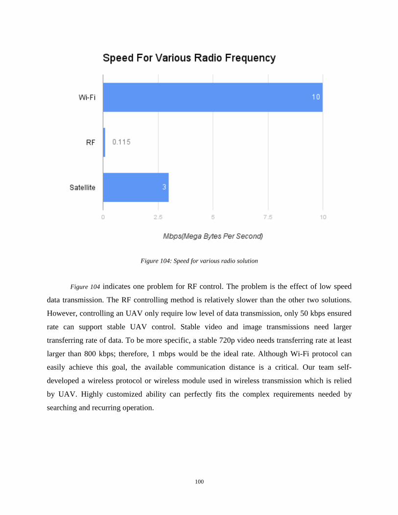
100
Figure 104: Speed for various radio solution
Figure 104 indicates one problem for RF control. The problem is the effect of low speed
data transmission. The RF controlling method is relatively slower than the other two solutions.
However, controlling an UAV only require low level of data transmission, only 50 kbps ensured
rate can support stable UAV control. Stable video and image transmissions need larger
transferring rate of data. To be more specific, a stable 720p video needs transferring rate at least
larger than 800 kbps; therefore, 1 mbps would be the ideal rate. Although Wi-Fi protocol can
easily achieve this goal, the available communication distance is a critical. Our team self-
developed a wireless protocol or wireless module used in wireless transmission which is relied
by UAV. Highly customized ability can perfectly fits the complex requirements needed by
searching and recurring operation.

101
Figure 105: Power consumption for different frequency
From the power consumption point of view, Wi-Fi and other RF family protocols have
similar power requirements, because they are all on 2.4 GHz or 5 GHz. Satellite has larger power
consumption requirements because it needs signal amplifier to send signal to satellite. In same
power consumption requirements, Wi-Fi and RF solutions have better performance and relatively
low latency. Low latency is another important factor that affects the quality of wireless
communication systems. If the video and the images received by base station are five or 10
earlier, base station will make the decision slower than the expected time. This our team believe
will increase the probability of successful search and rescue operations.
3.4.2 On Board Computational Systems
Jetson TK1 embedded system. Support high performance GPU and CPU computation.
Powerful port system provides us high scalable ability to extend the functions using sensors
attached to the embedded system.
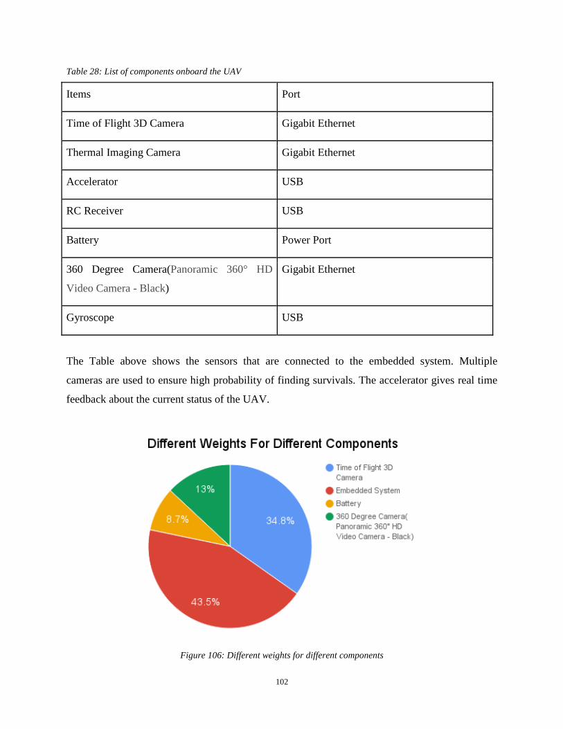
102
Table 28: List of components onboard the UAV
Items Port
Time of Flight 3D Camera Gigabit Ethernet
Thermal Imaging Camera Gigabit Ethernet
Accelerator USB
RC Receiver USB
Battery Power Port
360 Degree Camera(Panoramic 360° HD
Video Camera - Black)
Gigabit Ethernet
Gyroscope USB
The Table above shows the sensors that are connected to the embedded system. Multiple
cameras are used to ensure high probability of finding survivals. The accelerator gives real time
feedback about the current status of the UAV.
Figure 106: Different weights for different components

103
According to the Figure 106, embedded system takes the most part of weight. It contains
many units such as computing unit, wireless unit and storage unit. Compared to embedded
system, battery only takes 8.7% of total weight. It means drone can easily extends its power
capacity.
Figure 107: Relations among components in UAV
According to the Figure 107, the core of the embedded system is Jetson TK1, which is a
kind of Linux embedded system with a strong ability of GPU and CPU computation. One of the
most important reasons for choosing Jetson TK1 is its high GPU computing performance. Object
detection algorithm and other computer vision related algorithms will get accelerated by using
GPU computing. Parallel GPU programming can significantly speed up the processing of the
algorithm which support parallel programming. Quicker process speed of graph algorithm
performs better understanding of real time situation. Low latency and low delay can help base
station quicker and more precise to find possible survivals.
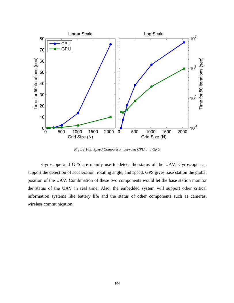
104
Figure 108: Speed Comparison between CPU and GPU
Gyroscope and GPS are mainly use to detect the status of the UAV. Gyroscope can
support the detection of acceleration, rotating angle, and speed. GPS gives base station the global
position of the UAV. Combination of these two components would let the base station monitor
the status of the UAV in real time. Also, the embedded system will support other critical
information systems like battery life and the status of other components such as cameras,
wireless communication.
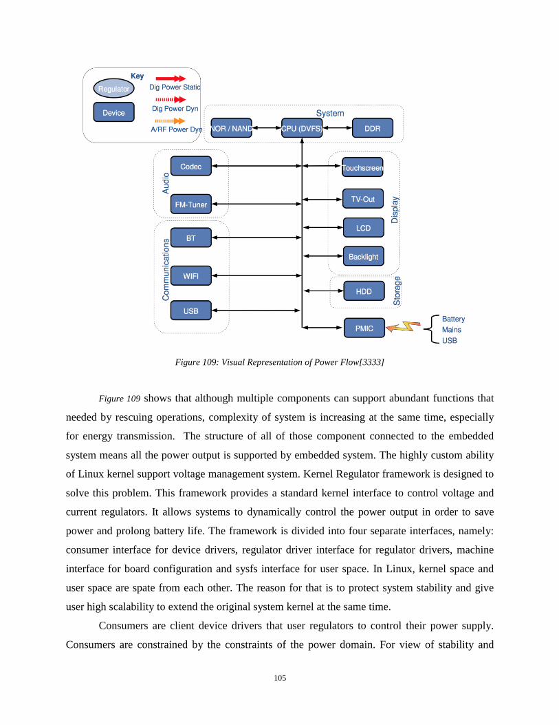
105
Figure 109: Visual Representation of Power Flow[3333]
Figure 109 shows that although multiple components can support abundant functions that
needed by rescuing operations, complexity of system is increasing at the same time, especially
for energy transmission. The structure of all of those component connected to the embedded
system means all the power output is supported by embedded system. The highly custom ability
of Linux kernel support voltage management system. Kernel Regulator framework is designed to
solve this problem. This framework provides a standard kernel interface to control voltage and
current regulators. It allows systems to dynamically control the power output in order to save
power and prolong battery life. The framework is divided into four separate interfaces, namely:
consumer interface for device drivers, regulator driver interface for regulator drivers, machine
interface for board configuration and sysfs interface for user space. In Linux, kernel space and
user space are spate from each other. The reason for that is to protect system stability and give
user high scalability to extend the original system kernel at the same time.
Consumers are client device drivers that user regulators to control their power supply.
Consumers are constrained by the constraints of the power domain. For view of stability and

106
scalability, consumers can’t request power setting that may damage themselves, other
consumers, or the system. If consumers have right to access and change these key information of
the system, whole UAV system is vulnerable. This is unexpected when the UAV is in operation.
Table 29: Functions used to control voltage in Linux
Regulator Access: regulator_get(dev, name) regulator_put(regulator)
Regulator Control: regulator_enable(regulator) regulator_disable(regulator)
regulator_set_voltage(regulator *, int
min_voltage, int max_voltage)
regulator_force_disable(regulator)
regulator_set_current_limit(regulator *,
int min_a, int max_a)
Regulator Status: regulator_is_enabled(regulator) regulator_get_voltage(regulator*)
regulator_get_current_limit(regulator *)
From Table 30, Linux system kernel give developers a complete tool chain to control the
voltage between component and system port. Depending on those robust application program
interface (API), system can customize the output voltage for different component connected to
itself.

107
3.4.3 UAV Data and Signal Transmission
Figure 110: UAV signal transmission structure
UAV data and signal transmission are two independent phases, non-interacting systems.
This ensures the stability and security of the UAV when one of them occurs unexpected problem,
such as loss of data transmission. If data stream is offline or broken, base station still have
backup stream system which is command stream to ensure that the UAV can be properly
controlled. Show in Figure 111, the data transmission is established by 5 GHz wireless
transmission with security protocol SSL; also, there will be two such transmission established
between the base and the UAV for failure prove purposes. Specifically, the flight parameters will
be transmitted to base station in real time, as well as the thermal image data stream, large data
stream like high resolution video and 3D data will be cached directly on storage which is inside
the UAV.
108
CHAPTER 4. CONCLUSION
Based upon research background on UAV applications and designs, our team successfully
design a UAV system that can be remotely controlled and operated at a radius of about 50
kilometers. This UAV would provide an opportunity for emergency medicine services teams to
respond to a scene of an incident in a timely manner. The UAV is also designed for search and
rescue purposes, and delivering medical supplies. It is the understanding of our team that the
Rwanda Zip-line UAV has the capability operating within a radius of 30 kilometers and able to
maintain a 30 minutes operation time. In the contrast, the UAV designed from this project is able
to carry more payload, stay in the air for longer time period, and also equipped with life
detecting abilities than the Rwanda Zip-line UAV
Overall this project can be viewed as an improvement with respect to current technologies.
However, there are number of areas that can be improved in the future. First and foremost, the
UAV design needs to be improved by using wind tunnel examination or air flow simulations.
Second, improving the security protocol on wireless transmission is also necessary. This
promises a successful search and rescue operation. Finally, an energy recycling system can also
be developed in the future. The proposed UAV uses butane as the fuel. Our team hope that
renewable forms of energy can be used to enhance the functions and efficiency of the
UAV. However, among the design and reasoning given in this IQP, the solution is reasonably
acceptable. We believe our suggestions and solutions will enhance the quality of emergency
medical UAVs.
109
REFERENCES
[1] A. Idries and N. Mohamed, "Towards Risk Knowledge Management in Unmanned Aerial
Vehicles Applications Development," Collaboration Technologies and Systems Conference
(CTS), June 2015.
[4] S. Jesse, "How a Quadcopter Works | Clay Allen," 20 January 2015. http://ffden-
2.phys.uaf.edu/webproj/212_spring_2014/Clay_Allen/clay_allen/works.html.
[5] J. Villbrandt, "Illumin - The Quadrotor’s Coming of Age," 1 July 2010.
[6] V. Olivares, F. Cordova, J. M. Sepulveda and I. Derpich, "Modeling Internal Logistics by
Using Drones on the Stage of Assembly of Products," 3rd International Conference on
Information Technology and Quantitative Management (ITQM), Chile, 2015.
[8] M. S. Fofana, "Calculating Feedback Controller and Compensator," MyWPI Control
Engineering, Class Notes, 15 April 2011.
[9] T. Takotomamonjy, M. Ouladsine and T. L. Moing, "Longitudinal modelling and control of a
flapping-wing micro aerial vehicle," Control Engineering Practice, vol. 18, no. 7, pp. 679-690,
July 2010.
[10] Airforce Technology.com, "X-47 Pegasus UCAV." Accessed April 21, 2016
http://www.airforce-technology.com/projects/x47/. http://www.airforce-
technology.com/projects/x47/.
[12] "The UAV - The Future of the Sky," 21 April 2016. Website |
http://www.theuav.com/fire_scout_uav.html.
[13] "EADS Talarion - Development and Operational History, Performance Specifications and
Picture Gallery," Website | http://www.militaryfactory.com/aircraft/detail.asp?aircraft_id=1087.
[Accessed 21 April 2016].
[14] G. Rob, "Solar Plane Aims for New Record: Three Months Aloft Without a Pilot or Fuel," 7
July 2010. https://www.element14.com/community/docs/DOC-43347/l/solar-plane-aims-for-
new-record-3-months-aloft-without-a-pilot-or-fuel
[15] "Official Phantom UAVs specifications.,"
http://research.omicsgroup.org/index.php/Phantom_(UAV), Accessed 7 March 2015
[18] "Rapid Manufactured Fixed Wing Powered UAV," AMRC Design and Prototyping Group,
Available: http://www.amrc.co.uk/wp-content/uploads/AMRC_DPG_PoweredUAV-v2.pdf.
110
[19] “Adhesively Bonded Joints in Aircraft Structures," Available:
http://link.springer.com/referenceworkentry/10.1007/978-3-642-01169-6_44. [Accessed 21 April
2016].
[20] "Design Analysis of the Zeke 32 (Hamp - Mitsubishi A6M3)," [Online]. Available:
http://rwebs.net/avhistory/history/zeke32.htm. [Accessed 21 April 2016].
[24] H. Chen, X. Dong, X. Xu and M. Mir, "3D Scanning Based on Computer Vision", Quora
2012.
[25] H.-U. Meier, “Die Pfeilflügelentwicklung in Deutschland bis, Einspruch 1984”, Gegen US-
Patentschrift NASA über, 1945.
[26] L. S. PhD, “Common Application of Airplane Wing Tips”, ZhiHu Inc, October 17, 2014.
[27] M. Y. a. A. C, “Air Flow Applications on Fighter Jets”, ZhiHu Inc, September 5, 2015.
[28] S. Ye, “Engine and Propeller Location Applications”, ZhiHu Inc, July 25, 2014.
[29] S. L. a. Z. C. “Changsong Xie, Engine Application Difference for Aircrafts”, ZhiHu Inc,
May 27, 2013.
[30] M. Wei, “Structure Difference Between UAVs and Commercial Aircraft”, ZhiHu Inc,
August 11, 2014.
[31] A. Salehian, “Vibration Analysis for Quadrotor Arm in an Unmanned Aerial Vehicle
(UAV)”, University of Waterloo, ON, Canada: Technical report, submitted to Aeryon Labs,
December 19. 2012.
[32] A. Salehian, “System Identification and Active Isolation of a High Altitude Reconecense
Camera”, Illinois, USA: Phase III Technical report, submitted to Recon Optical Inc, March 10,
2005, http://www.airforce-technology.com/projects/u2/
[33] A. Salehian, “System Identification and Active Isolation of a High Altitude Recon Cense
Camera”, Illinois, USA: Phase I and II Technical report, submitted to Recon Optical Inc, January
7, 2005. http://www.airforce-technology.com/projects/u2/
[34] B. Gunston, “The Cambridge Aerospace Dictionary Cambridge”, Cambridge University
Press, 2004.
[37] M. Sadraey, “Aircraft Design: A System Engineering Approach”, Wiley Publication,
Rudder Design Chapter 12 Design of Control Surfaces, September 2012.
[38] NASA, National Aeronautics and Space Administration, 5 May 2015. Available:
https://www.grc.nasa.gov/www/k-12/airplane/trbtyp.html.

111
[40] G. W. J. H. G. PinYing Yang, “Design of a Solar Power Management System for an
Experimental UAV”, Tamkang University, Taiwan, October, 2009.
[41] "Fuel Cell System with Sodium Borohydride as Hydrogen source for Unmanned Aerial
Vehicles," in Fuel Cells Science & Technology, vol. 196, 2011, pp. 9069-9075.
[42] "Energy Information Administration," , US Department of Energy, 29 July 2015, Available:
http://www.eia.gov/Energyexplained/?page=about_energy_units.
[43] "Lead-Free gasoline Material Safety Data Sheet," NOAA., 2008.
[45] C. Collins, "Implementing Phytoremediation of Petroleum Hydrocarbons," Methods in
Biotechnology (Humana Press), pp. 99-108, 2007.
[46] "Fuel Oil Combustion," Kerosene Blending.
[47] " Emissions Inventory Testing at Long Beach Turbine Combustion Turbine No. 3.
CARNOT," Tustin, 1989.
[49] "GAO-13-294SP, Defense Acquisitions Assessments of Selected Weapon Programs," US
Government Accountability Office, Northrop Grumman USAF, 2013, pp. 113-114.
[50] N. Grumman, "Global Hawk, Specifications (Multi-INT and Wide Area Surveillance
Models)," Northrop Grumman Corporation, 2016. [Online]. Available: http://www.north
ropgrumman.com/Capabilities/GlobalHawk/Pages/default.aspx.
[51] C. R. W. Wilson, "Eyes in the Sky Aerial Systems," Military Intelligence Professional
Bulletin, 1996.
[52] Northtrop Grummnan, "Global Hawk," Aeronautical Systems Center Laboratory, United
States Air Force, USA.
http://www.northropgrumman.com/Capabilities/RQ4Block20GlobalHawk/Pages/default.aspx
[53] Northrop Grumman, "Precisionhawk," PrecisionHawk 2016, Aeronautical Systems Center
Laboratory, United States Air Force, USA, Available: http://www.precisionhawk.com/lancaster.
[54] "Official Phantom UAVs Specifications.," Dà-Jiāng Innovations (DJI) Science and
Technology Co., China , 2015.
[55] B. Coxworth, "DJI Announces Stabilized HERO Mount, and Camera-Equipped Phantom
Quadcopter"n New Atlas, 2015.
[56] A. Fitzpatrick, "Finally, a Drone You Can Own," 30 January 2014,
http://techland.time.com/2014/01/30/dji-phantom-vision-quadcopter-drone-review/
[57] "Spreading-Wings s1000 Plus," DJI Technology. [Online]. [Accessed 2 March 2015].

112
[58] "Spreading-Wings s1000 Plus," 22 January 2015. [Online]. Available:
http://wiki.dji.com/en/index.php/Spreading_Wings_S1000%2B.
[59] "Design Build Fly Master Qualifying Project" WPI Aerospace Engineering, 2014.
[60] J. G. Fairman, "Lift Formula," NASA, [Online]. Available:
https://www.grc.nasa.gov/www/k-12/WindTunnel/Activities/lift_formula.html.
[61] Y. Tan, Y. Dong and X. Wang, "Review of MEMS Electronmagnetic Vibration Energy
Harvester," Journal of Microelectromechanical Systems, vol. PP, no. 99, pp. 1-16, 2016.
[62] A. Cho, J. Kim, S. Lee and C. Kee, "Wind Estimation and Airspeed Calibration Using a
UAV with a Single-Antenna GPS Receiver and Pitot Tube," IEEE Transactions on Aerospace
and Electronic Systems, vol. 47, no. 1, pp. 109-117, 2011.
[63] O. He, Z. Wang and J. He, "Temperature and Humidity Profiles Retrieving Over Land
Using Clear Sky Measurements of Microwave Humidity-Temperature Sounder on Chinese FY-
3C Satellite," IEEE International Geoscience and Remote Sensing Symposium, pp. 4161-4164,
2016.
[64] "MEMS Current Type Accelerometer," RION Tech. http://en.rion-
tech.net/products_detail/productId=75.html
[65] "MEMS Voltage Type Accelerometer," RION Tech. http://en.rion-
tech.net/products_detail/productId=75.html
[66] "Low Outgassing Triaxle ICP Accelerometer Installation and Operating Manual," PCB
Piezotronics Inc.. http://www.imi-sensors.com/Products.aspx?m=356M208_NC
[68] "MEMS Quartz Tactical Inertial Measurement Unit," Syttron Donner Inc.,
http://www.systron.com/sites/default/files/sdi510_b.pdf
[69] "MEMS Quartz Dual Axis Rate Sensor," Syttron Donner Inc.,
http://www.systron.com/sites/default/files/sdi510_b.pdf
[70] Static Pressure Probe A-520 Datasheet, DN520.5, MAMAC System.
[71] Channel Low Power GPS Receiver VENUS634FLPx 65 Datasheet, Version 0.5, Sky Traq
Technology, Inc., Taiwan
[72] Low Voltage Temperature Sensors TMP36 Datasheet, Analog Devices.
[73] H. RF, Humidity Sensor Module HH10D Datasheet, Version 2.0.
[74] L. Hebei, Thermoelectric Cooler., I.T Co., Shanghai, China
http://peltiermodules.com/peltier.datasheet/TEC1-12705.pdf
113
[75] Antmicro, “Antmicro at Embedded World 2016 – Sneak Peek”, 18 February, 2016.
[76] Nvidia,”Kitcontents”, 2016. Available: http://www.nvidia.com/object/jetson-tk1-embedded-
dev-kit.html.
[77] P. Vance VanDoren, “Back to Basics: How gain scheduling works”, 21 December, 2010.

114
APPENDICE
Dijkstra Functions
2
3 create vertex set Q
4
5 for each vertex v in Graph: // Initialization
6 dist[v] ← INFINITY // Unknown distance from source to v
7 prev[v] ← UNDEFINED // Previous node in optimal path from source
8 add v to Q // All nodes initially in Q (unvisited nodes)
9
10 dist[source] ← 0 // Distance from source to source
11
12 while Q is not empty:
13 u ← vertex in Q with min dist[u] // Source node will be selected first
14 remove u from Q
15
16 for each neighbor v of u: // where v is still in Q.
17 alt ← dist[u] + length(u, v)
18 if alt < dist[v]: // A shorter path to v has been found
19 dist[v] ← alt
20 prev[v] ← u
21
22 return dist[], prev[]
Any little improvements in this searching algorithm will benefits the UAV to auto-generating
flying route.
However, dijkstra’s algorithm only can solve problem in idea scenario. When UAV meets some
obstacles so that it need to change its direction or altitude. Keeping changing state of UAV will
accurate loosing power. What we want is to let UAV can fly in given route as long as possible.
In order to avoid that, A-star search algorithm is introduced to solve this problem.

115
function A*(start, goal)
// The set of nodes already evaluated.
closedSet := {}
// The set of currently discovered nodes still to be evaluated.
// Initially, only the start node is known.
openSet := {start}
// For each node, which node it can most efficiently be reached from.
// If a node can be reached from many nodes, cameFrom will eventually contain the
// most efficient previous step.
cameFrom := the empty map
// For each node, the cost of getting from the start node to that node.
gScore := map with default value of Infinity
// The cost of going from start to start is zero.
gScore[start] := 0
// For each node, the total cost of getting from the start node to the goal
// by passing by that node. That value is partly known, partly heuristic.
fScore := map with default value of Infinity
// For the first node, that value is completely heuristic.
fScore[start] := heuristic_cost_estimate(start, goal)
while openSet is not empty
current := the node in openSet having the lowest fScore[] value
if current = goal
return reconstruct_path(cameFrom, goal)
openSet.Remove(current)
closedSet.Add(current)
for each neighbor of current
if neighbor in closedSet
continue // Ignore the neighbor which is already evaluated.
// The distance from start to a neighbor
tentative_gScore := gScore[current] + dist_between(current, neighbor)
if neighbor not in openSet // Discover a new node
openSet.Add(neighbor)
else if tentative_gScore >= gScore[neighbor]
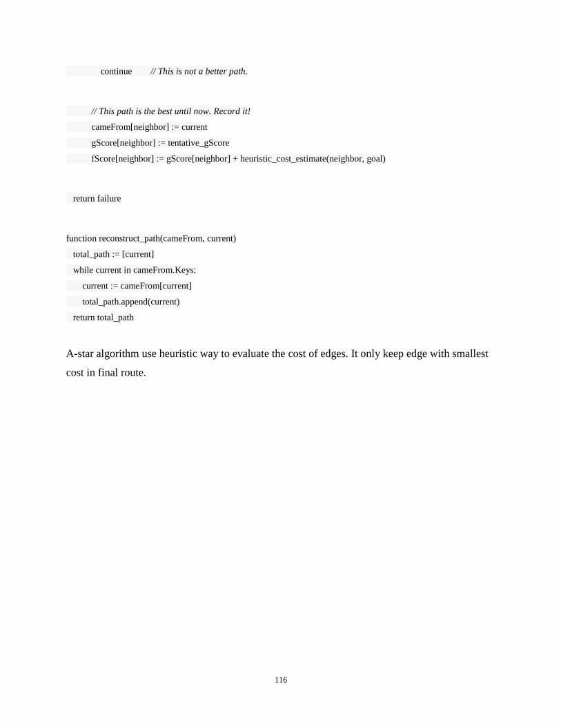
116
continue // This is not a better path.
// This path is the best until now. Record it!
cameFrom[neighbor] := current
gScore[neighbor] := tentative_gScore
fScore[neighbor] := gScore[neighbor] + heuristic_cost_estimate(neighbor, goal)
return failure
function reconstruct_path(cameFrom, current)
total_path := [current]
while current in cameFrom.Keys:
current := cameFrom[current]
total_path.append(current)
return total_path
A-star algorithm use heuristic way to evaluate the cost of edges. It only keep edge with smallest
cost in final route.
Related Documents