Wood-Mizer ® Sawmill Safety, Setup, Operation & Maintenance Manual LT10S3 E7,5S rev. A1.00 Safety is our #1 concern! Read and understand all safety information and instructions before operating, setting up or maintaining this machine. December 2006 Form #794 !

Welcome message from author
This document is posted to help you gain knowledge. Please leave a comment to let me know what you think about it! Share it to your friends and learn new things together.
Transcript

Wood-Mizer®SawmillSafety, Setup, Operation& Maintenance Manual
LT10S3 E7,5S rev. A1.00
Safety is our #1 concern! Read and understand allsafety information and instructions before operating,setting up or maintaining this machine.
December 2006
Form #794
!
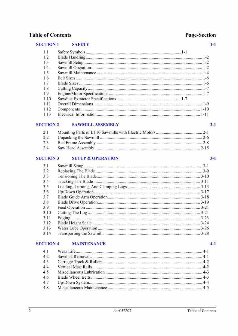
Table of Contents Page-Section
SECTION 1 SAFETY 1-11.1 Safety Symbols.......................................................................................1-11.2 Blade Handling.......................................................................................................... 1-21.3 Sawmill Setup............................................................................................................ 1-21.4 Sawmill Operation..................................................................................................... 1-21.5 Sawmill Maintenance ................................................................................................ 1-41.6 Belt Sizes ................................................................................................................... 1-61.7 Blade Sizes ................................................................................................................ 1-61.8 Cutting Capacity........................................................................................................ 1-71.9 Engine/Motor Specifications ..................................................................................... 1-71.10 Sawdust Extractor Specifications ...........................................................1-71.11 Overall Dimensions ................................................................................................... 1-91.12 Components............................................................................................................. 1-101.13 Electrical Information.............................................................................................. 1-11
SECTION 2 SAWMILL ASSEMBLY 2-1
2.1 Mounting Parts of LT10 Sawmills with Electric Motors .......................................... 2-12.2 Unpacking the Sawmill ............................................................................................. 2-62.3 Bed Frame Assembly ................................................................................................ 2-82.4 Saw Head Assembly................................................................................................ 2-15
SECTION 3 SETUP & OPERATION 3-1
3.1 Sawmill Setup............................................................................................................ 3-13.2 Replacing The Blade ................................................................................................. 3-93.3 Tensioning The Blade.............................................................................................. 3-103.4 Tracking The Blade ................................................................................................. 3-113.5 Loading, Turning, And Clamping Logs .................................................................. 3-133.6 Up/Down Operation ................................................................................................ 3-173.7 Blade Guide Arm Operation.................................................................................... 3-183.8 Blade Drive Operation............................................................................................. 3-193.9 Feed Operation ........................................................................................................ 3-213.10 Cutting The Log ...................................................................................................... 3-213.11 Edging...................................................................................................................... 3-233.12 Blade Height Scale .................................................................................................. 3-243.13 Water Lube Operation ............................................................................................. 3-263.14 Transporting the Sawmill ........................................................................................ 3-28
SECTION 4 MAINTENANCE 4-1
4.1 Wear Life................................................................................................................... 4-14.2 Sawdust Removal ...................................................................................................... 4-14.3 Carriage Track & Rollers .......................................................................................... 4-24.4 Vertical Mast Rails .................................................................................................... 4-24.5 Miscellaneous Lubrication ........................................................................................ 4-34.6 Blade Wheel Belts ..................................................................................................... 4-34.7 Up/Down System....................................................................................................... 4-44.8 Miscellaneous Maintenance ...................................................................................... 4-5
2 doc052207 Table of Contents

Table of Contents Page-Section
SECTION 5 TROUBLESHOOTING GUIDE 5-1
5.1 Sawing Problems ....................................................................................................... 5-1
SECTION 6 SAWMILL ALIGNMENT 6-1
6.1 Pre-Alignment Procedures......................................................................................... 6-16.2 Preparing The Sawmill For Alignment ..................................................................... 6-16.3 Blade Installation and Alignment.............................................................................. 6-26.4 Blade Wheel Alignment ............................................................................................ 6-46.5 Blade Guide Arm Alignment..................................................................................... 6-96.6 Aligning The Blade Guides ..................................................................................... 6-126.7 Blade Deflection...................................................................................................... 6-136.8 Blade Guide Vertical Tilt Adjustment..................................................................... 6-146.9 Blade Guide Flange Spacing ................................................................................... 6-166.10 Horizontal Tilt Adjustment...................................................................................... 6-176.11 Blade Height Scale Adjustment............................................................................... 6-186.12 Motor Drive Belt Adjustment.................................................................................. 6-206.13 Mast Side Bracket Adjustment................................................................................ 6-216.14 Safety Handle Linkage Adjustment......................................................................... 6-22
Table of Contents doc052207 3

-i G24doc052207
Sawmill and Customer Identification
Each Wood-Mizer LT10 sawmill is identified with a revision and VIN numbers.
When you pick up your mill, you will receive a customer number. The VIN number, revision, and your customer number expedite our service to you. Please write these numbers below so you have quick, easy access to them.
REVISION AND VIN NUMBERS
Customer No. Type VIN No. Revision No.
LT10Basic Sawmill I.D.
E7,5Motor/Engine
A1.Major “Revision” Code
00Minor ”Revision”
Type
Revision Number
Code

Safety 1
SECTION 1 SAFETY1.1 Safety Symbols
This symbol calls your attention to instructions concerning your personal safety. Be sureto observe and follow these instructions.
The word DANGER indicates an imminently hazardoussituation which, if not avoided, will result in death or seriousinjury.
WARNING suggests a potentially hazardous situationwhich, if not avoided, could result in death or serious injury.
CAUTION refers to potentially hazardous situations which,if not avoided, may result in minor or moderate injury topersons or equipment.
Warning stripes are placed on areas where a single decalwould be insufficient. To avoid serious injury, keep out ofthe path of any equipment marked with warning stripes.
Read and observe all safety instructions before operating this equipment! Also read anyadditional manufacturer’s manuals and observe any applicable safety instructionsincluding dangers, warnings, and cautions.
Always be sure that all safety decals are clean and readable. Replace all damaged safetydecals to prevent personal injury or damage to the equipment. Contact your localdistributor, or call your Customer Service Representative to order more decals.
IMPORTANT! It is always the owner's responsibility to comply with all applicable federal,state and local laws, rules and regulations regarding the ownership, operation and towingof your Wood-Mizer sawmill. All Wood-Mizer mill owners are encouraged to becomethoroughly familiar with these applicable laws and comply with them fully while using themill.
Always properly dispose of all sawing by-products, including sawdust and other debris,coolant, oil, fuel, oil filters and fuel filters.
Safety instructions are listed in this section by the following operations:
Blade Handling,
Sawmill Setup
Sawmill Operation
Sawmill Maintenance
Safety 15doc052207 1-1
SafetyBlade Handling1
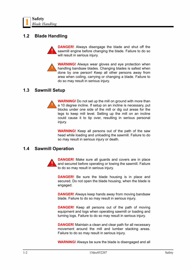
1.2 Blade Handling
DANGER! Always disengage the blade and shut off thesawmill engine before changing the blade. Failure to do sowill result in serious injury.
WARNING! Always wear gloves and eye protection whenhandling bandsaw blades. Changing blades is safest whendone by one person! Keep all other persons away fromarea when coiling, carrying or changing a blade. Failure todo so may result in serious injury.
1.3 Sawmill Setup
WARNING! Do not set up the mill on ground with more thana 10 degree incline. If setup on an incline is necessary, putblocks under one side of the mill or dig out areas for thelegs to keep mill level. Setting up the mill on an inclinecould cause it to tip over, resulting in serious personalinjury.
WARNING! Keep all persons out of the path of the sawhead while loading and unloading the sawmill. Failure to doso may result in serious injury or death.
1.4 Sawmill Operation
DANGER! Make sure all guards and covers are in placeand secured before operating or towing the sawmill. Failureto do so may result in serious injury.
DANGER! Be sure the blade housing is in place andsecured. Do not open the blade housing, when the blade isengaged.
DANGER! Always keep hands away from moving bandsawblade. Failure to do so may result in serious injury.
DANGER! Keep all persons out of the path of movingequipment and logs when operating sawmill or loading andturning logs. Failure to do so may result in serious injury.
DANGER! Maintain a clean and clear path for all necessarymovement around the mill and lumber stacking areas.Failure to do so may result in serious injury.
WARNING! Always be sure the blade is disengaged and all
1-2 15doc052207 Safety
SafetySawmill Operation 1
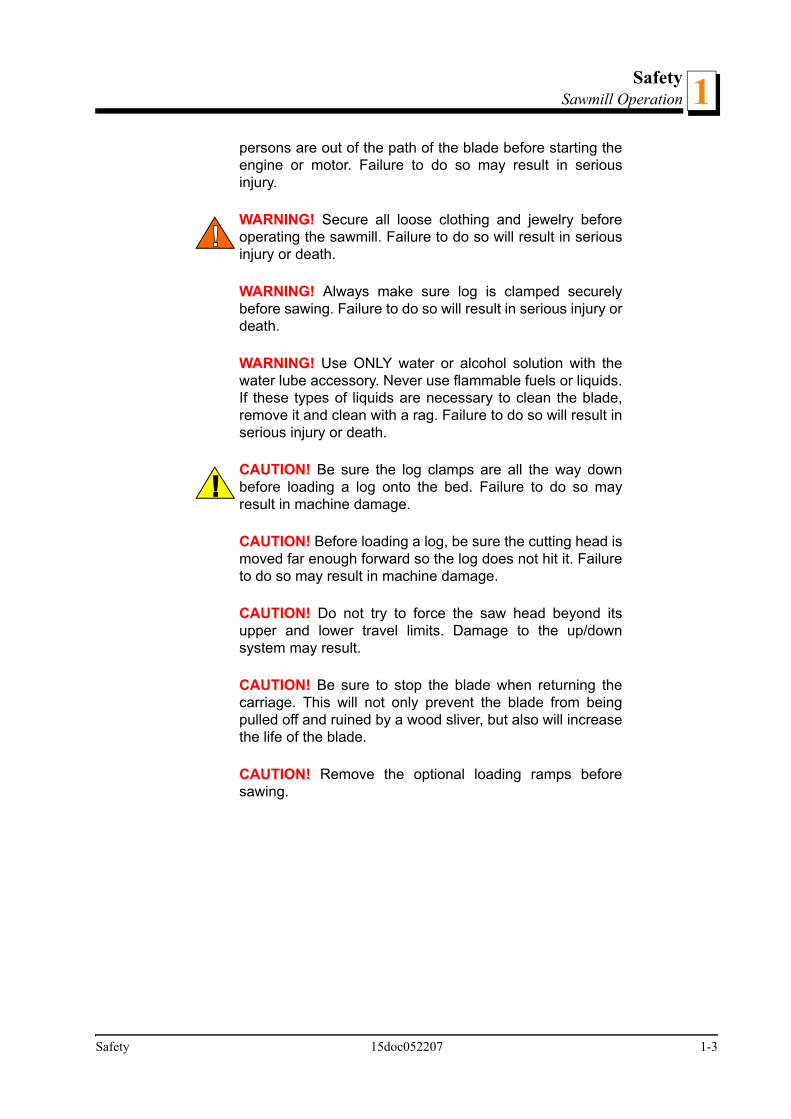
persons are out of the path of the blade before starting theengine or motor. Failure to do so may result in seriousinjury.
WARNING! Secure all loose clothing and jewelry beforeoperating the sawmill. Failure to do so will result in seriousinjury or death.
WARNING! Always make sure log is clamped securelybefore sawing. Failure to do so will result in serious injury ordeath.
WARNING! Use ONLY water or alcohol solution with thewater lube accessory. Never use flammable fuels or liquids.If these types of liquids are necessary to clean the blade,remove it and clean with a rag. Failure to do so will result inserious injury or death.
CAUTION! Be sure the log clamps are all the way downbefore loading a log onto the bed. Failure to do so mayresult in machine damage.
CAUTION! Before loading a log, be sure the cutting head ismoved far enough forward so the log does not hit it. Failureto do so may result in machine damage.
CAUTION! Do not try to force the saw head beyond itsupper and lower travel limits. Damage to the up/downsystem may result.
CAUTION! Be sure to stop the blade when returning thecarriage. This will not only prevent the blade from beingpulled off and ruined by a wood sliver, but also will increasethe life of the blade.
CAUTION! Remove the optional loading ramps beforesawing.
Safety 15doc052207 1-3

SafetySawmill Maintenance1
1.5 Sawmill Maintenance
CAUTION! Reinstall the track wiper so that it lightly touchesthe track bar. If the wiper presses too firmly against the bar,it can cause the power feed to bind.
CAUTION! Never use grease on the mast rails as it willcollect sawdust.
1-4 15doc052207 Safety

SafetySawmill Maintenance 1
Pictograph decals used to warn the user about danger in the LT10:
FIG. 1-0
Carefully read operator’s manual beforehandling the machine. Observe instructionsand safety rules when operating
Stay clear of hot surfaces
Do not open or remove safety shields whileengine is running
Do not open or remove safety shields whileengine is running
Close shields and guards prior to operatingthe machine
PICTOGR
Safety 15doc052207 1-5
SafetyBelt Sizes1
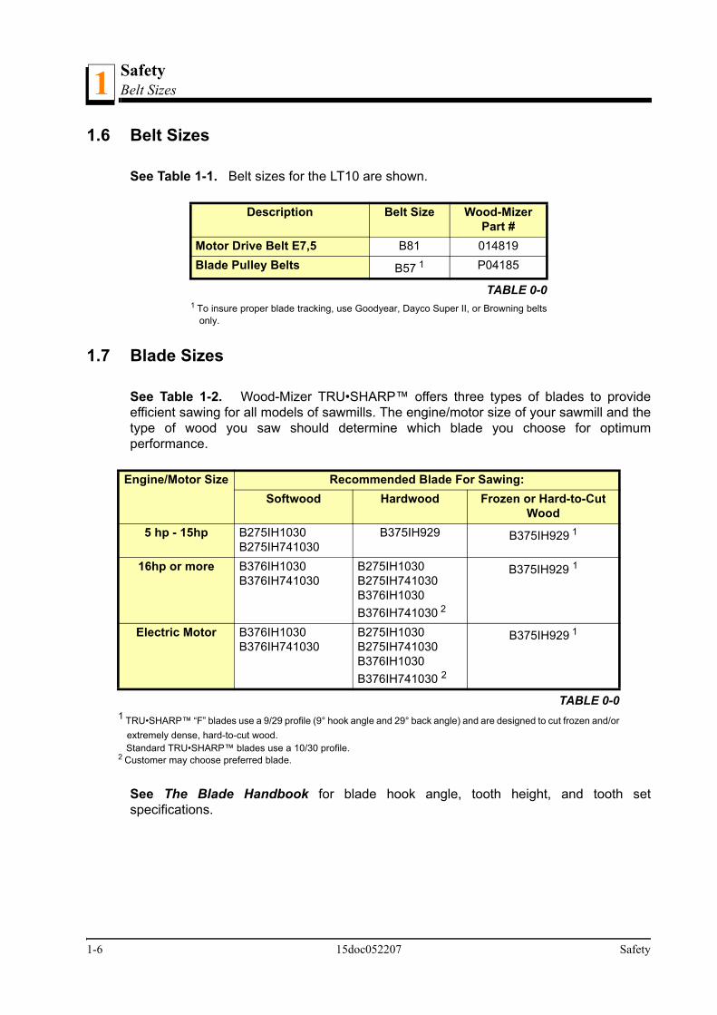
1.6 Belt Sizes
See Table 1-1. Belt sizes for the LT10 are shown.
1.7 Blade Sizes
See Table 1-2. Wood-Mizer TRU•SHARP™ offers three types of blades to provideefficient sawing for all models of sawmills. The engine/motor size of your sawmill and thetype of wood you saw should determine which blade you choose for optimumperformance.
See The Blade Handbook for blade hook angle, tooth height, and tooth setspecifications.
Description Belt Size Wood-Mizer Part #
Motor Drive Belt E7,5 B81 014819Blade Pulley Belts B57 1
1 To insure proper blade tracking, use Goodyear, Dayco Super II, or Browning beltsonly.
P04185
TABLE 0-0
Engine/Motor Size Recommended Blade For Sawing:Softwood Hardwood Frozen or Hard-to-Cut
Wood5 hp - 15hp B275IH1030
B275IH741030B375IH929 B375IH929 1
1 TRU•SHARP™ “F” blades use a 9/29 profile (9° hook angle and 29° back angle) and are designed to cut frozen and/orextremely dense, hard-to-cut wood.
Standard TRU•SHARP™ blades use a 10/30 profile.
16hp or more B376IH1030B376IH741030
B275IH1030B275IH741030B376IH1030B376IH741030 2
2 Customer may choose preferred blade.
B375IH929 1
Electric Motor B376IH1030B376IH741030
B275IH1030B275IH741030B376IH1030B376IH741030 2
B375IH929 1
TABLE 0-0
1-6 15doc052207 Safety

SafetyCutting Capacity 1
1.8 Cutting Capacity
See Table 1-3. The log size capacities of the LT10 sawmills are listed below.
1.9 Engine/Motor Specifications
See Table 1-4. The power options available for the LT10 sawmill are listed below.
See Table 1-5. The noise levels of the Wood-Mizer sawmills are listed below.
1.10 Sawdust Extractor Specifications
See Table 1-6. The dust extractor specifications are given below.
Max. Diameter Max. Length 1
1 Each additional bed frame segment adds approximately 195cm ( 6’ 5” ) to length capacity.
LT10 with three bed sections
71 cm 5,4 m
LT10 with two bed sections
71 cm 3,5 m
TABLE 0-0
Engine/Motor Type Manufacturer Model Number Specifications5.5 kW Electric Motor Siemens, Germany 1LA7130-2AA60-2 3 x 400V, 50 Hz
TABLE 0-0
Idle EngagedSawmill Equipped With Electric
Motor77,1 dB (A) 80,8 dB (A)
TABLE 0-0
Maximum Capacity 2300 m3/hCollector Inlet Diameters (in
front of fan)150 mm
Motor Power 3 kWNumber of Sacks for Waste 2 pcs
Total Capacity of Sacks 0.25 mpWeight 110 kg
TABLE 0-0
Safety 15doc052207 1-7

SafetyEngine/Motor Specifications1
Conveying Speed When 10m Long Hose is Used
20 m/s
TABLE 0-0
1-8 15doc052207 Safety

SafetyOverall Dimensions 1
1.11 Overall Dimensions
See Figure 1-1. The overall dimensions of the LT10 sawmills are shown below.
FIG. 1-1
2234
2043
918
385
385
1950
6610
4660
1714
1823
1950
Safety 15doc052207 1-9

SafetyComponents1
1.12 Components
See Figure 1-2. The major components of the Wood-Mizer LT10 are shown below.
FIG. 1-2
Water Tank
Blade Tension Handle
Up/Down Crank Handle
Sawmill Frame
Clamp
Blade Guide Arm Handle
Blade Drive Motor
Electric Box
1-10 15doc052207 Safety

SafetyElectrical Information 1
1.13 Electrical Information
See Figure 1-3. The electrical symbol diagram of the LT10 equipped with the 5,5kWelectric motor is shown below
FIG. 1-3
5,5k
W29
25 m
in-1
17 A
C1A
S1
S2
W1
W2
Safety 15doc052207 1-11

SafetyElectrical Information1
See Figure 1-4. The electrical components are listed in the table below.
See Table 1-7. LT10 Site preparation
DANGER! It is recommended to use 30mA GFI (GroundFault Interrupter.
Symbol Mfg. Part No. Manufacturer Wood-Mizer Part #
Description
GZ GZ1 M16 SCHNEIDER ELECTRIC
090430 Motor Solenoid/Braker GZ1M16
F2 C60N C1 24395 SCHNEIDER ELECTRIC
084454 Switch
Q OT16E3 ABB 089801 Switch, ABB TR 63 /A BREVE 094487 Transformer, TMM 1M LC1 D18 B7 SCHNEIDER
ELECTRIC084306 Contactor
L1 M22 WHITE MOELLER 090448 Control Light S1 XB4BS542 SCHNEIDER
ELECTRIC086556 Switch, Emergency Stop
S2 M22 MOELLER 090452 Switch, Start-StopM1 1LA7130-2AA60-2 SIEMENS 095785 Blade Drive Motor W1 AZ17-11ZRK SCHMERSAL 094232 Safety Switch W2 EVN2000C HONEYWELL 089816 Limit Switch
TABLE 0-0
3-Phase V Switch, Fuse Recommended wire section
400 VAC 16 A 1,5 mm2
to 15m length
TABLE 0-0
1-12 15doc052207 Safety

SAWMILL ASSEMBLYMounting Parts of LT10 Sawmills with Electric Motors 2
SECTION 2 SAWMILL ASSEMBLY
2.1 Mounting Parts of LT10 Sawmills with Electric Motors
2.1.1 Parts specifications
Table 1:
Sawmill Frame Assembly 1
Fig. Wood-Mizer No. Description Qty.
097466-1 Plate, frame supporting left
LT10-zinc
3
097465-1 Plate, frame supporting right
LT10-zinc
3
097181-1 Bed rail LT10-zinc 9
097185-1 Plate, segments connector LT10-zinc.
6
097182-1 Square, frame mount LT10-zinc
18
097464-1 Block, frame contracting LT10-zinc
12
097471-1 Side support, short LT10
3
097469-1 Side support long LT10
3
094513-1 Outrigger Weldment, LT10
zinc-plated
12
SAWMILL ASSEMBLY 15doc052207 2-1

SAWMILL ASSEMBLYParts specifications2
094530 Log Clamp 3
097369-1 Bed Extension, LT10-zinc
2
097473-1 Stop, Saw Head LT10-zinc
2
086035-1 Wedge Weldment, Log Taper LT10 zinc
1
092567-1 Upper Sprocket Cover, ptd.
1
Saw Head Assembly
086323 Plate, Left Track Wiper
2
086322 Plate, Right Track Wiper
2
093859 Operator’s Guard 1
086171-1 Side Bracket 2
086172-1 Lower Bracket 1
092378-1 Bracket, Roller Guard Mount
Painted
1
Table 1:
2-2 15doc052207 SAWMILL ASSEMBLY

SAWMILL ASSEMBLYSpecifications of Fasteners 2
2.1.2 Specifications of Fasteners
092379-1 Guard, Blade Guide Roller
1
086132-1 Power Cord Bracket 1
097567-1 Latch, Saw Head LT10
1
094246-1 Sawdust Chute 1
097248-1 Mast Side Bracket.LT10-ptd
1
1 Frame with 3-bed sections
Table 2:
Wood-Mizer No. Description Qty.
Sample designations of fasteners:
F81003-17 M10x35 Bolt 1
F81031-2 M6-8-B Nut 2
F81030-2 M5 Nut 2
F81000-7 M5x25 Bolt 2
F81053-11 Washer, 6.5 Special Flat Zinc 6
F81001-15 M6x16 Bolt 2
Table 1:
6,5
8
8,420
13
M8 Nut M8x20 Bolt 8.4 Washer
SAWMILL ASSEMBLY 15doc052207 2-3

SAWMILL ASSEMBLYSpecifications of Fasteners2
F81001-7 M6x12 Bolt 2
F81054-1 Flat Washer 8.4 264
F81032-2 M8 Nut 127
F81002-5 M8x25 Bolt 118
F81002-4 M8x20 Bolt 5
F81055-2 Washer, 10.2 Split Lock 2
F81003-11 M10x25 Bolt 4
F81003-1 M10x20 Bolt 2
F81055-1 Flat Washer 10.5 4
F81037-1 M20 Nut 28
F81032-1 M8 Nut 1
F81002-20 M8x16 Bolt 6
F81002-23 M8x100 Bolt 12
F81059-2 Washer, M20 FLAT ZINC 28
F81053-1 Washer, M6, FLAT,ZINC 2
095919 Cap, A 50x30, Black 2
097480 Pipe Cap 40x40x(3-4) 6
F81082-1 Clamp - Plastic Hose 2
Table 2:
2-4 15doc052207 SAWMILL ASSEMBLY

SAWMILL ASSEMBLYTools Necessary for Assembling the Sawmill 2
2.1.3 Tools Necessary for Assembling the Sawmill
Table 3:
Required tools
Flat Wrench #8 1pcs
Flat Wrench #10 2pcs
Flat Wrench #13 2pcs
Flat Wrench #17 2pcs
Flat Wrench #19 2pcs
Ratchet Wrench #30 1pcs
Hammer 1pcs
Allen Wrench #4 1pcs
Allen Wrench #5 1pcs
SAWMILL ASSEMBLY 15doc052207 2-5

SAWMILL ASSEMBLYUnpacking the Sawmill2
2.2 Unpacking the Sawmill
1. Cut the bands holding the components together.
2. Remove frame parts from the pallet.
3. Remove up/down crank from the saw head, slide on the up/down handle and secure withthe pin (Part No F81045-1).
FIG. 2-1
2-6 15doc052207 SAWMILL ASSEMBLY

SAWMILL ASSEMBLYUnpacking the Sawmill 2
4. Using the up/down crank raise the saw head. Open the box with sawmill’s equipment.
FIG. 2-1
Locking Pin F81045-1
SAWMILL ASSEMBLY 15doc052207 2-7

SAWMILL ASSEMBLYBed Frame Assembly2
2.3 Bed Frame Assembly
IMPORTANT! With all screw joints without spring lockwasher or lock nylon nut, use the "LOCTITE 243" (blue, ofaverage durability, for screw joints).
1. Mount 094513-1 outrigger legs to the frame supporting plates and to bed extension.
See Figure 2-2.
FIG. 2-2
!
097465-1
094513-1
M20 Nut
Washer, 21 Flat
097466-1
097369-1Bed Extension
2-8 15doc052207 SAWMILL ASSEMBLY

SAWMILL ASSEMBLYBed Frame Assembly 2
2. Mount the bed rails with frame supporting plates as shown on the figure below. Use theframe mounting squares (097182-1) to screw them together,
See Figure 2-3.
FIG. 2-3
M8x25 Bolt097181-1
8.4 Washer
M8 Nut
097182-1
M8x25 Bolt
M8x25 Bolt
SAWMILL ASSEMBLY 15doc052207 2-9

SAWMILL ASSEMBLYBed Frame Assembly2
3. Lay the frame sections end-to-end so they facing each other the correct side. Slide thesections together and using the outrigger adjusting nuts, adjust the segments position.The adjacent segments should be on the same height.
See Figure 2-4.
FIG. 2-4
2-10 15doc052207 SAWMILL ASSEMBLY
SAWMILL ASSEMBLYBed Frame Assembly 2
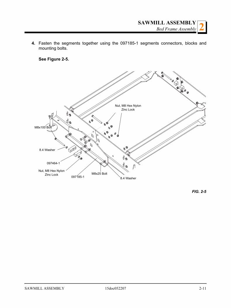
4. Fasten the segments together using the 097185-1 segments connectors, blocks andmounting bolts.
See Figure 2-5.
FIG. 2-5
Nut, M8 Hex Nylon Zinc Lock
M8x100 Bolt
8.4 Washer
097185-1
097464-1
M8x25 Bolt 8.4 Washer
Nut, M8 Hex Nylon Zinc Lock
SAWMILL ASSEMBLY 15doc052207 2-11

SAWMILL ASSEMBLYBed Frame Assembly2
5. Assemble the log clamp to the bed rail on each bed segment, using the hex head boltsand nylon lock nuts.
See Figure 2-6.
FIG. 2-6
Nut, M8 Hex Nylon Zinc Lock
M8x25 Bolts
8.4 Washers
M8x25 Bolts
8.4 WasherNuts, M8 Hex Nylon Zinc Lock
Step 1
Step 2
2-12 15doc052207 SAWMILL ASSEMBLY

SAWMILL ASSEMBLYBed Frame Assembly 2
6. Mount the bed extension (Part No 097369-1) and saw head stops (Part No 097473-1).
See Figure 2-7.
FIG. 2-7
097473-1
097369-1
097185-1
M8x25 Bolt
M8 Nut
8.4 Washer
097464-1
Nut, M8 Hex Nylon Zinc Lock
M8x100 Bolt
8.4 Washer
SAWMILL ASSEMBLY 15doc052207 2-13

SAWMILL ASSEMBLYBed Frame Assembly2
7. Each bed segment has got two side supports (Part No 097470 – long and 097472 –short). Install the log side supports as shown on the Figure 2-8. Each side support can beadjusted in two positions, depends of the cutting height.
See Figure 2-8.
FIG. 2-8
90
097470
097472
M8x12 Bolt
2-14 15doc052207 SAWMILL ASSEMBLY

SAWMILL ASSEMBLYSaw Head Assembly 2
2.4 Saw Head Assembly
1. Using a forklift truck or a winch with lifting capacity of minimum 500 kg, carefully lift thesaw head and set it aside. Attach the winch hook to the bracket on the saw head.
WARNING! When removing the saw head, use extremecare and keep all persons at a safe distance. Failure to doso may result in serious injury or death.
See Figure 2-9.
1. Position the saw head at the end of the bed frame assembly. Carefully slide the saw headrollers onto the bed frame track. Keep the saw head square to the bed to avoid jammingthe track rollers.
WARNING! When setting the saw head on the bed frame,use extreme care and keep all persons at a safe distance.Failure to do so may result in serious injury or death.
FIG. 2-9
500kg
SAWMILL ASSEMBLY 15doc052207 2-15
SAWMILL ASSEMBLYSaw Head Assembly2
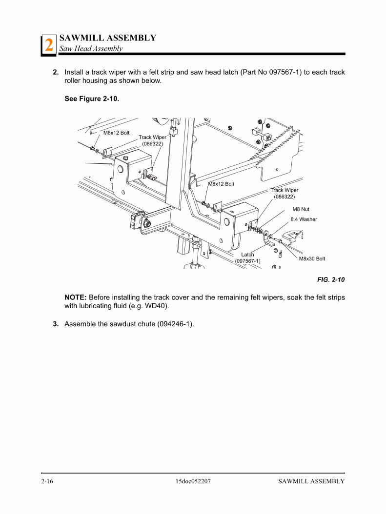
2. Install a track wiper with a felt strip and saw head latch (Part No 097567-1) to each trackroller housing as shown below.
See Figure 2-10.
NOTE: Before installing the track cover and the remaining felt wipers, soak the felt stripswith lubricating fluid (e.g. WD40).
3. Assemble the sawdust chute (094246-1).
FIG. 2-10
Latch (097567-1) M8x30 Bolt
M8x12 Bolt
M8x12 BoltTrack Wiper
(086322)
8.4 Washer
M8 Nut
Track Wiper (086322)
2-16 15doc052207 SAWMILL ASSEMBLY
SAWMILL ASSEMBLYSaw Head Assembly 2
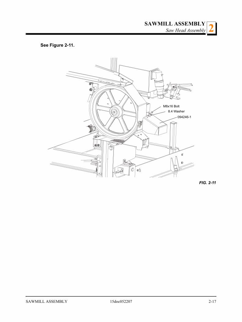
See Figure 2-11.
FIG. 2-11
094246-1
M8x16 Bolt8.4 Washer
SAWMILL ASSEMBLY 15doc052207 2-17
SAWMILL ASSEMBLYSaw Head Assembly2
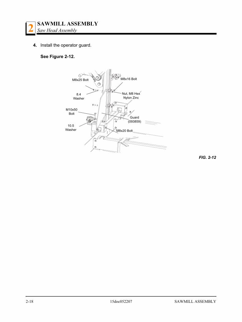
4. Install the operator guard.
See Figure 2-12.
FIG. 2-12
M10x50 Bolt
M8x16 BoltM8x25 Bolt
8.4 Washer
Guard (093859)
Nut, M8 Hex Nylon Zinc
10.5 Washer M8x20 Bolt
2-18 15doc052207 SAWMILL ASSEMBLY
SAWMILL ASSEMBLYSaw Head Assembly 2
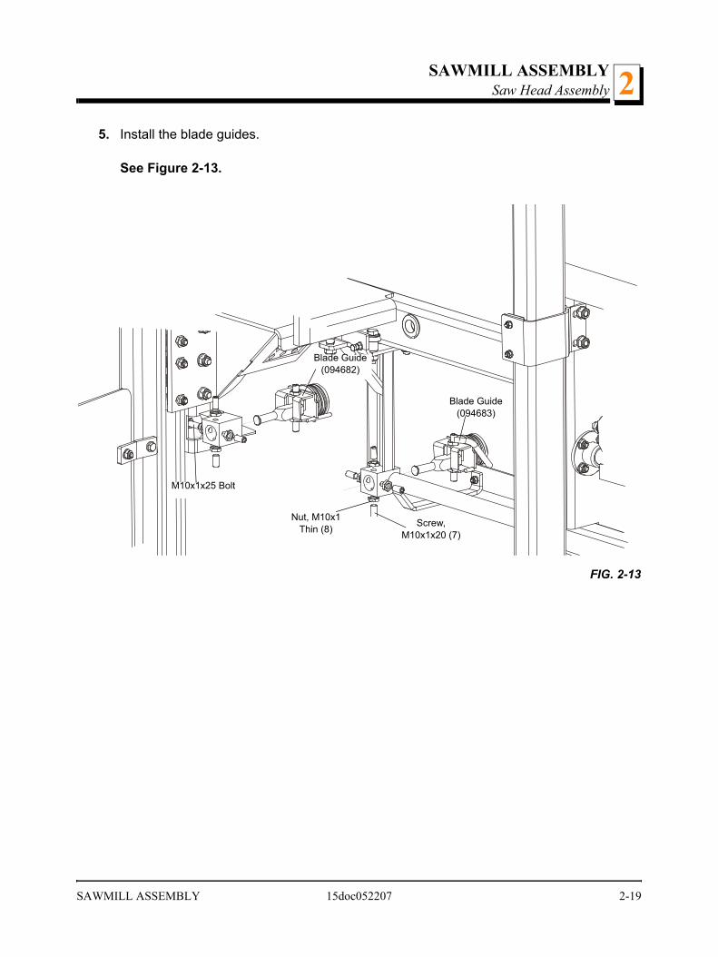
5. Install the blade guides.
See Figure 2-13.
FIG. 2-13
Screw, M10x1x20 (7)
Blade Guide (094682)
M10x1x25 Bolt
Nut, M10x1 Thin (8)
Blade Guide (094683)
SAWMILL ASSEMBLY 15doc052207 2-19

SAWMILL ASSEMBLYSaw Head Assembly2
6. Install the power cord bracket.
See Figure 2-14.
FIG. 2-14
Power Cord Bracket086132-1
Holder, Plastic Cable Tie (F81082-1)Screw, M4x16
4.3 WasherM4 Nut
2-20 15doc052207 SAWMILL ASSEMBLY

Setup & OperationSawmill Setup 3
SECTION 3 SETUP & OPERATION
3.1 Sawmill Setup
NOTE: The following setup procedure should be performed whenever the sawmill ismoved or reassembled. If sawing problems occur and misalignment is suspected, SeeSection SECTION 6 for complete alignment instructions.
1. Adjust the frame legs so the sawmill appears level. If sawmill is on soft ground, use shimsunder the legs if necessary.
2. Run a string from the front bed rail to the rear bed rail near the operator’s side of theframe. Place identical spacers between the string and the front and rear bed rails.Measure the distance between the string and the other bed rails. Adjust the frame legsuntil all bed rails measure the same distance from the string.
See Figure 3-1.
3. Repeat the bed rail adjustment with the string at the other side of the sawmill frame.
4. Install a blade (See Section 3.2 through Section 3.4) and move the saw carriage until theblade is positioned over the front bed rail.
FIG. 3-1
Setup & Operation 15doc052207 3-1

Setup & OperationSawmill Setup3
5. The blade guide rollers should not touch and deflect the blade and the blade guide armshould be adjusted all the way out, away from the other blade guide.
6. Measure the distance from the bed rail to the bottom of the blade near the inside (fixed)blade guide.
7. Measure the distance from the bed rail to the bottom of the blade near the outside(movable) blade guide.
See Figure 3-2. When the blade is parallel to the bed, it will measure the same distancefrom the bed rail at the inside and outside of the saw head. To adjust the saw head tilt,loosen the four mounting bolts of the roller bracket. Use the saw head adjustment nutslocated in the roller bracket to tilt the saw head.
FIG. 3-2
Lock Nut
Adjustment Nuts (2)
Roller Bracket Mounting Bolts (4)
3-2 15doc052207 Setup & Operation
Setup & OperationSawmill Setup 3
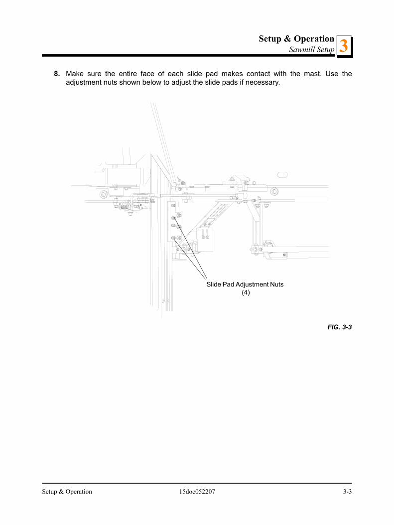
8. Make sure the entire face of each slide pad makes contact with the mast. Use theadjustment nuts shown below to adjust the slide pads if necessary.
FIG. 3-3
Slide Pad Adjustment Nuts (4)
Setup & Operation 15doc052207 3-3
Setup & OperationSawmill Setup3
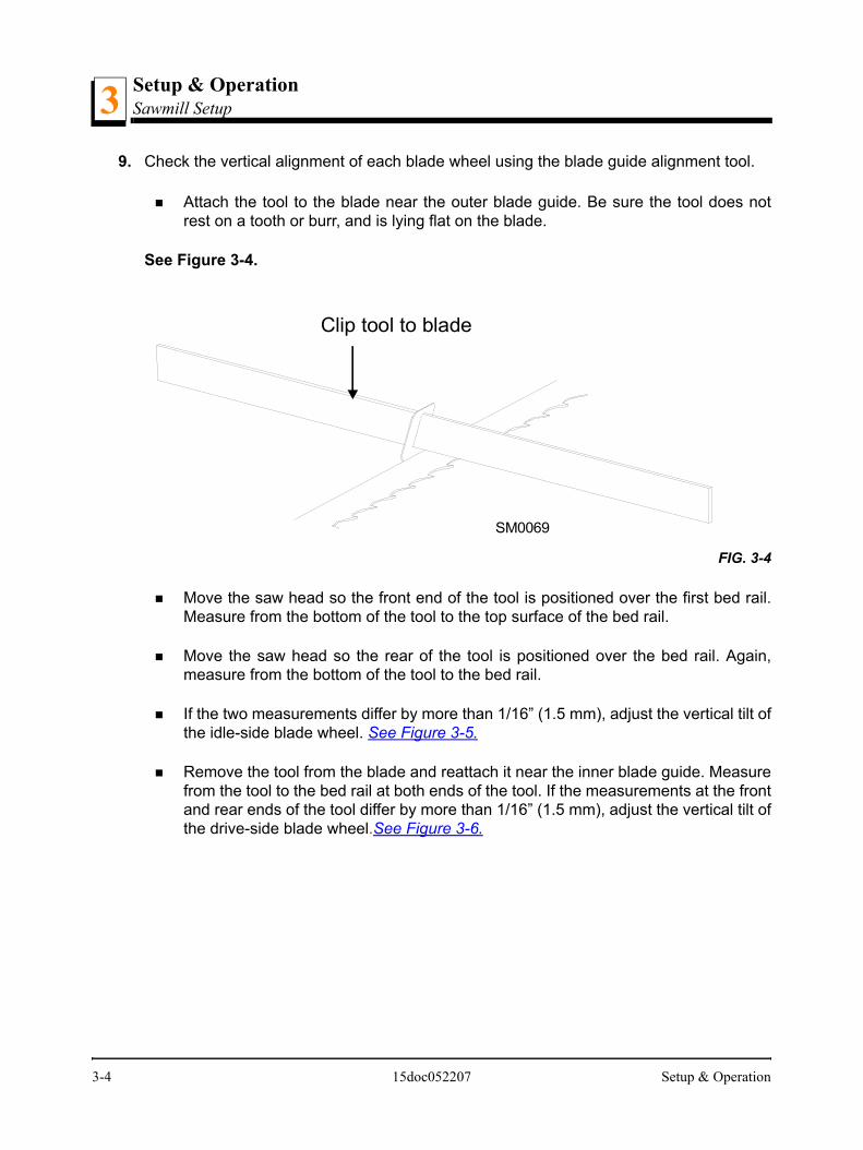
9. Check the vertical alignment of each blade wheel using the blade guide alignment tool.
Attach the tool to the blade near the outer blade guide. Be sure the tool does notrest on a tooth or burr, and is lying flat on the blade.
See Figure 3-4.
Move the saw head so the front end of the tool is positioned over the first bed rail.Measure from the bottom of the tool to the top surface of the bed rail.
Move the saw head so the rear of the tool is positioned over the bed rail. Again,measure from the bottom of the tool to the bed rail.
If the two measurements differ by more than 1/16” (1.5 mm), adjust the vertical tilt ofthe idle-side blade wheel. See Figure 3-5.
Remove the tool from the blade and reattach it near the inner blade guide. Measurefrom the tool to the bed rail at both ends of the tool. If the measurements at the frontand rear ends of the tool differ by more than 1/16” (1.5 mm), adjust the vertical tilt ofthe drive-side blade wheel.See Figure 3-6.
FIG. 3-4
Clip tool to blade
SM0069
3-4 15doc052207 Setup & Operation

Setup & OperationSawmill Setup 3
See Figure 3-5. To tilt the idle-side blade wheel up, loosen the bottom adjustment screw1/2 turn. Loosen the nut on the top adjustment screw and tighten the screw. Tighten thetop and bottom nuts.
To tilt the wheel down, loosen the top adjustment screw 1/2 turn. Loosen the nut on thebottom adjustment screw and tighten the screw. Tighten the top and bottom nuts .
FIG. 3-5
150075-2b
To tilt wheel up, tighten top screw (loosening earlier
bottom screw).To tilt wheel down, tighten bottom screw (loosening
earlier top screw).
Setup & Operation 15doc052207 3-5
Setup & OperationSawmill Setup3
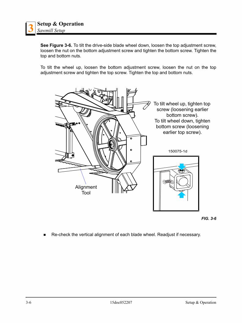
See Figure 3-6. To tilt the drive-side blade wheel down, loosen the top adjustment screw,loosen the nut on the bottom adjustment screw and tighten the bottom screw. Tighten thetop and bottom nuts.
To tilt the wheel up, loosen the bottom adjustment screw, loosen the nut on the topadjustment screw and tighten the top screw. Tighten the top and bottom nuts.
Re-check the vertical alignment of each blade wheel. Readjust if necessary.
FIG. 3-6
150075-1d
To tilt wheel up, tighten top screw (loosening earlier
bottom screw).To tilt wheel down, tighten bottom screw (loosening
earlier top screw).
Alignment Tool
3-6 15doc052207 Setup & Operation
Setup & OperationSawmill Setup 3
10. Adjust the spacing between each blade guide roller flange and the back of the blade. SeeSection 6.9
11. Adjust the horizontal angle of the blade guides. See Section 6.10
12. Adjust the blade deflection (See Section 6.7) and the vertical angle of the blade guides(See Section 6.8).
HINT: It is best to preliminarily set the blade deflection so that it is 3 - 4 mm, then adjustthe blade guides in the vertical plane and make the final adjustments to the bladedeflection. The proper blade deflection is 6 mm. After adjusting the blade deflection,recheck the vertical alignment of the blade guides and adjust if necessary.
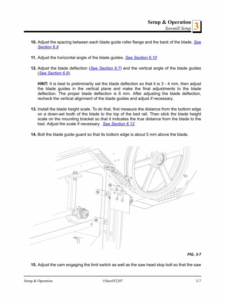
13. Install the blade height scale. To do that, first measure the distance from the bottom edgeon a down-set tooth of the blade to the top of the bed rail. Then stick the blade heightscale on the mounting bracket so that it indicates the true distance from the blade to thebed. Adjust the scale if necessary. See Section 6.12.
14. Bolt the blade guide guard so that its bottom edge is about 5 mm above the blade.
15. Adjust the cam engaging the limit switch as well as the saw head stop bolt so that the saw
FIG. 3-7
Setup & Operation 15doc052207 3-7

Setup & OperationSawmill Setup3
head stops moving at its lower travel limit, i.e. at the height of 25 mm above the bed.
16. Adjust the side bracket. See Section 6.13
WARNING! Adjust the side bracket before first operatingthe sawmill. Failure to do so may result in serious injury andmachine damage.
FIG. 3-8
Loosen the nut and adjust the stop bolt
3-8 15doc052207 Setup & Operation
Setup & OperationReplacing The Blade 3
3.2 Replacing The Blade
DANGER! Always disengage the blade and shut off thesawmill motor before changing the blade. Disconnect thepower supply using the main switch. Failure to do so willresult in serious injury.
WARNING! Always wear gloves and eye protection whenhandling bandsaw blades. Changing blades is safest whendone by one person! Keep all other persons away fromarea when coiling, uncoiling, carrying or changing a blade.Failure to do so may result in serious injury.
Adjust the blade guide arm all the way open.
Open the blade housing cover. Turn the blade tension handle to release the blade tensionuntil the wheel is pulled in and the blade is lying loose in the blade housing. Lift the bladeout of the blade housing.
Install a new blade on the blade wheels. When installing the blade, make sure the teethare pointing the correct direction. The teeth located between the blade guide assembliesshould be pointing toward the sawdust chute.
Position 1 1/4” wide blades on the wheels so the gullet is 1/8" (3.0 mm) out from the frontedge of the wheel. Position 1 1/2” wide blades on the wheels so the gullet is 3/16” (4.5mm) out from the front edge of the wheel.
Close the blade housing cover.
Next, turn the tension handle until the blade is tensioned correctly.
Setup & Operation 15doc052207 3-9

Setup & OperationTensioning The Blade3
3.3 Tensioning The Blade
See Figure 3-9. Turn the blade tension handle clockwise to compress the rubber springand tension the blade. Check the blade tension occasionally when adjusting the cantcontrol or while cutting. As the blade and belts heat up and stretch, the blade tension willchange. Also, ambient temperature changes can cause tension to change. Adjust thetension handle as necessary to keep the rubber spring washer aligned with the indicator.
CAUTION! Release the blade tension when the mill is notin use.
FIG. 3-9
20_002a
Outside face of washer even with indicator
Blade Tensioner Handle
Cant Control Bolt
Blade Tension Indicator
Rubber Spring
3-10 15doc052207 Setup & Operation
Setup & OperationTracking The Blade 3
3.4 Tracking The Blade
1. Make sure the blade housing cover is closed and all persons are clear of the blade.
2. Start the motor for a moment until the blade positions itself on the wheels.
WARNING! Do not spin the blade wheels by hand.Spinning the blade wheels by hand may result in seriousinjury.
3. Turn off the engine and check the position of the blade on the blade wheels.
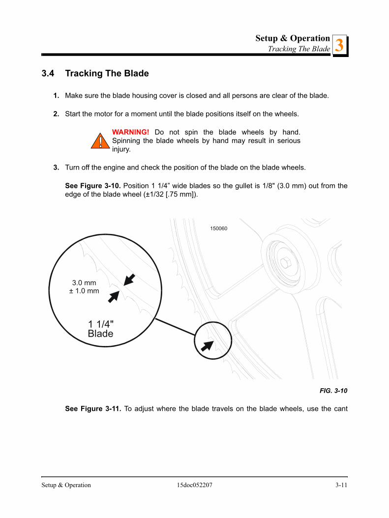
See Figure 3-10. Position 1 1/4” wide blades so the gullet is 1/8" (3.0 mm) out from theedge of the blade wheel (±1/32 [.75 mm]).
See Figure 3-11. To adjust where the blade travels on the blade wheels, use the cant
FIG. 3-10
150060
3.0 mm± 1.0 mm
1 1/4"Blade
Setup & Operation 15doc052207 3-11

Setup & OperationTracking The Blade3
control bolt.
If the blade is too far out, back the blade onto the wheel by turning the cant controlcounterclockwise. If the blade is too far in, turn the cant control clockwise until the gulletof the blade is the correct distance from the front edge of the wheel.
4. Adjust the blade tension if necessary to compensate for any changes that may haveoccurred while adjusting the cant control.
5. Close the blade housing cover.
DANGER! Make sure all guards and covers are in placeand secured/closed before operating the sawmill. Failure todo so may result in serious injury.
IMPORTANT! After aligning the blade on the wheels, always double-check the bladeguide spacing and location. (SECTION 6 for more information.)
FIG. 3-11
15B017
Cant Control Bolt
3-12 15doc052207 Setup & Operation

Setup & OperationLoading, Turning, And Clamping Logs 3
3.5 Loading, Turning, And Clamping Logs
To Load Logs
1. Move the cutting head to the front end of the frame.
CAUTION! Before loading a log, be sure the cutting head ismoved far enough forward so the log does not hit it. Failureto do so may result in machine damage.
2. Use the latch, to fix the saw head in this position.
See Figure 3-12.
3. Adjust the log clamps all the way down and move them toward the loading side of thesawmill frame.
CAUTION! Be sure the log clamps are all the way downbefore loading a log onto the bed. Failure to do so mayresult in machine damage.
4. Raise the side supports on the sawmill bed to prevent the log from falling off the side ofthe bed.
5. Place the optional loading ramps (optional equipment) in the frame brackets that will
FIG. 3-12
Setup & Operation 15doc052207 3-13
Setup & OperationLoading, Turning, And Clamping Logs3
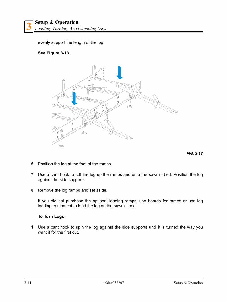
evenly support the length of the log.
See Figure 3-13.
6. Position the log at the foot of the ramps.
7. Use a cant hook to roll the log up the ramps and onto the sawmill bed. Position the logagainst the side supports.
8. Remove the log ramps and set aside.
If you did not purchase the optional loading ramps, use boards for ramps or use logloading equipment to load the log on the sawmill bed.
To Turn Logs:
1. Use a cant hook to spin the log against the side supports until it is turned the way youwant it for the first cut.
FIG. 3-13
3-14 15doc052207 Setup & Operation
Setup & OperationLoading, Turning, And Clamping Logs 3
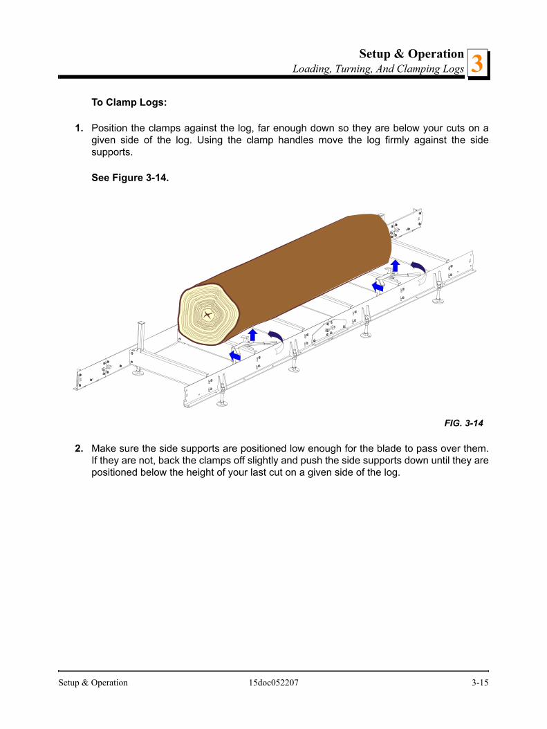
To Clamp Logs:
1. Position the clamps against the log, far enough down so they are below your cuts on agiven side of the log. Using the clamp handles move the log firmly against the sidesupports.
See Figure 3-14.
2. Make sure the side supports are positioned low enough for the blade to pass over them.If they are not, back the clamps off slightly and push the side supports down until they arepositioned below the height of your last cut on a given side of the log.
FIG. 3-14
Setup & Operation 15doc052207 3-15

Setup & OperationLoading, Turning, And Clamping Logs3
To Level A Tapered Log:
Use shims or the optional wedge to raise either end of a tapered log, if desired. Shim oneend of the log until the heart of the log measures the same distance from the bed rails ateach end of the log.
FIG. 3-14
Level log soheart is same
distancefrom bed railsat both ends
Leveling wedge
3-16 15doc052207 Setup & Operation
Setup & OperationUp/Down Operation 3
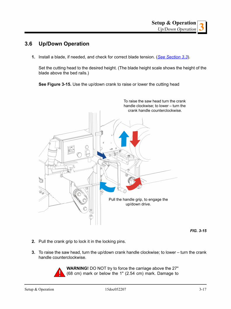
3.6 Up/Down Operation
1. Install a blade, if needed, and check for correct blade tension. (See Section 3.3).
Set the cutting head to the desired height. (The blade height scale shows the height of theblade above the bed rails.)
See Figure 3-15. Use the up/down crank to raise or lower the cutting head
2. Pull the crank grip to lock it in the locking pins.
3. To raise the saw head, turn the up/down crank handle clockwise; to lower – turn the crankhandle counterclockwise.
WARNING! DO NOT try to force the carriage above the 27"(68 cm) mark or below the 1" (2.54 cm) mark. Damage to
FIG. 3-15
To raise the saw head turn the crank handle clockwise; to lower – turn the
crank handle counterclockwise.
Pull the handle grip, to engage the up/down drive.
Setup & Operation 15doc052207 3-17

Setup & OperationBlade Guide Arm Operation3
the up/down system may result.
3.7 Blade Guide Arm Operation
1. Look down the length of the log to see its maximum width. The outer blade guide rollershould be adjusted to clear the widest section of the log by less than 1" (25.4 mm).
2. Use the blade guide arm handle to adjust the outer blade guide as necessary. Move theblade guide arm handle right to move the arm out. Move the handle left to move the armin.
See Figure 3-16.
FIG. 3-16
150120
Move the handle rightto move the blade arm out.
Move it left to movethe blade guide in.
3-18 15doc052207 Setup & Operation

Setup & OperationBlade Drive Operation 3
3.8 Blade Drive Operation
IMPORTANT! When starting the machine for the first time,check that main motor rotation direction is as indicated bythe arrow located on the motor body (fan guard). If therotation direction is incorrect, invert the phases in the phaseinverter located in the power socket (electric box). Correctmotor rotation direction is indicated by the arrow located onthe motor body.
DANGER! Make sure all guards and covers are in placeand secured/closed before operating the sawmill. Failure todo so may result in serious injury.
WARNING! Always wear eye, ear, respiration and footprotection when operating the sawmill. Failure to do so mayresult in serious injury.
Be sure the blade housing cover is in place and secured before starting the engine ormotor. Use the rubber latches to fasten the blade housing cover shut. If the blade housingcover is not closed and secured, the safety switch located on it interrupts the ignitioncircuit and the motor/engine cannot be started. If the cover is opened during the milloperation, the engine/motor will be stopped.
To engage the blade, perform the following steps:
1. Clear any loose objects from the area of the blade, motor, and drive belt.
2. Make sure the clamps and side supports are positioned low enough for the blade to passover them. Make sure the log is clamped securely.
3. Turn the main switch on the electrical box to the ON position, and check if the red safetybutton is released.
4. Press AND HOLD the safety handle on the control box. NOTE: If the safety handle isreleased, the blade disengages and stops.
5. Press the START button on the control box to start the motor.
!
Setup & Operation 15doc052207 3-19

Setup & OperationBlade Drive Operation3
FIG. 3-16
Switch, Emergency
Switch, Start-Stop
Safety Handle
Main Switch
3-20 15doc052207 Setup & Operation
Setup & OperationFeed Operation 3
3.9 Feed Operation
To move the saw head, use brackets locating on the control box.
HINT: To get a straight cut in the first part of the board, feed the blade into the log at aslow speed. This stops the blade from flexing and dipping up or down. Use a slow speeduntil the whole width of the blade has entered the cut. Then increase the feed rate asdesired. Maximum feed rate varies with width and hardness of the wood. Over-feedingresults in blade and drive belt wear.
CAUTION! Be sure to stop the blade when returning thecutting head. This will not only prevent the blade from beingpulled off and ruined by a wood sliver, but also will increasethe life of the blade.
HINT: Try to stop the blade while the heel of the blade is still on the log. Then bring thecarriage back without adjusting the blade up. This lets you keep the blade at the currentheight setting so you can make the next blade height adjustment more quickly.
3.10 Cutting The Log
The following steps guide you through normal operation of the Wood-Mizer sawmill.
1. Once the log is placed where you want it and clamped firmly, position the blade close tothe end of the log.
2. Use the blade height scale to determine where to make your first cut (See Section 3.12).Set the blade to the desired height with the up/down crank handle. Make sure that theblade will clear all side supports and clamps. Adjust the outer blade guide (See Section3.8).
3. Make sure all covers and guards are in place and secured. Start the engine.
4. Start the water lube if necessary to prevent sap buildup on the blade (See Section 3.13).
5. Feed the blade into the log slowly. Once the blade completely enters the log, increase thefeed rate as desired. Always try to cut at the fastest speed you can while keeping anaccurate cut. Cutting too slowly will waste blade life and lower production!
6. As you get to the end of the log, slow down the feed rate. When the teeth exit the end ofthe log, release the safety handle on the control box. Remove the slab that you have justcut from the log.
7. Use the feed crank to return the cutting head to the front of the mill. Always disengage the
Setup & Operation 15doc052207 3-21
Setup & OperationCutting The Log3
blade before returning the cutting head for the next cut.
8. Repeat until the first side of the log is cut as desired. Set aside the usable flitches (boardswith bark on one or both sides).You can edge them on the mill later.
9. Remove the leveling wedge if it was used. Release the clamps and turn the log 90 or 180degrees. Make sure the flat on the log is placed flat against side supports if turned 90degrees. Make sure it is placed on bed rails if turned 180 degrees. If the log was turned90 degrees and you are using the wedge to compensate for taper in the log, use thewedge again to adjust the heart of the log parallel with the bed.
10. Repeat the steps used to cut the first side of the log until the log is square. Cut boardsfrom the remaining cant.
Example: Remember that the blade cuts a 1/16 - 1/8" (1.6 - 3.2 mm) wide kerf. If youwant 1" (25 mm) thick boards, lower the carriage 1 1/16 - 1 1/8" (27 - 29 mm) for eachboard.
3-22 15doc052207 Setup & Operation

Setup & OperationEdging 3
3.11 Edging
The following steps guide you through edging boards on the Wood-Mizer sawmill.
1. Raise the side supports to 1/2 the height of the flitches, or the boards that need to beedged.
2. Stack the flitches on edge against the side supports.
3. Clamp the flitches against the side supports halfway up the flitch height. (Wider flitchesshould be placed to the clamp side. When they are edged, flip them over to edge thesecond side without disturbing the other flitches.)
4. Adjust the blade height to edge a few of the widest boards.
5. Loosen the clamps and turn the edged boards over to edge the other side.
6. Repeat steps 2-4.
7. Loosen the clamps and remove the boards that have good clean edges on both sides.Clamp the remaining flitches and repeat steps 2-5.
Setup & Operation 15doc052207 3-23

Setup & OperationBlade Height Scale3
3.12 Blade Height Scale
See Figure 3-17. The blade height scale is mounted on the vertical mast. It includes:
a blade height indicator
centimeter scale (or quarter inch scale)
Blade Height Indicator
The blade height indicator has two horizontal, red lines on both sides. Readings shouldbe taken with eyes level with the indicator, when the two red lines are in line. This willallow to avoid the parallax error (different scale readings depending on the angle ofvision).
The Scale
The horizontal red line on the blade height indicator shows how many centimeters thebottom of the blade is above the bed of the mill. If you know the height of your blade ateach cut, you can determine the thickness of lumber you are sawing.
Example: You want to cut 25 mm random width boards from a log. Position the blade forthe first cut. Move the carriage to an even measurement on the scale. Make a trim cut.Return the carriage for the second cut and lower it 29 mm below the originalmeasurement. (The extra 3 mm allows for saw kerf and shrinkage of the lumber.)
The yellow area on the scale identifies where the blade could encounter a side support orlog clamp. Check that these items are below the blade level before sawing.
The Quarter Scale
FIG. 3-17
150028C
Scale
Blade Height Indicator
3-24 15doc052207 Setup & Operation

Setup & OperationBlade Height Scale 3
See Table 3-1. The quarter scale contains of four sets of marks. Each set represents aspecific lumber thickness. Saw kerf and shrinkage allowance are included, but actualboard thickness will vary slightly depending on blade thickness and tooth set.
To choose which scale to use, determine what finished thickness you want to end up with.The Grade Hardwood Quarter Scale provides thicker finished boards usually required bycommercial buyers. The Standard Quarter Scale allows for kerf and shrinkage of finishedboards suitable for most custom applications. Always check with your customer beforeyou saw to determine what actual finished thickness is required.
To use the quarter scale, look at the blade height indicator. Example: You want to cut 1"(25 mm) (4/4) random width boards from a log. Position the blade for the first cut. Make atrim cut. Return the carriage for the second cut. Now, instead of having to measure down1 1/8" (29 mm) on the inch scale, you can simply lower the blade so the indicator isaligned with the next 4/4 mark on the quarter scale. Turn the log 90 degrees and repeat.
Standard Quarter Scale Grade Hardwood Quarter ScaleScale Actual Board Thickness Scale Actual Board Thickness
4/4 25 mm (1") 4/4 29 mm (1 1/8") 5/4 32 mm (1 1/4") 5/4 35 mm (1 3/8") 6/4 38 mm (1 1/2") 6/4 41 mm (1 5/8") 8/4 51 mm (2") 8/4 54 mm (2 1/8")
TABLE 3-0
Setup & Operation 15doc052207 3-25

Setup & OperationWater Lube Operation3
3.13 Water Lube Operation
The Water Lube System keeps the blade clean. Water flows from a 5 liter bottle through ahose to the blade guide where the blade enters the log. A valve in the bottle cap controlsthe amount of water flow.
See Figure 3-18. Install the water bottle at the top of the vertical mast.
FIG. 3-18
Place water bottle on tray
3-26 15doc052207 Setup & Operation

Setup & OperationWater Lube Operation 3
See Figure 3-19. Open the valve on the water bottle to start water flow on the blade.
Not all types of wood require the use of the Water Lube System. When it is needed, usejust enough water to keep the blade clean. This saves water, and lowers the risk ofstaining the boards with water. Usual flow will be 1-2 gallons (3.8-7.6 liters) per hour. Asquirt of liquid dishwashing detergent in the water bottle will help clean the blade whencutting wood with a high sap content.
WARNING! Use ONLY water with the water lubeaccessory. Never use flammable fuels or liquids. If thesetypes of liquids are necessary to clean the blade, remove itand clean with a rag. Failure to do so may result in seriousinjury or death.
Before removing the blade, engage blade drive. Let the blade spin with water running onit for about 15 seconds. This will clean the blade of sap buildup. Wipe the blade dry with arag before storing or sharpening.
If you are sawing in freezing temperatures, remove the water lube bottle from the sawmillwhen done sawing and store it in a warm place. Blow any remaining water from the waterlube hose.
FIG. 3-19
To close turn valve clockwise; to open turn valve counterclockwise.
Setup & Operation 15doc052207 3-27

Setup & OperationTransporting the Sawmill3
3.14 Transporting the Sawmill
The assembled sawmill cannot be transported. To transport the sawmill, the vertical mastand the saw head have to be removed from the frame, and secured.
WARNING! Keep all persons out of the path while loadingand unloading the sawmill. Failure to do so may result inserious injury or death.
Secure the sawmill to the truck bed to prevent the sawmill from shifting while it is beingtransported.
3-28 15doc052207 Setup & Operation

Wood-Mizer LT10 Short Interval Maintenance Schedule
PROCEDURE MANUAL REFERENCE
EVERY BLADE CHANGECheck Blade Guide Roller Performance SEE SECTION 4.2
Remove Excess Sawdust From Blade Wheel Housings And Sawdust Chute SEE SECTION 4.2EVERY 8 HOURSClean And Lubricate Track SEE SECTION 4.3
Remove Sawdust From Upper Cam Housings. SEE SECTION 4.3
f:\manuals\forms\749 15doc022007

1-2 30doc022007

30doc022007 1-3

f:\ma
S OF OPERATIONOURS AS YOU PERFORM EACH PROCEDURE.ENANCE IS NOT NEEDED AT THIS TIME.
300 HRS 350 HRS 400 HRS 450 HRS 500 HRS
Cl
Ch
Lu
S OF OPERATIONOURS AS YOU PERFORM EACH PROCEDURE.ENANCE IS NOT NEEDED AT THIS TIME.
800 HRS 850 HRS 900 HRS 950 HRS 1000 HRS
Cl
Ch
Lu
nuals\forms\610 15doc011507
WOOD-MIZER LT10 MAINTENANCE LOG
PROCEDURE MANUAL REFERENCE
TOTAL HOURFILL IN THE DATE AND THE MACHINE H
A SHADED BOX INDICATES MAINT50 HRS 100 HRS 150 HRS 200 HRS 250 HRS
ean & lubricate mast See Section4.4
eck blade wheel belts for wear. See Section4.6
bricate blade tensioner screw. See Section4.5
WOOD-MIZER LT10 MAINTENANCE LOG
PROCEDURE MANUAL REFERENCE
TOTAL HOURFILL IN THE DATE AND THE MACHINE H
A SHADED BOX INDICATES MAINT550 HRS 600 HRS 650 HRS 700 HRS 750 HRS
ean & lubricate mast See Section4.4
eck blade wheel belts for wear. See Section4.6
bricate blade tensioner screw. See Section4.5

f:\ma
S OF OPERATIONOURS AS YOU PERFORM EACH PROCEDURE.ENANCE IS NOT NEEDED AT THIS TIME.S 1300 HRS 1350 HRS 1400 HRS 1450 HRS 1500 HRS
Cl
Ch
Lu
S OF OPERATIONOURS AS YOU PERFORM EACH PROCEDURE.ENANCE IS NOT NEEDED AT THIS TIME.S 1800 HRS 1850 HRS 1900 HRS 1950 HRS 2000 HRS
Cl
Ch
Lu
nuals\forms\610 15doc011507
WOOD-MIZER LT10 MAINTENANCE LOG
PROCEDURE MANUAL REFERENCE
TOTAL HOURFILL IN THE DATE AND THE MACHINE H
A SHADED BOX INDICATES MAINT1050 HRS 1100 HRS 1150 HRS 1200 HRS 1250 HR
ean & lubricate mast See Section4.4
eck blade wheel belts for wear. See Section4.6
bricate blade tensioner screw. See Section4.5
WOOD-MIZER LT10 MAINTENANCE LOG
PROCEDURE MANUAL REFERENCE
TOTAL HOURFILL IN THE DATE AND THE MACHINE H
A SHADED BOX INDICATES MAINT1550 HRS 1600 HRS 1650 HRS 1700 HRS 1750 HR
ean & lubricate mast See Section4.4
eck blade wheel belts for wear. See Section4.6
bricate blade tensioner screw. See Section4.5

S OF OPERATIONOURS AS YOU PERFORM EACH PROCEDURE.ENANCE IS NOT NEEDED AT THIS TIME.S 2300 HRS 2350 HRS 2400 HRS 2450 HRS 2500 HRS
Cl
Ch
Lu
S OF OPERATIONOURS AS YOU PERFORM EACH PROCEDURE.ENANCE IS NOT NEEDED AT THIS TIME.S 2800 HRS 2850 HRS 2900 HRS 2950 HRS 3000 HRS
Cl
Ch
Lu
WOOD-MIZER LT10 MAINTENANCE LOG
PROCEDURE MANUAL REFERENCE
TOTAL HOURFILL IN THE DATE AND THE MACHINE H
A SHADED BOX INDICATES MAINT2050 HRS 2100 HRS 2150 HRS 2200 HRS 2250 HR
ean & lubricate mast See Section4.4
eck blade wheel belts for wear. See Section4.6
bricate blade tensioner screw. See Section4.5
WOOD-MIZER LT10 MAINTENANCE LOG
PROCEDURE MANUAL REFERENCE
TOTAL HOURFILL IN THE DATE AND THE MACHINE H
A SHADED BOX INDICATES MAINT2550 HRS 2600 HRS 2650 HRS 2700 HRS 2750 HR
ean & lubricate mast See Section4.4
eck blade wheel belts for wear. See Section4.6
bricate blade tensioner screw. See Section4.5
MaintenanceWear Life 4
SECTION 4 MAINTENANCE
This section lists the maintenance procedures that need to be performed on the LT10sawmills.
The Short Interval Maintenance Schedule lists procedures that need to be performedevery 4, 8 or 25 hours.The Maintenance Log lists procedures that need to be performedevery 50, 100, 200, or 1000 hours. Keep track of machine maintenance by filling in themachine hours and the date you perform each procedure.
This symbol identifies the interval (hours of operation) which each maintenanceprocedure should be performed.
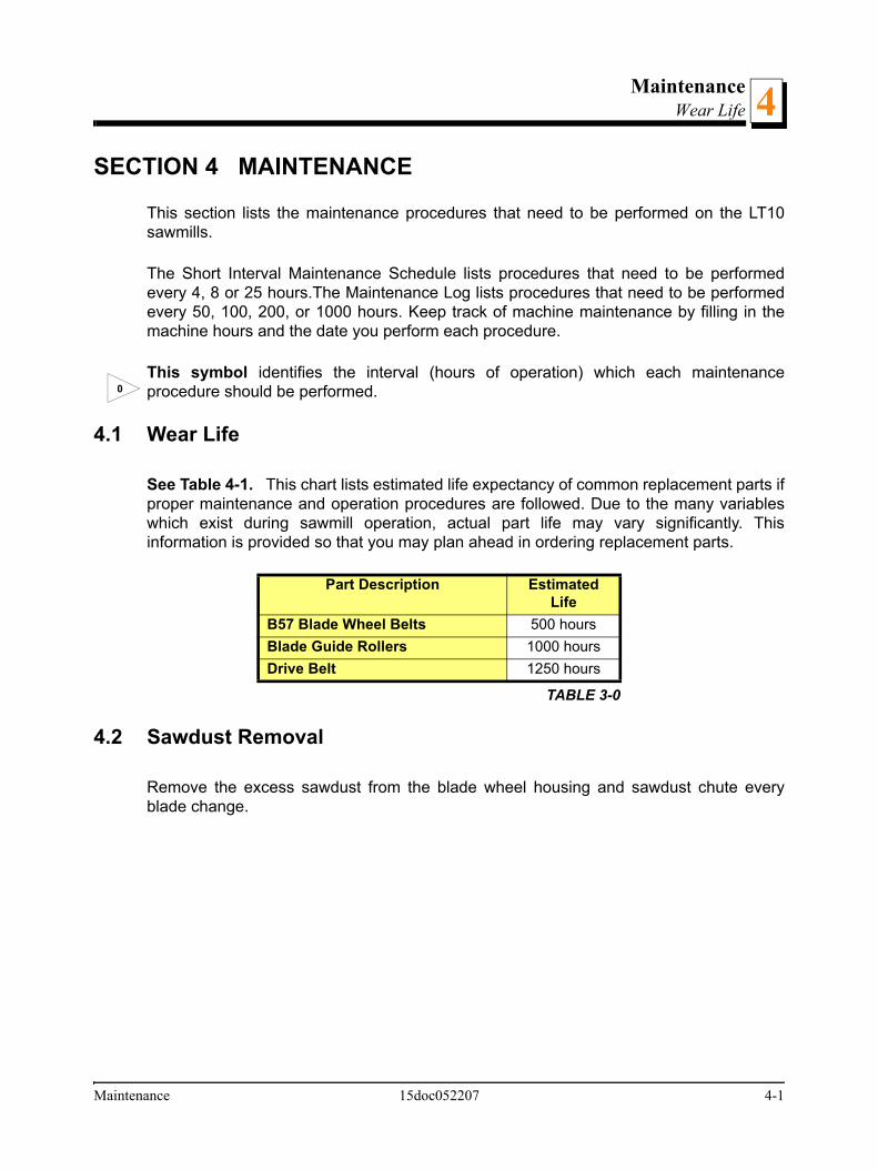
4.1 Wear Life
See Table 4-1. This chart lists estimated life expectancy of common replacement parts ifproper maintenance and operation procedures are followed. Due to the many variableswhich exist during sawmill operation, actual part life may vary significantly. Thisinformation is provided so that you may plan ahead in ordering replacement parts.
4.2 Sawdust Removal
Remove the excess sawdust from the blade wheel housing and sawdust chute everyblade change.
Part Description Estimated Life
B57 Blade Wheel Belts 500 hoursBlade Guide Rollers 1000 hoursDrive Belt 1250 hours
TABLE 3-0
0
Maintenance 15doc052207 4-1

MaintenanceCarriage Track & Rollers4
4.3 Carriage Track & Rollers
See Figure 4-1.
1. Clean the track bar to remove any sawdust and sap buildup every eight hours ofoperation.
2. Remove sawdust from the track roller housings. Remove the track roller housing coversand brush any sawdust buildup from the housings.
4.4 Vertical Mast Rails
Clean and lubricate the vertical mast rails every 50 hours of operation. Clean with solventand remove any rust with a light-grade sand paper. Lubricate the mast with motor oil orautomatic transmission fluid (e.g. Dextron II or Dextron III).
CAUTION! Never use grease on the mast rails as it willcollect sawdust.
FIG. 4-1
8
Roller housingTrack scrappers
50
4-2 15doc052207 Maintenance

MaintenanceMiscellaneous Lubrication 4
4.5 Miscellaneous Lubrication
1. Lubricate the tensioner screw and up/down crank handle shaft with a rolling bearinggrease (e.g. ŁT4S or Shell Extreme Pressure Grease) as needed.
See Figure 4-2.
4.6 Blade Wheel Belts
1. Check the blade wheel belts for wear. Replace belts as necessary. Rotating the beltsevery 50 hours will give you longer belt life. Use only B57 belts manufactured byGoodyear or Browning.
2. Periodically check all belts for wear. Replace any damaged or worn belts as needed.
FIG. 4-2
Grease the blade tensioner thread
50
Maintenance 15doc052207 4-3

MaintenanceUp/Down System4
4.7 Up/Down System
1. Adjust the up/down chain tension as needed. Measure chain tension, with the saw headall the way to the top of the vertical mast. Secure the saw head with a chain at the top orshim it underneath. Find the chain adjusting bolt at bottom part of the mast. Loosen thenut on the bolt and move the sprocket down until there is about 1” (2.5cm) total deflectionin the center of the chain with a 5 Ib. (2.3kg) deflection force.
WARNING! Always secure the cutting head with a chain orbrace before adjusting the up/down chain. The cutting headmay fall, causing severe injury or death.
FIG. 4-2
4-4 15doc052207 Maintenance

MaintenanceMiscellaneous Maintenance 4
4.8 Miscellaneous Maintenance
1. Check the drive belt tension after the first 20 hours, and every 50 hours thereafter. SeeSection 6.13 for more informations.
2. Check the mill alignment every setup. See Section 6, Alignment)
3. Make sure all safety warning decals are readable. Remove sawdust and dirt. Replace anydamaged or unreadable decals immediately. Order decals from your Customer ServiceRepresentative.
50
Maintenance 15doc052207 4-5

Troubleshooting GuideSawing Problems5
SECTION 5 TROUBLESHOOTING GUIDE
5.1 Sawing Problems
PROBLEM CAUSE SOLUTION
Blades Dull Quickly Dirty logs Clean or debark logs, especially on entry side of the cut
When grinding teeth, heating too much and causing teeth to soften
Grind just enough metalto restore sharpness to the teeth.Use water/coolant while sharpening blade.
Poor sharpening techniques Make sure the tip is being sharpened completely (See Sharpener Manual).
Blades Break Prematurely Rubber belts on blade wheels worn to a point that blade contacts metal pulley - look for shiny spots on edge of wheels.
Change blade wheel belts (B-57).
Poor sharpening techniques See Sharpener Manual
Tension too tight Tension blade to recommended specifications.
Blade Does Not Track Right on Wheels
Cant adjustment is incorrect Readjust.
Flat/worn belts Replace B-57 belts
Blade Guide Rollers Do Not Spin While Cutting
Frozen bearings Replace bearings
Worn bearings Replace bearings
Drive Belts Wear Prematurely or Jump
Engine/motor and drive pulleys out of alignment
Align pulleys.
5-1 15doc022007 Troubleshooting Guide
Troubleshooting GuideSawing Problems 5
PROBLEM CAUSE SOLUTION
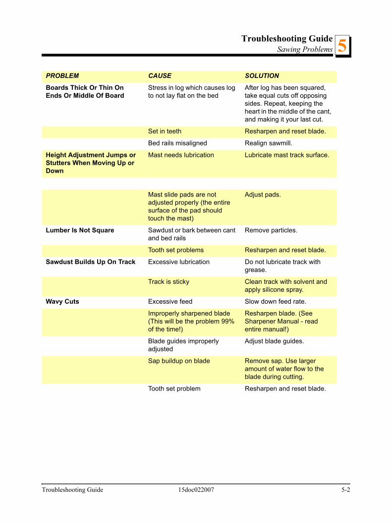
Boards Thick Or Thin On Ends Or Middle Of Board
Stress in log which causes log to not lay flat on the bed
After log has been squared, take equal cuts off opposing sides. Repeat, keeping the heart in the middle of the cant, and making it your last cut.
Set in teeth Resharpen and reset blade.
Bed rails misaligned Realign sawmill.
Height Adjustment Jumps or Stutters When Moving Up or Down
Mast needs lubrication Lubricate mast track surface.
Mast slide pads are not adjusted properly (the entire surface of the pad should touch the mast)
Adjust pads.
Lumber Is Not Square Sawdust or bark between cant and bed rails
Remove particles.
Tooth set problems Resharpen and reset blade.
Sawdust Builds Up On Track Excessive lubrication Do not lubricate track with grease.
Track is sticky Clean track with solvent and apply silicone spray.
Wavy Cuts Excessive feed Slow down feed rate.
Improperly sharpened blade (This will be the problem 99% of the time!)
Resharpen blade. (See Sharpener Manual - read entire manual!)
Blade guides improperly adjusted
Adjust blade guides.
Sap buildup on blade Remove sap. Use larger amount of water flow to the blade during cutting.
Tooth set problem Resharpen and reset blade.
Troubleshooting Guide 15doc022007 5-2

Troubleshooting GuideSawing Problems5
5-3 15doc022007 Troubleshooting Guide

Sawmill AlignmentPre-Alignment Procedures 6
SECTION 6 SAWMILL ALIGNMENT
6.1 Pre-Alignment Procedures
Periodically check the sawmill alignment and adjust if necessary. This chapter explainshow to align the entire sawmill. Care should be taken in performing these steps. Sawmillalignment determines the accuracy and squareness of your cuts.
The sawmill alignment steps are:
1. Prepare the sawmill for alignment
2. Adjust the blade parallel to the bed rails
3. Adjust the blade guide arm parallel to the saw head brace
4. Align blade guides to the blade
5. Final Adjustments.
To insure accurate alignment, the sawmill frame must be level and a blade properlyinstalled.
See SECTION 3 Setup & Operation for setup information.
6.2 Preparing The Sawmill For Alignment
Before performing the following alignment procedures, setup the mill on firm, levelground. String the bed and adjust the legs so the frame is level ( See Section 3.1).
Sawmill Alignment 15doc052207 6-1

Sawmill AlignmentBlade Installation and Alignment6
6.3 Blade Installation and Alignment
Install a blade and apply the appropriate tension as shown in See Section 3.3.
1. Close the blade housing cover and make sure all persons are clear of the open side ofthe saw head.
2. Start the motor for a moment.
WARNING! Do not spin the blade wheels by hand.Spinning the blade wheels by hand may result in seriousinjury.
3. Turn off the motor, open the blade housing cover, remove the key from the key switch andcheck the position of the blade on the blade wheels.
Check the vertical alignment of the idle-side blade wheel. The gullet of the blade shouldride the same distance from the front edge of the wheel at the top and bottom of thewheel. If it does not, loosen and tighten the appropriate adjustment screws on the wheelshaft.
See Figure 6-1. The blade wheels should be adjusted so that the gullet of 1 1/4" bladesride 1/8" (3 mm) out from the front edge of the wheels (±1/26 [1 mm]). The gullet of 1 1/2"blades should ride 3/16" (4.5 mm) from the front edge of the wheels (±1/26 [1 mm]). Donot let the teeth ride on the wheels.
6-2 15doc052207 Sawmill Alignment

Sawmill AlignmentBlade Installation and Alignment 6
To adjust where the blade travels on the idle-side and drive-side blade wheel, see nextsection in this manual.
FIG. 6-1
150060
3.0 mm± 1.0 mm
1 1/4"Blade
Sawmill Alignment 15doc052207 6-3

Sawmill AlignmentBlade Wheel Alignment6
6.4 Blade Wheel Alignment
The blade wheels should be adjusted so they are level in the vertical and horizontalplanes. If the blade wheels are tilted up or down, the blade will want to travel in the tilteddirection. If the blade wheels are tilted horizontally, the blade will not track properly on thewheels.
Use the blade guide alignment tool to check the vertical alignment of each blade wheel.
1. Attach the tool to the blade near the inner blade guide mount. Be sure the tool does notrest on a tooth or burr, and is lying flat against the bottom of the blade.
See Figure 6-2.
2. Move the saw carriage so the front end of the tool is positioned over the first bed rail.Measure from the bottom of the tool to the top surface of the bed rail.
3. Move the saw carriage so the rear of the tool is positioned over the bed rail. Again,measure from the bottom of the tool to the bed rail.
4. If the two measurements differ by more than 1/16" (1.5 mm), adjust the vertical tilt of thedrive-side blade wheel.
FIG. 6-2
Clip tool to blade
SM0069
6-4 15doc052207 Sawmill Alignment

Sawmill AlignmentBlade Wheel Alignment 6
See Figure 6-3. Use the vertical adjustment screws to adjust the drive-side blade wheel.To tilt the wheel down, loosen the top adjustment screw half turn. Loosen the jam nut onthe bottom adjustment screw and tighten the screw. Tighten the top and bottom jam nuts.
To tilt the wheel up, loosen the bottom adjustment screw half turn. Loosen the jam nut onthe top adjustment screw and tighten the screw. Tighten the top and bottom jam nuts.
5. Re-check the vertical tilt of the drive-side blade wheel with the blade guide alignment tool.Readjust the blade wheel as necessary until the front and rear of the tool are the samedistance from the bed rail (within 1/16" [1.5 mm]).
6. Remove the tool from the blade and re-attach it near the outer blade guide assembly.
7. Measure from the tool to the bed rail at both ends of the tool. If the measurements at thefront and rear ends of the tool differ by more than 1/16" (1.5 mm), adjust the vertical tilt ofthe idle-side blade wheel.
See Figure 6-4. Use the vertical adjustment screws to adjust the idle-side blade wheel.
FIG. 6-3
To tilt the wheel up, adjust screws down;
to tilt the wheel down, adjust the screws up.
Alignment Tool
Sawmill Alignment 15doc052207 6-5
Sawmill AlignmentBlade Wheel Alignment6
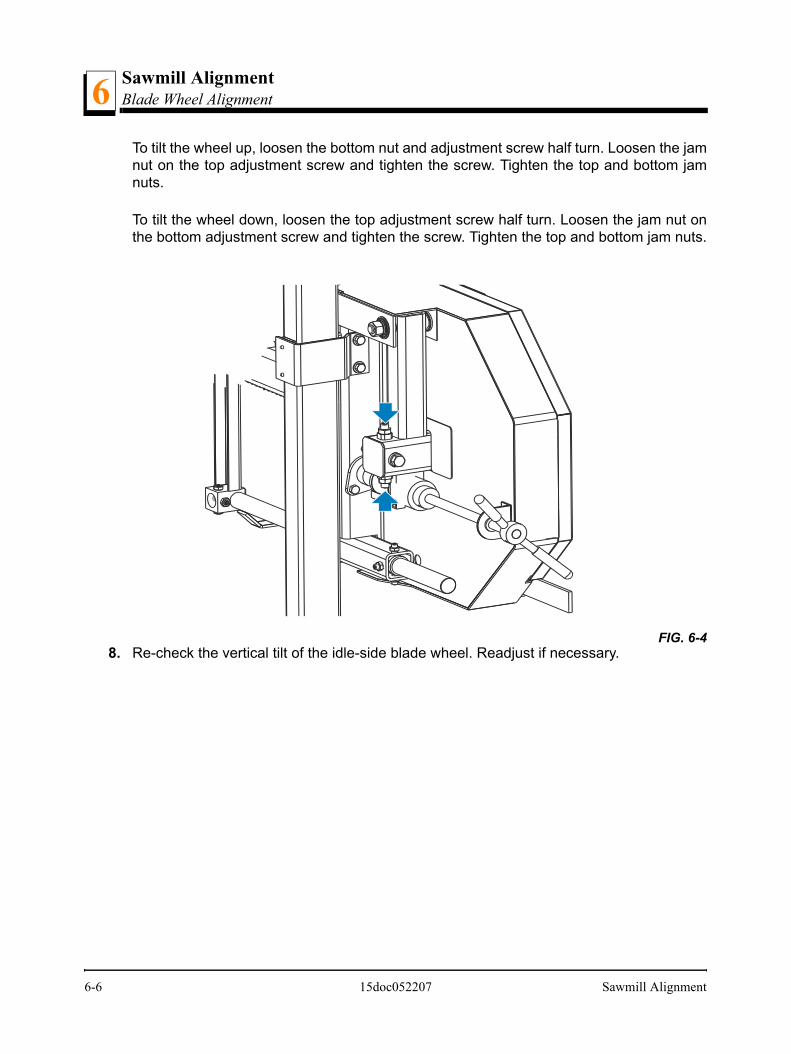
To tilt the wheel up, loosen the bottom nut and adjustment screw half turn. Loosen the jamnut on the top adjustment screw and tighten the screw. Tighten the top and bottom jamnuts.
To tilt the wheel down, loosen the top adjustment screw half turn. Loosen the jam nut onthe bottom adjustment screw and tighten the screw. Tighten the top and bottom jam nuts.
8. Re-check the vertical tilt of the idle-side blade wheel. Readjust if necessary. FIG. 6-4
6-6 15doc052207 Sawmill Alignment
Sawmill AlignmentBlade Wheel Alignment 6
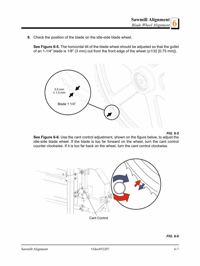
9. Check the position of the blade on the idle-side blade wheel.
See Figure 6-5. The horizontal tilt of the blade wheel should be adjusted so that the gulletof an 1-1/4" blade is 1/8" (3 mm) out from the front edge of the wheel (±1/32 [0.75 mm]).
See Figure 6-6. Use the cant control adjustment, shown on the figure below, to adjust theidle-side blade wheel. If the blade is too far forward on the wheel, turn the cant controlcounter clockwise. If it is too far back on the wheel, turn the cant control clockwise.
FIG. 6-5
FIG. 6-6
3.0 mm± 1.0 mm
Blade 1 1/4”
Cant Control
Sawmill Alignment 15doc052207 6-7

Sawmill AlignmentBlade Wheel Alignment6
10. Check the position of the blade on the drive-side blade wheel. The blade should bepositioned on the wheel as described for the idle-side blade wheel. Adjust the drive-sideblade wheel if necessary.
See Figure 6-7. Use the horizontal adjustment screw to adjust the drive-side bladewheel. Loosen the jam nut on the adjustment screw. Loosen adjustment screw to moveblade out on wheel. Tighten adjustment screw to move blade in on wheel. Tighten the jamnut.
11. Adjust the blade vibration damper screw. Distance from the screw to the blade should beabout 1mm.
Patrz rysunek 6-8.
FIG. 6-7
Adjustment screw
6-8 15doc052207 Sawmill Alignment
Sawmill AlignmentBlade Guide Arm Alignment 6
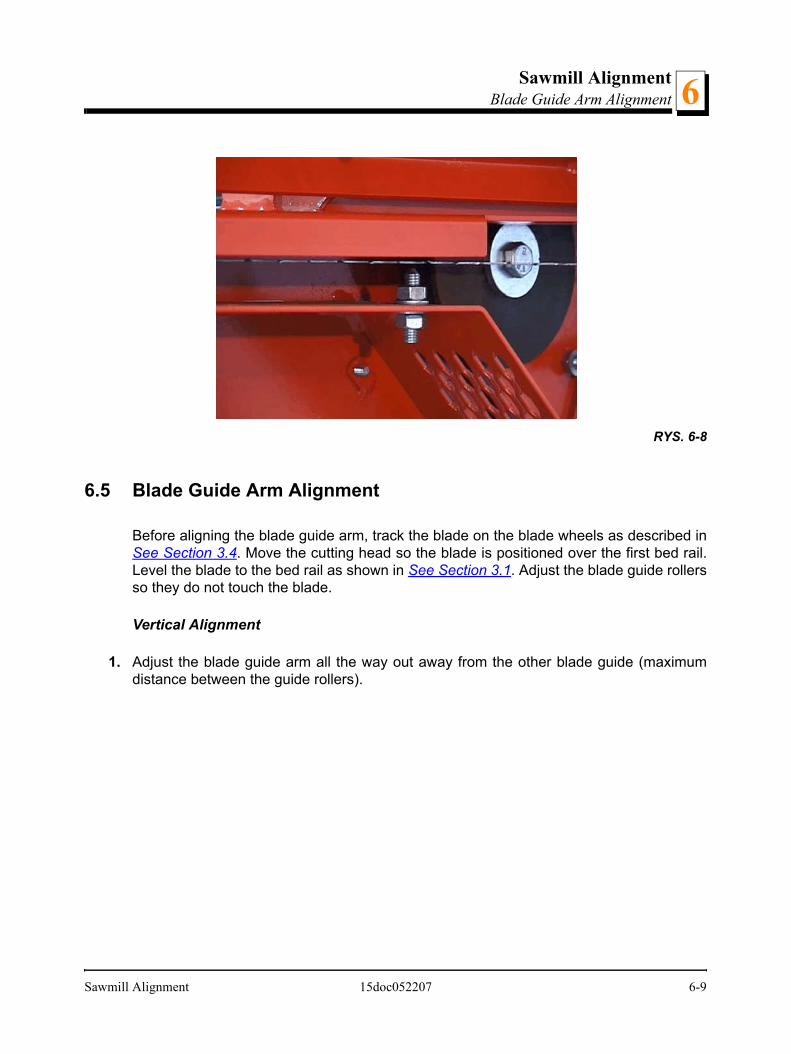
6.5 Blade Guide Arm Alignment
Before aligning the blade guide arm, track the blade on the blade wheels as described inSee Section 3.4. Move the cutting head so the blade is positioned over the first bed rail.Level the blade to the bed rail as shown in See Section 3.1. Adjust the blade guide rollersso they do not touch the blade.
Vertical Alignment
1. Adjust the blade guide arm all the way out away from the other blade guide (maximumdistance between the guide rollers).
RYS. 6-8
Sawmill Alignment 15doc052207 6-9

Sawmill AlignmentBlade Guide Arm Alignment6
See Figure 6-9.
2. Use the arm adjustment screws, marked with blue arrows in the figure above, to adjustthe arm up until the slide pad touches the saw head brace tube. Tighten the jam nuts.
3. Adjust the blade guide arm in all the way toward the other blade guide (minimum distancebetween the guide rollers).
4. Use the arm adjustment screws, marked with red arrows in the figure above, to adjust thearm up until the slide pad touches the saw head brace tube. Tighten the jam nuts.
NOTE: When adjusting the blade guide arm screws, be careful not to damage theirthreads or deform the arm guide bushing. Operate the blade guide arm handle to ensurethe arm moves easily left and right when the handle is moved.
FIG. 6-9
Adjust front top and bottomscrews with arm open Adjust rear top and bottom
screws with arm closed
6-10 15doc052207 Sawmill Alignment

Sawmill AlignmentBlade Guide Arm Alignment 6
Horizontal Alignment
See Figure 6-10.
1. With the blade guide arm still all the way in toward the other blade guide, tighten all theside screws until they touch the arm. Back the screws off 1/4 turn and tighten the jamnuts.
2. Sight across the horizontal saw head brace to view the blade guide arm. Adjust all sidescrews on the blade guide arm housing so the arm is parallel to the saw head brace.
3. To move the blade guide end of the arm toward the front of the sawmill, loosen jam nutson the front inside screw and the rear outside screw. Turn the screws counterclockwiseone full turn and tighten the jam nuts. Loosen the jam nuts on the front outside screw andthe rear inside screw. Turn the screws clockwise until they touch the arm, back off 1/4”turn, and tighten the jam nuts.
4. To move the blade guide end of the arm toward the rear of the sawmill, loosen jam nutson the front outside screw and the rear inside screw. Turn the screws counterclockwiseone full turn and tighten the jam nuts. Loosen the jam nuts on the front inside screw andthe rear outside screw. Turn the screws clockwise until they touch the arm, back off 1/4”turn, and tighten the jam nuts.
FIG. 6-10
Blade Guide Arm Parallel to Saw Head Brace
Adjust side screws tochange arm angle
Sawmill Alignment 15doc052207 6-11

Sawmill AlignmentAligning The Blade Guides6
6.6 Aligning The Blade Guides
Each Wood-Mizer sawmill has two blade guide assemblies that help the blade maintain astraight cut. The two blade guide assemblies are positioned on the saw head to guide theblade on each side of the material being cut.
One blade guide assembly is mounted in a stationary position on the drive side of the sawhead. This assembly is referred to as the "inner" blade guide assembly.
The other blade guide assembly is mounted on the idle side of the saw head. It is referredto as the "outer" assembly and is adjustable for various widths of materials to beprocessed.
Blade guide alignment includes four steps:
Blade Deflection,
Blade Guide Vertical Tilt,
Blade Guide Flange Spacing,
Blade Guide Horizontal Tilt.
Perform the blade guide alignment after you have aligned the blade on the wheels andadjusted the blade and blade guide arm parallel to the bed rails. After blade guidealignment, check the scale indicator to make sure it is adjusted properly.
6-12 15doc052207 Sawmill Alignment

Sawmill AlignmentBlade Deflection 6
6.7 Blade Deflection
Perform the following steps to achieve proper blade deflection with the blade guides:
1. Raise the carriage until the blade is 15" (375 mm) above a bed rail. Measure the actualdistance with a tape from the top of the rail to the bottom of the blade.
See Figure 6-11.
2. Loosen the bottom jam nut and tighten the top jam nut until the blade guide deflects theblade down 1/4" (6 mm).
3. Repeat for the other blade guide.
NOTE: Be sure that the blade guard clears the blade on both guide assemblies. Theguard on the outer guide assembly should be checked with the arm all the way in and allthe way out.
FIG. 6-11
Turn jam nuts to adjustroller up or down
SM0068
Sawmill Alignment 15doc052207 6-13

Sawmill AlignmentBlade Guide Vertical Tilt Adjustment6
6.8 Blade Guide Vertical Tilt Adjustment
Check that the blade guide does not tilt the blade up or down. A Blade Guide AlignmentTool (BGAT) is provided to help you measure the vertical tilt of the blade.
1. Open the adjustable blade guide arm 1/2" (15 mm) from full open.
2. Clamp the alignment tool on the blade. Position the tool close to a blade guide roller. Besure the tool does not rest on a tooth or burr, and is lying flat on the blade.
See Figure 6-12.
3. Measure the distance from the bed rail to the bottom of the tool.
4. Move the carriage so that the front end of the tool is positioned above the bed rail.
5. Measure the distance from the bed rail to the bottom edge of the tool.
6. Use the set screws shown to tilt the blade guide until the measurement from the bed railto the tool equals the first measurement taken at the center of the tool.
FIG. 6-12
Clip tool to blade
SM0069
6-14 15doc052207 Sawmill Alignment
Sawmill AlignmentBlade Guide Vertical Tilt Adjustment 6
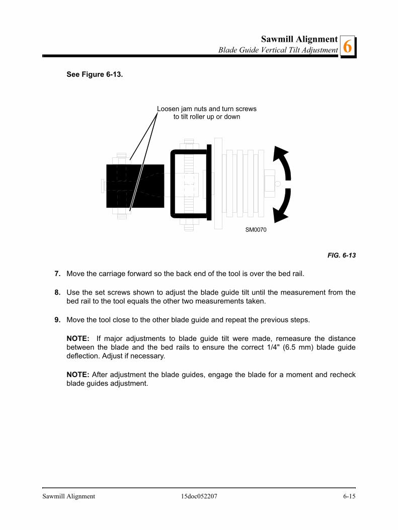
See Figure 6-13.
7. Move the carriage forward so the back end of the tool is over the bed rail.
8. Use the set screws shown to adjust the blade guide tilt until the measurement from thebed rail to the tool equals the other two measurements taken.
9. Move the tool close to the other blade guide and repeat the previous steps.
NOTE: If major adjustments to blade guide tilt were made, remeasure the distancebetween the blade and the bed rails to ensure the correct 1/4" (6.5 mm) blade guidedeflection. Adjust if necessary.
NOTE: After adjustment the blade guides, engage the blade for a moment and recheckblade guides adjustment.
FIG. 6-13
SM0070
Loosen jam nuts and turn screwsto tilt roller up or down
Sawmill Alignment 15doc052207 6-15

Sawmill AlignmentBlade Guide Flange Spacing6
6.9 Blade Guide Flange Spacing
HINT: When adjusting blade guide flange spacing, loosen the top set screw and one sideset screw only. This will insure horizontal and vertical tilt adjustments are maintainedwhen the set screws are retightened.
1. Adjust the inner blade guide so the blade guide flange is approximately 1/16" - 1/8" (1.5 -3.0 mm) from the back of the blade.
2. Loosen one side and one top set screw shown on the figure below. Tap the blade guideforward or backward until properly positioned.
See Figure 6-14.
3. Retighten the set screws.
4. Adjust the outer blade guide in the same way so the inner blade guide.
NOTE: After adjusting the spacing of the rollers, start the blade motor for a moment. Thenstop the blade and check the spacing again.
FIG. 6-14
SM0071a
1,5 - 3,0 mm
Loosen one top andone side set screw
Adjust distance between roller and back of blade
6-16 15doc052207 Sawmill Alignment

Sawmill AlignmentHorizontal Tilt Adjustment 6
6.10 Horizontal Tilt Adjustment
1. Move the blade guide arm half way in.
See Figure 6-15.
2. Place Blade Guide Alignment Tool against the face of the outer blade guide roller, asshown above.
3. Measure between the back edge of the blade and the tool at the end closest to the innerblade guide ("B").
4. Measure between the back edge of the blade and the other end of the tool ("A").
5. The roller should be parallel to the blade (A=B) or tilted slightly to the left (A=B-1/4"[6 mm]). Use the side set screws to adjust the horizontal tilt of the roller.
6. Repeat Steps 3 - 7 for the inner blade guide roller.
NOTE: Once the blade guides have been adjusted, any cutting variances are most likelycaused by the blade. See Blade Handbook, Form #600.
FIG. 6-15
50cm
Sawmill Alignment 15doc052207 6-17
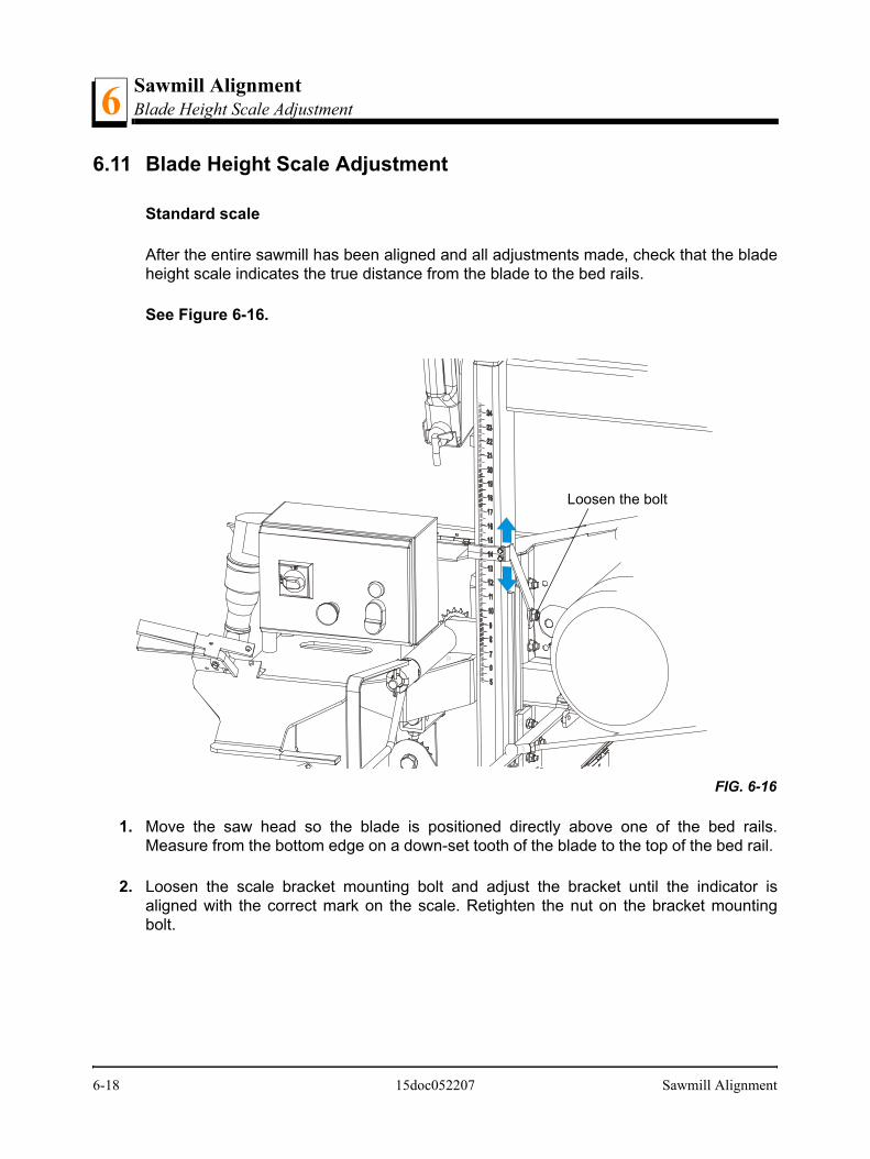
Sawmill AlignmentBlade Height Scale Adjustment6
6.11 Blade Height Scale Adjustment
Standard scale
After the entire sawmill has been aligned and all adjustments made, check that the bladeheight scale indicates the true distance from the blade to the bed rails.
See Figure 6-16.
1. Move the saw head so the blade is positioned directly above one of the bed rails.Measure from the bottom edge on a down-set tooth of the blade to the top of the bed rail.
2. Loosen the scale bracket mounting bolt and adjust the bracket until the indicator isaligned with the correct mark on the scale. Retighten the nut on the bracket mountingbolt.
FIG. 6-16
Loosen the bolt
6-18 15doc052207 Sawmill Alignment
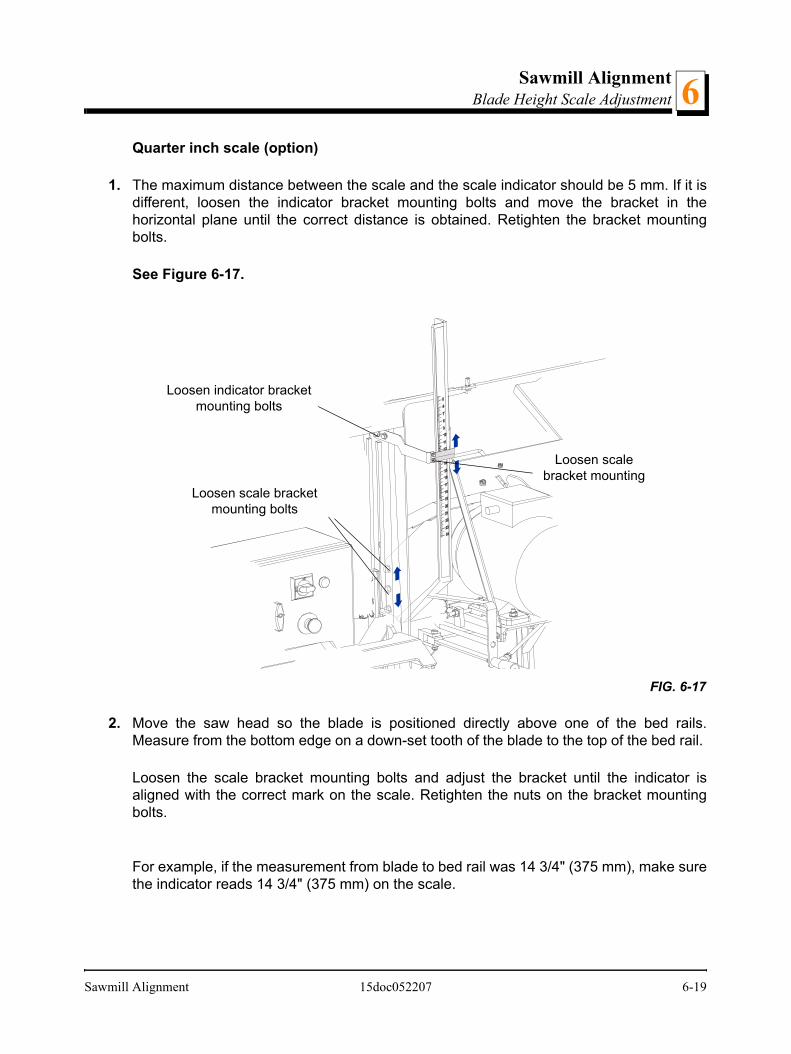
Sawmill AlignmentBlade Height Scale Adjustment 6
Quarter inch scale (option)
1. The maximum distance between the scale and the scale indicator should be 5 mm. If it isdifferent, loosen the indicator bracket mounting bolts and move the bracket in thehorizontal plane until the correct distance is obtained. Retighten the bracket mountingbolts.
See Figure 6-17.
2. Move the saw head so the blade is positioned directly above one of the bed rails.Measure from the bottom edge on a down-set tooth of the blade to the top of the bed rail.
Loosen the scale bracket mounting bolts and adjust the bracket until the indicator isaligned with the correct mark on the scale. Retighten the nuts on the bracket mountingbolts.
For example, if the measurement from blade to bed rail was 14 3/4" (375 mm), make surethe indicator reads 14 3/4" (375 mm) on the scale.
FIG. 6-17
Loosen indicator bracket mounting bolts
Loosen scale bracket mounting bolts
Loosen scale bracket mounting
Sawmill Alignment 15doc052207 6-19
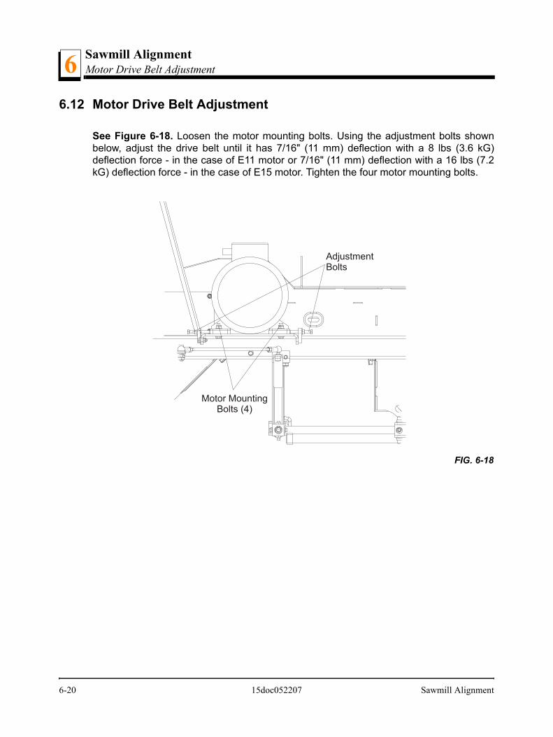
Sawmill AlignmentMotor Drive Belt Adjustment6
6.12 Motor Drive Belt Adjustment
See Figure 6-18. Loosen the motor mounting bolts. Using the adjustment bolts shownbelow, adjust the drive belt until it has 7/16" (11 mm) deflection with a 8 lbs (3.6 kG)deflection force - in the case of E11 motor or 7/16" (11 mm) deflection with a 16 lbs (7.2kG) deflection force - in the case of E15 motor. Tighten the four motor mounting bolts.
FIG. 6-18
Motor MountingBolts (4)
AdjustmentBolts
6-20 15doc052207 Sawmill Alignment

Sawmill AlignmentMast Side Bracket Adjustment 6
6.13 Mast Side Bracket Adjustment
To prevent saw head mast from tilting, the side bracket should be adjusted properly. Usethe adjustment bolt, and adjust it so the distance between bolt head and bed rail is about1mm.
WARNING! Adjust the side bracket before first operatingthe sawmill. Failure to do so may result in serious injury andmachine damage.
FIG. 6-18
1mm
Side Bracket Adjustment Bolt
Sawmill Alignment 15doc052207 6-21

Sawmill AlignmentSafety Handle Linkage Adjustment6
6.14 Safety Handle Linkage Adjustment
See Figure 6-19. Use the adjustment nuts to adjust linkage tension so the blade stopsduring 8 seconds after the safety handle is released.
FIG. 6-19
AdjustmentNuts
6-22 15doc052207 Sawmill Alignment
Related Documents