3/18/11 Wonderware ArchestrA System Platform in a Virtualized Environment Implementation Guide

Welcome message from author
This document is posted to help you gain knowledge. Please leave a comment to let me know what you think about it! Share it to your friends and learn new things together.
Transcript

3/18/11
WonderwareArchestrA System Platform in a Virtualized Environment
Implementation Guide
All rights reserved. No part of this documentation shall be reproduced, stored in a retrieval system, or transmitted by any means, electronic, mechanical, photocopying, recording, or otherwise, without the prior written permission of Invensys Systems, Inc. No copyright or patent liability is assumed with respect to the use of the information contained herein. Although every precaution has been taken in the preparation of this documentation, the publisher and the author assume no responsibility for errors or omissions. Neither is any liability assumed for damages resulting from the use of the information contained herein.
The information in this documentation is subject to change without notice and does not represent a commitment on the part of Invensys Systems, Inc. The software described in this documentation is furnished under a license or nondisclosure agreement. This software may be used or copied only in accordance with the terms of these agreements.
© 2011 by Invensys Systems, Inc. All rights reserved.
Invensys Systems, Inc.26561 Rancho Parkway SouthLake Forest, CA 92630 U.S.A.(949) 727-3200
http://www.wonderware.com
For comments or suggestions about the product documentation, send an e-mail message to [email protected].
All terms mentioned in this documentation that are known to be trademarks or service marks have been appropriately capitalized. Invensys Systems, Inc. cannot attest to the accuracy of this information. Use of a term in this documentation should not be regarded as affecting the validity of any trademark or service mark.
Alarm Logger, ActiveFactory, ArchestrA, Avantis, DBDump, DBLoad, DT Analyst, Factelligence, FactoryFocus, FactoryOffice, FactorySuite, FactorySuite A2, InBatch, InControl, IndustrialRAD, IndustrialSQL Server, InTouch, MaintenanceSuite, MuniSuite, QI Analyst, SCADAlarm, SCADASuite, SuiteLink, SuiteVoyager, WindowMaker, WindowViewer, Wonderware, Wonderware Factelligence, and Wonderware Logger are trademarks of Invensys plc, its subsidiaries and affiliates. All other brands may be trademarks of their respective owners.
3
ArchestrA System Platform Virtualization Guide
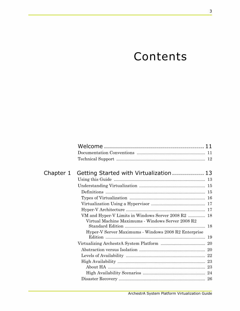
Contents
Welcome .................................................. 11Documentation Conventions ......................................................... 11Technical Support .......................................................................... 12
Chapter 1 Getting Started with Virtualization................ 13Using this Guide ............................................................................ 13Understanding Virtualization ....................................................... 15
Definitions ................................................................................... 15Types of Virtualization ............................................................... 16Virtualization Using a Hypervisor ............................................. 17Hyper-V Architecture .................................................................. 17VM and Hyper-V Limits in Windows Server 2008 R2 .............. 18
Virtual Machine Maximums - Windows Server 2008 R2 Standard Edition ................................................................... 18
Hyper-V Server Maximums - Windows 2008 R2 Enterprise Edition ................................................................................... 19
Virtualizing ArchestrA System Platform ..................................... 20Abstraction versus Isolation ....................................................... 20Levels of Availability .................................................................. 22High Availability ......................................................................... 23
About HA ................................................................................. 23High Availability Scenarios .................................................... 24
Disaster Recovery ........................................................................ 26
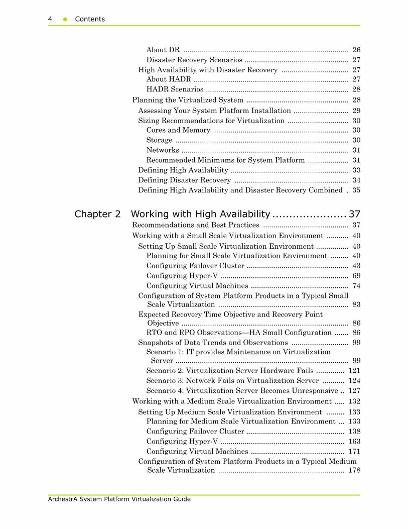
4 Contents
ArchestrA System Platform Virtualization Guide
About DR ................................................................................. 26Disaster Recovery Scenarios ................................................... 27
High Availability with Disaster Recovery ................................. 27About HADR ............................................................................ 27HADR Scenarios ...................................................................... 28
Planning the Virtualized System .................................................. 28Assessing Your System Platform Installation ........................... 29Sizing Recommendations for Virtualization .............................. 30
Cores and Memory .................................................................. 30Storage ..................................................................................... 30Networks .................................................................................. 31Recommended Minimums for System Platform .................... 31
Defining High Availability .......................................................... 33Defining Disaster Recovery ........................................................ 34Defining High Availability and Disaster Recovery Combined . 35
Chapter 2 Working with High Availability ...................... 37Recommendations and Best Practices .......................................... 37Working with a Small Scale Virtualization Environment ........... 40
Setting Up Small Scale Virtualization Environment ................ 40Planning for Small Scale Virtualization Environment ......... 40Configuring Failover Cluster .................................................. 43Configuring Hyper-V ............................................................... 69Configuring Virtual Machines ................................................ 74
Configuration of System Platform Products in a Typical Small Scale Virtualization ................................................................ 83
Expected Recovery Time Objective and Recovery Point Objective .................................................................................. 86RTO and RPO Observations—HA Small Configuration ....... 86
Snapshots of Data Trends and Observations ............................ 99Scenario 1: IT provides Maintenance on Virtualization
Server ..................................................................................... 99Scenario 2: Virtualization Server Hardware Fails .............. 121Scenario 3: Network Fails on Virtualization Server ........... 124Scenario 4: Virtualization Server Becomes Unresponsive .. 127
Working with a Medium Scale Virtualization Environment ..... 132Setting Up Medium Scale Virtualization Environment ......... 133
Planning for Medium Scale Virtualization Environment ... 133Configuring Failover Cluster ................................................ 138Configuring Hyper-V ............................................................. 163Configuring Virtual Machines .............................................. 171
Configuration of System Platform Products in a Typical Medium Scale Virtualization .............................................................. 178

Contents5
ArchestrA System Platform Virtualization Guide
Expected Recovery Time Objective and Recovery Point Objective ................................................................................ 181RTO and RPO Observations—HA Medium Configuration . 182
Snapshots of Data Trends and Observations .......................... 191Scenario 1: IT provides Maintenance on Virtualization
Server ................................................................................... 192Scenario 2: Virtualization Server Hardware Fails .............. 221Scenario 3: Network Fails on Virtualization Server ........... 230Scenario 4: Virtualization Server Becomes Unresponsive .. 239
Chapter 3 Working with Disaster Recovery ................. 245Recommendations and Best Practices ........................................ 245Working with a Small Scale Virtualization Environment ......... 250
Setting Up Small Scale Virtualization Environment .............. 251Planning for Disaster Recovery ............................................ 251Configuring Failover Cluster ................................................ 253Configuring Hyper-V ............................................................. 272Configuring SIOS (SteelEye) Mirroring Jobs ...................... 277Configuring Virtual Machines .............................................. 281
Configuration of System Platform Products in a Typical Small Scale Virtualization ................................................... 289
Expected Recovery Time Objective and Recovery Point Objective ................................................................................ 292RTO and RPO Observations - DR Small Configuration ..... 292
Snapshots of Data Trends and Observations .......................... 302Scenario 1: IT Provides Maintenance on Virtualization
Server ................................................................................... 302Scenario 2: Virtualization Server Hardware Fails .............. 322Scenario 3: Network Fails on Virtualization Server ........... 324Scenario 4: Virtualization Server Becomes Unresponsive .. 327
Working with a Medium Scale Virtualization Environment ..... 334Setting Up Medium Scale Virtualization Environment ......... 334
Planning for Disaster Recovery ............................................ 334Configuring Failover Cluster ................................................ 338Configuring Hyper-V ............................................................. 357Configuring SIOS(SteelEye)DataKeeper Mirroring Jobs ... 361Configuring a Virtual Machine ............................................ 365
Configuring System Platform Products in a Typical Medium Scale Virtualization .............................................................. 372
Expected Recovery Time Objective and Recovery Point Objective ................................................................................ 376RTO and RPO Observations - DR Medium Configuration . 376
Snapshots of Data Trends and Observations .......................... 389Scenario 1: IT provides Maintenance on Virtualization
6 Contents
ArchestrA System Platform Virtualization Guide
Server ................................................................................... 390Scenario 2: Virtualization Server Hardware Fails .............. 428Scenario 3: Network Fails on Virtualization Server ........... 434Scenario 4: Virtualization Server Becomes Unresponsive .. 440
Chapter 4 Working with High Availability and Disaster Recovery ............................................... 447
Recommendations and Best Practices ........................................ 447Working with Medium Scale Virtualization Environment ........ 452
Setting Up Virtualization Environment .................................. 453Planning for Virtualization Environment ........................... 453Configuring Failover Cluster ................................................ 456Configuring Hyper-V ............................................................. 478Configuring SIOS(SteelEye)DataKeeper Mirroring Jobs ... 482Configuring Virtual Machines .............................................. 486
Expected Recovery Time Objective and Recovery Point Objective ................................................................................ 494RTO and RPO Observations - HADR Medium
Configuration ...................................................................... 494Snapshots of Data Trends and Observations .......................... 498
Scenario: Virtualization Server Hardware Fails ................. 499Scenario: Network Fails on Virtualization Server .............. 505
Chapter 5 Working with Windows Server 2008 R2 Features513
About Windows Server 2008 R2 Hyper-V Features ................... 514Using VLAN for Communication Between System Platform
Nodes ......................................................................................... 515Configuring Virtual Network Switches on the Hyper-V Host
Server and Adding Virtual Network Adapters on the VM Nodes ..................................................................................... 516Creating a Virtual Network Switch for Communication
Between a VM Node and an External Domain or a Plant Network ............................................................................... 516
Creating a Virtual Network Switch for Communication Between Internal VM Nodes .............................................. 519
Adding an Internal Virtual Network Adapter to a VM Node for Communication Between VM Nodes .................. 522
Adding a Virtual Network Adapter to a VM Node for Communication Between a VM Node and a Plant Network ............................................................................... 525
Configuring Network Adapters on the System Platform Virtual Machine (VM) Nodes ............................................... 527
Contents7
ArchestrA System Platform Virtualization Guide
Using VLAN for RMC Communication Between Redundant Application Server Nodes ......................................................... 534Configuring RMC for Redundant AppEngine over a VLAN ... 535
Accessing a System Platform Node with a Remote Desktop ..... 539Accessing System Platform Applications as Remote
Applications ............................................................................... 541Installing and Configuring the Remote Desktop Web Access Role
Service at a Remote Desktop Session Host Server Node .... 543Configuring Remote Applications at Remote Desktop Session
Host Server Node ................................................................ 552Allowing Application Access to Specific Users .................... 554Accessing the Remote Applications from a Client Node ..... 556
Displaying the System Platform Nodes on a Multi-Monitor with a Remote Desktop ............................................................. 565Verifying the Display of System Platform Nodes on a Multi-
Monitor with a Remote Desktop .......................................... 566Using the Multi-Monitors as a Single Display ........................ 568
Working with Network Load Balancing ..................................... 569About the Network Load Balancing Feature .......................... 569About Remote Desktop Connection Broker ............................. 569About Managed InTouch application with Network Load
Balancing .............................................................................. 570Setting Up Network Load Balancing Cluster .......................... 572
Topology 1: Leveraging Network Load Balancing by Configuring Remote Desktop Connection Broker on One of the NLB Cluster Nodes ................................................... 573
Topology 2 : Leveraging Network Load Balancing by Configuring Remote Desktop Connection Broker on a Separate Node ..................................................................... 575
Installing Remote Desktop Services .................................... 576Installing Network Load Balancing ..................................... 583Adding a Remote Desktop Session Host Server .................. 585Creating a Network Load Balancing Cluster ...................... 587
Configuring Remote Desktop Connection Broker Settings ..... 596Disconnecting from and Connecting to a Remote Desktop
Session ................................................................................... 600Viewing Connected Sessions ................................................ 600
Configuring Network Load Balancing Cluster on Microsoft Failover Cluster .................................................................... 604Understanding the Behavior of NLB Cluster in Microsoft
Failover Cluster .................................................................. 605Observation while using NLB for Managed InTouch System
Platform node Observations: ................................................ 605Hardware Licenses in a Virtualized Environment .................... 606

8 Contents
ArchestrA System Platform Virtualization Guide
Chapter 6 Creating Virtual Images ............................ 607About Virtual Images ................................................................... 607Preparing a Virtual Image from an Operating System (OS)
Image ......................................................................................... 610Creating a Virtual Image with an ISO File on the Network
Location ................................................................................. 611Creating a Virtual Image from Extracted ISO Available
on CD or DVD ....................................................................... 622Tips and Recommendations ...................................................... 632
Preparing a Virtual Image from a Physical Machine ................ 633Creating a Virtual Image from a Physical Machine - Online
Conversion ............................................................................. 634Observation ........................................................................... 644
Creating a Virtual Image from a Physical Machine - Offline Conversion ............................................................................. 644
Observation ............................................................................... 656Tips and Recommendations ...................................................... 656
Preparing a Virtual Image from Another Virtual Image ........... 658Creating a Template from an Existing VM ............................. 659Creating a Virtual Machine from a Template ......................... 665Tips and Recommendations ...................................................... 674
Preparing a Virtual Image from a Ghost Backup ...................... 676Create a Virtual Machine from a .VHD ................................... 676Recommendation ....................................................................... 685
....................................................................................................... 685
Chapter 7 Implementing Backup Strategies in a Virtualized Environment .......................................... 687
Taking Checkpoints Using SCVMM ........................................... 688Taking a Checkpoint of an Offline VM .................................... 688Taking a Checkpoint of an Online VM ..................................... 691
Restoring Checkpoints ................................................................. 695Restoring Checkpoints from a Virtual System Platform
Backup ................................................................................... 695Restoring a Checkpoint of an Offline VM ............................ 695Restoring a Checkpoint of an Online VM ............................ 699
Take and Restore Checkpoints of Products with No Dependencies ............................................................................. 702
Checkpoints of System Platform Products - Observations and Recommendations ..................................................................... 707Taking and Restoring Checkpoints (Snapshots) in the Offline
Mode ...................................................................................... 708
Contents9
ArchestrA System Platform Virtualization Guide
Taking and Restoring Checkpoints (Snapshots) in the Online Mode ...................................................................................... 708
Glossary................................................. 711
Index..................................................... 719

10 Contents
ArchestrA System Platform Virtualization Guide
11
ArchestrA System Platform Virtualization Guide
Welcome
This guide describes the implementation of ArchestrA System Platform in a virtualized environment, using Microsoft Hyper-V technology, failover clustering, and other strategies to create High Availability, Disaster Recovery, and High Availability with Disaster Recovery capabilities.
You can view this document online or you can print it, in part or whole, by using the print feature in Adobe Acrobat Reader.
Documentation Conventions
This documentation uses the following conventions:
Convention Used for
Initial Capitals Paths and file names.
Bold Menus, commands, dialog box names, and dialog box options.
Monospace Code samples and display text.
12 Welcome
ArchestrA System Platform Virtualization Guide
Technical SupportWonderware Technical Support offers a variety of support options to answer any questions on Wonderware products and their implementation.
Before you contact Technical Support, refer to the relevant section(s) in this documentation for a possible solution to the problem. If you need to contact technical support for help, have the following information ready:
• The type and version of the operating system you are using.
• Details of how to recreate the problem.
• The exact wording of the error messages you saw.
• Any relevant output listing from the Log Viewer or any other diagnostic applications.
• Details of what you did to try to solve the problem(s) and your results.
• If known, the Wonderware Technical Support case number assigned to your problem, if this is an ongoing problem.
13
ArchestrA System Platform Virtual Implementation Guide
Chapter 1
Getting Started withVirtualization
Virtualization technologies are becoming high priority for IT administrators and managers, software and systems engineers, plant managers, software developers, and system integrators.
Mission-critical operations in both small- and large-scale organizations demand availability—defined as the ability of the user community to access the system—along with dependable recovery from natural or man-made disasters. Virtualization technologies provide a platform for High Availability and Disaster Recovery solutions.
Using this GuideThe purpose of this guide is to help you to implement ArchestrA System Platform in a virtualized environment, including:
• Implementing some of the new features in Microsoft Windows Server 2008 R2
• Implementing High Availability, Disaster Recovery, or High Availability with Disaster Recovery using Windows Server 2008 R2 virtualization technologies such as Hyper-V
This chapter introduces and defines virtualization concepts in general, as well as in a System Platform context. This chapter also defines a basic workflow and planning framework for your virtualization implementation.
14 Chapter 1 Getting Started with Virtualization
ArchestrA System Platform Virtual Implementation Guide
Subsequent chapters describe in detail the features of Windows Server 2008 R2 and how to use them, configuring High Availability, Disaster Recovery, High Availability with Disaster Recover, creating virtual images, and implementing a virtualized backup strategy.
Subsequent chapters also provide test and performance metrics for a wide variety of system configurations, including Recovery Time Objective (RTO), Recovery Point Objective (RPO), and data trend snapshots.

Understanding Virtualization15
ArchestrA System Platform Virtual Implementation Guide
Understanding VirtualizationVirtualization is the creation of an abstracted or simulated—virtual, rather than actual—version of something, such as an operating system, server, network resource, or storage device. Virtualization technology abstracts the hardware from the software, extending the life cycle of a software platform.
In virtualization, a single piece of hardware, such as a server, hosts and coordinates multiple guest operating systems. No guest operating system is aware that it is sharing resources and running on a layer of virtualization software rather than directly on the host hardware. Each guest operating system appears as a complete, hardware-based OS to the applications running on it.
DefinitionsThis implementation guide assumes that you and your organization have done the necessary research and analysis and have made the decision to implement ArchestrA System Platform in a virtualized environment that will replace the need for physical computers and instead run them in a virtualized environment. Such an environment can take advantage of advanced virtualization features including High Availability and Disaster Recovery. In that context, we’ll define the terms as follows:
• Virtualization can be defined as creating a virtual, rather than real, version of ArchestrA System Platform or one of its components, including servers, nodes, databases, storage devices, and network resources.
• High Availability (HA) can be defined as a primarily automated ArchestrA System Platform design and associated services implementation which ensures that a pre-defined level of operational performance will be met during a specified, limited time frame.
• Disaster Recovery (DR) can be defined as the organizational, hardware and software preparations for ArchestrA System Platform recovery or continuation of critical System Platform infrastructure after a natural or human-induced disaster.
While these definitions are general and allow for a variety of HA and DR designs, this implementation guide focuses on viritualization, an indispensible element in creating the redundancy necessary for HA and DR solutions.
The virtualized environment described in this guide is based on Microsoft Hyper-V technology incorporated in the Windows Server 2008 R2 operating system.

16 Chapter 1 Getting Started with Virtualization
ArchestrA System Platform Virtual Implementation Guide
Types of VirtualizationThere are eight types of virtualization:
Hardware A software execution environment separated from underlying hardware resources. Includes hardware-assisted virtualization, full and partial virtualization and paravirtualization.
Memory An application operates as though it has sole access to memory resources, which have been virtualized and aggregated into one memory pool. Includes virtual memory and memory virtualization.
Storage Complete abstraction of logical storage from physical storage
Software Multiple virtualized environments hosted within a single operating system instance. Related is a virtual machine (VM) which is a software implementation of a computer, possibly hardware-assisted, which behaves like a real computer.
Mobile Uses virtualization technology in mobile phones and other types of wireless devices.
Data Presentation of data as an abstract layer, independent of underlying databases, structures, and storage. Related is database virtualization, which is the decoupling of the database layer within the application stack.
Desktop Remote display, hosting, or management of a graphical computer environment—a desktop.
Network Implementation of a virtualized network address space within or across network subnets.
Understanding Virtualization17
ArchestrA System Platform Virtual Implementation Guide
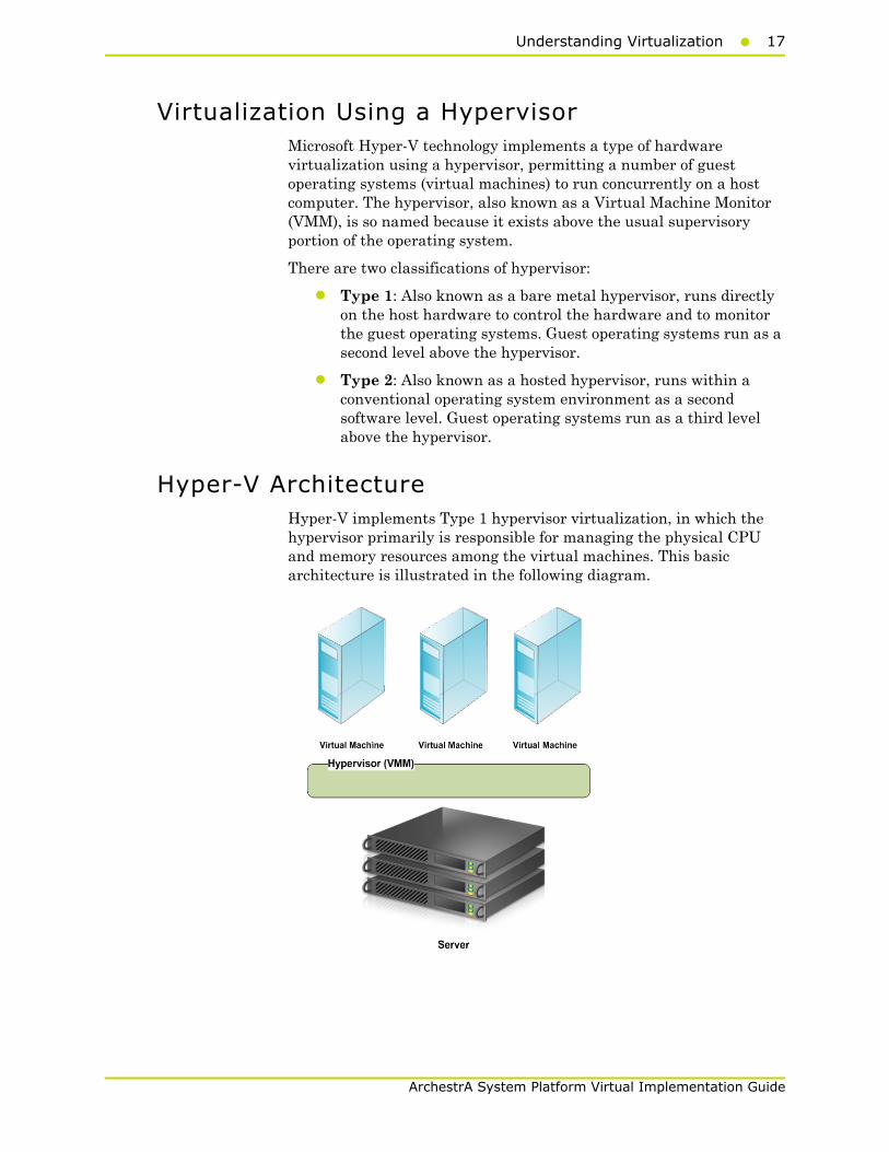
Virtualization Using a HypervisorMicrosoft Hyper-V technology implements a type of hardware virtualization using a hypervisor, permitting a number of guest operating systems (virtual machines) to run concurrently on a host computer. The hypervisor, also known as a Virtual Machine Monitor (VMM), is so named because it exists above the usual supervisory portion of the operating system.
There are two classifications of hypervisor:
• Type 1: Also known as a bare metal hypervisor, runs directly on the host hardware to control the hardware and to monitor the guest operating systems. Guest operating systems run as a second level above the hypervisor.
• Type 2: Also known as a hosted hypervisor, runs within a conventional operating system environment as a second software level. Guest operating systems run as a third level above the hypervisor.
Hyper-V ArchitectureHyper-V implements Type 1 hypervisor virtualization, in which the hypervisor primarily is responsible for managing the physical CPU and memory resources among the virtual machines. This basic architecture is illustrated in the following diagram.
18 Chapter 1 Getting Started with Virtualization
ArchestrA System Platform Virtual Implementation Guide
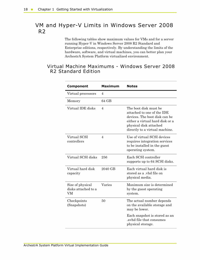
VM and Hyper-V Limits in Windows Server 2008 R2
The following tables show maximum values for VMs and for a server running Hyper-V in Windows Server 2008 R2 Standard and Enterprise editions, respectively. By understanding the limits of the hardware, software, and virtual machines, you can better plan your ArchestrA System Platform virtualized environment.
Virtual Machine Maximums - Windows Server 2008 R2 Standard Edition
Component Maximum Notes
Virtual processors 4
Memory 64 GB
Virtual IDE disks 4 The boot disk must be attached to one of the IDE devices. The boot disk can be either a virtual hard disk or a physical disk attached directly to a virtual machine.
Virtual SCSI controllers
4 Use of virtual SCSI devices requires integration services to be installed in the guest operating system.
Virtual SCSI disks 256 Each SCSI controller supports up to 64 SCSI disks.
Virtual hard disk capacity
2040 GB Each virtual hard disk is stored as a .vhd file on physical media.
Size of physical disks attached to a VM
Varies Maximum size is determined by the guest operating system.
Checkpoints (Snapshots)
50 The actual number depends on the available storage and may be lower.
Each snapshot is stored as an .avhd file that consumes physical storage.
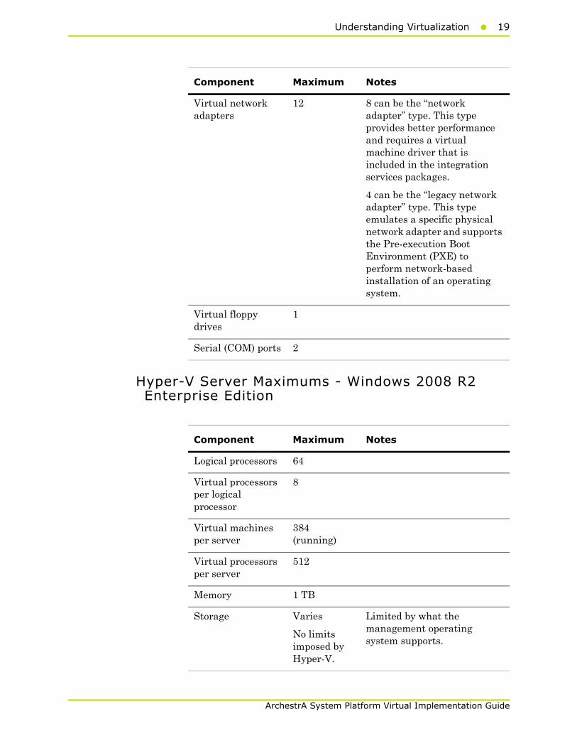
Understanding Virtualization19
ArchestrA System Platform Virtual Implementation Guide
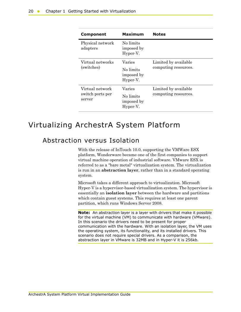
Hyper-V Server Maximums - Windows 2008 R2 Enterprise Edition
Virtual network adapters
12 8 can be the “network adapter” type. This type provides better performance and requires a virtual machine driver that is included in the integration services packages.
4 can be the “legacy network adapter” type. This type emulates a specific physical network adapter and supports the Pre-execution Boot Environment (PXE) to perform network-based installation of an operating system.
Virtual floppy drives
1
Serial (COM) ports 2
Component Maximum Notes
Component Maximum Notes
Logical processors 64
Virtual processors per logical processor
8
Virtual machines per server
384 (running)
Virtual processors per server
512
Memory 1 TB
Storage Varies
No limits imposed by Hyper-V.
Limited by what the management operating system supports.
20 Chapter 1 Getting Started with Virtualization
ArchestrA System Platform Virtual Implementation Guide
Virtualizing ArchestrA System Platform
Abstraction versus IsolationWith the release of InTouch 10.0, supporting the VMWare ESX platform, Wonderware became one of the first companies to support virtual machine operation of industrial software. VMware ESX is referred to as a "bare metal" virtualization system. The virtualization is run in an abstraction layer, rather than in a standard operating system.
Microsoft takes a different approach to virtualization. Microsoft Hyper-V is a hypervisor-based virtualization system. The hypervisor is essentially an isolation layer between the hardware and partitions which contain guest systems. This requires at least one parent partition, which runs Windows Server 2008.
Note: An abstraction layer is a layer with drivers that make it possible for the virtual machine (VM) to communicate with hardware (VMware). In this scenario the drivers need to be present for proper communication with the hardware. With an isolation layer, the VM uses the operating system, its functionality, and its installed drivers. This scenario does not require special drivers. As a comparison, the abstraction layer in VMware is 32MB and in Hyper-V it is 256kb.
Physical network adapters
No limits imposed by Hyper-V.
Virtual networks (switches)
Varies
No limits imposed by Hyper-V.
Limited by available computing resources.
Virtual network switch ports per server
Varies
No limits imposed by Hyper-V.
Limited by available computing resources.
Component Maximum Notes
Virtualizing ArchestrA System Platform21
ArchestrA System Platform Virtual Implementation Guide
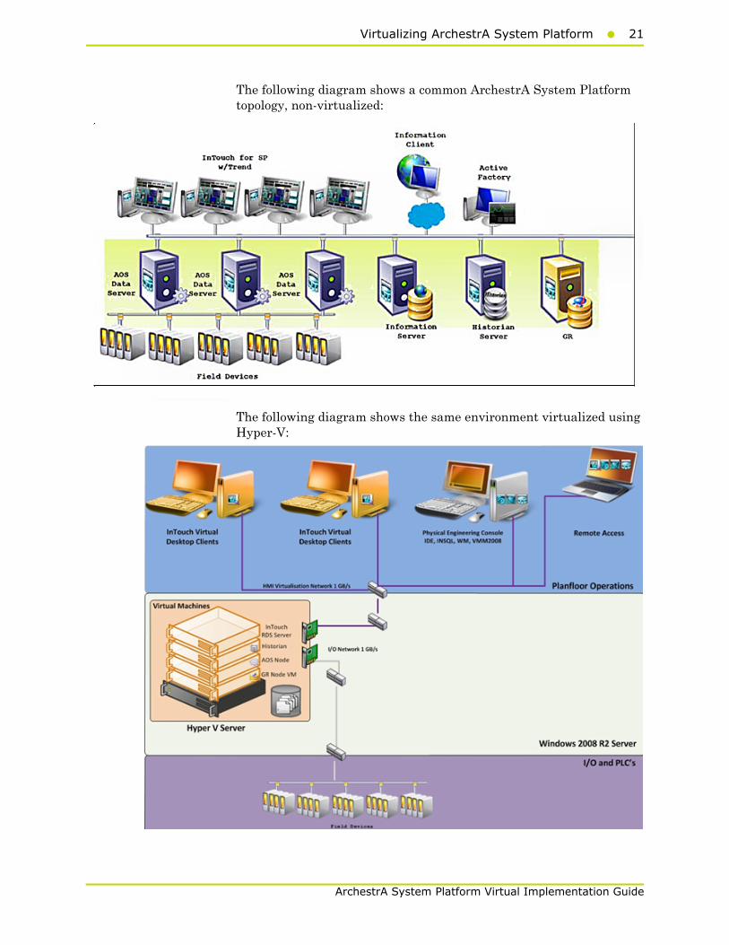
The following diagram shows a common ArchestrA System Platform topology, non-virtualized:
The following diagram shows the same environment virtualized using Hyper-V:
22 Chapter 1 Getting Started with Virtualization
ArchestrA System Platform Virtual Implementation Guide
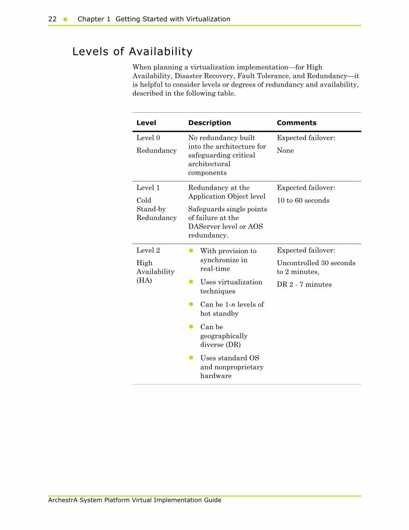
Levels of AvailabilityWhen planning a virtualization implementation—for High Availability, Disaster Recovery, Fault Tolerance, and Redundancy—it is helpful to consider levels or degrees of redundancy and availability, described in the following table.
Level Description Comments
Level 0
Redundancy
No redundancy built into the architecture for safeguarding critical architectural components
Expected failover:
None
Level 1
Cold Stand-by Redundancy
Redundancy at the Application Object level
Safeguards single points of failure at the DAServer level or AOS redundancy.
Expected failover:
10 to 60 seconds
Level 2
High Availability (HA)
• With provision to synchronize in real-time
• Uses virtualization techniques
• Can be 1-n levels of hot standby
• Can be geographically diverse (DR)
• Uses standard OS and nonproprietary hardware
Expected failover:
Uncontrolled 30 seconds to 2 minutes,
DR 2 - 7 minutes

Virtualizing ArchestrA System Platform23
ArchestrA System Platform Virtual Implementation Guide
High Availability
About HAHigh Availability refers to the availability of resources in a computer system following the failure or shutdown of one or more components of that system.
At one end of the spectrum, traditional HA has been achieved through custom-designed and redundant hardware. This solution produces High Availability, but has proven to be very expensive.
At the other end of the spectrum are software solutions designed to function with off-the-shelf hardware. This type of solution typically results in significant cost reduction, and has proven to survive single points of failure in the system.
Level 3
Hot Redundancy:
Redundancy at the application level typically provided by Invensys controllers. For example, hot backup of Invensys software such as Alarm System.
Expected failover:
Next cycle or single digit seconds
Level 4
Lock-step Fault Tolerance (FT)
Provides lock-step failover
Expected failover:
Next cycle or without loss of data.
For ArchestrA System Platform, this would be a Marathon-type solution, which also can be a virtualized system.
Level Description Comments

24 Chapter 1 Getting Started with Virtualization
ArchestrA System Platform Virtual Implementation Guide
High Availability ScenariosThe basic HA architecture implementation described in this guide consists of an online system including a Hyper-V Server and a number of virtual PCs, linked by a LAN to an offline duplicate system. The LAN accommodates a number of networks including a plant floor network linked to plant operations, an I/O network linked to field devices, and a replication network linked to storage.
Virtualizing ArchestrA System Platform25
ArchestrA System Platform Virtual Implementation Guide
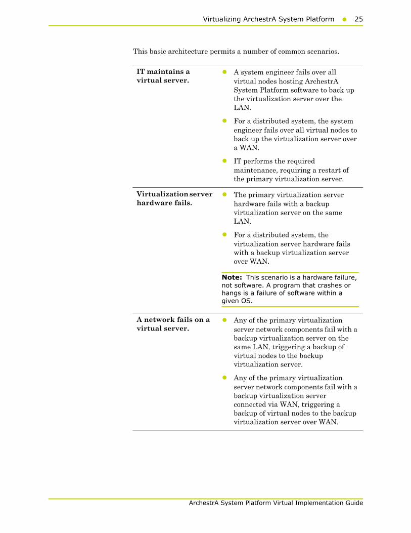
This basic architecture permits a number of common scenarios.
IT maintains a virtual server.
• A system engineer fails over all virtual nodes hosting ArchestrA System Platform software to back up the virtualization server over the LAN.
• For a distributed system, the system engineer fails over all virtual nodes to back up the virtualization server over a WAN.
• IT performs the required maintenance, requiring a restart of the primary virtualization server.
Virtualization server hardware fails.
• The primary virtualization server hardware fails with a backup virtualization server on the same LAN.
• For a distributed system, the virtualization server hardware fails with a backup virtualization server over WAN.
Note: This scenario is a hardware failure, not software. A program that crashes or hangs is a failure of software within a given OS.
A network fails on a virtual server.
• Any of the primary virtualization server network components fail with a backup virtualization server on the same LAN, triggering a backup of virtual nodes to the backup virtualization server.
• Any of the primary virtualization server network components fail with a backup virtualization server connected via WAN, triggering a backup of virtual nodes to the backup virtualization server over WAN.

26 Chapter 1 Getting Started with Virtualization
ArchestrA System Platform Virtual Implementation Guide
For these scenarios, the following expectations apply:
• For the maintenance scenario, all virtual images are up and running from the last state of execution prior to failover.
• For the hardware and network failure scenarios, the virtual images restart following failover.
• For LAN operations, you should see operational disruptions for approximately 2-15 seconds (LAN operations assumes recommended speeds and bandwidth. For more information refer to "Networks" on page 31).
• For WAN operations, you should see operational disruptions for approximately 2 minutes (WAN operations assumes recommended speeds and bandwidth. For more information refer to "Networks" on page 31).
Note: The disruption spans described here are general and approximate. For specific metrics under a variety of scenarios, see the relevant Recovery Time Objective (RTO) and Recovery Point Objective (RPO) sections in chapters 2, 3, and 4.
Disaster Recovery
About DRDisaster Recovery planning typically involves policies, processes, and planning at the enterprise level, which is well outside the scope of this implementation guide.
DR, at its most basic, is all about data protection. The most common strategies for data protection include the following:
• Backups made to tape and sent off-site at regular intervals, typically daily.
• For the hardware and network failure scenarios, the virtual images restart following failover
• For the hardware and network failure scenarios, the virtual images restart following failover
• Backups made to disk on-site, automatically copied to an off-site disk, or made directly to an off-site disk.
• Replication of data to an off-site location, making use of storage area network (SAN) technology. This strategy eliminates the need to restore the data. Only the systems need to be restored or synced.
• High availability systems which replicate both data and system off-site. This strategy enables continuous access to systems and data.
Virtualizing ArchestrA System Platform27
ArchestrA System Platform Virtual Implementation Guide
The ArchestrA System Platform virtualized environment implements the fourth strategy—building DR on an HA implementation.
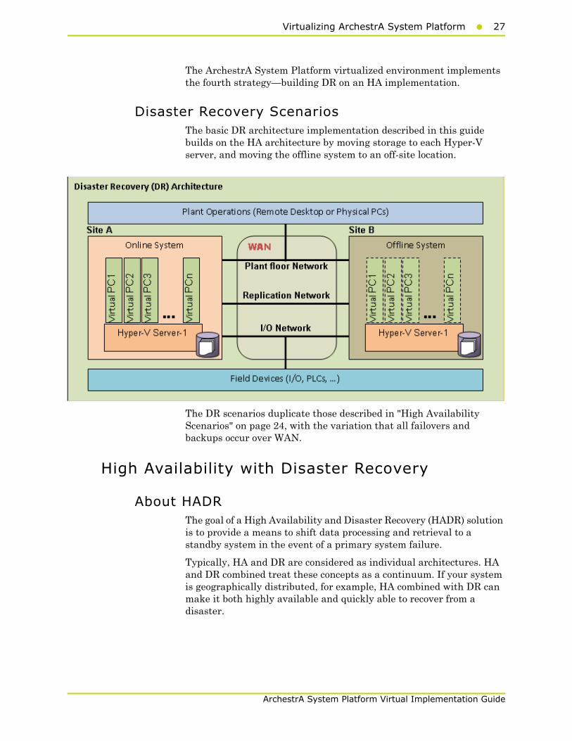
Disaster Recovery ScenariosThe basic DR architecture implementation described in this guide builds on the HA architecture by moving storage to each Hyper-V server, and moving the offline system to an off-site location.
The DR scenarios duplicate those described in "High Availability Scenarios" on page 24, with the variation that all failovers and backups occur over WAN.
High Availability with Disaster Recovery
About HADRThe goal of a High Availability and Disaster Recovery (HADR) solution is to provide a means to shift data processing and retrieval to a standby system in the event of a primary system failure.
Typically, HA and DR are considered as individual architectures. HA and DR combined treat these concepts as a continuum. If your system is geographically distributed, for example, HA combined with DR can make it both highly available and quickly able to recover from a disaster.
28 Chapter 1 Getting Started with Virtualization
ArchestrA System Platform Virtual Implementation Guide
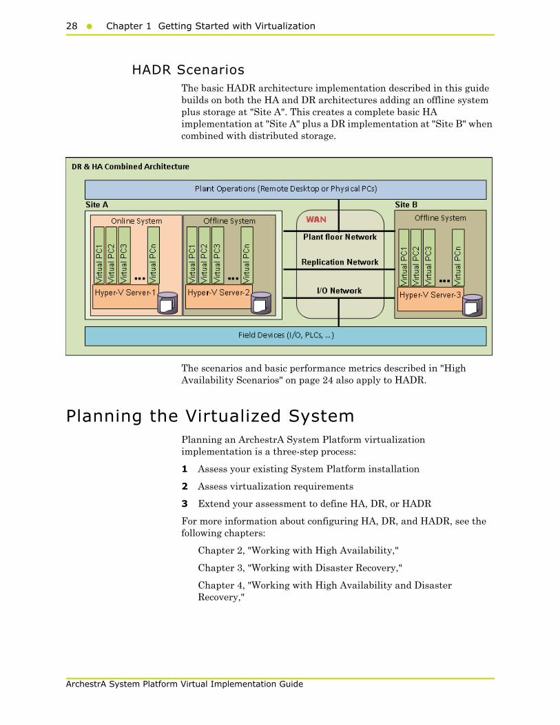
HADR ScenariosThe basic HADR architecture implementation described in this guide builds on both the HA and DR architectures adding an offline system plus storage at "Site A". This creates a complete basic HA implementation at "Site A" plus a DR implementation at "Site B" when combined with distributed storage.
The scenarios and basic performance metrics described in "High Availability Scenarios" on page 24 also apply to HADR.
Planning the Virtualized SystemPlanning an ArchestrA System Platform virtualization implementation is a three-step process:
1 Assess your existing System Platform installation
2 Assess virtualization requirements
3 Extend your assessment to define HA, DR, or HADR
For more information about configuring HA, DR, and HADR, see the following chapters:
Chapter 2, "Working with High Availability,"
Chapter 3, "Working with Disaster Recovery,"
Chapter 4, "Working with High Availability and Disaster Recovery,"

Planning the Virtualized System29
ArchestrA System Platform Virtual Implementation Guide
Assessing Your System Platform InstallationIn most cases, a System Platform installation already exists. You will need to create an assessment of the current architecture. You can start with a basic topology diagram, similar to the following:
Once you have diagramed your topology, you can build a detailed inventory of the system hardware and software.
Microsoft offers tools to assist with virtualization assessment and planning.
• Microsoft Assessment and Planning Toolkit (MAP)
The MAP toolkit is useful for a variety of migration projects, including virtualization. The component package for this automated tool is available for download from Microsoft at the following address:
http://www.microsoft.com/downloads/en/details.aspx?FamilyID=67240b76-3148-4e49-943d-4d9ea7f77730&displaylang=en
• Infrastructure Planning and Design Guides for Virtualization (IPD)
The IPD Guides from Microsoft provide a series of guides specifically geared to assist with virtualization planning. They are available for download from Microsoft at the following address:
http://technet.microsoft.com/en-us/solutionaccelerators/ee395429

30 Chapter 1 Getting Started with Virtualization
ArchestrA System Platform Virtual Implementation Guide
Sizing Recommendations for VirtualizationThis section provides sizing guidelines and recommended minimums for ArchestrA System Platform installations.
For a virtualization-only implementation, you can use these minimums and guidelines to size the virtualization server or servers that will host your System Platform configuration.
Cores and Memory
Spare Resources
The host server should always have spare resources of 25% above what the guest machines require.
For example, if a configuration with five nodes requires 20GB of RAM and 10 CPUs, the host system should have 25GB of RAM and 13 CPUs. If this is not feasible, choose the alternative closest to the 25% figure, but round up so the host server has 32GB of RAM and 16 cores.
Hyper-Threading
Hyper-Threading Technology can be used to extend the amount of cores, but it does impact performance. An 8-core CPU will perform better than a 4-core CPU that is Hyper-Threading.
StorageIt is always important to plan for proper Storage. A best practice is to dedicate a local drive or virtual drive on a Logical Unit Number (LUN) to each of the VMs being hosted. We recommend SATA or higher interfaces.
Recommended Storage Topology
To gain maximum performance, the host OS also should have a dedicated storage drive. A basic storage topology would include:
• Host storage
• VM storage for each VM
• A general disk
This disk should be large enough to hold snapshots, backups, and other content. It should not be used by the host or by a VM.
Planning the Virtualized System31
ArchestrA System Platform Virtual Implementation Guide
Recommended Storage Speed
Boot times and VM performance are impacted both by storage bandwidth and storage speed. Faster is always better. Drives rated at 7200 rpm perform better than those rated at 5400 rpm. Solid-state drives (SSDs) perform better than 7200-rpm drives.
Keep in mind that multiple VMs attempting to boot from one hard drive will be slow, and your performance will experience a significant degrade. Attempting to save on storage could well become more costly in the end.
NetworksNetworking is as important as any other component for the overall performance of the system.
Recommended Networking for Virtualization
If virtualization is your only requirement, your network topology could include the following elements:
• Plant network
• Storage network
• Hyper-V network.
A best practice is to establish, on every node, an internal-only Static Virtual Network. In the event that the host and the guest VMs become disconnected from the outside world, you will still be able to communicate through an RDP session independent of external network connectivity.
Recommended Networking for HA
If HA is your requirement, then we recommend using fast, dedicated drives for local use. In the case of a Storage Area Network (SAN), we recommend using iSCI 1GB/s as a minimum configuration.
A higher-performance configuration would be an FO connection to the storage at 10GB/s. For HA, we recommend a dedicated network for Hyper-V at 1GB/s. This will ensure fast transfers when using Quick Migration and Live Migration.
Recommended Minimums for System PlatformFollowing are approximate numbers of nodes to define small, medium, and large systems.
• Small: 1–3 nodes
• Medium: 4–8 nodes
• Large: More than 8 nodes
32 Chapter 1 Getting Started with Virtualization
ArchestrA System Platform Virtual Implementation Guide
The following table provides recommended minimums for System Platform configurations.
After installation of the server, you will start from scratch, or you can use the existing installation. A free tool on Microsoft TechNet called Disk2vhd supports extracting a physical machine to a VHD file. The Disk2vhd tool is available for download from Microsoft at the following address:
http://technet.microsoft.com/en-us/sysinternals/ee656415
Another tool you can use to migrate physical machines into to a virtual environment is VMM2008. This tool is availble for purchase from Microsoft. For more information, see the following Microsoft address:
http://www.microsoft.com/systemcenter/en/us/virtual-machine-manager.aspx
Cores RAM Storage
Small Systems
GR Node 2 2 100
Historian 2 2 250
Application Server
2 2 100
RDS Servers 2 2 100
Information Servers
2 2 100
Historian Clients
2 2 100
Medium and Large Systems
GR Node 4 4 250
Historian 4 4 500
Application Server
2–4 4 100
RDS Servers 4–8 4–8 100
Information Server
4 4 100
Historian Clients
2 4 100

Planning the Virtualized System33
ArchestrA System Platform Virtual Implementation Guide
Defining High AvailabilityTo define a High Availability implementation, you need to plan for the following requirements:
• Server specification doubles
Double the baseline configuration is required for shadow nodes in the Failover Cluster.
• Minimum OS requirements increase
Failover is supported only on Windows Server 2008 R2 Enterprise and higher operating system editions.
Also, live migration, remote applications, and other features are available only if the host machines are Windows Server 2008 R2 editions.
The following shows a System Platform HA implementation.
To implement HA, we strongly recommend the use of a SAN configured with the sizing guidelines and recommendations outlined in the preceding section.

34 Chapter 1 Getting Started with Virtualization
ArchestrA System Platform Virtual Implementation Guide
Defining Disaster RecoveryTo define a Disaster Recovery implementation, you need to plan for the following requirements:
• Adding a second server set with the same specifications as the first
The second server set moves to the off-site location and connects over LAN or (more likely) WAN.
• Configuring minimum bandwidth
The minimum network bandwidth is 100MB/sec. Recovery times improve with higher network speeds.
• Installing and configuring third-party software
Third party software from SIOS (SteelEye) mirrors the drives from site A to site B. The replication can be done on a SAN system or as shown in the illustration,with regular local hard drives.
Important: Mirrored partitions must have identical drive letters and sizes.

Planning the Virtualized System35
ArchestrA System Platform Virtual Implementation Guide
Defining High Availability and Disaster Recovery Combined
An important advantage from implementing HA and DR in the same scenario is that a local HA set can quickly resume functionality upon failure. In the event that site A is offline, the system can resume at site B without intervention from site A.
To define a HADR implementation, you need to plan for the following requirements:
• Sizing
You’ll need to triple the size of the estimated baseline server.
• SANs
Two SANs are required—one local and one remote—to host the storage. In HADR implemenation, the local configuration uses the failover cluster configuration and the set of VMs are replicated to a remote site.

36 Chapter 1 Getting Started with Virtualization
ArchestrA System Platform Virtual Implementation Guide
37
ArchestrA System Platform Virtualization Guide
Chapter 2
Working with HighAvailability
This section introduces virtualization high-availability solutions that improve the availability of System Platform Products. A high-availability solution masks the effects of a hardware or software failure, and maintains the availability of applications so that the perceived downtime for users is minimized.
The set-up and configuration procedures, expected Recovery Time Objective (RTO) observations, Recovery Point Objective (RPO) observations, and data trend snapshots are presented first for small-scale virtualization environment, and are then repeated for medium-scale virtualization environment.
Recommendations and Best Practices• Ensure that auto log on is set up for all Hyper-V virtual machines
running the System Platform products. This is to ensure that these Hyper-V virtual machines start up automatically after the failover.
• Ensure the time on all the Hyper-V host servers, the virtual machines and all other nodes which are part of the High Availability Environment are continuously synchronized. Otherwise, the Hyper-V virtual machines running on the host experience time drifts and results in discarding of data.You can add the time synchronization utility in the Start Up programs so that this utlity starts automatically whenever the Hyper V machine reboots.
38 Chapter 2 Working with High Availability
ArchestrA System Platform Virtualization Guide
• On the host servers disable all the network cards which are not utilized by the System Platform Environment. This is to avoid any confusion during the network selections while setting up the cluster.
• Ensure the Virtual Networks created in Hyper-V Manager have the same name across all the nodes which are participating in the Cluster. Otherwise, migration/failover of Hyper-V virtual machines will fail.
System Platform Product-specific Recommendations and Observations
• During the preparation for Live and Quick migrations it is observed that the network freezes intermittently and then at the time of actual migration connectivity to the VM is lost. As a result, the System Platform node under migration experiences intermittent data loss during the preparation for Live and Quick migrations, and then has a data gap for the duration of actual migration.
Historian
• In case of Live and Quick migration of Historian, you may notice that Historian logs values with quality detail 448 and there may be values logged twice with same timestamps. This is because the suspended Historian VM starts on the other cluster node with the system time it was suspended at before the migration. As a result, some of the data points it is receiving with the current time seem to be in the future to the Historian. This results in Historian modifying the timestamps to its system time and updating the QD to 448. This happens until the system time of the Historian node catches up with the real current time using the TimeSync utility, after which the problem goes away. So, it is recommended to stop the historian before the migration and restart it after the VM is migrated and its system time is synced up with the current time.
• Live and Quick migration of Historian should not be done when the block change over is in progress on the Historian node.
• If a failover happens (for example, due to a network disconnect on the source Host Virtualization Server) while the Historian status is still “Starting”, the Historian node fails over to the target Host Virtualization Server. In the target host, Historian fails to start. To recover from this state, kill the Historian services that failed to start and then start the Historian by launching the SMC.

Recommendations and Best Practices39
ArchestrA System Platform Virtualization Guide
InTouch
• Ensure that InTouch Window Viewer is added to the Start Up programs so that the view is started automatically when the virtual machine reboots.
Application Server
• If a failover happens (for example, due to a network disconnect on the source Host Virtualization Server) while the Galaxy Migration is in progress, the GR node fails over to the target Host Virtualization Server. In the target host, on opening the IDE for the galaxy, the templates do not appear in the Template toolbox and in Graphic toolbox. To recover from this state, delete the galaxy and create new Galaxy. Initiate the migration process once again.
• If a failover happens (for example, due to an abrupt power-off on the source Host Virtualization Server) while a platform deploy is in progress, the Platform node fails over to the target Host Virtualization Server. In the target host, some objects will be in deployed state and the rest will be in undeployed state. To recover from this state, redeploy the whole Platform once again.
• If a failover happens (for example, due to an abrupt power-off on the source Host Virtualization Server) while a platform undeploy is in progress, the Platform node fails over to the target Host Virtualization Server. In the target host, some objects will be in undeployed state and the rest will be in deployed state. To recover from this state, undeploy the whole Platform once again.
Data Access Server
• In case of Live and Quick migration of I/O Server node (for example, DASSIDirect), InTouch I/O Tags acquiring data from that I/O server needs to be reinitialized after the I/O server node is migrated. To automatically acquire the data for these tags from the I/O server after migration, it is recommended to have an InTouch script which monitors the quality status of any of those tags and triggers reinitialize I/O once the quality goes to bad. Execute this script every 3 to 5 seconds until the tag quality becomes good.
40 Chapter 2 Working with High Availability
ArchestrA System Platform Virtualization Guide
Working with a Small Scale Virtualization Environment
This section contains the following topics:
• Setting Up Small Scale Virtualization Environment
• Configuration of System Platform Products in a Typical Small Scale Virtualization
• Expected Recovery Time Objective and Recovery Point Objective
• Snapshots of Data Trends and Observations
Setting Up Small Scale Virtualization Environment
The following procedures help you to set up and implement a small scale virtualization environment.
Note: In the event that the private network becomes disabled, you may need to add a script to enable a failover. For more information, see "Failover of the Virtual Machine if the Domain/ Private Network is disabled" on page 80
Planning for Small Scale Virtualization EnvironmentThe following table lists the minimum and recommended hardware and software requirements for the machines used for a small scale virtualization environment:
Hyper-V Hosts
Note: For the Hyper-V Host to function optimally, the server should have the same processor, RAM, storage and service pack level. Preferably the servers should be purchased in pairs to avoid hardware discrepancies. Though the differences are supported, it will impact the performance during failovers.
Processor: Two - 2.66 GHz Intel Xeon with - 8 Cores
Operating System Windows Server 2008 R2 Enterprise with Hyper-V Enabled
Memory 12GB
Storage Local Volume with Capacity of 500 GB
Working with a Small Scale Virtualization Environment41
ArchestrA System Platform Virtualization Guide
Virtual Machines
Using the above Specified Hyper-V Host, three virtual machines can be created with the following Configuration.
Virtual Machine 1: DAS SI, Historian, and Application Server (GR) node
Processor Host Compatible Processor with 2-4 Cores
Operating System Windows Server 2008 R2 Standard
Memory 4 GB
Storage 80 GB
System Platform Products Installed
Historian, ArchestrA, DAS SI

42 Chapter 2 Working with High Availability
ArchestrA System Platform Virtualization Guide
Virtual Machine 2: Application Server Runtime node 1
Virtual Machine 3: Information Server node, InTouch, and Historian Client
Note: There should be a minimum of two Hyper-V hosts to configure the failover cluster.
Network Requirements
For this high availability architecture, you can use two physical network cards that need to be installed on a host computer and configured, to separate the domain network and the process network.
Processor Host Compatible Processor with 2-4 Cores
Operating System Windows Server 2008 R2 Standard
Memory 2 GB
Storage 40 GB
System Platform Products Installed
Application Server Runtime only, and InTouch
Processor Host Compatible Processor with 2-4 Cores
Operating System Windows Server 2008 Standard
Memory 4 GB
Storage 40 GB
System Platform Products Installed
Information Server , InTouch, Historian Client
Working with a Small Scale Virtualization Environment43
ArchestrA System Platform Virtualization Guide
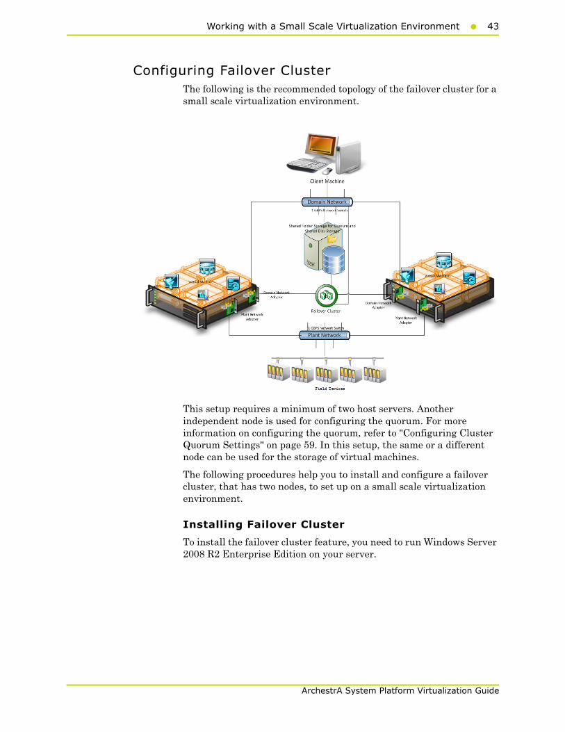
Configuring Failover ClusterThe following is the recommended topology of the failover cluster for a small scale virtualization environment.
This setup requires a minimum of two host servers. Another independent node is used for configuring the quorum. For more information on configuring the quorum, refer to "Configuring Cluster Quorum Settings" on page 59. In this setup, the same or a different node can be used for the storage of virtual machines.
The following procedures help you to install and configure a failover cluster, that has two nodes, to set up on a small scale virtualization environment.
Installing Failover Cluster
To install the failover cluster feature, you need to run Windows Server 2008 R2 Enterprise Edition on your server.
44 Chapter 2 Working with High Availability
ArchestrA System Platform Virtualization Guide
To install the failover cluster feature on a server
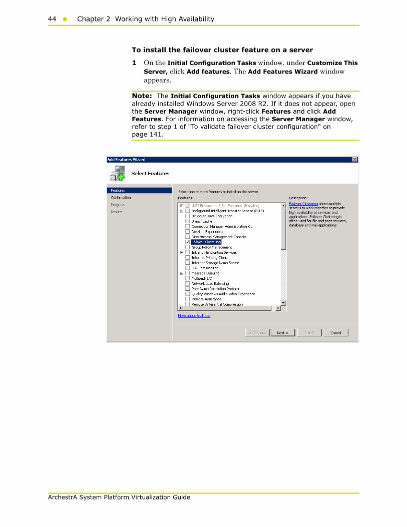
1 On the Initial Configuration Tasks window, under Customize This Server, click Add features. The Add Features Wizard window appears.
Note: The Initial Configuration Tasks window appears if you have already installed Windows Server 2008 R2. If it does not appear, open the Server Manager window, right-click Features and click Add Features. For information on accessing the Server Manager window, refer to step 1 of "To validate failover cluster configuration" on page 141.
Working with a Small Scale Virtualization Environment45
ArchestrA System Platform Virtualization Guide
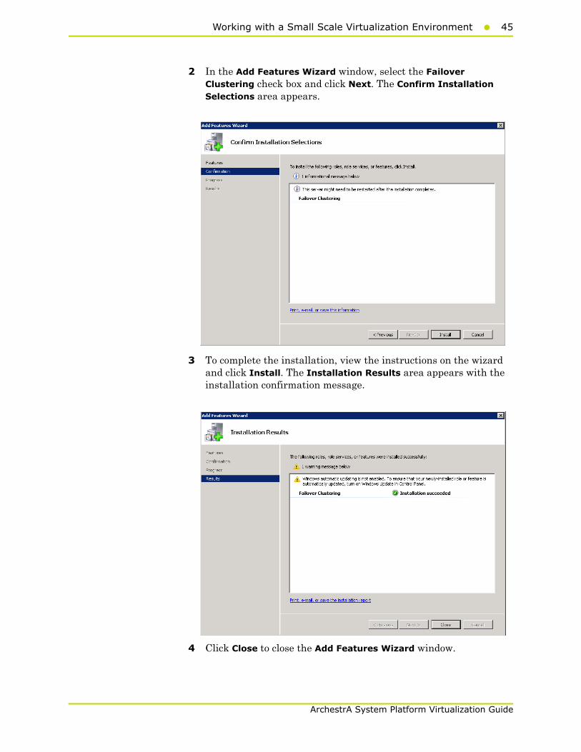
2 In the Add Features Wizard window, select the Failover Clustering check box and click Next. The Confirm Installation Selections area appears.
3 To complete the installation, view the instructions on the wizard and click Install. The Installation Results area appears with the installation confirmation message.
4 Click Close to close the Add Features Wizard window.
46 Chapter 2 Working with High Availability
ArchestrA System Platform Virtualization Guide
Note: Repeat the above procedure to include all the other nodes that are part of the Cluster configuration process.
Validating Failover Cluster Configuration
You must validate your configuration before you create a cluster. Validation helps you to confirm the configuration of your servers, network, and to storage meets the specific requirements for failover clusters.
To validate failover cluster configuration
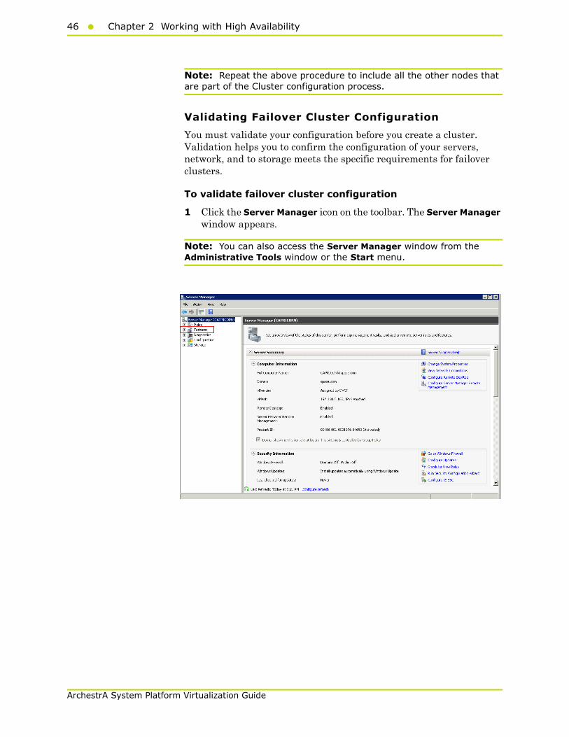
1 Click the Server Manager icon on the toolbar. The Server Manager window appears.
Note: You can also access the Server Manager window from the Administrative Tools window or the Start menu.

Working with a Small Scale Virtualization Environment47
ArchestrA System Platform Virtualization Guide
2 Expand Features and click Failover Cluster Manager. The Failover Cluster Manager area appears.
Note: If the User Account Control dialog box appears, confirm the action you want to perform and click Yes.
48 Chapter 2 Working with High Availability
ArchestrA System Platform Virtualization Guide
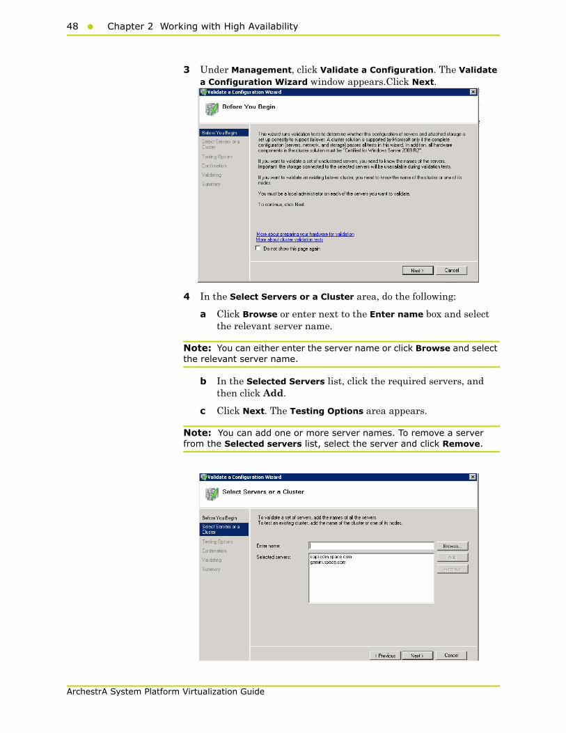
3 Under Management, click Validate a Configuration. The Validate a Configuration Wizard window appears.Click Next.
4 In the Select Servers or a Cluster area, do the following:
a Click Browse or enter next to the Enter name box and select the relevant server name.
Note: You can either enter the server name or click Browse and select the relevant server name.
b In the Selected Servers list, click the required servers, and then click Add.
c Click Next. The Testing Options area appears.
Note: You can add one or more server names. To remove a server from the Selected servers list, select the server and click Remove.

Working with a Small Scale Virtualization Environment49
ArchestrA System Platform Virtualization Guide
d Click Next. The Testing Options area appears.
Note: You can add one or more server names. To remove a server from the Selected servers list, select the server and click Remove.
5 Click the Run only tests I select option to skip storage validation process, and then click Next. The Test Selection area appears.
Note: Click the Run all tests (recommended) option to validate the default selection of tests.

50 Chapter 2 Working with High Availability
ArchestrA System Platform Virtualization Guide
6 Clear the Storage check box, and then click Next. The Summary screen appears.
7 Click View Report to view the test results or click Finish to close the Validate a Configuration Wizard window.
A warning message appears indicating that all tests have not been run. This usually happens in a multisite cluster where storage tests are skipped. You can proceed if there is no other error message. If the report indicates any other error, you need to fix the problem and rerun the tests before you continue. You can view the results of the tests after you close the wizard in SystemRoot\Cluster\Reports\Validation Report date and time.html where SystemRoot is the folder in which the operating system is installed (for example, C:\Windows).
To know more about cluster validation tests, click More about cluster validation tests on Validate a Configuration Wizard window.

Working with a Small Scale Virtualization Environment51
ArchestrA System Platform Virtualization Guide
Creating a Cluster
To create a cluster, you need to run the Create Cluster wizard.
To create a cluster
1 Click the Server Manager icon on the toolbar. The Server Manager window appears.
Note: You can also access the Server Manager window from the Administrative Tools window or the Start menu.
52 Chapter 2 Working with High Availability
ArchestrA System Platform Virtualization Guide
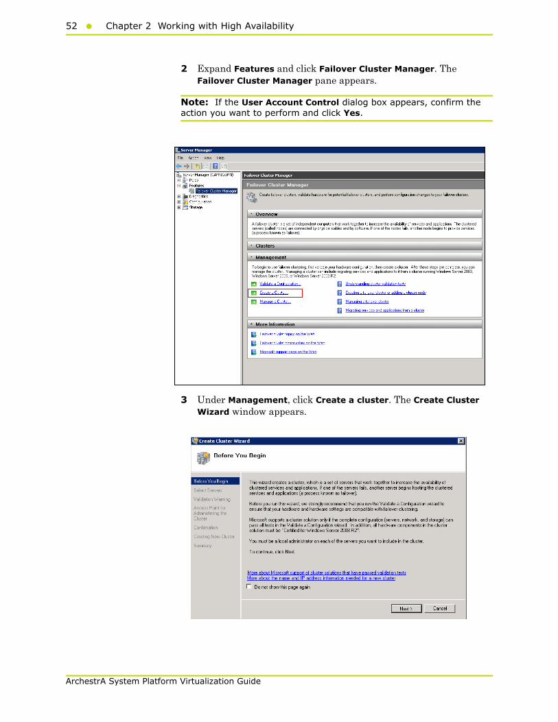
2 Expand Features and click Failover Cluster Manager. The Failover Cluster Manager pane appears.
Note: If the User Account Control dialog box appears, confirm the action you want to perform and click Yes.
3 Under Management, click Create a cluster. The Create Cluster Wizard window appears.

Working with a Small Scale Virtualization Environment53
ArchestrA System Platform Virtualization Guide
4 View the instructions and click Next. The Validation Warning area appears.
5 Click No. I do not require support from Microsoft for this cluster, and therefore do not want to run the validation tests. When I click Next, continue creating the cluster option and click Next. The Select Servers area appears.
Note: Click Yes. When I click Next, run configuration validation tests, and then return to the process of creating the cluster option if you want to run the configuration validation tests. Click View Report to view the cluster operation report.
6 In the Select Servers screen, do the following:
54 Chapter 2 Working with High Availability
ArchestrA System Platform Virtualization Guide
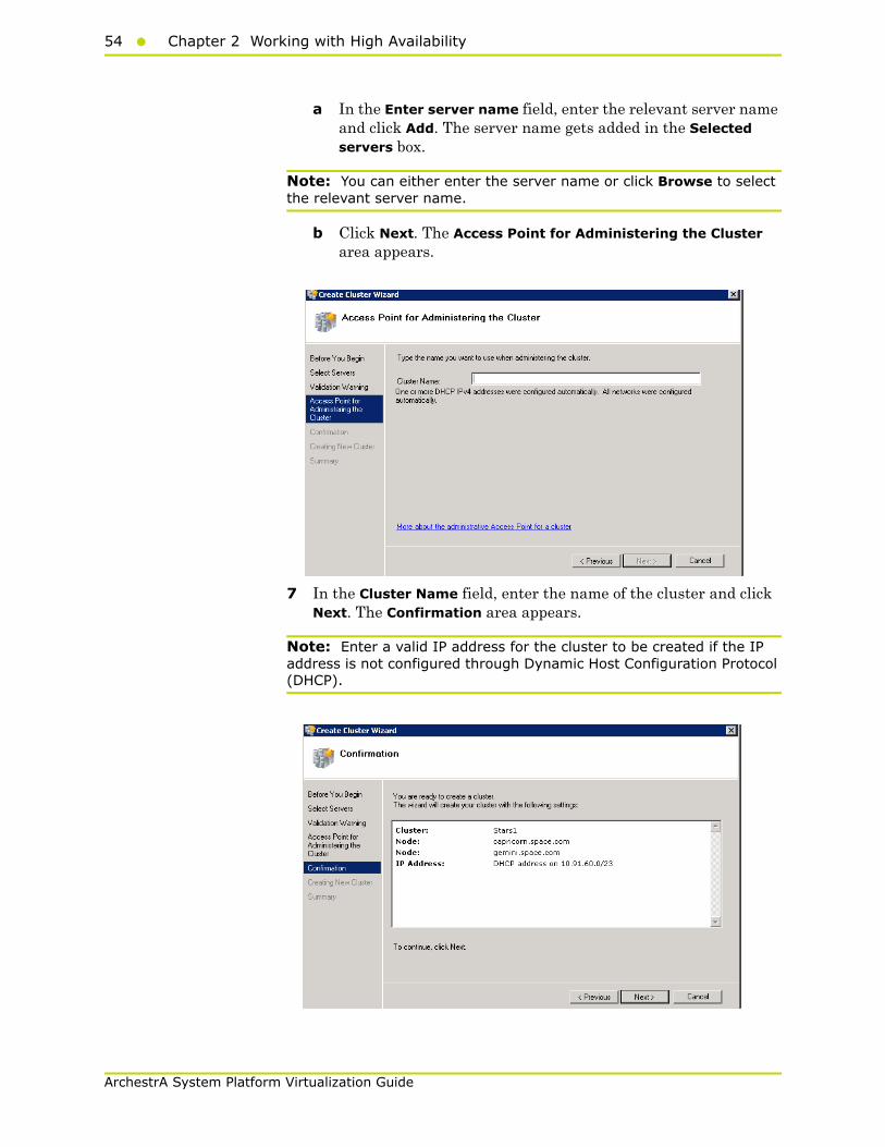
a In the Enter server name field, enter the relevant server name and click Add. The server name gets added in the Selected servers box.
Note: You can either enter the server name or click Browse to select the relevant server name.
b Click Next. The Access Point for Administering the Cluster area appears.
7 In the Cluster Name field, enter the name of the cluster and click Next. The Confirmation area appears.
Note: Enter a valid IP address for the cluster to be created if the IP address is not configured through Dynamic Host Configuration Protocol (DHCP).
Working with a Small Scale Virtualization Environment55
ArchestrA System Platform Virtualization Guide
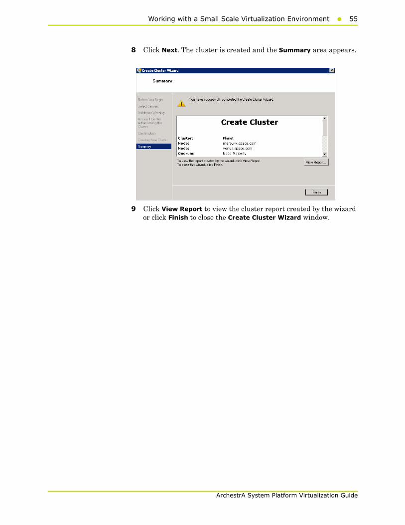
8 Click Next. The cluster is created and the Summary area appears.
9 Click View Report to view the cluster report created by the wizard or click Finish to close the Create Cluster Wizard window.

56 Chapter 2 Working with High Availability
ArchestrA System Platform Virtualization Guide
Disabling the Plant Network for the Cluster Communication
After creating the failover cluster using two or more enabled network cards, make sure only the primary network card which is used for the communication between the Hyper-V nodes is enabled for the Failover Communication. You must disable the remaining cluster networks.
To disable the plant network for the Cluster Communication
1 Click the Server Manager icon on the toolbar. The Server Manager window appears.
Note: You can also access the Server Manager window from the Administrative Tools window or the Start menu.
2 Expand the Failover Cluster Manager and select Networks to check how many networks are participating in the cluster.
Working with a Small Scale Virtualization Environment57
ArchestrA System Platform Virtualization Guide
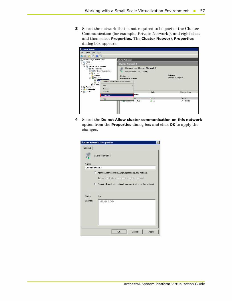
3 Select the network that is not required to be part of the Cluster Communication (for example, Private Network ), and right-click and then select Properties. The Cluster Network Properties dialog box appears.
4 Select the Do not Allow cluster communication on this network option from the Properties dialog box and click OK to apply the changes.

58 Chapter 2 Working with High Availability
ArchestrA System Platform Virtualization Guide
5 Check the summary pane of the networks and ensure Cluster Use is disabled for the network which is not required for cluster communication.
Note: Repeat the above process if more than two networks, which are not required for cluster communication, are involved in the Cluster Setup.
Working with a Small Scale Virtualization Environment59
ArchestrA System Platform Virtualization Guide
Configuring Cluster Quorum Settings
After both nodes have been added to the cluster, and the cluster networking components have been configured, you must configure the failover cluster quorum.
The File Share to be used for the node and File Share Majority quorum must be created and secured before configuring the failover cluster quorum. If the file share has not been created or correctly secured, the following procedure to configure a cluster quorum will fail. The file share can be hosted on any computer running a Windows operating system.
To configure the cluster quorum, you need to perform the following precedures:
• Create and secure a file share for the node, and file share majority quorum
• Use the failover cluster management tool to configure a node, and file share majority quorum
To create and secure a file share for the node and file share majority quorum
1 Create a new folder on the system that will host the share directory.
60 Chapter 2 Working with High Availability
ArchestrA System Platform Virtualization Guide
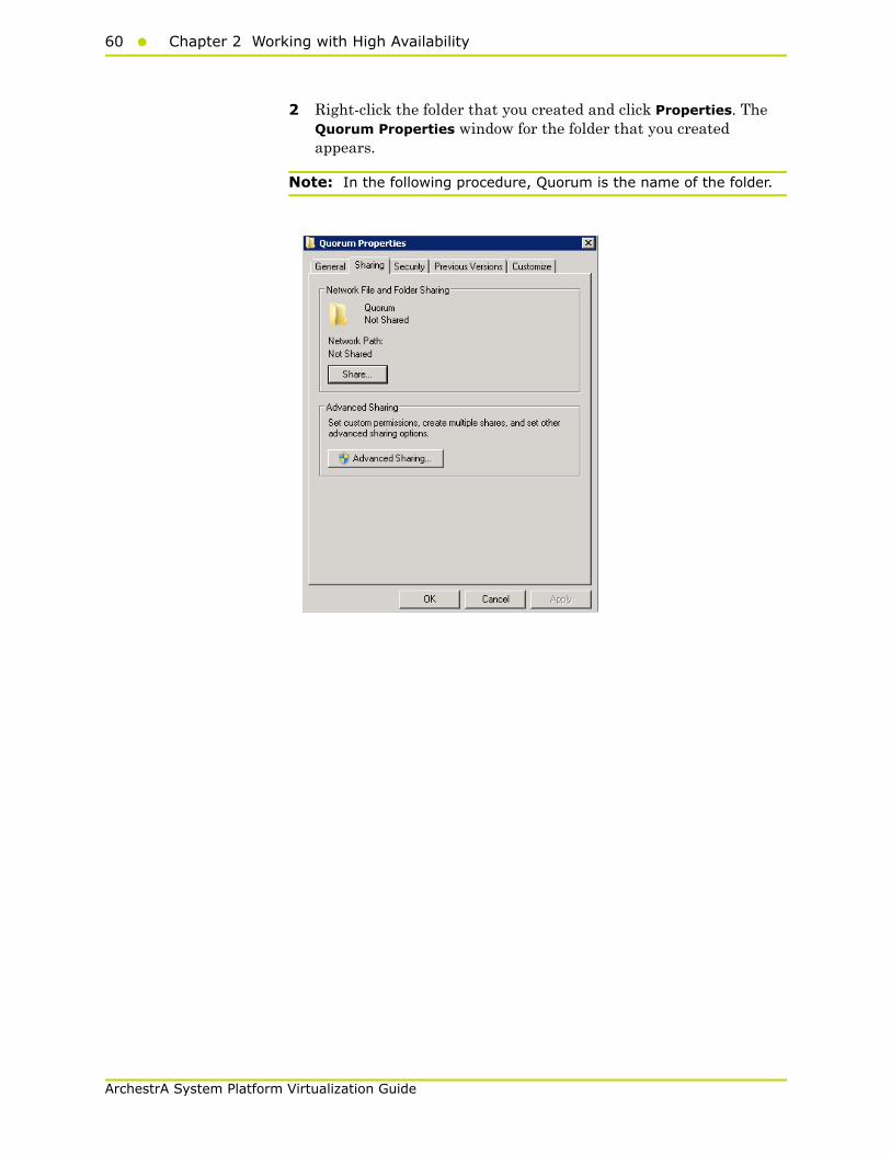
2 Right-click the folder that you created and click Properties. The Quorum Properties window for the folder that you created appears.
Note: In the following procedure, Quorum is the name of the folder.
Working with a Small Scale Virtualization Environment61
ArchestrA System Platform Virtualization Guide
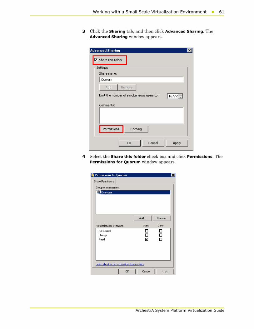
3 Click the Sharing tab, and then click Advanced Sharing. The Advanced Sharing window appears.
4 Select the Share this folder check box and click Permissions. The Permissions for Quorum window appears.
62 Chapter 2 Working with High Availability
ArchestrA System Platform Virtualization Guide
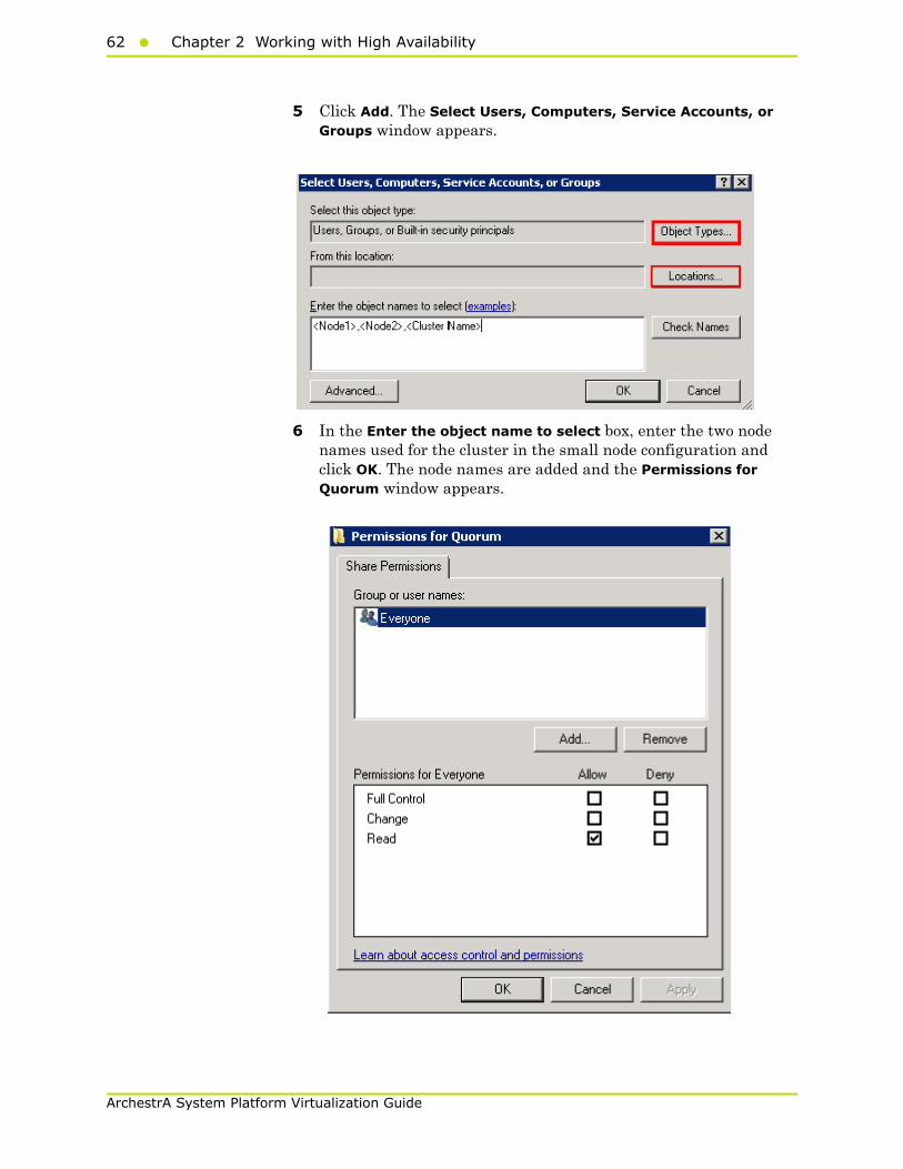
5 Click Add. The Select Users, Computers, Service Accounts, or Groups window appears.
6 In the Enter the object name to select box, enter the two node names used for the cluster in the small node configuration and click OK. The node names are added and the Permissions for Quorum window appears.

Working with a Small Scale Virtualization Environment63
ArchestrA System Platform Virtualization Guide
7 Select the Full Control, Change, and Read check boxes and click OK. The Properties window appears.
8 Click Ok. The folder is shared and can be used to create virtual machines.
64 Chapter 2 Working with High Availability
ArchestrA System Platform Virtualization Guide
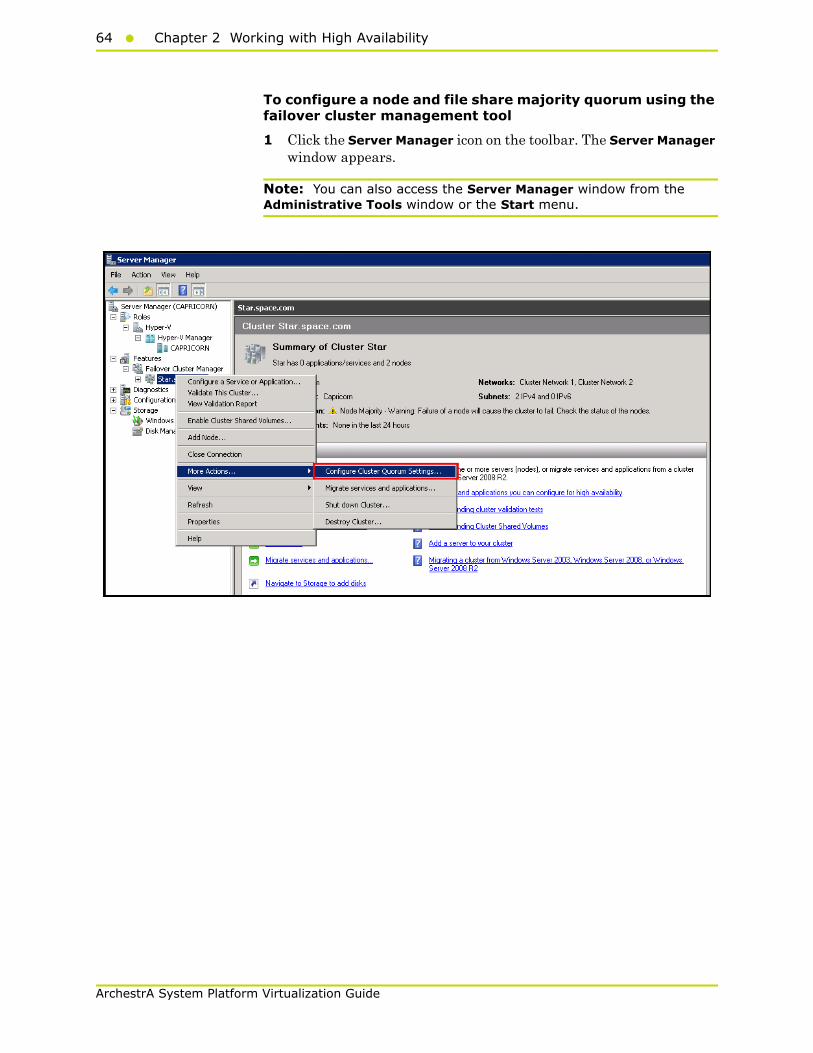
To configure a node and file share majority quorum using the failover cluster management tool
1 Click the Server Manager icon on the toolbar. The Server Manager window appears.
Note: You can also access the Server Manager window from the Administrative Tools window or the Start menu.
Working with a Small Scale Virtualization Environment65
ArchestrA System Platform Virtualization Guide
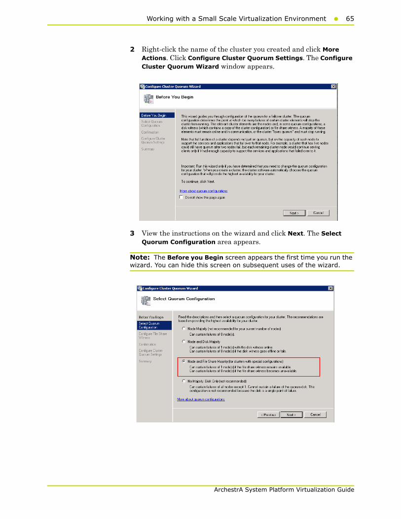
2 Right-click the name of the cluster you created and click More Actions. Click Configure Cluster Quorum Settings. The Configure Cluster Quorum Wizard window appears.
3 View the instructions on the wizard and click Next. The Select Quorum Configuration area appears.
Note: The Before you Begin screen appears the first time you run the wizard. You can hide this screen on subsequent uses of the wizard.

66 Chapter 2 Working with High Availability
ArchestrA System Platform Virtualization Guide
4 You need to select the relevant quorum node. For special configuration, click the Node and File Share Majority option and click Next. The Configure File Share Witness area appears.
Note: Click the Node Majority option if the cluster is configured for node majority or a single quorum resource. Click the Node and Disk Majority option if the number of nodes is even and not part of a multisite cluster. Click the No Majority: Disk Only option if the disk being used is only for the quorum.

Working with a Small Scale Virtualization Environment67
ArchestrA System Platform Virtualization Guide
5 In the Shared Folder Path box, enter the Universal Naming Convention (UNC) path to the file share that you created in the Shared Folder Path field, and then click Next. Permissions to the share are verified. If there are no problems with the access to the share, the Confirmation screen appears.
Note: You can either enter the server name or click Browse to select the relevant shared path.

68 Chapter 2 Working with High Availability
ArchestrA System Platform Virtualization Guide
6 The details you have selected are displayed. To confirm the details click Next. The Summary area appears and the configuration details of the quorum settings are displayed.
7 Click View Report to view a report of the tasks performed, or click Finish to close the window.
After you configure the cluster quorum, you must validate the cluster. For more information, refer to http://technet.microsoft.com/en-us/library/bb676379(EXCHG.80).aspx.
Configuring Storage
For a smaller virtualization environment, storage is one of the central barriers to implementing a good virtualization strategy. But with Hyper-V, VM storage is kept on a Windows file system. Users can put VMs on any file system that a Hyper-V server can access. As a result, HA can be built into the virtualization platform and storage for the virtual machines. This configuration can accommodate a host failure by making storage accessible to all Hyper-V hosts so that any host can run VMs from the same path on the shared folder. The back-end part of this storage can be a local or storage area network, iSCSI or whatever is available to fit the implementation.
For this architecture, the Shared Folder is used. The process of how to use the Shared Folder in the Failover Cluster for the High Availability is described in the section "Configuring Virtual Machines" on page 171.
Working with a Small Scale Virtualization Environment69
ArchestrA System Platform Virtualization Guide
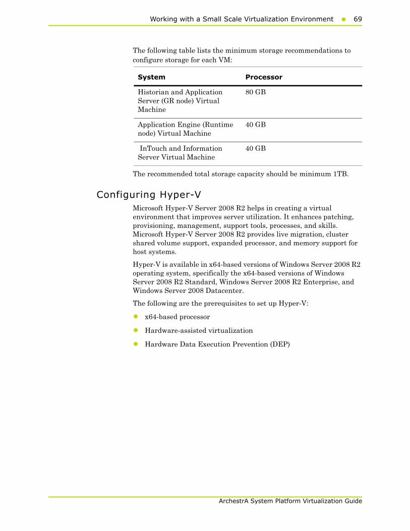
The following table lists the minimum storage recommendations to configure storage for each VM:
The recommended total storage capacity should be minimum 1TB.
Configuring Hyper-VMicrosoft Hyper-V Server 2008 R2 helps in creating a virtual environment that improves server utilization. It enhances patching, provisioning, management, support tools, processes, and skills. Microsoft Hyper-V Server 2008 R2 provides live migration, cluster shared volume support, expanded processor, and memory support for host systems.
Hyper-V is available in x64-based versions of Windows Server 2008 R2 operating system, specifically the x64-based versions of Windows Server 2008 R2 Standard, Windows Server 2008 R2 Enterprise, and Windows Server 2008 Datacenter.
The following are the prerequisites to set up Hyper-V:
• x64-based processor
• Hardware-assisted virtualization
• Hardware Data Execution Prevention (DEP)
System Processor
Historian and Application Server (GR node) Virtual Machine
80 GB
Application Engine (Runtime node) Virtual Machine
40 GB
InTouch and Information Server Virtual Machine
40 GB
70 Chapter 2 Working with High Availability
ArchestrA System Platform Virtualization Guide
To configure Hyper-V on Windows Server 2008 R2
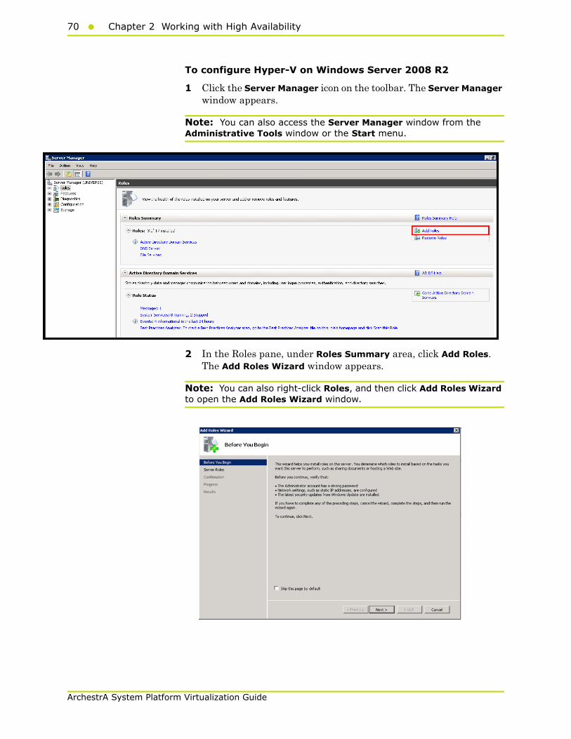
1 Click the Server Manager icon on the toolbar. The Server Manager window appears.
Note: You can also access the Server Manager window from the Administrative Tools window or the Start menu.
2 In the Roles pane, under Roles Summary area, click Add Roles. The Add Roles Wizard window appears.
Note: You can also right-click Roles, and then click Add Roles Wizard to open the Add Roles Wizard window.
Working with a Small Scale Virtualization Environment71
ArchestrA System Platform Virtualization Guide
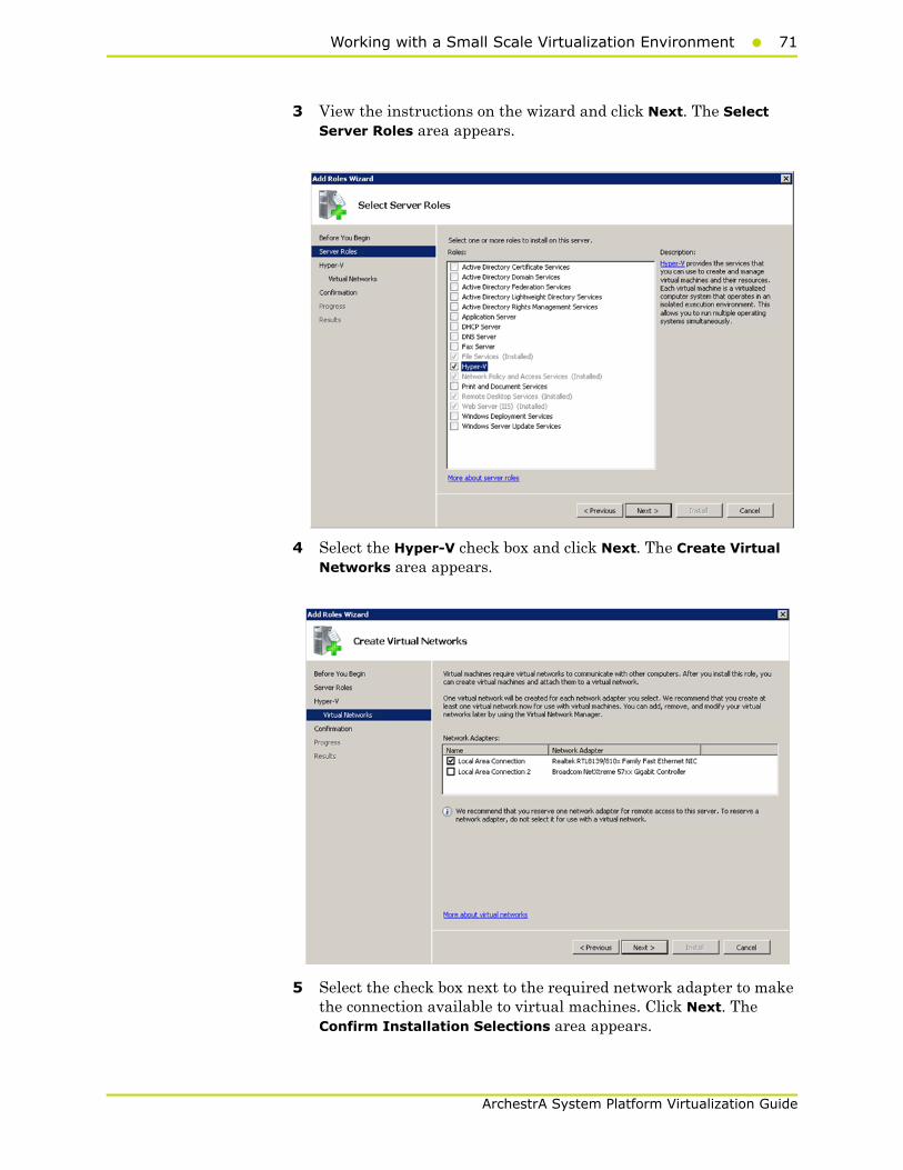
3 View the instructions on the wizard and click Next. The Select Server Roles area appears.
4 Select the Hyper-V check box and click Next. The Create Virtual Networks area appears.
5 Select the check box next to the required network adapter to make the connection available to virtual machines. Click Next. The Confirm Installation Selections area appears.

72 Chapter 2 Working with High Availability
ArchestrA System Platform Virtualization Guide
Note: You can select one or more network adapters.
6 Click Install. The Installation Results area appears.
Working with a Small Scale Virtualization Environment73
ArchestrA System Platform Virtualization Guide
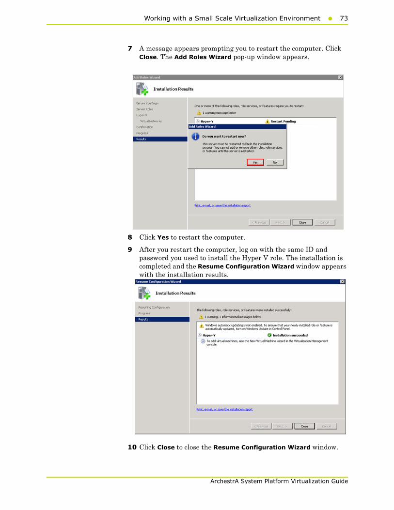
7 A message appears prompting you to restart the computer. Click Close. The Add Roles Wizard pop-up window appears.
8 Click Yes to restart the computer.
9 After you restart the computer, log on with the same ID and password you used to install the Hyper V role. The installation is completed and the Resume Configuration Wizard window appears with the installation results.
10 Click Close to close the Resume Configuration Wizard window.

74 Chapter 2 Working with High Availability
ArchestrA System Platform Virtualization Guide
Configuring Virtual MachinesAfter installing Hyper-V, you need to create a virtual machine.
To configure a virtual machine
1 In the Server Manager window, right-click Features, and then click Failover Cluster Manager. The Failover Cluster Manager tree expands.
2 Right-click Services and applications, click Virtual Machines, and then click New Virtual Machine. The New Virtual Machine Wizard window appears.

Working with a Small Scale Virtualization Environment75
ArchestrA System Platform Virtualization Guide
3 View the instructions in the Before You Begin area and click Next. The Specify Name and Location area appears.
4 In the Specify Name and Location area, do the following:
a In the Name box, enter a name for the virtual machine.
b Select the Store the virtual machine is a different location check box to be able to indicate the location of the virtual machine.

76 Chapter 2 Working with High Availability
ArchestrA System Platform Virtualization Guide
c In the Location box, enter the location where you want to store the virtual machine.
Note: You can either enter the path to the filename or click Browse to select the relevant server name.
d Click Next. The Assign Memory area appears.
5 Enter the recommended amount of memory in the Memory box and click Next. The Configure Networking area appears.

Working with a Small Scale Virtualization Environment77
ArchestrA System Platform Virtualization Guide
6 Select the network to be used for the virtual machine and click Next. The Connect Virtual Hard Disk area appears.
7 Click the Create a virtual hard disk option and then do the following:
a In the Name box, enter the name of the virtual machine.
b In the Location box, enter the location of the virtual machine.
Note: You can either enter the location or click Browse to select the location of the virtual machine and click Next.

78 Chapter 2 Working with High Availability
ArchestrA System Platform Virtualization Guide
c In the Size box, enter the size of the virtual machine and then click Next. The Installation Options area appears.
Note: You need to click either the Use an existing virtual hard disk or the Attach a virtual hard disk later option, only if you are using an existing virtual hard disk, or you want to attach a virtual disk later.

Working with a Small Scale Virtualization Environment79
ArchestrA System Platform Virtualization Guide
8 Click the Install an operating system later option and click Next. The Completing the New Virtual Machine Window area appears.
Note: If you want to install an operating system from a boot CD/DVD-ROM or a boot floppy disk or a network-based installation server, click the relevant option.
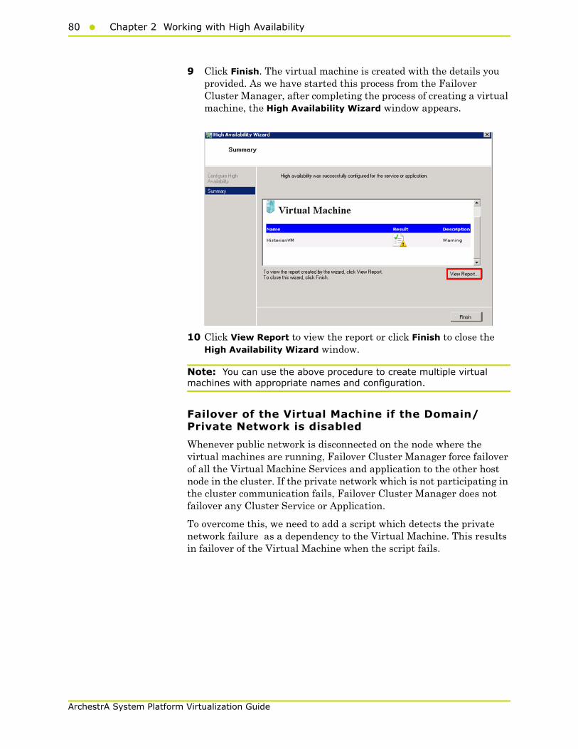
80 Chapter 2 Working with High Availability
ArchestrA System Platform Virtualization Guide
9 Click Finish. The virtual machine is created with the details you provided. As we have started this process from the Failover Cluster Manager, after completing the process of creating a virtual machine, the High Availability Wizard window appears.
10 Click View Report to view the report or click Finish to close the High Availability Wizard window.
Note: You can use the above procedure to create multiple virtual machines with appropriate names and configuration.
Failover of the Virtual Machine if the Domain/ Private Network is disabled
Whenever public network is disconnected on the node where the virtual machines are running, Failover Cluster Manager force failover of all the Virtual Machine Services and application to the other host node in the cluster. If the private network which is not participating in the cluster communication fails, Failover Cluster Manager does not failover any Cluster Service or Application.
To overcome this, we need to add a script which detects the private network failure as a dependency to the Virtual Machine. This results in failover of the Virtual Machine when the script fails.

Working with a Small Scale Virtualization Environment81
ArchestrA System Platform Virtualization Guide
To add a script which enables the failover of the virtual machine if the private network is disabled
1 Add a script to the virtual machine. Follow the process mentioned in the following URL to add the script: http://gallery.technet.microsoft.com/ScriptCenter/5f7b4df3-af02-47bf-b275-154e5edf17e6/
2 After the script is added, select the virtual machine and right-click. Click Properties. The Properties dialog box appears.

82 Chapter 2 Working with High Availability
ArchestrA System Platform Virtualization Guide
3 Navigate to the Failover tab and change Maximum failures in the specified period to 15 and Period (hours) to 1 and Click OK.
Note: If the Script fails when Domain/Private network is disabled, Virtual machine also fails and moves to the backup node.

Working with a Small Scale Virtualization Environment83
ArchestrA System Platform Virtualization Guide
Configuration of System Platform Products in a Typical Small Scale Virtualization
To record the expected Recovery Time Objective (RTO) and Recovery Point Objective (RPO) trends and various observations in a small scale virtualization environment, tests are performed with System Platform Product configuration shown below.
The virtualization host server used for small scale configuration consists of three virtual machines listed below.
Node 1: GR , Historian and DAS SI Direct - Windows 2008 R2 Standard edition (64bit) OS with SQL Server 2008 SP1 32 bit
Node 2 (AppEngine): Bootstrap , IDE and InTouch (Managed App) - Windows 2008 R2 Standard edition (64bit) OS
Node 3: Information Server , Bootstrap and IDE, InTouch Terminal Service and Historian Client - Windows Server 2008 SP2 (32bit) with SQL Server 2008 SP1 and Office 2007
Virtual Node IO tags (Approx.) Historized tags (Approx.)
GR 10000 2500
AppEngine 10000 5000
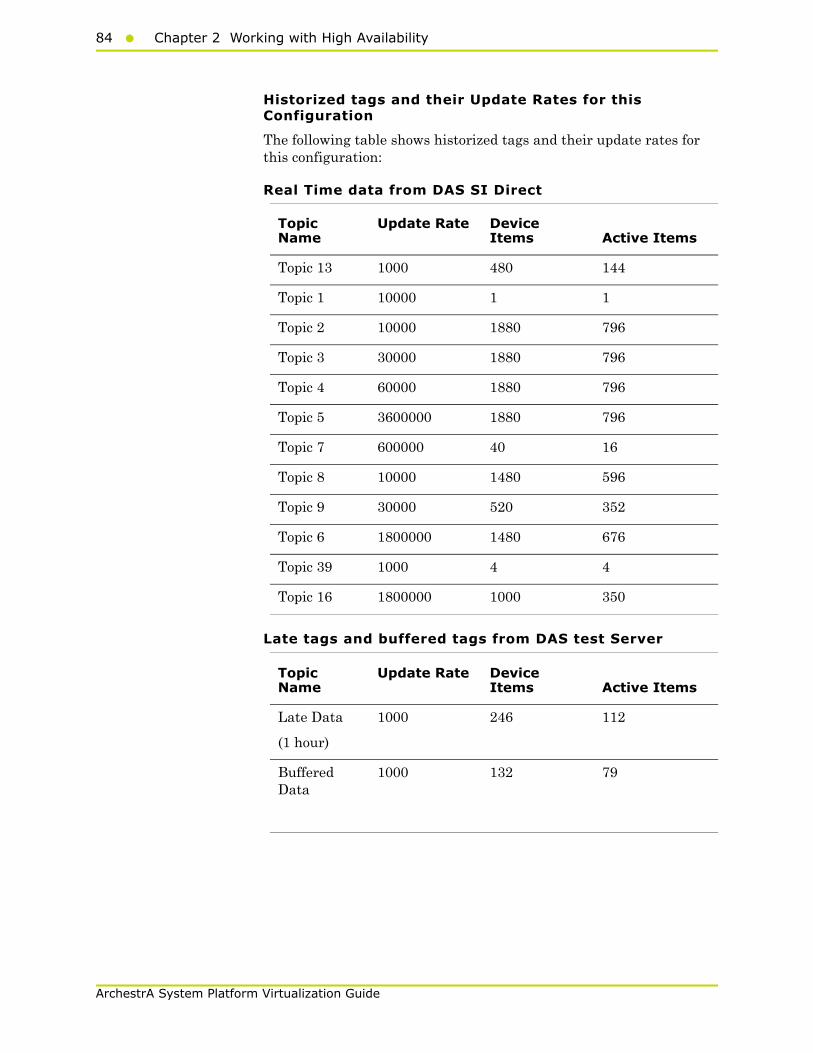
84 Chapter 2 Working with High Availability
ArchestrA System Platform Virtualization Guide
Historized tags and their Update Rates for this Configuration
The following table shows historized tags and their update rates for this configuration:
Real Time data from DAS SI Direct
Late tags and buffered tags from DAS test Server
Topic Name
Update Rate Device Items Active Items
Topic 13 1000 480 144
Topic 1 10000 1 1
Topic 2 10000 1880 796
Topic 3 30000 1880 796
Topic 4 60000 1880 796
Topic 5 3600000 1880 796
Topic 7 600000 40 16
Topic 8 10000 1480 596
Topic 9 30000 520 352
Topic 6 1800000 1480 676
Topic 39 1000 4 4
Topic 16 1800000 1000 350
Topic Name
Update Rate Device Items Active Items
Late Data
(1 hour)
1000 246 112
Buffered Data
1000 132 79
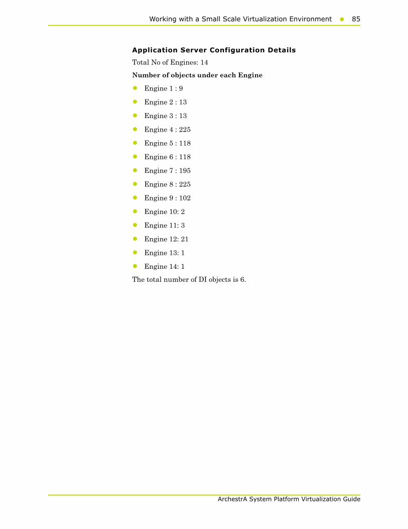
Working with a Small Scale Virtualization Environment85
ArchestrA System Platform Virtualization Guide
Application Server Configuration Details
Total No of Engines: 14
Number of objects under each Engine
• Engine 1 : 9
• Engine 2 : 13
• Engine 3 : 13
• Engine 4 : 225
• Engine 5 : 118
• Engine 6 : 118
• Engine 7 : 195
• Engine 8 : 225
• Engine 9 : 102
• Engine 10: 2
• Engine 11: 3
• Engine 12: 21
• Engine 13: 1
• Engine 14: 1
The total number of DI objects is 6.
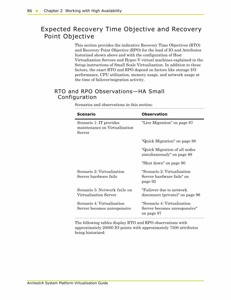
86 Chapter 2 Working with High Availability
ArchestrA System Platform Virtualization Guide
Expected Recovery Time Objective and Recovery Point Objective
This section provides the indicative Recovery Time Objectives (RTO) and Recovery Point Objective (RPO) for the load of IO and Attributes historized shown above and with the configuration of Host Virtualization Servers and Hyper-V virtual machines explained in the Setup instructions of Small Scale Virtualization. In addition to these factors, the exact RTO and RPO depend on factors like storage I/O performance, CPU utilization, memory usage, and network usage at the time of failover/migration activity.
RTO and RPO Observations—HA Small Configuration
Scenarios and observations in this section:
The following tables display RTO and RPO observations with approximately 20000 IO points with approximately 7500 attributes being historized:
Scenario Observation
Scenario 1: IT provides maintenance on Virtualization Server
"Live Migration" on page 87
"Quick Migration" on page 88
"Quick Migration of all nodes simultaneously" on page 89
"Shut down" on page 90
Scenario 2: Virtualization Server hardware fails
"Scenario 2: Virtualization Server hardware fails" on page 92
Scenario 3: Network fails on Virtualization Server
"Failover due to network disconnect (private)" on page 96
Scenario 4: Virtualization Server becomes unresponsive
"Scenario 4: Virtualization Server becomes unresponsive" on page 97
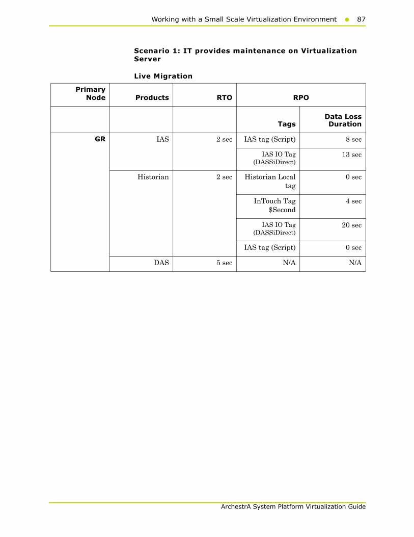
Working with a Small Scale Virtualization Environment87
ArchestrA System Platform Virtualization Guide
Scenario 1: IT provides maintenance on Virtualization Server
Live Migration
PrimaryNode Products RTO RPO
TagsData LossDuration
GR IAS 2 sec IAS tag (Script) 8 sec
IAS IO Tag(DASSiDirect)
13 sec
Historian 2 sec Historian Localtag
0 sec
InTouch Tag$Second
4 sec
IAS IO Tag(DASSiDirect)
20 sec
IAS tag (Script) 0 sec
DAS 5 sec N/A N/A
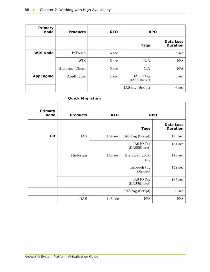
88 Chapter 2 Working with High Availability
ArchestrA System Platform Virtualization Guide
Quick Migration
Primarynode Products RTO RPO
TagsData LossDuration
WIS Node InTouch 5 sec 5 sec
WIS 5 sec N/A N/A
Historian Client 5 sec N/A N/A
AppEngine AppEngine 1 sec IAS IO tag(DASSiDirect)
3 sec
IAS tag (Script) 6 sec
Primarynode Products RTO RPO
TagsData LossDuration
GR IAS 134 sec IAS Tag (Script) 183 sec
IAS IO Tag(DASSiDirect)
184 sec
Historian 145 sec Historian Localtag
148 sec
InTouch tag$Second
152 sec
IAS IO Tag(DASSiDirect)
165 sec
IAS tag (Script) 0 sec
DAS 146 sec N/A N/A

Working with a Small Scale Virtualization Environment89
ArchestrA System Platform Virtualization Guide
Quick Migration of all nodes simultaneously
Primarynode Products RTO RPO
TagsData LossDuration
WIS Node InTouch 79 sec 89 sec
WIS 79 sec N/A N/A
Historian Client 79 sec N/A N/A
AppEngine AppEngine 59 sec IAS IO tag(DASSiDirect)
105 sec
IAS Tag (Script) 104 sec
Primarynode Products RTO RPO
TagsData LossDuration
GR IAS 188 sec IAS tag (Script) 222 sec
IAS IO tag(DASSiDirect)
227 sec
Historian 220 sec Historian Localtag
221 sec
InTouch tag$Second
228 sec
IAS IO tag(DASSiDirect)
238 sec
IAS tag (Script) 135 sec
DAS 221 sec N/A
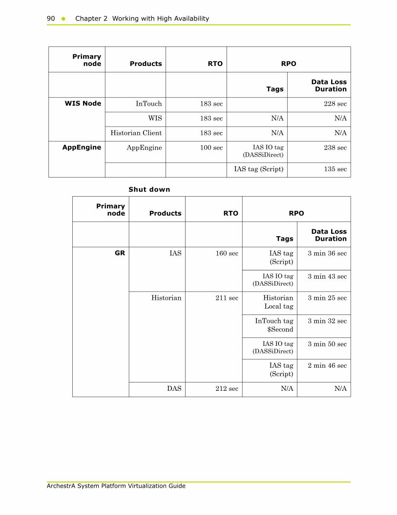
90 Chapter 2 Working with High Availability
ArchestrA System Platform Virtualization Guide
Shut down
Primarynode Products RTO RPO
TagsData LossDuration
WIS Node InTouch 183 sec 228 sec
WIS 183 sec N/A N/A
Historian Client 183 sec N/A N/A
AppEngine AppEngine 100 sec IAS IO tag(DASSiDirect)
238 sec
IAS tag (Script) 135 sec
Primarynode Products RTO RPO
TagsData LossDuration
GR IAS 160 sec IAS tag(Script)
3 min 36 sec
IAS IO tag(DASSiDirect)
3 min 43 sec
Historian 211 sec HistorianLocal tag
3 min 25 sec
InTouch tag$Second
3 min 32 sec
IAS IO tag(DASSiDirect)
3 min 50 sec
IAS tag(Script)
2 min 46 sec
DAS 212 sec N/A N/A
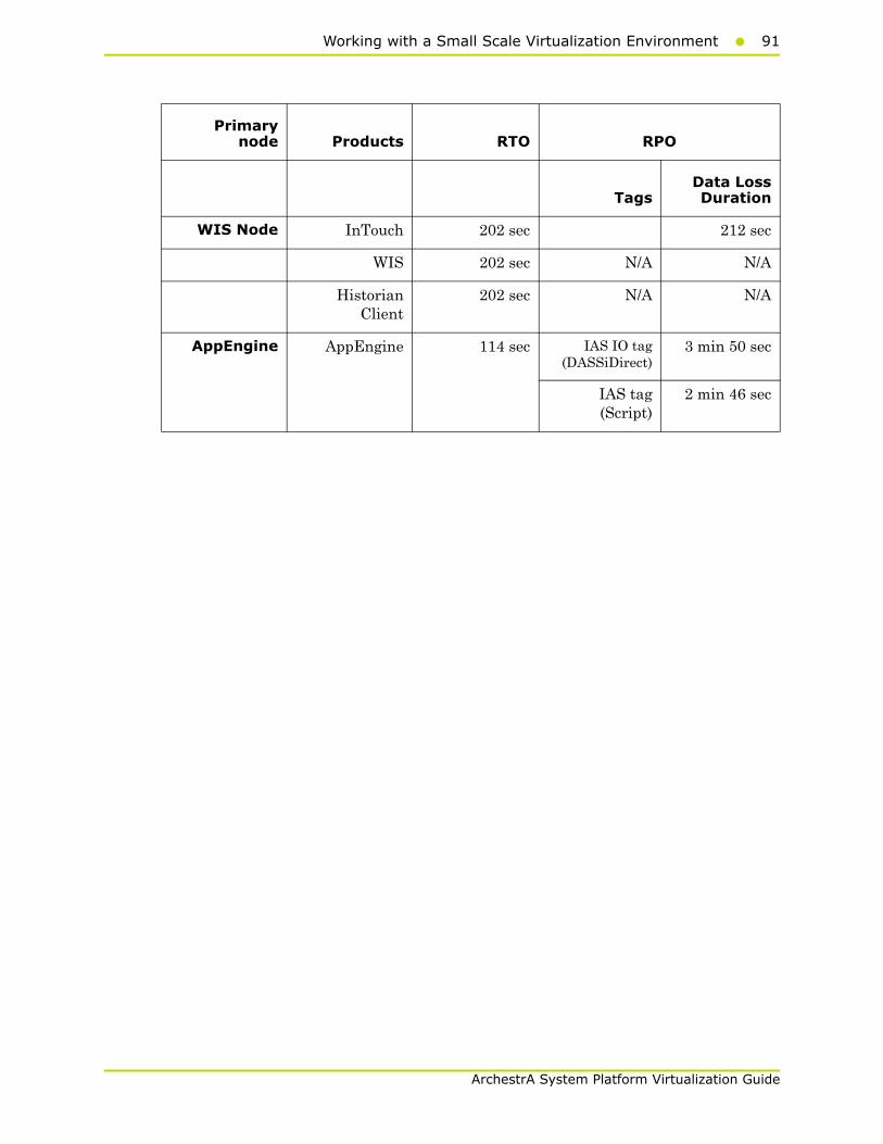
Working with a Small Scale Virtualization Environment91
ArchestrA System Platform Virtualization Guide
Primarynode Products RTO RPO
TagsData LossDuration
WIS Node InTouch 202 sec 212 sec
WIS 202 sec N/A N/A
HistorianClient
202 sec N/A N/A
AppEngine AppEngine 114 sec IAS IO tag(DASSiDirect)
3 min 50 sec
IAS tag(Script)
2 min 46 sec

92 Chapter 2 Working with High Availability
ArchestrA System Platform Virtualization Guide
Scenario 2: Virtualization Server hardware fails
The failover occurs due to hardware failure, and it is simulated with power-off on the host server.
Primarynode Products RTO RPO
TagsData LossDuration
GR IAS 497 sec IAS Tag (Script) 9min
IAS IO tag(DASSiDirect)
9 min
Historian 532 sec Historian localtag
9 min 23 sec
InTouch tag$Second
10 min + timetaken to start
viewer
Note: RPO is dependent on thetime taken by the user to start theInTouchView on the InTouch node
and the RTO of the Historian node,which historizes this tag.
IAS IO tag(DASSiDirect)
8 min 23 sec
IAS tag (Script) 7 min 1 sec
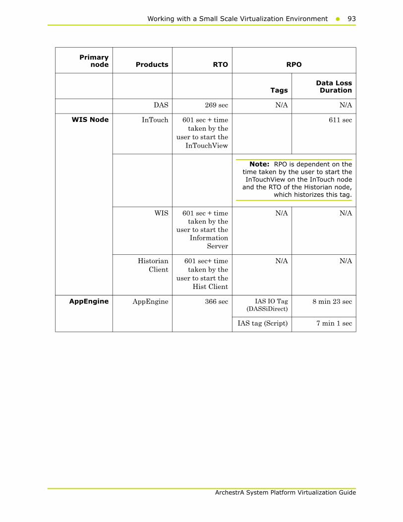
Working with a Small Scale Virtualization Environment93
ArchestrA System Platform Virtualization Guide
Primarynode Products RTO RPO
TagsData LossDuration
DAS 269 sec N/A N/A
WIS Node InTouch 601 sec + timetaken by the
user to start theInTouchView
611 sec
Note: RPO is dependent on thetime taken by the user to start theInTouchView on the InTouch node
and the RTO of the Historian node,which historizes this tag.
WIS 601 sec + timetaken by the
user to start theInformation
Server
N/A N/A
HistorianClient
601 sec+ timetaken by the
user to start theHist Client
N/A N/A
AppEngine AppEngine 366 sec IAS IO Tag(DASSiDirect)
8 min 23 sec
IAS tag (Script) 7 min 1 sec

94 Chapter 2 Working with High Availability
ArchestrA System Platform Virtualization Guide
Scenario 3: Network fails on Virtualization Server
The failover occurs due to network disconnect (public). In this case, the VMs restart, after moving to the other host server.
Primarynode Products RTO RPO
Tags Data Loss Duration
GR IAS 535 sec IAS Tag(Script)
9 min 8 sec
IAS IO Tag(DASSiDirect)
8 min 53 sec
Historian 544 sec HistorianLocal Tag
9 min 35 sec
InTouch Tag$Second
9 min 16 sec
Note: RPO is dependent on the timetaken by the user to start the InTouchView
on the InTouch node and the RTO of theHistorian node, which historizes this tag.
IAS IO Tag(DASSiDirect)
8 min 57 sec
IAS Tag(Script)
7 min 52 sec
DAS 457sec N/A N/A
WIS Node InTouch 415 sec +time taken by
the user tostart the
InTouchView
N/A 556 sec + Time taken torun viewer)
Note: RPO is dependent on the timetaken by the user to start the InTouchView
on the InTouch node and the RTO of theHistorian node, which historizes this tag.
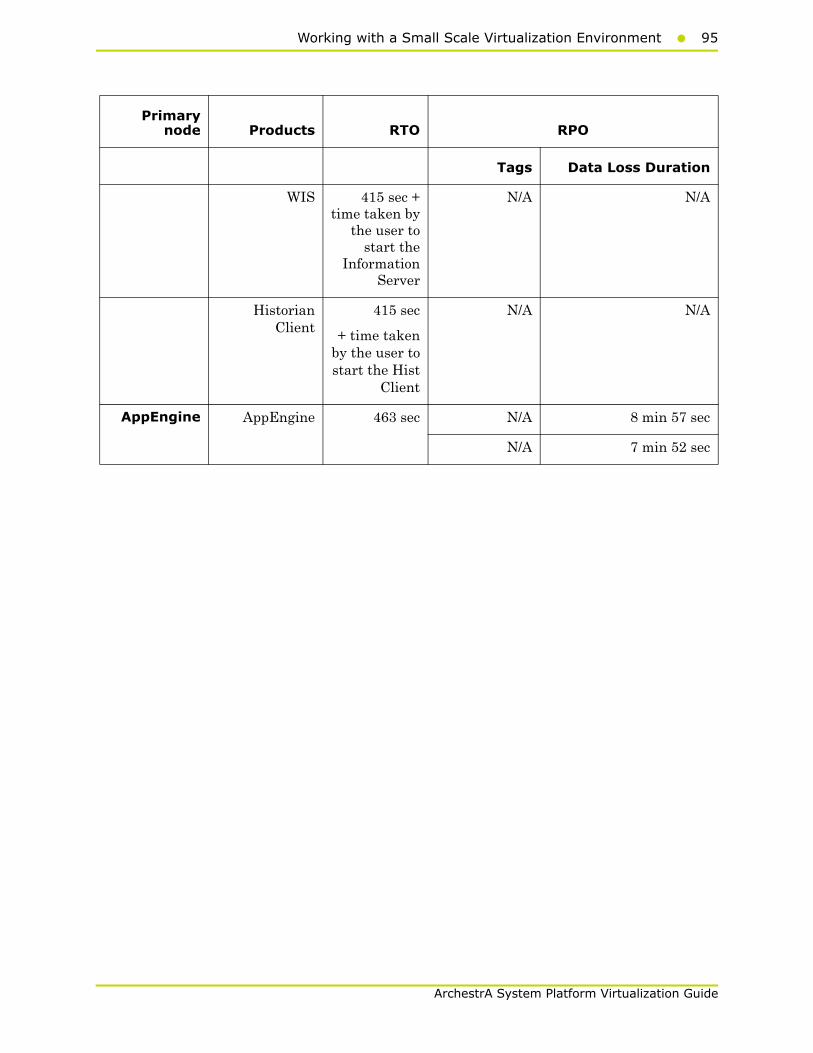
Working with a Small Scale Virtualization Environment95
ArchestrA System Platform Virtualization Guide
Primarynode Products RTO RPO
Tags Data Loss Duration
WIS 415 sec +time taken by
the user tostart the
InformationServer
N/A N/A
HistorianClient
415 sec
+ time takenby the user tostart the Hist
Client
N/A N/A
AppEngine AppEngine 463 sec N/A 8 min 57 sec
N/A 7 min 52 sec
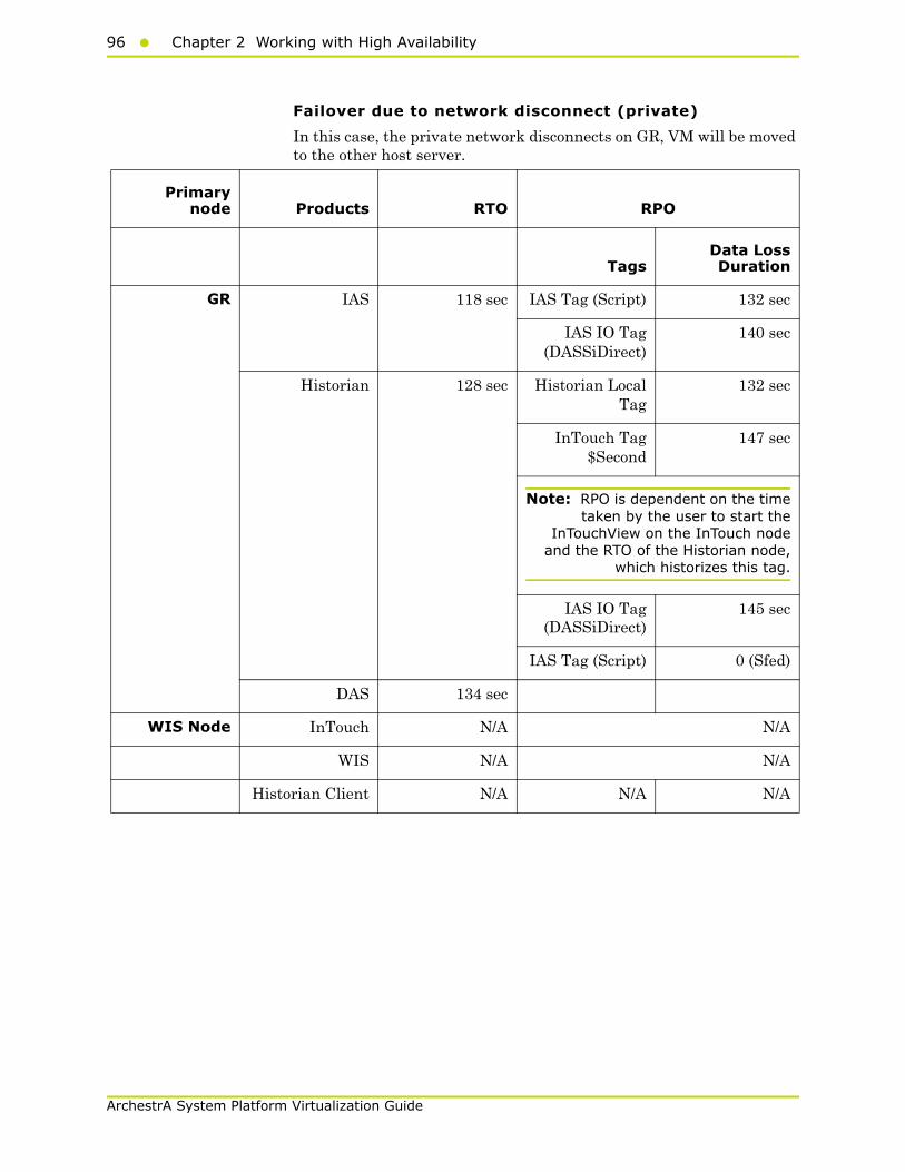
96 Chapter 2 Working with High Availability
ArchestrA System Platform Virtualization Guide
Failover due to network disconnect (private)
In this case, the private network disconnects on GR, VM will be moved to the other host server.
Primarynode Products RTO RPO
TagsData LossDuration
GR IAS 118 sec IAS Tag (Script) 132 sec
IAS IO Tag(DASSiDirect)
140 sec
Historian 128 sec Historian LocalTag
132 sec
InTouch Tag$Second
147 sec
Note: RPO is dependent on the timetaken by the user to start the
InTouchView on the InTouch nodeand the RTO of the Historian node,
which historizes this tag.
IAS IO Tag(DASSiDirect)
145 sec
IAS Tag (Script) 0 (Sfed)
DAS 134 sec
WIS Node InTouch N/A N/A
WIS N/A N/A
Historian Client N/A N/A N/A
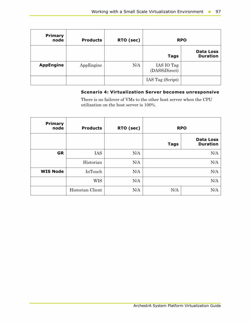
Working with a Small Scale Virtualization Environment97
ArchestrA System Platform Virtualization Guide
Scenario 4: Virtualization Server becomes unresponsive
There is no failover of VMs to the other host server when the CPU utilization on the host server is 100%.
Primarynode Products RTO (sec) RPO
TagsData LossDuration
AppEngine AppEngine N/A IAS IO Tag(DASSiDirect)
IAS Tag (Script)
Primarynode Products RTO (sec) RPO
TagsData LossDuration
GR IAS N/A N/A
Historian N/A N/A
WIS Node InTouch N/A N/A
WIS N/A N/A
Historian Client N/A N/A N/A

98 Chapter 2 Working with High Availability
ArchestrA System Platform Virtualization Guide
Primarynode Products RTO (sec) RPO
TagsData LossDuration
AppEngine AppEngine N/A N/A
InTouch N/A N/A
WIS Node InTouch N/A N/A

Working with a Small Scale Virtualization Environment99
ArchestrA System Platform Virtualization Guide
Snapshots of Data Trends and ObservationsScenarios and observations in this section:
Scenario 1: IT provides Maintenance on Virtualization Server
Live Migration of GR, Historian
Trend
In the Historian Trend below, the GR node tags are:
Tag1: SystemTimeSec tag of Historian
Tag2: I/O Tag (Integer_001.int1) getting data from DDESuiteLinkClient_001.Topic39.RealIO10000
Tag3: I/O Tag (Integer_001.bool1) getting data from DESuiteLinkClient_001.Topic39.RealIO10000
Scenario Observation
Scenario 1: IT provides maintenance on Virtualization Server
"Live Migration of GR, Historian" on page 99
"Live Migration of AppEngine" on page 102
"Live Migration of WIS, InTouch, HistorianClient" on page 104
"Quick Migration of GR, Historian" on page 106
"Quick Migration of all nodes" on page 114
"Shut down of Source Host Virtualization Server" on page 118
Scenario 2: Virtualization Server hardware fails
"Failover Due to Hardware Failure" on page 121
Scenario 3: Network fails on Virtualization Server
"Failover Due to Network Disconnect (Public)" on page 124
Scenario 4: Virtualization Server becomes unresponsive
"Hyper-V Virtual Machines with Static RAM and Reservations for Processors" on page 127
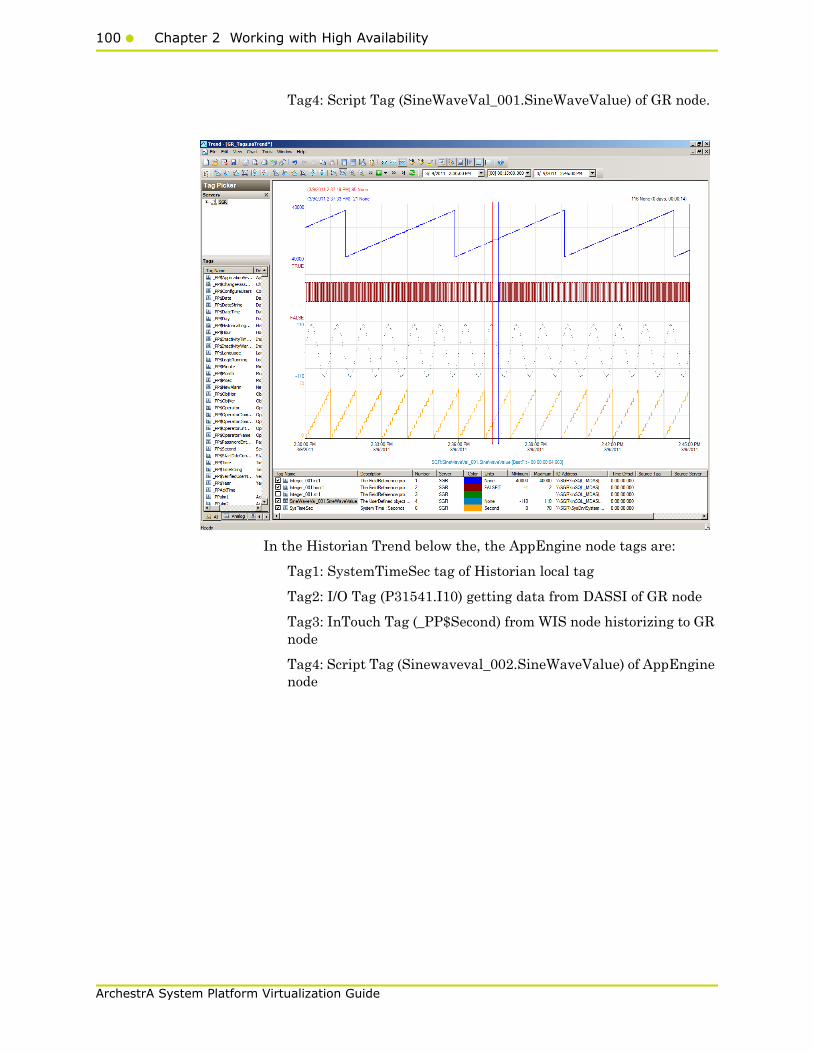
100 Chapter 2 Working with High Availability
ArchestrA System Platform Virtualization Guide
Tag4: Script Tag (SineWaveVal_001.SineWaveValue) of GR node.
In the Historian Trend below the, the AppEngine node tags are:
Tag1: SystemTimeSec tag of Historian local tag
Tag2: I/O Tag (P31541.I10) getting data from DASSI of GR node
Tag3: InTouch Tag (_PP$Second) from WIS node historizing to GR node
Tag4: Script Tag (Sinewaveval_002.SineWaveValue) of AppEngine node
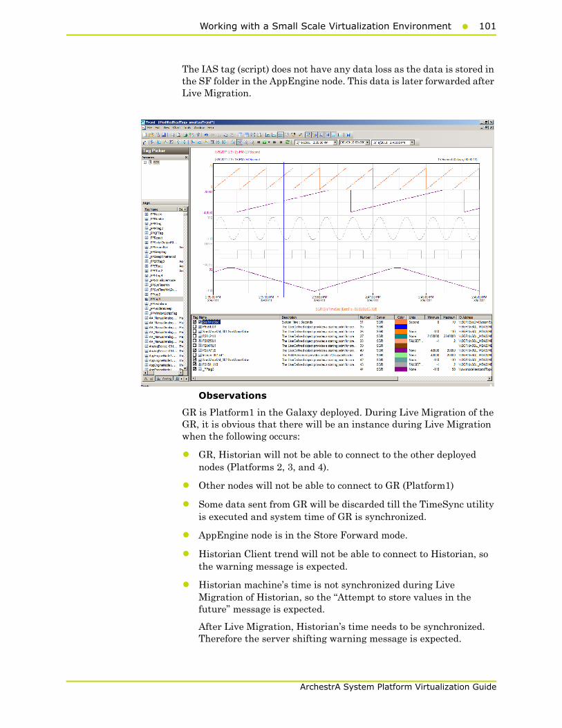
Working with a Small Scale Virtualization Environment101
ArchestrA System Platform Virtualization Guide
The IAS tag (script) does not have any data loss as the data is stored in the SF folder in the AppEngine node. This data is later forwarded after Live Migration.
Observations
GR is Platform1 in the Galaxy deployed. During Live Migration of the GR, it is obvious that there will be an instance during Live Migration when the following occurs:
• GR, Historian will not be able to connect to the other deployed nodes (Platforms 2, 3, and 4).
• Other nodes will not be able to connect to GR (Platform1)
• Some data sent from GR will be discarded till the TimeSync utility is executed and system time of GR is synchronized.
• AppEngine node is in the Store Forward mode.
• Historian Client trend will not be able to connect to Historian, so the warning message is expected.
• Historian machine’s time is not synchronized during Live Migration of Historian, so the “Attempt to store values in the future” message is expected.
After Live Migration, Historian’s time needs to be synchronized. Therefore the server shifting warning message is expected.

102 Chapter 2 Working with High Availability
ArchestrA System Platform Virtualization Guide
After the Live Migration of GR,Historian node, the stored data is forwarded from the AppEngine node. As a result, you see the following warnings on each of the VM nodes.
GR node
368064482/7/20117:39:13 PM23962556WarningNmxSvcPlatform 2
exceed maximum heartbeats timeout of 8000 ms.
368064492/7/20117:39:13 PM23962556WarningNmxSvcPlatform 3
exceed maximum heartbeats timeout of 8000 ms.
368064502/7/20117:39:13 PM23962556WarningNmxSvcPlatform 4
exceed maximum heartbeats timeout of 8000 ms.
368064532/7/20117:39:24 PM15442248WarningaahCfgSvc"Server time
is shifting (Expected time, Current time)"
(02/07/11,19:39:23,070, 02/07/11,19:39:09,503) [SGR;
Config.cpp; 2040]
AppEngine node
220263132/7/20117:39:08 PM25642580WarningNmxSvcPlatform 1
exceed maximum heartbeats timeout of 8000 ms.
220264202/7/20117:39:19 PM27203000WarningScriptRuntime
Insert.InsertValueWF: Script timed out.
220264462/7/20117:39:50 PM27203000WarningScriptRuntime
Insert.InsertValueWT: Script timed out.
WIS node
17174702/7/20117:39:07 PM37683684WarningNmxSvcPlatform 1 exceed
maximum heartbeats timeout of 8000 ms
Live Migration of AppEngine
Trends:
In the Historian Trend shown below, the first three tags receive data from DDESuiteLinkClient in Industrial Application Server (IAS) from the PLC and are historized from Platform AppEngine. There is a data loss for 27 seconds.
In the Historian Trend below, the AppEngine node tags are:
Tag1: SystemTimeSec tag of Historian local tag
Tag2: I/O Tag (P31541.I10) getting data from DASSI of GR node
Tag3: Script Tag (Sinewaveval_002.SineWaveValue)
The RPO value is captured in the RPO table of Live Migration of the AppEngine node. For AppEngine node Script tag and Intouch tag there is no data loss.

Working with a Small Scale Virtualization Environment103
ArchestrA System Platform Virtualization Guide
Observations
AppEngine is Platform2 in the Galaxy deployed. During Live Migration of the AppEngine, it is obvious that there will be an instance during Live Migration when the following occurs:
• AppEngine will not be able to connect to the other deployed nodes (Platforms 1, 3, and 4).
• Other nodes will not be able to connect to AppEngine (Platform2)
• Some data sent from AppEngine will be discarded till the TimeSync utility is executed and system time of AppEngine is synchronized. So Historian is bound to discard data from the AppEngine node.
As a result, you see the following warnings on each of the VM nodes.
GR node
368058502/7/20115:19:02 PM23962556WarningNmxSvcPlatform 2
exceed maximum heartbeats timeout of 8000 ms.
AppEngine
220261792/7/20115:19:05 PM25642580WarningNmxSvcPlatform 1
exceed maximum heartbeats timeout of 8000 ms.
220261802/7/20115:19:05 PM25642580WarningNmxSvcPlatform 3
exceed maximum heartbeats timeout of 8000 ms.
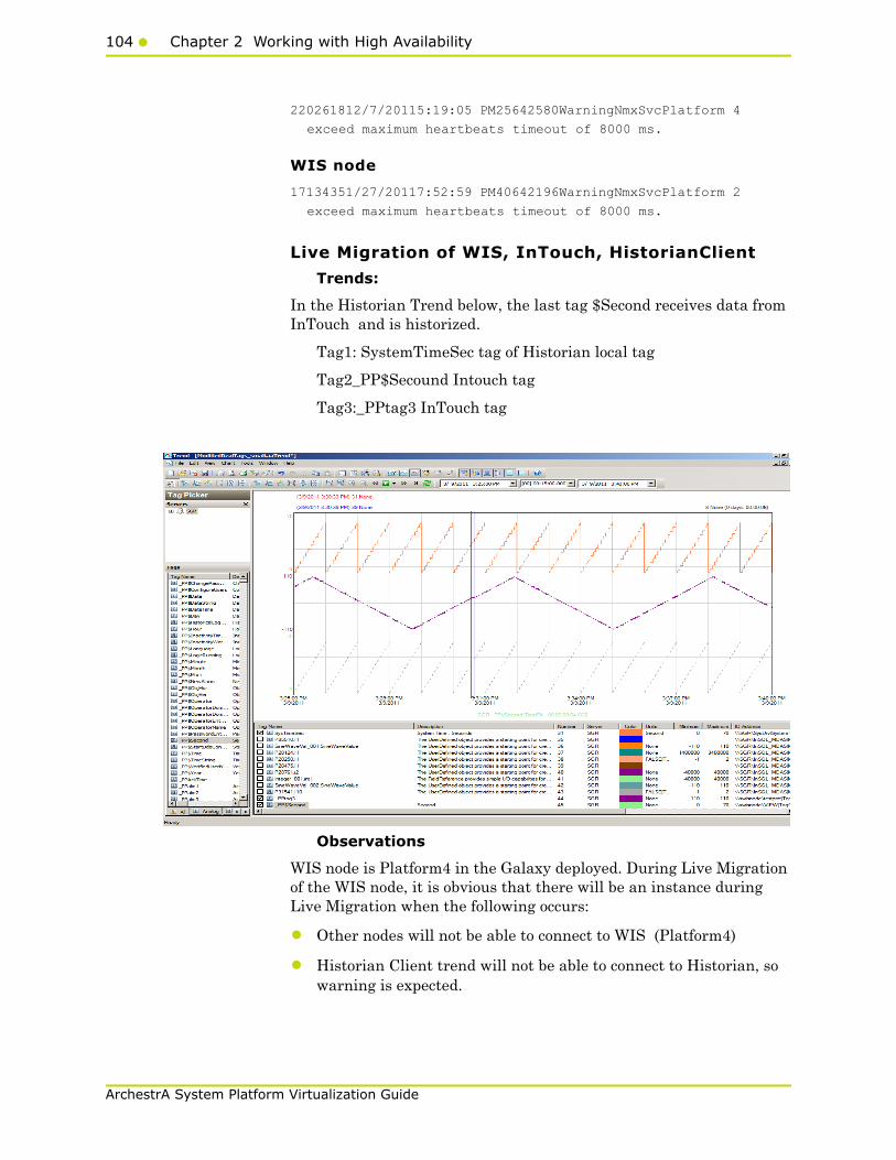
104 Chapter 2 Working with High Availability
ArchestrA System Platform Virtualization Guide
220261812/7/20115:19:05 PM25642580WarningNmxSvcPlatform 4
exceed maximum heartbeats timeout of 8000 ms.
WIS node
17134351/27/20117:52:59 PM40642196WarningNmxSvcPlatform 2
exceed maximum heartbeats timeout of 8000 ms.
Live Migration of WIS, InTouch, HistorianClient
Trends:
In the Historian Trend below, the last tag $Second receives data from InTouch and is historized.
Tag1: SystemTimeSec tag of Historian local tag
Tag2_PP$Secound Intouch tag
Tag3:_PPtag3 InTouch tag
Observations
WIS node is Platform4 in the Galaxy deployed. During Live Migration of the WIS node, it is obvious that there will be an instance during Live Migration when the following occurs:
• Other nodes will not be able to connect to WIS (Platform4)
• Historian Client trend will not be able to connect to Historian, so warning is expected.
Working with a Small Scale Virtualization Environment105
ArchestrA System Platform Virtualization Guide
• Historian machine’s time is not synchronized during Live Migration of WIS node, so the “Attempt to store values in the future” message is expected.
As a result, you see the following warnings on each of the VM nodes.
GR node
None
AppEngine node
220255672/7/20113:07:40 PM25082696WarningScriptRuntime
Insert.InsertValueWT: Script timed out.
220255682/7/20113:10:24 PM25082696WarningScriptRuntime
Insert.InsertValueWF: Script timed out.
220255692/7/20113:11:42 PM25082696WarningScriptRuntime
Insert.InsertValueWT: Script timed out.
WIS node
None
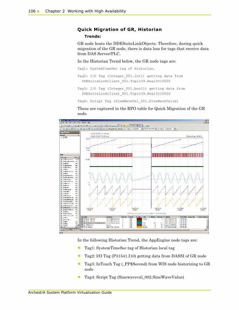
106 Chapter 2 Working with High Availability
ArchestrA System Platform Virtualization Guide
Quick Migration of GR, Historian
Trends:
GR node hosts the DDESuiteLinkObjects. Therefore, during quick migration of the GR node, there is data loss for tags that receive data from DAS Server/PLC.
In the Historian Trend below, the GR node tags are:
Tag1: SystemTimeSec tag of Historian.
Tag2: I/O Tag (Integer_001.int1) getting data from
DDESuiteLinkClient_001.Topic39.RealIO10000
Tag3: I/O Tag (Integer_001.bool1) getting data from
DDESuiteLinkClient_001.Topic39.RealIO10000
Tag4: Script Tag (SineWaveVal_001.SineWaveValue)
These are captured in the RPO table for Quick Migration of the GR node.
In the following Historian Trend, the AppEngine node tags are:
• Tag1: SystemTimeSec tag of Historian local tag
• Tag2: I/O Tag (P31541.I10) getting data from DASSI of GR node
• Tag3: InTouch Tag (_PP$Second) from WIS node historizing to GR node
• Tag4: Script Tag (Sinewaveval_002.SineWaveValue)
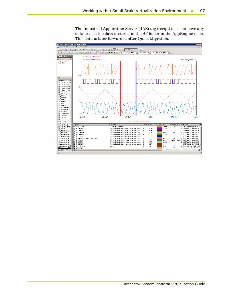
Working with a Small Scale Virtualization Environment107
ArchestrA System Platform Virtualization Guide
The Industrial Application Server ( IAS) tag (script) does not have any data loss as the data is stored in the SF folder in the AppEngine node. This data is later forwarded after Quick Migration.
108 Chapter 2 Working with High Availability
ArchestrA System Platform Virtualization Guide
Observations
GR is Platform1 in the Galaxy deployed. During Quick Migration of the GR, it is obvious that there will be an instance during Quick Migration when the following occurs:
• GR, Historian will not be able to connect to the other deployed nodes (Platforms 2, 3, and 4).
• Other nodes will not be able to connect to GR (Platform1).
• Some data sent from GR will be discarded till the TimeSync utility is executed and system time of GR is synchronized.
• AppEngine node is in the Store Forward mode.
• Historian Client trend will not be able to connect to Historian, so warning message is expected.
• Historian machine's time is not synchronized during Live
• Migration of the Historian, so the "Attempt to store values in the future" message is expected.
• After Live Migration, Historian's time needs to be synchronized. Therefore, the server shifting warning message is expected.
After the Quick Migration of GR, Historian Node, the stored data is forwarded from AppEngine node.
As a result, you see the following warnings on each of the VM nodes.
GR node
372973352/15/20115:34:19 PM7202748WarningNmxSvcPlatform 2
exceed maximum heartbeats timeout of 8000 ms.
372973362/15/20115:34:19 PM7202748WarningNmxSvcPlatform 3
exceed maximum heartbeats timeout of 8000 ms.
372973902/15/20115:34:25 PM12844968WarningDDESuiteLinkClient
CTopic::RemoveItems didn't get executed...: connection handle
m_hConn=0x00000000, connection status m_bConnected=false,
host handle m_pHost=0x0038eb80
372974562/15/20115:38:35 PM58683864WarningaaEngine0:6EC Values
in the past did not fit within the realtime window; discarding
data (260, 2011/02/15 12:00:25.440, 2011/02/15 12:04:22.490)
[aahMDASSF.cpp; 3722; 36]
AppEngine node
220482942/15/20115:30:33 PM26482672WarningNmxSvcPlatform 1
exceed maximum heartbeats timeout of 8000 ms.
220484332/15/20115:34:28 PM42764372WarningScriptRuntime
Insert.InsertValueWT: Script timed out.
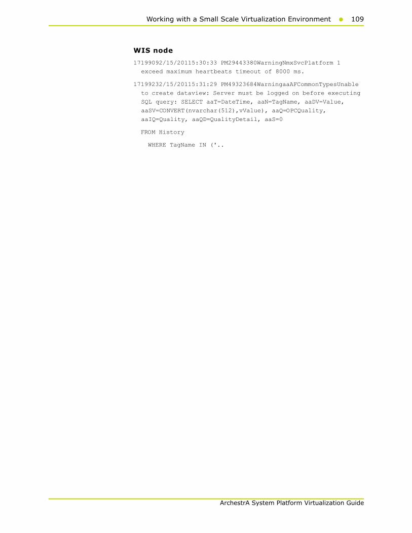
Working with a Small Scale Virtualization Environment109
ArchestrA System Platform Virtualization Guide
WIS node
17199092/15/20115:30:33 PM29443380WarningNmxSvcPlatform 1
exceed maximum heartbeats timeout of 8000 ms.
17199232/15/20115:31:29 PM49323684WarningaaAFCommonTypesUnable
to create dataview: Server must be logged on before executing
SQL query: SELECT aaT=DateTime, aaN=TagName, aaDV=Value,
aaSV=CONVERT(nvarchar(512),vValue), aaQ=OPCQuality,
aaIQ=Quality, aaQD=QualityDetail, aaS=0
FROM History
WHERE TagName IN ('..
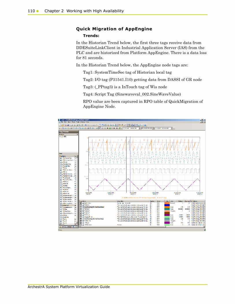
110 Chapter 2 Working with High Availability
ArchestrA System Platform Virtualization Guide
Quick Migration of AppEngine
Trends:
In the Historian Trend below, the first three tags receive data from DDESuiteLinkClient in Industrial Application Server (IAS) from the PLC and are historized from Platform AppEngine. There is a data loss for 81 seconds.
In the Historian Trend below, the AppEngine node tags are:
Tag1: SystemTimeSec tag of Historian local tag
Tag2: I/O tag (P31541.I10) getting data from DASSI of GR node
Tag3: (_PPtag3) is a InTouch tag of Wis node
Tag4: Script Tag (Sinewaveval_002.SineWaveValue)
RPO value are been captured in RPO table of QuickMigration of AppEngine Node.

Working with a Small Scale Virtualization Environment111
ArchestrA System Platform Virtualization Guide
Observations
AppEngine is Platform2 in the Galaxy deployed. During Quick Migration of the AppEngine, it is obvious that there will be an instance during Quick Migration when
• AppEngine will not be able to connect to the other deployed nodes (Platforms 1, 3, and 4).
• Other nodes will not be able to connect to AppEngine (Platform2)
• Some data sent from AppEngine will be discarded till the TimeSync utility is executed and system time of AppEngine is synchronized. So Historian is bound to discard data from AppEngine node.
• AppEngine is not synchronized during quick migration and a message “Values in the past did not fit within the realtime window” is expected on AppEngine.
As a result, you see the following warnings on each of the VM nodes.
GR node
413214162/16/20113:58:23 PM23962780WarningNmxSvcPlatform 2
exceed maximum heartbeats timeout of 8000 ms
AppEngine
220563372/16/20114:00:28 PM25162532WarningNmxSvcPlatform 1
exceed maximum heartbeats timeout of 8000 ms.
220563382/16/20114:00:28 PM25162532WarningNmxSvcPlatform 3
exceed maximum heartbeats timeout of 8000 ms.
220563392/16/20114:00:28 PM25162532WarningNmxSvcPlatform 4
exceed maximum heartbeats timeout of 8000 ms.
220564742/16/20114:01:06 PM31563160WarningScriptRuntime
Insert.InsertValueWF: Script timed out.
220565732/16/20114:04:42 PM32364488WarningaaEngine0:9B8 Values
in the past did not fit within the realtime window; discarding
data (1385, 2011/02/16 10:28:13.968, 2011/02/16 10:30:30.426)
[aahMDASSF.cpp; 3709; 121]
220565772/16/20114:04:45 PM33044556WarningaaEngine0:A04 Values
in the past did not fit within the realtime window; discarding
data (445, 2011/02/16 10:28:14.827, 2011/02/16 10:30:32.067)
[aahMDASSF.cpp; 3709; 2]
WIS node
17204112/16/20113:58:21 PM36523428WarningNmxSvcPlatform 2
exceed maximum heartbeats timeout of 8000 ms.
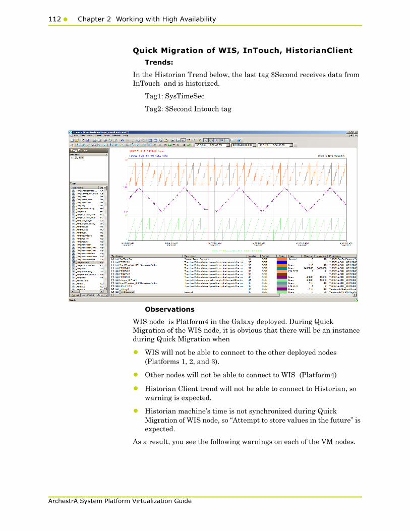
112 Chapter 2 Working with High Availability
ArchestrA System Platform Virtualization Guide
Quick Migration of WIS, InTouch, HistorianClient
Trends:
In the Historian Trend below, the last tag $Second receives data from InTouch and is historized.
Tag1: SysTimeSec
Tag2: $Second Intouch tag
Observations
WIS node is Platform4 in the Galaxy deployed. During Quick Migration of the WIS node, it is obvious that there will be an instance during Quick Migration when
• WIS will not be able to connect to the other deployed nodes (Platforms 1, 2, and 3).
• Other nodes will not be able to connect to WIS (Platform4)
• Historian Client trend will not be able to connect to Historian, so warning is expected.
• Historian machine’s time is not synchronized during Quick Migration of WIS node, so “Attempt to store values in the future” is expected.
As a result, you see the following warnings on each of the VM nodes.
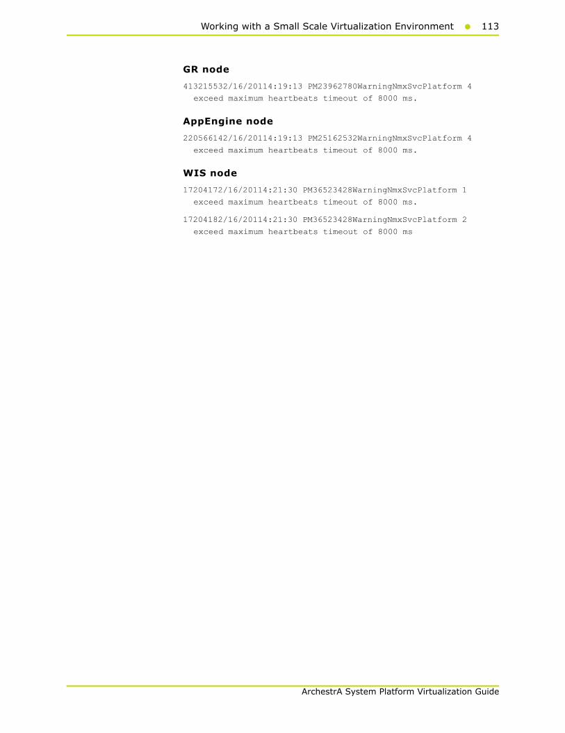
Working with a Small Scale Virtualization Environment113
ArchestrA System Platform Virtualization Guide
GR node
413215532/16/20114:19:13 PM23962780WarningNmxSvcPlatform 4
exceed maximum heartbeats timeout of 8000 ms.
AppEngine node
220566142/16/20114:19:13 PM25162532WarningNmxSvcPlatform 4
exceed maximum heartbeats timeout of 8000 ms.
WIS node
17204172/16/20114:21:30 PM36523428WarningNmxSvcPlatform 1
exceed maximum heartbeats timeout of 8000 ms.
17204182/16/20114:21:30 PM36523428WarningNmxSvcPlatform 2
exceed maximum heartbeats timeout of 8000 ms

114 Chapter 2 Working with High Availability
ArchestrA System Platform Virtualization Guide
Quick Migration of all nodes
Trends:
GR node hosts the DDESuiteLinkObjects. Therefore during Quick Migration of GR node, there is data loss for tags that does receive data from DAS Server/PLC.
In the Historian Trend below, GR node tags are:
Tag1: I/O Tag (Integer_001.int1) getting data from DDESuiteLinkClient_001.Topic39.RealIO10000
Tag2: I/O Tag (Integer_001.bool1) getting data from DDESuiteLinkClient_001.Topic39.RealIO10000
Tag3: I/O Tag (Integer_001.str1) getting data from DDESuiteLinkClient_001.Topic39.RealIO10000
Tag4: Script Tag (SineWaveVal_001.SineWaveValue)
Tag5: InTouch tag (_PP$Second) from WIS node Historising to GR node.
Tag6: SystemTimeSec tag of Historian.

Working with a Small Scale Virtualization Environment115
ArchestrA System Platform Virtualization Guide
In the Historian Trend below, the AppEngine tags are:
Tag: I/O Tag (P28762.i15) getting data from DASSI on GR
Tag: I/O Tag (P31541.i10) getting data from DASSI on GR
Tag: I/O Tag (P20124.i1) Buffer data tag getting data from DASSI on GR
Tag: I/O Tag (P20475.i1) Buffer data tag getting data from DASSI on GR
Tag: Script Tag (SineWaveVal_001.SineWaveValue) of GR
Tag: Script Tag (SineWaveVal_002.SineWaveValue) of AppEngine
Tag: SystemTimeSec tag of Historian.
Observations
The following warning are observed.
GR node
372976552/15/20116:09:39 PM7202748WarningNmxSvcPlatform 2
exceed maximum heartbeats timeout of 8000 ms.
372976562/15/20116:09:46 PM7202748WarningNmxSvcPlatform 4
exceed maximum heartbeats timeout of 8000 ms.
372976572/15/20116:17:21 PM7202748WarningNmxSvcPlatform 3
exceed maximum heartbeats timeout of 8000 ms.
116 Chapter 2 Working with High Availability
ArchestrA System Platform Virtualization Guide
372977172/15/20116:17:22 PM12846136WarningaaEngine0:B40 Values
in the past did not fit within the realtime window; discarding
data (392, 2011/02/15 12:39:47.662, 2011/02/15 12:47:22.031)
[aahMDASSF.cpp; 3722; 1]
372977192/15/20116:17:22 PM12844968WarningScanGroupRuntime2
Can't convert Var data type to MxDataType
372977662/15/20116:17:25 PM58683864WarningaaEngine0:6EC Values
in the past did not fit within the realtime window; discarding
data (260, 2011/02/15 12:39:47.405, 2011/02/15 12:47:23.232)
[aahMDASSF.cpp; 3722; 1]
372977692/15/20116:17:27 PM50685780WarningaahCfgSvc"Server time
is shifting (Expected time, Current time)"
(02/15/11,18:17:26,562, 02/15/11,18:09:53,900) [SGR;
Config.cpp; 2040]
372978322/15/20116:21:35 PM49123852WarningaaEngine0:EB8 Values
in the past did not fit within the realtime window; discarding
data (391, 2011/02/15 12:39:47.369, 2011/02/15 12:47:21.779)
[aahMDASSF.cpp; 3722; 64]
372978342/15/20116:21:35 PM58683864WarningaaEngine0:6EC Values
in the past did not fit within the realtime window; discarding
data (260, 2011/02/15 12:39:47.405, 2011/02/15 12:47:23.232)
[aahMDASSF.cpp; 3722; 57]
AppEngine
220485882/15/20116:13:36 PM26482672WarningNmxSvcPlatform 1
exceed maximum heartbeats timeout of 8000 ms.
220485892/15/20116:13:36 PM26482672WarningNmxSvcPlatform 3
exceed maximum heartbeats timeout of 8000 ms.
220485902/15/20116:13:36 PM26482672WarningNmxSvcPlatform 4
exceed maximum heartbeats timeout of 8000 ms.
220485912/15/20116:13:36 PM26482744WarningMessageChannelSGR
address was not resolved. Error = 10022
220486792/15/20116:13:40 PM5352524WarningaaEngine0:988 Values
in the past did not fit within the realtime window; discarding
data (6245, 2011/02/15 12:39:32.687, 2011/02/15 12:43:39.655)
[aahMDASSF.cpp; 3709; 1]
220486832/15/20116:13:40 PM68606540WarningaaEngine0:A80 Values
in the past did not fit within the realtime window; discarding
data (4500, 2011/02/15 12:39:32.936, 2011/02/15 12:43:39.093)
[aahMDASSF.cpp; 3709; 1]
220486942/15/20116:14:35 PM42764372WarningScriptRuntime
Insert.InsertValueWF: Script timed out.
220487542/15/20116:17:51 PM68606540WarningaaEngine0:A80 Values
in the past did not fit within the realtime window; discarding

Working with a Small Scale Virtualization Environment117
ArchestrA System Platform Virtualization Guide
data (4500, 2011/02/15 12:39:32.936, 2011/02/15 12:43:39.093)
[aahMDASSF.cpp; 3709; 6]
220487582/15/20116:17:53 PM42763452WarningaaEngine0:CEC Values
in the past did not fit within the realtime window; discarding
data (458, 2011/02/15 12:39:32.796, 2011/02/15 12:43:39.655)
[aahMDASSF.cpp; 3709; 15]
WIS node
17199362/15/20116:15:44 PM29443380WarningNmxSvcPlatform 1
exceed maximum heartbeats timeout of 8000 ms.
17199372/15/20116:15:44 PM29443380WarningNmxSvcPlatform 2
exceed maximum heartbeats timeout of 8000 ms.
17199442/15/20116:16:36 PM49324412WarningaaAFCommonTypesUnable
to create dataview: Server must be logged on before executing
SQL query: SELECT aaT=DateTime, aaN=TagName, aaDV=Value,
aaSV=CONVERT(nvarchar(512),vValue), aaQ=OPCQuality,
aaIQ=Quality, aaQD=QualityDetail, aaS=0
FROM History
WHERE TagName IN ('...

118 Chapter 2 Working with High Availability
ArchestrA System Platform Virtualization Guide
Shut down of Source Host Virtualization Server
Trends:
In the following Historian Trend, the GR node tags are:
Tag1: SystemTimeSec tag of Historian.
Tag2: I/O tag (Integer_001.int1) getting data from DDESuiteLinkClient_001.Topic39.RealIO10000
Tag3: I/O tag (Integer_001.bool1) getting data from DDESuiteLinkClient_001.Topic39.RealIO10000
Tag4: Script tag (SineWaveVal_001.SineWaveValue)
In the Historian Trend below, the AppEngine node tags are:
Tag1: I/O tag (P31541.I10) getting data from DASSI of GR node
Tag2: I/O tag (P15501.I17) getting data.
Tag3: Script tag (Sinewaveval_002.SineWaveValue)
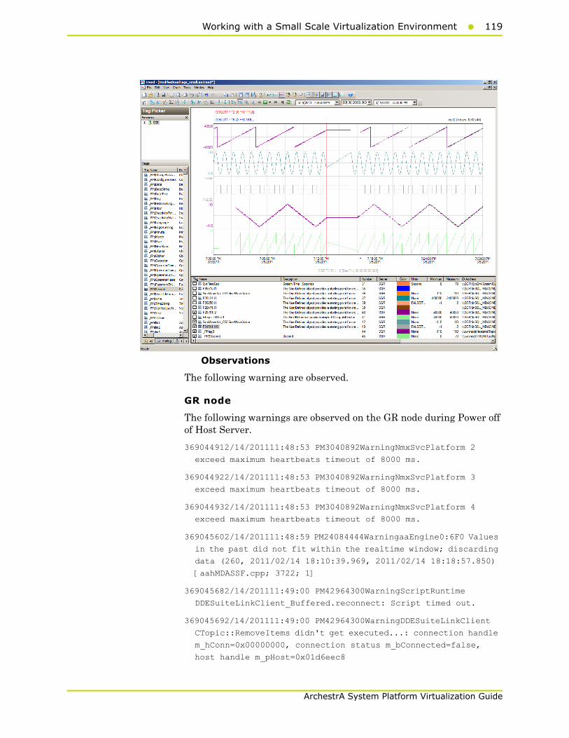
Working with a Small Scale Virtualization Environment119
ArchestrA System Platform Virtualization Guide
Observations
The following warning are observed.
GR node
The following warnings are observed on the GR node during Power off of Host Server.
369044912/14/201111:48:53 PM3040892WarningNmxSvcPlatform 2
exceed maximum heartbeats timeout of 8000 ms.
369044922/14/201111:48:53 PM3040892WarningNmxSvcPlatform 3
exceed maximum heartbeats timeout of 8000 ms.
369044932/14/201111:48:53 PM3040892WarningNmxSvcPlatform 4
exceed maximum heartbeats timeout of 8000 ms.
369045602/14/201111:48:59 PM24084444WarningaaEngine0:6F0 Values
in the past did not fit within the realtime window; discarding
data (260, 2011/02/14 18:10:39.969, 2011/02/14 18:18:57.850)
[aahMDASSF.cpp; 3722; 1]
369045682/14/201111:49:00 PM42964300WarningScriptRuntime
DDESuiteLinkClient_Buffered.reconnect: Script timed out.
369045692/14/201111:49:00 PM42964300WarningDDESuiteLinkClient
CTopic::RemoveItems didn't get executed...: connection handle
m_hConn=0x00000000, connection status m_bConnected=false,
host handle m_pHost=0x01d6eec8

120 Chapter 2 Working with High Availability
ArchestrA System Platform Virtualization Guide
AppEngine node
220418642/14/201111:47:02 PM24562476WarningNmxSvcPlatform 1
exceed maximum heartbeats timeout of 8000 ms.
220418652/14/201111:47:02 PM24562476WarningNmxSvcPlatform 3
exceed maximum heartbeats timeout of 8000 ms.
220418662/14/201111:47:02 PM24562476WarningNmxSvcPlatform 4
exceed maximum heartbeats timeout of 8000 ms.
220419262/14/201111:47:04 PM27323912WarningaaEngine0:9C0 Values
in the past did not fit within the realtime window; discarding
data (846, 2011/02/14 18:10:39.025, 2011/02/14 18:17:03.548)
[aahMDASSF.cpp; 3709; 1]
220419762/14/201111:49:41 PM15842492WarningScriptRuntime
Insert.InsertValueWF: Script timed out.
220420922/14/201111:51:16 PM29804064WarningaaEngine0:8A8 Values
in the past did not fit within the realtime window; discarding
data (1870, 2011/02/14 18:10:40.010, 2011/02/14 18:17:03.329)
[aahMDASSF.cpp; 3709; 144]
220420962/14/201111:51:18 PM24123836WarningaaEngine0:BD0 Values
in the past did not fit within the realtime window; discarding
data (324, 2011/02/14 18:10:39.838, 2011/02/14 18:17:05.094)
[aahMDASSF.cpp; 3709; 57]
WIS node
17187672/14/201111:48:49 PM24443064WarningNmxSvcPlatform 1
exceed maximum heartbeats timeout of 8000 ms.
17187682/14/201111:48:49 PM24443064WarningNmxSvcPlatform 2
exceed maximum heartbeats timeout of 8000 ms
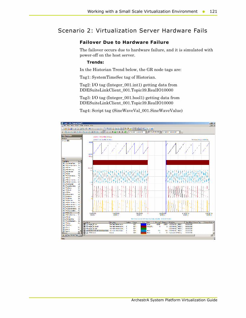
Working with a Small Scale Virtualization Environment121
ArchestrA System Platform Virtualization Guide
Scenario 2: Virtualization Server Hardware Fails
Failover Due to Hardware Failure
The failover occurs due to hardware failure, and it is simulated with power-off on the host server.
Trends:
In the Historian Trend below, the GR node tags are:
Tag1: SystemTimeSec tag of Historian.
Tag2: I/O tag (Integer_001.int1) getting data from DDESuiteLinkClient_001.Topic39.RealIO10000
Tag3: I/O tag (Integer_001.bool1) getting data from DDESuiteLinkClient_001.Topic39.RealIO10000
Tag4: Script tag (SineWaveVal_001.SineWaveValue)
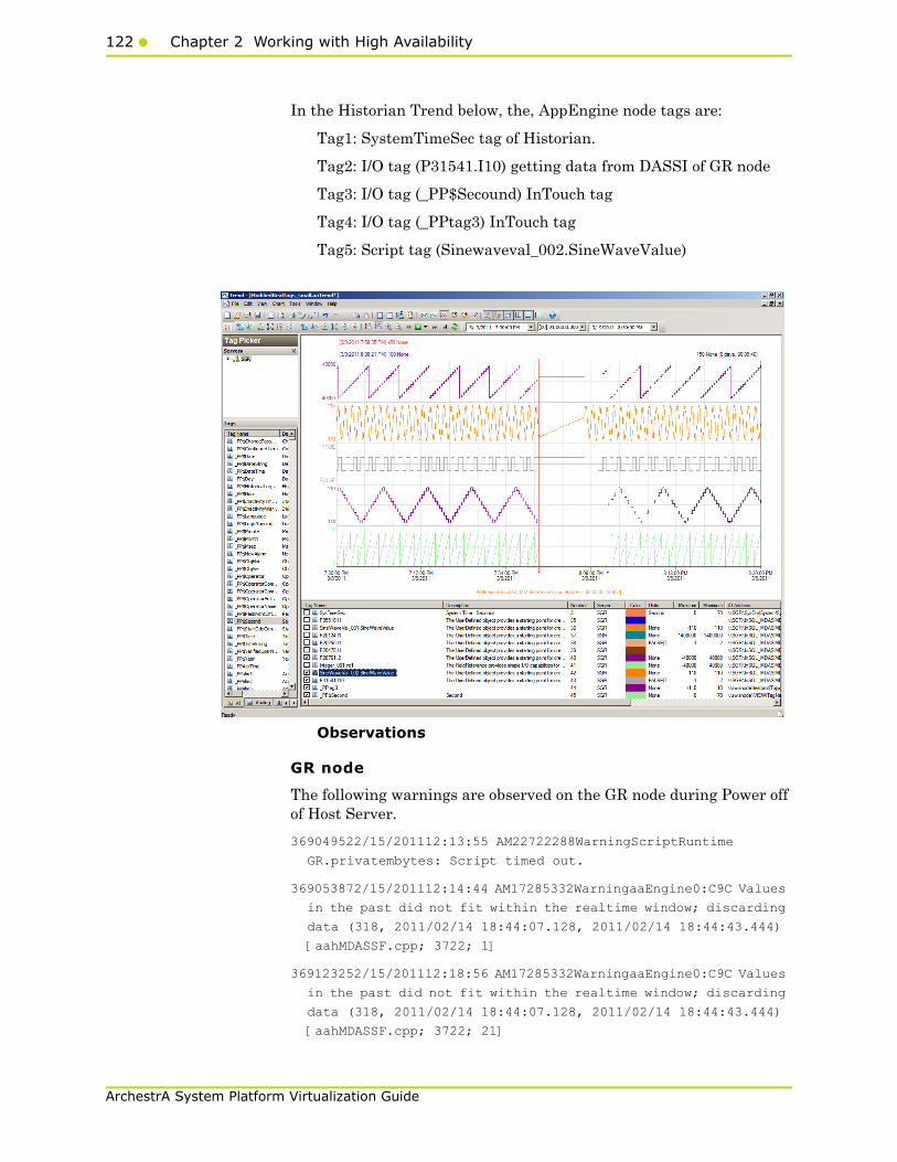
122 Chapter 2 Working with High Availability
ArchestrA System Platform Virtualization Guide
In the Historian Trend below, the, AppEngine node tags are:
Tag1: SystemTimeSec tag of Historian.
Tag2: I/O tag (P31541.I10) getting data from DASSI of GR node
Tag3: I/O tag (_PP$Secound) InTouch tag
Tag4: I/O tag (_PPtag3) InTouch tag
Tag5: Script tag (Sinewaveval_002.SineWaveValue)
Observations
GR node
The following warnings are observed on the GR node during Power off of Host Server.
369049522/15/201112:13:55 AM22722288WarningScriptRuntime
GR.privatembytes: Script timed out.
369053872/15/201112:14:44 AM17285332WarningaaEngine0:C9C Values
in the past did not fit within the realtime window; discarding
data (318, 2011/02/14 18:44:07.128, 2011/02/14 18:44:43.444)
[aahMDASSF.cpp; 3722; 1]
369123252/15/201112:18:56 AM17285332WarningaaEngine0:C9C Values
in the past did not fit within the realtime window; discarding
data (318, 2011/02/14 18:44:07.128, 2011/02/14 18:44:43.444)
[aahMDASSF.cpp; 3722; 21]

Working with a Small Scale Virtualization Environment123
ArchestrA System Platform Virtualization Guide
AppEngine node
220423732/15/201112:15:17 AM21002104WarningScriptRuntime
AppEngineNode1.privatembytes: Script timed out.
220425602/15/201112:16:10 AM24964832WarningDCMConnectionMgr
Open() of DCMConnection failed: 'A network-related or
instance-specific error occurred while establishing a
connection to SQL Server. The server was not found or was not
accessible. Verify that the instance name is correct and that
SQL Server is configured...
220425612/15/201112:16:11 AM24964832WarningSQLDataRuntime3
SQLTestResults Command Failure - A network-related or
instance-specific error occurred while establishing a
connection to SQL Server. The server was not found or was not
accessible. Verify that the instance name is correct and that
SQL Server is configured...
WIS node
None
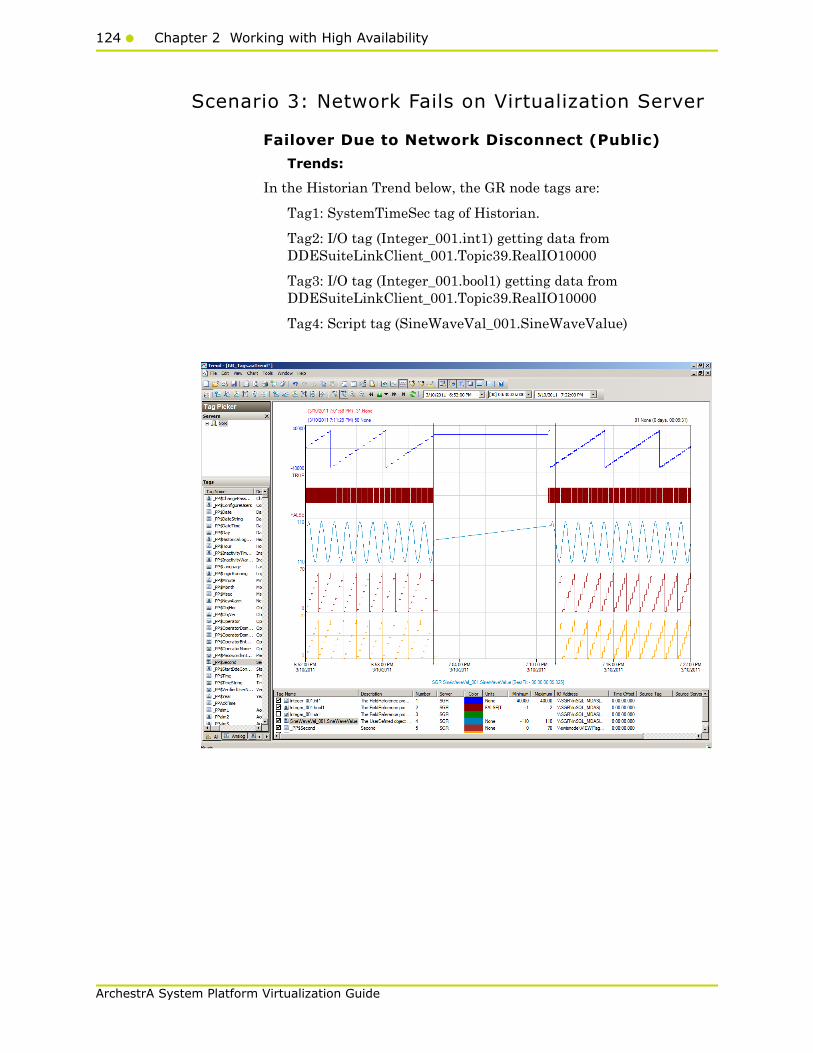
124 Chapter 2 Working with High Availability
ArchestrA System Platform Virtualization Guide
Scenario 3: Network Fails on Virtualization Server
Failover Due to Network Disconnect (Public)
Trends:
In the Historian Trend below, the GR node tags are:
Tag1: SystemTimeSec tag of Historian.
Tag2: I/O tag (Integer_001.int1) getting data from DDESuiteLinkClient_001.Topic39.RealIO10000
Tag3: I/O tag (Integer_001.bool1) getting data from DDESuiteLinkClient_001.Topic39.RealIO10000
Tag4: Script tag (SineWaveVal_001.SineWaveValue)
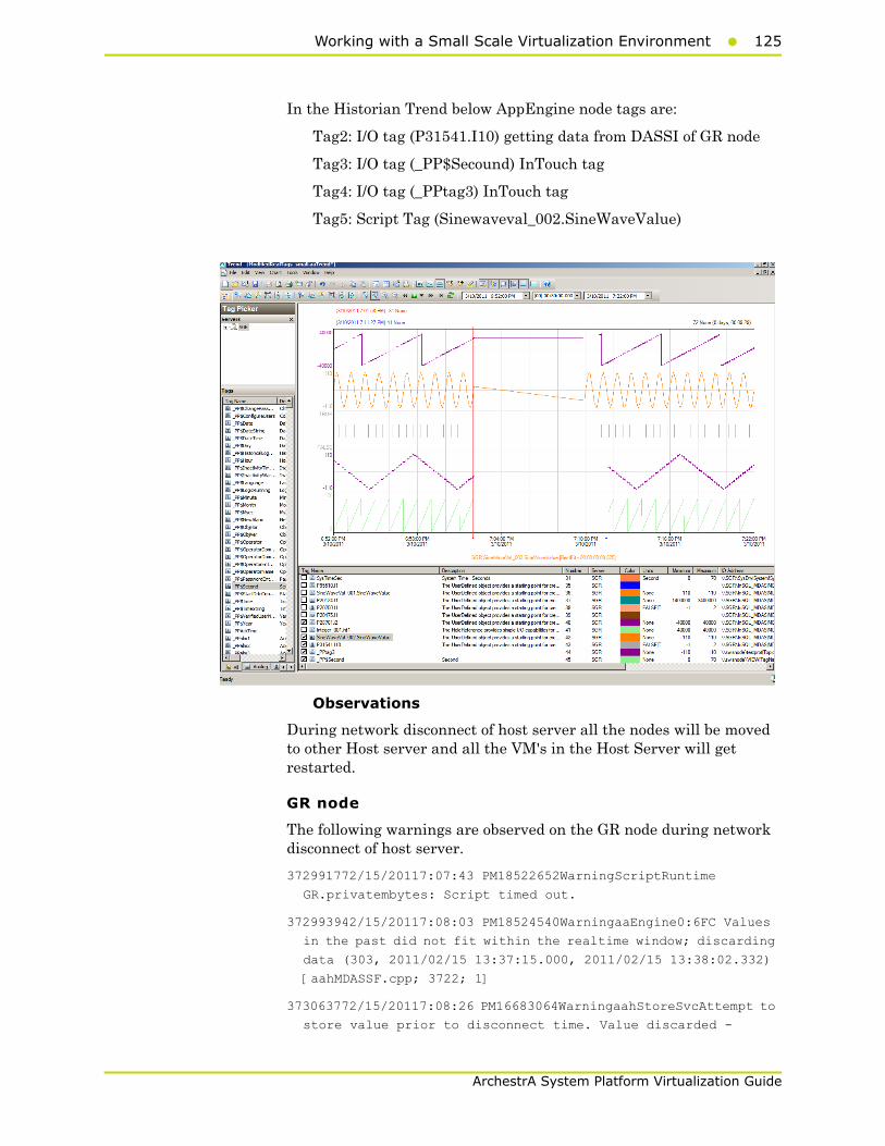
Working with a Small Scale Virtualization Environment125
ArchestrA System Platform Virtualization Guide
In the Historian Trend below AppEngine node tags are:
Tag2: I/O tag (P31541.I10) getting data from DASSI of GR node
Tag3: I/O tag (_PP$Secound) InTouch tag
Tag4: I/O tag (_PPtag3) InTouch tag
Tag5: Script Tag (Sinewaveval_002.SineWaveValue)
Observations
During network disconnect of host server all the nodes will be moved to other Host server and all the VM's in the Host Server will get restarted.
GR node
The following warnings are observed on the GR node during network disconnect of host server.
372991772/15/20117:07:43 PM18522652WarningScriptRuntime
GR.privatembytes: Script timed out.
372993942/15/20117:08:03 PM18524540WarningaaEngine0:6FC Values
in the past did not fit within the realtime window; discarding
data (303, 2011/02/15 13:37:15.000, 2011/02/15 13:38:02.332)
[aahMDASSF.cpp; 3722; 1]
373063772/15/20117:08:26 PM16683064WarningaahStoreSvcAttempt to
store value prior to disconnect time. Value discarded -
126 Chapter 2 Working with High Availability
ArchestrA System Platform Virtualization Guide
possible loss of data (SGR_mdas, 4504, 2011/02/15
13:38:25.428, 2011/02/15 13:38:24.868) [SGR; pipeserver.cpp;
958]
373065202/15/20117:12:14 PM18524540WarningaaEngine0:6FC Values
in the past did not fit within the realtime window; discarding
data (303, 2011/02/15 13:37:15.000, 2011/02/15 13:38:02.332)
[aahMDASSF.cpp; 3722; 33]
373065242/15/20117:12:38 PM16683064WarningaahStoreSvcAttempt to
store value prior to disconnect time. Value discarded -
possible loss of data (SGR_mdas, 4504, 2011/02/15
13:38:25.428, 2011/02/15 13:38:24.868) [SGR; pipeserver.cpp;
958; 3031]
AppEngine node
220493472/15/20117:07:15 PM23482352WarningScriptRuntime
AppEngineNode1.privatembytes: Script timed out.
220495942/15/20117:07:59 PM29765016WarningDCMConnectionMgr
Open() of DCMConnection failed: 'A network-related or
instance-specific error occurred while establishing a
connection to SQL Server. The server was not found or was not
accessible. Verify that the instance name is correct and that
SQL Server is configured...
220495952/15/20117:08:00 PM29764200WarningSQLDataRuntime3
SQLTestResults Command Failure - A network-related or
instance-specific error occurred while establishing a
connection to SQL Server. The server was not found or was not
accessible. Verify that the instance name is correct and that
SQL Server is configured...
220497602/15/20117:08:55 PM27281088WarningInTouchProxyFailed to
reconnecnt to data source
220498382/15/20117:13:19 PM29762980WarningScriptRuntime
Insert.InsertValueWF: Script timed out.
WIS node
None
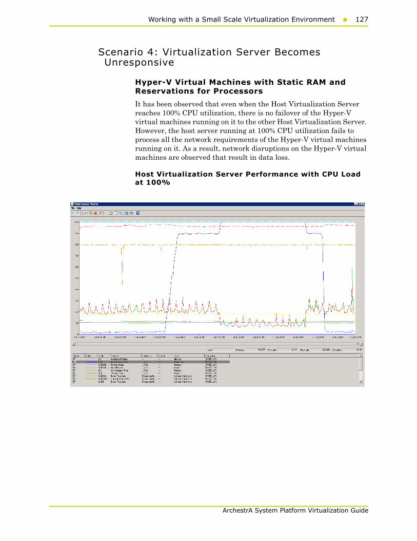
Working with a Small Scale Virtualization Environment127
ArchestrA System Platform Virtualization Guide
Scenario 4: Virtualization Server Becomes Unresponsive
Hyper-V Virtual Machines with Static RAM and Reservations for Processors
It has been observed that even when the Host Virtualization Server reaches 100% CPU utilization, there is no failover of the Hyper-V virtual machines running on it to the other Host Virtualization Server. However, the host server running at 100% CPU utilization fails to process all the network requirements of the Hyper-V virtual machines running on it. As a result, network disruptions on the Hyper-V virtual machines are observed that result in data loss.
Host Virtualization Server Performance with CPU Load at 100%
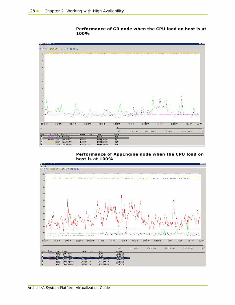
128 Chapter 2 Working with High Availability
ArchestrA System Platform Virtualization Guide
Performance of GR node when the CPU load on host is at 100%
Performance of AppEngine node when the CPU load on host is at 100%

Working with a Small Scale Virtualization Environment129
ArchestrA System Platform Virtualization Guide
Observations When CPU Load is 100% on Host Virtualization Server
The virtual machines do not failover when CPU load stays at 100%. All the virtual machines continue to run on the same Host Virtualization Server even though the CPU load is at 100%.
The messages "Snapshot write operation took longer than 10 seconds" are expected when the virtual machines are running at high Processor time % (Historian at 100% and AppEngine node at 50%).
The execution of time sync utility is impacted and the time is not synchronized on the Historian, AppEngine nodes and GR node. As a result, the message "Values in the past did not fit within the realtime window" is observed.
GR node
413126932/16/20113:08:02 PM15202136WarningaahStoreSvcSnapshot
write operation took longer than 10 seconds. Change your
system settings to decrease size of snapshot or stop other
applications which may affect this parameter (1024, 3, 0,
52004273, 2137401, 10) [SGR; deltastore.cpp; 2669]
413127142/16/20113:10:04 PM15202136WarningaahStoreSvcSnapshot
write operation took longer than 10 seconds. Change your
system settings to decrease size of snapshot or stop other
applications which may affect this parameter (1024, 3, 0,
52004273, 2200899, 11) [SGR; deltastore.cpp; 2669]
413127432/16/20113:10:47 PM15202136WarningaahStoreSvcValues in
the past did not fit within the realtime window; discarding
data (SGR_mdas, 4500, 2011/02/16 09:40:14.558, 2011/02/16
09:40:46.643) [SGR; pipeserver.cpp; 2388]
413127472/16/20113:10:49 PM15644892WarningaaEngine0:AF0 Values
in the past did not fit within the realtime window; discarding
data (392, 2011/02/16 09:40:13.767, 2011/02/16 09:40:49.195)
[aahMDASSF.cpp; 3722; 1]
AppEngine
220548592/16/20113:06:44 PM22364432WarningaaEngine0:9E8 Values
in the past did not fit within the realtime window; discarding
data (2790, 2011/02/16 09:36:13.631, 2011/02/16 09:36:44.035)
[aahMDASSF.cpp; 3709; 1]
220548852/16/20113:06:47 PM14764744WarningaaEngine0:A28 Values
in the past did not fit within the realtime window; discarding
data (444, 2011/02/16 09:36:14.506, 2011/02/16 09:36:45.534)
[aahMDASSF.cpp; 3709; 1]
220548922/16/20113:06:47 PM22804524WarningaaEngine0:9E8 Values
in the past did not fit within the realtime window; discarding
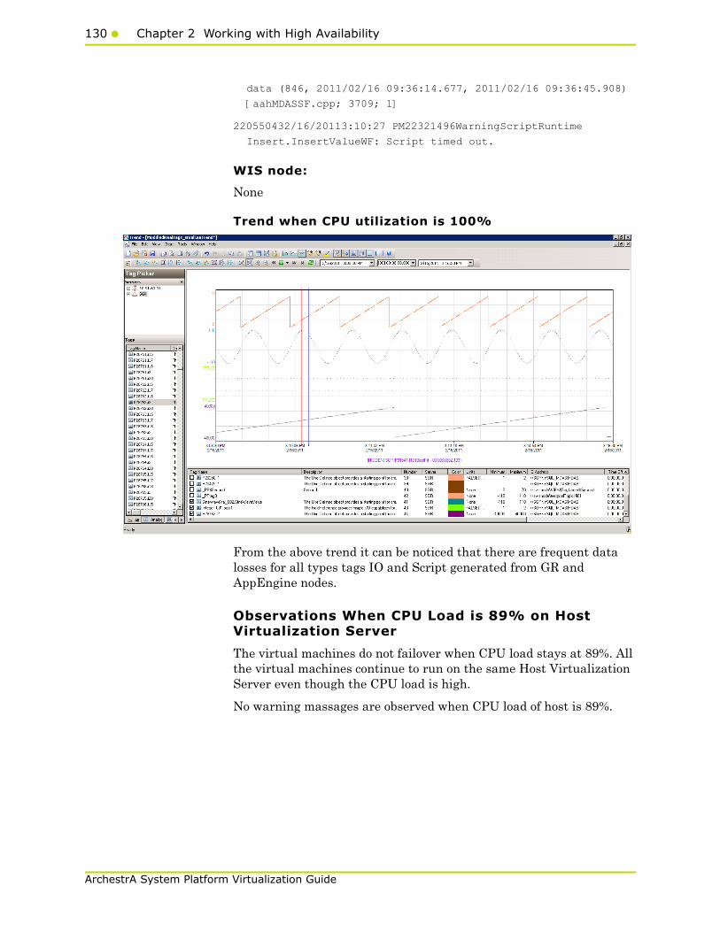
130 Chapter 2 Working with High Availability
ArchestrA System Platform Virtualization Guide
data (846, 2011/02/16 09:36:14.677, 2011/02/16 09:36:45.908)
[aahMDASSF.cpp; 3709; 1]
220550432/16/20113:10:27 PM22321496WarningScriptRuntime
Insert.InsertValueWF: Script timed out.
WIS node:
None
Trend when CPU utilization is 100%
From the above trend it can be noticed that there are frequent data losses for all types tags IO and Script generated from GR and AppEngine nodes.
Observations When CPU Load is 89% on Host Virtualization Server
The virtual machines do not failover when CPU load stays at 89%. All the virtual machines continue to run on the same Host Virtualization Server even though the CPU load is high.
No warning massages are observed when CPU load of host is 89%.

Working with a Small Scale Virtualization Environment131
ArchestrA System Platform Virtualization Guide
Trend when CPU Load is 89% on Host Virtualization Server
From the above trend it can be noticed that there is data loss for Script tags of AppEngine node.
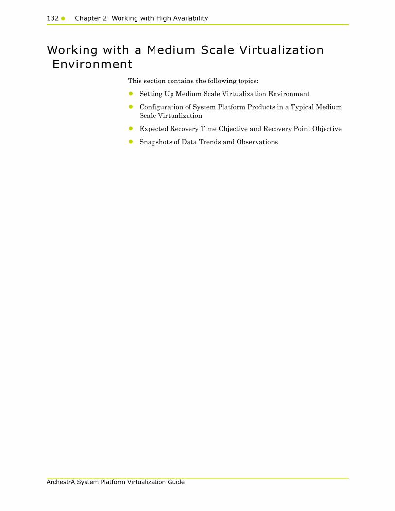
132 Chapter 2 Working with High Availability
ArchestrA System Platform Virtualization Guide
Working with a Medium Scale Virtualization Environment
This section contains the following topics:
• Setting Up Medium Scale Virtualization Environment
• Configuration of System Platform Products in a Typical Medium Scale Virtualization
• Expected Recovery Time Objective and Recovery Point Objective
• Snapshots of Data Trends and Observations

Working with a Medium Scale Virtualization Environment133
ArchestrA System Platform Virtualization Guide
Setting Up Medium Scale Virtualization Environment
The following procedures help you to set up and implement the medium scale virtualization high availability environment.
Note: In the event that the private network becomes disabled, you may need to add a script to enable a failover. For more information, see "Failover of the Virtual Machine if the Domain/ Private Network is disabled" on page 80
Planning for Medium Scale Virtualization Environment
The minimum recommended hardware and software requirements for the Host and Virtual machines used for medium virtualization environment are provided in the table below:
Hyper-V Host
Note: For the Hyper-V Host to function optimally, the server should have the same processor, RAM, storage and service pack level. Preferably the servers should be purchased in pairs to avoid hardware discrepancies. Though the differences are supported, it will impact the performance during failovers.
Virtual Machines
Using the Hyper-V host specified above, seven virtual machines can be created in the environment with the configuration given below.
Virtual Machine 1: Historian node
Processor Two 2.79 GHz Intel Xeon with 24 Cores
Operating System Windows Server 2008 R2 Enterprise with Hyper-V enabled
Memory 48 GB
Storage SAN with 1TB storage disk
Processor Host Compatible Processor with 2-4 Cores
Operating System Windows Server 2008 R2 Standard
Memory 8 GB

134 Chapter 2 Working with High Availability
ArchestrA System Platform Virtualization Guide
Storage 200 GB
System Platform Products Installed
Historian

Working with a Medium Scale Virtualization Environment135
ArchestrA System Platform Virtualization Guide
Virtual Machine 2: Application Server node, DAS SI
Processor Host Compatible Processor with 2-4 Cores
Operating System Windows Server 2008 R2 Standard
Memory 8 GB
Storage 100 GB
System Platform Products Installed
ArchestrA-Runtime, DAS SI
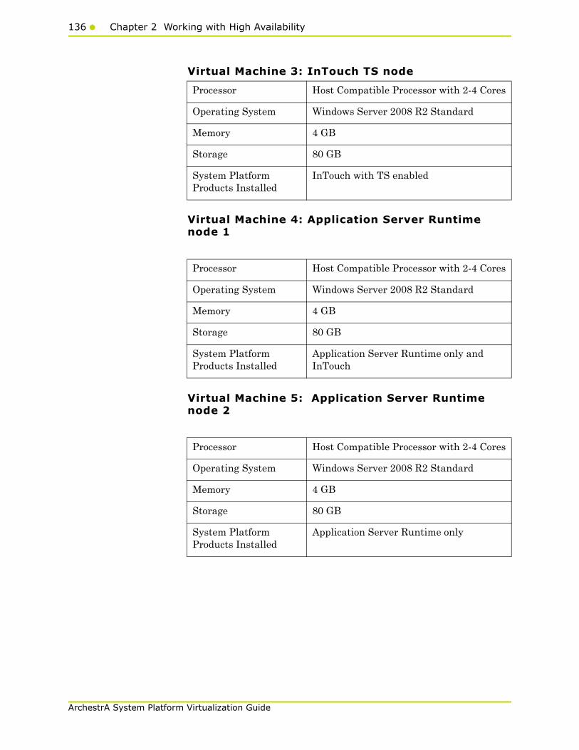
136 Chapter 2 Working with High Availability
ArchestrA System Platform Virtualization Guide
Virtual Machine 3: InTouch TS node
Virtual Machine 4: Application Server Runtime node 1
Virtual Machine 5: Application Server Runtime node 2
Processor Host Compatible Processor with 2-4 Cores
Operating System Windows Server 2008 R2 Standard
Memory 4 GB
Storage 80 GB
System Platform Products Installed
InTouch with TS enabled
Processor Host Compatible Processor with 2-4 Cores
Operating System Windows Server 2008 R2 Standard
Memory 4 GB
Storage 80 GB
System Platform Products Installed
Application Server Runtime only and InTouch
Processor Host Compatible Processor with 2-4 Cores
Operating System Windows Server 2008 R2 Standard
Memory 4 GB
Storage 80 GB
System Platform Products Installed
Application Server Runtime only
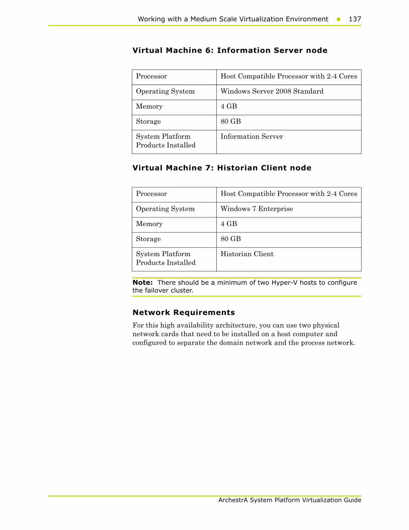
Working with a Medium Scale Virtualization Environment137
ArchestrA System Platform Virtualization Guide
Virtual Machine 6: Information Server node
Virtual Machine 7: Historian Client node
Note: There should be a minimum of two Hyper-V hosts to configure the failover cluster.
Network Requirements
For this high availability architecture, you can use two physical network cards that need to be installed on a host computer and configured to separate the domain network and the process network.
Processor Host Compatible Processor with 2-4 Cores
Operating System Windows Server 2008 Standard
Memory 4 GB
Storage 80 GB
System Platform Products Installed
Information Server
Processor Host Compatible Processor with 2-4 Cores
Operating System Windows 7 Enterprise
Memory 4 GB
Storage 80 GB
System Platform Products Installed
Historian Client

138 Chapter 2 Working with High Availability
ArchestrA System Platform Virtualization Guide
Configuring Failover ClusterThe following is the recommended topology of the failover cluster for a medium scale virtualization high availability environment.
This setup requires a minimum of two host servers and one storage server shared across two hosts. Another independent node is used for configuring the quorum. For more information on configuring the quorum, refer to "Configure Cluster Quorum Settings" on page 154.
The following procedures help you install and configure a failover cluster that has two nodes to set up on a medium scale virtualization high availability environment.
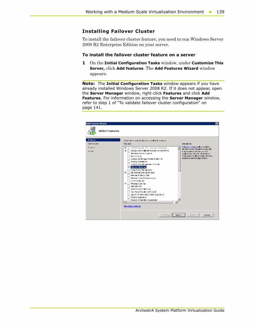
Working with a Medium Scale Virtualization Environment139
ArchestrA System Platform Virtualization Guide
Installing Failover Cluster
To install the failover cluster feature, you need to run Windows Server 2008 R2 Enterprise Edition on your server.
To install the failover cluster feature on a server
1 On the Initial Configuration Tasks window, under Customize This Server, click Add features. The Add Features Wizard window appears.
Note: The Initial Configuration Tasks window appears if you have already installed Windows Server 2008 R2. If it does not appear, open the Server Manager window, right-click Features and click Add Features. For information on accessing the Server Manager window, refer to step 1 of "To validate failover cluster configuration" on page 141.

140 Chapter 2 Working with High Availability
ArchestrA System Platform Virtualization Guide
2 In the Add Features Wizard window, select the Failover Clustering check box and click Next. The Confirm Installation Selections area appears.
3 To complete the installation, view the instructions on the wizard and click Install. The Installation Results area appears with the installation confirmation message.
4 Click Close to close the Add Features Wizard window.
Note: Repeat the above procedure to include all the other nodes that will be part of the Cluster configuration process.

Working with a Medium Scale Virtualization Environment141
ArchestrA System Platform Virtualization Guide
Validating Failover Cluster Configuration
You must validate your configuration before you create a cluster. Validation helps you confirm the configuration of your servers, network, and storage meets the specific requirements for failover clusters.
To validate failover cluster configuration
1 Click the Server Manager icon on the toolbar. The Server Manager window appears.
Note: You can also access the Server Manager window from the Administrative Tools window or the Start menu.
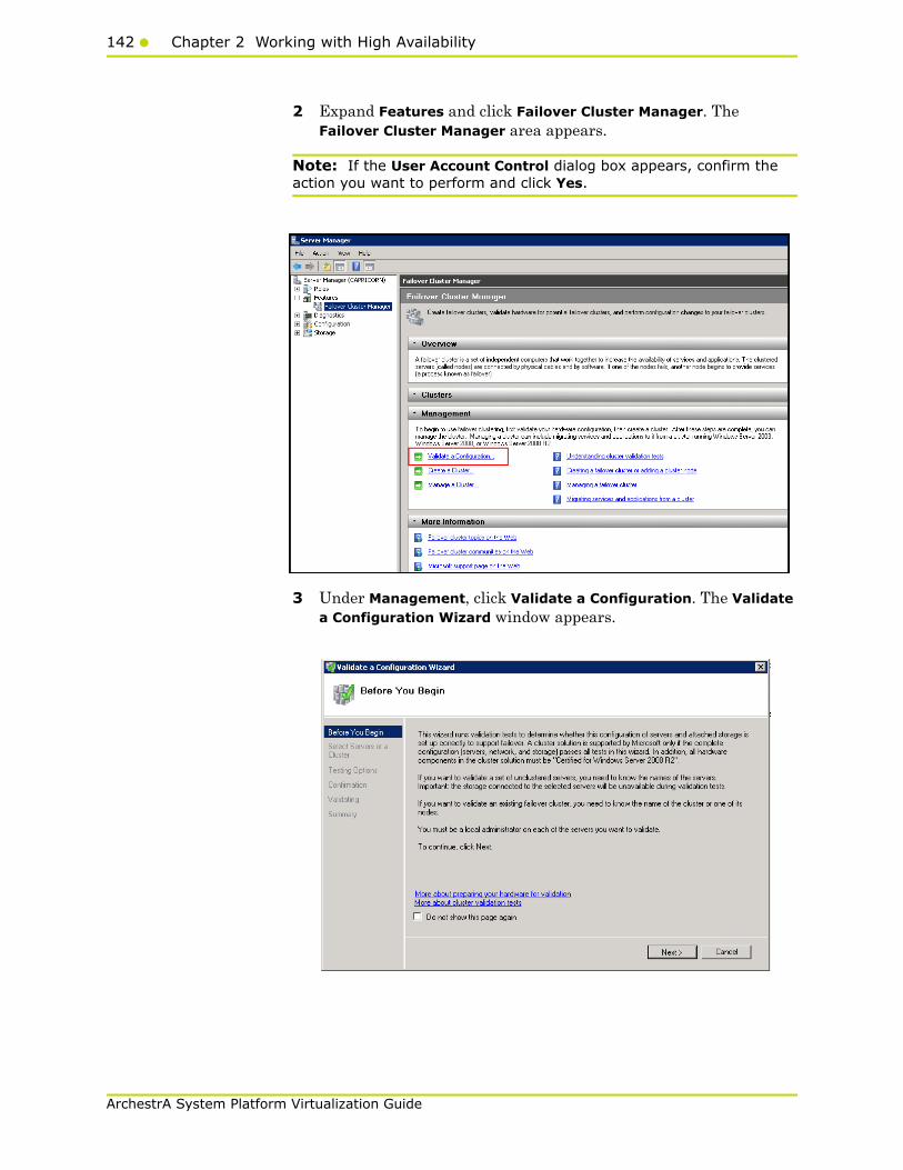
142 Chapter 2 Working with High Availability
ArchestrA System Platform Virtualization Guide
2 Expand Features and click Failover Cluster Manager. The Failover Cluster Manager area appears.
Note: If the User Account Control dialog box appears, confirm the action you want to perform and click Yes.
3 Under Management, click Validate a Configuration. The Validate a Configuration Wizard window appears.
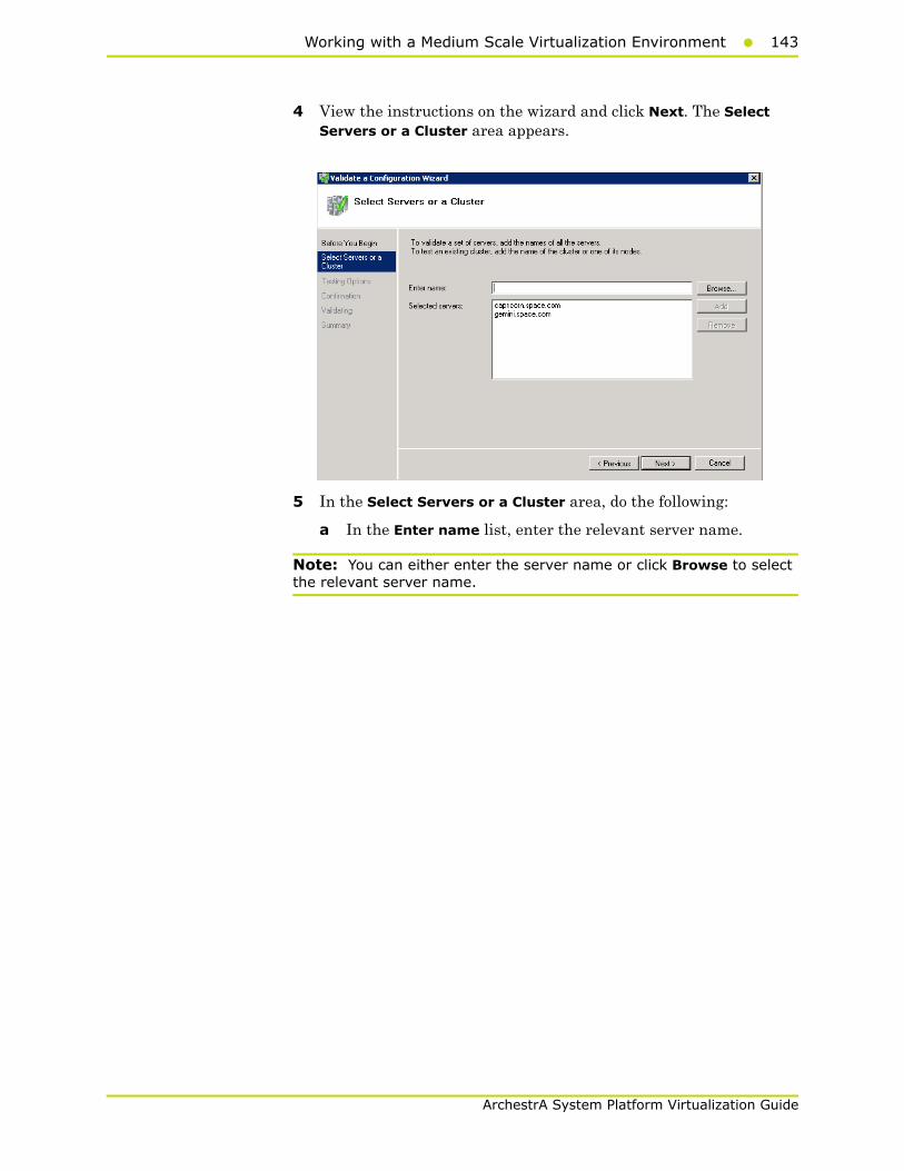
Working with a Medium Scale Virtualization Environment143
ArchestrA System Platform Virtualization Guide
4 View the instructions on the wizard and click Next. The Select Servers or a Cluster area appears.
5 In the Select Servers or a Cluster area, do the following:
a In the Enter name list, enter the relevant server name.
Note: You can either enter the server name or click Browse to select the relevant server name.
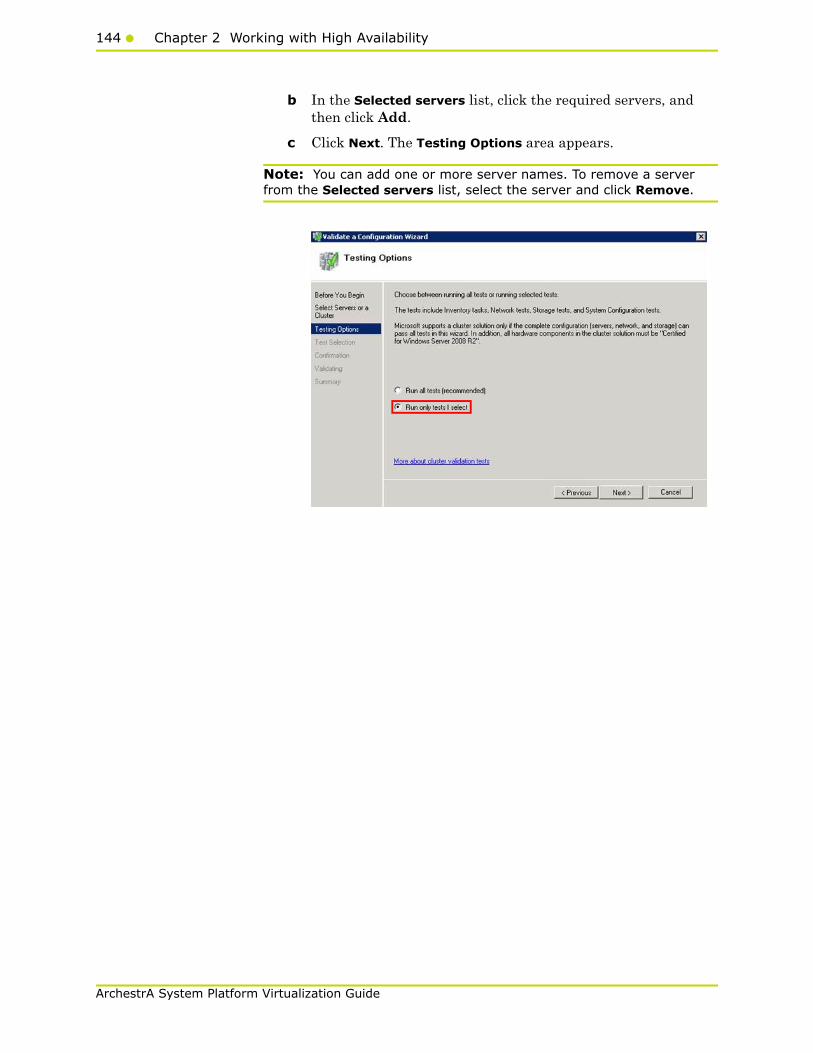
144 Chapter 2 Working with High Availability
ArchestrA System Platform Virtualization Guide
b In the Selected servers list, click the required servers, and then click Add.
c Click Next. The Testing Options area appears.
Note: You can add one or more server names. To remove a server from the Selected servers list, select the server and click Remove.

Working with a Medium Scale Virtualization Environment145
ArchestrA System Platform Virtualization Guide
6 Click the Run only tests I select option to skip storage validation process, and then click Next. The Test Selection screen appears.
Note: Click the Run all tests (recommended) option to validate the default selection of tests.
7 Clear the Storage check box, and then click Next. The Summary screen appears.
8 Click View Report to view the test results or click Finish to close the Validate a Configuration Wizard window.
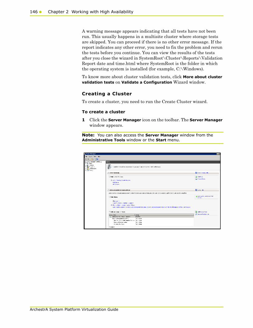
146 Chapter 2 Working with High Availability
ArchestrA System Platform Virtualization Guide
A warning message appears indicating that all tests have not been run. This usually happens in a multisite cluster where storage tests are skipped. You can proceed if there is no other error message. If the report indicates any other error, you need to fix the problem and rerun the tests before you continue. You can view the results of the tests after you close the wizard in SystemRoot\Cluster\Reports\Validation Report date and time.html where SystemRoot is the folder in which the operating system is installed (for example, C:\Windows).
To know more about cluster validation tests, click More about cluster validation tests on Validate a Configuration Wizard window.
Creating a Cluster
To create a cluster, you need to run the Create Cluster wizard.
To create a cluster
1 Click the Server Manager icon on the toolbar. The Server Manager window appears.
Note: You can also access the Server Manager window from the Administrative Tools window or the Start menu.
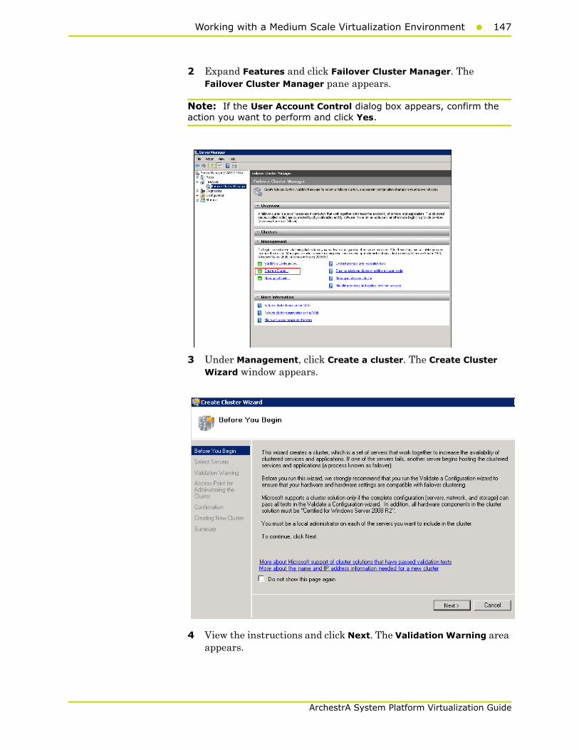
Working with a Medium Scale Virtualization Environment147
ArchestrA System Platform Virtualization Guide
2 Expand Features and click Failover Cluster Manager. The Failover Cluster Manager pane appears.
Note: If the User Account Control dialog box appears, confirm the action you want to perform and click Yes.
3 Under Management, click Create a cluster. The Create Cluster Wizard window appears.
4 View the instructions and click Next. The Validation Warning area appears.

148 Chapter 2 Working with High Availability
ArchestrA System Platform Virtualization Guide
5 Click No. I do not require support from Microsoft for this cluster, and therefore do not want to run the validation tests. When I click Next, continue creating the cluster option and click Next. The Select Servers area appears.
Note: Click Click Yes. When I click Next, run configuration validation tests, and then return to the process of creating the cluster option if you want to run the configuration validation tests. Click View Report to view the cluster operation report.
6 In the Select Servers screen, do the following:
a In the Enter server name box, enter the relevant server name and click Add. The server name gets added in the Selected servers box.

Working with a Medium Scale Virtualization Environment149
ArchestrA System Platform Virtualization Guide
Note: You can either enter the server name or click Browse to select the relevant server name.
b Click Next. The Access Point for Administering the Cluster area appears.

150 Chapter 2 Working with High Availability
ArchestrA System Platform Virtualization Guide
7 In the Cluster Name box, enter the name of the cluster and click Next. The Confirmation area appears.
Note: Enter a valid IP address for the cluster to be created if the IP address is not configured through Dynamic Host Configuration Protocol (DHCP).
8 Click Next. The cluster is created and the Summary area appears.
9 Click View Report to view the cluster report created by the wizard or click Finish to close the Create Cluster Wizard window

Working with a Medium Scale Virtualization Environment151
ArchestrA System Platform Virtualization Guide
Disabling the Plant Network for the Cluster Communication
After creating the Failover cluster using two or more Network Cards enabled, Make sure only Primary Network card which is used for the Communication between the Hyper-V nodes is enabled for the Failover Communication Disable the remaining Cluster Networks
To disable the plant network for the Cluster Communication
1 Click the Server Manager icon on the toolbar. The Server Manager window appears.
Note: You can also access the Server Manager window from the Administrative Tools window or the Start menu.
2 Expand the Failover Cluster Manager and select Networks to check how many networks are participating in the cluster.
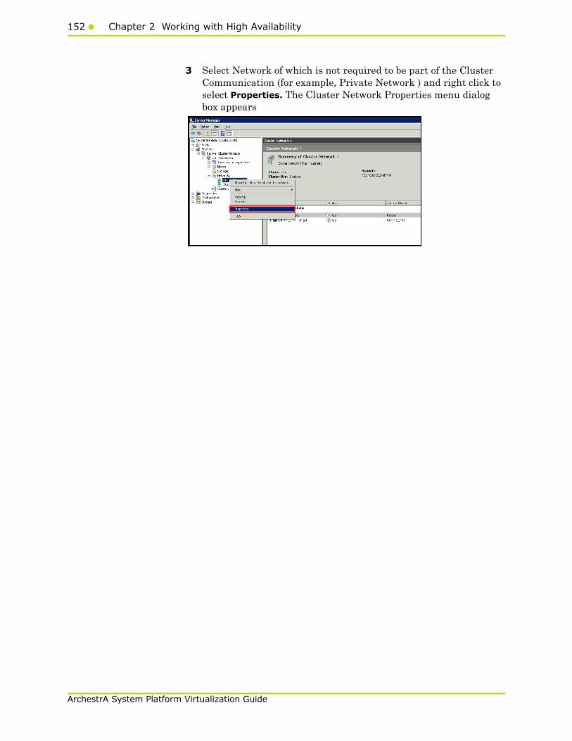
152 Chapter 2 Working with High Availability
ArchestrA System Platform Virtualization Guide
3 Select Network of which is not required to be part of the Cluster Communication (for example, Private Network ) and right click to select Properties. The Cluster Network Properties menu dialog box appears
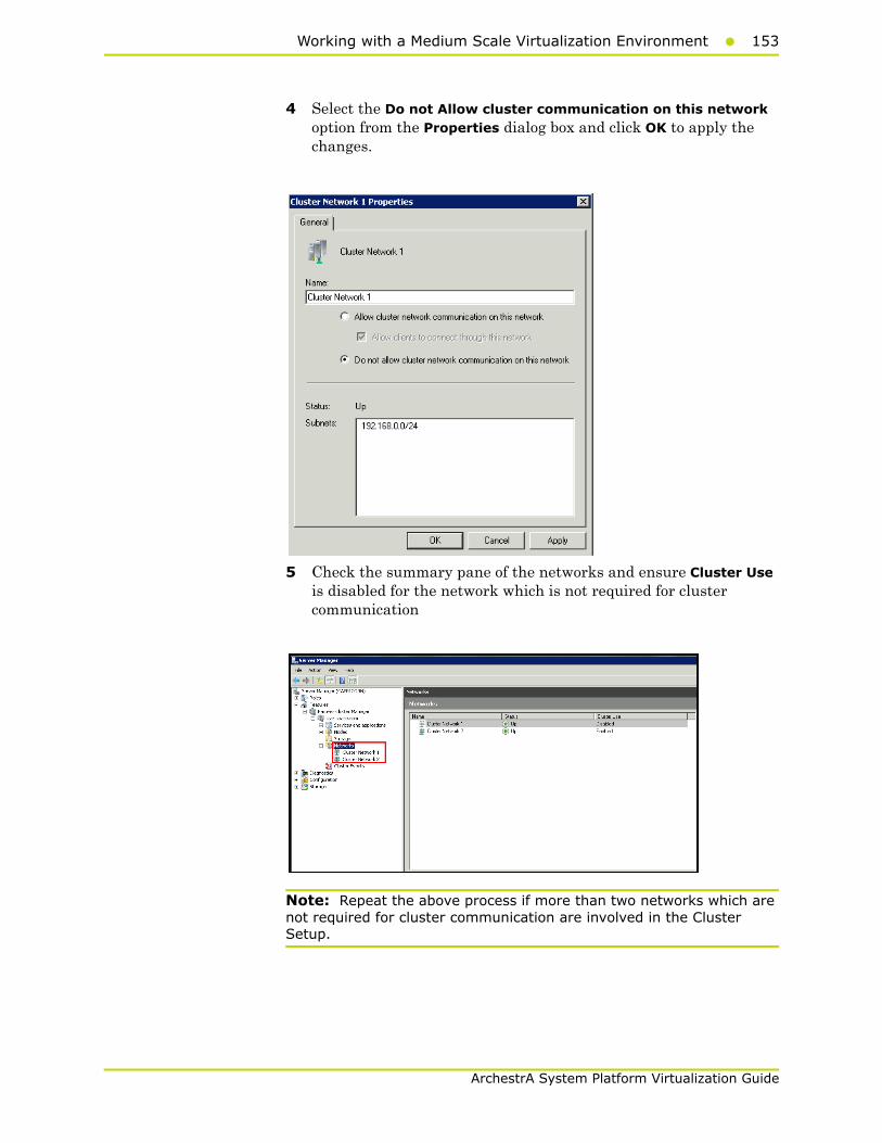
Working with a Medium Scale Virtualization Environment153
ArchestrA System Platform Virtualization Guide
4 Select the Do not Allow cluster communication on this network option from the Properties dialog box and click OK to apply the changes.
5 Check the summary pane of the networks and ensure Cluster Use is disabled for the network which is not required for cluster communication
Note: Repeat the above process if more than two networks which are not required for cluster communication are involved in the Cluster Setup.

154 Chapter 2 Working with High Availability
ArchestrA System Platform Virtualization Guide
Configure Cluster Quorum Settings
Quorum is the number of elements that need to be online to enable continuous running of a cluster. In most instances, the elements are nodes. In some cases, the elements also consist of disk or file share witnesses. Each of these elements determines whether the cluster should continue to run.
All elements, except the file share witnesses, have a copy of the cluster configuration. The cluster service ensures that the copies are always synchronized. The cluster should stop running if there are multiple failures or if there is a communication error between the cluster nodes.
After both nodes have been added to the cluster, and the cluster networking components have been configured, you must configure the failover cluster quorum.
The file share to be used for the node and File Share Majority quorum must be created and secured before configuring the failover cluster quorum. If the file share has not been created or correctly secured, the following procedure to configure a cluster quorum will fail. The file share can be hosted on any computer running a Windows operating system.
To configure the cluster quorum, you need to perform the following precedures:
• Create and secure a file share for the node and file share majority quorum
• Use the failover cluster management tool to configure a node and file share majority quorum
To create and secure a file share for the node and file share majority quorum
1 Create a new folder on the system that will host the share directory.

Working with a Medium Scale Virtualization Environment155
ArchestrA System Platform Virtualization Guide
2 Right-click the folder that you created and click Properties. The Quorum Properties window for the folder you created appears.
Note: In the following procedure, Quorum is the name of the folder.
3 Click the Sharing tab, and then click Advanced Sharing. The Advanced Sharing window appears.

156 Chapter 2 Working with High Availability
ArchestrA System Platform Virtualization Guide
4 Select the Share this folder check box and click Permissions. The Permissions for Quorum window appears.
5 Click Add. The Select Users, Computers, Service Accounts, or Groups window appears.
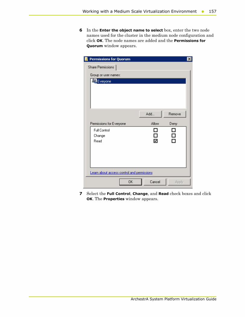
Working with a Medium Scale Virtualization Environment157
ArchestrA System Platform Virtualization Guide
6 In the Enter the object name to select box, enter the two node names used for the cluster in the medium node configuration and click OK. The node names are added and the Permissions for Quorum window appears.
7 Select the Full Control, Change, and Read check boxes and click OK. The Properties window appears.

158 Chapter 2 Working with High Availability
ArchestrA System Platform Virtualization Guide
8 Click Ok. The folder is shared and can be used to create virtual machines.
To configure a node and file share majority quorum using the failover cluster management tool
1 Click the Server Manager icon on the toolbar. The Server Manager window appears.
Note: You can also access the Server Manager window from the Administrative Tools window or the Start menu.

Working with a Medium Scale Virtualization Environment159
ArchestrA System Platform Virtualization Guide
2 Right-click the name of the cluster you created and click More Actions. Click Configure Cluster Quorum Settings. The Configure Cluster Quorum Wizard window appears.
3 View the instructions on the wizard and click Next. The Select Quorum Configuration area appears.
Note: The Before you Begin screen appears the first time you run the wizard. You can hide this screen on subsequent uses of the wizard.
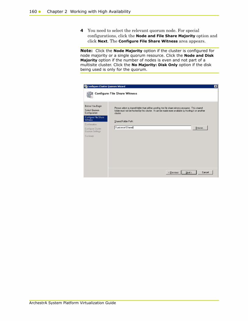
160 Chapter 2 Working with High Availability
ArchestrA System Platform Virtualization Guide
4 You need to select the relevant quorum node. For special configurations, click the Node and File Share Majority option and click Next. The Configure File Share Witness area appears.
Note: Click the Node Majority option if the cluster is configured for node majority or a single quorum resource. Click the Node and Disk Majority option if the number of nodes is even and not part of a multisite cluster. Click the No Majority: Disk Only option if the disk being used is only for the quorum.
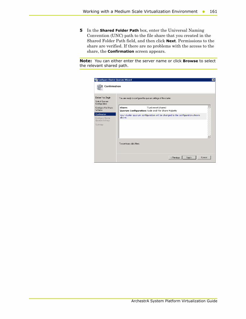
Working with a Medium Scale Virtualization Environment161
ArchestrA System Platform Virtualization Guide
5 In the Shared Folder Path box, enter the Universal Naming Convention (UNC) path to the file share that you created in the Shared Folder Path field, and then click Next. Permissions to the share are verified. If there are no problems with the access to the share, the Confirmation screen appears.
Note: You can either enter the server name or click Browse to select the relevant shared path.

162 Chapter 2 Working with High Availability
ArchestrA System Platform Virtualization Guide
6 The details you selected are displayed. To confirm the details click Next. The Summary screen appears and the configuration details of the quorum settings are displayed.
7 Click View Report to view a report of the tasks performed, or click Finish to close the window.
After you configure the cluster quorum, you must validate the cluster. For more information, refer to http://technet.microsoft.com/en-us/library/bb676379(EXCHG.80).aspx.
Configuring Storage
For any virtualization environment, storage is one of the central barriers to implementing a good virtualization strategy. But with Hyper-V, VM storage is kept on a Windows file system. Users can put VMs on any file system that a Hyper-V server can access. As a result, you can build HA into the virtualization platform and storage for the virtual machines. This configuration can accommodate a host failure by making storage accessible to all Hyper-V hosts so that any host can run VMs from the same path on the shared folder. The back-end part of this storage can be a local storage area network, iSCSI or whatever is available to fit the implementation.

Working with a Medium Scale Virtualization Environment163
ArchestrA System Platform Virtualization Guide
The following table lists the minimum storage recommendations for each VM :
The recommended total storage capacity should be minimum 1TB.
Configuring Hyper-VMicrosoft Hyper-V Server 2008 R2 helps in creating virtual environment that improves server utilization. It enhances patching, provisioning, management, support tools, processes, and skills. Microsoft Hyper-V Server 2008 R2 provides live migration, cluster shared volume support, expanded processor, and memory support for host systems.
Hyper-V is available in x64-based versions of Windows Server 2008 R2 operating system, specifically the x64-based versions of Windows Server 2008 R2 Standard, Windows Server 2008 R2 Enterprise, and Windows Server 2008 Datacenter.
The following are the pre-requisites to set up Hyper-V:
• x64-based processor
• Hardware-assisted virtualization
• Hardware Data Execution Prevention (DEP)
System Processor
Historian Virtual Machine 200 GB
Application Server (GR node) Virtual Machine
100 GB
Application Engine 1(Runtime node) Virtual Machine
80 GB
Application Engine 2 (Runtime node) Virtual Machine
80 GB
InTouch Virtual Machine 80 GB
Information Server Virtual Machine
80 GB
Historian Client 80 GB
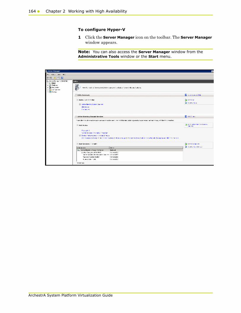
164 Chapter 2 Working with High Availability
ArchestrA System Platform Virtualization Guide
To configure Hyper-V
1 Click the Server Manager icon on the toolbar. The Server Manager window appears.
Note: You can also access the Server Manager window from the Administrative Tools window or the Start menu.
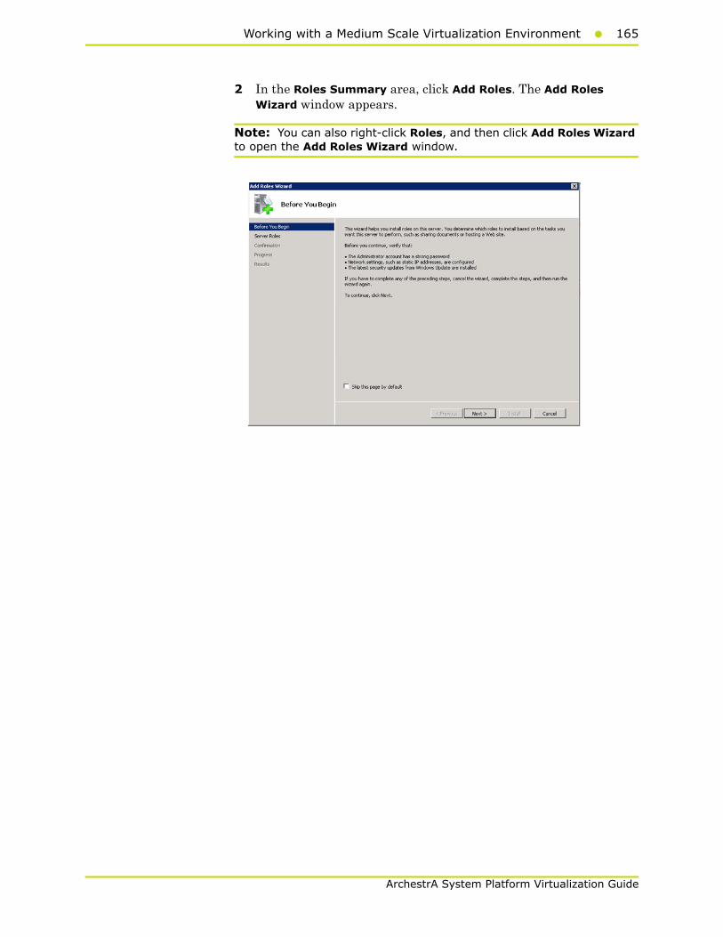
Working with a Medium Scale Virtualization Environment165
ArchestrA System Platform Virtualization Guide
2 In the Roles Summary area, click Add Roles. The Add Roles Wizard window appears.
Note: You can also right-click Roles, and then click Add Roles Wizard to open the Add Roles Wizard window.
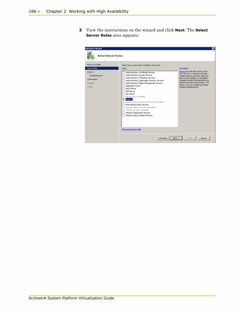
166 Chapter 2 Working with High Availability
ArchestrA System Platform Virtualization Guide
3 View the instructions on the wizard and click Next. The Select Server Roles area appears.

Working with a Medium Scale Virtualization Environment167
ArchestrA System Platform Virtualization Guide
4 Select the Hyper-V check box and click Next. The Create Virtual Networks area appears.
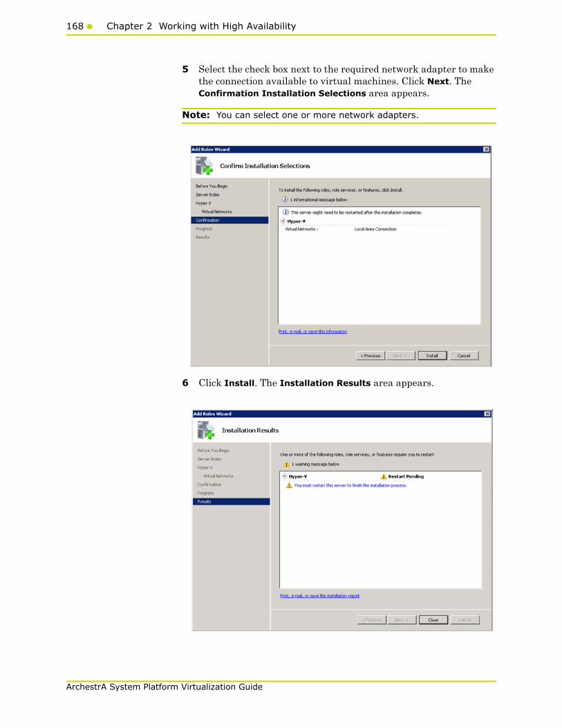
168 Chapter 2 Working with High Availability
ArchestrA System Platform Virtualization Guide
5 Select the check box next to the required network adapter to make the connection available to virtual machines. Click Next. The Confirmation Installation Selections area appears.
Note: You can select one or more network adapters.
6 Click Install. The Installation Results area appears.

Working with a Medium Scale Virtualization Environment169
ArchestrA System Platform Virtualization Guide
7 A message appears prompting you to restart the computer. Click Close. The Add Roles Wizard pop-up window appears.
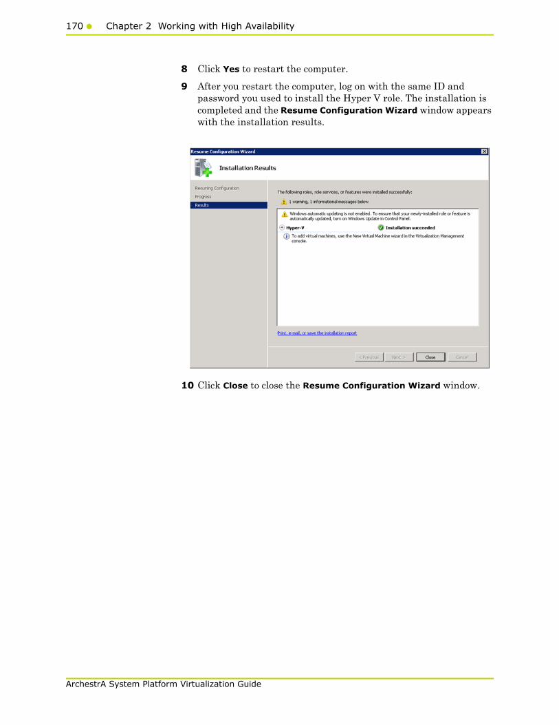
170 Chapter 2 Working with High Availability
ArchestrA System Platform Virtualization Guide
8 Click Yes to restart the computer.
9 After you restart the computer, log on with the same ID and password you used to install the Hyper V role. The installation is completed and the Resume Configuration Wizard window appears with the installation results.
10 Click Close to close the Resume Configuration Wizard window.
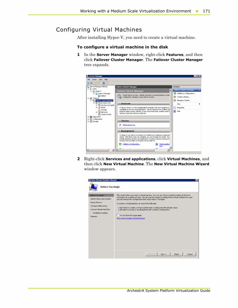
Working with a Medium Scale Virtualization Environment171
ArchestrA System Platform Virtualization Guide
Configuring Virtual Machines After installing Hyper-V, you need to create a virtual machine.
To configure a virtual machine in the disk
1 In the Server Manager window, right-click Features, and then click Failover Cluster Manager. The Failover Cluster Manager tree expands.
2 Right-click Services and applications, click Virtual Machines, and then click New Virtual Machine. The New Virtual Machine Wizard window appears.
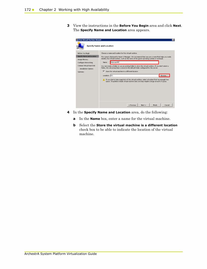
172 Chapter 2 Working with High Availability
ArchestrA System Platform Virtualization Guide
3 View the instructions in the Before You Begin area and click Next. The Specify Name and Location area appears.
4 In the Specify Name and Location area, do the following:
a In the Name box, enter a name for the virtual machine.
b Select the Store the virtual machine is a different location check box to be able to indicate the location of the virtual machine.
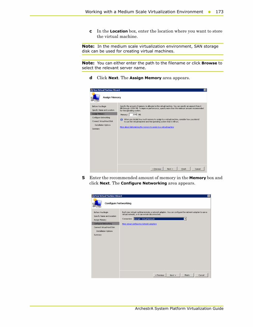
Working with a Medium Scale Virtualization Environment173
ArchestrA System Platform Virtualization Guide
c In the Location box, enter the location where you want to store the virtual machine.
Note: In the medium scale virtualization environment, SAN storage disk can be used for creating virtual machines.
Note: You can either enter the path to the filename or click Browse to select the relevant server name.
d Click Next. The Assign Memory area appears.
5 Enter the recommended amount of memory in the Memory box and click Next. The Configure Networking area appears.
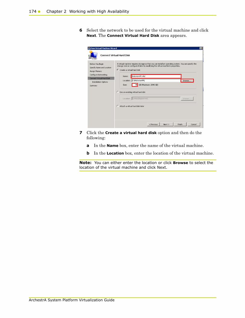
174 Chapter 2 Working with High Availability
ArchestrA System Platform Virtualization Guide
6 Select the network to be used for the virtual machine and click Next. The Connect Virtual Hard Disk area appears.
7 Click the Create a virtual hard disk option and then do the following:
a In the Name box, enter the name of the virtual machine.
b In the Location box, enter the location of the virtual machine.
Note: You can either enter the location or click Browse to select the location of the virtual machine and click Next.

Working with a Medium Scale Virtualization Environment175
ArchestrA System Platform Virtualization Guide
c In the Size box, enter the size of the virtual machine and then click Next. The Installation Options area appears.
Note: You need to click either the Use an existing virtual hard disk or the Attach a virtual hard disk later option, only if you are using an existing virtual hard disk, or you want to attach a virtual disk later.
8 Click the Install an operating system later option and click Next. The Completing the New Virtual Machine Window area appears.
Note: If you want to install an operating system from a boot CD/DVD-ROM or a boot floppy disk or a network-based installation server, click the relevant option.
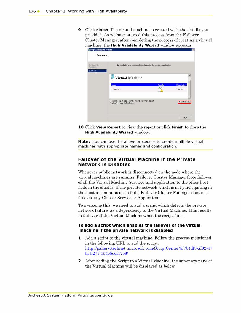
176 Chapter 2 Working with High Availability
ArchestrA System Platform Virtualization Guide
9 Click Finish. The virtual machine is created with the details you provided. As we have started this process from the Failover Cluster Manager, after completing the process of creating a virtual machine, the High Availability Wizard window appears
10 Click View Report to view the report or click Finish to close the High Availability Wizard window.
Note: You can use the above procedure to create multiple virtual machines with appropriate names and configuration.
Failover of the Virtual Machine if the Private Network is Disabled
Whenever public network is disconnected on the node where the virtual machines are running, Failover Cluster Manager force failover of all the Virtual Machine Services and application to the other host node in the cluster. If the private network which is not participating in the cluster communication fails, Failover Cluster Manager does not failover any Cluster Service or Application.
To overcome this, we need to add a script which detects the private network failure as a dependency to the Virtual Machine. This results in failover of the Virtual Machine when the script fails.
To add a script which enables the failover of the virtual machine if the private network is disabled
1 Add a script to the virtual machine. Follow the process mentioned in the following URL to add the script: http://gallery.technet.microsoft.com/ScriptCenter/5f7b4df3-af02-47bf-b275-154e5edf17e6/
2 After adding the Script to a Virtual Machine, the summary pane of the Virtual Machine will be displayed as below.
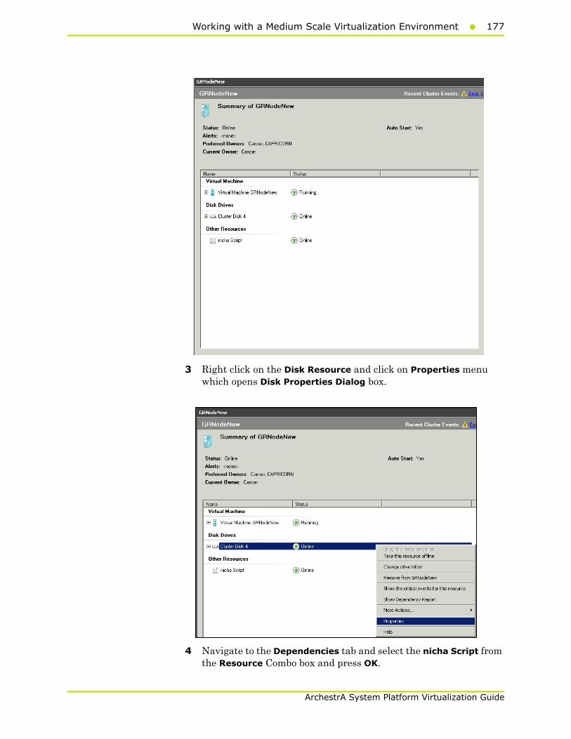
Working with a Medium Scale Virtualization Environment177
ArchestrA System Platform Virtualization Guide
3 Right click on the Disk Resource and click on Properties menu which opens Disk Properties Dialog box.
4 Navigate to the Dependencies tab and select the nicha Script from the Resource Combo box and press OK.
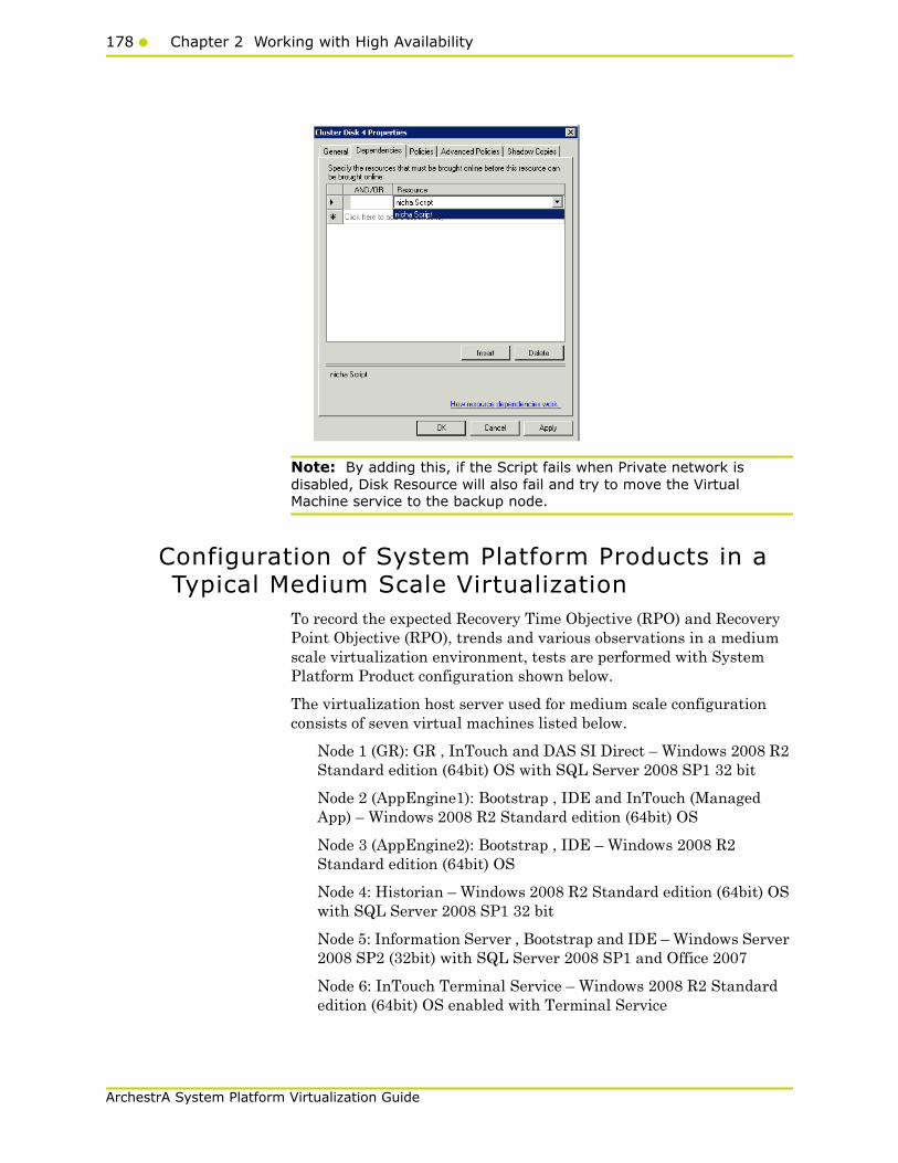
178 Chapter 2 Working with High Availability
ArchestrA System Platform Virtualization Guide
Note: By adding this, if the Script fails when Private network is disabled, Disk Resource will also fail and try to move the Virtual Machine service to the backup node.
Configuration of System Platform Products in a Typical Medium Scale Virtualization
To record the expected Recovery Time Objective (RPO) and Recovery Point Objective (RPO), trends and various observations in a medium scale virtualization environment, tests are performed with System Platform Product configuration shown below.
The virtualization host server used for medium scale configuration consists of seven virtual machines listed below.
Node 1 (GR): GR , InTouch and DAS SI Direct – Windows 2008 R2 Standard edition (64bit) OS with SQL Server 2008 SP1 32 bit
Node 2 (AppEngine1): Bootstrap , IDE and InTouch (Managed App) – Windows 2008 R2 Standard edition (64bit) OS
Node 3 (AppEngine2): Bootstrap , IDE – Windows 2008 R2 Standard edition (64bit) OS
Node 4: Historian – Windows 2008 R2 Standard edition (64bit) OS with SQL Server 2008 SP1 32 bit
Node 5: Information Server , Bootstrap and IDE – Windows Server 2008 SP2 (32bit) with SQL Server 2008 SP1 and Office 2007
Node 6: InTouch Terminal Service – Windows 2008 R2 Standard edition (64bit) OS enabled with Terminal Service
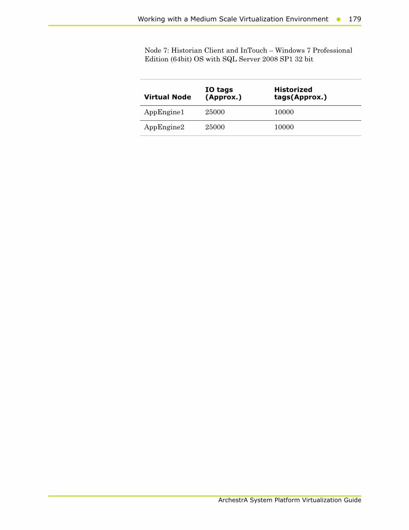
Working with a Medium Scale Virtualization Environment179
ArchestrA System Platform Virtualization Guide
Node 7: Historian Client and InTouch – Windows 7 Professional Edition (64bit) OS with SQL Server 2008 SP1 32 bit
Virtual NodeIO tags (Approx.)
Historized tags(Approx.)
AppEngine1 25000 10000
AppEngine2 25000 10000
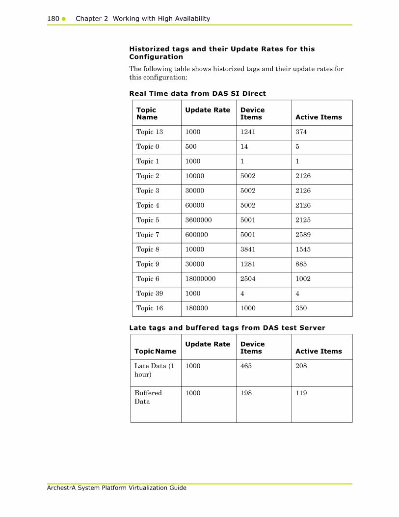
180 Chapter 2 Working with High Availability
ArchestrA System Platform Virtualization Guide
Historized tags and their Update Rates for this Configuration
The following table shows historized tags and their update rates for this configuration:
Real Time data from DAS SI Direct
Late tags and buffered tags from DAS test Server
Topic Name
Update Rate Device Items Active Items
Topic 13 1000 1241 374
Topic 0 500 14 5
Topic 1 1000 1 1
Topic 2 10000 5002 2126
Topic 3 30000 5002 2126
Topic 4 60000 5002 2126
Topic 5 3600000 5001 2125
Topic 7 600000 5001 2589
Topic 8 10000 3841 1545
Topic 9 30000 1281 885
Topic 6 18000000 2504 1002
Topic 39 1000 4 4
Topic 16 180000 1000 350
Topic Name Update Rate Device
Items Active Items
Late Data (1 hour)
1000 465 208
Buffered Data
1000 198 119
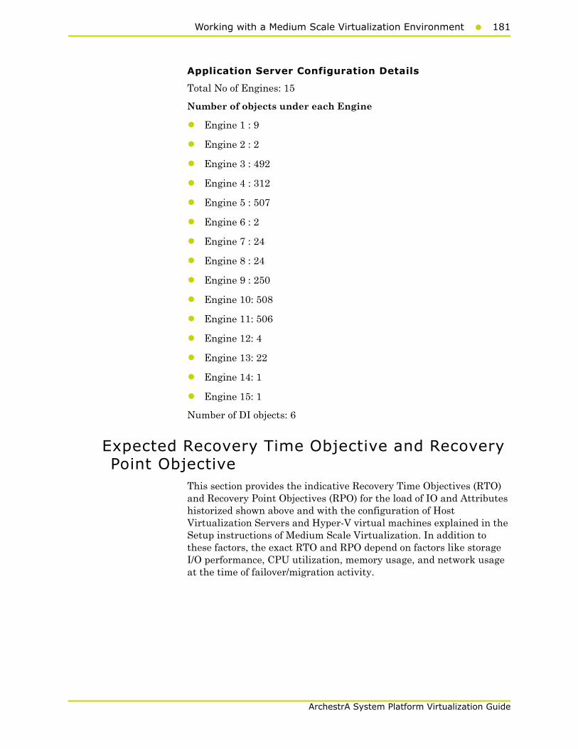
Working with a Medium Scale Virtualization Environment181
ArchestrA System Platform Virtualization Guide
Application Server Configuration Details
Total No of Engines: 15
Number of objects under each Engine
• Engine 1 : 9
• Engine 2 : 2
• Engine 3 : 492
• Engine 4 : 312
• Engine 5 : 507
• Engine 6 : 2
• Engine 7 : 24
• Engine 8 : 24
• Engine 9 : 250
• Engine 10: 508
• Engine 11: 506
• Engine 12: 4
• Engine 13: 22
• Engine 14: 1
• Engine 15: 1
Number of DI objects: 6
Expected Recovery Time Objective and Recovery Point Objective
This section provides the indicative Recovery Time Objectives (RTO) and Recovery Point Objectives (RPO) for the load of IO and Attributes historized shown above and with the configuration of Host Virtualization Servers and Hyper-V virtual machines explained in the Setup instructions of Medium Scale Virtualization. In addition to these factors, the exact RTO and RPO depend on factors like storage I/O performance, CPU utilization, memory usage, and network usage at the time of failover/migration activity.
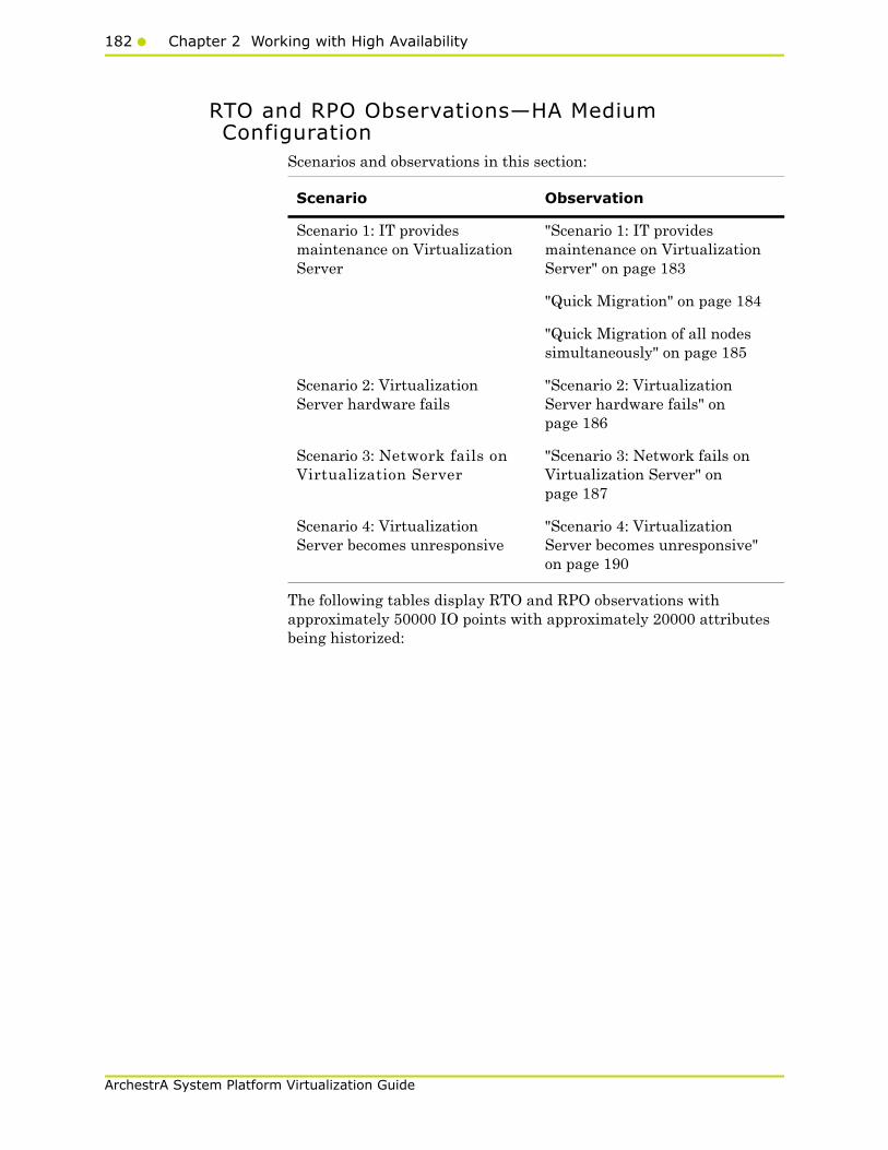
182 Chapter 2 Working with High Availability
ArchestrA System Platform Virtualization Guide
RTO and RPO Observations—HA Medium Configuration
Scenarios and observations in this section:
The following tables display RTO and RPO observations with approximately 50000 IO points with approximately 20000 attributes being historized:
Scenario Observation
Scenario 1: IT provides maintenance on Virtualization Server
"Scenario 1: IT provides maintenance on Virtualization Server" on page 183
"Quick Migration" on page 184
"Quick Migration of all nodes simultaneously" on page 185
Scenario 2: Virtualization Server hardware fails
"Scenario 2: Virtualization Server hardware fails" on page 186
Scenario 3: Network fails on Virtualization Server
"Scenario 3: Network fails on Virtualization Server" on page 187
Scenario 4: Virtualization Server becomes unresponsive
"Scenario 4: Virtualization Server becomes unresponsive" on page 190
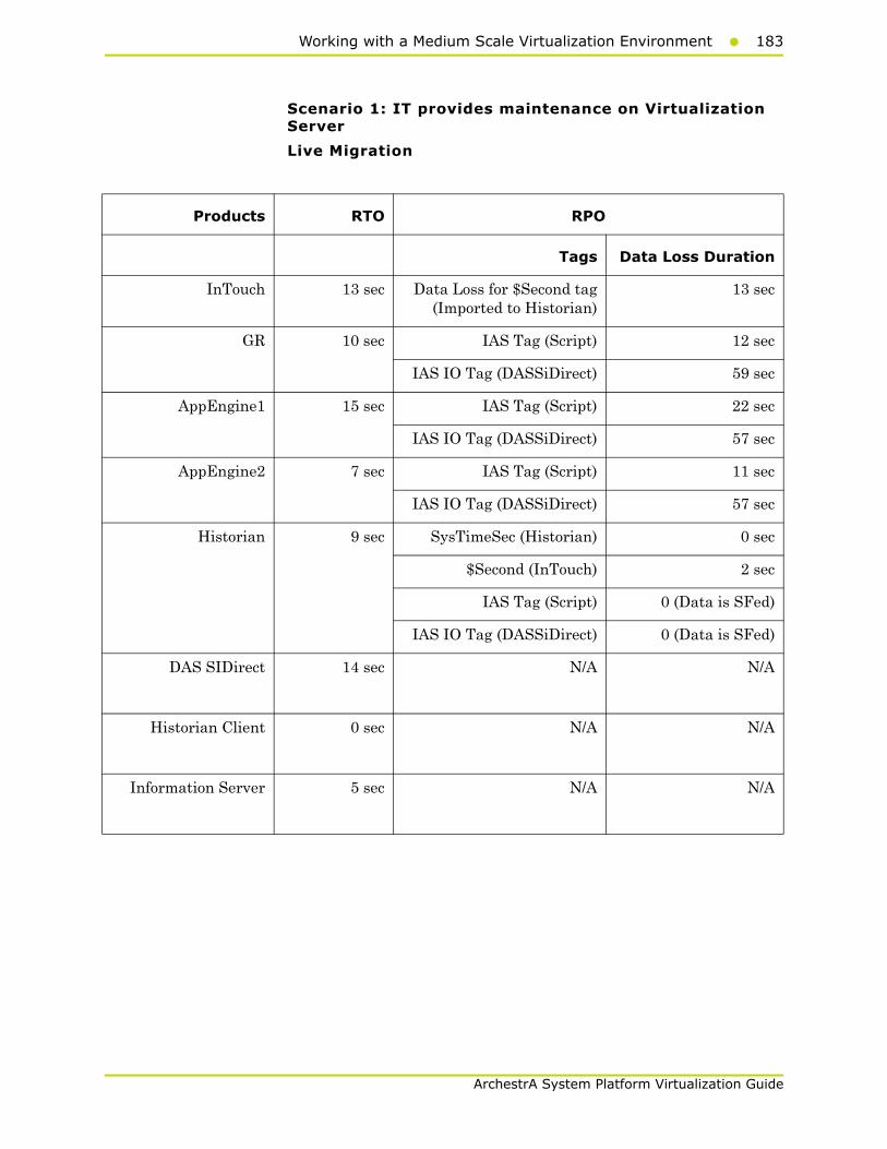
Working with a Medium Scale Virtualization Environment183
ArchestrA System Platform Virtualization Guide
Scenario 1: IT provides maintenance on Virtualization Server
Live Migration
Products RTO RPO
Tags Data Loss Duration
InTouch 13 sec Data Loss for $Second tag(Imported to Historian)
13 sec
GR 10 sec IAS Tag (Script) 12 sec
IAS IO Tag (DASSiDirect) 59 sec
AppEngine1 15 sec IAS Tag (Script) 22 sec
IAS IO Tag (DASSiDirect) 57 sec
AppEngine2 7 sec IAS Tag (Script) 11 sec
IAS IO Tag (DASSiDirect) 57 sec
Historian 9 sec SysTimeSec (Historian) 0 sec
$Second (InTouch) 2 sec
IAS Tag (Script) 0 (Data is SFed)
IAS IO Tag (DASSiDirect) 0 (Data is SFed)
DAS SIDirect 14 sec N/A N/A
Historian Client 0 sec N/A N/A
Information Server 5 sec N/A N/A
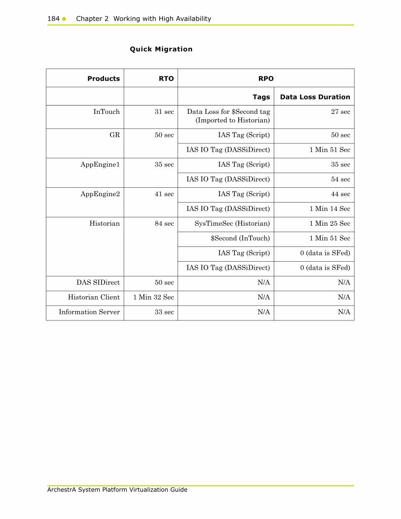
184 Chapter 2 Working with High Availability
ArchestrA System Platform Virtualization Guide
Quick Migration
Products RTO RPO
Tags Data Loss Duration
InTouch 31 sec Data Loss for $Second tag(Imported to Historian)
27 sec
GR 50 sec IAS Tag (Script) 50 sec
IAS IO Tag (DASSiDirect) 1 Min 51 Sec
AppEngine1 35 sec IAS Tag (Script) 35 sec
IAS IO Tag (DASSiDirect) 54 sec
AppEngine2 41 sec IAS Tag (Script) 44 sec
IAS IO Tag (DASSiDirect) 1 Min 14 Sec
Historian 84 sec SysTimeSec (Historian) 1 Min 25 Sec
$Second (InTouch) 1 Min 51 Sec
IAS Tag (Script) 0 (data is SFed)
IAS IO Tag (DASSiDirect) 0 (data is SFed)
DAS SIDirect 50 sec N/A N/A
Historian Client 1 Min 32 Sec N/A N/A
Information Server 33 sec N/A N/A
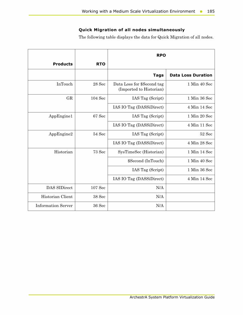
Working with a Medium Scale Virtualization Environment185
ArchestrA System Platform Virtualization Guide
Quick Migration of all nodes simultaneously
The following table displays the data for Quick Migration of all nodes.
Products RTO
RPO
Tags Data Loss Duration
InTouch 28 Sec Data Loss for $Second tag(Imported to Historian)
1 Min 40 Sec
GR 104 Sec IAS Tag (Script) 1 Min 36 Sec
IAS IO Tag (DASSiDirect) 4 Min 14 Sec
AppEngine1 67 Sec IAS Tag (Script) 1 Min 20 Sec
IAS IO Tag (DASSiDirect) 4 Min 11 Sec
AppEngine2 54 Sec IAS Tag (Script) 52 Sec
IAS IO Tag (DASSiDirect) 4 Min 28 Sec
Historian 73 Sec SysTimeSec (Historian) 1 Min 14 Sec
$Second (InTouch) 1 Min 40 Sec
IAS Tag (Script) 1 Min 36 Sec
IAS IO Tag (DASSiDirect) 4 Min 14 Sec
DAS SIDirect 107 Sec N/A
Historian Client 38 Sec N/A
Information Server 36 Sec N/A
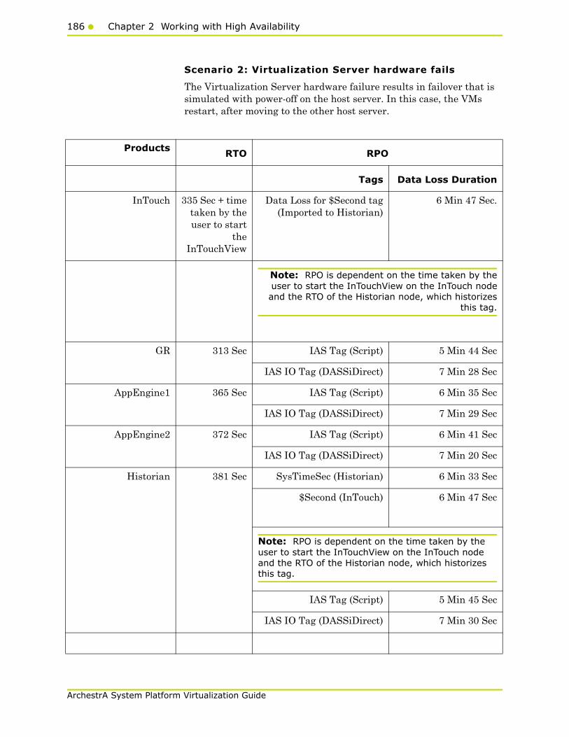
186 Chapter 2 Working with High Availability
ArchestrA System Platform Virtualization Guide
Scenario 2: Virtualization Server hardware fails
The Virtualization Server hardware failure results in failover that is simulated with power-off on the host server. In this case, the VMs restart, after moving to the other host server.
Products RTO RPO
Tags Data Loss Duration
InTouch 335 Sec + timetaken by theuser to start
theInTouchView
Data Loss for $Second tag(Imported to Historian)
6 Min 47 Sec.
Note: RPO is dependent on the time taken by theuser to start the InTouchView on the InTouch nodeand the RTO of the Historian node, which historizes
this tag.
GR 313 Sec IAS Tag (Script) 5 Min 44 Sec
IAS IO Tag (DASSiDirect) 7 Min 28 Sec
AppEngine1 365 Sec IAS Tag (Script) 6 Min 35 Sec
IAS IO Tag (DASSiDirect) 7 Min 29 Sec
AppEngine2 372 Sec IAS Tag (Script) 6 Min 41 Sec
IAS IO Tag (DASSiDirect) 7 Min 20 Sec
Historian 381 Sec SysTimeSec (Historian) 6 Min 33 Sec
$Second (InTouch) 6 Min 47 Sec
Note: RPO is dependent on the time taken by the user to start the InTouchView on the InTouch node and the RTO of the Historian node, which historizes this tag.
IAS Tag (Script) 5 Min 45 Sec
IAS IO Tag (DASSiDirect) 7 Min 30 Sec

Working with a Medium Scale Virtualization Environment187
ArchestrA System Platform Virtualization Guide
Scenario 3: Network fails on Virtualization Server
Failover due to Network Disconnect (Public)
In this case, after the VMs move to the other host server, the VMs restart.
Products RTO RPO
Tags Data Loss Duration
DAS SIDirect 265 Sec N/A N/A
Historian Client 214 Sec +time taken by
the user tostart the
HistorianClient
N/A N/A
Information Server 255 Sec +time taken by
the user tostart the
InformationServer
N/A N/A
Products RTO RPO
Tags Data Loss Duration
InTouch 150 sec + time taken by the user to start the InTouchView
Data Loss for $Second tag (Imported to Historian)
4 Min 14 Sec
Note: RPO is dependent on the time taken by the user to start the InTouchView on the InTouch node and the RTO of the Historian node, which historizes this tag.
GR 197 sec IAS Tag (Script) 3 Min 41 Sec
IAS IO Tag (DASSiDirect) 3 Min 50 Sec

188 Chapter 2 Working with High Availability
ArchestrA System Platform Virtualization Guide
Products RTO RPO
TagsData Loss Duration
AppEngine1 188 sec IAS Tag (Script) 3 Min 31 Sec
IAS IO Tag(DASSiDirect)
4 Min 2 Sec
AppEngine2 200 sec IAS Tag (Script) 3 Min 41 Sec
IAS IO Tag(DASSiDirect)
4 Min 08 Sec
Historian 236 sec SysTimeSec (Historian) 3 Min 55 Sec
$Second (InTouch) 4 Min 14 Sec
Note: RPO is dependent on the time taken by the user to start the InTouchView on the InTouch node and the RTO of the Historian node, which historizes this tag.
IAS Tag (Script) 3 Min 41 Sec
IAS IO Tag(DASSiDirect)
3 Min 50 Sec
DAS SIDirect 174 sec N/A N/A
Historian Client 163 sec + timetaken by the
user to start theHistorian Client
N/A N/A
Information Server 66 sec + timetaken by the
user to start theInformation
Server
N/A N/A

Working with a Medium Scale Virtualization Environment189
ArchestrA System Platform Virtualization Guide
Failover due to network disconnect (plant)
In this case, only the GR Node moves to other host server and restarts. Only GR has data acquisition through Plant network and disconnected Plant network results in failover of GR alone.
Products RTO RPO
Tags Data Loss Duration
InTouch N/A Data Loss for $Second tag(Imported to Historian)
N/A
GR 97 Sec IAS Tag (Script) 1 Min 43 Sec
IAS IO Tag (DASSiDirect) 1 Min 46 Sec
AppEngine1 N/A IAS Tag (Script) N/A
IAS IO Tag (DASSiDirect) 1 Min 50 Sec
AppEngine2 N/A IAS Tag (Script) N/A
IAS IO Tag (DASSiDirect) 1 Min 58 Sec
Historian N/A SysTimeSec (Historian) N/A
$Second (InTouch) N/A
IAS Tag (Script) 1 Min 43 Sec
IAS IO Tag (DASSiDirect) 1 Min 46 Sec
DAS SIDirect 111 Sec N/A N/A
Historian Client N/A N/A N/A
Information Server N/A N/A N/A

190 Chapter 2 Working with High Availability
ArchestrA System Platform Virtualization Guide
Scenario 4: Virtualization Server becomes unresponsive
There is no failover of VMs to the other host server when the CPU utilization on the host server is 100%.
Products RTO RPO
Tags Data Loss Duration
InTouch N/A N/A N/A
GR N/A N/A N/A
N/A N/A N/A
AppEngine1 N/A N/A N/A
N/A N/A N/A
AppEngine2 N/A N/A N/A
Historian N/A N/A N/A
N/A N/A N/A
N/A N/A N/A
N/A N/A N/A
DAS SIDirect N/A N/A N/A
Historian Client N/A N/A N/A
Information Server N/A N/A N/A

Working with a Medium Scale Virtualization Environment191
ArchestrA System Platform Virtualization Guide
Snapshots of Data Trends and ObservationsScenarios and observations in this section:
Scenario Observation
Scenario 1: IT provides maintenance on Virtualization Server
"Live Migration of InTouch" on page 192
"Live Migration of GR" on page 192
"Live Migration of AppEngine1" on page 195
"Live Migration of AppEngine2" on page 198
"Live Migration of Historian" on page 202
"Quick Migration of InTouch" on page 204
"Quick Migration of GR" on page 205
"Quick Migration of AppEngine1" on page 208
"Quick Migration of AppEngine2" on page 211
"Quick Migration of Historian" on page 214
"Quick Migration of All Nodes" on page 217
Scenario 2: Virtualization Server hardware fails
"Failover Due to Hardware failure" on page 221
Scenario 3: Network fails on Virtualization Server
"Failover Due to Network Disconnect (Public)" on page 230
Scenario 4: Virtualization Server becomes unresponsive
"Hyper-V Virtual Machines with Static RAM and Reservations for Processors" on page 239

192 Chapter 2 Working with High Availability
ArchestrA System Platform Virtualization Guide
Scenario 1: IT provides Maintenance on Virtualization Server
Live Migration of InTouch
Trends:
In the Historian Trend, the last tag $Second receives data from InTouch and is historized.
This is also captured in the RPO for Live Migration of InTouch tag.
Observations
There are no errors and warnings observed on all the virtual nodes.
Live Migration of GR
Trends:
In the Historian Trend below, the first tag SineWaveCal_001.SinewaveValue receives data from scripts on GR node and is historized.

Working with a Medium Scale Virtualization Environment193
ArchestrA System Platform Virtualization Guide
This is also captured in the RPO for Live Migration of GR node for IAS Tag (Script).
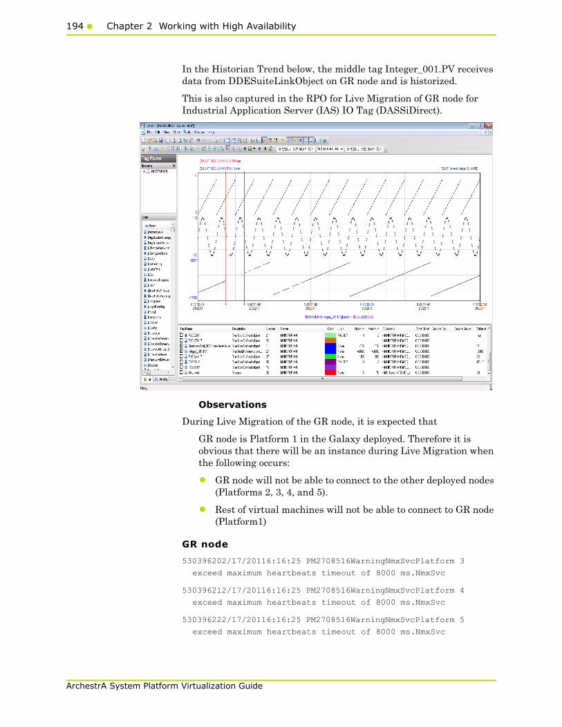
194 Chapter 2 Working with High Availability
ArchestrA System Platform Virtualization Guide
In the Historian Trend below, the middle tag Integer_001.PV receives data from DDESuiteLinkObject on GR node and is historized.
This is also captured in the RPO for Live Migration of GR node for Industrial Application Server (IAS) IO Tag (DASSiDirect).
Observations
During Live Migration of the GR node, it is expected that
GR node is Platform 1 in the Galaxy deployed. Therefore it is obvious that there will be an instance during Live Migration when the following occurs:
• GR node will not be able to connect to the other deployed nodes (Platforms 2, 3, 4, and 5).
• Rest of virtual machines will not be able to connect to GR node (Platform1)
GR node
530396202/17/20116:16:25 PM2708516WarningNmxSvcPlatform 3
exceed maximum heartbeats timeout of 8000 ms.NmxSvc
530396212/17/20116:16:25 PM2708516WarningNmxSvcPlatform 4
exceed maximum heartbeats timeout of 8000 ms.NmxSvc
530396222/17/20116:16:25 PM2708516WarningNmxSvcPlatform 5
exceed maximum heartbeats timeout of 8000 ms.NmxSvc

Working with a Medium Scale Virtualization Environment195
ArchestrA System Platform Virtualization Guide
530396232/17/20116:16:25 PM2708516WarningNmxSvcPlatform 6
exceed maximum heartbeats timeout of 8000 ms.NmxSvc
AppEngine1 node
1134668232/17/20116:16:17 PM29883004WarningNmxSvcPlatform 1
exceed maximum heartbeats timeout of 8000 ms.NmxSvc
AppEngine2 node
55437632/17/20116:16:17 PM30602176WarningNmxSvcPlatform 1
exceed maximum heartbeats timeout of 8000 ms.NmxSvc
Historian
None
WIS node
None
HistClient
None
Live Migration of AppEngine1
Trends:
Industrial Application Server (IAS) tags receiving data from IO Server (DAS SI Direct)
In the Historian Trend below, the first two tags receive data from DDESuiteLinkClient in Industrial Application Server (IAS) from the PLC and are historized from Platform AppEngine1.
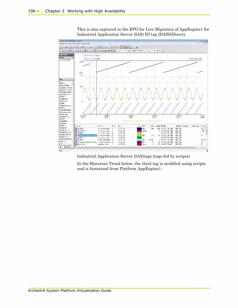
196 Chapter 2 Working with High Availability
ArchestrA System Platform Virtualization Guide
This is also captured in the RPO for Live Migration of AppEngine1 for Industrial Application Server (IAS) IO tag (DASSiDirect).
Industrial Application Server (IAS)tags (tags fed by scripts)
In the Historian Trend below, the third tag is modified using scripts and is historized from Platform AppEngine1.
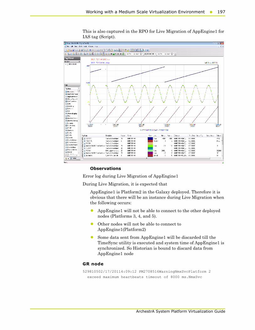
Working with a Medium Scale Virtualization Environment197
ArchestrA System Platform Virtualization Guide
This is also captured in the RPO for Live Migration of AppEngine1 for IAS tag (Script).
Observations
Error log during Live Migration of AppEngine1
During Live Migration, it is expected that
AppEngine1 is Platform2 in the Galaxy deployed. Therefore it is obvious that there will be an instance during Live Migration when the following occurs:
• AppEngine1 will not be able to connect to the other deployed nodes (Platforms 3, 4, and 5).
• Other nodes will not be able to connect to AppEngine1(Platform2)
• Some data sent from AppEngine1 will be discarded till the TimeSync utility is executed and system time of AppEngine1 is synchronized. So Historian is bound to discard data from AppEngine1 node
GR node
529810502/17/20114:09:12 PM2708516WarningNmxSvcPlatform 2
exceed maximum heartbeats timeout of 8000 ms.NmxSvc

198 Chapter 2 Working with High Availability
ArchestrA System Platform Virtualization Guide
AppEngine1
1133382602/17/20114:09:19 PM29883004WarningNmxSvcPlatform 1
exceed maximum heartbeats timeout of 8000 ms.NmxSvc
1133382612/17/20114:09:19 PM29883004WarningNmxSvcPlatform 3
exceed maximum heartbeats timeout of 8000 ms.NmxSvc
1133382622/17/20114:09:19 PM29883004WarningNmxSvcPlatform 4
exceed maximum heartbeats timeout of 8000 ms.NmxSvc
1133382632/17/20114:09:19 PM29883004WarningNmxSvcPlatform 5
exceed maximum heartbeats timeout of 8000 ms.NmxSvc
1133382642/17/20114:09:19 PM29883004WarningNmxSvcPlatform 6
exceed maximum heartbeats timeout of 8000 ms.NmxSvc
AppEngine2
55432652/17/20114:09:12 PM30602176WarningNmxSvcPlatform 2
exceed maximum heartbeats timeout of 8000 ms.NmxSvc
Historian
236000202/17/20114:10:03 PM1928968WarningaahStoreSvcValues in
the past did not fit within the realtime window; discarding
data (HISTORIAN_mdas, 28898, 2011/02/17 10:39:13.246,
2011/02/17 10:40:02.708) [HISTORIAN; pipeserver.cpp; 2388]
aahCfgSvc
236000452/17/20114:14:16 PM1928968WarningaahStoreSvcValues in
the past did not fit within the realtime window; discarding
data (HISTORIAN_mdas, 28898, 2011/02/17 10:39:13.246,
2011/02/17 10:40:02.708) [HISTORIAN; pipeserver.cpp; 2388;
15135]aahCfgSvc
WIS node
None
HistClient
None
Live Migration of AppEngine2
Trends
IAS tags receiving data from IO Server (DAS SI Direct)
In the Historian Trend below, the second and third tags receive data from DDESuiteLinkClient in Industrial Application Server (IAS) from the PLC and are historized from Platform AppEngine2.
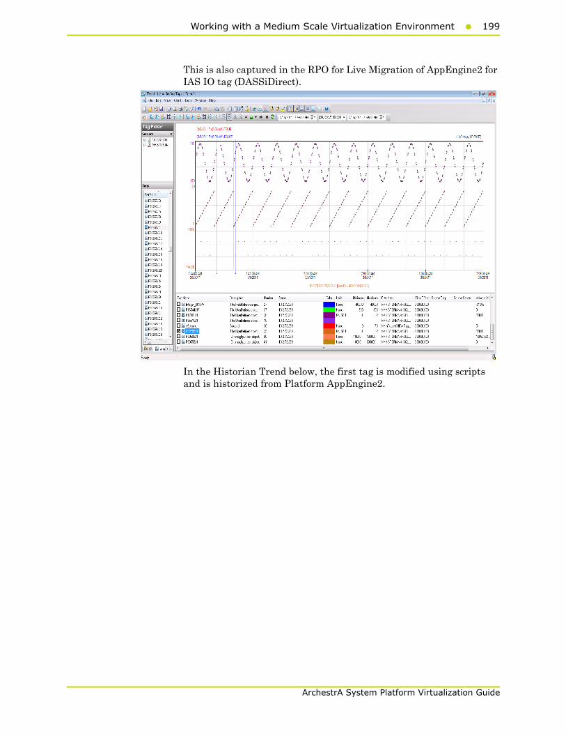
Working with a Medium Scale Virtualization Environment199
ArchestrA System Platform Virtualization Guide
This is also captured in the RPO for Live Migration of AppEngine2 for IAS IO tag (DASSiDirect).
In the Historian Trend below, the first tag is modified using scripts and is historized from Platform AppEngine2.
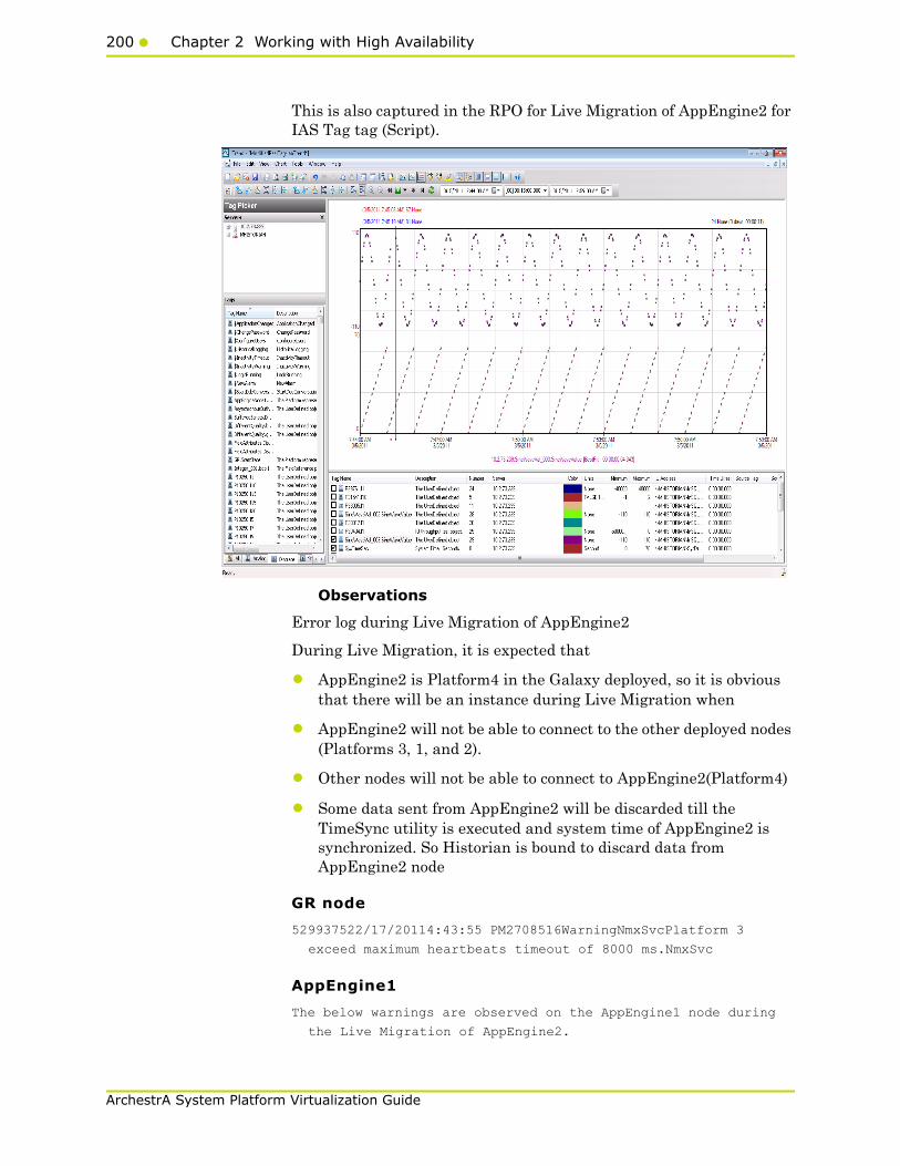
200 Chapter 2 Working with High Availability
ArchestrA System Platform Virtualization Guide
This is also captured in the RPO for Live Migration of AppEngine2 for IAS Tag tag (Script).
Observations
Error log during Live Migration of AppEngine2
During Live Migration, it is expected that
• AppEngine2 is Platform4 in the Galaxy deployed, so it is obvious that there will be an instance during Live Migration when
• AppEngine2 will not be able to connect to the other deployed nodes (Platforms 3, 1, and 2).
• Other nodes will not be able to connect to AppEngine2(Platform4)
• Some data sent from AppEngine2 will be discarded till the TimeSync utility is executed and system time of AppEngine2 is synchronized. So Historian is bound to discard data from AppEngine2 node
GR node
529937522/17/20114:43:55 PM2708516WarningNmxSvcPlatform 3
exceed maximum heartbeats timeout of 8000 ms.NmxSvc
AppEngine1
The below warnings are observed on the AppEngine1 node during
the Live Migration of AppEngine2.
Working with a Medium Scale Virtualization Environment201
ArchestrA System Platform Virtualization Guide
1133740042/17/20114:43:55 PM29883004WarningNmxSvcPlatform 3
exceed maximum heartbeats timeout of 8000 ms.NmxSvc
AppEngine2
55432662/17/20114:44:02 PM30602176WarningNmxSvcPlatform 1
exceed maximum heartbeats timeout of 8000 ms.NmxSvc
55432672/17/20114:44:02 PM30602176WarningNmxSvcPlatform 2
exceed maximum heartbeats timeout of 8000 ms.NmxSvc
55432682/17/20114:44:02 PM30602176WarningNmxSvcPlatform 4
exceed maximum heartbeats timeout of 8000 ms.NmxSvc
55432692/17/20114:44:02 PM30602176WarningNmxSvcPlatform 5
exceed maximum heartbeats timeout of 8000 ms.NmxSvc
55432702/17/20114:44:02 PM30602176WarningNmxSvcPlatform 6
exceed maximum heartbeats timeout of 8000 ms.NmxSvc
Historian
236003182/17/20114:44:47 PM1928968WarningaahStoreSvcValues in
the past did not fit within the realtime window; discarding
data (HISTORIAN_mdas, 20418, 2011/02/17 11:14:00.347,
2011/02/17 11:14:46.178) [HISTORIAN; pipeserver.cpp; 2388]
aahCfgSvc
236003622/17/20114:49:00 PM1928968WarningaahStoreSvcValues in
the past did not fit within the realtime window; discarding
data (HISTORIAN_mdas, 20418, 2011/02/17 11:14:00.347,
2011/02/17 11:14:46.178) [HISTORIAN; pipeserver.cpp; 2388;
1570]aahCfgSvc
WIS node
None
HistClient
None
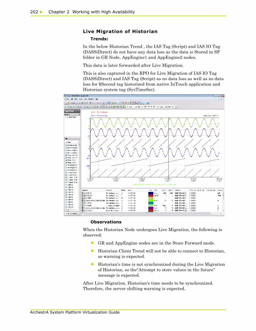
202 Chapter 2 Working with High Availability
ArchestrA System Platform Virtualization Guide
Live Migration of Historian
Trends:
In the below Historian Trend , the IAS Tag (Script) and IAS IO Tag (DASSiDirect) do not have any data loss as the data is Stored in SF folder in GR Node, AppEngine1 and AppEngine2 nodes.
This data is later forwarded after Live Migration.
This is also captured in the RPO for Live Migration of IAS IO Tag (DASSiDirect) and IAS Tag (Script) as no data loss as well as no data loss for $Second tag historized from native InTouch application and Historian system tag (SysTimeSec).
Observations
When the Historian Node undergoes Live Migration, the following is observed:
• GR and AppEngine nodes are in the Store Forward mode.
• Historian Client Trend will not be able to connect to Historian, so warning is expected.
• Historian's time is not synchronized during the Live Migration of Historian, so the"Attempt to store values in the future" message is expected.
After Live Migration, Historian's time needs to be synchronized. Therefore, the server shifting warning is expected.

Working with a Medium Scale Virtualization Environment203
ArchestrA System Platform Virtualization Guide
After Live Migration of the Historian node, the stored data is forwarded from the GR and AppEngine nodes.
GR node
528410852/17/20119:07:31 AM39202428WarningScanGroupRuntime2
Can't convert Var data type to MxDataTypeaaEngine
AppEngine1
None
AppEngine2
None
Historian
235940332/17/20119:07:34 AM37963388WarningaahStoreSvcValues in
the past did not fit within the realtime window; discarding
data (HISTORIAN_mdas, 19594, 2011/02/17 03:34:41.543,
2011/02/17 03:37:33.054) [HISTORIAN; pipeserver.cpp; 2388]
235940522/17/20119:10:28 AM37963388WarningaahStoreSvcAttempt to
store values in the future; timestamps were overwritten with
current time (pipe name, TagName, wwTagKey, system time (UTC),
time difference (sec)) (HISTORIAN_mdas, Integer_001.str1,
19598, 2011/02/17 03:40:27.073, 1) [HISTORIAN;
pipeserver.cpp; ...
235940602/17/20119:11:13 AM37963388WarningaahCfgSvc"Server time
is shifting (Expected time, Current time)"
(02/17/11,09:11:11,829, 02/17/11,09:10:54,775) [HISTORIAN;
Config.cpp; 2040]
WIS node
None
HistClient
None

204 Chapter 2 Working with High Availability
ArchestrA System Platform Virtualization Guide
Quick Migration of InTouch
Trends:
Observations
No error and warnings observed on the nodes
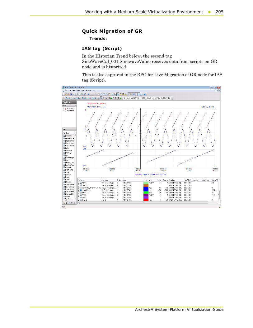
Working with a Medium Scale Virtualization Environment205
ArchestrA System Platform Virtualization Guide
Quick Migration of GR
Trends:
IAS tag (Script)
In the Historian Trend below, the second tag SineWaveCal_001.SinewaveValue receives data from scripts on GR node and is historized.
This is also captured in the RPO for Live Migration of GR node for IAS tag (Script).

206 Chapter 2 Working with High Availability
ArchestrA System Platform Virtualization Guide
IAS IO Tag (DASSiDirect)
GR node hosts the DDESuiteLinkObjects, so during quick migration of the GR node, there is data loss for tags that's receive data from DAS Server/PLC.
Observations
During Quick Migration of the GR node, it is expected that
GR node is Platform 1 in the Galaxy deployed. Therefore it is obvious that there will be an instance during Quick Migration when the following occurs:
• GR node will not be able to connect to the other deployed nodes(Platforms 2, 3, 4, and 5).
• Rest of virtual machines will not be able to connect to GR node (Platform1)
Since DAS SI Direct provides data to DDESuiteLinkObject and DAS SI Direct is on the GR Node, a message- "DAServerManager Target node is down" -is expected on AppEngine1 and AppEngine2.
Script involving SDK script library calls timeout during Quick Migration of the GR Node.
GR node
332550721/26/20116:30:35 PM30844484WarningNmxSvcPlatform 4
exceed maximum heartbeats timeout of 8000 ms. 33255074
1/26/20116:30:35 PM30844484WarningNmxSvcPlatform 2 exceed

Working with a Medium Scale Virtualization Environment207
ArchestrA System Platform Virtualization Guide
maximum heartbeats timeout of 8000 ms. 332552121/26/2011
6:30:54 PM49564952WarningaaEngine Unexpected packet from ND
Area_NonClusteredNode <P3 E2>, structId 938336640, request 0,
start 16103, end 16103, count 1,set 16100, sub 16100, state 1,
commAlarm 0, subStatus <success -1 category0 detectedBy 0
detail 0>, subQual 192, setCnt 118, setResult...aaEngine
332552441/26/20116:33:23 PM30844484WarningNmxSvcPlatform 3
exceed maximum heartbeats timeout of 8000 ms. 33255245
1/26/20116:33:23 PM30844484WarningNmxSvcPlatform 5 exceed
maximum heartbeats timeout of 8000 ms. 332552751/26/2011
6:33:26 PM42163432WarningaaEngine0:F20 Values in the past did
not fit within the realtime window; discarding data (218,
2011/01/26 13:00:59.640, 2011/01/2613:03:24.595)
[aahMDASSF.cpp; 3709; 1]aaEngine
332552961/26/20116:33:27 PM14881544WarningaaEngine0:C04 Values
in the past did not fit within the realtime window;discarding
data (23576, 2011/01/26 13:00:59.250, 2011/01/26
13:03:26.282)[aahMDASSF.cpp; 3709; 1]aaEngine
332553151/26/20116:33:28 PM4956412WarningaaEngine0:6BC Values
in the past did not fit within the realtime window; discarding
data (150,2011/01/26 13:00:59.703, 2011/01/26 13:03:26.688)
[aahMDASSF.cpp; 3709; 1] aaEngine
332553461/26/20116:33:33 PM1488 2816WarningScanGroupRuntime2
Can't convert Var data type to MxDataTypeaaEngine
332637691/26/20116:56:57 PM23405200WarningCRLinkServer
CQueue::BroadCastData Ping() hr:0x800706baaaGR
AppEngine1
934921901/26/20116:30:27 PM54804996WarningDAServerManagerTarget
node is down. DASCC will stop scanning for Server active
state.mmc
934922721/26/20116:30:31 PM16522908WarningNmxSvcPlatform 1
exceed maximum heartbeats timeout of 8000 ms.NmxSvc
934933061/26/20116:31:27 PM60966480WarningPackageManagerNet
GalaxyMonitor PollPackageServer Communication failed. A
connection attempt failed because the connected party did not
properly respond after a period of time, or established
connection failed because connected host has failed to respond
10.91.60.33:8090aaIDE
934963991/26/20116:34:11 PM39043908WarningScriptRuntime
Insert.InsertValuePerodic: Script timed out.aaEngine
935109161/26/20116:46:52 PM39043908WarningScriptRuntime
Insert.InsertValueWF: Script timed out.aaEngine
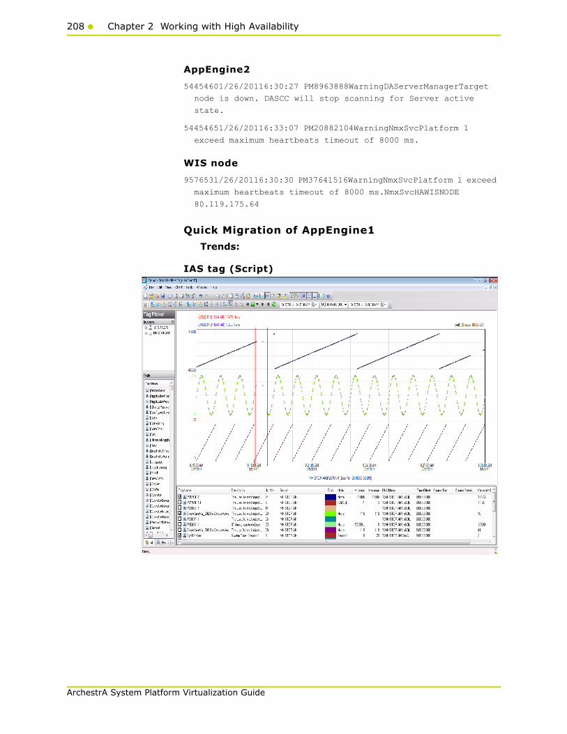
208 Chapter 2 Working with High Availability
ArchestrA System Platform Virtualization Guide
AppEngine2
54454601/26/20116:30:27 PM8963888WarningDAServerManagerTarget
node is down. DASCC will stop scanning for Server active
state.
54454651/26/20116:33:07 PM20882104WarningNmxSvcPlatform 1
exceed maximum heartbeats timeout of 8000 ms.
WIS node
9576531/26/20116:30:30 PM37641516WarningNmxSvcPlatform 1 exceed
maximum heartbeats timeout of 8000 ms.NmxSvcHAWISNODE
80.119.175.64
Quick Migration of AppEngine1
Trends:
IAS tag (Script)
Working with a Medium Scale Virtualization Environment209
ArchestrA System Platform Virtualization Guide
IAS IO Tag (DASSiDirect)
Observations
During Quick Migration of the AppEngine1 Node, it is expected that:
• AppEngine1 Node is Platform 2 in the Galaxy deployed. Therefore, it is obvious that there will be an instance during Quick Migration when the following occurs:
• AppEngine1 Node will not be able to connect to the other deployed nodes (Platforms 1, 3, 4, and 5).
• Rest of virtual machines will not be able to connect to AppEngine1 (Platform2).
• AppEngine1 is not synchronized during the quick migration and a message -"Values in the past did not fit within the realtime window" -is expected on AppEngine1.
• AppEngine1 is not synchronized during the Quick Migration and a message- "Values in the past did not fit within the realtime window"- is expected on the Historian node.
GR node
None
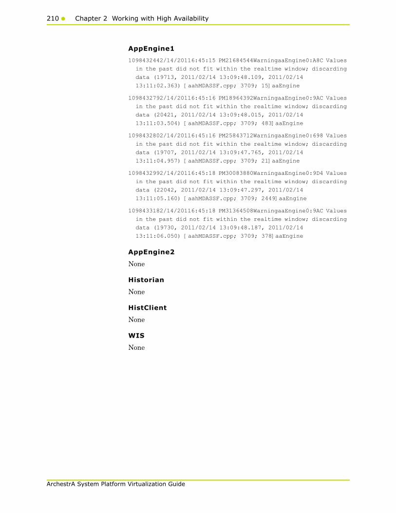
210 Chapter 2 Working with High Availability
ArchestrA System Platform Virtualization Guide
AppEngine1
1098432442/14/20116:45:15 PM21684544WarningaaEngine0:A8C Values
in the past did not fit within the realtime window; discarding
data (19713, 2011/02/14 13:09:48.109, 2011/02/14
13:11:02.363) [aahMDASSF.cpp; 3709; 15]aaEngine
1098432792/14/20116:45:16 PM18964392WarningaaEngine0:9AC Values
in the past did not fit within the realtime window; discarding
data (20421, 2011/02/14 13:09:48.015, 2011/02/14
13:11:03.504) [aahMDASSF.cpp; 3709; 483]aaEngine
1098432802/14/20116:45:16 PM25843712WarningaaEngine0:698 Values
in the past did not fit within the realtime window; discarding
data (19707, 2011/02/14 13:09:47.765, 2011/02/14
13:11:04.957) [aahMDASSF.cpp; 3709; 21]aaEngine
1098432992/14/20116:45:18 PM30083880WarningaaEngine0:9D4 Values
in the past did not fit within the realtime window; discarding
data (22042, 2011/02/14 13:09:47.297, 2011/02/14
13:11:05.160) [aahMDASSF.cpp; 3709; 2449]aaEngine
1098433182/14/20116:45:18 PM31364508WarningaaEngine0:9AC Values
in the past did not fit within the realtime window; discarding
data (19730, 2011/02/14 13:09:48.187, 2011/02/14
13:11:06.050) [aahMDASSF.cpp; 3709; 378]aaEngine
AppEngine2
None
Historian
None
HistClient
None
WIS
None
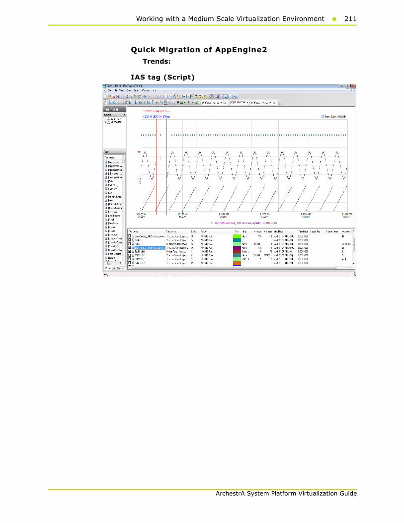
Working with a Medium Scale Virtualization Environment211
ArchestrA System Platform Virtualization Guide
Quick Migration of AppEngine2
Trends:
IAS tag (Script)
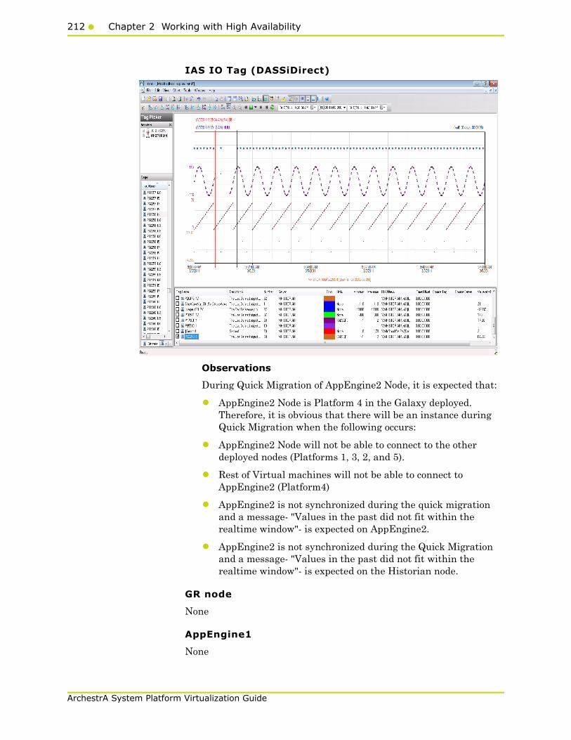
212 Chapter 2 Working with High Availability
ArchestrA System Platform Virtualization Guide
IAS IO Tag (DASSiDirect)
Observations
During Quick Migration of AppEngine2 Node, it is expected that:
• AppEngine2 Node is Platform 4 in the Galaxy deployed. Therefore, it is obvious that there will be an instance during Quick Migration when the following occurs:
• AppEngine2 Node will not be able to connect to the other deployed nodes (Platforms 1, 3, 2, and 5).
• Rest of Virtual machines will not be able to connect to AppEngine2 (Platform4)
• AppEngine2 is not synchronized during the quick migration and a message- "Values in the past did not fit within the realtime window"- is expected on AppEngine2.
• AppEngine2 is not synchronized during the Quick Migration and a message- "Values in the past did not fit within the realtime window"- is expected on the Historian node.
GR node
None
AppEngine1
None
Working with a Medium Scale Virtualization Environment213
ArchestrA System Platform Virtualization Guide
AppEngine2
55327542/14/20117:19:02 PM27682308WarningNmxSvcPlatform 1
exceed maximum heartbeats timeout of 8000 ms.
55327552/14/20117:19:02 PM27682308WarningNmxSvcPlatform 2
exceed maximum heartbeats timeout of 8000 ms.
55327562/14/20117:19:02 PM27682308WarningNmxSvcPlatform 5
exceed maximum heartbeats timeout of 8000 ms.
55327572/14/20117:19:02 PM27682308WarningNmxSvcPlatform 6
exceed maximum heartbeats timeout of 8000 ms.
55327892/14/20117:19:06 PM30284124WarningaaEngine0:998 Values
in the past did not fit within the realtime window; discarding
data (29347, 2011/02/14 13:47:50.796, 2011/02/14
13:49:05.836) [aahMDASSF.cpp; 3709; 1]
55327972/14/20117:19:06 PM33644280WarningaaEngine0:994 Values
in the past did not fit within the realtime window; discarding
data (34102, 2011/02/14 13:48:00.360, 2011/02/14
13:49:06.024) [aahMDASSF.cpp; 3709; 1]
55328002/14/20117:19:06 PM3884388WarningaaEngine0:99C Values in
the past did not fit within the realtime window; discarding
data (30147, 2011/02/14 13:48:00.798, 2011/02/14
13:49:06.180) [aahMDASSF.cpp; 3709; 1]
Historian:
None
HistClient
None
WIS
None
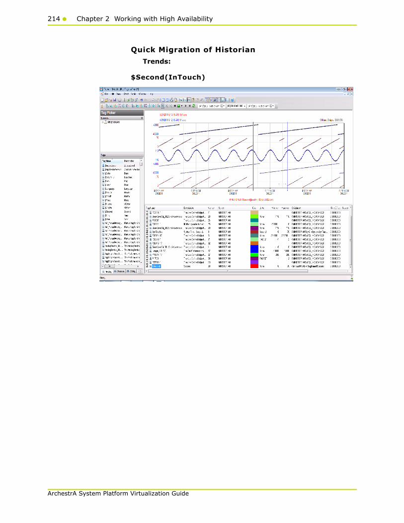
214 Chapter 2 Working with High Availability
ArchestrA System Platform Virtualization Guide
Quick Migration of Historian
Trends:
$Second(InTouch)
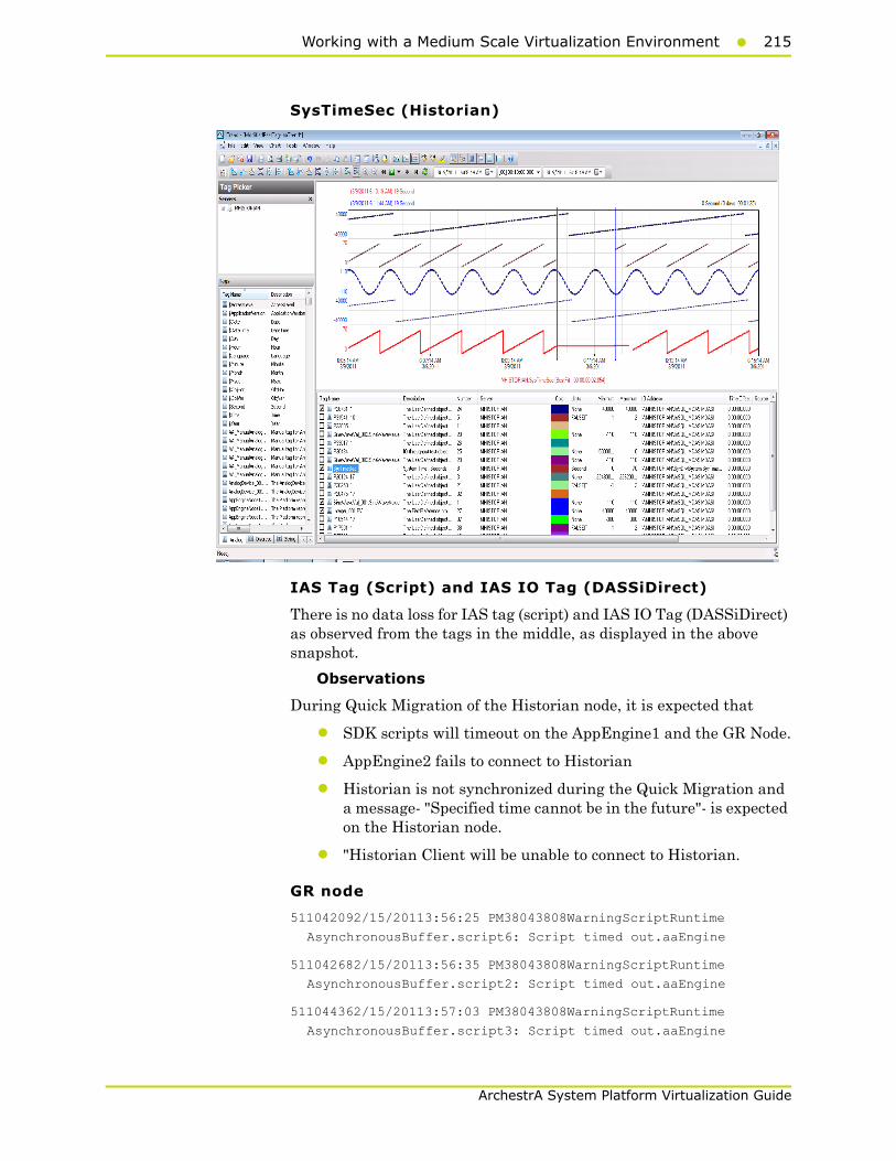
Working with a Medium Scale Virtualization Environment215
ArchestrA System Platform Virtualization Guide
SysTimeSec (Historian)
IAS Tag (Script) and IAS IO Tag (DASSiDirect)
There is no data loss for IAS tag (script) and IAS IO Tag (DASSiDirect) as observed from the tags in the middle, as displayed in the above snapshot.
Observations
During Quick Migration of the Historian node, it is expected that
• SDK scripts will timeout on the AppEngine1 and the GR Node.
• AppEngine2 fails to connect to Historian
• Historian is not synchronized during the Quick Migration and a message- "Specified time cannot be in the future"- is expected on the Historian node.
• "Historian Client will be unable to connect to Historian.
GR node
511042092/15/20113:56:25 PM38043808WarningScriptRuntime
AsynchronousBuffer.script6: Script timed out.aaEngine
511042682/15/20113:56:35 PM38043808WarningScriptRuntime
AsynchronousBuffer.script2: Script timed out.aaEngine
511044362/15/20113:57:03 PM38043808WarningScriptRuntime
AsynchronousBuffer.script3: Script timed out.aaEngine

216 Chapter 2 Working with High Availability
ArchestrA System Platform Virtualization Guide
AppEngine1
1112477922/15/20113:57:53 PM29083924WarningScriptRuntime
InsertAsync.InsertValueWF: Script timed out.aaEngine
1112477932/15/20113:57:53 PM29083932WarningScriptRuntime
InsertAsync.InsertValuePerodic: Script timed out.aaEngine
1112478062/15/20113:57:53 PM29082720WarningScriptRuntime
Insert.InsertValueWF: Script timed out.aaEngine
AppEngine2
55351222/15/20113:56:31 PM24722468WarningHistorianPrimitive
AppEngineNode2 failed to connect to Historian HISTORIAN. (Does
ArchestrA user account exist on Historian(InSQL) node or does
Historian not exist?)aaEngine
55351232/15/20113:57:31 PM24722468WarningHistorianPrimitive
AppEngineNode2 failed to connect to Historian HISTORIAN. (Does
ArchestrA user account exist on Historian(InSQL) node or does
Historian not exist?)aaEngine
Historian
235771112/15/20113:57:49 PM23681100WarningaahCfgSvc"Server time
is shifting (Expected time, Current time)"
(02/15/11,15:57:48,174, 02/15/11,15:54:50,984) [HISTORIAN;
Config.cpp; 2040]aahCfgSvc
Hist Client
6476362/15/20113:55:49 PM20963696WarningaaAFCommonTypesUnable
to create dataview: Server must be logged on before executing
SQL query: SELECT aaT=DateTime, aaN=TagName, aaDV=Value,
aaSV=CONVERT(nvarchar(512),vValue), aaQ=OPCQuality,
aaIQ=Quality, aaQD=QualityDetail, aaS=0
FROM History
WHERE TagName IN ('...

Working with a Medium Scale Virtualization Environment217
ArchestrA System Platform Virtualization Guide
Quick Migration of All Nodes
Trends:
IAS tag (Script) on AppEngine1 node
IAS IO Tag (DASSiDirect) on AppEngine1 node
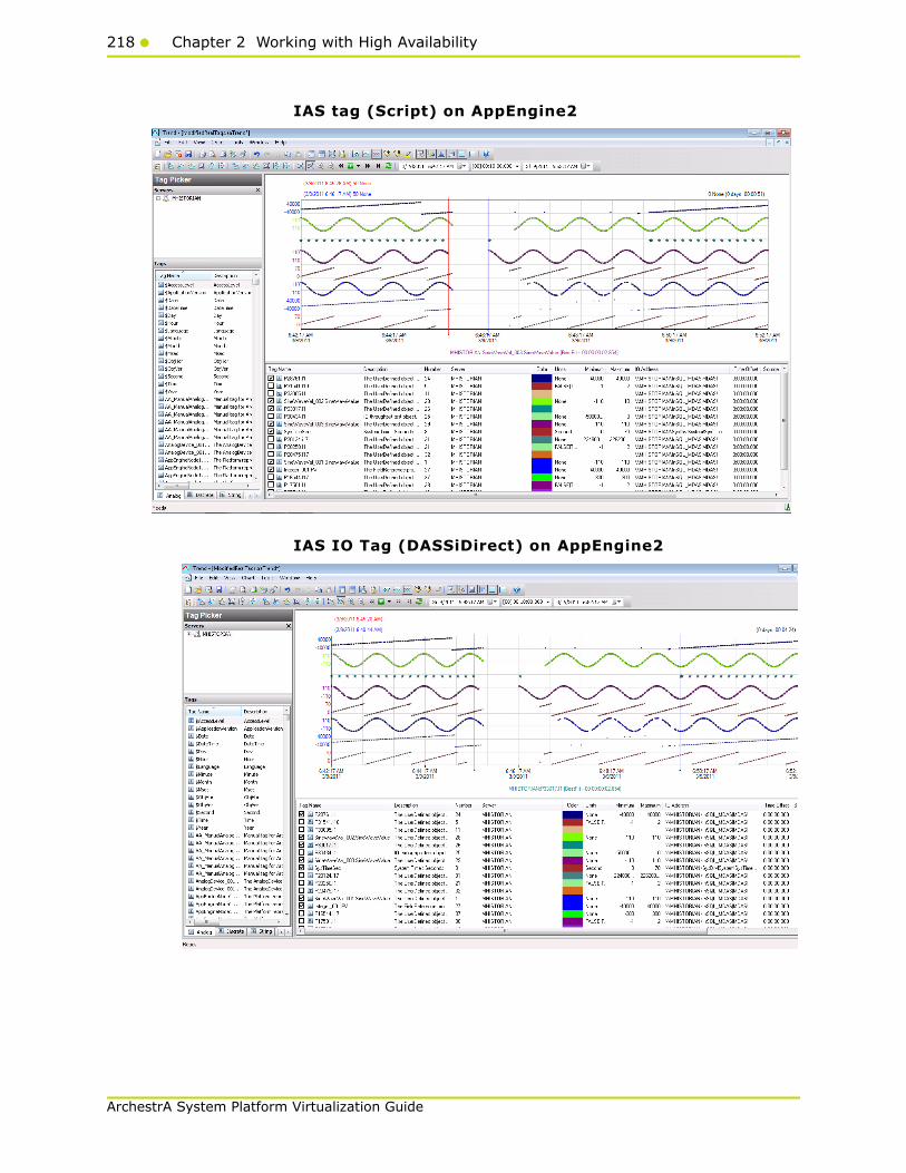
218 Chapter 2 Working with High Availability
ArchestrA System Platform Virtualization Guide
IAS tag (Script) on AppEngine2
IAS IO Tag (DASSiDirect) on AppEngine2
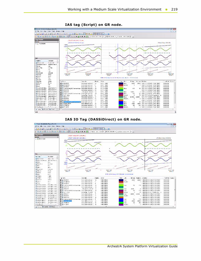
Working with a Medium Scale Virtualization Environment219
ArchestrA System Platform Virtualization Guide
IAS tag (Script) on GR node.
IAS IO Tag (DASSiDirect) on GR node.

220 Chapter 2 Working with High Availability
ArchestrA System Platform Virtualization Guide
$Second (InTouch) on Historian node
SysTimeSec on Historian node

Working with a Medium Scale Virtualization Environment221
ArchestrA System Platform Virtualization Guide
Scenario 2: Virtualization Server Hardware Fails
Failover Due to Hardware failure
The failover occurs due to hardware failure, and it is simulated with power-off on the host server.
Trends:
AppEngine1
IAS Tag (Script)

222 Chapter 2 Working with High Availability
ArchestrA System Platform Virtualization Guide
IAS IO Tag (DASSiDirect)
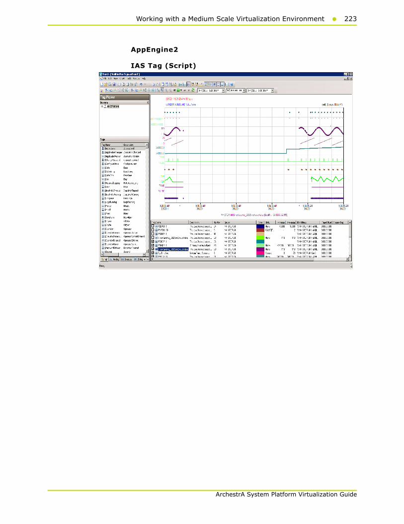
Working with a Medium Scale Virtualization Environment223
ArchestrA System Platform Virtualization Guide
AppEngine2
IAS Tag (Script)

224 Chapter 2 Working with High Availability
ArchestrA System Platform Virtualization Guide
IAS IO Tag (DASSiDirect)
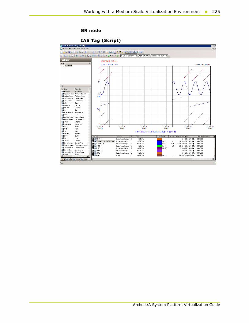
Working with a Medium Scale Virtualization Environment225
ArchestrA System Platform Virtualization Guide
GR node
IAS Tag (Script)

226 Chapter 2 Working with High Availability
ArchestrA System Platform Virtualization Guide
IAS IO Tag (DASSiDirect)
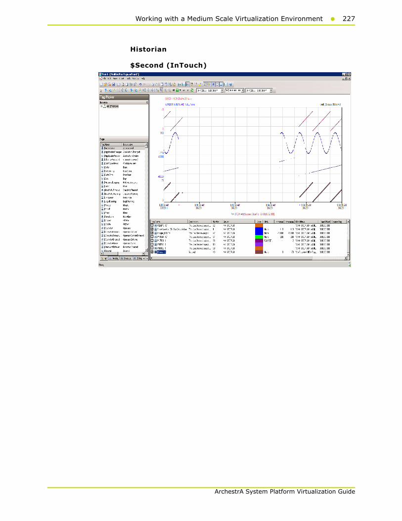
Working with a Medium Scale Virtualization Environment227
ArchestrA System Platform Virtualization Guide
Historian
$Second (InTouch)
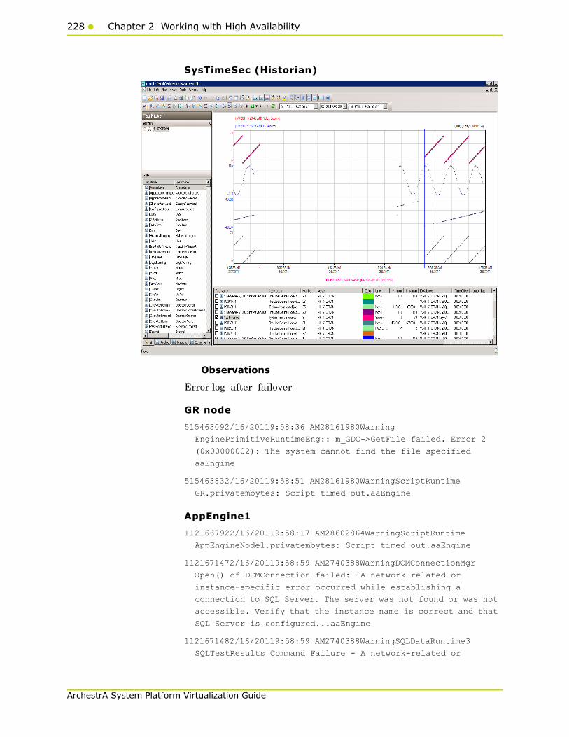
228 Chapter 2 Working with High Availability
ArchestrA System Platform Virtualization Guide
SysTimeSec (Historian)
Observations
Error log after failover
GR node
515463092/16/20119:58:36 AM28161980Warning
EnginePrimitiveRuntimeEng:: m_GDC->GetFile failed. Error 2
(0x00000002): The system cannot find the file specified
aaEngine
515463832/16/20119:58:51 AM28161980WarningScriptRuntime
GR.privatembytes: Script timed out.aaEngine
AppEngine1
1121667922/16/20119:58:17 AM28602864WarningScriptRuntime
AppEngineNode1.privatembytes: Script timed out.aaEngine
1121671472/16/20119:58:59 AM2740388WarningDCMConnectionMgr
Open() of DCMConnection failed: 'A network-related or
instance-specific error occurred while establishing a
connection to SQL Server. The server was not found or was not
accessible. Verify that the instance name is correct and that
SQL Server is configured...aaEngine
1121671482/16/20119:58:59 AM2740388WarningSQLDataRuntime3
SQLTestResults Command Failure - A network-related or
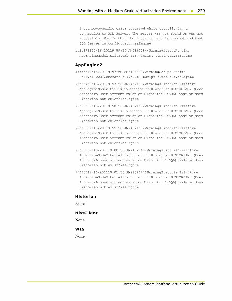
Working with a Medium Scale Virtualization Environment229
ArchestrA System Platform Virtualization Guide
instance-specific error occurred while establishing a
connection to SQL Server. The server was not found or was not
accessible. Verify that the instance name is correct and that
SQL Server is configured...aaEngine
1121676622/16/20119:59:59 AM28602864WarningScriptRuntime
AppEngineNode1.privatembytes: Script timed out.aaEngine
AppEngine2
55385612/16/20119:57:50 AM31283132WarningScriptRuntime
HourVal_003.GenerateHourValue: Script timed out.aaEngine
55385752/16/20119:57:56 AM24521672WarningHistorianPrimitive
AppEngineNode2 failed to connect to Historian HISTORIAN. (Does
ArchestrA user account exist on Historian(InSQL) node or does
Historian not exist?)aaEngine
55385952/16/20119:58:56 AM24521672WarningHistorianPrimitive
AppEngineNode2 failed to connect to Historian HISTORIAN. (Does
ArchestrA user account exist on Historian(InSQL) node or does
Historian not exist?)aaEngine
55385962/16/20119:59:56 AM24521672WarningHistorianPrimitive
AppEngineNode2 failed to connect to Historian HISTORIAN. (Does
ArchestrA user account exist on Historian(InSQL) node or does
Historian not exist?)aaEngine
55385982/16/201110:00:56 AM24521672WarningHistorianPrimitive
AppEngineNode2 failed to connect to Historian HISTORIAN. (Does
ArchestrA user account exist on Historian(InSQL) node or does
Historian not exist?)aaEngine
55386042/16/201110:01:56 AM24521672WarningHistorianPrimitive
AppEngineNode2 failed to connect to Historian HISTORIAN. (Does
ArchestrA user account exist on Historian(InSQL) node or does
Historian not exist?)aaEngine
Historian
None
HistClient
None
WIS
None
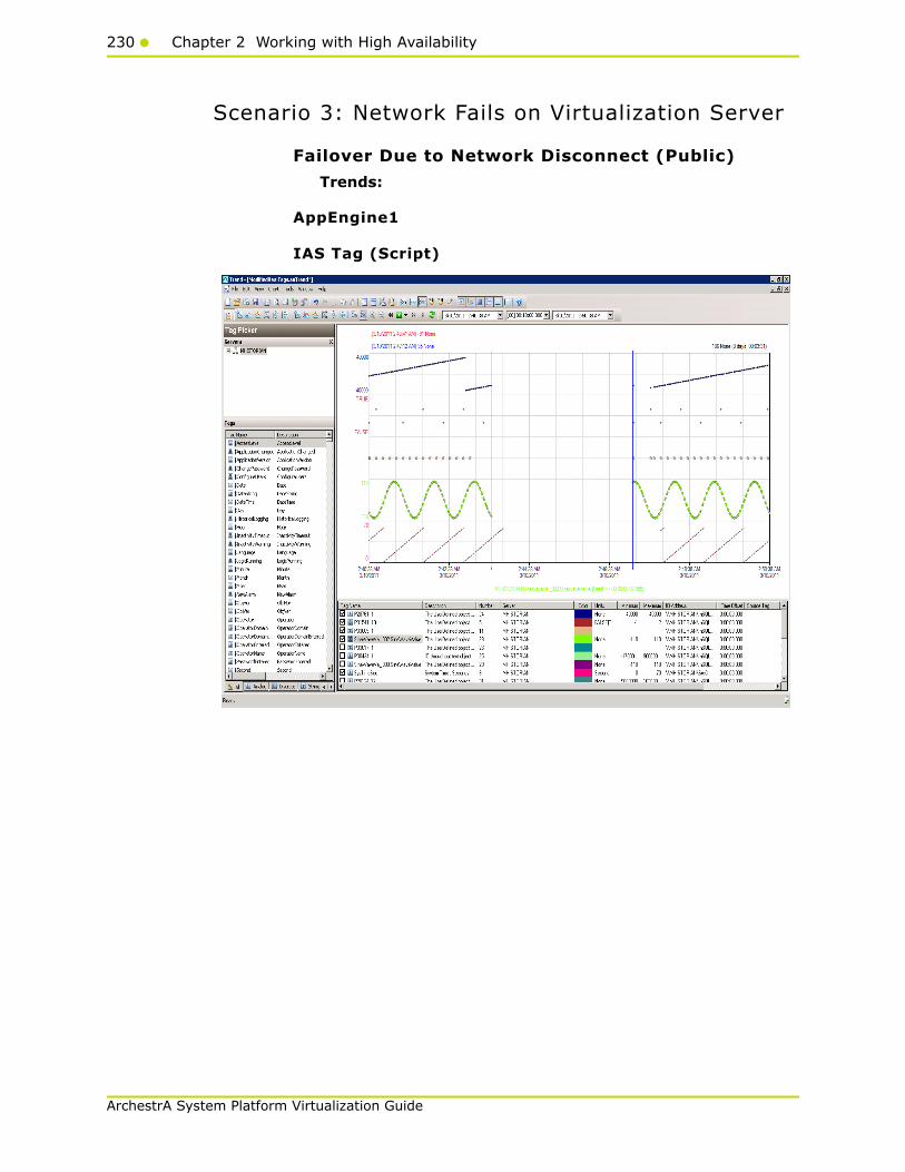
230 Chapter 2 Working with High Availability
ArchestrA System Platform Virtualization Guide
Scenario 3: Network Fails on Virtualization Server
Failover Due to Network Disconnect (Public)
Trends:
AppEngine1
IAS Tag (Script)

Working with a Medium Scale Virtualization Environment231
ArchestrA System Platform Virtualization Guide
IAS IO Tag (DASSiDirect)

232 Chapter 2 Working with High Availability
ArchestrA System Platform Virtualization Guide
AppEngine2
IAS Tag (Script)
IAS IO Tag (DASSiDirect)

Working with a Medium Scale Virtualization Environment233
ArchestrA System Platform Virtualization Guide
GR
IAS Tag (Script)
IAS IO Tag (DASSiDirect)

234 Chapter 2 Working with High Availability
ArchestrA System Platform Virtualization Guide
Historian
$ Second (InTouch)
SysTimeSec
Observations
Error log after failover
GR node
516659502/16/20113:05:39 PM30563060Warning
EnginePrimitiveRuntimeEng:: m_GDC->GetFile failed. Error 2
(0x00000002): The system cannot find the file specified
aaEngine
516660272/16/20113:06:03 PM30563060WarningScriptRuntime
GR.privatembytes: Script timed out.aaEngine
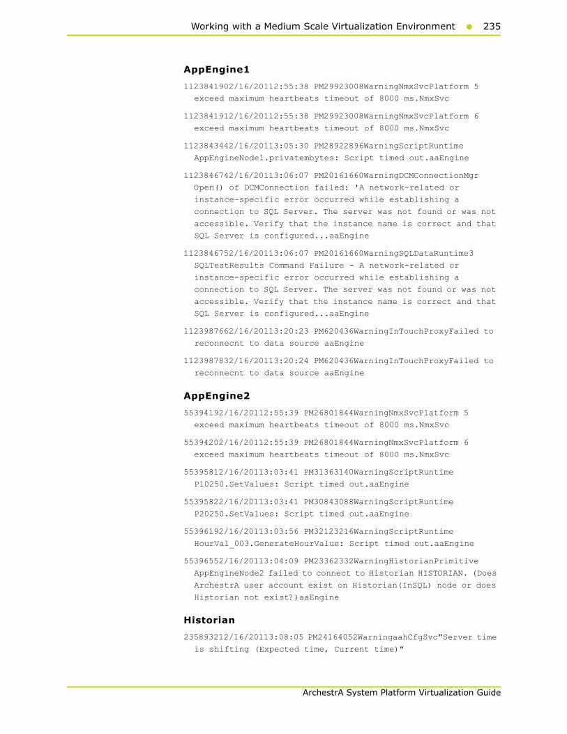
Working with a Medium Scale Virtualization Environment235
ArchestrA System Platform Virtualization Guide
AppEngine1
1123841902/16/20112:55:38 PM29923008WarningNmxSvcPlatform 5
exceed maximum heartbeats timeout of 8000 ms.NmxSvc
1123841912/16/20112:55:38 PM29923008WarningNmxSvcPlatform 6
exceed maximum heartbeats timeout of 8000 ms.NmxSvc
1123843442/16/20113:05:30 PM28922896WarningScriptRuntime
AppEngineNode1.privatembytes: Script timed out.aaEngine
1123846742/16/20113:06:07 PM20161660WarningDCMConnectionMgr
Open() of DCMConnection failed: 'A network-related or
instance-specific error occurred while establishing a
connection to SQL Server. The server was not found or was not
accessible. Verify that the instance name is correct and that
SQL Server is configured...aaEngine
1123846752/16/20113:06:07 PM20161660WarningSQLDataRuntime3
SQLTestResults Command Failure - A network-related or
instance-specific error occurred while establishing a
connection to SQL Server. The server was not found or was not
accessible. Verify that the instance name is correct and that
SQL Server is configured...aaEngine
1123987662/16/20113:20:23 PM620436WarningInTouchProxyFailed to
reconnecnt to data source aaEngine
1123987832/16/20113:20:24 PM620436WarningInTouchProxyFailed to
reconnecnt to data source aaEngine
AppEngine2
55394192/16/20112:55:39 PM26801844WarningNmxSvcPlatform 5
exceed maximum heartbeats timeout of 8000 ms.NmxSvc
55394202/16/20112:55:39 PM26801844WarningNmxSvcPlatform 6
exceed maximum heartbeats timeout of 8000 ms.NmxSvc
55395812/16/20113:03:41 PM31363140WarningScriptRuntime
P10250.SetValues: Script timed out.aaEngine
55395822/16/20113:03:41 PM30843088WarningScriptRuntime
P20250.SetValues: Script timed out.aaEngine
55396192/16/20113:03:56 PM32123216WarningScriptRuntime
HourVal_003.GenerateHourValue: Script timed out.aaEngine
55396552/16/20113:04:09 PM23362332WarningHistorianPrimitive
AppEngineNode2 failed to connect to Historian HISTORIAN. (Does
ArchestrA user account exist on Historian(InSQL) node or does
Historian not exist?)aaEngine
Historian
235893212/16/20113:08:05 PM24164052WarningaahCfgSvc"Server time
is shifting (Expected time, Current time)"

236 Chapter 2 Working with High Availability
ArchestrA System Platform Virtualization Guide
(02/16/11,15:08:04,096, 02/16/11,15:08:10,003) [HISTORIAN;
Config.cpp; 2040]aahCfgSvc
Failover Due to Network Disconnect (Plant)
Trends
AppEngine1
IAS IO Tag (DASSiDirect)

Working with a Medium Scale Virtualization Environment237
ArchestrA System Platform Virtualization Guide
AppEngine2
IAS IO Tag (DASSiDirect)
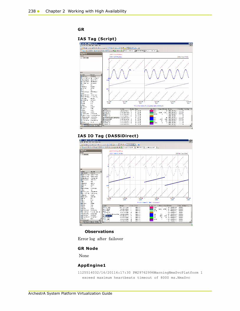
238 Chapter 2 Working with High Availability
ArchestrA System Platform Virtualization Guide
GR
IAS Tag (Script)
IAS IO Tag (DASSiDirect)
Observations
Error log after failover
GR Node
None
AppEngine1
1125514032/16/20116:17:30 PM29762996WarningNmxSvcPlatform 1
exceed maximum heartbeats timeout of 8000 ms.NmxSvc
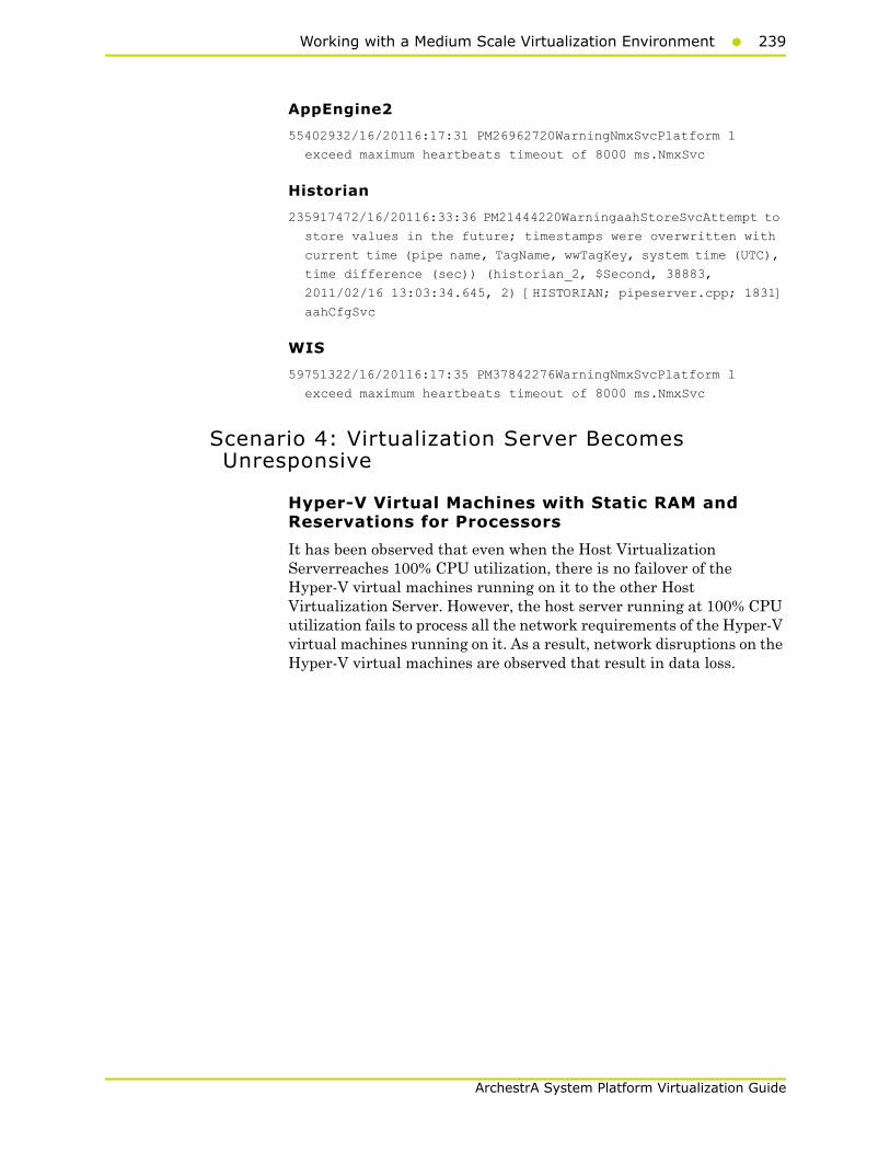
Working with a Medium Scale Virtualization Environment239
ArchestrA System Platform Virtualization Guide
AppEngine2
55402932/16/20116:17:31 PM26962720WarningNmxSvcPlatform 1
exceed maximum heartbeats timeout of 8000 ms.NmxSvc
Historian
235917472/16/20116:33:36 PM21444220WarningaahStoreSvcAttempt to
store values in the future; timestamps were overwritten with
current time (pipe name, TagName, wwTagKey, system time (UTC),
time difference (sec)) (historian_2, $Second, 38883,
2011/02/16 13:03:34.645, 2) [HISTORIAN; pipeserver.cpp; 1831]
aahCfgSvc
WIS
59751322/16/20116:17:35 PM37842276WarningNmxSvcPlatform 1
exceed maximum heartbeats timeout of 8000 ms.NmxSvc
Scenario 4: Virtualization Server Becomes Unresponsive
Hyper-V Virtual Machines with Static RAM and Reservations for Processors
It has been observed that even when the Host Virtualization Serverreaches 100% CPU utilization, there is no failover of the Hyper-V virtual machines running on it to the other Host Virtualization Server. However, the host server running at 100% CPU utilization fails to process all the network requirements of the Hyper-V virtual machines running on it. As a result, network disruptions on the Hyper-V virtual machines are observed that result in data loss.
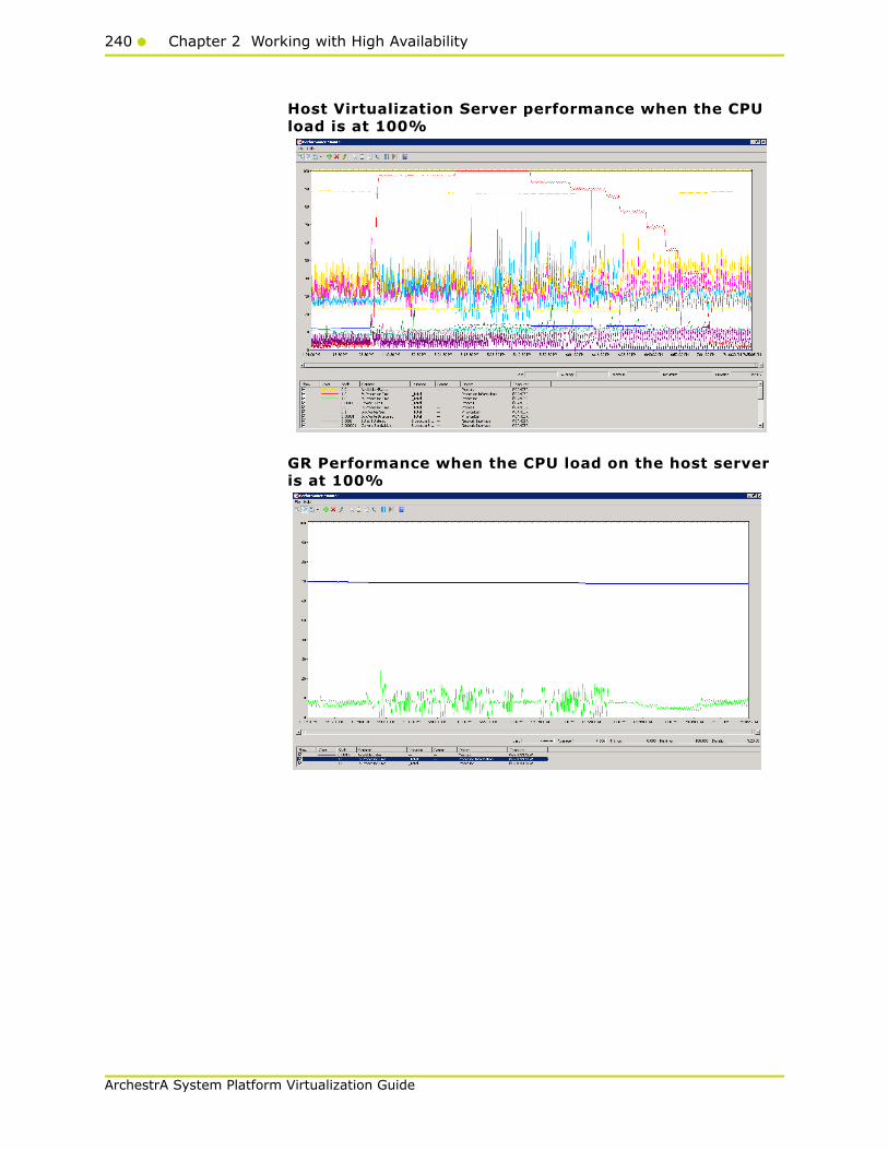
240 Chapter 2 Working with High Availability
ArchestrA System Platform Virtualization Guide
Host Virtualization Server performance when the CPU load is at 100%
GR Performance when the CPU load on the host server is at 100%
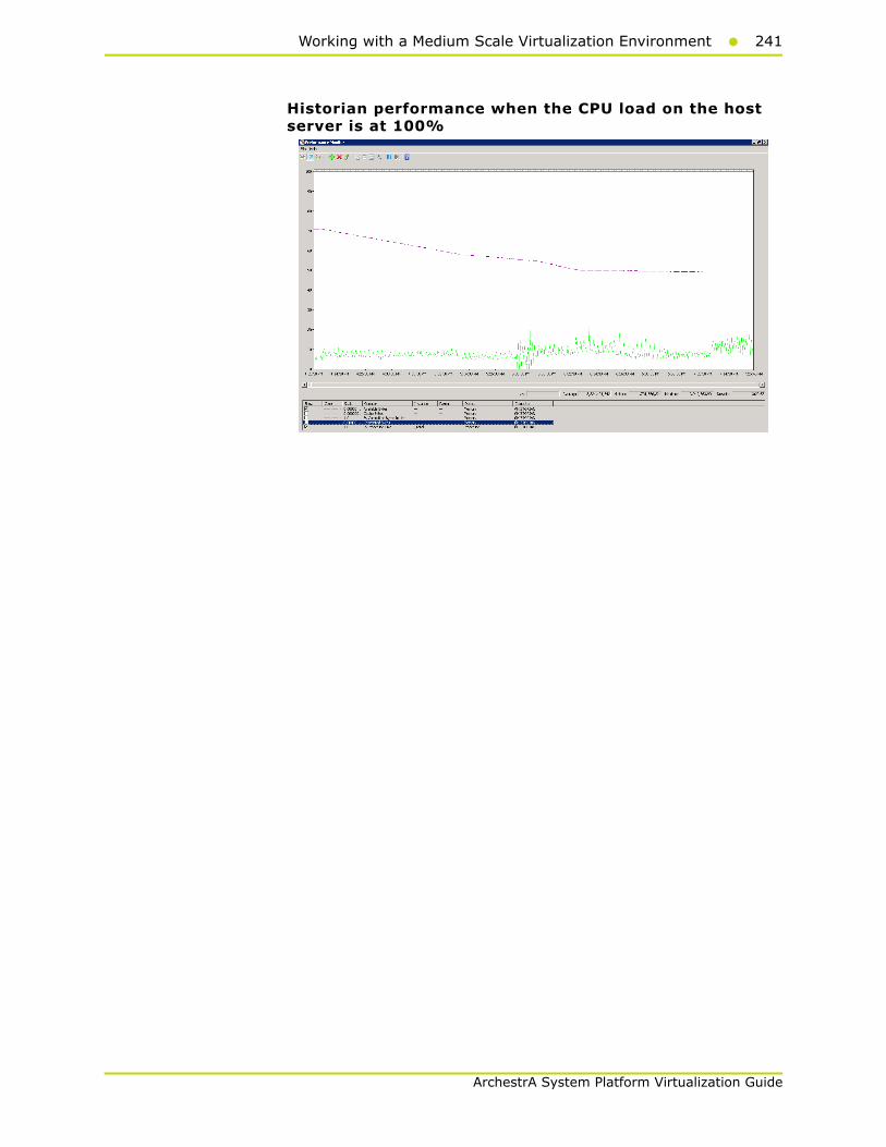
Working with a Medium Scale Virtualization Environment241
ArchestrA System Platform Virtualization Guide
Historian performance when the CPU load on the host server is at 100%

242 Chapter 2 Working with High Availability
ArchestrA System Platform Virtualization Guide
Observations When CPU Load is 100% on Host Virtualization Server
The virtual machines do not failover when the CPU load was maintained at 100%. All the virtual machines continue to run on the same Host Virtualization Server even though the CPU load is high.
The message - "Snapshot write operation took longer than 10 seconds" - is expected when the virtual machines are running at high Processor Time% (Historian at 89% and GR Node at 35%).
As time is not synchronized on the Historian, AppEngine, and the GR nodes, a message - "Values in the past did not fit within the realtime window"- is expected.
AppEngine1
1140593102/18/20115:31:25 PM36963700WarningScriptRuntime
Insert.InsertValueOT: Script timed out.aaEngine
1140644952/18/20115:37:24 PM36963700WarningScriptRuntime
Insert.InsertValueWF: Script timed out.aaEngine
1140662112/18/20115:39:26 PM36963700WarningScriptRuntime
Insert.InsertValueWT: Script timed out.aaEngine
1140662282/18/20115:39:30 PM36963700WarningScriptRuntime
Insert.InsertValuePerodic: Script timed out.aaEngine
AppEngine2
None
GR node
None
Historian node
236067632/18/20115:10:40 PM33842780WarningaahStoreSvcSnapshot
write operation took longer than 10 seconds. Change your
system settings to decrease size of snapshot or stop other
applications which may affect this parameter (1024, 3, 0,
203203432, 5893027, 15) [HISTORIAN; deltastore.cpp; 2669]
aahCfgSvc
236067642/18/20115:10:52 PM33842780WarningaahStoreSvcSnapshot
write operation took longer than 10 seconds. Change your
system settings to decrease size of snapshot or stop other
applications which may affect this parameter (1024, 3, 0,
209096459, 4186312, 11) [HISTORIAN; deltastore.cpp; 2669]
aahCfgSvc
236067672/18/20115:11:24 PM33842780WarningaahStoreSvcAttempt to
store values in the future; timestamps were overwritten with
current time (pipe name, TagName, wwTagKey, system time (UTC),
time difference (sec)) (HISTORIAN_mdas,

Working with a Medium Scale Virtualization Environment243
ArchestrA System Platform Virtualization Guide
DifferentQuality.goodbool, 19605, 2011/02/18 11:37:11.126, 1)
[HISTORIAN; pipeser...aahCfgSvc
WIS node
59756382/18/20115:11:23 PM36723676WarningNmxSvcPlatform 1
exceed maximum heartbeats timeout of 8000 ms.NmxSvc
Trend when CPU utilization is 100%
From the above trend, it is observed that there is data loss for IAS IO tags and script tags also on the GR Node and the AppEngine nodes.
Observations When CPU Load is 96% on Host Virtualization Server
The virtual machines do not failover when the CPU load was maintained at 96%. All the virtual machines continue to run on the same Host Virtualization Server even though the CPU load is high.
Only the following warning massage was observed when the CPU load of the host server was 96%.
Historian node
236067282/18/20115:07:12 PM33842780WarningaahStoreSvcAttempt to store values in the future; timestamps were overwritten with current time (pipe name, TagName, wwTagKey, system time (UTC), time difference (sec)) (HISTORIAN_mdas, DifferentQuality.goodbool, 19605, 2011/02/18 11:37:11.126, 1) [HISTORIAN; pipeser...aahCfgSvc
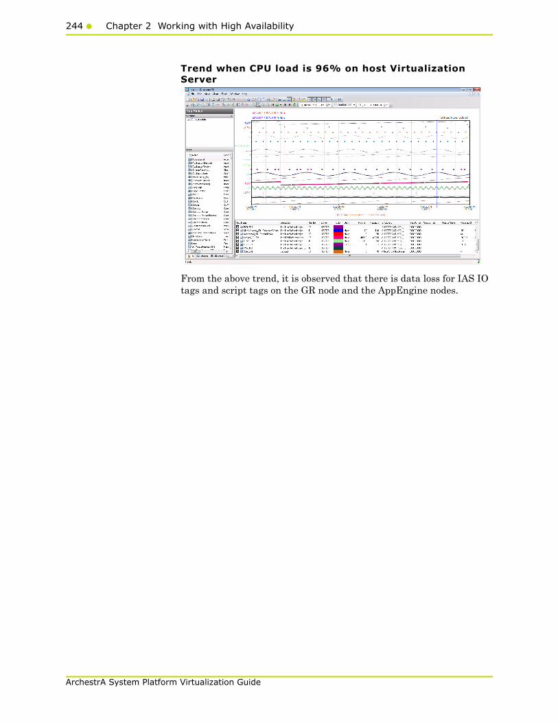
244 Chapter 2 Working with High Availability
ArchestrA System Platform Virtualization Guide
Trend when CPU load is 96% on host Virtualization Server
From the above trend, it is observed that there is data loss for IAS IO tags and script tags on the GR node and the AppEngine nodes.
245
ArchestrA System Platform Virtualization Guide
Chapter 3
Working with DisasterRecovery
This section introduces several Disaster Recovery (DR) virtualization solutions that improve the availability of System Platform Products. For more information refer to Chapter 1 Getting Started with High Availability and Disaster Recovery.
The set-up and configuration procedures, expected Recovery Time Objective (RTO) observations, Recovery Point Objective (RPO) observations, and data trend snapshots are presented first for small-scale virtualization environment, and are then repeated for medium-scale virtualization environment.
Recommendations and Best Practices• Ensure that auto log on is set up for all Hyper-V virtual machines
running the System Platform products. This is to ensure that these Hyper-V virtual machines start up automatically after the failover.
• Ensure the time on all the Hyper-V Host Servers, the virtual machines and all other nodes which are part of the Disaster Recovery Environment are continuously synchronized. Otherwise, the Hyper-V virtual machines running on the host experience time drifts and results in discarding of data.You can add the time synchronization utility in the Start Up programs so that this utlity starts automatically whenever the Hyper V machine reboots.
246 Chapter 3 Working with Disaster Recovery
ArchestrA System Platform Virtualization Guide
• On the host servers disable all the network cards which are not utilized by the System Platform Environment. This is to avoid any confusion during the network selections while setting up the cluster.
• As per the topology described above for the Disaster Recovery environment, only one network is used for all communications. If multiple networks are being used, then make sure only the primary network which is used for the communication between the Hyper-V Nodes is enabled for the Failover Cluster Communication. Disable the remaining cluster networks in Failover Cluster Manager.
• Ensure the virtual networks created in Hyper-V Manager have the same name across all the nodes which are participating in the Cluster. Otherwise, migration/failover of Hyper-V virtual machines will fail.
Best Practices for SteelEye DataKeeper Mirroring:
• While creating the SteelEye DataKeeper mirroring job, ensure the drive letters of the source and target drives to be mirrored are same.
• It is suggested to have zero latency in the network when SteelEye DataKeeper mirroring, failover/migration of virtual machines between host servers take place. In case of networks with latency, refer to the SteelEye documentation on network requirements.
• While designing the network architecture particularly bandwidth between the hosts in the Disaster Recovery Environment, make sure to select the bandwidth based on the rate of data change captured from Disk Write Bytes/Sec on the host server for all the mirrored volumes. To verify that you have sufficient network bandwidth to successfully replicate your volume, use the Windows Performance Monitoring and Alerts tool to collect Write Bytes/sec on the replicated volumes to calculate the rate of data change. Collect this counter every 10 seconds and use your own data analysis program to estimate your rate of data change. For more details, refer to SteelEye documentation on network requirements.
SteelEye DataKeeper can handle the following average rates of change, approximately:
Network Bandwith Rate of Change
1.5 Mbps(T1) 182,000 Bytes/sec (1.45 Mbps)
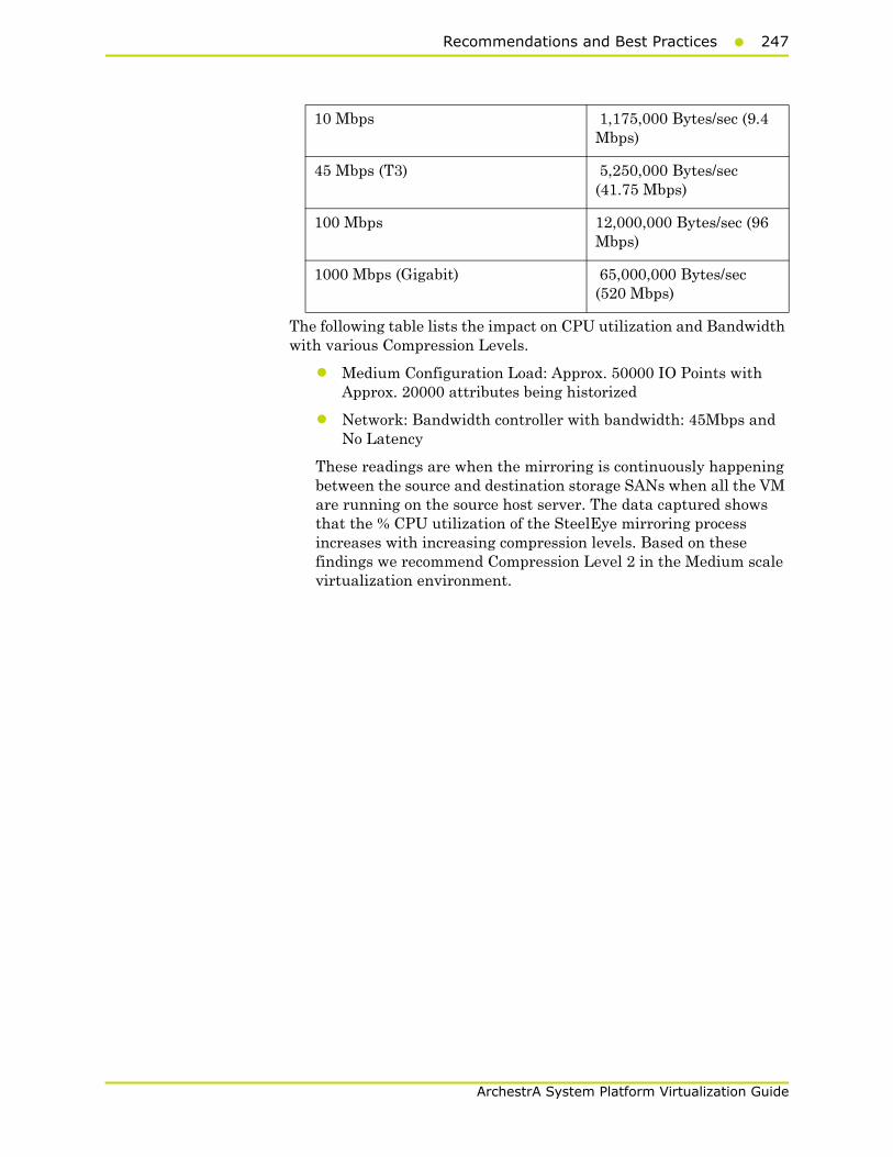
Recommendations and Best Practices247
ArchestrA System Platform Virtualization Guide
The following table lists the impact on CPU utilization and Bandwidth with various Compression Levels.
• Medium Configuration Load: Approx. 50000 IO Points with Approx. 20000 attributes being historized
• Network: Bandwidth controller with bandwidth: 45Mbps and No Latency
These readings are when the mirroring is continuously happening between the source and destination storage SANs when all the VM are running on the source host server. The data captured shows that the % CPU utilization of the SteelEye mirroring process increases with increasing compression levels. Based on these findings we recommend Compression Level 2 in the Medium scale virtualization environment.
10 Mbps 1,175,000 Bytes/sec (9.4 Mbps)
45 Mbps (T3) 5,250,000 Bytes/sec (41.75 Mbps)
100 Mbps 12,000,000 Bytes/sec (96 Mbps)
1000 Mbps (Gigabit) 65,000,000 Bytes/sec (520 Mbps)
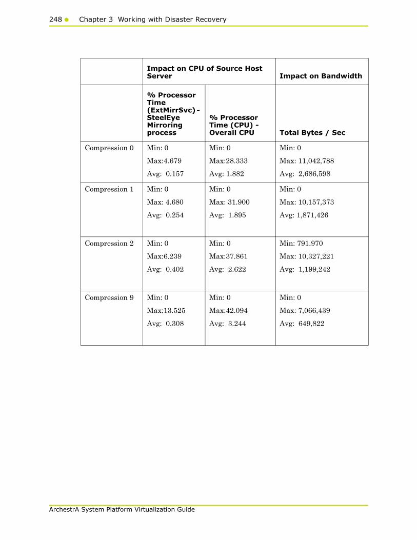
248 Chapter 3 Working with Disaster Recovery
ArchestrA System Platform Virtualization Guide
Impact on CPU of Source Host Server Impact on Bandwidth
% Processor Time (ExtMirrSvc) - SteelEye Mirroring process
% Processor Time (CPU) - Overall CPU Total Bytes / Sec
Compression 0 Min: 0
Max:4.679
Avg: 0.157
Min: 0
Max:28.333
Avg: 1.882
Min: 0
Max: 11,042,788
Avg: 2,686,598
Compression 1 Min: 0
Max: 4.680
Avg: 0.254
Min: 0
Max: 31.900
Avg: 1.895
Min: 0
Max: 10,157,373
Avg: 1,871,426
Compression 2 Min: 0
Max:6.239
Avg: 0.402
Min: 0
Max:37.861
Avg: 2.622
Min: 791.970
Max: 10,327,221
Avg: 1,199,242
Compression 9 Min: 0
Max:13.525
Avg: 0.308
Min: 0
Max:42.094
Avg: 3.244
Min: 0
Max: 7,066,439
Avg: 649,822
Recommendations and Best Practices249
ArchestrA System Platform Virtualization Guide
System Platform Product-specific recommendations and observations
• During the preparation for Live and Quick migrations it is observed that the network freezes intermittently and then at the time of actual migration connectivity to the VM is lost. As a result, the System Platform node under migration experiences intermittent data loss during the preparation for Live and Quick migrations, and then has a data gap for the duration of actual migration.
Historian
• In case of Live and Quick migration of Historian, you may notice that Historian logs values with quality detail 448 and there may be values logged twice with same timestamps. This is because the suspended Historian VM starts on the other cluster node with the system time it was suspended at before the migration. As a result, some of the data points it is receiving with the current time seem to be in the future to the Historian. This results in Historian modifying the timestamps to its system time and updating the QD to 448. This happens until the system time of the Historian node catches up with the real current time using the TimeSync utility, after which the problem goes away. So, it is recommended to stop the historian before the migration and restart it after the VM is migrated and its system time is synced up with the current time.
• Live and Quick migration of Historian should not be done when the block change over is in progress on the Historian node.
• If a failover happens (for example, due to a network disconnect on the source Host Virtualization Server) while the Historian status is still “Starting”, the Historian node fails over to the target Host Virtualization Server. In the target host, Historian fails to start. To recover from this state, kill the Historian services that failed to start and then start the Historian by launching the SMC.
InTouch
• Ensure that InTouch Window Viewer is added to the Start Up programs so that the view is started automatically when the virtual machine reboots.
250 Chapter 3 Working with Disaster Recovery
ArchestrA System Platform Virtualization Guide
Application Server
• If a failover happens (for example, due to a network disconnect on the source Host Virtualization Server) while the Galaxy Migration is in progress, the GR node fails over to the target Host Virtualization Server. In the target host, on opening the IDE for the galaxy, the templates do not appear in the Template toolbox and in Graphic toolbox. To recover from this state, delete the galaxy and create new Galaxy. Initiate the migration process once again.
• If a failover happens (for example, due to an abrupt power-off on the source Host Virtualization Server) while a platform deploy is in progress, the Platform node fails over to the target Host Virtualization Server. In the target host, some objects will be in deployed state and the rest will be in undeployed state. To recover from this state, redeploy the whole Platform once again.
• If a failover happens (for example, due to an abrupt power-off on the source Host Virtualization Server) while a platform undeploy is in progress, the Platform node fails over to the target Host Virtualization Server. In the target host, some objects will be in undeployed state and the rest will be in deployed state. To recover from this state, undeploy the whole Platform once again.
Data Access Server
• In case of Live and Quick migration of I/O Server node (for example, DASSIDirect), InTouch I/O tags acquiring data from that I/O server needs to be reinitialized after the I/O server node is migrated. To automatically acquire the data for these tags from the I/O server after migration, it is recommended to have an InTouch script which monitors the quality status of any of those tags and triggers reinitialize I/O once the quality goes to bad. Execute this script every 3 to 5 seconds until the tag quality becomes good.
Working with a Small Scale Virtualization Environment
This chapter contains the following topics:
• Setting Up Small Scale Virtualization Environment
• Configuration of System Platform Products in a Typical Small Scale Virtualization
• Expected Recovery Time Objective and Recovery Point Objective
• Snapshots of Data Trends and Observations

Working with a Small Scale Virtualization Environment251
ArchestrA System Platform Virtualization Guide
Setting Up Small Scale Virtualization Environment
The following procedures help you to set up small scale virtualization disaster recovery environment.
Planning for Disaster RecoveryThe minimum and recommended hardware and software requirements for the Host and Virtual machines used for small scale virtualization disaster recovery environment.
Hyper-V Hosts
Note: For the Hyper-V Host to function optimally, the server should have the same processor, RAM, storage and service pack level. Preferably, the servers should be purchased in pairs to avoid hardware discrepancies. Though the differences are supported, it will impact the performance during failovers.
Virtual Machines
Using the above Specified Hyper-V Host , three virtual machines can be created with below Configuration.
Virtual Machine 1: DAS SI, Historian, and Application Server (GR) Node
Processor: Two - 2.66 GHz Intel Xeon with - 8 Cores
Operating System Windows Server 2008 R2 Enterprise with Hyper-V Enabled
Memory 12GB
Storage Local Volume with Capacity of 500 GB
Processor Host Compatible Processor with 2-4 Cores
Operating System Windows Server 2008 R2 Standard
Memory 4 GB
Storage 80 GB
System Platform Products Installed
Historian, ArchestrA, DAS SI
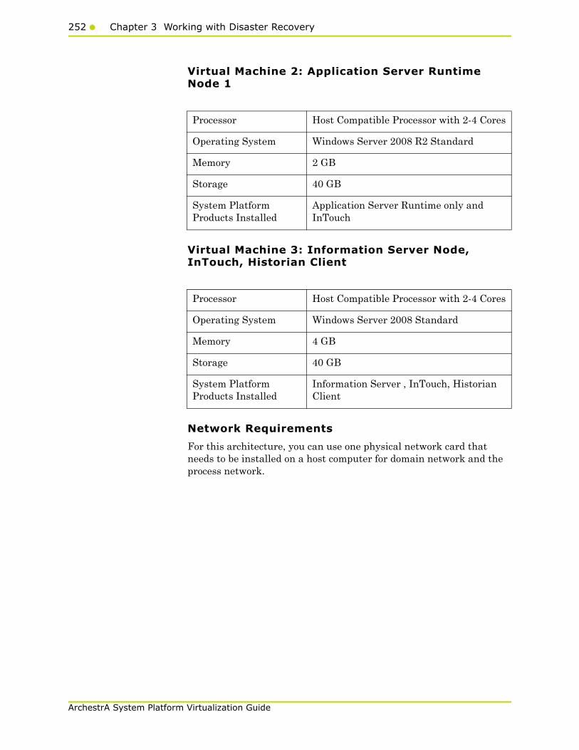
252 Chapter 3 Working with Disaster Recovery
ArchestrA System Platform Virtualization Guide
Virtual Machine 2: Application Server Runtime Node 1
Virtual Machine 3: Information Server Node, InTouch, Historian Client
Network Requirements
For this architecture, you can use one physical network card that needs to be installed on a host computer for domain network and the process network.
Processor Host Compatible Processor with 2-4 Cores
Operating System Windows Server 2008 R2 Standard
Memory 2 GB
Storage 40 GB
System Platform Products Installed
Application Server Runtime only and InTouch
Processor Host Compatible Processor with 2-4 Cores
Operating System Windows Server 2008 Standard
Memory 4 GB
Storage 40 GB
System Platform Products Installed
Information Server , InTouch, Historian Client

Working with a Small Scale Virtualization Environment253
ArchestrA System Platform Virtualization Guide
Configuring Failover ClusterThe recommended topology of the failover cluster for disaster recovery process for small scale virtualization environment is given below:
This setup requires a minimum of two host servers with sufficient local disk space on each server to create logical drives for the virtual machines. Each logical drive is replicated to the two hosts for disaster recovery. Another independent node is used for configuring the quorum. For more information on configuring the quorum, refer to"Configuring Cluster Quorum Settings" on page 264.
The following process will guide how to set up the small virtualization disaster recovery environment.
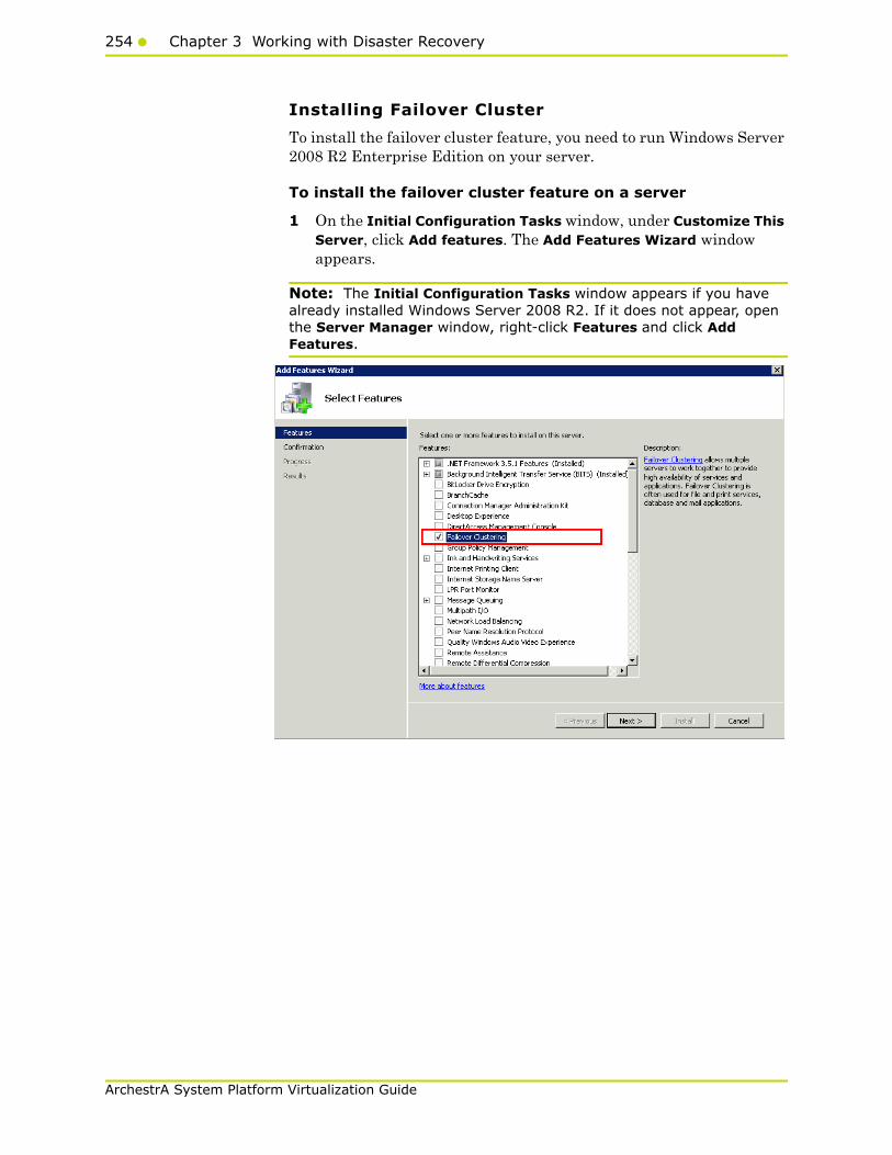
254 Chapter 3 Working with Disaster Recovery
ArchestrA System Platform Virtualization Guide
Installing Failover Cluster
To install the failover cluster feature, you need to run Windows Server 2008 R2 Enterprise Edition on your server.
To install the failover cluster feature on a server
1 On the Initial Configuration Tasks window, under Customize This Server, click Add features. The Add Features Wizard window appears.
Note: The Initial Configuration Tasks window appears if you have already installed Windows Server 2008 R2. If it does not appear, open the Server Manager window, right-click Features and click Add Features.

Working with a Small Scale Virtualization Environment255
ArchestrA System Platform Virtualization Guide
2 In the Add Features Wizard window, select the Failover Clustering check box, and then click Next. The Confirm Installation Selections area appears.
3 Click Install to complete the installation. The Installation Results area with the installation confirmation message appears.
4 Click Close to close the Add Features Wizard window.
Note: Repeat the procedure to include on all the other nodes that will be part of the Cluster configuration process.

256 Chapter 3 Working with Disaster Recovery
ArchestrA System Platform Virtualization Guide
Validating Cluster Configuration
Before creating a cluster, you must validate your configuration. Validation helps you confirm that the configuration of your servers, network, and storage meet the specific requirements for failover clusters.
To validate the failover cluster configuration
1 Click the Server Manager icon on the toolbar. The Server Manager window appears.
Note: You can also access the Server Manager window from the Administrative Tools window or the Start menu.
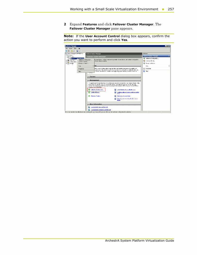
Working with a Small Scale Virtualization Environment257
ArchestrA System Platform Virtualization Guide
2 Expand Features and click Failover Cluster Manager. The Failover Cluster Manager pane appears.
Note: If the User Account Control dialog box appears, confirm the action you want to perform and click Yes.

258 Chapter 3 Working with Disaster Recovery
ArchestrA System Platform Virtualization Guide
3 Under Management, click Validate a Configuration. The Validate a Configuration Wizard window appears. Click Next.
4 In the Select Servers or a Cluster screen, you need to do the following:
a Click Browse or enter next to the Enter name field and select the relevant server name.
b From the Selected servers list, select the relevant servers and click Add.
c Click Next. The Testing Options screen appears.
d Enter the server name and click Add. The server gets added to the server box.
Note: To remove a server, select the server and click Remove.

Working with a Small Scale Virtualization Environment259
ArchestrA System Platform Virtualization Guide
5 Click the Run only the tests I select option to skip the storage validation process, and click Next. The Test Selection screen appears.
Note: Click the Run all tests (recommended) option to validate the default selection of tests.
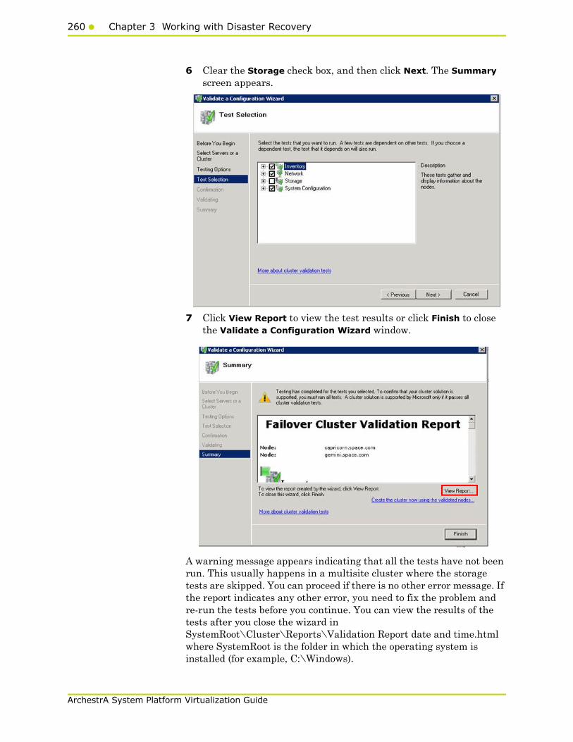
260 Chapter 3 Working with Disaster Recovery
ArchestrA System Platform Virtualization Guide
6 Clear the Storage check box, and then click Next. The Summary screen appears.
7 Click View Report to view the test results or click Finish to close the Validate a Configuration Wizard window.
A warning message appears indicating that all the tests have not been run. This usually happens in a multisite cluster where the storage tests are skipped. You can proceed if there is no other error message. If the report indicates any other error, you need to fix the problem and re-run the tests before you continue. You can view the results of the tests after you close the wizard in SystemRoot\Cluster\Reports\Validation Report date and time.html where SystemRoot is the folder in which the operating system is installed (for example, C:\Windows).
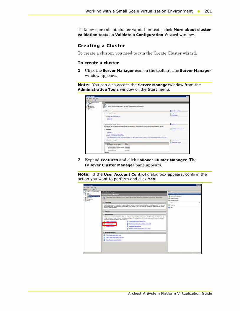
Working with a Small Scale Virtualization Environment261
ArchestrA System Platform Virtualization Guide
To know more about cluster validation tests, click More about cluster validation tests on Validate a Configuration Wizard window.
Creating a Cluster
To create a cluster, you need to run the Create Cluster wizard.
To create a cluster
1 Click the Server Manager icon on the toolbar. The Server Manager window appears.
Note: You can also access the Server Managerwindow from the Administrative Tools window or the Start menu.
2 Expand Features and click Failover Cluster Manager. The Failover Cluster Manager pane appears.
Note: If the User Account Control dialog box appears, confirm the action you want to perform and click Yes.

262 Chapter 3 Working with Disaster Recovery
ArchestrA System Platform Virtualization Guide
3 Under Management, click Create a cluster. The Create Cluster Wizard window appears.
4 View the instructions and click Next. The Validation Warning area appears.
5 Click No. I do not require support from Microsoft for this cluster, and therefore do not want to run the validation tests. Click When I click Next, continue creating the cluster option and click Next. The Select Servers area appears.
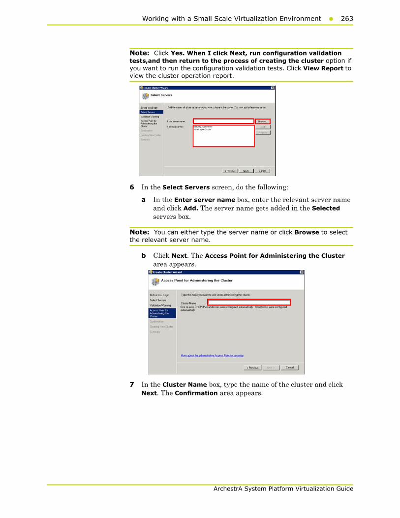
Working with a Small Scale Virtualization Environment263
ArchestrA System Platform Virtualization Guide
Note: Click Yes. When I click Next, run configuration validation tests,and then return to the process of creating the cluster option if you want to run the configuration validation tests. Click View Report to view the cluster operation report.
6 In the Select Servers screen, do the following:
a In the Enter server name box, enter the relevant server name and click Add. The server name gets added in the Selected servers box.
Note: You can either type the server name or click Browse to select the relevant server name.
b Click Next. The Access Point for Administering the Cluster area appears.
7 In the Cluster Name box, type the name of the cluster and click Next. The Confirmation area appears.
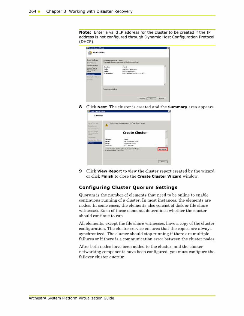
264 Chapter 3 Working with Disaster Recovery
ArchestrA System Platform Virtualization Guide
Note: Enter a valid IP address for the cluster to be created if the IP address is not configured through Dynamic Host Configuration Protocol (DHCP).
8 Click Next. The cluster is created and the Summary area appears.
9 Click View Report to view the cluster report created by the wizard or click Finish to close the Create Cluster Wizard window.
Configuring Cluster Quorum Settings
Quorum is the number of elements that need to be online to enable continuous running of a cluster. In most instances, the elements are nodes. In some cases, the elements also consist of disk or file share witnesses. Each of these elements determines whether the cluster should continue to run.
All elements, except the file share witnesses, have a copy of the cluster configuration. The cluster service ensures that the copies are always synchronized. The cluster should stop running if there are multiple failures or if there is a communication error between the cluster nodes.
After both nodes have been added to the cluster, and the cluster networking components have been configured, you must configure the failover cluster quorum.
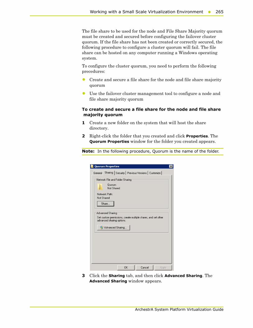
Working with a Small Scale Virtualization Environment265
ArchestrA System Platform Virtualization Guide
The file share to be used for the node and File Share Majority quorum must be created and secured before configuring the failover cluster quorum. If the file share has not been created or correctly secured, the following procedure to configure a cluster quorum will fail. The file share can be hosted on any computer running a Windows operating system.
To configure the cluster quorum, you need to perform the following precedures:
• Create and secure a file share for the node and file share majority quorum
• Use the failover cluster management tool to configure a node and file share majority quorum
To create and secure a file share for the node and file share majority quorum
1 Create a new folder on the system that will host the share directory.
2 Right-click the folder that you created and click Properties. The Quorum Properties window for the folder you created appears.
Note: In the following procedure, Quorum is the name of the folder.
3 Click the Sharing tab, and then click Advanced Sharing. The Advanced Sharing window appears.
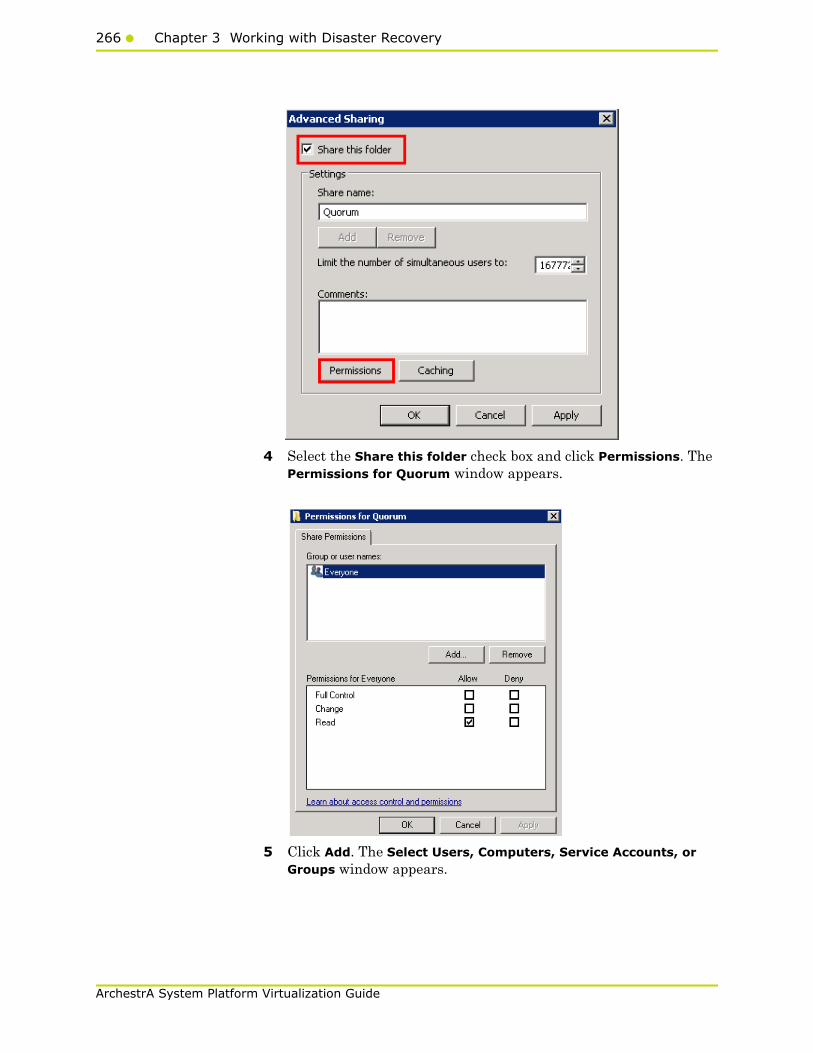
266 Chapter 3 Working with Disaster Recovery
ArchestrA System Platform Virtualization Guide
4 Select the Share this folder check box and click Permissions. The Permissions for Quorum window appears.
5 Click Add. The Select Users, Computers, Service Accounts, or Groups window appears.
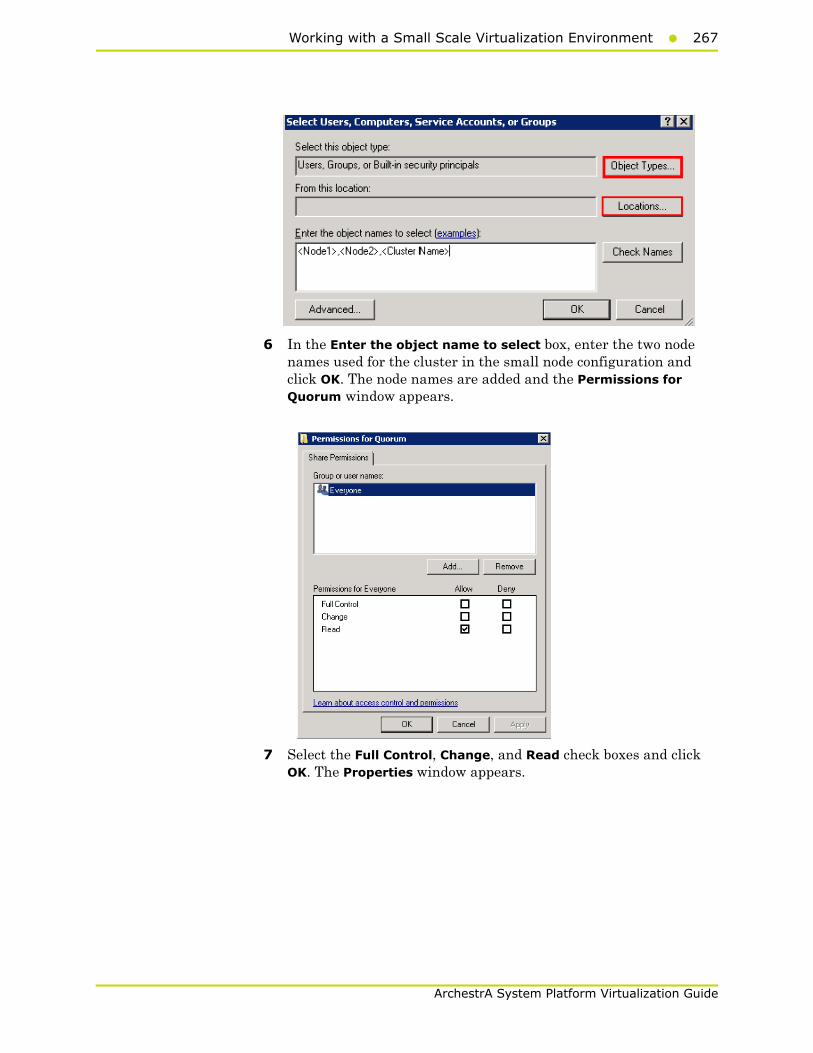
Working with a Small Scale Virtualization Environment267
ArchestrA System Platform Virtualization Guide
6 In the Enter the object name to select box, enter the two node names used for the cluster in the small node configuration and click OK. The node names are added and the Permissions for Quorum window appears.
7 Select the Full Control, Change, and Read check boxes and click OK. The Properties window appears.

268 Chapter 3 Working with Disaster Recovery
ArchestrA System Platform Virtualization Guide
8 Click OK. The folder is shared and can be used to create virtual machines.

Working with a Small Scale Virtualization Environment269
ArchestrA System Platform Virtualization Guide
To configure a node and file share majority quorum using the failover cluster management tool
1 Click the Server Manager icon on the toolbar. The Server Manager window appears.
Note: You can also access the Server Manager window from the Administrative Tools window or the Start menu.
2 Right-click the name of the cluster you created and click More Actions. Click Configure Cluster Quorum Settings. The Configure Cluster Quorum Wizard window appears.
3 View the instructions on the wizard and click Next. The Select Quorum Configuration area appears.
Note: The Before you Begin screen appears the first time you run the wizard. You can hide this screen on subsequent uses of the wizard.
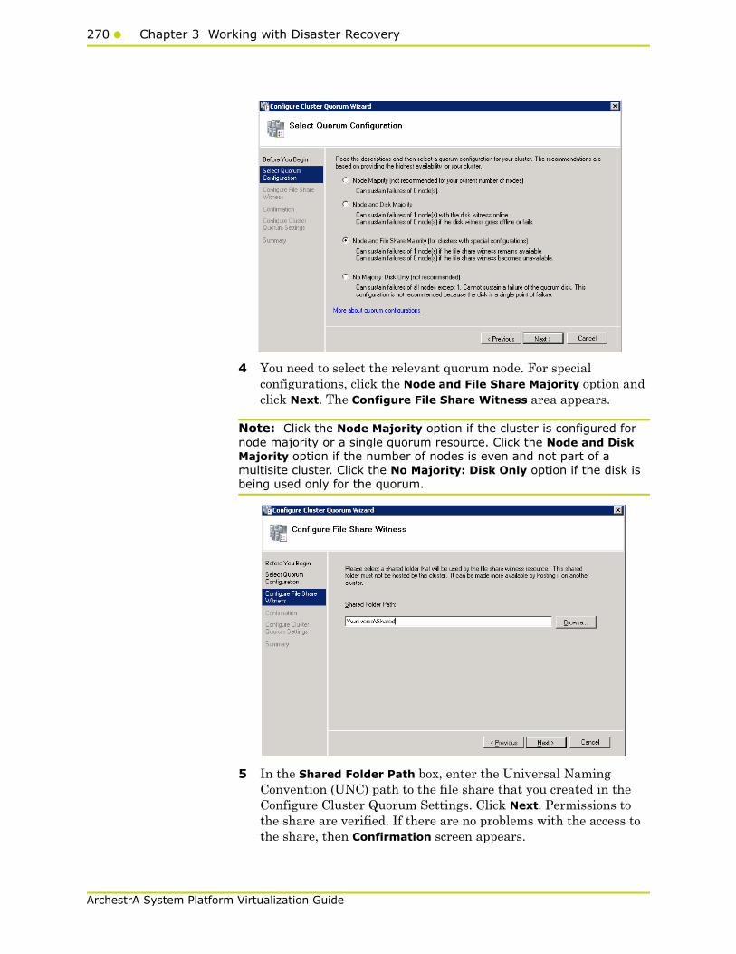
270 Chapter 3 Working with Disaster Recovery
ArchestrA System Platform Virtualization Guide
4 You need to select the relevant quorum node. For special configurations, click the Node and File Share Majority option and click Next. The Configure File Share Witness area appears.
Note: Click the Node Majority option if the cluster is configured for node majority or a single quorum resource. Click the Node and Disk Majority option if the number of nodes is even and not part of a multisite cluster. Click the No Majority: Disk Only option if the disk is being used only for the quorum.
5 In the Shared Folder Path box, enter the Universal Naming Convention (UNC) path to the file share that you created in the Configure Cluster Quorum Settings. Click Next. Permissions to the share are verified. If there are no problems with the access to the share, then Confirmation screen appears.
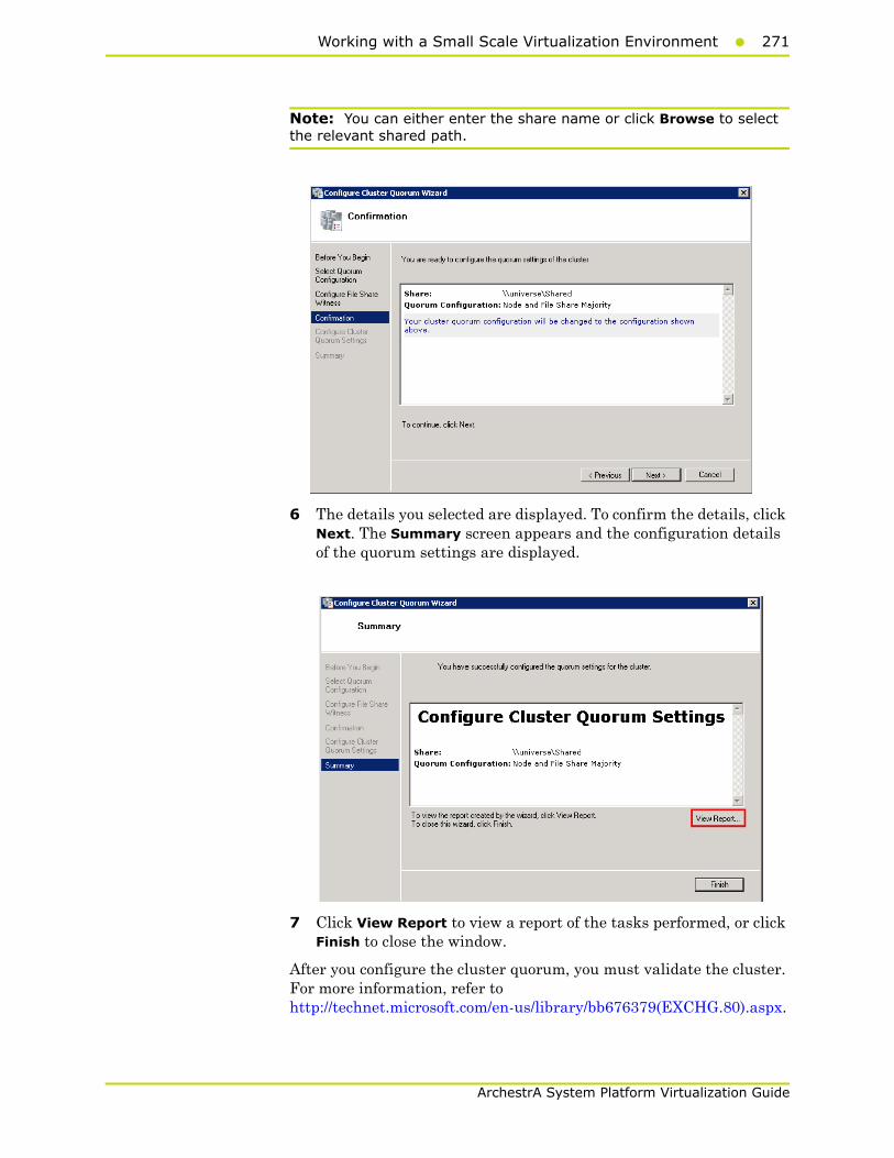
Working with a Small Scale Virtualization Environment271
ArchestrA System Platform Virtualization Guide
Note: You can either enter the share name or click Browse to select the relevant shared path.
6 The details you selected are displayed. To confirm the details, click Next. The Summary screen appears and the configuration details of the quorum settings are displayed.
7 Click View Report to view a report of the tasks performed, or click Finish to close the window.
After you configure the cluster quorum, you must validate the cluster. For more information, refer to http://technet.microsoft.com/en-us/library/bb676379(EXCHG.80).aspx.
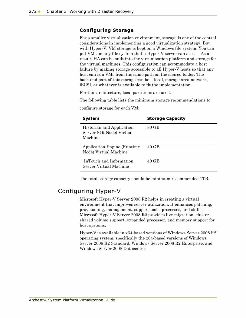
272 Chapter 3 Working with Disaster Recovery
ArchestrA System Platform Virtualization Guide
Configuring Storage
For a smaller virtualization environment, storage is one of the central considerations in implementing a good virtualization strategy. But with Hyper-V, VM storage is kept on a Windows file system. You can put VMs on any file system that a Hyper-V server can access. As a result, HA can be built into the virtualization platform and storage for the virtual machines. This configuration can accommodate a host failure by making storage accessible to all Hyper-V hosts so that any host can run VMs from the same path on the shared folder. The back-end part of this storage can be a local, storage area network, iSCSI, or whatever is available to fit the implementation.
For this architecture, local partitions are used.
The following table lists the minimum storage recommendations to
configure storage for each VM:
The total storage capacity should be minimum recommended 1TB.
Configuring Hyper-V Microsoft Hyper-V Server 2008 R2 helps in creating a virtual environment that improves server utilization. It enhances patching, provisioning, management, support tools, processes, and skills. Microsoft Hyper-V Server 2008 R2 provides live migration, cluster shared volume support, expanded processor, and memory support for host systems.
Hyper-V is available in x64-based versions of Windows Server 2008 R2 operating system, specifically the x64-based versions of Windows Server 2008 R2 Standard, Windows Server 2008 R2 Enterprise, and Windows Server 2008 Datacenter.
System Storage Capacity
Historian and Application Server (GR Node) Virtual Machine
80 GB
Application Engine (Runtime Node) Virtual Machine
40 GB
InTouch and Information Server Virtual Machine
40 GB

Working with a Small Scale Virtualization Environment273
ArchestrA System Platform Virtualization Guide
The following are the pre-requisites to set up Hyper-V:
• x64-based processor
• Hardware-assisted virtualization
• Hardware Data Execution Prevention (DEP)
To configure Hyper-V
1 Click the Server Manager icon on the toolbar. The Server Manager window appears.
2 In the Roles Summary area, click Add Roles. The Add Roles Wizard window appears.
Note: You can also right-click Roles and then click Add Roles Wizard to open the Add Roles Wizard window.

274 Chapter 3 Working with Disaster Recovery
ArchestrA System Platform Virtualization Guide
3 View the instructions on the wizard and then click Next. The Select Server Roles area appears.
4 Select the Hyper-V check box and click Next. The Create Virtual Networks area appears.
5 Select the check box next to the required network adapter to make the connection available to virtual machines. Click Next. The Confirmation Installation Selections area appears.

Working with a Small Scale Virtualization Environment275
ArchestrA System Platform Virtualization Guide
Note: You can select one or more network adapters.
6 Click Install. The Installation Results area appears.
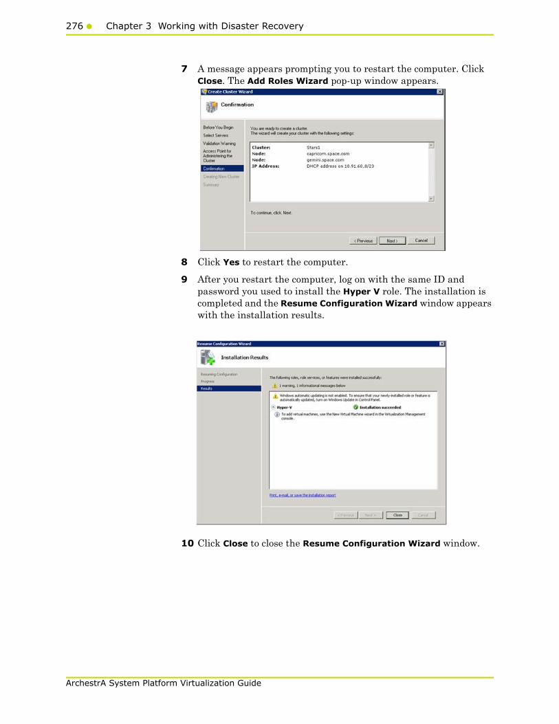
276 Chapter 3 Working with Disaster Recovery
ArchestrA System Platform Virtualization Guide
7 A message appears prompting you to restart the computer. Click Close. The Add Roles Wizard pop-up window appears.
8 Click Yes to restart the computer.
9 After you restart the computer, log on with the same ID and password you used to install the Hyper V role. The installation is completed and the Resume Configuration Wizard window appears with the installation results.
10 Click Close to close the Resume Configuration Wizard window.

Working with a Small Scale Virtualization Environment277
ArchestrA System Platform Virtualization Guide
Configuring SIOS (SteelEye) Mirroring JobsSIOS (SteelEye) DataKeeper is replication software for real-time Windows data. It helps replicate all data types, including the following:
• Open files
• SQL and Exchange Server databases
• Hyper-V .vhd files
SteelEye DataKeeper's ability to replicate live Hyper-V virtual machines ensures that a duplicate copy is available in case the primary storage array fails. This helps in disaster recovery (DR) without impacting production.
SteelEye DataKeeper Cluster Edition is a host-based replication solution, which extends Microsoft Windows Server 2008 R2 Failover Clustering (WSFC) and Microsoft Cluster Server (MSCS) features such as cross-subnet failover and tunable heartbeat parameters. These features make it possible to deploy geographically distributed clusters.
You can replicate a virtual machine across LAN, WAN, or any Windows server through SIOS Microsoft Management Console (MMC) interface. You can run the DataKeeper MMC snap-in from any server. The DataKeeper MMC snap-in interface is similar to the existing Microsoft Management tools.
Note: For information on installing the SteelEye DataKeeper, refer to SteelEye DataKeeper for Windows Server 2003/2008 Planning and Install Guide and SteelEye DataKeeper for Windows Server 2003/2008 Administration Guide at http://www.steeleye.com. Ensure that the local security policies, firewall, and port settings are configured as per the details in these documents.
The following procedures help you set up a virtual machine in the Disaster Recovery environment.
Creating a DataKeeper Mirroring Job
To set up a virtual machine in the Disaster Recovery environment you need to first create a SteelEye mirroring job.
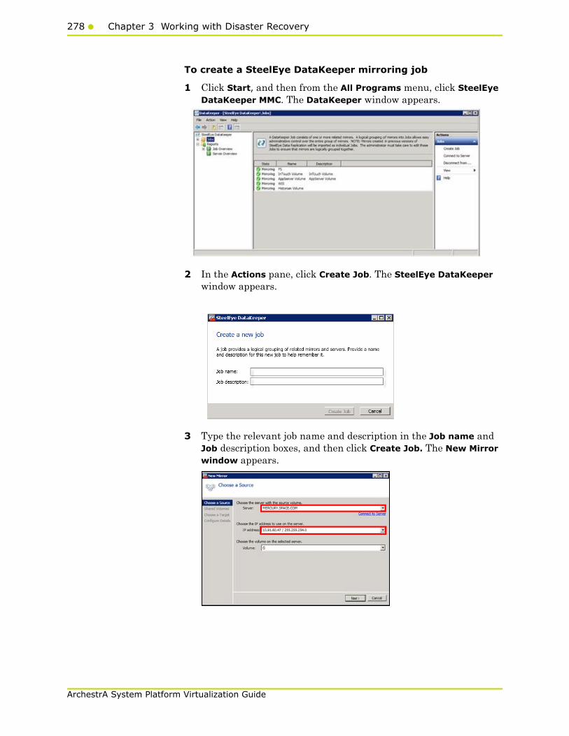
278 Chapter 3 Working with Disaster Recovery
ArchestrA System Platform Virtualization Guide
To create a SteelEye DataKeeper mirroring job
1 Click Start, and then from the All Programs menu, click SteelEye DataKeeper MMC. The DataKeeper window appears.
2 In the Actions pane, click Create Job. The SteelEye DataKeeper window appears.
3 Type the relevant job name and description in the Job name and Job description boxes, and then click Create Job. The New Mirror window appears.
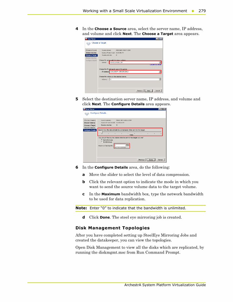
Working with a Small Scale Virtualization Environment279
ArchestrA System Platform Virtualization Guide
4 In the Choose a Source area, select the server name, IP address, and volume and click Next. The Choose a Target area appears.
5 Select the destination server name, IP address, and volume and click Next. The Configure Details area appears.
6 In the Configure Details area, do the following:
a Move the slider to select the level of data compression.
b Click the relevant option to indicate the mode in which you want to send the source volume data to the target volume.
c In the Maximum bandwidth box, type the network bandwidth to be used for data replication.
Note: Enter “0” to indicate that the bandwidth is unlimited.
d Click Done. The steel eye mirroring job is created.
Disk Management Topologies
After you have completed setting up SteelEye Mirroring Jobs and created the datakeeper, you can view the topologies.
Open Disk Management to view all the disks which are replicated, by running the diskmgmt.msc from Run Command Prompt.
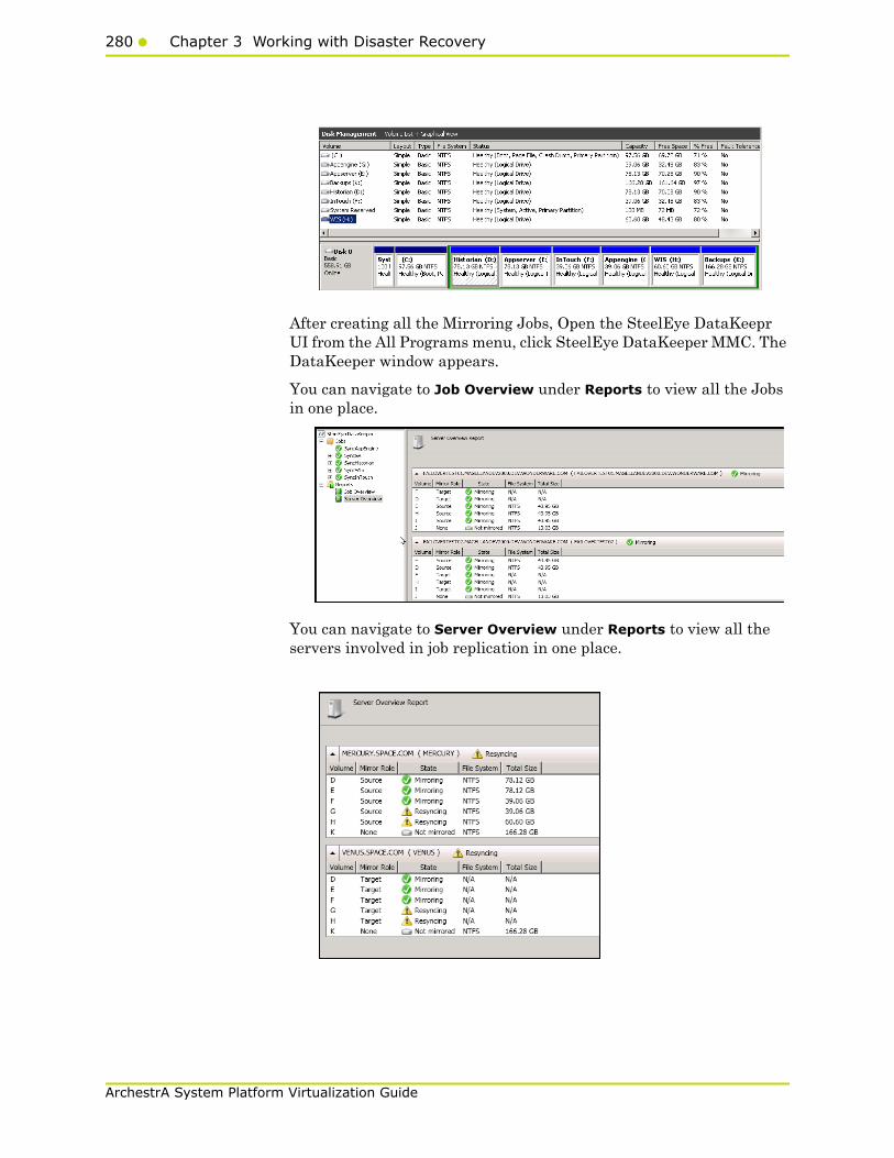
280 Chapter 3 Working with Disaster Recovery
ArchestrA System Platform Virtualization Guide
After creating all the Mirroring Jobs, Open the SteelEye DataKeepr UI from the All Programs menu, click SteelEye DataKeeper MMC. The DataKeeper window appears.
You can navigate to Job Overview under Reports to view all the Jobs in one place.
You can navigate to Server Overview under Reports to view all the servers involved in job replication in one place.

Working with a Small Scale Virtualization Environment281
ArchestrA System Platform Virtualization Guide
Configuring Virtual MachinesAfter creating a steel eye mirroring job, you need to create a virtual machine in the disk.
To configure a virtual machine
1 In the Server Manager window, right-click Features and click Failover Cluster Manager . The Failover Cluster Manager tree expands.
2 Right-click Services and applications, and click Virtual Machines, and then click New Virtual Machine. The New Virtual Machine Wizard window appears.

282 Chapter 3 Working with Disaster Recovery
ArchestrA System Platform Virtualization Guide
3 View the instructions in the Before You Begin area and click Next. The Specify Name and Location area appears.
4 In the Specify Name and Location area, do the following:
a In the Name box, type a name for the virtual machine.
b Select the Store the virtual machine in a different location check box to be able to indicate the location of the virtual machine.
c In the Location box, enter the location where you want to store the virtual machine.
Note: You can either type the location or click Browse to select the location where you want to store the virtual machine.
d Click Next. The Assign Memory area appears.

Working with a Small Scale Virtualization Environment283
ArchestrA System Platform Virtualization Guide
5 Type the recommended amount of memory in the Memory box and click Next. The Configure Networking area appears.
6 Select the network to be used for the virtual machine and click Next. The Connect Virtual Hard Disk area appears.

284 Chapter 3 Working with Disaster Recovery
ArchestrA System Platform Virtualization Guide
7 Click the Create a virtual hard disk option button , and then do the following:
a In the Name box, type the name of the virtual machine.
b In the Location box, enter the location of the virtual machine.
Note: You can either type the location or click Browse to select the location of the virtual machine.
c In the Size box, type the size of the virtual machine , and then click Next. The Installation Options area appears.
Note: You need to click either the Use an existing virtual hard disk or Attach a virtual hard disk later option, only if you are using an existing virtual hard disk or you want to attach a virtual disk later.
8 Click the Install an operating system later option and click Next. The Completing the New Virtual Machine Window area appears.
Note: If you want to install an operating system from a boot CD/DVD-ROM or a boot floppy disk or a network-based installation server, click the relevant option.

Working with a Small Scale Virtualization Environment285
ArchestrA System Platform Virtualization Guide
9 Click Finish. The virtual machine is created with the details you provided. As we have started this process from the Failover Cluster Manager, after completing the process of creating a virtual machine, the High Availability Wizard window appears.
10 Click View Report to view the report or click Finish to close the High Availability Wizard window.
Adding the Dependency between the Virtual Machine and the DataKeeper volume in the Cluster
After creating the virtual machine, you need to add the dependency between the virtual machine and the datakeeper volume in the cluster.This dependency triggers the switching of the the source and target Servers of the SteelEye DataKeeper Volume resource when failover of the virtual machines occurs in the Failover Cluster Manager.
To add the dependency between the virtual machine and the datakeeper volume in the cluster
1 On the Server Manager window, right-click the virtual machine, that you have created and then point to Add a resource, More Resources and then click Add DataKeeper Volumes. The Add a resource menu appears.

286 Chapter 3 Working with Disaster Recovery
ArchestrA System Platform Virtualization Guide
2 The New DataKeeper Volume is added under Disk Drives.
3 Right-click New DataKeeper Volume , and then click Properties. The New DataKeeper Volume Properties window appears.
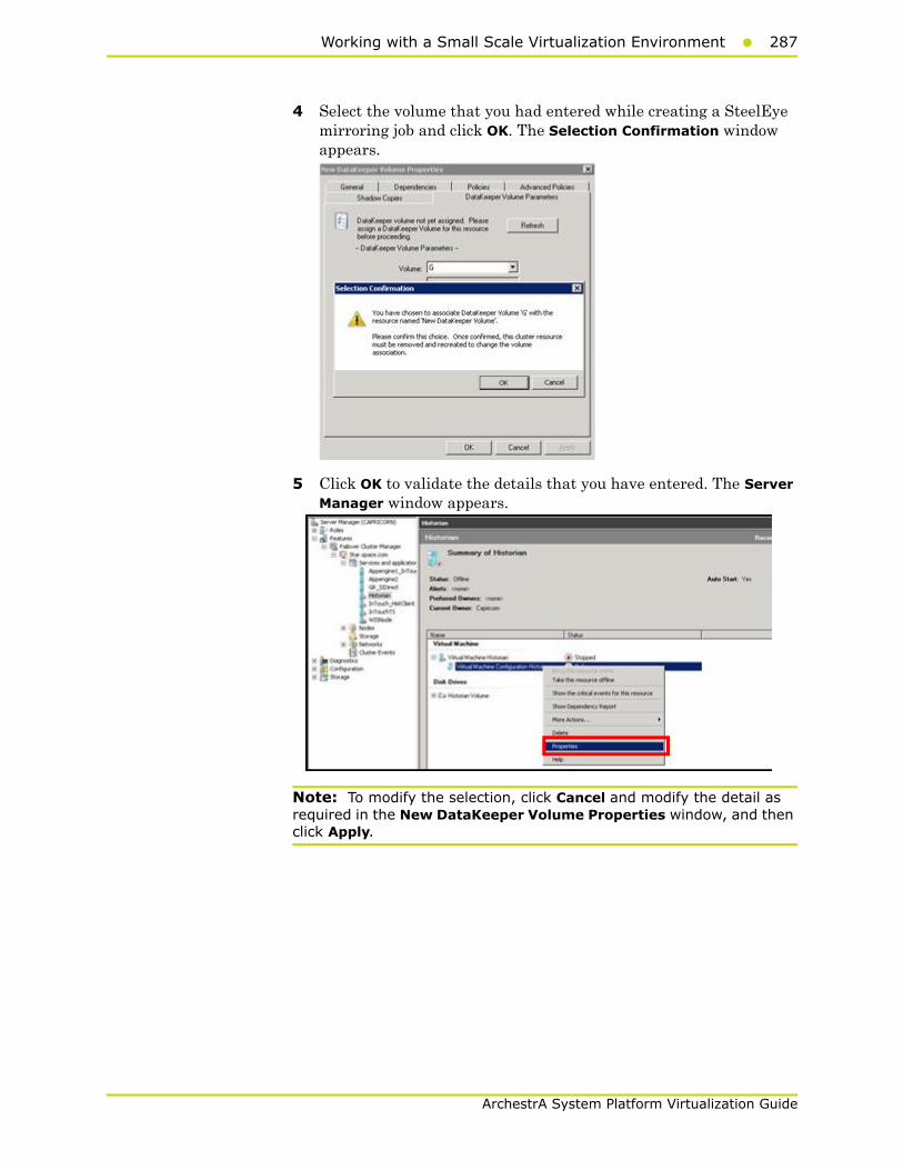
Working with a Small Scale Virtualization Environment287
ArchestrA System Platform Virtualization Guide
4 Select the volume that you had entered while creating a SteelEye mirroring job and click OK. The Selection Confirmation window appears.
5 Click OK to validate the details that you have entered. The Server Manager window appears.
Note: To modify the selection, click Cancel and modify the detail as required in the New DataKeeper Volume Properties window, and then click Apply.
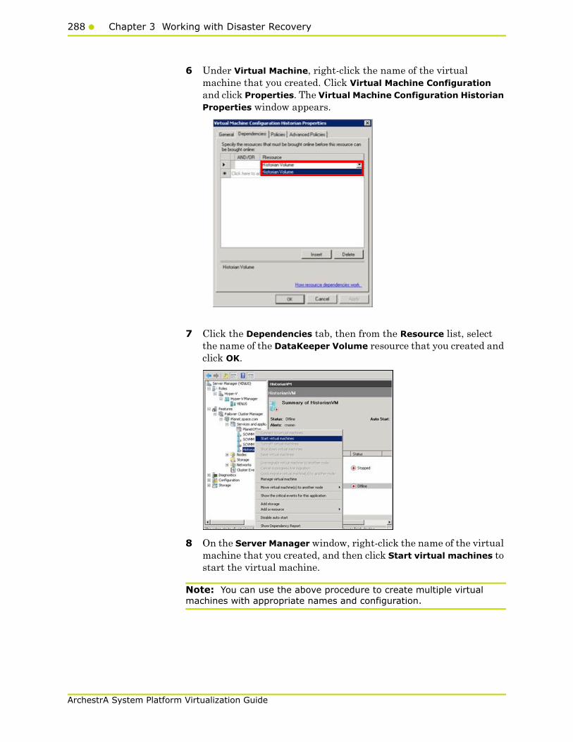
288 Chapter 3 Working with Disaster Recovery
ArchestrA System Platform Virtualization Guide
6 Under Virtual Machine, right-click the name of the virtual machine that you created. Click Virtual Machine Configuration and click Properties. The Virtual Machine Configuration Historian Properties window appears.
7 Click the Dependencies tab, then from the Resource list, select the name of the DataKeeper Volume resource that you created and click OK.
8 On the Server Manager window, right-click the name of the virtual machine that you created, and then click Start virtual machines to start the virtual machine.
Note: You can use the above procedure to create multiple virtual machines with appropriate names and configuration.
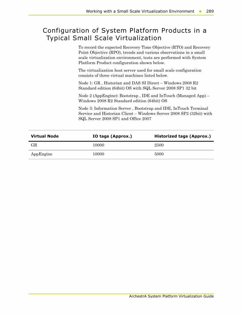
Working with a Small Scale Virtualization Environment289
ArchestrA System Platform Virtualization Guide
Configuration of System Platform Products in a Typical Small Scale Virtualization
To record the expected Recovery Time Objective (RTO) and Recovery Point Objective (RPO), trends and various observations in a small scale virtualization environment, tests are performed with System Platform Product configuration shown below.
The virtualization host server used for small scale configuration consists of three virtual machines listed below.
Node 1: GR , Historian and DAS SI Direct – Windows 2008 R2 Standard edition (64bit) OS with SQL Server 2008 SP1 32 bit
Node 2 (AppEngine): Bootstrap , IDE and InTouch (Managed App) – Windows 2008 R2 Standard edition (64bit) OS
Node 3: Information Server , Bootstrap and IDE, InTouch Terminal Service and Historian Client – Windows Server 2008 SP2 (32bit) with SQL Server 2008 SP1 and Office 2007
Virtual Node IO tags (Approx.) Historized tags (Approx.)
GR 10000 2500
AppEngine 10000 5000
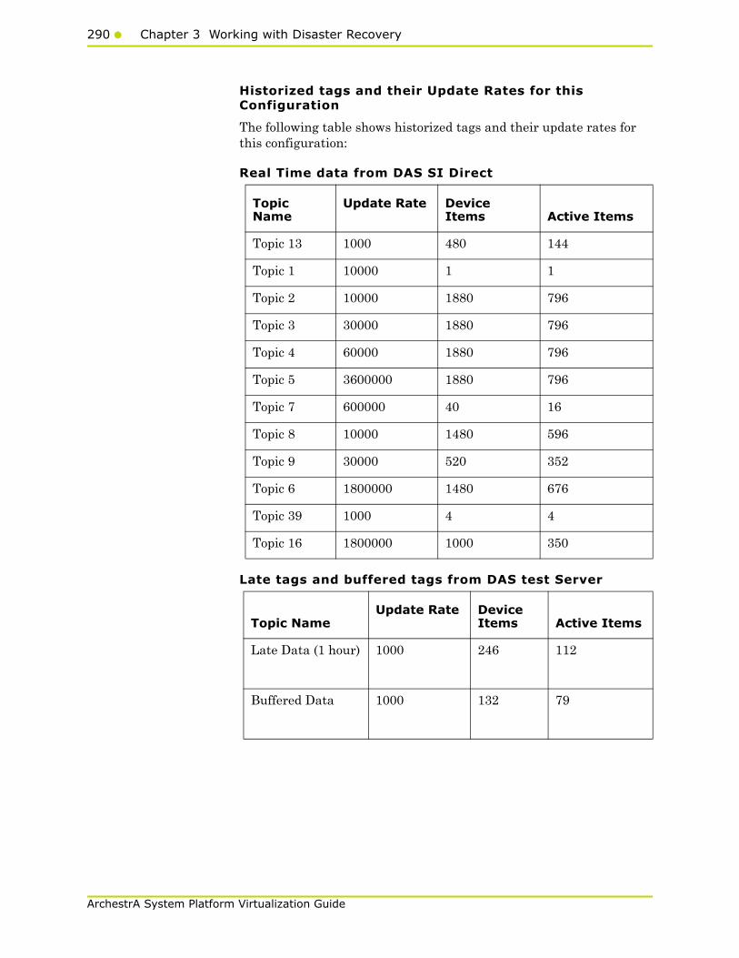
290 Chapter 3 Working with Disaster Recovery
ArchestrA System Platform Virtualization Guide
Historized tags and their Update Rates for this Configuration
The following table shows historized tags and their update rates for this configuration:
Real Time data from DAS SI Direct
Late tags and buffered tags from DAS test Server
Topic Name
Update Rate Device Items Active Items
Topic 13 1000 480 144
Topic 1 10000 1 1
Topic 2 10000 1880 796
Topic 3 30000 1880 796
Topic 4 60000 1880 796
Topic 5 3600000 1880 796
Topic 7 600000 40 16
Topic 8 10000 1480 596
Topic 9 30000 520 352
Topic 6 1800000 1480 676
Topic 39 1000 4 4
Topic 16 1800000 1000 350
Topic Name Update Rate Device
Items Active Items
Late Data (1 hour) 1000 246 112
Buffered Data 1000 132 79

Working with a Small Scale Virtualization Environment291
ArchestrA System Platform Virtualization Guide
Application Server Configuration Details
Total No of Engines: 14
Number of objects under each Engine
• Engine 1 : 9
• Engine 2 : 13
• Engine 3 : 13
• Engine 4 : 225
• Engine 5 : 118
• Engine 6 : 118
• Engine 7 : 195
• Engine 8 : 225
• Engine 9 : 102
• Engine 10: 2
• Engine 11: 3
• Engine 12: 21
• Engine 13: 1
• Engine 14: 1
The total number of DI objects is 6.

292 Chapter 3 Working with Disaster Recovery
ArchestrA System Platform Virtualization Guide
Expected Recovery Time Objective and Recovery Point Objective
This section provides the indicative Recovery Time Objectives (RTO) and RecoveryPoint Objectives (RPO) for the load of IO and Attributes historized shown above and with the configuration of Host Virtualization Servers and Hyper-V virtual machines explained in the Setup instructions of Small Scale Virtualization. In addition to these factors, the exact RTO and RPO depend on factors like storage I/O performance, CPU utilization, memory usage, and network usage at the time of failover/migration activity.
RTO and RPO Observations - DR Small Configuration
Scenarios and observations in this section:
The following tables display RTO and RPO Observations with approximately 20000 IO points with approximately 7500 attributes being historized:
Scenario Observation
Scenario 1: IT provides maintenance on Virtualization Server
"Live Migration" on page 293
"Quick Migration" on page 294
"Quick Migration of All Nodes Simultaneously" on page 295
Scenario 2: Virtualization Server hardware fails
"Scenario 2: Virtualization Server hardware fails" on page 297
Scenario 3: Network fails on Virtualization Server
"Scenario 3: Network fails on Virtualization server" on page 299
Scenario 4: Virtualization Server becomes unresponsive
"Scenario 4: Virtualization Server becomes unresponsive" on page 301

Working with a Small Scale Virtualization Environment293
ArchestrA System Platform Virtualization Guide
Scenario 1: IT provides maintenance on Virtualization Server
Live Migration
Primary Node Products RTORPO
TagsData LossDuration
GR IAS 14 sec IAS tag (Script) 20 sec
IAS IO tag(DASSiDirect)
26 sec
Historian 19 sec Historian Localtag
22 sec
InTouch Tag$Second
27 sec
IAS IO Tag(DASSiDirect)
32 sec
IAS tag (Script) 0 (data is SFed)
DAS 21 sec N/A N/A

294 Chapter 3 Working with Disaster Recovery
ArchestrA System Platform Virtualization Guide
Quick Migration
Primary Node Products RTO RPO
TagsData LossDuration
WIS InTouch 12 sec $Second 12 sec
WIS 12 sec N/A N/A
Historian Client 12 sec N/A N/A
AppEngine AppEngine 12 sec IAS IO tag(DASSiDirect)
26 sec
IAS tag Script) 13 sec
InTouch 12 sec $Second 12 sec
Node Name Products RTO RPO
TagsData LossDuration
GR IAS 147 sec IAS tag (Script) 160 sec
IAS IO Tag(DASSiDirect)
167 sec
Historian 156 sec Historian Localtag
164 sec
InTouch tag$Second
171 sec
IAS IO Tag(DASSiDirect)
170 sec
IAS tag (Script) 0 (data is SFed)
DAS 156 sec N/A N/A

Working with a Small Scale Virtualization Environment295
ArchestrA System Platform Virtualization Guide
Quick Migration of All Nodes Simultaneously
Node Name Products RTO RPO
TagsData LossDuration
WIS InTouch 91 sec $Second 91 sec
WIS 91 sec N/A N/A
Historian Client 91 sec N/A N/A
AppEngine AppEngine 59 sec IAS IO tag(DASSiDirect)
80 sec
IAS Tag (Script) 73 sec
InTouch 68 sec $Second 68 sec
Primarynode Products RTO RPO
TagsData LossDuration
GR IAS 221 sec IAS tag (Script) 229 sec
IAS IO tag(DASSiDirect)
234 sec
Historian 225 sec Historian Localtag
226 sec
InTouch tag$Second
238 sec
IAS IO tag(DASSiDirect)
242 sec
IAS tag (Script) 160 sec
DAS 225 sec N/A
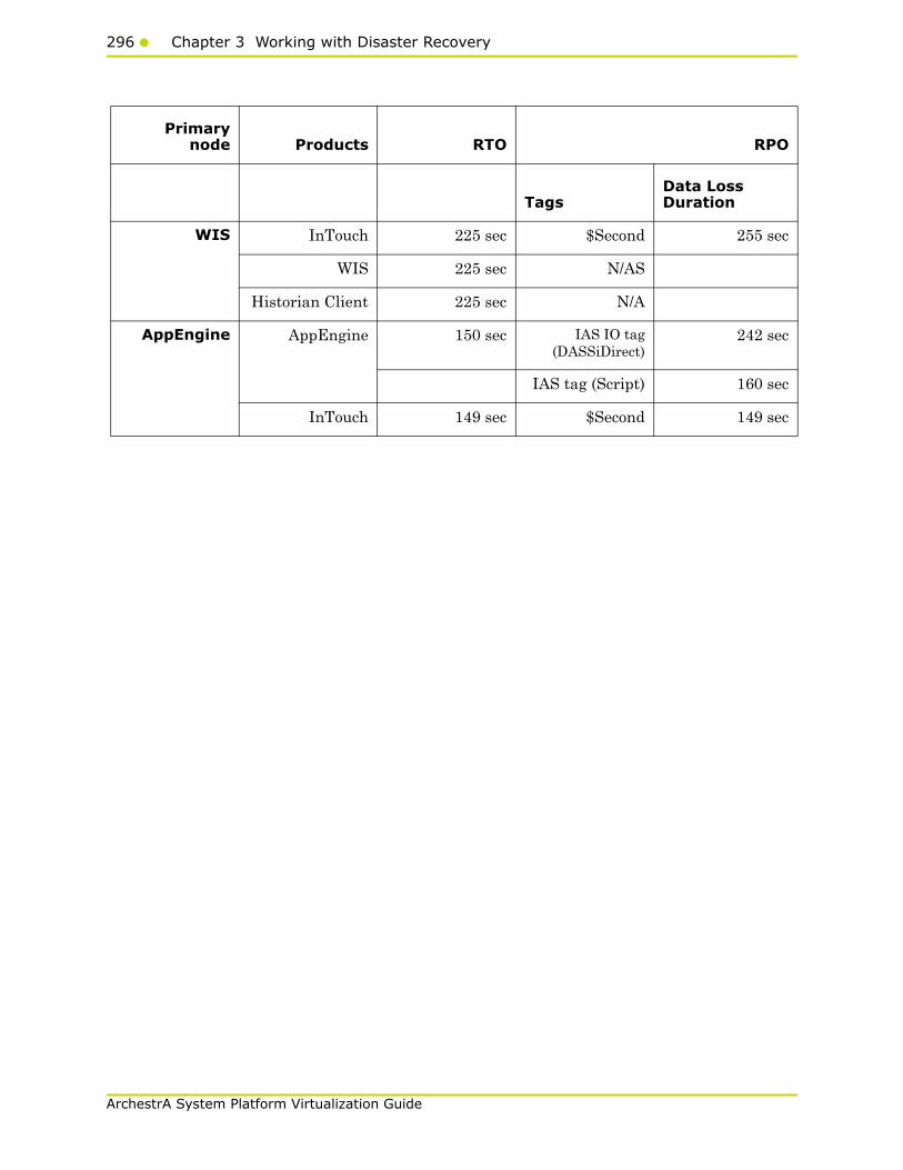
296 Chapter 3 Working with Disaster Recovery
ArchestrA System Platform Virtualization Guide
Primarynode Products RTO RPO
TagsData Loss Duration
WIS InTouch 225 sec $Second 255 sec
WIS 225 sec N/AS
Historian Client 225 sec N/A
AppEngine AppEngine 150 sec IAS IO tag(DASSiDirect)
242 sec
IAS tag (Script) 160 sec
InTouch 149 sec $Second 149 sec

Working with a Small Scale Virtualization Environment297
ArchestrA System Platform Virtualization Guide
Scenario 2: Virtualization Server hardware fails
The Virtualization Server hardware failure results in failover that is simulated with power-off on the host server. In this case, the VMs restart, after moving to the other host server.
Primary node Products RTO RPO
TagsData LossDuration
GR IAS 270 sec IAS tag (Script) 5 Min 22 sec
IAS IO tag(DASSiDirect)
5 Min 12 sec
Historian 362 sec Historian Localtag
6 Min 40 sec
InTouch tag$Second
6 Min 58 sec
Note: RPO isdependent on
the time takenby the user to
start theInTouchView on
the InTouchnode and the
RTO of theHistorian node,which historizes
this tag.
IAS IO tag(DASSiDirect)
5 Min 16 sec
IAS tag (Script) 4 Min 55 sec
DAS 196 sec N/A N/A

298 Chapter 3 Working with Disaster Recovery
ArchestrA System Platform Virtualization Guide
Primary Node Products RTO RPO
TagsData LossDuration
WIS InTouch 240 sec + timetaken by the
user to start theInTouchView
$Second 6 Min 58 sec
Note: RPO isdependent on
the time takenby the user to
start theInTouchView on
the InTouchnode and the
RTO of theHistorian node,which historizes
this tag.
WIS 240 sec + timetaken by the
user to start theInformation
Server
N/A N/A
Historian Client 240 sec + timetaken by the
user to start theHistorian Client
N/A N/A
AppEngine AppEngine 267 sec IAS IO tag(DASSiDirect)
5 Min 16 sec
IAS tag (Script) 4 Min 55 sec
InTouch 267 sec + timetaken by the
user to start theITView
$Second 267 sec + timetaken by the
user to start theITView
Note: RPO is dependent on the timetaken by the user to start the
InTouchView on the InTouch node andthe RTO of the Historian node, which
historizes this tag.

Working with a Small Scale Virtualization Environment299
ArchestrA System Platform Virtualization Guide
Scenario 3: Network fails on Virtualization server
The failure of network on the Virtualization Server results in failover due to network disconnect (Public). Bandwidth used is 45Mbps and there is no latency. In this case, the VMs restart, after moving to the other host server.
Primary Node Products RTO RPO
TagsData LossDuration
GR IAS 251 sec IAS tag (Script) 4 Min 42 sec
IAS IO tag(DASSiDirect)
4 Min 47 sec
Historian 290 sec Historian localtag
5 Min 11 sec
InTouch tag$Second
5 Min 10 sec
Note: RPO isdependent on
the time takenby the user to
start theInTouchView on
the InTouchnode and the
RTO of theHistorian node,which historizes
this tag.
IAS IO tag(DASSiDirect)
4 Min 42 sec
IAS tag (Script) 3 Min 58 sec
DAS 191 sec N/A N/A
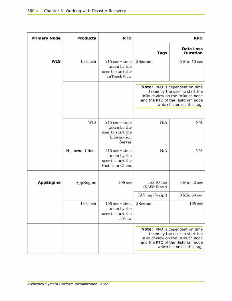
300 Chapter 3 Working with Disaster Recovery
ArchestrA System Platform Virtualization Guide
Primary Node Products RTO RPO
TagsData LossDuration
WIS InTouch 215 sec + timetaken by the
user to start theInTouchView
$Second 5 Min 10 sec
Note: RPO is dependent on timetaken by the user to start the
InTouchView on the InTouch nodeand the RTO of the Historian node
which historizes this tag.
WIS 215 sec + timetaken by the
user to start theInformation
Server
N/A N/A
Historian Client 215 sec + timetaken by the
user to start theHistorian Client
N/A N/A
AppEngine AppEngine 209 sec IAS IO Tag(DASSiDirect)
4 Min 42 sec
IAS tag (Script) 3 Min 58 sec
InTouch 195 sec + timetaken by the
user to start theITView
$Second 195 sec
Note: RPO is dependent on timetaken by the user to start the
InTouchView on the InTouch nodeand the RTO of the Historian node
which historizes this tag.
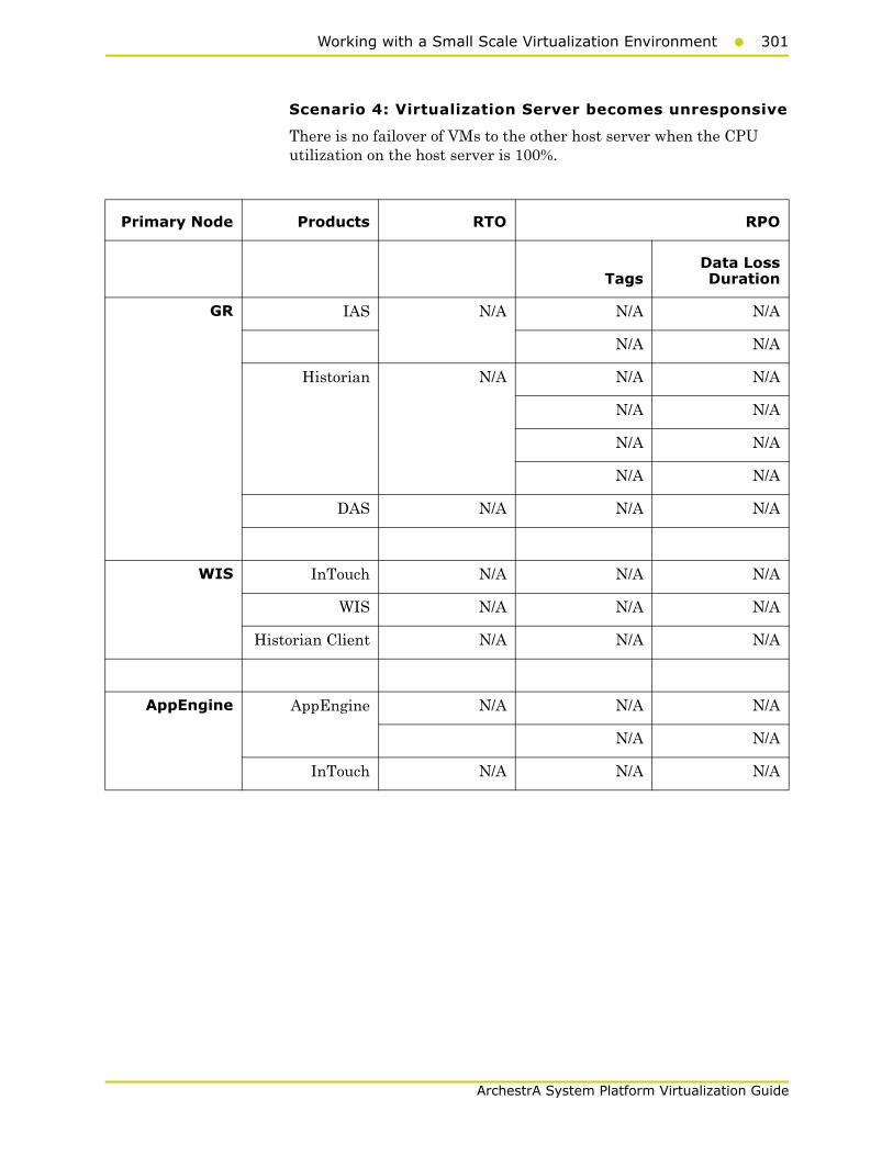
Working with a Small Scale Virtualization Environment301
ArchestrA System Platform Virtualization Guide
Scenario 4: Virtualization Server becomes unresponsive
There is no failover of VMs to the other host server when the CPU utilization on the host server is 100%.
Primary Node Products RTO RPO
TagsData LossDuration
GR IAS N/A N/A N/A
N/A N/A
Historian N/A N/A N/A
N/A N/A
N/A N/A
N/A N/A
DAS N/A N/A N/A
WIS InTouch N/A N/A N/A
WIS N/A N/A N/A
Historian Client N/A N/A N/A
AppEngine AppEngine N/A N/A N/A
N/A N/A
InTouch N/A N/A N/A
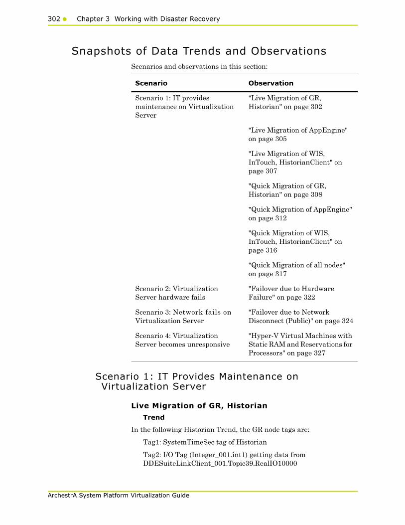
302 Chapter 3 Working with Disaster Recovery
ArchestrA System Platform Virtualization Guide
Snapshots of Data Trends and ObservationsScenarios and observations in this section:
Scenario 1: IT Provides Maintenance on Virtualization Server
Live Migration of GR, Historian
Trend
In the following Historian Trend, the GR node tags are:
Tag1: SystemTimeSec tag of Historian
Tag2: I/O Tag (Integer_001.int1) getting data from DDESuiteLinkClient_001.Topic39.RealIO10000
Scenario Observation
Scenario 1: IT provides maintenance on Virtualization Server
"Live Migration of GR, Historian" on page 302
"Live Migration of AppEngine" on page 305
"Live Migration of WIS, InTouch, HistorianClient" on page 307
"Quick Migration of GR, Historian" on page 308
"Quick Migration of AppEngine" on page 312
"Quick Migration of WIS, InTouch, HistorianClient" on page 316
"Quick Migration of all nodes" on page 317
Scenario 2: Virtualization Server hardware fails
"Failover due to Hardware Failure" on page 322
Scenario 3: Network fails on Virtualization Server
"Failover due to Network Disconnect (Public)" on page 324
Scenario 4: Virtualization Server becomes unresponsive
"Hyper-V Virtual Machines with Static RAM and Reservations for Processors" on page 327
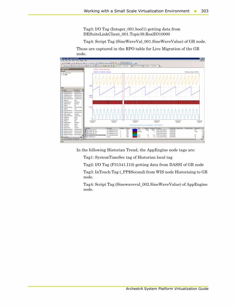
Working with a Small Scale Virtualization Environment303
ArchestrA System Platform Virtualization Guide
Tag3: I/O Tag (Integer_001.bool1) getting data from DESuiteLinkClient_001.Topic39.RealIO10000
Tag4: Script Tag (SineWaveVal_001.SineWaveValue) of GR node.
These are captured in the RPO table for Live Migration of the GR node.
In the following Historian Trend, the AppEngine node tags are:
Tag1: SystemTimeSec tag of Historian local tag
Tag2: I/O Tag (P31541.I10) getting data from DASSI of GR node
Tag3: InTouch Tag (_PP$Second) from WIS node Historising to GR node.
Tag4: Script Tag (Sinewaveval_002.SineWaveValue) of AppEngine node.
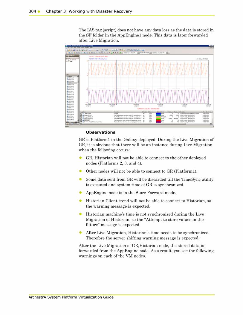
304 Chapter 3 Working with Disaster Recovery
ArchestrA System Platform Virtualization Guide
The IAS tag (script) does not have any data loss as the data is stored in the SF folder in the AppEngine1 node. This data is later forwarded after Live Migration.
Observations
GR is Platform1 in the Galaxy deployed. During the Live Migration of GR, it is obvious that there will be an instance during Live Migration when the following occurs:
• GR, Historian will not be able to connect to the other deployed nodes (Platforms 2, 3, and 4).
• Other nodes will not be able to connect to GR (Platform1).
• Some data sent from GR will be discarded till the TimeSync utility is executed and system time of GR is synchronized.
• AppEngine node is in the Store Forward mode.
• Historian Client trend will not be able to connect to Historian, so the warning message is expected.
• Historian machine’s time is not synchronized during the Live Migration of Historian, so the “Attempt to store values in the future” message is expected.
• After Live Migration, Historian’s time needs to be synchronized. Therefore the server shifting warning message is expected.
After the Live Migration of GR,Historian node, the stored data is forwarded from the AppEngine node. As a result, you see the following warnings on each of the VM nodes.
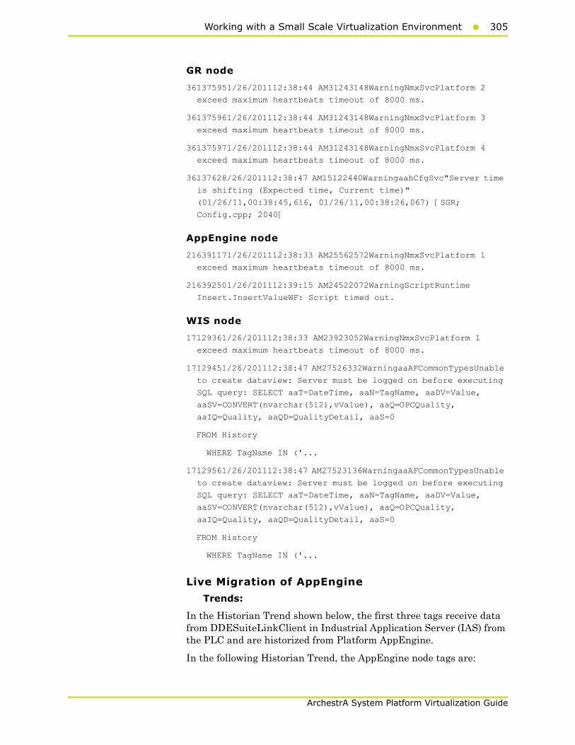
Working with a Small Scale Virtualization Environment305
ArchestrA System Platform Virtualization Guide
GR node
361375951/26/201112:38:44 AM31243148WarningNmxSvcPlatform 2
exceed maximum heartbeats timeout of 8000 ms.
361375961/26/201112:38:44 AM31243148WarningNmxSvcPlatform 3
exceed maximum heartbeats timeout of 8000 ms.
361375971/26/201112:38:44 AM31243148WarningNmxSvcPlatform 4
exceed maximum heartbeats timeout of 8000 ms.
36137628/26/201112:38:47 AM15122440WarningaahCfgSvc"Server time
is shifting (Expected time, Current time)"
(01/26/11,00:38:45,616, 01/26/11,00:38:26,067) [SGR;
Config.cpp; 2040]
AppEngine node
216391171/26/201112:38:33 AM25562572WarningNmxSvcPlatform 1
exceed maximum heartbeats timeout of 8000 ms.
216392501/26/201112:39:15 AM24522072WarningScriptRuntime
Insert.InsertValueWF: Script timed out.
WIS node
17129361/26/201112:38:33 AM23923052WarningNmxSvcPlatform 1
exceed maximum heartbeats timeout of 8000 ms.
17129451/26/201112:38:47 AM27526332WarningaaAFCommonTypesUnable
to create dataview: Server must be logged on before executing
SQL query: SELECT aaT=DateTime, aaN=TagName, aaDV=Value,
aaSV=CONVERT(nvarchar(512),vValue), aaQ=OPCQuality,
aaIQ=Quality, aaQD=QualityDetail, aaS=0
FROM History
WHERE TagName IN ('...
17129561/26/201112:38:47 AM27523136WarningaaAFCommonTypesUnable
to create dataview: Server must be logged on before executing
SQL query: SELECT aaT=DateTime, aaN=TagName, aaDV=Value,
aaSV=CONVERT(nvarchar(512),vValue), aaQ=OPCQuality,
aaIQ=Quality, aaQD=QualityDetail, aaS=0
FROM History
WHERE TagName IN ('...
Live Migration of AppEngine
Trends:
In the Historian Trend shown below, the first three tags receive data from DDESuiteLinkClient in Industrial Application Server (IAS) from the PLC and are historized from Platform AppEngine.
In the following Historian Trend, the AppEngine node tags are:

306 Chapter 3 Working with Disaster Recovery
ArchestrA System Platform Virtualization Guide
Tag1: SystemTimeSec tag of Historian local tag
Tag2: I/O Tag (P31541.I10) getting data from DASSI of GR node
Tag3: Script Tag (Sinewaveval_002.SineWaveValue)
The RPO value is captured in the RPO table of Live Migration of the AppEngine node. .
Observations
AppEngine is Platform2 in the Galaxy deployed. During the Live Migration of AppEngine, it is obvious that there will be an instance during Live Migration when the following occurs:
• AppEngine will not be able to connect to the other deployed nodes (Platforms 1, 3, and 4).
• Other nodes will not be able to connect to AppEngine (Platform2)
• Some data sent from AppEngine will be discarded till the TimeSync utility is executed and system time of AppEngine is synchronized. So Historian is bound to discard data from the AppEngine node.
As a result, you see the following warnings on each of the VM nodes.
GR node
364408421/27/20117:52:59 PM30083108WarningNmxSvcPlatform 2
exceed maximum heartbeats timeout of 8000 ms.
AppEngine
216460131/27/20117:52:51 PM28722876WarningScriptRuntime
Insert.InsertValueWT: Script timed out.
216460141/27/20117:53:11 PM24442460WarningNmxSvcPlatform 1
exceed maximum heartbeats timeout of 8000 ms.
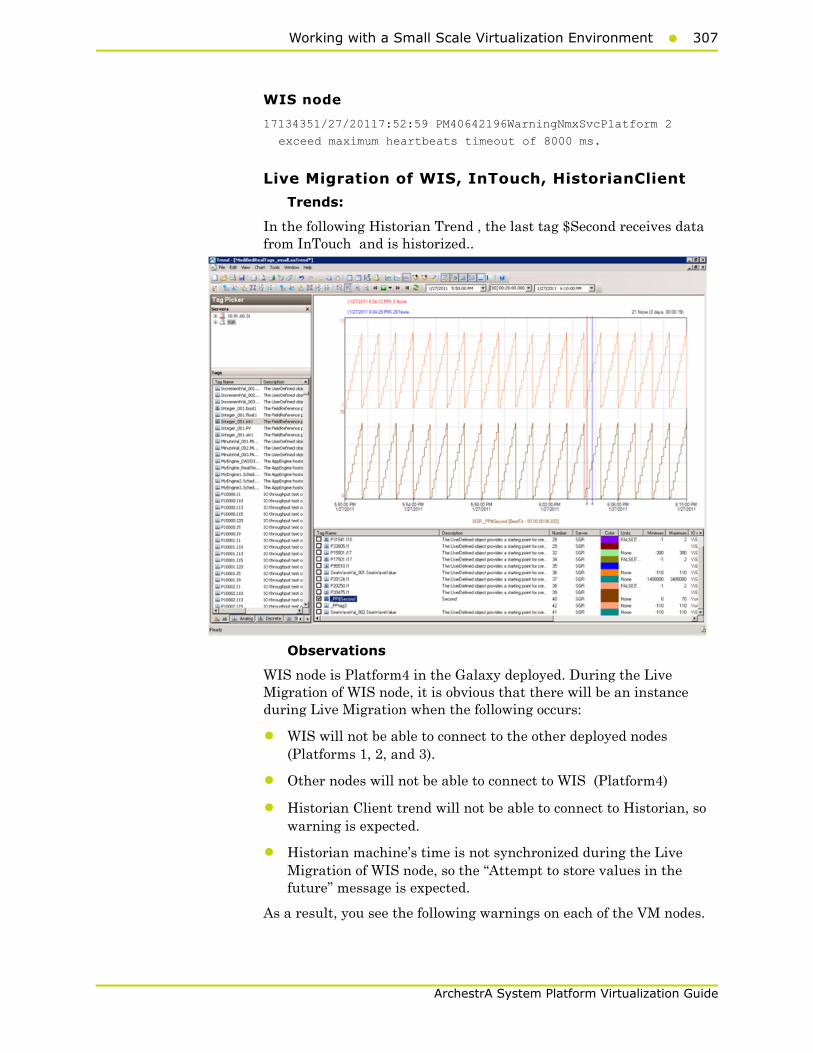
Working with a Small Scale Virtualization Environment307
ArchestrA System Platform Virtualization Guide
WIS node
17134351/27/20117:52:59 PM40642196WarningNmxSvcPlatform 2
exceed maximum heartbeats timeout of 8000 ms.
Live Migration of WIS, InTouch, HistorianClient
Trends:
In the following Historian Trend , the last tag $Second receives data from InTouch and is historized..
Observations
WIS node is Platform4 in the Galaxy deployed. During the Live Migration of WIS node, it is obvious that there will be an instance during Live Migration when the following occurs:
• WIS will not be able to connect to the other deployed nodes (Platforms 1, 2, and 3).
• Other nodes will not be able to connect to WIS (Platform4)
• Historian Client trend will not be able to connect to Historian, so warning is expected.
• Historian machine’s time is not synchronized during the Live Migration of WIS node, so the “Attempt to store values in the future” message is expected.
As a result, you see the following warnings on each of the VM nodes.
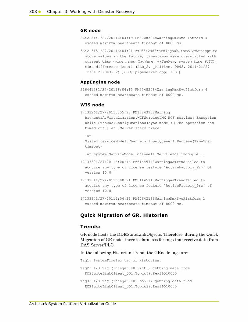
308 Chapter 3 Working with Disaster Recovery
ArchestrA System Platform Virtualization Guide
GR node
364213141/27/20116:04:19 PM30083068WarningNmxSvcPlatform 4
exceed maximum heartbeats timeout of 8000 ms.
364213151/27/20116:04:21 PM15562488WarningaahStoreSvcAttempt to
store values in the future; timestamps were overwritten with
current time (pipe name, TagName, wwTagKey, system time (UTC),
time difference (sec)) (SGR_2, _PP$Time, 9092, 2011/01/27
12:34:20.343, 2) [SGR; pipeserver.cpp; 1831]
AppEngine node
216441281/27/20116:04:15 PM25482564WarningNmxSvcPlatform 4
exceed maximum heartbeats timeout of 8000 ms.
WIS node
17133261/27/20115:55:28 PM17843908Warning
ArchestrA.Visualization.WCFServiceLMX WCF service: Exception
while PushBackConfigurations(sync mode): [The operation has
timed out.] at [Server stack trace:
at
System.ServiceModel.Channels.InputQueue`1.Dequeue(TimeSpan
timeout)
at System.ServiceModel.Channels.ServicePollingDuple...
17133301/27/20116:00:16 PM51445748WarningaaTrendFailed to
acquire any type of license feature 'ActiveFactory_Pro' of
version 10.0
17133311/27/20116:00:21 PM51445748WarningaaTrendFailed to
acquire any type of license feature 'ActiveFactory_Pro' of
version 10.0
17133341/27/20116:04:22 PM40642196WarningNmxSvcPlatform 1
exceed maximum heartbeats timeout of 8000 ms.
Quick Migration of GR, Historian
Trends:
GR node hosts the DDESuiteLinkObjects. Therefore, during the Quick Migration of GR node, there is data loss for tags that receive data from DAS Server/PLC.
In the following Historian Trend, the GRnode tags are:
Tag1: SystemTimeSec tag of Historian.
Tag2: I/O Tag (Integer_001.int1) getting data from
DDESuiteLinkClient_001.Topic39.RealIO10000
Tag3: I/O Tag (Integer_001.bool1) getting data from
DDESuiteLinkClient_001.Topic39.RealIO10000
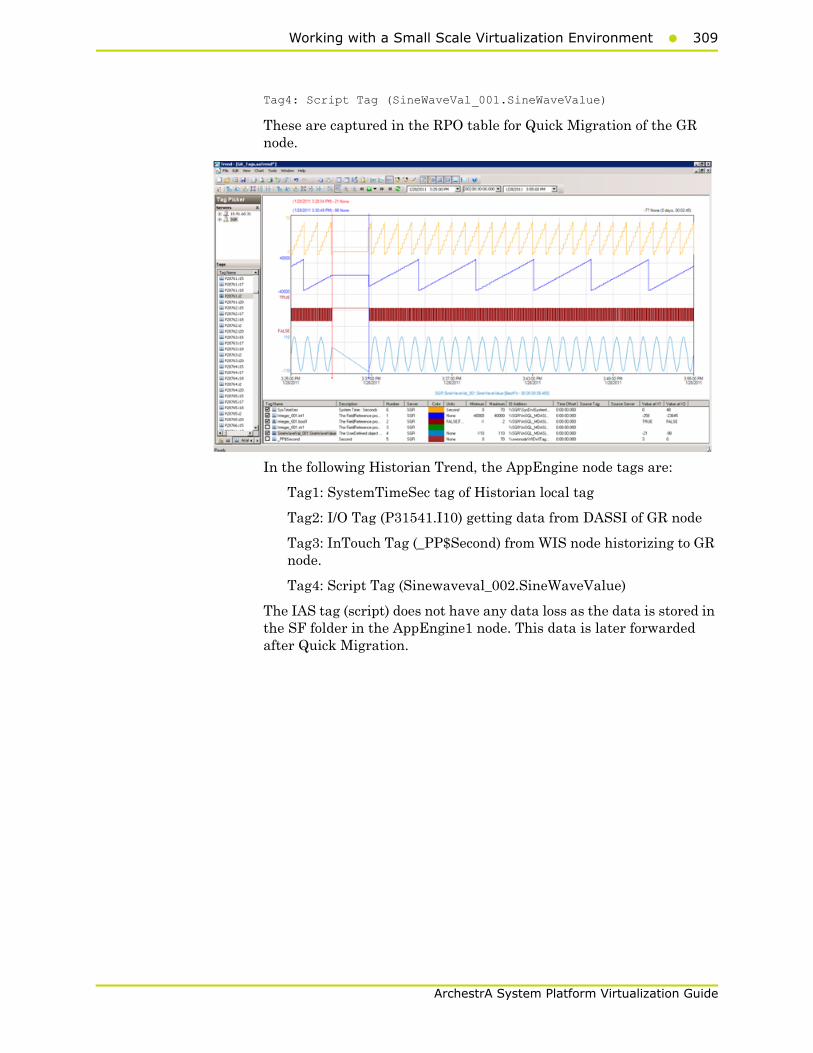
Working with a Small Scale Virtualization Environment309
ArchestrA System Platform Virtualization Guide
Tag4: Script Tag (SineWaveVal_001.SineWaveValue)
These are captured in the RPO table for Quick Migration of the GR node.
In the following Historian Trend, the AppEngine node tags are:
Tag1: SystemTimeSec tag of Historian local tag
Tag2: I/O Tag (P31541.I10) getting data from DASSI of GR node
Tag3: InTouch Tag (_PP$Second) from WIS node historizing to GR node.
Tag4: Script Tag (Sinewaveval_002.SineWaveValue)
The IAS tag (script) does not have any data loss as the data is stored in the SF folder in the AppEngine1 node. This data is later forwarded after Quick Migration.

310 Chapter 3 Working with Disaster Recovery
ArchestrA System Platform Virtualization Guide
These are captured in the RPO table for Quick Migration of the GR node.
Observations
GR is Platform1 in the Galaxy deployed. During the Quick Migration of GR, it is obvious that there will be an instance during Quick Migration when the following occurs:
• GR, Historian will not be able to connect to the other deployed nodes (Platforms 2, 3, and 4).
• Other nodes will not be able to connect to GR (Platform1).
• Some data sent from GR will be discarded till the TimeSync utility is executed and system time of GR is synchronized.
• AppEngine node is in the Store Forward mode.
• Historian Client trend will not be able to connect to Historian, so warning message is expected.
• Historian machine's time is not synchronized during the Live Migration of Historian, so the "Attempt to store values in the future" message is expected.
• After Live Migration, Historian's time needs to be synchronized. Therefore, the server shifting warning message is expected.
After the Quick Migration of GR, Historian node, the stored data is forwarded from AppEngine node.
As a result, you see the following warnings on each of the VM nodes.
GR node
364855861/28/20113:30:43 PM34003416WarningNmxSvcPlatform 2
exceed maximum heartbeats timeout of 8000 ms.NmxSvc
Working with a Small Scale Virtualization Environment311
ArchestrA System Platform Virtualization Guide
364855871/28/20113:30:43 PM34003416WarningNmxSvcPlatform 3
exceed maximum heartbeats timeout of 8000 ms.NmxSvc
364855881/28/20113:30:43 PM34003416WarningNmxSvcPlatform 4
exceed maximum heartbeats timeout of 8000 ms.NmxSvc
364856201/28/20113:30:46 PM45444868WarningaaEngine0:D38 Values
in the past did not fit within the realtime window; discarding
data (218, 2011/01/28 09:58:05.466, 2011/01/28 10:00:44.529)
[aahMDASSF.cpp; 3722; 1]aaEngine
364856211/28/20113:30:46 PM15442424WarningaahStoreSvcValues in
the past did not fit within the realtime window; discarding
data (SGR_mdas, 9119, 2011/01/28 09:58:04.310, 2011/01/28
10:00:43.832) [SGR; pipeserver.cpp; 2388]aahCfgSvc
364856241/28/20113:30:46 PM15442424WarningaahCfgSvc"Server time
is shifting (Expected time, Current time)"
(01/28/11,15:30:45,935, 01/28/11,15:28:07,638) [SGR;
Config.cpp; 2040]aahCfgSvc
364856381/28/20113:30:47 PM45804768WarningaaEngine0:AB4 Values
in the past did not fit within the realtime window; discarding
data (9112, 2011/01/28 09:58:05.513, 2011/01/28 10:00:47.170)
[aahMDASSF.cpp; 3722; 1]aaEngine
364856391/28/20113:30:48 PM32764128WarningaaEngine0:6F4 Values
in the past did not fit within the realtime window; discarding
data (150, 2011/01/28 09:58:05.295, 2011/01/28 10:00:47.029)
[aahMDASSF.cpp; 3722; 1]aaEngine
364857051/28/20113:34:56 PM45444868WarningaaEngine0:D38 Values
in the past did not fit within the realtime window; discarding
data (218, 2011/01/28 09:58:05.466, 2011/01/28 10:00:44.529)
[aahMDASSF.cpp; 3722; 27]aaEngine
364857061/28/20113:34:59 PM32764128WarningaaEngine0:6F4 Values
in the past did not fit within the realtime window; discarding
data (150, 2011/01/28 09:58:05.295, 2011/01/28 10:00:47.029)
[aahMDASSF.cpp; 3722; 57]aaEngine
364857071/28/20113:34:59 PM45804768WarningaaEngine0:AB4 Values
in the past did not fit within the realtime window; discarding
data (9112, 2011/01/28 09:58:05.513, 2011/01/28 10:00:47.170)
[aahMDASSF.cpp; 3722; 7]aaEngine
364857081/28/20113:35:00 PM15442424WarningaahStoreSvcValues in
the past did not fit within the realtime window; discarding
data (SGR_mdas, 9119, 2011/01/28 09:58:04.310, 2011/01/28
10:00:43.832) [SGR; pipeserver.cpp; 2388; 2]aahCfgSvc
AppEngine node
216478441/28/20113:28:13 PM24442460WarningNmxSvcPlatform 1
exceed maximum heartbeats timeout of 8000 ms.

312 Chapter 3 Working with Disaster Recovery
ArchestrA System Platform Virtualization Guide
216479431/28/20113:29:28 PM28722876WarningScriptRuntime
Insert.InsertValueWT: Script timed out.
216479441/28/20113:30:23 PM28722876WarningScriptRuntime
Insert.InsertValueWF: Script timed out.
WIS node
17136281/28/20113:28:12 PM40642196WarningNmxSvcPlatform 1
exceed maximum heartbeats timeout of 8000 ms.
17136351/28/20113:29:06 PM58565984WarningaaAFCommonTypesUnable
to create dataview: Server must be logged on before executing
SQL query: SELECT aaT=DateTime, aaN=TagName, aaDV=Value,
aaSV=CONVERT(nvarchar(512),vValue), aaQ=OPCQuality,
aaIQ=Quality, aaQD=QualityDetail, aaS=0
FROM History
WHERE TagName IN ('...
Quick Migration of AppEngine
Trends:
In the following Historian Trend, the first three tags receive data from DDESuiteLinkClient in Industrial Application Server (IAS) from the PLC and are historized from Platform AppEngine. In the following Historian Trend, the AppEngine node tags are:
Tag1: SystemTimeSec tag of Historian local tag
Tag2: I/O tag (P31541.I10) getting data from DASSI of GR node
Tag3: Script tag (Sinewaveval_002.SineWaveValue)
The RPO value is captured in the RPO table of Live Migration of the AppEngine node.
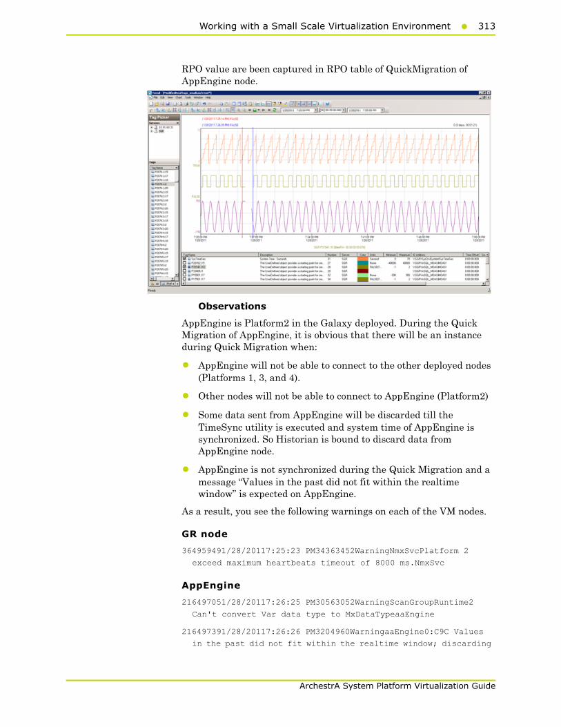
Working with a Small Scale Virtualization Environment313
ArchestrA System Platform Virtualization Guide
RPO value are been captured in RPO table of QuickMigration of AppEngine node.
Observations
AppEngine is Platform2 in the Galaxy deployed. During the Quick Migration of AppEngine, it is obvious that there will be an instance during Quick Migration when:
• AppEngine will not be able to connect to the other deployed nodes (Platforms 1, 3, and 4).
• Other nodes will not be able to connect to AppEngine (Platform2)
• Some data sent from AppEngine will be discarded till the TimeSync utility is executed and system time of AppEngine is synchronized. So Historian is bound to discard data from AppEngine node.
• AppEngine is not synchronized during the Quick Migration and a message “Values in the past did not fit within the realtime window” is expected on AppEngine.
As a result, you see the following warnings on each of the VM nodes.
GR node
364959491/28/20117:25:23 PM34363452WarningNmxSvcPlatform 2
exceed maximum heartbeats timeout of 8000 ms.NmxSvc
AppEngine
216497051/28/20117:26:25 PM30563052WarningScanGroupRuntime2
Can't convert Var data type to MxDataTypeaaEngine
216497391/28/20117:26:26 PM3204960WarningaaEngine0:C9C Values
in the past did not fit within the realtime window; discarding

314 Chapter 3 Working with Disaster Recovery
ArchestrA System Platform Virtualization Guide
data (8941, 2011/01/28 13:55:14.626, 2011/01/28 13:56:26.068)
[aahMDASSF.cpp; 3709; 1]aaEngine
216497701/28/20117:26:27 PM31043344WarningaaEngine0:A4C Values
in the past did not fit within the realtime window; discarding
data (2403, 2011/01/28 13:55:13.895, 2011/01/28 13:56:26.287)
[aahMDASSF.cpp; 3709; 1]aaEngine
216497931/28/20117:26:28 PM31363916WarningaaEngine0:A00 Values
in the past did not fit within the realtime window; discarding
data (2584, 2011/01/28 13:55:14.939, 2011/01/28 13:56:28.577)
[aahMDASSF.cpp; 3709; 1]aaEngine
216498001/28/20117:26:29 PM24684736WarningaaEngine0:9B4 Values
in the past did not fit within the realtime window; discarding
data (326, 2011/01/28 13:55:14.939, 2011/01/28 13:56:28.577)
[aahMDASSF.cpp; 3709; 1]aaEngine
216498011/28/20117:26:29 PM26364440WarningaaEngine0:9C0 Values
in the past did not fit within the realtime window; discarding
data (330, 2011/01/28 13:55:14.939, 2011/01/28 13:56:28.593)
[aahMDASSF.cpp; 3709; 1]aaEngine
216498021/28/20117:26:29 PM24443800WarningaaEngine0:778 Values
in the past did not fit within the realtime window; discarding
data (268, 2011/01/28 13:55:15.173, 2011/01/28 13:56:28.983)
[aahMDASSF.cpp; 3709; 1]aaEngine
216498041/28/20117:26:29 PM31845100WarningaaEngine0:9F4 Values
in the past did not fit within the realtime window; discarding
data (328, 2011/01/28 13:55:15.048, 2011/01/28 13:56:28.967)
[aahMDASSF.cpp; 3709; 1]aaEngine
216498081/28/20117:26:30 PM6486540WarningaaEngine0:A1C Values
in the past did not fit within the realtime window; discarding
data (7646, 2011/01/28 13:55:14.939, 2011/01/28 13:56:28.577)
[aahMDASSF.cpp; 3709; 1]aaEngine
216498351/28/20117:27:00 PM320296WarningScriptRuntime
Insert.InsertValueWT: Script timed out.aaEngine
216499391/28/20117:30:38 PM31043344WarningaaEngine0:A4C Values
in the past did not fit within the realtime window; discarding
data (2403, 2011/01/28 13:55:13.895, 2011/01/28 13:56:26.287)
[aahMDASSF.cpp; 3709; 1894]aaEngine
216499401/28/20117:30:39 PM3204960WarningaaEngine0:C9C Values
in the past did not fit within the realtime window; discarding
data (8941, 2011/01/28 13:55:14.626, 2011/01/28 13:56:26.068)
[aahMDASSF.cpp; 3709; 2]aaEngine
216499411/28/20117:30:40 PM6486540WarningaaEngine0:A1C Values
in the past did not fit within the realtime window; discarding
data (7646, 2011/01/28 13:55:14.939, 2011/01/28 13:56:28.577)
[aahMDASSF.cpp; 3709; 1124]aaEngine
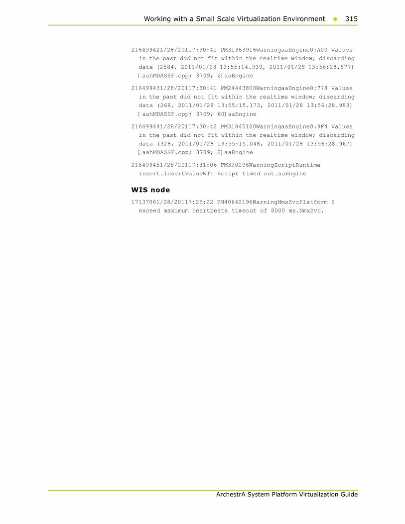
Working with a Small Scale Virtualization Environment315
ArchestrA System Platform Virtualization Guide
216499421/28/20117:30:41 PM31363916WarningaaEngine0:A00 Values
in the past did not fit within the realtime window; discarding
data (2584, 2011/01/28 13:55:14.939, 2011/01/28 13:56:28.577)
[aahMDASSF.cpp; 3709; 2]aaEngine
216499431/28/20117:30:41 PM24443800WarningaaEngine0:778 Values
in the past did not fit within the realtime window; discarding
data (268, 2011/01/28 13:55:15.173, 2011/01/28 13:56:28.983)
[aahMDASSF.cpp; 3709; 60]aaEngine
216499441/28/20117:30:42 PM31845100WarningaaEngine0:9F4 Values
in the past did not fit within the realtime window; discarding
data (328, 2011/01/28 13:55:15.048, 2011/01/28 13:56:28.967)
[aahMDASSF.cpp; 3709; 2]aaEngine
216499451/28/20117:31:06 PM320296WarningScriptRuntime
Insert.InsertValueWT: Script timed out.aaEngine
WIS node
17137061/28/20117:25:22 PM40642196WarningNmxSvcPlatform 2
exceed maximum heartbeats timeout of 8000 ms.NmxSvc.

316 Chapter 3 Working with Disaster Recovery
ArchestrA System Platform Virtualization Guide
Quick Migration of WIS, InTouch, HistorianClient
Trends:
In the following Historian Trend, the last tag $Second receives data from InTouch and is historized.
Tag1: SysTimeSec
Tag2: $Second InTouch tag
Observations
WIS node is Platform4 in the Galaxy deployed. During the Quick Migration of WIS node, it is obvious that there will be an instance during Quick Migration when
• WIS will not be able to connect to the other deployed nodes (Platforms 1, 2, and 3).
• Other nodes will not be able to connect to WIS (Platform4)
• Historian Client trend will not be able to connect to Historian, so warning is expected.
• Historian machine’s time is not synchronized during the Quick Migration of WIS node, so “Attempt to store values in the future” is expected.
As a result, you see the following warnings on each of the VM nodes.
Working with a Small Scale Virtualization Environment317
ArchestrA System Platform Virtualization Guide
GR node
364954901/28/20115:34:24 PM34363452WarningNmxSvcPlatform 4
exceed maximum heartbeats timeout of 8000 ms.
AppEngine node
216495751/28/20115:34:25 PM25882604WarningNmxSvcPlatform 4
exceed maximum heartbeats timeout of 8000 ms.
216495761/28/20115:35:10 PM320296WarningScriptRuntime
Insert.InsertValueWF: Script timed out.
216495771/28/20115:35:16 PM320296WarningScriptRuntime
Insert.InsertValueWF: Script timed out.
WIS node
17136831/28/20115:35:54 PM58563024WarningaaAFCommonTypesUnable
to create dataview: Server must be logged on before executing
SQL query: SELECT aaT=DateTime, aaN=TagName, aaDV=Value,
aaSV=CONVERT(nvarchar(512),vValue), aaQ=OPCQuality,
aaIQ=Quality, aaQD=QualityDetail, aaS=0
FROM History
WHERE TagName IN ('....
Quick Migration of all nodes
Trends:
GR node hosts the DDESuiteLinkObjects, so during the Quick Migration of GR node, there is data loss for tags that does receive data from DAS Server/PLC.
In the following Historian Trend GR node tags are:
Tag1: I/O Tag (Integer_001.int1) getting data from DDESuiteLinkClient_001.Topic39.RealIO10000
Tag2: I/O Tag (Integer_001.bool1) getting data from DDESuiteLinkClient_001.Topic39.RealIO10000
Tag3: I/O Tag (Integer_001.str1) getting data from DDESuiteLinkClient_001.Topic39.RealIO10000
Tag4: Script Tag (SineWaveVal_001.SineWaveValue)
Tag5: InTouch Tag (_PP$Second) from WIS node Historising to GR node.
Tag6: SystemTimeSec tag of Historian.

318 Chapter 3 Working with Disaster Recovery
ArchestrA System Platform Virtualization Guide
RPO value are been captured in RPO table of Quick Migration of All nodes.
In the following Historian Trend, AppEngine tags are:
Tag: I/O Tag (P28762.i15) getting data from DASSI on GR
Tag: I/O Tag (P31541.i10) getting data from DASSI on GR
Tag: I/O Tag (P20124.i1) Buffer data tag getting data from DASSI on GR
Tag: I/O Tag (P20475.i1) Buffer data tag getting data from DASSI on GR
Tag: Script Tag (SineWaveVal_001.SineWaveValue) of GR
Tag: Script Tag (SineWaveVal_002.SineWaveValue) of AppEngine
Tag: SystemTimeSec tag of Historian.
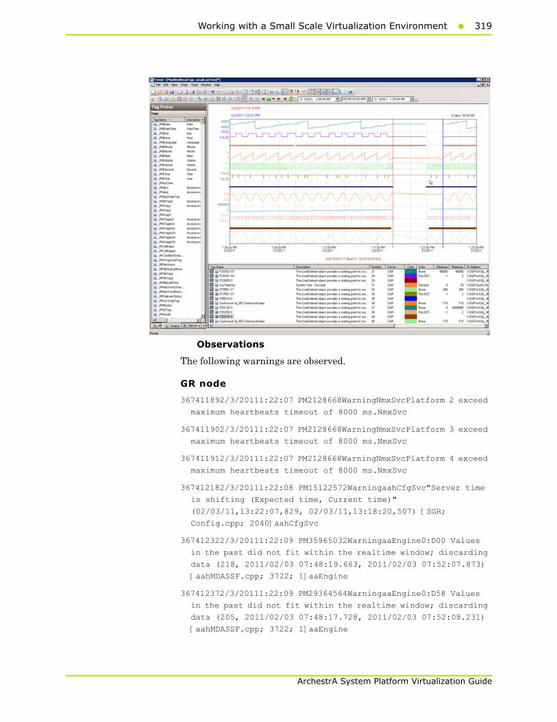
Working with a Small Scale Virtualization Environment319
ArchestrA System Platform Virtualization Guide
Observations
The following warnings are observed.
GR node
367411892/3/20111:22:07 PM2128668WarningNmxSvcPlatform 2 exceed
maximum heartbeats timeout of 8000 ms.NmxSvc
367411902/3/20111:22:07 PM2128668WarningNmxSvcPlatform 3 exceed
maximum heartbeats timeout of 8000 ms.NmxSvc
367411912/3/20111:22:07 PM2128668WarningNmxSvcPlatform 4 exceed
maximum heartbeats timeout of 8000 ms.NmxSvc
367412182/3/20111:22:08 PM15122572WarningaahCfgSvc"Server time
is shifting (Expected time, Current time)"
(02/03/11,13:22:07,829, 02/03/11,13:18:20,507) [SGR;
Config.cpp; 2040]aahCfgSvc
367412322/3/20111:22:09 PM35965032WarningaaEngine0:D00 Values
in the past did not fit within the realtime window; discarding
data (218, 2011/02/03 07:48:19.663, 2011/02/03 07:52:07.873)
[aahMDASSF.cpp; 3722; 1]aaEngine
367412372/3/20111:22:09 PM29364564WarningaaEngine0:D58 Values
in the past did not fit within the realtime window; discarding
data (205, 2011/02/03 07:48:17.728, 2011/02/03 07:52:08.231)
[aahMDASSF.cpp; 3722; 1]aaEngine

320 Chapter 3 Working with Disaster Recovery
ArchestrA System Platform Virtualization Guide
367412462/3/20111:22:11 PM6964900WarningaaEngine0:A84 Values in
the past did not fit within the realtime window; discarding
data (9112, 2011/02/03 07:48:19.530, 2011/02/03 07:52:09.934)
[aahMDASSF.cpp; 3722; 1]aaEngine
367413442/3/20111:26:20 PM35965032WarningaaEngine0:D00 Values
in the past did not fit within the realtime window; discarding
data (218, 2011/02/03 07:48:19.663, 2011/02/03 07:52:07.873)
[aahMDASSF.cpp; 3722; 28]aaEngine
367413452/3/20111:26:20 PM29364564WarningaaEngine0:D58 Values
in the past did not fit within the realtime window; discarding
data (205, 2011/02/03 07:48:17.728, 2011/02/03 07:52:08.231)
[aahMDASSF.cpp; 3722; 40]aaEngine
367413462/3/20111:26:22 PM6964900WarningaaEngine0:A84 Values in
the past did not fit within the realtime window; discarding
data (9112, 2011/02/03 07:48:19.530, 2011/02/03 07:52:09.934)
[aahMDASSF.cpp; 3722; 7]aaEngine
AppEngine
217672662/3/20111:18:18 PM19922372WarningScriptRuntime
Insert.InsertValueDataChange: Script timed out.aaEngine
217672672/3/20111:20:58 PM25642580WarningNmxSvcPlatform 1
exceed maximum heartbeats timeout of 8000 ms.NmxSvc
217672682/3/20111:20:58 PM25642580WarningNmxSvcPlatform 3
exceed maximum heartbeats timeout of 8000 ms.NmxSvc
217672732/3/20111:20:59 PM5961044WarningScanGroupRuntime2Can't
convert Var data type to MxDataTypeaaEngine
217672742/3/20111:20:59 PM5961044WarningScanGroupRuntime2Can't
convert Var data type to MxDataTypeaaEngine
217673112/3/20111:21:02 PM24643744WarningaaEngine0:778 Values
in the past did not fit within the realtime window; discarding
data (299, 2011/02/03 07:48:19.967, 2011/02/03 07:51:02.144)
[aahMDASSF.cpp; 3709; 1]aaEngine
217673202/3/20111:21:03 PM28924968WarningaaEngine0:9A8 Values
in the past did not fit within the realtime window; discarding
data (1738, 2011/02/03 07:48:18.846, 2011/02/03 07:51:02.769)
[aahMDASSF.cpp; 3709; 1]aaEngine
217673252/3/20111:21:03 PM30764724WarningaaEngine0:A18 Values
in the past did not fit within the realtime window; discarding
data (2329, 2011/02/03 07:48:18.685, 2011/02/03 07:51:02.191)
[aahMDASSF.cpp; 3709; 1]aaEngine
217673652/3/20111:21:04 PM31002412WarningaaEngine0:9DC Values
in the past did not fit within the realtime window; discarding
data (2916, 2011/02/03 07:48:19.389, 2011/02/03 07:51:02.894)
[aahMDASSF.cpp; 3709; 1]aaEngine

Working with a Small Scale Virtualization Environment321
ArchestrA System Platform Virtualization Guide
217673812/3/20111:21:05 PM31443524WarningaaEngine0:9CC Values
in the past did not fit within the realtime window; discarding
data (4280, 2011/02/03 07:48:19.732, 2011/02/03 07:51:03.863)
[aahMDASSF.cpp; 3709; 1]aaEngine
217673822/3/20111:21:05 PM23443668WarningaaEngine0:9B4 Values
in the past did not fit within the realtime window; discarding
data (729, 2011/02/03 07:48:20.951, 2011/02/03 07:51:03.847)
[aahMDASSF.cpp; 3709; 1]aaEngine
217673832/3/20111:21:06 PM26362300WarningaaEngine0:A0C Values
in the past did not fit within the realtime window; discarding
data (7646, 2011/02/03 07:48:19.077, 2011/02/03 07:51:04.160)
[aahMDASSF.cpp; 3709; 1]aaEngine
217674042/3/20111:22:10 PM19922372WarningScriptRuntime
Insert.InsertValuePerodic: Script timed out.aaEngine
217674062/3/20111:22:15 PM19922372WarningScriptRuntime
Insert.InsertValueWF: Script timed out.aaEngine
217675242/3/20111:25:14 PM31002412WarningaaEngine0:9DC Values
in the past did not fit within the realtime window; discarding
data (2916, 2011/02/03 07:48:19.389, 2011/02/03 07:51:02.894)
[aahMDASSF.cpp; 3709; 181]aaEngine
217675252/3/20111:25:14 PM24643744WarningaaEngine0:778 Values
in the past did not fit within the realtime window; discarding
data (299, 2011/02/03 07:48:19.967, 2011/02/03 07:51:02.144)
[aahMDASSF.cpp; 3709; 88]aaEngine
217675262/3/20111:25:15 PM28924968WarningaaEngine0:9A8 Values
in the past did not fit within the realtime window; discarding
data (1738, 2011/02/03 07:48:18.846, 2011/02/03 07:51:02.769)
[aahMDASSF.cpp; 3709; 308]aaEngine
217675272/3/20111:25:15 PM30764724WarningaaEngine0:A18 Values
in the past did not fit within the realtime window; discarding
data (2329, 2011/02/03 07:48:18.685, 2011/02/03 07:51:02.191)
[aahMDASSF.cpp; 3709; 5111]aaEngine
217675282/3/20111:25:15 PM31443524WarningaaEngine0:9CC Values
in the past did not fit within the realtime window; discarding
data (4280, 2011/02/03 07:48:19.732, 2011/02/03 07:51:03.863)
[aahMDASSF.cpp; 3709; 126]aaEngine
217675292/3/20111:25:16 PM23443668WarningaaEngine0:9B4 Values
in the past did not fit within the realtime window; discarding
data (729, 2011/02/03 07:48:20.951, 2011/02/03 07:51:03.847)
[aahMDASSF.cpp; 3709; 8]aaEngine
217675302/3/20111:25:16 PM26362300WarningaaEngine0:A0C Values
in the past did not fit within the realtime window; discarding
data (7646, 2011/02/03 07:48:19.077, 2011/02/03 07:51:04.160)
[aahMDASSF.cpp; 3709; 1124]aaEngine
322 Chapter 3 Working with Disaster Recovery
ArchestrA System Platform Virtualization Guide
WIS node
17158432/3/20111:18:28 PM38524104WarningNmxSvcPlatform 1 exceed
maximum heartbeats timeout of 8000 ms.NmxSvc
17158462/3/20111:18:33 PM38524104WarningNmxSvcPlatform 2 exceed
maximum heartbeats timeout of 8000 ms.NmxSvc
17158532/3/20111:21:20 PM60483068WarningaaAFCommonTypesUnable
to create dataview: Server must be logged on before executing
SQL query: SELECT aaT=DateTime, aaN=TagName, aaDV=Value,
aaSV=CONVERT(nvarchar(512),vValue), aaQ=OPCQuality,
aaIQ=Quality, aaQD=QualityDetail, aaS=0
FROM History
WHERE TagName IN ('...aaTrend
Scenario 2: Virtualization Server Hardware Fails
Failover due to Hardware Failure
The failover occurs due to hardware failure, and it is simulated with power-off on the host server.
Trends:
In the following Historian Trend, GRnode tags are:
Tag1: SystemTimeSec tag of Historian.
Tag2: I/O Tag (Integer_001.int1) getting data from DDESuiteLinkClient_001.Topic39.RealIO10000
Tag3: I/O Tag (Integer_001.bool1) getting data from DDESuiteLinkClient_001.Topic39.RealIO10000
Tag4: Script Tag (SineWaveVal_001.SineWaveValue)
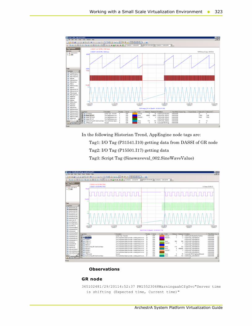
Working with a Small Scale Virtualization Environment323
ArchestrA System Platform Virtualization Guide
In the following Historian Trend, AppEngine node tags are:
Tag1: I/O Tag (P31541.I10) getting data from DASSI of GR node
Tag2: I/O Tag (P15501.I17) getting data
Tag3: Script Tag (Sinewaveval_002.SineWaveValue)
Observations
GR node
365102481/29/20114:52:37 PM15523068WarningaahCfgSvc"Server time
is shifting (Expected time, Current time)"
324 Chapter 3 Working with Disaster Recovery
ArchestrA System Platform Virtualization Guide
(01/29/11,16:52:36,421, 01/29/11,16:52:42,044) [SGR;
Config.cpp; 2040]
365103161/29/20114:52:47 PM29082912WarningScriptRuntime
GR.privatembytes: Script timed out.
365106351/29/20114:53:13 PM29085088WarningaaEngine0:7D4 Values
in the past did not fit within the realtime window; discarding
data (193, 2011/01/29 11:22:20.000, 2011/01/29 11:23:12.198)
[aahMDASSF.cpp; 3722; 1]
365177651/29/20114:57:25 PM29085088WarningaaEngine0:7D4 Values
in the past did not fit within the realtime window; discarding
data (193, 2011/01/29 11:22:20.000, 2011/01/29 11:23:12.198)
[aahMDASSF.cpp; 3722; 38]
AppEngine node
216506701/29/20114:52:13 PM24762480WarningScriptRuntime
AppEngineNode1.privatembytes: Script timed out.aaEngine
216509601/29/20114:52:52 PM3924936WarningDCMConnectionMgrOpen()
of DCMConnection failed: 'A network-related or
instance-specific error occurred while establishing a
connection to SQL Server. The server was not found or was not
accessible. Verify that the instance name is correct and that
SQL Server is configured...aaEngine
WIS node
17138461/29/20114:56:32 PM23163916WarningNmxSvcPlatform 1
exceed maximum heartbeats timeout of 8000 ms.NmxSvc
17139371/29/20115:11:53 PM23163916WarningNmxSvcPlatform 1
exceed maximum heartbeats timeout of 8000 ms.NmxSvc
17141071/29/20115:27:42 PM57085456Warning
ArchestrA.Visualization.WCFServiceLMX WCF service: Exception
while PushBackConfigurations(sync mode): [The operation has
timed out.] at [
Server stack trace:
at
System.ServiceModel.Channels.InputQueue`1.Dequeue(TimeSpan
timeout)
at System.ServiceModel.Channels.ServicePollingDuple...w3wp
Scenario 3: Network Fails on Virtualization Server
Failover due to Network Disconnect (Public)
Trends:
In the following Historian Trend, GRnode tags are:
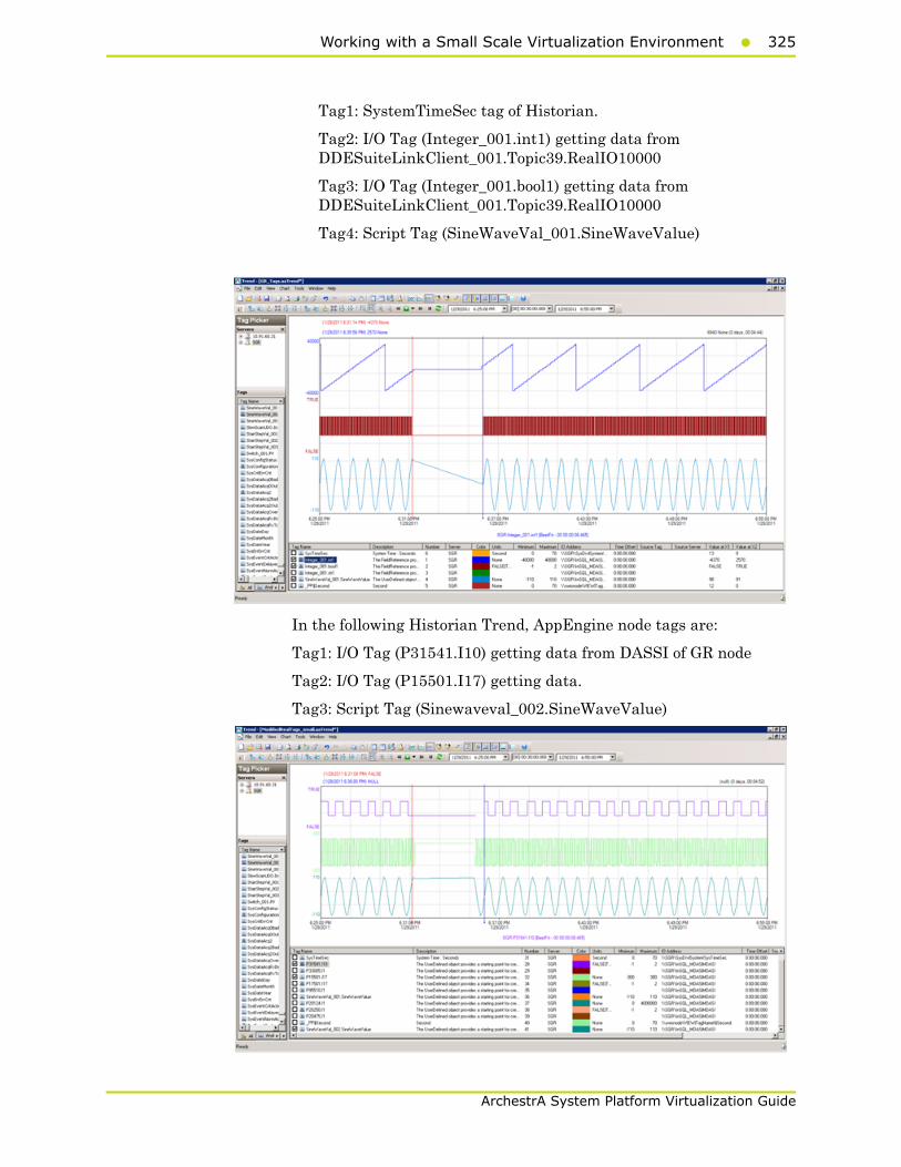
Working with a Small Scale Virtualization Environment325
ArchestrA System Platform Virtualization Guide
Tag1: SystemTimeSec tag of Historian.
Tag2: I/O Tag (Integer_001.int1) getting data from DDESuiteLinkClient_001.Topic39.RealIO10000
Tag3: I/O Tag (Integer_001.bool1) getting data from DDESuiteLinkClient_001.Topic39.RealIO10000
Tag4: Script Tag (SineWaveVal_001.SineWaveValue)
In the following Historian Trend, AppEngine node tags are:
Tag1: I/O Tag (P31541.I10) getting data from DASSI of GR node
Tag2: I/O Tag (P15501.I17) getting data.
Tag3: Script Tag (Sinewaveval_002.SineWaveValue)

326 Chapter 3 Working with Disaster Recovery
ArchestrA System Platform Virtualization Guide
Observations
During the network disconnect of host server, all the nodes will be moved to other Host server and all the VM's in the host server will get restarted.
GR node
365197041/29/20116:35:37 PM16282572WarningaahCfgSvc"Server time
is shifting (Expected time, Current time)"
(01/29/11,18:35:36,507, 01/29/11,18:35:40,334) [SGR;
Config.cpp; 2040]aahCfgSvc
365197161/29/20116:35:43 PM28442848WarningScriptRuntime
GR.privatembytes: Script timed out.aaEngine
365200231/29/20116:36:00 PM28444660WarningaaEngine0:6F4 Values
in the past did not fit within the realtime window; discarding
data (193, 2011/01/29 13:05:16.771, 2011/01/29 13:06:00.106)
[aahMDASSF.cpp; 3722; 1]aaEngine
365201071/29/20116:36:16 PM38965028WarningaaEngine0:C88 Values
in the past did not fit within the realtime window; discarding
data (215, 2011/01/29 13:05:29.000, 2011/01/29 13:06:15.355)
[aahMDASSF.cpp; 3722; 1]aaEngine
365269551/29/20116:36:36 PM16282572WarningaahStoreSvcAttempt to
store value prior to disconnect time. Value discarded -
possible loss of data (SGR_mdas, 2916, 2011/01/29
13:06:36.090, 2011/01/29 13:06:35.519) [SGR; pipeserver.cpp;
958]aahCfgSvc
365271041/29/20116:40:12 PM28444660WarningaaEngine0:6F4 Values
in the past did not fit within the realtime window; discarding
data (193, 2011/01/29 13:05:16.771, 2011/01/29 13:06:00.106)
[aahMDASSF.cpp; 3722; 33]aaEngine
365271051/29/20116:40:27 PM38965028WarningaaEngine0:C88 Values
in the past did not fit within the realtime window; discarding
data (215, 2011/01/29 13:05:29.000, 2011/01/29 13:06:15.355)
[aahMDASSF.cpp; 3722; 17]aaEngine
365271071/29/20116:40:53 PM16282572WarningaahStoreSvcAttempt to
store value prior to disconnect time. Value discarded -
possible loss of data (SGR_mdas, 2916, 2011/01/29
13:06:36.090, 2011/01/29 13:06:35.519) [SGR; pipeserver.cpp;
958; 56]aahCfgSvc
AppEngine node
216513881/29/20116:35:05 PM25002504WarningScriptRuntime
AppEngineNode1.privatembytes: Script timed out.aaEngine
216516741/29/20116:35:41 PM22843016WarningScriptRuntime
Insert.InsertValueWT: Script timed out.aaEngine

Working with a Small Scale Virtualization Environment327
ArchestrA System Platform Virtualization Guide
216516861/29/20116:35:45 PM22844824WarningDCMConnectionMgr
Open() of DCMConnection failed: 'A network-related or
instance-specific error occurred while establishing a
connection to SQL Server. The server was not found or was not
accessible. Verify that the instance name is correct and that
SQL Server is configured...aaEngine
216516891/29/20116:35:46 PM22844824WarningSQLDataRuntime3
SQLTestResults Command Failure - A network-related or
instance-specific error occurred while establishing a
connection to SQL Server. The server was not found or was not
accessible. Verify that the instance name is correct and that
SQL Server is configured...aaEngine
216518961/29/20116:37:28 PM13162080WarningInTouchProxyFailed to
reconnect to data source aaEngine
WIS node
None
Scenario 4: Virtualization Server Becomes Unresponsive
Hyper-V Virtual Machines with Static RAM and Reservations for Processors
It has been observed that even when the Host Virtualization Server reaches 100% CPU utilization, there is no failover of the Hyper-V virtual machines running on it to the other Host Virtualization Server. However, the host server running at 100% CPU utilization fails to process all the network requirements of the Hyper-V virtual machines running on it. As a result, network disruptions on the Hyper-V virtual machines are observed that result in data loss.
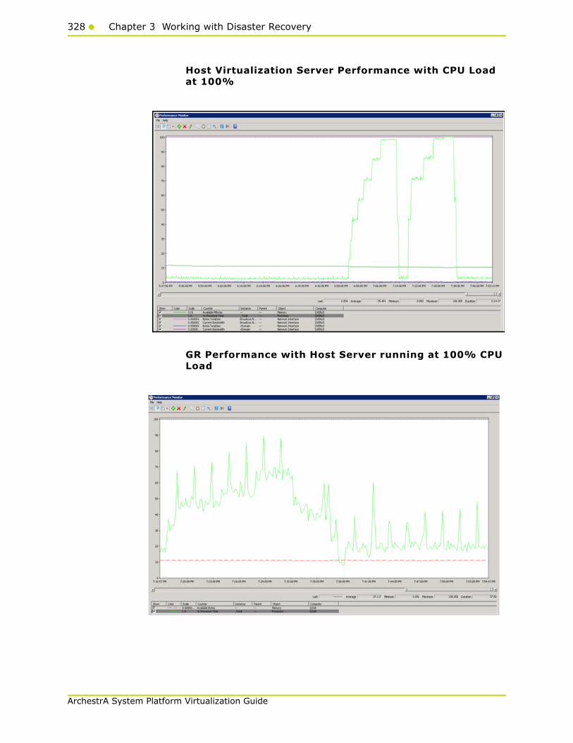
328 Chapter 3 Working with Disaster Recovery
ArchestrA System Platform Virtualization Guide
Host Virtualization Server Performance with CPU Load at 100%
GR Performance with Host Server running at 100% CPU Load
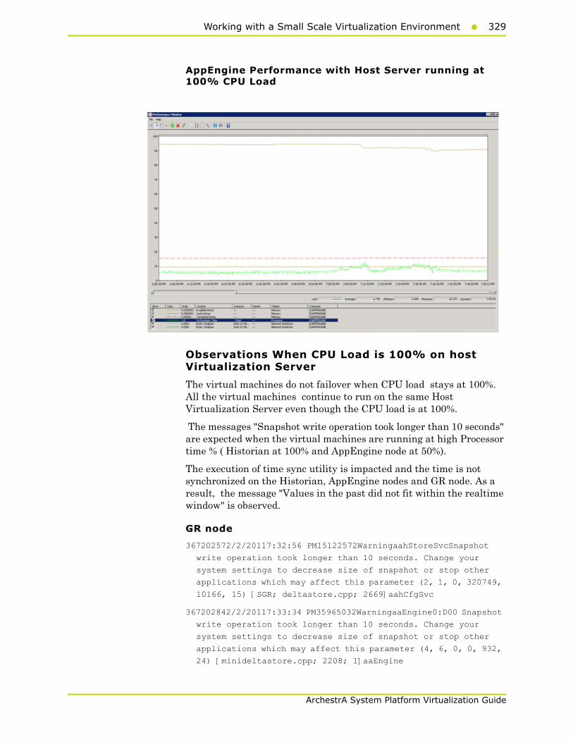
Working with a Small Scale Virtualization Environment329
ArchestrA System Platform Virtualization Guide
AppEngine Performance with Host Server running at 100% CPU Load
Observations When CPU Load is 100% on host Virtualization Server
The virtual machines do not failover when CPU load stays at 100%. All the virtual machines continue to run on the same Host Virtualization Server even though the CPU load is at 100%.
The messages "Snapshot write operation took longer than 10 seconds" are expected when the virtual machines are running at high Processor time % ( Historian at 100% and AppEngine node at 50%).
The execution of time sync utility is impacted and the time is not synchronized on the Historian, AppEngine nodes and GR node. As a result, the message "Values in the past did not fit within the realtime window" is observed.
GR node
367202572/2/20117:32:56 PM15122572WarningaahStoreSvcSnapshot
write operation took longer than 10 seconds. Change your
system settings to decrease size of snapshot or stop other
applications which may affect this parameter (2, 1, 0, 320749,
10166, 15) [SGR; deltastore.cpp; 2669]aahCfgSvc
367202842/2/20117:33:34 PM35965032WarningaaEngine0:D00 Snapshot
write operation took longer than 10 seconds. Change your
system settings to decrease size of snapshot or stop other
applications which may affect this parameter (4, 6, 0, 0, 932,
24) [minideltastore.cpp; 2208; 1]aaEngine
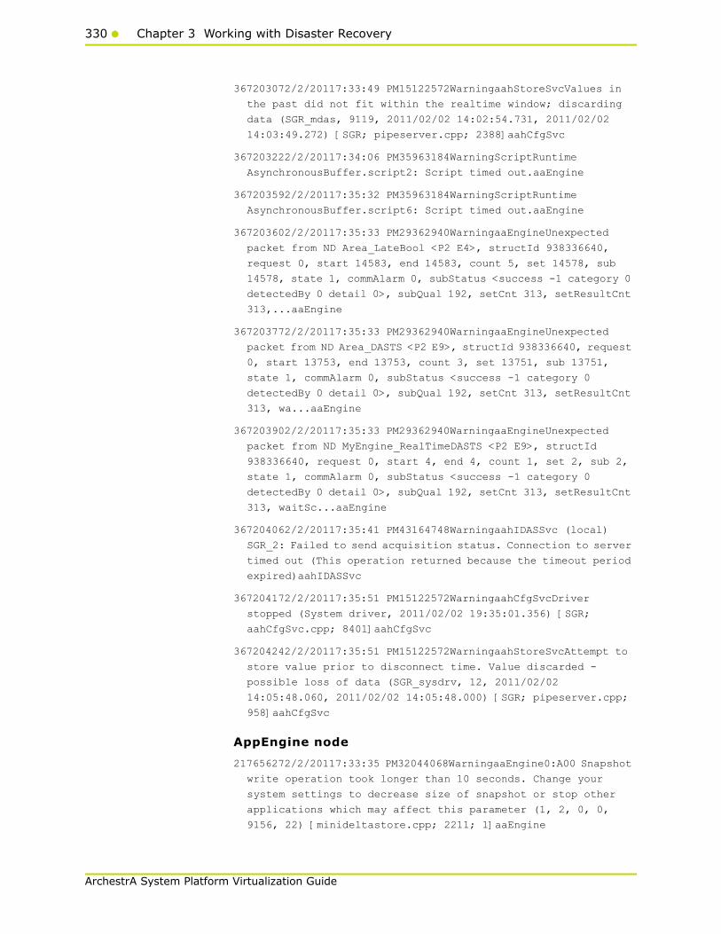
330 Chapter 3 Working with Disaster Recovery
ArchestrA System Platform Virtualization Guide
367203072/2/20117:33:49 PM15122572WarningaahStoreSvcValues in
the past did not fit within the realtime window; discarding
data (SGR_mdas, 9119, 2011/02/02 14:02:54.731, 2011/02/02
14:03:49.272) [SGR; pipeserver.cpp; 2388]aahCfgSvc
367203222/2/20117:34:06 PM35963184WarningScriptRuntime
AsynchronousBuffer.script2: Script timed out.aaEngine
367203592/2/20117:35:32 PM35963184WarningScriptRuntime
AsynchronousBuffer.script6: Script timed out.aaEngine
367203602/2/20117:35:33 PM29362940WarningaaEngineUnexpected
packet from ND Area_LateBool <P2 E4>, structId 938336640,
request 0, start 14583, end 14583, count 5, set 14578, sub
14578, state 1, commAlarm 0, subStatus <success -1 category 0
detectedBy 0 detail 0>, subQual 192, setCnt 313, setResultCnt
313,...aaEngine
367203772/2/20117:35:33 PM29362940WarningaaEngineUnexpected
packet from ND Area_DASTS <P2 E9>, structId 938336640, request
0, start 13753, end 13753, count 3, set 13751, sub 13751,
state 1, commAlarm 0, subStatus <success -1 category 0
detectedBy 0 detail 0>, subQual 192, setCnt 313, setResultCnt
313, wa...aaEngine
367203902/2/20117:35:33 PM29362940WarningaaEngineUnexpected
packet from ND MyEngine_RealTimeDASTS <P2 E9>, structId
938336640, request 0, start 4, end 4, count 1, set 2, sub 2,
state 1, commAlarm 0, subStatus <success -1 category 0
detectedBy 0 detail 0>, subQual 192, setCnt 313, setResultCnt
313, waitSc...aaEngine
367204062/2/20117:35:41 PM43164748WarningaahIDASSvc (local)
SGR_2: Failed to send acquisition status. Connection to server
timed out (This operation returned because the timeout period
expired)aahIDASSvc
367204172/2/20117:35:51 PM15122572WarningaahCfgSvcDriver
stopped (System driver, 2011/02/02 19:35:01.356) [SGR;
aahCfgSvc.cpp; 8401]aahCfgSvc
367204242/2/20117:35:51 PM15122572WarningaahStoreSvcAttempt to
store value prior to disconnect time. Value discarded -
possible loss of data (SGR_sysdrv, 12, 2011/02/02
14:05:48.060, 2011/02/02 14:05:48.000) [SGR; pipeserver.cpp;
958]aahCfgSvc
AppEngine node
217656272/2/20117:33:35 PM32044068WarningaaEngine0:A00 Snapshot
write operation took longer than 10 seconds. Change your
system settings to decrease size of snapshot or stop other
applications which may affect this parameter (1, 2, 0, 0,
9156, 22) [minideltastore.cpp; 2211; 1]aaEngine
Working with a Small Scale Virtualization Environment331
ArchestrA System Platform Virtualization Guide
217656372/2/20117:33:38 PM26244968WarningaaEngine0:C88 Snapshot
write operation took longer than 10 seconds. Change your
system settings to decrease size of snapshot or stop other
applications which may affect this parameter (4, 1, 0, 0, 260,
26) [minideltastore.cpp; 2211; 1]aaEngine
217656512/2/20117:33:55 PM30844132WarningaaEngine0:9AC Values
in the past did not fit within the realtime window; discarding
data (1738, 2011/02/02 14:02:54.731, 2011/02/02 14:03:55.637)
[aahMDASSF.cpp; 3709; 1]aaEngine
217657772/2/20117:36:14 PM26244968WarningaaEngine0:C88 Snapshot
write operation took longer than 10 seconds. Change your
system settings to decrease size of snapshot or stop other
applications which may affect this parameter (4, 1, 0, 0, 260,
13) [minideltastore.cpp; 2211; 1]aaEngine
WIS node
17157102/2/20117:36:25 PM60485304WarningaaAFCommonTypesUnable
to create dataview: Server must be logged on before executing
SQL query: SELECT aaT=DateTime, aaN=TagName, aaDV=Value,
aaSV=CONVERT(nvarchar(512),vValue), aaQ=OPCQuality,
aaIQ=Quality, aaQD=QualityDetail, aaS=0
FROM History
WHERE TagName IN ('...aaTrend
17157122/2/20117:36:27 PM60484536WarningaaAFCommonTypesUnable
to create dataview: Server must be logged on before executing
SQL query: SELECT aaT=DateTime, aaN=TagName, aaDV=Value,
aaSV=CONVERT(nvarchar(512),vValue), aaQ=OPCQuality,
aaIQ=Quality, aaQD=QualityDetail, aaS=0
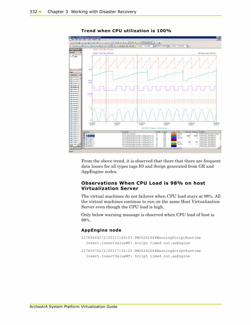
332 Chapter 3 Working with Disaster Recovery
ArchestrA System Platform Virtualization Guide
Trend when CPU utilization is 100%
From the above trend, it is observed that there that there are frequent data losses for all types tags IO and Script generated from GR and AppEngine nodes.
Observations When CPU Load is 98% on host Virtualization Server
The virtual machines do not failover when CPU load stays at 98%. All the virtual machines continue to run on the same Host Virtualization Server even though the CPU load is high.
Only below warning massage is observed when CPU load of host is 98%.
AppEngine node
217655642/2/20117:29:03 PM26242644WarningScriptRuntime
Insert.InsertValueWF: Script timed out.aaEngine
217655722/2/20117:32:25 PM26242644WarningScriptRuntime
Insert.InsertValueWT: Script timed out.aaEngine

Working with a Small Scale Virtualization Environment333
ArchestrA System Platform Virtualization Guide
Trend when CPU Load is 98% on host Virtualization Server
From the above trend, it is observed that there is data loss for Script tags of AppEngine node.
334 Chapter 3 Working with Disaster Recovery
ArchestrA System Platform Virtualization Guide
Working with a Medium Scale Virtualization Environment
This section contains the following topics:
• Setting Up Medium Scale Virtualization Environment
• Configuring System Platform Products in a Typical Medium Scale Virtualization
• Expected Recovery Time Objective and Recovery Point Objective
• Snapshots of Data Trends and Observations
Setting Up Medium Scale Virtualization Environment
The following procedures help you to set up small scale virtualization disaster recovery environment.
Planning for Disaster RecoveryThe minimum and recommended hardware and software requirements for the Host and Virtual machines used for small scale virtualization disaster recovery environment.
Hyper-V Hosts
Note: For the Hyper-V Host to function optimally, the server should have the same processor, RAM, storage and service pack level. Preferably the servers should be purchased in pairs to avoid hardware discrepancies. Though the differences are supported, it will impact the performance during failovers.
Processor Two 2.79 GHz Intel Xeon with 24 Cores
Operating System Windows Server 2008 R2 Enterprise with Hyper-V enabled
Memory 48 GB
Storage SAN with 1TB storage disk
Working with a Medium Scale Virtualization Environment335
ArchestrA System Platform Virtualization Guide
Virtual Machines
Using the Hyper-V host specified above, seven virtual machines can be created in the environment with the configuration given below.
Virtual Machine 1: Historian Node
Virtual Machine 2: Application Server Node, DAS SI
Processor Host Compatible Processor with 2-4 Cores
Operating System Windows Server 2008 R2 Standard
Memory 8 GB
Storage 200 GB
System Platform Products Installed
Historian
Processor Host Compatible Processor with 2-4 Cores
Operating System Windows Server 2008 R2 Standard
Memory 8 GB
Storage 100 GB
System Platform Products Installed
ArchestrA-Runtime, DAS SI

336 Chapter 3 Working with Disaster Recovery
ArchestrA System Platform Virtualization Guide
Virtual Machine 3: InTouch TS Node
Virtual Machine 4: Application Server Runtime Node 1
Virtual Machine 5: Application Server Runtime Node 2
Processor Host Compatible Processor with 2-4 Cores
Operating System Windows Server 2008 R2 Standard
Memory 4 GB
Storage 80 GB
System Platform Products Installed
InTouch with TS enabled
Processor Host Compatible Processor with 2-4 Cores
Operating System Windows Server 2008 R2 Standard
Memory 4 GB
Storage 80 GB
System Platform Products Installed
Application Server Runtime only and InTouch
Processor Host Compatible Processor with 2-4 Cores
Operating System Windows Server 2008 R2 Standard
Memory 4 GB
Storage 80 GB
System Platform Products Installed
Application Server Runtime only

Working with a Medium Scale Virtualization Environment337
ArchestrA System Platform Virtualization Guide
Virtual Machine 6: Information Server Node
Virtual Machine 7: Historian Client Node
Network Requirements
For this architecture, you can use one physical network card that needs to be installed on a host computer for the domain network and the process network.
Processor Host Compatible Processor with 2-4 Cores
Operating System Windows Server 2008 Standard
Memory 4 GB
Storage 80 GB
System Platform Products Installed
Information Server
Processor Host Compatible Processor with 2-4 Cores
Operating System Windows 7 Enterprise
Memory 4 GB
Storage 80 GB
System Platform Products Installed
Historian Client

338 Chapter 3 Working with Disaster Recovery
ArchestrA System Platform Virtualization Guide
Configuring Failover ClusterThe recommended topology of the failover cluster for disaster recovery process for medium scale virtualization environment is given below:
This setup requires a minimum of two host servers and two storage servers connected to each host independently. Another independent node is used for configuring the quorum. For more information on configuring the quorum, refer to "Configuring Cluster Quorum Settings" on page 348.
The following procedures help you install and configure a failover cluster that has two nodes to set up on medium configuration.
To install the failover cluster feature, you need to run Windows Server 2008 R2 Enterprise Edition on your server.

Working with a Medium Scale Virtualization Environment339
ArchestrA System Platform Virtualization Guide
To configure failover cluster
1 On the Initial Configuration Tasks window, under Customize This Server, click Add features. The Add Features Wizard window appears.
Note: The Initial Configuration Tasks window appears if you have already installed Windows Server 2008 R2. If it does not appear, open the Server Manager window, right-click Features and click Add Features.
2 In the Add Features Wizard window, select the Failover Clustering check box, and then click Next. The Confirm Installation Selections area appears.
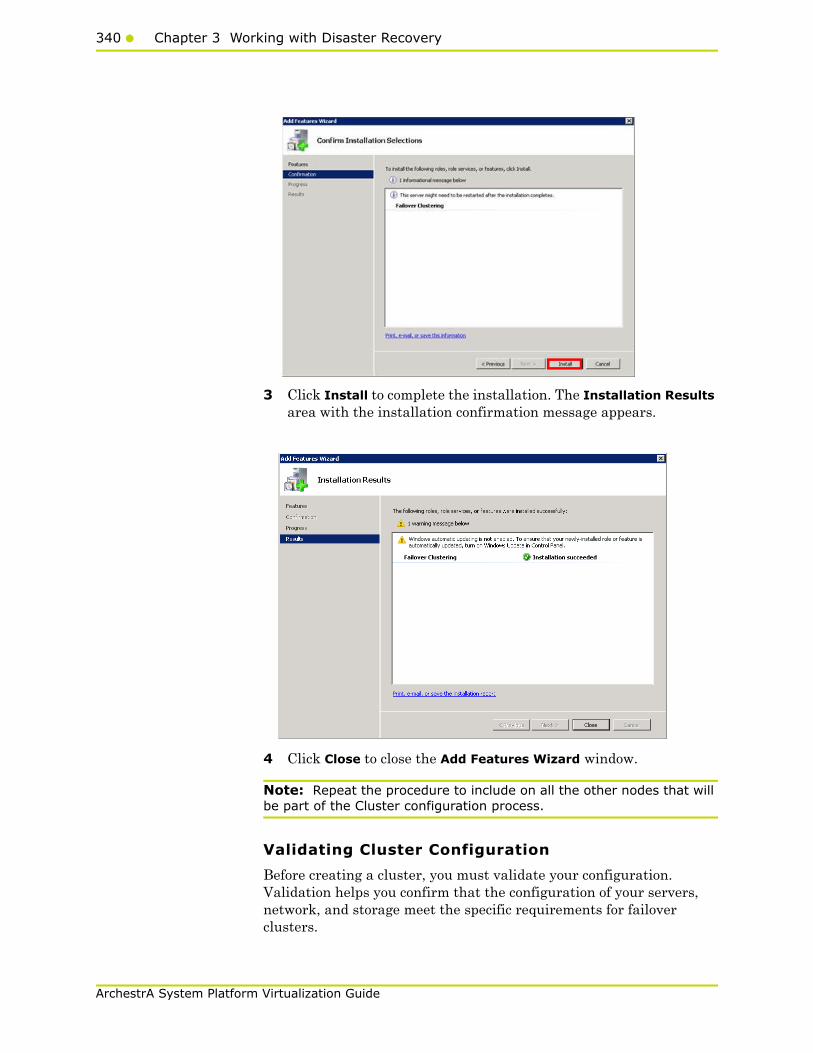
340 Chapter 3 Working with Disaster Recovery
ArchestrA System Platform Virtualization Guide
3 Click Install to complete the installation. The Installation Results area with the installation confirmation message appears.
4 Click Close to close the Add Features Wizard window.
Note: Repeat the procedure to include on all the other nodes that will be part of the Cluster configuration process.
Validating Cluster Configuration
Before creating a cluster, you must validate your configuration. Validation helps you confirm that the configuration of your servers, network, and storage meet the specific requirements for failover clusters.
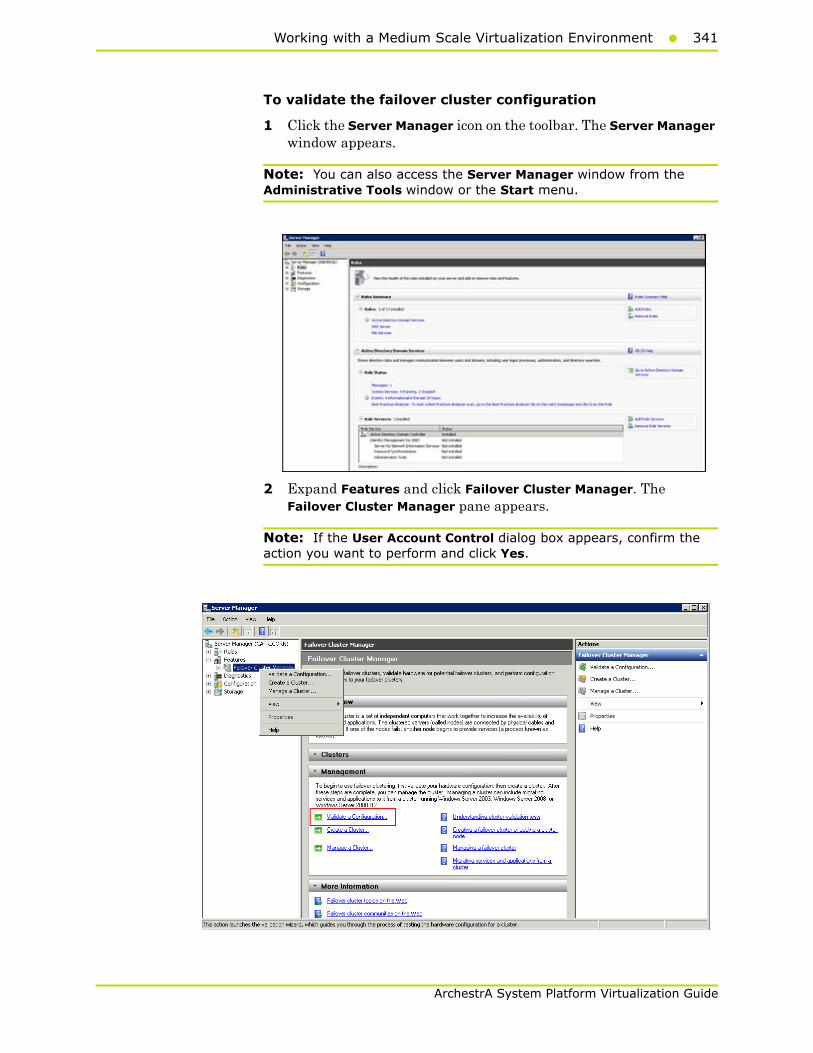
Working with a Medium Scale Virtualization Environment341
ArchestrA System Platform Virtualization Guide
To validate the failover cluster configuration
1 Click the Server Manager icon on the toolbar. The Server Manager window appears.
Note: You can also access the Server Manager window from the Administrative Tools window or the Start menu.
2 Expand Features and click Failover Cluster Manager. The Failover Cluster Manager pane appears.
Note: If the User Account Control dialog box appears, confirm the action you want to perform and click Yes.
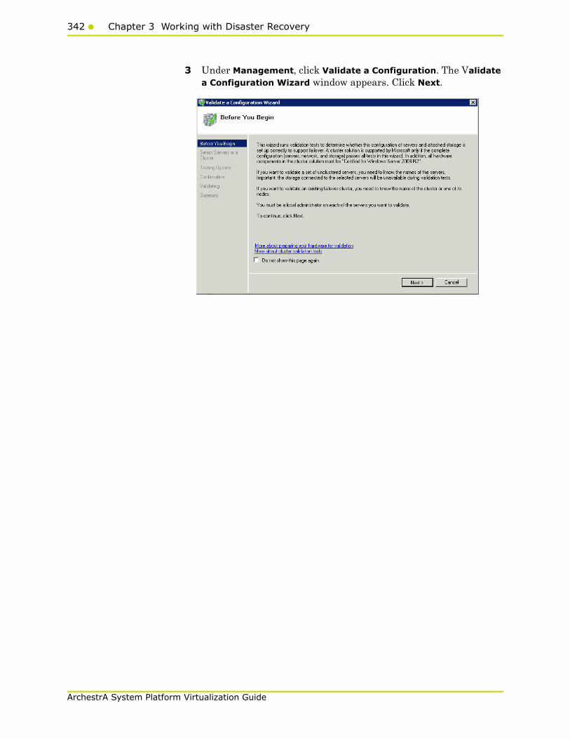
342 Chapter 3 Working with Disaster Recovery
ArchestrA System Platform Virtualization Guide
3 Under Management, click Validate a Configuration. The Validate a Configuration Wizard window appears. Click Next.
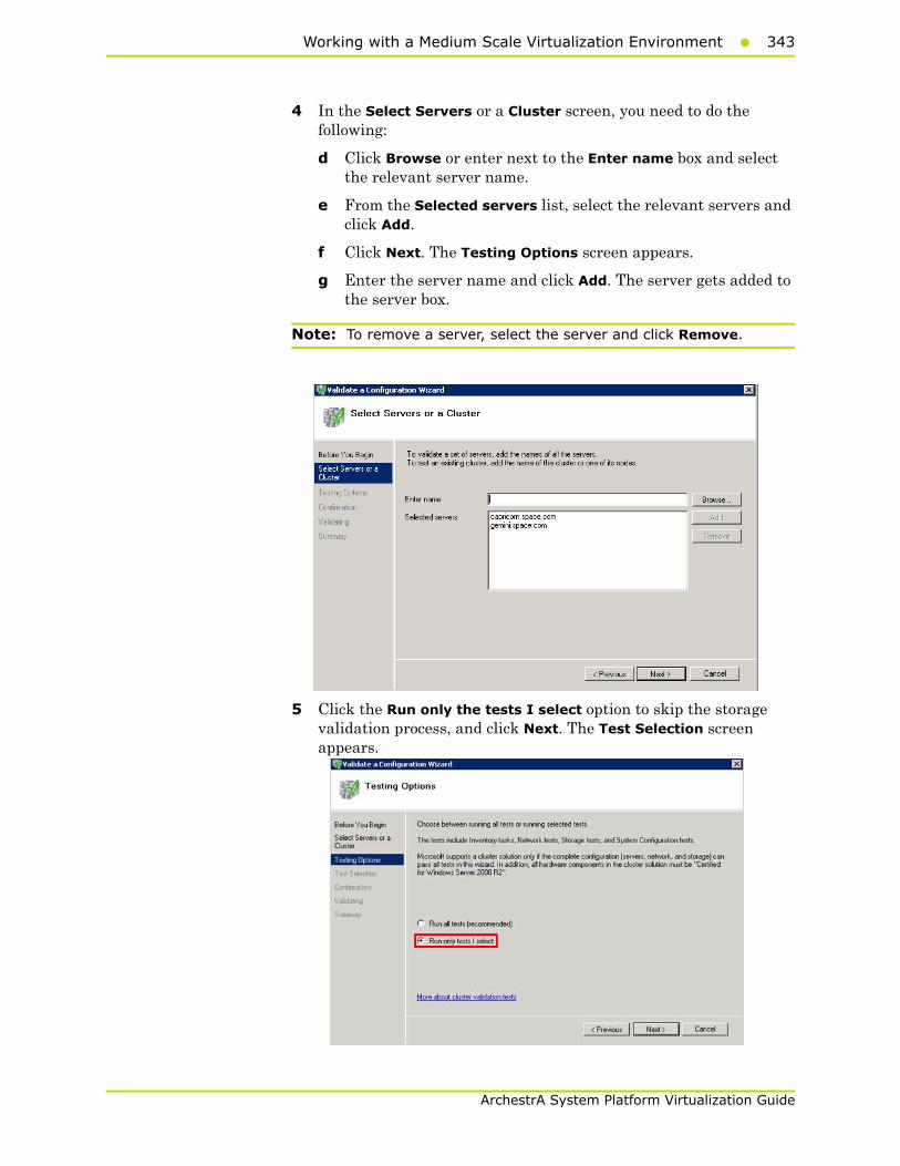
Working with a Medium Scale Virtualization Environment343
ArchestrA System Platform Virtualization Guide
4 In the Select Servers or a Cluster screen, you need to do the following:
d Click Browse or enter next to the Enter name box and select the relevant server name.
e From the Selected servers list, select the relevant servers and click Add.
f Click Next. The Testing Options screen appears.
g Enter the server name and click Add. The server gets added to the server box.
Note: To remove a server, select the server and click Remove.
5 Click the Run only the tests I select option to skip the storage validation process, and click Next. The Test Selection screen appears.
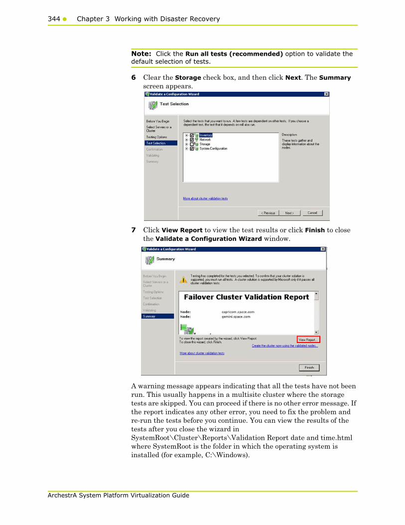
344 Chapter 3 Working with Disaster Recovery
ArchestrA System Platform Virtualization Guide
Note: Click the Run all tests (recommended) option to validate the default selection of tests.
6 Clear the Storage check box, and then click Next. The Summary screen appears.
7 Click View Report to view the test results or click Finish to close the Validate a Configuration Wizard window.
A warning message appears indicating that all the tests have not been run. This usually happens in a multisite cluster where the storage tests are skipped. You can proceed if there is no other error message. If the report indicates any other error, you need to fix the problem and re-run the tests before you continue. You can view the results of the tests after you close the wizard in SystemRoot\Cluster\Reports\Validation Report date and time.html where SystemRoot is the folder in which the operating system is installed (for example, C:\Windows).
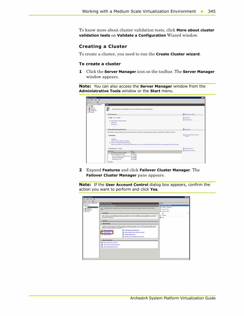
Working with a Medium Scale Virtualization Environment345
ArchestrA System Platform Virtualization Guide
To know more about cluster validation tests, click More about cluster validation tests on Validate a Configuration Wizard window.
Creating a Cluster
To create a cluster, you need to run the Create Cluster wizard.
To create a cluster
1 Click the Server Manager icon on the toolbar. The Server Manager window appears.
Note: You can also access the Server Manager window from the Administrative Tools window or the Start menu.
2 Expand Features and click Failover Cluster Manager. The Failover Cluster Manager pane appears.
Note: If the User Account Control dialog box appears, confirm the action you want to perform and click Yes.
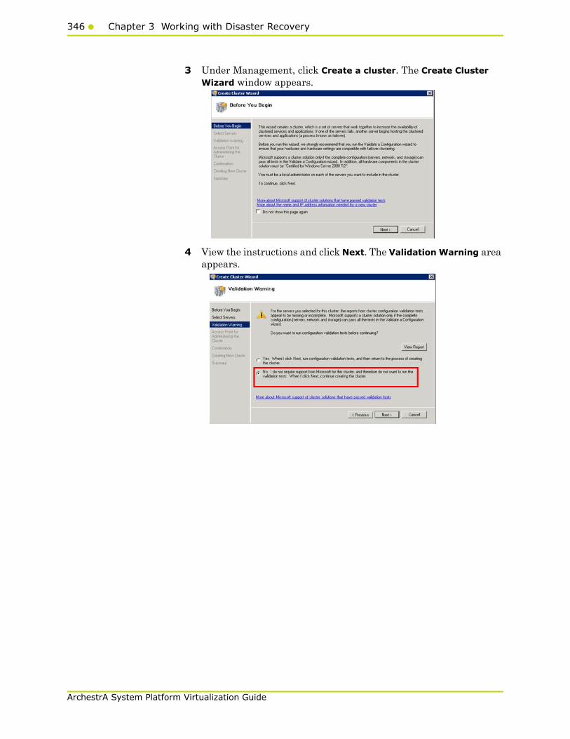
346 Chapter 3 Working with Disaster Recovery
ArchestrA System Platform Virtualization Guide
3 Under Management, click Create a cluster. The Create Cluster Wizard window appears.
4 View the instructions and click Next. The Validation Warning area appears.

Working with a Medium Scale Virtualization Environment347
ArchestrA System Platform Virtualization Guide
5 Click No. I do not require support from Microsoft for this cluster, and therefore do not want to run the validation tests. When I click Next, continue creating the cluster option and click Next. The Select Servers area appears.
Note: Click Click Yes. When I click Next, run configuration validation tests, and then return to the process of creating the cluster option if you want to run the configuration validation tests. Click View Report to view the cluster operation report.
6 In the Select Servers screen, do the following:
a In the Enter server name box, enter the relevant server name and click Add. The server name gets added in the Selected servers box.
Note: You can either type the server name or click Browse to select the relevant server name.
b Click Next. The Access Point for Administering the Cluster area appears.

348 Chapter 3 Working with Disaster Recovery
ArchestrA System Platform Virtualization Guide
7 In the Cluster Name box, type the name of the cluster and click Next. The Confirmation area appears.
Note: Enter a valid IP address for the cluster to be created if the IP address is not configured through Dynamic Host Configuration Protocol (DHCP).
8 Click Next. The cluster is created and the Summary area appears.
9 Click View Report to view the cluster report created by the wizard or click Finish to close the Create Cluster Wizard window.
Configuring Cluster Quorum Settings
Quorum is the number of elements that need to be online to enable continuous running of a cluster. In most instances, the elements are nodes. In some cases, the elements also consist of disk or file share witnesses. Each of these elements determines whether the cluster should continue to run.
All elements, except the file share witnesses, have a copy of the cluster configuration. The cluster service ensures that the copies are always synchronized. The cluster should stop running if there are multiple failures or if there is a communication error between the cluster nodes.
After both nodes have been added to the cluster, and the cluster networking components have been configured, you must configure the failover cluster quorum.

Working with a Medium Scale Virtualization Environment349
ArchestrA System Platform Virtualization Guide
You must create and secure the file share that you want to use for the node and the file share majority quorum before configuring the failover cluster quorum. If the file share has not been created or correctly secured, the following procedure to configure a cluster quorum will fail. The file share can be hosted on any computer running a Windows operating system.
To configure the cluster quorum, you need to perform the following precedures:
• Create and secure a file share for the node and file share majority quorum
• Use the failover cluster management tool to configure a node and file share majority quorum
To create and secure a file share for the node and file share majority quorum
1 Create a new folder on the system that will host the share directory.
2 Right-click the folder that you created and click Properties. The Quorum Properties window for the folder you created appears.
Note: In the following procedure, Quorum is the name of the folder.
3 Click the Sharing tab, and then click Advanced Sharing. The Advanced Sharing window appears.
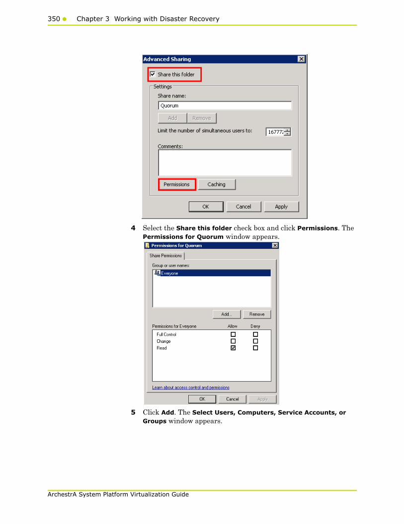
350 Chapter 3 Working with Disaster Recovery
ArchestrA System Platform Virtualization Guide
4 Select the Share this folder check box and click Permissions. The Permissions for Quorum window appears.
5 Click Add. The Select Users, Computers, Service Accounts, or Groups window appears.

Working with a Medium Scale Virtualization Environment351
ArchestrA System Platform Virtualization Guide
6 In the Enter the object name to select box, enter the two node names used for the cluster in the medium node configuration and click OK. The node names are added and the Permissions for Quorum window appears.
7 Select the Full Control, Change, and Read check boxes and click OK. The Properties window appears.

352 Chapter 3 Working with Disaster Recovery
ArchestrA System Platform Virtualization Guide
8 Click Ok. The folder is shared and can be used to create virtual machines.
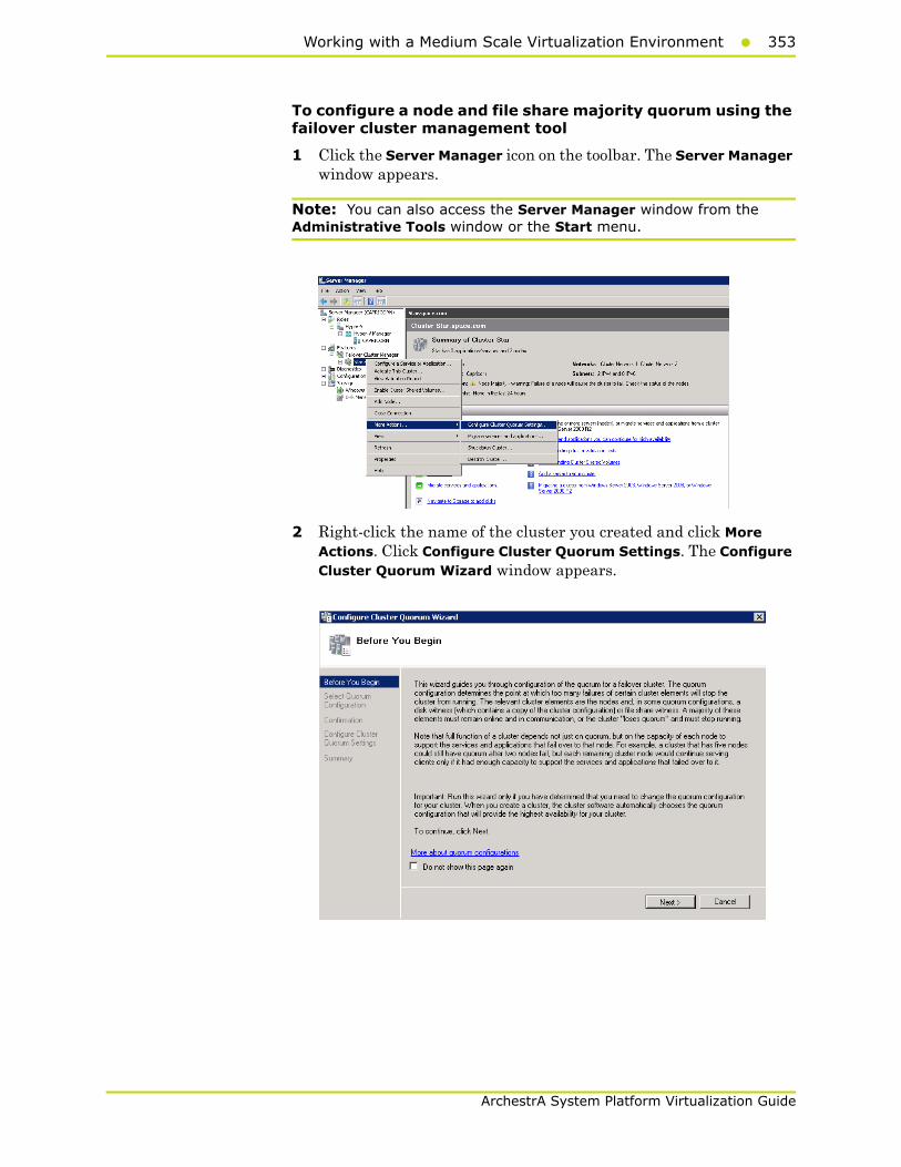
Working with a Medium Scale Virtualization Environment353
ArchestrA System Platform Virtualization Guide
To configure a node and file share majority quorum using the failover cluster management tool
1 Click the Server Manager icon on the toolbar. The Server Manager window appears.
Note: You can also access the Server Manager window from the Administrative Tools window or the Start menu.
2 Right-click the name of the cluster you created and click More Actions. Click Configure Cluster Quorum Settings. The Configure Cluster Quorum Wizard window appears.

354 Chapter 3 Working with Disaster Recovery
ArchestrA System Platform Virtualization Guide
3 View the instructions on the wizard and click Next. The Select Quorum Configuration area appears.
Note: The Before you Begin screen appears the first time you run the wizard. You can hide this screen on subsequent uses of the wizard.
4 You need to select the relevant quorum node. For special configurations, click the Node and File Share Majority option and click Next. The Configure File Share Witness area appears.
Note: Click the Node Majority option if the cluster is configured for node majority or a single quorum resource. Click the Node and Disk Majority option if the number of nodes is even and not part of a multisite cluster. Click the No Majority: Disk Only option if the disk being used is only for the quorum.

Working with a Medium Scale Virtualization Environment355
ArchestrA System Platform Virtualization Guide
5 In the Shared Folder Path box, enter the Universal Naming Convention (UNC) path to the file share that you created in the Configure Cluster Quorum Settings. Click Next. Permissions to the share are verified. If there are no problems with the access to the share, then Confirmation screen appears.
Note: You can either enter the share name or click Browse to select the relevant shared path.
6 The details you selected are displayed. To confirm the details, click Next. The Summary screen appears and the configuration details of the quorum settings are displayed.
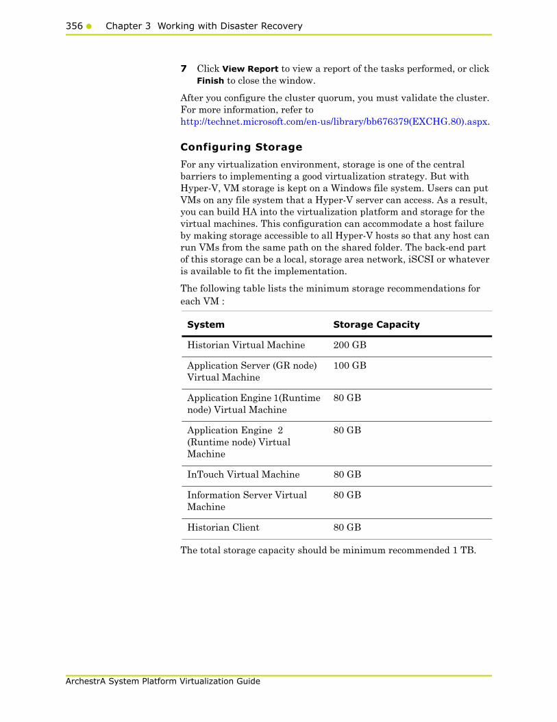
356 Chapter 3 Working with Disaster Recovery
ArchestrA System Platform Virtualization Guide
7 Click View Report to view a report of the tasks performed, or click Finish to close the window.
After you configure the cluster quorum, you must validate the cluster. For more information, refer to http://technet.microsoft.com/en-us/library/bb676379(EXCHG.80).aspx.
Configuring Storage
For any virtualization environment, storage is one of the central barriers to implementing a good virtualization strategy. But with Hyper-V, VM storage is kept on a Windows file system. Users can put VMs on any file system that a Hyper-V server can access. As a result, you can build HA into the virtualization platform and storage for the virtual machines. This configuration can accommodate a host failure by making storage accessible to all Hyper-V hosts so that any host can run VMs from the same path on the shared folder. The back-end part of this storage can be a local, storage area network, iSCSI or whatever is available to fit the implementation.
The following table lists the minimum storage recommendations for each VM :
The total storage capacity should be minimum recommended 1 TB.
System Storage Capacity
Historian Virtual Machine 200 GB
Application Server (GR node) Virtual Machine
100 GB
Application Engine 1(Runtime node) Virtual Machine
80 GB
Application Engine 2 (Runtime node) Virtual Machine
80 GB
InTouch Virtual Machine 80 GB
Information Server Virtual Machine
80 GB
Historian Client 80 GB
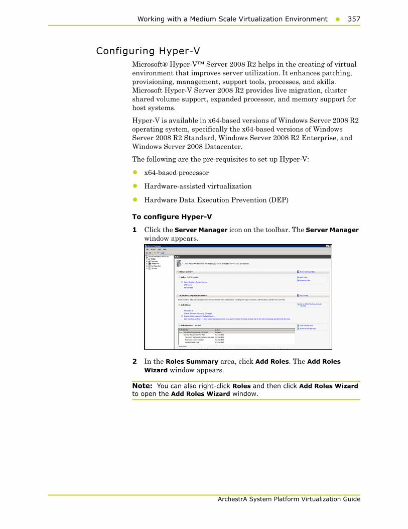
Working with a Medium Scale Virtualization Environment357
ArchestrA System Platform Virtualization Guide
Configuring Hyper-VMicrosoft® Hyper-V™ Server 2008 R2 helps in the creating of virtual environment that improves server utilization. It enhances patching, provisioning, management, support tools, processes, and skills. Microsoft Hyper-V Server 2008 R2 provides live migration, cluster shared volume support, expanded processor, and memory support for host systems.
Hyper-V is available in x64-based versions of Windows Server 2008 R2 operating system, specifically the x64-based versions of Windows Server 2008 R2 Standard, Windows Server 2008 R2 Enterprise, and Windows Server 2008 Datacenter.
The following are the pre-requisites to set up Hyper-V:
• x64-based processor
• Hardware-assisted virtualization
• Hardware Data Execution Prevention (DEP)
To configure Hyper-V
1 Click the Server Manager icon on the toolbar. The Server Manager window appears.
2 In the Roles Summary area, click Add Roles. The Add Roles Wizard window appears.
Note: You can also right-click Roles and then click Add Roles Wizard to open the Add Roles Wizard window.

358 Chapter 3 Working with Disaster Recovery
ArchestrA System Platform Virtualization Guide
3 View the instructions on the wizard , and then click Next. The Select Server Roles area appears.
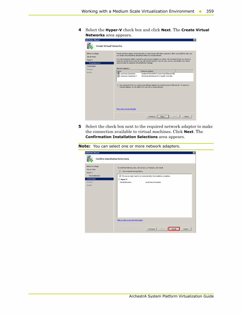
Working with a Medium Scale Virtualization Environment359
ArchestrA System Platform Virtualization Guide
4 Select the Hyper-V check box and click Next. The Create Virtual Networks area appears.
5 Select the check box next to the required network adapter to make the connection available to virtual machines. Click Next. The Confirmation Installation Selections area appears.
Note: You can select one or more network adapters.
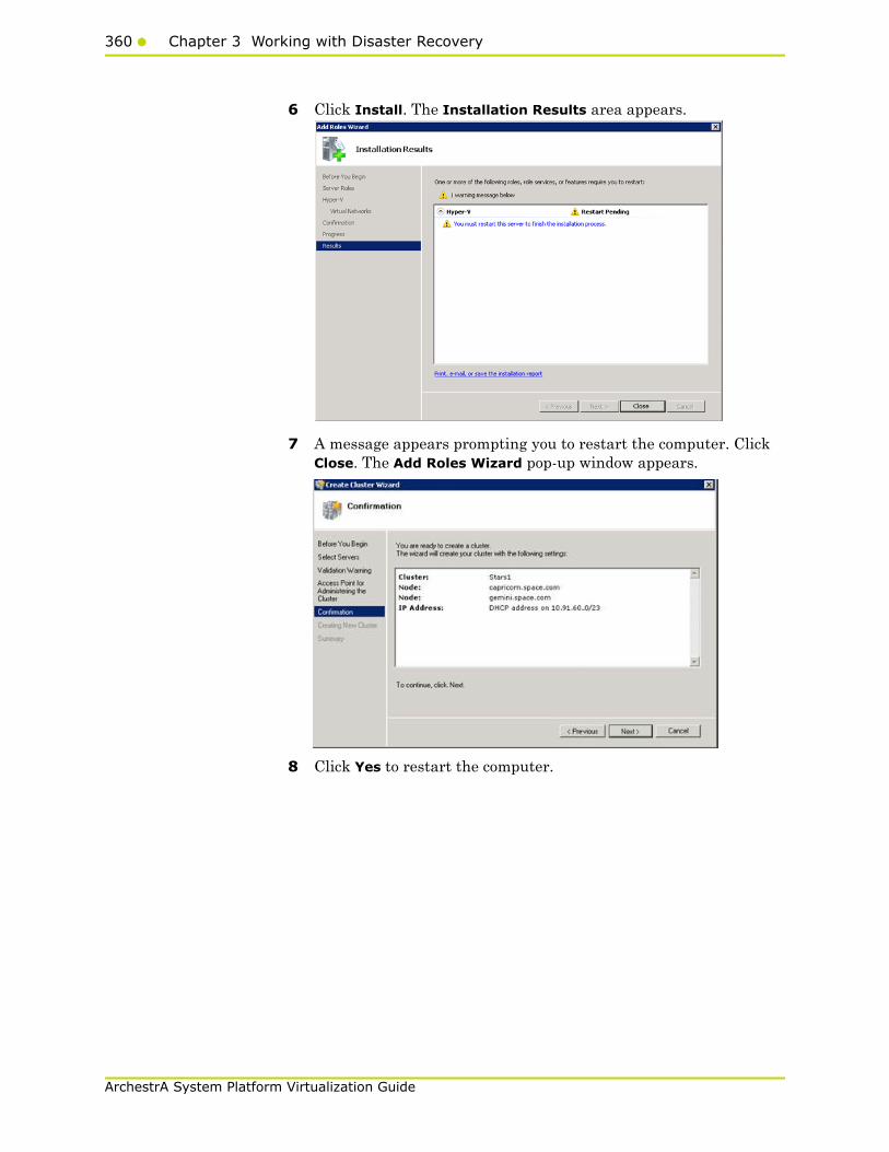
360 Chapter 3 Working with Disaster Recovery
ArchestrA System Platform Virtualization Guide
6 Click Install. The Installation Results area appears.
7 A message appears prompting you to restart the computer. Click Close. The Add Roles Wizard pop-up window appears.
8 Click Yes to restart the computer.
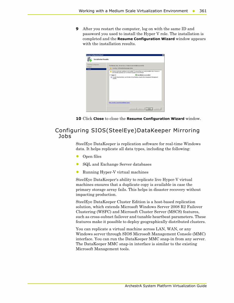
Working with a Medium Scale Virtualization Environment361
ArchestrA System Platform Virtualization Guide
9 After you restart the computer, log on with the same ID and password you used to install the Hyper V role. The installation is completed and the Resume Configuration Wizard window appears with the installation results.
10 Click Close to close the Resume Configuration Wizard window.
Configuring SIOS(SteelEye)DataKeeper Mirroring Jobs
SteelEye DataKeeper is replication software for real-time Windows data. It helps replicate all data types, including the following:
• Open files
• SQL and Exchange Server databases
• Running Hyper-V virtual machines
SteelEye DataKeeper's ability to replicate live Hyper-V virtual machines ensures that a duplicate copy is available in case the primary storage array fails. This helps in disaster recovery without impacting production.
SteelEye DataKeeper Cluster Edition is a host-based replication solution, which extends Microsoft Windows Server 2008 R2 Failover Clustering (WSFC) and Microsoft Cluster Server (MSCS) features, such as cross-subnet failover and tunable heartbeat parameters. These features make it possible to deploy geographically distributed clusters.
You can replicate a virtual machine across LAN, WAN, or any Windows server through SIOS Microsoft Management Console (MMC) interface. You can run the DataKeeper MMC snap-in from any server. The DataKeeper MMC snap-in interface is similar to the existing Microsoft Management tools.
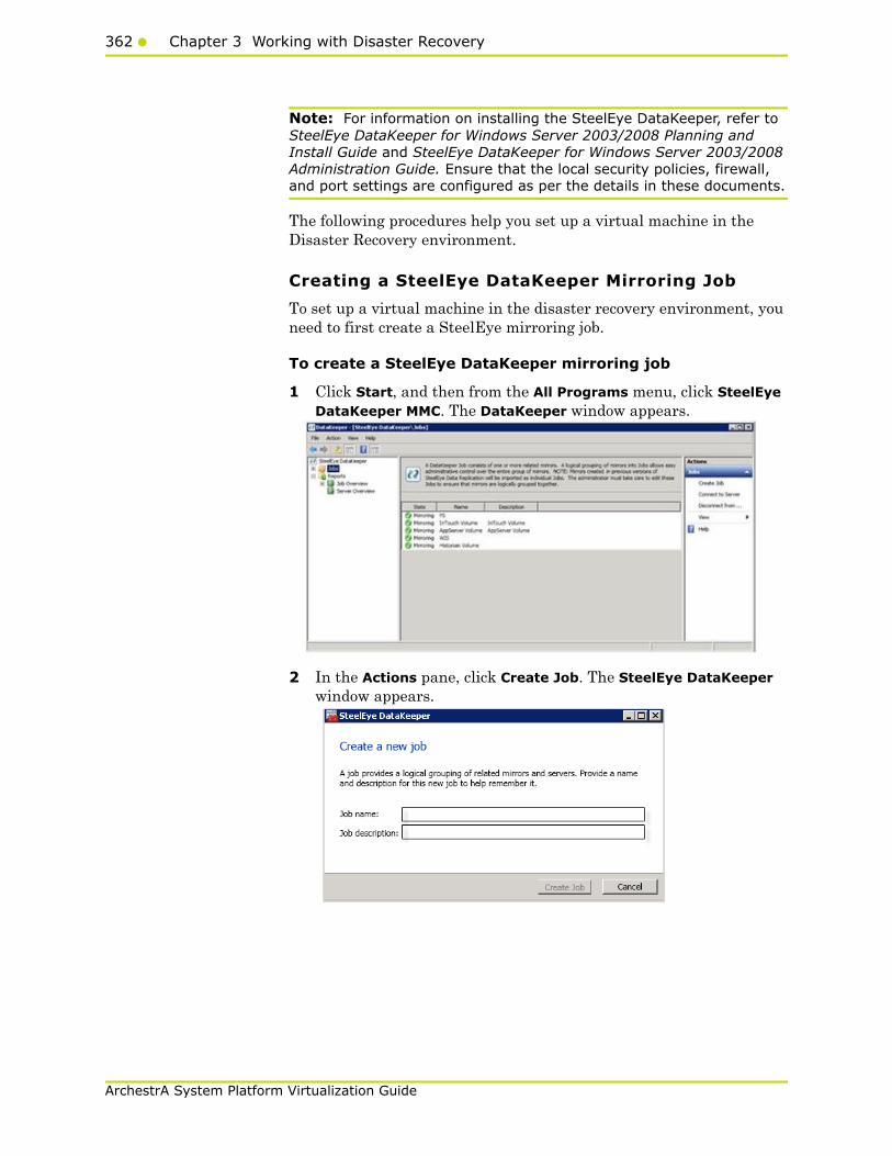
362 Chapter 3 Working with Disaster Recovery
ArchestrA System Platform Virtualization Guide
Note: For information on installing the SteelEye DataKeeper, refer to SteelEye DataKeeper for Windows Server 2003/2008 Planning and Install Guide and SteelEye DataKeeper for Windows Server 2003/2008 Administration Guide. Ensure that the local security policies, firewall, and port settings are configured as per the details in these documents.
The following procedures help you set up a virtual machine in the Disaster Recovery environment.
Creating a SteelEye DataKeeper Mirroring Job
To set up a virtual machine in the disaster recovery environment, you need to first create a SteelEye mirroring job.
To create a SteelEye DataKeeper mirroring job
1 Click Start, and then from the All Programs menu, click SteelEye DataKeeper MMC. The DataKeeper window appears.
2 In the Actions pane, click Create Job. The SteelEye DataKeeper window appears.
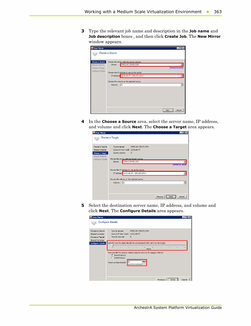
Working with a Medium Scale Virtualization Environment363
ArchestrA System Platform Virtualization Guide
3 Type the relevant job name and description in the Job name and Job description boxes , and then click Create Job. The New Mirror window appears.
4 In the Choose a Source area, select the server name, IP address, and volume and click Next. The Choose a Target area appears.
5 Select the destination server name, IP address, and volume and click Next. The Configure Details area appears.

364 Chapter 3 Working with Disaster Recovery
ArchestrA System Platform Virtualization Guide
6 In the Configure Details area, do the following:
a Move the slider to select the level of data compression.
b Click the relevant option to indicate the mode in which you want to send the source volume data to the target volume.
c In the Maximum bandwidth box, type the network bandwidth to be used for data replication.
Note: Enter “0” to indicate that the bandwidth is unlimited.
d Click Done. The SteelEye mirroring job is created.
Disk Management Topologies
After you have completed setting up SteelEye Mirroring Jobs and created the datakeeper, you can view the following topologies:
Open Disk Management to view all the disks which are replicated, by running the diskmgmt.msc from Run Command Prompt.
After creating all the Mirroring Jobs, open the SteelEye DataKeepr UI from the All Programs menu, click SteelEye DataKeeper MMC. The DataKeeper window appears.
You can navigate to Server Overview under Reports to view all the servers involved in job replication in one place.

Working with a Medium Scale Virtualization Environment365
ArchestrA System Platform Virtualization Guide
Configuring a Virtual MachineAfter creating a DataKeeper mirroring job, you need to create a virtual machine on disk.
To configure a virtual machine
1 In the Server Manager window, right-click Features , and then click Failover Cluster Manager. The Failover Cluster Manager tree expands.
2 Right-click Services and applications, then click Virtual Machines, and then New Virtual Machine. The New Virtual Machine Wizard window appears.

366 Chapter 3 Working with Disaster Recovery
ArchestrA System Platform Virtualization Guide
3 View the instructions in the Before You Begin area and click Next. The Specify Name and Location area appears.
4 In the Specify Name and Location area, do the following:
a In the Name box, type a name for the virtual machine.
b Select the Store the virtual machine in a different location check box to be able to indicate the location of the virtual machine.
c In the Location box, enter the location where you want to store the virtual machine.
Note: You can either type the location or click Browse to select the location where you want to store the virtual machine.
d Click Next. The Assign Memory area appears.
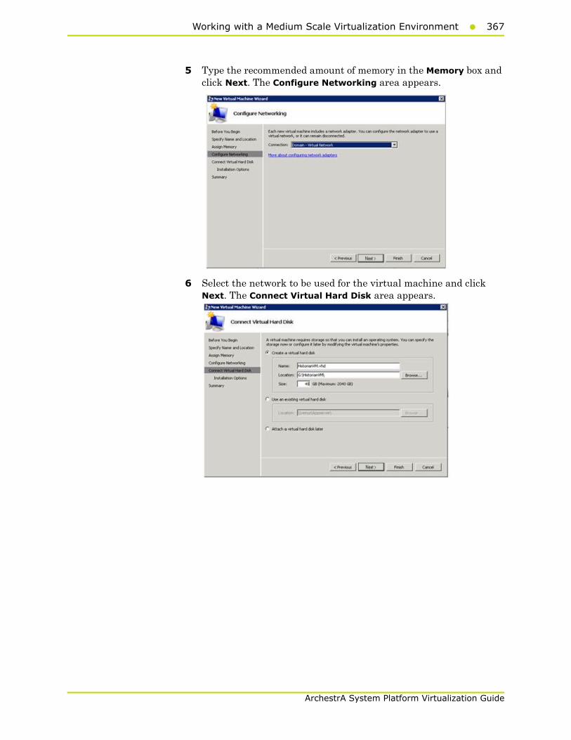
Working with a Medium Scale Virtualization Environment367
ArchestrA System Platform Virtualization Guide
5 Type the recommended amount of memory in the Memory box and click Next. The Configure Networking area appears.
6 Select the network to be used for the virtual machine and click Next. The Connect Virtual Hard Disk area appears.
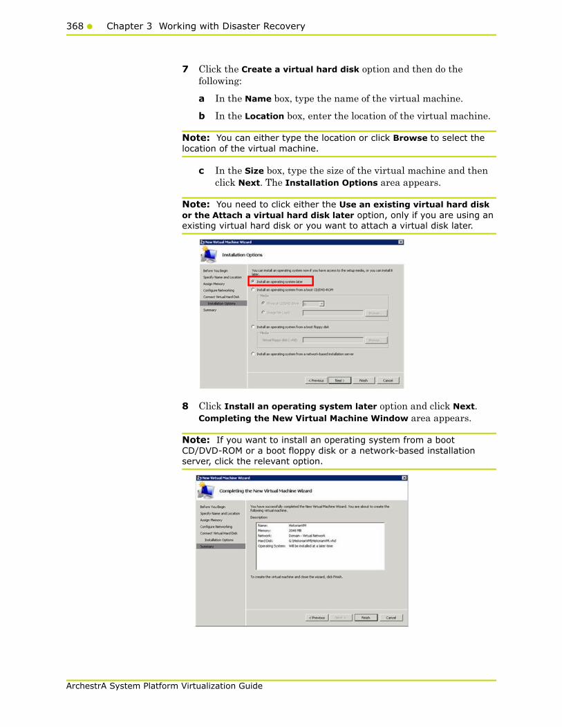
368 Chapter 3 Working with Disaster Recovery
ArchestrA System Platform Virtualization Guide
7 Click the Create a virtual hard disk option and then do the following:
a In the Name box, type the name of the virtual machine.
b In the Location box, enter the location of the virtual machine.
Note: You can either type the location or click Browse to select the location of the virtual machine.
c In the Size box, type the size of the virtual machine and then click Next. The Installation Options area appears.
Note: You need to click either the Use an existing virtual hard disk or the Attach a virtual hard disk later option, only if you are using an existing virtual hard disk or you want to attach a virtual disk later.
8 Click Install an operating system later option and click Next. Completing the New Virtual Machine Window area appears.
Note: If you want to install an operating system from a boot CD/DVD-ROM or a boot floppy disk or a network-based installation server, click the relevant option.
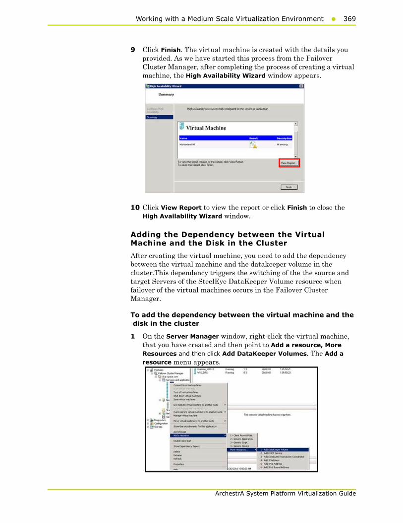
Working with a Medium Scale Virtualization Environment369
ArchestrA System Platform Virtualization Guide
9 Click Finish. The virtual machine is created with the details you provided. As we have started this process from the Failover Cluster Manager, after completing the process of creating a virtual machine, the High Availability Wizard window appears.
10 Click View Report to view the report or click Finish to close the High Availability Wizard window.
Adding the Dependency between the Virtual Machine and the Disk in the Cluster
After creating the virtual machine, you need to add the dependency between the virtual machine and the datakeeper volume in the cluster.This dependency triggers the switching of the the source and target Servers of the SteelEye DataKeeper Volume resource when failover of the virtual machines occurs in the Failover Cluster Manager.
To add the dependency between the virtual machine and the disk in the cluster
1 On the Server Manager window, right-click the virtual machine, that you have created and then point to Add a resource, More Resources and then click Add DataKeeper Volumes. The Add a resource menu appears.

370 Chapter 3 Working with Disaster Recovery
ArchestrA System Platform Virtualization Guide
2 The New DataKeeper Volume is added under Disk Drives.
3 Right-click New DataKeeper Volume and then click Properties. The New DataKeeper Volume Properties window appears.
4 Select the volume for creating a SteelEye mirroring job and click OK. The Selection Confirmation window appears.

Working with a Medium Scale Virtualization Environment371
ArchestrA System Platform Virtualization Guide
5 Click OK to validate the details that you have entered. The Server Manager window appears.
Note: To modify the selection, click Cancel and modify the detail as required in the New DataKeeper Volume Properties window, and click Apply.
6 Under Virtual Machine, right-click the name of the virtual machine that you created. Click Virtual Machine Configuration and click Properties. The Virtual Machine Configuration Historian Properties window appears.
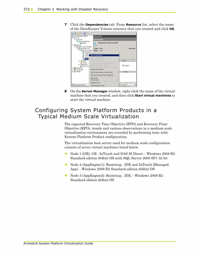
372 Chapter 3 Working with Disaster Recovery
ArchestrA System Platform Virtualization Guide
7 Click the Dependencies tab. From Resource list, select the name of the DataKeeper Volume resource that you created and click OK.
8 On the Server Manager window, right-click the name of the virtual machine that you created, and then click Start virtual machines to start the virtual machine.
Configuring System Platform Products in a Typical Medium Scale Virtualization
The expected Recovery Time Objective (RTO) and Recovery Point Objective (RPO), trends and various observations in a medium scale virtualization environment are recorded by performing tests with System Platform Product configuration.
The virtualization host server used for medium scale configuration consists of seven virtual machines listed below.
• Node 1 (GR): GR , InTouch and DAS SI Direct – Windows 2008 R2 Standard edition (64bit) OS with SQL Server 2008 SP1 32 bit
• Node 2 (AppEngine1): Bootstrap , IDE and InTouch (Managed App) – Windows 2008 R2 Standard edition (64bit) OS
• Node 3 (AppEngine2): Bootstrap , IDE – Windows 2008 R2 Standard edition (64bit) OS
Working with a Medium Scale Virtualization Environment373
ArchestrA System Platform Virtualization Guide
• Node 4: Historian – Windows 2008 R2 Standard edition (64bit) OS with SQL Server 2008 SP1 32 bit
• Node 5: Information Server , Bootstrap and IDE – Windows Server 2008 SP2 (32bit) with SQL Server 2008 SP1 and Office 2007
• Node 6: InTouch Terminal Service – Windows 2008 R2 Standard edition (64bit) OS enabled with Terminal Service
• Node 7: Historian Client and InTouch – Windows 7 Professional Edition (64bit) OS with SQL Server 2008 SP1 32 bit
The following table displays the approximate data of virtual nodes, IO tags and historized tags in a medium scale virtualization environment:
Virtual NodeIO tags (Approx.)
Historized tags(Approx.)
AppEngine1 25000 10000
AppEngine2 25000 10000

374 Chapter 3 Working with Disaster Recovery
ArchestrA System Platform Virtualization Guide
Tags getting historized and their update rates for this configuration
The following table shows tags getting historized and their update rates for this configuration:
Real Time data from DAS SI Direct
Topic Name
Update Rate Device Items Active Items
Topic 13 1000 1241 374
Topic 0 500 14 5
Topic 1 1000 1 1
Topic 2 10000 5002 2126
Topic 3 30000 5002 2126
Topic 4 60000 5002 2126
Topic 5 3600000 5001 2125
Topic 7 600000 5001 2589
Topic 8 10000 3841 1545
Topic 9 30000 1281 885
Topic 6 18000000 2504 1002
Topic 39 1000 4 4
Topic 16 180000 1000 350
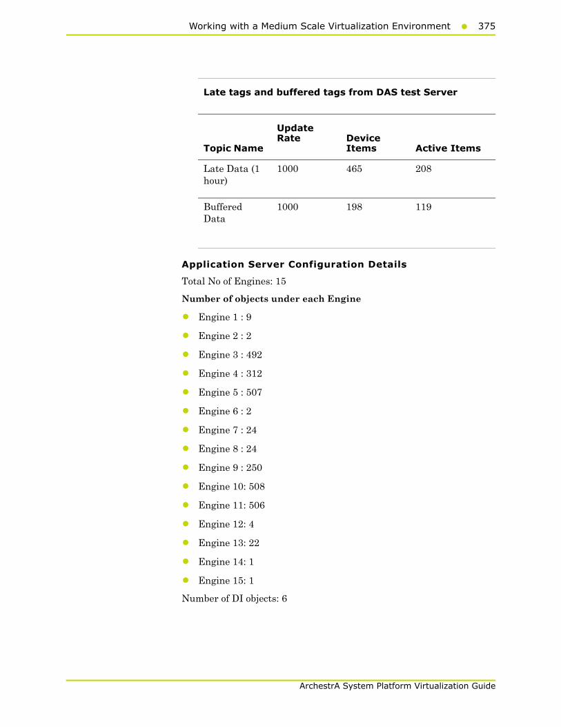
Working with a Medium Scale Virtualization Environment375
ArchestrA System Platform Virtualization Guide
Application Server Configuration Details
Total No of Engines: 15
Number of objects under each Engine
• Engine 1 : 9
• Engine 2 : 2
• Engine 3 : 492
• Engine 4 : 312
• Engine 5 : 507
• Engine 6 : 2
• Engine 7 : 24
• Engine 8 : 24
• Engine 9 : 250
• Engine 10: 508
• Engine 11: 506
• Engine 12: 4
• Engine 13: 22
• Engine 14: 1
• Engine 15: 1
Number of DI objects: 6
Late tags and buffered tags from DAS test Server
Topic Name
Update Rate Device
Items Active Items
Late Data (1 hour)
1000 465 208
Buffered Data
1000 198 119

376 Chapter 3 Working with Disaster Recovery
ArchestrA System Platform Virtualization Guide
Expected Recovery Time Objective and Recovery Point Objective
This section provides the indicative Recovery Time Objectives (RTO) and Recovery Point Objectives (RPO) for the load of IO and Attributes historized shown above and with the configuration of Host Virtualization Servers and Hyper-V virtual machines explained in the Setup instructions of Medium Scale Virtualization. For more information refer to "Setting Up Medium Scale Virtualization Environment" on page 334. In addition to these factors, the exact RTO and RPO depend on factors like storage I/O performance, CPU utilization, memory usage, and network usage at the time of failover/migration activity.
RTO and RPO Observations - DR Medium Configuration
The following tables display RTO and RPO Observations with approximately 50000 IO points with approximately 20000 attributes being historized:
Scenario Observation
Scenario 1: IT provides maintenance on Virtualization Server
"Live Migration" on page 377
"Quick Migration of all nodes simultaneously" on page 380
"Shut down of host server" on page 382
Scenario 2: Virtualization Server hardware fails
"Scenario 2: Virtualization Server hardware fails" on page 383
Scenario 3: Network fails on Virtualization Server
"Scenario 3: Network fails on Virtualization Server" on page 385
Scenario 4: Virtualization Server becomes unresponsive
"Scenario 4: Virtualization Server becomes unresponsive" on page 388
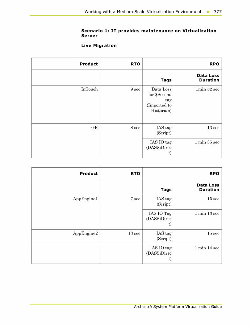
Working with a Medium Scale Virtualization Environment377
ArchestrA System Platform Virtualization Guide
Scenario 1: IT provides maintenance on Virtualization Server
Live Migration
Product RTO RPO
TagsData LossDuration
InTouch 9 sec Data Lossfor $Second
tag(Imported to
Historian)
1min 52 sec
GR 8 sec IAS tag(Script)
13 sec
IAS IO tag(DASSiDirec
t)
1 min 35 sec
Product RTO RPO
TagsData LossDuration
AppEngine1 7 sec IAS tag(Script)
15 sec
IAS IO Tag(DASSiDirec
t)
1 min 13 sec
AppEngine2 13 sec IAS tag(Script)
15 sec
IAS IO tag(DASSiDirec
t)
1 min 14 sec
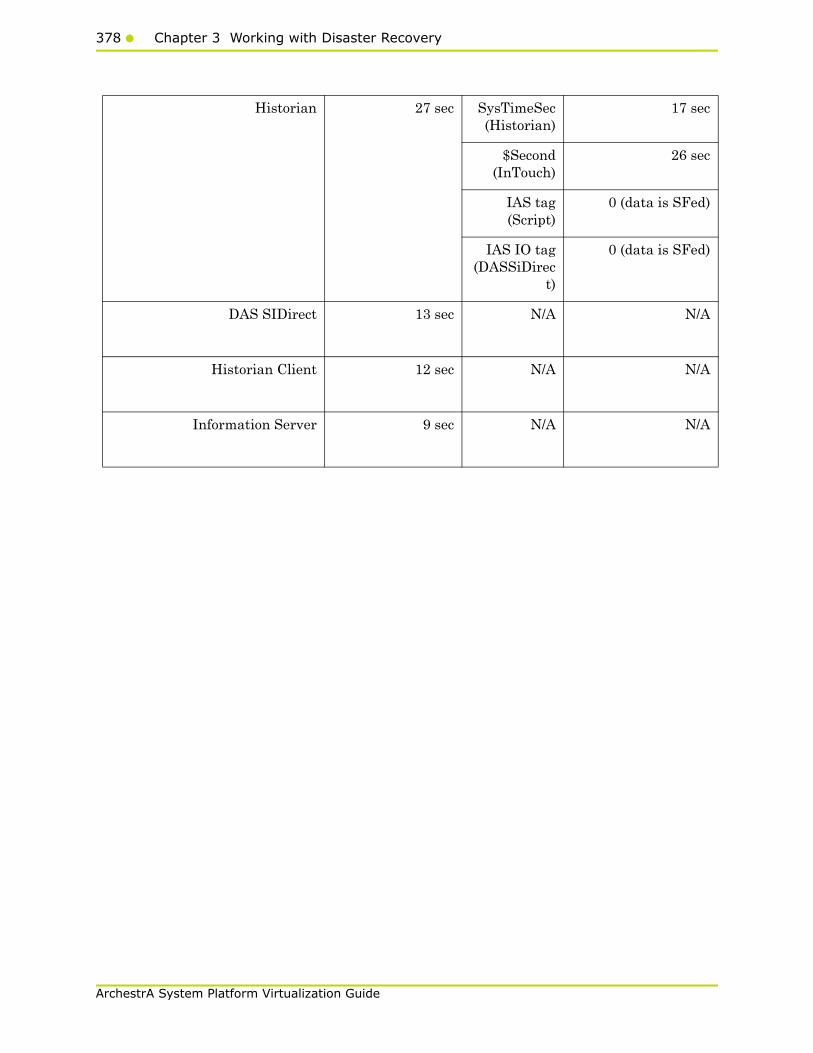
378 Chapter 3 Working with Disaster Recovery
ArchestrA System Platform Virtualization Guide
Historian 27 sec SysTimeSec(Historian)
17 sec
$Second(InTouch)
26 sec
IAS tag(Script)
0 (data is SFed)
IAS IO tag(DASSiDirec
t)
0 (data is SFed)
DAS SIDirect 13 sec N/A N/A
Historian Client 12 sec N/A N/A
Information Server 9 sec N/A N/A

Working with a Medium Scale Virtualization Environment379
ArchestrA System Platform Virtualization Guide
Product RTO RPO
TagsData LossDuration
InTouch 1 min 18 sec Data Lossfor $Second
tag(Imported to
Historian)
1min 23 sec
GR 1 min 55 sec IAS tag(Script)
2 min 43 sec
IAS IO tag(DASSiDirec
t)
2 min 55 sec
AppEngine1 3 min 25 sec IAS Tag(Script)
3 min 40 sec
IAS IO Tag(DASSiDirec
t)
3min 49 sec
AppEngine2 2 min 20 sec IAS Tag(Script)
2 min 48 sec
IAS IO tag(DASSiDirec
t)
2 min 54 sec
Historian 6 min 27 sec SysTimeSec(Historian)
5 min 57 sec
$Second(InTouch)
6 min 19 sec
IAS tag(Script)
0 (data is SFed)
IAS IO tag(DASSiDirec
t)
0 (data is SFed)
DAS SIDirect 2min 1 sec N/A N/A
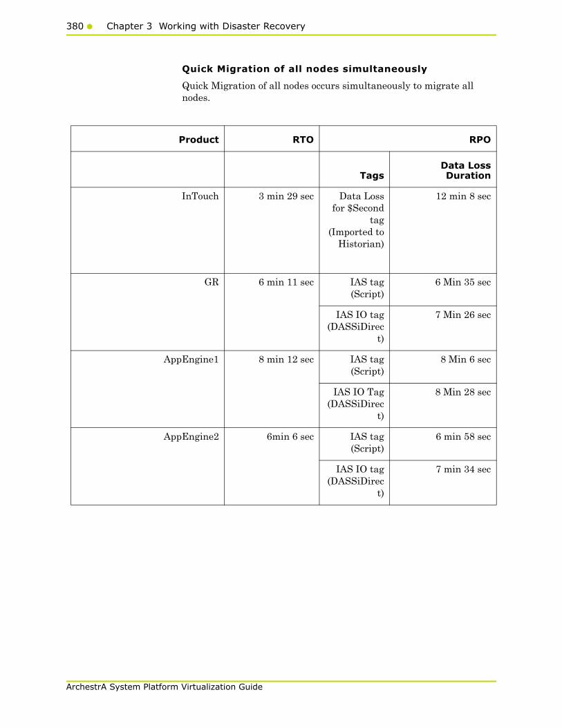
380 Chapter 3 Working with Disaster Recovery
ArchestrA System Platform Virtualization Guide
Quick Migration of all nodes simultaneously
Quick Migration of all nodes occurs simultaneously to migrate all nodes.
Product RTO RPO
TagsData LossDuration
InTouch 3 min 29 sec Data Lossfor $Second
tag(Imported to
Historian)
12 min 8 sec
GR 6 min 11 sec IAS tag(Script)
6 Min 35 sec
IAS IO tag(DASSiDirec
t)
7 Min 26 sec
AppEngine1 8 min 12 sec IAS tag(Script)
8 Min 6 sec
IAS IO Tag(DASSiDirec
t)
8 Min 28 sec
AppEngine2 6min 6 sec IAS tag(Script)
6 min 58 sec
IAS IO tag(DASSiDirec
t)
7 min 34 sec
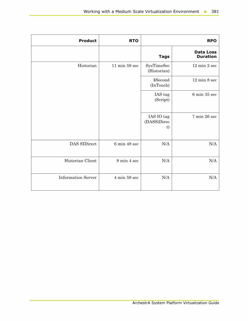
Working with a Medium Scale Virtualization Environment381
ArchestrA System Platform Virtualization Guide
Product RTO RPO
TagsData LossDuration
Historian 11 min 59 sec SysTimeSec(Historian)
12 min 2 sec
$Second(InTouch)
12 min 8 sec
IAS tag(Script)
6 min 35 sec
IAS IO tag(DASSiDirec
t)
7 min 26 sec
DAS SIDirect 6 min 48 sec N/A N/A
Historian Client 9 min 4 sec N/A N/A
Information Server 4 min 59 sec N/A N/A
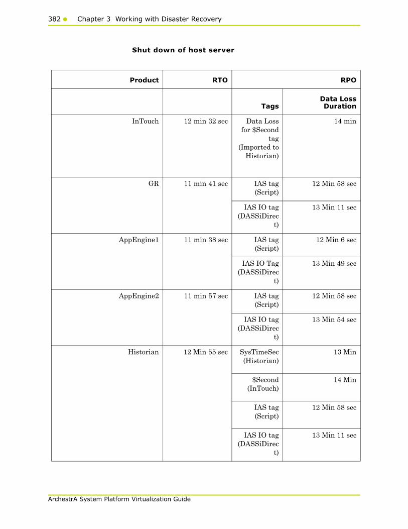
382 Chapter 3 Working with Disaster Recovery
ArchestrA System Platform Virtualization Guide
Shut down of host server
Product RTO RPO
TagsData LossDuration
InTouch 12 min 32 sec Data Lossfor $Second
tag(Imported to
Historian)
14 min
GR 11 min 41 sec IAS tag(Script)
12 Min 58 sec
IAS IO tag(DASSiDirec
t)
13 Min 11 sec
AppEngine1 11 min 38 sec IAS tag(Script)
12 Min 6 sec
IAS IO Tag(DASSiDirec
t)
13 Min 49 sec
AppEngine2 11 min 57 sec IAS tag(Script)
12 Min 58 sec
IAS IO tag(DASSiDirec
t)
13 Min 54 sec
Historian 12 Min 55 sec SysTimeSec(Historian)
13 Min
$Second(InTouch)
14 Min
IAS tag(Script)
12 Min 58 sec
IAS IO tag(DASSiDirec
t)
13 Min 11 sec

Working with a Medium Scale Virtualization Environment383
ArchestrA System Platform Virtualization Guide
Scenario 2: Virtualization Server hardware fails
The failover occurs due to hardware failure, and it is simulated with power-off on the host server.
Product RTO RPO
TagsData LossDuration
DAS SIDirect 6 Min 48 sec N/A N/A
Historian Client 9 Min 4 sec N/A N/A
Information Server 4 Min 59 sec N/A N/A
Product RTO RPO
TagsData LossDuration
InTouch 11 Min 43 sec +time taken by the
user to start theInTouchView
Data Loss for$Second tag(Imported to
Historian)
12 Min 27
Note: RPO isdependent on thetime taken by the
user to start theInTouchView on the
InTouch node and theRTO of the Historian
node, whichhistorizes this tag.
GR 10 Min 51 sec IAS tag(Script)
11 Min 16
IAS IO tag(DASSiDirect)
11 Min 02
AppEngine1 10 min 29 sec IAS tag(Script)
10 Min 40
IAS IO Tag(DASSiDirect)
11 Min 16
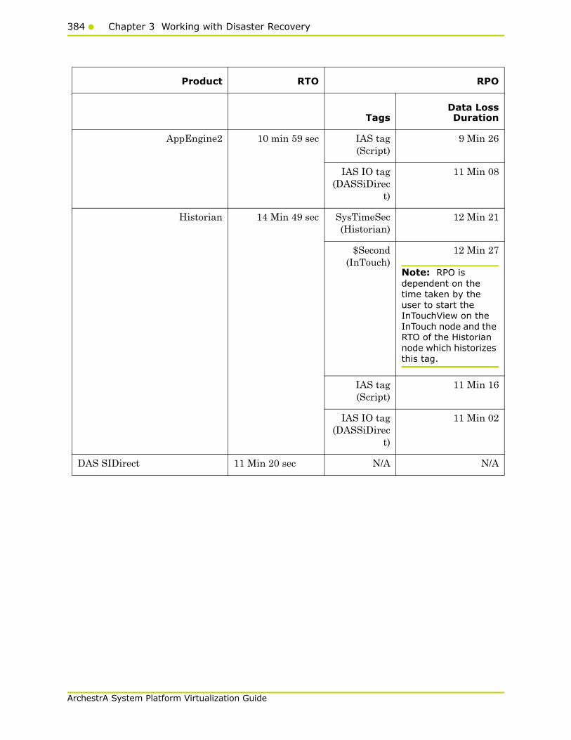
384 Chapter 3 Working with Disaster Recovery
ArchestrA System Platform Virtualization Guide
Product RTO RPO
TagsData LossDuration
AppEngine2 10 min 59 sec IAS tag(Script)
9 Min 26
IAS IO tag(DASSiDirec
t)
11 Min 08
Historian 14 Min 49 sec SysTimeSec(Historian)
12 Min 21
$Second(InTouch)
12 Min 27
Note: RPO is dependent on the time taken by the user to start the InTouchView on the InTouch node and the RTO of the Historian node which historizes this tag.
IAS tag(Script)
11 Min 16
IAS IO tag(DASSiDirec
t)
11 Min 02
DAS SIDirect 11 Min 20 sec N/A N/A

Working with a Medium Scale Virtualization Environment385
ArchestrA System Platform Virtualization Guide
Scenario 3: Network fails on Virtualization Server
There is a failover due to network disconnect (Public). In this case,the VMs restart, after moving to the other host server.
Products RTO RPO
TagsData LossDuration
Historian Client 7 Min 16 sec +time taken by the
user to start theHistorian Client
N/A N/A
Information Server 9 Min 39 sec +time taken by the
user to start theInformation
Server
N/A N/A
Products RTO RPO
TagsData LossDuration
InTouch 8 min 55 sec +time taken by the
user to start theInTouchView
Data Loss for$Second tag(Imported to
Historian)
14 min
Note: RPO is dependent on the time taken by the user to start the InTouchView on the InTouch node and the RTO of the Historian node, which historizes this tag.
GR 11 min 32 sec IAS Tag(Script)
12 min 01
IAS IO Tag(DASSiDirect)
12 min
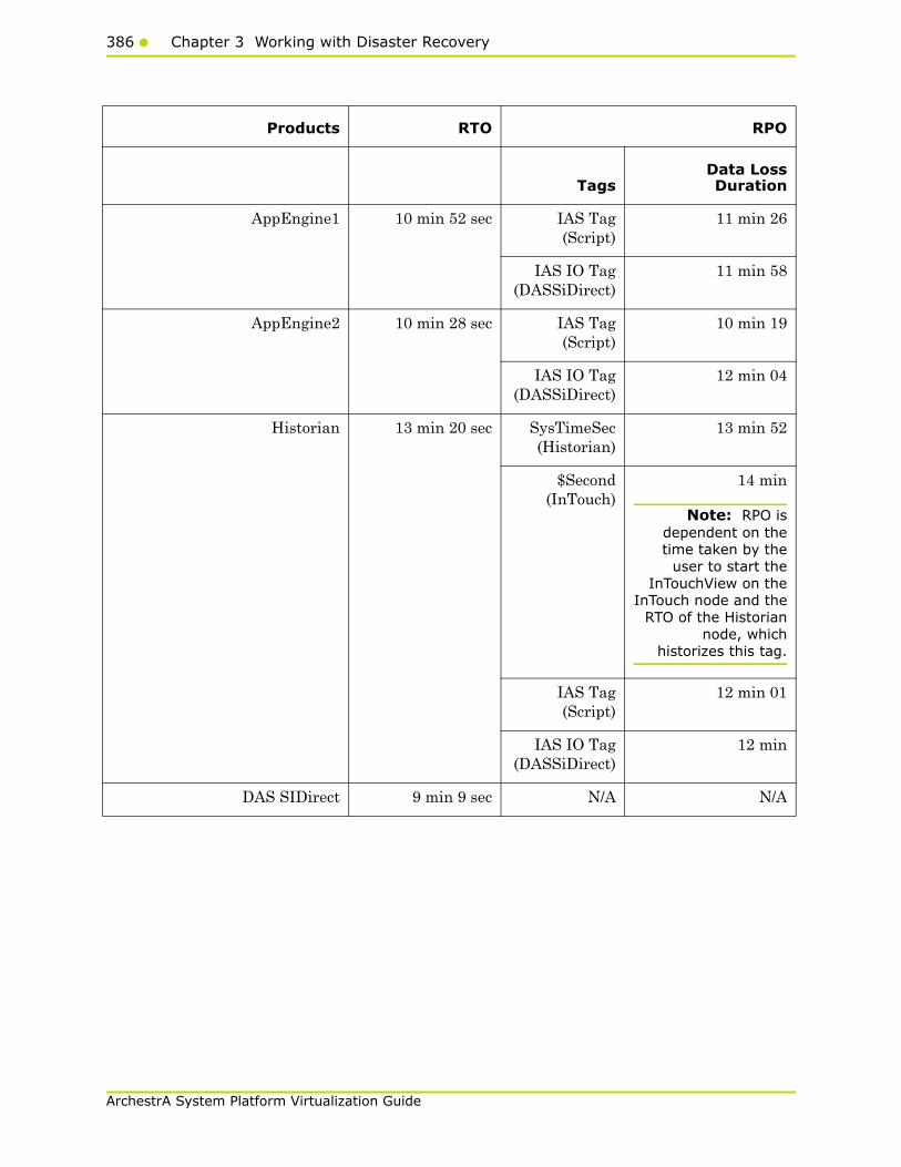
386 Chapter 3 Working with Disaster Recovery
ArchestrA System Platform Virtualization Guide
Products RTO RPO
TagsData LossDuration
AppEngine1 10 min 52 sec IAS Tag(Script)
11 min 26
IAS IO Tag(DASSiDirect)
11 min 58
AppEngine2 10 min 28 sec IAS Tag(Script)
10 min 19
IAS IO Tag(DASSiDirect)
12 min 04
Historian 13 min 20 sec SysTimeSec(Historian)
13 min 52
$Second(InTouch)
14 min
Note: RPO isdependent on thetime taken by the
user to start theInTouchView on the
InTouch node and theRTO of the Historian
node, whichhistorizes this tag.
IAS Tag(Script)
12 min 01
IAS IO Tag(DASSiDirect)
12 min
DAS SIDirect 9 min 9 sec N/A N/A

Working with a Medium Scale Virtualization Environment387
ArchestrA System Platform Virtualization Guide
Products RTO RPO
TagsData LossDuration
Historian Client 8 min + time takenby the user to start
the HistorianClient
N/A N/A
Information Server 8 min 25 sec + timetaken by the user
to start theInformation Server
N/A N/A
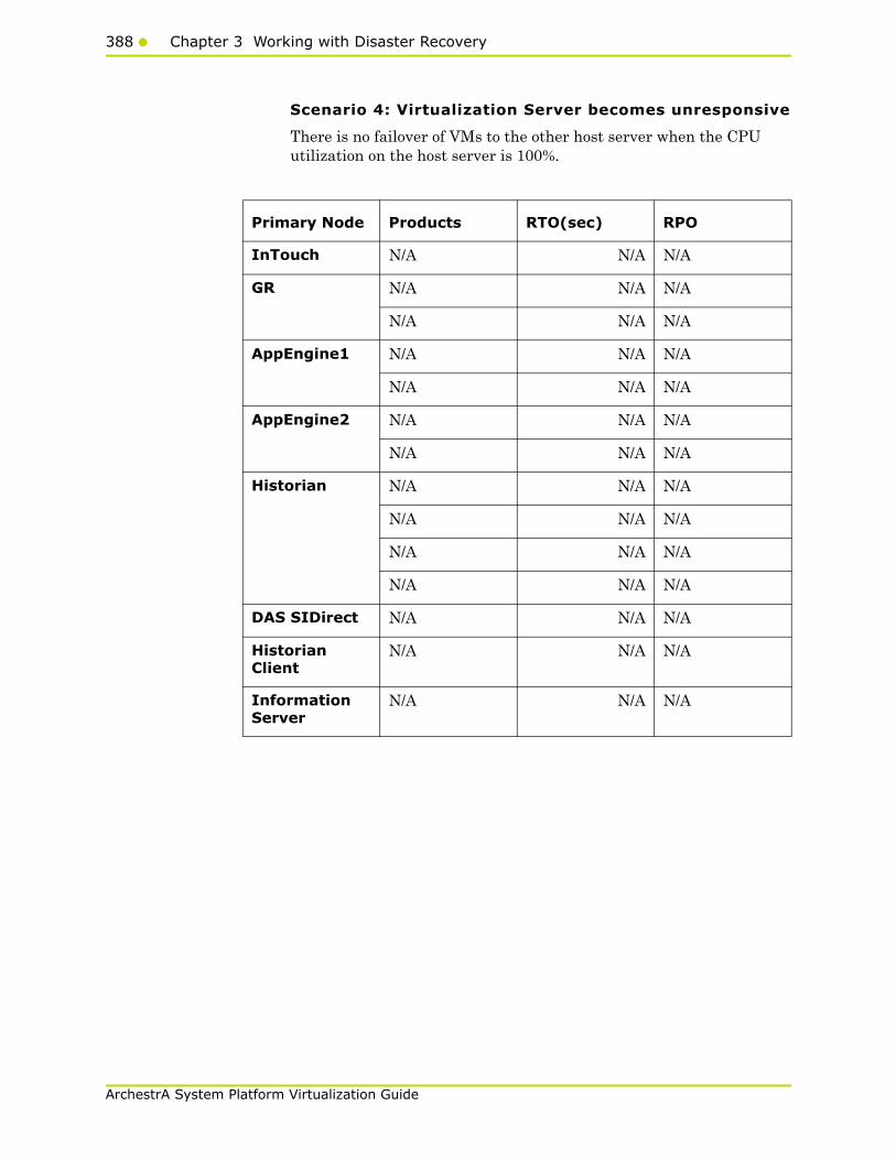
388 Chapter 3 Working with Disaster Recovery
ArchestrA System Platform Virtualization Guide
Scenario 4: Virtualization Server becomes unresponsive
There is no failover of VMs to the other host server when the CPU utilization on the host server is 100%.
Primary Node Products RTO(sec) RPO
InTouch N/A N/A N/A
GR N/A N/A N/A
N/A N/A N/A
AppEngine1 N/A N/A N/A
N/A N/A N/A
AppEngine2 N/A N/A N/A
N/A N/A N/A
Historian N/A N/A N/A
N/A N/A N/A
N/A N/A N/A
N/A N/A N/A
DAS SIDirect N/A N/A N/A
Historian Client
N/A N/A N/A
Information Server
N/A N/A N/A
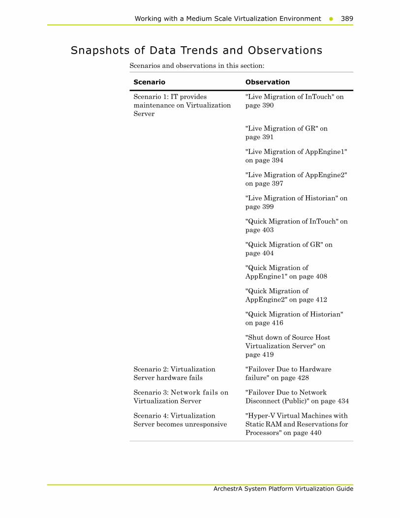
Working with a Medium Scale Virtualization Environment389
ArchestrA System Platform Virtualization Guide
Snapshots of Data Trends and ObservationsScenarios and observations in this section:
Scenario Observation
Scenario 1: IT provides maintenance on Virtualization Server
"Live Migration of InTouch" on page 390
"Live Migration of GR" on page 391
"Live Migration of AppEngine1" on page 394
"Live Migration of AppEngine2" on page 397
"Live Migration of Historian" on page 399
"Quick Migration of InTouch" on page 403
"Quick Migration of GR" on page 404
"Quick Migration of AppEngine1" on page 408
"Quick Migration of AppEngine2" on page 412
"Quick Migration of Historian" on page 416
"Shut down of Source Host Virtualization Server" on page 419
Scenario 2: Virtualization Server hardware fails
"Failover Due to Hardware failure" on page 428
Scenario 3: Network fails on Virtualization Server
"Failover Due to Network Disconnect (Public)" on page 434
Scenario 4: Virtualization Server becomes unresponsive
"Hyper-V Virtual Machines with Static RAM and Reservations for Processors" on page 440
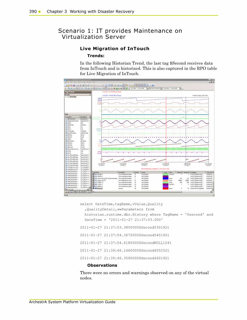
390 Chapter 3 Working with Disaster Recovery
ArchestrA System Platform Virtualization Guide
Scenario 1: IT provides Maintenance on Virtualization Server
Live Migration of InTouch
Trends:
In the following Historian Trend, the last tag $Second receives data from InTouch and is historized. This is also captured in the RPO table for Live Migration of InTouch.
select DateTime,tagName,vValue,Quality
,QualityDetail,wwParameters from
historian.runtime.dbo.History where TagName = '$second' and
DateTime > '2011-01-27 21:37:53.000'
2011-01-27 21:37:53.3850000$Second5301921
2011-01-27 21:37:54.3670000$Second5401921
2011-01-27 21:37:54.6180000$SecondNULL1241
2011-01-27 21:39:46.1460000$Second4502521
2011-01-27 21:39:46.3590000$Second4601921
Observations
There were no errors and warnings observed on any of the virtual nodes.
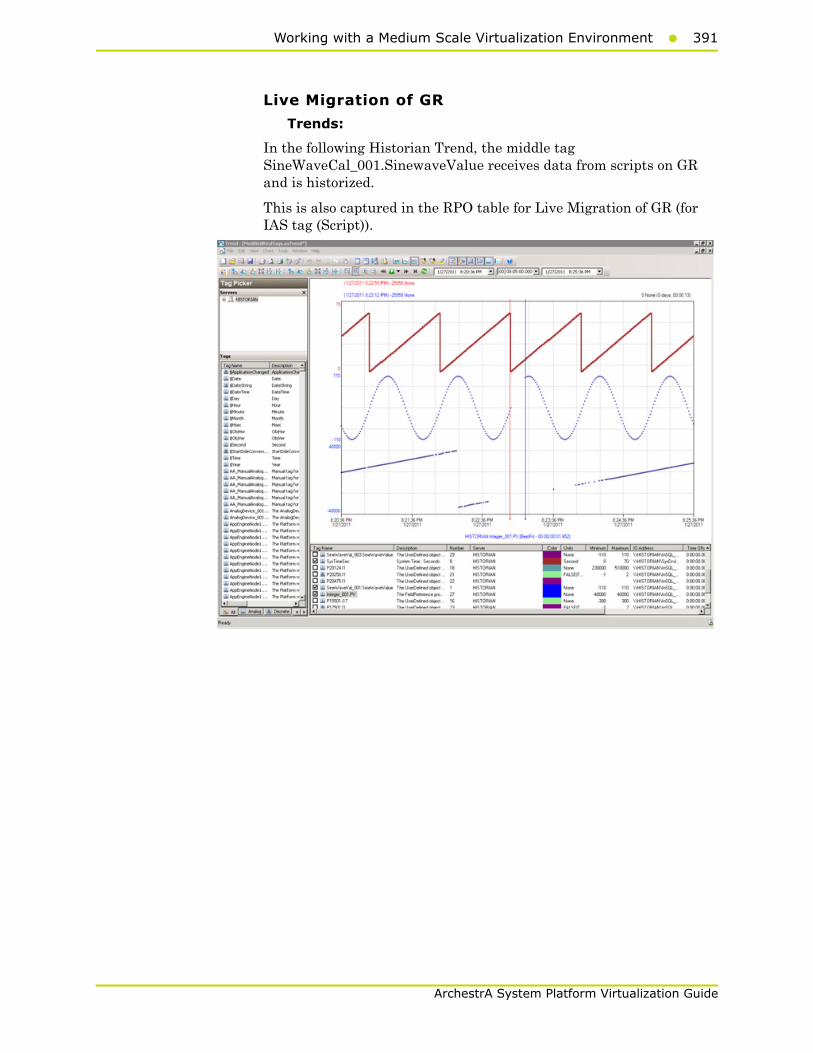
Working with a Medium Scale Virtualization Environment391
ArchestrA System Platform Virtualization Guide
Live Migration of GR
Trends:
In the following Historian Trend, the middle tag SineWaveCal_001.SinewaveValue receives data from scripts on GR and is historized.
This is also captured in the RPO table for Live Migration of GR (for IAS tag (Script)).

392 Chapter 3 Working with Disaster Recovery
ArchestrA System Platform Virtualization Guide
In the following Historian Trend, the last tag Integer_001.PV receives data from DDESuiteLinkObject on GR and is historized. This is also captured in the RPO table for Live Migration of GR (for IAS IO tag (DASSiDirect)).
Observations
GR node is Platform1 in the Galaxy deployed. During the Live Migration of GR, it is obvious that there will be an instance during the Live Migration when the following occurs:
• GR node will not be able to connect to the other deployed nodes (Platforms 2, 3, 4, and 5).
• Rest of Virtual machines will not be able to connect to GR node (Platform1)
As a result, you see the following warnings on each of the VM nodes.
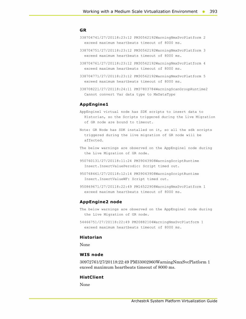
Working with a Medium Scale Virtualization Environment393
ArchestrA System Platform Virtualization Guide
GR
338704741/27/20118:23:12 PM30562192WarningNmxSvcPlatform 2
exceed maximum heartbeats timeout of 8000 ms.
338704751/27/20118:23:12 PM30562192WarningNmxSvcPlatform 3
exceed maximum heartbeats timeout of 8000 ms.
338704761/27/20118:23:12 PM30562192WarningNmxSvcPlatform 4
exceed maximum heartbeats timeout of 8000 ms.
338704771/27/20118:23:12 PM30562192WarningNmxSvcPlatform 5
exceed maximum heartbeats timeout of 8000 ms.
338708221/27/20118:24:11 PM37803784WarningScanGroupRuntime2
Cannot convert Var data type to MxDataType
AppEngine1
AppEngine1 virtual node has SDK scripts to insert data to
Historian, so the Scripts triggered during the Live Migration
of GR node are bound to timeout.
Note: GR Node has SDK installed on it, so all the sdk scripts
triggered during the live migration of GR node will be
affected.
The below warnings are observed on the AppEngine1 node during
the Live Migration of GR node.
950760131/27/20118:11:24 PM39043908WarningScriptRuntime
Insert.InsertValuePerodic: Script timed out.
950768461/27/20118:12:14 PM39043908WarningScriptRuntime
Insert.InsertValueWF: Script timed out.
950869671/27/20118:22:49 PM16522908WarningNmxSvcPlatform 1
exceed maximum heartbeats timeout of 8000 ms.
AppEngine2 node
The below warnings are observed on the AppEngine1 node during
the Live Migration of GR node.
54466751/27/20118:22:49 PM20882104WarningNmxSvcPlatform 1
exceed maximum heartbeats timeout of 8000 ms.
Historian
None
WIS node
30972761/27/20118:22:49 PM33002960WarningNmxSvcPlatform 1 exceed maximum heartbeats timeout of 8000 ms.
HistClient
None
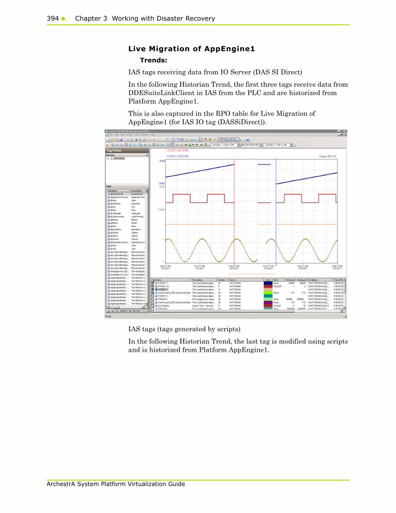
394 Chapter 3 Working with Disaster Recovery
ArchestrA System Platform Virtualization Guide
Live Migration of AppEngine1
Trends:
IAS tags receiving data from IO Server (DAS SI Direct)
In the following Historian Trend, the first three tags receive data from DDESuiteLinkClient in IAS from the PLC and are historized from Platform AppEngine1.
This is also captured in the RPO table for Live Migration of AppEngine1 (for IAS IO tag (DASSiDirect)).
IAS tags (tags generated by scripts)
In the following Historian Trend, the last tag is modified using scripts and is historized from Platform AppEngine1.
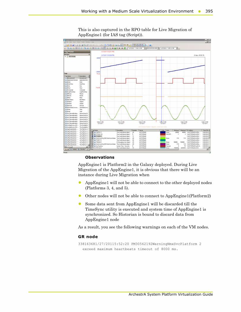
Working with a Medium Scale Virtualization Environment395
ArchestrA System Platform Virtualization Guide
This is also captured in the RPO table for Live Migration of AppEngine1 (for IAS tag (Script)).
Observations
AppEngine1 is Platform2 in the Galaxy deployed. During Live Migration of the AppEngine1, it is obvious that there will be an instance during Live Migration when
• AppEngine1 will not be able to connect to the other deployed nodes (Platforms 3, 4, and 5).
• Other nodes will not be able to connect to AppEngine1(Platform2)
• Some data sent from AppEngine1 will be discarded till the TimeSync utility is executed and system time of AppEngine1 is synchronized. So Historian is bound to discard data from AppEngine1 node
As a result, you see the following warnings on each of the VM nodes.
GR node
338163681/27/20115:52:20 PM30562192WarningNmxSvcPlatform 2
exceed maximum heartbeats timeout of 8000 ms.

396 Chapter 3 Working with Disaster Recovery
ArchestrA System Platform Virtualization Guide
AppEngine1
949341461/27/20115:53:06 PM16522908WarningNmxSvcPlatform 3
exceed maximum heartbeats timeout of 8000 ms.
949341471/27/20115:53:06 PM16522908WarningNmxSvcPlatform 4
exceed maximum heartbeats timeout of 8000 ms.
949341481/27/20115:53:06 PM16522908WarningNmxSvcPlatform 5
exceed maximum heartbeats timeout of 8000 ms.
AppEngine2
54464381/27/20115:52:20 PM20882104WarningNmxSvcPlatform 2
exceed maximum heartbeats timeout of 8000 ms.
Historian
95837141/27/20115:53:13 PM14923380WarningaahStoreSvcValues in
the past did not fit within the realtime window; discarding
data (HISTORIAN_mdas, 19017, 2011/01/27 12:22:27.608,
2011/01/27 12:23:12.991) [HISTORIAN; pipeserver.cpp; 2388]
95838831/27/20115:57:27 PM14923380WarningaahStoreSvcValues in
the past did not fit within the realtime window; discarding
data (HISTORIAN_mdas, 19017, 2011/01/27 12:22:27.608,
2011/01/27 12:23:12.991) [HISTORIAN; pipeserver.cpp; 2388;
17881]
WIS node
30972381/27/20115:52:18 PM33002960WarningNmxSvcPlatform 2
exceed maximum heartbeats timeout of 8000 ms.
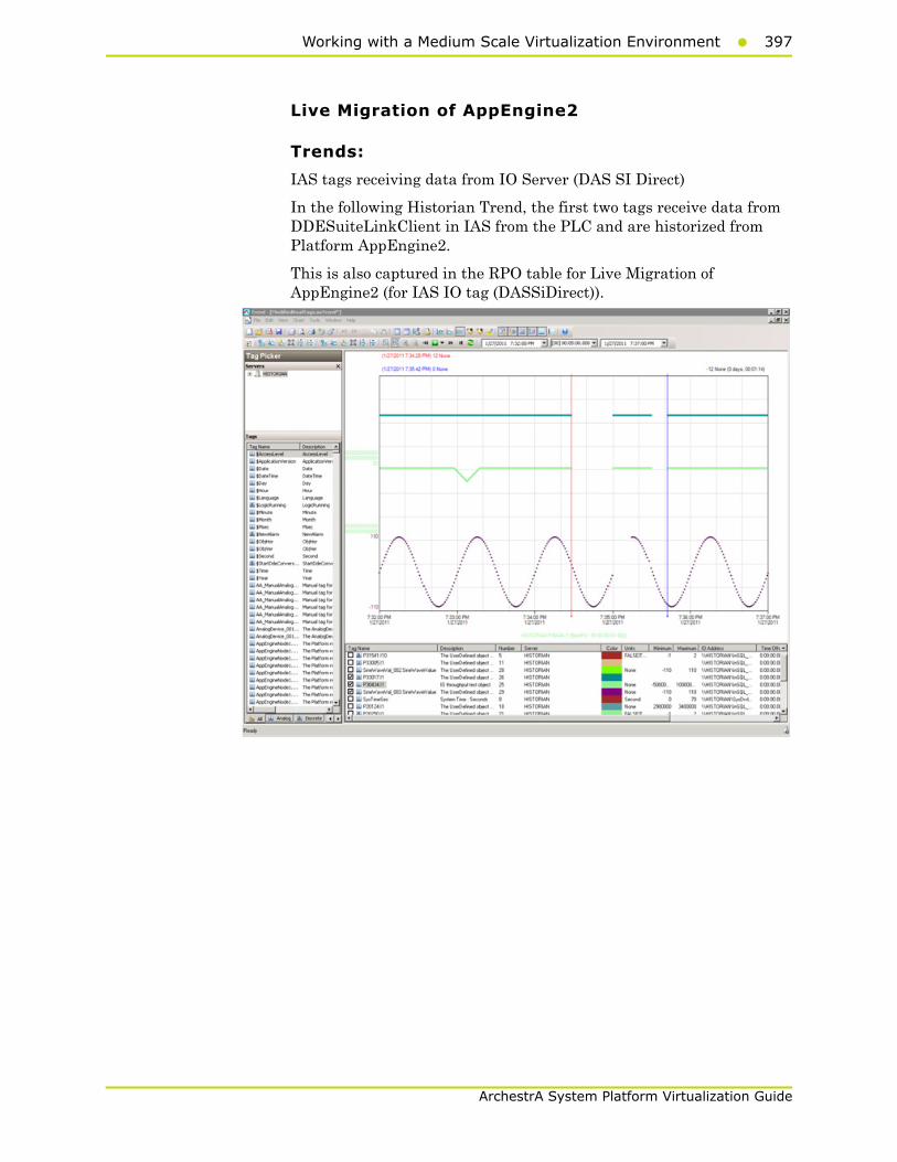
Working with a Medium Scale Virtualization Environment397
ArchestrA System Platform Virtualization Guide
Live Migration of AppEngine2
Trends:
IAS tags receiving data from IO Server (DAS SI Direct)
In the following Historian Trend, the first two tags receive data from DDESuiteLinkClient in IAS from the PLC and are historized from Platform AppEngine2.
This is also captured in the RPO table for Live Migration of AppEngine2 (for IAS IO tag (DASSiDirect)).
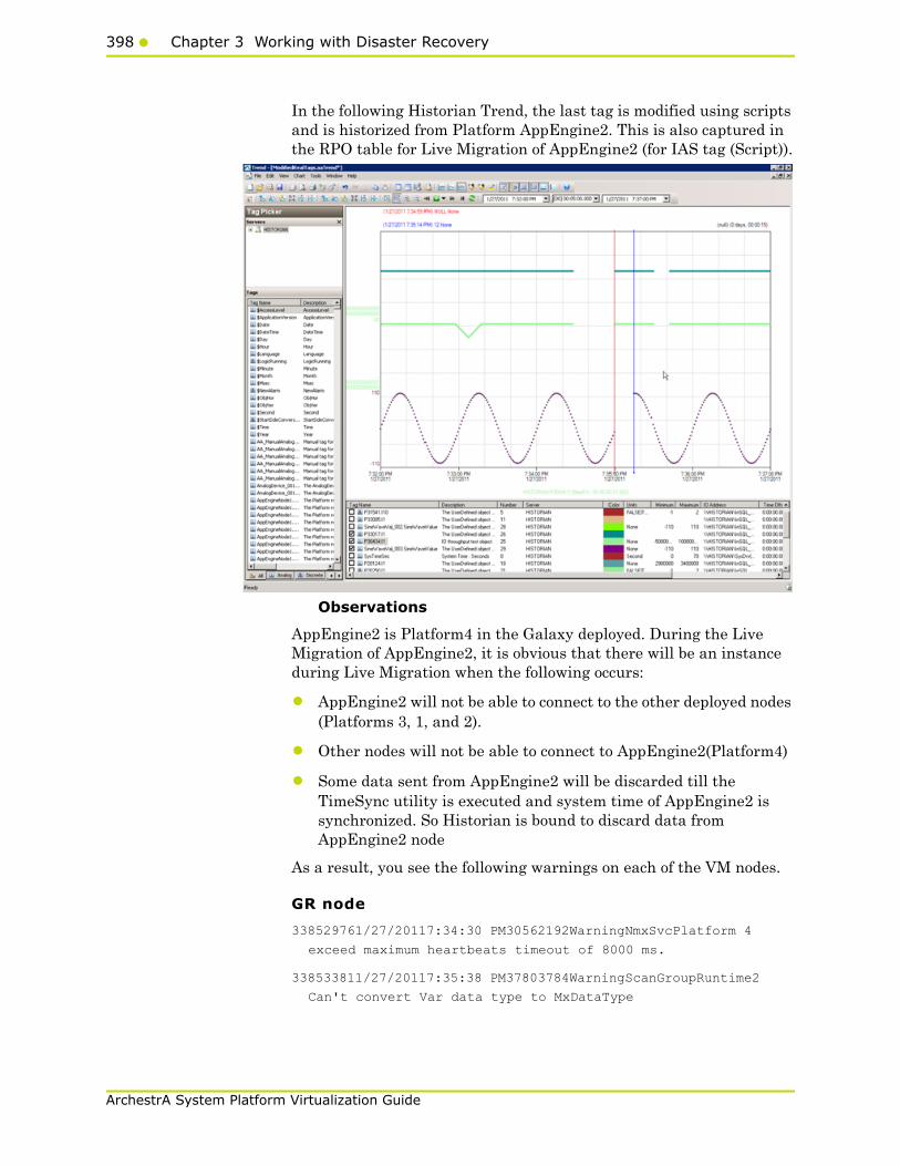
398 Chapter 3 Working with Disaster Recovery
ArchestrA System Platform Virtualization Guide
In the following Historian Trend, the last tag is modified using scripts and is historized from Platform AppEngine2. This is also captured in the RPO table for Live Migration of AppEngine2 (for IAS tag (Script)).
Observations
AppEngine2 is Platform4 in the Galaxy deployed. During the Live Migration of AppEngine2, it is obvious that there will be an instance during Live Migration when the following occurs:
• AppEngine2 will not be able to connect to the other deployed nodes (Platforms 3, 1, and 2).
• Other nodes will not be able to connect to AppEngine2(Platform4)
• Some data sent from AppEngine2 will be discarded till the TimeSync utility is executed and system time of AppEngine2 is synchronized. So Historian is bound to discard data from AppEngine2 node
As a result, you see the following warnings on each of the VM nodes.
GR node
338529761/27/20117:34:30 PM30562192WarningNmxSvcPlatform 4
exceed maximum heartbeats timeout of 8000 ms.
338533811/27/20117:35:38 PM37803784WarningScanGroupRuntime2
Can't convert Var data type to MxDataType
Working with a Medium Scale Virtualization Environment399
ArchestrA System Platform Virtualization Guide
AppEngine1
The warnings below are observed on the AppEngine1 node during the Live Migration of AppEngine2.
950335701/27/20117:29:36 PM39043908WarningScriptRuntime
Insert.InsertValueDataChange: Script timed out.
950341791/27/20117:30:13 PM39043908WarningScriptRuntime
Insert.InsertValueWF: Script timed out.
950353481/27/20117:31:25 PM39043908WarningScriptRuntime
Insert.InsertValuePerodic: Script timed out.
950384051/27/20117:34:29 PM16522908WarningNmxSvcPlatform 4
exceed maximum heartbeats timeout of 8000 ms.
AppEngine2
54465261/27/20117:35:14 PM20882104WarningNmxSvcPlatform 1
exceed maximum heartbeats timeout of 8000 ms.
54465271/27/20117:35:14 PM20882104WarningNmxSvcPlatform 2
exceed maximum heartbeats timeout of 8000 ms.
54465281/27/20117:35:14 PM20882104WarningNmxSvcPlatform 3
exceed maximum heartbeats timeout of 8000 ms.
Historian
95851951/27/20117:35:28 PM14923380WarningaahStoreSvcValues in
the past did not fit within the realtime window; discarding
data (HISTORIAN_mdas, 7033, 2011/01/27 14:04:54.532,
2011/01/27 14:05:27.276) [HISTORIAN; pipeserver.cpp; 2388]
95852311/27/20117:39:41 PM14923380WarningaahStoreSvcValues in
the past did not fit within the realtime window; discarding
data (HISTORIAN_mdas, 7033, 2011/01/27 14:04:54.532,
2011/01/27 14:05:27.276) [HISTORIAN; pipeserver.cpp; 2388;
2872]
Live Migration of Historian
Trends:
In the following Historian Trend, the IAS tag (Script) and IAS IO tag (DASSiDirect) do not have any data loss as the data is Stored in SF folder in GR node, AppEngine1 and AppEngine2 nodes. This data is later forwarded after Live Migration.
This is also captured in the RPO table for Live Migration of IAS IO Tag (DASSiDirect) and IAS tag (Script) as no data loss.
In the following Historian Trend, the last tag $Second gets data from InTouch and is historized.

400 Chapter 3 Working with Disaster Recovery
ArchestrA System Platform Virtualization Guide
This is also captured in the RPO table for Live Migration of Historian for $Second(InTouch).
In the following Historian Trend, it is observed that the Historian system tag SysTimeSec has a data gap.

Working with a Medium Scale Virtualization Environment401
ArchestrA System Platform Virtualization Guide
This is also captured in the RPO table for Live Migration of Historian for SysTimeSec (Historian).
Observations
When the Historian node undergoes Live Migration
• GR and AppEngine nodes are in Store Forward mode
• Historian Client trend will not be able to connect to Historian, so warning is expected.
• Historian machine’s time is not synchronized during the Live Migration of Historian, so “Attempt to store values in the future” is expected.
• After Live Migration, historian’s time needs to be synchronized so Server Shifting warning is expected.
After the Live Migration of Historian node, the stored data is forwarded from GR and AppEngine nodes.
GR node
339084501/27/201110:08:07 PM37803312WarningaahMDASTime
synchronization with historian node out of spec, please resync
to avoid data loss. (129406198613500000, 129406198876145320)
[StorageNode.cpp,2576]
95871031/27/201110:08:17 PM50765116InfoaahDrvSvcHISTORIAN_1:
Server is too busy (buffers full)

402 Chapter 3 Working with Disaster Recovery
ArchestrA System Platform Virtualization Guide
95871041/27/201110:08:17 PM50765116InfoaahDrvSvcHISTORIAN_1:
Clearing buffer cache for recovery (buffers full)
95871051/27/201110:08:17 PM50765116InfoaahDrvSvcHISTORIAN_1:
HISTORIAN: 722 data buffers lost: header/dirty time of the
last lost buffer = 22:07:51.000/22:08:17.018
95871061/27/201110:08:19 PM14923380InfoaahManStSvcSuccessfully
processed file (name)
(C:\Historian\Data\DataImport\Manual\LateData\latedata_129406
197731664416_0000.bin) [HISTORIAN; insertmanual.cpp; 736]
AppEngine1
None
AppEngine2
None
Historian
95871021/27/201110:07:48 PM14923380WarningaahStoreSvcAttempt to
store values in the future; timestamps were overwritten with
current time (pipe name, TagName, wwTagKey, system time (UTC),
time difference (sec)) (HISTORIAN_2, $Time, 23556, 2011/01/27
16:37:47.216, 24) [HISTORIAN; pipeserver.cpp; 1831]
95871161/27/201110:08:21 PM14923380WarningaahCfgSvc"Server time
is shifting (Expected time, Current time)"
(01/27/11,22:08:20,898, 01/27/11,22:07:54,696) [HISTORIAN;
Config.cpp; 2040]
WIS node
None
HistClient
1235971/27/201110:07:59 PM32321312WarningaaAFCommonTypesUnable
to create dataview: Server must be logged on before executing
SQL query: SELECT aaT=DateTime, aaN=TagName, aaDV=Value,
aaSV=CONVERT(nvarchar(512),vValue), aaQ=OPCQuality,
aaIQ=Quality, aaQD=QualityDetail, aaS=0
FROM History
WHERE TagName IN ('...
1235981/27/201110:07:59 PM32321312WarningaaTrendDataSetProvider
The configured InSQL server HISTORIAN is either Disconnnected
from Network or in ShutDown/Disable state.

Working with a Medium Scale Virtualization Environment403
ArchestrA System Platform Virtualization Guide
Quick Migration of InTouch
Trends:
In the following Historian Trend, the last tag $Second receives data from InTouch and is historized.
Observations
There were no errors and warnings observed on any of the virtual nodes.
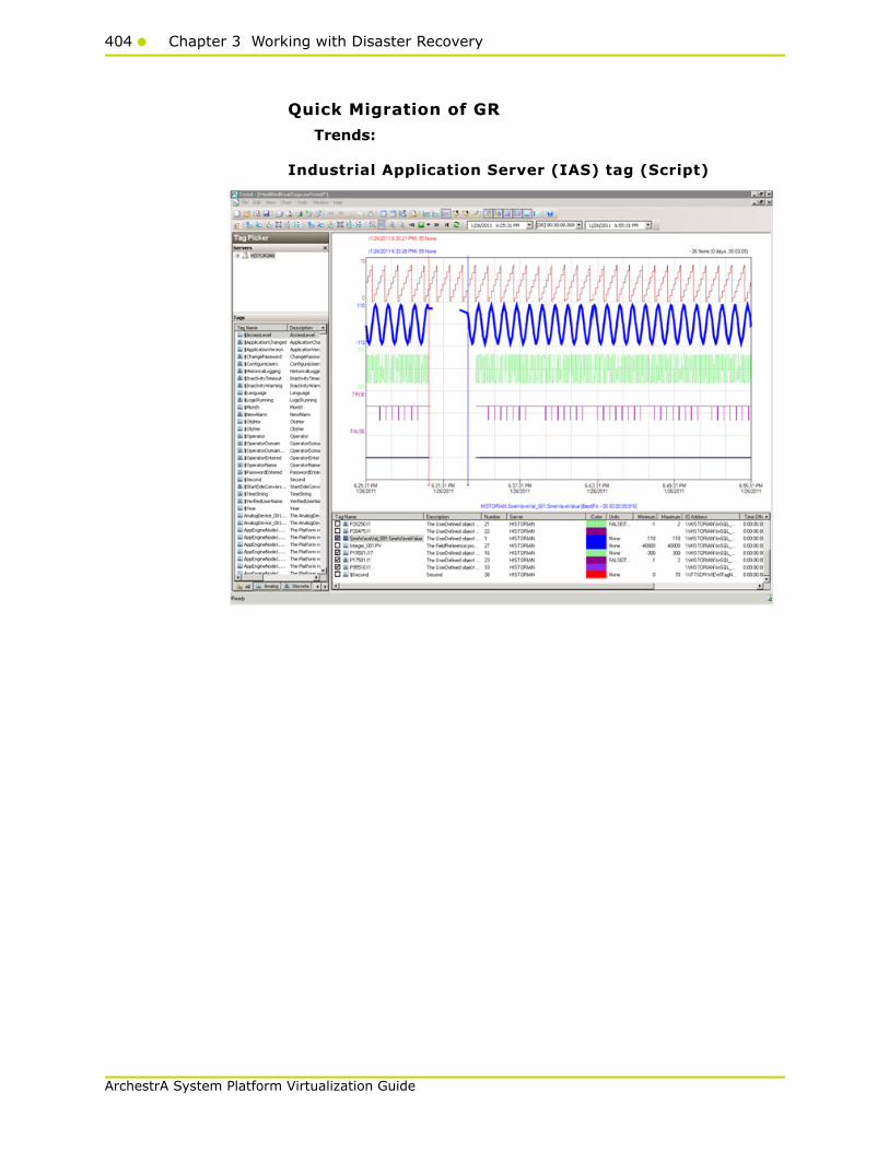
404 Chapter 3 Working with Disaster Recovery
ArchestrA System Platform Virtualization Guide
Quick Migration of GR
Trends:
Industrial Application Server (IAS) tag (Script)

Working with a Medium Scale Virtualization Environment405
ArchestrA System Platform Virtualization Guide
Industrial Application Server (IAS) IO tag (DASSiDirect)
GR node hosts the DDESuiteLinkObjects, so during the Quick Migration of GR node, there is data loss for tags that receive data from DAS Server/PLC.
Observations
GR node is Platform1 in the Galaxy deployed. During the Quick Migration of GR node it is obvious that there will be an instance during Quick Migration when the following occurs:
• GR node will not be able to connect to the other deployed nodes (Platforms 2, 3, 4, and 5).
• Rest of Virtual machines will not be able to connect to GR node (Platform1)
• Since DAS SI Direct provides data to DDESuiteLinkObject and DAS SI Direct is on GR node, the message "DAServerManagerTarget node is down" is expected on AppEngine1 and AppEngine2.
• Script involving SDK script library calls timeout during the Quick Migration of GR node.
406 Chapter 3 Working with Disaster Recovery
ArchestrA System Platform Virtualization Guide
GR Node
510877212/15/20113:11:51 PM32043224WarningNmxSvcPlatform 2
exceed maximum heartbeats timeout of 8000 ms.NmxSvc
510877222/15/20113:11:51 PM32043224WarningNmxSvcPlatform 3
exceed maximum heartbeats timeout of 8000 ms.NmxSvc
510877232/15/20113:11:51 PM32043224WarningNmxSvcPlatform 4
exceed maximum heartbeats timeout of 8000 ms.NmxSvc
510877242/15/20113:11:51 PM32043224WarningNmxSvcPlatform 5
exceed maximum heartbeats timeout of 8000 ms.NmxSvc
510877252/15/20113:11:51 PM32043224WarningNmxSvcPlatform 6
exceed maximum heartbeats timeout of 8000 ms.NmxSvc
510877402/15/20113:11:52 PM3681032WarningaaEngine0:B5C Values
in the past did not fit within the realtime window; discarding
data (19598, 2011/02/15 09:40:24.026, 2011/02/15
09:41:51.565) [aahMDASSF.cpp; 3709; 1]aaEngine
510877482/15/20113:11:52 PM38044344WarningaaEngine0:E14 Values
in the past did not fit within the realtime window; discarding
data (19594, 2011/02/15 09:40:21.407, 2011/02/15
09:41:51.924) [aahMDASSF.cpp; 3709; 1]aaEngine
510877722/15/20113:11:54 PM23884496WarningaaEngine0:704 Values
in the past did not fit within the realtime window; discarding
data (19529, 2011/02/15 09:40:24.863, 2011/02/15
09:41:53.731) [aahMDASSF.cpp; 3709; 1]aaEngine
510878202/15/20113:12:03 PM32043224WarningNmxSvcPlatform 3
exceed maximum heartbeats timeout of 8000 ms.NmxSvc
510878492/15/20113:12:08 PM32043224WarningNmxSvcPlatform 2
exceed maximum heartbeats timeout of 8000 ms.NmxSvc
510880302/15/20113:12:30 PM3683932WarningScanGroupRuntime2Can't
convert Var data type to MxDataTypeaaEngine
510894042/15/20113:16:03 PM3681032WarningaaEngine0:B5C Values
in the past did not fit within the realtime window; discarding
data (19598, 2011/02/15 09:40:24.026, 2011/02/15
09:41:51.565) [aahMDASSF.cpp; 3709; 14]aaEngine
510894082/15/20113:16:04 PM38044344WarningaaEngine0:E14 Values
in the past did not fit within the realtime window; discarding
data (19594, 2011/02/15 09:40:21.407, 2011/02/15
09:41:51.924) [aahMDASSF.cpp; 3709; 45]aaEngine
510894152/15/20113:16:05 PM23884496WarningaaEngine0:704 Values
in the past did not fit within the realtime window; discarding
data (19529, 2011/02/15 09:40:24.863, 2011/02/15
09:41:53.731) [aahMDASSF.cpp; 3709; 57]aaEngine
Working with a Medium Scale Virtualization Environment407
ArchestrA System Platform Virtualization Guide
AppEngine1
1112021172/15/20113:10:32 PM57965620WarningDAServerManager
Target node is down. DASCC will stop scanning for Server
active state.mmc
1112021502/15/20113:10:33 PM29162932WarningNmxSvcPlatform 1
exceed maximum heartbeats timeout of 8000 ms.NmxSvc
1112031342/15/20113:11:31 PM39923228WarningPackageManagerNet
GalaxyMonitor PollPackageServer Communication failed. A
connection attempt failed because the connected party did not
properly respond after a period of time, or established
connection failed because connected host has failed to respond
10.91.60.63:8090aaIDE
AppEngine2
55350642/15/20113:10:33 PM27002684WarningNmxSvcPlatform 1
exceed maximum heartbeats timeout of 8000 ms.NmxSvc
55350652/15/20113:11:33 PM16722940WarningPackageManagerNet
GalaxyMonitor PollPackageServer Communication failed. A
connection attempt failed because the connected party did not
properly respond after a period of time, or established
connection failed because connected host has failed to respond
10.91.60.63:8090aaIDE
WIS node
59743762/15/20113:10:32 PM8443788WarningNmxSvcPlatform 1 exceed
maximum heartbeats timeout of 8000 ms.NmxSvc
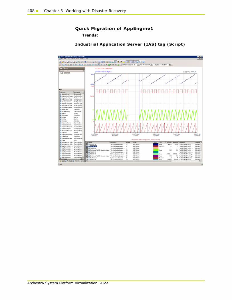
408 Chapter 3 Working with Disaster Recovery
ArchestrA System Platform Virtualization Guide
Quick Migration of AppEngine1
Trends:
Industrial Application Server (IAS) tag (Script)

Working with a Medium Scale Virtualization Environment409
ArchestrA System Platform Virtualization Guide
Industrial Application Server (IAS) IO tag (DASSiDirect)
Observations
AppEngine1 is Platform2 in the Galaxy deployed. During the Live Migration of AppEngine1, it is obvious that there will be an instance during Live Migration when the following occurs:
• AppEngine1 will not be able to connect to the other deployed nodes (Platforms 3, 4, and 5).
• Rest of Virtual machines will not be able to connect to AppEngine1(Platform2)
• AppEngine1 is not time synchronized during the Quick Migration and a message “Values in the past did not fit within the realtime window” is expected on AppEngine1.
• AppEngine1 is not time synchronized during the Quick Migration and a message “Values in the past
410 Chapter 3 Working with Disaster Recovery
ArchestrA System Platform Virtualization Guide
GR node
336481011/27/201110:20:09 AM30562192WarningNmxSvcPlatform 2
exceed maximum heartbeats timeout of 8000 ms.NmxSvc
AppEngine1
944715761/27/201110:20:00 AM1652796WarningMessageChannel
idcinsql21 address was not resolved. Error = 10022NmxSvc
944716581/27/201110:23:38 AM16522908WarningNmxSvcPlatform 3
exceed maximum heartbeats timeout of 8000 ms.NmxSvc
944716591/27/201110:23:38 AM16522908WarningNmxSvcPlatform 5
exceed maximum heartbeats timeout of 8000 ms.NmxSvc
944716721/27/201110:23:39 AM39441968WarningaaEngine0:9AC Values
in the past did not fit within the realtime window; discarding
data (648, 2011/01/27 04:50:04.767, 2011/01/27 04:53:39.338)
[aahMDASSF.cpp; 3709; 1]aaEngine
944717251/27/201110:23:41 AM39243636WarningaaEngine0:9E8 Values
in the past did not fit within the realtime window; discarding
data (21030, 2011/01/27 04:50:04.564, 2011/01/27
04:53:41.400) [aahMDASSF.cpp; 3709; 1]aaEngine
944717421/27/201110:23:41 AM39763940WarningaaEngine0:9C8 Values
in the past did not fit within the realtime window; discarding
data (6650, 2011/01/27 04:50:05.002, 2011/01/27 04:53:40.713)
[aahMDASSF.cpp; 3709; 1]aaEngine
944717441/27/201110:23:41 AM39042588WarningaaEngine0:B64 Values
in the past did not fit within the realtime window; discarding
data (21040, 2011/01/27 04:50:05.298, 2011/01/27
04:53:39.838) [aahMDASSF.cpp; 3709; 1]aaEngine
944718251/27/201110:23:45 AM28721828WarningaaEngine0:690 Values
in the past did not fit within the realtime window; discarding
data (297, 2011/01/27 04:50:04.298, 2011/01/27 04:53:45.619)
[aahMDASSF.cpp; 3709; 1]aaEngine
944766431/27/201110:27:51 AM39441968WarningaaEngine0:9AC Values
in the past did not fit within the realtime window; discarding
data (648, 2011/01/27 04:50:04.767, 2011/01/27 04:53:39.338)
[aahMDASSF.cpp; 3709; 4248]aaEngine
944766561/27/201110:27:51 AM39042588WarningaaEngine0:B64 Values
in the past did not fit within the realtime window; discarding
data (21040, 2011/01/27 04:50:05.298, 2011/01/27
04:53:39.838) [aahMDASSF.cpp; 3709; 2]aaEngine
944766771/27/201110:27:53 AM39243636WarningaaEngine0:9E8 Values
in the past did not fit within the realtime window; discarding
data (21030, 2011/01/27 04:50:04.564, 2011/01/27
04:53:41.400) [aahMDASSF.cpp; 3709; 2449]aaEngine
Working with a Medium Scale Virtualization Environment411
ArchestrA System Platform Virtualization Guide
944766941/27/201110:27:53 AM39763940WarningaaEngine0:9C8 Values
in the past did not fit within the realtime window; discarding
data (6650, 2011/01/27 04:50:05.002, 2011/01/27 04:53:40.713)
[aahMDASSF.cpp; 3709; 374]aaEngine
944767591/27/201110:27:57 AM28721828WarningaaEngine0:690 Values
in the past did not fit within the realtime window; discarding
data (297, 2011/01/27 04:50:04.298, 2011/01/27 04:53:45.619)
[aahMDASSF.cpp; 3709; 62]aaEngine
AppEngine2
54457791/27/201110:20:08 AM20882104WarningNmxSvcPlatform 2
exceed maximum heartbeats timeout of 8000 ms.
Historian
95774041/27/201110:21:01 AM14923380WarningaahStoreSvcValues in
the past did not fit within the realtime window; discarding
data (HISTORIAN_mdas, 11057, 2011/01/27 04:50:09.341,
2011/01/27 04:51:00.524) [HISTORIAN; pipeserver.cpp; 2388]
95774811/27/201110:25:12 AM14923380WarningaahStoreSvcValues in
the past did not fit within the realtime window; discarding
data (HISTORIAN_mdas, 11057, 2011/01/27 04:50:09.341,
2011/01/27 04:51:00.524) [HISTORIAN; pipeserver.cpp; 2388;
16827]

412 Chapter 3 Working with Disaster Recovery
ArchestrA System Platform Virtualization Guide
Quick Migration of AppEngine2
Trends:
Industrial Application Server (IAS) tag (Script)

Working with a Medium Scale Virtualization Environment413
ArchestrA System Platform Virtualization Guide
Industrial Application Server (IAS) IO tag (DASSiDirect)
Observations
AppEnginer2 is Platform4 in the Galaxy deployed. During the Quick Migration of AppEngine2 it is obvious that there will be an instance during Quick Migration when
• AppEngine2 node will not be able to connect to the other deployed nodes (Platforms 1,3, 2, and 5).
• Rest of Virtual machines will not be able to connect to AppEngine2 (Platform4)
• AppEngine2 is not time synchronized during the Quick Migration and a message "Values in the past did not fit within the realtime window" is expected on AppEngine2.
• AppEngine2 is not time synchronized during the Quick Migration and a message "Values in the past did not it within the realtime window" is expected on Historian node.
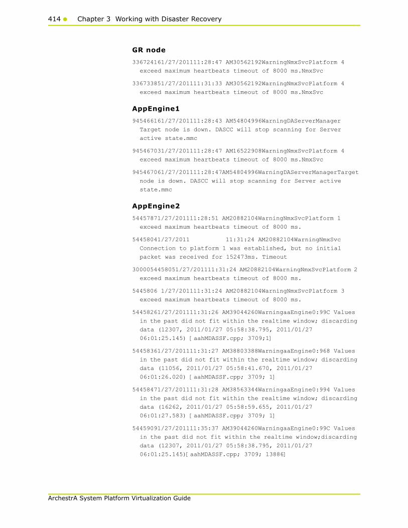
414 Chapter 3 Working with Disaster Recovery
ArchestrA System Platform Virtualization Guide
GR node
336724161/27/201111:28:47 AM30562192WarningNmxSvcPlatform 4
exceed maximum heartbeats timeout of 8000 ms.NmxSvc
336733851/27/201111:31:33 AM30562192WarningNmxSvcPlatform 4
exceed maximum heartbeats timeout of 8000 ms.NmxSvc
AppEngine1
945466161/27/201111:28:43 AM54804996WarningDAServerManager
Target node is down. DASCC will stop scanning for Server
active state.mmc
945467031/27/201111:28:47 AM16522908WarningNmxSvcPlatform 4
exceed maximum heartbeats timeout of 8000 ms.NmxSvc
945467061/27/201111:28:47AM54804996WarningDAServerManagerTarget
node is down. DASCC will stop scanning for Server active
state.mmc
AppEngine2
54457871/27/201111:28:51 AM20882104WarningNmxSvcPlatform 1
exceed maximum heartbeats timeout of 8000 ms.
54458041/27/2011 11:31:24 AM20882104WarningNmxSvc
Connection to platform 1 was established, but no initial
packet was received for 152473ms. Timeout
3000054458051/27/201111:31:24 AM20882104WarningNmxSvcPlatform 2
exceed maximum heartbeats timeout of 8000 ms.
5445806 1/27/201111:31:24 AM20882104WarningNmxSvcPlatform 3
exceed maximum heartbeats timeout of 8000 ms.
54458261/27/201111:31:26 AM39044260WarningaaEngine0:99C Values
in the past did not fit within the realtime window; discarding
data (12307, 2011/01/27 05:58:38.795, 2011/01/27
06:01:25.145) [aahMDASSF.cpp; 3709;1]
54458361/27/201111:31:27 AM38803388WarningaaEngine0:968 Values
in the past did not fit within the realtime window; discarding
data (11056, 2011/01/27 05:58:41.670, 2011/01/27
06:01:26.020) [aahMDASSF.cpp; 3709; 1]
54458471/27/201111:31:28 AM38563344WarningaaEngine0:994 Values
in the past did not fit within the realtime window; discarding
data (16262, 2011/01/27 05:58:59.655, 2011/01/27
06:01:27.583) [aahMDASSF.cpp; 3709; 1]
54459091/27/201111:35:37 AM39044260WarningaaEngine0:99C Values
in the past did not fit within the realtime window;discarding
data (12307, 2011/01/27 05:58:38.795, 2011/01/27
06:01:25.145)[aahMDASSF.cpp; 3709; 13886]
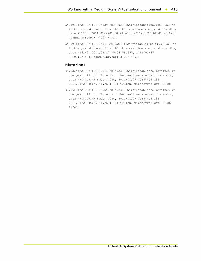
Working with a Medium Scale Virtualization Environment415
ArchestrA System Platform Virtualization Guide
54459101/27/201111:35:39 AM38803388WarningaaEngine0:968 Values
in the past did not fit within the realtime window; discarding
data (11056, 2011/01/2705:58:41.670, 2011/01/27 06:01:26.020)
[aahMDASSF.cpp; 3709; 4402]
54459111/27/201111:35:41 AM38563344WarningaaEngine 0:994 Values
in the past did not fit within the realtime window; discarding
data (16262, 2011/01/27 05:58:59.655, 2011/01/27
06:01:27.583)[aahMDASSF.cpp; 3709; 4701]
Historian:
95783041/27/201111:29:43 AM14923380WarningaahStoreSvcValues in
the past did not fit within the realtime window; discarding
data (HISTORIAN_mdas, 1024, 2011/01/27 05:58:52.136,
2011/01/27 05:59:41.757) [HISTORIAN; pipeserver.cpp; 2388]
95786821/27/201111:33:55 AM14923380WarningaahStoreSvcValues in
the past did not fit within the realtime window; discarding
data (HISTORIAN_mdas, 1024, 2011/01/27 05:58:52.136,
2011/01/27 05:59:41.757) [HISTORIAN; pipeserver.cpp; 2388;
12243]

416 Chapter 3 Working with Disaster Recovery
ArchestrA System Platform Virtualization Guide
Quick Migration of Historian
Trends:
$Second(InTouch)

Working with a Medium Scale Virtualization Environment417
ArchestrA System Platform Virtualization Guide
SysTimeSec (Historian)
Industrial Application Server (IAS) tag (Script) and IAS IO Tag (DASSiDirect)
There is no data loss for IAS Tag (Script) and IAS IO Tag (DASSiDirect) as observed from the tags in the middle from the above snapshot.
Observations
During the Quick Migration of Historian node, it is expected that
• SDK scripts will timeout on Appengine1 and GR node.
• AppEngine2 fails to connect to Historian
• Historian is not synchronized during the Quick Migration and a message "Specified time cannot be in the future" is expected on Historian node.
• Late data acquired from PLC Historian is not synchronized during the Quick Migration and a message "Processing file produced errors: file moved to support folder" is expected on Historian node.
• Historian Client will be unable to connect to Historian.

418 Chapter 3 Working with Disaster Recovery
ArchestrA System Platform Virtualization Guide
GR Node
332273241/26/20115:13:38 PM42163488WarningScriptRuntime
AsynchronousBuffer.script6: Script timed out.aaEngine
AppEngine1
934165241/26/20115:13:50 PM39043908WarningScriptRuntime
Insert.InsertValueWT: Script timed out.aaEngine93417566
AppEngine2
54453561/26/20115:13:53 PM852484WarningHistorianPrimitive
AppEngineNode2 failed to connect to Historian HISTORIAN. (Does
ArchestrA user account exist on Historian(InSQL) node or does
Historian not exist?)
Historian
95646651/26/20115:12:30 PM14642120ErroraahStoreSvcERROR:
Specified time cannot be in the future (2011/01/26
11:42:29.856, 2011/01/26 11:48:39.085) [HISTORIAN;
cmanualpipe.cpp; 697]
95646661/26/20115:12:30 PM14642120ErroraahStoreSvcERROR: Data
packet lost - broken packet saved in bpack.bin
(HISTORIAN_ManualDataPipe, bPacket_129405157498567410.bin)
[HISTORIAN; cmanualpipe.cpp; 1267]
95647071/26/20115:18:45 PM14642120WarningaahCfgSvc"Server time
is shifting (Expected time, Current time)"
(01/26/11,17:18:44,306, 01/26/11,17:12:35,057) [HISTORIAN;
Config.cpp; 2040]
95647171/26/20115:18:58 PM14642120WarningaahManStSvcCannot
insert values for delta tags into history block (18,
P10128.i20, 2011/01/26 11:42:22.293, 3) [HISTORIAN;
insertmanual.cpp; 4787]
95647181/26/20115:18:58 PM14642120WarningaahManStSvcCannot
insert values for delta tags into history block (18,
P10125.i20, 2011/01/26 11:42:22.293, 3) [HISTORIAN;
insertmanual.cpp; 4787]
95647191/26/20115:18:58 PM14642120ErroraahManStSvcERROR:
Processing file produced errors: file moved to support folder
(latedata_129405161297112310_0000.bin) [HISTORIAN;
insertmanual.cpp; 771]
Hist Client
1134381/26/20115:13:29 PM3232884WarningaaAFCommonTypesUnable to
create dataview: Server must be logged on before executing SQL
query: SELECT aaT=DateTime, aaN=TagName, aaDV=Value,
aaSV=CONVERT(nvarchar(512),vValue), aaQ=OPCQuality,
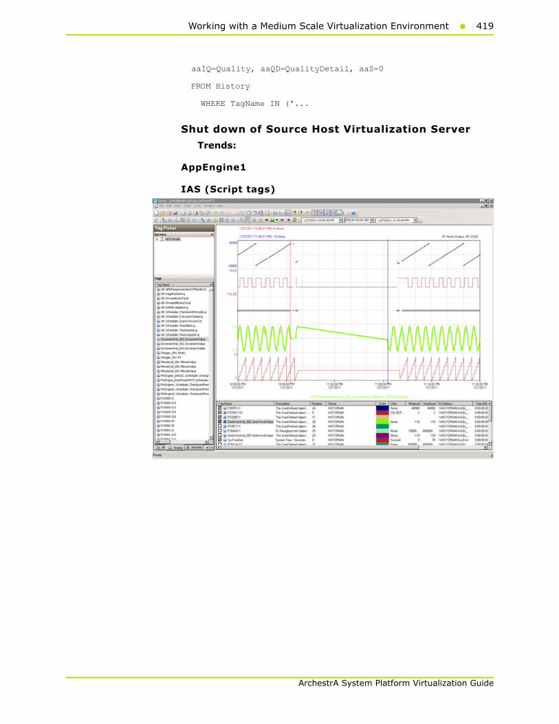
Working with a Medium Scale Virtualization Environment419
ArchestrA System Platform Virtualization Guide
aaIQ=Quality, aaQD=QualityDetail, aaS=0
FROM History
WHERE TagName IN ('...
Shut down of Source Host Virtualization Server
Trends:
AppEngine1
IAS (Script tags)

420 Chapter 3 Working with Disaster Recovery
ArchestrA System Platform Virtualization Guide
IAS IO Tag (DASSiDirect)
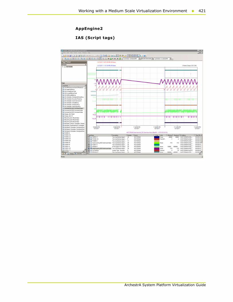
Working with a Medium Scale Virtualization Environment421
ArchestrA System Platform Virtualization Guide
AppEngine2
IAS (Script tags)

422 Chapter 3 Working with Disaster Recovery
ArchestrA System Platform Virtualization Guide
IAS IO Tag (DASSiDirect)
GR
IAS (Script tags)

Working with a Medium Scale Virtualization Environment423
ArchestrA System Platform Virtualization Guide
IAS IO Tag (DASSiDirect).
Historian
SysTimeSec (Historian)

424 Chapter 3 Working with Disaster Recovery
ArchestrA System Platform Virtualization Guide
$Second tag (In Touch)
Observations
GR Node
339257881/27/201110:56:34 PM37803784WarningScanGroupRuntime2
Can't convert Var data type to MxDataType
339258091/27/201111:08:25 PM30562192WarningNmxSvcPlatform 2
exceed maximum heartbeats timeout of 8000 ms.
339258101/27/201111:08:25 PM30562192WarningNmxSvcPlatform 3
exceed maximum heartbeats timeout of 8000 ms.
339258111/27/201111:08:25 PM30562192WarningNmxSvcPlatform 4
exceed maximum heartbeats timeout of 8000 ms.
339258121/27/201111:08:25 PM30562192WarningNmxSvcPlatform 5
exceed maximum heartbeats timeout of 8000 ms.
339258131/27/201111:08:26 PM37443748WarningScriptRuntime
AsynchronousBuffer.script2: Script timed out.
339258411/27/201111:08:31 PM27683860WarningaaEngine0:6D4 Values
in the past did not fit within the realtime window; discarding
data (182, 2011/01/27 17:26:32.562, 2011/01/27 17:38:30.874)
[aahMDASSF.cpp; 3709; 1]
339263771/27/201111:09:53 PM37444076WarningaahMDASTime
synchronization with historian node out of spec, please resync
to avoid data loss. (129406228210600000, 129406235937946214)
[StorageNode.cpp,2576]
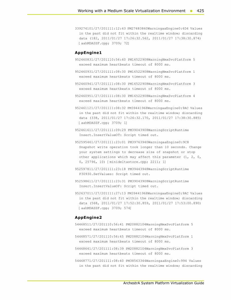
Working with a Medium Scale Virtualization Environment425
ArchestrA System Platform Virtualization Guide
339274101/27/201111:12:43 PM27683860WarningaaEngine0:6D4 Values
in the past did not fit within the realtime window; discarding
data (182, 2011/01/27 17:26:32.562, 2011/01/27 17:38:30.874)
[aahMDASSF.cpp; 3709; 72]
AppEngine1
952460831/27/201110:56:40 PM16522908WarningNmxSvcPlatform 5
exceed maximum heartbeats timeout of 8000 ms.
952460931/27/201111:08:30 PM16522908WarningNmxSvcPlatform 1
exceed maximum heartbeats timeout of 8000 ms.
952460941/27/201111:08:30 PM16522908WarningNmxSvcPlatform 3
exceed maximum heartbeats timeout of 8000 ms.
952460951/27/201111:08:30 PM16522908WarningNmxSvcPlatform 4
exceed maximum heartbeats timeout of 8000 ms.
952461121/27/201111:08:32 PM39441968WarningaaEngine0:9AC Values
in the past did not fit within the realtime window; discarding
data (338, 2011/01/27 17:26:32.170, 2011/01/27 17:38:30.885)
[aahMDASSF.cpp; 3709; 1]
952461611/27/201111:09:29 PM39043908WarningScriptRuntime
Insert.InsertValueOT: Script timed out.
952595461/27/201111:23:01 PM39763940WarningaaEngine0:9C8
Snapshot write operation took longer than 10 seconds. Change
your system settings to decrease size of snapshot or stop
other applications which may affect this parameter (1, 2, 0,
0, 25796, 10) [minideltastore.cpp; 2211; 1]
952597811/27/201111:23:18 PM39443948WarningScriptRuntime
P30930.SetValues: Script timed out.
952598611/27/201111:23:31 PM39043908WarningScriptRuntime
Insert.InsertValueOF: Script timed out.
952637011/27/201111:27:13 PM39441968WarningaaEngine0:9AC Values
in the past did not fit within the realtime window; discarding
data (568, 2011/01/27 17:52:30.859, 2011/01/27 17:53:00.890)
[aahMDASSF.cpp; 3709; 574]
AppEngine2
54468511/27/201110:56:41 PM20882104WarningNmxSvcPlatform 5
exceed maximum heartbeats timeout of 8000 ms.
54468571/27/201110:56:45 PM20882104WarningNmxSvcPlatform 1
exceed maximum heartbeats timeout of 8000 ms.
54468641/27/201111:08:39 PM20882104WarningNmxSvcPlatform 3
exceed maximum heartbeats timeout of 8000 ms.
54468771/27/201111:08:40 PM38563344WarningaaEngine0:994 Values
in the past did not fit within the realtime window; discarding

426 Chapter 3 Working with Disaster Recovery
ArchestrA System Platform Virtualization Guide
data (16262, 2011/01/27 17:26:33.903, 2011/01/27
17:38:39.841) [aahMDASSF.cpp; 3709; 1]
54470211/27/201111:22:59 PM38324072WarningaaEngine0:97C
Snapshot write operation took longer than 10 seconds. Change
your system settings to decrease size of snapshot or stop
other applications which may affect this parameter (1024, 3,
0, 0, 244, 11) [minideltastore.cpp; 2211; 1]
54471201/27/201111:27:16 PM39044260WarningaaEngine0:99C Values
in the past did not fit within the realtime window; discarding
data (12307, 2011/01/27 17:52:32.183, 2011/01/27
17:53:03.354) [aahMDASSF.cpp; 3709; 3835]
54471211/27/201111:27:28 PM38803388WarningaaEngine0:968 Attempt
to store values in the future; timestamps were overwritten
with current time (11057, 2011/01/27 17:53:16.324, 2011/01/27
17:53:16.323) [aahMDASSF.cpp; 3315; 38]
Historian
95878001/27/201110:56:42 PM14923380WarningaahStoreSvcAttempt to
store values in the future; timestamps were overwritten with
current time (pipe name, TagName, wwTagKey, system time (UTC),
time difference (sec)) (HISTORIAN_2, $Time, 23556, 2011/01/27
17:26:40.479, 771) [HISTORIAN; pipeserver.cpp; 1831]
95878041/27/201110:56:58 PM14923380ErroraahStoreSvcERROR:
Specified time cannot be in the future (2011/01/27
17:26:58.457, 2011/01/27 17:39:51.164) [HISTORIAN;
cmanualpipe.cpp; 697]
95878051/27/201110:56:58 PM14923380ErroraahStoreSvcERROR: Data
packet lost - broken packet saved in bpack.bin
(HISTORIAN_ManualDataPipe, bPacket_129406228184574640.bin)
[HISTORIAN; cmanualpipe.cpp; 1267]
95878591/27/201111:10:18 PM39563920InfoaahIDASSvc (local)
HISTORIAN_2: Network or server is too busy (max time lag
reached, time lag 773733 ms)
95878601/27/201111:10:18 PM39563920InfoaahIDASSvc (local)
HISTORIAN_2: Clearing buffer cache for recovery (max time lag
reached)
95878611/27/201111:10:18 PM39563920InfoaahIDASSvc (local)
HISTORIAN_2: A data buffer lost: header/dirty time of the lost
buffer = 22:57:24.413/23:10:18.145
95878641/27/201111:10:18 PM50765116InfoaahDrvSvcHISTORIAN_1:
HISTORIAN: 17 data buffers lost: header/dirty time of the last
lost buffer = 22:57:26.000/23:10:18.389
95879431/27/201111:10:20 PM14923380WarningaahStoreSvcAttempt to
store values in the future; timestamps were overwritten with
current time (pipe name, TagName, wwTagKey, system time (UTC),

Working with a Medium Scale Virtualization Environment427
ArchestrA System Platform Virtualization Guide
time difference (sec)) (HISTORIAN_2, $Time, 23556, 2011/01/27
17:26:40.479, 771) [HISTORIAN; pipeserver.cpp; 1831; 77980]
95879571/27/201111:10:26 PM14923380WarningaahCfgSvc"Server time
is shifting (Expected time, Current time)"
(01/27/11,23:10:25,776, 01/27/11,22:57:33,033) [HISTORIAN;
Config.cpp; 2040]
95881611/27/201111:23:02 PM14923380WarningaahStoreSvcSnapshot
write operation took longer than 10 seconds. Change your
system settings to decrease size of snapshot or stop other
applications which may affect this parameter (2, 1, 0,
2154928, 21081, 14) [HISTORIAN; deltastore.cpp; 2669]
95881671/27/201111:23:04 PM14923380WarningaahStoreSvcValues in
the past did not fit within the realtime window; discarding
data (HISTORIAN_mdas, 23580, 2011/01/27 17:52:32.691,
2011/01/27 17:53:04.250) [HISTORIAN; pipeserver.cpp; 2388]
95879431/27/201111:10:20 PM14923380WarningaahStoreSvcAttempt to
store values in the future; timestamps were overwritten with
current time (pipe name, TagName, wwTagKey, system time (UTC),
time difference (sec)) (HISTORIAN_2, $Time, 23556, 2011/01/27
17:26:40.479, 771) [HISTORIAN; pipeserver.cpp; 1831; 77980]
HistClient
1382081/27/201110:56:42 PM32322264WarningaaAFCommonTypesUnable
to create dataview: Server must be logged on before executing
SQL query: SELECT aaT=DateTime, aaN=TagName, aaDV=Value,
aaSV=CONVERT(nvarchar(512),vValue), aaQ=OPCQuality,
aaIQ=Quality, aaQD=QualityDetail, aaS=0
FROM History
WHERE TagName IN ('...
1382091/27/201110:56:42 PM32322264WarningaaTrendDataSetProvider
The configured InSQL server HISTORIAN is either Disconnnected
from Network or in shutdown/Disable state
WISNode
30973991/27/201110:56:40 PM33002960WarningNmxSvcPlatform 4
exceed maximum heartbeats timeout of 8000 ms.
30974011/27/201111:09:31 PM33002960WarningNmxSvcPlatform 1
exceed maximum heartbeats timeout of 8000 ms.
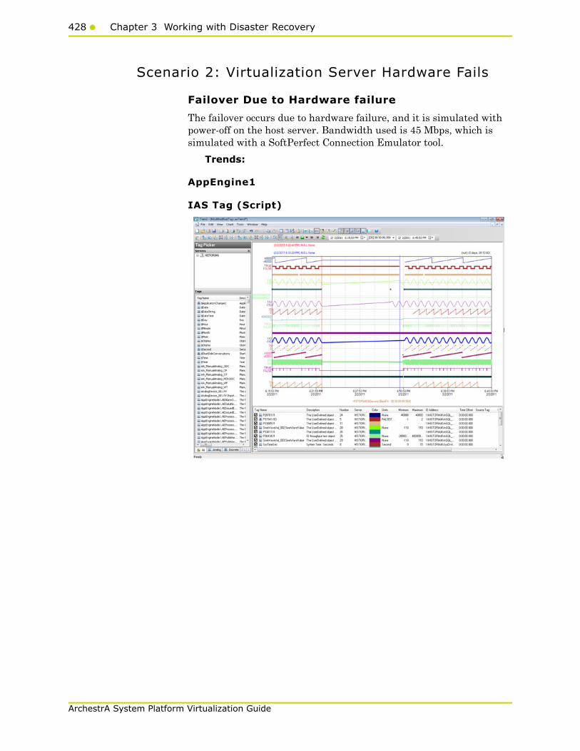
428 Chapter 3 Working with Disaster Recovery
ArchestrA System Platform Virtualization Guide
Scenario 2: Virtualization Server Hardware Fails
Failover Due to Hardware failure
The failover occurs due to hardware failure, and it is simulated with power-off on the host server. Bandwidth used is 45 Mbps, which is simulated with a SoftPerfect Connection Emulator tool.
Trends:
AppEngine1
IAS Tag (Script)
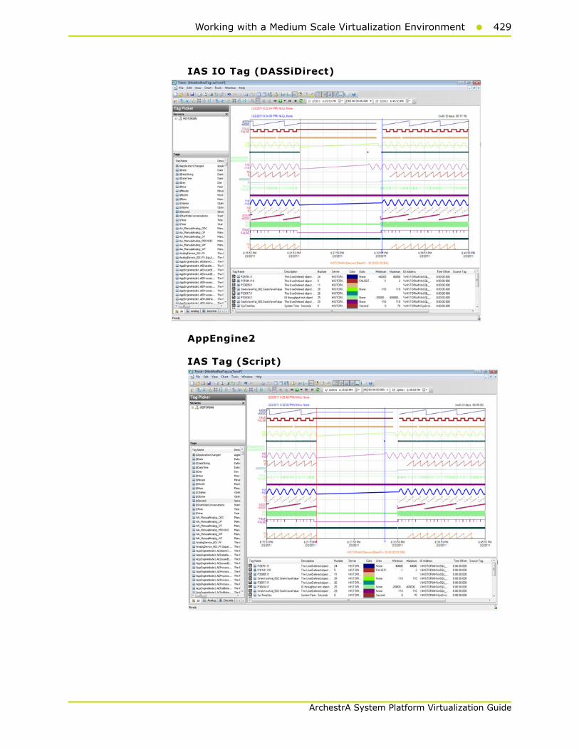
Working with a Medium Scale Virtualization Environment429
ArchestrA System Platform Virtualization Guide
IAS IO Tag (DASSiDirect)
AppEngine2
IAS Tag (Script)

430 Chapter 3 Working with Disaster Recovery
ArchestrA System Platform Virtualization Guide
IAS IO tag (DASSiDirect)
GR
IAS tag (Script)

Working with a Medium Scale Virtualization Environment431
ArchestrA System Platform Virtualization Guide
IAS IO tag (DASSiDirect)
Historian
$Second (InTouch)
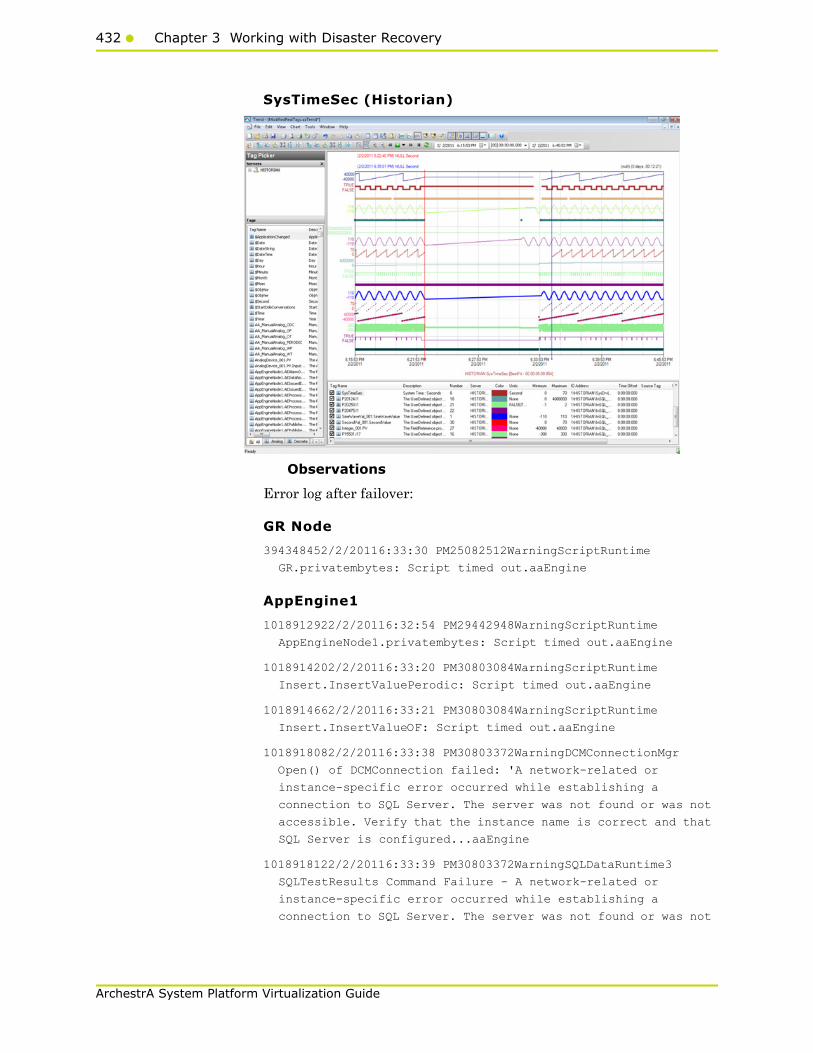
432 Chapter 3 Working with Disaster Recovery
ArchestrA System Platform Virtualization Guide
SysTimeSec (Historian)
Observations
Error log after failover:
GR Node
394348452/2/20116:33:30 PM25082512WarningScriptRuntime
GR.privatembytes: Script timed out.aaEngine
AppEngine1
1018912922/2/20116:32:54 PM29442948WarningScriptRuntime
AppEngineNode1.privatembytes: Script timed out.aaEngine
1018914202/2/20116:33:20 PM30803084WarningScriptRuntime
Insert.InsertValuePerodic: Script timed out.aaEngine
1018914662/2/20116:33:21 PM30803084WarningScriptRuntime
Insert.InsertValueOF: Script timed out.aaEngine
1018918082/2/20116:33:38 PM30803372WarningDCMConnectionMgr
Open() of DCMConnection failed: 'A network-related or
instance-specific error occurred while establishing a
connection to SQL Server. The server was not found or was not
accessible. Verify that the instance name is correct and that
SQL Server is configured...aaEngine
1018918122/2/20116:33:39 PM30803372WarningSQLDataRuntime3
SQLTestResults Command Failure - A network-related or
instance-specific error occurred while establishing a
connection to SQL Server. The server was not found or was not

Working with a Medium Scale Virtualization Environment433
ArchestrA System Platform Virtualization Guide
accessible. Verify that the instance name is correct and that
SQL Server is configured...aaEngine
1019127142/2/20116:53:52 PM26722448WarningInTouchProxyFailed to
reconnecnt to data source aaEngine
1019235332/2/20117:04:27 PM30803084WarningScriptRuntime
Insert.InsertValueWF: Script timed out.aaEngine
AppEngine2
54719382/2/20116:31:18 PM2508332WarningEnginePrimitiveRuntime
Eng:: m_GDC->GetFile failed. Error 2 (0x00000002): The system
cannot find the file specified
54721462/2/20116:32:29 PM2508332WarningHistorianPrimitive
AppEngineNode2 failed to connect to Historian HISTORIAN. (Does
ArchestrA user account exist on Historian(InSQL) node or does
Historian not exist?)
54721512/2/20116:33:29 PM2508332WarningHistorianPrimitive
AppEngineNode2 failed to connect to Historian HISTORIAN. (Does
ArchestrA user account exist on Historian(InSQL) node or does
Historian not exist?)
54721542/2/20116:34:29 PM2508332WarningHistorianPrimitive
AppEngineNode2 failed to connect to Historian HISTORIAN. (Does
ArchestrA user account exist on Historian(InSQL) node or does
Historian not exist?)
Historian
232629982/2/20116:35:09 PM14722220WarningaahStoreSvcAttempt to
store values in the future; timestamps were overwritten with
current time (pipe name, TagName, wwTagKey, system time (UTC),
time difference (sec)) (HISTORIAN_mdas,
GR.Engine.ProcessIODataBytes, 182, 2011/02/02 13:05:08.273,
1) [HISTORIAN; pipese...
232630402/2/20116:39:21 PM14722220WarningaahStoreSvcAttempt to
store values in the future; timestamps were overwritten with
current time (pipe name, TagName, wwTagKey, system time (UTC),
time difference (sec)) (HISTORIAN_mdas,
GR.Engine.ProcessIODataBytes, 182, 2011/02/02 13:05:08.273,
1) [HISTORIAN; pipese...
232662142/2/20117:04:28 PM14722220WarningaahStoreSvcSnapshot
write operation took longer than 10 seconds. Change your
system settings to decrease size of snapshot or stop other
applications which may affect this parameter (4, 1, 0,
9097524, 1214182, 18) [HISTORIAN; deltastore.cpp; 2669]
232662152/2/20117:04:28 PM14722220WarningaahStoreSvcSnapshot
write operation took longer than 10 seconds. Change your
system settings to decrease size of snapshot or stop other
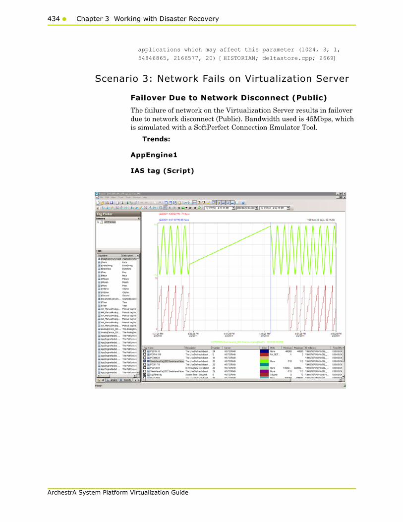
434 Chapter 3 Working with Disaster Recovery
ArchestrA System Platform Virtualization Guide
applications which may affect this parameter (1024, 3, 1,
54846865, 2166577, 20) [HISTORIAN; deltastore.cpp; 2669]
Scenario 3: Network Fails on Virtualization Server
Failover Due to Network Disconnect (Public)
The failure of network on the Virtualization Server results in failover due to network disconnect (Public). Bandwidth used is 45Mbps, which is simulated with a SoftPerfect Connection Emulator Tool.
Trends:
AppEngine1
IAS tag (Script)
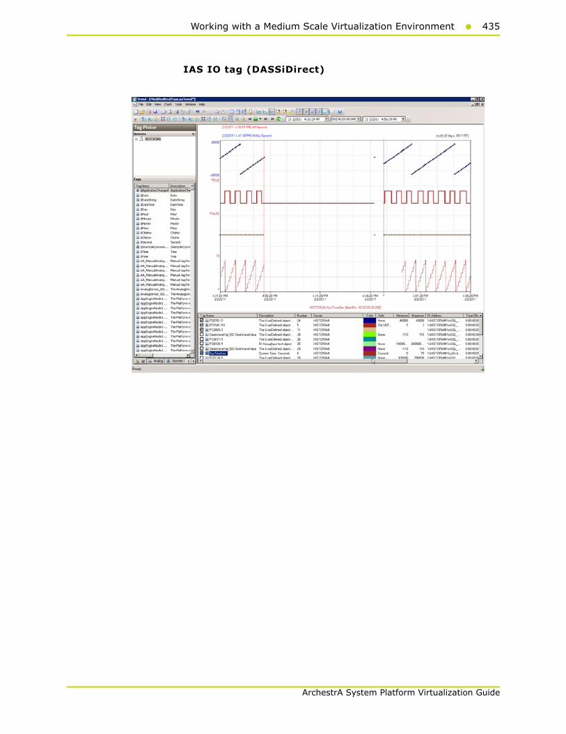
Working with a Medium Scale Virtualization Environment435
ArchestrA System Platform Virtualization Guide
IAS IO tag (DASSiDirect)

436 Chapter 3 Working with Disaster Recovery
ArchestrA System Platform Virtualization Guide
AppEngine2
IAS tag (Script)

Working with a Medium Scale Virtualization Environment437
ArchestrA System Platform Virtualization Guide
IAS IO tag (DASSiDirect)

438 Chapter 3 Working with Disaster Recovery
ArchestrA System Platform Virtualization Guide
Historian
$Second (Intouch)
Observations
Error log after failover
GR Node
393988582/2/20114:46:34 PM26602664WarningEnginePrimitiveRuntime
Eng:: m_GDC->GetFile failed. Error 2 (0x00000002): The system
cannot find the file specifiedaaEngine
393989522/2/20114:47:31 PM26602664WarningScriptRuntime
GR.privatembytes: Script timed out.aaEngine
AppEngine1
1017936492/2/20114:46:34 PM29522956WarningScriptRuntime
AppEngineNode1.privatembytes: Script timed out.aaEngine
1017938352/2/20114:47:05 PM27002184WarningScriptRuntime
Insert.InsertValueDataChange: Script timed out.aaEngine
1017940012/2/20114:47:32 PM27003592WarningDCMConnectionMgr
Open() of DCMConnection failed: 'A network-related or
instance-specific error occurred while establishing a
connection to SQL Server. The server was not found or was not

Working with a Medium Scale Virtualization Environment439
ArchestrA System Platform Virtualization Guide
accessible. Verify that the instance name is correct and that
SQL Server is configured...aaEngine
1017940022/2/20114:47:33 PM27003592WarningSQLDataRuntime3
SQLTestResults Command Failure - A network-related or
instance-specific error occurred while establishing a
connection to SQL Server. The server was not found or was not
accessible. Verify that the instance name is correct and that
SQL Server is configured...aaEngine
1017940192/2/20114:48:26 PM27004048WarningScriptRuntime
InsertAsync.InsertValueWF: Script timed out.aaEngine
1017940322/2/20114:48:26 PM27002184WarningScriptRuntime
Insert.InsertValueWF: Script timed out.aaEngine
1018040142/2/20114:58:02 PM20082652WarningInTouchProxyFailed to
reconnecnt to data source aaEngine
1018047432/2/20114:58:43 PM20082652WarningInTouchProxyFailed to
reconnecnt to data source aaEngine
AppEngine2
54716472/2/20114:46:07 PM21721972WarningScriptRuntime
HourVal_003.GenerateHourValue: Script timed out.aaEngine
54716942/2/20114:46:29 PM2480672WarningHistorianPrimitive
AppEngineNode2 failed to connect to Historian HISTORIAN. (Does
ArchestrA user account exist on Historian(InSQL) node or does
Historian not exist?)aaEngine
54717192/2/20114:49:29 PM2480672WarningHistorianPrimitive
AppEngineNode2 failed to connect to Historian HISTORIAN. (Does
ArchestrA user account exist on Historian(InSQL) node or does
Historian not exist?)aaEngine
Historian
232207772/2/20114:33:29 PM15162260WarningaahStoreSvcValues in
the past did not fit within the realtime window; discarding
data (historian_2, 23987, 2011/02/02 10:49:20.680, 2011/02/02
10:59:15.351) [HISTORIAN; pipeserver.cpp; 2388; 535]aahCfgSvc
232400692/2/20114:49:41 PM15202800WarningaahStoreSvcAttempt to
store values in the future; timestamps were overwritten with
current time (pipe name, TagName, wwTagKey, system time (UTC),
time difference (sec)) (HISTORIAN_mdas,
IncrementVal_003.IncrementValue, 12307, 2011/02/02
11:19:37.535, 1) [HISTORIAN; p...aahCfgSvc
232401232/2/20114:53:51 PM15202800WarningaahStoreSvcAttempt to
store values in the future; timestamps were overwritten with
current time (pipe name, TagName, wwTagKey, system time (UTC),
time difference (sec)) (HISTORIAN_mdas,

440 Chapter 3 Working with Disaster Recovery
ArchestrA System Platform Virtualization Guide
IncrementVal_003.IncrementValue, 12307, 2011/02/02
11:19:37.535, 1) [HISTORIAN; p...aahCfgSvc
Scenario 4: Virtualization Server Becomes Unresponsive
Hyper-V Virtual Machines with Static RAM and Reservations for Processors
It has been observed that even when the Host Virtualization Server reaches 100% CPU utilization, there is no failover of the Hyper-V virtual machines running on it to the other Host Virtualization Server. However, the host server running at 100% CPU utilization fails to process all the network requirements of the Hyper-V virtual machines running on it. As a result, network disruptions on the Hyper-V virtual machines are observed that result in data loss.
Host Virtualization server performance with CPU load at 100%

Working with a Medium Scale Virtualization Environment441
ArchestrA System Platform Virtualization Guide
GR Performance with host server running at 100% CPU load
Historian performance with host server running at 100% CPU load
442 Chapter 3 Working with Disaster Recovery
ArchestrA System Platform Virtualization Guide
Observations When CPU Load is 100% on host Virtualization Server
The virtual machines do not failover when CPU load stays at 100%. All the virtual machines continue to run on the same Host Virtualization Server even though the CPU load is at 100%.
The messages “Snapshot write operation took longer than 10 seconds” are expected when the virtual machines are running at high Processor time % (Historian at 89% and GR Node at 35%).
The execution of time sync utility is impacted and the time is not synchronized on the Historian, AppEngine nodes and GR node. As a result, the message “Values in the past did not fit within the realtime window” is observed.
AppEngine1
2/4/20114:41:11 PMWarningaaEngine0:A50 Snapshot write operation
took longer than 10 seconds. Change your system settings to
decrease size of snapshot or stop other applications which may
affect this parameter (1024, 3, 0, 0, 7316, 11)
[minideltastore.cpp; 2211; 1]
2/4/20114:41:35 PMWarningaaEngine0:9D8 Values in the past did
not fit within the realtime window; discarding data (1481,
2011/02/04 11:11:02.029, 2011/02/04 11:11:35.041)
[aahMDASSF.cpp; 3709; 1]
AppEngine2
2/4/20114:56:49 PMWarningaaEngine0:A08 Snapshot write operation
took longer than 10 seconds. Change your system settings to
decrease size of snapshot or stop other applications which may
affect this parameter (4, 6, 0, 0, 3288, 11)
[minideltastore.cpp; 2211; 1]
2/4/20114:58:21 PMWarningaaEngine0:9D4 Values in the past did
not fit within the realtime window; discarding data (11701,
2011/02/04 11:23:35.788, 2011/02/04 11:24:08.264)
[aahMDASSF.cpp; 3709; 4331]
GR Node
2/4/20114:50:54 PMWarningaaEngine0:B34 Snapshot write operation
took longer than 10 seconds. Change your system settings to
decrease size of snapshot or stop other applications which may
affect this parameter (1, 2, 0, 0, 301, 10)
[minideltastore.cpp; 2211; 1]
2/4/20114:51:18 PMWarningaaEngine0:B34 Values in the past did
not fit within the realtime window; discarding data (23580,
2011/02/04 11:16:35.876, 2011/02/04 11:17:07.056)
[aahMDASSF.cpp; 3709; 10]

Working with a Medium Scale Virtualization Environment443
ArchestrA System Platform Virtualization Guide
2/4/20114:51:20 PMWarningaaEngine0:D38 Values in the past did
not fit within the realtime window; discarding data (218,
2011/02/04 11:16:35.297, 2011/02/04 11:17:08.259)
[aahMDASSF.cpp; 3709; 132]
2/4/20114:52:12 PMWarningScriptRuntime
AsynchronousBuffer.script6: Script timed out.
Scripts on GR node time out
Historian Node
2/4/20114:15:22 PMWarningaahStoreSvcValues in the past did not
fit within the realtime window; discarding data
(HISTORIAN_mdas, 182, 2011/02/04 10:40:24.919, 2011/02/04
10:41:07.901) [HISTORIAN; pipeserver.cpp; 2388; 4836]
2/4/20114:15:40 PMWarningaahStoreSvcSnapshot write operation
took longer than 10 seconds. Change your system settings to
decrease size of snapshot or stop other applications which may
affect this parameter (1, 2, 0, 17223628, 221525, 14)
[HISTORIAN; deltastore.cpp; 2669]
2/4/20114:15:40 PMWarningaahStoreSvcSnapshot write operation
took longer than 10 seconds. Change your system settings to
decrease size of snapshot or stop other applications which may
affect this parameter (1024, 3, 0, 369892038, 1896467, 26)
[HISTORIAN; deltastore.cpp; 2669]
2/4/20114:15:45 PMErroraahRetSvcERROR: Failed to open file
(C:\Historian\Data\Circular\A110204_015\stringD1024_2.sdt)
[HISTORIAN; retdelta.cpp; 4344]
2/4/20114:15:45 PMErroraahRetSvcERROR: Could not load delta data
from disk [HISTORIAN; retdelta.cpp; 726]
The error message “ERROR: Failed to open file
(C:\Historian\Data\Circular\..” and “ERROR: Could not load
delta data from disk”is expected when Historian client is used
to retrieve data when %Processor Time is high.
WIS Node
2/4/20114:47:02 PMWarningArchestrA.Visualization.WCFServiceLMX
WCF service: Exception while PushBackData(sync mode): [The
operation has timed out.] at [
Server stack trace:
at
System.ServiceModel.Channels.InputQueue`1.Dequeue(TimeSpan
timeout)
at
System.ServiceModel.Channels.ServicePollingDuplexSessionCh...

444 Chapter 3 Working with Disaster Recovery
ArchestrA System Platform Virtualization Guide
Trend when CPU Load is 100% on host Virtualization Server
From the above trend, it is observed that there is data loss for 33 seconds at a stretch IAS Script tags on GR node. It can also be noticed that there are frequent data losses for all types tags IO and Script generated from GR and AppEngine nodes.
Observations When CPU Load is 96% on host Virtualization Server
The virtual machines do not failover when CPU load stays at 96%. All the virtual machines continue to run on the same Host Virtualization Server even though the CPU load is high.
Only below warning massage is observed when CPU load of host is 96%.
WIS node
2/4/20113:12:32 PMWarningrdbhandler
!RdbHandlerListerner::OnData() - Invalid Session (ID:3801155)

Working with a Medium Scale Virtualization Environment445
ArchestrA System Platform Virtualization Guide
Trend When CPU Load is 96% on host Virtualization Server
From the above trend, it is observed that there is data loss for IAS IO tags and Script tags on GR node and AppEngine Nodes.

446 Chapter 3 Working with Disaster Recovery
ArchestrA System Platform Virtualization Guide

447
ArchestrA System Platform Virtualization Guide
Chapter 4
Working with HighAvailability and Disaster
Recovery
This section introduces several High Availability and Disaster Recovery (HADR) virtualization solutions that improve the availability of System Platform Products. A HADR solution offsets the effects of a hardware or software failure across multiple sites during a disaster. It makes sure all applications are available in order to minimize the downtime during times of crisis.
Recommendations and Best Practices• Ensure that auto logon is set up for all Hyper-V virtual machines
running the System Platform products. This is to ensure that these Hyper-V virtual machines start up automatically after the failover.
• Ensure the time on all the Hyper-V host servers, the virtual machines, and all other nodes, which are part of the Disaster Recovery environment are continuously synchronized. Otherwise, the Hyper-V virtual machines running on the host experience time drifts and discards data.You can add the time synchronization utility in the Start Up programs so that this utlity starts automatically whenever the Hyper-V machine reboots.
• On the host servers, disable all the network cards that are not utilized by the System Platform environment. This is to avoid any confusion during the network selections while setting up the cluster.

448 Chapter 4 Working with High Availability and Disaster Recovery
ArchestrA System Platform Virtualization Guide
• As per the topology described above for the High Availability and Disaster Recovery environment, only one network is used for all communications. If multiple networks are used, then make sure only the primary network used for communication between the Hyper-V Nodes is enabled for the Failover Cluster Communication. Disable the remaining cluster networks in Failover Cluster Manager.
• Ensure the virtual networks created in Hyper-V Manager have the same name across all the nodes, which are participating in the cluster. Otherwise, migration/failover of Hyper-V virtual machines will fail.
• Though this is a three-node failover topology, to achieve the required failover order, a fourth node is required for setting up the Node Majority in the failover cluster. The three nodes are used for virtual machine services and the fourth node is used for Quorum witness. The fourth node is not meant for failover of Hyper-V virtual machines running on the cluster. This fourth node should not be marked as the preferred owner while setting up the preferred owners for the Hyper-V virtual machines running on the cluster.
The following scenario is an explanation for the failover order.
Node 1 and Node 2 are in High Available site and Node 3 is in Disaster site. The failover sequence is Node 1 > Node 2 > Node 3.
• When all VMs are running on Node 1:
• All three nodes are up. Now Node 1 goes down. The VMs running on Node 1 move to Node 2.
• Node 1 and Node 3 are up and Node 2 is down. Now Node 1 goes down. The VMs running on Node 1 move to Node 3.
• When all VMs are running on Node 2:
• Node 2 and Node 3 are up and Node 1 is down. Now Node 2 goes down. The VMs running on Node 2 move to Node 3.
• All three nodes are up. Now Node 2 goes down. The VMs running on Node 2 move to Node 3.
Best Practices for SteelEye DataKeeper Mirroring:
• While creating the SteelEye DataKeeper mirroring job, ensure the drive letters of the source and target drives to be mirrored are same.
• It is recommended to have zero latency in the network when SteelEye DataKeeper mirroring, failover/migration of virtual machines between host servers take place. In case of networks with latency, refer to the SteelEye DataKeeper documentation on network requirements.
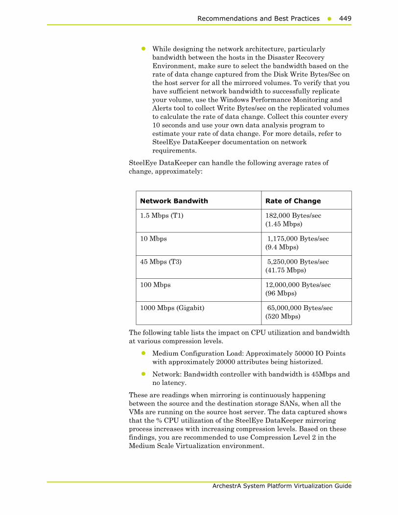
Recommendations and Best Practices449
ArchestrA System Platform Virtualization Guide
• While designing the network architecture, particularly bandwidth between the hosts in the Disaster Recovery Environment, make sure to select the bandwidth based on the rate of data change captured from the Disk Write Bytes/Sec on the host server for all the mirrored volumes. To verify that you have sufficient network bandwidth to successfully replicate your volume, use the Windows Performance Monitoring and Alerts tool to collect Write Bytes/sec on the replicated volumes to calculate the rate of data change. Collect this counter every 10 seconds and use your own data analysis program to estimate your rate of data change. For more details, refer to SteelEye DataKeeper documentation on network requirements.
SteelEye DataKeeper can handle the following average rates of change, approximately:
The following table lists the impact on CPU utilization and bandwidth at various compression levels.
• Medium Configuration Load: Approximately 50000 IO Points with approximately 20000 attributes being historized.
• Network: Bandwidth controller with bandwidth is 45Mbps and no latency.
These are readings when mirroring is continuously happening between the source and the destination storage SANs, when all the VMs are running on the source host server. The data captured shows that the % CPU utilization of the SteelEye DataKeeper mirroring process increases with increasing compression levels. Based on these findings, you are recommended to use Compression Level 2 in the Medium Scale Virtualization environment.
Network Bandwith Rate of Change
1.5 Mbps (T1) 182,000 Bytes/sec (1.45 Mbps)
10 Mbps 1,175,000 Bytes/sec (9.4 Mbps)
45 Mbps (T3) 5,250,000 Bytes/sec (41.75 Mbps)
100 Mbps 12,000,000 Bytes/sec (96 Mbps)
1000 Mbps (Gigabit) 65,000,000 Bytes/sec (520 Mbps)
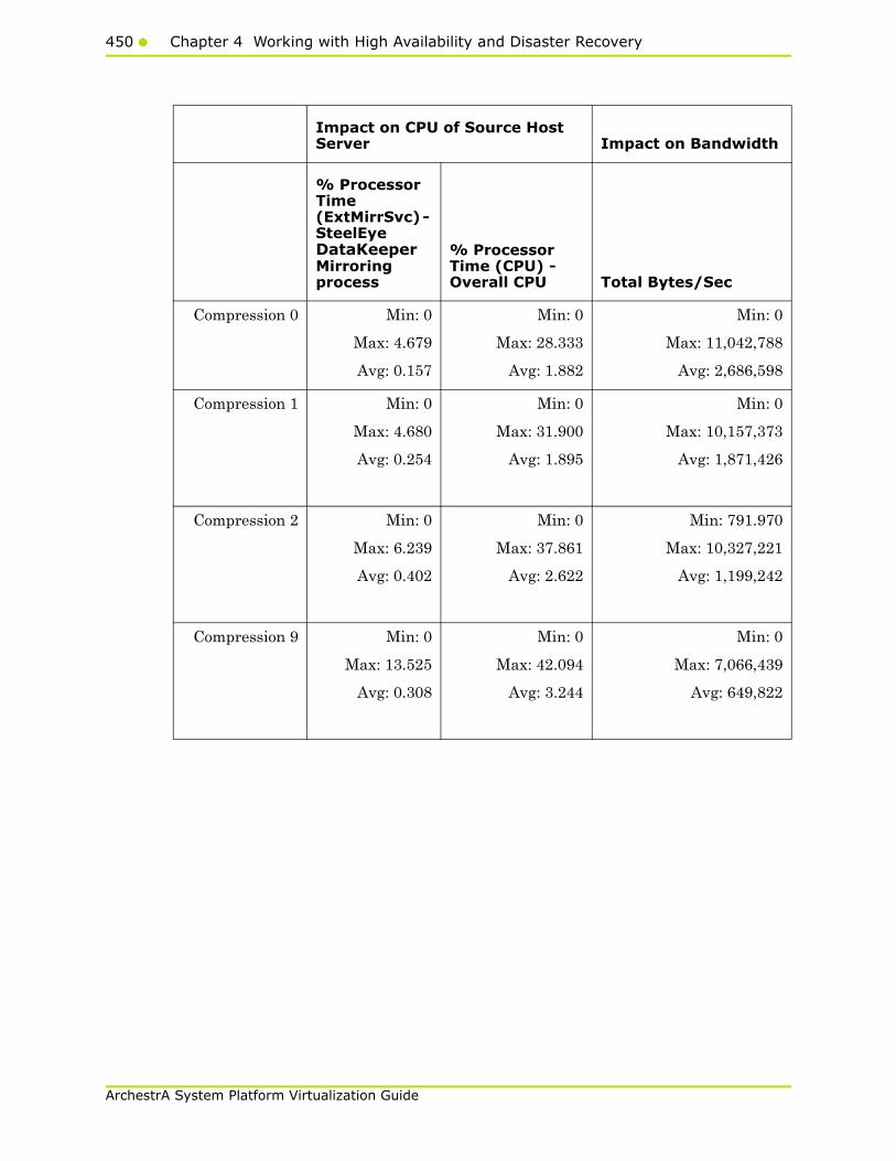
450 Chapter 4 Working with High Availability and Disaster Recovery
ArchestrA System Platform Virtualization Guide
Impact on CPU of Source Host Server Impact on Bandwidth
% Processor Time (ExtMirrSvc) - SteelEye DataKeeper Mirroring process
% Processor Time (CPU) - Overall CPU Total Bytes/Sec
Compression 0 Min: 0
Max: 4.679
Avg: 0.157
Min: 0
Max: 28.333
Avg: 1.882
Min: 0
Max: 11,042,788
Avg: 2,686,598
Compression 1 Min: 0
Max: 4.680
Avg: 0.254
Min: 0
Max: 31.900
Avg: 1.895
Min: 0
Max: 10,157,373
Avg: 1,871,426
Compression 2 Min: 0
Max: 6.239
Avg: 0.402
Min: 0
Max: 37.861
Avg: 2.622
Min: 791.970
Max: 10,327,221
Avg: 1,199,242
Compression 9 Min: 0
Max: 13.525
Avg: 0.308
Min: 0
Max: 42.094
Avg: 3.244
Min: 0
Max: 7,066,439
Avg: 649,822
Recommendations and Best Practices451
ArchestrA System Platform Virtualization Guide
System Platform Product-specific Recommendations and Observations
• During the preparation for Live and Quick migrations it is observed that the network freezes intermittently and then at the time of actual migration connectivity to the VM is lost. As a result, the System Platform node under migration experiences intermittent data loss during the preparation for Live and Quick migrations, and then has a data gap for the duration of actual migration.
Historian
• In case of Live and Quick migration of Historian, you may notice that Historian logs values with quality detail 448 and there may be values logged twice with same timestamps. This is because the suspended Historian VM starts on the other cluster node with the system time it was suspended at before the migration. As a result, some of the data points it is receiving with the current time seem to be in the future to the Historian. This results in Historian modifying the timestamps to its system time and updating the QD to 448. This happens until the system time of the Historian node catches up with the real current time using the TimeSync utility, after which the problem goes away. So, it is recommended to stop the historian before the migration and restart it after the VM is migrated and its system time is synced up with the current time.
• Live and Quick migration of Historian should not be done when the block change over is in progress on the Historian node.
• If a failover happens (for example, due to a network disconnect on the source host Virtualization Server) while the Historian status is still “Starting”, the Historian node fails over to the target host Virtualization Server. In the target host, Historian fails to start. To recover from this state, kill the Historian services that failed to start and then start the Historian by launching the SMC.
InTouch
• Ensure that InTouch Window Viewer is added to the Start Up programs so that the view is started automatically when the virtual machine reboots.

452 Chapter 4 Working with High Availability and Disaster Recovery
ArchestrA System Platform Virtualization Guide
Application Server
• If a failover happens (for example, due to a network disconnect on the source host Virtualization Server) while the Galaxy Migration is in progress, the GR node fails over to the target host Virtualization Server. In the target host, on opening the IDE for the galaxy, the templates do not appear in the Template toolbox and in Graphic toolbox. To recover from this state, delete the galaxy and create new Galaxy. Initiate the migration process once again.
• If a failover happens (for example, due to an abrupt power-off on the source host Virtualization Server) while a platform deploy is in progress, the Platform node fails over to the target host Virtualization Server. In the target host, some objects will be in deployed state and the rest will be in undeployed state. To recover from this state, redeploy the whole Platform once again.
• If a failover happens (for example, due to an abrupt power-off on the source host Virtualization Server) while a platform undeploy is in progress, the Platform node fails over to the target host Virtualization Server. In the target host, some objects will be in undeployed state and the rest will be in deployed state. To recover from this state, undeploy the whole Platform once again.
Data Access Server
• In case of Live and Quick migration of I/O Server node (for example, DASSIDirect), InTouch I/O Tags acquiring data from that I/O server needs to be reinitialized after the I/O server node is migrated. To automatically acquire the data for these tags from the I/O server after migration, it is recommended to have an InTouch script which monitors the quality status of any of those tags and triggers reinitialize I/O once the quality goes to bad. Execute this script every 3 to 5 seconds until the tag quality becomes good.
Working with Medium Scale Virtualization Environment
This section contains the following topics:
• Setting Up Virtualization Environment
• Expected Recovery Time Objective and Recovery Point Objective
• Snapshots of Data Trends and Observations
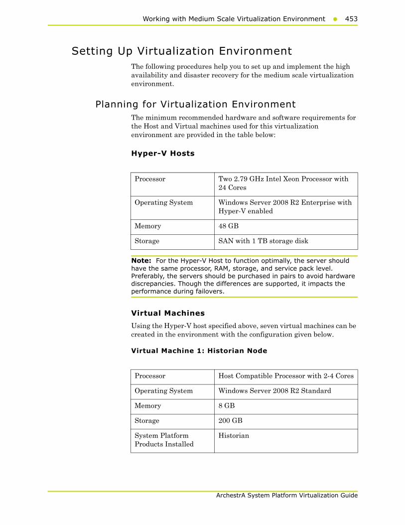
Working with Medium Scale Virtualization Environment453
ArchestrA System Platform Virtualization Guide
Setting Up Virtualization EnvironmentThe following procedures help you to set up and implement the high availability and disaster recovery for the medium scale virtualization environment.
Planning for Virtualization EnvironmentThe minimum recommended hardware and software requirements for the Host and Virtual machines used for this virtualization environment are provided in the table below:
Hyper-V Hosts
Note: For the Hyper-V Host to function optimally, the server should have the same processor, RAM, storage, and service pack level. Preferably, the servers should be purchased in pairs to avoid hardware discrepancies. Though the differences are supported, it impacts the performance during failovers.
Virtual Machines
Using the Hyper-V host specified above, seven virtual machines can be created in the environment with the configuration given below.
Virtual Machine 1: Historian Node
Processor Two 2.79 GHz Intel Xeon Processor with 24 Cores
Operating System Windows Server 2008 R2 Enterprise with Hyper-V enabled
Memory 48 GB
Storage SAN with 1 TB storage disk
Processor Host Compatible Processor with 2-4 Cores
Operating System Windows Server 2008 R2 Standard
Memory 8 GB
Storage 200 GB
System Platform Products Installed
Historian
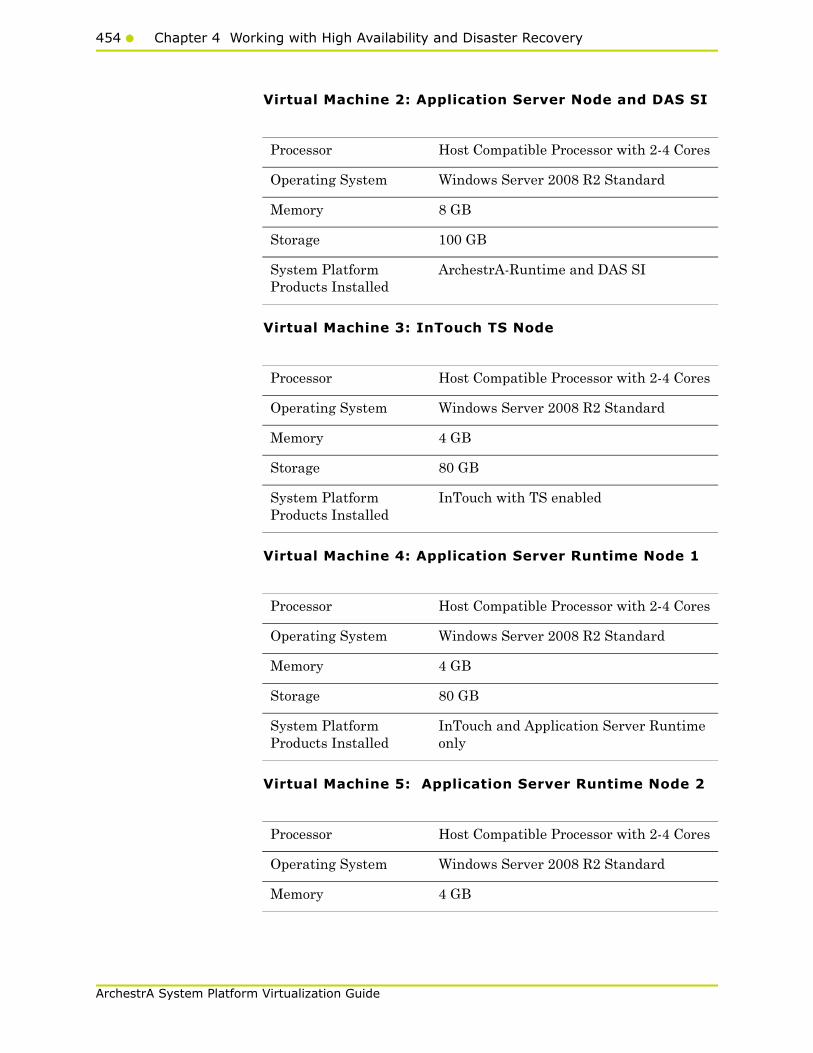
454 Chapter 4 Working with High Availability and Disaster Recovery
ArchestrA System Platform Virtualization Guide
Virtual Machine 2: Application Server Node and DAS SI
Virtual Machine 3: InTouch TS Node
Virtual Machine 4: Application Server Runtime Node 1
Virtual Machine 5: Application Server Runtime Node 2
Processor Host Compatible Processor with 2-4 Cores
Operating System Windows Server 2008 R2 Standard
Memory 8 GB
Storage 100 GB
System Platform Products Installed
ArchestrA-Runtime and DAS SI
Processor Host Compatible Processor with 2-4 Cores
Operating System Windows Server 2008 R2 Standard
Memory 4 GB
Storage 80 GB
System Platform Products Installed
InTouch with TS enabled
Processor Host Compatible Processor with 2-4 Cores
Operating System Windows Server 2008 R2 Standard
Memory 4 GB
Storage 80 GB
System Platform Products Installed
InTouch and Application Server Runtime only
Processor Host Compatible Processor with 2-4 Cores
Operating System Windows Server 2008 R2 Standard
Memory 4 GB

Working with Medium Scale Virtualization Environment455
ArchestrA System Platform Virtualization Guide
Virtual Machine 6: Information Server Node
Virtual Machine 7: Historian Client Node
Network Requirements
For this architecture, you can use one physical network card that needs to be installed on a host computer for both the domain and the process networks.
Storage 80 GB
System Platform Products Installed
Application Server Runtime only
Processor Host Compatible Processor with 2-4 Cores
Operating System Windows Server 2008 Standard
Memory 4 GB
Storage 80 GB
System Platform Products Installed
Information Server
Processor Host Compatible Processor with 2-4 Cores
Operating System Windows 7 Enterprise
Memory 4 GB
Storage 80 GB
System Platform Products Installed
Historian Client
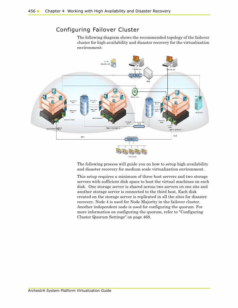
456 Chapter 4 Working with High Availability and Disaster Recovery
ArchestrA System Platform Virtualization Guide
Configuring Failover ClusterThe following diagram shows the recommended topology of the failover cluster for high availability and disaster recovery for the virtualization environment:
The following process will guide you on how to setup high availability and disaster recovery for medium scale virtualization environment.
This setup requires a minimum of three host servers and two storage servers with sufficient disk space to host the virtual machines on each disk. One storage server is shared across two servers on one site and another storage server is connected to the third host. Each disk created on the storage server is replicated in all the sites for disaster recovery. Node 4 is used for Node Majority in the failover cluster. Another independent node is used for configuring the quorum. For more information on configuring the quorum, refer to "Configuring Cluster Quorum Settings" on page 468.
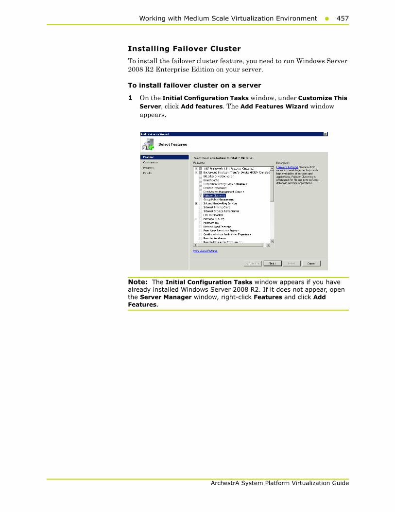
Working with Medium Scale Virtualization Environment457
ArchestrA System Platform Virtualization Guide
Installing Failover Cluster
To install the failover cluster feature, you need to run Windows Server 2008 R2 Enterprise Edition on your server.
To install failover cluster on a server
1 On the Initial Configuration Tasks window, under Customize This Server, click Add features. The Add Features Wizard window appears.
Note: The Initial Configuration Tasks window appears if you have already installed Windows Server 2008 R2. If it does not appear, open the Server Manager window, right-click Features and click Add Features.
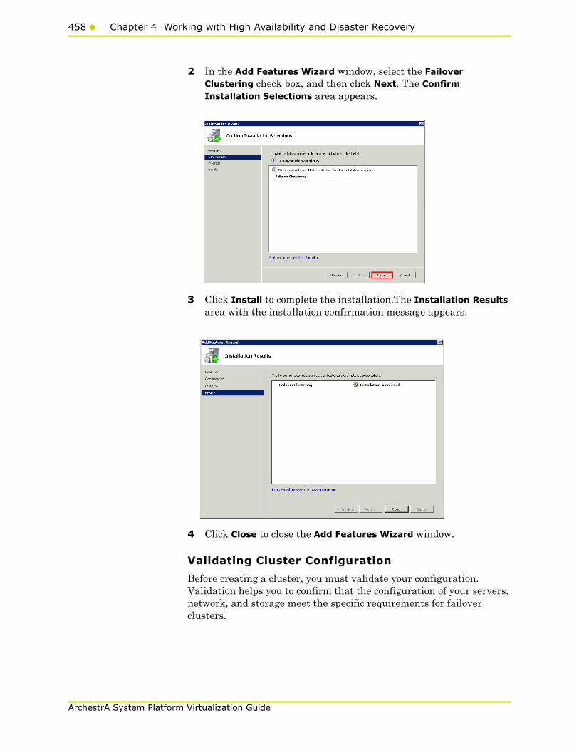
458 Chapter 4 Working with High Availability and Disaster Recovery
ArchestrA System Platform Virtualization Guide
2 In the Add Features Wizard window, select the Failover Clustering check box, and then click Next. The Confirm Installation Selections area appears.
3 Click Install to complete the installation.The Installation Results area with the installation confirmation message appears.
4 Click Close to close the Add Features Wizard window.
Validating Cluster Configuration
Before creating a cluster, you must validate your configuration. Validation helps you to confirm that the configuration of your servers, network, and storage meet the specific requirements for failover clusters.
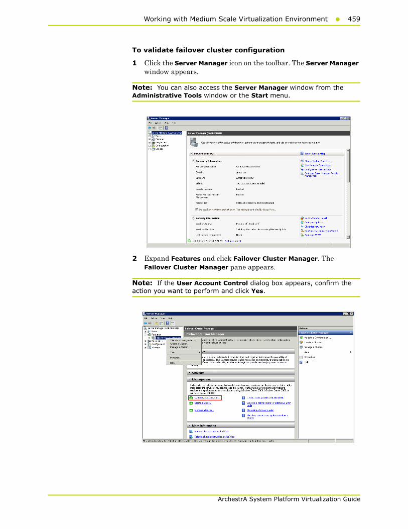
Working with Medium Scale Virtualization Environment459
ArchestrA System Platform Virtualization Guide
To validate failover cluster configuration
1 Click the Server Manager icon on the toolbar. The Server Manager window appears.
Note: You can also access the Server Manager window from the Administrative Tools window or the Start menu.
2 Expand Features and click Failover Cluster Manager. The Failover Cluster Manager pane appears.
Note: If the User Account Control dialog box appears, confirm the action you want to perform and click Yes.

460 Chapter 4 Working with High Availability and Disaster Recovery
ArchestrA System Platform Virtualization Guide
3 Under Management, click Validate a Configuration. The Validate a Configuration Wizard window appears. Click Next.
4 In the Select Servers or a Cluster area, do the following:
a In the Enter name field, enter the relevant server name.
Note: You can either enter the server name or click Browse and select the relevant server name.
Working with Medium Scale Virtualization Environment461
ArchestrA System Platform Virtualization Guide
b In the Selected Servers list, click the required servers, and then click Add.
c Click Next. The Testing Options area appears.
Note: You can add one or more server names. To remove a server from the Selected servers list, select the server and click Remove.
5 Click the Run only the tests I select option to skip the storage validation process, and click Next. The Test Selection screen appears.
Note: Click the Run all tests (recommended) option to validate the default selection of tests.

462 Chapter 4 Working with High Availability and Disaster Recovery
ArchestrA System Platform Virtualization Guide
6 Clear the Storage check box, and then click Next. The Summary screen appears.
7 Click View Report to view the test results or click Finish to close the Validate a Configuration Wizard window.
A warning message appears indicating that all the tests have not been run. This usually happens in a multisite cluster where the storage tests are skipped. You can proceed if there is no other error message. If the report indicates any other error, you need to fix the problem and re-run the tests before you continue. You can view the results of the tests after you close the wizard in SystemRoot\Cluster\Reports\Validation Report date and time.html where SystemRoot is the folder in which the operating system is installed (for example, C:\Windows).
To know more about cluster validation tests, click More about cluster validation tests on Validate a Configuration Wizard window.

Working with Medium Scale Virtualization Environment463
ArchestrA System Platform Virtualization Guide
Creating a Cluster
To create a cluster, you need to run the Create Cluster wizard.
To create a cluster
1 Click the Server Manager icon on the toolbar. The Server Manager window appears.
Note: You can also access the Server Manager window from the Administrative Tools window or the Start menu.
2 Expand Features and click Failover Cluster Manager. The Failover Cluster Manager pane appears.
Note: If the User Account Control dialog box appears, confirm the action you want to perform and click Yes.

464 Chapter 4 Working with High Availability and Disaster Recovery
ArchestrA System Platform Virtualization Guide
Working with Medium Scale Virtualization Environment465
ArchestrA System Platform Virtualization Guide
3 Under Management, click Create a cluster. The Create Cluster Wizard window appears. Click Next.
4 In the Select Servers screen, do the following:
a In the Enter server name field, enter the relevant server name and click Add. The server name gets added in the Selected servers box.
Note: You can either enter the server name or click Browse and select the relevant server name.
466 Chapter 4 Working with High Availability and Disaster Recovery
ArchestrA System Platform Virtualization Guide
5 Click Next. The Validation Warning area appears.
6 In the Validation Warning dialog box, click No. I do not require support from Microsoft for this cluster, and therefore do not want to run the validation tests. When I click Next, continue creating the cluster option and click Next. The Access Point for Administering the Cluster area appears.
Note: Click Yes. When I click Next, run configuration validation tests, and then return to the process of creating the cluster option if you want to run the configuration validation tests. Click View Report to view the cluster operation report.

Working with Medium Scale Virtualization Environment467
ArchestrA System Platform Virtualization Guide
7 In the Cluster Name field, type the name of the cluster and click Next. The Confirmation area appears.
Note: Enter a valid IP address for the cluster to be created if the IP address is not configured through Dynamic Host Configuration Protocol (DHCP).
8 Click Next. The cluster is created and the Summary area appears.
9 Click View Report to view the cluster report created by the wizard or click Finish to close the Create Cluster Wizard window.
468 Chapter 4 Working with High Availability and Disaster Recovery
ArchestrA System Platform Virtualization Guide
Configuring Cluster Quorum Settings
Quorum is the number of elements that need to be online to enable continuous running of a cluster. In most instances, the elements are nodes. In some cases, the elements also consist of disk or file share witnesses. Each of these elements determines whether the cluster should continue to run or not.
All elements, except the file share witnesses, have a copy of the cluster configuration. The cluster service ensures that the copies are always synchronized. The cluster should stop running if there are multiple failures or if there is a communication error between the cluster nodes.
After both nodes have been added to the cluster, and the cluster networking components have been configured, you must configure the failover cluster quorum.
You must create and secure the file share that you want to use for the node and the file share majority quorum before configuring the failover cluster quorum. If the file share has not been created or correctly secured, the following procedure to configure a cluster quorum will fail. The file share can be hosted on any computer running a Windows operating system.
To configure the cluster quorum, you need to perform the following precedures:
• Create and secure a file share for the node and file share majority quorum
• Use the failover cluster management tool to configure a node and file share majority quorum
To create and secure a file share for the node and file share majority quorum
1 Create a new folder on the system that will host the share directory.
2 Right-click the folder that you have created and click Properties. The Quorum Properties window for the folder you created appears.
Note: In the following procedure, Quorum is the name of the folder.
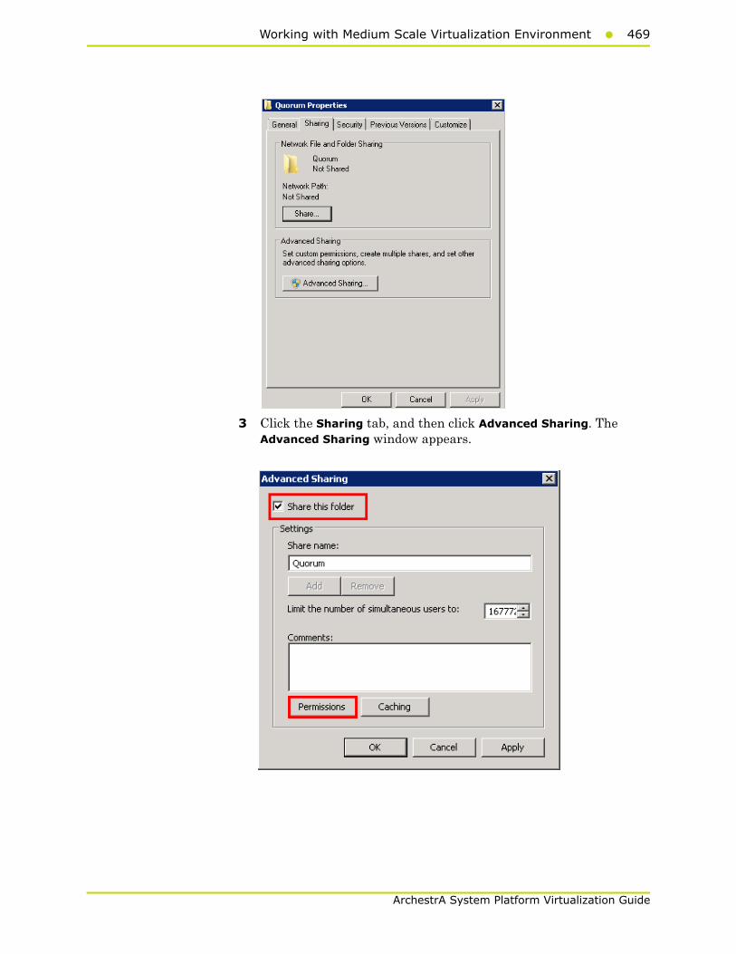
Working with Medium Scale Virtualization Environment469
ArchestrA System Platform Virtualization Guide
3 Click the Sharing tab, and then click Advanced Sharing. The Advanced Sharing window appears.
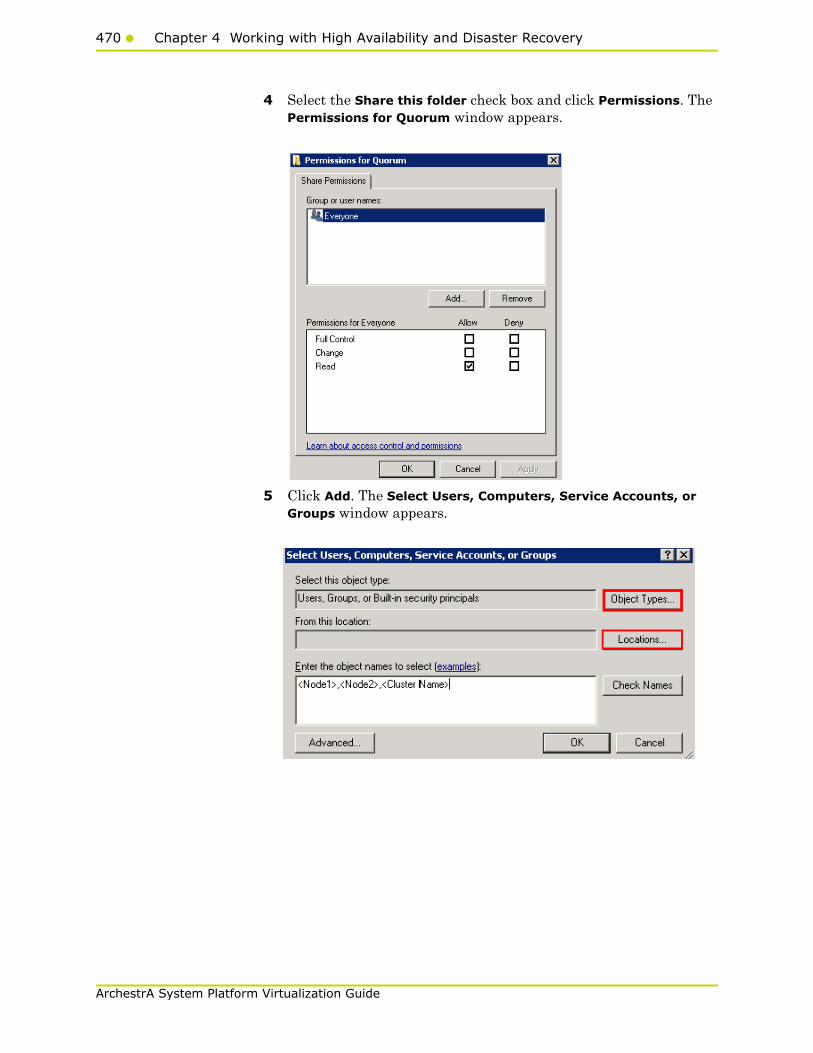
470 Chapter 4 Working with High Availability and Disaster Recovery
ArchestrA System Platform Virtualization Guide
4 Select the Share this folder check box and click Permissions. The Permissions for Quorum window appears.
5 Click Add. The Select Users, Computers, Service Accounts, or Groups window appears.

Working with Medium Scale Virtualization Environment471
ArchestrA System Platform Virtualization Guide
6 In the Enter the object name to select box, enter the four node names used for the cluster in the high availabilty and disaster recovery configuration and click OK. The node names are added and the Permissions for Quorum window appears.
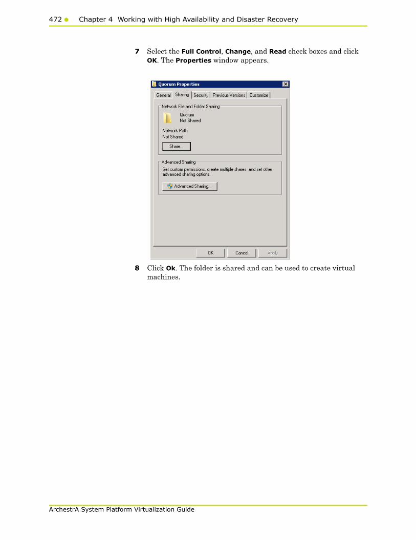
472 Chapter 4 Working with High Availability and Disaster Recovery
ArchestrA System Platform Virtualization Guide
7 Select the Full Control, Change, and Read check boxes and click OK. The Properties window appears.
8 Click Ok. The folder is shared and can be used to create virtual machines.
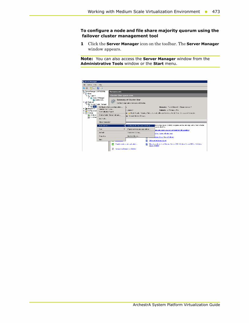
Working with Medium Scale Virtualization Environment473
ArchestrA System Platform Virtualization Guide
To configure a node and file share majority quorum using the failover cluster management tool
1 Click the Server Manager icon on the toolbar. The Server Manager window appears.
Note: You can also access the Server Manager window from the Administrative Tools window or the Start menu.

474 Chapter 4 Working with High Availability and Disaster Recovery
ArchestrA System Platform Virtualization Guide
2 Right-click the name of the cluster you have created and click More Actions. Click Configure Cluster Quorum Settings. The Configure Cluster Quorum Wizard window appears.
3 View the instructions on the wizard and click Next. The Select Quorum Configuration area appears.
Note: The Before you Begin screen appears the first time you run the wizard. You can hide this screen on subsequent uses of the wizard.
4 You need to select the relevant quorum node. For special configurations, click the Node and File Share Majority option and click Next. The Configure File Share Witness area appears.
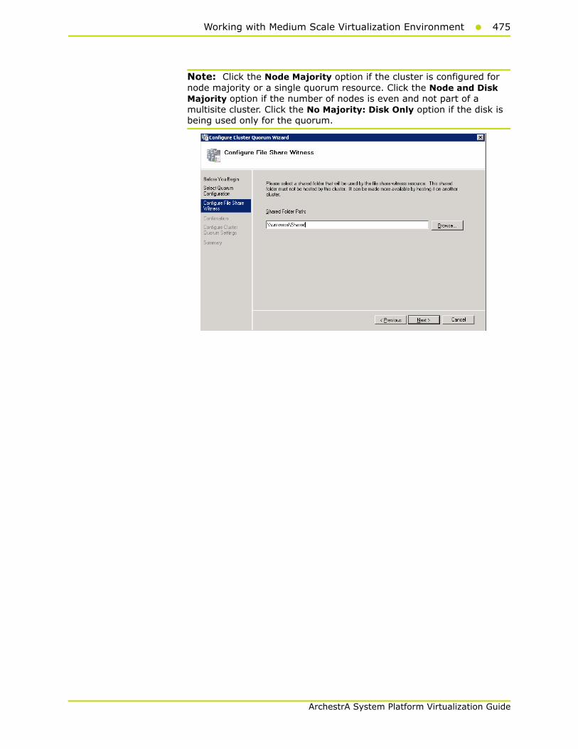
Working with Medium Scale Virtualization Environment475
ArchestrA System Platform Virtualization Guide
Note: Click the Node Majority option if the cluster is configured for node majority or a single quorum resource. Click the Node and Disk Majority option if the number of nodes is even and not part of a multisite cluster. Click the No Majority: Disk Only option if the disk is being used only for the quorum.
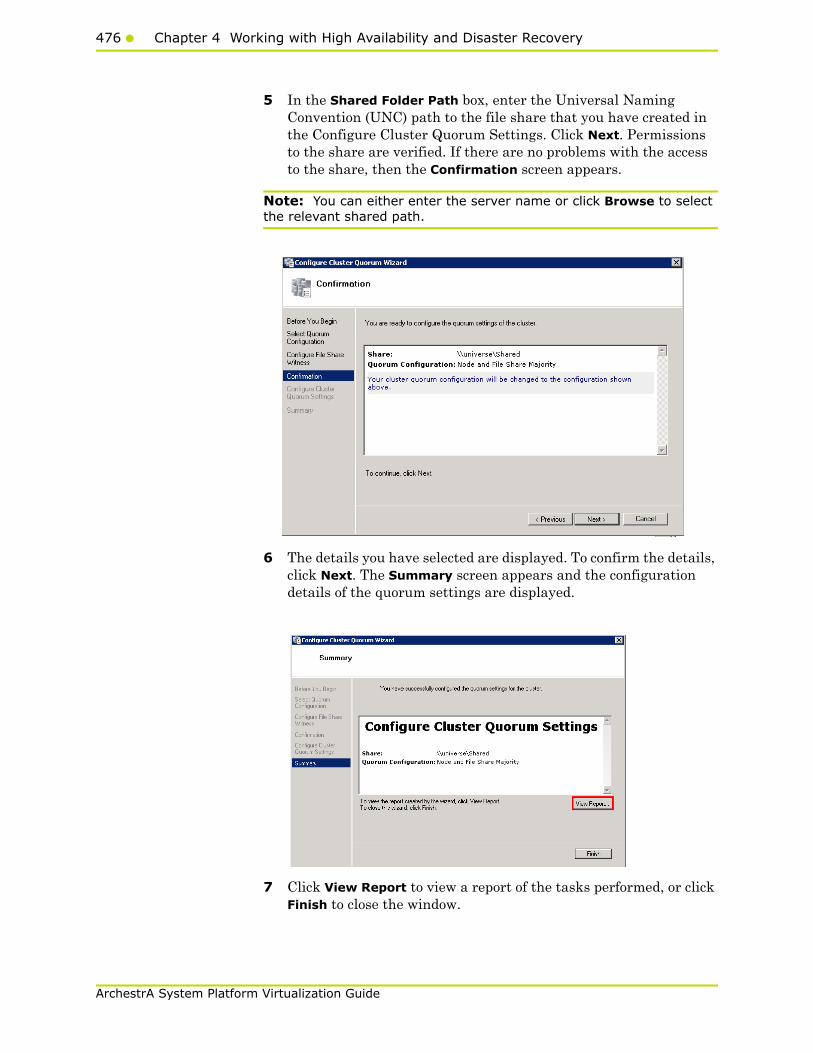
476 Chapter 4 Working with High Availability and Disaster Recovery
ArchestrA System Platform Virtualization Guide
5 In the Shared Folder Path box, enter the Universal Naming Convention (UNC) path to the file share that you have created in the Configure Cluster Quorum Settings. Click Next. Permissions to the share are verified. If there are no problems with the access to the share, then the Confirmation screen appears.
Note: You can either enter the server name or click Browse to select the relevant shared path.
6 The details you have selected are displayed. To confirm the details, click Next. The Summary screen appears and the configuration details of the quorum settings are displayed.
7 Click View Report to view a report of the tasks performed, or click Finish to close the window.
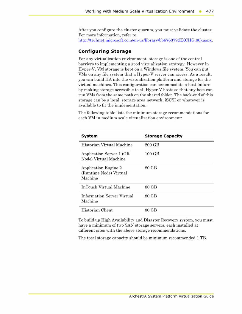
Working with Medium Scale Virtualization Environment477
ArchestrA System Platform Virtualization Guide
After you configure the cluster quorum, you must validate the cluster. For more information, refer to http://technet.microsoft.com/en-us/library/bb676379(EXCHG.80).aspx.
Configuring Storage
For any virtualization environment, storage is one of the central barriers to implementing a good virtualization strategy. However in Hyper-V, VM storage is kept on a Windows file system. You can put VMs on any file system that a Hyper-V server can access. As a result, you can build HA into the virtualization platform and storage for the virtual machines. This configuration can accommodate a host failure by making storage accessible to all Hyper-V hosts so that any host can run VMs from the same path on the shared folder. The back-end of this storage can be a local, storage area network, iSCSI or whatever is available to fit the implementation.
The following table lists the minimum storage recommendations for each VM in medium scale virtualization environment:
To build up High Availability and Disaster Recovery system, you must have a minimum of two SAN storage servers, each installed at different sites with the above storage recommendations.
The total storage capacity should be minimum recommended 1 TB.
System Storage Capacity
Historian Virtual Machine 200 GB
Application Server 1 (GR Node) Virtual Machine
100 GB
Application Engine 2 (Runtime Node) Virtual Machine
80 GB
InTouch Virtual Machine 80 GB
Information Server Virtual Machine
80 GB
Historian Client 80 GB

478 Chapter 4 Working with High Availability and Disaster Recovery
ArchestrA System Platform Virtualization Guide
Configuring Hyper-VMicrosoft Hyper-V Server 2008 R2 helps in creating virtual environment that improves server utilization. It enhances patching, provisioning, management, support tools, processes, and skills. Microsoft Hyper-V Server 2008 R2 provides live migration, cluster shared volume support, expanded processor, and memory support for host systems.
Hyper-V is available in x64-based versions of Windows Server 2008 R2 operating system, specifically the x64-based versions of Windows Server 2008 R2 Standard, Windows Server 2008 R2 Enterprise, and Windows Server 2008 Datacenter.
The following are the pre-requisites to set up Hyper-V:
• x64-based processor
• Hardware-assisted virtualization
• Hardware Data Execution Prevention (DEP)
To configure Hyper-V
1 Click the Server Manager icon on the toolbar. The Server Manager window appears.

Working with Medium Scale Virtualization Environment479
ArchestrA System Platform Virtualization Guide
2 In the Roles Summary area, click Add Roles. The Add Roles Wizard window appears.
Note: You can also right-click Roles, and then click Add Roles Wizard to open the Add Roles Wizard window.
3 Read the instructions on the wizard and then click Next. The Select Server Roles area appears.
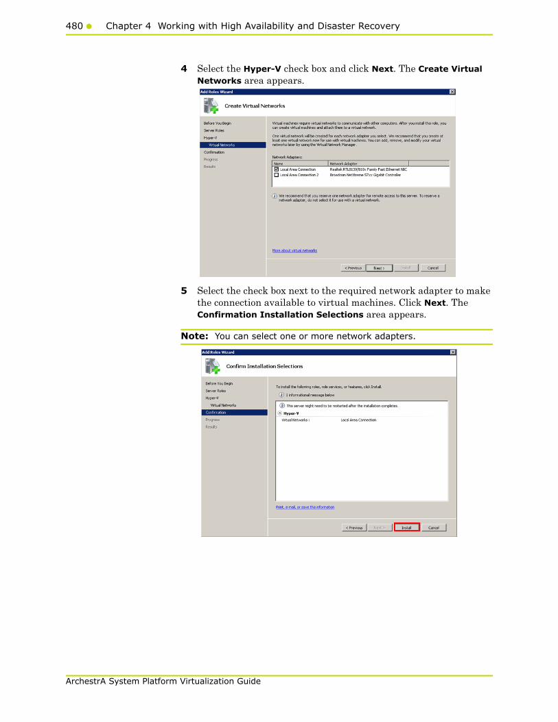
480 Chapter 4 Working with High Availability and Disaster Recovery
ArchestrA System Platform Virtualization Guide
4 Select the Hyper-V check box and click Next. The Create Virtual Networks area appears.
5 Select the check box next to the required network adapter to make the connection available to virtual machines. Click Next. The Confirmation Installation Selections area appears.
Note: You can select one or more network adapters.

Working with Medium Scale Virtualization Environment481
ArchestrA System Platform Virtualization Guide
6 Click Install. The Installation Results area appears.
7 A message appears prompting you to restart the computer. Click Close. The Add Roles Wizard pop-up window appears.
8 Click Yes to restart the computer.
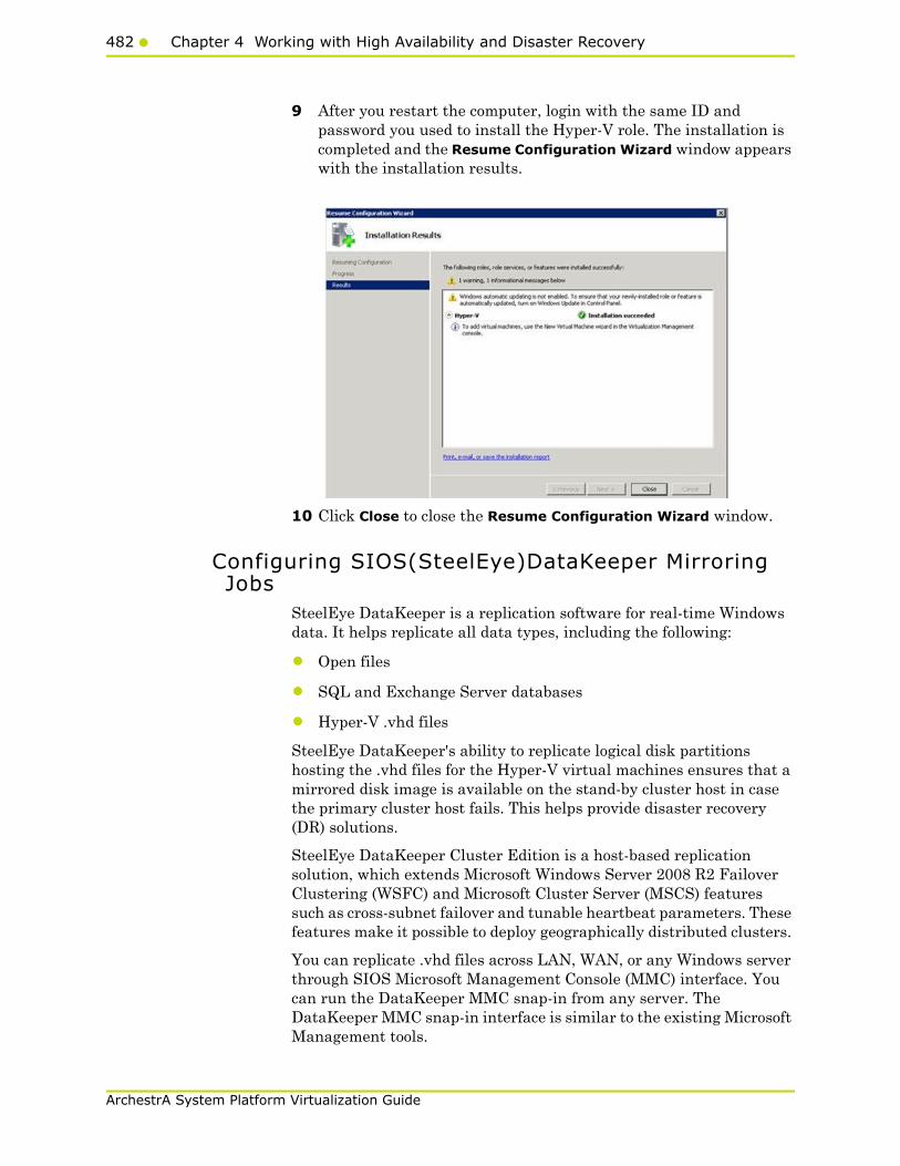
482 Chapter 4 Working with High Availability and Disaster Recovery
ArchestrA System Platform Virtualization Guide
9 After you restart the computer, login with the same ID and password you used to install the Hyper-V role. The installation is completed and the Resume Configuration Wizard window appears with the installation results.
10 Click Close to close the Resume Configuration Wizard window.
Configuring SIOS(SteelEye)DataKeeper Mirroring Jobs
SteelEye DataKeeper is a replication software for real-time Windows data. It helps replicate all data types, including the following:
• Open files
• SQL and Exchange Server databases
• Hyper-V .vhd files
SteelEye DataKeeper's ability to replicate logical disk partitions hosting the .vhd files for the Hyper-V virtual machines ensures that a mirrored disk image is available on the stand-by cluster host in case the primary cluster host fails. This helps provide disaster recovery (DR) solutions.
SteelEye DataKeeper Cluster Edition is a host-based replication solution, which extends Microsoft Windows Server 2008 R2 Failover Clustering (WSFC) and Microsoft Cluster Server (MSCS) features such as cross-subnet failover and tunable heartbeat parameters. These features make it possible to deploy geographically distributed clusters.
You can replicate .vhd files across LAN, WAN, or any Windows server through SIOS Microsoft Management Console (MMC) interface. You can run the DataKeeper MMC snap-in from any server. The DataKeeper MMC snap-in interface is similar to the existing Microsoft Management tools.

Working with Medium Scale Virtualization Environment483
ArchestrA System Platform Virtualization Guide
Note: For information on installing the SteelEye DataKeeper, refer to SteelEye DataKeeper for Windows Server 2003/2008 Planning and Install Guide and SteelEye DataKeeper for Windows Server 2003/2008 Administration Guide at http://www.steeleye.com. Ensure that the local security policies, firewall, and port settings are configured as per the details in these documents.
The following procedures help you set up a virtual machine in the Disaster Recovery environment.
Creating a SteelEye DataKeeper Mirroring Job
To set up a virtual machine in the Disaster Recovery environment you need to first create a SteelEye DataKeeper mirroring job.
To create a SteelEye DataKeeper mirroring job
1 Click Start, and then from the All Programs menu, click SteelEye DataKeeper MMC. The DataKeeper window appears.
2 In the Actions pane, click Create Job. The SteelEye DataKeeper window appears.

484 Chapter 4 Working with High Availability and Disaster Recovery
ArchestrA System Platform Virtualization Guide
3 Type the relevant job name and description in the Job name and Job description boxes, and then click Create Job. The New Mirror window appears.
4 In the Choose a Source area, select the Server, IP address, and Volume and click Next. The Choose a Target area appears.
5 Select the destination Server, IP address, and Volume and click Next. The Configure Details area appears.
6 In the Configure Details area, do the following:
a Move the slider to select the level of data compression.
b Click the relevant option to indicate the mode in which you want to send the source volume data to the target volume.
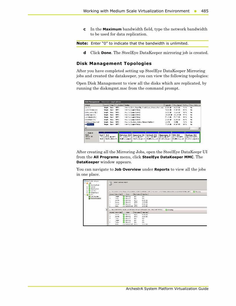
Working with Medium Scale Virtualization Environment485
ArchestrA System Platform Virtualization Guide
c In the Maximum bandwidth field, type the network bandwidth to be used for data replication.
Note: Enter “0” to indicate that the bandwidth is unlimited.
d Click Done. The SteelEye DataKeeper mirroring job is created.
Disk Management Topologies
After you have completed setting up SteelEye DataKeeper Mirroring jobs and created the datakeeper, you can view the following topologies:
Open Disk Management to view all the disks which are replicated, by running the diskmgmt.msc from the command prompt.
After creating all the Mirroring Jobs, open the SteelEye DataKeepr UI from the All Programs menu, click SteelEye DataKeeper MMC. The DataKeeper window appears.
You can navigate to Job Overview under Reports to view all the jobs in one place.

486 Chapter 4 Working with High Availability and Disaster Recovery
ArchestrA System Platform Virtualization Guide
You can navigate to Server Overview under Reports to view all the servers involved in job replication in one place.
Configuring Virtual MachinesAfter creating a steel eye mirroring job, you need to create a virtual machine in the disk.
To configure virtual machines
1 In the Server Manager window, right-click Features and then click Failover Cluster Manager. The Failover Cluster Manager tree expands.
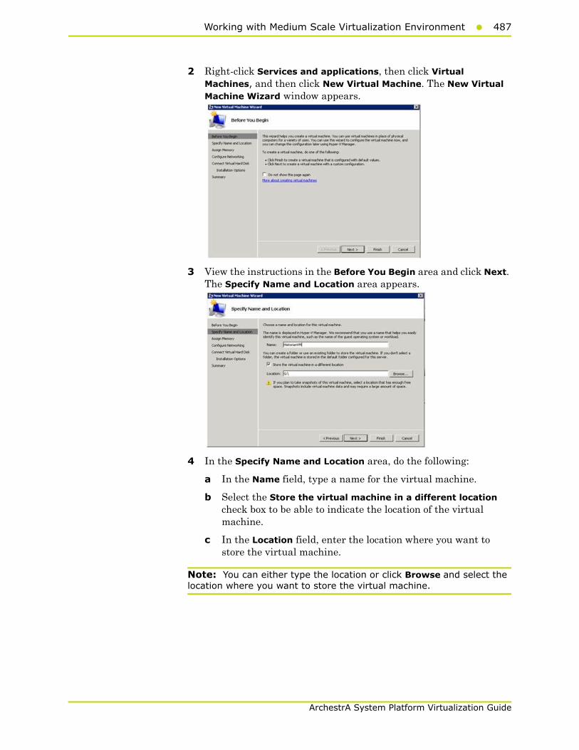
Working with Medium Scale Virtualization Environment487
ArchestrA System Platform Virtualization Guide
2 Right-click Services and applications, then click Virtual Machines, and then click New Virtual Machine. The New Virtual Machine Wizard window appears.
3 View the instructions in the Before You Begin area and click Next. The Specify Name and Location area appears.
4 In the Specify Name and Location area, do the following:
a In the Name field, type a name for the virtual machine.
b Select the Store the virtual machine in a different location check box to be able to indicate the location of the virtual machine.
c In the Location field, enter the location where you want to store the virtual machine.
Note: You can either type the location or click Browse and select the location where you want to store the virtual machine.

488 Chapter 4 Working with High Availability and Disaster Recovery
ArchestrA System Platform Virtualization Guide
d Click Next. The Assign Memory area appears.
5 Type the recommended amount of memory in the Memory field and click Next. The Configure Networking area appears.
6 Select the network to be used for the virtual machine from the Connection drop-down list, and click Next. The Connect Virtual Hard Disk area appears.
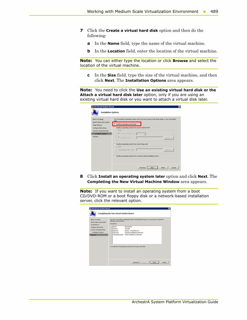
Working with Medium Scale Virtualization Environment489
ArchestrA System Platform Virtualization Guide
7 Click the Create a virtual hard disk option and then do the following:
a In the Name field, type the name of the virtual machine.
b In the Location field, enter the location of the virtual machine.
Note: You can either type the location or click Browse and select the location of the virtual machine.
c In the Size field, type the size of the virtual machine, and then click Next. The Installation Options area appears.
Note: You need to click the Use an existing virtual hard disk or the Attach a virtual hard disk later option, only if you are using an existing virtual hard disk or you want to attach a virtual disk later.
8 Click Install an operating system later option and click Next. The Completing the New Virtual Machine Window area appears.
Note: If you want to install an operating system from a boot CD/DVD-ROM or a boot floppy disk or a network-based installation server, click the relevant option.

490 Chapter 4 Working with High Availability and Disaster Recovery
ArchestrA System Platform Virtualization Guide
9 Click Finish. The virtual machine is created with the details you have provided. As we have started this process from the Failover Cluster Manager, after completing the process of creating a virtual machine, the High Availability Wizard window appears.
10 Click View Report to view the report or click Finish to close the High Availability Wizard window.
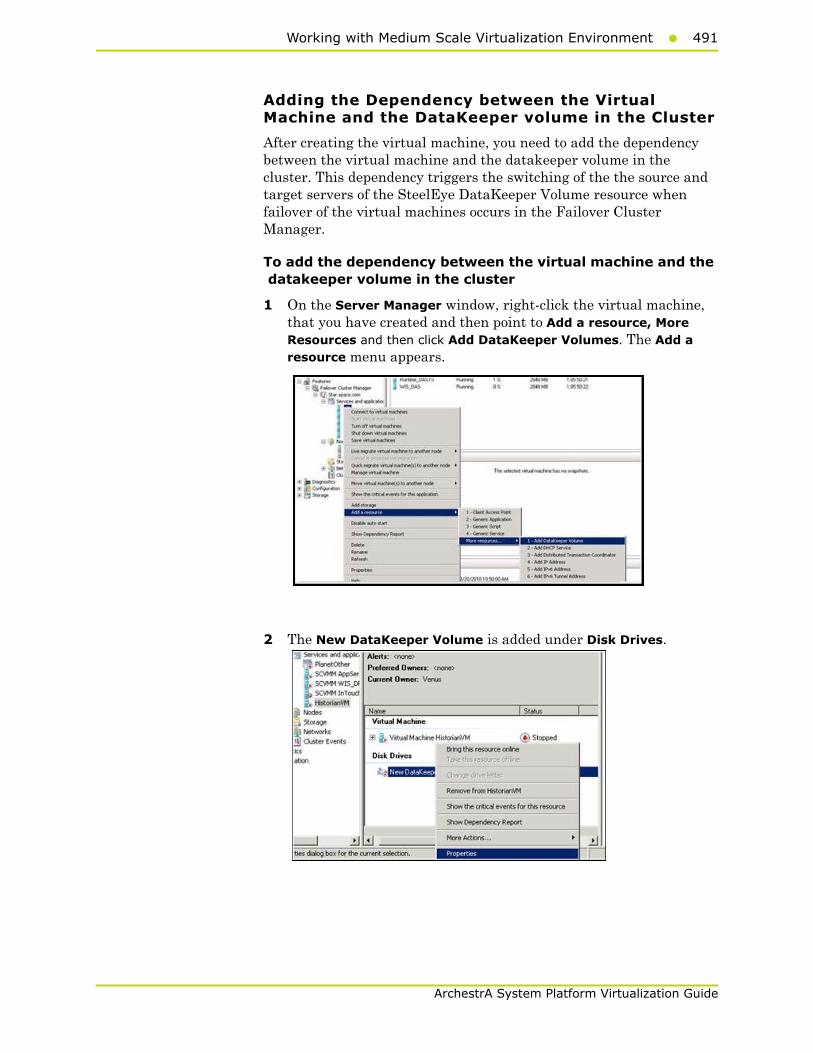
Working with Medium Scale Virtualization Environment491
ArchestrA System Platform Virtualization Guide
Adding the Dependency between the Virtual Machine and the DataKeeper volume in the Cluster
After creating the virtual machine, you need to add the dependency between the virtual machine and the datakeeper volume in the cluster. This dependency triggers the switching of the the source and target servers of the SteelEye DataKeeper Volume resource when failover of the virtual machines occurs in the Failover Cluster Manager.
To add the dependency between the virtual machine and the datakeeper volume in the cluster
1 On the Server Manager window, right-click the virtual machine, that you have created and then point to Add a resource, More Resources and then click Add DataKeeper Volumes. The Add a resource menu appears.
2 The New DataKeeper Volume is added under Disk Drives.
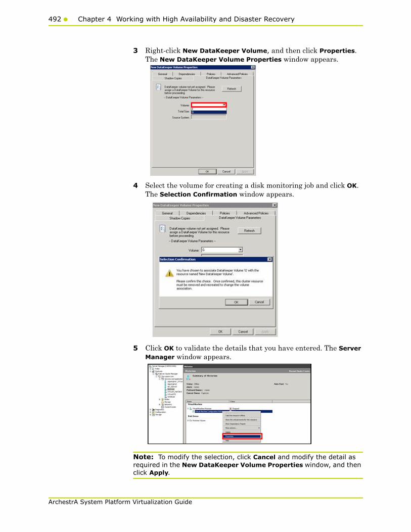
492 Chapter 4 Working with High Availability and Disaster Recovery
ArchestrA System Platform Virtualization Guide
3 Right-click New DataKeeper Volume, and then click Properties. The New DataKeeper Volume Properties window appears.
4 Select the volume for creating a disk monitoring job and click OK. The Selection Confirmation window appears.
5 Click OK to validate the details that you have entered. The Server Manager window appears.
Note: To modify the selection, click Cancel and modify the detail as required in the New DataKeeper Volume Properties window, and then click Apply.
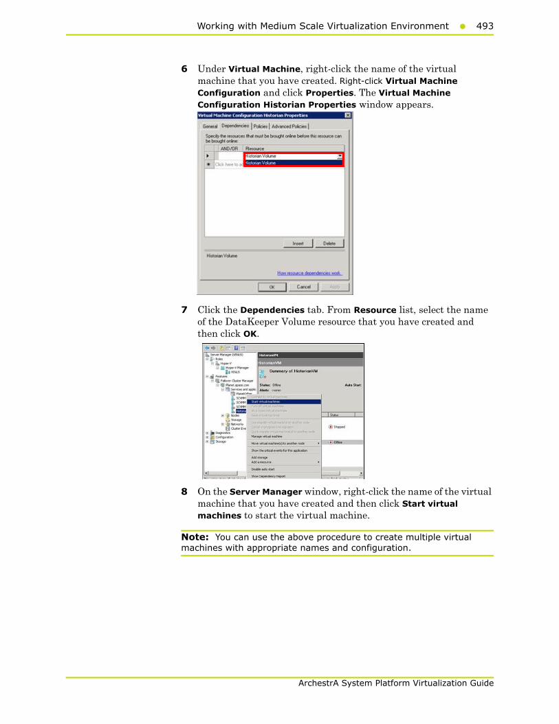
Working with Medium Scale Virtualization Environment493
ArchestrA System Platform Virtualization Guide
6 Under Virtual Machine, right-click the name of the virtual machine that you have created. Right-click Virtual Machine Configuration and click Properties. The Virtual Machine Configuration Historian Properties window appears.
7 Click the Dependencies tab. From Resource list, select the name of the DataKeeper Volume resource that you have created and then click OK.
8 On the Server Manager window, right-click the name of the virtual machine that you have created and then click Start virtual machines to start the virtual machine.
Note: You can use the above procedure to create multiple virtual machines with appropriate names and configuration.
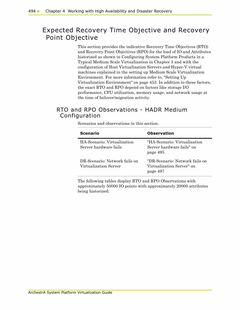
494 Chapter 4 Working with High Availability and Disaster Recovery
ArchestrA System Platform Virtualization Guide
Expected Recovery Time Objective and Recovery Point Objective
This section provides the indicative Recovery Time Objectives (RTO) and Recovery Point Objectives (RPO) for the load of IO and Attributes historized as shown in Configuring System Platform Products in a Typical Medium Scale Virtualization in Chapter 3 and with the configuration of Host Virtualization Servers and Hyper-V virtual machines explained in the setting up Medium Scale Virtualization Environment. For more information refer to, "Setting Up Virtualization Environment" on page 453. In addition to these factors, the exact RTO and RPO depend on factors like storage I/O performance, CPU utilization, memory usage, and network usage at the time of failover/migration activity.
RTO and RPO Observations - HADR Medium Configuration
Scenarios and observations in this section:
The following tables display RTO and RPO Observations with approximately 50000 IO points with approximately 20000 attributes being historized:
Scenario Observation
HA-Scenario: Virtualization Server hardware fails
"HA-Scenario: Virtualization Server hardware fails" on page 495
DR-Scenario: Network fails on Virtualization Server
"DR-Scenario: Network fails on Virtualization Server" on page 497

Working with Medium Scale Virtualization Environment495
ArchestrA System Platform Virtualization Guide
HA-Scenario: Virtualization Server hardware fails
The failover occurs due to hardware failure, and it is simulated with power-off on the host server.
Products RTO RPO
TagsData LossDuration
InTouch 5 min 35 sec + timetaken by the user to
start theInTouchView
Data Loss for$Second tag(Imported to
Historian)
6 min 47 sec
Note: RPO is dependent on the time taken by the user to start the InTouchView on the InTouch node and the RTO of the Historian node, which historizes this tag.
GR 5 min 13 sec IAS Tag(Script)
5 min 44 sec
IAS IO Tag(DASSiDirect)
7 min 28 sec
AppEngine1 6 min 05 sec IAS Tag(Script)
6 min 35 sec
IAS IO Tag(DASSiDirect)
7 min 29 sec
AppEngine2 6 Min 12 sec IAS Tag(Script)
6 Min 41 sec
IAS IO Tag(DASSiDirect)
7 Min 20 sec

496 Chapter 4 Working with High Availability and Disaster Recovery
ArchestrA System Platform Virtualization Guide
Products RTO RPO
TagsData LossDuration
Historian 6 min 21 sec SysTimeSec(Historian)
6 Min 33 sec
$Second(InTouch)
6 Min 47 sec
Note: RPO is dependent on the time taken by the user to start the InTouchView on the InTouch node and the RTO of the Historian node, which historizes this tag.
IAS Tag(Script)
5 Min 45 sec
IAS IO Tag(DASSiDirect)
7 Min 30 sec
DAS SIDirect 4 Min 25 sec N/A N/A
Historian Client 3 Min 34 sec + timetaken by the user tostart the Historian
Client
N/A N/A
Information Server 4 Min 15 sec + timetaken by the user to
start theInformation Server
N/A N/A

Working with Medium Scale Virtualization Environment497
ArchestrA System Platform Virtualization Guide
DR-Scenario: Network fails on Virtualization Server
There is a failover due to network disconnect (Public). In this case,the VMs restart after moving to the other host server.
Products RTO RPO
TagsData LossDuration
InTouch 11 min 4 sec +time taken by the
user to start theInTouchView
Data Loss for$Second tag(Imported to
Historian)
15 min 32 sec
Note: RPO is dependent on the time taken by the user to start the InTouchView on the InTouch node and the RTO of the Historian node, which historizes this tag.
GR 12 min 20 sec IAS Tag(Script)
13 min 11 sec
IAS IO Tag(DASSiDirect)
13 min 01 sec
AppEngine1 11 min 35 sec IAS Tag(Script)
12 min 26 sec
IAS IO Tag(DASSiDirect)
13 min 05 sec
AppEngine2 11 min 48 sec IAS Tag(Script)
11 min 24 sec
IAS IO Tag(DASSiDirect)
13 min 19 sec

498 Chapter 4 Working with High Availability and Disaster Recovery
ArchestrA System Platform Virtualization Guide
Snapshots of Data Trends and ObservationsScenarios and observations in this section:
Products RTO RPO
TagsData LossDuration
Historian 20 min 0 sec SysTimeSec(Historian)
15 min 16 sec
$Second(InTouch)
15 min 32 sec
RPO is dependent onthe time taken by the
user to start theInTouchView on the
InTouch node and theRTO of the Historian
node, whichhistorizes this tag.
IAS Tag(Script)
13 min 11 sec
IAS IO Tag(DASSiDirect)
13 min 01 sec
DAS SIDirect 12 min 25 sec N/A N/A
Historian Client 5 min 32 sec +time taken by the
user to start theHistorian Client
N/A N/A
Information Server 5 min 38 sec +time taken by the
user to start theInformation
Server
N/A N/A
Scenario Observation
Scenario: Virtualization Server Hardware Fails
"Failover due to Hardware failure" on page 499
Scenario: Network Fails on Virtualization Server
"Failover due to Network Disconnect (Public)" on page 505
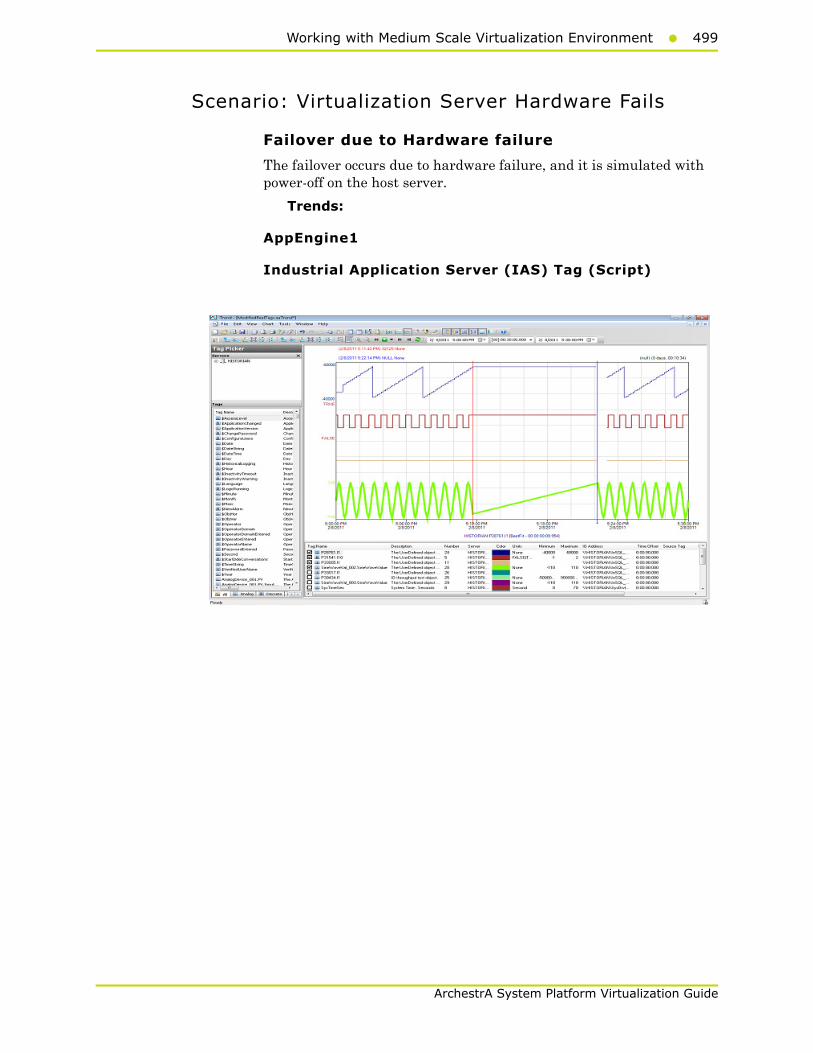
Working with Medium Scale Virtualization Environment499
ArchestrA System Platform Virtualization Guide
Scenario: Virtualization Server Hardware Fails
Failover due to Hardware failure
The failover occurs due to hardware failure, and it is simulated with power-off on the host server.
Trends:
AppEngine1
Industrial Application Server (IAS) Tag (Script)
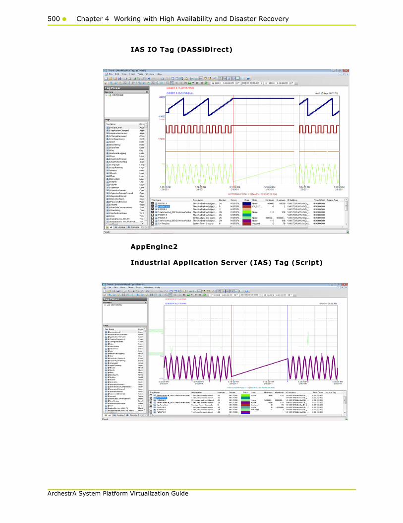
500 Chapter 4 Working with High Availability and Disaster Recovery
ArchestrA System Platform Virtualization Guide
IAS IO Tag (DASSiDirect)
AppEngine2
Industrial Application Server (IAS) Tag (Script)
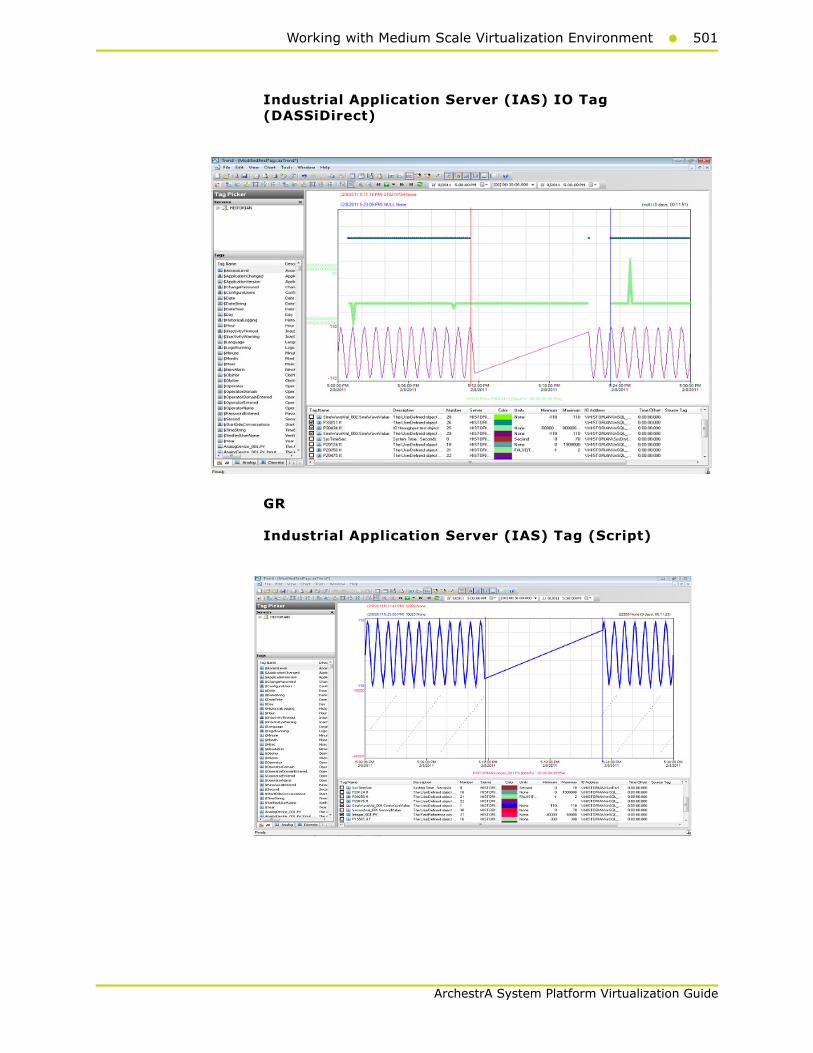
Working with Medium Scale Virtualization Environment501
ArchestrA System Platform Virtualization Guide
Industrial Application Server (IAS) IO Tag (DASSiDirect)
GR
Industrial Application Server (IAS) Tag (Script)
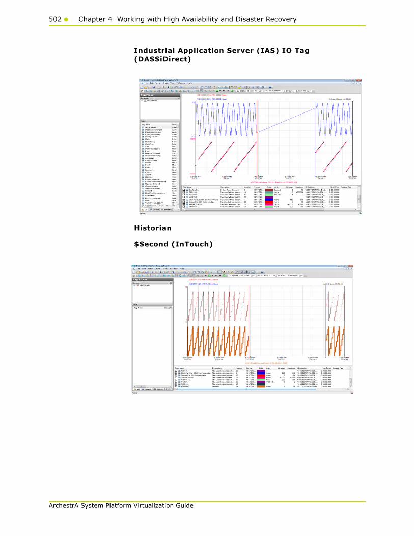
502 Chapter 4 Working with High Availability and Disaster Recovery
ArchestrA System Platform Virtualization Guide
Industrial Application Server (IAS) IO Tag (DASSiDirect)
Historian
$Second (InTouch)
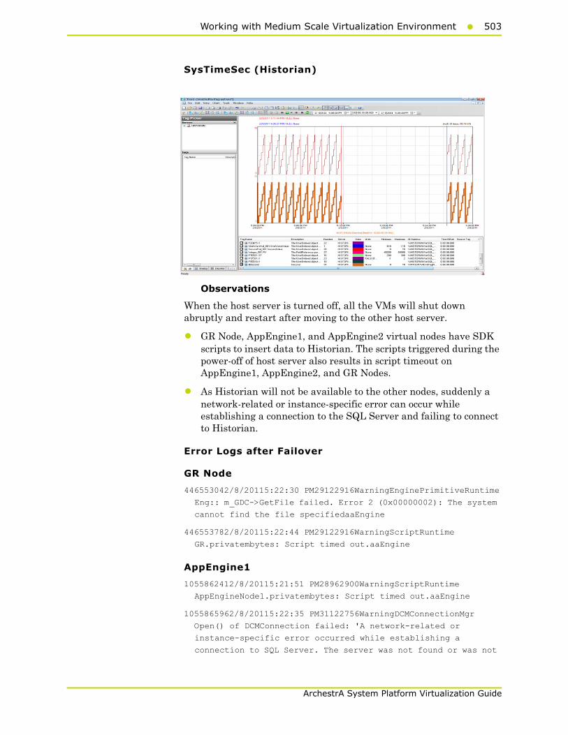
Working with Medium Scale Virtualization Environment503
ArchestrA System Platform Virtualization Guide
SysTimeSec (Historian)
Observations
When the host server is turned off, all the VMs will shut down abruptly and restart after moving to the other host server.
• GR Node, AppEngine1, and AppEngine2 virtual nodes have SDK scripts to insert data to Historian. The scripts triggered during the power-off of host server also results in script timeout on AppEngine1, AppEngine2, and GR Nodes.
• As Historian will not be available to the other nodes, suddenly a network-related or instance-specific error can occur while establishing a connection to the SQL Server and failing to connect to Historian.
Error Logs after Failover
GR Node
446553042/8/20115:22:30 PM29122916WarningEnginePrimitiveRuntime
Eng:: m_GDC->GetFile failed. Error 2 (0x00000002): The system
cannot find the file specifiedaaEngine
446553782/8/20115:22:44 PM29122916WarningScriptRuntime
GR.privatembytes: Script timed out.aaEngine
AppEngine1
1055862412/8/20115:21:51 PM28962900WarningScriptRuntime
AppEngineNode1.privatembytes: Script timed out.aaEngine
1055865962/8/20115:22:35 PM31122756WarningDCMConnectionMgr
Open() of DCMConnection failed: 'A network-related or
instance-specific error occurred while establishing a
connection to SQL Server. The server was not found or was not
504 Chapter 4 Working with High Availability and Disaster Recovery
ArchestrA System Platform Virtualization Guide
accessible. Verify that the instance name is correct and that
SQL Server is configured...aaEngine
1055865972/8/20115:22:35 PM31122756WarningSQLDataRuntime3
SQLTestResults Command Failure - A network-related or
instance-specific error occurred while establishing a
connection to SQL Server. The server was not found or was not
accessible. Verify that the instance name is correct and that
SQL Server is configured...aaEngine
AppEngine2
54976222/8/20115:21:19 PM26842676WarningScriptRuntime
HourVal_003.GenerateHourValue: Script timed out.aaEngine
54976442/8/20115:21:37 PM1540496WarningHistorianPrimitive
AppEngineNode2 failed to connect to Historian HISTORIAN. (Does
ArchestrA user account exist on Historian(InSQL) node or does
Historian not exist?)aaEngine
54976522/8/20115:22:37 PM1540496WarningHistorianPrimitive
AppEngineNode2 failed to connect to Historian HISTORIAN. (Does
ArchestrA user account exist on Historian(InSQL) node or does
Historian not exist?)aaEngine
54976532/8/20115:23:38 PM1540496WarningHistorianPrimitive
AppEngineNode2 failed to connect to Historian HISTORIAN. (Does
ArchestrA user account exist on Historian(InSQL) node or does
Historian not exist?)aaEngine
54976542/8/20115:24:38 PM1540496WarningHistorianPrimitive
AppEngineNode2 failed to connect to Historian HISTORIAN. (Does
ArchestrA user account exist on Historian(InSQL) node or does
Historian not exist?)aaEngine
54976612/8/20115:25:38 PM1540496WarningHistorianPrimitive
AppEngineNode2 failed to connect to Historian HISTORIAN. (Does
ArchestrA user account exist on Historian(InSQL) node or does
Historian not exist?)aaEngine
Historian
None
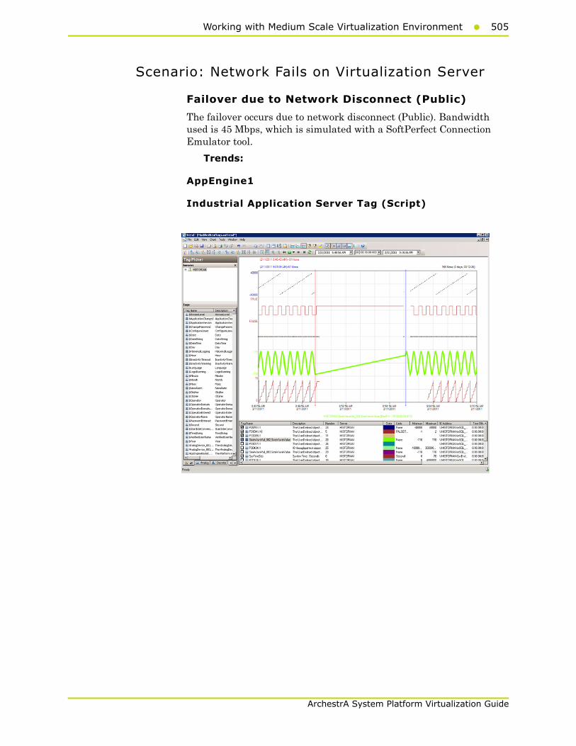
Working with Medium Scale Virtualization Environment505
ArchestrA System Platform Virtualization Guide
Scenario: Network Fails on Virtualization Server
Failover due to Network Disconnect (Public)
The failover occurs due to network disconnect (Public). Bandwidth used is 45 Mbps, which is simulated with a SoftPerfect Connection Emulator tool.
Trends:
AppEngine1
Industrial Application Server Tag (Script)

506 Chapter 4 Working with High Availability and Disaster Recovery
ArchestrA System Platform Virtualization Guide
Industrial Application Server (IAS) IO Tag (DASSiDirect)
AppEngine2
Industrial Application Server (IAS) Tag (Script)

Working with Medium Scale Virtualization Environment507
ArchestrA System Platform Virtualization Guide
Industrial Application Server (IAS) IO Tag (DASSiDirect)
GR
Industrial Application Server (IAS) Tag (Script)

508 Chapter 4 Working with High Availability and Disaster Recovery
ArchestrA System Platform Virtualization Guide
IAS IO Tag (DASSiDirect)
Historian
$Second (InTouch)
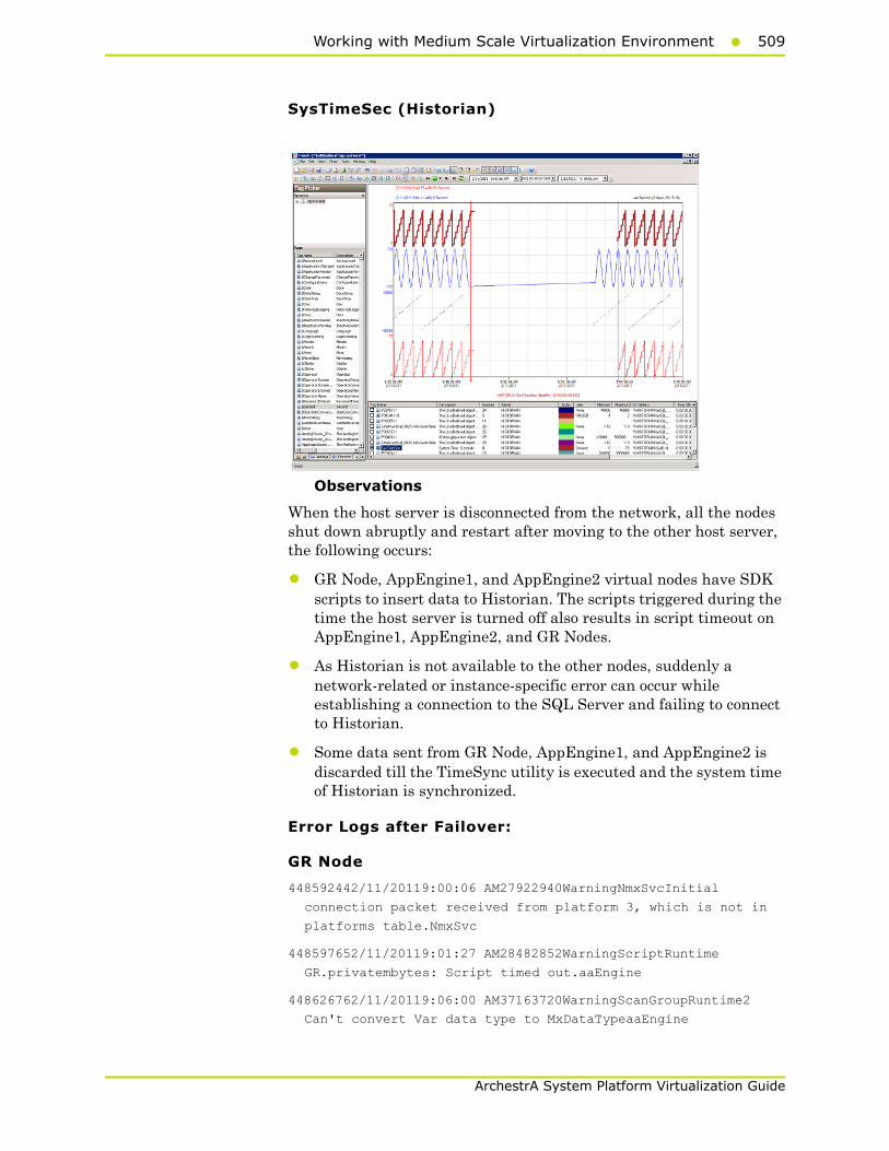
Working with Medium Scale Virtualization Environment509
ArchestrA System Platform Virtualization Guide
SysTimeSec (Historian)
Observations
When the host server is disconnected from the network, all the nodes shut down abruptly and restart after moving to the other host server, the following occurs:
• GR Node, AppEngine1, and AppEngine2 virtual nodes have SDK scripts to insert data to Historian. The scripts triggered during the time the host server is turned off also results in script timeout on AppEngine1, AppEngine2, and GR Nodes.
• As Historian is not available to the other nodes, suddenly a network-related or instance-specific error can occur while establishing a connection to the SQL Server and failing to connect to Historian.
• Some data sent from GR Node, AppEngine1, and AppEngine2 is discarded till the TimeSync utility is executed and the system time of Historian is synchronized.
Error Logs after Failover:
GR Node
448592442/11/20119:00:06 AM27922940WarningNmxSvcInitial
connection packet received from platform 3, which is not in
platforms table.NmxSvc
448597652/11/20119:01:27 AM28482852WarningScriptRuntime
GR.privatembytes: Script timed out.aaEngine
448626762/11/20119:06:00 AM37163720WarningScanGroupRuntime2
Can't convert Var data type to MxDataTypeaaEngine
510 Chapter 4 Working with High Availability and Disaster Recovery
ArchestrA System Platform Virtualization Guide
448626772/11/20119:06:00 AM37163720WarningScanGroupRuntime2
Can't convert Var data type to MxDataTypeaaEngine
448626782/11/20119:06:00 AM37163720WarningScanGroupRuntime2
Can't convert Var data type to MxDataTypeaaEngine
448626792/11/20119:06:00 AM37163720WarningScanGroupRuntime2
Can't convert Var data type to MxDataTypeaaEngine
448626972/11/20119:06:00 AM37163720WarningScanGroupRuntime2
Can't convert Var data type to MxDataTypeaaEngine
448626982/11/20119:06:00 AM37163720WarningScanGroupRuntime2
Can't convert Var data type to MxDataTypeaaEngine
448626992/11/20119:06:00 AM37163720WarningScanGroupRuntime2
Can't convert Var data type to MxDataTypeaaEngine44862697
2/11/20119:06:00 AM37163720WarningScanGroupRuntime2Can't
convert Var data type to MxDataTypeaaEngine
AppEngine 1
1059130762/11/20118:59:15 AM28602864Warning
EnginePrimitiveRuntimeEng:: m_GDC->GetFile failed. Error 2
(0x00000002): The system cannot find the file specified
aaEngine
1059131592/11/20119:00:30 AM28602864WarningScriptRuntime
AppEngineNode1.privatembytes: Script timed out.aaEngine
1059135022/11/20119:01:15 AM30324132WarningDCMConnectionMgr
Open() of DCMConnection failed: 'A network-related or
instance-specific error occurred while establishing a
connection to SQL Server. The server was not found or was not
accessible. Verify that the instance name is correct and that
SQL Server is configured...aaEngine
1059135032/11/20119:01:15 AM30324132WarningSQLDataRuntime3
SQLTestResults Command Failure - A network-related or
instance-specific error occurred while establishing a
connection to SQL Server. The server was not found or was not
accessible. Verify that the instance name is correct and that
SQL Server is configured...aaEngine
AppEngine2
55019182/11/20119:00:03 AM17241776WarningScriptRuntime
HourVal_003.GenerateHourValue: Script timed out.aaEngine
55019542/11/20119:00:16 AM26642808WarningNmxSvcPlatform 1
exceed maximum heartbeats timeout of 7500 ms.NmxSvc
55019742/11/20119:00:28 AM24882484WarningHistorianPrimitive
AppEngineNode2 failed to connect to Historian HISTORIAN. (Does
ArchestrA user account exist on Historian(InSQL) node or does
Historian not exist?)aaEngine

Working with Medium Scale Virtualization Environment511
ArchestrA System Platform Virtualization Guide
55019752/11/20119:01:29 AM24882484WarningHistorianPrimitive
AppEngineNode2 failed to connect to Historian HISTORIAN. (Does
ArchestrA user account exist on Historian(InSQL) node or does
Historian not exist?)aaEngine
55019762/11/20119:02:30 AM24882484WarningHistorianPrimitive
AppEngineNode2 failed to connect to Historian HISTORIAN. (Does
ArchestrA user account exist on Historian(InSQL) node or does
Historian not exist?)aaEngine
55019832/11/20119:03:30 AM24882484WarningHistorianPrimitive
AppEngineNode2 failed to connect to Historian HISTORIAN. (Does
ArchestrA user account exist on Historian(InSQL) node or does
Historian not exist?)aaEngine
Historian
235194832/11/20119:05:27 AM30483692WarningaahStoreSvcAttempt to
store values in the future; timestamps were overwritten with
current time (pipe name, TagName, wwTagKey, system time (UTC),
time difference (sec)) (HISTORIAN_mdas,
SlowScanUDO.IncrementValue, 334, 2011/02/11 03:35:27.296, 1)
[HISTORIAN; pipeserv...aahCfgSvc
235195792/11/20119:09:42 AM30483692WarningaahStoreSvcAttempt to
store values in the future; timestamps were overwritten with
current time (pipe name, TagName, wwTagKey, system time (UTC),
time difference (sec)) (HISTORIAN_mdas,
SlowScanUDO.IncrementValue, 334, 2011/02/11 03:35:27.296, 1)
[HISTORIAN; pipeserv...aahCfgSvc

512 Chapter 4 Working with High Availability and Disaster Recovery
ArchestrA System Platform Virtualization Guide

513
ArchestrA System Platform Virtualization Guide
Chapter 5
Working with WindowsServer 2008 R2 Features
This chapter describes how to use the features of Windows Server 2008 R2 to perform the following functions:
• Using VLAN for Communication Between System Platform Nodes
• Using VLAN for RMC Communication Between Redundant Application Server Nodes
• Accessing a System Platform Node with a Remote Desktop
• Accessing System Platform Applications as Remote Applications
• Displaying the System Platform Nodes on a Multi-Monitor with a Remote Desktop
• Working with Network Load Balancing
• Hardware Licenses in a Virtualized Environment

514 Chapter 5 Working with Windows Server 2008 R2 Features
ArchestrA System Platform Virtualization Guide
About Windows Server 2008 R2 Hyper-V Features
A virtualized environment can run multiple virtual machines (VMs) on a single server, thereby reducing the number of physical servers required on the network. Hyper-V provides a virtualized computing environment on Windows Server 2008 R2. Hyper-V is a hardware-assisted virtualization platform that uses partitions to host VMs. One of the benefits that Hyper-V provides is isolation, which ensures that the child VMs execute in their individual partitions and exist on the host as separate machines. This allows multiple operating systems and conflicting applications to run on the same server.
Windows Server 2008 R2 Hyper-V provides support for using Virtual LANs (VLANs) on both parent and child partitions. By configuring VLAN, VMs can communicate over the specified VLAN using Virtual Network switch.
Microsoft introduced RemoteApp with the release of Windows 2008 Terminal Services. In the past, Windows 2008 TS Microsoft Terminal Services solutions only supported the publication of a full desktop using the RDP protocol. In Windows 2008, it was possible to start an application seamlessly from a Terminal Server making it appear as it were running locally on the client machine.
RemoteApp is an application that runs on from a Terminal Server running seamlessly to the client.
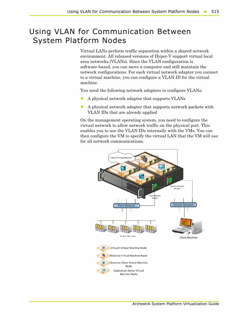
Using VLAN for Communication Between System Platform Nodes515
ArchestrA System Platform Virtualization Guide
Using VLAN for Communication Between System Platform Nodes
Virtual LANs perform traffic separation within a shared network environment. All released versions of Hyper-V support virtual local area networks (VLANs). Since the VLAN configuration is software-based, you can move a computer and still maintain the network configurations. For each virtual network adapter you connect to a virtual machine, you can configure a VLAN ID for the virtual machine.
You need the following network adapters to configure VLANs:
• A physical network adapter that supports VLANs
• A physical network adapter that supports network packets with VLAN IDs that are already applied
On the management operating system, you need to configure the virtual network to allow network traffic on the physical port. This enables you to use the VLAN IDs internally with the VMs. You can then configure the VM to specify the virtual LAN that the VM will use for all network communications.
516 Chapter 5 Working with Windows Server 2008 R2 Features
ArchestrA System Platform Virtualization Guide
Configuring Virtual Network Switches on the Hyper-V Host Server and Adding Virtual Network Adapters on the VM Nodes
You can create virtual networks on a server running Hyper-V to define various networking topologies for VMs and the virtualization server. Following are the three types of virtual networks:
• Private network: Provides communication between VMs
• Internal network: Provides communication between the virtualization server and VMs
• External network: Provides communication between a VM and a physical network by associating to a physical network adapter on the virtualization server
On a Hyper-V host server, you can create the following virtual network adapter switches.
• External Network adapter switch to communicate with the external domain network.
• External Network adapter switch to communicate with the external plant network.
• Internal Network adapter switch to communicate between VM nodes created on Hyper-V host server.
For more information, refer to http://technet.microsoft.com/en-us/library/cc732470(WS.10).aspx
Creating a Virtual Network Switch for Communication Between a VM Node and an External Domain or a Plant Network
A virtual network switch or a virtual switch is a virtual version of a physical network switch. A virtual network provides access to local or external network resources for one or more VMs. You need to create a virtual network switch to communicate with the external domain or plant network.
Note: A virtual network works like a physical network except that the switch is software based. After an external virtual network is configured, all networking traffic is routed through the virtual switch.
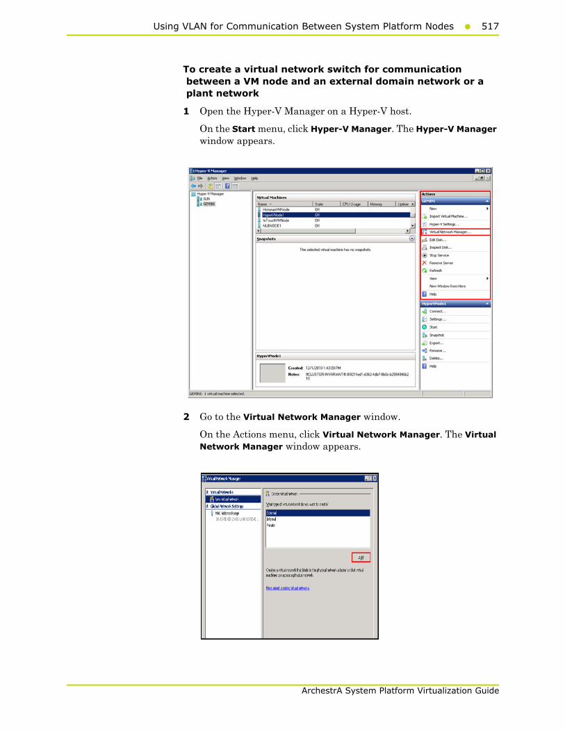
Using VLAN for Communication Between System Platform Nodes517
ArchestrA System Platform Virtualization Guide
To create a virtual network switch for communication between a VM node and an external domain network or a plant network
1 Open the Hyper-V Manager on a Hyper-V host.
On the Start menu, click Hyper-V Manager. The Hyper-V Manager window appears.
2 Go to the Virtual Network Manager window.
On the Actions menu, click Virtual Network Manager. The Virtual Network Manager window appears.

518 Chapter 5 Working with Windows Server 2008 R2 Features
ArchestrA System Platform Virtualization Guide
3 Add a new virtual network.
a Under Virtual Networks, click New virtual network.
b Under Create virtual network, click External.
c Click Add. The New Virtual Network section appears.
4 Enter the new virtual network details.
• In the Name box, enter the Virtual Network name.
• Click the External option, and then select the required external domain or plant network that you want to connect to.
• Select the Allow management operating system to share this network adapter check box if you want to manage activities on the virtual network switch created.
Note: Do not select this check box if you are creating a virtual network for communication between VM nodes and a plant network.
• Click OK to close the Virtual Network Manager window or click Apply to create the virtual network and continue using Virtual Network Manager.
The external virtual network switch is created and can be used to communicate between the VM nodes and the domain or plant network.
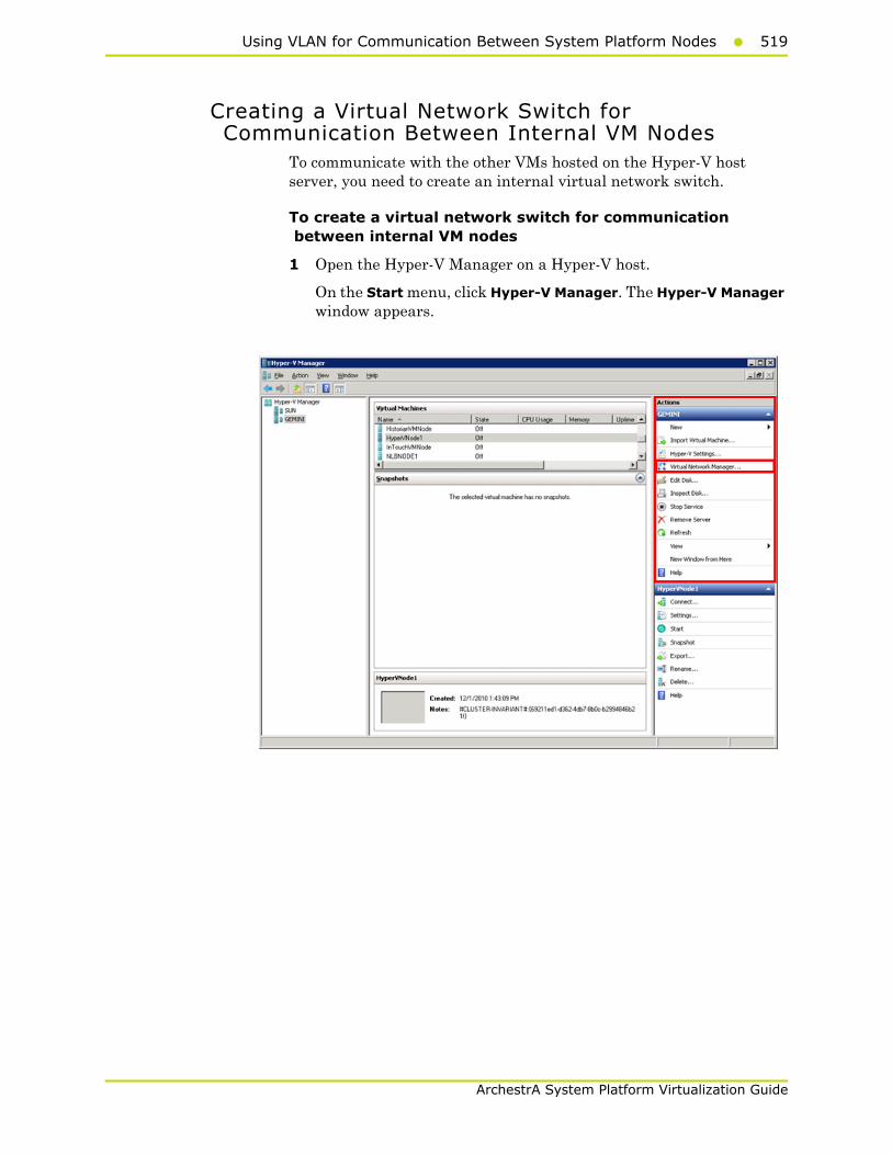
Using VLAN for Communication Between System Platform Nodes519
ArchestrA System Platform Virtualization Guide
Creating a Virtual Network Switch for Communication Between Internal VM Nodes
To communicate with the other VMs hosted on the Hyper-V host server, you need to create an internal virtual network switch.
To create a virtual network switch for communication between internal VM nodes
1 Open the Hyper-V Manager on a Hyper-V host.
On the Start menu, click Hyper-V Manager. The Hyper-V Manager window appears.
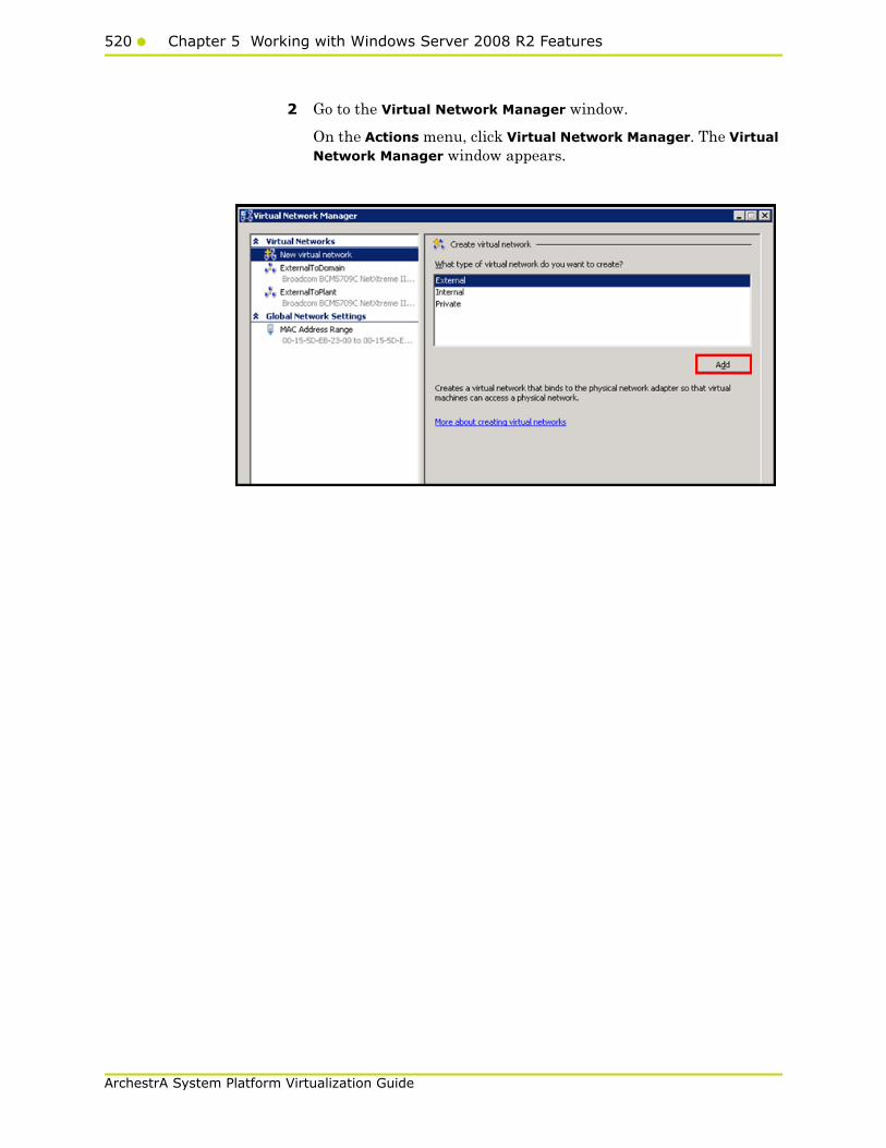
520 Chapter 5 Working with Windows Server 2008 R2 Features
ArchestrA System Platform Virtualization Guide
2 Go to the Virtual Network Manager window.
On the Actions menu, click Virtual Network Manager. The Virtual Network Manager window appears.
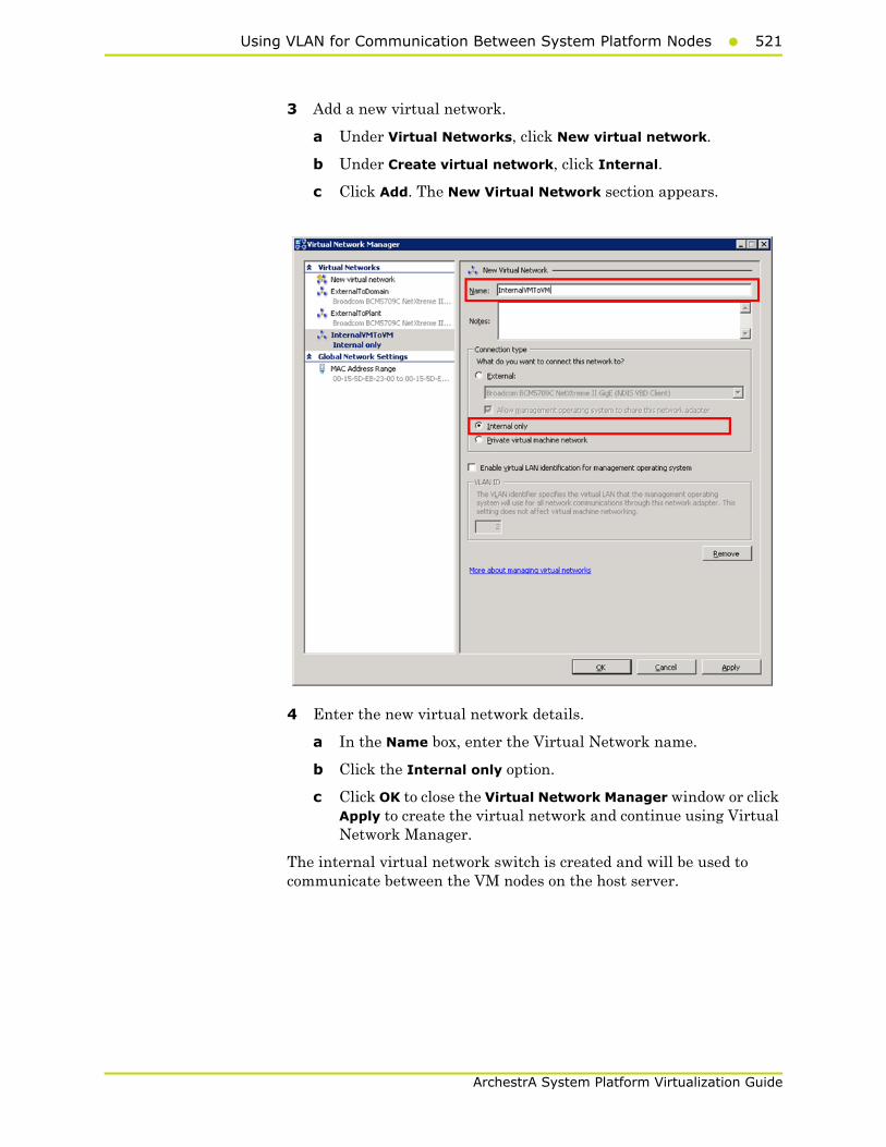
Using VLAN for Communication Between System Platform Nodes521
ArchestrA System Platform Virtualization Guide
3 Add a new virtual network.
a Under Virtual Networks, click New virtual network.
b Under Create virtual network, click Internal.
c Click Add. The New Virtual Network section appears.
4 Enter the new virtual network details.
a In the Name box, enter the Virtual Network name.
b Click the Internal only option.
c Click OK to close the Virtual Network Manager window or click Apply to create the virtual network and continue using Virtual Network Manager.
The internal virtual network switch is created and will be used to communicate between the VM nodes on the host server.

522 Chapter 5 Working with Windows Server 2008 R2 Features
ArchestrA System Platform Virtualization Guide
Adding an Internal Virtual Network Adapter to a VM Node for Communication Between VM Nodes
You can configure one or more virtual network adapters for a VM by creating or modifying the hardware profile of a VM.
If you connect a virtual network adapter configured for a VM to an internal network, you can connect to the VMs deployed on the same host and communicate over that internal network.
To add an internal virtual network adapter to a VM node for communication between VM nodes
1 Open the Hyper-V Manager on a Hyper-V host.
On the Start menu, click Hyper-V Manager. The Hyper-V Manager window appears.
2 Shut down the VM node to which you want to add the network adapter.
Right-click the required VM node. The VM menu appears.

Using VLAN for Communication Between System Platform Nodes523
ArchestrA System Platform Virtualization Guide
Click Shut Down.
3 Go to the Settings window for the required VM node.
Right-click the VM node and click Settings. The Settings window for the VM node appears.
4 Select the hardware settings for the VM node.
a With Add Hardware selected, click Network Adapter, and then click Add. The Network Adapter area appears.

524 Chapter 5 Working with Windows Server 2008 R2 Features
ArchestrA System Platform Virtualization Guide
b In the Hardware pane, click the relevant network adapter.
c Select the Enable Virtual LAN identification check box.
d In the VLAN ID box, enter the VLAN ID, and then click OK to close the window.
Note: All traffic for the management operating system that goes through the network adapter is tagged with the VLAN ID you enter.
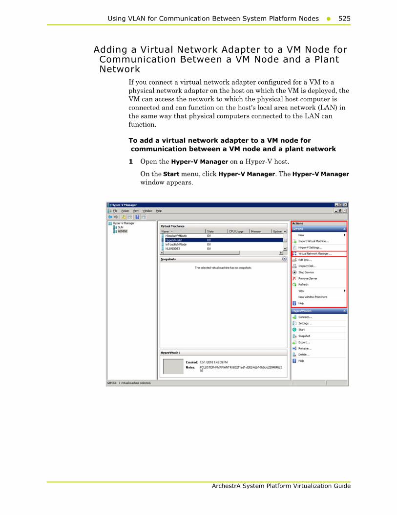
Using VLAN for Communication Between System Platform Nodes525
ArchestrA System Platform Virtualization Guide
Adding a Virtual Network Adapter to a VM Node for Communication Between a VM Node and a Plant Network
If you connect a virtual network adapter configured for a VM to a physical network adapter on the host on which the VM is deployed, the VM can access the network to which the physical host computer is connected and can function on the host's local area network (LAN) in the same way that physical computers connected to the LAN can function.
To add a virtual network adapter to a VM node for communication between a VM node and a plant network
1 Open the Hyper-V Manager on a Hyper-V host.
On the Start menu, click Hyper-V Manager. The Hyper-V Manager window appears.

526 Chapter 5 Working with Windows Server 2008 R2 Features
ArchestrA System Platform Virtualization Guide
2 Shut down the VM node to which you want to add the network adapter.
Right-click the required VM node. The VM menu appears.
Click Shut Down.
3 Go to the Settings window for the required VM node.
Right-click the VM node and click Settings. The Settings window for the VM node appears.
4 Select the hardware settings for the VM node.
a With Add Hardware selected, click Network Adapter, and then click Add. The Network Adapter area appears.
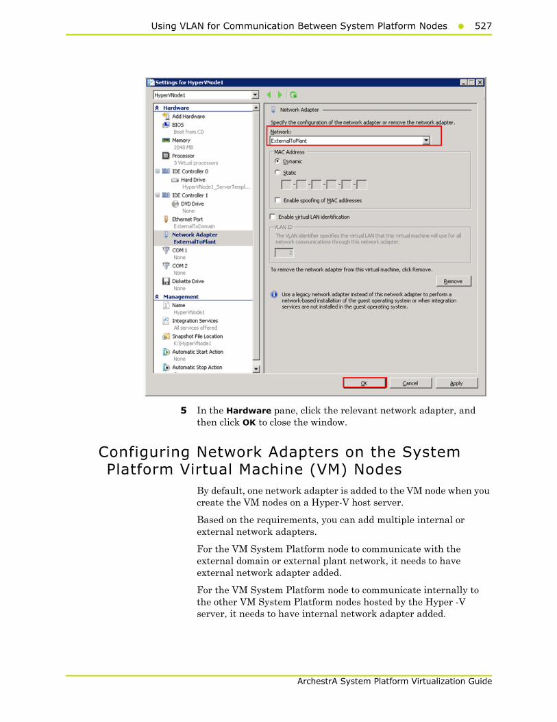
Using VLAN for Communication Between System Platform Nodes527
ArchestrA System Platform Virtualization Guide
5 In the Hardware pane, click the relevant network adapter, and then click OK to close the window.
Configuring Network Adapters on the System Platform Virtual Machine (VM) Nodes
By default, one network adapter is added to the VM node when you create the VM nodes on a Hyper-V host server.
Based on the requirements, you can add multiple internal or external network adapters.
For the VM System Platform node to communicate with the external domain or external plant network, it needs to have external network adapter added.
For the VM System Platform node to communicate internally to the other VM System Platform nodes hosted by the Hyper -V server, it needs to have internal network adapter added.
528 Chapter 5 Working with Windows Server 2008 R2 Features
ArchestrA System Platform Virtualization Guide
You can create the following VM nodes on the virtualization server for which the VLAN communication needs to be set up:
• InTouch VM node
• Historian VM node
• Application Server VM node
• Historian Client VM node
• Wonderware Information Server VM node
VM nodes on Hyper-V host server have the following network adapters:
• An external network adapter to communicate with the external domain network
• An external network adapter to communicate with the external plant network. This is available if the VM node is acquiring the data from the IOServer connected to the external plant network
• An internal network adapter to communicate internally between the VM nodes configured on Hyper-V host server
• An internal network adapter to communicate between the Application Server nodes to use for Redundancy Message Channel (RMC) communication. Only the Application Server VM nodes configured for Redundant Application Engines have this network adapter.
Each System Platform node can have various combinations of the following network adapters, depending on your configuration:
Using VLAN for Communication Between System Platform Nodes529
ArchestrA System Platform Virtualization Guide
Note: It is assumed that the host virtualization server is configured with one external virtual network switch to communicate with the domain network, one external virtual network switch to communicate with the plant network, and one internal virtual network switch for the internal VM to VM communication.
Product node Network adapters
InTouch • An external network adapter to communicate with the external domain network
• An external network adapter to communicate with the external plant network (This is to acquire the data from the IOServer which is connected to the plant network.)
• An internal network adapter to communicate between the other VM nodes configured on a Hyper-V host server (For example, to a Historian VM node)
Historian • An external network adapter to communicate with the external domain network
• An external network adapter to communicate with the external plant network(This is to acquire the data from the IOServer which is connected to the plant network.)
• An internal network adapter to communicate between the other VM nodes configured on a Hyper-V host server (For example, an InTouch VM node.)
530 Chapter 5 Working with Windows Server 2008 R2 Features
ArchestrA System Platform Virtualization Guide
In the following procedure, the VM nodes are created with the specified OS installed on all the nodes. One physical machine is configured in the workgroup with an IOServer installed and connected to a plant or private network.
Historian Client • An external network adapter to communicate with the external domain network
• An external network adapter to communicate with the external plant network(This is to acquire the data from the IOServer which is connected to the plant network.)
• An internal network adapter to communicate between the other VM nodes configured on a Hyper-V host server (For example, a Historian VM node.)
Wonderware Information Server (WIS)
• An external network adapter to communicate with the external domain network
• An internal network adapter to communicate between the other VM nodes configured on a Hyper-V host server (For example, to a Historian Client VM node.)
Wonderware Application Server
• An external network adapter to communicate with the external domain network
• An external network adapter to communicate with the external plant network (This is to acquire the data from the IOServer which is connected to the plant network.)
• An internal network adapter to communicate between the other VM nodes configured on a Hyper-V host server (For example, a Historian VM node.)
Product node Network adapters
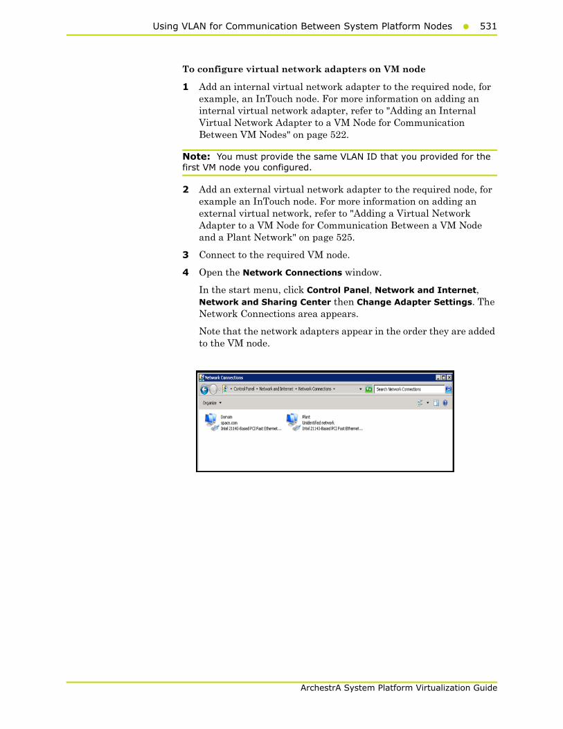
Using VLAN for Communication Between System Platform Nodes531
ArchestrA System Platform Virtualization Guide
To configure virtual network adapters on VM node
1 Add an internal virtual network adapter to the required node, for example, an InTouch node. For more information on adding an internal virtual network adapter, refer to "Adding an Internal Virtual Network Adapter to a VM Node for Communication Between VM Nodes" on page 522.
Note: You must provide the same VLAN ID that you provided for the first VM node you configured.
2 Add an external virtual network adapter to the required node, for example an InTouch node. For more information on adding an external virtual network, refer to "Adding a Virtual Network Adapter to a VM Node for Communication Between a VM Node and a Plant Network" on page 525.
3 Connect to the required VM node.
4 Open the Network Connections window.
In the start menu, click Control Panel, Network and Internet, Network and Sharing Center then Change Adapter Settings. The Network Connections area appears.
Note that the network adapters appear in the order they are added to the VM node.

532 Chapter 5 Working with Windows Server 2008 R2 Features
ArchestrA System Platform Virtualization Guide
5 Configure the required VM node.
a Right-click the required internal or external network adapter. The Local Area Connection Properties window appears.

Using VLAN for Communication Between System Platform Nodes533
ArchestrA System Platform Virtualization Guide
b Select the Internet Protocol Version 4 check box, and then click OK. The Properties window appears for the Internet protocol version you selected.
c Click the Use the following IP address option.
d In the IP address box, enter the IP address for the network adapter, and then click OK.
• For the internal network added for communication between VM nodes, enter the required IP address.
• For external network adapter added for communication between a VM node and an external plant network communication, enter the required static IP address.
Note: Configure the other VM nodes following the same steps.

534 Chapter 5 Working with Windows Server 2008 R2 Features
ArchestrA System Platform Virtualization Guide
Using VLAN for RMC Communication Between Redundant Application Server Nodes
For successful communication between a redundant pair of Application Engines, each Application Engine must be assigned to a separate WinPlatform and a valid redundancy message channel (RMC) must be configured for each WinPlatform. You can configure an RMC using a virtual LAN.

Using VLAN for RMC Communication Between Redundant Application Server Nodes535
ArchestrA System Platform Virtualization Guide
Configuring RMC for Redundant AppEngine over a VLAN
For a successful communication between a redundant pair of Application Engines, each Application Engine should configure a valid redundancy message channel (RMC). You can configure the RMC using Virtual LAN (VLAN). For configuring the RMC, Wonderware Application Server VM System Platform node requires the internal network adapters for communication:
• An internal network adapter to communicate between the other VM nodes configured on a Hyper-V host server, for example, a Historian VM node
• An internal network adapter to communicate with the other Wonderware Application Server VM nodes configured as Redundancy Application Engine to use as a RMC
To configure RMC for a Redundant AppEngine node
1 Add an internal virtual network adapter to a Wonderware Application Server node.
For more information on adding an internal virtual network adapter, refer to "Adding an Internal Virtual Network Adapter to a VM Node for Communication Between VM Nodes" on page 522.
Note: In the Settings window, enter the same VLAN ID that you entered while configuring the InTouch and Historian Client nodes. This enables the VM nodes to communicate internally over the specified LAN ID.
2 Add an internal virtual network adapter to a Wonderware Application Server node to use as RMC communication.
Note: In the Settings window, enter the same VLAN ID you entered on both the Application Server nodes for virtual network adapter. This enables the Application Server VM node to communicate internally over the specified LAN ID as an RMC channel to communicate to another Application Server VM node.
3 Add an external virtual network adapter to a Wonderware Application Server node.
For more information on adding an external virtual network adapter, refer to "Adding a Virtual Network Adapter to a VM Node for Communication Between a VM Node and a Plant Network" on page 525.
4 Connect to the required Wonderware Application Server VM node.
5 Open the Network Connections window.
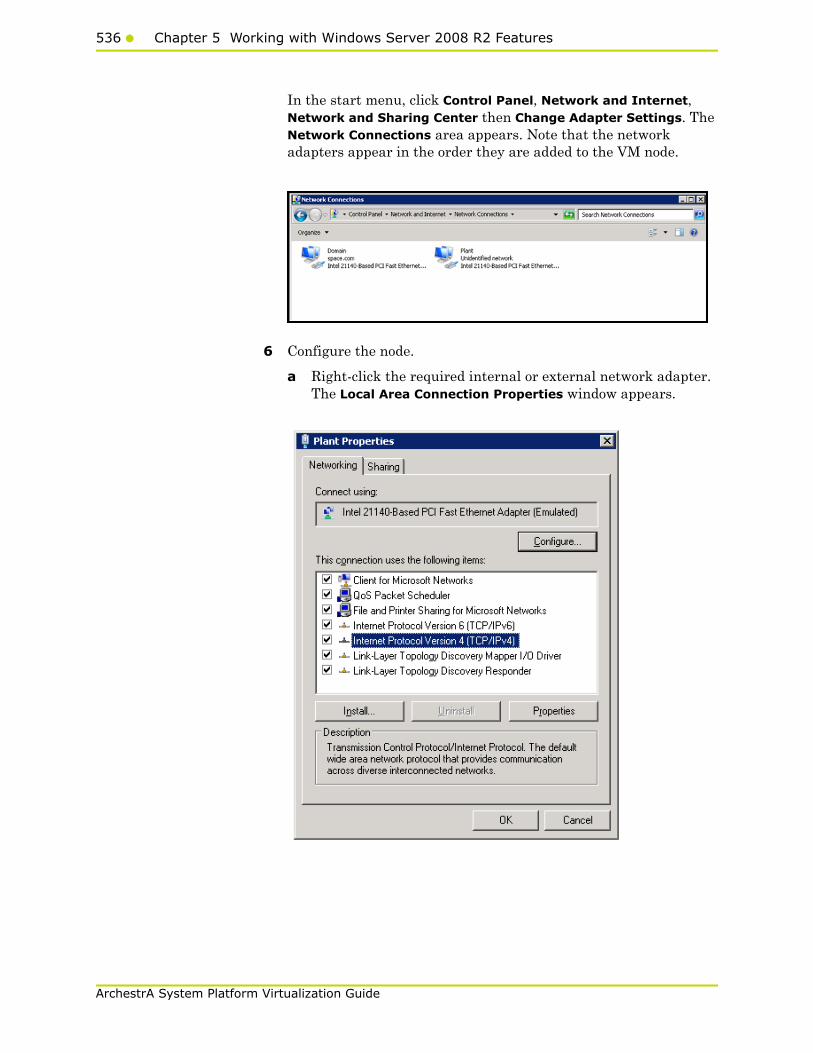
536 Chapter 5 Working with Windows Server 2008 R2 Features
ArchestrA System Platform Virtualization Guide
In the start menu, click Control Panel, Network and Internet, Network and Sharing Center then Change Adapter Settings. The Network Connections area appears. Note that the network adapters appear in the order they are added to the VM node.
6 Configure the node.
a Right-click the required internal or external network adapter. The Local Area Connection Properties window appears.
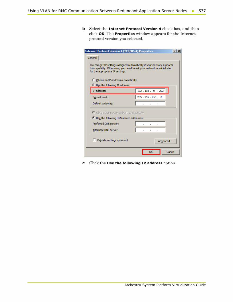
Using VLAN for RMC Communication Between Redundant Application Server Nodes537
ArchestrA System Platform Virtualization Guide
b Select the Internet Protocol Version 4 check box, and then click OK. The Properties window appears for the Internet protocol version you selected.
c Click the Use the following IP address option.

538 Chapter 5 Working with Windows Server 2008 R2 Features
ArchestrA System Platform Virtualization Guide
d Enter the IP address for the network adapter, and then click OK.
• For the internal and external networks added to the Wonderware Application Server node, enter the required IP address in the IP address box.
• For the internal network adapter added to use as RMC, enter the required static IP address in the IP address box and subnet mask in the Subnet mask box.
For example:
• 10.0.0.1
• 255.0.0.0
7 Follow the same steps to configure another Wonderware Application Server node for Redundant Application Server.
Note: While installing the Wonderware products, select the Create Local Account check box and provide the same user name and password to use as network account user.

Accessing a System Platform Node with a Remote Desktop539
ArchestrA System Platform Virtualization Guide
Accessing a System Platform Node with a Remote Desktop
You can use Hyper-V to access a system platform node through a remote desktop. You can specify the required remote users, who will be able to access the VM running the system platform.
To access a system platform node with a remote desktop
1 Log on to the system platform node as a member of the local administrators group.
2 Modify the remote settings of the system platform node.
a On the Start menu, click Control Panel, System and Security, System then Remote settings. The System Properties window appears.
b Under Remote Desktop, click the relevant option to specify the remote desktop versions you want to allow access to.
3 Select users to provide access to the system.
a Click Select Users. The Remote Desktop Users window appears.
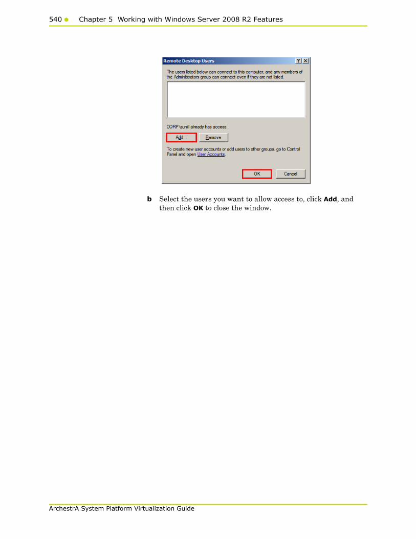
540 Chapter 5 Working with Windows Server 2008 R2 Features
ArchestrA System Platform Virtualization Guide
b Select the users you want to allow access to, click Add, and then click OK to close the window.
Accessing System Platform Applications as Remote Applications541
ArchestrA System Platform Virtualization Guide
Accessing System Platform Applications as Remote Applications
Remote Desktop Services (RDS) Remote Applications enables you to deploy RemoteApp programs to users. With RemoteApp, the remote session connects with a specific application rather than with the entire desktop. You can access the RemoteApp programs remotely through Remote Desktop Service. A RemoteApp program appears as if it is running on your local computer. Instead of being present on the desktop of the remote terminal server, the RemoteApp program is integrated with the client's desktop, running in its own resizable window with its own entry in the task bar.
Prerequisites for accessing Remote Applications
• A virtual machine node or physical node with Windows Server R2 which has Remote Desktop Session Host server installed
• Remote Applications, part of the Windows Server 2008 Terminal Services role that are available on Windows Server 2008 Standard and Enterprise Editions
• VM nodes (Remote Desktop Session Host server) running IOM Products, such as InTouch and Historian Client need to be on Windows Server 2008 R2 where Remote Desktop Services are available
• Client node with a browser (any operating system)
Note: To access RemoteApp programs through Remote Desktop-Web Access, the client computer must be running RDC 6.1. RDC 6.1 is included with Windows Server 2008 operating systems, Windows Vista SP1 or later, and Windows XP SP 3.Use About dialog box to verify which version of RDC your system has.
• The client node and the Remote Desktop Session Host server should be able to communicate.
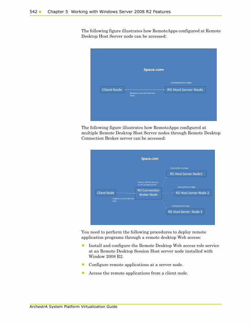
542 Chapter 5 Working with Windows Server 2008 R2 Features
ArchestrA System Platform Virtualization Guide
The following figure illustrates how RemoteApps configured at Remote Desktop Host Server node can be accessed:
The following figure illustrates how RemoteApps configured at multiple Remote Desktop Host Server nodes through Remote Desktop Connection Broker server can be accessed:
You need to perform the following procedures to deploy remote application programs through a remote desktop Web access:
• Install and configure the Remote Desktop Web access role service at an Remote Desktop Session Host server node installed with Window 2008 R2.
• Configure remote applications at a server node.
• Access the remote applications from a client node.
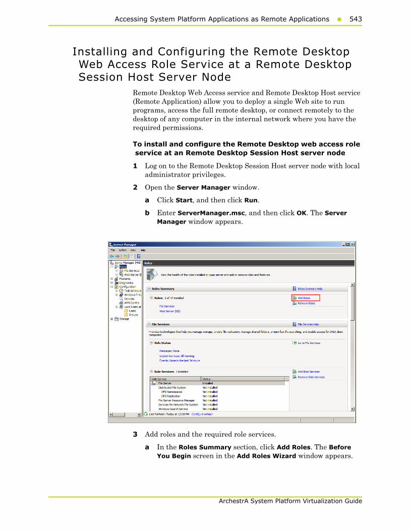
Accessing System Platform Applications as Remote Applications543
ArchestrA System Platform Virtualization Guide
Installing and Configuring the Remote Desktop Web Access Role Service at a Remote Desktop Session Host Server Node
Remote Desktop Web Access service and Remote Desktop Host service (Remote Application) allow you to deploy a single Web site to run programs, access the full remote desktop, or connect remotely to the desktop of any computer in the internal network where you have the required permissions.
To install and configure the Remote Desktop web access role service at an Remote Desktop Session Host server node
1 Log on to the Remote Desktop Session Host server node with local administrator privileges.
2 Open the Server Manager window.
a Click Start, and then click Run.
b Enter ServerManager.msc, and then click OK. The Server Manager window appears.
3 Add roles and the required role services.
a In the Roles Summary section, click Add Roles. The Before You Begin screen in the Add Roles Wizard window appears.

544 Chapter 5 Working with Windows Server 2008 R2 Features
ArchestrA System Platform Virtualization Guide
b Click Next. The Select Server Roles screen appears.

Accessing System Platform Applications as Remote Applications545
ArchestrA System Platform Virtualization Guide
c Select the Remote Desktop Services check box, and then click Next. The Remote Desktop Services screen appears.
d Click Next. The Select Role Services screen appears.
e Select the Remote Desktop Session Host and Remote Desktop Web Access check boxes. The Add Roles Wizard window appears.

546 Chapter 5 Working with Windows Server 2008 R2 Features
ArchestrA System Platform Virtualization Guide
Note: These are the role services that are being installed in this procedure. You can select other role services, as required.
f Click Add Required Role Services. Any missing required role services or features for Remote Desktop Web Access role service is added.
4 Specify the authentication method for the remote desktop session host.
a Click Next. The Specify Authentication Method for Remote Desktop Session Host screen appears.
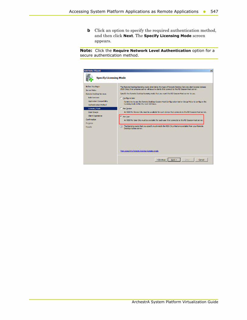
Accessing System Platform Applications as Remote Applications547
ArchestrA System Platform Virtualization Guide
b Click an option to specify the required authentication method, and then click Next. The Specify Licensing Mode screen appears.
Note: Click the Require Network Level Authentication option for a secure authentication method.
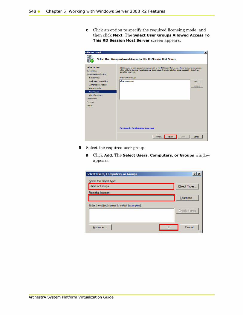
548 Chapter 5 Working with Windows Server 2008 R2 Features
ArchestrA System Platform Virtualization Guide
c Click an option to specify the required licensing mode, and then click Next. The Select User Groups Allowed Access To This RD Session Host Server screen appears.
5 Select the required user group.
a Click Add. The Select Users, Computers, or Groups window appears.

Accessing System Platform Applications as Remote Applications549
ArchestrA System Platform Virtualization Guide
b Select a user or user group you want to allow access to the Remote Desktop Session Host server, and then click OK to close the window.
c On the Select User Groups Allowed Access To This RD Session Host Server screen, click Next. The Configure Client Experience screen appears.
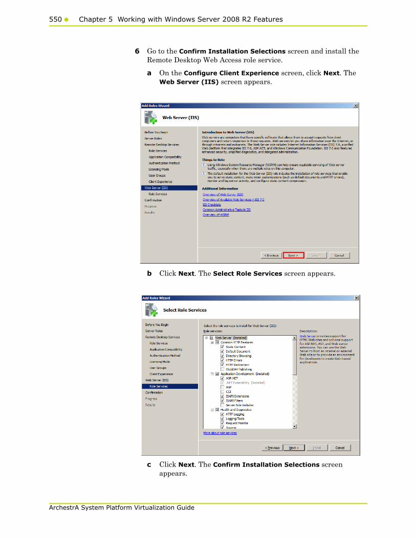
550 Chapter 5 Working with Windows Server 2008 R2 Features
ArchestrA System Platform Virtualization Guide
6 Go to the Confirm Installation Selections screen and install the Remote Desktop Web Access role service.
a On the Configure Client Experience screen, click Next. The Web Server (IIS) screen appears.
b Click Next. The Select Role Services screen appears.
c Click Next. The Confirm Installation Selections screen appears.
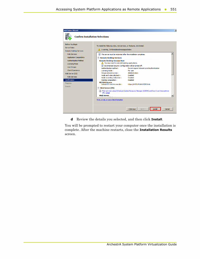
Accessing System Platform Applications as Remote Applications551
ArchestrA System Platform Virtualization Guide
d Review the details you selected, and then click Install.
You will be prompted to restart your computer once the installation is complete. After the machine restarts, close the Installation Results screen.
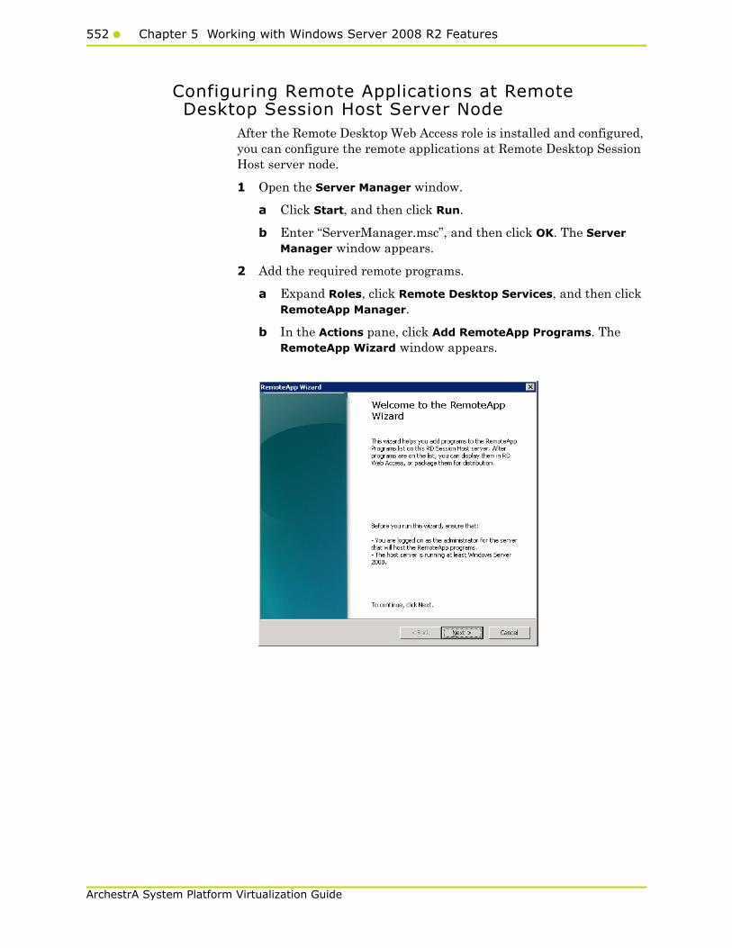
552 Chapter 5 Working with Windows Server 2008 R2 Features
ArchestrA System Platform Virtualization Guide
Configuring Remote Applications at Remote Desktop Session Host Server Node
After the Remote Desktop Web Access role is installed and configured, you can configure the remote applications at Remote Desktop Session Host server node.
1 Open the Server Manager window.
a Click Start, and then click Run.
b Enter “ServerManager.msc”, and then click OK. The Server Manager window appears.
2 Add the required remote programs.
a Expand Roles, click Remote Desktop Services, and then click RemoteApp Manager.
b In the Actions pane, click Add RemoteApp Programs. The RemoteApp Wizard window appears.
Accessing System Platform Applications as Remote Applications553
ArchestrA System Platform Virtualization Guide
c Click Next. The Choose Programs to add to the RemoteApp Programs List screen appears.
d Select the programs you want to add to the RemoteApps list, and then click Next. The Review Setting screen appears.
3 Review your selections, then click Finish to close the window.

554 Chapter 5 Working with Windows Server 2008 R2 Features
ArchestrA System Platform Virtualization Guide
Allowing Application Access to Specific UsersAfter the remote applications are configured, you can define users or user groups who can access the applications at the client node, if required.
To allow application access to specific users
1 Configure remote applications.
For more information on configuring remote applications, refer to "Configuring Remote Applications at Remote Desktop Session Host Server Node" on page 552.

Accessing System Platform Applications as Remote Applications555
ArchestrA System Platform Virtualization Guide
2 Select the required remote application.
In the Server Manager window, select the required remote application, and then click Properties in the Action pane. The RemoteApp Properties window appears.
3 Add users.
a Click the User Assignment tab.
b Click the Specified domain users and domain groups option.
c Click Add. The Select Users, Computers, or Groups window appears.
556 Chapter 5 Working with Windows Server 2008 R2 Features
ArchestrA System Platform Virtualization Guide
d Select the names of the users or user groups you want to provide access to the application, and then click OK to close the window. On the RemoteApp Properties window, the user names appear in the Domain user and domain group names box. Click OK to close the window.
The added users or user groups can now access the application at the client node.
Accessing the Remote Applications from a Client Node
At the client node, you can access the configured remote applications in the following ways:
• Access a program on a Web site using Remote Desktop Web Access
• Access a program on a Web site using Remote Desktop Web Access with Remote Desktop Connection Broker
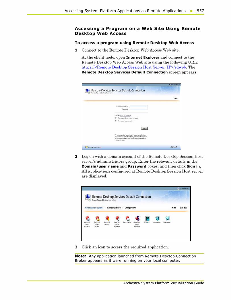
Accessing System Platform Applications as Remote Applications557
ArchestrA System Platform Virtualization Guide
Accessing a Program on a Web Site Using Remote Desktop Web Access
To access a program using Remote Desktop Web Access
1 Connect to the Remote Desktop Web Access Web site.
At the client node, open Internet Explorer and connect to the Remote Desktop Web Access Web site using the following URL: https://<Remote Desktop Session Host Server_IP>/rdweb. The Remote Desktop Services Default Connection screen appears.
2 Log on with a domain account of the Remote Desktop Session Host server’s administrators group. Enter the relevant details in the Domain/user name and Password boxes, and then click Sign in. All applications configured at Remote Desktop Session Host server are displayed.
3 Click an icon to access the required application.
Note: Any application launched from Remote Desktop Connection Broker appears as it were running on your local computer.

558 Chapter 5 Working with Windows Server 2008 R2 Features
ArchestrA System Platform Virtualization Guide
Accessing a Program using Remote Desktop Web Access with Remote Desktop Connection Broker
You can also access the configured remote applications from a client through another Remote Desktop Connection Broker Server node.
Remote Desktop Connection Broker (RD Connection Broker), earlier known as Terminal Services Session Broker (TS Session Broker), provides access to remote applications and desktop connections. Accessing the remote applications and a desktop connection you can get a single, personalized, and aggregated view of RemoteApp programs, session-based desktops, and virtual desktops. Remote Desktop Connection Broker also supports load balancing and reconnection to existing sessions on virtual desktops, Remote Desktop sessions, and RemoteApp programs and aggregates RemoteApp sources from multiple Remote Desktop Session host (RD Session Host) servers that host different RemoteApp programs.
Remote Desktop Connection Broker extends the TS Session Broker capabilities included in Windows Server 2008 by creating a unified administrative experience for traditional session-based remote desktops and VM-based remote desktops. A VM-based remote desktop can be either a personal virtual desktop or part of a virtual desktop pool.
In case of a personal virtual desktop, there is a one-to-one mapping of VMs. You are assigned a personal virtual desktop that can be personalized and customized. These changes are available to you each time you log on to your personal virtual desktop. For a virtual desktop pool, a single image is replicated across many VMs.Virtual desktop pool is to provide users with a virtual desktop that is dynamically assigned from a pool of identically configured virtual machines. As you connect to the shared virtual desktop pool, you are dynamically assigned a virtual desktop. You may not be assigned the same virtual desktop when you connect the next time. This means that any personalization and customization made by you are not saved. If you use a virtual desktop pool and want to save any customization, you can use roaming profiles and folder redirection.
Note: The improvements to the Remote Desktop Connection Broker role service are particularly useful while implementing a Virtual Desktop Infrastructure (VDI) or deploying session-based desktops or RemoteApp programs. These improvements further enhance the Remote Desktop Services.
Add a Remote Desktop Session Host Server in RemoteApp Sources of Remote Desktop Connection Broker Server
You must add the Remote Desktop Connection Broker role service on a computer running Windows Server 2008 R2, and then use Remote Desktop Connection Manager to identify the RemoteApp programs and virtual desktops that are available through RemoteApp and Desktop Connection.

Accessing System Platform Applications as Remote Applications559
ArchestrA System Platform Virtualization Guide
You need to prepare another node where Remote Desktop role service is installed and Remote Desktop Connection Broker service is enabled. For more information, refer to "Installing and Configuring the Remote Desktop Web Access Role Service at a Remote Desktop Session Host Server Node" on page 543
To add Remote Desktop Session Host server in RemoteApp sources of Remote Desktop connection broker server
1 Open the Server Manager window.
Click the Server Manager icon on the task bar of the Remote Desktop Session Host server. The Server Manager window appears.
2 Go to the Add RemoteApp Source window.
a Expand Roles, and then click Remote Desktop Services, Remote Desktop Connection Manager, then RemoteApp Sources.
b In the Actions pane, click Add RemoteApp Source. The Add RemoteApp Source window appears.
3 Add the Remote Desktop Session Host server name.
In the RemoteApp Source Name box, enter the Remote Desktop Session Host Server name and click Add. The server name is added under RemoteApp Sources.

560 Chapter 5 Working with Windows Server 2008 R2 Features
ArchestrA System Platform Virtualization Guide
4 Add the Remote Desktop Connection Broker Server name in the TS Web Access Computers security group.
a On the Remote Desktop Session Host server, click Start, point to Administrative Tools, and then click Computer Management. The Computer Management window appears.
b Expand Local Users and Groups, and then click Groups.
c Double-click TS Web Access Computers. The TS Web Access Computers Properties window appears.
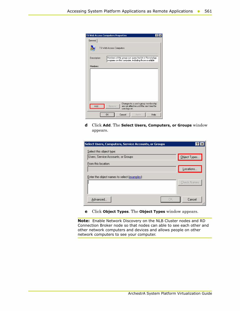
Accessing System Platform Applications as Remote Applications561
ArchestrA System Platform Virtualization Guide
d Click Add. The Select Users, Computers, or Groups window appears.
e Click Object Types. The Object Types window appears.
Note: Enable Network Discovery on the NLB Cluster nodes and RD Connection Broker node so that nodes can able to see each other and other network computers and devices and allows people on other network computers to see your computer.
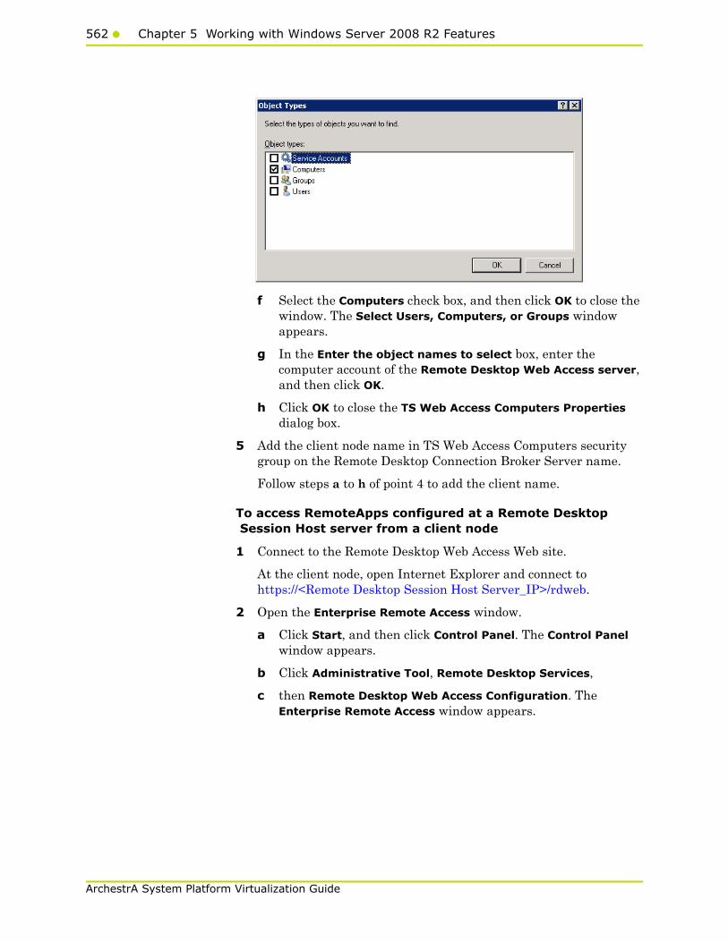
562 Chapter 5 Working with Windows Server 2008 R2 Features
ArchestrA System Platform Virtualization Guide
f Select the Computers check box, and then click OK to close the window. The Select Users, Computers, or Groups window appears.
g In the Enter the object names to select box, enter the computer account of the Remote Desktop Web Access server, and then click OK.
h Click OK to close the TS Web Access Computers Properties dialog box.
5 Add the client node name in TS Web Access Computers security group on the Remote Desktop Connection Broker Server name.
Follow steps a to h of point 4 to add the client name.
To access RemoteApps configured at a Remote Desktop Session Host server from a client node
1 Connect to the Remote Desktop Web Access Web site.
At the client node, open Internet Explorer and connect to https://<Remote Desktop Session Host Server_IP>/rdweb.
2 Open the Enterprise Remote Access window.
a Click Start, and then click Control Panel. The Control Panel window appears.
b Click Administrative Tool, Remote Desktop Services,
c then Remote Desktop Web Access Configuration. The Enterprise Remote Access window appears.
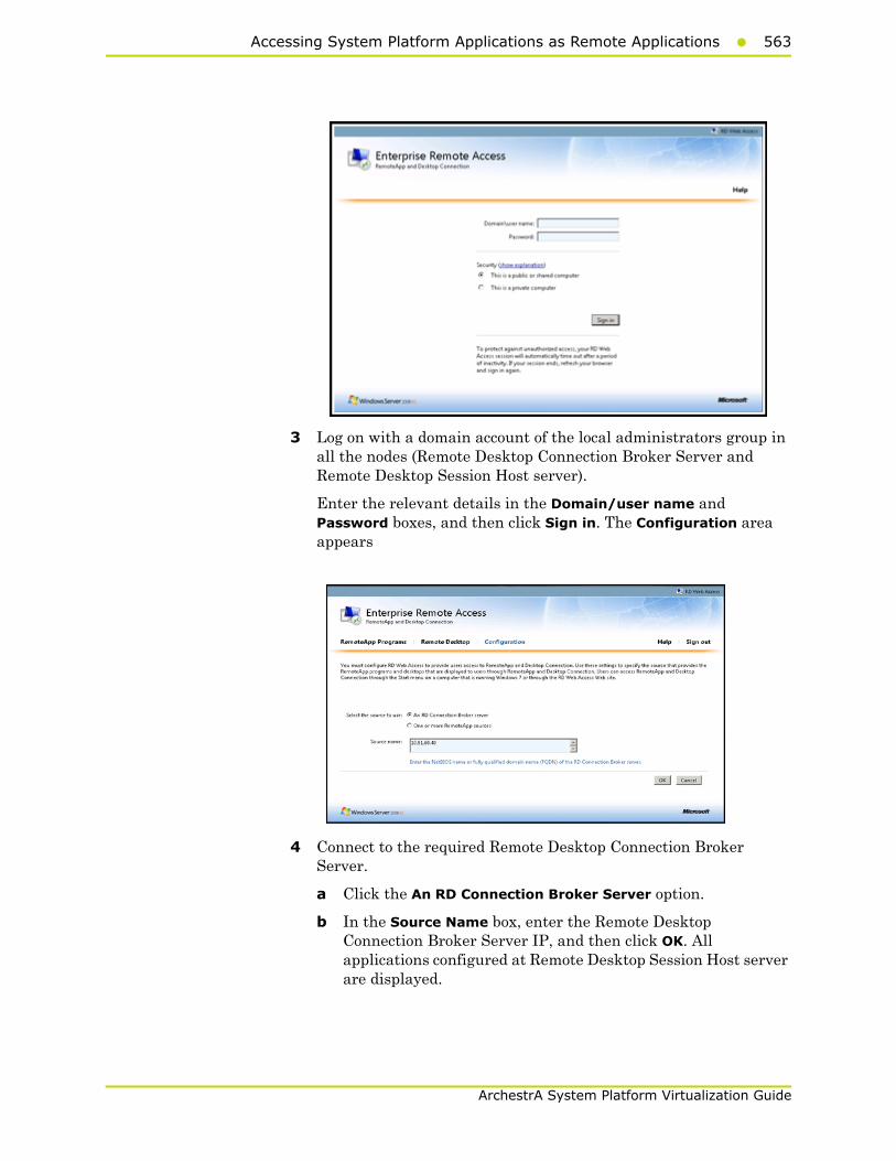
Accessing System Platform Applications as Remote Applications563
ArchestrA System Platform Virtualization Guide
3 Log on with a domain account of the local administrators group in all the nodes (Remote Desktop Connection Broker Server and Remote Desktop Session Host server).
Enter the relevant details in the Domain/user name and Password boxes, and then click Sign in. The Configuration area appears
4 Connect to the required Remote Desktop Connection Broker Server.
a Click the An RD Connection Broker Server option.
b In the Source Name box, enter the Remote Desktop Connection Broker Server IP, and then click OK. All applications configured at Remote Desktop Session Host server are displayed.
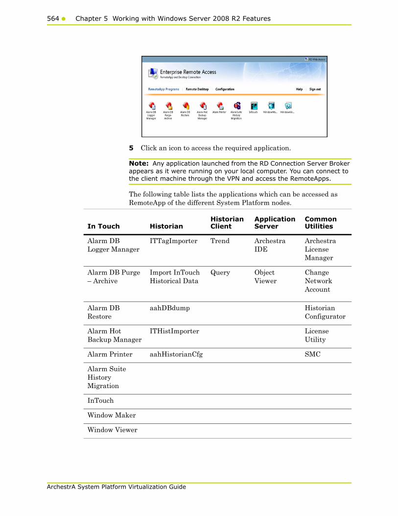
564 Chapter 5 Working with Windows Server 2008 R2 Features
ArchestrA System Platform Virtualization Guide
5 Click an icon to access the required application.
Note: Any application launched from the RD Connection Server Broker appears as it were running on your local computer. You can connect to the client machine through the VPN and access the RemoteApps.
The following table lists the applications which can be accessed as RemoteApp of the different System Platform nodes.
In Touch HistorianHistorian Client
Application Server
Common Utilities
Alarm DB Logger Manager
ITTagImporter Trend Archestra IDE
Archestra License Manager
Alarm DB Purge – Archive
Import InTouch Historical Data
Query Object Viewer
Change Network Account
Alarm DB Restore
aahDBdump Historian Configurator
Alarm Hot Backup Manager
ITHistImporter License Utility
Alarm Printer aahHistorianCfg SMC
Alarm Suite History Migration
InTouch
Window Maker
Window Viewer

Displaying the System Platform Nodes on a Multi-Monitor with a Remote Desktop565
ArchestrA System Platform Virtualization Guide
Displaying the System Platform Nodes on a Multi-Monitor with a Remote Desktop
Prerequisites for the client node where the remote desktop is invoked
• Graphics card that supports multi-monitor and associated drivers
• Client Machine with an operating system (OS) that has RDP 7.0
• Client Machine with the following operating systems:
• Windows XP SP3 Professional (32-bit)
• Windows 7 Professional Edition (64-bit WOW)
• Windows Server 2003 R2 SP2 Standard Edition (32-bit)
• Windows Server 2008 R2 Standard Edition (64-bit WOW)
Note: RDP 7.0 features are available for computers that are running Windows XP Service Pack 3 (SP3), Windows Vista Service Pack 1 (SP1), and Windows Vista Service Pack 2 (SP2). To use Windows XP SP3, Windows Vista SP1 and Windows Vista SP2 client machine must be updated with the RDP 7.0.
Note: Windows Server 2003 does not support RDP 7.0. To use Windows XP, the client machine must be updated with RDP 7.0.
After the client machine is prepared, you can display the system platform on a multi-monitor with a remote desktop.
To display the system platform nodes on a multi-monitor with a remote desktop
1 Ensure that the client machine is able to detect plugged-in secondary monitors. On the Start menu, click Control Panel, Display, Change Display Settings, then Detect. This ensures that all plugged-in monitors are detected.
2 Modify the display settings.
a On the Control Panel window, click Display Change, then Display settings. The Change the appearance of your displays area appears.
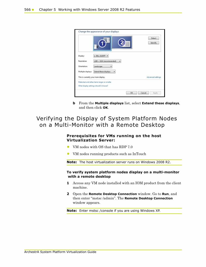
566 Chapter 5 Working with Windows Server 2008 R2 Features
ArchestrA System Platform Virtualization Guide
b From the Multiple displays list, select Extend these displays, and then click OK.
Verifying the Display of System Platform Nodes on a Multi-Monitor with a Remote Desktop
Prerequisites for VMs running on the host Virtualization Server:
• VM nodes with OS that has RDP 7.0
• VM nodes running products such as InTouch
Note: The host virtualization server runs on Windows 2008 R2.
To verify system platform nodes display on a multi-monitor with a remote desktop
1 Access any VM node installed with an IOM product from the client machine.
2 Open the Remote Desktop Connection window. Go to Run, and then enter “mstsc /admin”. The Remote Desktop Connection window appears.
Note: Enter mstsc /console if you are using Windows XP.
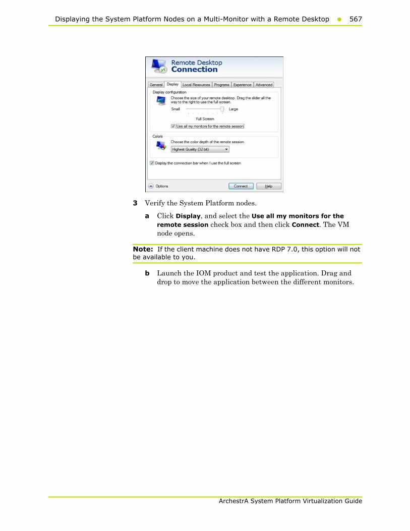
Displaying the System Platform Nodes on a Multi-Monitor with a Remote Desktop567
ArchestrA System Platform Virtualization Guide
3 Verify the System Platform nodes.
a Click Display, and select the Use all my monitors for the remote session check box and then click Connect. The VM node opens.
Note: If the client machine does not have RDP 7.0, this option will not be available to you.
b Launch the IOM product and test the application. Drag and drop to move the application between the different monitors.
568 Chapter 5 Working with Windows Server 2008 R2 Features
ArchestrA System Platform Virtualization Guide
Using the Multi-Monitors as a Single DisplayThe multiple monitors configured on the client node, from where the remote desktop session is invoked, are used as independent displays when the remote session is used to connect to the System Platform products except InTouch installed, on the VM nodes. In case of InTouch, the multi-monitors can be used either as independent displays or as a single display.
To use the multi-monitors as a single display
1 On an InTouch VM node, go to the path where win.ini exists and open win.ini. For example, the path is C:\User\<User_Name>\AppData\Local\Wonderware, where <User_Name> is the user login with which the remote session from the client connects to this VM node.
2 Enter the following parameters under the InTouch section and save it.
• MultiScreen – Enter “1” to enable the multi-monitor mode. Enter “0” to disable the multi-monitor mode.
• MultiScreenWidth – Enter the width of a single screen in pixels.
• MultiScreenHeight – Enter the height of a single screen in pixels. For example, if you want to show your InTouch application with a screen resolution of 2560 x 1024 on two horizontal monitors, enter the following:
• “[InTouch]
• MultiScreen=1
• MultiScreenWidth=1280
• MultiScreenHeight=1024”
3 Verify the settings. On the Start menu, click All Programs, Wonderware, then InTouch. The InTouch Application Manager window appears. Note that the window appears across all monitors as a single display.
Refer to the TechNote on multi-monitors for InTouch at https://wdnresource.wonderware.com/support/kbcd/html/1/T001115.htm
Working with Network Load Balancing569
ArchestrA System Platform Virtualization Guide
Working with Network Load BalancingNetwork Load Balancing (NLB) distributes traffic across several servers by using the TCP/IP networking protocol. You can use NLB with a terminal server farm to scale the performance of a single terminal server by distributing sessions across multiple servers.
About the Network Load Balancing FeatureThe NLB feature in Windows Server 2008 R2 enhances the availability and scalability of Internet server applications such as those used on Web, FTP, firewall, proxy, virtual private network (VPN), and other mission-critical servers. A single computer running Windows Server 2008 R2 provides a limited level of server reliability and scalable performance. However, by combining the resources of two or more computers running one of the products in Windows Server 2008 R2 into a single virtual cluster, an NLB can deliver the reliability and performance that Web servers and other mission-critical servers need.
About Remote Desktop Connection BrokerRemote Desktop Connection Broker keeps track of user sessions in a load-balanced Remote Desktop Session Host server farm. The Remote Desktop Connection Broker database stores session information, (including the name of the Remote Desktop Session Host server where each session resides), the session state for each session, the session ID for each session; and the user name associated with each session. Remote Desktop Connection Broker uses this information to redirect a user who has an existing session to the Remote Desktop Session Host server where the user’s session resides.
Remote Desktop Connection Broker is also used to provide users with access to RemoteApp and Desktop Connection. RemoteApp and Desktop Connection provide a customized view of RemoteApp programs and virtual desktops. Remote Desktop Connection Broker supports load balancing and reconnection to existing sessions on virtual desktops accessed by using RemoteApp and Desktop Connection. To configure the Remote Desktop Connection Broker server to support RemoteApp and Desktop Connection, use the Remote Desktop Connection Manager tool. For more information, see the Remote Desktop Connection Manager Help in Windows Server 2008 R2.
Remote Desktop Connection Broker that is used in an NLB setup is included in Windows Server® 2008 R2 Standard, Windows Server 2008 R2 Enterprise and Windows 2008 R2 Datacenter.
The NLB feature is included in Windows Server 2008 R2. You do not require a license to use this feature.
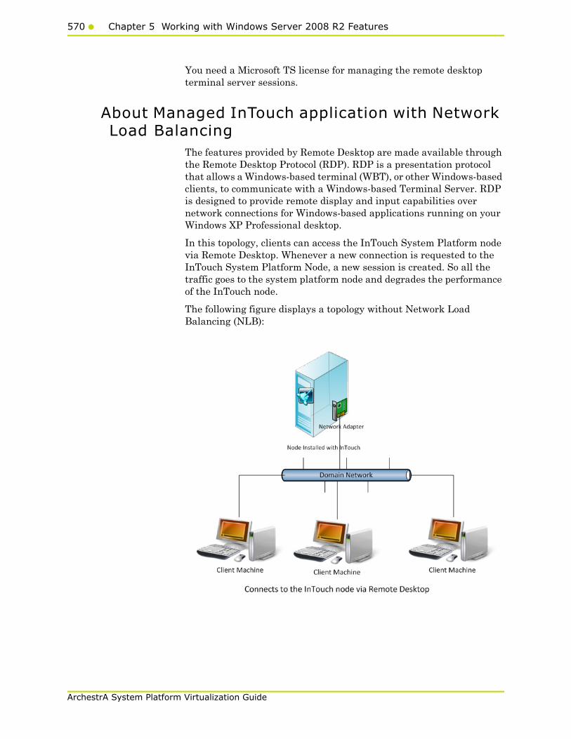
570 Chapter 5 Working with Windows Server 2008 R2 Features
ArchestrA System Platform Virtualization Guide
You need a Microsoft TS license for managing the remote desktop terminal server sessions.
About Managed InTouch application with Network Load Balancing
The features provided by Remote Desktop are made available through the Remote Desktop Protocol (RDP). RDP is a presentation protocol that allows a Windows-based terminal (WBT), or other Windows-based clients, to communicate with a Windows-based Terminal Server. RDP is designed to provide remote display and input capabilities over network connections for Windows-based applications running on your Windows XP Professional desktop.
In this topology, clients can access the InTouch System Platform node via Remote Desktop. Whenever a new connection is requested to the InTouch System Platform Node, a new session is created. So all the traffic goes to the system platform node and degrades the performance of the InTouch node.
The following figure displays a topology without Network Load Balancing (NLB):
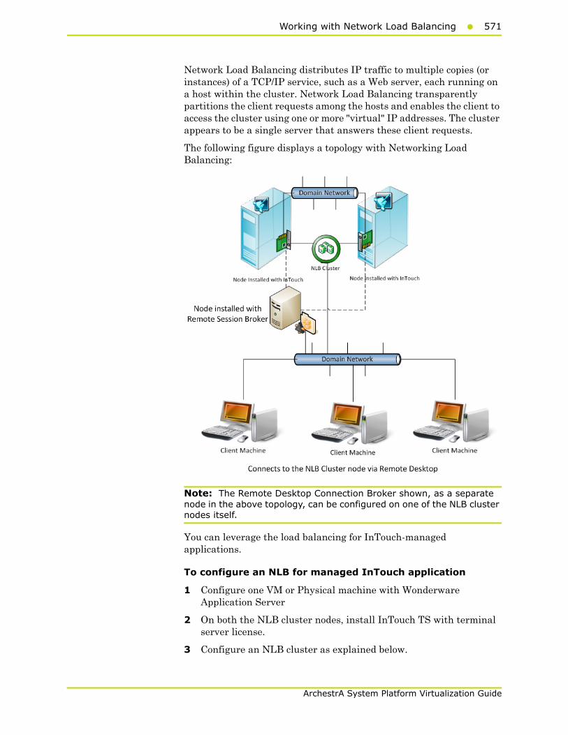
Working with Network Load Balancing571
ArchestrA System Platform Virtualization Guide
Network Load Balancing distributes IP traffic to multiple copies (or instances) of a TCP/IP service, such as a Web server, each running on a host within the cluster. Network Load Balancing transparently partitions the client requests among the hosts and enables the client to access the cluster using one or more "virtual" IP addresses. The cluster appears to be a single server that answers these client requests.
The following figure displays a topology with Networking Load Balancing:
Note: The Remote Desktop Connection Broker shown, as a separate node in the above topology, can be configured on one of the NLB cluster nodes itself.
You can leverage the load balancing for InTouch-managed applications.
To configure an NLB for managed InTouch application
1 Configure one VM or Physical machine with Wonderware Application Server
2 On both the NLB cluster nodes, install InTouch TS with terminal server license.
3 Configure an NLB cluster as explained below.
572 Chapter 5 Working with Windows Server 2008 R2 Features
ArchestrA System Platform Virtualization Guide
4 On Wonderware Application Server node, develop managed InTouch application and deploy it on each of the NLB Cluster node.
Configuring an NLB for InTouch System Platform nodes, allows you to combine application servers to provide a level of scaling and availability that is not possible with an individual server.
NLB distributes incoming client requests to InTouch System Platform nodes among the servers in the cluster to more evenly balance the workload of each InTouch System Platform server and prevent overload on any InTouch System Platform server. To client computers, the NLB cluster appears as a single server that is highly scalable and fault tolerant.
Setting Up Network Load Balancing Cluster
To setup an NLB:
1 Prepare two VM nodes that are remote desktop-enabled and have Windows Server 2008 R2 Operating System.
2 Assign static IPs to both nodes.
Note: NLB disables Dynamic Host Configuration Protocol (DHCP) on each interface it configures, so the IP addresses must be static.
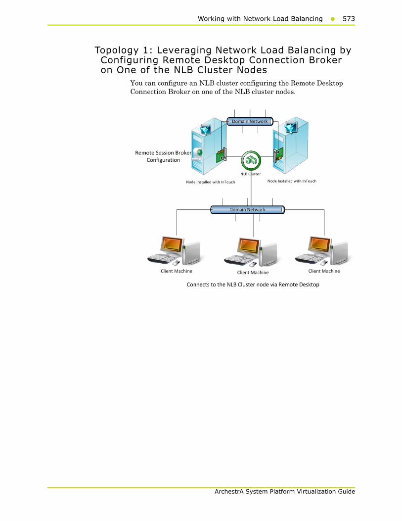
Working with Network Load Balancing573
ArchestrA System Platform Virtualization Guide
Topology 1: Leveraging Network Load Balancing by Configuring Remote Desktop Connection Broker on One of the NLB Cluster Nodes
You can configure an NLB cluster configuring the Remote Desktop Connection Broker on one of the NLB cluster nodes.
574 Chapter 5 Working with Windows Server 2008 R2 Features
ArchestrA System Platform Virtualization Guide
To configure NLB with Topology 1
1 On each of the cluster nodes install Remote Desktop Services. For more information, refer to "Installing Remote Desktop Services" on page 576.
Note: On the Select Role Services screen, select Remote Desktop Session Host and Remote Desktop Connection Broker on one of the Cluster Nodes to configure it as NLB Cluster node as well as RD connection broker node. On the other NLB Cluster node, select only Remote Desktop Session Host.
2 On each of the cluster nodes, install Network Load Balancing. For more information, refer to "Installing Network Load Balancing" on page 583.
3 On the NLB cluster node which is configured as RD connection broker as well, add a Remote Desktop Session Host Server. For more information, refer to "Adding a Remote Desktop Session Host Server" on page 585.
4 On each of the cluster nodes, create a Network Load Balancing Cluster. For more information, refer to "Creating a Network Load Balancing Cluster" on page 587.
5 On each of the cluster nodes, configure Remote Desktop Connection Broker Settings. For more information, refer to "Configuring Remote Desktop Connection Broker Settings" on page 596.

Working with Network Load Balancing575
ArchestrA System Platform Virtualization Guide
Topology 2 : Leveraging Network Load Balancing by Configuring Remote Desktop Connection Broker on a Separate Node
Instead of configuring the Remote Desktop Connection Broker on one of the NLB cluster nodes, you can also configure the Remote Desktop Connection Broker on a separate node.
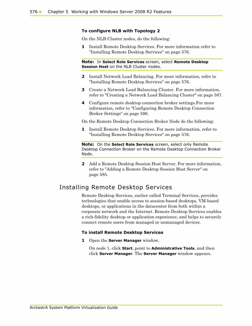
576 Chapter 5 Working with Windows Server 2008 R2 Features
ArchestrA System Platform Virtualization Guide
To configure NLB with Topology 2
On the NLB Cluster nodes, do the following:
1 Install Remote Desktop Services. For more information refer to "Installing Remote Desktop Services" on page 576.
Note: In Select Role Services screen, select Remote Desktop Session Host on the NLB Cluster nodes.
2 Install Network Load Balancing. For more information, refer to "Installing Remote Desktop Services" on page 576.
3 Create a Network Load Balancing Cluster. For more information, refer to "Creating a Network Load Balancing Cluster" on page 587.
4 Configure remote desktop connection broker settings.For more information, refer to "Configuring Remote Desktop Connection Broker Settings" on page 596.
On the Remote Desktop Connection Broker Node do the following:
1 Install Remote Desktop Services. For more information, refer to "Installing Remote Desktop Services" on page 576.
Note: On the Select Role Services screen, select only Remote Desktop Connection Broker on the Remote Desktop Connection Broker Node.
2 Add a Remote Desktop Session Host Server. For more information, refer to "Adding a Remote Desktop Session Host Server" on page 585.
Installing Remote Desktop ServicesRemote Desktop Services, earlier called Terminal Services, provides technologies that enable access to session-based desktops, VM-based desktops, or applications in the datacenter from both within a corporate network and the Internet. Remote Desktop Services enables a rich-fidelity desktop or application experience, and helps to securely connect remote users from managed or unmanaged devices.
To install Remote Desktop Services
1 Open the Server Manager window.
On node 1, click Start, point to Administrative Tools, and then click Server Manager. The Server Manager window appears.
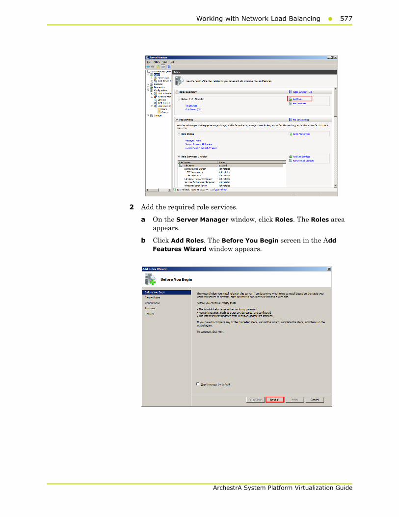
Working with Network Load Balancing577
ArchestrA System Platform Virtualization Guide
2 Add the required role services.
a On the Server Manager window, click Roles. The Roles area appears.
b Click Add Roles. The Before You Begin screen in the Add Features Wizard window appears.

578 Chapter 5 Working with Windows Server 2008 R2 Features
ArchestrA System Platform Virtualization Guide
c Click Next. The Select Server Roles screen appears.
d Select the Remote Desktop Services check box, and then click Next. The Remote Desktop Services screen appears.
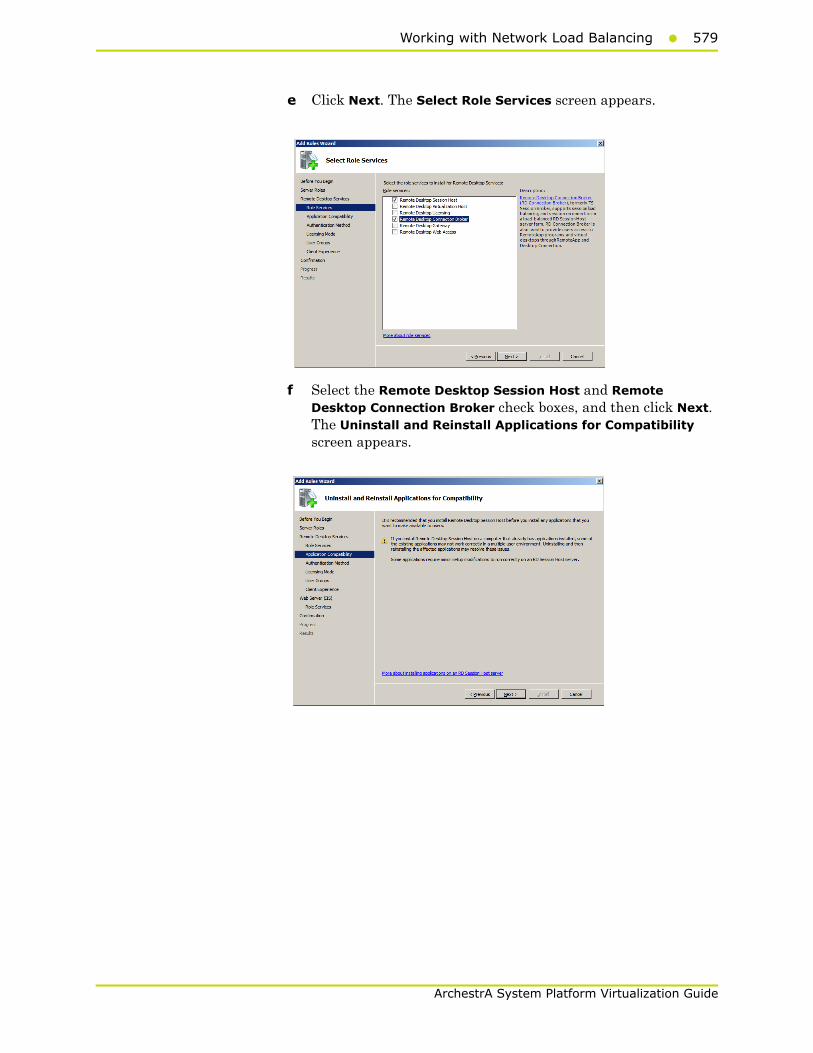
Working with Network Load Balancing579
ArchestrA System Platform Virtualization Guide
e Click Next. The Select Role Services screen appears.
f Select the Remote Desktop Session Host and Remote Desktop Connection Broker check boxes, and then click Next. The Uninstall and Reinstall Applications for Compatibility screen appears.
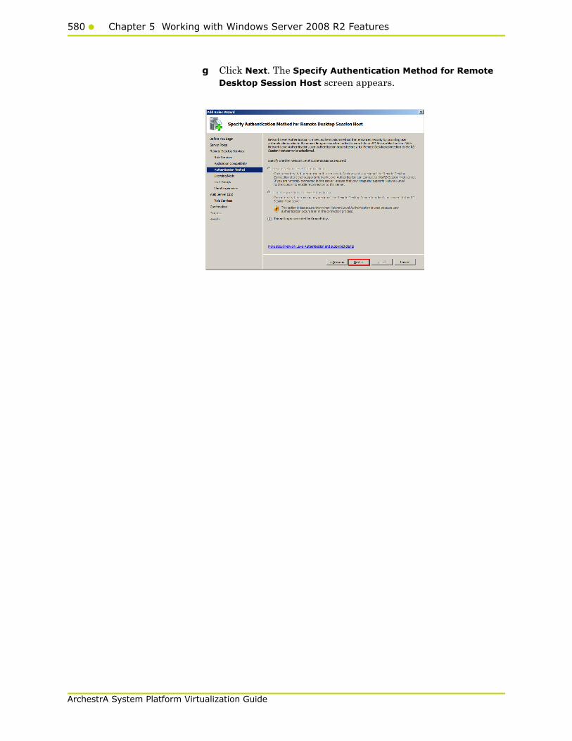
580 Chapter 5 Working with Windows Server 2008 R2 Features
ArchestrA System Platform Virtualization Guide
g Click Next. The Specify Authentication Method for Remote Desktop Session Host screen appears.
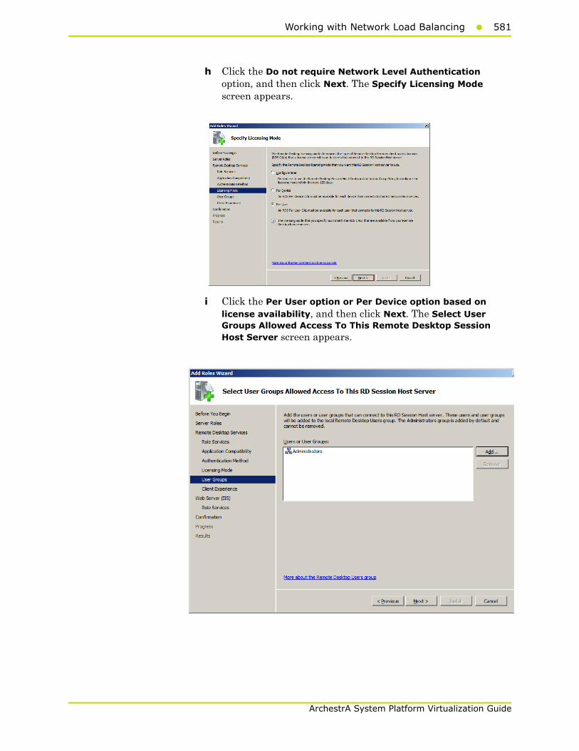
Working with Network Load Balancing581
ArchestrA System Platform Virtualization Guide
h Click the Do not require Network Level Authentication option, and then click Next. The Specify Licensing Mode screen appears.
i Click the Per User option or Per Device option based on license availability, and then click Next. The Select User Groups Allowed Access To This Remote Desktop Session Host Server screen appears.

582 Chapter 5 Working with Windows Server 2008 R2 Features
ArchestrA System Platform Virtualization Guide
Note: There are two types of Windows Client Access Licenses from which to choose: device-based or user-based, also known as Windows Device CALs or Windows User CALs. This means you can choose to acquire a Windows CAL for every device (used by any user) accessing your servers, or you can choose to acquire a Windows CAL for every named user accessing your servers (from any device).
3 Confirm the details you entered, and install the services.
a On the Select User Groups Allowed Access To This Remote Desktop Session Host Server screen, click Next. The Configure Client Experience screen appears.
b Click Next. The Confirm Installation Selections screen appears.
c Click Install. The Installation Results screen appears.

Working with Network Load Balancing583
ArchestrA System Platform Virtualization Guide
After the installation, restart the node. To complete the installation restart the node.
Installing Network Load BalancingYou need to install an NLB on the network adapter that you want to use for the Remote Desktop Protocol (RDP) connection..
To install an NLB
1 Open the Server Manager window.
Click Start, point to Administrative Tools, and then click Server Manager. The Server Manager window appears.
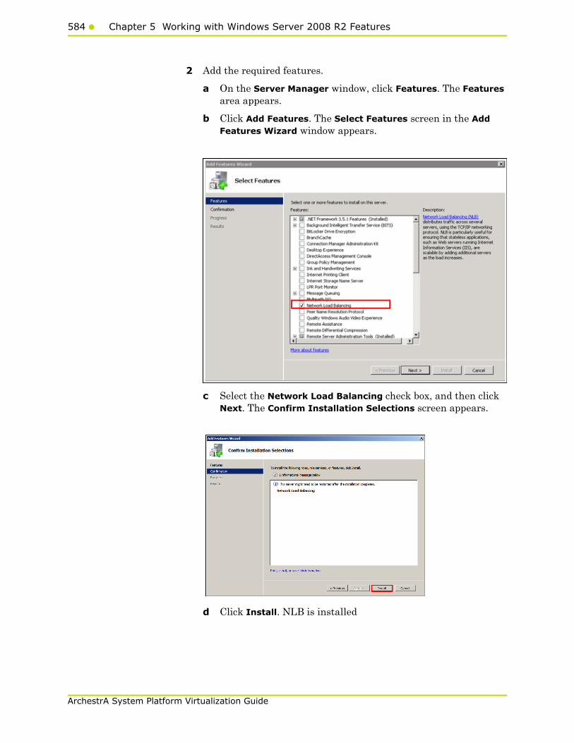
584 Chapter 5 Working with Windows Server 2008 R2 Features
ArchestrA System Platform Virtualization Guide
2 Add the required features.
a On the Server Manager window, click Features. The Features area appears.
b Click Add Features. The Select Features screen in the Add Features Wizard window appears.
c Select the Network Load Balancing check box, and then click Next. The Confirm Installation Selections screen appears.
d Click Install. NLB is installed
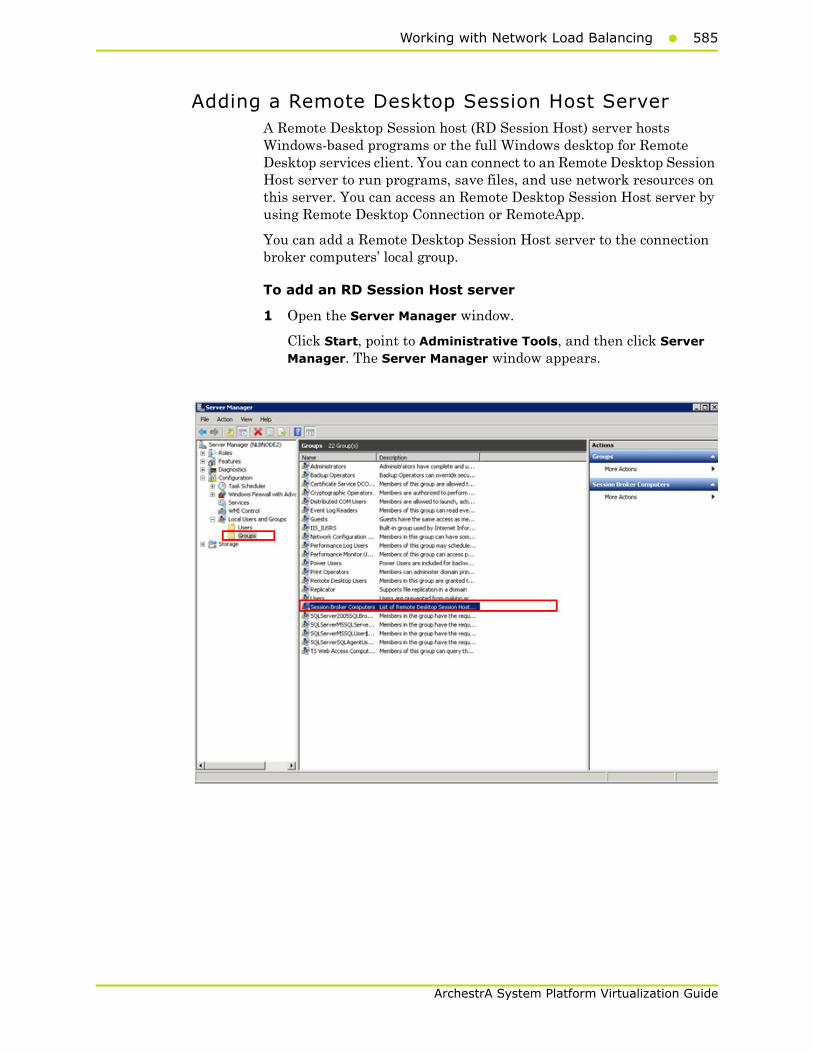
Working with Network Load Balancing585
ArchestrA System Platform Virtualization Guide
Adding a Remote Desktop Session Host Server A Remote Desktop Session host (RD Session Host) server hosts Windows-based programs or the full Windows desktop for Remote Desktop services client. You can connect to an Remote Desktop Session Host server to run programs, save files, and use network resources on this server. You can access an Remote Desktop Session Host server by using Remote Desktop Connection or RemoteApp.
You can add a Remote Desktop Session Host server to the connection broker computers’ local group.
To add an RD Session Host server
1 Open the Server Manager window.
Click Start, point to Administrative Tools, and then click Server Manager. The Server Manager window appears.
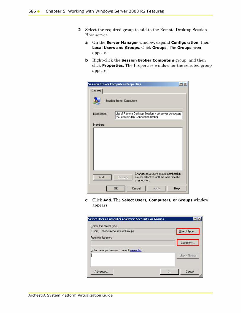
586 Chapter 5 Working with Windows Server 2008 R2 Features
ArchestrA System Platform Virtualization Guide
2 Select the required group to add to the Remote Desktop Session Host server.
a On the Server Manager window, expand Configuration, then Local Users and Groups. Click Groups. The Groups area appears.
b Right-click the Session Broker Computers group, and then click Properties. The Properties window for the selected group appears.
c Click Add. The Select Users, Computers, or Groups window appears.
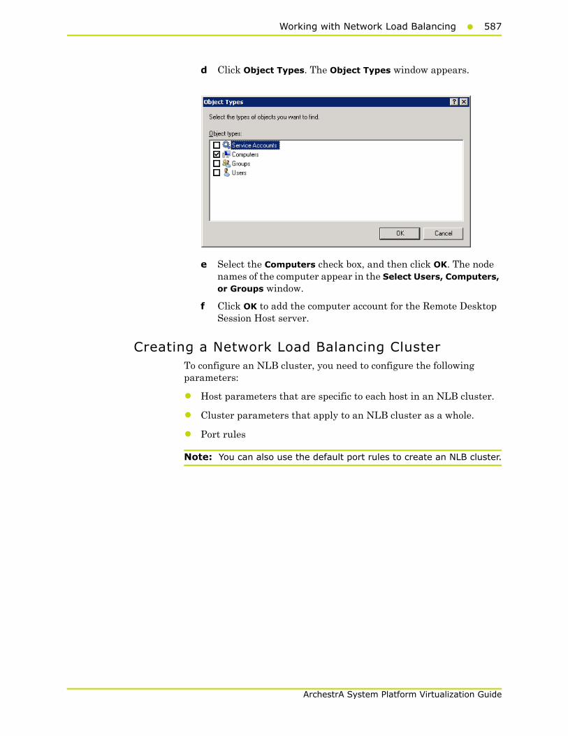
Working with Network Load Balancing587
ArchestrA System Platform Virtualization Guide
d Click Object Types. The Object Types window appears.
e Select the Computers check box, and then click OK. The node names of the computer appear in the Select Users, Computers, or Groups window.
f Click OK to add the computer account for the Remote Desktop Session Host server.
Creating a Network Load Balancing ClusterTo configure an NLB cluster, you need to configure the following parameters:
• Host parameters that are specific to each host in an NLB cluster.
• Cluster parameters that apply to an NLB cluster as a whole.
• Port rules
Note: You can also use the default port rules to create an NLB cluster.
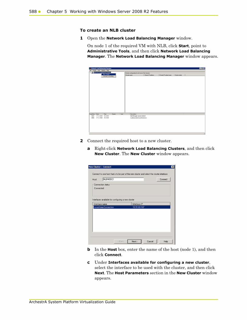
588 Chapter 5 Working with Windows Server 2008 R2 Features
ArchestrA System Platform Virtualization Guide
To create an NLB cluster
1 Open the Network Load Balancing Manager window.
On node 1 of the required VM with NLB, click Start, point to Administrative Tools, and then click Network Load Balancing Manager. The Network Load Balancing Manager window appears.
2 Connect the required host to a new cluster.
a Right-click Network Load Balancing Clusters, and then click New Cluster. The New Cluster window appears.
b In the Host box, enter the name of the host (node 1), and then click Connect.
c Under Interfaces available for configuring a new cluster, select the interface to be used with the cluster, and then click Next. The Host Parameters section in the New Cluster window appears.
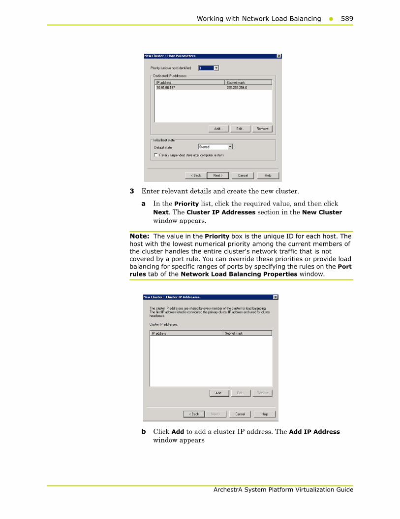
Working with Network Load Balancing589
ArchestrA System Platform Virtualization Guide
3 Enter relevant details and create the new cluster.
a In the Priority list, click the required value, and then click Next. The Cluster IP Addresses section in the New Cluster window appears.
Note: The value in the Priority box is the unique ID for each host. The host with the lowest numerical priority among the current members of the cluster handles the entire cluster's network traffic that is not covered by a port rule. You can override these priorities or provide load balancing for specific ranges of ports by specifying the rules on the Port rules tab of the Network Load Balancing Properties window.
b Click Add to add a cluster IP address. The Add IP Address window appears
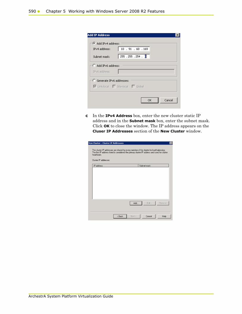
590 Chapter 5 Working with Windows Server 2008 R2 Features
ArchestrA System Platform Virtualization Guide
c In the IPv4 Address box, enter the new cluster static IP address and in the Subnet mask box, enter the subnet mask. Click OK to close the window. The IP address appears on the Cluser IP Addresses section of the New Cluster window.

Working with Network Load Balancing591
ArchestrA System Platform Virtualization Guide
d Click Next. The Cluster Parameters section for the New Cluster window appears.
e In the Full Internet name box, enter the name of the new cluster.
f Click the Multicast option, and then click Next.The Port Rules section in the New Cluster window appears.
Note: If you click the Unicast option, NLB instructs the driver that belongs to the cluster adapter to override the adapter's unique, built-in network address and change its MAC address to the cluster's MAC address. Nodes in the cluster can communicate with addresses outside the cluster subnet. However, no communication occurs between the nodes in the cluster subnet.
Note: If you click the Multicast option, both network adapter and cluster MAC addresses are enabled. Nodes within the cluster are able to communicate with each other within the cluster subnet, and also with addresses outside the subnet.

592 Chapter 5 Working with Windows Server 2008 R2 Features
ArchestrA System Platform Virtualization Guide
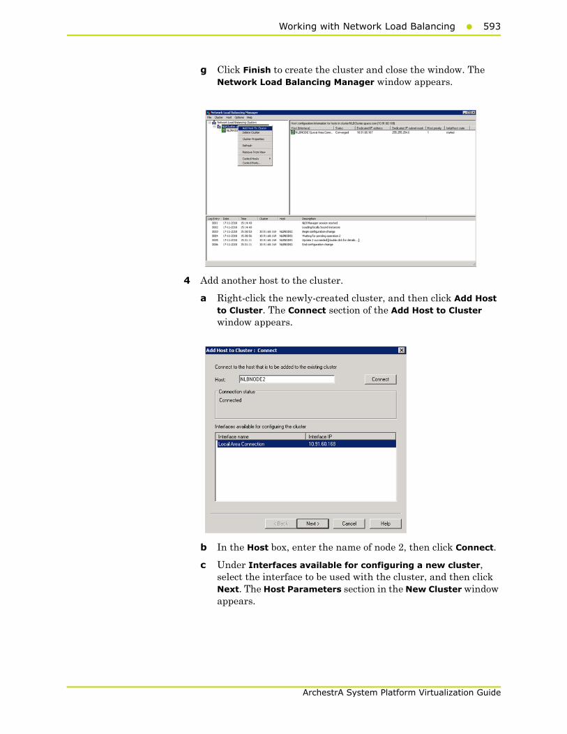
Working with Network Load Balancing593
ArchestrA System Platform Virtualization Guide
g Click Finish to create the cluster and close the window. The Network Load Balancing Manager window appears.
4 Add another host to the cluster.
a Right-click the newly-created cluster, and then click Add Host to Cluster. The Connect section of the Add Host to Cluster window appears.
b In the Host box, enter the name of node 2, then click Connect.
c Under Interfaces available for configuring a new cluster, select the interface to be used with the cluster, and then click Next. The Host Parameters section in the New Cluster window appears.
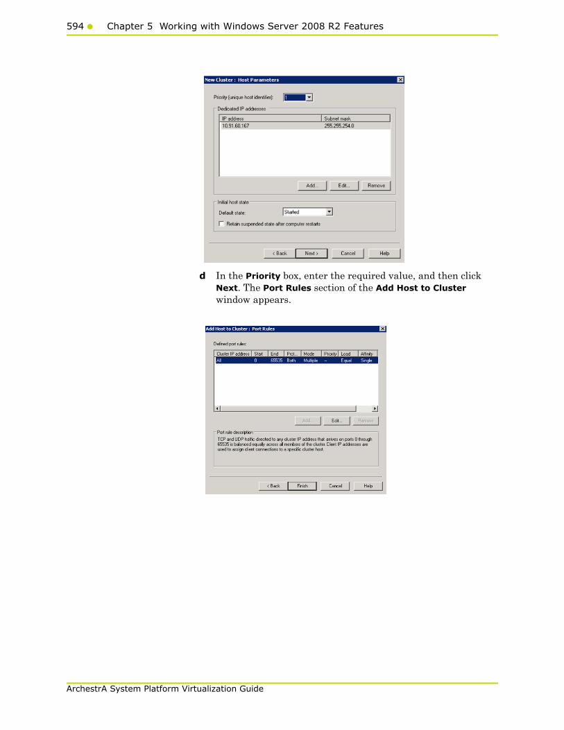
594 Chapter 5 Working with Windows Server 2008 R2 Features
ArchestrA System Platform Virtualization Guide
d In the Priority box, enter the required value, and then click Next. The Port Rules section of the Add Host to Cluster window appears.

Working with Network Load Balancing595
ArchestrA System Platform Virtualization Guide
e Click Finish to add the host and close the window. The Network Load Balancing Manager window appears.
The statuses of both the hosts are displayed.
To add users to the Remote Desktop Users group to access Network Load Balancing Cluster
1 On the Start menu, click Control Panel, System and Security then System Remote settings. The System Properties window appears
2 Under Remote Desktop, click the relevant option to specify the remote desktop versions you want to allow access to.

596 Chapter 5 Working with Windows Server 2008 R2 Features
ArchestrA System Platform Virtualization Guide
3 Select users to provide access to the system
a Click Select Users. The Remote Desktop Users window appears
4 Select the users you want to allow access to, click Add, and then click OK to close the window.
Note: The users can be local users and need not be domain users/administrators. If the users are local users they should be added on both the NLB cluster nodes with same user name and password.
Configuring Remote Desktop Connection Broker Settings
Remote Desktop Connection Broker, earlier called Terminal Services Session Broker (TS Session Broker), is a role service that enables you to do the following:
• Reconnect to existing sessions in a load-balanced Remote Desktop Session Host server farm. You cannot connect a different Remote Desktop Session Host server with a disconnected session and start a new session
• Evenly distribute the session load among Remote Desktop Session Host servers in a load-balanced Remote Desktop Session Host server farm.
• Access virtual desktops hosted on Remote Desktop Virtualization host servers and RemoteApp programs hosted on Remote Desktop Session Host servers through RemoteApp and Desktop Connection.

Working with Network Load Balancing597
ArchestrA System Platform Virtualization Guide
To configure Remote Desktop connection broker settings
1 Open the Remote Desktop Session Host Configuration window.
Click Start, Administrative Tools, Remote Desktop Services, then Remote Desktop Session Host Configuration. The Remote Desktop Session Host Configuration window appears.
2 Edit settings.
a In the Edit settings area, under Remote Desktop Connection Broker, double-click Member of farm in RD Connection Broker. The Properties window appears.
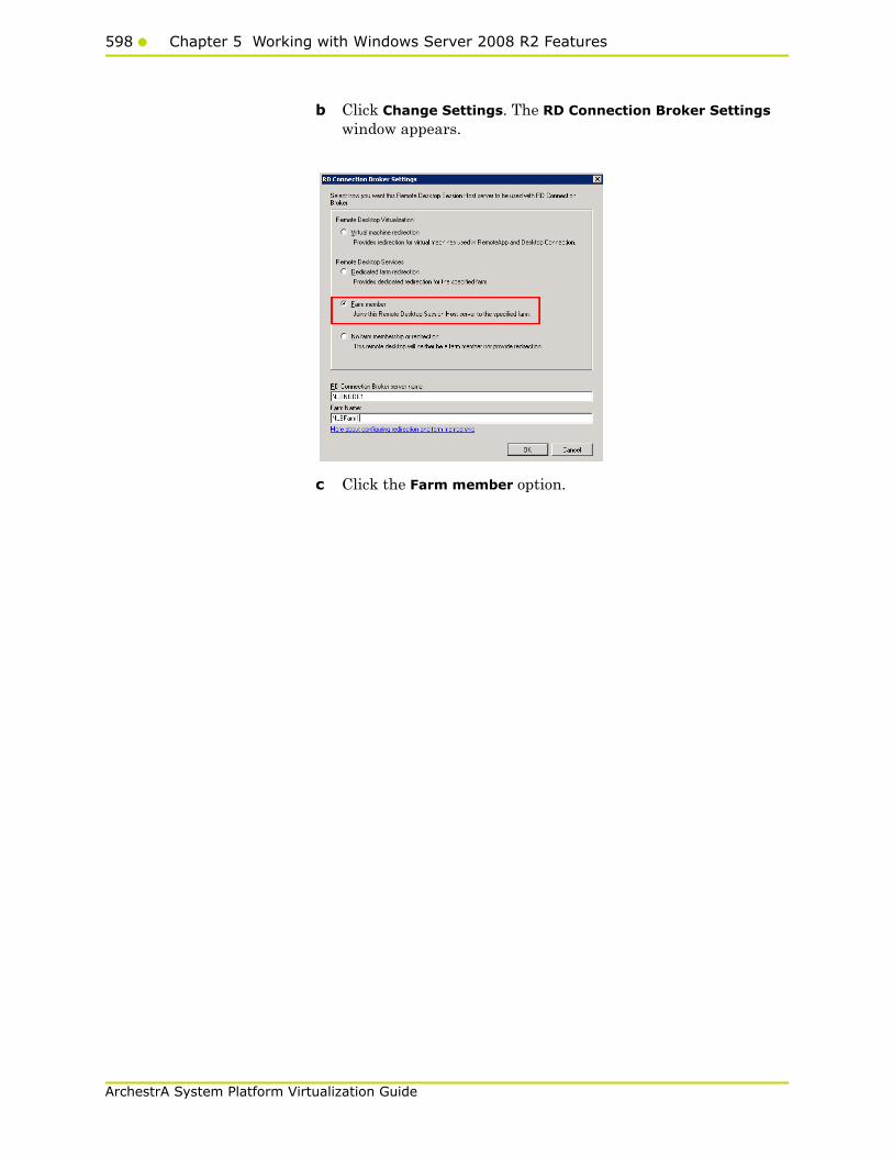
598 Chapter 5 Working with Windows Server 2008 R2 Features
ArchestrA System Platform Virtualization Guide
b Click Change Settings. The RD Connection Broker Settings window appears.
c Click the Farm member option.
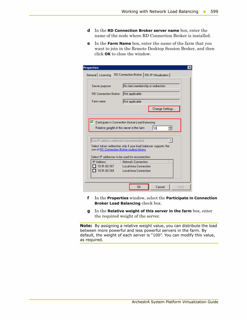
Working with Network Load Balancing599
ArchestrA System Platform Virtualization Guide
d In the RD Connection Broker server name box, enter the name of the node where RD Connection Broker is installed.
e In the Farm Name box, enter the name of the farm that you want to join in the Remote Desktop Session Broker, and then click OK to close the window.
f In the Properties window, select the Participate in Connection Broker Load Balancing check box.
g In the Relative weight of this server in the farm box, enter the required weight of the server.
Note: By assigning a relative weight value, you can distribute the load between more powerful and less powerful servers in the farm. By default, the weight of each server is “100”. You can modify this value, as required.
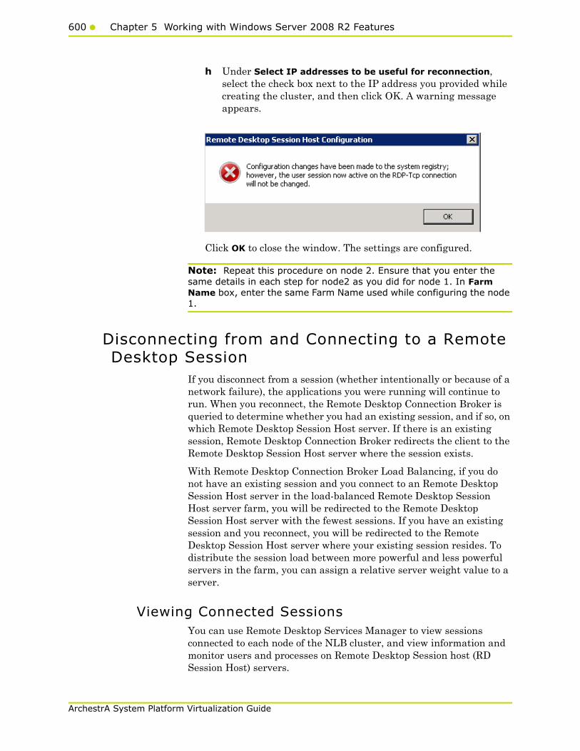
600 Chapter 5 Working with Windows Server 2008 R2 Features
ArchestrA System Platform Virtualization Guide
h Under Select IP addresses to be useful for reconnection, select the check box next to the IP address you provided while creating the cluster, and then click OK. A warning message appears.
Click OK to close the window. The settings are configured.
Note: Repeat this procedure on node 2. Ensure that you enter the same details in each step for node2 as you did for node 1. In Farm Name box, enter the same Farm Name used while configuring the node 1.
Disconnecting from and Connecting to a Remote Desktop Session
If you disconnect from a session (whether intentionally or because of a network failure), the applications you were running will continue to run. When you reconnect, the Remote Desktop Connection Broker is queried to determine whether you had an existing session, and if so, on which Remote Desktop Session Host server. If there is an existing session, Remote Desktop Connection Broker redirects the client to the Remote Desktop Session Host server where the session exists.
With Remote Desktop Connection Broker Load Balancing, if you do not have an existing session and you connect to an Remote Desktop Session Host server in the load-balanced Remote Desktop Session Host server farm, you will be redirected to the Remote Desktop Session Host server with the fewest sessions. If you have an existing session and you reconnect, you will be redirected to the Remote Desktop Session Host server where your existing session resides. To distribute the session load between more powerful and less powerful servers in the farm, you can assign a relative server weight value to a server.
Viewing Connected Sessions You can use Remote Desktop Services Manager to view sessions connected to each node of the NLB cluster, and view information and monitor users and processes on Remote Desktop Session host (RD Session Host) servers.
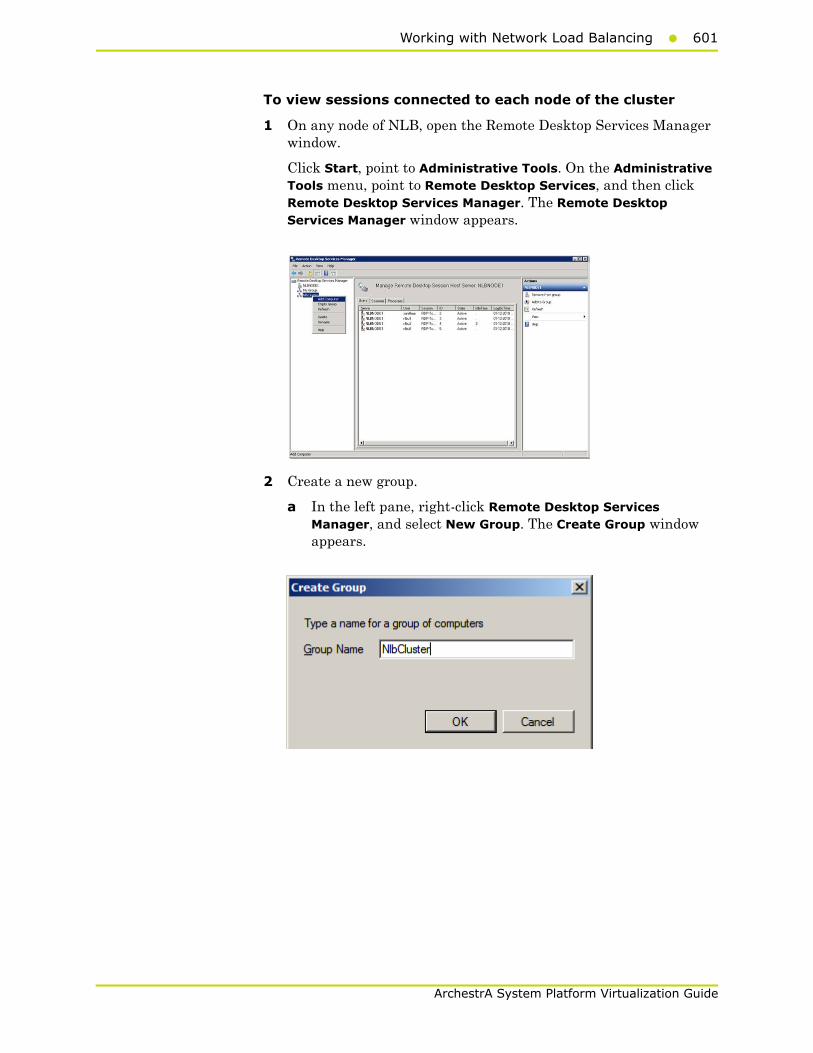
Working with Network Load Balancing601
ArchestrA System Platform Virtualization Guide
To view sessions connected to each node of the cluster
1 On any node of NLB, open the Remote Desktop Services Manager window.
Click Start, point to Administrative Tools. On the Administrative Tools menu, point to Remote Desktop Services, and then click Remote Desktop Services Manager. The Remote Desktop Services Manager window appears.
2 Create a new group.
a In the left pane, right-click Remote Desktop Services Manager, and select New Group. The Create Group window appears.

602 Chapter 5 Working with Windows Server 2008 R2 Features
ArchestrA System Platform Virtualization Guide
b In the Group Name box, enter the name of the group, and then click OK to close the window.
Note: The group name need not be the same as the cluster name.
c Repeat steps c and d of point 3 to add other node names of the cluster to the newly-created group.
You can now select the newly-created group name in the left pane andview the sessions connected to each node of the cluster.

Working with Network Load Balancing603
ArchestrA System Platform Virtualization Guide
3 Add the required computers to the group.
a In the left pane, right-click the newly created group, and then click Add Computer. The Select Computer window appears.
4 Enter name of the new computer.
a Click the Another Computer option.
b In the Another Computer box, enter the node 1 name of the cluster, and then click OK to close the window. The Remote Desktop Services Manager window appears.
Note: You can either type or click Browse to select the required node name.
c Repeat steps 3c and 3d of point 3 to add other node names of the cluster to the newly-created group.
You can now select the newly-created group name in the left pane and view the sessions connected to each node of the cluster.

604 Chapter 5 Working with Windows Server 2008 R2 Features
ArchestrA System Platform Virtualization Guide
Configuring Network Load Balancing Cluster on Microsoft Failover Cluster
Windows Server® 2008 R2 provides two clustering technologies: failover clusters and NLB. Failover clusters primarily provide high availability; NLB provides scalability and, at the same time, helps increase availability of Web-based services.
By using a failover cluster, you can ensure that there is nearly constant access to important server-based resources. A failover cluster is a set of independent computers that work together to increase the availability of services and applications. The clustered servers (called nodes) are connected by physical cables and by software. If one of the nodes fails, another node begins to provide service through a process known as failover.
NLB that is configured in a failover cluster offers high performance in environments in which each request from a client is stateless, and there is no in-memory application state to maintain
.
To configure NLB cluster on Microsoft failover cluster
1 Set up Microsoft Failover Cluster out of two Hyper-V host servers.
2 Configure two VM nodes one on each Hyper-V host server.
Working with Network Load Balancing605
ArchestrA System Platform Virtualization Guide
3 Configure the NLB cluster out of two VM nodes hosted by each Hyper-V host server following the procedures in Leveraging NLB by Configuring Remote Desktop Session Broker on a NLB Cluster Node explained in topology 1. For more information, refer to "Topology 1: Leveraging Network Load Balancing by Configuring Remote Desktop Connection Broker on One of the NLB Cluster Nodes" on page 573.
Understanding the Behavior of NLB Cluster in Microsoft Failover Cluster
1 During a live migration of one of the NLB cluster nodes, there are no disruptions in the active sessions connected to the cluster node. The Reconnect window will not appear on the NLB cluster node as there is no disruption of the active session. After the live migration is complete all sessions connected to the NLB cluster node are retained.
2 During a quick migration, when one of the Hyper-V host servers (Microsoft Failover Cluster Node) is shut down or switched off and the failover is completed, all active sessions on the NLB cluster node hosted by the Microsoft failover cluster node are automatically connected and all sessions on the NLB cluster node are retained.
Observation while using NLB for Managed InTouch System Platform node Observations:
• The NLB feature is qualified for InTouch managed application. InTouch TSE license is required on each of the NLB cluster nodes.
• Local InTouch Tag Alarms are local to the session. Local InTouch Tag alarms updated in a session remain local to that session only.
• ArchestrA Alarms are common across all sessions. ArchestrA Alarms updated in one of the sessions get reflected across all the sessions.
• For IO tags poking in one session, the data reflects across all the sessions. However, while poking local InTouch tags, data does not get updated across all sessions since it is local to the session.
• When you lose the NLB cluster node with the active sessions, all the active sessions on the NLB cluster node closes. To retain all the active sessions, configure the NLB Cluster in a Microsoft Failover Cluster in a Hyper-V environment. The NLB cluster nodes are VM nodes hosted by Hyper-V host servers and Hyper-V host. For more information, refer to "Configuring Network Load Balancing Cluster on Microsoft Failover Cluster" on page 604.
606 Chapter 5 Working with Windows Server 2008 R2 Features
ArchestrA System Platform Virtualization Guide
Hardware Licenses in a Virtualized Environment
Hardware licenses are not supported in the Hyper-V virtualized environment with the release of Windows Server 2008 R2. You may want to verify support under later server editions.
607
ArchestrA System Platform Virtualization Guide
Chapter 6
Creating Virtual Images
About Virtual ImagesA virtual image is a software implementation of a machine or computer that executes programs as though it were a physical machine. It is an isolated software container that runs its own operating systems and applications and contains its own virtual or software-based CPU, RAM, hard disk, and network interface card.
There is no functional difference between a virtual and a physical machine. However, a virtual machine offers the following advantages over a physical machine:
• Multiple operating system (OS) environments can exist on the same computer, in isolation from each other
• A virtual machine provides an Instruction Set Architecture (ISA) that is somewhat different from a real machine
• A virtual machine enables application provisioning, maintenance, high availability, and disaster recovery
In a Microsoft virtual environment, you can create and manage virtual images with either System Center Virtual Machine Manager 2008 R2 (SCVMM) or Microsoft® Hyper-V Manager.
SCVMM has specific advantages over Hyper-V Manager, and is used in creating and managing the virtual machines.
SCVMM is a stand-alone server application for managing a virtual environment running on Windows Server 2008 Hyper-V, Microsoft Virtual Server, and VMware hosts. By using SCVMM, you can centrally manage physical and virtual machine infrastructures through a single console.

608 Chapter 6 Creating Virtual Images
ArchestrA System Platform Virtualization Guide
You can create and configure virtual machines in SCVMM by using the SCVMM library, and manage virtual machine hosts by creating host groups.
SCVMM Features
Virtual Machine and Host Management
This feature is used to create and manage virtual machines. If you add a host running Windows Server 2008, which is not Hyper-V enabled, SCVMM 2008 automatically enables the Hyper-V role on the host.
Intelligent Placement
When a virtual machine is deployed, SCVMM 2008 analyzes performance data and resource requirements for both the workload and the host. By using this analysis, you can modify placement algorithms to get customized deployment recommendations.
Library Management
The SCVMM library contains file-based resources and hardware profiles that you can use to create standardized virtual machines.
Physical to Virtual (P2V) and Virtual to Virtual (V2V) Conversion
SCVMM 2008 helps improve the P2V experience by integrating the P2V conversion process and using the Volume Shadow Copy Service (VSS) of Windows Server.
SCVMM 2008 also provides a wizard that converts VMware virtual machines to virtual hard disks (VHDs) through an easy and speedy V2V transfer process.
Existing Storage Area Network (SAN)
Virtual machine images are often very large and are slow to move across a local area network (LAN). You can configure SCVMM 2008 to use the application in an environment that has a fiber channel or a SAN, so that you can perform SAN transfers within SCVMM.
After VMM 2008 is configured, the application automatically detects and uses an existing SAN infrastructure to transfer virtual machine files. This transfer facilitates the movement of large virtual machine files at the fastest possible speed, and reduces the impact on LAN.
Virtual Machine Self-Service Portal
You can designate self-service to users and grant them controlled access to specific virtual machines, templates, and other SCVMM 2008 resources through a Web-based portal. This controlled access helps users, such as testers and developers, to allot new virtual machines to themselves. The users can allot the virtual machines according to the controls you set by using the self-service policies.

About Virtual Images609
ArchestrA System Platform Virtualization Guide
Automation with Windows PowerShell
For increased automation and control, you can use Windows PowerShell to run remote scripted services against multiple virtual machines. This lets you avoid the manual processes that are performed in a graphical user interface (GUI). You can also manage host systems by using Windows PowerShell.
Centralized Monitoring and Reporting
Server virtualization enables multiple operating systems to run on a single physical computer as virtual machines. By using the server virtualization technology and VMM, you can consolidate workloads of underutilized servers on to a smaller number of fully-utilized servers and provision new virtual machines. Fewer physical computers lead to reduced costs because of lower hardware, energy, and management overheads.
For more information on SCVMM, refer to "Microsoft System Center Virtual Machine Manager 2008 R2 Reviewer’s Guide".
For more information on installation, refer to http://msdn.microsoft.com/en-us/library/dd380687.aspx#SCVMM.
You can create a virtual image (VM) from the following sources:
• Operating system ISO image
You can create a VM from an operating system with either an existing ISO file on a network location or an extracted ISO file available on a CD or DVD.
In this process, you can use an ISO on the network location or on a CD, and then modify the hardware configuration. You can then create and generate a VM and store it.
For more information, refer to "Preparing a Virtual Image from an Operating System (OS) Image" on page 610.
• Physical machine
You can perform a P2V conversion online or offline.
To start a P2V conversion, SCVMM temporarily installs an agent on the physical source computer that you want to convert. In an online P2V conversion, SCVMM uses VSS to copy data, while the server continues to work with user requests. In this conversion, the source computer does not restart. In an offline P2V conversion, the source computer restarts into the Windows Pre-installation Environment (Windows PE) before SCVMM converts the physical disks to VHDs.
For more information, refer to "Preparing a Virtual Image from a Physical Machine" on page 633.
610 Chapter 6 Creating Virtual Images
ArchestrA System Platform Virtualization Guide
• Another VM image
SCVMM allows you to copy existing virtual machines and create Hyper-V virtual machines.
A V2V conversion process converts virtual machines to VHDs. You can use a V2V conversion to convert either an entire virtual machine or its disk image file to the Microsoft virtual machine format.
To perform a V2V conversion
a Add the host server-based virtual machine files to a SCVMM library.
b Select the Convert Virtual Machine option in the Library view in the SCVMM administrator console.
For more information, refer to "Preparing a Virtual Image from Another Virtual Image" on page 658.
• Ghost backup
You can create VMs from images supported by third-party vendors, such as Norton (Norton Ghost).
SCVMM allows you to create a virtual machine using VHD images. The VHD images are created using a ghost backup.
To create a virtual machine from a ghost backup
a Create a ghost backup (.GHO).
b Convert a ghost backup (.GHO) to a virtual hard disk (.VHD).
c Create a virtual machine from .VHD.
For more information, refer to "Preparing a Virtual Image from a Ghost Backup" on page 676.
For more information on creating VMs, refer to http://technet.microsoft.com/en-us/library/cc764227.aspx.
The following sections describe how to create virtual images using SCVMM.
Preparing a Virtual Image from an Operating System (OS) Image
You can create virtual images (VMs) from an operating system ISO image. An ISO image (International Organization for Standardization) is an archive file or a disk image of an optical disk. The image is composed of data contents of all the written sectors of an optical disk, including the optical disk file system. VMs can be created from either an existing ISO file on your network location or an extracted ISO file available on a CD or DVD.
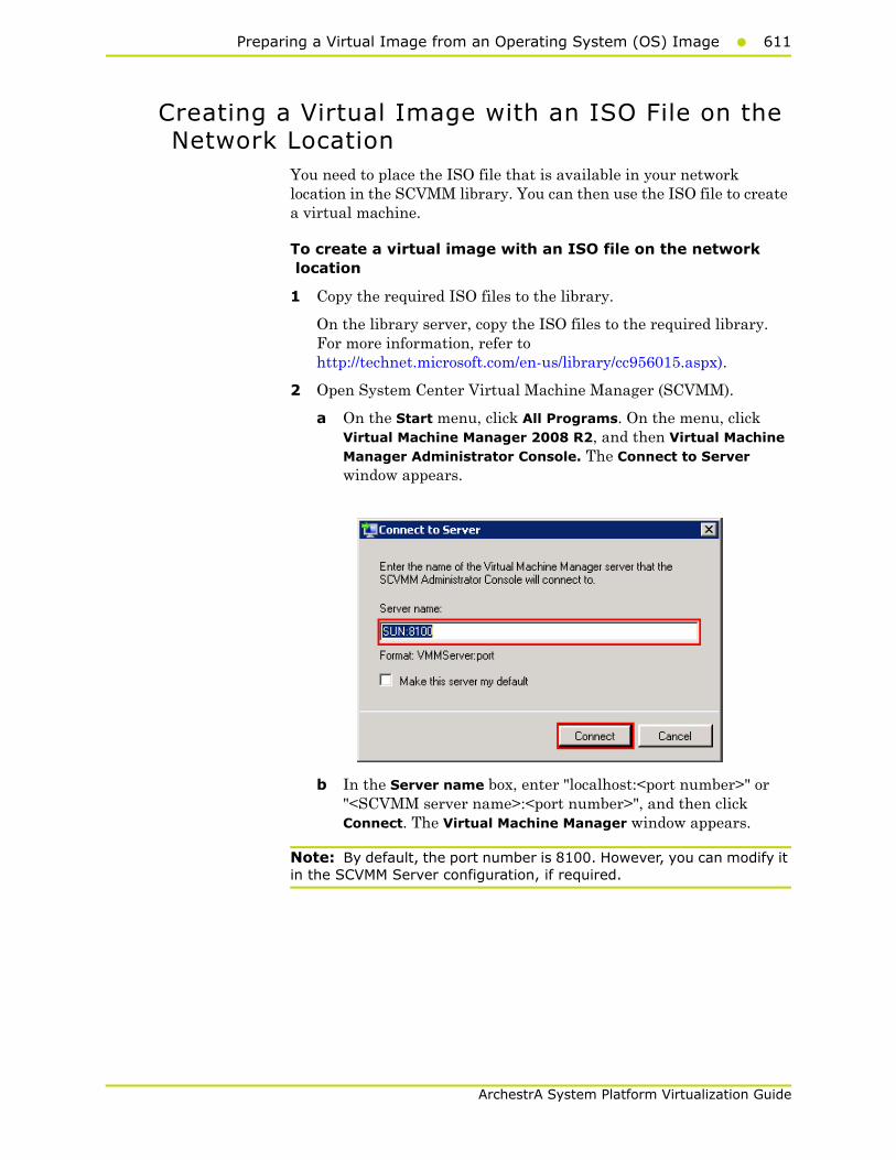
Preparing a Virtual Image from an Operating System (OS) Image611
ArchestrA System Platform Virtualization Guide
Creating a Virtual Image with an ISO File on the Network Location
You need to place the ISO file that is available in your network location in the SCVMM library. You can then use the ISO file to create a virtual machine.
To create a virtual image with an ISO file on the network location
1 Copy the required ISO files to the library.
On the library server, copy the ISO files to the required library. For more information, refer to http://technet.microsoft.com/en-us/library/cc956015.aspx).
2 Open System Center Virtual Machine Manager (SCVMM).
a On the Start menu, click All Programs. On the menu, click Virtual Machine Manager 2008 R2, and then Virtual Machine Manager Administrator Console. The Connect to Server window appears.
b In the Server name box, enter "localhost:<port number>" or "<SCVMM server name>:<port number>", and then click Connect. The Virtual Machine Manager window appears.
Note: By default, the port number is 8100. However, you can modify it in the SCVMM Server configuration, if required.

612 Chapter 6 Creating Virtual Images
ArchestrA System Platform Virtualization Guide
3 Add ISO files in the SCVMM library.
c On the Virtual Machine Manager window, click Go. On the menu, click Library. The library servers are displayed.
d In the Resources pane, right-click the library share where you have copied the files, and then click Refresh. The files on the share are indexed in the Virtual Machine Manager window and displayed in the Library Servers list.
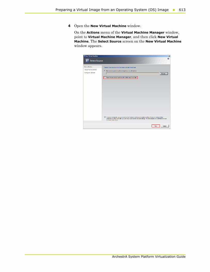
Preparing a Virtual Image from an Operating System (OS) Image613
ArchestrA System Platform Virtualization Guide
4 Open the New Virtual Machine window.
On the Actions menu of the Virtual Machine Manager window, point to Virtual Machine Manager, and then click New Virtual Machine. The Select Source screen on the New Virtual Machine window appears.

614 Chapter 6 Creating Virtual Images
ArchestrA System Platform Virtualization Guide
5 Select the source machine or hard disk you want to use for the new VM.
On the Select Source screen, click the Create the new virtual machine with a blank virtual hard disk option, and then click Next. The Virtual Machine Identity screen appears.
Note: By default, the Use an existing virtual machine, template, or virtual hard disk option is selected.
6 Enter the details of the new VM.
Enter the virtual machine name, owner name, and description name, and then click Next. The Configure Hardware screen appears.
Note: You can either type or click Browse to select the relevant owner name.

Preparing a Virtual Image from an Operating System (OS) Image615
ArchestrA System Platform Virtualization Guide
7 Enter the hardware details for the new VM.
Note: In the Configure Hardware screen, ensure that there is at least one network adapter listed under Network Adapters.
a In the Configure Hardware screen, click Processor. The CPU area appears.
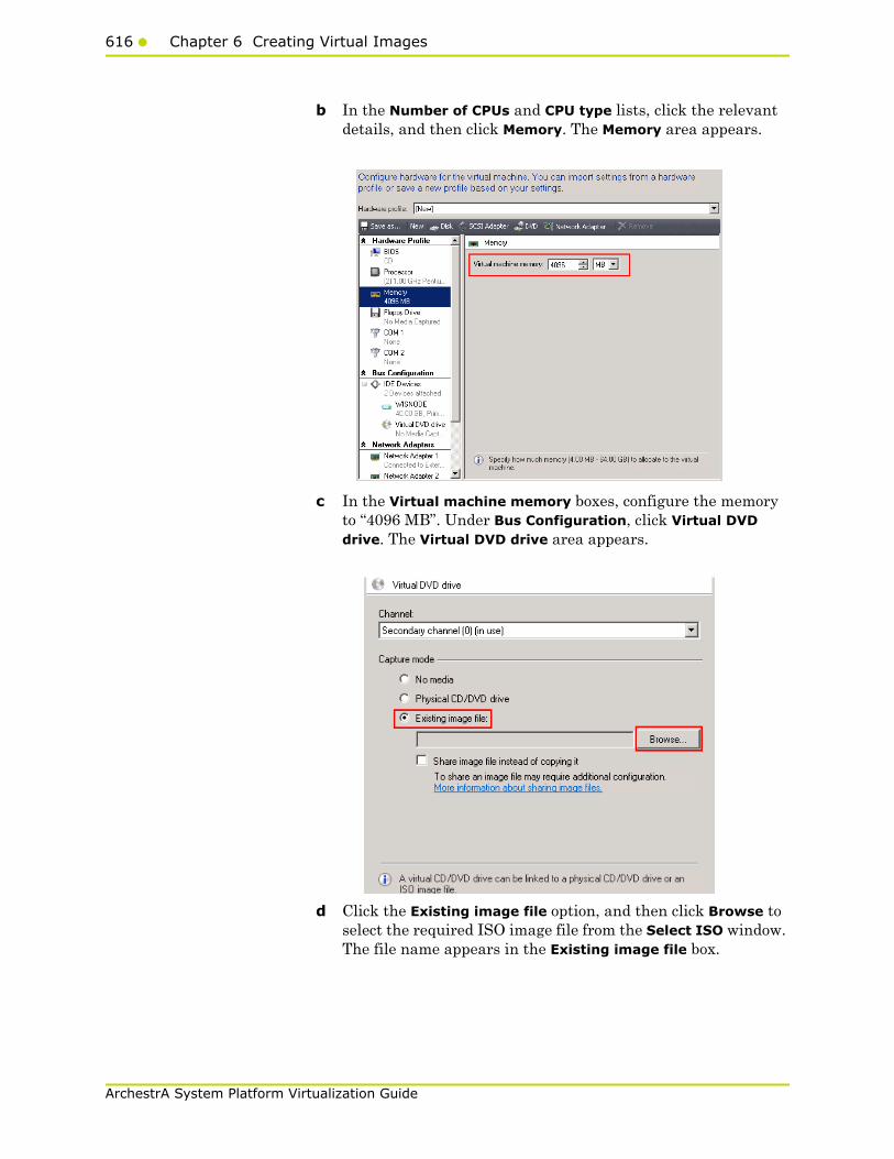
616 Chapter 6 Creating Virtual Images
ArchestrA System Platform Virtualization Guide
b In the Number of CPUs and CPU type lists, click the relevant details, and then click Memory. The Memory area appears.
c In the Virtual machine memory boxes, configure the memory to “4096 MB”. Under Bus Configuration, click Virtual DVD drive. The Virtual DVD drive area appears.
d Click the Existing image file option, and then click Browse to select the required ISO image file from the Select ISO window. The file name appears in the Existing image file box.

Preparing a Virtual Image from an Operating System (OS) Image617
ArchestrA System Platform Virtualization Guide
e Click Next. The Select Destination screen appears.
f Click the Place the Virtual Machine on a host option, and then click Next. The Select Host screen appears.
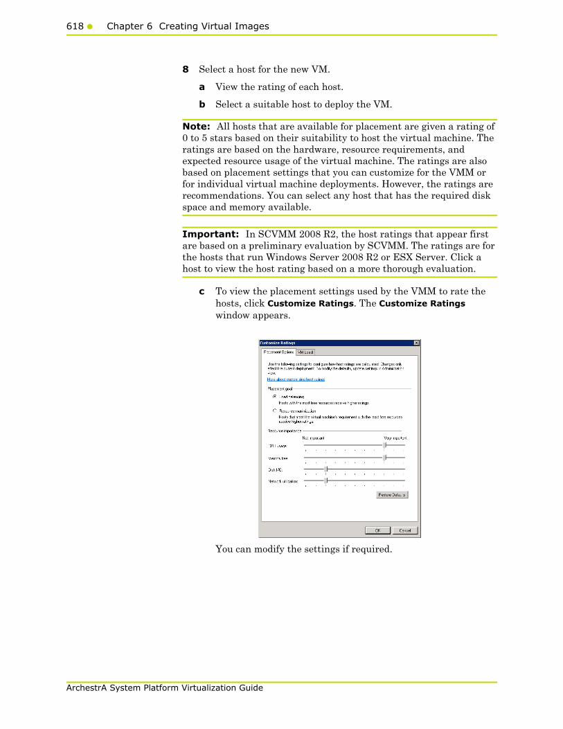
618 Chapter 6 Creating Virtual Images
ArchestrA System Platform Virtualization Guide
8 Select a host for the new VM.
a View the rating of each host.
b Select a suitable host to deploy the VM.
Note: All hosts that are available for placement are given a rating of 0 to 5 stars based on their suitability to host the virtual machine. The ratings are based on the hardware, resource requirements, and expected resource usage of the virtual machine. The ratings are also based on placement settings that you can customize for the VMM or for individual virtual machine deployments. However, the ratings are recommendations. You can select any host that has the required disk space and memory available.
Important: In SCVMM 2008 R2, the host ratings that appear first are based on a preliminary evaluation by SCVMM. The ratings are for the hosts that run Windows Server 2008 R2 or ESX Server. Click a host to view the host rating based on a more thorough evaluation.
c To view the placement settings used by the VMM to rate the hosts, click Customize Ratings. The Customize Ratings window appears.
You can modify the settings if required.

Preparing a Virtual Image from an Operating System (OS) Image619
ArchestrA System Platform Virtualization Guide
d To view additional information about a host rating, select the host and click the following tabs:
• Details
This tab displays the status of the host and lists the virtual machines that are currently deployed on it.
• Ratings Explanation
This tab lists the conditions that cause a host to receive a zero rating.
• SAN Explanation
This tab lists the conditions that prevent a Storage Area Network (SAN) transfer used to move the virtual machine's files to the host.
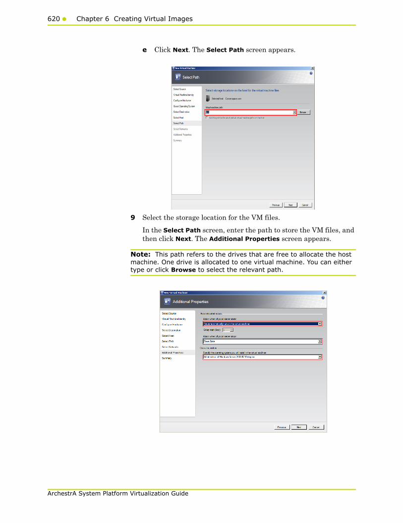
620 Chapter 6 Creating Virtual Images
ArchestrA System Platform Virtualization Guide
e Click Next. The Select Path screen appears.
9 Select the storage location for the VM files.
In the Select Path screen, enter the path to store the VM files, and then click Next. The Additional Properties screen appears.
Note: This path refers to the drives that are free to allocate the host machine. One drive is allocated to one virtual machine. You can either type or click Browse to select the relevant path.

Preparing a Virtual Image from an Operating System (OS) Image621
ArchestrA System Platform Virtualization Guide
10 Specify any additional properties of the VM.
a In the Action when physical server starts list, click Never automatically turn on the virtual machine.
b In the Action when physical server stops list, click Save State.
Note: You can configure the details as required.
c From the Specify the operating system you will install in the virtual machine list, select the operating system based on the ISO selected, and then click Next. The Summary screen appears.
11 Create the new VM.
Select the Start the Virtual machine after deploying it on the host check box if required, and then click Create. The virtual machine is created and the Jobs window appears.
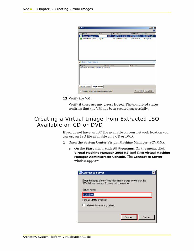
622 Chapter 6 Creating Virtual Images
ArchestrA System Platform Virtualization Guide
12 Verify the VM.
Verify if there are any errors logged. The completed status confirms that the VM has been created successfully.
Creating a Virtual Image from Extracted ISO Available on CD or DVD
If you do not have an ISO file available on your network location you can use an ISO file available on a CD or DVD.
1 Open the System Center Virtual Machine Manager (SCVMM).
a On the Start menu, click All Programs. On the menu, click Virtual Machine Manager 2008 R2, and then Virtual Machine Manager Administrator Console. The Connect to Server window appears.

Preparing a Virtual Image from an Operating System (OS) Image623
ArchestrA System Platform Virtualization Guide
b In the Server name box, enter "localhost:<port number>" or "<SCVMM server name>:<port number>", and then click Connect. The Virtual Machine Manager window appears.
Note: By default, the port number is 8100. However, you can modify it in the SCVMM server configuration, if required.
2 Open the New Virtual Machine window.
On the Actions menu of the Virtual Machine Manager window, point to Virtual Machine Manager, and then click New Virtual Machine. The Select Source screen on the New Virtual Machine window appears.

624 Chapter 6 Creating Virtual Images
ArchestrA System Platform Virtualization Guide
3 Select the source machine or hard disk you want to use for the new VM.
On the Select Source screen, click the Create the new virtual machine with a blank virtual hard disk option, and then click Next. The Virtual Machine Identity screen appears.
4 Enter the details of the new VM.
Enter the virtual machine name, owner name, and description name, and then click Next. The Configure Hardware screen appears.
Note: You can either type or click Browse to select the relevant owner name.
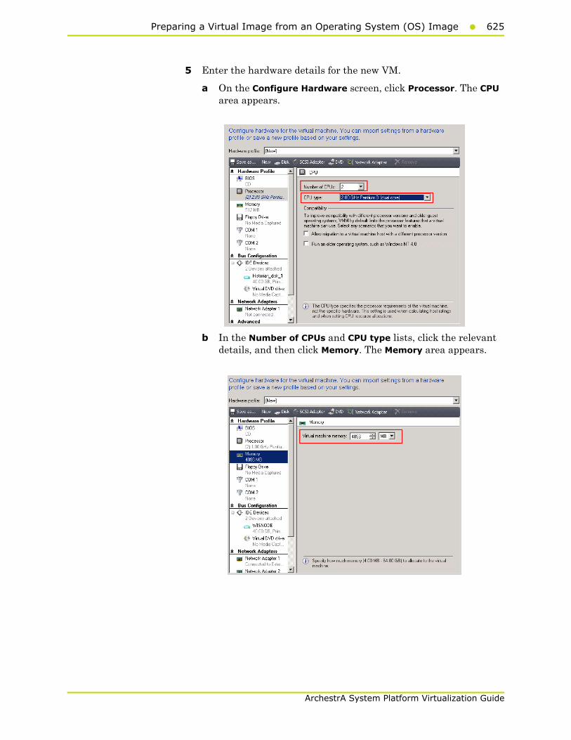
Preparing a Virtual Image from an Operating System (OS) Image625
ArchestrA System Platform Virtualization Guide
5 Enter the hardware details for the new VM.
a On the Configure Hardware screen, click Processor. The CPU area appears.
b In the Number of CPUs and CPU type lists, click the relevant details, and then click Memory. The Memory area appears.
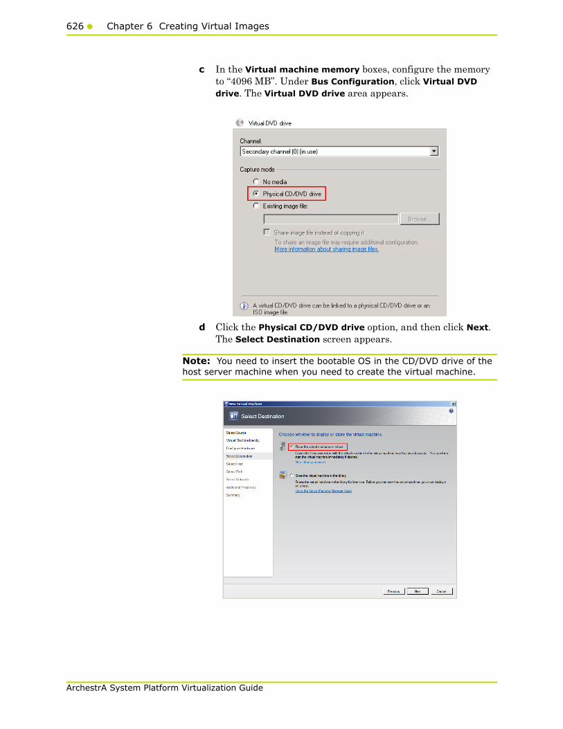
626 Chapter 6 Creating Virtual Images
ArchestrA System Platform Virtualization Guide
c In the Virtual machine memory boxes, configure the memory to “4096 MB”. Under Bus Configuration, click Virtual DVD drive. The Virtual DVD drive area appears.
d Click the Physical CD/DVD drive option, and then click Next. The Select Destination screen appears.
Note: You need to insert the bootable OS in the CD/DVD drive of the host server machine when you need to create the virtual machine.
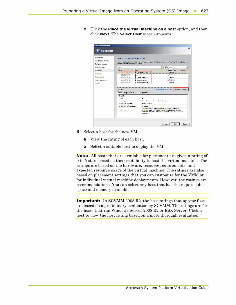
Preparing a Virtual Image from an Operating System (OS) Image627
ArchestrA System Platform Virtualization Guide
e Click the Place the virtual machine on a host option, and then click Next. The Select Host screen appears.
6 Select a host for the new VM.
a View the rating of each host.
b Select a suitable host to deploy the VM.
Note: All hosts that are available for placement are given a rating of 0 to 5 stars based on their suitability to host the virtual machine. The ratings are based on the hardware, resource requirements, and expected resource usage of the virtual machine. The ratings are also based on placement settings that you can customize for the VMM or for individual virtual machine deployments. However, the ratings are recommendations. You can select any host that has the required disk space and memory available.
Important: In SCVMM 2008 R2, the host ratings that appear first are based on a preliminary evaluation by SCVMM. The ratings are for the hosts that run Windows Server 2008 R2 or ESX Server. Click a host to view the host rating based on a more thorough evaluation.

628 Chapter 6 Creating Virtual Images
ArchestrA System Platform Virtualization Guide
c To view the placement settings used by the VMM to rate the hosts, click Customize Ratings. The Customize Ratings window appears.
You can modify the settings if required.
d To view additional information about a host rating, select the host and click the following tabs:
• Details
This tab displays the status of the host and lists the virtual machines that are currently deployed on it.
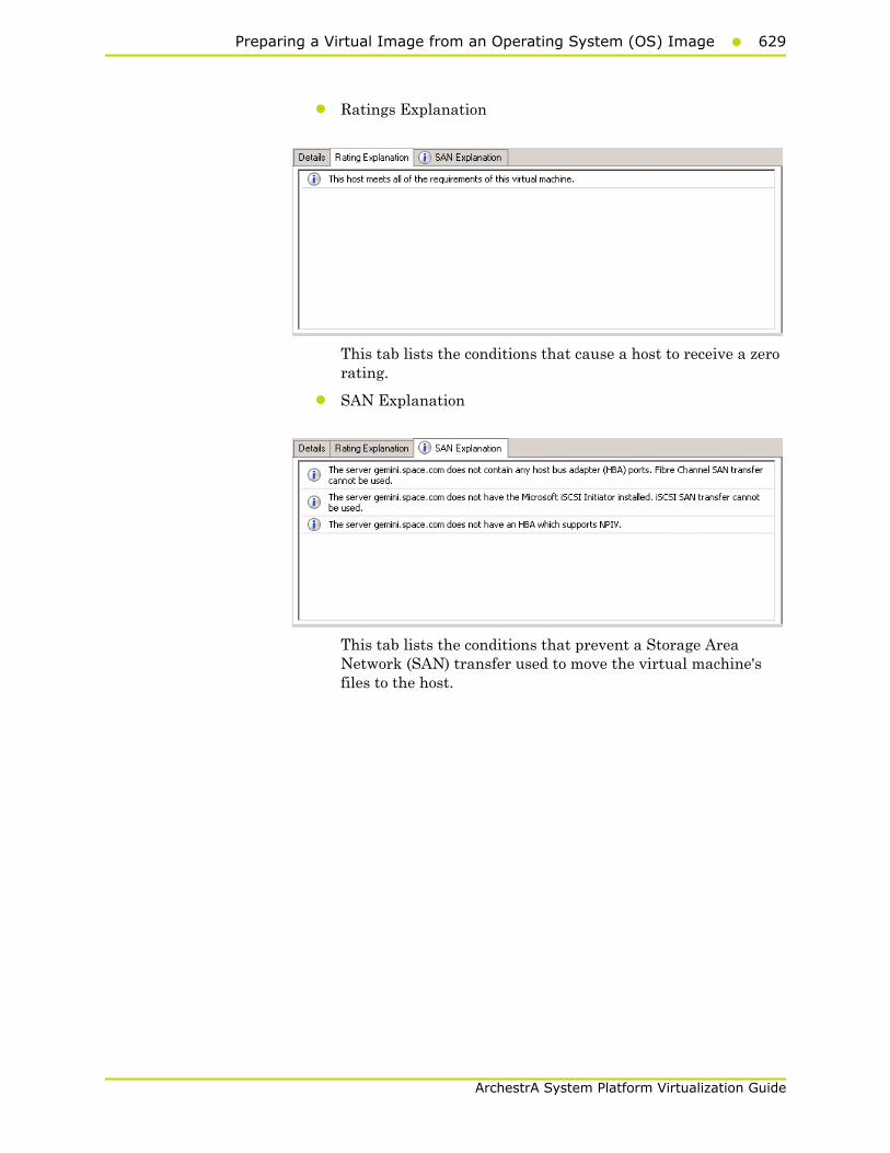
Preparing a Virtual Image from an Operating System (OS) Image629
ArchestrA System Platform Virtualization Guide
• Ratings Explanation
This tab lists the conditions that cause a host to receive a zero rating.
• SAN Explanation
This tab lists the conditions that prevent a Storage Area Network (SAN) transfer used to move the virtual machine's files to the host.

630 Chapter 6 Creating Virtual Images
ArchestrA System Platform Virtualization Guide
e Click Next. The Select Path screen appears.
7 Select the storage location for the VM files.
On the Select Path screen, enter the path to store the VM files, and then click Next. The Additional Properties screen appears.
Note: This path refers to the drives which are free to allocate the host machine. One drive is allocated to one virtual machine. You can either type or click Browse to select the relevant path.
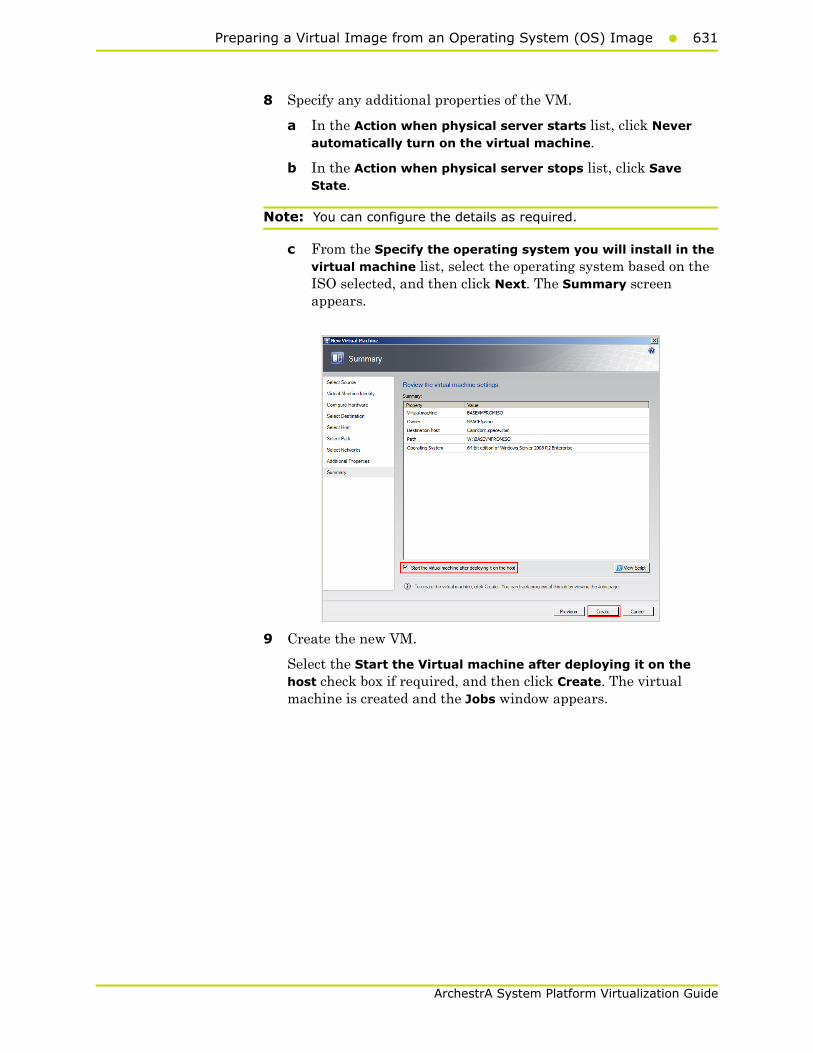
Preparing a Virtual Image from an Operating System (OS) Image631
ArchestrA System Platform Virtualization Guide
8 Specify any additional properties of the VM.
a In the Action when physical server starts list, click Never automatically turn on the virtual machine.
b In the Action when physical server stops list, click Save State.
Note: You can configure the details as required.
c From the Specify the operating system you will install in the virtual machine list, select the operating system based on the ISO selected, and then click Next. The Summary screen appears.
9 Create the new VM.
Select the Start the Virtual machine after deploying it on the host check box if required, and then click Create. The virtual machine is created and the Jobs window appears.

632 Chapter 6 Creating Virtual Images
ArchestrA System Platform Virtualization Guide
10 Verify the VM.
Verify if there are any errors logged. The completed status confirms that the VM has been created successfully.
Tips and RecommendationsNote the following points while creating a VM from an extracted ISO available on a CD or a DVD:
1 Insert the bootable OS CD/DVD in the CD/DVD drive of the host server machine.
2 Stop the virtual machine created.
3 Select No Media in the virtual machine properties in the Virtual Drive Area.
If you do not do these, you will get the following warning message:
Warning (12711)
“VMM cannot complete the WMI operation on server <server name> because of error: [MSCluster_Resource.Name="SCVMM Historian DVD"] the group or resource is not in the correct state to perform the requested operation.
(The group or resource is not in the correct state to perform the requested operation (0x139F)”
Preparing a Virtual Image from a Physical Machine633
ArchestrA System Platform Virtualization Guide
Preparing a Virtual Image from a Physical Machine
You can prepare a virtual image from a physical machine using the following:
• Disk2vhd
• System Center Virtual Machine Manager (SCVMM)
Disk2vhd helps you create Virtual Hard Disk (VHD) versions of physical disks that you can use in Microsoft Virtual PCs or Microsoft Hyper-V VMs. Disk2vhd also helps you create VHDs on local volumes, even ones being converted, although this is not recommended.
One of the advantages of using Disk2vhd is that you can run it on an online system. Disk2vhd uses Volume Snapshot capability, introduced in Windows XP, to create consistent point-in-time snapshots of the volumes you want to include in a conversion.
For more information on Disk2vhd, refer to http://technet.microsoft.com/en-us/sysinternals/ee656415.aspx.
System Center Virtual Machine Manager (SCVMM) allows you to convert an existing physical computer into a VM. During a physical-to-virtual machine conversion (P2V conversion), images of the hard disks on the physical computer are created and formatted as virtual hard disks. These images are used in the new virtual machine. The new virtual machine has the same computer identity as the source machine. SCVMM provides a conversion wizard that automates most of the conversion process.
The following sections describe how to create a virtual image from a physical machine using SCVMM.
You can create a VM from either an online or an offline source machine.
During the creation of a VM from a source machine, SCVMM temporarily installs an agent on the source computer that you want to convert.
For an online P2V conversion, SCVMM uses Volume Shadow Copy Service (VSS) to copy data while the server continues to work with user requests. The source computer is not restarted during the conversion.
For an offline P2V conversion, the source computer restarts into the Windows Pre-installation Environment (Windows PE) before SCVMM converts the physical disks to VHDs.

634 Chapter 6 Creating Virtual Images
ArchestrA System Platform Virtualization Guide
Creating a Virtual Image from a Physical Machine - Online Conversion
You can create a virtual machine from a physical machine in the online mode. This means the source machine continues to function normally during the conversion. The Virtual Machine Manager creates a copy of local New Technology File System (NTFS) volumes and data of VSS-aware applications. The VSS ensures that data is backed up consistently while the source machine continues to work with user requests. The VMM uses the read-only checkpoint to create a VHD.
Note: Since SCVMM uses HTTP and WMI services, ensure that WMI service is running and a firewall is not blocking HTTP and WMI traffic at the source machine.
To create a virtual image from an online physical machine
1 Open the System Center Virtual Machine Manager (SCVMM).
a On the Start menu, click All Programs. On the menu, click Virtual Machine Manager 2008 R2, and then Virtual Machine Manager Administrator Console. The Connect to Server window appears.
b In the Server name box, enter "localhost:<port number>" or "<SCVMM server name>:<port number>", and then click Connect. The Virtual Machine Manager window appears.
Note: By default, the port number is 8100. However, you can modify it in the SCVMM server configuration, if required.
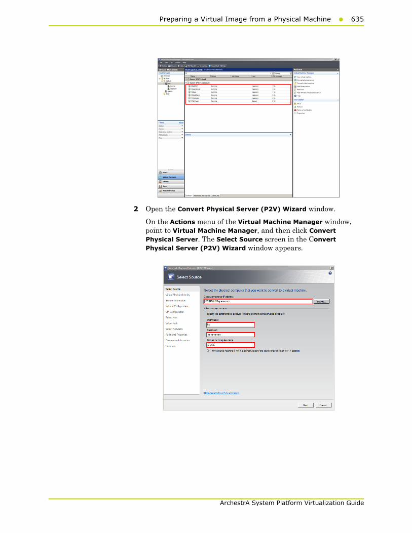
Preparing a Virtual Image from a Physical Machine635
ArchestrA System Platform Virtualization Guide
2 Open the Convert Physical Server (P2V) Wizard window.
On the Actions menu of the Virtual Machine Manager window, point to Virtual Machine Manager, and then click Convert Physical Server. The Select Source screen in the Convert Physical Server (P2V) Wizard window appears.

636 Chapter 6 Creating Virtual Images
ArchestrA System Platform Virtualization Guide
3 Enter the source machine details.
On the Select Source screen, enter the computer name or IP address, user name, password, and the domain name, and then click Next. The Virtual Machine Identity screen appears.
Note: You can either type the computer name or click Browse to select the required computer name.
4 Enter the virtual machine details.
Enter the virtual machine name, owner name, and description name, and then click Next. The System Information screen appears.
Note: You can either type or click Browse to select the relevant owner name.
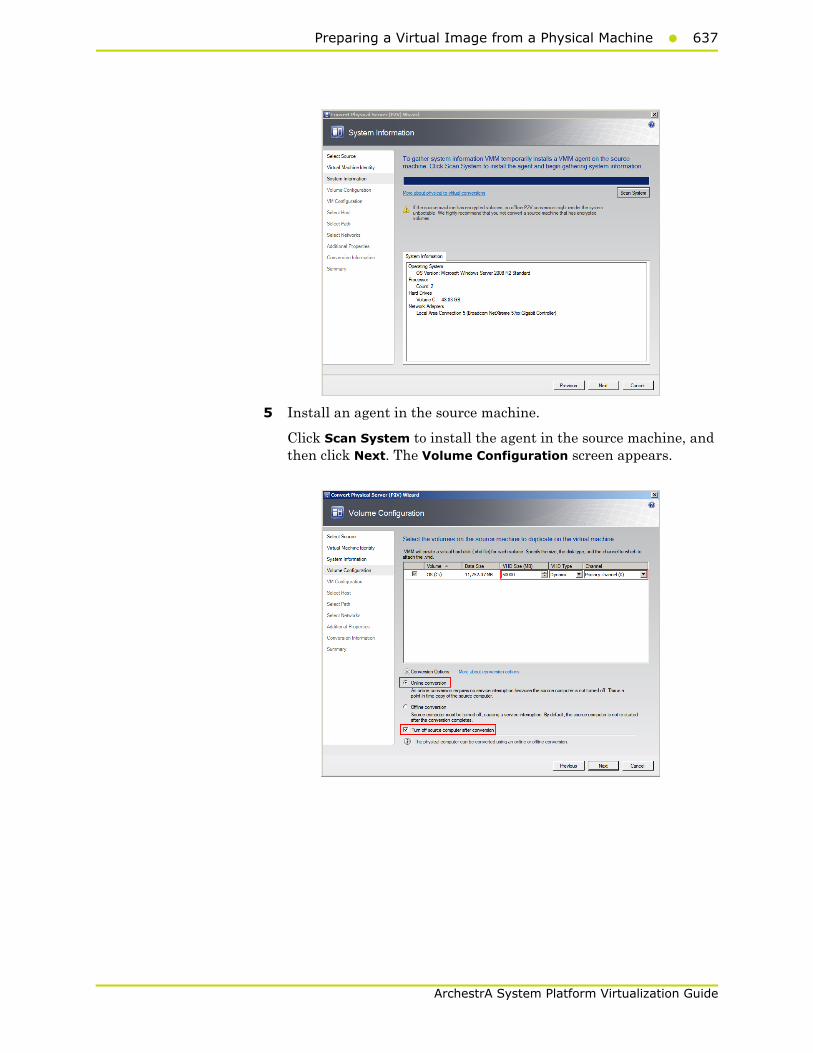
Preparing a Virtual Image from a Physical Machine637
ArchestrA System Platform Virtualization Guide
5 Install an agent in the source machine.
Click Scan System to install the agent in the source machine, and then click Next. The Volume Configuration screen appears.

638 Chapter 6 Creating Virtual Images
ArchestrA System Platform Virtualization Guide
6 Configure the volume for the new VM.
a Select the relevant VHD size, VHD type, and channel.
b Click the Online conversion option.
c Select the Turn Off source computer after conversion check box, and then click Next. The Virtual Machine Configuration screen appears.
7 Specify the number of processors and memory for the new VM.
Select the required figures from the Number of processors and Memory boxes, and then click Next. The Select Host screen appears.

Preparing a Virtual Image from a Physical Machine639
ArchestrA System Platform Virtualization Guide
8 Select a host for the new VM.
a View the rating of each host.
b Select a suitable host to deploy the VM.
Note: All hosts that are available for placement are given a rating of 0 to 5 stars based on their suitability to host the virtual machine. The ratings are based on the hardware, resource requirements, and expected resource usage of the virtual machine. The ratings are also based on placement settings that you can customize for the VMM or for individual virtual machine deployments. However, the ratings are recommendations. You can select any host that has the required disk space and memory available.
Important: In SCVMM 2008 R2, the host ratings that appear first are based on a preliminary evaluation by SCVMM. The ratings are for the hosts that run Windows Server 2008 R2 or ESX Server. Click a host to view the host rating based on a more thorough evaluation.
c To view the placement settings used by the VMM to rate the hosts, click Customize Ratings. The Customize Ratings window appears.
You can modify the settings if required.

640 Chapter 6 Creating Virtual Images
ArchestrA System Platform Virtualization Guide
d To view additional information about a host rating, select the host and click the following tabs:
• Details
This tab displays the status of the host and lists the virtual machines that are currently deployed on it.
• Ratings Explanation
This tab lists the conditions that cause a host to receive a zero rating.
• SAN Explanation
This tab lists the conditions that prevent a Storage Area Network (SAN) transfer used to move the virtual machine's files to the host.
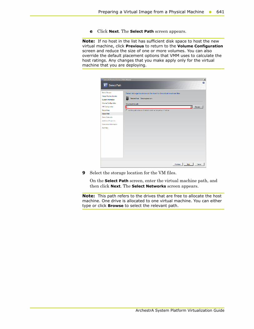
Preparing a Virtual Image from a Physical Machine641
ArchestrA System Platform Virtualization Guide
e Click Next. The Select Path screen appears.
Note: If no host in the list has sufficient disk space to host the new virtual machine, click Previous to return to the Volume Configuration screen and reduce the size of one or more volumes. You can also override the default placement options that VMM uses to calculate the host ratings. Any changes that you make apply only for the virtual machine that you are deploying.
9 Select the storage location for the VM files.
On the Select Path screen, enter the virtual machine path, and then click Next. The Select Networks screen appears.
Note: This path refers to the drives that are free to allocate the host machine. One drive is allocated to one virtual machine. You can either type or click Browse to select the relevant path.

642 Chapter 6 Creating Virtual Images
ArchestrA System Platform Virtualization Guide
10 Select the network to be used for the new VM.
In the Virtual Network list, click the virtual network you want to use for the virtual machine, and then click Next. The Additional Properties window appears.
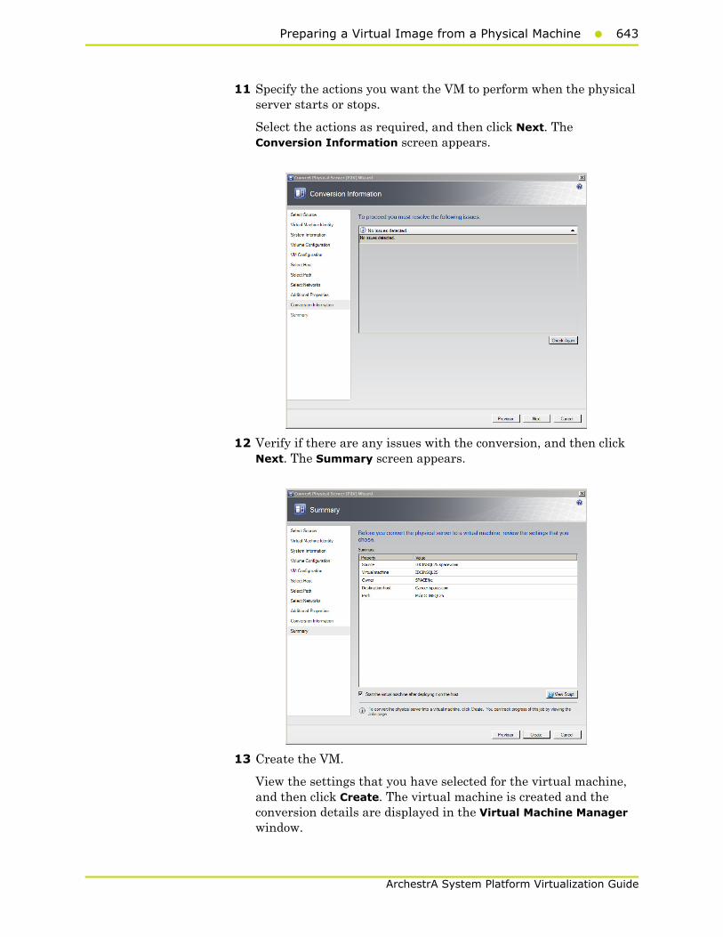
Preparing a Virtual Image from a Physical Machine643
ArchestrA System Platform Virtualization Guide
11 Specify the actions you want the VM to perform when the physical server starts or stops.
Select the actions as required, and then click Next. The Conversion Information screen appears.
12 Verify if there are any issues with the conversion, and then click Next. The Summary screen appears.
13 Create the VM.
View the settings that you have selected for the virtual machine, and then click Create. The virtual machine is created and the conversion details are displayed in the Virtual Machine Manager window.

644 Chapter 6 Creating Virtual Images
ArchestrA System Platform Virtualization Guide
Note: It takes about 45 minutes to convert to a virtual machine.
The Virtual Machine Manager window displays the VM conversion details.
ObservationWhen you create a VM from a physical machine in the online mode, all of the data on the physical machine is not saved in the VM. This happens if an IOM product is installed in the physical machine, for example Historian, which acquires data from a remote SF-enabled Application Server.
Since the physical machine operates during the conversion, any data change that happens during the conversion is stored in the physical machine, but not saved in the VM. The state of the created VM is same as the source machine at the time the conversion is initiated. Hence, any data change that takes place during the conversion is not saved in the VM.
Creating a Virtual Image from a Physical Machine - Offline Conversion
When you create a VM from a physical machine in the offline mode, the source machine restarts in the Windows Pre-installation Environment (Windows PE). SCVMM then clones the disk volume of the source machine to a VHD, and restarts the source machine.

Preparing a Virtual Image from a Physical Machine645
ArchestrA System Platform Virtualization Guide
Creating a VM in the offline mode ensures data consistency and is the only method that can be used for Windows 2000 conversion. It is the recommended method to migrate File Allocation Table (FAT) volumes and convert domain controllers.
For more information on Windows PE, refer to http://technet.microsoft.com/en-us/library/cc766093(WS.10).aspx.
Prerequisites for a source machine during an offline P2V conversion
• The source computer must have at least 512 MB of RAM.
• The source computer cannot be in a perimeter network. A perimeter network or a screened subnet is a collection of devices. Subnets are placed between an intranet and the Internet to help protect the intranet from unauthorized Internet users. The source computer for a P2V conversion can be in any other network topology in which the VMM server can connect to the source machine to temporarily install an agent. The VMM server can also make Windows Management Instrumentation (WMI) calls to the source computer.
To create a virtual image from an offline physical machine
1 Open the System Center Virtual Machine Manager (SCVMM).
a On the Start menu, click All Programs. On the menu, click Virtual Machine Manager 2008 R2, and then Virtual Machine Manager Administrator Console. The Connect to Server window appears.
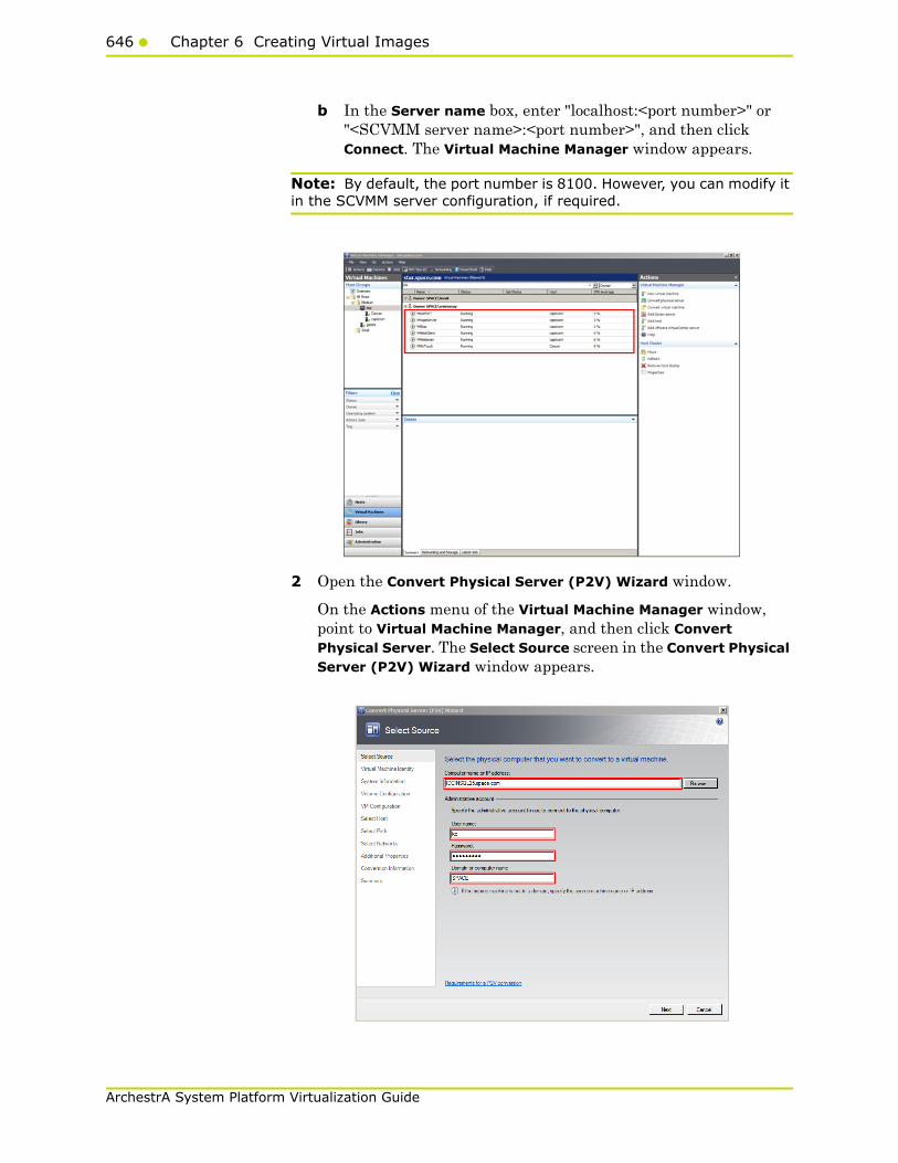
646 Chapter 6 Creating Virtual Images
ArchestrA System Platform Virtualization Guide
b In the Server name box, enter "localhost:<port number>" or "<SCVMM server name>:<port number>", and then click Connect. The Virtual Machine Manager window appears.
Note: By default, the port number is 8100. However, you can modify it in the SCVMM server configuration, if required.
2 Open the Convert Physical Server (P2V) Wizard window.
On the Actions menu of the Virtual Machine Manager window, point to Virtual Machine Manager, and then click Convert Physical Server. The Select Source screen in the Convert Physical Server (P2V) Wizard window appears.
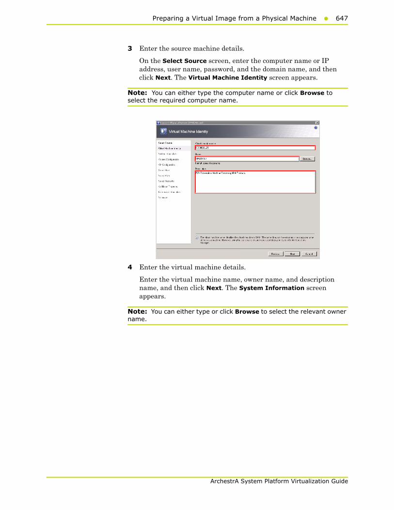
Preparing a Virtual Image from a Physical Machine647
ArchestrA System Platform Virtualization Guide
3 Enter the source machine details.
On the Select Source screen, enter the computer name or IP address, user name, password, and the domain name, and then click Next. The Virtual Machine Identity screen appears.
Note: You can either type the computer name or click Browse to select the required computer name.
4 Enter the virtual machine details.
Enter the virtual machine name, owner name, and description name, and then click Next. The System Information screen appears.
Note: You can either type or click Browse to select the relevant owner name.
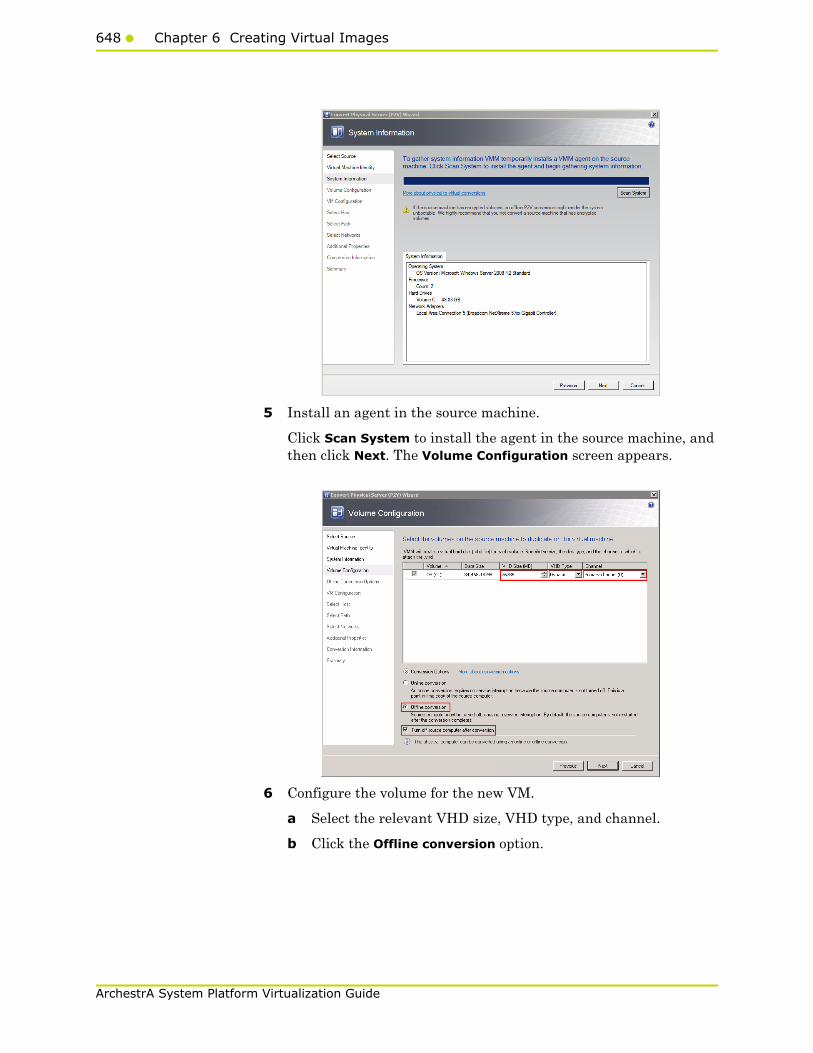
648 Chapter 6 Creating Virtual Images
ArchestrA System Platform Virtualization Guide
5 Install an agent in the source machine.
Click Scan System to install the agent in the source machine, and then click Next. The Volume Configuration screen appears.
6 Configure the volume for the new VM.
a Select the relevant VHD size, VHD type, and channel.
b Click the Offline conversion option.

Preparing a Virtual Image from a Physical Machine649
ArchestrA System Platform Virtualization Guide
c Select the Turn Off source computer after conversion check box, and then click Next. The Offline Conversion Options screen appears.
7 Select an IP address for offline conversion.
Click the required option to obtain an IP address for the offline conversion, and then click Next. The Virtual Machine Configuration window appears.

650 Chapter 6 Creating Virtual Images
ArchestrA System Platform Virtualization Guide
8 Specify the number of processors and memory for the new VM.
Select the required figures from the Number of processors and Memory boxes, and then click Next. The Select Host screen appears.
9 Select a host for the new VM.
a View the rating of each host.
b Select a suitable host to deploy the VM.
Note: All hosts that are available for placement are given a rating of 0 to 5 stars based on their suitability to host the virtual machine. The ratings are based on the hardware, resource requirements, and expected resource usage of the virtual machine. The ratings are also based on placement settings that you can customize for the VMM or for individual virtual machine deployments. However, the ratings are recommendations. You can select any host that has the required disk space and memory available.
Important: In SCVMM 2008 R2, the host ratings that appear first are based on a preliminary evaluation by SCVMM. The ratings are for the hosts that run Windows Server 2008 R2 or ESX Server. Click a host to view the host rating based on a more thorough evaluation.
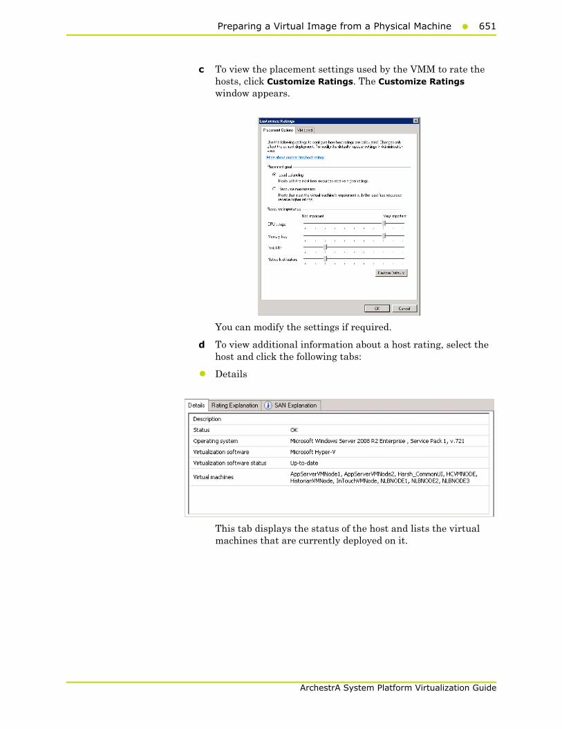
Preparing a Virtual Image from a Physical Machine651
ArchestrA System Platform Virtualization Guide
c To view the placement settings used by the VMM to rate the hosts, click Customize Ratings. The Customize Ratings window appears.
You can modify the settings if required.
d To view additional information about a host rating, select the host and click the following tabs:
• Details
This tab displays the status of the host and lists the virtual machines that are currently deployed on it.
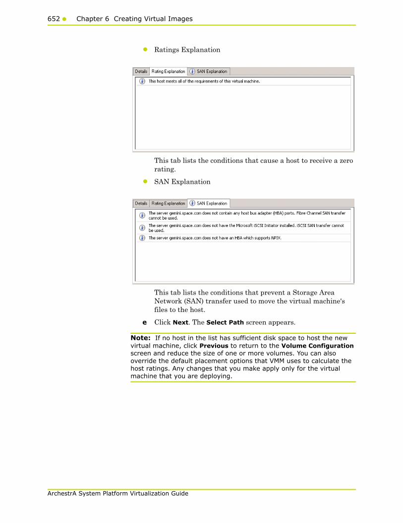
652 Chapter 6 Creating Virtual Images
ArchestrA System Platform Virtualization Guide
• Ratings Explanation
This tab lists the conditions that cause a host to receive a zero rating.
• SAN Explanation
This tab lists the conditions that prevent a Storage Area Network (SAN) transfer used to move the virtual machine's files to the host.
e Click Next. The Select Path screen appears.
Note: If no host in the list has sufficient disk space to host the new virtual machine, click Previous to return to the Volume Configuration screen and reduce the size of one or more volumes. You can also override the default placement options that VMM uses to calculate the host ratings. Any changes that you make apply only for the virtual machine that you are deploying.
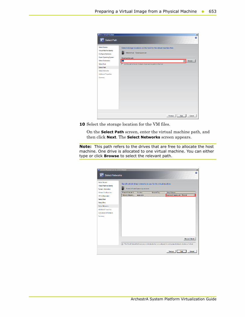
Preparing a Virtual Image from a Physical Machine653
ArchestrA System Platform Virtualization Guide
10 Select the storage location for the VM files.
On the Select Path screen, enter the virtual machine path, and then click Next. The Select Networks screen appears.
Note: This path refers to the drives that are free to allocate the host machine. One drive is allocated to one virtual machine. You can either type or click Browse to select the relevant path.
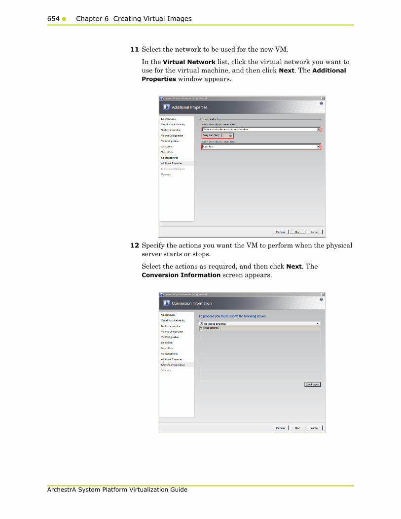
654 Chapter 6 Creating Virtual Images
ArchestrA System Platform Virtualization Guide
11 Select the network to be used for the new VM.
In the Virtual Network list, click the virtual network you want to use for the virtual machine, and then click Next. The Additional Properties window appears.
12 Specify the actions you want the VM to perform when the physical server starts or stops.
Select the actions as required, and then click Next. The Conversion Information screen appears.

Preparing a Virtual Image from a Physical Machine655
ArchestrA System Platform Virtualization Guide
13 Verify if there are any issues with the conversion, and then click Next. The Summary screen appears.
14 Create the VM.
View the settings that you have selected for the virtual machine, and then click Create. The virtual machine is created and the conversion details are displayed in the Virtual Machine Manager window.
Note: It takes about 45 minutes to convert to a virtual machine.
The Virtual Machine Manager window displays the VM conversion details.
656 Chapter 6 Creating Virtual Images
ArchestrA System Platform Virtualization Guide
ObservationWhen you create a VM from a physical machine in the offline mode, and if an IOM product is installed in the physical machine, for example Historian, which acquires data from a remote Application Server that is SF-enabled, select the Turn off source computer after conversion check box. This helps save all data in the created VM.
Note: If you do not select the Turn off source computer after conversion check box, all data changes that take place during the conversion is saved in the source machine.
When the physical machine is in the offline mode during the conversion and the Application Server is in the SF mode, the SF data is forwarded to the VM after it is created.
Tips and Recommendations
Category Recommendation
Hardware • Ensure that the hardware is compatible for conversion before converting it to a virtual machine.
• You cannot transfer a bad sector on a disk during a conversion.
Virtual Machine Manager
• During conversion, SCVMM installs Virtual Machine Manager Agent in the source machine, and this agent takes care of all automation processes. After conversion of the source machine to a VM, the SCVMM server sometimes cannot remove this agent automatically from the physical machine. In such situations, you need to uninstall the agent (SCVMM agent) manually from the physical machine (Go to Control Panel and click Add Remove Programs).
• Since Virtual Machine Manager uses HTTP and WMI service, ensure that WMI service is running and a firewall is not blocking HTTP and WMI traffic at the source machine.
Preparing a Virtual Image from a Physical Machine657
ArchestrA System Platform Virtualization Guide
Network If the source machine communicates with other machines remotely, you can create a VM from an offline machine as SF data stored at remote machines will be forwarded to the newly-created VM.
VMware Before you convert a VMware virtual machine to a Hyper-V or Virtual Server virtual machine, you must uninstall VMware tools on the guest operating system of the virtual machine.
Operating Systems • VMM does not support P2V conversion for computers with Itanium architecture-based operating systems. .
• VMM does not support P2V on source computers running Windows NT Server 4.0. However, you can use the Microsoft Virtual Server 2005 Migration Toolkit (VSMT) or third-party solutions for converting computers running Windows NT Server 4.0.
• VMM 2008 R2 does not support converting a physical computer running Windows Server 2003 SP1 to a virtual machine managed by Hyper-V. Hyper-V does not support Integration Components on computers running Windows Server 2003 SP1. As a result, there is no mouse control when you use Remote Desktop Protocol (RDP) to connect to the virtual machine. To avoid this, update the operating system to Windows Server 2003 SP2 before you convert the physical computer. As an alternative, you can convert the computer by using VMM 2008, and then deploy the virtual machine in VMM 2008 R2.
Category Recommendation
658 Chapter 6 Creating Virtual Images
ArchestrA System Platform Virtualization Guide
Preparing a Virtual Image from Another Virtual Image
VMM allows you to copy existing VMware virtual machines and create Hyper-V or Virtual Server VMs. Virtual-to-Virtual (V2V) conversion is a read-only operation that does not delete or affect the original source virtual machine. You can copy VMware virtual machines that are on an ESX host, in the VMM Library, or on a Windows share. The resulting virtual machine matches VMware virtual machine properties, including name, description, memory, disk-to-bus assignment, CD and DVD settings, network adapter settings, and parameters.
To prepare a virtual image from another virtual image, you need to follow a two-step method:
• Create a template from an existing VM
• Create a new VM from the template
A virtual machine template is a library resource and consists of the following parts:
Hardware profile - To define a standard set of hardware settings, you can create a hardware profile and associate it with a template. When you create a new template or create a virtual machine from a template, you can specify the virtual hardware settings or reuse an existing hardware profile from the library. Like operating system profiles, hardware profiles are logical entities that are stored in the database.
Virtual hard disk - You can use a generalized virtual hard disk from the library or create a virtual hard disk from an existing virtual machine. If the source virtual machine for your template has multiple virtual hard disks, select the disk that contains the operating system. To simplify the generalization process, include Virtualization Guest Services (such as Virtual Machine Additions or Integration Components) in your template.
Guest operating system profile (optional) - To use the same product key, administrator password, time zone, and other items in a set of templates, you can create a guest operating system profile and store it in the library. When you create a new template or a virtual machine from a template, you can specify the settings manually or use an operating system profile associated with your answer files.
Templates provide a standardized group of hardware and software settings that you can use to create multiple new virtual machines configured with those settings. VMM supports both customized and non-customized templates.
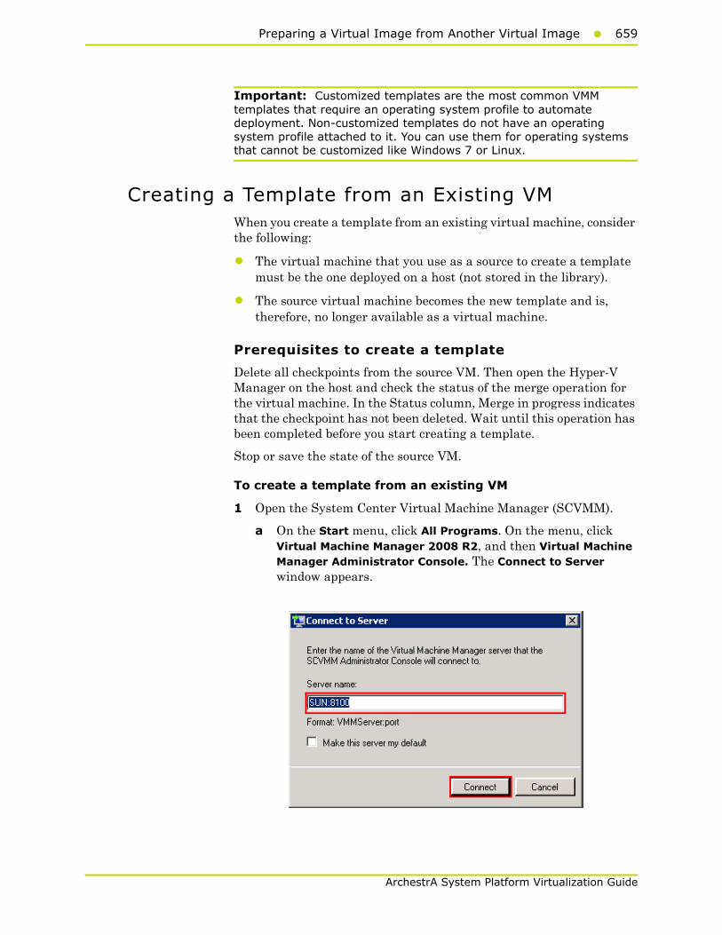
Preparing a Virtual Image from Another Virtual Image659
ArchestrA System Platform Virtualization Guide
Important: Customized templates are the most common VMM templates that require an operating system profile to automate deployment. Non-customized templates do not have an operating system profile attached to it. You can use them for operating systems that cannot be customized like Windows 7 or Linux.
Creating a Template from an Existing VMWhen you create a template from an existing virtual machine, consider the following:
• The virtual machine that you use as a source to create a template must be the one deployed on a host (not stored in the library).
• The source virtual machine becomes the new template and is, therefore, no longer available as a virtual machine.
Prerequisites to create a template
Delete all checkpoints from the source VM. Then open the Hyper-V Manager on the host and check the status of the merge operation for the virtual machine. In the Status column, Merge in progress indicates that the checkpoint has not been deleted. Wait until this operation has been completed before you start creating a template.
Stop or save the state of the source VM.
To create a template from an existing VM
1 Open the System Center Virtual Machine Manager (SCVMM).
a On the Start menu, click All Programs. On the menu, click Virtual Machine Manager 2008 R2, and then Virtual Machine Manager Administrator Console. The Connect to Server window appears.

660 Chapter 6 Creating Virtual Images
ArchestrA System Platform Virtualization Guide
b In the Server name box, enter "localhost:<port number>" or "<SCVMM server name>:<port number>", and then click Connect. The Virtual Machine Manager window appears.
Note: By default, the port number is 8100. However, you can modify it in the SCVMM server configuration, if required.
2 Select the source VM to create a template.
On the Virtual Machine Manager window, right-click the VM you want to use as the source. The VM menu appears.
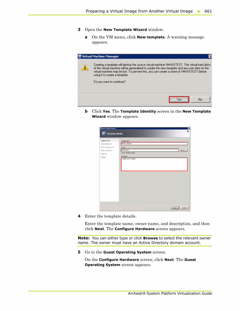
Preparing a Virtual Image from Another Virtual Image661
ArchestrA System Platform Virtualization Guide
3 Open the New Template Wizard window.
a On the VM menu, click New template. A warning message appears.
b Click Yes. The Template Identity screen in the New Template Wizard window appears.
4 Enter the template details.
Enter the template name, owner name, and description, and then click Next. The Configure Hardware screen appears.
Note: You can either type or click Browse to select the relevant owner name. The owner must have an Active Directory domain account.
5 Go to the Guest Operating System screen.
On the Configure Hardware screen, click Next. The Guest Operating System screen appears.
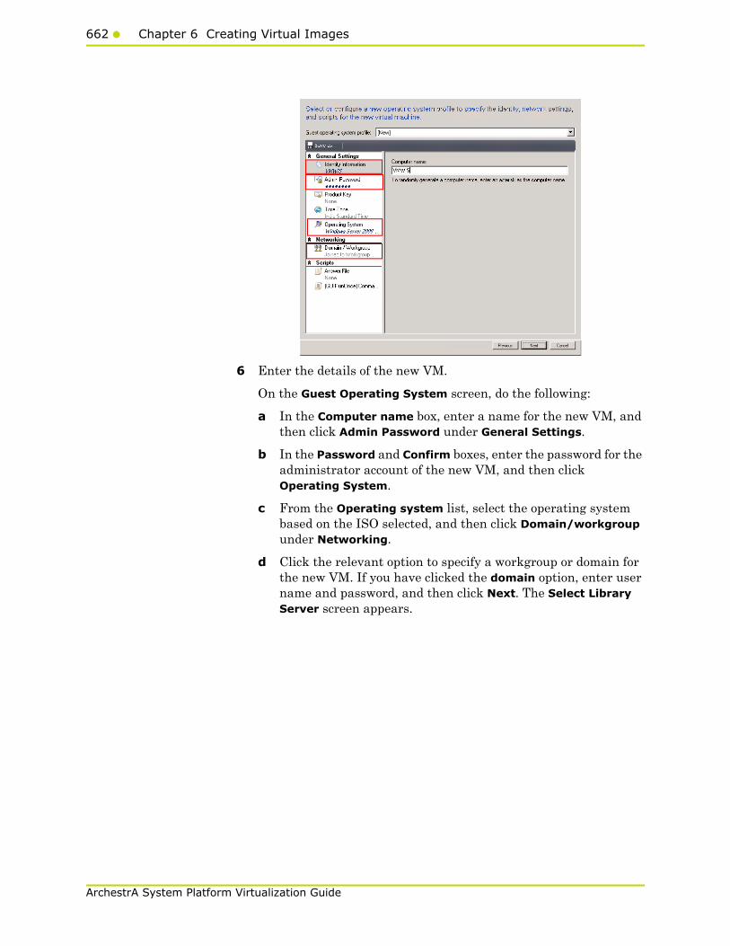
662 Chapter 6 Creating Virtual Images
ArchestrA System Platform Virtualization Guide
6 Enter the details of the new VM.
On the Guest Operating System screen, do the following:
a In the Computer name box, enter a name for the new VM, and then click Admin Password under General Settings.
b In the Password and Confirm boxes, enter the password for the administrator account of the new VM, and then click Operating System.
c From the Operating system list, select the operating system based on the ISO selected, and then click Domain/workgroup under Networking.
d Click the relevant option to specify a workgroup or domain for the new VM. If you have clicked the domain option, enter user name and password, and then click Next. The Select Library Server screen appears.

Preparing a Virtual Image from Another Virtual Image663
ArchestrA System Platform Virtualization Guide
7 Select a library server for the new VM.
Select a library server for the template to be used, and then click Next. The Select Path screen appears.
8 Select a location to save the new VM.
a Click Browse to select the location of the template. The selected path appears in the Virtual machine path box.
b Click Next. The Summary screen appears.

664 Chapter 6 Creating Virtual Images
ArchestrA System Platform Virtualization Guide
9 Create a template.
Click Create. The Jobs window appears.
View the status of the template you created. The completed status confirms that the template has been created successfully.
Note: If the template is not created successfully, you can refer to http://technet.microsoft.com/en-us/library/cc764306.aspx to verify the cause.
Preparing a Virtual Image from Another Virtual Image665
ArchestrA System Platform Virtualization Guide
Creating a Virtual Machine from a TemplateYou can create a VM from a template of an existing VM.
Considerations
• You cannot change the system disk or startup disk configuration.
• Templates are database objects that are displayed in the library. The templates are displayed in the VMs and Templates folder in the Library Server.
Requirements
• The virtual hard disk must have a supporting OS installed.
• The administrator password on the virtual hard disk should be blank as part of the Sysprep process. However, the administrator password for the guest OS profile may not be blank.
• For customized templates, the OS on the virtual hard disk must be prepared by removing the computer identity information. For Windows operating systems, you can prepare the virtual hard disk by using the Sysprep tool.
Prerequisite
The template of the source VM should be created before creating the new VM.
For more information on creating a template, refer to "Creating a Template from an Existing VM" on page 659.
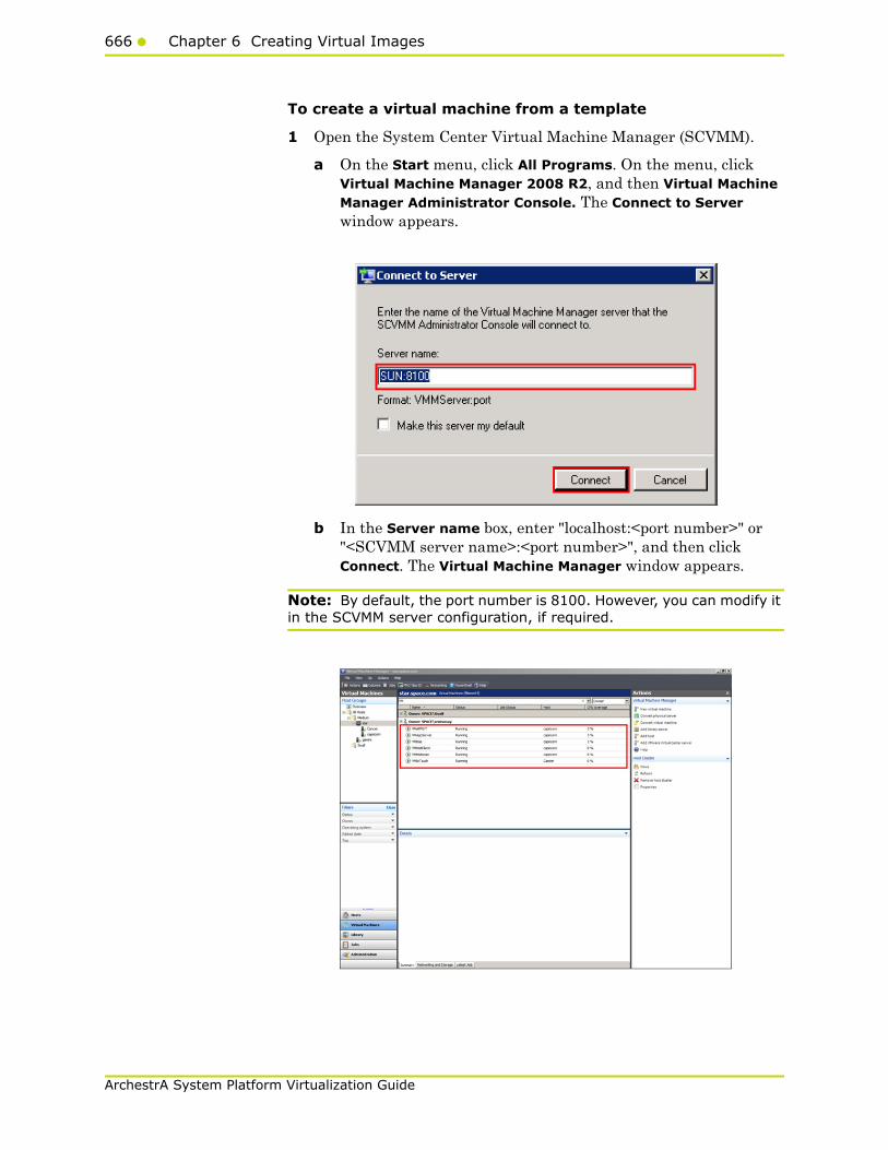
666 Chapter 6 Creating Virtual Images
ArchestrA System Platform Virtualization Guide
To create a virtual machine from a template
1 Open the System Center Virtual Machine Manager (SCVMM).
a On the Start menu, click All Programs. On the menu, click Virtual Machine Manager 2008 R2, and then Virtual Machine Manager Administrator Console. The Connect to Server window appears.
b In the Server name box, enter "localhost:<port number>" or "<SCVMM server name>:<port number>", and then click Connect. The Virtual Machine Manager window appears.
Note: By default, the port number is 8100. However, you can modify it in the SCVMM server configuration, if required.
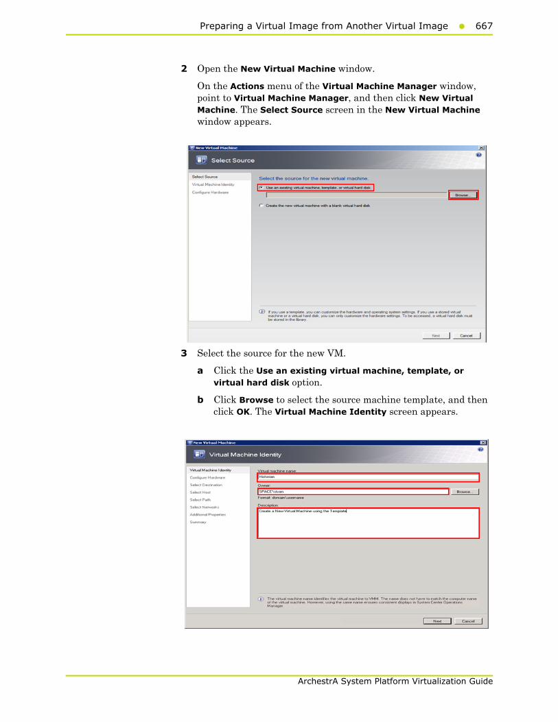
Preparing a Virtual Image from Another Virtual Image667
ArchestrA System Platform Virtualization Guide
2 Open the New Virtual Machine window.
On the Actions menu of the Virtual Machine Manager window, point to Virtual Machine Manager, and then click New Virtual Machine. The Select Source screen in the New Virtual Machine window appears.
3 Select the source for the new VM.
a Click the Use an existing virtual machine, template, or virtual hard disk option.
b Click Browse to select the source machine template, and then click OK. The Virtual Machine Identity screen appears.

668 Chapter 6 Creating Virtual Images
ArchestrA System Platform Virtualization Guide
4 Enter the details of the new VM.
Enter the virtual machine name, owner name, and description, and then click Next. The Configure Hardware screen appears.
Note: You can either type or click Browse to select the relevant owner name. The owner must have an Active Directory domain account.
5 Go to the Guest Operating System screen.
On the Configure Hardware screen, click Next. The Guest Operating System screen.
6 Enter the details of the new VM.
On the Guest Operating System screen, do the following:
a In the Computer name box, enter a name for the new VM, and then click Admin Password under General Settings.
b In the Password and Confirm boxes, enter the password for the administrator account of the new VM, and then click Operating System.
Note: To prompt for a password while createing a virtual machine with the template, enter an asterisk (*) in the Password box. If you leave the field blank, you will not be able to create the virtual machine.
c From the Operating system list, select the operating system based on the ISO selected, and then click Domain/workgroup under Networking.
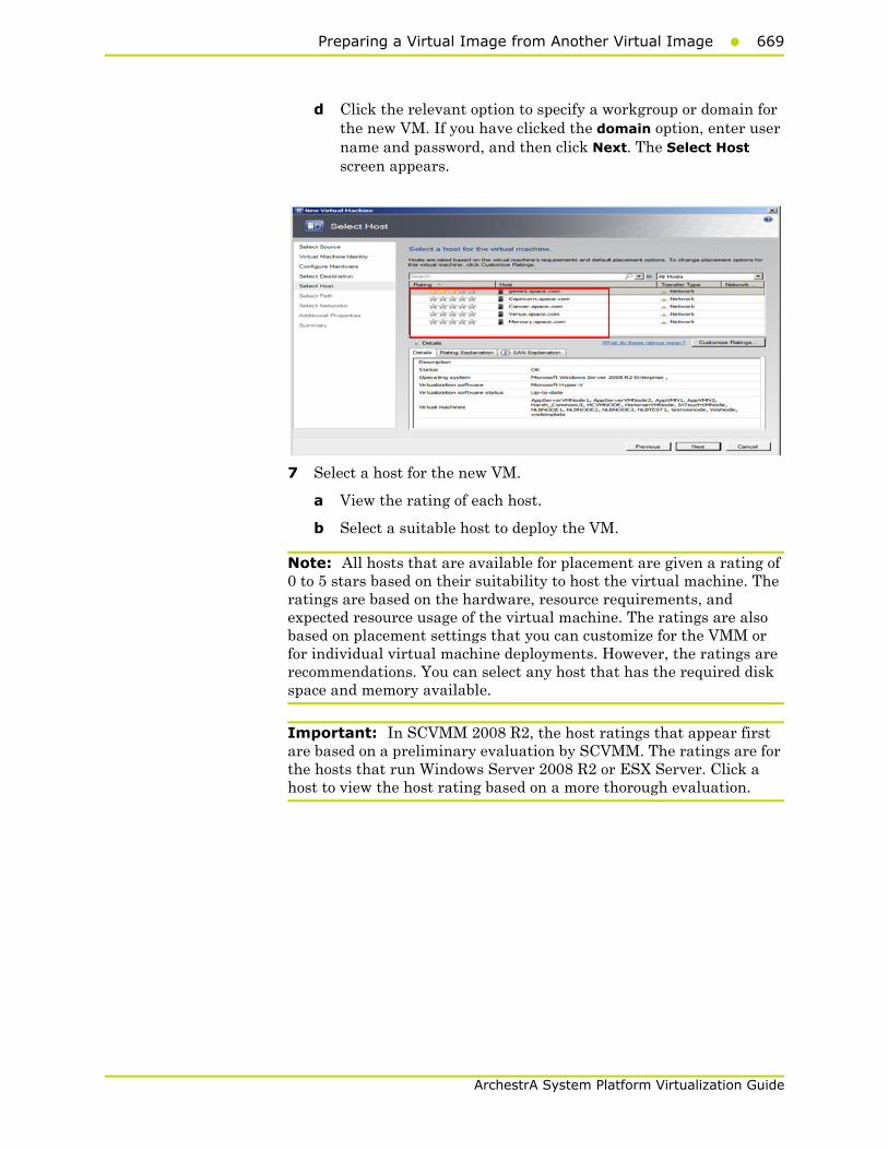
Preparing a Virtual Image from Another Virtual Image669
ArchestrA System Platform Virtualization Guide
d Click the relevant option to specify a workgroup or domain for the new VM. If you have clicked the domain option, enter user name and password, and then click Next. The Select Host screen appears.
7 Select a host for the new VM.
a View the rating of each host.
b Select a suitable host to deploy the VM.
Note: All hosts that are available for placement are given a rating of 0 to 5 stars based on their suitability to host the virtual machine. The ratings are based on the hardware, resource requirements, and expected resource usage of the virtual machine. The ratings are also based on placement settings that you can customize for the VMM or for individual virtual machine deployments. However, the ratings are recommendations. You can select any host that has the required disk space and memory available.
Important: In SCVMM 2008 R2, the host ratings that appear first are based on a preliminary evaluation by SCVMM. The ratings are for the hosts that run Windows Server 2008 R2 or ESX Server. Click a host to view the host rating based on a more thorough evaluation.

670 Chapter 6 Creating Virtual Images
ArchestrA System Platform Virtualization Guide
c To view the placement settings used by the VMM to rate the hosts, click Customize Ratings. The Customize Ratings window appears.
You can modify the settings if required.
d To view additional information about a host rating, select the host and click the following tabs:
• Details
This tab displays the status of the host and lists the virtual machines that are currently deployed on it.

Preparing a Virtual Image from Another Virtual Image671
ArchestrA System Platform Virtualization Guide
• Ratings Explanation
This tab lists the conditions that cause a host to receive a zero rating.
• SAN Explanation
This tab lists the conditions that prevent a Storage Area Network (SAN) transfer used to move the virtual machine's files to the host.

672 Chapter 6 Creating Virtual Images
ArchestrA System Platform Virtualization Guide
e Click Next. The Select Path screen appears.
Note: If a host has network optimization enabled, a green arrow appears in the Network Optimization column. VMM 2008 R2 enables you to use the network optimization capabilities that are available on Hyper-V hosts that are running Windows Server 2008 R2. For information about network optimization and the hardware that supports it, see the "Windows Server 2008 R2" documentation. After a virtual machine is deployed, this feature is displayed only for virtual machines that are deployed on a host that runs Windows Server 2008 R2.
8 Select the storage location for the VM files.
On the Select Path screen, enter the path to store the VM files, and then click Next. The Additional Properties screen appears.
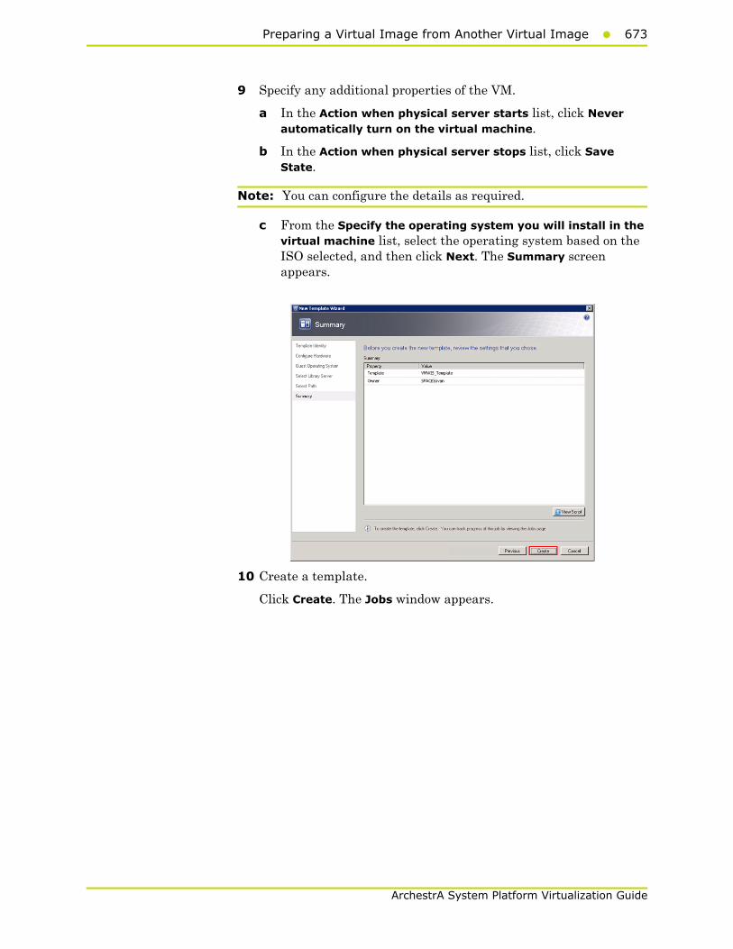
Preparing a Virtual Image from Another Virtual Image673
ArchestrA System Platform Virtualization Guide
9 Specify any additional properties of the VM.
a In the Action when physical server starts list, click Never automatically turn on the virtual machine.
b In the Action when physical server stops list, click Save State.
Note: You can configure the details as required.
c From the Specify the operating system you will install in the virtual machine list, select the operating system based on the ISO selected, and then click Next. The Summary screen appears.
10 Create a template.
Click Create. The Jobs window appears.

674 Chapter 6 Creating Virtual Images
ArchestrA System Platform Virtualization Guide
View the status of the template you created. The completed status confirms that the template has been created successfully.
Tips and Recommendations• When creating a template, use a base OS without an SQL Server.
• To create a VM that hosts System Platform Products, select the template with the relevant OS. Install the SQL Server as required, and then install the System Platform Product.
• If you create a template with an SQL Server and/or System Platform Products, and you create a VM with that template, ensure the machine name is the same as the node name in the template. If you use a different name, do the following:
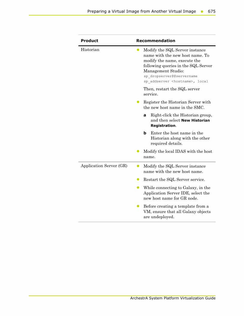
Preparing a Virtual Image from Another Virtual Image675
ArchestrA System Platform Virtualization Guide
Product Recommendation
Historian • Modify the SQL Server instance name with the new host name. To modify the name, execute the following queries in the SQL Server Management Studio:sp_dropserver@@servername
sp_addserver <hostname>, local
Then, restart the SQL server service.
• Register the Historian Server with the new host name in the SMC.
a Right-click the Historian group, and then select New Historian Registration.
b Enter the host name in the Historian along with the other required details.
• Modify the local IDAS with the host name.
Application Server (GR) • Modify the SQL Server instance name with the new host name.
• Restart the SQL Server service.
• While connecting to Galaxy, in the Application Server IDE, select the new host name for GR node.
• Before creating a template from a VM, ensure that all Galaxy objects are undeployed.

676 Chapter 6 Creating Virtual Images
ArchestrA System Platform Virtualization Guide
Preparing a Virtual Image from a Ghost BackupVMM allows you to create a virtual machine using .VHD images created using a ghost backup. You cannot create a virtual machine directly from a ghost .GHO backup file. Ghost backup images are created using the Symantec Ghost Utility software.
To create a virtual machine from a ghost backup, do the following:
a Create a ghost backup (.GHO).
b Convert a ghost backup (.GHO) to a virtual hard disk (.VHD).
c Create a virtual machine from .VHD.
The procedure to create a .GHO image is explained in the Symantec TM Ghost Imaging Foundation 7 documentation.
Refer to the following links for information on Creation of Ghost Backup (.GHO) and Conversion of Ghost backup (.GHO) to Virtual Hard Disk (.VHD).
• ftp://ftp.symantec.com/public/english_us_canada/products/symantec_ghost_solution_suite/2.0/manuals/Ghost_imp_guide.pdf
• http://www.symantec.com/business/support/index?page=content&id=DOC2207&key=52023&actp=LIST
• http://www.symantec.com/business/support/resources/sites/BUSINESS/content/staging/DOCUMENTATION/2000/DOC2565/en_US/1.0/EM_GIF_user_gde.pdf.
Create a Virtual Machine from a .VHDYou can use the New Virtual Machine feature of the VMM to create a virtual machine from an existing VHD. VMM creates a copy of the source VHD so that the original VHD is not moved or modified. The administrator password on the VHD should be blank as part of the Sysprep process.
You can also create a template from the VHD, and then create the new virtual machine from the template.
Limitations: When creating a new virtual machine directly from an existing VHD, you cannot specify the OS configuration information (sysprep settings). To specify sysprep settings, you need to do the following:
• Create a template
• Create the new virtual machine based on that template

Preparing a Virtual Image from a Ghost Backup677
ArchestrA System Platform Virtualization Guide
To create a virtual machine from a .VHD
1 Copy the created .VHD file.
Copy the .VHD file that is created using the ghost image to the Virtual Server Library.
2 Open the System Center Virtual Machine Manager (SCVMM).
a On the Start menu, click All Programs. On the menu, click Virtual Machine Manager 2008 R2, and then Virtual Machine Manager Administrator Console. The Connect to Server window appears.
b In the Server name box, enter "localhost:<port number>" or "<SCVMM server name>:<port number>", and then click Connect. The Virtual Machine Manager window appears.
Note: By default, the port number is 8100. However, you can modify it in the SCVMM server configuration, if required.
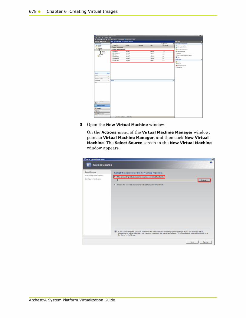
678 Chapter 6 Creating Virtual Images
ArchestrA System Platform Virtualization Guide
3 Open the New Virtual Machine window.
On the Actions menu of the Virtual Machine Manager window, point to Virtual Machine Manager, and then click New Virtual Machine. The Select Source screen in the New Virtual Machine window appears.
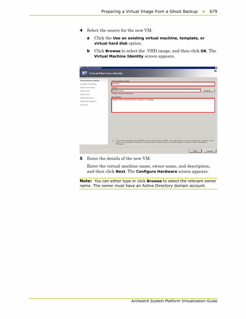
Preparing a Virtual Image from a Ghost Backup679
ArchestrA System Platform Virtualization Guide
4 Select the source for the new VM.
a Click the Use an existing virtual machine, template, or virtual hard disk option.
b Click Browse to select the .VHD image, and then click OK. The Virtual Machine Identity screen appears.
5 Enter the details of the new VM.
Enter the virtual machine name, owner name, and description, and then click Next. The Configure Hardware screen appears.
Note: You can either type or click Browse to select the relevant owner name. The owner must have an Active Directory domain account.

680 Chapter 6 Creating Virtual Images
ArchestrA System Platform Virtualization Guide
6 Go to the Select Host screen.
a On the Configure Hardware screen, click Next. The Guest Operating System screen.
b On the Guest Operating System screen, click Next. The Select Host screen appears.
7 Select a host for the new VM.
a View the rating of each host.
b Select a suitable host to deploy the VM.
Note: All hosts that are available for placement are given a rating of 0 to 5 stars based on their suitability to host the virtual machine. The ratings are based on the hardware, resource requirements, and expected resource usage of the virtual machine. The ratings are also based on placement settings that you can customize for the VMM or for individual virtual machine deployments. However, the ratings are recommendations. You can select any host that has the required disk space and memory available.
Important: In SCVMM 2008 R2, the host ratings that appear first are based on a preliminary evaluation by SCVMM. The ratings are for the hosts that run Windows Server 2008 R2 or ESX Server. Click a host to view the host rating based on a more thorough evaluation.
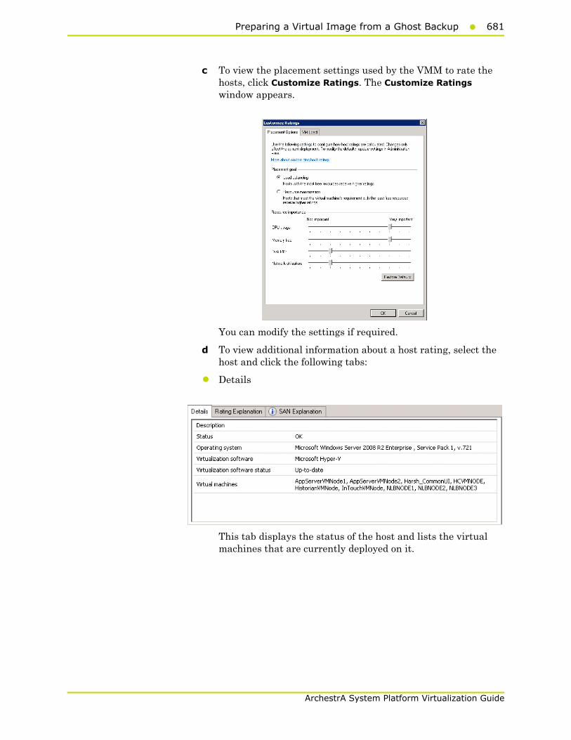
Preparing a Virtual Image from a Ghost Backup681
ArchestrA System Platform Virtualization Guide
c To view the placement settings used by the VMM to rate the hosts, click Customize Ratings. The Customize Ratings window appears.
You can modify the settings if required.
d To view additional information about a host rating, select the host and click the following tabs:
• Details
This tab displays the status of the host and lists the virtual machines that are currently deployed on it.

682 Chapter 6 Creating Virtual Images
ArchestrA System Platform Virtualization Guide
• Ratings Explanation
This tab lists the conditions that cause a host to receive a zero rating.
• SAN Explanation
This tab lists the conditions that prevent a Storage Area Network (SAN) transfer used to move the virtual machine's files to the host.
e Click Next. The Select Path screen appears.
Note: If a host has network optimization enabled, a green arrow appears in the Network Optimization column. VMM 2008 R2 enables you to use the network optimization capabilities that are available on Hyper-V hosts that are running Windows Server 2008 R2. For information about network optimization and the hardware that supports it, see the "Windows Server 2008 R2" documentation. After a virtual machine is deployed, this feature is displayed only for virtual machines that are deployed on a host that runs Windows Server 2008 R2.
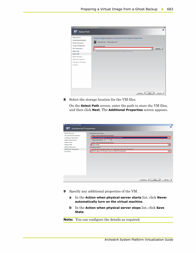
Preparing a Virtual Image from a Ghost Backup683
ArchestrA System Platform Virtualization Guide
8 Select the storage location for the VM files.
On the Select Path screen, enter the path to store the VM files, and then click Next. The Additional Properties screen appears.
9 Specify any additional properties of the VM.
a In the Action when physical server starts list, click Never automatically turn on the virtual machine.
b In the Action when physical server stops list, click Save State.
Note: You can configure the details as required.
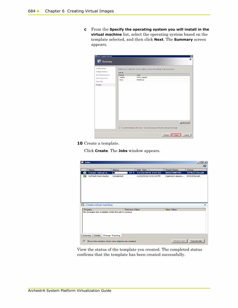
684 Chapter 6 Creating Virtual Images
ArchestrA System Platform Virtualization Guide
c From the Specify the operating system you will install in the virtual machine list, select the operating system based on the template selected, and then click Next. The Summary screen appears.
10 Create a template.
Click Create. The Jobs window appears.
View the status of the template you created. The completed status confirms that the template has been created successfully.
685
ArchestrA System Platform Virtualization Guide
RecommendationWhen taking ghost backup, ensure that all drives where programs are installed are part of the backup.

686 Chapter 6 Creating Virtual Images
ArchestrA System Platform Virtualization Guide

687
ArchestrA System Platform Virtualization Guide
Chapter 7
Implementing BackupStrategies in a Virtualized
Environment
A virtual server backup is a copy of data stored on a virtual server to prevent data loss. There are two fundamental types of backups:
• Guest-level backup
• Host-level backup
Backup and Restore Strategies
There are a number of backup and restore strategies in both virtualized and non-virtualized environments. In the guest level, the virtual machines (VMs) are backed up as if they were physical servers. Although this strategy is among the simplest, it also has several drawbacks. You need to install backup software in each virtual machine (VM) to be copied in Guest Operating Systems, and maintain separate backup jobs (or even multiple backup jobs) per VM. This approach requires additional resources to execute the backups, and can affect the performance of the virtual machines. This backup type is not suitable for restore in the event of a disaster or granular restores within applications, such as databases or email.
Another backup strategy is to use a host-level backup. In this approach, back up the entire VM at one time. However, it can be as granular as your backup and restore application allows it to be.
688 Chapter 7 Implementing Backup Strategies in a Virtualized Environment
ArchestrA System Platform Virtualization Guide
We recommend the host-level backup. It creates a complete disaster recovery image of the virtual server, which can be restored directly into the source virtual infrastructure.
Checkpointing Method
In this method you can take point-in-time checkpoints (snapshots) of the entire VM. We recommend this method as it ensures data consistency and allows for a fast and complete restore of the entire VM. One of the few disadvantages in this method is that you need to restore the entire checkpoint even if a file is lost or corrupt.
In a Microsoft virtualized environment, you can take and restore checkpoints using either System Center Virtual Machine Manager 2008 R2 (VMM) or Microsoft® Hyper-V Manager. The following sections describe how to implement backup strategies using SCVMM.
Taking Checkpoints Using SCVMMBy creating a checkpoint, you can save all contents of a virtual machine hard disk. You can reset your machine to a previous configuration if required, without having to uninstall programs or reinstall operating systems. This also helps you test applications across various configurations.
You can checkpoint one or multiple VMs both in the online and offline modes. However, you can checkpoint a VM only when it is deployed on a host.
Important: Typically, there are dependencies among nodes. Taking a checkpoint of a VM and restoring it later could negatively impact those dependencies. For more information, refer to "Checkpoints of System Platform Products - Observations and Recommendations" on page 707.
Taking a Checkpoint of an Offline VMIt is recommended that you shut down the virtual machine before creating a checkpoint. You can also create a checkpoint of the virtual machine offline. This stops the machine temporarily while the checkpoint is created. Turning off the virtual machine prevents loss of data while the conversion takes place.

Taking Checkpoints Using SCVMM689
ArchestrA System Platform Virtualization Guide
To take a checkpoint of an offline VM
1 Open the System Center Virtual Machine Manager (SCVMM).
a On the Start menu, click All Programs. On the menu, click Virtual Machine Manager 2008 R2, and then Virtual Machine Manager Administrator Console. The Connect to Server window appears.
b In the Server name box, enter "localhost:<port number>" or "<SCVMM server name>:<port number>", and then click Connect. The Virtual Machine Manager window appears.
Note: By default, the port number is 8100. However, you can modify it, if required.
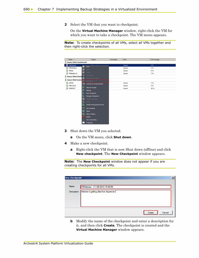
690 Chapter 7 Implementing Backup Strategies in a Virtualized Environment
ArchestrA System Platform Virtualization Guide
2 Select the VM that you want to checkpoint.
On the Virtual Machine Manager window, right-click the VM for which you want to take a checkpoint. The VM menu appears.
Note: To create checkpoints of all VMs, select all VMs together and then right-click the selection.
3 Shut down the VM you selected.
a On the VM menu, click Shut down.
4 Make a new checkpoint.
a Right-click the VM that is now Shut down (offline) and click New checkpoint. The New Checkpoint window appears.
Note: The New Checkpoint window does not appear if you are creating checkpoints for all VMs.
b Modify the name of the checkpoint and enter a description for it, and then click Create. The checkpoint is created and the Virtual Machine Manager window appears.

Taking Checkpoints Using SCVMM691
ArchestrA System Platform Virtualization Guide
Note: By default, the Name box displays the name of the VM and the time when the checkpoint is created.
5 Verify the checkpoint.
Right-click the VM and click Manage checkpoints. The Virtual Machine Properties window appears.
This window displays all the checkpoints created for the VM. The corresponding details indicate the date and time when each checkpoint was created. A green dot appears below the checkpoint you created indicating that it is now active. Click OK to exit the window.
Taking a Checkpoint of an Online VMIt is possible to create checkpoints of a virtual machine while it is running. However, creating a checkpoint in online mode requires special application support.
Important: To avoid losing any data, do not make any configuration changes to the machine while creating a checkpoint. For more information, refer to "Checkpoints of System Platform Products - Observations and Recommendations" on page 707.
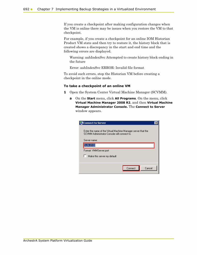
692 Chapter 7 Implementing Backup Strategies in a Virtualized Environment
ArchestrA System Platform Virtualization Guide
If you create a checkpoint after making configuration changes when the VM is online there may be issues when you restore the VM to that checkpoint.
For example, if you create a checkpoint for an online IOM Historian Product VM state and then try to restore it, the history block that is created shows a discrepancy in the start and end time and the following errors are displayed.
Warning: aahIndexSvc Attempted to create history block ending in the future
Error: aahIndexSvc ERROR: Invalid file format
To avoid such errors, stop the Historian VM before creating a checkpoint in the online mode.
To take a checkpoint of an online VM
1 Open the System Center Virtual Machine Manager (SCVMM).
a On the Start menu, click All Programs. On the menu, click Virtual Machine Manager 2008 R2, and then Virtual Machine Manager Administrator Console. The Connect to Server window appears.

Taking Checkpoints Using SCVMM693
ArchestrA System Platform Virtualization Guide
b In the Server name box, enter "localhost:<port number>" or "<SCVMM server name>:<port number>", and then click Connect. The Virtual Machine Manager window appears.
Note: By default, the port number is 8100. However, you can modify it, if required.
2 Select the VM that you want to checkpoint.
On the Virtual Machine Manager window, right-click the VM for which you want to take a checkpoint. The VM menu appears.
Note: To create checkpoints of all VMs, select all VMs together and then right-click the selection.

694 Chapter 7 Implementing Backup Strategies in a Virtualized Environment
ArchestrA System Platform Virtualization Guide
3 Make a new checkpoint.
a Click New checkpoint. The New Checkpoint window appears.
Note: The New Checkpoint window does not appear, if you are creating checkpoints for all VMs.
b Modify the name of the checkpoint and enter a description for it, and then click Create. The checkpoint is created and the Virtual Machine Manager window appears.
Note: By default, the Name box displays the name of the VM and the time when the checkpoint is created.
4 Verify the checkpoint.
Right-click the VM for which you have created a checkpoint and click Manage checkpoints. The Virtual Machine Properties window for the selected VM appears.
Restoring Checkpoints695
ArchestrA System Platform Virtualization Guide
This window displays all the checkpoints created for the VM. The corresponding details indicate the date and time when each checkpoint was created. A green dot appears below the checkpoint you created indicating that it is now active. Click OK to exit the window.
Restoring CheckpointsYou can revert a virtual machine to a previous state by restoring it to the required checkpoint. When you restore a virtual machine to a checkpoint, VMM stops the virtual machine and the files on the virtual machine are restored to their previous state.
Important: If the virtual machine has been in use since the checkpoint was created, take a backup of the data files before you restore the virtual machine to avoid loss of any data.
Restoring Checkpoints from a Virtual System Platform Backup
You can restore a VM to its previous state by using checkpoints. You can restore checkpoints of VMs both in the online and offline modes.
Restoring a Checkpoint of an Offline VMWhen you restore a VM to a checkpoint taken of an offline VM, there should not be any loss of data. When checkpoints are taken from a VM that is offline, the machine temporarily stops, minimizing data loss during the conversion process.
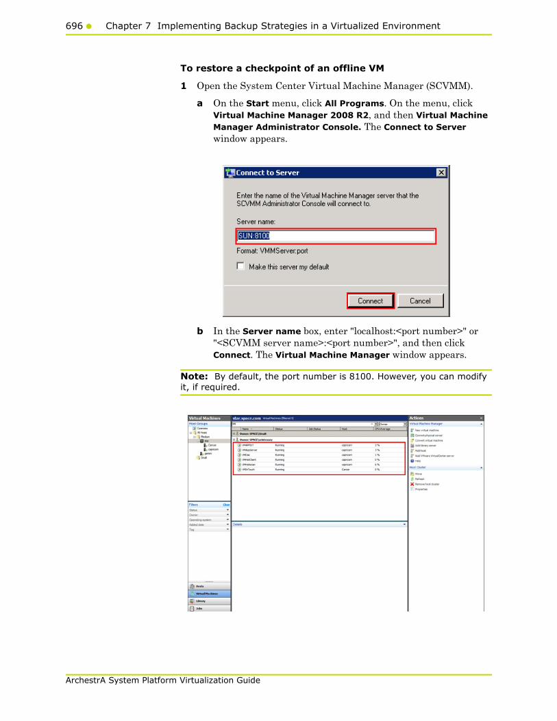
696 Chapter 7 Implementing Backup Strategies in a Virtualized Environment
ArchestrA System Platform Virtualization Guide
To restore a checkpoint of an offline VM
1 Open the System Center Virtual Machine Manager (SCVMM).
a On the Start menu, click All Programs. On the menu, click Virtual Machine Manager 2008 R2, and then Virtual Machine Manager Administrator Console. The Connect to Server window appears.
b In the Server name box, enter "localhost:<port number>" or "<SCVMM server name>:<port number>", and then click Connect. The Virtual Machine Manager window appears.
Note: By default, the port number is 8100. However, you can modify it, if required.
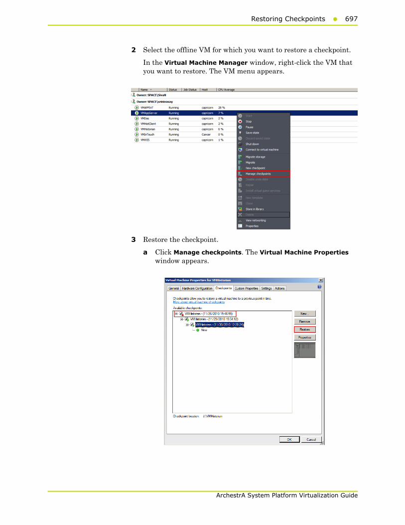
Restoring Checkpoints697
ArchestrA System Platform Virtualization Guide
2 Select the offline VM for which you want to restore a checkpoint.
In the Virtual Machine Manager window, right-click the VM that you want to restore. The VM menu appears.
3 Restore the checkpoint.
a Click Manage checkpoints. The Virtual Machine Properties window appears.

698 Chapter 7 Implementing Backup Strategies in a Virtualized Environment
ArchestrA System Platform Virtualization Guide
b Select the VM that is offline and click Restore. A confirmation message appears.
c Click Yes. The checkpoint is restored and the Virtual Machine Properties window appears.
A green dot appears below the checkpoint that you restored indicating that it is now active. Click OK to exit the window.

Restoring Checkpoints699
ArchestrA System Platform Virtualization Guide
Restoring a Checkpoint of an Online VMYou can retore a VM to a checkpoint that was taken when the machine was online. Restoring a VM to a checkpoint taken while online may lead to loss of data. However, if no changes to the configuration were made while creating the checkpoint, there should not be any data loss.
To restore a checkpoint of an online VM
1 Open the System Center Virtual Machine Manager (SCVMM).
a On the Start menu, click All Programs. On the menu, click Virtual Machine Manager 2008 R2, and then Virtual Machine Manager Administrator Console. The Connect to Server window appears.

700 Chapter 7 Implementing Backup Strategies in a Virtualized Environment
ArchestrA System Platform Virtualization Guide
b In the Server name box, enter "localhost:<port number>" or "<SCVMM server name>:<port number>", and then click Connect. The Virtual Machine Manager window appears.
Note: By default, the port number is 8100. However, you can modify it, if required.
2 Select the VM for which you want to restore a checkpoint.
On the Virtual Machine Manager window, right-click the VM that you want to restore. The VM menu appears.
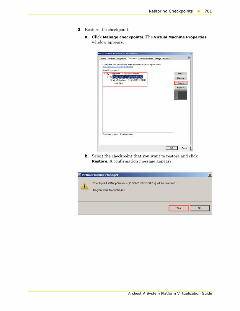
Restoring Checkpoints701
ArchestrA System Platform Virtualization Guide
3 Restore the checkpoint.
a Click Manage checkpoints. The Virtual Machine Properties window appears.
b Select the checkpoint that you want to restore and click Restore. A confirmation message appears.
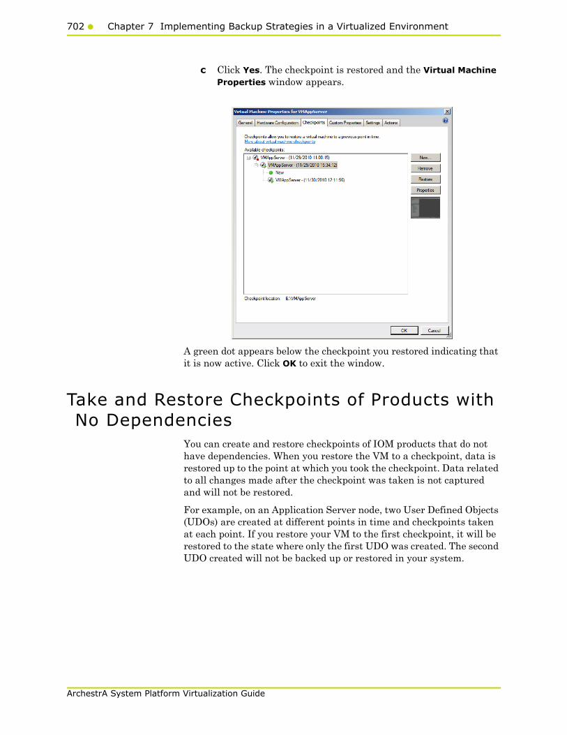
702 Chapter 7 Implementing Backup Strategies in a Virtualized Environment
ArchestrA System Platform Virtualization Guide
c Click Yes. The checkpoint is restored and the Virtual Machine Properties window appears.
A green dot appears below the checkpoint you restored indicating that it is now active. Click OK to exit the window.
Take and Restore Checkpoints of Products with No Dependencies
You can create and restore checkpoints of IOM products that do not have dependencies. When you restore the VM to a checkpoint, data is restored up to the point at which you took the checkpoint. Data related to all changes made after the checkpoint was taken is not captured and will not be restored.
For example, on an Application Server node, two User Defined Objects (UDOs) are created at different points in time and checkpoints taken at each point. If you restore your VM to the first checkpoint, it will be restored to the state where only the first UDO was created. The second UDO created will not be backed up or restored in your system.

Take and Restore Checkpoints of Products with No Dependencies703
ArchestrA System Platform Virtualization Guide
To take and restore checkpoints of products with no dependencies
1 Open the System Center Virtual Machine Manager (SCVMM).
a On the Start menu, click All Programs. On the menu, click Virtual Machine Manager 2008 R2, and then Virtual Machine Manager Administrator Console. The Connect to Server window appears.
b In the Server name box, enter "localhost:<port number>" or "<SCVMM server name>:<port number>", and then click Connect. The Virtual Machine Manager window appears.
Note: By default, the port number is 8100. However, you can modify it, if required.
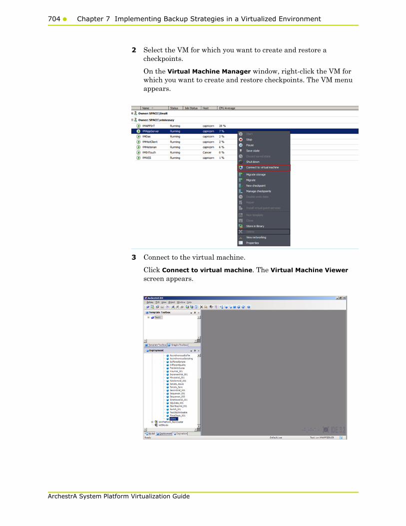
704 Chapter 7 Implementing Backup Strategies in a Virtualized Environment
ArchestrA System Platform Virtualization Guide
2 Select the VM for which you want to create and restore a checkpoints.
On the Virtual Machine Manager window, right-click the VM for which you want to create and restore checkpoints. The VM menu appears.
3 Connect to the virtual machine.
Click Connect to virtual machine. The Virtual Machine Viewer screen appears.
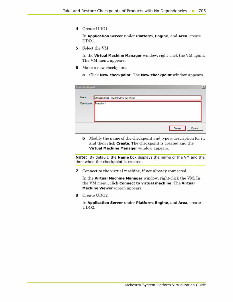
Take and Restore Checkpoints of Products with No Dependencies705
ArchestrA System Platform Virtualization Guide
4 Create UDO1.
In Application Server under Platform, Engine, and Area, create UDO1.
5 Select the VM.
In the Virtual Machine Manager window, right-click the VM again. The VM menu appears.
6 Make a new checkpoint.
a Click New checkpoint. The New checkpoint window appears.
b Modify the name of the checkpoint and type a description for it, and then click Create. The checkpoint is created and the Virtual Machine Manager window appears.
Note: By default, the Name box displays the name of the VM and the time when the checkpoint is created.
7 Connect to the virtual machine, if not already connected.
In the Virtual Machine Manager window, right-click the VM. In the VM menu, click Connect to virtual machine. The Virtual Machine Viewer screen appears.
8 Create UDO2.
In Application Server under Platform, Engine, and Area, create UDO2.
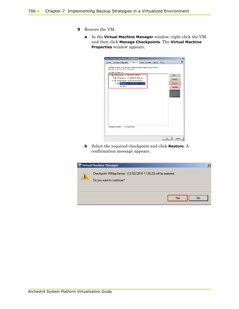
706 Chapter 7 Implementing Backup Strategies in a Virtualized Environment
ArchestrA System Platform Virtualization Guide
9 Restore the VM.
a In the Virtual Machine Manager window, right-click the VM and then click Manage Checkpoints. The Virtual Machine Properties window appears.
b Select the required checkpoint and click Restore. A confirmation message appears.
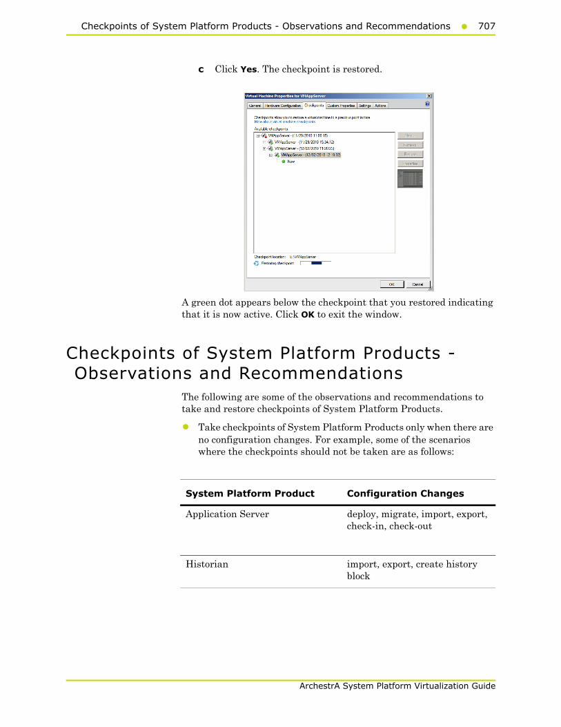
Checkpoints of System Platform Products - Observations and Recommendations707
ArchestrA System Platform Virtualization Guide
c Click Yes. The checkpoint is restored.
A green dot appears below the checkpoint that you restored indicating that it is now active. Click OK to exit the window.
Checkpoints of System Platform Products - Observations and Recommendations
The following are some of the observations and recommendations to take and restore checkpoints of System Platform Products.
• Take checkpoints of System Platform Products only when there are no configuration changes. For example, some of the scenarios where the checkpoints should not be taken are as follows:
System Platform Product Configuration Changes
Application Server deploy, migrate, import, export, check-in, check-out
Historian import, export, create history block

708 Chapter 7 Implementing Backup Strategies in a Virtualized Environment
ArchestrA System Platform Virtualization Guide
• You must be aware of the consequences and make decisions when taking and restoring checkpoints of System Platform Products that have dependencies. If the configuration of a System Platform node has a dependency on the configuration of another System Platform node, it is recommended to take and restore checkpoints on such dependent nodes together. For more information, refer to "Recommendations" on page 709.
Taking and Restoring Checkpoints (Snapshots) in the Offline Mode
It is recommended that you take checkpoints of System Platform Products when the VMs hosting them are in the offline mode. Turn off the System Platform Product VM before taking a checkpoint.
Restoring checkpoints of VMs in the offline mode result in smooth functioning of the System Platform Products after the restoration. After restoring a checkpoint, start the VM, and then start the System Platform Product hosted in the VM.
Taking and Restoring Checkpoints (Snapshots) in the Online Mode
While the VM is in the online mode, the System Platform Product hosted on the VM functions in either the following way:
• Scenario 1: If the System Platform Product is not running on an online VM, it functions smoothly after the restoration of checkpoints.
• Scenario 2: If a checkpoint is taken while the System Platform Product is running on an online VM and there are no configuration changes in progress, the System Platform Product performs normally. However, when checkpoints are restored, there would be issues with the System Platform Product running on that VM. Some of the issues are explained in the following table.
Checkpoints of System Platform Products - Observations and Recommendations709
ArchestrA System Platform Virtualization Guide
Recommendations
Observation Recommendations
Historian
• Do not take checkpoints while a history block change is in progress. Restoring such a checkpoint leads to unpredictable behavior of the product.
• In case of communication issues between the Historian and dependent System Platform Products, restart the VMs.
• If a checkpoint is taken before configuring Application Server to historize attributes, re-deploy the platform after the Historian is restored.
Issue 1: When you restore a checkpoint of the Historian node taken while the Historian was running and the block change was in progress, there is a conflict in the start and end time in the history block. The following errors and warnings are logged:
Warning: aahIndexSvc Attempted to create history block ending in the future.
Error: aahIndexSvc ERROR: Invalid file format.
As a recovery step of Issue 1, shut down and disable the Historian, and then start and enable it.
Issue 2: While creating a checkpoint there may be an action in progress resulting from an event. The incomplete action is not saved when you restore such a checkpoint.
Application Server
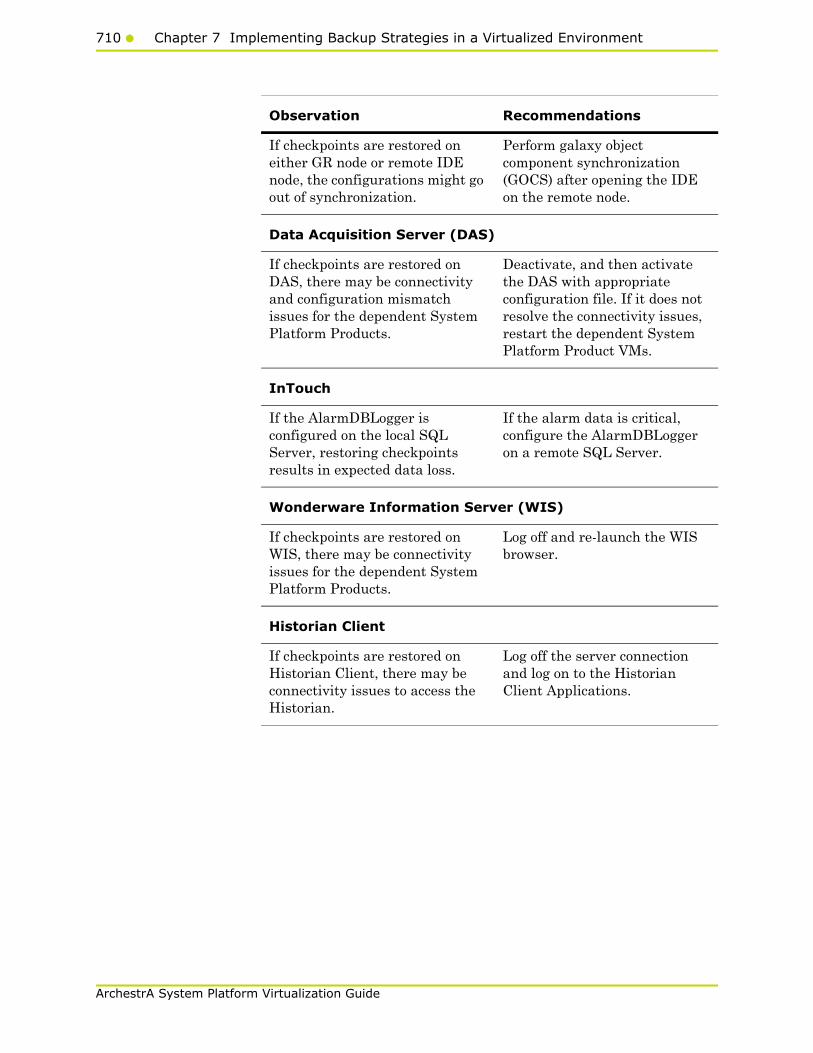
710 Chapter 7 Implementing Backup Strategies in a Virtualized Environment
ArchestrA System Platform Virtualization Guide
If checkpoints are restored on either GR node or remote IDE node, the configurations might go out of synchronization.
Perform galaxy object component synchronization (GOCS) after opening the IDE on the remote node.
Data Acquisition Server (DAS)
If checkpoints are restored on DAS, there may be connectivity and configuration mismatch issues for the dependent System Platform Products.
Deactivate, and then activate the DAS with appropriate configuration file. If it does not resolve the connectivity issues, restart the dependent System Platform Product VMs.
InTouch
If the AlarmDBLogger is configured on the local SQL Server, restoring checkpoints results in expected data loss.
If the alarm data is critical, configure the AlarmDBLogger on a remote SQL Server.
Wonderware Information Server (WIS)
If checkpoints are restored on WIS, there may be connectivity issues for the dependent System Platform Products.
Log off and re-launch the WIS browser.
Historian Client
If checkpoints are restored on Historian Client, there may be connectivity issues to access the Historian.
Log off the server connection and log on to the Historian Client Applications.
Observation Recommendations
711
ArchestrA System Platform Virtualization Guide
Glossary
Application Engine (AppEngine)
A scan-based engine that hosts and executes the run-time logic contained within Automation Objects.
application object An Automation Object that represents some element of your production environment. This can include things like:
• An automation process component. For example, a thermocouple, pump, motor, valve, reactor, or tank
• An associated application component. For example, function block, PID loop, sequential function chart, ladder logic program, batch phase, or SPC data sheet
Application Server It is the supervisory control platform. Application Server uses existing Wonderware products, such as InTouch for visualization, Wonderware Historian for data storage, and the device integration product line like a Data Access Server (DAServer) for device communications.
An Application Server can be distributed across multiple computers as part of a single Galaxy namespace.
ArchestrA The distributed architecture for supervisory control and manufacturing information systems. It is an open and extensible technology based on a distributed, object-based design.
child partition Child partitions are made by the hypervisor in response to a request from the parent partition. There are a couple of key differences between a child partition and a parent/root partition. Child partitions are unable to create new partitions. Child partitions do not have direct access to devices (any attempt to interact with hardware directly is routed to the parent partition). Child partitions do not have direct access to memory. When a child partition tries to access memory the hypervisor / virtualization stack re-maps the request to different memory locations.

712 Glossary
ArchestrA System Platform Virtualization Guide
clone A VM clone is an exact copy of a VM at a specific moment in time. The most common use of a VM clone is for mass deployment of standardized VMs, called VM templates. VM clones also come in handy for test and development; because they allow use of a real workload without affecting the production environment. A VM clone is not appropriate for backup, disaster recovery, or other data protection methods.
clustered file system A clustered file system organizes files, stored data, and access for multiple servers in a cluster. Clustered file systems are most useful when clusters work together and require shared access, which individual file systems do not provide. A Windows or Linux clustered file system can also identify and isolate defective nodes in a cluster. A Windows clustered file system will isolate the node logically, while a Linux clustered file system will use a utility to power down the node.
compact To reduce the size of a dynamically expanding virtual hard disk by removing unused space from the .vhd file. See also dynamically expanding virtual hard disk
differencing disk A virtual hard disk that is associated with another virtual hard disk in a parent-child relationship. The differencing disk is the child and the associated virtual hard disk is the parent.
differencing virtual hard disk (diffdisk)
A virtual hard disk that stores the changes or "differences" to an associated parent virtual hard disk for the purpose of keeping the parent intact. The differencing disk is a separate .vhd file (that may be stored in a seperate location) that is associated with the .vhd file of the parent disk. These disks are often referred to as "children" or "child" disks to disintguish them from the "parent" disk. There can be only one parent disk in a chain of differencing disks. There can be one or more child disks in a differencing disk chain of disks that are "related" to each other. Changes continue to accumulate in the differencing disk until it is merged to the parent disk. See also virtual hard disk. A common use for differencing disks is to manage storage space on a virtualization server. For example, you can create a base parent disk- such as a Windows 2008 R2 Standard base image - and use it as the foundation for all other guest virtual machines and disks that will be based on Windows Server 2008 R2.
dynamically expanding virtual hard disk (dynamic VHD, DVHD)
A virtual hard disk that grows in size each time it is modified. This type of virtual hard disk starts as a 3 KB .vhd file and can grow as large as the maximum size specified when the file was created. The only way to reduce the file size is to zero out the deleted data and then compact the virtual hard disk. See also virtual hard disk, VHD.
external virtual network
A virtual network that is configured to use a physical network adapter. These networks are used to connect virtual machines to external networks. See also internal virtual network, private virtual network.
failover In server clusters, failover is the process of taking resource groups offline on one node and bringing them online on another node.

Glossary713
ArchestrA System Platform Virtualization Guide
fragmentation The scattering of parts of the same disk file over different areas of the disk.
guest operating system
This is the operating system/runtime environment that is present inside a partition. Historically with Virtual Server / Virtual PC, in a host operating system and a guest operating system where the host ran on the physical hardware and the guest ran on the host. In Hyper-V, all operating systems on the physical computer are running on top of the hypervisor so the correct equivalent terms are parent guest operating system and child guest operating system. Many find these terms confusing and instead use physical operating system and guest operating system to refer to parent and child guest operating systems, respectively.
guests and hosts A guest virtual machine and host server are the two main building blocks of virtualization. The guest virtual machine is a file that contains a virtualized operating system and application, and the host server is the hardware on which it runs. The other important component is the hypervisor—the software that creates the guest virtual machine and lets it interact with the host server. The hypervisor also makes the host server run multiple guest virtual machines.
historical storage system (Historian)
The time series data storage system that compresses and stores high volumes of time series data for later retrieval. The standard Historian is the Wonderware Historian.
hypervisor The hypervisor is to Hyper-V what the kernel is to Windows. The hypervisor is the lowest level component that is responsible for interaction with core hardware. It is responsible for creating, managing, and destroying partitions. It directly controls access to processor resource and enforces an externally-delivered policy on memory and device access. The hypervisor is just over 100k in size and the entire Hyper-V role is around 100mb in size. A full installation of Windows Server 2008 with Hyper-V will be multiple gigabytes in size. After you have installed the Hyper-V role, the hypervisor is loaded as a boot critical device.
live migration Virtual machine live migration is the process of moving a VM from one host server to another without shutting down the application. The benefits of virtual machine live migration are some of the biggest selling points for virtualization, affecting business continuity, disaster recovery, and server consolidation. Virtual machine live migration is a feature in all of the major virtualization platforms, including VMware vSphere, Microsoft Hyper-V R2, and Citrix Systems XenServer.
logical processor This is a single execution pipeline on the physical processor.Earlier, if someone told you that they had a two-processor system, you would know exactly what they had. Today, if someone told you they had a two-processor system, you do not know how many cores each processor has, or if hyperthreading is present. A two-processor computer with

714 Glossary
ArchestrA System Platform Virtualization Guide
hyperthreading would actually have four execution pipelines, or four logical processors. A two-processor computer with quad-core processors would, in turn, have eight logical processors.
management operating system
The operating system that was originally installed on the physical machine when the Hyper-V role was enabled. After installing the Hyper-V role, this operating system is moved into the parent partition. The management operating system automatically launches when you reboot the physical machine. The management operating system actually runs in a special kind of virtual machine that can create and manage the virtual machines that are used to run workloads and/or different operating systems. These virtual machines are sometimes also called child partitions. The management operating system provides management access to the virtual machines and an execution environment for the Hyper-V services. The management operating system also provides the virtual machines with access to the hardware resources it owns.
memory overcommit A hypervisor can let a guest VM use more memory space than that available in the host server. This feature is called memory overcommit. Memory overcommit is possible because most VMs use only a little bit of their allocated physical memory. That frees up memory for the few VMs that need more. Hypervisors with memory overcommit features can identify unused memory and reallocate it to more memory-intensive VMs as needed.
Network Load Balancing (NLB)
A Windows network component that uses a distributed algorithm to load-balance IP traffic across a number of hosts, helping to enhance the scalability and availability of mission-critical, IP-based services.
network virtualization
Network virtualization lets you combine multiple networks into one, divide one network into many and even create software-only networks between VMs. The basis of network virtualization is virtual network software, to which there are two approaches: internal and external. Internal network virtualization uses virtual network software to emulate network connectivity among VMs inside a host server. External network virtualization virtual network software to consolidate multiple physical networks or create several virtual networks out of one physical network.
NTFS An advanced file system that provides performance, security, reliability, and advanced features that are not found in any version of the file allocation table (FAT).
parent partition The parent partition can call hypervisor and request for new partitions to be created. There can only be one parent partition. In the first release of Hyper-V, the parent and root partitions are one and the same.
Glossary715
ArchestrA System Platform Virtualization Guide
partition A partition is the basic entity that is managed by the hypervisor. It is an abstract container that consists of isolated processor and memory resources with policies on device access. A partition is a lighter weight concept than a virtual machine and could be used outside the context of virtual machines to provide a highly isolated execution environment.
physical computer The computer, or more specifically, the hardware that is running the Hyper-V role.
physical processor It is the squarish chip that you put in your computer to make it run. This is sometimes also referred to as a "package" or a "socket".
private virtual network
A virtual network without a virtual network adapter in the management operating system. It allows communication only between virtual machines on the same physical server.
processor topology This is the concept by which your logical processors correlate to your physical processors. For example, a two processor, quad-core system and a four-processor dual-core system both have eight logical processors but they have different processor topologies.
P2V A physical-to-virtual server migration, also known as a P2V server migration, is the process of converting a physical workload into a VM. To perform a physical-to-virtual server migration, copy bits from the physical disk to the VM, inject drivers, then modify other bits to support the drivers. Some operating systems and virtual server migration tools let you perform a P2V server migration while the host is running, but others require a shutdown.
release key combination
The key combination (CTRL+ALT+LEFT ARROW by default) that must be pressed to move keyboard and mouse focus from a guest operating system back to the physical computer.
root partition This is the first partition on the computer. This is the partition that is responsible for starting the hypervisor. It is also the only partition that has direct access to memory and devices.
saved state A manner of storing a virtual machine so that it can be quickly resumed (similar to a hibernated laptop). When you place a running virtual machine in a saved state, Virtual Server and Hyper-V stop the virtual machine, write the data that exists in memory to temporary files, and stop the consumption of system resources. Restoring a virtual machine from a saved state returns it to the same condition it was in when its state was saved.
small computer system interface (SCSI)
A standard high-speed parallel interface used for connecting microcomputers to peripheral devices, such as hard disks and printers, and to other computers and local area networks (LANs).
716 Glossary
ArchestrA System Platform Virtualization Guide
snapshot A VM snapshot backup is the most common way to protect a virtual machine. A VM snapshot is a copy of the state of a VM (and any virtual disks assigned to it) as it exists in server memory at a specific moment. The snapshot is usually saved to the SAN, where it can be recovered in case of a failure. Regular VM snapshot backups can significantly reduce recovery point objectives.
storage area network (SAN)
A set of interconnected devices, such as disks and tapes, and servers that are connected to a common communication and data transfer infrastructure, such as fibre channel.
storage virtualization
Storage virtualization separates the operating system from physical disks used for storage, making the storage location independent. The benefits of storage virtualization include more efficient storage use and better management. Dynamic provisioning is similar to storage virtualization, but it still requires more traditional storage management.
system center virtual machine manager (SCVMM)
A centralized management console that helps you manage and administer a virtual environment.
.vfd or virtual floppy disk
The file format for a virtual floppy disk. See also virtual floppy disk.
.vhd or virtual hard disk
The file format for a virtual hard disk, the storage medium for a virtual machine. It can reside on any storage topology that the management operating system can access, including external devices, storage area networks, and network-attached storage.
virtual hardware The computing resources that the host server assigns to a guest VM make up the virtual hardware platform. The hypervisor controls the virtual hardware platform and allows the VM to run on any host server, regardless of the physical hardware. The virtual hardware platform includes memory, processor cores, optical drives, network adapters, I/O ports, a disk controller and virtual hard disks. Virtualization lets a user adjust the levels of these resources on each VM as needed.
virtual machine A virtual machine (VM) is a file that includes an application and an underlying operating system combines with a physical host server and a hypervisor to make server virtualization possible. A virtual machine is a super-set of a child partition. A virtual machine is a child partition combined with virtualization stack components that provide functionality, such as access to emulated devices, and features like being able to save state a virtual machine. As a virtual machine is essentially a specialized partition, the terms "partition" and "virtual machine" is often used interchangeably. But, while a virtual machine will always have a partition associated with it, a partition may not always be a virtual machine.
Glossary717
ArchestrA System Platform Virtualization Guide
virtual machine bus A communications line used in Hyper-V by virtual machines and certain types of virtual devices. The virtual devices that use virtual machine bus have been optimized for use in virtual machines.
virtual machine configuration
The configuration of the resources assigned to a virtual machine. Examples include devices such as disks and network adapters, as well as memory and processors.
Virtual machine connection
A Hyper-V management tool that allows a running virtual machine to be managed through an interactive session.
virtual machine management service
The SCVMM service that provides management access to virtual machines.
virtual machine monitoring
Virtual machine monitoring actually means virtual machine performance monitoring. Virtual machine performance monitoring tools keep tabs on the state of VMs in an environment. Though it is possible to monitor the VM performance from within, but it's recommended to monitor it from outside the VM.
virtual machine snapshot
A virtual machine snapshot is a point in time image of a virtual machine that includes its disk, memory and device state at the time that the snapshot was taken. At any time can be used to return a virtual machine to a specific moment in time, at any time. Virtual machine snapshots can be taken irrespective of the state or type of child guest operating system being used.
virtual network A virtual version of a physical network switch. A virtual network can be configured to provide access to local or external network resources for one or more virtual machines.
virtual network manager
The Hyper-V component used to create and manage virtual networks.
virtualization server A physical computer with the Hyper-V role installed. This server contains the management operating system and it provides the environment for creating and running virtual machines. Sometimes referred to as a server running Hyper-V.
virtualization stack The virtualization stack is everything else that makes up Hyper-V. This is the user interface, management services, virtual machine processes, emulated devices.
virtual processor A virtual processor is a single logical processor that is exposed to a partition by the hypervisor. Virtual processors can be mapped to any of the available logical processors in the physical computer and are scheduled by the hypervisor to allow you to have more virtual processors than you have logical processors.
virtual switch A virtual switch is the key to network virtualization. It connects physical switches to VMs through physical network interface cards and ports. A virtual switch is similar to a virtual bridge, which many virtualization platforms use, but it is more advanced. Virtual LANs,
718 Glossary
ArchestrA System Platform Virtualization Guide
EtherChannel and additional virtual networking tools are only available in a virtual switch. Some virtual switches even offer their own security features.
virtualization WMI provider
The WMI provider for virtualization that can be used with the hypervisor API to enable developers and scripters to build custom tools, utilities, and enhancements for the virtualization platform.
VMDK The Virtual Machine Disk (VMDK) file format is used to identify VMware virtual machines. (In virtualization, the hypervisor creates a VM file that consists of an operating system instance, an application and other associated components.) Other platforms that support the VMDK file format include Sun Microsystems xVM, Oracle VirtualBox, and QEMU. It competes with Microsoft's Virtual Hard Disk format, which is used in Virtual Server and Hyper-V.

Index719
ArchestrA System Platform Virtualization Guide
Index
Aabstraction layer 20AppEngine
live migration 102performance 128quick migration 110redundant 535
AppEngine1live migration 195quick migration 208
AppEngine2live migration 198quick migration 211
applicationaccess 554allow 554node 136, 252runtime 136, 252server 136, 251, 252server, application
runtime 42users 554
Application Serverconfiguration 181runtime 136virtual machine 135, 136
Application Server Runtime nodevirtual machine 136
Application Server Runtime node 2virtual machine 136
applicationsconfigure 552remote 552system platform 541
Bbackup
implementing strategies 687preparing virtual image 676
Ccheckpoint
taking offline vm 688, 691using vmm 688
checkpointsrestore 702restore system platform products (offline mode) 708
restore system platform products (online mode) 708
restoring 695cluster
communication 56, 151configuration 46configure 43, 59, 138, 154, 253configuring 43, 59create 51, 146, 463creating 51, 146failover 43, 46, 138, 139, 253, 254, 604installing 43, 139

720Index
ArchestrA System Platform Virtualization Guide
plant network 56, 151quorum 59, 154quorum settings 59, 154validate 141validating 46
communicationexternal domain 516internal VM node 519plant network 525redundant application server nodes 534system platform nodes 515VM node 516, 522, 525
connected sessionsview 600
CPUobservations 129, 243obsevations 130trend 131, 244
DDAS SI
direct 180real time data 84, 180virtual machine 135
datasnapshots 99, 191trends 99, 191
data trendssnapshots 99, 191
disaster recoverysetting up 685working 245
Eexpected
Recovery Point Objective 181recovery time objective 181
external domainVM node 516
Ffailover cluster
installing 43, 139network load balancing 604
file share 59create 154secure 59, 154
GGR
live migration 99, 192quick migration 106, 205
Hhigh availability
working 37Historian
live migration 99, 202node 133quick migration 106, 214, 217virtual machine 133
HistorianClientlive migration 104quick migration 112virtual machine 137
hostHyper-V 40
Hyper-Vconfigure 69, 163configuring 69, 163host 251small scale virtualization environment 40virtual network switches 516
IInTouch
about 570live migration 104, 192network 570network load balancing 570node 136quick migration 112, 204system platform node 605TS node 136virtual machine 136
isolation layer 20
Llicenses
hardware 606virtualized environment hardware 606
live migrationAppEngine 102AppEngine1 195AppEngine2 198
Index721
ArchestrA System Platform Virtualization Guide
GR 99, 192Historian 99HistorianClient 104InTouch 104, 192WIS 104
Mmajority quorum
file share 59medium scale virtualization
configuring system platform products 178setting up 133working 132
multi-monitordisplay (single) 568system platform nodes 566
multi-monitorssingle display 568
Nnetwork
cluster communication 56, 151communication 525configure 516create 516, 519disabling 151disconnect 124, 230failover 96, 124failure 124internal adapter 525leveraging 573leveraging load balancing 573plant 56, 151, 525private 96public 230remote desktop broker 573requirements 137, 252setting up 572virtual adapter 516, 522virtual switches 516, 519virtualization server 230working 569
network load balancingsetting up 572working 569
network locationcreating virtual image 611with ISO file 611
Ooffline vm
restoring checkpoint 695
Pphysical machine
create 634, 644tips 656
productdependencies 702restore checkpoints 702
Qquick migration
nodes 114quorum
majority 59
Rrecommendation
preparing virtual image from ghost backup 685
Recovery Point Objectiveexpected 86HA small configuration 86observations 86, 181
recovery point objectiveexpected 181
Recovery Time Objectiveexpected 86, 181HA small configuration 86medium configuration 181observations 86, 181
redundant application servercommunication 534
remote applicationsaccess 556accessing 556client node 556configure 552remote desktop session host server node 552
system platform applications 541remote desktop
configure 543, 596connect 600connection broker 575, 596disconnect session 600
722Index
ArchestrA System Platform Virtualization Guide
installing 543session 600system platform node 539
remote desktop connection broker569
configure 596network load balancing 573, 575
remote desktop sessionconnect 600disconnect 600host server node 552
RMCconfigure 535redundant AppEngine 535using VLAN 534
Sserver
data access 39hardware failure 121, 221information 137IT maintenance 99, 191network fails 230network failure 124node 137performance 127power-off 221unresponsive 127virtual machine 137virtualization 92, 121windows 2008 514
small scale virtualizationHyper-V host 40planning 40setting up 40system platform products 83virtual machines 41working 40
source host virtualization servershutdown 118
storageconfigure 68, 162
system platformaccessing 539, 541accessing applications 541accessing node 539accessing remote applications 541communication nodes 515
configuration 83, 178configuring VM node 527medium scale 178multi-monitor nodes 566node 539observations 38, 707product 38products 83, 178recommendations 38remote desktop node 539verifying display nodes 566virtualization 178
system platform productscheckpoints 707configuration 83, 178configuring 83observations 707small scale virtualization 83
Ttags
historized 84, 180template
creating from existing VM 659
Uusers
application access 554using
VLAN 515
Vvirtual
network adapter 522virtual image
create 622creating 634, 644extracted ISO 622ghost backup 685ISO file 611operating system image 610physical machine 633, 634, 644preparing 658preparing another virtual image 658preparing ghost backup 676preparing operating system image 610preparing physical machine 633
virtual images
Index723
ArchestrA System Platform Virtualization Guide
607creating 607overview 607
virtual machineanother virtual machine 674application server 41configuring 74, 171create 676DAS SI 41, 135domain 80failover 80, 176Historian 41, 133Historian Client node 137Historian node 133Information Server node 137InTouch TS node 136operating system 632preparing from another VM 674preparing from operating system 632preparing from physical machine
virtual machinetips 656
private network 80processor 127restoring checkpoint 695, 699Small Scale Virtualization Environment 133, 334
small scale virtualization environment 40static RAM 127taking checkpoint 691taking checkpoints 688template 665tips 632, 674.vhd 676
virtual machinesconfigure 74, 171
virtual network adapteradding 516, 525
virtual network switchconfigure 516create 516, 519Hyper-V host server 516
virtual system platform backuprestoring checkpoints 695
virtualization
environment 40, 132, 250hardware 92medium scale 132, 133network failure 94overview 15planning 40server 92, 97, 121, 124, 221setting up 133small scale 40, 250small scale environment 40understanding 15unresponsive 97working 132
virtualization environmentsetting up 40
virtualization serverfailover 121, 124hardware failure 121, 124harware failure 221network disconnect 230unresponsive 127
virtualized environmentimplementing backup strategies 687
VLANRMC communication 534system platform nodes communication 515
VMnode communication 519template 659
VM nodecommunication 516, 522, 525
vmmtaking checkpoints 688
WWindows server
2008 R2 5132008 R2 Hyper-V features 514
Windows server 2008 R2Hyper-V features 513
Windows server 2008 R2 featuresworking 513
WISlive migration 104quick migration 112

724Index
ArchestrA System Platform Virtualization Guide
Related Documents