Electrical and Computer Department Advance Computer Network Engr. JolanSy ,MSECE,R.ECE Advance Computer Networks Laboratory Manual S.Y 2018-2019 Name : ________________________________________ ID. NO: ________________________Section : _____________ WOLLO UNIVERSITY

Welcome message from author
This document is posted to help you gain knowledge. Please leave a comment to let me know what you think about it! Share it to your friends and learn new things together.
Transcript
Electrical and Computer Department Advance Computer Network Engr. JolanSy ,MSECE,R.ECE
Advance Computer Networks
Laboratory Manual
S.Y 2018-2019 Name : ________________________________________ ID. NO: ________________________Section : _____________
WOLLO UNIVERSITY
Electrical and Computer Department Advance Computer Network Engr. JolanSy ,MSECE,R.ECE
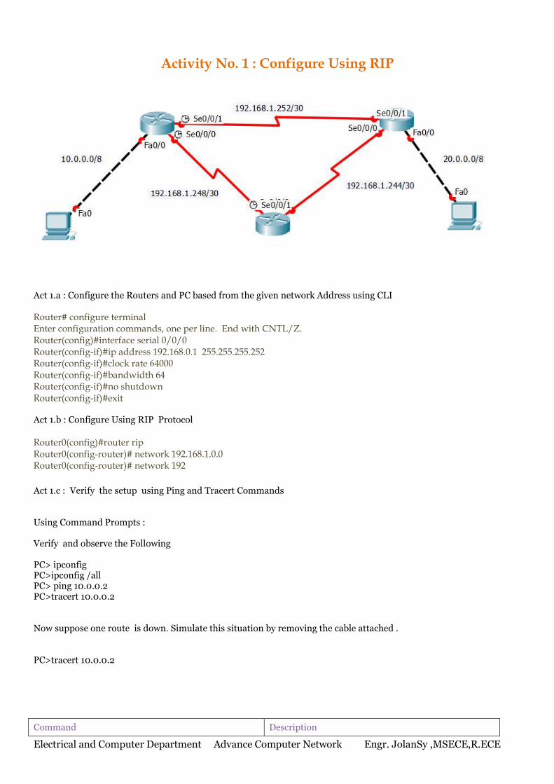
Activity No. 1 : Configure Using RIP
Act 1.a : Configure the Routers and PC based from the given network Address using CLI Router# configure terminal Enter configuration commands, one per line. End with CNTL/Z. Router(config)#interface serial 0/0/0 Router(config-if)#ip address 192.168.0.1 255.255.255.252 Router(config-if)#clock rate 64000 Router(config-if)#bandwidth 64 Router(config-if)#no shutdown Router(config-if)#exit Act 1.b : Configure Using RIP Protocol Router0(config)#router rip Router0(config-router)# network 192.168.1.0.0 Router0(config-router)# network 192
Act 1.c : Verify the setup using Ping and Tracert Commands Using Command Prompts : Verify and observe the Following PC> ipconfig PC>ipconfig /all PC> ping 10.0.0.2 PC>tracert 10.0.0.2 Now suppose one route is down. Simulate this situation by removing the cable attached . PC>tracert 10.0.0.2
Command Description
Electrical and Computer Department Advance Computer Network Engr. JolanSy ,MSECE,R.ECE
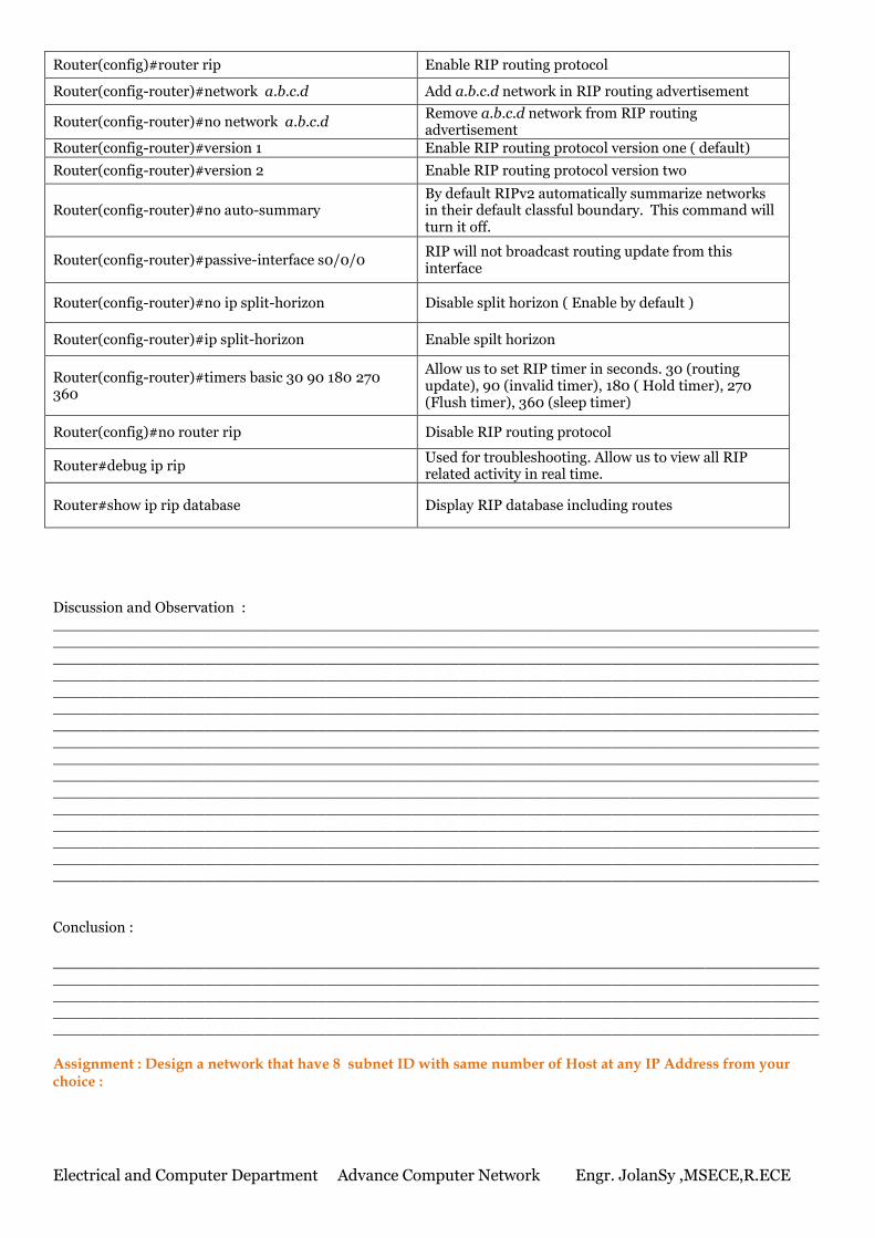
Router(config)#router rip Enable RIP routing protocol
Router(config-router)#network a.b.c.d Add a.b.c.d network in RIP routing advertisement
Router(config-router)#no network a.b.c.d Remove a.b.c.d network from RIP routing advertisement
Router(config-router)#version 1 Enable RIP routing protocol version one ( default)
Router(config-router)#version 2 Enable RIP routing protocol version two
Router(config-router)#no auto-summary By default RIPv2 automatically summarize networks in their default classful boundary. This command will turn it off.
Router(config-router)#passive-interface s0/0/0 RIP will not broadcast routing update from this interface
Router(config-router)#no ip split-horizon Disable split horizon ( Enable by default )
Router(config-router)#ip split-horizon Enable spilt horizon
Router(config-router)#timers basic 30 90 180 270 360
Allow us to set RIP timer in seconds. 30 (routing update), 90 (invalid timer), 180 ( Hold timer), 270 (Flush timer), 360 (sleep timer)
Router(config)#no router rip Disable RIP routing protocol
Router#debug ip rip Used for troubleshooting. Allow us to view all RIP related activity in real time.
Router#show ip rip database Display RIP database including routes
Discussion and Observation : ________________________________________________________________________________________________________________________________________________________________________________________________________________________________________________________________________________________________________________________________________________________________________________________________________________________________________________________________________________________________________________________________________________________________________________________________________________________________________________________________________ ________________________________________________________________________________________________________________________________________________________________________________________________________________________________________________________________________________________________________________________________________________________________________________________________________________________________________________________________________________________________________________________________________________________________________________________________________________________________________________________________________ Conclusion : _____________________________________________________________________________________________________________________________________________________________________________________________________________________________________________________________________________________________________________________________________________________________________________________________________________________ Assignment : Design a network that have 8 subnet ID with same number of Host at any IP Address from your choice :
Electrical and Computer Department Advance Computer Network Engr. JolanSy ,MSECE,R.ECE
Name : ________________________________________ ID. NO: ________________________Section : _____________
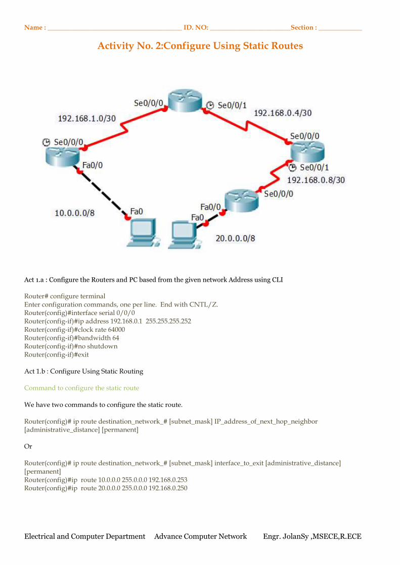
Activity No. 2:Configure Using Static Routes
Act 1.a : Configure the Routers and PC based from the given network Address using CLI Router# configure terminal Enter configuration commands, one per line. End with CNTL/Z. Router(config)#interface serial 0/0/0 Router(config-if)#ip address 192.168.0.1 255.255.255.252 Router(config-if)#clock rate 64000 Router(config-if)#bandwidth 64 Router(config-if)#no shutdown Router(config-if)#exit Act 1.b : Configure Using Static Routing Command to configure the static route We have two commands to configure the static route. Router(config)# ip route destination_network_# [subnet_mask] IP_address_of_next_hop_neighbor [administrative_distance] [permanent] Or Router(config)# ip route destination_network_# [subnet_mask] interface_to_exit [administrative_distance] [permanent] Router(config)#ip route 10.0.0.0 255.0.0.0 192.168.0.253
Router(config)#ip route 20.0.0.0 255.0.0.0 192.168.0.250
Electrical and Computer Department Advance Computer Network Engr. JolanSy ,MSECE,R.ECE
Act 1.c : Verify the setup using Ping and Tracert Commands PC> ipconfig PC>ipconfig /all PC> ping 10.0.0.2 PC>tracert 10.0.0.2
Configure Default Route Static routing solves one more network problem. It can redirect all unmatched packets to a certain port. This feature is extremely helpful in several situations. We can set a default route for internet connection or we can implement a security measurement to deal with all matched packet. By default Routers are configured to drop the packet if destination address is not found in routing table. Default route will override this behavior. If no match for destination network is found in routing table then it would be forwarded to the default route. Thus default route is a way to deal with all unmatched packets. Following command will set default route Router(config)# ip route 0.0.0.0 0.0.0.0 IP_address_of_next_hop_neighbor [administrative_distance] [permanent] Or Router(config)# ip route 0.0.0.0 0.0.0.0 interface_to_exit [administrative_distance] [permanent] Above command sets destination network to 0.0.0.0/0 that represents all networks. Discussion and Observation : ________________________________________________________________________________________________________________________________________________________________________________________________________________________________________________________________________________________________________________________________________________________________________________________________________________________________________________________________________________________________________________________________________________________________________________________________________________________________________________________________________ ________________________________________________________________________________________________________________________________________________________________________________________________________________________________________________________________________________________________________________________________________________________________________________________________________________________________________________________________________________________________________________________________________________________________________________________________________________________________________________________________________ Conclusion : _____________________________________________________________________________________________________________________________________________________________________________________________________________________________________________________________________________________________________________________________________________________________________________________________________________________ Assignment : Design a network that have 8 subnet ID with different number of Host at any IP Address from your choice :
Electrical and Computer Department Advance Computer Network Engr. JolanSy ,MSECE,R.ECE
Name : ________________________________________ ID. NO: ________________________Section : _____________
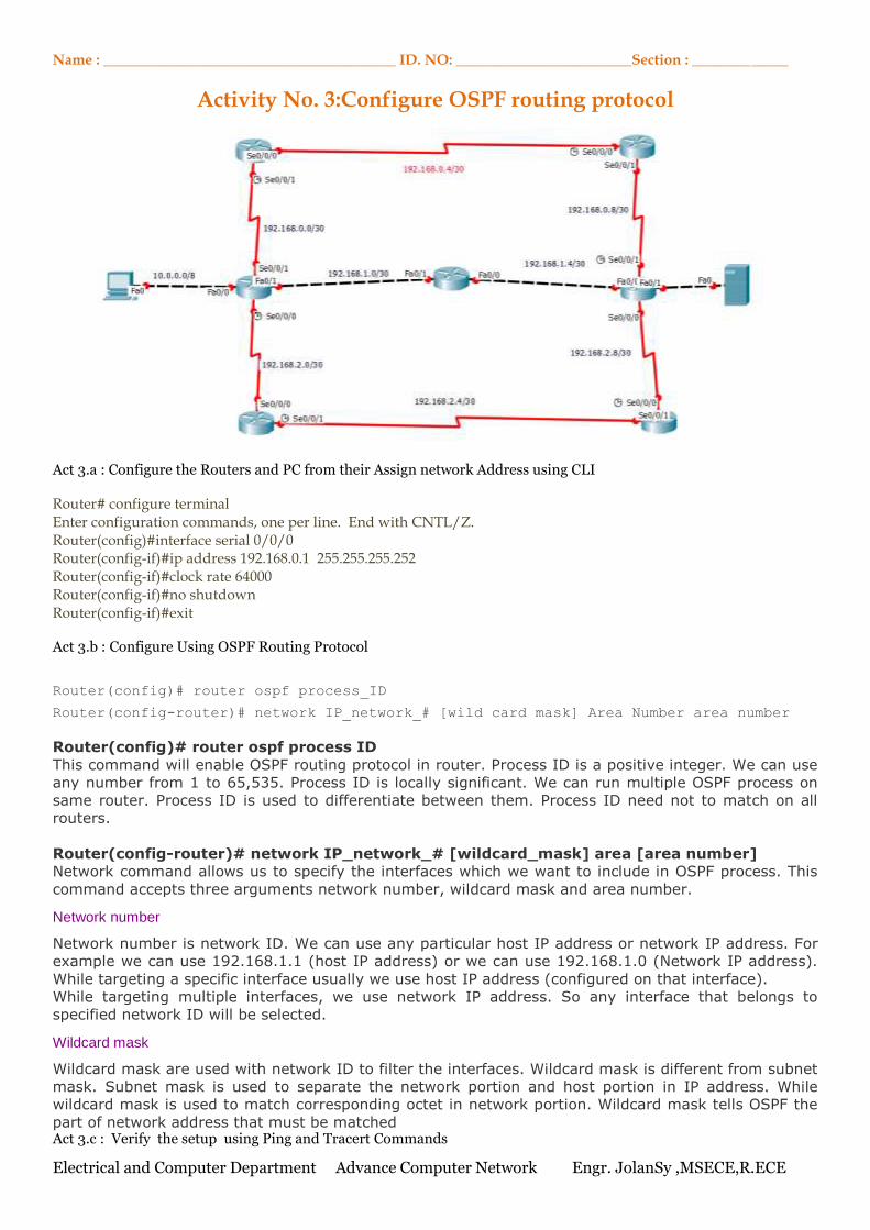
Activity No. 3:Configure OSPF routing protocol Act 3.a : Configure the Routers and PC from their Assign network Address using CLI Router# configure terminal Enter configuration commands, one per line. End with CNTL/Z. Router(config)#interface serial 0/0/0 Router(config-if)#ip address 192.168.0.1 255.255.255.252 Router(config-if)#clock rate 64000 Router(config-if)#no shutdown Router(config-if)#exit Act 3.b : Configure Using OSPF Routing Protocol
Router(config)# router ospf process_ID
Router(config-router)# network IP_network_# [wild card mask] Area Number area number
Router(config)# router ospf process ID
This command will enable OSPF routing protocol in router. Process ID is a positive integer. We can use
any number from 1 to 65,535. Process ID is locally significant. We can run multiple OSPF process on
same router. Process ID is used to differentiate between them. Process ID need not to match on all
routers.
Router(config-router)# network IP_network_# [wildcard_mask] area [area number]
Network command allows us to specify the interfaces which we want to include in OSPF process. This
command accepts three arguments network number, wildcard mask and area number.
Network number
Network number is network ID. We can use any particular host IP address or network IP address. For
example we can use 192.168.1.1 (host IP address) or we can use 192.168.1.0 (Network IP address).
While targeting a specific interface usually we use host IP address (configured on that interface).
While targeting multiple interfaces, we use network IP address. So any interface that belongs to
specified network ID will be selected.
Wildcard mask
Wildcard mask are used with network ID to filter the interfaces. Wildcard mask is different from subnet
mask. Subnet mask is used to separate the network portion and host portion in IP address. While
wildcard mask is used to match corresponding octet in network portion. Wildcard mask tells OSPF the
part of network address that must be matched Act 3.c : Verify the setup using Ping and Tracert Commands
Electrical and Computer Department Advance Computer Network Engr. JolanSy ,MSECE,R.ECE
PC> ping 20.0.0.2 PC > tracert 20.0.0.2
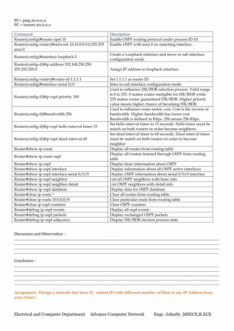
Command Description
Router(config)#router opsf 10 Enable OSPF routing protocol under process ID 10.
Router(config-router)#network 10.10.0.0 0.0.255.255 area 0
Enable OSPF with area 0 on matching interface.
Router(config)#interface loopback 0 Create a Loopback interface and move in sub interface configuration mode
Router(config-if)#ip address 192.168.250.250 255.255.255.0
Assign IP address to loopback interface
Router(config-router)#router-id 1.1.1.1 Set 1.1.1.1 as router ID
Router(config)#interface serial 0/0 Inter in sub interface configuration mode
Router(config-if)#ip ospf priority 100
Used to influence DR/BDR selection process. Valid range is 0 to 255. 0 makes router ineligible for DR/BDR while 255 makes router guaranteed DR/BDR. Higher priority value means higher chance of becoming DR/BDR.
Router(config-if)#bandwidth 256 Used to influence route metric cost. Cost is the inverse of bandwidth. Higher bandwidth has lower cost. Bandwidth is defined in Kbps. 256 means 256 Kbps.
Router(config-if)#ip ospf hello-interval timer 15 Set hello interval timer to 15 seconds. Hello timer must be match on both routers in order become neighbors.
Router(config-if)#ip ospf dead-interval 60 Set dead interval timer to 60 seconds. Dead interval timer must be match on both routers in order to become neighbor
Router#show ip route Display all routes from routing table
Router#show ip route ospf Display all routers learned through OSPF from routing table
Router#show ip ospf Display basic information about OSPF
Router#show ip ospf interface Display information about all OSPF active interfaces
Router#show ip ospf interface serial 0/0/0 Display OSPF information about serial 0/0/0 interface
Router#show ip ospf neighbor List all OSPF neighbors with basic info
Router#show ip ospf neighbor detail List OSPF neighbors with detail info
Router#show ip ospf database Display data for OSPF database
Router#clear ip route * Clear all routes from routing table.
Router#clear ip route 10.0.0.0/8 Clear particular route from routing table
Router#clear ip ospf counters Clear OSPF counters
Router#debug ip ospf events Display all ospf events
Router#debug ip ospf packets Display exchanged OSPF packets
Router#debug ip ospf adjacency Display DR/BDR election process state Discussion and Observation : ____________________________________________________________________________________________________________________________________________________________________________________________________________________________________________________________________________________________________________________________________ Conclusion : _____________________________________________________________________________________________________________________________________________________________________________________________________________________________________________________________________________________________________________________________________________________________________________________________________________________ Assignment : Design a network that have 12 subnet ID with different number of Host at any IP Address from your choice :
Electrical and Computer Department Advance Computer Network Engr. JolanSy ,MSECE,R.ECE
Name : ________________________________________ ID. NO: ________________________Section : _____________
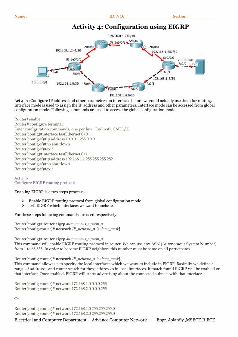
Activity 4: Configuration using EIGRP Act 4. A :Configure IP address and other parameters on interfaces before we could actually use them for routing. Interface mode is used to assign the IP address and other parameters. Interface mode can be accessed from global configuration mode. Following commands are used to access the global configuration mode. Router>enable Router# configure terminal Enter configuration commands, one per line. End with CNTL/Z. Router(config)#interface fastEthernet 0/0 Router(config-if)#ip address 10.0.0.1 255.0.0.0 Router(config-if)#no shutdown Router(config-if)#exit Router(config)#interface fastEthernet 0/1 Router(config-if)#ip address 192.168.1.1 255.255.255.252 Router(config-if)#no shutdown Router(config-if)#exit Act 4. b Configure EIGRP routing protocol Enabling EIGRP is a two steps process:-
Enable EIGRP routing protocol from global configuration mode. Tell EIGRP which interfaces we want to include.
For these steps following commands are used respectively. Router(config)# router eigrp autonomous_system_# Router(config-router)# network IP_network_# [subnet_mask] Router(config)# router eigrp autonomous_system_# This command will enable EIGRP routing protocol in router. We can use any ASN (Autonomous System Number) from 1 to 65,535. In order to become EIGRP neighbors this number must be same on all participates. Router(config-router)# network IP_network_# [subnet_mask] This command allows us to specify the local interfaces which we want to include in EIGRP. Basically we define a range of addresses and router search for these addresses in local interfaces. If match found EIGRP will be enabled on that interface. Once enabled, EIGRP will starts advertising about the connected subnets with that interface. Router(config-router)# network 172.168.1.0 0.0.0.255 Router(config-router)# network 172.168.2.0 0.0.0.255 Or Router(config-router)# network 172.168.1.0 255.255.255.0 Router(config-router)# network 172.168.2.0 255.255.255.0
Electrical and Computer Department Advance Computer Network Engr. JolanSy ,MSECE,R.ECE
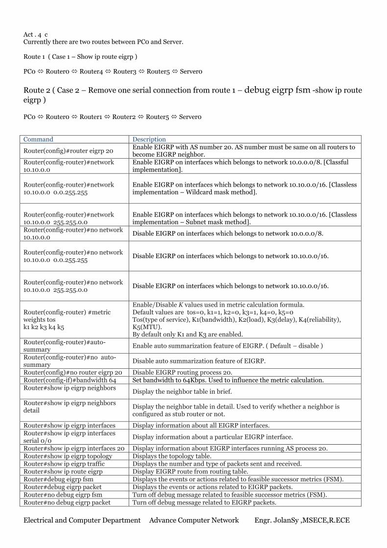
Act . 4 c Currently there are two routes between PC0 and Server. Route 1 ( Case 1 – Show ip route eigrp ) PC0 Router0 Router4 Router3 Router5 Server0
Route 2 ( Case 2 – Remove one serial connection from route 1 – debug eigrp fsm -show ip route
eigrp ) PC0 Router0 Router1 Router2 Router5 Server0 Command Description
Router(config)#router eigrp 20 Enable EIGRP with AS number 20. AS number must be same on all routers to become EIGRP neighbor.
Router(config-router)#network 10.10.0.0
Enable EIGRP on interfaces which belongs to network 10.0.0.0/8. [Classful implementation].
Router(config-router)#network 10.10.0.0 0.0.255.255
Enable EIGRP on interfaces which belongs to network 10.10.0.0/16. [Classless implementation – Wildcard mask method].
Router(config-router)#network 10.10.0.0 255.255.0.0
Enable EIGRP on interfaces which belongs to network 10.10.0.0/16. [Classless implementation – Subnet mask method].
Router(config-router)#no network 10.10.0.0
Disable EIGRP on interfaces which belongs to network 10.0.0.0/8.
Router(config-router)#no network 10.10.0.0 0.0.255.255
Disable EIGRP on interfaces which belongs to network 10.10.0.0/16.
Router(config-router)#no network 10.10.0.0 255.255.0.0
Disable EIGRP on interfaces which belongs to network 10.10.0.0/16.
Router(config-router) #metric weights tos k1 k2 k3 k4 k5
Enable/Disable K values used in metric calculation formula. Default values are tos=0, k1=1, k2=0, k3=1, k4=0, k5=0 Tos(type of service), K1(bandwidth), K2(load), K3(delay), K4(reliability), K5(MTU). By default only K1 and K3 are enabled.
Router(config-router)#auto-summary
Enable auto summarization feature of EIGRP. ( Default – disable )
Router(config-router)#no auto-summary
Disable auto summarization feature of EIGRP.
Router(config)#no router eigrp 20 Disable EIGRP routing process 20. Router(config-if)#bandwidth 64 Set bandwidth to 64Kbps. Used to influence the metric calculation. Router#show ip eigrp neighbors
Display the neighbor table in brief.
Router#show ip eigrp neighbors detail
Display the neighbor table in detail. Used to verify whether a neighbor is configured as stub router or not.
Router#show ip eigrp interfaces Display information about all EIGRP interfaces. Router#show ip eigrp interfaces serial 0/0
Display information about a particular EIGRP interface.
Router#show ip eigrp interfaces 20 Display information about EIGRP interfaces running AS process 20. Router#show ip eigrp topology Displays the topology table. Router#show ip eigrp traffic Displays the number and type of packets sent and received. Router#show ip route eigrp Display EIGRP route from routing table. Router#debug eigrp fsm Displays the events or actions related to feasible successor metrics (FSM). Router#debug eigrp packet Displays the events or actions related to EIGRP packets. Router#no debug eigrp fsm Turn off debug message related to feasible successor metrics (FSM). Router#no debug eigrp packet Turn off debug message related to EIGRP packets.
Electrical and Computer Department Advance Computer Network Engr. JolanSy ,MSECE,R.ECE
Name : ________________________________________ ID. NO: ________________________Section : _____________
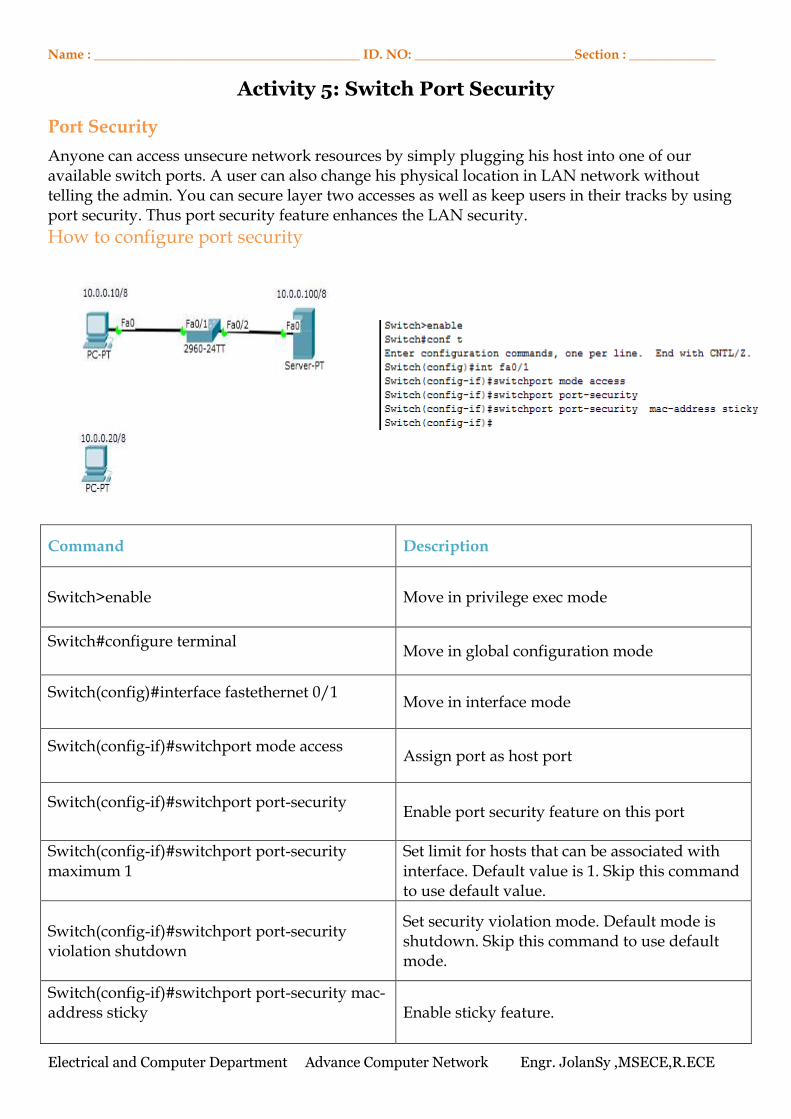
Activity 5: Switch Port Security
Port Security
Anyone can access unsecure network resources by simply plugging his host into one of our available switch ports. A user can also change his physical location in LAN network without telling the admin. You can secure layer two accesses as well as keep users in their tracks by using port security. Thus port security feature enhances the LAN security.
How to configure port security
Command Description
Switch>enable
Move in privilege exec mode
Switch#configure terminal
Move in global configuration mode
Switch(config)#interface fastethernet 0/1
Move in interface mode
Switch(config-if)#switchport mode access
Assign port as host port
Switch(config-if)#switchport port-security
Enable port security feature on this port
Switch(config-if)#switchport port-security maximum 1
Set limit for hosts that can be associated with interface. Default value is 1. Skip this command to use default value.
Switch(config-if)#switchport port-security violation shutdown
Set security violation mode. Default mode is shutdown. Skip this command to use default mode.
Switch(config-if)#switchport port-security mac-address sticky
Enable sticky feature.
Electrical and Computer Department Advance Computer Network Engr. JolanSy ,MSECE,R.ECE
Electrical and Computer Department Advance Computer Network Engr. JolanSy ,MSECE,R.ECE
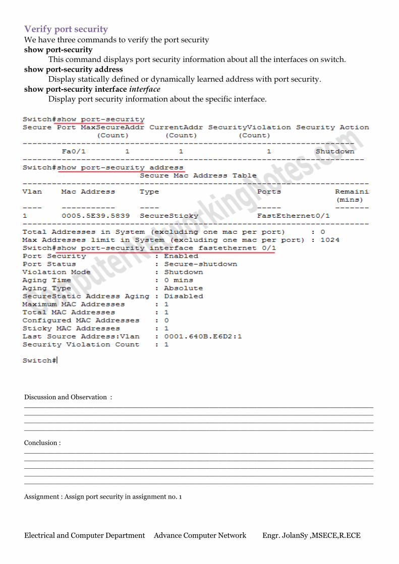
Verify port security We have three commands to verify the port security show port-security
This command displays port security information about all the interfaces on switch. show port-security address
Display statically defined or dynamically learned address with port security. show port-security interface interface
Display port security information about the specific interface. Discussion and Observation : ____________________________________________________________________________________________________________________________________________________________________________________________________________________________________________________________________________________________________________________________________ Conclusion : _____________________________________________________________________________________________________________________________________________________________________________________________________________________________________________________________________________________________________________________________________________________________________________________________________________________ Assignment : Assign port security in assignment no. 1
Electrical and Computer Department Advance Computer Network Engr. JolanSy ,MSECE,R.ECE
Name : ________________________________________ ID. NO: ________________________Section : _____________
Activity 6: VLAN Trunk Protocol (VTP)
Protocol used to share VLAN configuration across the network. Cisco created this protocol to share and synchronize their VLAN information throughout the network. Main goal of VTP is to manage all configured VLANs across the network.
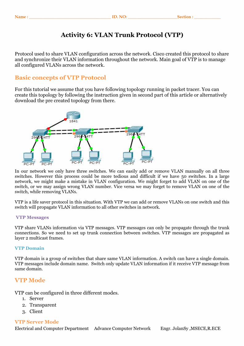
Basic concepts of VTP Protocol For this tutorial we assume that you have following topology running in packet tracer. You can create this topology by following the instruction given in second part of this article or alternatively download the pre created topology from there.
In our network we only have three switches. We can easily add or remove VLAN manually on all three switches. However this process could be more tedious and difficult if we have 50 switches. In a large network, we might make a mistake in VLAN configuration. We might forget to add VLAN on one of the switch, or we may assign wrong VLAN number. Vice versa we may forget to remove VLAN on one of the switch, while removing VLANs. VTP is a life saver protocol in this situation. With VTP we can add or remove VLANs on one switch and this switch will propagate VLAN information to all other switches in network. VTP Messages VTP share VLANs information via VTP messages. VTP messages can only be propagate through the trunk connections. So we need to set up trunk connection between switches. VTP messages are propagated as layer 2 multicast frames. VTP Domain VTP domain is a group of switches that share same VLAN information. A switch can have a single domain. VTP messages include domain name. Switch only update VLAN information if it receive VTP message from same domain.
VTP Mode VTP can be configured in three different modes.
1. Server
2. Transparent
3. Client
VTP Server Mode
Electrical and Computer Department Advance Computer Network Engr. JolanSy ,MSECE,R.ECE
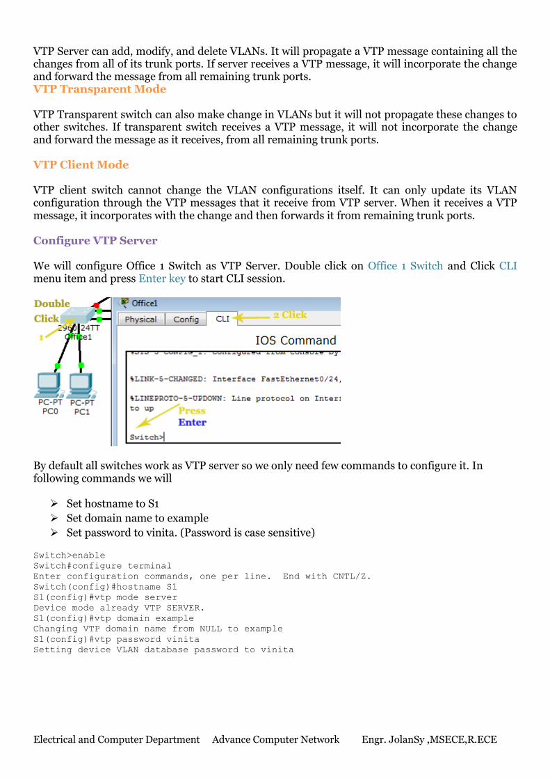
VTP Server can add, modify, and delete VLANs. It will propagate a VTP message containing all the changes from all of its trunk ports. If server receives a VTP message, it will incorporate the change and forward the message from all remaining trunk ports. VTP Transparent Mode VTP Transparent switch can also make change in VLANs but it will not propagate these changes to other switches. If transparent switch receives a VTP message, it will not incorporate the change and forward the message as it receives, from all remaining trunk ports. VTP Client Mode VTP client switch cannot change the VLAN configurations itself. It can only update its VLAN configuration through the VTP messages that it receive from VTP server. When it receives a VTP message, it incorporates with the change and then forwards it from remaining trunk ports. Configure VTP Server We will configure Office 1 Switch as VTP Server. Double click on Office 1 Switch and Click CLI menu item and press Enter key to start CLI session.
By default all switches work as VTP server so we only need few commands to configure it. In following commands we will Set hostname to S1
Set domain name to example
Set password to vinita. (Password is case sensitive)
Switch>enable
Switch#configure terminal
Enter configuration commands, one per line. End with CNTL/Z.
Switch(config)#hostname S1
S1(config)#vtp mode server
Device mode already VTP SERVER.
S1(config)#vtp domain example
Changing VTP domain name from NULL to example
S1(config)#vtp password vinita
Setting device VLAN database password to vinita
Electrical and Computer Department Advance Computer Network Engr. JolanSy ,MSECE,R.ECE
Configure VTP Client We will configure Office 2 Switch and Office 3 Switch as VTP client switch. Access CLI prompts of Office 2 Switch and execute following commands Switch>enable
Switch#configure terminal
Enter configuration commands, one per line. End with CNTL/Z.
Switch(config)#hostname S2
S2(config)#vtp mode client
Setting device to VTP CLIENT mode.
S2(config)#vtp domain example
Changing VTP domain name from NULL to example
S2(config)#vtp password vinita
Setting device VLAN database password to vinita
S2(config)#
Now access CLI prompts of Office 3 Switch and enter following commands Switch>enable
Switch#configure terminal
Enter configuration commands, one per line. End with CNTL/Z.
Switch(config)#hostname S3
S3(config)#vtp mode client
Setting device to VTP CLIENT mode.
S3(config)#vtp domain example
Changing VTP domain name from NULL to example
S3(config)#vtp password vinita
Setting device VLAN database password to vinita
S3(config)#
We have configured VTP server and VTP client. At this moment VTP client will not receive VTP messages from server. We need to configure DTP between switches. Discussion and Observation : ____________________________________________________________________________________________________________________________________________________________________________________________________________________________________________________________________________________________________________________________________ ______________________________________________________________________________________________________________________________________________________________________________________________________________________________________________________________________________________________________________________________________________________________________________________________________________________________________________________________________________________________________ Conclusion : _____________________________________________________________________________________________________________________________________________________________________________________________________________________________________________________________________________________________________________________________________________________________________________________________________________________ Assignment : Design a network that have 5 offices with 5 network address.
Electrical and Computer Department Advance Computer Network Engr. JolanSy ,MSECE,R.ECE
Name : ________________________________________ ID. NO: ________________________Section : _____________
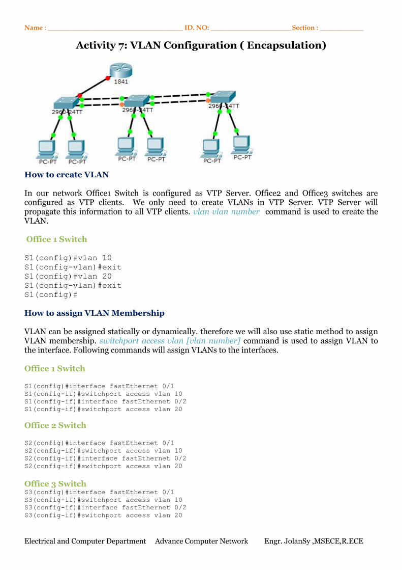
Activity 7: VLAN Configuration ( Encapsulation)
How to create VLAN In our network Office1 Switch is configured as VTP Server. Office2 and Office3 switches are configured as VTP clients. We only need to create VLANs in VTP Server. VTP Server will propagate this information to all VTP clients. vlan vlan number command is used to create the VLAN. Office 1 Switch S1(config)#vlan 10
S1(config-vlan)#exit
S1(config)#vlan 20
S1(config-vlan)#exit
S1(config)#
How to assign VLAN Membership VLAN can be assigned statically or dynamically. therefore we will also use static method to assign VLAN membership. switchport access vlan [vlan number] command is used to assign VLAN to the interface. Following commands will assign VLANs to the interfaces. Office 1 Switch S1(config)#interface fastEthernet 0/1
S1(config-if)#switchport access vlan 10
S1(config-if)#interface fastEthernet 0/2
S1(config-if)#switchport access vlan 20
Office 2 Switch S2(config)#interface fastEthernet 0/1
S2(config-if)#switchport access vlan 10
S2(config-if)#interface fastEthernet 0/2
S2(config-if)#switchport access vlan 20
Office 3 Switch S3(config)#interface fastEthernet 0/1
S3(config-if)#switchport access vlan 10
S3(config-if)#interface fastEthernet 0/2
S3(config-if)#switchport access vlan 20
Electrical and Computer Department Advance Computer Network Engr. JolanSy ,MSECE,R.ECE
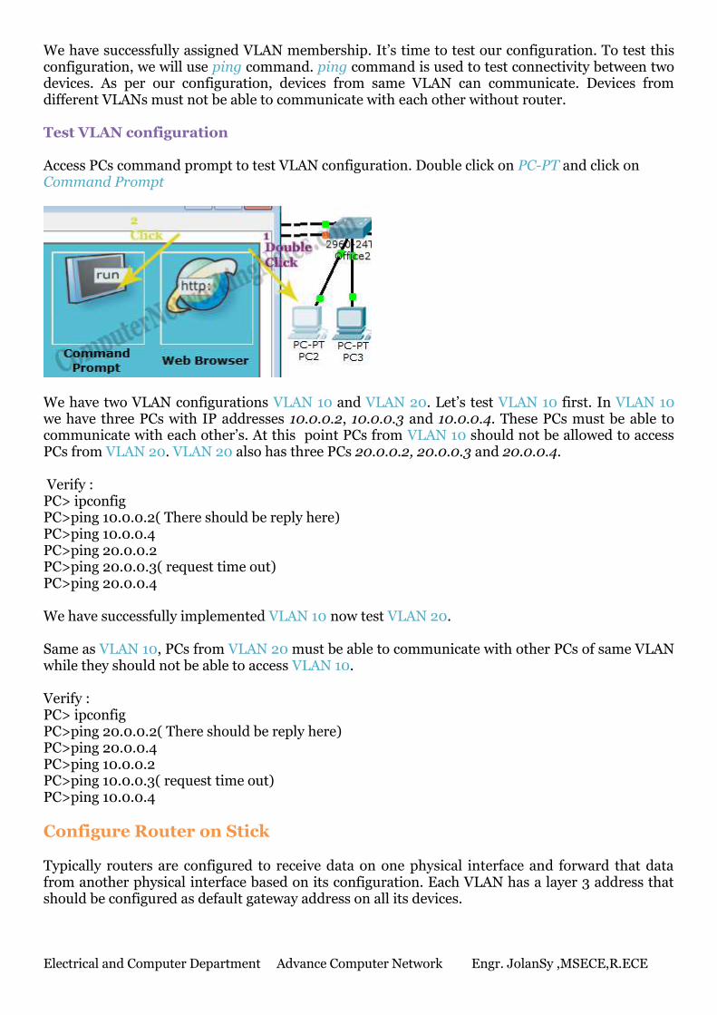
We have successfully assigned VLAN membership. It’s time to test our configuration. To test this configuration, we will use ping command. ping command is used to test connectivity between two devices. As per our configuration, devices from same VLAN can communicate. Devices from different VLANs must not be able to communicate with each other without router. Test VLAN configuration Access PCs command prompt to test VLAN configuration. Double click on PC-PT and click on Command Prompt
We have two VLAN configurations VLAN 10 and VLAN 20. Let’s test VLAN 10 first. In VLAN 10 we have three PCs with IP addresses 10.0.0.2, 10.0.0.3 and 10.0.0.4. These PCs must be able to communicate with each other’s. At this point PCs from VLAN 10 should not be allowed to access PCs from VLAN 20. VLAN 20 also has three PCs 20.0.0.2, 20.0.0.3 and 20.0.0.4. Verify : PC> ipconfig PC>ping 10.0.0.2( There should be reply here) PC>ping 10.0.0.4 PC>ping 20.0.0.2 PC>ping 20.0.0.3( request time out) PC>ping 20.0.0.4 We have successfully implemented VLAN 10 now test VLAN 20. Same as VLAN 10, PCs from VLAN 20 must be able to communicate with other PCs of same VLAN while they should not be able to access VLAN 10. Verify : PC> ipconfig PC>ping 20.0.0.2( There should be reply here) PC>ping 20.0.0.4 PC>ping 10.0.0.2 PC>ping 10.0.0.3( request time out) PC>ping 10.0.0.4
Configure Router on Stick Typically routers are configured to receive data on one physical interface and forward that data from another physical interface based on its configuration. Each VLAN has a layer 3 address that should be configured as default gateway address on all its devices.
Electrical and Computer Department Advance Computer Network Engr. JolanSy ,MSECE,R.ECE
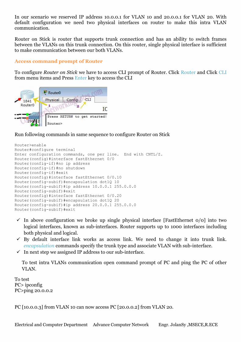
In our scenario we reserved IP address 10.0.0.1 for VLAN 10 and 20.0.0.1 for VLAN 20. With default configuration we need two physical interfaces on router to make this intra VLAN communication. Router on Stick is router that supports trunk connection and has an ability to switch frames between the VLANs on this trunk connection. On this router, single physical interface is sufficient to make communication between our both VLANs. Access command prompt of Router To configure Router on Stick we have to access CLI prompt of Router. Click Router and Click CLI from menu items and Press Enter key to access the CLI
Run following commands in same sequence to configure Router on Stick Router>enable
Router#configure terminal
Enter configuration commands, one per line. End with CNTL/Z.
Router(config)#interface fastEthernet 0/0
Router(config-if)#no ip address
Router(config-if)#no shutdown
Router(config-if)#exit
Router(config)#interface fastEthernet 0/0.10
Router(config-subif)#encapsulation dot1Q 10
Router(config-subif)#ip address 10.0.0.1 255.0.0.0
Router(config-subif)#exit
Router(config)#interface fastEthernet 0/0.20
Router(config-subif)#encapsulation dot1Q 20
Router(config-subif)#ip address 20.0.0.1 255.0.0.0
Router(config-subif)#exit
In above configuration we broke up single physical interface [FastEthernet 0/0] into two
logical interfaces, known as sub-interfaces. Router supports up to 1000 interfaces including
both physical and logical.
By default interface link works as access link. We need to change it into trunk link.
encapsulation commands specify the trunk type and associate VLAN with sub-interface.
In next step we assigned IP address to our sub-interface.
To test intra VLANs communication open command prompt of PC and ping the PC of other
VLAN.
To test PC> ipconfig PC>ping 20.0.0.2 PC [10.0.0.3] from VLAN 10 can now access PC [20.0.0.2] from VLAN 20.
Electrical and Computer Department Advance Computer Network Engr. JolanSy ,MSECE,R.ECE
Name : ________________________________________ ID. NO: ________________________Section : _____________
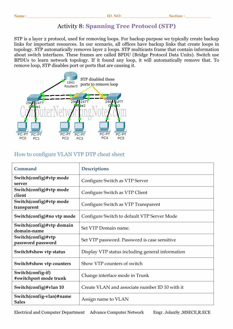
Activity 8: Spanning Tree Protocol (STP)
STP is a layer 2 protocol, used for removing loops. For backup purpose we typically create backup links for important resources. In our scenario, all offices have backup links that create loops in topology. STP automatically removes layer 2 loops. STP multicasts frame that contain information about switch interfaces. These frames are called BPDU (Bridge Protocol Data Units). Switch use BPDUs to learn network topology. If it found any loop, it will automatically remove that. To remove loop, STP disables port or ports that are causing it.
How to configure VLAN VTP DTP cheat sheet
Command Descriptions
Switch(config)#vtp mode server
Configure Switch as VTP Server
Switch(config)#vtp mode client
Configure Switch as VTP Client
Switch(config)#vtp mode transparent
Configure Switch as VTP Transparent
Switch(config)#no vtp mode Configure Switch to default VTP Server Mode
Switch(config)#vtp domain domain-name
Set VTP Domain name.
Switch(config)#vtp password password
Set VTP password. Password is case sensitive
Switch#show vtp status Display VTP status including general information
Switch#show vtp counters Show VTP counters of switch
Switch(config-if) #switchport mode trunk
Change interface mode in Trunk
Switch(config)#vlan 10 Create VLAN and associate number ID 10 with it
Switch(config-vlan)#name Sales
Assign name to VLAN
Electrical and Computer Department Advance Computer Network Engr. JolanSy ,MSECE,R.ECE
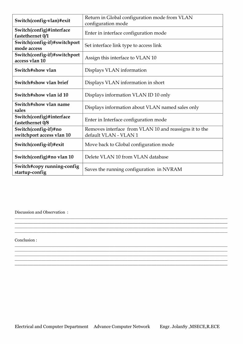
Switch(config-vlan)#exit Return in Global configuration mode from VLAN configuration mode
Switch(config)#interface fastethernet 0/1
Enter in interface configuration mode
Switch(config-if)#switchport mode access
Set interface link type to access link
Switch(config-if)#switchport access vlan 10
Assign this interface to VLAN 10
Switch#show vlan Displays VLAN information
Switch#show vlan brief Displays VLAN information in short
Switch#show vlan id 10 Displays information VLAN ID 10 only
Switch#show vlan name sales
Displays information about VLAN named sales only
Switch(config)#interface fastethernet 0/8
Enter in Interface configuration mode
Switch(config-if)#no switchport access vlan 10
Removes interface from VLAN 10 and reassigns it to the default VLAN - VLAN 1
Switch(config-if)#exit Move back to Global configuration mode
Switch(config)#no vlan 10 Delete VLAN 10 from VLAN database
Switch#copy running-config startup-config
Saves the running configuration in NVRAM
Discussion and Observation : ____________________________________________________________________________________________________________________________________________________________________________________________________________________________________________________________________________________________________________________________________ Conclusion : _____________________________________________________________________________________________________________________________________________________________________________________________________________________________________________________________________________________________________________________________________________________________________________________________________________________
Electrical and Computer Department Advance Computer Network Engr. JolanSy ,MSECE,R.ECE
Name : ________________________________________ ID. NO: ________________________Section : _____________
Activity 9
Frame Relay
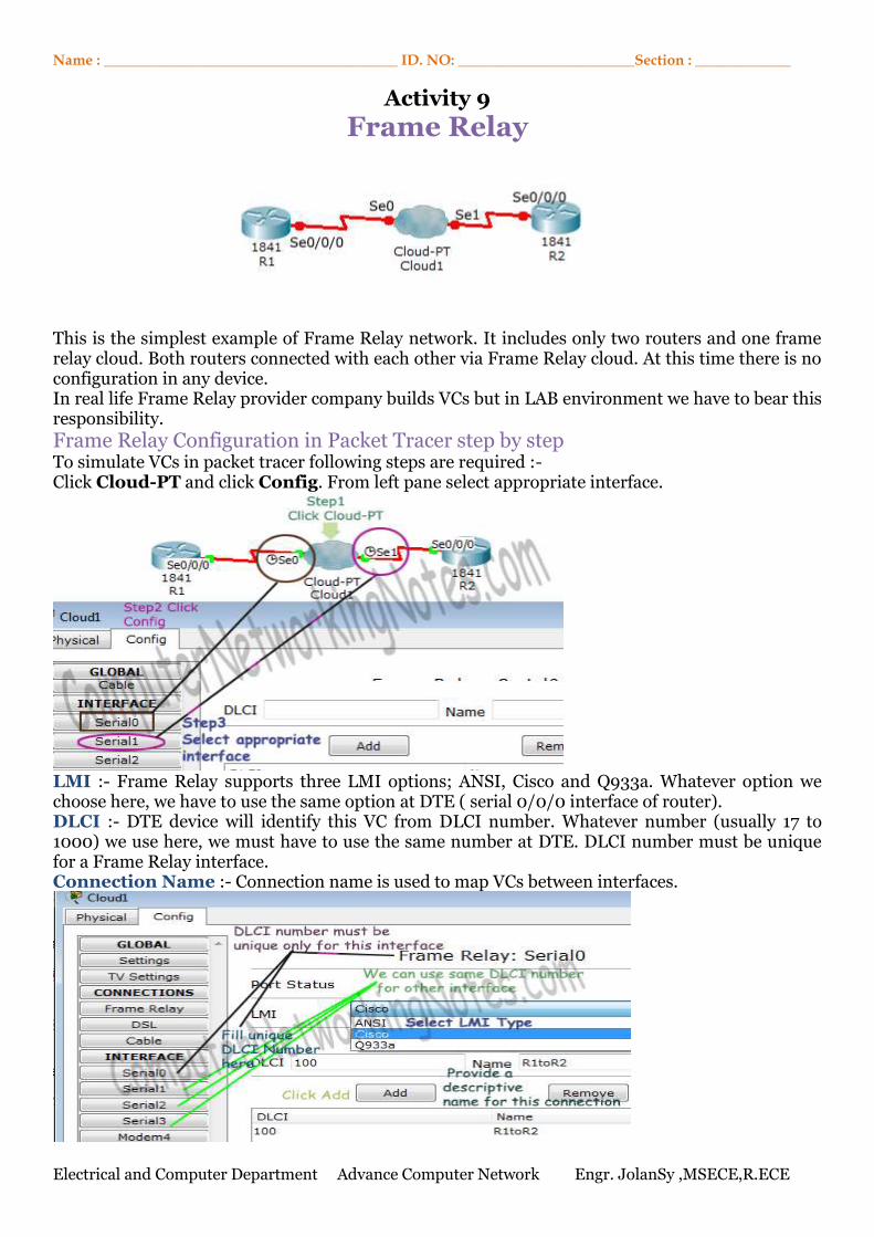
This is the simplest example of Frame Relay network. It includes only two routers and one frame relay cloud. Both routers connected with each other via Frame Relay cloud. At this time there is no configuration in any device. In real life Frame Relay provider company builds VCs but in LAB environment we have to bear this responsibility.
Frame Relay Configuration in Packet Tracer step by step To simulate VCs in packet tracer following steps are required :- Click Cloud-PT and click Config. From left pane select appropriate interface.
LMI :- Frame Relay supports three LMI options; ANSI, Cisco and Q933a. Whatever option we choose here, we have to use the same option at DTE ( serial 0/0/0 interface of router). DLCI :- DTE device will identify this VC from DLCI number. Whatever number (usually 17 to 1000) we use here, we must have to use the same number at DTE. DLCI number must be unique for a Frame Relay interface. Connection Name :- Connection name is used to map VCs between interfaces.
Electrical and Computer Department Advance Computer Network Engr. JolanSy ,MSECE,R.ECE
LMI option and DLCI number are provided by Frame Relay company.
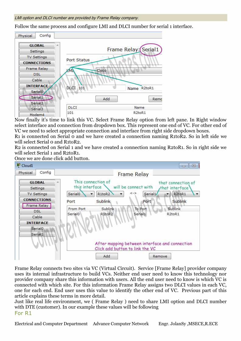
Follow the same process and configure LMI and DLCI number for serial 1 interface.
Now finally it’s time to link this VC. Select Frame Relay option from left pane. In Right window select interface and connection from dropdown box. This represent one end of VC. For other end of VC we need to select appropriate connection and interface from right side dropdown boxes. R1 is connected on Serial 0 and we have created a connection naming R1toR2. So in left side we will select Serial 0 and R1toR2. R2 is connected on Serial 1 and we have created a connection naming R2toR1. So in right side we will select Serial 1 and R2toR1. Once we are done click add button.
Frame Relay connects two sites via VC (Virtual Circuit). Service [Frame Relay] provider company uses its internal infrastructure to build VCs. Neither end user need to know this technology nor provider company share this information with users. All the end user need to know is which VC is connected with which site. For this information Frame Relay assigns two DLCI values in each VC, one for each end. End user uses this value to identify the other end of VC. Previous part of this article explains these terms in more detail. Just like real life environment, we ( Frame Relay ) need to share LMI option and DLCI number with DTE (customer). In our example these values will be following
For R1
Electrical and Computer Department Advance Computer Network Engr. JolanSy ,MSECE,R.ECE
LMI option – ANSI DLCI Number – 100
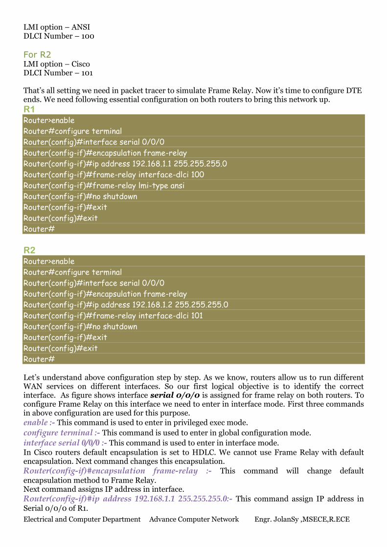
For R2 LMI option – Cisco DLCI Number – 101 That’s all setting we need in packet tracer to simulate Frame Relay. Now it’s time to configure DTE ends. We need following essential configuration on both routers to bring this network up.
R1 Router>enable
Router#configure terminal
Router(config)#interface serial 0/0/0
Router(config-if)#encapsulation frame-relay
Router(config-if)#ip address 192.168.1.1 255.255.255.0
Router(config-if)#frame-relay interface-dlci 100
Router(config-if)#frame-relay lmi-type ansi
Router(config-if)#no shutdown
Router(config-if)#exit
Router(config)#exit
Router#
R2
Router>enable
Router#configure terminal
Router(config)#interface serial 0/0/0
Router(config-if)#encapsulation frame-relay
Router(config-if)#ip address 192.168.1.2 255.255.255.0
Router(config-if)#frame-relay interface-dlci 101
Router(config-if)#no shutdown
Router(config-if)#exit
Router(config)#exit
Router# Let’s understand above configuration step by step. As we know, routers allow us to run different WAN services on different interfaces. So our first logical objective is to identify the correct interface. As figure shows interface serial 0/0/0 is assigned for frame relay on both routers. To configure Frame Relay on this interface we need to enter in interface mode. First three commands in above configuration are used for this purpose.
enable :- This command is used to enter in privileged exec mode.
configure terminal :- This command is used to enter in global configuration mode.
interface serial 0/0/0 :- This command is used to enter in interface mode. In Cisco routers default encapsulation is set to HDLC. We cannot use Frame Relay with default encapsulation. Next command changes this encapsulation.
Router(config-if)#encapsulation frame-relay :- This command will change default encapsulation method to Frame Relay. Next command assigns IP address in interface.
Router(config-if)#ip address 192.168.1.1 255.255.255.0:- This command assign IP address in Serial 0/0/0 of R1.
Electrical and Computer Department Advance Computer Network Engr. JolanSy ,MSECE,R.ECE
Router(config-if)#ip address 192.168.1.2 255.255.255.0 :- This command assign IP address in Serial 0/0/0 of R2. Next command assigns DLCI value in interface.
Router(config-if)#frame-relay interface-dlci 100 :- This command assigns DLCI value 100 in Serial interface of R1.
Router(config-if)#frame-relay interface-dlci 101 :- This command assigns DLCI value 101 in Serial interface of R2. Next command sets LMI option in interface. Until we change LMI option with next command default LMI option is set to Cisco (in Cisco routers).
Router(config-if)#frame-relay lmi-type ansi :- This command will change default LMI option to ANSI. Have you notice ? we did not run this command in R2. Since LMI option [Cisco] that we got from provider matches with the default (Cisco) setting, so there is no need to run this command in R2. By default all interfaces on router are disabled. We need to enable them before they can communicate with other.
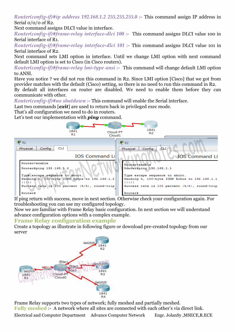
Router(config-if)#no shutdown :- This command will enable the Serial interface. Last two commands [exit] are used to return back in privileged exec mode. That’s all configuration we need to do in routers. Let’s test our implementation with ping command.
If ping return with success, move in next section. Otherwise check your configuration again. For troubleshooting you can use my configured topology. Now we are familiar with Frame Relay basic configuration. In next section we will understand advance configuration options with a complex example.
Frame Relay configuration example Create a topology as illustrate in following figure or download pre-created topology from our server
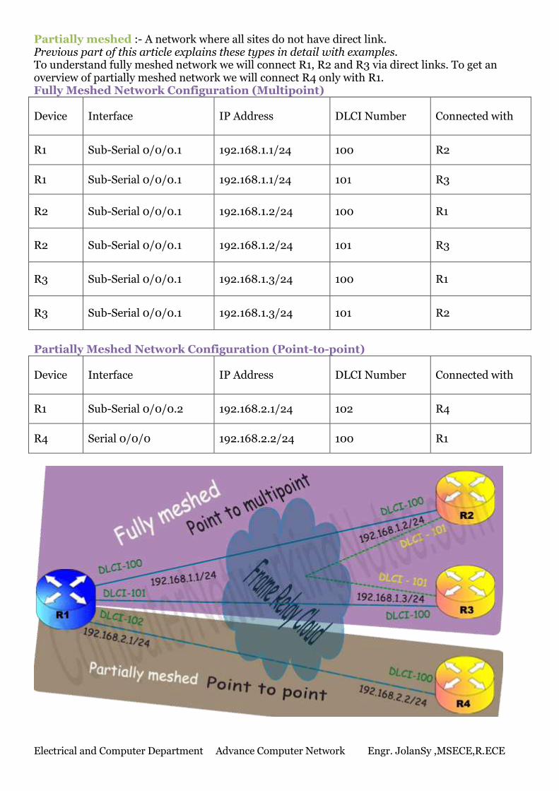
Frame Relay supports two types of network; fully meshed and partially meshed. Fully meshed :- A network where all sites are connected with each other’s via direct link.
Electrical and Computer Department Advance Computer Network Engr. JolanSy ,MSECE,R.ECE
Partially meshed :- A network where all sites do not have direct link. Previous part of this article explains these types in detail with examples. To understand fully meshed network we will connect R1, R2 and R3 via direct links. To get an overview of partially meshed network we will connect R4 only with R1. Fully Meshed Network Configuration (Multipoint)
Device Interface IP Address DLCI Number Connected with
R1 Sub-Serial 0/0/0.1 192.168.1.1/24 100 R2
R1 Sub-Serial 0/0/0.1 192.168.1.1/24 101 R3
R2 Sub-Serial 0/0/0.1 192.168.1.2/24 100 R1
R2 Sub-Serial 0/0/0.1 192.168.1.2/24 101 R3
R3 Sub-Serial 0/0/0.1 192.168.1.3/24 100 R1
R3 Sub-Serial 0/0/0.1 192.168.1.3/24 101 R2
Partially Meshed Network Configuration (Point-to-point)
Device Interface IP Address DLCI Number Connected with
R1 Sub-Serial 0/0/0.2 192.168.2.1/24 102 R4
R4 Serial 0/0/0 192.168.2.2/24 100 R1
Electrical and Computer Department Advance Computer Network Engr. JolanSy ,MSECE,R.ECE
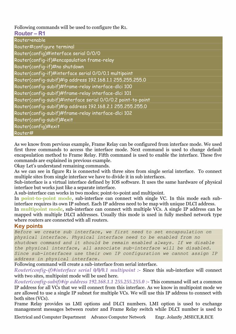
Following commands will be used to configure the R1.
Router – R1 Router>enable
Router#configure terminal
Router(config)#interface serial 0/0/0
Router(config-if)#encapsulation frame-relay
Router(config-if)#no shutdown
Router(config-if)#interface serial 0/0/0.1 multipoint
Router(config-subif)#ip address 192.168.1.1 255.255.255.0
Router(config-subif)#frame-relay interface-dlci 100
Router(config-subif)#frame-relay interface-dlci 101
Router(config-subif)#interface serial 0/0/0.2 point-to-point
Router(config-subif)#ip address 192.168.2.1 255.255.255.0
Router(config-subif)#frame-relay interface-dlci 102
Router(config-subif)#exit
Router(config)#exit
Router# As we know from pervious example, Frame Relay can be configured from interface mode. We used first three commands to access the interface mode. Next command is used to change default encapsulation method to Frame Relay. Fifth command is used to enable the interface. These five commands are explained in previous example. Okay Let’s understand remaining commands. As we can see in figure R1 is connected with three sites from single serial interface. To connect multiple sites from single interface we have to divide it in sub interfaces. Sub-interface is a virtual interface defined by IOS software. It uses the same hardware of physical interface but works just like a separate interface. A sub-interface can works in two modes; point-to-point and multipoint. In point-to-point mode, sub-interface can connect with single VC. In this mode each sub-interface requires its own IP subnet. Each IP address need to be map with unique DLCI address. In multipoint mode, sub-interface can connect with multiple VCs. A single IP address can be mapped with multiple DLCI addresses. Usually this mode is used in fully meshed network type where routers are connected with all routers.
Key points Before we create sub interface, we first need to set encapsulation on
physical interface. Physical interface need to be enabled from no
shutdown command and it should be remain enabled always. If we disable
the physical interface, all associate sub-interface will be disabled.
Since sub-interfaces use their own IP configuration we cannot assign IP
address in physical interface.
Following command will create a sub-interface from serial interface.
Router(config-if)#interface serial 0/0/0.1 multipoint :- Since this sub-interface will connect with two sites, multipoint mode will be used here.
Router(config-subif)#ip address 192.168.1.1 255.255.255.0 :- This command will set a common IP address for all VCs that we will connect from this interface. As we know in multipoint mode we are allowed to use a single IP subnet for multiple VCs. We will use this IP address to connect with both sites (VCs). Frame Relay provides us LMI options and DLCI numbers. LMI option is used to exchange management messages between router and Frame Relay switch while DLCI number is used to
Electrical and Computer Department Advance Computer Network Engr. JolanSy ,MSECE,R.ECE
identify the other end of VC. In our example VC that has DLCI number 100 is connected with R2 and VC with DLCI number 101 is connected with R3. Router will automatically map DLCI number with correct VC. We only need to provide the DLCI numbers which are associated with the interface. Following commands will do this job for this sub-interface.
Router(config-subif)#frame-relay interface-dlci 100 AND Router(config-subif)#frame-relay interface-dlci 101 Since default LMI (Cisco) option is used in this example, we need not configure it here.
On Job If Cisco router is running IOS version 11.2 or higher, interface will
automatically detect corresponding LMI type.
R1 has one more point-to-point connection. For that connection we need a separate sub-interface. Following command will create another point-to-point sub-interface.
Router(config-subif)#interface serial 0/0/0.2 point-to-point Following command will assign IP address in interface.
Router(config-subif)#ip address 192.168.2.1 255.255.255.0 Next command will assign associated DLCI number to it.
Router(config-subif)#frame-relay interface-dlci 102
Exam Tip Point-to-point sub-interface map single DLCI and use a separate IP
subnet. It also solve split horizon issue.
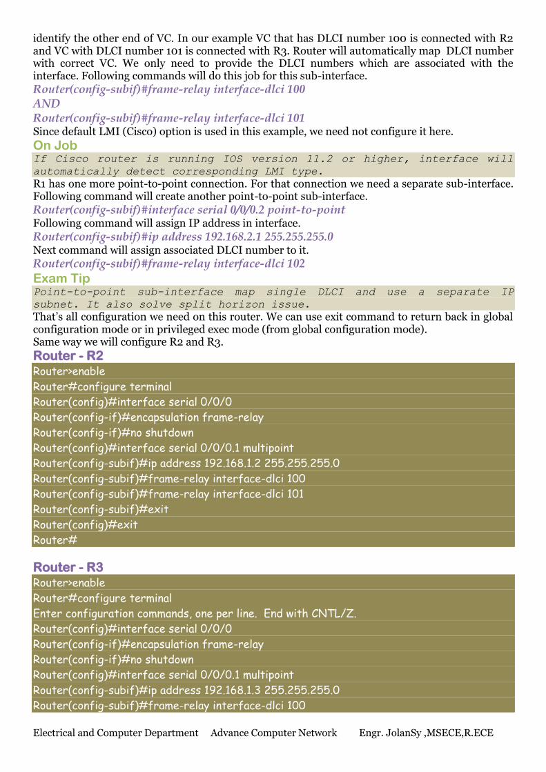
That’s all configuration we need on this router. We can use exit command to return back in global configuration mode or in privileged exec mode (from global configuration mode). Same way we will configure R2 and R3.
Router - R2 Router>enable
Router#configure terminal
Router(config)#interface serial 0/0/0
Router(config-if)#encapsulation frame-relay
Router(config-if)#no shutdown
Router(config)#interface serial 0/0/0.1 multipoint
Router(config-subif)#ip address 192.168.1.2 255.255.255.0
Router(config-subif)#frame-relay interface-dlci 100
Router(config-subif)#frame-relay interface-dlci 101
Router(config-subif)#exit
Router(config)#exit
Router#
Router - R3 Router>enable
Router#configure terminal
Enter configuration commands, one per line. End with CNTL/Z.
Router(config)#interface serial 0/0/0
Router(config-if)#encapsulation frame-relay
Router(config-if)#no shutdown
Router(config)#interface serial 0/0/0.1 multipoint
Router(config-subif)#ip address 192.168.1.3 255.255.255.0
Router(config-subif)#frame-relay interface-dlci 100
Electrical and Computer Department Advance Computer Network Engr. JolanSy ,MSECE,R.ECE
Router(config-subif)#frame-relay interface-dlci 101
Router(config-subif)#exit
Router(config)#exit
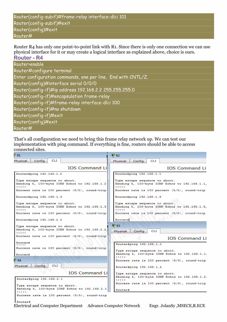
Router# Router R4 has only one point-to-point link with R1. Since there is only one connection we can use physical interface for it or may create a logical interface as explained above, choice is ours.
Router - R4 Router>enable
Router#configure terminal
Enter configuration commands, one per line. End with CNTL/Z.
Router(config)#interface serial 0/0/0
Router(config-if)#ip address 192.168.2.2 255.255.255.0
Router(config-if)#encapsulation frame-relay
Router(config-if)#frame-relay interface-dlci 100
Router(config-if)#no shutdown
Router(config-if)#exit
Router(config)#exit
Router# That’s all configuration we need to bring this frame relay network up. We can test our implementation with ping command. If everything is fine, routers should be able to access connected sites.
Electrical and Computer Department Advance Computer Network Engr. JolanSy ,MSECE,R.ECE
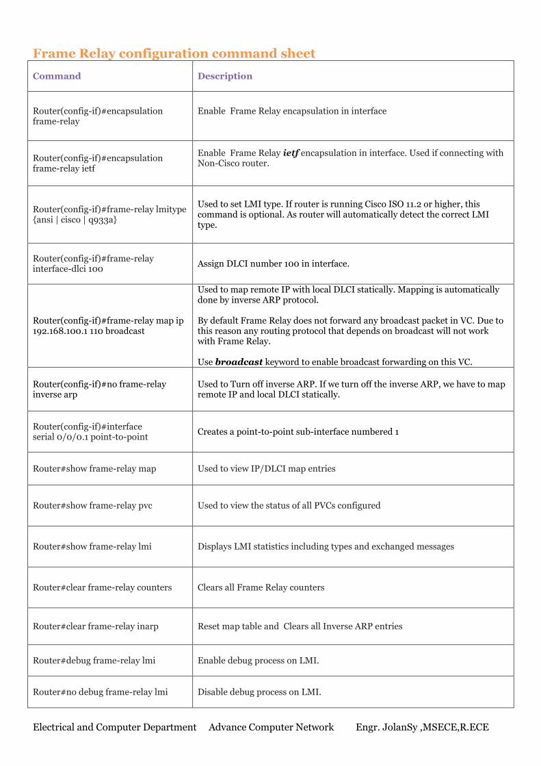
Frame Relay configuration command sheet
Command Description
Router(config-if)#encapsulation frame-relay
Enable Frame Relay encapsulation in interface
Router(config-if)#encapsulation frame-relay ietf
Enable Frame Relay ietf encapsulation in interface. Used if connecting with Non-Cisco router.
Router(config-if)#frame-relay lmitype {ansi | cisco | q933a}
Used to set LMI type. If router is running Cisco ISO 11.2 or higher, this command is optional. As router will automatically detect the correct LMI type.
Router(config-if)#frame-relay interface-dlci 100
Assign DLCI number 100 in interface.
Router(config-if)#frame-relay map ip 192.168.100.1 110 broadcast
Used to map remote IP with local DLCI statically. Mapping is automatically done by inverse ARP protocol. By default Frame Relay does not forward any broadcast packet in VC. Due to this reason any routing protocol that depends on broadcast will not work with Frame Relay. Use broadcast keyword to enable broadcast forwarding on this VC.
Router(config-if)#no frame-relay inverse arp
Used to Turn off inverse ARP. If we turn off the inverse ARP, we have to map remote IP and local DLCI statically.
Router(config-if)#interface serial 0/0/0.1 point-to-point
Creates a point-to-point sub-interface numbered 1
Router#show frame-relay map Used to view IP/DLCI map entries
Router#show frame-relay pvc Used to view the status of all PVCs configured
Router#show frame-relay lmi Displays LMI statistics including types and exchanged messages
Router#clear frame-relay counters Clears all Frame Relay counters
Router#clear frame-relay inarp Reset map table and Clears all Inverse ARP entries
Router#debug frame-relay lmi Enable debug process on LMI.
Router#no debug frame-relay lmi Disable debug process on LMI.
Electrical and Computer Department Advance Computer Network Engr. JolanSy ,MSECE,R.ECE
Name : ________________________________________ ID. NO: ________________________Section : _____________
Activity 9
Part 2: Frame Relay
.
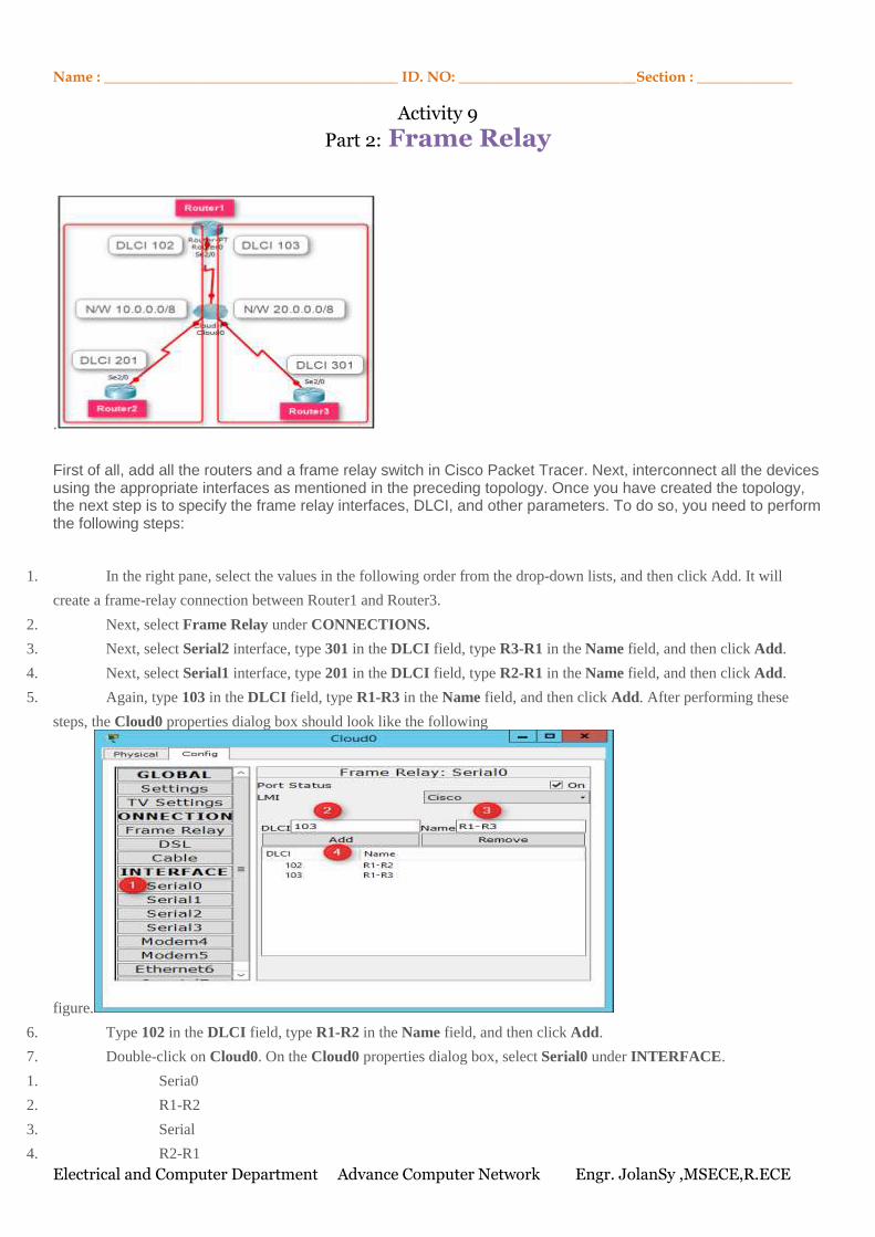
First of all, add all the routers and a frame relay switch in Cisco Packet Tracer. Next, interconnect all the devices using the appropriate interfaces as mentioned in the preceding topology. Once you have created the topology, the next step is to specify the frame relay interfaces, DLCI, and other parameters. To do so, you need to perform the following steps:
1. In the right pane, select the values in the following order from the drop-down lists, and then click Add. It will
create a frame-relay connection between Router1 and Router3.
2. Next, select Frame Relay under CONNECTIONS.
3. Next, select Serial2 interface, type 301 in the DLCI field, type R3-R1 in the Name field, and then click Add.
4. Next, select Serial1 interface, type 201 in the DLCI field, type R2-R1 in the Name field, and then click Add.
5. Again, type 103 in the DLCI field, type R1-R3 in the Name field, and then click Add. After performing these
steps, the Cloud0 properties dialog box should look like the following
figure.
6. Type 102 in the DLCI field, type R1-R2 in the Name field, and then click Add.
7. Double-click on Cloud0. On the Cloud0 properties dialog box, select Serial0 under INTERFACE.
1. Seria0
2. R1-R2
3. Serial
4. R2-R1
Electrical and Computer Department Advance Computer Network Engr. JolanSy ,MSECE,R.ECE
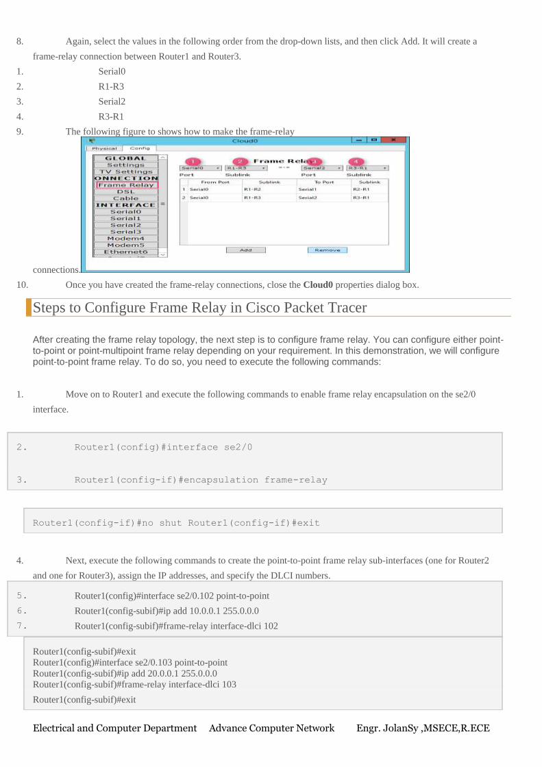
8. Again, select the values in the following order from the drop-down lists, and then click Add. It will create a
frame-relay connection between Router1 and Router3.
1. Serial0
2. R1-R3
3. Serial2
4. R3-R1
9. The following figure to shows how to make the frame-relay
connections.
10. Once you have created the frame-relay connections, close the Cloud0 properties dialog box.
Steps to Configure Frame Relay in Cisco Packet Tracer
After creating the frame relay topology, the next step is to configure frame relay. You can configure either point-to-point or point-multipoint frame relay depending on your requirement. In this demonstration, we will configure point-to-point frame relay. To do so, you need to execute the following commands:
1. Move on to Router1 and execute the following commands to enable frame relay encapsulation on the se2/0
interface.
2. Router1(config)#interface se2/0
3. Router1(config-if)#encapsulation frame-relay
Router1(config-if)#no shut Router1(config-if)#exit
4. Next, execute the following commands to create the point-to-point frame relay sub-interfaces (one for Router2
and one for Router3), assign the IP addresses, and specify the DLCI numbers.
5. Router1(config)#interface se2/0.102 point-to-point
6. Router1(config-subif)#ip add 10.0.0.1 255.0.0.0
7. Router1(config-subif)#frame-relay interface-dlci 102
Router1(config-subif)#exit
Router1(config)#interface se2/0.103 point-to-point
Router1(config-subif)#ip add 20.0.0.1 255.0.0.0
Router1(config-subif)#frame-relay interface-dlci 103
Router1(config-subif)#exit
Electrical and Computer Department Advance Computer Network Engr. JolanSy ,MSECE,R.ECE
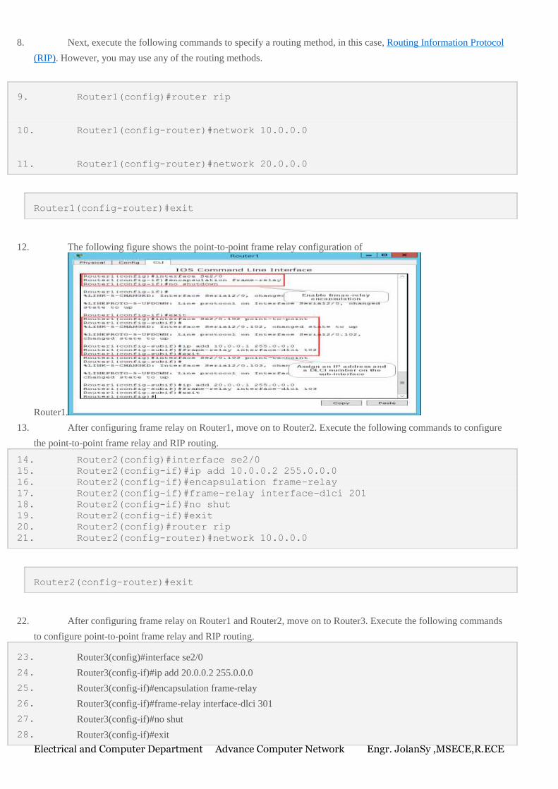
8. Next, execute the following commands to specify a routing method, in this case, Routing Information Protocol
(RIP). However, you may use any of the routing methods.
9. Router1(config)#router rip
10. Router1(config-router)#network 10.0.0.0
11. Router1(config-router)#network 20.0.0.0
Router1(config-router)#exit
12. The following figure shows the point-to-point frame relay configuration of
Router1.
13. After configuring frame relay on Router1, move on to Router2. Execute the following commands to configure
the point-to-point frame relay and RIP routing.
14. Router2(config)#interface se2/0
15. Router2(config-if)#ip add 10.0.0.2 255.0.0.0
16. Router2(config-if)#encapsulation frame-relay
17. Router2(config-if)#frame-relay interface-dlci 201
18. Router2(config-if)#no shut
19. Router2(config-if)#exit
20. Router2(config)#router rip
21. Router2(config-router)#network 10.0.0.0
Router2(config-router)#exit
22. After configuring frame relay on Router1 and Router2, move on to Router3. Execute the following commands
to configure point-to-point frame relay and RIP routing.
23. Router3(config)#interface se2/0
24. Router3(config-if)#ip add 20.0.0.2 255.0.0.0
25. Router3(config-if)#encapsulation frame-relay
26. Router3(config-if)#frame-relay interface-dlci 301
27. Router3(config-if)#no shut
28. Router3(config-if)#exit
Electrical and Computer Department Advance Computer Network Engr. JolanSy ,MSECE,R.ECE
29. Router3(config)#router rip
30. Router3(config-router)#network 20.0.0.0
Router3(config-router)#exit
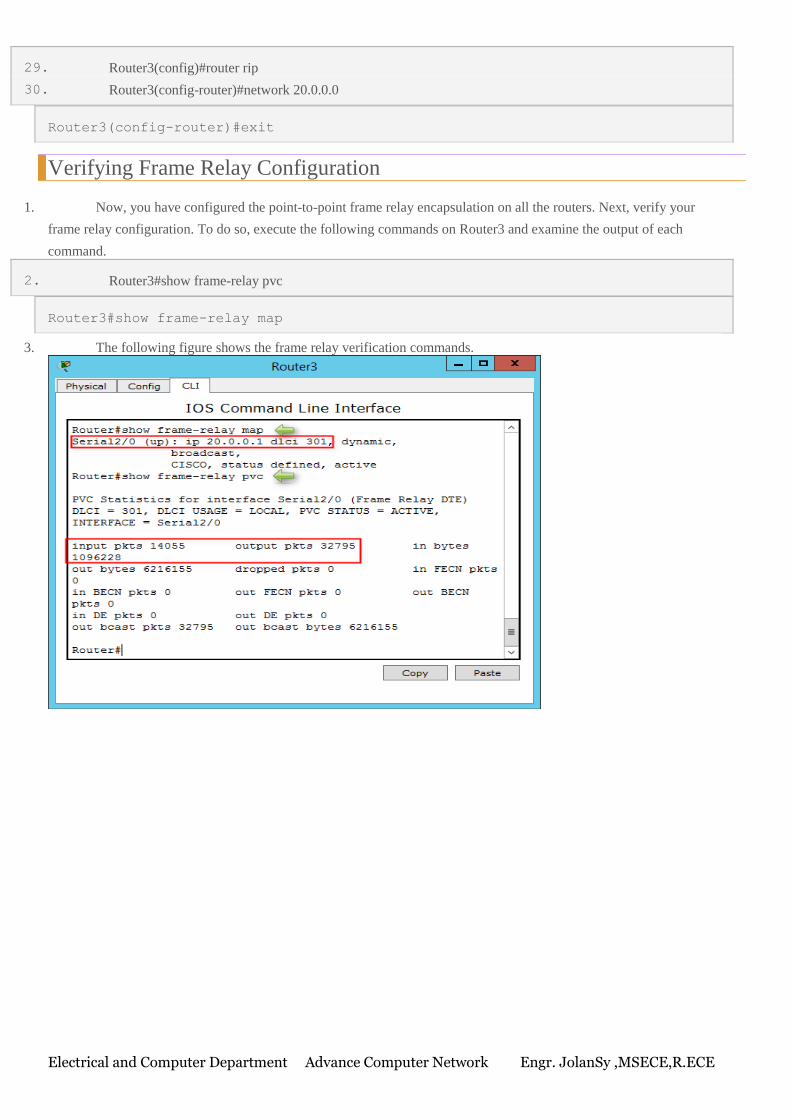
Verifying Frame Relay Configuration
1. Now, you have configured the point-to-point frame relay encapsulation on all the routers. Next, verify your
frame relay configuration. To do so, execute the following commands on Router3 and examine the output of each
command.
2. Router3#show frame-relay pvc
Router3#show frame-relay map
3. The following figure shows the frame relay verification commands.
Electrical and Computer Department Advance Computer Network Engr. JolanSy ,MSECE,R.ECE
Name : ________________________________________ ID. NO: ________________________Section : _____________
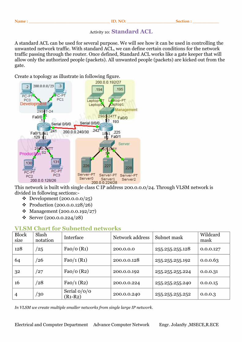
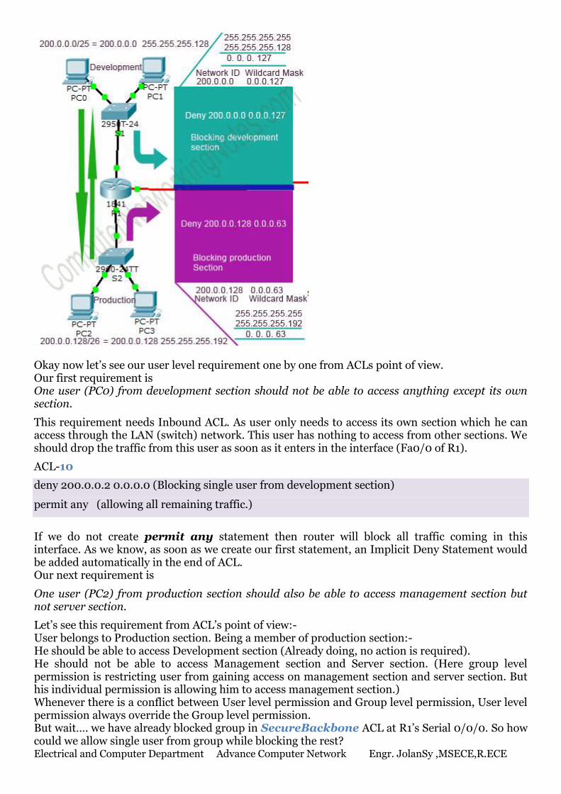
Activity 10: Standard ACL A standard ACL can be used for several purpose. We will see how it can be used in controlling the unwanted network traffic. With standard ACL, we can define certain conditions for the network traffic passing through the router. Once defined, Standard ACL works like a gate keeper that will allow only the authorized people (packets). All unwanted people (packets) are kicked out from the gate. Create a topology as illustrate in following figure.
This network is built with single class C IP address 200.0.0.0/24. Through VLSM network is divided in following sections:- Development (200.0.0.0/25)
Production (200.0.0.128/26)
Management (200.0.0.192/27)
Server (200.0.0.224/28)
VLSM Chart for Subnetted networks Block size
Slash notation
Interface Network address Subnet mask Wildcard mask
128 /25 Fa0/0 (R1) 200.0.0.0 255.255.255.128 0.0.0.127
64 /26 Fa0/1 (R1) 200.0.0.128 255.255.255.192 0.0.0.63
32 /27 Fa0/0 (R2) 200.0.0.192 255.255.255.224 0.0.0.31
16 /28 Fa0/1 (R2) 200.0.0.224 255.255.255.240 0.0.0.15
4 /30 Serial 0/0/0 (R1-R2)
200.0.0.240 255.255.255.252 0.0.0.3
In VLSM we create multiple smaller networks from single large IP network.
Electrical and Computer Department Advance Computer Network Engr. JolanSy ,MSECE,R.ECE
These sections are connected via two routers. Routers are running RIVv2 routing protocol. For this article I assume that you know how to Create above topology in network simulator
Assign essential IP configuration as shown in above figure
Configure RIPv2 protocol in R1 and R2 for IP routing
In this network, at this moment all sections are connected with each other’s. Users are able to access all resources from other sections as well as their own. You are hired to secure this network. This network has following security requirements. Section level requirement Development section should be able to access only production section. It should not be able
to access management section and server section.
Production section should be able to access only development section. It should not be able
to access management section and server section.
User level requirement One user (PC0) from development section should not be able to access anything except its
own section.
One user (PC2) from production section should also be able to access management section
but not server section.
One user (PC3) from production section should be able to access server section but not
management section.
One user (laptop0) from management section should be able to access only Server section
not the development section and production section.
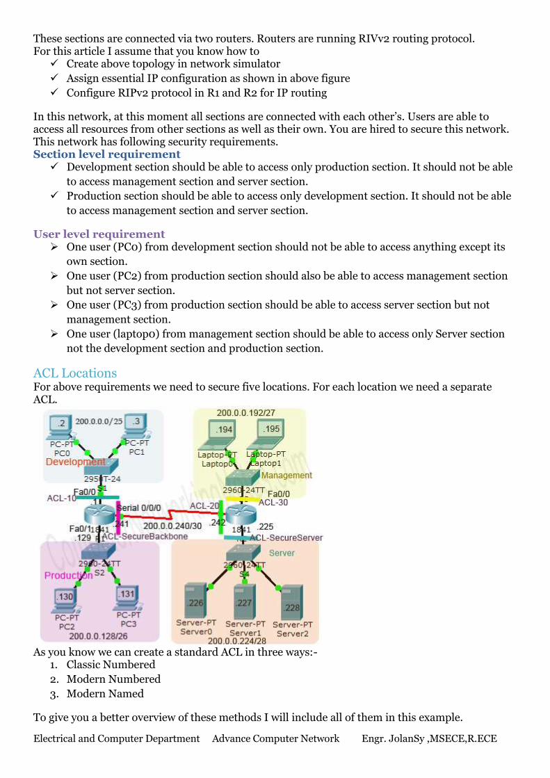
ACL Locations For above requirements we need to secure five locations. For each location we need a separate ACL.
As you know we can create a standard ACL in three ways:-
1. Classic Numbered
2. Modern Numbered
3. Modern Named
To give you a better overview of these methods I will include all of them in this example.
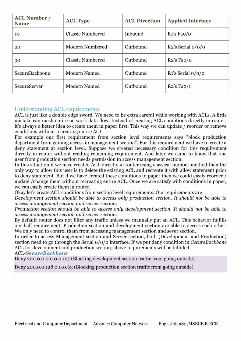
Electrical and Computer Department Advance Computer Network Engr. JolanSy ,MSECE,R.ECE
ACL Number / Name
ACL Type ACL Direction Applied Interface
10 Classic Numbered Inbound R1’s Fa0/0
20 Modern Numbered Outbound R2’s Serial 0/0/0
30 Classic Numbered Outbound R2’s Fa0/0
SecureBackbone Modern Named Outbound R1’s Serial 0/0/0
SecureServer Modern Named Outbound R2’s Fa0/1
Understanding ACL requirements ACL is just like a double edge sword. We need to be extra careful while working with ACLs. A little mistake can mesh entire network data flow. Instead of creating ACL conditions directly in router, it’s always a better idea to create them in paper first. This way we can update / reorder or remove conditions without recreating entire ACL. For example our first requirement from section level requirements says “block production department from gaining access in management section”. For this requirement we have to create a deny statement at section level. Suppose we created necessary condition for this requirement directly in router without reading remaining requirement. And later we came to know that one user from production section needs permission to access management section. In this situation if we have created ACL directly in router using classical number method then the only way to allow this user is to delete the existing ACL and recreate it with allow statement prior to deny statement. But if we have created these conditions in paper then we could easily reorder / update /change them without recreating entire ACL. Once we are satisfy with conditions in paper, we can easily create them in router. Okay let’s create ACL conditions from section level requirements. Our requirements are Development section should be able to access only production section. It should not be able to access management section and server section. Production section should be able to access only development section. It should not be able to access management section and server section. By default router does not filter any traffic unless we manually put an ACL. This behavior fulfills our half requirement. Production section and development section are able to access each other. We only need to control them from accessing management section and sever section. In order to access Management section and Server section, both (Development and Production) section need to go through the Serial 0/0/0 interface. If we put deny condition in SecureBackbone ACL for development and production section, above requirements will be fulfilled. ACL-SecureBackbone Deny 200.0.0.0 0.0.0.127 (Blocking development section traffic from going outside)
Deny 200.0.0.128 0.0.0.63 (Blocking production section traffic from going outside)
Electrical and Computer Department Advance Computer Network Engr. JolanSy ,MSECE,R.ECE
Okay now let’s see our user level requirement one by one from ACLs point of view. Our first requirement is One user (PC0) from development section should not be able to access anything except its own section.
This requirement needs Inbound ACL. As user only needs to access its own section which he can access through the LAN (switch) network. This user has nothing to access from other sections. We should drop the traffic from this user as soon as it enters in the interface (Fa0/0 of R1).
ACL-10
deny 200.0.0.2 0.0.0.0 (Blocking single user from development section)
permit any (allowing all remaining traffic.)
If we do not create permit any statement then router will block all traffic coming in this interface. As we know, as soon as we create our first statement, an Implicit Deny Statement would be added automatically in the end of ACL. Our next requirement is
One user (PC2) from production section should also be able to access management section but not server section.
Let’s see this requirement from ACL’s point of view:- User belongs to Production section. Being a member of production section:- He should be able to access Development section (Already doing, no action is required). He should not be able to access Management section and Server section. (Here group level permission is restricting user from gaining access on management section and server section. But his individual permission is allowing him to access management section.) Whenever there is a conflict between User level permission and Group level permission, User level permission always override the Group level permission. But wait…. we have already blocked group in SecureBackbone ACL at R1’s Serial 0/0/0. So how could we allow single user from group while blocking the rest?
Electrical and Computer Department Advance Computer Network Engr. JolanSy ,MSECE,R.ECE
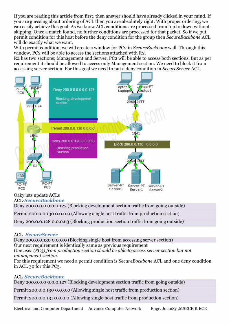
If you are reading this article from first, then answer should have already clicked in your mind. If you are guessing about ordering of ACL then you are absolutely right. With proper ordering, we can easily achieve this goal. As we know ACL conditions are processed from top to down without skipping. Once a match found, no further conditions are processed for that packet. So if we put permit condition for this host before the deny condition for the group then SecureBackbone ACL will do exactly what we want. With permit condition, we will create a window for PC2 in SecureBackbone wall. Through this window, PC2 will be able to access the sections attached with R2. R2 has two sections; Management and Server. PC2 will be able to access both sections. But as per requirement it should be allowed to access only Management section. We need to block it from accessing server section. For this goal we need to put a deny condition in SecureServer ACL.
Oaky lets update ACLs ACL-SecureBackbone Deny 200.0.0.0 0.0.0.127 (Blocking development section traffic from going outside)
Permit 200.0.0.130 0.0.0.0 (Allowing single host traffic from production section)
Deny 200.0.0.128 0.0.0.63 (Blocking production section traffic from going outside)
ACL -SecureServer Deny 200.0.0.130 0.0.0.0 (Blocking single host from accessing server section) Our next requirement is identically same as previous requirement One user (PC3) from production section should be able to access server section but not management section. For this requirement we need a permit condition is SecureBockbone ACL and one deny condition in ACL 30 for this PC3. ACL-SecureBackbone Deny 200.0.0.0 0.0.0.127 (Blocking development section traffic from going outside)
Permit 200.0.0.130 0.0.0.0 (Allowing single host traffic from production section)
Permit 200.0.0.131 0.0.0.0 (Allowing single host traffic from production section)
Electrical and Computer Department Advance Computer Network Engr. JolanSy ,MSECE,R.ECE
Deny 200.0.0.128 0.0.0.63 (Blocking production section traffic from going outside)
ACL -30 Deny 200.0.0.131 0.0.0.0 (Blocking single host from accessing management section) Our last requirement is fairly simple. One user (laptop0) from management section should be able to access only Server section not the development section and production section. Simply creating a block condition in ACL 20 (R2’s Serial 0/0/0) will do this job. deny 200.0.0.194 0.0.0.0 (Blocking single host from management section) We have gone through all the requirements. Let’s have quick look on ACL conditions ACL-10 (Filtering incoming traffic on R1’s Fa0/0) deny 200.0.0.2 0.0.0.0 (Blocking incoming traffic from single host)
permit any (Allowing remaining all hosts.)
ACL-SecureBackbone (Filtering outgoing traffic on R1’s Serial 0/0/0)
deny 200.0.0.0 0.0.0.127 (Blocking development section )
permit 200.0.0.130 0.0.0.0 (Allowing single host from production section )
permit 200.0.0.131 0.0.0.0 (Allowing single host from production section)
deny 200.0.0.128 0.0.0.63 (Blocking production section)
ACL-20 (Filtering outgoing traffic on R2’s Serial 0/0/0) deny 200.0.0.194 0.0.0.0 (Blocking single host from management section)
permit any (Allowing remaining traffic)
ACL-30 (Filtering traffic going from R2’s Fa0/0) deny 200.0.0.131 0.0.0.0 (Blocking single user from production section from gaining
unauthorized on management section.)
permit any (Allowing remaining traffic)
ACL-SecureServer (Filtering traffic going from R2’s Fa0/1) deny 200.0.0.130 0.0.0.0 (Blocking single user from production section from gaining
unauthorized on server section.)
permit any (Allowing remaining traffic)
That’s all paper work we need to do before creating real ACLs. Well… you may be a little bit annoyed with all above preparation. But believe me friends; it will save a lot of time and effort in Cisco exams and as well as in job life.
Create Standard ACL A standard ACL can be created in two ways:-
1. Classic numbered method
2. Modern numbered or named method
Classic numbered method uses following global configuration mode command Router(config)# access-list ACL_Identifier_number permit/deny matching-parameters Modern numbered or named method uses following global configuration mode commands Router(config)#ip access-list standard ACL_Number / ACL_Name Router(config-std-nacl)#permit / deny Source Address Router(config-std-nacl)#exit Router(config)#
I have already explained above commands and parameters in detail with examples in previous part of this article. For this part I assume that you are familiar with above commands.
Electrical and Computer Department Advance Computer Network Engr. JolanSy ,MSECE,R.ECE
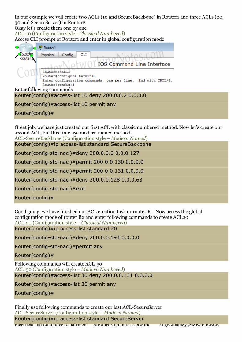
In our example we will create two ACLs (10 and SecureBackbone) in Router1 and three ACLs (20, 30 and SecureServer) in Router2. Okay let’s create them one by one ACL-10 (Configuration style - Classical Numbered) Access CLI prompt of Router1 and enter in global configuration mode
Enter following commands
Router(config)#access-list 10 deny 200.0.0.2 0.0.0.0
Router(config)#access-list 10 permit any
Router(config)#
Great job, we have just created our first ACL with classic numbered method. Now let’s create our second ACL, but this time use modern named method. ACL-SecureBackbone (Configuration style – Modern Named)
Router(config)#ip access-list standard SecureBackbone
Router(config-std-nacl)#deny 200.0.0.0 0.0.0.127
Router(config-std-nacl)#permit 200.0.0.130 0.0.0.0
Router(config-std-nacl)#permit 200.0.0.131 0.0.0.0
Router(config-std-nacl)#deny 200.0.0.128 0.0.0.63
Router(config-std-nacl)#exit
Router(config)#
Good going, we have finished our ACL creation task or router R1. Now access the global configuration mode of router R2 and enter following commands to create ACL20 ACL-20 (Configuration style – Classical Numbered)
Router(config)#ip access-list standard 20
Router(config-std-nacl)#deny 200.0.0.194 0.0.0.0
Router(config-std-nacl)#permit any
Router(config)#
Following commands will create ACL-3o ACL-30 (Configuration style – Modern Numbered)
Router(config)#access-list 30 deny 200.0.0.131 0.0.0.0
Router(config)#access-list 30 permit any
Router(config)#
Finally use following commands to create our last ACL-SecureServer ACL-SecureServer (Configuration style – Modern Named)
Router(config)#ip access-list standard SecureServer
Electrical and Computer Department Advance Computer Network Engr. JolanSy ,MSECE,R.ECE
Router(config-std-nacl)#deny 200.0.0.130 0.0.0.0
Router(config-std-nacl)#permit any
Router(config-std-nacl)#exit
Router(config)#
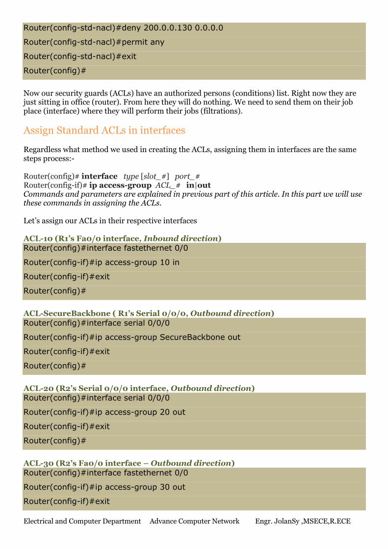
Now our security guards (ACLs) have an authorized persons (conditions) list. Right now they are just sitting in office (router). From here they will do nothing. We need to send them on their job place (interface) where they will perform their jobs (filtrations).
Assign Standard ACLs in interfaces
Regardless what method we used in creating the ACLs, assigning them in interfaces are the same steps process:- Router(config)# interface type [slot_#] port_# Router(config-if)# ip access-group ACL_# in|out Commands and parameters are explained in previous part of this article. In this part we will use these commands in assigning the ACLs. Let’s assign our ACLs in their respective interfaces ACL-10 (R1’s Fa0/0 interface, Inbound direction)
Router(config)#interface fastethernet 0/0
Router(config-if)#ip access-group 10 in
Router(config-if)#exit
Router(config)#
ACL-SecureBackbone ( R1’s Serial 0/0/0, Outbound direction)
Router(config)#interface serial 0/0/0
Router(config-if)#ip access-group SecureBackbone out
Router(config-if)#exit
Router(config)#
ACL-20 (R2’s Serial 0/0/0 interface, Outbound direction)
Router(config)#interface serial 0/0/0
Router(config-if)#ip access-group 20 out
Router(config-if)#exit
Router(config)#
ACL-30 (R2’s Fa0/0 interface – Outbound direction)
Router(config)#interface fastethernet 0/0
Router(config-if)#ip access-group 30 out
Router(config-if)#exit
Electrical and Computer Department Advance Computer Network Engr. JolanSy ,MSECE,R.ECE
Router(config)#
ACL-SecureServer (R2’s Fa0/1 interface – Outbound direction)
Router(config)#interface fastethernet 0/1
Router(config-if)#ip access-group SecureServer out
Router(config-if)#exit
Router(config)#
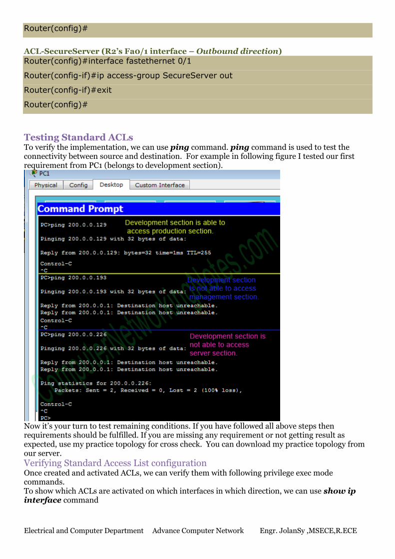
Testing Standard ACLs To verify the implementation, we can use ping command. ping command is used to test the connectivity between source and destination. For example in following figure I tested our first requirement from PC1 (belongs to development section).
Now it’s your turn to test remaining conditions. If you have followed all above steps then requirements should be fulfilled. If you are missing any requirement or not getting result as expected, use my practice topology for cross check. You can download my practice topology from our server.
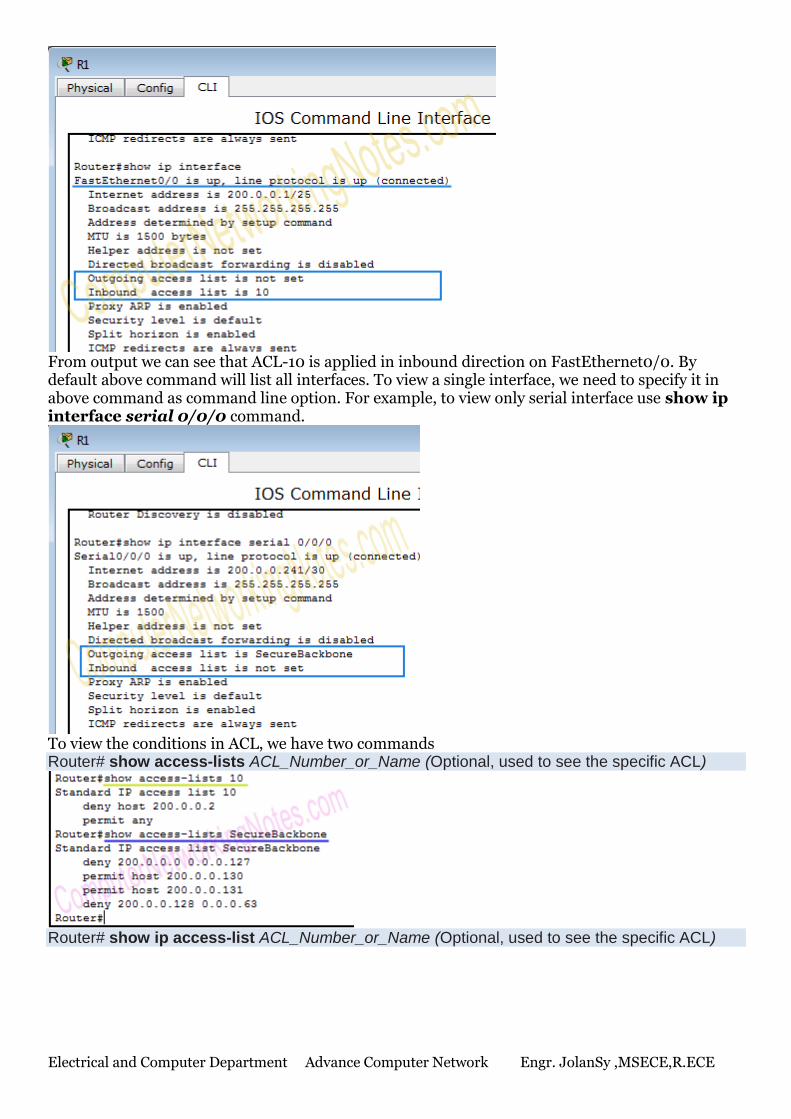
Verifying Standard Access List configuration Once created and activated ACLs, we can verify them with following privilege exec mode commands. To show which ACLs are activated on which interfaces in which direction, we can use show ip interface command
Electrical and Computer Department Advance Computer Network Engr. JolanSy ,MSECE,R.ECE
From output we can see that ACL-10 is applied in inbound direction on FastEthernet0/0. By default above command will list all interfaces. To view a single interface, we need to specify it in above command as command line option. For example, to view only serial interface use show ip interface serial 0/0/0 command.
To view the conditions in ACL, we have two commands Router# show access-lists ACL_Number_or_Name (Optional, used to see the specific ACL)
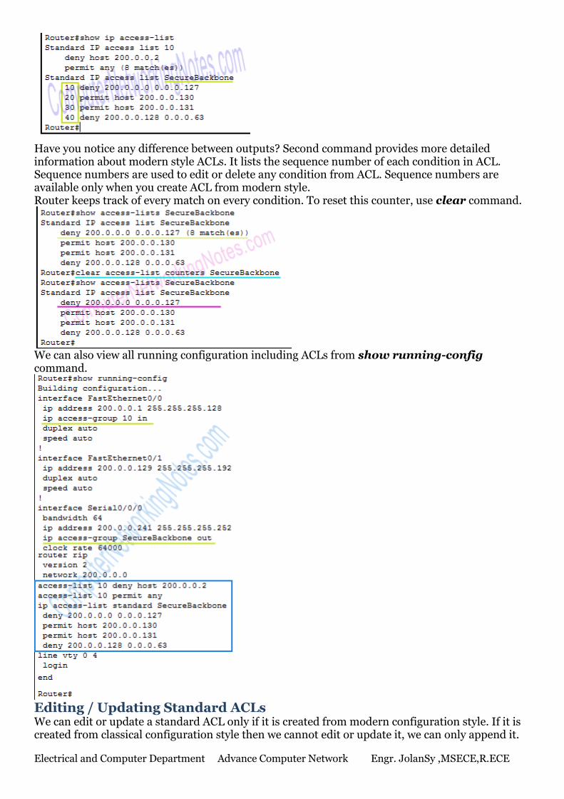
Router# show ip access-list ACL_Number_or_Name (Optional, used to see the specific ACL)
Electrical and Computer Department Advance Computer Network Engr. JolanSy ,MSECE,R.ECE
Have you notice any difference between outputs? Second command provides more detailed information about modern style ACLs. It lists the sequence number of each condition in ACL. Sequence numbers are used to edit or delete any condition from ACL. Sequence numbers are available only when you create ACL from modern style. Router keeps track of every match on every condition. To reset this counter, use clear command.
We can also view all running configuration including ACLs from show running-config command.
Editing / Updating Standard ACLs We can edit or update a standard ACL only if it is created from modern configuration style. If it is created from classical configuration style then we cannot edit or update it, we can only append it.
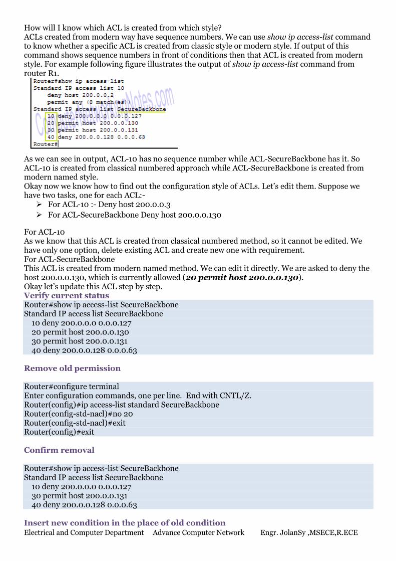
Electrical and Computer Department Advance Computer Network Engr. JolanSy ,MSECE,R.ECE
How will I know which ACL is created from which style? ACLs created from modern way have sequence numbers. We can use show ip access-list command to know whether a specific ACL is created from classic style or modern style. If output of this command shows sequence numbers in front of conditions then that ACL is created from modern style. For example following figure illustrates the output of show ip access-list command from router R1.
As we can see in output, ACL-10 has no sequence number while ACL-SecureBackbone has it. So ACL-10 is created from classical numbered approach while ACL-SecureBackbone is created from modern named style. Okay now we know how to find out the configuration style of ACLs. Let’s edit them. Suppose we have two tasks, one for each ACL:- For ACL-10 :- Deny host 200.0.0.3
For ACL-SecureBackbone Deny host 200.0.0.130
For ACL-10 As we know that this ACL is created from classical numbered method, so it cannot be edited. We have only one option, delete existing ACL and create new one with requirement. For ACL-SecureBackbone This ACL is created from modern named method. We can edit it directly. We are asked to deny the host 200.0.0.130, which is currently allowed (20 permit host 200.0.0.130). Okay let’s update this ACL step by step. Verify current status Router#show ip access-list SecureBackbone Standard IP access list SecureBackbone 10 deny 200.0.0.0 0.0.0.127 20 permit host 200.0.0.130 30 permit host 200.0.0.131 40 deny 200.0.0.128 0.0.0.63 Remove old permission Router#configure terminal Enter configuration commands, one per line. End with CNTL/Z. Router(config)#ip access-list standard SecureBackbone Router(config-std-nacl)#no 20 Router(config-std-nacl)#exit Router(config)#exit Confirm removal Router#show ip access-list SecureBackbone Standard IP access list SecureBackbone 10 deny 200.0.0.0 0.0.0.127 30 permit host 200.0.0.131 40 deny 200.0.0.128 0.0.0.63 Insert new condition in the place of old condition
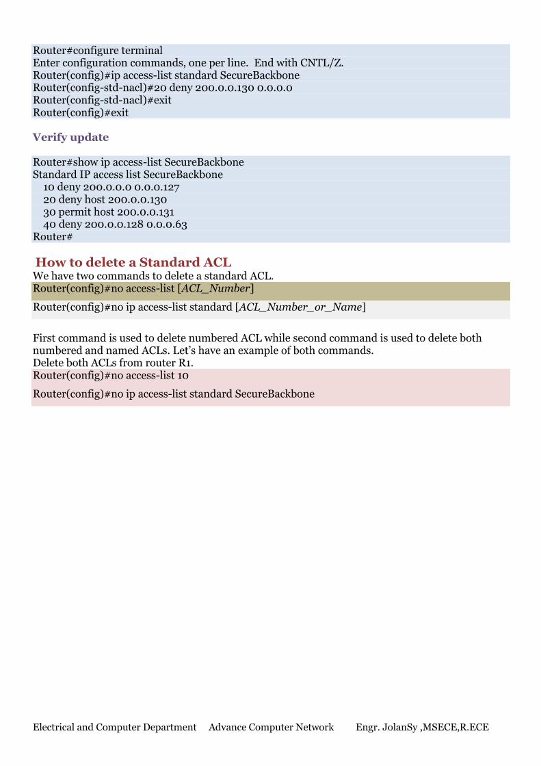
Electrical and Computer Department Advance Computer Network Engr. JolanSy ,MSECE,R.ECE
Router#configure terminal Enter configuration commands, one per line. End with CNTL/Z. Router(config)#ip access-list standard SecureBackbone Router(config-std-nacl)#20 deny 200.0.0.130 0.0.0.0 Router(config-std-nacl)#exit Router(config)#exit Verify update Router#show ip access-list SecureBackbone Standard IP access list SecureBackbone 10 deny 200.0.0.0 0.0.0.127 20 deny host 200.0.0.130 30 permit host 200.0.0.131 40 deny 200.0.0.128 0.0.0.63 Router#
How to delete a Standard ACL We have two commands to delete a standard ACL. Router(config)#no access-list [ACL_Number]
Router(config)#no ip access-list standard [ACL_Number_or_Name]
First command is used to delete numbered ACL while second command is used to delete both numbered and named ACLs. Let’s have an example of both commands. Delete both ACLs from router R1. Router(config)#no access-list 10
Router(config)#no ip access-list standard SecureBackbone
Electrical and Computer Department Advance Computer Network Engr. JolanSy ,MSECE,R.ECE
Name : ________________________________________ ID. NO: ________________________Section : _____________
Activity 11: Extended ACL
An Extended IP ACL can filter a packet based on its source and destination IP address, protocol information, port number, message type for ICMP and TCP/IP protocol such as FTP, HTTP, SSH, Telnet etc. In this tutorial I will explain extended access list configuration commands and its parameters in detail with example. Just like Standard ACL we can create Extended ACL in two ways:-
1. Classical approach (numbered)
2. Modern approach (numbered or named)
Classical approach (numbered ACL) To create an Extended numbered ACL following global configuration mode command is used:- Router(config)# access-list ACL_Identifier_number permit|deny IP_protocol source_address source_wildcard_mask [protocol_information] destination_address destination_wildcard_mask [protocol_information] [log] Router(config)# This command prompt indicates that we are in global configuration mode. access-list Through this parameter we tell router that we are creating or accessing an access list. ACL_Identifier_number With this parameter we specify the type of access list. We have two types of access list; standard and extended. Both lists have their own unique identifier numbers. Extended ACL uses numbers range 100 to 199 and 2000 to 2699. We can pick any number from this range to tell the router that we are working with Extended ACL. This number is used in groping the conditions under a single ACL. This number is also a unique identifier for this ACL in router. permit/deny As we know an ACL condition has two actions; permit and deny. If we use permit keyword, ACL will allow all packets that match with parameters specified next in command. If we use deny keyword, ACL will drop all packets which match with following specified parameters. IP_protocol This parameter tells router that what kind of filtering we want. We have two choices here, host level filtering and application level filtering. Host level filtering is used for generic filtering while application level filtering is used for more specific filtering. In easy language Host level filtering checks “Whether host A is allowed to access host B or not” while application level filtering checks “How much host A is allowed to access host B”. Host Level filtering IP For host level filtering we need to use IP keyword here. Please make sure if you choose IP here, you will not be able to specify a specific application layer protocol in this statement later. Generic command for host level filtering is following Router(config)# access-list 100-199|2000-2699 permit|deny ip source_address source_wildcard_mask destination_address destination_wildcard_mask [log] After IP keyword we need to provide source and destination address with wildcard mask. I have already explained wildcard mask in detail with example in second part of this article. In standard ACL, to match a specific host we are allowed to type IP address alone. (Router will automatically add host keyword with it). But in extended ACL we have to type host keyword with IP address to match a specific host.
Application level filtering
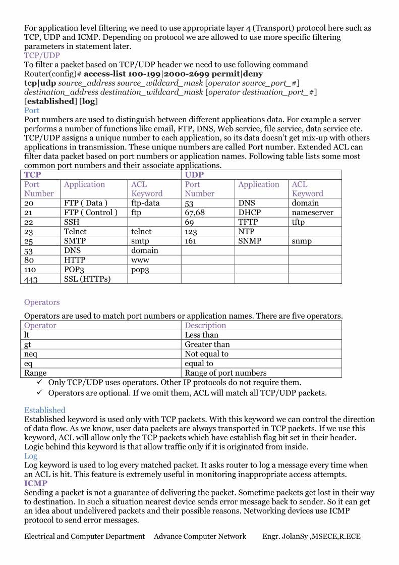
Electrical and Computer Department Advance Computer Network Engr. JolanSy ,MSECE,R.ECE
For application level filtering we need to use appropriate layer 4 (Transport) protocol here such as TCP, UDP and ICMP. Depending on protocol we are allowed to use more specific filtering parameters in statement later. TCP/UDP To filter a packet based on TCP/UDP header we need to use following command Router(config)# access-list 100-199|2000-2699 permit|deny tcp|udp source_address source_wildcard_mask [operator source_port_#] destination_address destination_wildcard_mask [operator destination_port_#] [established] [log] Port Port numbers are used to distinguish between different applications data. For example a server performs a number of functions like email, FTP, DNS, Web service, file service, data service etc. TCP/UDP assigns a unique number to each application, so its data doesn’t get mix-up with others applications in transmission. These unique numbers are called Port number. Extended ACL can filter data packet based on port numbers or application names. Following table lists some most common port numbers and their associate applications. TCP UDP Port Number
Application ACL Keyword
Port Number
Application ACL Keyword
20 FTP ( Data ) ftp-data 53 DNS domain 21 FTP ( Control ) ftp 67,68 DHCP nameserver 22 SSH 69 TFTP tftp 23 Telnet telnet 123 NTP 25 SMTP smtp 161 SNMP snmp 53 DNS domain 80 HTTP www 110 POP3 pop3 443 SSL (HTTPs)
Operators
Operators are used to match port numbers or application names. There are five operators. Operator Description lt Less than gt Greater than neq Not equal to eq equal to Range Range of port numbers Only TCP/UDP uses operators. Other IP protocols do not require them.
Operators are optional. If we omit them, ACL will match all TCP/UDP packets.
Established Established keyword is used only with TCP packets. With this keyword we can control the direction of data flow. As we know, user data packets are always transported in TCP packets. If we use this keyword, ACL will allow only the TCP packets which have establish flag bit set in their header. Logic behind this keyword is that allow traffic only if it is originated from inside. Log Log keyword is used to log every matched packet. It asks router to log a message every time when an ACL is hit. This feature is extremely useful in monitoring inappropriate access attempts. ICMP Sending a packet is not a guarantee of delivering the packet. Sometime packets get lost in their way to destination. In such a situation nearest device sends error message back to sender. So it can get an idea about undelivered packets and their possible reasons. Networking devices use ICMP protocol to send error messages.
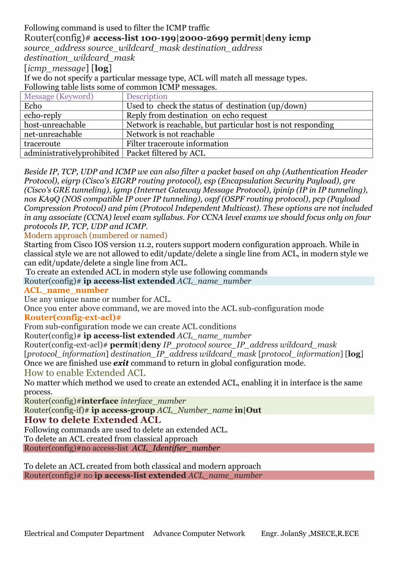
Electrical and Computer Department Advance Computer Network Engr. JolanSy ,MSECE,R.ECE
Following command is used to filter the ICMP traffic
Router(config)# access-list 100-199|2000-2699 permit|deny icmp source_address source_wildcard_mask destination_address destination_wildcard_mask [icmp_message] [log] If we do not specify a particular message type, ACL will match all message types. Following table lists some of common ICMP messages. Message (Keyword) Description Echo Used to check the status of destination (up/down) echo-reply Reply from destination on echo request host-unreachable Network is reachable, but particular host is not responding net-unreachable Network is not reachable traceroute Filter traceroute information administrativelyprohibited Packet filtered by ACL Beside IP, TCP, UDP and ICMP we can also filter a packet based on ahp (Authentication Header Protocol), eigrp (Cisco's EIGRP routing protocol), esp (Encapsulation Security Payload), gre (Cisco's GRE tunneling), igmp (Internet Gateway Message Protocol), ipinip (IP in IP tunneling), nos KA9Q (NOS compatible IP over IP tunneling), ospf (OSPF routing protocol), pcp (Payload Compression Protocol) and pim (Protocol Independent Multicast). These options are not included in any associate (CCNA) level exam syllabus. For CCNA level exams we should focus only on four protocols IP, TCP, UDP and ICMP. Modern approach (numbered or named) Starting from Cisco IOS version 11.2, routers support modern configuration approach. While in classical style we are not allowed to edit/update/delete a single line from ACL, in modern style we can edit/update/delete a single line from ACL. To create an extended ACL in modern style use following commands Router(config)# ip access-list extended ACL_name_number ACL_name_number Use any unique name or number for ACL. Once you enter above command, we are moved into the ACL sub-configuration mode Router(config-ext-acl)# From sub-configuration mode we can create ACL conditions Router(config)# ip access-list extended ACL_name_number Router(config-ext-acl)# permit|deny IP_protocol source_IP_address wildcard_mask [protocol_information] destination_IP_address wildcard_mask [protocol_information] [log] Once we are finished use exit command to return in global configuration mode.
How to enable Extended ACL No matter which method we used to create an extended ACL, enabling it in interface is the same process. Router(config)#interface interface_number Router(config-if)# ip access-group ACL_Number_name in|Out
How to delete Extended ACL Following commands are used to delete an extended ACL. To delete an ACL created from classical approach Router(config)#no access-list ACL_Identifier_number To delete an ACL created from both classical and modern approach Router(config)# no ip access-list extended ACL_name_number
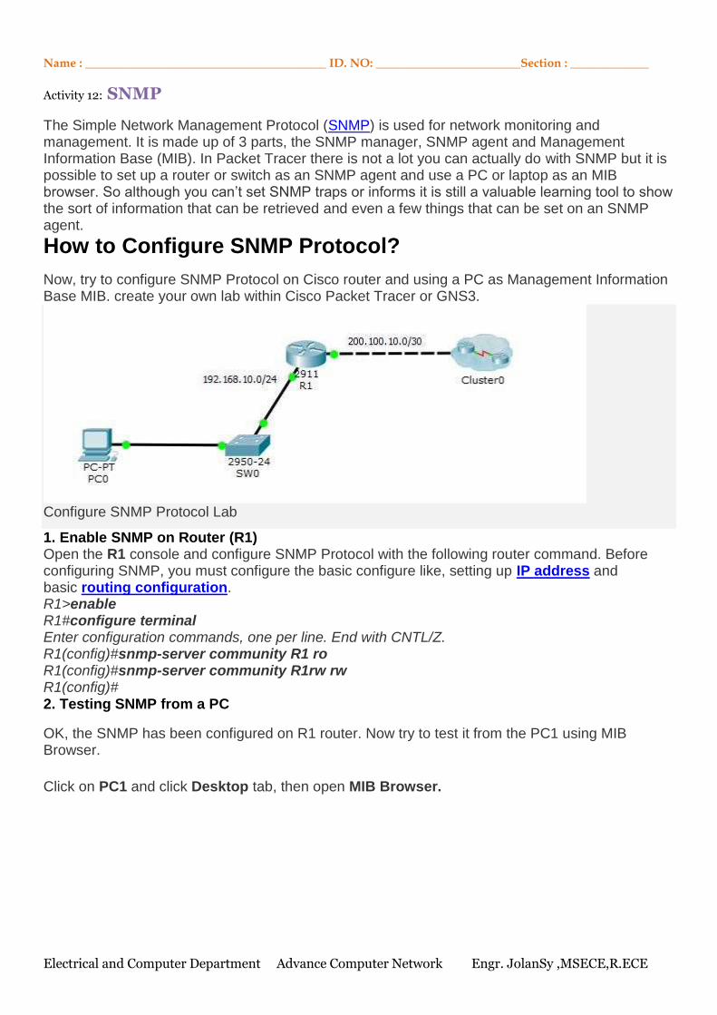
Electrical and Computer Department Advance Computer Network Engr. JolanSy ,MSECE,R.ECE
Name : ________________________________________ ID. NO: ________________________Section : _____________
Activity 12: SNMP
The Simple Network Management Protocol (SNMP) is used for network monitoring and management. It is made up of 3 parts, the SNMP manager, SNMP agent and Management Information Base (MIB). In Packet Tracer there is not a lot you can actually do with SNMP but it is possible to set up a router or switch as an SNMP agent and use a PC or laptop as an MIB browser. So although you can’t set SNMP traps or informs it is still a valuable learning tool to show the sort of information that can be retrieved and even a few things that can be set on an SNMP agent.
How to Configure SNMP Protocol?
Now, try to configure SNMP Protocol on Cisco router and using a PC as Management Information Base MIB. create your own lab within Cisco Packet Tracer or GNS3.
Configure SNMP Protocol Lab
1. Enable SNMP on Router (R1) Open the R1 console and configure SNMP Protocol with the following router command. Before configuring SNMP, you must configure the basic configure like, setting up IP address and basic routing configuration. R1>enable R1#configure terminal Enter configuration commands, one per line. End with CNTL/Z. R1(config)#snmp-server community R1 ro R1(config)#snmp-server community R1rw rw R1(config)# 2. Testing SNMP from a PC
OK, the SNMP has been configured on R1 router. Now try to test it from the PC1 using MIB Browser.
Click on PC1 and click Desktop tab, then open MIB Browser.
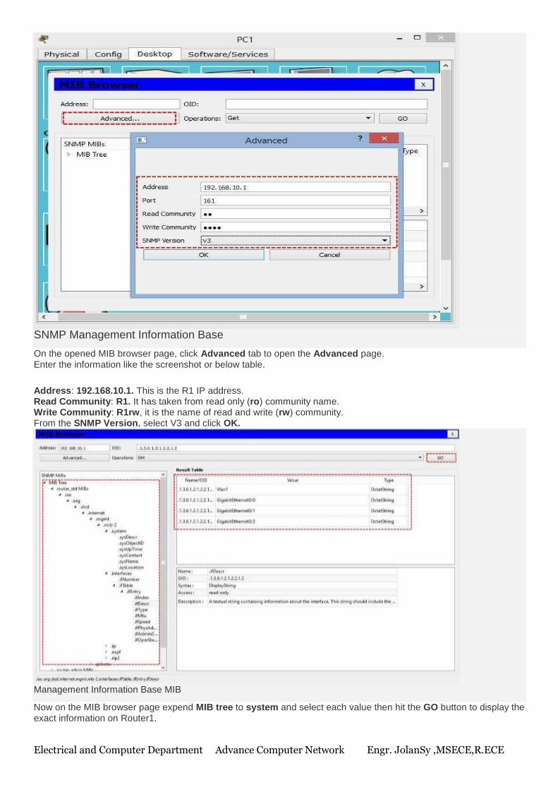
Electrical and Computer Department Advance Computer Network Engr. JolanSy ,MSECE,R.ECE
SNMP Management Information Base
On the opened MIB browser page, click Advanced tab to open the Advanced page. Enter the information like the screenshot or below table.
Address: 192.168.10.1. This is the R1 IP address. Read Community: R1. It has taken from read only (ro) community name. Write Community: R1rw, it is the name of read and write (rw) community. From the SNMP Version, select V3 and click OK.
Management Information Base MIB
Now on the MIB browser page expend MIB tree to system and select each value then hit the GO button to display the exact information on Router1.
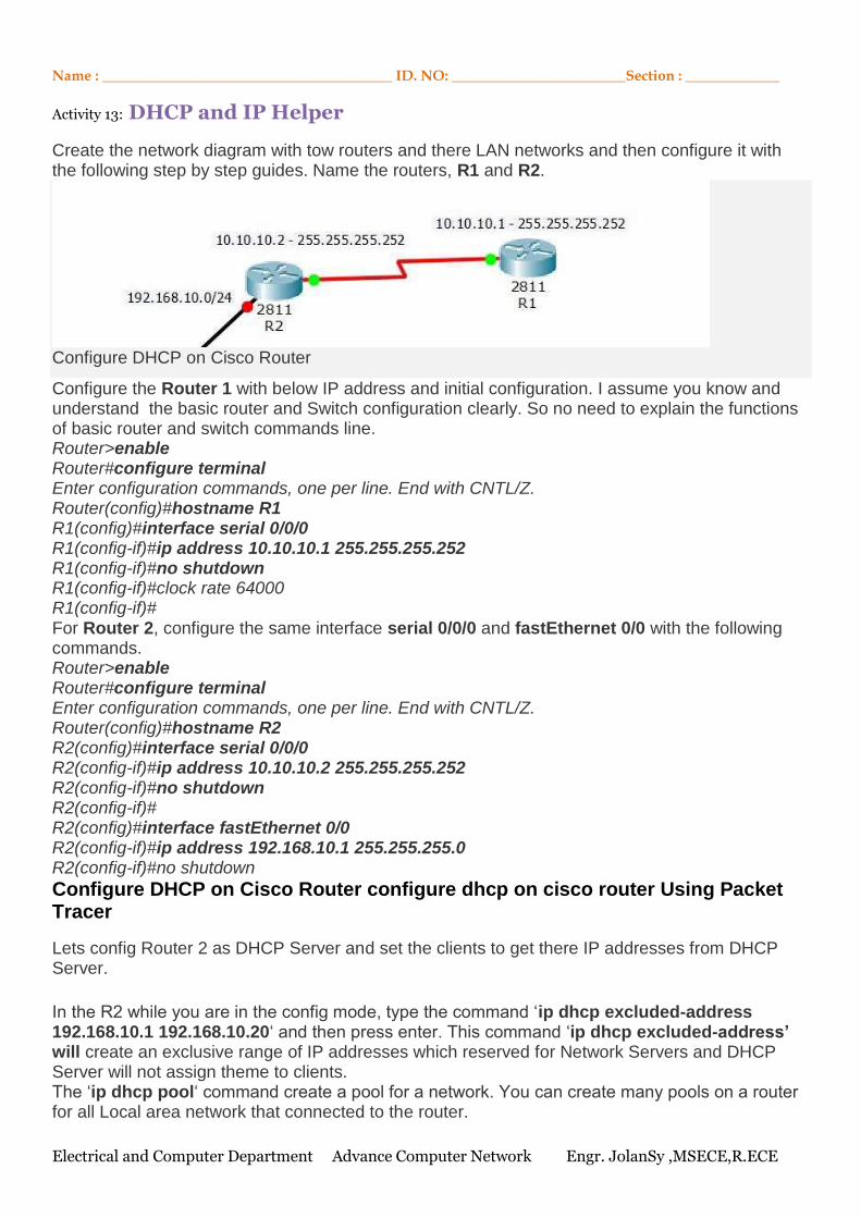
Electrical and Computer Department Advance Computer Network Engr. JolanSy ,MSECE,R.ECE
Name : ________________________________________ ID. NO: ________________________Section : _____________
Activity 13: DHCP and IP Helper
Create the network diagram with tow routers and there LAN networks and then configure it with the following step by step guides. Name the routers, R1 and R2.
Configure DHCP on Cisco Router
Configure the Router 1 with below IP address and initial configuration. I assume you know and understand the basic router and Switch configuration clearly. So no need to explain the functions of basic router and switch commands line. Router>enable Router#configure terminal Enter configuration commands, one per line. End with CNTL/Z. Router(config)#hostname R1 R1(config)#interface serial 0/0/0 R1(config-if)#ip address 10.10.10.1 255.255.255.252 R1(config-if)#no shutdown R1(config-if)#clock rate 64000 R1(config-if)# For Router 2, configure the same interface serial 0/0/0 and fastEthernet 0/0 with the following commands. Router>enable Router#configure terminal Enter configuration commands, one per line. End with CNTL/Z. Router(config)#hostname R2 R2(config)#interface serial 0/0/0 R2(config-if)#ip address 10.10.10.2 255.255.255.252 R2(config-if)#no shutdown R2(config-if)# R2(config)#interface fastEthernet 0/0 R2(config-if)#ip address 192.168.10.1 255.255.255.0 R2(config-if)#no shutdown
Configure DHCP on Cisco Router configure dhcp on cisco router Using Packet Tracer
Lets config Router 2 as DHCP Server and set the clients to get there IP addresses from DHCP Server.
In the R2 while you are in the config mode, type the command ‘ip dhcp excluded-address 192.168.10.1 192.168.10.20‘ and then press enter. This command ‘ip dhcp excluded-address’ will create an exclusive range of IP addresses which reserved for Network Servers and DHCP Server will not assign theme to clients. The ‘ip dhcp pool‘ command create a pool for a network. You can create many pools on a router for all Local area network that connected to the router.
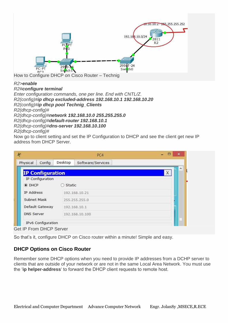
Electrical and Computer Department Advance Computer Network Engr. JolanSy ,MSECE,R.ECE
How to Configure DHCP on Cisco Router – Technig
R2>enable R2#configure terminal Enter configuration commands, one per line. End with CNTL/Z. R2(config)#ip dhcp excluded-address 192.168.10.1 192.168.10.20 R2(config)#ip dhcp pool Technig_Clients R2(dhcp-config)# R2(dhcp-config)#network 192.168.10.0 255.255.255.0 R2(dhcp-config)#default-router 192.168.10.1 R2(dhcp-config)#dns-server 192.168.10.100 R2(dhcp-config)# Now go to client setting and set the IP Configuration to DHCP and see the client get new IP address from DHCP Server.
Get IP From DHCP Server
So that’s it, configure DHCP on Cisco router within a minute! Simple and easy.
DHCP Options on Cisco Router
Remember some DHCP options when you need to provide IP addresses from a DCHP server to clients that are outside of your network or are not in the same Local Area Network. You must use the ‘ip helper-address‘ to forward the DHCP client requests to remote host.
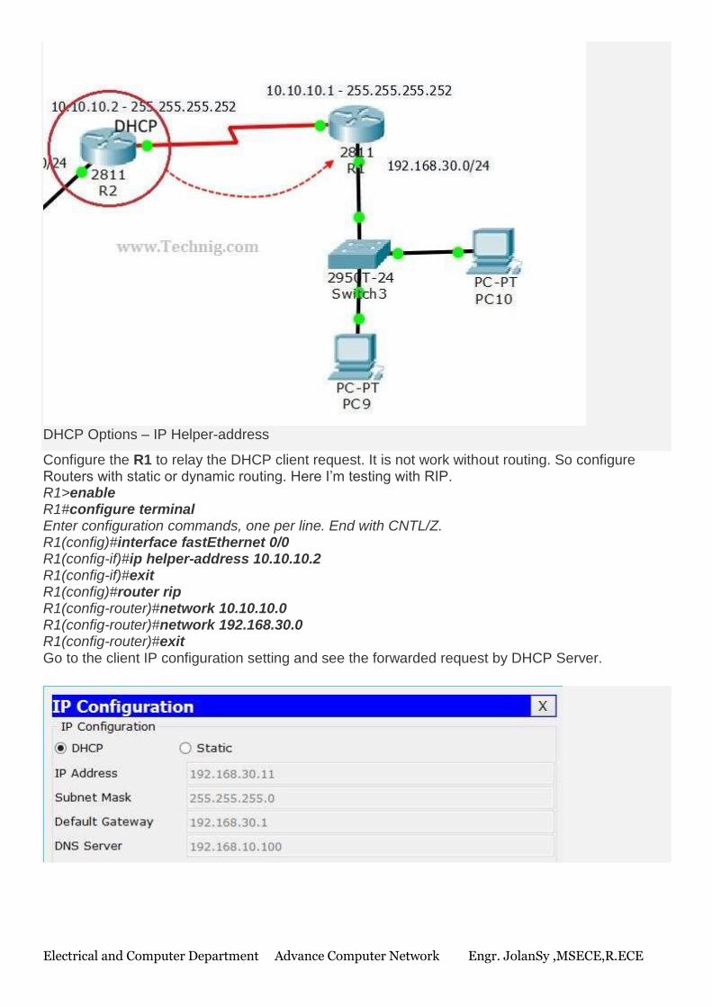
Electrical and Computer Department Advance Computer Network Engr. JolanSy ,MSECE,R.ECE
DHCP Options – IP Helper-address
Configure the R1 to relay the DHCP client request. It is not work without routing. So configure Routers with static or dynamic routing. Here I’m testing with RIP. R1>enable R1#configure terminal Enter configuration commands, one per line. End with CNTL/Z. R1(config)#interface fastEthernet 0/0 R1(config-if)#ip helper-address 10.10.10.2 R1(config-if)#exit R1(config)#router rip R1(config-router)#network 10.10.10.0 R1(config-router)#network 192.168.30.0 R1(config-router)#exit Go to the client IP configuration setting and see the forwarded request by DHCP Server.
Related Documents


