WMATA MANUAL OF DESIGN CRITERIA SECTION 25 FIGURE 25 - TC-25 25-118 Release 9, revision 2

Welcome message from author
This document is posted to help you gain knowledge. Please leave a comment to let me know what you think about it! Share it to your friends and learn new things together.
Transcript

WMATA MANUAL OF DESIGN CRITERIASECTION 25
FIGURE 25 - TC-25
25-118Release 9, revision 2

WMATA MANUAL OF DESIGN CRITERIASECTION 25
FIGURE 25 - TC-26
25-119Release 9, revision 2

WMATA MANUAL OF DESIGN CRITERIASECTION 25
FIGURE 25 - TC-27
25-120Release 9, revision 2

WMATA MANUAL OF DESIGN CRITERIASECTION 25
FIGURE 25 - TC-28
25-121Release 9, revision 2

WMATA MANUAL OF DESIGN CRITERIASECTION 25
FIGURE 25 - TC-29
25-122Release 9, revision 2
WMATA MANUAL OF DESIGN CRITERIASECTION 25
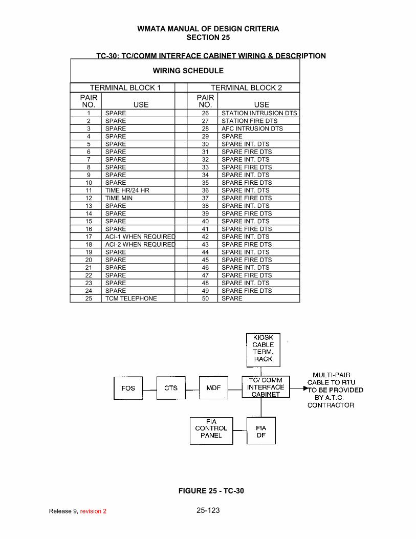
TC-30: TC/COMM INTERFACE CABINET WIRING & DESCRIPTION
WIRING SCHEDULE
TERMINAL BLOCK 1 TERMINAL BLOCK 2
PAIRNO. USE
PAIRNO. USE
1 SPARE 26 STATION INTRUSION DTS
2 SPARE 27 STATION FIRE DTS
3 SPARE 28 AFC INTRUSION DTS
4 SPARE 29 SPARE
5 SPARE 30 SPARE INT. DTS
6 SPARE 31 SPARE FIRE DTS
7 SPARE 32 SPARE INT. DTS
8 SPARE 33 SPARE FIRE DTS
9 SPARE 34 SPARE INT. DTS
10 SPARE 35 SPARE FIRE DTS
11 TIME HR/24 HR 36 SPARE INT. DTS
12 TIME MIN 37 SPARE FIRE DTS
13 SPARE 38 SPARE INT. DTS
14 SPARE 39 SPARE FIRE DTS
15 SPARE 40 SPARE INT. DTS
16 SPARE 41 SPARE FIRE DTS
17 ACI-1 WHEN REQUIRED 42 SPARE INT. DTS
18 ACI-2 WHEN REQUIRED 43 SPARE FIRE DTS
19 SPARE 44 SPARE INT. DTS
20 SPARE 45 SPARE FIRE DTS
21 SPARE 46 SPARE INT. DTS
22 SPARE 47 SPARE FIRE DTS
23 SPARE 48 SPARE INT. DTS
24 SPARE 49 SPARE FIRE DTS
25 TCM TELEPHONE 50 SPARE
FIGURE 25 - TC-30
25-123Release 9, revision 2
WMATA MANUAL OF DESIGN CRITERIASECTION 25
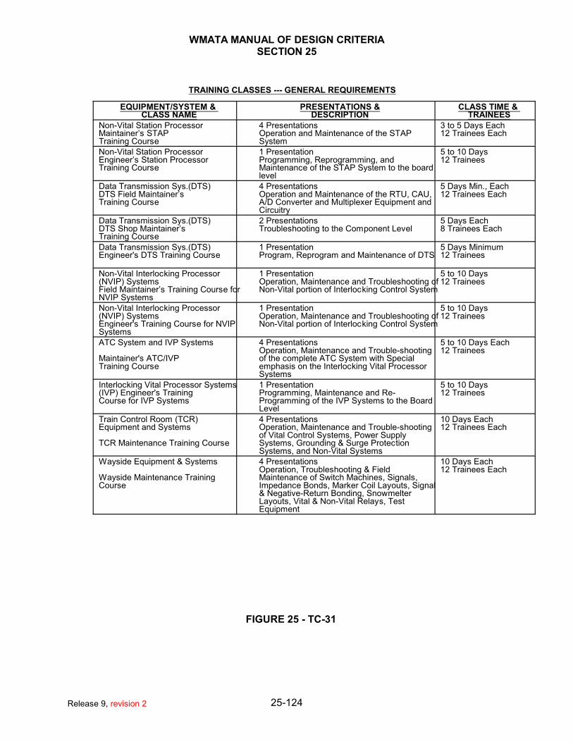
TRAINING CLASSES --- GENERAL REQUIREMENTS
EQUIPMENT/SYSTEM & CLASS NAME
PRESENTATIONS &DESCRIPTION
CLASS TIME & TRAINEES
Non-Vital Station ProcessorMaintainer’s STAP Training Course
4 PresentationsOperation and Maintenance of the STAPSystem
3 to 5 Days Each12 Trainees Each
Non-Vital Station ProcessorEngineer’s Station ProcessorTraining Course
1 PresentationProgramming, Reprogramming, andMaintenance of the STAP System to the boardlevel
5 to 10 Days12 Trainees
Data Transmission Sys.(DTS)DTS Field Maintainer’s Training Course
4 PresentationsOperation and Maintenance of the RTU, CAU,A/D Converter and Multiplexer Equipment andCircuitry
5 Days Min., Each12 Trainees Each
Data Transmission Sys.(DTS)DTS Shop Maintainer’s Training Course
2 PresentationsTroubleshooting to the Component Level
5 Days Each8 Trainees Each
Data Transmission Sys.(DTS)Engineer's DTS Training Course
1 PresentationProgram, Reprogram and Maintenance of DTS
5 Days Minimum12 Trainees
Non-Vital Interlocking Processor(NVIP) SystemsField Maintainer’s Training Course forNVIP Systems
1 PresentationOperation, Maintenance and Troubleshooting ofNon-Vital portion of Interlocking Control System
5 to 10 Days12 Trainees
Non-Vital Interlocking Processor(NVIP) SystemsEngineer's Training Course for NVIPSystems
1 PresentationOperation, Maintenance and Troubleshooting ofNon-Vital portion of Interlocking Control System
5 to 10 Days12 Trainees
ATC System and IVP Systems
Maintainer's ATC/IVPTraining Course
4 PresentationsOperation, Maintenance and Trouble-shootingof the complete ATC System with Specialemphasis on the Interlocking Vital ProcessorSystems
5 to 10 Days Each12 Trainees
Interlocking Vital Processor Systems(IVP) Engineer's Training Course for IVP Systems
1 PresentationProgramming, Maintenance and Re-Programming of the IVP Systems to the BoardLevel
5 to 10 Days12 Trainees
Train Control Room (TCR)Equipment and Systems
TCR Maintenance Training Course
4 PresentationsOperation, Maintenance and Trouble-shootingof Vital Control Systems, Power SupplySystems, Grounding & Surge ProtectionSystems, and Non-Vital Systems
10 Days Each12 Trainees Each
Wayside Equipment & Systems
Wayside Maintenance TrainingCourse
4 PresentationsOperation, Troubleshooting & FieldMaintenance of Switch Machines, Signals,Impedance Bonds, Marker Coil Layouts, Signal& Negative-Return Bonding, SnowmelterLayouts, Vital & Non-Vital Relays, TestEquipment
10 Days Each12 Trainees Each
FIGURE 25 - TC-31
25-124Release 9, revision 2

WMATA MANUAL OF DESIGN CRITERIASECTION 26
26 .1.1.1.1.1.1. COMPUTER SYSTEMS
26 .2 GENERAL (Future)
26 .3 HEAVY RAIL
26 .3.1 RAIL OPERATIONS CONTROL CENTER (OCC) OVERVIEW
The overall supervisory control of WMATA METRORAIL operations is conducted by specially trainedWMATA personnel at a central control facility known as the Operations Control Center (OCC), locatedin the Jackson Graham Building (WMATA Headquarters) in downtown Washington, DC. This centralcontrol facility, part of the ATC Automatic Train Supervision (ATS) System, contains: a controlcomputer; a hot backup computer, and; a computer for software development, which also serves asthe ultimate backup computer.
The control computer receives and transmits messages between the operations control center andstation locations via the Data Transmission System (DTS). It communicates with the central controloperator by providing displays on a large scale screen and on individual video monitors (CRTs), andby accepting operator input from the computer control consoles. The control computer performsschedule adjustments by changing station dwell times and train performance levels. These changesare sent to the applicable station Remote Terminal Units (RTUs) via the DTS.
The METRORAIL system can operate as a stand alone entity without the computer complex at theOCC. However, without the capabilities provided by the ATS software in the central control computer,the display system, and the DTS, the job of monitoring and supervising the METRO operations,especially to maintain schedules, would be more difficult. This is especially true when an abnormalcondition (e.g., a malfunctioning train) is encountered.
The general Train Control and ancillary functions provided to aid the central control operators are:
26 .3.1.1 Display System
26 .3.1.1.1 Train System Displays
26 .3.1.1.2 Train and Interlocking Detail Displays
26 .3.1.1.3 Train Information Displays
26 .3.1.1.4 Electrical System Displays
26 .3.1.1.5 Train and Electrical System Alarm Displays
26 .3.1.1.6 Geographic Displays
26 .3.1.2 Traffic Regulation Monitoring
26 .3.1.2.1 Schedule Control
26 .3.1.2.2 Schedule Adjustment Strategies
26 .3.1.2.3 Schedule linkage of train put-ins
26 .3.1.3 Supervisory Capability
26 .3.1.3.1 Train Control requests to wayside ATP system
26 .3.1.3.2 Interlocking requests to wayside ATP system
26 .3.1.3.3 Commands to wayside ATS equipment
26 .3.1.3.4 Commands to wayside support system devices
26-1Release 9, revision 2

WMATA MANUAL OF DESIGN CRITERIASECTION 26
26 .3.1.4 Status Monitoring and Alarm Processing
26 .3.2 AUTOMATIC TRAIN SUPERVISION SOFTWARE
The software for the central computer has been designed in a building block approach and providesthe primary functions of Traffic Regulation, and Control and Display.
26 .3.2.1 Traffic Regulation
26 .3.2.1.1 All trains in the METRO system under central computer supervision enter revenueservice, run, and terminate revenue service according to times provided by predeterminedtrain schedules. These train schedules are the basis for Traffic Regulation Control. Atrain schedule is defined as a set of arrival and departure times at successive locationswhich completely dictates a train's intended movement from entry into revenue serviceuntil layup. A train schedule defines, among other things, the scheduled arrival time andthe scheduled dwell time at every station traversed by a given train. A unique scheduleis defined for each train that is in revenue service or is about to enter revenue service. The system schedules are selected by the central control operators at the start of revenueservice on a particular day.
26 .3.2.1.2 Traffic Regulation automatically maintains the scheduled headways between all of thetrains operating in the territory and regulates train movements for time scheduleadherence, proper merging of trains at rail line junction points, and optimum utilization ofterminal locations. This is achieved by control of both station dwell time, and trainperformance (speed) and acceleration levels which govern the interstation running time.
26 .3.2.1.3 The four main components of the Traffic Regulation software are Put-in Processing, theLine Algorithm, the Terminal Algorithm, and Strategy Selection. Also, statistics of theactual performance of trains are gathered for off-line analysis.
26 .3.2.1.3.1 Put-in Processing
The Put-in Processing software initiates train entry into revenue service eitherfrom a storage point, such as a yard or a pocket track, or from a terminal stationafter a train reversal. The primary function of the Put-in Processing software is toconstruct a schedule for the next terminal-to-terminal run of the train so that theTerminal Algorithm and the Line Algorithm can control it. Another functionperformed is the lighting of warning lamps at yards prior to the scheduled dispatchof a train so that the yard personnel can prepare a train for revenue service.
26 .3.2.1.3.2 Line Algorithm
26 .3.2.1.3.2.1 The primary function of the Line Algorithm is to attenuate delays due to minorline disturbances as quickly as possible and prior to the arrival of trains inareas where the probability of such delays is high. Line disturbances areevents or conditions which cause a train to be early or late with respect to itsschedule. Such events cause the Line Algorithm to affect the dwell time of atrain at a station and the performance of a train departing from a station. TheLine Algorithm minimizes or eliminates the effects of delays by adjusting thedwell and performance level of a train such that the departure schedule errorat a station and the arrival schedule error at the next station are bothminimized.
26 .3.2.1.3.2.2 There are four performance levels. Performance Level 1 (PL1) requests thetrain to run at the maximum safe interstation speed, resulting in the minimumsafe interstation run time. The normal schedule for a train is based on PL2,which is approximately 10 percent slower than PL1. This gives trafficregulation a catch-up capability by allowing it to request PL1 to reduce a train'slateness. PL3 and PL4 are approximately 10 percent and 20 percent slowerthan PL2 and are used when trains are ahead of schedule.
26-2Release 9, revision 2
WMATA MANUAL OF DESIGN CRITERIASECTION 26
26 .3.2.1.3.2.3 Each of the four performance levels may be combined with a request for eitherfull or half acceleration, thus providing eight different interstation run times. For each station platform the program can select either a normal dwell time oranother value which lies within the range of minimum and maximum dwelltimes for that platform. Dwell times available for some platforms can be variedwith the time of day.
26 .3.2.1.3.3 Terminal Algorithm
26 .3.2.1.3.3.1 A special case handled by a part of Traffic Regulation called the TerminalAlgorithm is used to avoid conflicts between trains at terminals having acrossover interlocking located between the terminal station and thepenultimate station. Since these interlockings are used to reverse trains,conflicts in the use of the interlockings can be generated by trains arriving atand departing from a terminal station at close headways. A route conflictexists whenever two trains attempt to traverse conflicting routes through aninterlocking at the same time.
26 .3.2.1.3.4 Strategy Selection
26 .3.2.1.3.4.1 The central control operators have the capability of providing correctivestrategies through the Strategy Selection program whenever required. Thecontrol philosophy employed here is that the operator is the best judge of whatcorrective action is most suitable in any given situation and the computer ismost useful as a device to display the options available and to implement theselected option. The Strategy Selection programs include Replace Train,Delete Train, Add Train, Eliminate Gap, Create Gap, Offset Schedule, TiltSchedule and Skip Stop. All act to either modify or maintain the existingschedule.
26 .3.2.1.4 Control and Display Software
26 .3.2.1.4.1 The Control and Display software drives the displays and alarm printers andresponds to central control operator inputs through the console trackballs and keyboards. The Control and Display software responds to field changes or whenrequested by an operator input to update train displays. It examines the datareturned from the field and marked as changed by the Data Base Processorsoftware. It then updates displays and alarm messages for the central operatoras required.
26 .3.2.1.4.2 The Control and Display software provides the processing of all operator inputsand coordinates execution of the software required by those inputs. Thesecommands allow the central control operators to manually supervise systemoperation and to request specific displays.
26 .3.3 OCC SYSTEM HARDWARE
The system hardware is used to perform the required Automatic Train Supervision functions andbackup functions. The individual components are integrated to provide the means by which thevarious software components perform their functions.
26 .3.3.1 General Purpose Computer Subsystem
Three interconnected computers comprise this subsystem. Each computer consists of acentral processor with byte addressing, floating point and memory protection instructions, apriority interrupt system, and a power monitoring circuit.
The computer systems are networked to each other and to the peripheral devices through adual Ethernet network.
26 .3.3.2 Communications Subsystem
26-3Release 9, revision 2

WMATA MANUAL OF DESIGN CRITERIASECTION 26
To handle the specialized data transmission, the central computers are connected to twoFront End Processors which are connected to a bank of modems. The modems areconnected through the DTS to the various field devices and permit the transfer of data to andfrom the central control computer. The FEPs receive the raw data from the field and forwardchange information to the central processors.
26 .3.3.3 Control and Display Subsystem
26 .3.3.3.1 The Control and Display subsystem, used by the central control operators in controllingthe system, has as its main functions; the presentation of system status, operational dataand alarms to the central operator, and the execution of system commands from theconsole trackball and keyboard.
26 .3.3.3.2 Video monitors (CRTs) provide the display facility: "Closeup" views of the interlockings;System alarms (Train and E&S Alarm); Performance statistics (Train Information);Electrification system (Traction Power); and the state of mechanical support equipmentat a station selected by the operator (Support Station). In the event that a CRTmalfunctions, the central control operators have the capability of reconfiguring the displays so that a desired display can be moved to a working CRT.
26 .3.3.3.3 A Large Scale Display System provides an overview display of the METRO System andcan also be used to display any of the System's local or special displays.
26 .3.3.3.4 All alarm conditions on the METRO System, whether the result of train control indications,calculations, traction power and support system indications or computer indications, aredisplayed in tabular form on the appropriate alarm display and can be output to a printer. Alarms are also displayed in the alarm area (bottom three lines) of the CRT screen. Eachmessage is accompanied by an audible alarm. The alarm area contains up to three of themost current unacknowledged alarm messages. There is an indication if there are morethan three currently unacknowledged alarms.
26 .4 BUS GARAGE / SHOP FACILITIES (Future)
26 .5 LIGHT RAIL FACILITIES (Future)
26 .6 HEAVY RAIL YARD / SHOP FACILITIES (Future)
26 .7 PARKING GARAGE (Future)
26-4Release 9, revision 2

WMATA MANUAL OF DESIGN CRITERIASECTION 27
SECTION 27 General Communication System
27.1 Purpose
27.1.1 The purpose of the Rail Communications System is to provide state-of-the-art, efficient and reliablecommunications between all elements of the Rail System. Verbal, data and visual communicationsshall be furnished.
27.1.2 Communications service shall be provided for train operations, passenger station operation andsecurity, transit police operations, maintenance operations, and monitoring and alarming of all areasfor fire, bio-chemical detection, and unauthorized entry.
27.1.3 The design of the Communication systems must be coordinated with the design of the Train Controlsystem, the Traction Power system, the Fare Collection system, the IT components, miscellaneoussupport facilities, revenue and nonrevenue vehicles and equipment, and other components orelements of the transit system.
27.1.4 The communications system shall incorporate the most modern proven designs available to providethe highest degree of safety, efficiency, and reliability.
27.1.5 All equipment and systems shall be designed for immediate 10% expansion.
27.1.6 All equipment and systems shall be designed and constructed with consideration given to physicaland electrical environment such as temperature and humidity, range of operation, vibration andshock, dust and weather, electric and magnetic fields, electromagnetic coupling of conductors, pairsand cables, transient peaks of electrical grounding, and voltage and current.
27.1.7 Mechanical configuration of equipment shall provide for ease of inspection and replacement.
27.1.8 Electrical test points, adjustments, fuses, equipment alarms, and indication shall be provided at frontpanels wherever possible.
27.1.9 All electronic equipment shall be standard, commercially available solid state devices, whereverpracticable. Plug-in printed circuit card construction shall provide extender units as standardequipment. Communications and equipment design shall be in accordance with one or more of thefollowing codes and specifications where applicable. The intent of these regulations should also bemaintained where new devices or methods are introduced, even through the details of thespecifications do not apply.
NOTE:The design criteria for the phone system, network, and Garage communication equipment(such as GETS & Elevator Intercom) can be found in IT Design Criteria.
27.2 Design
27.2.1 A Communication Room shall be provided in each rail station, rail yard building, parking garage, busgarage building, or any other facility that WMATA builds. Larger buildings shall be provided withmultiple COM rooms. The Communication (COM) room shall be conditioned space and provided withan HVAC sized to provide the designed heat load plus a 40 percent growth margin.
27.2.2 A telephone closet or Bell room shall be provided near each kiosk within the station. ¾” x 4’ x 8’ footplywood shall line the walls of the telephone closets.
27.2.3 Typical Communication conduits shall be as shown on the design drawings. CAT6 and Fiber Opticpatch panels shall be provided in the COM rooms and in the Kiosks.
27.2.4 The Communication system shall include the following equipment:
27.2.4.1 Public Address System27.2.4.2 Radio System
27-5Release 9, revision 2

WMATA MANUAL OF DESIGN CRITERIASECTION 27
27.2.4.3 Video Surveillance System27.2.4.4 Fire Alarm System27.2.4.5 Intrusion Detection System27.2.4.6 Access Control System27.2.4.7 Call for Aid System27.2.4.8 Information Display System27.2.4.9 Kiosks 27.2.4.10 Operation Control Centers
NOTE:See IT Design Criteria for Phones, Network, and structured cabling design criteria.
27.3 Power for Communications
27.3.1 The Electrical Power System shall provide power distribution from the 3-phase, 4-wire, 120/208 VAC,primary power feed, provided by others, to the communications room.
27.3.2 Communication devices with redundant power supplies shall be connected to different power sources. One side shall be connected to the Emergency supply and the other side shall be connected to theNormal supply.
27.3.3 The design shall provide for a 120/208 VAC Emergency Power Distribution System for eachPassenger Station, and shall include as a minimum:
27.3.3.1 An Emergency power distribution panelboard-3-phase 4-wire, 120/208 VAC w/solid neutralbus and ground bus. Main lugs rated 100 Amp. Minimum 20 single pole breaker capacity.
27.3.3.2 AC Power Disconnect Switch with minimum ampere rating of 100 Amp
27.3.3.3 AC Emergency power distribution panel in the Kiosk
27.3.3.4 AC Normal power distribution panel in the Kiosk
27.3.3.5 AC power receptacles.
27.4 Grounding
27.4.1 All conduit shall be electrically insulated from equipment racks and equipment cabinets; powerground shall be separate and isolated from the communications ground.
27.4.2 Conduit containing branch circuit conductors shall be insulated from the equipment racks andcabinets by means of short lengths of non-conducting conduit.
27.4.3 Short lengths of flexible metallic conduit shall be provided in the equipment cabinets and on theequipment racks between the non-conducting conduit and the ac power receptacle strips.
27.4.4 Each branch circuit shall contain a separate neutral conductor to the Communications EquipmentRoom Power Distribution Panel board.
27.5 Surge Suppression
27-6Release 9, revision 2

WMATA MANUAL OF DESIGN CRITERIASECTION 27
27.5.1 Surge suppression shall be provided on all incoming lines that are exposed to the externalenvironment.
27.6 Security Provisions
27.6.1 Access control shall be provided on all doors entering or exiting the COM room. A PTZ camera shallbe provided to monitor all doors entering or exiting the COM room. Both the Access Control systemand the PTZ camera shall integrate with the electronic Safety and Security (ESS) system.
27.7 Public Address System
27.7.1 Purpose
27.7.1.1 The purpose of the Public Address (PA) system is used to provide audio information to thepublic, employees, and contractors in both the public and non-public areas of passengerstations.
27.7.2 Design
27.7.2.1 A Public Address system shall be installed in each passenger rail station and be designedand maintained to have a Speech Transmission Index (STI) of 0.7.
27.7.2.2 The Public Address system shall allow announcements to be made with the following priorityand from the following locations:
27.7.2.2.1 The Station Fire Alarm Panel27.7.2.2.2 The Rail Operational Control Center at:
27.7.2.2.2.1 Jackson Graham Building27.7.2.2.2.2 Carmen Turner Facility
27.7.2.2.3 The Kiosk Wireless Microphone27.7.2.2.4 The Kiosk Wired/Gooseneck Microphone27.7.2.2.5 The End of Line Station / Dispatcher’s Office (Block House)
27.7.2.3 Major System Components
27.7.2.3.1 The PA system shall include the following major components:27.7.2.3.1.1 JGB OCC Head End27.7.2.3.1.2 CTF OCC Head End27.7.2.3.1.3 Station IP to Audio converter27.7.2.3.1.4 Redundant Station Amplifiers27.7.2.3.1.5 Station Speakers27.7.2.3.1.6 Kiosk Control Panel with Microphone27.7.2.3.1.7 Wireless Microphone System27.7.2.3.1.8 Intercom
27.7.2.4 The basis of design for the PA system is as follows:27.7.2.4.1 OCC Head End – Penta27.7.2.4.2 Station IP to Audio Converter – Barix27.7.2.4.3 Audio Amplifiers – 27.7.2.4.4 Speakers - 27.7.2.4.5 Intercom - Commend27.7.2.4.6 OCC Head End
27-7Release 9, revision 2

WMATA MANUAL OF DESIGN CRITERIASECTION 27
27.7.2.5 The Rail Operations Control Center (OCC) uses the PENTA PA Control Equipment to selectand broadcast in the following ways:
27.7.2.5.1 System wide announcements to all Metro Rail Stations 27.7.2.5.2 Announcements to selected Lines (i.e., Red Line, Green Line, or Blue/Orange Lines)27.7.2.5.3 Individual Passenger Stations
27.8 Passenger Stations Public Address System
27.8.1 Each passenger station in the WMATA Rail System shall be designed to have an independent PublicAddress (PA) System. The Passenger Station PA System provides for general purpose andemergency evacuation announcements throughout the passenger station.
27.8.2 PA coverage shall be provided to all public and nonpublic areas of the station.
27.8.3 Each station shall be provided with a priority mixer. The line mixer shall be used to control the levelof the individual audio inputs. A single output shall be taken from the mixer and input to the poweramplification. When an announcement of a higher priority is initiated, the lower priority announcementis removed from the amplifier’s input until the high priority announcement is completed.
27.8.4 Below ground stations shall be provided with a noise compensated circuits for the platform andmezzanine areas. This noise compensation circuit shall be used to automatically adjust the PAvolume when trains are arriving or departing the station. Above ground stations shall not be providedwith noise compensated circuits.
27.8.5 Stations shall be provided with non-noise compensated circuits for service rooms and non-revenuepassageways. Service rooms shall be provided with a volume control circuit.
27.8.6 The operation of the Passenger Station PA System from the Kiosk is accomplished by simultaneouslydepressing the push-to-talk pushbuttons on the hand-held microphone and the Kiosk PA ControlPanel, then speaking into the hand-held microphone.
27.8.7 Kiosks shall be provided with a portable wireless microphone. The wireless microphone shall workfrom any location on the platform or mezzanine(s). The wireless microphone shall by-pass and takesthe place of the normal kiosk microphone when the wireless microphone is keyed. This feature isused to allow the kiosk attendant freedom of movement beyond the kiosk for various reasonsincluding crowd control.
27.8.8 When a selection is made by a Passenger Operations Supervisor in the Rail Operations ControlCenter, the audio path of the console is connected to the station PA via an IP connection.
27.8.9 The PA system design shall have redundant power amplifiers. The Power Amplifiers shall beconnected to the Amplifier Supervisory Control Unit. One Power Amplifier shall be connected to the"MAIN CHANNEL" of the Amplifier Supervisory Control Unit, and the second Power Amplifier shallbe connected to the "auxiliary channel" of the Amplifier Supervisory Control Unit. Each AmplifierSupervisory Control Unit shall monitor the associated Power Amplifiers and, upon sensing amalfunction of the "main channel" Power Amplifier, shall automatically transfer the audio path to the"auxiliary channel" Power Amplifier.
27.8.10 The Passenger Station PA Speakers shall be designed to be wired in either noise-compensatedor non-noise compensated circuits. Noise-compensated circuits shall be used in areas where trainnoise must be overcome by automatically adjusting the PA volume. The station mezzanine area
27-8Release 9, revision 2

WMATA MANUAL OF DESIGN CRITERIASECTION 27
and Platform areas are of noise compensated circuits which use Automatic Level Control. Forareas where noise compensation is required, circuits shall be wired to the LoudspeakerDistribution Panel designated for noise-compensated circuits. Non-noise compensated circuitsshall be used in all other areas. In areas where noise-compensated circuits are not required,circuits shall be wired to the Loudspeaker Distribution Panel designated for non-noisecompensated circuits. Passenger station service rooms and non-revenue passageways areexamples of areas that require non-noise compensated speaker circuits.
27.8.11 The PA amplifiers shall have a constant voltage output of 70.7 volts. Each loudspeaker shall beequipped with an audio transformer to match the 70.7 volt line with the loudspeaker. Thetransformers shall have various taps to allow for adjustment of the sound level in a particular area.Each transformer shall have a minimum of four taps. The power rating for each of the taps shallbe determined during installation.
27.8.12 The design and deployment of public address speakers shall be coordinated with architecturaldesign. The speaker quantities and locations shall be determined by the coverage requirements. A sufficient quantity of speakers shall be placed in passenger stations to give even volumedistribution without objectionable loudness from any one speaker location. Speakers shall befeed from two different amplifiers in an alternating feed pattern so that if one amplifier fails, PAaudio is provided to all coverage locations.
27.9 End-Of-Line Stations Public Address System
27.9.1 The PA system for End-Of-Line Stations shall be designed to have a Dispatcher PA input at theStation. The Dispatcher PA System input shall provide access to the Passenger Station PA Systemto make announcements at any time that the station PA system is not already in use.
27.9.2 A Dispatcher's PA Control Panel shall be provided in the dispatcher’s office and function in anidentical manner as the Kiosk Public Address Control Panel. The Dispatcher’s PA Control Panel shallhave a Zone Selection capability. The Dispatcher PA system Zone Selection shall provide theDispatcher with the ability to choose between either (1) All Station Speakers or (2) Platform SpeakersOnly.
27.10 Intercoms
27.10.1 Each Kiosk in the WMATA Rail System shall be provided with an Attendant/Passenger InterphoneSystem. The Attendant/Passenger Interphone System shall provide for communication betweenpassengers and the Kiosk Attendant at the Kiosk. The Attendant/Passenger Interphone Systemshall serve both the “PAID” and the “UNPAID” side of each Kiosk.
27.10.2 Additionally, a separate Intercom System shall be provided at the Dispatcher's Room to provideverbal communications between the Train Control Room, the Dispatcher's Room, and theOperations Room.
27.11 Land Mobile Radio Systems
27.11.1 Purpose
27.11.1.1 The purpose of the radio system is to provide public service grade wireless voicecommunication both above ground and below ground.
27-9Release 9, revision 2

WMATA MANUAL OF DESIGN CRITERIASECTION 27
27.11.2 Design
27.11.2.1 The current WMATA Mobile Radio System consists of a 490 MHz Comprehensive RadioCommunication System (CRCS) for above ground and below ground communication.
27.11.2.2 Additionally, multiple Local Jurisdictional Public Safety Radio Systems (PSRS) operating inthe 800 MHz frequency band are installed in underground locations throughout the railsystem.
27.11.2.3 An old VHF radio system is still deployed by WMATA. It should be removed some time duringthe 2013 to 2014 time frame.
27.11.2.4 The existing CRCS provides voice and data communications among Bus, Rail, Metro TransitPolice (MTPD), Para-Transit, Maintenance, and Administrative personnel and vehicles. Theexisting CRCS is composed of 10 remote above ground sites, 15 voice channels, 4 data AVL(bus) channels, one mobile data channel and one paging channel.
27.11.2.5 The WMATA CRCS shall consist of multiple talk groups:27.11.2.5.1 (OPS-1) 27.11.2.5.2 (OPS-2) 27.11.2.5.3 (OPS-3) 27.11.2.5.4 (OPS-4) 27.11.2.5.5 (MTPD)27.11.2.5.6 BUS 27.11.2.5.7 Maintenance
27.11.3 Major System Components
27.11.3.1 The radio system shall include the following major components:27.11.3.1.1 Above Ground Radio System27.11.3.1.2 Below Ground Radio System27.11.3.1.3 Public Safety Radio System (PSRS)27.11.3.1.4 Distributed Antenna System27.11.3.1.5 Consoles27.11.3.1.6 Subscriber Units27.11.3.1.7 Future Radio System
27.11.4 Basis of Design
27.11.4.1 The basis of design for the radio system shall be Motorola.
27.12 Above-Ground (AG) Radio System
27.12.1 The above ground CRCS radio system shall provide DAQ 3.4 quality with 95/95% reliability instreet portable radio coverage with the radio mounted on the hip throughout the entire WMATAservice area.
27.12.2 The WMATA Comprehensive Radio Communication System (CRCS) consists of a frequencymodulated, UHF T-Band, (operating in the 470-512 MHz portions of the frequency band) digital,single-cell simulcast trunked Motorola Smart Zone 3.0z radio system, used for communicatingwith radio users throughout the entire WMATA service area.
27-10Release 9, revision 2

WMATA MANUAL OF DESIGN CRITERIASECTION 27
27.12.3 The radio system is configured to operate with one Master Site Controller located at CTF andgeographically redundant Prime Site Controllers located at CTF and JGB. Existing remote radiosites are connected by redundant T-1 lines leased from Verizon.
27.12.4 The WMATA Comprehensive Radio Communication System (CRCS) is a fifteen channel, tenantenna site, 490 MHz ASTRO Simulcast trunked radio system. This system employs the latesttrunking technology in a wide area configuration. The Prime Site Controller has control over thecall processing activity within the simulcast radio system and is located at the Carmen TurnerFacility (CTF). The Zone Controller directs call processing activity for the entire network. TheAmbassador Electronics Bank (AEB) serves as the heart of the ASTRO Simulcast system andthe central point for all audio routing across the radio sites, the dispatch center, and the telephoneinterconnect terminal. The Zone Controller processes the inbound signaling word (ISW) fromsubscribers units requesting a channel and issues the outbound signaling word (OSW) to unitsin the field
Figure 1- Inbound Transmission Above Ground:
27.12.5 In a simulcast system, audio is often received at more than one site when a user transmits. Voting comparators examine the audio received at each RF site. The system then selects thebest audio from each input and creates the optimal output signal. This assures that the signalproviding the highest audio quality is used. The simulcast trunking repeaters receive the audioand call requests from the field units and transmit the voted audio to the designated service area. The method of site-to-site transport is leased T1 circuits. Motorola employs the Premisys TeNSrchannel bank to interface the network’s components (such as the simulcast repeaters, AEB, etc.)with the transport medium. Strongest Signal is Optimized and Retransmitted. The retransmittedaudio is always the signal with the highest audio quality. It is optimized and phased to provideconsistent, high quality simulcast transmissions.
27-11Release 9, revision 2

WMATA MANUAL OF DESIGN CRITERIASECTION 27
Figure 2 - Outbound Transmission Above Ground:
27.13 Below-Ground (BG) Radio System
27.13.1 The below ground system shall provide DAQ 3.4 quality with 95/95% reliability in rail vehicles inthe tunnels and in station (both public & non-public locations) with the radio mounted on the hip. Radio coverage is provided by a DAS (Distributed Antenna System) installed throughout theunderground. The DAS is fed by a redundant radio frequency (RF) donor system, whichdistributes the above ground RF signal using fiber-optic links to a number of UHF bi-directionalamplifiers (BDAs) installed along the right of way.
27.13.2 The below ground systems utilizes fiber-optic transport technology along with wide band Bi-directional Amplifiers (BDA) in a Distributed Antenna System (DAS) configuration to provide twoway communications in below ground areas that are not covered by the CRCS 490 MHz aboveground system. These areas include station platforms, mezzanines, tunnels bores, and servicerooms. Each station has specific antennas on the platform and mezzanine areas to provide radiocoverage on these levels. It also includes radio coverage in all station public areas, service roomsand other non-public areas that are part of the station
27.13.3 The underground system has system components in the Jackson Graham Building, throughout26 select stations and integrated into the neutral host cable system in the tunnels. See figure 3below.
27.13.4 All CRCS radios in an underground station shall communicate via a slotted leaky coaxial cableantenna system installed in underground stations and tunnels. The 800 MHz PSRS also sharesthe leaky coax cable throughout the underground by connecting into a Cross-Band Coupler atport #2 with the 490MHz CRCS on Port #1. Port 3 (the output port) is connected to the
Underground Radiax Antenna System.
27-12Release 9, revision 2
WMATA MANUAL OF DESIGN CRITERIASECTION 27
Figure 3 – Typical underground interface to JGB
27.14 Public Safety Radio System (PSRS)
27.14.1 Multiple local jurisdictions have installed 800MHz Public Safety Radio System (PSRS) in theunderground. These systems provide two-way voice communications between control centerfacilities of local Fire Departments, Police Departments, and Emergency Medical Services (EMS)authorities and their corresponding portable radios.
27.14.2 Typically, these Public Safety Radio Systems (PSRS) are a frequency modulated voice radiosystem operating in the 850 MHz portions of the frequency band. Each of the three networks(Fire, Police, and Emergency Medical Services) shall operate, each with its individual radioequipment, control logic frequency(s), and portable radios.
27.14.3 The PSRS radio base stations shall be located in the passenger station CommunicationsEquipment Room. The PSRS radios shall provide coverage from portable radios in undergroundstations and tunnels to their local jurisdictional control consoles, and to other portable andvehicular units above ground. Please refer to drawing CPFI-5583.PSRS.E1 for a system blockdiagram of the PSRS underground system. Please refer to drawing CPFI-5583.PSRS.E201 fora system block diagram of a typical tunnel system segment (Segment 8).
27.14.4 The PSRS radio base stations shall be multiplexed onto the same slotted coaxial cable antennasystem used by the WMATA Comprehensive radio communication system (CRCS). Each PSRSnetwork radio base station shall be connected to its Local Jurisdictional Radio Control Facility byleased telephone lines.
27.14.5 In general, the PSRS consists of signal splitters, signal taps, impedance transformers and 50-ohmterminating resistors which are wideband enough to pass both the 800 MHz PSRS frequenciesas well as the CRCS 490 MHz frequencies simultaneously. Therefore, the combined output of the800 MHz PSRS fiber optic head end amplifier and output of the CRCS 490 MHz system are fedto a common signal splitter. One or two output ports of the 4-way splitter feed the stationantennas and the other 2 output ports feed the tunnel tracks. Returning to the 4-way splitter atthe output of the FOHE, one other output port of the splitter feed Track 1 in the tunnel. Thebackbone cable consists of multiple sections of 50-ohm cable under the neutral host project.
27.14.6 The following jurisdictions have underground PSRS within WMATA’s tunnels:
27.14.6.1 Washington DC27.14.6.2 Prince Georges County27.14.6.3 Fairfax County
27-13Release 9, revision 2

WMATA MANUAL OF DESIGN CRITERIASECTION 27
27.15 Distributed Antenna System (DAS)
27.15.1 The design of the Distributed Antenna System shall provide for radio coverage in the belowground system. The below ground radio provides radio coverage in tunnels, shafts, ancillarybuilding and underground station areas. Underground coverage shall be provided from slottedcoaxial antenna cable installed in tunnels, passenger stations and underground passageways.
27.15.2 A typical underground cable installation is shown is figure 4 below:
Figure 4 – Typical underground cable installation inside tunnels.
27.15.3 The Slotted Coaxial Cable Antenna System shall act as the medium for receiving and transmittingthe radio frequency signals to and from the WMATA Comprehensive Radio Communicationssystem (CRCS) and Public Safety Radio System (PSRS).
27.15.4 The design of the below ground Radio System shall include 490 MHz bi-directional amplifiers(BDA), multi-couplers and associated equipment located in the Communications Equipment
27-14Release 9, revision 2

WMATA MANUAL OF DESIGN CRITERIASECTION 27
Rooms. The cascaded BDAs under the CRCS network serve the entire Rail Mobile RadioSubsystem including Rail Operations, Maintenance and Transit Police. Bi-directional amplifiersoperating in the 800 MHz frequency band for Public Safety Radio System (PSRS) shall bedesigned to provide compatible radio service to each particular local jurisdiction.
27.15.5 The design shall include Multi-couplers to simultaneously multiplex with WMATA’s comprehensiveradio communication systems (CRCS) and the Public Safety Radio System (PSRS) onto theDistributed Antenna System (DAS) which incorporates the Slotted Coaxial Cable. Multi-couplerracks shall contain cavities (filters) which distinguish between RF signals of different frequencies,and which can direct RF signals in specific directions or to specific parts of the cavities.
27.15.6 The above ground CRCS consist fixed transmitters and receivers at the 10 different remote sitesand a main prime site housing the system control equipment. This control equipment includes thesimulcast voting comparators, simulcast equalization and distribution equipment, the site-to-sitelinks and modems (for connection with all simulcast sites), and a set of test and optimizationcomponents
27.16 Consoles
27.16.1 Radio consoles shall be provided in the following locations:
27.16.1.1 Rail OCC at CTF27.16.1.2 Rail OCC at JGB27.16.1.3 Bus OCC at CTF27.16.1.4 Bus OCC at JGB27.16.1.5 Police Dispatch at CTF27.16.1.6 Police Dispatch at JGB
27.16.2 Consolettes shall be provided and connected to each console. These Consolettes shall allow theconsole operator to use the console in the event there is a Master Site failure.
27.17 Subscriber Units
27.17.1 The following subscriber units shall be provided:27.17.1.1 Handheld Radios27.17.1.2 Mobile Radios27.17.1.3 Base Stations
27.17.2 Handheld units shall be distributed to WMATA personnel. Handhelds shall have a MID end unitand a HIGH end unit. LOW end units shall be predominately used by rail and bus personnel. TheHIGH end units with encryption shall be predominately used by MTPD.
27.17.3 Handhelds shall be provided with the following accessories:27.17.3.1 Detachable speaker/microphone27.17.3.2 Spare Battery27.17.3.3 Battery Charger27.17.3.4 Automotive Battery Charger27.17.3.5 Holster
27.17.4 Mobile radios shall be installed on busses, revenue rail vehicles, non-revenue rail vehicle (yellowiron), MTPD Scout cars, and miscellaneous non-revenue autos.
27-15Release 9, revision 2

WMATA MANUAL OF DESIGN CRITERIASECTION 27
27.17.5 Mobile radios shall be provided with the following accessories:27.17.5.1 Permanent power connections External mounted antennas. 27.17.5.2 Concealed antennas on undercover MTPD vehicles27.17.5.3 Base stations shall be installed in Rail End Of Line offices, Guard Shacks, Yard Tower offices
and other locations as required. Base stations shall be provided with the followingaccessories:
27.17.5.4 120 VAC power supply27.17.5.5 Desk mounted microphone27.17.5.6 External mounted antennas.
27.18 Future Radio System - General
27.18.1 The Job Creation Act of 2012 mandated that all radio systems which operate in the 490 MHzspectrum be relocated from the 490 MHz spectrum to another frequency spectrum no later than2021. WMATA currently operates in the 490 MHZ and will need to relocate to a differentfrequency spectrum. The new radio system shall be a 700 MHz digital simulcast trunked radiosystem based on Project 25 (P25) Phase 2 standards for public safety radio systems.
27.19 Frequencies
27.19.1 The following frequencies are in use throughout the WMATA rail system.
AssignmentTX
Frequency(MHz)
RXFrequency
(MHz)Operating Mode
1 490.8625 493.8625 Mixed Mode (A/D)2 490.7875 493.7875 Mixed Mode (A/D)3 496.4375 499.4375 Mixed Mode (A/D)4 496.5375 499.5375 Mixed Mode (A/D)5 496.6125 499.6125 Mixed Mode (A/D)6 496.5625 499.5625 Mixed Mode (A/D)7 496.4875 499.4875 Mixed Mode (A/D)8 496.3375 499.3375 Mixed Mode (A/D)9 490.9625 493.9625 Mixed Mode (A/D)
10 490.9125 493.9125 Mixed Mode (A/D)11 490.8875 493.8875 ASTRO Only (D)12 490.8375 493.8375 ASTRO Only (D)13 489.5375 492.5375 ASTRO Only (D)14 489.5125 492.5125 ASTRO Only (D)15 496.5875 499.5875 ASTRO Only (D)
AVL 1 496.4625 499.4625 Orbital Data (A)AVL 2 489.0875 492.0875 Orbital Data (A)AVL 3 489.1625 492.1625 Orbital Data (A)AVL 4 490.7625 493.7625 Orbital Data (A)MTPD 490.9375 493.9375 Mobile DataSMNT 496.5125 499.5125 Paging (D)
Table X – WMATA CRCS Frequencies
27-16Release 9, revision 2

WMATA MANUAL OF DESIGN CRITERIASECTION 27
27-17Release 9, revision 2

WMATA MANUAL OF DESIGN CRITERIASECTION 27
Channel No. Mobile Tx Freq Base Tx Freq
Base Rx Mobile Rx
719 806.2125 851.2125
TBD 806.2750 851.2750
724 806.3375 851.3375
730 806.4875 851.4875
TBD 806.6500 851.6500
784 807.8375 852.8375
786 807.8875 852.8875
787 807.9125 852.9125
795 808.1125 853.1125
797 808.1625 853.1625
TBD 808.2750 853.2750
805 808.3625 853.3625
806 808.3875 853.3875
808 808.4375 853.4375
815 808.6125 853.6125
816 808.6375 853.6375
818 808.6875 853.6875
825 808.8625 853.8625
826 808.8875 853.8875
828 808.9375 853.9375
Table X – Montgomery County Underground Frequencies
27-18Release 9, revision 2

WMATA MANUAL OF DESIGN CRITERIASECTION 27
AssignmentTX Frequency
(MHz)RX Frequency
(MHz)
1 860.4375 815.4375
2 859.9375 814.9375
3 859.7625 814.7625
4 859.4375 814.4375
5 858.9375 813.9375
6 858.7625 813.7325
7 858.4375 813.4375
8 857.9375 812.9375
9 857.7625 812.7625
10 856.9375 811.9375
11 856.7625 811.7625
12 856.4375 811.4375
13 866.7125 821.7125
14 852.1875 807.1875
15 851.8125 806.8125
16 852.675 807.675
17 860.9375 815.9375
18 860.7625 815.7625
Table X – Arlington County Underground Frequencies
27-19Release 9, revision 2

WMATA MANUAL OF DESIGN CRITERIASECTION 27
ChannelNumber
Pre - RebandingFIRE 800 MHz
Post - RebandingFIRE 800 MHz
TX RX TX RX
CH 01 852.6125 807.6125 854.8625 809.8625
CH 02 852.6375 807.6375 856.1875 811.1875
CH 03 852.6625 807.6625 856.5875 811.5875
CH 04 852.6875 807.6875 857.1875 812.1875
CH 05 852.7125 807.7125 857.5875 812.5875
CH 06 852.7375 807.7375 858.5875 813.5875
CH 07 852.7625 807.7625 859.0375 814.0375
CH 08 852.7875 807.7875 859.0875 814.0875
CH 09 855.2125 810.2125 855.2125 810.2125
CH 10 855.2375 810.2375 855.2375 810.2375
CH 11 855.4625 810.4625 855.4625 810.4625
CH 12 856.9875 811.9875 856.9875 811.9875
CH 13 857.9875 812.9875 857.9875 812.9875
CH 14 858.9875 813.9875 858.9875 813.9875
CH 15 859.9875 814.9875 859.9875 814.9875
CH 16 860.9875 815.9875 860.9875 815.9875
Table X – DC Fire Underground Frequencies
Fire Dept. Freqs. (MHz) Fire Dept. Freqs. (MHz) Emergency Medical Svcs.Freqs (MHz)
Transmit. Receive. Transmit. Receive. Transmit. Receive.TBD TBD TBD TBD TBD TBD
Table X – Prince George’s County Underground Frequencies
TBD = To be Determined by Engineer. These frequencies will be in the bands of 851 MHz to 869 MHz basestation Transmit, and 806 MHz to 824 MHz base station receive.
27-20Release 9, revision 2

WMATA MANUAL OF DESIGN CRITERIASECTION 27
27.20 Video Surveillance System
27.20.1 Purpose
27.20.1.1 The purpose of the Video Surveillance system is to provide real time and recorded video foruse by all departments at WMATA as well as for viewing by our regional partners.
27.20.2 Design
27.20.2.1 The design shall be based on IP camera technology and Network Video recorders located inthe station communication equipment rooms. Where possible, the cabling connecting thecameras to the network switches shall be CAT6 copper connections. Small form factornetwork switches (packaged in NEMA 4X enclosures) shall be located throughout the stationto minimize fiber optic cabling. Both fixed-lens cameras and pan tilt zoom cameras shall beprovided in IP-66 enclosures.
27.20.3 Major System Components
27.20.3.1 The Video Surveillance system shall include the following major components:27.20.3.1.1.1 Cameras27.20.3.1.1.2 Video Recording27.20.3.1.1.3 Kiosk Viewing Station27.20.3.1.1.4 Network Connections27.20.3.1.1.5 Video Analytics27.20.3.1.1.6 Remote Viewing
27.20.4 Basis of Design
27.20.4.1 The basis of design for the Video Surveillance system shall be 27.20.4.1.1 Fixed View Cameras – Axis27.20.4.1.2 Pant Tilt Zone Cameras – Axis27.20.4.1.3 Thermal Cameras – Axis27.20.4.1.4 Network Video Recorder – Pivot3 hardware with Verint software27.20.4.1.5 Kiosk Viewing Station – Dell hardware with CNL software27.20.4.1.6 Secondary Network Equipment – COMNET switches27.20.4.1.7 Video analytics – BRS & Axis27.20.4.1.8 OCC & SOCC Viewing – Dell hardware and CNL software
27.20.4.1.9 The system shall be designed for 30 days of storage and provide viewing at all Kiosks,Operational Control Centers, and other work station locations.
27.20.5 Cameras
27.20.5.1 The design shall use IP cameras. These cameras may be fixed cameras, Pan-Tilt Zoom(PTZ) cameras, or Thermal cameras. The cameras shall provide a minimum of three (3) dayslocal storage.
27.20.5.2 The design shall provide the camera coverage detail in Table No.1 – Station CameraCovergae
27.20.5.3 The design, placement, and installation of the cameras shall be coordinated with thearchitectural design to provide an appearance that is acceptable to the architects.
27-21Release 9, revision 2

WMATA MANUAL OF DESIGN CRITERIASECTION 27
27.20.5.4 The design, placement, and installation of the cameras shall be coordinated with the stationlighting to ensure that adequate illumination is provided for proper camera operation.
27.20.5.5 IP Cameras shall be configured using an enterprise software package from the camerasupplier.
27.20.6 Video Recording
27.20.6.1 A Network Video Recorder shall be installed in each COM room. The Network Recordingdevice shall provide 30 days of video storage at a resolution that is acceptable to MTPD andRail Operations.
27.20.7 Kiosk Viewing Station
27.20.7.1 The design shall provide for camera viewing in the kiosks, in the dispatchers End of Lineoffice, in the various control centers, and on the desktop computers throughout the authority.
27.20.7.2 Each kiosk shall be provided with four (4) monitors mounted up high on the inside of the kioskand two (2) touch screens mounted on the cabinets inside the kiosk. These four (4) monitorsand two (2) touch screens shall be connected to a computer workstation inside the cabinetsinternal to the kiosk. The workstation shall be running a CNL thick client. This thick client willcontrol cameras and provide alarms inside the kiosk.
27.20.7.3 The design shall provide camera viewing at End of Line dispatch offices. Each dispatch officeshall be provided with a workstation, mounting hardware and a minimum of four monitors.
27.20.8 Network Connections
27.20.8.1 The IP cameras shall be connected to IP switches with Power-Over-Ethernet (POE)capability. The Ethernet switches shall be located in the COM room, located in the Kiosk, orin located in NEMA 4X enclosures connected to MetroNET and placed strategicallythroughout the rail system.
27.20.8.2 See WMATA communication Standard Drawings for a typical NEMA 4X network enclosure.
27.20.9 Video Analytics
27.20.9.1 Video analytics shall be provided at each station.
27.20.9.2 Video analytics software can either reside on the end device or may reside on a dedicatedserver in the COM room.
27.20.9.3 As a minimum, the video analytics shall detect and alarm:27.20.9.3.1 Unauthorized access into the Right of Way whether falling or jumping27.20.9.3.2 Unauthorized passage though end of platform gates
27.20.10 Remote Viewing
27-22Release 9, revision 2

WMATA MANUAL OF DESIGN CRITERIASECTION 27
27.20.10.1 The cameras shall be viewed from the kiosks, the dispatchers office, the Rail OperationalControl Centers (ROCC) at JGB & CTF, the Security Operational Control Center (SOCC),various offices throughout WMATA, and regional partners.
27-23Release 9, revision 2
WMATA MANUAL OF DESIGN CRITERIASECTION 27
DESIGN CRITERIA
(Video Portion)
BUS GARAGE
27-24Release 9, revision 2

WMATA MANUAL OF DESIGN CRITERIASECTION 27
27.21 Bus Facility - Communication
27.21.1 Video Surveillance System
27.21.1.1 Purpose
27.21.1.1.1 The purpose of the Video Surveillance system is to provide real time and recordedvideo for use by all departments at WMATA as well as for viewing by our regionalpartners.
27.21.1.2 Design
27.21.1.2.1 The design shall be based on IP camera technology and Network Video recorderslocated in the communication equipment rooms. Where possible, the cablingconnecting the cameras to the network switches shall be CAT6 copper connections. Small form factor network switches (packaged in NEMA 4X enclosures) shall belocated to minimize fiber optic cabling. Cameras shall be provided in IP-66 enclosures.
27.21.1.2.2 The design of the video surveillance system shall be in accordance with APTARecommended Practice APTA IT-CCTV-RP-001-11 – Selection of Cameras, DigitalRecording systems, Digital High-Speed Networks and Trainlines for Use in Transit-Related CCTV Systems.
27.21.1.3 Major System Components
27.21.1.3.1 The Video Surveillance system shall include the following major components:27.21.1.3.1.1 Cameras27.21.1.3.1.2 Video Recording27.21.1.3.1.3 Viewing Station27.21.1.3.1.4 Network Connections27.21.1.3.1.5 Video Analytics27.21.1.3.1.6 Remote Viewing27.21.1.3.1.7 Structured Cabling
27.21.1.3.2 Basis of Design
27.21.1.3.2.1 The basis of design for the Video Surveillance system shall be 27.21.1.3.2.1.1 Fixed View Cameras – Axis27.21.1.3.2.1.2 Pant Tilt Zone Cameras – Axis27.21.1.3.2.1.3 Thermal Cameras – Axis27.21.1.3.2.1.4 Network Video Recorder – Pivot3 hardware with Verint software27.21.1.3.2.1.5 Kiosk Viewing Station – Dell hardware with CNL software27.21.1.3.2.1.6 Secondary Network Equipment – COMNET switches27.21.1.3.2.1.7 Video analytics – BRS & Axis & Other27.21.1.3.2.1.8 OCC & SOCC Viewing – Dell hardware and CNL software27.21.1.3.2.1.9 The system shall be designed for 30 days of storage and provide viewing
at viewing stations identified below.
27.21.1.3.3 Cameras
27-25Release 9, revision 2

WMATA MANUAL OF DESIGN CRITERIASECTION 27
27.21.1.3.3.1 The design shall use IP cameras. These cameras may be fixed cameras, Pan-TiltZoom (PTZ) cameras, or Thermal cameras. The cameras shall provide aminimum of three (3) days local storage.
27.21.1.3.3.2 The design, placement, and installation of the cameras shall be coordinated withthe architectural design to provide an appearance that is acceptable to thearchitects.
27.21.1.3.3.3 The design, placement, and installation of the cameras shall be coordinated withthe station lighting to ensure that adequate illumination is provided for propercamera operation.
27.21.1.3.3.4 IP Cameras shall be configured using an enterprise software package from thecamera supplier.
27.21.1.3.3.5 Cameras mounted on poles shall have conduit routed internal to pole.
27.21.1.3.3.6 External cameras directly attached to COM room switch shall be provided withsurge protection.
27.21.1.3.3.7 The cameras shall be mounted to provide for easy maintenance.
27.21.1.3.3.8 Camera shall be ONVIF compliant.
27.21.1.3.4 Camera Coverage
27.21.1.3.4.1 The design shall provide the camera coverage detail in Table No.1 – Bus GarageCamera Coverage
27.21.1.3.5 Video Recording
27.21.1.3.5.1 A Network Video Recorder shall be installed in each COM room. The NetworkRecording device shall provide 30 days of video storage at a resolution that isacceptable to MTPD and Bus Operations.
27.21.1.3.6 Viewing Stations
27.21.1.3.6.1 The design shall provide for camera viewing in the guard shacks, in the clerk’soffice and on desktop computers throughout the bus garage.
27.21.1.3.7 Guard Shack Viewing Station
27.21.1.3.7.1 Each guard shack shall be provided with four (4) monitors mounted up high on theinside of the guard shack. These four (4) monitors shall be connected to acomputer workstation inside the guard shack. The workstation shall be runninga CNL thick client. This thick client will control cameras and provide alarms insidethe guard shack.
27.21.1.3.8 Clerk Viewing Station
27-26Release 9, revision 2
WMATA MANUAL OF DESIGN CRITERIASECTION 27
27.21.1.3.8.1 Each Clerk Office shall be provided with two (2) monitors. These monitors shallbe connected to a computer workstation that is running a CNL thick client. Thisthick client will control cameras and provide alarms.
27.21.1.3.9 Network Connections
27.21.1.3.9.1 The IP cameras shall be connected to IP switches with Power-Over-Ethernet(POE) capability. The Ethernet switches shall be located in the COM room,located in the Guard Shack, or located in NEMA 4X enclosures connected toMetroNET and placed strategically throughout the Bus Garage.
27.21.1.3.9.2 Network connections shall be powered from WMATA’s Emergency Powerdistribution system.
27.21.1.3.9.3 See Video Design Drawings for a typical NEMA 4X network enclosure.
27.21.1.3.10 Video Analytics
27.21.1.3.10.1 Video analytics shall be provided where identified on Table 1 – Bus GarageCamera Coverage.
27.21.1.3.10.2 Video analytics software can either reside on the end device or may reside on adedicated server in the COM room.
27.21.1.3.10.3 As a minimum, the video analytics shall detect and alarm:27.21.1.3.10.3.1 Intrusion Detection on the Bus Garage Lot Perimeter27.21.1.3.10.3.2 Motion Detection in Service Rooms
27.21.1.3.11 Remote Viewing
27.21.1.3.11.1 The cameras shall be viewed from the Bus Operational Control Centers (BOCC)at JGB & CTF, the Security Operational Control Center (SOCC), various officesthroughout WMATA, and regional partners.
27.21.1.3.12 Structured Cabling
27.21.1.3.12.1 Structure cabling shall be in accordance with WMATA’s IT Design and Wiringstandards.
27.21.1.3.12.2 CAT 6 cabling shall be colored yellow.
27.21.1.3.13 Naming Convention
27.21.1.3.13.1 All drawings and other design documents shall identify cameras, displays, networkswitches and other components using WMATA’s standard naming convention.
27.21.1.3.13.2 See Video Design Drawings for a WMATA’s naming convention.
27.21.1.3.14 ITS Security
27.21.1.3.14.1 The cameras and all other IP connected equipment shall comply with all WMATAIT security requirements including strong passwords, managed ports, and otherrelated security requirements
27-27Release 9, revision 2

WMATA MANUAL OF DESIGN CRITERIASECTION 27
WMATA DESIGN CRITERIABus Garage Camera Coverage
Coverage Description Analytics PTZ Purpose CommentsRequired?Required?
Bus Garage Parking Lot Perimeter Y Intrusion Detection 100 % Perimeter CoverageBus Garage Parking Lot Interior Situation Awareness 100 % Bus MovementBus Garage Power Service Rooms Y Intrusion Detection Motion DetectionBus Garage Generator Rooms Y Intrusion Detection Motion DetectionBus Garage COM Service Rooms Y Intrusion Detection Motion DetectionBus Garage AC Power Service Rooms Y Intrusion Detection Motion DetectionBus Garage IT Service Rooms/Closets Y Intrusion Detection Motion DetectionEntry/Exits to Bus Garage Facility Facial Recognition 60 Pixels per FootEntry/Exits to Material Storage Locations Facial Recognition 60 Pixels per FootEntry/Exit to Buildings Facial Recognition 60 Pixels per FootStorage Locations - Toolbox Situation AwarenessStorage Locations - Outside Situation AwarenessStorage Locations - Interior Parts Situation AwarenessShop Bays Situation Awareness 75 % CoverageOffice Corridors Situation Awareness 75 % CoverageBus Probing & Fare Collection Area Situation Awareness 3 Camera Views - See DetailsNon-Revenue Vehicle Fueling Area Situation AwarenessTime Clock Situation Awareness
27-28Release 9, revision 2

WMATA MANUAL OF DESIGN CRITERIASECTION 27
DESIGN CRITERIA
(Video Portion)
PARKING GARAGE
27-29Release 9, revision 2

WMATA MANUAL OF DESIGN CRITERIASECTION 27
27.22 Parking Garage - Communication
27.22.1 Video Surveillance System
27.22.1.1 Purpose
27.22.1.1.1 The purpose of the Video Surveillance system is to provide real time and recordedvideo for use by all departments at WMATA as well as for viewing by our regionalpartners.
27.22.1.2 Design
27.22.1.2.1 The design shall be based on IP camera technology and Network Video recorderslocated in the communication equipment rooms. Where possible, the cablingconnecting the cameras to the network switches shall be CAT6 copperconnections. Small form factor network switches (packaged in NEMA 4Xenclosures) shall be located to minimize fiber optic cabling. Cameras shall beprovided in IP-66 enclosures.
27.22.1.2.2 The design of the video surveillance system shall be in accordance with APTARecommended Practice APTA IT-CCTV-RP-001-11 – Selection of Cameras,Digital Recording systems, Digital High-Speed Networks and Trainlines for Use inTransit-Related CCTV Systems.
27.22.1.3 Major System Components
27.22.1.3.1 The Video Surveillance system shall include the following major components:27.22.1.3.2 Cameras27.22.1.3.3 Video Recording27.22.1.3.4 Viewing Station27.22.1.3.5 Network Connections27.22.1.3.6 Video Analytics27.22.1.3.7 Remote Viewing
27.22.1.4 Basis of Design
27.22.1.4.1 The basis of design for the Video Surveillance system shall be 27.22.1.4.1.1 Fixed View Cameras – Axis27.22.1.4.1.2 Pant Tilt Zone Cameras – Axis27.22.1.4.1.3 Thermal Cameras – Axis27.22.1.4.1.4 Network Video Recorder – Pivot3 hardware with Verint software27.22.1.4.1.5 Kiosk Viewing Station – Dell hardware with CNL software27.22.1.4.1.6 Secondary Network Equipment – COMNET switches27.22.1.4.1.7 Video analytics – BRS & Axis & Other27.22.1.4.1.8 OCC & SOCC Viewing – Dell hardware and CNL software
27.22.1.4.2 The system shall be designed for 30 days of storage and provide viewing atviewing stations identified below.
27.22.1.5 Cameras
27-30Release 9, revision 2
WMATA MANUAL OF DESIGN CRITERIASECTION 27
27.22.1.5.1 The design shall use IP cameras. These cameras may be fixed cameras, Pan-TiltZoom (PTZ) cameras, or Thermal cameras. The cameras shall provide a minimumof three (3) days local storage.
27.22.1.5.2 The design, placement, and installation of the cameras shall be coordinated withthe architectural design to provide an appearance that is acceptable to thearchitects.
27.22.1.5.3 The design, placement, and installation of the cameras shall be coordinated withthe station lighting to ensure that adequate illumination is provided for propercamera operation.
27.22.1.5.4 IP Cameras shall be configured using an enterprise software package from thecamera supplier.
27.22.1.5.5 Cameras mounted on poles shall have conduit routed internal to pole.
27.22.1.5.6 External cameras directly attached to COM room switch shall be provided withsurge protection.
27.22.1.5.7 The cameras shall be mounted to provide for easy maintenance.
27.22.1.6 Camera Coverage
27.22.1.6.1 The design shall provide the camera coverage detail in Table No.1 – ParkingGarage Camera Coverage
27.22.2 Video Recording
27.22.2.1.1 A Network Video Recorder shall be installed in each COM room. The NetworkRecording device shall provide 30 days of video storage at a resolution that isacceptable to MTPD and Parking Operations.
27.22.2.2 Viewing Stations
27.22.2.2.1 The design shall provide for camera viewing in the Police Room, in the variouscontrol centers, and on the desktop computers throughout the authority.
27.22.2.3 Police Room Viewing Station
27.22.2.3.1 Each Police Room shall be provided with two (2) monitors connected to acomputer workstation inside the Police Room. The workstation shall be running aVerint thick client. This thick client will control cameras and provide alarms insidethe kiosk.
27.22.2.4 Network Connections
27.22.2.4.1 The IP cameras shall be connected to IP switches with Power-Over-Ethernet(POE) capability. The Ethernet switches shall be located in the COM room,located in the Kiosk, or in located in NEMA 4X enclosures connected to MetroNETand placed strategically throughout the rail system.
27-31Release 9, revision 2

WMATA MANUAL OF DESIGN CRITERIASECTION 27
27.22.2.4.2 See Video Design Drawings for a typical NEMA 4X network enclosure.
27.22.2.5 Video Analytics
27.22.2.5.1 N/A
27.22.2.6 Remote Viewing
27.22.2.6.1 The cameras shall be viewed from the kiosks, the dispatcher’s office, the RailOperational Control Centers (ROCC) at JGB & CTF, the Security OperationalControl Center (SOCC), various offices throughout WMATA, and regional partners.
27.22.2.7 IT Security
27.22.2.7.1 The cameras and all other IP connected equipment shall comply with all WMATAIT security requirements including strong passwords, managed ports, and otherrelated security requirements
WMATA DESIGN CRITERIAParking Garage Camera Coverage
Coverage Description Analytics PTZ Purpose CommentsRequired?Required?
Pedestrian Walkways to/from Stations Situation AwarenessCall For Aid Boxes Y Situation Awareness Coverage of Person Elevators Cabs Situation Awareness 360 Degree CamerasElevators Landings Situation AwarenessEntrance Lanes - Car Driver Faces Facial RecognitionEntrance Lanes - Car Liscense Plates Liscense PlatesExit Lanes - Car Driver Faces Facial RecognitionExit Lanes - Car Liscense Plates Liscense PlatesPedestrian Entrances Y Facial Recognition 100 % CoverageCOM Rooms Y Facial RecognitionStairway Landings Y Situation AwarenessAC Rooms Y Facial RecognitionPolice Rooms Situation AwarenessBike Racks Situation AwarenessParking Deck Situation Awareness 75 % Parking Deck
WMATA Bus Bays Situation Awareness 85 % CoverageHigh level View Y Situation Awareness 100 % Building Corners
27-32Release 9, revision 2

WMATA MANUAL OF DESIGN CRITERIASECTION 27
DESIGN CRITERIA
(Video Portion)
RAIL SYSTEM
27-33Release 9, revision 2
WMATA MANUAL OF DESIGN CRITERIASECTION 27
27.23 Rail Facilities - Communication
27.23.1 Video Surveillance System
27.23.1.1 Purpose
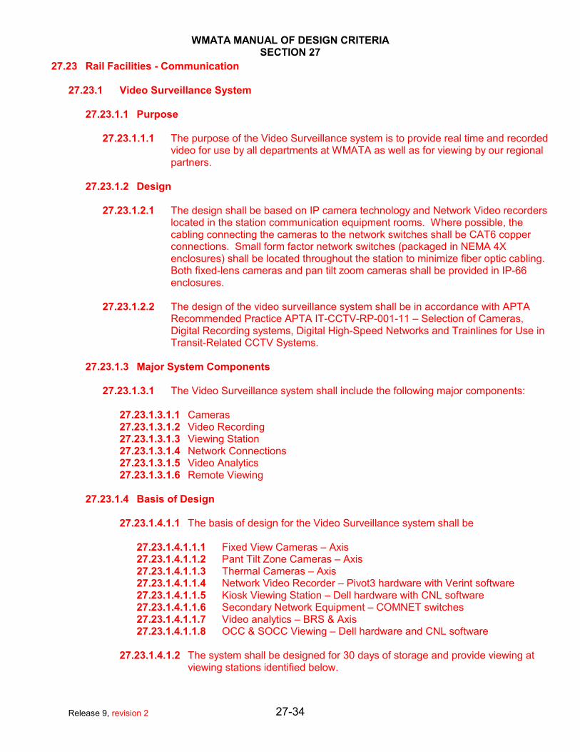
27.23.1.1.1 The purpose of the Video Surveillance system is to provide real time and recordedvideo for use by all departments at WMATA as well as for viewing by our regionalpartners.
27.23.1.2 Design
27.23.1.2.1 The design shall be based on IP camera technology and Network Video recorderslocated in the station communication equipment rooms. Where possible, thecabling connecting the cameras to the network switches shall be CAT6 copperconnections. Small form factor network switches (packaged in NEMA 4Xenclosures) shall be located throughout the station to minimize fiber optic cabling.Both fixed-lens cameras and pan tilt zoom cameras shall be provided in IP-66enclosures.
27.23.1.2.2 The design of the video surveillance system shall be in accordance with APTARecommended Practice APTA IT-CCTV-RP-001-11 – Selection of Cameras,Digital Recording systems, Digital High-Speed Networks and Trainlines for Use inTransit-Related CCTV Systems.
27.23.1.3 Major System Components
27.23.1.3.1 The Video Surveillance system shall include the following major components:
27.23.1.3.1.1 Cameras27.23.1.3.1.2 Video Recording27.23.1.3.1.3 Viewing Station27.23.1.3.1.4 Network Connections27.23.1.3.1.5 Video Analytics27.23.1.3.1.6 Remote Viewing
27.23.1.4 Basis of Design
27.23.1.4.1.1 The basis of design for the Video Surveillance system shall be
27.23.1.4.1.1.1 Fixed View Cameras – Axis27.23.1.4.1.1.2 Pant Tilt Zone Cameras – Axis27.23.1.4.1.1.3 Thermal Cameras – Axis27.23.1.4.1.1.4 Network Video Recorder – Pivot3 hardware with Verint software27.23.1.4.1.1.5 Kiosk Viewing Station – Dell hardware with CNL software27.23.1.4.1.1.6 Secondary Network Equipment – COMNET switches27.23.1.4.1.1.7 Video analytics – BRS & Axis27.23.1.4.1.1.8 OCC & SOCC Viewing – Dell hardware and CNL software
27.23.1.4.1.2 The system shall be designed for 30 days of storage and provide viewing atviewing stations identified below.
27-34Release 9, revision 2

WMATA MANUAL OF DESIGN CRITERIASECTION 27
27.23.1.5 Cameras
27.23.1.5.1 The design shall use IP cameras. These cameras may be fixed cameras, Pan-TiltZoom (PTZ) cameras, or Thermal cameras. The cameras shall provide a minimumof three (3) days local storage.
27.23.1.5.2 The design, placement, and installation of the cameras shall be coordinated withthe architectural design to provide an appearance that is acceptable to thearchitects.
27.23.1.5.3 The design, placement, and installation of the cameras shall be coordinated withthe station lighting to ensure that adequate illumination is provided for propercamera operation.
27.23.1.5.4 IP Cameras shall be configured using an enterprise software package from thecamera supplier.
27.23.1.5.5 Cameras mounted on poles shall have conduit routed internal to pole.
27.23.1.5.6 External cameras directly attached to COM room switch shall be provided withsurge protection.
27.23.1.5.7 The cameras shall be mounted to provide for easy maintenance.
27.23.1.6 Camera Coverage
27.23.1.6.1 The design shall provide the camera coverage detail in Table No.1 – Rail SystemCamera Coverage
27.23.1.6.2 Video Recording
27.23.1.6.2.1 A Network Video Recorder shall be installed in each COM room. The NetworkRecording device shall provide 30 days of video storage at a resolution that isacceptable to MTPD and Rail Operations.
27.23.1.6.3 Viewing Stations
27.23.1.6.3.1 The design shall provide for camera viewing in the kiosks, in the GuardShacks, in the Yard Masters office, in the dispatchers End of Line office, in thevarious control centers, and on the desktop computers throughout theauthority.
27.23.1.6.4 Kiosk Viewing Station
27.23.1.6.4.1 Each kiosk shall be provided with four (4) monitors mounted up high on theinside of the kiosk and two (2) touch screens mounted on the cabinets insidethe kiosk. These four (4) monitors and two (2) touch screens shall beconnected to a computer workstation inside the cabinets internal to the kiosk. The workstation shall be running a CNL thick client. This thick client will controlcameras and provide alarms inside the kiosk.
27.23.1.6.5 Guard Shack Viewing Station
27-35Release 9, revision 2

WMATA MANUAL OF DESIGN CRITERIASECTION 27
27.23.1.6.5.1 Each guard shack shall be provided with four (4) monitors mounted up high onthe inside of the guard shack. These four (4) monitors shall be connected to acomputer workstation inside the guard shack. The workstation shall be runninga CNL thick client. This thick client will control cameras and provide alarmsinside the guard shack.
27.23.1.6.6 Yard Master Viewing Station
27.23.1.6.6.1 Each Yard Master Office shall be provided with four (4) monitors. These four(4) monitors shall be connected to a computer workstation that is running aCNL thick client. This thick client will control cameras and provide alarms.
27.23.1.6.7 End of Line Dispatch Office Viewing Station
27.23.1.6.7.1 The design shall provide camera viewing at End of Line dispatch offices. Eachdispatch office shall be provided with a workstation, mounting hardware and aminimum of four monitors.
27.23.1.6.8 Network Connections
27.23.1.6.8.1 The IP cameras shall be connected to IP switches with Power-Over-Ethernet(POE) capability. The Ethernet switches shall be located in the COM room,located in the Kiosk, or in located in NEMA 4X enclosures connected toMetroNET and placed strategically throughout the rail system.
27.23.1.6.8.2 See Video Design Drawings for a typical NEMA 4X network enclosure.
27.23.1.6.9 Video Analytics
27.23.1.6.9.1 Video analytics shall be provided at each station, rail yard, or other locations.
27.23.1.6.9.2 Video analytics software can either reside on the end device or may reside ona dedicated server in the COM room.
27.23.1.6.9.2.1 As a minimum, the video analytics shall detect and alarm:27.23.1.6.9.2.2 Unauthorized access into the Right of Way whether falling or jumping27.23.1.6.9.2.3 Unauthorized passage though End of Platform gates 27.23.1.6.9.2.4 Intrusion Detection on the Rail Yard Perimeter27.23.1.6.9.2.5 Motion Detection on Vent/Shafts27.23.1.6.9.2.6 Motion Detection in Service Rooms
27.23.1.6.10 Remote Viewing
27.23.1.6.10.1 The cameras shall be viewed from the kiosks, the dispatcher’s office, the RailOperational Control Centers (ROCC) at JGB & CTF, the Security OperationalControl Center (SOCC), various offices throughout WMATA, and regionalpartners.
27.23.1.6.11 ITS Security
27-36Release 9, revision 2

WMATA MANUAL OF DESIGN CRITERIASECTION 27
27.23.1.6.11.1 The cameras and all other IP connected equipment shall comply with allWMATA IT security requirements including strong passwords, managed ports,and other related security requirements
27-37Release 9, revision 2

WMATA MANUAL OF DESIGN CRITERIASECTION 27
WMATA DESIGN CRITERIARail System Camera Coverage
Coverage Description Analytics PTZ Purpose CommentsRequired? Required?
Stations - PublicArea
Platforms Situation Awareness 95 % CoveragePlatforms Edges Yes Support Analytics 100 % Platform Edge CoverageTrack Bed in Station Yes Situation Awareness 100 % CoverageEnd of Platforms - FacingPlatform
Facial Recognition
End of Platforms - FacingTrack
Situation Awareness Thermal Camera
Station Entrance Escalators Situation Awareness 100 % Landings & 80 % TravelStation Escalators Situation Awareness 100 % Landings & 50 % TravelPassageway from EntranceTo Kiosk
Situation Awareness 100%
Fare Vending Machines Situation Awareness Theft & Vandalism ProtectionFare Gate Array Situation AwarenessEntrance Elevators Cabs 360 Degree CamerasEntrance ElevatorsLandingsKiosks - Facing Entrance Facial Recognition at
ChokepointsCrown of Kiosks - 60 Pixels /foot
Kiosks - Facing Exit Facial Recognition Crown of Kiosks - 60 Pixels /foot
Areas of Rescue Assistance(AORA)
Y Situation Awareness
Pedestrian Bridges Situation Awareness 95 % CoverageEntrance Canopies Y Facial RecognitionCall For Aid Boxes Y Coverage of Person
27-38Release 9, revision 2
WMATA MANUAL OF DESIGN CRITERIASECTION 27
27.24 Fire Detection and Alarm System
27.24.1 Purpose
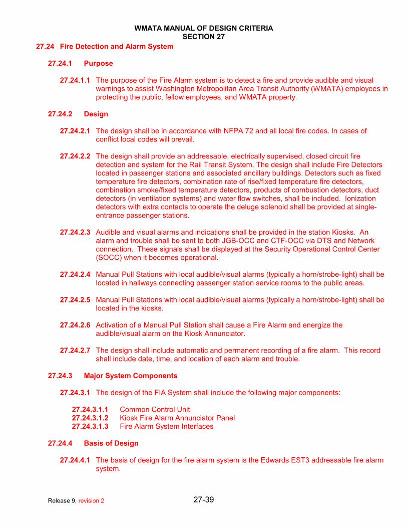
27.24.1.1 The purpose of the Fire Alarm system is to detect a fire and provide audible and visualwarnings to assist Washington Metropolitan Area Transit Authority (WMATA) employees inprotecting the public, fellow employees, and WMATA property.
27.24.2 Design
27.24.2.1 The design shall be in accordance with NFPA 72 and all local fire codes. In cases ofconflict local codes will prevail.
27.24.2.2 The design shall provide an addressable, electrically supervised, closed circuit firedetection and system for the Rail Transit System. The design shall include Fire Detectorslocated in passenger stations and associated ancillary buildings. Detectors such as fixedtemperature fire detectors, combination rate of rise/fixed temperature fire detectors,combination smoke/fixed temperature detectors, products of combustion detectors, ductdetectors (in ventilation systems) and water flow switches, shall be included. Ionizationdetectors with extra contacts to operate the deluge solenoid shall be provided at single-entrance passenger stations.
27.24.2.3 Audible and visual alarms and indications shall be provided in the station Kiosks. Analarm and trouble shall be sent to both JGB-OCC and CTF-OCC via DTS and Networkconnection. These signals shall be displayed at the Security Operational Control Center(SOCC) when it becomes operational.
27.24.2.4 Manual Pull Stations with local audible/visual alarms (typically a horn/strobe-light) shall belocated in hallways connecting passenger station service rooms to the public areas.
27.24.2.5 Manual Pull Stations with local audible/visual alarms (typically a horn/strobe-light) shall belocated in the kiosks.
27.24.2.6 Activation of a Manual Pull Station shall cause a Fire Alarm and energize theaudible/visual alarm on the Kiosk Annunciator.
27.24.2.7 The design shall include automatic and permanent recording of a fire alarm. This recordshall include date, time, and location of each alarm and trouble.
27.24.3 Major System Components
27.24.3.1 The design of the FIA System shall include the following major components:
27.24.3.1.1 Common Control Unit27.24.3.1.2 Kiosk Fire Alarm Annunciator Panel27.24.3.1.3 Fire Alarm System Interfaces
27.24.4 Basis of Design
27.24.4.1 The basis of design for the fire alarm system is the Edwards EST3 addressable fire alarmsystem.
27-39Release 9, revision 2

WMATA MANUAL OF DESIGN CRITERIASECTION 27
27.24.5 Common Control Unit
27.24.5.1 A Common Control Unit shall be located in the Communications Equipment Room andshall contain all the logic, software and circuitry required to supervise and control the Fireand Intrusion Detectors.
27.24.5.2 The Common Control Unit shall be modular in construction and provide for ease ofmaintenance and expansion. It shall contain trouble circuitry powered from a dedicatedpower source that electrically supervises all zone circuit wiring for a "Short" or an "Open."
27.24.5.3 The Common Control Unit shall support the following functions:
27.24.5.3.1 Provide audible and visual "Alarm" indications at the Kiosk Annunciator Panel27.24.5.3.2 Provide audible and visual "Alarm" indications at the Kiosk Annunciator Panel27.24.5.3.3 Provide contact closures to indicate "Alarm" conditions27.24.5.3.4 Provide contact closures to indicate "Trouble" conditions27.24.5.3.5 Provide a network interface for connection to the Fire Alarm head end27.24.5.3.6 Provide a phone interface for connection to the Fire alarm head end27.24.5.3.7 Provide common system controls at the Kiosk FIA Annunciator Panel
27.24.5.4 The Common Control Unit shall be provided with twenty-four (24) hours of battery backupfor panel, sensors, and alarm indicators.
27.24.5.5 The Common Control Unit shall utilize a fused neutral line design. The neutral line shall besupervised and the indication of a blown fuse shall illuminate the LED integrated in thereset pushbutton located on the Kiosk FIA Annunciator Panel.
27.24.6 Kiosk Fire Alarm (FA) Annunciator Panel
27.24.6.1 A Kiosk FA Annunciator Panel shall be located in each passenger station Kiosk andcontain indicators identifying the "Alarm" condition and "Trouble" condition of eachdetector.
27.24.6.2 The Kiosk FA Annunciator Panel shall contain an audible Annunciator that indicates analarm condition by using one tone and indicates a trouble condition by using a differenttone.
27.24.6.3 The Kiosk FA Annunciator Panel shall also include the following indicators andpushbuttons for common system controls:
27.24.6.3.1 Trouble Silence Momentary Contact Pushbutton27.24.6.3.2 Alarm Acknowledge Momentary Contact Pushbutton27.24.6.3.3 Reset Momentary Contact Pushbutton with integral LED27.24.6.3.4 Lamp (LED) Test Momentary Contact Pushbutton27.24.6.3.5 Power "On" Indicator27.24.6.3.6 Manual Fire Alarm Pushbutton
27.24.7 Fire Alarm System Interfaces
27.24.7.1 The design of the Fire Detection System shall provide controls and/or interfaces with thefollowing systems and equipment:
27-40Release 9, revision 2

WMATA MANUAL OF DESIGN CRITERIASECTION 27
27.24.7.1.1 Ventilation Fans27.24.7.1.1.1 Selected ventilation fans shall shutdown when a Fire Alarm associated with an
area being serviced by a ventilation fan is initiated in a passenger station roomor an ancillary building within the passenger station
27.24.7.1.2 Sprinkler System27.24.7.1.2.1 Tamper switches shall detect any movement of the Fire Main manual shut-off
valves and provide a “Trouble” condition for the associated Sprinkler System.
27.24.7.1.3 Fare Gates27.24.7.1.3.1 The Fare Gates shall open when a Fire Alarm is initiated in a passenger station
room or an ancillary building within the passenger station
27.24.7.1.4 Entrance Escalators27.24.7.1.4.1 The Entrance Escalators shall stop when a Fire Alarm is initiated in a
passenger station room or an ancillary building within the passenger station
27.24.7.1.5 Elevator Machine Room27.24.7.1.5.1 All elevators associated with the Elevator Machine Room that travel more than
25 feet, shall immediately return to a designated level when a Fire Alarm isinitiated in a passenger station room or an ancillary building within thepassenger station. Additionally elevator cab controls (except for emergencycontrols) shall be rendered inoperative as long as smoke is detected within theassociated Elevator Machine Room.
27.24.7.1.6 Public Address27.24.7.1.6.1 The Fire Alarm system shall provide a canned message to the station Public
Address system when a Fire Alarm is initiated in a passenger station room oran ancillary building within the passenger station. After a predetermined timedelay, a "Reset" circuit shall be provided that will silence the Fire Alarmwarning being broadcast by the PA system.
27.24.8 Intrusion Detection and Alarm System
27.24.8.1 Purpose
27.24.8.1.1 The purpose of the Intrusion Alarm system is to detect an unauthorized intrusionand provide an intrusion alarm to assist Washington Metropolitan Area TransitAuthority (WMATA) employees in protecting the public, fellow employees, andWMATA property.
27.24.8.2 Design
27.24.8.2.1 The design shall be an addressable, electrically supervised, closed circuit intrusiondetection system for the Rail Transit System. The design shall include intrusiondetection devices such as tape or switches and shall be provided on doors,windows, louvers, and other intrusion points as required in substations,passengers stations, tie-breaker stations, fan and vent shafts, AFC machines, traincontrol and communications buildings which require protection againstunauthorized entry.
27-41Release 9, revision 2

WMATA MANUAL OF DESIGN CRITERIASECTION 27
27.24.8.2.2 An Intrusion Detection System shall be installed in the passenger station,equipment areas, ancillary buildings within the passenger station limits andancillary buildings or outside areas located along the right-of-way that areaccessible to the public. Intrusion Detectors shall provide alarms indicatingunauthorized entry for each of the following conditions:
27.24.8.2.2.1 A broken or opened window connected to a public or outside area.27.24.8.2.2.2 A broken or opened air duct cover, louver or grating connected to a public or
outside area, if the shortest side is greater than six inches.27.24.8.2.2.3 A protected door when opened.
27.24.8.2.3 Audible and visual alarms and indications shall be provided in the station Kiosks. An alarm and trouble shall be sent to both JGB-OCC and CTF-OCC via DTS andNetwork connection. These signals shall be displayed at the Security OperationalControl Center (SOCC) when it becomes operational.
27.24.8.2.4 The design shall alarm the following:
27.24.8.2.4.1 Automatic Fare Collection Equipment Intrusion Alarm27.24.8.2.4.2 Revenue Cart Storage Area Intrusion Alarm27.24.8.2.4.3 Ancillary Structure Intrusion Alarm27.24.8.2.4.4 Rail Station Intrusion Alarm27.24.8.2.4.5 Tie Breaker Station Intrusion Alarm27.24.8.2.4.6 Traction Power Substation Intrusion Alarm
27.24.8.2.5 The design shall include automatic and permanent recording of an intrusion alarm. This record shall include date, time, and location of each alarm and trouble.
27.24.8.3 Major System Components
27.24.8.3.1 The Intrusion Detection System shall include the following major components:
27.24.8.3.1.1 Intrusion Detection Devices27.24.8.3.1.2 Alarm Indications27.24.8.3.1.3 Special Protection Devices
27.24.8.4 Basis of Design
27.24.8.4.1 The basis of design for the intrusion and detection system is the Edwards EST3platform.
27.24.8.4.2 The current Edwards EST3 system combined both a Fire Alarm system, anIntrusion Detections system, and an Access Control system in the same integratedplatform.
27.24.8.5 Specific Location for Intrusion Detection
27.24.8.5.1 The design shall incorporate the latest state-of-the-art intrusion detectors. Thefollowing criteria shall be used in the design layout of Intrusion Detection:
27.24.8.5.2 Intrusion Detector shall be provided on each entrance elevator door
27-42Release 9, revision 2
WMATA MANUAL OF DESIGN CRITERIASECTION 27
27.24.8.5.3 Intrusion Detector shall be provided on each fare collection equipment array
27.24.8.5.4 Intrusion Detector shall be provided on protected doors to areas containingmultiple rooms or corridors
27.24.8.5.5 Intrusion Detector shall be provided on each door of ancillary buildings along theright-of-way
27.24.8.5.6 Intrusion Detector shall be provided on each door of the Tie Breaker Station
27.24.8.5.7 Intrusion Detector shall be provided on each door of the Traction Power Substation
27.24.8.5.8 Trip wire and window tape shall be provided across louver openings and windows
27.24.8.5.9 Magnetic Switches shall be used on grates and doors to detect when they areopened
27.24.8.5.10 Intrusion Detectors shall be weather tight or installed in a Weather tight enclosure
27.24.8.5.11 Tamperproof Intrusion Detectors shall be provided
27.24.8.6 Special Protection Areas
27.24.8.6.1 Doors leading from an outside or public area into a protected zone, including roll-up doors, shall be furnished with additional features.
27.24.8.6.2 A key-operated access control switch, a non-locking pushbutton switch, and amagnetic switch shall be provided
27.24.8.6.3 Roll-up doors shall be equipped with only a key-operated access control switchand a magnetic switch
27-43Release 9, revision 2

WMATA MANUAL OF DESIGN CRITERIASECTION 27
DESIGN CRITERIA
(Access Control Portion)
BUS GARAGE
27-44Release 9, revision 2

WMATA MANUAL OF DESIGN CRITERIASECTION 27
27.25 Bus Garage - Access Control System
27.25.1 Purpose
27.25.1.1 The purpose of the Access Control system is to limit access into service rooms and otherareas of concern to authorized WMATA employees and/or contractors. Additionally, theAccess Control system shall keep a record of who enters each room.
27.25.2 Design
27.25.2.1 The design shall include automatic and permanent recording of each entry and/or exit.This record shall include date, time, and location of each alarm and trouble.
27.25.3 Major System Components
27.25.3.1 The Access Control system shall include the following major components:
27.25.3.1.1 Card Reader27.25.3.1.2 Access Controller27.25.3.1.3 Request To Exit Sensor27.25.3.1.4 Door Contact Switch27.25.3.1.5 Door Strike
27.25.4 Basis of Design
27.25.4.1 The basis of design for the Access Control system is a Honeywell Prowatch platform usinga HID card reader with a Weigand interface. WMATA plans to change credentials in thefuture and at some point in the future will go to a MiFare Plus card reader.
27.25.5 Specific Locations for Access Control
27.25.5.1 Access Control shall be provided at the following locations within the station and along theright of way:
27.25.5.1.1 Electrical Service Rooms27.25.5.1.2 Communication Service Room27.25.5.1.3 Mechanical Service Room27.25.5.1.4 Parts & Material Storage Locations27.25.5.1.5 Tool Cribs27.25.5.1.6 Clerk’s Office27.25.5.1.7 Pedestrian Entrances27.25.5.1.8 Human Resource Office27.25.5.1.9 Police Office27.25.5.1.10 Superintendent Offices27.25.5.1.11 Locations where high value items stored
27.26 Access Control System (RAIL)
27.26.1 Purpose
27-45Release 9, revision 2

WMATA MANUAL OF DESIGN CRITERIASECTION 27
27.26.1.1 The purpose of the Access Control system is to limit access into service rooms and otherareas of concern to authorized WMATA employees and/or contractors. Additionally, theAccess Control system shall keep a record of who enters each room.
27.26.2 Design
27.26.2.1 The design shall include automatic and permanent recording of each entry and/or exit.This record shall include date, time, and location of each alarm and trouble.
27.26.3 Major System Components
27.26.3.1 The Access Control system shall include the following major components:27.26.3.2 Card Reader27.26.3.3 Access Controller27.26.3.4 Request To Exit Sensor27.26.3.5 Door Contact Switch27.26.3.6 Door Strike
27.26.4 Basis of Design
27.26.4.1 The basis of design for the Access Control system is the Edwards EST3 platform. However, Edwards is not advancing the Access Control portion of this work anymore. There, Prowatch is also being used as the basis of design for limited application. Thecurrent Edwards EST3 system combined both a Fire Alarm system, an IntrusionDetections system, and an Access Control system in the same integrated platform.
27.26.5 Specific Locations for Access Control
27.26.5.1 Access Control shall be provided at the following locations within the station and along theright of way:
27.26.5.2 Train Control Room27.26.5.3 Communication Service Room27.26.5.4 AC Rooms (typically two per station)27.26.5.5 Traction Power Substation27.26.5.6 Tie Breaker Station
27.27 Call-For-Aid System
27.27.1 Purpose
27.27.1.1 The purpose of the Call-For-Aid system is to provide emergency communication betweenpeople (employees or patrons) on the platform and the kiosk (or rollover location). Additionally, the Call-For-Aid system provides for emergency communications betweenthe people (employees or patrons) using the station elevators and the kiosk (or rolloverlocation).
27.27.2 Design
27.27.2.1 The Call-For-Aid System shall provide a means of reporting emergency situations from thepassenger station platforms to the Station Manager(s). Intercom facilities between CallStation Panels mounted on pylons (approximately 200 feet from the end of each platform)
27-46Release 9, revision 2

WMATA MANUAL OF DESIGN CRITERIASECTION 27
and a control panel within the station Kiosk shall permit easy verbal communicationsbetween the Station Manager and Rail System passengers.
27.27.2.2 Previously, the Call-for-Aid system was known as the Passenger Emergency ReportingSystem (PERS) or Raimax system.
27.27.3 Major System Components
27.27.3.1 The Call-for-Aid System shall include the following major equipment:27.27.3.1.1 Kiosk Call-For-Aid Control Panel (located in the Kiosk)27.27.3.1.2 Call-For-Aid Control Unit (located in COM room)27.27.3.1.3 Integrated Power Amplifier (located in COM room)27.27.3.1.4 Call Station Panels 27.27.3.1.5 Platform (located at designated positions on the station platform)27.27.3.1.6 Elevator Landing Call Station Panel (located on each station elevator landing)27.27.3.1.7 Elevator Cab Call Station Panel (located in each station elevator cab station)27.27.3.1.8 Kiosk Exterior Speaker Horn/Light (located on the top of the Kiosk)
NOTE: The Call for Aid system on parking garages elevators is a separate system than the Call-For-Aid system within the station.
27.27.4 Basis of Design
27.27.4.1 The basis of design for the Call-For-Aid system is Commend.
27.27.4.2 The Kiosk Call-For-Aid Control Panel design shall provide the interface point between theStation Manager and the Call-for-Aid system. The Call-For-Aid Control Panel shall bemounted in the kiosk and shall provide the controls, indications and input/output devices tothe Station Manager.
27.27.4.3 As a minimum the Call-For-Aid Control Panel design shall include:
27.27.4.3.1 A Push-To-Call pushbutton switch with an LED indicator for each Call Station. Thisswitch shall control a half duplex audio path to each Call Station.
27.27.4.3.2 A monitor speaker.27.27.4.3.3 A timer circuit to inhibit automatic termination of an emergency call.27.27.4.3.4 The capability to transfer an emergency call to the Operation Control Center.27.27.4.3.5 A Call-For-Aid Reset Switch to restore the PERS system to its normal condition
ready to receive the next emergency call.27.27.4.3.6 Call-For-Aid Control Unit
27.27.4.4 The Call-For-Aid Control Unit design shall provide the required interfaces between theKiosk Call-For-Aid Control Panel, the Call Station Panels, and the Integrated Power. TheCall-For-Aid Control Unit design shall accommodate four Call Station Panels and shall beable to:
27.27.4.4.1 Establish and control the audio paths between the Call Station Panels and theKiosk Call-For-Aid Control Panel(s).
27.27.4.4.2 Detect calls initiated at the Call Station Panels and provide appropriate outputs forindications on the Kiosk Call-For-Aid Control Panel.
27-47Release 9, revision 2

WMATA MANUAL OF DESIGN CRITERIASECTION 27
27.27.4.4.3 Provide signals to a Kiosk Exterior Speaker Horn (to generate a chime) and to acalling Call Station Panel (to generate a call-waiting tone) to indicate that anemergency call has been initiated at that Call Station Panel.
27.27.4.4.4 Provide the appropriate dc power, ground and reset control paths to the CallStation Panels.
27.27.4.4.5 Provide the appropriate outputs for the control of the talk/listen functions of the CallStation Panels.
27.27.4.4.6 Automatically terminate an unanswered call, after the preset time period.27.27.4.4.7 Provide the appropriate interfaces to the Call Station Panels and the Kiosk Call-
For-Aid Control Panel for the activation and termination of the call waiting tone.27.27.4.4.8 Detect the loss of dc power over a 10 second interval ("FAULT") at each of the Call
Station Panels, and then provide the appropriate outputs for the FAULT indicationon the Kiosk Call-For-Aid Control Panel.
27.27.4.4.9 Provide the appropriate interfaces for the connections of the Call Station Panelsand the Kiosk Call-For-Aid Control Panel to the Call-For-Aid Control Unit.
27.27.4.4.10 Provide signals to a Kiosk Exterior Speaker Horn/Light, to generate a chime/tone,to indicate that the Automatic Public Address Announcement System (APAAS) hasbeen activated.
27.27.4.4.11 The design shall provide a PAS/Call-For-Aid Muting Circuit in the passengerstation Kiosk to mute the monitor loudspeaker of the Kiosk Public Address SystemControl Panel when the "PUSH-TO-TALK" pushbutton on the Kiosk Call-For-AidControl Panel is depressed. This shall prevent the possibility of creating anacoustical feedback path between the Call-For-Aid and the Public AddressSystem.
27.27.4.4.12 Integrated Power Amplifier27.27.4.4.13 As a minimum the Integrated Power Amplifier design shall provide the audio
amplification necessary to simultaneously drive any combination of the four CallStation Panel speakers and the Kiosk Call-For-Aid Control Panel monitor speaker,the necessary audio pre-amplification adjustments, audio filtering and chimegeneration.
27.27.4.4.14 Platform Call Station Panels27.27.4.4.15 The Call Station Panel design shall provide the interface points between the
WMATA Rail System patrons and the Call-For-Aid System. The Call Station Panelsshall provide the controls, indications, input/output devices, and instructions whichare necessary for the patrons to operate the Call-For-Aid System.
27.27.4.4.16 As a minimum the design shall include a loudspeaker and a contact pushbuttonswitch on the Call Station Panel to initiate an emergency call between that CallStation Panel and the Kiosk Call-For-Aid Control Panel.
27.27.4.4.17 Two Platform Call Station Panels shall be mounted on each center platform for atotal of two Platform Call Station Panels in each center platform station.
27.27.4.4.18 Two Platform Call Station Panels shall be mounted on each split platform for a totalof four Platform Call Station Panels in each split platform station.
27.27.4.4.19 A Call-For-Aid Call Station panel shall be provided on the each and every landingof all station elevators.
27.27.4.4.20 A Call-For-Aid Call Station panel shall be provided in each and every cab of allstation elevators.
27.27.4.4.21 Kiosk Exterior Speaker Horns
27.27.4.5 The design shall include Kiosk Exterior Speaker Horns/Lights to provide for thebroadcasting of the chime/tone that indicates an emergency call has been initiated at aCall Station Panel. It shall provide for the broadcasting of the chime/tone that indicatesactivation of the Automatic Public Address Announcement System.
27-48Release 9, revision 2

WMATA MANUAL OF DESIGN CRITERIASECTION 27
27.27.5 Information Display Systems
27.27.5.1 Purpose
27.27.5.1.1 The purpose of the Information Display system is to provide real time digitalsignage information to rail customers.
27.27.5.2 Design
27.27.5.2.1 There are two major information display systems in each rail station. The firstsystem is called the Passenger Information Display System (PIDS) and the secondsystem is the Kiosk Information Display System (KIDS).
27.27.5.2.2 The PIDS is designed to provide train arrival information and the displays aremounted along the platform.
27.27.5.2.3 The KIDS is designed to provide general rail system information or alerts and thedisplays are mounted on the Kiosk. The specific purpose of this display is toinform the public about service disruption prior to the public entering the paidportion of the station.
27.27.5.3 Major System Components
27.27.5.3.1 The Information Display system shall include the following major components:
27.27.5.3.1.1 Passenger Information Display System27.27.5.3.1.2 OCC Head End27.27.5.3.1.3 Ethernet Connection from COM room switch to Converter27.27.5.3.1.4 Station COM Room Converter27.27.5.3.1.5 RS-485 Cabling27.27.5.3.1.6 Platform Display 27.27.5.3.1.7 Platform Display Mounting Bracket27.27.5.3.1.8 Kiosk Information Display system27.27.5.3.1.9 Software Head End27.27.5.3.1.10 Ethernet Connection to Network Switch27.27.5.3.1.11 Digital Media Player27.27.5.3.1.12 HDMI Cable27.27.5.3.1.13 Kiosk Display27.27.5.3.1.14 Mounting Bracket
27.27.5.4 Basis of Design
27.27.5.4.1 The basis of design for the Information Display shall be as follows:
27.27.5.4.1.1 PIDS Display - 27.27.5.4.1.2 PIDS Head End Software - COMNET27.27.5.4.1.3 KIDS Display - Ciil27.27.5.4.1.4 KID Head End Software - 27.27.5.4.1.5 KIDS Media Player - Cisco
27.27.5.4.2 Passenger Information Display System (PIDS)
27-49Release 9, revision 2
WMATA MANUAL OF DESIGN CRITERIASECTION 27
27.27.5.4.2.1 The location of the platform information display shall be in accordance withADA requirements. New stations shall be provided with a minimum of twodisplays along each track. Fonts and display images shall be in accordancewith ADA requirements.
27.27.5.4.2.2 A platform display shall be provided on the platform at each location where astation entrance elevator is located on the platform.
27.27.5.4.3 Kiosk Information Display System (KIDS)
27.27.5.4.3.1 The location of the kiosk information display shall be in accordance with ADArequirements. New stations shall be provided with a minimum of one display.Fonts and display images shall be in accordance with ADA requirements.
27.27.5.4.3.2 A minimum of one Kiosk Information Display shall be mounted on each kiosk. Some kiosk locations may require two Kiosk Information Displays to bemounted. The display shall be readable when traveling from the Non-Paid tothe Paid portion of the station entrance.
27.27.5.5 Kiosk System
27.27.5.5.1 Design
27.27.5.5.1.1 The purpose of the Kiosk System is to provide the Kiosk with the equipmentneeded to monitor and control passenger station Communications Systems,Fire and Intrusion Alarm Systems, wire and cabling interconnections fromparking garage booth’s unified fare technology (UFT) and fare collectionequipment, elevators and escalators, and to provide an effectivecommunications interface with the public (passengers). At least one Kiosk islocated in each passenger station of the Washington Metropolitan Area TransitAuthority (WMATA) Rail Rapid Transit System. It is the focal point of activity ateach passenger station.
27.27.5.5.1.2 The design shall provide all facilities necessary to monitor and control thepassenger station systems. It shall include the Kiosk cabinets, system interfacepanels, cabling and cable termination facilities and monitoring and controlpanels for the various systems, facilities and equipment in the passengerstations. It shall include fire and intrusion facilities for protection of the Kioskand electrical power facilities for the panels, monitors and control.
27.27.5.5.1.3 Cabinet Facilities - As a minimum, the design shall include cabinet facilities forthe following items:
27.27.5.5.1.3.1 Telephone Instruments27.27.5.5.1.3.2 Public Address System Panel27.27.5.5.1.3.3 Video Surveillance Viewing System27.27.5.5.1.3.4 Fire Alarm Annunciator27.27.5.5.1.3.5 Call-For-Aid Control Panel27.27.5.5.1.3.6 Elevator Monitor and Control Panel27.27.5.5.1.3.7 Escalator Monitor and Control Panel27.27.5.5.1.3.8 Kiosk Attendant/Passenger Intercom System
27-50Release 9, revision 2

WMATA MANUAL OF DESIGN CRITERIASECTION 27
27.27.5.5.1.4 Interfaces - The design shall include interface between the various panels,monitors and controls and their respective system central control facilities.
27.27.5.5.1.5 Performance - The design shall ensure that the system performance of eachpanel, monitor and control is in compliance with the system performancerequirements of the system of which it is a part.
27.27.5.5.1.6 Kiosk Construction - It has been the Authority’s past practice to include theconstruction and installation of the station Kiosk in the CommunicationsContract. The detailed specifications and drawings pertaining to this portion ofthe work will be supplied by the Authority to the Communications Designer.These drawings and specifications shall be incorporated into the Kiosk &Communications Systems procurement documents.
27.27.5.6 Operations Control Center - Communications
27.27.5.6.1 General
27.27.5.6.1.1 The Jackson Graham Building houses the headquarters and associated officesof the management, administration and operations of the WashingtonMetropolitan Area Transit Authority (WMATA).
27.27.5.6.1.2 Located in this building is the Operations Control Center from which isexercised the centralized control of the Rail Rapid Transit System(METRORAIL) and the WMATA Bus System (METROBUS) and the traincontrol and communications systems necessary to support these operations.
27.27.5.6.1.3 Located in the Communications Equipment Area of this building is theequipment that provides the hub of the system-wide communications network.Radiating from this centralized equipment the communication service extendsthroughout the transit property to trains, buses, administrative, transportation,maintenance and security vehicles, passenger stations, yards, ancillarybuildings, wayside areas, security and transit police.
27.27.5.6.1.4 The central control facility contains a control computer, a hot backup computer,and an additional computer for software development which also serves asanother level of backup for the main computer. The control computer receivesand transmits messages between the operations control center and stationlocations via the Carrier Transmission System (CTS) to the Data TransmissionSystem’s remote terminal units (RTUs) in the field locations. The central controlcomputer communicates with the central control operator by providing displayson a large scale display and video monitors (CRTs) and accepting operatorinput from the consoles.
27.27.5.6.1.5 The control computer performs schedule adjustments by changing dwell timesand inter-station run times, both of which are sent over communicationschannels to the station RTUs via the DTS. The telephone system provides themeans for console operators to contact needed personnel or to report tomanagement.
27-51Release 9, revision 2

WMATA MANUAL OF DESIGN CRITERIASECTION 27
27.27.5.6.1.6 The general communications functions provided to aid the central controloperators are:
27.27.5.6.1.6.1 Public Address Display and Control System
27.27.5.6.1.7 The central control facility for the Public Address System is equipped with anelectronic switching system, stand-alone central electronics equipment, andtouch screen displays. Through the touch screen displays the operator canmake an assortment of pre-recorded announcements.
27.27.5.6.2 Description
27.27.5.6.2.1 The Public Address (PA) consoles are installed in the Rail OCC PassengerOperations consoles. The PA consoles are an integral part of the PublicAddress Control System provided by Penta Corporation, serving as the meansfor accessing the PA system.
27.27.5.6.2.2 Each PA console is comprised of the following components:
27.27.5.6.2.2.1 PA console Central Processor Unit (CPU)27.27.5.6.2.2.2 Touch screen CRT27.27.5.6.2.2.3 mouse27.27.5.6.2.2.4 headset27.27.5.6.2.2.5 foot switch27.27.5.6.2.2.6 microphone27.27.5.6.2.2.7 console speaker panel27.27.5.6.2.2.8 keyboard
27.27.5.6.3 Keying Stations
27.27.5.6.3.1 In order to make announcements to the connected stations, they must bekeyed by pressing one of the console PTT switches. There are three PTTswitches available. PTT on the microphone panel; PTT on the headset; and thefoot switch. Activating any of the PTT switches results in audio beingtransmitted over the stations in the Connect list.
27.27.5.6.3.2 Intercom Use - Each console has the same ability to connect to anotherconsole for communication as it has for any station. The intercom link isestablished when the connected console answers a call.
27.27.5.7 Public Address Console Equipment
27.27.5.7.1 PA Console CPU - The Central Processor Unit (CPU) is the main portion of the PAconsole. There are power, reset, and turbo activation switches on the front of theCPU, as well as connectors on the back for the monitor, mouse, and the consolespeaker panel. Each Passenger Operations Console supports two PA consoles.The CPUs are installed on the back table at either end of the operations console,as they require no hands-on contact during normal daily operations.
27.27.5.7.2 Touch screen CRT/Mouse - The Touch screen CRT is the primary device foroperating the PA System. Menu selections are made by touching the CRT display
27-52Release 9, revision 2
WMATA MANUAL OF DESIGN CRITERIASECTION 27
"buttons" with a finger, or by positioning the cursor on the desired selection andclicking the mouse.
27.27.5.7.3 Touch screen CRT Controls - The CRT displays provide information which enablesthe operator to control the PA System by touching the screen in a prescribedmanner.
27.27.5.7.4 Microphone - At the end of the operations con-sole closest to the PA Touch screenthere is a microphone with a push-to-talk switch for making voice transmissions.
27.27.5.7.5 Headset - A headset is provided as an alter-native to the microphone mounted tothe console. A headset jack is mounted on the side of the console electronics bayfor each operating position.
27.27.5.7.6 Foot switch - The foot switch provides an alternative to the push-to-talk switch onthe microphone mounting as a means for keying connected base station radios.There is one foot switch provided for each console operating position.
27.27.5.8 Directories
27.27.5.8.1 Types - To simplify access to the WMATA PA system, the individual stations andoperations consoles have been subdivided into access groups called directories. Inthe descriptions and procedures which follow, the term “station” may refer to eitherof these two types of directory entries. Passenger Stations are assigned todirectories at the PACES.
27.27.5.8.2 Directory Assignment - The PA CES is connected with the two Radio Base StationControl System CESs (Systems A and B). The Radio System A and System BCESs, and the PA System CES all have their own directory assignments. Since theRadio Base Station Control System is comprised of two identical CESs, each isassigned an identical directory.
27.27.5.8.3 Status Indications/Instant Transmit Selections are as follows:
27.27.5.8.3.1 Connect - A list of all the currently connected stations is provided in theConnect field. As many as eight stations may appear in the Connect list, formulti-station announcements. More than eight stations may be connected atonce, but only eight will appear in the list.
27.27.5.8.3.2 Instant Transmit - This list indicates stations which have been programmed forinstant transmit, i.e. stations to which transmissions may be made without firstconnecting. A maximum of four stations may be programmed for instanttransmit by calling up the Edit Menu.
27.27.5.8.3.3 Last Select - This field allows the most recently disconnected station to berecalled without first accessing the appropriate directory.
27.27.5.8.3.4 Function Menu Bar - This menu bar displays the available console functions.Selecting one of these screen fields provides access to the correspondingfunction.
27-53Release 9, revision 2

WMATA MANUAL OF DESIGN CRITERIASECTION 27
27.27.5.8.3.5 Volume - This function provides a means to adjust the volume of the right(Select) and left (Unselect) speakers on the console speaker panel. WhenVOLUME is selected, a volume adjust window appears.
27.27.5.8.3.6 Left Mon - LEFT MON allows the connect speaker to be used as an additionalmonitor speaker. When LEFT MON is selected, and then a station is selectedto monitor, the connect speaker is used to monitor that station; to return thespeaker to a connect speaker, LEFT MON must be selected. When a station isbeing monitored over the connect (left) speaker, its name appears red in theMonitor list. Stations being monitored on the monitor (right) speaker appearblue in the Monitor list. While the connect speaker is being used to monitor,"LEFT MONITOR" appears on the left side of the Message display.
27.27.5.8.3.7 Status - The STATUS function provides a quick summary of consolecommunications activity. When STATUS is selected, a Console Status Screenappears. This screen shows which stations are currently active, as well as thetype of communications activity occurring. The station names which appear inthe Status display appear in the proper colors representing the activityoccurring.
27.27.5.8.3.8 PA - PA calls the PA Announcement Menu to record, store, and selectrecorded announcements. When a recorded announcement is selected fromthis menu, the Call Check Options display allows listening to or broadcastingthe recorded message.
27.27.5.9 Section Terminology
27.27.5.9.1 Central Electronics System (CES)(PA) - The central computer, switch matrix, andinterface cards which route all PA traffic between the operations consoles and theMETRORAIL passenger stations. The PA System CES is connected to the twoRadio Base Station Control CESs (System A and System B).
27.27.5.9.2 Central Electronics System (CES) (Radio) - The central computer, switch matrix,and interface cards which route all radio traffic between the operations consolesand the base stations. The Radio Base Station Control System is comprised of twoidentical CESs (System A and System B), each of which is capable of handling allradio base station communications.
27.27.5.9.3 Connect (PA) - A designation indicating that a communications link has beenestablished between a console and a passenger station or another console.“Connect” is also used to refer to the act of establishing such a communicationslink. The Connect field on the directory display lists the names of all connectedstations and consoles.
27.27.5.9.4 Connect (Radio) - A designation indicating that a communications link has beenestablished between a console and a radio base station, Group Expansion Module(GEM) group, or another console. “Connect” is also used to refer to the act ofestablishing such a communications link. The Connect field on the directory displaylists the names of all connected base stations, GEM groups, and consoles.
27-54Release 9, revision 2
WMATA MANUAL OF DESIGN CRITERIASECTION 27
27.27.5.9.5 Connect Audio (PA) - Audio transmissions to connected passenger stations orconsoles. Connect audio is broadcast over the connect (left) speaker on theconsole speaker panel. Connect audio is also referred to as "select" audio.
27.27.5.9.6 Connect Audio (Radio) - Audio transmissions from connected radio base stations,GEM groups, or consoles. Connect audio is broadcast over the connect (left)speaker on the console speaker/microphone panel. Connect audio is also referredto as "select" audio.
27.27.5.9.7 Disconnect (PA) - To terminate an established communications link between aconsole and passenger station(s) or another console.
27.27.5.9.8 Disconnect (Radio) - To terminate an established communications link between theconsole and a radio base station, GEM group, or other console.
27.27.5.9.9 Group Expansion Module (GEM) - A hardware/software configuration whichpermits simultaneous operation of a group of radio base stations (maximum of 32stations per group). The group may consist of voted and non-voted sites, and isnormally configured for radios operating on the same frequency.
27.27.5.9.10 Key - To activate a PA microphone by depressing a push-to-talk switch.
27.27.5.9.11 Monitor - To receive audio transmissions from radio base stations or consoleswhich are not connected at the console doing the monitoring.
27.27.5.9.12 Monitor Audio - Audio transmissions from monitored radio base stations orconsoles. Monitor audio is broadcast over the monitor speaker on the consolespeaker panel.
27.27.5.9.13 Phantom Group (PA) - A pre-selected and pre-programmed station indication thatconnects a number of individual passenger stations.
27.27.5.9.14 Phantom Group (Radio) - A pre-selected and pre-programmed station indicationthat connects a number of individual radio base stations.
27.27.5.9.15 Un-monitor (PA) - To terminate the monitoring of a passenger station or operationsconsole.
27.27.5.9.16 Un-monitor (Radio) - To terminate the monitoring of a base station, GEM group, oroperations console.
27.27.5.9.17 Voting (Radio) - A process in which the received signals from a number of basestations are analyzed to determine and choose the highest quality signal.
27.28 ABBREVIATIONS AND GLOSSARY
27.28.1 Abbreviations
27.28.1.1 AAR Association of American Railroads, 50 F St., N.W. Washington, DC 2000127.28.1.2 AASHTO American Association of State Highway and Transportation Officials
27-55Release 9, revision 2

WMATA MANUAL OF DESIGN CRITERIASECTION 27
27.28.1.3 ACD Automatic Call Distributor27.28.1.4 AC lternating Current27.28.1.5 ACI Automatic Car Identification27.28.1.6 ADRA Area of Rescue Assistance27.28.1.7 AEMS Automated Energy Management System27.28.1.8 AFC Automatic Fare Collection27.28.1.9 AGC Automatic Gain Control 27.28.1.10 AM Amplitude Modulation27.28.1.11 ANSI American National Standards Institute, Inc., 1430 Broadway New York, NY
1001827.28.1.12 amp Ampere27.28.1.13 APAAS Automatic Public Address Announcement System27.28.1.14 APA American Plywood Association27.28.1.15 APL Average Peak Level27.28.1.16 APD Avalanche Photodiode27.28.1.17 AR As Required27.28.1.18 AREMA American Railway Engineering and Maintenance-of-Way Association, 8201
Corporate Dr., Ste. 1125, Landover, MD 20785 (Successor to AmericanRailway Engineering Association (AREA))
27.28.1.19 AORA Area of Rescue Assistance’s27.28.1.20 ASCII American Standard Code for Information Interchange27.28.1.21 ASTM American Society for Testing and Materials 1916 Race St. Philadelphia, PA 1910327.28.1.22 ATC Automatic Train Control27.28.1.23 AWG American Wire Gauge
27.28.2 B
27.28.2.1 BBL Bus Buildings27.28.2.2 BCD Binary Coded Decimal27.28.2.3 BER Bit Error Rate27.28.2.4 bps Bits Per Second27.28.2.5 BUS OCC Bus Operation Control Center27.28.2.6 BW Bandwidth
27.28.3 C
27.28.3.1 C Celsius (Centigrade)27.28.3.2 CBX Computerized Branch Exchange27.28.3.3 CCE Control Center Equipment27.28.3.4 CCS Hundred Call - Seconds27.28.3.5 CCTV Closed Circuit Television (System)27.28.3.6 CDF Combined Distribution Frame27.28.3.7 CER Communications Equipment Room27.28.3.8 CHP Chilled Water Plant27.28.3.9 cm Centimeter27.28.3.10 CM Communications27.28.3.11 CMNT Car Maintenance27.28.3.12 CNC Console Configuration27.28.3.13 COMMCommunications27.28.3.14 CPU Central Processing Unit27.28.3.15 CRT Cathode Ray Tube27.28.3.16 CTS Carrier Transmission System
27-56Release 9, revision 2
WMATA MANUAL OF DESIGN CRITERIASECTION 27
27.28.4 D
27.28.4.1 DADS Data Acquisition and Display System27.28.4.2 dB Decibel27.28.4.3 dc Direct Current27.28.4.4 DCTB DC Tie Breaker27.28.4.5 DPS Drainage Pumping Station27.28.4.6 DS Digital Signal27.28.4.7 DTMF Dual Tone Multiple Frequency27.28.4.8 DTS Data Transmission System
27.28.5 E
27.28.5.1 ECS Emergency Communications System27.28.5.2 ELEV Elevator27.28.5.3 ESCL Escalator27.28.5.4 EDADS Enhanced Data Acquisition and Display System27.28.5.5 EE Emergency Exit27.28.5.6 EIA Electronics Industries Association, 1722 Eye St., N.W., Washington, DC
2000627.28.5.7 EMS Emergency Medical Service27.28.5.8 ETS Emergency Trip Station/Emergency Telephone System (Formally called FRTS)
27.28.6 F
27.28.6.1 F Fahrenheit27.28.6.2 FCC Federal Communications Commission27.28.6.3 FD Fire Department27.28.6.4 FDM Frequency Division Multiplexing27.28.6.5 FEP Fluorinated Ethylene Propylene27.28.6.6 FIA Fire and Intrusion Alarm (System)27.28.6.7 Fig Figure27.28.6.8 FM Frequency Modulation27.28.6.9 FMC Facility Maintenance Center27.28.6.10 FMFB Facilities Maintenance Field Base27.28.6.11 FMNT Facilities Maintenance27.28.6.12 FOS Fiber-Optics System27.28.6.13 FRTS Fire and Rescue Telephone System (Now called ETS)27.28.6.14 FS Fan Shaft27.28.6.15 FSK Frequency Shift Keying27.28.6.16 ft Foot, Feet27.28.6.17 FVD Flammable Vapor Detection (System)
27.28.7 G
27.28.7.1 GAC General Architectural Consultant27.28.7.2 GCC General Construction Consultant27.28.7.3 GEC General Engineering Consultant27.28.7.4 GETS Garage Emergency Telephone System27.28.7.5 GMFB General Maintenance Field Base (building) now FMFB
27.28.8 H
27-57Release 9, revision 2

WMATA MANUAL OF DESIGN CRITERIASECTION 27
27.28.8.1 HIB Halon Interface Box27.28.8.2 HVAC Heating, Ventilation, and Air Conditioning27.28.8.3 Hz Hertz (Cycles per Second)
27.28.9 I
27.28.9.1 IC Integrated Circuit27.28.9.2 ICEA Insulated Cable Engineers Association, 155 East 44th Street, New York, NY
1001727.28.9.3 ID Identification or Identifier27.28.9.4 IDF Intermediate Distribution Frame27.28.9.5 IDW Intrusion Detection and Warning (System)27.28.9.6 IEEE Institute of Electrical and Electronics Engineers, Inc.27.28.9.7 ILD Injection Laser Diode27.28.9.8 IPS Inches Per Second27.28.9.9 IR Infrared27.28.9.10 ITU International Telegraphic Union
27.28.10 J
27.28.10.1 JEDEC Joint Electronic Device Engineering Council27.28.10.2 JGB Jackson Graham Building, 600 Fifth St., N.W., Washington, DC 20001
27.28.11 K
27.28.11.1 K Kelvin27.28.11.2 kHz Kilohertz27.28.11.3 km Kilometer27.28.11.4 KSK Kiosk Equipment
27.28.12 L
27.28.12.1 LED Light Emitting Diode27.28.12.2 LF Linear Feet
27.28.13 M
27.28.13.1 mA Milliampere27.28.13.2 Main-PABX Main Private Automatic Branch Exchange (at the JGB)27.28.13.3 max Maximum27.28.13.4 MDF Main Distribution Frame27.28.13.5 mF Microfarad27.28.13.6 mFd Microfarad27.28.13.7 MHz Megahertz27.28.13.8 min Minimum or Minute27.28.13.9 MISV Management Information Service27.28.13.10 mm Millimeter27.28.13.11 MOCC Matintenance Operations Control Center27.28.13.12 mph Miles Per Hour27.28.13.13 MRS Mobile Radio System27.28.13.14 ms Millisecond
27-58Release 9, revision 2

WMATA MANUAL OF DESIGN CRITERIASECTION 27
27.28.13.15 MTBF Mean Time Between Failures27.28.13.16 MTTR Mean Time to Repair27.28.13.17 MUX Multiplexer27.28.13.18 mV Millivolt27.28.13.19 MW Microwave Radio27.28.13.20 mW Milliwatt27.28.13.21 µm Micrometer
27.28.14 N
27.28.14.1 N Newton, North27.28.14.2 NA Numerical Aperture27.28.14.3 N/A Not Applicable27.28.14.4 NEC National Electrical Code27.28.14.5 NEMA National Electrical Manufacturers Association, 2101 L St., N.W., Washington, DC
2003727.28.14.6 NIC Not Included in (this) Contract27.28.14.7 nm Nanometer27.28.14.8 NRZ None Return to Zero
27.28.15 O
27.28.15.1 OCCB Jackson Graham Building (formerly the Operations Control Center Building orOperations Command Center Building)
27.28.15.2 OCC Operations Control Center27.28.15.3 OCCS Operations Control Center Security (Console)27.28.15.4 OCUDP Office Channel Unit Data Port27.28.15.5 OD Outside Diameter27.28.15.6 OFS Order for Service27.28.15.7 OPS Operations27.28.15.8 OTDR Optical Time Domain Reflectometer
27.28.16 P
27.28.16.1 PA Public Address (System)27.28.16.2 PABX Private Automatic Branch Exchange27.28.16.3 PAM Pulse Amplitude Modulation27.28.16.4 PAS Public Address System27.28.16.5 PC Printed Circuit27.28.16.6 PCM Pulse Code Modulation27.28.16.7 PCO Purchase Change Order27.28.16.8 PD Police Department27.28.16.9 PEP Peak Envelope Power27.28.16.10 PERS Passenger Emergency Reporting System27.28.16.11 PIDS Passenger Information Display System27.28.16.12 PIN Positive-Intrinsic-Negative (refers to solid state structure of device)27.28.16.13 PLJ Primary Local Jurisdiction (Radio System)27.28.16.14 PM Phase Modulation27.28.16.15 P/O Part of27.28.16.16 Pr Pair27.28.16.17 psi Pounds Per Square Inch27.28.16.18 p to p Peak to Peak
27-59Release 9, revision 2

WMATA MANUAL OF DESIGN CRITERIASECTION 27
27.28.16.19 PT&Z Pan, Tilt, Zoom27.28.16.20 PVC Polyvinylchloride27.28.16.21 PWR Electrical Power Distribution
27.28.17 R
27.28.17.1 RCF Revenue Collection Facility (building)27.28.17.2 RCV Receive27.28.17.3 RCVR Receiver27.28.17.4 RDDS Remote Digital Display System27.28.17.5 RF Radio Frequency27.28.17.6 RI Raytheon Infrastructure Inc, 1627 K St., N.W., 4th Floor,Washington, DC 20006-
170227.28.17.7 RMFB RAIL Maintenance Field Base27.28.17.8 rms Root Mean Square27.28.17.9 RPMC Rail Plant Maintenance Center27.28.17.10 RPT Repeater 27.28.17.11 RPTR Repeater27.28.17.12 RTCR Remote Train Control Room27.28.17.13 RTLP Reference Transmission Level Point27.28.17.14 RTRA Rail Transportation27.28.17.15 RTU Remote Terminal Unit27.28.17.16 RZ Return to Zero
27.28.18 S
27.28.18.1 SPABX Satellite Private Automatic Branch Exchange27.28.18.2 S&I Service and Inspection (Yard)27.28.18.3 SEJ Sewage Ejector27.28.18.4 SMADS Station Monitor and Display System27.28.18.5 SMNT System Maintenance27.28.18.6 SP Sump Pump27.28.18.7 SPL Sound Pressure Level27.28.18.8 SPNO Single-Pole, Normally Open Contact27.28.18.9 SPNC Single-Pole, Normally Closed Contact27.28.18.10 SPDT Single-Pole, Double-Throw Contact27.28.18.11 SYPM Systems Project Management
27.28.19 T
27.28.19.1 TBS Tie Breaker Station27.28.19.2 TC Train Control27.28.19.3 TC/COMM Train Control/Communications27.28.19.4 TCF Tech. Control Facility27.28.19.5 TCR Train Control Room27.28.19.6 TDM Time Division Multiplex27.28.19.7 THD Total Harmonic Distortion27.28.19.8 TPAS Transit Police and Security27.28.19.9 TPSS Traction Power Substation27.28.19.10 TS,TEL Telephone System27.28.19.11 TV Television27.28.19.12 TX Transmit
27-60Release 9, revision 2

WMATA MANUAL OF DESIGN CRITERIASECTION 27
27.28.20 U
27.28.20.1 UFT Uniform Fare Technology27.28.20.2 UHF Ultra High Frequency27.28.20.3 UL Underwriters Laboratories27.28.20.4 UPS Uninterruptible Power Supply
27.28.21 V
27.28.21.1 Vac Volts, Alternating Current27.28.21.2 Vdc Volts, Direct Current27.28.21.3 Vpp Volts, Peak to Peak27.28.21.4 VS Vent Shaft27.28.21.5 VSWR Voltage Standing Wave Ratio
27.28.22 W
27.28.22.1 WDM Wavelength Division Multiplex27.28.22.2 WMATA Washington Metropolitan Area Transit Authority (METRO), 600 Fifth St.,
N.W., Washington, DC 20001 (Also referred to as “The Authority”.)
27.28.23 X
27.28.23.1 X Transmit27.28.23.2 XMT Transmit27.28.23.3 XMIT Transmit27.28.23.4 XMTR Transmitter
27.29 Glossary Of Terms
As used in these Criteria, the listed terms shall be defined as follows:
27.29.1 Absorption Losses (Fiber Optics)
Reduction in light amplitude or strength caused by impurities in the optical fiber and by thescattering of light from the optical fiber.
27.29.2 AC Service Room
Room housing equipment and facilities for the distribution of ac power throughout an installationsuch as a passenger station or shop building.
27.29.3 Alarm
An alerting signal indicating an abnormal condition.
27.29.4 Alphanumeric
Alphabetic and numeric representation, letters, numbers, and symbols.
27-61Release 9, revision 2

WMATA MANUAL OF DESIGN CRITERIASECTION 27
27.29.5 Ambient
Typical of the environment. Specifically used to designate properties of the surroundings whichare measurable and distinguishable from absolute zero energy levels.
27.29.6 American National Standards Institute, Inc. (ANSI)
American National Standards Institute, Inc. (ANSI)1430 BroadwayNew York, NY 10018
27.29.7 American Railway Engineering and Maintenance-of-Way Association
American Railway Engineering and Maintenance-of-Way Association (AREMA)8201 Corporate Dr., Ste. 1125Landover, MD 20785-2230
27.29.8 American Society for Testing and Materials (ASTM)
American Society for Testing and Materials (ASTM)916 Race StreetPhiladelphia, PA 19103
27.29.9 American Standard Code for Information Interchange (ASCII)
Consists of 10 or 11 bits per character - one start bit, seven information bits, one parity bit, one ortwo stop bits.
27.29.10 Amplitude Modulation (AM)
The process of varying the amplitude of a carrier wave in accordance with the instantaneousvalue of a modulating signal.
27.29.11 Ancillary Building
A room, area or structure which is used primarily to house some WMATA METRORAIL functionother than Train Control or Communications.
27.29.12 Angstrom
(Fiber Optics) A unit of optical wavelength historically used in the field of optics, but not anInternational System unit.
1 Angstrom = 0.1 nanometer
27.29.13 Annunciator
An audible signaling device which usually includes signal lights, each one indicating theconditions that exist or have existed in an associated circuit.
27.29.14 Armored Cable
27-62Release 9, revision 2

WMATA MANUAL OF DESIGN CRITERIASECTION 27
A cable provided with a wrapping of metal primarily for the purpose of mechanical protection. Thearmor is sometimes used as an electrical shield.
27.29.15 Association of American Railroads (AAR)
Association of American Railroads (AAR)50 F Street, N.W.Washington, DC 20001
27.29.16 ATC and Communications General Consultant
ATC and Communications General ConsultantCurrently:Raytheon Infrastructure Inc.1627 K St., N.W. - Fourth FloorWashington, DC 20006-1702
27.29.17 At-Grade
That portion of the system which is constructed at the approximate elevation of the adjacentground surface.
27.29.18 Attenuation
A decrease in the amplitude of a signal as it travels along or through a transmission medium,usually expressed as a ratio or in dB.
(Fiber Optics) A measure of the decrease in energy transmission (loss of light) expressed indB/km. In optical waveguides it is primarily due to absorption losses and scattering losses.
27.29.19 Attenuation Distortion
Distortion caused by the non-uniform attenuation or gain of a system, with respect to frequency,under specified terminal conditions.
27.29.20 Audio Frequency
Frequency range approximately equal to 15 Hz to 20,000 Hz (i.e. frequencies typically audible byhuman ears).
27.29.21 Authority (The)
Washington Metropolitan Area Transit Authority (WMATA).
27.29.22 Auto Scan
The automatic scan of the TV cameras in the horizontal (pan) plane.
27.29.23 Automatic Fare Collection (AFC)
Computer controlled system for the collection of fares, control of access, and associatedfunctions.
27-63Release 9, revision 2

WMATA MANUAL OF DESIGN CRITERIASECTION 27
27.29.24 Automatic Frequency Control (AFC)
Means whereby the frequency of a circuit is automatically maintained, within specified limits, withrespect to a reference frequency.
27.29.25 Avalanche Photodiode (APD)
(Fiber Optics) One type of receiver or detector used in the receiving portion of Fiber-Opticsterminals or repeaters. It is called a detector or receiver, since it detects and converts the lightsignal to a copy of the original electrical signal.
27.29.26 Bandwidth
Limiting frequencies between which the performance of a device or system falls within specifiedlimits.
(Fiber Optics) The capacity of an optical fiber to transmit information, expressed in bits ofinformation transmitted per specific time period for a specific length of optical waveguide. Bandwidth is limited by pulse spreading or broadening due to dispersion, so that adjacent pulsesoverlap and cannot be distinguished.
27.29.27 Ballast
(Trackwork) Crushed rock, slag, or other suitable material placed between, under, and at the endsof railroad ties to support and stabilize the track.
(Electronics) A device utilized to limit current flow.
27.29.28 Battery
An assembly of cells electrically connected for producing electric energy. In telephone systems, itusually refers to centralized dc source, located in the central office, nominally -48 volts.
27.29.29 Baud
Unit of signaling speed equal to the number of discrete signal events per second.
27.29.30 Binary Coded Decimal (BCD)
A notation in which each individual decimal digit is represented by a pattern of "ones" and "zeros."
27.29.31 Bit
A binary digit, 0 or 1 in number representation, with the radix 2.
27.29.32 Bus
A conductor, or group of conductors, that serve as a common connection for two or more circuits.
27.29.33 Cable Binder
27-64Release 9, revision 2

WMATA MANUAL OF DESIGN CRITERIASECTION 27
A wrapping of tapes or cords around several conductors of a multiconductor cable used to holdthem together which may be color coded to designate the group of conductors enclosed.
27.29.34 Cable Tray
A tray or rack used for the installation and support of cable.
27.29.35 Cable Trough
A trough used for the installation, support, and protection of cable.
27.29.36 Call
The act of establishing and completing a telephone connection from one telephone instrument toanother.
27.29.37 Called Party
The telephone instrument at the "distant end" being called.
27.29.38 Calling Party
The telephone instrument that originates the call.
27.29.39 Cardioid (Pattern)
A heart-shaped pattern obtained as a response or radi-ation characteristic of certain directionalantennas, or as the response characteristic of certain types of microphones.
27.29.40 Cassette
A small reel-to-reel tape magazine on which is recorded analog or digital information.
27.29.41 Cassette Recorder
A tape recorder used to record or playback cassettes.
27.29.42 Central Office
Equipment in a telephone system that provides central-ized switching, battery, and supervision fora group of subscribers or terminals (i.e. a Main PABX or Satellite PABX Equipment Room).
27.29.43 Channel
A path for transmitting electrical signals.
27.29.44 Character
A combination of bits denoting a specific alphanumeric symbol.
27.29.45 Chromatic or Material Dispersion
27-65Release 9, revision 2
WMATA MANUAL OF DESIGN CRITERIASECTION 27
(Fiber Optics) This refers to "colors" or wavelengths in a lightwave source. Light rays withdifferent wavelengths travel along a fiber at different speeds. The broader the range ofwavelengths emitted, the more light pulse will spread as it traverses the length of the fiber.
27.29.46 Circuit
A conductor or system of conductors through which an electric current is intended to flow. Anetwork providing one or more closed paths.
27.29.47 Cladding
(Fiber Optics) The low refractive index material which surrounds the core of the fiber and protectsagainst surface contaminant scattering. The cladding may be glass or clear plastic. In interofficetelecommun-ication systems, glass cladding is used.
27.29.48 C-Message Weighting
Noise weighting used in a noise measuring set to simulate use of the Type 500 telephone (whichhas characteristics that are typical of most modern telephone instruments in commercial use inthis Metropolitan area).
27.29.49 Combined Distribution Frame (CDF)
A distribution frame which, in addition to the functions of an MDF, provides for the cross-connection of the PABX subscriber line multiple and the subscriber line circuits.
27.29.50 Command Message
Digital message transmitted from the Mobile Radio System control console to base stations toquery status or to direct action.
27.29.51 Command Message Enable
Message used to cause selected base station(s) to be ready for two-way voice operation.
27.29.52 Command Message Station Connect
Message used to restore a base station(s) to service in the system in a quiescent mode with itsreceiver in a monitoring condition with squelch operating.
27.29.53 Command Message Station Disconnect
Message used to intentionally remove a base station(s) from service in the system.
27.29.54 Commercial Telephone Network
The public telephone system. In the WMATA area, usually Bell Atlantic for local public networkand special services cable connections.
27.29.55 Communications Equipment Room
27-66Release 9, revision 2
WMATA MANUAL OF DESIGN CRITERIASECTION 27
Room housing centralized communications equipment for an installation such as a Metrorailpassenger station or yard.
27.29.56 Communications Ground
An earth ground connection of 5 ohms or less resistance that is provided in the CommunicationsEquipment Room in each passenger station and yard for the sole purpose of groundingcommunications equipment. The Communica-tions Ground in the Communications EquipmentRoom at Jackson Graham Building has a resistance of 1 ohm or less to earth.
27.29.57 Compandor
A combination of a compressor at one point in a com-munications path for reducing the amplituderange of signals followed by an expander at another point for a complementary increase in theamplitude range. The purpose is to improve the ratio of the signal to the interference entering thepath between the compressor and the expander.
27.29.58 Compartmental Cable
A multiconductor cable with its core divided into two compartments, a transmit section and areceive section, which are separated by an insulated metallic divider.
27.29.59 Conduit
A tube-like structure for electrical wires or cables. Conduit may be either rigid or flexible, metallicor non-metallic, as specified.
27.29.60 Conduit Stub Out
A short length of conduit that is joined as a branch to a conduit run and, as used in theseSpecifications, is the termination of a conduit run.
27.29.61 Console
A panel or cabinet on which are mounted switches or lamps for use by a human operator inmonitoring and controlling equipment and functions.
27.29.62 Contact Rail
A bus bar alongside a track that carries electric energy for the propulsion of trains.
27.29.63 Contractor (The)
The person, partnership, corporation, or joint venture that is awarded the prime contract toprovide the facilities, equipment, and installations described in the Specifications. As used in theSpecifications, this term also includes subcontractors, suppliers, vendors, and employees thereof,except as otherwise stated (subject at all times to the Contractor's responsibility therefore).
The person or company who is awarded a contract to provide all the facilities, equipment, andinstalla-tions described in the Specifications.
27-67Release 9, revision 2

WMATA MANUAL OF DESIGN CRITERIASECTION 27
27.29.64 Core (Fiber Optics)
The light conducting portion of the optical fiber, defined by the high refractive index region. Thecore is normally in the center of the optical fiber, bounded by the cladding material.
27.29.65 Coverage
Inclusion within the range of a communications device, equipment unit, system or medium.
27.29.66 Crosstalk
Undesired signal coupling between two different communications channels or signal components.
27.29.67 Data Acquisition and Display System (DADS)
A system for the collection, recording, consolidation, and display of fare collection data at thepassenger stations.
Enhanced Data Acquisition and Display System (EDADS)
An upgraded version of the DADS System.
27.29.68 Data Transmission System (DTS)
The bi-directional, non-vital, digital, communications system between Central Control and theTrain Control Room. The DTS utilizes a channel of the Carrier Transmission System (CTS) as atransmission medium.
27.29.69 Decibel (dB)
Unit used to express the ratio between two amounts of electrical power, Pl and P2, defined as:
Also used to express voltage and current ratios, defined as:
(Voltages and currents must be measured with identical impedances.)
Also used to express intensity of sound; defined as equal to 20 times the common logarithm ofthe ratio of the sound pressure of a wave to a reference pressure of 0.0002 dyne per squarecentimeter.
27.29.70 dBm
Measure of absolute electrical power in decibels referred to one milliwatt.
27.29.71 dBm0
27-68Release 9, revision 2

WMATA MANUAL OF DESIGN CRITERIASECTION 27
A measure of power, with reference to zero dBm, at the reference transmission level point(RTLP).
27.29.72 dBrnc0
A measure of noise power in dB above one picowatt measured with a C-message weightingnetwork referred to or measured at an RTLP.
27.29.73 Delay Distortion
Distortion caused by differences in transit time for different frequencies within a specified systembandwidth.
27.29.74 Desk Telephone
A telephone instrument designed for desk top use.
27.29.75 Detector
A device used to sense a particular condition - smoke, temperature, open circuit, received signal,etc.
27.29.76 Dial
Normally, a face plate which has been graduated into arbitrary units. As a special case, intelephony, the hand operated device used to generate pulses or tones for establishingconnections over a telephone switching system.
27.29.77 Dialing
The act of operating a dial - specifically, a telephone dial. As used in this document, includes theact of operating a telephone instrument "touchtone" pad.
27.29.78 Diode Auctioneering
A method of obtaining redundancy in use of power supplies by utilizing diode coupling from eachpower supply to a common load.
27.29.79 Direct Burial
A method of installing cable underground, not in conduit or duct, in such a manner that it cannotbe removed without disturbing the soil.
27.29.80 Dry Contact
An electrical contact through which no direct current normally flows.
27.29.81 Duct Bank
An arrangement of conduit providing more than one duct to accommodate and protect cablesbetween two points.
27-69Release 9, revision 2

WMATA MANUAL OF DESIGN CRITERIASECTION 27
27.29.82 DTMF
Dual Tone Multifrequency audio signaling scheme utilized as the standard subscriber line tonesignaling method in the USA. Also known as Touch-tone dialing, which is a copyrighted BellTelephone Company term for such signaling. (Utilized for some other remote control devicesalso.)
27.29.83 Duplex
Type of operation that permits simultaneous communications in both directions.
27.29.84 E&M Signaling
A signaling system characterized by the use of separate paths for the signaling and voice signals. The M lead transmits battery or ground to the distant end of the circuit while incoming signals arereceived as ground or open on the E lead.
27.29.85 E&M Trunk
An audio trunk circuit utilizing E&M signaling.
27.29.86 Electro-Mechanical
An electrical device with moving parts.
27.29.87 Electronic Industries Association (EIA)
Electronic Industries Association (EIA)2001 Eye Street, N.W.Washington, DC 20006
27.29.88 Elevated
That portion of the Metrorail System which is constructed above the adjacent ground surface.
27.29.89 Emergency Power
Electrical power provided to operate essential equipment during periods of failure of primarypower source.
27.29.90 Emergency Trip Station (ETS)
An enclosure containing an emergency telephone and an electric switch to deenergize a sectionof the contact rail.
27.29.91 Engineer (The)
Wherever, on the Contract Drawings or in the Specifications, the term "Engineer" is used, it shallmean the Resident Engineer or other duly authorized representative of the Contracting Officer.
27.29.92 Engineering Services
27-70Release 9, revision 2

WMATA MANUAL OF DESIGN CRITERIASECTION 27
Engineering Services to be provided, as required and detailed in the Contract Documents.
27.29.93 Entrance Escalator
Escalator from street level to a passenger station.
27.29.94 Environment
The universe within which the system must operate, the elements over which the designer has nocontrol.
27.29.95 Error Rate
The ratio of the number of characters of a message(s) received incorrectly to the total number ofcharacters of the message(s) received.
27.29.96 ETS Telephone
An emergency telephone generally located along Metrorail R.O.W. and co-located with orenclosed in Emergency Trip Station boxes in most instances.
27.29.97 Factory Test
Test of equipment at the manufacturer's plant.
27.29.98 Failure
An inability to perform an intended function.
27.29.99 Fare Gates
Gate in stations through which passengers pass separating FREE (UNPAID) and PAID areas.
27.29.100 Federal Communications Commission (FCC)
Federal Communications Commission (FCC)Washington, DC 20554
27.29.101 Fiber Buffer
(Fiber Optics) A material that may be used to protect an optical fiber from physical damage,thus providing mechanical isolation and/or protection.
27.29.102 Fiber Bundle (Fiber Optics)
In a fiber optics cable, a group of parallel optical fibers over which a loose-fitting jacket (fiberbuffer) has been extruded. (As used in "loose tube" type fiber optic cables, for example).
27.29.103 Fiber Optics
27-71Release 9, revision 2

WMATA MANUAL OF DESIGN CRITERIASECTION 27
The branch of optical technology concerned with the transmission of radiant power throughfibers made of transparent materials such as glass, fused silica, or plastic.
27.29.104 Fiber Optics Cable
A cable made up of several optical fibers incorporated into an assembly of organic materialsarranged for providing the necessary tensile strength, external protection, and handlingproperties. (Communications cables usually utilize "loose tube" or "open channel" type internalconstruction.)
27.29.105 Fire Zone
A portion of a building, installation or area desig-nated for fire detection by a specific circuit.
27.29.106 Flutter
Cyclic deviation of signaling power (with a period in the neighborhood of 10 Hz for audio, forexample).
27.29.107 Foot Lambert (fl)
The amount of light energy reflected from an object or scene equal to the product ofillumination in foot-candles and the luminous reflectance of the object or scene.
27.29.108 4-Wire Terminating Set
A hybrid set for interconnecting a four-wire and a two-wire circuit (usually refers to audiofrequency devices).
27.29.109 FREE (Unpaid) Area
Area of passenger station to which public has access (from the street) prior to passingthrough entrance fare gates.
27.29.110 Frequency Modulation (FM)
The process of varying the instantaneous frequency of a sine wave carrier by an amountproportional to the instantaneous value of a modulating signal.
27.29.111 Frequency Response
The measure of effectiveness with which a circuit or device receives or transmits a range offrequencies.
Frequency Shift Keying (FSK)
The form of frequency modulation in which the modu-lating wave shifts the output frequencybetween pre-determined values, and the output wave has no phase discontinuity (usuallyaccomplished at audio frequencies).
27.29.112 Fuse
27-72Release 9, revision 2

WMATA MANUAL OF DESIGN CRITERIASECTION 27
An overcurrent protective device with a circuit-opening part that is heated and severed by thepassage of overcurrent through it.
27.29.113 Fuse Alarm
A circuit which produces a visual or audible signal to indicate a blown fuse.
27.29.114 Fusion Splice (Fiber Optics)
A splice accomplished by the application of localized heat sufficient to fuse or melt the ends oftwo lengths of optical fiber, forming a continuous, single fiber.
27.29.115 Gallery Place
A Metrorail passenger station located at the junction of Route B with Routes J, E, & F, whichis a secondary hub of the WMATA Rail Rapid Transit System.
27.29.116 Gatehouse
A building at the entrance to a Metrorail train yard, from which control of pedestrian andvehicular (other than trains) access to the yard is exercised.
27.29.117 General Architectural Consultant (GAC):
Currently:Formerly:
Harry Weese & Associates600 Fifth Street, N.W.Washington, DC 20001(Subject to change without prior notice to the Contractor)
27.29.118 General Construction Consultant (GCC):
Formerly:
Bechtel Associates600 Fifth Street, N.W.Washington, DC 20001(No GCC is currently employed by WMATA)
DeLeuw Cather & Company Inc.1133 15th Street, N.W.Washington, DC 20005(Subject to change by WMATA without prior notice to the Contractor)
27.29.119 On-Call General Architectural and Engineering Severices Consultant (GECP2D):
Currently:Parsons Transportation Group Inc., PB Americas, Inc., Delon Hampton & Associated,CharteredDeLeuw Cather & Company Inc.
27-73Release 9, revision 2

WMATA MANUAL OF DESIGN CRITERIASECTION 27
1133 15th Street, N.W.Washington, DC 20005(Subject to change by WMATA without prior notice to the Contractor)
27.29.120 Graded-Index (Fiber Optics)
An optical fiber type wherein the core refractive index decreases almost parabolically radiallyoutward toward the cladding. This type of fiber combines high-bandwidth capacity withmoderately high coupling efficiency.
27.29.121 Ground
A conducting connection, whether intentional or accidental, by which an electric circuit orequipment is connected to the earth, or to some conducting body of relatively large extent thatserves in place of the earth. A common return to a point of zero potential. (Intentionalgrounding for WMATA projects providing low resistance current return paths to the earth.)
27.29.122 Half Duplex
A method of operation in which two-way communication is possible, but only one way at atime.
27.29.123 Handset/Speaker Station
A self-contained terminal station of the paging-intercom subsystem of the Yard Public AddressSystem.
27.29.124 Hardware
Physical entities such as computers, equipment, and instruments. Also parts made of metalsuch as fasteners, straps, clamps, and anchors.
27.29.125 Harmonic Distortion
Non-linear distortion of a system or transducer characterized by the appearance in the outputof harmonics, other than the fundamental component, when the input wave is sinusodial.
27.29.126 Hertz (Hz)
Unit of frequency equal to one cycle per second.
27.29.127 Hundred-Call-Seconds (CCS)
A measure of communications traffic equal to one hundred seconds of communicating. Inpractice, "CCS" is used for hundred call seconds per hour.
27.29.128 Identifying Digits
Alphanumeric digits that identify each passenger station and yard.
27.29.129 Idle
27-74Release 9, revision 2

WMATA MANUAL OF DESIGN CRITERIASECTION 27
In communications systems, indicates a circuit, device or system is not in active use (i.e. inthe quiescent state).
27.29.130 Idle Noise
That noise which is inherent in a circuit or device and is not contingent upon modulation.
27.29.131 Impedance
The opposition in an electrical circuit to the flow of alternating current.
27.29.132 Impulse Noise
Noise characterized by transient disturbances separated in time by quiescent intervals.
27.29.133 Inbound Track
Track that is normally used by trains travelling toward Metro Center passenger station on theA, B, C, D, G, and K routes; and towards the Gallery Place passenger station on the E, F, J,and L routes.
27.29.134 Incident Scene Illumination
The amount of light expressed in footcandles which is actually falling on an object.
27.29.135 Index of Refraction (Fiber Optics)
The relative index of refraction is a fraction or ratio of the velocity of light in one medium,compared to the velocity of light in another medium.
27.29.136 Infrared (Fiber Optics)
The region of the electromagnetic spectrum between the long-wavelength of the visiblespectrum (about 750nm) and the shortest microwaves (about 1300nm). Infrared is usedextensively in the transmission of light through optical waveguides.
27.29.137 Injection Laser Diode (Fiber Optics)
A laser employing a forward-biased semiconductor junction as the active medium. Light isemitted from the diode edge.
27.29.138 Insertion Loss
The loss resulting from the insertion of a transducer or other device in a transmission system.
27.29.139 Install
When used in these Specifications, the verb install shall signify that the Contractor shallfurnish, install, and test the equipment and materials specified, unless specifically indicateddifferently in the text.
27.29.140 Institute of Electrical and Electronics Engineers, Inc. (IEEE)
27-75Release 9, revision 2
WMATA MANUAL OF DESIGN CRITERIASECTION 27
Institute of Electrical and Electronics Engineers, Inc. (IEEE)345 East 74th StreetNew York, NY 10017
27.29.141 Insulated Cable Engineers Association (ICEA)
Insulated Cable Engineers Association (ICEA)155 East 44th StreetNew York, NY 10017
27.29.142 Interface
A shared boundary. The interconnection between two pieces of equipment orsystems/facilities.
27.29.143 Interlocking
An arrangement of signals and signal appliances interconnected so that their operations mustsucceed each other in proper sequence, thereby permitting train movements over controlledroutes, only if safe conditions exist.
27.29.144 Intermodulation Noise
That noise which is contingent upon modulation and results from any non-linear characteristicin the path or device.
27.29.145 Interphone
Equipment used to provide telephone communications between personnel at various locationswithin a defined space. As used in these Specifications, provides communications betweenthe Station Manager in the Kiosk and the public.
27.29.146 Intrusion Zone
A portion of a building, installation or an area designated for detection of intrusion by aspecific circuit.
27.29.147 Jacket
A thermoplastic or thermosetting covering, sometimes fabric reinforced, applied over theinsulation, core, metallic sheath or armor of a cable.
27.29.148 Jackfield
An arrangement of telephone jacks, usually grouped on a mounting strip, to provideconvenient access to lines and equipment for testing.
27.29.149 Joint Electron Device Engineering Council (JEDEC)
Cooperative effort of Electronic Industries Association (EIA) and National ElectricalManufacturers Association (NEMA).
27-76Release 9, revision 2
WMATA MANUAL OF DESIGN CRITERIASECTION 27
27.29.150 Key Telephone System (KTS)
Assemblage of telephone relay or electronic equipment which provides switching and controlof telephone service within a localized area. KTS equipment is differentiated from PABXequipment primarily by more limited switching functions. Insofar as external telephone trunksare concerned, KTS equipment is generally limited to applications requiring less than 100subscriber lines and the provision of service that is generally limited to a single building orarea of a building.
27.29.151 Kiosk
A booth-like structure within Metrorail passenger stations which contains station monitoringand control facilities and from which an attendant may provide information and assistance topassengers.
27.29.152 Laser (Fiber Optics)
A device that produces optical radiation using population inversion to provide LightAmplification by Stimulated Emission of Radiation and (generally) an optical resonant cavity toprovide positive feedback.
27.29.153 Light Emitting Diode (LED)
A pn junction semiconductor device that emits incoherent optical radiation when biased in theforward direction.
27.29.154 Main Distribution Frame (MDF)
Provides for the termination and cross connection of outside lines entering a building,including electrical protection devices, internal subscriber lines, and terminal equipment.
27.29.155 Major Items
Major Items are defined as items listed in Estimated Quantities Tables.
27.29.156 Manhole
A subsurface chamber or opening in the route of a conduit or duct run that provides facilitiesfor splicing, testing, and maintaining cables and conductors.
27.29.157 Manual Pull Box
Specifically refers to FIRE alarm switch which, when operated manually, initiates a FIREalarm.
27.29.158 MDF/Protector Cabinet
Specifically refers to a cabinet located in passenger stations and yard buildings containingMDF and cable protection facilities.
27.29.159 Mechanical Splice (Fiber Optics)
27-77Release 9, revision 2
WMATA MANUAL OF DESIGN CRITERIASECTION 27
An optical fiber splice accomplished by fixtures or materials, rather than by thermal fusion. Index matching material may be applied between the two fiber ends.
27.29.160 Metro Center
A Metrorail passenger station located at the junction of Routes A and B with Routes C and D,which is the major hub of the WMATA Rail Rapid Transit System.
27.29.161 Microbar
Unit of pressure equal to one dyne per square centi-meter.
27.29.162 Millisecond (ms)
A unit of time equal to one one-thousandth of a second.
27.29.163 Mobile Radio Unit
A radio transmitter/receiver designed for installation in a vehicle or train.
27.29.164 Modal Dispersion (Fiber Optics)
The component of pulse spreading caused by differential optical path lengths in a multimodefiber.
27.29.165 Modem
A modulator and demodulator housed in a common assembly.
27.29.166 Multi-Mode Fiber (Fiber Optics)
An optical fiber that will allow more than one mode to propagate. May be either a gradedindex or step index configuration.
27.29.167 Multiline Telephone
A telephone instrument with the capability of being connected to more than one line.
27.29.168 Multiplexer (MUX)
A device which combines several inputs into a single output.
27.29.169 Muting
The action of reducing a sound level.
27.29.170 National Electrical Manufacturers Association (NEMA)
National Electrical Manufacturers Association (NEMA)155 East 44th StreetNew York, NY 10017
27-78Release 9, revision 2

WMATA MANUAL OF DESIGN CRITERIASECTION 27
27.29.171 Noise
Any undesired, interfering signal contained in a communications channel or circuit.
27.29.172 Noise Weighting
An amplitude-frequency characteristic of a noise measuring set. C-Message weighting is sodesigned as to give numerical readings which approximate the amount of transmissionimpairment, due to noise, that an average listener experiences using a specific commonlyutilized modern class of telephone subset. "Flat" weighting and other wideband weightingmay be utilized to measure noise on data channels. Meters designed to measure ambientnoise (environmental) utilize other weighting networks (to obtain readings in dba, forexample).
27.29.173 Numerical Aperture (Fiber Optics)
Measure of light acceptance of an optical fiber.
27.29.174 Off-Hook
A telephone line condition or the signal indicating that the circuit is in use (i.e., the handset isoff its switch-hook).
27.29.175 Omni-Directional
(Antenna) An antenna having essentially non-directional pattern in azimuth but that may havea directional pattern in elevation in many instances.
(Microphone) A microphone, the response of which is essentially independent of the directionof sound input.
27.29.176 On-Hook
A telephone line condition or the signal indicating that the circuit is idle - not in use.
27.29.177 On-Site Test
Test of equipment or system after installation in its operational location.
27.29.178 Open
A break or discontinuity in a circuit which normally passes a current.
27.29.179 Operations Control Center (OCC)
(Located in the Jackson Graham Building which was previously designated as the OCCBuilding - OCCB on some WMATA documentation).
The operational center for the WMATA Metrorail and Metrobus systems (includes centralizedoperations and communications functions). Also known as “Central Control” and “CommandCenter.”
27-79Release 9, revision 2

WMATA MANUAL OF DESIGN CRITERIASECTION 27
27.29.180 Operations Control Center - Security (OCCS)
Usually refers to the consoles in the Security Center for the WMATA System.
27.29.181 Optical Fiber (Fiber Optics)
Any filament or fiber, made of dielectric material, that guides light.
27.29.182 Outbound Track
Track normally used by trains traveling away from Metro Center passenger station on the A,B, C, D, G, and K routes, and away from Gallery Place passenger station on the E, F, J, and Lroutes.
27.29.183 Override
A communications trunk feature whereby one call has a greater priority of using a commonfacility over another call.
27.29.184 PABX
A designation used in the national telephone system to denote a privately owned telephoneswitching center which operates by the use of dialing (i.e. Private Automatic BranchExchange). PABXs can be differentiated from KTS systems by their generally more extensivetrunk and remote line switching capability, and by the fact that they generally handle 60 ormore subscriber lines.
27.29.185 PABX Extension
A telephone instrument connected to a PABX.
27.29.186 Paging-Intercom
A system which provides for public address type paging and telephone type intercom service.
27.29.187 PAID Area
Area of passenger station accessed by the passengers after passing through entrance faregates.
27.29.188 Parity
Used in digital code formats for self-checking in which the total number of ls or 0s in anacceptable code is always odd or always even, depending on whether an odd or even paritycheck is used.
27.29.189 Passenger Station
A location which provides the public access to the WMATA Rail Rapid Transit System(Metrorail System), i.e., provides facilities for payment of fares, train information, entrance andexit of passengers.
27-80Release 9, revision 2
WMATA MANUAL OF DESIGN CRITERIASECTION 27
27.29.190 Phase Modulation (PM)
The process of varying the angle of a carrier from its reference value by an amountproportional to the instantaneous value of a modulating signal.
27.29.191 Pin Photodiode (Fiber Optics)
A diode with a large intrinsic region sandwiched between p-doped and n-dopedsemiconducting regions. A commonly used detector or receiver in fiber systems.
27.29.192 Plug-In Unit
A communications device so designed that connections to the device may be completedthrough pins, plugs, jacks, sockets, receptacles or other forms of ready connectors.
27.29.193 Portable Radio
A radio transmitter/receiver designed to be carried by or on a person.
27.29.194 Power Distribution Panel
A facility which provides for the distribution of power circuits and overload protection for thosecircuits.
27.29.195 Power Supply
A unit for converting power from an ac or dc source into ac or dc power at voltages suitable forsupplying power to equipment.
27.29.196 Pre-empt
A communications trunk feature whereby one call takes a common trunk facility away fromanother call.
27.29.197 Primary Cable
Specifically refers to the normally on-line cable of the dual redundant communications cablefacility of the Fiber Optics/Carrier Transmission Systems.
27.29.198 Protection Tube
An expulsion arrestor or glow-discharge cold cathode tube that employs a low-voltagebreakdown between two or more electrodes to protect circuits against overvoltage.
27.29.199 Pulse Dispersion
(Fiber Optics) The separation or spreading of the input characteristics of the optical signal thatappears along the length of the optical fiber and limits the useful transmission bandwidth ofthe fiber. Expressed in time and distance as nanoseconds per kilometer. Three basicmechanisms for dispersion are the material effect, the waveguide effect, and the multimodeeffect.
27-81Release 9, revision 2

WMATA MANUAL OF DESIGN CRITERIASECTION 27
27.29.200 PT&Z Camera(Pan, Tilt, Zoom)
A television camera with facility for remote control of azimuth, elevation, and zoom.
27.29.201 Public Address System
A system which provides transmission, amplification, and reproduction of speech with highcommunications band fidelity and sufficient power to make sound simultaneously available,and fully intelligible, to large numbers of people.
27.29.202 Pulse Code Modulation (PCM)
A modulation process involving the conversion of a wave form from analog to digital by meansof coding. Usually a form of pulse modulation in which a code is used to represent quantizedvalues of instantaneous samples of the signal waves.
27.29.203 Push-To-Talk (Operation)
Voice communications on a circuit in one direction at a time requiring activation of a switchprior to and during transmission.
27.29.204 Quench
An action whereby an active circuit is stifled or inhibited.
27.29.205 Radio Base Station
A complete assemblage of equipment for radio transmission and reception includingantenna(s) and control devices or interfacing equipment accommodating remote controldevices.
27.29.206 Rail Rapid Transit System
The portion of the WMATA transportation system that is a third rail electrified system asdistinguished from the motor bus operations.
27.29.207 Rapid Battery Charger
Electrical device used for rapidly charging storage batteries.
27.29.208 Redundancy
The existence in a system of more than one means of accomplishing a given function, for thepurpose of increasing security or reliability.
27.29.209 Redundant Cable
Specifically refers to the secondary cable of the dual cable facility of the Fiber Optic/CarrierTransmission Systems.
27.29.210 Reference Transmission Level Point (RTLP)
27-82Release 9, revision 2
WMATA MANUAL OF DESIGN CRITERIASECTION 27
In a communications system it is an arbitrarily chosen point to which the levels at all otherpoints in the system are referenced. It is frequently the input to the 2-wire side of the 2-wire/4-wire terminating set at the transmitting end of a telephone channel.
27.29.211 Relay Contact Types
FORM-A: SPNO(Single-Pole, Normally Open) Contact
FORM-B: SPNC (Single-Pole, Normally Closed) Contact
FORM-C: SPDT (Single-Pole, Double-Throw) Contact
27.29.212 Reliability
The probability of performing a specified function, without failure and within designparameters, for the period of time intended under actual operating conditions.
27.29.213 Remote Building
An area or structure (frequently containing support equipment, such as: Fan shafts, chillerplants, substations, and tie breaker stations) generally within or along the WMATA right-of-way, but not part of a passenger station or yard. Remote buildings may also include MRSTwo-Way Line Drivers, Fire and/or Intrusions alarm detectors, wayside telephones, etc.
27.29.214 Remote Terminal Unit(RTU)
A modem installed at each ATC field control location (usually at passenger station TCRs) toact as the interface unit between the Data Transmission System (DTS) and the local ATC andsupport system functions.
27.29.215 Response Message
Digital message transmitted from base station(s) of the Mobile Radio System to the controlconsole with information in reply to a command message initiated at the control console.
27.29.216 Revenue Service
The transportation of passengers who have paid a fare.
27.29.217 Revenue System
The portion of the METRO System on which revenue service is conducted.
27.29.218 Right-of-Way (R.O.W.)
The land or structure surface occupied by the Metrorail Transit System, especially for itsmainline. Also, the land or structure surface used by another transporta-tion facility such as arailroad or highway.
The right of traffic on a given route to take precedence.
27-83Release 9, revision 2

WMATA MANUAL OF DESIGN CRITERIASECTION 27
27.29.219 Ringdown
A method of signaling in which ringing current is transmitted over a circuit to operate a deviceor circuit to produce a steady signal.
27.29.220 Ringing
The audible or visual signal produced by an alternating or pulsating current to signal atelephone station, central office or other terminating equipment.
27.29.221 Root Mean Square (rms)
The square root of the mean of the squares of the sum of instantaneous voltages or currentsduring a complete cycle.
27.29.222 Rotary Hunting Group (RHG)
A group of telephone lines which are accessible under a common calling number and areused sequentially as calls are received.
27.29.223 Scene Highlight Brightness
The amount of illumination which is reflected off an object of interest expressed in footlamberts.
27.29.224 Seize
In communications signaling terminology, to take control of a connecting circuit.
27.29.225 Sensitivity
The degree to which a component, circuit or system is affected by some condition.
27.29.226 Sensor
A device for detection of a condition or change in condition - such as smoke, temperature,humidity, light level, open circuit, closed circuit.
27.29.227 Service and Inspection (S&I) Yard
Yard which provides for the make-up, cleaning, maintenance, inspection, and repair of trains.
27.29.228 Shield
A housing, screen or other object, usually conductive, that substantially reduces the effect ofelectric or magnetic fields on one side and upon devices or circuits on the other side.
27.29.229 Shop Building
Building within a Metrorail yard or elsewhere which houses repair facilities.
27.29.230 Short Circuit
27-84Release 9, revision 2

WMATA MANUAL OF DESIGN CRITERIASECTION 27
An abnormal connection of relatively low resistance between two points of different potentialin a circuit.
27.29.231 Simplex
A method of operation in which communications takes place in one direction only.
27.29.232 Singing Point
The point at which the gain is just sufficient to make the circuit break into oscillation.
27.29.233 Single Mode Fiber (Fiber Optics)
An optical fiber in which only the lowest order mode can propagate at the wavelength ofinterest.
27.29.234 Slotted Coaxial Cable
A coaxial cable with slots cut into the outer conductor, thereby permitting radio frequencyradiation into and from the cable.
27.29.235 Software
Computer programs and routines; a collection of related utility, assembly, and other programsthat are desirable for proper utilization of a device or equipment; detailed procedures,documents, manuals, drawings, and diagrams relating to a device, equipment or system.
27.29.236 Solid State
A device or system whose operation is dependent upon a combination of optical, electrical ormagnetic phenomena occurring within a solid. Functions are performed by semiconductorsand wholly static components, i.e., resistors, capacitors, etc.
27.29.237 Sound Pressure Level (SPL)
A measure, in dB, of acoustic loudness, usually designated to be the effective rms soundpressure referenced to 0.0002 dyne per square centimeter.
27.29.238 Span Section
A span section is defined in these Specifications as a transmission segment of the Fiber OpticSystem or Carrier Transmission System that extends from the Control Center to and includingthe passenger station, yard or other intermediate repeater or terminal of the span.
27.29.239 Spare
Equipment, assemblies or components, complete or in parts, on hand for repair orreplacement.
27.29.240 Speech-Plus
27-85Release 9, revision 2

WMATA MANUAL OF DESIGN CRITERIASECTION 27
Method of operation that permits the simultaneous transmission of speech and telegraphsignals over a single voice channel.
27.29.241 Squelch
An action whereby a signal is completely cut off, unless a predetermined threshold level isattained.
27.29.242 Stationing
A system for establishing reference points along the Rail System. Civil stationing is used ininitial design and development of the Rail Right-Of-Way. Train Control Stationing is laterestablished as a permanent reference for operation of the Rail System.
27.29.243 Storage and Inspection Yard
A Metrorail yard which provides for the make up of trains and for the cleaning and minormaintenance of cars. No major repair facilities are provided.
27.29.244 Sub-Ballast
Crushed rock or stone that is placed between the ballast and the sub-grade.
27.29.245 Subscriber Loop
A circuit that is formed by the subscriber's telephone, the cable pairs and other conductors,and the telephone central office, PABX or other terminating equipment.
27.29.246 Substation, Traction Power
Building housing equipment and facilities for providing electrical energy to the trains via thecontact rail.
27.29.247 Subway
That portion of the system which is constructed beneath the ground surface (i.e., undergroundMetrorail facilities).
27.29.248 Supervision
The process of monitoring the condition of a circuit to determine its status.
27.29.249 Supervisory Alarm Subsystem (SAS)
A subsystem of the Technical Control Facility which provides for the transmission of alarminformation from a remote terminal in passenger stations and yards to the Control Center.
27.29.250 Talkback System
A system of the yard which provides two-way voice communications between the YardCommunications Console and the track areas.
27-86Release 9, revision 2

WMATA MANUAL OF DESIGN CRITERIASECTION 27
27.29.251 Talk Path
In a telephone or radio system, the circuit or channel which provides for the transmission ofvoice signals.
27.29.252 Terminal Strip (Board)
An insulating base equipped with terminals for connecting wires.
27.29.253 Third Rail
See contact rail.
27.29.254 Tie Breaker Station
Building housing power switching equipment for the purpose of sectionalizing contact railpower.
27.29.255 Tone Call
A system of exchanging calling or alerting signals and acknowledgment signals betweenmobile radio units and base stations that utilize modulated tones in the voice band.
27.29.256 Tone Dialing
The transfer of digital information from a telephone instrument to a central office or otherterminal device utilizing multi-frequency tones. (Typically by standard DTMF tone signaling).
27.29.257 Tone Generator
A device for providing audio frequency currents suitable for signaling purposes.
27.29.258 Total Harmonic Distortion (THD)
A measure of the total effect of the various higher order harmonics of a sinusodial signal.
27.29.259 Trackbed
The area and material directly under the track which provides support to the track. It includesties and ballast, or other supporting material.
27.29.260 Train Control Contractor
The contractor who has been awarded a contract to provide a mainline Automatic TrainControl System or a Yard Signal Control and Interlocking System.
27.29.261 Train Control Room (TCR)
(Mainline) A room located in a passenger station or at some other strategic point to housewayside ATC equipment including a Remote Terminal Unit. A major wayside control point forthe ATC system.
27-87Release 9, revision 2
WMATA MANUAL OF DESIGN CRITERIASECTION 27
(Yard) A room located at a strategic point in a Yard to house wayside Train Controlequipment.
27.29.262 Trunk
A one or two-way channel connecting two telephone central offices, or a central office and anindividual terminal.
27.29.263 Vehicular Radio
Radio transmitter/receiver and associated equipment designed to be installed in and operatedfrom vehicles.
27.29.264 Voltage Standing Wave Ratio (VSWR)
The ratio of the highest to the lowest voltage of a standing wave at a feed through point.
27.29.265 Washington Metropolitan Area Transit Authority (WMATA)
Headquarters Located at:
Jackson Graham Building600 Fifth Street, N.W.Washington, DC 20001
27.29.266 Wayside Telephone System
A subsystem of the WMATA Telephone System.
27.29.267 Wet Contact
An electrical contact through which direct current flows.
27.29.268 WMATA Configuration
The arrangement of hardware or software, wiring, etc. within the equipment, equipment racks,rooms, or systems utilized by WMATA.
27.29.269 WOW
The slow cyclic deviation of audio signaling power with an approximate period of 0.5 Hz.
27.29.270 Yard
A system of Metrorail tracks and buildings within defined limits provided for the make-up oftrains, storage of cars, and for cleaning, maintenance, inspection, and repair of trains.
27.29.271 Yard Control Room
The room in a Metrorail Yard which contains the Yard Train Control Console.
27-88Release 9, revision 2

WMATA MANUAL OF DESIGN CRITERIASECTION 27
27-89Release 9, revision 2
Related Documents