English - 1 English 565, 572XP, 572XPG Workshop manual

Welcome message from author
This document is posted to help you gain knowledge. Please leave a comment to let me know what you think about it! Share it to your friends and learn new things together.
Transcript

English - 1
English
565, 572XP, 572XPGWorkshop manual

2 - English
Workshop Manual
565, 572XP, 572XPG
Contents1 Introduction and safety regulations .........................31.1 General ......................................................................................................31.2 Safety ..........................................................................................................31.3 Target Group ............................................................................................31.4 Modifications ...........................................................................................31.5 Layout ........................................................................................................31.6 Numbering ...............................................................................................31.1 General instructions..............................................................................41.2 Special instructions ...............................................................................41.3 Symbols on the chainsaw ...................................................................51.4 Symbols in this Workshop Manual ..................................................5
2 Technical data ....................................................................63 Service tools .......................................................................84 Service data ..................................................................... 10 5 Chain brake .................................................................... 125.1 Dismantling ...........................................................................................125.2 Cleaning and inspection ...................................................................135.2.1 Cleaning and inspection of the air channel ............................135.3 Assembly .................................................................................................145.4 Function check .....................................................................................156 Chain catcher ................................................................. 167 Muffler .............................................................................. 177.1 Dismantling ...........................................................................................177.2 Cleaning and inspection ...................................................................177.3 Assembly .................................................................................................178 Start/stop switch .......................................................... 188.1 Dismantling ...........................................................................................188.2 Cleaning and inspection ...................................................................188.3 Assembly .................................................................................................188.4 Function check .....................................................................................189 Throttle trigger lockout, throttle trigger and spring .................................................................................... 199.1 Dismantling ...........................................................................................199.2 Cleaning and inspection ...................................................................199.3 Replace a defect throttle cable .......................................................20
9.4 Assembly. ................................................................................................2010 Starter ............................................................................ 2110.1 Dismantling .........................................................................................2110.2 Cleaning and inspection .................................................................2110.3 Assembly ..............................................................................................2210.4 Cord tension check ...........................................................................2211 Ignition system ........................................................... 2311.1 Dismantling .........................................................................................2311.2 Cleaning and inspection .................................................................2311.3 Assembly ..............................................................................................2411.4 AutoTune ..............................................................................................2511.5 Replacing the generator (XPG) .....................................................2611.6 Replacing the switch (XPG) ............................................................2711.7 Replacing the heating element in the rear handle (XPG) ...2711.8 Replacing the front handle ............................................................2712 Centrifugal clutch ...................................................... 2812.1 Dismantling .........................................................................................2812.2 Cleaning and inspection .................................................................2912.3 Assembly ..............................................................................................2913 Lubrication system ..............................................................................3013.1 Dismantling .........................................................................................30
13.2 Cleaning and inspection .................................................................3013.3 Assembly ..............................................................................................3113.3.1 Adjustment of the pump feed rate..........................................3114 Carburettor .................................................................. 3214.1 Description ..........................................................................................3214.2 Design ...................................................................................................3214.3 Function ................................................................................................3314.4 Dismantling the carburettor .........................................................3414.5 Cleaning and inspection .................................................................3614.6 Assembly ..............................................................................................3614.7 Adjustment of AutoTune at change of carburettor ..............3714.8 Fitting the carburettor on the chainsaw ...................................3814.9 Manifold ................................................................................................4014.10 Dismantling the manifold when the cylinder is attached to the chainsaw ........................................................................................................4015 Tank unit ....................................................................... 4115.1 Dismantling .........................................................................................4115.2 Replacing the fuel hose...................................................................4115.5 Tank valve .............................................................................................4215.5.1 Replace the tank valve ................................................................4215.3 Cleaning and inspection .................................................................4215.4 Assembly ..............................................................................................4216 Anti-vibration system ............................................... 4316.1 Dismantling .........................................................................................4316.2 Cleaning and inspection .................................................................4316.3 Assembly ..............................................................................................4317 Piston and cylinder .................................................... 4417.1 Dismantling .........................................................................................4417.2 Cleaning and inspection .................................................................4417.3 Assembly ..............................................................................................4618 Crankcase and crankshaft ...................................... 4718.1 Dismantling .........................................................................................4718.2 Cleaning and inspection .................................................................4818.3 Assembly ..............................................................................................4918.4 Seals .......................................................................................................5118.5 Bar bolts ................................................................................................51
19 Troubleshooting .......................................................... 52 19.1 Troubleshooting for hand grips and carburettor heater (XPG) 5219.2 Troubleshooting of the piston .....................................................5319.3 Pressure testing of the carburettor ............................................5319.4 Pressure testing the crankcase and cylinder ..........................54
English - 3
1.1 General
This Workshop Manual provides a comprehensive description of how to trouble shoot, repair and test the chainsaw. A description of different safety measures that should be taken during repair work is also given.
1.2 Safety
Note! The section dealing with safety should be read and understood by all who carry out repair and service work on the chainsaw.
Warning symbols can be found in this Workshop Manual and on the chainsaw. See page 5. A new warning symbol must be applied as soon as possible if a warning symbol on the chainsaw has been damaged or is missing to ensure the greatest possible safety when using the chainsaw.
1.3 Target Group
When producing this Workshop Manual the assumption has been made that personnel who use it have general knowledge in the repair and service of small engines.
The Workshop Manual must be read and understood by personnel who are to carry out repair work and service on the chainsaw. The Manual is also suitable for use when training new employees.
1.4 Modifications
Modifications will be successively introduced on the chainsaw during production. When these modifications affect servicing and/or spare parts, separate service information will be sent out on each occasion. This means that in time this Workshop manual will become out of date. In order to prevent this, the Manual should be read together with all service information issued concerning the chainsaw in question.
1.5 Layout
This Workshop Manual can be used in two different ways:
• For the repair of a particular system on the chainsaw.• Dismantling and Assembly of the entire chainsaw.
Repair of a particular system
When a particular system on the chainsaw is to be repaired, proceed as follows:
1. Look up the page for the system in question.
2. Carry out the sections: Dismantling Cleaning and inspection Assembly
Dismantling and Assembly of the entire chainsaw
Proceed as follows when the entire chainsaw is to be dismantled and assembled:
1. Look up the starter chapter and carry out the instructions under the heading Dismantling.
2. Leaf forward in the book and carry out Dismantling in the order given in the sections.
3. Go back to the Starter chapter and carry out the instructions under Cleaning and inspection.
4. Leaf forward in the book and carry out Cleaning and inspection in the order given in the sections.
5. Order or take out all requisite spare parts from the stores.
6. Look up the Crankcase chapter and carry out the instructions under Assembly.
7. Leaf forward in the book and carry out Assembly in the order given in the sections.
To improve understanding some sections provide a Description first of the actual unit. Some chapters also conclude specific instructions that explain how to repair or replace a certain component.
1.6 Numbering
Position references to components inside the figures are designated A, and B, etc.The figures are number 1, 2 etc.The position references figure numbers restart in each new section.
Introduction and safety regulations
1 Introduction and safety regulations
4 - English
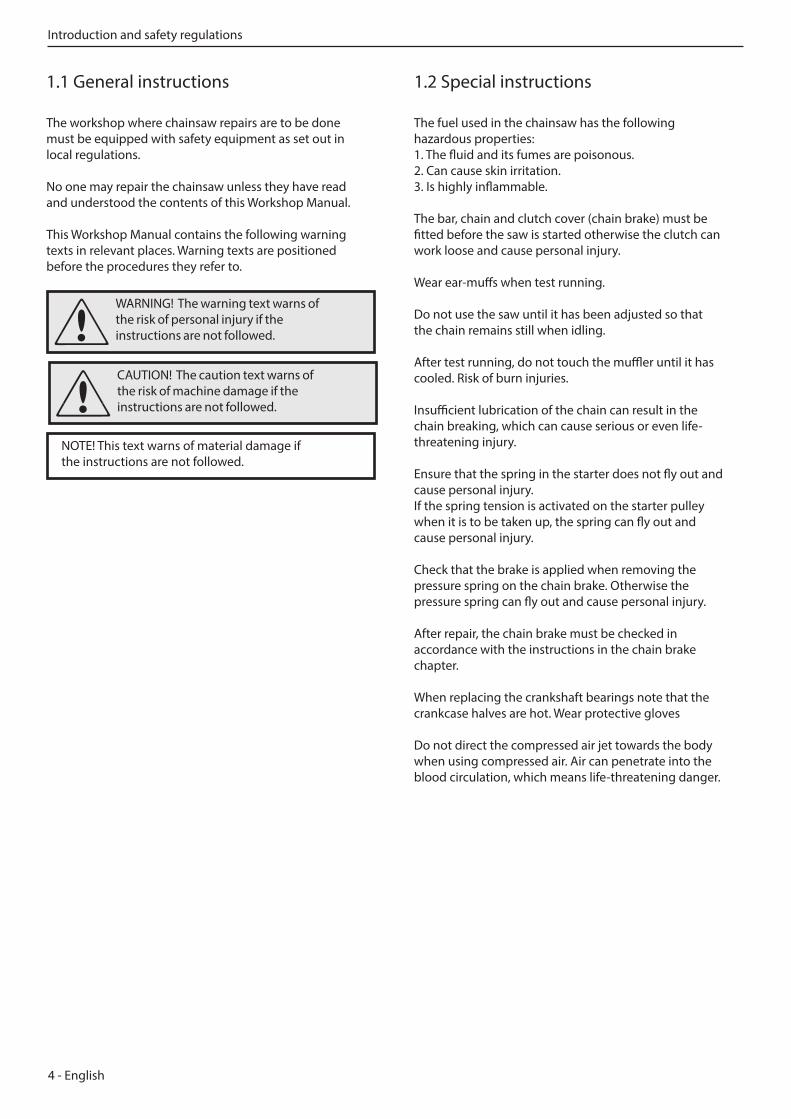
WARNING! The warning text warns of the risk of personal injury if the instructions are not followed.
1.1 General instructions
The workshop where chainsaw repairs are to be done must be equipped with safety equipment as set out in local regulations.
No one may repair the chainsaw unless they have read and understood the contents of this Workshop Manual.
This Workshop Manual contains the following warning texts in relevant places. Warning texts are positioned before the procedures they refer to.
1.2 Special instructions
The fuel used in the chainsaw has the following hazardous properties:1. The fluid and its fumes are poisonous.2. Can cause skin irritation.3. Is highly inflammable.
The bar, chain and clutch cover (chain brake) must be fitted before the saw is started otherwise the clutch can work loose and cause personal injury.
Wear ear-muffs when test running.
Do not use the saw until it has been adjusted so that the chain remains still when idling.
After test running, do not touch the muffler until it has cooled. Risk of burn injuries.
Insufficient lubrication of the chain can result in the chain breaking, which can cause serious or even life-threatening injury.
Ensure that the spring in the starter does not fly out and cause personal injury.If the spring tension is activated on the starter pulley when it is to be taken up, the spring can fly out and cause personal injury.
Check that the brake is applied when removing the pressure spring on the chain brake. Otherwise the pressure spring can fly out and cause personal injury.
After repair, the chain brake must be checked in accordance with the instructions in the chain brake chapter.
When replacing the crankshaft bearings note that the crankcase halves are hot. Wear protective gloves
Do not direct the compressed air jet towards the body when using compressed air. Air can penetrate into the blood circulation, which means life-threatening danger.
NOTE! This text warns of material damage if the instructions are not followed.
CAUTION! The caution text warns of the risk of machine damage if the instructions are not followed.
Introduction and safety regulations
English - 5
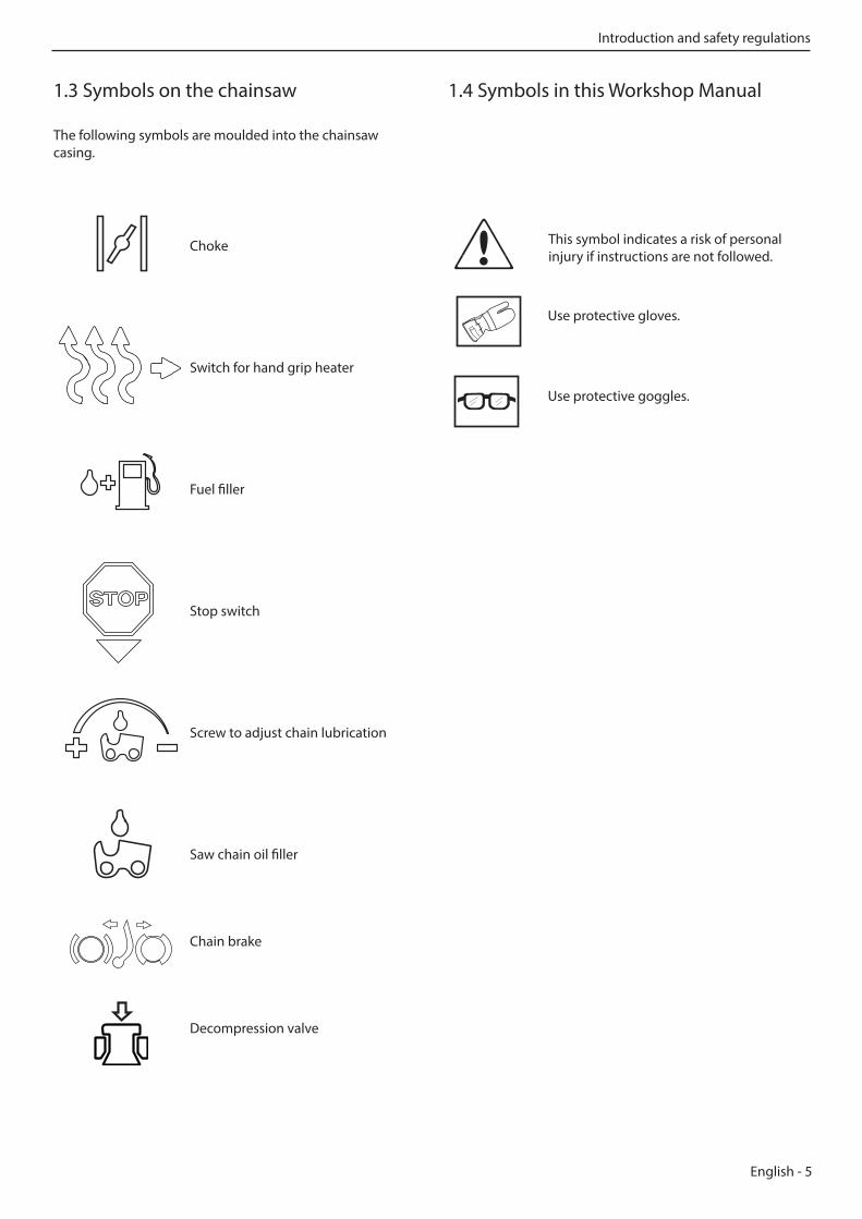
1.3 Symbols on the chainsaw
The following symbols are moulded into the chainsaw casing.
1.4 Symbols in this Workshop Manual
This symbol indicates a risk of personal injury if instructions are not followed.
Choke
Switch for hand grip heater
Fuel filler
Stop switch
Screw to adjust chain lubrication
Saw chain oil filler
Chain brake
Decompression valve
Use protective gloves.
Use protective goggles.
Introduction and safety regulations
6 - English
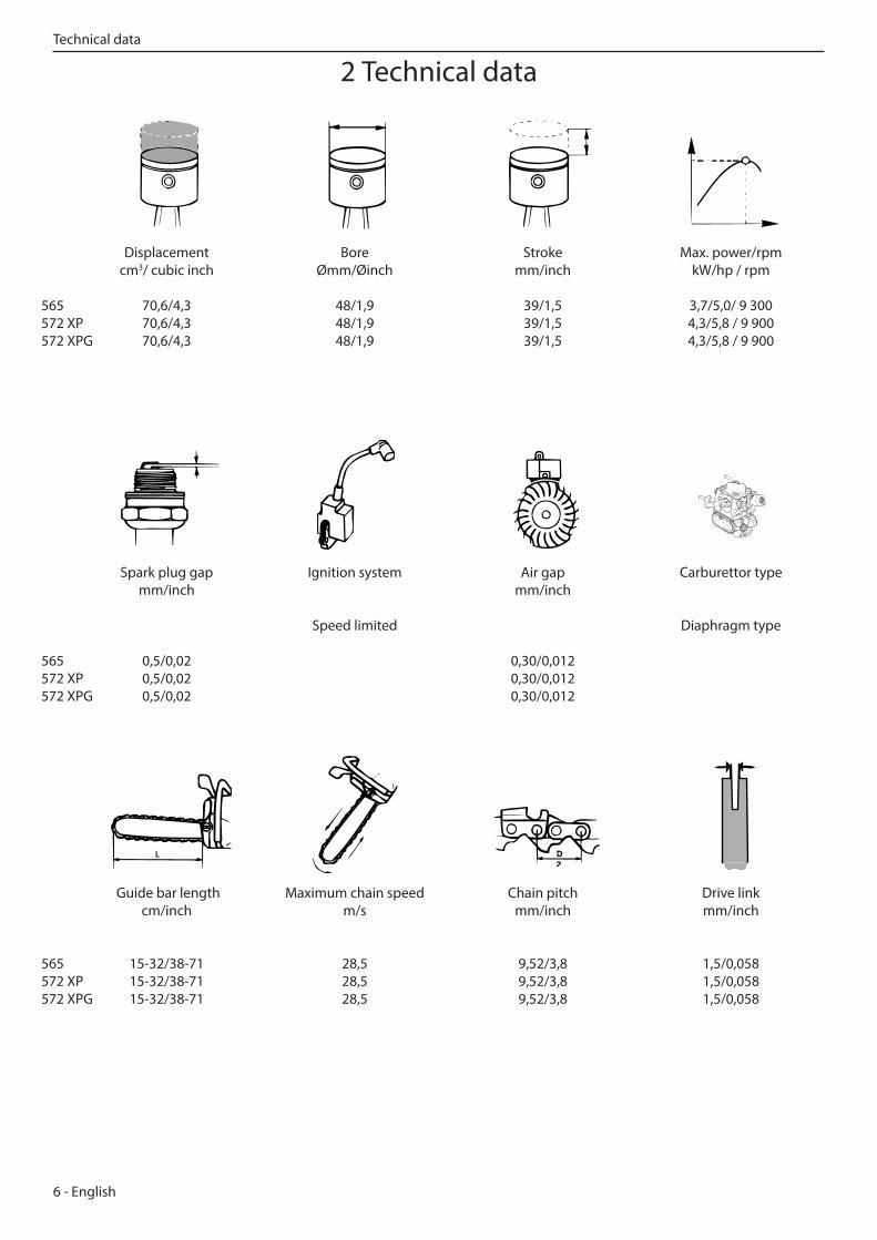
Displacement Bore Stroke Max. power/rpm cm3/ cubic inch Ømm/Øinch mm/inch kW/hp / rpm
565 70,6/4,3 48/1,9 39/1,5 3,7/5,0/ 9 300572 XP 70,6/4,3 48/1,9 39/1,5 4,3/5,8 / 9 900 572 XPG 70,6/4,3 48/1,9 39/1,5 4,3/5,8 / 9 900
Guide bar length Maximum chain speed Chain pitch Drive link cm/inch m/s mm/inch mm/inch 565 15-32/38-71 28,5 9,52/3,8 1,5/0,058572 XP 15-32/38-71 28,5 9,52/3,8 1,5/0,058572 XPG 15-32/38-71 28,5 9,52/3,8 1,5/0,058
Spark plug gap Ignition system Air gap Carburettor type mm/inch mm/inch
Speed limited Diaphragm type 565 0,5/0,02 0,30/0,012 572 XP 0,5/0,02 0,30/0,012 572 XPG 0,5/0,02 0,30/0,012
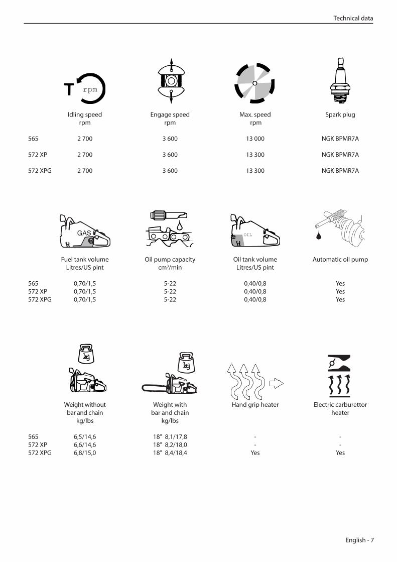
2 Technical dataTechnical data
English - 7
Idling speed Engage speed Max. speed Spark plug rpm rpm rpm
565 2 700 3 600 13 000 NGK BPMR7A 572 XP 2 700 3 600 13 300 NGK BPMR7A 572 XPG 2 700 3 600 13 300 NGK BPMR7A
Fuel tank volume Oil pump capacity Oil tank volume Automatic oil pump Litres/US pint cm3/min Litres/US pint
565 0,70/1,5 5-22 0,40/0,8 Yes572 XP 0,70/1,5 5-22 0,40/0,8 Yes572 XPG 0,70/1,5 5-22 0,40/0,8 Yes
Weight without Weight with Hand grip heater Electric carburettor bar and chain bar and chain heater kg/lbs kg/lbs
565 6,5/14,6 18" 8,1/17,8 - -572 XP 6,6/14,6 18" 8,2/18,0 - -572 XPG 6,8/15,0 18" 8,4/18,4 Yes Yes
rpm
OIL
Technical data
8 - English
9
3
10
12
8
1 2a 4a
5 6
7
13 14
2b
4b
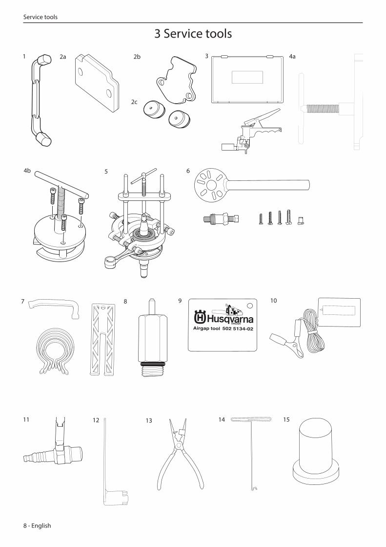
3 Service toolsService tools
1511
2c
English - 9
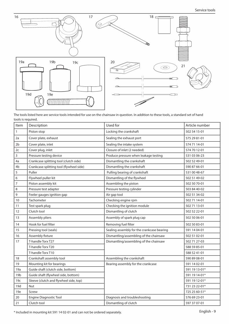
The tools listed here are service tools intended for use on the chainsaw in question. In addition to these tools, a standard set of hand tools is required.
16 17
Service tools
Item Description Used for Article number
1 Piston stop Locking the crankshaft 502 54 15-01
2a Cover plate, exhaust Sealing the exhaust port 575 29 81-01
2b Cover plate, inlet Sealing the intake system 574 71 14-01
2c Cover plug, inlet Closure of inlet (2 needed) 574 70 12-01
3 Pressure testing device Produce pressure when leakage testing 531 03 06-23
4a Crankcase splitting tool (clutch side) Dismantling the crankshaft 502 52 49-01
4b Crankcase splitting tool (flywheel side) Dismantling the crankshaft 590 87 66-01
5 Puller Pulling bearing of crankshaft 531 00 48-67
6 Flywheel puller kit Dismantling of the flywheel 502 51 49-02
7 Piston assembly kit Assembling the piston 502 50 70-01
8 Pressure test adapter Pressure testing cylinder 503 84 40-02
9 Feeler gauges ignition gap Air gap tool 502 51 34-02
10 Tachometer Checking engine rpm 502 71 14-01
11 Test spark plug Checking the ignition module 502 71 13-01
12 Clutch tool Dismantling of clutch 502 52 22-01
13 Assembly pliers Assembly of spark plug cap 502 50 06-01
14 Hook for fuel filter Removing fuel filter 502 50 83-01
15 Pressing tool (seals) Sealing assembly for the crankcase bearing 591 14 04-01
16 Assembly fixture Dismantling/assembling of the chainsaw 502 51 02-01
17 T-handle Torx T27 Dismantling/assembling of the chainsaw 502 71 27-03
T-handle Torx T20 588 59 85-01
T-handle Torx T10 588 52 41-01
18 Crankshaft assembly tool Assembling the crankshaft 590 89 08-01
19 Mounting kit for bearings Bearing assembly for the crankcase 591 14 02-01
19a Guide shaft (clutch side, bottom) 591 19 13-01*
19b Guide shaft (flywheel side, bottom) 591 19 14-01*
19c Sleeve (clutch and flywheel side, top) 591 19 12-01*
19d Nut 731 23 22-01*
19e Screw 725 25 60-51*
20 Engine Diagnostic Tool Diagnosis and troubleshooting 576 69 23-01
21 Clutch tool Dismantling of clutch 597 37 07-01
19a 19b
19d
20
* Included in mounting kit 591 14 02-01 and can not be ordered separately.
18
19e
2119c

10 - English
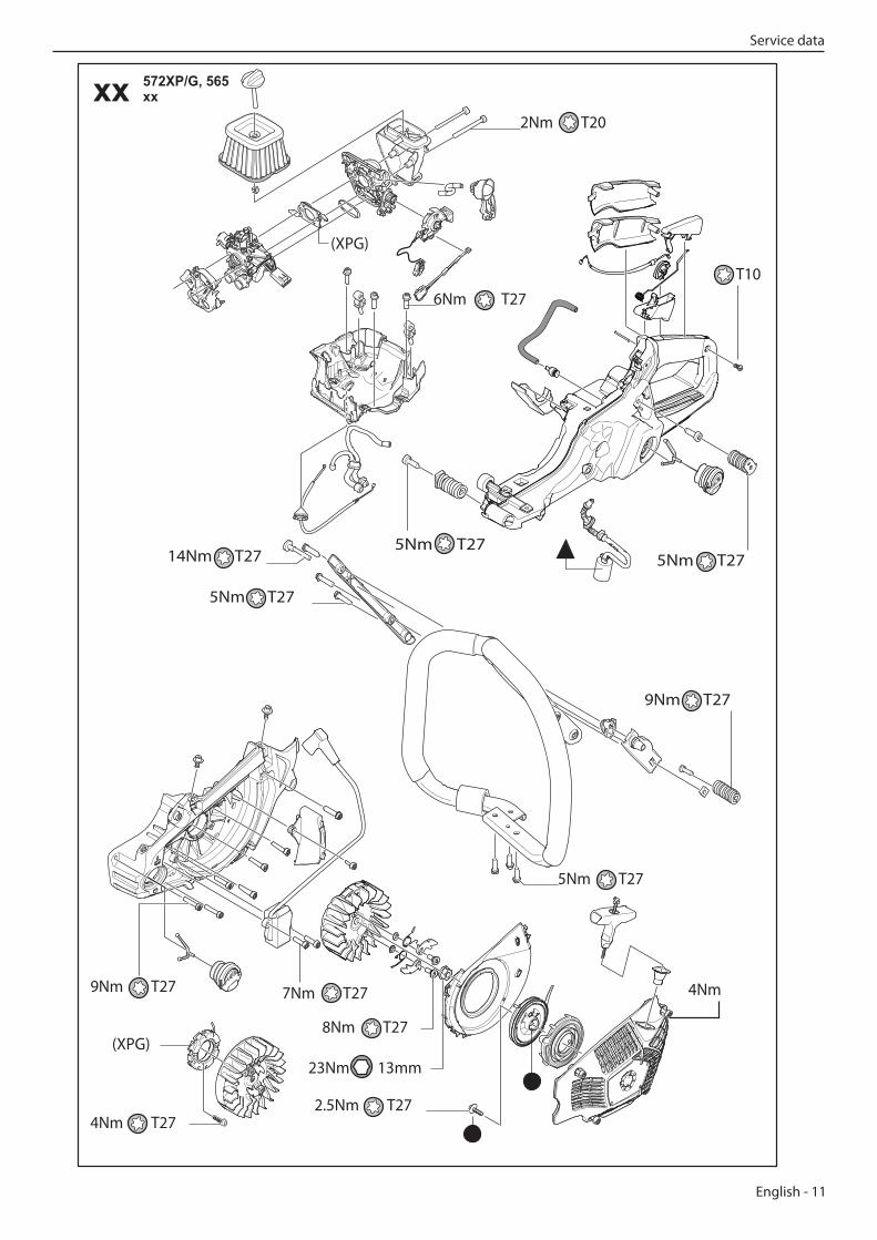
Key to diagramsThe figures next to parts screwed on indicatethe tightening torque Nm.
= Lubricate with two-stroke oil.= Lubricate with chain oil.= Lubricate with grease.
xx 572XP/G, 565xx
1.5Nm T20
1.5Nm
1.5Nm
9Nm T27
9Nm T27
20Nm
20Nm 19mm9Nm T27
13Nm 13mm
8.5Nm T27
15Nm 13mm
3.5Nm T27
17Nm T2717Nm T27
4.5Nm T27
5-6Nm T27
1-2Nm T20
4 Service dataService data
English - 11
xx 572XP/G, 565xx
2Nm T20
9Nm T27
5Nm T27
6Nm T27T10
5Nm T27
14Nm T27
7Nm T279Nm T27
4Nm T27
(XPG)
(XPG)
2.5Nm T27
8Nm T27
23Nm 13mm
5Nm T27
4Nm
5Nm T27
Service data
12 - English
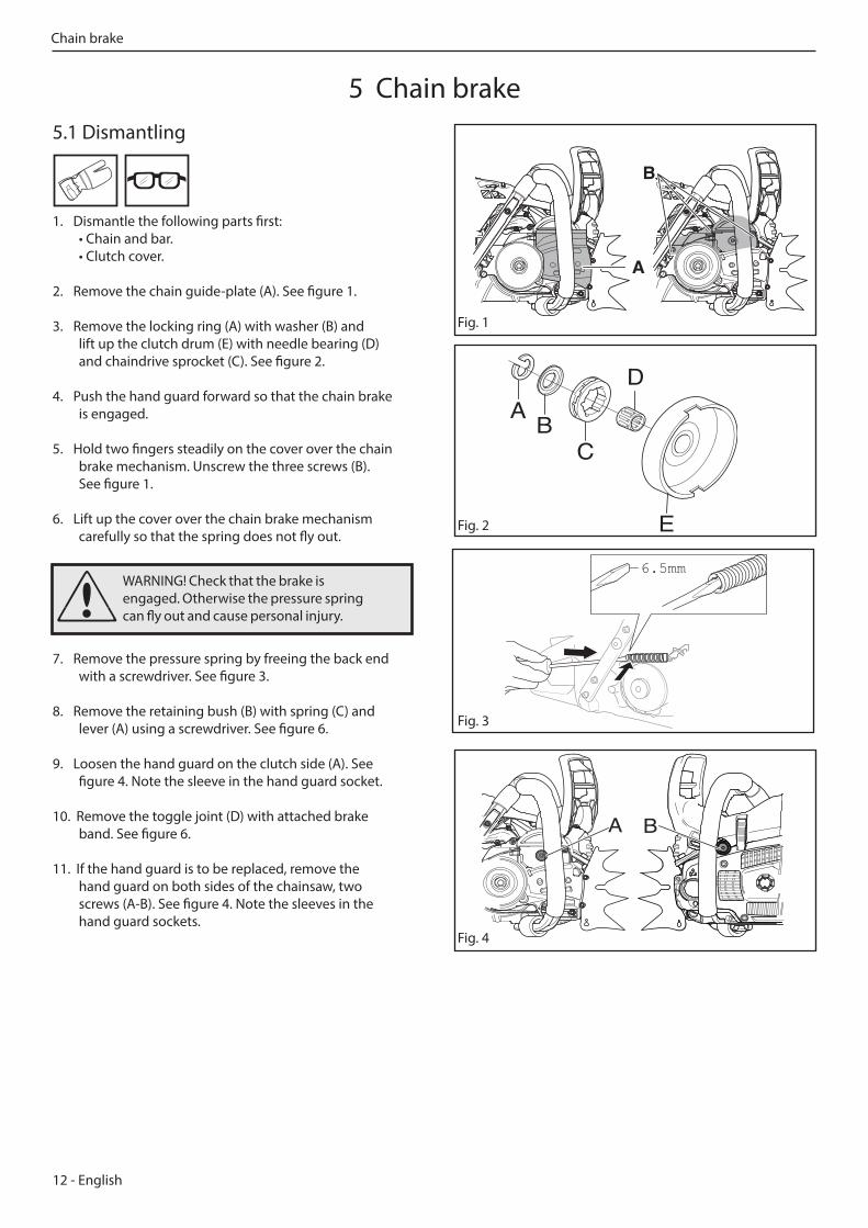
WARNING! Check that the brake is engaged. Otherwise the pressure spring can fly out and cause personal injury.
Fig. 1
A
B
A B
Fig. 2
Fig. 3
Fig. 4
A BC
E
D
5.1 Dismantling
1. Dismantle the following parts first: • Chain and bar. • Clutch cover.
2. Remove the chain guide-plate (A). See figure 1.
3. Remove the locking ring (A) with washer (B) and lift up the clutch drum (E) with needle bearing (D) and chaindrive sprocket (C). See figure 2.
4. Push the hand guard forward so that the chain brake is engaged.
5. Hold two fingers steadily on the cover over the chain brake mechanism. Unscrew the three screws (B). See figure 1.
6. Lift up the cover over the chain brake mechanism carefully so that the spring does not fly out.
7. Remove the pressure spring by freeing the back end with a screwdriver. See figure 3.
8. Remove the retaining bush (B) with spring (C) and lever (A) using a screwdriver. See figure 6.
9. Loosen the hand guard on the clutch side (A). See figure 4. Note the sleeve in the hand guard socket.
10. Remove the toggle joint (D) with attached brake band. See figure 6.
11. If the hand guard is to be replaced, remove the hand guard on both sides of the chainsaw, two screws (A-B). See figure 4. Note the sleeves in the hand guard sockets.
5 Chain brake
6.5mm
Chain brake
English - 13
Min. 0.8 mm
Fig. 5
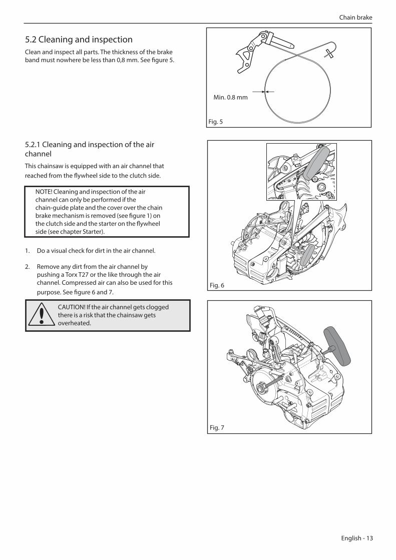
5.2 Cleaning and inspectionClean and inspect all parts. The thickness of the brake band must nowhere be less than 0,8 mm. See figure 5.
5.2.1 Cleaning and inspection of the air channelThis chainsaw is equipped with an air channel that reached from the flywheel side to the clutch side.
1. Do a visual check for dirt in the air channel.
2. Remove any dirt from the air channel by pushing a Torx T27 or the like through the air channel. Compressed air can also be used for this purpose. See figure 6 and 7.
NOTE! Cleaning and inspection of the air channel can only be performed if the chain-guide plate and the cover over the chain brake mechanism is removed (see figure 1) on the clutch side and the starter on the flywheel side (see chapter Starter).
CAUTION! If the air channel gets clogged there is a risk that the chainsaw gets overheated.
Chain brake
Fig. 6
Fig. 7
14 - English
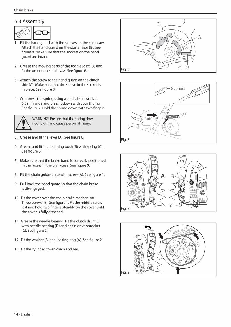
WARNING! Ensure that the spring does not fly out and cause personal injury.
A B
5.3 Assembly
1. Fit the hand guard with the sleeves on the chainsaw. Attach the hand guard on the starter side (B). See figure 8. Make sure that the sockets on the hand guard are intact.
2. Grease the moving parts of the toggle joint (D) and fit the unit on the chainsaw. See figure 6.
3. Attach the screw to the hand guard on the clutch side (A). Make sure that the sleeve in the socket is in place. See figure 8.
4. Compress the spring using a conical screwdriver 6.5 mm wide and press it down with your thumb. See figure 7. Hold the spring down with two fingers.
5. Grease and fit the lever (A). See figure 6.
6. Grease and fit the retaining bush (B) with spring (C). See figure 6.
7. Make sure that the brake band is correctly positioned in the recess in the crankcase. See figure 9.
8. Fit the chain guide-plate with screw (A). See figure 1.
9. Pull back the hand guard so that the chain brake is disengaged.
10. Fit the cover over the chain brake mechanism. Three screws (B). See figure 1. Fit the middle screw last and hold two fingers steadily on the cover until the cover is fully attached.
11. Grease the needle bearing. Fit the clutch drum (E) with needle bearing (D) and chain drive sprocket (C). See figure 2.
12. Fit the washer (B) and locking ring (A). See figure 2.
13. Fit the cylinder cover, chain and bar.
D
A
C B Fig. 6
Fig. 9
6.5mm
Fig. 7
Fig. 8
Chain brake

English - 15
WARNING! After repair, you have to carry out a function check of the chain brake.
Bar length, L Height, H
15-28 inch 30-40 cm
For this test, the engine must not be running. Check that the chain brake engages as follows:
1. Hold the chainsaw over a stable surface as shown in figure 10. The distance between the bar and surface is given in the table below.
2. Let go of the front handle and let the chainsaw pivot round on the rear handle.
3. When the bar hits the surface the chain brake should cut in.
5.4 Function check
L
L
Fig. 10
L
H
Chain brake
16 - English
Fig. 1
6 Chain catcher
Chain catcher
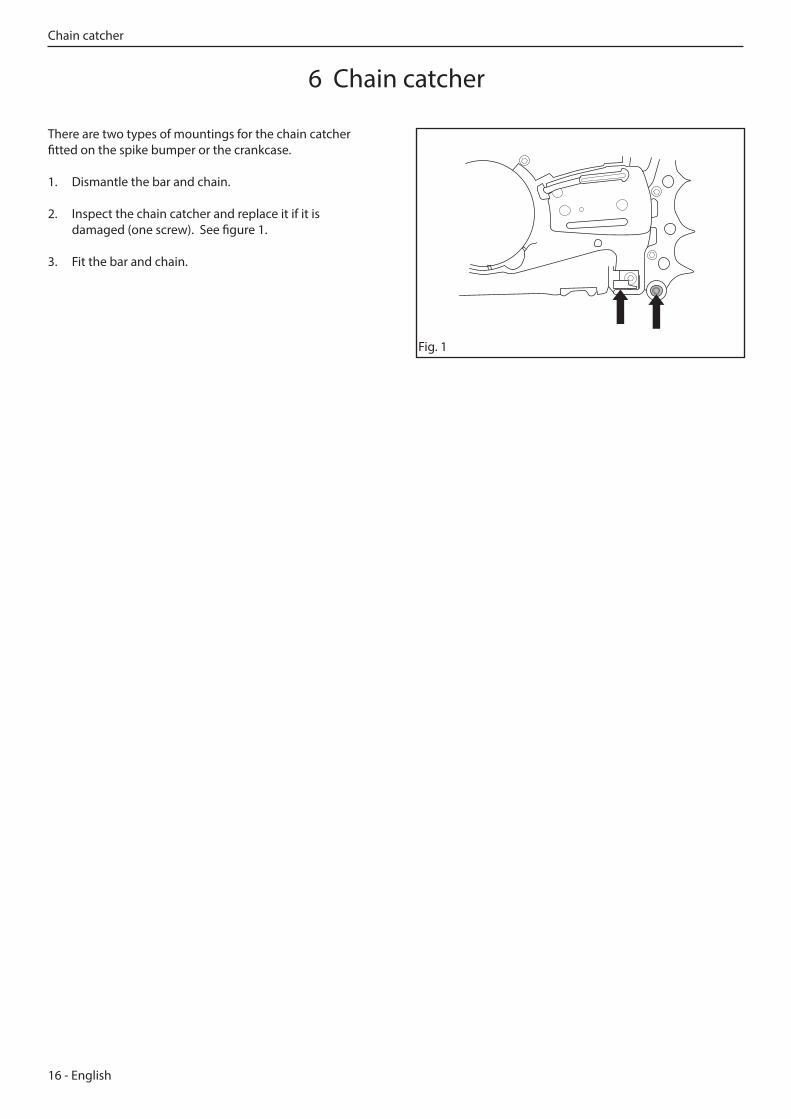
There are two types of mountings for the chain catcher fitted on the spike bumper or the crankcase.
1. Dismantle the bar and chain.
2. Inspect the chain catcher and replace it if it is damaged (one screw). See figure 1.
3. Fit the bar and chain.
English - 17
WARNING! Do not touch the muffler until it has cooled. Risk of burn injuries.
Fig. 1
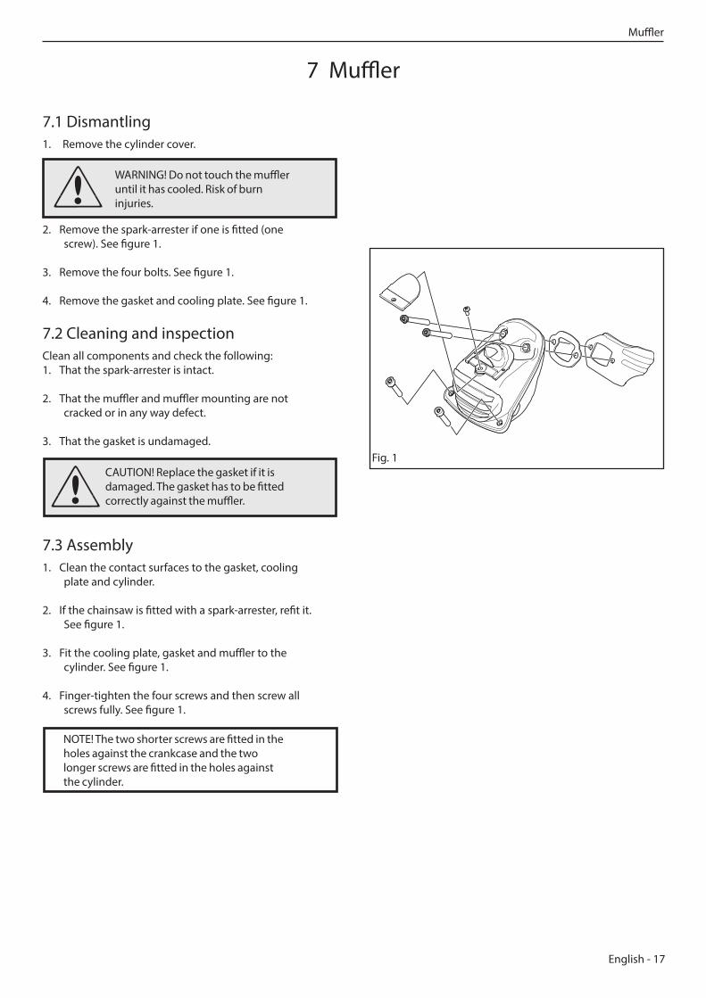
7.1 Dismantling1. Remove the cylinder cover.
2. Remove the spark-arrester if one is fitted (one screw). See figure 1.
3. Remove the four bolts. See figure 1.
4. Remove the gasket and cooling plate. See figure 1.
7.2 Cleaning and inspectionClean all components and check the following:1. That the spark-arrester is intact.
2. That the muffler and muffler mounting are not cracked or in any way defect.
3. That the gasket is undamaged.
7.3 Assembly1. Clean the contact surfaces to the gasket, cooling
plate and cylinder.
2. If the chainsaw is fitted with a spark-arrester, refit it. See figure 1.
3. Fit the cooling plate, gasket and muffler to the cylinder. See figure 1.
4. Finger-tighten the four screws and then screw all screws fully. See figure 1.
7 Muffler
CAUTION! Replace the gasket if it is damaged. The gasket has to be fitted correctly against the muffler.
NOTE! The two shorter screws are fitted in the holes against the crankcase and the two longer screws are fitted in the holes against the cylinder.
Muffler
18 - English
8.1 Dismantling1. Remove the cylinder cover and air filter.
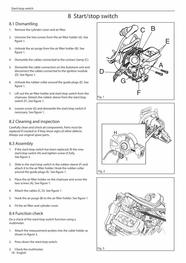
2. Unscrew the two screws from the air filter holder (A). See figure 1.
3. Unhook the air purge from the air filter holder (B). See figure 1.
4. Dismantle the cables connected to the contact clamp (C).
5. Dismantle the cable connection on the Autotune unit and disconnect the cables connected to the ignition module (D). See figure 1.
6. Unhook the rubber collar around the guide plugs (E). See figure 1.
7. Lift out the air filter holder and start/stop switch from the chainsaw. Detach the rubber sleeve from the start/stop switch (F). See figure 1.
8. Loosen screw (G) and dismantle the start/stop switch if necessary. See figure 1.
8.2 Cleaning and inspectionCarefully clean and check all components. Parts must be replaced if cracked or if they show signs of other defects. Always use original spare parts.
8.3 Assembly1. If the start/stop switch has been replaced, fit the new
start/stop switch (H) and tighten screw (I) fully. See figure 2.
2. Slide in the start/stop switch in the rubber sleeve (F) and attach it to the air filter holder. Hook the rubber collar around the guide plugs (E). See figure 1.
3. Place the air filter holder on the chainsaw and screw the two screws (A). See figure 1.
4. Attach the cables (C, D). See figure 1.
5. Hook the air purge (B) to the air filter holder. See figure 1.
6. Fit the air filter and cylinder cover.
8.4 Function checkDo a check of the start/stop switch function using a multimeter.
1. Attach the measurement probes into the cable holder as shown in figure 3.
2. Press down the start/stop switch.
3. Check the multimeter.
Fig. 1
H
I
Fig. 2
Fig. 3
B
A
C
F
D
E
G
8 Start/stop switchStart/stop switch
English - 19
A
A
B
Fig. 5
A
Fig. 2
A
B
C
Fig. 3
Fig. 1
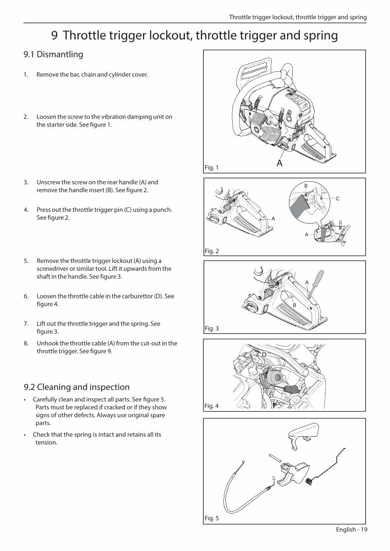
2. Loosen the screw to the vibration damping unit on the starter side. See figure 1.
3. Unscrew the screw on the rear handle (A) and remove the handle insert (B). See figure 2.
4. Press out the throttle trigger pin (C) using a punch. See figure 2.
5. Remove the throttle trigger lockout (A) using a screwdriver or similar tool. Lift it upwards from the shaft in the handle. See figure 3.
6. Loosen the throttle cable in the carburettor (D). See figure 4.
7. Lift out the throttle trigger and the spring. See figure 3.
8. Unhook the throttle cable (A) from the cut-out in the throttle trigger. See figure 9.
9.2 Cleaning and inspection• Carefully clean and inspect all parts. See figure 5.
Parts must be replaced if cracked or if they show signs of other defects. Always use original spare parts.
• Check that the spring is intact and retains all its tension.
9 Throttle trigger lockout, throttle trigger and spring 9.1 Dismantling
1. Remove the bar, chain and cylinder cover.
D
Fig. 4
Throttle trigger lockout, throttle trigger and spring
20 - English
Fig. 6
B
C
D
A
Fig. 9
Fig. 10
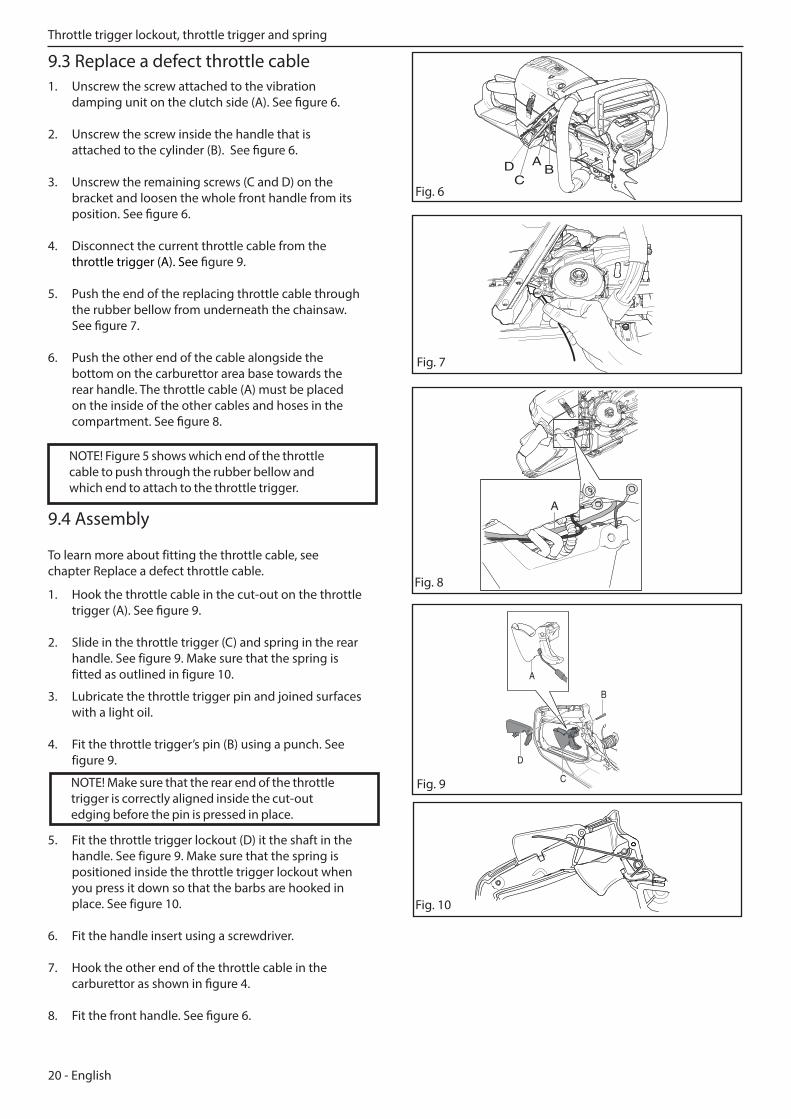
9.3 Replace a defect throttle cable1. Unscrew the screw attached to the vibration
damping unit on the clutch side (A). See figure 6.
2. Unscrew the screw inside the handle that is attached to the cylinder (B). See figure 6.
3. Unscrew the remaining screws (C and D) on the bracket and loosen the whole front handle from its position. See figure 6.
4. Disconnect the current throttle cable from the throttle trigger (A). See figure 9.
5. Push the end of the replacing throttle cable through the rubber bellow from underneath the chainsaw. See figure 7.
6. Push the other end of the cable alongside the bottom on the carburettor area base towards the rear handle. The throttle cable (A) must be placed on the inside of the other cables and hoses in the compartment. See figure 8.
9.4 Assembly To learn more about fitting the throttle cable, see chapter Replace a defect throttle cable.
1. Hook the throttle cable in the cut-out on the throttle trigger (A). See figure 9.
2. Slide in the throttle trigger (C) and spring in the rear handle. See figure 9. Make sure that the spring is fitted as outlined in figure 10.
D AB
C
NOTE! Make sure that the rear end of the throttle trigger is correctly aligned inside the cut-out edging before the pin is pressed in place.
Fig. 7
A
Fig. 8
NOTE! Figure 5 shows which end of the throttle cable to push through the rubber bellow and which end to attach to the throttle trigger.
3. Lubricate the throttle trigger pin and joined surfaces with a light oil.
4. Fit the throttle trigger’s pin (B) using a punch. See figure 9.
5. Fit the throttle trigger lockout (D) it the shaft in the handle. See figure 9. Make sure that the spring is positioned inside the throttle trigger lockout when you press it down so that the barbs are hooked in place. See figure 10.
6. Fit the handle insert using a screwdriver.
7. Hook the other end of the throttle cable in the carburettor as shown in figure 4.
8. Fit the front handle. See figure 6.
Throttle trigger lockout, throttle trigger and spring
English - 21
WARNING! If the spring inside the spring cassette is tensioned it can fly up and cause personal injury. Wear protective glasses.
10 Starter
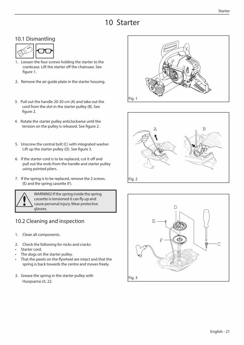
10.1 Dismantling
10.2 Cleaning and inspection
1. Clean all components.
2. Check the following for nicks and cracks:• Starter cord.• The dogs on the starter pulley.• That the pawls on the flywheel are intact and that the
spring is back towards the centre and moves freely.
3. Grease the spring in the starter pulley with Husqvarna UL 22.
Fig. 1
Fig. 2
Fig. 3
5. Unscrew the central bolt (C) with integrated washer. Lift up the starter pulley (D). See figure 3.
6. If the starter cord is to be replaced, cut it off and pull out the ends from the handle and starter pulley using pointed pliers.
7. If the spring is to be replaced, remove the 2 screws. (E) and the spring cassette (F).
A B
E
F
D
C
1. Loosen the four screws holding the starter to the crankcase. Lift the starter off the chainsaw. See figure 1.
2. Remove the air guide plate in the starter housing.
3. Pull out the handle 20-30 cm (A) and take out the cord from the slot in the starter pulley (B). See figure 2.
4. Rotate the starter pulley anticlockwise until the tension on the pulley is released. See figure 2.
Starter
22 - English
WARNING! If the spring is tensioned on the starter pulley it can fly up and cause personal injury.
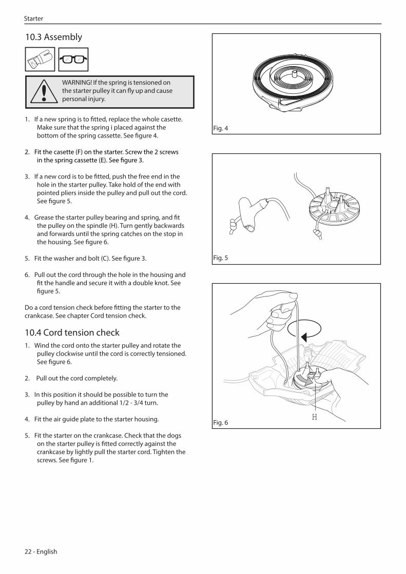
10.3 Assembly
Fig. 4
Fig. 5
1. If a new spring is to fitted, replace the whole casette. Make sure that the spring i placed against the bottom of the spring cassette. See figure 4.
2. Fit the casette (F) on the starter. Screw the 2 screws in the spring cassette (E). See figure 3.
3. If a new cord is to be fitted, push the free end in the hole in the starter pulley. Take hold of the end with pointed pliers inside the pulley and pull out the cord. See figure 5.
4. Grease the starter pulley bearing and spring, and fit the pulley on the spindle (H). Turn gently backwards and forwards until the spring catches on the stop in the housing. See figure 6.
5. Fit the washer and bolt (C). See figure 3.
6. Pull out the cord through the hole in the housing and fit the handle and secure it with a double knot. See figure 5.
Do a cord tension check before fitting the starter to the crankcase. See chapter Cord tension check.
10.4 Cord tension check1. Wind the cord onto the starter pulley and rotate the
pulley clockwise until the cord is correctly tensioned. See figure 6.
2. Pull out the cord completely.
3. In this position it should be possible to turn the pulley by hand an additional 1/2 - 3/4 turn.
4. Fit the air guide plate to the starter housing.
5. Fit the starter on the crankcase. Check that the dogs on the starter pulley is fitted correctly against the crankcase by lightly pull the starter cord. Tighten the screws. See figure 1.
H Fig. 6
Starter
English - 23
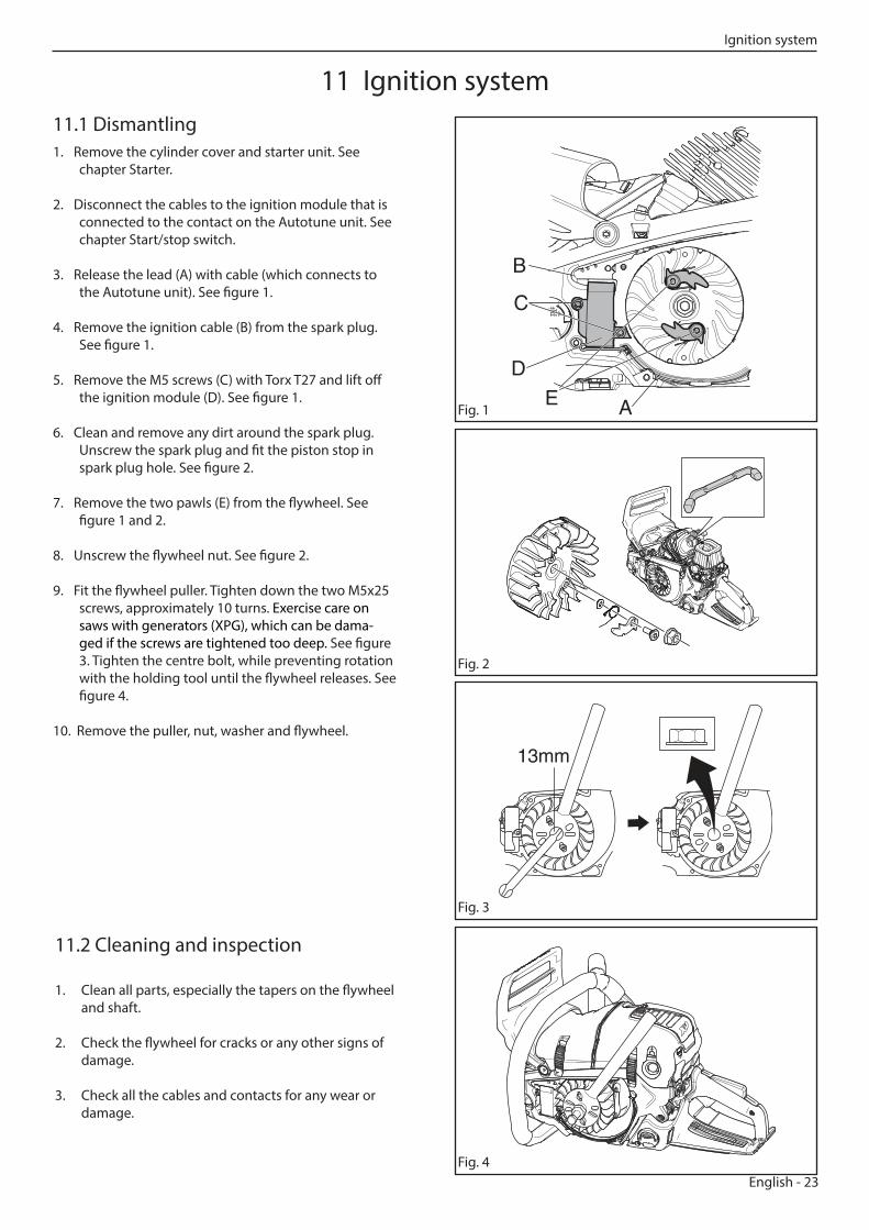
11.1 Dismantling1. Remove the cylinder cover and starter unit. See
chapter Starter.
2. Disconnect the cables to the ignition module that is connected to the contact on the Autotune unit. See chapter Start/stop switch.
3. Release the lead (A) with cable (which connects to the Autotune unit). See figure 1.
4. Remove the ignition cable (B) from the spark plug. See figure 1.
5. Remove the M5 screws (C) with Torx T27 and lift off the ignition module (D). See figure 1.
6. Clean and remove any dirt around the spark plug. Unscrew the spark plug and fit the piston stop in spark plug hole. See figure 2.
7. Remove the two pawls (E) from the flywheel. See figure 1 and 2.
8. Unscrew the flywheel nut. See figure 2.
9. Fit the flywheel puller. Tighten down the two M5x25 screws, approximately 10 turns. Exercise care on saws with generators (XPG), which can be dama-ged if the screws are tightened too deep. See figure 3. Tighten the centre bolt, while preventing rotation with the holding tool until the flywheel releases. See figure 4.
10. Remove the puller, nut, washer and flywheel.
A
D
B
E
C
13mm
11.2 Cleaning and inspection
1. Clean all parts, especially the tapers on the flywheel and shaft.
2. Check the flywheel for cracks or any other signs of damage.
3. Check all the cables and contacts for any wear or damage.
Fig. 1
Fig. 3
Fig. 4
Fig. 2
11 Ignition system
Ignition system
24 - English
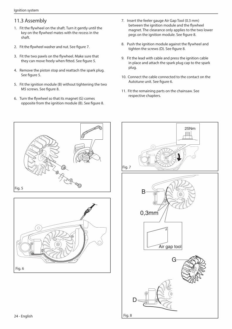
11.3 Assembly1. Fit the flywheel on the shaft. Turn it gently until the
key on the flywheel mates with the recess in the shaft.
2. Fit the flywheel washer and nut. See figure 7.
3. Fit the two pawls on the flywheel. Make sure that they can move freely when fitted. See figure 5.
4. Remove the piston stop and reattach the spark plug. See figure 5.
5. Fit the ignition module (B) without tightening the two M5 screws. See figure 8.
6. Turn the flywheel so that its magnet (G) comes opposite from the ignition module (B). See figure 8.
Fig. 7
Fig. 5
25Nm
7. Insert the feeler gauge Air Gap Tool (0.3 mm) between the ignition module and the flywheel magnet. The clearance only applies to the two lower pegs on the ignition module. See figure 8.
8. Push the ignition module against the flywheel and tighten the screws (D). See figure 8.
9. Fit the lead with cable and press the ignition cable in place and attach the spark plug cap to the spark plug.
10. Connect the cable connected to the contact on the Autotune unit. See figure 6.
11. Fit the remaining parts on the chainsaw. See respective chapters.
0,3mm
B
Air gap tool
G
D
Fig. 6
Fig. 8
Ignition system
English - 25
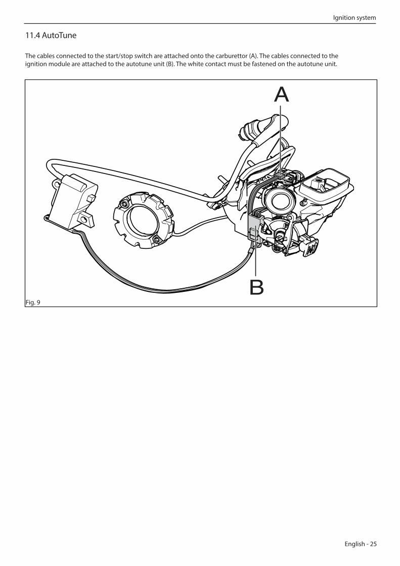
11.4 AutoTune
The cables connected to the start/stop switch are attached onto the carburettor (A). The cables connected to the ignition module are attached to the autotune unit (B). The white contact must be fastened on the autotune unit.
Fig. 9
A
B
Ignition system
26 - English
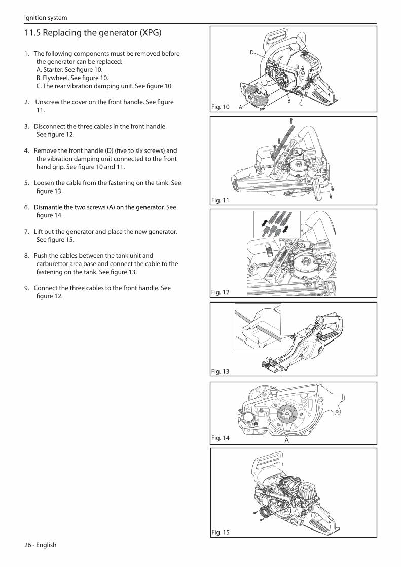
11.5 Replacing the generator (XPG)
1. The following components must be removed before the generator can be replaced: A. Starter. See figure 10. B. Flywheel. See figure 10. C. The rear vibration damping unit. See figure 10.
2. Unscrew the cover on the front handle. See figure 11.
3. Disconnect the three cables in the front handle. See figure 12.
4. Remove the front handle (D) (five to six screws) and the vibration damping unit connected to the front hand grip. See figure 10 and 11.
5. Loosen the cable from the fastening on the tank. See figure 13.
6. Dismantle the two screws (A) on the generator. See figure 14.
7. Lift out the generator and place the new generator. See figure 15.
8. Push the cables between the tank unit and carburettor area base and connect the cable to the fastening on the tank. See figure 13.
9. Connect the three cables to the front handle. See figure 12.
Fig. 11
AB C
D
Fig. 10
Fig. 12
Fig. 14 A
Fig. 15
Fig. 13
Ignition system
English - 27
Fig. 16
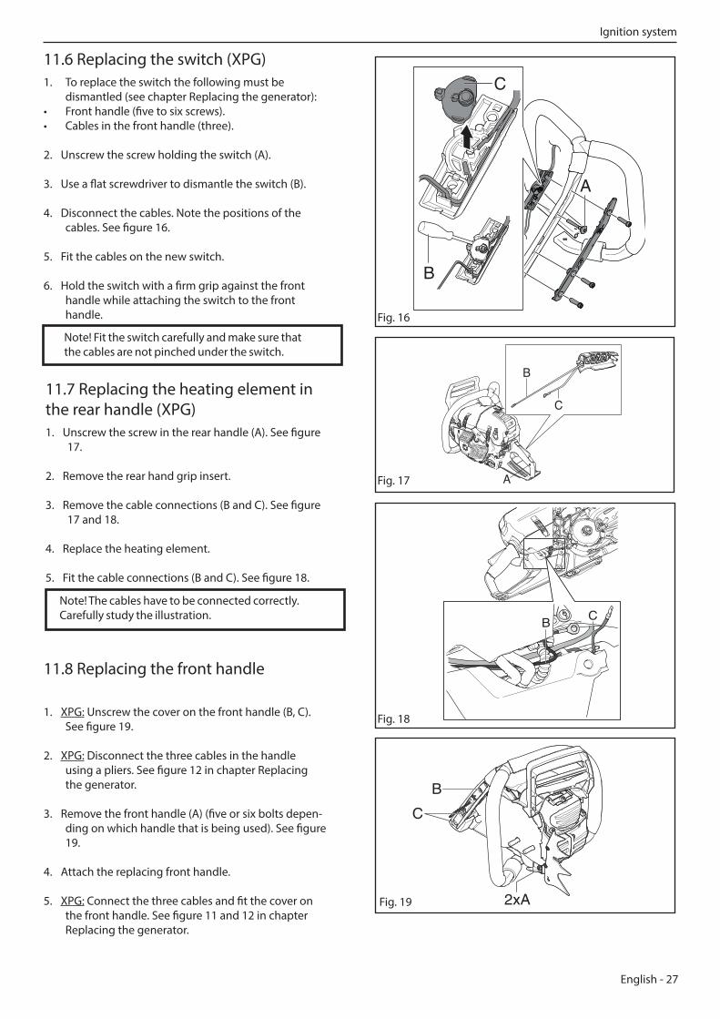
11.6 Replacing the switch (XPG)1. To replace the switch the following must be
dismantled (see chapter Replacing the generator): • Front handle (five to six screws).• Cables in the front handle (three).
2. Unscrew the screw holding the switch (A).
3. Use a flat screwdriver to dismantle the switch (B).
4. Disconnect the cables. Note the positions of the cables. See figure 16.
5. Fit the cables on the new switch.
6. Hold the switch with a firm grip against the front handle while attaching the switch to the front handle.
11.7 Replacing the heating element in the rear handle (XPG)1. Unscrew the screw in the rear handle (A). See figure
17.
2. Remove the rear hand grip insert.
3. Remove the cable connections (B and C). See figure 17 and 18.
4. Replace the heating element.
5. Fit the cable connections (B and C). See figure 18.
Fig. 18
Fig. 17 A
C
B
CB
A
Note! The cables have to be connected correctly. Carefully study the illustration.
Note! Fit the switch carefully and make sure that the cables are not pinched under the switch.
BC
11.8 Replacing the front handle
1. XPG: Unscrew the cover on the front handle (B, C). See figure 19.
2. XPG: Disconnect the three cables in the handle using a pliers. See figure 12 in chapter Replacing the generator.
3. Remove the front handle (A) (five or six bolts depen-ding on which handle that is being used). See figure 19.
4. Attach the replacing front handle.
5. XPG: Connect the three cables and fit the cover on the front handle. See figure 11 and 12 in chapter Replacing the generator.
B
C
2xA Fig. 19
C
B
A
Ignition system
28 - English
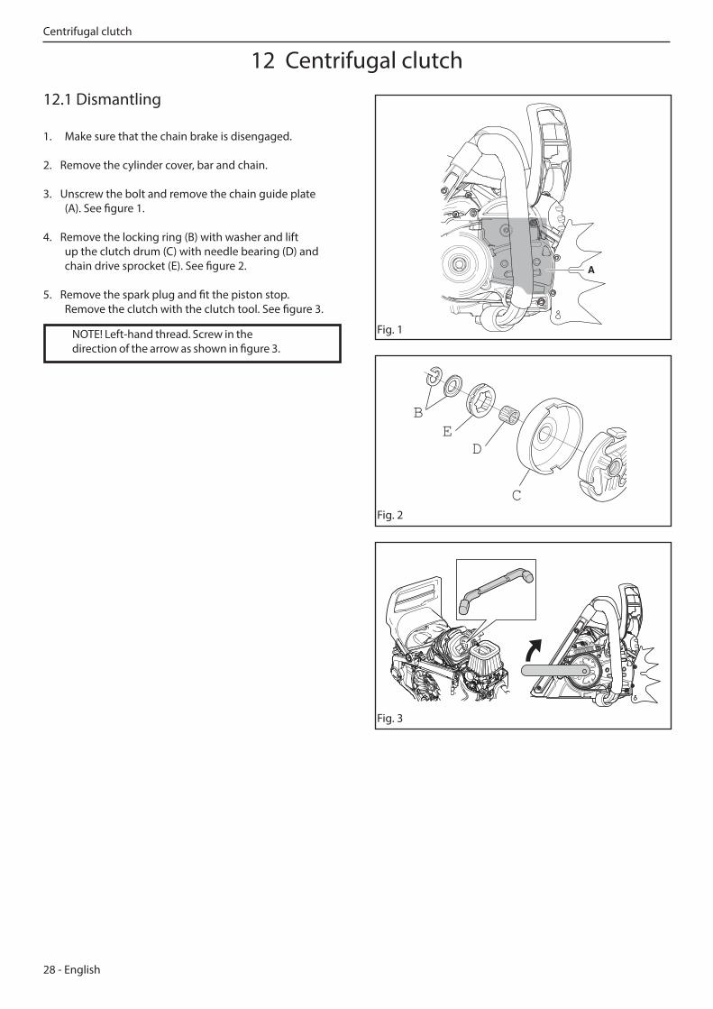
12.1 Dismantling
1. Make sure that the chain brake is disengaged.
2. Remove the cylinder cover, bar and chain.
3. Unscrew the bolt and remove the chain guide plate (A). See figure 1.
4. Remove the locking ring (B) with washer and lift up the clutch drum (C) with needle bearing (D) and chain drive sprocket (E). See figure 2.
5. Remove the spark plug and fit the piston stop. Remove the clutch with the clutch tool. See figure 3.
A
Fig. 1
Fig. 2
Fig. 3
BE
D
C
NOTE! Left-hand thread. Screw in the direction of the arrow as shown in figure 3.
12 Centrifugal clutch Centrifugal clutch
English - 29
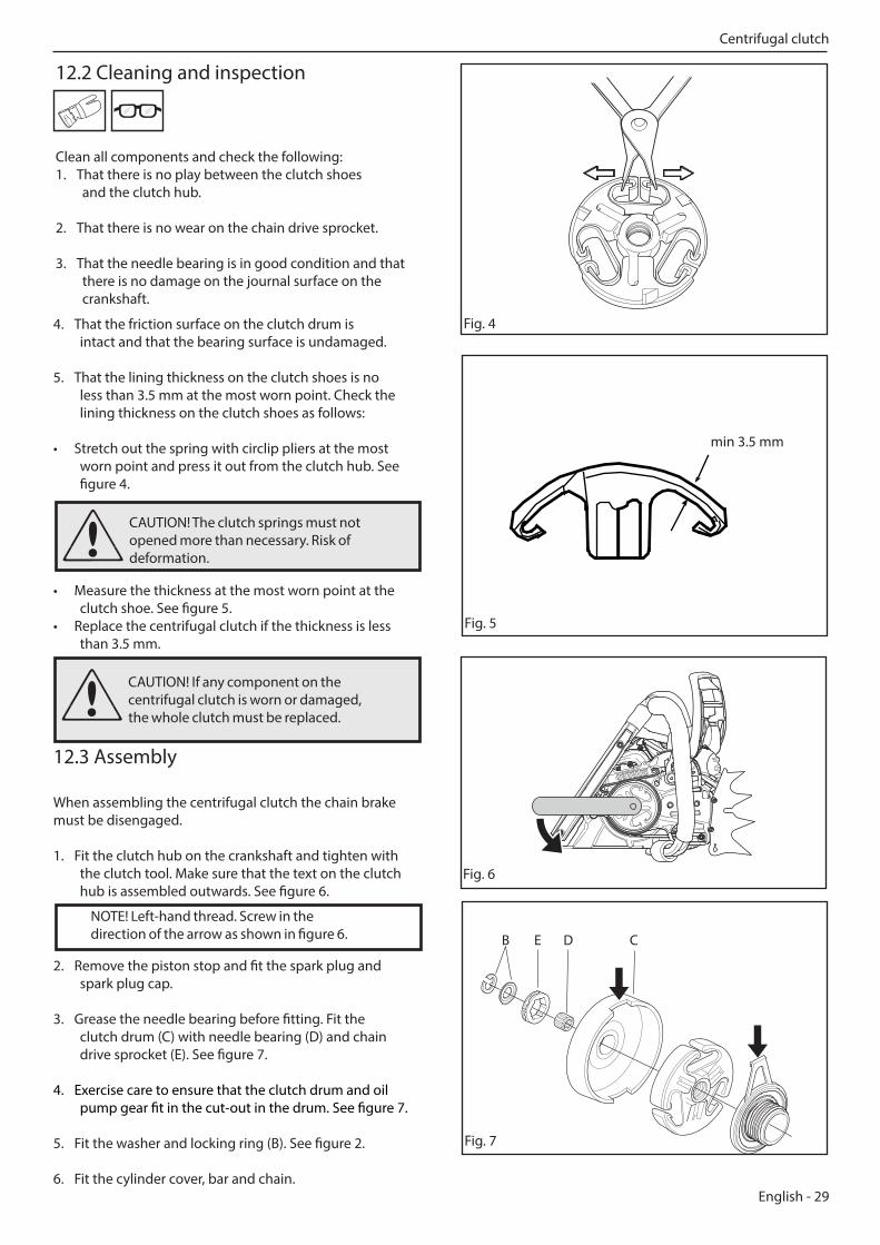
12.2 Cleaning and inspection
Clean all components and check the following:1. That there is no play between the clutch shoes
and the clutch hub.
2. That there is no wear on the chain drive sprocket.
3. That the needle bearing is in good condition and that there is no damage on the journal surface on the crankshaft.
Fig. 44. That the friction surface on the clutch drum is intact and that the bearing surface is undamaged.
5. That the lining thickness on the clutch shoes is no less than 3.5 mm at the most worn point. Check the lining thickness on the clutch shoes as follows:
• Stretch out the spring with circlip pliers at the most worn point and press it out from the clutch hub. See figure 4.
• Measure the thickness at the most worn point at the clutch shoe. See figure 5.
• Replace the centrifugal clutch if the thickness is less than 3.5 mm.
12.3 Assembly
When assembling the centrifugal clutch the chain brake must be disengaged.
1. Fit the clutch hub on the crankshaft and tighten with the clutch tool. Make sure that the text on the clutch hub is assembled outwards. See figure 6.
Fig. 5
Fig. 6
min 3.5 mm
2. Remove the piston stop and fit the spark plug and spark plug cap.
3. Grease the needle bearing before fitting. Fit the clutch drum (C) with needle bearing (D) and chain drive sprocket (E). See figure 7.
4. Exercise care to ensure that the clutch drum and oil pump gear fit in the cut-out in the drum. See figure 7.
5. Fit the washer and locking ring (B). See figure 2.
6. Fit the cylinder cover, bar and chain.
B CDE
Fig. 7
CAUTION! If any component on the centrifugal clutch is worn or damaged, the whole clutch must be replaced.
NOTE! Left-hand thread. Screw in the direction of the arrow as shown in figure 6.
CAUTION! The clutch springs must not opened more than necessary. Risk of deformation.
Centrifugal clutch
30 - English
WARNING! Insufficient lubrication of the chain can result in the chain breaking, which can cause serious or even life-threatening injury.
13 Lubrication system
A
B
B
C
D
E
F
H
IJ
G
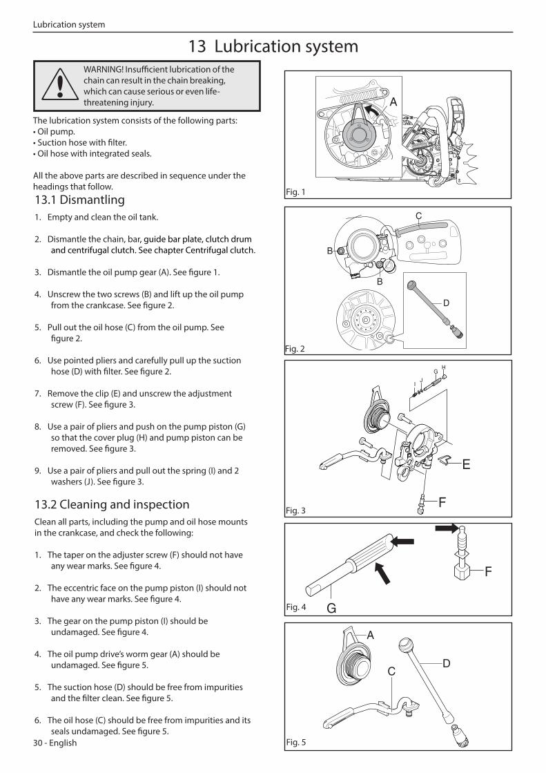
The lubrication system consists of the following parts:• Oil pump.• Suction hose with filter.• Oil hose with integrated seals. All the above parts are described in sequence under the headings that follow.
13.1 Dismantling1. Empty and clean the oil tank.
2. Dismantle the chain, bar, guide bar plate, clutch drum and centrifugal clutch. See chapter Centrifugal clutch.
3. Dismantle the oil pump gear (A). See figure 1.
4. Unscrew the two screws (B) and lift up the oil pump from the crankcase. See figure 2.
5. Pull out the oil hose (C) from the oil pump. See figure 2.
6. Use pointed pliers and carefully pull up the suction hose (D) with filter. See figure 2.
7. Remove the clip (E) and unscrew the adjustment screw (F). See figure 3.
8. Use a pair of pliers and push on the pump piston (G) so that the cover plug (H) and pump piston can be removed. See figure 3.
9. Use a pair of pliers and pull out the spring (I) and 2 washers (J). See figure 3.
13.2 Cleaning and inspectionClean all parts, including the pump and oil hose mounts in the crankcase, and check the following:
1. The taper on the adjuster screw (F) should not have any wear marks. See figure 4.
2. The eccentric face on the pump piston (I) should not have any wear marks. See figure 4.
3. The gear on the pump piston (I) should be undamaged. See figure 4.
4. The oil pump drive’s worm gear (A) should be undamaged. See figure 5.
5. The suction hose (D) should be free from impurities and the filter clean. See figure 5.
6. The oil hose (C) should be free from impurities and its seals undamaged. See figure 5.
Fig. 1
Fig. 2
Fig. 3
A
DC
Fig. 4
Fig. 5
G
F
Lubrication system
English - 31
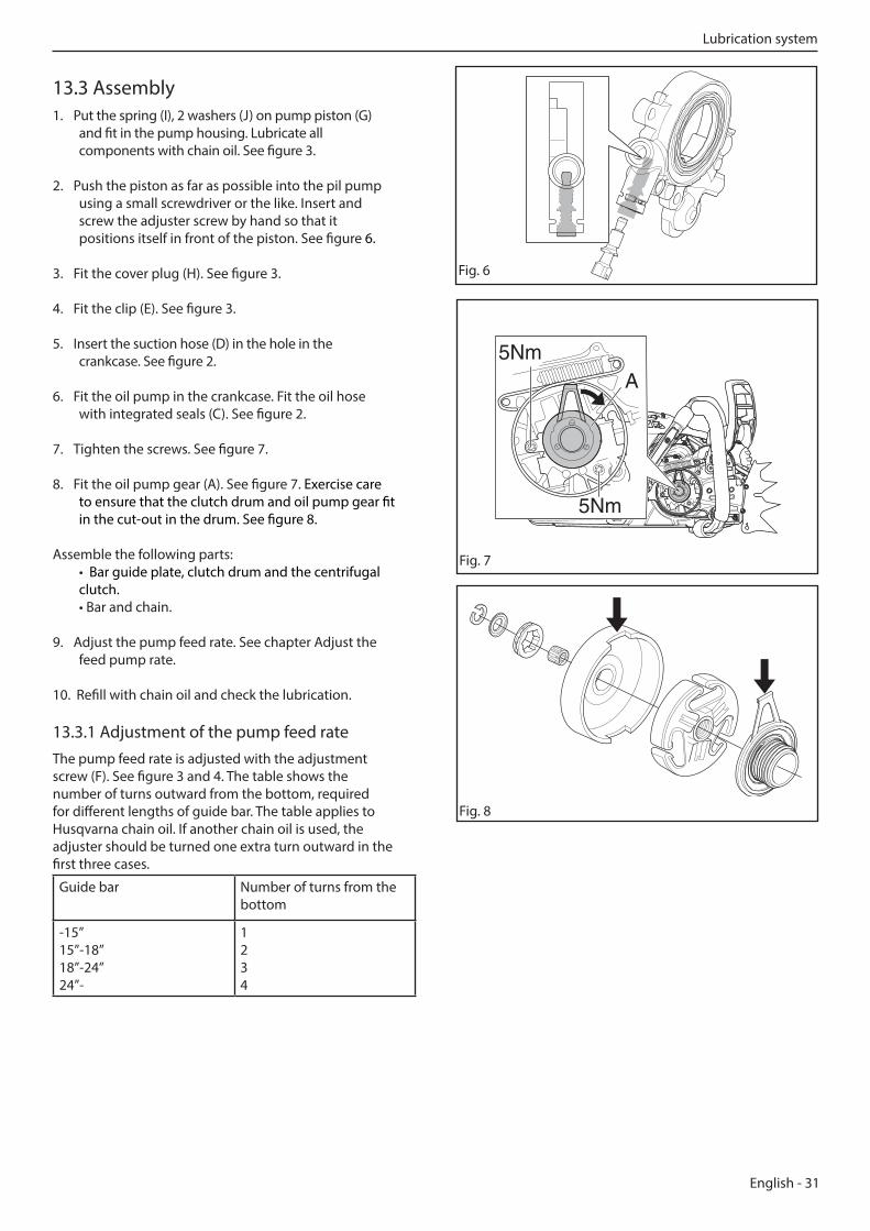
13.3 Assembly1. Put the spring (I), 2 washers (J) on pump piston (G)
and fit in the pump housing. Lubricate all components with chain oil. See figure 3.
2. Push the piston as far as possible into the pil pump using a small screwdriver or the like. Insert and screw the adjuster screw by hand so that it positions itself in front of the piston. See figure 6.
3. Fit the cover plug (H). See figure 3.
4. Fit the clip (E). See figure 3.
5. Insert the suction hose (D) in the hole in the crankcase. See figure 2.
6. Fit the oil pump in the crankcase. Fit the oil hose with integrated seals (C). See figure 2.
7. Tighten the screws. See figure 7.
8. Fit the oil pump gear (A). See figure 7. Exercise care to ensure that the clutch drum and oil pump gear fit in the cut-out in the drum. See figure 8.
Assemble the following parts: • Bar guide plate, clutch drum and the centrifugal clutch. • Bar and chain.
9. Adjust the pump feed rate. See chapter Adjust the feed pump rate.
10. Refill with chain oil and check the lubrication. 13.3.1 Adjustment of the pump feed rateThe pump feed rate is adjusted with the adjustment screw (F). See figure 3 and 4. The table shows the number of turns outward from the bottom, required for different lengths of guide bar. The table applies to Husqvarna chain oil. If another chain oil is used, the adjuster should be turned one extra turn outward in the first three cases.
Guide bar Number of turns from the bottom
-15”15”-18”18”-24”24”-
1234
5NmA
5Nm
Fig. 7
Fig. 8
Fig. 6
Lubrication system
32 - English
WARNING! The fuel used in the chainsaw has the following hazardous properties:
1. The fluid and its vapour are poisonous. 2. Can cause skin irritation. 3. Is highly inflammable.
14 Carburettor
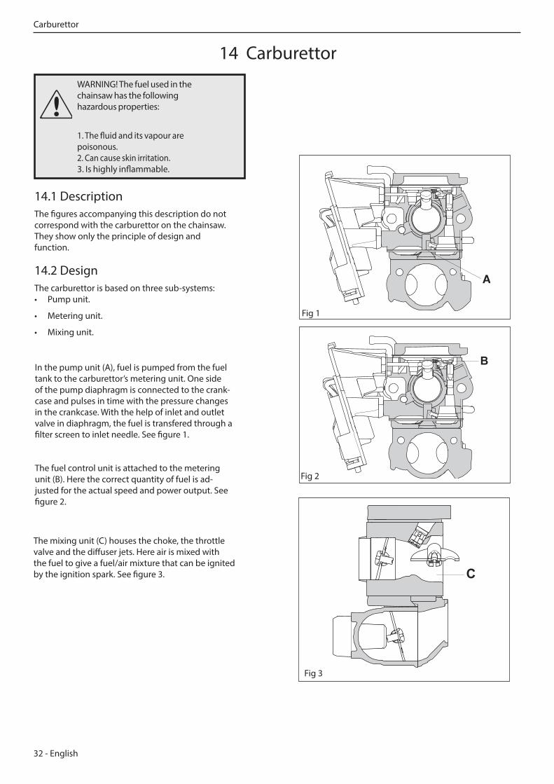
14.1 DescriptionThe figures accompanying this description do not correspond with the carburettor on the chainsaw. They show only the principle of design and function.
14.2 DesignThe carburettor is based on three sub-systems:• Pump unit.
• Metering unit.
• Mixing unit.
The mixing unit (C) houses the choke, the throttle valve and the diffuser jets. Here air is mixed with the fuel to give a fuel/air mixture that can be ignited by the ignition spark. See figure 3. C
Fig 3
In the pump unit (A), fuel is pumped from the fuel tank to the carburettor’s metering unit. One side of the pump diaphragm is connected to the crank-case and pulses in time with the pressure changes in the crankcase. With the help of inlet and outlet valve in diaphragm, the fuel is transfered through a filter screen to inlet needle. See figure 1.
The fuel control unit is attached to the metering unit (B). Here the correct quantity of fuel is ad-justed for the actual speed and power output. See figure 2.
A
Fig 1
B
Fig 2
Carburettor
English - 33
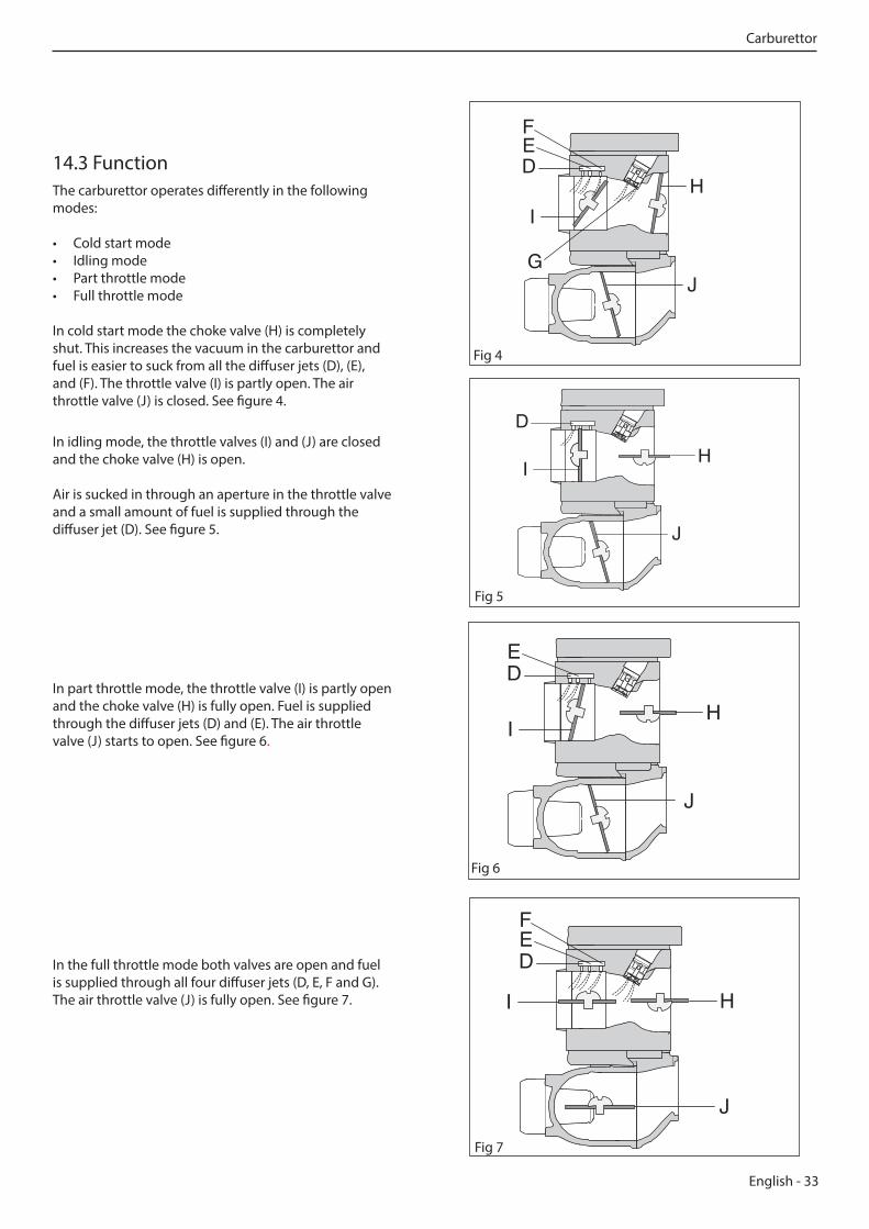
14.3 FunctionThe carburettor operates differently in the following modes:
• Cold start mode• Idling mode• Part throttle mode• Full throttle mode
In cold start mode the choke valve (H) is completely shut. This increases the vacuum in the carburettor and fuel is easier to suck from all the diffuser jets (D), (E), and (F). The throttle valve (I) is partly open. The air throttle valve (J) is closed. See figure 4.
Fig 4
In idling mode, the throttle valves (I) and (J) are closed and the choke valve (H) is open.
Air is sucked in through an aperture in the throttle valve and a small amount of fuel is supplied through the diffuser jet (D). See figure 5.
Fig 5
In part throttle mode, the throttle valve (I) is partly open and the choke valve (H) is fully open. Fuel is supplied through the diffuser jets (D) and (E). The air throttle valve (J) starts to open. See figure 6.
Fig 6
In the full throttle mode both valves are open and fuel is supplied through all four diffuser jets (D, E, F and G). The air throttle valve (J) is fully open. See figure 7.
Fig 7
Carburettor
34 - English
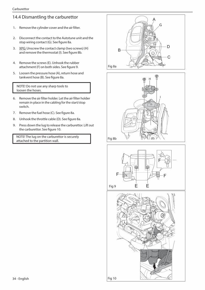
14.4 Dismantling the carburettor
1. Remove the cylinder cover and the air filter.
2. Disconnect the contact to the Autotune unit and the stop wiring contact (G). See figure 8a.
3. XPG: Unscrew the contact clamp (two screws) (H) and remove the thermostat (I). See figure 8b.
4. Remove the screws (E). Unhook the rubber attachment (F) on both sides. See figure 9.
5. Loosen the pressure hose (A), return hose and tankvent hose (B). See figure 8a.
E
F F
F
EFig 9
Fig 8a
6. Remove the air filter holder. Let the air filter holder remain in place in the cabling for the start/stop switch.
7. Remove the fuel hose (C). See figure 8a.
8. Unhook the throttle cable (D). See figure 8a.
9. Press down the lug to release the carburettor. Lift out the carburettor. See figure 10.
Fig 10
NOTE! Do not use any sharp tools to loosen the hoses.
NOTE! The lug on the carburettor is securely attached to the partition wall.
Fig 8b
H
I
D
C
G
Carburettor
English - 35
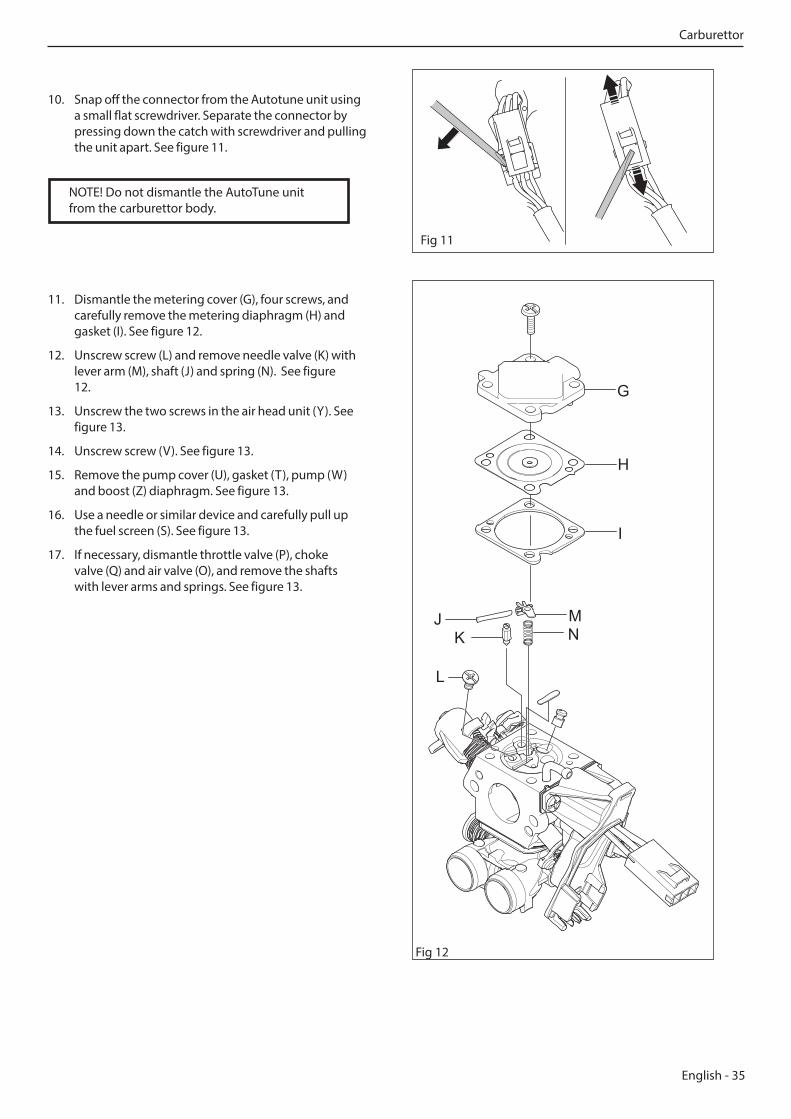
11. Dismantle the metering cover (G), four screws, and carefully remove the metering diaphragm (H) and gasket (I). See figure 12.
12. Unscrew screw (L) and remove needle valve (K) with lever arm (M), shaft (J) and spring (N). See figure 12.
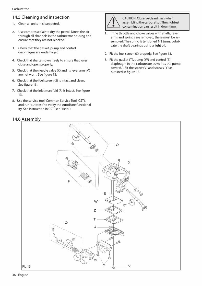
13. Unscrew the two screws in the air head unit (Y). See figure 13.
14. Unscrew screw (V). See figure 13.
15. Remove the pump cover (U), gasket (T), pump (W)and boost (Z) diaphragm. See figure 13.
16. Use a needle or similar device and carefully pull up the fuel screen (S). See figure 13.
17. If necessary, dismantle throttle valve (P), choke valve (Q) and air valve (O), and remove the shafts with lever arms and springs. See figure 13.
Fig 11
G
H
I
MN
JK
L
Fig 12
10. Snap off the connector from the Autotune unit using a small flat screwdriver. Separate the connector by pressing down the catch with screwdriver and pulling the unit apart. See figure 11.
Carburettor
NOTE! Do not dismantle the AutoTune unit from the carburettor body.
36 - English
1. If the throttle and choke valves with shafts, lever arms and springs are removed, these must be as-sembled. The spring is tensioned 1-2 turns. Lubri-cate the shaft bearings using a light oil.
2. Fit the fuel screen (S) properly. See figure 13.
3. Fit the gasket (T), pump (W) and control (Z) diaphragm in the carburettor as well as the pump cover (U). Fit the screw (V) and screws (Y) as outlined in figure 13.
14.5 Cleaning and inspection1. Clean all units in clean petrol.
2. Use compressed air to dry the petrol. Direct the air through all channels in the carburettor housing and ensure that they are not blocked.
3. Check that the gasket, pump and control diaphragms are undamaged.
4. Check that shafts moves freely to ensure that vales close and open properly.
5. Check that the needle valve (K) and its lever arm (M) are not worn. See figure 12.
6. Check that the fuel screen (S) is intact and clean. See figure 13.
7. Check that the inlet manifold (R) is intact. See figure 13.
8. Use the service tool, Common Service Tool (CST), and run “autotest” to verify the AutoTune functional-ity. See instruction in CST (see “Help”).
14.6 Assembly
O
P
S
TQ
R X
V
U
W
Y
Z
Fig 13
CAUTION! Observe cleanliness when assembling the carburettor. The slightest contamination can result in downtime.
Carburettor
English - 37
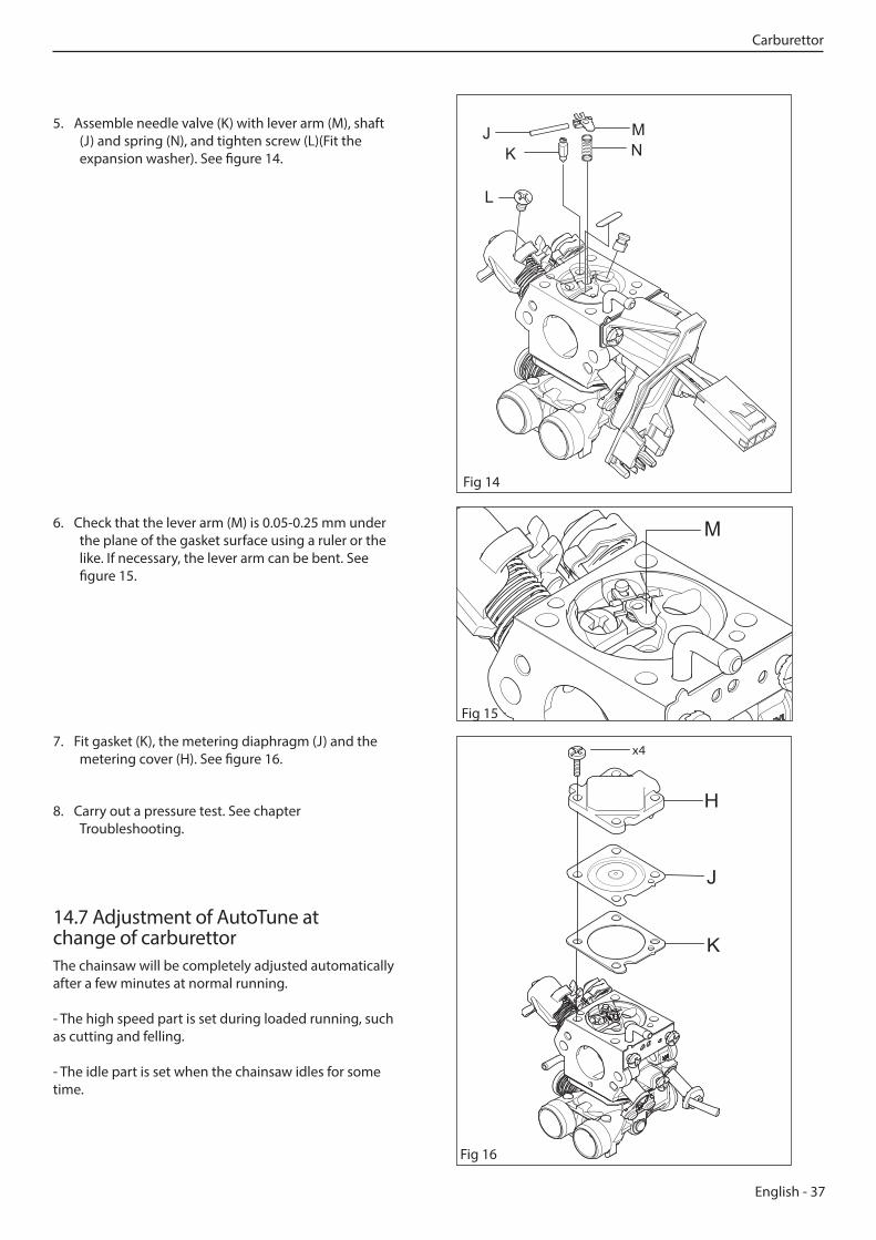
5. Assemble needle valve (K) with lever arm (M), shaft (J) and spring (N), and tighten screw (L)(Fit the expansion washer). See figure 14.
6. Check that the lever arm (M) is 0.05-0.25 mm under the plane of the gasket surface using a ruler or the like. If necessary, the lever arm can be bent. See figure 15.
Fig 14
MN
JK
L
M
Fig 15
7. Fit gasket (K), the metering diaphragm (J) and the metering cover (H). See figure 16.
8. Carry out a pressure test. See chapter Troubleshooting.
14.7 Adjustment of AutoTune at change of carburettorThe chainsaw will be completely adjusted automatically after a few minutes at normal running.
- The high speed part is set during loaded running, such as cutting and felling.
- The idle part is set when the chainsaw idles for some time.
Fig 16
Carburettor
38 - English
14.8 Fitting the carburettor on the chainsaw
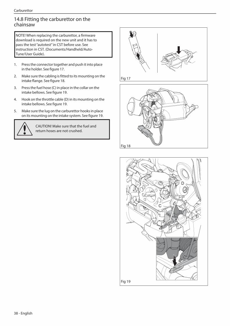
1. Press the connector together and push it into place in the holder. See figure 17.
2. Make sure the cabling is fitted to its mounting on the intake flange. See figure 18.
3. Press the fuel hose (C) in place in the collar on the intake bellows. See figure 19.
4. Hook on the throttle cable (D) in its mounting on the intake bellows. See figure 19.
5. Make sure the lug on the carburettor hooks in place on its mounting on the intake system. See figure 19.
D
C
Fig 19
Fig 17
Fig 18
CAUTION! Make sure that the fuel and return hoses are not crushed.
Carburettor
NOTE! When replacing the carburettor, a firmware download is required on the new unit and it has to pass the test “autotest” in CST before use. See instruction in CST. (Documents/Handheld/Auto-Tune/User Guide).
English - 39
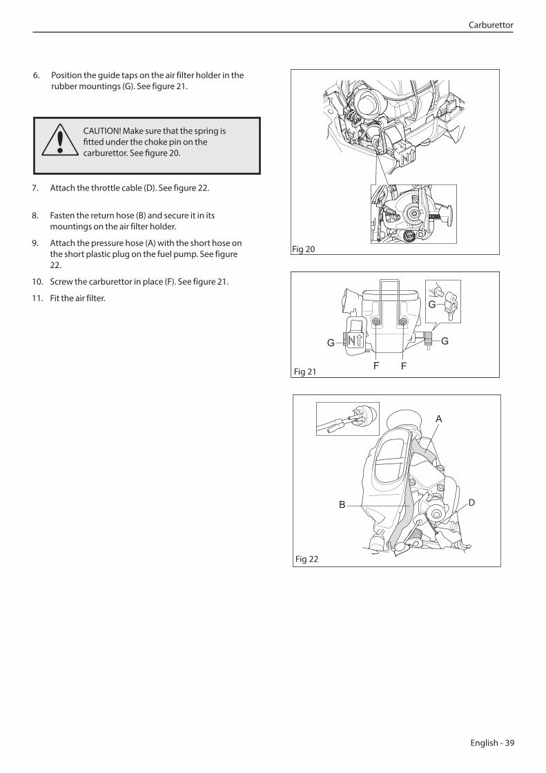
7. Attach the throttle cable (D). See figure 22.
8. Fasten the return hose (B) and secure it in its mountings on the air filter holder.
9. Attach the pressure hose (A) with the short hose on the short plastic plug on the fuel pump. See figure 22.
10. Screw the carburettor in place (F). See figure 21.
11. Fit the air filter.
Fig 22
D
Fig 21
6. Position the guide taps on the air filter holder in the rubber mountings (G). See figure 21.
Fig 20
CAUTION! Make sure that the spring is fitted under the choke pin on the carburettor. See figure 20.
Carburettor
40 - English
F
E
G
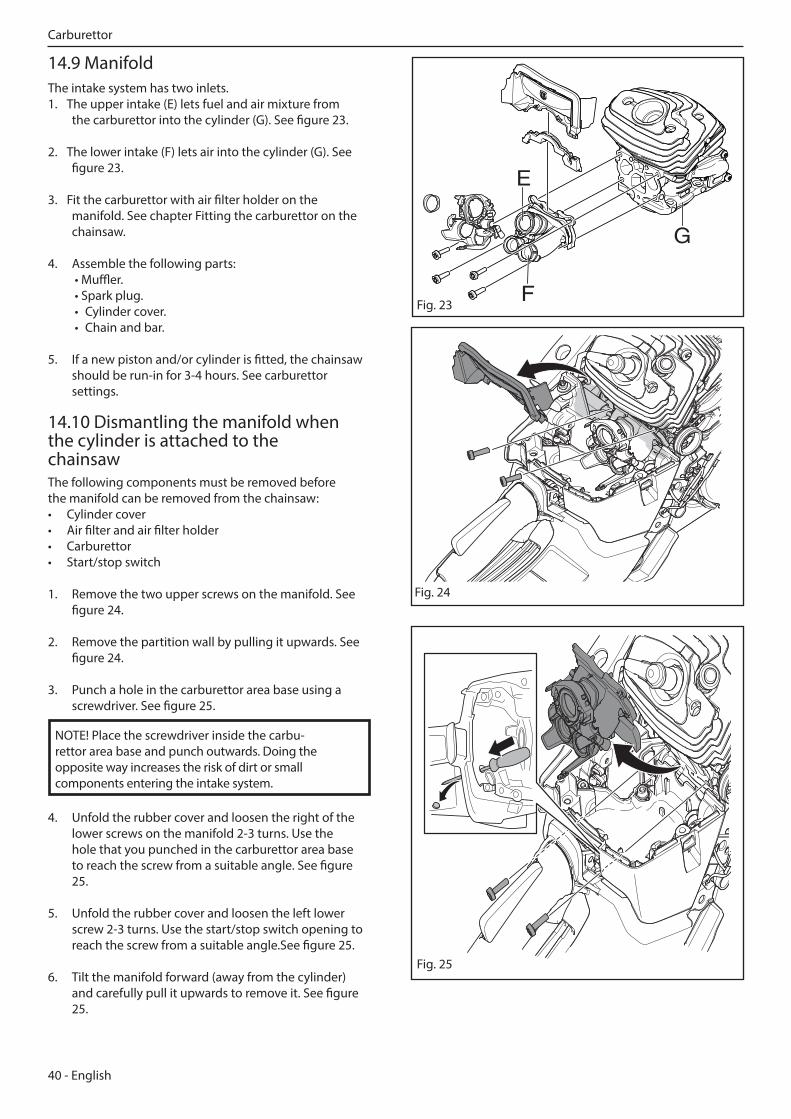
14.9 ManifoldThe intake system has two inlets.1. The upper intake (E) lets fuel and air mixture from
the carburettor into the cylinder (G). See figure 23.
2. The lower intake (F) lets air into the cylinder (G). See figure 23.
3. Fit the carburettor with air filter holder on the manifold. See chapter Fitting the carburettor on the chainsaw.
4. Assemble the following parts: • Muffler. • Spark plug. • Cylinder cover. • Chain and bar.
5. If a new piston and/or cylinder is fitted, the chainsaw should be run-in for 3-4 hours. See carburettor settings.
14.10 Dismantling the manifold when the cylinder is attached to the chainsawThe following components must be removed before the manifold can be removed from the chainsaw:• Cylinder cover• Air filter and air filter holder• Carburettor• Start/stop switch
1. Remove the two upper screws on the manifold. See figure 24.
2. Remove the partition wall by pulling it upwards. See figure 24.
3. Punch a hole in the carburettor area base using a screwdriver. See figure 25.
4. Unfold the rubber cover and loosen the right of the lower screws on the manifold 2-3 turns. Use the hole that you punched in the carburettor area base to reach the screw from a suitable angle. See figure 25.
5. Unfold the rubber cover and loosen the left lower screw 2-3 turns. Use the start/stop switch opening to reach the screw from a suitable angle.See figure 25.
6. Tilt the manifold forward (away from the cylinder) and carefully pull it upwards to remove it. See figure 25.
NOTE! Place the screwdriver inside the carbu-rettor area base and punch outwards. Doing the opposite way increases the risk of dirt or small components entering the intake system.
Fig. 23
Fig. 24
Fig. 25
Carburettor
English - 41
WARNING! The fuel used in the chainsaw has the following hazardous properties: 1. The fluid and its fumes are poisonous. 2. Can cause skin irritation. 3. Is highly inflammable.
15 Tank unit
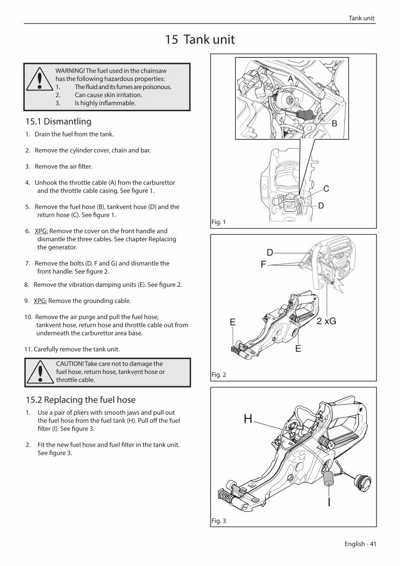
15.1 Dismantling1. Drain the fuel from the tank.
2. Remove the cylinder cover, chain and bar.
3. Remove the air filter.
4. Unhook the throttle cable (A) from the carburettor and the throttle cable casing. See figure 1.
5. Remove the fuel hose (B), tankvent hose (D) and the return hose (C). See figure 1.
6. XPG: Remove the cover on the front handle and dismantle the three cables. See chapter Replacing the generator.
7. Remove the bolts (D, F and G) and dismantle the front handle. See figure 2.
Fig. 2
Fig. 3
8. Remove the vibration damping units (E). See figure 2.
9. XPG: Remove the grounding cable.
10. Remove the air purge and pull the fuel hose, tankvent hose, return hose and throttle cable out from underneath the carburettor area base.
11. Carefully remove the tank unit.
Fig. 1
B
A
D
C
15.2 Replacing the fuel hose1. Use a pair of pliers with smooth jaws and pull out
the fuel hose from the fuel tank (H). Pull off the fuel filter (I). See figure 3.
2. Fit the new fuel hose and fuel filter in the tank unit. See figure 3.
CAUTION! Take care not to damage the fuel hose, return hose, tankvent hose or throttle cable.
D
2 xG
F
E
E
I
H
Tank unit
42 - English
15.3 Cleaning and inspectionClean all parts and check that the fuel hose is intact.
15.4 Assembly1. If the throttle trigger lockout has been removed, it
should be refitted before the tank unit and engine unit are assembled. See chapter Throttle trigger lockout, throttle trigger and spring.
2. Push the fuel hose, tankvent hose and throttle cable through their holes in the carburettor area base.
3. XPG: Assemble the screw to the grounding cable.
4. Fit the vibration damping units (E). See figure 2.
5. Fit the front handle with the bolts (D, F and G). See figure 2.
6. XPG: Assemble the cables in the handle and fit the cover on the front handle. See chapter Replacing the generator.
7. Fit the fuel hose (B), tankvent hose (D) and return hose (C). See figure 1.
8. Insert the throttle cable casing in the attachment and hook on the throttle cable (A) to the carburettor. See figure 1.
9. Fit the cylinder cover, bar and chain.
CAUTION! Take care not to damage the fuel hose and throttle cable.
15.5 Tank valveThe tank valve is a two-way valve and has the following features:• Controlled opening pressure in both directions, which prevents excess of pressure or vacuum developing in the fuel tank and impairing engine operation.
• Resistant to clogging with dirt.
• Resistant to icing up during winter operation. Venting pressure 150-400 mbar. Opening pressure under vacuum, max. 115 mbar.
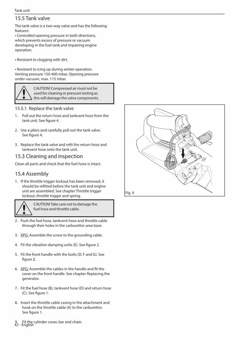
15.5.1 Replace the tank valve1. Pull out the return hose and tankvent hose from the
tank unit. See figure 4.
2. Use a pliers and carefully pull out the tank valve. See figure 4.
3. Replace the tank valve and refit the return hose and tankvent hose onto the tank unit.
CAUTION! Compressed air must not be used for cleaning or pressure testing as this will damage the valve components.
Fig. 4
Tank unit
English - 43
WARNING! The fuel used in the chainsaw has the following hazardous properties: 1. The fluid and its fumes are poisonous. 2. Can cause skin irritation. 3. Is highly inflammable.
16 Anti-vibration system
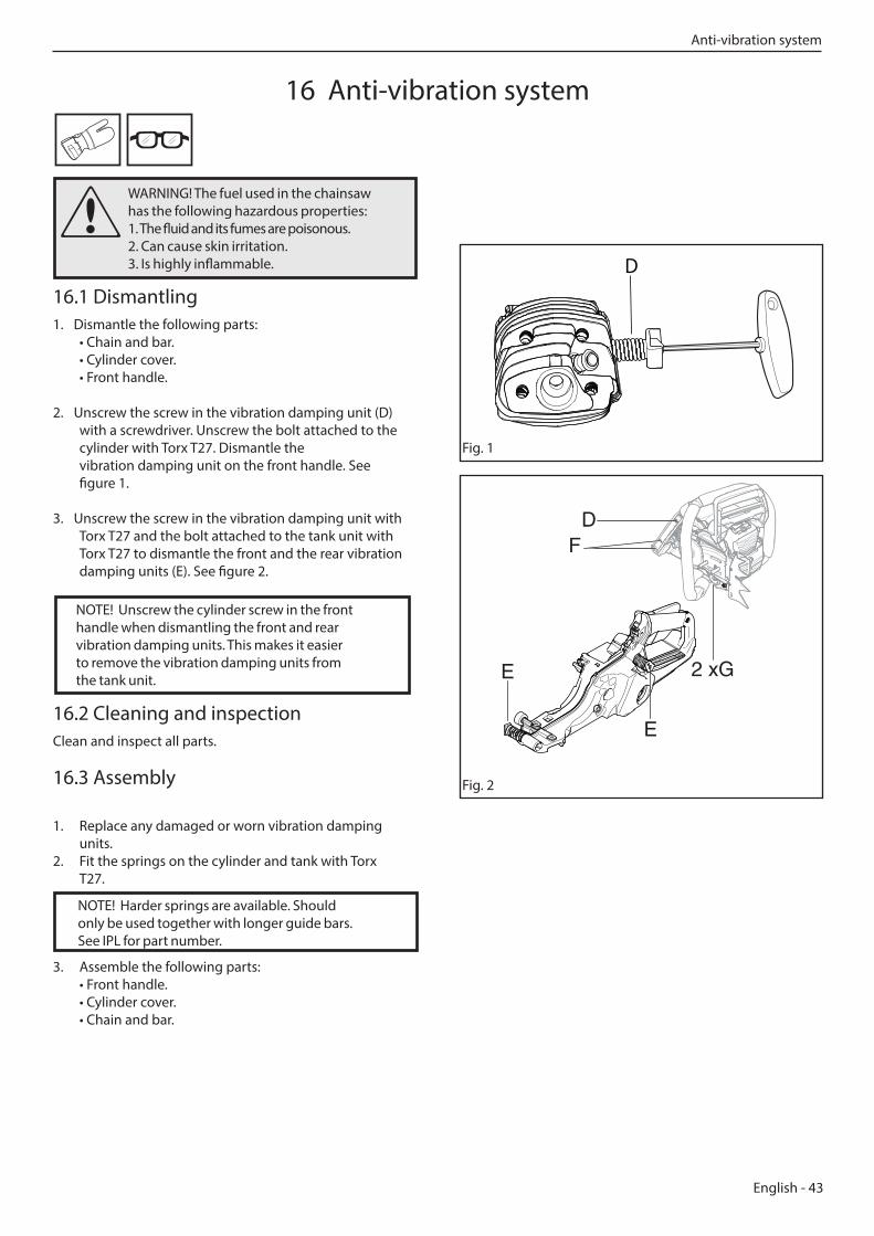
16.1 Dismantling1. Dismantle the following parts:
• Chain and bar. • Cylinder cover. • Front handle.
2. Unscrew the screw in the vibration damping unit (D)with a screwdriver. Unscrew the bolt attached to the cylinder with Torx T27. Dismantle the vibration damping unit on the front handle. See figure 1.
3. Unscrew the screw in the vibration damping unit with Torx T27 and the bolt attached to the tank unit with Torx T27 to dismantle the front and the rear vibration damping units (E). See figure 2.
16.2 Cleaning and inspectionClean and inspect all parts.
16.3 Assembly
1. Replace any damaged or worn vibration damping units.
2. Fit the springs on the cylinder and tank with Torx T27.
3. Assemble the following parts: • Front handle. • Cylinder cover. • Chain and bar.
D
Fig. 1
Fig. 2
NOTE! Unscrew the cylinder screw in the front handle when dismantling the front and rear vibration damping units. This makes it easier to remove the vibration damping units from the tank unit.
NOTE! Harder springs are available. Should only be used together with longer guide bars. See IPL for part number.
D
2 xG
F
E
E
Anti-vibration system
44 - English
17.1 Dismantling
1. Dismantle the following parts: • Cylinder cover. • Spark plug. • Carburettor. See chapter Carburettor. • Muffler. See chapter Muffler.
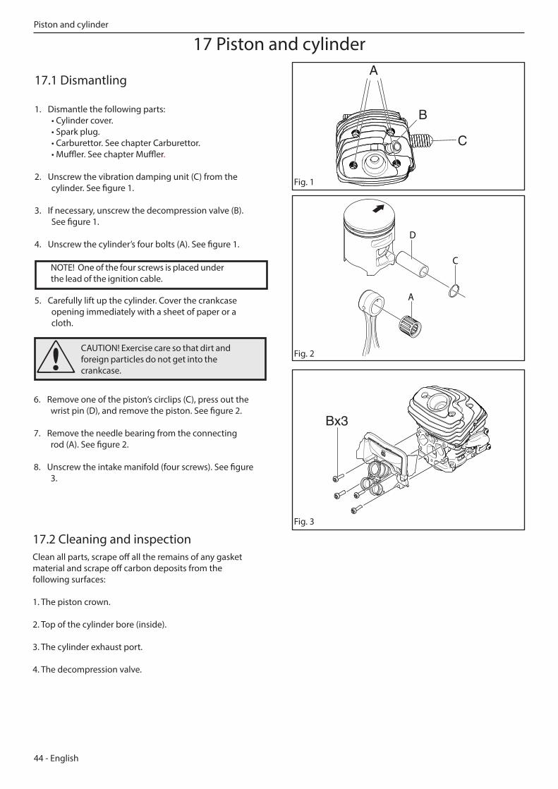
2. Unscrew the vibration damping unit (C) from the cylinder. See figure 1.
3. If necessary, unscrew the decompression valve (B). See figure 1.
4. Unscrew the cylinder’s four bolts (A). See figure 1.
5. Carefully lift up the cylinder. Cover the crankcase opening immediately with a sheet of paper or a cloth.
17 Piston and cylinder
Fig. 1
Fig. 2
17.2 Cleaning and inspectionClean all parts, scrape off all the remains of any gasket material and scrape off carbon deposits from the following surfaces:
1. The piston crown.
2. Top of the cylinder bore (inside).
3. The cylinder exhaust port.
4. The decompression valve.
Bx3
6. Remove one of the piston’s circlips (C), press out the wrist pin (D), and remove the piston. See figure 2.
7. Remove the needle bearing from the connecting rod (A). See figure 2.
8. Unscrew the intake manifold (four screws). See figure 3.
CAUTION! Exercise care so that dirt and foreign particles do not get into the crankcase.
Fig. 3
A
B
C
NOTE! One of the four screws is placed under the lead of the ignition cable.
A
D
C
Piston and cylinder
English - 45
Fig. 5
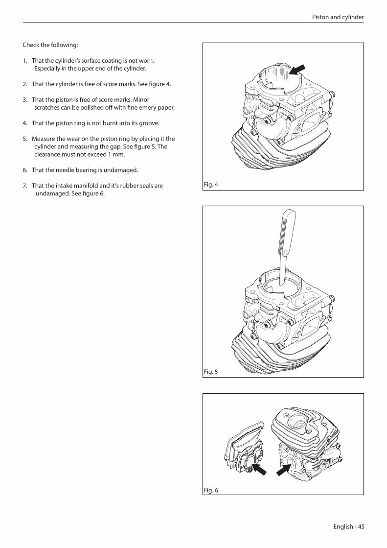
Check the following:
1. That the cylinder’s surface coating is not worn. Especially in the upper end of the cylinder.
2. That the cylinder is free of score marks. See figure 4.
3. That the piston is free of score marks. Minor scratches can be polished off with fine emery paper.
4. That the piston ring is not burnt into its groove.
5. Measure the wear on the piston ring by placing it the cylinder and measuring the gap. See figure 5. The clearance must not exceed 1 mm.
6. That the needle bearing is undamaged.
7. That the intake manifold and it's rubber seals are undamaged. See figure 6.
Fig. 4
Fig. 6
Piston and cylinder
46 - English
17.3 Assembly
A
D
C
Fig. 7
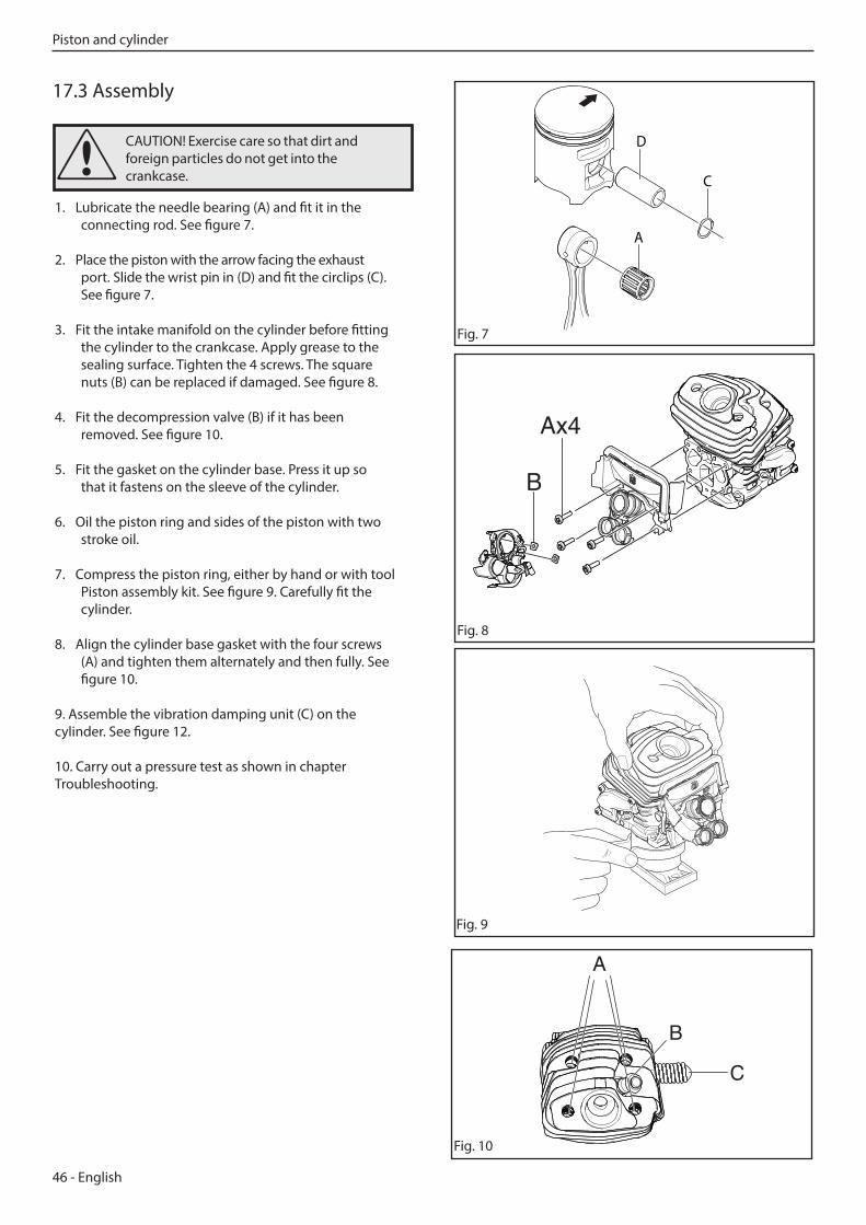
1. Lubricate the needle bearing (A) and fit it in the connecting rod. See figure 7.
2. Place the piston with the arrow facing the exhaust port. Slide the wrist pin in (D) and fit the circlips (C). See figure 7.
3. Fit the intake manifold on the cylinder before fitting the cylinder to the crankcase. Apply grease to the sealing surface. Tighten the 4 screws. The square nuts (B) can be replaced if damaged. See figure 8.
4. Fit the decompression valve (B) if it has been removed. See figure 10.
5. Fit the gasket on the cylinder base. Press it up so that it fastens on the sleeve of the cylinder.
6. Oil the piston ring and sides of the piston with two stroke oil.
7. Compress the piston ring, either by hand or with tool Piston assembly kit. See figure 9. Carefully fit the cylinder.
8. Align the cylinder base gasket with the four screws (A) and tighten them alternately and then fully. See figure 10.
9. Assemble the vibration damping unit (C) on the cylinder. See figure 12.
10. Carry out a pressure test as shown in chapter Troubleshooting.
Ax4
B
Fig. 8
CAUTION! Exercise care so that dirt and foreign particles do not get into the crankcase.
Fig. 9
A
B
C
Fig. 10
Piston and cylinder
English - 47
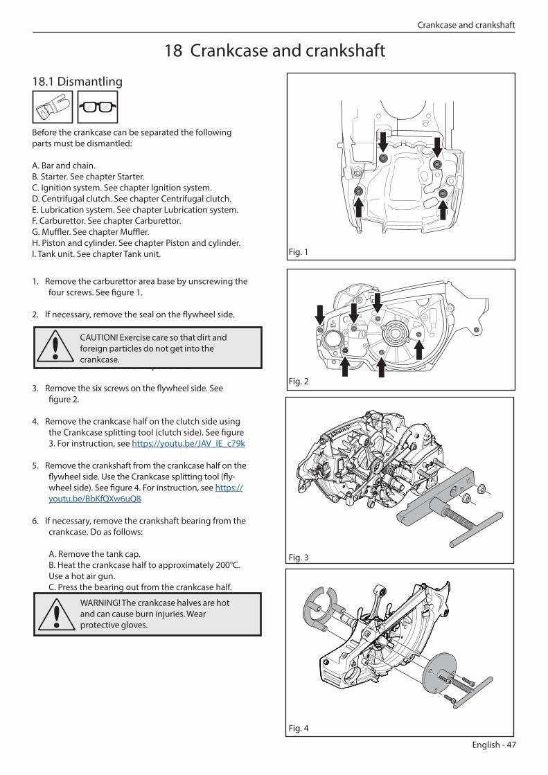
18.1 Dismantling Before the crankcase can be separated the following parts must be dismantled: A. Bar and chain. B. Starter. See chapter Starter. C. Ignition system. See chapter Ignition system. D. Centrifugal clutch. See chapter Centrifugal clutch. E. Lubrication system. See chapter Lubrication system. F. Carburettor. See chapter Carburettor. G. Muffler. See chapter Muffler. H. Piston and cylinder. See chapter Piston and cylinder. I. Tank unit. See chapter Tank unit.
1. Remove the carburettor area base by unscrewing the four screws. See figure 1.
2. If necessary, remove the seal on the flywheel side.
Use the Puller tool. See chapter Seals.
3. Remove the six screws on the flywheel side. See figure 2.
4. Remove the crankcase half on the clutch side using the Crankcase splitting tool (clutch side). See figure 3. For instruction, see https://youtu.be/JAV_lE_c79k
5. Remove the crankshaft from the crankcase half on the flywheel side. Use the Crankcase splitting tool (fly-wheel side). See figure 4. For instruction, see https://youtu.be/BbKfQXw6uQ8
6. If necessary, remove the crankshaft bearing from the crankcase. Do as follows: A. Remove the tank cap. B. Heat the crankcase half to approximately 200°C. Use a hot air gun. C. Press the bearing out from the crankcase half.
Fig. 1
Fig. 2
Fig. 3
WARNING! The crankcase halves are hot and can cause burn injuries. Wear protective gloves.
CAUTION! Exercise care so that dirt and foreign particles do not get into the crankcase.
Fig. 4
18 Crankcase and crankshaft
Crankcase and crankshaft
48 - English
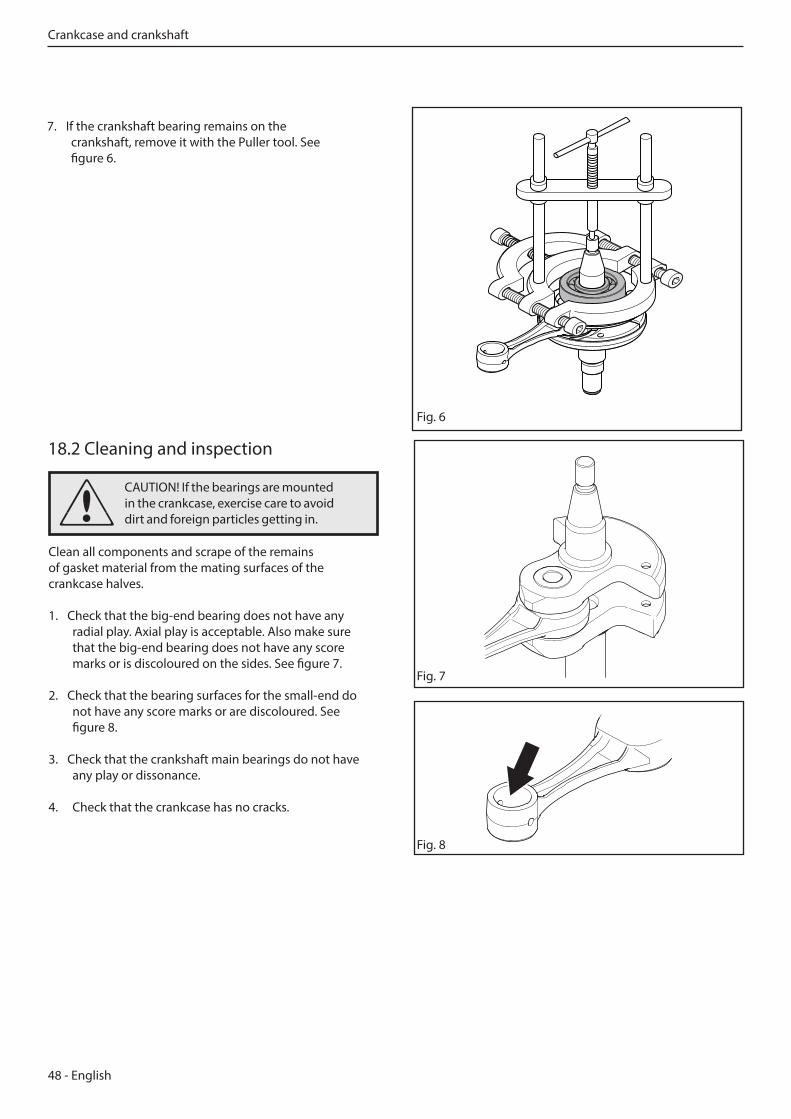
7. If the crankshaft bearing remains on the crankshaft, remove it with the Puller tool. See figure 6.
18.2 Cleaning and inspection
Clean all components and scrape of the remains of gasket material from the mating surfaces of the crankcase halves.
1. Check that the big-end bearing does not have any radial play. Axial play is acceptable. Also make sure that the big-end bearing does not have any score marks or is discoloured on the sides. See figure 7.
2. Check that the bearing surfaces for the small-end do not have any score marks or are discoloured. See figure 8.
3. Check that the crankshaft main bearings do not have any play or dissonance.
4. Check that the crankcase has no cracks.
Fig. 7
Fig. 6
CAUTION! If the bearings are mounted in the crankcase, exercise care to avoid dirt and foreign particles getting in.
Fig. 8
Crankcase and crankshaft
English - 49
18.3 Assembly
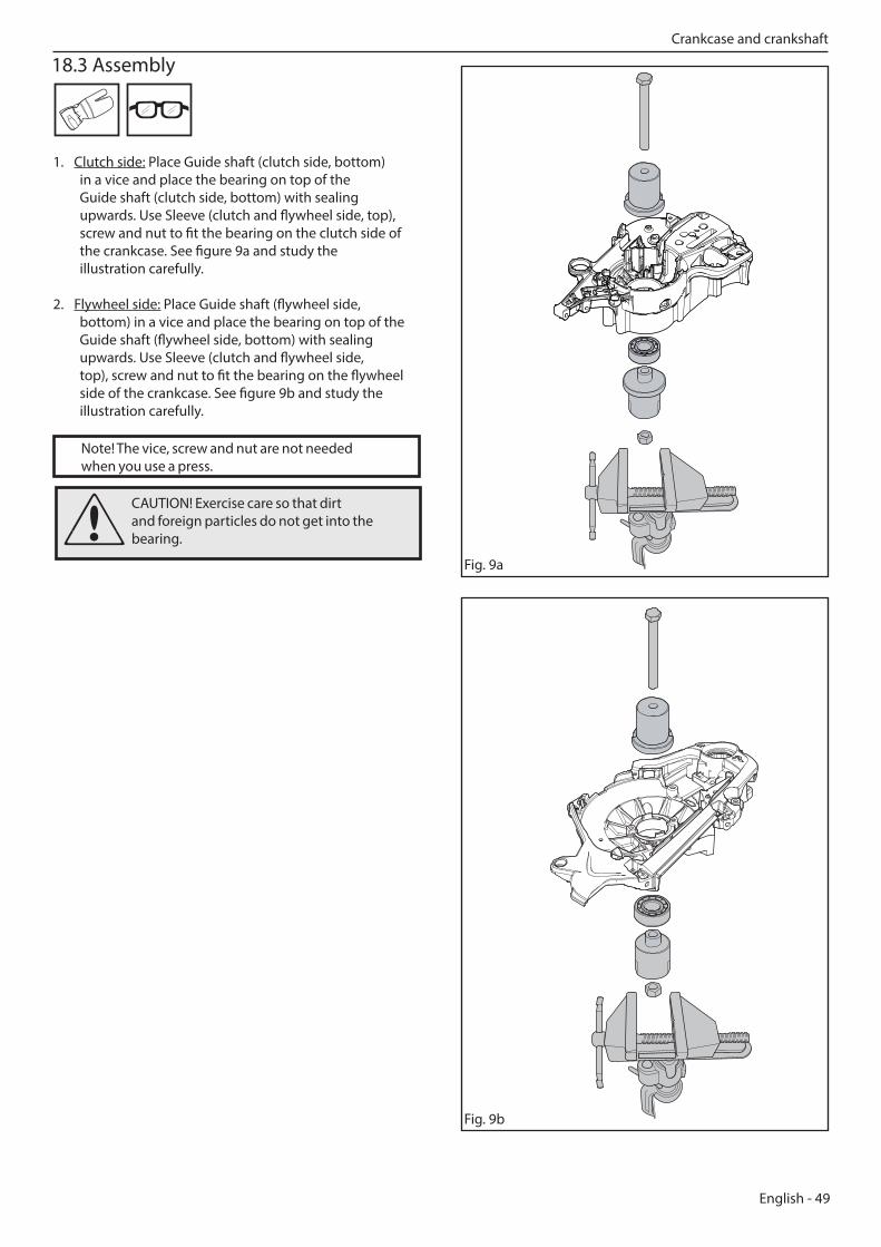
1. Clutch side: Place Guide shaft (clutch side, bottom) in a vice and place the bearing on top of the Guide shaft (clutch side, bottom) with sealing upwards. Use Sleeve (clutch and flywheel side, top), screw and nut to fit the bearing on the clutch side of the crankcase. See figure 9a and study the illustration carefully.
2. Flywheel side: Place Guide shaft (flywheel side, bottom) in a vice and place the bearing on top of the Guide shaft (flywheel side, bottom) with sealing upwards. Use Sleeve (clutch and flywheel side, top), screw and nut to fit the bearing on the flywheel side of the crankcase. See figure 9b and study the illustration carefully.
Fig. 9a
CAUTION! Exercise care so that dirt and foreign particles do not get into the bearing.
Crankcase and crankshaft
Note! The vice, screw and nut are not needed when you use a press.
Fig. 9b
50 - English
Crankcase and crankshaft
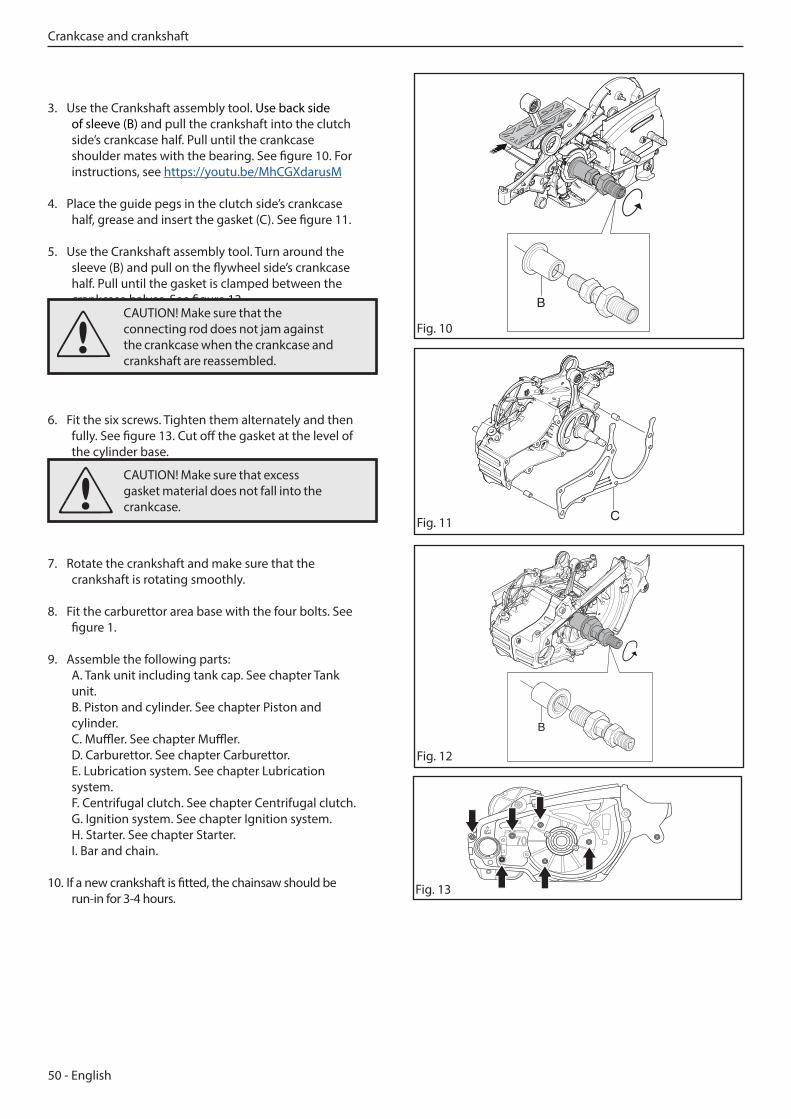
3. Use the Crankshaft assembly tool. Use back side of sleeve (B) and pull the crankshaft into the clutch side’s crankcase half. Pull until the crankcase shoulder mates with the bearing. See figure 10. For instructions, see https://youtu.be/MhCGXdarusM
4. Place the guide pegs in the clutch side’s crankcase half, grease and insert the gasket (C). See figure 11.
5. Use the Crankshaft assembly tool. Turn around the sleeve (B) and pull on the flywheel side’s crankcase half. Pull until the gasket is clamped between the crankcase halves. See figure 12.
6. Fit the six screws. Tighten them alternately and then fully. See figure 13. Cut off the gasket at the level of the cylinder base.
7. Rotate the crankshaft and make sure that the crankshaft is rotating smoothly.
8. Fit the carburettor area base with the four bolts. See figure 1.
9. Assemble the following parts: A. Tank unit including tank cap. See chapter Tank unit. B. Piston and cylinder. See chapter Piston and cylinder. C. Muffler. See chapter Muffler. D. Carburettor. See chapter Carburettor. E. Lubrication system. See chapter Lubrication system. F. Centrifugal clutch. See chapter Centrifugal clutch. G. Ignition system. See chapter Ignition system. H. Starter. See chapter Starter. I. Bar and chain.
10. If a new crankshaft is fitted, the chainsaw should be run-in for 3-4 hours.
B
C
Fig. 10CAUTION! Make sure that the connecting rod does not jam against the crankcase when the crankcase and crankshaft are reassembled.
B
Fig. 12
Fig. 13
CAUTION! Make sure that excess gasket material does not fall into the crankcase.
Fig. 11
English - 51
18.4 Seals
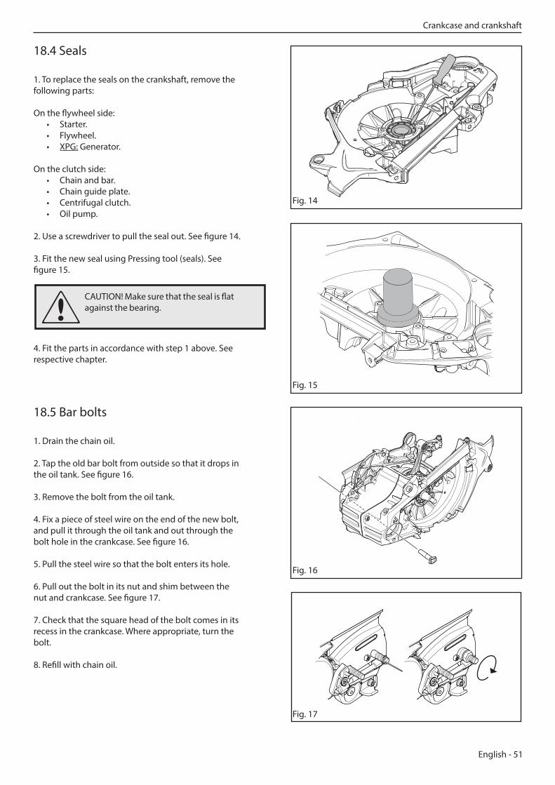
1. To replace the seals on the crankshaft, remove the following parts:
On the flywheel side: • Starter. • Flywheel. • XPG: Generator.
On the clutch side: • Chain and bar. • Chain guide plate. • Centrifugal clutch. • Oil pump.
2. Use a screwdriver to pull the seal out. See figure 14.
3. Fit the new seal using Pressing tool (seals). See figure 15.
4. Fit the parts in accordance with step 1 above. See respective chapter.
18.5 Bar bolts
1. Drain the chain oil.
2. Tap the old bar bolt from outside so that it drops in the oil tank. See figure 16.
3. Remove the bolt from the oil tank.
4. Fix a piece of steel wire on the end of the new bolt, and pull it through the oil tank and out through the bolt hole in the crankcase. See figure 16.
5. Pull the steel wire so that the bolt enters its hole.
6. Pull out the bolt in its nut and shim between the nut and crankcase. See figure 17.
7. Check that the square head of the bolt comes in its recess in the crankcase. Where appropriate, turn the bolt.
8. Refill with chain oil.
Fig. 14
Fig. 15
Fig. 16
Fig. 17
CAUTION! Make sure that the seal is flat against the bearing.
Crankcase and crankshaft
52 - English
19 Troubleshooting
Troubleshooting
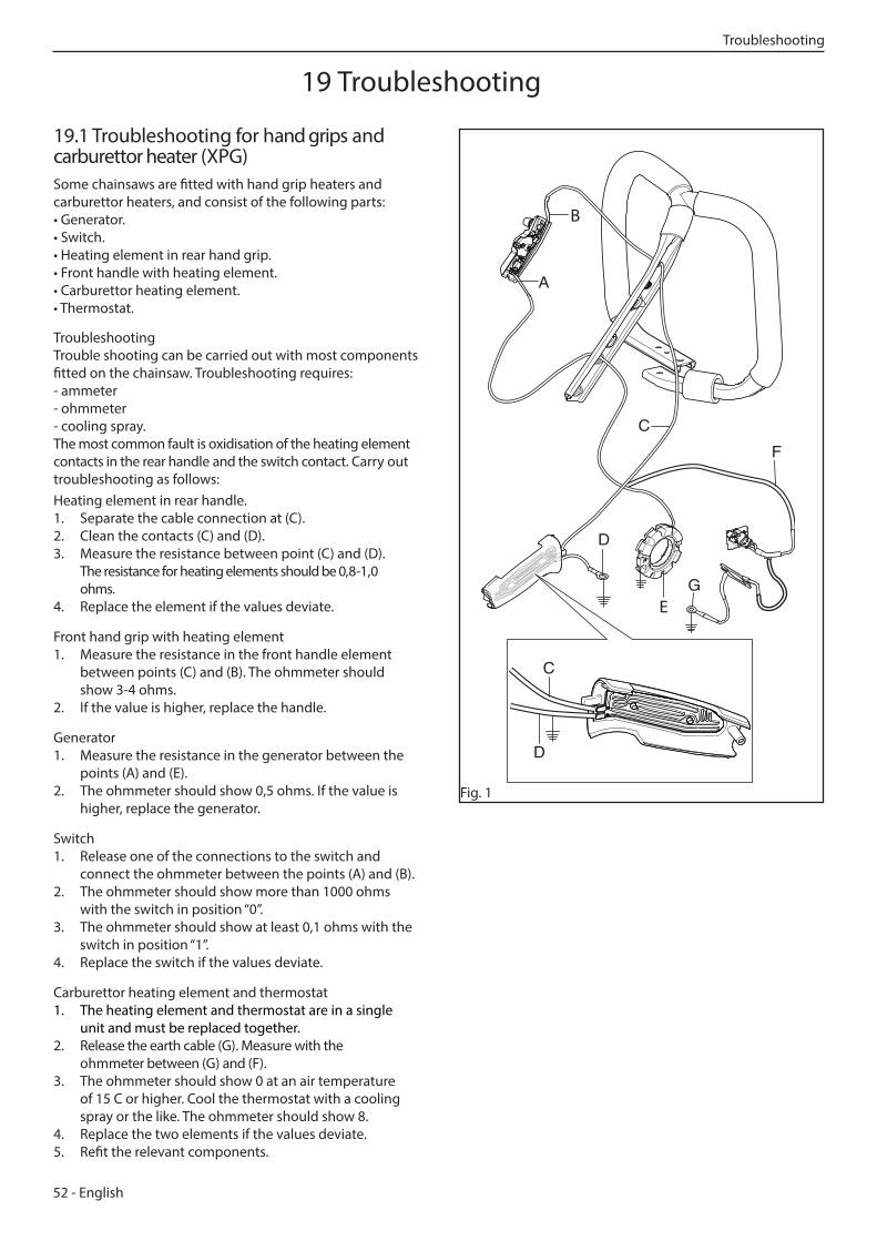
19.1 Troubleshooting for hand grips and carburettor heater (XPG)Some chainsaws are fitted with hand grip heaters and carburettor heaters, and consist of the following parts:• Generator.• Switch.• Heating element in rear hand grip.• Front handle with heating element.• Carburettor heating element.• Thermostat.
TroubleshootingTrouble shooting can be carried out with most components fitted on the chainsaw. Troubleshooting requires: - ammeter- ohmmeter- cooling spray.The most common fault is oxidisation of the heating element contacts in the rear handle and the switch contact. Carry out troubleshooting as follows:Heating element in rear handle.1. Separate the cable connection at (C).2. Clean the contacts (C) and (D).3. Measure the resistance between point (C) and (D).
The resistance for heating elements should be 0,8-1,0 ohms.
4. Replace the element if the values deviate.
Front hand grip with heating element1. Measure the resistance in the front handle element
between points (C) and (B). The ohmmeter should show 3-4 ohms.
2. If the value is higher, replace the handle.
Generator1. Measure the resistance in the generator between the
points (A) and (E). 2. The ohmmeter should show 0,5 ohms. If the value is
higher, replace the generator.
Switch1. Release one of the connections to the switch and
connect the ohmmeter between the points (A) and (B). 2. The ohmmeter should show more than 1000 ohms
with the switch in position “0”.3. The ohmmeter should show at least 0,1 ohms with the
switch in position “1”.4. Replace the switch if the values deviate.
Carburettor heating element and thermostat1. The heating element and thermostat are in a single
unit and must be replaced together.2. Release the earth cable (G). Measure with the
ohmmeter between (G) and (F). 3. The ohmmeter should show 0 at an air temperature
of 15 C or higher. Cool the thermostat with a cooling spray or the like. The ohmmeter should show 8.
4. Replace the two elements if the values deviate. 5. Refit the relevant components.
D
C
F
G
A
E
B
D
C
Fig. 1
English - 53
Troubleshooting
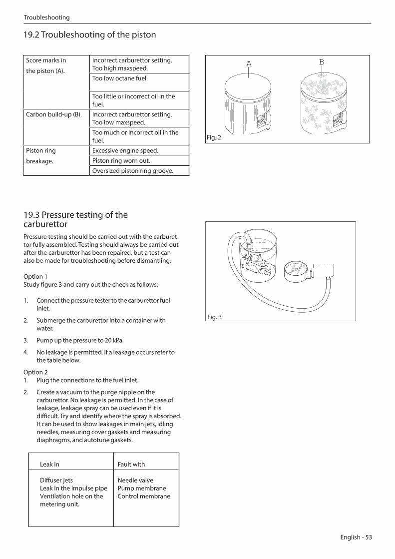
19.2 Troubleshooting of the piston
Score marks in
the piston (A).
Incorrect carburettor setting. Too high maxspeed.
Too low octane fuel.
Too little or incorrect oil in the fuel.
Carbon build-up (B). Incorrect carburettor setting. Too low maxspeed.
Too much or incorrect oil in the fuel.
Piston ring
breakage.
Excessive engine speed.
Piston ring worn out.
Oversized piston ring groove.
Fig. 2
A B
Leak in Fault with Diffuser jets Needle valve Leak in the impulse pipe Pump membrane Ventilation hole on the Control membrane metering unit.
19.3 Pressure testing of the carburettorPressure testing should be carried out with the carburet-tor fully assembled. Testing should always be carried out after the carburettor has been repaired, but a test can also be made for troubleshooting before dismantling. Option 1 Study figure 3 and carry out the check as follows:
1. Connect the pressure tester to the carburettor fuel inlet.
2. Submerge the carburettor into a container with water.
3. Pump up the pressure to 20 kPa.
4. No leakage is permitted. If a leakage occurs refer to the table below.
Option 2 1. Plug the connections to the fuel inlet.
2. Create a vacuum to the purge nipple on the carburettor. No leakage is permitted. In the case of leakage, leakage spray can be used even if it is difficult. Try and identify where the spray is absorbed. It can be used to show leakages in main jets, idling needles, measuring cover gaskets and measuring diaphragms, and autotune gaskets.
Fig. 3
54 - English
Troubleshooting
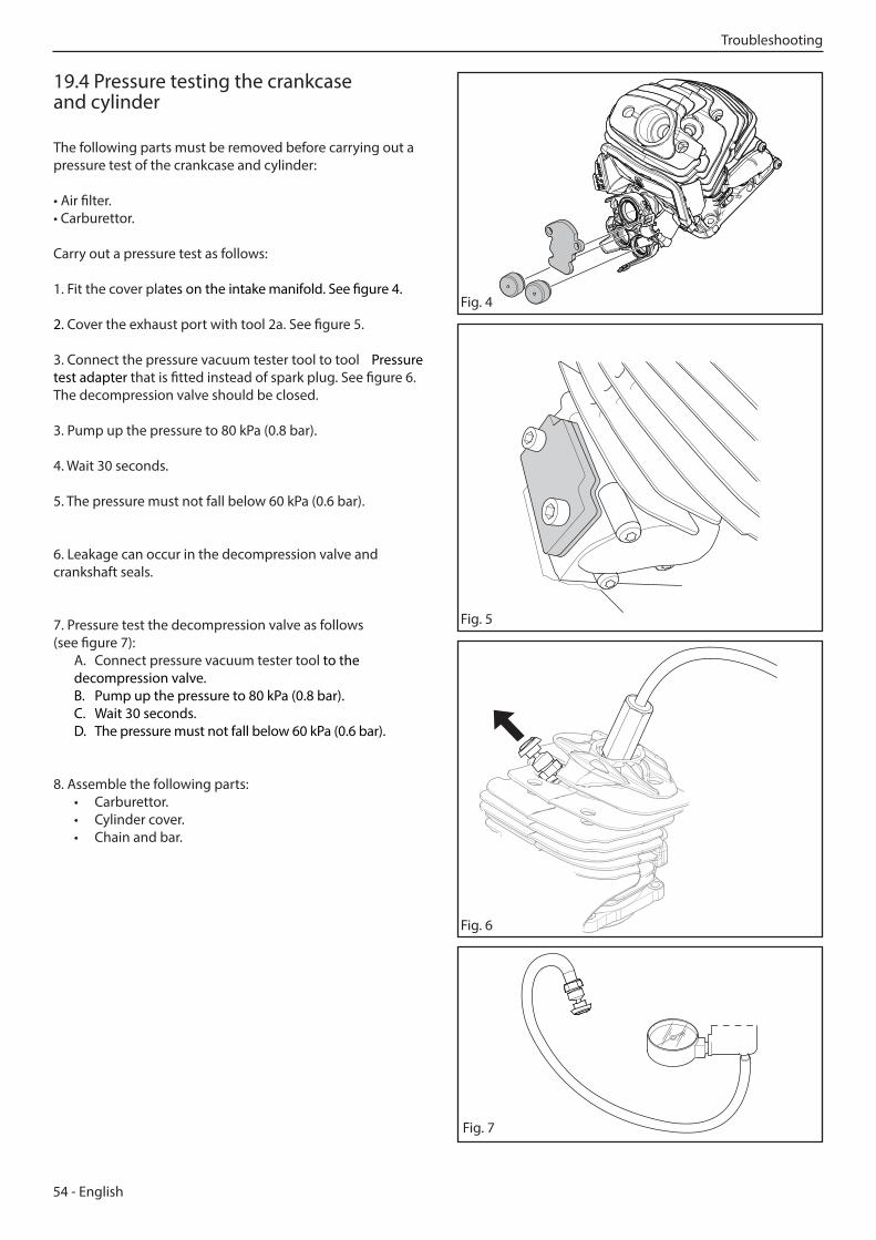
19.4 Pressure testing the crankcase and cylinder
The following parts must be removed before carrying out a pressure test of the crankcase and cylinder:
• Air filter. • Carburettor.
Carry out a pressure test as follows:
1. Fit the cover plates on the intake manifold. See figure 4. 2. Cover the exhaust port with tool 2a. See figure 5.
3. Connect the pressure vacuum tester tool to tool Pressure test adapter that is fitted instead of spark plug. See figure 6. The decompression valve should be closed.
3. Pump up the pressure to 80 kPa (0.8 bar).
4. Wait 30 seconds.
5. The pressure must not fall below 60 kPa (0.6 bar).
6. Leakage can occur in the decompression valve and crankshaft seals.
7. Pressure test the decompression valve as follows (see figure 7): A. Connect pressure vacuum tester tool to the decompression valve. B. Pump up the pressure to 80 kPa (0.8 bar). C. Wait 30 seconds. D. The pressure must not fall below 60 kPa (0.6 bar).
8. Assemble the following parts: • Carburettor. • Cylinder cover. • Chain and bar.
Fig. 4
Fig. 5
Fig. 6
Fig. 7 115 88 76-26

English - 55
2019-05-21
115 88 76-26
Related Documents