S-72.3240 Wireless Personal, Local, Metropolitan, and Wide Area Networks 1 WLAN, part 2 Contents IEEE 802.11 MAC layer operation • Basic CSMA/CA operation • Network Allocation Vector (NAV) • Backoff • Contention window • Wireless medium access example Usage of RTS / CTS • Basic operation • When should RTS/CTS be used?

Welcome message from author
This document is posted to help you gain knowledge. Please leave a comment to let me know what you think about it! Share it to your friends and learn new things together.
Transcript
S-72.3240 Wireless Personal, Local, Metropolitan, and Wide Area Networks 1
WLAN, part 2
Contents
IEEE 802.11 MAC layer operation• Basic CSMA/CA operation• Network Allocation Vector (NAV)• Backoff• Contention window • Wireless medium access example
Usage of RTS / CTS• Basic operation• When should RTS/CTS be used?

S-72.3240 Wireless Personal, Local, Metropolitan, and Wide Area Networks 2
WLAN, part 2
Medium Access Control (MAC)
LLCLLCMACMACPHYPHY
:
Medium access control: Different nodes must gain accessto the shared medium (for instance a wireless channel) in a controlled fashion (otherwise there will be collisions).
FDMAFDMA
TDMATDMA
CDMACDMA
CSMACSMA
Assigning channels in frequency domainAssigning time slots in time domainAssigning code sequences in code domainAssigning transmission opportunities in time domain on a statistical basis
Access methods:
S-72.3240 Wireless Personal, Local, Metropolitan, and Wide Area Networks 3
WLAN, part 2
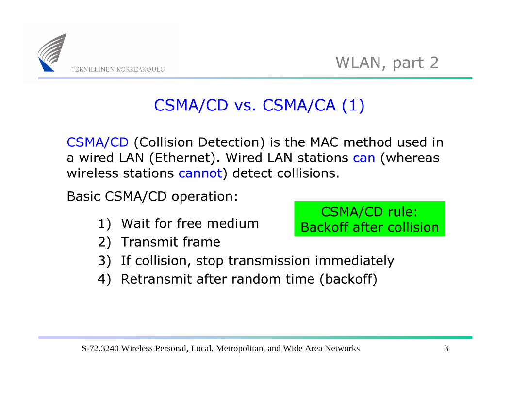
CSMA/CD vs. CSMA/CA (1)CSMA/CD (Collision Detection) is the MAC method used in a wired LAN (Ethernet). Wired LAN stations can (whereaswireless stations cannot) detect collisions.Basic CSMA/CD operation:
1) Wait for free medium 2) Transmit frame3) If collision, stop transmission immediately4) Retransmit after random time (backoff)
CSMA/CD rule: Backoff after collision
S-72.3240 Wireless Personal, Local, Metropolitan, and Wide Area Networks 4
WLAN, part 2
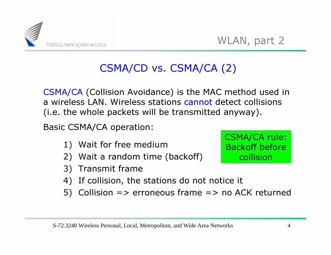
CSMA/CD vs. CSMA/CA (2)CSMA/CA (Collision Avoidance) is the MAC method used in a wireless LAN. Wireless stations cannot detect collisions(i.e. the whole packets will be transmitted anyway).Basic CSMA/CA operation:
1) Wait for free medium 2) Wait a random time (backoff)3) Transmit frame4) If collision, the stations do not notice it5) Collision => erroneous frame => no ACK returned
CSMA/CA rule: Backoff before
collision
S-72.3240 Wireless Personal, Local, Metropolitan, and Wide Area Networks 5
WLAN, part 2
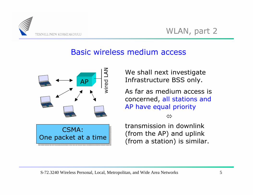
Basic wireless medium access
APWe shall next investigateInfrastructure BSS only.As far as medium access is concerned, all stations and AP have equal priority
�transmission in downlink(from the AP) and uplink(from a station) is similar.
CSMA:One packet at a time
wire
d LA
N
S-72.3240 Wireless Personal, Local, Metropolitan, and Wide Area Networks 6
WLAN, part 2
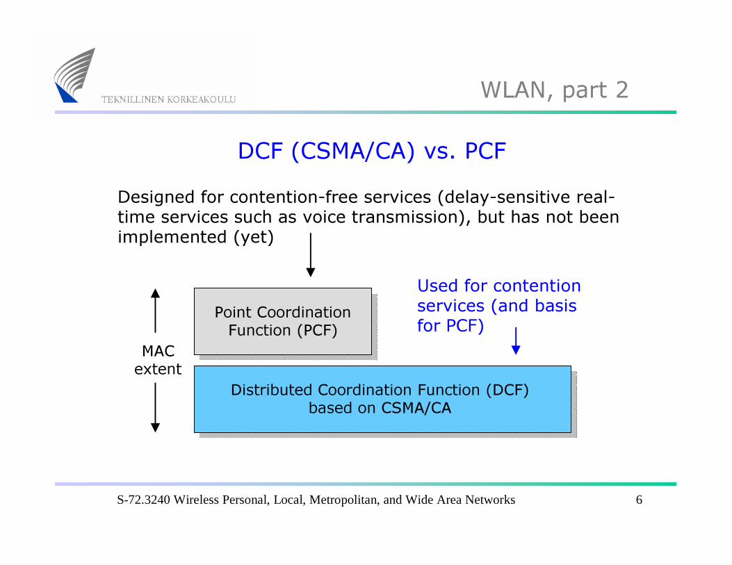
DCF (CSMA/CA) vs. PCF
Distributed Coordination Function (DCF) based on CSMA/CA
Point Coordination Function (PCF)
MAC extent
Used for contention services (and basis for PCF)
Designed for contention-free services (delay-sensitive real-time services such as voice transmission), but has not been implemented (yet)

S-72.3240 Wireless Personal, Local, Metropolitan, and Wide Area Networks 7
WLAN, part 2
Wireless medium access (1)
DIFS SIFS
ACK (B=>A)
Transmittedframe
(A=>B)
When a frame is received without bit errors, the receivingstation (B) sends an Acknowledgement (ACK) frame backto the transmitting station (A).
If the received frameis erroneous, no ACK will be sent
Cyclic RedundancyCheck (CRC) is usedfor error detection

S-72.3240 Wireless Personal, Local, Metropolitan, and Wide Area Networks 8
WLAN, part 2
Wireless medium access (2)
DIFS SIFS DIFS
ACK (B=>A)
Transmittedframe
(A=>B)
During the transmission sequence (Frame + SIFS + ACK) the medium (radio channel) is reserved. The next framecan be transmitted at earliest after the next DIFS period.
Next frame(from any station)
Earliest allowedtransmission timeof next frame
S-72.3240 Wireless Personal, Local, Metropolitan, and Wide Area Networks 9
WLAN, part 2
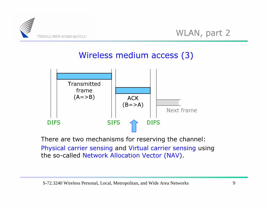
Wireless medium access (3)
DIFS SIFS DIFS
ACK (B=>A)
Transmittedframe
(A=>B)
There are two mechanisms for reserving the channel: Physical carrier sensing and Virtual carrier sensing usingthe so-called Network Allocation Vector (NAV).
Next frame
S-72.3240 Wireless Personal, Local, Metropolitan, and Wide Area Networks 10
WLAN, part 2
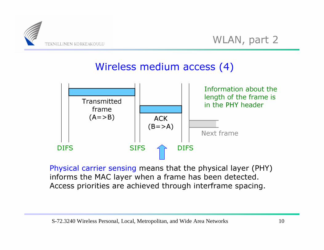
Wireless medium access (4)
DIFS SIFS DIFS
ACK (B=>A)
Transmittedframe
(A=>B)
Physical carrier sensing means that the physical layer (PHY) informs the MAC layer when a frame has been detected. Access priorities are achieved through interframe spacing.
Next frame
Information about the length of the frame is in the PHY header
S-72.3240 Wireless Personal, Local, Metropolitan, and Wide Area Networks 11
WLAN, part 2
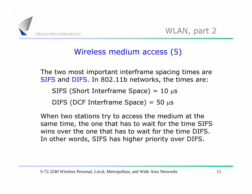
Wireless medium access (5)
The two most important interframe spacing times areSIFS and DIFS. In 802.11b networks, the times are:
SIFS (Short Interframe Space) = 10 µsDIFS (DCF Interframe Space) = 50 µs
When two stations try to access the medium at the same time, the one that has to wait for the time SIFS wins over the one that has to wait for the time DIFS. In other words, SIFS has higher priority over DIFS.
S-72.3240 Wireless Personal, Local, Metropolitan, and Wide Area Networks 12
WLAN, part 2
Wireless medium access (6)
DIFS SIFS DIFS
ACK
Transmittedframe
NAV
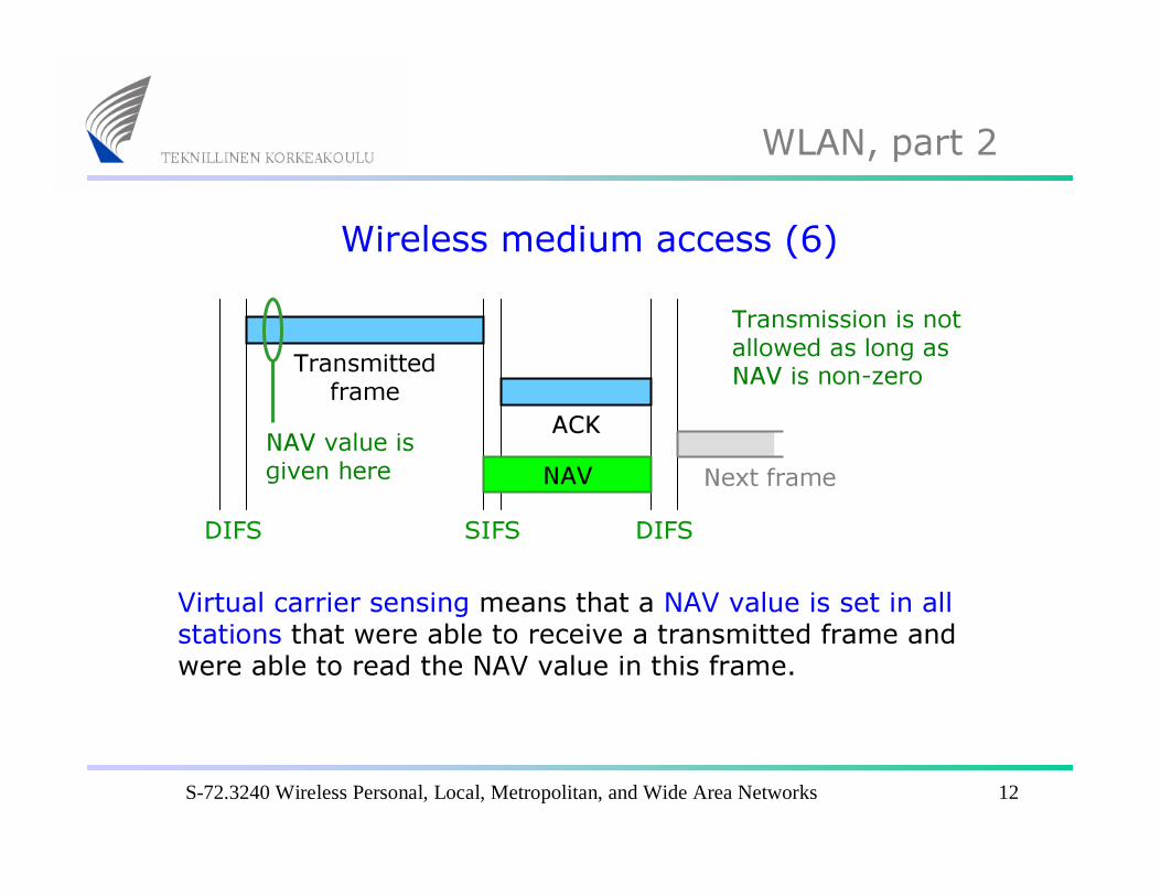
Virtual carrier sensing means that a NAV value is set in allstations that were able to receive a transmitted frame and were able to read the NAV value in this frame.
NAV value is given here Next frame
Transmission is notallowed as long as NAV is non-zero

S-72.3240 Wireless Personal, Local, Metropolitan, and Wide Area Networks 13
WLAN, part 2
Wireless medium access (7)
DIFS SIFS
Transmittedframe
NAV
Virtual carrier sensing using NAV is important in situationswhere the channel should be reserved for a ”longer time” (RTS/CTS usage, fragmentation, etc.).
Long transaction
DIFS
S-72.3240 Wireless Personal, Local, Metropolitan, and Wide Area Networks 14
WLAN, part 2
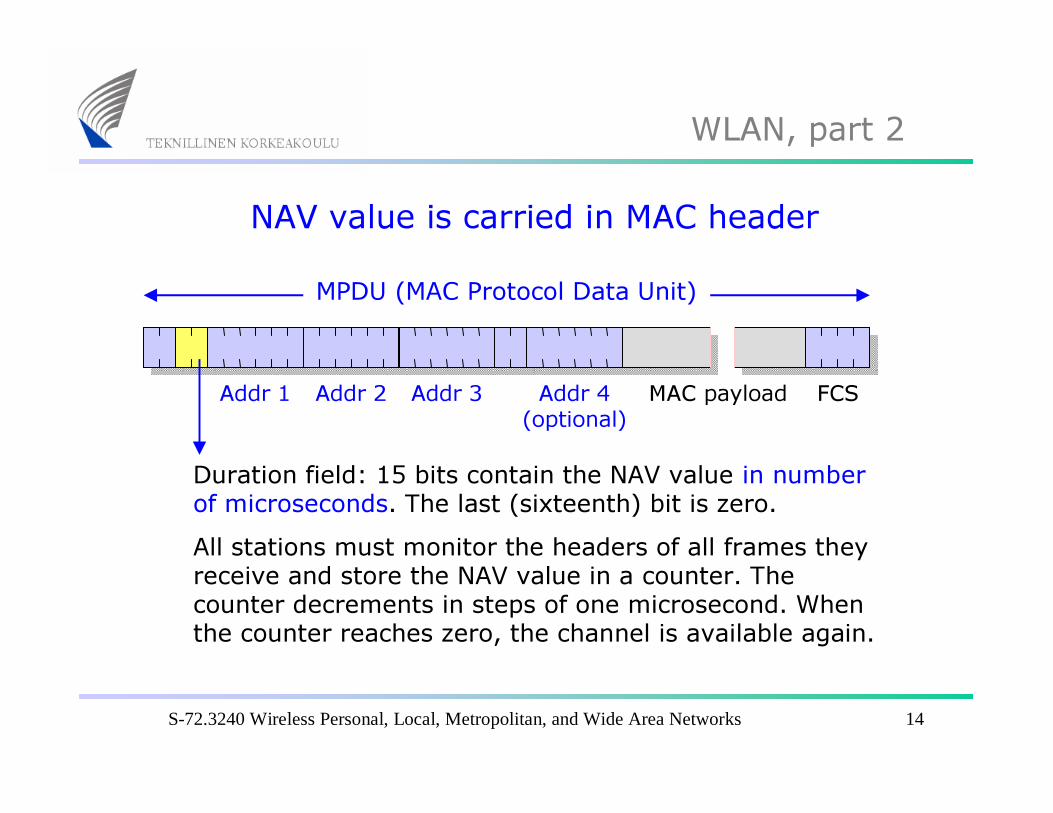
NAV value is carried in MAC headerMPDU (MAC Protocol Data Unit)
MAC payloadAddr 1 Addr 2 Addr 3 Addr 4 (optional)
FCS
Duration field: 15 bits contain the NAV value in number of microseconds. The last (sixteenth) bit is zero.All stations must monitor the headers of all frames they receive and store the NAV value in a counter. The counter decrements in steps of one microsecond. When the counter reaches zero, the channel is available again.
S-72.3240 Wireless Personal, Local, Metropolitan, and Wide Area Networks 15
WLAN, part 2
Wireless medium access (8)
DIFS SIFS t > DIFS
ACK (B=>A)
Transmittedframe
(A=>B)
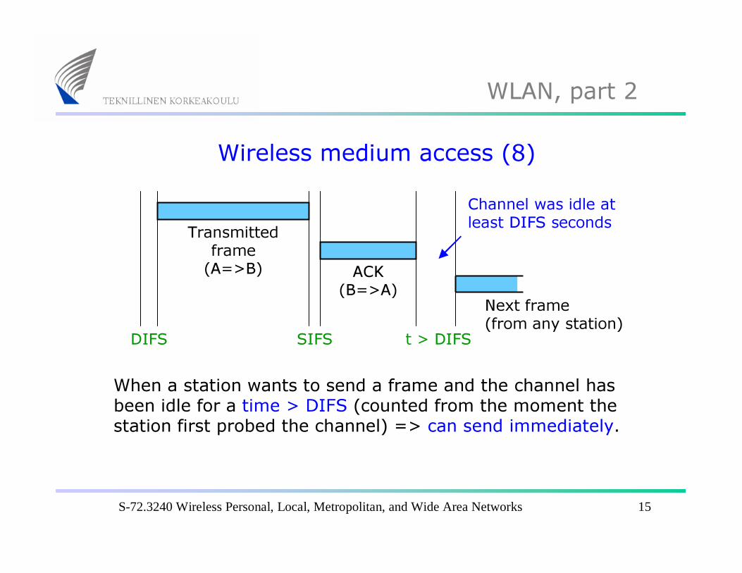
When a station wants to send a frame and the channel hasbeen idle for a time > DIFS (counted from the moment the station first probed the channel) => can send immediately.
Next frame(from any station)
Channel was idle at least DIFS seconds
S-72.3240 Wireless Personal, Local, Metropolitan, and Wide Area Networks 16
WLAN, part 2
Wireless medium access (9)
DIFS SIFS DIFS
ACK (B=>A)
Transmittedframe
(A=>B)
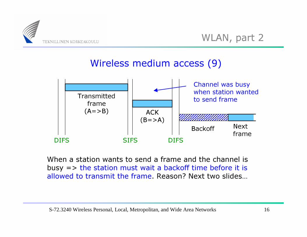
When a station wants to send a frame and the channel is busy => the station must wait a backoff time before it is allowed to transmit the frame. Reason? Next two slides…
Nextframe
Channel was busywhen station wantedto send frame
Backoff
S-72.3240 Wireless Personal, Local, Metropolitan, and Wide Area Networks 17
WLAN, part 2
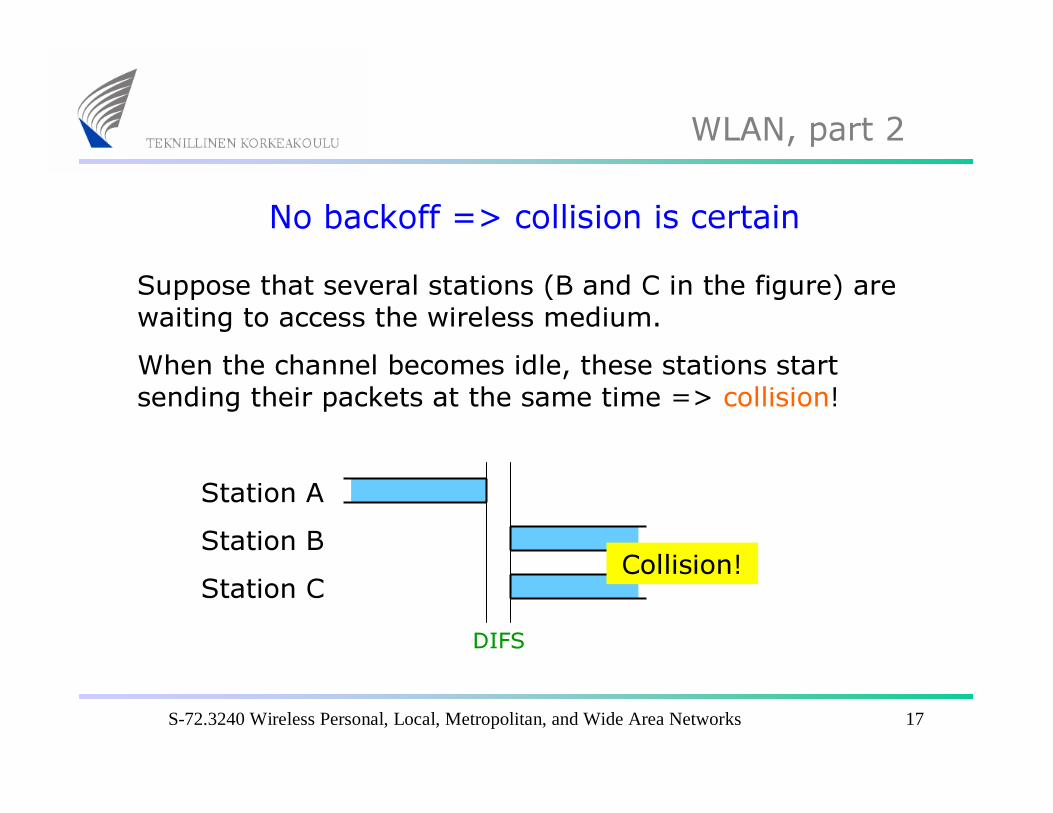
No backoff => collision is certainSuppose that several stations (B and C in the figure) arewaiting to access the wireless medium. When the channel becomes idle, these stations startsending their packets at the same time => collision!
Station AStation BStation C
DIFS
Collision!
S-72.3240 Wireless Personal, Local, Metropolitan, and Wide Area Networks 18
WLAN, part 2
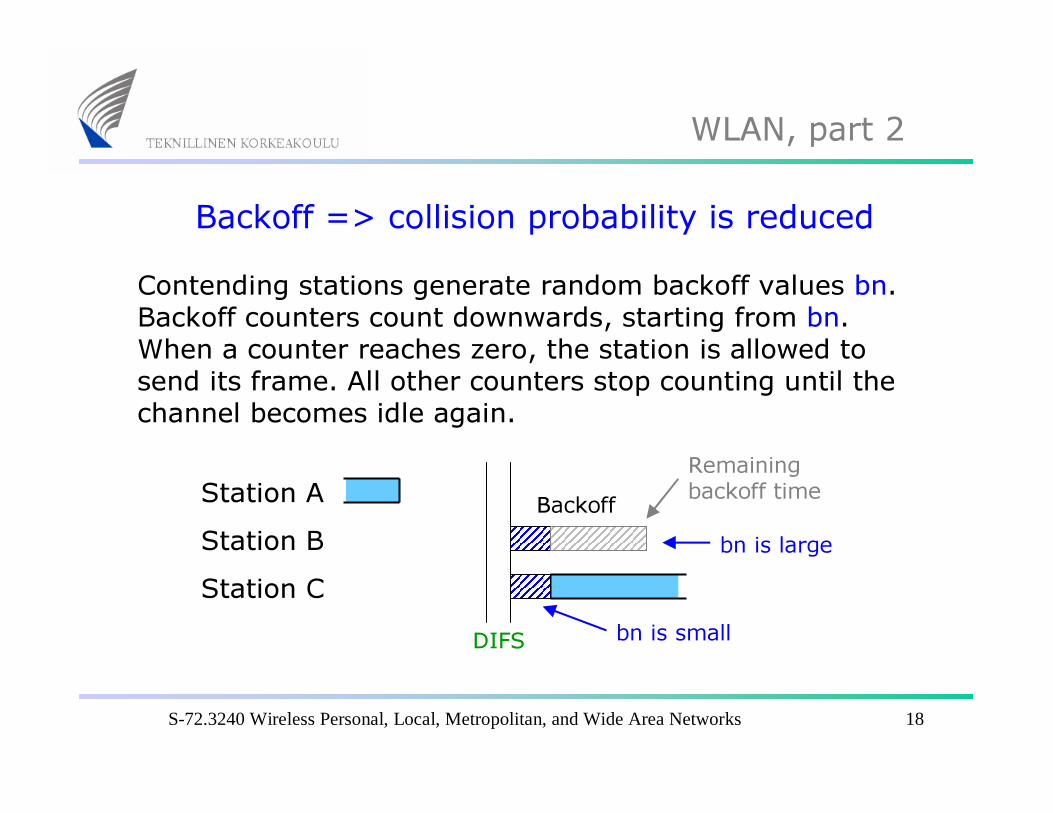
Backoff => collision probability is reducedContending stations generate random backoff values bn. Backoff counters count downwards, starting from bn. When a counter reaches zero, the station is allowed to send its frame. All other counters stop counting until the channel becomes idle again.
Station AStation BStation C
DIFS
bn is large
bn is small
BackoffRemainingbackoff time
S-72.3240 Wireless Personal, Local, Metropolitan, and Wide Area Networks 19
WLAN, part 2
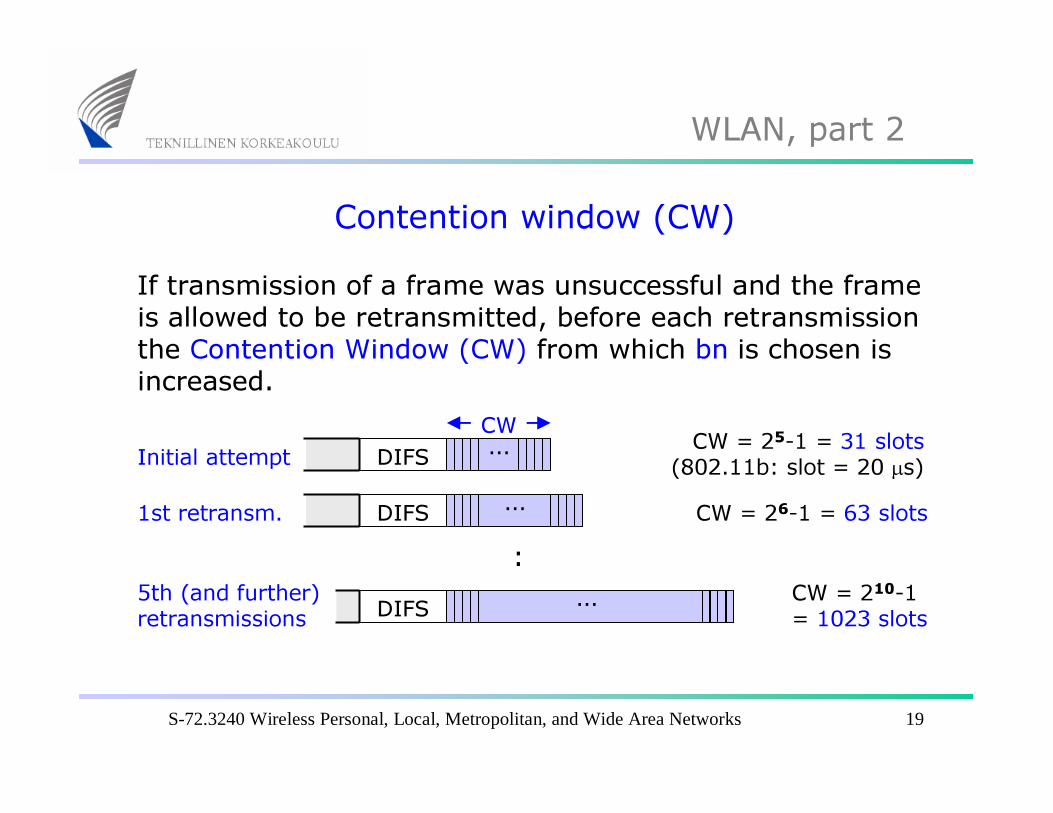
Contention window (CW)If transmission of a frame was unsuccessful and the frameis allowed to be retransmitted, before each retransmissionthe Contention Window (CW) from which bn is chosen is increased.
DIFS … CW = 25-1 = 31 slots(802.11b: slot = 20 µs)Initial attempt
DIFS … CW = 26-1 = 63 slots1st retransm.
DIFS CW = 210-1 = 1023 slots
5th (and further) retransmissions
:…
CW

S-72.3240 Wireless Personal, Local, Metropolitan, and Wide Area Networks 20
WLAN, part 2
Selection of random backoffFrom the number CW (= 31 … 1023 slots) the randombackoff bn (in terms of slots) is chosen in such a way thatbn is uniformly distributed between 0 … CW.Since it is unlikely that several stations will choose the same value of bn, collisions are avoided.
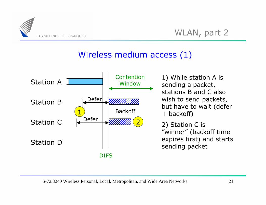
The next slides show wireless medium access in action. The example involves four stations: A, B, C and D. ”Sending a packet” means ”Data+SIFS+ACK” sequence. Note how the backoff time can be split into several parts.
S-72.3240 Wireless Personal, Local, Metropolitan, and Wide Area Networks 21
WLAN, part 2
Wireless medium access (1)
Station A
Station B
Station C
Station DDIFS
Defer
Defer
ContentionWindow
Backoff
1) While station A is sending a packet, stations B and C alsowish to send packets, but have to wait (defer+ backoff)2) Station C is ”winner” (backoff timeexpires first) and startssending packet
21

S-72.3240 Wireless Personal, Local, Metropolitan, and Wide Area Networks 22
WLAN, part 2
Wireless medium access (2)
Station A
Station B
Station C
Station DDIFS DIFS
Defer
3) Station D also wishes to send a packet4) However, station B is ”winner” and starts sendingpacket3
4
S-72.3240 Wireless Personal, Local, Metropolitan, and Wide Area Networks 23
WLAN, part 2
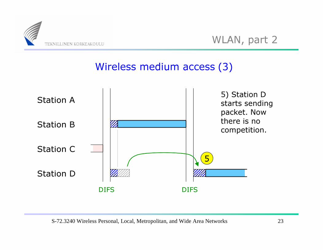
Wireless medium access (3)
Station A
Station B
Station C
Station DDIFS
5) Station D starts sendingpacket. Nowthere is no competition.
DIFS
5
S-72.3240 Wireless Personal, Local, Metropolitan, and Wide Area Networks 24
WLAN, part 2
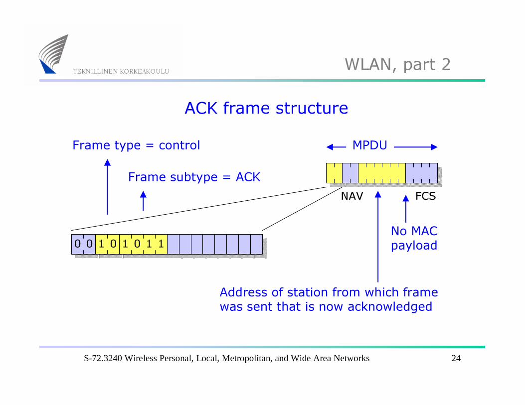
ACK frame structureMPDU
Address of station from which frame was sent that is now acknowledged
FCS
No MAC payload
NAV
00 1 0 1 0 1 1
Frame type = control
Frame subtype = ACK
S-72.3240 Wireless Personal, Local, Metropolitan, and Wide Area Networks 25
WLAN, part 2
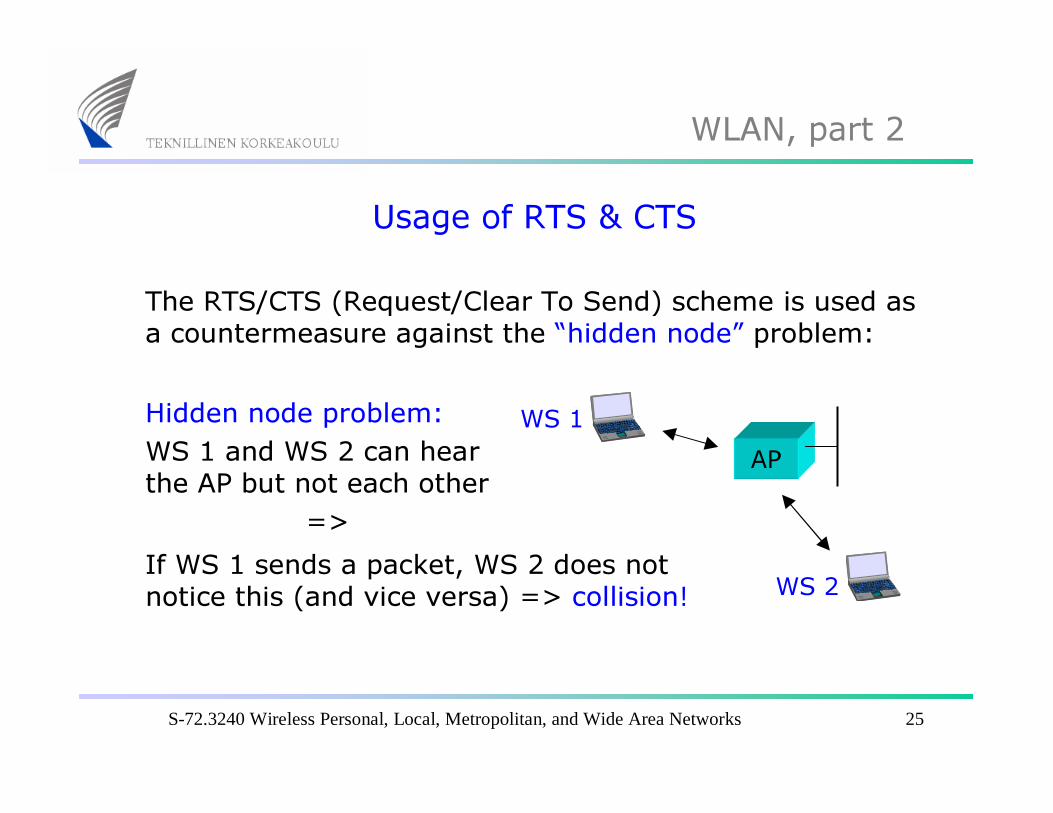
Usage of RTS & CTS
The RTS/CTS (Request/Clear To Send) scheme is used as a countermeasure against the “hidden node” problem:
APWS 1
WS 2
Hidden node problem:WS 1 and WS 2 can hear the AP but not each other
=>If WS 1 sends a packet, WS 2 does not notice this (and vice versa) => collision!
S-72.3240 Wireless Personal, Local, Metropolitan, and Wide Area Networks 26
WLAN, part 2
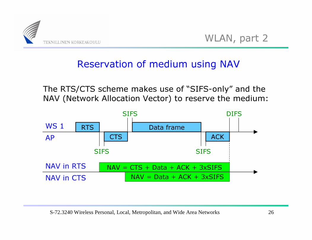
Reservation of medium using NAV
The RTS/CTS scheme makes use of “SIFS-only” and the NAV (Network Allocation Vector) to reserve the medium:
RTS
SIFS
DIFS
NAV = CTS + Data + ACK + 3xSIFS
CTSData frame
ACK
SIFS
SIFS
WS 1AP
NAV = Data + ACK + 3xSIFSNAV in RTSNAV in CTS
S-72.3240 Wireless Personal, Local, Metropolitan, and Wide Area Networks 27
WLAN, part 2
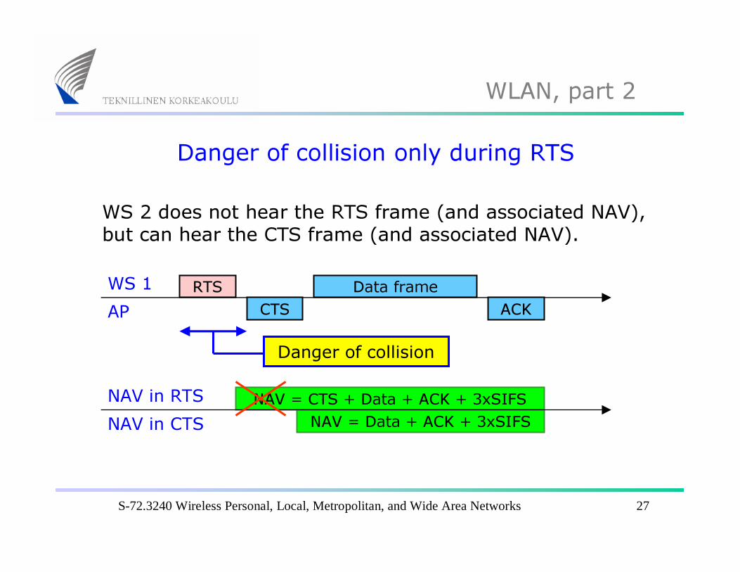
Danger of collision only during RTS
WS 2 does not hear the RTS frame (and associated NAV), but can hear the CTS frame (and associated NAV).
RTS
NAV = CTS + Data + ACK + 3xSIFS
CTSData frame
ACKWS 1AP
NAV = Data + ACK + 3xSIFSNAV in RTSNAV in CTS
Danger of collision
S-72.3240 Wireless Personal, Local, Metropolitan, and Wide Area Networks 28
WLAN, part 2
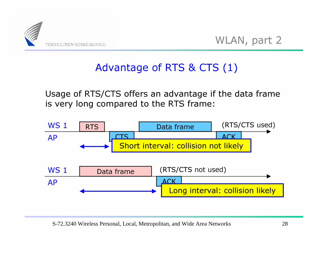
Advantage of RTS & CTS (1)
Usage of RTS/CTS offers an advantage if the data frame is very long compared to the RTS frame:
RTSCTS
Data frameACK
WS 1AP
Short interval: collision not likely
Data frameACK
WS 1AP
Long interval: collision likely
(RTS/CTS not used)
(RTS/CTS used)
S-72.3240 Wireless Personal, Local, Metropolitan, and Wide Area Networks 29
WLAN, part 2
Advantage of RTS & CTS (2)
A long collision danger interval (previous slide) should be avoided for the following reasons:
Larger probability of collisionGreater waste of capacity if a collision occurs and the frame has to be retransmitted.
A threshold parameter (dot11RTSThreshold) can be set in the mobile station. Frames shorter than this threshold value will be transmitted without using RTS/CTS.
Related Documents