Hindawi Publishing Corporation International Journal of Navigation and Observation Volume 2012, Article ID 743625, 15 pages doi:10.1155/2012/743625 Research Article Receiver Design for Time-Based Ranging with IEEE 802.11b Signals Reinhard Exel Institute for Integrated Sensor Systems, Austrian Academy of Sciences, 2700 Wiener Neustadt, Austria Correspondence should be addressed to Reinhard Exel, [email protected] Received 3 December 2011; Revised 4 April 2012; Accepted 30 May 2012 Academic Editor: Armin Dammann Copyright © 2012 Reinhard Exel. This is an open access article distributed under the Creative Commons Attribution License, which permits unrestricted use, distribution, and reproduction in any medium, provided the original work is properly cited. This paper presents a ranging receiver architecture able to timestamp IEEE 802.11b Wireless LAN signals with sub-100 picosecond precision enabling time-based range measurements. Starting from the signal model, the performance of the proposed architecture is assessed in terms of statistical bounds when perturbed by zero-mean additive white Gaussian noise (AWGN) as well as in case of multipath propagation. Results of the proposed architecture, implemented in a Field Programmable Gate Array-(FPGA-) based prototype, are presented for different environments. For AWGN channels, the prototype system is able to attain an accuracy of 1.2 cm while the ranging accuracy degrades in dynamic multipath scenarios to about 0.6 m for 80% of the measurements due to the limited bandwidth of the signal. 1. Introduction Despite the fact that Global Navigation Satellite Systems (GNSSes) cover nearly 100% of the planet, satellite-based localization is not available within buildings as the roofing and walls deteriorate the signal to a degree where an error- less decoding is no longer possible. Mounting pseudolites, devices transmitting the navigation signals, under the roofs are certainly not a valid solution, not only due to legal restrictions. The differences between indoor and outdoor localization are more substantial than just the received power. Radio propagation within complex environments, typical for indoor scenarios, are challenging for high-speed wireless communication, but even tougher for any form of localization service. Many localization concepts (e.g., based on ultrasonic, electromagnetic waves, inertial sensors) have been proposed to bridge the gap between GNSSes and the lack of indoor locating systems. Nevertheless, for indoor environments, there is still no general satisfactory solution available as dif- ferent key factors, such as low power consumption and high refreshment rate are incompatible. One major reason why indoor radio localization systems are way behind satellite navigation solutions is that the majority of all current wireless communication standards have not been designed with position determination in mind. These signals are often referred to as Signals of Opportunity (SoO). In theory, adding a localization service upon an existing standard is always possible. However, the key parameters like accuracy, reliability, or cost depend on the restrictions of the wireless standard. As a result, retrofitting a localization service to an existing technology might turn out to be highly complex as, for example, the integration of the Enhanced 911 service into GSM networks. The degree of complexity depends primarily on the measurement principles ranging from Received Signal Strength (RSS) to time or angle measurements, or a combination of these. Some principles require proprietary hardware, while others only require software modifications, but impose other restrictions, such as limited range or accuracy. As a result, there is no generally best solution to retrofit localization to a communication standard. In particular, Wireless LAN (WLAN) seems to be an in- teresting candidate for localization as it is a widely accepted industrial standard deployed in billions of mobile devices in home and office environments. RSS-based WLAN localiza- tion is a thoroughly investigated subject, and still the posi- tional accuracy can be considered rather poor. Time-based localization methods like Time of Arrival (ToA) or Time Dif- ference of Arrival (TDoA) are attractive not only for satellite- based positioning, but also for indoor applications. The fact

Welcome message from author
This document is posted to help you gain knowledge. Please leave a comment to let me know what you think about it! Share it to your friends and learn new things together.
Transcript
Hindawi Publishing CorporationInternational Journal of Navigation and ObservationVolume 2012, Article ID 743625, 15 pagesdoi:10.1155/2012/743625
Research Article
Receiver Design for Time-Based Ranging withIEEE 802.11b Signals
Reinhard Exel
Institute for Integrated Sensor Systems, Austrian Academy of Sciences, 2700 Wiener Neustadt, Austria
Correspondence should be addressed to Reinhard Exel, [email protected]
Received 3 December 2011; Revised 4 April 2012; Accepted 30 May 2012
Academic Editor: Armin Dammann
Copyright © 2012 Reinhard Exel. This is an open access article distributed under the Creative Commons Attribution License,which permits unrestricted use, distribution, and reproduction in any medium, provided the original work is properly cited.
This paper presents a ranging receiver architecture able to timestamp IEEE 802.11b Wireless LAN signals with sub-100 picosecondprecision enabling time-based range measurements. Starting from the signal model, the performance of the proposed architectureis assessed in terms of statistical bounds when perturbed by zero-mean additive white Gaussian noise (AWGN) as well as in caseof multipath propagation. Results of the proposed architecture, implemented in a Field Programmable Gate Array-(FPGA-) basedprototype, are presented for different environments. For AWGN channels, the prototype system is able to attain an accuracy of1.2 cm while the ranging accuracy degrades in dynamic multipath scenarios to about 0.6 m for 80% of the measurements due tothe limited bandwidth of the signal.
1. Introduction
Despite the fact that Global Navigation Satellite Systems(GNSSes) cover nearly 100% of the planet, satellite-basedlocalization is not available within buildings as the roofingand walls deteriorate the signal to a degree where an error-less decoding is no longer possible. Mounting pseudolites,devices transmitting the navigation signals, under the roofsare certainly not a valid solution, not only due to legalrestrictions. The differences between indoor and outdoorlocalization are more substantial than just the receivedpower. Radio propagation within complex environments,typical for indoor scenarios, are challenging for high-speedwireless communication, but even tougher for any form oflocalization service.
Many localization concepts (e.g., based on ultrasonic,electromagnetic waves, inertial sensors) have been proposedto bridge the gap between GNSSes and the lack of indoorlocating systems. Nevertheless, for indoor environments,there is still no general satisfactory solution available as dif-ferent key factors, such as low power consumption and highrefreshment rate are incompatible. One major reason whyindoor radio localization systems are way behind satellitenavigation solutions is that the majority of all currentwireless communication standards have not been designed
with position determination in mind. These signals are oftenreferred to as Signals of Opportunity (SoO). In theory,adding a localization service upon an existing standard isalways possible. However, the key parameters like accuracy,reliability, or cost depend on the restrictions of the wirelessstandard. As a result, retrofitting a localization service to anexisting technology might turn out to be highly complex as,for example, the integration of the Enhanced 911 service intoGSM networks. The degree of complexity depends primarilyon the measurement principles ranging from ReceivedSignal Strength (RSS) to time or angle measurements, or acombination of these. Some principles require proprietaryhardware, while others only require software modifications,but impose other restrictions, such as limited range oraccuracy. As a result, there is no generally best solution toretrofit localization to a communication standard.
In particular, Wireless LAN (WLAN) seems to be an in-teresting candidate for localization as it is a widely acceptedindustrial standard deployed in billions of mobile devices inhome and office environments. RSS-based WLAN localiza-tion is a thoroughly investigated subject, and still the posi-tional accuracy can be considered rather poor. Time-basedlocalization methods like Time of Arrival (ToA) or Time Dif-ference of Arrival (TDoA) are attractive not only for satellite-based positioning, but also for indoor applications. The fact
2 International Journal of Navigation and Observation
Receivedsignal
Parameterestimation
RSSToF
Carrier phase
Parameter-based
Locationestimate
position det.
Geometrystatistics
Figure 1: Two-step position determination.
that the measured time is a linear function of the range makesit an ideal candidate even for larger distances in contrast toRSS.
The outline of the paper is as follows. Section 2 describesthe localization process and technologies related to WLANlocating. In the following section, the signal model and com-mon cross-correlation TDoA estimation methods are dis-cussed. The proposed receiver architecture able to measurethe ToA by means of timestamping is found in Section 4. Sec-tion 5 discusses the error due to multipath propagation andmitigation techniques for the presented receiver architecture.Subsequently, a set of these receivers is used in a hardwareimplementation to assess the performance under variousconditions in Section 6. The conclusion summarizes the find-ings, and finally an outlook for further investigations is given.
2. Related Work
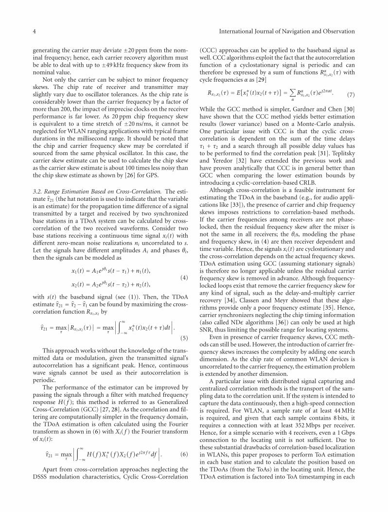
2.1. The Localization Process. Locating a target in a radiolocalization system is based on the exchange of signalsbetween the target and a number of base stations withknown positions. In a network-based localization system,the location of the target can be calculated directly from thereceived signals collected by a locating unit or by the mobiledevice in case of handset-based localization. This approach iscalled direct position determination (DPD) [1]. Similarly, ifan extraction of ranging parameters from the received signalsprecedes the position determination step, locating is based ona two-step approach as shown in Figure 1. While DPD offershigher performance for low signal-to-noise ratio (SNR)conditions [2], the joint position estimation increases thecomputational complexity of DPD and therefore decreasesits practical applicability.
The simulations performed by [3] showed that DPDperforms nearly identical than the conventional two-stepapproach, and DPD can only provide improved positionalaccuracy in case of difficult situations such as obstructedpropagation paths. In this paper, we assume the commonlyused two-step approach. The second step, position determi-nation, can be grouped in subtasks starting with parameterconversion (propagation models, fingerprinting), prepro-cessing (filtering, weighting, selection), localization (nearestneighbor search, Bayesian or probabilistic approaches [4,5]) up to tracking algorithms (Kalman or particle filtering,Markov models, neural networks [6]). Nevertheless, allthese sophisticated methods depend on the quality of theparameter estimates of the first step. In this paper, we focus
on the parameter estimation process, particularly for time-based WLAN ranging systems.
2.2. Related Work. RSS localization in WLANs is the mostinvestigated solution as the measurement of the RSS is amandatory feature in standard compliant WLAN devices.All that is required is to read the RSS information fromthe devices and collect it at the locating unit perform-ing the localization based on fingerprinting or geometricapproaches. One of the oldest RSS system is the RADARsystem from Microsoft research [7] using fingerprintingtechniques based on combining empirical measurementswith signal propagation models. It can be considered as anetwork-based system as the APs collect the signal strengthof all associated targets. In the recent past, a plethora ofRSS propagation models have been proposed for WLANmodeling different environments, such as offices, parkinglots, outdoor or industrial environments [8–10]. Despite allthe effort and optimizations, the location accuracy of RSSsolutions is poor, in the 2–20 m range depending on the en-vironment and distance to the AP [11].
Time-based WLAN ranging has been analyzed by theauthors of [12]. The basis for their approach is two-way ToA,where the target operates as interrogator sending rangingrequests to the access point (AP). The round-trip time of theframe minus the turn-around time in the AP yields the timeof flight in both directions. As neither the target nor the APhas any capabilities to perform accurate time measurements,the authors propose to use software timestamping within theLinux Kernel of the operating system (OS) in the AP and thetarget. Software timestamping is influenced by various jittersources in the OS such as interrupt latency, bus arbitration,and therefore the measured round-trip times suffer froma large variance. With software modifications, the authorsmeasured an average round-trip time of 269.83 μs with astandard deviation of 371 ns (corresponding to 111 m).
Even higher accuracy can be achieved directly in thephysical layer. A WLAN mechanism exploiting the Requestto Send/Clear to Send (RTS/CTS) handshake mechanismfor two-way range measurements is presented in [13]. Theauthors have built a printed circuit board (PCB) support-ing hardware timestamping, which starts a counter whentransmitting an RTS frame. The counter stops when the CTSresponse frame from the target is received. Despite someconcurrence and interference issues, which are mitigatedthrough filtering and selection, the system is bound by the22.72 ns resolution of the counter running with 44 MHz.To decrease the large variance of the measurement, robustlinear regression techniques are used, averaging over 50measurements. Even closer to the physical layer are methodsprocessing the sampled baseband signal, for instance, meth-ods based on dirty templates [14, 15], where a previouslyreceived signal is used as a correlation template. Alternatively,Generalized Cross Correlation-(GCC-) based ToA estima-tion methods are used for WLAN as well [16].
As alternative to cross-correlation, some authors haveproposed to use subsample interpolation methods belongingto the group of super resolution methods, such as theEstimation of Signal Parameters via Rotational Invariance
International Journal of Navigation and Observation 3
Technique (ESPRIT), Root-MUltiple Signal Classification(RootMUSIC), or Matrix Pencil (MP) [17, 18]. Others preferto estimate the ranging parameters in the frequency domain,such as the Prony method used by [19]. Compared withthe matched filter approach, which is optimal in AWGNenvironments, these algorithms offer improved accuracy inmultipath environments when the channel complies to a cer-tain known model.
The Global Positioning System (GPS) also belongs to thegroup of time-based systems and can be considered similarto ToA WLAN localization. However, the properties of GPSare specifically designed for ranging applications, whereasWLAN was designed as more or less a cable replacement. Thelargest difference is that the GPS C/A code is permanentlytransmitted with a chip rate of 1.023 MChips/s and a datarate of just 50 bit/s [20]. In contrast, IEEE 802.11b WLANemploys a Carrier Sense Multiple Access (CSMA) schemewith 11 MChips/s and a data rate of up to 11 Mbit/s. AsWLAN devices do not send constantly, they can naturallyonly be located during the transmission of frames. Thereceived signal power and therefore the signal-to-noise ratio(SNR) in GPS are 60 dB and more lower than in WLAN,which is compensated in GPS by length of the Gold code usedfor signal correlation. In total, the higher chip rate of WLANsuggests that localization in WLANs should be even moreaccurate than GPS given the same channel conditions apply.
2.3. Previous Work. The work presented in this paper isbased on previous investigations extended in terms ofaccuracy, multipath mitigation, and a detailed analysis ofimpairments. In [21], we described the basic measurementprinciple of WLAN ranging as a piggy-back solution to anexisting WLAN transceiver architecture. Finally, we designeda stand-alone transceiver solution based on the Maxim2822 transceiver chipset. The design considerations for thehardware platform are described in [22]. A predecessor ofthe receiver architecture achieving nanosecond precision isdescribed in [23]. In all papers, we consider a network-basedTDoA solution, where synchronized base stations capture thewireless signal and process it locally to generate ToA times-tamps. These timestamps are submitted (together with frameidentification information) to a central locating unit, whichgroups them by the unique frame check sum and performsparameter-based position determination, the second step ofFigure 1. Taking timestamps in the base stations requiresa priori knowledge of the modulation and frame format.Knowledge of the used modulation is required to decodethe frame and to optimize the estimation algorithm. Thestructure of the wireless frame is necessary to detect a uniqueposition within the frame (epoch) to take a timestamp. Asthe epoch is agreed among all base stations, the difference oftwo ToA timestamps yields a similar estimate as correlation-based approaches. The necessary synchronization of the basestations is only briefly discussed within this paper, differentapproaches based on wired and wireless synchronization canbe found in [24]. As outlined in Section 6.1, all base stationsare assumed to be supplied by a common clock sourced froman Ethernet switch.
3. Signal Model and RangeEstimation Techniques
3.1. Signal Model. The data of a WLAN frame, according tothe IEEE 802.11b standard [25], is modulated using eitherDifferential Binary Phase-Shift Keying (DBPSK) or Differ-ential Quadrature Phase-Shift Keying (DQPSK) in combi-nation with Direct Sequence Spread Spectrum (DSSS) orComplementary Code Keying (CCK) baseband modulation.Common to all encodings is that the transmitted basebandsignal can be expressed by a sum of periodic pulses as given in
s(t) =∑
m
amg(t −mT). (1)
s(t) describes the baseband signal neglecting any modu-lation to an RF carrier, g(t) is a real-valued baseband pulse,1/T is the chip rate, am is the sequence of complex-valuedchips, and m refers to the chip counter. In particular forWLAN, the chip rate is 1/T = 11000 000 s−1, the alphabetof am is {+1,−1} in case of BPSK, and {+1, +j,−1,−j} incase of QPSK. Given that the chip sequence am is wide-sense stationary, the transmitted signal s(t) is a wide-sensecyclostationary process with period T . The cyclostationaryproperty is obvious as the generated sequence has the samestatistical properties as a time-shifted process s(t − kT) forany arbitrary integer k. The actual shape of the basebandpulse g(t) is not specified, but only the spectral mask for thetransmit pulse in subsection 15.4.7.4 of the 802.11b standard[25]. That is, the side lobes 11 or 22 MHz apart from thecarrier frequency must be suppressed by −30 or−50 dB withrespect to the carrier.
The baseband signal is modulated to the RF carrier anddemodulated again in the receiver. If the carrier frequenciesin the receiver and the target are sourced from differentoscillators, the carrier frequencies are not exactly the same aseach oscillator is subject to different tolerances and jitter. Thefrequency of an oscillator can be modeled as the sum of thenominal frequency ωn, a frequency skew Δω, and a randomterm ω(t) as shown in
ω(t) = ωn + Δω + ω(t). (2)
Hence, the received signal includes also a residual carrierfrequency skew Ω = ωt − ωl = Δωt − Δωl with Δωt andΔωl the frequency skews of the transmitter and receiver withrespect to the nominal frequency ωn. The received signal y(t)delayed by τ and with a phase offset θ and skew Ω in presenceof AWGN noise n(t) can therefore be described by
y(t) =∑
m
amg(t −mT − τ)ej(θ+Ωt) + n(t). (3)
Depending on the length of the transmitted frame andthe joint stability of ωt and ωl, the residual carrier frequencymay be considered constant or variable with time. For thelatter case, some kind of carrier recovery algorithm has toconstantly track Ω and remove it. The removal of the residualcarrier frequency is commonly termed carrier wipeoff. TheIEEE 802.11 standard requests that the oscillator used for
4 International Journal of Navigation and Observation
generating the carrier may deviate ±20 ppm from the nom-inal frequency; hence, each carrier recovery algorithm mustbe able to deal with up to ±49 kHz frequency skew from itsnominal value.
Not only the carrier can be subject to minor frequencyskews. The chip rate of receiver and transmitter mayslightly vary due to oscillator tolerances. As the chip rate isconsiderably lower than the carrier frequency by a factor ofmore than 200, the impact of imprecise clocks on the receiverperformance is far lower. As 20 ppm chip frequency skewis equivalent to a time stretch of ±20 ns/ms, it cannot beneglected for WLAN ranging applications with typical framedurations in the millisecond range. It should be noted thatthe chip and carrier frequency skew may be correlated ifsourced from the same physical oscillator. In this case, thecarrier skew estimate can be used to calculate the chip skewas the carrier skew estimate is about 100 times less noisy thanthe chip skew estimate as shown by [26] for GPS.
3.2. Range Estimation Based on Cross-Correlation. The esti-mate τ21 (the hat notation is used to indicate that the variableis an estimate) for the propagation time difference of a signaltransmitted by a target and received by two synchronizedbase stations in a TDoA system can be calculated by cross-correlation of the two received waveforms. Consider twobase stations receiving a continuous time signal xi(t) withdifferent zero-mean noise realizations ni uncorrelated to s.Let the signals have different amplitudes Ai and phases θi,then the signals can be modeled as
x1(t) = A1ejθ1s(t − τ1) + n1(t),
x2(t) = A2ejθ2s(t − τ2) + n2(t),
(4)
with s(t) the baseband signal (see (1)). Then, the TDoAestimate τ21 = τ2− τ1 can be found by maximizing the cross-correlation function Rx1,x2 by
τ21 = maxτ
∣∣Rx1,x2 (τ)∣∣ = max
τ
∣∣∣∣∫∞
−∞x∗1 (t)x2(t + τ)dt
∣∣∣∣.
(5)
This approach works without the knowledge of the trans-mitted data or modulation, given the transmitted signal’sautocorrelation has a significant peak. Hence, continuouswave signals cannot be used as their autocorrelation isperiodic.
The performance of the estimator can be improved bypassing the signals through a filter with matched frequencyresponse H( f ); this method is referred to as GeneralizedCross-Correlation (GCC) [27, 28]. As the correlation and fil-tering are computationally simpler in the frequency domain,the TDoA estimation is often calculated using the Fouriertransform as shown in (6) with Xi( f ) the Fourier transformof xi(t):
τ21 = maxτ
∣∣∣∣∫∞
−∞H(f)X∗1(f)X2(f)ej2π f τdf
∣∣∣∣. (6)
Apart from cross-correlation approaches neglecting theDSSS modulation characteristics, Cyclic Cross-Correlation
(CCC) approaches can be applied to the baseband signal aswell. CCC algorithms exploit the fact that the autocorrelationfunction of a cyclostationary signal is periodic and cantherefore be expressed by a sum of functions Rα
x1,x2(τ) with
cycle frequencies α as [29]
Rx1,x2 (τ) = E[x∗1 (t)x2(t + τ)
] =∑
α
Rαx1,x2
(τ)ej2παt. (7)
While the GCC method is simpler, Gardner and Chen [30]have shown that the CCC method yields better estimationresults (lower variance) based on a Monte-Carlo analysis.One particular issue with CCC is that the cyclic cross-correlation is dependent on the sum of the time delaysτ1 + τ2 and a search through all possible delay values hasto be performed to find the correlation peak [31]. Teplitskyand Yeredor [32] have extended the previous work andhave proven analytically that CCC is in general better thanGCC when comparing the lower estimation bounds byintroducing a cyclic-correlation-based CRLB.
Although cross-correlation is a feasible instrument forestimating the TDoA in the baseband (e.g., for audio appli-cations like [33]), the presence of carrier and chip frequencyskews imposes restrictions to correlation-based methods.If the carrier frequencies among receivers are not phase-locked, then the residual frequency skew after the mixer isnot the same in all receivers; the θis, modeling the phaseand frequency skew, in (4) are then receiver dependent andtime variable. Hence, the signals xi(t) are cyclostationary andthe cross-correlation depends on the actual frequency skews.TDoA estimation using GCC (assuming stationary signals)is therefore no longer applicable unless the residual carrierfrequency skew is removed in advance. Although frequency-locked loops exist that remove the carrier frequency skew forany kind of signal, such as the delay-and-multiply carrierrecovery [34], Classen and Meyr showed that these algo-rithms provide only a poor frequency estimate [35]. Hence,carrier synchronizers neglecting the chip timing information(also called NDε algorithms [36]) can only be used at highSNR, thus limiting the possible range for locating systems.
Even in presence of carrier frequency skews, CCC meth-ods can still be used. However, the introduction of carrier fre-quency skews increases the complexity by adding one searchdimension. As the chip rate of common WLAN devices isuncorrelated to the carrier frequency, the estimation problemis extended by another dimension.
A particular issue with distributed signal capturing andcentralized correlation methods is the transport of the sam-pling data to the correlation unit. If the system is intended tocapture the data continuously, then a high-speed connectionis required. For WLAN, a sample rate of at least 44 MHzis required, and given that each sample contains 8 bits, itrequires a connection with at least 352 Mbps per receiver.Hence, for a simple scenario with 4 receivers, even a 1 Gbpsconnection to the locating unit is not sufficient. Due tothese substantial drawbacks of correlation-based localizationin WLANs, this paper proposes to perform ToA estimationin each base station and to calculate the position based onthe TDoAs (from the ToAs) in the locating unit. Hence, theTDoA estimation is factored into ToA timestamping in each
International Journal of Navigation and Observation 5
BPF
CarrierNCO
CodeNCO
Frameprocessor
f1
Discr.:
carrier
code
data
Figure 2: Generic receiver architecture.
base station instead of a joint estimation of the TDoAs usingcorrelation methods.
4. Proposed Receiver Architecture
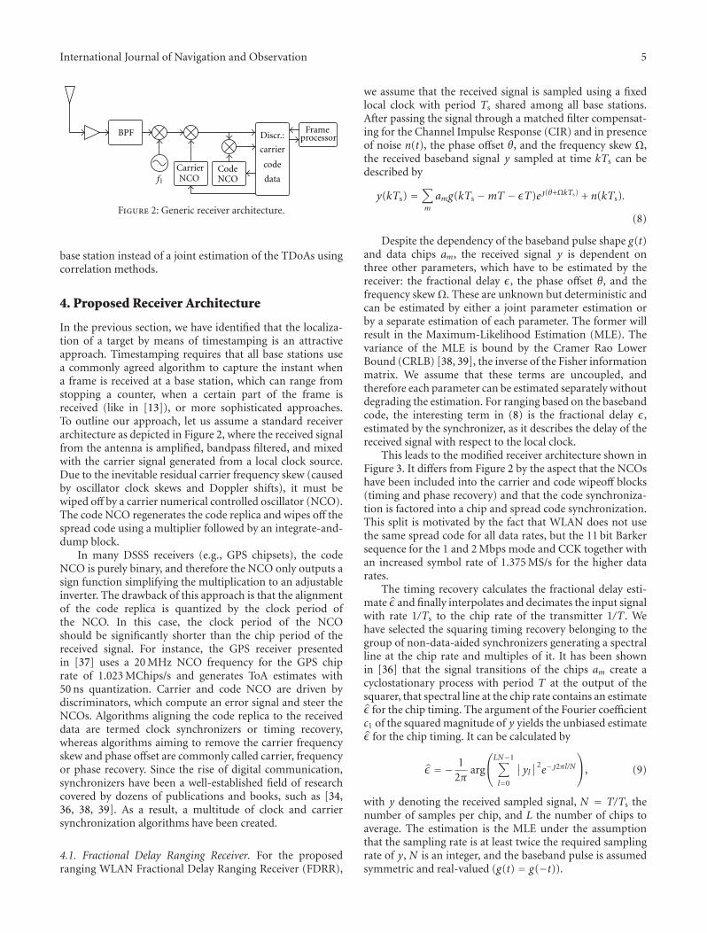
In the previous section, we have identified that the localiza-tion of a target by means of timestamping is an attractiveapproach. Timestamping requires that all base stations usea commonly agreed algorithm to capture the instant whena frame is received at a base station, which can range fromstopping a counter, when a certain part of the frame isreceived (like in [13]), or more sophisticated approaches.To outline our approach, let us assume a standard receiverarchitecture as depicted in Figure 2, where the received signalfrom the antenna is amplified, bandpass filtered, and mixedwith the carrier signal generated from a local clock source.Due to the inevitable residual carrier frequency skew (causedby oscillator clock skews and Doppler shifts), it must bewiped off by a carrier numerical controlled oscillator (NCO).The code NCO regenerates the code replica and wipes off thespread code using a multiplier followed by an integrate-and-dump block.
In many DSSS receivers (e.g., GPS chipsets), the codeNCO is purely binary, and therefore the NCO only outputs asign function simplifying the multiplication to an adjustableinverter. The drawback of this approach is that the alignmentof the code replica is quantized by the clock period ofthe NCO. In this case, the clock period of the NCOshould be significantly shorter than the chip period of thereceived signal. For instance, the GPS receiver presentedin [37] uses a 20 MHz NCO frequency for the GPS chiprate of 1.023 MChips/s and generates ToA estimates with50 ns quantization. Carrier and code NCO are driven bydiscriminators, which compute an error signal and steer theNCOs. Algorithms aligning the code replica to the receiveddata are termed clock synchronizers or timing recovery,whereas algorithms aiming to remove the carrier frequencyskew and phase offset are commonly called carrier, frequencyor phase recovery. Since the rise of digital communication,synchronizers have been a well-established field of researchcovered by dozens of publications and books, such as [34,36, 38, 39]. As a result, a multitude of clock and carriersynchronization algorithms have been created.
4.1. Fractional Delay Ranging Receiver. For the proposedranging WLAN Fractional Delay Ranging Receiver (FDRR),
we assume that the received signal is sampled using a fixedlocal clock with period Ts shared among all base stations.After passing the signal through a matched filter compensat-ing for the Channel Impulse Response (CIR) and in presenceof noise n(t), the phase offset θ, and the frequency skew Ω,the received baseband signal y sampled at time kTs can bedescribed by
y(kTs) =∑
m
amg(kTs −mT − εT)ej(θ+ΩkTs) + n(kTs).
(8)
Despite the dependency of the baseband pulse shape g(t)and data chips am, the received signal y is dependent onthree other parameters, which have to be estimated by thereceiver: the fractional delay ε, the phase offset θ, and thefrequency skew Ω. These are unknown but deterministic andcan be estimated by either a joint parameter estimation orby a separate estimation of each parameter. The former willresult in the Maximum-Likelihood Estimation (MLE). Thevariance of the MLE is bound by the Cramer Rao LowerBound (CRLB) [38, 39], the inverse of the Fisher informationmatrix. We assume that these terms are uncoupled, andtherefore each parameter can be estimated separately withoutdegrading the estimation. For ranging based on the basebandcode, the interesting term in (8) is the fractional delay ε,estimated by the synchronizer, as it describes the delay of thereceived signal with respect to the local clock.
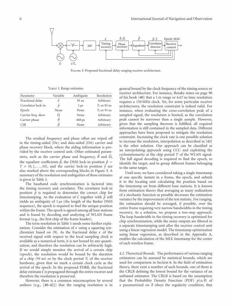
This leads to the modified receiver architecture shown inFigure 3. It differs from Figure 2 by the aspect that the NCOshave been included into the carrier and code wipeoff blocks(timing and phase recovery) and that the code synchroniza-tion is factored into a chip and spread code synchronization.This split is motivated by the fact that WLAN does not usethe same spread code for all data rates, but the 11 bit Barkersequence for the 1 and 2 Mbps mode and CCK together withan increased symbol rate of 1.375 MS/s for the higher datarates.
The timing recovery calculates the fractional delay esti-mate ε and finally interpolates and decimates the input signalwith rate 1/Ts to the chip rate of the transmitter 1/T . Wehave selected the squaring timing recovery belonging to thegroup of non-data-aided synchronizers generating a spectralline at the chip rate and multiples of it. It has been shownin [36] that the signal transitions of the chips am create acyclostationary process with period T at the output of thesquarer, that spectral line at the chip rate contains an estimateε for the chip timing. The argument of the Fourier coefficientc1 of the squared magnitude of y yields the unbiased estimateε for the chip timing. It can be calculated by
ε = − 12π
arg
⎛⎝LN−1∑
l=0
∣∣yl∣∣2e−j2πl/N
⎞⎠, (9)
with y denoting the received sampled signal, N = T/Ts thenumber of samples per chip, and L the number of chips toaverage. The estimation is the MLE under the assumptionthat the sampling rate is at least twice the required samplingrate of y, N is an integer, and the baseband pulse is assumedsymmetric and real-valued (g(t) = g(−t)).
6 International Journal of Navigation and Observation
f1
MFTimingrecovery
Phaserecovery Equalizer
Correlatordetector
Epoch, MAC^βɛ ^θ, ^Ω p, γ
Receivercontrol
1/Ts
Figure 3: Proposed fractional delay ranging receiver architecture.
Table 1: Range estimates.
Parameter Variable Ambiguity Resolution
Fractional delay ε 91 ns Arbitrary
Correlator lock-in p 1 μs Tl or 91 ns
Epoch None None Tl or 91 ns
Carrier freq. skew Ω None Arbitrary
Carrier phase θ 408 ps Arbitrary
CIR β None Arbitrary
The residual frequency and phase offset are wiped offin the timing-aided (Dε) and data-aided (DA) carrier andphase recovery block, where the aiding information is pro-vided by the receiver control unit. Other estimated param-
eters, such as the carrier phase and frequency, θ and Ω,
the equalizer coefficients β, the DSSS lock-in position p =T × (0, 1, . . . , 10), and the carrier lock-in position γ arealso marked above the corresponding blocks in Figure 3. Asummary of the resolution and ambiguities of these estimatesis given in Table 1.
The baseband code synchronization is factored intothe timing recovery and correlator. The correlator lock-inposition p is required to determine the correct chip fortimestamping. As the evaluation of ε together with p stillyields an ambiguity of 1 μs (the length of the Barker DSSSsequence), the epoch is required to find the unique positionwithin the frame. The epoch is agreed among all base stationsand is found by decoding and analyzing of WLAN frameformat (e.g., the first chip of the frame header).
The term resolution in Table 1 needs some further expla-nation. Consider the estimation of ε using a squaring syn-chronizer based on (9). As the fractional delay ε of thereceived signal with respect to the local sampling clock isavailable as a numerical term, it is not bound by any quanti-zation, and therefore the resolution can be arbitrarily high.If we would simply monitor the arrival of a certain chip(epoch), the resolution would be bound by the durationof a chip (91 ns) or by the clock period Tl of the receiverhardware, given that we mark a certain clock cycle as thearrival of the epoch. In the proposed FDRR, the fractionaldelay estimate ε is propagated through the entire receiver andtherefore the resolution is preserved.
However, there is a common misconception by severalauthors (e.g., [40–42]) that the ranging resolution is in
general bound by the clock frequency of the timing source orreceiver architecture. For instance, Bensky states on page 90of his book [40] that a 1 m range or 6.67 ns time resolutionrequires a 150 MHz clock. Yet, for some particular receiverarchitectures, the resolution constraint is indeed valid. Forinstance, when evaluating the cross-correlation peak of asampled signal, the resolution is limited, as the correlationpeak cannot be narrower than a single sample. However,given that the sampling theorem is fulfilled, all requiredinformation is still contained in the sampled data. Differentapproaches have been proposed to mitigate the resolutionconstraint. Increasing the clock rate is one possible solutionto increase the resolution, interpolation as described in [43]is the other solution. Our approach can be classified asan interpolating approach using CCC and exploiting thecyclostationarity at the chip period T of the WLAN signal.The full signal decoding is required to find the epoch, toidentify the target, and to group different frames belongingto the same target.
Until now, we have considered taking a single timestampat one specific instant in a frame, the epoch, and submitit to the locating unit calculating the position based onthe timestamp set from different base stations. It is knownfrom estimation theory that averaging as many realizationsof a stochastic function as possible decreases the estimationvariance by the improvement of the test statistic. For ranging,the estimation should be averaged, if possible, over theentire frame requiring very narrow bandwidths in the timingrecovery. As a solution, we propose a two-step approach.The loop bandwidth in the timing recovery is optimized forchip synchronization, while the noisy outputs are filtered ina separate timestamping unit after the receiver control unitusing a linear regression model. The timestamp optimizationusing linear regression, as described in the Appendix A,enables the calculation of the MLE timestamp for the centerof each wireless frame.
4.2. Theoretical Bounds. The performance of various rangingestimators can be assessed by statistical bounds, which areused for comparison in Section 6. In the field of estimationtheory, there exist a number of such bounds, one of them isthe CRLB defining the lowest bound for the variance of anunbiased estimator. The CRLB is based on the assumptionthat the Probability Density Function (PDF) p(x; ϑ) ofx parametrized on ϑ obeys the regularity condition, that
International Journal of Navigation and Observation 7
the expectation of the derivative of the log-likelihood ofp(x; ϑ) is zero as stated in
E
[∂ ln p(x; ϑ)
∂ϑ
]= 0. (10)
Then, the CRLB defines a lower bound for any unbiasedestimator as
var(ϑ)≥ 1−E[∂2 ln p(x; ϑ)/∂ϑ2
] , (11)
where the derivative is evaluated at ϑ. When the CRLB isapplied to the ToA estimation problem, the ToA variancewith c the propagation speed is bound by [44]
√var(d)≥ c
2√
2π√
SNRβ, (12)
where d is the range estimate and SNR refers to the signal-to-noise ratio. β represents the effective bandwidth of thesignal, which is the square root of the second moment of thespectrum, expressed by the Fourier transform of the pulse,S( f ), normalized over the energy of the signal E by
β =√
1E
∫∞
−∞f 2∣∣S(f)∣∣2
df . (13)
Increasing the effective bandwidth β or the SNR improvesthe ToA ranging variance. This objective can be achievedby using a large signal bandwidth as in Ultra-Wideband(UWB) communication systems. For WLAN with raised-cosine pulses (e.g., with a roll-off factor of 50%), the effectivebandwidth is 2.96 MHz and therefore the variance can onlybe decreased by increasing the SNR.
5. Multipath
5.1. Multipath Modeling. Multipath propagation is presentwhen the transmitted signal arrives at the receiver viamultiple echoes. In contrast to interference with AWGN,the multipath components (MPCs) have similar statisticalproperties and are correlated to the direct signal. If thenumber of MPCs is L, the received signal r(t) can be writtenas the sum of weighted and delayed transmit signals s(t) inform of a tapped delay line model perturbed by zero-meanAWGN n(t) by
r(t) =L∑
l=1
αls(t − τl) + n(t). (14)
The complex-valued channel coefficients are represented byαl, and the path delays by τl. The CIR decays for longdelays due to the path loss. The terms, where the channelcoefficients are nonzero, define the multipath spread. If thetarget, the base stations, and the Interfering Objects (IOs) arestatic, then the channel coefficients can be considered time-invariant. For practical applications with moving objects,this assumption does not hold and the time variability of thechannel coefficients must be taken into account [45].
When multipath is present, the tracking loop of the tim-ing recovery locks on the composite signal consisting ofthe line-of-sight signal (LOS) and the MPCs as the receiveris unable to differentiate between this perturbed signaland the desired signal. An MLE receiver tries to find theToA by maximizing the cross-correlation function of thereceived signal r with the stored template x (e.g., by meansof a matched filter). In presence of multipath, the cross-correlation function Rxr is no longer identical to the auto-correlation function (ACF) Rxx, it is rather a weighted sumof shifted ACFs as
Rxr(t) =L∑
l=1
αlRxx(t − τl). (15)
Hence, the cross-correlation function becomes a non-symmetric function with a correlation peak that may beshifted with respect to the correlation peak of the directsignal. The estimation error due to the distortion is knownas multipath error. It is dependent on the current channelcoefficients (amplitude, phase, delay), which are defined bythe propagation conditions. As the phase of the channelcoefficients changes for movements as small as the carrierwavelength, the error is not predictable by a receiver in thevicinity. This small-scale multipath effect is well known forGPS and addressed by a number of mitigation strategiessuch as modified synchronizer discriminator functions (e.g.,narrow correlators for delay-locked loops [46]).
In spite of the limited realism, it is a common modelto describe multipath propagation by the two-path channelmodel, where the CIR consists only of two terms, the LOSsignal and a single multipath component. We consider theCIR as time-invariant, which represents the case of zeroDoppler spread or infinite coherence time, respectively. Thissetup is, for instance, present if all transmitters, receivers, andIOs are static. Without loss of generality, we assume in thetwo-path scenarios that the LOS signal has unity amplitude(α1 = 1 in (14)), zero phase, and zero delay τ1 = 0. Thesimplified CIR is therefore
h(t) = δ(t) + α2δ(t − τ2). (16)
5.2. Multipath Ranging Errors. Even for the two-path chan-nel model, three parameters influence the multipath error:the amplitude |α2|, the phase φ = arg(α2), and the delay τ2.
Let us recall that a spectral-line generating squaringsynchronizer, as used by our proposed FDRR, squares theabsolute of the signal and calculates the Fourier coefficientc1. The argument of c1 times −1/(2π) yields an unbiasedestimate ε of the chip timing, with T the chip period andrc the composite received signal as
ε = − 12π
arg∫∞
−∞|rc(t)|2e−j2πt/Tdt. (17)
If we insert the composite signal rc(t) = r(t)+α2r(t−τ2),generated by convolution of the direct signal with (16), into(17) and exploit the cosine formula, the multipath error eMP
8 International Journal of Navigation and Observation
can be derived as the difference between the estimates of thecomposite and direct signal by
eMP = − cT
2π
[arg∫∞
−∞
(r2(t)− 2|α2| cosφr(t)r(t − τ2)
+|α2|2r2(t − τ2))e−(j2πt/T)dt
− arg∫∞
−∞r2(t)e−(j2πt/T)dt
].
(18)
It can be seen that the multipath error depends not onlyon α2 (amplitude and phase) and τ2, but also on the receivedsignal r(t) itself. As the squaring synchronizer works in non-data-aided (NDA) mode, it operates on the plain receivedsignal without taking any symbol decisions in the receiverinto account. r(t) is cyclostationary with the chip period Tgiven that the alphabet sequence am used to generate r(t) isuncorrelated (see (1)). A useful interpretation for wide-sensecyclostationary signals is that the ACF can be expressed by asum of functionsRα
rr(t) with cycle frequencies α [29] (cf. (7)).As the ACF of a cyclostationary signal is insensitive to a shiftT , the nth Fourier coefficient of the ACF can be calculated bysetting α = n/T as
Rn/Trr (τ) = 1
T
∫ T/2
−T/2r(t − τ
2
)r∗(t +
τ
2
)e−(j2πnt/T)dt.
(19)
The Fourier coefficients Rn/Trr (τ) are also referred to as
cyclic autocorrelation functions [47]. Using (19), the timingestimate of (17) evaluates arg (Rn/T
rr (τ)) for n = 1 and τ =0, τ2. Hence, the multipath error can be rewritten as
eMP =− cT
2π
[arg(R1/Trr (0)− 2|α2| cosφR1/T
rr (τ2)
+|α2|2R1/Trr (0)e−(j2πτ2/T)
)− argR1/T
rr (0)].
(20)
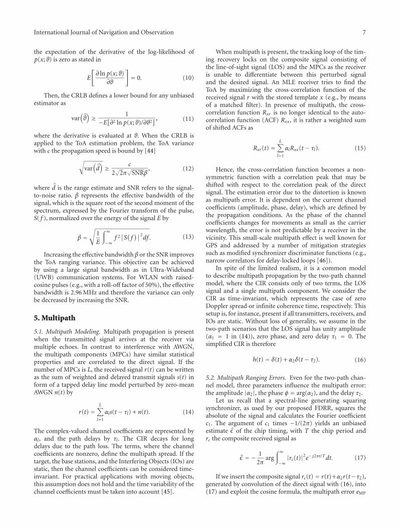
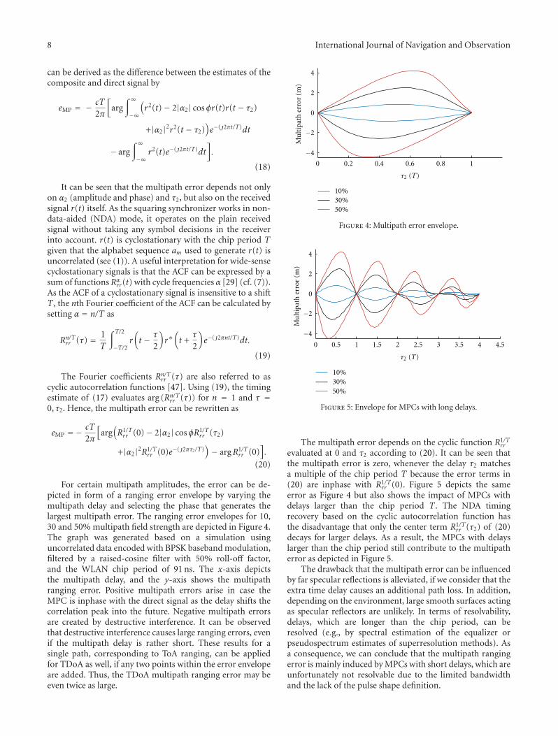
For certain multipath amplitudes, the error can be de-picted in form of a ranging error envelope by varying themultipath delay and selecting the phase that generates thelargest multipath error. The ranging error envelopes for 10,30 and 50% multipath field strength are depicted in Figure 4.The graph was generated based on a simulation usinguncorrelated data encoded with BPSK baseband modulation,filtered by a raised-cosine filter with 50% roll-off factor,and the WLAN chip period of 91 ns. The x-axis depictsthe multipath delay, and the y-axis shows the multipathranging error. Positive multipath errors arise in case theMPC is inphase with the direct signal as the delay shifts thecorrelation peak into the future. Negative multipath errorsare created by destructive interference. It can be observedthat destructive interference causes large ranging errors, evenif the multipath delay is rather short. These results for asingle path, corresponding to ToA ranging, can be appliedfor TDoA as well, if any two points within the error envelopeare added. Thus, the TDoA multipath ranging error may beeven twice as large.
0
2
4
−2
−4
0.2 0.4 0.6 0.8 10
Mu
ltip
ath
err
or (
m)
50%30%10%
τ2 (T)
Figure 4: Multipath error envelope.
0
2
4
−2
−4
Mu
ltip
ath
err
or (
m)
0 0.5 1 1.5 2 2.5 3 3.5 4 4.5
50%30%10%
τ2 (T)
Figure 5: Envelope for MPCs with long delays.
The multipath error depends on the cyclic function R1/Trr
evaluated at 0 and τ2 according to (20). It can be seen thatthe multipath error is zero, whenever the delay τ2 matchesa multiple of the chip period T because the error terms in(20) are inphase with R1/T
rr (0). Figure 5 depicts the sameerror as Figure 4 but also shows the impact of MPCs withdelays larger than the chip period T . The NDA timingrecovery based on the cyclic autocorrelation function hasthe disadvantage that only the center term R1/T
rr (τ2) of (20)decays for larger delays. As a result, the MPCs with delayslarger than the chip period still contribute to the multipatherror as depicted in Figure 5.
The drawback that the multipath error can be influencedby far specular reflections is alleviated, if we consider that theextra time delay causes an additional path loss. In addition,depending on the environment, large smooth surfaces actingas specular reflectors are unlikely. In terms of resolvability,delays, which are longer than the chip period, can beresolved (e.g., by spectral estimation of the equalizer orpseudospectrum estimates of superresolution methods). Asa consequence, we can conclude that the multipath rangingerror is mainly induced by MPCs with short delays, which areunfortunately not resolvable due to the limited bandwidthand the lack of the pulse shape definition.
International Journal of Navigation and Observation 9
5.3. Multipath Mitigation. Multipath can cause significantranging errors in the order of several meters as the receivertracks the composite signal. Despite particular antenna de-signs which attenuate the MPCs, multipath can also betackled by signal and data processing using nonparametric,parametric, and averaging techniques. Nonparametric tech-niques use a modified receiver template, which rather tracksthe derivative of the pulse shape than the pulse shape itself,such as a narrow correlator setup commonly used in GPSreceivers. The modified template is designed to achieve asharper correlation result that is less influenced by multipathpropagation. Parametric techniques rely on a certain CIRmodel and estimate the nuisance parameters such as phases,amplitudes, and delays of the MPCs. A common approachwithin this group is superresolution techniques in the timeand frequency domain [48].
A necessary assumption for all estimation methods is thatthe signal (or at least its autocorrelation and covariance) iseither known in advance or the receiver is able to reconstructthis information. Whereas the digital information andsignal constellation of each chip in the baseband can bereconstructed, the WLAN pulse shape is not defined andmay vary from device to device. Hence, an estimation of theCIR is not possible because the transmitted signal cannot bereconstructed. On the other hand, nonparametric multipathmitigation techniques, such as narrow correlators with anearly-late spacing of 0.1T resulted in the same multipatherror as the squaring synchronizer (Figure 4). The reason forthe discrepancy with the multipath mitigation improvementsreported by other authors (e.g., [49]) stems from the fact thatcommonly a triangular ACF (responding to the transmissionof rectangular pulses) is assumed, while the bandwidthlimitation of WLAN imposes a rounded (raised-cosine) ACFof the signal and therefore diminishes the advantages ofspecial correlator arm arrangements.
Multipath is in particular the limiting factor for pointpositioning applications. When the channel is static andtherefore the channel coherence time is infinite, the rangeestimate may include a constant ranging bias. In principle,multipath mitigation through averaging can be done by anykind of frequency or space diversity, which is able to changethe CIR or minimize the coherence time. If the target changesthe position by about 10 times the carrier wavelength,the small-scale fading effects and connected to these themultipath errors average. For WLAN, this equates to a dis-placement of more than 1 m. Spatial averaging is impracticalas it prohibits point positioning and requires a constantmovement to generate varying CIRs.
Frequency diversity is another option to mitigate multi-path errors as different carrier frequencies change the CIR.The main disadvantage of this approach is that changing theWLAN channel causes a loss of connection, if not enforcedsimultaneously by the AP and all associated targets. Yet, westill propose this method as it is one of the few methods,which requires only software modifications of the target,namely, preplanned channel hopping. As shown in the nextsection, frequency diversity can significantly improve themultipath performance.
TA1
A2
Figure 6: Cabled setup for assessing the synthetic performance.
6. Results
This section presents the results of the FDRR architectureintroduced in Section 4 based on a digital logic implemen-tation using an FPGA platform. Several measurements havebeen performed to assess the synthetic performance (perfectchannel) and the practical performance in line-of-sight andmultipath conditions.
6.1. Measurement Setup and Platform. The proposed FDRRarchitecture has been implemented using the SMart inte-grated Localization Extension 3 (SMiLE 3) base station hard-ware, which is a revised version of our previous hardwaredescribed in [22]. It consists primarily of an RF mixer IC toconvert the WLAN signal to the baseband, a dual-channelADC/DAC, an FPGA for signal processing and messagehandling, and an Ethernet connection to communicate thecaptured ranging parameters to the locating PC calculatingthe positions. Two methods for synchronizing the basestations are available: Ethernet synchronization and Board-Link. Ethernet synchronization exploits the fact that thetransmit signal of a 100Base-TX Ethernet link is synchronousto the source oscillator of the transmitter. When all SMiLEsare connected to a common switch, the base stations areable to recover the transmit Ethernet clock from the receivedEthernet signal and can build a synchronous network withphase-locked sampling clocks 1/Ts. The same can be donewhen connecting two base stations with a dedicated clockcable named Board-Link. Still, as the startup time of all basestations is not synchronized, clock offsets between the basestations exist. These offsets can be resolved by transmitting aWLAN frame from a known position and compensating forthe propagation time to the base stations. This step is referredto as clock offset calibration.
Various measurements have been conducted by deploy-ing either two or four base stations for one- and two-dimensional setups. The RF mixer of SMiLE 3 platform hasa dependency of the delay on the premixer and postmixeramplification by a few nanoseconds. In all measurements,these systematic errors are compensated by a table lookup.
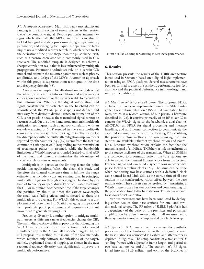
6.2. Synthetic Performance. First, we assess the syntheticperformance of the hardware, when the RF signal betweenthe base stations is connected via cables and attenuators asdepicted in Figure 6. The setup consists of a transmitter Tsending frames with adjustable frame length and period totwo base stations A1 and A2. The transmitter’s RF signalis fed into an 18 dB splitter, and each of the branches is
10 International Journal of Navigation and Observation
0
20
40
60
80
Ran
gin
gσ
(ps)
0 500 1000 1500 2000 2500 3000 3500 4000
Frame length (symbols)
Quantization boundGCC CRLB
Board-LinkEthernet
Figure 7: Ranging performance: frame length dependency.
connected by attenuators to one base station. Each basestation captures the frame, timestamps it, and transmits thetimestamp together with the frame check sum and the iden-tification MAC address to the locating PC, which subtractsthe timestamps and records the TDoA.
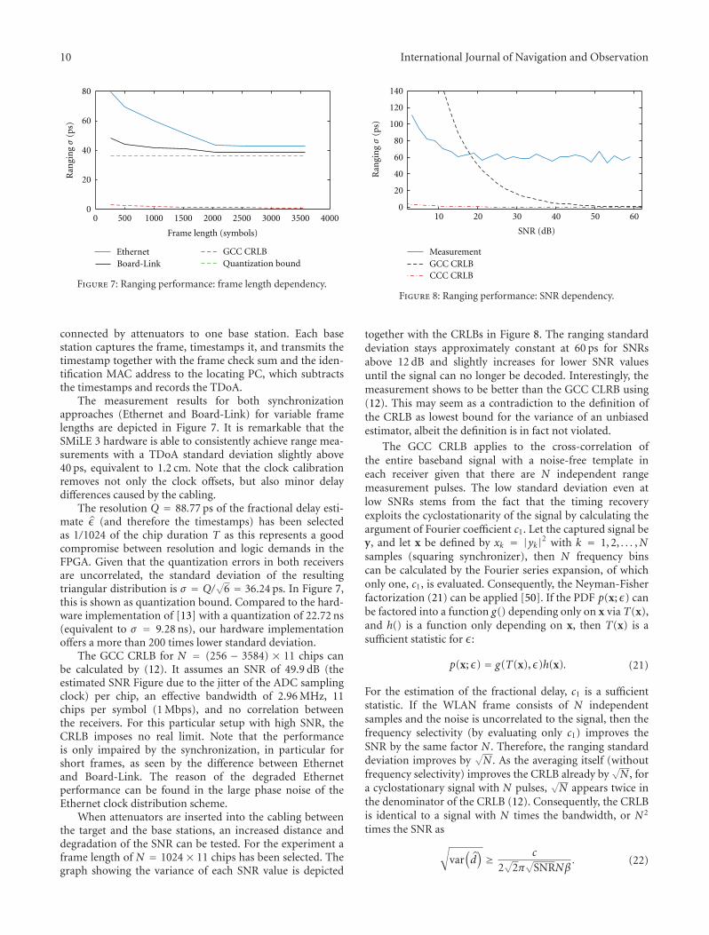
The measurement results for both synchronizationapproaches (Ethernet and Board-Link) for variable framelengths are depicted in Figure 7. It is remarkable that theSMiLE 3 hardware is able to consistently achieve range mea-surements with a TDoA standard deviation slightly above40 ps, equivalent to 1.2 cm. Note that the clock calibrationremoves not only the clock offsets, but also minor delaydifferences caused by the cabling.
The resolution Q = 88.77 ps of the fractional delay esti-mate ε (and therefore the timestamps) has been selectedas 1/1024 of the chip duration T as this represents a goodcompromise between resolution and logic demands in theFPGA. Given that the quantization errors in both receiversare uncorrelated, the standard deviation of the resultingtriangular distribution is σ = Q/
√6 = 36.24 ps. In Figure 7,
this is shown as quantization bound. Compared to the hard-ware implementation of [13] with a quantization of 22.72 ns(equivalent to σ = 9.28 ns), our hardware implementationoffers a more than 200 times lower standard deviation.
The GCC CRLB for N = (256 − 3584) × 11 chips canbe calculated by (12). It assumes an SNR of 49.9 dB (theestimated SNR Figure due to the jitter of the ADC samplingclock) per chip, an effective bandwidth of 2.96 MHz, 11chips per symbol (1 Mbps), and no correlation betweenthe receivers. For this particular setup with high SNR, theCRLB imposes no real limit. Note that the performanceis only impaired by the synchronization, in particular forshort frames, as seen by the difference between Ethernetand Board-Link. The reason of the degraded Ethernetperformance can be found in the large phase noise of theEthernet clock distribution scheme.
When attenuators are inserted into the cabling betweenthe target and the base stations, an increased distance anddegradation of the SNR can be tested. For the experiment aframe length of N = 1024 × 11 chips has been selected. Thegraph showing the variance of each SNR value is depicted
0
20
40
60
80
100
120
140
Ran
gin
gσ
(ps)
10 20 30 40 50 60
SNR (dB)
CCC CRLBGCC CRLBMeasurement
Figure 8: Ranging performance: SNR dependency.
together with the CRLBs in Figure 8. The ranging standarddeviation stays approximately constant at 60 ps for SNRsabove 12 dB and slightly increases for lower SNR valuesuntil the signal can no longer be decoded. Interestingly, themeasurement shows to be better than the GCC CLRB using(12). This may seem as a contradiction to the definition ofthe CRLB as lowest bound for the variance of an unbiasedestimator, albeit the definition is in fact not violated.
The GCC CRLB applies to the cross-correlation ofthe entire baseband signal with a noise-free template ineach receiver given that there are N independent rangemeasurement pulses. The low standard deviation even atlow SNRs stems from the fact that the timing recoveryexploits the cyclostationarity of the signal by calculating theargument of Fourier coefficient c1. Let the captured signal bey, and let x be defined by xk = |yk|2 with k = 1, 2, . . . ,Nsamples (squaring synchronizer), then N frequency binscan be calculated by the Fourier series expansion, of whichonly one, c1, is evaluated. Consequently, the Neyman-Fisherfactorization (21) can be applied [50]. If the PDF p(x; ε) canbe factored into a function g() depending only on x via T(x),and h() is a function only depending on x, then T(x) is asufficient statistic for ε:
p(x; ε) = g(T(x), ε)h(x). (21)
For the estimation of the fractional delay, c1 is a sufficientstatistic. If the WLAN frame consists of N independentsamples and the noise is uncorrelated to the signal, then thefrequency selectivity (by evaluating only c1) improves theSNR by the same factor N . Therefore, the ranging standarddeviation improves by
√N . As the averaging itself (without
frequency selectivity) improves the CRLB already by√N , for
a cyclostationary signal with N pulses,√N appears twice in
the denominator of the CRLB (12). Consequently, the CRLBis identical to a signal with N times the bandwidth, or N2
times the SNR as√
var(d)≥ c
2√
2π√
SNRNβ. (22)
International Journal of Navigation and Observation 11
0 5
0
5
10
15
20
25
30
35
A2
A3
A1
A4
10 15 20 25 30 35
y-ax
is (
m)
x-axis (m)
Figure 9: 2D position measurement in LOS conditions.
This bound is depicted as CCC CRLB in Figure 8.The actual receiver design diverts from this approach asit uses an NDA timing recovery, which has an increasedvariance compared to a decision-directed timing recoveryfor conditions with an SNR below 7 dB in case of BPSKmodulation, as shown by the closed-form evaluation in [51].The CCC CRLB assumes perfect synchronization and nochip frequency skews. In practical implementations, chipfrequency skews are always present, and therefore the loopbandwidth in the timing recovery must be sufficiently largeto track frequency changes. As a result, the noise over a largerbandwidth needs to be collected for tracking reasons, thusleading to an increased variance.
6.3. Performance in LOS Conditions. In all the followingmeasurements, a Linksys WRT54GL wireless access pointhas been used sending beacons with N = 944 chips withan interval of approximately 10 ms. The target is equippedwith a standard dipole antenna with horizontal polarization,which ensures angular-independent uniform signal coverage.The target is moved within the area of interest, and theposition of the target is calculated in the locating unit basedon the parameter estimates captured by the base stations.Once the setup is built up, the initial clock offset calibrationis performed and the same offsets are used for all positions ofthe measurement.
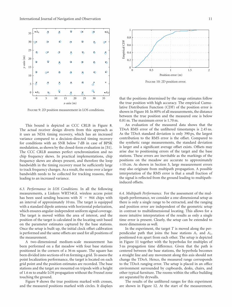
A two-dimensional medium-scale measurement hasbeen performed on a flat meadow with four base stationspositioned in the corners of a 36 m square. The square hasbeen divided into sections of 6 m forming a grid. To assess thepoint localization performance, the target is located on eachgrid point and the position estimates are recorded. The basestations and the target are mounted on tripods with a heightof 1.6 m to enable LOS propagation without the Fresnel zonetouching the ground.
Figure 9 shows the true positions marked with crosses,and the measured positions marked with circles. It displays
0 0.5 1 1.5 2
1
0.8
0.6
0.4
0.2
0
Em
piri
cal C
DF
Position error (m)
Figure 10: 2D position error.
that the positions determined by the range estimates followthe true position with high accuracy. The empirical Cumu-lative Distribution Function (CDF) of the position error isshown in Figure 10. In 80% of all measurements, the distancebetween the true position and the measured one is below0.81 m. The maximum error is 1.70 m.
An evaluation of the measured data shows that theTDoA RMS error of the unfiltered timestamps is 2.45 ns.As the TDoA standard deviation is only 390 ps, the largestcontribution to the RMS error is the offset. Compared tothe synthetic range measurements, the standard deviationis larger and a significant average offset exists. Offsets mayarise due to positioning errors of the target and the basestations. These errors are inevitable as the markings of thepositions on the meadow are accurate to approximately±10 cm. As shown in Section 5, large measurement errorsmay also originate from multipath propagation. A possibleinterpretation of the RMS error is that a small fraction ofthe signal is reflected from the ground leading to multipath-induced offsets.
6.4. Multipath Performance. For the assessment of the mul-tipath performance, we consider a one-dimensional setup asthere is only a single range to be extracted, and the rangingand position error are independent of the geometric setupin contrast to multidimensional locating. This allows for amore intuitive interpretation of the results as only a singletime error is present. Clearly, the setup can be extended tomore dimensions as well.
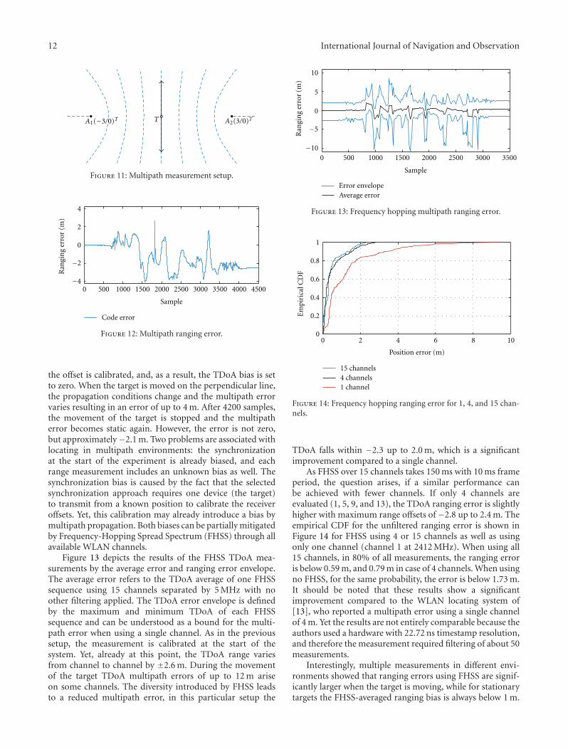
In the experiment, the target T is moved along the per-pendicular path that joins the base stations A1 and A2,positioned 6 m apart from each other. The setup is depictedin Figure 11 together with the hyperbolas for multiples of5 ns propagation time difference. Given that the path iscentered between the base stations, the hyperbola becomesa straight line and any movement along this axis should notchange the TDoA. Hence, the measured range correspondsto the TDoA ranging error. The setup is placed in an officeenvironment surrounded by cupboards, desks, chairs, andother typical furniture. The rooms within the office buildingare separated by drywalls.
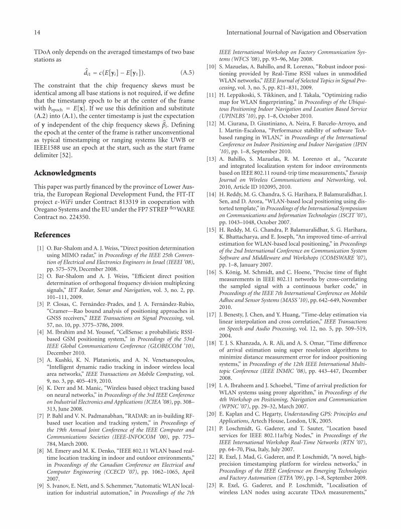
The results of the unfiltered ranges for this experimentare shown in Figure 12. At the start of the measurement,
12 International Journal of Navigation and Observation
A1(−3/0)T A2(3/0)TT
Figure 11: Multipath measurement setup.
4
2
0
−2
−44500
Sample
Code error
Ran
gin
g er
ror
(m)
0 500 1000 1500 2000 2500 3000 3500 4000
Figure 12: Multipath ranging error.
the offset is calibrated, and, as a result, the TDoA bias is setto zero. When the target is moved on the perpendicular line,the propagation conditions change and the multipath errorvaries resulting in an error of up to 4 m. After 4200 samples,the movement of the target is stopped and the multipatherror becomes static again. However, the error is not zero,but approximately−2.1 m. Two problems are associated withlocating in multipath environments: the synchronizationat the start of the experiment is already biased, and eachrange measurement includes an unknown bias as well. Thesynchronization bias is caused by the fact that the selectedsynchronization approach requires one device (the target)to transmit from a known position to calibrate the receiveroffsets. Yet, this calibration may already introduce a bias bymultipath propagation. Both biases can be partially mitigatedby Frequency-Hopping Spread Spectrum (FHSS) through allavailable WLAN channels.
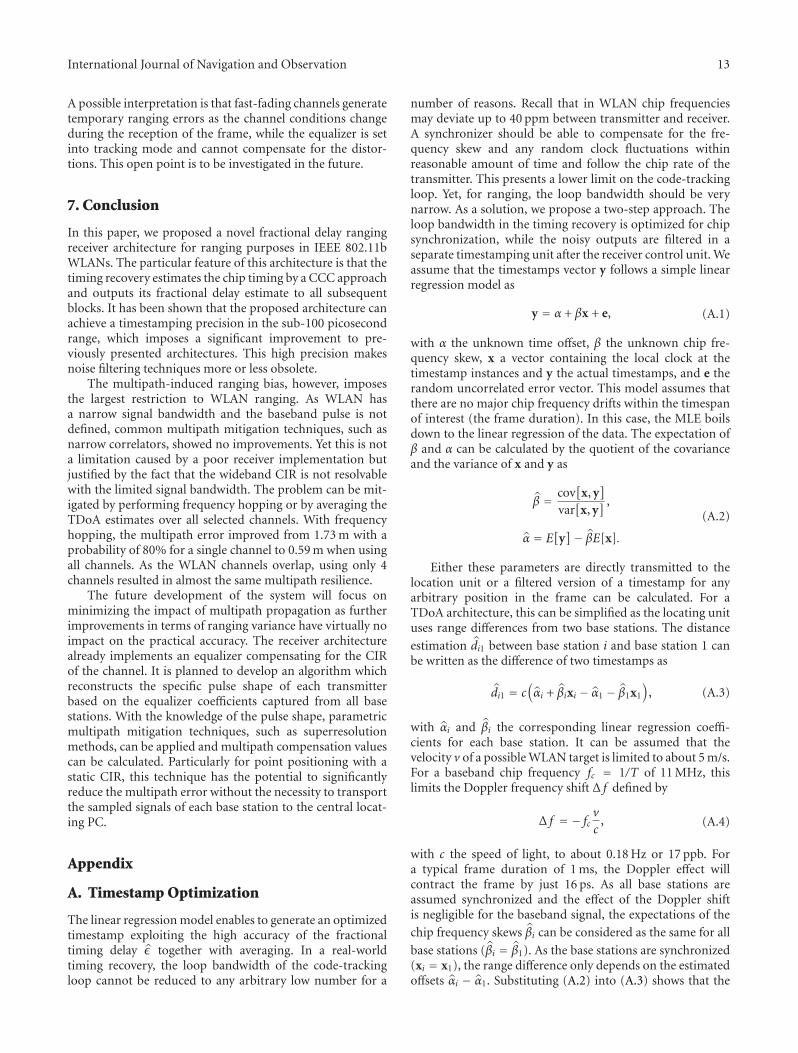
Figure 13 depicts the results of the FHSS TDoA mea-surements by the average error and ranging error envelope.The average error refers to the TDoA average of one FHSSsequence using 15 channels separated by 5 MHz with noother filtering applied. The TDoA error envelope is definedby the maximum and minimum TDoA of each FHSSsequence and can be understood as a bound for the multi-path error when using a single channel. As in the previoussetup, the measurement is calibrated at the start of thesystem. Yet, already at this point, the TDoA range variesfrom channel to channel by ±2.6 m. During the movementof the target TDoA multipath errors of up to 12 m ariseon some channels. The diversity introduced by FHSS leadsto a reduced multipath error, in this particular setup the
0 500 1000 1500 2000 2500 3000 3500
10
5
0
−5
−10
Error envelopeAverage error
Sample
Ran
gin
g er
ror
(m)
Figure 13: Frequency hopping multipath ranging error.
0 2 4 6 8 10
1
0.8
0.6
0.4
0.2
0
Position error (m)
Em
piri
cal C
DF
4 channels15 channels
1 channel
Figure 14: Frequency hopping ranging error for 1, 4, and 15 chan-nels.
TDoA falls within −2.3 up to 2.0 m, which is a significantimprovement compared to a single channel.
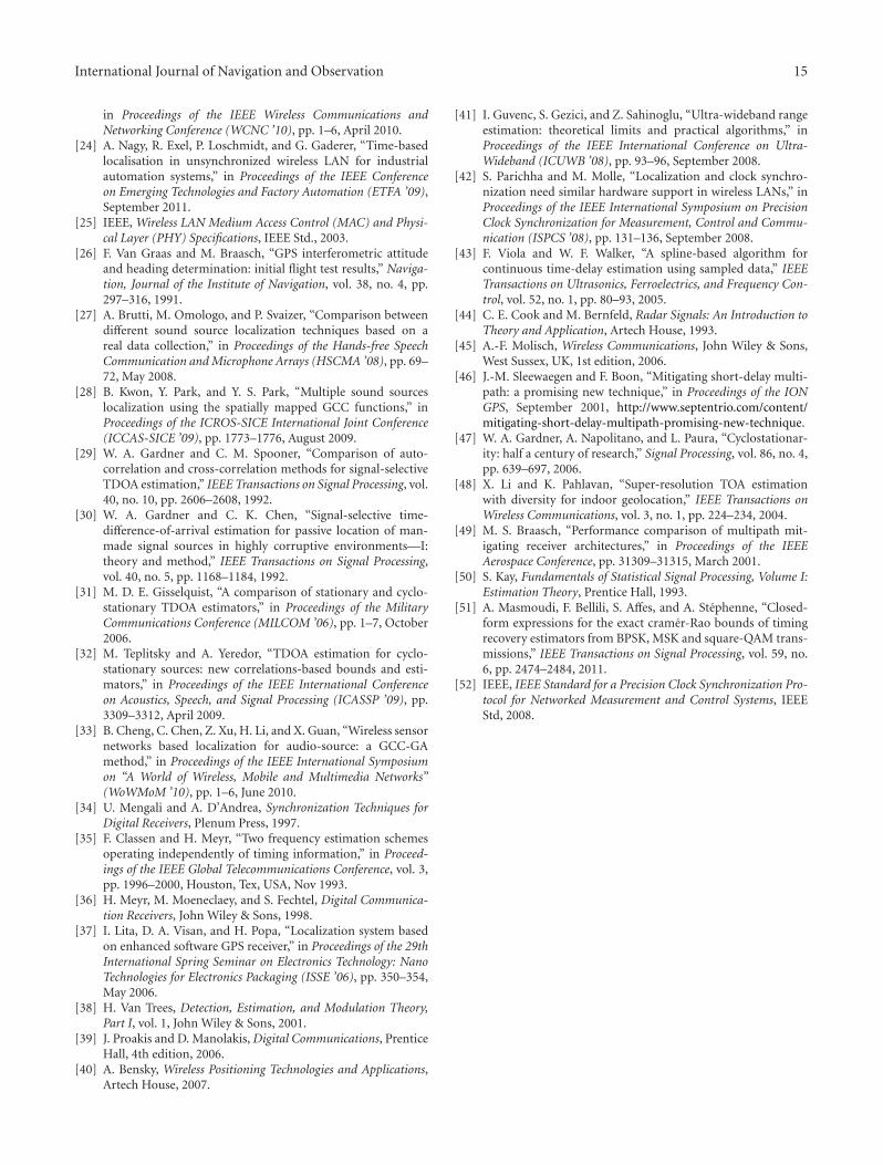
As FHSS over 15 channels takes 150 ms with 10 ms frameperiod, the question arises, if a similar performance canbe achieved with fewer channels. If only 4 channels areevaluated (1, 5, 9, and 13), the TDoA ranging error is slightlyhigher with maximum range offsets of −2.8 up to 2.4 m. Theempirical CDF for the unfiltered ranging error is shown inFigure 14 for FHSS using 4 or 15 channels as well as usingonly one channel (channel 1 at 2412 MHz). When using all15 channels, in 80% of all measurements, the ranging erroris below 0.59 m, and 0.79 m in case of 4 channels. When usingno FHSS, for the same probability, the error is below 1.73 m.It should be noted that these results show a significantimprovement compared to the WLAN locating system of[13], who reported a multipath error using a single channelof 4 m. Yet the results are not entirely comparable because theauthors used a hardware with 22.72 ns timestamp resolution,and therefore the measurement required filtering of about 50measurements.
Interestingly, multiple measurements in different envi-ronments showed that ranging errors using FHSS are signif-icantly larger when the target is moving, while for stationarytargets the FHSS-averaged ranging bias is always below 1 m.
International Journal of Navigation and Observation 13
A possible interpretation is that fast-fading channels generatetemporary ranging errors as the channel conditions changeduring the reception of the frame, while the equalizer is setinto tracking mode and cannot compensate for the distor-tions. This open point is to be investigated in the future.
7. Conclusion
In this paper, we proposed a novel fractional delay rangingreceiver architecture for ranging purposes in IEEE 802.11bWLANs. The particular feature of this architecture is that thetiming recovery estimates the chip timing by a CCC approachand outputs its fractional delay estimate to all subsequentblocks. It has been shown that the proposed architecture canachieve a timestamping precision in the sub-100 picosecondrange, which imposes a significant improvement to pre-viously presented architectures. This high precision makesnoise filtering techniques more or less obsolete.
The multipath-induced ranging bias, however, imposesthe largest restriction to WLAN ranging. As WLAN hasa narrow signal bandwidth and the baseband pulse is notdefined, common multipath mitigation techniques, such asnarrow correlators, showed no improvements. Yet this is nota limitation caused by a poor receiver implementation butjustified by the fact that the wideband CIR is not resolvablewith the limited signal bandwidth. The problem can be mit-igated by performing frequency hopping or by averaging theTDoA estimates over all selected channels. With frequencyhopping, the multipath error improved from 1.73 m with aprobability of 80% for a single channel to 0.59 m when usingall channels. As the WLAN channels overlap, using only 4channels resulted in almost the same multipath resilience.
The future development of the system will focus onminimizing the impact of multipath propagation as furtherimprovements in terms of ranging variance have virtually noimpact on the practical accuracy. The receiver architecturealready implements an equalizer compensating for the CIRof the channel. It is planned to develop an algorithm whichreconstructs the specific pulse shape of each transmitterbased on the equalizer coefficients captured from all basestations. With the knowledge of the pulse shape, parametricmultipath mitigation techniques, such as superresolutionmethods, can be applied and multipath compensation valuescan be calculated. Particularly for point positioning with astatic CIR, this technique has the potential to significantlyreduce the multipath error without the necessity to transportthe sampled signals of each base station to the central locat-ing PC.
Appendix
A. Timestamp Optimization
The linear regression model enables to generate an optimizedtimestamp exploiting the high accuracy of the fractionaltiming delay ε together with averaging. In a real-worldtiming recovery, the loop bandwidth of the code-trackingloop cannot be reduced to any arbitrary low number for a
number of reasons. Recall that in WLAN chip frequenciesmay deviate up to 40 ppm between transmitter and receiver.A synchronizer should be able to compensate for the fre-quency skew and any random clock fluctuations withinreasonable amount of time and follow the chip rate of thetransmitter. This presents a lower limit on the code-trackingloop. Yet, for ranging, the loop bandwidth should be verynarrow. As a solution, we propose a two-step approach. Theloop bandwidth in the timing recovery is optimized for chipsynchronization, while the noisy outputs are filtered in aseparate timestamping unit after the receiver control unit. Weassume that the timestamps vector y follows a simple linearregression model as
y = α + βx + e, (A.1)
with α the unknown time offset, β the unknown chip fre-quency skew, x a vector containing the local clock at thetimestamp instances and y the actual timestamps, and e therandom uncorrelated error vector. This model assumes thatthere are no major chip frequency drifts within the timespanof interest (the frame duration). In this case, the MLE boilsdown to the linear regression of the data. The expectation ofβ and α can be calculated by the quotient of the covarianceand the variance of x and y as
β = cov[
x, y]
var[
x, y] ,
α = E[
y]− βE[x].
(A.2)
Either these parameters are directly transmitted to thelocation unit or a filtered version of a timestamp for anyarbitrary position in the frame can be calculated. For aTDoA architecture, this can be simplified as the locating unituses range differences from two base stations. The distance
estimation di1 between base station i and base station 1 canbe written as the difference of two timestamps as
di1 = c(αi + βixi − α1 − β1x1
), (A.3)
with αi and βi the corresponding linear regression coeffi-cients for each base station. It can be assumed that thevelocity v of a possible WLAN target is limited to about 5 m/s.For a baseband chip frequency fc = 1/T of 11 MHz, thislimits the Doppler frequency shift Δ f defined by
Δ f = − fcv
c, (A.4)
with c the speed of light, to about 0.18 Hz or 17 ppb. Fora typical frame duration of 1 ms, the Doppler effect willcontract the frame by just 16 ps. As all base stations areassumed synchronized and the effect of the Doppler shiftis negligible for the baseband signal, the expectations of the
chip frequency skews βi can be considered as the same for all
base stations (βi = β1). As the base stations are synchronized(xi = x1), the range difference only depends on the estimatedoffsets αi − α1. Substituting (A.2) into (A.3) shows that the
14 International Journal of Navigation and Observation
TDoA only depends on the averaged timestamps of two basestations as
di1 = c(E[
yi]− E
[y1]). (A.5)
The constraint that the chip frequency skews must beidentical among all base stations is not required, if we definethat the timestamp epoch to be at the center of the framewith bepoch = E[x]. If we use this definition and substitute(A.2) into (A.1), the center timestamp is just the expectation
of y independent of the chip frequency skews βi. Definingthe epoch at the center of the frame is rather unconventionalas typical timestamping or ranging systems like UWB orIEEE1588 use an epoch at the start, such as the start framedelimiter [52].
Acknowledgments
This paper was partly financed by the province of Lower Aus-tria, the European Regional Development Fund, the FIT-ITproject ε-WiFi under Contract 813319 in cooperation withOregano Systems and the EU under the FP7 STREP flexWAREContract no. 224350.
References
[1] O. Bar-Shalom and A. J. Weiss, “Direct position determinationusing MIMO radar,” in Proceedings of the IEEE 25th Conven-tion of Electrical and Electronics Engineers in Israel (IEEEI ’08),pp. 575–579, December 2008.
[2] O. Bar-Shalom and A. J. Weiss, “Efficient direct positiondetermination of orthogonal frequency division multiplexingsignals,” IET Radar, Sonar and Navigation, vol. 3, no. 2, pp.101–111, 2009.
[3] P. Closas, C. Fernandez-Prades, and J. A. Fernandez-Rubio,“Cramer—Rao bound analysis of positioning approaches inGNSS receivers,” IEEE Transactions on Signal Processing, vol.57, no. 10, pp. 3775–3786, 2009.
[4] M. Ibrahim and M. Youssef, “CellSense: a probabilistic RSSI-based GSM positioning system,” in Proceedings of the 53rdIEEE Global Communications Conference (GLOBECOM ’10),December 2010.
[5] A. Kushki, K. N. Plataniotis, and A. N. Venetsanopoulos,“Intelligent dynamic radio tracking in indoor wireless localarea networks,” IEEE Transactions on Mobile Computing, vol.9, no. 3, pp. 405–419, 2010.
[6] K. Derr and M. Manic, “Wireless based object tracking basedon neural networks,” in Proceedings of the 3rd IEEE Conferenceon Industrial Electronics and Applications (ICIEA ’08), pp. 308–313, June 2008.
[7] P. Bahl and V. N. Padmanabhan, “RADAR: an in-building RF-based user location and tracking system,” in Proceedings ofthe 19th Annual Joint Conference of the IEEE Computer andCommunications Societies (IEEE-INFOCOM ’00), pp. 775–784, March 2000.
[8] M. Emery and M. K. Denko, “IEEE 802.11 WLAN based real-time location tracking in indoor and outdoor environments,”in Proceedings of the Canadian Conference on Electrical andComputer Engineering (CCECD ’07), pp. 1062–1065, April2007.
[9] S. Ivanov, E. Nett, and S. Schemmer, “Automatic WLAN local-ization for industrial automation,” in Proceedings of the 7th
IEEE International Workshop on Factory Communication Sys-tems (WFCS ’08), pp. 93–96, May 2008.
[10] S. Mazuelas, A. Bahillo, and R. Lorenzo, “Robust indoor posi-tioning provided by Real-Time RSSI values in unmodifiedWLAN networks,” IEEE Journal of Selected Topics in Signal Pro-cessing, vol. 3, no. 5, pp. 821–831, 2009.
[11] H. Leppakoski, S. Tikkinen, and J. Takala, “Optimizing radiomap for WLAN fingerprinting,” in Proceedings of the Ubiqui-tous Positioning Indoor Navigation and Location Based Service(UPINLBS ’10), pp. 1–8, October 2010.
[12] M. Ciurana, D. Giustiniano, A. Neira, F. Barcelo-Arroyo, andI. Martin-Escalona, “Performance stability of software ToA-based ranging in WLAN,” in Proceedings of the InternationalConference on Indoor Positioning and Indoor Navigation (IPIN’10), pp. 1–8, September 2010.
[13] A. Bahillo, S. Mazuelas, R. M. Lorenzo et al., “Accurateand integrated localization system for indoor environmentsbased on IEEE 802.11 round-trip time measurements,” EurasipJournal on Wireless Communications and Networking, vol.2010, Article ID 102095, 2010.
[14] H. Reddy, M. G. Chandra, S. G. Harihara, P. Balamuralidhar, J.Sen, and D. Arora, “WLAN-based local positioning using dis-torted template,” in Proceedings of the International Symposiumon Communications and Information Technologies (ISCIT ’07),pp. 1043–1048, October 2007.
[15] H. Reddy, M. G. Chandra, P. Balamuralidhar, S. G. Harihara,K. Bhattacharya, and E. Joseph, “An improved time-of-arrivalestimation for WLAN-based local positioning,” in Proceedingsof the 2nd International Conference on Communication SystemSoftware and Middleware and Workshops (COMSWARE ’07),pp. 1–8, January 2007.
[16] S. Konig, M. Schmidt, and C. Hoene, “Precise time of flightmeasurements in IEEE 802.11 networks by cross-correlatingthe sampled signal with a continuous barker code,” inProceedings of the IEEE 7th International Conference on MobileAdhoc and Sensor Systems (MASS ’10), pp. 642–649, November2010.
[17] J. Benesty, J. Chen, and Y. Huang, “Time-delay estimation vialinear interpolation and cross correlation,” IEEE Transactionson Speech and Audio Processing, vol. 12, no. 5, pp. 509–519,2004.
[18] T. J. S. Khanzada, A. R. Ali, and A. S. Omar, “Time differenceof arrival estimation using super resolution algorithms tominimize distance measurement error for indoor positioningsystems,” in Proceedings of the 12th IEEE International Multi-topic Conference (IEEE INMIC ’08), pp. 443–447, December2008.
[19] I. A. Ibraheem and J. Schoebel, “Time of arrival prediction forWLAN systems using prony algorithm,” in Proceedings of the4th Workshop on Positioning, Navigation and Communication(WPNC ’07), pp. 29–32, March 2007.
[20] E. Kaplan and C. Hegarty, Understanding GPS: Principles andApplications, Artech House, London, UK, 2005.
[21] P. Loschmidt, G. Gaderer, and T. Sauter, “Location basedservices for IEEE 802.11a/b/g Nodes,” in Proceedings of theIEEE International Workshop Real-Time Networks (RTN ’07),pp. 64–70, Pisa, Italy, July 2007.
[22] R. Exel, J. Mad, G. Gaderer, and P. Loschmidt, “A novel, high-precision timestamping platform for wireless networks,” inProceedings of the IEEE Conference on Emerging Technologiesand Factory Automation (ETFA ’09), pp. 1–8, September 2009.
[23] R. Exel, G. Gaderer, and P. Loschmidt, “Localisation ofwireless LAN nodes using accurate TDoA measurements,”
International Journal of Navigation and Observation 15
in Proceedings of the IEEE Wireless Communications andNetworking Conference (WCNC ’10), pp. 1–6, April 2010.
[24] A. Nagy, R. Exel, P. Loschmidt, and G. Gaderer, “Time-basedlocalisation in unsynchronized wireless LAN for industrialautomation systems,” in Proceedings of the IEEE Conferenceon Emerging Technologies and Factory Automation (ETFA ’09),September 2011.
[25] IEEE, Wireless LAN Medium Access Control (MAC) and Physi-cal Layer (PHY) Specifications, IEEE Std., 2003.
[26] F. Van Graas and M. Braasch, “GPS interferometric attitudeand heading determination: initial flight test results,” Naviga-tion, Journal of the Institute of Navigation, vol. 38, no. 4, pp.297–316, 1991.
[27] A. Brutti, M. Omologo, and P. Svaizer, “Comparison betweendifferent sound source localization techniques based on areal data collection,” in Proceedings of the Hands-free SpeechCommunication and Microphone Arrays (HSCMA ’08), pp. 69–72, May 2008.
[28] B. Kwon, Y. Park, and Y. S. Park, “Multiple sound sourceslocalization using the spatially mapped GCC functions,” inProceedings of the ICROS-SICE International Joint Conference(ICCAS-SICE ’09), pp. 1773–1776, August 2009.
[29] W. A. Gardner and C. M. Spooner, “Comparison of auto-correlation and cross-correlation methods for signal-selectiveTDOA estimation,” IEEE Transactions on Signal Processing, vol.40, no. 10, pp. 2606–2608, 1992.
[30] W. A. Gardner and C. K. Chen, “Signal-selective time-difference-of-arrival estimation for passive location of man-made signal sources in highly corruptive environments—I:theory and method,” IEEE Transactions on Signal Processing,vol. 40, no. 5, pp. 1168–1184, 1992.
[31] M. D. E. Gisselquist, “A comparison of stationary and cyclo-stationary TDOA estimators,” in Proceedings of the MilitaryCommunications Conference (MILCOM ’06), pp. 1–7, October2006.
[32] M. Teplitsky and A. Yeredor, “TDOA estimation for cyclo-stationary sources: new correlations-based bounds and esti-mators,” in Proceedings of the IEEE International Conferenceon Acoustics, Speech, and Signal Processing (ICASSP ’09), pp.3309–3312, April 2009.
[33] B. Cheng, C. Chen, Z. Xu, H. Li, and X. Guan, “Wireless sensornetworks based localization for audio-source: a GCC-GAmethod,” in Proceedings of the IEEE International Symposiumon “A World of Wireless, Mobile and Multimedia Networks”(WoWMoM ’10), pp. 1–6, June 2010.
[34] U. Mengali and A. D’Andrea, Synchronization Techniques forDigital Receivers, Plenum Press, 1997.
[35] F. Classen and H. Meyr, “Two frequency estimation schemesoperating independently of timing information,” in Proceed-ings of the IEEE Global Telecommunications Conference, vol. 3,pp. 1996–2000, Houston, Tex, USA, Nov 1993.
[36] H. Meyr, M. Moeneclaey, and S. Fechtel, Digital Communica-tion Receivers, John Wiley & Sons, 1998.
[37] I. Lita, D. A. Visan, and H. Popa, “Localization system basedon enhanced software GPS receiver,” in Proceedings of the 29thInternational Spring Seminar on Electronics Technology: NanoTechnologies for Electronics Packaging (ISSE ’06), pp. 350–354,May 2006.
[38] H. Van Trees, Detection, Estimation, and Modulation Theory,Part I, vol. 1, John Wiley & Sons, 2001.
[39] J. Proakis and D. Manolakis, Digital Communications, PrenticeHall, 4th edition, 2006.
[40] A. Bensky, Wireless Positioning Technologies and Applications,Artech House, 2007.
[41] I. Guvenc, S. Gezici, and Z. Sahinoglu, “Ultra-wideband rangeestimation: theoretical limits and practical algorithms,” inProceedings of the IEEE International Conference on Ultra-Wideband (ICUWB ’08), pp. 93–96, September 2008.
[42] S. Parichha and M. Molle, “Localization and clock synchro-nization need similar hardware support in wireless LANs,” inProceedings of the IEEE International Symposium on PrecisionClock Synchronization for Measurement, Control and Commu-nication (ISPCS ’08), pp. 131–136, September 2008.
[43] F. Viola and W. F. Walker, “A spline-based algorithm forcontinuous time-delay estimation using sampled data,” IEEETransactions on Ultrasonics, Ferroelectrics, and Frequency Con-trol, vol. 52, no. 1, pp. 80–93, 2005.
[44] C. E. Cook and M. Bernfeld, Radar Signals: An Introduction toTheory and Application, Artech House, 1993.
[45] A.-F. Molisch, Wireless Communications, John Wiley & Sons,West Sussex, UK, 1st edition, 2006.
[46] J.-M. Sleewaegen and F. Boon, “Mitigating short-delay multi-path: a promising new technique,” in Proceedings of the IONGPS, September 2001, http://www.septentrio.com/content/mitigating-short-delay-multipath-promising-new-technique.
[47] W. A. Gardner, A. Napolitano, and L. Paura, “Cyclostationar-ity: half a century of research,” Signal Processing, vol. 86, no. 4,pp. 639–697, 2006.
[48] X. Li and K. Pahlavan, “Super-resolution TOA estimationwith diversity for indoor geolocation,” IEEE Transactions onWireless Communications, vol. 3, no. 1, pp. 224–234, 2004.
[49] M. S. Braasch, “Performance comparison of multipath mit-igating receiver architectures,” in Proceedings of the IEEEAerospace Conference, pp. 31309–31315, March 2001.
[50] S. Kay, Fundamentals of Statistical Signal Processing, Volume I:Estimation Theory, Prentice Hall, 1993.
[51] A. Masmoudi, F. Bellili, S. Affes, and A. Stephenne, “Closed-form expressions for the exact cramer-Rao bounds of timingrecovery estimators from BPSK, MSK and square-QAM trans-missions,” IEEE Transactions on Signal Processing, vol. 59, no.6, pp. 2474–2484, 2011.
[52] IEEE, IEEE Standard for a Precision Clock Synchronization Pro-tocol for Networked Measurement and Control Systems, IEEEStd, 2008.

Submit your manuscripts athttp://www.hindawi.com
VLSI Design
Hindawi Publishing Corporationhttp://www.hindawi.com Volume 2014
International Journal of
RotatingMachinery
Hindawi Publishing Corporationhttp://www.hindawi.com Volume 2014
Hindawi Publishing Corporation http://www.hindawi.com
Journal ofEngineeringVolume 2014
Hindawi Publishing Corporationhttp://www.hindawi.com Volume 2014
Shock and Vibration
Hindawi Publishing Corporationhttp://www.hindawi.com Volume 2014
Mechanical Engineering
Advances in
Hindawi Publishing Corporationhttp://www.hindawi.com Volume 2014
Civil EngineeringAdvances in
Acoustics and VibrationAdvances in
Hindawi Publishing Corporationhttp://www.hindawi.com Volume 2014
Hindawi Publishing Corporationhttp://www.hindawi.com Volume 2014
Electrical and Computer Engineering
Journal of
Hindawi Publishing Corporationhttp://www.hindawi.com Volume 2014
Distributed Sensor Networks
International Journal of
The Scientific World JournalHindawi Publishing Corporation http://www.hindawi.com Volume 2014
SensorsJournal of
Hindawi Publishing Corporationhttp://www.hindawi.com Volume 2014
Modelling & Simulation in EngineeringHindawi Publishing Corporation http://www.hindawi.com Volume 2014
Hindawi Publishing Corporationhttp://www.hindawi.com Volume 2014
Active and Passive Electronic Components
Hindawi Publishing Corporationhttp://www.hindawi.com Volume 2014
Chemical EngineeringInternational Journal of
Control Scienceand Engineering
Journal of
Hindawi Publishing Corporationhttp://www.hindawi.com Volume 2014
Antennas andPropagation
International Journal of
Hindawi Publishing Corporationhttp://www.hindawi.com Volume 2014
Hindawi Publishing Corporationhttp://www.hindawi.com Volume 2014
Navigation and Observation
International Journal of
Advances inOptoElectronics
Hindawi Publishing Corporation http://www.hindawi.com
Volume 2014
RoboticsJournal of
Hindawi Publishing Corporationhttp://www.hindawi.com Volume 2014
Related Documents