Working Photovoltaic Systems Daystar, Inc. Genesis Center--NMSU P.O. Box 30001 Las Cruces, New Mexico 88003 (505) 646-6435

Wksafe
Apr 02, 2016
Working with photovoltaic systems
Welcome message from author
This document is posted to help you gain knowledge. Please leave a comment to let me know what you think about it! Share it to your friends and learn new things together.
Transcript

WorkingPhotovoltaic Systems
Daystar, Inc.Genesis Center--NMSU
P.O. Box 30001Las Cruces, New Mexico 88003
(505) 646-6435

This booklet, produced by Daystar, Inc.. under contract to Sandia NationalLaboratories summarizes material that was presented to Sandia employeesand contractor personnel in two seminars given in 1991. All materials used arein the public domain. This booklet was prepared as an account of worksponsored by an agency of the United States Government. Neither the UnitedStates Government nor any agency thereof, nor any of their employees, norany of their contractors, subcontractors, or their employees, makes anywarranty, express or implied, or assumes any legal liability or responsibility forthe accuracy, completeness, or usefulness of any information, apparatus,product, or process disclosed or represents that its use would not infringeprivately owned rights. Reference herein to any specific commercial product,process, or service by trade name, trademark, manufacturer, or otherwise,does not necessarily constitute or imply its endorsement, recommendation, orfavoring by the United States Government, any agency thereof or any of theircontractors or subcontractors. The views and opinions expressed herein donot necessarily state or reflect those of the United States Government, anyagency thereof or any of their contractor or subcontractors.

1.0 Introduction
Safety is a full-time and the responsibility of everyemployee. Practicing safety requires:
• Good work habits and a clean work area• Proper equipment and its use• Awareness of hazards and how to avoid them• Training in CPR (cardiopulmonary resuscitation) and
First Aid• Periodic reviews of safety procedures
This booklet contains safety recommendations for peoplewho work with photovoltaic (PV) systems. Photovoltaicsystems produce direct current (dc) power from sunlight.This power may be directed to dc loads or stored in electro-chemical batteries for use when the sun is not shinning. Also,it can be inverted to alternating current (ac) power for acloads or for transfer to an electric utility grid. This versatility ofPV power is one reason it is being used in an increasingnumber of applications.
A PV array is made up from individually framed PV modulesconnected electrically to produce the voltage and currentrequired by the load. When exposed to sunlight, the mostcommonly available PV module produces about 22 volts dcwhen open circuited and about 15 volts when operating at itspeak power output. A 1’ x 4’ module with 4-inch square cellsoperating at this voltage will produce about 3 amperes in fullsun. This is enough current and voltage to cause injury underworst case conditions. If an array contains more than twomodules in series, the shock hazard increases. Whenworking with any PV system, the precautions listed belowshould be heeded.
• The best safety system is an alert mind, a skepticalnature, and a slow hand.
• Never work on a PV system alone!!• Know the system before you start to work on it.
Discuss the test objectives and techniques with yourpartner. Study electrical diagrams of the system.
1

• Keep your test equipment in top operating condition.Check your test equipment before you go to thesystem site.
• Wear appropriate clothing. Wear an approvedelectrical safety hat. Wear eye protection, particularlyif working on batteries. Remove any jewelry. Weardry leather gloves to reduce the probability of gettingshocked.
• Measure first -- always measure! Measure theconductivity from exposed metal frames andjunction boxes to ground. Measure voltage from allconductors (on the PV output circuit) to ground.Measure the operating voltage and current. Workwith one hand whenever possible.
• Be skeptical. Expect the unexpected. Do notassume that switches always work, that the actualconfiguration agrees with the electrical diagrams, thatcurrent is not flowing in grounding circuit, etc.
2.0 About This Booklet
This booklet was written for use as a reference and a hand-book with helpful and easily-accessible information on how towork safely with photovoltaic systems. It contains common-sense recommendations that will help keep you safe. Itcontains information on specific hazards, their commoncauses, and ways to avoid them. References for furtherreading and more detailed information are provided.
This booklet has three main parts:• PV System Characteristics and Hazards contains
an overview of PV system characteristics and a list ofhazards involved in working with PV systems.Recommended safe-guards are given.
• Safe PV Systems contains a discussion of applicablesafety codes, and regulations to follow whendesigning, installing, and testing a PV system. 2

• The For Your Health section includes a discussionof possible injuries and describes basic First Aidtechniques.
This booklet has two columns per page. The right column oneach page contains notes, location guides, references, orwarnings. Drawings of Wise Watt and Jo Ordinary are usedto illustrate or emphasize a point. The left column containsthe text with bold print or underline used for important items.
3.0 PV System Characteristics and Hazards
Photovoltaic systems are designed to meet a specific loadand are seldom consistent in configuration and componentusage. Some grid-connected PV arrays use hundreds ofmodules connected in series and parallel to produce largeamounts of power. Operating voltages may exceed 600 voltsdc and currents at the subfield level may be hundreds ofamperes! Many stand-alone systems have fewer modulesbut use batteries to store energy for later use. One of thesetypical 12-volt batteries can produce over 6000 amperes ifshorted--severe burns can occur. The point is, each systempresents hazards to operating and maintenance personnel.Helping you recognize these hazards and avoid injury is thesole purpose of this booklet.
3.1 PV System Characteristics
The photovoltaic effect can be produced with dozens ofmaterials. However, there are a limited number that aretechnically feasible. The few with some commercial potentialare given in Table 1. Since over 99.9 percent of PV powersystems installed today use crystalline silicon material, we willlimit our attention to these cells. Unless specifically statedotherwise, reference to a PV cell will mean a crystallinesilicon PV cell. 3

Table 1Photovoltaic Materials with Commercial Potential
MaterialTypical Cell Voltage Typical Cell Current
at Open-Circuit at Short-Circuit
Crystalline andPolycrystallineSilicon (x-Si)
Gallium Arsenide
Amorphous Si (a-Si)
Tandem a-Si(Two-Cell)
~0.6 Volts ~35 mA/cm2
~1.0 Volts ~27 mA/cm2
~0.9 Volts ~15 mA/cm2
~1.8 Volts ~10 mA/cm2
Copper-lndium-Diselenide (CIS)
Cadmium Sulfide,Cadmium Telluride
-0.4 volts ~35 mA/cm2
-0.7 volts ~25 mA/cm2
The voltage on a PV cell increases rapidly when illuminatedand approaches its maximum value even at low solarconditions. For this reason, any PV assembly should beconsidered electrically “hot” during the daytime. Each PV cell,regardless of its area, produces approximately 0.6 volts dcwhen open-circuited and exposed to sunlight. The currentoutput of a cell varies directly with its area and the solarirradiance. A 4-inch square cell produces about 3 amperesin full sun.
A PV module is a laminated, environmentally-sealed packageof PV cells, usually connected in series to produce a usablevoltage. The more common PV modules contain 35-40 cellsin series and generate an open-circuit voltage of about 22volts dc.
4

When a number of PV modules are connected in series togenerate the voltage required to operate the load, theconfiguration is called a source circuit (also called a string).
A PV array consists of parallel-connected source circuits thatgenerate the current required to meet the power demands ofthe load. For larger systems, a number of source circuits maybe grouped together and routed through large dc disconnectswitches. Such a grouping is called a subarray or subfield.
The PV system includes not only the source circuits orsubarrays, but also the associated power conditioning,protection and safety equipment, and support structures.
Further reading on photovoltaic technology and the designand installation of PV systems can be found in general texts.{1, 2, 3}
The current-voltage characteristic (I-V) curve of a PV cell,module, source circuit, or array is specific to that particulardevice but all I-V curves have roughly the same shape. AnI-V curve can be obtained by changing the impedanceconnected to the device output. At each point on the curve,the current-voltage product equals the power of the deviceat that point. For each curve, there is a single point at whichthe power is the greatest. This is the largest area rectanglethat can be drawn under the curve. This point is calledthe maximum power point, Pmax, and is the preferredoperating point for most applications. Other points of interestare the short-circuit current, Isc, and the open-circuitvoltage, Voc. If the device is forced to operate in the secondor fourth quadrant (negative voltage or current), it will have todissipate power. This will cause heating and early failure.Bypass diodes are used in most arrays to limit the negativevoltage across a cell.
The current of the PV cell increases linearly with solarirradiance and/or the area of the cell. For a given device, theI-V curves for constant temperature and changing solarirradiance look like those shown at the right.
5

The power output of a silicon PV device decreases withincreasing temperature. The current of the device increasesslightly with temperature, but the voltage decreases at a morerapid rate. The result is a decrease in power of 0.4-0.6percent per degree C.
3.1.1 Types of Systems
PV systems are grouped in several ways. Some commonclassifications are:
• Stand-Alone System: A PV system that is notconnected to the utility grid. Most stand-alonesystems use batteries to store the energy producedduring daylight hours for use at night or on cloudydays.
• Grid-Connected System: A PV system tied to theelectric utility’s power distribution grid. The power notused by the loads is transferred to the grid (which, inthe United States, the electric utility is required toaccept); the load can receive the power from the gridwhen the PV system is not generating enough tosatisfy demand.
• Flat-Plate System: A PV system comprised ofmodules that are flat in geometry and use natural(unconcentrated) solar irradiance. They use bothdirect beam and diffuse (or scattered) solar irradi-ance to produce electricity, and some power isgenerated even on cloudy days. The sum of directand diffuse solar irradiance is called total globalirradiance.
• Concentrator System: A PV system comprised ofmodules that have concentrating optics as part oftheir structure. They use only the direct beam solarirradiance. Since only the direct beam irradiance canbe focused by lenses or mirrors, a concentratingsystem will not generate power on cloudy days. Thehigh intensities produced by these modules alsoproduce intense heating that must be dissipated byactive or passive cooling mechanisms.
6

• Fixed-Tilt System: Any PV array with modules at afixed tilt angle and orientation. The array may bemounted on a rooftop, on a pole, or on the ground.These systems use flat-plate modules only, sinceconcentrator modules must track the sun to capturethe direct beam irradiance.
• Tracking System: A PV system with modulesmounted on a tracking unit that follows the sun.Single-axis trackers follow the sun daily from east towest, and two-axis trackers include elevation controlto correct for seasonal north-south sun movement.Tracked systems are more expensive than fixed-tiltsystems, but also produce more electric energy perunit area because they follow the sun and “see” themaximum available irradiance at all times. Trackingsystems may employ either flat-plate or concentratormodules.
• Hybrid System: Any system with more than onepower source.
3.1.2 Balance of Systems
The balance-of-systems (BOS) is defined as everythingexcept the PV modules and the load. The BOS includes:
The land, fencing, buildings, etc.Module support structuresExternal wiring and connection boxesPower conditioning equipment-- inverters, controllers,transformers, etc.Safety and protective equipment--diodes, switches,lightning protection, circuit breakers, ground rods andcables, etc.Energy storage batteriesUtility grid interface and connection devicesWeather instruments (pyranometers, thermometers,anemometers, etc.)Data acquisition equipment for monitoring andevaluating the PV system performance 7

3.2 System Hazards and Recommendations
You can get injured working on any PV system. Cuts, bumps,falls, and sprains hurt just as much and cause as much losttime as the electrical shock and burn hazards generallythought of. Although, most safety suggestions are just plaincommon sense, people still get hurt in industrial accidents.Fortunately, few have been hurt working on PV systems--nodeaths have been reported. The goal is to reduce the numberof injuries to zero. This requires good work habits, an aware-ness of potential hazards and a program where safety rulesare frequently reviewed. The responsibility is yours.
3.2.1 Non-Electrical Hazards
There is an incorrect perception among many that you can’tget hurt working on a small PV system. Anyone who hasseen a car battery explode could argue this point. Safetyshould be foremost in the mind of anyone working on PVsystems. Some common hazards that may be encounteredare discussed below.
ExposurePV systems are installed where the sun is brightest and noshade exists. When you work on a PV system you shouldwear a hat, keep the limbs covered, and/or use plenty of lotionwith a sunscreen rating of 15 or higher. In the summertime,drink plenty of liquid--never alcoholic--and take a break andget into the shade for a few minutes each hour. In the winter-time, dress warmly, wear gloves whenever possible, and ifyou are working on a pumping system, don’t stick your tongueon the pump handle.
Insects, Snakes, and Other VerminSpiders, wasps, and other insects often move in and inhabitjunction boxes in PV systems. Some wasps build nests in thearray framing. Rattlesnakes use the shade provided by the
8

array and fire ants are commonly found under arrays or nearbattery storage boxes. Always be prepared for the unex-pected when you open junction boxes. Look carefully beforeyou crawl under the array. It may sound funny, but fire antsor black widow spiders (let alone rattlesnakes) can causepainful injury.
Cuts and BumpsMost PV systems contain metal framing, junction boxes, bolts,nuts, guy wires, anchor bolts, etc. Many of these commonitems have sharp edges and can cause injury if you are notcareful. Wear gloves when handling metal, particularly if youare drilling or sawing. Metal slivers from a drill bit oftenremain around a hole and these can cause severe cuts to abare hand. Wear a dielectric hard hat any time you areworking under an array or on a system with hardware higherthan your head.
Falls, Sprains, and StrainsMany PV systems are installed in remote areas in roughterrain. Walking to and around the site, particularly carryingmaterials or test equipment, can result in falls and/or sprains.Wear comfortable shoes, preferably with soft soles. Steel toereinforced shoes not be worn around PV systemsbecause they lower the resistance of a potential current path.Be careful when lifting and toting heavy equipment, particu-larly batteries. Lift with the legs and not the back to avoidback strains. If climbing is required, be sure the ladder isfirmly anchored and remember a PV module can act as awindsail and knock you off a ladder on windy days.
Burns--ThermalMetal left exposed in the sun can reach temperatures of80°C. This is too hot to handle, but is unlikely to cause bumsif extended contact is not made. Concentrating PV systemspose an added hazard from burns. Some concentrating PVsystems focus up to 400 suns on the PV cell. This addedthermal energy is dissipated using active or passive coolingmechanisms with temperatures far exceeding 100°C. 9
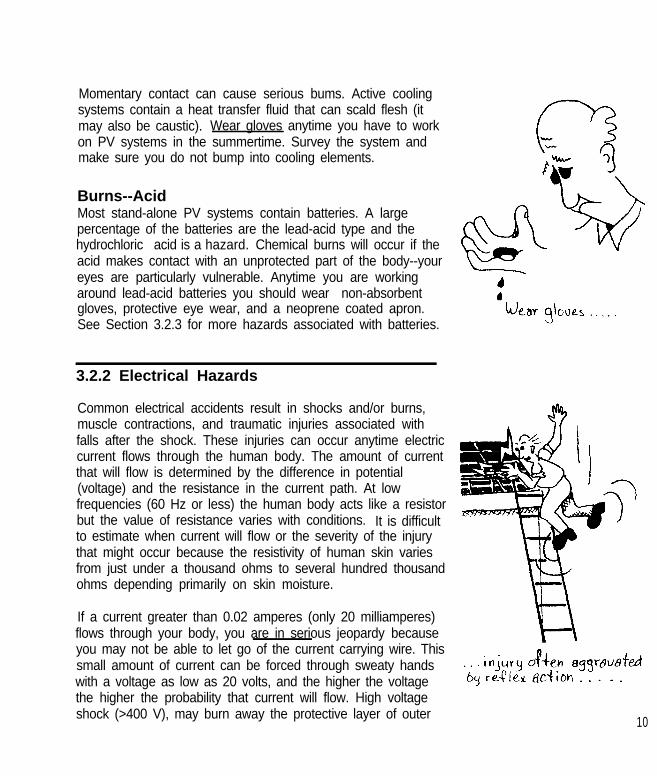
Momentary contact can cause serious bums. Active coolingsystems contain a heat transfer fluid that can scald flesh (itmay also be caustic). Wear gloves anytime you have to workon PV systems in the summertime. Survey the system andmake sure you do not bump into cooling elements.
Burns--AcidMost stand-alone PV systems contain batteries. A largepercentage of the batteries are the lead-acid type and thehydrochloric acid is a hazard. Chemical burns will occur if theacid makes contact with an unprotected part of the body--youreyes are particularly vulnerable. Anytime you are workingaround lead-acid batteries you should wear non-absorbentgloves, protective eye wear, and a neoprene coated apron.See Section 3.2.3 for more hazards associated with batteries.
3.2.2 Electrical Hazards
Common electrical accidents result in shocks and/or burns,muscle contractions, and traumatic injuries associated withfalls after the shock. These injuries can occur anytime electriccurrent flows through the human body. The amount of currentthat will flow is determined by the difference in potential(voltage) and the resistance in the current path. At lowfrequencies (60 Hz or less) the human body acts like a resistorbut the value of resistance varies with conditions. It is difficultto estimate when current will flow or the severity of the injurythat might occur because the resistivity of human skin variesfrom just under a thousand ohms to several hundred thousandohms depending primarily on skin moisture.
If a current greater than 0.02 amperes (only 20 milliamperes)flows through your body, you are in serious jeopardy becauseyou may not be able to let go of the current carrying wire. Thissmall amount of current can be forced through sweaty handswith a voltage as low as 20 volts, and the higher the voltagethe higher the probability that current will flow. High voltageshock (>400 V), may burn away the protective layer of outer 10

skin at the entry and exit points. When this occurs the bodyresistance is lowered and lethal currents may cause instantdeath. Dalziel {4} and Lee {5} studied the effects of acelectrical shock on the human body. Dalziel also reported onthe reaction of his subjects when they were exposed to a dcelectrical shock. The data in Table 2 are based on theirreports and you can see that low currents can cause severeinjury or death.
Table 2Electric Shock Hazards
Reaction
Perception - Tingle, Warmth 1 ma 6 ma
Shock - Retain muscle control; reflex may 2 ma 9 macause injury
Severe Shock - Lose muscle control,cannot let-go; burns; asphyxia
20 ma 90 ma
Ventricular Fibrillation - Probable death 100 ma 500 ma
Heart Frozen - Body temperature rise;death will occur in minutes
>1 A >1 A
Electrical shock is painful and a potentially minor injury is oftenaggravated by the reflex reaction of jumping back away fromthe source of the shock. Anytime a PV array containsmore than two PV modules, a shock hazard should bepresumed to exist.
The best way to avoid shock is to measure--always measure--the voltage from any wire to any other wires, and to ground.Use a clamp-on ammeter to measure the current flowing in thewires. Never disconnect a wire before you have checked thevoltage and current. Do not presume everything is in perfect
11
order. Do not trust switches to operate perfectly and do not“believe” schematics. A digital voltmeter is a wonderfulinstrument and using it often could save your life.
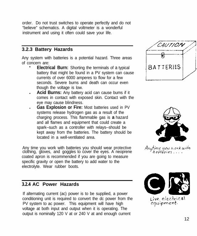
3.2.3 Battery Hazards
Any system with batteries is a potential hazard. Three areasof concern are:
• Electrical Burn: Shorting the terminals of a typicalbattery that might be found in a PV system can causecurrents of over 6000 amperes to flow for a fewseconds. Severe burns and death can occur eventhough the voltage is low.
l Acid Burns: Any battery acid can cause bums if itcomes in contact with exposed skin. Contact with theeye may cause blindness.
l Gas Explosion or Fire: Most batteries used in PVsystems release hydrogen gas as a result of thecharging process. This flammable gas is a hazardand all flames and equipment that could create aspark--such as a controller with relays--should bekept away from the batteries. The battery should belocated in a well-ventilated area.
Any time you work with batteries you should wear protectiveclothing, gloves, and goggles to cover the eyes. A neoprenecoated apron is recommended if you are going to measurespecific gravity or open the battery to add water to theelectrolyte. Wear rubber boots.
3.2.4 AC Power Hazards
If alternating current (ac) power is to be supplied, a powerconditioning unit is required to convert the dc power from thePV system to ac power. This equipment will have highvoltage at both input and output when it is operating. Theoutput is nominally 120 V at or 240 V at and enough current
12

will be present to kill. All of the precautions for ac circuits thatare given in the National Electric Code should be followed.(See the next section.)
4.0 Safe PV Systems
Almost all PV systems that are installed in the United Statesare covered by regulations in the National Electric Code(NEC). {6} The intent of the NEC is to ensure safe electricalsystems are designed and installed. Some PV systemdesigners ignore the NEC because they don’t think it appliesto their system. Sometimes they consider the “Code” as animpediment and a few have spent more time trying tocircumvent applicable regulations than it would have takento meet them. We need to recognize the Code for what it is--a set of regulations that have contributed to making theelectrical systems in the United States one of the safest in theworld. Although addressing Code issues can be frustrating attimes, most inspectors are willing to listen and work with youif you are making a good faith attempt to meet the Coderequirements and install and maintain a safe PV system.
This section will summarize some important issues coveredby the NEC and present some safety procedures that shouldbe followed when testing existing systems--some of whichmay not meet all requirements of the Code.
4.1 Applicable Safety Codes
The National Fire Protection Association has sponsored theNational Electric Code since 1911. The NEC is a how-toguide that changes as technology evolves and componentsophistication increases. The Code is updated every threeyears and in 1984, Article 690 was included to provideregulations pertaining to solar photovoltaic systems. The
13

NEC is not a PV system design guide and does not attemptto make things easy for the designer, installer, operator ormaintenance person. However, following the Code is notoptional-- it is the law in most location. You can negotiatewith the local inspector, but you cannot bypass therecommendations given.
There are other codes and standards that have beendeveloped for PV systems and components that touch onsafety issues. Underwriters Laboratory (UL) has developedconstruction standards and test procedures for PV modulesand selected other components that might be installed in aPV system. {7} However, few components from PV manufac-turers have been submitted for UL certification. The IEEEStandards 928 and 929 gives recommendations for design-ing terrestrial PV systems and connecting them to the utilityrespectively. {8,9}
We will consider mostly the NEC, specifically Article 690which addresses PV systems. Some of the other sections ofthe NEC that may apply are:
- Article 240 - Overcurrent Protection- Article 250 - Grounding- Article 300 - Wiring Methods- Article 339 - Underground Feeders- Article 480 - Storage Batteries- Article 705 - Interconnected Power Sources- Article 720 - Low Voltage Systems
Before designing and installing a PV system you should readArticle 690. It has eight sections, A through H, with informa-tion on the topics shown below.
A General690-1 Scope690-2 Definitions690-3 Other Articles690-4 Installation690-5 Ground Fault Detection & Interruption
14

B
C
D
E
F
G
H
Circuit Requirements690-7 Maximum Voltage690-8 Circuits Over 150 Volts to Ground690-9 Overcurrent ProtectionDisconnecting Means690-13 All Conductors690-14 Additional Provisions690-15 Disconnection of Photovoltaic Equipment690-16 Fuses690-17 Switch or Circuit Breaker690-18 Disablement of an ArrayWiring Methods690-31 Methods Permitted690-32 Component Interconnections690-33 Connectors690-34 Access to BoxesGrounding690-41 System Grounding690-42 Point of System Grounding Connection690-43 Size of Equipment Grounding Conductor690-44 Common Grounding ElectrodeMarking690-51 Modules690-52 Photovoltaic Power SourceConnection to Other Sources690-61 Loss of System Voltage690-62 Ampacity of Neutral Conductor690-63 Unbalanced Interconnections690-64 Point of ConnectionStorage Batteries690-71 Installation690-72 State of Charge690-73 Grounding
A good reference with recommended PV system installationpractices that comply with the NEC is produced and distrib-uted by the Southwest Technology Development Institute.{10} Development of this handbook was under the direction
15

of Sandia National Laboratories with funding from theDepartment of Energy. Most of what is presented here isdiscussed in more detail in this reference.
4.2 Designing and Installing a PV System-What the NEC Says
This section will highlight the primary requirements of theNEC that apply to the design and installation of PV systems.This list is a simplification of the Code requirements and notintended to replace or supplement the NEC. Hopefully, it willserve to increase awareness of the NEC by identifying thebroad issues in the Code that the designer should consider.This section is based on the latest version of the NEC (1990)with articles referenced by numbers in brackets, e.g. [690-1].
4.2 .1 System Current and Vol tage
When designing a PV system, consider the following:Use open-circuit voltage as the rated voltage in anyPV source circuit. [690-7a]Voltages should be less than 600 Volts. [690-7c]Conductors and overcurrent devices shall be able tocarry at least 125 percent of the short-circuit currentof the source circuit. (690-8)PV source circuit, inverter, and battery conductorsshall have overcurrent protection. [690-9a]A sign indicating the PV system operating voltage andcurrent, the open-circuit voltage, and the short-circuitcurrent shall be placed near the system disconnectpoint. [690-52]
16

4.2.2 Wiring and Disconnect Requirements
The Code requires certain conventions for color of conduc-tors and specifies requirements for disconnecting the powersource. Specifically:
The grounded conductor is to be white. [200-6]Convention is for the first ungrounded conductor of aPV system to be red, and the second ungroundedconductor black (negative in a center tapped PVsystem).Single-conductor cable is allowed for module connec-tions only. Sunlight resistant cable should be used ifthe cable is exposed. (690-31 b]Modules should be wired so they can be removedwithout interrupting the grounded conductor ofanother source circuit. [690-4c]Any wiring junction boxes should be accessible.[690-34]Connectors should be polarized and guarded toprevent shock. [690-33]Means to disconnect and isolate all PV sourcecircuits will be provided. [690-13]All ungrounded conductors should be able to bedisconnected from the inverter. [690-15]If fuses are used, you must be able to disconnect thepower from both ends. [690-16]Switches should be accessible and clearly labeled.[690-17]
4.2.3 Grounding
The purpose of grounding any electrical system is to preventunwanted currents from flowing (especially through people)and possibly causing equipment damage, personal injury, ordeath. Lightning, natural and man-made ground faults, andline surges can cause high voltages to exist in an otherwiselow-voltage system. Proper grounding, along withovercurrent protection, limits the possible damage that a 17
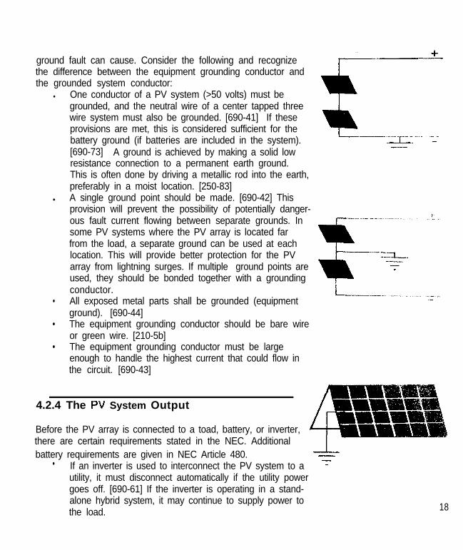
ground fault can cause. Consider the following and recognizethe difference between the equipment grounding conductor andthe grounded system conductor:
l One conductor of a PV system (>50 volts) must begrounded, and the neutral wire of a center tapped threewire system must also be grounded. [690-41] If theseprovisions are met, this is considered sufficient for thebattery ground (if batteries are included in the system).[690-73] A ground is achieved by making a solid lowresistance connection to a permanent earth ground.This is often done by driving a metallic rod into the earth,preferably in a moist location. [250-83]
l A single ground point should be made. [690-42] Thisprovision will prevent the possibility of potentially danger-ous fault current flowing between separate grounds. Insome PV systems where the PV array is located farfrom the load, a separate ground can be used at eachlocation. This will provide better protection for the PVarray from lightning surges. If multiple ground points areused, they should be bonded together with a groundingconductor.
• All exposed metal parts shall be grounded (equipmentground). [690-44]
• The equipment grounding conductor should be bare wireor green wire. [210-5b]
• The equipment grounding conductor must be largeenough to handle the highest current that could flow inthe circuit. [690-43]
4.2.4 The PV System Output
Before the PV array is connected to a toad, battery, or inverter,there are certain requirements stated in the NEC. Additionalbattery requirements are given in NEC Article 480.
• If an inverter is used to interconnect the PV system to autility, it must disconnect automatically if the utility powergoes off. [690-61] If the inverter is operating in a stand-alone hybrid system, it may continue to supply power tothe load. 18

• The output of a single-phase inverter should not beconnected to a three-phase service. [690-63a]
• The ac output from a PV system inverter must begrounded in accordance with requirements for acsystems. [250-5]
• A circuit breaker or fuse/switch mechanism must beincluded so that the PV system output can be discon-nected. [690-64]
• The interconnection shall be made so that all groundfault interrupters remain active. [690-4]
• If batteries are used in a system, they must beguarded to prevent unauthorized access if thevoltage is greater than 50 volts dc. Otherwise, thevoltage must remain below 50 volts dc. [690-b]
• Charge controllers must be used with batteries.
4.3 Testing a PV System--Safety Hints
[690-72]
Sometimes it is necessary to troubleshoot a PV system thatis not working correctly. Safety should be the main concern,both in planning before you go to the site and during theactual testing. Some recommendations are given.Remember: Do not test a PV system alone!
Before testing any PV system, you should become familiarwith the electrical configuration. How many modules makeup a source circuit? What are the system voltages?Currents? How many circuits are there? Do overcurrentdevices exist? Where? How can the system be discon-nected? What safety equipment is available.
When you get to the PV system site:• Remove jewelry.• Walk around the PV system and record any apparent
hazards in the system logbook or a notebook. Takephotographs of the system and any hazards.
19

• Locate the safety equipment, fire extinguisher, etc.and check their condition. Where is the nearesttelephone?
• Check the actual system configuration against theelectrical schematics.
• Locate and inspect all subsystems such as thebatteries, inverter, and the load.
• Determine if, how, and where the system isgrounded. Check to see if the ac and dc grounds arecommon.
• Locate and inspect all disconnect switches. Checkany fuses. Determine if the switches are designed tointerrupt both positive and negative conductors.
• Disconnect the source circuits and measure allopen-circuit voltage to verify the proper operation ofthe disconnect switch.
• Measure the voltage from each conductor to ground,and from line to line.
Only when you are sure that you understand the circuitshould you proceed with testing.
• Keep the work area clear of obstacles, particularlythe area behind you.
• Never disconnect a wire before measuring voltages.• Keep your hands dry and/or wear gloves.• Work with only one hand if possible.• Have your buddy stationed near the disconnect
switches.• Once a wire is disconnected don’t leave the end
exposed--tape it or use a wire nut for temporarycovering.
• Reconnect the wires from one source circuit beforedisconnecting a second source circuit.
20

5 . 0 F o r Y o u r H e a l t hThis section presents a review of the first aid procedures thatanyone working on PV systems should be familiar with. Theyare based on the book “American Red Cross: Standard FirstAide.” {11} It is recommended that each person also com-plete a CPR course or equivalent training offered by theAmerican Heart Association or the American Red Cross. Thisbooklet contains a summary of first aid suggestions, but is notintended to replace formal training in first aid or CPR.
If you witness an accident or are the first person to arrive atthe scene:
l Survey the scene for potential hazards.Try to determine if a shock hazard still exists. Is a liveconductor still lying on or near the victim’s body? Isthe victim still holding a live conductor? Are thereother hazards such as fire or spilled caustic materialthat would put you in jeopardy? You will be safer inassisting a victim if you are with someone else, butdon’t delay your help to watt for a buddy. Also, beaware that some otherwise trustworthy people cannotbe trusted in an emergency situation--everyone reactsdifferently. You are on your own to protect yourselfand save the victim--make it happen!
l Check the victim for breathing and pulse.Determine victim’s status.
l Call for help and give victim status.During an emergency, do anything you can to quicklyattract attention to the scene. Call an ambulance, getsomeone else to do it, or even pull a fire alarm, butget qualified emergency personnel to the scene asquickly as possible. Then attend to the victim usingaccepted CPR techniques.
Roth electrical and non-electrical injuries can occur whenworking around/with PV systems. First aid techniques foreach will be reviewed.
21

5.1 Non-Electrical Injuries
These injuries include cuts, sprains, broken bones, exposure,and insect or snake bites. In most cases they are not lifethreatening, but if care is not given immediately, the victimmay go into shock and could die. Respond quickly.
CutsStop the bleeding by using the following methods in thisorder: direct pressure, elevation, pressure points, and apressure bandage. If possible, apply direct pressure with asterile dressing (gauze pad) between the wound and yourhand. Use a clean cloth if a sterile dressing is not available.If bleeding does not stop, elevate the wound area if possible.If the wound is still bleeding, apply pressure on a nearbypressure point. For example, if the lower arm is cut, applypressure with fingers on the middle inside of the upper armwhere a pulse is felt. Lastly, use a pressure bandage byadding more sterile dressings if necessary and wrap with aroller bandage. Use overlapping turns to cover dressingcompletely and secure by tying off the bandage over thewound.
Sprains, Strains, Dislocations, and FracturesIt is sometimes hard to tell the difference between theseinjuries so treat them all as you would a fracture. Help thevictim move into the shade and/or comfortable position withas little movement to the injured area as possible. The injury(usually an arm or leg) needs to be splinted to lessen the painand prevent further injury. Splints can be made from rolledup newspaper, magazines, pieces of wood, blankets, orpillows. The splint can be tied up with bandages or cloth (ashirt torn into strips will do). The following principles apply.Splint only if you can do it without causing more pain. Splintan injury in the position you find it. Immobilize the limb andjoints above and below the injury. Check the blood circulationby pinching nail beds of the fingers or toes. Red color should
22

return in two seconds--if not loosen splint. If the injury is aclosed fracture (no bone extruding) apply a cold pack to it. Donot apply a cold pack to an open fracture.
Exposure-ColdPersons exposed to extended periods of cold may suffer fromhypothermia. Symptoms that may occur are shivering, feelingdizzy, confusion, or numbness. Take the victim to a warmplace, remove wet clothing, and warm the body slowly. Callan ambulance. Give nothing to eat or drink unless the victimis fully conscious. If fully conscious give him a warm drink alittle at a time. Check the temperature of the liquid. Don’t adda scalded tongue to their injuries.
Exposure-HeatThis is a common hazard for PV system maintenancepersonnel because of the location of the systems. If you oryour partner has cramps, heavy sweating, cool and pale skin,dilated pupils, headaches, nausea, or dizziness you may benearing heat exhaustion. Get the victim to the shade and givehim one-half glassful of water (if he can tolerate it) every 15minutes. If heavy sweating occurs have the victim lie downand raise his feet, loosen clothing, and put wet towels orsheets over him. If the victim has red dry skin, he may haveheat stroke, which is life-threatening. Immerse in cool water, ifpossible, or wrap the body with wet sheets and/or fan thevictim. Don’t give him anything to drink. Call an ambulance.
Insect/Snake BitesA small number of people may have an allergic reaction to aninsect bite or sting. In this case, it could be life-threatening.Signs of an allergic reaction are pain, swelling of the throat,redness or discoloration, itching, hives, decreased conscious-ness, and difficulty in breathing. If these symptoms occur callan ambulance immediately. If a stinger from an insect isembedded into the flesh remove it (do not squeeze it) withtweezers or scrape it away with a credit card. Then wash thearea and put on a cold pack with a cloth between the skin andthe ice. Try to arrange the victim so the bitten area is below 23

the heart. Few people die from snake bites. However, ifsomeone is bitten by a snake, they should receive medicalhelp quickly. Call an ambulance. Keep the victim still and thebitten area below the heart to slow absorption of the snakevenom. A splint can be used if the bite is on an arm or leg.Try to remember what the snake looked like. Do not cut asnake bite and try to suck the venom out.
5.2 Electrical Injuries
The number one priority in assisting injured people shouldalways be your (the rescuer's) safety. This is especiallyimportant in situations involving elect&al hazards. Avoidbecoming a second victim. Electrical injuries consist mainlyof shocks, burns, muscle contractions, and traumatic injuriesassociated with falls after electric shocks. Electric shock is ageneral term, indicating any situation where electric currentflows through the body. The intensity of a shock can varyfrom a barely perceptible tingle, to a strong zap, to instantdeath. A stabbing pain or intense tingling and burning isusually associated with electric shock. The points of entry andexit are often badly burned.
Frequently a shock involves involuntary muscle contraction. Ifthe strong muscles of the back and legs contract, this canlead to falls and broken bones. The large muscles of thechest, throat, and diaphragm can contract, and causerespiratory arrest.
When electric current passes through the heart, it can cause aspasmodic contraction and relaxation of the ventricles, calledventricular fibrillation. This is one of the major causes ofdeath associated with shocks. Once a person’s heart hasbegun fibrillating, it is difficult to stop. Sometimes anotherelectric shock, administered by a paramedic using adefibrillator, can restore the heart to its normal beating cycle.Victim fibrillation need qualified (paramedic) help inminutes if they are to live. 24

6.0 References
1.
2.
Maycock, Paul D. and Stirewalt, Edward N., A Guide tothe Photovoltaic Revolution, Rodale Press, Emmaus, PA,1985.Davidson, Joel, The New Solar Electric Home: ThePhotovoltaics How-To Handbook, Aatec Publications,Ann Arbor, MI, 1987.
3. Strong, Steven J. and Scheller, William G., The SolarElectric House: A Design Manual for Home-ScalePhotovoltaic Power Systems,Rodale Press, Emmaus,PA, 1987.
4.
5.
Lee, Ralph H., “Electrical Safety in Industrial Plants,”IEEE Spectrum, pp. 51-55, June 1971.Dalziel, C. F., “Effects of Electric Shock on Man,” IRETrans. Medical Electronics, Vol. PGME-5, pp. 44-62, July1956; also reprinted as USAEC Safety Bulletin 7.
6.
7.
National Electric Code, National Fire Protection Associa-tion, Quincy, MA, 1990.
8.
9.
UL 1703, Standard for Safety: Flat-Plate PhotovoltaicModules and Panels, Underwriters’ Laboratories,Northbrook, IL, 1989.ANSI/IEEE Standard 928-l 1986, IEEE RecommendedCriteria for Terrestrial Photovoltaic Power Systems,Institute of Electrical and Electronics Engineers, NewYork, NY.ANSI/IEEE Standard 929, IEEE Recommended Practicefor Utility Interface for Residential and IntermediatePhotovoltaic Systems, Institute of Electrical andElectronics Engineers, New York, NY.
10. Photovoltaic Power Systems and the National ElectricCode: Recommended Installation Practices, SouthwestTechnology Development Institute, Las Cruces, NM,1991.
11. “First Aid Procedures,” American Red Cross Handbook;Adult CPR, The American Red Cross, 1987.
27