1551 S. Vineyard Avenue Ontario, CA 91761 (909) 923-1973 WIRING SCHEMATICS ON-ROAD VEHICLE CONVERSION SINGLE AND DUAL MOTOR APPLICATION FOR SOFTWARE VERSIONS 5.30 AND HIGHER FOR CURTIS CONTROLLERS 1232/1234/1236/1238 REVISION: D Date: 10/5/16

Welcome message from author
This document is posted to help you gain knowledge. Please leave a comment to let me know what you think about it! Share it to your friends and learn new things together.
Transcript
1551 S. Vineyard Avenue
Ontario, CA 91761 (909) 923-1973
WIRING SCHEMATICS
ON-ROAD VEHICLE CONVERSION
SINGLE AND DUAL MOTOR APPLICATION
FOR SOFTWARE VERSIONS 5.30 AND HIGHER
FOR CURTIS CONTROLLERS 1232/1234/1236/1238
REVISION: D
Date: 10/5/16
2 | P a g e
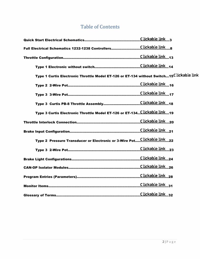
Table of Contents
Quick Start Electrical Schematics……………………………………….…..………………………3
Full Electrical Schematics 1232-1238 Controllers………..…………………….………………8
Throttle Configuration….……..……………….………..…………….…………………………………13
Type 1 Electronic without switch.………………………………..………………………..14
Type 1 Curtis Electronic Throttle Model ET-126 or ET-134 without Switch…15
Type 2 2-Wire Pot..……………………………………………………………..………………..16
Type 3 3-Wire Pot…………………………………………………………………..…………….17
Type 3 Curtis PB-8 Throttle Assembly……………………………………..…………….18
Type 3 Curtis Electronic Throttle Model ET-126 or ET-134………………………..19
Throttle Interlock Connection………………….…..……………..……………….……….…….…..20
Brake Input Configuration…………………….………………..……………..……………..…….…..21
Type 2 Pressure Transducer or Electronic or 3-Wire Pot…………..……….…….22
Type 3 2-Wire Pot…………………………………………………………………..……….……23
Brake Light Configurations…………………………………………………..………..…….….……..24
CAN-OP Isolator Modules……………………………………………………………………...………..26
Program Entries (Parameters)…………………………………………………………………..…….28
Monitor Items……….………….…….…….………………………………….…..……………….……...31
Glossary of Terms…………………………………………………………………………………….……32
3 | P a g e
QUICK START GENERIC ELECTRICAL SCHEMATICS 1232-1238 CONTROLLERS
The following quick start electrical schematics for both single and dual motor
configurations have been generated to assist in quickly getting the drive system connected and running.
4 | P a g e
NOTICE: This drawing is the property of Hi Performance Electric Vehicle Systems Inc., and/or its subsidiaries and affiliates (individually and
collectively “HPEVS”), and contains highly proprietary, confidential, and trade secret information of HPEVS. The recipient of this drawing agrees
(a) to use the information contained herein for the purpose for which it was furnished by HPEVS (b) to return this drawing upon HPEVS request.
This notice shall appear on any complete or partial reproduction of this drawing.RE V DE SCRIP T ION A P P ROV E D
A Ini t i al Rel ease 4/ 18/ 2016
RE V ISIONS
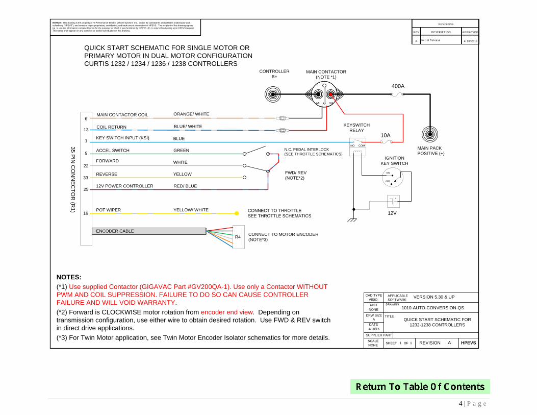
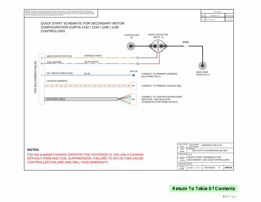
NOTES:
(*1) Use supplied Contactor (GIGAVAC Part #GV200QA-1). Use only a Contactor WITHOUT
PWM AND COIL SUPPRESSION. FAILURE TO DO SO CAN CAUSE CONTROLLER
FAILURE AND WILL VOID WARRANTY.
(*2) Forward is CLOCKWISE motor rotation from encoder end view. Depending on
transmission configuration, use either wire to obtain desired rotation. Use FWD & REV switch
in direct drive applications.
(*3) For Twin Motor application, see Twin Motor Encoder Isolator schematics for more details.
VISIO
4/18/16
11 A
1010-AUTO-CONVERSION-QS
QUICK START SCHEMATIC FOR
1232-1238 CONTROLLERS
NONE
A
NONE
DRW SIZE
APPLICABLE
SOFTWARE
CAD TYPE
UNIT DRAWING
TITLE
SCALE
DATE
REVISIONSHEET HPEVSOF
SUPPLIER PART
KEY SWITCH INPUT (KSI)
35
PIN
CO
NN
EC
TO
R (R
1)
6
13
1
9
22
33
25
KEYSWITCH
RELAY
12V
10A
IGNITION
KEY SWITCH
OFF
ON
MAIN CONTACTOR
(NOTE *1)
BLUE
COIL RETURN
ORANGE/ WHITE MAIN CONTACTOR COIL
BLUE/ WHITE
ACCEL SWITCH GREEN
FORWARD WHITE
REVERSE YELLOW
N.C. PEDAL INTERLOCK
(SEE THROTTLE SCHEMATICS)
FWD/ REV
(NOTE*2)
12V POWER CONTROLLER RED/ BLUE
QUICK START SCHEMATIC FOR SINGLE MOTOR OR
PRIMARY MOTOR IN DUAL MOTOR CONFIGURATION
CURTIS 1232 / 1234 / 1236 / 1238 CONTROLLERS
VERSION 5.30 & UP
400A
+A1A2-
16CONNECT TO THROTTLE
SEE THROTTLE SCHEMATICS
POT WIPER YELLOW/ WHITE
MAIN PACK
POSITIVE (+)
CONTROLLER
B+
CONNECT TO MOTOR ENCODER
(NOTE*3)R4
ENCODER CABLE
COMNO
5 | P a g e
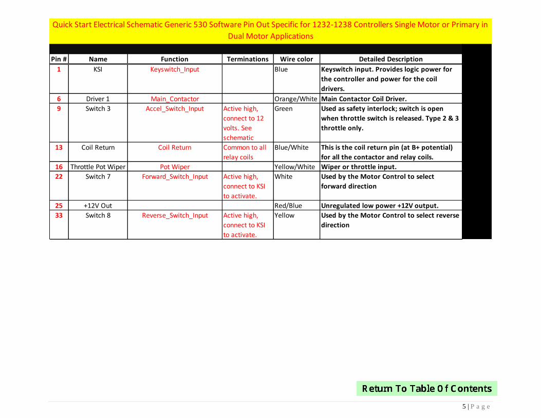
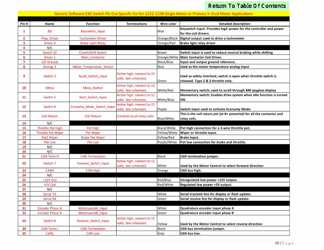
Pin # Name Function Terminations Wire color Detailed Description
1 KSI Keyswitch_Input Blue Keyswitch input. Provides logic power for
the controller and power for the coil
drivers.
6 Driver 1 Main_Contactor Orange/White Main Contactor Coil Driver.
9 Switch 3 Accel_Switch_Input Active high,
connect to 12
volts. See
schematic
Green Used as safety interlock; switch is open
when throttle switch is released. Type 2 & 3
throttle only.
13 Coil Return Coil Return Common to all
relay coils
Blue/White This is the coil return pin (at B+ potential)
for all the contactor and relay coils.
16 Throttle Pot Wiper Pot Wiper Yellow/White Wiper or throttle input.
22 Switch 7 Forward_Switch_Input Active high,
connect to KSI
to activate.
White Used by the Motor Control to select
forward direction
25 +12V Out Red/Blue Unregulated low power +12V output.
33 Switch 8 Reverse_Switch_Input Active high,
connect to KSI
to activate.
Yellow Used by the Motor Control to select reverse
direction
Quick Start Electrical Schematic Generic 530 Software Pin Out Specific for 1232-1238 Controllers Single Motor or Primary in
Dual Motor Applications
6 | P a g e
NOTICE: This drawing is the property of Hi Performance Electric Vehicle Systems Inc., and/or its subsidiaries and affiliates (individually and
collectively “HPEVS”), and contains highly proprietary, confidential, and trade secret information of HPEVS. The recipient of this drawing agrees
(a) to use the information contained herein for the purpose for which it was furnished by HPEVS (b) to return this drawing upon HPEVS request.
This notice shall appear on any complete or partial reproduction of this drawing.RE V DE SCRIP T ION A P P ROV E D
A Ini t i al Rel ease 4/ 18/ 2016
RE V ISIONS
NOTES:
(*1) Use supplied Contactor (GIGAVAC Part #GV200QA-1). Use only a Contactor
WITHOUT PWM AND COIL SUPPRESSION. FAILURE TO DO SO CAN CAUSE
CONTROLLER FAILURE AND WILL VOID WARRANTY.
VISIO
4/18/16
11 A
1010-AUTO-CONVERSION-QS-SEC
QUICK START SCHEMATIC FOR
SECONDARY 1232-1238 CONTROLLERS
NONE
A
NONE
DRW SIZE
APPLICABLE
SOFTWARE
CAD TYPE
UNIT DRAWING
TITLE
SCALE
DATE
REVISIONSHEET HPEVSOF
SUPPLIER PART
KEY SWITCH INPUT (KSI)
35
PIN
CO
NN
EC
TO
R (R
1)
6
13
1
MAIN PACK
POSITIVE (+)
MAIN CONTACTOR
(NOTE *1)
BLUE
COIL RETURN
ORANGE/ WHITE MAIN CONTACTOR COIL
BLUE/ WHITE
QUICK START SCHEMATIC FOR SECONDARY MOTOR
CONFIGURATION CURTIS 1232 / 1234 / 1236 / 1238
CONTROLLERS
VERSION 5.30 & UP
400A
+A1A2-
CAN BUS HARNESS
CONTROLLER
B+
CONNECT TO PRIMARY CAN BUS (R5)
CONNECT TO TWIN MOTOR ENCODER
ISOLATOR. SEE ISOLATOR
SCHEMATICS FOR MORE DETAILS
CONNECT TO PRIMARY HARNESS
BLUE WIRE (PIN 1)
SPLICE
R4ENCODER CABLE
P5
7 | P a g e
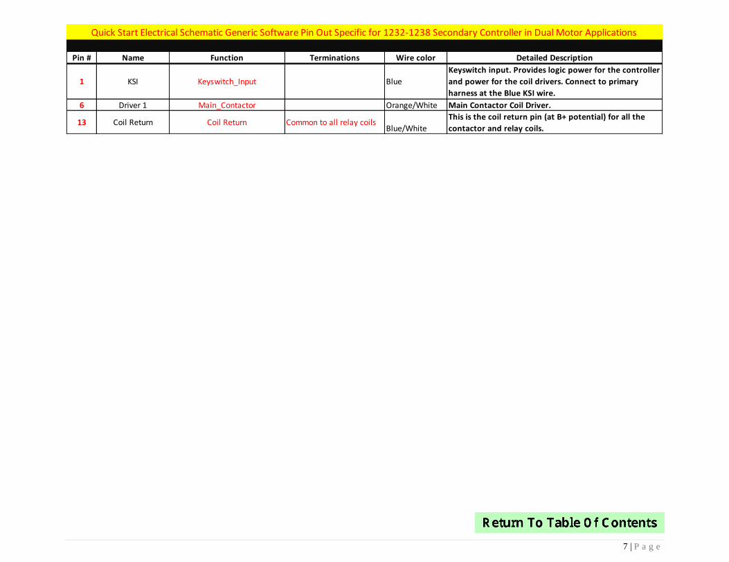
Pin # Name Function Terminations Wire color Detailed Description
1 KSI Keyswitch_Input Blue
Keyswitch input. Provides logic power for the controller
and power for the coil drivers. Connect to primary
harness at the Blue KSI wire.
6 Driver 1 Main_Contactor Orange/White Main Contactor Coil Driver.
13 Coil Return Coil Return Common to all relay coilsBlue/White
This is the coil return pin (at B+ potential) for all the
contactor and relay coils.
Quick Start Electrical Schematic Generic Software Pin Out Specific for 1232-1238 Secondary Controller in Dual Motor Applications
8 | P a g e
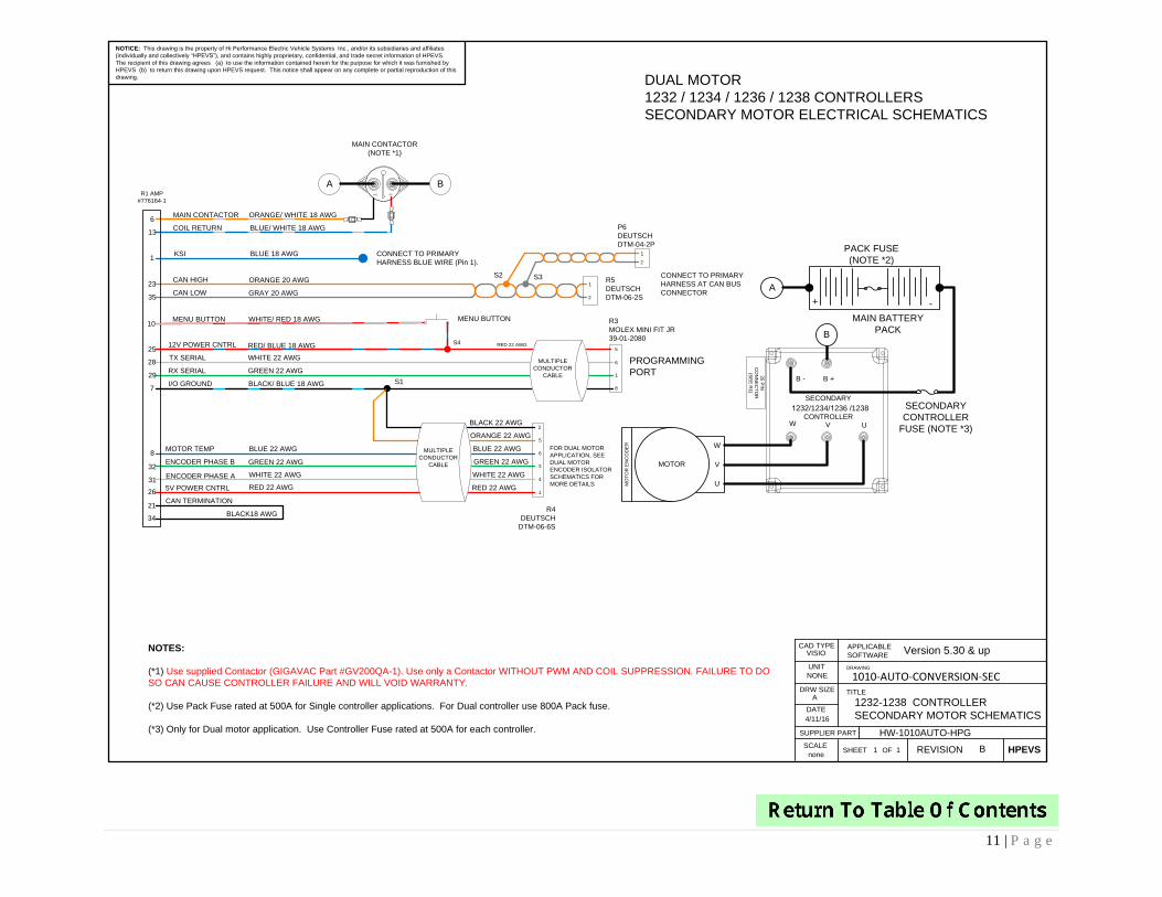
FULL ELECTRICAL SCHEMATICS CURTIS 1232-1238 CONTROLLERS

9 | P a g e
NOTICE: This drawing is the property of Hi Performance Electric Vehicle Systems Inc., and/or its subsidiaries and affiliates (individually and collectively
“HPEVS”), and contains highly proprietary, confidential, and trade secret information of HPEVS. The recipient of this drawing agrees (a) to use the
information contained herein for the purpose for which it was furnished by HPEVS (b) to return this drawing upon HPEVS request. This notice shall appear
on any complete or partial reproduction of this drawing.
ORANGE/ WHITE 18 AWG
I/O GROUND
PEDAL INTERLOCK
12V POWER CNTRL
5V POWER CNTRL
TX SERIAL
RX SERIAL
ENCODER PHASE A
ENCODER PHASE B
KSI
MAIN CONTACTOR
COIL RETURN
BLUE 18 AWG
BLACK/ BLUE 18 AWG
GREEN 18 AWG
BLUE/ WHITE 18 AWG
RED/ BLUE 18 AWG
RED / WHITE 18 AWG
WHITE 22 AWG
GREEN 22 AWG
GREEN 22 AWG
WHITE 22 AWG
MOTOR TEMP
OPTIONAL ECONOMY SWITCH (NOTE*6)
START SWITCH INPUT (NOTE *5)
BLUE 22 AWG
R4
DEUTSCH
DT-06-6S
R3
MOLEX MINI FIT JR
39-01-2080
BLACK 22 AWG
RED 22 AWG
WHITE 22 AWG
CAN TERMINATION
S3
GREEN 22 AWG
TACHOMETER DRIVER
MULTIPLE
CONDUCTOR
CABLE
BLACK18 AWG
PURPLE 18 AWG
CLUTCH/ SHIFT SWITCH
N.C. PEDAL INTERLOCK (SEE THROTTLE SCHEMATICS)
ECONOMY MODE
CAN HIGH
BROWN 18 AWG
MULTIPLE
CONDUCTOR
CABLE
OPTIONAL CLUTCH / SWITCH (NOTE *4)
R1
AMP
#776164-1
1
2
3
5
6
7
8
9
12
13
21
23
25
26
35
28
29
31
32
34
1
6
5
8
2
5
1
3
4
6
See Opto Isolator schematics (orange/black)
R5
DEUTSCH
DTM-06-2S
ORANGE 20 AWG
CAN LOW GREY 20 AWG
OPTIONAL
CAN BUS
(NOTE *2)
S1
FEMALE
3/16” QDLABEL
“# 7”
BRAKE LIGHT RELAY ORANGE/ RED 18 AWG SEE BRAKE
SCHEMATICS
1
2
S2
LABEL
“# 26”
FEMALE
1/4” QD
BRAKE POT WIPER MALE 3/16” QDLABEL
“# 17”YELLOW/ RED 18 AWG FEMALE 3/16” QDSEE BRAKE
SCHEMATICS17
POT WIPER YELLOW/ WHITE 18 AWG
POT HIGH BLACK/ WHITE 18 AWG
POT LOW PURPLE/ WHITE 18 AWG
FEMALE 3/16” QD MALE 3/16” QD
FEMALE 1/4” QD MALE 1/4” QD
LABEL
“# 15”
LABEL
“# 18”
SEE THROTTLE
SCHEMATICS
15
16
18
MAIN CONTACTOR (NOTE *1)
A B+A1 A2-
GREEN 22 AWG
WHITE 22 AWG
BLACK 22 AWG
ORANGE 22 AWG
BLUE 22 AWG
RED 22 AWG
UVW
B +B -35 P
IN
CO
NN
EC
TO
R
(SE
E R
1)
A
B
MAIN BATTERY
PACK (NOTE *3)
1232/1234/1236 /1238
CONTROLLER
+ -
PACK FUSE
(NOTE *8)
CONTROLLER
FUSE (NOTE *9)
U
MOTOR
MO
TO
R E
NC
OD
ER W
VFOR DUAL MOTOR
APPLICATION, SEE
DUAL MOTOR
ENCODER ISOLATOR
SCHEMATICS FOR
MORE DETAILS
FOR SINGLE MOTOR
CAR CONVERSION,
CONNECT TO MOTOR
ENCODER HARNESS
KEYSWITCH
RELAY
12V
RED 18AWG
(NOT INCLUDED)
10AIGNITION
KEYSWITCH
OFF
ON
VISIO
4/11/16
11 D
1010-AUTO-CONVERSION
ON-ROAD VEHICLE CONVERSION /
PRIMARY DUAL MOTOR SCHEMATICS
NONE
A
NONE
DRW SIZE
APPLICABLE
SOFTWARE
CAD TYPE
UNIT DRAWING
TITLE
SCALE
DATE
REVISIONSHEET HPEVSOF
SUPPLIER PART HW-AUTOCONVERSION-HPG
Version 5.30 & up
ELECTRICAL SCHEMATICS FOR SINGLE MOTOR OR
PRIMARY MOTOR IN DUAL MOTOR CONFIGURATION
1232 / 1234 / 1236 / 1238 CONTROLLERS
PROGRAMMING
PORT
NOTES:
(*1) Use supplied Contactor (GIGAVAC Part #GV200QA-1). Use only a Contactor WITHOUT PWM AND COIL SUPPRESSION. FAILURE TO DO SO CAN CAUSE CONTROLLER FAILURE AND WILL VOID
WARRANTY.
(*2) The Controller CAN Communication needs to be isolated from other CAN based components. A CAN isolator may be needed.
Possible source of CAN isolator is CANOP from B&B Electronics (www.bb-elec.com)
(*3) A Battery Management System (BMS) is strongly recommended if Lithium Ion batteries are used. Possible source of BMS is Ewert Energy System’s ORION BMS (www.orionbms.com)
(*4) Install the Clutch/ Shift Switch so that is ON when the clutch pedals is pressed. When clutch pedal is pressed the Regen setting is changed to Shift Neutral Braking Parameter to prevent the motor from
stalling during gear shifting. In a Clutch-less system, this allows you to set the coast down rate of the motor so that the gears align properly See Instructions on SHIFT-NEUTRAL BRAKING PARAMETERS.
(*5) Start switch required if Idle function or creep torque is turned ON.
(*6) Allows the use of ECONO Mode Parameters. See Programming Instructions.
(*7) Forward is CLOCKWISE motor rotation from Encoder end view. Depending on Transmission configuration, use either wire to obtain desired rotation. Use FWD & REV Switch in direct drive applications.
(*8) Use Pack Fuse rated at 500A for Single controller applications. For Dual controller use 800A Pack Fuse.
(*9) Only for Dual motor application. Use Controller Fuse rated at 500A for each controller.
(*10) Gives access to Drive System information. Required to access Programming and Diagnostic modes. See Programming Instructions.
START BUTTON INPUT 11
WHITE/ BLUE 18 AWG
FORWARD
REVERSE YELLOW 18 AWG
WHITE 18 AWG
FWD/ REV SWITCH (NOTE*7)
22
33
MENU BUTTON (NOTE*10)10MENU BUTTON WHITE/ RED 18 AWG
COMNO
10 | P a g e
Pin # Name Function Terminations Wire color Detailed Description
1 KSI Keyswitch_Input BlueKeyswitch input. Provides logic power for the controller and power
for the coil drivers.
2 Prop. Driver Tachometer Driver Orange/Black Digital output used to drive a tachometer
3 Driver 4 Brake Light Relay Orange/Red Brake light relay driver
4 N/C
5 Switch 10 Clutch/Shift Switch Brown Switch input is used to reduce neutral braking while shifting
6 Driver 1 Main_Contactor Orange/White Main Contactor Coil Driver.
7 I/O Ground Black/Blue Input and output ground reference.
8 Analog 2 Motor_Temperature_Sensor Blue Used as the motor temperature analog input
9 Switch 3 Accel_Switch_InputActive high, connect to 12
volts. See schematicGreen
Used as safety interlock; switch is open when throttle switch is
released. Type 2 & 3 throttle only.
10 Menu Menu_ButtonActive high, connect to 12
volts. See schematic White/Red Momentary switch; used to scroll through 840 spyglass display
11 Switch 5 Start_Switch_InputActive high, connect to 12
volts. See schematic White/Blue
Momentary switch; Enables drive system when Idle function is turned
ON.
12 Switch 6 Economy_Mode_Switch_InputActive high, connect to 12
volts. See schematic Purple Switch input used to activate Economy Mode.
13 Coil Return Coil Return Common to all relay coilsBlue/White
This is the coil return pin (at B+ potential) for all the contactor and
relay coils.
14 N/C
15 Throttle Pot High Pot High Black/White Pot high connection for a 3-wire throttle pot.
16 Throttle Pot Wiper Pot Wiper Yellow/White Wiper or throttle input.
17 Pot2 Wiper Brake Pot Wiper Yellow/Red Brake input.
18 Pot Low Pot Low Purple/White Pot low connection for brake and throttle.
19 N/C
20 N/C
21 CAN Term H CAN Termination Black CAN termination jumper.
22 Switch 7 Forward_Switch_InputActive high, connect to 12
volts. See schematic White Used by the Motor Control to select forward direction
23 CANH CAN High Orange CAN bus high.
24 N/C
25 +12V Out Red/Blue Unregulated low power +12V output.
26 +5V Out Red/White Regulated low power +5V output.
27 N/C
28 Serial TX White Serial transmit line for display or flash update.
29 Serial RX Green Serial receive line for display or flash update.
30 N/C
31 Encoder Phase A MotorspeedA_Input White Quadrature encoder input phase A
32 Encoder Phase B MotorspeedB_Input Green Quadrature encoder input phase B
33 Switch 8 Reverse_Switch_InputActive high, connect to 12
volts. See schematic Yellow Used by the Motor Control to select reverse direction
34 CAN Term L CAN Termination Black CAN bus termination jumper.
35 CANL CAN Low Grey CAN bus low.
Generic Software 530 Switch Pin Out Specific for for 1232-1238 Single Motor or Primary in Dual Motor Applications
11 | P a g e
NOTICE: This drawing is the property of Hi Performance Electric Vehicle Systems Inc., and/or its subsidiaries and affiliates
(individually and collectively “HPEVS”), and contains highly proprietary, confidential, and trade secret information of HPEVS.
The recipient of this drawing agrees (a) to use the information contained herein for the purpose for which it was furnished by
HPEVS (b) to return this drawing upon HPEVS request. This notice shall appear on any complete or partial reproduction of this
drawing.
MAIN CONTACTOR
(NOTE *1)
ORANGE/ WHITE 18 AWG
I/O GROUND
12V POWER CNTRL
TX SERIAL
RX SERIAL
ENCODER PHASE A
ENCODER PHASE B
KSI
MAIN CONTACTOR
COIL RETURN
BLUE 18 AWG
BLACK/ BLUE 18 AWG
BLUE/ WHITE 18 AWG
RED/ BLUE 18 AWG
WHITE 22 AWG
GREEN 22 AWG
GREEN 22 AWG
WHITE 22 AWG
MOTOR TEMP BLUE 22 AWG
R3
MOLEX MINI FIT JR
39-01-2080
CAN TERMINATION
S4
BLACK18 AWG
A B
MULTIPLE
CONDUCTOR
CABLE
R1 AMP
#776164-1
UVW
B +B -
35 P
IN
CO
NN
EC
TO
R
(SE
E R
1)
A
B
MAIN BATTERY
PACK
U
MOTOR
MO
TO
R E
NC
OD
ER
6
13
23
35
25
28
29
21
7
8
31
32
34
W
V
CONNECT TO PRIMARY
HARNESS BLUE WIRE (Pin 1).
SECONDARY
CONTROLLER
1
6
5
8
+ -
PACK FUSE
(NOTE *2)
SECONDARY
CONTROLLER
FUSE (NOTE *3)
R5
DEUTSCH
DTM-06-2S
S2 S3
P6
DEUTSCH
DTM-04-2P
CONNECT TO PRIMARY
HARNESS AT CAN BUS
CONNECTOR
1
2
1
2
CAN HIGH ORANGE 20 AWG
CAN LOW GRAY 20 AWG
+A1 A2-
1
NOTES:
(*1) Use supplied Contactor (GIGAVAC Part #GV200QA-1). Use only a Contactor WITHOUT PWM AND COIL SUPPRESSION. FAILURE TO DO
SO CAN CAUSE CONTROLLER FAILURE AND WILL VOID WARRANTY.
(*2) Use Pack Fuse rated at 500A for Single controller applications. For Dual controller use 800A Pack fuse.
(*3) Only for Dual motor application. Use Controller Fuse rated at 500A for each controller.
RED 22 AWG
S1
2
5
6
3
4
1
GREEN 22 AWG
WHITE 22 AWG
RED 22 AWG
BLACK 22 AWG
ORANGE 22 AWG
BLUE 22 AWGMULTIPLE
CONDUCTOR
CABLE
FOR DUAL MOTOR
APPLICATION, SEE
DUAL MOTOR
ENCODER ISOLATOR
SCHEMATICS FOR
MORE DETAILS 5V POWER CNTRL RED 22 AWG
26
VISIO
4/11/16
11 B
1232-1238 CONTROLLER
SECONDARY MOTOR SCHEMATICS
NONE
A
none
DRW SIZE
APPLICABLE
SOFTWARE
CAD TYPE
UNIT DRAWING
TITLE
SCALE
DATE
REVISIONSHEET HPEVSOF
SUPPLIER PART
1010-AUTO-CONVERSION-SEC
HW-1010AUTO-HPG
Version 5.30 & up
DUAL MOTOR
1232 / 1234 / 1236 / 1238 CONTROLLERS
SECONDARY MOTOR ELECTRICAL SCHEMATICS
PROGRAMMING
PORT
10MENU BUTTON WHITE/ RED 18 AWG MENU BUTTON
R4
DEUTSCH
DTM-06-6S
1232/1234/1236 /1238
12 | P a g e
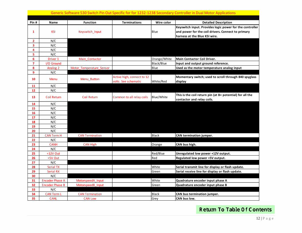
Pin # Name Function Terminations Wire color Detailed Description
1 KSI Keyswitch_Input Blue
Keyswitch input. Provides logic power for the controller
and power for the coil drivers. Connect to primary
harness at the Blue KSI wire.
2 N/C
3 N/C
4 N/C
5 N/C
6 Driver 1 Main_Contactor Orange/White Main Contactor Coil Driver.
7 I/O Ground Black/Blue Input and output ground reference.
8 Analog 2 Motor_Temperature_Sensor Blue Used as the motor temperature analog input
9 N/C
10 Menu Menu_ButtonActive high, connect to 12
volts. See schematic White/Red
Momentary switch; used to scroll through 840 spyglass
display
11 N/C
12 N/C
13 Coil Return Coil Return Common to all relay coils Blue/WhiteThis is the coil return pin (at B+ potential) for all the
contactor and relay coils.
14 N/C
15 N/C
16 N/C
17 N/C
18 N/C
19 N/C
20 N/C
21 CAN Term H CAN Termination Black CAN termination jumper.
22 N/C
23 CANH CAN High Orange CAN bus high.
24 N/C
25 +12V Out Red/Blue Unregulated low power +12V output.
26 +5V Out Red Regulated low power +5V output.
27 N/C
28 Serial TX White Serial transmit line for display or flash update.
29 Serial RX Green Serial receive line for display or flash update.
30 N/C
31 Encoder Phase A MotorspeedA_Input White Quadrature encoder input phase A
32 Encoder Phase B MotorspeedB_Input Green Quadrature encoder input phase B
33 N/C
34 CAN Term L CAN Termination Black CAN bus termination jumper.
35 CANL CAN Low Grey CAN bus low.
Generic Software 530 Switch Pin Out Specific for for 1232-1238 Secondary Controller in Dual Motor Applications
13 | P a g e
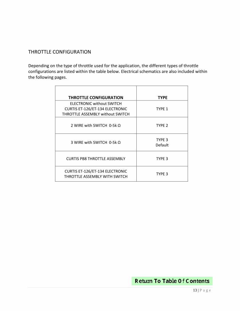
THROTTLE CONFIGURATION
Depending on the type of throttle used for the application, the different types of throttle configurations are listed within the table below. Electrical schematics are also included within the following pages.
THROTTLE CONFIGURATION TYPE ELECTRONIC without SWITCH
CURTIS ET-126/ET-134 ELECTRONIC THROTTLE ASSEMBLY without SWITCH
TYPE 1
2 WIRE with SWITCH 0-5k Ω TYPE 2
3 WIRE with SWITCH 0-5k Ω TYPE 3 Default
CURTIS PB8 THROTTLE ASSEMBLY TYPE 3
CURTIS ET-126/ET-134 ELECTRONIC THROTTLE ASSEMBLY WITH SWITCH
TYPE 3
14 | P a g e
NOTICE: This drawing is the property of Hi Performance Electric Vehicle Systems Inc., and/or its subsidiaries and
affiliates (individually and collectively “HPEVS”), and contains highly proprietary, confidential, and trade secret
information of HPEVS. The recipient of this drawing agrees (a) to use the information contained herein for the
purpose for which it was furnished by HPEVS (b) to return this drawing upon HPEVS request. This notice shall appear
on any complete or partial reproduction of this drawing.
REV DESCRIPTION APPROVED
A INITIAL RELEASE 1/22/2013
REVISIONS
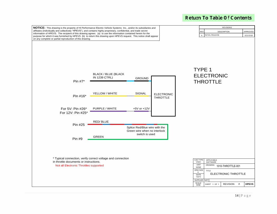
BLACK / BLUE (BLACK
IN 1239 CTRL)
YELLOW / WHITE
PURPLE / WHITE
TYPE 1
ELECTRONIC
THROTTLEGROUND
SIGNAL
+5V or +12V
ELECTRONIC
THROTTLE
1/22/13
1010-THROTTLE-001
NONE
ELECTRONIC THROTTLE
VISIO
11 A
NONE
A
DRW SIZE
APPLICABLE
SOFTWARE
CAD TYPE
UNIT DRAWING
TITLE
SCALE
DATE
REVISIONSHEET HPEVSOF
SUPPLIER PART
Pin #7*
Pin #16*
For 5V: Pin #26*
For 12V: Pin #25*
* Typical connection, verify correct voltage and connection
in throttle documents or instructions.
Not all Electronic Throttles supported
RED/ BLUE
GREEN
Pin #25
Pin #9
Splice Red/Blue wire with the
Green wire when no interlock
switch is used
15 | P a g e
REV DESCRIPTION APPROVED
A Init ial Release 11/17/2015
REVISIONS
VISIO
11 A
Curtis Electronic Throttle
Part ET-126 OR ET-134
Type 1
NONE
none
11/17/ 15
A
DRW SIZE
APPLICABLE
SOFTWARE
CAD TYPE
UNIT DRAWING
TITLE
SCALE
DATE
REVISIONSHEET HPEVSOF
SUPPLIER PART
1010-EThorttle
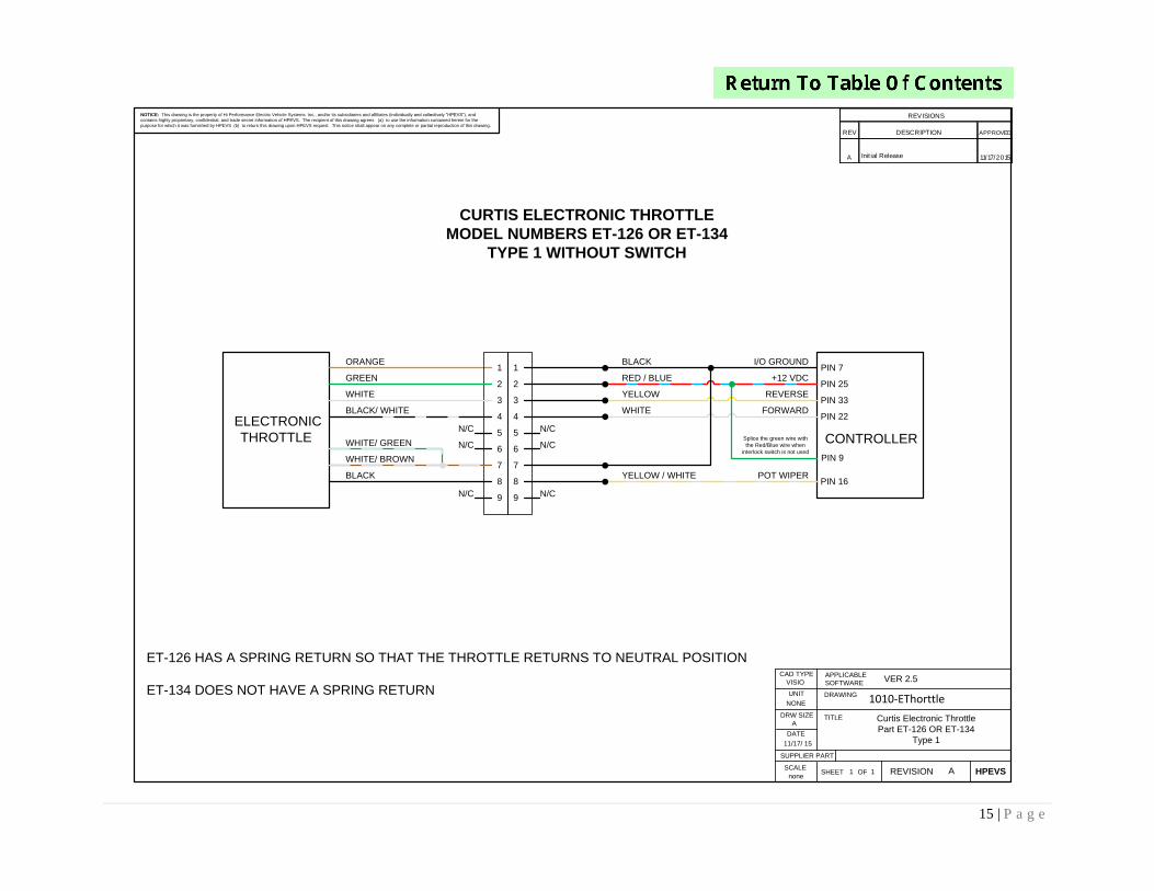
NOTICE: This drawing is the property of Hi Performance Electric Vehicle Systems Inc., and/or its subsidiaries and affiliates (individually and collectively “HPEVS”), and
contains highly proprietary, confidential, and trade secret information of HPEVS. The recipient of this drawing agrees (a) to use the information contained herein for the
purpose for which it was furnished by HPEVS (b) to return this drawing upon HPEVS request. This notice shall appear on any complete or partial reproduction of this drawing.
N/C
ELECTRONIC
THROTTLE
CURTIS ELECTRONIC THROTTLE
MODEL NUMBERS ET-126 OR ET-134
TYPE 1 WITHOUT SWITCH
VER 2.5
1
2
3
4
5
6
7
8
9N/C
N/C
ORANGE
GREEN
WHITE
BLACK/ WHITE
WHITE/ GREEN
WHITE/ BROWN
BLACK
1
2
3
4
5
6
7
8
9
YELLOW / WHITE POT WIPERPIN 16
PIN 22
PIN 33
PIN 25
PIN 7
CONTROLLERN/C
N/C
N/C
WHITE FORWARD
YELLOW REVERSE
RED / BLUE +12 VDC
BLACK I/O GROUND
ET-126 HAS A SPRING RETURN SO THAT THE THROTTLE RETURNS TO NEUTRAL POSITION
ET-134 DOES NOT HAVE A SPRING RETURN
PIN 9
Splice the green wire with
the Red/Blue wire when
interlock switch is not used
16 | P a g e
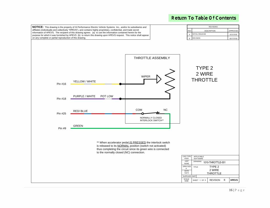
NOTICE: This drawing is the property of Hi Performance Electric Vehicle Systems Inc., and/or its subsidiaries and
affiliates (individually and collectively “HPEVS”), and contains highly proprietary, confidential, and trade secret
information of HPEVS. The recipient of this drawing agrees (a) to use the information contained herein for the
purpose for which it was furnished by HPEVS (b) to return this drawing upon HPEVS request. This notice shall appear
on any complete or partial reproduction of this drawing.
REV DESCRIPTION APPROVED
A INITIAL RELEASE 1/22/2013
B REVISION 11/27/2013
REVISIONS
YELLOW / WHITE
PURPLE / WHITE
RED/ BLUE
GREEN
NORMALLY CLOSED
INTERLOCK SWITCH**
** When accelerator pedal IS PRESSED the interlock switch
is released to its NORMAL position (switch not activated)
thus completing the circuit since its green wire is connected
to the normally closed (NC) connection.
COM NC
TYPE 2
2 WIRE
THROTTLE
POT LOW
WIPER
THROTTLE ASSEMBLY
1/22/13
1010-THROTTLE-001
NONE
TYPE 2
2 WIRE
THROTTLE
VISIO
81 B
NONE
A
DRW SIZE
APPLICABLE
SOFTWARE
CAD TYPE
UNIT DRAWING
TITLE
SCALE
DATE
REVISIONSHEET HPEVSOF
SUPPLIER PART
Pin #16
Pin #25
Pin #18
Pin #9
17 | P a g e
1/22/13
1010-THROTTLE-001
NONE
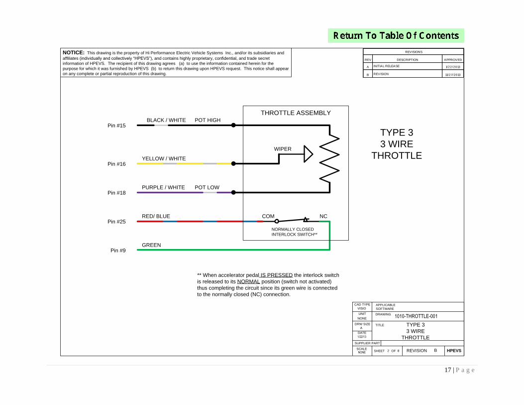
NOTICE: This drawing is the property of Hi Performance Electric Vehicle Systems Inc., and/or its subsidiaries and
affiliates (individually and collectively “HPEVS”), and contains highly proprietary, confidential, and trade secret
information of HPEVS. The recipient of this drawing agrees (a) to use the information contained herein for the
purpose for which it was furnished by HPEVS (b) to return this drawing upon HPEVS request. This notice shall appear
on any complete or partial reproduction of this drawing.
TYPE 3
3 WIRE
THROTTLE
BLACK / WHITE
** When accelerator pedal IS PRESSED the interlock switch
is released to its NORMAL position (switch not activated)
thus completing the circuit since its green wire is connected
to the normally closed (NC) connection.
NC
TYPE 3
3 WIRE
THROTTLE
POT HIGH
REV DESCRIPTION APPROVED
A INITIAL RELEASE 1/22/2013
B REVISION 11/27/2013
REVISIONS
YELLOW / WHITE
PURPLE / WHITE
RED/ BLUE
GREEN
NORMALLY CLOSED
INTERLOCK SWITCH**
COM
POT LOW
WIPER
THROTTLE ASSEMBLY
VISIO
82 B
NONE
A
DRW SIZE
APPLICABLE
SOFTWARE
CAD TYPE
UNIT DRAWING
TITLE
SCALE
DATE
REVISIONSHEET HPEVSOF
SUPPLIER PART
Pin #15
Pin #16
Pin #25
Pin #18
Pin #9
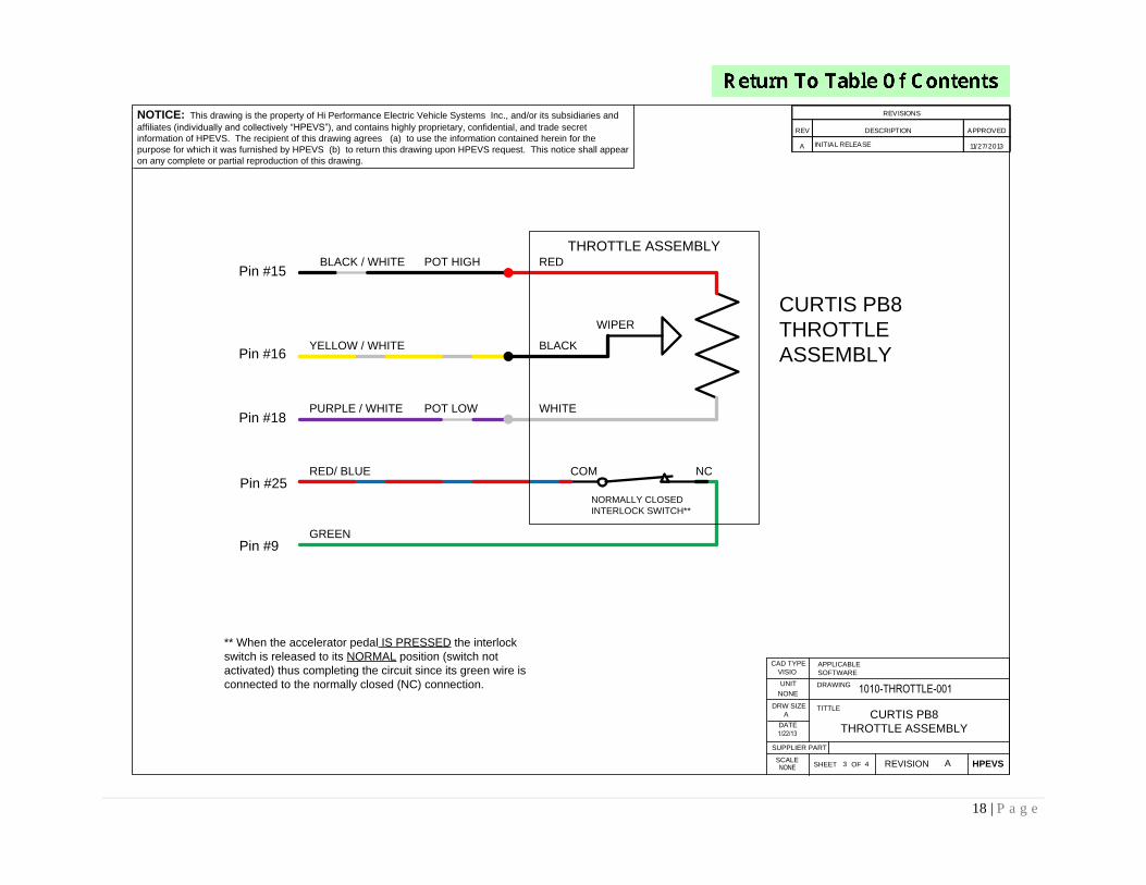
18 | P a g e
NOTICE: This drawing is the property of Hi Performance Electric Vehicle Systems Inc., and/or its subsidiaries and
affiliates (individually and collectively “HPEVS”), and contains highly proprietary, confidential, and trade secret
information of HPEVS. The recipient of this drawing agrees (a) to use the information contained herein for the
purpose for which it was furnished by HPEVS (b) to return this drawing upon HPEVS request. This notice shall appear
on any complete or partial reproduction of this drawing.
BLACK / WHITE
** When the accelerator pedal IS PRESSED the interlock
switch is released to its NORMAL position (switch not
activated) thus completing the circuit since its green wire is
connected to the normally closed (NC) connection.
NC
CURTIS PB8
THROTTLE
ASSEMBLY
POT HIGH
REV DESCRIPTION APPROVED
A INITIAL RELEASE 11/27/2013
REVISIONS
YELLOW / WHITE
PURPLE / WHITE
RED/ BLUE
GREEN
NORMALLY CLOSED
INTERLOCK SWITCH**
COM
POT LOW
WIPER
WHITE
BLACK
THROTTLE ASSEMBLYRED
1/22/13
1010-THROTTLE-001
NONE
CURTIS PB8
THROTTLE ASSEMBLY
VISIO
43 A
NONE
A
DRW SIZE
APPLICABLE
SOFTWARE
CAD TYPE
UNIT DRAWING
TITTLE
SCALE
DATE
REVISIONSHEET HPEVSOF
SUPPLIER PART
Pin #15
Pin #16
Pin #18
Pin #25
Pin #9
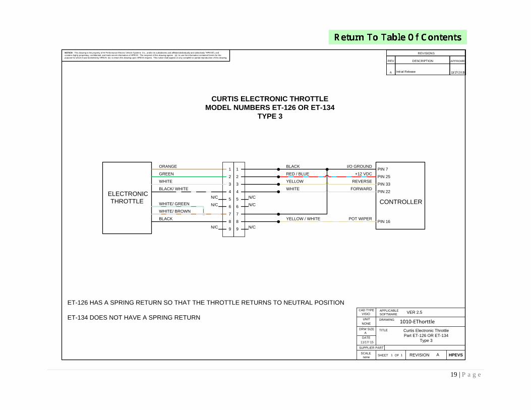
19 | P a g e
REV DESCRIPTION APPROVED
A Init ial Release 11/17/2015
REVISIONS
VISIO
11 A
Curtis Electronic Throttle
Part ET-126 OR ET-134
Type 3
NONE
none
11/17/ 15
A
DRW SIZE
APPLICABLE
SOFTWARE
CAD TYPE
UNIT DRAWING
TITLE
SCALE
DATE
REVISIONSHEET HPEVSOF
SUPPLIER PART
1010-EThorttle
NOTICE: This drawing is the property of Hi Performance Electric Vehicle Systems Inc., and/or its subsidiaries and affiliates (individually and collectively “HPEVS”), and
contains highly proprietary, confidential, and trade secret information of HPEVS. The recipient of this drawing agrees (a) to use the information contained herein for the
purpose for which it was furnished by HPEVS (b) to return this drawing upon HPEVS request. This notice shall appear on any complete or partial reproduction of this drawing.
N/C
ELECTRONIC
THROTTLE
CURTIS ELECTRONIC THROTTLE
MODEL NUMBERS ET-126 OR ET-134
TYPE 3
VER 2.5
1
2
3
4
5
6
7
8
9N/C
N/C
ORANGE
GREEN
WHITE
BLACK/ WHITE
WHITE/ GREEN
WHITE/ BROWN
BLACK
1
2
3
4
5
6
7
8
9
YELLOW / WHITE POT WIPERPIN 16
PIN 22
PIN 33
PIN 25
PIN 7
CONTROLLERN/C
N/C
N/C
WHITE FORWARD
YELLOW REVERSE
RED / BLUE +12 VDC
BLACK I/O GROUND
ET-126 HAS A SPRING RETURN SO THAT THE THROTTLE RETURNS TO NEUTRAL POSITION
ET-134 DOES NOT HAVE A SPRING RETURN
20 | P a g e
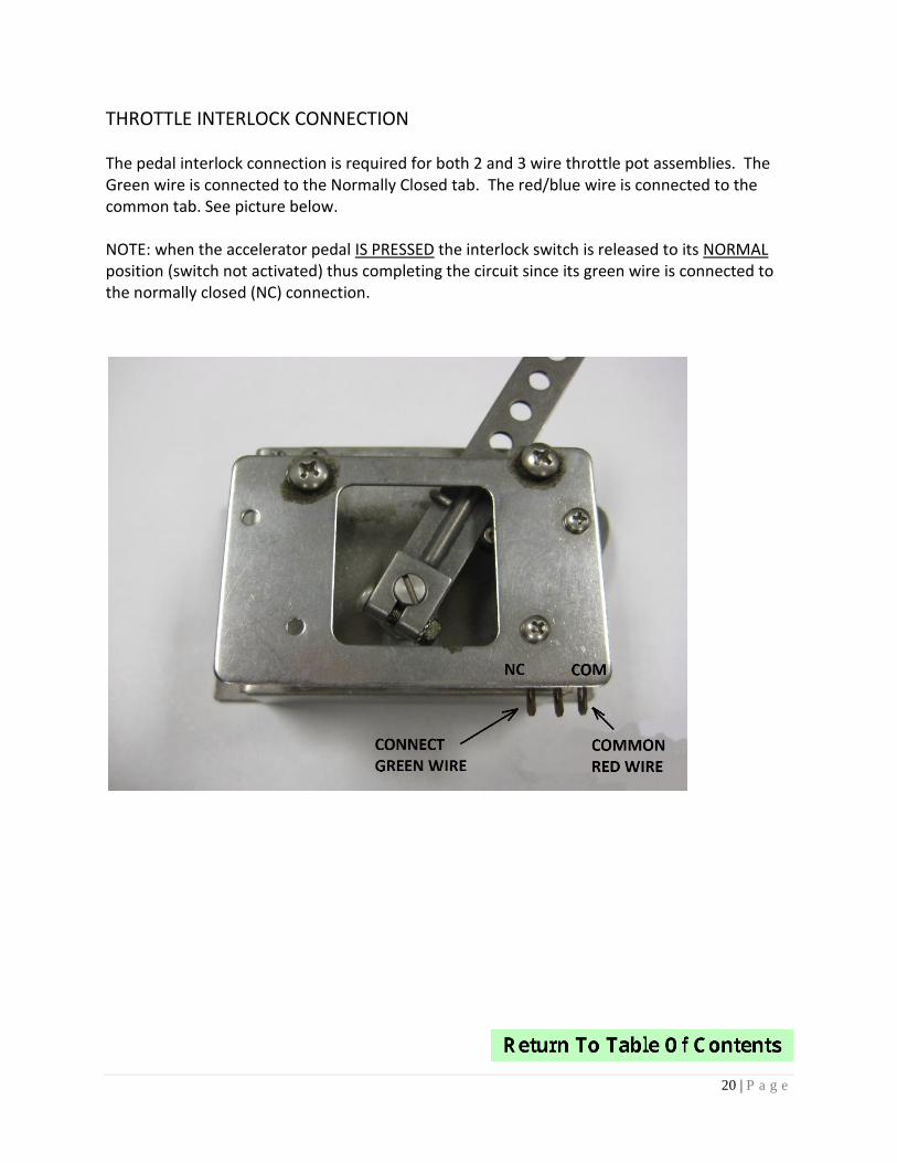
THROTTLE INTERLOCK CONNECTION
The pedal interlock connection is required for both 2 and 3 wire throttle pot assemblies. The Green wire is connected to the Normally Closed tab. The red/blue wire is connected to the common tab. See picture below.
NOTE: when the accelerator pedal IS PRESSED the interlock switch is released to its NORMAL position (switch not activated) thus completing the circuit since its green wire is connected to the normally closed (NC) connection.
21 | P a g e
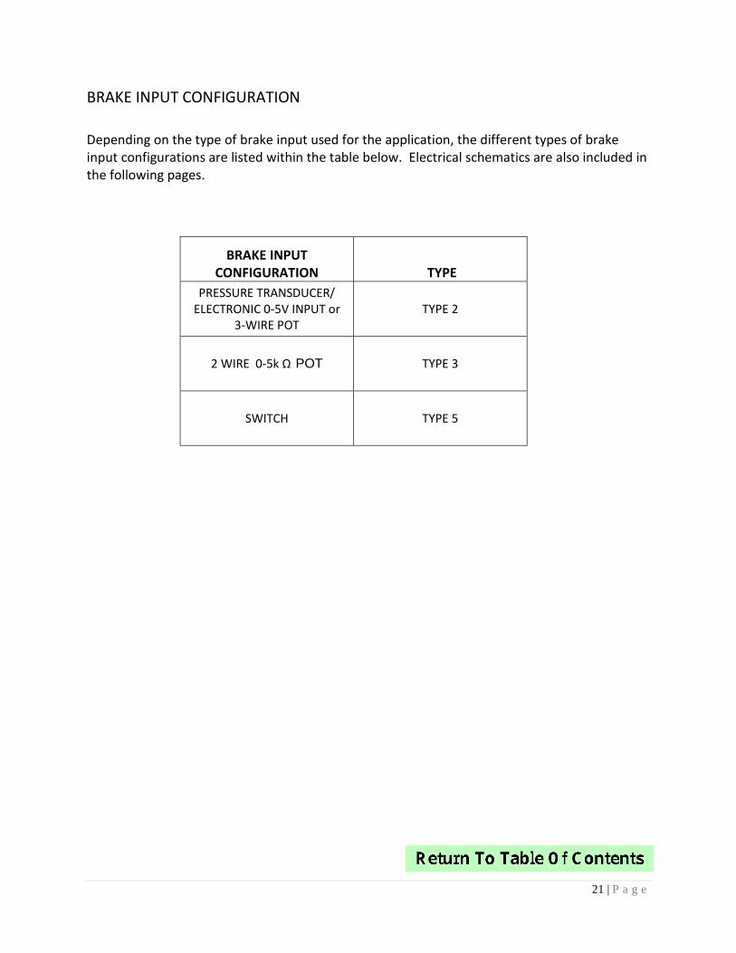
BRAKE INPUT CONFIGURATION
Depending on the type of brake input used for the application, the different types of brake input configurations are listed within the table below. Electrical schematics are also included in the following pages.
BRAKE INPUT CONFIGURATION TYPE
PRESSURE TRANSDUCER/ ELECTRONIC 0-5V INPUT or
3-WIRE POTTYPE 2
2 WIRE 0-5k Ω POT TYPE 3
SWITCH TYPE 5
22 | P a g e
VISIO
2/19/13 2 2
1010-BRAKE
NONE
NOTICE: This drawing is the property of Hi Performance Electric Vehicle Systems Inc., and/or its subsidiaries and
affiliates (individually and collectively “HPEVS”), and contains highly proprietary, confidential, and trade secret
information of HPEVS. The recipient of this drawing agrees (a) to use the information contained herein for the
purpose for which it was furnished by HPEVS (b) to return this drawing upon HPEVS request. This notice shall appear
on any complete or partial reproduction of this drawing.
DRW SIZE ACAD FILECAD LOC.CAD TYPE
OPER. NO. UNIT DRAWING
TITLEDETAILDESIGN
CHECKED SAFETY
SCALE DATE REVISION
SHEETHPEVS
OF
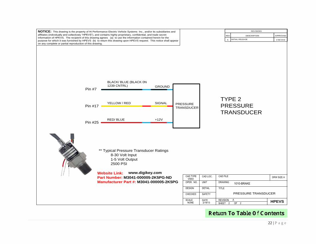
PRESSURE TRANSDUCER
A
BLACK/ BLUE (BLACK 0N
1239 CNTRL)
YELLOW / RED
RED/ BLUE
TYPE 2
PRESSURE
TRANSDUCER
GROUND
SIGNAL
+12V
PRESSURE
TRANSDUCER
REV DESCRIPTION APPROVED
A INITIAL RELEASE 2/19/2013
REVISIONS
** Typical Pressure Transducer Ratings
8-30 Volt Input
1-5 Volt Output
2500 PSI
Pin #7
Pin #17
Pin #25
Website Link:
Part Number: M3041-000005-2K5PG-ND
Manufacturer Part #: M3041-000005-2K5PG
www.digikey.com
23 | P a g e
VISIO
2/19/13 1 1
1010-BRAKE
NONE
NOTICE: This drawing is the property of Hi Performance Electric Vehicle Systems Inc., and/or its subsidiaries and
affiliates (individually and collectively “HPEVS”), and contains highly proprietary, confidential, and trade secret
information of HPEVS. The recipient of this drawing agrees (a) to use the information contained herein for the
purpose for which it was furnished by HPEVS (b) to return this drawing upon HPEVS request. This notice shall appear
on any complete or partial reproduction of this drawing.
DRW SIZE ACAD FILECAD LOC.CAD TYPE
OPER. NO. UNIT DRAWING
TITLEDETAILDESIGN
CHECKED SAFETY
SCALE DATE REVISION
SHEETHPEVS
OF
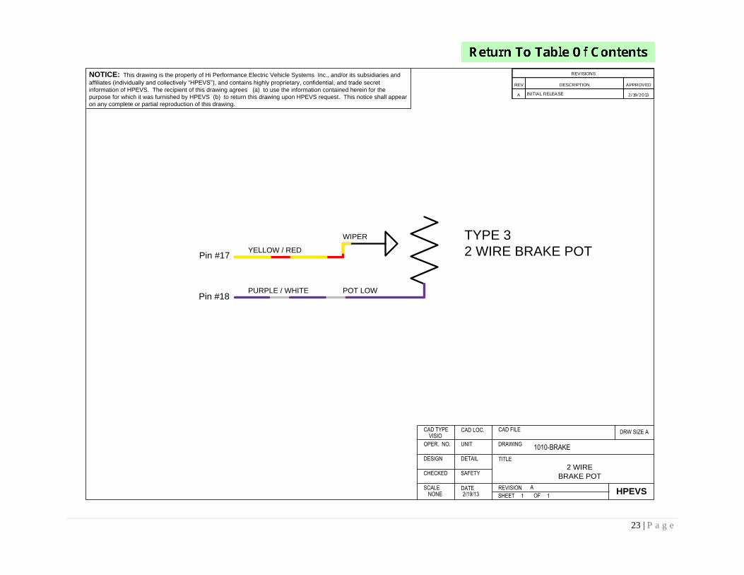
2 WIRE
BRAKE POT
A
REV DESCRIPTION APPROVED
A INITIAL RELEASE 2/19/2013
REVISIONS
YELLOW / RED
PURPLE / WHITE
TYPE 3
2 WIRE BRAKE POT
POT LOW
WIPER
Pin #18
Pin #17

24 | P a g e
OPTIONAL ACTIVE BRAKE LIGHT CONFIGURATIONS These optional active brake light configurations are used to activate the brake lights during regenerative braking or when the vehicle brakes are being applied. Based on the brake type configuration that is being used in the application use one of the following wiring configurations.
25 | P a g e
VISIO
12/5/13 3 4
1010-BRAKE
NONE
NOTICE: This drawing is the property of Hi Performance Electric Vehicle Systems Inc., and/or its subsidiaries and
affiliates (individually and collectively “HPEVS”), and contains highly proprietary, confidential, and trade secret
information of HPEVS. The recipient of this drawing agrees (a) to use the information contained herein for the
purpose for which it was furnished by HPEVS (b) to return this drawing upon HPEVS request. This notice shall appear
on any complete or partial reproduction of this drawing.
DRW SIZE ACAD FILECAD LOC.CAD TYPE
OPER. NO. UNIT DRAWING
TITLEDETAILDESIGN
CHECKED SAFETY
SCALE DATE REVISION
SHEETHPEVS
OF
OPTION 1
BRAKE LIGHT SWITCH
A
ORANGE / RED
BLUE / WHITE
REV DESCRIPTION APPROVED
A INITIAL RELEASE 2/19/2013
REVISIONS
TO BRAKE LIGHT
OEM BRAKE SWITCH
+12V
OPTION 1
FOR BRAKE TYPE 2, 3 OR 5 CONFIGURATIONS
1232/1234/1236/1238 CONTROLLERS
COIL RETURN (pin #13)
BRAKE LIGHT RELAY (pin #3)
85
86 30
87
** This option turns the brake lights ON during REGEN. Brake TYPE 5
allows for NEUTRAL BRAKING AND/OR BOOSTED REGEN while
pressing the brake pedal. Brake TYPE 2 & 3 uses a variable input for
BOOSTED REGEN.
26 | P a g e
VISIO
4/17/13 1 1
1010-CAN-OP-ISOLATOR
NONE
NOTICE: This drawing is the property of Hi Performance Electric Vehicle Systems Inc., and/or its subsidiaries and
affiliates (individually and collectively “HPEVS”), and contains highly proprietary, confidential, and trade secret
information of HPEVS. The recipient of this drawing agrees (a) to use the information contained herein for the
purpose for which it was furnished by HPEVS (b) to return this drawing upon HPEVS request. This notice shall appear
on any complete or partial reproduction of this drawing.
DRW SIZE ACAD FILECAD LOC.CAD TYPE
OPER. NO. UNIT DRAWING
TITLEDETAILDESIGN
CHECKED SAFETY
SCALE DATE REVISION
SHEETHPEVS
OF
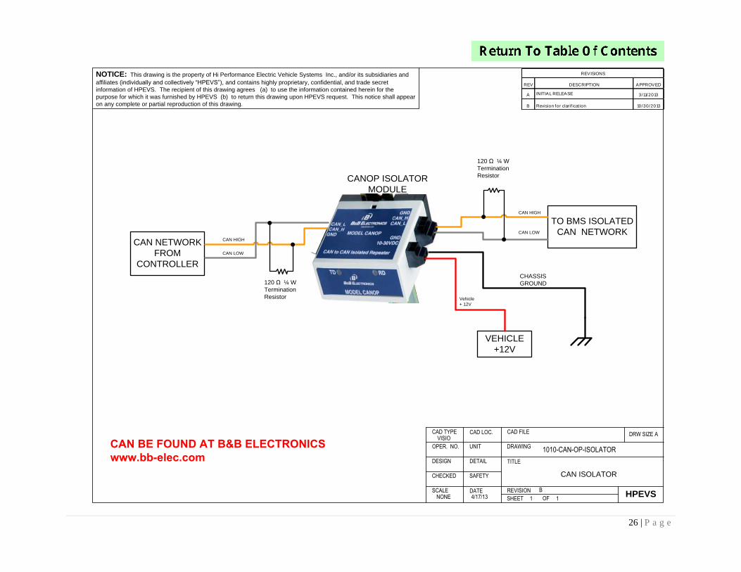
CAN ISOLATOR
B
REV DESCRIPTION APPROVED
A INITIAL RELEASE 3/11/2013
B Revision for clarif icat ion 10/30/2013
REVISIONS
CAN NETWORK
FROM
CONTROLLER
CAN HIGH
CAN LOW
TO BMS ISOLATED
CAN NETWORK
Vehicle
+ 12V
CHASSIS
GROUND
VEHICLE
+12V
CANOP ISOLATOR
MODULE
CAN HIGH
CAN LOW
120 Ω ¼ W
Termination
Resistor
120 Ω ¼ W
Termination
Resistor
CAN BE FOUND AT B&B ELECTRONICSwww.bb-elec.com
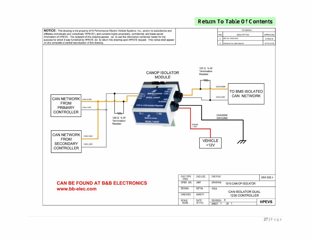
27 | P a g e
CAN BE FOUND AT B&B ELECTRONICSwww.bb-elec.com
28 | P a g e
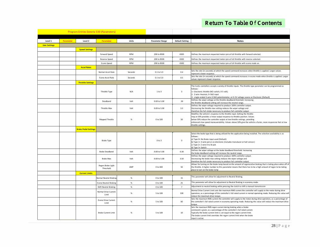
Level 1 Parameter Level 2 Parameter Units Parameter Range Default Setting Notes
User Settings
Speed Settings
Forward Speed RPM 200 to 8500 6500 Defines the maximum requested motor rpm at full throttle with forward selected.
Reverse Speed RPM 200 to 8500 6500 Defines the maximum requested motor rpm at full throttle with reverse selected.
Econo Speed RPM 200 to 8500 6500 Defines the maximum requested motor rpm at full throttle with econo mode on.
Accel Rates
Normal Accel Rate Seconds 0.1 to 5.0 0.4Sets the rate (in seconds) at which the speed command increases when throttle is applied. Larger values
represent slower response.
Econo Accel Rate Seconds 0.1 to 5.0 0.5Sets the rate (in seconds) at which the speed command increases in econo mode when throttle is applied. Larger
values represent slower response.
Throttle Settings
Throttle Type N/A 1 to 3 3
The Curtis controllers accept a variety of throttle inputs. The throttle type parameter can be programmed as
follows:
1= Electronic throttle (NO switch, 0-5 volt).
2: 2-wire rheostat, 0–5kΩ input
3: single-ended 3-wire 0-5kΩ potentiometer, or 0–5V voltage source or Electronic (Default)
Deadband Volt 0.00 to 5.00 .30Defines the wiper voltage at the throttle deadband threshold. Increasing
the throttle deadband setting will increase the neutral range.
Throttle Max Volt 0.00 to 5.00 3.5
Defines the wiper voltage required to produce 100% controller output.
Decreasing the throttle max setting reduces the wiper voltage and
therefore the full stroke necessary to produce full controller output.
Mapped Throttle % 0 to 100 50
Modifies the vehicle’s response to the throttle input. Setting the throttle
map at 50% provides a linear output response to throttle position. Values
below 50% reduce the controller output at low throttle settings, providing
enhanced slow speed maneuverability. Values above 50% give the vehicle a faster, more responsive feel at low
throttle settings.
Brake Pedal Settings
Brake Type 0 to 3 0
Select the brake type that is being utilized for the application being installed. The selection availability is as
follows:
a) Type 0= No Brake input used (Default)
b) Type 1= 3-wire pot or an electronic (includes transducer or hall sensor.)
c) Type 2= 2 wire 0 to 5k pot.
d) Type 3= Switch
Brake Deadband Volt 0.00 to 5.00 0.30Defines the wiper voltage at the brake deadband threshold. Increasing
the brake deadband setting will increase the neutral range.
Brake Max Volt 0.00 to 5.00 3.50
Defines the wiper voltage required to produce 100% controller output.
Decreasing the brake max setting reduces the wiper voltage and
therefore the full stroke necessary to produce full controller output.
Regen Brake Light
ThresholdAMP 0 to 400 50
Allows for turning on the brake lamp based on the amount of regenerative braking that is taking place when off of
the throttle. A higher number to this parameter means that there has to be a high amount of regen to be taking
place to turn on the brake lamp
Current Limits
Normal Neutral Braking % 0 to 100 15This parameter will allow for adjustment to Neutral Braking.
Econo Neutral Braking % 0 to 100 25 This parameter will allow for adjustment to Neutral Braking in economy mode.
Shift Neutral Braking % 0 to 100 7 Adjustment to neutral braking while pressing the clutch to shift a manual transmission
Normal Drive Current
Limit% 5 to 100 100
Normal Drive Current Limit sets the maximum RMS current the controller will supply to the motor during drive
operation, as a percentage of the controller’s full rated current in normal operating mode. Reducing this value will
reduce the maximum drive torque.
Econo Drive Current
Limit% 5 to 100 60
Sets the maximum RMS current the controller will supply to the motor during drive operation, as a percentage of
the controller’s full rated current in economy operating mode. Reducing this value will reduce the maximum drive
torque.
Brake Current Limit % 5 to 100 10
Sets the maximum RMS regen current during braking when a brake
command is given, as a percentage of the controller’s full rated current.
Typically the brake current limit is set equal to the regen current limit.
The brake current limit overrides the regen current limit when the brake
input is active.
Program Entries Generic 530 (Parameters)
29 | P a g e
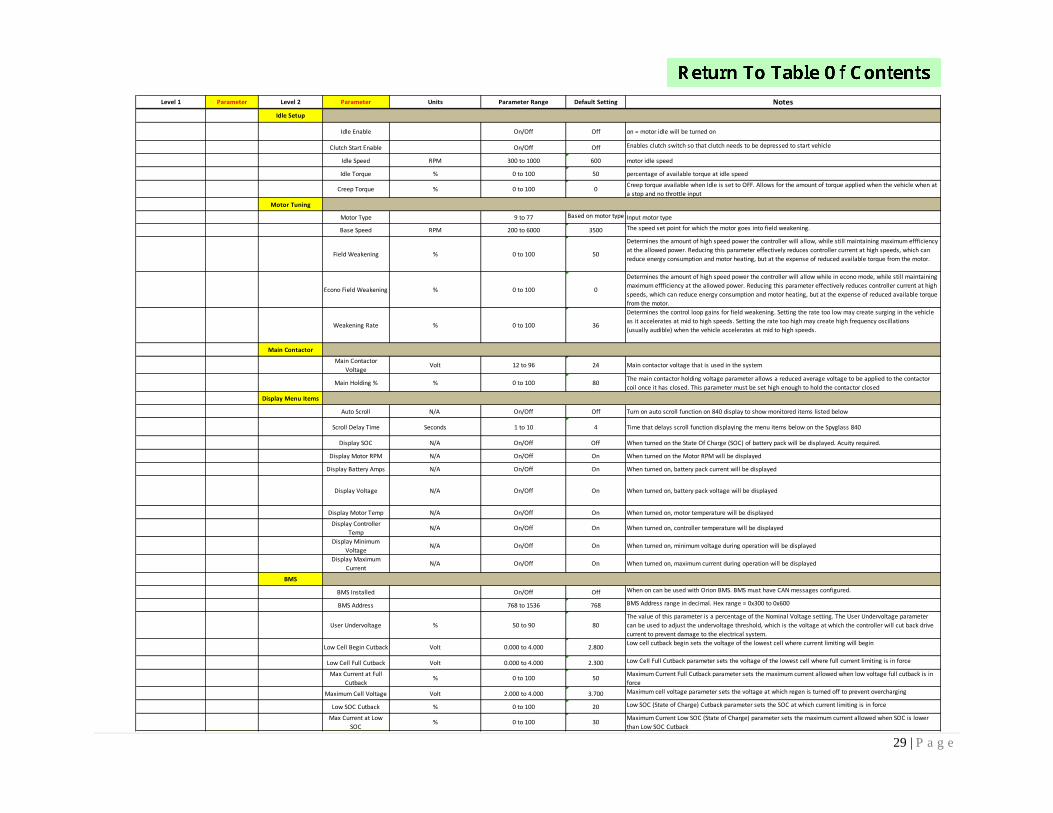
Level 1 Parameter Level 2 Parameter Units Parameter Range Default Setting Notes
Idle Setup
Idle Enable On/Off Off on = motor idle will be turned on
Clutch Start Enable On/Off Off Enables clutch switch so that clutch needs to be depressed to start vehicle
Idle Speed RPM 300 to 1000 600 motor idle speed
Idle Torque % 0 to 100 50 percentage of available torque at idle speed
Creep Torque % 0 to 100 0Creep torque available when Idle is set to OFF. Allows for the amount of torque applied when the vehicle when at
a stop and no throttle input
Motor Tuning
Motor Type 9 to 77 Based on motor type Input motor type
Base Speed RPM 200 to 6000 3500 The speed set point for which the motor goes into field weakening.
Field Weakening % 0 to 100 50
Determines the amount of high speed power the controller will allow, while still maintaining maximum effficiency
at the allowed power. Reducing this parameter effectively reduces controller current at high speeds, which can
reduce energy consumption and motor heating, but at the expense of reduced available torque from the motor.
Econo Field Weakening % 0 to 100 0
Determines the amount of high speed power the controller will allow while in econo mode, while still maintaining
maximum effficiency at the allowed power. Reducing this parameter effectively reduces controller current at high
speeds, which can reduce energy consumption and motor heating, but at the expense of reduced available torque
from the motor.
Weakening Rate % 0 to 100 36
Determines the control loop gains for field weakening. Setting the rate too low may create surging in the vehicle
as it accelerates at mid to high speeds. Setting the rate too high may create high frequency oscillations
(usually audible) when the vehicle accelerates at mid to high speeds.
Main Contactor
Main Contactor
VoltageVolt 12 to 96 24 Main contactor voltage that is used in the system
Main Holding % % 0 to 100 80The main contactor holding voltage parameter allows a reduced average voltage to be applied to the contactor
coil once it has closed. This parameter must be set high enough to hold the contactor closed
Display Menu Items
Auto Scroll N/A On/Off Off Turn on auto scroll function on 840 display to show monitored items listed below
Scroll Delay Time Seconds 1 to 10 4 Time that delays scroll function displaying the menu items below on the Spyglass 840
Display SOC N/A On/Off Off When turned on the State Of Charge (SOC) of battery pack will be displayed. Acuity required.
Display Motor RPM N/A On/Off On When turned on the Motor RPM will be displayed
Display Battery Amps N/A On/Off On When turned on, battery pack current will be displayed
Display Voltage N/A On/Off On When turned on, battery pack voltage will be displayed
Display Motor Temp N/A On/Off On When turned on, motor temperature will be displayed
Display Controller
TempN/A On/Off On When turned on, controller temperature will be displayed
Display Minimum
VoltageN/A On/Off On When turned on, minimum voltage during operation will be displayed
Display Maximum
CurrentN/A On/Off On When turned on, maximum current during operation will be displayed
BMS
BMS Installed On/Off Off When on can be used with Orion BMS. BMS must have CAN messages configured.
BMS Address 768 to 1536 768 BMS Address range in decimal. Hex range = 0x300 to 0x600
User Undervoltage % 50 to 90 80
The value of this parameter is a percentage of the Nominal Voltage setting. The User Undervoltage parameter
can be used to adjust the undervoltage threshold, which is the voltage at which the controller will cut back drive
current to prevent damage to the electrical system.
Low Cell Begin Cutback Volt 0.000 to 4.000 2.800Low cell cutback begin sets the voltage of the lowest cell where current limiting will begin
Low Cell Full Cutback Volt 0.000 to 4.000 2.300 Low Cell Full Cutback parameter sets the voltage of the lowest cell where full current limiting is in force
Max Current at Full
Cutback% 0 to 100 50
Maximum Current Full Cutback parameter sets the maximum current allowed when low voltage full cutback is in
force
Maximum Cell Voltage Volt 2.000 to 4.000 3.700 Maximum cell voltage parameter sets the voltage at which regen is turned off to prevent overcharging
Low SOC Cutback % 0 to 100 20 Low SOC (State of Charge) Cutback parameter sets the SOC at which current limiting is in force
Max Current at Low
SOC% 0 to 100 30
Maximum Current Low SOC (State of Charge) parameter sets the maximum current allowed when SOC is lower
than Low SOC Cutback
30 | P a g e
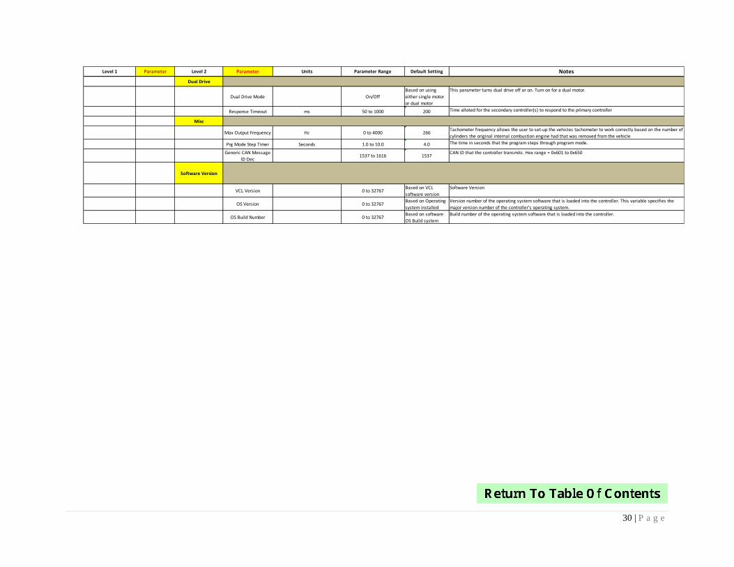
Level 1 Parameter Level 2 Parameter Units Parameter Range Default Setting Notes
Dual Drive
Dual Drive Mode On/Off
Based on using
either single motor
or dual motor
This parameter turns dual drive off or on. Turn on for a dual motor.
Response Timeout ms 50 to 1000 200 Time alloted for the secondary controller(s) to respond to the primary controller
Misc
Max Output Frequency Hz 0 to 4000 266Tachometer frequency allows the user to set-up the vehicles tachometer to work correctly based on the number of
cylinders the original internal combustion engine had that was removed from the vehicle
Prg Mode Step Timer Seconds 1.0 to 10.0 4.0 The time in seconds that the program steps through program mode.
Generic CAN Message
ID Dec1537 to 1616 1537
CAN ID that the controller transmits. Hex range = 0x601 to 0x650
Software Version
VCL Version 0 to 32767Based on VCL
software version
Software Version
OS Version 0 to 32767Based on Operating
system installed
Version number of the operating system software that is loaded into the controller. This variable specifies the
major version number of the controller’s operating system.
OS Build Number 0 to 32767Based on software
OS Build system
Build number of the operating system software that is loaded into the controller.
31 | P a g e
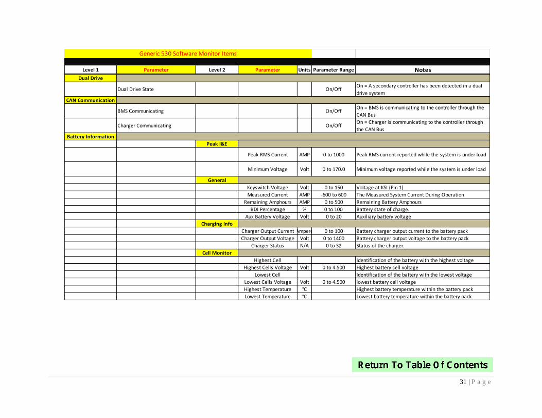
Level 1 Parameter Level 2 Parameter Units Parameter Range NotesDual Drive
Dual Drive State On/OffOn = A secondary controller has been detected in a dual
drive system
CAN Communication
BMS Communicating On/OffOn = BMS is communicating to the controller through the
CAN Bus
Charger Communicating On/OffOn = Charger is communicating to the controller through
the CAN Bus
Battery Information
Peak I&E
Peak RMS Current AMP 0 to 1000 Peak RMS current reported while the system is under load
Minimum Voltage Volt 0 to 170.0 Minimum voltage reported while the system is under load
General
Keyswitch Voltage Volt 0 to 150 Voltage at KSI (Pin 1)
Measured Current AMP -600 to 600 The Measured System Current During Operation
Remaining Amphours AMP 0 to 500 Remaining Battery Amphours
BDI Percentage % 0 to 100 Battery state of charge.
Aux Battery Voltage Volt 0 to 20 Auxiliary battery voltage
Charging Info
Charger Output Current Ampere 0 to 100 Battery charger output current to the battery pack
Charger Output Voltage Volt 0 to 1400 Battery charger output voltage to the battery pack
Charger Status N/A 0 to 32 Status of the charger.
Cell Monitor
Highest Cell Identification of the battery with the highest voltage
Highest Cells Voltage Volt 0 to 4.500 Highest battery cell voltage
Lowest Cell Identification of the battery with the lowest voltage
Lowest Cells Voltage Volt 0 to 4.500 lowest battery cell voltage
Highest Temperature °C Highest battery temperature within the battery pack
Lowest Temperature °C Lowest battery temperature within the battery pack
Generic 530 Software Monitor Items
32 | P a g e
GLOSSARY OF TERMS
1. Accel Rate: sets the rate (in seconds) at which the motor torque increases to full when full throttle
is applied. Larger values represent slower response.
2. Baud rate: a unit used to measure the speed of electronic code transmission, equal to one-unit
interval per second.
3. BMS: Battery Management System
4. Brake Current Limit: Sets the maximum RMS regen current during braking when a brake command
is given, as a percentage of the controller’s full rated current. The full rated current depends on the
controller model.
5. Brake Input Rate: Sets the rate (in seconds) at which the vehicle slows down when brake is applied
or when throttle is applied in the opposite direction. Larger values represent slower response.
6. Brake Maximum: Defines the input voltage required to produce 100% braking torque. Decreasing
the brake max setting reduces the amount of voltage necessary to produce full braking torque.
7. Brake Type: Defines the brake input for the controller:
a. Type 2= 3 wire 0 to 5kohm pot or electronic 0-5v input or pressure transducer.
b. Type 3= 2 wire with switch; 0 to 5kohm.
c. Type 5= switch.
8. CAN: Controller Area Network. A vehicle bus standard designed to allow microcontrollers and
devices to communicate with each other within a vehicle. All controllers on the CAN bus need to
have the Baud Rate set the same.
9. Creep Torque: Determines the amount of torque applied to the vehicle at a stop with no throttle
input, to emulate the feel of an automatic transmission automobile. WARNING! When interlock is
engaged, creep torque allows vehicle propulsion if a direction is selected even though no throttle is
applied. Care should be taken when setting up this parameter. If pedal braking is enabled, creep
torque is progressively disabled as brake is applied so as to prevent the motor from driving into the
brakes and thus wasting energy.
10. Deadband: is an area of a signal range or band where no action occurs (the system is dead).
11. EncA & B: two signals from the encoder for which the controller determines direction of rotation
and speed of the motor.
12. Field Weakening Rate: Determines the control loop gains for field weakening. Setting the rate too
low may create surging in the vehicle as it accelerates at mid to high speeds. Setting the rate too
high may create high frequency oscillations (usually audible) when the vehicle accelerates at mid to
high speeds.
13. Generic CAN Message: CAN message containing general information regarding the status of the
motor and controller.
14. Idle Torque: Torque load delivered by the motor at idle. If the Idle for the motor is enabled, idle
torque will equal creep torque.
33 | P a g e
15. Load Meter: The LED lights that are located on the bottom of the Spyglass represent how much of a
load is exerted on the system.
16. Neutral Braking: Neutral braking occurs progressively when the throttle is reduced toward the
neutral position or when no direction is selected. The neutral braking parameter is adjustable from
0 to 100% of the regen current limit.
17. Nominal Voltage: Battery pack voltage; not to exceed controller voltage ratings.
18. Regenerative Braking: Regenerative braking is used on electric vehicles to recoup some of the
energy lost during stopping. This energy is saved to the batteries and used later to power the motor
to put the car in motion.
19. Shift Neutral Braking: Adjustment to neutral braking while pressing the clutch to shift a manual
transmission
20. SOC: State of charge.
21. Spyglass: Name given by Curtis Instruments to the 8 segment LCD, 5-LED display.
22. Throttle Maximum: Defines the wiper input voltage required to produce 100% controller output.
Decreasing the throttle max setting reduces the amount of voltage necessary to produce full
controller output.
23. Throttle Type: Defines the throttle input for the controller:
a. Type 1= Electronic without switch
b. Type 2= 0-5K ohm 2 wire pot with switch.
c. Type 3= 0-5K ohm 3-wire pot with switch. Electronic with switch.
Related Documents


