Wireless Networks

Wireless Networks. Anatomy of a radio LAN The radio modem –Analog transmitter The MAC controller –Interface to transmitter –At least partly in hardware.
Dec 18, 2015
Welcome message from author
This document is posted to help you gain knowledge. Please leave a comment to let me know what you think about it! Share it to your friends and learn new things together.
Transcript

Wireless Networks

Anatomy of a radio LAN
• The radio modem – Analog transmitter
• The MAC controller – Interface to transmitter – At least partly in hardware
• The host interface – How the software(driver) talks to the MAC– PCI, PCMCIA, USB, Ethernet
• The driver – How the App talks to the device– Implements the part of MAC not in hardware
The Radio Modem (Physical Layer)
• ISM frequency bands (900 MHz & 2.4 GHz) • 5 GHz frequency bands (HiperLan and UNII
band) • Spread Spectrum techniques • Modulations • Interferences and noises • Other (analog concerns)
The MAC level (link layer)
• Main channel access mechanisms
• MAC techniques
• Network topology
• Some throughput considerations
Some Wireless LAN standards
• IEEE 802.11
• 802.11 HR and 802.11 at 5 GHz
• HiperLan
• HiperLan II
• HomeRF & SWAP
• BlueTooth
The radio modem (physical layer)
ISM frequency bands
• FCC/ETSI allocated– Unlicensed but regulated
• Very different from HAM radio
– For industrial/scientific/medical use
• (900 MHz & 2.4 GHz) • rules originally allowed around 2 Mb/s maximum bit
rate – found a loophole and now offer 11 Mb/s systems
• Free = heavily polluted • 2.4 GHz suffers from microwave oven interference

5 GHz frequency bands
• complicated power rules – around 20 MHz bandwidth is optimal
• More bandwidth = more speed– 10 – 40Mb/s
• Higher frequency– More interference
• Obstacles
– Requires greater SNR (signal to noise ratio)• Shorter range
Spread Spectrum
• Use increased bandwidth– Decrease noise effects– Shares spectrum pretty fairly
• Direct Sequence vs. Frequency Hopping

Direct Sequence
• Broadcast on many channels
– Modulate signal via a single code
• One chip per band $$
• Same chip for decoding
– Take average of decoded signals
• Interference on any narrow bands is averaged out
– What if interference is too great?
• Wide channels
– Only a few available (about 3)
• CDMA (cell phones) use something like this
– Different (orthogonal) code for each channel
Frequency Hopping
• Uses a set of narrow channels– Changes channel every 20 - 400 ms
• If a channel is bad (interference) a new one will be used soon– Averages interference over time– At least some channels should be good
• Complicates MAC level– Performance cost of synch/init
• Co-Existance• Ultra Secure
Modulations
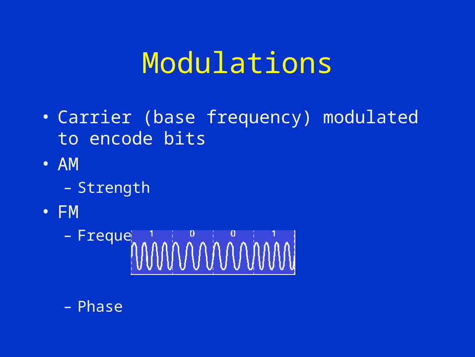
• Carrier (base frequency) modulated to encode bits• AM
– Strength
• FM– Frequency
– Phase
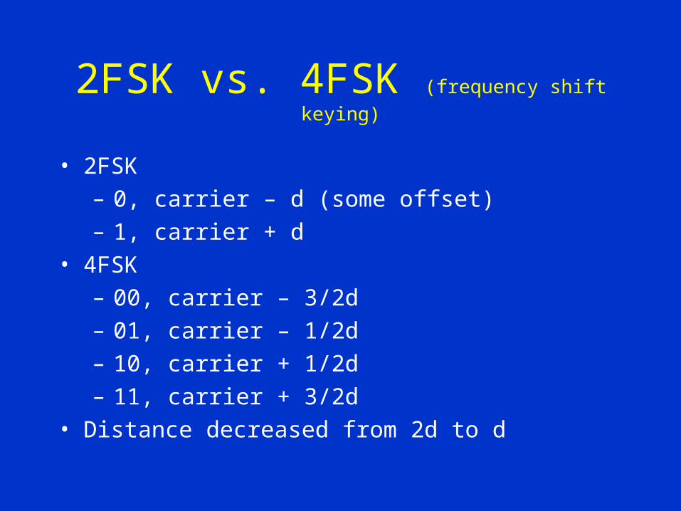
2FSK vs. 4FSK (frequency shift keying)
• 2FSK
– 0, carrier – d (some offset)
– 1, carrier + d
• 4FSK
– 00, carrier – 3/2d
– 01, carrier – 1/2d
– 10, carrier + 1/2d
– 11, carrier + 3/2d
• Distance decreased from 2d to d

11Mb/s? (802.11 HR)
• Modulate code of DS to encode more data– Not originally allowed but after showing FCC
that it causes no more harm than DS it was allowed
• Faster = reduced range• More complex hardware• More sensitive to noise
OFDM
• Transmit bits in parallel• Orthogonal sub-carriers modulated independently
Interference and Noise
• Fading
– Temporal variations
• Microwave Oven noise
– 2.4Ghz is the frequency where water molecules vibrate
• FEC
– Error correcting codes
– Not very useful since errors tend to be bursty
– Still used to correct small errors
• Multi-path/delay– Not a problem at lower bit-rate (up to 1Mb/s)

The MAC level

Main channel access mechanisms
• Must allocate the main resource (channel) between nodes
• Allocated by regulating its use– TDMA– CSMA– Polling
TDMA (Time Division Multiple Access)
• Time broken up into frames
• Time slices of a frame given to nodes
• Done via mgmt. Frame – Specified by base station
• Up slices and down slices

TDMA
• Used for cell phones
• Low latency
• Guarantee of bandwidth
• Connection oriented
• Not well suited for data network– Inflexibility– Does not handle bursts of traffic well

CSMA/CA
• Used by most wireless LANs (in ISM)
• Connectionless
• Best effort
• No bandwidth or latency guarantees
• Because a nodes own signal overpowers all others collisions are not detectable– Collision avoidance
CSMA/CA
• Listen to channel
• If idle - send one packet
• If busy - wait until idle then start contention– Transmissions only start at beginning of slots
• Since it takes time to switch from rcv to xmit
• 20 - 50µs
Polling
• Mix of TDMA and CSMA/CA
• Base controls channel access
• Asks nodes if they want to transmit– Connection oriented or connectionless– Ask each node or reservation (out of channel)
MAC Techniques
• Need to improve performance of CSMA/CA• Retransmission
– Via ack’s
• Fragmentation– Small packets to reduce retransmissions
• RTS/CTS– CSMA/CA only sees locally – Ask receiver if ok to send– One side effect is reduced collision penalty
• All add overhead

Network topology
• Ad hoc– Isolated– Each node provides routing
• Access points– Similar to bridges

Some throughput considerations
• Very low user throughput– On a 1Mb/s system users can frequently
see as low as hundreds of bits per second
• Multi-rate systems– Lesser bandwidth channel available with
greater range
• TCP assumes packet loss is congestion

Some Wireless LAN standards
IEEE 802.11
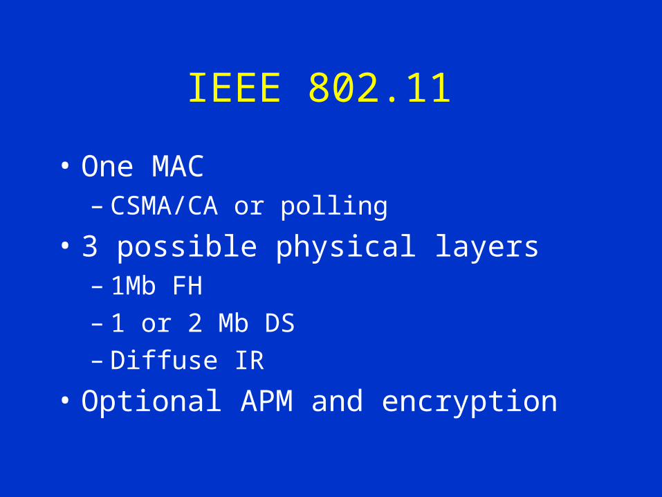
• One MAC– CSMA/CA or polling
• 3 possible physical layers– 1Mb FH– 1 or 2 Mb DS– Diffuse IR
• Optional APM and encryption

802.11 HR & 802.11 at 5 GHz
• Only changes physical layer
• 5Ghz – OFDM– 6 - 52 Mb

HiperLan
• By ETSI
• Dedicated band – 5.1 - 5.3GHz– Only in Europe
• 23.5 Mb
HiperLan II
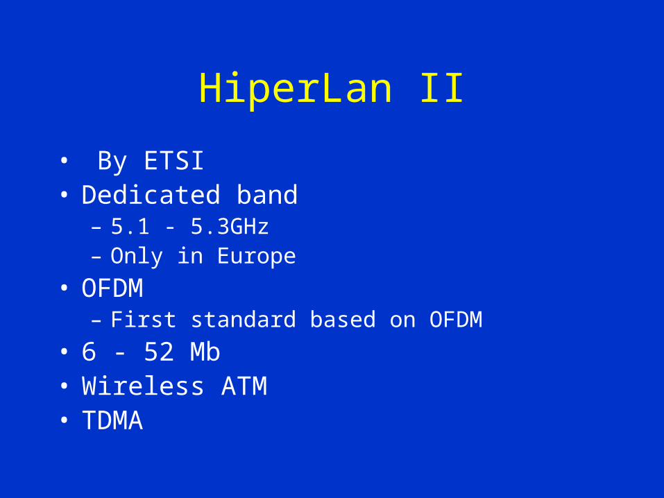
• By ETSI• Dedicated band
– 5.1 - 5.3GHz– Only in Europe
• OFDM– First standard based on OFDM
• 6 - 52 Mb• Wireless ATM• TDMA
HomeRF & SWAP
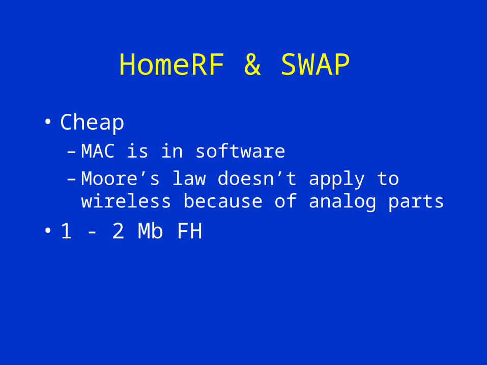
• Cheap– MAC is in software– Moore’s law doesn’t apply to wireless
because of analog parts
• 1 - 2 Mb FH

BlueTooth
• Not wireless LAN
• Cable replacement technology
• Offers point to point links
• No IP support only PPP
• Each channel is ~768kb FH– 1 data, 3 voice
Related Documents