Department Of Electronic Systems Wireless M-Bus based eXtremely Low Power protocol for wireless communication with water meters Group 1000 NDS Dimo Donev 31. May 2012 Supervisor: Neeli Prasad

Welcome message from author
This document is posted to help you gain knowledge. Please leave a comment to let me know what you think about it! Share it to your friends and learn new things together.
Transcript

Department Of Electronic Systems
Wireless M-Bus basedeXtremely Low Power protocol
for wireless communicationwith water meters
Group 1000 NDS
Dimo Donev
31. May 2012Supervisor: Neeli Prasad


Department of Electronic Systems I-8Fredrik Bajers Vej 79220 Aalborg Østhttp://www.es.aau.dk/
Title:Wireless M-Bus based eXtremelyLow Power protocol for wirelesscommunication with water meters
Theme:Power efficient protocols
Project Period:Spring 2012
Project Group:1001
Member:
Dimo Donev
Supervisor:Neeli Prasad
Number of copies printed andpages: 3, 68
Finished the 31 of May 2012.
Synopsis:
This report investigates the possibility ofcreating an eXtreme Low Power proto-col for wireless communication with wa-ter meters. It is based on Wireless M-Bus protocol and focuses on modifyingit in order to achieve maximum powerefficiency in the meter side. The workis concentrated on investigations aboutthe possibility of reducing the transmit-ting packet up to a bare minimum andthe ways it can be recovered after its re-ception.A motivation for the problem andoverview of Wireless M-Bus are pre-sented. It is investigated the require-ments and limitations for communica-tion with water meters. Simulationtests, conclusions and proposal for oper-ating under certain conditions are given.At the end, overview of the work is doneand future tasks for developing and im-proving the current work are suggested.


Contents
1 Introduction 61.1 Being “Smart” . . . . . . . . . . . . . . . . . . . . . . . . . . 61.2 AMR and AMI . . . . . . . . . . . . . . . . . . . . . . . . . . 71.3 Seeing a Problem? . . . . . . . . . . . . . . . . . . . . . . . . 81.4 Water meters and their place in the world . . . . . . . . . . . 91.5 Water meter reading methods [8] . . . . . . . . . . . . . . . . 101.6 Motivation . . . . . . . . . . . . . . . . . . . . . . . . . . . . 11
2 M-Bus 132.1 Wireless M-Bus - Physical Layer . . . . . . . . . . . . . . . . 14
2.1.1 Mode S . . . . . . . . . . . . . . . . . . . . . . . . . . 152.1.2 Mode T . . . . . . . . . . . . . . . . . . . . . . . . . . 152.1.3 Mode R2 . . . . . . . . . . . . . . . . . . . . . . . . . 162.1.4 More C . . . . . . . . . . . . . . . . . . . . . . . . . . 162.1.5 Mode N . . . . . . . . . . . . . . . . . . . . . . . . . . 162.1.6 Mode F . . . . . . . . . . . . . . . . . . . . . . . . . . 16
2.2 Wireless M-Bus - Data Link Layer . . . . . . . . . . . . . . . 162.2.1 Frame Format A . . . . . . . . . . . . . . . . . . . . . 172.2.2 Frame Format B . . . . . . . . . . . . . . . . . . . . . 19
2.3 Wireless M-Bus - Application Link Layer . . . . . . . . . . . 202.3.1 Data block - Standard M-Bus frame . . . . . . . . . . 212.3.2 Data field - Compact M-Bus frame . . . . . . . . . . . 222.3.3 Encryption . . . . . . . . . . . . . . . . . . . . . . . . 23
3 Analysis 243.1 “Drive-by” meter reading . . . . . . . . . . . . . . . . . . . . 263.2 Project Statement . . . . . . . . . . . . . . . . . . . . . . . . 26
4 Design Considerations 284.1 Cyclic Redundancy Check . . . . . . . . . . . . . . . . . . . . 28
4.1.1 Number of undetected errors . . . . . . . . . . . . . . 294.1.2 Format Signature and CRC . . . . . . . . . . . . . . . 30
4.2 Number of meters in receiver’s range . . . . . . . . . . . . . . 30
2

4.2.1 Coverage area . . . . . . . . . . . . . . . . . . . . . . . 314.2.2 Water meter density . . . . . . . . . . . . . . . . . . . 32
4.3 Data from the meter . . . . . . . . . . . . . . . . . . . . . . . 334.3.1 BCD or Binary . . . . . . . . . . . . . . . . . . . . . . 344.3.2 Water consumption . . . . . . . . . . . . . . . . . . . 35
5 XLP 365.1 Preamble and mode distinguishing . . . . . . . . . . . . . . . 365.2 XLP and Data reduction . . . . . . . . . . . . . . . . . . . . . 37
5.2.1 Frame Format . . . . . . . . . . . . . . . . . . . . . . 385.2.2 C-field . . . . . . . . . . . . . . . . . . . . . . . . . . . 385.2.3 Meter ID . . . . . . . . . . . . . . . . . . . . . . . . . 385.2.4 CI-field . . . . . . . . . . . . . . . . . . . . . . . . . . 385.2.5 Data Header . . . . . . . . . . . . . . . . . . . . . . . 395.2.6 Data fields . . . . . . . . . . . . . . . . . . . . . . . . 395.2.7 Format Signature . . . . . . . . . . . . . . . . . . . . . 395.2.8 XLP - final look . . . . . . . . . . . . . . . . . . . . . 40
5.3 XLP message encoding . . . . . . . . . . . . . . . . . . . . . . 415.4 XLP message decoding . . . . . . . . . . . . . . . . . . . . . . 42
6 Tests and results 466.1 Architecture of the simulation engine . . . . . . . . . . . . . . 476.2 Results . . . . . . . . . . . . . . . . . . . . . . . . . . . . . . . 50
6.2.1 Expected water consumption of maximum 1000m3 andtransmitted information down to 1 liter . . . . . . . . 50
6.2.2 Expected water consumption of maximum 1000m3 andtransmitted information down to 1m3 . . . . . . . . . 51
6.2.3 Expected water consumption of maximum 100m3 andtransmitted information down to 1 liter . . . . . . . . 51
6.2.4 Expected water consumption of maximum 100m3 andtransmitted information down to 1m3 . . . . . . . . . 51
6.3 Current consumption and Throughput . . . . . . . . . . . . . 526.3.1 Packet Throughput . . . . . . . . . . . . . . . . . . . . 536.3.2 Current consumption . . . . . . . . . . . . . . . . . . . 54
6.4 XLP proposal for Miitors water meter . . . . . . . . . . . . . 546.4.1 XLP encoding . . . . . . . . . . . . . . . . . . . . . . 556.4.2 XLP decoding . . . . . . . . . . . . . . . . . . . . . . 566.4.3 Encryption . . . . . . . . . . . . . . . . . . . . . . . . 57
7 Conclusions 60
8 Future Work 618.1 Improving the Encryption Model . . . . . . . . . . . . . . . . 618.2 Identifying Transmitting Meters . . . . . . . . . . . . . . . . . 61
3

8.3 Batteryless operation . . . . . . . . . . . . . . . . . . . . . . . 628.4 Fixed Network . . . . . . . . . . . . . . . . . . . . . . . . . . 62
Bibliography 62
A 3-out-of-6 encoding 65
B T2-mode 66
C CD with the Simulation tool and Matlab codes 68
4

Acknowledgements
I would like to express my gratitude to:
• Rasmus Melchior Jacobsen, an industrial PhD student in Aalborg Uni-versity, who provided some real world information about using of Wire-less M-Bus.
• Miitors for the topic of this report and the provided information andcollaboration.
• Neeli Prasad and Rasmus Hjorth Nielsen from CTIF for the supervi-sion.
• Jeremie Pierre Gay, formal Aalborg University student and currentCEO of Create It Real Aps, for his assistance and help in the devel-oping of the simulation script.
5

Chapter 1
Introduction
Preserving resources is getting one of the most important issues for themodern world. Together with the requirements for security and reliability,lowering of consumption and costs of the utilities and devices is main focusfor most of the manufacturers and users.
1.1 Being “Smart”
With the development of the communication technologies, lately it happensmore and more often to talk about wireless sensor networks,“smart” homes,“smart” buildings, “smart” cities, etc. One of the ideas behind these terms isa number of sensors, meters and utilities connected together into a networkkeeping track of certain parameters in the area and based on some criteriaexecute commands to the appliances connected in the network. A shortexample of “smart” home is shown on figure 1.1.
A possible scenario:
• Detectors for smoke and gas inform the owners if there is presence ofsuch;
• When the door is opened, the lights are turned on automatically;
• The sprinkler in the garden is turned on in particular time intervalsor when the soil’s moisture is measured under a certain level;
• If the water consumption increase rapidly the owners are informed forpossible water leaks;
• If the owners are out, they can access their house through internet andon the way home can turn on the heaters and start the coffee machineso they can enjoy a warm beverage in the moment they step into.
6

Figure 1.1: Smart Home example
1.2 AMR and AMI
Automatic Meter Reading (AMR) is a major part of “being smart”. As itsname implies, in its basis AMR is a technology that provides the capabilityof automatic data collecting from different meters. But since the technolo-gies used for AMR provide a lot of opportunities, now this term includesalso event alarms, data storage and data transfer to a base station. It givesthe possibility of real time tracking of consumption, more accurate billing,and including the meters as part of bigger systems for automation and con-trol. The existence of AMR has led to the implementation of AdvancedMetering Infrastructure (AMI) - “systems that measure, collect and analyseenergy usage, and communicate with metering devices such as electricitymeters, gas meters, heat meters, and water meters, either on request oron a schedule. These systems include hardware, software, communications,consumer energy displays and controllers, customer associated systems, Me-ter Data Management (MDM) software, and supplier business systems”[13].Basically what AMI includes in its meaning is AMR with the possibility ofestablishing two-way communication with the meters.
There are different wired and wireless technologies that Automatic MeterReading can use - Power Line Communications (PLC), ZigBee, Bluetooth,WiFi, GPRS, M-Bus, Wireless M-Bus, Z-wave, etc. Which one will beused depends on number of factors like application, environment, meteringsystem, budget, scalability of the system, etc. In many cases a mixturebetween some these technologies can be exploited.
Currently, the most frequently mentioned technology for implementing
7
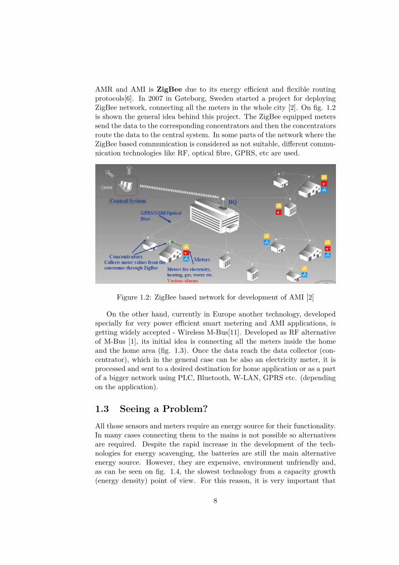
AMR and AMI is ZigBee due to its energy efficient and flexible routingprotocols[6]. In 2007 in Gøteborg, Sweden started a project for deployingZigBee network, connecting all the meters in the whole city [2]. On fig. 1.2is shown the general idea behind this project. The ZigBee equipped meterssend the data to the corresponding concentrators and then the concentratorsroute the data to the central system. In some parts of the network where theZigBee based communication is considered as not suitable, different commu-nication technologies like RF, optical fibre, GPRS, etc are used.
Figure 1.2: ZigBee based network for development of AMI [2]
On the other hand, currently in Europe another technology, developedspecially for very power efficient smart metering and AMI applications, isgetting widely accepted - Wireless M-Bus[11]. Developed as RF alternativeof M-Bus [1], its initial idea is connecting all the meters inside the homeand the home area (fig. 1.3). Once the data reach the data collector (con-centrator), which in the general case can be also an electricity meter, it isprocessed and sent to a desired destination for home application or as a partof a bigger network using PLC, Bluetooth, W-LAN, GPRS etc. (dependingon the application).
1.3 Seeing a Problem?All those sensors and meters require an energy source for their functionality.In many cases connecting them to the mains is not possible so alternativesare required. Despite the rapid increase in the development of the tech-nologies for energy scavenging, the batteries are still the main alternativeenergy source. However, they are expensive, environment unfriendly and,as can be seen on fig. 1.4, the slowest technology from a capacity growth(energy density) point of view. For this reason, it is very important that
8

Figure 1.3: Wireless M-Bus concept
these devices have very low energy consumption and use very power efficientcommunication protocols for the data exchange between each other.
Figure 1.4: Moore’s law for different units
The necessity of good protocols increases even more when the devices useradio frequency communication due to number of reasons like the possibilityof interference between them, security issues and also the power consumptionof the transmitter/receiver which in some cases exceeds the self consumptionof the devices thousands of times.
1.4 Water meters and their place in the worldWater meter is a device whose main function is to collect information of thewater consumption over a period of time in certain region/location. It isin use for everybody who needs to keep track of the water float, therefore
9

water consumption. Water meters are important components for the waterproviding companies and their customers due to number of reasons. Theyallow the company to charge customers for the amount of used water; moni-tor the water sent to the distribution system; detect leaks in the system. Onthe other hand, the customers can keep track of their water consumptionwhich gives them the opportunity to control their bills, detect leaks at theirlocation.
In the countries with a developed water providing infrastructure, everyhousehold, office building, store, etc. with access to water-main have atleast one water meter. On fig. 1.5 is presented statistics for the number ofhouseholds in Denmark for the period of 10 years (from 1995 to 2004). Also,keeping in mind that the population on Earth and the average standard oflife are increasing, the market for these devices is huge and will keep growing.
Figure 1.5: Households in Denmark for the period 1995 - 2004 [3]
Water meters are not new for the market. They exist for many yearsand there are many companies that work in this field, therefore there areplenty of solutions for measuring and reading the water consumption.
As part of the modern world, with the progress of the technology thewater meters and the way they interact with the surrounding have evolveda lot. Starting as a stand alone pure mechanical devices, during the yearsthey have become more accurate, complex and with different capabilitiesallowing them to be a part of AMR/AMI, providing additional informationand services for the water providers and their customers. Of course, theseadvantages have price - the meters are electronic, which leads to requirementof energy source.
1.5 Water meter reading methods [8]
Based on the type of water meter, there exist different methods for its read-ing by the water provider:
Eyeball - the traditional method in which there is a dial that shows the waterconsumption and a person has to reach the water meter and write downthe information manually. This method requires people working fulltime to walk around from door to door and disturb company’s clients.This leads to complications if there is nobody to open the door for the
10

employee. Also, the meters have to be located in places with relativelyeasy access. This is labor-intensive and expensive method and for thisreason the information is collected very rarely (once a month or less).
Walk-by - the meter is connected with wires to a device located outside thebuilding or is equipped with radio transmitter. It still requires a phy-sical visit by a collector with a handheld device for collecting the data,but eliminates the problems like lack of access to the water meter. Thefrequency of collecting the data is the same as the Eyeball method.
Drive-by - the meter is equipped with radio transmitter. The receiver is portable,placed in a vehicle, and the information is gathered wirelessly whenthe reader is in the coverage of the transmitter. This method is usedin rural areas, where implementation of a fixed network (see below)is not cost effective. Major problem is the energy efficiency, since themeter is supposed to be awake very often, while the receiver “showsup” very rarely. Solution for the problem can be if the meter awakesonly in certain times when it is expected that the receiver will be inthe area, but this requires very good time scheduling.
Fixed network - the meters are connected to a base station, repeater or to each otherestablishing a fixed network. This provides automatic reading of thewater meter which can be practically continuous (depending on theimplementation and requirements).
1.6 Motivation
Usually water meters are located in basements, closets or meter pits. Theseplaces have something in common - most probably there is no access to themains. This leads to usage of battery for supplying the device.
Let’s observe the following case: A water provider company uses batterysupplied water meters for their utilities. This company supplies a whole citywith water and has to equip all the households, offices, factories, etc. in thecity with water meters. According to [3] for year 2004 in city of Aalborg(Denmark) only the households were 80198. Including the rest of the placeswhere water meter is required, their number of the devices in the city caneasily exceed 100000. If we assume that each meter has to have its batterychanged once every 2 years and the battery discharge of the meters is equallyspread in time, for 1 year the company will have to change 100000
2·365 ≈ 137batteries daily, which leads to necessity of having people working full dayonly for changing batteries, big expenses and enormous pollution of theenvironment.
The current master thesis is based on collaboration withMiitors (www.miitors.com)- company located in Aarhus, Denmark. Their business model is develop-
11

ment of ultra precise and energy efficient ultrasonic water meters. Com-pany’s mission is providing state of the art water meter technology to me-ter manufacturers. The first product to be released is W-Miitor - batterypowered water meter with Wireless M-Bus communication interface. It isestimated that the device will be capable of working for more than 10 yearswith one small battery.
Since the radio communication is the biggest energy drainer, reducingthe time in which the radio module of the device is on will increase thebattery life significantly. For this reason, from the company are interestedin investigating the possibilities for implementing an eXtreme Low Powerprotocol (XLP), reducing the information the meter sends up to the bareminimum. Though, the reduction has to be such, that when received, withadditional help from a Database containing a priori information, the messageshould still be possible to be extracted into a complete Wireless M-Busdatagram for further processing (if needed) (see fig. 1.6).
Figure 1.6: Diagram of the project statement
12

Chapter 2
M-Bus
M-Bus (Meter-Bus) is a standard developed in Europe for remote reading ofmeters for gas, water, heat and electricity. It is described by the EuropeanNorm (EN 13757) and defines the communication between meters and adata collector. Initially its interface is made for Power Line Communication(PLC), but lately it is developed a wireless communication standard, calledWireless M-Bus. The EN specification is divided into five parts, definingdifferent aspects of the standard:
EN 13757-1 - Data exchange[4]. Describes the basic communication between me-ters and a data collector. It provides an overview of the communicationsystem.
EN 13757-2 - Physical and link layer [5]. Describes the physical and the link layersfor wired connected system.
EN 13757-3 - Dedicated application layer [10]. Describes the application layer. Itis dedicated to vendor’s
EN 13757-4 - Wireless meter readout[11]. Specifies the wireless communication ofM-Bus. It describes the Physical and the Data link layers. Corre-sponds to 13757-2 for wired connection.
EN 13757-5 - Relaying[12]. Provides different proposals for routing the meter datain order to overcome the limited range problems between the metersand the data collectors. It is a new part of the standard and is stillunder development.
M-Bus uses the 3-layer IEC model. With respect to the OSI model,the standard is compatible but specifies only the Physical, Data Link andApplication layers (see table 2.1).
On fig. 2.1 is shown the architecture of a M-Bus system and the dedi-cated layers. It should be noted that the Control and Security layers are notformal parts of M-Bus. The Control is defined by combination of specific
13

Layer 7 Application Layer (EN 13757-3)Layer 2 Data Link Layer (EN 13757-2 or EN 13757-4)Layer 1 Physical Layer (EN 13757-2 or EN 13757-4)
Table 2.1: OSI layers and M-Bus
bytes from Data Link and Application layers to specify the message exchangebetween the M-Bus device and the collector/concentrator. Up to date, allthe other protocol layers are implemented into the Application layer. Thisincludes also the networking layer (specified in 13757-5). The reason for thisis that the standard is developed for residential point-to-point or star topo-logy networks where on the one side are low-cost/low-power M-Bus meteringdevices, and on the other - data collectors or gateways (usually combinedwith electricity meter) with higher performance. Since the required rout-ing protocols are still under development, mesh network topology is notavailable yet.
Figure 2.1: M-Bus Architecture
2.1 Wireless M-Bus - Physical Layer
Wireless M-Bus (wM-Bus) is a standard for wireless communication betweenmetering devices and data collectors. It operates in the European ISM fre-quency bands - 169, 433 and 868MHz. The standard itself is separated in six
14

different operating modes (described in details in [11]), which define severaldifferent ways of exchanging data between the communicating devices.• Mode S - Stationary
• Mode T - frequent Transmit
• Mode R2 - frequent Receive
• Mode C - Compact
• Mode N - Narrowband VHF
• Mode F - Frequent receive and transmitModes S, T, R2 and C use 868MHz frequency band, Mode N uses 169MHzand mode F - 433MHz
2.1.1 Mode S
• S1 - A one way communication. The meter transmits its data withouttaking care if it will be received and returns immediately in power-savemode. The chiprate is 32.768kcps, Manchester encoded with a longheader. The chiprate and the encoding lead to data transfer speedRb = 1/2 · 32.768 = 16.384kbps [11]. The meter sends it’s data severaltimes a day. Due to the long header, this mode is suitable for batterysupplied receiver (collector).
• S1-m - This mode is the same as S1, but with a short header. For thisreason it requires continuously enabled receiver.
• S2 - Bidirectional with the same parameters as S1. The header can belong or short.
2.1.2 Mode T
• T1 - One way communication. Chiprate is 100kcps. 3to6 encodingwith short header (Rb = 2/3 · 100kcps = 66.7kbps) [11]. Transmitswith very short data bursts (3 to 8mS) every few seconds. Suitablefor walk-by and/or drive-by readout. The transmission requires atleast meter ID and meter value, sent periodically.
• T2 - Two way communication. Meter-to-collector communication isas in T1, but collector-to-meter direction the chiprate is 32.768kcps,Manchester encoded (as in S2) (Rb = 16.384kbs). The meter unittransmits billing data just like in T1, but after the transmission opensa short reception window for 3mS in case the collector has some com-mands or firmware information that is intended for the meter. Inappendix B can be seen a detailed description of T2-mode communi-cation scenario.
15

2.1.3 Mode R2
Unlike the other modes, in this one the meter does not send spontaneouslydata. It wakes up periodically in Rx mode and waits for a wake-up signalfrom the receiver. If there is no such, the meter returns in sleep modeagain. In case of wake-up signal, a 2 way communication is established.Chiprate is 4.8kcps, Manchester encoding with medium size of the header(Rb = 2.4kbps). Optionally it may have up to 10 frequency channels withhigh precision for frequency division multiplexing.
2.1.4 More C
• C1 - Its operation is like T1, but with different data encoding - NRZ.Chiprate is 100kcps and short header. Since for NRZ every chip sendsone bit of data, Rb = 100kbps.
• C2 - Operates like T2. The difference is the other−to−meter chiprate- 50kcps with NRZ encoding (Rb = 50kbps).
2.1.5 Mode N
This mode operates on 169MHz with chiprate 2.4 or 4.8kbps with NRZencoding. N2g sub-mode has chiprate 16.2kcps but the signal is 4GFSKmodulated, which corresponds to Rb = 32.4kbps. N mode is recommendedfor long range communication with a stationary receiver. There are seve-ral sub-modes for one-way and two-way communication, depending on themodulation, bit rate and center frequency (for more information see [11])
2.1.6 Mode F
Mode F is bidirectional, operating on 433MHz with chiprate 2.4kcps andNRZ encoding. Also recommended for long range communication. It isseparated in two sub-modes which define the initiator of the communication.It can be either the metering device (similar to T2), or the data collectorusing a wake-up frame (like in R2).
2.2 Wireless M-Bus - Data Link Layer
EN 13757-4:2011 defines two different frame formats - A and B. In general,each data frame is composed of several data blocks with specific functionsand definitions. The data is presented in hexadecimal numbers, where onebyte of data consists 2 hex numbers.
16

2.2.1 Frame Format A
On fig. 2.2 is presented the construction of frame format A. It can be usedby all the modes explained in the previous section.
Figure 2.2: Frame Fromat A
It starts with preamble, used for synchronization between the trans-mitter and the receiver. It includes also the header of the packet. For eachmode the size of the preamble is different.
• Mode S: The short preamble is 6 bytes and the long one is 72 bytes
• Mode T: 6 bytes
• Mode R2: 12 bytes
• Mode C: 8 bytes
• Mode N: depends on the used modulation (sub-modes respectively).For 4GFSK (sub-mode N2g) is 8 bytes, while for the rest is 4 bytes
• Mode F: 12 bytes
The next block is Block 1 (fig. 2.3) This block is with fixed length and
Figure 2.3: Block 1
contains the following information:
• L-field - The length of the message that will be sent excluding theCRC bytes.
• C-field - Control field. Specifies the frame type. The content of thisbyte is presented on fig. 2.4. RES=0; PRM defines the source ofthe message (primary - 1 or secondary - 0 station); FCB is used fordetecting frame duplication (alternates between 0 and 1 for successiveframes from a primary to secondary station); FCV specifies if FCB isused; ACD if set to 1, indicates that the sending secondary station hashigh priority data available, which should be requested by the primary
17

station; DFC is the indicator if receiver’s buffer is full and will not beable to process further frames. The last four bits define the FunctionCode. This determines the type of the frame being sent - SND-NR(Send, no response), SND-UD (Send a command), etc.
Figure 2.4: C-field byte content
• M-field - Specifies the manufacturer’s ID according to ISO 646 - withthree uppercase ASCII letters. There is a strict algorithm for creatingit, so that each ASCII letter to be presented as a 5-bit long word,instead of 8-bit.
• A-field - Unique address for the device. If the MSB of the M-field is 1- the address is “soft” (Programmed by the installer). Otherwise, theaddress is defined by the manufacturer. The field contains 4 bytes ID,1 byte for device version and 1 byte for the type of the meter (water,electricity, gas, etc.). If the address is “soft” and all the meters haveunique ID, then the remaining bytes can be used for specific purposes.
• CRC-field - a 2-byte Cyclic Redundancy Check for verification of thereceived data. It is calculated over the block where it is contained. TheCRC polynomial is x16 + x13 + x12 + x11 + x10 + x8 + x6 + x5 + x2 + 1with initial value 0
Block 2, presented on fig.2.5, starts with a Control Information (CI) bytewhere is specified the type of the application protocol and the type of datathat will follow in the Data-field.
Figure 2.5: Blcok 2
In case the message is longer than 15 bytes, it is followed by additionaln data blocks, shown of fig.2.6
Blocks 2 to n are optional and are based on the length of the messagethat is supposed to be sent. The Postamble block is a short bit sequenceused by S, T and R2 modes.
18

Figure 2.6: Block n
2.2.2 Frame Format B
Modes C and F optionally can use another frame format - B. The idea behindthis format is to reduce the sent data. It is separated in 4 blocks, shownon fig. 2.7. The preamble is the same as for Frame Format A - 8 bytes forC-mode and 12 bytes for N-mode respectively. It is followed by Block 1,which contains the same information fields as A format, with this differencethat it does not finish with CRC-field. The main difference between thetwo formats is the length of the data field that can be sent without beingfollowed by CRC bytes. For B format, it is 115 bytes or L−12 bytes. Block3 is optional and should be used if the length of the data field exceed themaximum allowed in block 2.
Figure 2.7: Frame Format B
It should be noted that the multi byte data is transmitted with LSB first(in both Data link and Application layers).
19

2.3 Wireless M-Bus - Application Link LayerThe Application layer is developed with the main purpose to be optimal withrespect to devices’ battery consumption, possible collisions and also proces-sor regarded requirements like RAM and computational power. It startswith the Control Information (CI) byte, which distinguishes between thevarious telegram types, header length (if present) and application functionssuch as Error from device, Alarm from device, Transport layer, Networklayer, Link Layer Extension, Response from device, Response from devicewith a compact frame, etc.
Based on CI, the next byte may contain data from the meter, or may havean extension of the link layer. This extension is used for two way commu-nication and contains information about the synchronization, whether theframe is relayed or duplicated, priority indication. It can be short (2 bytes)and long (8 bytes), where the long one contains also information about theencryption of the frames. After the Extended Link Layer, another CI fieldfollows.
In fig. 2.8 is presented the application layer with a long header (Thelong header can be observed as the transport layer).
Figure 2.8: Application layer with long header
In the cases when the meter address is different then the address ofthe transmitting device, then a Long Header is expected, where the first8 bytes contain the information about the metering device for its address,manufacturer, version and type (like in the Data Link Layer). The 4 byteswhich follow afterwards, which are also part of the Short Header, are asfollows:ACC - Access number: For Wireless M-Bus devices this field is for clear
indication of a new data telegram (for both, pushed and requesteddata). In case the telegram has the same ACC, the receiver shoulddiscard the telegram.
STS - Status byte: Depends on which is the transmitter (the meter or asupporting partner). If meter, contains information for the status ofthe device - low battery, application error, temporary error, permanenterror (see fig. 2.9). If partner, contains information about the qualityof the link between its receiver and the meter.
20

Conf. Word - Configuration word (also called configuration field) - contains infor-mation about the encryption and the number of encrypted bytes.
Figure 2.9: Status Field of the Meter
The presence of at least short header is recommended since it takes careof the security of the transmitted data. The last field - AES-Check isrequired for some of the encryption modes used by Wireless M-Bus (mode5 and 6). It should be filled with data 2Fh.
The header is followed by the a Data Block where is contained the realmeasurements information lead by service bytes used for defining the inter-pretation of the data.
2.3.1 Data block - Standard M-Bus frame
On fig. 2.10 is presented the structure of a regular Application Layer Datablock.
Figure 2.10: Standard M-Bus Data Block
Every data record has a Data Record Header (DRH), which containsData Information Block (DIB) with information about the length, type and
21
coding of the data (e.g. 4 digit BCD, minimum value), and Value Informa-tion Block (VIB) with information about the value of the unit and multiplier(e.g. E0111nnn is Volume flow, l/h, with multiplier between 0.001 and 10000 depending on the value of nnn, E is the bit for extension and is used ifafter VIF follows VIFE). The fields DIF and VIF are always present, whileDIFE and VIFE are optional and not often used. One M-Bus frame can be(and usually is) consisted of concatenation of several data records.
2.3.2 Data field - Compact M-Bus frame
In most of the cases, the DRH fields from a metering device do not changefor a very long period (or do not change at all). Therefore this informationbecomes redundant. In the same time, it may consist a very considerableamount of bytes. For example, if some of the transmitted values is not ametric unit, there is requirement of existence of a VIFE field with value 3Dh,which informs that the value is in non-metric values and Table C.1 in [10]presents the units that can be used. In case, though, that value’s unit doesnot exist also in this table, then there is option for sending ASCII stringwith the information of the unit string. Knowing that each symbol fromthe ASCII is presented with 8 bits, the value of VIFE can easily reach thelimit of 10 bytes. If this value is the standard value the meter is supposedto transmit, the length of the frame is increased with 10 bytes only foradditional information, that will never change. This makes the protocolinefficient. For this reason it is developed another M-Bus frame, calledCompact.
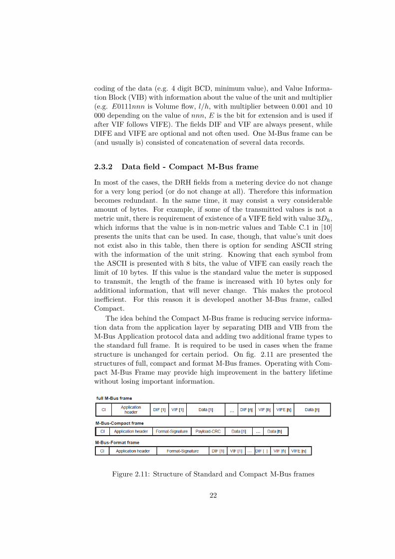
The idea behind the Compact M-Bus frame is reducing service informa-tion data from the application layer by separating DIB and VIB from theM-Bus Application protocol data and adding two additional frame types tothe standard full frame. It is required to be used in cases when the framestructure is unchanged for certain period. On fig. 2.11 are presented thestructures of full, compact and format M-Bus frames. Operating with Com-pact M-Bus Frame may provide high improvement in the battery lifetimewithout losing important information.
Figure 2.11: Structure of Standard and Compact M-Bus frames
22

When transmitting a compact frame, the Format-Signature is consistedof 2-byte CRC calculated over the M-Bus Format Frame starting from thefirst DIF until the last DIF/VIF. After that a 2-byte Payload-CRC, calcu-lated over the data of the standard M-Bus frame starting from the firstDIF until the last Data block. After the Payload-CRC follows a con-catenation of all the data in the frame. It is recommended a full M-Bus frame to be transmitted after certain interval, even if the format ofthe frame does not change. Both fields - Format-Signature and Payload-CRC, are calculated over the polynomial, which is used for the other CRCs(x16 + x13 + x12 + x11 + x10 + x8 + x6 + x5 + x2 + 1 with initial value 0)
The Format Frame is used when the receiver requires information aboutthe DRH. In this case it is transmitted either a full M-Bus and the informa-tion is gathered from there, or a Format Frame is transmitted.
2.3.3 Encryption
Wireless M-Bus has option for 2 types of encryption - DES and AES-128in different modes and starts right after the configuration word. In orderto verify the correctness of the decryption, it should start with a knownsequence. For the DES modes it is required that the data sequence shouldstart with data point containing “date and time” (2 bytes). For AES it is awell known sequence - 2 bytes of 2Fh.
Due to the mathematical nature of the encryption methods, the numberof encrypted bytes should be multiple of 8 for DES and multiple of 16 forAES-128. In the cases where these requirements are not fulfilled, to the datahas to be added padding “dummy” bytes until data (mod a) = 0 (a = 8 or16, depending on the encryption).
It is also possible to have partial encryption. In these cases the encrypteddata is followed by unencrypted one.
23
Chapter 3
Analysis
Once installed, the water meter becomes static. Other words, its locationwill not change in time and in most of its lifetime will transmit the same typeof data. This gives certain flexibility for reducing the sent information andrecover it based on indirect clues and a priori data taken from a database.Some examples for such a reduction are:
• Removing part of the identification number of the water meter;
• Giving a new, smaller, ID to the meter based on the area where it islocated;
• Removing the DRH from the Data fields
• Removing some of the most significant bytes from the water consump-tion values. For example, if a water meter sends it’s information onceper minute, it is not necessary to send value for the current consump-tion 87654415 liters. It may be enough to send “415” and based onthe ID and some data stored in a database, the collector will processthe rest of the information.
• Sending information only for the change in the water consumptionbetween the current and the previous transmission
The reading methods that are of particular interest for the scope of theproject are “Drive-by” and “Fixed Network” due to the fact that currentlythey are the most commonly used methods for remote reading of watermeters. So, the possible receivers can be:
1. in a vehicle for “Drive-by” data collecting;
2. a stand alone collector, located somewhere in the coverage of the trans-mitting meter, owned by the water-providing company (or other insti-tution) used as part of a fixed network;
24

3. a stand alone collector, located in user’s home for collecting the datafrom all the meters in his/hers home/office/etc;
4. a portable device, owned by the user of the water meter (for exampleUSB stick for his/hers PC);
It should be considered that several different receivers (from the ex-plained above) might be connected to one water meter. For example, thewater providing company’s reading method for certain area is “Drive-by”and in the same time the owners of one of the homes are equipped withsmart meter data collector (fig. 3.1). This leads to the need the protocol tobe such that gives the possibility all the receivers to be able to reproducethe data. For example:
• the meter sends message “I am alive, and there is no change/the changeis X liters” - it will be suitable for fixed networks, but if the vehiclereceive such information, it will not be possible to decode the value ofthe meter
• in a fixed network, established by the water provider company, may berequired receiving of data 1 − 2 times per day. On the other hand, ifthe owner has a “smart” home system and requires real time data fromthe water meter, getting the information so rarely is not acceptable.
Figure 3.1: Scenario for use of XLP
As water meter, the device is not taking care of automation and control,but only of measuring. For this, it is acceptable if the meter has only one-waycommunication. The two way communication could be, if it is necessary, for
25

service (protocol updates, commands) or to shorten the transmission withthe idea not to pollute the ether/to preserve energy (if the data is too much,it is useless to send the data if there is nobody, who is capable of receivingit).
Establishing of fixed network and implementation of AMI is promisingand probably will be part of every city in the future. Though, time willpass before it is implemented everywhere, since it requires a lot of resourcesand regulations. Furthermore, not many homes are equipped with M-Businfrastructures. For this reason one of the most frequently used methods forreading water meters is “Drive-by”.
3.1 “Drive-by” meter readingThe general approach for “Drive-by” reading (which is also suggested in[11]) is using T- or C-mode where the transmission is very short and in afew seconds interval. Furthermore, C-mode has the option of using FrameFormat B which has reduced CRC bytes and also, as mentioned before,is developed on the base of T-mode but with higher bit rate due to thedifferent encoding. In addition, the frequent transmissions will allow a userwith installed data collector (static or portable) to have almost real-timeinformation about his/hers consumption.
Since the other parameters for these modes are the same, both can bereceived by the same receiver configuration (see below). After some discus-sions with Rasmus Jacobsen (see the Acknowledgements), it was concludedthat currently, most of the companies who use Wireless M-Bus in their smartwater meters which are suitable for “drive-by” reading, develop their appli-cations on the base of C-mode. One example can be seen in [7] - a datasheet of a water meter with wM-Bus communication, operating in C-mode,which transmits data package every 16th second. In its entire lifetime thismeter sends wM-Bus frames with the following pattern: 7 M-Bus Compactframes, 1 full M-Bus frame. Regarding the life time, we read the following:
• 12-year battery - 3.65 VDC, 2 A cells lithium
• 16-year battery - 3.65 VDC, 1 C cell lithium
3.2 Project StatementThe goal of the project is investigating ways for creating an eXtreme LowPower (XLP) protocol, based on reduction of Wireless M-Bus standard data-gram. A requirement is that once the information reach the desired destina-tion, to be possible to be recreated into a functional Wireless M-Bus messagefor further exploitation (for reference see fig. 1.6). For this reason it is ex-amined the wM-Bus standard and the ways the data is created. Further
26

requirement is the same electronic equipment to be used also for the other868MHz wM-Bus modes (see section 2.1). For this reason, the Physicallayer will not be taken under consideration. Therefore, the investigationsare focused on Data link and Application layers. Since the XLP concept isbased on reducing redundant data, it will be investigated also the requiredtype of data in the database necessary for recovering the wM-Bus datagram.Physical limitations in the receiver’s side, like size, available memory, powerconstrains, etc. are not taken under consideration either. To ease the in-vestigation, it will be assumed that only water meters operate with XLP.The protocol has to be suitable for “drive-by” reading. The water meterpresented in [7] and its data are used as reference. The calculations for theradio module are based on Texas Instrument’s CC1121 - High PerformanceLow Power RF Transceiver [14], operating on 868MHz with output power10dBm.
27

Chapter 4
Design Considerations
4.1 Cyclic Redundancy Check
The cyclic redundancy check (CRC) is a method for detecting errors thathave occurred during the transmission. It is based on division of two poly-nomials in GF(2). It is implemented by adding redundant information,called checksum in the end of each transmitted frame. The content ofthese checksum bits is dependent on the message that is supposed to betransmitted and on a generating polynomial G(x) (For wM-Bus G(x) =x16 + x13 + x12 + x11 + x10 + x8 + x6 + x5 + x2 + 1). The message can beobserved as a big binary number mnmn−1mn−2 · · ·m2m1m0.
The algorithm for creating CRC checksum is as follows:
1. The binary number’s polynomial is M(x) = mnxn + mn−1x
n−1 +mn−2x
n−2 + · · ·+m2x2 +m1x
1 +m0.
2. Multiply M(x) with xk, where k is the degree of the generator poly-nomial G(x).
3. Compute xkM(x) (mod G(x)) = R(x), where R(x) is the remainder.
4. The message that will be transmitted in this case is T (x) = xkM(x)+R(x)
On the other side, when the message T (x) is received, the same operationwith the same generating polynomial G(x) is performed. If the result ofthe calculation T (x) (mod G(x)) = 0, then the message is assumed to becorrect.
In case an error occur in the message, it can be presented as a polynomialE(x) with different degree and terms, depending on the position and thenumber or alternated bits. In this case the received message is T ′(x) =T (x) + E(x). Since T (x) (mod G(x)) = 0, the remainder R(x) can beobserved as R(x) = E(x) (mod G(x)). If R(x) 6= 0, then an error is detected
28

and the message is discarded. This means that the errors that have occurredduring the transmission such that E(x) is multiple of G(x), will not bedetected.
The Cyclic Redundancy Check is reliable method and if the generatingpolynomial G(x) is chosen properly, it is capable of detecting errors like:
• if G(x) has at least two terms (G(x) 6= xi, ∀i), can detect every 1 bit,2 bit and 2 adjacent bit errors
• if G(x) is a multiple of (x+ 1), any odd number of errors
• burst errors with length equal or less then the degree of G(x)
• for burst error of length k + 1, the chance of not detecting an error is(1/2)k−1
4.1.1 Number of undetected errors
Let’s observe the sent message
T (x) = xkM(x) +R(x), (4.1)
where M(x) is the actual message with degree i and R(x) is the checksumwith degree less than k. Then
deg(T (x)) = deg(xkM(x)) = k + i, (4.2)
and since deg(R(x)) < k + i, the deg(T (x)) = k + i. From this, the degreeof the received message T ′(x) is also k + i, so deg(E(x)) ≤ k + i. We knowthat we have an error if G(x) does not divide E(x). But in the cases whereG(x) divide E(x), we are not able to detect the error.
Let’s assume that G(x)|E(x), then there exist a polynomial Q(x) suchthat
E(x) = Q(x)G(x) (4.3)
The degree of Q(x) is then given by
deg(Q(x)) = deg(E(x))− deg(G(x)) ≤ k + i− k = i. (4.4)
So there exist Q(x) = 2i+1 different polynomials which will give the resultE(x) (mod G(x)) = 0 and from this, 2i + 1 different messages T ′(x) whichgive T ′(x) (mod G(x)) = 0.
Considering that the length of the message T (x) = i+ 1 + k bits, whichgives 2i+1+k different messages, then it can be denoted that a CRC with apolynomial with degree k can detect
1− 2i+1
2i+1+k − 1 = 1− 12k − 1 . (4.5)
29
of the error cases.With respect to the wM-Bus polynomial, this is (1 − 1
216−1 = 99.998%of the errors.
4.1.2 Format Signature and CRC
As discussed in section 2.3.2, since the information in the Data RecordHeader (DRH) is considered as redundant, a Format Signature is computedover all DRHs in in the same way the CRC is calculated and with the samegenerating polynomial G(x). So, the compact frame contains this CRCin the form of Format Signature instead of all DRHs. But applying thisapproach, as was shown previously in this section, there is certain chancethat different combinations in the DRHmay give the same Format Signature,which will lead to a problem regarding the decoding of the received messagefrom the receiver.
If the concatenation of all the DRHs in one wM-Bus frame is observedas a message M(x) with degree i, and a Format Signature in the form ofCRC is calculated over it. Let’s denote a presence of error E(x), whichis actually the presence of a DRH with other values. In this case thedeg(E(x)) ≤ deg(M(x)) ≤ i. Therefore the coefficient polynomial Q((x)),based on equation 4.4 can be denoted that
deg(Q(x)) = deg(E(x))− deg(G(x)) = i− k, (4.6)
therefore 2i−k+1 different possible options for DRH, which will provide thesame Frame Signature. For example, if the concatenation of all DRHs in awM-Bus frame is B = 10 bytes (80 bits => deg(B(x)) = i = 79), knowingthat the FS is 2 bytes (16 bits), calculated with generating polynomial G(x),where degG(x) = k = 16, it leads that depending on the values in theDRHs, the number of words that will have the same FS is B = 279−16+1 =264. Despite the fact that the number of combinations that will give thesame Format Signature (FS) is 2i−k+1
2i+1 = 12k = 1
216 = 0.0015% of all thepossible combinations, this is quite large number and that might lead tocomplications when messages with different data structures calculate andsend the same FS.
A CRC with the right polynomial is very good for detecting errors whichcan occur in a communication channel during the transmission, due to burstsor electrical spikes. In the cases, though, where the data can be completelydifferent from the beginning to the end, is not that efficient.
4.2 Number of meters in receiver’s range
The number of meters in the receiver’s range depend on number of param-eters such as:
30
• Transmitter’s antenna, output power and position
• Receiver’s antenna and its location
• Presence of obstacles between the communicating devices
• The size and nature of these obstacles (concrete wall, metal wall, trees,etc.)
4.2.1 Coverage area
According to Friis transmission equation, the input power of the receivingantenna PRX in terms of decibels (dBm) is
PRX = PT X +GT X +GRX − Loss− 20 log10(4πdλ
) (4.7)
where
PRX - Input power of the receiving antenna
PT X - Output power to the transmitting antenna
GT X - Gain of the transmitter antenna
GRX - Gain of the receiver antenna
Loss - Losses (due to antenna mismatches, polarization, reflection, fading,environmental conditions, etc.)
λ - wavelength of the carrier signal (λ = cFc, where c is the speed of light
and Fc is the carrier frequency)
d - distance between the two communicating devices
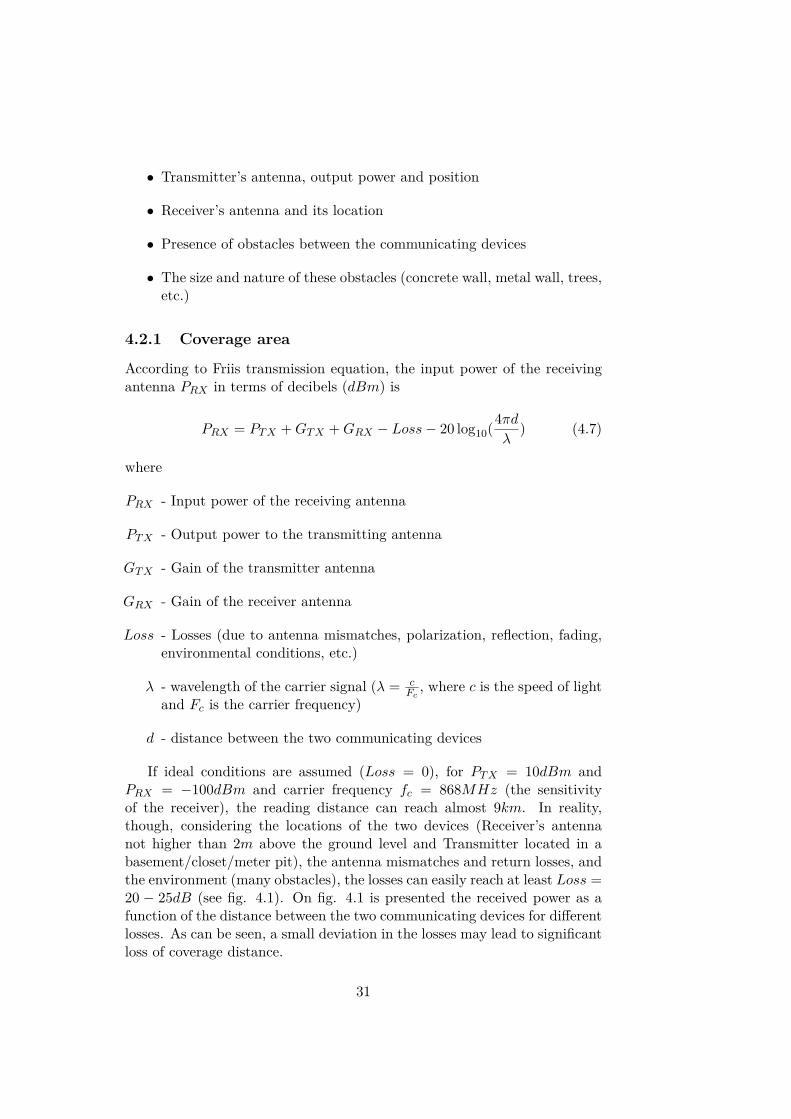
If ideal conditions are assumed (Loss = 0), for PT X = 10dBm andPRX = −100dBm and carrier frequency fc = 868MHz (the sensitivityof the receiver), the reading distance can reach almost 9km. In reality,though, considering the locations of the two devices (Receiver’s antennanot higher than 2m above the ground level and Transmitter located in abasement/closet/meter pit), the antenna mismatches and return losses, andthe environment (many obstacles), the losses can easily reach at least Loss =20 − 25dB (see fig. 4.1). On fig. 4.1 is presented the received power as afunction of the distance between the two communicating devices for differentlosses. As can be seen, a small deviation in the losses may lead to significantloss of coverage distance.
31

0 1000 2000 3000 4000 5000 6000 7000 8000 9000 10000−140
−120
−100
−80
−60
−40
−20
8731 m
Distance x [m]
Rec
eive
d po
wer
[dB
m]
874 m
489 m
Received Power (Loss=0dB)Received Power (Loss=20dB)Received Power (Loss=25dB)Sensitivity level
Figure 4.1: Received power as a function of the distance between two com-municatin devices
4.2.2 Water meter density
On table 4.1 is presented the population density per km2 for some of themost populated cities in Europe. According to this source, the most densepopulated city in the world is Mumbai with 29650ppl/km2.
It should be considered that in some areas of those cities the populationdensity is much higher than in other areas. Also should be noted that usuallyfor several people is counted one meter (since in one home usually live 2,3and more people, using one water meter). For this reason an assumption of≈ 10000 water meters per km2 is considered as relatively acceptable.
Assuming the range of the receiver is d ≈ 560m, then the coveragearea is S = πd2 ≈ 1km2, therefore in the coverage of the receiver can beexpected up to 10000 water meters. This value is highly overrated, due tothe fact that this coverage range could be reached in rural areas, where notmany obstacles are between the transmitter and the receiver. The higherthe density of meters is, the more obstacles are in the area (e.g. buildings).Considering that the high frequencies have very low wall penetration, thecommunication range will be reduced rapidly.
32

country population density (ppl/km2)St. Petersburg 8550
Istanbul 7700Athens 5400Madrid 5200London 5100Munich 3100
Stockholm 2700Rotterdam 2500Copenhagen 1850
Table 4.1: Population density, people per square kilometer, for some of themost populated cities in Europe (source: http://www.citymayors.com/)
4.3 Data from the meter
The reference water meter used in this project - Kamstrup’s Multical 21 [7]transmits the following information:
• Current meter reading
• Meter reading on the first day of this month. Alternatively, max. flowduring latest completed month
• Operational Hour counter
• List of active info codes
• List of info codes which have been active within the latest 30 days(and how long they have been active).
On fig. 4.2 are presented device’s display and list of info codes. As can beseen, the information about the water consumption is presented with 8 digitsand shows information down to liters. The indicators under the digits arethe info codes. With respect to the transmission, these codes are presentedas a bitmask (active/no active). Due to the fact that further informationwas not provided regarding these info codes, it is assumed that the metertransmits one byte for the currently active codes and one byte for the onesactive in the past 30 days. The information about the time the info codeshave been active, according to [7], is hourly rounded. This means that thevalue is maximum 31 · 24 = 744 hours.
Since the exact information that Miitor’s meters will transmit is notdefined yet, for the purpose of this project it will be assumed they transmitthe same information.
33

Figure 4.2: Display and Info codes for Multical 21 [7]
4.3.1 BCD or Binary
Whether the meters transmit their values in BCD (Binary Coded Decimal)or binary format, it is defined in the DIF field of every data block. Tak-ing again for example the meter from [7], its value is from 00000000dec to99999999dec (108) liters. If decoded as BCD, the value should be sent with8 · 4 = 32 bits, where every digit is presented with a 4-bit binary number.In the same time, 99999999dec = 101111101011110000011111111bin, whichis a 27-bit binary number. Though, with respect to the transmission, thevalue has to be transmitted as a byte sequence with LSB first, so the valuewill be presented as a 4-byte (32-bit) number, where the 5 MSBs are 0 . Inthis case, with respect to the transmission time, there is no difference if thevalue is BCD or binary presented.
Regarding the time the codes have been active, the information shouldbe transmitted with 2 bytes and again does not matter whether it is in BCDor binary format. Though, since the value cannot exceed 744, an option isto “merge” values, in case that more codes have been active. Since it isrequired max 12 bits for each value, 2 timing values could be written in 3bytes.
34

A concept for saving power by reducing the transmission time leads toidea not to transmit information, contained in the most significant digitsof the transmitted data. For this reason, let’s observe the value field. Ifremoving the two MSBytes, the meter will transmit information for up to9999 liters if BCD and up to 65 535 liters if binary. This is 6.5 timesmore information within the same transmission time. For this reason, it isbetter at least the values for the consumption (historic and current) to betransmitted in binary format.
4.3.2 Water consumption
On fig. 4.3 is presented the annual water consumption per person for year2000 in several countries. As can be seen, USA are leaders in this chart with1682m3 per capita. This is about 100m3 per month. It has to be notedthat this chart considers also the water used by the industry. According tothis source of the chart (www.conferenceboard.ca), the people in Canada intheir home use about 300 liters per day. Therefore, for an average household, the monthly increase of the water meter value can be approximated to45m3 (assuming 5-member family). In the same time the industry uses “68per cent of the total water used in Canada”. This makes 85m3 per capitaper month in Canada.
Figure 4.3: Annual Water Consumption per capita [m3] (source:http://www.conferenceboard.ca/)
Taking under consideration all these values, it is assumed that for onemonth the water consumption detected by a single water meter will notexceed 1000m3 and this value will be considered as a limit for this project.This will allow the results from this project to be applicable for water meterused in house holds and industries with monthly water consumption up tothis level. In cases where this consumption is higher, additional investigationshould be provided. Another investigated limit will be 100m3 for domesticwater meters.
35

Chapter 5
XLP
The structure of the XLP protocol is meant to save energy on the meterside. Since in most of the cases the meter transmits a regular message withdata for its values, it is of interest the XLP to take over when such messageis about to be transmitted and reduce it as much as possible. Limited op-eration options will provide the possibility of reduction of the transmittedpackage even deeper by removing some of the control bytes that are neces-sary for proper interpretation of the received data. The principle of creatingan XLP should be in a sense the same as the creating of Compact M-BusFrame. For this reason a regular wM-Bus message has to be prepared fromthe microprocessor unit of the meter device. The transition wM-Bus-to-XLP should be implemented on top. This will provide more flexibility ofthe devices (despite the fact that the MCU has to perform several moreoperations).
For a wM-Bus, the content of the frame is interpreted by reading theC−field from the Data Link Layer and the CI−field from the ApplicationLayer. Since the idea is the XLP to be active only under standard conditions- broadcasting of normal values with no priority, it should activate only ifthe content of C-field is 44h (SND-NR, message from a primary source) andthe content of the CI-field is “Response from a device” - 78h, 79h, 69h,7Ah, 7Bh, 6Ah, 72, 73 or 6B (full, compact and format frame formats withno-, short- and long application headers respectively). In cases where anextraordinary message, such as alert, is supposed to be transmitted or a2-way communication is initiated, the transition wM-Bus-to-XLP shouldnot be established.
5.1 Preamble and mode distinguishing
Whether it is T-mode or C-mode, the receiver distinguishes when the pream-ble (which also contains the synchword) is received. In table 5.1 are pre-sented the preamble blocks for the two modes. As can be seen, C-mode’s
36

first 6 bytes are the same as T-mode’s and after that is followed by two ad-ditional bytes which define the C-mode and the frame used format (C(A) orC(B)). The receiver can clearly recognize that this is C-mode synchword, butnot data from T-mode since in the specified wireless M-Bus’ 3−out−of −6encoding there is no combination 010101 (see Appendix A). The last 8 bitsdefine the frame format (11001101 for format A and 00111101 for format B)
mode preamble chip sequence encodingT1 19*(01) 0000111101 3-out-of-6
C1(A) 19*(01) 0000111101 01010100 11001101 NRZC1(B) 19*(01) 0000111101 01010100 00111101 NRZ
Table 5.1: Preambles for T- and C-modes
The 3 − to − 6 encoding (or 3 − out − of − 6) is a modification of m −of − n code, where n−bit word contains m instances of a “one”. For the3− out− of − 6 code the transmitted words are 6−bit consisting 3 1’s and3 0’s. This allows (
63
)= 6!
3!(6− 3)! = 20 (5.1)
different combinations. Considering that the wireless M-Bus protocol in-formation is presented as hexadecimal numbers, this encoding uses 16 ofthe 20 different bit sequences. In appendix A is presented a table with the3-out-of-6 encoded numbers in T-mode. Starting from 0dec (0000bin) andfinishing with 15dec (1111bin = Fh), all the 16 numbers are presented with6 bits. This leads to four sequences that are available and not used in theT-mode. One of them (010101) is used for defining the C-mode. The otherthree are free. It can be easily implemented one of the residual three com-binations (for example 101010), followed by 2 additional bits, to be used fordefining the XLP protocol. Since the idea behind the protocol is to be asshort as possible, different data formats will not be used, which leads to thepossibility of removing the final 8th byte of the C-mode preamble. In thiscase the preamble for XLP will be defined as:
19*(01) 0000111101 101010XX, where the first 6 bytes are like T-mode’s, and the 7th byte defines that the information is in XLP format.
With such a created preamble, it gives the opportunity of having thesame radio equipment for different implementations and flexible solutionswith switching between the different modes.
5.2 XLP and Data reductionThe data reduction can be established in both, Data link and Applicationlayers. In this section is given short overview and observation about thesepossibilities.
37

5.2.1 Frame Format
Wireless M-Bus suggests two frame formats - A and B. Depending on whichone is used a number of CRC bytes can be reduced. Though, with increasingthe amount of data covered by a single CRC check, the chance for undetectederrors rises.
5.2.2 C-field
Since the previously defined standard conditions are based on C-field = 44h,and the presence of XLP is already recognized in the preamble, this bytecan be removed from the XLP datagram.
5.2.3 Meter ID
The meter ID is 8 bytes, where 2 bytes are manufacturer, 4 bytes are address,1 byte is version and 1 byte is type. According to [10], if MSB of themanufacturer’s field is 1, then the A-field can be “soft” address and as longas there is unique address for each meter in the coverage area, the rest ofthe bits can be used for user specific purposes. According to section 4.2.2,the water meters in an area covered by a receiver are no more than 10 000.For this reason if it is transmitted only 2 bytes of information, it will besufficient to provide unique ID for every meter in the coverage area of thereceiver (216 = 65536 unique IDs). On the other hand, if 2 or more metershave the same ID and all the meters are in the receiver’s database, basedon different criteria, it can be denoted which one is the transmitting one.This may provide the opportunity of transmitting only 1 byte of the Addressfield. Such criteria can be:
• the current location of the vehicle (for “drive-by” readout),
• the RSSI from the receiver
• the data content of the meter. (e.g. if the water meter sends informa-tion about its current value, it should be incremental, so based on thelast record, if the data is with lower value, then this is not the meterthat is currently read)
• after implementing a CRC-payload check the values should match.
5.2.4 CI-field
The CI field, as mentioned before, shows the type of the data that will followafter. If the XLP is only for one strict data type, e.g. “M-Bus Responsefrom device with short header” (7A), then the CI field also can be excludedfrom the datagram of the XLP.
38
5.2.5 Data Header
• Long Data Header - Considering that the meters will be with build-intransmitter, the long header will be discarded and not investigated.
• Short Data Header - The Status and Access Number bytes are not ofparticular importance and can be skipped and wM −Bus− to−XLPtransition to be applied when the value of the Status Field is 00h (noerrors), but the configuration bytes take care of the encryption andfor wireless transmission it is mandatory to have certain protection.Though, the incrementation of the access number might be used fordetecting malicious intervention. Since on every next transmission itshould be incremented with a specific number, if an extra radio deviceis used to send the same data all the time in order to hide the value ofthe meter, it can be detected. The Access Number is also used as partof the initialization vector for one of the AES-128 encryption modes.Furthermore, in the status byte there is a lot of information that canbe found helpful, plus there are 3 specific to manufacturer bits thatcan be used to support the XLP datagram.
• No Data Header - The shortest possible option. Though, this meansthat there is no information about the Access Number, Status andworst of all, no encryption of the data.
5.2.6 Data fields
With respect to reducing the redundant data in the telegram, the CompactM-Bus frame presents very optimal solution. All the Data Record Headers(DRH) are removed and instead of transmitting them, a calculated formatsignature is transmitted. When received, the receiver checks in its databaseif the received Format Signature (FS) is available and makes the decodingof the data based on it. In this case, the second CRC (Payload-CRC) is alsorequired, since it is calculated over the whole M-Bus data block and givesinformation about the correctness of the assumed data. On the other hand,depending on the type of blocks “Data 1 · · · Data n” some of the mostsignificant bytes (MSByte) may be possible to be reduced if they do notchange often. The reproduction of the reduced data could be accomplishedwith the help of proper database with historical values for this data and theCRC-payload.
5.2.7 Format Signature
As it was discussed in section 4.1.2, an automatically CRC generated FormatSignature may lead to some complications if two different DRHs give thesame CRC result. Furthermore, it 2 bytes. On the other hand, in the Status
39

byte of the header (STS), there are 3 bits for manufacturer specific use. Oneof them (e.g. STS[5]) can be used as a flag for “default” Data Field, whichcan allow the reduction of FS. In case that one meter transmits XLP frameswith different types of data, it could be implemented a table with all thepossible data structures that it may possibly transmit. Such, 1 byte will givethe opportunity of having 256 different data structures, which are enough.
5.2.8 XLP - final look
Based on the previous discussions in this section, a proposal for an XLPframe content is:
• 1 byte length information
• 2 bytes address
• 6 bytes short header (including two 2Fh bytes for AES-128 or twobytes with date information for DES encryption)
• 1 Format Signature word (optional)
• 2 bytes CRC-Payload
• n bytes data
For standard conditions are considered C = 44h and CI = 7Ah. The valueof n depends on the amount of data that has to be sent. Refering to themeter from [7], as it was discussed in 4.3, the data that is supposed to betransmitted most of the times will be 4 bytes for current value and 4 bytesfor a historical value (if no reduction is implemented there). Including alsothe info codes (which are not present always), the number of bytes may reachmaximum 20 bytes. In this case, the worst case scenario for a XLP frametransmission is 32 bytes. For this reason, Frame Format B is considered asreasonable solution.
Such encoded, the XLP frame is not compatible with the standard wM-Bus receivers. Though, due to the nature of the frame, receivers created forXLP will be able to read also standard wM-Bus messages. For the sake ofcompatibility and to ensure the possibility the reader to “learn” quick, it ispreferable if the meters send a regular wM-Bus message once in a while (asis suggested also for the Compact M-Bus frame).
On fig. 5.1 is presented the algorithm for deciding whether XLP frame tobe created or not. A regular wM-Bus message is created and in case that therequirements for standard message are fulfilled (C = 44h and CI = 7Ah),and a standard wM-Bus message has been transmitted soon (Count < 7),an XLP will be created.
40

create basic.jpg
Figure 5.1: Algoritm for deciding wheter to create XLP frame
5.3 XLP message encoding
On figure 5.2 is presented algorithm for creating (encoding) a XLP message.It starts after the standard conditions are true (see fig. 5.1). In case thatthe Data Record Headers for all types of data in the Data Field are thedefault ones, flag is raised (STS[5] = 1, STS is the Status byte from theHeader). Otherwise, a Format Signature is created and STS[5] = 0. CRC-payload is calculated over the Data Field of the regular wM-Bus messageand DRHs are removed. In case that some of the data is supposed to bereduced, the corresponding bytes are removed. Then the new Data Fieldis a concatenation of the CRC-payload, Format signature (if such), and theData values. The Data Field is attached to the rest of the fields, specifiedin 5.2.8 (Length, ID, header). Then the length of the message is calculated(including the 2 bytes CRC and the “dummy” bytes used for fulfilling theencryption requirements) and the result is put in the L-field; a CRC iscalculated over the whole frame and is placed at the end.
41

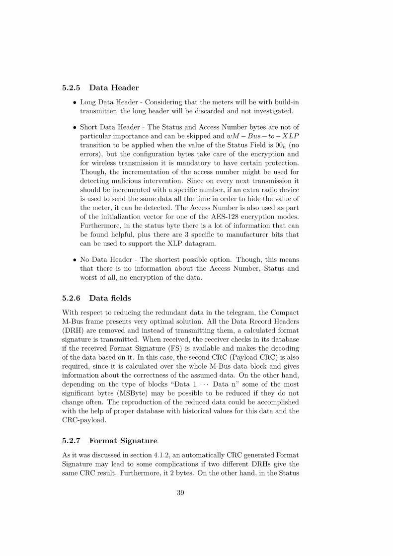
5.4 XLP message decodingThe algorithm for decoding an XLP is separated in 2 parts - identifying theXLP (fig. 5.3) and the actual decoding (fig. 5.4). If the received messagehave the XLP preamble, and the meter is properly identified, the messageis decrypted and the decoding of the XLP starts.
During the decoding (fig. 5.4), the first step is to recover the missingbytes from the Data Link layer. The C-field is filled with 44h, the 8 iden-tification bytes are filled with the original ID of the meter (taken from thedatabase), CI = 7Ah, the Header and the Initialization Vector (2Fh or date)are the same, so they are placed directly. In case SY S[5] = 0 and the Formatsignature is not present in the database, the message is discarded. Other-wise, a new, empty array, is created with the size of the regular wM-Busdata field that is supposed to be recovered (this information is also takenfrom the database). Then, fill the DRH bytes with the corresponding val-ues, fill the bytes for which is available information from the XLP messageand the rest of the bytes fill with the data stored in the database. A CRCis calculated over the restored Data Field and is compared with the CRC-payload, (which is part of the XLP message). In case they don’t match, thebytes, taken from the database are incremented one by one until the twoCRCs match. In this moment the message is considered as decoded and allthe necessary data for creating a standard wM-Bus message are available.Then this data is processed according to the specification of the receiver.
42

create2.jpg
Figure 5.2: Algorithm for creating XLP message43
Decode basic.jpg
Figure 5.3: Identifying the XLP message
44

decode.jpg
Figure 5.4: Decoding the XLP message
45

Chapter 6
Tests and results
It was performed simulation test in order to investigate the possible reduc-tion of the Data field bytes. It is assumed that water meter from some“dummy” manufacturer and with “dummy” address transmits informationfor “normal” conditions (C−field = 44h, CI = 7Ah), the info codes have 0h
values (so, information about the active hours is not transmitted), and op-erating hours are not transmitted. It is assumed that the meter is correctlyidentified, the information is properly decrypted and there are no errors dueto noise in the communication channel (message is received correct). Theother assumption is that the transmitted values are:
• Data1 - Current Value of the meter
• Data2 - Value for the first measurement of the month
and are presented as 4-byte binary numbers.The DIF and V IF values are assumed to be as follows:
• Current Value: DIF1 = 04h (32-bit binary number), V IF1 = 13h
(Volume in liters down to 1 liter)
• Value for the first time of the month: DIF2 = 44h (32-bit binarynumber, historical value), V IF2 = 13h (Volume in liters down to 1liter).
Simulations for different transmissions are made, but the change of thesevalues are not taken under consideration due to the reason that they are notobject of investigation. It should be noted that their size will not change forthe different data types used in the simulations.
In the simulations is not taken under consideration also the case whenthe value shown by the water meter reach its maximum value and start from0 again.
It is important to be noted that the algorithm is created based onvalues calculated in a time line as follows: Database record - Data2 - Data1(see fig. 6.1) and will not work for other cases!
46

Figure 6.1: Time line of the measured values
In the simulations are considered 4 major different cases. As it was dis-cussed in section 4.3.2, the average monthly water consumption in a regularhousehold is 45m3, and it was assumed that the value of 1000m3 is sufficientalso for industry purposes. Regarding the data that should be transmittedfrom the water meter, the traditional water meters measure down to 1m3
and the one observed in this project [7] gives information down to 1 liter.For this reason, the observed cases are:
• Maximum water consumption - 1000m3, resolution - 1 liter
• Maximum water consumption - 100m3, resolution - 1 liter
• Maximum water consumption - 1000m3, resolution - 1m3
• Maximum water consumption - 100m3, resolution - 1m3
For each case is made observation for the number of properly reproduceddata values for different reductions of Data1 and Data2.
In the end is made a comparison between a standard wM-Bus frame,Compact frame and XLP frame for the same “default” message.
6.1 Architecture of the simulation engineOn fig. 6.2 is presented the architecture of the simulation engine used inthis work. For its creation was used the programming language C#.
In object Meter is created the meter data using the following steps:
1. It is created a DataField, in the form of M-Bus message, with randomvalue between 0 and 97 999 999 (volume in liters) or 97 999 (volumein m3). This is used to simulate a value from the last reading in theDatabase of receiver Rx.
2. The value Data2 = DataField + Random - random incrementationwith value between 0 and 1 000 000 for liters (or 1000 for m3)
3. Data1 = Data2 + Random - another random incrementation in thesame range as the incrementation of Data2.
4. A standard Data Field of a M-Bus message is created with structureshown on fig. 6.3
47

Figure 6.2: Architecture of the simulation setting
5. A CRC is calculated over this message in object CRC
6. An encoded (XLP) message is created by removing some of the mostsignificant bytes (MSBytes) from the standard message and a CRCpayload is attached to the beginning of the message (fig. 6.3)
Figure 6.3: Standard and XLP messages created in the simulation
The meter sends both Standard and XLP messages to the receiver Rx.In the receiver the XLP is decoded with the following algorithm:
• An empty array with 12 bytes is created
• In bytes 1, 2, 6 and 7 are placed the DIF and VIF values
• The data from the transmitted XLP message is placed in the corre-sponding fields1 and the rest of the data is taken from the database(see fig. 6.4).
1Note that the receiver should be aware with the number of removed bytes from eachdata (in this case Data1 and Data2)
48
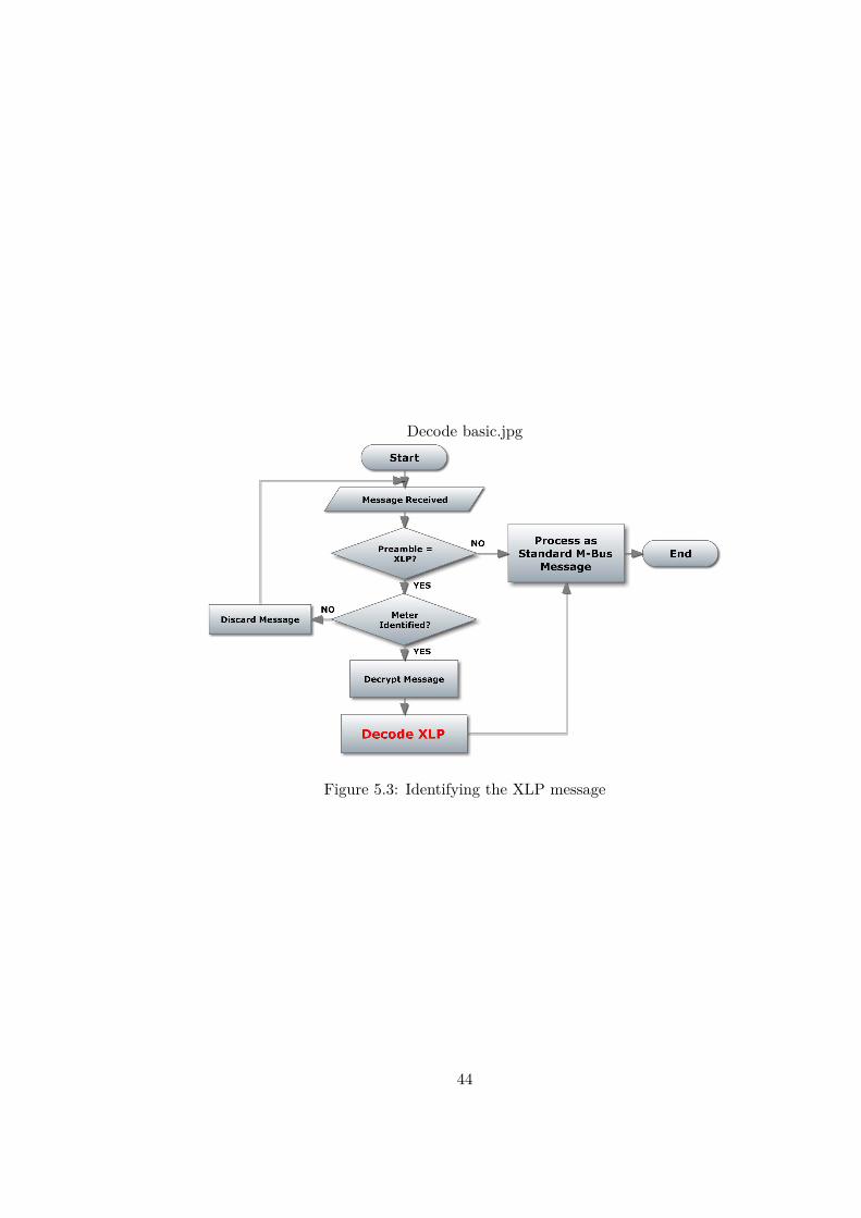
• After the frame is filled with data, a CRC is calculated and is comparedwith the CRC-payload, which is sent with the XLP.
– If they are equal, the message is considered as decoded– If not, it is performed incrementation of the bytes taken from the
database. After each incrementation a new CRC is calculatedand compared with the CRC-payload until a match occur.
Figure 6.4: Decoding the XLP message
The incrementation of the bytes, taken from the data base is different,depending on the reduced from the original message bytes. It considers twocases of data reduction - equally removed amount of bytes from each data(Data1 and Data2), and case when from Data2 is removed 1 byte more thanfrom Data1. The incrementation is implemented in a way to save computingpower and improve accuracy. It is based on the fact that Data2 can neverexceed Data1.
• when equal bytes are removed: increment Data1 with i = from 0to 1FFFFF with step 1 and for each incrementation, check all thepossible options for incrementation of Data2 from 0 to i. The value1FFFFF is chosen high enough, so the incrementation will reach thelimit of the meter value. In reality, this value is never reached, sincematching CRC is found much before i = 1FFFFF .
• when Data2 has 1 transmitted byte less than Data1: in this caseData2 has one LSByte more taken from the database, so incrementa-tion of this byte has to be performed, too. For this reason, in Data2for each i, increment Data2 from 0 to 255 + (i ∗ 256), and after eachincrementation is checked if Data2 > Data1.
After the message is considered as decoded, it is compared with theStandard message that was transmitted in the same time with the XLP. Ifthey are not equal, a counter for the errors increments its value.
49

The whole procedure is repeated number of times (between 1 000 000 and1000), depending on the amount of calculations that have to be performed.The reason some of the tests to be repeated less times then others is based onthe lack of computing power. Furthermore, the big amount of repetitionswas established in the cases when there were no errors detected, or theywere very small amount. In the cases where the errors exceeded 10 − 15%,the data reduction was considered as unappropriate and more then 100 −1000 repetitions were considered as unnecesary. On fig. 6.5 is presented ascreenshot of the GUI implemented for the simulation engine.
Figure 6.5: Screenshot of the simulation tool’s GUI
6.2 ResultsIn this section are presented the observed results for each expected maxi-mum consumption and resolution. In the cases when the amount of wronglydecoded messages became high enough, further data reduction was not per-formed since it is expected that the results will get even worse.
6.2.1 Expected water consumption of maximum 1000m3 andtransmitted information down to 1 liter
Table 6.1 shows the results that were observed for such configuration. Sincethe initial tests showed good performance when 2 bytes of each data wereremoved, it was made a big test to make sure that it works properly. Theresults were satisfying, but for this simulation were needed ≈ 3 hours (laptopwith 4GB RAM and 2.4 GHz Dual core processor)
50

Reduced bytes Compared AverageData1 Data2 Messages Errors Errors[%]
1 1 10 000 0 01 2 10 000 0 02 2 1 000 000 0 02 3 3000 909 30
Table 6.1: Results for max water consumption 1000m3 and resolution 1 liter
Reduced bytes Compared AverageData1 Data2 Messages Errors Errors[%]
2 2 10 000 0 02 3 10 000 0 03 3 100 000 0 03 4 30 000 230 0.84 4 100 93 93
Table 6.2: Results for max water consumption 1000m3 and resolution 1m3
6.2.2 Expected water consumption of maximum 1000m3 andtransmitted information down to 1m3
In table 6.2 are presented the results for max consumption of 1000m3 andresolution down to 1m3. Again the most tests were performed in the casewith maximum reduction and no errors. On the other hand, a relativelygood result was observed when Data2 was not transmitted at all, but was“guessed” by the algorithm (less than 1%). The final test was made justfrom curiousity.
6.2.3 Expected water consumption of maximum 100m3 andtransmitted information down to 1 liter
In table 6.3 are presented the results when max consumption is 100m3 andthe resolution is down to 1 liter. This was the test with the highest jump inthe errors after reduction of only 1 byte. This shows that the LSBytes arecrucial when the resolution is big.
6.2.4 Expected water consumption of maximum 100m3 andtransmitted information down to 1m3
Since the tests in the expected consumption of 1000m3 for resolution of1m3 showed that it is enough to transmit only one byte of each value, soit was expected that for 100m3 will give the same result. For this reasonit was tested the option with total brute force and trying to recover the
51

Reduced bytes Compared AverageData1 Data2 Messages Errors Errors[%]
2 2 100 000 0 02 3 100 000 0 03 3 250 151 60
Table 6.3: Results for max water consumption 100m3 and resolution 1mliter
Reduced bytes Compared AverageData1 Data2 Messages Errors Errors[%]
3 3 100 000 0 03 4 100 000 0 04 4 10 000 292 2.9
Table 6.4: Results for max water consumption 100m3 and resolution 1m3
message if only the CRC-payload is transmitted. The results (table 6.4)were surprisingly good.
6.3 Current consumption and Throughput
The reduction of the frame size is expected to improve the throughput prob-ability and to reduce the current consumption. Let’s assume that a messagewith the same data from the same meter is transmitted as XLP, CompactM-Bus and Standard M-Bus messages. The content of the data is the sameas observed so far - current value, historical value, info codes. It is assumedthat there is only current active codes, and no active ones in the past 30days. On fig. 6.6 are presented the different frames and their lengths foreach type (the preambles of the messages are also presented, since XLPreduces information also there). The investigated Frame Format is B, sothere is only one CRC in the end of the frame (which is 2 bytes and is notshown on the figure). It should be noted that the encryption requirementfor number of bytes multiple of 8 or 16 is not taken into account.
For the calculations is assumed:
• bit rate Rb = 100kbps, therefore transmission time t = 8·sizeRb (size -
number of bytes in one frame)
• transmission interval T = 15s
• number of meters N = 1000
52

Figure 6.6: The same data presented in the three different frames - StandardM-Bus, Compact M-Bus and XLP
Frame Size Transmission Probability ProbabilityFormat [bytes] time [mS] 1000 meters [%] 10 000 meters [%]
Standard M-Bus 41 3.3 64.6 1.3Compact M-Bus 40 3.2 65.3 1.4
XLP 23 1.8 78.2 8.6
Table 6.5: Probability for throughput for Standard M-Bus, Compact M-Busand XLP messages
6.3.1 Packet Throughput
Every meter transmits periodically every T seconds. The transmission timeis t seconds. To calculate a probability that a certain packet will not collidewith other packets, we need to calculate probability that no other packets aresent by other transmitters t seconds before and t seconds after “our” packettransmission. Therefore, the vulnerable period is 2t seconds. Assuming thatthere are N transmitters and they are independent, this probability will bea product of individual probabilities.
The probability transmitter does not transmit during 2t seconds in aperiod of T seconds is T−2t
T , therefore the probability that a packet will notcollide is:
Psuccess = (1− 2tT
)N−1, (6.1)
whereIn table 6.5 is presented the probability for throughput for each of the
messages for 1000 and 10 000 meters in the coverage area.The results show that if a lot of meters are in the coverage area, the
distribution of the IDs will be the least problem for the designers of thesystem. This proves that transmitting only 2 bytes from the ID is enoughfor the purposes of “drive-by” data collecting. In these cases a drive-bymethod will be inefficient, so it should be searched approach with fixednetwork and transmissions in much bigger intervals.
53

Frame Format Duty cycle % Average consumption [µA]Standard M-Bus 0.022 7.4Compact M-Bus 0.021 7.37 XLP, 1 M-Bus 0.013 4.6
XLP 0.012 4.2
Table 6.6: Duty cycle and average consumption for the different frame for-mats
6.3.2 Current consumption
On fig. 6.7 is presented an estimation of the lifetime of a water meter when issupplied with battery which capacity 2000mAh. The average consumptionof the device without transmitting is considered 6.5µA, in order to fit thevalues such that a meter transmitting compact M-Bus message to reach thelimit after 16 years (which is reasonable, considering that Miitors’ meters areestimated to consume less than 5µA). In these 6.5µA are included the selfconsumption of the meter and self consumption of the RF chip in stand-by(< 1µA). In the simulation is taken also under consideration the fact thatthe transceiver switches from Stand-by to an IDLE mode before switch toTx/Rx modes. The consumption in Idle mode is 1.3mA and the time fortransaction IDLE−Tx is 400µS [14]. On table 6.6 is presented the averageconsumption of a transmitter using the three different frame formats. It isconsidered that it transmits once every 15 seconds
6.4 XLP proposal for Miitors water meter
The results from the simulations showed that brute force based on CRCis relatively powerful tool for proper “guessing” of the unknown informa-tion up to a certain level. The current algorithm proposal is based on theassumption that the monthly water consumption is up to 1000m3 and themeter transmits the values with resolution 1 liter. Thus, the reduction is 2of the MSBytes from each of the two values for the water consumption inorder to assure 100% accuracy. On fig. 6.8 and 6.9 are presented block dia-grams of the algorithms for encoding and decoding such XLP message. Theindexes of DataField[] and XLP [] are exact numbers, calculated for thisalgorithm. It is made this way for two reasons: 1) To give the reader moreacurate picture of how the message is processed byte by byte, and 2) to showthe importance of the requirement that the receiver must know how manybytes are removed and from where. In case of other requirements for thewater meter (regarding monthly consumption and resolution), these indexesshould be changed in order to fullfil the correct structure of the messages.
54

0 5 10 15 20 25 300
500
1000
1500
2000
2500
3000
3500
4000
Years: 17
years
Tot
al C
onsu
mpt
ion
[mA
]
Years: 21
Standard M−BusCompact M−BusXLP7 XLP, 1 StandardBattery charge
Figure 6.7: Average current consumption for the different frame formats
6.4.1 XLP encoding
The algorithm starts right after standard conditions are detected (C = 44h
and CI = 7Ah). First is checked if a default message will be transmitted(Current value, Value for the 1st day of the month and info codes). If so:
• a flag is raised (STS[5] = 1: bit 5 of the Status byte, which is part ofthe header);
• the Data Field is a concatenation of the data for CRC-payload and 2of the LSBytes from each value;
• in case that there is active info code in the moment of the transmission,the byte with current info codes is added to the Data Field.
• in case there have been active info codes in the past 30 days, in orderthe receiver to be able to interpret the message correct, to the DataField are added the byte with these info codes AND the byte withthe current active ones (even if currently there is no active one). Ifthere have been active more than 1 info codes, this data should befilled in order of their active codes, presented in the info code byte(e.g. info30 = 10010000, then the following information is: first
55

info30[0]; then info30[3]). The filling of the info codes should startfrom the MSB, since otherwise, there is option that an info code byteget value 00101111, which is 2Fh and the receiver will interpret thatas a “dummy” byte. For this reason, LSB should be 0 always (or someother one from the first 4 LSB)
If the message is not with a default content, the Data Field should start witha Format signature (2 bytes calculated on the DRH fields, as in CompactM-Bus Frame, or 1 byte based on an already filled table with possible modesof the meter, as suggested in section 5.2.7, depending on which strategy forthe meter is chosen). Then the length of the frame L is calculated (Note thatID is the 2-byte part of the full ID of the meter; the header is 4 byte andthe InitV ect is the Initialization Vector of the encryption, which is 2Fh2Fh
for AES-128, or 2 timing bytes for DES). Then XLP message is created.Before the transmission, a CRC is calculated over the whole frame and isadded to the XLP message.
6.4.2 XLP decoding
After a XLP message from a meter subscribed in the receiver’s database isreceived and decrypted, starts the algorithm for decoding the XLP data andrecovering the full M-Bus message. The M-Bus frame fields are filled withthe known data: C-field is 44h, CI-field is 7Ah, the header is 4-byte shortheader and the following 2 bytes from the initialization vector. After, startsthe decoding of the Data Field. If STS[5] = 1:
• the corresponding bytes of the Data Field are filled with the DRHs forthe current and historical (1stday) values;
• for each value is allocated 4 bytes of data. The first 2 bytes are filledfrom the received message and the rest is taken from the last record,saved in the database;
• if the XLP message is not finished yet (L < 14) and the followingbytes are not “dummy”, then in the data field is added new DRH(DIF3), which shows that until the end of the message there will bemanufacturer specific data structure. In this case, the info codes;
• if there is only one byte left then this means “There are current activeinfo codes, but none of them has been active in the past 30 days”;
• if the bytes are more, the first one is “current active info codes”, then“active codes in the past 30 days”, followed by information about thetime they have been active. The interpretation of this data shouldfollow the same pattern as the way it was produced (explained in thealgorithm for XLP encoding)
56

• After the message is recovered as a standard M-Bus , a CRC is calcu-lated over the Data Field and is compared with the CRC-payload thathas been transmitted with the XLP message (XLP [9, 10]). If they areequal, the message is considered as decoded. Otherwise, the data takenfrom the database is incremented according to the algorithm presentedin section 6.1 and is compared again until they become equal
In case STS[5] = 0, the first 2 bytes of the Data Field are Frame Signa-ture. Then the receiver has to check if this FS is present in its database. Ifyes, the data is interpreted in according to the algorithm corresponding tothis FS (in case the data is with reduced bytes, the same recovering proce-dure can be implemented). If not, there are two options, depending on thestrategy the company has chosen for this water meter:
• If the meter is programmed to transmit a full M-Bus message aftercertain interval, the receiver has to wait until a full M-Bus messagefrom this meter is received.
• If not, the message is discarded.
6.4.3 Encryption
The requirement for the encryption to have encrypted data with number ofbytes multiple of 8 or 16 brings some complications in the efficiency of theprotocol, since the data should be filled with “dummy” bytes (see section2.3.3). The algorithm for default message, presented in this section, hasInitV ect+CRCpay +Data1 +Data2 = 2 + 2 + 2 + 2 = 8 (if no info codesare or have been present). In case that the manufacturer choose minimumtransmission time, then a partial DES encryption should be implemented(for the first 8 bytes). Then the values of the water meter will be encryptedand the data for the info codes will not.
Though, DES encryption is considered as not very reliable and for wM-Bus messages it is recommended AES-128. In this case the encrypted datashould be with number of bytes multiple of 16, which stultifies the reductionof the data values.
57

Figure 6.8: Algorithm for encoding an XLP message
58

Figure 6.9: Algorithm for decoding XLP message59

Chapter 7
Conclusions
In this project was investigated the possibility of creating a frame formatfor eXtremely Low Power wireless communication based on Wireless M-Bus.The results showed that despite the fact that this protocol is created with themain purpose to be very power efficient with respect to radio transmissionsand computing power, some aspects can be improved for the cost of others.The implementation of XLP frame format in the battery powered deviceswhich transmit frequently can prolong the battery life with several years.Furthermore, the short transmission time can open doors for supplying thedevices with alternative energy harvesting sources.
It was explored the possibility to use Cyclic Redundancy Check not onlyfor detecting errors occurred during the transmission, but also as a tool forrecovering information. The simulations showed that such use of CRC ispossible, at least for short messages. Though, this requires certain compu-tational power in the data recovering device (in this case in the receiver).
Additionally, a result of this project was development of simulation toolfor investigating the results of data reduction, which is recovered with thehelp of CRC. Currently it works for very narrowed use cases, but with slightmodification based on the requirements of the messages, it may be used forsimulation of additional data reduction/recovery.
60

Chapter 8
Future Work
There are several aspects, proposed in this report, that have not been inves-tigated:
• To be implemented “merging” of the timing information for the activeinfo codes (mentioned in section 4.3.1);
• Dynamic data reduction based on the consumption for the last 30 days;
• Optimization of the decoding algorithm for higher accuracy and speed;
• Optimization of the decoding algorithm for different time lines (data inthe database to be newer than 1st day of the month data). This couldbe implemented by including observation of the date in the databaseand the algorithm.
With respect to a future work that can be observed as project by itself,there are several different aspects.
8.1 Improving the Encryption ModelCurrently it is suggested an encryption AES-128 which uses initializationvector based on meter’s address and identification bytes and access numberbyte. This provides certain vulnerability considering that there is limitednumber of unique vectors. An option is transmitting information with theoperating time of the meter and use it as an initialization vector. This willimprove the robustness of the encryption.
8.2 Identifying Transmitting MetersCurrently it is assumed that all the meters in the coverage area of the receiverhave unique addresses. It is possible to reduce the transmitted ID byteseven more, which will lead to existence of several meters with the same ID
61

configuration. Based on the fact that the meters have static positions, it ispossible to implement a solution for accurate identification of specific meterbased on:
• GPS coordinates of the receiver
• GPS coordinates of all the meters
• RSSI from every meter
• considering that every meter transmits in strict intervals, the receivercan add time stamps to all the received messages.
• strictly defined route of the receiving vehicle
It is also possible to include in the identifying the transmitting meter a hintbased on the data it sends (if 2 meters with the same ID provide information45 liter and 23 liters, and if according to the last data collecting one of themhas had 40 liters, it is not likely that the value 23 is from it). This faces aproblem that if the information is encrypted, there is no access to the realvalues of the data. There could be investigated certain criteria that is ispossible to decode and define the transmitter more accurate.
8.3 Batteryless operationThe suggested protocol is very low power consuming, but despite that, thereis still requirement for presence of battery in the metering device. With thedevelopment of the technologies, number of energy “harvesters” were createdin the past years, which collect energy from the environment they are locatedin.
An interesting work could be investigating of using an alternative powersource. A major requirement for such source is to be able to provide current≈ 35− 40mA in relatively short time (2− 3mS).
8.4 Fixed NetworkWith the developing of the routing protocols for Wireless M-Bus, a partic-ularly interesting future work will be investigating of implementation of afixed network based on this technology. On fig. 8.1 is presented simplifiedpossible scenario. The sensor nodes (meters) use XLP protocol for commu-nication with their corresponding cluster nodes (data collectors or routers),which form a mesh network in order to transmit the information to the waterprovider base, where the data will be processed for future exploitation.
62

Figure 8.1: Future Work Scenario
63

Bibliography
[1] M-bus. http://www.m-bus.com/.
[2] Tomas arnewid, 2009. Presentation: Gøteborg – The first ZigBee City?
[3] Statistics Denmark. Bil3: Number of households by region, use of carsand household type. http://www.statistikbanken.dk.
[4] EN 13757-1. Communication systems for meters and remote reading ofmeters - Part 1: Data exchange, 2002.
[5] EN 13757-2. Communication systems for meters and remote reading ofmeters - Part 2: Physical and link layer.
[6] National Instruments. Zigbee. http://zone.ni.com/devzone/cda/tut/p/id/7118#toc0.
[7] Kamstrup. Miltical 21 - Datasheet.
[8] John McNabb. Vulnerabilities of wireless water meter networks. BlackHat USA Las Vegas, 2011.
[9] Netbeheer Nederland. P2 Companion Standard - Dutch Smart MeterRequirements, March 2012.
[10] prEN 13757-3. Communication systems for and remote reading of me-ters — Part 3: Dedicated application layer, 2010.
[11] prEN 13757-4. Communication systems for meters and remote readingof meters - Part 4: Wireless meter readout (Radio meter reading foroperation in SRD bands), 2011.
[12] prEN 13757-5. Communication systems for meters and remote readingof meters - Part 5: Wireless Relaying, 2009.
[13] Citygrow Energy Systems. Advanced metering infrastructure.http://www.citygrowsys.com/zaspx/products.aspx?id=105.
[14] Texas Instruments. CC1121 - High Performance Low Power RFTransceiver (Datasheet).
64

Appendix A
3-out-of-6 encoding
On the figure below is presented the table of the 3-out-of-6 encoding forT-mode wM-Bus protocol. As can be seen, every 4-bit symbol is presentedwith 6 bits with equal number of 1s and 0s.
Figure A.1: 3-out-of-6 encoding for T-mode wM-Bus protocol [11]
65

Appendix B
T2-mode
On figure B.1 is presented an example T-mode of 2-way communication.The “short reception window” is usually 3mS.
66

! " # $ $ % & ' (
) * + , - . / , 0 1 2 3 4 5 6 / . 7 3 8 , 3 , 7 9 , : 2 * 7 , / , - 3 ; < = > ? > = ) * - . + @ A > B C 4 1 . 3 , 0 A ? D ? E D A ? F AG 2 3 5 C 7 0 H , 3 I , 5 , , 7 H , B , 7 + . - BJ , 7 ; * C - 0 = > ? > = 1 7 . K 3
L M N O P O QR S S T U L M V W X Y V M Z [ \ ] O ^ _ ` OR S S T U T S T U V M a L b Y
c d e f g h e i e j h k lj e m n e o i k p p q i q r s k tu v n j j e s i w p k i k r j o e s pk s r i d e j v r h h k s pq h h e p q k i e t l x r t t r y q s zi d e { | } ~
� x i d e f g h e i e j d k o kh e o o k z e i r o e s pu e ~ z ~ v r h h k s p r jx q j h y k j e w � q i o e s p oi d e h e o o k z e i r� g � n o p e � q v e y d e si d e � g � n o p e � q v e� j r � q p e o k v v e o o ~
� e j q r p q v u d r n j t l wi j k s o h q o o q r s y q i d� q t t q s z p k i k x j r h� g � n o p e � q v e ~
� f � g � � � u | � � � wf g � c � � | � � � � � � g � f � � { | | � �
� � � g � � u | � � � w� g � f � � | � � � { � { | | � � �� � � g � � u | � � � w� g � f � � | � � � { � { | | � � �� � � g � � u | � � � wf g � c � � | � � � � � � g � f � � { | | � � c d e � g � n o p e � q v ej e v e q � e o i d ev r h h k s p k s pv r s x q j h o � l k sk v � s r y t e p z e y q i d k� j e p e x q s e p p e t k l i � � � ~{ | } u | � � � w� g � f � � | � � � { � { | | � �� � � g � � u | � � � w� g � f � � | � � � { � { | | � � i � � � ¡ ¢ £ c d e � g � n o p e � q v ez e s e j k i e o kj e o � r s o e k x i e j i d e� j e p e x q s e p p e t k l i � � � ~� � � g � � u | � � � wf g � c � � | � � � � � � g � f � � { | | � �� � � g � � u | � � � w� g � f � � | � � � { � { | | � � c d e � g � n o p e � q v ep r e o s r i j e v e q � ek s r i d e j h e o o k z ex j r h i d e f g h e i e j k s pj e � e k i o q i o t k o ih e o o k z e k z k q s ~
� x i d e f g h e i e j h q o o e oi d e y q s p r y i ri j k s o h q i � q i d k o i ry k q i n s i q t i d e s e ¤ ii j k s o h q o o q r s r x i d e� g � n o p e � q v e i r z k q sk v v e o o ~ { | } u | � � � w� g � f � � | � � � { � { | | � �� � � g � } f u | � � � wf g � c � � | � � � � � � g � f � � { | | � �c r i e j h q s k i e i d eo e o o q r s u ¥ { | w y q i di d e � g � n o p e � q v e � i d ef g h e i e j o e s p o k� � � ¦ � } f k x i e jj e v e � i q r s r x i d e t k o ij e o � r s o e ~ § i d e j y q o ei d e � g � n o p e � q v ej e � e k i o i d e t k o ij e o � r s o e n s i q t k i q h e gr n i u i � � w ~c d e � g � n o p e � q v ev r s x q j h o y q i d kj e o � r s o e k s pj e � e k i o i d q o j e o � r s o en s i q t i d e s e ¤ ih e o o k z e r x i d e f gh e i e j � r j n s i q t k i q h e gr n i u i � � w ~c d e � g � n o p e � q v ej e v e q � e k � � � g � } fu ¨ © ª « ¬ ® « ¯ ° ±² ³ ª « ¬ ¨ ´ ¬ ¬ ´ ° « µ w ~� i o i r � o i d e x j e m n e s ik v v e o o v l v t e ~� � � g � � u | � � � w� g � f � � | � � � { � { | | � � �
i � �
i � �
i � �
i � � i � � � ¶ · £
i � � � ¡ ¢ £
i � � � ¶ · £
i � � � ¶ · £
i � � � ¶ · £i � � �i � � �i � � �i � � �
i � � � ¡ ¢ £� � � g � � u | � � � w� g � f � � | � � � { � { | | � � � i � � � ¡ ¢ £ { o d r j i j e v e � i q r sy q s p r y o x r t t r y o k x i e je � e j l � e j q r p q vi j k s o h q o o q r s ~
c d e � g � n o p e � q v ej e o n h e o q i o � e j q r p q vu d r n j t l w i j k s o h q o o q r sy q i d � q t t q s z p k i k ~¸ ¹ º » ¼ ½ ¾ ¿ À ¹ Á ¹ Â º Ã ¹ Ä º ¼ Ä Á Å Æ Ç ¹ ¼ ½ È ½ É É Á ½ É É Ä º ½ Ê ¼ Ä Â É Ä Ë Ê ¹ Å Â É ¹ Â À Ì Í Á Å Ã ½ Ç ¹ Ê Î É Î Å ¼ Ê Ä Ã Ã ¼ ½ É É ÏFigure B.1: Mode T2 [9]
67

Appendix C
CD with the Simulation tooland Matlab codes
To this report is attached a CD with the simulation tool used in this project.It is provided an executable file with and the source codes. It is also attachedMatlab codes used for some of the calculations in the reports.
68
Related Documents