Research And Development Center TEKO ASTRA ZITADEL Wireless Intrusion and Fire Detection System QUICK START GUIDE

Welcome message from author
This document is posted to help you gain knowledge. Please leave a comment to let me know what you think about it! Share it to your friends and learn new things together.
Transcript

Research And Development Center TEKO
ASTRA ZITADEL
Wireless Intrusion and Fire Detection System
QUICK START GUIDE
2
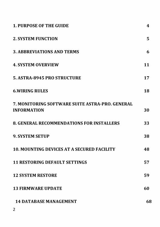
1. PURPOSE OF THE GUIDE 4
2. SYSTEM FUNCTION 5
3. ABBREVIATIONS AND TERMS 6
4. SYSTEM OVERVIEW 11
5. ASTRA-8945 PRO STRUCTURE 17
6.WIRING RULES 18
7. MONITORING SOFTWARE SUITE ASTRA-PRO. GENERAL
INFORMATION 30
8. GENERAL RECOMMENDATIONS FOR INSTALLERS 33
9. SYSTEM SETUP 38
10. MOUNTING DEVICES AT A SECURED FACILITY 48
11 RESTORING DEFAULT SETTINGS 57
12 SYSTEM RESTORE 59
13 FIRMWARE UPDATE 60
14 DATABASE MANAGEMENT 68

3
15 EVENT LOG 72
16 SYSTEM USERS 75
17 LED INDICATION 85

4
1. PURPOSE OF THE GUIDE
The Guide is intended for quick start of the Astra-Zitadel Alarm System based on Astra-
8945 Pro Control Panel version v1_x and Astra-Pro Monitoring Software Suite (MSS)
version v2_x.
Before you begin setting up your equipment, we strongly recommend reading Chapters 1-
8 of the Guide. This will help you properly prepare your equipment for setup and
installation.

5
2. SYSTEM FUNCTION
Astra-Zitadel system is intended for arranging complex intrusion/fire and other types of
alarm systems (emergency, technological alarms, etc.) using wireless, wired and
analogue addressable technology.
The system with a central device Astra-8945 Pro Control Panel ensures arrangement of
on-site alarm system with computer monitoring at one or more surveillance posts
operating within information networks using the TCP/IP transport protocol.
The distinguishing feature of the wireless part of the system is data transfer over wireless
networks in accordance with IEEE 802.15.4 ZigBee Pro standard within the radio
frequency range of 2.4 – 2.4835 GHz.
The distinguishing feature of the wired part of the system is data exchange within random
topology networks of TIA/EIA-485-A (RS-485) standard with improved driver parameters
allowing over 100 components to be connected within the network without special circuit
matching and decoupling.
2.1 SYSTEM ADVANTAGES
Setting of the system and all system components using MSS is performed with only
central Control Panel being connected to the computer.
The interface of MSS Setup module is easy to use and self-explanatory with integrated
instructions.
Ease of installation of system wireless part.
Complete freedom when choosing mounting places for wireless devices at the facility.
Automatic calculation of data transmission routes within radio network. Dynamic
routing.
Short system response time.
Dynamic crypto-protection algorithm under the AES standard with 128-bit keys.
6
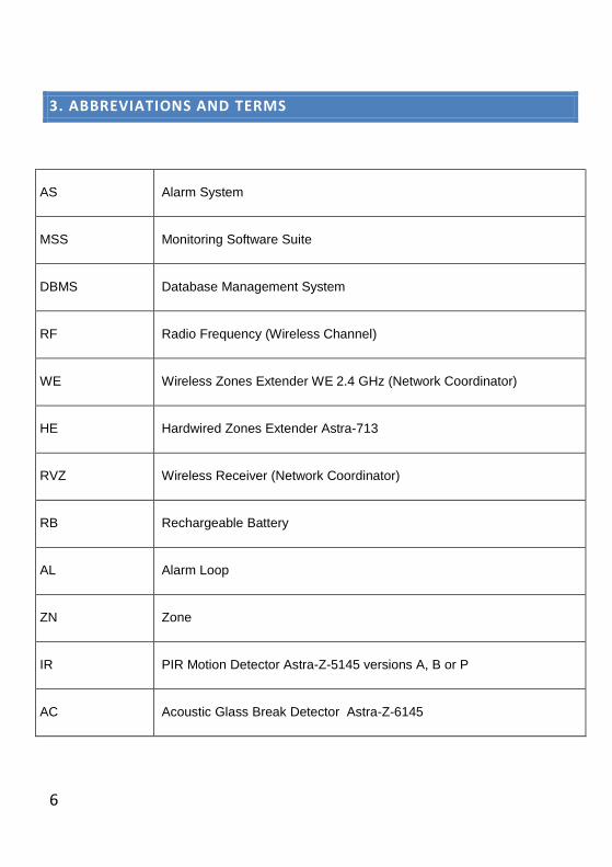
3. ABBREVIATIONS AND TERMS
AS Alarm System
MSS Monitoring Software Suite
DBMS Database Management System
RF Radio Frequency (Wireless Channel)
WE Wireless Zones Extender WE 2.4 GHz (Network Coordinator)
HE Hardwired Zones Extender Astra-713
RVZ Wireless Receiver (Network Coordinator)
RB Rechargeable Battery
AL Alarm Loop
ZN Zone
IR PIR Motion Detector Astra-Z-5145 versions A, B or P
AC Acoustic Glass Break Detector Astra-Z-6145
7
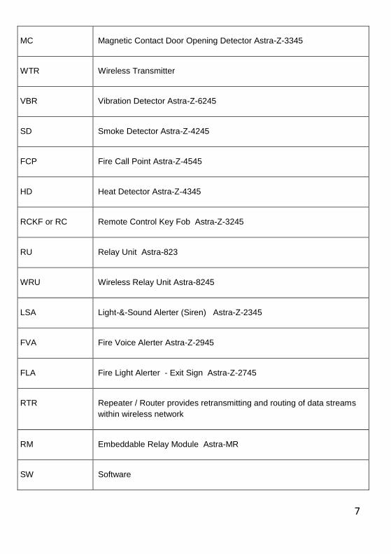
MC Magnetic Contact Door Opening Detector Astra-Z-3345
WTR Wireless Transmitter
VBR Vibration Detector Astra-Z-6245
SD Smoke Detector Astra-Z-4245
FCP Fire Call Point Astra-Z-4545
HD Heat Detector Astra-Z-4345
RCKF or RC Remote Control Key Fob Astra-Z-3245
RU Relay Unit Astra-823
WRU Wireless Relay Unit Astra-8245
LSA Light-&-Sound Alerter (Siren) Astra-Z-2345
FVA Fire Voice Alerter Astra-Z-2945
FLA Fire Light Alerter - Exit Sign Astra-Z-2745
RTR Repeater / Router provides retransmitting and routing of data streams
within wireless network
RM Embeddable Relay Module Astra-MR
SW Software
8
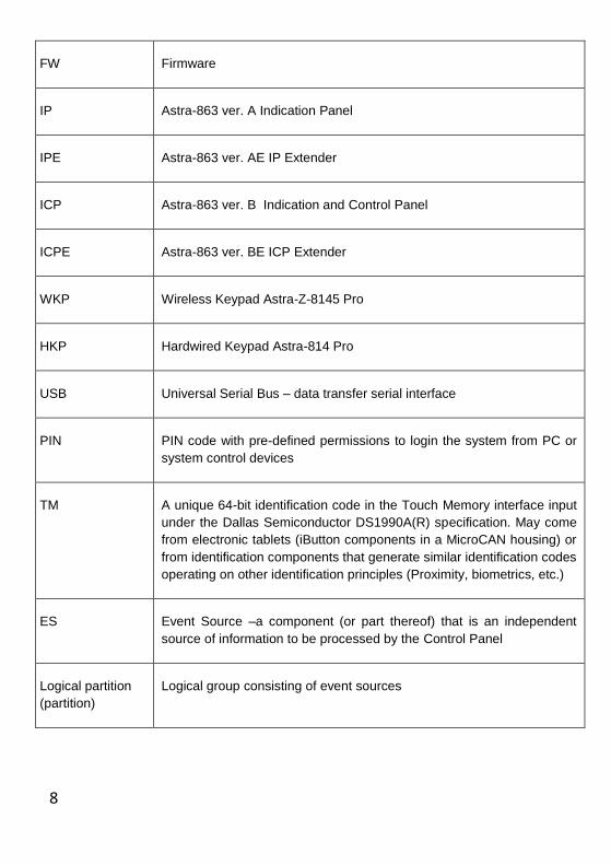
FW Firmware
IP Astra-863 ver. A Indication Panel
IPE Astra-863 ver. AE IP Extender
ICP Astra-863 ver. B Indication and Control Panel
ICPE Astra-863 ver. BE ICP Extender
WKP Wireless Keypad Astra-Z-8145 Pro
HKP Hardwired Keypad Astra-814 Pro
USB Universal Serial Bus – data transfer serial interface
PIN PIN code with pre-defined permissions to login the system from PC or
system control devices
TM A unique 64-bit identification code in the Touch Memory interface input
under the Dallas Semiconductor DS1990A(R) specification. May come
from electronic tablets (iButton components in a MicroCAN housing) or
from identification components that generate similar identification codes
operating on other identification principles (Proximity, biometrics, etc.)
ES Event Source –a component (or part thereof) that is an independent
source of information to be processed by the Control Panel
Logical partition
(partition)
Logical group consisting of event sources
9
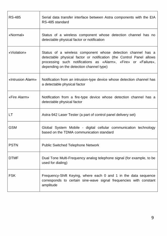
RS-485 Serial data transfer interface between Astra components with the EIA
RS-485 standard
«Normal» Status of a wireless component whose detection channel has no
detectable physical factor or notification
«Violation» Status of a wireless component whose detection channel has a
detectable physical factor or notification (the Control Panel allows
processing such notifications as «Alarm», «Fire» or «Failure»,
depending on the detection channel type)
«Intrusion Alarm» Notification from an intrusion-type device whose detection channel has
a detectable physical factor
«Fire Alarm» Notification from a fire-type device whose detection channel has a
detectable physical factor
LT Astra-942 Laser Tester (a part of control panel delivery set)
GSM Global System Mobile - digital cellular communication technology
based on the TDMA communication standard
PSTN Public Switched Telephone Network
DTMF Dual Tone Multi-Frequency analog telephone signal (for example, to be
used for dialing)
FSK Frequency-Shift Keying, where each 0 and 1 in the data sequence
corresponds to certain sine-wave signal frequencies with constant
amplitude
10
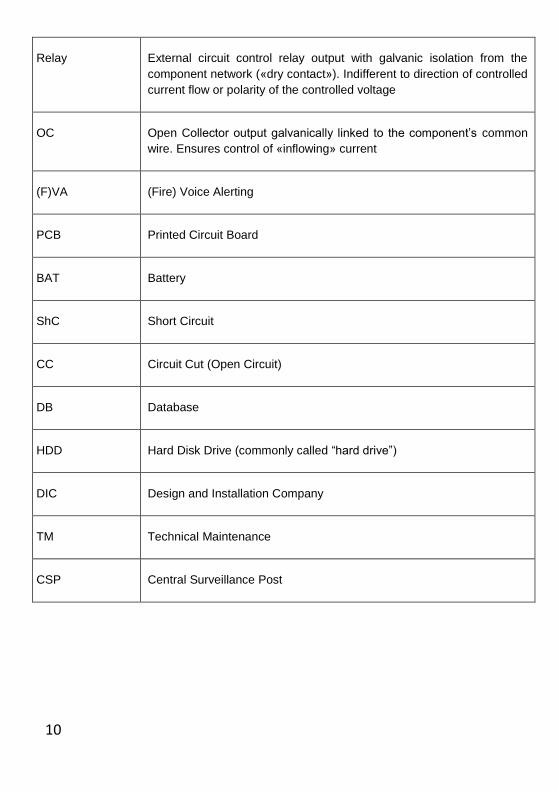
Relay External circuit control relay output with galvanic isolation from the
component network («dry contact»). Indifferent to direction of controlled
current flow or polarity of the controlled voltage
OC Open Collector output galvanically linked to the component’s common
wire. Ensures control of «inflowing» current
(F)VA (Fire) Voice Alerting
PCB Printed Circuit Board
BAT Battery
ShC Short Circuit
CC Circuit Cut (Open Circuit)
DB Database
HDD Hard Disk Drive (commonly called “hard drive”)
DIC Design and Installation Company
TM Technical Maintenance
CSP Central Surveillance Post
11
4. SYSTEM OVERVIEW
4.1. MAIN FEATURES
up to 8 wireless networks - 2.4 GHz with 250 wireless components each or 433
MHz with 192 wireless components each - with the total capacity of the
wireless part of the whole system of up to 2 000 wireless components
up to 125 hardwired devices on RS-485 interface
support of up to 7 wireless extenders WE 2.4 GHz and up to 4 wireless
extenders WE 433 MHz. Total amount of wireless extenders of different types
supported is 7.
up to 30 hardwired zones extenders with capacity of up to 8 alarm lops each
with a maximum total capacity of up to 240 zones;
up to 250 logical partitions;
up to 500 system outputs located in various system components;
availability of system outputs (Relay/OC) with circuit integrity supervision;
up to 250 users;
up to 1 000 system control identifiers (PINs, TM keys and remote control key
fobs);
up to 50 ID readers located in various system components;
up to 4 wireless keypads, operating within wireless network of Astra-8945 Pro
central control panel;
up to 8 hardwired keypads operating via RS-485 interface;
possibility of arrangement of access control system;
up to 8 system messages recipients;
PSTN, GSM and LAN are used as an external communication channels; USB,
LAN, RS-485 are used as a communication channel with MSS; possibility to
12
remotely monitor the system via Internet through TCP/IP networks with fixed IP
addresses using MSS software;
system remote control with SMS;
AstraMobile app for OS Android;
up to 96 separate programmable voice alerting areas.
These system parameters may decrease in case of simultaneous use of resource
consuming devices like PSTN, LAN or GSM modules.
4.2. SYSTEM STRUCTURE
4.2.1. The central device of the system is Astra-8945 Pro Control Panel with built-in
radio network coordinator. Panel`s sufficient memory allows saving all common system
settings and the events history. Panel is equipped with a built-in non-volatile clock.
4.2.2. WE 2.4 GHz or WE 433 MHz are used as external wireless zones extenders
without memory and clock.
4.2.3. Astra-713 version 3_0_1 is used as a hard-wired zones extender.
4.2.4. The Control Panel supports operation with Astra-823 and Astra-Z-8245 relay units.
4.2.5. Astra-8945 Pro Control Panel has 2 slots for installing and registering the
following embeddable modules (delivered separately):
Astra-PSTN module (provides message transmission in Contact ID and SIA FSK
standards);
Astra-GSM module (2 SIM; voice messaging, CID standard message transmission
in voice channel; SIA IP and PRO-net standard message transmission in GPRS
channel; Argus-ST standard message transmission in CSD channel);
Astra-LAN module (provides message transmission via TCP/IP networks in PRO-
net and SIA IP standards; ensures data exchange with MSS Cores installed on
distant PCs and servers);
Astra-RS-485 module (provides additional connection of up to 127 devices per
every RS-485 module, up to 250 devices in total including devices registered in the
built-in RS-485 interface; possible interface length is up to 1000 m);
13
Astra-RM module (provides 2 additional system relay outputs).
4.2.6. System monitoring is provided by indication panels Astra-863, wireless keypads
Astra-Z-8145 Pro, hard-wired keypads Astra-814 Pro and the Monitoring Software Suite
MSS Astra Pro.
4.2.7. Wireless light and sound alerting is provided by means of Astra-Z-2345, wireless
evacuation signs - by means of Astra-Z-2745 (Exit sign), and wireless voice alerting - by
means of Astra-Z-2945.
4.3. PROCESSING INFORMATION
4.3.1. The Control Panel Astra-8945 Pro processes information coming from event
sources (ES) in logical partitions assigned to them. Each system component (wired or
wireless) may have several event sources:
The body of any device which reflects its operability status. Its address is indicated
in the MSS interface after «#».
For example: MC#1; RTR#2
Detection channels:
channel 1 - this is the main detection channel for wireless IR, AC, MC, etc.
detectors;
channel 2 - this is an auxiliary detection channel implemented by ZONE
terminals on a wireless device PCB, or opening circuit of the magnets fixed to
the metal surface at detachment of vibration detector;
activated zones of Astra-713 hardwired zones extenders or other devices.
Detection channel is indicated in the MSS interface by the number after the
component address number and «/».
For example: MC#1/1; RTR#2/1
Each event source is assigned to appropriate partition with pre-set properties.
4.3.2. An information about any violation in a logical partition is processed only in case
14
the partition is armed.
4.3.3. Arming/disarming of partitions is performed using identifiers.
4.3.4. System supports 3 types of identifiers (ID) and corresponding ID readers:
PIN code is a code consisting of 4 to 6 digits.
Readers for PIN codes are: MSS modules, Control Panel Astra-8945 Pro,
keypads Astra-Z-8145 Pro and Astra-814 Pro.
ТМ keys/Wiegand keys
Astra-8945 Pro, Astra-814 Pro, Astra-713, Astra-863 ver.А/B have an input
interface for connection of ТМ readers.
Astra-8945 Pro Control Panel supports readers of Wiegand and Dallas
Semiconductor DS 1990A(R) standards.
Remote Control Key Fobs Astra-Z-3245 or Astra-RC with dedicated
arm/disarm buttons .
4.3.5. All events are divided into categories. Categorization is performed on the basis of
the Ademco ® Contact ID Protocol for Alarm System Communications (SIA DC-05-
1999.09).
4.4. INFORMATION OUTPUT
To output and process information are used:
Relay/OC system outputs located in various system components (Astra-8945 Pro
Control Panel, WE 2.4 GHz or WE 433 MHz wireless extender, Astra-823 and
Astra-Z-8245 relay units, Astra-RM relay module, Astra-713 wired extender,
Astra-Z-8745 and Astra-Z-8845 routers, Astra-814 hardwired keypad);
virtual system outputs belonging to alerters Astra-Z-2345 and Astra-Z-2745 in
the form of light and sound alerting channels;
virtual system outputs belonging to indication panels of Astra-863 series and
control keypads Astra-Z-8145Pro, Astra-814 Pro in the form of LED indicators
and built-in buzzers;
15
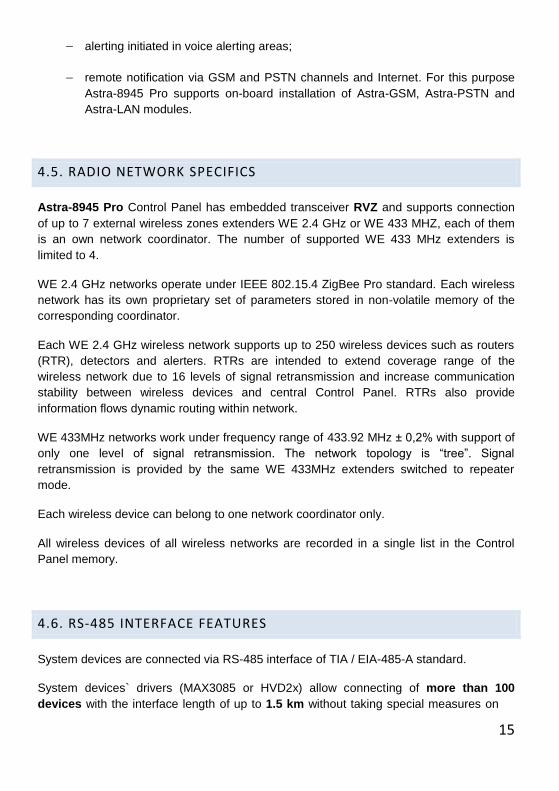
alerting initiated in voice alerting areas;
remote notification via GSM and PSTN channels and Internet. For this purpose
Astra-8945 Pro supports on-board installation of Astra-GSM, Astra-PSTN and
Astra-LAN modules.
4.5. RADIO NETWORK SPECIFICS
Astra-8945 Pro Control Panel has embedded transceiver RVZ and supports connection
of up to 7 external wireless zones extenders WE 2.4 GHz or WE 433 MHZ, each of them
is an own network coordinator. The number of supported WE 433 MHz extenders is
limited to 4.
WE 2.4 GHz networks operate under IEEE 802.15.4 ZigBee Pro standard. Each wireless
network has its own proprietary set of parameters stored in non-volatile memory of the
corresponding coordinator.
Each WE 2.4 GHz wireless network supports up to 250 wireless devices such as routers
(RTR), detectors and alerters. RTRs are intended to extend coverage range of the
wireless network due to 16 levels of signal retransmission and increase communication
stability between wireless devices and central Control Panel. RTRs also provide
information flows dynamic routing within network.
WE 433MHz networks work under frequency range of 433.92 MHz ± 0,2% with support of
only one level of signal retransmission. The network topology is “tree”. Signal
retransmission is provided by the same WE 433MHz extenders switched to repeater
mode.
Each wireless device can belong to one network coordinator only.
All wireless devices of all wireless networks are recorded in a single list in the Control
Panel memory.
4.6. RS-485 INTERFACE FEATURES
System devices are connected via RS-485 interface of TIA / EIA-485-A standard.
System devices` drivers (MAX3085 or HVD2x) allow connecting of more than 100
devices with the interface length of up to 1.5 km without taking special measures on
16
signal amplification or retransmission.
For more details refer to «Guidelines for Proper Wiring of an RS-485 (TIA/EIA-485-A)
Network" at http://www.maximintegrated.com/en/app-notes/index.mvp/id/763.
4.7. COMMUNICATION PORTS
Astra-8945 Pro Control Panel may be connected to a PC via 3 different communication
ports:
built-in RS-485 interface of TIA/EIA-485-A standard;
additional main RS-485 interfaces of TIA/EIA-485-A standard implemented by
means of universal outputs of A or B slot provided Astra-RS-485 module is in-
stalled;
LAN interface implemented by means of universal outputs of A or B slot provid-
ed Astra-LAN module is installed;
USB interface.
By means of any of these interfaces the Control Panel may be connected to a PC for
system setting and monitoring. The first connection is available only via USB. Then you
are free to change communication port.
We recommend RS-485 or LAN interface for continuous system monitoring. The Astra-
8945 Pro housing design doesn’t allow connection to PC via USB unless the cover is
removed.
For more details, please, refer to Paragraph 7.4. of this Guide.
17
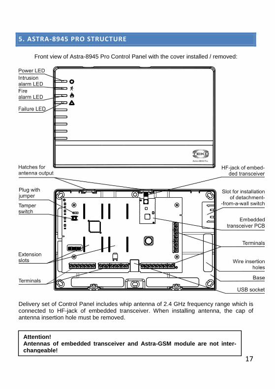
5. ASTRA-8945 PRO STRUCTURE
Front view of Astra-8945 Pro Control Panel with the cover installed / removed:
Delivery set of Control Panel includes whip antenna of 2.4 GHz frequency range which is connected to HF-jack of embedded transceiver. When installing antenna, the cap of antenna insertion hole must be removed.
Attention! Antennas of embedded transceiver and Astra-GSM module are not inter-changeable!

18
6.WIRING RULES
6.1. POWER SUPPLY
6.1.1. The main system hardwired devices:
Control Panel Astra-8945 Pro
Wireless Extender WE 2.4 GHz or WE 433 MHz
Hardwired Keypad HKP Astra-814 Pro
Indication Panel Astra-863 ver.A/B
are powered from DC power supply of 10-27 V. These devices have an additional
input for connecting backup power supply.
IP Astra-863 ver.A/B contain a DC-DC converter in its electronic circuit for supplying
Astra-863 ver. AE/BE extenders ("+SLV" and "-SLV" terminals).
Astra-8945 Pro, Astra-814 Pro and Astra-863 ver. A/B have a special Zone input
with current control terminated by a resistor of 3.9 kOhm to connect a relay output of a
power supply unit for the purpose of its operability supervision. The resistance of the
input of 3.9 kOhm provides “Normal” status; short circuit or circuit cut provide “Failure”
status of the Zone input.
In case the Zone input is not used, it must be terminated with the resistor of 3.9 kOhm
and de-activated.
Astra-Z WE, Astra-863 ver.AE/BE and Astra-823 have no Zone input.
Attention!
System wiring must be carried out with the power switched off!

19
6.1.2. System hardwired devices:
Astra-713
Astra-823
are powered from DC power supply of 10.5-15 V. These devices don’t have the
additional input for connecting backup power supply.
6.1.3. To provide continuous receiving/transmitting of signals within radio network,
repeaters-routers should be continuously powered from external power supply.
Different types of repeaters-routers can be powered from different types of power
sources:
Astra-Z-8845 ver. A - supply voltage is 10-27 V DC; possibility to put backup
battery of LP704374 type (delivered separately) inside the device to provide 24 h. of
continuous work is available.
Astra-Z-8845 ver. B - supply voltage is 10-27 V DC. Power reservation is
possible only by external power supply used.
Astra-Z-8745 ver. A - supply voltage is 220 V AC; possibility to install backup
battery of LP704374 type (delivered separately) inside the device to provide 24 h. of
continuous work is available.
Astra-Z-8745 ver. B - supply voltage is 220 V AC. There is no possibility for
power reservation.
Additionally the Astra-Z-8245 relay unit can be used as a repeater-router; supply
voltage is 220 V AC or 10-27 V DC. Power reservation is possible only by DC power
supply used.
In 433MHz wireless network the WE 433 MHz extender is used as a repeater;
supplied from 2 power sources with DC voltage of 10-27 V.
6.1.4. Wireless devices of Intrusion-protection sub-system and of technological
type:
PIR Astra-Z-5145 ver. A/B/P, Astra-5131 ver.A/B, Astra-5121
AC Astra-Z-6145, Astra-6131
MC Astra-Z-3345, Astra-3321

20
VBR Astra-Z-6245
WLD Astra-Z-3645, Astra-361 RF
RC Astra-Z-3245, Astra-RC
PB Astra-3221
are powered from lithium batteries of different types. Power reservation is provided
by permanent battery charge control. Battery discharge message is issued at least
one month prior to reaching device inoperability threshold.
Wireless devices of Fire-protection sub-system and wireless alerters:
SD Astra-Z-4245, Astra-421 RF (2)
HD Astra-Z-4345
FCP Astra-Z-4545, Astra-4511 RF (2)
LSA Astra-Z-2345
FLA Astra-Z-2745
FVA Astra-Z-2945
are powered from 2 lithium batteries of different types depending on device type.
Power reservation is provided by permanent battery charge control. Battery discharge
message is issued at least one month prior to reaching pre-set discharge threshold on
each battery separately.
6.1.5. When TTD Astra-Y is used in the alarm system, it is supplied with power from
DC power source with supply voltage of 10.5-15 V. Power reservation is possible by
power supply unit only.
Warning! When power source with rated DC voltage of 24 V is used for
supplying the Control Panel, connection of TTD Astra-Y to this source is
prohibited!

21
6.2. ASTRA-8945 PRO COMMON WIRING DIAGRAM

22
6.3. WIRING DIAGRAM FOR SYSTEM COMPONENTS
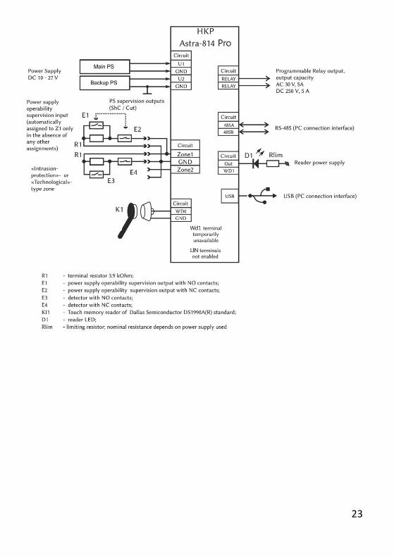
23

24
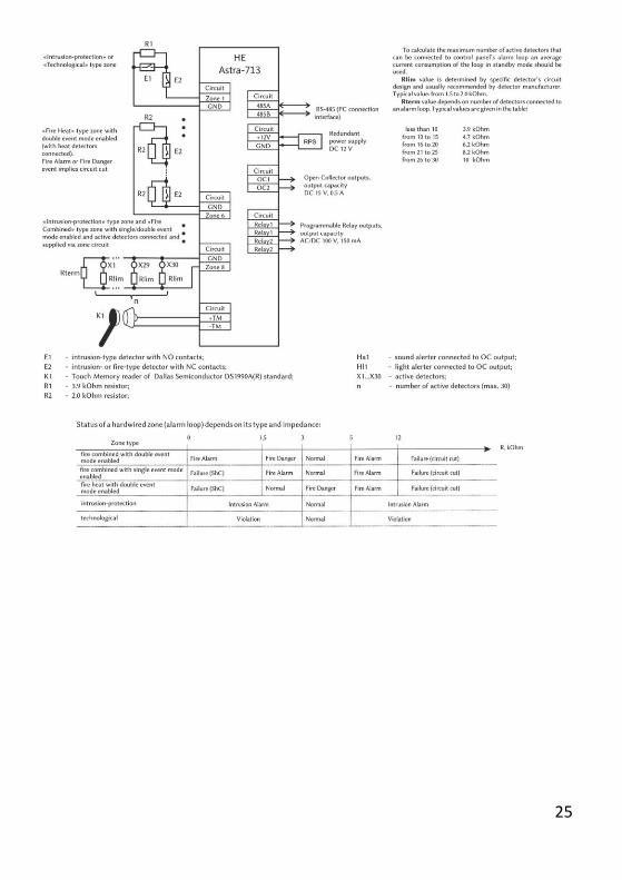
25
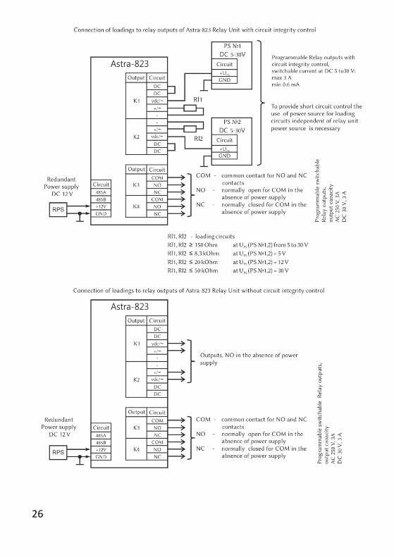
26

27

28
29
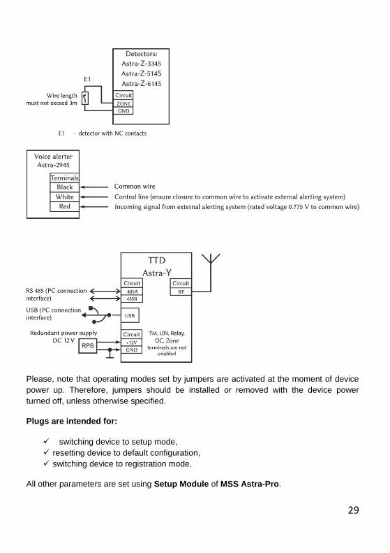
Please, note that operating modes set by jumpers are activated at the moment of device
power up. Therefore, jumpers should be installed or removed with the device power
turned off, unless otherwise specified.
Plugs are intended for:
switching device to setup mode,
resetting device to default configuration,
switching device to registration mode.
All other parameters are set using Setup Module of MSS Astra-Pro.
30
7. MONITORING SOFTWARE SUITE ASTRA-PRO. GENERAL
INFORMATION
7.1. MSS PURPOSE
Monitoring Software Suite Astra-Pro is intended for configuring and monitoring a
wireless alarm system based on Astra-8945 Pro central Control Panel from a PC.
The MSS Astra-Pro is available for free at www.controlex.eu or www.teko.biz/en .
Operability of the software is guaranteed on 32- and 64-bit computers under Win XP, Win
7, Win 8_x operating systems.
7.2. MSS STRUCTURE
7.2.1. Microsoft SQL Server is used as a database server.
MS SQL Server is automatically installed while installing MSS software.
7.2.2. The MSS is divided into three main program modules and two utilities:
1) System Core. This is the main MSS module. Operates as a Windows Service and
runs automatically at PC startup. You can change some settings of the System
Core using Core Manager.
2) Setup Module. This module is intended for system setup and service.
3) Monitor Module. This module is intended for continuous monitoring of the system.
4) DB Manager. DB Manager serves to create and delete databases, switch between
databases belonging to different control panels, as well as to save their backup
copies.
5) FW Update Module. FW Update Module serves to update devices, as well as to
restore system default settings.
When working with any of the MSS modules, available program functions are regulated
by permissions of PIN code entered at a module startup.
31
7.3. SYSTEM USERS AND THEIR PERMISSIONS
System supports 4 types of users with different authority levels:
The Engineer can login the system from any PC of the network, on which MSS
modules are installed, as well as from hardwired/wireless keypads. System stops
functioning while the Engineer is being logged in the system. Default Engineer’s PIN is
«1 2 3 4 5 6» and it has the highest priority. The Engineer cannot control the system
(arming/disarming). The Engineer’s account cannot be deleted from the system. The
Engineer can freely change system settings.
The Technician can read out some settings of the system from system database in
order to carry out equipment maintenance. The Technician can arm/disarm the system
with its PIN. Technician can login the system from any PC of the network, on which
MSS modules are installed, as well as from hardwired/wireless keypads. The
Technician doesn’t stop work of the Operators (see below). The Technician cannot
change system settings.
The Operator performs system monitoring. The Operator can arm/disarm the system
with its PIN. The Operator cannot change system settings.
The User can arm/disarm alarm system with its PINs, ТМ keys, Wiagand cards,
Remote Control keyfobs in concordance with specified permissions.
Attention! Loss of the Engineer’s PIN leads to complete reset of the Control Panel to de-
fault settings and initialization of a new system database.
Attention!
The pre-set «Engineer» PIN code must be necessarily changed.
32
7.4. MSS ASTRA-PRO INSTALLATON OPTIONS
7.4.1. MSS Astra-Pro can be installed and used in a variety of ways:
On one PC with SQL Server installed.
In a local computer network with SQL Server and MSS modules distributed among several computers.
For system remote setting and monitoring through the Internet provided Astra-LAN module is installed inside the Control Panel and static IP address is assigned.
7.4.2. We recommend using USB connection of the panel to PC only for initial system configuration, but not for system monitoring. For the continuous monitoring should be used: additional RS-485 ports provided:
Astra-RS-485 module is installed,
None of hard-wired devices is registered on selected RS-485 port,
Astra-984 adapter is used for physical connection (not included) LAN-port provided:
Astra-LAN module is installed (not included),
EIA/TIA 568B crossed-type patch cord is used for connection to the closest router or PC network card.
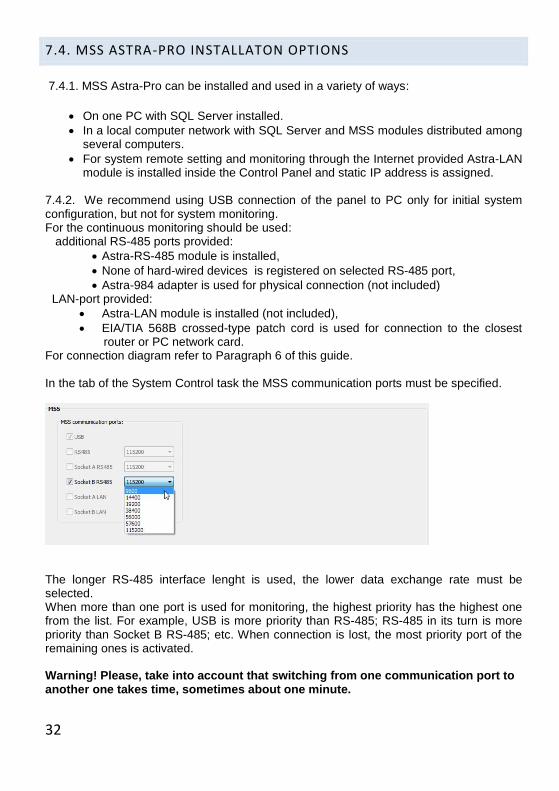
For connection diagram refer to Paragraph 6 of this guide. In the tab of the System Control task the MSS communication ports must be specified.
The longer RS-485 interface lenght is used, the lower data exchange rate must be selected. When more than one port is used for monitoring, the highest priority has the highest one from the list. For example, USB is more priority than RS-485; RS-485 in its turn is more priority than Socket B RS-485; etc. When connection is lost, the most priority port of the remaining ones is activated. Warning! Please, take into account that switching from one communication port to another one takes time, sometimes about one minute.
33
8. GENERAL RECOMMENDATIONS FOR INSTALLERS
8.1. WIRELESS PART OF THE SYSTEM
Astra-8945 Pro has embedded radio transceiver 2.4 GHz, which supports up to 250
wireless devices of different types.
Astra-8945 Pro allows connecting of up to 7 external wireless zones extenders WE 2.4
GHz with support of 250 wireless devices of different types by each one. Thus the full
capacity of the wireless part of the system is 2000 wireless devices.
Astra-8945 Pro also allows connecting of up to 4 external wireless zones extenders WE
433 MHz. 433 MHz wireless part of the system may consist of 192 wireless devices being
registered in one extender or distributed between 4 extenders.
Total amount of external wireless zones extenders of any type cannot exceed 7.
Astra-8945 Pro or WE 2.4 network supports dynamic routing of information flows within
the network, so that wireless devices are not strongly linked to each other and data
transmission routs are built automatically within the network through several levels (up to
16) of signal retransmission.
WE 433 network supports only one level of signal retransmission, but doesn’t support
dynamic routing function.
Wireless coverage range depends on the number and nature of obstacles inside the
protected facility and on operating frequency.
8.2. WIRELESS NETWORK 2.4 GHZ
To ensure efficient operation of detectors and alerters at real facilities, special devices are
included into radio network that perform signal retransmission with the checkback and
dynamic routing while delivering messages to the Control Panel, delivering commands to
each alerter and checkback about command execution.
These devices are routers/repeaters Astra-Z-8845, Astra-Z-8745 and relay units Astra-Z-
8245.
There are some restrictions that are imposed on routers’ functions:
30 wireless devices per one router. At least one router/repeater per 30 wireless devices must be registered.
2 remote controls Astra-Z-3245 per one router,
34
processing no more than 16 information flows coming from the same routers/repeaters,
max 16 levels of signal retransmission,
lack of bindings between each other and “daughter” devices.
ATTENTION! Don’t turn off the power and move away from radio visibility area those devices that are already registered in wireless network!
In order to avoid loss of wireless communication between Control Panel and wireless devices and ensure effectiveness of dynamic routing algorithm, we recommend registering one router per 12-15 wireless devices.
8.3. WIRELESS NETWORK 433 MHZ
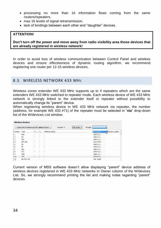
Wireless zones extender WE 433 MHz supports up to 4 repeaters which are the same extenders WE 433 MHz switched to repeater mode. Each wireless device of WE 433 MHz network is strongly linked to the extender itself or repeater without possibility to automatically change its “parent” device. When registering wireless device in WE 433 MHz network via repeater, the number (address, for example WE 433 #71) of the repeater must be selected in “via” drop-down
list of the W/devices List window.
Current version of MSS software doesn’t allow displaying “parent” device address of wireless devices registered in WE 433 MHz networks in Owner column of the W/devices List. So, we strongly recommend printing the list and making notes regarding “parent” devices.
35
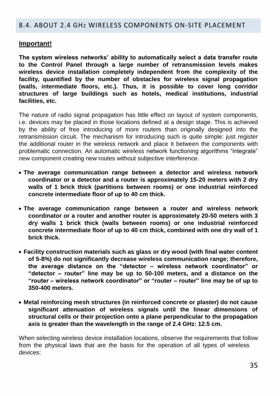
8.4. ABOUT 2.4 GHZ WIRELESS COMPONENTS ON-SITE PLACEMENT
Important!
The system wireless networks’ ability to automatically select a data transfer route
to the Control Panel through a large number of retransmission levels makes
wireless device installation completely independent from the complexity of the
facility, quantified by the number of obstacles for wireless signal propagation
(walls, intermediate floors, etc.). Thus, it is possible to cover long corridor
structures of large buildings such as hotels, medical institutions, industrial
facilities, etc.
The nature of radio signal propagation has little effect on layout of system components,
i.e. devices may be placed in those locations defined at a design stage. This is achieved
by the ability of free introducing of more routers than originally designed into the
retransmission circuit. The mechanism for introducing such is quite simple: just register
the additional router in the wireless network and place it between the components with
problematic connection. An automatic wireless network functioning algorithms “integrate”
new component creating new routes without subjective interference.
The average communication range between a detector and wireless network
coordinator or a detector and a router is approximately 15-20 meters with 2 dry
walls of 1 brick thick (partitions between rooms) or one industrial reinforced
concrete intermediate floor of up to 40 cm thick.
The average communication range between a router and wireless network
coordinator or a router and another router is approximately 20-50 meters with 3
dry walls 1 brick thick (walls between rooms) or one industrial reinforced
concrete intermediate floor of up to 40 cm thick, combined with one dry wall of 1
brick thick.
Facility construction materials such as glass or dry wood (with final water content
of 5-8%) do not significantly decrease wireless communication range; therefore,
the average distance on the “detector – wireless network coordinator” or
“detector – router” line may be up to 50-100 meters, and a distance on the
“router – wireless network coordinator” or “router – router” line may be of up to
350-400 meters.
Metal reinforcing mesh structures (in reinforced concrete or plaster) do not cause
significant attenuation of wireless signals until the linear dimensions of
structural cells or their projection onto a plane perpendicular to the propagation
axis is greater than the wavelength in the range of 2.4 GHz: 12.5 cm.
When selecting wireless device installation locations, observe the requirements that follow
from the physical laws that are the basis for the operation of all types of wireless
devices:

36
Do not place wireless components directly on massive metal structures (metal building
framework, ventilation ducts, shelves, etc.), as this will decrease the effectiveness of
antennas because metal structures release and distort the antenna pattern.
Do not place wireless devices inside metal structures (in cabinets, in rooms with fine
metal mesh in the wall finishing, etc.). Use remote antennas, if needed.
Do not place power supply wires of the central Control Panel and routers in cable
channels together with high-power cables of 220-380 V power grids.
Do not place wireless devices close to (min 1 m away of) sources of radio interference
(medical devices that use electromagnetic field during operation, video signal
processing devices and computer hardware, antennas and radio frequency tracts of
communication devices, including radio message transmitting systems, etc.).
Place wireless devices (except the control panel, keypad, FCP, wireless relay unit and
WLD) as high as possible, no lower than 2 m away of the floor; as a rule, at this height
there are the fewest obstacles in rooms, and this height also ensures normal
functioning conditions for IR, AC, MC, and SD, HD type of detectors according to the
physical principles of detection.
Place wireless devices no closer than 10 cm away of the surface of walls and ceilings
that contain closely spaced metal reinforcement (reinforced concrete) or fine mesh
reinforcement (less than 4 cm) under plaster surfaces.
During placement, ensure the least possible deviation from direct view and obstruction
by foreign objects between directly communicating wireless devices.
In premises with high human occupancy, place wireless devices so as to ensure backup
data transfer routes, as people moving throughout the space can weaken wireless
signals.
General recommendations: for every 2-3 adjacent rooms on a single floor with a
total of 4-5 detectors per room, install one router. This will automatically ensure
good conditions for achieving a communication quality level of at least 4 and the
possibility of backup routes.
8.5. ABOUT 433 MHZ WIRELESS COMPONENTS ON-SITE PLACEMENT
37
8.6. GENERAL RECOMMENDATIONS ON WIRELESS COMPONENTS ON-
SITE PLACEMENT
Do not place wireless devices directly on massive metal constructions to avoid distortion of antenna pattern;
Do not place central control panel Astra-8945 Pro, wireless zones extenders and wireless devices inside metal constructions (metal boxes, safes etc.) or use re-mote antenna to secure wireless connection;
Wireless relay unit Astra-Z-8245, when installed into metal box, must be con-nected with remote antenna (included into delivery set);
Do not place power supply wires of the central control panel and routers in cable channels jointly with high-power cables of AC 220-380 V power nets;
Do not place wireless devices close to (min 1 m away of) sources of radio inter-ference (medical devices that use electromagnetic field during operation, video signal processing devices and computer hardware, antennas and radio fre-quency tracts of communication devices, including radio message transmitting systems, etc.);
Place wireless devices (except the control panel, keypad, FCP, wireless relay unit and WLD) as high as possible and no lower than 2 m away of the floor; as a rule, at this height there are the fewest obstacles, and this height also ensures normal functioning conditions for IR, AC, MC, and SD, HD type of detectors ac-cording to the physical principles of detection;
Place wireless devices no closer than 10 cm away of the surface of walls and ceil-ings that contain closely spaced metal reinforcement (reinforced concrete) or fine mesh reinforcement (less than 4 cm) under plaster surfaces;
During placement, ensure the least possible deviation from direct view and ob-struction by foreign objects between directly communicating wireless devices;
In premises with high human occupancy, place wireless devices so as to ensure backup data transfer routes, as people moving throughout the space can weaken wireless signals;
38
9. SYSTEM SETUP
System setup is performed in two main stages:
Stage 1: System equipment setup and testing. This stage includes registering
devices in the control panel memory and recording required parameters into sysytem
devices.
Stage 2: On-site installation. This stage is performed after the whole system
operability test is completed.
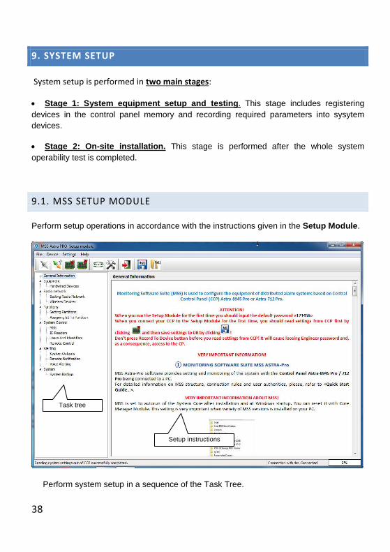
9.1. MSS SETUP MODULE
Perform setup operations in accordance with the instructions given in the Setup Module.
Perform system setup in a sequence of the Task Tree.
Task tree
Setup instructions
39
9.1.1. The Procedure.
1) Place the system equipment on worktable at the facility close to the Control Panel and
the computer with MS SQL Server and MSS Astra-Pro installed.
2) Wire system components in accordance with Wiring Diagram of Paragraph 6 of this
Guide.
3) Connect the Control Panel to the computer via USB.
4) Launch the Core Service using Core Manager. By default the Core Service is
launched automatically at PC start up.
When the MSS is installed, the DB contains a single user with Engineer permissions and
a pre-set PIN «1 2 3 4 5 6»; therefore, the launched Core receives this PIN as the access
password for administration when it communicates with the DB. The Engineer PIN is
active in the Core until it is changed and recorded to the DB or recorded to the Control
Panel memory, which entails automatic updating of the DB. As soon as it is recorded to
the DB, the new PIN is active in the Core.
5) Launch the Setup Module, login with Engineer PIN. After the PIN is entered, the
Module’s interface is set up according to Engineer permissions, i.e. full access is granted
to system settings.
6) Establish connection with the device by clicking in the toolbox. In some cases,
when changes have been made during a previous setting session and written to the DB
but not to the device, there may be discrepancies in the settings. In this case, the Core
exports a record of discrepancies to a separate screen.

40
7) Read settings out of the device and record them to the DB. Thereafter, when
performing any settings, always record them to the device. The DB is updated
automatically.
8) Perform initial setup: change the Engineer PIN and record it to the device by clicking
.
9) Change all settings needed.
Thereafter, all subsequent settings can be performed using the new password only.
Attention! After the Engineer PIN is changed, be sure to SAVE it. Otherwise, loss of the PIN
causes impossibility of further changing system settings.
41
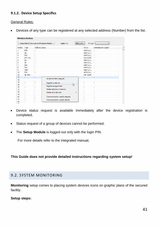
9.1.2. Device Setup Specifics
General Rules:
Devices of any type can be registered at any selected address (Number) from the list.
Device status request is available immediately after the device registration is
completed.
Status request of a group of devices cannot be performed.
The Setup Module is logged out only with the login PIN.
For more details refer to the integrated manual.
This Guide does not provide detailed instructions regarding system setup!
9.2. SYSTEM MONITORING
Monitoring setup comes to placing system devices icons on graphic plans of the secured
facility.
Setup steps:
42
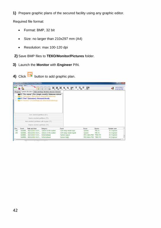
1) Prepare graphic plans of the secured facility using any graphic editor.
Required file format:
Format: BMP, 32 bit
Size: no larger than 210x297 mm (A4)
Resolution: max 100-120 dpi
2) Save BMP files to ТЕКО/Monitor/Pictures folder.
3) Launch the Monitor with Engineer PIN.
4) Click button to add graphic plan.
43
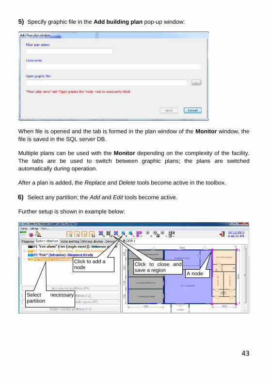
5) Specify graphic file in the Add building plan pop-up window:
When file is opened and the tab is formed in the plan window of the Monitor window, the
file is saved in the SQL server DB.
Multiple plans can be used with the Monitor depending on the complexity of the facility.
The tabs are be used to switch between graphic plans; the plans are switched
automatically during operation.
After a plan is added, the Replace and Delete tools become active in the toolbox.
6) Select any partition; the Add and Edit tools become active.
Further setup is shown in example below:
Select necessary partition
Click to add a node
Click to close and save a region
A node
44
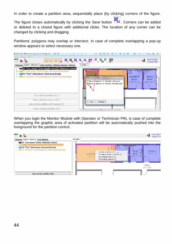
In order to create a partition area, sequentially place (by clicking) corners of the figure.
The figure closes automatically by clicking the Save button . Corners can be added
or deleted to a closed figure with additional clicks. The location of any corner can be
changed by clicking and dragging.
Partitions’ polygons may overlap or intersect. In case of complete overlapping a pop-up
window appears to select necessary one.
When you login the Monitor Module with Operator or Technician PIN, is case of complete overlapping the graphic area of activated partition will be automatically pushed into the foreground for the partition control.
45
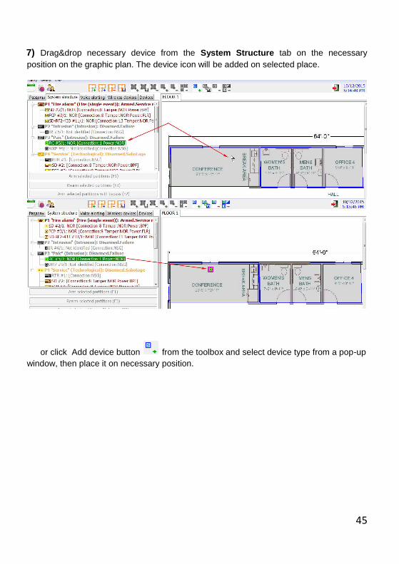
7) Drag&drop necessary device from the System Structure tab on the necessary
position on the graphic plan. The device icon will be added on selected place.
or click Add device button from the toolbox and select device type from a pop-up
window, then place it on necessary position.
46
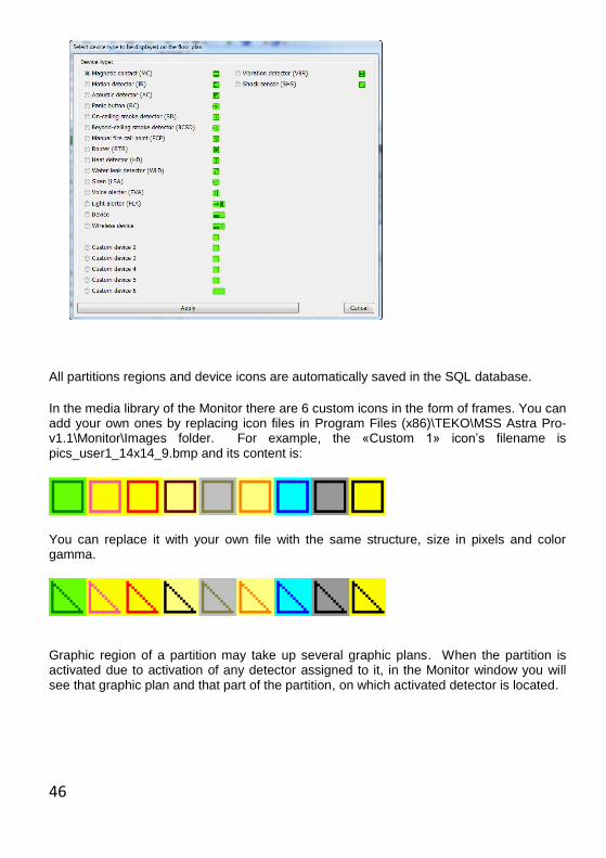
All partitions regions and device icons are automatically saved in the SQL database.
In the media library of the Monitor there are 6 custom icons in the form of frames. You can add your own ones by replacing icon files in Program Files (x86)\TEKO\MSS Astra Pro-v1.1\Monitor\Images folder. For example, the «Custom 1» icon’s filename is pics_user1_14x14_9.bmp and its content is:
You can replace it with your own file with the same structure, size in pixels and color gamma.
Graphic region of a partition may take up several graphic plans. When the partition is activated due to activation of any detector assigned to it, in the Monitor window you will see that graphic plan and that part of the partition, on which activated detector is located.

47
8) Re-login the Monitor with Operator PIN by clicking . The Monitor window will
change.
Monitor setup is complete.

48
10. MOUNTING DEVICES AT A SECURED FACILITY
10.1. GENERAL RECOMMENDATIONS
WARNING!
If after complete system configuration, but before mounting equipment on-
site it should be stored for a long time, we recommend taking battery cells
out of wireless devices in order to save their capacities.
In case the 433 MHz wireless devices are kept with battery cells taken out for more
than 2 weeks, de-synchronization between wireless devices and their “parent” de-
vices may take place. Further it will require re-registering wireless devices again.
1) First mount the Control Panel Astra-8945 Pro, all hardwired devices and alarm
loops cables. Switch the power on.
2) Perform sequential mounting of routers, switching on the power starting from those
closest to the control panel and moving to those farthest ones. Installation in this
order automatically creates optimal data transfer routes within wireless networks
2.4 GHz.
3) Install WE 433 intended to working in repeater mode.
4) Check communication quality. Run Setup Module, open Wireless Devices list
and perform status request for selected device from the right-click menu. Make
sure that communication level is not less than 2 (out of 8) for 2.4 GHz devices and
5 (out of 13) for 433 MHz devices.
49
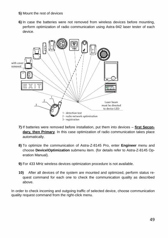
5) Mount the rest of devices
6) In case the batteries were not removed from wireless devices before mounting,
perform optimization of radio communication using Astra-942 laser tester of each
device.
7) If batteries were removed before installation, put them into devices – first Secon-
dary, then Primary. In this case optimization of radio communication takes place
automatically.
8) To optimize the communication of Astra-Z-8145 Pro, enter Engineer menu and
choose Device\Optimization submenu item. (for details refer to Astra-Z-8145 Op-
eration Manual).
9) For 433 MHz wireless devices optimization procedure is not available.
10) After all devices of the system are mounted and optimized, perform status re-
quest command for each one to check the communication quality as described
above.
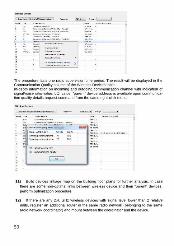
In order to check incoming and outgoing traffic of selected device, choose communication quality request command from the right-click menu.
50
The procedure lasts one radio supervision time period. The result will be displayed in the Communication Quality column of the Wireless Devices table. In-depth information on incoming and outgoing communication channel with indication of signal/noise ratio value, LQI value, “parent” device address is available upon communica-tion quality details request command from the same right-click menu.
11) Build devices linkage map on the building floor plans for further analysis. In case
there are some non-optimal links between wireless device and their “parent” devices,
perform optimization procedure.
12) If there are any 2.4. GHz wireless devices with signal level lower than 2 relative
units, register an additional router in the same radio network (belonging to the same
radio network coordinator) and mount between the coordinator and the device.
51
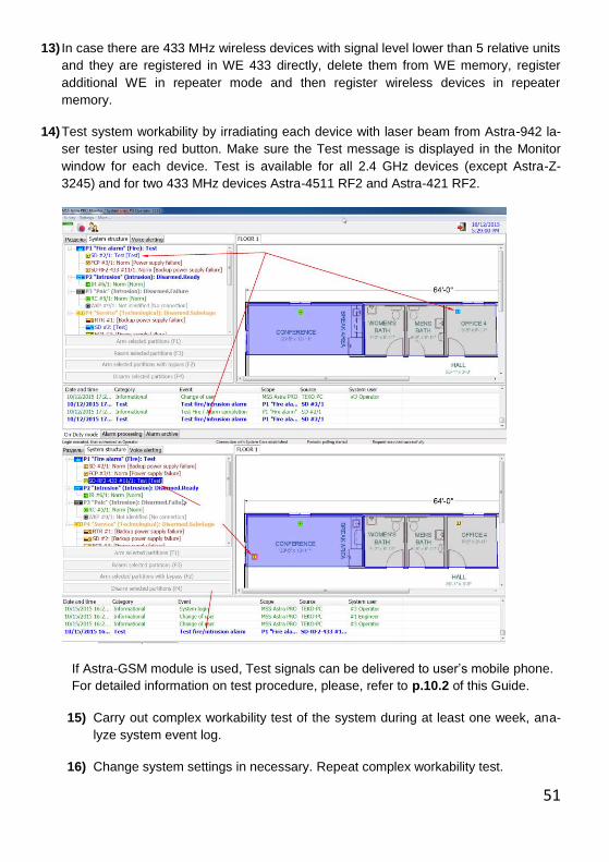
13) In case there are 433 MHz wireless devices with signal level lower than 5 relative units
and they are registered in WE 433 directly, delete them from WE memory, register
additional WE in repeater mode and then register wireless devices in repeater
memory.
14) Test system workability by irradiating each device with laser beam from Astra-942 la-
ser tester using red button. Make sure the Test message is displayed in the Monitor
window for each device. Test is available for all 2.4 GHz devices (except Astra-Z-
3245) and for two 433 MHz devices Astra-4511 RF2 and Astra-421 RF2.
If Astra-GSM module is used, Test signals can be delivered to user’s mobile phone.
For detailed information on test procedure, please, refer to p.10.2 of this Guide.
15) Carry out complex workability test of the system during at least one week, ana-
lyze system event log.
16) Change system settings in necessary. Repeat complex workability test.
52
10.2. TESTING OF INSTALLED EQUIPMENT
There are two testing methods:
1. Real alarm activation method
2. Test method. Recommended for regular system maintenance works.
10.2.1. Test method
Operability test with red button of Astra-942 laser tester is available for all 2.4 GHz wire-
less devices (except Astra-Z-3245) and for two 433 MHz devices Astra-4511 RF2 and As-
tra-421 RF2.
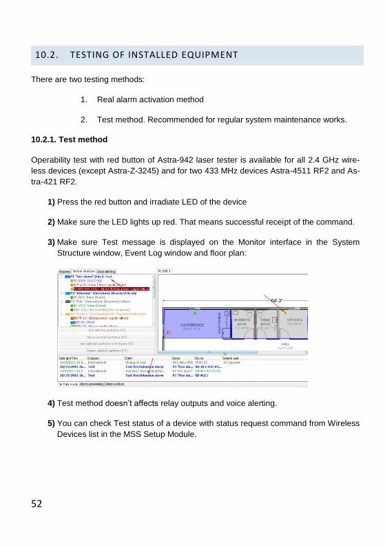
1) Press the red button and irradiate LED of the device
2) Make sure the LED lights up red. That means successful receipt of the command.
3) Make sure Test message is displayed on the Monitor interface in the System
Structure window, Event Log window and floor plan:
4) Test method doesn’t affects relay outputs and voice alerting.
5) You can check Test status of a device with status request command from Wireless
Devices list in the MSS Setup Module.

53
6) For fire-type detectors Astra-Z-4245 and Asra-Z-4545 a group testing is available.
Group test is launched from Wireless Devices tab of the Monitor interface by
means of selecting necessary devices and choosing group testing request com-
mand from the right-click menu. For that purpose the Monitor Module must be
logged in with the Operator or Technician PIN.
Test of the group is carried out in ascending order of address numbers in the list.
54
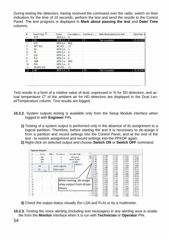
During testing the detectors, having received the command over the radio, switch on their indicators for the time of 10 seconds, perform the test and send the results to the Control Panel. The test progress is displayed in Mark about passing the test and Date/ Time
columns.
Test results in a form of a relative value of dust, expressed in % for SD detectors, and ac-tual temperature Cº of the ambient air for HD detectors are displayed in the Dust Lev-el/Temperature column. Test results are logged. 10.2.2. System outputs testing is available only from the Setup Module interface when
logged in with Engineer PIN.
1) Testing of a system output is performed only in the absence of its assignment to a
logical partition. Therefore, before starting the test it is necessary to de-assign it from a partition and record settings into the Control Panel, and at the end of the test - to restore assignment and record settings into the PPKOP again.
2) Right-click on selected output and choose Switch ON or Switch OFF command.
3) Check the output status visually (for LSA and FLA) or by a multimeter. 10.2.3. Testing the voice alerting (including test messages) in any alerting area is availa-
ble from the Monitor interface when it is run with Technician or Operator PIN.
When testing, de-assign relay output from all par-titions

55
1) Enginer can start voice alerting test from the Setup Module.
2) All tests of voice alerting are logged. 3) Technician or Operator can start voice alerting test from the Monitor interface on the
Voice Alerting tab.
4) Right-click on selected alerting area and select message to start by number, or select message number in Start field.
5) After the pre-set delay (min 30 sec) the voice alerters Astra-Z-2945 playback se-
lected message in selected area.
6) To intentionally stop the alerting, choose Stop alerting … command from the context
menu or from Start message field.
56
Stop alerting command delivery to all voice alerters may take up to 15 seconds. The
current phrase is played back until the end.
7) In order to test voice alerting from Setup Module, start Setup Module with Engi-
neer PIN.
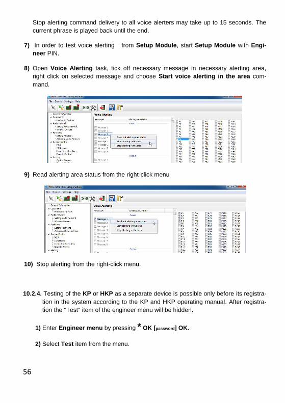
8) Open Voice Alerting task, tick off necessary message in necessary alerting area,
right click on selected message and choose Start voice alerting in the area com-
mand.
9) Read alerting area status from the right-click menu
10) Stop alerting from the right-click menu.
10.2.4. Testing of the KP or HKP as a separate device is possible only before its registra-
tion in the system according to the KP and HKP operating manual. After registra-
tion the "Test" item of the engineer menu will be hidden.
1) Enter Engineer menu by pressing * OK [password] OK.
2) Select Test item from the menu.
57
11 RESTORING DEFAULT SETTINGS
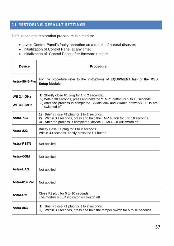
Default settings restoration procedure is aimed to:
avoid Control Panel’s faulty operation as a result of natural disaster;
initialization of Control Panel at any time;
initialization of Control Panel after firmware update
Device Procedure
Astra-8945 Pro For the procedure refer to the instructions of EQUIPMENT task of the MSS
Setup Module
WE 2.4 GHz
WE 433 MHz
1) Shortly close F1 plug for 1 to 2 seconds.. 2) Within 30 seconds, press and hold the “TMP” button for 5 to 10 seconds. 3) After the process is completed, «Violation» and «Radio network» LEDs are
switched off.
Astra-713 1) Briefly close F1 plug for 1 to 2 seconds. 2) Within 30 seconds, press and hold the TMP button for 5 to 10 seconds. 3) After the process is completed, device LEDs 1 – 8 will switch off.
Astra-823 Briefly close F1 plug for 1 to 2 seconds. Within 30 seconds, briefly press the S1 button.
Astra-PSTN Not applied
Astra-GSM Not applied
Astra-LAN Not applied
Astra-814 Pro Not applied
Astra-RM Close F1 plug for 5 to 10 seconds. The module’s LED indicator will switch off.
Astra-863 1) Briefly close F1 plug for 1 to 2 seconds. 2) Within 30 seconds, press and hold the tamper switch for 5 to 10 seconds.

58
Device Procedure
Astra-814 Procedure not required.
ATTENTION! Default Settings Restoration Procedure resets all parameters to their default val-ues, deletes registered devices from the system and clears system event log! Default configuration comprises two system access PINs: 1 2 3 4 5 6 – Engineer PIN (user #1), 1 2 3 4 – Technician PIN (user #2).
59
12 SYSTEM RESTORE
There is a possibility to backup existing radio networks, i.e. all data about registered wire-
less devices and their parameters. Backup copy is created in control panel and automati-
cally saved in a dedicated field of the database.
We recommend performing the backup procedure only after system setup is completed,
operability tests are done and system is put into operation.
It will allow you to easily replace the central Control Panel Astra-8945 Pro or wireless ex-
tenders WE 2.4 / WE 433 later on, for example, in case of physical damage.
Backup data are saved in current database and in Control Panel memory. Together with
system settings saved it allows recovering full operational capability of the system at any
time.
Backup procedure, as well as restoration procedure is described in instructions of
SYSTEM task of the MSS Setup Module.
60
13 FIRMWARE UPDATE
13.1 GENERAL INFORMATION
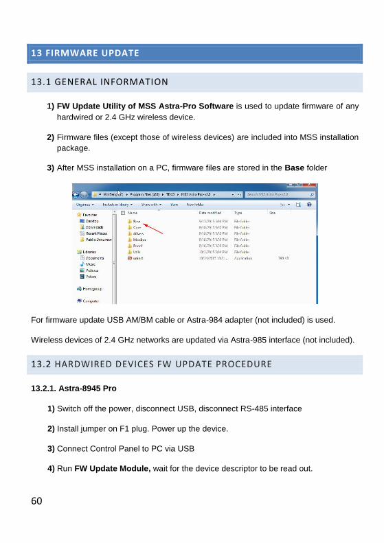
1) FW Update Utility of MSS Astra-Pro Software is used to update firmware of any
hardwired or 2.4 GHz wireless device.
2) Firmware files (except those of wireless devices) are included into MSS installation
package.
3) After MSS installation on a PC, firmware files are stored in the Base folder
For firmware update USB AM/BM cable or Astra-984 adapter (not included) is used.
Wireless devices of 2.4 GHz networks are updated via Astra-985 interface (not included).
13.2 HARDWIRED DEVICES FW UPDATE PROCEDURE
13.2.1. Astra-8945 Pro
1) Switch off the power, disconnect USB, disconnect RS-485 interface
2) Install jumper on F1 plug. Power up the device.
3) Connect Control Panel to PC via USB
4) Run FW Update Module, wait for the device descriptor to be read out.
61
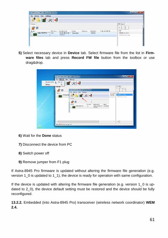
5) Select necessary device in Device tab. Select firmware file from the list in Firm-
ware files tab and press Record FW file button from the toolbox or use
drag&drop.
6) Wait for the Done status
7) Disconnect the device from PC
8) Switch power off
9) Remove jumper from F1 plug
If Astra-8945 Pro firmware is updated without altering the firmware file generation (e.g.
version 1_0 is updated to 1_1), the device is ready for operation with same configuration.
If the device is updated with altering the firmware file generation (e.g. version 1_0 is up-
dated to 2_0), the device default setting must be restored and the device should be fully
reconfigured.
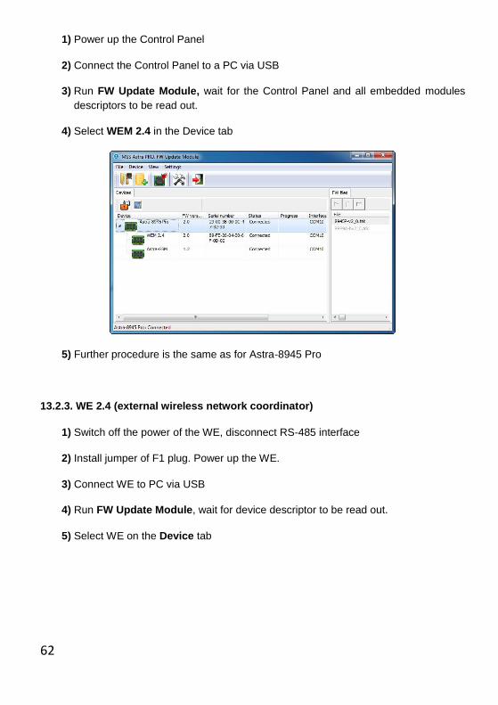
13.2.2. Embedded (into Astra-8945 Pro) transceiver (wireless network coordinator) WEM
2.4.
62
1) Power up the Control Panel
2) Connect the Control Panel to a PC via USB
3) Run FW Update Module, wait for the Control Panel and all embedded modules
descriptors to be read out.
4) Select WEM 2.4 in the Device tab
5) Further procedure is the same as for Astra-8945 Pro
13.2.3. WE 2.4 (external wireless network coordinator)
1) Switch off the power of the WE, disconnect RS-485 interface
2) Install jumper of F1 plug. Power up the WE.
3) Connect WE to PC via USB
4) Run FW Update Module, wait for device descriptor to be read out.
5) Select WE on the Device tab
63
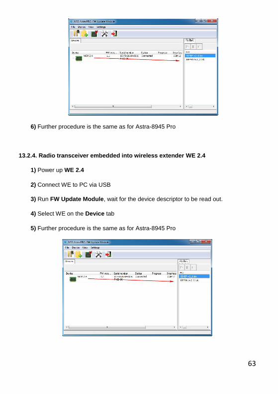
6) Further procedure is the same as for Astra-8945 Pro
13.2.4. Radio transceiver embedded into wireless extender WE 2.4
1) Power up WE 2.4
2) Connect WE to PC via USB
3) Run FW Update Module, wait for the device descriptor to be read out.
4) Select WE on the Device tab
5) Further procedure is the same as for Astra-8945 Pro
64
13.2.5. HE Astra-713
1) Switch off the power of the HE, disconnect RS-485 interface
2) Install jumper on F7 plug (on two right-hand pins)
3) Connect Astra-984 adapter to the device. Switch device power on.
4) Connect Astra-984 adapter to PC via USB
5) Further procedure is the same as for Astra-8945 Pro
Note. Serial firmware version of the hardwired extender Astra-713 doesn’t support operat-ing with Pro-series Control Panels. Therefore, the device firmware must be neces-sarily updated.
13.2.6. Astra-PSTN Module, Astra-RM Module.
Firmware update is not applied.
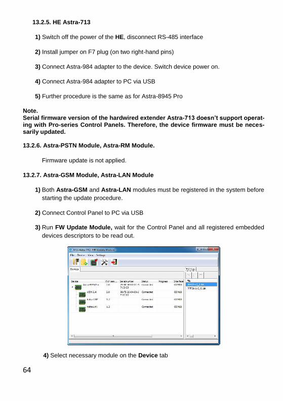
13.2.7. Astra-GSM Module, Astra-LAN Module
1) Both Astra-GSM and Astra-LAN modules must be registered in the system before
starting the update procedure.
2) Connect Control Panel to PC via USB
3) Run FW Update Module, wait for the Control Panel and all registered embedded
devices descriptors to be read out.
4) Select necessary module on the Device tab
65
5) Further procedure is the same as for Astra-8945 Pro
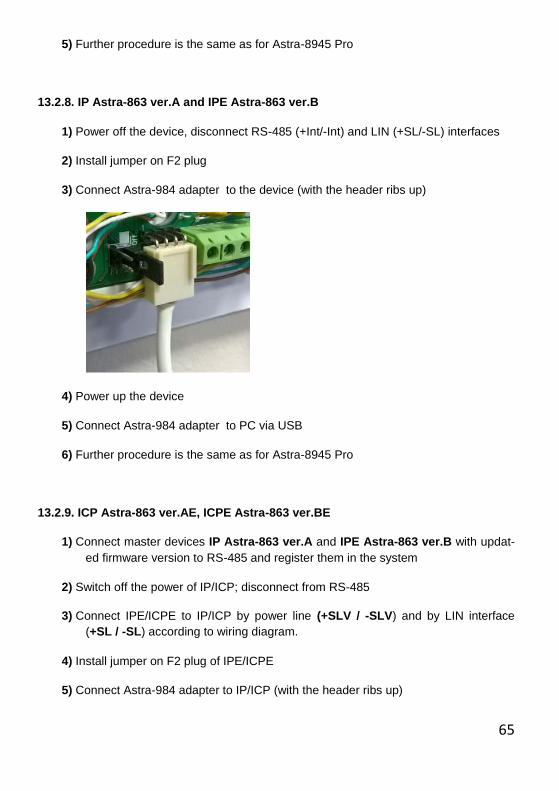
13.2.8. IP Astra-863 ver.A and IPE Astra-863 ver.B
1) Power off the device, disconnect RS-485 (+Int/-Int) and LIN (+SL/-SL) interfaces
2) Install jumper on F2 plug
3) Connect Astra-984 adapter to the device (with the header ribs up)
4) Power up the device
5) Connect Astra-984 adapter to PC via USB
6) Further procedure is the same as for Astra-8945 Pro
13.2.9. ICP Astra-863 ver.AE, ICPE Astra-863 ver.BE
1) Connect master devices IP Astra-863 ver.A and IPE Astra-863 ver.B with updat-
ed firmware version to RS-485 and register them in the system
2) Switch off the power of IP/ICP; disconnect from RS-485
3) Connect IPE/ICPE to IP/ICP by power line (+SLV / -SLV) and by LIN interface
(+SL / -SL) according to wiring diagram.
4) Install jumper on F2 plug of IPE/ICPE
5) Connect Astra-984 adapter to IP/ICP (with the header ribs up)

66
6) Switch IP/ICP power on
7) Connect Astra-984 adapter to PC via USB
8) Further procedure is the same as for Astra-8945 Pro
13.2.10 Astra-823 Relay Unit (RU)
1) Switch off the power of the RU; disconnect the device from RS-485 interface
2) Install jumper on F2 plug
3) Connect Astra-984 adapter to the RU; power up the device
4) Connect Astra-984 adapter to PC via USB
5) Further procedure is the same as for Astra-8945 Pro
13.2.11. HKP Astra-814
1) witch off the power of the HKP; disconnect the device from RS-485 interface
2) While holding down the "#" key, switch power on
3) Connect HKP to PC via USB
4) Run FW Update Module, wait for the devices descriptors to be read out.
5) Select HKP on the Device tab
6) Drag&drop available FW file to the HKP to start updating
7) After the loading file into device is completed, wait for HKP to restart
8) To check the result follow the procedure from p.1) to p.3), wait for the device de-
scriptor to be read out
9) Disconnect the HKP from USB, press "#" key to restart the device
For the HKP the firmware update mode is available also from the device menu (6.Device /
4. FW Update) after entering the device menu with Engineer PIN.
67
We recommend disconnecting HKP from RS-485 interface before starting the up-
date procedure.
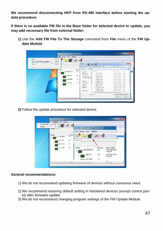
If there is no available FW file in the Base folder for selected device to update, you
may add necessary file from external folder:
1) Use the Add FW File To The Storage command from File menu of the FW Up-
date Module
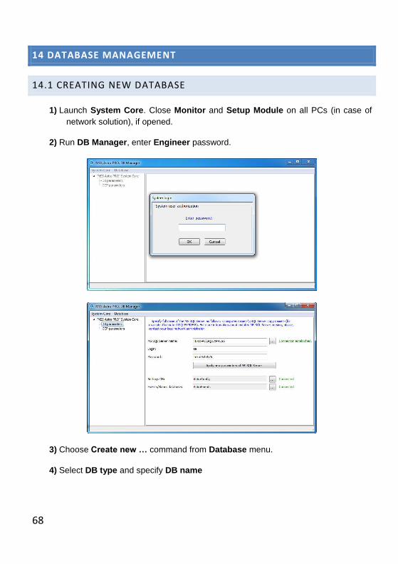
2) Follow the update procedure for selected device.
General recommendations:
1) We do not recommend updating firmware of devices without conscious need.
2) We recommend restoring default setting in hardwired devices (except control pan-el) after firmware update.
3) We do not recommend changing program settings of the FW Update Module.
68
14 DATABASE MANAGEMENT
14.1 CREATING NEW DATABASE
1) Launch System Core. Close Monitor and Setup Module on all PCs (in case of
network solution), if opened.
2) Run DB Manager, enter Engineer password.
3) Choose Create new … command from Database menu.
4) Select DB type and specify DB name

69
5) Specify folder you want to save new database to. Press OK.
6) Wait for new database to be created
Follow the procedure twice to create two databases: Settings DB and Events DB.
Note.
New Settings Database is accessible with the default Engineer’s PIN 123456 only. New Settings Database doesn’t contain any system settings.
7) Press Connected button , select newly created database from the list.
70
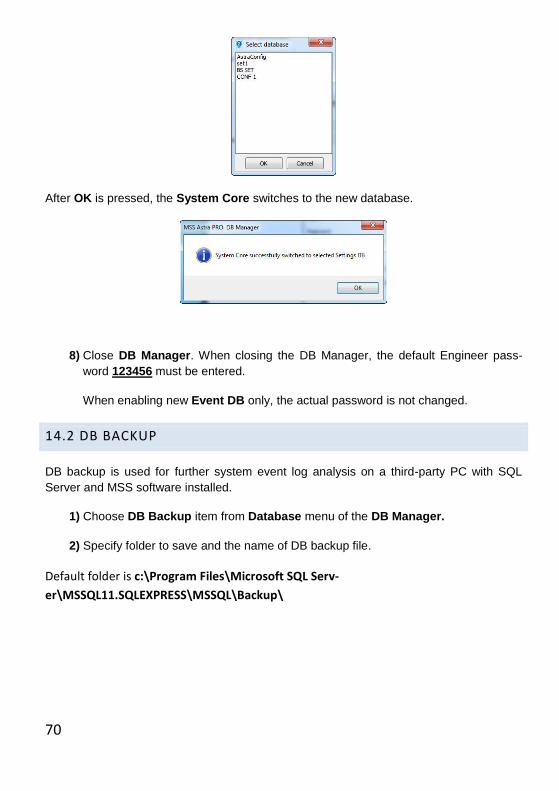
After OK is pressed, the System Core switches to the new database.
8) Close DB Manager. When closing the DB Manager, the default Engineer pass-
word 123456 must be entered.
When enabling new Event DB only, the actual password is not changed.
14.2 DB BACKUP
DB backup is used for further system event log analysis on a third-party PC with SQL
Server and MSS software installed.
1) Choose DB Backup item from Database menu of the DB Manager.
2) Specify folder to save and the name of DB backup file.
Default folder is c:\Program Files\Microsoft SQL Serv-
er\MSSQL11.SQLEXPRESS\MSSQL\Backup\
71
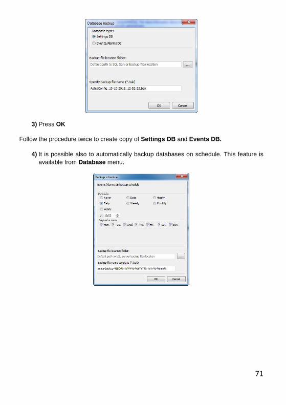
3) Press OK
Follow the procedure twice to create copy of Settings DB and Events DB.
4) It is possible also to automatically backup databases on schedule. This feature is
available from Database menu.
72
15 EVENT LOG
15.1 GENERAL INFORMATION
The capacity of Astra 8945 Pro Event Log is 10,000 events. Each event in the log has its
own serial number. When filling the full capacity of the log, a cyclic event overwriting
starts as follows:
1) The oldest event is deleted
2) New event is assigned #0001
When connecting Astra-8945 Pro to MSS, all events are copied and saved in Events Da-
tabase.
Note that Events DB, unlike Control Panel’s Event Log, contains information not only
about system events, but also about user actions and MSS status. That is the reason for
discrepancy in events numbering between the Event Log and Events DB.
15.2 ANALYZING SYSTEM EVENT LOG FROM THE MONITOR INTERFACE
The Event Log of the MSS software is available for the Engineer, Operator and Techni-
cian.
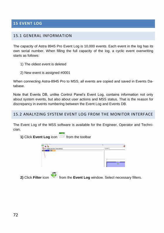
1) Click Event Log icon from the toolbar
2) Click Filter icon from the Event Log window. Select necessary filters.
73
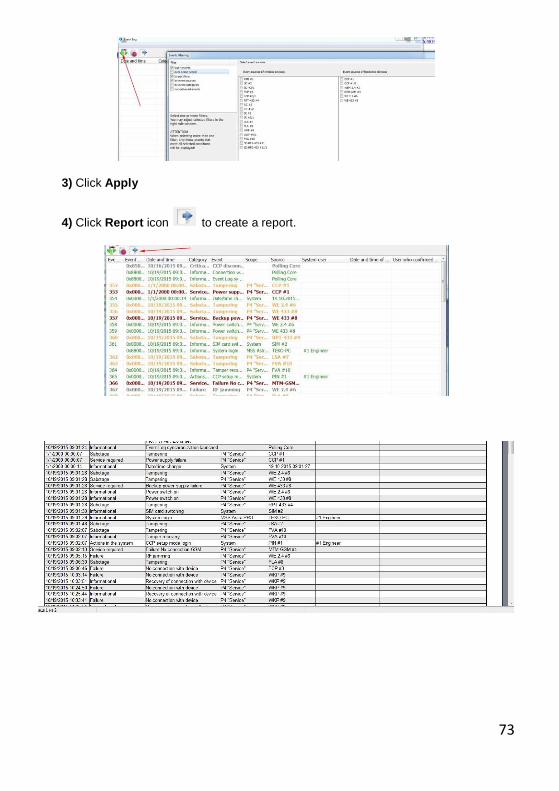
3) Click Apply
4) Click Report icon to create a report.

74
5) Click icon to create a list of events per shift
75
16 SYSTEM USERS
4 different types of users are supported by the system. Those are:
(simple) USER
OPERATOR
TECHNICIAN
ENGINEER
The difference between them consists in their system access permissions.
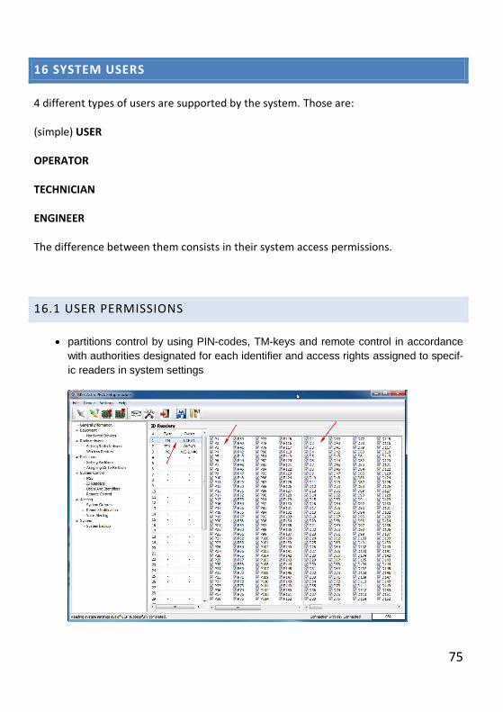
16.1 USER PERMISSIONS
partitions control by using PIN-codes, TM-keys and remote control in accordance
with authorities designated for each identifier and access rights assigned to specif-
ic readers in system settings
76
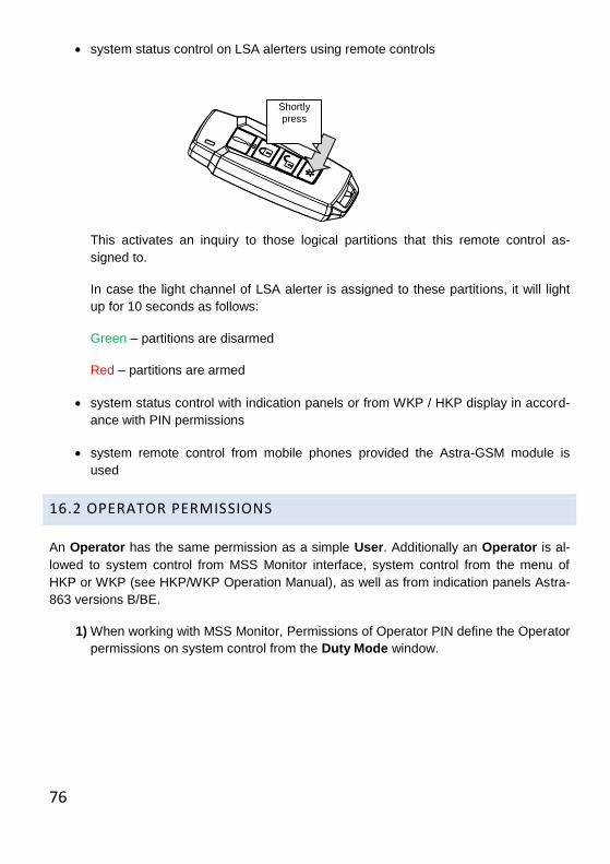
system status control on LSA alerters using remote controls
This activates an inquiry to those logical partitions that this remote control as-
signed to.
In case the light channel of LSA alerter is assigned to these partitions, it will light
up for 10 seconds as follows:
Green – partitions are disarmed
Red – partitions are armed
system status control with indication panels or from WKP / HKP display in accord-
ance with PIN permissions
system remote control from mobile phones provided the Astra-GSM module is
used
16.2 OPERATOR PERMISSIONS
An Operator has the same permission as a simple User. Additionally an Operator is al-
lowed to system control from MSS Monitor interface, system control from the menu of
HKP or WKP (see HKP/WKP Operation Manual), as well as from indication panels Astra-
863 versions B/BE.
1) When working with MSS Monitor, Permissions of Operator PIN define the Operator
permissions on system control from the Duty Mode window.
Shortly
press
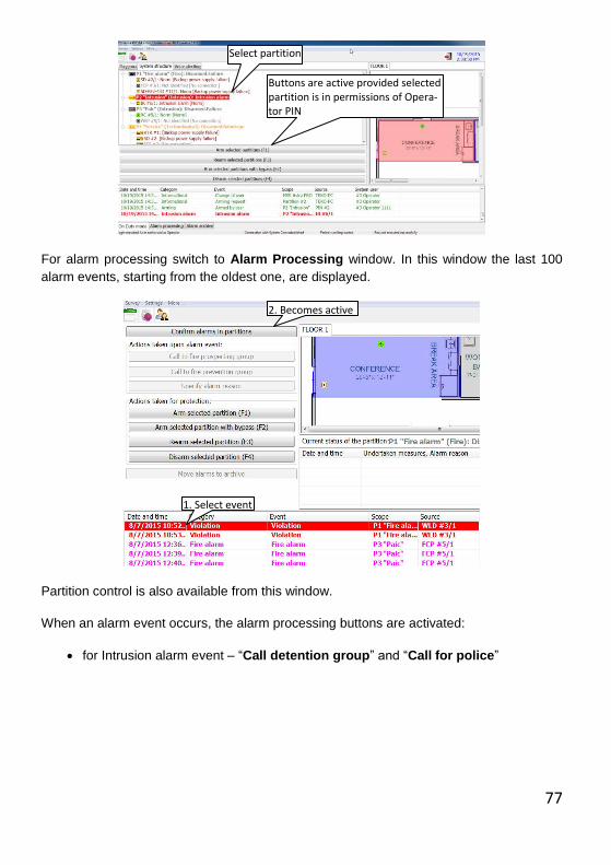
77
For alarm processing switch to Alarm Processing window. In this window the last 100
alarm events, starting from the oldest one, are displayed.
Partition control is also available from this window.
When an alarm event occurs, the alarm processing buttons are activated:
for Intrusion alarm event – “Call detention group” and “Call for police”
Select partition
Buttons are active provided selected partition is in permissions of Opera-tor PIN
1. Select event
2. Becomes active
78
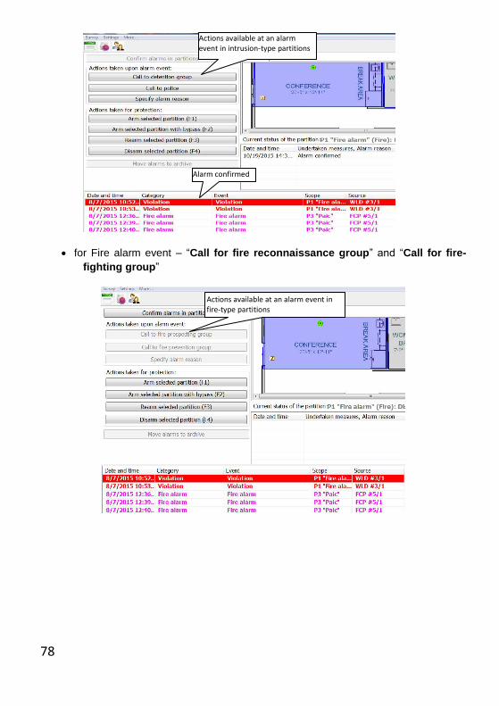
for Fire alarm event – “Call for fire reconnaissance group” and “Call for fire-
fighting group”
Actions available at an alarm event in fire-type partitions
Alarm confirmed
Actions available at an alarm event in intrusion-type partitions
79
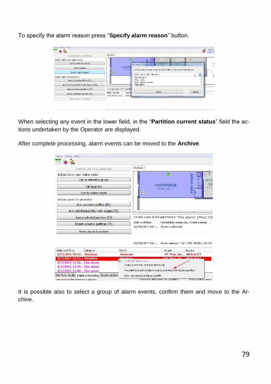
To specify the alarm reason press “Specify alarm reason” button.
When selecting any event in the lower field, in the “Partition current status” field the ac-
tions undertaken by the Operator are displayed.
After complete processing, alarm events can be moved to the Archive.
It is possible also to select a group of alarm events, confirm them and move to the Ar-
chive.
80
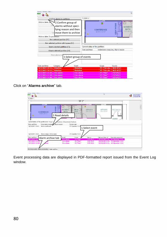
Click on “Alarms archive” tab.
Event processing data are displayed in PDF-formatted report issued from the Event Log
window.
1.Select group of events
2.Confirm group of alarms without speci-fying reason and then move them to archive
Alarm archive tab
1.Select event
2.Read details

81
2) An Operator can control partitions with the buttons of Astra-863 ver.B/BE indication
panels. To make it possible:
Operator should have a TM key with the permissions to control certain partitions
TM reader connected to an indication panel should be assigned to this TM key as
well as to the same partitions.
For partition control an Operator should apply the TM key to the reader of the indi-
cation panel, then press certain button on the panel, and then apply the TM key
once again within 30 sec to confirm the command. If more than 30 seconds have
passed after the last button has been pressed, the command is cancelled automat-
ically.
3) An Operator has permissions to monitor or control logical partitions and alerting
sub-system from HKP Astra-814 Pro and WKP Astra-8145 Pro menu in accord-
ance with his PIN permissions (for details see HKP/WKP Operation Manual).
16.3 TECHNICIAN PERMISSIONS
1) Technician’s permissions are defined by the Engineer to perform system mainte-
nance.
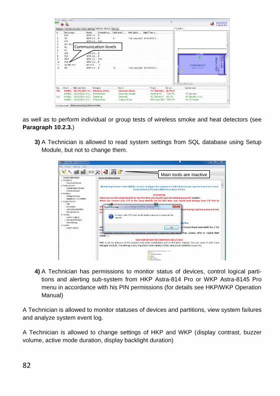
2) A Technician is allowed to request quality of radio communication from Wireless
devices tab of the MSS Monitor
82
as well as to perform individual or group tests of wireless smoke and heat detectors (see
Paragraph 10.2.3.)
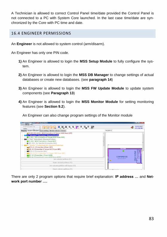
3) A Technician is allowed to read system settings from SQL database using Setup
Module, but not to change them.
4) A Technician has permissions to monitor status of devices, control logical parti-
tions and alerting sub-system from HKP Astra-814 Pro or WKP Astra-8145 Pro
menu in accordance with his PIN permissions (for details see HKP/WKP Operation
Manual)
A Technician is allowed to monitor statuses of devices and partitions, view system failures
and analyze system event log.
A Technician is allowed to change settings of HKP and WKP (display contrast, buzzer
volume, active mode duration, display backlight duration)
Main tools are inactive
Communication levels
83
A Technician is allowed to correct Control Panel time/date provided the Control Panel is
not connected to a PC with System Core launched. In the last case time/date are syn-
chronized by the Core with PC time and date.
16.4 ENGINEER PERMISSIONS
An Engineer is not allowed to system control (arm/disarm).
An Engineer has only one PIN code.
1) An Engineer is allowed to login the MSS Setup Module to fully configure the sys-
tem.
2) An Engineer is allowed to login the MSS DB Manager to change settings of actual
databases or create new databases. (see paragraph 14)
3) An Engineer is allowed to login the MSS FW Update Module to update system
components (see Paragraph 13)
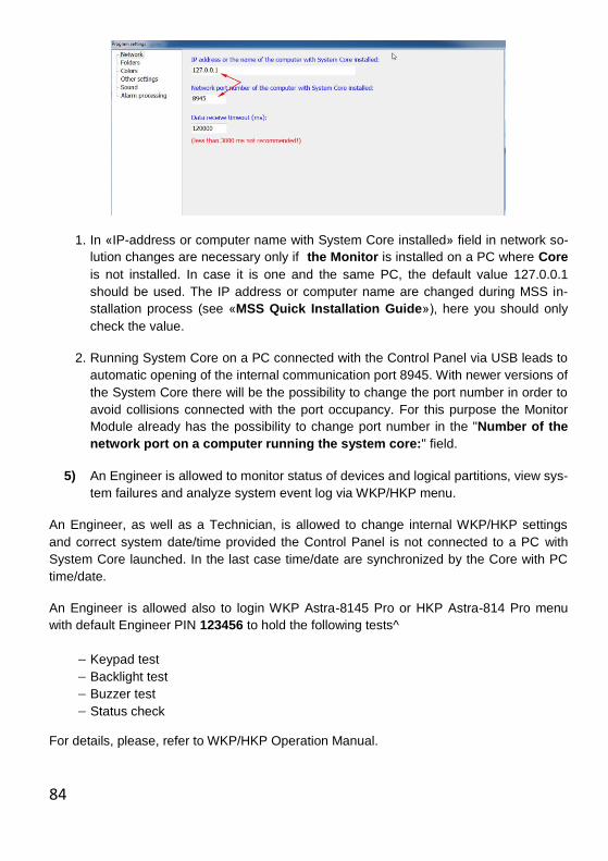
4) An Engineer is allowed to login the MSS Monitor Module for setting monitoring
features (see Section 9.2).
An Engineer can also change program settings of the Monitor module
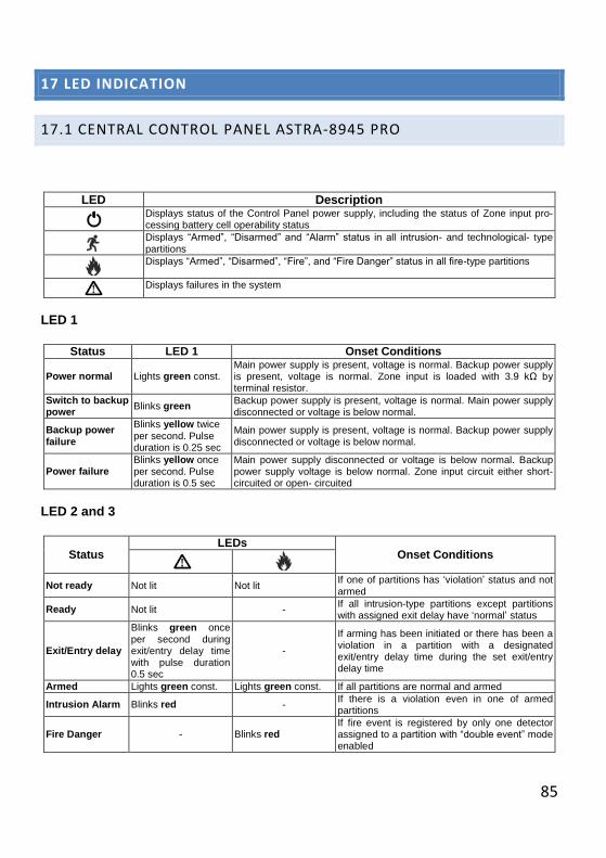
There are only 2 program options that require brief explanation: IP address … and Net-
work port number ….
84
1. In «IP-address or computer name with System Core installed» field in network so-
lution changes are necessary only if the Monitor is installed on a PC where Core
is not installed. In case it is one and the same PC, the default value 127.0.0.1
should be used. The IP address or computer name are changed during MSS in-
stallation process (see «MSS Quick Installation Guide»), here you should only
check the value.
2. Running System Core on a PC connected with the Control Panel via USB leads to
automatic opening of the internal communication port 8945. With newer versions of
the System Core there will be the possibility to change the port number in order to
avoid collisions connected with the port occupancy. For this purpose the Monitor
Module already has the possibility to change port number in the "Number of the
network port on a computer running the system core:" field.
5) An Engineer is allowed to monitor status of devices and logical partitions, view sys-
tem failures and analyze system event log via WKP/HKP menu.
An Engineer, as well as a Technician, is allowed to change internal WKP/HKP settings
and correct system date/time provided the Control Panel is not connected to a PC with
System Core launched. In the last case time/date are synchronized by the Core with PC
time/date.
An Engineer is allowed also to login WKP Astra-8145 Pro or HKP Astra-814 Pro menu
with default Engineer PIN 123456 to hold the following tests^
Keypad test
Backlight test
Buzzer test
Status check
For details, please, refer to WKP/HKP Operation Manual.
85
17 LED INDICATION
17.1 CENTRAL CONTROL PANEL ASTRA-8945 PRO
LED Description
Displays status of the Control Panel power supply, including the status of Zone input pro-cessing battery cell operability status
Displays “Armed”, “Disarmed” and “Alarm” status in all intrusion- and technological- type partitions
Displays “Armed”, “Disarmed”, “Fire”, and “Fire Danger” status in all fire-type partitions
Displays failures in the system
LED 1
Status LED 1 Onset Conditions
Power normal Lights green const. Main power supply is present, voltage is normal. Backup power supply is present, voltage is normal. Zone input is loaded with 3.9 kΩ by terminal resistor.
Switch to backup power
Blinks green Backup power supply is present, voltage is normal. Main power supply disconnected or voltage is below normal.
Backup power failure
Blinks yellow twice per second. Pulse duration is 0.25 sec
Main power supply is present, voltage is normal. Backup power supply disconnected or voltage is below normal.
Power failure Blinks yellow once per second. Pulse duration is 0.5 sec
Main power supply disconnected or voltage is below normal. Backup power supply voltage is below normal. Zone input circuit either short-circuited or open- circuited
LED 2 and 3
Status LEDs
Onset Conditions
Not ready Not lit Not lit If one of partitions has ‘violation’ status and not armed
Ready Not lit - If all intrusion-type partitions except partitions with assigned exit delay have ‘normal’ status
Exit/Entry delay
Blinks green once
per second during exit/entry delay time with pulse duration 0.5 sec
-
If arming has been initiated or there has been a violation in a partition with a designated exit/entry delay time during the set exit/entry delay time
Armed Lights green const. Lights green const. If all partitions are normal and armed
Intrusion Alarm Blinks red - If there is a violation even in one of armed partitions
Fire Danger - Blinks red If fire event is registered by only one detector assigned to a partition with “double event” mode enabled
86
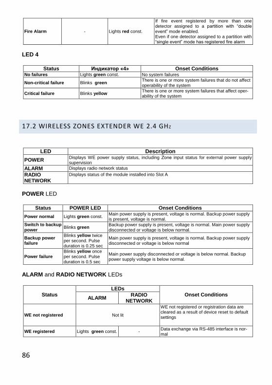
Fire Alarm - Lights red const.
If fire event registered by more than one detector assigned to a partition with “double event” mode enabled. Even if one detector assigned to a partition with “single event” mode has registered fire alarm
LED 4
Status Индикатор «4» Onset Conditions No failures Lights green const. No system failures
Non-critical failure Blinks green There is one or more system failures that do not affect operability of the system
Critical failure Blinks yellow There is one or more system failures that affect oper-ability of the system
17.2 WIRELESS ZONES EXTENDER WE 2.4 GHZ
LED Description
POWER Displays WE power supply status, including Zоne input status for external power supply supervision
ALARM Displays radio network status
RADIO NETWORK
Displays status of the module installed into Slot А
POWER LED
Status POWER LED Onset Conditions
Power normal Lights green const. Main power supply is present, voltage is normal. Backup power supply is present, voltage is normal.
Switch to backup power
Blinks green Backup power supply is present, voltage is normal. Main power supply disconnected or voltage is below normal.
Backup power failure
Blinks yellow twice per second. Pulse duration is 0.25 sec
Main power supply is present, voltage is normal. Backup power supply disconnected or voltage is below normal
Power failure Blinks yellow once per second. Pulse duration is 0.5 sec
Main power supply disconnected or voltage is below normal. Backup power supply voltage is below normal.
ALARM and RADIO NETWORK LEDs
Status LEDs
Onset Conditions ALARM
RADIO NETWORK
WE not registered Not lit
WE not registered or registration data are cleared as a result of device reset to default settings
WE registered Lights green const. - Data exchange via RS-485 interface is nor-mal
87
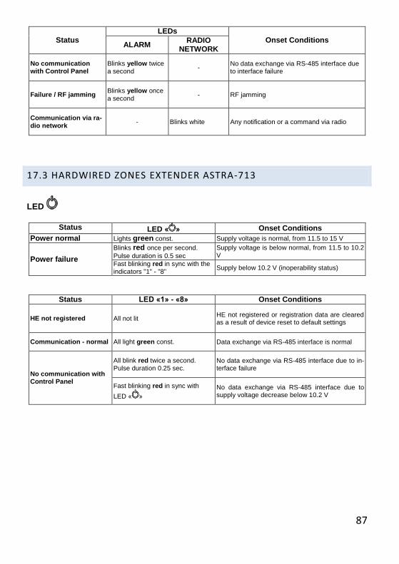
Status LEDs
Onset Conditions ALARM
RADIO NETWORK
No communication with Control Panel
Blinks yellow twice a second
- No data exchange via RS-485 interface due to interface failure
Failure / RF jamming Blinks yellow once a second
- RF jamming
Communication via ra-dio network
- Blinks white Any notification or a command via radio
17.3 HARDWIRED ZONES EXTENDER ASTRA-713
LED
Status LED « » Onset Conditions Power normal Lights green const. Supply voltage is normal, from 11.5 to 15 V
Power failure
Blinks red once per second.
Pulse duration is 0.5 sec
Supply voltage is below normal, from 11.5 to 10.2 V
Fast blinking red in sync with the indicators "1" - "8"
Supply below 10.2 V (inoperability status)
Status LED «1» - «8» Onset Conditions
HE not registered All not lit HE not registered or registration data are cleared as a result of device reset to default settings
Communication - normal All light green const. Data exchange via RS-485 interface is normal
No communication with Control Panel
All blink red twice a second. Pulse duration 0.25 sec.
No data exchange via RS-485 interface due to in-terface failure
Fast blinking red in sync with
LED « »
No data exchange via RS-485 interface due to supply voltage decrease below 10.2 V
88
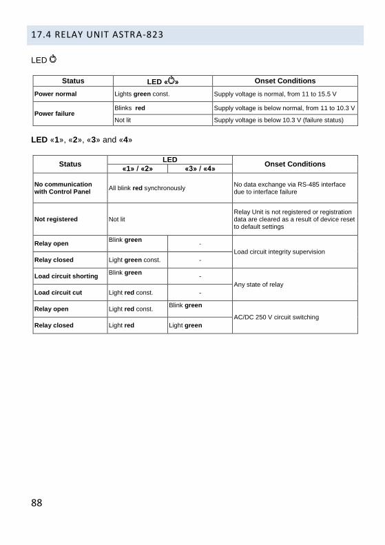
17.4 RELAY UNIT ASTRA-823
LED
Status LED « » Onset Conditions
Power normal Lights green const. Supply voltage is normal, from 11 to 15.5 V
Power failure Blinks red Supply voltage is below normal, from 11 to 10.3 V
Not lit Supply voltage is below 10.3 V (failure status)
LED «1», «2», «3» and «4»
Status LED
Onset Conditions «1» / «2» «3» / «4»
No communication with Control Panel
All blink red synchronously No data exchange via RS-485 interface due to interface failure
Not registered Not lit Relay Unit is not registered or registration data are cleared as a result of device reset to default settings
Relay open Blink green
-
Load circuit integrity supervision
Relay closed Light green const. -
Load circuit shorting Blink green
-
Any state of relay
Load circuit cut Light red const. -
Relay open Light red const. Blink green
AC/DC 250 V circuit switching
Relay closed Light red Light green
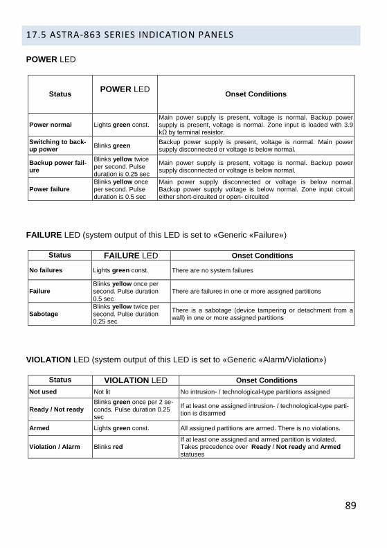
89
17.5 ASTRA-863 SERIES INDICATION PANELS
POWER LED
Status POWER LED
Onset Conditions
Power normal Lights green const. Main power supply is present, voltage is normal. Backup power supply is present, voltage is normal. Zone input is loaded with 3.9 kΩ by terminal resistor.
Switching to back-up power
Blinks green Backup power supply is present, voltage is normal. Main power supply disconnected or voltage is below normal.
Backup power fail-ure
Blinks yellow twice per second. Pulse duration is 0.25 sec
Main power supply is present, voltage is normal. Backup power supply disconnected or voltage is below normal.
Power failure Blinks yellow once per second. Pulse duration is 0.5 sec
Main power supply disconnected or voltage is below normal. Backup power supply voltage is below normal. Zone input circuit either short-circuited or open- circuited
FAILURE LED (system output of this LED is set to «Generic «Failure»)
Status FAILURE LED Onset Conditions
No failures Lights green const. There are no system failures
Failure Blinks yellow once per
second. Pulse duration 0.5 sec
There are failures in one or more assigned partitions
Sabotage Blinks yellow twice per second. Pulse duration 0.25 sec
There is a sabotage (device tampering or detachment from a wall) in one or more assigned partitions
VIOLATION LED (system output of this LED is set to «Generic «Alarm/Violation»)
Status VIOLATION LED Onset Conditions
Not used Not lit No intrusion- / technological-type partitions assigned
Ready / Not ready Blinks green once per 2 se-
conds. Pulse duration 0.25 sec
If at least one assigned intrusion- / technological-type parti-tion is disarmed
Armed Lights green const. All assigned partitions are armed. There is no violations.
Violation / Alarm Blinks red If at least one assigned and armed partition is violated. Takes precedence over Ready / Not ready and Armed statuses

90
TEST LED (system output of this LED is set to «Generic «Test»)
Status TEST LED Onset Conditions
Standby mode Not lit Test is not performed
Test Lights yellow const. Test of LEDs and functionality is performed
FIRE DANGER LED (system output of this LED is set to «Generic «Fire Danger»)
Status FIRE DANNGER
LED Onset Conditions
Not used Not lit There are no partitions with double-event mode enabled and assigned to any LED
Not ready Blinks green once per 2 seconds. Pulse duration 0.25 sec
Among partitions with double-event mode enabled and as-signed to any LED(s) at least one is disarmed and has ‘not ready’ status
Normal Lights green const. No Fire Danger detected in assigned partitions with dou-ble-event mode enabled
Fire Danger Blinks red Fire Danger detected in one of the assigned partitions with double-event mode enabled
FIRE ALARM LED (system output of this LED is set to «Generic «Fire Alarm»)
Status FIRE ALARM LED Onset Conditions
Not used Not lit There are no partitions assigned to any LED
Not ready Blinks green once per 2 seconds. Pulse duration 0.25 sec
Among partitions assigned to any LED(s) at least one is disarmed and has ‘not ready’ status
Normal Lights green const. No Fire Alarm detected in assigned partitions
Fire Alarm Lights red const. Fire Alarm detected in one of the assigned partitions
In current system version «SYSTEMS START», «SYSTEMS ON» и «SYSTEMS STOP»
LEDs are not enabled.
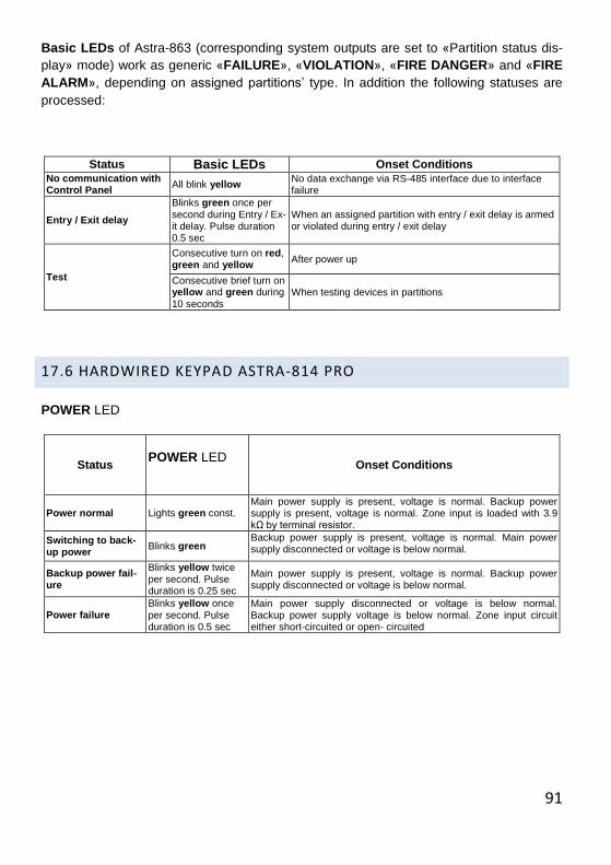
91
Basic LEDs of Astra-863 (corresponding system outputs are set to «Partition status dis-
play» mode) work as generic «FAILURE», «VIOLATION», «FIRE DANGER» and «FIRE
ALARM», depending on assigned partitions’ type. In addition the following statuses are
processed:
Status Basic LEDs Onset Conditions No communication with Control Panel
All blink yellow No data exchange via RS-485 interface due to interface failure
Entry / Exit delay
Blinks green once per second during Entry / Ex-it delay. Pulse duration 0.5 sec
When an assigned partition with entry / exit delay is armed or violated during entry / exit delay
Test
Consecutive turn on red, green and yellow
After power up
Consecutive brief turn on yellow and green during 10 seconds
When testing devices in partitions
17.6 HARDWIRED KEYPAD ASTRA-814 PRO
POWER LED
Status POWER LED
Onset Conditions
Power normal Lights green const. Main power supply is present, voltage is normal. Backup power supply is present, voltage is normal. Zone input is loaded with 3.9 kΩ by terminal resistor.
Switching to back-up power
Blinks green Backup power supply is present, voltage is normal. Main power supply disconnected or voltage is below normal.
Backup power fail-ure
Blinks yellow twice per second. Pulse duration is 0.25 sec
Main power supply is present, voltage is normal. Backup power supply disconnected or voltage is below normal.
Power failure Blinks yellow once per second. Pulse duration is 0.5 sec
Main power supply disconnected or voltage is below normal. Backup power supply voltage is below normal. Zone input circuit either short-circuited or open- circuited
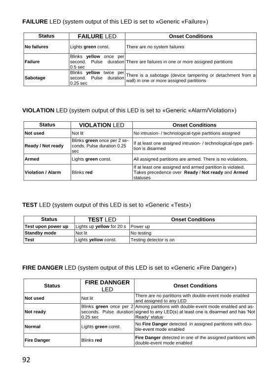
92
FAILURE LED (system output of this LED is set to «Generic «Failure»)
Status FAILURE LED Onset Conditions
No failures Lights green const. There are no system failures
Failure Blinks yellow once per second. Pulse duration 0.5 sec
There are failures in one or more assigned partitions
Sabotage Blinks yellow twice per second. Pulse duration 0.25 sec
There is a sabotage (device tampering or detachment from a wall) in one or more assigned partitions
VIOLATION LED (system output of this LED is set to «Generic «Alarm/Violation»)
Status VIOLATION LED Onset Conditions
Not used Not lit No intrusion- / technological-type partitions assigned
Ready / Not ready Blinks green once per 2 se-conds. Pulse duration 0.25 sec
If at least one assigned intrusion- / technological-type parti-tion is disarmed
Armed Lights green const. All assigned partitions are armed. There is no violations.
Violation / Alarm Blinks red If at least one assigned and armed partition is violated. Takes precedence over Ready / Not ready and Armed statuses
TEST LED (system output of this LED is set to «Generic «Test»)
Status TEST LED Onset Conditions
Test upon power up Lights up yellow for 20 s Power up
Standby mode Not lit No testing
Test Lights yellow const. Testing detector is on
FIRE DANGER LED (system output of this LED is set to «Generic «Fire Danger»)
Status FIRE DANNGER
LED Onset Conditions
Not used Not lit There are no partitions with double-event mode enabled and assigned to any LED
Not ready Blinks green once per 2 seconds. Pulse duration 0.25 sec
Among partitions with double-event mode enabled and as-signed to any LED(s) at least one is disarmed and has ‘Not Ready’ status
Normal Lights green const. No Fire Danger detected in assigned partitions with dou-ble-event mode enabled
Fire Danger Blinks red Fire Danger detected in one of the assigned partitions with double-event mode enabled
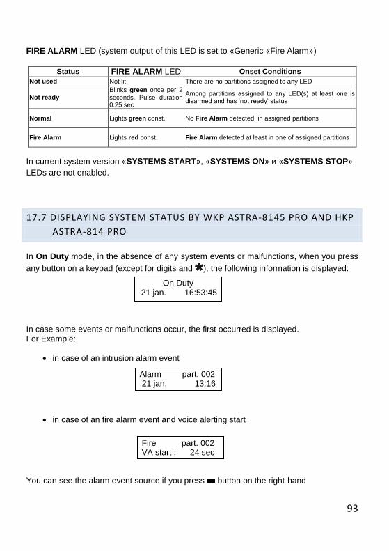
93
FIRE ALARM LED (system output of this LED is set to «Generic «Fire Alarm»)
Status FIRE ALARM LED Onset Conditions
Not used Not lit There are no partitions assigned to any LED
Not ready Blinks green once per 2 seconds. Pulse duration 0.25 sec
Among partitions assigned to any LED(s) at least one is disarmed and has ‘not ready’ status
Normal Lights green const. No Fire Alarm detected in assigned partitions
Fire Alarm Lights red const. Fire Alarm detected at least in one of assigned partitions
In current system version «SYSTEMS START», «SYSTEMS ON» и «SYSTEMS STOP»
LEDs are not enabled.
17.7 DISPLAYING SYSTEM STATUS BY WKP ASTRA-8145 PRO AND HKP
ASTRA-814 PRO
In On Duty mode, in the absence of any system events or malfunctions, when you press
any button on a keypad (except for digits and ), the following information is displayed:
In case some events or malfunctions occur, the first occurred is displayed. For Example:
in case of an intrusion alarm event
in case of an fire alarm event and voice alerting start
You can see the alarm event source if you press button on the right-hand
On Duty 21 jan. 16:53:45
Alarm part. 002 21 jan. 13:16
Fire part. 002 VA start : 24 sec
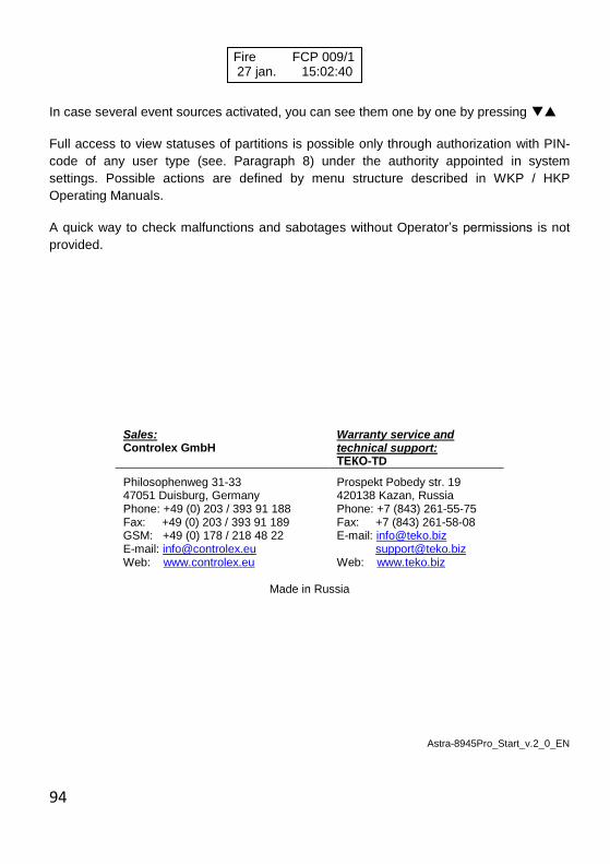
94
In case several event sources activated, you can see them one by one by pressing
Full access to view statuses of partitions is possible only through authorization with PIN-
code of any user type (see. Paragraph 8) under the authority appointed in system
settings. Possible actions are defined by menu structure described in WKP / HKP
Operating Manuals.
A quick way to check malfunctions and sabotages without Operator’s permissions is not
provided.
Sales: Controlex GmbH
Warranty service and technical support: ТЕКО-TD
Philosophenweg 31-33 47051 Duisburg, Germany Phone: +49 (0) 203 / 393 91 188 Fax: +49 (0) 203 / 393 91 189 GSM: +49 (0) 178 / 218 48 22 E-mail: [email protected] Web: www.controlex.eu
Prospekt Pobedy str. 19 420138 Kazan, Russia Phone: +7 (843) 261-55-75 Fax: +7 (843) 261-58-08 E-mail: [email protected] [email protected] Web: www.teko.biz
Made in Russia
Astra-8945Pro_Start_v.2_0_EN
Fire FCP 009/1 27 jan. 15:02:40
Related Documents