Welcome message from author
This document is posted to help you gain knowledge. Please leave a comment to let me know what you think about it! Share it to your friends and learn new things together.
Transcript

WIRELESSINTERNET
Technologies, Standards,and Applications
HANDBOOK

This new book series presents the latest research and technologicaldevelopments in the field of internet and multimedia systems and applications.We remain committed to publishing high-quality reference and technicalbooks written by experts in the field.
If you are interested in writing, editing, or contributing to a volume inthis series, or if you have suggestions for needed books, please contactDr. Borko Furht at the following address:
Borko Furht, Ph.D., DirectorMultimedia Laboratory
Department of Computer Science and EngineeringFlorida Atlantic University
777 Glades RoadBoca Raton, FL 33431 U.S.A.
E-mail: [email protected]
INTERNET and COMMUNICATIONS

CRC PR ESSBoca Raton London New York Washington, D.C.
WIRELESSINTERNET
Technologies, Standards,and Applications
Edited byBorko Furht, Ph.D.
Mohammad Ilyas, Ph.D.
HANDBOOK

This book contains information obtained from authentic and highly regarded sources. Reprinted materialis quoted with permission, and sources are indicated. A wide variety of references are listed. Reasonableefforts have been made to publish reliable data and information, but the author and the publisher cannotassume responsibility for the validity of all materials or for the consequences of their use.
Neither this book nor any part may be reproduced or transmitted in any form or by any means, electronicor mechanical, including photocopying, microfilming, and recording, or by any information storage orretrieval system, without prior permission in writing from the publisher.
All rights reserved. Authorization to photocopy items for internal or personal use, or the personal orinternal use of specific clients, may be granted by CRC Press LLC, provided that $1.50 per pagephotocopied is paid directly to Copyright Clearance Center, 222 Rosewood Drive, Danvers, MA 01923USA. The fee code for users of the Transactional Reporting Service is ISBN 0-8493-1502-6/03/$0.00+$1.50.The fee is subject to change without notice. For organizations that have been granted a photocopy licenseby the CCC, a separate system of payment has been arranged.
The consent of CRC Press LLC does not extend to copying for general distribution, for promotion, forcreating new works, or for resale. Specific permission must be obtained in writing from CRC Press LLCfor such copying.
Direct all inquiries to CRC Press LLC, 2000 N.W. Corporate Blvd., Boca Raton, Florida 33431.
Trademark Notice: Product or corporate names may be trademarks or registered trademarks, and areused only for identification and explanation, without intent to infringe.
Visit the CRC Press Web site at www.crcpress.com
© 2003 by CRC Press LLC Auerbach is an imprint of CRC Press LLC
No claim to original U.S. Government worksInternational Standard Book Number 0-8493-1502-6
Library of Congress Card Number 2002038795
Library of Congress Cataloging-in-Publication Data
Wireless internet handbook : technologies, standards, and applications / editors, BorkoFurht, Mohammad Ilyas.
p. cm.Includes bibliographical references and index.ISBN 0-8493-1502-6 (alk. paper) 1. Wireless Internet--Handbooks, manuals, etc. I. Furht, Borivoje. II. Ilyas,
Mohammad, 1953-
TK5103.4885 .W5714 2003 004.67'8--dc21
2002038795
This edition published in the Taylor & Francis e-Library, 2005.
collection of thousands of eBooks please go to www.eBookstore.tandf.co.uk.”“To purchase your own copy of this or any of Taylor & Francis or Routledge’s
ISBN 0-203-01169-4 Master e-book ISBN
Preface
Just a few years ago, the only way to access the Internet and the Web was by usingwireline desktop and laptop computers. Today, however, users are traveling betweencorporate offices and customer sites, and there is a great need to access the Internetthrough wireless devices. The wireless revolution started with wireless phones andcontinued with Web phones and wireless handheld devices that can access theInternet. Many nations and corporations are making enormous efforts to establish awireless infrastructure, including declaring new wireless spectrum, building newtowers, and inventing new handheld devices, high-speed chips, and protocols.
The purpose of the Handbook of Wireless Internet is to provide a comprehensivereference on advanced topics in this field. The Handbook is intended both forresearchers and practitioners in the field, and for scientists and engineers involvedin the design and development of the wireless Internet and its applications. TheHandbook can also be used as the textbook for graduate courses in the area of thewireless Internet.
This Handbook is comprised of 24 chapters that cover various aspects of wirelesstechnologies, networks, architectures, and applications. Part I, Basic Concepts, intro-duces fundamental wireless concepts and techniques, including various generationsof wireless systems, security aspects of wireless Internet, and current industry trends.
Part II, Technologies and Standards, covers multimedia and video streamingover the wireless Internet, voice service over the wireless Internet, and wirelessstandards such as IEEE 802.11 (for wireless LANs) and Wireless Application Pro-tocol.
Part III, Networks and Architectures, consists of chapters dealing with issuessuch as user mobility in IP networks, location-prediction techniques, wireless localaccess techniques, multiantenna technology, Bluetooth-based wireless systems, adhoc networks, and others.
Part IV, Applications, includes chapters describing typical applications enabledby wireless Internet, including M-commerce, telemedicine, delivering music, andothers.
We would like to thank the authors, who are experts in the field, for theircontributions of individual chapters to the Handbook. Without their expertise andeffort, this handbook would never have come to fruition. CRC Press editors andstaff also deserve our sincere recognition for their support throughout the project.
Borko Furht and Mohammad IlyasBoca Raton, Florida

This page intentionally left blank
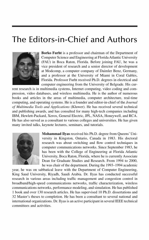
The Editors-in-Chief and AuthorsBorko Furht is a professor and chairman of the Department ofComputer Science and Engineering at Florida Atlantic University(FAU) in Boca Raton, Florida. Before joining FAU, he was avice president of research and a senior director of developmentat Modcomp, a computer company of Daimler Benz, Germany,and a professor at the University of Miami in Coral Gables,Florida. Professor Furht received Ph.D. degrees in electrical andcomputer engineering from the University of Belgrade. His cur-
rent research is in multimedia systems, Internet computing, video coding and com-pression, video databases, and wireless multimedia. He is the author of numerousbooks and articles in the areas of multimedia, computer architecture, real-timecomputing, and operating systems. He is a founder and editor-in-chief of the Journalof Multimedia Tools and Applications (Kluwer). He has received several technicaland publishing awards, and has consulted for many high-tech companies includingIBM, Hewlett-Packard, Xerox, General Electric, JPL, NASA, Honeywell, and RCA.He has also served as a consultant to various colleges and universities. He has givenmany invited talks, keynote lectures, seminars, and tutorials.
Mohammad Ilyas received his Ph.D. degree from Queens’ Uni-versity in Kingston, Ontario, Canada in 1983. His doctoralresearch was about switching and flow control techniques incomputer communications networks. Since September 1983, hehas been with the College of Engineering at Florida AtlanticUniversity, Boca Raton, Florida, where he is currently AssociateDean for Graduate Studies and Research. From 1994 to 2000,he was chair of the department. During the 1993–1994 academic
year, he was on sabbatical leave with the Department of Computer Engineering,King Saud University, Riyadh, Saudi Arabia. Dr. Ilyas has conducted successfulresearch in various areas including traffic management and congestion control inbroadband/high-speed communications networks, traffic characterization, wirelesscommunications networks, performance modeling, and simulation. He has published1 book and over 130 research articles. He has supervised 10 Ph.D. dissertations and32 Master’s theses to completion. He has been a consultant to several national andinternational organizations. Dr. Ilyas is an active participant in several IEEE technicalcommittees and activities.

This page intentionally left blank

Contributors
Kalyan BasuCenter for Research in Wireless Mobility
and NetworkingDepartment of Computer Science and
EngineeringThe University of Texas at ArlingtonArlington, Texas
Nitish BarmanDepartment of Computer Science and
EngineeringFlorida Atlantic UniversityBoca Raton, Florida
Amiya BhattacharyaCenter for Research in Wireless Mobility
and NetworkingDepartment of Computer Science and
EngineeringThe University of Texas at ArlingtonArlington, Texas
Jill BoyceCorporate ResearchThomson MultimediaPrinceton, New Jersey
Stefano CacciaguerraDepartment of Computer ScienceUniversity of BolognaBologna, Italy
Jonathan ChanCSIRO Centre for Networking
Technologies for the Information Economy
Collingswood, Australia
Christine ChengDepartment of Electrical Engineering
and Computer ScienceUniversity of Wisconsin-MilwaukeeMilwaukee, Wisconsin
Igor D.D. CurcioNokia CorporationTampere, Finland
Sajal K. DasCenter for Research in Wireless Mobility
and NetworkingDepartment of Computer Science and
EngineeringThe University of Texas at ArlingtonArlington, Texas
Ahmed K. ElhakeemConcordia UniversityMontreal, Quebec, Canada
Stefano FerrettiDepartment of Computer ScienceUniversity of BolognaBologna, Italy
Mark L. FerreyMinnesota Pollution Control AgencySite Remediation SectionSt. Paul, Minnesota
David FurunoAdvanced Wireless GroupGeneral Atomics, Photonics
DivisionSan Diego, California

Borko FurhtFlorida Atlantic UniversityDepartment of Computer Science and
EngineeringBoca Raton, Florida
José Antonio Garcia-MaciasCICESE Research CenterEsenada, Mexico
Vittorio GhiniDepartment of Computer ScienceUniversity of BolognaBologna, Italy
David GoodmanDepartment of Electrical and Computer
EngineeringPolytechnic UniversityBrooklyn, New York
Kevin HungJoint Research Center for Biomedical
EngineeringDepartment of Electronic EngineeringThe Chinese University of Hong KongShatin, Hong Kong
Mohammad IlyasFlorida Atlantic UniversityDepartment of Computer Science and
EngineeringBoca Raton, Florida
Ravi JainDoCoMo USA LabsSan Jose, California
Sanjay JhaSchool of Computer Science and
EngineeringUniversity New South WalesSydney, Australia
Björn LandfeldtSchool of Information Technologies and
School of Electrical and Information Engineering
The University of SydneySydney, Australia
Dennis Seymour LeeForest Hills, New York
Andres Llana, Jr.Vermont Studies Group, Inc.King of Prussia, Pennsylvania
Angel LozanoWireless Communication Research
DepartmentBell Laboratories (Lucent Technologies)Holmdel, New Jersey
Oge MarquesDepartment of Computer Science and
EngineeringFlorida Atlantic UniversityBoca Raton, Florida
Archan MisraIBM T.J. Watson Research CenterHawthorne, New York
Amitava MukherjeeIBM Global ServiceCalcutta, India
Gopal RacherlaAdvanced Wireless GroupGeneral Atomics, Photonics DivisionSan Diego, California
Sridhar RadhakrishnanSchool of Computer ScienceUniversity of OklahomaNorman, Oklahoma

G. RadhamaniFaculty of Information TechnologyMultimedia UniversityCyberjaya CampusSelangor D.E., Malaysia
Mahesh S. RaisinghaniCenter for Applied Information
TechnologyGraduate School of ManagementUniversity of DallasDallas, Texas
Marco RoccettiDepartment of Computer ScienceUniversity of BolognaBologna, Italy
Valerie A. RosenblattW StyleBurlingame, California
Abhishek RoyCenter for Research in Wireless Mobility
and NetworkingDepartment of Computer Science and
EngineeringThe University of Texas at ArlingtonArlington, Texas
Debashis SahaIndian Institute of ManagementCalcutta, India
Paola SalomoniDepartment of Computer ScienceUniversity of BolognaBologna, Italy
Aruna SeneviratneSchool of Electrical Engineering and
TelecommunicationsThe University of New South WalesKensington, Australia
Mohammad Umar SiddiqiFaculty of EngineeringMultimedia UniversityCyberjaya CampusSelangor D.E., Malaysia
Sirin TekinayDepartment of Electrical and Computer
EngineeringNew Jersey Institute of TechnologyNewark, New Jersey
Binh ThaiSchool of Electrical Engineering and
TelecommunicationsThe University of New South WalesKensington, Australia
Leyla ToumiLSR-IMAGCNSR/INPGGrenoble, France
Eric van den BergApplied ResearchTelcordia TechnologiesMorristown, New Jersey
Yuan-Ting ZhangJoint Research Center for Biomedical
EngineeringDepartment of Electrical EngineeringThe Chinese University of Hong KongShatin, Hong Kong
Haitao ZhengBell LaboratoriesLucent TechnologiesHolmdel, New Jersey

This page intentionally left blank
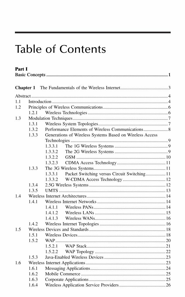
Table of Contents
Part IBasic Concepts .........................................................................................................1
Chapter 1 The Fundamentals of the Wireless Internet.........................................3
Abstract ......................................................................................................................41.1 Introduction ....................................................................................................41.2 Principles of Wireless Communications........................................................6
1.2.1 Wireless Technologies .....................................................................61.3 Modulation Techniques..................................................................................7
1.3.1 Wireless System Topologies............................................................71.3.2 Performance Elements of Wireless Communications.....................81.3.3 Generations of Wireless Systems Based on Wireless Access
Technologies ....................................................................................91.3.3.1 The 1G Wireless Systems ..............................................91.3.3.2 The 2G Wireless Systems ..............................................91.3.2.2 GSM .............................................................................101.3.2.3 CDMA Access Technology..........................................11
1.3.3 The 3G Wireless Systems..............................................................111.3.3.1 Packet Switching versus Circuit Switching.................111.3.3.2 W-CDMA Access Technology.....................................12
1.3.4 2.5G Wireless Systems ..................................................................121.3.5 UMTS ............................................................................................13
1.4 Wireless Internet Architectures....................................................................141.4.1 Wireless Internet Networks ...........................................................14
1.4.1.1 Wireless PANs..............................................................141.4.1.2 Wireless LANs .............................................................151.4.1.3 Wireless WANs.............................................................16
1.4.2 Wireless Internet Topologies .........................................................161.5 Wireless Devices and Standards ..................................................................18
1.5.1 Wireless Devices............................................................................181.5.2 WAP ...............................................................................................20
1.5.2.1 WAP Stack....................................................................211.5.2.2 WAP Topology .............................................................22
1.5.3 Java-Enabled Wireless Devices .....................................................231.6 Wireless Internet Applications .....................................................................23
1.6.1 Messaging Applications.................................................................241.6.2 Mobile Commerce .........................................................................251.6.3 Corporate Applications ..................................................................251.6.4 Wireless Application Service Providers ........................................26

1.6.5 Mobile Web Services.....................................................................261.6.6 Wireless Teaching and Learning ...................................................26
1.7 Future of Wireless Technology....................................................................271.8 Conclusions ..................................................................................................28References................................................................................................................29
Chapter 2 Wireless Internet > Wireless + Internet.............................................31
Abstract ....................................................................................................................312.1 Introduction ..................................................................................................322.2 WLANs and Cellular Networks: Comparison and Contrast.......................33
2.2.1 WLAN Trends ...............................................................................352.2.2 Cellular Trends ..............................................................................362.2.3 Uniting WLANs and Cellular .......................................................382.2.4 Personal Area Networks ................................................................382.2.5 Technology Gaps ...........................................................................39
2.3 Framework for Technology Creation...........................................................392.3.1 The Geography of Wireless Internet Users...................................402.3.2 The Geography of Information9 ...................................................412.3.3 The Geography of Signal Transmission........................................42
2.4 Research Initiatives ......................................................................................432.4.1 Adaptive Network Architectures ...................................................43
2.4.1.1 Proximity-Based Systems ............................................452.4.1.2 Cooperative Communications ......................................462.4.1.3 Hybrid Architectures ....................................................46
2.4.2 The IP-Based Core Network .........................................................482.4.2.1 Geolocation...................................................................482.4.2.2 Resource Management .................................................49
2.5 Conclusions ..................................................................................................50References................................................................................................................50
Chapter 3 Wireless Internet Security..................................................................53
3.1 Introduction ..................................................................................................533.2 Who Is Using the Wireless Internet?...........................................................543.3 What Types of Applications Are Available?................................................553.4 How Secure Are the Transmission Methods? .............................................56
3.4.1 Frequency Division Multiple Access Technology ........................573.4.2 Time Division Multiple Access Technology.................................573.4.3 Global Systems for Mobile Communications...............................583.4.4 Code Division Multiple Access Technology.................................603.4.5 Other Methods ...............................................................................61
3.5 How Secure Are Wireless Devices? ............................................................623.5.1 Authentication................................................................................623.5.2 Confidentiality................................................................................643.5.3 Malicious Code and Viruses..........................................................65
3.6 How Secure Are the Network Infrastructure Components? .......................663.6.1 The “Gap in WAP”........................................................................663.6.2 WAP Gateway Architectures .........................................................67
3.6.2.1 WAP Gateway at the Service Provider ........................673.6.2.2 WAP Gateway at the Host ...........................................683.6.2.3 Pass-Through from Service Provider’s WAP
Gateway to Host’s WAP Proxy....................................703.7 Conclusion....................................................................................................71Bibliography ............................................................................................................72
Part IITechnologies and Standards .................................................................................75
Chapter 4 Multimedia Streaming over Mobile Networks: European Perspective .........................................................................77
4.1 Introduction ..................................................................................................774.2 End-to-End System Architecture .................................................................794.3 The Challenges of Mobile Networks...........................................................80
4.3.1 Mobile Networks for Streaming....................................................814.3.1.1 Circuit-Switched Mobile Channels..............................814.3.1.2 Packet-Switched Mobile Channels ..............................84
4.4 Standards for Mobile Streaming..................................................................944.4.1 Release 4 PSS................................................................................94
4.4.1.1 Control and Scene Description Elements ....................954.4.1.2 Media Elements............................................................96
4.4.2 Release 5 PSS................................................................................974.4.2.1 Control Elements..........................................................974.4.2.2 Media Elements............................................................98
4.5 Performance Issues of Mobile Streaming ...................................................984.5.1 Bearer Considerations..................................................................1004.5.2 RTCP............................................................................................1004.5.3 RTSP Signaling Issues.................................................................1014.5.4 Link Aliveness .............................................................................101
4.6 Conclusions ................................................................................................102References..............................................................................................................102
Chapter 5 Streaming Video over Wireless Networks .......................................105
5.1 Introduction ................................................................................................1055.2 Video Compression Standards ...................................................................106
5.2.1 H.261............................................................................................1065.2.2 MPEG-1 .......................................................................................1075.2.3 MPEG-2 .......................................................................................1075.2.4 H.263............................................................................................107

5.2.5 MPEG-4 .......................................................................................1085.2.6 JVT...............................................................................................109
5.3 Protocols.....................................................................................................1105.4 Streaming Video over the Internet.............................................................1115.5 Wireless Networks and Challenges ...........................................................114
5.5.1 Dynamic Link Characteristics .....................................................1155.5.2 Asymmetric Data Rate ................................................................1165.5.3 Resource Contention....................................................................116
5.6 Adaptation by Cross Layer Design ...........................................................1165.6.1 Application Transmission Adaptation .........................................1175.6.2 Transport Layer Transmission Adaptation ..................................1175.6.3 Network Layer and Link Layer Transmission Adaptation .........1195.6.4 Network and Channel Condition Estimation and Report ...........1195.6.5 Proxy Server ................................................................................119
5.7 Integrating the Adaptation for Streaming Video over Wireless Networks .............................................................................120
5.8 Conclusions ................................................................................................121References..............................................................................................................122
Chapter 6 Clustering and Roaming Techniques for IEEE 802.11 Wireless LANs .................................................................................127
Abstract ..................................................................................................................1276.1 Introduction ................................................................................................1276.2 Wireless LANs Clustering .........................................................................128
6.2.1 IAPP.............................................................................................1306.3 Location-Based Clustering.........................................................................1306.4 Graph-Based Clustering.............................................................................1366.5 Quasihierarchical Routing..........................................................................1426.6 Strict Hierarchical Routing ........................................................................1466.7 Conclusion..................................................................................................147References..............................................................................................................147
Chapter 7 VoIP Services in Wireless Networks ...............................................149
7.1 Introduction ................................................................................................1497.2 Wireless Networks .....................................................................................1517.3 Basis of Voice Coding................................................................................1547.4 Network Quality Requirements .................................................................1557.5 Overview of the H.323 Protocol................................................................1587.6 Overview of SIP.........................................................................................1617.7 RLP.............................................................................................................1637.8 H.323 Implementation Architecture ..........................................................165
7.8.1 Delay Analysis of H.323 Control Signaling over Wireless ........1687.8.2 Analysis of RTCP:CNAME Packet Delay..................................1697.8.3 H.323 Call Setup Message Delay Analysis ................................170
7.8.4 Average TCP Packet Transmission Delay...................................1717.8.4.1 Average TCP Packet Transmission Delay
without RLP ...............................................................1717.8.5 Average H.323 Call Setup Delay ................................................1727.8.6 Experimental Verification ............................................................172
7.9 Media Packet-Blocking Analysis in GPRS ...............................................1757.9.1 VoIP Traffic Blocking..................................................................178
7.10 Conclusion................................................................................................180References..............................................................................................................181
Chapter 8 Wireless Application Protocol (WAP) and Mobile Wireless Access................................................................................185
8.1 Introduction ................................................................................................1858.2 Wireless Application Protocol ...................................................................186
8.2.1 WAP Specification .......................................................................1878.3 WAP Solution Benefits ..............................................................................188
8.3.1 Benefits to the Service Provider..................................................1888.3.2 Benefits to the Manufacturer .......................................................1888.3.3 Developer Benefits.......................................................................189
8.4 Some Constraints of a WAP-Enabled Wireless Network..........................1898.4.1 Security Issues .............................................................................1898.4.2 Secure Applications Development...............................................190
8.5 Preparing for the Move Forward ...............................................................1908.6 Recent WAP Developments and Applications...........................................191
8.6.1 Information Search and Retrieval................................................1918.6.2 E-Mail and More .........................................................................1918.6.3 Banking and E-Commerce ..........................................................1928.6.4 Management Applications ...........................................................1928.6.5 GPS Positioning-Based Location Services .................................1938.6.6 WAP Mobile Wireless Moves Ahead..........................................193
8.7 Summary ....................................................................................................1938.7.1 The Future Expansion of Technology.........................................193
Part III Networks and Architectures ...............................................................................195
Chapter 9 User Mobility in IP Networks: Current Issues and Recent Developments ...................................................................................197
9.1 Introduction ................................................................................................1989.2 A Contemporary View of User Mobility...................................................199
9.2.1 Terminal Mobility........................................................................1999.2.1.1 Network Layer Mobility ............................................1999.2.1.2 Mobile IP....................................................................201

9.2.2 Personal Mobility ........................................................................2039.2.2.1 Universal Personal Telecommunication.....................2049.2.2.2 SIP ..............................................................................2059.2.2.3 Personal Mobility Systems that Support
User Location .............................................................2069.2.2.4 Personal Mobility Systems that Support
Personalization ...........................................................2079.3 Challenges and Recent Developments of Terminal Mobility ...................208
9.3.1 Mobile IP Enhancements.............................................................2089.3.1.1 Route Optimization ....................................................2089.3.1.2 Frequent Handover and Fast Location Updates ........2099.3.1.3 Tunneling across QoS Domains.................................2129.3.1.4 Link Layer Assisted Handover Detection..................2139.3.1.5 Discussion of Mobile IP Enhancements....................213
9.3.2 Higher-Layer Mobility Management ..........................................2149.3.3 Enhancements to Support Conversational Multimedia...............215
9.3.3.1 Advance Resource Reservation..................................2159.3.3.2 Reactive Enhancements to Support
Multimedia Delivery ..................................................2199.4 Challenges and Recent Developments of Personal Mobility....................220
9.4.1 Heterogeneity...............................................................................2209.4.2 Mobile Agents..............................................................................2219.4.3 Integrated Presence......................................................................221
9.4.3.1 IPMoA ........................................................................2229.5 Concluding Remarks..................................................................................222References..............................................................................................................223
Chapter 10 Wireless Local Access to the Mobile Internet ..............................227
10.1 Introduction ................................................................................................22710.2 Local Access Technologies ........................................................................228
10.2.1 The 802.11 Standard....................................................................22810.2.2 802.11 Architecture .....................................................................22910.2.3 The Physical Layer ......................................................................23010.2.4 The Data Link Layer ...................................................................23110.2.5 Other Related Standards ..............................................................232
10.2.5.1 HiperLAN...................................................................23210.2.5.2 Bluetooth ....................................................................234
10.2.6 WLAN Interoperability ...............................................................23510.3 Mobility and the Internet Protocols...........................................................236
10.3.1 The Problem of IP-Based Mobility.............................................23610.3.2 Mobile IP .....................................................................................23810.3.4 Mobile IP problems .....................................................................23910.3.5 Micro-Mobility ............................................................................240
10.4 Perspectives and Conclusions ....................................................................242References..............................................................................................................242

Chapter 11 Location Prediction Algorithms for Mobile Wireless Systems ....245
Abstract ..................................................................................................................24511.1 Introduction ................................................................................................24611.2 Preliminaries...............................................................................................248
11.2.1 Movement History .......................................................................24811.2.2 Approach......................................................................................249
11.3 Domain-Independent Algorithms...............................................................24911.3.1 The Order-K Markov Predictor ...................................................25011.3.2 The LZ-Based Predictors.............................................................251
11.3.2.1 The LZ Parsing Algorithm.........................................25111.3.2.2 Applying LZ to Prediction.........................................251
11.3.3 Other Approaches ........................................................................25511.4 Domain-Specific Heuristics .......................................................................256
11.4.1 Mobile Motion Prediction (MMP) ..............................................25611.4.2 Segment Matching .......................................................................25711.4.3 Hierarchical Location Prediction (HLP) .....................................25811.4.4 Other Approaches ........................................................................260
11.5 Conclusions ................................................................................................260Acknowledgments..................................................................................................261References..............................................................................................................261
Chapter 12 Handoff and Rerouting in Cellular Data Networks ......................265
12.1 Introduction ................................................................................................26612.1.1 Classification of Rerouting Schemes ..........................................26812.1.2 Related Work ...............................................................................269
12.2 Analysis of Rerouting Schemes.................................................................27112.2.1 Common Handshaking Signals for Rerouting Schemes.............271
12.2.1.1 Without Hints .............................................................27212.2.1.2 With Hints ..................................................................272
12.2.2 Full Rerouting..............................................................................27312.2.2.1 Implementations .........................................................27312.2.2.2 Special Metrics ...........................................................274
12.2.3 Partial Rerouting..........................................................................27412.2.3.1 Implementations .........................................................27512.2.3.2 Special Metrics ...........................................................276
12.2.4 Tree Rerouting .............................................................................27712.2.4.1 Tree-Group Rerouting ................................................27712.2.4.2 Tree-Virtual Rerouting ...............................................27712.2.4.3 Implementations .........................................................27712.2.4.4 Special Metrics ...........................................................279
12.2.5 Cell Forwarding Rerouting..........................................................28012.2.5.1 Implementations .........................................................28012.2.5.2 Special metrics ...........................................................280
12.3 Performance Evaluation of Rerouting Schemes........................................28112.3.1 Comparison of Rerouting Schemes.............................................282
12.3.1.1 Advantages and Disadvantages of the Rerouting Schemes.....................................................282
12.3.1.2 Metrics not Dependent on the Connection Length.........................................................................283
12.3.1.3 Metrics Dependent on the Connection Length..........28412.4 Mobile–Mobile Rerouting in Connection-Oriented Networks .................290
12.4.1 Problems in Mobile–Mobile Rerouting ......................................29112.4.1.1 Inefficiency .................................................................29112.4.1.2 Lack of Coordination .................................................291
12.4.2 Techniques for Mobile–Mobile Rerouting..................................29112.4.2.1 Biswas’ Strategy: Mobile Representative and
Segment-Based Rerouting..........................................29112.4.2.2 CBT (Core-Based Tree) Strategy: Extending
Biswas’ Work..............................................................29212.4.2.3 Ghai and Singh’s Strategy: Two-Level
Picocellular Rerouting................................................29212.4.2.4 EIA/TIA IS-41(c) Rerouting......................................29312.4.2.5 Racherla’s Framework for Mobile–Mobile
Rerouting ....................................................................29312.4.3 Comparison of Rerouting Schemes for Mobile–Mobile
Connections..................................................................................29412.5 Performance of Mobile–Mobile rerouting.................................................295
12.5.1 Total Rerouting Distance.............................................................29712.5.2 Cumulative Connection Path Length ..........................................30012.5.3 Number of Connections...............................................................302
12.6 Conclusion..................................................................................................302References..............................................................................................................304
Chapter 13 Wireless Communications Using Bluetooth..................................307
13.1 Introduction ................................................................................................30813.2 Overview ....................................................................................................309
13.2.1 Masters and Slaves ......................................................................31013.2.2 Frequency Hopping Spread Spectrum (FHSS) and
Time-Division Duplexing (TDD) ................................................31013.2.3 Piconets and Scatternets ..............................................................310
13.3 Protocol Stack ............................................................................................31113.3.1 The Radio Layer ..........................................................................31313.3.2 The Baseband Layer ....................................................................314
13.3.2.1 Device Addressing......................................................31413.3.2.2 Frequency Hopping ....................................................31513.3.2.3 Link Types (ACL and SCO) ......................................31513.3.2.4 Packet Definitions.......................................................31613.3.2.5 Logical Channels........................................................319

13.3.2.6 Channel Control .........................................................32013.3.2.7 Error Checking and Correction..................................32013.3.2.8 Security.......................................................................321
13.3.3 The LMP Layer ...........................................................................32213.3.4 The L2CAP Layer .......................................................................325
13.3.4.1 L2CAP Channel Management ...................................32713.3.5 The SDP Layer ............................................................................327
13.4 Bluetooth Profiles Specification.................................................................32913.4.1 GAP..............................................................................................32913.4.2 SDAP ...........................................................................................33013.4.3 SPP...............................................................................................33013.4.4 GOEP ...........................................................................................331
13.5 Additional Considerations..........................................................................33113.5.1 Power Management .....................................................................33113.5.2 Security ........................................................................................332
13.6 Concluding Remarks..................................................................................332Acknowledgment ...................................................................................................333References..............................................................................................................333
Chapter 14 Multiantenna Technology for High-Speed Wireless Internet Access ...............................................................................335
14.1 Introduction ................................................................................................33514.2 Fundamental Limits to Mobile Data Access .............................................336
14.2.1 Capacity and Bandwidth Efficiency............................................33614.2.2 Space: The Final Frontier............................................................33714.2.3 Pushing the Limits with Multiantenna Technology....................337
14.3 Models ........................................................................................................33814.4 Single-User Throughput.............................................................................341
14.4.1 Single-User Bandwidth Efficiency ..............................................34114.4.2 Transmit Diversity .......................................................................34214.4.3 Receive Diversity.........................................................................34214.4.4 Multiple-Transmit Multiple-Receive Architectures ....................343
14.5 System Throughput ....................................................................................34414.6 Implementation: Realizing the MTMR Potential......................................34614.7 Summary ....................................................................................................347References..............................................................................................................348
Chapter 15 Location Management in Mobile Wireless Networks...................351
Abstract ..................................................................................................................35215.1 Paging.........................................................................................................353
15.1.1 Blanket Paging.............................................................................35315.1.2 Different Paging Procedures........................................................354
15.2 Intelligent Paging Scheme .........................................................................35515.2.1 Sequential Intelligent Paging.......................................................358
15.2.2 Parallel-o-Sequential Intelligent Paging......................................35915.2.3 Comparison of Paging Costs .......................................................361
15.3 Other Paging Schemes ...............................................................................36215.3.1 Reverse Paging ............................................................................36215.3.2 Semireverse Paging......................................................................36315.3.3 Uniform Paging ...........................................................................363
15.4 Intersystem Paging .....................................................................................36315.5 IP Micromobility and Paging ....................................................................36515.6 Location Update.........................................................................................365
15.6.1 Location Update Static Strategies ...............................................36615.6.2 Location Update Dynamic Strategies..........................................367
15.7 Location Management................................................................................36915.7.1 Without Location Management ...................................................37015.7.2 Manual Registration in Location Management...........................37015.7.3 Automatic Location Management Using Location Area ............37015.7.4 Memoryless-Based Location Management Methods..................371
15.7.4.1 Database Architecture ................................................37115.7.4.2 Optimizing Fixed Network Architecture ...................37115.7.4.3 Combining Location Areas and Paging Areas...........37115.7.4.4 Multilayer LAs ...........................................................372
15.7.5 Memory-Based Location Management Methods........................37215.7.5.1 Dynamic LA and PA Size..........................................37215.7.5.2 Individual User Patterns .............................................372
15.7.6 Location Management in 3G-and-Beyond Systems ...................37315.8 Location Area Planning .............................................................................375
15.8.1 Two-Step Approach .....................................................................37515.8.2 LA Planning and Signaling Requirements..................................376
References..............................................................................................................378
Chapter 16 Mobile Ad Hoc Networks: Principles and Practices .....................381
16.1 Introduction ................................................................................................38216.2 A Wireless Ad Hoc Network Application .................................................38416.3 Issues for Protocol Layers in MANETs....................................................386
16.3.1 Application Layer ........................................................................38616.3.2 Transport Layer............................................................................38716.3.3 Network Layer and Routing........................................................38816.3.4 Data Link Layer...........................................................................39116.3.5 Physical Layer .............................................................................394
16.4 MANET Implementation: Related Technologies and Standards ..............39416.4.1 Software Technologies.................................................................395
16.4.1.1 Java and Jini ...............................................................39516.4.1.2 UPnP...........................................................................39716.4.1.3 OSGi ...........................................................................39716.4.1.4 HAVi ...........................................................................39716.4.1.5 P2P Computing ..........................................................398
16.4.2 Network technologies ..................................................................39816.4.2.1 Bluetooth ....................................................................39816.4.2.2 UWB...........................................................................39816.4.2.3 HiperLAN/1 and HiperLAN/2 ...................................39916.4.2.4 IEEE 802.11 ...............................................................39916.4.2.5 IEEE 802.15.3 ............................................................40016.4.2.6 HomeRF .....................................................................401
16.4.3 Hardware Technologies ...............................................................40116.4.3.1 Smart Wireless Sensors66 ..........................................40116.4.3.2 Smart Batteries67 .......................................................40116.4.3.3 Software-Defined Radio68 .........................................40216.4.3.4 GPS69.........................................................................402
16.5 Conclusion..................................................................................................402Acknowledgments..................................................................................................402References..............................................................................................................403
Chapter 17 Managing Location in “Universal” Location-Aware Computing...........................................................407
17.1 Introduction ................................................................................................40717.2 Location Resolution and Management Techniques in Pervasive
Computing Applications ............................................................................40917.2.1 IP Mobility Support over Cellular Systems................................40917.2.2 Mobile Information Services.......................................................41117.2.3 Tracking Systems.........................................................................41117.2.4 Additional Techniques .................................................................413
17.3 Pervasive Computing Requirements and Appropriate Location Representation ............................................................................41517.3.1 Geometric or Symbolic Representation? ....................................417
17.4 “Optimal” Location Tracking and Prediction in Symbolic Space............42017.4.1 The LeZi-Update Algorithm........................................................42117.4.2 Translation of Mobility Profiles during Vertical Handoffs .........422
17.5 Conclusion..................................................................................................423Acknowledgment ...................................................................................................424References..............................................................................................................424
Part IVApplications .........................................................................................................427
Chapter 18 Mobile and Wireless Internet Services: From Luxury to Commodity ................................................................................429
18.1 Introduction ................................................................................................42918.2 Evolution of Mobile Internet Services ......................................................43018.3 Slow Motion over Plain Old Cellular........................................................43118.4 Web Clipping over Pager Networks ..........................................................432

18.5 Primitive Digital Data over Packet-Switching Networks..........................43218.6 Moderate Speeds over Wireless WANs .....................................................43418.7 2.5G: Half-Step Forward to Wireless Broadband .....................................43518.8 i-mode: Wireless Internet Phenomenon.....................................................43718.9 3G: Redefining Wireless Internet Services................................................43818.10 High-Speed Wi-Fi: A Different Type of Wireless.....................................43918.11 Applications Are Key to Wireless Internet Growth ..................................441
Chapter 19 Wireless Technology Impacts the Enterprise Network .................443
19.1 Introduction ................................................................................................44319.2 Wireless Communications .........................................................................44419.3 Wireless Office Services (WOS) ...............................................................44519.4 More Integration.........................................................................................447
19.4.1 Wireless Local Area Networks....................................................44719.5 A New Standard.........................................................................................44819.6 Wireless Internet Access ............................................................................44919.7 Broadband Internet Access ........................................................................44919.8 Who Uses Wireless Technology? ..............................................................450
19.8.1 Consumer Applications................................................................45019.8.2 Transportation ..............................................................................45019.8.3 Health Care ..................................................................................45119.8.4 Manufacturing..............................................................................45119.8.5 Financial.......................................................................................452
19.9 Searching for a Wireless Solution .............................................................45219.10 Summary ....................................................................................................452
Chapter 20 An Efficient WAP-Enabled Transaction Processing Model for Mobile Database Systems ........................................................455
Abstract ..................................................................................................................45520.1 Introduction ................................................................................................45620.2 Background ................................................................................................45620.3 Mobility Applications ................................................................................45920.4 The WAP-Enabled Transaction Model ......................................................46120.5 A Sample Application................................................................................46320.6 Simulation Results .....................................................................................46420.7 Conclusion..................................................................................................467Acknowledgments..................................................................................................467References..............................................................................................................467
Chapter 21 Mobile Video Telephony................................................................469
21.1 Introduction ................................................................................................46921.2 End-to-End System Architecture ...............................................................47021.3 Mobile Networks for Video Telephony .....................................................473
21.4 Standards for Mobile Video Telephony.....................................................47521.4.1 Circuit-Switched Mobile Video Telephony.................................475
21.4.1.1 Media Elements..........................................................47621.4.1.2 System Control and Multiplexing..............................477
21.4.2 Packet-Switched Mobile Video Telephony .................................47921.4.2.1 Media Elements..........................................................48021.4.2.2 System Control ...........................................................48121.4.2.3 Call Control Issues .....................................................482
21.5 Performance Issues in Mobile Video Telephony.......................................48421.5.1 Error Resilience and QoS............................................................48421.5.2 Video QoS Metrics ......................................................................48521.5.3 Video Quality Results for 3G-324M...........................................48721.5.4 SIP Signaling Delay ....................................................................48921.5.5 RTCP Performance ......................................................................492
21.6 Conclusions ................................................................................................493Acknowledgments..................................................................................................493References..............................................................................................................494
Chapter 22 WAP: Transitional Technology for M-Commerce ........................497
Abstract ..................................................................................................................49722.1 Introduction ................................................................................................49822.2 Will WAP-Enabled Phones Dominate the Personal Computer
Marketplace? ..............................................................................................49922.3 WAP: A Global Standard...........................................................................50022.4 Operating Systems for WAP......................................................................50022.5 WAP Forum................................................................................................50222.6 Arguments for WAP...................................................................................50222.7 Arguments against WAP ............................................................................50222.8 Are Mobile Telephones Hazardous to Health? .........................................50322.9 Poor Security? ............................................................................................50322.10 WAP and M-Commerce.............................................................................50422.11 Critical Success Factors for M-Commerce ...............................................504
22.11.1 Speed..........................................................................................50422.11.2 Billing ........................................................................................50522.11.3 Security ......................................................................................505
22.12 Future Impact: Generation “W” in a Wireless World .............................507References..............................................................................................................509
Chapter 23 Wireless Internet in Telemedicine .................................................511
23.1 Introduction ................................................................................................51223.1.1 Definition of Telemedicine ..........................................................51223.1.2 Areas of Telemedicine Applications ...........................................51223.1.3 The Need for Telemedicine .........................................................51223.1.4 Chapter Overview........................................................................513
23.2 Telemedicine Applications .........................................................................51323.2.1 Brief History of Telemedicine.....................................................51323.2.2 Internet-Based Telemedicine Applications..................................51423.2.3 Importance of Mobility in Telemedicine ....................................515
23.3 Wireless Internet in Telemedicine .............................................................51523.3.1 Telemedicine Using Cellular Technologies.................................51523.3.2 Telemedicine Using Local Wireless Networks ...........................51723.3.3 Telemedicine Using Satellite Communication............................517
23.4 Case Study: WAP in Telemedicine............................................................51823.4.1 Objective ......................................................................................51823.4.2 Method .........................................................................................518
23.4.2.1 System Specification ..................................................51823.4.2.2 Overall Architecture ...................................................52023.4.2.3 Relational Database....................................................52123.4.2.4 Program for WAP Access...........................................52123.4.2.5 ECG Browsing and Feature Extraction .....................52223.4.2.6 Wireless Subsystem....................................................526
23.4.3 Results..........................................................................................52723.4.3.1 Emulation ...................................................................52723.4.3.2 Experience with WAP Phone .....................................527
23.4.4 Discussion ....................................................................................53123.5 Issues to Be Resolved ................................................................................532References..............................................................................................................533
Chapter 24 Delivering Music over the Wireless Internet: From Song Distribution to Interactive Karaoke on UMTS Devices ......537
Abstract ..................................................................................................................53824.1 Introduction ................................................................................................53824.2 System Issues .............................................................................................54024.3 A Wireless Internet Application for Music Distribution...........................542
24.3.1 Search and Download of Musical Resources .............................54324.3.2 Design Principles .........................................................................54424.3.3 Structuring Karaoke Clips ...........................................................549
24.4 An Experimental Study..............................................................................55124.4.1 UMTS Simulation Model ............................................................55224.4.2 Song-On-Demand: Measurement Architecture and Results .......55324.4.3 Mobile Karaoke: Measurement Architecture and Results ..........556
24.5 Related Work and Comparison ..................................................................55924.5.1 Distribution of Multimedia Resources over the Internet ............55924.5.2 Wireless Access to the Internet ...................................................56024.5.3 Multimedia Synchronization for Delivering Karaoke.................561
24.6 Concluding Remarks..................................................................................562Acknowledgments..................................................................................................564References..............................................................................................................564
Index......................................................................................................................567
Part I
Basic Concepts

This page intentionally left blank

30-8493-1502-6/03/$0.00+$1.50© 2003 by CRC Press LLC
1 The Fundamentals of the Wireless Internet
Borko Furht and Mohammad Ilyas
CONTENTS
Abstract ......................................................................................................................41.1 Introduction ......................................................................................................41.2 Principles of Wireless Communications..........................................................6
1.2.1 Wireless Technologies..........................................................................61.3 Modulation Techniques....................................................................................7
1.3.1 Wireless System Topologies ................................................................71.3.2 Performance Elements of Wireless Communications .........................81.3.3 Generations of Wireless Systems Based on Wireless Access
Technologies.........................................................................................91.3.3.1 The 1G Wireless Systems.....................................................91.3.3.2 The 2G Wireless Systems.....................................................91.3.2.2 GSM....................................................................................101.3.2.3 CDMA Access Technology ................................................11
1.3.3 The 3G Wireless Systems ..................................................................111.3.3.1 Packet Switching versus Circuit Switching .......................111.3.3.2 W-CDMA Access Technology ...........................................12
1.3.4 2.5G Wireless Systems ......................................................................121.3.5 UMTS.................................................................................................13
1.4 Wireless Internet Architectures......................................................................141.4.1 Wireless Internet Networks................................................................14
1.4.1.1 Wireless PANs ....................................................................141.4.1.2 Wireless LANs....................................................................151.4.1.3 Wireless WANs...................................................................16
1.4.2 Wireless Internet Topologies..............................................................161.5 Wireless Devices and Standards ....................................................................18
1.5.1 Wireless Devices ................................................................................181.5.2 WAP ...................................................................................................20
1.5.2.1 WAP Stack ..........................................................................211.5.2.2 WAP Topology....................................................................22
1.5.3 Java-Enabled Wireless Devices..........................................................231.6 Wireless Internet Applications .......................................................................23
1.6.1 Messaging Applications .....................................................................24

4 Handbook of Wireless Internet
1.6.2 Mobile Commerce..............................................................................251.6.3 Corporate Applications ......................................................................251.6.4 Wireless Application Service Providers ............................................261.6.5 Mobile Web Services .........................................................................261.6.6 Wireless Teaching and Learning........................................................26
1.7 Future of Wireless Technology......................................................................271.8 Conclusions ....................................................................................................28References................................................................................................................29
ABSTRACT
This chapter presents a comprehensive introduction to the field of wireless systems andtheir applications. We begin with the fundamental principles of wireless communica-tions, including modulation techniques, wireless system topologies, and performanceelements. Next, we present three generations of wireless systems based on accesstechniques, and we introduce the basic principles of frequency division multiple access,time division multiple access, and code division multiple access techniques. We discussvarious wireless Internet networks and architectures, including wireless personal areanetworks, local area networks, and wide area networks. We present common wirelessdevices and their features, as well as wireless standards such as Wireless ApplicationProtocol. A survey of present and future wireless applications is given, from messagingapplications to M-commerce, entertainment, and mobile Web services. We discussbriefly the future trends in wireless technologies and systems.
1.1 INTRODUCTION
The wireless Internet is coming of age! Millions of people worldwide already areusing Web phones and wireless handheld devices to access the Internet. Nations andcorporations are making enormous efforts to establish a wireless infrastructure,including declaring new wireless spectrum, building new towers, inventing newhandset devices and high-speed chips, and developing protocols.
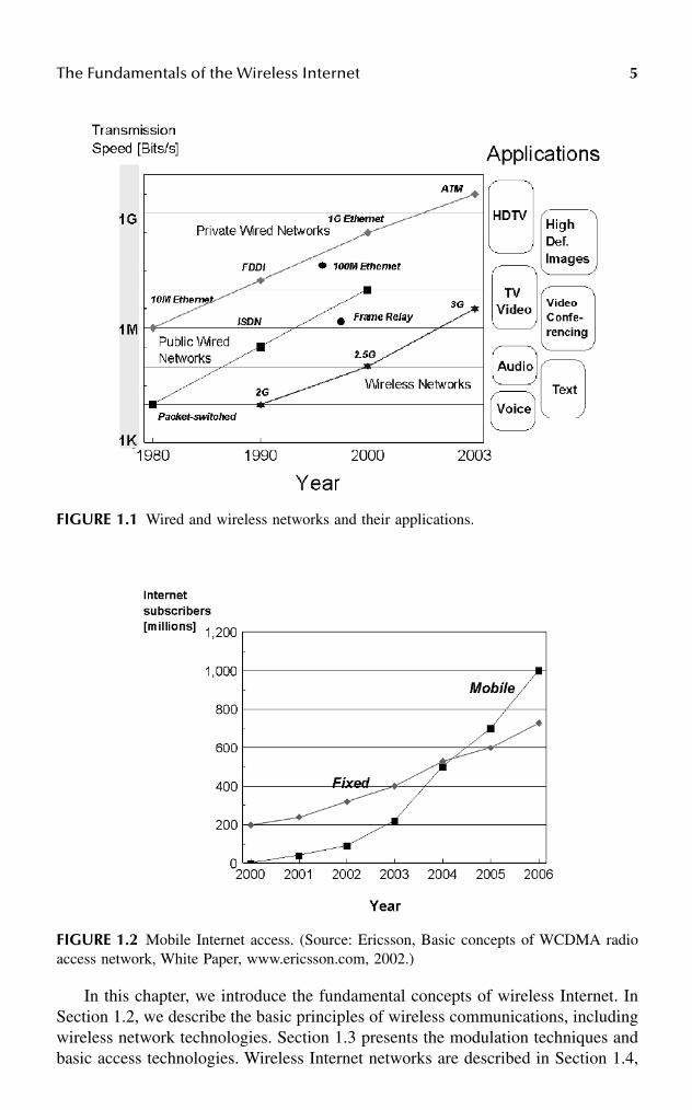
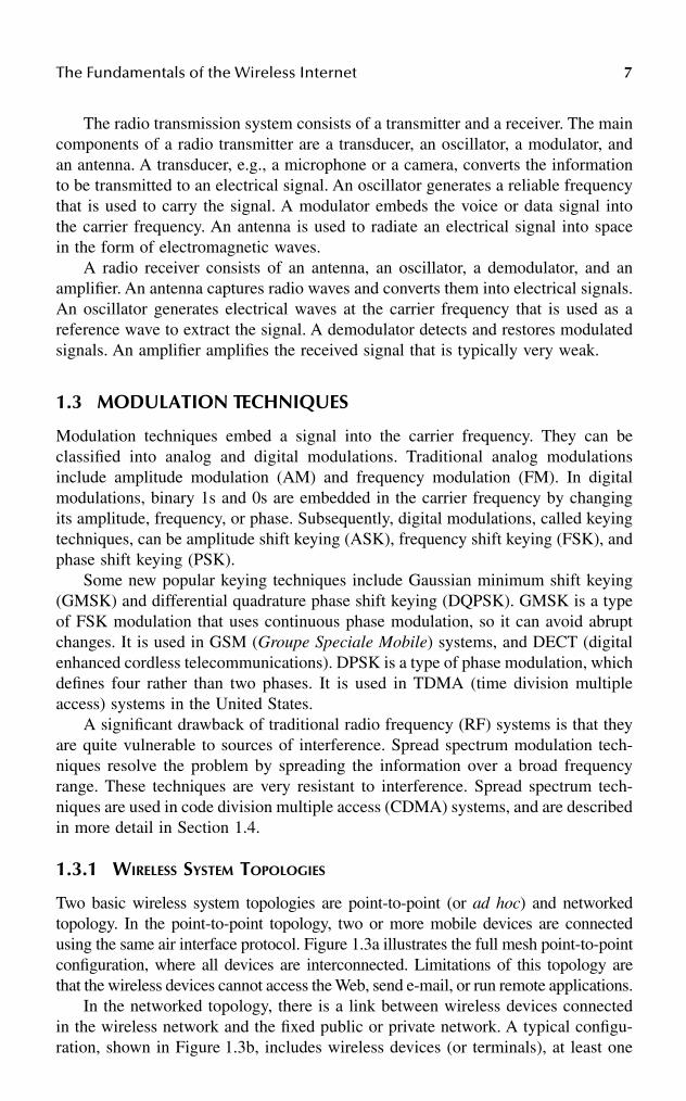
The adoption of the wireless Internet strictly depends on the mobile bandwidth,the bandwidth of access technologies. The current 2G wireless access technologiestransmit at 9.6 to 19.2 kbps. These speeds are much slower than the dial-up ratesof desktop PCs connecting to the Internet. However, 2.5G wireless technologiesalready in use provide speeds of 100 kbps, and 3G technologies with speeds of 2to 4 Mbps will allow wireless connections to run much faster than today’s wiredcable and DSL services. Figure 1.1 illustrates the transmission speeds of wirednetworks and their applications. This figure includes wireless access networks,showing that 2G networks are basically used for voice and text messaging, but 2.5Gnetworks and particularly 3G networks will open doors for many new wirelessapplications that use streaming video and multimedia.
Today, the number of subscribers with fixed Internet access is much higher thanthose with mobile Internet access. However, according to a forecast from Ericsson,in several years the number of mobile subscribers to the Internet will reach 1 billionand will be higher than those having fixed access (see Figure 1.2).
The Fundamentals of the Wireless Internet 5
In this chapter, we introduce the fundamental concepts of wireless Internet. InSection 1.2, we describe the basic principles of wireless communications, includingwireless network technologies. Section 1.3 presents the modulation techniques andbasic access technologies. Wireless Internet networks are described in Section 1.4,
FIGURE 1.1 Wired and wireless networks and their applications.
FIGURE 1.2 Mobile Internet access. (Source: Ericsson, Basic concepts of WCDMA radioaccess network, White Paper, www.ericsson.com, 2002.)

6 Handbook of Wireless Internet
while wireless devices and their functionality are presented in Section 1.5. Section1.6 gives an overview of current and potential wireless Internet applications, whilesome future trends in wireless technologies are discussed in Section 1.7. Concludingremarks are given in Section 1.8.
1.2 PRINCIPLES OF WIRELESS COMMUNICATIONS
In this section, we describe fundamental principles of wireless communications andrelated wireless technologies, including wireless radio and satellite communications.We introduce basic modulation techniques used in radio communications and twofundamental wireless system topologies: point-to-point and networked topologies.We discuss performance elements of wireless communications.
1.2.1 WIRELESS TECHNOLOGIES
Today, there are many wireless technologies that are used for a variety of applica-tions. Wireless radio communications are based on transmission of radio wavesthrough the air. Radio waves between 30 MHz and 20 GHz are used for datacommunications. The range lower than 30 MHz could support data communication;however, it is typically used for FM and AM radio broadcasting, because these wavesreflect on the Earth’s ionosphere to extend the communication. Radio waves over20 GHz may be absorbed by water vapor, and therefore, they are not suitable forlong distance communication. Table 1.1 shows radio frequencies used for wirelessradio applications in AM and FM radio, TV, GPS, and cell phones.1
Microwave transmission is based on the same principles as radio transmission.The microwave networks require a direct transmission path, high transmission tow-ers, and antennas. Microwave equipment in the United States operates at 18 to 23GHz. There are 23,000 microwave networks in the United States alone.
Satellite communications are used for a variety of broadcasting applications.The two most-popular frequency bands for satellite communications are C-band(frequency range 5.9 to 6.4 GHz for uplink and 3.7 to 4.2 GHz for downlink) andKu-band (frequency range 14 to 14.5 GHz for uplink and 11.7 to 12.2 GHz fordownlink). Recently, the Ku-band spectrum has been opened up to U.S. satellitecommunication, which receives at 30 GHz and sends at 20 GHz.
TABLE 1.1Radio Spectrum and Applications
Applications Frequency Spectrum
AM 535 to 1700 kHzFM 88 to 108 MHzTV 54 to 88, 174 to 220 MHzGPS 1200 to 1600 MHzCell phones 800 to 1000 MHz
1800 to 2000 MHz
The Fundamentals of the Wireless Internet 7
The radio transmission system consists of a transmitter and a receiver. The maincomponents of a radio transmitter are a transducer, an oscillator, a modulator, andan antenna. A transducer, e.g., a microphone or a camera, converts the informationto be transmitted to an electrical signal. An oscillator generates a reliable frequencythat is used to carry the signal. A modulator embeds the voice or data signal intothe carrier frequency. An antenna is used to radiate an electrical signal into spacein the form of electromagnetic waves.
A radio receiver consists of an antenna, an oscillator, a demodulator, and anamplifier. An antenna captures radio waves and converts them into electrical signals.An oscillator generates electrical waves at the carrier frequency that is used as areference wave to extract the signal. A demodulator detects and restores modulatedsignals. An amplifier amplifies the received signal that is typically very weak.
1.3 MODULATION TECHNIQUES
Modulation techniques embed a signal into the carrier frequency. They can beclassified into analog and digital modulations. Traditional analog modulationsinclude amplitude modulation (AM) and frequency modulation (FM). In digitalmodulations, binary 1s and 0s are embedded in the carrier frequency by changingits amplitude, frequency, or phase. Subsequently, digital modulations, called keyingtechniques, can be amplitude shift keying (ASK), frequency shift keying (FSK), andphase shift keying (PSK).
Some new popular keying techniques include Gaussian minimum shift keying(GMSK) and differential quadrature phase shift keying (DQPSK). GMSK is a typeof FSK modulation that uses continuous phase modulation, so it can avoid abruptchanges. It is used in GSM (Groupe Speciale Mobile) systems, and DECT (digitalenhanced cordless telecommunications). DPSK is a type of phase modulation, whichdefines four rather than two phases. It is used in TDMA (time division multipleaccess) systems in the United States.
A significant drawback of traditional radio frequency (RF) systems is that theyare quite vulnerable to sources of interference. Spread spectrum modulation tech-niques resolve the problem by spreading the information over a broad frequencyrange. These techniques are very resistant to interference. Spread spectrum tech-niques are used in code division multiple access (CDMA) systems, and are describedin more detail in Section 1.4.
1.3.1 WIRELESS SYSTEM TOPOLOGIES
Two basic wireless system topologies are point-to-point (or ad hoc) and networkedtopology. In the point-to-point topology, two or more mobile devices are connectedusing the same air interface protocol. Figure 1.3a illustrates the full mesh point-to-pointconfiguration, where all devices are interconnected. Limitations of this topology arethat the wireless devices cannot access the Web, send e-mail, or run remote applications.
In the networked topology, there is a link between wireless devices connectedin the wireless network and the fixed public or private network. A typical configu-ration, shown in Figure 1.3b, includes wireless devices (or terminals), at least one
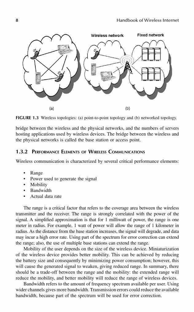
8 Handbook of Wireless Internet
bridge between the wireless and the physical networks, and the numbers of servershosting applications used by wireless devices. The bridge between the wireless andthe physical networks is called the base station or access point.
1.3.2 PERFORMANCE ELEMENTS OF WIRELESS COMMUNICATIONS
Wireless communication is characterized by several critical performance elements:
• Range• Power used to generate the signal• Mobility• Bandwidth• Actual data rate
The range is a critical factor that refers to the coverage area between the wirelesstransmitter and the receiver. The range is strongly correlated with the power of thesignal. A simplified approximation is that for 1 milliwatt of power, the range is onemeter in radius. For example, 1 watt of power will allow the range of 1 kilometer inradius. As the distance from the base station increases, the signal will degrade, and datamay incur a high error rate. Using part of the spectrum for error correction can extendthe range; also, the use of multiple base stations can extend the range.
Mobility of the user depends on the size of the wireless device. Miniaturizationof the wireless device provides better mobility. This can be achieved by reducingthe battery size and consequently by minimizing power consumption; however, thiswill cause the generated signal to weaken, giving reduced range. In summary, thereshould be a trade-off between the range and the mobility: the extended range willreduce the mobility, and better mobility will reduce the range of wireless devices.
Bandwidth refers to the amount of frequency spectrum available per user. Usingwider channels gives more bandwidth. Transmission errors could reduce the availablebandwidth, because part of the spectrum will be used for error correction.
FIGURE 1.3 Wireless topologies: (a) point-to-point topology and (b) networked topology.

The Fundamentals of the Wireless Internet 9
Actual data rate mostly depends on the bandwidth available to the user; however,there are some other factors that influence it, such as the movement of the transceiver,position of the cell, and density of users. The actual data rate is typically higher forstationary users than for users who are walking. Users traveling at high speed (suchas in cars or trains) have the lowest actual data rate. The reason for this is that partof the available bandwidth must be used for error correction due to greater interfer-ence that traveling users may experience.
Similarly, interference depends on the position of the cell; with higher interfer-ence, the actual data rate will be reduced. Optimal location is where there is directline-of-sight between the user and the base station and the user is not far from thebase station. In that case, there is no interference and the transmission requiresminimum bandwidth for error correction.
Finally, if the density of users is high, there will be more users transmittingwithin a given cell, and consequently there will be less aggregate bandwidth peruser. This reduces the actual data rate.
1.3.3 GENERATIONS OF WIRELESS SYSTEMS BASED ON WIRELESS ACCESS TECHNOLOGIES
From the late 1970s until today, there were three generations of wireless systemsbased on different access technologies:
1. 1G wireless systems, based on FDMA (frequency division multipleaccess)
2. 2G wireless systems, based on TDMA and CDMA3. 3G wireless systems, mostly based on W-CDMA (wideband code division
multiple access)
In Section 1.7, we introduce the future efforts in building the 4G wirelesssystems.
1.3.3.1 The 1G Wireless Systems
The first generation of wireless systems was introduced in the late 1970s and early1980s and was built for voice transmission only. It was an analog, circuit-switchednetwork that was based on FDMA air interface technology. In FDMA, each callerhas a dedicated frequency channel and related circuits. For example, three callersuse three frequency channels (see Figure 1.4a). An example of a wireless systemthat employs FDMA is AMPS (Advanced Mobile Phone Service).
1.3.3.2 The 2G Wireless Systems
The second generation of wireless systems was introduced in the late 1980s andearly 1990s with the objective to improve transmission quality, system capacity, andrange. Major multiple-access technologies used in 2G systems are TDMA andCDMA. These systems are digital, and they use circuit-switched networks.

10 Handbook of Wireless Internet
1.3.3.2.1 TDMA TechnologyIn TDMA systems, several callers timeshare a frequency channel. A call is slicedinto a series of time slots, and each caller gets one time slot at regular intervals.Typically, a 39-kHz channel is divided into three time slots, which allows threecallers to use the same channel. In this case, nine callers use three channels.Figure 1.4 illustrates the operation of FDMA and TDMA access technologies.
The main advantage of the TDMA system is increased efficiency of transmission;however, there are some additional benefits compared to the CDMA-based systems.First, TDMA systems can be used for transmission of both voice and data. Theyoffer data rates from 64 kbps to 120 Mbps, which enables operators to offer personalcommunication services such as fax, voice-band data, and Short Message Services(SMS). TDMA technology separates users in time, thus ensuring that they will nothave interference from other simultaneous transmissions. TDMA provides extendedbattery life, because transmission occurs only part of the time. One of the disadvan-tages of TDMA is caused by the fact that each caller has a predefined time slot. Theresult is that when callers are roaming from one cell to another, all time slots in thenext cell are already occupied, and the call might be disconnected.
1.3.2.2 GSM
GSM (Groupe Special Mobile or Global System for Mobile Communications) is thebest-known European implementation of services that uses TDMA air interfacetechnology. It operates at 900 and 1800 MHz in Europe, and 1900 MHz in the UnitedStates. European GSM has been exported also to the rest of the world.
GSM has applied the frequency hopping technique, which involves switchingthe call frequency many times per second for security.
The other systems that deploy TDMA are DECT (digital enhanced cordlesstelephony), IS-136 standard, and iDEN (integrated Digital Enhanced Network).
FIGURE 1.4 FDMA versus TDMA: (a) In FDMA, a 30-kHz channel is dedicated to eachcaller. (b) In TDMA, a 30-kHz channel is timeshared by three callers.

The Fundamentals of the Wireless Internet 11
1.3.2.3 CDMA Access Technology
CDMA is a radically different air interface technology that uses the frequencyhopping (FH) spread spectrum technique. The signal is randomly spread across theentire allocated 1.35-MHz bandwidth, as illustrated in Figure 1.5. The randomlyspread sequences are transmitted all at once, which gives higher data rate andimproved capacity of the channels compared to TDMA and FDMA. It gives eightto ten times more callers per channel than FDMA/TDMA air interface. CDMAprovides better signal quality and secure communications. The transmitted signal isdynamic bursty, ideal for data communication. Many mobile phone standards cur-rently being developed are based on CDMA.
1.3.3 THE 3G WIRELESS SYSTEMS
The 3G wireless systems are digital systems based on packet-switched networktechnology intended for wireless transmission of voice, data, images, audio, andvideo. These systems typically employ W-CDMA and CDMA 2000 air interfacetechnologies.
1.3.3.1 Packet Switching versus Circuit Switching
In circuit-switching networks, resources needed along a path for providing commu-nication between the end systems are reserved for the entire duration of the session.These resources are typically buffers and bandwidth. In packet-switching networks,
FIGURE 1.5 Frequency hopped spread spectrum applied in CDMA air interface.
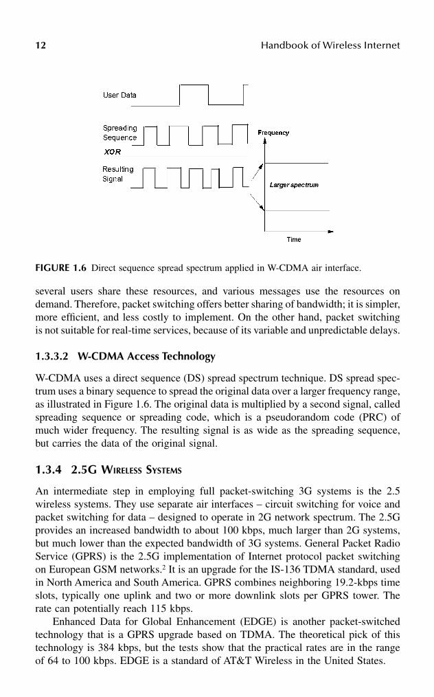
12 Handbook of Wireless Internet
several users share these resources, and various messages use the resources ondemand. Therefore, packet switching offers better sharing of bandwidth; it is simpler,more efficient, and less costly to implement. On the other hand, packet switchingis not suitable for real-time services, because of its variable and unpredictable delays.
1.3.3.2 W-CDMA Access Technology
W-CDMA uses a direct sequence (DS) spread spectrum technique. DS spread spec-trum uses a binary sequence to spread the original data over a larger frequency range,as illustrated in Figure 1.6. The original data is multiplied by a second signal, calledspreading sequence or spreading code, which is a pseudorandom code (PRC) ofmuch wider frequency. The resulting signal is as wide as the spreading sequence,but carries the data of the original signal.
1.3.4 2.5G WIRELESS SYSTEMS
An intermediate step in employing full packet-switching 3G systems is the 2.5wireless systems. They use separate air interfaces – circuit switching for voice andpacket switching for data – designed to operate in 2G network spectrum. The 2.5Gprovides an increased bandwidth to about 100 kbps, much larger than 2G systems,but much lower than the expected bandwidth of 3G systems. General Packet RadioService (GPRS) is the 2.5G implementation of Internet protocol packet switchingon European GSM networks.2 It is an upgrade for the IS-136 TDMA standard, usedin North America and South America. GPRS combines neighboring 19.2-kbps timeslots, typically one uplink and two or more downlink slots per GPRS tower. Therate can potentially reach 115 kbps.
Enhanced Data for Global Enhancement (EDGE) is another packet-switchedtechnology that is a GPRS upgrade based on TDMA. The theoretical pick of thistechnology is 384 kbps, but the tests show that the practical rates are in the rangeof 64 to 100 kbps. EDGE is a standard of AT&T Wireless in the United States.
FIGURE 1.6 Direct sequence spread spectrum applied in W-CDMA air interface.

The Fundamentals of the Wireless Internet 13
1.3.5 UMTS
Universal Mobile Telecommunications System (UMTS) is a 3G wireless standardthat supports two different air interfaces: wideband CDMA (W-CDMA) and timedivision CDMA (TD-CDMA). W-CDMA will be used for the cellular wide areacoverage and high mobility service, while TD-CDMA will be used for low mobility,local in-building services, asymmetrical data transmission, and typical office appli-cations. GSM, IS-136, and PDC (Personal Digital Cellular) operators have alladopted the UMTS standard, but Qualcomm has developed a similar standard,CDMA 2000, which could attract existing IS-95 carriers. Basic concepts of W-CDMA radio access network are described in the Ericsson white paper.3
Table 1.2 presents the characteristics of three generations of wireless systems, andFigure 1.7 shows the most-possible migration path from 2G to 3G wireless systems.
TABLE 1.2Basic Characteristics of Generations of Wireless Systems
Features 1G 2G 2.5G 3G
Air interfaces FDMA TDMACDMA
TDMA W-CDMATD-CDMACDMA 200
Bandwidth ∼10 kbps ~100 kbps ~2 to 4 MbpsData traffic No data Circuit switched Packet switched Packet switchedExamples of services AMPS GSM
IS-136PDCIS-95
GPRSEDGE
UMTScdma 2000
Modulation Analog Digital Digital Digital Voice traffic Circuit switched Circuit switched Circuit switched Packet switched
(VoIP)
FIGURE 1.7 Migration path from 2G to 3G wireless systems.
14 Handbook of Wireless Internet
In summary, the target features of 3G wireless systems include:
• High data rates, which are expected to be 2 to 4 Mbps for indoor use,384 kbps for pedestrians, and 144 kbps for vehicles
• Packet-switched networks, which provide that the users will be alwaysconnected
• Voice and data network will be dynamically allocated• The system will offer enhanced roaming• The system will include common billing and will have user profiles• The system will be able to determine the geographic position of the users
via mobile terminals and networks• The system will be well suited for transmission of multimedia and will
offer various services such as bandwidth on demand, variable data rates,quality sound, etc.
1.4 WIRELESS INTERNET ARCHITECTURES
The general wireless system architecture, which includes connections to the Internet,is shown in Figure 1.8.4 A wireless device is connected to a base station throughone of the wireless Internet networks (see Section 1.4.1); the base station is wiredto a telecommunications switch. In 2.5G systems, the telecommunication switch isused to send voice calls through the circuit-switched telephone network, and datathrough the packet-switched Internet. However, 3G systems use the packet-switchedInternet for both voice and data.
1.4.1 WIRELESS INTERNET NETWORKS
The wireless part of the Internet architecture, shown in Figure 1.8, is referred to aswireless Internet network. Wireless Internet networks can be classified as:
• Wireless personal area networks (PANs)• Wireless local area networks (LANs)• Wireless wide area networks (WANs)
The main difference between these networks is in the range they cover. WirelessPANs and LANs operate on unlicensed spectrum; wireless WANs are licensed, well-regulated public networks. They can all be used as access networks to the Internet,as discussed in Section 1.4.2.
1.4.1.1 Wireless PANs
Wireless PANs have a very short range of up to 10 meters. They are used to connectmobile devices to send voice and data in order to perform transactions, data transfer,or voice relay functions. They are used in personal computers to replace keyboardand printer cables and connectors. Two popular technologies for wireless PANs areinfrared (IR) and Bluetooth technologies. Infrared devices use IRDA standard and
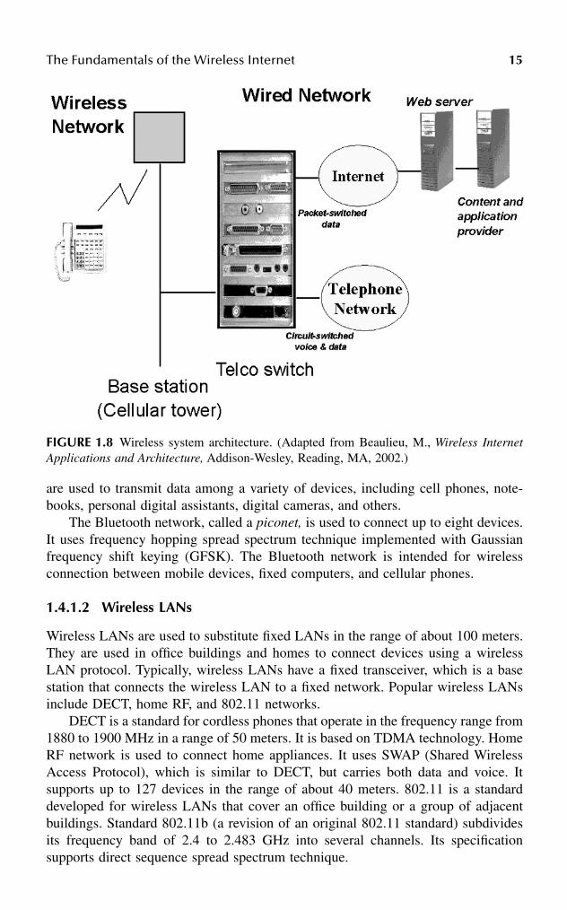
The Fundamentals of the Wireless Internet 15
are used to transmit data among a variety of devices, including cell phones, note-books, personal digital assistants, digital cameras, and others.
The Bluetooth network, called a piconet, is used to connect up to eight devices.It uses frequency hopping spread spectrum technique implemented with Gaussianfrequency shift keying (GFSK). The Bluetooth network is intended for wirelessconnection between mobile devices, fixed computers, and cellular phones.
1.4.1.2 Wireless LANs
Wireless LANs are used to substitute fixed LANs in the range of about 100 meters.They are used in office buildings and homes to connect devices using a wirelessLAN protocol. Typically, wireless LANs have a fixed transceiver, which is a basestation that connects the wireless LAN to a fixed network. Popular wireless LANsinclude DECT, home RF, and 802.11 networks.
DECT is a standard for cordless phones that operate in the frequency range from1880 to 1900 MHz in a range of 50 meters. It is based on TDMA technology. HomeRF network is used to connect home appliances. It uses SWAP (Shared WirelessAccess Protocol), which is similar to DECT, but carries both data and voice. Itsupports up to 127 devices in the range of about 40 meters. 802.11 is a standarddeveloped for wireless LANs that cover an office building or a group of adjacentbuildings. Standard 802.11b (a revision of an original 802.11 standard) subdividesits frequency band of 2.4 to 2.483 GHz into several channels. Its specificationsupports direct sequence spread spectrum technique.
FIGURE 1.8 Wireless system architecture. (Adapted from Beaulieu, M., Wireless InternetApplications and Architecture, Addison-Wesley, Reading, MA, 2002.)

16 Handbook of Wireless Internet
1.4.1.3 Wireless WANs
Wireless WANs are licensed public wireless networks that are used by Web cellphones and digital modems in handheld devices. With a single transceiver (alsocalled base station or cellular tower), the range is about 2500 meters; however,wireless LANs usually have multiple receivers that make their range practicallyunlimited. The most popular wireless WANs are cellular networks that consist ofmultiple base stations positioned in a hexagon (see Figure 1.9). Cellular networkscan be classified as mobile phone networks that primarily carry voice, and theytypically use circuit switching technology, and packet data networks that primarilycarry data and use packet-switching technology.
Table 1.3 summarizes basic features of three wireless networks.
1.4.2 WIRELESS INTERNET TOPOLOGIES
A typical wireless device that has one radio and one antenna can either connect toa public, cellular phone network (WAN), to a private wireless LAN, or to a PAN.
FIGURE 1.9 Cellular network is a wireless LAN that has multiple base stations positionedin a hexagon.
TABLE 1.3Wireless Internet Networks
Wireless Networks Range
Frequency Spectrum
Examples of Networks
PAN ∼10 m Unlicensed IRDABluetooth
LAN ∼100 m Unlicensed DECTHomeRF802.11b
WAN ∼2500 m: One transceiverUnlimited: Multiple transceivers
Licensed Cellular networksGSMIS-95IS-136PDC
Adapted from Rhoton, J., The Wireless Internet Explained, Digital Press, 2002.

The Fundamentals of the Wireless Internet 17
However, all these devices can connect to the wireless Internet. One of the recenttrends is that some wireless devices have multiple antennas, and thus, multiple airinterfaces. This approach allows the devices to connect to various wireless networksin order to optimize coverage.
Figure 1.8, presented earlier in this section, is a typical wireless Internet topologythat consists of a wireless and fixed network. This architecture can be furtherexpended into a star topology, shown in Figure 1.10.5 In this topology, a centralizedradio network controller (RNC) is connected by point-to-point links with the basestations that handle connectivity for a particular geographic area or cell. RNCs areinterconnected to allow mobile users to roam between geographical areas controlledby different RNCs. RNCs are further connected to a circuit-switching network forvoice calls (in 2G and 2.5G systems), and to a packet-switching network for dataand access to the Internet. One of the drawbacks of this architecture is that the RNCpresents a single-point-of-failure; therefore, if an RNC fails, the entire geographicalregion will lose service. This problem is addressed in Kempf and Yegani,5 and somenew architectures for future 4G generation of wireless systems are proposed.
Figure 1.11 illustrates a network topology that includes a combination of wire-less PANs, LANs, and WANs, all connected to the Internet through base stationsand fixed networks. Some devices, such as one denoted in Figure 1.11 as the MAI(multiple air interfaces) device, can be connected to several wireless networks,including a satellite network. Multiple air interfaces in this case can complementeach other to provide optimized coverage of a particular area.
FIGURE 1.10 Wireless Internet architecture using star topology.

18 Handbook of Wireless Internet
1.5 WIRELESS DEVICES AND STANDARDS
In this section, we introduce the most-common wireless devices and their applica-tions. We discuss the Wireless Application Protocol, which is a common standardfor presenting and delivering services on wireless devices. We describe Java-enabledwireless devices, which use Java technology to run applications on wireless devices.
1.5.1 WIRELESS DEVICES
Wireless (or mobile) devices can be classified into six groups:4
1. Web phones. A Web phone is most commonly a cellular phone devicewith an Internet connection. The three major Web phones are theHDML&WAP phone in the United States, the WAP phone in Europe, andthe i-mode phone in Japan. Web phones can exchange short messages,access Web sites with a minibrowser, and run personal service applicationssuch as locating nearby places of interest. Web phones operate only whenthey have a network connection; however, advanced Web phones can runtheir own applications.
FIGURE 1.11 A network topology with various wireless networks connected to the Internet.A wireless device with multiple air interfaces (MAI) can be connected to the Internet throughW-LAN, W-PAN, or through a satellite network.

The Fundamentals of the Wireless Internet 19
2. Wireless handheld devices. A wireless handheld device (such as Palm) isanother common device that can exchange messages and use a mini-browser to access the Internet. Industrial handheld devices, such as Sym-bol and Psion, can perform complex operations such as completing orders.
3. Two-way pagers. A two-way pager allows users to send and receivemessages and provides the use of a minibrowser. They are typically usedin business applications.
4. Voice portals. Voice portals allow users to have a conversation with aninformation service using a kind of telephone or mobile phone.
5. Communication appliances. Communication appliances are electronicdevices that use wireless technology to access the Internet. Examplesinclude wireless cameras, watches, radios, pens, and others.
6. Web PCs. Web PCs are standard PCs connected to the Internet that canaccess mobile services wirelessly.
Wireless devices typically use an embedded real-time operating system. Themost-common operating systems for wireless devices include Palm OS® (used inPalm handheld devices), Windows® CE and Windows NT Embedded by Microsoft(used in a variety of devices such as handheld PCs, pocket PCs, WebTV, SmartPhone, etc.), and Symbian OS.
We present a brief description of the Symbian OS (renamed from Epoc OS) thatwas used for many years in Psion handheld devices. It is currently used in manywireless devices, including the Nokia 9200 Communicator Series. The architectureof the Symbian OS, shown in Figure 1.12, consists of four layers. The Symbian coreis common for all devices and consists of a kernel, a file server, memory manage-ment, and device drivers. The system layer consists of data service enablers thatprovide communications and computing services, such as TCP/IP, IMP4, SMS, anddatabase management. User interface software is made and licensed by manufac-turers, e.g., for the Nokia 9200 platform. Application engines enable software devel-opers to create user interfaces. Various applications are at the last layer.
Figure 1.13 shows several representative wireless devices: the Palm VII, theSony-Ericsson R520, and Nokia’s 9210 and 9290.
FIGURE 1.12 The architecture of the Symbian OS.

20 Handbook of Wireless Internet
The Nokia 9290 Communicator is a wireless device that combines wirelessphone and handheld device. The user can send and receive e-mail messages withattachments, and can an access the Internet. It has many applications built-in, suchas MS Word, PowerPoint, and Excel. An interesting feature is that the user can takenotes using the keyboard while conference calling on a built-in, hands-free speak-erphone.
1.5.2 WAP
Wireless Application Protocol (WAP) is a de facto standard for presenting anddelivering wireless services on mobile devices. It is developed by mobile and wire-less communication companies (Nokia, Motorola, Ericsson, and Unwired Planet)and includes a minibrowser, scripting language, access function, and layered com-munication specification. Most wireless device manufacturers as well as service andinfrastructure providers have adopted the WAP standard.
There are three main reasons why wireless Internet needs a different protocol:
1. Transfer rates2. Size and readability3. Navigation
The 2G wireless systems have data transfer rates of 14.4 kbps or less, which ismuch less than 56 kbps modems, DSL connections, or cable modems. Therefore,loading existing Web pages at these speeds will take a very long time.
Another challenge is the small size of the screens of wireless phones or handhelddevices. Web pages are designed for desktops and laptops that have a resolution of640 × 480 pixels. Wireless devices may have a resolution of 150 × 150 pixels, andthe page cannot fit on the display.
Navigation is quite different on wireless devices. On desktops and laptops,navigation is performed using point-and-click action of a mouse, while typicalwireless devices (specifically phones) use the scroll keys.
FIGURE 1.13 Contemporary wireless phones and handheld devices.
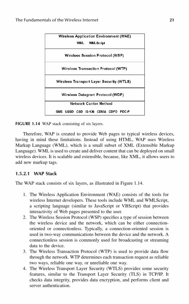
The Fundamentals of the Wireless Internet 21
Therefore, WAP is created to provide Web pages to typical wireless devices,having in mind these limitations. Instead of using HTML, WAP uses WirelessMarkup Language (WML), which is a small subset of XML (Extensible MarkupLanguage). WML is used to create and deliver content that can be deployed on smallwireless devices. It is scalable and extensible, because, like XML, it allows users toadd new markup tags.
1.5.2.1 WAP Stack
The WAP stack consists of six layers, as illustrated in Figure 1.14.
1. The Wireless Application Environment (WAE) consists of the tools forwireless Internet developers. These tools include WML and WMLScript,a scripting language (similar to JavaScript or VBScript) that providesinteractivity of Web pages presented to the user.
2. The Wireless Session Protocol (WSP) specifies a type of session betweenthe wireless device and the network, which can be either connection-oriented or connectionless. Typically, a connection-oriented session isused in two-way communications between the device and the network. Aconnectionless session is commonly used for broadcasting or streamingdata to the device.
3. The Wireless Transaction Protocol (WTP) is used to provide data flowthrough the network. WTP determines each transaction request as reliabletwo ways, reliable one way, or unreliable one way.
4. The Wireless Transport Layer Security (WTLS) provides some securityfeatures, similar to the Transport Layer Security (TLS) in TCP/IP. Itchecks data integrity, provides data encryption, and performs client andserver authentication.
FIGURE 1.14 WAP stack consisting of six layers.
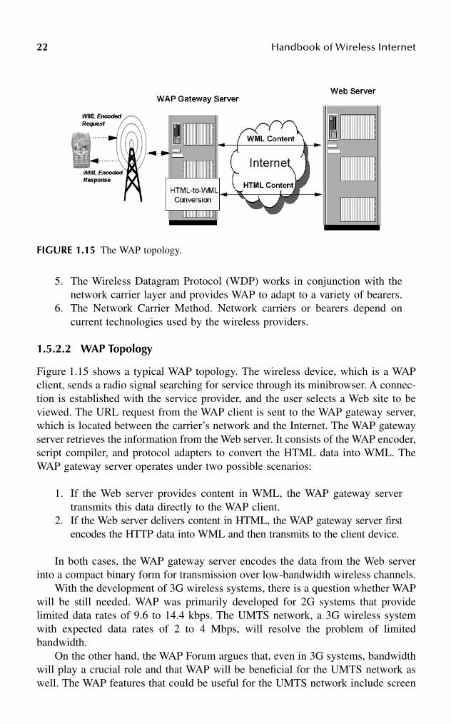
22 Handbook of Wireless Internet
5. The Wireless Datagram Protocol (WDP) works in conjunction with thenetwork carrier layer and provides WAP to adapt to a variety of bearers.
6. The Network Carrier Method. Network carriers or bearers depend oncurrent technologies used by the wireless providers.
1.5.2.2 WAP Topology
Figure 1.15 shows a typical WAP topology. The wireless device, which is a WAPclient, sends a radio signal searching for service through its minibrowser. A connec-tion is established with the service provider, and the user selects a Web site to beviewed. The URL request from the WAP client is sent to the WAP gateway server,which is located between the carrier’s network and the Internet. The WAP gatewayserver retrieves the information from the Web server. It consists of the WAP encoder,script compiler, and protocol adapters to convert the HTML data into WML. TheWAP gateway server operates under two possible scenarios:
1. If the Web server provides content in WML, the WAP gateway servertransmits this data directly to the WAP client.
2. If the Web server delivers content in HTML, the WAP gateway server firstencodes the HTTP data into WML and then transmits to the client device.
In both cases, the WAP gateway server encodes the data from the Web serverinto a compact binary form for transmission over low-bandwidth wireless channels.
With the development of 3G wireless systems, there is a question whether WAPwill be still needed. WAP was primarily developed for 2G systems that providelimited data rates of 9.6 to 14.4 kbps. The UMTS network, a 3G wireless systemwith expected data rates of 2 to 4 Mbps, will resolve the problem of limitedbandwidth.
On the other hand, the WAP Forum argues that, even in 3G systems, bandwidthwill play a crucial role and that WAP will be beneficial for the UMTS network aswell. The WAP features that could be useful for the UMTS network include screen
FIGURE 1.15 The WAP topology.

The Fundamentals of the Wireless Internet 23
size, low power consumption, carrier independence, multidevice support, and inter-mittent coverage. Another argument is that new applications will require higherbandwidth and data rates, so WAP will still play a crucial role.
1.5.3 JAVA-ENABLED WIRELESS DEVICES
New wireless devices, referred to as Java-enabled wireless devices, have recentlyemerged. While WAP wireless devices run new applications remotely using WAP,Java-enabled wireless devices allow users to download applications directly fromthe Internet. In addition, these devices allow users to download Java applets that cancustomize their devices. Another benefit of Java-enabled wireless devices is thatthey run applications and services from different platforms.
Java-enabled wireless devices use J2ME (Java 2 Platform Mobile Edition) thatallows Java to work on small devices. J2ME includes some core Java instructionsand APIs (application programming interfaces); however, its graphics and databaseaccess are less sophisticated than in J2SE and J2EE.
Java technology can be implemented either in software or in hardware. In asoftware implementation, the CPU of the wireless device runs the Java code, whilehardware implementation is based on either a specialized Java acceleration chip ora core within the main processor. The hardware approach typically increases theperformance of Java applications by running more efficiently and thus reduces powerdemands. Several companies are currently developing hardware chips that run Javaor can be used as Java coprocessors, including ARC Cores, ARM Ltd., Aurora VLSI,and Zucotto Wireless.
Korea’s LG Telecom developed the first Java-enabled phone in 2000. Java phonesare presently produced by Nextel in the United States, NTT BoCoMo in Japan, andBritish Telecom. Nokia planned to ship 50 million Java phones in 2002 and 100million in 2003.6
1.6 WIRELESS INTERNET APPLICATIONS
The wireless Internet will keep a large number of people in motion. Four wirelessapplications drive the wireless Internet: messaging, browsing, interacting, and con-versing.4 In messaging applications, a wireless device is used to send and receivemessages. The device uses Short Message Service (SMS) and other e-mail protocols.In browsing applications, a wireless device uses a minibrowser to access variousWeb sites and receives Web services. In interacting applications, the applicationsrun on wireless devices and include business and personal applications, and stand-alone games. In conversing applications, a wireless device calls voice portals (suchas Wildfire®) to get voice information from Web services.
However, there are still a number of challenges in the development of wirelessapplications. The desktop computer will continue to be a dominant platform forgenerating content; however, professionals and consumers will increasingly usewireless devices to access and manage information. The great challenge for devel-opers is to tailor content to the unique characteristics of wireless devices. The mainobjective is to provide quick and easy access to the required information rather than
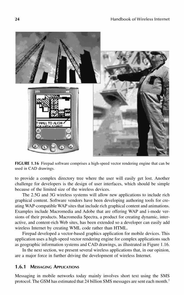
24 Handbook of Wireless Internet
to provide a complex directory tree where the user will easily get lost. Anotherchallenge for developers is the design of user interfaces, which should be simplebecause of the limited size of the wireless devices.
The 2.5G and 3G wireless systems will allow new applications to include richgraphical content. Software vendors have been developing authoring tools for cre-ating WAP-compatible WAP sites that include rich graphical content and animations.Examples include Macromedia and Adobe that are offering WAP and i-mode ver-sions of their products. Macromedia Spectra, a product for creating dynamic, inter-active, and content-rich Web sites, has been extended so a developer can easily addwireless Internet by creating WML code rather than HTML.
Firepad developed a vector-based graphics application for mobile devices. Thisapplication uses a high-speed vector rendering engine for complex applications suchas geographic information systems and CAD drawings, as illustrated in Figure 1.16.
In the next section, we present several wireless applications that, in our opinion,are a major force in further driving the development of wireless Internet.
1.6.1 MESSAGING APPLICATIONS
Messaging in mobile networks today mainly involves short text using the SMSprotocol. The GSM has estimated that 24 billion SMS messages are sent each month.7
FIGURE 1.16 Firepad software comprises a high-speed vector rendering engine that can beused in CAD drawings.
The Fundamentals of the Wireless Internet 25
However, it is expected that soon wireless devices will support pictures, audio, andvideo messages. At the same time, the popular messaging services on the Internet,such as e-mail, chat, and instant messaging, are extending to wireless environments.
1.6.2 MOBILE COMMERCE
M-commerce applications refer to conducting business and services using wirelessdevices. These applications can be grouped into (1) transaction management appli-cations, (2) digital content delivery, and (3) telemetry services.
Transaction management applications include online shopping tailored to wire-less devices with online catalogs, shopping carts, and back-office functions. Othertransaction applications include micro transactions and low cost purchases for sub-way or road tolls, parking tickets, digital cash, and others.
Digital content delivery includes a variety of applications:
• Information browsing for weather, travel, schedules, sport scores, stockprices, etc.
• Downloading educational and entertainment products• Transferring software, images, and video• Innovative multimedia applications
According to the recent study by HPI Research Group,7 the following are thetop ten mobile entertainment features:
1. Sending SMS messages2. Checking local traffic and weather information3. Using a still camera4. Getting latest news headlines5. Sending photos to a friend6. Using a video camera7. Booking and buying movie tickets8. Getting information on movies9. Listening to radio
10. Requesting specific songs
Entertainment on mobile devices is attractive because it is almost always withthe user, whether commuting, traveling, or waiting.
Telemetry services include a wide range of new applications:
• Transmission of status, sensing, and measurement information• Communications with various devices from homes, offices, or in the field• Activation of remote recording devices or service systems
1.6.3 CORPORATE APPLICATIONS
Banks and transport companies were among the first businesses to deploy wirelessapplications based on WAP for their customers and employees. In banks, the goal

26 Handbook of Wireless Internet
was to reduce consumer banking transaction costs, while transport companies wantedto track transportation and delivery status online.
Gartner Research Group expects most corporations to implement wireless appli-cations in four overlapping phases:7
1. The first group of applications is readily justifiable and includes high-value, vertical niche solutions, such as field force automation.
2. The second phase includes horizontal applications such as e-mail andpersonal information management applications.
3. The third wave of applications consists of vertical applications, such asmobile extensions to CRM (Customer Relationship Management), salesforce automation, and enterprise resource planning systems.
In the long term, Gartner expects that 40 to 60 percent of all corporate systemswill involve mobile elements.
1.6.4 WIRELESS APPLICATION SERVICE PROVIDERS
WASPs allow wireless access to various software products and services. BusinessWASP applications are targeted to mobile business people, field personnel, and salesstaff. Other WASP applications include:8
• Mobile entertainment services• Wireless gaming• Wireless stock trading• In-vehicle services, such as traffic control, car management, etc.
1.6.5 MOBILE WEB SERVICES
Web services include well-defined protocol interfaces through which businesses canprovide services to customers and business partners over the Internet. Web servicesspecify a common and interoperable way for defining, publishing, invoking, andusing application services over networks. They are built on emerging technologiessuch as XML, SOAP (Simple Access Object Protocol), WSDL (Web ServiceDescription Language), UDDI (Universal Description, Discovery, and Integration),and HTTP.
Mobile Web Services provide content delivery, location discovery, user authen-tication, presence awareness, user profile management, data synchronization, termi-nal profile management, and event notification services. Initially, wireless terminalsare likely to access Mobile Web Services indirectly, through application servers. Theapplication server will manage the interactions with the required Web services.
1.6.6 WIRELESS TEACHING AND LEARNING
Web-based distance learning could be extended to wireless systems. For example,the project Numina at the University of North Carolina–Wilmington is intended to

The Fundamentals of the Wireless Internet 27
explore how wireless technology can be used to facilitate learning of abstract sci-entific and mathematical concepts.9 Students use handheld computers (with appro-priate software) which are connected to the wireless Internet. The system providesinteractive exercises, and integrates various media and hypertext material.
1.7 FUTURE OF WIRELESS TECHNOLOGY
The major trend that is already emerging is the migration of mobile networks tofully IP-based networks. The next generation of wireless systems, 4G systems, willuse new spectrum and emerging wireless air interfaces that will provide a very highbandwidth of 10+ Mbps. It will be entirely IP-based and use packet-switchingtechnology. It is expected that 4G systems will increase usage of wireless spectrum.According to Cooper’s law, on average, the number of channels has doubled every30 months since 1985.
Figure 1.17 shows the user mobility and data rates for different generations ofwireless systems, and for wireless PANs and LANs. The 3G and later 4G systemswill provide multimedia services to users everywhere, while WLANs provide broad-band services in hot spots, and WPANs connect personal devices together at veryshort distances.
FIGURE 1.17 User mobility and data rates for wireless PANs and wireless LANs. (Adaptedfrom Pahlavan, K. and Krishnamurthy, P., Principles of Wireless Networks, Prentice Hall,Englewood Cliffs, NJ, 2002.)

28 Handbook of Wireless Internet
Spread spectrum technology is presently used in 3G systems; however, there arealready research experiments with Multicarrier Modulation (MCM), which is a stepfurther from spread spectrum. MCM transmits simultaneously at many frequencies.
New types of smart antennas are currently under development. Most currentantennas are omnidirectional, which means that they transmit in all directions withsimilar intensity. New directional antennas transmit primarily in one direction, whileadaptive antennas vary direction in order to maximize performance.
New generations of software radios will dynamically adapt to wireless technol-ogy. They apply digital signal processors, so they can update the software with newversions of transmission techniques.
The transition from circuit-switched to packet-switched networks providesincreased efficiency of the network and higher overall throughput. However, packet-switched networks operate on a best-effort basis, and therefore, cannot guaranteethe service (specifically when the load is high). This will require the developmentof new QoS (quality of service) approaches to handle various network scenarios.
New wireless multimedia applications will require new solutions related to errorresilience, network access, adaptive decoding, and negotiable QoS.
Error resilience solutions should enable delivery of rich digital media overwireless networks that have high error rates and low and varying transmission speeds.Network access techniques should provide the delivery of rich media withoutadversely affecting the delivery of voice and data services. Innovative adaptivedecoding techniques should optimize rich media for wireless devices with limitedprocessing power, limited battery life, and varying display sizes. New negotiableQoS algorithms should be developed for IP multimedia sessions, as well as forindividual media components.
1.8 CONCLUSIONS
In this chapter, we presented fundamental concepts and technologies for wirelesscommunications, and introduced various architectures and three generations of wire-less systems. We are currently at the transition between 2G and 3G systems (2.5Gsystems). The 3G systems will soon offer higher data rates suitable for a variety ofapplications dealing with multimedia. Services and applications are driving 3Gsystems. With 3G systems, users will be able to send graphics, play games, locatea restaurant, book a ticket, read news updates, check a bank statement, watch theirfavorite soap operas, and many other exciting applications.
In July 2002, Ericsson delivered 15 real-life 3G applications, including real-timesport applications, face-to-face video calling, and exciting team games, to 40 oper-ators so they can demonstrate to their customers what the wireless Internet is allabout.
In the meantime, researchers are already working on 4G systems that will provideeven higher data rates, will be entirely IP-based, and will include many other newfeatures.

The Fundamentals of the Wireless Internet 29
References
1. Rhoton, J., The Wireless Internet Explained, Digital Press, 2002.2. Park, J.-H., Wireless Internet access for mobile subscribers based on GPRS network,
IEEE Communication Magazine, 40 (4), 38–49, 2002.3. Ericsson, Basic concepts of WCDMA radio access network, White Paper, www.eric-
sson.com, 2002.4. Beaulieu, M., Wireless Internet Applications and Architecture, Addison-Wesley, Read-
ing, MA, 2002.5. Kempf, J. and Yegani, P., OpenRAN: a new architecture for mobile wireless Internet
radio access network, IEEE Communication Magazine, May 2002, 118–123.6. Lawton, G., Moving Java into mobile phones, IEEE Comput., June 2002, 17–20.7. Nokia, Mobile terminal software — markets and technologies for the future, White
Paper, www.nokia.com, 2002.8. Steemers, P., Critical success factors for wireless application service providers, White
Paper, Cap Gemini Ernst & Young, 2002.9. Shotsberger, P.G. and Vetter, R., Teaching and learning in the wireless classroom,
IEEE Comput., 110–111, 2001.10. Buracchini, E., The software radio concept, IEEE Communications Magazine, Sep-
tember 2000, 138–143.11. Hanzo, L., Cherriman, P.J., and Streit, J., Wireless Video Communications, IEEE
Press, New York, 2001.12. Krikke, J., Graphics applications over the wireless Web: Japan sets the pace, IEEE
Comput. Graphics Appl., May/June 2001, pp. 9–15.13. Pahlavan, K. and Krishnamurthy, P., Principles of Wireless Networks, Prentice Hall,
Englewood Cliffs, NJ, 2002.

This page intentionally left blank

310-8493-1502-6/03/$0.00+$1.50© 2003 by CRC Press LLC
2 Wireless Internet > Wireless + Internet
Sirin Tekinay and David Goodman
CONTENTS
Abstract ....................................................................................................................312.1 Introduction ....................................................................................................322.2 WLANs and Cellular Networks: Comparison and Contrast.........................33
2.2.1 WLAN Trends....................................................................................352.2.2 Cellular Trends...................................................................................362.2.3 Uniting WLANs and Cellular............................................................382.2.4 Personal Area Networks.....................................................................382.2.5 Technology Gaps................................................................................39
2.3 Framework for Technology Creation.............................................................392.3.1 The Geography of Wireless Internet Users .......................................402.3.2 The Geography of Information..........................................................412.3.3 The Geography of Signal Transmission ............................................42
2.4 Research Initiatives ........................................................................................432.4.1 Adaptive Network Architectures........................................................43
2.4.1.1 Proximity-Based Systems...................................................452.4.1.2 Cooperative Communications.............................................462.4.1.3 Hybrid Architectures...........................................................46
2.4.2 The IP-Based Core Network..............................................................482.4.2.1 Geolocation .........................................................................482.4.2.2 Resource Management........................................................49
2.5 Conclusions ....................................................................................................50References................................................................................................................50
ABSTRACT
The technical and business communities view a “wireless Internet” as an inevitablesequel to the spectacular growth of cellular communications and the World WideWeb in the 1990s. The prevailing wisdom is that without the nuisance of wiredconnections to consumer equipment, Internet access will be more convenient andenjoyable. While this is true, it is only part of the picture because it fails to acknowl-edge the fact that information services shaped by the needs and characteristics ofpeople on the move and the nature of the information they send and receive will be

32 Handbook of Wireless Internet
qualitatively different from services delivered to people in fixed locations. In thelong run, a wireless Internet will offer far more than the negative benefit of anInternet with some of its wires removed. However, to realize the full potential of awireless Internet, it will be necessary to transcend the technical assumptions thatnurtured cellular communications and the Web.
This chapter examines current industry trends in uniting wireless communica-tions and the Internet. It describes the advances these trends will produce and thebottlenecks they do not address. It then surveys current research initiatives that gobeyond the centralized topology of wireless systems and the client/server model ofInternet information delivery.
2.1 INTRODUCTION
Since the late 1990s, the cellular industry and the business press have promotedwireless Internet as “the next big thing” in information technology. The idea wascompelling in view of the huge public appetite for cellular telephones and the Webin the 1990s. The enthusiastic predictions of the growth of the wireless Internet werelinked to two emerging technologies:
1. Third-generation (3G) cellular systems that would overcome the bit ratebottleneck of existing technology.
2. Internet-enabled cell phones that within a few years would be more numer-ous than personal computers.
As we write this chapter three years later, we are drawn to the adage “the futureisn’t what it used to be.” Instead of cellular modems, the preferred mode of wirelessaccess to the Internet in 2002 is a WLAN (wireless local area network) plug-in cardor a WLAN modem built into a notebook computer. In limited coverage areas,WLANs give stationary (or slowly moving) users of notebook computers access tothe two “killer apps” (mass-market applications) of the Internet: the Web and e-mail.In wide coverage areas (metropolitan and national), specialized wireless data net-works and cellular networks transfer e-mail to and from PDAs (personal digitalassistants) and specialized e-mail terminals. The most popular PDAs use the Palmoperating system. Blackberry is a popular specialized e-mail terminal.
Simultaneous with the rapid growth of WLAN usage, the cellular industry iscautiously inaugurating 3G networks in Europe and Asia, and upgrading second-generation systems with “2.5G” (enhanced digital cellular) technology in manycountries. In parallel with the cellular and WLAN radio developments, there is ahigh volume of activity in the Internet community focused on extending existingInternet protocols and introducing new ones with the aim of accommodating mobilityand the characteristics of radio communications.
This chapter focuses on trends in wireless communications aimed at promotinga wireless Internet. The following section introduces a framework for comparingdifferent wireless Internet radio technologies and describes the evolution of cellularsystems and WLANs. The emerging technologies will overcome some of the defi-ciencies of mobile wireless communications relative to the transmission technologies

Wireless Internet > Wireless + Internet 33
of the wired Internet. However, even after these evolutionary measures mature, manygaps will remain between expectations for a wireless Internet and what can beachieved in practice. The remainder of the chapter describes work in progress toovercome these gaps and create a wireless Internet that is more than the presentInternet with some of the wires eliminated. Section 2.3 suggests an approach toadvancing beyond the technologies emerging in 2002, and Section 2.4 describesresearch in progress that follows this approach.
2.2 WLANS AND CELLULAR NETWORKS: COMPARISON AND CONTRAST
Any practical communications system represents a compromise between a varietyof technology and cost criteria. Some of the principal figures of merit for wirelesscommunications systems are bit rate, mobility of terminals, signal quality, coveragearea, service price, and demands on the power supplies of portable terminals.
Goals for third-generation wireless communication, enunciated in the early1990s by the International Telecommunications Union Task Group IMT-2000,focused on the first two criteria, bit rate and mobility. Third-generation systemsshould deliver 2 Mbps to stationary or slowly moving terminals, and at least 144kbps to terminals moving at vehicular speeds. Meanwhile, WLAN development hasconfined itself to communications with low-mobility (stationary or slowly moving)terminals, and focused on high-speed data transmission. The relationship of bit rateto mobility in cellular and WLAN systems has been commonly represented in twodimensions by diagrams resembling Figure 2.1. The principal goal of succeeding
FIGURE 2.1 Bit rate and mobility in WLAN and cellular systems.

34 Handbook of Wireless Internet
generations of cellular technology has been to move to the right in the bit rate/mobil-ity plane. Coverage, the geographical area that a signal can reach, is a third figureof merit. The relationship between bit rate and coverage is similar to the relationshipbetween bit rate and mobility. Cellular systems provide wide area ubiquitous cov-erage, while WLANs, as the name implies, cover only local areas, with large gapsbetween coverage areas. With respect to signal quality, a fourth figure of merit,cellular networks employ elaborate radio resources management technology to main-tain high signal quality for the highest possible user population. Moreover, cellularnetwork operators own expensive licenses, granting them exclusive use of radiospectrum in their service areas. By contrast, WLANs, operating in unlicensed spec-trum bands, are vulnerable to interference from various sources, including otherWLANs, cordless telephones, microwave ovens, and Bluetooth personal area net-works.
In addition to the criteria of mobility, bit rate, coverage, and signal quality,Table 2.1 indicates that cellular terminals make greater demands on their batteriesthan WLAN modems. The radiated power in a cell phone can be as high as severalhundred milliwatts, while WLANs transmit at a maximum of 100 milliwatts. Inaddition, cellular networks are far more expensive to establish and maintain thanWLAN access points. As a consequence, WLAN service prices are considerablylower (in many situations, they are free) than cellular prices. Consider the fact thatin a cellular network, a 1-MB file transfer uses comparable transmission resourcesto 500 seconds of a phone conversation (at 16 kbps speech transmission) and a fewthousand short messages (at 200 characters per message). Consumers are accustomedto paying much more per bit for phone calls and short messages than for Internetaccess. It is a challenge to the cellular industry to establish prices for broadbandservices at a level high enough to compensate them for the radio resources consumedand simultaneously low enough to attract a large number of customers. The othercellular advantage in Table 2.1 is the network infrastructure of base stations,switches, routers, and databases that regulate access to a network and facilitatemobility.
All in all, we observe in Table 2.1 that, with respect to the figures of merit forwireless communications, cellular systems and WLANs are complementary; eachone is strong where the other is weak. This suggests that both technologies will play
TABLE 2.1Figures of Merit for Wireless Internet Access Technologies
Cellular WLAN
Strong Ubiquitous coverageHigh mobilityControlled signal qualityInfrastructure
High bit rateLow powerLow cost
Weak Low bit rateHigh powerHigh cost
Isolated coverageLow mobilityVulnerable to interference
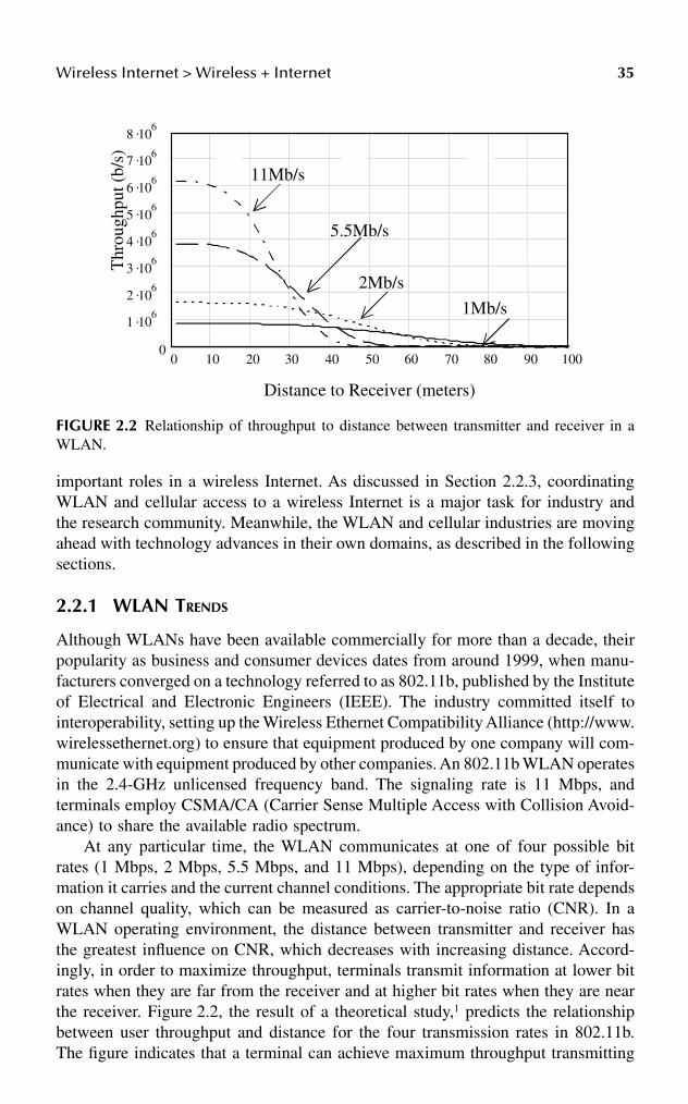
Wireless Internet > Wireless + Internet 35
important roles in a wireless Internet. As discussed in Section 2.2.3, coordinatingWLAN and cellular access to a wireless Internet is a major task for industry andthe research community. Meanwhile, the WLAN and cellular industries are movingahead with technology advances in their own domains, as described in the followingsections.
2.2.1 WLAN TRENDS
Although WLANs have been available commercially for more than a decade, theirpopularity as business and consumer devices dates from around 1999, when manu-facturers converged on a technology referred to as 802.11b, published by the Instituteof Electrical and Electronic Engineers (IEEE). The industry committed itself tointeroperability, setting up the Wireless Ethernet Compatibility Alliance (http://www.wirelessethernet.org) to ensure that equipment produced by one company will com-municate with equipment produced by other companies. An 802.11b WLAN operatesin the 2.4-GHz unlicensed frequency band. The signaling rate is 11 Mbps, andterminals employ CSMA/CA (Carrier Sense Multiple Access with Collision Avoid-ance) to share the available radio spectrum.
At any particular time, the WLAN communicates at one of four possible bitrates (1 Mbps, 2 Mbps, 5.5 Mbps, and 11 Mbps), depending on the type of infor-mation it carries and the current channel conditions. The appropriate bit rate dependson channel quality, which can be measured as carrier-to-noise ratio (CNR). In aWLAN operating environment, the distance between transmitter and receiver hasthe greatest influence on CNR, which decreases with increasing distance. Accord-ingly, in order to maximize throughput, terminals transmit information at lower bitrates when they are far from the receiver and at higher bit rates when they are nearthe receiver. Figure 2.2, the result of a theoretical study,1 predicts the relationshipbetween user throughput and distance for the four transmission rates in 802.11b.The figure indicates that a terminal can achieve maximum throughput transmitting
FIGURE 2.2 Relationship of throughput to distance between transmitter and receiver in aWLAN.
0 10 20 30 40 50 60 70 80 90 1000
1 .106
2 .106
3 .106
4 .106
5 .106
6 .106
7 .106
8 .106
Distance to Receiver (meters)
Thr
ough
put (
b/s)
1Mb/s
2Mb/s
5.5Mb/s
11Mb/s

36 Handbook of Wireless Internet
at 11 Mbps when it is within 28 meters of the receiver. Between 28 and 38 meters,the throughput is highest at 5.5 Mbps, while 2 Mbps is preferred between 38 and55 meters. At distances greater than 55 meters, transmission at 1 Mbps maximizesthroughput.
Most WLANs transmit signals between an access point connected to an Ethernetand a laptop computer with a built-in WLAN modem or a modem contained in aplug-in card. WLANs also are capable of direct (peer-to-peer) communicationbetween two terminals.
While the overwhelming majority of WLANs in operation conform to 802.11b,more-advanced technologies were on the drawing boards in 2002, and to a smallextent marketed commercially. Two organizations guide the standardization of newWLAN technology, the IEEE (http://ieee802.org/11) and ETSI (European Telecommu-nications Standards Institute) (http://portal.etsi.org/bran/kta/Hiperlan/ hiperlan2.asp).IEEE efforts take place within the 802.11 Working Group, which consists of anumber of task groups, each labeled with a lower case letter. ETSI activity, referredto as HiperLAN2 (high performance LAN), focuses on WLAN technology operatingin the 5-GHz band at a bit rate of 54 Mbps. Table 2.2, a summary of bit rates andspectrum bands for existing and emerging WLANs, shows that 802.11a technologyoperates at the same bit rate and in the same part of the electromagnetic spectrumas HiperLAN2. This congruence has been the stimulus for discussions on harmo-nizing the two technologies.2
2.2.2 CELLULAR TRENDS
Progress in cellular communications technology has been measured by “genera-tions.” The principal characteristics of first-generation systems, introduced in theearly 1980s, were analog speech transmission over radio channels and limited built-in roaming capability. Second-generation systems, transmitting digital speech sig-nals, were introduced in the early 1990s and today account for the overwhelmingmajority of cellular telephone communications. Starting with a wide array of incom-patible first-generation radio transmission technologies deployed throughout theworld, the number converged to four in the second generation. GSM (Global Systemfor Mobile Telecommunications), standardized by ETSI, has by far the largest
TABLE 2.2WLAN Bit Rates and Carrier Frequencies
Spectrum Band (GHz)
Maximum Bit Rate (Mbps)
802.11a 5 54802.11b 2.4 11802.11g 2.4 20HiperLAN1 5 20HiperLAN2 5 54

Wireless Internet > Wireless + Internet 37
subscriber base and the most-widespread adoption geographically. The most-salientcharacteristic of GSM radio transmission is its TDMA (time division multiple access)technique. A GSM signal occupies a bandwidth of 200 kHz. The transmission bitrate is 270 kbps with eight digital signals sharing the same carrier. The CDMA (codedivision multiple access) system, conforming to Interim Standard 95 published bythe TIA (Telecommunications Industry Association), has the second-largest sub-scriber base. It is deployed throughout North America and in several Asian countries.CDMA signals occupy a bandwidth of 1.25 MHz with a binary signaling rate of1,228,800 chips per second. The two other digital systems are similar to one another.NA-TDMA, the North American time division multiple access system conformingto TIA Interim Standard 136, operates with a bandwidth of 30 kHz per channel anda signaling rate of 48,600 bits per second. It is deployed throughout North Americaand in a few countries in Latin America. PDC (Personal Digital Cellular), with asignal bandwidth of 25 kHz, is a Japanese standard similar to NA-TDMA.
In 2002, the introduction of new radio technology proceeds in two streams, onebased on GSM and the other on CDMA. Both streams contain 2.5G (advancedsecond generation) systems, with signals confined to the existing 2G bands (200 kHzfor GSM and 1.25 MHz for CDMA) and 3G systems, with signals occupying 4 or5 MHz bandwidth. Table 2.3 is a catalog of the systems in the GSM and CDMAstreams. In North America, NA-TDMA operating companies have announced technol-ogy migration paths to the GSM stream. In Japan, PDC operating companies haveintroduced 3G systems based on W-CDMA (wideband code division multiple access).
The original second generation systems were designed to carry voice conversa-tions, for the most part. They also carry circuit-switched data. Their enhancements
TABLE 2.3Advanced Second-Generation (2.5G) and Third-Generation Cellular Systems
GenerationChannel BW (Hz)
Channel Rate (bps)
Principal Information Format
GSMGSM 2 200 k 271 k Voice and circuit dataEDGE 2.5 200 k 813 k Voice and circuit dataGPRS 2.5 200 k 271 k Packet dataE-GPRS 2.5 200 k 813 k Packet dataW-CDMA/FDD 3 5 M 3.84 M MultimediaW-CDMA/TDD 3 5 M 3.84 M Multimedia
CDMACDMA1 2 1.25 M 1.2288 M Voice and circuit data1XRTT 2.5 1.25 M 1.2288 M Voice and circuit dataHDR 2.5 1.25 M Uplink 2.4 M
Downlink 153 kPacket data
CDMA2000 3 3.75 M 3.6864 M Multimedia
38 Handbook of Wireless Internet
(2.5G) are segregated in two categories: EDGE and 1XRTT carry voice and circuit-switched data at higher bit rates than GSM and CDMA1, respectively. On the otherhand, GPRS (General Packet Radio Service), E-GPRS, and HDR are designed forpacket-switched data. A principal characteristic of the 3G systems is their ability tocarry a variety of traffic types. While 2G and 2.5G systems classify information aseither circuit or packet oriented, 3G systems’ planners classify information accordingto latency requirements within four categories: background, interactive, streaming,and conversational.
Although the channel signaling rates are fixed for each system, only 2G systemsspecify constant user throughput. All of the other systems contain “rate adaptation”technology that matches the transmission rate available at each terminal to the currentchannel quality, as determined by network congestion and location-specific radiopropagation conditions. For example, EDGE defines 12 “modulation and codingschemes,” with user bit rates ranging from 8.8 to 88.8 kbps per time slot.3 Anapplication can use from one to eight time slots to exchange information.
2.2.3 UNITING WLANS AND CELLULAR
The complementary strengths and weaknesses of WLANs and cellular systems makeit certain that a wireless Internet will contain both technologies. Recognizing thisprospect, the technical community has turned its attention to coordination of cellularsystems and WLANs. Short-term approaches to this coordination use existing net-work infrastructure, while more futuristic work anticipates new network architecturebased on Internet protocols that inherently accommodate both types of radio access.One example based on existing infrastructure is an OWLAN (operator WLAN)4
combining GSM subscriber management and billing mechanisms (authorization,authentication, and accounting) with WLAN radio access. A key aspect of theOWLAN is incorporation of a GSM SIM (subscriber identity module) in the sub-scriber equipment containing a WLAN modem. Another example uses a cellulardata modem as a bridge linking the Internet with a cluster of laptop computers, allcommunicating with a WLAN access point.5 The cellular modem relays data betweenthe access point and the cellular network infrastructure operating a suite of Internetprotocols.
In contrast to cellular–WLAN coordination using existing infrastructure, thereis intense industry effort devoted to specification of a core network based on Internetprotocols. Such a core network would serve terminals that communicate by meansof WLAN, cellular, and a variety of other wired and wireless access technologies.Section 2.4.2 describes examples of work in progress on network architectures thataddress a broad range of technical challenges including roaming, handoff, security,and quality of service (QoS).
2.2.4 PERSONAL AREA NETWORKS
Although cellular telephones and WLANs have attracted the greatest consumeracceptance to date, other wireless networks have a role to play in a wireless Internet.Among them personal area networks (PANs) using Bluetooth technology are the

Wireless Internet > Wireless + Internet 39
most prominent.6 The original aim of Bluetooth was to provide low-cost, low-powerconnections between a variety of consumer products. One example is a Bluetoothlink between a laptop computer and a 3G cell phone enabling the computer to gainaccess to the Internet by means of the 3G packet data infrastructure. Another exampleis a cordless headset linked to a cell phone or a personal stereo device. In the contextof these applications, Bluetooth appears as a low-cost alternative to WLAN modems.In addition, Bluetooth also contains sophisticated ad hoc networking capabilities.These capabilities are contained in technologies built into the Bluetooth standardfor creating piconets and scatternets that use Bluetooth modems to create networkslinking a large number of wireless devices.
2.2.5 TECHNOLOGY GAPS
Each of the emerging advances in the cellular, WLAN, and PAN domains workswithin a region of the six-dimensional figure of merit volume (mobility, bit rate,coverage, signal quality, power, and price) described at the beginning of Section 2.2.All of them address the “last mile” or “last five meters” problem of linking devicesto the Internet. An examination of the details of each of these technologies revealsthat in sum they will remain inferior to wired connections consisting of Ethernets,digital subscriber lines, or cable modems connected to a 10 Gbps Internet backbone.The result will be
wireless Internet = Internet – some of the wires < Internet with wires
To get beyond these limitations, it will be necessary to create new communica-tions paradigms that are matched directly to the requirements and constraints of theusers, the information, and the operating environment of a wireless Internet. Thenext section adopts the theme of “geography” to formulate a framework for tech-nology creation, and Section 2.4 describes current research within this framework.
2.3 FRAMEWORK FOR TECHNOLOGY CREATION
The incremental evolution of a wireless Internet, described in Section 2.2, takes abottom-up approach of augmenting existing wireless technology and Internet pro-tocols in order to provide a smoother interface between the two marriage partners.On the wireless side, the principal aim is to increase channel bit rate. On the Internetside, extended protocols aim to accommodate mobility, the variable quality ofwireless signals, and vulnerability of wireless systems to eavesdropping and unau-thorized access. In this section, we introduce a top-down approach that aims for awireless Internet that is more than the sum of the two existing communicationssystems. This approach begins with a three-dimensional analysis, including thecharacteristics of (1) the endpoints of communication, (2) the information trans-ferred, and (3) the physical nature of wireless signals. In this analysis, we findsignificant differences from the wired Internet on all three dimensions. The commonaspect of all three dimensions can be summed up in the word “geography.” Cellularsystems aim to be the same “anytime, anywhere,” and the name “World Wide Web”
40 Handbook of Wireless Internet
carries a similar suggestion. By contrast, our analysis of wireless Internet require-ments in the following paragraphs reveals a fundamental dependence on location,including (1) locations of information terminals (geography of users), (2) the loca-tion-dependent relevance of information (geography of information), and (3) loca-tion-dependent quality of signals (geography of signal transmission). Section 2.4refers to examples of research in progress that aligns technology with the geographyof users, the geography of information, and the geography of signal transmission.
2.3.1 THE GEOGRAPHY OF WIRELESS INTERNET USERS
The Internet was originally designed to move data packets carrying many types ofinformation between host computers in stationary, known locations. By contrast,cellular networks were originally designed to carry telephone calls and short mes-sages in systems that are matched to the geographical distribution of subscribers,their mobility patterns, and the temporal distribution their service needs. Technologycreation and deployment are considerably more complicated in a wireless Internetbecause mobile terminals with different capabilities will transmit and receive mul-timedia information in a variety of formats, with widely different quality-of-servicerequirements that place varying demands on network resources.
Wireless Internet technology needs to be sensitive to the characteristics of thesources and destinations of information, which will often be groups that shareinformation. Groups form and dissolve as clusters in time and space. The formationand disintegration of such groups may or may not be initiated by the users involved.Key characteristics of the geography of users are location, mobility state (speed anddirection), timing of information needs, and demographics of individuals and usergroups. An example of a group formed spontaneously is the population of mobilecallers in an unexpected traffic jam. In this case, the defining characteristics of thegroup are the locations and mobility states of the group members.
The endpoints of a wireless Internet will include familiar information devicescarried by people (telephones, PDAs, laptop computers). There will be an increasingnumber of autonomous devices such as wireless sensors with specialized tasks ofacquiring, transmitting, and receiving diverse types of data. A few examples aregeolocation information, biomedical measurements, and surveillance pictures. Per-vasive computing anticipates a proliferation of cooperating autonomous wirelessterminals.
Multicasting, an increasingly popular mode of Internet information transfer, islikely to be even more attractive in a wireless Internet. In a multicast, the “end user”is a group comprising a variable population of members defined on a per-sessionbasis. In a wireless Internet, multicasting is likely to be just as popular but, owingto the mobility of terminals and variability of transmission conditions, it will presentchallenges that do not arise in the wired Internet.7
Geocasting is a form of multicast that that can add to the value of a wirelessInternet.8 Geocasting defines a multicast group with reference to a target area. Themembers of the group are terminals with geographical coordinates within the targetarea. In addition to location, mobility states (velocity and direction) and demograph-ics can be major factors in the definition of geocast groups. The geocast membership

Wireless Internet > Wireless + Internet 41
can be specified by the sender of information, the recipient, or by a service provider.A geocast session may consist of one or more messages that are sent to the geocastgroup. A message can originate with a group member or outside the group. Forexample, in the action “send a reminder to all students and faculty within 3 km ofthe campus that a seminar will begin in 30 minutes,” the originator of a messagedefines a geocast group by location and demographic category. In the action “getinformation about all shoe stores that I can reach in 30 minutes,” the informationrecipient defines a group by location and mobility. Finally, in the action “notifyeveryone within a radius of 10 km of a traffic jam,” the service provider uses anarbitrary criterion defined by location to specify a group.
Geolocation (discussed in further detail in Section 2.4.2.1), the process of deter-mining the geographical coordinates of an information device, is a technology thatsupports geocasting. The construction and maintenance of the geocast group arenontrivial tasks for mobile networks. Most studies assume that geolocation infor-mation is continuously available to mobile nodes via the Global Positioning System(GPS). While this is generally a viable assumption, the manner in which the geolo-cation information is acquired and disseminated has significant impact on networkcapacity and performance.
2.3.2 THE GEOGRAPHY OF INFORMATION9
For twenty years, the expression “anytime, anywhere” has been a cellular technologymantra. At first only a lofty goal, the combination of satellite telephones and terres-trial cellular systems have made “anytime, anywhere” a reality for telephone callsand short text messages; it is also a good description of the World Wide Webparadigm in which content seems pervasive, contained in Web pages that can besummoned to any computer in the world at the click of a mouse. Although thisparadigm is appealing, the geography of signal transmission, described in Section2.3.3, makes it difficult and expensive to achieve with wireless technology, even forthe simple task of delivering telephone calls and short messages. With the addedcomplexity of multimedia wireless Internet information and the diversity of usercharacteristics, “anytime, anywhere” becomes prohibitively demanding. Thus, wewould do well to examine the nature of the information conveyed in a wirelessInternet to determine the conditions in which ubiquitous, instantaneous coverage isessential, not merely a convenience to be weighed against its costs. Rather thanimpose the burden of “anytime, anywhere” on all communications in a wirelessInternet, we examine the temporal, spatial, and demographic coordinates of infor-mation. Matching communication technology to information geography promisesgains in efficiency and quality of a wireless Internet.
In examining the geography of information, we classify services according towhere, when, and to whom the information is relevant. We represent the classificationin each of these dimensions — space, time, and personal — in a range from specificto general. At one extreme we have information that is useful to only one person,at a particular time, when the person is in a particular place. For example, a messagegenerated while you are on your way to the airport that “you are urgently requestedto deal with an emergency in your home” is localized in all three dimensions. Unless
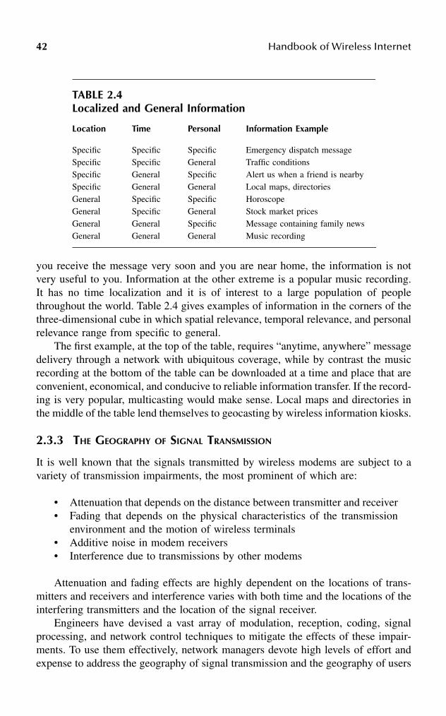
42 Handbook of Wireless Internet
you receive the message very soon and you are near home, the information is notvery useful to you. Information at the other extreme is a popular music recording.It has no time localization and it is of interest to a large population of peoplethroughout the world. Table 2.4 gives examples of information in the corners of thethree-dimensional cube in which spatial relevance, temporal relevance, and personalrelevance range from specific to general.
The first example, at the top of the table, requires “anytime, anywhere” messagedelivery through a network with ubiquitous coverage, while by contrast the musicrecording at the bottom of the table can be downloaded at a time and place that areconvenient, economical, and conducive to reliable information transfer. If the record-ing is very popular, multicasting would make sense. Local maps and directories inthe middle of the table lend themselves to geocasting by wireless information kiosks.
2.3.3 THE GEOGRAPHY OF SIGNAL TRANSMISSION
It is well known that the signals transmitted by wireless modems are subject to avariety of transmission impairments, the most prominent of which are:
• Attenuation that depends on the distance between transmitter and receiver• Fading that depends on the physical characteristics of the transmission
environment and the motion of wireless terminals• Additive noise in modem receivers• Interference due to transmissions by other modems
Attenuation and fading effects are highly dependent on the locations of trans-mitters and receivers and interference varies with both time and the locations of theinterfering transmitters and the location of the signal receiver.
Engineers have devised a vast array of modulation, reception, coding, signalprocessing, and network control techniques to mitigate the effects of these impair-ments. To use them effectively, network managers devote high levels of effort andexpense to address the geography of signal transmission and the geography of users
TABLE 2.4Localized and General Information
Location Time Personal Information Example
Specific Specific Specific Emergency dispatch messageSpecific Specific General Traffic conditionsSpecific General Specific Alert us when a friend is nearby Specific General General Local maps, directoriesGeneral Specific Specific HoroscopeGeneral Specific General Stock market pricesGeneral General Specific Message containing family newsGeneral General General Music recording
Wireless Internet > Wireless + Internet 43
in determining the locations of base stations and access points and precisely orientingtheir antennas. They aim for highly reliable signal reception in the greatest possiblecoverage area at all times.
In spite of the effort and expense devoted to erasing the inherent time and locationdependence of signal quality, the goal of “anytime, anywhere” communicationsremains elusive in all WLANs and new (2.5G and 3G) cellular systems. All of thesetechnologies prescribe radio modems that can operate with a collection of modula-tion and coding schemes, each with its own transmission rate and immunity toimpairments. They employ rate adaptation to find at any time and place the bestcompromise between signal quality and transmission rate. As in the example ofFigure 2.2, this trade-off depends on the locations of transmitters and receivers andon network activity.
The nature of the compromise resembles that of a telephone modem built intoa personal computer in that the modem operates at a bit rate matched to the char-acteristics of each dial-up connection. However, the effects on applications are quitedifferent. A dial-up modem operates at one rate for the duration of a connection. Bycontrast, the mobility of wireless terminals and the time-varying nature of theinterference will cause wireless modems to change their rates far more frequently.Managing quality of service of applications in the presence of location-dependentand time-dependent transmission rates and signal quality levels is a major challengethat remains to be addressed.
2.4 RESEARCH INITIATIVES
The industry trends described in Section 2.2 follow evolutionary paths within theframework of established cellular and local area networks. In doing so, they fail toaddress directly the essential characteristics of a wireless Internet as represented bythe geography of users, the geography of information, and the geography of signaltransmission described in Section 2.3.3. To fill the gap, the research community isexploring novel network architectures supported by an IP-based core network. Thenetwork architectures include proximity-based communications, ad hoc networking,and hybrids incorporating these with cellular networks, WLANs, and otherapproaches. The IP core network will require a new service support sublayer betweenthe transport layer and the applications layer. It will make use of geolocationinformation to facilitate network control and optimize the use of network resources.This section describes examples of work in progress on adaptive network architectureand on the core network.
2.4.1 ADAPTIVE NETWORK ARCHITECTURES
A wireless Internet presents new possibilities of adaptive networking solutions.Instead of simply cutting the wires in the last mile and viewing air as the hostilemedium of transmission whose shortcomings need to be combated, the absence ofwires can provide novel means of disseminating control and user information bytaking advantage of mobility. The client/server model that governs the cellular

44 Handbook of Wireless Internet
approach, where all radio resource allocation is determined centrally, attempts toerase the effects of mobility rather than take advantage of it. As mentioned in Section2.3.1, the diversity of users accessing a wireless Internet will proliferate with thefuture deployment of autonomous devices that collect, measure, process, query, andrelay information. The growth in pervasive computing devices will make it imprac-tical for fixed access points to provide centralized mobility management and ensurebandwidth efficiency. Therefore, in the confines of the client/server model of thecellular architecture, mobile users would experience limited quality of service andlimited data access.
The radio links of a wireless Internet are at the perimeter of a complex infor-mation network. The interface between the core Internet and the radio links of awireless Internet comprise a radio access network, which needs to respond to thechanging wireless landscape. Radio access networks for cellular and WLAN radiolinks differ significantly. Cellular access networks consist of a sophisticated infra-structure linking base stations, routers, servers, and databases. WLAN access net-works come in many varieties. They can have a substantial infrastructure or noneat all, relying on ad hoc connections between WLAN modems for network control.The networks can have a hierarchical or peer-to-peer topology. However, no radioaccess network has yet emerged as the clear winner. The next-generation wirelessnetwork will need to be a network of networks where the boundaries betweendifferent modes of radio access are transparent to the user. The quest for thiscapability is reflected in the research-and-development efforts toward WLAN/cel-lular coordination discussed in Section 2.2.3. More radical examples of seamlesstransition between modes of access in real-time are emerging in the research com-munity.
Future radio access networks will need to promote efficient use of electromag-netic resources by all transceivers, mobile and fixed. This mindset immediately pointsto the flexibility offered by proximity-based and peer-to-peer communications aug-menting the conventional infrastructure networking. Such flexibility would presentadaptation capability to overall spatial and temporal variation of traffic, as well asthe mobility states of user groups and individual users. Further, mobility of nodescan now be viewed as an advantage in information dissemination, routing, andcooperation for improved quality of service. In an adaptive network of mobile nodes,each mobile device enriches the web of communication by contributing to thenetwork density. Data can move from car to car, among people passing each otherin the streets, in the hallways of an office building, in a park, or in an airport. Militarycommunications development efforts have for some time taken these concepts intoaccount. Proximity-based communications will promote the efficiency and resilienceof a wireless Internet.
Solutions that take advantage of proximity and peer-to-peer cooperative com-munications include Infostations, multihop systems that extend the range of fixedwireless systems, ad hoc networks of various hierarchy levels, and hybrid systems.The common thread in this seemingly diverse set of architectures is the motivationto adapt to the geography of users, information, and signal transmission in a locallyoptimal manner. This section is a survey of exemplary new architectures.

Wireless Internet > Wireless + Internet 45
2.4.1.1 Proximity-Based Systems
An Infostation is an example of a proximity-based system that takes advantage ofuser mobility;10 it provides wireless information services to users located in ortraversing a limited coverage area. As people with notebook computers or PDAspass by an Infostation, they receive useful information, with little or no humaninteraction. This could be information that is most relevant near the Infostation, suchas local maps, restaurant listings, or information about courses at a university; or itcould be information of general interest, such as news articles or music.
As shown in Figure 2.3, an Infostation consists of a radio transceiver (such asa WLAN access point) that provides high bit rate, low-cost, low-power networkconnections to portable terminals in a restricted coverage area, along with computerhardware and software that caches relevant data and schedules transmissions.Because a subscriber to an Infostation service may spend a short time in the servicearea of each Infostation, the information transfer should be organized in advanceand should take place at the speed of electronic processes rather than the speed ofhuman–computer interactions. A network of Infostations consists of several isolatedcoverage areas separated by large gaps. The cellular network serving the regioncontaining all the Infostations can enhance the operation of the Infostation networkby observing the changing locations of users. The Infostation system can use thislocation knowledge to move information needed by a user to an Infostation beforethe user arrives.11 The information can be quickly downloaded to an informationterminal in the short time that the user is in the Infostation coverage area.
The Infostation paradigm is motivated by our earlier observation that no single“one size fits all” technology is suitable for all wireless information services, andWLANs and cellular networks both will be prominent in a wireless Internet. Thebest way to deliver information depends on various facets of the geography of theinformation, including spatial and temporal aspects, as well as characteristics of the
FIGURE 2.3 Infostation system elements.
internet
data broadcast
servers
Infostation=PC + WLAN AccessPoint
users with laptops, PDAs
46 Handbook of Wireless Internet
users. For many types of information, “many-time, many-where” coverage offeredby Infostations is sufficient to serve a mobile population. For services such as e-mail,voice mail, maps, restaurant locations, and many others, there is no penalty incurredby waiting until a terminal arrives in range of an Infostation, provided the user issufficiently mobile. If information delivery becomes urgent, the cellular network isavailable to deliver it, albeit at lower bit rates and higher cost in fees and powerdissipation.
2.4.1.2 Cooperative Communications
A large body of research in progress anticipates that devices will cooperate withone another to deliver information. The cooperation can occur at different protocollayers. At the physical layer, one device can provide diversity transmission andreception for another one. At the application layer, a user can receive a Web pagefrom the cache of a nearby user and avoid the need to communicate with the Webserver where the page originated. Multihopping is an example of cooperation at thenetwork layer.
Cooperation naturally relies on proximity of network devices that can assist oneanother. Mobility enhances cooperation by increasing the probability that a devicewill be able to receive assistance from other devices.12 The following paragraphsrefer to work in progress on cooperative systems.
The large body of current research on ad hoc networks anticipates cooperativecommunications in many forms. Demon Networks (http://www.winlab.rut-gers.edu/~crose) envision an ad hoc local area network that takes advantage ofmobility in order to route information. The network is not necessarily fully connectedat any given time. Therefore, changes in network topology are essential for packetdelivery rather than a complication to be overcome. Mobile stations can keep packetsthey receive and each packet to be delivered will almost certainly have many copiesin the system at a given instant. The dissemination of information in this caseresembles an epidemic, in which useful information is the contagious disease. Thedestination can be a single node or a multicast group. Each node is responsible formanaging its memory allocation by making timely decisions regarding the deletionof packets it carries and disseminates.
The Terminode project applies this idea in a metropolitan area.13 It uses mobilityof users to disseminate information throughout a city. Each Terminode contains amap of the city and uses the map to make routing decisions.
Other forms of cooperation in ad hoc networks have been formulated as powercombining and cooperative coding where diversity is exploited for purposes ofmaximizing bandwidth efficiency, extending coverage, network lifetime, and batterylife.14,15
2.4.1.3 Hybrid Architectures
In addition to the limitations of cellular infrastructure in terms of quality of serviceand data rates, there are situations (for example shadowing and equipment failure)in which no communication infrastructure is available to terminals. The 7DS system

Wireless Internet > Wireless + Internet 47
(seven degrees of separation) is motivated by the limitations of dependence on anetwork infrastructure.16 In 7DS, mobile and stationary terminals cooperate to shareinformation, help maintain connectivity to the network, and relay messages for oneanother. They can serve as ad hoc gateways into the Internet.
The 7DS architecture allows peer nodes to communicate via a WLAN, forminga flat ad hoc network, where some nodes have connectivity to the Internet. Theconnection to the infrastructure can be achieved by any access mode, such asInfostations, cellular base stations, or WLAN access points. For purposes of infor-mation sharing, peers query, discover and disseminate information. When the net-work connection sharing is enabled, the system allows a host to act as an application-based gateway and share its connection to the Internet. For message relaying, hoststhat do have access to the Internet forward messages on behalf of other hosts. Thesystem is an example of adaptive networking that adjusts its routing, cooperation,and power control based on the availability of energy and bandwidth. Furthermore,7DS inherently exploits host mobility. Currently, the peer-to-peer portion of thenetwork is implemented in a WLAN environment.
The hybrid Cellular Ad Hoc Augmented Network (CAHAN) has been developedwith the above influences.17 The goal of CAHAN is to make the best use of thecellular infrastructure where the centralized control and the fixed reference pointsprovided by base stations are advantageous, and to incorporate peer-to-peer com-munications to optimize radio resource allocation, resilience, and power consump-tion. Figure 2.4 depicts an exemplary snapshot of CAHAN.
FIGURE 2.4 An exemplary snapshot of a CAHAN.
: AP
: MN
: radio link
Legend:
: ad hoc network
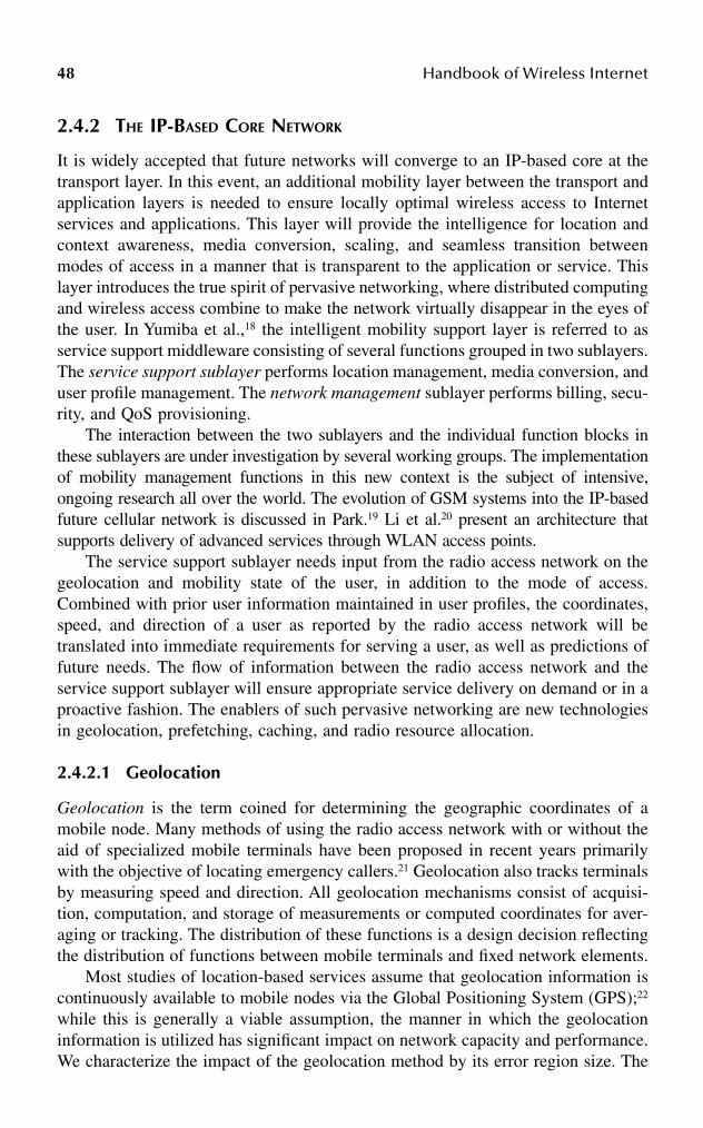
48 Handbook of Wireless Internet
2.4.2 THE IP-BASED CORE NETWORK
It is widely accepted that future networks will converge to an IP-based core at thetransport layer. In this event, an additional mobility layer between the transport andapplication layers is needed to ensure locally optimal wireless access to Internetservices and applications. This layer will provide the intelligence for location andcontext awareness, media conversion, scaling, and seamless transition betweenmodes of access in a manner that is transparent to the application or service. Thislayer introduces the true spirit of pervasive networking, where distributed computingand wireless access combine to make the network virtually disappear in the eyes ofthe user. In Yumiba et al.,18 the intelligent mobility support layer is referred to asservice support middleware consisting of several functions grouped in two sublayers.The service support sublayer performs location management, media conversion, anduser profile management. The network management sublayer performs billing, secu-rity, and QoS provisioning.
The interaction between the two sublayers and the individual function blocks inthese sublayers are under investigation by several working groups. The implementationof mobility management functions in this new context is the subject of intensive,ongoing research all over the world. The evolution of GSM systems into the IP-basedfuture cellular network is discussed in Park.19 Li et al.20 present an architecture thatsupports delivery of advanced services through WLAN access points.
The service support sublayer needs input from the radio access network on thegeolocation and mobility state of the user, in addition to the mode of access.Combined with prior user information maintained in user profiles, the coordinates,speed, and direction of a user as reported by the radio access network will betranslated into immediate requirements for serving a user, as well as predictions offuture needs. The flow of information between the radio access network and theservice support sublayer will ensure appropriate service delivery on demand or in aproactive fashion. The enablers of such pervasive networking are new technologiesin geolocation, prefetching, caching, and radio resource allocation.
2.4.2.1 Geolocation
Geolocation is the term coined for determining the geographic coordinates of amobile node. Many methods of using the radio access network with or without theaid of specialized mobile terminals have been proposed in recent years primarilywith the objective of locating emergency callers.21 Geolocation also tracks terminalsby measuring speed and direction. All geolocation mechanisms consist of acquisi-tion, computation, and storage of measurements or computed coordinates for aver-aging or tracking. The distribution of these functions is a design decision reflectingthe distribution of functions between mobile terminals and fixed network elements.
Most studies of location-based services assume that geolocation information iscontinuously available to mobile nodes via the Global Positioning System (GPS);22
while this is generally a viable assumption, the manner in which the geolocationinformation is utilized has significant impact on network capacity and performance.We characterize the impact of the geolocation method by its error region size. The

Wireless Internet > Wireless + Internet 49
error region is the area around the actual position of the mobile that the computedgeolocation will lie in with a given high probability. The optimization of the geolo-cation and update intervals will mostly depend on the mobility patterns of the mobilenodes, as well as the target area size.
As an enabler of wireless Internet, a geolocation method of choice should bedictated by the requirements of the location-aware application or service. Further-more, the signaling flow for geolocation will be different in different networkarchitectures. Measurement, computation, and storage functions can be performedby different network components, in a hierarchy or in a cooperative, peer-to-peerfashion. The geolocation method, along with the mode of communication, shouldbe optimized locally, so that it will work in harmony with the adaptive networkarchitectures. The role of geolocation with respect to the geographical frameworkin Section 2.3 is summarized as follows: Geolocation enables the adaptation to thegeography of information and users by facilitating location-aware services andapplications. It helps the radio access network cater to the geography of users andthe geography of signal transmission.
Facilitation of location-aware services and applications prompts signalingbetween the radio access network and the service support sublayer. Media conver-sion, content, and location management components need to interpret the position,speed, and direction of the mobile obtained from the radio access network by cross-referencing these with target area and subscriber profile information, which is main-tained in the service support sublayer. The amount of signaling between the servicesupport sublayer and the radio access network needs to be optimized. Mobilitymodeling and trajectory prediction methods are found to be helpful in assigning themaximum geolocation update interval subject to the quality of service requirementsof the particular application or service.23
Along with mobility modeling and trajectory prediction, geolocation and track-ing mechanisms make it possible for the network to prefetch and cache informationproactively. An example of file prefetching in a drive-through Infostation system isgiven in Iacono and Rose.24 Other studies consider the file prefetching in base stationsof the cellular infrastructure.25
2.4.2.2 Resource Management
The ad hoc networks investigated in Section 2.4.1 raise new issues related tomanagement of radio resources and management of battery energy in terminals. Inthese networks, terminals sometimes function as endpoints of communication linksand other times as relays, receiving and forwarding packets moving to and fromother terminals. Each terminal therefore will use some of its energy for sending andreceiving its own data and another portion of its energy assisting other terminals.Routing algorithms have a strong effect on overall energy consumption in a networkand in individual terminals. They influence the proportion of energy each terminalexpends for itself relative to energy used to assist other terminals. Research onenergy-efficient routing in ad hoc networks considers total energy consumption intransmitting a message as well as average energy consumed by the terminals thatparticipate in the transmission. Most of this work examines a stationary network
50 Handbook of Wireless Internet
with terminals in random positions. In this situation, there is considerable variationfrom terminal to terminal in the proportion of energy used for the tasks of relayingand communicating. By contrast, a recent study shows that when terminals aremobile, the variation is considerably diminished.14 However, truly adaptive tech-niques that will optimize routing decisions based on the instantaneous remainingbattery power of each node need to be devised.
Game theory appears to be a promising approach to the management of batteryenergy in the terminals of a network of cooperating nodes. A game theory formu-lation defines a utility function for each terminal and an overall (“social”) utilityfunction for the network. The utility function relates to the amount of data sent andreceived by the terminal and the energy consumed. Each terminal adopts a strategyfor maximizing its utility. Because many terminals in a network share radioresources, the strategy adopted by one terminal affects the utility obtained by theothers. This situation is similar to the one addressed in research on power controlin cellular systems,26 in which game theory strategies led to the design of efficientalgorithms for power control for cellular data. In applying game theory to resourcemanagement in networks of cooperating nodes, a major issue is the nature of thecooperation that will promote effective distribution of radio resources and fairexpenditure of battery energy across the terminals in a network. It is clear that acompletely noncooperative game produces suboptimum results. In the studies ofcellular data systems, the base station can coordinate the cooperation among termi-nals.27 On the other hand, the terminals in the ad hoc networks under investigationare not in communication with a single coordinating device. Therefore, the cooper-ation must be distributed among the terminals in the network.
2.5 CONCLUSIONS
In this chapter, we have presented state-of-the-art wireless Internet technologies andtheir shortcomings. Prioritizing formulation of problems before solutions, we rede-fined wireless Internet as a range of opportunities fueled by the lack of wires andmobility rather than an array of obstacles in competing with wired Internet. Viewingwireless Internet as such, we introduced emerging network architectures andenabling technologies that pave the way toward this vision. Wireless Internet, if fullyrealized, will be the pervasive network that will disappear from the point of viewof the end user. The network will sense the present state of its users, as well aspredict their future needs and adapt, react, and plan proactively. In order to havethese abilities, wireless Internet will need to be a network of networks, whoseboundaries will be as transparent as possible to the user.
References
1. Fainberg, M. and Goodman, D., Maximizing performance of a wireless LAN in thepresence of Bluetooth, Proc. 3rd IEEE Workshop on Wireless LANs, 2001.
2. Grass, E. et al., On the single-chip implementation of a Hiperlan/2 and IEEE802.11acapable modem, IEEE Pers. Commun., 8 (6), 48–57, 2001.

Wireless Internet > Wireless + Internet 51
3. Eriksson, M. et al., System performance with higher level modulation in theGSM/EDGE radio access network, IEEE Globecom, 5, 3065–3069, 2001.
4. Ala-Laurila, J., Mikkonen, J., and Rinnemaa, J., Wireless LAN access network archi-tecture for mobile operators, IEEE Communications Magazine, 39(11), 82–89, 2001.
5. Noerenberg, J., Bridging wireless protocols, IEEE Communications Magazine,39(11), 90–97, 2001.
6. Haartsen, J.C., The Bluetooth radio system, IEEE Pers. Commun., 7 (1), 28–36, 2000.7. Gossain, H., de Morais Cordeiro, C., and Agrawal, D.P., Multicast: wired to wireless,
IEEE Communications Magazine, 40(6)116–123, June 2002.8. Navas, J.C. and Imielinski, T., Geographic addressing and routing, Proc. Mobicom
’97, Budapest, Hungary, September 1997.9. Goodman, D.J., The wireless Internet: promises and challenges, Computer, 33 (7),
36–41, 2000.10. Goodman, D.J. et al., Infostations: a new system model for data and messaging
services, Proc. IEEE Vehicular Technology Conference, 969–973, 1997.11. Iacono, A.L. and Rose, C., Bounds on file delivery delay in an Infostation system,
Proc. IEEE Vehicular Technology Conference, 2295–2299, 2000.12. Grossglauser, M. and Tse, D., Mobility increases the capacity of ad hoc wireless
networks, IEEE/ACM Transactions on Networking, 10(4), 477–486, 2002.13. Blazevic, L., Giordano, S., and Le Boudec, J.-Y., Self organized routing in wide area
mobile ad hoc networks, Proc. IEEE Globecom, 5, 2814–2818, 2001.14. Catovic, A. and Tekinay, S., A New Approach to Minimum Energy Routing for Next
Generation Multihop Wireless Networks, J. Communications and Networks, 4(4),351–362, 2002.
15. http://eeweb.poly.edu/~elza/Publications.htm.16. http://www.cs.columbia.edu/~maria/project/.17. Tekinay, S., Adaptive networks for next generation wireless communications: the
growing role of peer-to-peer communications, in Wireless Communications and Net-working, Sunay, O., Ed., Kluwer, Dordrecht, Netherlands, in press.
18. Yumiba, H., Imai, K., and Yabusaki, M., IP-based IMT network platform, IEEE Pers.Commun., 8 (6), 18, 2001.
19. Park, J.-H., Wireless Internet access for mobile subscribers based on the GPRS/UMTSnetwork, IEEE Communications Magazine, 40(4), 38–49, 2002.
20. Li, J. et al., Public access mobility LAN: extending the wireless Internet into theLAN environment, IEEE Wireless Commun., 9(3), 22–30, 2002.
21. S. Tekinay, Guest Ed., Wireless geolocation systems and services, IEEE Communi-cations Magazine, 36, 36(4), 28, 1998.
22. Sarikaya, B., Ed., Geographic Location in the Internet, Kluwer, Dordrecht, 2002.23. Choi, W.-J. and Tekinay, S., Mobility modeling and management for next generation
wireless networks, Proc. Symp. on Wireless Personal Multimedia Communications2001, Aalborg, Denmark, 2001.
24. Iacono, A.L. and Rose, C., Infostations: a new perspective on wireless data networks,in Next Generation Wireless Networks, Tekinay, S., Ed., Kluwer, Dordrecht, Netherlands,2001.
25. Kobayashi, H., Yu, S.-Z., and Mark, B.L., An integrated mobility and traffic modelfor resource allocation in wireless networks, Proc. Workshop on Wireless MobileMultimedia, Boston, 3–63, 2000.
26. Saraydar, C.U., Mandayam, N.B., and Goodman, D.J., Efficient power control viapricing in wireless data networks, IEEE Trans. Commun., 50(2), 291–303, 2002.
27. Goodman, D.J. and Mandayam, N.B., Network Assisted Power Control for WirelessData, Mobile Networks and Applications, 6(5), 409–418, 2001.

This page intentionally left blank

530-8493-1502-6/03/$0.00+$1.50© 2003 by CRC Press LLC
3 Wireless Internet Security
Dennis Seymour Lee
CONTENTS
3.1 Introduction ....................................................................................................533.2 Who Is Using the Wireless Internet?.............................................................543.3 What Types of Applications Are Available?..................................................553.4 How Secure Are the Transmission Methods? ...............................................56
3.4.1 Frequency Division Multiple Access Technology.............................573.4.2 Time Division Multiple Access Technology .....................................573.4.3 Global Systems for Mobile Communications ...................................583.4.4 Code Division Multiple Access Technology .....................................603.4.5 Other Methods....................................................................................61
3.5 How Secure Are Wireless Devices? ..............................................................623.5.1 Authentication ....................................................................................623.5.2 Confidentiality ....................................................................................643.5.3 Malicious Code and Viruses ..............................................................65
3.6 How Secure Are the Network Infrastructure Components? .........................663.6.1 The “Gap in WAP” ............................................................................663.6.2 WAP Gateway Architectures..............................................................67
3.6.2.1 WAP Gateway at the Service Provider ..............................673.6.2.2 WAP Gateway at the Host..................................................683.6.2.3 Pass-Through from Service Provider’s WAP Gateway
to Host’s WAP Proxy..........................................................703.7 Conclusion......................................................................................................71Bibliography ............................................................................................................72
3.1 INTRODUCTION
Recalling the early days of the Internet, one can recount several reasons why theInternet came about:
• A vast communications medium to share electronic information• A multiple-path network that could survive localized outages• A means for computers from different manufacturers and different net-
works to talk to one another
54 Handbook of Wireless Internet
Commerce and security at that time were not high on the agenda (with theexception of preserving network availability). The thought of commercializing theInternet in the early days was almost unheard of. In fact, it was considered improperetiquette to use the Internet to sell products and services. Commercial activity andits security needs are more-recent developments on the Internet, having come aboutstrongly in the past few years.
Today, in contrast, the wireless Internet is being designed from the very begin-ning with commerce as its main driving force. Nations and organizations around theglobe are spending millions, even billions of dollars to buy infrastructure, transmis-sion frequencies, technology, and applications in the hopes of drawing business. Insome ways, this has become the “land rush” of the new millennium. It stands toreason, then, that security must play a critical role early on as well: where moneychanges hands, security will need to accompany this activity.
Although the wireless industry is still in its infancy, the devices, infrastructure, andapplications development for the wireless Internet are rapidly growing on a worldwidescale. Those with foresight will know that security must fit into these designs early.The aim of this chapter is to highlight some of the significant security issues in thisemerging industry that need addressing. These are concerns that any business wishingto deploy a wireless Internet service or application will need to consider to protect itselfand its customers, and to safeguard investments in this new frontier.
Incidentally, the focus of this chapter is not about accessing the Internet usinglaptops and wireless modems; that technology, which has been around for manyyears, in many cases is an extension of traditional wired Internet access. Neitherwill this chapter focus on wireless LANs and Bluetooth, which are not necessarilyInternet based, but deserve chapters on their own. Rather, the concentration is onportable Internet devices, such as cell phones and PDAs (personal digital assistants),which inherently have far less computing resources than regular PCs. Therefore,these devices require different programming languages, protocols, encryption meth-ods, and security perspectives to cope with the technology. It is important to note,however, that despite their smaller sizes and limitations, these devices have a sig-nificant impact on information security, mainly because of the electronic commerceand intranet-related applications that are being designed for them.
3.2 WHO IS USING THE WIRELESS INTERNET?
Many studies and estimates are available today that suggest the number of wirelessInternet users will soon surpass the millions of wired Internet users. The assumptionis based on the many more millions of worldwide cell phone users who are alreadyout there, a population that grows by the thousands every day. If every one of thesemobile users chooses to access the Internet through a cell phone, indeed that pop-ulation could easily exceed the number of wired Internet users by several times. Itis this very enormous potential that has many businesses devoting substantialresources and investments in the hopes of capitalizing on this growing industry.
The wireless Internet is still very young. Many mobile phone users do not yet haveaccess to the Internet through their cell phones. Many are taking a “wait-and-see”

Wireless Internet Security 55
attitude toward available services. Most who do have wireless Internet access areearly adopters experimenting with the potential of what this service could provide.Because of the severe limitations in the wireless devices — the tiny screens, theextremely limited bandwidth, as well as other issues — most users who have bothwired and wireless Internet access will admit that, for today, the wireless deviceswill not replace their desktop computers and notebooks anytime soon as their primarymeans of accessing the Internet. Many admit that “surfing the Net” using a wirelessdevice today could become a disappointing exercise. Most of these wireless Internetusers have expressed the following frustrations:
• It is too slow to connect to the Internet.• Mobile users can be disconnected in the middle of a session when they
are on the move.• It is cumbersome to type out sentences using a numeric keypad.• It is expensive to use the wireless Internet, especially when billed on a
per-minute basis.• There is very little or no graphics display capabilities on wireless devices.• The screens are too small and users have to scroll constantly to read a
long message.• There are frequent errors when surfing Web sites (mainly because most
Web sites today are not yet wireless Internet compatible).
At the time of this writing, the one notable exception to these disappointmentsis found in Japan. The telecommunications provider NTT DoCoMo has experiencedphenomenal growth in the number of wireless Internet subscribers, using a wirelessapplication environment called i-mode (as opposed to the wireless application pro-tocol, or WAP). For many in Japan, connection using a wireless phone is their onlymeans of accessing the Internet. In many cases, wireless access to the Internet is farcheaper than wired access, especially in areas where the wired infrastructure isexpensive to set up. i-mode users have the benefit of “always online” wirelessconnections to the Internet, color displays on their cell phones, and even graphics,musical tones, and animation. Perhaps Japan’s success with the wireless Internetwill offer an example of what can be achieved in the wireless arena, given the rightelements.
3.3 WHAT TYPES OF APPLICATIONS ARE AVAILABLE?
Recognizing the frustrations and limitations of today’s wireless technology, manybusinesses are designing their wireless devices and services not necessarily asreplacements for wired Internet access, but as specialized services that extend whatthe wired Internet could offer. Most of these services highlight the attractive conve-nience of portable informational access, “anytime, anywhere,” without having to sitin front of a computer; essentially, Internet services one can carry in one’s pocket.Clearly, the information would have to be concise, portable, useful, and easy toaccess. Examples of mobile services available or being designed today include:

56 Handbook of Wireless Internet
• Shopping online using a mobile phone; comparing online prices with storeprices while inside an actual store
• Getting current stock prices, trading price alerts, trade confirmations, andportfolio information anywhere
• Performing bank transactions and obtaining account information• Obtaining travel schedules and booking reservations• Obtaining personalized news stories and weather forecasts• Receiving the latest lottery numbers• Obtaining the current delivery status for express packages• Reading and writing e-mail “on the go”• Accessing internal corporate databases such as inventory, client lists, etc.• Getting maps and driving directions• Finding the nearest ATM machines, restaurants, theaters, and stores, based
on the user’s present location• Dialing 911 and having emergency services quickly triangulate the caller’s
location• Browsing a Web site and speaking real-time with the site’s representative,
all within the same session
Newer and more-innovative services are in the works. As any new and emergingtechnology, wireless services and applications are often surrounded by much hope andhype, as well as some healthy skepticism. But as the technology and services matureover time, yesterday’s experiments can become tomorrow’s standards. The Internet isa grand example of this evolving progress. Development of the wireless Internet willgo through the same evolutionary cycle, although probably at an even faster pace.
Like any new technology, however, security and safety issues can damage itsreputation and benefits if they are not included intelligently into the design from thevery beginning. It is with this in mind that this chapter is written.
Because the wireless Internet covers much territory, the same goes for its securityas well. This chapter discusses security issues as they relate to the wireless Internetin a few select categories, starting with transmission methods to the wireless devicesand ending with some of the infrastructure components themselves.
3.4 HOW SECURE ARE THE TRANSMISSION METHODS?
For many years, it has been public knowledge that analog cell phone transmissionsare fairly easy to intercept. It has been a known problem for as long as analog cellphones have been available. They are easily intercepted using special radio-scanningequipment. For this reason, as well as many others, many cell phone service providershave been promoting digital services to their subscribers and reducing analog to alegacy service.
Digital cell phone transmissions, on the other hand, are typically more difficultto intercept. It is on these very same digital transmissions that most of the newwireless Internet services are based.

Wireless Internet Security 57
However, there is no single method for digital cellular transmission. In fact,there are several different methods for wireless transmission available today. Forexample, in the United States, providers such as Verizon and Sprint primarily useCDMA (Code Division Multiple Access), whereas AT&T primarily uses TDMA(Time Division Multiple Access) and Voicestream uses GSM (Global Systems forMobile Communications). Other providers, such as Cingular, offer more than onemethod (TDMA and GSM), depending on the geographic location. All these methodsdiffer in the way they use the radio frequencies and the way they allocate users onthose frequencies. This chapter discusses each of these in more detail.
Cell phone users who want wireless Internet access are generally not concernedwith choosing a particular transmission method, nor do they really care to. Instead,most users select their favorite wireless service provider when they sign up forservice. It is generally transparent to the user which transmission method theirprovider has implemented. It is an entirely different matter for the service provider,however. Whichever method they implement has significant bearing on its infra-structure. For example, the type of radio equipment they use, the location and numberof transmission towers to deploy, the amount of traffic they can handle, and the typeof cell phones to sell to their subscribers are all directly related to the digitaltransmission method chosen.
3.4.1 FREQUENCY DIVISION MULTIPLE ACCESS TECHNOLOGY
All cellular communications, analog or digital, are transmitted using radio frequen-cies that are purchased by or allocated to the wireless service provider. Each serviceprovider typically purchases licenses from the appropriate authority to operate aspectrum of radio frequencies.
Analog cellular communications typically operate on what is called FrequencyDivision Multiple Access (FDMA) technology. With FDMA, each service providerdivides its spectrum of radio frequencies into individual frequency channels. Eachchannel has a width of 10 to 30 kilohertz (kHz) and is a specific frequency thatsupports a one-way communication session. For a regular two-way phone conver-sation, every cell phone caller is assigned two frequency channels: one to send andone to receive.
Because each phone conversation occupies two channels (two frequencies), itis not too difficult for specialized radio scanning equipment to tap into a live analogphone conversation once the equipment has tuned into the right frequency channel.There is very little privacy protection in analog cellular communications if noencryption is added.
3.4.2 TIME DIVISION MULTIPLE ACCESS TECHNOLOGY
Digital cellular signals, on the other hand, can operate on a variety of encodingtechniques, most of which are resistant to analog radio frequency scanning. (Note:the term encoding in wireless communications does not mean encryption and is hereused to refer to converting a signal from one format to another e.g., from a wiredsignal to a wireless signal.)
58 Handbook of Wireless Internet
One such technique is called time division multiple access, or TDMA. Similarto FDMA, TDMA typically divides the radio spectrum into multiple 30-kHz fre-quency channels (sometimes called frequency carriers). Every two-way communi-cation requires two of these frequency channels: one to send and one to receive. Butin addition, TDMA further subdivides each frequency channel into three to six timeslots called voice/data channels, so that now up to six digital voice or data sessionscan take place using the same frequency. With TDMA, a service provider can handlemore calls at the same time, compared to FDMA. This is accomplished by assigningeach of the six sessions a specific time slot within the same frequency. Each timeslot (or voice/data channel) is approximately seven milliseconds in duration. Thetime slots are arranged and transmitted over and over again in rapid rotation. Voiceor data for each caller is placed into the time slot assigned to that caller and thentransmitted. Information from the corresponding time slot is quickly extracted andreassembled at the receiving cellular base station to piece together the conversationor session. Once that time slot (or voice/data channel) is assigned to a caller, it isdedicated to that caller for the duration of the session, until it terminates. In TDMA,a user is not assigned an entire frequency, but shares the frequency with other users,each with an assigned time slot.
As of the writing of this chapter, there have not been many publicized cases ofeavesdropping of TDMA phone conversations and data streams as they travel acrossthe wireless space. Access to special types of equipment or test equipment wouldprobably be required to perform such a feat. It is possible that an illegally modifiedTDMA cell phone also could do the job.
However, this does not mean that eavesdropping is unfeasible. With regard to awireless Internet session, consider the full path that such a session takes. For amobile user to communicate with an Internet Web site, a wireless data signal fromthe cell phone will eventually be converted into a wired signal before traversing theInternet itself. As a wired signal, the information can travel across the Internet inclear text until it reaches the Web site. Although the wireless signal itself may bedifficult to intercept, once it becomes a wired signal, it is subject to the sameinterception vulnerabilities as all unencrypted communications traversing the Inter-net. As a precaution, if there is confidential information being transmitted over theInternet, regardless of the method, it is always necessary to encrypt that sessionfrom end-to-end. Encryption is discussed in a later section.
3.4.3 GLOBAL SYSTEMS FOR MOBILE COMMUNICATIONS
Another method of digital transmission is Global Systems for Mobile Communications(GSM). GSM is actually a term that covers more than just the transmission methodalone. It covers the entire cellular system, from the assortment of GSM services to theactual GSM devices themselves. GSM is primarly used in European nations.
As a digital transmission method, GSM uses a variation of TDMA. Similar toFDMA and TDMA, the GSM service provider divides the allotted radio frequencyspectrum into multiple frequency channels. This time, each frequency channel has

Wireless Internet Security 59
a much larger width of 200 kHz. Again, similar to FDMA and TDMA, each GSMcellular phone uses two frequency channels: one to send and one to receive.
Like TDMA, GSM further subdivides each frequency channel into time slotscalled voice/data channels. However, with GSM, there are eight time slots, so thatnow up to eight digital voice or data sessions can take place using the same frequency.As for TDMA, when that time slot (or voice/data channel) is assigned to a caller,it is dedicated to that caller for the duration of the session until it terminates.
GSM has additional features that enhance security. Each GSM phone uses asubscriber identity module (SIM). A SIM can look like a credit-card sized smartcard or a postage-stamp sized chip. This removable SIM is inserted into the GSMphone during usage. The smart card or chip contains information pertaining to thesubscriber, such as the cell phone number belonging to the subscriber, authenticationinformation, encryption keys, directory of phone numbers, and short saved messagesbelonging to that subscriber. Because the SIM is removable, the subscriber can takethis SIM out of one phone and insert it into another GSM phone. The new phonewith the SIM will then take on the identity of the subscriber. The user’s identity isnot tied to a particular phone, but to the removable SIM itself. This makes it possiblefor a subscriber to use or upgrade to different GSM phones without changing phonenumbers. It is possible also to rent a GSM phone in another country, even if thatcountry uses phones that transmit on different GSM frequencies. This arrangementworks, of course, only if the GSM service providers from the different countrieshave compatible arrangements with each other.
The SIM functions as an authentication tool because the GSM phones are uselesswithout it. When the SIM is inserted into a phone, users are prompted to put in theirpersonal identification numbers (PINs) associated with that SIM (if the SIM is PIN-enabled). Without the correct PIN number, the phone will not work.
In addition to authenticating the user to the phone, the SIM also is used toauthenticate the phone to the phone network itself during connection. Using theauthentication (or Ki) key in the SIM, the phone authenticates to the service pro-vider’s Authentication Center during each call. The process employs a challenge-response technique, similar in some respects to using a token card to remotely loga PC onto a network.
The keys in the SIM have another purpose in addition to authentication. Theencryption (or Kc) key generated by the SIM can be used to encrypt communicationsbetween the mobile phone and the service provider’s transmission equipment forconfidentiality. This encryption prevents eavesdropping, at least between these twopoints.
GSM transmissions, similar to TDMA, are difficult but not impossible to inter-cept using radio frequency scanning equipment. A frequency can have up to eightusers on it, making the digital signals difficult to extract. By adding encryption usingthe SIM card, GSM can add yet another layer of security against interception.
However, when it comes to wireless Internet sessions, this form of encryptiondoes not provide end-to-end protection; only part of the path is actually protected.This is similar to the problem mentioned previously with TDMA Internet sessions.
60 Handbook of Wireless Internet
A typical wireless Internet session takes both a wireless and a wired path. GSMencryption protects only the path between the cell phone and the service provider’stransmission site — the wireless portion. The remainder of the session through thewired Internet — from the service provider’s site to the Internet Web site — canstill travel in the clear. One would need to add end-to-end encryption if there is aneed to keep the entire Internet session confidential.
3.4.4 CODE DIVISION MULTIPLE ACCESS TECHNOLOGY
Another digital transmission method is called code division multiple access(CDMA). CDMA is based on spread spectrum, a transmission technology that hasbeen used by the U.S. military for many years to make radio communications moredifficult to intercept and jam. Qualcomm is one of the main pioneers incorporatingCDMA spread spectrum technology into the area of cellular phones.
Instead of dividing a spectrum of radio frequencies into narrow frequency bandsor time slots, CDMA uses a very large portion of that radio spectrum, also called afrequency channel. The frequency channel has a wide width of 1.25 megahertz(MHz). For duplex communications, each cell phone uses two of these wide CDMAfrequency channels: one to send and one to receive.
During communication, each voice or data session is first converted into a seriesof data signals. Next, the signals are marked with a unique code to indicate that theybelong to a particular caller. This code is called a pseudorandom noise (PN) code.Each mobile phone is assigned a new PN code by the base station at the beginningof each session. These coded signals are then transmitted by spreading them outacross a very wide radio frequency spectrum. Because the channel width is verylarge, it has the capacity to handle many other user sessions at the same time, eachsession again tagged by unique PN codes to associate them to the appropriate caller.
A CDMA phone receives transmissions using the appropriate PN code to pickout the data signals that are destined for it and ignores all other encoded signals.
With CDMA, cell phones communicating with the base stations all share thesame wide frequency channels. What distinguishes each caller is not the frequencyused (as in FDMA), nor the time slot within a particular frequency (as in TDMAor GSM), but the PN noise code assigned to that caller. With CDMA, a voice/datachannel is a data signal marked with a unique PN code.
Intercepting a single CDMA conversation would be difficult because its digitalsignals are spread out across a very large spectrum of radio frequencies. The con-versation does not reside on just one frequency alone, making it difficult to scan.Also, without knowledge of the PN noise code, an eavesdropper would not be ableto extract the relevant session from the many frequencies used. To further complicateinterception, the entire channel width is populated by many other callers at the sametime, creating a vast amount of noise for anyone trying to intercept the call.
However, as seen earlier with the other digital transmission methods, Internetsessions using CDMA cell phones are not impossible to intercept. As before,although the CDMA digital signals themselves can be difficult to intercept, oncethese wireless signals are converted into wired signals, the latter signals can beintercepted as they travel across the Internet. Without using end-to-end encryption,

Wireless Internet Security 61
wireless Internet sessions are as vulnerable as other unencrypted communicationstraveling over the Internet.
3.4.5 OTHER METHODS
There are additional digital transmission methods, many of which are derivatives ofthe types already discussed, and some of which are still under development. Someof these that are under development are called third-generation or 3G transmissionmethods. Second-generation (2G) technologies, such as TDMA, GSM, and CDMA,offer transmission speeds of 9.6 to 14.4 kbps, which is slower than today’s typicalmodem speeds. 3G technologies, on the other hand, are designed to transmit muchfaster and carry larger amounts of data. Some will be capable of providing high-speed Internet access, as well as video transmission. Below is a partial listing ofother digital transmission methods, including those in the 3G category.
• iDEN (integrated Digital Enhanced Network) is a 2G transmission methodbased on TDMA. In addition to sending voice and data, it can be usedalso for two-way radio communications between two iDEN phones, muchlike walkie-talkies.
• PDC (Personal Digital Communications) is based on TDMA and is a 2Gtransmission method widely used in Japan.
• GPRS (General Packet Radio Service) is a 2.5G (not quite 3G) technologybased on GSM. It is a packet-switched data technology that provides“always online” connections, which means that the subscriber can staylogged on to the phone network all day but uses it only if there is actualdata to send or receive. Maximum data rates are estimated to be 115 kbps.
• EDGE (Enhanced Data rates for Global Evolution) is a 3G technologybased on TDMA and GSM. Like GPRS, it features “always online”connections using packet-switched data technologies. Maximum datarates are estimated to be 384 kbps.
• UMTS (Universal Mobile Telecommunications System) is a 3G technol-ogy based on GSM. Maximum data rates are estimated at 2 Mbps.
• CDMA2000 and W-CDMA (wideband CDMA) are two 3G technologiesbased on CDMA. CDMA2000 is more of a North American design,whereas W-CDMA is more European and Japanese oriented. Both providemaximum data rates estimated at 384 kbps for slow-moving mobile unitsand at 2 Mbps for stationary units.
Regardless of the methods or the speeds, the need for end-to-end encryptionwill still be a requirement if confidentiality is needed between the mobile deviceand the Internet or intranet site. Because wireless Internet communications encom-pass both wireless and wired-based transmissions, encryption features covering justthe wireless portion of the communication is clearly not enough. For end-to-endprivacy protection, the applications and the protocols have a role to play, as discussedlater in this chapter.
62 Handbook of Wireless Internet
3.5 HOW SECURE ARE WIRELESS DEVICES?
Internet security, as many have seen it applied to corporate networks today, can bedifficult to implement on wireless phones and PDAs for a variety of reasons. Mostof these devices have limited CPUs, memory, bandwidth, and storage abilities. Asa result, many have disappointingly slow and limited computing power. Robustsecurity features that can take less than a second to process on a typical workstationcan take potentially many minutes on a wireless device, making them impracticalor inconvenient for the mobile user. Because many of these devices have merely afraction of the hardware capabilities found on typical workstations, the securityfeatures on portable devices are often lightweight or even nonexistent from anInternet security perspective. However, these same devices are now being used tolog onto sensitive corporate intranets, or to conduct mobile commerce and banking.Although these wireless devices are smaller in every way, their security needs arejust as significant as before. It would be a mistake for corporate IT and informationsecurity departments to ignore these devices as they start to populate the corporatenetwork. After all, these devices do not discriminate; they can be designed to tapinto the same corporate assets as any other node on a network. Some of the securityaspects as they relate to these devices are examined here.
3.5.1 AUTHENTICATION
The process of authenticating wireless phone users has gone through many years ofimplementation and evolution. It is probably one of the most reliable security featuresdigital cell phones have today, given the many years of experience service providershave had in trying to reduce the theft of wireless services. Because the serviceproviders have a vested interest in knowing who to charge for the use of theirservices, authenticating the mobile user is of utmost importance.
As previously mentioned, GSM phones use SIM cards or chips that containauthentication information about the user. SIMs typically carry authentication andencryption keys, authentication algorithms, identification information, phone num-bers belonging to the subscriber, etc. They allow users to authenticate to their ownphones and to the phone network to which they are subscribed.
In North America, TDMA and CDMA phones use a similarly complex methodof authentication as in GSM. Like GSM, the process incorporates keys, Authenti-cation Centers, and challenge-response techniques. However, because TDMA andCDMA phones do not generally use removable SIM cards or chips, these phonesrely instead on the authentication information embedded into the handset. The user’sidentity is therefore tied to the single mobile phone itself.
The obvious drawback is that for authentication purposes, TDMA and CDMAphones offer less flexibility when compared to GSM phones. To deploy a newauthentication feature with a GSM phone, in many cases, all that is needed is toupdate the SIM card or chip. On the other hand, with TDMA and CDMA, deployingnew authentication features would probably require users to buy new cell phones —a more expensive way to go. Because it is easier to update a removable chip than

Wireless Internet Security 63
an entire cell phone, it is likely that one will find more security features andinnovations being offered for GSM.
It is important to note, however, that this form of authentication does not nec-essarily apply to Internet-related transactions. It merely authenticates the mobileuser to the service provider’s phone network, which is only one part of the trans-mission if one is talking about Internet transactions. For securing end-to-end Internettransactions, mobile users still need to authenticate the Internet Web servers theyare connecting to, to verify that indeed the servers are legitimate. Likewise, theInternet Web servers need to authenticate the mobile users that are connecting to it,to verify that they are legitimate users and not impostors. The wireless serviceproviders, however, are seldom involved in providing full end-to-end authenticationservice, from mobile phone to Internet Web site. That responsibility usually falls tothe owners of the Internet Web servers and applications.
Several methods for providing end-to-end authentication are being tried todayat the application level. Most secure mobile commerce applications are using IDsand passwords, an old standby, which of course has its limitations because it providesonly single-factor authentication. Other organizations are experimenting with GSMSIMs by adding additional security ingredients such as public/private key pairs,digital certificates, and other public key infrastructure (PKI) components into theSIMs. However, because the use of digital certificates can be process intensive, cellphones and handheld devices typically use lightweight versions of these securitycomponents. To accommodate the smaller processors in wireless devices, the digitalcertificates and their associated public keys may be smaller or weaker than thosetypically deployed on desktop Web browsers, depending on the resources availableon the wireless device.
Additionally, other organizations are experimenting with using elliptic-curvecryptography (ECC) for authentication, digital certificates, and public key encryptionon the wireless devices. ECC is an ideal tool for mobile devices because it can offerstrong encryption capabilities, but requires less computing resources than otherpopular forms of public key encryption. Certicom is one of the main pioneersincorporating ECC for use on wireless devices.
As more and more developments take place with wireless Internet authentication,it becomes clear that, in time, these Internet mobile devices will become full-fledgedauthentication devices, much like tokens, smart cards, and bank ATM cards. If usersbegin conducting Internet commerce using these enhanced mobile devices, securingthose devices themselves from loss or theft now becomes a priority. With identityinformation embedded into the devices or the removable SIMs, losing these couldmean that an impostor can now conduct electronic commerce transactions using thatstolen identity. With a mobile device, the user, of course, plays the biggest role inmaintaining its overall security. Losing a cell phone that has Internet access and anembedded public/private key pair can be potentially as disastrous as losing a bankATM card with its associated PIN written on it, or worse. If a user loses such adevice, contacting the service provider immediately about the loss and suspendingits use is a must.
64 Handbook of Wireless Internet
3.5.2 CONFIDENTIALITY
Preserving confidentiality on wireless devices poses several interesting challenges.Typically, when one accesses a Web site with a browser and enters a password togain entry, the password one types is masked with asterisks or some other placeholderto prevent others from seeing the actual password on one’s screen. With cell phonesand handheld devices, masking the password could create problems during typing.With cell phones, letters are often entered using the numeric keypad, a method thatis cumbersome and tedious for many users. For example, to type the letter “R,” onemust press the number 7 key three times to get to the right letter. If the result ismasked, it is not clear to the user what letter was actually submitted. Because ofthis inconvenience, some mobile Internet applications do away with masking so thatthe entire password is displayed on the screen in the original letters. Other applica-tions initially display each letter of the password for a few seconds as they are beingentered, before masking each with a placeholder afterward. This gives the user somepositive indication that the correct letters were indeed entered, while still preservingthe need to mask the password on the device’s screen for privacy. The latter approachis probably the more sensible of the two, and should be the one that applicationdesigners adopt.
Another challenge to preserving confidentiality is making sure that confidentialinformation such as passwords and credit card numbers are purged from the mobiledevice’s memory after they are used. Many times, such sensitive information isstored as variables by the wireless Internet application and subsequently cached inthe memory of the device. There have been documented cases in which credit cardnumbers left in the memory of cell phones were reusable by other people whoborrowed the same phones to access the same sites. Once again, the applicationdesigners are the chief architects in preserving the confidentiality here. It is importantthat programmers design an application to clear the mobile device’s memory ofsensitive information when the user finishes using that application. Although leavingsuch information in the memory of the device may spare the user of having to reenterit the next time, it is as risky as writing the associated PIN or password on a bankATM card itself.
Yet another challenge in preserving confidentiality is making sure that sensitiveinformation is kept private as it travels from the wireless device to its destinationon the Internet, and back. Traditionally, for the wired Internet, most Web sites useSecure Sockets Layer (SSL) or its successor, Transport Layer Security (TLS), toencrypt the entire path end-to-end, from the client to the Web server. However, manywireless devices, particularly cell phones, lack the computing power and bandwidthto run SSL efficiently. One of the main components of SSL is RSA public keyencryption. Depending on the encryption strength applied at the Web site, this formof public key encryption can be processor and bandwidth intensive, and can tax themobile device to the point where the communication session itself becomes too slowto be practical.
Instead, wireless Internet applications that are developed using the WirelessApplication Protocol (WAP) use a combination of security protocols. Secure WAPapplications use both SSL and WTLS (Wireless Transport Layer Security) to protect

Wireless Internet Security 65
different segments of a secure transmission. Typically, SSL protects the wired portionof the connection and WTLS primarily protects the wireless portion. Both are neededto provide the equivalent of end-to-end encryption.
WTLS is similar to SSL in operation. However, although WTLS can supporteither RSA or ECC, ECC is probably preferred because it provides strong encryptioncapabilities but is more compact and faster than RSA.
WTLS has other differences from SSL as well. WTLS is built to provide encryp-tion services for a slower and less resource-intensive environment, whereas SSLcould tax such an environment. This is because SSL encryption requires a reliabletransport protocol, particularly TCP (Transmission Control Protocol, a part ofTCP/IP). TCP provides error detection, communication acknowledgments, andretransmission features to ensure reliable network connections back and forth. Butbecause of these features, TCP requires more bandwidth and resources than whattypical wireless connections and devices can provide. Most mobile connections todayare low bandwidth and slow, and not designed to handle the constant, back-and-forth error-detection traffic that TCP creates.
Realizing these limitations, the WAP Forum, the group responsible for puttingtogether the standards for WAP, designed a supplementary protocol stack that ismore suitable for the wireless environment. Because this environment typically haslow connection speeds, low reliability, and low bandwidth in order to compensate,the protocol stack uses compressed binary data sessions and is more tolerant ofintermittent coverage. The WAP protocol stack resides in layers 4, 5, 6, and 7 of theOSI reference model. The WAP protocol stack works with UDP (User DatagramProtocol) for IP-based networks and WDP (Wireless Datagram Protocol) for non-IP networks. WTLS, which is the security protocol from the WAP protocol stack,can be used to protect UDP or WDP traffic in the wireless environment.
Because of the differences between WTLS and SSL, as well as the differentunderlying environments that they work within, an intermediary device such as aWAP gateway is needed to translate the traffic going from one environment into thenext. The WAP gateway is discussed in more detail in the infrastructure section ofthis chapter.
3.5.3 MALICIOUS CODE AND VIRUSES
The number of security attacks on wireless devices has been small compared to themany attacks against workstations and servers. This is due in part to the very simplefact that most mobile devices, particularly cell phones, lack sufficient processors,memory, or storage that malicious code and viruses can exploit. For example, apopular method for spreading viruses today is by hiding them in file attachments toe-mail. However, many mobile devices, particularly cell phones, lack the ability tostore or open e-mail attachments. This makes mobile devices relatively unattractiveas targets because the damage potential is relatively small.
However, mobile devices are still vulnerable to attack and will become increas-ingly more so as they evolve with greater computing, memory, and storage capabil-ities. With greater speeds, faster downloading abilities, and better processing, mobiledevices can soon become the equivalent of today’s workstations, with all their
66 Handbook of Wireless Internet
exploitable vulnerabilities. As of the writing of this chapter, cell phone manufacturerswere already announcing that the next generation of mobile phones will supportlanguages such as Java so that users can download organizers, calculators, and gamesto their Web-enabled phones. However, on the negative side, this also opens up moreopportunities for users to unwittingly download malicious programs (or “malware”).The following adage applies to mobile devices: “The more brains they have, themore attractive they become as targets.”
3.6 HOW SECURE ARE THE NETWORK INFRASTRUCTURE COMPONENTS?
As many of us who have worked in the information security field know, security isusually assembled using many components, but its overall strength is only as goodas its weakest link. Sometimes it does not matter if one is using the strongestencryption available over the network and the strongest authentication at the device.If there is a weak link anywhere along the chain, attackers will focus on thisvulnerability and may eventually exploit it, choosing a path that requires the leasteffort and the least amount of resources.
Because the wireless Internet world is still relatively young and a work inprogress, vulnerabilities abound, depending on the technology one has implemented.This chapter section focuses on some infrastructure vulnerabilities for those whoare using WAP (Wireless Application Protocol).
3.6.1 THE “GAP IN WAP”
Encryption has been an invaluable tool in the world of E-commerce. Many onlinebusinesses use SSL (Secure Sockets Layer) or TLS (Transport Layer Security) toprovide end-to-end encryption to protect Internet transactions between the client andthe Web server.
When using WAP, however, if encryption is activated for the session, there areusually two zones of encryption applied, each protecting the two different halves ofthe transmission. SSL or TLS is generally used to protect the first path, between theWeb server and an important network device called the WAP gateway that wasmentioned previously. WTLS (Wireless Transport Layer Security) is used to protectthe second path, between the WAP gateway and the wireless mobile device.
The WAP gateway is an infrastructure component needed to convert wiredsignals into a less-bandwidth-intensive and compressed binary format, compatiblefor wireless transmissions. If encryption such as SSL is used during a session, theWAP gateway will need to translate the SSL-protected transmission by decryptingthis SSL traffic and reencrypting it with WTLS, and vice versa in the other direction.This translation can take just a few seconds; but during this brief period, the datasits in the memory of the WAP gateway decrypted and in the clear before it isreencrypted using the second protocol. This brief period in the WAP gateway —some have called it the “gap in WAP” — is an exploitable vulnerability. Howvulnerable one is depends on where the WAP gateway is located, how well it issecured, and who is in charge of protecting it.

Wireless Internet Security 67
Clearly, the WAP gateway should be placed in a secure environment. Otherwise,an intruder attempting to access the gateway can steal sensitive data while it tran-sitions in clear text. The intruder also can sabotage the encryption at the gateway,or even initiate a denial-of-service or other malicious attack on this critical networkcomponent. In addition to securing the WAP gateway from unauthorized access,proper operating procedures also should be applied to enhance its security. Forexample, it is wise not to save any of the clear-text data to disk storage during thedecryption and reencryption process. Saving this data to log files, for example, couldcreate an unnecessarily tempting target for intruders. In addition, the decryption andreencryption should operate in memory only and proceed as quickly as possible.Furthermore, to prevent accidental disclosure, the memory should be properly over-written, thereby purging any sensitive data before that memory is reused.
3.6.2 WAP GATEWAY ARCHITECTURES
Depending on the sensitivity of the data and the liability for its unauthorized dis-closure, businesses offering secure wireless applications (as well as their customers)may have concerns about where the WAP gateway is situated, how it is protected,and who is protecting it. Three possible architectures and their security implicationsare examined: (1) the WAP gateway at the service provider, (2) WAP gateway at thehost, and (3) pass-through from service provider’s WAP gateway to host’s WAPproxy.
3.6.2.1 WAP Gateway at the Service Provider
In most cases, the WAP gateways are owned and operated by the wireless serviceproviders. Many businesses that deploy secure wireless applications today rely onthe service provider’s WAP gateway to perform the SSL-to-WTLS encryption trans-lation. This implies that the business owners of the sensitive wireless applications,as well as their users, are entrusting the wireless service providers to keep the WAPgateway and the sensitive data that passes through it safe and secure. Figure 3.1provides an example of such a setup, where the WAP gateway resides within theservice provider’s secure environment. If encryption is applied in a session betweenthe user’s cell phone and the application server behind the business’ firewall, thepath between the cell phone and the service provider’s WAP gateway is typicallyencrypted using WTLS. The path between the WAP gateway and the business host’sapplication server is encrypted using SSL or TLS.
A business deploying secure WAP applications using this setup should realize,however, that it cannot guarantee end-to-end security for the data because it isdecrypted, exposed in clear text for a brief moment, and then reencrypted, all at anexternal gateway, away from the business’ control. The WAP gateway is generallyhoused in the wireless service provider’s data center and attended by those who arenot directly accountable to the businesses. Of course, it is in the best interest of theservice provider to maintain the WAP gateway in a secure manner and location.
Sometimes, to help reinforce that trust, businesses may wish to conduct periodicsecurity audits on the service provider’s operation of the WAP gateways to ensure
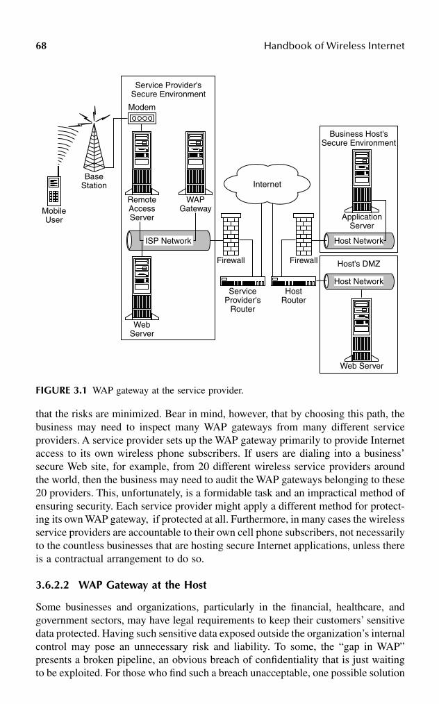
68 Handbook of Wireless Internet
that the risks are minimized. Bear in mind, however, that by choosing this path, thebusiness may need to inspect many WAP gateways from many different serviceproviders. A service provider sets up the WAP gateway primarily to provide Internetaccess to its own wireless phone subscribers. If users are dialing into a business’secure Web site, for example, from 20 different wireless service providers aroundthe world, then the business may need to audit the WAP gateways belonging to these20 providers. This, unfortunately, is a formidable task and an impractical method ofensuring security. Each service provider might apply a different method for protect-ing its own WAP gateway, if protected at all. Furthermore, in many cases the wirelessservice providers are accountable to their own cell phone subscribers, not necessarilyto the countless businesses that are hosting secure Internet applications, unless thereis a contractual arrangement to do so.
3.6.2.2 WAP Gateway at the Host
Some businesses and organizations, particularly in the financial, healthcare, andgovernment sectors, may have legal requirements to keep their customers’ sensitivedata protected. Having such sensitive data exposed outside the organization’s internalcontrol may pose an unnecessary risk and liability. To some, the “gap in WAP”presents a broken pipeline, an obvious breach of confidentiality that is just waitingto be exploited. For those who find such a breach unacceptable, one possible solution
FIGURE 3.1 WAP gateway at the service provider.
RemoteAccessServer
WebServer
WAPGateway
ISP Network
Modem
MobileUser
BaseStation
Service Provider'sSecure Environment
Business Host'sSecure Environment
ApplicationServer
Host Network
Firewall Firewall
ServiceProvider's
Router
HostRouter
Host's DMZ
Web Server
Host Network
Internet

Wireless Internet Security 69
is to place the WAP gateway at the business host’s own protected network, bypassingthe wireless service provider’s WAP gateway entirely. Figure 3.2 provides an exam-ple of such a setup. Nokia, Ericsson, and Ariel Communications are just a few ofthe vendors offering such a solution.
This approach has the benefit of keeping the WAP gateway and its WTLS-SSLtranslation process in a trusted location, within the confines of the same organizationthat is providing the secure Web applications. Using this setup, users are typicallydialing directly from their wireless devices, through their service provider’s publicswitched telephone network (PSTN), and into the business’ own remote accessservers (RAS). Once they reach the RAS, the transmission continues onto the WAPgateway, and then onward to the application or Web server, all of these deviceswithin the business host’s own secure environment.
Although it provides better end-to-end security, the drawback to this approachis that the business host will need to set up banks of modems and RAS so usershave enough access points to dial in. The business also will need to reconfigure theusers’ cell phones and PDAs to point directly to the business’ own WAP gatewayinstead of (typically) to the service provider’s. However, not all cell phones allowthis reconfiguration by the user. Furthermore, some cell phones can point to onlyone WAP gateway, while others are fortunate enough to point to more than one. Ineither case, individually reconfiguring all those wireless devices to point to thebusiness’ own WAP gateway may take significant time and effort.
FIGURE 3.2 WAP gateway at the host.
RemoteAccessServer
WAPGateway
ApplicationServer
WebServer
ISP Network
Modem
MobileUser
BaseStation
Business Host'sSecure Environment
Service Provider'sSecure Environment
Firewall
PSTN/ISDN
Internet

70 Handbook of Wireless Internet
For users whose cell phones can point to only a single WAP gateway, thisreconfiguration introduces yet another issue. If these users now want to access otherWAP sites across the Internet, they still must go through the business host’s WAPgateway first. If the host allows outgoing traffic to the Internet, the host then becomesan Internet service provider (ISP) to these users who are newly configured to pointto the host’s own WAP gateway. Acting as a makeshift ISP, the host will inevitablyneed to attend to service- and user-related issues, which too many businesses canbe an unwanted burden because of the significant resources required.
3.6.2.3 Pass-Through from Service Provider’s WAP Gateway to Host’s WAP Proxy
For businesses that want to provide secure end-to-end encrypted transactions and toavoid the administrative headaches of setting up their own WAP gateways, there areother approaches. One such approach, as shown in Figure 3.3, is to keep the WTLS-encrypted data unchanged as it goes from the user’s mobile device and through theservice provider’s WAP gateway. The WTLS-SSL encryption translation will notoccur until the encrypted data reaches a second WAP gateway-like device residingwithin the business host’s own secure network. One vendor developing such asolution is Openwave Systems (a combination of Phone.com and Software.com).Openwave calls this second WAP gateway-like device the Secure Enterprise Proxy.During an encrypted session, the service provider’s WAP gateway and the business’Secure Enterprise Proxy negotiate with each other, so that the service provideressentially passes the encrypted data unchanged to the business that is using this
FIGURE 3.3 Pass-through from service provider’s WAP gateway to host’s WAP proxy.
RemoteAccessServer
WebServer
WAPGateway
ISP Network
Modem
MobileUser
BaseStation
Service Provider'sSecure Environment
Business Host'sSecure Environment
SecureEnterprise
Proxy
Host Network
Firewall Firewall
ServiceProvider's
Router
HostRouter
ApplicationServer
Internet

Wireless Internet Security 71
proxy. This solution utilizes the service provider’s WAP gateway because it is stillneeded to provide proper Internet access for the mobile users, but it does not performthe WTLS-SSL encryption translation there and thus is not exposing confidentialdata. The decryption is passed on and occurs instead within the confines of thebusiness’ own secure network, either at the Secure Enterprise Proxy or at theapplication server.
One drawback to this approach, however, is its proprietary nature. At the timeof this writing, to make the Openwave solution work, three parties would need toimplement components exclusively from Openwave. The wireless service providerswould need to use Openwave’s latest WAP gateway. Likewise, the business hostingthe secure applications would need to use Openwave’s Secure Enterprise Proxy tonegotiate the encryption pass-through with that gateway. In addition, the mobiledevices themselves would need to use Openwave’s latest Web browser, at least MicroBrowser version 5. Although approximately 70 percent of WAP-enabled phonesthroughout the world are using some version of Openwave Micro Browser, most ofthese phones are using either version 3 or 4. Unfortunately, most of these existingbrowsers are not upgradable by the user, so most users may need to buy new cellphones to incorporate this solution. It may take some time before this solution comesto fruition and becomes popular.
These are not the only solutions for providing end-to-end encryption for wirelessInternet devices. Other methods in the works include applying encryption at theapplications level, adding encryption keys and algorithms to cell phone SIM cards,and adding stronger encryption techniques to the next revisions of the WAP speci-fications, perhaps eliminating the “gap in WAP” entirely.
3.7 CONCLUSION
Two sound recommendations for the many practitioners in the information securityprofession are:
1. Stay abreast of wireless security issues and solutions.2. Do not ignore wireless devices.
Many in the IT and information security professions regard the new wirelessInternet devices diminutively as personal gadgets or executive toys. Many are sobusy grappling with the issues of protecting their corporate PCs, servers, and net-works that they cannot imagine worrying about yet another class of devices. Manycorporate security policies make no mention of securing mobile handheld devicesand cell phones, although some of these same corporations are already using thesedevices to access their own internal e-mail. The common fallacy is that these theycan cause no harm.
Security departments have had to wrestle with the migration of informationassets from the mainframe world to distributed PC computing. Many corporateattitudes have had to change during that evolution regarding where to apply security.With no exaggeration, corporate computing is undergoing yet another significantphase of migration. It is not so much that corporate information assets can be
72 Handbook of Wireless Internet
accessed through wireless means, because wireless notebook computers have beendoing that for years; rather, the means of access will become ever cheaper and,hence, greater in volume. Instead of using a $3000 notebook computer, users (orintruders) can now tap into a sensitive corporate network from anywhere, using justa $40 Internet-enabled cell phone. Over time, these mobile devices will have increas-ing processing power, memory, bandwidth, storage, ease of use, and popularity. Itis this last item that will inevitably draw upon corporate resources.
Small as these devices may be, once they access the sensitive assets of anorganization, they can do as much good or harm as any other computer. Ignoringor disallowing these devices from an information security perspective has twoprobable consequences:
1. The business units or executives within the organization will push, oftensuccessfully, to deploy wireless devices and services anyway, shutting outany involvement or guidance from the information security department.Inevitably, information security will be involved at a much later date, butreactively and often too late to have a significant impact on proper designand planning.
2. By ignoring wireless devices and their capabilities, the information secu-rity department will give attackers just what they need: a neglected andunprotected window into an otherwise fortified environment. Such anorganization will be caught unprepared when an attack using wirelessdevices surfaces.
Wireless devices should not be treated as mere gadgets or annoyances. Oncethey tap into the valued assets of an organization, they are indiscriminate and equalto any other node on the network. To stay truly informed and prepared, informationsecurity practitioners should stay abreast of the new developments and security issuesregarding wireless technology. In addition, they need to work with the applicationdesigners as an alliance to ensure that applications designed for wireless take intoconsideration the many points discussed in this chapter. And finally, organizationsneed to expand the categories of devices protected under their information securitypolicies to include wireless devices, because they are in effect yet another infra-structure component of the organization.
Bibliography
Appleby, T.P., WAP — the wireless application protocol, White paper, Global Integrity.Blake, R., Wireless Communication Technology, Delmar Thomson Learning, 2001.Certicom, Complete WAP Security from Certicom, http://www.certicom.com.CMP Media, Wireless devices present new security challenges — growth in wireless Internet
access means handhelds will be targets of more attacks, October 21, 2000.DeJesus, E.X., Wireless devices are flooding the airwaves with millions of bits of information.
Securing those transmissions is the next challenge facing E-commerce, White paper,http://www.infosecuritymag.com, October 2000.
Harte, L. et al., Cellular and PCS: The Big Picture, McGraw-Hill, New York, 1997.

Wireless Internet Security 73
Howell, R. et al., Professional WAP, Wrox Press Ltd., Birmingham, 2000.Izarek, S., Next-gen cell phones could be targets for viruses, http://www.foxnews.com, June 1,
2000.Muller, N.J., Desktop Encyclopedia of Telecommunications, 2nd ed., McGraw-Hill, New York,
2000.Nobel, C., Phone.com plugs WAP security hole, eWEEK, September 25, 2000.Nokia, Secure Corporate WAP services: Nokia Activ Server, White paper, http://www.nokia.
com.Radding, A., Crossing the wireless security gap, http://www.computerworld.com, January 1,
2001.Saarinen, M.-J., Attacks against the WAP WTLS Protocol, University of Jvyskyl, Finland.Saita, A., Case study: securing thin air, academia seeks better security solutions for handheld
wireless devices, http://www.infosecuritymag.com, April 2001.Schwartz, E., Two-zone wireless security system creates a big hole in your communications,
http://www.infoworld.com, November 6, 2000.Tulloch, M., Microsoft Encyclopedia of Networking, Microsoft Press, Redmond, WA, 2000.Unstrung.com, Does Java solve worldwide WAP wait?, http://www.unstrung.com, April 9,
2001.Van der Heijden, M. and Taylor, M., Understanding WAP: Wireless Applications, Devices,
and Services, Artech House Publishers, 2000.

This page intentionally left blank
Part II
Technologies and Standards

This page intentionally left blank

770-8493-1502-6/03/$0.00+$1.50© 2003 by CRC Press LLC
4 Multimedia Streaming over Mobile Networks: European Perspective
Igor D.D. Curcio*
CONTENTS
4.1 Introduction ....................................................................................................774.2 End-to-End System Architecture ...................................................................794.3 The Challenges of Mobile Networks.............................................................80
4.3.1 Mobile Networks for Streaming ........................................................814.3.1.1 Circuit-Switched Mobile Channels ....................................814.3.1.2 Packet-Switched Mobile Channels.....................................84
4.4 Standards for Mobile Streaming....................................................................944.4.1 Release 4 PSS ....................................................................................94
4.4.1.1 Control and Scene Description Elements ..........................954.4.1.2 Media Elements ..................................................................96
4.4.2 Release 5 PSS ....................................................................................974.4.2.1 Control Elements ................................................................974.4.2.2 Media Elements ..................................................................98
4.5 Performance Issues of Mobile Streaming .....................................................984.5.1 Bearer Considerations ......................................................................1004.5.2 RTCP ................................................................................................1004.5.3 RTSP Signaling Issues .....................................................................1014.5.4 Link Aliveness..................................................................................101
4.6 Conclusions ..................................................................................................102References..............................................................................................................102
4.1 INTRODUCTION
Mobile communications, Internet connectivity, and multimedia technologies areprogressively merging in a single paradigm of personal communications. Mobilecommunications originate from the increasing need of users to have information
* The opinions expressed in this chapter are those of the author and not necessarily those of his employer.

78 Handbook of Wireless Internet
available “anytime, anywhere.” Internet connectivity puts a huge quantity of infor-mation resources at users’ disposal, including services such as searching, browsing,e-mail, and E-commerce. Multimedia technologies are emerging as users want tohave more information in audio/visual form rather than in textual form.
Mobile networks have been developed in the past two decades to allow users tomake phone calls in total mobility. These systems have evolved from the firstgeneration (1G) of analog networks (such as AMPS, TACS, NMT, and NTT) in the1980s, to the second generation (2G) of digital networks (such as GSM, PDC, D-AMPS, IS-95) in the late 1980s. Digital networks offer higher spectrum efficiency,better data services, and more-advanced roaming capabilities than the 1G systems.Furthermore, GSM has evolved to offer more-advanced services such as higher bitrates for circuit- and packet-switched data transmission. Those networks are com-monly referred to as the 2.5G networks. HSCSD (High-Speed Circuit-SwitchedData), GPRS (General Packet Radio Service) and EDGE (Enhanced Data rates forGSM Evolution) are extensions of the current GSM network, and allow reachingbit rates up to 64, 171.2, and 473.6 kbps, respectively. The new 2.5G networks areable to carry low and medium bit rate multimedia traffic, allowing the feasibility ofapplications requiring real-time video and audio.
A strong effort has been made by standardization bodies toward third generation(3G) networks that offer even higher bit rates (up to 2 Mbps), more flexibility,multiple simultaneous services for one user, and different quality-of-service (QoS)classes. For example, a user could establish a video streaming session or browse theWorld Wide Web while retrieving a file from a corporate intranet server as a back-ground process. In the International Telecommunications Union (ITU), the 3G net-works are called IMT-2000 (International Mobile Telecommunications year 2000).IMT-2000 represents the joint effort of merging the European, Asian/Japanese, andNorth American standards into a unique common platform for mobile communica-tions. IMT-2000 specifications are defined by the Third Generation PartnershipProject (3GPP), which has written standards for UMTS (Universal Mobile Telecom-munications System) 3G networks and services since December 1998. The specifi-cations have evolved through different releases, from Release ’99, to Releases 4, 5,and 6. The different releases have been planned to enable the transition to packet-switched (PS), all-IP (Internet Protocol) mobile networks.
Recent advances in video compression technology have made possible the trans-mission of real-time video over low-bit-rate links. H.263 and MPEG-4 are two examplesof video compression algorithms. However, the deployment of mobile video is a chal-lenging issue. First, video processing, including compression and decompression, isCPU intensive; this and the constraints of a mobile device mean that the digital signalprocessing (DSP) platform must be of limited size and weight, but still capable ofprocessing a large quantity of data, possibly in real-time. Second, efficient error-resil-ience techniques must be developed in order to recover from bit errors and packet lossesinherently present in the air interface during data transmission.
A typical video application is multimedia streaming, which has been widelydeployed over the Internet for many years. Mobile multimedia streaming is enabledby the capacity of the current 2.5G or 3G networks, and by the multimedia capa-bilities of current and next-generation mobile phones.
Multimedia Streaming over Mobile Networks: European Perspective 79
This chapter is an introduction to mobile multimedia streaming. It is organizedas follows: Section 4.2 describes the end-to-end architecture for mobile streamingsystems. Section 4.3 includes a review of the current mobile networks that enablestreaming applications, and Section 4.4 introduces the current standards for mobilestreaming. Section 4.5 contains some performance and QoS considerations forstreaming. Section 4.6 concludes this chapter.
4.2 END-TO-END SYSTEM ARCHITECTURE
A streaming system is a real-time system of the nonconversational type. It is real-time because the playback of continuous media, such as audio and video, must occurin an isochronous fashion. A streaming application is different from a conversationalapplication because it has the following properties:
1. One-way data distribution. The media flow is always unidirectional, fromthe streaming server to the mobile client (in the downlink direction).Normally, the user has limited control over a streaming session, and thereis not a high level of interactivity between mobile client and streamingserver. Typical user control commands in the uplink direction includePLAY, PAUSE, STOP, FAST-FORWARD, and REWIND.
2. Offline media encoding. A streaming system is similar to a Video OnDemand system, where the user can play only prestored content. Thiscontent is not encoded in real-time, but in an offline fashion using specificcontent creation tools.
3. Not highly delay sensitive. Because high interactivity is not a requirementof a streaming system, end-to-end delays can be relaxed. For example,the time required by the streaming client to execute a command issuedby the user (such as PLAY) does not need to be on the order of millisec-onds. Media can be streamed after an initial latency period. This allowsthe mobile client to smooth out eventual network jitter without compro-mising user QoS.
Figure 4.1 describes the high-level architecture of a typical mobile multimediastreaming system over an IP-based mobile network. We will follow an end-to-endapproach, analyzing the system in its different parts. A mobile streaming systemconsists mainly of three components: (1) the streaming server, (2) the mobile net-work, and (3) the mobile streaming client.
The streaming server is connected to a fixed IP network and can reside either withinthe mobile operator’s domain or outside it (e.g., the Internet). The location of thestreaming server is important when considering the end-to-end quality of service of astreaming service. In fact, if the server is located in the public Internet, the QoS of thenetwork trunk between the streaming server and the mobile network is not usuallycontrolled by the mobile operator, and it can be of the best-effort type in the worst case.This may have impact on the perceived streaming service user quality.
The content created offline is loaded onto the streaming server before a user canactually request its playback. The content that is estimated to be highly requested

80 Handbook of Wireless Internet
can be replicated or cached in proxy servers using appropriate techniques that makeuse of usage patterns.
The mobile network carries multimedia streaming traffic mainly between thestreaming server and the mobile streaming client. A logical connection establishedbetween the network and the mobile client addresses is called PDP (Packet DataProtocol) context. This uses physical transport channels in the downlink and uplinkdirections to enable the data transfer in the two directions.
The mobile streaming client keeps a radio connection with the mobile network,utilizing the allocated PDP context for data transfer. The mobile client has thepossibility to roam (i.e., upon mobility, change the network operator without affect-ing the received service), provided there is always radio coverage to guarantee theservice. The data flows received by the mobile client in the downlink direction are,for example, audio and video plus additional information for session establishment,control, and media synchronization. The data flows sent by the client in the uplinkdirection are mainly session control data and QoS reports. The streaming server mayreact accordingly upon reception of the QoS reports, taking appropriate actions forguaranteeing the best-possible media quality at any instant.
4.3 THE CHALLENGES OF MOBILE NETWORKS
This section analyzes the differences between fixed IP networks and mobile networks,from the streaming service perspective. Deploying a streaming service over mobilenetworks is a challenging task, because all the constraints and properties of a mobilenetwork must be taken into account when developing a streaming application.
In a fixed IP environment such as the Internet, the main obstacles for achievinga good QoS are packet losses and delays. Losses are mainly caused by congestionin the routers along the end-to-end path between the streaming server and thestreaming client. If a router is congested, it starts to drop packets. These packets arenormally not retransmitted by the network protocols, unless ad hoc retransmissiontechniques are used at the application layer or reliable transport protocols asemployed. Delays may depend on congestion issues, out-of-sequence packet reor-dering and on the physical capacity of the network trunks between streaming serverand client. A variable delay over time is called jitter. Whenever the inter-arrival timeof the media packets at the streaming client is variable, delay jitter occurs. Normally,
FIGURE 4.1 A typical mobile multimedia streaming system.
Streaming Server
Fixed IP network
Mobile network
Mobile streaming client
Session control data
Audio/video streams and sessioncontrol data
Session control data
(up link)
Audio/videostreams and
session controldata (downlink)
PDPcontext
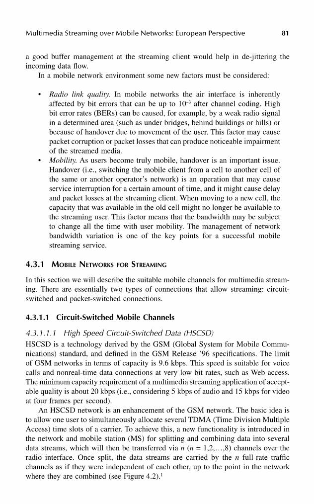
Multimedia Streaming over Mobile Networks: European Perspective 81
a good buffer management at the streaming client would help in de-jittering theincoming data flow.
In a mobile network environment some new factors must be considered:
• Radio link quality. In mobile networks the air interface is inherentlyaffected by bit errors that can be up to 10–3 after channel coding. Highbit error rates (BERs) can be caused, for example, by a weak radio signalin a determined area (such as under bridges, behind buildings or hills) orbecause of handover due to movement of the user. This factor may causepacket corruption or packet losses that can produce noticeable impairmentof the streamed media.
• Mobility. As users become truly mobile, handover is an important issue.Handover (i.e., switching the mobile client from a cell to another cell ofthe same or another operator’s network) is an operation that may causeservice interruption for a certain amount of time, and it might cause delayand packet losses at the streaming client. When moving to a new cell, thecapacity that was available in the old cell might no longer be available tothe streaming user. This factor means that the bandwidth may be subjectto change all the time with user mobility. The management of networkbandwidth variation is one of the key points for a successful mobilestreaming service.
4.3.1 MOBILE NETWORKS FOR STREAMING
In this section we will describe the suitable mobile channels for multimedia stream-ing. There are essentially two types of connections that allow streaming: circuit-switched and packet-switched connections.
4.3.1.1 Circuit-Switched Mobile Channels
4.3.1.1.1 High Speed Circuit-Switched Data (HSCSD)HSCSD is a technology derived by the GSM (Global System for Mobile Commu-nications) standard, and defined in the GSM Release ’96 specifications. The limitof GSM networks in terms of capacity is 9.6 kbps. This speed is suitable for voicecalls and nonreal-time data connections at very low bit rates, such as Web access.The minimum capacity requirement of a multimedia streaming application of accept-able quality is about 20 kbps (i.e., considering 5 kbps of audio and 15 kbps for videoat four frames per second).
An HSCSD network is an enhancement of the GSM network. The basic idea isto allow one user to simultaneously allocate several TDMA (Time Division MultipleAccess) time slots of a carrier. To achieve this, a new functionality is introduced inthe network and mobile station (MS) for splitting and combining data into severaldata streams, which will then be transferred via n (n = 1,2,…,8) channels over theradio interface. Once split, the data streams are carried by the n full-rate trafficchannels as if they were independent of each other, up to the point in the networkwhere they are combined (see Figure 4.2).1

82 Handbook of Wireless Internet
The data rate of a single time slot can be increased up to 14.4 kbps by puncturing(i.e., by deleting) certain error correction bits of the existing 9.6 kbps. In theory, up to8 time slots can be allocated at the same time; therefore, the available user bit rate couldbe as high as 115.2 kbps (8 × 14.4 kbps). In practice, however, the maximum bit rateper user is limited to 64 kbps, because only one ISDN B-channel is reserved per userin the A interface of GSM network infrastructure.1 Table 4.1 summarizes the possiblebit rates achievable in uplink and downlink with HSCSD networks.
HSCSD has both transparent and nontransparent types of services. Transparentmode offers error protection at the channel coding level only. In this mode retrans-mission of packets hit by errors is not used. As a result, the bit rate and networkdelay are constant,2 but the BER is variable (up to 10–3), depending on the channelcondition. Nontransparent mode offers retransmission of erroneous frames, usingthe GSM Radio Link Protocol (RLP) (see Figure 4.3),1 in addition to error correctionmade by channel coding. Typical BER values in nontransparent mode are less than10–6. The available throughput and transmission delay vary with the channel quality
FIGURE 4.2 Network architecture for supporting HSCSD. (Source: ETSI, High speed cir-cuit-switched data [HSCSD], Stage 2 [Release ’96], GSM 03.34, v.5.2.0 [1999–05].)
TABLE 4.1Bit Rates for HSCSD Networks
Number of Time Slots
Bit Rate per Time Slot
(kbps)
Total User Bit Rate (kbps)
1 9.6 9.62 9.6 19.23 9.6 28.84 9.6 38.41 14.4 14.42 14.4 28.83 14.4 43.24 14.4 57.6
MS BTS BSC MSC
Air I/F Abis I/F A I/F
TAF
n full-rate channelsor n time slots per TDMA frame
1 circuit maximum
WF

Multimedia Streaming over Mobile Networks: European Perspective 83
(the higher the BER, the lower the throughput and the higher the network delay).Typical delay values range from 400 milliseconds up to 1 second in case of mobile-to-mobile connections.3
HSCSD services can be further classified in symmetrical and asymmetricalservices. Symmetrical service allows allocating equal bit rates to both the uplinkand downlink connections. Asymmetrical service can provide different data rates inthe uplink and downlink direction. Asymmetrical services are only applicable innontransparent mode,2 and are most suitable for multimedia streaming. In fact, inthis case most of the data flow goes from the network to the MS; only a fraction ofthe traffic goes in the opposite direction. An example of a streaming connection overasymmetrical HSCSD is a 3+1 time slot service (43.2 kbps for downlink directionand 14.4 kbps for uplink direction).
4.3.1.1.2 Enhanced Circuit-Switched Data (ECSD)ECSD is a network technology defined within EDGE in Release ’99 specifications, andit has the same principle as HSCSD. The fundamental enhancement consists of a newmodulation technique used in the air interface. This modulation is called 8-PSK (octag-onal Phase Shift Keying) and it triples the data rate per time slot. However, the limitationof the A interface to 64 kbps is always in place. Table 4.2 summarizes the bit ratesachievable with ECSD (in addition to those available with HSCSD).4
FIGURE 4.3 The HSCSD concept in nontransparent mode. (Source: ETSI, High speedcircuit-switched data [HSCSD], Stage 2 [Release ’96], GSM 03.34, v.5.2.0 [1999–05].)
TABLE 4.2Bit Rates for ECSD Networks
Number of Time Slots
Bit Rate per Time Slot
(kbps)
Total User Bit Rate (kbps)
1 28.8 28.82 28.8 57.62 32.0a 64.01 43.2 43.2
The 32 kbps configuration is available only formultiple slot transparent service.56
L2R L2RHSCSDRLP
HSCSDRLP
L1 entity L1 entity
L1 entity
L1 entity
L1 entity
L1 entity
MS IWF
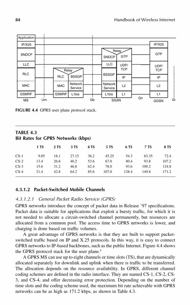
84 Handbook of Wireless Internet
4.3.1.2 Packet-Switched Mobile Channels
4.3.1.2.1 General Packet Radio Service (GPRS)GPRS networks introduce the concept of packet data in Release ’97 specifications.Packet data is suitable for applications that exploit a bursty traffic, for which it isnot needed to allocate a circuit-switched channel permanently, but resources areallocated from a common pool. The access time to GPRS networks is lower, andcharging is done based on traffic volumes.
A great advantage of GPRS networks is that they are built to support packet-switched traffic based on IP and X.25 protocols. In this way, it is easy to connectGPRS networks to IP-based backbones, such as the public Internet. Figure 4.4 showsthe GPRS protocol stack for the user plane.5
A GPRS MS can use up to eight channels or time slots (TS), that are dynamicallyallocated separately for downlink and uplink when there is traffic to be transferred.The allocation depends on the resource availability. In GPRS, different channelcoding schemes are defined in the radio interface. They are named CS-1, CS-2, CS-3, and CS-4, and offer decreasing error protection. Depending on the number oftime slots and the coding scheme used, the maximum bit rate achievable with GPRSnetworks can be as high as 171.2 kbps, as shown in Table 4.3.
FIGURE 4.4 GPRS user plane protocol stack.
TABLE 4.3Bit Rates for GPRS Networks (kbps)
1 TS 2 TS 3 TS 4 TS 5 TS 6 TS 7 TS 8 TS
CS-1 9.05 18.1 27.15 36.2 45.25 54.3 63.35 72.4CS-2 13.45 26.8 40.25 53.6 67.05 80.4 93.85 107.2CS-3 15.65 31.2 46.85 62.4 78.05 93.6 109.25 124.8CS-4 21.45 42.8 64.25 85.6 107.05 128.4 149.85 171.2
Application
IP/X25
SNDCP
LLC
RLC
MAC
GSMRF
MS Um
Relay
RLC BSSGP
MAC NetworkService
L1bisGSMRF
Gb
Relay
SNDCP GTP
LLC UDP/TCP
BSSGPIP
L2
L1
NetworkService
L1bis
SGSNGn
IP/X25
GTP
UDP/TCP
IP
L2
L1
GGSN Gi

Multimedia Streaming over Mobile Networks: European Perspective 85
Between the MS and the BSS (Base Station Subsystem) transmission can occurin Unacknowledged or Acknowledged mode at the Radio Link Control (RLC) layer.6
Unacknowledged mode is a transparent transmission mode. In acknowledged mode,the RLC layer provides the ability to retransmit the erroneous frames that have beencorrupted by errors in the air interface. Acknowledged mode is appropriate for mobilemultimedia streaming.
The SNDCP (SubNetwork Dependent Convergence Protocol)7 layer providesTCP/IP header compression8 and V.42 bis9 data compression to enhance the capacityof the network. SNDCP allows a reduction of the packet header size from 40 to 3 bytes.
GPRS introduces the concept of QoS profile for a PDP context. A QoS profiledefines a set of attributes that characterize the expected quality of the connection.These attributes are described in Table 4.4.5,10 For real-time traffic, such as multi-media streaming traffic, the QoS profile must be set with appropriate combinationof values, in order to guarantee the best user QoS. It must be noted that the throughputvalues can be renegotiated by the network at any time.
4.3.1.2.2 Enhanced General Packet Radio Service (E-GPRS)E-GPRS is defined in the EDGE framework of Release ’99 specifications.58 In E-GPRS, as in ECSD, the 8-PSK modulation is used to increase the network capacity.This modulation scheme is used in addition to the GMSK (Gaussian Minimum ShiftKeying) already employed in GPRS. The major impacts of E-GPRS, compared toGPRS, are in layers 1 and 2 of the protocol stack. In layer 1 a new set of modulationand coding schemes (MCS) are defined. The GPRS GMSK coding schemes (CS-1through CS-4) are replaced with four new GMSK modulation and coding schemes(MCS-1 through MCS-4) offering decreasing error protection. In addition, five 8-PSKcoding schemes (MCS-5 through MCS-9) are defined, which yield decreasing errorprotection as well.
The E-GPRS coding schemes support incremental redundancy (IR), which is aphysical layer performance enhancement for the RLC acknowledged mode of layer2. Whenever a request for a retransmission is triggered by the RLC protocol, the IRmechanism dynamically adjusts the code rate to the actual channel conditions byincrementally redundant information, until the reception of the lost RLC block issuccessful. This effectively increases the probability of data reception at the RLCpeer entity.11 This feature is a great benefit in nonconversational real-time applica-tions, such as mobile multimedia streaming.
In E-GPRS, bit rates can be increased up to 473.6 kbps, as illustrated in Table 4.8,which shows the bit rates for different combinations of time slots and coding schemes.
Another improvement offered by E-GPRS is the TCP and UDP (over IPv4 andIPv6) header compression capability in the SNDCP layer. This allows the packetheaders to reduce from a maximum size of 60 to 4 bytes.12
The QoS profile for E-GPRS is essentially similar to that for UTRAN. Pleaserefer to the information provided in Tables 4.9, 4.10, and in the next section.
4.3.1.2.3 UMTS Terrestrial Radio Access Network (UTRAN)The IMT-2000 specifications for 3G networks are written by 3GPP, which hasdefined standards for UMTS networks. The air interface technology for UMTS is

86 Handbook of Wireless Internet
W-CDMA (Wideband Code Division Multiple Access). The main objectives andfeatures for UMTS networks can be summarized as:
• Full area coverage and mobility for 144 kbps (at vehicular speed), pref-erably 384 kbps (at pedestrian speed). Limited area coverage and mobilityfor 2 Mbps.
• Multiplexing of services with different QoS requirements on a singlebearer (e.g., a speech call, a multimedia streaming session, and a Websession). This is one of the key features of W-CDMA. Power is thecommon shared resource for users. As the bit rate changes, the power
TABLE 4.4QoS Profile for GPRS Release ’97 Networks
QoS Profile Attribute Description
Precedence class The precedence class indicates a priority in case of abnormal network behavior. For example, in case of congestion, the precedence class determines which packet to discard first.
Values: [1…3] in decreasing order of precedenceDelay class The delay class defines the maximum and 95-percentile of mean transfer delay
within a GPRS network end-to-end (it does not include transfer delays in external networks). Examples for packet sizes of 128 and 1024 bytes are shown in Table 4.5.
Values: [1…4]. A GPRS network must support at least the Class 4 (best effort)Reliability class Data reliability is defined in terms of residual probabilities of data loss, out-of-
sequence delivery, duplicate data delivery and data corruption. These probabilities are defined for three classes in Table 4.6. The reliability class specifies the requirements of the various network protocol layers. The combinations of the GTP (GPRS Tunneling Protocol), LLC (Logical Link Control), and RLC transmission modes support the reliability class performance requirements. The combinations are shown in Table 4.7.
Values: [1…5]. A GPRS network may support only a subset of the defined reliability classes
Mean throughput class
It specifies the average rate at which data is expected to be transferred across the GPRS network during the remaining lifetime of an activated PDP context. The rate is measured in bytes per hour.
Values: [1…18, 31], where the value 31 means best effort, and the values from 1 to 18 define discrete rates in the range [100, 50 × 106] bytes per hour, i.e., in the range [0.22, 111 × 103] bits per second
Peak throughput class
It specifies the maximum rate at which data is expected to be transferred across the GPRS network for an activated PDP context. There is no guarantee that this peak rate can be achieved or sustained for any time period, and this depends on the MS capability and the available radio resources. The rate is measured in bytes per second.
Values: [1…9], which define discrete rates in the range [1 × 10³, 256 × 103] bytes per second, i.e., in the range [8, 2048] kbps

Multimedia Streaming over Mobile Networks: European Perspective 87
allocated to the channel is adjusted so that the continuity of service isguaranteed at any instant of the connection. The relative transmitted powerduring a 10-millisecond radio frame is a function of the bit rate: the higherthe bit rate, the higher the transmitted power. In this way there is no wasteof resources. For example, when a short voice segment has low informa-tion content, it can be encoded with few bits that will be transmitted usinga relatively small amount of power, thus minimizing interference withother users.
• Delay requirements that range from the most stringent values for real-time traffic to more relaxed ones for best-effort traffic.
• Coexistence of 2G, 2.5G, and 3G networks through intersystem handovercapability.
TABLE 4.5Delay Classes for GPRS Release ’97 Networks
Delay Class
Delay (Maximum Values)
Packet Size: 128 Bytes Packet Size: 1024 Bytes
Mean Transfer Delay
(sec)
95th Percentile Transfer Delay
(sec)
Mean Transfer Delay
(sec)
95th PercentileTransfer Delay
(sec)
1. (Predictive) < 0.5 < 1.5 < 2 < 72. (Predictive) < 5 < 25 < 15 < 753. (Predictive) < 50 < 250 < 75 < 3754. (Best Effort) Unspecified
TABLE 4.6Residual Error Probabilities for Reliability Classes in GPRS Release ’97 Networks
Reliability Class
Probability
Example of Application Characteristics
Packet Loss
Duplicate Packet
Out of Sequence Packet
Packet Corruption
1 10–9 10–9 10–9 10–9 Error sensitive, no error-correction capability, limited error-tolerance capability
2 10–4 10–5 10–5 10–6 Error sensitive, limited error-correction capability, good error-tolerance capability
3 10–2 10–5 10–5 10–2 Not error sensitive, error-correction capability, very good error-tolerance capability
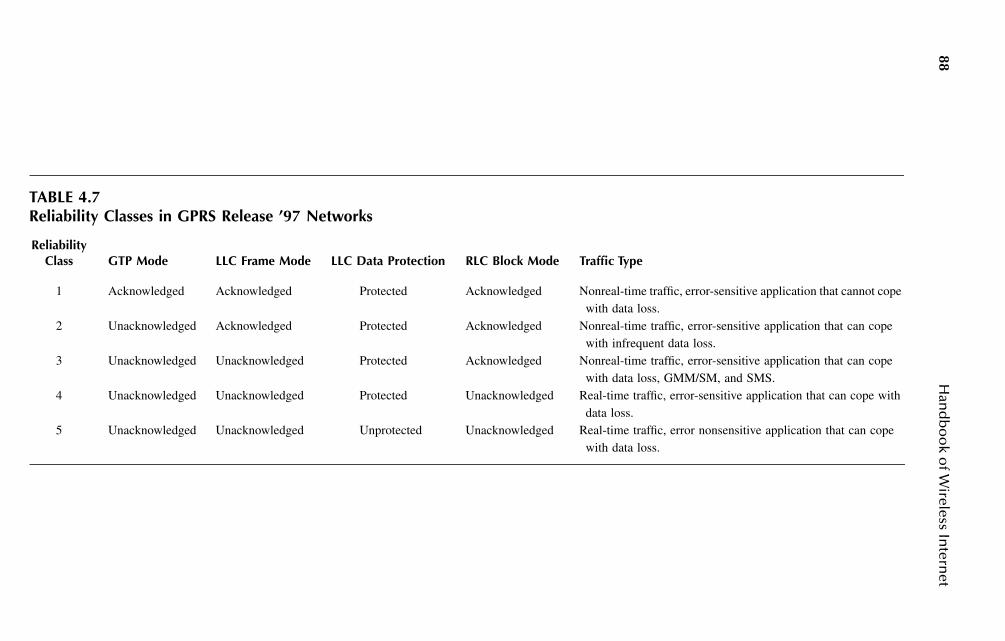
88H
and
bo
ok o
f Wireless In
ternet
TABLE 4.7Reliability Classes in GPRS Release ’97 Networks
Reliability Class GTP Mode LLC Frame Mode LLC Data Protection RLC Block Mode Traffic Type
1 Acknowledged Acknowledged Protected Acknowledged Nonreal-time traffic, error-sensitive application that cannot cope with data loss.
2 Unacknowledged Acknowledged Protected Acknowledged Nonreal-time traffic, error-sensitive application that can cope with infrequent data loss.
3 Unacknowledged Unacknowledged Protected Acknowledged Nonreal-time traffic, error-sensitive application that can cope with data loss, GMM/SM, and SMS.
4 Unacknowledged Unacknowledged Protected Unacknowledged Real-time traffic, error-sensitive application that can cope with data loss.
5 Unacknowledged Unacknowledged Unprotected Unacknowledged Real-time traffic, error nonsensitive application that can cope with data loss.

Multimedia Streaming over Mobile Networks: European Perspective 89
• Fast transmit power control (TPC). Because W-CDMA networks are inter-ference limited, fast TPC based on the measurement of signal-to-interfer-ence ratio (SIR) can always minimize the transmitted power according tothe traffic load, and thus interference to other users can be reduced.
3GPP has gone through different releases of the UTRAN specifications, namelyRelease ’99, Release 4, and Release 5. At the time of writing this chapter, the Release6 specifications were in the process of being defined. UTRAN networks offer bothcircuit-switched and packet-switched services. Release 5 specifications define theIP Multimedia Subsystem (IMS)13 in the Core Network (CN) that makes all-IPnetworks a reality. IMS is based on the Session Initiation Protocol (SIP) defined inthe IETF (Internet Engineering Task Force).14–16 IMS in the CN enables moreInternet-based multimedia services that are not available in the Release 4 CN.
Figure 4.5 shows the user plane protocol stack for UTRAN networks.17 Betweenthe MS and the UTRAN, the RLC Protocol can operate in transparent, unacknowledged,
TABLE 4.8Bit Rates For E-GPRS Networks (kbps)
1 TS 2 TS 3 TS 4 TS 5 TS 6 TS 7 TS 8 TS
MCS-1 18.8 117.6 126.4 135.2 144.0 152.8 161.6 170.4MCS-2 11.2 122.4 133.6 144.8 156.0 167.2 178.4 189.6MCS-3 14.8 129.6 144.4 159.2 174.0 188.8 103.6 118.4MCS-4 17.6 135.2 152.8 170.4 188.0 105.6 123.2 140.8MCS-5 22.4 144.8 167.2 189.6 112.0 134.4 156.8 179.2MCS-6 29.6 159.2 188.8 118.4 148.0 177.6 207.2 236.8MCS-7 44.8 189.6 134.4 179.2 224.0 268.8 313.6 358.4MCS-8 54.4 108.8 163.2 217.6 272.0 326.4 380.8 435.2MCS-9 59.2 118.4 177.6 236.8 296.0 355.2 414.4 473.6
FIGURE 4.5 User plane protocol stack for UTRAN networks (Iu mode)
Application
E.g, IPPPP
PDCP
RLC
MAC
L1Uu
Relay
PDCP GTP-U
RLC UDP/IP
MAC AAL5
L1 ATM
UTRAN
Relay
GTP-U GTP-U
UDP/IP UDP/IP
AAL5 L2
ATM L1
lu-PS3G-SGSN
E.g, IP,PPP
GTP-U
UDP/IP
L2
L1
3G-GGSNGn Gi
MS
90 Handbook of Wireless Internet
and acknowledged modes. In transparent mode no protocol overhead is added to thehigher layer data, while in unacknowledged and acknowledged modes a certain RLClayer overhead is added (sequence numbers, length indication, and other informa-tion). Acknowledged mode is suitable for a mobile multimedia streaming application,because it provides retransmissions of the lost blocks. Retransmission can be con-figured in the RLC protocol in different ways:18
• Retransmissions for n times. The RLC layer tries to retransmit the lostblock up to n times. If it does not reach the RLC peer entity within nretransmission attempts, the block is considered lost. This option tries toachieve a constant BLER (block error rate) at the cost of a variable delayat the RLC peer entity.
• Retransmission with a timer. The RLC tries to retransmit the lost blockan undefined number of times until a timer fires. Afterwards, the block isconsidered lost. This option defines implicitly an upper bound on the delayat the RLC peer entity; however, the BLER is variable.
• Fully persistent retransmission. The RLC layer retransmits the lost blockan undefined number of times until the block is received by the RLC peerentity. The RLC block is discarded only when the RLC layer buffer isfull. This option defines an upper bound on the BLER, but it may producethe highest variations of delay at the receiver (jitter).
Other functions of the RLC layer include segmentation/reassembly, concatena-tion, padding, error correction, in-sequence delivery, duplicate detection, flow con-trol, sequence number check, and ciphering.
The PDCP (Packet Data Convergence Protocol) layer57 is located immediatelybelow the IP layer, and it exists only for services from the packet-switched domain.Its main functionality is that of compressing higher-layer protocol headers for thepurpose of reducing the bit rate toward the radio interface. For Release ’99 networksthe compression algorithm is the same as the one included in the E-GPRS specifi-cations,12 while from Release 4 onward the ROHC (Robust Header Compression)algorithm19 is supported also to compress RTP/UDP/IP or UDP/IP (under IPv4 orIPv6 environment) headers from a maximum of 60 to 3 bytes. In the PDCP, differ-ently than the SNDCP layer in GPRS, no data compression is supported. The reasonfor this choice is to achieve a higher protocol speed, and also because many types ofdata encapsulated using the Real-Time Transport Protocol (RTP) are already com-pressed (speech, audio, video, images), making a second compression step unnecessary.
To guarantee end-to-end quality of service, the UMTS specifications define anew, important parameter: the traffic class. This is considered as a fundamental wayto distinguish services of different types and their respective quality. Table 4.9summarizes the four traffic classes defined for UMTS networks.20 The practicaldifferences between the four classes is in terms of delay and error rates. Whileconversational and streaming classes guarantee low delays at the cost of higher errorrates, interactive and background traffic classes guarantee lower error rates at thecost of higher delays.
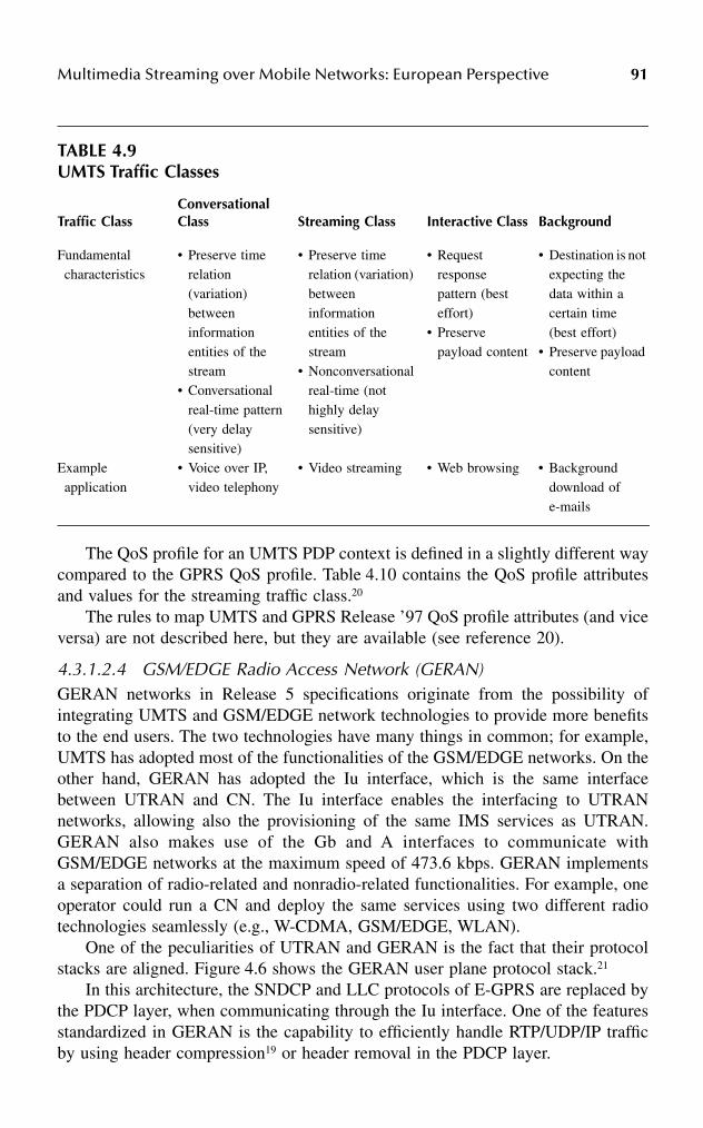
Multimedia Streaming over Mobile Networks: European Perspective 91
The QoS profile for an UMTS PDP context is defined in a slightly different waycompared to the GPRS QoS profile. Table 4.10 contains the QoS profile attributesand values for the streaming traffic class.20
The rules to map UMTS and GPRS Release ’97 QoS profile attributes (and viceversa) are not described here, but they are available (see reference 20).
4.3.1.2.4 GSM/EDGE Radio Access Network (GERAN)GERAN networks in Release 5 specifications originate from the possibility ofintegrating UMTS and GSM/EDGE network technologies to provide more benefitsto the end users. The two technologies have many things in common; for example,UMTS has adopted most of the functionalities of the GSM/EDGE networks. On theother hand, GERAN has adopted the Iu interface, which is the same interfacebetween UTRAN and CN. The Iu interface enables the interfacing to UTRANnetworks, allowing also the provisioning of the same IMS services as UTRAN.GERAN also makes use of the Gb and A interfaces to communicate withGSM/EDGE networks at the maximum speed of 473.6 kbps. GERAN implementsa separation of radio-related and nonradio-related functionalities. For example, oneoperator could run a CN and deploy the same services using two different radiotechnologies seamlessly (e.g., W-CDMA, GSM/EDGE, WLAN).
One of the peculiarities of UTRAN and GERAN is the fact that their protocolstacks are aligned. Figure 4.6 shows the GERAN user plane protocol stack.21
In this architecture, the SNDCP and LLC protocols of E-GPRS are replaced bythe PDCP layer, when communicating through the Iu interface. One of the featuresstandardized in GERAN is the capability to efficiently handle RTP/UDP/IP trafficby using header compression19 or header removal in the PDCP layer.
TABLE 4.9UMTS Traffic Classes
Traffic ClassConversational Class Streaming Class Interactive Class Background
Fundamental characteristics
• Preserve time relation (variation) between information entities of the stream
• Conversational real-time pattern (very delay sensitive)
• Preserve time relation (variation) between information entities of the stream
• Nonconversational real-time (not highly delay sensitive)
• Request response pattern (best effort)
• Preserve payload content
• Destination is not expecting the data within a certain time (best effort)
• Preserve payload content
Example application
• Voice over IP, video telephony
• Video streaming • Web browsing • Background download of e-mails
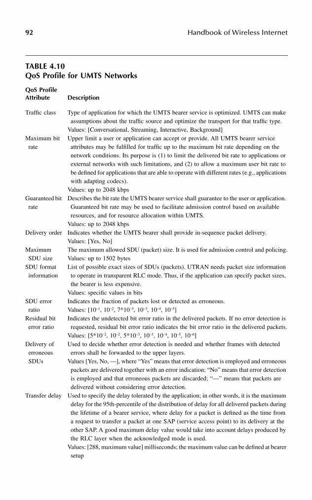
92 Handbook of Wireless Internet
TABLE 4.10 QoS Profile for UMTS Networks
QoS Profile Attribute Description
Traffic class Type of application for which the UMTS bearer service is optimized. UMTS can make assumptions about the traffic source and optimize the transport for that traffic type.
Values: [Conversational, Streaming, Interactive, Background]Maximum bit rate
Upper limit a user or application can accept or provide. All UMTS bearer service attributes may be fulfilled for traffic up to the maximum bit rate depending on the network conditions. Its purpose is (1) to limit the delivered bit rate to applications or external networks with such limitations, and (2) to allow a maximum user bit rate to be defined for applications that are able to operate with different rates (e.g., applications with adapting codecs).
Values: up to 2048 kbpsGuaranteed bit rate
Describes the bit rate the UMTS bearer service shall guarantee to the user or application. Guaranteed bit rate may be used to facilitate admission control based on available resources, and for resource allocation within UMTS.
Values: up to 2048 kbpsDelivery order Indicates whether the UMTS bearer shall provide in-sequence packet delivery.
Values: [Yes, No]Maximum SDU size
The maximum allowed SDU (packet) size. It is used for admission control and policing.Values: up to 1502 bytes
SDU format information
List of possible exact sizes of SDUs (packets). UTRAN needs packet size information to operate in transparent RLC mode. Thus, if the application can specify packet sizes, the bearer is less expensive.
Values: specific values in bitsSDU error ratio
Indicates the fraction of packets lost or detected as erroneous.Values: [10–1, 10–2, 7*10–3, 10–3, 10–4, 10–5]
Residual bit error ratio
Indicates the undetected bit error ratio in the delivered packets. If no error detection is requested, residual bit error ratio indicates the bit error ratio in the delivered packets.
Values: [5*10–2, 10–2, 5*10–3, 10–3, 10–4, 10–5, 10–6]Delivery of erroneous SDUs
Used to decide whether error detection is needed and whether frames with detected errors shall be forwarded to the upper layers.
Values [Yes, No, —], where “Yes” means that error detection is employed and erroneous packets are delivered together with an error indication; “No” means that error detection is employed and that erroneous packets are discarded; “—” means that packets are delivered without considering error detection.
Transfer delay Used to specify the delay tolerated by the application; in other words, it is the maximum delay for the 95th-percentile of the distribution of delay for all delivered packets during the lifetime of a bearer service, where delay for a packet is defined as the time from a request to transfer a packet at one SAP (service access point) to its delivery at the other SAP. A good maximum delay value would take into account delays produced by the RLC layer when the acknowledged mode is used.
Values: [288, maximum value] milliseconds; the maximum value can be defined at bearer setup

Multimedia Streaming over Mobile Networks: European Perspective 93
The RLC layer is similar to the one defined for UTRAN, but also it can benefitfrom incremental redundancy of E-GPRS. All the other protocol details are similarto those for UTRAN. The same is valid for the QoS profile parameters.
In this section we have surveyed the standards for 2.5G and 3G mobile networks.These networks allow the deployment of mobile multimedia streaming. The nextsection is about standardized protocols, codecs, and issues related to multimediastreaming applications.
Traffic handling priority
Specifies the relative importance for handling of all the packets belonging to the bearer compared to the packets of other bearers. This parameter is not used for the streaming traffic class.
Values: [1, 2, 3]Allocation/retention priority
Used for differentiating between bearers when performing allocation and retention of a bearer. In situations where resources are scarce, the network can use this attribute to prioritize bearers with a high priority over bearers with a low priority when performing admission control. This is a subscription attribute, which is not negotiated from the mobile terminal.
Values: [1, 2, 3]Source statistics descriptor
Specifies characteristics of the source traffic. Conversational speech has a well-known statistical behavior. By being informed that the packets are generated by a speech source, the network and the mobile station may, based on experience, calculate a statistical multiplex gain for use in admission control on the relevant interfaces.
Values: [Speech, unknown].
FIGURE 4.6 User plane protocol stack for GERAN networks.
TABLE 4.10 (continued)QoS Profile for UMTS Networks
MS GERAN SGSN
SNDCP
LLC
PDCP PDCP
Ack/UnackRLC RLC
MAC MAC
PHY PHYUm
Relay
RLC Ack/UnackRLC
BSSGP
NetworkService
IP
L2FR
L1
GTP-U
UDP/IP
As definedin Iu Specs.
As definedin Iu Specs.
L2
L1
L2
L1
Gb
lu-ps
GTP-U
UDP/IP
SNDCP
LLC
BSSGP
Networkservice
FRIP
L2
L1
Common protocols
Iu influenced protocols
Gb influenced protocols

94 Handbook of Wireless Internet
4.4 STANDARDS FOR MOBILE STREAMING
The need to have an optimized end-to-end multimedia streaming service over mobilenetworks has pushed the 3GPP organization to standardize such service within theService Aspects Codec Working Group. The first standardized service is in Release4 specifications of transparent end-to-end packet-switched streaming service (PSS).Release 5 specifications define additional capabilities to the streaming service. Atthe time of writing this chapter, Release 6 specifications were being written by 3GPP.
4.4.1 RELEASE 4 PSS
The specifications for PSS in Release 4 are basically defined in two documents.22,23
Here we describe the main features and architecture of a mobile streaming servicethat is implemented according to Release 4 specifications. No details on the fileformats for PSS are included in this chapter.
Figure 4.7 shows the end-to-end architecture for PSS service.22 In this architec-ture only content servers and streaming clients are required. The dashed elementsmay not be present. The content server resides behind the Gi interface, possiblywithin the operator’s network. However, streaming servers also may reside on thepublic Internet. Content cache servers can be used for service optimization, and maykeep the replicated copies of the most-popular items streamed by the users. Portalsservers are engines that allow an easier access facility to the end user, often throughthe use of searching and browsing capabilities. User and terminal profile serversstore user preferences and terminal capabilities data that can be used to control thestreaming session to the end user.
FIGURE 4.7 Network elements involved in a 3G packet-switched streaming service.
StreamingClient
ContentServersContent
Cache
StreamingClient
GERAN
UTRAN
UMTSCore Network
Gb
SGSN GGSN IP Network
User andterminalprofiles
Portals
IU-PS
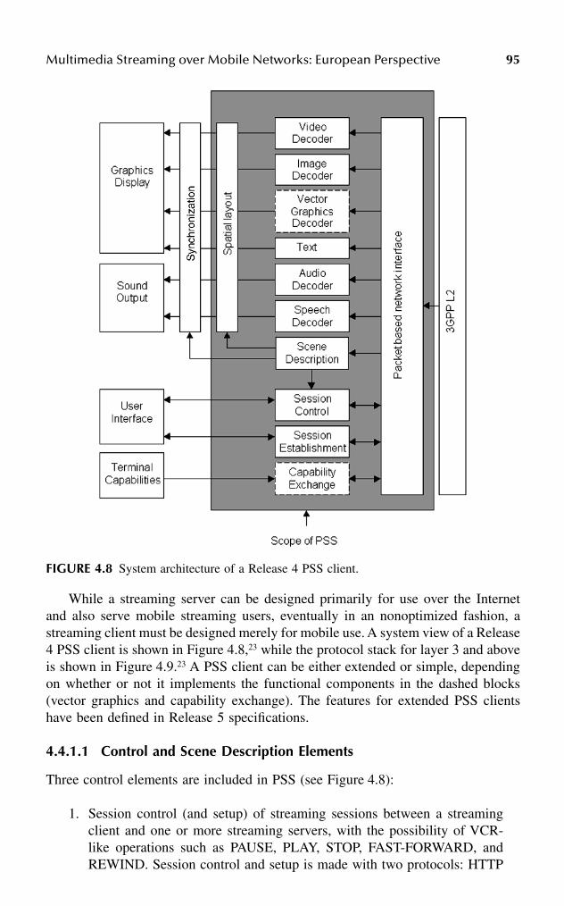
Multimedia Streaming over Mobile Networks: European Perspective 95
While a streaming server can be designed primarily for use over the Internetand also serve mobile streaming users, eventually in an nonoptimized fashion, astreaming client must be designed merely for mobile use. A system view of a Release4 PSS client is shown in Figure 4.8,23 while the protocol stack for layer 3 and aboveis shown in Figure 4.9.23 A PSS client can be either extended or simple, dependingon whether or not it implements the functional components in the dashed blocks(vector graphics and capability exchange). The features for extended PSS clientshave been defined in Release 5 specifications.
4.4.1.1 Control and Scene Description Elements
Three control elements are included in PSS (see Figure 4.8):
1. Session control (and setup) of streaming sessions between a streamingclient and one or more streaming servers, with the possibility of VCR-like operations such as PAUSE, PLAY, STOP, FAST-FORWARD, andREWIND. Session control and setup is made with two protocols: HTTP
FIGURE 4.8 System architecture of a Release 4 PSS client.
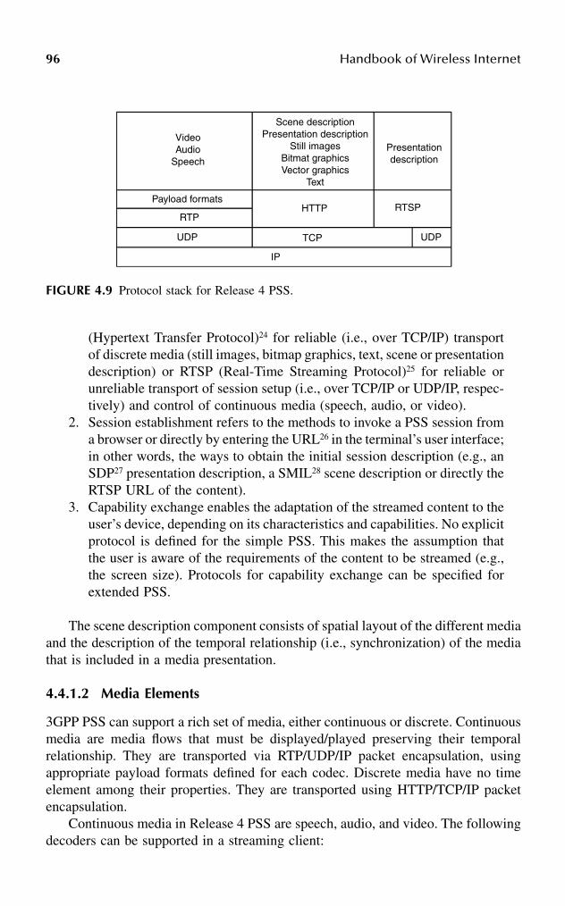
96 Handbook of Wireless Internet
(Hypertext Transfer Protocol)24 for reliable (i.e., over TCP/IP) transportof discrete media (still images, bitmap graphics, text, scene or presentationdescription) or RTSP (Real-Time Streaming Protocol)25 for reliable orunreliable transport of session setup (i.e., over TCP/IP or UDP/IP, respec-tively) and control of continuous media (speech, audio, or video).
2. Session establishment refers to the methods to invoke a PSS session froma browser or directly by entering the URL26 in the terminal’s user interface;in other words, the ways to obtain the initial session description (e.g., anSDP27 presentation description, a SMIL28 scene description or directly theRTSP URL of the content).
3. Capability exchange enables the adaptation of the streamed content to theuser’s device, depending on its characteristics and capabilities. No explicitprotocol is defined for the simple PSS. This makes the assumption thatthe user is aware of the requirements of the content to be streamed (e.g.,the screen size). Protocols for capability exchange can be specified forextended PSS.
The scene description component consists of spatial layout of the different mediaand the description of the temporal relationship (i.e., synchronization) of the mediathat is included in a media presentation.
4.4.1.2 Media Elements
3GPP PSS can support a rich set of media, either continuous or discrete. Continuousmedia are media flows that must be displayed/played preserving their temporalrelationship. They are transported via RTP/UDP/IP packet encapsulation, usingappropriate payload formats defined for each codec. Discrete media have no timeelement among their properties. They are transported using HTTP/TCP/IP packetencapsulation.
Continuous media in Release 4 PSS are speech, audio, and video. The followingdecoders can be supported in a streaming client:
FIGURE 4.9 Protocol stack for Release 4 PSS.
VideoAudio
Speech
Scene descriptionPresentation description
Still imagesBitmat graphicsVector graphics
Text
Presentationdescription
Payload formats
RTP
UDP
IP
HTTP
TCP
RTSP
UDP
Multimedia Streaming over Mobile Networks: European Perspective 97
• AMR (Adaptive MultiRate) narrowband is the mandatory speech decoderfor PSS.29 Speech is encoded at 8 kHz sampling frequency at 8 differentbit rates ranging from 4.75 to 12.20 kbps. An AMR speech flow is pack-etized by a streaming server using the RTP payload format described inreference 30.
• AMR wideband decoder is mandatory for a PSS client when speechencoded at 16 kHz sampling frequency is supported.31 It supports ninedifferent bit rates ranging from 6.60 to 23.85 kbps. An AMR widebandflow is packetized using the RTP payload format described in reference 30.
• MPEG-4 AAC. If audio is supported, AAC Low Complexity32 with amaximum sampling frequency of 48 kHz in mono (1/0) and stereo (2/0)is the decoder supported. However, the AAC Long-Term Predictiondecoder can also be supported. An AAC flow is packetized using thepayload format as described in reference 33.
• H.263 Video. Profile 0 Level 10 is the mandatory decoder for videostreams.34 It supports video at a maximum bit rate of 64 kbps at QCIFpicture size (176 × 144 pixels). Optionally, Profile 3 Level 10 can alsobe supported35 to provide better error resilience. An H.263 video streamis packetized using the payload format defined in reference 36.
• MPEG-4 Visual is an optional decoder that can be supported at SimpleProfile Level 0.37,38 An MPEG-4 video stream is packetized using thepayload format described in reference 33.
Discrete media in Release 4 PSS are still images, bitmap graphics, vectorgraphics, and text. The following discrete media decoders can be supported in astreaming client:
• JPEG is the mandatory format for still images.39 It is supported in thebaseline and progressive DCT mode (nondifferential Huffman encoding).
• GIF is the format supported for bitmap graphics. Two formats can bedecoded by a PSS client: GIF87a and GIF89a.40,41
• Vector graphics. No decoders are specified for a simple PSS client. How-ever, decoders can be specified for extended PSS clients.
• The text decoder is supposed to be used in a SMIL presentation with thetext formatted following XHTML Mobile Profile.42 The supported char-acter coding formats are UTF-844 and UCS-2.43
4.4.2 RELEASE 5 PSS
The specifications for Release 5 PSS are defined in three documents.45–47 Release 5enhances PSS with new features. The major features are described here (file formatissues will not be covered here).
4.4.2.1 Control Elements
The most important enhancement of the application control plane is a new mecha-nism for capability exchange, which means the functionality of PSS servers to

98 Handbook of Wireless Internet
provide content for a wide set of mobile devices. The device capabilities and preferencesare described in a device profile using attributes into an RDF48 document that followsthe structure of the CC/PP49 framework and the CC/PP application, UAProf.50 Followingare some of the possible attributes that can characterize a mobile device:
• Audio channels• Max polyphony capabilities when supporting scalable polyphony MIDI
sounds• List of MIME types that the PSS device accepts• Screen size• SMIL modules supported• Decoding video byte rate• Size of predecoder buffer• Size of postdecoder buffer• Number of bits per pixel• Color capability• Pixel aspect ratio• List of supported character sets
Whenever this mechanism for capability negotiation is used, device capabilityprofiles are stored on a device profile server that is inquired by a PSS server (viaHTTP or RTSP) before delivering multimedia content to the mobile device.
4.4.2.2 Media Elements
The new media formats that are introduced in Release 5 of PSS specifications areall of the discrete type (i.e., transport over HTTP/TCP/IP):
• Scalable polyphony MIDI (SP-MIDI) is the format to support syntheticaudio.51
• PNG (Portable Network Graphics) is yet another format to support bitmapgraphics.52
• SVG (Scalable Vector Graphics) is the mandatory format used to supportvector graphics. Optionally, the Basic profile also can be supported.53,54
• Timed text is supported as downloadable text (not streamed viaRTP/UDP/IP). Timed text can define color, font, writing direction (i.e., leftto right, or other directions), Karaoke highlighting, and other attributes.47
This section discussed the main features of PSS in Release 4 and Release 5specifications. The next section covers some QoS and performance issues of mobilemultimedia streaming.
4.5 PERFORMANCE ISSUES OF MOBILE STREAMING
When implementing a PSS services, the underlying mobile network brings require-ments and constraints that must be taken into consideration. To understand how a

Multimedia Streaming over Mobile Networks: European Perspective 99
multimedia session is started and handled end-to-end, Figure 4.10 shows a possiblescenario for an example session (here and in the following, we consider only theusage of packet switched bearers, rather than circuit switched bearers).45
The session is started by a mobile user getting a URI to the specific content thatsuits the user’s terminal. The URI comes from a WAP (Wireless Application Proto-col)/Web browser, or it is typed in. The URI specifies the streaming server and theaddress of the content on that server. A PSS application that establishes the multi-media session must understand an SDP file. The SDP file may be obtained in anumber of ways. In the example described here, it is obtained through RTSP sig-naling via the DESCRIBE message. The SDP file contains the description of thesession (session name, author, and other parameters), the type of media to bepresented, and the bit rate.
The session establishment is the process in which the mobile user invokes astreaming client to set up the session with the server. The mobile device is expectedto activate a PDP context that enables IP packet transmission, with an appropriateQoS profile for streaming media.
The setup of the streaming service is done by sending an RTSP SETUP messagefor each media stream chosen by the client. This returns, among other information,the UDP and TCP port to be used for the respective media stream. The client sends
FIGURE 4.10 Message exchange of a typical basic mobile streaming session.

100 Handbook of Wireless Internet
an RTSP PLAY message to the server that starts to send one or more streams overthe IP network.
At the end of the session a TEARDOWN message is sent by the client and thePDP context can be deallocated.
The following sections introduce some QoS issues in mobile multimedia stream-ing.
4.5.1 BEARER CONSIDERATIONS
The PDP context activation described in Figure 4.10 must be activated with anadequate set of parameters. SDU error rates and transfer delay are key parametersand must be tuned according to the RLC mode chosen. If acknowledged mode isselected, the streaming client can rely on lower error rates because the lost blocksare retransmitted. As a downside, the delay jitter perceived at the PSS client maybe rather high, especially if fully persistent acknowledged mode transmission ischosen. On the other hand, when unacknowledged mode is selected, the delay jitteris supposedly limited, but no retransmissions are occurring at the RLC layer. Con-sequently, the PSS client cannot benefit from a much higher level of data deliveryreliability.
Particular attention must be paid to RTP packet sizes. When using RLC acknowl-edged mode, using bigger packets produces higher delay jitters at the PSS client,because there is a higher probability that more RLC blocks have to be retransmittedin order to deliver a single RTP packet. On the other hand, when using RLCunacknowledged mode, larger packets are more susceptible to losses than smallerpackets, because the loss of a single RLC block produces the loss of the entire RTPpacket. In this case using small packets is recommended. Too-small packets wouldcause too much RTP/UDP/IP header overhead. It is clear that the best settings arefound when considering all the mentioned issues at the same time.
4.5.2 RTCP
The RTP (Real-Time Transport Protocol) specifies its control protocol RTCP55 thatallows monitoring of the data delivery or, in other words, the quality of service. Themain function of RTCP is to convey feedback information about the participants inan ongoing session. The information provided includes packet losses and interarrivaljitter information. In a point-to-point connection, such as a multimedia streamingsession, RTCP can offer a valid means for adjusting the error resilience propertiesof the media streams carried over mobile networks. In such networks the quality ofthe connection may vary all the time, and prompt action is crucial for guaranteeingthe best possible quality of service at any instant. An example of action to be takenby a streaming server is the dynamic change of the packetization parameters toprovide an increased level of error resilience. However, the utility function forrepairing media is decreasing over time, because an action taken too late can beuseless or it may even worsen the quality of service. Normally, RTCP feedback is
Multimedia Streaming over Mobile Networks: European Perspective 101
sent at an interval of at least 5 seconds. The recommended fraction bandwidthreserved for RTCP is 5 percent of the RTP session bandwidth. However, at low bitrates (up to 64 kbps), if the minimum RTCP transmission interval is 5 seconds, itis impossible to reach the full 5 percent bandwidth.
The PSS specifications of Release 547 define two working modes for PSS clientsthat intend to send more-frequent feedback to the PSS server:
1. Mode 1 (normal feedback) uses the rule defined in reference 55, wherefeedback is sent at intervals of at least 5 seconds.
2. Mode 2 (more frequent feedback) fills the 5 percent bandwidth reservedfor RTCP to send feedback information.
Mode 2 allows feedback to be sent at a higher rate (the RTCP transmissioninterval is much smaller than 5 seconds), and it allows QoS-enabled PSS servers totake appropriate actions to guarantee good QoS at the PSS client. If 5 percentbandwidth is costly in terms of bearer allocation, Mode 1 can be used. It consumesless network resources, but the feedback capability is limited (on average) to oneRTCP feedback report every 5 seconds.
4.5.3 RTSP SIGNALING ISSUES
Session setup time is one of the most important factors to determine the efficiencyof a PSS service. RTSP is the protocol that handles session setup, and it supportsboth TCP and UDP transport. TCP is the mandatory transport mechanism for RTSP.
For TCP, two types of connections are possible:
1. Persistent, where a connection is used for several RTSP request/responsepairs
2. Nonpersistent, where a connection is used for a single RTSP request/response pair
Every nonpersistent connection starts with a three-way handshake (SYN, ACK,SYN) before any RTSP message can be sent. This increases signaling time consid-erably. For this reason, the use of persistent TCP connections is recommended inorder to keep the signaling time as low as possible.47
4.5.4 LINK ALIVENESS
In mobile networks, connection can be lost because of low network coverage, fading,shadowing, loss of battery power, or turning off the PSS client even if the streamingsession is active. In order for the streaming server to understand the client alivenessstatus, the PSS client should send periodic wellness information to the PSS server. Thedefault period to send this information is 1 minute, as described in reference 25. Forthis purpose RTCP or RTSP can be used to signal link aliveness to the PSS server.

102 Handbook of Wireless Internet
4.6 CONCLUSIONS
Current mobile networks, such as GPRS, E-GPRS, GERAN, and UTRAN, aredesigned and optimized to transport IP-based traffic. Consequently, mobile multi-media streaming can become one of the key applications for mobile users.
Packet-switched streaming will offer end users the ability to receive content suchas audio and video directly to their mobile device. This service not only enablesnew content providers to distribute media content to mobile users, but also enablesconnection to the huge amount of content available on the Internet, making thetransition toward the Wireless Internet feasible.
References
1. ETSI, High speed circuit-switched data (HSCSD). Stage 2 (Release ’96), GSM 03.34,v.5.2.0 (1999–05).
2. ETSI, High speed circuit-switched data (HSCSD). Stage 1 (Release ’98), GSM 02.34,v.7.0.0 (1999–08).
3. Nieweglowski, J. and Leskinen, T., Video in mobile networks, European Conferenceon Multimedia Applications, Services and Techniques (ECMAST ’96), 28–30 May1996, Louvain-la-Neuve, Belgium, pp. 120–133.
4. 3GPP TSGS-SA, High speed circuit-switched data (HSCSD). Stage 1 (Release 4),TS 22.034, v.4.1.0 (2001–03).
5. 3GPP TSGS-SA, General packet radio service (GPRS), service description. Stage 2(Release ’97), TS 03.60, v.6.11.0 (2002–06).
6. 3GPP TSG-GERAN, General packet radio service (GPRS), mobile station (MS)–basestation system (BSS) interface, radio link protocol/medium access control(RLC/MAC) protocol (Release ’97), TS 04.60, v.6.14.0 (2001–07).
7. 3GPP TSG-CN, General packet radio service (GPRS), mobile station — servingGPRS support node (MS-SGSN), subnetwork dependent convergence protocol(SNDCP) (Release ’97), TS 04.65, v.6.7.0 (2000–03).
8. Jacobson, V., Compressing TCP/IP headers for low-speed serial links, IETF (InternetEngineering Task Force) RFC 1144, February 1990.
9. ITU-T, Data compression procedures for data circuit-terminating equipment (DCE)using error correcting procedures, Recommendation V.42 bis, January 1990.
10. ETSI, General packet radio service (GPRS), service description (Stage 1) (Release’98), GSM 02.60, v.7.5.0 (2000–07).
11. Halonen, T., Romero, J., and Melero, J., Eds., GSM, GPRS and EDGE Performance,John Wiley & Sons, New York, 2002.
12. Degermark, M., Nordgren, B., and Pink, S., IP header compression, IETF (InternetEngineering Task Force) RFC 2507, February 1999.
13. 3GPP TSG SSA, IP Multimedia subsystem (IMS). Stage 2 (Release 5), TS 23.228,v.5.7.0 (2002–12).
14. 3GPP TSG-CN, Signaling flows for the IP multimedia call control based on SIP andSDP. Stage 3 (Release 5), TS 24.228, v.5.3.0 (2002–12).
15. 3GPP TSG-CN, IP multimedia call control protocol based on SIP and SDP. Stage 3(Release 5), TS 24.229, v.5.3.0 (2002–12).

Multimedia Streaming over Mobile Networks: European Perspective 103
16. Rosenberg, J. et al., SIP: Session Initiation Protocol, IETF (Internet Engineering TaskForce) RFC 3261, March 2002.
17. 3GPP TSGS-SA, General packet radio service (GPRS), service description. Stage 2(Release 5), TS 23.060, v.5.4.0 (2002–12).
18. 3GPP TSG-RAN, Radio link control (RLC) protocol specification (Release 5), TS25.322, v.5.3.0 (2002–12).
19. Bormann, C., Ed., Robust header compression (ROHC): framework and four profiles:RTP, UDP, ESP and uncompressed, IETF (Internet Engineering Task Force) RFC3095, July 2001.
20. 3GPP TSGS-SA, QoS concept and architecture (Release 5), TS 23.107, v.5.7.0(2002–11).
21. 3GPP TSG-GERAN, Overall description. Stage 2 (Release 5), TS 43.051, v.5.8.0(2002–11).
22. 3GPP TSGS-SA, Transparent end-to-end packet-switched streaming service (PSS).General description (Release 4), TS 26.233, v.4.2.0 (2002–03).
23. 3GPP TSGS-SA, Transparent end-to-end packet-switched streaming service (PSS).Protocols and codecs (Release 4), TS 26.234, v.4.5.0 (2002–12).
24. Fielding, R. et al., Hypertext transfer protocol – HTTP/1.1, IETF (Internet Engineer-ing Task Force) RFC 2616, June 1999.
25. Schulzrinne, H., Rao, A., and Lanphier, R., Real-time streaming protocol (RTSP),IETF (Internet Engineering Task Force) RFC 2326, April 1998.
26. Berners-Lee, T., Masinter, L., and McCahill, M., Uniform resource locators (URL),IETF (Internet Engineering Task Force) RFC 1738, December 1994.
27. Handley, M. and Jacobson, V., SDP: Session description protocol, IETF (InternetEngineering Task Force) RFC 2327, April 1998.
28. W3C, Synchronized multimedia integration language (SMIL 2.0), Recommendation,August 2001.
29. 3GPP TSGS-SA, Mandatory speech codec speech processing functions. AMR speechcodec. General description (Release 5), TS 26.071, v.5.0.0 (2002–06).
30. Sjoberg, J. et al., RTP payload format and file storage format for the Adaptive Multi-Rate (AMR) and Adaptive Multi-Rate Wideband (AMR-WB) audio codecs, IETF(Internet Engineering Task Force) RFC 3267, March 2002.
31. ITU-T, Wideband coding of speech at around 16 kbits/s using Adaptive Multi-RateWideband (AMR-WB), Recommendation G.722.2, January 2002.
32. ISO/IEC, Information technology – Coding of audio-visual objects – Part 3: Audio,14496–3, 2001.
33. Kikuchi, Y. et al., RTP payload format for MPEG-4 audio/visual streams, IETF(Internet Engineering Task Force) RFC 3016, November 2000.
34. ITU-T, Video coding for low bit rate communication, Recommendation H.263, Feb-ruary 1998.
35. ITU-T, Video coding for low bit rate communication. Profiles and levels definition,Recommendation H.263 Annex X, April 2001.
36. Bormann, C. et al., RTP payload format for the 1998 version of ITU-T Rec. H.263(H.263+), IETF (Internet Engineering Task Force) RFC 2429, October 1998.
37. ISO/IEC, Information technology – Coding of audio-visual objects – Part 2: Visual,14496–2, 2001.
38. ISO/IEC, Streaming video profile, 14496–2, 2001/Amd 2, 2002.
104 Handbook of Wireless Internet
39. ISO/IEC, Information technology – Digital compression and coding of continuous-tone still images. Requirements and guidelines, 10918–1, 1992.
40. Compuserve Incorporated, GIF graphics interchange format: a standard defining amechanism for the storage and transmission of raster-based graphics information,Columbus, OH, 1987.
41. Compuserve Incorporated, Graphics interchange format: version 89a, Columbus, OH,1990.
42. WAP Forum Specification, XHTML Mobile Profile, October 2001.43. ISO/IEC, Information technology – Universal multiple-octet coded character set
(UCS) – Part 1: architecture and basic multilingual plane, 10646–1, 2000.44. The Unicode Consortium, The Unicode standard, Version 3.0, Addison-Wesley, Read-
ing, MA, 2000.45. 3GPP TSGS-SA, Transparent end-to-end packet-switched streaming service (PSS).
General description (Release 5), TS 26.233, v.5.0.0 (2002–03).46. 3GPP TSGS-SA, Transparent end-to-end packet-switched streaming service. Service
aspects. Stage 1 (Release 5), TS 22.233, v.5.0.0 (2002–03).47. 3GPP TSGS-SA, Transparent end-to-end packet-switched streaming service (PSS).
Protocols and codecs (Release 5), TS 26.234, v.5.3.0 (2002–12).48. W3C, Resource description framework (RDF) schema specification 1.0, Candidate
Recommendation, March 2000.49. W3C, CC/PP structure and vocabularies, Working Draft Recommendation, June 2001.50. WAP Forum, WAP UAProf specification, Specification, October 2001.51. MIDI Manufacturers Association, Scalable polyphony MIDI specification version
1.0, RP-34, Los Angeles, February 2002.52. Boutell, T., et al., PNG (Portable Network Graphics) specification version 1.0, IETF
(Internet Engineering Task Force) RFC 2083, March 1997.53. W3C, Scalable vector graphics (SVG) 1.1 specification, Working Draft Recommen-
dation, February 2002.54. W3C, SVG mobile specification, Working Draft Recommendation, February 2002.55. Schulzrinne, H. et al., RTP: a transport protocol for real-time applications, IETF
(Internet Engineering Task Force) RFC 1889, January 1996.56. 3GPP TSG-CN, High Speed Circuit Switched Data (HSCSD), Stage 2 (Release ’99),
TS 23.034, v.3.3.0 (2000-12).57. 3GPP TSG-RAN, Packet Data Convergence Protocol (PDCP) Specification (Release 4),
TS 25.323, v.4.6.0 (2002-09).58. 3GPP TSGS-SA, General Packet Radio Service (GPRS), Service Description, Stage 2
(Release ’99), TS 23.060, v.3.14.0 (2002-12).

1050-8493-1502-6/03/$0.00+$1.50© 2003 by CRC Press LLC
5 Streaming Video over Wireless Networks
Haitao Zheng and Jill Boyce
CONTENTS
5.1 Introduction ..................................................................................................1055.2 Video Compression Standards .....................................................................106
5.2.1 H.261 ................................................................................................1065.2.2 MPEG-1 ...........................................................................................1075.2.3 MPEG-2 ...........................................................................................1075.2.4 H.263 ................................................................................................1075.2.5 MPEG-4 ...........................................................................................1085.2.6 JVT ...................................................................................................109
5.3 Protocols.......................................................................................................1105.4 Streaming Video over the Internet...............................................................1115.5 Wireless Networks and Challenges .............................................................114
5.5.1 Dynamic Link Characteristics .........................................................1155.5.2 Asymmetric Data Rate.....................................................................1165.5.3 Resource Contention ........................................................................116
5.6 Adaptation by Cross Layer Design .............................................................1165.6.1 Application Transmission Adaptation..............................................1175.6.2 Transport Layer Transmission Adaptation.......................................1175.6.3 Network Layer and Link Layer Transmission Adaptation..............1195.6.4 Network and Channel Condition Estimation and Report ...............1195.6.5 Proxy Server.....................................................................................119
5.7 Integrating the Adaptation for Streaming Video over Wireless Networks .......................................................................................120
5.8 Conclusions ..................................................................................................121References..............................................................................................................122
5.1 INTRODUCTION
Video streaming is becoming ubiquitous on the wired Internet, as broadband Internetaccess is more commonly available. With the advent of higher-bandwidth wirelessInternet access enabled by 3G wireless networks, video streaming over wirelessnetworks also is likely to become common and enable new services and applications.

106 Handbook of Wireless Internet
In this chapter, we provide an introduction to intelligent video streaming overwireless networks. We begin by providing a brief background on digital videocompression standards that are frequently used for video streaming. Because manyof the same problems exist and protocols are used for both wired and wireless packetnetworks, we first describe the protocols used for streaming video over IP networks,and the problems and solutions associated with video streaming over lossy packetnetworks. Then we describe the characteristics of wireless networks and the partic-ular challenges associated with video streaming over wireless networks. We proceedto describe a cross layer design framework that enables adaptation to continuouslychanging wireless environments. Finally, we analyze proposed solutions that improvethe quality of video streamed over wireless networks.
5.2 VIDEO COMPRESSION STANDARDS
Streaming of video over today’s wired and wireless networks depends heavily oninternational video compression standards. There are numerous video compressionsystems that do not use open standards, such as Real Network’s RealVideo andMicrosoft’s Windows Media Player, but they are not discussed in this chapter, asdetails of their inner workings are not publicly available. Standardization in thevideo compression space has been done primarily by two different standards bodies,the International Organization for Standardization (ISO) and the International Tele-communications Union (ITU), previously CCITT. The video communications stan-dards of the highest past, current, and future interest are H.261, H.263, MPEG-1,MPEG-2, MPEG-4, and JVT. These video compression standards aree describedbriefly here, with their particular features relevant to wireless streaming highlighted.More details on the video compression standards themselves can be found in Puriand Chen1 and Rao and Hwang.2
5.2.1 H.261
ITU-T H.261, “Video codec for audiovisual services at p × 64 kbps,” is the ancestorof all of the popular video compression standards in use today. H.261 was designedfor video telephony and video conferencing, for use over one or more dedicatedISDN lines. The standardization effort for H.261 began with the establishment inDecember 1984 of CCITT Study Group XV, Specialist Group on Coding for VisualTelephony. In March 1989, the p × 64 kbps specification was frozen. Final standard-ization was established in December 1990.
Like the other video compression standards that follow it, H.261 uses block-based motion estimation and compensation and block-based transform and quanti-zation. Intracoded frames and intercoded frames are allowed in H.261. Intercodedframes are encoded with respect to a prediction formed from a previously codedframe. A Discrete Cosine Transform is applied to 8 × 8 pixel blocks, and the resultingtransform coefficients are quantized and entropy coded using variable length coding(VLC) techniques. Macroblocks are arranged into Group of Blocks (GOBs). Picturesand GOBs contain unique start codes, which can be used as resynchronization pointswhen transmission errors occur.

Streaming Video over Wireless Networks 107
5.2.2 MPEG-1
Work on MPEG began in 1988. ISO IEC/JTC1 SC29 IS 11172, “Coded represen-tation of picture, audio, and multimedia/hypermedia information,” became an inter-national standard in November 1992. MPEG was originally designed for digitalstorage applications with a target bit rate of about 1.5 Mbps, but has been appliedto a wide spectrum of application, including video streaming over the Internet.
Like H.261, MPEG allows intracoded frames (“I” frames) and intercoded frames(“P” frames); also, MPEG introduced bidirectionally coded frames (“B” frames). Bframes are predicted using a frame before and after the coded frame, and can becoded using relatively fewer bits. In MPEG, B frames are never used in coding otherpictures. This disposable property of B frames can be important when MPEG isstreamed over lossy networks. MPEG improved intracoding also by adding a quan-tization matrix, and improved intercoding by allowing motion estimation at half pelresolution. Any number of consecutive macroblocks, in scan order, can be groupedinto a slice. Slices are begun with unique slice start codes, which can serve asresynchronization points.
In addition to providing a video compression standard, MPEG provided also anaudio compression standard, and a systems standard. MPEG video can be carriedeither as a video elementary stream or as a program stream.
5.2.3 MPEG-2
Work on MPEG-2 began in 1990 and the video coding portion became an interna-tional standard in November 1994, entitled “Generic coding of moving pictures andassociated audio,” and standardized as ISO/IEC Committee Draft 13818 and ITU-T H.262. MPEG-2 was targeted at higher bit rate applications than MPEG-1, includ-ing standard definition television (SDTV) and high definition television (HDTV).
MPEG-2 builds on MPEG-1 coding techniques by adding tools for interlacedpicture coding and methods of scalability. MPEG-2 was the first standard to introducethe concept of profiles and levels, to describe interoperability points. Each profileincludes a group of tools that compliant decoders must support. Each level provideslimitations of pixel dimensions and frame rates that a decoder must support. MPEG-2 defined seven profiles: Simple, Main, SNR, Spatial, High, 4:2:2, and Multi. MPEG-1 defined four levels: High, High1440, Main, and Low.
The methods of scalability that MPEG-2 provides are spatial scalability, SNRscalability, temporal scalability, and data partitioning. Scalable video encoding tech-niques can be of great use for video streaming when used in conjunction withUnequal Error Protection (UEP), as described in Section 5.4 of this chapter. The bitrates used in MPEG-2 video coding are generally higher than are used for Internetor wireless video streaming.
5.2.4 H.263
Design of ITU-T H.263, “Video coding for low bit rate communication,” began in1993, and the Version 1 standard was published in March 1996. H.263 was designedas an extension of H.261, and greatly increased compression efficiency over H.261.

108 Handbook of Wireless Internet
H.261 added some of the tools from MPEG-1 and MPEG-2, as well as some originaltools. The tools added to H.261 that improve coding efficiency include half pelmotion compensation, median prediction of motion vectors, improved entropy cod-ing, unrestricted motion vectors, and more efficient coding of Macroblock and blocksignaling overhead.
Version 2, also called H.263+, was standardized in September 1997. Version 3,or H263++, was standardized in January 1998. Version 2 added several features forerror resilience, including a slice-structured mode, reference picture selection, andtemporal, spatial, and SNR scalability. Version 3 added data partitioning and revers-ible variable length coding for additional error resilience.
H.263 is commonly used in videoconferencing over dedicated telecommunica-tions lines, as well as over IP.
5.2.5 MPEG-4
Design of the MPEG-4 standard, “Coding of audio-visual objects,” began in 1993.Its initial version, ISO/IEC 14496, was finalized in October 1998 and became aninternational standard in the first months of 1999. The fully backward compatibleextensions under the title of MPEG-4 Version 2 were frozen at the end of 1999, andachieved formal international standard status in early 2000.
Relative to the preexisting video compression standards, MPEG-4 added object-based coding and improved video compression efficiency. According to Koenen,3
MPEG-4 provides standardized ways to:
1. Represent units of aural, visual, or audiovisual content, called “mediaobjects.” These media objects can be of natural or synthetic origin, whichmeans they could be recorded with a camera or microphone, or generatedwith a computer.
2. Describe the composition of these objects to create compound mediaobjects that form audiovisual scenes.
3. Multiplex and synchronize the data associated with media objects, so thatthey can be transported over network channels providing a QoS appro-priate for the nature of the specific media objects.
4. Interact with the audiovisual scene generated at the receiver’s end.
MPEG-4 provides many profiles; for natural video alone, there are 11 profiles:
1. Simple Visual Profile2. Simple Scalable Visual Profile3. Core Visual Profile4. Main Visual Profile N-Bit Visual Profile5. Advanced Real-Time Simple Profile6. Core Scalable Profile7. Advanced Coding Efficiency8. Advanced Simple Profile

Streaming Video over Wireless Networks 109
9. Fine Granularity Scalability Profile10. Simple Studio Profile11. Core Studio Profile
Because of the large number of profiles for MPEG-4, interoperability has beendifficult. The most commonly used profile is the Simple Profile.
MPEG-4 has several tools to improve error resilience, including reversible vari-able length coding and several methods of scalability. Fine Grain Scalability, inparticular, is well suited for use with Unequal Error Protection for video streamingover lossy networks. Li4 describes MPEG-4 Fine Grain Scalability in detail, andcompares its use with SNR scalability and simulcast.
MPEG4IP5 is an open source package designed to enable developers to createstreaming servers and clients that are standards-based and free from proprietarytechnology. MPEG4IP uses the MPEG-4 Simple Profile.
5.2.6 JVT
In 2001, ISO and ITU-T joined forces to develop the JVT (Joint Video Team)standard. This effort was originally begun in the ITU-T as H.26L. Committee Draftstatus was reached in May 2002. JVT is scheduled to become an internationalstandard in February 2003, and called H.264 by the ITU and MPEG-4 Part 10 by ISO.
JVT provides many of the tools found in H.263 and its extended versions H.263+and H.263++, but at an improved coding efficiency. JVT is claimed to provide thesame visual quality as MPEG-4 Advanced Simple Profile at half the bit rate.6 JVTuses 4 × 4 block integer transform and motion blocks of a variety of sizes. JVT’sMay 2002 Committee Draft defines two profiles: Baseline and Main.
JVT’s May 2002 Committee Draft does not include scalability, although it isintended for use in video streaming applications. Flexible Macroblock Ordering canimprove performance over lossy networks, by allowing slices to be formed fromnonneighboring macroblocks; in other words, to put neighboring macroblocks intodifferent slices. Therefore, if one slice is unavailable at the decoder due to packetloss, neighboring macroblocks from other slices can be used to perform spatialconcealment of the missing data. In JVT, pictures not used to predict other picturesare known as disposable pictures and are indicated in picture headers. In previouscoding standards, B pictures were the only pictures to have this characteristic, whilein JVT bipredictively coded pictures are not required to be disposable. Indicationof the disposable nature of a picture in the picture header effectively allows temporalscalability, which can be used with Unequal Error Protection.
Table 5.1 provides a list of the video compression standards and the bit rateranges that they were originally designed for. All of these video compression stan-dards share the property that they use interframe prediction. A video frame ispredicted from a previous frame, and only the differences are transmitted. This meansthat if transmission errors occur, the errors will persist for many frames. In general,macroblocks or entire frames are intracoded at regular intervals to limit the lengthof time an error can persist.

110 Handbook of Wireless Internet
5.3 PROTOCOLS
Transmission Control Protocol (TCP)7,8 and User Datagram Protocol (UDP)9 aretwo Internet Protocol transport protocols that can be used for transmitting com-pressed video over the Internet. TCP, a reliable protocol, guarantees delivery of allpackets and in order, while UDP does not guarantee delivery of packets or theordering of received packets. TCP uses retransmissions to guarantee that all packetsarrive.
Most streaming video applications do not require guaranteed in-order arrival ofall packets, and cannot tolerate the unbounded delay of using TCP to send com-pressed video data. So UDP is the transport protocol generally used for videostreaming over IP networks.
The Real-Time Transport Protocol (RTP) is frequently used with UDP forstreaming of video over IP networks. RTP provides functionality suited for carryingreal-time content and for synchronizing different streams with timing properties.RTP specifies a header at the beginning of each packet that includes fields for payloadtype, time stamp, and sequence number. The RTP specification was published asRFC 188910 by the Audio/Video Transport Working Group of the Internet Engineer-ing Task Force (IETF).
RFC 1889 defines also the Real-Time Transport Control Protocol, RTCP, whichworks in conjunction with RTP. RTCP defines a syntax for providing feedback ofquality-of-service (QoS) parameters to the participants of an RTP session.
RTP can be used with many different audio or video compression standards.The Audio/Video Transport Working Group also has published several RFCs thatspecify carriage of specific video compression standards over RTP, in general byadding standard-specific RTP header extensions. For example, RFC 203211 “RTPPayload Format for H.261 Video Streams,” describes a recommended syntax for anH.261 specific header to be included in an RTP packet, after the basic RTP header.In order to be error resilient, higher layer syntax elements from the H.261 bit streamare redundantly repeated in each packet header, in a fixed length format.
RFC 2038,12 “RTP Payload Format for MPEG1/MPEG2 Video,” similarlydescribes a recommended syntax for MPEG video data to be streamed using RTP.RFC 2038 applies only to MPEG elementary streams. RFC 2038 requires that coded
TABLE 5.1Video Compression Standards
Standard Bit Rate Range
H.261 64 to 384 kbpsH.263 64 kbps to 1 MbpsMPEG-1 1 to 1.5 MbpsMPEG-2 2 to 15 MbpsMPEG-4 64 kbps to 2 MbpsJVT 32 kbps to ?

Streaming Video over Wireless Networks 111
pictures be fragmented into separate packets. New pictures must be at the start of apacket. Certain picture layer parameters are repeated in the MPEG specific RTPheader extension.
RFC 2429,13 “RTP Payload Format for the 1998 Version of ITU-T Rec. H.263Video (H.263+),” describes a syntax for streaming H.263 over RTP. In addition toproviding syntax for an H.263+ payload header, it provides an optional VideoRedundancy Coding Header that works with H.263+’s reference picture selectionto improve error resilience.
RFB 3016, “RTP Payload Format for MPEG-4 Audio/Visual Streams,” does notprovide an MPEG-4-specific RTP header extension. It does provide rules for frag-menting the MPEG-4 Visual Bitstream into RTP packets. An IETF Internet Draft,draft-ietf-avt-mpeg4-multisl-04.txt, “RTP Payload Format for MPEG-4 Streams,”provides an MPEG-4-specific RTP header extension.
The Real-Time Streaming Protocol (RTSP) is a session control protocol forinitiating and direction streaming of multimedia over IP. RTSP provides VCR-likecontrol functions, such as PLAY, PAUSE, RESUME, FAST-FORWARD, and FAST-REWIND. RTSP is not used to deliver compressed video data itself, but is used inconjunction with other protocols such as RTP.
5.4 STREAMING VIDEO OVER THE INTERNET
Because the protocols typically used for streaming of compressed video over theInternet, UDP and RTP, do not guarantee end-to-end delivery of compressed videodata, packet losses introduce errors into the decoded video, which reduces theperceived video quality by viewers. Because interframe coding is used in all of thecommon video compression standards, those errors propagate and hence can havea large impact on video quality.
Consider a typical application, with video encoded at 30 fps, and an intracodedframe occurring every 15 frames or every half a second. If packet loss occurs in thetransmission of the intracoded (I) frame, a visible error can persist for half a second,until a new I frame is transmitted. An error persisting for half a second is quitenoticeable to a viewer. As shown in Boyce,14 packet loss rates as low as 3 percentcan translate into frame error rates as high as 30 percent. Figure 5.1 shows frameerror rates from sample traces of MPEG video data transmitted over the publicInternet at 384 kbps, with I frames occurring every 15 frames. Frame error rate isdefined by counting the percentage of decoded frames that are affected by a packetloss.
Error concealment techniques applied at the decoder can reduce the visual impactof packet losses. An overview of error concealment techniques for video compressionwas provided in Wang and Zhu.15 These techniques generally copy information fromspatial or temporal neighbors to reduce the visual effect of packet losses. Errorconcealment techniques are most effective at relatively low error rates. To protectvideo quality from higher loss rates, it is necessary to involve the transmitting aswell as the receiving end. A good overview of error control techniques involvingboth the send and receiver ends was provided also in Wang and Zhu.15 A summaryof approaches to streaming video over the Internet can be found in Wu et al.16

112 Handbook of Wireless Internet
Because the visual effects of packet losses persist until an intracoded Macroblockis received, an encoder can choose to perform intracoding more frequently to protectagainst packet loss. However, this comes with a visual-quality penalty, as intercodingis generally considerably more efficient than intercoding. More-sophisticated tech-niques can reduce the coding efficiency penalty by allowing the intra update ratesfor different image regions to vary according to various channel conditions andimage characteristics.17
Alternatively, reference picture selection, such as that available in H.263+, canbe used in networks with NAK feedback capability.18 Instead of encoding a pictureusing intracoding after detecting a network transmission error, this approach elim-inates the persistence of the error effects by intercoding the picture with respect toa previously coded picture, which has been decoded and stored at the decoder.
Scalable video coding can be used to improve the quality of video streamedover lossy networks. With scalable video coding, a base and one or more enhance-ment layers are encoded, and it is expected that the base layer alone should provideat least a minimally acceptable quality representation of the video. For networksthat possess paths with different levels of QoS, the base layer is transmitted with ahigher level of QoS than the enhancement layer. In Aravind and coworkers,19 theperformance of different types of MPEG-2 scalability over lossy networks wasdescribed. In Receiver Driven Layered Multicast,20 scalable video coding is used
FIGURE 5.1 Frame error rate versus packet loss rate for MPEG video data.

Streaming Video over Wireless Networks 113
with IP multicast, and each layer of video is transmitted in a separate multicastgroup. Clients can join as many multicast groups as may fit in their availablebandwidth.
For streaming applications, where a small amount of additional delay can betolerated, the use of Forward Error Correction (FEC) or Forward Erasure Correction(FXC) can protect against packet loss Using media-independent FEC, well-knowninformation theory techniques can be applied to streaming video. In Rosenberg andSchulzrinne,21 several variations of XOR operations are used to create parity packetsfrom one or more data packets. More-complex techniques such as Reed Solomon(RS) coding also can be used. In RS coding, the original information bytes aretransmitted, as well as additional parity bytes. When an RS(n,k) codeword is con-structed from byte data, h parity bytes are created from k information bytes, and alln = k + h bytes are transmitted. Such a Reed Solomon decoder can correct up toany h/2 byte errors, or any h byte erasures, where an erasure is defined as an errorin a known position. Because in wired IP networks packets are generally lostcompletely rather than being transmitted with bit errors, when FEC is applied tovideo streaming over IP networks, the FEC is applied across packets. When RScoding is applied, k information packets of length l bytes are coded using l RScodewords. For each RS codeword, k information bytes are taken from k differentpackets (one from each packet), and the constructed parity bytes are placed intoseparate parity packets, and all n = k + h packets are transmitted. Because RTPsequence numbers make it possible to determine if a given packet is lost, an RS(n,k)code can protect against up to any h = n – k packet losses. Figure 5.2 shows anexample of an RS(5,3) code applied to IP data. For this example, three informationpackets are RS encoded, yielding two parity packets and the 3 + 2 = 5 packets aretransmitted. The three original information packets can be recovered perfectly if nomore than two of the five transmitted packets are lost.
Because RS coding is systematic, i.e., the original information bytes themselvesare transmitted, if all k information bytes are received, no computations are neededat the receiver to reconstruct the original information bytes. A key advantage of RScoding over simple parity is its ability to protect against several consecutive errors,depending on the parameter choices.
Varying amounts of packet loss protection can be achieved by varying theRS(n,k) parameters. The trade-off between delay and error protection capabilityaffects the choice of the n, k parameters. As n and k increase for protection againsta burst of length h, the overhead rate h/k decreases, but the delay in the systemincreases. In Rizzo,22 any code parameter values of n, k up to 255 can be generatedusing the same generator polynomial, such that as the value of n increases, the paritybytes generated for lower values of n are unchanged. For example, the first 9 bytesof a (10,5) code are the same as would be used in a (9,5) code. The type of FECcode with multicast was used in Rhee et al.23 to achieve variable levels of errorprotection for different users. Several multicast groups transmit different numbersof parity packets, and individual receivers join as many of the multicast groups asneeded to achieve the level of error protection appropriate for their network con-nection. FEC is well suited to multicast, because the same parity packets can beused to protect against different losses in the separate multicast transmission paths.
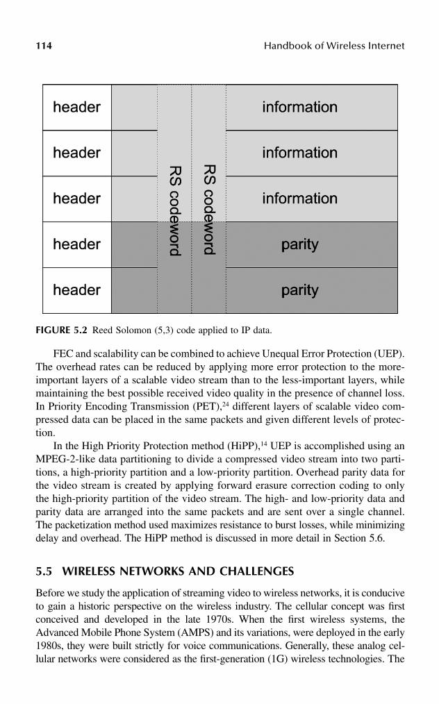
114 Handbook of Wireless Internet
FEC and scalability can be combined to achieve Unequal Error Protection (UEP).The overhead rates can be reduced by applying more error protection to the more-important layers of a scalable video stream than to the less-important layers, whilemaintaining the best possible received video quality in the presence of channel loss.In Priority Encoding Transmission (PET),24 different layers of scalable video com-pressed data can be placed in the same packets and given different levels of protec-tion.
In the High Priority Protection method (HiPP),14 UEP is accomplished using anMPEG-2-like data partitioning to divide a compressed video stream into two parti-tions, a high-priority partition and a low-priority partition. Overhead parity data forthe video stream is created by applying forward erasure correction coding to onlythe high-priority partition of the video stream. The high- and low-priority data andparity data are arranged into the same packets and are sent over a single channel.The packetization method used maximizes resistance to burst losses, while minimizingdelay and overhead. The HiPP method is discussed in more detail in Section 5.6.
5.5 WIRELESS NETWORKS AND CHALLENGES
Before we study the application of streaming video to wireless networks, it is conduciveto gain a historic perspective on the wireless industry. The cellular concept was firstconceived and developed in the late 1970s. When the first wireless systems, theAdvanced Mobile Phone System (AMPS) and its variations, were deployed in the early1980s, they were built strictly for voice communications. Generally, these analog cel-lular networks were considered as the first-generation (1G) wireless technologies. The
FIGURE 5.2 Reed Solomon (5,3) code applied to IP data.
Streaming Video over Wireless Networks 115
advent of voice coding and digital modulation technologies brought the evolutionto the second generation or 2G wireless networks. The leading technologies includedGlobal Systems for Mobile (GSM) in Europe, the IS-95 CDMA and IS-136 in theUnited States, and Pacific Digital Cellular (PDC) in Japan. Similar to the 1G wirelessnetworks, the 2G networks are mostly used for low data rate, circuit-switched voiceapplications.
In the past few years, the explosion of Internet traffic has inevitably increasedthe need for packet-based wireless networks. As a result, the circuit-switched 1Gand 2G wireless networks have gradually evolved into packet-switched 2.5G tech-nologies such as GPRS, EDGE, and 1X-EVDV to provide packet data services andfurther improve voice capacity, which will eventually be phased out by the 3Gwireless technologies. Employing increased spectrum, highly sophisticated air inter-faces, and packet switching at the core, the 3G wireless networks further improvethe capability to provide advanced data services. The high data rate (up to 2 Mbps)provided by 3G networks is much higher than that of today’s wireline networks. Inaddition, 3G technologies provide seamless roaming across global networks. Withthese advantages, the 3G networks can support a wide variety of data services,including real-time, streaming multimedia and fast Internet access. In the end, theevolution of the 3G networks will bridge the gap between the wireline and thewireless worlds.
Given that the Internet traffic increases dramatically and users desire ubiquitousInternet access, the next generation of networking systems will be data-centric withthe addressed mobility consideration. IP-based communications systems, whichenable much-higher data rates and network flexibility, will gradually predominateover the traditional circuit-switched systems. In recent years, enormous effort hasbeen made to support IP in wireless networks. Protocols and programming lan-guages, including WAP, WML, and J2ME, have been developed to adapt Web contentto the limitations of handheld devices by reducing the amount of transmitted datawith minimum sacrifice of information. Mobile IP networks have been designed tomaintain consistent transport-layer quality as the remote terminal is constantly inmotion. However, in developing IP-based wireless data networks, significant diffi-culties remain to be addressed. They are summarized next.
5.5.1 DYNAMIC LINK CHARACTERISTICS
The process of a mobile device transmitting and receiving radio signals through theair makes wireless transmission vulnerable to noise and interference. The shadowingeffect, multipath fading, and interference from the other devices make channelconditions vary unpredictably over time. Changing the transmission rate as thechannel varies does improve efficiency but results in data rate oscillation. Further-more, mobility introduces difficulty in channel estimation and prediction, thus raiseserror rate. Two approaches have commonly been used to address this problem. Thefirst approach employs sophisticated channel coding and interleaving technologies.For example, turbo coding, despite its complexity, is now standard channel codingtechnique in 3G UMTS.25 This approach, however, heavily relies on the quality of
116 Handbook of Wireless Internet
channel estimation. The second approach, the link layer ARQ mechanism, performserror control by retransmitting lost frames.26 Although insensitive to the quality ofchannel estimation, this approach introduces latency and delay jitters to IP packetflow. The trade-off between latency and reliability depends on the ARQ persistence,which defines the willingness of the protocol to retransmit lost frames to ensurereliable transmission.27 The persistence can be expressed in terms of time or themaximum number of retransmissions.
5.5.2 ASYMMETRIC DATA RATE
A mobile terminal has limited power so that the uplink data rate is usually less thanthe downlink data rate. This limitation is less stringent because most data applicationsare asymmetric.
5.5.3 RESOURCE CONTENTION
As in wireline networks, users share channel resources in wireless networks. Whenmultiple users run a variety of applications, the most salient issue is the significantvariability in terms of QoS requirements such as error rate, latency, and bandwidth.The resource contention problem is already quite challenging in wireline networks.As the result of mobility and unpredictable link variation, dynamic network topologymakes wireless networks even harder to coordinate. The Medium Access Control(MAC) layer uses a scheduler to determine the next user to be served based on anindividual user’s channel condition and QoS requirement.28–30 Currently, this sched-uler is developed only for downlink transmission because only the base stationgathers all the user information. The uplink transmission is typically made throughcontention, yielding high delay jitters.
Overall, high transmission errors and variable latency are the major causes ofdata loss in wireless networks. In the past, IP-based data applications have beendesigned mostly for wireline networks, where links and subnetworks normally haverelatively stable transmission rates at low error rates. Data loss is primarily due tonetwork congestion and buffer exhaustion. As described earlier in this chapter, manytechniques have been developed to support efficient packet transmission over wire-line networks. Unfortunately, they are not applicable to wireless networks. Forexample, in wireline networks, adding bandwidth can solve latency problemsbecause bandwidth is not a paramount concern. However, in a wireless environment,this is quite difficult due to adverse channel condition and limited battery life of themobile device.
5.6 ADAPTATION BY CROSS LAYER DESIGN
An important aspect of wireless networks is dynamic behavior. The conventionalprotocol structure is inflexible as various protocol layers can only communicate ina strict manner. In such a case, the layers are designed to operate under the worstconditions, rather than adapting to changing conditions. This leads to inefficient useof spectrum and energy.

Streaming Video over Wireless Networks 117
Adaptation represents the ability of network protocols and applications toobserve and respond to the channel variation. Central to adaptation is the conceptof cross layer design.31,32 Cross layer design for the three key layers in the overallprotocol stack (i.e., application layer, transport layer, and network and link layer)are reviewed in this section. An example framework is illustrated in Figure 5.3 interms of streaming video over wireline-to-wireless networks.
5.6.1 APPLICATION TRANSMISSION ADAPTATION
Application Transmission Adaptation refers to the application’s capability to adjustits behavior to changing network and channel characteristics. Wireless networksoften have to deal with adverse conditions where handoffs, deep fading, and badcarrier signals result in a high rate of packet losses. Only adaptive applications cancope with these challenging circumstances. For multimedia delivery, a media servercan track packet losses and adjust media source rate accordingly.33–37 To reduceinformation loss, the media server can employ packet FEC coding and UEP, asdescribed in Section 5.4.
Whereas this level of adaptation is system independent and application specific,an application is able to reconfigure itself accurately only if it identifies the under-lying network and channel variations.
5.6.2 TRANSPORT LAYER TRANSMISSION ADAPTATION
Instead of application layer adaptation, the adaptation can be shifted to the underlyingtransport layer, making it transparent to the application layer, so that applicationsoriginally developed for wireline networks remain intact. One drawback of this levelof adaptation is that it is impossible to implement a complete adaptation if part ofit is application specific.
The protocol should differentiate various packet loss patterns (i.e., packet lossesdue to network congestion or from channel errors),38–40 and invoke congestion controland rate adaptation accordingly. Several cross layer approaches, such as EBSN,41
snoop,42 and freeze TCP,43 have been proposed as TCP alternatives to distinguishcongestion loss from noncongestion loss and invoke different flow control mecha-nisms. TCP and its variants provide reliable connections by retransmitting the lostpackets. However, the resulting latency is in general too large for real-time andstreaming media applications. For this reason, most streaming applications use UDPprotocol with an unreliable packet delivery. However, by discarding corrupted pack-ets, UDP does not distinguish between packet losses due to congestion and corrup-tion. Alternatively, UDP-Lite applies partial checksum to some parts of a packet(i.e., packet payload) and reduces packet loss rate.44 It is explicitly designed forcertain applications, multimedia for example, which can detect and even recoverfrom certain level of errors. CUDP conducts a precise error detection and recoverythrough error location information from link-layer.45
Note that the transport layer can only adapt effectively if it can observe thenetwork layer and link layer conditions, propagate the information to the applicationlayer, and in the meantime, identify and accommodate the application layer’s need.

118H
and
bo
ok o
f Wireless In
ternet
FIGURE 5.3 A video streaming architecture using cross layer design.

Streaming Video over Wireless Networks 119
5.6.3 NETWORK LAYER AND LINK LAYER TRANSMISSION ADAPTATION
The application characteristics, such as QoS requirement and packet priority, couldbe used in coordinating the network layer and link layer. In particular, the persistencelevel of the link layer ARQ mechanism should adapt to each application’s latencyand reliability requirements, while the link layer scheduler allocates radio resourcesto various packet flows based on their QoS priorities. The adaptation, however,requires the link layer and network layer to distinguish different packet flows, whichin general can be achieved by an explicit indication of the QoS requirement asso-ciated with each packet flow.27 Note that in some systems, the transport layer andlink layer both conduct error recovery by using FEC coding and retransmissions.The balance between both schemes is important for the optimal usage of the overallcommunication resources.46 Meanwhile, the network could operate efficiently byusing the link layer and physical layer information, such as rate fluctuation and errorcondition, to distribute channel resources.
5.6.4 NETWORK AND CHANNEL CONDITION ESTIMATION AND REPORT
The adaptation relies on each layer’s ability to estimate current and even futurenetwork and channel conditions. The receiving entity evaluates current condition toinvoke reception mechanism accordingly, while the sending entity uses current andfuture condition to adjust transmission flow. A condition report based on receiverfeedback is normally more accurate than estimations at the transmitter.
Within a protocol stack, the link layer must detect its present status, includinglink availability, congestion, and error conditions, and signal it to upper layers forappropriate adaptation. In Zheng and Boyce,45 the receiving link layer formats thelocation of channel errors in a meaningful manner, either implicitly or explicitly, sothat the upper layers can identify and use it to detect and recover channel errors.Network layer and transport layer must propagate signals of the current conditionsissued by lower layer(s) and themselves to upper layer(s). A proper form of the infor-mation exchange across multiple layers is crucial to the effectiveness of the adaptation.
5.6.5 PROXY SERVER
To allow efficient packet delivery through heterogeneous networks, a proxy serveror gateway is placed between different networks. It provides seamless connectionbetween the application server and the end users, regardless of their underlyingnetwork behavior. Using mobile streaming video as an example, a proxy server atthe edge of the wireless network can virtually separate transmission path to server-to-proxy (e.g., wireline) and proxy-to-mobile-user (e.g., wireless). It can transcodemedia signal to a format suitable for low rate wireless transmission and limitedmobile display,47 add channel coding or perform retransmissions to maintain reliable
120 Handbook of Wireless Internet
transmissions,48,49 and prefetch portions of media signals to allow continuous play-back during adverse channel conditions.50 In addition, a proxy server can monitornetwork conditions in different paths and feedback them to the application serverfor appropriate adaptation.51
In general, in building an efficient wireless network, we strive to create a seriesof protocol layers that communicate, interact, and thus yield continuously improvedapplications and services. Next, we will highlight some of the innovative processesto improve the performance of streaming video over wireless network in terms ofadaptation and cross layer design.
5.7 INTEGRATING THE ADAPTATION FOR STREAMING VIDEO OVER WIRELESS NETWORKS
UDP is generally used for video streaming; however, it is unable to distinguishbetween packet losses caused by network congestion and by channel errors. For thisreason, it is more appropriate to use UDP over wireline networks than over wirelessnetworks. UDP-Lite, on the other hand, ignores channel errors unless they corrupta packet header. By doing so, it shifts the error-handling responsibility to theapplication. When packet-level FER coding is deployed to provide error control,CUDP is superior to UDP-Lite because CUDP utilizes error indication from the linklayer. In general, the transmission unit at the link layer is smaller than that at thenetwork and transport layers, so that link layer error indications provide a preciseestimation of the error location. In general, a (n,k) FEC code can recover any (n–k)/2errors or (n–k) erasures per n data units. A packet FEC decoder can use the errorlocations to group erroneous data blocks to erasures and double the error recoverycapability. Without packet FEC coding, the error indication is still beneficial becauseit can assist a video decoder to locate errors by formatting the corrupted link layerunit as all “1s.”
The performance of UDP, UDP-Lite, and CUDP was compared in Zheng andBoyce45 in terms of streaming MPEG video through a UMTS-similar system. Thesimulation flow chart is shown in Figure 5.4, where an MPEG video sequence ofQSIF format (176 × 120 pixels) was coded at a bit rate of 288 kbps and a framerate of 24 fps. The HiPP method14 was used to provide packet FEC coding with anoverhead of 25 percent, yielding a total source rate of 384 kbps. In particular, theMPEG video was split into two partitions with different priorities, HP and LP. TheHP data contain more-important information. Video can be decoded with reducedquality, by using only the HP data. In regard to the trade-off between overhead andresilience, only the HP data was protected with an FEC coding by application server.Experimental IP packet loss traces and simulated wireless error traces52 were appliedto the packet flow. Transport packets were segmented to IP packets of 800 bytesand experimental IP packet loss traces were applied at the network layer. Link layerprovides up to 384-kbps connections, and data units are 90 bytes each. The effectof link layer retransmissions and MAC layer scheduling is embedded in the errortraces.
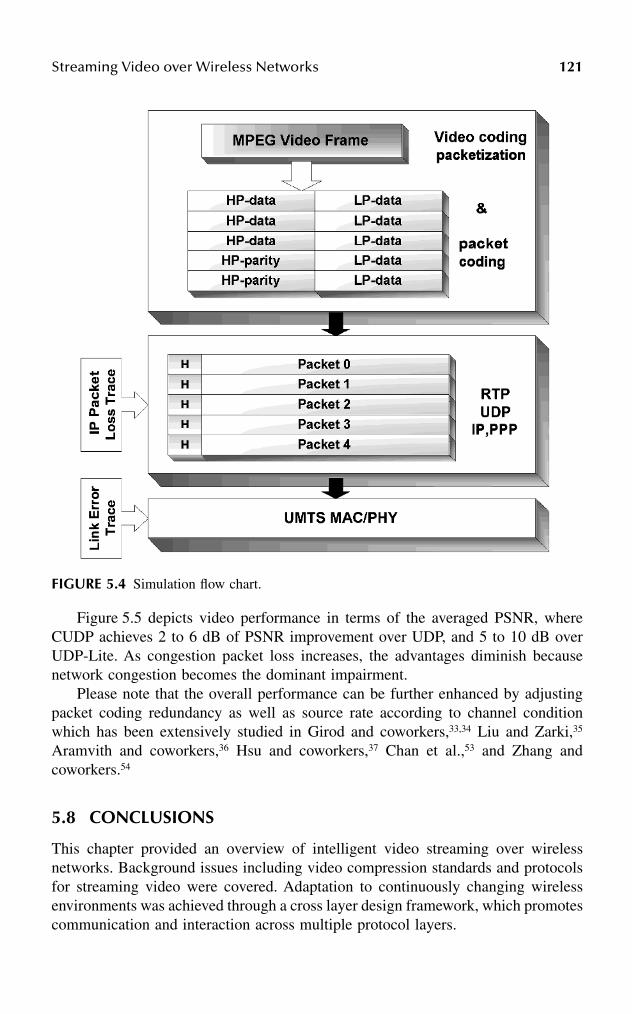
Streaming Video over Wireless Networks 121
Figure 5.5 depicts video performance in terms of the averaged PSNR, whereCUDP achieves 2 to 6 dB of PSNR improvement over UDP, and 5 to 10 dB overUDP-Lite. As congestion packet loss increases, the advantages diminish becausenetwork congestion becomes the dominant impairment.
Please note that the overall performance can be further enhanced by adjustingpacket coding redundancy as well as source rate according to channel conditionwhich has been extensively studied in Girod and coworkers,33,34 Liu and Zarki,35
Aramvith and coworkers,36 Hsu and coworkers,37 Chan et al.,53 and Zhang andcoworkers.54
5.8 CONCLUSIONS
This chapter provided an overview of intelligent video streaming over wirelessnetworks. Background issues including video compression standards and protocolsfor streaming video were covered. Adaptation to continuously changing wirelessenvironments was achieved through a cross layer design framework, which promotescommunication and interaction across multiple protocol layers.
FIGURE 5.4 Simulation flow chart.
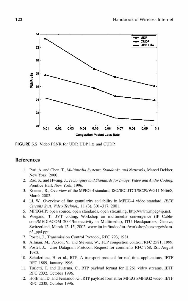
122 Handbook of Wireless Internet
References
1. Puri, A. and Chen, T., Multimedia Systems, Standards, and Networks, Marcel Dekker,New York, 2000.
2. Rao, K. and Hwang, J., Techniques and Standards for Image, Video and Audio Coding,Prentice Hall, New York, 1996.
3. Koenen, R., Overview of the MPEG-4 standard, ISO/IEC JTC1/SC29/WG11 N4668,March 2002.
4. Li, W., Overview of fine granularity scalability in MPEG-4 video standard, IEEECircuits Syst. Video Technol., 11 (3), 301–317, 2001.
5. MPEG4IP: open source, open standards, open streaming, http://www.mpeg4ip.net.6. Wiegand, T., JVT coding, Workshop on multimedia convergence (IP Cable-
com/MEDIACOM 2004/Interactivity in Multimedia), ITU Headquarters, Geneva,Switzerland, March 12–15, 2002, www.itu.int/itudoc/itu-t/workshop/converge/s6am-p3_pp4.ppt.
7. Postel, J., Transmission Control Protocol, RFC 793, 1981.8. Allman, M., Paxson, V., and Stevens, W., TCP congestion control, RFC 2581, 1999.9. Postel, J., User Datagram Protocol, Request for comments RFC 768, ISI, August
1980.10. Schulzrinne, H. et al., RTP: A transport protocol for real-time applications, IETF
RFC 1889, January 1996.11. Turletti, T. and Huitema, C., RTP payload format for H.261 video streams, IETF
RFC 2032, October 1996.12. Hoffman, D. and Fernando, G., RTP payload format for MPEG1/MPEG2 video, IETF
RFC 2038, October 1996.
FIGURE 5.5 Video PSNR for UDP, UDP lite and CUDP.

Streaming Video over Wireless Networks 123
13. Zhu, C., RTP payload format for H.263 video streams, IETF RFC 2190, September1997.
14. Boyce, J., Packet loss resilient transmission of MPEG video over the Internet, SignalProcessing: Image Communication, pp. 7–24, September 1999.
15. Wang, Y. and Zhu, Q.F., Error control and concealment for video communication: areview, Proc. IEEE, 86 (5), 974–997, 1998.
16. Wu, D. et al., Streaming video over the Internet: approaches and directions, IEEETrans. Circuits Syst. Video Technol., 11 (3), 282–300, 2001.
17. Liao J. and Villasenor, J., Adaptive intra block update for robust transmission ofH.263, IEEE Trans. Circuits Syst. Video Technol., 10 (1), 30, 2002.
18. Fukunaga, S., Nakai, T., and Inoue, H., Error resilient video coding by dynamicreplacing of reference pictures, Proc. IEEE Global Telecommun. Config. (GLOBE-COM), Vol. 3, London, pp. 1503–1508.
19. Aravind, R., Civanlar, M., and Riebman, A., Packet loss resilience of MPEG-2scalable video coding algorithms, IEEE Trans. Circuits Syst. Video Technol., 6 (5),426–435, 1996.
20. Jacobson, V., McCanne, S., and Vetterli, M., Receiver-driven layered multicast, Proc.ACM SIGCOMM ’96, Stanford, CA, August 1996, pp. 117–130.
21. Rosenberg, J. and Schulzrinne, H., “An RTP payload format for generic forward errorcorrection,” RFC2733, http://www.faqs.org/rfcs/rfc2733.html.
22. Rizzo, L., Effective erasure codes for reliable computer communication protocols,Comput. Commun. Rev., 27 (2), 24–36, 1997.
23. Rhee, I. et al., Layered multicast recovery, Technical report TR-99–09, NCSU, Com-puter Science Dept., February 1999.
24. Albanese, A. et al., Priority encoding transmission, Proc. 35th Ann. IEEE Symp.Foundations of Computer Science, November 1994, pp. 604–612.
25. 3rd Generation Partnership Project, Technical specification group radio access net-work, physical layer aspects of UTRA high speed downlink packet access (Release2000), 3G Technical report (TR) 25.848.
26. Wang, Y. and Lin, S., A modified selective-repeat type-II hybrid ARQ system and itsperformance analysis, IEEE Trans. Commun., COM31, 593–608, 1983.
27. Advice to link designers on link Automatic Repeat reQuest (ARQ), Internet Draft,March 2002, draft-ietf-pilc-link-arq-issues-04.txt.
28. Jalali, A., Padovani, R., and Pankaj, R., Data throughput of CDMA-HDR: a highefficiency high data rate personal communication wireless system, Proc. IEEE Vehic-ular Technology Conference, Tokyo, Japan, May 2000.
29. Andrews, M. et al., Providing quality of service over a shared wireless link, IEEECommunications Magazine, 39 (2), 150–154, 2001.
30. Tse, D., Forward link multiuser diversity through rate adaptation and scheduling, BellLabs presentation, New Jersey, 1999.
31. A multilayered approach to mobile networking, Stanford University Project Report.32. Tong, L., Zhao, Q., and Mergen, G., Multipacket reception in random access wireless
networks: from signal processing to optimal medium access control, IEEE Commu-nications Magazine, 39 (11), 108–112, 2001.
33. Girod, B. and Färber, N., Wireless Video, in Compressed Video Over Network,Reibman, A.and Sun, M.T., Eds., Marcel Dekker, New York, 2000.
34. Girod, B. et al., Advances in channel adaptive video streaming, Proc. IEEE Interna-tional Conference on Image Processing (ICIP 2002), Rochester, September 2002.
35. Liu H. and Zarki, M.E., Adaptive source rate control for real-time wireless videotransmission, Mobile Networks Appl., 3, 49–60, 1998.
124 Handbook of Wireless Internet
36. Aramvith, S., Pao, I.-M., and Sun, M.-T., A rate-control scheme for video transportover wireless channels, IEEE Trans. Circuits Syst. Video Technol., 11, 569–580, 2001.
37. Hsu, C.Y., Ortega, A., and Khansari, M., Rate control for robust video transmissionover burst error wireless channels, IEEE J. Selected Areas Commun., 17 (5), 756–773,1999.
38. Cen, S., Cosman, P.C., and Voelker, G.M., End-to-end differentiation of congestionand wireless losses, SPIE Multimedia Computing and Networking, (MMCN2002),San Jose, CA, January 18–25, 2002.
39. Samaraweera, N.K.G., Noncongestion packet loss detection for TCP error recoveryusing wireless links, IEEE Proc. Commun., 146 (4), 1999.
40. Biaz, S. and Vaidya, N., Discriminating congestion losses from wireless losses usinginterarrival timers at the receiver, Technical report 98–014, Computer Science Depart-ment, Texas A&M University, June 1998.
41. Bikram, S. et al., Improving performance of TCP over wireless networks, Technicalreport 96–014, Texas A&M University, 1996.
42. Balakrishnan, H. et al., A comparison of mechanisms for improving TCP performanceover wireless links, IEEE/ACM Trans. Networking, 5(6), 756–759, 1997.
43. Goff, T. et al., Freeze-TCP: A true end-to-end TCP enhancement mechanism formobile environments, in Proc. of IEEE Infocom 2000.
44. Larzon, L., Degermark, M., and Pink, S., Efficient Use of Wireless Bandwidth forMultimedia Applications, MoMuc ’99, San Diego, November 1999, pp. 187–193.
45. Zheng, H. and Boyce, J., An improved UDP protocol for video transmission overInternet-to-wireless networks, IEEE Trans. Multimedia, 3 (3), 356–364, 2001.
46. Chockalingam, A. and Bao, G., Performance of TCP/RLP protocol stack on correlatedfading DS-CDMA wireless links, IEEE Trans. Vehicular Technology, 49, 28–33, 2000.
47. de los Reyes, G., Reibman, A.R., and Chang, S.F., Error resilient transcoding forvideo over wireless channels, IEEE J. Selected Areas Commun., 18 (6), 1063–1074,2000.
48. Vass, J. et al., Mobile video communications in wireless environments, IEEE Inter-national Workshop on Multimedia Signal Processing, Copenhagen, Denmark, Sept.13–15, 1999.
49. Pei, Y. and Modestino, J.W., Robust packet video transmission over heterogenouswired-to-wireless IP networks using ALF together with edge proxies, Proc. EuropeanWireless 2002, Feb. 25–28, Florence, Italy.
50. Fitzek, F.H.P, and Reisslein, M., A prefetching protocol for continuous media stream-ing in wireless environments, IEEE J. Selected Areas Commun., 19 (10), 2015–2028,2001.
51. Yu, F. et al., QoS adaptive proxy caching for multimedia streaming over the Internet,1st IEEE Pacific Rim Conference on Multimedia (IEEE PCM 2000), December 2000,Australia.
52. Foschini, G.J., Layered space-time architecture for wireless communication in afading environment when using multiple antennas, Bell Labs Tech. J., 1 (2), 41–59,1996.
53. Chan, C.W. et al., Eds., Special issue on error resilient image and video transmissions,IEEE J. Selected Areas Commun., 18 (6), 2001.
54. Zhang, Q., Zhu, W., and Zhang, Y.Q., Network-adaptive rate control and unequal lossprotection with TCP-friendly protocol for scalable video over Internet, J. VLSI SignalProcess.: Syst. Signal, Image Video Technol., 2001.
55. Sun, M. and Reibman, A., Compressed Video over Networks, Marcel Dekker, NewYork, September 2000.

Streaming Video over Wireless Networks 125
56. Wiegand, T., ISO/IEC 14496–10: 2002, Joint Committee Draft, May 2002.57. Larzon, L., Degermark, M., and Pink, S., UDP lite for real time multimedia appli-
cations, Proc. QoS Mini-Conference, IEEE International Conference of Communi-cations (ICC ’99), Vancouver, Canada, June 1999.
58. Budge, D. et al., Media-independent error correction using RTP, Internet EngineeringTask Force, Internet Draft, May 1997.
59. Wenger S. and Côté, G., Using RFC2429 and H.263+ at low to medium bit-rates forlow-latency applications, Packet Video ’99, New York, April 1999.
60. Gallant, M. and Kossentini, F., Robust and efficient layered H.263 Internet videobased on rate-distortion optimized joint source/channel coding, Packet Video ’00,Italy, 2000.
61. Wenger, S. and Côté, G., Test model extension justification for Internet/H.323 videotransmission, Document Q15-G-17, ITU Q15, Video Coding Experts Group, February1999.

This page intentionally left blank
1270-8493-1502-6/03/$0.00+$1.50© 2003 by CRC Press LLC
6 Clustering and Roaming Techniques for IEEE 802.11 Wireless LANs
Ahmed K. Elhakeem
CONTENTS
Abstract ..................................................................................................................1276.1 Introduction ..................................................................................................1276.2 Wireless LANs Clustering ...........................................................................128
6.2.1 IAPP .................................................................................................1306.3 Location-Based Clustering...........................................................................1306.4 Graph-Based Clustering...............................................................................1366.5 Quasihierarchical Routing............................................................................1426.6 Strict Hierarchical Routing ..........................................................................1466.7 Conclusion....................................................................................................147References..............................................................................................................147
ABSTRACT
Clustering refers to the set of rules and algorithms that different nodes follow togroup themselves into interconnected communications networks. Tactical, emer-gency, and rural communications have traditionally applied various clustering algo-rithms in fields where prior communications infrastructure does not exist. Recently,clustering gained wider attention due to the advent and wide deployment of IEEE802.11 wireless LANs, Bluetooth, and other noncellular wireless platforms. Thischapter surveys the various algorithms used in the IEEE 802.11 Standard and adhoc wireless LANs for clustering, and describes also the close interaction betweenclustering and routing.
6.1 INTRODUCTION
Nodes should be grouped into clusters in a way that maintains maximum connec-tivity. Maximizing the stability and links connectivity as well as traffic intensitieswithin each cluster leads to efficient clustering, routing, and overall communication

128 Handbook of Wireless Internet
efficiency. Minimizing the amount of clustering and routing information and num-bers of intracluster links contributes also to overall communication efficiency.
Clustering helps also to manage the allocation of wireless channel resources,e.g., in the IEEE 802.11 Standard, the access point coordinates the transmissiontimes of various nodes. Clustering leads also to formation of backbones and reductionof the state of the network. As an example, it is easier for cluster heads to exchangeinformation in regard to 50 nodes in each cluster rather than allowing the 10,000nodes of the whole wireless network to exchange information about the other 9,999nodes. Clustering and subsequent formulation of backbone links of high quality andlow delay may lead to overall end-to-end transmission delay in multihop networks.
Because of node movement, the establishment and maintaining of clusters in adhoc wireless networks where there is no access point becomes a harder task comparedto fixed nodes. More-frequent exchange of clustering information and routing tablesmay lead to less time available for information transmission and hence less com-munication efficiency. Added to this inefficiency is the nature of the wireless channel,which faces additive Gaussian noise, path loss due to shadowing and various obsta-cles, fading, sensitivity to distance, nodes transmission powers, etc.
In this chapter, some of the basic clustering techniques for wireless LANs and thevarious trade-offs involved are presented. While trying to explain the clustering/routinginterrelationship, more details on the wireless LAN routing techniques may be foundin Elhakeem1 complementing the clustering techniques discussed herein. Other issuessuch as security and authentication are related but not investigated here.
6.2 WIRELESS LANS CLUSTERING
The IEEE 802.11 Standard2 used in numerous wireless LAN products has fewroaming and clustering facilities. This standard maintains two basic modes of oper-ation: (1) access point (AP) and (2) ad hoc. In the AP mode, users (mobile orstationary) group around a typically stationary station, which then resembles thebase station of the cellular radio system. The AP may be connected to other APs byradio or other ground-based networks, but 802.11 does not address such intercon-nection. The access point is assigned a basic service set (BSS) identification (BSSID,or network ID), which distinguishes between neighboring APs, as shown inFigure 6.1. The amalgamation of BSS will constitute the extended service set. Amobile station roaming from one BSS to another will have to know the IDs of theBSS it is passing through. Most APs will come with a default BSSID; however, anoperator can easily change this, therefore no two APs will share the same BSSID.
When a mobile station is powered on, it tries first to see the availability of otherAPs to join. The AP is responsible for coordinating the sharing of the radio channelcapacity among the nodes, authenticating the nodes, association with the nodes, andrelaying various management and supervisory information to the nodes such asallowed transmission powers, etc. The AP determines when to switch the MACaccess mode from contention mode (distribution function3) to the point coordinationfunction where polling is used.
The mobile station goes through either active or passive scanning modes tocheck for such availability. In the passive scanning mode, it will listen to the pilot
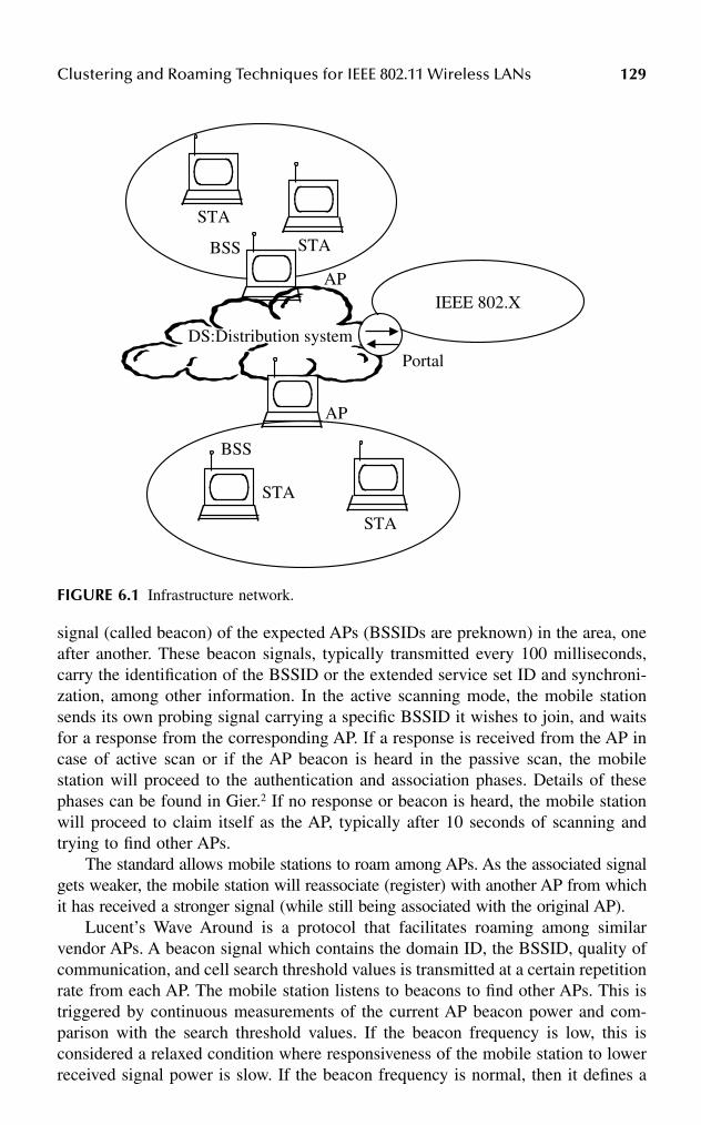
Clustering and Roaming Techniques for IEEE 802.11 Wireless LANs 129
signal (called beacon) of the expected APs (BSSIDs are preknown) in the area, oneafter another. These beacon signals, typically transmitted every 100 milliseconds,carry the identification of the BSSID or the extended service set ID and synchroni-zation, among other information. In the active scanning mode, the mobile stationsends its own probing signal carrying a specific BSSID it wishes to join, and waitsfor a response from the corresponding AP. If a response is received from the AP incase of active scan or if the AP beacon is heard in the passive scan, the mobilestation will proceed to the authentication and association phases. Details of thesephases can be found in Gier.2 If no response or beacon is heard, the mobile stationwill proceed to claim itself as the AP, typically after 10 seconds of scanning andtrying to find other APs.
The standard allows mobile stations to roam among APs. As the associated signalgets weaker, the mobile station will reassociate (register) with another AP from whichit has received a stronger signal (while still being associated with the original AP).
Lucent’s Wave Around is a protocol that facilitates roaming among similarvendor APs. A beacon signal which contains the domain ID, the BSSID, quality ofcommunication, and cell search threshold values is transmitted at a certain repetitionrate from each AP. The mobile station listens to beacons to find other APs. This istriggered by continuous measurements of the current AP beacon power and com-parison with the search threshold values. If the beacon frequency is low, this isconsidered a relaxed condition where responsiveness of the mobile station to lowerreceived signal power is slow. If the beacon frequency is normal, then it defines a
FIGURE 6.1 Infrastructure network.
IEEE 802.X
STA
STA
BSS
Portal
AP
DS:Distribution system
AP
STA
STA
BSS

130 Handbook of Wireless Internet
normal response. If the beacon frequency is fast, responsiveness is higher, meaningfaster reaction of the mobile station to declining received signal power.
The cell search thresholds contained in the AP beacons determine the times atwhich a mobile station will switch to another AP or remain in cell search mode,depending on the quality of service (QoS) of the received signal at the mobile station.When this QoS is less than or equal to the “regular cell search” threshold, the mobilestation will start to look for another AP, but it will switch to the new AP if the QoSof that AP is higher than the “stop cell search” threshold. “Fast cell search” thresholdcorresponds to the level of QoS at which the mobile station should immediatelyswitch to any AP that yields better quality of service.
“Stop cell search” corresponds to the acceptable QoS range, meaning the mobilestation will stop looking for a new AP. However, in this case three sensitivity levelsarise: (1) “low” defines the condition where the mobile station should stay associatedwith the AP as long as possible, e.g., due to unavailability of other APs; (2) “normal”means that the mobile station will stay an average amount of time; and (3) “high”means that the mobile station will try to switch to another AP as soon as possible.
6.2.1 IAPP
The previous mechanisms of the standard work well for overlapping or nonoverlap-ping BSS as long as all APs are made by the same manufacturer. However, Lucentand other companies came up with the IAPP (Interaccess Point Protocol) to facilitateroaming between different vendor APs. IAPP uses UDP or IP on top of the 802.11Protocol, and consists of the “announce” and “hand-over” protocols. The “announce”protocol informs APs about new APs, and all APs about networkwide configuration.The “hand-over” protocol informs one AP that one of its mobile stations has movedto another AP. In this case, the bending files will be transmitted to the new AP fromthe old AP. Filter tables (bridging functionality) are provided also by the hand-overprotocol to enable the extended LAN configuration (similar to terrestrial LANbridging).
6.3 LOCATION-BASED CLUSTERING
The aforementioned clustering techniques apply to infrastructure networks wherean AP is typically present. If all nodes (mobile stations) assume the same function-ality and have similar processing capabilities, then the need arises for ad hocclustering and routing techniques to enable roaming and forwarding of informationand control packets to the appropriate destination. Although all nodes are similar inad hoc networks, most routing and clustering protocols would assign certain func-tions to some nodes, i.e., cluster heads and gateways. Accurate position informationcould be available to the nodes as, for example, when GPS interfaces are availablewithin the nodes, or when certain nodes transmit position aiding signals (pilots orbeacons) so other nodes will know their location. Such position information couldlead to facilitating the clustering and routing problems in ad hoc networks,4 wherea zone-based, two-level link state (called zone-based hierarchical LSR routing,ZHLS) is used for both clustering and routing.
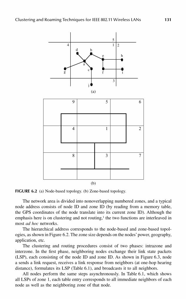
Clustering and Roaming Techniques for IEEE 802.11 Wireless LANs 131
The network area is divided into nonoverlapping numbered zones, and a typicalnode address consists of node ID and zone ID (by reading from a memory table,the GPS coordinates of the node translate into its current zone ID). Although theemphasis here is on clustering and not routing,1 the two functions are interleaved inmost ad hoc networks.
The hierarchical address corresponds to the node-based and zone-based topol-ogies, as shown in Figure 6.2. The zone size depends on the nodes’ power, geography,application, etc.
The clustering and routing procedures consist of two phases: intrazone andinterzone. In the first phase, neighboring nodes exchange their link state packets(LSP), each consisting of the node ID and zone ID. As shown in Figure 6.3, nodea sends a link request, receives a link response from neighbors (at one-hop hearingdistance), formulates its LSP (Table 6.1), and broadcasts it to all neighbors.
All nodes perform the same steps asynchronously. In Table 6.1, which showsall LSPs of zone 1, each table entry corresponds to all immediate neighbors of eachnode as well as the neighboring zone of that node.
(a)
(b)
FIGURE 6.2 (a) Node-based topology. (b) Zone-based topology.
451 2
3
a
g
d b
c
j
h
i
e
f

132 Handbook of Wireless Internet
As an example, node a has b, c, and d as immediate neighbors and can reachthe neighboring zone 4 through node g, while node d has only a as a neighbor andcannot reach any neighboring zones. From Table 6.1, node a derives Table 6.2, whichshows the intrazone (same zone) routing table of node a. As an example, for nodea to reach node c, it will go directly to node c (same zone). For node a to contactany node in zone 2, it will go through node b [as in Figure 6.3d, the border node hin zone 2 hears node e, which in turn hears node b].
At the end of the first phase (intrazone) and following the exchange of all LSPsby all nodes of each zone, each node would then have the same table of zone LSPs.
In the second phase (interzone), the gateway nodes [those hearing messagesfrom different zones such as nodes e, a, f, and c of Figure 6.3d] will propagate thezone LSPs through the network, as illustrated in Figure 6.4. This will enable eachnode to store a zone LSP similar to the one in Table 6.3. Taking the fourth entry ofthis table means the neighboring zones of 4 are 1, 9. Figure 6.4b shows the spanningtree or virtual links between the zones in this network.
Because each node receives all zone LSPs (Table 6.3), shortest-path algorithmsare used at each node to find the best route to each zone, as shown in Table 6.4.
Routing of data messages is now proactive if the destination lies within the samezone as the source, according to Table 6.2, and reactive if the destination is not withinthe same zone. In the later case, a route search is conducted and the facilities of thezone LSPs of Table 6.3 and the various nodes interzone routing (Table 6.4) are used tofind an end-to-end route. See Elhakeem1 and Jao-Ng and Lu4 for further routing details.
Needless to say, exchange of node LSPs and zone LSPs among nodes will causesome flooding, which can be minimized if repeated LSP messages are not transmittedagain by any node. To have some idea about savings in the cost of control messages,one finds that in a flat topology, the number of control messages exchanged perclustering cycle is defined as:
(6.1)
where U is the total number of nodes, because each node transmits one clusteringmessage to every other node. A flat topology assumes that all nodes are consideredto be in one large zone.
TABLE 6.1Node LSPs in Zone I
Source Node LSP
a b, c, d, 4b a, ec a, 3d ae b, f, m, 2f e, 2
C Uf = 2
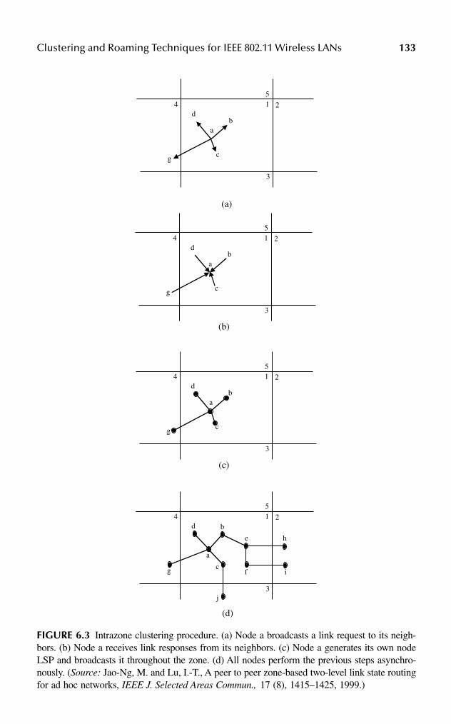
Clustering and Roaming Techniques for IEEE 802.11 Wireless LANs 133
FIGURE 6.3 Intrazone clustering procedure. (a) Node a broadcasts a link request to its neigh-bors. (b) Node a receives link responses from its neighbors. (c) Node a generates its own nodeLSP and broadcasts it throughout the zone. (d) All nodes perform the previous steps asynchro-nously. (Source: Jao-Ng, M. and Lu, I.-T., A peer to peer zone-based two-level link state routingfor ad hoc networks, IEEE J. Selected Areas Commun., 17 (8), 1415–1425, 1999.)
(a)
(b)
(c)
(d)
451 2
3
a
g
d b
c
j
h
i
e
f
451 2
3
a
g
db
c
451 2
3
a
g
db
c
451 2
3
a
g
db
c

134 Handbook of Wireless Internet
TABLE 6.2Intrazone Routing Table of Node a
Destination Next Node
b bc cd de bf b2 b3 c4 g
TABLE 6.3Zone LSPs
Source Node LSP
1 2, 3, 42 1, 63 1, 7, 84 1, 95 6, 96 2, 57 38 39 4, 5
TABLE 6.4Interzone Routing Table of Node a
Destination Zone Next Zone Next Node
2 2 b3 3 c4 4 g5 4 g6 2 b7 3 c8 3 c9 4 g
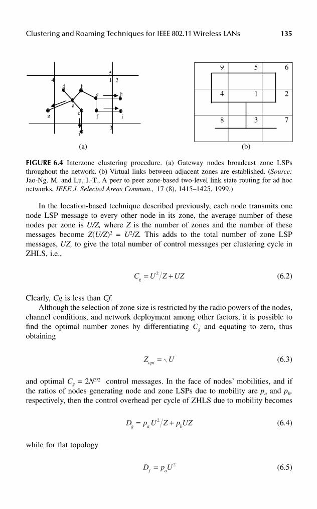
Clustering and Roaming Techniques for IEEE 802.11 Wireless LANs 135
In the location-based technique described previously, each node transmits onenode LSP message to every other node in its zone, the average number of thesenodes per zone is U/Z, where Z is the number of zones and the number of thesemessages become Z(U/Z)2 = U2/Z. This adds to the total number of zone LSPmessages, UZ, to give the total number of control messages per clustering cycle inZHLS, i.e.,
(6.2)
Clearly, Cg is less than Cf.Although the selection of zone size is restricted by the radio powers of the nodes,
channel conditions, and network deployment among other factors, it is possible tofind the optimal number zones by differentiating Cg and equating to zero, thusobtaining
(6.3)
and optimal Cg = 2N3/2 control messages. In the face of nodes’ mobilities, and ifthe ratios of nodes generating node and zone LSPs due to mobility are pa and pb,respectively, then the control overhead per cycle of ZHLS due to mobility becomes
(6.4)
while for flat topology
(6.5)
FIGURE 6.4 Interzone clustering procedure. (a) Gateway nodes broadcast zone LSPsthroughout the network. (b) Virtual links between adjacent zones are established. (Source:Jao-Ng, M. and Lu, I.-T., A peer to peer zone-based two-level link state routing for ad hocnetworks, IEEE J. Selected Areas Commun., 17 (8), 1415–1425, 1999.)
9 5 6
4 1 2
8 3 7
(a) (b)
451 2
3
a
g
d b
c
j
h
i
e
f
C Z UZg = +U2
Z Uopt =
D p U Z p UZg a b= +2
D p Uf a= 2

136 Handbook of Wireless Internet
Because zone topology changes are less frequent than node-level changes, pa isgreater than pb, and hence
(6.6)
Jao-Ng and Lu4 present simulation results that display the superiority of zoneclustering using GPS; also, Chen and coworkers5 report a similar location-basedtechnique, called geographical-based routing and clustering technique, whichemphasizes radio range considerations in the process of zone formations. Theseclustering techniques are typically implemented within the application layers abovethe wireless IEEE 802.11 MAC layer. We notice that only gateways (not clusterheads or APs) are defined here, and that both gateways and ordinary nodes cooperateto route nodes packets from source to destination based on the routing tables men-tioned previously.
6.4 GRAPH-BASED CLUSTERING
The coverage area of the network is to be divided into nonoverlapping clusters bymeans of the clustering algorithm. For clustering purposes, each node is assigned aunique ID number, and maintains a set of its single-hop neighbors. In one versionof this clustering technique, called minimum ID, the node with the minimum IDamong the neighbors is selected as the cluster head. The cluster head would havefunctionality similar to the AP mentioned previously.
A node turning on would listen to the beacons of the cluster head and configu-ration messages of the various nodes and join the cluster head with the minimum ID.
Each node transmits a clustering configuration message composed of the nodeID and the thought-of cluster head ID to its neighbors. All neighboring nodes hearthe message, adjust their conclusion in regard to cluster head election accordingly,but do not repeat this control message, but modify, and transmit a new configurationmessage. Each node in a cluster is at one hop away from the cluster head and, atmost, two hops away from other nodes. A node, which is heard in two neighboringclusters, will belong to only one cluster.
A manager node also may exist in some systems,5 where ad hoc networkmanagement is required, but this requirement is not a must for ID-based clustering,as shown in Figure 6.5.
It is possible also that one node (e.g., node 5 in Figure 6.5) can hear nodes fromtwo different clusters, but will join only one. Clustering will take place accordingto cycles (timespan where topology is preserved, and through which a node keepsits thought-of cluster head ID). This cycle may vary from node to node. As anexample, had node 1 been idle, node 2 would have been the cluster head of C1. Butas soon as node 1 starts to transmit the clustering configuration messages, node 2and other nodes in C1 will change their thought-of cluster head in the next clusteringcycle.
If C1 and C2 clusters are formed in the same clustering cycle, then node 4 thinksof node 2 as the thought-of cluster head and thinks to join C1. However, after hearing
D p U Z p UZ Dg a a f≤ + ≤2

Clustering and Roaming Techniques for IEEE 802.11 Wireless LANs 137
from node 2 that node 1 is the thought-of cluster head, and because node 4 cannothear node 1, node 4 will change its cluster configuration message so it becomes acluster head of a new C2. Node 4 will not join C3 for a similar reason, i.e., it hearsfrom node 5 that node 3 is the thought-of cluster head, but because it cannot hearnode 3 directly, it will not accept node 3 as a cluster head and will start to form itsown cluster.
Figure 6.5 assumes that clusters C2 and C3 were formed in the same clusteringcycle; however, if C2 started to form before C3, then node 5 would have joined C2instead (because nodes 3, 7, and 9 were idle, for example). Following the clusterformation and election of the cluster head, each node will keep the following databasein regard to clustering:
• Cluster list (all nodes in the cluster), neighbor list (all nodes one hop away)• A ping counter, which counts the time since the node last heard from the
cluster head
As mentioned previously, when the cluster is formed each node is at one hopfrom the cluster head and two hops at most from other nodes in the cluster. As someof the nodes and cluster heads move in and out of the cluster, the cluster formationmay be affected, as shown in Figure 6.6.
A good clustering algorithm should yield cluster node selection, cluster headselection, and possibly gateway nodes that do not change much in the face of nodesmobility. As shown in Figure 6.6a, in C1 nodes 2, 6, and 8 moved but remain in C1;cluster head node 1 moved, is now at two hops from nodes 6 and 12, but still remainsin C1. In C2, cluster head node 4 moved, is now at two hops from nodes 5 and 10,but still remains in C2. In C3, nodes 3, 5, and 7 moved and the result is similar. Theconclusion from Figure 6.6a is that there is no need for reconfiguration of theclusters. However, in Figure 6.6b, node 4 (the cluster head of C2) moved too farfrom C2, and accordingly joins C1 (through node 2). On the other hand, nodes 10
FIGURE 6.5 Clusters formed using graphical clustering.
C118
2
6
12
C2C3
M
4
10
11
3
5
9
7Manager station
Cluster Head

138 Handbook of Wireless Internet
FIGURE 6.6 (a) Effect of node mobility on clusters. (Source: Chen, W., Jain, N., and Suresh,S., ANMP: Ad Hoc Network Management Protocol, IEEE J. Selected Areas Commun., 17(8), 1506–1531, 1999.) (b) Effect of node mobility on clusters. (Source: Chen, W., Jain, N.,and Suresh, S., ANMP: Ad Hoc Network Management Protocol, IEEE J. Selected AreasCommun., 17 (8), 1506–1531, 1999.)
C118
2
6
12
C2C3
M
4
10
11
3
5
9
7Manager station
Cluster Head
Moved nodes
Moved Cluster heads
C118
2
6
12
C4 C3
M
4
10
11
3
5
9
7Manager station
Cluster Head
Moved nodes
Moved Cluster heads
New Cluster

Clustering and Roaming Techniques for IEEE 802.11 Wireless LANs 139
and 11 find out that the cluster head has moved, and so form a new cluster C4, withnode 10 becoming the cluster head. Because of node mobility as explained previ-ously, some variations of the clustering rules5 allow certain adaptability to mobility.One of those rules is the following:
If a node detects that it has lost its links to the nodes in its cluster, it either joins anothercluster or forms another cluster by itself.
In this case, the node may join a cluster head, which is two hops away. Forfurther adaptability to mobility, at regular intervals of time each node detects andreports to the cluster head one or more of the following events:
• One neighbor in the same cluster moved out of the cluster.• One node moved into the cluster, and wishes to join the cluster.• One node became a neighbor and is a member of the cluster.• The node was at one hop from the cluster head, but now is at 2 hops or
more.• The node was at two or more hops from the cluster head, but now is at
one hop from the cluster head.
The cluster head will receive all those periodical reports from the nodes in itscluster, process them, and then broadcast a fresh list of cluster nodes to all nodesof the cluster.
The crucial function of the cluster head now becomes evident: if the cluster headmoves, this leads to confusion among the member nodes. To protect against suchan occurrence, a ping counter is incremented at each node at a regular interval oftime. If the value of this counter exceeds a certain threshold, the cluster headbroadcasts a ping message to all cluster nodes. On the other hand, if these nodes donot hear the ping message after their counters exceed the threshold, the nodes inferthat the cluster head has been turned off or has moved out, in which case the votingprocess for establishing a new cluster head will commence again.
A number-crunching simulation involving 30 nodes5 moving in a 1500 × 1500unit area was conducted to test the resilience of the graph-based technique tomobility. The speed of each node varied in the range of 1 to 50 units per second,the transmission range was 450 units, and the nodes moved in random direction(uniformly distributed from 0 to 360 degrees). Figure 6.7 shows the number ofmessages exchanged to maintain the cluster in the face of mobility for different pingintervals, where no ping means infinite time steps, and 1 means one ping messageevery time interval. This number increases linearly with nodes’ speeds.
Figure 6.8 shows the percentage of nodes unmanaged by cluster heads.Figure 6.8a outperforms those of Figure 6.8b due to the utilization of the availableinformation from the 802.11 MAC layer.
A similar graph-based clustering appears in Lin and Gerla,6 where it is proved thatthe ID-based algorithm guarantees that each node joins only one cluster. Figures 6.9and 6.10 show some of the simulation results from Lin and Gerla.6 Figure 6.9 showsthe average node connectivity of the algorithm versus the transmission range for
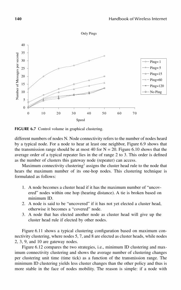
140 Handbook of Wireless Internet
different numbers of nodes N. Node connectivity refers to the number of nodes heardby a typical node. For a node to hear at least one neighbor, Figure 6.9 shows thatthe transmission range should be at most 40 for N = 20. Figure 6.10 shows that theaverage order of a typical repeater lies in the of range 2 to 3. This order is definedas the number of clusters this gateway node (repeater) can access.
Maximum connectivity clustering7 assigns the cluster head rule to the node thathears the maximum number of its one-hop nodes. This clustering technique isformulated as follows:
1. A node becomes a cluster head if it has the maximum number of “uncov-ered” nodes within one hop (hearing distance). A tie is broken based onminimum ID.
2. A node is said to be “uncovered” if it has not yet elected a cluster head,otherwise it becomes a “covered” node.
3. A node that has elected another node as cluster head will give up thecluster head rule if elected by other nodes.
Figure 6.11 shows a typical clustering configuration based on maximum con-nectivity clustering, where nodes 5, 7, and 8 are elected as cluster heads, while nodes2, 3, 9, and 10 are gateway nodes.
Figure 6.12 compares the two strategies, i.e., minimum ID clustering and max-imum connectivity clustering and shows the average number of clustering changesper clustering unit time (time tick) as a function of the transmission range. Theminimum ID clustering yields less cluster changes than the other policy and thus ismore stable in the face of nodes mobility. The reason is simple: if a node with
FIGURE 6.7 Control volume in graphical clustering.
Only Pings
0
5
10
15
20
25
30
35
40
0 10 20 30 40 50 60 70
Speed
Num
ber
of M
essa
ges
per
seco
nd
Ping= 1
Ping= 5
Ping=15
Ping=60
Ping=120
No Ping

Clustering and Roaming Techniques for IEEE 802.11 Wireless LANs 141
FIGURE 6.8 Percentage of nodes unmanaged by cluster heads. (Source: Chen, W., Jain, N.,and Suresh, S., ANMP: Ad Hoc Network Management Protocol, IEEE J. Selected AreasCommun., 17 (8), 1506–1531, 1999.)
Only Pings
0
10
20
30
40
50
60
70
0 10 20 30 40 50 60 70
Speed
Per
cent
age
of u
nman
aged
nod
es
Ping= 1
Ping= 5
Ping=15
Ping=60
Ping=120
No Ping
(a)
Ping + MAC layer information
0
10
20
30
40
50
60
70
0 10 20 30 40 50 60 70
Speed
Per
cent
age
of u
nman
aged
nod
es
Ping= 1
Ping= 5
Ping=15
Ping=60
Ping=120
No Ping
(b)

142 Handbook of Wireless Internet
highest connectivity moves away, many links are broken; with minimum ID clus-tering fewer links are broken, and hence the cluster may remain intact.
6.5 QUASIHIERARCHICAL ROUTING
Quasihierarchical routing is mainly intended to provide routing efficiency in ad hocand other networks. As shown in Figure 6.13, N nodes are arranged into m levelhierarchy of clusters. Clusters at a certain level i (0 ≤ i < m) are typically assumedto be disjointed. Each node is assigned an address of the form bcd, which is thesuccession of the ID of each cluster starting with b, i.e., the ID of (m – 1)th cluster,and ending with the zero-th level cluster ID, which is the node ID within its firstcluster, and with the ID of the parent cluster.
A cluster head8 generates and distributes routing information for the cluster. Thecluster head summarizes the cluster condition and relays this to neighboring clusters.The mobility or downtimes of this cluster head may disrupt both routing and clus-tering functionality unless hot standbys are provided. In quasihierarchical routing,
FIGURE 6.9 Connectivity property. (Source: Lin, C.R. and Gerla, M., Adaptive clusteringfor mobile wireless networks, IEEE J. Selected Areas Commun., 15 (7), 1265–1275, 1997.)
FIGURE 6.10 Average order of repeaters.
00.10.20.30.40.50.60.70.80.9
1
10 20 30 40 50 60 70 80 90 100
Transmission range
aver
age
conn
ectiv
ity N=20
N=30
N=40
22.12.22.32.42.52.62.72.82.9
10 20 30 40 50 60 70 80 90 100
Transmission range
aver
age
orde
r of
re
peat
ers N=20
N=30
N=40

Clustering and Roaming Techniques for IEEE 802.11 Wireless LANs 143
FIGURE 6.11 Example of cluster formation (highest connectivity). (Source: Gerla, M. andTsai, J.T.C., Multiuser, mobile, multimedia radio network, Wireless Networks J., 255–265,1995.)
FIGURE 6.12 Comparisons of clustering (N = 30): random movements. (Source: Gerla, M.and Tsai, J.T.C., Multiuser, mobile, multimedia radio network, Wireless Networks J., 255–265,1995.)
5
102
8
6
47
9
3
1
0
2
4
6
8
10
12
0 10 20 30 40 50 60 70 80 90 100
tx-range
avg
no. o
f cl
uste
r ch
ange
s pe
r
time
tick
lowest-ID:C changed
highest-conn: CH changed
lowes-ID: radio moved toother cluster
highest-conn: radio movedto other cluster

144 Handbook of Wireless Internet
a node seeks to minimize the number of hops by sending the message to the boundaryof that highest level cluster that encloses the destination node.
Figure 6.14 shows an example with cj the lowest level cluster having both sourceand destination nodes s0, d0, and j = 3. Source packets are sent directly from s0 tod2, which is the highest level cluster that includes the destination node, then to d1,then d0.
In order to build the forwarding tables based on which routing commences, thecluster head broadcasts to all neighbors its routing cost, which is the average it hasto all nodes within its cluster.9 This cost will be used distributively by all nodes todetermine the least cost from a typical node to every level i cluster, 0 ≤ i < m, lyinginside the node i + 1 cluster. This cost information is updated and propagated bynodes per the following steps, which pertain to two neighboring nodes, x and y,belonging to the same j + 1 level parent cluster but a different j-th cluster level.Node x receives from another neighbor, node z, a new cost in regard to cluster c,i.e., one of the i-th cluster levels, where 0 ≤ i < m. Node x has to determine if itneeds to update its cost in regard to c:
FIGURE 6.13 The nested cluster architecture.
Level-3 Clustera
Level-2 Cluster
b
Level-1 Cluster
cLevel-0 Cluster
d

Clustering and Roaming Techniques for IEEE 802.11 Wireless LANs 145
1. If c is not a parent cluster of x, then x will add the advertised cost receivedfrom node z to the cost of its link to z. If the sum is less than the costthat node x has stored for cluster c before, it will replace this cost withthe new reduced cost, and update its forwarding tables accordingly. If not,the forwarding table entry in regard to cluster c remains the same and nochange is broadcast from x to the neighbors.
2. If c is a parent cluster of x, x does not update its forwarding tablesaccordingly.
3. The new updated information at node x in Step 1 is broadcast to theneighbors of lowest level cluster of node x only if i ≥ j, and sent to nodey if the forwarding point from x to cluster c is not y, or looping may takeplace.
In a uniform hierarchical network of N nodes and m levels where every clusterhas the same number of lower level clusters, the size of the forwarding tables ateach node is of the order of mN1/m, while for the quasihierarchical clustering thisbecomes of the order of mCmax, where Cmax is the maximum number of inner clusterswithin the parent (j + 1) level cluster.
Propagating the cost information according to the steps mentioned previouslydoes not necessarily yield optimum shortest path to any node; in this regard, Kamounand Kleinrock10 and Lauer11 try to treat this shortcoming of quasihierarchical clustering.In the literature, all clusters at a certain level were assumed to be nonoverlapping.
FIGURE 6.14 Quasihierarchical routing versus strict hierarchical routing. (Source: Perkins,C.E., Ad Hoc Networks, Addison-Wesley, Reading, MA, 2001.)
Strict-hierarchical Route
S0 S1
S2
Quasi-hierarchical Route
C3
d0
d2 d1
S2
S1

146 Handbook of Wireless Internet
Overlapping clusters may provide better amenability to roaming because a node willnot lose connection as it switches from cluster to cluster (if that node happened tobelong to the overlapping clusters).
Allowing cluster overlap adds to the complexity of establishing clustering androuting tables for all nodes, not just nodes belonging to more than one cluster at thesame level.12
6.6 STRICT HIERARCHICAL ROUTING
Similar to quasihierarchical routing, strict hierarchical routing helps routing objec-tives, and provides communications connectivity in mobile wireless networks at theexpense of increased processing cost. The forwarding tables help to identify theclusters and boundaries enclosing both source and destination nodes. As illustratedin Figure 6.14, where the number of cluster levels is k = 3, the data packets areforwarded from s0 to the boundary of s1, then to level 1 clusters until they reach theboundary of s2, then to the boundary of sk–1. The packets hop then on k – 1 levelclusters until they reach the boundary of dk–1. The packets then hop to cluster levelsk – 2, then k – 1, around the destination node until they reach the destination node d0.
Building the clustering and routing tables at the cluster head of cluster c at levelj (0 ≤ j < m) involves the following steps:
1. Calculation of the average cost of cluster c.2. Determination if cluster c is at the boundary of a higher level cluster j + 1.3. If 2 is true, determination of which clusters at level i, i = j + 1 are neighbors
of c, these clusters at level j + 1 are directly linked to c and together withc lie within parent level j + 2 cluster. However, i can be larger than j + 1if c happens to lie on the boundary of a higher level parent cluster.
4. Each cluster head within clustering level j relays the cost and neighborinformation in 1 to 3 to cluster heads of neighboring clusters of level j,by which each cluster head would be able to compute its cluster minimumroute cost to any level j cluster and the identity of the next cluster to taketo reach another level j cluster (all within the next parent level j + 1).
5. In the sequel and once these pieces of information in 1 to 4 are exchanged,all cluster heads would know also the identity of level j clusters lying onthe boundary of level j + 1, and the clusters these boundary clusters arelinked to, as well as least cost routing information.
Strict clustering is not as accurate in calculating minimum routing cost as quasiclustering, because the strict clustering table contains mainly costs between clustersof various levels rather than between actual nodes. The details of the costs of variouslinks of a certain cluster are averaged out.
This coarse granularity of strict clustering is a mixed blessing in the sense ofproviding less-frequent cost advertisement and hence savings in the precious radiochannel capacity (cost is averaged over many links before being relayed to neigh-bors), while yielding higher routing cost by the same mechanism.

Clustering and Roaming Techniques for IEEE 802.11 Wireless LANs 147
Clustering and routing tables in strict hierarchical routing may have the samenumber of entries as in quasihierarchical routing. However, the processing time tofind the route to a certain node in strict clustering costs 2m – 18 investigations oftable entries, while in quasi clustering only one table entry may be consulted.
Routes computed based on strict routing are generally longer than their quasirouting counterparts, which are longer than routes based on nonhierarchical routingtechniques.11
6.7 CONCLUSION
Clustering is still an ongoing research area, and the literature in this area is rich. Forexample, McDonald and Znati13 introduce a clustering routing technique for ad hocwireless LANs, where the network is partitioned into clusters of nodes mutually reach-able with a certain specified probability for a certain time. Simulation results supportthe inherent adaptability and stability of the protocol. Hierarchical clustering and routingtechniques have been and continue to be under investigation.11,14 A strict hierarchicalclustering and routing technique, which was designed for multimedia support in largemobile wireless networks, is presented in Ramanathan and Steenstrup.15 Another hier-archical clustering and routing technique, NTDR,16 was designed for the tactical envi-ronment, where a backbone network exists between cluster heads.
References
1. Elhakeem, A.K., Ad-hoc routing techniques for wireless LANs, in The Communica-tions Handbook, 2nd ed., Gibson, J.D., Ed., CRC Press, Boca Raton, FL, 2002, 92-1.
2. Gier, J., Wireless LANs Implementing Interoperable Networks, McMillan TechnicalPublishing, New York, 1999.
3. Crow, P.C. et al., IEEE 802.11 wireless local area networks, IEEE CommunicationMagazine, September 1997, p. 116–126.
4. Jao-Ng, M. and Lu, I.-T., A peer to peer zone-based two-level link state routing forad hoc networks, IEEE J. Selected Areas Commun., 17 (8), 1415–1425, 1999.
5. Chen, W., Jain, N., and Suresh, S., ANMP: Ad Hoc Network Management Protocol,IEEE J. Selected Areas Commun., 17 (8), 1506–1531, 1999.
6. Lin, C.R. and Gerla, M., Adaptive clustering for mobile wireless networks, IEEE J.Selected Areas Commun., 15 (7), 1265–1275, 1997.
7. Gerla, M., Baltzer, J.C., and Tsai, J.T.C., Multiuser, mobile, multimedia radio net-work, Wireless Networks J., 255–265, 1995.
8. Perkins, C.E., Ad Hoc Networks, Addison-Wesley, Reading, MA, 2001.9. Kleinrock, L. and Kamoun, F., Hierarchical routing for large networks: performance
evaluation and optimization, Comput. Networks, 1 (1), 155–174, 1977.10. Kamoun, F. and Kleinrock, L., Stochastic performance evaluation of hierarchical
routing for large networks, Comput. Networks,3 (5), 337–353, 1979.11. Lauer, G.S., Hierarchical routing design for SURAN, IEEE International Communi-
cations Conference (ICC), June 1986, pp. 93–102.12. Garcia-Luna-Aceves, J.J. and Shacham, N., Analysis of routing strategies for packet
radio networks, IEEE Infocom Conference, March 1985, pp. 292–302.

148 Handbook of Wireless Internet
13. McDonald, B. and Znati, T., A mobility based framework for adaptive clustering inwireless ad hoc networks, IEEE J. Selected Areas Commun., 17 (8), 1–20, 1999.
14. Lee, W.C., Topology aggregation in hierarchical routing in ATM networks, ACMSigcomm ’95, Corp. Commun. Rev., 25 (2), 82–92, 1995.
15. Ramanathan, R. and Steenstrup, M., Hierarchically-organized multihop mobile wire-less networks for quality-of-service support, ACM/Blatzer Mobile Networks Appl. J.,3 (1), 101–119, 1988.
16. Zavgren, J., NTDR mobility management protocols and procedures, Proc. IEEEMilitary Communications Conference (MILCOM) ’97, November 1997.

1490-8493-1502-6/03/$0.00+$1.50© 2003 by CRC Press LLC
7 VoIP Services in Wireless Networks
Sajal K. Das and Kalyan Basu
CONTENTS
7.1 Introduction ..................................................................................................1497.2 Wireless Networks .......................................................................................1517.3 Basis of Voice Coding..................................................................................1547.4 Network Quality Requirements ...................................................................1557.5 Overview of the H.323 Protocol..................................................................1587.6 Overview of SIP...........................................................................................1617.7 RLP...............................................................................................................1637.8 H.323 Implementation Architecture ............................................................165
7.8.1 Delay Analysis of H.323 Control Signaling over Wireless ....................................................................................168
7.8.2 Analysis of RTCP:CNAME Packet Delay ......................................1697.8.3 H.323 Call Setup Message Delay Analysis.....................................1707.8.4 Average TCP Packet Transmission Delay .......................................171
7.8.4.1 Average TCP Packet Transmission Delay without RLP......................................................................171
7.8.5 Average H.323 Call Setup Delay ....................................................1727.8.6 Experimental Verification.................................................................172
7.9 Media Packet-Blocking Analysis in GPRS .................................................1757.9.1 VoIP Traffic Blocking ......................................................................178
7.10 Conclusion....................................................................................................180References..............................................................................................................181
7.1 INTRODUCTION
The success of wireless voice services has created opportunities for new informationand entertainment services, leading to a ubiquitous information environment for thefuture. The potential for wireless data services has been demonstrated recentlythrough the tremendous success of i-mode services in Japan. More and more peopleare getting accustomed to the concept of wireless appliances that can provide manyattractive services by integrating content, voice, and text communications. Along
150 Handbook of Wireless Internet
with this development, core global information networks are becoming a reality thatconverge multimedia (audio, video, and text) services on a single, seamless networkinfrastructure. Such convergence will not only reduce network complexity and infra-structure equipment, but also will be easy to maintain. The switching and routingtechnologies of core networks are evolving toward packet-based transmission suchas IP (Internet Protocol), ATM (asynchronous transfer mode), frame relay, andoptical routing. Thus, the migration of the core network toward packet-based trans-mission has created the opportunity for integrating voice and data traffic on the samewireless and IP network infrastructure.
Although the evolution of the core network to IP is enabling the migration oftraditional circuit-switched voice- and call-signaling message traffic over the Internetusing VoIP (Voice over IP) technology, there are many technical issues and challengesthat need to be resolved for its successful commercial deployment. Before proceedingfurther, we analyze the benefits offered by such a unified end-to-end IP network:
• Cost reduction: The convergence of voice and data traffic can reduceoperations costs and improve network efficiency.
• Simplification: An integrated infrastructure that supports all forms of com-munication allows more standardization and reduces network complexity.
• Consolidation: Because personnel are among the most-significant expenseelements in a network, any opportunity to combine operations wouldeliminate points of failure and reduce expense.
• Advanced applications: Although telephony is the basic application forvoice over all-IP networks, the long-term benefits are expected to bederived from multimedia and multiservice applications. For example, E-commerce solutions can combine World Wide Web access to informationwith a voice call button that allows immediate access to a call center agentfrom a personal computer.
Voice traffic transfer through the packet network involves the following impor-tant components:
• Coding of voice signals for packet mode transfer, and the resulting impactof the code on subjective voice quality
• Network impediments that are acceptable for voice packets and theirallocation to different parts of the network
• Voice connection signaling mechanisms• Core network quality of service (QoS) management for voice communi-
cation
There are three general areas of research that will influence the successful migrationof wireless voice traffic to integrated voice, data, and text on the IP network:
1. Migration of traditional circuit-switched voice-call session signaling tothe Internet-based signaling scheme that meets voice signaling perfor-mance requirements

VoIP Services in Wireless Networks 151
2. Selection of appropriate voice coding and decoding methods, and themechanism for assembling and dissembling wireless packet frames totransfer VoIP frames through the wireless link, to meet network perfor-mance requirements
3. Developing a successful micro-mobility management scheme to hand overVoIP frames from one base station to another without impacting voicequality
At present these issues are not fully resolved to provide a wireless VoIP servicethat can be compared with the voice quality offered on current wireless voiceservices. Many efforts are being made by the different standards bodies and researchlaboratories to address these challenging issues. In this chapter, we identify andexplore some of these issues and describe the current state of the art in VoIP servicesin wireless networks. The focus of this discussion is mostly on the system issues ofthis problem, and hence all design- and architecture-related issues might not becovered.
This chapter presents a summary of our original research in VoIP services inwireless data networks. Section 7.2 deals with the basics of wireless networks,including GPRS (General Packet Radio Service) and the challenges in providingVoIP services. Section 7.3 briefly summarizes the principles of voice coding, whileSection 7.4 analyzes the network quality requirements for VoIP implementation.Sections 7.5 and 7.6 give an overview of the H.323 Protocol and SIP (SessionInitiation Protocol) for multimedia services, respectively, and Section 7.7 discussesthe Radio Link Protocol (RLP) standard in wireless networks. Section 7.8 detailsthe architecture implementation of H.323 using wireless links, presents the delayanalysis for control messages and call set-up message with and without RLP, as wellas the experimental verification using Microsoft® NetMeeting®. Media packetsblocking and VoIP traffic blocking analysis in GPRS are discussed in Section 7.9.Section 7.10 concludes the chapter.
7.2 WIRELESS NETWORKS
Currently, voice and data traffic are treated separately in wireless networks such asGSM (Global Special Mobile)1 and GPRS (General Packet Radio Service)2 systems.The Release 1 definition of third generation (3G) wireless systems also kept thisseparation. Wireless voice traffic is routed through the circuit-switched infrastructurewhereas data traffic is routed through the packet network. To explain this integration,we look to GPRS integration in the existing GSM network. As shown in Figure 7.1,two new GPRS dedicated nodes, SGSN (Serving GPRS Support Node) and GGSN(Gateway GPRS Support Node), are added in the existing GSM network. An SGSNis responsible for the delivery of data packets to and from the mobile station withinits service area. Its tasks include packet routing and transfer, mobility management(attach/detach and location management), logical link management, and the authen-tication and charging functions. The location register of the SGSN stores the locationinformation and user profiles of all GPRS users registered within the SGSN. GGSNacts as an interface between the GPRS backbone and the external packet data

152 Handbook of Wireless Internet
networks. It converts GPRS packets coming from the SGSN into appropriate PDP(Packet Data Protocol) format and sends them out on the corresponding packet datanetwork. In the other direction, the PDP addresses of incoming data packets areconverted to the GSM addresses of the destination. The addressed packets are sentto the responsible SGSN. For this purpose the SGSN stores the current SGSN addressof the user and the user’s profile in its location register. GGSN also performs theauthentication and charging function.
Although wireless and Internet technologies perform quite well within their owndomains, the integration of wireless links into the Internet exhibits considerablechallenges. Unpredictability in the air-link conditions, such as rapid fading, shad-owing, and intermittent disconnection, affect the radio link performance, and theframe error rate (FER) can be as high as 10–1. This causes serious quality degradationto the data users. Packet traffic is very sensitive to the bit error rate (BER). Toovercome the higher BER problem, the Wireless Air Interface Protocol has includedthe definition of a new protocol layer, RLP (Radio Link Protocol), on top of theMAC (medium access control) layer. The RLP layer brings higher reliability on thewireless link by using the ARQ (automatic repeat request) retransmission techniquein conjunction with the cyclic redundancy check (CRC).
The signaling for VoIP should be able to gracefully migrate into the existinginfrastructure to converge voice and data networks. Existing GSM voice networksand terminals use SS7 (Signaling System 7) and ISDN (Integrated Signaling DigitalNetwork) protocols. The International Telecommunications Union (ITU) has definedH.3233 as the key protocol that implements this migration to today’s PSTN (publicswitched telephone network) signaling domain. New protocols such as SIP (Session
FIGURE 7.1 GPRS network. SMS-MSC: Short Messaging Services-Mobile Switch Center;PLMN: Public land mobile network; GGSN: Gateway GPRS Support Node; BSC: BaseStation Controller; SGSN: Serving GPRS Support Node; MS: Mobile Station; BTS: BaseStation; EIR: Equipment Identifying Register; VLR: Visiting Location Register; HLR: HomeLocation Register.
Other GPRSPLMN
BTS
GGSN
BTS
SGSN
MS EIR
VLR HLR
SMS-MSC
User and Signaling Data
Signaling Data
GGSNBSC
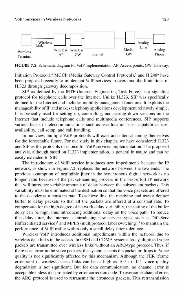
VoIP Services in Wireless Networks 153
Initiation Protocol),4 MGCP (Media Gateway Control Protocol),5 and H.2486 havebeen proposed recently to implement VoIP services to overcome the limitations ofH.323 through gateway decomposition.
SIP, as defined by the IETF (Internet Engineering Task Force), is a signalingprotocol for telephone calls over the Internet. Unlike H.323, SIP was specificallydefined for the Internet and includes mobility management functions. It exploits themanageability of IP and makes telephony applications development relatively simple.It is basically used for setting up, controlling, and tearing down sessions on theInternet that include telephone calls and multimedia conferences. SIP supportsvarious facets of telecommunications such as user location, user capabilities, useravailability, call setup, and call handling.
In our view, multiple VoIP protocols will exist and interact among themselvesfor the foreseeable future. For our study in this chapter, we have considered H.323and SIP as the protocols of choice for VoIP services implementation. The proposedanalysis, although based on H.323 implementation, is general in nature and can beeasily extended to SIP.
The introduction of VoIP service introduces new impediments because the IPnetwork, as shown in Figure 7.2, replaces the network between the two ends. Theprevious assumption of negligible jitter in the synchronous digital network is nolonger valid because of the packet-handling process in the best-effort IP networkthat will introduce variable amounts of delay between the subsequent packets. Thisvariability must be eliminated at the destination so that the voice packets are offeredto the decoder at a constant rate. To achieve this, the receiving end uses a dejitterbuffer to delay packets so that all the packets are offered at a constant rate. Tocompensate for the high degree of network delay variability, the setting of the bufferdelay can be high, thus introducing additional delay on the voice path. To reducethis delay jitter, the Internet is introducing new service types, such as Diff-Serv(differentiated service)7 and MPLS (multiprotocol label switching),8 to maintain theperformance of VoIP traffic within only a small delay jitter tolerance.
Wireless VoIP introduces additional impediments within the network due towireless data links in the access. In GSM and CDMA systems today, digitized voicepackets are transmitted over wireless links without an ARQ-type protocol. Thus, ifthere is an error in the voice packets, the system accepts the packet or drops it. Voicequality is not significantly affected by this mechanism. Although the FER (frameerror rate) in wireless access links can be as high as 10–1 to 10–3, voice qualitydegradation is not significant. But for data communication, no channel error isacceptable unless it is protected by error correction code. To overcome channel error,the ARQ protocol is used to retransmit the erroneous packets. This retransmission
FIGURE 7.2 Schematic diagram for VoIP implementation. AP: Access points; GW: Gateway.
Wireless Terminal
Wireless AP Internet
Media GW
Analog Phone
Wireless Link
Analog Line
Wireless GW

154 Handbook of Wireless Internet
currently happens at the TCP level because the original design of the IP protocolconsidered a very low error probability on the channel. Application of TCP retrans-mission for error correction in wireless networks only will significantly slow downthe wireless link throughput and increase delay. To overcome this delay and through-put problem, MAC layer retransmission is considered for wireless data links. Wire-less data access standards, such as GPRS and cdma2000, use MAC layer retrans-mission, called RLC/MAC, which causes additional delay jitter for wireless VoIPpackets.
7.3 BASIS OF VOICE CODING
Voice signals in the telephone device are analog signals within the frequency rangeof 300 Hz to 3.4 kHz. The landline digital voice network converts these analogsignals into digital signals with the help of the PCM (Pulse Code Modulation)9
scheme. In this scheme, the voice band analog signals are sampled at 8 kHz speedto meet the Nyquist sampling rate, fs > 2 × bandwidth. The samples are digitizedby the different quantization techniques to 8 bits of data. Thus, the wireline PCMsystem is a 64-kbps stream where one voice sample of 8 bits is generated every 125microseconds. The quantization of the samples creates error. Successive quantizationerrors of voice samples can be assumed uncorrelated random noise. Therefore, thequantization error is viewed as noise and expressed as the signal-to-quantizationnoise ratio (SQR). It is expressed as
where E[.] denotes the expectation value, X(t) is the analog input signal at time t,and Y(t) is the decoded output signal at time t. The error [Y(t) – X(t)] is limited inamplitude to q/2, where q is the height of the quantization interval. If all quantizationintervals have equal lengths and the input analog signal is a sinusoidal, the SQR indB is expressed as
where v is the RMS (root mean square) value of the amplitude of the input. TheSQR values of the signals increase with the sample amplitude and penalize the smallsample-size signals. A more-efficient coding can be achieved by not having uniformsample size, but rather by having sample size vary. The process of compounding9
is used to achieve this nonuniform sampling. The compression algorithm used inNorth America and Japan for PCM is called µ-law, and a compounding formularecommended by the ITU for Europe and the rest of the world is called A-law. The64-kbps voice-coding standard is issued from the ITU as Recommendation G.711.10
In addition, the ITU developed Recommendations G.726 and G.727 on 40, 32, 24,and 16-kbps adaptive differential PCM (ADPCM) coding standards and G.722 on56 to 64 kbps, 7-kHz wideband ADPCM standard.
SQRE X t
E Y t X t=
−{ ( )}
{[ ( ) ( )] }
2
2
SQR dB v q( ) . log [ ]= +10 8 20 10

VoIP Services in Wireless Networks 155
The introduction of digital wireless communication in the early 1980s introduceda new challenge: G.711 and G.721 are not usable for wireless networks due to verylimited bandwidth of wireless links. The early digital wireless access standard cansupport only 108 kbps over 200-kHz bandwidth in GSM and about 24 kbps over 30kHz for North American IS-54 TDMA digital standards. It was felt that lower ratevoice coders are needed for wireless voice communications. In addition, the voicecoder should be able to provide robust communication under fading channel behav-ior. The initial answer came from many different solutions such as the code excitedlinear prediction (CELP) codec at 6.5 kbps, called the half-rate codec. For example,CDMA introduced the system with a full-rate 13-kbps CELP codec. The ETSI(European Telecommunications Standards Institution) introduced residual excitedlinear predictive speech coding (RPE-LTP) that is 13 kbps with a frame size of 20milliseconds and no look-ahead delay. The ANSI (American National StandardsInstitution) proposed vector-sum excited linear predictive coding (VSELP) at 7.95kbps for TDMA IS-54 system that has a frame size of 20 milliseconds and look-ahead delay of 5 milliseconds. This RPE-LTP codec of GSM allows supporting 8voice calls simultaneously within the 200-kHz bandwidths and three voice callswithin the 30-kHz bandwidth of the North American IS-54 TDMA system. Newcoders with improved performance were introduced in the subsequent GSM net-works. They include full rate,11 half rate, enhanced full rate,12 adaptive multirate,13
and RECOVC (recognition-compatible voice coding) speech transcoding. Othercoders include G.728 16-kbps speech coding using low delay code excited linearprediction and G.72914 8-kbps speech coding using conjugate structure algebraiccode excited linear prediction. The Qualcom code excited linear prediction (QCELP)is a variable bit rate codec of 8.5, 4.0, 2.0, and 0.8 kbps speeds, a frame size of 20milliseconds, and a look-ahead delay of 5 milliseconds. Further to this bit ratereduction, a single call also can be provisioned for half-rate coding by takingadvantage of the silence period during the conversation. At present a number oflower bit rate coding techniques are under consideration for wireless voice commu-nications.
7.4 NETWORK QUALITY REQUIREMENTS
The measurement of voice quality is rather difficult. A subjective rating scale of 1to 5, called mean opinion score (MOS),15 is used to state voice quality. Wirelinevoice quality is normally within 4 to 4.5 MOS, the current wireless voice qualitylies between 3.5 and 4 MOS. To improve the quality of voice signal for wirelessnetworks, G.729 adopted 10-millisecond frame times. The computation time is 10milliseconds and look-ahead delay is 5 milliseconds. This results in a total one-waycodec delay of 25 milliseconds. In addition to the delay criteria, speech performancedepends also on the bit error rate. The objective of performance under random biterror rate < 10–3 is recommended not to be worse than that of G.726 under similarconditions.16 To introduce VoIP, the appropriate selection of coding technology isnecessary to meet the criteria of delay and bit error rate of the network.
In network applications of speech coding, coded voice signals are transmittedthrough multiple nodes and links, as shown in Figure 7.2. All these network links
156 Handbook of Wireless Internet
and nodes cause impediments to the coded voice signals. The ITU RecommendationsG.113 and G.11417 specify several system requirements, including:
• End-to-end noise accumulation is limited to 14 QDU (quantization dis-tortion unit), where each QDU is equal to the noise of a single 64-kbpsPCM device
• End-to-end transmission delay budget is 300 milliseconds• G.114 limits the processing delay for codec at each end to 10 milliseconds
Among these network requirements, the most important one in the design ofVoIP using wireless is the end-to-end delay budget of 300 milliseconds. In digitalnetworks, because of the synchronous nature of transmission, this delay budget ismostly used for the switching and transmission delay. There is very little variationof this delay, called jitter, within the synchronous digital network for voice signals.In the current wireless voice links, the air interface introduces additional delaybecause of the air link multiple access standards. Most of the wireless link designsattempt to meet the delay requirements of 300 milliseconds for single-link voicecalls in a national network. So single-link wireless calls without intermediate satellitelinks perform with a reasonable MOS rating today, however, if two ends of theconnection are wireless links, the speech quality deteriorates below MOS 3.0.
There are three important network performance parameters for wireless VoIPservice:
1. Performance to set up and tear down the call2. Quality of voice payload packets during conversation3. Performance of the voice session handoff
These parameters will depend on the selection of VoIP service protocols to set upthe voice session, the voice signal coding and transporting scheme, and themicro/macro mobility protocols used for VoIP services.
The call setup delay depends on the successful transfer of the current Q.931 andISDN-type messages and the additional message sets for capability check of theterminals and media packet synchronization in the IP network. Both H.323 and SIPsignaling protocol implement this function. The average call setup delay of thepresent wireless voice network is about 3 seconds, H.323 and SIP implementationswill have to meet this delay requirement.
Network voice quality will depend on the contribution of the different compo-nents of a hypothetical connection of VoIP in wireless network. A hypotheticalconnection, as shown in Figure 7.2, includes network components such as a wirelessterminal, a wireless link, an access point, a wireless gateway, the Internet, a mediagateway, and a landline terminal. The landline phone is assumed connected through ananalog line. The wireless terminal includes the codec and the function to map the codedframes into the wireless data channel for communication with the wireless access point.The common wireless channel is shared between multiple users, so to get access to thecapacity of the channel is a delay process. The fading and propagation loss of the

VoIP Services in Wireless Networks 157
wireless channel causes the frame error that introduces additional impediments tothe transfer of data. Once the packet is received at the wireless access point, it istransferred to the terminating media gateway through the Internet. Internet perfor-mance depends on the delay at the different routers and the propagation delay throughthe transport links. Due to the use of fiber transmission, the transmission related biterror rate or packet loss is almost nonexistent in the links and propagation delay isvery small. The delay in the router depends on the long-range dependency of thetraffic and link congestion. Using proper engineering techniques, this Internet delaycan be maintained within strict limits. The DiffServ and MPLS protocols will beable to support the core Internet with minimum delay and jitter. At the media gateway,the coded voice packets are reconverted to analog voice signals and transferred tothe terminating analog voice terminals using copper wire connection. The end-to-end delay of the voice packet for this hypothetical connection can be representedby the following equation:
wheredjitter = Delay introduced by the jitter buffer. To compensate for the fluctuating
network conditions, it is necessary to implement a jitter buffer in voice gateways or terminals. This is a packet buffer that holds incoming packets for a specified amount of time before forwarding them to decoding. This has the effect of smoothing the packet flow, increasing the resiliency of the codec to packet loss, delayed packets, and other transmission effects. The downside of the jitter buffer is that it can add significant additional delay in the path. It is not uncommon to see jitter buffer settings approach-ing 80 milliseconds for each direction.
dwt = Delay at the wireless terminal for coding and decoding voice packets and creating voice frames conforming to the Internet frame packet format (TCP or UDP). Each coding algorithm has certain built-in delay. For example, G.723 adds fixed 30-millisecond delay. To reduce the IP overhead, multiple voice packets may be mapped to one Internet frame and thus introduce bundling delay.
dwc = Delay at the wireless terminal to get a wireless data channel and map the Internet voice packet to it. This includes delay for buffer allocation such as GSM TBF (temporary buffer flow)2 allocation. In uplink transmission: Before sending the data to the base station, the mobile station must access the common channel in the uplink direction to send the request. Getting permission to send data in the uplink direction takes time, which increases the end-to-end delay.
dw1 = Delay to transfer the voice packets to the wireless access point, including the retransmission delay to protect the frame error during propagation.
dwap = Delay at the wireless access point to assemble and reassemble the voice frame from wireless frame formats to the Internet format.
D d d d d d d dend to end jitter wt wc w wap internet mgw− − = + + + + + +1
158 Handbook of Wireless Internet
dinternet = Delay to transfer the packet through the Internet to the media gateway. This is the delay incurred in traversing the VoIP backbone. In general, reducing the number of router hops minimizes this delay. Alternatively, it is possible to negotiate a higher priority to voice traffic than for delay-insensitive data.
dmgw = Delay at the media gateway to convert Internet voice packets to analog voice signals and transfer to analog voice lines.
The TCP retransmission delay impacts the delay parameters of dwc and dwap. Theend-to-end delay, Dend-to-end, of voice packets for conversation should be less than300 milliseconds, as specified by ITU G.114; one-way delay greater than 300milliseconds has an adverse impact on conversation, and the conversation seems likehalf duplex or push-to-talk.
The wireless VoIP session handoff between the two wireless access points isdetermined by the handoff mechanism supported by the wireless mobility protocol.There are two mobility functions for the wireless IP network: (1) micro–mobilityand (2) macro–mobility. The consensus between the different standards bodies isthat current Mobile IP may be suitable for macro–mobility, but a new technique isnecessary for micro–mobility. The potential micro-mobility protocols are GPRSGMM, Cellular-IP, Hawaii, TIMIP,18 IDMP,19,20 etc. The challenge of these mobilityprotocols is to ensure that the voice packets can be routed to the new access pointwithout any packet loss or significant additional delay on the voice path. Most ofthe protocols in their current form have difficulty meeting the micro-mobility require-ments of the voice packets. The current soft handoff of CDMA, the make-before-break mechanism on the GSM, and hard handoff in TDMA maintain the continuityof voice packet flow during handoff. The method of GPRS and 3G packet handoffdo not allow similar mechanisms at this time.
7.5 OVERVIEW OF THE H.323 PROTOCOL
This section presents a brief introduction to the H.323 and RTP/RTCP21 protocols.The H.323 standard provides a foundation for audio, video, and data communicationsacross IP-based networks for multimedia communications over LAN with no QoSguarantee. The standard is broad in scope and includes both stand-alone devices,embedded personal computer technology, and point-to-point and point-to-multipointconferences. The standard specifies the interfaces between LANs and other networks,and addresses call control, multimedia management, and bandwidth managementmethods. It uses the concept of channels to structure information exchange betweenthe communications entities. A channel is a transport layer connection (unidirectionalor bidirectional).
The Real-Time Transport Protocol (RTP) is used in conjunction with H.323 toprovide end-to-end data delivery services with real-time characteristics. RTP canhandle interactive audio and video services over a connectionless network. Atpresent, RTP/RTCP (Real-Time Control Protocol) along with UDP provides thebare-bones real-time services capability to IP networks with minimum reliability. A
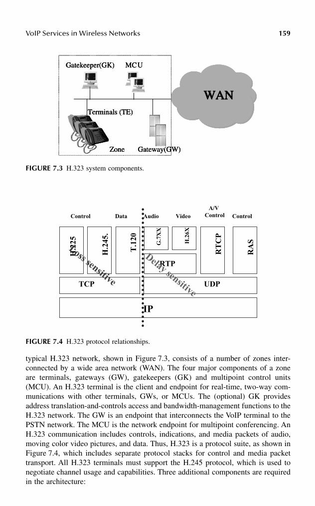
VoIP Services in Wireless Networks 159
typical H.323 network, shown in Figure 7.3, consists of a number of zones inter-connected by a wide area network (WAN). The four major components of a zoneare terminals, gateways (GW), gatekeepers (GK) and multipoint control units(MCU). An H.323 terminal is the client and endpoint for real-time, two-way com-munications with other terminals, GWs, or MCUs. The (optional) GK providesaddress translation-and-controls access and bandwidth-management functions to theH.323 network. The GW is an endpoint that interconnects the VoIP terminal to thePSTN network. The MCU is the network endpoint for multipoint conferencing. AnH.323 communication includes controls, indications, and media packets of audio,moving color video pictures, and data. Thus, H.323 is a protocol suite, as shown inFigure 7.4, which includes separate protocol stacks for control and media packettransport. All H.323 terminals must support the H.245 protocol, which is used tonegotiate channel usage and capabilities. Three additional components are requiredin the architecture:
FIGURE 7.3 H.323 system components.
FIGURE 7.4 H.323 protocol relationships.
WWWWAAAANNNNTerminals (TE)
Gatekeeper(GK) MCU
Gateway(GW)Zone
WWWWAAAANNNNTerminals (TE)
Gatekeeper(GK) MCU
Gateway(GW)Zone
WWWWAAAANNNNWWWWAAAANNNNTerminals (TE)
Gatekeeper(GK) MCU
Gateway(GW)Zone
IP
TCP UDP
H.2
25
H.2
45.
RTP
RT
CP
RA
SG.7
XX
H.2
6X
T.1
20
Data Audio VideoA/V
ControlControl Control
Delay sensitive
Loss sensitive
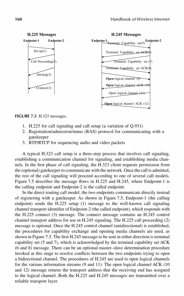
160 Handbook of Wireless Internet
1. H.225 for call signaling and call setup (a variation of Q.931)2. Registration/admission/status (RAS) protocol for communicating with a
gatekeeper3. RTP/RTCP for sequencing audio and video packets
A typical H.323 call setup is a three-step process that involves call signaling,establishing a communication channel for signaling, and establishing media chan-nels. In the first phase of call signaling, the H.323 client requests permission fromthe (optional) gatekeeper to communicate with the network. Once the call is admitted,the rest of the call signaling will proceed according to one of several call models.Figure 7.5 describes the message flows in H.225 and H.245, where Endpoint-1 isthe calling endpoint and Endpoint-2 is the called endpoint.
In the direct routing call model, the two endpoints communicate directly insteadof registering with a gatekeeper. As shown in Figure 7.5, Endpoint-1 (the callingendpoint) sends the H.225 setup (1) message to the well-known call signalingchannel transport identifier of Endpoint-2 (the called endpoint), which responds withthe H.225 connect (3) message. The connect message contains an H.245 controlchannel transport address for use in H.245 signaling. The H.225 call proceeding (2)message is optional. Once the H.245 control channel (unidirectional) is established,the procedures for capability exchange and opening media channels are used, asshown in Figure 7.5. The first H.245 message to be sent in either direction is terminalcapability set (5 and 7), which is acknowledged by the terminal capability set ACK(6 and 8) message. There can be an optional master–slave determination procedureinvoked at this stage to resolve conflicts between the two endpoints trying to opena bidirectional channel. The procedures of H.245 are used to open logical channelsfor the various information streams (9 and 11). The open logical channel ACK (10and 12) message returns the transport address that the receiving end has assignedto the logical channel. Both the H.225 and H.245 messages are transmitted over areliable transport layer.
FIGURE 7.5 H.323 messages.
Set-up(1)
Call Proceeding(2)
Alerting(3)
Connect(3)
Endpoint-1 Endpoint-2Terminal Capability set(5)
Terminal Capability set ACK(6)
Terminal Capability set (7)
Terminal Capability set ACK(8)
Open logical channel (9)
Open logical channel ACK (10)
Open logical channel (11)
Open logical channel ACK (12)
Endpoint-1 Endpoint-2
H.225 Messages H.245 Messages

VoIP Services in Wireless Networks 161
After the media channel has been set up and RTCP CNAMEs (canonical name)are exchanged, two TCP sessions are established, one for H.225 and the other forH.245 procedures, so that multiple media streams (e.g., audio and video) to the sameuser can be synchronized.21 The setup delay is very large in H.323 for a regular call,which involves multiple messages from its underlying protocols such as H.225 andH.245. This delay is rather prominent on a low-bandwidth, high-loss environment.It is further aggravated by the higher delay margin on wireless access links. The fastcall setup method is an option specified in H.323 that reduces the delay involved inestablishing a call and initial media streams.
7.6 OVERVIEW OF SIP
SIP (Session Initiation Protocol) is an application layer protocol used for setting upand tearing down VoIP sessions. The major difference between SIP and H.323 isSIP is fully based on Internet context and thus does not support the Q.931 or ISUPmessages that are currently used for telephony networks. But SIP extends the func-tionality of telephony signaling and supports mobility, and it is part of the overallIETF multimedia architecture framework that includes protocols such as RTP, RTSP(Real-Time Streaming Protocol), SDP (Session Description Protocol), SAP (SessionAnnouncement Protocol), and others. SIP uses a text message format with an encod-ing scheme very similar to HTTP. Currently, SIP uses SDP22 to establish the mediasession and the terminal capabilities, as H.245 in H.323. SDP messages are carriedas the message body of a SIP message. A complete VoIP session includes a numberof SDP messages for resource reservation, connection, and ringing in addition toSIP INVITE and BYE messages, as shown in Figure 7.6. All SIP messages aretransported at the RTP layer, whereas H.323 control messages use TCP. SIP is basedon client/server architecture with a SIP user agent and a SIP proxy server. The SIPuser agent has two important functions: (1) it listens to the incoming SIP messagesand (2) it sends SIP messages on receipt of an incoming SIP message or on useractions. The SIP proxy server relays SIP messages, so that it is possible to use adomain name to find a user. This simplifies the user location determination andallows scalability. The SIP server can be used as a redirect server, in which case itwill provide the host location information without relaying the SIP messages, andthe SIP user client will set up the session directly with the user.
The SIP mobility architecture components for VoIP are shown in Figure 7.7,where we assumed the mobile host and foreign network use DHCP (Dynamic HostConfiguration Protocol)23 or one of its variations for subnetwork configuration. AnSIP-capable mobile host uses DHCP to register in the network. A mobile hostbroadcasts a DHCP_DISCOVER message to register to a network. Multiple DHCPservers will respond to this request with the IP address of the server and defaultgateway in the DHCP_OFFER message. The mobile host selects the DHCP serverand sends the DHCP_REQUEST message to register. The registration is confirmedby DHCP_ACK at the DHCP server. As previously mentioned, SIP includes themobility function, and the mobile host then uses its temporary IP address to registerto the visiting register of the foreign network. The registration in a foreign networkincludes the authentication function, which uses AAA (authentication, accounting,

162 Handbook of Wireless Internet
and administration)21 servers. The foreign AAA server communicates with the homeAAA server to get the confirmation from the home register about customer authen-ticity. Ultimately, the visiting register receives the authentication response messageand, if it is accepted, it sends the 200 OK messages to the mobile host. If authen-tication fails, it sends 401 messages indicating unauthorized request for registration.After this registration, the mobile host initiates SIP registration for session start bysending an INVITE message to the SIP proxy server. In the case of micro–mobility,authentication with the AAA server is not necessary. The visiting register can authen-ticate the mobile host (expedited registration). The complete SIP registration sequence
FIGURE 7.6 SIP signaling for VoIP.
FIGURE 7.7 SIP mobility architecture components.
MS1 Proxy
Location Server
MS2
INVITE MS2
MS2
INVITE
TryingTrying
OKOK
ACKACK
RTP P ackets
BYE
OK
y

VoIP Services in Wireless Networks 163
is required for macro–mobility. To reduce the macro-mobility registration delay ofSIP, a quasiregistration concept is proposed in Schulzrinne.23 In quasiregistration,whenever the mobile host hands off from an old visiting register to a new visitingregister, it informs its home register of its location by sending a REGISTER message.When the home register replies its OK message, it will include the old visitingregister’s IP address along with the response. Thus, visiting registers will know theadjacent visiting register’s address to use for fast registration.
7.7 RLP
ETSI and T-1 standards bodies defined the GPRS and 3G standards to carry packetdata traffic in addition to voice in wireless access links. A new protocol layer, RadioLink Protocol (RLP), is defined on top of the MAC layer to improve bit error rateperformance by using an ARQ retransmission technique. In addition to retransmis-sion, GPRS RLC (Radio Link Control) performs block segmentation, reassembly,and buffering. As GPRS provides limited data capability, 3G standards are definedthat extend the data capability of radio frequency. The main operation principles ofGPRS and 3G RLP standards are very similar, although 3G provides some additionalQoS management capability in RLP management at the MAC layer. In our analysis,we will use GPRS and 3G RLP capabilities interchangeably without significantimpact on the results. cdma200024 is one of several 3G air-interface standards underconsideration by standards bodies such as the 3GPP/3GPP2 (3G Partnership Project).The MAC layer of cdma2000 provides two important functions:
1. Best-effort delivery using the retransmission mechanism of RLP thatprovides reliability
2. Multiplexing and QoS management by mediating conflicting servicerequests
In addition, voice packets are directly given to the multiplex sublayer thatbypasses the RLP function. Many transport channels have been defined forcdma2000 to provide services from physical to higher layers. These channels areunidirectional and either common (shared between multiple users) or fully dedicatedto a user for the duration of the service. cdma2000 has defined many channels forits operation, the following transport channels are of interest:
1. Forward common control channel (F-CCCH): Communication from basestation to mobile station for layer 3 and MAC messages
2. Forward supplemental channel (F-SCH): Operated in two modes, blindmode for data rate not exceeding 14.4 kbps, and explicit mode, wheredata rate information is explicitly provided, individual F-SCH target frameerror rates can be different than other F-SCHs
3. Forward fundamental channel (F-FCH): Transmits at variable data rates,as specified in TIA/EIA-95-B
164 Handbook of Wireless Internet
4. Reverse access channel (R-ACH) and reverse common control channel(R-CCCH): Used by a mobile station to communicate layer 3 and MACmessages
5. R-CCCH supports the low latency access procedure required for efficientoperation of packet data suspend state
6. Reverse supplemental channel (R-SCH): Operates on two modes, blindand explicit
7. Reverse fundamental channel (F-SCH) supports 5- and 20-millisecondframes, the 20-millisecond frame structures provide rates derived fromthe TIA/EIA-95-B Rate Set-1 or Rate Set-2
The RLC and MAC layers are responsible for efficient data transfer of both real-time and nonreal-time services. The transfer of nonreal-time data includes the ARQ forlow-level data to provide reliable transfers at higher levels. The network layer dataPDUs (N-PDUs) are first segmented into smaller packets and transformed into linkaccess control PDUs. The link access control overhead includes a service access pointidentifier, a sequence number for higher-level ARQ, and other data fields. The linkaccess control PDUs are then transferred to SRBP (Signaling Radio Burst Protocol), aconnectionless protocol for signaling messages. The data PDUs are segmented intosmaller packet RLC PDUs corresponding to the physical layer transport blocks. EachRLC PDU contains a sequence number for lower-level ARQ and CRC fields for errordetection. CRC is calculated and appended by the physical layer. When RLP at thereceiving end finds a frame in error or missing, it sends back a NAK (negative acknowl-edgment) request for retransmission of this frame and starts a retransmission timer.When the timer expires for the first attempt, the RLP resets the timer and sends backa NAK request. This NAK triggers a retransmission of the requested frame from thesender. In this way, the number of attempts per retransmission increases with everyretransmission trial. As noted in Bao,25 the number of trials is usually less than four.
The GPRS structures of different radio channels and MAC/RLC are very similarto cdma2000. GPRS uses the same TDMA/FDMA structure as GSM to form thephysical channels. For the uplink and downlink direction, many frequency channelswith a bandwidth of 200 kHz are defined. These channels are further subdividedinto the length of 4.615 milliseconds. Each TDMA frame is further split into eighttime slots of equal size. As an extension to GSM, GPRS uses the same frequencybands as GSM and both share the same physical channels. Each time slot can beassigned to either GSM or GPRS. Time slots used by the GPRS are known as packetdata channels (PDCH). The basic transmission unit of a PDCH is called a radioblock. To transmit a radio block, four consecutive TDMA frames are utilized.Depending on the message type transmitted in one radio block, a sequence of radioblocks forms a logical channel.
• PRACH (packet random access channel, uplink): This common channelis used by the mobile stations to initiate the transfer in the uplink direction.
• PPCH (packet paging channel, uplink): The base station controllers (BSC)uses this channel to page the mobile station prior to downlink data trans-mission.
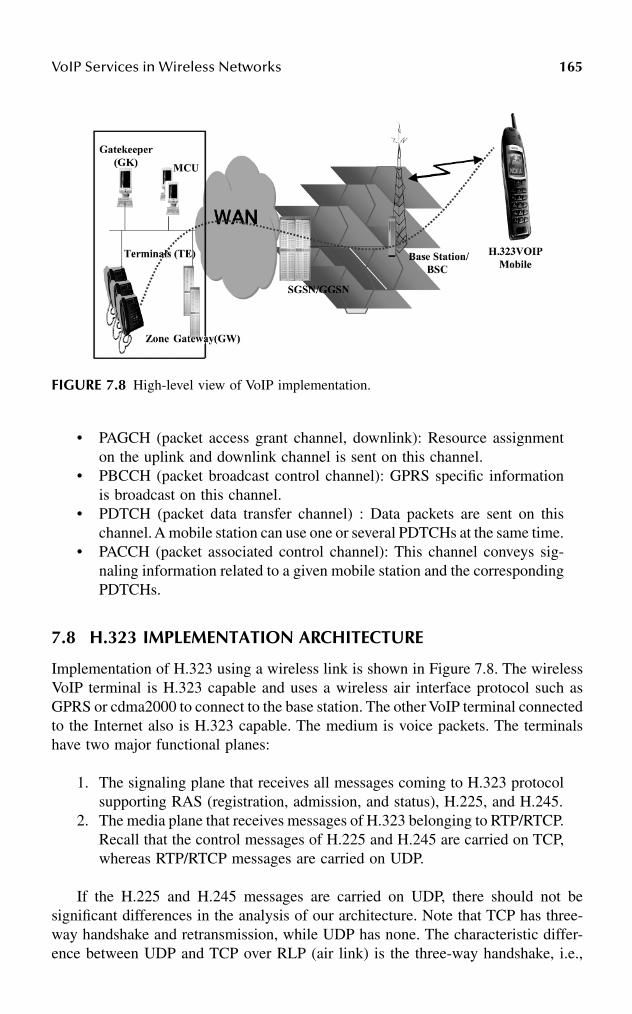
VoIP Services in Wireless Networks 165
• PAGCH (packet access grant channel, downlink): Resource assignmenton the uplink and downlink channel is sent on this channel.
• PBCCH (packet broadcast control channel): GPRS specific informationis broadcast on this channel.
• PDTCH (packet data transfer channel) : Data packets are sent on thischannel. A mobile station can use one or several PDTCHs at the same time.
• PACCH (packet associated control channel): This channel conveys sig-naling information related to a given mobile station and the correspondingPDTCHs.
7.8 H.323 IMPLEMENTATION ARCHITECTURE
Implementation of H.323 using a wireless link is shown in Figure 7.8. The wirelessVoIP terminal is H.323 capable and uses a wireless air interface protocol such asGPRS or cdma2000 to connect to the base station. The other VoIP terminal connectedto the Internet also is H.323 capable. The medium is voice packets. The terminalshave two major functional planes:
1. The signaling plane that receives all messages coming to H.323 protocolsupporting RAS (registration, admission, and status), H.225, and H.245.
2. The media plane that receives messages of H.323 belonging to RTP/RTCP.Recall that the control messages of H.225 and H.245 are carried on TCP,whereas RTP/RTCP messages are carried on UDP.
If the H.225 and H.245 messages are carried on UDP, there should not besignificant differences in the analysis of our architecture. Note that TCP has three-way handshake and retransmission, while UDP has none. The characteristic differ-ence between UDP and TCP over RLP (air link) is the three-way handshake, i.e.,
FIGURE 7.8 High-level view of VoIP implementation.

166 Handbook of Wireless Internet
the beginning of the TCP session. The purpose of RLP is to provide reliable trans-mission, hence, TCP retransmission has no, if not zero, significant impact. Theadvantage of using UDP over TCP is (1) the UDP header overhead is lower (20bytes as opposed to about 40 bytes for TCP), and (2) TCP has three-way handshakebefore each session. For an H.323 connection, typically, one handshake over air linkis used. But there may be more than one if a gateway is being used, in that case, itis over land link communication only. If the air-link bandwidth is higher, so that 20bytes vs. 40 bytes is not an issue, then the initial delay caused by the TCP three-way handshake is the only difference. The TCP retransmission could come in handyover a complex link (air and land) situation.
The performance of VoIP call setup using wireless links is influenced by threefactors:
1. The number of messages exchanged to set up the call2. The size of the messages3. The number of TCP sessions that are set up
Reduction of any of these factors results in shorter call setup delay. Table 7.1 showsthe size of the signaling and control messages for call setup using regular H.323procedures. The frames indicate the number of air links. The wireless link FER(probability) can be as high as 0.1. With this high FER, the regular H.323 procedurecall setup delay contribution can be as high as 40 seconds for a 9.6-kbps link and30 seconds for a 19.2-kbps link. This high delay is unacceptable, compared to thecurrent call setup delay (less than 3 seconds) of the PSTN system. To improveperformance, we consider direct routing call model for this implementation.Table 7.2 shows the fastConnect messages and their sizes, which are significantlyreduced.
The calling endpoint initiates the fastConnect procedure by sending an H.225setup message containing the fastStart element to the called endpoint. When thecalled endpoint accepts the fastConnect procedure, it sends an H.225 message (callproceeding, alerting, progress or connect) containing a fastStart element selected
TABLE 7.1Message Sizes Associated with the Regular Call Setup Procedure
Messages Payload SizeNumber of Frames
(9.6 kbps)Number of Frames
(19.2 kbps)
Setup: H.225 254 octet 14 7Alerting: H.225 97 octet 7 4Connect: H.225 165 octet 10 5TC Set: H.225 587 octet (×2) 29 (×2) 15 (×2)TC Set ACK: H.245 (×2) 71 octet (×2) 6 (×2) 3 (×2)OC: H.245 (×2) 115 octet (×4) 8 (×4) 4 (×4)OC ACK: H.245 (×4) 64 octet (×4) 5 (×4) 3 (×4)RTCP packet 120 octet 8 4
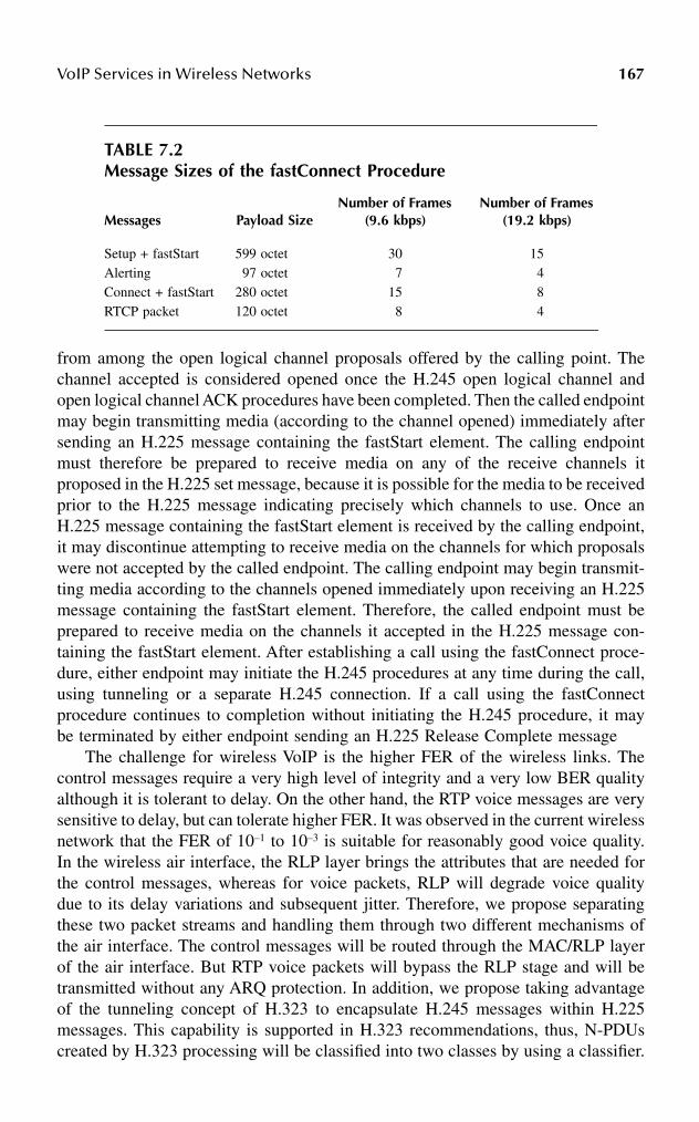
VoIP Services in Wireless Networks 167
from among the open logical channel proposals offered by the calling point. Thechannel accepted is considered opened once the H.245 open logical channel andopen logical channel ACK procedures have been completed. Then the called endpointmay begin transmitting media (according to the channel opened) immediately aftersending an H.225 message containing the fastStart element. The calling endpointmust therefore be prepared to receive media on any of the receive channels itproposed in the H.225 set message, because it is possible for the media to be receivedprior to the H.225 message indicating precisely which channels to use. Once anH.225 message containing the fastStart element is received by the calling endpoint,it may discontinue attempting to receive media on the channels for which proposalswere not accepted by the called endpoint. The calling endpoint may begin transmit-ting media according to the channels opened immediately upon receiving an H.225message containing the fastStart element. Therefore, the called endpoint must beprepared to receive media on the channels it accepted in the H.225 message con-taining the fastStart element. After establishing a call using the fastConnect proce-dure, either endpoint may initiate the H.245 procedures at any time during the call,using tunneling or a separate H.245 connection. If a call using the fastConnectprocedure continues to completion without initiating the H.245 procedure, it maybe terminated by either endpoint sending an H.225 Release Complete message
The challenge for wireless VoIP is the higher FER of the wireless links. Thecontrol messages require a very high level of integrity and a very low BER qualityalthough it is tolerant to delay. On the other hand, the RTP voice messages are verysensitive to delay, but can tolerate higher FER. It was observed in the current wirelessnetwork that the FER of 10–1 to 10–3 is suitable for reasonably good voice quality.In the wireless air interface, the RLP layer brings the attributes that are needed forthe control messages, whereas for voice packets, RLP will degrade voice qualitydue to its delay variations and subsequent jitter. Therefore, we propose separatingthese two packet streams and handling them through two different mechanisms ofthe air interface. The control messages will be routed through the MAC/RLP layerof the air interface. But RTP voice packets will bypass the RLP stage and will betransmitted without any ARQ protection. In addition, we propose taking advantageof the tunneling concept of H.323 to encapsulate H.245 messages within H.225messages. This capability is supported in H.323 recommendations, thus, N-PDUscreated by H.323 processing will be classified into two classes by using a classifier.
TABLE 7.2Message Sizes of the fastConnect Procedure
Messages Payload SizeNumber of Frames
(9.6 kbps)Number of Frames
(19.2 kbps)
Setup + fastStart 599 octet 30 15Alerting 97 octet 7 4Connect + fastStart 280 octet 15 8RTCP packet 120 octet 8 4

168 Handbook of Wireless Internet
H.323 media streams for interactive traffic (particularly, VoIP) are treated differentlythan the H.323 control packet streams (e.g., H.225, H.245, RTCP messages). Becausethe VoIP packets can sustain higher FER than the control traffic, it is recommendedthat transparent RLP (i.e., no RLP retransmission) be used for VoIP packets, whilenontransparent (regular) RLP be used for H.323 control packets. Due to the inter-active nature of voice, VoIP packets should get higher priority over any in-bandH.323 control packets within the session. Two types of subflows requiring differen-tiation have been identified for VoIP service using H.323:
1. H.323 control packets including H.225 and RTCP: These packets needhigher reliability for better performance. They have less-stringent delayrequirements compared to media packets. The QoS to be satisfied forthese packets is• Call setup delay is the time required to set up the call after completion
of sending the information for the call, i.e., after pressing the sendbutton of the wireless terminal. The H.225 signaling will control thisdelay.
• Connection delay is the time required to make the media connectionafter receipt of the answer signal. RTCP packet synchronization willcontrol this delay.
2. H.323 media packets carried by RTP: These packets have lower reliabilityrequirements than the control packets, but have stringent delay require-ments. Handle these packets at highest priority within a delay restrictionof 250 to 300 milliseconds. The two components of this QoS are the end-to-end delay of the voice packets and the blocking probability of the voicepackets when multiple sources are sharing the same wireless resources.
7.8.1 DELAY ANALYSIS OF H.323 CONTROL SIGNALING OVER WIRELESS
We will assume the simple call setup message flows of H.323, as depicted inFigure 7.4. The total call setup delay will be the cumulative delay due to:
1. Setup time for two TCP sessions that include exchange of SYN, SYN-ACK, and ACK messages
2. Successfully transmitting all H.225 and H.245 messages3. Successfully receiving an RTCP CNAME message
First, we present the analysis of RTCP packets based on mathematical modelsas suggested in Bao25 and Sen et al.26 for CDMA networks. Next, we analyze H.323call setup flows and their interactions with TCP. Some information in an RTCPpacket is more important than other information, e.g., CNAME and BYE. They arecritical and need to be reliably transmitted to guarantee user-perceived QoS andnetwork performance. We assume a maximum of three trials in our analysis for RLP,and restrict the maximum retransmission time for a packet to be much less than the

VoIP Services in Wireless Networks 169
RTCP transmission interval T. (Note: We present here the results of the paper [seeDas et al.27,28] without discussing the details of the analysis. Interested readers canrefer to the original papers for the details.)
7.8.2 ANALYSIS OF RTCP:CNAME PACKET DELAY
Letp = The probability of a frame being in error in the air linkk = The number of RLP frames in an RTCP packet transmitted over air and T ≥
5 seconds is the RTCP transmission intervalD = The end-to-end frame propagation delay over the radio channel, with typical
values on the order of 100 millisecondsτ = The interframe time of RLP with typical values on the order of 20 milliseconds
Assume a user just joined the RTP session. The average delay of receiving theCNAME packet indicates the waiting period for the user to play the associated RTPstreams properly. Thus
The packet loss rate without RLP:
The packet loss rate with RLP:
Thus, the average delay (T1) associated with receiving the first RTCP CNAME packetafter joining the session without RLP is given by
If RLP is used, the average delay T2 for a newly joined member to receive the firstRTCP packet containing the CNAME item after joining the session with RLP canbe approximated by
where the delay D is changed to D″ for RLP retransmission and is given by
where Cij represents that the first frame received correctly at destination is the i-thretransmission frame at the j-th retransmission trial, n denotes the maximum number
q p k= − −1 1( )
q p p p k= − − −1 1 2 6( ( ( )) )
T Tqq
D k Tp
pD k
k
k1
12 1
12 12 1
1= +−
+ + − = − −−
+ + −[( )
] ( ) [( )
( )] ( )τ τ
T Tqq
D TP
k
fk2
12 1
2
2= +
−+ ′′ =
−+ ′′[
( )] [ ]
′′ = + − +− −
× + + +
==
∑∑D D kk P p
PP C jD
j jif
fij
i
j
j
n
( )[ ( )]
( )( (( )
) ]11
21
22
11
τ τ

170 Handbook of Wireless Internet
of RLP retransmissions, and Pf denotes the effective packet loss seen at the RTCPlayer (q) and is given by
7.8.3 H.323 CALL SETUP MESSAGE DELAY ANALYSIS
Because H.225 and H.245 messages are carried over TCP, an analysis of TCPtransport delay over wireless will lead to an insight to the H.323 call setup delayperformance. We have assumed a radio channel bandwidth of 9.6 kbps. The twoendpoints are assumed to be in close proximity, hence any wireline network delayis assumed to be negligible. The following assumptions are made about the end-to-end TCP sessions carrying the H.323 messages:
1. TCP operates in an interactive mode.2. The delayed acknowledgment mode of TCP operation is turned off.3. TCP always times out whenever a packet is lost (i.e., it never does fast
retransmit).4. Round-trip delay is 200 milliseconds, because the one-way delay for
message (D) is assumed to be 100 milliseconds (approx.).5. The initial TCP round-trip timer (RTO) value is exactly equal to the round-
trip delay. Subsequent variation of RTO is as specified for TCP.29
6. If initial capability exchange or master–slave determination proceduresfail, no retry should be issued, as opposed to the standard that suggestsat least two additional retransmissions before the endpoint abandons theconnection attempt.
Following Karn’s algorithm for TCP timer backoff, the RTO is multiplied by aconstant factor after each retransmission due to time out. Hence, RTOi+1 = c × RTOi,where RTOi is the i-th TCP retransmission timer. This causes RTO to grow expo-nentially after each retransmission. We let c = 2, as it is most commonly imple-mented. Initially, RTO = 100 milliseconds, as assumed previously. Hence, RTOi =2 × 100 milliseconds, …, RTOi = 2i × 100 milliseconds. Furthermore, TCP will notallow infinite number of retransmissions. Hence, if TCP retransmission succeeds,after Nm attempts (without loss of generality, we assume Nm = 10) for example, theaverage delay to transmit a TCP packet is
where T′ is the end-to-end propagation delay of the TCP packet. We shall establishthe average delay for successful transmission of a TCP packet both with and withouta radio link reliable transmission scheme (RLP).
P P B p p p
q P
f n
n n
fk
= − = − −[ ]
= −
+1 1 2
1
12( ) ( )
( )
′ + + + + = ′ + − ×+T RTO RTO RTO TmNm
1 212 2 100... ( )
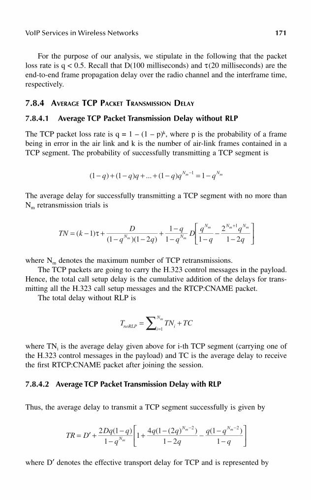
VoIP Services in Wireless Networks 171
For the purpose of our analysis, we stipulate in the following that the packetloss rate is q < 0.5. Recall that D(100 milliseconds) and τ(20 milliseconds) are theend-to-end frame propagation delay over the radio channel and the interframe time,respectively.
7.8.4 AVERAGE TCP PACKET TRANSMISSION DELAY
7.8.4.1 Average TCP Packet Transmission Delay without RLP
The TCP packet loss rate is q = 1 – (1 – p)k, where p is the probability of a framebeing in error in the air link and k is the number of air-link frames contained in aTCP segment. The probability of successfully transmitting a TCP segment is
The average delay for successfully transmitting a TCP segment with no more thanNm retransmission trials is
where Nm denotes the maximum number of TCP retransmissions.The TCP packets are going to carry the H.323 control messages in the payload.
Hence, the total call setup delay is the cumulative addition of the delays for trans-mitting all the H.323 call setup messages and the RTCP:CNAME packet.
The total delay without RLP is
where TNi is the average delay given above for i-th TCP segment (carrying one ofthe H.323 control messages in the payload) and TC is the average delay to receivethe first RTCP:CNAME packet after joining the session.
7.8.4.2 Average TCP Packet Transmission Delay with RLP
Thus, the average delay to transmit a TCP segment successfully is given by
where D′ denotes the effective transport delay for TCP and is represented by
( ) ( ) ... ( )1 1 1 11− + − + + − = −−q q q q q qN Nm m
TN kD
q qq
qD
qqN N
N N N
m m
m m m
= − +− −
+ −− −
−−
+
( )( )( )
11 1 2
11 1
21 2
1
τ
T TN TCnoRLP ii
Nm= +
=∑ 1
TR DDq q
qq q
qq q
qN
N N
m
m m
= ′ + −−
+ −−
− −−
− −2 11
14 1 2
1 21
1
2 2( ) ( ( ) ) ( )

172 Handbook of Wireless Internet
When the air-link FER is very high, too many RLP retransmissions may causeenough delay that TCP’s retransmission timer always times out, thus, the averagecall setup delay with RLP is
where Ti = min{TRi, TNi}.
7.8.5 AVERAGE H.323 CALL SETUP DELAY
We now compute the average call setup delay for a regular H.323 procedure and afastConnect procedure. The models presented in the previous section imply that anaverage regular H.323 call setup delay increases exponentially as FER increases.Three major factors contribute to the delay — the number of message exchanges,size of message exchanges, and the number of TCP sessions set up. Reduction ofany of these factors results in shorter call setup delay for any H.323 call. H.323provides ways for addressing this or similar issues, including encapsulation of H.245messages within H.225 messages (tunneling), and the fastConnect procedure. Inorder to conserve resources, either or both these mechanisms synchronize callsignaling and control, and reduce call setup time. These mechanisms can be invokedby the H.323 calling endpoint. In this discussion, we will investigate the call setupdelay incurred by the fastConnect procedure only.
H.323 endpoints may establish media channels in a call using either the regularprocedures defined in Recommendation H.245 or the so-called fastConnect proce-dure. The fastConnect procedure allows the endpoints to establish a basic point-to-point call with as few as one round-trip message exchange, enabling immediatemedia stream delivery upon call connection.
Figures 7.9 and 7.10 compare the average call setup delays associated with aregular connect procedure and a fastConnect procedure for a 9.6- and a 19.2-kbpschannel, respectively. Each procedure is further evaluated with and without supportfrom RLP over the error-prone wireless channel. It can be observed that fastConnectwith RLP support provides the minimum call setup delay. Furthermore, the callsetup delay for the fastConnect procedure is consistently below 5 seconds for 9.6kbps and 4 seconds for 19.2 kbps channels, if FER is less than 9%. This is close tothe PSTN call setup time of 3 seconds.
7.8.6 EXPERIMENTAL VERIFICATION
Experiments for call setup delay at various FER rates between 1 and 10 percentover the wireless link emulator (WLE) were conducted using Microsoft NetMeeting.
′ = − + + + + +
==
∑∑DP
D p P C j Dj j
if
ij
i
j
j
n1
1 2 11
211
( ) ( ) ( )( ) τ
T T TCRLP ii
Nm= +
=∑ 1

VoIP Services in Wireless Networks 173
An end-to-end NetMeeting VoIP session from Endpoint A (Caller) to Endpoint B(Callee) over the WLE was created. NetMeeting 3.01 uses H.323v2 call signaling(Q.931/H.225/H.245 over TCP) to set up VoIP sessions and the default Microsoftcodec G.723.1, 8-kHz mono, 6400 bps for audio compression. In these experiments,the call is considered successful only when the voice path is cut through (i.e.,Endpoint B can hear the caller’s voice). In addition, the maximum amount of timethe called party waited for voice cut-through is 2 minutes, after which the call wasmarked as unsuccessful.
FIGURE 7.9 Call setup delay (9.6 kbps).
FIGURE 7.10 Call setup delay (19.2 kbps).
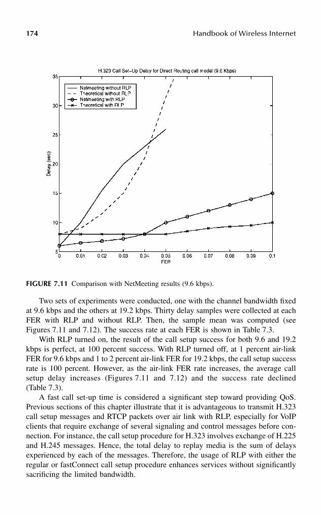
174 Handbook of Wireless Internet
Two sets of experiments were conducted, one with the channel bandwidth fixedat 9.6 kbps and the others at 19.2 kbps. Thirty delay samples were collected at eachFER with RLP and without RLP. Then, the sample mean was computed (seeFigures 7.11 and 7.12). The success rate at each FER is shown in Table 7.3.
With RLP turned on, the result of the call setup success for both 9.6 and 19.2kbps is perfect, at 100 percent success. With RLP turned off, at 1 percent air-linkFER for 9.6 kbps and 1 to 2 percent air-link FER for 19.2 kbps, the call setup successrate is 100 percent. However, as the air-link FER rate increases, the average callsetup delay increases (Figures 7.11 and 7.12) and the success rate declined(Table 7.3).
A fast call set-up time is considered a significant step toward providing QoS.Previous sections of this chapter illustrate that it is advantageous to transmit H.323call setup messages and RTCP packets over air link with RLP, especially for VoIPclients that require exchange of several signaling and control messages before con-nection. For instance, the call setup procedure for H.323 involves exchange of H.225and H.245 messages. Hence, the total delay to replay media is the sum of delaysexperienced by each of the messages. Therefore, the usage of RLP with either theregular or fastConnect call setup procedure enhances services without significantlysacrificing the limited bandwidth.
FIGURE 7.11 Comparison with NetMeeting results (9.6 kbps).

VoIP Services in Wireless Networks 175
7.9 MEDIA PACKET-BLOCKING ANALYSIS IN GPRS
The media packet transport of VoIP consists of three important functions at theterminal:
FIGURE 7.12 Comparison with NetMeeting results (19.2 kbps).
TABLE 7.3Success Rate with NetMeeting
FER(percent)
Call Setup Success Rate (percent)
9.6 kbps(w/RLP)
19.2 kbps(w/RLP)
9.6 kbps(w/o RLP)
19.2 kbps(w/o RLP)
1 100 100 100 1002 100 100 93 1003 100 100 83 934 100 100 47 935 100 100 30 878 100 100 0 40
10 100 100 0 23
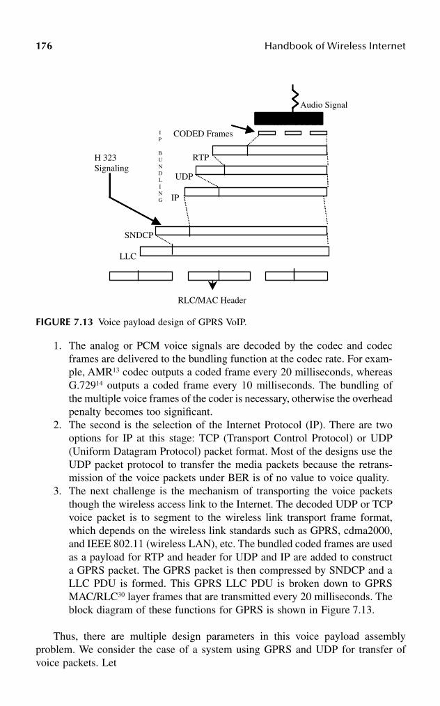
176 Handbook of Wireless Internet
1. The analog or PCM voice signals are decoded by the codec and codecframes are delivered to the bundling function at the codec rate. For exam-ple, AMR13 codec outputs a coded frame every 20 milliseconds, whereasG.72914 outputs a coded frame every 10 milliseconds. The bundling ofthe multiple voice frames of the coder is necessary, otherwise the overheadpenalty becomes too significant.
2. The second is the selection of the Internet Protocol (IP). There are twooptions for IP at this stage: TCP (Transport Control Protocol) or UDP(Uniform Datagram Protocol) packet format. Most of the designs use theUDP packet protocol to transfer the media packets because the retrans-mission of the voice packets under BER is of no value to voice quality.
3. The next challenge is the mechanism of transporting the voice packetsthough the wireless access link to the Internet. The decoded UDP or TCPvoice packet is to segment to the wireless link transport frame format,which depends on the wireless link standards such as GPRS, cdma2000,and IEEE 802.11 (wireless LAN), etc. The bundled coded frames are usedas a payload for RTP and header for UDP and IP are added to constructa GPRS packet. The GPRS packet is then compressed by SNDCP and aLLC PDU is formed. This GPRS LLC PDU is broken down to GPRSMAC/RLC30 layer frames that are transmitted every 20 milliseconds. Theblock diagram of these functions for GPRS is shown in Figure 7.13.
Thus, there are multiple design parameters in this voice payload assemblyproblem. We consider the case of a system using GPRS and UDP for transfer ofvoice packets. Let
FIGURE 7.13 Voice payload design of GPRS VoIP.
Voice CODECVoice CODEC
H 323 Signaling
IP
BUNDLING
Audio Signal
RTP
UDP
IP
CODED Frames
SNDCP
LLC
RLC/MAC Header
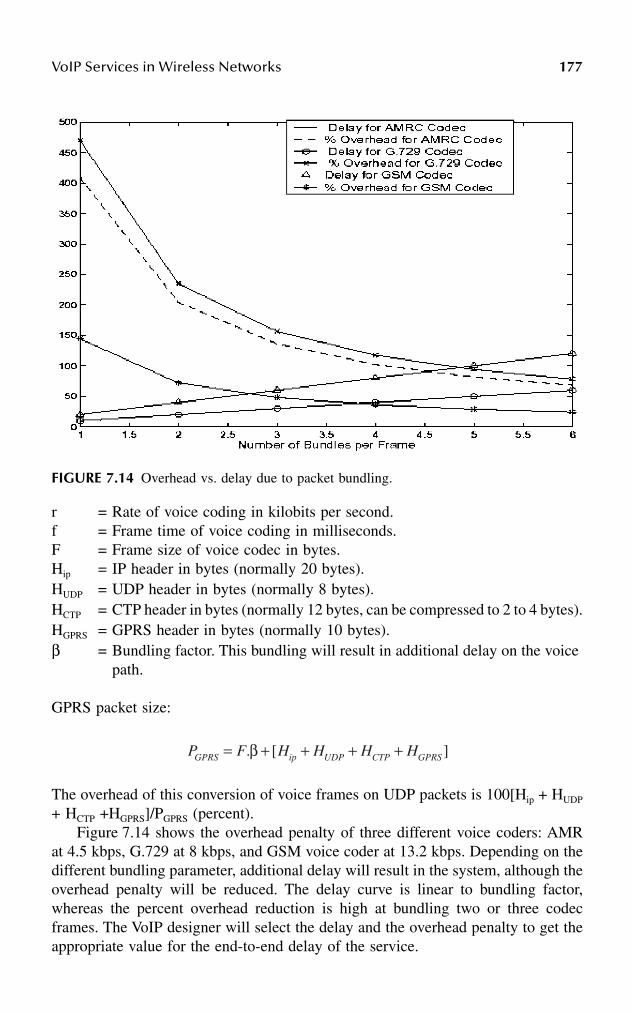
VoIP Services in Wireless Networks 177
r = Rate of voice coding in kilobits per second.f = Frame time of voice coding in milliseconds.F = Frame size of voice codec in bytes.Hip = IP header in bytes (normally 20 bytes).HUDP = UDP header in bytes (normally 8 bytes).HCTP = CTP header in bytes (normally 12 bytes, can be compressed to 2 to 4 bytes).HGPRS = GPRS header in bytes (normally 10 bytes).β = Bundling factor. This bundling will result in additional delay on the voice
path.
GPRS packet size:
The overhead of this conversion of voice frames on UDP packets is 100[Hip + HUDP
+ HCTP +HGPRS]/PGPRS (percent).Figure 7.14 shows the overhead penalty of three different voice coders: AMR
at 4.5 kbps, G.729 at 8 kbps, and GSM voice coder at 13.2 kbps. Depending on thedifferent bundling parameter, additional delay will result in the system, although theoverhead penalty will be reduced. The delay curve is linear to bundling factor,whereas the percent overhead reduction is high at bundling two or three codecframes. The VoIP designer will select the delay and the overhead penalty to get theappropriate value for the end-to-end delay of the service.
FIGURE 7.14 Overhead vs. delay due to packet bundling.
P F H H H HGPRS ip UDP CTP GPRS= + + + +. [ ]β
178 Handbook of Wireless Internet
The codec voice packets after being bundled are segmented to fit into the GPRSframe size. The actual transmission of the packets through the GPRS channel in theupstream involves two functions. In the uplink direction, the GPRS traffic channelrequest is sent to the GPRS base station using uplink random access channel. TheBSC transmits a notification to a mobile station terminal indicating temporary bufferflow (TBF) allocation. TBF allocation is basically a physical connection used tosupport the transfer of blocks. Each TBF connection is assigned one TFI (temporaryflow identifier). TFI is included in each of the transmitted radio blocks so thatmultiplexing of different mobile stations can be done on the same packet datachannel. As a matter of fact, GPRS uses dynamic bandwidth allocation. When auser needs more bandwidth, physical connection is established by the interactionbetween the mobile station and the base station to allow the mobile station to sendthe data in the uplink direction. This physical connection is considered TBF alloca-tion. Every time the mobile station wants to send the data, it must establish thisphysical connection with the base station and tear down the connection at the endof the transmission. This whole process is time consuming, especially when thetransmitting packet is too small, and the delay incurred by the TBF increases themean delay. To support the packet-switched principle of GPRS, resources of the onepacket data channel are assigned only temporarily to one mobile station.
In GPRS, uplink and downlink are carried out on different 200 kHz channels. TheBSC handles the resource allocation in downlink as well as in uplink. All the packetsare originated from the BSC (downlink), no concurrent access on one packet datachannel can occur. While in the uplink, more than one mobile station can try to gethold of one packet data channel at the same time. To avoid the access conflict in theuplink direction, the BSC transmits the USF associated with each of the radio blocksin the downlink direction (USF identifies each of the mobile stations distinctly), indi-cating which mobile station has rights to send the data in the corresponding uplink block.
The PCU (process control unit) of the GPRS performs the allocation of capacityof the traffic channel for transfer of the voice packets to the base station. Becauseof the sharing of multiple GPRS terminals by the same GPRS traffic, the VoIP willencounter blocking when it requests the service from the GPRS system. This block-ing depends on the number of active GPRS terminals in the cell and the intensityof the voice packets generated by the active voice terminals. The channel blockingprobabilities are determined by the two-stage modeling technique. In the first stage,the probability of the number of active sources in the system is determined, and inthe second step, out of these active terminals, probabilities of numbers of simulta-neous traffic bursts generated by the terminals are determined. The probabilities ofthe simultaneous traffic bursts of the sources are modeled by considering the on–offburst source model of the individual source. Consider the case of an only-VoIPterminal in a GPRS system.
7.9.1 VOIP TRAFFIC BLOCKING
The model of the GPRS VoIP user in a cell is considered as a finite-state Markovprocess with quasirandom arrival. The idle-state arrival rate decreases and departurerate increases, as more users are in the system. This is the traditional Engset Model31
VoIP Services in Wireless Networks 179
of telephony. This model will give the state probability of active users in the system.The actual design of the system will include a threshold of maximum number ofusers that the system will allow to enter (new users and handoff users). Let
n = Total number of VoIP terminals in the cell coverage area.α = Arrival rate of the free VoIP traffic source.1/µ = Mean service time of one VoIP source during active voice session.Pi = Probability of i-VoIP traffic source active in the system.
where β = α/µ.The accepted VoIP session will generate the voice traffic bursts depending on
the coding speed and the bundling mechanism used in the system. The GPRS usesmultiple coding schemes. Four GPRS coding schemes are proposed: CS-1 (9.05kbps), CS-2, CS-3, and CS-4 (21.4 kbps). The CS-1 scheme has the highest error-correction capability, whereas CS-4 has no error-correction capability. In the typicalGPRS system, most likely only CS-1 and CS-2 will be used. CS-2 has a user datarate of 13.4 kbps with some error-correcting capability. Any GPRS terminal caninitiate a session and the talk bursts can be modeled as an on–off source. We candivide the entire holding time in the two regions: user is in on-state when it is active,and in off-state when there is no talk burst and a silent period during the conversation.
So from “i” users in the system, the probability that “k” users will be in on-state is given as
where ρ = probability of being in on-state in one second (assuming the same for allthe users), and 1 – ρ = probability of being in off-state.
The joint probability that the i users are active and k users are in on-state isgiven by Pi × Pik. Hence for a GPRS system with 8 slots in 200-kHz spectrum andassuming each active burst is using one slot at a time, the probabilities of burst levelblocking of the system is given by
The PCU of the GPRS performs the allocation of the capacity of the trafficchannel for transfer of the voice packets to the base station. The GPRS traffic channel
P
n
in
k
i
i
k
k
n=
=∑
β
β0
Pi
kik
k i k=
− −ρ ρ( )1
B P Pi ikk
Min i
i
n
= − ×== ∑∑1
0
8
0
[ , ]
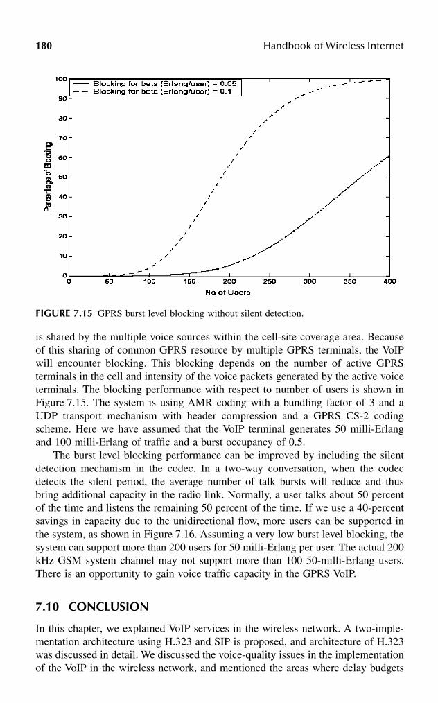
180 Handbook of Wireless Internet
is shared by the multiple voice sources within the cell-site coverage area. Becauseof this sharing of common GPRS resource by multiple GPRS terminals, the VoIPwill encounter blocking. This blocking depends on the number of active GPRSterminals in the cell and intensity of the voice packets generated by the active voiceterminals. The blocking performance with respect to number of users is shown inFigure 7.15. The system is using AMR coding with a bundling factor of 3 and aUDP transport mechanism with header compression and a GPRS CS-2 codingscheme. Here we have assumed that the VoIP terminal generates 50 milli-Erlangand 100 milli-Erlang of traffic and a burst occupancy of 0.5.
The burst level blocking performance can be improved by including the silentdetection mechanism in the codec. In a two-way conversation, when the codecdetects the silent period, the average number of talk bursts will reduce and thusbring additional capacity in the radio link. Normally, a user talks about 50 percentof the time and listens the remaining 50 percent of the time. If we use a 40-percentsavings in capacity due to the unidirectional flow, more users can be supported inthe system, as shown in Figure 7.16. Assuming a very low burst level blocking, thesystem can support more than 200 users for 50 milli-Erlang per user. The actual 200kHz GSM system channel may not support more than 100 50-milli-Erlang users.There is an opportunity to gain voice traffic capacity in the GPRS VoIP.
7.10 CONCLUSION
In this chapter, we explained VoIP services in the wireless network. A two-imple-mentation architecture using H.323 and SIP is proposed, and architecture of H.323was discussed in detail. We discussed the voice-quality issues in the implementationof the VoIP in the wireless network, and mentioned the areas where delay budgets
FIGURE 7.15 GPRS burst level blocking without silent detection.
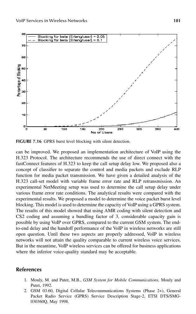
VoIP Services in Wireless Networks 181
can be improved. We proposed an implementation architecture of VoIP using theH.323 Protocol. The architecture recommends the use of direct connect with thefastConnect features of H.323 to keep the call setup delay low. We proposed also aconcept of classifier to separate the control and media packets and exclude RLPfunction for media packet transmission. We have given a detailed analysis of theH.323 call-set model with variable frame error rate and RLP retransmission. Anexperimental NetMeeting setup was used to determine the call setup delay undervarious frame error rate conditions. The analytical results were compared with theexperimental results. We proposed a model to determine the voice packet burst levelblocking. This model is used to determine the capacity of VoIP using a GPRS system.The results of this model showed that using AMR coding with silent detection andCS2 coding and assuming a bundling factor of 3, considerable capacity gain ispossible by using VoIP over GPRS, compared to the current GSM system. The end-to-end delay and the handoff performance of the VoIP in wireless networks are stillopen question. Until these two aspects are properly addressed, VoIP in wirelessnetworks will not attain the quality comparable to current wireless voice services.But in the meantime, VoIP wireless services can be offered for business applicationswhere the inferior voice-quality standard may be acceptable.
References
1. Mouly, M. and Putet, M.B., GSM System for Mobile Communications, Mouly andPutet, 1992.
2. GSM 03.60, Digital Cellular Telecommunications Systems (Phase 2+), GeneralPacket Radio Service (GPRS) Service Description Stage-2, ETSI DTS/SMG-030360Q, May 1998.
FIGURE 7.16 GPRS burst level blocking with silent detection.

182 Handbook of Wireless Internet
3. International Telecommunications Union, Packet Based Multimedia CommunicationsSystems, Recommendation H.323, Telecom Standardization Sector, Geneva, Swit-zerland, Feb. 1998.
4. Handley, M. et al., SIP: Session Initiation Protocol, Request for Comments (RFC)2543, Internet Engineering Task Force, Mar. 1999.
5. Greene, N., Ramalho, M.A., and Rosen, B., Media Gateway Control Protocol Archi-tecture and Requirements, RFC 2805, Apr. 2000.
6. International Telecommunications Union, Gateway Control Protocol, Recommenda-tion H.248, Telecom Standardization Sector, Geneva, Switzerland, June 2000.
7. Blake, S. et al., An Architecture of Differentiated Services, RFC 2475, Dec. 1998.8. Rosen, E., Viswanathan, A., and Callon, R., Multiprotocol Level Switching Archi-
tecture, RFC 3031, Jan. 2001.9. Bellamy, J.C., Digital Telephony, Wiley Interscience, New York, 1991, pp. 98–142.
10. International Telecommunications Union, Pulse Code Modulation of Voice Frequen-cies, Recommendation G.711, Telecom Standardization Sector, Geneva, Switzerland,1988.
11. GSM 06.10, Digital Cellular Telecommunications System (Phase 2+): Full RateSpeech Transcoding, Version 7.0.1, Release 1998.
12. GSM 06.60, Digital Cellular Telecommunications System (Phase 2+): Enhanced FullRate (FER) Speech Transcoding, Version 7.0.1, Release 1998.
13. GSM 06.10, Digital Cellular Telecommunications System (Phase 2+): AdaptiveMulti-Rate (AMR) Speech Transcoding, Version 7.1.0, Release 1998.
14. International Telecommunications Union, Coding of Speech at 8 kbits/sec UsingConjugate-Structure Algebraic Code-Excited Linear-Predictive (CS-ACLEP) Coding,Recommendation H.729, Telecom Standardization Sector, Geneva, Switzerland, Mar.1996.
15. Lakaniemi, A. and Parantainen, J., On Voice Quality of IP Voice over GPTS, IEEEInternational Conference on Multimedia, ICME, 3, 751–754, 2000.
16. Cox, R.V., Three new speech coders from the ITU cover a range of applications,IEEE Communications Magazine, 39(9), 40–47, Sep. 1997.
17. International Telecommunications Union, G.114: Mean One-Way Propagation Time,Recommendation G.114, Telecom Standardization Sector, Geneva, Switzerland, Nov.1988.
18. Grilo, A., Estrela, P., and Nunes, M., Terminal independent mobility for IP (TIMIP),IEEE Communications Magazine, 39(12), 34–46, Dec. 2001.
19. Das, S. et al., IDMP: An intra-domain mobility management protocol for next gen-eration wireless networks, IEEE Wireless Communications, Special issue on Mobileand Wireless Internet: Architectures and Protocols, Agrawal, P., Omidyar, G., andWolisz, A., Guest Eds., 9 (3), 38–45, 2002.
20. Misra, A. et al., IDMP-based fast handoffs and paging in IP-based 4G mobile net-works, IEEE Communications, Special issue on 4G Mobile Technologies, Lu, W.,Guest Ed., 40 (3), 138–145, 2002.
21. Schulzrinne, H. et al., RTP: A Transport Protocol for Real-Time Applications, RFC1889, IETF, Jan. 1996.
22. Song, J. et al., MIPv6 User Authentication Support through AAA, Internet draft,draft-song-mobileip-mipv6-user-authentication-00.txt, Nov. 2001.
23. Schulzrinne, H., DHCP Option for SIP Servers, Internet draft, draft-ietf-sip-dhep-05.txt, Nov. 2001.
24. http://3GPP2.org.
VoIP Services in Wireless Networks 183
25. Bao, G., Performance evaluation of TCP/RLP protocol stack over CDMA wirelesslink, Wireless Networks, 3 (2), 229–237, 1996.
26. Sen, S.K. et al., A call admission control scheme for TCP/IP based CDMA voice/datanetwork, ACM/IEEE International Conference on Mobile Computing and Network-ing, Oct. 1998, Dallas, pp. 276–283.
27. Das, S.K. et al., Performance Optimization of VoIP Calls over Wireless Links UsingH.323 Protocol, IEEE Infocom, June 2002.
28. Das, S.K. et al., Performance optimization of VoIP calls over wireless links usingH.323 Protocol, IEEE Trans. Computers, Special issue on Wireless Internet, Lin, Y.B.and Tseng, Y.-C., Guest Eds., submitted, 2002.
29. Postel, J., Transmission Control Protocol, RFC 793, IETF, Sept. 1981.30. GSM 04.60, Digital Cellular Telecommunications System (Phase 2+): General Packet
Radio Service (GPRS): Radio Link Control/Media Access Control (RLC/MAC) Pro-tocol, July 1998.
31. Kleinrock, L., Queueing Systems, Vol. 1: Theory, John Wiley and Sons, New York,1975, pp. 99–110.
32. Kwon, T.T. et al., Mobility management for VoIP service: mobile IP vs. SIP, IEEEWireless Communications, Special issue on IP Multimedia in Next-Generation MobileNetworks, Apostolis, S. and Merakos, L., Guest Eds., Oct. 2002.
33. Westberg, L. and Lindqvist, M., Realtime Traffic over Cellular Access Networks,IETF draft-westberg-realtime-cellular-01.txt, Oct. 1999.

This page intentionally left blank

1850-8493-1502-6/03/$0.00+$1.50© 2003 by CRC Press LLC
8 Wireless Application Protocol (WAP) and Mobile Wireless Access
Andres Llana, Jr.
CONTENTS
8.1 Introduction ..................................................................................................1858.2 Wireless Application Protocol .....................................................................186
8.2.1 WAP Specification ...........................................................................1878.3 WAP Solution Benefits ................................................................................188
8.3.1 Benefits to the Service Provider ......................................................1888.3.2 Benefits to the Manufacturer ...........................................................1888.3.3 Developer Benefits ...........................................................................189
8.4 Some Constraints of a WAP-Enabled Wireless Network............................1898.4.1 Security Issues..................................................................................1898.4.2 Secure Applications Development ...................................................190
8.5 Preparing for the Move Forward .................................................................1908.6 Recent WAP Developments and Applications.............................................191
8.6.1 Information Search and Retrieval ....................................................1918.6.2 E-Mail and More..............................................................................1918.6.3 Banking and E-Commerce...............................................................1928.6.4 Management Applications................................................................1928.6.5 GPS Positioning-Based Location Services......................................1938.6.6 WAP Mobile Wireless Moves Ahead ..............................................193
8.7 Summary ......................................................................................................1938.7.1 The Future Expansion of Technology .............................................193
8.1 INTRODUCTIONIt is projected that in 2003 there will be over 400 million Internet subscribers and 600million mobile phone users. As a result of this expansion, there will be a growingdemand for wireless data services with a corresponding demand for quick access toinformation from any location; hence, the watchword of “anytime, anywhere.” WhileWAP does provide access to the Internet, a “killer” application has not yet made anappearance.

186 Handbook of Wireless Internet
Behind this rapid growth in the Wireless Application Protocol (WAP) has beenthe WAP Forum. The WAP Forum began in December 1997 as an industry associ-ation to develop, support, and promote a world standard for wireless informationand services accessed via a digital mobile telephone or similar wireless device. TheWAP Forum was chartered to bring together service providers, handset manufactur-ers, Internet content providers, applications developers, and infrastructure manufac-turers to ensure interoperability between devices and promote the growth of wirelessInternet-based service (see Figure 8.1). The WAP Forum has over 300 regular mem-bers plus associate members, including handset manufacturers representing over 95percent of the market, carriers with over 150 million customers, infrastructureproviders, software developers, and other related industries.
The WAP Forum maintains liaison with other industry organizations to includethe European Telecommunications Standards Institute, Cellular TelecommunicationsIndustry Association, the Worldwide Web Consortium, and the Internet EngineeringTask Force. All are actively working with the Forum to evolve the next-generationHTML (HTML-NG).
WAP also is being enhanced to address the 3G wireless networks that willsupport fully packetized information transmission.
8.2 WIRELESS APPLICATION PROTOCOL
Wireless Application Protocol (WAP) is the de facto standard for providing Internetcommunications and advanced telephony-based services over digital mobile tele-phones, pagers, personal digital assistants (PDAs), and other wireless terminals.
FIGURE 8.1 Get Rid of the Phones
WAP-enabled pagers are fast becoming a way to send messages back and forth over the Internet. Today,there are many regional and national pager carriers that offer short messaging services using a Palm Pilotor one of the popular Motorola devices such as the Talkbout or Timeport. These must be a viable servicebecause they have been very popular with teenagers since they found that they can send messages backand forth to their friends. Teachers have now banned them from classrooms because obviously they canbe used to cheat on tests.
The costs vary from service carrier to service carrier. Generally, the devices range from $149 to $400,in addition to an access fee of about $18 per month for up to 25,000 characters; extra messages abovethis cost $0.01 per 100 characters. The subscriber is given an 800 number that can be accessed by othersimilar devices to send messages to the subscriber. For those who do not have such a device, an operator,who will manually key in any desired messages, can be accessed through an 800 number. The subscriberpays about $10 per month for this service for up to 30 such messages and $0.65 for additional messagesabove the 30-message rate.
Generally speaking, these services have become quite popular because the per-call costs are very lowand the subscriber can be reached anywhere in the United States, and there are carriers overseas that canbe used to extend services. The bottom line is that short messaging services are more cost effective thanWAP-enabled telephones.

Wireless Application Protocol (WAP) and Mobile Wireless Access 187
WAP is an open, global standard that empowers users of mobile telephones andwireless devices to securely access and instantly react with Internet information andservices.
This single-industry, agreed-upon standard for wireless application interopera-bility uses an XML-compliant markup language called WML (Wireless MarkupLanguage). The advantage of WML is that it provides a path for application devel-opers as well as content providers to develop and deliver Web-based services. TheWML user interface is a WAP microbrowser that maps into mobile phones and otherwireless devices. Devices using WAP-based microbrowsers can access an array ofinnovative value-added services.
The basic concept of WAP is to specify the network server, the mobile telephonesoftware, and the communications between them. Communication is establishedbetween the mobile handset (client) and a gateway that serves as the gateway to theInternet. The gateway supports protocol and format conversion between a networkapplication server, enabling communication with a WAP-enabled handset or client.
WAP is designed to function over any wireless network, including CDPD,CDMA, GSM, PDC, Mobitex, and others. An application server on the Internetprovides the information or data desired by the client while the network serves asthe bearer for the data.
Microbrowser firmware is embedded into the mobile phone and the developermust be able to support that version of the microbrowser. However, because eachmanufacturer is different, there are subtleties that the developer must be able tosupport for each handset. Further, the programming language used to develop appli-cations (WML or HTML) may have variants when deployed in the Asian market,where slightly different versions of these programming languages are used. Thisforces developers to be conversant in four versions of the markup language and todesign their applications to interface with each of these language variants.
Design differences in the handset create additional problems for the developerbecause screen space varies, forcing the application designer to work toward thelowest common denominator. Because present-day WAP telephones are slow anddo not always respond as expected, software applications may not perform asdesigned. This creates additional design problems affecting security and user privacyissues.
8.2.1 WAP SPECIFICATION
WAP specification is unique because it defines an open standard architecture andset of protocols intended to facilitate wireless Internet access. It provides solutionsfor problems not solved by other standards bodies (e.g., W3C, ETSI, TIS, IETF,etc.) and serves as a catalyst for wireless development and standardization. Thespecification’s key elements include a definition of the WAP programming model,which is based on the existing World Wide Web programming model. This servesto benefit the developer community because it provides a familiar programmingmodel, an established architecture, and the ability to leverage existing tools (i.e.,Web servers, XML tools, etc.). A markup language adhering to XML standards is

188 Handbook of Wireless Internet
designed to enable powerful applications within the constraints and limitations ofhandheld devices. WML and WML Script do not assume the availability of aQWERTY keyboard or mouse for user input. Unlike the flat structure of HTMLdocuments, WML documents are divided into a set of well-defined units of userinteraction.
Another key element is the specification for a microbrowser in the wirelessterminal that controls the user interface and is analogous to a standard Web browser.This specification defines how WML and WML Script should be interpreted in thehandset and presented to the user.
In addition to the above, there is a lightweight protocol stack to minimizebandwidth requirements, guaranteeing that a variety of wireless networks can runWAP applications, a framework for Wireless Telephony Applications (WTA) thatallows access to telephony functionality such as call control, phone book access,and messaging within WML Script applets. This allows the operator to developsecure telephony applications integrated into WML/WML Scripts.
8.3 WAP SOLUTION BENEFITS
8.3.1 BENEFITS TO THE SERVICE PROVIDER
It should not be a secret that service providers can add significant value to theirservice offerings by adding WAP-based services to their wireless networks. Atpresent, many of the mobile handset and PDA manufacturers are starting to sellWAP-enabled devices. The only thing for the service providers to do is to packagea product. By developing a WAP-based product line, the service providers will beable to market new services to the subscribers, which greatly increase network usage.By controlling the data connection through a WAP gateway, service providers canmaintain strong relationships with their subscribers, forestalling customer churn.Many WAP developers are beginning to offer new content systems that provide theservice provider with new easy-to-access subscriber services. This is much the sameas with a new public page on the Internet that can be accessed globally by anyInternet user. Because of the WAP open standard, many more options are availableto the service providers for WAP gateways, WAP-enabled handsets, or Web-enabledcontent services. This flexibility of choice makes it possible for the service providerto choose from a wide array of vendor products, all at competitive price levels.
8.3.2 BENEFITS TO THE MANUFACTURER
Handset manufacturers are now beginning to see the advantage of integrating amicrobrowser into their handsets that is low in cost and provides additional capabilitybeyond voice access. Some vendors are including Bluetooth chips as well, whichwill enhance the value of their handsets over that of competitors. These micro-browser-enabled handsets will allow handsets to work on all WAP servers and allnetworks that offer WAP-based services. These new enhancements increase theirvalue to the network service provider, who is now in a position to package thesenew handsets into a variety of new service offerings.

Wireless Application Protocol (WAP) and Mobile Wireless Access 189
8.3.3 DEVELOPER BENEFITS
Applications developers are now in a position to reach a much-larger audience ofend users who carry Web-enabled mobile handsets. Phone.com, a wireless Internetservice provider, reported that its registered developers who create Web sites andapplications grew from 62,000 to over 110,000. Another element that has encourageddevelopers is the fact that WML is based on XML and is an easy markup languagefor the developers to learn. Because WML has its basis in XML, it sets the stagefor automatic content transformation. Information written in XML can be auto-matically translated into content for HTML or WML. As the technology foruniversal content continues to evolve, applications developers can feel secure inusing present-day WML because there will always be a migration path upwardfrom WML. WML serves as the common denominator for all developers, with noone having a unique advantage over competitors. WML provides a common threadamong developers because any application written in WML will run on anynetwork. WML allows developers to integrate applications with any device ortelephony function.
8.4 SOME CONSTRAINTS OF A WAP-ENABLED WIRELESS NETWORK
8.4.1 SECURITY ISSUES
Many of the applications destined for the Web require a secure connection betweenthe client (mobile handset) and the application server. The WAP specification ensuresthat there is a secure protocol to support transactions between a wireless handsetand the application server. This secure protocol is known as Wireless Transport LayerSecurity (WTLS) and is based on the industry-standard Transport Layer Security(TLS) Protocol, also known as Secure Sockets Layer (SSL). WTLS is designed tobe used with WAP transport protocols and has been optimized for use over narrow-band communications channels. WTLS is designed to ensure data integrity, privacy,authentication, and denial-of-service protection. Where Web applications employstandard Internet security techniques using TLS, the WAP gateway automaticallyand transparently manages wireless security.
In the WAP environment, the WAP gateway serves to translate WAP to Webprotocols, thereby enabling WAP devices to access the Web. WTLS encrypts trans-mission from the mobile handset to the gateway. However, before the gateway canencrypt the transmission into TLS/SSL, it must first decrypt the WTLS packets. Inthis situation, all of the data is briefly in the clear before being encrypted for itsjourney to the application server. This results in a weak link in the WAP transmissionprocess. To correct this problem, the WAP Forum is working on a fix that may wellappear in WAP Version 1.2 or 1.x in the near future.
There have been some half solutions proposed to combat this situation, such assecuring one’s own gateway in a locked facility. There are a number of softwarevendors (e.g., Entrust Technologies) that offer software suites that will provide end-to-end security. Utilizing PKI (public key infrastructure) software modules, such

190 Handbook of Wireless Internet
systems can issue WAP server certificates as well as client certificates for completeuser-to-server authentication.
Baltimore Telepathy offers a security gateway that supports end-to-end securityfrom the mobile user to the WAP/Web server. This is a stand-alone solution forcontent service providers that requires digital signatures for authentication.
Hardware manufacturers are starting to announce secure WAP servers that canbe placed online and provide immediate security. Hewlett Packard has recentlyannounced its Praesidium Virtual Vault, which is aimed at the financial arena. Thistrusted WAP solution sits at the edge of the network between the outside world andthe enterprise to connect mobile users to corporate applications and databases.
8.4.2 SECURE APPLICATIONS DEVELOPMENT
To date, there have been a number of products that support securing WAP-basedoperations. Many of these developments have been in the software arena.
Certicom and 724 Solutions have joined forces to develop a wireless PKI solutionfor the financial industry. This will be an open standards-based security solution thatenables secure communications and digital signatures via a variety of Internet-enabled devices such as PDAs, mobile telephones, and pagers. This system willserve to support the new legislation that went into effect October 1, 2000, whichallows businesses and consumers the ability to close contracts with digital signatures.The new wireless PKI solution will provide financial institutions with the ability tooffer consumers the confidence and convenience of performing secure “anytime,anywhere” high-value transactions.
8.5 PREPARING FOR THE MOVE FORWARD
High-speed Internet access over circuit-switched wireless networks is not a veryviable means for providing a base for data services that expect access to screens ofinformation. Fortunately, circuit-switched wireless networks are undergoing changefrom their present form to one where all information will travel in the form ofpackets. At present, there are any number of GPRS tests underway in various GSMnetworks in Europe and Asia. Similarly in the United States, Sprint and Bell Atlantic(now Verizon) have moved to convert their wireless networks from circuit-switchedto 2G IP packet-based networks. The impact of these migrations will serve to enhanceWAP-based applications because the higher-speed IP packet networks will supportgreater throughput for all services.
Operators see the introduction of data as a way of addressing declining voicerevenues. These operators will be only too glad to accommodate the WAP-enableduser who wishes access to the Internet for a variety of services. If nothing else,WAP-enabled handsets will more than ensure the operator of much-higher revenuesover voice because data access will ensure long call-hold times and therefore muchgreater network occupancy.
Integrated access of both voice and enhanced WAP data services will ensurethat the network operators will have more services to sell under a variety of pricingplans. Network operators will be more than a data delivery pipe; they will be

Wireless Application Protocol (WAP) and Mobile Wireless Access 191
purveyors of a range of upscale consumer services. These services will serve theneeds of the subscriber in ways not thought of previously.
8.6 RECENT WAP DEVELOPMENTS AND APPLICATIONS
Numerous announcements were made during 2000, many coming during the PCIA2000 conference. There are starting to emerge many content and value services thatuntil now have been well developed for those who access the Web through a wiredconnection. In addition, another new application that will be coming along withWAP-based applications will be location services utilizing GPS. While GPS serviceshave been around for some time, they will now be embedded in mobile phones.These new services will allow the end user to access a Web site that will providedirections to a specific location or service. This is very similar to the very sameservices that are available to a wired user accessing the Web with a browser. Forexample, GeePS announced that it has agreed with Advanced Internet, a creator ofcommunity-based Web sites, to provide a wireless version of its product. This newproduct will merge WAP and GPS technologies and will allow consumers to surfthe Web to locate local merchants.
Visa and BT Cellnet, a U.K. service provider have announced a new WAPlocation service for Visa card holders who have WAP-enabled handsets. This newlocation service will allow card holders to use their WAP telephones to locate thenearest Visa ATM by entering the postal code for the area where they are located.BT Cellnet will extend this service to locate over 531,000 Visa ATMs locatedthroughout the world. Future versions of this service will support mobile handsetsequipped with GPS so that the service can locate the nearest ATM automaticallywithout regard to a postal code.
8.6.1 INFORMATION SEARCH AND RETRIEVAL
There have been a number of WAP utility packages developed to search the Webfor a specific information stream. MobileWAP.com is a good example of a searchengine dedicated to finding WAP content on the Internet. A built-in electronic agentcontinuously searches the Web, seeking and indexing relevant Internet pages writtenfor WAP-enabled devices using WML and adding these to its range of listings.MobileWAP.com can be accessed wirelessly with any WAP-enabled device orthrough the Internet using wired access.
8.6.2 E-MAIL AND MORE
Sheffield Dialogue Communications recently demonstrated in Europe a Windows e-mail attachment to a WAP-enabled device. Using the latest version of their DialogueExpressway 2000 E-Mailconnector, users can read any document from the MicrosoftOffice Suite of software using their WAP-enabled telephone. In this system, docu-ments using MS Word or Powerpoint are translated into simplified text that can beread on a mobile handset screen. This connector allows the user to read, reply,

192 Handbook of Wireless Internet
forward, or delete messages, as well as view attachments and have access to addressbooks.
The Expressway 2000 acts as a broker for WAP-enabled devices providing afully functional e-mail client on a phone. Access to personal or global address booksis provided through LDAP support. Expressway 2000 employs advanced sessionhandling and e-mail session spoofing to ensure that the user’s e-mail remains intacteven if the WAP device drops the connection to the network.
8.6.3 BANKING AND E-COMMERCE
There have been a number of initiatives undertaken in the banking industry. Thiseffort has been reinforced with the introduction of PKI systems to ensure customersecurity. In Germany, Savings Bank Dortman has introduced WAP-based servicesusing MATERNA Information & Communication’s WAP-based software and theirAnny Way WAP gateway. This system allows any user with a WAP-enabled mobiletelephone to request account balances as well as view the financial status of all theiraccounts and deposits. End users can make transfers and payments through theirWAP brokerage service. Customers can request stock exchange indices and stockvalues, as well as buy and sell securities. All of these services are available throughany WAP-enabled telephone.
8.6.4 MANAGEMENT APPLICATIONS
Memorex Telex Ireland’s field sales force is using WAP technology to update itscustomer management database using WAP-enabled handsets. The system uses theEsat Digifone network and software designed by eWARE Limited. This systemallows the user to access content and then update relevant information to the Cus-tomer Relationship Management (CRM) system. The Memorex system is isolatedfrom the rest of the Memorex network and users must sign on through a separatefirewall. The eWARE has its own separate application-level security that serves tosecure the entire application.
The Memorex sales staff are now able to dial up current customer histories,pricing, or any other information that they may have had access to back at the homeoffice that is necessary to service their customers. This new WAP-based CRM systemallows the Memorex salespeople to concentrate on selling without the burden ofadministrative details because all of the information needed is available to them viatheir WAP-enabled telephone.
Phone.com, a developer of WAP-based software, has announced a softwarepackage for service providers: Mobile Management Server (MMS) version 1.0. ThisWAP-based system will enable service operators to provision their WAP gateways,applications, and handsets “over the air.” MMS uses WAP’s WTLS secure protocolto communicate with a handset; also, it uses a trusted provisioning domain mecha-nism to authenticate MMS to a handset. This version of MMS allows the serviceoperator to remotely alter specific software settings and configurations of handsetsonce they have been placed in service.

Wireless Application Protocol (WAP) and Mobile Wireless Access 193
8.6.5 GPS POSITIONING-BASED LOCATION SERVICES
Landstar Systems (a transportation services company) and PhoneOnline.com (awireless software development company) have launched a WAP-based vehicle loca-tion and intermodal transportation service for over 8000 independent trucking oper-ators. Three applications were put online via a WAP-based solution using a WAP-enabled handset (Nokia 7190). The first application was the Balance Inquiry appli-cation. This application allows a driver to access his account to determine the balancein his debit account. The amount can be read on his handset screen. The nextapplication is the Check Call application, in which a driver can call the Landstarsystem to update his arrival at a customer location. The driver can enter arrivalinformation, tractor number, trailer number, freight bill, current date, time, andlocation using his Nokia 7190 WAP mobile telephone. The third application is theAvailable Load application. This allows the driver to access the Landstar system toidentify available loads that the driver can elect to pick up for his return trip backto his point of origin. This is a very valuable service because it allows the driver togain revenue from a return trip rather than driving back home “empty” or “deadheading” as it is known in the industry.
8.6.6 WAP MOBILE WIRELESS MOVES AHEAD
While some observers have felt that mobile handset manufacturers would continueto produce voice-only handsets, particularly for Third World users, this has not beenthe case. The PCIA 2000 show seemed to indicate that manufacturers are movingahead with WAP-enabled phones, some equipped with Bluetooth chip sets. For somemanufacturers, China has proven to be their best customer with major purchases ofWAP-enabled phones. Perhaps the feeling among some developing nations is thatwhile every village cannot be equipped with PCs, at least one mobile handset mightbe available for Internet access.
Some observers estimate that there are over four million WAP-enabled phonesin the United States alone, and 12 million in Japan. In Japan, NTT DoCoMo’s WAP-based i-mode service has proven to be very successful, due to the fact that i-modeuses a cut-down version of HTML (compact “cHTML”) and employs an “always-on” link to the Internet.
To keep pace with this rapidly evolving future, mobile service providers arerapidly upgrading their networks to support future foolproof methods for deliveringwireless data services while overcoming bandwidth and ergonomic obstacles asso-ciated with mobile communications.
8.7 SUMMARY
8.7.1 THE FUTURE EXPANSION OF TECHNOLOGY
While the present adoption of WAP technology is still evolving, future WAP tele-phone designs will provide the required WAP improvements. However, there is a

194 Handbook of Wireless Internet
lot of hype going full throttle that would have one believe that nearly everyone willbe WAP-enabled next week. For example, the Strategis Group in Washington, D.C.predicts that the sales of handsets with microbrowsers will grow by more than 900percent to 7.8 billion by the year 2005. They predict that by 2005, more than 9.6million people will have subscribed to 3G networks or 2.5G mobile high-speed dataservices. While all of this is encouraging, we still must wait and see which WAP-based applications come to the top that will encourage the widespread use of theInternet for purely data-based applications.
There is no doubt that some form of short messaging services will continue toprevail. At present, many vendors have reported utter amazement at the sale of PDAsand other short messaging devices. For example, short messaging devices are beingsold to a very large subscriber base in the teenage and young-adult market, both inthe United States and in Europe. These devices have quickly replaced pagers becausethey now provide two-way capability.
In other information areas such as stock market quotes, weather, location ser-vices, etc., it remains to be seen how quickly these services will expand intoconvenience services such as banking, which is already taking hold as a Web-basedservice via wired access.
Another area that shows promise for the future is in vehicle systems such aswireless enhanced “smart vehicles.” Such systems are already making their appear-ance in GPS/cellular location systems such as OnStar, which provides location anddirection services, as well as basic vehicle security support.
There are a lot of novelty Web-based services that have made their appearance;however, as more WAP-based systems become available that empower the user tobetter navigate the business world, there will be an expanded use of WAP-basedservices. Further, as these services along with Bluetooth-based services becomemore affordable and prove to increase personal productivity, there will be an observ-able increase in wireless access services of all types.

Part III
Networks and Architectures

This page intentionally left blank

1970-8493-1502-6/03/$0.00+$1.50© 2003 by CRC Press LLC
9 User Mobility in IP Networks: Current Issues and Recent Developments
Björn Landfeldt, Jonathan Chan, Binh Thai, and Aruna Seneviratne
CONTENTS
9.1 Introduction ..................................................................................................1989.2 A Contemporary View of User Mobility.....................................................199
9.2.1 Terminal Mobility ............................................................................1999.2.1.1 Network Layer Mobility...................................................1999.2.1.2 Mobile IP ..........................................................................201
9.2.2 Personal Mobility.............................................................................2039.2.2.1 Universal Personal Telecommunication ...........................2049.2.2.2 SIP.....................................................................................2059.2.2.3 Personal Mobility Systems that Support User Location.....2069.2.2.4 Personal Mobility Systems that Support Personalization ...207
9.3 Challenges and Recent Developments of Terminal Mobility .....................2089.3.1 Mobile IP Enhancements .................................................................208
9.3.1.1 Route Optimization...........................................................2089.3.1.2 Frequent Handover and Fast Location Updates...............2099.3.1.3 Tunneling across QoS Domains .......................................2129.3.1.4 Link Layer Assisted Handover Detection ........................2139.3.1.5 Discussion of Mobile IP Enhancements ..........................213
9.3.2 Higher-Layer Mobility Management...............................................2149.3.3 Enhancements to Support Conversational Multimedia ...................215
9.3.3.1 Advance Resource Reservation ........................................2159.3.3.2 Reactive Enhancements to Support Multimedia
Delivery.............................................................................2199.4 Challenges and Recent Developments of Personal Mobility......................220
9.4.1 Heterogeneity ...................................................................................2209.4.2 Mobile Agents ..................................................................................221
198 Handbook of Wireless Internet
9.4.3 Integrated Presence ..........................................................................2219.4.3.1 IPMoA...............................................................................222
9.5 Concluding Remarks....................................................................................222References..............................................................................................................223
9.1 INTRODUCTION
The introduction of wireless networks to the Internet infrastructure will bring manychanges to the way we use and relate to computers. Wireless networks have manypotential advantages such as lowering of installation and deployment costs, but thebiggest impact will come from users becoming mobile.
The mobility factor has proven itself one of the most-successful features inmodern telephony. The advent of cellular telephony clearly showed the demand fromusers, who have been willing to pay a considerably higher price for telephonyservices if only they could be mobile. There has been unprecedented growth incustomer bases in most if not all rolled-out cellular networks, and regions such asScandinavia have almost full geographic coverage, making telephony ubiquitous. Asimilar success story can be seen in Japan, where NTT Docomo’s i-mode systemhas brought mobile data services to the Japanese public. With i-mode, similar topure cellular telephony networks, the growth in customer base has been unprece-dented for data services.
The deployment of GPRS and 3G networks will bring packet switching tocellular terminals. This will create an integration of mobility and data services, andlay the foundation of the mobile Internet. Cellular technologies, as is the case of 2Gnetworks, provide a wide range of coverage from local to wide area. The data ratesof these networks are modest at present, but are expected to increase considerablyover the next few years. However, it is difficult for cellular technologies to competewith wireless LAN (WLAN) solutions in terms of providing high data rates. Thecosts involved with the two technologies also are very different. Cellular networksare inherently more complex than WLANs and use licensed spectrum. Therefore, itis more costly to run traffic through these networks.
This has lead to the emergence of a market for WLAN in so-called hot spots.This market segment consists of areas of predictably high mobile user densities suchas hotels, airports, and conference centers. At these locations, wireless coveragethrough the IEEE 802.11 WLAN standard is being rolled out and offered to thegeneral public. This standard is being widely deployed in enterprise networks, aswell as gaining momentum in the home network market segment. Together, thecellular and WLAN technologies constitute the base needed for the emergence ofthe mobile Internet. Users will have ubiquitous access through a variety of accessnetworks as they move around geographically.
There are many forms of mobility and all play a role in the mobile Internet. Byuser mobility we mean the ability of users to either move geographically or to changeaccess points in the Internet by either updating the destination IP address or tochange the routing of packets to the destination address. There are other forms ofmobility as well. For example, teleporting1 is an example of presentation mobility
User Mobility in IP Networks: Current Issues and Recent Developments 199
where the applications are executed on one host but the presentation (screen output)can be moved between computers as the user requires. Another example is applica-tions that can maintain states while hosts are disconnected from the network. Forexample, many FTP clients can maintain states if the network connection disappearsand resume the file transfer when another connection is available even if the terminalhas a new address. In this chapter, we focus on user mobility because it is funda-mental and critical for the success of the emerging mobile Internet.
9.2 A CONTEMPORARY VIEW OF USER MOBILITY
Current user mobility support mechanisms can be divided into two categories:personal mobility and terminal (device) mobility. Personal mobility refers to users’ability to access network services from any terminal at any location. Thus, personalmobility management schemes enable the network to identify end users, as theirpoint and method of access change.
Terminal mobility refers to the networks’ ability to provide support for handoverbetween networks for mobile devices as they change point of access while stillmaintaining connectivity.
9.2.1 TERMINAL MOBILITY
Terminal mobility support can be handled at different layers in the DOD referencemodel, starting from the link layer and finishing at the application layer.
In the existing cellular networks and emerging 3G networks, mobility is handledat the link layer. In doing so, the mobility is handled entirely by the access networkand transparent to the outside. However, managing mobility at this level can onlybe done as long as the terminal stays within the same access network technology.If it were to attach to a different type of access network, the mobility managementwould fail.
Generally speaking, mobility management can be better optimized the lower inthe protocol stack. However, the lower the layer, the more specialization is required,with the ensuing increases in complexity and limitations in scope. Therefore, thereis a trade-off between optimization, complexity, and functionality that has to beconsidered when deploying terminal mobility.
In future all-IP mobile networks, the trend is to use a combination of link layerand network layer mobility management to provide ubiquitous access and globalroaming. The cellular industry is currently deploying link layer tunneling solutionsfor cellular networks and the IETF (Internet Engineering Task Force) currentlysupports a network layer solution, Mobile IP,2 as the global mobility managementscheme.
9.2.1.1 Network Layer Mobility
The current form of IP, IPv4, cannot support terminal mobility. The cause of theproblem is the double meaning of IP addresses, which can be interpreted as boththe endpoint identifier and the topological location of a terminal. Unfortunately, the

200 Handbook of Wireless Internet
initial IP design did not take mobility into account. The initial design was madewith the idea that in connectionless IP networks, it is necessary to deploy a hierar-chical addressing scheme3 to make routing simpler and more manageable. Thissolution allows routers to only maintain routing information about the local topologyand to use a fallback forwarding mechanism for all traffic destined outside this localtopology. Although such an addressing scheme provides a scalable solution forrouting data across large internetworks, there is a serious implication with lockingthe topological knowledge to only local routers. Should a host move from its localnetwork to a foreign location, the foreign routers would not have any rules forforwarding traffic to the host. Therefore, it will use the fallback mechanism toforward the traffic toward the local network specified in the terminal’s address, andeven if the local routers know which foreign network a host is attached to, theycannot forward the traffic there because the foreign routers would only return thetraffic back to them.
In mobile environments, users can freely move from one network to another andtherefore this restriction on address usage is violated. One possible solution is toassign a new IP address to the mobile terminal when it arrives at a new subnet. Thisapproach, however, can create problems in the transport and application layers, wherean IP address serves as part of an endpoint identifier. For instance, a TCP connectionis identified by the source/destination addresses and port numbers. If any one ofthese four components in the identifier changes, the ongoing TCP connection willbe broken. For a UDP data session destined to a mobile host, it is possible to updateits endpoint address whenever the mobile host moves. Despite its feasibility, suchan arrangement implies that user applications need to be mobility aware. Unfortu-nately, it is unlikely that this global awareness of user mobility will become a realityin the near future.
Because IP addresses contain implicit location information, in order to supportterminal mobility at the network layer, either the IP forwarding mechanism needsto be changed or the addressing scheme has to be modified. There are three primaryalternatives to achieving this goal.
1. IP encapsulation (tunneling): This process involves the technique ofencapsulating a packet, including the header, as data inside another packet.Because the header of the new packet, i.e., the tunnel header, has atopologically correct IP address, this packet can follow the standard IProuting mechanisms and reach the IP subnet where the mobile terminalis attached. This method has been widely studied and adopted as the data-forwarding mechanism in the IETF Mobile IP.2
2. Loose source routing: As an option in an IP packet header, loose sourcerouting enables the sender to perform address translation operations. Thesource generates a list of addresses of intermediate routers it wants thepacket to pass on its way to the destination, with the last entry being thecurrent address of the mobile terminal. When building a normal IP packet,the destination field is filled with the address of the mobile terminal. Whenusing loose source routing, this field is assigned instead the first entry inthe address list. When the packet reaches this node, the destination address
User Mobility in IP Networks: Current Issues and Recent Developments 201
is replaced with the next address from the list. This process is repeateduntil the packet reaches the mobile terminal. This function has beencarefully integrated in IPv6 using a routing extension header, which avoidscurrent problems in IPv4 with regard to security and performance.4
3. Dynamic per-host routing: In this routing scheme, the destination IPaddress is used as a terminal identifier only, removing its association withthe terminal’s current location. Packets are forwarded on a hop-by-hopbasis from a gateway over special dynamically established paths to theterminal. The forwarding entries at each router along the path are refreshedperiodically using update messages sent from the terminal. This categoryof packet forwarding has been proposed lately in some micro-mobilityarchitectures, which we will discuss later in this chapter.
The main difference between these three routing schemes is the way locationinformation is placed. In the case of tunneling, it is embedded within the packetpayload; with loose source routing, it is provided in the packet header; and indynamic host routing, it is maintained in the forwarding table of each intermediaterouter.
9.2.1.2 Mobile IP
The current supported IETF standard for terminal mobility in the Internet is calledMobile IP. In this approach, a fixed terminal (corresponding host, CH) that wantsto communicate with another host (mobile host, MH) is unaware if the other hostis in its home network or is away in a different (foreign) network. This transparencyis provided by using two network agents, one located at the mobile host’s homenetwork (home agent, HA) and the other located on the visited network (foreignagent, FA). These mobility agents (i.e., HA and FA) and the MH cooperate witheach other and perform mobility management without any other modifications tothe network. The functionality of Mobile IP can be roughly divided into threecomponents (Figure 9.1): (1) location registration, (2) packet forwarding, and (3)handover detection.
9.2.1.2.1 Location RegistrationMobile IP adopts a simplistic approach to location management. For example, inMobile IP there is no terminal paging algorithm. Instead a location update is executedevery time a mobile host arrives at a new subnet. In addition, Mobile IP does notuse databases to store user location information, but performs location updates bycreating or modifying a mobility binding at the HA. When a mobile host moves toa foreign network, it registers with the FA on that network and obtains a care-ofaddress (COA). The mobile host then updates its current COA, possibly via thecurrent FA, by sending a registration request message to its HA. After receiving thismessage, the HA associates the mobile host’s home address with its current COAvia a binding cache. This mobility binding is automatically deleted from the HA ifthe lifetime of the binding expires without receiving any new registration from themobile host.

202 Handbook of Wireless Internet
9.2.1.2.2 Packet ForwardingThe packets destined to a mobile host are always forwarded to this mobile host’shome network because the CH is not assumed to be mobility aware. In the case thatthe mobile host is currently away, the HA intercepts the packets, encapsulates thembased on its binding cache and relays them to the FA currently serving the mobilehost (the COA). When these packets arrive at the FA, it decapsulates them andforwards them to the mobile host via the local link layer technology.
It is worth noting that packets in the reverse direction can be delivered in twodifferent ways, depending on the level of security the foreign network implements(see Figure 9.1). If routing is independent of source address within the foreignnetwork, the mobile host can send packets directly to the CH. This routing asym-metry between the corresponding and mobile hosts is known as “triangular routing.”On the other hand, if source-filtering routers are installed in the network (i.e., therouters check the source address of packets for correctness), they will drop all packetsoriginating from the mobile host because its source address is topologically incorrect.One possible solution to this problem is to establish a reverse tunnel from the mobilehost to its HA so that all tunneled packets bear a correct source address.5 Whenthese packets arrive at the HA, they will be decapsulated and forwarded to the CH.
9.2.1.2.3 Handover DetectionUsing a tunneling mechanism, the HA can easily reroute mobile connections to thecurrent location of a mobile host provided its binding cache is up-to-date. MobileIP specifies some generic mechanisms for mobile hosts to discover FAs withoutassistance from the link layer. In essence, the FA advertises its availability throughperiodically transmitted router advertisements. The mobile host can detect that it
FIGURE 9.1 Mobile IP components.
HA
FA
CH
MH
a
b
c
d
e
f
Normal forwarding =IP encapsulation =Triangle Routing = a, b, c, dRouting with Reversed Tunnell = a, b, c, e, f
User Mobility in IP Networks: Current Issues and Recent Developments 203
has moved from one subnet to another in one of two ways. First, the mobile hostcan use the lifetime field of an FA advertisement to refresh its association with thatFA. If the lifetime expires before receiving another advertisement, the mobile hostwill attempt to register with a new agent. Second, the mobile host can compare thesubnet prefixes of agent advertisements. If the prefixes differ from the current care-of address, the mobile host will assume that it has moved.
It is worth noting that because agent advertisements are either broadcast ormulticast in nature, they cannot be transmitted too often as they consume radioresources. In the older Mobile IP specification,2 the maximum frequency of adver-tisement is only once per second, but in the revised version6 this limit is lifted (i.e.,unspecified), and FAs can be discovered by a link layer protocol.
9.2.2 PERSONAL MOBILITY
Presently, “all-in-one” mobile devices are being introduced in the marketplace. Thesedevices integrate diverse network accesses and general purpose operating systemsso they can be used both as cellular phones and as hyper-portable computers. Evenif these devices are versatile and convenient, it is unlikely that they will satisfy auser’s every need. Existing devices such as desktop PCs are difficult to completelyreplace with such a mobile device due to the difference in power constraints, screensize, and CPU capability, etc. Therefore, rather than relying on a single device forall activities, users will continue to use several devices for different purposes.
With a combination of fixed and mobile devices, terminal mobility support alonewill not be sufficient to address user mobility as the user is moving and switchingbetween different devices. Therefore, personal mobility will be of fundamentalimportance in future communications.
Personal mobility support has not been addressed as much as terminal mobilityand, as a consequence, it is not as well defined as the role of terminal mobility. Todate, two distinct roles have emerged together constituting a user’s networked pres-ence. The first area addresses user location and means of contact; the second areaaddresses the issues associated with personalizing a user’s presence and describing theuser’s operating environment. Therefore, the area can be defined as personalization.
In traditional telecommunications systems, devices (or telephones) have beenidentified through a hierarchical numbering scheme. It has been possible to map theID of the device to its current point of attachment, and therefore make the devicereachable using this scheme, even if mobile. Similarly, personal mobility manage-ment schemes need a mechanism for allowing users to change their point of presencewhile still being reachable.
The user has to use a globally unique identifier for the scheme to work. Theidentifiers have to be resolvable to identify an anchor point for personal informationretrieval. Possible candidates are, for example, telephone numbers, e-mail addressesor URLs. Consider an e-mail address such as [email protected]. From this addressit is possible to extract the user name (user) and the anchor point (domain.com).
With personalization, the presence information can be used for a number of pur-poses by the user, network services, and peers. For example, the presence information

204 Handbook of Wireless Internet
can be used to identify the device where the user currently can be reached. Differentpeers can obtain different results according to the user’s preferences so that, forexample, some peers can reach the user for personal communication whereas otherusers will obtain an alternative device such as an answering machine or e-mail inbox.Another use of presence information is to obtain the characteristics of the devicethe user is currently using to determine if some means of communication is possible.For example, capability information can be used to determine if the user device iscapable of displaying video or whether only voice communication is possible.
Despite the fact that personal mobility and presence has not yet been thoroughlyinvestigated, a couple of systems for supporting personal mobility have been stan-dardized: Universal Personal Telecommunication (UPT)7 by the ITU-T and SessionInitiation Protocol (SIP)8 by the IETF.
9.2.2.1 Universal Personal Telecommunication
UPT provides access to telecommunications services while allowing personal mobil-ity. It enables each UPT user to initiate and receive calls on the basis of a personal,network-transparent UPT number across multiple networks, regardless of the typeof terminal or geographical location.
In the architecture (Figure 9.2), the user has a personal UPT number subscribedto a UPT service provider. Each UPT service provider maintains a UPT serviceprovider database that tracks the location of a user through registrations. A UPTuser can register with the database at either a fixed or wireless terminal. To supportservice provider portability of UPT numbers, a UPT global database registers theUPT service provider for each assigned UPT number. When a UPT user changesUPT service provider, the new service provider can notify the UPT global databaseadministrator to update the database.
A UPT user may register to separately receive incoming calls and originateoutgoing calls at any specified terminal according to a service profile. The serviceprofile includes identification and authorization information that can be used to allowor disallow making or receiving calls from a UPT terminal.
FIGURE 9.2 The architecture of UPT.
Fixed AccessNetwork
User witha UPT number
terminal
Wireless AccessNetwork
ServiceProviderDatabase
GlobalDatabase
SS 7Signalling
terminal
Network

User Mobility in IP Networks: Current Issues and Recent Developments 205
9.2.2.2 SIP
Session Initiation Protocol (SIP) was developed to assist in establishing, maintaining,and terminating advanced telephone services between two or more users across theInternet. It is part of the IETF standards process and is modeled on HTTP. Theprotocol supports personal mobility by providing the capability to each called partyat a single, location-independent address.
SIP is based on client/server architecture. The main entities are user agent (UA),the SIP proxy server, the SIP redirect server and the registrar.
The user agents are the SIP endpoints. They operate as clients when initiatingrequests and as servers when responding to requests. A UA can communicate withanother UA directly or via an intermediate server, and also store and manage thestates of a call. SIP intermediate servers can act as proxy or redirect servers withthe following functions: (1) proxy servers forward requests from the user agent tothe next SIP server or user agent within the network; (2) proxy servers can maintaininformation for billing and accounting purposes; and (3) redirect servers respond toclient requests and inform them of a requested server’s address.
The final entity in the SIP architecture is the SIP registrar. The UA sends aregistration message to the SIP registrar when the user location needs to be updated.The registrar stores the registration information in a location service via a non-SIPprotocol and sends an appropriate response back to the user agent.
When a user (caller) wants to place a call to another user (callee), the processis initiated by the caller issuing an invite request. The request contains enoughinformation for the callee to join the session. There are two possible sequences ofevents in issuing the invite request. If the caller knows the address of the callee, theinvite request is sent directly the callee’s UA; otherwise the invite request is sent toa SIP server (Figure 9.3).
The type of SIP server determines its response to the caller’s invite request. Ifthe server is a SIP proxy server, it will try to resolve the callee’s location and forwardthe request to callee’s UA; however, if it is a SIP redirect server it will return thelocation of the callee to the caller after the location resolution process, which enablesthe caller to send the invite request directly to the callee. When locating the callee,a SIP server can proxy or redirect the call to additional servers until the callee islocated.
Once the request has arrived at the callee, several options are available. In thesimplest case, the callee will be notified that a call has arrived. For example, thephone rings. If the callee answers the call, the callee’s UA will respond to the inviteand establish a connection; if the callee declines the call, the session can be redirectedto other entities such as a voice mail server or another user.
SIP has two additional significant features. The first is a SIP proxy server’sability to split incoming calls so that several extensions can be run concurrently.This feature is useful if a callee may potentially be at two different locations. Thesecond feature is the protocol’s ability to return different media types in responseto requests. For example, when a caller is contacting a collee, the SIP server thatreceives the connection request can return the caller an interactive Web page insteadof a busy tone.
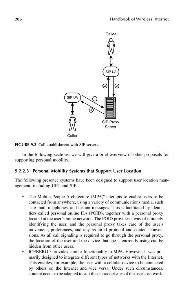
206 Handbook of Wireless Internet
In the following sections, we will give a brief overview of other proposals forsupporting personal mobility.
9.2.2.3 Personal Mobility Systems that Support User Location
The following presence systems have been designed to support user location man-agement, including UPT and SIP.
• The Mobile People Architecture (MPA)9 attempts to enable users to becontacted from anywhere, using a variety of communications media, suchas e-mail, telephones, and instant messages. This is facilitated by identi-fiers called personal online IDs (POID), together with a personal proxylocated at the user’s home network. The POID provides a way of uniquelyidentifying the user, and the personal proxy takes care of the user’smovement, preferences, and any required protocol and content conver-sions. As all call signaling is required to go through the personal proxy,the location of the user and the device that she is currently using can behidden from other users.
• ICEBERG10 provides similar functionality to MPA. However, it was pri-marily designed to integrate different types of networks with the Internet.This enables, for example, the user with a cellular device to be contactedby others on the Internet and vice versa. Under such circumstances,content needs to be adapted to suit the characteristics of the user’s network.
FIGURE 9.3 Call establishment with SIP servers.
Caller
SIP UA
SIP ProxyServer
4
SIP UA
Callee
1
32

User Mobility in IP Networks: Current Issues and Recent Developments 207
This is performed by ICEBERG Point of Presence (iPOP). Because it isbased on the Ninja clustering platform,11 it provides an execution envi-ronment, where adaptation libraries can be downloaded and configuredon demand.
9.2.2.4 Personal Mobility Systems that Support Personalization
The following architectures were designed to support personalization:
• NetChaser12 is a mobile-agent-based framework that is designed to supportpersonal mobility in accessing three Internet services: HTTP, e-mail, andFTP. The mobile agents in NetChaser form a wrapper layer between theapplications (Internet clients and servers) and the network. They assistthe users by following them when they change working terminals. Inter-action with the user is achieved by using a Web browser.
• Secure and Open Mobile Agent (SOMA) is an architecture where mobileagents are used as middleware to support mobile computing, whichincludes both terminal and personal mobility.13 Personal mobility is sup-ported in this architecture through the use of user virtual environment(UVE). The UVE service lets users connect to the Internet at differentlocations while maintaining the personal configurations indicated in theiruser profiles.
• In the Telecom Research Programme (TELEREP), a mobile-agent-basedarchitecture to support mobility was introduced.14 The architecture usesvarious mobile agents to perform different tasks. A user agent (UA) actson the user’s behalf when the user moves between different networks andcontrols the other agents. The application agent (AA) and the data agent(DA) maintain the user’s applications and data by moving them close tothe user. Finally, the profile agent (PA) stores the user’s profiles. When auser moves from the home network, all the above-mentioned agents willmigrate as well, carrying with them the applications, data, and profiles.This allows the user to access applications and data locally.
• Using the technique of application migration, Takashio and coworkersintroduced a framework called follow-me Desktop, or f-Desktop.15 In thisframework, the context of so-called follow-me applications is mobile. Thefollow-me applications can be implemented using mobile agent technol-ogies. When a user changes terminal, the user’s applications are “frozen.”The frozen applications are transmitted across the network to the user’snew terminal and resume their execution there.
• None of the above-mentioned personal mobility architectures support bothuser location and personalization. The Integrated Personal Mobility Archi-tecture (IPMOA)16 addressed this issue by introducing an overlay networkthat caters for various personal mobility services such as interpersonalcommunications (location support), customized Internet services, remoteapplication execution, and file synchronization (personalization support).

208 Handbook of Wireless Internet
9.3 CHALLENGES AND RECENT DEVELOPMENTS OF TERMINAL MOBILITY
At present, we experience the early stages of the emerging mobile Internet and theroad has not yet been mapped out. The work that has been proposed from differentresearch groups has largely addressed the fundamental issues of user mobility andmany areas still remain relatively untouched. As can be expected, the industry lagsbehind the research community and there is no universal consensus on standards formobility management.
To date, the predominant picture is to use Mobile IP for global addressing andspecific link layer technologies for certain access technologies, e.g., GPRS TunnelingProtocol (GTP) in UMTS networks. However, because the rollout of mobile datanetworks has just begun, there is little experience with the difficulties and propertiesof mobile computing. Therefore, over the next few years as the mobile experiencegrows, many new issues will be revealed and problems that only have been touchedby researchers to date will be thoroughly investigated.
9.3.1 MOBILE IP ENHANCEMENTS
Although Mobile IP is a simple and scalable solution for IP mobility, it suffers fromperformance and security problems and has a number of drawbacks, especially whenserving users with high mobility and quality of service (QoS) expectations. Currently,there are many enhancements being proposed to Mobile IP, and these proposals aresummarized in the following sections.
9.3.1.1 Route Optimization
Because all packets destined to a mobile host have to be routed through its HA, thechosen path can be significantly longer than the direct route. In a QoS supportedmobile network, a longer path and the ensuing delay will produce a higher probabilityof call dropping and service refusal. To rectify this problem, the extension of routeoptimization in Mobile IP17 provides a means for corresponding hosts to cache theactual location of a mobile host so that their packets can be tunneled to the mobilehost directly.
The IPv6 base specification incorporates this idea. In addition, it replaces thetunneling mechanism with loose source routing that incurs less delivery overheads.18
Thus, Mobile IPv6 overcomes the previously mentioned shortcoming of MobileIPv4.
Another approach to this problem is to introduce the concept of a location server.Through the location server, the mobile host can update its current location and theCH can then query the server for the current location of a mobile user beforetransmitting a packet. Because the CH knows the actual location of an MH, bothtriangle routing and tunneling can be avoided. The associated call setup and signalingprotocols can be implemented by either changing the Mobile IP protocol (e.g., MIP-LR19), setting up user agents at the application layer (e.g., the SIP with mobility

User Mobility in IP Networks: Current Issues and Recent Developments 209
support20 and session layer mobility management21), or modifying the upper layerprotocol (e.g., the MSOCKS22 and the end-to-end approach to host mobility23).
It is worth noting that in order to enable optimal routing, all the above proposalshave to introduce mobility awareness in the corresponding hosts. In particular, itrequires either modifications to the IP protocol stack (binding cache followed bytunneling or loose source routing), or the addition of a location server and associatedsignaling protocols. Unfortunately, a global deployment of these enhancements willnot be available in the near future.
9.3.1.2 Frequent Handover and Fast Location Updates
Mobile IP does not mandate fast handover and location updates, and hence thereare several problems when serving highly mobile users. Each time a mobile hostmoves from one subnet to another, it needs to register its new location with the HA.Thus, if the visited network is some distance away from the home network, thesignaling delay for reregistrations can become large and, consequently, many packetscould be misrouted.
In addition, Mobile IP does not require a mobile host to inform its previous FAwhen it moves. Therefore, the previous FA is not able to reroute packets to thecurrent FA. The extension of routing optimization in Mobile IP17 allows the misroutedpackets to be tunneled from the old to the new foreign agent. However, a drawback isthat the mobility agents need to deal with many associated security issues.
Another disadvantage is that when intersubnet handovers occur, the mobile hostobtains a new COA and thus packets destined to the mobile host will be encapsulatedwith a different tunnel header. Even if we assume that network resources can bedynamically reallocated across a QoS-capable Internet backbone during handovers,such rerouting and resource allocation processes may take a long time when the HAand the FA are far apart (see Figure 9.4(a)).
Lately, in addition the work on Mobile IPv6, there have been attempts in theInternet community to resolve these problems by introducing the concept of micromobility. This concept is a promising approach to efficiently manage high usermobility within a single administrative domain (see Figure 9.4(b)). In micro-mobilityschemes, (1) location updates within a domain are handled locally, thus avoidingfrequent reregistrations across the Internet to the HA; and (2) by using a specificpacket delivery scheme within the region, it prevents the costly reestablishment ofend-to-end routing between the HA and the FA. This regional framework is normallycoordinated by a domain gateway, which serves as the interchange entity for mobilitymanagement within a domain (micro–mobility) and mobility management acrossdifferent domains (macro–mobility).
9.3.1.2.1 Micro MobilitySo far, only Mobile IP has been considered as the solution for macro-mobilitymanagement. On the other hand, many types of regional network architectures havebeen proposed for micro-mobility management. The proposals can be divided intofour categories:

210 Handbook of Wireless Internet
FIGURE 9.4 An illustration of the necessity of micro-mobility management in IP network-ing: (a) signaling and rerouting without the support of micro mobility; (b) signaling andrerouting with the support of micro mobility.
CH
HA
FA1 FA0
MH
a
b
c
d e
(a)
Normal forwarding =IP encapsulation =Re-registration Messages =Data Path before Handover = a, bPropergation of Location Updates = c, dData Path after Handover = a, e
InternetBackbone
ForeignAdministrative
Domain
CH
HA
FA1 FA0
MH
f
b
c
a
e
(b)
InternetBackbone
ForeignAdministrative
Domain
DomainGateway
d
Normal forwarding =IP encapsulation =Micro-mobility signaling =Micro-mobility forwarding =Data Path before Handover = a, b, cPropagation of Location Updates = d, eData Path after Handover = a, b, f

User Mobility in IP Networks: Current Issues and Recent Developments 211
1. Cascade tunneling: This has been proposed as a solution to locationregistration latencies resulting from large distances between mobile hostsand servers. The solution is to perform registrations locally in the visiteddomain through a hierarchy of foreign agents with tunneling betweenthem as described in Gustafsson and coworkers.24 This approach reducesthe number of signaling messages to the home network and shortens thesignaling latency when moving from one foreign agent to another. How-ever, the scheme requires the introduction of new registration messagesfor local mobility. Furthermore, a special gateway entity (gateway foreignagent) is required to handle and transform these regional registrations,and also to dynamically manage regional tunnels for the mobile host inboth the forward and reverse directions. As a result, changes to both HA,FA, and MH are necessary. The changes ensure that the HA will alwayssee the gateway foreign agent as the current location of a mobile host,regardless of which FA is serving the mobile host in the visited domain.The cascade tunneling approach also can be found in other proposals suchas Regional Aware Foreign Agent25 and Transparent Hierarchical MobilityAgents.26 Instead of modifying those well-defined mobility agents ofMobile IP, these proposals introduce several new entities in their frame-works for handling the regional tunnel management.
2. Dynamic per-host routing: In a limited geographical area, i.e., betweendifferent subnets within the same management domain, the concept ofdynamic per-host routing can be deployed as an alternative to regular IProuting. Problems associated with scalability and compatibility can beminimized because of the limited scope and single ownership of themanagement domain. With this scheme, IP addresses have no locationsignificance inside the domain, and therefore neither tunneling nor addressconversion is necessary during packet delivery. For example, HAWAII27
uses path refresh messages to establish and update host-specific forward-ing entries in routers between a gateway entity called the domain rootrouter and the base station. In HAWAII, the role of a base station istwofold. First, it emulates an FA for replying to Mobile IP registrationmessages, thus making HAWAII entities transparent to mobile hosts thatuse Mobile IP. Second, it converts Mobile IP registration updates intoHAWAII refresh messages, which in turn either revives or creates newforwarding entries in the routers, depending on whether a subnet handoverhas taken place. A similar approach is used in Cellular IP,28 which alsorequires special routers that can set up, refresh, or modify host-specificforwarding entries using control packets. Besides control packets, routersutilize user data packets to refresh forwarding entries. To cater to large-scaledeployment, special paging packets and paging caches are integrated in sucha way that the gateway router can efficiently locate any idle mobile hosts.
3. Overlay routing: Regional overlay routing applies an overlay model whereIP packets are either segmented or encapsulated into another packet formatfor local delivery. Because the data forwarding mechanism is no longerIP-based, address conversions need to be done at the gateway entity and

212 Handbook of Wireless Internet
the base stations, and all mobility support issues have to be resolved bythe overlay network. One example of this approach is IP over MobileATM,29 where IP packets are segmented into ATM cells and delivered byvirtual connections between the gateway and a base station across amobility-enabled ATM network. When the MH roams from one basestation to another, its ongoing virtual connections need to be rerouted toits latest location. Another example of overlay routing that can be con-sidered is multiprotocol label switching (MPLS) for Mobile IP,30 whereIP packets are encapsulated with a label that directs the forwarding pathto a base station. In fact, this is very similar to the cascade tunnelingscheme mentioned earlier, except that the regional IP tunnel is nowreplaced by a label-switched path across the MPLS domain.
9.3.1.3 Tunneling across QoS Domains
Even though tunneling has been adopted as the standard mechanism for redirectingpackets in Mobile IP, there are certain constraints if it is used in conjunction withthe currently developed QoS frameworks. For example, when the protocol that hasbeen adopted by the IETF Resource Reservation Protocol (RSVP) is applied toMobile IP it is assumed that RESV messages follow the inverse path of PATHmessages. However, this is not the case for the base specification of Mobile IP whichresults in triangle routing.
Another incompatibility comes from the IP-in-IP encapsulation. The insertionof a tunnel header offsets the packet payload, which prevents the fields in thetransport and higher layers from being accessed normally. When RSVP signalingmessages enter a tunnel, they are encapsulated with a tunnel header that carries anIP-in-IP encapsulation rather than a router-alert option. Consequently, RSVP-capablerouters cannot recognize the packets, and resources are not reserved accordingly.
Moreover, even if the required resources could be reserved, the intermediateRSVP routers will not be able to access port numbers correctly in order to distinguishdata packets belonging to different flows. Therefore, it will not be possible to honorthe per-flow state resource reservations.
To resolve these problems, an RSVP tunneling algorithm has been proposed inTerzis et al.31 This scheme passes end-to-end RSVP messages transparently (i.e.,without reservations) between tunnel endpoints and instead the tunnel ingress andegress nodes are responsible for generating additional RSVP signaling to reserveresources between them. When data packets arrive at the tunnel ingress node, theyare wrapped with extra IP and UDP headers such that intermediate routers can applya standard RSVP filter specification to map a packet to the appropriate reservation.Because the source and destination IP address and the destination UDP port number(being assigned as a constant value of 363) are identical for every flow inside thetunnel, a unique source UDP port number is used to differentiate packets fromvarious flows within the tunnel. However, this approach results in further compli-cating both the signaling and encapsulation at the tunnel endpoints. Moreover, itconsiderably increases the overhead of transferring small packet payloads such asvoice data.

User Mobility in IP Networks: Current Issues and Recent Developments 213
RSVP is proposed to be used with and tightly connected to the Integrated Services(IntServ) architecture, and it is considered as the signaling protocol to be used withDifferentiated Services (DiffServ) as well.32 The same shortcomings when combiningQoS and tunneling will apply to both the IntServ and DiffServ environments. In thecase of a DiffServ infrastructure without RSVP signaling, tunneling poses fewer prob-lems because the DiffServ code point (DSCP) can be copied forwards and backwardsbetween the tunnel header and the original IP header when encapsulation and decap-sulation take place. However, in certain networking scenarios when path- or source-dependent services are desirable, multiple field (MF) classification has to be invokedat the ingress and egress DiffServ routers.33 Similar to RSVP-compliant routers withoutmodifications, these DiffServ edge routers will not be able to access the higher layerinformation in the packet payload due to the extra location offset created by the tunnelheader, thus MF classification cannot be performed properly.
9.3.1.4 Link Layer Assisted Handover Detection
The base specification of Mobile IP was designed to be independent of the underlyinglink layer technology. However, because of its passive approach to handover detec-tion, the registration process when moving from one FA to another can be longenough to cause problems, especially for real-time communications and reliable datatransfers using TCP.34,35
Recently in the IETF, there have been at least two proposals that couple linklayer functionality with Mobile IP in an attempt to minimize service disruptionexperienced by a mobile host when moving between foreign agents. In the FastHandoffs draft,36 the movement of an MH is anticipated from the link layer infor-mation, and simultaneous bindings are used to send multiple copies of packets todifferent potential foreign agents. In the FA Assisted Handoff draft,37 the FA takesa proactive approach to manage handover events. When an FA is aware of a handoveroccurring at the link layer of its current cell, it sets up a mobile host’s visitor entryand issues the handover messages on behalf of the mobile host to the next FA. Asa result, packets can be forwarded from the current FA to the next FA prior toreceiving a formal registration request at the network layer. Unfortunately, thesehandover proposals assume that the identity of the new FA is known to the MH. Ifthere are multiple foreign agents appearing at the link layer, these proposals do notprovide a solution to choose the one the mobile host will select.
9.3.1.5 Discussion of Mobile IP Enhancements
Future IP mobility frameworks need to consider the QoS constraints of activeconnections more closely when handling the usual requests of handover and rerout-ing. Several optimizations can be done to improve the overall mobility performance:
• The handover latency could be improved significantly by tightly couplingthe IP layer with the link layer to give “hints” of potential handovers.
• It is beneficial to forward packets directly between the corresponding andmobile hosts, as it enables the resultant path to be optimized for quality

214 Handbook of Wireless Internet
of service. However, it is unclear if and when all corresponding hostswould become mobility aware to provide this service.
• It would be advantageous to assign a gateway entity near the mobile hostto handle micro–mobility. Techniques such as cascade tunneling, dynamicper-host routing, and overlay routing can be realized with such a gateway.However, it is still debatable as to which approach is the most appropriate.The most obvious consideration is that if tunneling is used to redirectpackets in the future wireless Internet environment, its integration intothe IntServ and DiffServ framework demands more attention and newsolutions.
9.3.2 HIGHER-LAYER MOBILITY MANAGEMENT
One of the visions of future mobile communication is that of a multiaccess envi-ronment in which terminals will be attached to several different overlaid accessnetworks simultaneously. In a multiaccess scenario, it is possible to select networkinterfaces for separate connections. It is likely that users will have access to severaldifferent networked devices. If this becomes a reality, it is likely that future serviceswill emerge where it is possible to hand over sessions between different terminals.
These functions and others are, at the very best, cumbersome to solve in thenetwork layer and therefore some proposals have been made that enable thesefunctions by performing IP mobility management in layers above the network layer.
The MSOCKS proposal22 places the mobility management function in the trans-port layer. This proposal is optimized for local mobility management within a singleaccess network. The mobility management is carried out through splicing differentsocket endpoints together in the kernel of an intermediate node. The binding betweendifferent sockets is updated as clients move around and make address updates.
Another proposal, Session Layer Mobility Management (SLM)21 places mobilitymanagement in a layer above the transport layer. This proposal lifts transport protocoldependency by maintaining states outside of sockets. This way, the data deliverycan be totally separated from IP addresses and even socket endpoints. This in turnenables easy integration of intermediate nodes such as PEPs and handover betweendifferent devices. SLM uses a location server for both users and terminals; this way,it is possible to resolve user identifiers to terminals and to follow these terminals asthey move and change addresses.
A final proposal23 advocates changes to the TCP stack on end hosts to includemobility support. As is the case with MSOCKS, this proposal is transport-protocol-specific, but the mobility management is carried out end-to-end without requiringany intermediate node.
All these proposals require significant changes to end systems. However, it canbe argued that software updates are necessary in any case, and that this is an ongoingprocess. If IPv6 is to be implemented or if RSIP is to be used, end hosts have to beupdated. Similarly, if QoS support will be offered in access networks, end hosts willhave to be upgraded with this support.

User Mobility in IP Networks: Current Issues and Recent Developments 215
9.3.3 ENHANCEMENTS TO SUPPORT CONVERSATIONAL MULTIMEDIA
Traditional circuit switched telephony networks were designed and optimized tosupport voice services. Contrary to this, the packet-switched data network paradigmintroduces a network that is able to support a variety of services and is optimizedfor maximum utilization. QoS management is an important building block to supportclasses of services with strict requirements in terms of parameters such as bandwidth,delay, and jitter from the network. In a fixed networking environment, resourcereservations will suffice because the network behavior is predictable, but a wirelesslink will always suffer from varying conditions due to factors such as noise, handoverlatency, and overcrowded cells. However, interactive and especially conversationalmedia require predictable network behavior even when the host is mobile.
The measures taken to alleviate these problems in mobile networks can bedivided into two orthogonal classes, proactive and reactive. Proactive measures tryto predict the needs of applications and make advance measures on their behalf.Network resource reservation is one of the measures in this category, but at handoverQoS management has to be extended with additional functions to guarantee a smoothtransition to the new cell.
9.3.3.1 Advance Resource Reservation
It is generally difficult to promise a specified level of QoS to mobile uses in mobileenvironments, because there may not be enough resources in the part of the networkinto which the mobile user is moving. Moreover, during handovers the ongoingtraffic is likely to be disrupted, which can violate some of the previously agreedupon QoS parameters such as packet delay, jitter, and loss.
To date, there have essentially been two methods proposed to make QoS supportmore mobility aware. The first method focuses on the preallocation of networkresources in locations where the mobile host is likely to visit. Preallocation canimprove the continuity of a connection after a move, and reduce packet losses andlatency of resource allocation. However, preallocation requests can fail under severenetwork congestion because there are simply no resources available for reservation.Moreover, even after preallocation, signal fluctuations of the wireless link can con-tribute to the failure of QoS guarantees. Under such conditions, it becomes necessaryto take an alternative approach.
The second approach emphasizes the adaptivity of end systems, where theirapplication, middleware or proxy, reacts to the changes of network resources causedby wireless channel fading and user mobility. This functionality can be achieved bymeans of session customization at various places. In the Internet environment,adaptive end systems have to rely on mechanisms that probe the network in orderto avoid congestion. Unfortunately, this action is likely to cause traffic interruptionsbefore congestion can be avoided on a long-term basis.
From this discussion, we believe that the first method (i.e., advance reservation)is a proactive approach to deliver some level of QoS guarantees (at least statistically)

216 Handbook of Wireless Internet
to the mobile users, whereas the second method (i.e., end system adaptivity) is areactive approach to cope with changes of QoS and, as such, they are complementary.
9.3.3.1.1 Current Approaches of Advance ReservationAdvance reservation needs to deal with two nontrivial problems, namely, how toconfigure resources in advance, and where to preallocate resources for mobiledevices.
How to Configure Resources in Advance when Mobile: Advance reservationwas originally considered in Wireless ATM research.38–41 Because of the recentinterest in providing mobile QoS in an IP environment, the research community hasaddressed this issue using a combination of Mobile IP and IntServ models. Basedon the topology used for reserved data paths, these proposals can be classified intothree categories as shown in Figure 9.5.
1. Preconfigured anchor rerouting: The MRSVP protocol42 is an example ofpreconfigured anchor routing. In MRSVP, an MH specifies and dynami-cally maintains a set of locations (known as the MSPEC), from which itwants to make advance reservations to its HA (i.e., the anchor point).Special routing entities, called RSVP proxy agents, are provided at thelocations specified in the MSPEC to make reservations on behalf of themobile host. To allow for better link utilization, reservations made bythese proxy agents allow resources to be temporarily borrowed by lowerpriority services. The reservations are either classified as active or passive,depending on whether the reserved resources are strictly used for a dataflow or if they can be temporarily borrowed by other services. Of all proxyagents associated with an MSPEC, only the one currently serving themobile host is allowed to make active reservations. The others will remaincapable of making passive reservations until the mobile host moves intotheir wireless region. Similar mechanisms also can be found in otherproposals such as RSVP-A43 and Mobile Extensions to RSVP.44
2. Preconfigured path extensions: An example of preconfigured path exten-sions is Advanced Reservation Signaling.45 This scheme uses a conceptof passive reservations similar to MRSVP. However, instead of makingmultiple reservation paths connecting the HA with other foreign agents,the advance reservation signaling simply extends the existing RSVP datapath from the current position of a mobile host to all its adjacent basestations.
3. Preconfigured tunneling tree: The proposal in Terzis and coworkers46 isan example of preconfigured tunneling tree schemes. It does not rely onthe notion of passive reservations. Instead, it requires RSVP-capabletunnels47 to be established between the HA and other foreign agents.Unlike ordinary IP encapsulations, these RSVP tunnels are preprovisionedwith certain levels of resources while accommodating multiple end-to-end RSVP sessions. When the resources consumed by mobile hosts vis-iting an FA exceed the reserved amount, the FA can request an incrementalblock of resources to be added to the RSVP tunnel.

User Mobility in IP Networks: Current Issues and Recent Developments 217
FIGURE 9.5 Various schemes for resource preallocation: (a) preconfigured anchor rerouting;(b) preconfigured path extensions; (c) preconfigured tunneling tree.
CH
MH
CH
MH
(a)
CH
1 0
3
42
HA
FA0
FA1FA2 FA3
FA4
MH
1 0
3
42
HA
FA0
FA1FA2 FA3
FA4
(b)
1 0
3
42
HA
FA0
FA1FA2 FA3
FA4
(c)
218 Handbook of Wireless Internet
Where to Preallocate Network Resources for Mobile Devices: It is difficultto determine where to preallocate resources, because of the difficulties of predictinguser movements. Despite this, many resource preallocation algorithms have beenproposed in the literature as an attempt to safeguard the QoS agreements for mobileservices. The algorithms can be classified into three main categories.
1. Neighborhood-based allocation: These schemes preallocate networkresources between an anchor node and a set of base stations surroundingthe MH. The number of base stations involved in the preallocation processdepends on how far ahead in time the network is willing to support amobile service. For example, Virtual Connection Tree48 configuresresources in advance between a root switch and each base station in themanagement domain upon the admission of a call. This implies that thenetwork is willing to support this mobile host as long as it stays withinthe domain, but the network also may have low utilization of resources.In contrast, Advanced Reservation Signaling45 reserves resources onlybetween a, MH’s current location and all adjacent cells. Thus the networkguarantees continuity of services after the next handover, but its furthercommitments are subject to successful reservations at the new neighboringcells.
2. History-based allocation: Through modeling and simulation, many pro-posals have shown that the user mobility history can be helpful in pre-dicting the future movements of a mobile host. Depending on the servicecommitment to mobile users, these proposals preallocate resources atvarious levels in advance along the predicted path. For instance, in orderto obtain mobility-independent service guarantees, MRSVP and othersimilar protocols attempt to make resource reservations at each locationa mobile host may visit during the lifetime of a session. The ShadowCluster concept,49 on the other hand, estimates an MH’s future locationin the short term rather than the long term. Based on the probabilities ofprevious visits and the current trajectory of a mobile host, networkresources are reserved near its present location and along its direction oftravel. A less-ambiguous scheme can be found in the Profile-Based Next-Cell Prediction,50 where resources are reserved only at the most-likelyvisiting cell, and further QoS commitments depend on the reservationprocess after the next handover. It is noticeable that the further ahead ascheme tries to predict the movement, the more likely it is to support thelifetime of a session. However, this is achieved at the expense of overallnetwork utilization because of poor prediction accuracy.
3. Coarse-grained allocation: This scheme does not reserve resources on aper-user or per-cell basis, but works on a logical model called the VirtualBottleneck Cell,51 which treats a cluster of base stations as an aggregatevirtual system. We believe that by controling the parameters and functionsof a virtual bottleneck cell, the QoS agreements at each base station insidethe cluster can be satisfied, even in environments with heterogeneousdemands among base stations. However, it is not obvious how to decide

User Mobility in IP Networks: Current Issues and Recent Developments 219
the boundary of a virtual bottleneck cell, so that it is large enough forusers to stay for a sufficient duration but small enough to accurately reflectthe characteristics of underlying base stations. Moreover, because of itsdesign philosophy, it is difficult to integrate this aggregated admissioncontrol with flow-specific mobility protocols such as MRSVP orAdvanced Reservation Signaling.
9.3.3.1.2 Discussion of Advance Reservation IssuesAdvance reservation should make a compromise between the continuity of QoSsupport and the risk of overreserving resources in the mobile network. The coarse-grained allocation appears to be a scalable solution to this problem, but the feasibilityof aggregated functions and the scope of a virtual bottleneck cell both require furtherinvestigations. The neighborhood-based allocation is the simplest scheme to imple-ment. However, resources are likely to be oversubscribed because mobile users areseldom moving randomly in real life. By applying user mobility patterns, the history-based allocation scheme reserves resources in selective surrounding cells, andthereby attempts to minimize the probability of overreserving resources in the mobilenetwork. This view has been supported by simulation results from various stud-ies,40,49,52 but its usefulness in real life cannot be fully verified unless the actual usermobility in wireless networks is better understood.53
9.3.3.2 Reactive Enhancements to Support Multimedia Delivery
The second class of measures that can be taken to increase QoS in a mobile environmentis reactive measures. These are measures that react when the network characteristicsfail to meet the requirements of the application. If the proactive measures work properly,there is no need for reactive measures because the application requirements would bemet and therefore the two classes of measures are orthogonal.
The most commonly proposed reactive measure is to make the applicationselastic through adaptation. For example, the adaptive multirate (AMR) codec inUMTS networks measures the available data rate due to packet loss and sets theencoding parameters accordingly. In this way, the voice quality can be degraded butstill be continuous when the signal quality goes down. The proactive alternative, torely only on resource reservation, means that resources will have to be overreservedin order to maintain a quality buffer for the codec or the voice output will beintermittent when the network fails to meet the codec demands.
The User Services Assistant (USA)54 architecture takes this a step further. Thearchitecture introduces a reactive QoS manager through which users can start andregister application sessions and subsequently maintain them. USA allows users tomake initial resource reservations, but rather than making hard reservations formaximum usage, minimum reservations are made and the decision of when to reactto low quality is left to the user. Users indicate dissatisfaction to the manager, whichthen proposes adaptations to improve the quality of the session. The adaptations canthen range from lowering encoding rate or increasing reservations to insertingtranscoding functions or protocol translators in the data path.
220 Handbook of Wireless Internet
Thus, USA integrates both proactive and reactive QoS management into the onearchitecture. Initially, the proactive measure of resource reservations takes place,and subsequently when a user indicates that the QoS level is too low, reactivemeasures take place. The steps can take place completely independently because thetwo measures are orthogonal and complementary.
9.4 CHALLENGES AND RECENT DEVELOPMENTS OF PERSONAL MOBILITY
Terminal mobility support mechanisms regard the terminal as the endpoint forcommunication and this has been the traditional view in the single-service telephonysystems as well. Personal mobility shifts the focus from the terminal to the user.From this viewpoint, the terminal becomes a means for transferring the informationfrom the network to the user and for enabling the user to interact with the network.When placing a phone call, the number is linked to the terminal and not the user.In the future, users will have identifiers that are independent of the terminal theyuse but can be resolved into the terminal address.
9.4.1 HETEROGENEITY
When personal mobility becomes a reality, the users’ operational environmentbecomes dynamic and has to be taken into consideration for any communication.One example regarding the emerging mobile Internet infrastructure is the composi-tion of vastly different network technologies with equally different characteristics.Most services on the Internet have been designed with certain assumptions aboutnetwork characteristics such as a certain bandwidth, minimum delay, etc. Much ofthe content assumes capabilities of the end hosts such as screen size, color depth,codec availability, etc.
The mobile Internet is moving toward a situation where these assumptions oftenare broken due to the variations in terminals (PCs, laptops, PDAs, mobile phones,etc.) and the differentiation in access network characteristics. Today, users connectto the Internet through such different networks as Ethernet, cable modems, dial-upmodems, ISDN, GSM, and satellite connections. To cope with this heterogeneity,recent proposals introduced proxy-based solutions that tailor the media to suit theoverall characteristics of the environment.55,56 Furthermore, TCP assumes that alllost packets are due to congestion in the network. In wireless networks, this doesnot hold true. Fluctuations in packet loss are, in these networks, more likely to betransient effects of the signal-to-noise ratio than dependent on congestion. Therefore,recent suggestions place performance enhancing proxies (PEPs) in the radio accessnetworks.57 These proxies implement a modified TCP solution or at least behavedifferently than standard end-to-end TCP.
This discussion illustrates the need for systems that can describe and categorizethe user’s operational environment so that applications can adapt to it. It is criticalto know by what means and under which circumstances a user can be contactedbefore attempting it.
User Mobility in IP Networks: Current Issues and Recent Developments 221
9.4.2 MOBILE AGENTS
One interesting aspect of the personal mobility systems presented earlier in thischapter is that all the systems that support personalization use mobile agent tech-nologies in their design. This is not a coincidence as the characteristics of mobileagents provide many benefits in supporting personal mobility.
Mobile agent technology is regarded by many as the next step from the object-oriented paradigm, and is gaining popularity among software designers. Mobileagents are software agents that are not bounded to the system where they commencetheir execution. Once they have been created by a host, they can suspend theirexecution at any time, transport from one execution environment to another, andresume their execution.58 This ability, in certain realizations, allows mobile agentsto overcome network latency and reduce network traffic. In addition, mobile agentsare autonomous; they have the ability to decide for themselves when and where tomigrate. This characteristic allows mobile agents to operate asynchronously andindependently of the process that created them, which can aid in making a systemrobust and fault tolerant. These two characteristics – autonomy and mobility –provide a good basis for designers to design any type of personal mobility frame-work.
One of the many benefits with mobile agents is that they are naturally hetero-geneous. Because mobile agents are generally system and transport layer indepen-dent and are dependent only on their execution environment, they provide an optimalcondition for seamless system integration.
According to the mobile agent list published in [MOBI02],59 currently there aremore than 70 different mobile agent systems available and this number is growingsteadily. The contributions on the development of these systems come from both theresearch and commercial communities. As each system is designed with differentphilosophies and built for different purposes, each one has its own characteristics,such as migration and agent communication mechanisms. Despite their differences,many mobile agent systems have one thing in common: they use Java as the devel-opment and supporting programming language. The introduction of Java has helpedsolve many of the issues associated with mobile agents, such as performance,security, and agent migration.
Although mobile agents can provide many benefits to mobility systems design,the technology has not yet gained widespread commercial use. Issues such asstandardization, security, and performance still need to be addressed before mobileagents can be used in a wider context. Despite these issues, the technology hasproved to be a useful tool in solving the problems associated with the area of personalmobility.
9.4.3 INTEGRATED PRESENCE
As illustrated earlier, the current personal mobility systems provide support in twovery distinctive areas. They support either contactability or personalization. To thebest of our knowledge, currently there are no personal mobility systems that providecomplete personal mobility support. Today’s devices are no longer restricted to
222 Handbook of Wireless Internet
perform just one function. A computer terminal can act as a communicating devicewith voice over IP and PSTN gateways, and a communicating device has sufficientprocessing capability to perform operations that used to be restricted to desktop PCs.Thus, having a framework that supports only one aspect of personal mobility isinsufficient.
It is likely that a user would like to keep all personal settings and at the sametime be reached by others when migrating from one location to another. Thus,providing true personal mobility with the systems that have been made thus far willrequire the integration of methods of providing personal communications such asMobile People Architecture with a scheme to support personalization of the user’soperating environment, such as NetChaser. However, as each of these schemes wasdesigned with objectives using different philosophies, combining them is at bestcumbersome, and will lead to complex compatibility problems.
9.4.3.1 IPMoA
The Integrated Personal Mobility Architecture (IPMoA)16 is a personal mobilitysystem that attempts to address the above-mentioned issue by introducing an overlaynetwork that caters to various personal mobility services through the use of mobileagent technology. The services the system supports include interpersonal commu-nication (location support), customized Internet services, remote application execu-tion, and file synchronization (personalization support).
9.5 CONCLUDING REMARKS
Currently, wireless Internet access does not differ much from wired access in termsof features. The majority of work so far has focused on rolling out standards foraccess technologies for basic connectivity. However, once the wireless Internet gainspopularity the demand for additional services will become prevalent, and architec-tures will emerge from research laboratories to be implemented in the infrastructure.
In this chapter, we have tried to give an overview of the existing acceptedsolutions and list the most burning issues for the mobile Internet. Each of theseissues will have to be taken into account when designing mobility solutions. Therewill undoubtedly emerge further issues in the future, as the mobile Internet maturesand new types of services are introduced. One of the real challenges will be to devisesolutions that cater to all the aspects and issues.
It is possible that there will be a number of coexisting solutions that are designedto address different scenarios and use cases. The Internet as a connecting infrastruc-ture enables players as different as single applications developers and multinationaloperators to share the one infrastructure for data transfer. The demands put onsolutions to support single applications and global user mobility are very differentindeed. It is evident also that the trend of an increasingly heterogeneous Internetwill continue in the future. The available access technologies will become even morediversified and terminals will become increasingly personalized and reflect userhabits.

User Mobility in IP Networks: Current Issues and Recent Developments 223
In this environment, mobility will take on different roles. For the travelingbusinessman, global connectivity with a traditional roaming agreement infrastructurewill be necessary for all data services, as it is today for 2G cellular telephony. Fora teenager, high bandwidth hot spots for networked gaming consoles, without therequirement of seamless mobility coupled with a separate cellular terminal formessaging, might be the right solution. The important issue is that mobility man-agement will be one of the infrastructure components that will act as a serviceenabler. Therefore the primary goal of these components will be to impose as fewrestrictions on the services as possible. Only then will the mobile Internet reach itsfull potential.
References
1. Richardson, T. et al., Teleporting in an X window system environment, IEEE PersonalCommunications Magazine, 1(3), 6–12, 1994.
2. Perkins, C., Ed., “IP Mobility Support for IPv4,” IETF RFC 2002, Oct. 1996.3. Ford, P., Rekhter, Y., and Braun, H.-W., Improving the routing and addressing of IP,
IEEE Network, May 1993.4. Deering, S. and Hinden, R., “Internet Protocol, Version 6 (IPv6) Specification,” IETF
RFC 2460, Dec. 1998.5. Montenegro, G., “Reverse Tunneling for Mobile IP,” IETF RFC 2344, May 1998.6. Perkins, C., Ed., “IP Mobility Support for IPv4,” IETF RFC 3220, Jan. 2002.7. “Principles of universal personal telecommunication (UPT),” ITU-T Recommenda-
tion F.850, Mar. 1993.8. Rosenberg, J. et al., “SIP: Session Initiation Protocol,” Internet Engineering Task
Force (IETF) Internet draft, Feb. 2002.9. Maniatis, P. et al., The Mobile People Architecture, Mobile Computing and Commu-
nications Review, July 1999.10. Wang, H. et al., ICEBERG: An Internet-core network architecture for integrated
communications, IEEE Personal Communications, Aug. 2000.11. The Ninja Project, http://ninja.cs.berkeley.edu/.
12. Distefano, A. and Santoro, C., “NetChaser: Agent Support for Personal Mobility,”IEEE Internet Computing, March-April 2000, 74–79.
13. Bellavista, P., Corradi, A., and Stefanelli, C., Mobile agent middleware for mobilecomputing, IEEE Computer, 34 (3), 73–81, 2001.
14. Thanh, D. et al., Using Mobile Agent Paradigm in Mobile Communications, EricssonConference Software Engineering, 1999.
15. Takashio, K., Soeda, G., and Tokuda, H., A Mobile Agent Framework for Follow-Me Applications in Ubiquitous Computing Environment, International Conferenceon Distributed Computing Systems Workshop, 2001.
16. Thai, B. et al., Integrated personal mobility architecture: a complete personal mobilitysolution, MONET Journal on Personal Environment Mobility in Multi-Provider andMulti-Segment Networks, submitted, 2002.
17. Perkins, C. and Johnson, D., “Route Optimization in Mobile IP,” IETF Internet draft,Nov. 2000, work in progress.
18. Johnson, D. and Perkins, C., “Mobility Support in IPv6,” IETF Internet draft, May2002, work in progress.

224 Handbook of Wireless Internet
19. Jain, R. et al., Mobile Internet Access and QoS Guarantees Using Mobile IP andRSVP with Location Registers, Proc. IEEE ICC’98, June 1998.
20. Wedlund, E. and Schulzrinne, H., Mobility Support using SIP, Proc. ACMWoWMo’99, Aug. 1999.
21. Landfeldt, B. et al., SLM, A Framework for Session Layer Mobility Management,Proc. IEEE ICCCN, Oct. 1999.
22. Maltz, D. and Bhagwat, P., MSOCKS: An Architecture for Transport Layer Mobility,Proc. IEEE INFOCOM’98, Mar. 1998.
23. Snoeren, A. and Balakrishnan, H., An End-to-End Approach to Host Mobility,ACM/IEEE Mobicom’00, Aug. 2000.
24. Gustafsson, E., Jonsson, A., and Perkins, C., “Mobile IP Regional Registration,” IETFInternet draft, Mar. 2001, work in progress.
25. Foo, S. and Chua, K.C., Regional Aware Foreign Agent Scheme for Mobile-IP, Proc.MoMuC’99, Nov. 1999.
26. McCann, P. et al., “Transparent Hierarchical Mobility Agents (THEMA),” IETFInternet draft, Mar. 1999 (outdated).
27. Ramjee, R. et al., IP-based access network infrastructure for next-generation wirelessdata networks, IEEE Personal Communications, 7 (4), 2000.
28. Campbell, A. et al., Design, implementation, and evaluation of Cellular IP, IEEEPersonal Communications, Aug. 2000.
29. Acharya, A. et al., Mobility support for IP over wireless ATM, IEEE PersonalCommunications, Apr. 1998.
30. Zhong, R. et al., “Integration of Mobile IP and MPLS,” IETF Internet draft, June2000 (outdated).
31. Terzis, A. et al., “RSVP operation over IP tunnels,” IETF RFC 2746, Jan. 2000.32. Bernet, Y. et al., “A Framework for Integrated Services Operation over DiffServ
Networks,” IETF RFC 2998, Nov. 2000.33. Black, D., “Differentiated Services and Tunnels,” IETF RFC 2983, Oct. 2000.34. Fikouras, N. et al., Performance of TCP and UDP during Mobile IP Handoffs in
Single-Agent Subnetworks, Proc. IEEE WCNC’99, Sep. 1999.35. Fladenmuller, A. and De Silva, R., The effect of mobile IP handoffs on the perfor-
mance of TCP, ACM/Baltzer MONET, 4 (2), 1999.36. El Malki, K. and Soliman, H., “Fast Handoffs in Mobile IPv4,” IETF Internet draft,
Sep. 2000, work in progress.37. Calhoun, P. et al., “Foreign Agent Assisted Hand-off,” IETF Internet draft, Nov. 2000,
work in progress.38. Liu, G. and Maguire, G. Jr., A class of mobile motion prediction algorithms for
wireless mobile computing and communications, ACM/Baltzer MONET, 1 (2), 1996.39. Levine, D., Akyildiz, I., and Naghshineh, M., A resource estimation and call admis-
sion algorithm for wireless multimedia networks using the shadow cluster concept,IEEE/ACM Trans. Networking, 5 (1), Feb. 1997.
40. Oliveira, C., Kim, J., and Suda, T., An Adaptive Bandwidth Reservation Scheme forHigh-speed Multimedia Wireless Networks, IEEE JSAC, 16 (6), Aug. 1998.
41. Liu, T., Bahl, P., and Chlamtac, I., Mobility modeling, location tracking, and trajectoryprediction in wireless ATM networks, IEEE JAC, 16 (6), Aug. 1998.
42. Talukdar, A., Badrinath, B., and Acharya, A., MRSVP: A resource reservation protocolfor an integrated services network with mobile hosts, to appear in ACM/WINET, May1999.
43. Pajares, A. et al., An Approach to Support Mobile QoS in an Integrated ServicesPacket Network, Proc. IQWiM Workshop, Apr. 1999.
User Mobility in IP Networks: Current Issues and Recent Developments 225
44. Awduche, D. and Agu, E., Mobile Extensions to RSVP, Proc. IEEE ICCN’97, 1997.45. Mahadevan, I. and Sivalingam, K., Architecture and experimental results for quality
of service in mobile networks using RSVP and CBQ, ACM/Baltzer Wireless Network,6 (3), July 2000.
46. Terzis, A., Srivastava, M., and Zhang, L., A Simple QoS Signaling Protocol for MobileHosts in the Integrated Services Internet, Proc. IEEE INFOCOM’99, Mar. 1999.
47. Terzis, A. et al., “RSVP operation over IP tunnels,” IETF RFC 2746, Jan. 2000.48. Acampora, A. and Naghshineh, M., An architecture and methodology for mobile-
executed handoff in cellular ATM networks” IEEE JACS, 12 (8), Oct. 1994.49. Levine, D., Akyildiz, I., and Naghshineh, M., A resource estimation and call admis-
sion algorithm for wireless multimedia networks using the shadow cluster concept,IEEE/ACM Trans. Networking, 5 (1), Feb. 1997.
50. Bharghavan, V. and Mysore, J., Profile Based Next-Cell Prediction in Indoor WirelessLANs, Proc. IEEE SICON’97, Apr. 1997.
51. Jain, R., Sadeghi, B., and Knightly, E., Toward Coarse-Grained Mobile QoS, Proc.ACM WoWMoM’99, Aug. 1999.
52. Ramanathan, P., Sivalingam, K., Agrawal, P., and Kishore, S., “Dynamic ResourceAllocation Schemes During Handoff for Mobile Multimedia Wireless Networks,”IEEE/JSAC, 17(7), July 1999, pp. 1270–1283.
53. Chan, J. et al., Integrating Mobility Prediction and Resource Pre-allocation into aHome-Proxy Based Wireless Internet Framework, Proc. IEEE ICON 2000, Sep. 2000.
54. Landfeldt, B., Seneviratne, A., and Diot, C., User Services Assistant: An End-to-EndReactive QoS Architecture, Proc. IWQOS98, Napa, California, 1998.
55. Ardon, S. et al., Mobile Aware Server Architecture: A DIstributed Proxy Architecturefor Content Adaptation, INET2001, Stockholm, 2001.
56. Fox, A. et al., Adapting to network and client variation using active proxies: lessonsand perspectives, IEEE Personal Communications, Aug. 1998.
57. “Performance Enhancing Proxies,” http://search.ietf.org/internet-drafts/draft-ietf-pilc-pep-05.txt
58. Lange, D. and Oshima, M., Programming and Deploying Java Mobile Agents withAglets, Addison-Wesley, Reading, MA, 1998.
59. The Mobile Agent List, http://mole.informatik.uni-stuttgart.de/mal/mal.html60. Jung, E. et al., Mobile Agent Network for Support Personal Mobility, Proc. Interna-
tional Conference on Information Network (ICOIN), 1998, pp.131–136.61. Di Stefano, A. and Santoro, C., NetChaser: Agent Support for Personal Mobility,
IEEE Internet Computing, Mar.–Apr. 74–79, 2000.

This page intentionally left blank

2270-8493-1502-6/03/$0.00+$1.50© 2003 by CRC Press LLC
10 Wireless Local Access to the Mobile Internet
José Antonio García-Macías and Leyla Toumi
CONTENTS
10.1 Introduction ................................................................................................22710.2 Local Access Technologies ........................................................................228
10.2.1 The 802.11 Standard....................................................................22810.2.2 802.11 Architecture .....................................................................22910.2.3 The Physical Layer ......................................................................23010.2.4 The Data Link Layer ...................................................................23110.2.5 Other Related Standards ..............................................................232
10.2.5.1 HiperLAN...................................................................23210.2.5.2 Bluetooth ....................................................................234
10.2.6 WLAN Interoperability ...............................................................23510.3 Mobility and the Internet Protocols...........................................................236
10.3.1 The Problem of IP-Based Mobility.............................................23610.3.2 Mobile IP .....................................................................................23810.3.4 Mobile IP problems .....................................................................23910.3.5 Micro-Mobility ............................................................................240
10.4 Perspectives and Conclusions ....................................................................242References..............................................................................................................242
10.1 INTRODUCTION
The Internet has been around for more than three decades now. A key factor for itslongevity is its flexibility to incorporate new technologies. However, this is notalways a seamless process, as some of these new technologies break the basicassumptions under which the Internet works. For instance, the Internet was born ata time when all nodes in a network were fixed devices. Therefore, all the basicprotocols were designed assuming that the end-points would stay fixed. Obviously,with the recent arrival of mobile networking devices (PDAs, laptops, 3G phones,etc.), these assumptions no longer hold.
We will discuss the problem of mobility in IP networks, with a special emphasison the case of mobility within a restricted geographical span, also called micro-mobility.

228 Handbook of Wireless Internet
Before addressing the problem of local IP mobility, we will examine the technologiesthat allow local connectivity, so-called “last-meter” technologies such as 802.11(WiFi), Bluetooth, and HiperLan.
10.2 LOCAL ACCESS TECHNOLOGIES
Among the different technologies available for wireless local networks, the mostpopular without a doubt is IEEE 802.11. Such popularity is evidenced by the numberof products based on this standard that are commercially available. We will describetechnologies used for access networks, with a particular emphasis on the 802.11standard; also, we will discuss other technologies such as Bluetooth and HiperLAN.
It is also worth noting that some companies (e.g., Airify) have announcedproducts to support multiple wireless standards using the same network interface;this way, the same device could be used to take advantage of WLAN technologiessuch as 802.11 or Bluetooth, or wide area wireless, such as GSM or GPRS. However,these types of products have yet to be commercially available.
10.2.1 THE 802.11 STANDARD
The Institute of Electrical and Electronic Engineers (IEEE) ratifed the original802.11 specification in 1997 as the standard for wireless LANs (WLANs). Thatversion of 802.11 provides for 1 and 2 Mbps data rates and a set of fundamentalsignaling methods and other services. Some disadvantages with the original 802.11standard are the data rates that are too slow to support most general businessrequirements. Recognizing the critical need to support higher data transmission rates,the IEEE ratified the 802.11b standard for transmissions of up to 11 Mbps. With802.11b (also known as WiFi), WLANs are able to achieve wireless performanceand throughput comparable to wired 10-Mbps Ethernet. 802.11a offers speeds of upto 54 Mbps, but runs in the 5-GHz band, so products based on this standard are notcompatible with those based on 802.11b.1 Several task groups are working on furtherdevelopments for the 802.11 standard, as shown in Table 10.1.
TABLE 10.1Activities of the Task Groups Working on the 802.11 Standard
Task Group Activities
802.11 Initial standard, 2.4-GHz band, 2 Mbps802.11a High speed PHY layer in the 5-GHz band, up to 24 or 54 Mbps802.11b High speed PHY layer in the 2.4-GHz band, up to 11 Mbps802.11d New regulatory domains (countries)802.11e Medium access control (MAC) enhancements: Multimedia, QoS, enhanced security802.11f Interaccess point protocol for AP interoperability802.11g Higher data rate extension in the 2.4-GHz band, up to 22 Mbps802.11h Extensions for the 5-GHz band support in Europe
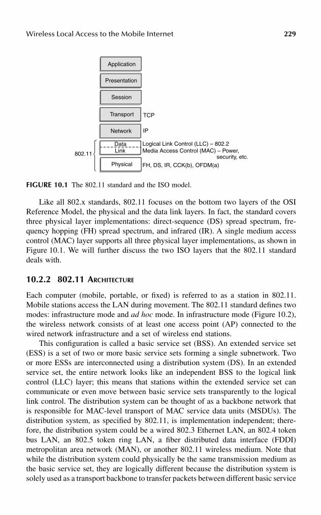
Wireless Local Access to the Mobile Internet 229
Like all 802.x standards, 802.11 focuses on the bottom two layers of the OSIReference Model, the physical and the data link layers. In fact, the standard coversthree physical layer implementations: direct-sequence (DS) spread spectrum, fre-quency hopping (FH) spread spectrum, and infrared (IR). A single medium accesscontrol (MAC) layer supports all three physical layer implementations, as shown inFigure 10.1. We will further discuss the two ISO layers that the 802.11 standarddeals with.
10.2.2 802.11 ARCHITECTURE
Each computer (mobile, portable, or fixed) is referred to as a station in 802.11.Mobile stations access the LAN during movement. The 802.11 standard defines twomodes: infrastructure mode and ad hoc mode. In infrastructure mode (Figure 10.2),the wireless network consists of at least one access point (AP) connected to thewired network infrastructure and a set of wireless end stations.
This configuration is called a basic service set (BSS). An extended service set(ESS) is a set of two or more basic service sets forming a single subnetwork. Twoor more ESSs are interconnected using a distribution system (DS). In an extendedservice set, the entire network looks like an independent BSS to the logical linkcontrol (LLC) layer; this means that stations within the extended service set cancommunicate or even move between basic service sets transparently to the logicallink control. The distribution system can be thought of as a backbone network thatis responsible for MAC-level transport of MAC service data units (MSDUs). Thedistribution system, as specified by 802.11, is implementation independent; there-fore, the distribution system could be a wired 802.3 Ethernet LAN, an 802.4 tokenbus LAN, an 802.5 token ring LAN, a fiber distributed data interface (FDDI)metropolitan area network (MAN), or another 802.11 wireless medium. Note thatwhile the distribution system could physically be the same transmission medium asthe basic service set, they are logically different because the distribution system issolely used as a transport backbone to transfer packets between different basic service
FIGURE 10.1 The 802.11 standard and the ISO model.
Application
Presentation
Session
Transport
Network
TCP
IP
DataLink
Physical
802.11
Logical Link Control (LLC) – 802.2Media Access Control (MAC) – Power,
security, etc.
FH, DS, IR, CCK(b), OFDM(a)

230 Handbook of Wireless Internet
sets in the extended service set. An extended service set can provide gateway accessfor wireless users into a wired network such as the Internet. This is accomplishedvia a device known as a portal. The portal is a logical entity that specifies theintegration point on the distribution system where the 802.11 network integrateswith a non-802.11 network. If the network is an 802.x, the portal incorporatesfunctions that are analogous to a bridge, i.e., it provides range extension and thetranslation between different frame formats.
The ad hoc mode (also called peer-to-peer mode or an independent basic serviceset, or IBSS) is simply a set of 802.11 stations that communicate directly with oneanother without using an access point or any connection to a wired network(Figure 10.3). In ad hoc networks, there is no base and no one gives permission totalk; these networks are spontaneous and can be set up rapidly, but are limited bothtemporally and spatially.
10.2.3 THE PHYSICAL LAYER
The three physical layers originally defined in the 802.11 standard included twospread spectrum radio techniques and a diffuse infrared specification. The radio-based standards operate within the 2.4-GHz ISM (industrial, scientific, and medical)band. These frequency bands are recognized by international regulatory agencies,such as the FCC (United States), ETSI (Europe) and the MKK (Japan) for unlicensedradio operations. As such, 802.11-based products do not require user licensing orspecial training. Spread spectrum techniques, in addition to satisfying regulatoryrequirements, boost throughput and allow many unrelated products to share thespectrum without explicit cooperation and with minimal interference.
FIGURE 10.2 Infrastructure mode.
Distribution System (DS)
Access Point (AP)
Basic Service Set (BSS) –
single cell
Station
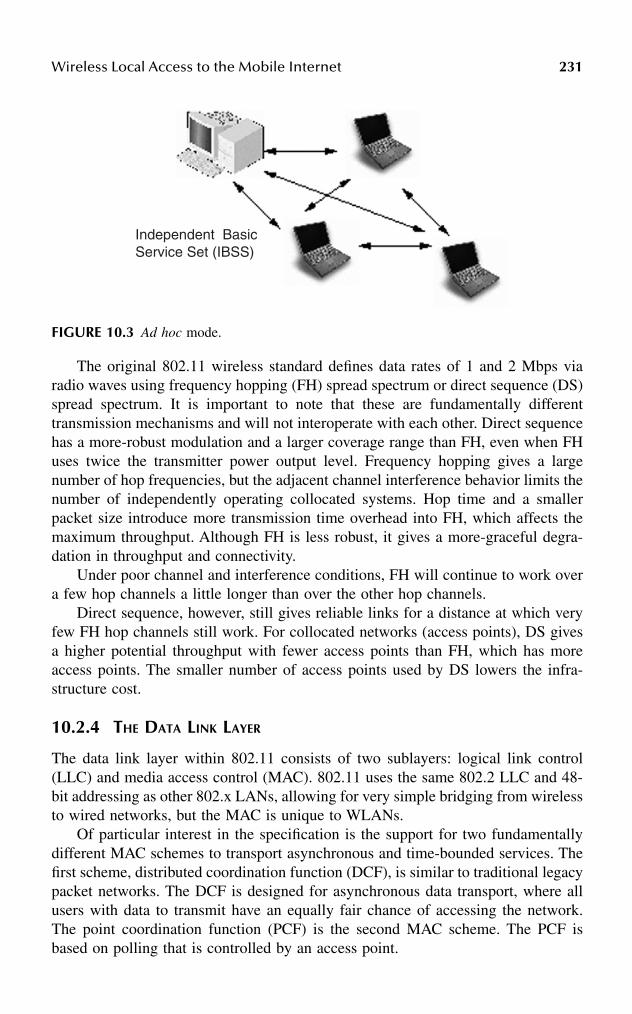
Wireless Local Access to the Mobile Internet 231
The original 802.11 wireless standard defines data rates of 1 and 2 Mbps viaradio waves using frequency hopping (FH) spread spectrum or direct sequence (DS)spread spectrum. It is important to note that these are fundamentally differenttransmission mechanisms and will not interoperate with each other. Direct sequencehas a more-robust modulation and a larger coverage range than FH, even when FHuses twice the transmitter power output level. Frequency hopping gives a largenumber of hop frequencies, but the adjacent channel interference behavior limits thenumber of independently operating collocated systems. Hop time and a smallerpacket size introduce more transmission time overhead into FH, which affects themaximum throughput. Although FH is less robust, it gives a more-graceful degra-dation in throughput and connectivity.
Under poor channel and interference conditions, FH will continue to work overa few hop channels a little longer than over the other hop channels.
Direct sequence, however, still gives reliable links for a distance at which veryfew FH hop channels still work. For collocated networks (access points), DS givesa higher potential throughput with fewer access points than FH, which has moreaccess points. The smaller number of access points used by DS lowers the infra-structure cost.
10.2.4 THE DATA LINK LAYER
The data link layer within 802.11 consists of two sublayers: logical link control(LLC) and media access control (MAC). 802.11 uses the same 802.2 LLC and 48-bit addressing as other 802.x LANs, allowing for very simple bridging from wirelessto wired networks, but the MAC is unique to WLANs.
Of particular interest in the specification is the support for two fundamentallydifferent MAC schemes to transport asynchronous and time-bounded services. Thefirst scheme, distributed coordination function (DCF), is similar to traditional legacypacket networks. The DCF is designed for asynchronous data transport, where allusers with data to transmit have an equally fair chance of accessing the network.The point coordination function (PCF) is the second MAC scheme. The PCF isbased on polling that is controlled by an access point.
FIGURE 10.3 Ad hoc mode.
Independent BasicService Set (IBSS)
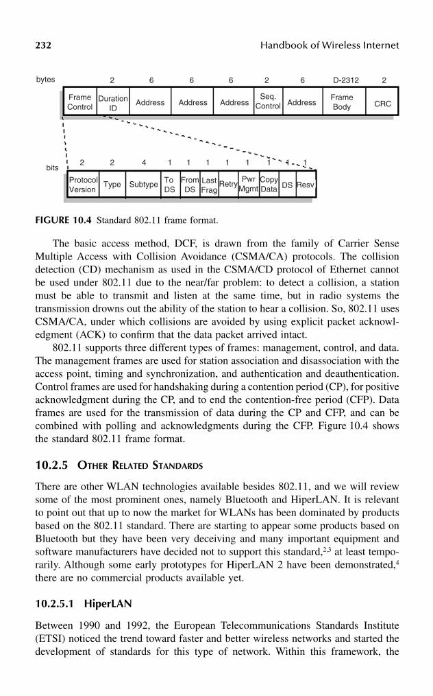
232 Handbook of Wireless Internet
The basic access method, DCF, is drawn from the family of Carrier SenseMultiple Access with Collision Avoidance (CSMA/CA) protocols. The collisiondetection (CD) mechanism as used in the CSMA/CD protocol of Ethernet cannotbe used under 802.11 due to the near/far problem: to detect a collision, a stationmust be able to transmit and listen at the same time, but in radio systems thetransmission drowns out the ability of the station to hear a collision. So, 802.11 usesCSMA/CA, under which collisions are avoided by using explicit packet acknowl-edgment (ACK) to confirm that the data packet arrived intact.
802.11 supports three different types of frames: management, control, and data.The management frames are used for station association and disassociation with theaccess point, timing and synchronization, and authentication and deauthentication.Control frames are used for handshaking during a contention period (CP), for positiveacknowledgment during the CP, and to end the contention-free period (CFP). Dataframes are used for the transmission of data during the CP and CFP, and can becombined with polling and acknowledgments during the CFP. Figure 10.4 showsthe standard 802.11 frame format.
10.2.5 OTHER RELATED STANDARDS
There are other WLAN technologies available besides 802.11, and we will reviewsome of the most prominent ones, namely Bluetooth and HiperLAN. It is relevantto point out that up to now the market for WLANs has been dominated by productsbased on the 802.11 standard. There are starting to appear some products based onBluetooth but they have been very deceiving and many important equipment andsoftware manufacturers have decided not to support this standard,2,3 at least tempo-rarily. Although some early prototypes for HiperLAN 2 have been demonstrated,4
there are no commercial products available yet.
10.2.5.1 HiperLAN
Between 1990 and 1992, the European Telecommunications Standards Institute(ETSI) noticed the trend toward faster and better wireless networks and started thedevelopment of standards for this type of network. Within this framework, the
FIGURE 10.4 Standard 802.11 frame format.
bytes
2 2 4 1 1 1 1 1 1 1 1
2 6 6 6 2 6 D-2312 2
FrameControl
FrameBody
DurationID
Address Address Address AddressSeq.
Control CRC
bits
ProtocolVersion
Type Subtype ToDS
FromDS
LastFrag
RetryPwr
MgmtCopyData DS Resv

Wireless Local Access to the Mobile Internet 233
Broadband Radio Access Networks (BRAN) Project 3 of ETSI is working on astandard called High Performance Radio Local Area Network (HiperLAN). Thisproject quickly separated into four different HiperLAN types:
1. HiperLAN 1 is a standard for ad hoc networking operating in the 5.2-GHz band with a spectrum of 100 MHz and speeds of up to 19 Mbps. Itoffers one-to-one communications as well as one-to-many broadcasts.Using the CSMA/CA technique for resolving contention, the schemeshares available radio capacity between active users who attempt to trans-mit data during an overlapping time span. Although HiperLAN 1 providesa means of transporting time-bounded services, it does not control norguarantee QoS on the wireless link. This is what motivated ETSI todevelop a new generation of standards that support asynchronous data andtime-critical services bounded by specific time delays.
2. HiperLAN 2 specifies a radio-access network that can be used with a varietyof core networks (e.g., IP, ATM, UMTS). HiperLAN 2 operates in the 5.2-GHz band with 100 MHz spectrum, but at speeds of up to 54 Mbps.5
3. HiperAccess is the next step from HiperLAN 2, providing outdoor wire-less access. It gives up to 5 km coverage between wireless access pointsand wireless termination points and is therefore intended for stationaryand semistationary applications. The original operating frequencies werein the 5-GHz band, but this is currently under discussion.
4. HiperLink is the standard meant to provide interconnecting services forhigh data rate sources, such as networks (e.g., HiperLANs). Therefore,HiperLink provides point-to-point interconnections at very high data ratesof up to 155 Mbps over distances up to 150 meters. The operating fre-quency is in the 17-GHz band with 200 MHz spectrum at the moment.
The standard for HiperLAN 1 was finalized in 1996, although amendments weremade to it in 1998. HiperLAN types 2 through 4 were designed to support onlyATM networks, but at the moment HiperLAN 2 supports access to IP and UMTSnetworks. The names for types 3 and 4 were changed to HiperAccess and HiperLink,respectively. Figure 10.5 gives an overview of the different HiperLAN standards.
FIGURE 10.5 Overview of HiperLAN standards.
Hiper LAN Type 1 Hiper LAN Type 2 HiperAccess HiperLink
Wireless 8802 LAN Wireless IP andATM short range
access
Wireless IP andATM remote
access
Wireless broadbandinterconnect
MAC MAC MAC MAC
PHY(5GHz)
PHY(5GHz)
PHY(?? GHz)
PHY(17GHz)

234 Handbook of Wireless Internet
10.2.5.2 Bluetooth
Bluetooth is a protocol intended to wirelessly connect cellular phones, laptops,handheld computers, digital cameras, printers, and other devices.6 It operates overshort distances of up to 10 meters, basically being a wireless replacement for datacables and infrared connections. There are currently some discussions underway toextend its range to 100 meters by increasing the transmit power to 100 mW. AlthoughBluetooth was initially developed by Ericsson in the late 1990s, it is currently ledby the Bluetooth SIG 4, including members such as Nokia, IBM, Toshiba, Intel,3Com, Motorola, Lucent Technologies, and Microsoft. It is, then, not a technologybacked by an standards body, but instead backed by an industry consortium.
The Bluetooth system supports point-to-point or point-to-multipoint connec-tions. In point-to-multipoint, the channel is shared among several Bluetooth units.Two or more units sharing the same channel form a piconet. There is one masterunit and up to seven active slave units in a piconet. These devices can be in any ofthe following states: active, park, hold, and sniff. Multiple piconets with overlappingcoverage areas form a scatternet (Figure 10.6).
The Bluetooth system consists of a radio unit, a link control unit, and a supportunit for link management and host terminal interface functions.
The radio operates in the 2.4-GHz ISM band. Depending on the class of thedevice, a Bluetooth radio can transmit up to 100 mW (20 dBm) to a minimum of 1mW (0 dBm) of power. It uses frequency hopping for low interference and fading,and a TDD (time-division duplex) scheme for full-duplex transmission and transmitsusing GFSK (Gaussian frequency shift keying) modulation.7
FIGURE 10.6 A Bluetooth scatternet of four piconets.
LAN Access Point
PDA
Laptop
Laptop
Mobile phone
Printer

Wireless Local Access to the Mobile Internet 235
The Bluetooth protocol uses a combination of circuit and packet switching. Thechannel is slotted and slots can be reserved for synchronous packets. The protocolstack can support an asynchronous connectionless link (ACL) for data and up tothree simultaneous synchronous connection-oriented (SCO) links for voice or acombination of asynchronous data and synchronous voice (DV packet type). Eachvoice channel supports a 64 kbps synchronous channel in each direction. The asyn-chronous channel can support a maximum of 723.2 kbps uplink and 57.6 kbpsdownlink (or vice versa) or 433.9 kbps symmetric links. The stack (shown inFigure 10.7) primarily contains a physical level protocol (baseband) and a link levelprotocol (LMP) with an adaptation layer (L2CAP) for upper layer protocols tointeract with lower layer ones.
It should be clear, given its distance coverage, bandwidth, and other character-istics, that Bluetooth does not really fit within the profile for supporting WLANs astheir promoters portend through intense marketing campaigns. Bluetooth fits morewithin the profile of technologies used for wireless personal area networks (WPANs),as those studied by the 802.15 Working Group.
10.2.6 WLAN INTEROPERABILITY
Given their ease of installation, dropping prices, and increasingly higher speeds,WLANs are gradually replacing many wired LANs as the networks of choice fortypical activities such as Internet access. There are currently coexistence problemsbetween some of the technologies we mention here, namely between 802.11 andBluetooth. A source of problems is the fact that Bluetooth has been designed totransmit blindly, whenever its timing dictates, as if there was no possibility that a
FIGURE 10.7 The Bluetooth protocol stack.
Applications
TC/IP HID RFCOMM
Data
serial portemulation
L2CAP
synchronous(voice link)
Audio
Con
trol
Link manager
flow control, multiplexing,segmentation, reassembly
Baseband
RF
Asynchronouslinks

236 Handbook of Wireless Internet
collocated system might be using the same frequency (as 802.11 does). This hasearned it the reputation of a “bad neighbor” in the 2.4-GHz band. There are alsoother common sources of interference in this unregulated band, including microwaveovens and newer generations of cordless phones. Historically, microwave ovens areby far the most-significant source of interference in residential and office environ-ments, but with the impending avalanche of new communications devices withembedded Bluetooth radios, serious questions have been raised about their interfer-ence on wireless LANs. The 802.15 WPAN Task Group 2 is developing recom-mended practices and mechanisms to facilitate coexistence between WLANs (suchas 802.11) and WPANs (such as Bluetooth).
10.3 MOBILITY AND THE INTERNET PROTOCOLS
The Internet was born in an era when no mobile networking equipment was available.Therefore, all the basic protocols were designed under the tacit assumption that theend-points of a communication would stay fixed all along a session. With the arrivalof modern communications equipment that allows these end-points to change theirposition, new protocols for handling mobility have been proposed.
Mobile IP allows mobility of devices, potentially around the world; this is whythe type of mobility support it provides is sometimes referred to as global mobility.However, as we will see, mobility within a limited geographical area (called micro-mobility), has different characteristics and requirements that pose the need forspecialized support.
10.3.1 THE PROBLEM OF IP-BASED MOBILITY
Although networking-enabled mobile devices are becoming more common everyday,most networking protocols — including the TCP/IP protocol suite — have beendesigned assuming that hosts are always attached to the network at a single physicallocation. Therefore, host mobility is seen as a rarely occurring fact that can behandled manually. Consider for instance the following scenario: a business executiveis usually connected to the network in the office, but occasionally needs to use alaptop computer for meetings; the meeting facilities may be elsewhere in the buildingor perhaps in a different building or city. If the executive’s desk and the meetingroom have direct access to the same IP subnet, then the mobility process is trivial.In situations where this is not the case, the only solution is for the user to acquirea new IP address from the appropriate local authority. Then, several configurationfiles on the moving machine, on various name servers, and on other machines thatuse the original IP address to identify the moving machine need to be modified.Thus, moving the computer from one place to another involves a slow, error-prone,manual procedure that a typical user does not have the skills or the inclination todeal with. Moreover, even if the process is successfully performed, the mobile hostwill lose its former identity and will usually need rebooting.
The situation is that, given TCP/IP’s early design assumptions that end systemsare stationary, if during an active connection one end system moves, then the wholeconnection breaks, obviously disrupting all networking services layered on top of
Wireless Local Access to the Mobile Internet 237
TCP/IP. Evidence has been given8 that in order to retain transport layer connections,a mobile host’s address must be preserved regardless of its point of attachment tothe network. The problem with a transport layer protocol such as TCP is that a TCPconnection is identified by a 4-tuple:
<src IP address, src TCP port, dest IP address, dest TCP port>
So, if neither host moves, all elements of the tuple remain fixed and the TCPconnection can be preserved. However, if either end of the connection moves, thefollowing problem will take place:
• If the mobile host acquires a new IP address, then its associated TCPconnection identifier also changes. This causes all TCP connectionsinvolving the mobile host to break.
• If the mobile retains its address, then the routing system cannot forwardpackets to its new location.
These problems come from the very design of IP which, in addition to fragmen-tation and reassembly, is responsible for “providing the functions necessary to delivera package of bits (an Internet datagram) from a source to a destination over aninterconnected system of networks.”9 So, this definition designates responsibility toIP for routing datagrams to and from mobile hosts transparently to higher layers.The problem is that IP addresses serve a dual purpose, as they are not only used byhigher layers to identify source and destination hosts, but also by their division intonetwork and host parts which contain location information. Therefore, in its role asan identifier, an IP address must be constant during mobility to avoid affecting higherlayers.
Research studies on IP mobility have suggested that mobility is essentially anaddress translation problem and is best resolved at the network layer.8 As Figure 10.8shows, a mobile host MH can move away from its home network and attach to theInternet through a foreign network. While away, MH obtains a forwarding addressderived from the address space of the foreign network. However, if another host Stries to send packets to MH, it will do so using MH’s home address. The problemis resolved by the use of an address translation agent (ATA) at the home network,and a forwarding agent (FA) at the foreign network. These agents perform functionsf and g, respectively, which are defined as follows:
• f: home address → forwarding address• g: forwarding address → home address
This way, when S sends packets to MH, they first pass through ATA. This agentperforms mapping f to send the packets to the address that MH acquired in theforeign network. At the foreign network, FA intercepts all packets containing MH’sforwarding address. It then proceeds to apply the function g to map from thisforwarding address to MH’s original home address and effectively forward thepackets.

238 Handbook of Wireless Internet
10.3.2 MOBILE IP
In order to react to the new challenges posed to the Internet architecture by thearrival of mobile networking devices, the IETF created the Mobile IP WorkingGroup. The basic Mobile IP standard10 specifies a mobility management architecturefor the Internet. In principle, both local-area and wide-area mobility across wiredand wireless networks can be handled, although certain inefficiencies have beendetected. Later, we will see extensions to Mobile IP proposed to overcome suchinefficiencies.
Figure 10.9 shows the basic operation of Mobile IP. A mobile node is normallyattached to its home network using a static home address. When the mobile nodemoves to a foreign network, it makes its presence known by registering with a foreignagent (FA). The mobile node then communicates with a home agent (HA) in itshome network, giving it the care-of address (COA), which identifies the foreignagent’s location. Typically, routers in a network will implement the roles of homeand foreign agents. When IP datagrams are exchanged over a connection betweenthe mobile node A and a correspondent host B, the following operations occur:11
1. Host B transmits an IP datagram destined for mobile node A, with A’shome address in the IP header. The IP datagram is routed to A’s homenetwork.
2. At the home network, the incoming IP datagram is intercepted by thehome agent. The home agent encapsulates the entire datagram inside anew IP datagram, which has A’s care-of address in the header, and retrans-mits the datagram. The use of an outer IP datagram with a differentdestination IP address is known as tunneling.
3. The foreign agent strips off the outer IP header, encapsulates the originalIP datagram in a MAC-level PDU (for example, an Ethernet frame), anddelivers the original datagram to A across the foreign network.
FIGURE 10.8 Mobility as an address translation problem.
Hos St
ATA
Home network
f
gForeign network
host MHf; home address forwarding address
g: forwarding address home address
FA
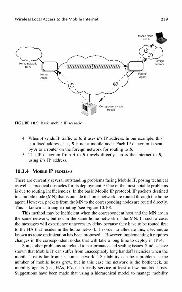
Wireless Local Access to the Mobile Internet 239
4. When A sends IP traffic to B, it uses B’s IP address. In our example, thisis a fixed address; i.e., B is not a mobile node. Each IP datagram is sentby A to a router on the foreign network for routing to B.
5. The IP datagram from A to B travels directly across the Internet to B,using B’s IP address.
10.3.4 MOBILE IP PROBLEMS
There are currently several outstanding problems facing Mobile IP, posing technicalas well as practical obstacles for its deployment.12 One of the most notable problemsis due to routing inefficiencies. In the basic Mobile IP protocol, IP packets destinedto a mobile node (MN) that is outside its home network are routed through the homeagent. However, packets from the MN to the corresponding nodes are routed directly.This is known as triangle routing (see Figure 10.10).
This method may be inefficient when the correspondent host and the MN are inthe same network, but not in the same home network of the MN. In such a case,the messages will experience unnecessary delay because they have to be routed firstto the HA that resides in the home network. In order to alleviate this, a techniqueknown as route optimization has been proposed.13 However, implementing it requireschanges in the correspondent nodes that will take a long time to deploy in IPv4.
Some other problems are related to performance and scaling issues. Studies haveshown that Mobile IP can suffer from unacceptably long handoff latencies when themobile host is far from its home network.14 Scalability can be a problem as thenumber of mobile hosts grow, but in this case the network is the bottleneck, asmobility agents (i.e., HAs, FAs) can easily service at least a few hundred hosts.Suggestions have been made that using a hierarchical model to manage mobility
FIGURE 10.9 Basic mobile IP scenario.
Home networkfor A
HomeAgent
Mobile NodeHost A
ForeignAgent
Foreignnetwork
Correpondent NodeHost B
1 5
3
4
2

240 Handbook of Wireless Internet
could reduce or eliminate these performance and scaling problems.15,16 Security isalso a particular area of attention in Mobile IP.
A lot of the problems of Mobile IP are related to the lack of features forstreamlining mobility support in IPv4.17 Some of these problems may be solved byIPv6. While Mobile IP was originally designed for IPv4, IPv618 incorporates featuresthat support mobility much more easily; several mechanisms that had to be specifiedseparately now come integrated with IPv6. Some of these IPv6 features includestateless address autoconfiguration19 and neighbor discovery.20 IPv6 also attemptsto drastically simplify the process of renumbering, which may be critical to thefuture of routability of the Internet.21 Security is a required feature for all IPv6 nodes.
10.3.5 MICRO-MOBILITY
As several studies indicate,22,23 users’ mobility patterns are highly localized. Forinstance, business professionals may spend a considerable amount of time awayfrom their desks, but once away, most of their mobility will take place within thesame building. While the mobile user is at the foreign administrative domain, thereis no need to expose motion within that domain to the home agent or to correspondenthosts in other domains. Therefore, mobility management within an administrativedomain should be separate from global mobility management.
In principle, Mobile IP can handle both global and local mobility. However, itrequires that the mobile’s home network is notified of every change in location.Moreover, route optimization extensions13 further require that every new location isregistered with hosts that are actively communicating with the mobile node. All
FIGURE 10.10 Triangular routing.
Correspondent node
Homeagent
Foreignagent
Mobile node

Wireless Local Access to the Mobile Internet 241
these location updates incur communications latency and also add traffic to the wide-area portion of the internetwork. Therefore, Mobile IP does not extend well to largenumbers of portable devices moving frequently between small cells. It also has beendemonstrated that, when used for micro-mobility support, Mobile IP incurs disrup-tion to user traffic during handoff, and high control overhead due to frequent noti-fications to the home agent.15 Another type of protocol, a micro-mobility protocol,24
is then needed for local environments where mobile hosts change their point ofattachment to the network so frequently that the basic Mobile IP tunneling mecha-nism introduces network overhead in terms of increased delay, packet loss, andsignaling.
Acknowledging the fact that Mobile IP may not be the universal end-all solutionfor mobility on the Internet, its performance and scalability challenges have beenunder discussion. Within this context, the Mobile IP working group has recentlystarted discussing the subject of micro-mobility protocols. There are severalattributes that micro-mobility protocols aim toward:
• Minimum (or zero) packet loss: Fast handoff techniques have been devel-oped to achieve this, and they may reduce latency or delay.
• Reduced signaling: Techniques for locating mobile hosts, known as pag-ing, have been proposed in order to reduce signaling. Reduced registrationis also an outcome of these techniques.
HAWAII and Cellular IP are two prominent proposals for micro-mobility man-agement and we give a brief presentation of both:
• HAWAII25,26 (Handoff-Aware Wireless Access Internet Infrastructure) isan alternative for providing domain-based mobility (i.e., micro-mobility).Under this approach, Mobile IP is used as the basis for mobility manage-ment in wide-area wireless networks, but new methods for managingmobility within an administrative domain are developed. One point worthhighlighting is that mobile hosts retain their network address while movingwithin a domain; this way, the Home Agent (HA) — if using Mobile IP —and any corresponding hosts are not aware that the host has performedintradomain mobility. Dividing the network into hierarchies, loosely mod-eling the autonomous system hierarchy used in the Internet, is part of theHAWAII approach. Indeed, the gateway into each domain is called thedomain root router, and each host is assumed to have an IP address anda home domain. As already stated, hosts retain their address while movingwithin a domain, so when packets destined to a mobile host arrive at thedomain root router, they are forwarded over specially established pathsto reach the mobile host. However, if the mobile host moves to a foreigndomain, traditional Mobile IP mechanisms are used.
• Cellular IP27,28 aims to integrate cellular technology principles with theIP networking paradigm; this poses difficult challenges, as there are fun-damental architectural differences between cellular and IP networks. ACellular IP node constitutes the universal component of a Cellular IP

242 Handbook of Wireless Internet
network, because it serves as a wireless access point but at the same timeroutes IP packets and integrates cellular control functionality traditionallyfound in mobile switching centers (MSC) and base station controllers(BSC). Cellular IP nodes are modified IP nodes where standard routingis replaced by Cellular IP’s own routing and location-management func-tions. A Cellular IP network is connected to the Internet via a gatewayrouter. Mobility between gateways (i.e., Cellular IP access networks) ismanaged by Mobile IP, while mobility within access networks is handledby Cellular IP. Mobile hosts attached to the network use the IP addressof the gateway as their Mobile IP care-of address.
Another important aspect that has received little attention in the design of micro-mobility protocols is that of quality of service (QoS). Triangular routing, addresstranslation, and complex interaction between agents make Mobile IP unsuitable forQoS support in local environments.29–31
10.4 PERSPECTIVES AND CONCLUSIONS
Among local wireless access technologies, WLANs have a predominant place in themarket, as they are increasingly replacing wired LANs as the method of choice foraccessing the Internet. By far, the most popular WLAN technology is currently802.11 (particularly the 802.11b variation, also named Wi-Fi). Wireless technologiesallow hosts to freely roam between cells, but the Internet’s core protocols were notdesigned with mobility in mind. Even though Mobile IP has been proposed as asolution to handle IP mobility, it is not very suitable for the case of micro-mobility(i.e., mobility within a very limited geographical span). Thus, IP micro-mobilityprotocols have been proposed.
Recent research has addressed the problem of providing QoS guarantees inmicro-mobility environments. Some have proposed RSVP-like signaling protocolsto make resources reservations,32 while others have taken the differentiated servicesapproach (proposed by the IETF), where no hard QoS guarantees are provided, butonly statistical guarantees.33 Also, work in progress within the IETF’s SeaMobyWorking Group is currently addressing problems related to QoS in mobile environ-ments, although not exclusively for the case of micro-mobility.
References
1. Nobel, C., Making 802.11 standards work together, eWeek, July 19, 2000.2. Staff, N., Psion backtracks on consumer plans, http://news.cnet.com, July 12, 2001.3. Orlowski, A., Microsoft turns the drill on Bluetooth, August 1, 2001, available at
http://www.theregister.co.uk.4. Ericsson, Ericsson demonstrates HiperLAN 2 prototypes, Press release, December
11, 2000, available at http://www.ericsson.com/press/20001211–0067.html.5. Khun-Jush, J. et al., HiperLAN type 2 for broadband wireless communication, Eric-
sson Review, 2, 108, 2000.
Wireless Local Access to the Mobile Internet 243
6. Haarsten, J., Bluetooth – the universal radio interface for ad hoc, wireless connectivity,Ericsson Review, 3, 110, 1998.
7. Haarsten, J., The Bluetooth radio system, IEEE Personal Communications Magazine,7, 28, 2000.
8. Bhagwat, P., Perkins, C., and Tripathi, S., Network layer mobility: an architectureand survey, IEEE Personal Communications Magazine, 3, 54, 1996.
9. DARPA, DARPA Internet Program Protocol Specification, Internet RFC 791, 1981.10. Perkins, C., Mobile IP specification, Internet RFC 2002, 1996.11. Stallings, W., Mobile IP, The Internet Protocol Journal, 4, 2, 2001.12. Chesire, S. and Baker, M., Internet mobility 4x4, in ACM SIGCOMM Computer
Communications Review, 318, 1994.13. Johnson, D. and Perkins, C., Route optimization in mobile IP, IETF Mobile-IP draft,
July 1995.14. Mukkamalla S. and Raman, B., Latency and scaling issues in mobile IP, Iceberg
Project technical report, University of California, Berkeley, 2001.15. Caceres, R. and Padmanabhan, V., Fast and scalable handoffs for wireless internet-
works, in ACM Mobicom 96, 1996.16. Soliman, H. et al., Hierarchical MIPv6 mobility management (HMIPv6), Internet
draft draft-ietf-mobileip-hmipv6–04.txt, work in progress, July 2001.17. Perkins, C., Mobile networking through mobile IP, IEEE Internet Computing, 2 (1),
1998.18. Deering, S. and Hinden, R., Internet Protocol version 6 (IPv6), Internet RFC 1883,
1995.19. Thomson, S. and Narten, T., IPv6 stateless address autoconfiguration, Internet RFC
1971, 1996.20. Narten, T., Nordmark, E., and Simpson, W., Neighbor discovery for IP version 6
(IPv6), Internet RFC 1970, 1996.21. Castineyra, I., Chiappa, J., and Steenstrup, M., The Nimrod routing architecture,
Internet RFC 1992, 1996.22. Kirby, G., Locating the user, Communications International, 1995.23. Toh, C., The design and implementation of a hybrid handover protocol for multimedia
wireless LANs, in Proc. 1st International Conference on Mobile Computing andNetworking, 1995.
24. Campbell, A. and Gomez-Castellanos, J., IP micro-mobility protocols, ACM Sigmo-bile Mobile Computer and Communications Review, 2001.
25. Ramjee, R. et al., IP micro-mobility support using HAWAII, Internet draft draft-ietf-mobileip-hawaii-01.txt, work in progress, July 1999.
26. Ramjee, R. et al., HAWAII: a domain-based approach for supporting mobility inwide-area wireless networks, in IEEE International Conference on Network Protocols,1999.
27. Valko, A., Cellular IP — a new approach to Internet host mobility, ACM ComputerCommunication Review, 1999.
28. Campbell, A. et al., An overview of cellular IP, in IEEE Wireless Communicationsand Networks Conference, WCNC, 1999.
29. Chan, J. et al., The challenges of provisioning real-time services in wireless Internet,Telecommunications Journal of Australia, 2000.
30. Helal, A. et al., Towards integrating wireless LANs with wireless WANs using mobileIP, in IEEE Wireless Communications and Networks Conference, WCNC, 2000.
31. Mukkamalla, S. and Raman, B., Latency and scaling issues in mobile IP, ICEBERGProject technical report, University of California, Berkeley, 2001.

244 Handbook of Wireless Internet
32. Legrand, G., Qualité de Service dans les Environnements Internet Mobile, Ph.D.thesis, Université Pierre et Marie Curie, Paris VII, July 2001.
33. García-Macías, J.A. et al., Quality of service and mobility for the wireless Internet,in ACM/IEEE Mobicom 2001, Workshop on Mobile Internet (WMI), Rome, Italy,July 2001.
2450-8493-1502-6/03/$0.00+$1.50© 2003 by CRC Press LLC
11 Location Prediction Algorithms for Mobile Wireless Systems
Christine Cheng, Ravi Jain, and Eric van den Berg
CONTENTS
Abstract ..................................................................................................................24511.1 Introduction ................................................................................................24611.2 Preliminaries...............................................................................................248
11.2.1 Movement History .......................................................................24811.2.2 Approach......................................................................................249
11.3 Domain-Independent Algorithms...............................................................24911.3.1 The Order-K Markov Predictor ...................................................25011.3.2 The LZ-Based Predictors.............................................................251
11.3.2.1 The LZ Parsing Algorithm.........................................25111.3.2.2 Applying LZ to Prediction.........................................251
11.3.3 Other Approaches ........................................................................25511.4 Domain-Specific Heuristics .......................................................................256
11.4.1 Mobile Motion Prediction (MMP) ..............................................25611.4.2 Segment Matching .......................................................................25711.4.3 Hierarchical Location Prediction (HLP) .....................................25811.4.4 Other Approaches ........................................................................260
11.5 Conclusions ................................................................................................260Acknowledgments..................................................................................................261References..............................................................................................................261
ABSTRACT
Predicting the location of a mobile wireless user is an inherently interesting andchallenging problem. Location prediction has received increasing interest over thepast decade, driven by applications in location management, call admission control,smooth handoffs, and resource reservation for improved quality of service. It islikely that location prediction will receive even more interest in the future, espe-cially given the increased availability and importance of location estimation hard-ware and applications.
246 Handbook of Wireless Internet
In this chapter, we present an overview of location prediction in mobile wirelesssystems. We do not attempt to provide a comprehensive survey of all techniquesand applications, but offer instead a description of several types of algorithms usedfor location prediction. We classify them broadly into two types of approaches: (1)domain-independent algorithms that take results from Markov analysis or text com-pression algorithms and apply them to prediction, and (2) domain-specific algorithmsthat consider the geometry of user motion as well as the semantics of the symbolsin the user’s movement history. We briefly mention other algorithms using Bayesianor neural network approaches, and end with some concluding remarks.
11.1 INTRODUCTION
Predicting the location of a user or a user’s mobile device is an inherently interestingproblem and one that presents many open research challenges. The explosion inmobile wireless technologies and applications over the past decade has sparkedrenewed interest in location prediction techniques. The advent of new access tech-nologies such as wireless local area network (WLAN) and third-generation (3G)systems, location based services, and pervasive computing and communicationsindicate that location prediction will become even more important in the future.
There are two classes of applications that can benefit from accurate predictionof a user’s location:
1. End-user applications, where the object is to predict location so that ahuman user can prepare or react accordingly. An example of an end-userapplication is one that predicts the location of a moving vehicle for roadtraffic optimization or for catching thieves if the vehicle is stolen.
2. System-enhancement applications, where location prediction can be usedto enhance system performance, availability, or other metrics. An exampleof a system-enhancement application is one that predicts the location ofa moving vehicle where a passenger is using a cell phone so as to reserveresources in adjoining cells and provide a smooth handoff.
Location can be specified in an absolute coordinate system, e.g., latitude/longi-tude, or in symbolic coordinates (e.g., cell ID). In some cases, both may be available.For example, a facilities administrator in an office building is likely to have a detailedmap of the room layout, showing both absolute locations (in meters from some fixedorigin) as well as symbolic locations (room numbers).
While in principle the same basic prediction techniques can be used for bothend-user and system-enhancement applications, the constraints and metrics differ.For example, in end-user applications it may be important to know the user’sgeographical location, while for a system-enhancement application knowing param-eters required for signaling (e.g., cell ID or paging area) is more relevant. In thischapter, we have assumed that system-enhancement applications are the target. Weassume that time is discretized and a user’s location is given in symbolic coordinates.The task of the location prediction algorithm is to provide the user’s (symbolic)location at the next time step or, if possible, the path of the user (a sequence of
Location Prediction Algorithms for Mobile Wireless Systems 247
locations) over several time steps. Note that the user’s predicted location at the nexttime step may be the same as the current location.
Location prediction has been implicitly or explicitly utilized in many areas ofmobile and wireless system design. For example, consider the problem of locatinga cellular phone user in order to deliver a call to that user or, more specifically, todetermine in which set of cells, called a location area (or registration area or pagingarea), the user is currently located. Broadly speaking, the strategies employed incellular systems essentially consist of having the mobile device report its locationarea to a set of databases that are queried when an incoming call arrives for theuser.1,2 Analysis showed that these strategies placed a heavy burden on the SS7signaling network used in the PSTN wired backbone, in particular on the HomeLocation Register (HLR) database in the user’s home network. Early work onreducing this signaling impact used the following simple idea: the caller’s switchrecorded (cached) the location area at which the called party was found when theswitch last queried the HLR database.3 For the new call, it attempted to locate theuser at that location area first, and only queried the HLR if the user was no longerfound there. Essentially, the switch using this caching strategy employed a simplelocation prediction algorithm in order to reduce the overall signalling load in thesystem. As we discuss later in this chapter, this can be regarded as a type of order-1 Markov predictor where the next term in the sequence is assumed to be identicalto the present term. In this example, as in other applications, in abstract terms thelocation prediction algorithm is worthwhile if, over the entire population of users:
(11.1)
where p is the probability of successful prediction, S is the benefit of success, A isthe cost of running the prediction algorithm itself, and F is the cost of failure. Ofcourse, this general relation has to be made specific and evaluated for any particularapplication, architecture, and prediction algorithm.
We briefly mention types of location and mobility prediction that we do notconsider in this chapter. Efforts on location management and prediction for othertypes of mobile objects, including software objects such as agents,4,5 are outside thescope of this chapter. We also do not cover efforts on predicting the amount of timethat the wireless link that a mobile host is using will stay usable (e.g., Su andcoworkers6), or on predicting the link quality and availability.7
In Section 11.2, we begin our discussion with some definitions and preliminaries.In Section 11.3, we describe location prediction algorithms that do not explicitlytake advantage of the specifics of the mobile wireless environment. These algorithmsgenerally are based on order-k Markov prediction or on the prediction capabilitiesinherent in text compression algorithms. In Section 11.4, we describe algorithmsthat have been designed for location prediction in mobile wireless environments andexplicitly take advantage of their characteristics. Location prediction techniques havebeen developed or suggested for many domain-specific applications, including locationmanagement (e.g., see references 8 through 10, and references therein), smooth handoffs(e.g., see references 10 through 13, and references therein), resource reservations (e.g.,see references 14 through 19, and references therein), call admission control (e.g., see
pS A p F> (1 )+ −
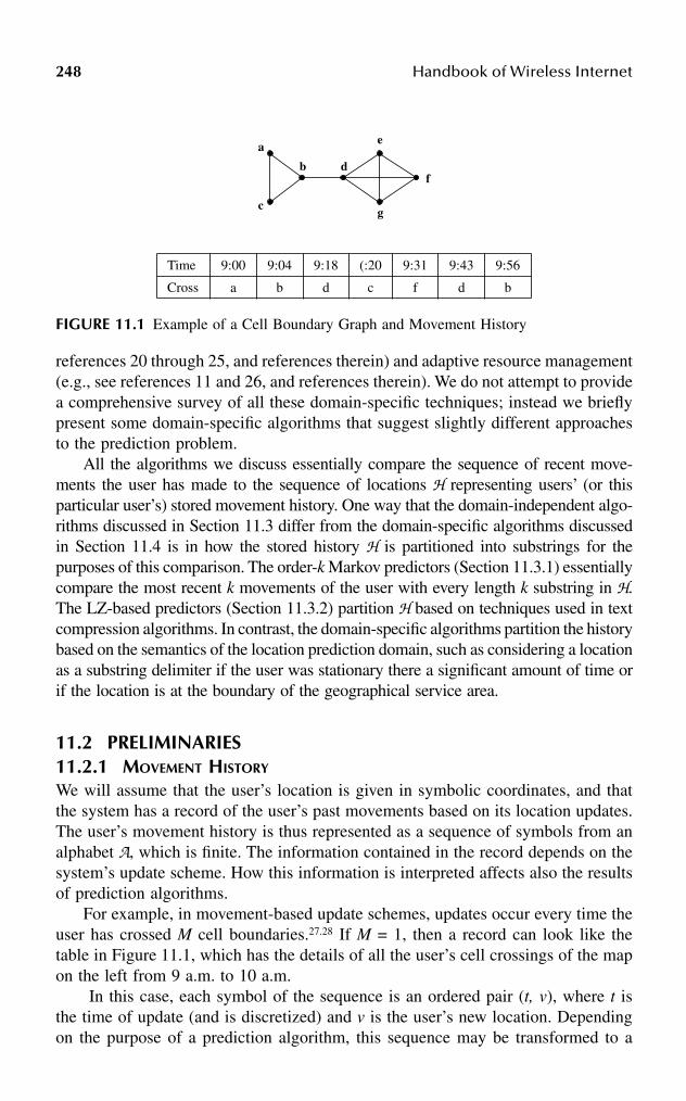
248 Handbook of Wireless Internet
references 20 through 25, and references therein) and adaptive resource management(e.g., see references 11 and 26, and references therein). We do not attempt to providea comprehensive survey of all these domain-specific techniques; instead we brieflypresent some domain-specific algorithms that suggest slightly different approachesto the prediction problem.
All the algorithms we discuss essentially compare the sequence of recent move-ments the user has made to the sequence of locations H representing users’ (or thisparticular user’s) stored movement history. One way that the domain-independent algo-rithms discussed in Section 11.3 differ from the domain-specific algorithms discussedin Section 11.4 is in how the stored history H is partitioned into substrings for thepurposes of this comparison. The order-k Markov predictors (Section 11.3.1) essentiallycompare the most recent k movements of the user with every length k substring in H.The LZ-based predictors (Section 11.3.2) partition H based on techniques used in textcompression algorithms. In contrast, the domain-specific algorithms partition the historybased on the semantics of the location prediction domain, such as considering a locationas a substring delimiter if the user was stationary there a significant amount of time orif the location is at the boundary of the geographical service area.
11.2 PRELIMINARIES11.2.1 MOVEMENT HISTORY
We will assume that the user’s location is given in symbolic coordinates, and thatthe system has a record of the user’s past movements based on its location updates.The user’s movement history is thus represented as a sequence of symbols from analphabet A, which is finite. The information contained in the record depends on thesystem’s update scheme. How this information is interpreted affects also the resultsof prediction algorithms.
For example, in movement-based update schemes, updates occur every time theuser has crossed M cell boundaries.27.28 If M = 1, then a record can look like thetable in Figure 11.1, which has the details of all the user’s cell crossings of the mapon the left from 9 a.m. to 10 a.m.
In this case, each symbol of the sequence is an ordered pair (t, v), where t isthe time of update (and is discretized) and v is the user’s new location. Dependingon the purpose of a prediction algorithm, this sequence may be transformed to a
Time 9:00 9:04 9:18 (:20 9:31 9:43 9:56
Cross a b d c f d b
FIGURE 11.1 Example of a Cell Boundary Graph and Movement History
a
b
c
d
e
f
g

Location Prediction Algorithms for Mobile Wireless Systems 249
new one so that the size of A is smaller.* For instance, if a prediction algorithm’sobjective is to predict the user’s next cell, it may just consider the sequence abdefdb.In this case, A = V, the set of all the cell IDs.
For a time-based update scheme such as described in Rose,29 updates occur everyT time units. If we set T = 5 minutes, then the sequence generated from Figure 11.1would be abbbeeeffdddb. Notice that while this sequence is able to capture theduration of residence of the user at a cell, it misses the cell crossings that took placebetween updates. It will, nonetheless, be useful for a prediction algorithm that seeksto predict the user’s location in the next T time units.
In Bhattacharya and Das,30 the authors suggested generating a movement historythat reflects both cell crossings and durations of residence of the user at each cell,while keeping A = V. Such a history is generated when a user updates every T timeunits and every M cell crossings. If T = 5 and M = 1, the sequence that reflects themovement in Figure 11.1 would be abbbbdeeefffddddb.
Hence, there are different ways of representing a user’s movement history as asequence from a finite alphabet. It is imperative that the choice of sequence bematched to the purpose(s) of the prediction algorithm.
In the following discussion, we will assume that the appropriate movementhistory has been chosen. A history of length n is denoted as a sequence
where each Xi is a random variable and each ai ∈ A. For brevity we will sometimesdenote a sequence as a1a2 ... an. The notation P(Xi = ai) denotes the probability thatXi takes the value ai and denotes an estimate of P(Xi).
11.2.2 APPROACH
We will discuss various prediction algorithms which use different approaches topredict the next term of the user’s itinerary, i.e., sequence L. When possible, wediscuss also how these methods can be extended to predict not just the next termbut the future terms of the sequence as well.
Prediction algorithms usually consist of two steps: (1) to assign conditionalprobabilities to the elements of A given the user’s movement history H, and (2) touse these values to predict the next term in the sequence.
We note that there are some applications where a single guess for the next termmay be too restrictive. For example, to satisfy QoS requirements, Chan andcoworkers31 proposed an algorithm that outputs a subset of A so that the probabilitythat the next term of the movement history is in this set is above some threshold.
11.3 DOMAIN-INDEPENDENT ALGORITHMS
We discuss two families of domain-independent algorithms that have been used asthe core of techniques for location prediction in mobile wireless systems.
* Intuitively, the smaller |A| is, the better because there will be fewer choices for a prediction.
H n n nX a X a= = … =1 1, ,
P̂ Xi( )
250 Handbook of Wireless Internet
11.3.1 THE ORDER-K MARKOV PREDICTOR
The order-k Markov predictor assumes that the next term of the movement historydepends only on the most recent k terms. Moreover, the next term is independentof time, i.e., if the user’s history consists of Hn = {X1 = a1, ..., Xn = an}, then for alla ∈ A,
P(Xn+1 = a | Hn) = P(Xn+1 = a | Xn–k+1 = an–k+1, ..., Xn = an)= P(Xi+k+1 = a | Xi+1 = an–k+1, ..., Xi+k = an), ∀i ∈ N
The current state of the predictor is assumed to be < an–k+1, an–k+2, ..., an>.If the movement history was truly generated by an order-k Markov source, then
there would be a transition probability matrix M that encodes these probabilityvalues. Both the rows and columns of M are indexed by length-k strings from Ak sothat P(Xn+1 = a | Hn) = M(s, s′ ), where s′ and s are the strings an–k+1an–k+2...an andan–k+2an–k+3...ana, respectively. In this case, knowing M would immediately providethe probability for each possible next term of Hn.
Unfortunately, even if we assume the movement history is an order-k Markovchain for some k we do not know M. Here is how the order-k Markov predictorestimates the entries of M. Let N(t, s) denote the number of times the substring toccurs in the string s. Then, for each a ∈ A,
(11.2)
If r predictions are allowed for Xn+1 then the predictor chooses the r symbols inA with the highest probability estimates. In other words, the predictor always choosesthe r symbols which most frequently followed the string an–k+1...an in Hn.
Vitter and Krishnan32 suggested using the above predictor in the context ofprefetching Web pages. Chan and coworkers31 considered five prediction algorithms,three of which can be expressed as order-k predictors. (We will briefly describe theother two in a later section.) Two of them, the location based and direction-basedprediction algorithms, are equivalent to the order-1 and order-2 Markov predictors,respectively, when A is the set of all cell IDs. The time-based prediction algorithmis an order-2 Markov predictor when A is the set of all time-cell ID pairs.
We emphasize that the above prediction scheme can be used even if the move-ment history is not generated by an order-k Markov source. If the assumption aboutthe movement history is true, however, the predictor has the following nice property.Consider F, the family of prediction algorithms that make their decisions based onlyon the user’s history, including those that have full knowledge of the matrix M.Suppose each predictor in F is used sequentially so that a guess is made for each
Xi. We say that a predictor has made an error at step i if its guess does not equal
Xi. Let where I is the indicator function, denote the
ˆ ...
...P X a
N a a a
N a an nn k n n
n k n n
( | )( , )
( , )11
1+
− +
− +
= =HH
H
X̂i
ˆ ˆ ,π H ni
n
i iI X X n( ) = ≠( )=∑ 1

Location Prediction Algorithms for Mobile Wireless Systems 251
average error rate for the order-k Markov predictor. Let F (Hn) be the best possibleaverage error rate achieved by any predictor in F. Vitter and Krishnan32 showed that
as i.e., the average error rate of the order-k predictor is
the best possible as, or that the average error rate is asymptotically optimal.This result holds for any given value of k.
We observe that the algorithm can (naively) be generalized for predicting loca-tion beyond the next cell, i.e., predicting the user’s path, as follows. If M is known,P(Xt = a | Hn) for any t > n + 1 and each a ∈ A can be determined exactly fromM(t–n). The process to estimate M(t–n) is to first construct , the estimate for M, andthen raising it to the (t – n)th power. Then the value(s) of Xt can be predicted usingthe same procedure as for Xn+1. However, any errors in the estimate of M willaccumulate as prediction is attempted for further steps in the future.
11.3.2 THE LZ-BASED PREDICTORS
LZ-based predictors are based on a popular incremental parsing algorithm by Zivand Lempel33 used for text compression. Some of the reasons this approach wasconsidered were (1) most good text compressors are good predictors32 and (2) LZ-based predictors are like the order-k Markov predictor except that k is a variableallowed to grow to infinity.30 We first describe the Lempel-Ziv parsing algorithm.
11.3.2.1 The LZ Parsing Algorithm
Let γ be the empty string. Given an input string s, the LZ parsing algorithm partitionsthe string into distinct substrings s0,s1,…,sm such that s0 = γ, for all j ≥ 1, substringsj without its last character is equal to some si, 0 ≤ i < j, and s0,s1,…,sm = s. Observethat the partitioning is done sequentially, i.e., after determining each si, the algorithmonly considers the remainder of the input string. For example, Hn = abbbbdeeefffd-dddb is parsed as γ, a, b, bb, bd, e, ee, f, ff, d, dd, db.
Associated with the algorithm is a tree, which we call the LZ tree, that is growndynamically to represent the substrings. The nodes of the tree represent the substringswhere node si is an ancestor of node sj if and only if si is a prefix of sj. Typically,statistics are stored at each node to keep track of information such as the numberof times the corresponding substring has been seen as a prefix of s0,s1,…,sm or thesequence of symbols that has followed the substring. The tree associated with thisexample is shown in Figure 11.2.
Suppose sm+1 is the newest substring parsed. The process of adding the nodecorresponding to the sm+1 in the LZ tree is equivalent to tracing a path starting fromthe root of the tree through the nodes that correspond to the prefixes of sm+1 until aleaf is reached. The node for sm+1 is then added to this leaf. Path tracing resumes atthe root.
11.3.2.2 Applying LZ to Prediction
Different predictors based on the LZ parsing algorithm have been suggested in thepast.19,30,32,34,35 We describe some of these here and then discuss how they differ.
n → ∞, ˆ ,π πH HFn n( ) → ( )n → ∞,
M̂

252 Handbook of Wireless Internet
Suppose Hn has been parsed into s0,s1,…,sm. If the node associated with sm is aleaf of the LZ tree, then LZ-based predictors usually assume that each element inA is equally likely to follow sm. That is, Otherwise, LZ-basedpredictors estimate P(Xn+1 = a | Hn) based on the symbols that have followed sm inthe past when Hn was parsed.
1. Vitter and Krishnan32 considered the case when the generator of Hn is afinite-state Markov source, which produces sequences where the nextsymbol is dependent on only its current state. (We note that a finite-stateMarkov source is more general than the order-k Markov source in thatthe states do not have to correspond to strings of a fixed length from A.)They suggested using the following probability estimates: for each a ∈A, let
(11.3)
where NLZ(s′,s) denotes the number of times s′ occurs as a prefix amongthe substrings s0,…, sm, which were obtained by parsing s using the LZalgorithm.
It is worthwhile comparing Equation 11.2 with Equation 11.3. Whilethe former considers how often the string of interest occurs in the entireinput string, (i.e., in our application, the history Hn), the latter considershow often it occurs in the partitions si created by LZ. Thus, in the exampleof Figure 11.2, while bbb occurs in Hn, it does not occur in any si.
If r predictions are allowed for Xn+1, then the predictor chooses the rsymbols in A that have the highest probability estimates. Once again,Vitter and Krishnan showed that this predictor’s average error rate isasymptotically optimal when used sequentially.
FIGURE 11.2 An example LZ parsing tree.
" "
"a"
"b" "e"
"f"
"d"
"bd"
"db" "dd"
"ee"
"ff""bb"
ˆ .P X an n+ =( ) =1 1H A
ˆ ,
,P X a
N s a
N sn n
LZm n
LZm n
+ =( ) = ( )( )1 H
H
H

Location Prediction Algorithms for Mobile Wireless Systems 253
2. Feder and coworkers35 designed a predictor for arbitrary binarysequences, i.e., sequences where A = {0,1}. The following are their prob-ability estimates:
(11.4)
For convenience let . Then the predictor guesses thatthe next term is 0 with probability φ/α, where for some chosen ε > 0
Essentially, the predictor outputs 0 if α is above 1/2 + ε, 1 if α is below1/2 + ε, and otherwise outputs 0 or 1 probabilistically.
Example: Let sm = 00 and suppose NLZ(000) = 11 and NLZ (001) =9. Thus, If ε = 0.01,then the predictor would guess 0 for Xn+1; if ε = 0.25, then the predictorwould guess 0 for Xn+1 with probability of 13/22 and 1 with probability9/22.
Compare the output of Vitter and Krishnan32 with Feder and coworkers’algorithm35 for this example assuming a single prediction is desired (r =1). The former simply calculates the probability estimates
and so that the predic-tion is 0. The latter provides predictions with certainty only if the prob-ability estimates for 0 and 1 are not too close (i.e., not within 2ε of eachother).
If the predictor is used sequentially, then Feder and coworkers35 showedthat its asymptotic error rate is the best possible among predictors withfinite memory.
3. Krishnan and Vitter generalized Feder and coworkers’ procedure and resultto arbitrary sequences generated from a bigger alphabet;34 i.e., |A| ≥ 2. Theirscheme for computing for each a ∈ A is not only basedon how frequently a followed sm, but also on the order in which thesymbols followed sm. Specifically, they assigned probability estimates inthe following manner. Suppose after the first occurrence of sm, the nextoccurrence is smh1 for some symbol h1, the following occurrence is smh2,etc. Consider all the symbols hi that have followed sm (after its firstoccurrence), and create the sequence h = h1h2h…ht. Let h(i, j) denote the
ˆ
ˆ
P XN s
N s N s
P X
n n
LZm
LZm
LZm
n n
( 0 | )( ( 0) 1)
( ( 0) ( 1) 2)
1 ( 1 | ).
1
1
+
+
= = ++ +
= − =
H
H
a P Xn n= =+ˆ( 0 | )1 H
φ α
α ε
εα ε α ε
ε α
( )
0 0 <12
12
12
12
12
12
112
< 1.
=
≤ −
−
+ − ≤ ≤ +
+ ≤
ˆ ˆ .P X a P Xn n n n( | ) 12 22 0.545 1 ( 1 | )1 1+ += = = = − =H H
P̂ Xn n( 0 | ) 12 221+ = =H ˆ ,P Xn n( 1 | ) 10 221+ = =H
P̂ X an n( | )1+ = H

254 Handbook of Wireless Internet
subsequence hihi+1h…hj. Let and h′ = h(4q–1 + 2, t). Then foreach a ∈ A,
(11.5)
If r predictions are allowed for Xn+1, then the predictor uses theseprobability estimates to choose without replacement r symbols from A.
Example: Suppose 9 symbols from A = {0,1,2} followed sm and thesequence of the symbols is h = 210011102. Thus, q = 2. The relevantsubsequence h for predicting Xn+1 is 1102. The frequency of 0, 1, and 2in the subsequence are 1, 2, and 1, respectively, so their probabilityestimates are 1/18, 16/18, and 1/18, respectively. The predictor will pickr of these symbols without replacement using these probabilities
4. Bhattacharya and Das30 proposed a heuristic modification to the construc-tion of the LZ tree, as well as a way of using the modified tree to predictthe most-likely cells that the user will reside in so as to minimize pagingcosts to locate the user. The resulting algorithm is called LeZi-Update.Although their application (similar to that of Yu and Leung19) lies in themobile wireless environment, the core prediction algorithm itself is notspecific to this domain. For this reason, and for ease of exposition, weinclude it in this section.
As pointed out earlier, not every substring in Hn forms a leaf si in theLZ parsing tree. In particular, substrings that cross boundaries of the si,0 < i ≤ m, are missed. Further, previous LZ-based predictors take intoaccount only the occurrence statistics for the prefixes of the leaves si. Toovercome this, the following modification is proposed. When a leaf si iscreated, all the proper suffixes of si are considered (i.e., all the suffixesnot including si itself.) If an interior node representing a suffix does notexist, it is created, and the occurrence frequency for every prefix of everysuffix is incremented.
Example: Suppose the current leaf is sm = bde and the string de is onethat crosses boundaries of existing si for 1 ≤ i < m (see Figure 11.2). Thusde has not occurred as a prefix or a suffix of any si, 0 < i < m. The set ofproper suffixes of sm is Sm = {γ,e,de}and because there is no interior nodefor de, it is created. Then the occurrence frequency is incremented for theroot labeled γ, the first-level children b and d, and the new interior node de.
We observe that this heuristic only discovers substrings that lie withina leaf string. Also, at this point it would be possible to use the modifiedLZ tree and apply one of the existing prediction heuristics, e.g., useEquation 11.3 and the Vitter-Krishnan method.
However, in Bhattacharya and Das30 a further heuristic is proposed touse the modified LZ tree for determining the most-likely locations of the
q t= 4
P̂ X aN a h
N a hn n
q
a A
q( | )( ( , ))
( ( , )).1
2
2+
∈
= = ′′∑
H

Location Prediction Algorithms for Mobile Wireless Systems 255
user. This second heuristic is based on the prediction by partial match(PPM) algorithm for text compression.36 (The PPM algorithm essentiallyattempts to “blend” the predictions of several order-k Markov predictors, fork = 1, 2, 3, ...; we do not describe it here in detail.) Given a leaf string sm,the set of proper suffixes Sm is found. Observe that each element of Sm is aninterior node in the LZ tree. Then, for each suffix, the heuristic considers thesubtree rooted at the suffix and finds all the paths in this subtree originatingfrom the root. (Thus these paths would be of length l for l = 1, 2,…t, wheret is the height of the suffix in the LZ tree.) The PPM algorithm is then applied.PPM first computes the predicted probability of each path in the entire setof paths and then uses these probabilities to compute the most-probablesymbol(s), which is the predicted location of the user.
5. Yu and Leung19 use LZ prediction methods for call admission control andbandwidth reservation. Their mobility prediction approach is novel in thatit predicts both the location and handoff times of the users. Assume timeis discretized into slots of a fixed duration. The movement history Hn ofa user is recorded as a sequence of ordered pairs (S,l1),(T2,l2),…,(Tn,ln),where S is the time when the call was initiated at cell l1 and S + Ti iswhen the i-th handoff occurred to cell li for i ≥ 2. In other words, Ti isthe relative time (in time slots) that has elapsed since the beginning ofthe call when the i-th handoff was made.
Similar to LeZi-Update, if the user is currently at cell l and time S +T, the predictor uses the LZ tree to determine the possible paths the usermight take and then computes the probabilities of these paths. UnlikeLeZi-Update, the computation is easier and is not based on PPM. Thealgorithm estimates the probabilities Pi,j(Tk), the probability that a mobilein cell i will visit cell j at timeslot S + Tk, by adding up the probabilitiesof the paths in the LZ tree that are rooted at the current time-cell pair andcontain the ordered pair (j, Tk).
11.3.3 OTHER APPROACHES
Chan et al.31 suggest a different approach for location prediction based on using anorder-2 Markov predictor with Bayes’ rule. The idea is to first predict the generaldirection of movement and then use that to predict the next location. For the order-2 predictor, the last two terms of the user’s itinerary, L = <L
1, L
2> are used. First,
the most-likely location m steps away from the current location, i.e., L2+m, is predictedbased on the user’s past history. Then the next location L
3 is predicted using Bayes’
rule and the reference point Lm+2 by choosing the location Bx with the highestprobability as follows.
(11.6)P L L B LP L L L B P L L B
P L L B P L L L Bx m
m x x
j
n
j m j
( | )( | ) ( )
( ) ( | )1 2 2
2 1 2 1 2
1
1 2 2 1 2
++
=+
=
∑

256 Handbook of Wireless Internet
11.4 DOMAIN-SPECIFIC HEURISTICS
In this section, we discuss several location prediction algorithms that have beenproposed for specific application domains.
11.4.1 MOBILE MOTION PREDICTION (MMP)Liu and Maguire11 present a location prediction algorithm that can be used forimproving mobility management in a cellular network. The movement of a user ismodeled as a process {M(a,t) : a ∈ A, t ∈ T}, where A is the set of possible locations(called states) and T is an index set indicating time. It is assumed that the user’smovement is composed of a regular movement process {S(a,t)} and a randommovement process {X(a,t)}.
A location is called a stationary state if the user resides there longer than somethreshold time interval, and a transitional state otherwise. A location at the geo-graphical boundary of the service area is called a boundary state. For conveniencewe call the stationary and boundary states marker states. Two types of movementpatterns are then defined. A movement circle (MC) is a sequence of locations thatbegins and ends with the same location and contains at least one marker state. Amovement track (MT) is a sequence of locations that begins and ends with a markerstate. It is possible for an MC to be an MT and vice versa. It is assumed that theregular movement process {S(a,t)} consists only of the MC process {MC(a,t)} andthe MT process {MT(a,t)}. The random movement process is further assumed to bea pure (i.e., order-1) Markov process.
The mobile motion prediction (MMP) algorithm consists of a regularity detectionalgorithm (RDA) that builds up a database of MC and MT seen for each user overtime, and a motion prediction algorithm (MPA) that uses this database. Althoughthe details of these algorithms are not clearly specified, it appears that MPA operatesas follows (for convenience we describe the algorithm using MTs, although theprocess for MCs is similar). Suppose the most-recent k – 1 locations of the mobile’shistory are the sequence L = l1l2…lk–1, i.e., L is the suffix of H of length k – 1.Suppose there exists an MT stored in the database, C = c0…cn, where c0 and cn aremarker states. Using a matching algorithm (described later), suppose L matches C;we call C a candidate MT. If the current location of the mobile lk equals that predictedby C, then C continues as the candidate MT and MPA uses it for prediction (asdescribed later). Otherwise, MPA uses the matching algorithm on the sequence L =lili+1…lk–1lk, where li is the most recent marker state in L, to find a new MT candidate D.
The matching algorithm uses three matching heuristics. The first is called statematching and computes a state matching index µ indicating the degree of similarityin the locations of the mobile’s actual itinerary compared to the candidate MT. Usingthe notation above, for the itinerary L, let m, 0 < m < k, be the number of locationsthat appear in both L and C. Then µ = m/(k – 1), and higher values indicate a bettermatch. The second heuristic is time matching and computes an index η indicatingthe degree of similarity in the residence times of the mobile in each location for themobile’s itinerary compared to the candidate MT. Let ri be the time the mobilespends at each location li in L, and similarly si be the residence time for location ci
in C. Then
Location Prediction Algorithms for Mobile Wireless Systems 257
(11.7)
and lower values indicate a better match. The third heuristic is frequency matchingand computes an index Φ comparing F′ and F, where F′ is how often the mobile’sitinerary appears in a given time period, and F is how often the candidate MT appearsover the time period in the database. (Unfortunately, only approximation equationsand an example are given for F′ and F, so this heuristic is quite unclear.) Then Φ =|(F′ /F) – 1| and lower values indicate a better match. The matching algorithm appliesthe three matching heuristics in sequence, so that the final prediction is dependenton µ, η, and Φ.
Note that in MMP any itinerary that cannot be classified based on the storedMT and MC is assumed to be a random movement. The MMP algorithm is notclearly specified and lacks a theoretical foundation but does contain interesting ideasin terms of classifying location types (stationary and boundary states), as well asmovement patterns (MC, MT) and different matching heuristics applied in sequence.Because it was one of the first attempts at location prediction for mobility manage-ment, it is often referenced.
11.4.2 SEGMENT MATCHING
Chan et al.31 use a simplification of the Liu and Maguire algorithm, which they callthe segment criterion algorithm. Like Liu and Maguire’s stationary states, they definestationary cells based on the residence time of the user in the cell. They then partitionthe individual user’s history into segments, where a segment is a sequence of cellsthat starts with a stationary cell and ends with the same or different stationary cell.Thus a segment is similar to an MT in Liu and Maguire except that it applies onlyto stationary cells; there is no concept of boundary cells.
The prediction algorithm begins constructing a segment as the user moves, i.e.,the user’s itinerary after k moves is L = l1l2…lk, where l1 is a stationary cell. L iscompared with the user’s stored segments. A match is found if li = ci, 1 ≤ i ≤ k ≤ n,for some stored candidate segment C = c1c2…cn. In that case, the prediction is thecell ck+1. If there are multiple candidates, then the prediction is the most frequentlyoccurring cell in position k + 1 among the candidate segments.
Chan et al.31 use two heuristics for overcoming the limitations of relying on theindividual user’s history. The first heuristic attempts to compensate for suddenchanges in movement behavior as follows. The last ten predictions are comparedwith the user’s actual itinerary; a higher weight is assigned to the latest movementof the user if six of the predictions were incorrect, and this weight is decreasedgradually if predictions come inside a preset criterion of success. (The weight, theway in which it is decreased, and the criterion are not specified.) The second heuristicattempts to compensate for users who do not have a movement history, and uses the
η =−
+
=
−
=
−
∑∑
i
k
i i
i
k
i i
r s
r s
1
2
1
2
| |
| |
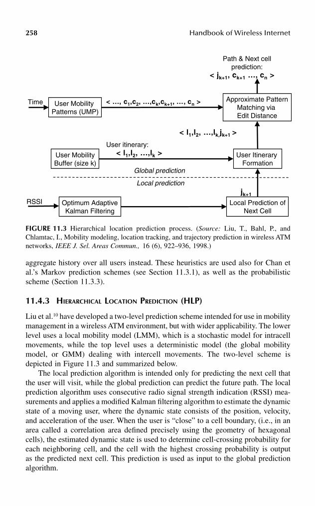
258 Handbook of Wireless Internet
aggregate history over all users instead. These heuristics are used also for Chan etal.’s Markov prediction schemes (see Section 11.3.1), as well as the probabilisticscheme (Section 11.3.3).
11.4.3 HIERARCHICAL LOCATION PREDICTION (HLP)
Liu et al.10 have developed a two-level prediction scheme intended for use in mobilitymanagement in a wireless ATM environment, but with wider applicability. The lowerlevel uses a local mobility model (LMM), which is a stochastic model for intracellmovements, while the top level uses a deterministic model (the global mobilitymodel, or GMM) dealing with intercell movements. The two-level scheme isdepicted in Figure 11.3 and summarized below.
The local prediction algorithm is intended only for predicting the next cell thatthe user will visit, while the global prediction can predict the future path. The localprediction algorithm uses consecutive radio signal strength indication (RSSI) mea-surements and applies a modified Kalman filtering algorithm to estimate the dynamicstate of a moving user, where the dynamic state consists of the position, velocity,and acceleration of the user. When the user is “close” to a cell boundary, (i.e., in anarea called a correlation area defined precisely using the geometry of hexagonalcells), the estimated dynamic state is used to determine cell-crossing probability foreach neighboring cell, and the cell with the highest crossing probability is outputas the predicted next cell. This prediction is used as input to the global predictionalgorithm.
FIGURE 11.3 Hierarchical location prediction process. (Source: Liu, T., Bahl, P., andChlamtac, I., Mobility modeling, location tracking, and trajectory prediction in wireless ATMnetworks, IEEE J. Sel. Areas Commun., 16 (6), 922–936, 1998.)
Optimum AdaptiveKalman Filtering
Local Prediction ofNext Cell
RSSIjk+1
User itinerary:
User MobilityBuffer (size k)
User Itinerary Formation
User Mobility Patterns (UMP)
Approximate PatternMatching via Edit Distance
< l1,l2, …,lk >
< l1,l2, …,lk,jk+1 >
< …, c1,c2, …,ck,ck+1, …, cn >
< jk+1, ck+1 …, cn >
Path & Next cellprediction:
Local prediction
Global prediction
Time
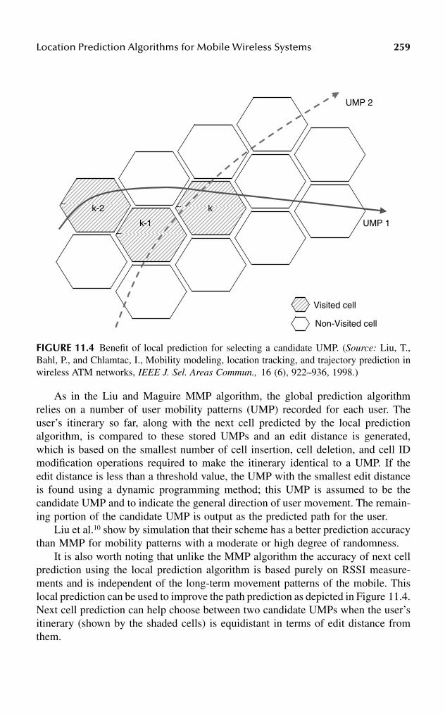
Location Prediction Algorithms for Mobile Wireless Systems 259
As in the Liu and Maguire MMP algorithm, the global prediction algorithmrelies on a number of user mobility patterns (UMP) recorded for each user. Theuser’s itinerary so far, along with the next cell predicted by the local predictionalgorithm, is compared to these stored UMPs and an edit distance is generated,which is based on the smallest number of cell insertion, cell deletion, and cell IDmodification operations required to make the itinerary identical to a UMP. If theedit distance is less than a threshold value, the UMP with the smallest edit distanceis found using a dynamic programming method; this UMP is assumed to be thecandidate UMP and to indicate the general direction of user movement. The remain-ing portion of the candidate UMP is output as the predicted path for the user.
Liu et al.10 show by simulation that their scheme has a better prediction accuracythan MMP for mobility patterns with a moderate or high degree of randomness.
It is also worth noting that unlike the MMP algorithm the accuracy of next cellprediction using the local prediction algorithm is based purely on RSSI measure-ments and is independent of the long-term movement patterns of the mobile. Thislocal prediction can be used to improve the path prediction as depicted in Figure 11.4.Next cell prediction can help choose between two candidate UMPs when the user’sitinerary (shown by the shaded cells) is equidistant in terms of edit distance fromthem.
FIGURE 11.4 Benefit of local prediction for selecting a candidate UMP. (Source: Liu, T.,Bahl, P., and Chlamtac, I., Mobility modeling, location tracking, and trajectory prediction inwireless ATM networks, IEEE J. Sel. Areas Commun., 16 (6), 922–936, 1998.)
k
k-1
k-2
UMP 1
UMP 2
Visited cell
Non-Visited cell

260 Handbook of Wireless Internet
11.4.4 OTHER APPROACHES
One approach we have not considered so far is to take the help of the user forprediction. Obviously, as little burden as possible should be placed on the user, butone could envision a situation where the user is only prompted for current destination(which could be collected, for example, via a voice prompt) and this is used (possiblyalong with history information) to do cell and path prediction. Another variationcould be that at the start of the day, the user is prompted for a list of the day’s likelydestinations (or is approximately inferred from her calendar), so that interaction isminimized further. Madi et al.37 have developed schemes for prompting for userdestination input in this way, although no prediction is carried out as such.
Biesterfeld et al.38 propose using neural networks for location prediction. Theyhave considered both feedback and feed-forward networks with a variety of learningalgorithms. Their preliminary results indicated, somewhat nonintuitively, that feed-forward networks delivered better results than feedback networks.
Das and Sen39 consider how to use location prediction to assign cells to locationareas so as to minimize mobility management cost (i.e., the combined paging andlocation update cost), where the location areas are arranged hierarchically. Theassignment is dynamic and is calculated periodically, every τ seconds. The user’smovement history is assumed only to consist of a set, Lc = {(li, fi) : 0 ≤ i ≤ c},recording the frequency fi with which each cell li is visited during the previousperiod, where c is the number of distinct cells visited.
Then the probability of the user visiting a given cell li is calculated simply asthe relative frequency with which the user has visited that cell in the previous period,
i.e., . (Similarly, frequencies for visiting areas where two or more cells
overlap are recorded, and the probability of visiting the overlapping area calculated.)We observe that this scheme is similar to order-0 Markov prediction, as describedin Bhattacharya and Das.30
These cell visit probabilities are used to assign cells to a most-probable locationarea (MPLA). However, it is possible that the user has left this area and moved toan adjoining area, called the future probable location area (FPLA). If the user is notfound in the MPLA, the FPLA is paged. The cells belonging to the FPLA aredetermined based on the current mean velocity, the last cell visited, and (optionally)the direction of future movement. Given the cells in the FPLA, the probability thatthe user will visit a particular cell is estimated by a heuristic that takes into account
the total number of cell crossings , the frequency maxi fi, and c, the number
of distinct cells visited.
11.5 CONCLUSIONSIn this chapter, we have provided an overview of different approaches to predictingthe location of users in a mobile wireless system. This chapter is not intended to bea comprehensive survey, and in particular we have only summarized a few of theapproaches being used in domain-specific algorithms for location prediction.
f fi jj∑
fjj∑

Location Prediction Algorithms for Mobile Wireless Systems 261
We see two general ideas pursued in the literature: domain-independent algo-rithms that take results from Markov analysis or text compression algorithms andapply them to prediction, and domain-specific algorithms that consider the geometryof user motion as well as the semantics of the symbols in the movement history.Domain-independent algorithms tend to have well-founded theoretical principles onwhich they are based and can make analytical statements about their predictionaccuracy. However, in some cases, these statements refer to the asymptotic optimalityof their accuracy, i.e., that as the input history approaches infinite length, no similarprediction algorithm can do any better. While satisfying from a theoretical point ofview, it is unclear how relevant these results are in practice. On the other hand, somedomain-specific algorithms offer heuristics that appear intuitively appealing but haveno explicit theoretical analysis to support them. Clearly, a better bridge betweenengineering intuition and theoretical analysis would be helpful.
One of the major barriers to practical advancement in this area is the lack ofpublicly available empirical data to guide future research. Most studies have usedartificial mobility models; relatively few, e.g., Chan and coworkers,31 have collectedempirical data for the domain of interest (cellular handoffs) and used them forvalidation. We compare the situation to the early work done on caching disk pagesin computer systems. A large variety of cache replacement policies, many of whichwere intuitively plausible, were proposed. It was only empirical data from page faulttraces that enabled the conclusion that the Least Recently Used (LRU) algorithmoffered the best compromise between simplicity and effectiveness in most cases.Large-scale statistical data for the domains of interest is sorely needed to help providebenchmarks and directions for future research.
ACKNOWLEDGMENTS
We thank Prof. John Kieffer for interesting and helpful discussions, as well as Dr.Xiaoning He for comments on a draft of this chapter.
References
1. Jain, R., Lin, Y.-B., and Mohan, S., Location strategies for personal communicationsservices, Mobile Communications Handbook, 2nd ed., Gibson, J., Ed., CRC Press,Boca Raton, FL, 1999.
2. Akyildiz, I.F. et al., Mobility management for next generation wireless systems, Proc.IEEE, 87(8), 1347–1385, 1999.
3. Jain, R. et al., A caching strategy to reduce network impacts of PCS, IEEE J. SelectedAreas Commun., 12(8), 1434–1444, 1994.
4. Wolfson, O. et al., Cost and imprecision in modeling the position of moving objects,Proc. IEEE Intl. Conf. Data Eng. (ICDE), Feb. 1998.
5. Pitoura, E. and Samaras, G., Locating objects in mobile computing, IEEE Trans.Knowledge Database Eng., 13 (4), 571–692, 2001.
6. Su, W., Lee, S., and Gerla, M., Mobility prediction and routing in ad hoc wirelessnetworks, Intl. J. Net. Mgmt., (11), 3–30, 2001.

262 Handbook of Wireless Internet
7. Jiang, S., He, D., and Rao, J., A prediction-based link availability estimation algorithmfor mobile ad hoc networks, Proc. IEEE InfoCom, 2001.
8. Krishna, P., Vaidya, N., and Pradhan, D., Static and adaptive location managementin mobile wireless networks, Computer Commun., 19 (4), 321–334, 1996.
9. Shivakumar, N., Jannink, J., and Widom, J., Per-user profile replication in mobileenvironments: algorithms, analysis, and simulation results, ACM/Baltzer Mobile Net-works Appl. (MONET), 2 (2), 129–140, 1997.
10. Liu, T., Bahl, P., and Chlamtac, I., Mobility modeling, location tracking, and trajectoryprediction in wireless ATM networks, IEEE J. Selected Areas Commun., 16 (6),922–936, 1998.
11. Liu, G. and Maguire, G. Jr., A class of mobile motion prediction algorithms forwireless mobile computing and communications, ACM/Baltzer Mobile NetworksAppl. (MONET), 1 (2), 113–121, 1996.
12. Chan, J. et al., A framework for mobile wireless networks with an adaptive QoScapability, Proc. Mobile Mult. Comm. (MoMuC), Oct. 1998, pp. 131–137.
13. Erbas, F. et al., A regular path recognition method and prediction of user movementsin wireless networks, IEEE Vehic. Tech. Conf. (VTC), Oct. 2001.
14. Levine, D., Akyildiz, I., and Naghshineh, M., A resource estimation and call admis-sion algorithm for wireless multimedia networks using the shadow cluster concept,IEEE/ACM Trans. Networking, 2, 1–15, 1997.
15. Bharghavan, V. and Jayanth, M. Profile-based next-cell prediction in indoor wirelessLAN, Proc. IEEE SICON, Singapore, Apr. 1997.
16. Riera, M. and Aspas, J., Variable channel reservation mechanism for wireless net-works with mixed types of mobility platforms, Proc. IEEE Vehic. Tech. Conf. (VTC),May 1998, pp. 1259–1263.
17. Oliveira, C., Kim, J., and Suda, T., An adaptive bandwidth reservation scheme forhigh-speed multimedia wireless networks, IEEE J. Selected Areas Commun., 16 (6),858–874, 1998.
18. Chua, K.C. and Choo, S.Y., Probabilistic channel reservation scheme for mobilepico/microcellular networks, IEEE Commun. Lett., 2 (7), 195–196, 1998.
19. Yu, F. and Leung, V., Mobility-based predictive call admission control and bandwidthreservation in wireless cellular networks, Computer Networks, 38, 577–589, 2002.
20. Posner, C. and Guerin, R., Traffic policies in cellular radio that minimize blockingof handoff calls, Proc. 11th Int. Teletraffic Cong., Kyoto, Japan, 1985.
21. Ramjee, R., Nagarajan, R., and Towsley, D., On optimal call admission control incellular networks, Proc. IEEE Infocom, San Francisco, 1996.
22. Naghshineh, M. and Schwartz, M., Distributed call admission control in mobile/wire-less networks, IEEE J. Selected Areas Commun., 14, 711–717, 1996.
23. Chao C. and Chen, W. Connection admission control for mobile multiple-class per-sonal communications networks, IEEE J. Selected Areas Commun., 15, 1618–1626,1997.
24. Luo, X., Thng, I., and Zhuang, W., A dynamic channel pre-reservation scheme forhandoffs with GoS guarantee in mobile networks, Proc. IEEE ICC, Vancouver, Can-ada, 1999.
25. Zhang, T. et al., Local predictive reservation for handoff in multimedia wireless IPnetworks, IEEE J. Selected Areas Commun., 19, 1931–1941, 2001.
26. Bharghavan, V. et al., The TIMELY adaptive resource management architecture, IEEEPers. Commun., 20–31, 1998.
27. Akyildiz, I., Ho, J., and Lin, Y., Movement based location update and selective pagingfor PCS networks, IEEE/ACM Trans. Networking, 4 (4), 629–638, 1996.

Location Prediction Algorithms for Mobile Wireless Systems 263
28. Bar-Noy, A., Kessler, I., and Sidi, M., Mobile users: to update or not to update?,ACM/Baltzer J. Wireless Networks, 1 (2), 175–195, 1995.
29. Rose, C., Minimizing the average cost of paging and registration: a timer-basedmethod, Wireless Networks, 2 (2), 109–116, 1996.
30. Bhattacharya, A. and Das, S.K., LeZi-update: an information-theoretic frameworkfor personal mobility tracking in PCS networks, ACM/Kluwer Wireless Networks, 8(2-3), 121–135, 2002.
31. Chan, J., Zhou, S., and Seneviratne, A., A QoS adaptive mobility prediction schemefor wireless networks, Proc. IEEE Globecom, Sydney, Australia, Nov. 1998.
32. Vitter, J. and Krishnan, P., Optimal prefetching via data compression, J. ACM, 43(5), 771–793, 1996.
33. Ziv, J. and Lempel, A., Compression of individual sequences via variable-rate coding,IEEE Trans. Inf. Theory, 24 (5), 530–536, 1978.
34. Krishnan, P. and Vitter, J., Optimal prediction for prefetching in the worst case, SIAMJ. Computing, 27 (6), 1617–1636, 1998.
35. Feder, M., Merhav, N., and Gutman, M., Universal prediction of individual sequences,IEEE Trans. Inf. Theory, 38, 1258–1270, 1992.
36. Bell, T.C., Cleary, J.G., and Witten, I.H., Text Compression, Prentice Hall, New York,1990.
37. Madi, M., Graham, P., and Barker, K., Mobile computing: predictive connectionmanagement with user input, Technical report, Department of. Computer Science,University of Manitoba, Aug. 1996.
38. Biesterfeld, J., Ennigrou, E., and Jobmann, K., Location prediction in mobile net-works with neural networks, Proc. Intl. Workshop Appl. Neural Networks to Telecom.,June 1997, pp. 207–214.
39. Das, S.K. and Sen, S.K., Adaptive location prediction strategies based on a hierar-chical network model in a cellular mobile environment, Computer J., 42 (6), 473–486,1999.

This page intentionally left blank

2650-8493-1502-6/03/$0.00+$1.50© 2003 by CRC Press LLC
12 Handoff and Rerouting in Cellular Data Networks
Gopal Racherla and Sridhar Radhakrishnan
CONTENTS
12.1 Introduction ................................................................................................26612.1.1 Classification of Rerouting Schemes ..........................................26812.1.2 Related Work ...............................................................................269
12.2 Analysis of Rerouting Schemes.................................................................27112.2.1 Common Handshaking Signals for Rerouting Schemes.............271
12.2.1.1 Without Hints .............................................................27212.2.1.2 With Hints ..................................................................272
12.2.2 Full Rerouting..............................................................................27312.2.2.1 Implementations .........................................................27312.2.2.2 Special Metrics ...........................................................274
12.2.3 Partial Rerouting..........................................................................27412.2.3.1 Implementations .........................................................27512.2.3.2 Special Metrics ...........................................................276
12.2.4 Tree Rerouting .............................................................................27712.2.4.1 Tree-Group Rerouting ................................................27712.2.4.2 Tree-Virtual Rerouting ...............................................27712.2.4.3 Implementations .........................................................27712.2.4.4 Special Metrics ...........................................................279
12.2.5 Cell Forwarding Rerouting..........................................................28012.2.5.1 Implementations .........................................................28012.2.5.2 Special metrics ...........................................................280
12.3 Performance Evaluation of Rerouting Schemes........................................28112.3.1 Comparison of Rerouting Schemes.............................................282
12.3.1.1 Advantages and Disadvantages of the Rerouting Schemes......................................................................282
12.3.1.2 Metrics not Dependent on the Connection Length ...28312.3.1.3 Metrics Dependent on the Connection Length..........284

266 Handbook of Wireless Internet
12.4 Mobile–Mobile Rerouting in Connection-Oriented Networks .................29012.4.1 Problems in Mobile–Mobile Rerouting ......................................291
12.4.1.1 Inefficiency .................................................................29112.4.1.2 Lack of Coordination .................................................291
12.4.2 Techniques for Mobile–Mobile Rerouting..................................29112.4.2.1 Biswas’ Strategy: Mobile Representative and
Segment-Based Rerouting..........................................29112.4.2.2 CBT (Core-Based Tree) Strategy:
Extending Biswas’ Work ............................................29212.4.2.3 Ghai and Singh’s Strategy:
Two-Level Picocellular Rerouting .............................29212.4.2.4 EIA/TIA IS-41(c) Rerouting......................................29312.4.2.5 Racherla’s Framework for Mobile–Mobile
Rerouting ....................................................................29312.4.3 Comparison of Rerouting Schemes for Mobile–Mobile
Connections..................................................................................29412.5 Performance of Mobile–Mobile rerouting.................................................295
12.5.1 Total Rerouting Distance.............................................................29712.5.2 Cumulative Connection Path Length ..........................................30012.5.3 Number of Connections...............................................................302
12.6 Conclusion..................................................................................................302References..............................................................................................................304
12.1 INTRODUCTION
Cellular mobile data networks consist of wireless mobile hosts (MH), static hosts(SH), and an underlying wired network consisting of base stations (BS) and inter-mediate routers. Each base station has a geographical area of coverage called a cell.Hosts communicate with each other using the base stations and the underlying wirednetwork. Figure 12.1 shows the architecture of a cellular data network. The figureshows the fixed cellular backbone consisting of base stations and a group of mobilehosts that can move from one cell to another. When a mobile host moves from onecell to another, it registers with the base station of the new cell. If there is an ongoingcommunication session between two hosts and one of the hosts moves out of itspresent cell, the session is interrupted. In order for the session to be restarted, ahandoff or handover needs to take place in the network. Handoff is the process oftransferring the control and responsibility for maintaining communication connec-tivity from one base station to another. Handoff is used by the mobile network toprovide the mobile hosts with seamless access to network services and the freedomof mobility beyond the cell coverage of a base station. Rerouting is the process ofsetting up a new route (path) between the hosts after the handoff has occurred.Handoff1–6 in mobile and wireless networks has been an active topic of research anddevelopment for the past several years. The rerouting problem also has been studiedextensively in cellular, mobile, and wireless networks, including wireless ATM,1,2,7–11
picocellular networks,12 cellular networks,3 wireless LANs,5,6,13 and connectionlessnetworks.14–18

Handoff and Rerouting in Cellular Data Networks 267
Communication in a mobile data network can be either between two static hosts(static–static), a static host and a mobile host (static–mobile), or two mobile hosts(mobile–mobile). Static–static communication and its related routing algorithmshave been studied extensively in the literature. Static–mobile communication andthe consequent handoff and rerouting also have been studied in detail.7,8,12,13,18 How-ever, mobile–mobile rerouting has not been explored much in the literature. Thereare only a few4,12,18 suggested schemes for mobile–mobile data communication andrerouting in mobile data networks. However, these mobile–mobile rerouting schemesare suboptimal. In addition, these schemes do not look at different rerouting strat-egies. Racherla and coworkers4 have proposed a scheme for performing optimalrerouting in mobile–mobile networks.
In this chapter, we survey, classify, analyze, and evaluate several known rerouting(static–mobile and mobile–mobile) techniques for connection-oriented cellular datanetworks. We study connection-oriented networks as they provide performanceguarantees needed for delivery of multimedia data to mobile hosts. We classify thevarious rerouting schemes in four major categories and do a survey of related workin detail. We use a set of rerouting metrics in order to compare and classify variousstatic–mobile and mobile–mobile rerouting schemes. We discuss the characteristics andperformance metrics used for the comparison of static–mobile and mobile–mobilererouting in more detail later in the chapter.
The rest of the chapter is organized as follows. In this section, we continue toexplore the nuances of the rerouting process in more detail. We study the charac-teristics of rerouting and use them for comparison and classification of reroutingschemes proposed in the literature. We classify various rerouting schemes in fourcategories. In Section 12.2, we analyze and evaluate the various rerouting classes.Each class is explained in detail, including the protocol used for rerouting, theadvantages and disadvantages of the class, and implementation examples and vari-ations of the rerouting class. In Section 12.3, we evaluate the rerouting schemesusing several performance metrics that are calculated using analytical cost modeling.We study the issues involved in mobile–mobile rerouting, including potential prob-lems and solution ideas for alleviating these problems, as well as all the known
FIGURE 12.1 Architecture of a cellular data network.

268 Handbook of Wireless Internet
solutions for rerouting in mobile–mobile connections, in Section 12.4. In Section12.5, we compare these schemes using several performance metrics including thetotal rerouting distance, the cumulative connection path length and the number ofconnections as the mobile hosts move. Finally, in Section 12.6, we present ourconclusions and the plan for future work.
12.1.1 CLASSIFICATION OF REROUTING SCHEMES
Rerouting in cellular mobile environments occurs as result of a handoff. When amobile host moves from one cell to another, a handoff is said to have taken place.In order to maintain communication connectivity, packets have to be rerouted to andfrom the MH. This process of reestablishment of a route (connection) is called asrerouting. Figure 12.2 depicts the rerouting process. Initially, the source mobile host(MHS) is in a session with the destination mobile host (MHD). MHS is in the cellbeing administered by source base station (BSS). After some time, MHD moves fromthe cell of BSold to BSnew after performing a handoff while MHS is stationary. Theold route (between BSS and BSold) and the new route (between BSS and BSnew) may bethe same, partially the same or completely different. Because of overlaps in the cellcoverage of adjacent cells, MHD may get a radio “hint” before it enters its cell. Usingthe radio hint, MHD can request BSold to inform BSnew to set up the required connectionsin advance. This mechanism of using radio hints is known as radio hint processing.
We classify the rerouting strategies broadly as full rerouting, partial rerouting,tree-based rerouting, and cell forwarding rerouting. Each of the schemes can beeither with or without a radio hint.3–5 Full rerouting involves establishing a newrouting path from BSnew to BSS. Full rerouting schemes are slow and inefficient andhence perform poorly. Examples of such schemes include full reestablishment with-out hints and full reestablishment with hint rerouting.3 Partial rerouting involvesfinding the crossover point of the route between BSS and BSold and the route betweenBSS and BSnew with a view to increasing route reuse. Examples of these schemesinclude incremental reestablishment without hints and incremental reestablishmentwith hint rerouting3,5 and Nearest Common Neighbor Routing (NCNR).8 Tree rerout-ing involves routing using a tree-based structure for communication. The basestations in the network form the nodes of the tree. The tree has a specially designatedbase station that acts as the root of the tree. Some implementations may have multipletrees that form the communication structure. This scheme typically uses multicastingfor communication. Tree rerouting can be either (a) to a group (tree-group rerouting)as described in multicast reestablishment rerouting (with and without hint)3 and the
FIGURE 12.2 Rerouting process.

Handoff and Rerouting in Cellular Data Networks 269
picocellular network architecture rerouting,12 or (b) from a single source to a singledestination using a virtual tree (tree-virtual rerouting), where only one branch of thetree is active at a time. Examples of this scheme include the virtual tree scheme1
and the SRMC scheme.19 Also, tree-group rerouting can have either a static3,19 or adynamic group12 to communicate with. Static tree-group rerouting involves a groupconsisting of members that do not change over time, while in the case of a dynamictree-group rerouting the membership of a group may change. Cell forwarding rerout-ing involves designating a specialized base station to forward data packets to theMHD when it moves from a “home” area. Such schemes include the ones describedin the adaptive routing scheme20 and the BAHAMA scheme.21 Figure 12.3 showsthe classification scheme.
12.1.2 RELATED WORK
In this section, we briefly describe related work in the area of comparative analysisof handovers and rerouting.
Toh explained how handovers in multicast connections can be achieved irrespec-tive of the kind of multicast tree (source-based, server-based, or core-based) usedin a wireless ATM environment.6 Toh has proposed solutions to handle handoverand rerouting for both multicast and unicast connections without categorizing rerout-ing strategies. However, his scheme also does not consider pure cell-forwardingschemes. The rerouting algorithm used in Toh’s approach is partial rerouting usinga crossover discovery algorithm. Toh demonstrates how this handoff and reroutingscheme can be used for both unicast and multicast connections using either distrib-uted or centralized connection management. Toh’s work considers partial reroutingwith static–mobile connections.
Ramanathan and Steenstrup22 have made an extensive survey of routing tech-niques for cellular, satellite, and packet radio networks. They categorize differenttypes of handoffs in cellular telecommunication networks. These include mobile-controlled handoff (the MH chooses its new BS based on the relative signal strength),network controlled handoff (the MH’s current BS decides the occurrence of a handoffbased on the signal strength from the mobile host), mobile-assisted handoff (theMH’s current BS requests the MH for information on the signal strengths fromseveral nearby base stations and then decides, in consultation with the mobileswitching center, when a handoff has occurred), and soft handoff (the MH may beaffiliated to multiple base stations with approximately equal signal quality).
FIGURE 12.3 Classification of rerouting schemes.
270 Handbook of Wireless Internet
Bush2 has classified handoff schemes for mobile ATM networks. The classificationis specific to handovers (and not rerouting) for connection-oriented networks. Theseinclude pivotal connection handoff (a specific base station is chosen as a pivot to performhandoff), IP mobility-based handoff (handoffs require IP packet forwarding using mech-anisms such as loose source routing), and handoff tree (a preestablished virtual circuittree is used to automatically detect handoffs in a wireless ATM environment).
Cohen and Segall23 describe a scheme for connection management and reroutingin standard (not wireless/mobile) ATM networks. Their rerouting is a Network NodeInterface protocol, which can be invoked when an intermediate link or node in thevirtual path fails. The protocol reroutes all the affected nodes to an alternate virtual path.
Ramjee et al.24 have performed experimental performance evaluations of fivetypes of rerouting protocols for wireless ATM networks. Their rerouting protocolsare primarily based on crossover switch-based rerouting using mobile-directed hand-off. In order to perform rerouting in an ATM environment, the ATM switch at thecrossover point must change the appropriate entry in the translation table. Thisinvolves dismantling the old entry (break) and installing the new entry (make). Theirevaluation includes the following rerouting schemes: make–break (make followedby break), break–make (break followed by make), chaining (cell forwarding fromthe old base station to the new base station), make–break with chaining, andbreak–make with chaining.
Song and coworkers25 have defined five kinds of rerouting schemes for connec-tion-oriented networks:
1. Connection-extension rerouting: This rerouting is the same as cell for-warding rerouting.
2. Destination-based rerouting: In this scheme, the rerouting point is prede-termined at the connection time. This is similar to connection-extensionrerouting except the rerouting base station is a predetermined base stationand not necessarily the old base station.
3. Branch-point-traversal-based rerouting: This rerouting is the same aspartial rerouting.
4. Multicast-join-based rerouting: This rerouting is the same as tree-grouprerouting.
5. Virtual-tree-based rerouting: This rerouting is the same as tree-virtualrerouting.
Mishra and Srivastava10 have classified rerouting schemes in an ATM environ-ment as:
• Extension: This rerouting is the same as cell forwarding rerouting.• Extension with loop removal: This rerouting is a specialized case of cell
forwarding rerouting with removal of any possible path loops caused bychaining.
• Total rebuild: This rerouting is the same as full rerouting.• Partial rebuild: This rerouting is the same as partial rerouting. There are
two variants in this scheme (fixed or dynamically chosen crossover point).• Multicast to neighbors: This rerouting is the same as tree-group rerouting.

Handoff and Rerouting in Cellular Data Networks 271
Naylon et al.9 have provided classification of rerouting in the wireless ATMLANs as follows:
• Virtual connection tree: This rerouting is the same as tree-virtual rerouting.• Path rerouting: This rerouting is the same as partial rerouting.• Path extension scheme: This rerouting is the same as cell forwarding
rerouting.
From the related work described here, we see that our classification encompassesall the proposed rerouting schemes we have described. In this sense, our work canbe viewed as a generalization of previous rerouting classifications. As we shall wein the subsequent sections of the chapter, our contribution in this work is fourfold.First, we provide a comprehensive framework for comparing rerouting strategies forconnection-oriented cellular data networks. We subsume also the classification pro-posed by various authors in the literature. Second, we analyze and evaluate theperformance of the rerouting schemes using a large array of metrics, including theones proposed by other researchers. We propose and evaluate specialized metricsthat are applicable to each class of rerouting schemes. Third, we abstract the commonhandshaking signals from all the rerouting schemes (with and without hints) to avoidrepetition and provide also a framework to compare these common handshakingsignals. Finally, we compare and contrast the performance of rerouting inmobile–mobile connections. This last contribution is the first such attempt, to thebest of our knowledge.
12.2 ANALYSIS OF REROUTING SCHEMES
In this section, we describe for each class of rerouting the basic protocol and itsdifferent implementations, advantages, and disadvantages. Self-descriptive figuresare provided to aid in the explanation.
In the descriptions of the rerouting schemes, we make the following assumptions.There is coverage overlap between cells. An MH communicates with only one BSat a time. Each MH can measure the radio signal strength of the base stations inorder to know about its entry into a new cell. Handoff and rerouting is initiated bythe destination mobile host (MHD). The source mobile host (MHS) is assumed to bestationary during the rerouting process.
12.2.1 COMMON HANDSHAKING SIGNALS FOR REROUTING SCHEMES
Many handshaking signals during the rerouting process are common to all thererouting schemes. We have abstracted these signals in order to avoid repetition inall the rerouting schemes. Using the framework that we describe here, we canselectively compare the rerouting schemes, with or without these handshaking sig-nals. The handshaking protocol is assumed to be completed before the actual rerout-ing protocol. We describe these signals for rerouting schemes, with and withouthints, separately. In case of schemes without hints, the handshaking protocol is the
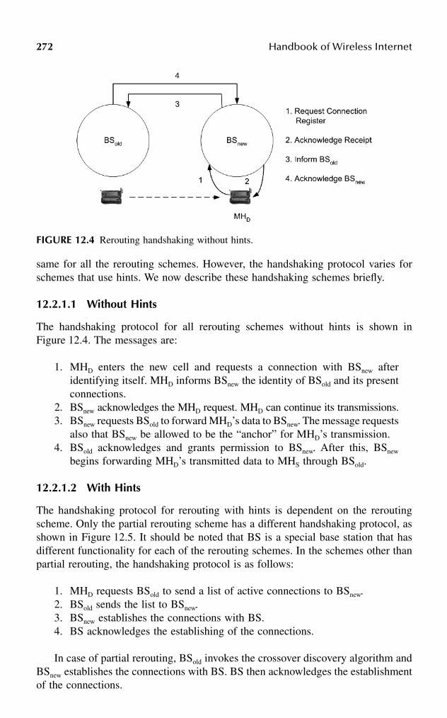
272 Handbook of Wireless Internet
same for all the rerouting schemes. However, the handshaking protocol varies forschemes that use hints. We now describe these handshaking schemes briefly.
12.2.1.1 Without Hints
The handshaking protocol for all rerouting schemes without hints is shown inFigure 12.4. The messages are:
1. MHD enters the new cell and requests a connection with BSnew afteridentifying itself. MHD informs BSnew the identity of BSold and its presentconnections.
2. BSnew acknowledges the MHD request. MHD can continue its transmissions.3. BSnew requests BSold to forward MHD’s data to BSnew. The message requests
also that BSnew be allowed to be the “anchor” for MHD’s transmission.4. BSold acknowledges and grants permission to BSnew. After this, BSnew
begins forwarding MHD’s transmitted data to MHS through BSold.
12.2.1.2 With Hints
The handshaking protocol for rerouting with hints is dependent on the reroutingscheme. Only the partial rerouting scheme has a different handshaking protocol, asshown in Figure 12.5. It should be noted that BS is a special base station that hasdifferent functionality for each of the rerouting schemes. In the schemes other thanpartial rerouting, the handshaking protocol is as follows:
1. MHD requests BSold to send a list of active connections to BSnew.2. BSold sends the list to BSnew.3. BSnew establishes the connections with BS.4. BS acknowledges the establishing of the connections.
In case of partial rerouting, BSold invokes the crossover discovery algorithm andBSnew establishes the connections with BS. BS then acknowledges the establishmentof the connections.
FIGURE 12.4 Rerouting handshaking without hints.

Handoff and Rerouting in Cellular Data Networks 273
12.2.2 FULL REROUTING
Full rerouting can occur with or without hints. We describe later the generic fullrerouting schemes without hints. Detailed protocol descriptions of all reroutingschemes (with and without hints) are explained in Seshan3 and Racherla and cowork-ers.4 Figures 12.6 and 12.7 describe the protocol of a generic full rerouting withouthints and full rerouting with hints, respectively.
12.2.2.1 Implementations
An implementation of full rerouting, namely, full reestablishment schemes with andwithout hints, is described by Seshan.3 The generic full rerouting explained prviouslyis the same as Seshan’s implementation. The source (a video server in the imple-mentation) is assumed to be fixed, while the destination is the MHD. The mobilehost moves from the old base station BSold to the new base station BSnew. Thererouting involves finding a new route from BSnew to BSS.
FIGURE 12.5 Rerouting handshaking with hints.
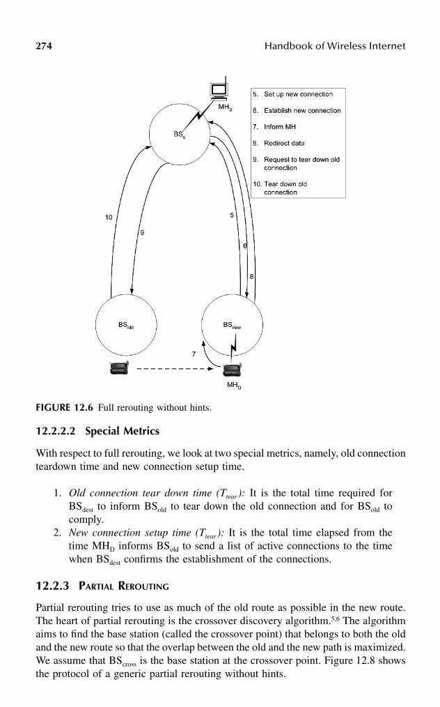
274 Handbook of Wireless Internet
12.2.2.2 Special Metrics
With respect to full rerouting, we look at two special metrics, namely, old connectionteardown time and new connection setup time.
1. Old connection tear down time (Ttear): It is the total time required forBSdest to inform BSold to tear down the old connection and for BSold tocomply.
2. New connection setup time (Ttear): It is the total time elapsed from thetime MHD informs BSold to send a list of active connections to the timewhen BSdest confirms the establishment of the connections.
12.2.3 PARTIAL REROUTING
Partial rerouting tries to use as much of the old route as possible in the new route.The heart of partial rerouting is the crossover discovery algorithm.5,6 The algorithmaims to find the base station (called the crossover point) that belongs to both the oldand the new route so that the overlap between the old and the new path is maximized.We assume that BScross is the base station at the crossover point. Figure 12.8 showsthe protocol of a generic partial rerouting without hints.
FIGURE 12.6 Full rerouting without hints.

Handoff and Rerouting in Cellular Data Networks 275
12.2.3.1 Implementations
There are many variations of implementing partial rerouting. Seshan3 gives animplementation called incremental reestablishment rerouting with and without hints.The protocol of Seshan’s implementation is the same as the generic protocoldescribed previously. However, the protocol does not specify the crossover discoverymechanism.
Toh6 gives an implementation of partial rerouting, also called incremental rees-tablishment with and without hints. Toh’s implementation is tailored for wirelessLANs (local area networks). Toh’s strategy for partial rerouting without hints, unlikethe generic partial rerouting without hints described in Figure 12.8, assumes that thewireless link between the MH and BSold has failed, resulting in the unavailability ofhints. In Toh’s incremental reestablishment rerouting without hints protocol, BSold
does not acknowledge the MH (message 2 in the generic protocol). Also, messages3 and 4 are absent, and there is cell loss as BSnew does not request BSold to forwardcells. In addition, there are no explicit messages to tear down the old connection(messages 10 and 11). In case of Toh’s incremental reestablishment rerouting withhints, BSnew invokes the crossover discovery algorithm (message 3) instead of BSold
as described in the generic partial rerouting with hints scheme.4 Also, messages 8
FIGURE 12.7 Full rerouting with hints.

276 Handbook of Wireless Internet
and 9 intended for cell forwarding from BSold to BSnew are absent, resulting is cellloss. Toh describes many algorithms for discovery of the crossover switch. Akyoland Cox’s7,8 strategy, called NCNR rerouting, performs partial rerouting by choosingthe crossover discovery as the nearest common neighbor of the BSold and BSnew.Their scheme checks to see if there is a direct link between BSnew and BSold andwhether the traffic is time dependent (e.g., voice, video) or throughput dependent(e.g., data). It should be noted that the performance of the partial rerouting is stronglydependent on the performance of the crossover discovery algorithm.
12.2.3.2 Special Metrics
With respect to partial rerouting, we study several performance metrics, includingold connection teardown time, new connection setup time, the time required to invokecrossover discovery algorithm, the time required to actually discover the crossoverswitch, and the efficiency of path reuse.
FIGURE 12.8 Partial rerouting without hints.

Handoff and Rerouting in Cellular Data Networks 277
1. Old connection teardown time (Ttear): It is the time required for BScross toinform BSold to tear down the old connection and for BSold to comply.
2. New connection setup time (Tnew): It is the total time elapsed since MHD
requests a connection with BSnew till the confirmation of the establishmentof the new connection.
3. Time required for invoking the crossover discovery algorithm (Tcross): Thetotal time in the rerouting process until the crossover switch discoveryalgorithm has been invoked.
4. Time to discover the crossover switch (Tdiscover): The total time for findingthe crossover point after invoking the crossover discovery algorithm. Thisterm depends on the algorithm used.
5. Partial reuse efficiency (ηpart): The fraction of the new path that has beenreused.
12.2.4 TREE REROUTING
Tree routing involves setting up and using a tree with base stations as nodes tocommunicate to a group of base stations. The tree can be either static or dynamic.
12.2.4.1 Tree-Group Rerouting
Figure 12.9 describes the protocol of a generic tree-group rerouting without hints.In this case, there is a dynamic multicast tree built that is used to multicast data toa group of base stations. The base station BSroot is the root of the multicast tree. Themessages used to perform rerouting are described in the figure.
12.2.4.2 Tree-Virtual Rerouting
Figure 12.10 describes the protocol of a tree-virtual rerouting without hints. LetBSroot be the root of the virtual tree that connects a group of base stations. Thereare no tree-virtual rerouting algorithms with hints described in the literature. How-ever, it is easy to conceive such a class. The most important aspect of this class ofrerouting is that one path (from the root of the tree to the leaves of the tree) is activeat a time unlike the tree-group rerouting. We assume that the virtual tree is establishedstatically and is in place before the commencement of the rerouting process.
12.2.4.3 Implementations
Acampora1 describes a rerouting scheme using virtual connection trees in a wirelessATM environment. A virtual connection tree is a collection of base stations andwired switching nodes and the connecting links. Each virtual connection tree, whichis statically built prior to rerouting, has a fixed root node and the leaves of the treeare base stations. For each mobile connection, the tree provides a set of virtualconnection numbers in each direction, each associated with a path from a leaf androot. When a mobile host that is already in the tree wants to handoff to another basestation (in the same tree), it starts to transmit ATM cells with the connection numberassigned for use between itself and the new base station. The cells flow along the

278 Handbook of Wireless Internet
fixed path between the new base station and the root. Appropriate translation tablesare maintained at the nodes of the tree to understand and implement handoff andthe consequent rerouting. Seshan3 describes a scheme for tree-group rerouting calledmulticasting reestablishment. The protocol of the generic tree-group reroutingdescribed earlier is based on Seshan’s proposed scheme, which includes strategiesfor multicasting rerouting with and without hints. However, Seshan’s scheme doesnot address the issue of how the members of the groups are decided. Ghai andSingh12 describe a tree-group rerouting scheme based on a dynamic grouping ofbase stations and the mobility characteristics of the MH. The scheme is for a
FIGURE 12.9 Tree-group rerouting without hints.

Handoff and Rerouting in Cellular Data Networks 279
picocellular network with a three-tier hierarchy of cells. The scheme does not takeadvantage of hints to aid in rerouting.
12.2.4.4 Special Metrics
12.2.4.4.1 Tree-Virtual Rerouting
• Virtual tree setup time (Tvtree-setup): It is the time required for setting up thevirtual tree, which includes the time to choose the root, broadcast theinformation to all the nodes of the tree, and for all the nodes to join the tree.
• Virtual tree teardown time (Tvtree-tear): It is the time required to tear downthe virtual tree.
• Number of nodes in virtual tree (Nvtree): Nvtree is determined statically andremains fixed.
FIGURE 12.10 Tree-virtual rerouting without hints.

280 Handbook of Wireless Internet
12.2.4.4.2 Tree-Group Rerouting
• Multicast tree setup time (Tmcast-setup): The time required to set up themulticast tree.
• Multicast tree teardown time (Tmcast-tear): The time required to tear downthe multicast tree.
• Number of nodes in the multicast tree (Nmcast): Nmcast depends on thealgorithm in question. In static algorithms, this value is fixed and remainsconstant. In algorithms that dynamically decide the number on-the-fly,the number changes dynamically.
• Multicast join/leave time (Tmcast-jn, Tmcast-lv): The time required for nodesof the multicast tree to join or leave the tree.
12.2.5 CELL FORWARDING REROUTING
Cell forwarding rerouting involves using a specialized base station (BSfwd) as an“anchor.” Cell forwarding is used in many rerouting schemes implicitly. Full rerout-ing and partial rerouting can be considered specialized cell forwarding reroutingschemes. The anchor in all these cases is BSold. Figure 12.11 describes the protocolof a generic cell forwarding rerouting without hints. There is no known cell for-warding scheme described in the literature, although such a scheme can be easilyconceived. In the remainder of the discussion, when we refer to cell forwarding, weassume that the anchor is the old base station; thus, in this case data is simplyforwarded from the previous destination base station. Therefore, we simply do notneed any signaling other than the regular handshake without hints. In other words,steps 5 through 10 do not exist; this way, we avoid the overhead of setting up thenew path and tearing down the old path.
12.2.5.1 Implementations
Cell forwarding and its variations are used in almost all rerouting schemes. In mostcases, the old base station, BSold, acts as the anchor. Yuan20 describes a scheme usinga specialized “anchor” to perform the cell forwarding.
12.2.5.2 Special metrics
In the case of cell forwarding, we study the following special metrics:
• Old connection teardown time (Ttear): This is true only if there is a spe-cialized anchor used for forwarding data.
• New connection setup time (Tnew): This is true only if there is a specializedanchor used for forwarding data.
• Time to establish a path between BSold and BSfwd (Tcellfwd-path): It is the timerequired to set up a path between BSold and BSfwd.

Handoff and Rerouting in Cellular Data Networks 281
12.3 PERFORMANCE EVALUATION OF REROUTING SCHEMES
In this section, we use analytical cost modeling to calculate the performance metrics.Our cost model heavily borrows from the work done by Seshan3 and Toh.5,6 Thecost modeling involves calculating the time required for each step in the protocolof the rerouting scheme. These individual times are used to calculate the proposedmetrics.
We use the network parameters described in the literature3–6 for our analyticalcost models: bandwidth of the wireless link = 2 Mbps; bandwidth of the wired
FIGURE 12.11 Cell forwarding rerouting without hints.

282 Handbook of Wireless Internet
backbone network = 155 Mbps; latency of the wireless link, including data link andnetwork layer processing = 2 ms; latency of the wired backbone, including data linkand network layer processing = 500 µs; protocol processing time for control mes-sages = 0.5 ms; protocol processing time for admission control = 2 ms ; maximumsize of a control packet = 50 B; maximum size of a data packet = 1 kb; wirelesschannel acquisition time for a MH from a BS = 5 ms.
We measure the performance of the metrics by changing the number of hops inthe appropriate paths, depending on the rerouting scheme. For cost modeling, weassume a perfect delivery of messages and that maximum throughput for a connec-tion is the throughput of the bandwidth of the wireless link. Also, the calculationsused in the model are on a per-channel basis. Detailed cost modeling and perfor-mance metric calculations can be found in Racherla and coworkers.4
12.3.1 COMPARISON OF REROUTING SCHEMES
We first look at the advantages and the disadvantages of each of the reroutingschemes. In order to compare the rerouting schemes, we built cost models for severalmetrics for each rerouting scheme using the system parameters and the length ofthe routes. Then, we compare the schemes using the metrics. To this end, we firstconsider metrics that are not dependent on the path length (in terms of number ofhops) of the old/new connection. Next, we consider the metrics that are dependenton the length of the old/new connection. In this case, we vary the path length todetermine its effect on these metrics.
12.3.1.1 Advantages and Disadvantages of the Rerouting Schemes
The advantages and disadvantages of the various rerouting schemes are describedin Table 12.1.
TABLE 12.1Advantages and Disadvantages of Various Rerouting Schemes
Rerouting Advantages Disadvantages
Full Simple, easy to implement Naive, inefficient, slow, prone to data loss
Partial Maximizes resource utilization Prone to data loss, onus of crossover discovery
Tree-virtual Fastest, efficient, low data loss, works well if enough resources present
Multiple connections, static membership, membership difficult to decide
Tree-group Fast, efficient, low data loss, dynamic membership
Multiple connections, resource intensive, wasted bandwidth
Cell forwarding
Simple, easy to implement Requires special anchor node, requires a lot of buffering, inefficient, slow, prone to data loss
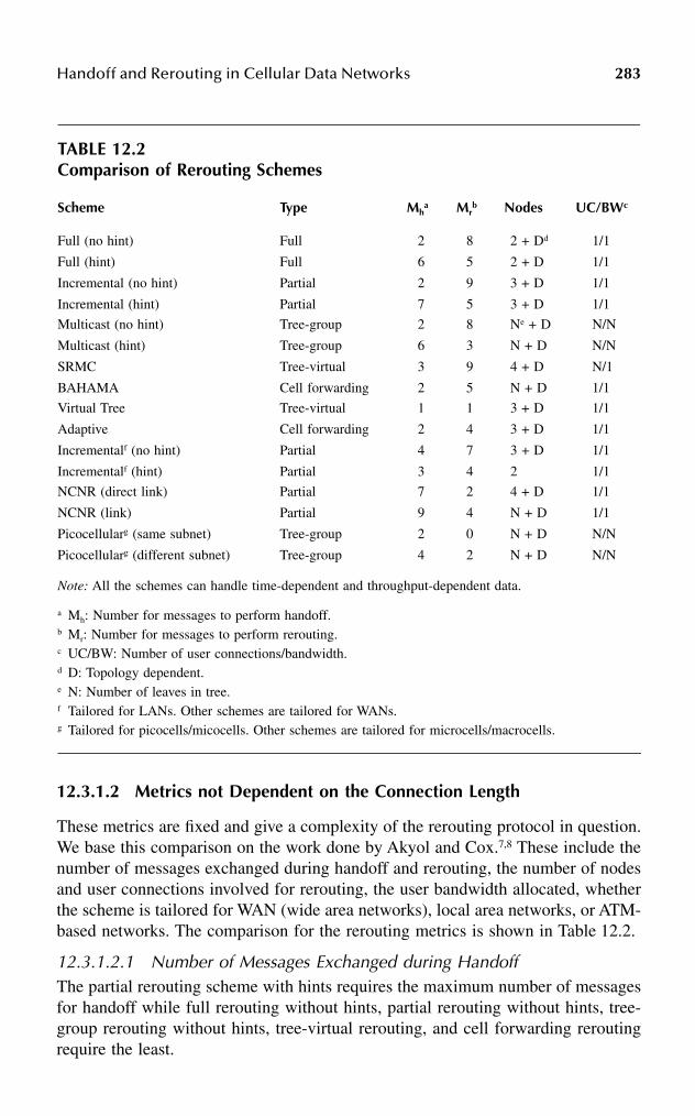
Handoff and Rerouting in Cellular Data Networks 283
12.3.1.2 Metrics not Dependent on the Connection Length
These metrics are fixed and give a complexity of the rerouting protocol in question.We base this comparison on the work done by Akyol and Cox.7,8 These include thenumber of messages exchanged during handoff and rerouting, the number of nodesand user connections involved for rerouting, the user bandwidth allocated, whetherthe scheme is tailored for WAN (wide area networks), local area networks, or ATM-based networks. The comparison for the rerouting metrics is shown in Table 12.2.
12.3.1.2.1 Number of Messages Exchanged during HandoffThe partial rerouting scheme with hints requires the maximum number of messagesfor handoff while full rerouting without hints, partial rerouting without hints, tree-group rerouting without hints, tree-virtual rerouting, and cell forwarding reroutingrequire the least.
TABLE 12.2Comparison of Rerouting Schemes
Scheme Type Mha Mr
b Nodes UC/BWc
Full (no hint) Full 2 8 2 + Dd 1/1
Full (hint) Full 6 5 2 + D 1/1
Incremental (no hint) Partial 2 9 3 + D 1/1
Incremental (hint) Partial 7 5 3 + D 1/1
Multicast (no hint) Tree-group 2 8 Ne + D N/N
Multicast (hint) Tree-group 6 3 N + D N/N
SRMC Tree-virtual 3 9 4 + D N/1
BAHAMA Cell forwarding 2 5 N + D 1/1
Virtual Tree Tree-virtual 1 1 3 + D 1/1
Adaptive Cell forwarding 2 4 3 + D 1/1
Incrementalf (no hint) Partial 4 7 3 + D 1/1
Incrementalf (hint) Partial 3 4 2 1/1
NCNR (direct link) Partial 7 2 4 + D 1/1
NCNR (link) Partial 9 4 N + D 1/1
Picocellularg (same subnet) Tree-group 2 0 N + D N/N
Picocellularg (different subnet) Tree-group 4 2 N + D N/N
Note: All the schemes can handle time-dependent and throughput-dependent data.
a Mh: Number for messages to perform handoff.b Mr: Number for messages to perform rerouting.c UC/BW: Number of user connections/bandwidth.d D: Topology dependent.e N: Number of leaves in tree.f Tailored for LANs. Other schemes are tailored for WANs.g Tailored for picocells/micocells. Other schemes are tailored for microcells/macrocells.

284 Handbook of Wireless Internet
12.3.1.2.2 Number of Messages Exchanged during ReroutingCell forwarding rerouting requires the maximum number of messages exchangedduring rerouting while tree-group with hints requires the minimum number.
12.3.1.2.3 Number of Nodes Involved in Handoff and ReroutingThe number of the nodes required depends on the network topology. However, interms of the minimum requirements, the full rerouting schemes are the best, as theyrequire two nodes (BSold and BSnew) in addition to BSdest, while the other schemesrequire at least three nodes in addition to BSdest.
12.3.1.2.4 Number of User Connections Established for ReroutingThe tree-group rerouting schemes can handle Nmcast connections, while the othershandle only one connection.
12.3.1.2.5 User Bandwidth Allocated for Handoff and ReroutingIf we consider the bandwidth allocated for handoff and rerouting for the full reroutingwithout hints as unity, then all the schemes have the same bandwidth requirementswith the exception of the tree-group rerouting schemes. The tree-group reroutingrequires a bandwidth that is N times the unit bandwidth requirements.
12.3.1.3 Metrics Dependent on the Connection Length
We now study the metrics that depend on the connection path length. Figures 12.12(a–d)show the effect of old connection path length on the service disruption time, totalrerouting time, buffering requirements at the mobile host, buffering requirements at thebase station on the uplink, and buffering requirements at the base station on the down-link, respectively. In these figures, we vary the old connection path length from 1 hopto 10 hops. We assume that the new connection path length is of the same length asthe old connection and the control path length is twice the size of the connection pathlength (based on the assumptions in Seshan3 and Gopal and co-workers).4 We nowdiscuss the performance of the various rerouting schemes in detail.
12.3.1.3.1 Service Disruption TimeFigure 12.12(a) depicts the effect of old connection path length on the servicedisruption time. From the figure, we see that:
1. The minimum service disruption time is for the tree-group with hintsrerouting scheme. It does not vary with the number of hops in the path.
2. For all schemes, except the tree-group with hints, the service disruptiontime is dependent on the control path length between BSold and BSnew.This is because, in the case of tree-group with hints scheme, there is noneed to forward the data from BSold to BSnew as the data is being multicastto both BSold and BSnew.

Handoff and Rerouting in Cellular Data Networks 285
FIGURE 12.12 Performance metrics dependent on path length for rerouting: (a) servicedisruption time; (b) buffering at mobile host; (c) buffering at base station (uplink); (d) bufferingat base station (downlink); (e) total rerouting completion time.
FIGURE 12.12 (continued)
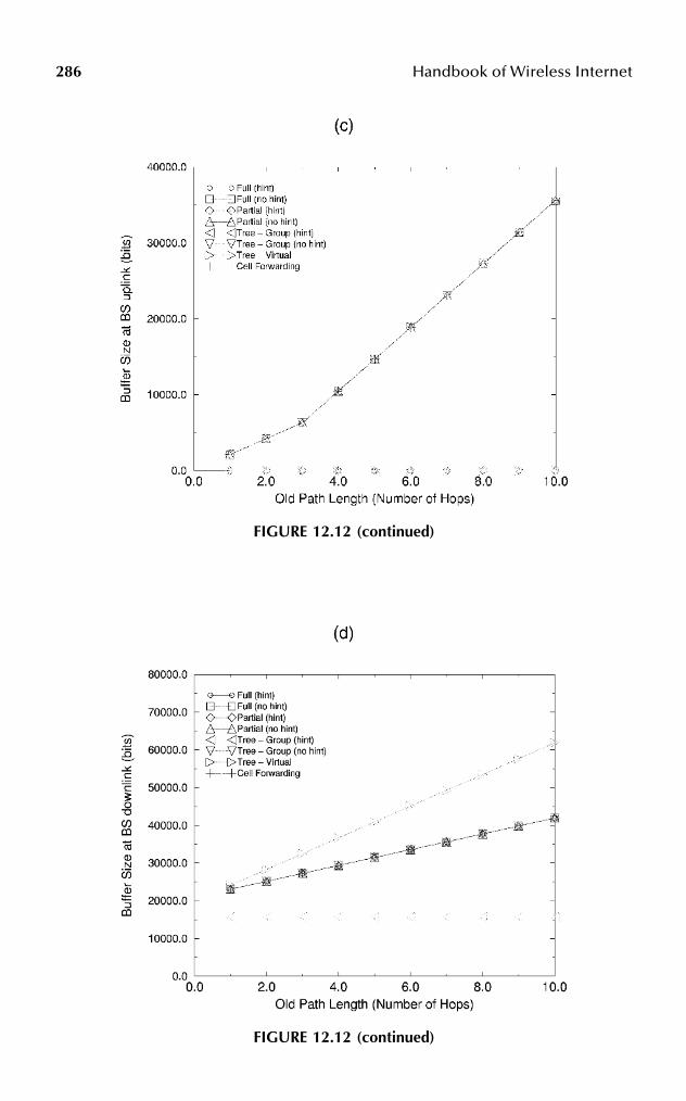
286 Handbook of Wireless Internet
FIGURE 12.12 (continued)
FIGURE 12.12 (continued)

Handoff and Rerouting in Cellular Data Networks 287
3. The service disruption time for the full without hints, full with hints,partial without hints, partial with hints, tree-group without hints, and cellforwarding rerouting schemes is the same because all of these schemesdepend on forwarding of downlink data from BSold. The service disruptiontime for tree-virtual rerouting is not dependent on the length of controlpath, as it does not rely on downlink data forwarding. However, it isdependent on the length of the new path. In case of the tree-virtualrerouting, when the mobile host moves to a new base station, the rootautomatically recognizes that a handoff has taken place.
12.3.1.3.2 Buffering Required at the Mobile HostFigure 12.12(b) depicts the effect of old connection path length on the bufferingrequirements at the mobile host. From the figure, we see that in each reroutingscheme, the buffering at the MH is only used to buffer data for the two specificmessages in their respective protocol. The first is the registration message that MHsends to the BSnew and the second is for the acknowledgment that it receives inresponse to the first message; the cost of the messages is constant for the givenparameters for all the schemes. All the schemes require the same amount of bufferingat the MH.
12.3.1.3.3 Buffering Required in Base Station for the UplinkFigure 12.12(c) depicts the effect of old connection path length on the bufferingrequirements at the base station for the uplink. From the figure, we see that:
FIGURE 12.12 (continued)

288 Handbook of Wireless Internet
1. The buffering requirements for uplink data for all the schemes withouthints, including tree-virtual and cell forwarding, are the same.
2. There are no buffering requirements for uplink data for all the schemes withhints if the length of new and old forwarding path is the same. In general,buffering is dependent on the difference of the old and new path lengths.
3. Except for the case of tree-virtual rerouting, the buffering requirement foruplink data is proportional to the forwarding path length. In the case oftree-virtual rerouting, the buffering requirement for uplink data is propor-tional to the new path length between BSsrc and BSnew.
12.3.1.3.4 Buffering Required in Base Station for the DownlinkFigure 12.12(d) depicts the effect of the old connection path length on the bufferingrequirements at the base station for the downlink. From the figure, we see that:
1. This metric is very closely dependent on the time required for forwardingdownlink data from BSold to BSnew.
2. Because all schemes with the exception of the tree-group with hints andtree-virtual scheme require data forwarding of downlink data, the buffer-ing required in the base station for downlink for them is larger than therequirements for the tree-group with hints scheme.
3. The buffering requirements are the maximum for the tree-virtual reroutingas it does not rely on downlink data forwarding on the control pathbetween BSold to BSnew. BSnew has to buffer all the data on the downlinkuntil it gets an acknowledgment from the server (source) that it hasaccepted the request to reroute data to BSnew.
4. There is a fixed amount of downlink buffering for the tree-group withhints scheme. This is used to buffer the data during the handoff periodalone while the others require downlink buffering for the handoff and thetime period until BSnew requests forwarding of data.
12.3.1.3.5 Rerouting Completion TimeFigure 12.12(e) depicts the effect of old connection path length on the reroutingcompletion time. From the figure, we see that:
1. The minimum rerouting time is for the tree-virtual rerouting scheme. Themetric varies with the length of the new path (and hence with the numberof hops in the old path). However, there is no need to either forwarddownlink data or form new connections or delete connections as the virtualtree is fixed.
2. The rerouting completion time for cell forwarding is comparable to thererouting time for tree-virtual rerouting. In case of cell forwarding, there isno need to form new connections or delete old connections as the connectionpath is simply extended. The problem with cell forwarding is in the case ofmultiple handoffs, the length of the downlink forwarding path can becomevery large, giving rise to inefficiency. For tree-group with hints, rerouting

Handoff and Rerouting in Cellular Data Networks 289
the completion time is dependent on old path length and performs fairly wellbecause it does not require any downlink data forwarding.
3. Full rerouting and partial rerouting perform worse than the other reroutingschemes. When the old path is small, full rerouting performs worse thanpartial rerouting. However, as the old (and the new) path length increases,partial rerouting performs worse than full rerouting because of the addi-tional onus of computing the crossover point.
4. The completion time for the rerouting schemes with hints is less than theircounterparts, which do not take advantage of hints. The completion timefor rerouting schemes without hints is dependent on the length of the newpath. In case of rerouting schemes with hints, the completion time isdependent and closely related to time needed for forwarding downlinkdata and to tear down old connections.
12.3.1.3.6 Special MetricsTable 12.3 shows the values of some of the special metrics (described earlier) forthe different rerouting schemes. More analysis of these results can be found inRacherla and coworkers.4 We see from the previous discussions that:
1. The tree-group with hints and tree-virtual schemes perform the best amongthe rerouting schemes. However, they use a lot more resources for prees-tablishing the tree and maintaining it. This overhead may be worthwhile
TABLE 12.3Special Metrics for Rerouting Schemes
Rerouting Scheme Special Metrics Without Hints With Hints
Full• Old path teardown time• New path setup time
12.36 ms23.82 ms
12.36 ms23.76 ms
Partial• Old path teardown time• New path setup time• Crossover discovery time• Partial reuse efficiency
12.36 ms16.18 ms
1.06 ms0.5
12.36 ms15.55 ms
1.06 ms0.5
Tree-group• Tree teardown time• Tree setup time
12.36 ms16.43 ms
12.36 ms16.43 ms
Tree-virtual• Old path teardown time• Tree setup time
12.36 ms16.43 ms
12.36 ms16.43 ms
Cell forwarding• Old path teardown time• New path setup time
12.36 ms16.18 ms
12.36 ms16.18 ms
290 Handbook of Wireless Internet
for time-critical applications that require low rerouting completion timeand service disruption.
2. In order to minimize service disruption, tree-group rerouting with hintsis the best choice. If the rerouting completion time is the criterion con-sidered, tree-virtual and cell forwarding rerouting perform the best, asthey do not require forming new paths and tearing down old paths.
3. It is certainly advantageous to use rerouting with hints. This readilyimproves service disruption time (for tree-group rerouting), total reroutingcompletion time, and uplink buffering requirements at the base station.
4. Needless to say, the topology of the network is important. In essence, thelengths of the new and old paths are of vital importance.
5. Most of the rerouting schemes behave somewhat similarly because theunderlying mechanisms use downlink data forwarding.
6. The full rerouting and the partial rerouting schemes perform the worst,as they involve forming new paths, tearing down old paths, and downlinkdata forwarding.
12.4 MOBILE–MOBILE REROUTING IN CONNECTION-ORIENTED NETWORKS
Static–static communication has been studied extensively and the routing algorithmsfor this type of communication are well known. The problem with the reroutingschemes for connection-oriented mobile networks described in the literature is theassumption that only one of the parties communicating in a session can be a mobilehost (typically, the destination) and the other is stationary. Only Racherla andcoworkers,4 Ghai and Singh,12 Biswas,18 and cellular telecommunications standardIS-41(c)26,27 suggest schemes for mobile-host-to-mobile-host communication. Bis-was’18 strategy uses an already preestablished route between two stationary hoststhat house the mobile agents in charge of the communication. The only reroutinginvolves both the source and destination mobile hosts establishing paths to thesestationary hosts. The disadvantage of this scheme is that if the mobile hosts keepmoving, the path used for communication may be inefficient, as the scheme doesnot dynamically update the paths based on the location of the mobile hosts. Thescheme proposed by Ghai and Singh suffers from the same problem. In addition,Ghai and Singh’s scheme uses only dynamic multicast rerouting. The complex setuparchitecture uses a three-tier hierarchy (mobile host, base station, and supervisoryhost). In case of cellular telecommunications using the EIA/TIA IS-41(c) standard,cell forwarding rerouting is used continuously for multiple handoffs, as the mobilehosts move away from the original source and the destination base stations. Theobvious disadvantage is that the new cell forwarding routes used are not optimal.We shall see this in more detail later as we compare all these schemes. In addition,these schemes do not look at different rerouting strategies known for static–mobileconnections. Racherla and coworkers4 have proposed a generic framework formobile–mobile rerouting allowing unlimited movement by both the source anddestination mobile hosts, while alleviating the problem of nonoptimal paths. Also,this framework for mobile–mobile rerouting is not tied to the type of rerouting (full,
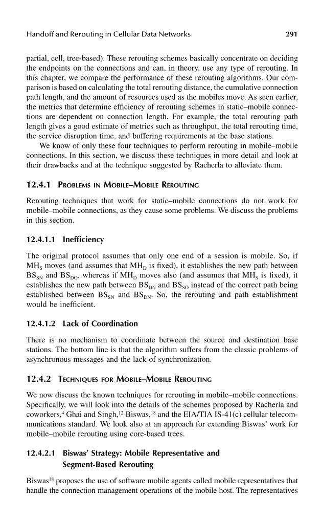
Handoff and Rerouting in Cellular Data Networks 291
partial, cell, tree-based). These rerouting schemes basically concentrate on decidingthe endpoints on the connections and can, in theory, use any type of rerouting. Inthis chapter, we compare the performance of these rerouting algorithms. Our com-parison is based on calculating the total rerouting distance, the cumulative connectionpath length, and the amount of resources used as the mobiles move. As seen earlier,the metrics that determine efficiency of rerouting schemes in static–mobile connec-tions are dependent on connection length. For example, the total rerouting pathlength gives a good estimate of metrics such as throughput, the total rerouting time,the service disruption time, and buffering requirements at the base stations.
We know of only these four techniques to perform rerouting in mobile–mobileconnections. In this section, we discuss these techniques in more detail and look attheir drawbacks and at the technique suggested by Racherla to alleviate them.
12.4.1 PROBLEMS IN MOBILE–MOBILE REROUTING
Rerouting techniques that work for static–mobile connections do not work formobile–mobile connections, as they cause some problems. We discuss the problemsin this section.
12.4.1.1 Inefficiency
The original protocol assumes that only one end of a session is mobile. So, ifMHS moves (and assumes that MHD is fixed), it establishes the new path betweenBSSN and BSDO, whereas if MHD moves also (and assumes that MHS is fixed), itestablishes the new path between BSDN and BSSO instead of the correct path beingestablished between BSSN and BSDN. So, the rerouting and path establishmentwould be inefficient.
12.4.1.2 Lack of Coordination
There is no mechanism to coordinate between the source and destination basestations. The bottom line is that the algorithm suffers from the classic problems ofasynchronous messages and the lack of synchronization.
12.4.2 TECHNIQUES FOR MOBILE–MOBILE REROUTING
We now discuss the known techniques for rerouting in mobile–mobile connections.Specifically, we will look into the details of the schemes proposed by Racherla andcoworkers,4 Ghai and Singh,12 Biswas,18 and the EIA/TIA IS-41(c) cellular telecom-munications standard. We look also at an approach for extending Biswas’ work formobile–mobile rerouting using core-based trees.
12.4.2.1 Biswas’ Strategy: Mobile Representative and Segment-Based Rerouting
Biswas18 proposes the use of software mobile agents called mobile representatives thathandle the connection management operations of the mobile host. The representatives

292 Handbook of Wireless Internet
reside on one of the intermediate routers. Each mobile host has a correspondingmobile representative. It is assumed that the source mobile host MHS (resp. thedestination mobile host MHD) is in the cell corresponding to the base station BSS
(resp. BSD) and its mobile representative is MRS (resp. MRD). Thus, the initial routein the source mobile host–destination mobile host connection is MHS – BSS – MRS –MRD – BSD – MHD. The crux of Biswas’ rerouting strategy is that the path connectingthe corresponding source and the destination mobile representative is the same duringthe lifetime of the connection except the portion of the connection between themobile host and the mobile representative that changes with handoff.
12.4.2.1.1 Problem with Biswas’ StrategyThe disadvantage of this scheme is that if the mobile hosts keep moving, the pathused for communication may be inefficient, as the scheme does not dynamicallyupdate the paths based on the location of the mobile hosts.
12.4.2.2 CBT (Core-Based Tree) Strategy: Extending Biswas’ Work
We propose an extension of Biswas’ approach by using a core-based tree connectingthe source mobile representative to a group of destination mobile representativesinstead of a simple path connecting the mobile representatives. The advantage withthis scheme is that the total rerouting distance can be reduced significantly comparedto Biswas’ strategy. We will see in detail how this can be accomplished when weanalyze the performance of this strategy.
12.4.2.2.1 Problem with the CBT StrategyThe only problem with the CBT is the excess use of resources as the core-basedtree has to be built a priori for the purpose of rerouting.
12.4.2.3 Ghai and Singh’s Strategy: Two-Level Picocellular Rerouting
Ghai and Singh12 present a picocellular-based architecture wherein the number ofhandoffs and therefore handoff overhead within the network increases as cell sizedecreases. Their proposal describes a network architecture that supports a methodfor reducing the handoff overhead and the buffer space requirements using multicastgroups and mobile trajectory prediction. Base stations (referred in this proposal asmobility support stations or MSSs) do not have any intelligence, but rely on acentralized authority called a supervisory host. The supervisory host calculates themobile’s likely trajectory, and forms a multicast group for MSSs that the mobile islikely to handoff to in the near future. All packets are multicast to this group. MSSs donot currently host the mobile host buffer packets in anticipation of a handoff. Suchbuffered packets are tossed out when the MSSs receive an update of the mobile’sacknowledged sequence numbers. A connection-oriented network architecture isdescribed also in this proposal. Virtual circuits are set up between the endpoints forcommunication. The communication is optimized for the case where two mobiles usethe base stations and supervisory host(s). Multiple supervisory hosts are needed if thecommunicating mobile hosts are under the supervision of different supervisory hosts.

Handoff and Rerouting in Cellular Data Networks 293
12.4.2.3.1 Problem with Ghai and Singh’s StrategyThe scheme proposed by Ghai and Singh suffers from several drawbacks. Thearchitecture is fixed, rigid, and requires a tree or tree-like topology. In addition, itrequires an extra level of hierarchy (supervisory hosts), compared to the otherschemes that we discussed earlier. This hierarchy results in longer paths. In addition,this scheme performs rerouting using a tree-group mechanism and does not allowfor the other rerouting strategies.
12.4.2.4 EIA/TIA IS-41(c) Rerouting
The EIA/TIA IS-41(c) Protocol for cellular communications is designed to deal withhandoffs and the subsequent forwarding of connections as the mobile hosts move.This is done by cell forwarding rerouting (called chaining in the scheme). Chainingin this case is done using switches as opposed to base stations used in all the otherschemes described earlier. Because the connections are through switches, the linksto old base stations are automatically removed during switching. These protocolsare meant for circuit-switched networks and not for packet-switched networks. Dataloss and data ordering is not an important concern in this case.
12.4.2.4.1 Problem with EIA/TIA IS-41(c) ReroutingWe cannot compare this scheme with the other schemes described earlier as thisscheme is for circuit-switched networks and switches are used instead of basestations. However, because the rerouting involves cell forwarding, the rerouting isnonoptimal and inefficient.
12.4.2.5 Racherla’s Framework for Mobile–Mobile Rerouting
In order to avoid the above-mentioned problems, Racherla and coworkers4 proposeda source-initiated distributed rerouting algorithm. In this algorithm, the source basestation is responsible for initiating the rerouting. The destination base station informsthe source base station of the movement of MHD. The establishment and removalof routes is initiated by the appropriate source base stations. The crux of this proposedframework is that incorrect requests for new path establishment are rejected, unlikethe other proposed rerouting algorithms described earlier. In addition, Racherla’sframework for rerouting in mobile–mobile communications is independent of thetype of rerouting scheme (full, partial, tree-based or cell forwarding). Each basestation maintains data structures in its local memory to keep track of connections,movements, and identities of mobile hosts MHS and MHD. This data structure allowsbase stations to decide whether or not to accept the creation or termination of a routeduring the rerouting procedure. The framework assumes that there are no lostmessages and that the messages are delivered in a first-in, first-out manner on achannel. A mobile host can move any number of times. However, it eventually staysin a cell long enough for the rerouting to be completed. Each MH receives a radiohint informing it of its movement into another cell, which can be used to set upconnections a priori. The framework assumes that there is initially a connection

294 Handbook of Wireless Internet
between the base stations corresponding to MHS and MHD. This proposed schemehas the following advantages over the other schemes described earlier:
• It uses optimal routes and avoids creating unnecessary routes.• It gives the flexibility to use either full, partial, tree, or cell forwarding
routing.• It is independent of the network architecture and network topology.• Packet loss is kept to a minimum using radio hints effectively.• Processing at the mobile hosts is kept at a minimum.
12.4.3 COMPARISON OF REROUTING SCHEMES FOR MOBILE–MOBILE CONNECTIONS
We compare the previously described schemes based on the rerouting distances. Weuse the extended cross-bar network and analysis as suggested by Song andcoworkers25 for calculating the rerouting distance. The extended cross-bar architec-ture allows for simplified calculations. The analysis can be extended to other typesof networks. In the architecture, the nodes represent the base stations. The horizontaland vertical links are of length 1, while the slanted links are in length. We useRDS,D to represent the reroute distance between nodes S and D. We use TRD(a, d)to represent the total rerouting distance between BSSN and BSDN, where the initialpath length between the source and destination base station is a and the movementdistance of the MH from its initial position is d. We denote the performance metricsfor each of the rerouting schemes by using the name of the scheme as a subscript.
We assume that:
• The MHS and MHD are moving in a straight line in the same direction,and the top and the bottom of the network grid respectively.
• The mobile hosts both moved hops.• MHS moves from cell of its old base station BSSO to a new old base station
BSSN.• MHD moves from cell of its old base station BSDO to a new old base
station BSDN.• There is a connection path between the old base stations for the mobile
hosts to start with. The minimum length of this route is a, and is shownas the straight line connecting BSSO and BSDO.
• The mobile hosts stay at the new base station long enough for the reroutingto be completed.
• For simplicity of analysis, we assume that the mobile hosts start movingat the same time and continue moving at the same speed.
We calculate the following metrics for comparing the performance for all of themobile–mobile rerouting schemes. We consider each case separately for calculatingthe metrics.
2
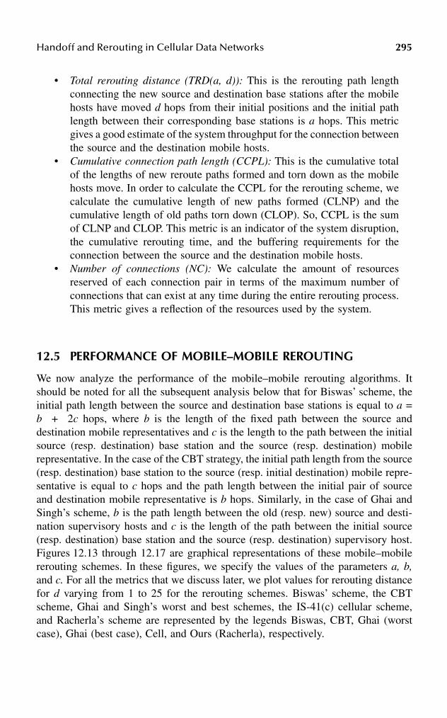
Handoff and Rerouting in Cellular Data Networks 295
• Total rerouting distance (TRD(a, d)): This is the rerouting path lengthconnecting the new source and destination base stations after the mobilehosts have moved d hops from their initial positions and the initial pathlength between their corresponding base stations is a hops. This metricgives a good estimate of the system throughput for the connection betweenthe source and the destination mobile hosts.
• Cumulative connection path length (CCPL): This is the cumulative totalof the lengths of new reroute paths formed and torn down as the mobilehosts move. In order to calculate the CCPL for the rerouting scheme, wecalculate the cumulative length of new paths formed (CLNP) and thecumulative length of old paths torn down (CLOP). So, CCPL is the sumof CLNP and CLOP. This metric is an indicator of the system disruption,the cumulative rerouting time, and the buffering requirements for theconnection between the source and the destination mobile hosts.
• Number of connections (NC): We calculate the amount of resourcesreserved of each connection pair in terms of the maximum number ofconnections that can exist at any time during the entire rerouting process.This metric gives a reflection of the resources used by the system.
12.5 PERFORMANCE OF MOBILE–MOBILE REROUTING
We now analyze the performance of the mobile–mobile rerouting algorithms. Itshould be noted for all the subsequent analysis below that for Biswas’ scheme, theinitial path length between the source and destination base stations is equal to a =b + 2c hops, where b is the length of the fixed path between the source anddestination mobile representatives and c is the length to the path between the initialsource (resp. destination) base station and the source (resp. destination) mobilerepresentative. In the case of the CBT strategy, the initial path length from the source(resp. destination) base station to the source (resp. initial destination) mobile repre-sentative is equal to c hops and the path length between the initial pair of sourceand destination mobile representative is b hops. Similarly, in the case of Ghai andSingh’s scheme, b is the path length between the old (resp. new) source and desti-nation supervisory hosts and c is the length of the path between the initial source(resp. destination) base station and the source (resp. destination) supervisory host.Figures 12.13 through 12.17 are graphical representations of these mobile–mobilererouting schemes. In these figures, we specify the values of the parameters a, b,and c. For all the metrics that we discuss later, we plot values for rerouting distancefor d varying from 1 to 25 for the rerouting schemes. Biswas’ scheme, the CBTscheme, Ghai and Singh’s worst and best schemes, the IS-41(c) cellular scheme,and Racherla’s scheme are represented by the legends Biswas, CBT, Ghai (worstcase), Ghai (best case), Cell, and Ours (Racherla), respectively.

296 Handbook of Wireless Internet
FIGURE 12.13 Ghai and Singh’s scheme: (a) worst case; (b) best case.
FIGURE 12.14 Core-based tree scheme.
FIGURE 12.15 IS-41(c) scheme.
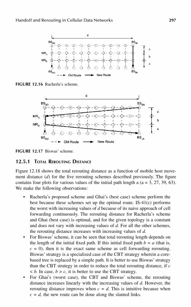
Handoff and Rerouting in Cellular Data Networks 297
12.5.1 TOTAL REROUTING DISTANCE
Figure 12.18 shows the total rerouting distance as a function of mobile host move-ment distance (d) for the five rerouting schemes described previously. The figurecontains four plots for various values of the initial path length a (a = 3, 27, 39, 63).We make the following observations:
• Racherla’s proposed scheme and Ghai’s (best case) scheme perform thebest because these schemes set up the optimal route. IS-41(c) performsthe worst with increasing values of d because of its naive approach of cellforwarding continuously. The rerouting distance for Racherla’s schemeand Ghai (best case) is optimal, and for the given topology is a constantand does not vary with increasing values of d. For all the other schemes,the rerouting distance increases with increasing values of d.
• For Biswas’ scheme, it can be seen that total rerouting length depends onthe length of the initial fixed path. If this initial fixed path b = a (that is,c = 0), then it is the exact same scheme as cell forwarding rerouting.Biswas’ strategy is a specialized case of the CBT strategy wherein a core-based tree is replaced by a simple path. It is better to use Biswas’ strategythan the CBT strategy in order to reduce the total rerouting distance, if c< b. In case, b > c, it is better to use the CBT strategy.
• For Ghai’s (worst case), the CBT and Biswas’ scheme, the reroutingdistance increases linearly with the increasing values of d. However, thererouting distance improves when c = d. This is intuitive because whenc = d, the new route can be done along the slanted links.
FIGURE 12.16 Racherla’s scheme.
FIGURE 12.17 Biswas’ scheme.

298 Handbook of Wireless Internet
FIGURE 12.18 Effect of the moving distance on the total rerouting distance for variousrerouting schemes.
FIGURE 12.18 (continued)
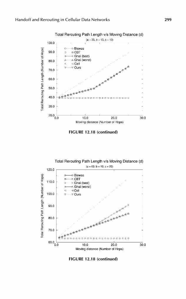
Handoff and Rerouting in Cellular Data Networks 299
FIGURE 12.18 (continued)
FIGURE 12.18 (continued)

300 Handbook of Wireless Internet
12.5.2 CUMULATIVE CONNECTION PATH LENGTH
Figure 12.19 shows the cumulative connection path length as a function of mobilehost movement distance (d) for the rerouting schemes. From the figure, we makethe following observations:
FIGURE 12.19 Effect of the moving distance on the cumulative connection path length forvarious rerouting schemes.
FIGURE 12.19 (continued)

Handoff and Rerouting in Cellular Data Networks 301
• The IS-41(c) scheme does the best because there is no need to removeany of the old paths and every move of the mobile translates to an increaseof a unit length increase in the cumulative path.
• Racherla’s strategy performs the next best as the cumulative path lengthis increased by a hops every time the mobile moves. This is because anew optimal path of length a hops needs to be established.
FIGURE 12.19 (continued)
FIGURE 12.19 (continued)

302 Handbook of Wireless Internet
• In case of all the other schemes, the cumulative path length is much higherand grows exponentially. The CCPL for d moves in each of these casesis a sum of all the total rerouting distance values for all moves 1 through d.
• We see again that it is better to use Biswas’ strategy than the CBT strategyin order to reduce the cumulative path length, if c < b. In case, b > c, itis better to use the CBT strategy.
12.5.3 NUMBER OF CONNECTIONS
In Figure 12.20, we show the cumulative connection path length as a function ofmobile host movement distance (d) for the rerouting schemes. The figure containstwo parts showing the plots for various values of the initial path length a (a = 3,39). From this figure, we observe that the number of connections is minimum andconstant (equal to 2) in the case of Racherla’s strategy. Biswas’ strategy requiresalso a constant number of connections, namely, 5. Also, the number of connectionsfor the other schemes is dependent on the moving distance.
Among the remaining schemes, the CBT scheme requires the least number ofconnections. Ghai (best case) and Ghai (worst case) and IS-41(c) require the samenumber of connections. From the observations of the performance of all thesererouting schemes with respect to the metrics, we infer that Racherla’s schemeperforms the best as far as the total rerouting distance and the number of connectionsare concerned. Ghai (best case) performs as well as our scheme in terms of the totalrerouting distance. However, it requires many more connections to be establishedand incurs more cumulative cost in establishing connections. Also in the worst case,the routes for Ghai and Singh’s scheme are suboptimal. In addition, Ghai and Singh’sstrategy requires specialized supervisory hosts and a tree-based network for optimalperformance. IS-41(c) performs the best with respect to the cumulative cost incurredin establishing connections. However, IS-41(c) requires a high number of connec-tions and its total rerouting distance is very high. CBT is a generalized case ofBiswas’ scheme. In general, the CBT scheme requires more resources than Biswas’scheme and its performance advantage in terms of total rerouting distance overBiswas’ scheme is highly dependent on the underlying topology and the details ofthe core-based tree.
12.6 CONCLUSION
In this chapter, we examined various existing static–mobile rerouting schemes forconnection-oriented cellular mobile computing environments and have proposed ageneric framework to classify them. We presented an exhaustive survey of variousrerouting techniques and rerouting classification schemes proposed in the literature.We proposed generic protocols also for each of the rerouting classes. In addition,we studied each class by looking at its variations, which have been proposed in theliterature. We used a variety of performance metrics to compare and contrast thesererouting schemes. These metrics include the ones common to all the reroutingschemes and the ones that are specific to each class. We surveyed and compared

Handoff and Rerouting in Cellular Data Networks 303
rerouting techniques for mobile–mobile connections. Our future work in this areaincludes increasing the array of performance metrics for comparison, studying theeffect of traffic patterns and traffic distribution on the performance of reroutingschemes, and developing simulation models for the implementation of more-efficientrerouting schemes based on the lessons learned in this chapter.
FIGURE 12.20 Effect of the moving distance on the number of connections established ortorn down for various rerouting schemes.
304 Handbook of Wireless Internet
References
1. Acampora, A., An architecture and methodology for mobile-executed handoff incellular ATM networks, IEEE J. Selected Areas Commun., 12 (8), 1365–1375, 1994.
2. Bush, S., “Handoff mechanism for mobile ATM systems,” Internet draft, 1995.3. Seshan, S., Low latency handoff for cellular data networks, Ph.D. diss., University
of California, Berkeley, 1995.4. Racherla, G., Radhakrishnan, S., and Sekharan, C.N., A framework for evaluation of
rerouting in connection-oriented mobile networks, Technical report, School of Com-puter Science, University of Oklahoma, Norman, 1998.
5. Toh, C-K., The design and implementation of a hybrid handover protocol for multi-media wireless LANs, Proc. ACM Mobicom, Berkeley, California, November 1995.
6. Toh, C-K., A unifying methodology for handovers of heterogeneous connections inwireless ATM networks, in Computer Communication Review, 1997, pp. 12–30.
7. Akyol, B. and Cox, D., Handling mobility in a wireless ATM network, Proc. IEEEInfoCom 96, 3, 8, 1405–1413, March 1996.
8. Akyol, B. and Cox, D., Rerouting for handoff in a wireless ATM network, IEEEPersonal Commun., 3 (5), 26–33, 1996.
9. Naylon, J. et al., Low-latency handover in a wireless ATM LAN, IEEE J. SelectedAreas Commun., 16 (6), 909–921, 1998.
10. Srivastava, M. and Mishra, P.P., Effect of connection rerouting on application perfor-mance in mobile networks, IEEE Trans. Comput., 47 (4), 371–390, 1998.
11. Keeton, K. et al., Providing connection-oriented network services to mobile hosts,Proc. USENIX Symposium on Mobile and Location Independent Computing, Cam-bridge, Massachusetts, August 1993, pp. 83–102.
12. Ghai, R. and Singh, S., An architecture and communication protocol for picocellularnetworks, IEEE Personal Commun., Third Quarter, 36–47, 1994.
13. Toh, C-K., Performance evaluation of crossover switch discovery algorithms forwireless ATM LANs, Proc. IEEE InfoCom, San Francisco, March 1996, pp.1380–1387.
14. Rekhter, Y. and Perkins, C., Optimal routing for mobile hosts using IPs loose sourceroute option, IETF RFC, 1992.
15. Teraoka, F. et al., VIP: a protocol providing host mobility, Commun. ACM, 37 (8),67–75, 1994.
16. Mobile IP Working Group, Routing support for IP mobile hosts, Internet draft, 1993.17. Wada, H. et al., Mobile computing environment based on Internet packet forwarding,
Proc. USENIX Tech. Conf., San Diego, California, Winter 1993, pp. 503–517.18. Biswas, S.K., Handling real-time traffic in mobile networks, Ph.D. diss., University
of Cambridge, 1994. 19. Yuan, R., Biswas, S.K., and Raychaudhuri, D., Mobility support in a wireless ATM
network, Proc. 5th Workshop on Third Generation Wireless Information Networks,Kluwer, Dordrecht, 1995, pp. 335–45.
20. Eng, K.Y. et al., A wireless broadband ad-hoc ATM local area network, ACM J.Wireless Networks (WINET), 1 (2), 161–174, 1995.
21. Ramanathan, S. and Streenstrup, M., A survey of routing techniques for mobilecommunication networks, ACM/Baltzer Mobile Networks Appl., Special issue onRouting in Mobile Communications Networks, 1 (2), 89–104, 1996.
22. Cohen, R. and Segall, A,. Connection management and rerouting in ATM networks,Internet draft, 1998.

Handoff and Rerouting in Cellular Data Networks 305
23. Ramjee, R., La Porta, T.F., Kurose, J., and Towsley, D., Performance evaluation ofconnection rerouting schemes for ATM-based wireless networks, IEEE/ACM Trans.Networking, 6 (3), 249–261, 1998.
24. Song, M., Choi, Y., and Kim, C., Connection-information-based connection reroutingfor connection oriented mobile communication networks, Distributed Systems Engi-neering, 5, 47–65. 1998.
25. EIA/TIA, IS-41(c), Cellular radio telecommunications intersystem operations, 1995.26. Racherla, G., Radhakrishnan, S., and Sekharan, C.N., A distributed rerouting algo-
rithm for mobile–mobile connections in connection-oriented mobile networks, Proc.7th Int. Conf. Comput. Commun. Networks (ICCCN), September 1998, pp. 40–44.
27. Wu, O.T.W. and Leung, V.C.M., B-ISDN architectures and protocols to supportwireless personal communications internetworking, Proc. PIMRC’95, Toronto, Can-ada, September 1995.

This page intentionally left blank

3070-8493-1502-6/03/$0.00+$1.50© 2003 by CRC Press LLC
13 Wireless Communications Using Bluetooth
Oge Marques and Nitish Barman
CONTENTS
13.1 Introduction ................................................................................................30813.2 Overview ....................................................................................................309
13.2.1 Masters and Slaves ......................................................................31013.2.2 Frequency Hopping Spread Spectrum (FHSS) and
Time-Division Duplexing (TDD) ................................................31013.2.3 Piconets and Scatternets ..............................................................310
13.3 Protocol Stack ............................................................................................31113.3.1 The Radio Layer ..........................................................................31313.3.2 The Baseband Layer ....................................................................314
13.3.2.1 Device Addressing......................................................31413.3.2.2 Frequency Hopping ....................................................31513.3.2.3 Link Types (ACL and SCO) ......................................31513.3.2.4 Packet Definitions.......................................................31613.3.2.5 Logical Channels........................................................31913.3.2.6 Channel Control .........................................................32013.3.2.7 Error Checking and Correction..................................32013.3.2.8 Security.......................................................................321
13.3.3 The LMP Layer ...........................................................................32213.3.4 The L2CAP Layer .......................................................................325
13.3.4.1 L2CAP Channel Management ...................................32713.3.5 The SDP Layer ............................................................................327
13.4 Bluetooth Profiles Specification.................................................................32913.4.1 GAP..............................................................................................32913.4.2 SDAP ...........................................................................................33013.4.3 SPP...............................................................................................33013.4.4 GOEP ...........................................................................................331
13.5 Additional Considerations..........................................................................33113.5.1 Power Management .....................................................................33113.5.2 Security ........................................................................................332
308 Handbook of Wireless Internet
13.6 Concluding Remarks..................................................................................332Acknowledgment ...................................................................................................333References..............................................................................................................333
13.1 INTRODUCTIONBluetooth is a wireless communications standard that allows compliant devices toexchange information with each other. The technology makes use of the globallyavailable, unlicensed ISM (Industrial, Scientific, and Medical) band. Although it wasinitially developed as a cable-replacement technology, it has grown into a standardthat is designed to support an open-ended list of applications (including multimediaapplications). As a short-range, low-power technology with data rates of up to 720kbps, it is ideally suited for use in establishing ad hoc personal area networks (PANs).
The Bluetooth specification emerged from a study undertaken by EricssonMobile Communications in 1994 to find alternatives to using cables to facilitatecommunications between mobile phones and accessories. As this study grew inscope, other companies joined Ericsson’s efforts to utilize radio links as cablereplacements. In 1998 these companies – Ericsson, Intel, IBM, Toshiba, and Nokia– formally founded the Bluetooth Special Interest Group (SIG). In July 1999 thiscore group of promoters published version 1.0 of the Bluetooth specification.1
Shortly after the specification was published, the group of core promoters wasenlarged further with the addition of four more companies: Microsoft, Agere Systems(a Lucent Technologies spin-off), 3COM, and Motorola.
In addition to the core promoters group, many hundreds of companies havejoined the SIG as Bluetooth adopter companies. In fact, any incorporated companycan join the SIG as an adopter company by signing the Bluetooth SIG membershipagreement (available on the Bluetooth Web site1). Joining the SIG entitles an adoptercompany to a free license to build Bluetooth-based products, as well as the right touse the Bluetooth brand.
The list of adopter companies continues to grow in part because there is no costassociated with intellectual property rights, but primarily because there are so manypotential applications and usage models for Bluetooth:
1. Cordless desktop: In this cable-replacement usage model, all (or most) ofthe peripheral devices (e.g., mouse, keyboard, printer, speakers, etc.) areconnected to the PC cordlessly.
2. Ultimate headset: This usage model would allow one headset to be used withmyriad devices, including telephones, portable computers, stereos, etc.
3. Automatic synchronization: This usage model makes use of the hiddencomputing paradigm, which focuses on applications in which devicesautomatically carry out certain tasks on behalf of the user without userintervention or awareness. Consider the following scenario: A user attendsa business meeting, exchanges contact information with other attendees,and stores this information on a PDA. Upon returning to the user’s office,the PDA automatically establishes a Bluetooth link with the user’s desktopPC and the information stored on the PDA is automatically uploaded tothe PC. All this happens without the user’s conscious involvement.

Wireless Communications Using Bluetooth 309
There are many other usage models that have been proposed by the BluetoothSIG as well as other contributors. With increasing numbers of applications beingdeveloped around Bluetooth, it is highly likely that the technology will be wellaccepted by the market.
The remainder of this chapter is organized as follows. Section 13.2 provides abroad overview of the Bluetooth protocol stack and introduces some concepts andterminology. Section 13.3 gives a more-detailed explanation of the key features ofthe various layers of the Bluetooth protocol stack. Section 13.4 introduces the secondvolume of the Bluetooth specification, the Profile specification. It serves as a basicintroduction to the concept of Bluetooth profiles, and gives a brief description ofthe fundamental profiles. Section 13.5 discusses security and power managementissues, two items that are critical for the acceptance of Bluetooth in the consumermarket. Finally, Section 13.6 concludes this chapter with some anecdotal evidenceof the interest evinced in Bluetooth application development.
13.2 OVERVIEW
The Bluetooth specification comprises two parts:
1. The core specification,2 which defines the Bluetooth protocol stack andthe requirements for testing and qualification of Bluetooth-based products
2. The profiles specification,3 which defines usage models that providedetailed information about how to use the Bluetooth protocol for varioustypes of applications
The Bluetooth core protocol stack consists of the following five layers:
1. Radio specifies the requirements for radio transmission – including fre-quency, modulation, and power characteristics – for a Bluetooth trans-ceiver.
2. Baseband defines physical and logical channels and link types (voice ordata); specifies various packet formats, transmit and receive timing, chan-nel control, and the mechanism for frequency hopping (hop selection) anddevice addressing.
3. Link Manager Protocol (LMP) defines the procedures for link set up andongoing link management.
4. Logical Link Control and Adaptation Protocol (L2CAP) is responsible foradapting upper-layer protocols to the baseband layer.
5. Service Discovery Protocol (SDP) – allows a Bluetooth device to queryother Bluetooth devices for device information, services provided, andthe characteristics of those services.
In addition to the core protocol stack, the Bluetooth specification also definesother layers that facilitate telephony, cable replacement, and testing and qualification.The most important layers in this group are the Host Controller Interface (HCI) andRFCOMM, which simply provides a serial interface that is akin to the EIA-232
310 Handbook of Wireless Internet
(formerly RS-232) serial interface. HCI provides a standard interface between thehost controller and the Bluetooth module, as well as a means of testing/qualifyinga Bluetooth device.
The Bluetooth protocol stack is discussed in greater detail in Section 13.3. Inthe remainder of this section we will introduce key concepts and terminology thatare helpful for an understanding of Bluetooth technology.
13.2.1 MASTERS AND SLAVES
All active Bluetooth devices must operate either as a master or a slave. A masterdevice is a device that initiates communication with another Bluetooth device. Themaster device governs the communications link and traffic between itself and theslave devices associated with it. A slave device is the device that responds to themaster device. Slave devices are required to synchronize their transmit/receive timingwith that of the masters. In addition, transmissions by slave devices are governedby the master device (i.e., the master device dictates when a slave device maytransmit). Specifically, a slave may only begin its transmissions in a time slotimmediately following the time slot in which it was addressed by the master, or ina time slot explicitly reserved for use by the slave device.
13.2.2 FREQUENCY HOPPING SPREAD SPECTRUM (FHSS) AND TIME-DIVISION DUPLEXING (TDD)
Bluetooth employs a frequency hopping technique to ensure secure and robustcommunication. The hopping scheme is such that the Bluetooth device hops fromone 1-MHz channel to another in a pseudorandom manner – altogether there are 79such 1-MHz channels defined by the SIG. Typically, each hop lasts for 625 µs. Atthe end of the 625-µs time slot, the device hops to a different 1-MHz channel. Thetechnology ensures full-duplex communication by utilizing a TDD scheme. In thesimplest terms this means that a Bluetooth device must alternate between transmit-ting and receiving (or at least listening for) data from one time slot to the next. TheBluetooth specification facilitates this TDD scheme by (1) using numbered timeslots (the slots are numbered according to the clock of the master device), and (2)mandating that master devices begin their transmissions in even-numbered time slotsand slave devices begin their transmissions in odd-numbered time slots (Figure 13.1).Both these techniques will be further discussed in Section 13.3.
13.2.3 PICONETS AND SCATTERNETS
Bluetooth technology furthers the concept of ad hoc networking where deviceswithin range of each other can dynamically form a localized network for an indefiniteduration. Ad hoc Bluetooth networks in which all member devices share the same(FHSS) channel are referred to as piconets.4 A piconet can consist of up to eightdevices: a single master and up to seven slave devices. The frequency hoppingsequence of the piconet is determined by the Bluetooth device address (BD_ADDR)of the master device. At the time that the piconet is established, the master device’saddress and clock are communicated to all slave devices on the piconet. The slaves

Wireless Communications Using Bluetooth 311
use this information to synchronize their hop sequence as well as their clocks withthat of the master’s.
Scatternets (Figure 13.2) are created when a device becomes an active memberof more than one piconet. Essentially, the adjoining device shares its time slotsamong the different piconets. Scatternets are not limited to a combination of onlytwo piconets; multiple piconets may be linked together to form a scatternet. However,as the number of piconets increases, the total throughput of the scatternet decreases.Note that the piconets that make up a scatternet still retain their own FH sequencesand remain distinct entities.
Scatternets offer two advantages over traditional collocated ad hoc networks.First, because each individual piconet in the scatternet retains its own FH sequence,the bandwidth available to the devices on any one piconet is not degraded by thepresence of the other piconets (although the probability of collisions may increase).Second, devices on different piconets are able to “borrow” services from each otherif they are on the same scatternet.
13.3 PROTOCOL STACK
The five layers of the Bluetooth core protocol are divided into two logical parts(Figure 13.3). The lower three layers (Radio, Baseband, and LMP) comprise the
FIGURE 13.1 Frequency hopping and time-division duplexing. During even-numbered slots,the master device transmits and the slave device receives. During odd-numbered slots, theslave device transmits and the master device receives.
10 11 12 13 14 15 16
10 11 12 13 14 15 16
time slots
time slots
R F c h a n n e l
R F c h a n n e l
Master Device
Slave Device
transmit
receive

312 Handbook of Wireless Internet
Bluetooth module, whereas the upper layers (L2CAP and SDP) make up the host. Theinterface between these two logical groupings is called the Host Controller Interface(HCI). Note that the HCI is itself a distinct layer of the Bluetooth protocol stack. Thereason for separating the layers into two groups stems from implementation issues. In
FIGURE 13.2 Scatternet examples: (a) piconet 1 and piconet 2 share a common slave device;(b) a device acts as slave in piconet 1 and master in piconet 2.
(a)
(b)
Piconet 2
M
M
S
S
S
S
S
S
S
Piconet 1
Scatternet
Piconet 2
M
S
M
S
S
S
S
S
Piconet 1
Scatternet
S

Wireless Communications Using Bluetooth 313
many Bluetooth systems the lower layers reside on separate hardware than the upperlayers of the protocol. A good example of this is a Bluetooth-based wireless LANcard. Because the PC to which the LAN card connects typically has enough spareresources to implement the upper layers in software, the LAN card itself onlycontains the lower layers, thus reducing hardware complexity and user cost. In sucha scenario the HCI provides a well-defined, standard interface between the host (thePC) and the Bluetooth module (the LAN card).
13.3.1 THE RADIO LAYER
Bluetooth devices operate in the 2.4-GHz ISM band. In North America, Europe, andmost of the rest of the world, a bandwidth of 83.5 MHz is available in the ISMband. In France, however, the ISM band is much narrower. The Bluetooth SIG hasactively lobbied the French regulatory bodies to release the full ISM band; Franceis expected to comply by 2003. Although the Bluetooth specification defines aseparate RF specification for the narrower (French) band, we will not consider it here.
The ISM band is littered with millions of RF emitters ranging from randomnoise generators, such as sodium vapor street lamps, to well-defined, short-rangeapplications, such as remote entry devices for automobiles. Microwave ovens areparticularly noisy and cause significant interference. Clearly, the ISM band is not avery reliable medium. Bluetooth overcomes the hurdles presented by the pollutedenvironment of the ISM band by employing techniques that ensure the robustnessof transmitted data. Specifically, Bluetooth makes use of frequency hopping (alongwith fairly short data packets) and adaptive power control techniques in order toensure the integrity of transmitted data.
FIGURE 13.3 Bluetooth protocol stack.
Link Manager Protocol
Radio
Baseband
Bluetooth Module
Applications
Logical Link Control And Adaptation Protocol
SDP RFCOMM
Host
HCI

314 Handbook of Wireless Internet
The Bluetooth Radio specification defines a frequency hopping spread spectrumradio transceiver operating over multiple RF channels. The specification divides the83.5-MHz bandwidth available in the ISM band into 79 RF channels of 1 MHz each,a 2-MHz lower guard band, and a 3.5-MHz upper guard band. The channel frequen-cies are defined as
2402 + k MHz
where k = 0, 1, …, 78.In order to maximize the available channel bandwidth, the data rate for the RF
channels is set at 1 Mbps. Gaussian frequency shift keying (GFSK) is used as themodulation scheme, with a binary 1 defined as a positive frequency deviation fromthe carrier frequency and a binary 0 defined as a negative frequency deviation.
In addition to specifying the modulation scheme, the Radio specification definesalso three power classes (Table 13.1) for Bluetooth devices. Each power class hasassociated with it a nominal transmission range and a maximum power output. Thenominal power output for all three classes is 1 mW (0 dBm).
13.3.2 THE BASEBAND LAYER
The baseband layer is by far the most-complex layer defined in the Bluetoothspecification. It encompasses a wide range of topics, not all of which can be discussedin this short introduction to the Bluetooth technology. What follows is a briefoverview of the key aspects of the baseband layer.
13.3.2.1 Device Addressing
The radio transceiver on each Bluetooth device is assigned a unique 48-bit Bluetoothdevice address (BD_ADDR) at the time of manufacture. Portions of this address areused to generate three types of access codes: the device access code (DAC), thechannel access code (CAC), and the inquiry access code (IAC). The DAC and theIAC are used for paging and inquiry procedures. The CAC is specified for the entirepiconet and is derived from the device address of the master device. It is used asthe preamble of all packets exchanged on that piconet.
With regard to slave devices on a piconet, there are two other addresses ofinterest. The first is the active member address (AM_ADDR). This is a 3-bit address
TABLE 13.1Bluetooth Radio Power Classes
Power ClassRange of Transmission
(meters)Maximum Power Output
(mW/dBm)
1 3 1/02 10 2.5/43 100 100/20

Wireless Communications Using Bluetooth 315
that is assigned to an active slave device on the piconet. Because the piconet mayhave seven active slaves at any given time, a slave’s AM_ADDR uniquely identifiesit within its piconet. The second address of interest is the parked member address(PM_ADDR). This is an 8-bit address assigned to slave devices that are parked, i.e.,devices that are not active on the piconet but remain synchronized to the piconet’smaster. An active slave device loses its AM_ADDR as soon as it is parked. Similarly,a parked device that becomes active immediately relinquishes its PM_ADDR andtakes on an AM_ADDR. Note that the reactivated device may or may not be assignedthe same AM_ADDR that it was assigned before it was parked.
13.3.2.2 Frequency Hopping
In order to ensure secure and robust data transmission, Bluetooth technology utilizesa frequency hopping spread spectrum technique. Under this scheme, Bluetoothdevices in a piconet hop from one RF channel to another in a pseudorandomsequence. Typically, a hop occurs once at the beginning of every time slot. Becauseeach time slot has a 625-µs duration, the nominal hopping frequency is 1600 hopsper second. All devices that are part of the same piconet hop in synchrony. Thehopping sequence is based on the master’s BD_ADDR and consequently is uniquefor each piconet.
Because there can be multiple piconets operating in close proximity to eachother, it is important to minimize collisions between the devices in different piconets.The specification addresses this issue in two ways. First, the pseudorandom hopselection algorithm is designed to generate the maximum distance between adjacenthop channels. Second, the duration of the time slots is kept very small (625 µs).Time slots of such short duration ensure that even if a collision occurs it will notlast long. A collision is unlikely to recur during the next time slot because the piconetwill have hopped to a different RF channel.
Strictly speaking, the baseband specification defines a different hoppingsequence for different types of operations. The earlier description is that of thechannel hopping sequence, which utilizes all 79 RF channels and defines a uniquephysical channel for the piconet. However, the other hopping sequences (associatedwith device discovery procedures such as paging and inquiry) utilize only 32 RFchannels.
One final note: It was previously stated that the nominal hop rate is 1600 hopsper second. This is true only for packets (discussed later) that occupy a single timeslot. For packets that occupy three (or five) time slots, the same RF channel is usedfor transmission during all three (or five) time slots.
13.3.2.3 Link Types (ACL and SCO)
The baseband specification defines two types of links between Bluetooth devices.
1. Synchronous Connection Oriented (SCO) link: This is a bidirectional (64kbps each way), point-to-point link between a master and a single slavedevice. The master maintains the SCO link by using reserved time slots

316 Handbook of Wireless Internet
at regular intervals. The slots are reserved as consecutive pairs: one fortransmissions from the master to the slave and the other for transmissionsin the opposite direction. The master can support up to three SCO linkssimultaneously. A slave device can support up to three simultaneous SCOlinks with one master or — if it is the adjoining device on a scatternet —it can support up to two simultaneous SCO links with two differentmasters. SCO links are used for exchanging time-bound user information(e.g., voice). Packets sent on these links are never retransmitted.
2. Asynchronous Connectionless (ACL) link: This is a point-to-multipointlink between the master and all the slaves on a piconet. An ACL link canutilize any packet that is not reserved for an SCO link. The master canexchange packets with any slave on the piconet on a per-slot basis, includ-ing slaves with which it has an established SCO link. Only one ACL linkcan exist between any master–slave pair. ACL links are used for theexchange of control information and user data, therefore packet retrans-mission is applied to ACL packets received in error.
13.3.2.4 Packet Definitions
The baseband layer defines the format and structure of the various packet types usedin the Bluetooth system. The length of a packet can range from 68 bits (shortenedaccess code) to a maximum of 3071 bits. A typical packet (Figure 13.4), however,consists of a 72-bit access code, a 54-bit packet header, and a variable length (0 to2745 bits) payload.
Every packet must begin with an access code (see Section 3.2.1). The accesscode is used for synchronization and identification at either the device level(DAC/IAC) or the piconet level (CAC).
The packet header contains link control information, so it is important to ensureits integrity. This is accomplished by applying a 1/3-rate FEC scheme to the entireheader. The packet header consists of six different fields:
1. AM_ADDR (3-bit field): This field contains the active member addressof the slave device that transmitted the packet (or, if the master sent thepacket, the AM_ADDR of the slave device to which the packet wasaddressed).
2. TYPE (4-bit field) : This field identifies the type of packet, as explainedlater in this section.
3. FLOW (1-bit field): This field is used for providing flow control informa-tion on an ACL link. A value of 0 (STOP) indicates a request to the senderto stop sending information, whereas a value of 1 (GO) indicates that thereceiver is once again ready to receive additional packets. If no packet isreceived from the receiver, a GO is implicitly assumed.
FIGURE 13.4 Packet structure of a typical Bluetooth packet.
Access Code Packet Header Payload (variable length)
0
Wireless Communications Using Bluetooth 317
4. ARQ (1-bit field): This field is used for acknowledging payload dataaccompanied by a CRC (cyclic redundancy check). If the payload wasreceived without error, a positive acknowledgment (ACK) is sent; other-wise, a negative acknowledgment (NACK) is sent. An ACK correspondsto a binary 1 and a NACK corresponds to a binary 0. Note that NACK isthe default value for this field and is implicitly assumed.
5. SEQN (1-bit field): This field is used for a very simple sequential num-bering scheme for transmitted packets. The SEQN bit is inverted for eachnew transmitted packet containing a payload accompanied by a CRC. Thisfield is required for filtering out retransmissions at the destination.
6. HEC (8-bit field) : This field, the header error check, is used for ascer-taining the integrity of the header. If the header is received in error, theentire packet is ignored.
The payload portion of the packet is used to carry either voice or data informa-tion. Typically, packets transmitted on SCO links carry voice information – with theexception of the DV packet type, which carries both voice and data – and packetstransmitted on ACL links carry data. For packets carrying voice information, thepayload length is fixed at 240 bits (except DV packets). Packets carrying data, onthe other hand, have variable length payloads that are segmented into three parts: apayload header, payload body, and a CRC.
The payload header is either one or two bytes long. It specifies the logicalchannel on which the payload is to be carried, provides flow control information forthe specified channel, and indicates the length of the payload body. The only dif-ference between the one-byte and two-byte headers is that the two-byte headers usemore bits to specify the length of the payload body. The payload body simplycontains the user host data and the 16-bit CRC field is used for performing errorchecking on the payload body.
13.3.2.4.1 Packet TypesThe packets defined for use in the Bluetooth system (Table 13.2) are identified bythe 4-bit TYPE field in the packet header. As is evident from the length of the TYPEfield, 16 possible packet types can be defined altogether. Bluetooth packet types canbe categorized in four broad groups: control packets, single-slot packets, three-slotpackets, and five-slot packets. Single-slot packets require only one time slot forcomplete transmission. Similarly, three-slot and five-slot packets require three andfive time slots, respectively, for complete transmission. The single-slot, three-slot,and five-slot packets are defined differently for the two different link types (SCOand ACL), while the control packets are common to both links.
The four control packets defined in the specification are:
1. NULL: This packet type is used to return acknowledgments and flowcontrol information to the source.
2. POLL: This packet is used by the master to poll slave devices in a piconet.Slave devices must respond to this packet even if they have no informationto send.

318 Handbook of Wireless Internet
3. FHS: The frequency hop selection packet is used to identify the frequencyhop sequence before a piconet is established or when an existing piconetchanges to a new piconet as a result of a master–slave role switch. Thiscontrol packet contains the BD_ADDR and clock of the sender (recallthat the master’s device address and clock are used to generate a pseudo-random frequency hop sequence). In addition, the packet contains alsothe AM_ADDR to be assigned to the recipient along with other informa-tion required in establishing a piconet.
4. DM1: The DM1 (data–medium rate) packet is used for supporting controlinformation on any link. This is necessary, for example, when synchronousinformation (on an SCO link) must be interrupted in order to supplycontrol information. In an ACL link, this packet can be used to carry userdata. The packet’s payload can contain up to 18 bytes of information. Thepayload data is followed by a 16-bit CRC. Both the data and the CRCare encoded with a 2/3-rate forward error correction (FEC) scheme.
The remaining 12 packet types are defined differently for each link. Some packettypes have not yet been defined or have been set aside for future use.
13.3.2.4.2 SCO PacketsAll packets defined specifically for the SCO link are single-slot packets. They allhave a 240-bit payload and do not include a CRC. The first three SCO packets aredesigned to carry high-quality voice (HV) information (64 kbps) and are defined asfollows:
TABLE 13.2Bluetooth Packet Types
Packet GroupType Code
Packet Name on SCO Link
Packet Name on ACL Link
Number of Slots
0000 NULL NULL 1Control group 0001 POLL POLL 1
0010 FHS FHS 10011 DM1 DM1 10100 Undefined DH1 10101 HV1 Undefined 1
Single-slot group 0110 HV2 Undefined 10111 HV3 Undefined 11000 DV Undefined 11001 Undefined AUX1 11010 Undefined DM3 3
Three-slot group 1011 Undefined DH3 31100 Undefined Undefined 31101 Undefined Undefined 3
Five-slot group 1110 Undefined DM5 51111 Undefined DH5 5

Wireless Communications Using Bluetooth 319
• HV1: This packet contains 10 bytes of data and is protected by 1/3-rateFEC. Because one packet can carry about 1.25 ms of speech, HV1 packetsneed to be transmitted once every two time slots.
• HV2: This packet contains 20 bytes of data and is protected by 2/3-rateFEC. Because one packet can carry about 2.5 ms of speech, HV2 packetsonly need to be transmitted once every four time slots.
• HV3: This packet contains 30 bytes of data and is not encoded with anerror correction scheme. Because one packet can carry about 3.75 ms ofspeech, HV3 packets need to be transmitted only once every six time slots.
The last packet type defined for the SCO link is the DV (combined data andvoice) packet. This packet contains a 10-byte voice field and a data field containingup to 10 bytes of data. The data field is encoded with 2/3-rate FEC and is protectedby a 16-bit CRC. It is interesting to note that the voice and data information containedin this packet are treated completely differently. The voice information – which issynchronous – is never retransmitted, whereas the data information is retransmittedif it is found to be in error. So, for example, if the data field of a packet is receivedin error, the packet is retransmitted (i.e., the data field contains the same information),but the voice field contains new (different) information.
13.3.2.4.3 ACL PacketsSix different packet types have been defined specifically for the ACL link. All theACL packets are designed to carry data information and are distinguished from oneanother by two basic criteria: (1) whether they are encoded with a FEC scheme, and(2) how many time slots they require for complete transmission. The packet typesprotected with an FEC scheme are referred to as medium data rate (DM) packets,whereas the unprotected packets are referred to as high data rate (DH) packets.
There are two DM packet types defined: DM3 and DM5. Both these packettypes are similar to the DM1 control packet in that they are protected with a 2/3-rate FEC scheme. The difference is that unlike DM1, which requires one time slotfor complete transmission, DM3 and DM5 require three time slots and five timeslots, respectively. Additionally, as one might expect, DM5 packets can carry moredata than DM3 packets, which in turn can carry more data than DM1.
Three different DH packet types are defined for the ACL link: DH1, DH3 andDH5. All these packets can carry more data than their DM counterparts because theDH packets are not encoded with an error correction scheme. As with the DM packettypes, DH3 and DH5 carry more information than DH1.
The sixth packet type defined for the ACL link is the AUX1 (auxiliary) packettype. This packet type is very similar to DH1 except it does not contain a CRC code.
The remaining packet types have not been defined as yet and have been set asideto accommodate packet types that may be required in the future.
13.3.2.5 Logical Channels
Bluetooth specification defines five logical channels for carrying either link controland management information or user data.
320 Handbook of Wireless Internet
The two channels that carry link control information are the link control (LC)channel and the link manager (LM) channel. The LC logical channel is mapped tothe header of every packet (except the ID packet) exchanged on a Bluetooth link.This channel carries low level link information such as flow control, ARQ, etc. TheLM channel is typically carried on protected DM packets and it can utilize eitherlink type (SCO or ACL). A packet used for the LM channel is identified by an L_CHvalue of 11 in the packet’s header. The LM channel carries LMP traffic and thereforetakes priority over user data channels.
Three logical channels are defined for conveying user data: the user asynchro-nous (UA) channel, the user isochronous (UI) channel, and the user synchronous(US) channel. The UA and UI channels are normally mapped to the payload ofpackets transmitted over an ACL link, but they can be mapped also to the data fieldof the DV packet on an SCO link. The US channel carries synchronous user data(e.g., voice communication) and is mapped to the payload field of packets transmittedover an SCO link.
13.3.2.6 Channel Control
Channel control deals with the establishment of a piconet and adding/removingdevices to/from a piconet. The specification defines two primary states for a Blue-tooth device: standby and connected. The standby state is the default, low-powerstate. A device is in the connected state when it is a member of a piconet, i.e., whena device is synchronized to the hop sequence of a piconet.
Devices do not transition directly from the standby state to the connected state,and vice versa. In fact, the specification describes several substates that a devicemust transition through in order to move from one primary state to the other. Thesesubstates are associated with inquiry and paging procedures that are required forslave devices to join or leave the piconet. Figure 13.5 depicts the state transitionsinvolved in going from the standby state to the connected state and back. Theobservant reader will note that there is a direct transition from the connected stateback to the standby state. This direct transition occurs only in case of a hard reset.Normally, devices must methodically detach from the piconet, which requires tran-sitioning through different substates.
The Bluetooth system makes provisions for connected devices to be put intoone of three low-power modes while remaining synchronized to the hop sequenceof the piconet. These modes (discussed further in Section 3.3) can be considered assubstates of the connected state (Figure 13.5).
13.3.2.7 Error Checking and Correction
Bluetooth provides a variety of error checking and error correction mechanisms.Bluetooth packets can be checked for errors at three levels. When a packet is received,the receiver immediately checks its channel access code (recall that the CAC is thepreamble for all packets). If the CAC embedded in the packet does not match theCAC of the piconet, then either the packet was received in error, or the packet wasdestined for another piconet. In either case, the packet is discarded. If the CAC
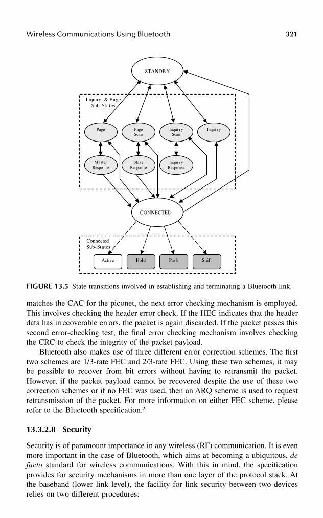
Wireless Communications Using Bluetooth 321
matches the CAC for the piconet, the next error checking mechanism is employed.This involves checking the header error check. If the HEC indicates that the headerdata has irrecoverable errors, the packet is again discarded. If the packet passes thissecond error-checking test, the final error checking mechanism involves checkingthe CRC to check the integrity of the packet payload.
Bluetooth also makes use of three different error correction schemes. The firsttwo schemes are 1/3-rate FEC and 2/3-rate FEC. Using these two schemes, it maybe possible to recover from bit errors without having to retransmit the packet.However, if the packet payload cannot be recovered despite the use of these twocorrection schemes or if no FEC was used, then an ARQ scheme is used to requestretransmission of the packet. For more information on either FEC scheme, pleaserefer to the Bluetooth specification.2
13.3.2.8 Security
Security is of paramount importance in any wireless (RF) communication. It is evenmore important in the case of Bluetooth, which aims at becoming a ubiquitous, defacto standard for wireless communications. With this in mind, the specificationprovides for security mechanisms in more than one layer of the protocol stack. Atthe baseband (lower link level), the facility for link security between two devicesrelies on two different procedures:
FIGURE 13.5 State transitions involved in establishing and terminating a Bluetooth link.
Connected Sub-States
Inquiry & Page Sub-States
Page
Master Response
Page Scan
Inqui ry
Inqui ry Response
Slave Response
Inqui ry Scan
CONNECTED
STANDBY
Active Hold Park Sniff
322 Handbook of Wireless Internet
1. Authentication: Procedure used to verify the identity claimed by a Blue-tooth device
2. Encryption: Procedure used to encode user data so that it is unintelligibleuntil decoded using a specific key
The security algorithms defined in the baseband specification utilize the follow-ing four parameters:
1. BD_ADDR: Publicly known 48-bit address of the device2. Authentication key: 128-bit secret key preconfigured with the device3. Privacy key: Variable length (4 to 128 bits) secret key that is preconfigured
also with the device4. Random number: 128-bit number used for device authentication
In addition to these key responsibilities, the baseband layer addresses otherissues, including transmit/receive timing, data whitening, and encoding of audioinformation for transmission over Bluetooth links.
13.3.3 THE LMP LAYER
The Link Manager Protocol is responsible for establishing and maintaining ACLand SCO links, and establishing, managing, and terminating the connections betweendifferent devices. LMP provides a mechanism for the link managers (LMs) onseparate devices to exchange messages containing link management informationwith each other. These messages are sent as LMP protocol data units (PDUs) andare carried in the payload of single-slot packets (DM1 or DV) transmitted on theLM logical channel.
Because LMP PDUs are used for link management, they have been assigned avery high priority. Consequently, LMP PDUs may be transmitted during slotsreserved for an SCO link. The PDU contains three fields:
1. A 1-bit transaction ID field, which specifies whether the link managementtransaction was initiated by the master (0) or the slave (1) device
2. A 7-bit OpCode field, which identifies the PDU and provides informationabout the PDUs payload
3. A payload field, which contains the actual information necessary to man-age the link
Many PDUs have been defined for the different transactions defined in the speci-fication. Two of the most general response PDUs are LMP_Accepted andLMP_Not_Accepted. Although many link management transactions have been definedin the specification, not all of them are mandatory. However, the LM on every Bluetoothdevice must be able to recognize and respond to any of the specified transactions. Incase the LM on the receiving device does not support a particular transaction, it muststill respond to the requesting device’s LM with an LMP_Not_Accepted PDU.

Wireless Communications Using Bluetooth 323
In the remainder of this section we will briefly mention some of the more-important link management transactions defined in the specification. These transac-tions are grouped into three broad categories: link control, power management, andsecurity management.
Link management transactions used for link control include:
• Connection establishment: Before two devices can exchange L2CAPinformation, they must first establish a communications link (Figure 13.6).The procedure for establishing a link is as follows: the LM of the devicerequesting the connection sends an LMP_Host_Connection_Req PDU tothe receiving device. The LM of the receiving device may then eitheraccept or reject the request. If the request is accepted, the LMs of the twodevices further negotiate the parameters of the link to be set up. Whenthis negotiation is completed, the LMs of both devices send anLMP_Setup_Complete PDU to each other and the link is established.
• Link detachment: When a device wishes to terminate its link to anotherdevice, it issues an LMP_Detach PDU. The receiving device cannot rejectthe detach request and the link between the two devices is immediatelyterminated.
• Clock and timing information: LMP PDUs in clock-and-timing-relatedtransactions are used by devices to obtain clock offsets and slot offsetsfrom each other. Support for many of these PDUs is mandatory becauselink timing cannot be established or negotiated without them.
• Master–slave role switch: This transaction plays an important role in theestablishment of a scatternet.5 The device that wants to switch roles
FIGURE 13.6 LM connection request transactions: In both cases, the transaction is initiatedby LM 1 (on device 1). (a) LM 2 rejects the request for establishing a connection, and thetransaction terminates; (b) LM 2 accepts the request, LM 1 and LM 2 negotiate the linkparameters, the negotiation process is completed, and the connection is established.
(a)
(b)
LM 1
LM 2
1 Request Connection
2 Reject Connection Request
LM 1
LM 2
1 Request Connection
2 Affirmative Response
3 Negotiate Parameters of Link
4 Accept Link

324 Handbook of Wireless Internet
initiates the process by sending an LMP_Switch_Req PDU. If the requestis accepted, the role switch occurs after the two devices exchange sometiming information.
• Information exchange: Transactions of this type allow devices to requestinformation from each other. As an example, a (local) device may wantto inquire another (remote) device about the optional link manager featuressupported by the receiving device. In that case, the local device sends anLMP_Features_Req PDU to the remote device. In addition to requestinga list of features supported by the remote device, the PDU containsinformation about the optional features supported by the local device.When the remote device receives the request, i t sends anLMP_Fea tu res_Res PDU back to the loca l dev ice . TheLMP_Features_Res PDU contains information about the optional featuressupported by the remote device. At the end of the transaction, both devicesare aware of the optional services supported by the other.
Power management transactions allow Bluetooth devices the flexibility to con-serve power when they are not actively exchanging information. The transactionsin this category include:
• Sniff mode: While an active slave must monitor every even-numberedtime slot for transmissions from the master, a slave device in sniff modehas to monitor far fewer slots. Note that slots reserved for an SCO linkare not affected by sniff mode. A master may force a slave device intosniff mode by sending an LMP_Sniff PDU to the slave. Alternatively,either the master or the slave may request that the slave device be placedin sniff mode by issuing an LMP_Sniff_Req PDU.
• Hold mode: In an established piconet, there may be times when a slavedevice will not be addressed for a significant duration. In such instances,it is highly desirable to place the slave device in sleep-like mode for theduration of time that it will not be addressed, in order to conserve power.In hold mode, the ACL link between the master and slave is temporarilysuspended (i.e., there is no ACL traffic between the master and slave).The duration for which the link is suspended is called the hold time andis stipulated at the time the link is suspended. Note that any SCO linksbetween the master and slave device are unaffected. As with sniff mode,the master may either force a slave into hold mode (LMP_Hold PDU) oreither the master or the slave may request that the slave be placed in holdmode (LMP_Hold_Req).
• Park mode: In the sniff and hold modes, the slave device is consideredan active member of the piconet (i.e., it is still one of the seven activeslave devices on the piconet). In park mode, however, the slave device isno longer active on the piconet; however, it still remains synchronized tothe piconet. The advantage is that if the device needs to rejoin the piconet,it can do so very quickly. Interested readers are referred to the LMPspecification for further information.

Wireless Communications Using Bluetooth 325
Security is addressed in more than one layer of the Bluetooth protocol stack. Inthe LMP layer, the key security management transactions are device authenticationand link encryption; while the former is a mandatory feature of all Bluetooth devices,the latter is optional.
• Device authentication: This transaction is based on a challenge responsescheme. The transaction begins by one device (the verifier) sending anLMP_Au_Rand PDU to another device (the claimant). The PDU containsa 128-bit random number. The claimant uses this number as the input toan encryption function. The output of this function is then transmittedback to the verifier. If the value received by the verifier matches the valueit expects, the claimant is authenticated. At the end of this transaction,the verifier and claimant may swap roles in order to authenticate the linkin the opposite direction. The authentication transaction is far more com-plex than the simple procedure outlined here. A much more detailedexplanation can be found in the Bluetooth LMP specification.2
• Link encryption: Link encryption is often necessary to protect the privacyof the data transmitted over a Bluetooth link. This transaction is initiatedwhen a device issues an LMP_Encryption_Mode_Req PDU. The encryp-tion mode determines whether the encryption is to be applied to a point-to-point link only or to broadcast packets as well. If the request is accepted,the devices negotiate the size of the encryption key to be used by exchang-ing LMP_Encryption_Key_Size_Req PDUs. Once the encryption key sizehas been determined, the devices begin the encryption process by issuingan LMP_Start_Encryption PDU.
13.3.4 THE L2CAP LAYER
The L2CAP layer serves to insulate higher-layer protocols (including non-Bluetooth-specific protocols such as TCP/IP, PPP, etc.) from the lower-layer Bluetooth transportprotocols. In addition, it supports protocol multiplexing with respect to higher-layerprotocols. Another key feature of the L2CAP layer is that it facilitates segmentationand reassembly of higher-layer packets. Note that L2CAP itself does not segment(or reassemble) packets. It simply provides packet length information to the higher-layer protocols, which allows those protocols to segment (and reassemble) thepackets submitted to (and received from) the L2CAP layer. L2CAP supports quality-of-service (QoS) features by allowing the exchange of QoS information betweenthe L2CAP layers on different devices.
The L2CAP layer messages are sent in packets known as L2CAP PDUs. ThesePDUs are carried on ACL packets transmitted on the user asynchronous logicalchannel. Because these PDUs may be carried on multislot packets, the L_CH fieldin the payload header of the ACL packets is used to indicate whether the currentpacket is the start of the L2CAP PDU (denoted by an L_CH value of 10) or acontinuation of the L2CAP PDU (denoted by an L_CH value of 01). The L2CAPlayer does not itself guarantee the reliable transmission of L2CAP PDUs. It assumesthat the packet retransmission facility provided by the baseband layer is sufficientfor ensuring a reliable communication channel.

326 Handbook of Wireless Internet
All communication between the L2CAP layers on different devices occurs overlogical links referred to as channels (Figure 13.7). These channels are identified bythe two endpoints (one on the first device, the other on the second device) of thelink. Each endpoint is assigned a unique 16-bit channel identifier (CID). The CIDsare assigned locally, i.e., the endpoint local to a particular device is assigned its CIDby the L2CAP layer of that same device. These endpoints are in turn uniquelyassociated with some recipient (e.g., higher-layer protocol) to which the payload ofthe L2CAP PDU is delivered. The CIDs are administered locally and the schemefor assigning CIDs is left up to the implementer. The only exception is that someCIDs have been reserved (Table 13.3) for specific channels.
TABLE 13.3L2CAP CID Definitions
CID hex Description
0000 NULL identifier0001 Signaling channel0002 Connectionless reception channel0003-003F Reserved0040-FFFF Dynamically allocated
FIGURE 13.7 L2CAP channels between three different devices. Device A maintains twoconnectionless (CL) channels, one each with Device B and Device C. Devices A and B sharea bidirectional connection-oriented (CO) channel also, as do Device B and Device C. Notethat all the channels terminate at endpoints in the L2CAP entities of the different devices.Each of these endpoints is assigned a CID by its L2CAP entity. The endpoints in each of thedevices are uniquely associated with some recipient application.
Device A
Device B
Device C
L2CAP A
L2CAP B
L2CAP C
CID: 2
CID: 2
CID: 25
CID: 17
CID: 79
CID: 41
Application
Application
Application
Application
Application
Application
Application
CID: 35
CO Channel
CL Channel

Wireless Communications Using Bluetooth 327
The Bluetooth specification defines three types of L2CAP channels:
1. Connection-oriented (CO) channel: This is a persistent channel that sup-ports bidirectional communication and requires the exchange of signalinginformation before it can be established.
2. Connectionless (CL) channel: CL channels are unidirectional, are notpersistent, and are typically used for broadcast messages. If a device wantsto respond to a L2CAP transmission on a CL channel, it must send itsresponse on another channel. Also, CL channels allow the L2CAP layerto provide protocol multiplexing (refer to the specification for additionaldetails).
3. Signaling channel: This is very similar to the CO channel except that itsCID (and other channel parameters) are fixed, and therefore no signalinginformation is exchanged in order to establish the channel. Indeed, thesignaling channel is itself used for exchanging signaling information.
13.3.4.1 L2CAP Channel Management
In order for a CO channel to be established or terminated, signaling information has tobe exchanged between the local and remote devices. This signaling information isexchanged by means of a request-and-response transaction mechanism. The signalingcommands used in th is t ransact ion are L2CAP_Connect ion_Req,L2CAP_Connection_Res, L2CAP_Configuration_Req, L2CAP_Configuration_Res,L2CAP_Disconnection_Req, and L2CAP_Disconnection_Res. There are additionalsignaling commands defined in the specification, but they will not be discussed here.
The procedure for establishing a CO channel is as follows: the local device (i.e.,the device that wants to establish the CO channel) sends an L2CAP_Connection_Reqcommand to the remote device. The command contains the source CID (i.e., theCID of the endpoint on the local device) and other signaling information. If theremote device accepts the connection request, it sends an L2CAP_Connection_Rescommand back to the local device. The response command contains the destinationCID (i.e., the CID of the endpoint on the remote device), as well as other signalinginformation. Once the CO channel has been established, it has to be configured. Thelocal and remote devices negotiate channel configuration by exchangingL2CAP_Configuration_Req and L2CAP_Configuration_Res commands. If the twodevices cannot agree on configuration parameters, the CO channel is either termi-nated or the default configuration parameters (implementation dependent) are used.The most important of the configuration parameters negotiated between the twodevices are the QoS parameters.
13.3.5 THE SDP LAYER
Bluetooth technology was developed to support mobility and facilitate the formationof ad hoc networks. This scenario is qualitatively different from “static” networksin which member devices do not constantly leave/join the network. In an ad hocnetwork, devices are free to join or leave the network at whim. This presents a

328 Handbook of Wireless Internet
complex challenge, because a device leaving a network may deprive the network ofsome service that only that device provides. On the other hand, a device that joinsa network (piconet) may provide a service that was previously not available on anyother device in that network. So how does any device on the network know whatservices are available on the network at any given time? This is precisely the issueaddressed by the SDP.
SDP utilizes the concept of a client/server model. Clients are devices that aresearching for services, whereas servers are devices that provide services. These rolesare entirely interchangeable, i.e., any device can be either a client or a server, dependingon whether it is using a service provided by another device or providing a service toanother device. SDP requires that all devices (in their role as servers) maintain a serviceregistry. The service registry is a collection of service records that provide information(service attributes) about the services provided by the device.
SDP specifies two types of service attributes: (1) universal service attributes,which could apply to any class of service (e.g., printing, telephony, LAN access,etc.); and (2) service-specific attributes, which are meaningful only in the contextof a particular service class. It is important to note that the universal service attributesare not necessarily mandatory. In fact, the specification mandates only two suchattributes: the service class attribute, which identifies the class or type of service,and the service record handle, which is a pointer to the service record of that service.6
Service discovery is accomplished by means of SDP transactions. SDP transac-tion information is communicated using SDP PDUs. In order for service discoveryto work, it is necessary that the services are represented in a standard format, onethat both the client and the server can use to refer to the service. SDP uses universallyunique identifiers (UUIDs) to represent the services. Typically, two transactions arerequired in order for a client to obtain service information from the server: a servicesearch transaction, and a service attribute transaction. The first transaction is initiatedby the client when it sends an SDP_Service_Search_Req PDU to the server. Uponreceiving this request , the server responds to the cl ient with anSDP_Service_Search_Res PDU. The response PDU returns a list of service recordhandles that match the service requested by the client. Of course, if the server doesnot support the requested service, it still responds to the client, but the list of servicerecord handles is empty. Following the response from the server, the client beginsthe second transaction by sending an SDP_Service_Attribute_Req PDU to the server.The parameters of this PDU are the service record handle (for the service of interest)and the attribute IDs of the attributes desired by the client. When the server receivesthe SDP_Service_Attribute_Req PDU from the client, it responds with anSDP_Service_Attribute_Res PDU that contains a list of attributes (attribute ID andthe corresponding value) retrieved from the service record specified by the servicerecord handle supplied by the client. At the end of the second transaction, the clientshould have enough information to connect to the service. It is important to notethat SDP does not actually provide the client with the requested service. If the clientwants to connect to the service, it utilizes some other protocol to do so.
There is a third type of transaction defined in the SDP specification, but it issimply a composite of the first two transactions, and is not discussed here. Interestedreaders may refer to the specification itself for additional details.
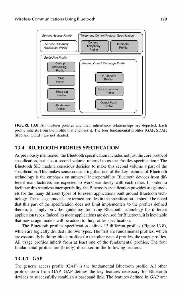
Wireless Communications Using Bluetooth 329
13.4 BLUETOOTH PROFILES SPECIFICATIONAs previously mentioned, the Bluetooth specification includes not just the core protocolspecification, but also a second volume referred to as the Profiles specification.2 TheBluetooth SIG made a conscious decision to make this second volume a part of thespecification. This makes sense considering that one of the key features of Bluetoothtechnology is the emphasis on universal interoperability. Bluetooth devices from dif-ferent manufacturers are expected to work seamlessly with each other. In order tofacilitate this seamless interoperability, the Bluetooth specification provides usage mod-els for the many different types of foreseen applications built around Bluetooth tech-nology. These usage models are termed profiles in the specification. It should be notedthat this part of the specification does not limit implementers to the profiles definedtherein; it simply provides guidelines for using Bluetooth technology for differentapplication types. Indeed, as more applications are devised for Bluetooth, it is inevitablethat new usage models will be added to the profiles specification.
The Bluetooth profiles specification defines 13 different profiles (Figure 13.8),which are logically divided into two types. The first are fundamental profiles, whichare essentially building-block profiles for the other type of profiles, the usage profiles.All usage profiles inherit from at least one of the fundamental profiles. The fourfundamental profiles are (briefly) discussed in the following sections.
13.4.1 GAPThe generic access profile (GAP) is the fundamental Bluetooth profile. All otherprofiles stem from GAP. GAP defines the key features necessary for Bluetoothdevices to successfully establish a baseband link. The features defined in GAP are:
FIGURE 13.8 All thirteen profiles and their inheritance relationships are depicted. Eachprofile inherits from the profile that encloses it. The four fundamental profiles (GAP, SDAP,SPP, and GOEP) are not shaded.
Generic Access Profile
Service DiscoveryApplication Profile
Serial Port Profile
Telephony Control Protocol Specification
CorlessTelephony
Profile
Intercom Profile
Dial-up networking
Profile
FAX Profile
Head set Profile
LAN AccessProfile
File Transfer Profile
Object PushProfile
SynchronizationProfile
Generic Object Exchange Profile

330 Handbook of Wireless Internet
• Conformance: Every Bluetooth device that does not support some otherprofile must at least conform to GAP. Essentially, this means that GAPspecifies certain features that must be implemented in all Bluetoothdevices.
• Discovery procedures: The minimum set of procedures required for aBluetooth device to discover another Bluetooth device.
• Security procedures: Procedures required for using the different securitylevels.
• Link management facilities: Facilities that ensure that Bluetooth devicescan connect to each other.
In addition to these features, GAP defines also the mandatory and optional modesof operation for a Bluetooth device. Please refer to the specification for furtherinformation. Finally, GAP defines a standard set of terminology that is to be usedwith respect to user interfaces developed for Bluetooth devices. Defining standard-ized terminology ensures that users of the technology will recognize Bluetoothfunctionality across different user interface designs.5
13.4.2 SDAP
The service discovery application profile describes, in general terms, how applica-tions that use the SDP should be created, and how they should behave. Fundamen-tally, SDAP specifies which services an SDAP-based application should provide toits users. These services are defined as “service primitive abstractions,” and foursuch primitives are defined:
1. ServiceBrowse: Used by a local device when conducting a general searchfor services available on a set of remote devices
2. ServiceSearch: Used by a local device when searching for a specificservice type on a set of remote devices
3. EnumerateRemDev: Used by a local device to search for remote devicesin its vicinity
4. TerminatePrimitive: Used to terminate the operations initiated by the otherthree primitives
13.4.3 SPP
The serial port profile is concerned with providing serial port emulation to twodevices that want to utilize a Bluetooth link for serial communication. As can beexpected, SPP uses the RFCOMM protocol for providing serial port emulation. Thekey feature of the SPP is that it outlines the procedures necessary for using theRFCOMM protocol to establish a serial link between two devices. The overarchinggoal of the SPP is to ensure transparency, i.e., an application using the emulatedserial link should not be able to distinguish it from a physical serial link. By definingthe SPP profile, the SIG has assured that legacy applications (that make use of serialcommunication links) will not have to be modified in order to use Bluetooth.

Wireless Communications Using Bluetooth 331
13.4.4 GOEP
The generic object exchange profile is based on the object push/pull model, asdefined in Infrared Data Association’s (IrDA) OBEX layer. GOEP distinguishesbetween a client device and a server device. The client device is the device thatinitiates the object exchange operation by requesting the OBEX service from theserver. The client either pushes a data object onto or pulls a data object off of theserver device. The server device is the device that provides the client device withthis push/pull object exchange service. Note that there is no correlation betweenmaster/slave (in the context of Bluetooth) on the one hand, and client/server in thecontext of OBEX on the other. In the simplest terms, GOEP defines the primitivesthat allow objects to be exchanged between a client and server. The two mostimportant of these primitives are object push and object pull. An interesting sidenote regarding GOEP is that it was originally developed to provide Bluetooth deviceswith a synchronization capability, but during the course of development, it grew intothe concept of IrDA interoperability.6
The remaining nine profiles are usage profiles. As stated earlier, these profilesinherit features from at least one of the four fundamental profiles. Although we willnot discuss the usage profiles, they are listed below for reference:
1. Cordless telephony2. Intercom3. Headset4. Fax5. Dial-up networking6. LAN access7. Object push8. Synchronization9. File transfer (FTP)
13.5 ADDITIONAL CONSIDERATIONS
13.5.1 POWER MANAGEMENT
Bluetooth technology is motivated by the desire to provide a universal interface tobattery-driven portable devices. As such, the technology makes several provisionsfor effective power management in order to conserve power. Some of the key powermanagement features are implemented at the micro level. The first such feature isidentified with respect to frequency hopping. The mechanism for frequency hoppingis defined such that no dummy data has to be exchanged in order to keep the masterand slave devices synchronized to each other. This obviates the need for the trans-ceivers on both the master and slave devices to periodically wake up and transmitdummy packets. The second feature is inherent in the packet format. BecauseBluetooth packets begin with the access code of the piconet for which they areintended, a device that is listening on the piconet’s hop frequency during its receiveslot can quickly ascertain whether the packet carried on the current hop frequency

332 Handbook of Wireless Internet
is intended for its piconet. If the device determines that the packet was not intendedfor its piconet, the device’s receiver can go to sleep for the remainder of the timeslot. Moreover, the packet header contains information about the length of thepayload. So, if the payload is very small, the device does not have to keep its receiveron for the entire duration of the time slot. It can put its receiver to sleep as soon asthe entire payload has been received. Aside from the micro-level power managementfeatures discussed here, Bluetooth provides support for macro-level power manage-ment in that it allows devices to be put in any one of three power saving modes:hold, sniff, and park (see Section 13.3.3).
13.5.2 SECURITY
Because Bluetooth is an RF-based wireless technology, data exchanged betweenBluetooth devices can be easily intercepted. Clearly, there is a need to protectpersonal and private data from would-be eavesdroppers. The Bluetooth SIG hasmade a conscious effort to provide various security mechanisms at many differentlevels of the specification. To begin with, the fact that the technology employs afrequency hopping spread spectrum technique to establish a channel for communi-cation itself provides a certain degree of security. Consider that without knowingthe hop sequence of the piconet, the eavesdropper will not know which 1-MHzchannel to listen to during the next 625-µs time slot. But there are other intentionalsecurity mechanisms provided in the Bluetooth specification.
At a macro level, the specifications provide three security modes for a Bluetoothdevice. Devices in security mode 1 never initiate any security procedures. Addition-ally, devices in this mode are not required to support device authentication. Insecurity mode 2, devices do not need to initiate security procedures until an L2CAPchannel is established. Once the L2CAP link is established, the device can decidewhich security procedures to enforce. Security mode 3 is the most stringent of thethree security modes. In this mode, security procedures are initiated at the link level,i.e., before any link is established between devices.
There are two key security procedures defined in the specification: device authen-tication and link encryption (see Section 13.3). In addition to the security mecha-nisms provided by Bluetooth at the lowest levels, more-advanced security mecha-nisms can be employed at higher layers.4,7,8
13.6 CONCLUDING REMARKS
Although the Bluetooth profiles specification defines usage models for several fore-seen applications of Bluetooth technology, these are by no means the only applica-tions that can be built around Bluetooth. In fact, new applications are constantlybeing defined. One source for innovative new applications is the Computer SocietyInternational Design Competition.9 In 2001 and 2002, this international competition,sponsored by the IEEE Computer Society, focused on Bluetooth technology. Thecompetition required student teams to build applications around Bluetooth technol-ogy. Some of the applications envisioned by the student teams have promptedmembers of the SIG to consider new profiles (e.g., a profile designed specifically
Wireless Communications Using Bluetooth 333
for medical devices). All this development activity bodes well for the acceptance ofBluetooth technology by the consumer market.
In this chapter we have endeavored to present a salient, albeit cursory overviewof Bluetooth technology. It must be borne in mind, however, that Bluetooth is afeature-rich and well-defined wireless communications standard. Indeed, the Blue-tooth specification spans more than 1500 pages. Interested readers are encouragedto refer to the specifications,2,3 as well as several publications that discuss thetechnology in much greater detail.5,10
ACKNOWLEDGMENT
Nitish Barman gratefully acknowledges the support and encouragement providedby his family (especially his brother) and the generous assistance (proofreading andfeedback) provided by his good friends and colleagues, Ms. Shefat Sharif and Mr.Scott Bowser.
References
1. The Official Bluetooth Web site, http://www.bluetooth.com.2. Specification of the Bluetooth System – Core online, available at http://www.blue-
tooth.com.3. Specification of the Bluetooth System – Profiles online, available at http://www.blue-
tooth.com.4. Haartsen, J.C., Bluetooth – ad hoc networking in an uncoordinated environment,
Proc. IEEE International Conference on Acoustics, Speech, and Signal Processing,4, 2029–2032, 2001.
5. Miller, B.A. and Bisdikian, C., Bluetooth Revealed: The Insider’s Guide to an OpenSpecification for Global Wireless Communications, Prentice-Hall, Upper SaddleRiver, NJ, 2001.
6. Stallings, W., Wireless Communications and Networks, Prentice-Hall, Upper SaddleRiver, NJ, 2002.
7. Haartsen, J. C., The Bluetooth radio system, IEEE Personal Commun., 7 (1), 28–36,2000.
8. Haartsen, J. C. and Mattisson, S., Bluetooth – a new low-power radio interfaceproviding short-range connectivity, Proc. IEEE, 88 (10), 1651–1661, 2000.
9. CSIDC Web site, http://www.computer.org/csidc. 10. Bray, J. and Sturman, C.F., Bluetooth 1.1: Connect Without Cables, 2nd ed., Prentice-
Hall, Upper Saddle River, NJ, 2001.

This page intentionally left blank

3350-8493-1502-6/03/$0.00+$1.50© 2003 by CRC Press LLC
14 Multiantenna Technology for High-Speed Wireless Internet Access
Angel Lozano
CONTENTS
14.1 Introduction ................................................................................................33514.2 Fundamental Limits to Mobile Data Access .............................................336
14.2.1 Capacity and Bandwidth Efficiency............................................33614.2.2 Space: The Final Frontier............................................................33714.2.3 Pushing the Limits with Multiantenna Technology....................337
14.3 Models ........................................................................................................33814.4 Single-User Throughput.............................................................................341
14.4.1 Single-User Bandwidth Efficiency ..............................................34114.4.2 Transmit Diversity .......................................................................34214.4.3 Receive Diversity.........................................................................34214.4.4 Multiple-Transmit Multiple-Receive Architectures ....................343
14.5 System Throughput ....................................................................................34414.6 Implementation: Realizing the MTMR Potential......................................34614.7 Summary ....................................................................................................347References..............................................................................................................348
14.1 INTRODUCTION
With the explosive growth of both the wireless industry and the Internet, it is inevitablethat demand for seamless mobile wireless access to the Internet explodes as well.Limited Internet access, at very low speeds, is already available as an enhancement tosome second-generation (2G) cellular systems. Third-generation (3G) mobile wirelesssystems will bring true packet access at significantly higher speeds.1
Traditional wireless technologies, however, are not particularly well suited tomeet the extremely demanding requirements of providing the very high data rates

336 Handbook of Wireless Internet
and low cost associated with wired Internet access and the ubiquity, mobility, andportability characteristics of cellular systems. Some fundamental barriers, associatedwith the nature of the radio channel as well as with limited bandwidth availabilityat the frequencies of interest, stand in the way. As a result, the cost-per-bit in wirelessis much higher than in the wired world, wherein an entire generation of Internetusers has grown accustomed to accessing huge volumes of information at very highspeed and negligible cost.
14.2 FUNDAMENTAL LIMITS TO MOBILE DATA ACCESS
14.2.1 CAPACITY AND BANDWIDTH EFFICIENCY
Ever since the dawn of the Information Age, capacity has been the principal metricused to assess the value of a communication system.2,3 Irrespective of whether it isapplied to an individual radio link, to a cell, or even to an entire system, the capacitysignifies the largest volume of data throughput that can be communicated witharbitrary reliability.
Because capacity grows linearly with the amount of spectrum utilized, the mostimmediate way in which capacity can be enlarged is by allocating additional band-width. However, radio spectrum is a scarce and very expensive resource at thefrequencies of interest, where propagation conditions are favorable.* Hence, it isimperative that the available bandwidth is utilized as efficiently as possible. Conse-quently, bandwidth efficiency — defined as the capacity per unit bandwidth — hasbecome a key figure of merit.
Besides bandwidth, the capacity also is a function of the received signal poweror, more specifically, of the signal-to-interference-and-noise ratio (SINR) at thereceiver.
However, unlike with bandwidth, the capacity only scales logarithmically withthe SINR and thus trying to enhance the capacity by simply transmitting more poweris extremely costly. Furthermore, it is futile in the context of a dense interference-limited cellular system, wherein an increase in everybody’s transmit power scalesup both the desired signals as well as their mutual interference, yielding no netbenefit. Therefore, power increases are useless once a system has become limitedin essence by its own interference. Furthermore, because mature systems designedfor high capacity tend to be interference-limited,4 it is power itself — in the formof interference — that ultimately limits their performance.
In order to improve bandwidth efficiency, multiple access methods — originallyrather conservative in their design — have evolved toward much more sophisticatedschemes. In the context of frequency division multiple access (FDMA) and timedivision multiple access (TDMA), this evolutionary path has led to advanced formsof dynamic channel assignment, as well as the incorporation of frequency hopping.
* Efforts to exploit the larger bandwidths available at frequencies above 10 to 20 GHz are under way,but radio propagation and equipment cost pose serious challenges and thus the realm of portable andmobile systems appear to be, for now, confined to the range around 1 to 5 GHz.
Multiantenna Technology for High-Speed Wireless Internet Access 337
In the context of code division multiple access (CDMA), it has led to a variety ofmultiuser detection and interference cancellation techniques.5.6 In all cases, theobjective is to attain the highest possible degree of bandwidth utilization throughaggressive frequency reuse.
14.2.2 SPACE: THE FINAL FRONTIER
As a key ingredient in the design of more spectrally efficient systems, space hasbecome, in recent years, the last frontier. Nonetheless, the use of the spatial dimen-sion in wireless is hardly new. In fact, one could argue that the entire concept offrequency reuse on which cellular systems are based constitutes a simple way ofexploiting the spatial dimension. Cell sectorization, a widespread procedure thatreduces interference, can be regarded also as a form of spatial processing. Thesebasic concepts can be taken to the limit, and the area capacity can be increasedalmost indefinitely,* by shrinking the cells and deploying additional base stations.4
However, the cost and difficulty of deploying the vast infrastructure required toprovide ubiquitous coverage using only microcells has proved prohibitive in thepast; it remains to be seen whether that will change with the advent of wirelessdata. In light of these developments, the use of the spatial dimension is now gearedmostly toward maximizing the system capacity on a per-base-station basis.** Here,base station antenna arrays are the enabling tool for a wide range of spatialprocessing techniques.7 Because capacity grows roughly linearly with the numberof sectors per cell, the most immediate use for such arrays is an increase in thenumber of sectors. This idea can be refined by making such sectors adaptive usingbeam-steering and beam-forming techniques devised to enhance desired signalsand mitigate interference. All such schemes, however, are fundamentally limitedby the multipath nature of the radio channel: sectors and beams are only effectiveas long as they are sufficiently broad with respect to the angular dispersion orspread introduced by the channel.
Any attempts to create excessively narrow sectors or beams will result in dis-torted patterns and unforeseen interference. This fundamental barrier, however, canbe overcome by incorporating a second antenna array at the terminal.
14.2.3 PUSHING THE LIMITS WITH MULTIANTENNA TECHNOLOGY
Until recently, the deployment of antenna arrays in mobile systems had been con-templated exclusively at base station sites because of size and cost considerations.One of the principal role of those arrays was to provide spatial diversity againstsignal fading.4,8 Such fading, arising from multipath propagation caused by scatter-ing, had always been regarded as an impairment that had to be mitigated. However,recent advances in information theory have shown that, with the simultaneous useof antenna arrays at both base station and terminal, multipath interference cannot
* Up to the point where the propagation exponent becomes too small for effective distance decay andfrequency reuse.** The use of microcells is still actively considered for dense urban areas, hot spots, indoor environments,etc., but often as a complementary overlay to macrocells.
338 Handbook of Wireless Internet
only be mitigated, but actually exploited to establish multiple parallel channels thatoperate simultaneously and in the same frequency band.9–11 Based on this funda-mental idea, an entire new class of multiple-transmit multiple-receive (MTMR)communications architectures has emerged.* A critical feature of these MTMRarchitectures is that the total radiated power is held constant irrespective of thenumber of transmit antennas. Extraordinary levels of bandwidth efficiency can thusbe achieved without any increase in the amount of interference caused to other users.
Imagine a number of single-antenna user terminals collocated into an MTMRterminal that handled their multiple signals simultaneously. Intuitively, this wouldrequire the base station to be able to resolve the individual antennas within theterminal array, which in turn would require synthesizing an impossibly narrow beam.The novelty in MTMR communication, however, is that the scattering environmentaround the terminal is used as an aperture through which those antennas becomeeffectively resolvable.
Notice that, by reusing the same frequency band at each antenna, very largeincreases in throughput are achieved without increasing the user bandwidth. Hence,in many respects, these MTMR schemes can be regarded as the ultimate step in thequest for ever-tighter levels of frequency reuse, for here every individual user isreusing its bandwidth multiple times.
14.3 MODELS
With nT transmit and nR receive antennas, a baseband discrete-time model for themultiantenna channel with frequency-flat fading** is
(14.1)
where x is the nT-dimensional vector representing the transmit signal and y is the nR-dimensional received vector. The vector n, containing both thermal noise and interfer-ence, is modeled as Gaussian with zero-mean independent components and power σ2
per receive antenna.*** The channel, in turn, is represented by the (nR × nT) randommatrix containing the transfer coefficients from each transmit to each receiveantenna. For convenience, we choose to factor out the scalar so as to yield anormalized channel H, the second-order moment of whose entries is unity.
We define also the ratio
(14.2)
* These communication architectures are also referred to as multiple-input multiple-output (MIMO).** The analysis and results to follow can be extended to the more general case of frequency-selectivefading.*** While thermal noise is inherently white, interference tends to be spatially colored, and thus itscomponents are not necessarily independent. Nonetheless, for the sake of simplicity the entire vector ncan be modeled as white to yield a lower bound on the bandwidth efficiency.
y Hx n= +g
gHg
β = n
nT
R
Multiantenna Technology for High-Speed Wireless Internet Access 339
The transmit power is constrained to some value P and thus
(14.3)
While power control proved to be an essential ingredient in telephony systems, wheresource rate variability was minimal, in mobile data systems rate adaptation becomesnot only an attractive complement, but even a full alternative to power control.12
Hence, we restrict ourselves to the case where the total transmit power is heldconstant while the data rate is being adapted.
The thermal noise power per receive antenna is σ2 = N0BF, where N0 is the one-sided noise spectral density, B is the signal bandwidth, and F is the receiver noisefigure. We set the noise figure to an optimistic value of F = 3 dB and use the noisespectral density corresponding to a standard temperature of 300 K. In line with the3G framework, the available bandwidth is set to B = 5 MHz.
Within the channel,4 different levels of randomness exist:
• The large-scale randomness associated with distance decay, shadow fad-ing, etc., determines the average conditions at every location. Its impactis absorbed into the path gain g, which has a coherence distance of tensor even hundreds of wavelengths, and thus can be regarded as determin-istic within a local area. The path gain has a range-dependent component,which we model using the well-established COST231 model,13 and ashadow fading component, which is taken to be log-normally distributedwith an 8-dB standard deviation.4 In suburban environments at 2 GHz,the average path gain is given by*
(14.4)
d where the expectation is over the shadow fading, the range in km andG the total (combined transmit and receive) antenna gain.
• The small-scale randomness caused by multipath propagation can bemodeled as a locally stationary random process. This level of randomness,contained within H, has a coherence distance that is on the order of awavelength. Because the small-scale fading encountered in wireless sys-tems tends to be Rayleigh in distribution, the entries of H can be realis-tically modeled as zero-mean complex Gaussian random variables.**With that, the characterization of H entails simply determining the cor-relation between its entries. A typical propagation scenario, portrayed in
* The base station and terminal heights are set to 35 and 2 m, respectively. The path gain can be adjustedfor other types of environment and frequency bands.** Channels that are non-Gaussian and behave abnormally may in theory occur.40,41
E P[ ]x 2 =
E d G
d G
[ ]
log log
.g
dB
= ⋅
= − − +
− −4 10
134 35 10
14 3 5
10 10
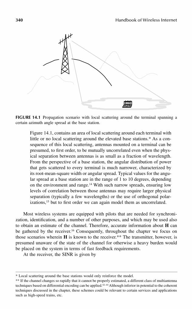
340 Handbook of Wireless Internet
Figure 14.1, contains an area of local scattering around each terminal withlittle or no local scattering around the elevated base stations.* As a con-sequence of this local scattering, antennas mounted on a terminal can bepresumed, to first order, to be mutually uncorrelated even when the phys-ical separation between antennas is as small as a fraction of wavelength.From the perspective of a base station, the angular distribution of powerthat gets scattered to every terminal is much narrower, characterized byits root-mean-square width or angular spread. Typical values for the angu-lar spread at a base station are in the range of 1 to 10 degrees, dependingon the environment and range.14 With such narrow spreads, ensuring lowlevels of correlation between those antennas may require larger physicalseparation (typically a few wavelengths) or the use of orthogonal polar-izations,15 but to first order we can again model them as uncorrelated.
Most wireless systems are equipped with pilots that are needed for synchroni-zation, identification, and a number of other purposes, and which may be used alsoto obtain an estimate of the channel. Therefore, accurate information about H canbe gathered by the receiver.16 Consequently, throughout the chapter we focus onthose scenarios wherein H is known to the receiver.** The transmitter, however, ispresumed unaware of the state of the channel for otherwise a heavy burden wouldbe placed on the system in terms of fast feedback requirements.
At the receiver, the SINR is given by
FIGURE 14.1 Propagation scenario with local scattering around the terminal spanning acertain azimuth angle spread at the base station.
* Local scattering around the base stations would only reinforce the model.** If the channel changes so rapidly that it cannot be properly estimated, a different class of multiantennatechniques based on differential encoding can be applied.42–44 Although inferior in potential to the coherenttechniques discussed in the chapter, these schemes could be relevant to certain services and applicationssuch as high-speed trains, etc.

Multiantenna Technology for High-Speed Wireless Internet Access 341
(14.5)
We shall concentrate mostly on the downlink, which has the most stringent demandsfor Internet access, but occasional references to the uplink will be made as well.The analysis of both links is quite similar, with the exception of much tighter transmitpower constraints for the uplink, which originates at the terminal. In terms of systemstructure, a cellular layout with fairly large hexagonal cells is assumed, with everycell partitioned into three equal-sized sectors.
14.4 SINGLE-USER THROUGHPUT
14.4.1 SINGLE-USER BANDWIDTH EFFICIENCY
We first consider an isolated single-user link limited only by thermal noise. Withinthe context of a real system, this would correspond to an extreme case wherein theentire system bandwidth is allocated to an individual user. Furthermore, it wouldrequire that no other users are active anywhere in the system or that their interferenceis perfectly suppressed. Clearly, these are unrealistic conditions, and thus the single-user analysis provides simply an upper bound, only a fraction of which is attainable.In addition, this analysis determines what cell sizes can be supported.
With a single transmit and a single receive antenna, the normalized channel isnot a matrix but rather a scalar H and the single-user bandwidth efficiency can beexpressed as
(14.6)
with expectation over the distribution of H. Implicit in this expectation is the use ofinterleaving and coding over the small-scale fading fluctuations.5 Shadow fading,however, cannot be similarly averaged out without imposing an unacceptable degreeof latency. Thus, with respect to the large-scale variations, we prefer to resort to theidea of outage bandwidth efficiency, which is the value of C supported with certain(high) probability.
When multiple antennas are used at the transmitter or receiver, the bandwidthefficiency can be generalized9 to
(14.7)
with I the identity matrix and with |H|2 replaced by HH,H where (·)H indicates theHermitian transpose of a matrix. Although a closed-form solution for Equation 14.7
SINR
g
=
=
E
E
P
[ ][ ]Hxn
2
2
2σ
C E H= +( )[ ]log221 SINR
C E nH= +( )[ ]log2 I HHSINR
T

342 Handbook of Wireless Internet
can be obtained, the corresponding expression is rather involved.10 More insightfulexpressions can be obtained by making the number of antennas large and, remark-ably, such asymptotic expressions can be scaled to yield a very tight approximationto the capacity for any number of antennas.17 Therefore, throughout the rest of thissection we shall evaluate these limiting behaviors to gain some insight while illus-trating the exact behavior numerically.
14.4.2 TRANSMIT DIVERSITY
A basic downlink strategy based on the deployment of base station arrays only,which has already been incorporated into the 3G roadmap, is that of transmitdiversity. In this case, the base station is equipped with nT uncorrelated antennas,while the terminal is equipped with a single antenna. Thus, the normalized channelH adopts the form of a vector and the single-user bandwidth efficiency becomes
(14.8)
From the law of large numbers, the term ||H||2/nT converges to unity as the numberof transmit antennas grows,10 and thus Equation 14.8 converges to
(14.9)
showing no dependence on the number of antennas. Hence, the bandwidth efficiencysaturates rapidly. The single-user throughput achievable with B = 5 MHz as afunction of the range is plotted in Figure 14.2 parameterized by the number oftransmit antennas. As certified by this figure, there is little advantage in increasingthe number of base antennas beyond nT ≈ 3 to 4, because of the increasinglydiminishing returns. The limiting throughput achieved with an infinite number ofantennas, corresponding to the bandwidth efficiency in Equation 14.9, is also shown.
14.4.3 RECEIVE DIVERSITY
The same structure that provides transmit diversity to the downlink enables, byreciprocity, receive diversity for the uplink. The uplink channel H is still a vector,the exact transpose of its downlink counterpart, and the corresponding efficiency isgiven by
(14.10)
Again, as nR grows the law of large numbers can be invoked to yield, in the limit
(14.11)
C En
= +
log2 12
SINRT
H
C = +( )log2 1 SINR
C E= +( )[ ]log221 SINR H
C n= +( )log2 1 R SINR

Multiantenna Technology for High-Speed Wireless Internet Access 343
displaying the well-known logarithmic improvement with the number of receiveantennas, improvement that is a direct consequence of a progressively higher SINR,as more power is being captured by the additional antennas. Notice that this is insharp contrast with the transmit diversity case, where the total transmit power isconstrained, and thus does not grow with the number of antennas.
Hence, the uplink efficiency does not saturate, but it grows at an increasinglyslower pace.
14.4.4 MULTIPLE-TRANSMIT MULTIPLE-RECEIVE ARCHITECTURES
We now turn our attention to MTMR architectures. In this case, the terminal mustbe equipped with its own array of antennas. For the sake of concreteness, we considera symmetric scenario with n = nT = nR, but similar analysis can be performed fornT ≠ nR. As n is driven to infinity, the bandwidth efficiency converges18,19 to
(14.12)
indicating that the bandwidth efficiency grows linearly with the number of (uncor-related) antennas, which is a key result that contrasts with conventional diversitysystems, using multiple antennas at either transmitter or receiver exclusively, whereinthe growth is at best logarithmic. The bandwidth efficiency becomes particularlyrevealing at high SINR, wherein Equation 14.12 particularizes9 to
FIGURE 14.2 Single-user throughput (Mbps) supported in 90 percent of locations vs. range(km), with transmit diversity at the base station and a single omnidirectional antenna at theterminal. nT is the number of 15-dB uncorrelated antennas at the base. Transmit power P =10 W; bandwidth B = 5 MHz.
1
10
100
1 10
Range (Km)
90%
Sin
gle-
Use
r Thr
ough
put (
Mbp
s)P =10 WB=5 MHz
nT=1
nT=4
nT
5
C ne= + +
− + −( )
SINR
4 SINR SINR2
1 1 42
1 4 122
2log
log
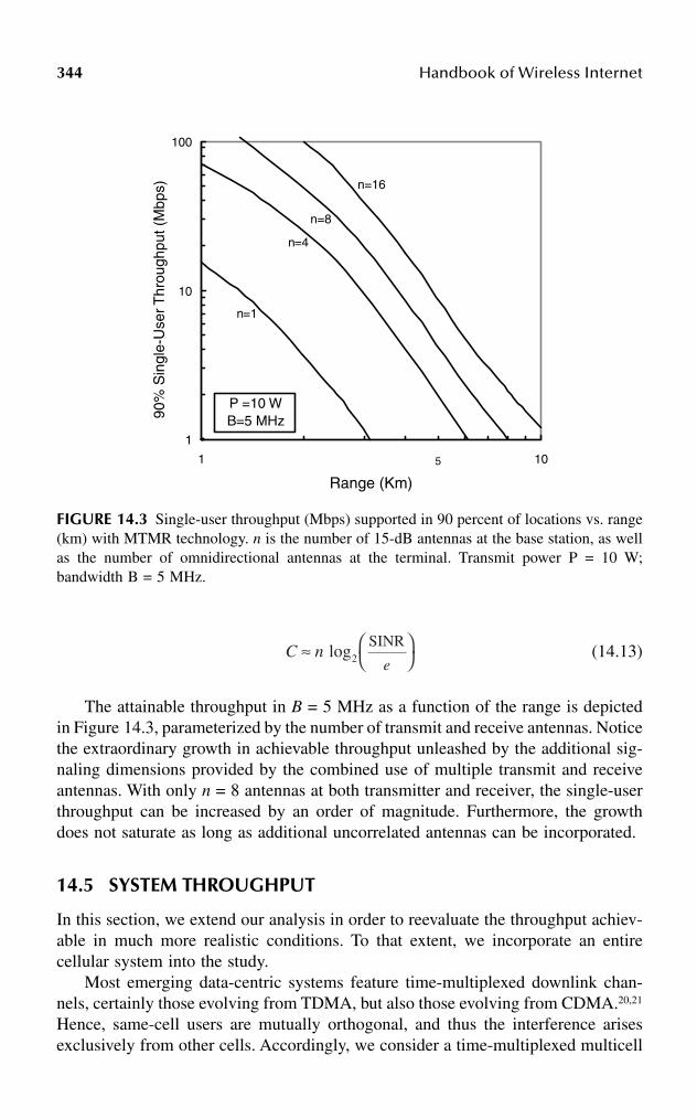
344 Handbook of Wireless Internet
(14.13)
The attainable throughput in B = 5 MHz as a function of the range is depictedin Figure 14.3, parameterized by the number of transmit and receive antennas. Noticethe extraordinary growth in achievable throughput unleashed by the additional sig-naling dimensions provided by the combined use of multiple transmit and receiveantennas. With only n = 8 antennas at both transmitter and receiver, the single-userthroughput can be increased by an order of magnitude. Furthermore, the growthdoes not saturate as long as additional uncorrelated antennas can be incorporated.
14.5 SYSTEM THROUGHPUT
In this section, we extend our analysis in order to reevaluate the throughput achiev-able in much more realistic conditions. To that extent, we incorporate an entirecellular system into the study.
Most emerging data-centric systems feature time-multiplexed downlink chan-nels, certainly those evolving from TDMA, but also those evolving from CDMA.20,21
Hence, same-cell users are mutually orthogonal, and thus the interference arisesexclusively from other cells. Accordingly, we consider a time-multiplexed multicell
FIGURE 14.3 Single-user throughput (Mbps) supported in 90 percent of locations vs. range(km) with MTMR technology. n is the number of 15-dB antennas at the base station, as wellas the number of omnidirectional antennas at the terminal. Transmit power P = 10 W;bandwidth B = 5 MHz.
1
10
100
1 10
Range (Km)
90%
Sin
gle-
Use
r Thr
ough
put (
Mbp
s)
P =10 WB=5 MHz
n=1
n=4
n=8
5
n=16
C ne
≈
SINRlog2
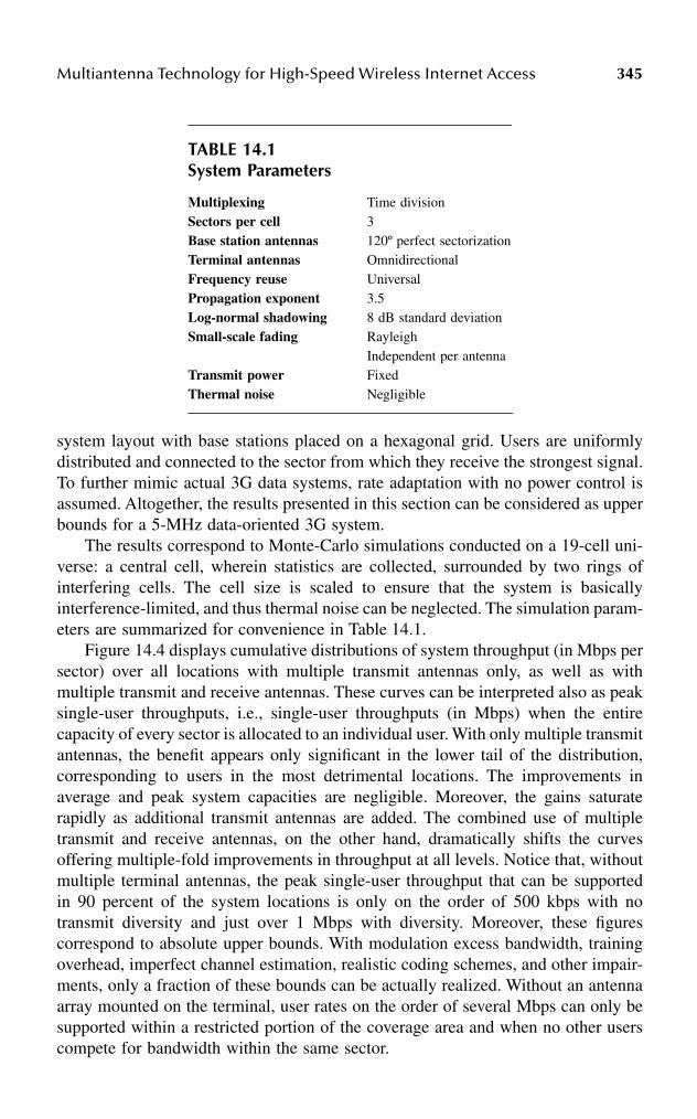
Multiantenna Technology for High-Speed Wireless Internet Access 345
system layout with base stations placed on a hexagonal grid. Users are uniformlydistributed and connected to the sector from which they receive the strongest signal.To further mimic actual 3G data systems, rate adaptation with no power control isassumed. Altogether, the results presented in this section can be considered as upperbounds for a 5-MHz data-oriented 3G system.
The results correspond to Monte-Carlo simulations conducted on a 19-cell uni-verse: a central cell, wherein statistics are collected, surrounded by two rings ofinterfering cells. The cell size is scaled to ensure that the system is basicallyinterference-limited, and thus thermal noise can be neglected. The simulation param-eters are summarized for convenience in Table 14.1.
Figure 14.4 displays cumulative distributions of system throughput (in Mbps persector) over all locations with multiple transmit antennas only, as well as withmultiple transmit and receive antennas. These curves can be interpreted also as peaksingle-user throughputs, i.e., single-user throughputs (in Mbps) when the entirecapacity of every sector is allocated to an individual user. With only multiple transmitantennas, the benefit appears only significant in the lower tail of the distribution,corresponding to users in the most detrimental locations. The improvements inaverage and peak system capacities are negligible. Moreover, the gains saturaterapidly as additional transmit antennas are added. The combined use of multipletransmit and receive antennas, on the other hand, dramatically shifts the curvesoffering multiple-fold improvements in throughput at all levels. Notice that, withoutmultiple terminal antennas, the peak single-user throughput that can be supportedin 90 percent of the system locations is only on the order of 500 kbps with notransmit diversity and just over 1 Mbps with diversity. Moreover, these figurescorrespond to absolute upper bounds. With modulation excess bandwidth, trainingoverhead, imperfect channel estimation, realistic coding schemes, and other impair-ments, only a fraction of these bounds can be actually realized. Without an antennaarray mounted on the terminal, user rates on the order of several Mbps can only besupported within a restricted portion of the coverage area and when no other userscompete for bandwidth within the same sector.
TABLE 14.1System Parameters
Multiplexing Time divisionSectors per cell 3Base station antennas 120º perfect sectorizationTerminal antennas OmnidirectionalFrequency reuse UniversalPropagation exponent 3.5Log-normal shadowing 8 dB standard deviationSmall-scale fading Rayleigh
Independent per antennaTransmit power FixedThermal noise Negligible

346 Handbook of Wireless Internet
14.6 IMPLEMENTATION: REALIZING THE MTMR POTENTIAL
In order to realize the bandwidth efficiency potential promised by the use of MTMRtechnology in multipath environments, a number of practical approaches have beenproposed in recent years. These approaches can be naturally grouped in two distinctcategories:
1. Space–time coding schemes, wherein the signals radiated from the varioustransmit antennas are jointly encoded and must, therefore, be jointlydecoded.22–26 These schemes tend to be more robust, but the joint decodingprocess required for good performance suffers rapid increases in com-plexity as the number of antennas grows. Additionally, new (vector) cod-ing formats may have to be devised. It appears, however, that both theseshortcomings may have remedies. Recent results appear to indicate thatconventional (scalar) codes may be used to build good vector codes,27,28
while at the same time some reduced-complexity decoding strategies areemerging.29
2. An alternative approach is that of layered architectures, wherein eachtransmit antenna radiates a separately encoded signal. At the receiver,these signals can be successively decoded and their interference can-celed.30,31 The decoding complexity of these architectures increases moregracefully with the number of antennas. Furthermore, they make directuse of existing scalar coding formats. As an added benefit, layered archi-tectures may offer interesting synergies with upper layers on the data
FIGURE 14.4 Cumulative distributions of system throughput (Mbps per sector) with multipletransmit antennas only, as well as with multiple transmit and receive antennas. n is the numberof antennas. System bandwidth B = 5 MHz.
0
0.1
0.2
0.3
0.4
0.5
0.6
0.7
0.8
0.9
1
1 10 100 1000
C (Mbps/sector)
Pro
b. {
Sys
tem
Thr
ough
put <
C }
TransmitDiversity
n=1
MTMR
B=5 MHz
n=4
n=8n=16nT
nT=4 and
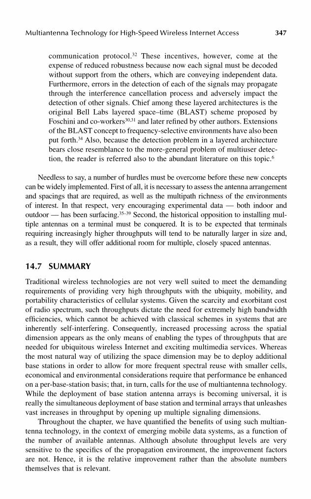
Multiantenna Technology for High-Speed Wireless Internet Access 347
communication protocol.32 These incentives, however, come at theexpense of reduced robustness because now each signal must be decodedwithout support from the others, which are conveying independent data.Furthermore, errors in the detection of each of the signals may propagatethrough the interference cancellation process and adversely impact thedetection of other signals. Chief among these layered architectures is theoriginal Bell Labs layered space–time (BLAST) scheme proposed byFoschini and co-workers30,31 and later refined by other authors. Extensionsof the BLAST concept to frequency-selective environments have also beenput forth.34 Also, because the detection problem in a layered architecturebears close resemblance to the more-general problem of multiuser detec-tion, the reader is referred also to the abundant literature on this topic.6
Needless to say, a number of hurdles must be overcome before these new conceptscan be widely implemented. First of all, it is necessary to assess the antenna arrangementand spacings that are required, as well as the multipath richness of the environmentsof interest. In that respect, very encouraging experimental data — both indoor andoutdoor — has been surfacing.35–39 Second, the historical opposition to installing mul-tiple antennas on a terminal must be conquered. It is to be expected that terminalsrequiring increasingly higher throughputs will tend to be naturally larger in size and,as a result, they will offer additional room for multiple, closely spaced antennas.
14.7 SUMMARY
Traditional wireless technologies are not very well suited to meet the demandingrequirements of providing very high throughputs with the ubiquity, mobility, andportability characteristics of cellular systems. Given the scarcity and exorbitant costof radio spectrum, such throughputs dictate the need for extremely high bandwidthefficiencies, which cannot be achieved with classical schemes in systems that areinherently self-interfering. Consequently, increased processing across the spatialdimension appears as the only means of enabling the types of throughputs that areneeded for ubiquitous wireless Internet and exciting multimedia services. Whereasthe most natural way of utilizing the space dimension may be to deploy additionalbase stations in order to allow for more frequent spectral reuse with smaller cells,economical and environmental considerations require that performance be enhancedon a per-base-station basis; that, in turn, calls for the use of multiantenna technology.While the deployment of base station antenna arrays is becoming universal, it isreally the simultaneous deployment of base station and terminal arrays that unleashesvast increases in throughput by opening up multiple signaling dimensions.
Throughout the chapter, we have quantified the benefits of using such multian-tenna technology, in the context of emerging mobile data systems, as a function ofthe number of available antennas. Although absolute throughput levels are verysensitive to the specifics of the propagation environment, the improvement factorsare not. Hence, it is the relative improvement rather than the absolute numbersthemselves that is relevant.

348 Handbook of Wireless Internet
REFERENCES
1. Ojanpera, T. and Prasad, R., An overview of third-generation wireless personal com-munications: a European perspective, IEEE Personal Commun., 5 (6), 59–65, 1998.
2. Shannon, C.E., A mathematical theory of communications, Bell Syst. Tech. J., 27,379–423 and 623–656, 1948.
3. Cover, T.M. and Thomas, J.A., Elements of Information Theory, John Wiley & Sons,New York, 1990.
4. Cox, D.C., Universal digital portable radio communications, Proc. IEEE, 75 (4),436–477, 1987.
5. Biglieri, E., Proakis, J., and Shamai, S., Fading channels: information-theoretic andcommunication aspects, IEEE Trans. Information Theory, 44 (6), 2619–2692, 1998.
6. Verdú, S., Multiuser Detection, Cambridge University Press, New York, 1998.7. Winters, J.H., Smart antennas for wireless systems, IEEE Personal Commun., 5,
23–27, 1998.8. Jakes, W.C., Microwave Mobile Communications, IEEE Press, New York, 1974.9. Foschini, G.J. and Gans, M.J., On the limits of wireless communications in a fading
environment when using multiple antennas, Wireless Personal Communications,1998, pp. 315–335.
10. Telatar, I.E., Capacity of multiantenna Gaussian channels, Eur. Trans. Telecommun.,10, Nov. 1999, pp. 585–595.
11. Raleigh, G. and Cioffi, J.M., Spatio-temporal coding for wireless communications,IEEE Trans. Commun., 46 (3), 357–366, 1998.
12. Goldsmith, A.J. and Varaiya, P., Capacity of fading channels with channel sideinformation, IEEE Trans. Information Theory, 1985–1992, Nov. 1997.
13. European Corporation in the Field of Scientific and Technical Research EURO-COST231, Urban Transmission Loss Models for Mobile Radio in the 900 and 1800 MHzBands, Revision 2, The Hague, Sept. 1991.
14. Chu, T.-S. and Greenstein, L.J., A semiempirical representation of antenna diversitygain at cellular and PCS base stations, IEEE Trans. Commun., 45–46, June 1997.
15. Gesbert, D. et al., MIMO Wireless Channels: Capacity and Performance Prediction,Proc. IEEE GLOBECOM’00, San Francisco, Dec. 2000.
16. Marzetta, T.L., BLAST Training: Estimating Channel Characteristics for High Capac-ity Space-Time Wireless, Proc. 37th Annual Allerton Conference on Communication,Control, and Computing, Monticello, Illinois, Sept. 1999.
17. Lozano, A. and Tulino, A.M., Capacity of multiple-transmit multiple-receive antennaarchitectures, IEEE Trans. Inf. Theory, 48(12), 3117–3128, Dec. 2002.
18. Verdú, S. and Shamai, S., Spectral efficiency of CDMA with random spreading, IEEETrans. Inf. Theory, 45, 622–640, 1999.
19. Rapajic, P. and Popescu, D., Information capacity of a random signature multiple-input multiple-output channel, IEEE Trans. Commun., 48 (8), 1245–1248, 2000.
20. Bender, P. et al., CDMA/HDR: a bandwidth-efficient high-speed wireless data servicefor nomadic users, IEEE Commun., 38 (7), 70–77, 2000.
21. 3G TR 25.950, UTRA High Speed Downlink Packet Access, Third Generation Part-nership Project, Technical Specification Group Radio Access Network, March 2001.
22. Guey, J.-C. et al., Signal design for transmitter diversity wireless communicationsystems over Rayleigh fading channels, Proc. IEEE Vehicular Technology Conference(VTC’96), Atlanta, 1996, pp. 136–140.

Multiantenna Technology for High-Speed Wireless Internet Access 349
23. Tarokh, V., Seshadri, N., and Calderbank, A.R., Space–time codes for high data ratewireless communications: performance criterion and code construction, IEEE Trans.Inf. Theory, 44, 744–765, 1998.
24. Hammons, A.R. Jr. and El Gamal, H., On the theory of space–time codes for PSKmodulation, IEEE Trans. Inf. Theory, 46 (2), 524–542, 2000.
25. Tao, M. and Cheng, R.S., Improved design criteria and new trellis codes forspace–time coded modulation in slow flat-fading channels, IEEE Commun. Lett., 5(7), 313–315, 2001.
26. Byun, M.-K. and Lee, B.G., New Bounds of Pairwise Error Probability forSpace–Time Codes in Rayleigh Fading Channels, Proc. Wireless Communication andNetworking Conference (WCNC’02), March 2002, 89–93.
27. Hochwald, B.M. and ten Brink, S., Achieving Near-Capacity on a Multiple-AntennaChannel, Proc. Allerton Conference on Communication, Control, and Computing,Oct. 2001, 815–824.
28. Biglieri, E., Tulino, A.M., and Taricco, G., Performance of space–time codes for alarge number of antennas, IEEE Trans. Inf. Theory, 48 (7), 1794–1803, 2002.
29. Vikalo, H. and Hassibi, B., Maximum-likelihood sequence detection of multipleantenna systems over dispersive channels via sphere decoding, EURASIP J. Appl.Signal Process., Special issue on space–time coding and its applications, Part II, 2002.
30. Foschini, G.J., Layered space-time architecture for wireless communications in a fadingenvironment when using multielement antennas, Bell Labs Tech. J., 41–59, 1996.
31. Foschini, G.J. et al., Simplified processing for high spectral efficiency wireless com-munication employing multielement arrays, J. Selected Areas Commun., 17 (11),1841–1852, 1999.
32. Zheng, H., Lozano, A., and Haleem, M., Multiple ARQ Processes for MIMO Systems,13th IEEE International Symposium on Personal, Indoor and Mobile Radio Commu-nications (PIMRC’2000), Lisbon, Portugal, Sept. 15–18, 2002.
33. Ariyavisitakul, S.L., Turbo space–time processing to improve wireless channel capac-ity, IEEE Trans. Commun., 48 (8), 1347–1358, 2000.
34. Lozano, A. and Papadias, C.B., Layered space–time receivers for frequency-selectivewireless channels, IEEE Trans. Commun., 50 (1), 65–73, 2002.
35. Kermoal, J. P. et al., Experimental Investigation of Multipath Richness for Multiele-ment Transmit-and-Receive Antenna Arrays, Proc. IEEE Vehicular Technology Con-ference (VTC’00 Spring), Tokyo, May 2000.
36. Martin, C.C., Winters, J. H., and Sollenberger, N.R., Multiple-Input Multiple-Output(MIMO) Radio Channel Measurements, Proc. IEEE Vehicular Technology Confer-ence (VTC’00 Fall), Boston, Sept. 2000.
37. Xu, H. et al., Experimental verification of MTMR system capacity in a controlledpropagation environment, IEEE Electron. Lett., July 2001.
38. Ling, J. et al., Multiple transmit multiple receive (MTMR) capacity survey in Man-hattan, IEEE Electron. Lett., 37 (16), 1041–1042, 2001.
39. Erceg, V. et al., Capacity Obtained from Multiple-Input Multiple-Output ChannelMeasurements in Fixed Wireless Environments at 2.5 GHz, Int. Conf. on Communi-cations (ICC’02), New York, Apr. 2002.
40. Chizhik, D. et al., Keyholes, Correlations and capacities of multielement transmit-and-receive antennas, IEEE Trans. Wireless Commun., 2 (1), 361–368, 2002.
41. Dietrich, C.B. Jr. et al., Spatial, polarization, and pattern diversity for wireless hand-held terminals, IEEE Trans. Antennas Propagation, 49 (9), 1271–1281, 2001.
350 Handbook of Wireless Internet
42. Marzetta, T.L. and Hochwald, B.H., Capacity of a mobile multiple-antenna commu-nication link in Rayleigh flat fading, IEEE Trans. Inf. Theory, 45 (1), 139–157, 1999.
43. Hochwald, B.H. and Marzetta, T.L., Unitary space–time modulation for multiple-antenna communications in Rayleigh flat fading, IEEE Trans. Inf. Theory, 46,543–564, Mar. 2000.
44. Hassibi, B., Cayley Codes for Multiple-Antenna Differential Modulation, Proc. Asi-lomar Conference on Signals, Systems, and Computers, Pacific Grove, California,Vol. 1, Nov. 2001.

3510-8493-1502-6/03/$0.00+$1.50© 2003 by CRC Press LLC
15 Location Management in Mobile Wireless Networks
Amitava Mukherjee, Debashis Saha, and Sanjay Jha
CONTENTS
Abstract ..................................................................................................................35215.1 Paging.........................................................................................................353
15.1.1 Blanket Paging.............................................................................35315.1.2 Different Paging Procedures........................................................354
15.2 Intelligent Paging Scheme .........................................................................35515.2.1 Sequential Intelligent Paging.......................................................35815.2.2 Parallel-o-Sequential Intelligent Paging......................................35915.2.3 Comparison of Paging Costs .......................................................361
15.3 Other Paging Schemes ...............................................................................36215.3.1 Reverse Paging ............................................................................36215.3.2 Semireverse Paging......................................................................36315.3.3 Uniform Paging ...........................................................................363
15.4 Intersystem Paging .....................................................................................36315.5 IP Micromobility and Paging ....................................................................36515.6 Location Update.........................................................................................365
15.6.1 Location Update Static Strategies ...............................................36615.6.2 Location Update Dynamic Strategies..........................................367
15.7 Location Management................................................................................36915.7.1 Without Location Management ...................................................37015.7.2 Manual Registration in Location Management...........................37015.7.3 Automatic Location Management Using Location Area ............37015.7.4 Memoryless-Based Location Management Methods..................371
15.7.4.1 Database Architecture ................................................37115.7.4.2 Optimizing Fixed Network Architecture ...................37115.7.4.3 Combining Location Areas and Paging Areas...........37115.7.4.4 Multilayer LAs ...........................................................372
15.7.5 Memory-Based Location Management Methods........................37215.7.5.1 Dynamic LA and PA Size..........................................372

352 Handbook of Wireless Internet
15.7.5.2 Individual User Patterns .............................................37215.7.6 Location Management in 3G-and-Beyond Systems ...................373
15.8 Location Area Planning .............................................................................37515.8.1 Two-Step Approach .....................................................................37515.8.2 LA Planning and Signaling Requirements..................................376
References..............................................................................................................378
ABSTRACT
Location management schemes are essentially based on users’ mobility and incom-ing call rate characteristics. The network mobility process has to face strong antag-onism between its two basic procedures: location update (or registration) and paging.The location update procedure allows the system to keep location knowledge moreor less accurately in order to find the user in case of an incoming call, for example.Location registration also is used to bring the user’s service profile near its locationand allows the network to rapidly provide the user with services. The paging processachieved by the system consists of sending paging messages in all cells where themobile terminal could be located. A detailed description of the means and techniquesfor user location management in present cellular networks is addressed.
A network must retain information about the locations of endpoints in thenetwork in order to route traffic to the correct destinations. Location tracking (alsoreferred to as mobility tracking or mobility management) is the set of mechanismsby which location information is updated in response to endpoint mobility. Inlocation tracking, it is important to differentiate between the identifier of an endpoint(i.e., what the endpoint is called) and its address (i.e., where the endpoint is located).Mechanisms for location tracking provide a time-varying mapping between theidentifier and the address of each endpoint. Most location tracking mechanisms maybe perceived as updating and querying a distributed database (the location database)of endpoint identifier-to-address mappings. In this context, location tracking has twocomponents: (1) determining when and how a change in a location database entryshould be initiated; and (2) organizing and maintaining the location database. Incellular networks, endpoint mobility within a cell is transparent to the network, andhence location tracking is only required when an endpoint moves from one cell toanother. Location tracking typically consists of two operations: (1) updating (orregistration), the process by which a mobile endpoint initiates a change in the locationdatabase according to its new location; and (2) finding (or paging), the process by whichthe network initiates a query for an endpoint’s location (which also may result in anupdate to the location database). Most location tracking techniques use a combinationof updating and finding in an effort to select the best trade-off between update overheadand delay incurred in finding. Specifically, updates are not usually sent every time anendpoint enters a new cell, but rather are sent according to a predefined strategy so thatthe finding operation can be restricted to a specific area. There is also a trade-off,analyzed formally between the update and paging costs.
Location management methods are most adapted and widely used in currentcellular networks, e.g., GSM, IS-54, IS-95, etc. The location management methodsare broadly classified into two groups. The first group includes all methods based
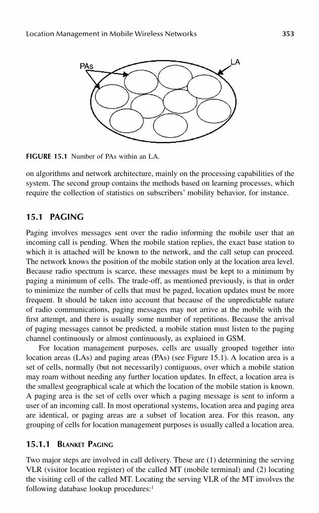
Location Management in Mobile Wireless Networks 353
on algorithms and network architecture, mainly on the processing capabilities of thesystem. The second group contains the methods based on learning processes, whichrequire the collection of statistics on subscribers’ mobility behavior, for instance.
15.1 PAGING
Paging involves messages sent over the radio informing the mobile user that anincoming call is pending. When the mobile station replies, the exact base station towhich it is attached will be known to the network, and the call setup can proceed.The network knows the position of the mobile station only at the location area level.Because radio spectrum is scarce, these messages must be kept to a minimum bypaging a minimum of cells. The trade-off, as mentioned previously, is that in orderto minimize the number of cells that must be paged, location updates must be morefrequent. It should be taken into account that because of the unpredictable natureof radio communications, paging messages may not arrive at the mobile with thefirst attempt, and there is usually some number of repetitions. Because the arrivalof paging messages cannot be predicted, a mobile station must listen to the pagingchannel continuously or almost continuously, as explained in GSM.
For location management purposes, cells are usually grouped together intolocation areas (LAs) and paging areas (PAs) (see Figure 15.1). A location area is aset of cells, normally (but not necessarily) contiguous, over which a mobile stationmay roam without needing any further location updates. In effect, a location area isthe smallest geographical scale at which the location of the mobile station is known.A paging area is the set of cells over which a paging message is sent to inform auser of an incoming call. In most operational systems, location area and paging areaare identical, or paging areas are a subset of location area. For this reason, anygrouping of cells for location management purposes is usually called a location area.
15.1.1 BLANKET PAGING
Two major steps are involved in call delivery. These are (1) determining the servingVLR (visitor location register) of the called MT (mobile terminal) and (2) locatingthe visiting cell of the called MT. Locating the serving VLR of the MT involves thefollowing database lookup procedures:1
FIGURE 15.1 Number of PAs within an LA.

354 Handbook of Wireless Internet
1. The calling MT sends a call initiation signal to the serving MSC (mobileswitching center) of the MT through a nearby base station.
2. The MSC determines the address of the HLR (home location register) ofthe called MT by global title translation (GTT) and sends a locationrequest message to the HLR.
3. The HLR determines the serving VR of the called MT and sends a routerequest message to the MSC serving the MT.
4. The MSC allocates a temporary identifier called temporary local directorynumber (TLDN) to the MT and sends a reply to the HLR together withthe TLDN.
5. The HLR forwards this information to the MSC of the calling MT.6. The calling MSC requests a call setup to the called MSC through the CCS
7 network.
The procedure described here allows the network to set up a connection fromthe calling MT to the serving MSC of the called MT.
Because each MSC is associated with a location area, a mechanism is thereforenecessary to determine the cell location of the called MT. In current cellular net-works, this is achieved by a paging procedure so that polling signals are broadcastto all the cells within the residing LA of the called MT over a forward controlchannel. On receiving the polling signal, the MT sends a reply over a backwardcontrol channel, which allows the MSC to determine its current residing cell. Thisis called the blanket-paging method. In a selective paging scheme, instead of pollingall the cells in an LA, a few cells are polled at a time. The cluster of cells polled atthe same time constitutes the paging area. Here, a factor called granularity, K, isdefined as the ratio of the number of cells in the PA to the number of cells in theLA. K denotes the fineness in the polling scheme. In a purely sequential pollingscheme, K = 1/Sj, whereas the granularity factor is 1 in case of blanket polling andSj is the number of cells in the j-th LA.
15.1.2 DIFFERENT PAGING PROCEDURES
The work reported in Rose2 developed methods for balancing call registration andpaging. The probability distribution on the user location as a function of time iseither known or can be calculated, the lower bounds on the average cost of pagingare used in conjunction with a Poisson incoming-call arrival model to formulate thepaging/registration optimization problem in terms of time-out parameters.
In another work by Rose and Yates,3 efficient paging procedures are used tominimize the amount of bandwidth expended in locating a mobile unit. Given theprobability distribution on user location, they have shown that optimal paging strat-egy, which minimizes the expected number of locations polled, is to query eachlocation sequentially in order of decreasing probability. Because sequential searchover many locations may impose unacceptable polling delay, they considered optimalpaging subject to delay constraint.
Akyildiz and Ho4 proposed a mobile user location mechanism that incorporatesa distance-based location update scheme and a paging mechanism that satisfied
Location Management in Mobile Wireless Networks 355
predefined delay requirements. Akyildiz and coworkers5 have introduced a mobilitytracking mechanism that combines a movement-based location update policy witha selective paging scheme. This selective paging scheme decreases the locationtracking cost under a small increase in the allowable paging delay.
Bar-Noy and Kessler6 explored tracking strategies for mobile users in personalcommunications networks, which are based on topology of cells. The notion oftopology-based strategies was introduced in a general form in this work. In particular,the known paging areas, overlapping paging areas, reporting centers, and distance-based strategies were covered by this notion.
Lyberopoulos et al.7 proposed a method that aims at the reduction of signalingoverhead on the radio link, produced by the paging procedure. The key idea is theapplication of a multiple-step paging strategy, which operates as follows: At theinstance of a call terminating to a mobile user that roams within a certain locationarea, paging is initially performed in a portion of the location area (the paging area)that the so-called paging-related information indicates. Upon a no-paging response,the mobile user is paged in the complementary portion of the location area; thisphase can be completed in more than one (paging) step. Several “intelligent” pagingstrategies were defined in this work. In Wang and coworkers,8 various pagingschemes were presented for locating mobile users in wireless networks. Paging costsand delay bounds are considered because paging costs are associated with bandwidthutilization and delay bounds influence call setup time. To reduce the paging costs,three paging schemes (reverse, semireverse, and uniform) were introduced to providea simple way of partitioning the service areas and decreased the paging costs basedon each mobile terminal’s location probability distribution.
The several paging strategies mainly based on blanket paging were applied toreduce the paging costs, as well as update costs associated with constraints. Thestrategies briefly discussed here were widely used and few of them are applied inindustry. In spite of having widespread use of those paging strategies, some disad-vantages have been discovered. In the next section, we discuss new paging schemesto overcome the disadvantages in the different blanket-paging schemes.
15.2 INTELLIGENT PAGING SCHEME
The movement of MTs is modeled according to some ergodic, stochastic process.9
To provide a ubiquitous communications link, irrespective of the location of MTs,the BSs (base stations) provide continuous coverage during the call, as well as inthe idle state. When an incoming call comes to an MT, which roams within a certainLA, paging is initially performed within a portion of LA, which is a subset of theactual LA. This portion of the LA, which is a set of base stations of paging (BSPs),is termed a paging area (PA). Intelligent paging is a multistep paging strategy,10
which aims at determining the proper PA within which the called MT currentlyroams. In order to quantitatively evaluate the average cost of paging, time-varyingprobability distributions on MTs are required. These distributions may be derivedfrom the specific motion models, approximated via empirical data or even providedby the MTs in the form of partial itinerary at the time of last contact. It is assumed that

356 Handbook of Wireless Internet
1. The probability density function of the speed of MTs is known.2. The process of movement of MTs is isotropic, Brownian motion11 with
drift. In a one-dimensional version of Brownian motion, an MT movesby one step ∆x to the right with some probability p, and to the left withprobability q, and stays there with probability (1-p-q) for each time step∆t. Given the MT starts at time t = 0 for position x = 0, the Gaussian pdfon the location of an MT is given by
PX(t) (x(t)) = (πDt)–0.5 e –k(x–vt)*(x–vt)/Dt (15.1)
where v = (p – q) * (∆x/∆t) is the drift velocity, and D = 2[(1 – p)p +(1 – q)q + 2pq] (∆x)2/∆t is the diffusion constant, both functions of therelative values of time and space steps. Drift is defined as mean velocityin a given direction and is used to model directed traffic such as vehiclesalong a highway.
3. Time has elapsed since the last known location.4. The paging process described here is rapid enough to the rate of motion
of MT (i.e., MT, to be found, does not change its location during thepaging process).
The algorithm of the intelligent paging process on arrival of a PR is
While PR is attached {while MT is not busy {
if current traffic load exceeds threshold traffic load {initialize the incremental counter i = 0;select the proper PA;page within the selected PA;if reply against PR received
then stop;else {
while (i < maximum value of incremental counter i)do {
page within another PA;increase the incremental counter i = i +1;
}}
}else
apply blanket paging;}
}
The intelligent paging strategy maps the cells inside the location area comprisingS cells into a probability line at the time of arrival of the incoming call. This mappingdepends on factors such as mobility of the MT, its speed profile, the incoming call

Location Management in Mobile Wireless Networks 357
statistics, and the state of the MT at that instant. This procedure is called attachment.If it is detached, the paging requests (PRs) are cancelled. If it is busy, a relationbetween the MT and the network already exists and therefore paging is not required.If it is free, the network proceeds for paging upon receipt of a PR (see abovealgorithm). In an intelligent paging scheme, the network determines the probabilityof occupancy of the called MT in different cells in an LA. These probabilities arearranged in descending order. The order in which cells are to be polled depends onthe ordered set of probability occupancy vectors. In each paging cycle, the MSCserves PRs stored in its buffer, independently of each other. It is done by assigninga BS to each of the n requests in the buffer according to an assignment policy. Thej-th PR may be sent to the i-th BS, in order to be paged in the corresponding cell.There are many ways to generate such assignments. Two methods will be presentedsubsequently in this chapter as part of the proposed intelligent paging scheme. Ifthe buffer size is n and there are k PAs (denoted by A1, A2, .., Ak), then we can write
A1∪A2∪…..∪Ak = S
Ai∪Aj = φ
This means that the PAs are mutually exclusive and collectively exhaustive. Pagingand channel allocation packets from a BS to MTs are multiplexed stream in a forwardsignaling channel. Paging rate represents the average number of paging packets,which arrive at a base station during unit time. Paging signals are sent to the BSsvia landlines and are broadcast over the forward signaling channel. As each attachedMT in the location area constantly monitors the paging channels to check whetherit is paged or not, the distributor in the MSC which is a part of MM allocates thedistribution of PRs to the BSs for each paging cycle based on the informationcollected over the previous paging cycle. As soon as an MT is found, the corre-sponding PR is purged from the buffer and a new PR replaces it. The function ofthe distributor in the MM is to map the PRs to the PAs:
g : (PR1, PR2, …, PRn) → (A1, A2, …,Ak)
Paging and channel allocation packets from a BS to MTs are multiplexed tostream in a forward signaling channel. Paging rate represents the average numberof paging packets, which arrives at a base station during unit time. Paging signalsare sent to the BSs via landlines and are broadcast over the forward signaling channel.As each attached MT in the location area constantly monitors the paging channelsto check whether it is paged or not, the distributor in the MSC which is a part ofMM allocates the distribution of PRs to the BSs for each paging cycle based on theinformation collected over previous paging cycle. As soon as an MT is found, thecorresponding PR is purged from the buffer and a new PR replaces it.
Depending on the nature of polling, there may be two types of search, sequentialand parallel-o-sequential. In purely sequential polling, one cell is polled in a pagingcycle. Sometimes, due to delay constraint, instead of polling one cell at a time, we
358 Handbook of Wireless Internet
poll a cluster of cells in an LA. This is called parallel-o-sequential intelligent paging(PSIP), which is a special case of sequential intelligent polling (SIP).The network first examines whether a multiple-step paging strategy should be appliedor not. The decision is based on the current traffic load. Normally, when this loadexceeds a threshold value, a multiple-step paging strategy is employed (Figure 15.1).In the very first phase, the network decides whether checking the current status ofthe MT needs paging. The network then examines whether the appropriate type ofpaging is blanket paging or multiple step paging. The granularity factor (K) showsfineness in polling. In general, the granularity factor is defined as
K = (number of cells to be polled in a cycle)/(number of cells in an LA)
The maximum value of granularity factor is 1, when all cells in an LA are polledin one polling cycle. The granularity factor in SIP is
KSIP = 1/(number of cells in an LA)
The granularity factor in PSIP is
KPSIP = (number of cells in the cluster)/(number of cells in an LA)
We assumed a perfect paging mechanism where an MT will always respond to apaging signal meant for it, provided it receives the PR. However, situations may leavean MT undetected even though the distributor in the MSC is able to select the corre-sponding BS and initiate PR for it. Such a situation will arise when there are more PRsassigned to a BS by the distributor than the number of paging channels available in acycle. As there are only l paging channels per BS, the PRs in excess of l will beconsidered blocked. These excess PRs will be attempted for sending to select BSs insubsequent paging cycles. So the called MT may be inside the area of an overloadedcell. But the PR for it might be blocked in a paging cycle. So, the distributor must keeptrack of the number of times a search has been attempted for the PR.
The application of intelligent paging includes the event of paging failures dueto wrong predictions of the locations of the called MT. In such cases, another stepor more than one step will be required (i.e., the called MT will be paged in otherPAs). Continuous unsuccessful paging attempts may lead to unacceptable networkperformance in terms of paging delay. Moreover, the paging cost will increase witheach unsuccessful attempt to locate the called MT. In such cases, the network doesnot preclude the option of single-step paging at certain intermediate point of search.
15.2.1 SEQUENTIAL INTELLIGENT PAGING
In a sequential intelligent paging scheme, one cell is polled at a time and the processcontinues until such time the called MT is found or time out occurs, whichever isearlier. The selection of the cell to be polled sequentially depends on the value ofoccupancy probability vector, which is based on the stochastic modeling delineatingthe movement of the MT. In SIP, the PRs are stored in a buffer of MSC, and each

Location Management in Mobile Wireless Networks 359
PR is sent to that BS where there is maximum probability of finding the called MT.When the paging is unsuccessful during a polling cycle, the MT is paged sequentiallyin other cells of the LA that have not been polled so far. This phase is completedin one or more paging step(s). The sequential paging algorithm is
STEP 1: When an incoming call arrives, calculate the occupancy proba-bility vector [P] of an MT for the cells in the LA based on theprobability density function, which characterizes the motion ofthe MT;
STEP 2: Sort the elements of [P] in descending order;STEP 3.0: FLAG = False;
i = 1;STEP 3.1: Poll the i-th cell for I ∈ S;STEP 3.2: If the MT is found
FLAG = True;Go to ENDSTEP;
STEP 4.0: If time out occurs
Go to ENDSTEP;Else
i = i + 1;Go to STEP 3.1;
EndifENDSTEP: If FLAG = True
Declare “Polling is Successful”;Else
Declare “Polling is Unsuccessful”;Endif
As extra processing is required to be done at the MSC, an inherent delay willbe associated with this process, i.e., before the PR is sent to the appropriate BS.This delay includes the determination of the probabilities in different cells, sortingof these probabilities in descending order, and polling the cells sequentially depend-ing on those values. This delay will be added to the call setup process. The amountof this delay will be ~ [O (S) + O (S log S) + O (S/2)].
15.2.2 PARALLEL-O-SEQUENTIAL INTELLIGENT PAGING
Parallel-o-sequential intelligent paging is a special case of SIP where K > 1. Insteadof polling a single cell in each cycle, here we partition the LAs into several PAs andpoll those PAs sequentially comprising more than one cell. The benefit that accruesout of PSIP is significant improvement in expected discovery rate of called MTsand the overwhelming reduction in paging cost and signaling load. The number ofsteps in which the paging process should be completed depends on the allowed delayduring paging. The application of PSIP also includes the event of paging failuresdue to unsuccessful predictions of location of called MT. In such cases, multiple

360 Handbook of Wireless Internet
steps are required and the called MT is paged in another portion of the LA. Toobviate the deterioration of the network performance in such a situation and minimizethe number of paging steps, the network should guarantee formation of PAs suchthat the PSFP is high (typical value > 90 percent). So, the PA should consist of thosecells where the sum of probabilities of finding the called MT is greater than or equalto the typical value chosen for PSFP. The parallel-o-sequential paging algorithm is
STEP 1: When an incoming call arrives, find out the current state of thecalled MT;
STEP 2: If MT is detachedPR is cancelled;Go to ENDSTEP;
ElseIf MT is busy (location is known)Go to ENDSTEP;
ElseFind granularity factor K;
EndifSTEP 3: If granularity factor is 1
Poll all the cells;Go to ENDSTEP;
ElseFind out [P], the occupancy probability vector of the MT forthe cells in the LA, based on the probability density function,which characterizes the motion of the MT;
EndifSTEP 4: Sort the elements of [P] in descending order;
Set all the cells as “unmarked”;STEP 5.0: Select a proper PA consisting of “unmarked” cells for which Spi
> PSFP;FLAG = False;
STEP 5.1: Poll i-th cluster and label the cells in i-th cluster as “marked”STEP 5.2: If the MT is found
FLAG = True;Go to ENDSTEP;
STEP 6.0: If time out occursGo to ENDSTEP;
ElseGo to STEP 5.0;
EndifENDSTEP: If FLAG = True
Declare : “Polling is Successful”;Else
Declare “Polling is Unsuccessful”;Endif

Location Management in Mobile Wireless Networks 361
15.2.3 COMPARISON OF PAGING COSTS
In the conventional or the blanket paging, upon arrival of an incoming call the pagingmessage is broadcast from all the BSs in the LA, which means all the cells in theLA are polled at a time for locating the called MT, i.e., each MT is paged S timesbefore the called MT is discovered. The polling cost per cycle is
C pconv = S Acell ρµ TpBp (15.2)
The SIP strategy described here aims at the significant reduction in load ofpaging signaling on the radio link by paging a cell sequentially. PRs arrive accordingto a Poisson process at the buffer of the MSC. The distributor issues the PRs toappropriate BSs. These PRs are queued at the location and serviced on FCFS at theaverage rate ζ. The result may be a success or a failure. The results of completedpolls are fed back to the controller in the BS for further appropriate action. Aspointed out earlier, a called MT may not be found during a paging cycle. Either thenumber of paging channels may be insufficient to accommodate the PR in a particularcycle or the search for the called MT in the cell results in a failure. In both cases,the polling process goes through more than one cycle. So, the paging cost per pollingcycle in this scheme is
CpSIP = KSIP S Acell ρµ (1 + z)TpBp (15.3)
The variable z accounts for the unsuccessful PRs from the previous cycle dueto either of two reasons: z depends on the success rate, time-out duration, and thenumber of paging channels available per BS. In GSM, assuming that a sufficientchannel for paging is there, z becomes zero. In the best case, i.e., when the calledMT is found during the first polling cycle of SIP, z also is zero. In the worst case,all the cells in the LA are to be polled before the MT is found. Then the pollingcost just exceeds that of GSM. Moreover, the delay is maximum, i.e., S units. Theremay be a situation when the polling cost in the SIP scheme exceeds the cost inblanket polling significantly. If the MT resides in a cell with a low occupancy ofprobability and returns to one of the cells, which is polled already after the pollingcycle, the called MT will not be found even after polling all the cells in the LA.Such an incidence is likely when the number of cells is more, a few cells have thesame probability of occupancy, and the MT is very mobile. In this case, the call isblocked or the cells are polled sequentially once again to find out the MT. So, Khas an inverse effect on z. The granularity factor K is generally chosen more thanonce to avoid such a scenario. The paging cost per polling cycle in PSIP is
CpPSIP = KPSIP S Acell ρµ (1 + z)TpBp (15.4)
The variable z also accounts for the unsuccessful PRs from the previous cycle.As mentioned earlier, K is chosen such that PSFP > 0.9. The optimum value of Kvaries from case to case.

362 Handbook of Wireless Internet
15.3 OTHER PAGING SCHEMES
Assume that each LA consists of the same number N of cells in the system.8 Theworst-case paging delay is considered as delay bound, D, in terms of polling cycle.When D is equal to 1, the system should find the called MT in one polling cycle,requiring all cells within the LA to be polled simultaneously. The paging cost, C,which is the number of cells polled to find the called MT, is equal to N. In this case,the average paging delay is at its lowest, which is one polling cycle, and the averagepaging cost is at its highest, C = N. On the other hand, when D is equal to N, thesystem will poll one cell in each polling cycle and search all cells one by one. Thus,the worst case occurs when the called MT is found in the last polling cycle, whichmeans the paging delay would be at its maximum and equal to N polling cycles.12
However, the average paging cost may be minimized if the cells are searched indecreasing order of location probabilities.3
Consider the partition of PAs given that 1 ≤ D ≤ N, which requires groupingcells within an LA into the smaller PAs under delay bound D. Suppose, at a giventime, the initial state P is defined as P = [p1p2…,pj…,pN], where pj is the locationprobability of the j-th cell to be searched in decreasing order of probability. Thusthe time effect is reflected in the location probability distribution. We use tripletsPA*
Ρ (i, qi, ni) to denote the PAs under the paging scheme Ρ in which i is the sequencenumber of the PA, qi is the location probability that the called MT can be foundwithin the i-th PA, and ni is the number of cells contained in this PA. In Figure 15.2,an LA is divided into D PAs because the delay bound is assumed to be D. Thus,the worst-case delay is guaranteed to be D polling cycles. The system searches thePAs one after another until the called MT is found. Three paging schemes arediscussed in this section.
15.3.1 REVERSE PAGING
This scheme is designed for a situation where the called MT is most probably tobe found in a few cells. Consider the first (D – 1) highest probability cells as thefirst (D – 1) PAs to be searched. Each of these (D – 1) PAs consists of only one cell.
FIGURE 15.2 Partition of location area in paging areas.
n cells n cells n cells1 2 n
P1 P2
Cells
Pagingareas (PAs)
PA*(1, q ,n )1 1
PA*(2, q ,n )2 2
PA*(1, q ,n )D D
Location Management in Mobile Wireless Networks 363
It is then lumped with the remaining (N – D + 1) lower probability cells to be the lastPA, i.e., the D-th PA. The newly formed PAs become PA*
r (1, p1, 1), PA*r (2, p2, 1), …,
PA*r (D – 1, pD–1, 1), PA*
r (D, qD, N – D + 1), where r denotes the reverse paging scheme.
15.3.2 SEMIREVERSE PAGING
Because the average paging cost can be minimized by searching cells in decreasingorder of location probability if a delay bound D is not applied,3 intuitively the pagingcost can be reduced by searching the PAs in decreasing order of probability. Undera semireverse paging scheme, a set of PAs is created in a nonincreasing order oflocation probabilities. Combine first the two cells with the lowest location proba-bilities into one PA, and then reorder all PAs in nonincreasing order of locationprobabilities. Keep combining the two lowest probabilities PAs and reorder themuntil the total number of PAs is equal to D. If two PAs have the same probability,the PA with fewer cells has higher priority, i.e., its sequence number is smaller. Thesemireverse paging scheme guarantees that the location probability of each PA is ina nonincreasing order. However, the cell with lower probability may be searchedbefore the cell with higher probability because the initial sequence of the cells isreordered during the semireverse paging procedure.
15.3.3 UNIFORM PAGING
Under this scheme, the LA is partitioned into a series of PAs in such a way that allPAs consist of approximately the same number of cells. The uniform paging proce-dure is as follows:
• Calculate the number of cells in each PA as n0 = N/D, where N = n0D + k.• Determine a series of PAs as PA*
u (1, p1, 1), PA*u (2, p2, 1), …, PA*
u (D, qD,nD). Note that there are n0 cells in each of the first (D – k) PAs and there aren0 + 1 cells in each of the remaining PAs. This means n1 = n2 = … = nD–k =n0, and nD–k+1 = … = nD = n0 + 1. For example, the first PA consists of n0
cells and the last PA, i.e., D-th PA, consists of n0 + 1 cells.• The network polls one PA after another sequentially until the called MT
is found.
15.4 INTERSYSTEM PAGING
In a multitier wireless service area consisting of dissimilar systems, it is desirableto consider some factors that will influence the radio connections of the mobileterminals (MTs) roaming between different systems.13 Consider there are two sys-tems, Y and W, in the microcell tier, that may use different protocols such asDCS1800 and PCS1900. Each hexagon represents a location area (LA) within astand-alone system and each LA is composed of a cluster of microcells. The terminalsare required to update their location information with the system whenever theyenter a new LA; therefore, the system knows the residing LA of a terminal all thetime. In the macrocell tier there are also two systems, X and Z, in which different

364 Handbook of Wireless Internet
protocols (e.g., GSM and IS-41) are applied. For macrocell systems, one LA canbe one macrocell. It is possible that systems X and W, although in different tiers,may employ similar protocols such as IS-95, GSM, or any other protocol. There aretwo types of roaming: intra- or intersystem. Intrasystem roaming refers to an MT’smovement between the LAs within a system such as Y and Z. Intersystem roamingrefers to the MTs that move between different systems. For example, mobile usersmay travel from a macrocell system within an IS-41 network to a region that usesGSM standard.
For intersystem location update, a boundary region called boundary locationarea (BLA) exists at the boundary between two systems in different tiers.13 Inaddition to the concept of BLA, a boundary location register (BLR) is embedded inthe BIU. A BLR is a database cache to maintain the roaming information of MTsmoving between different systems. The roaming information is captured when theMT requests a location registration in the BLA. The BLRs enable the intersystempaging to be implemented within the appropriate system that an MT is currentlyresiding in, thus reducing the paging costs. Therefore, the BLR and the BIU areaccessible to the two adjacent systems and are colocated to handle the intersystemroaming of MTs. On the contrary, the VLR and the MSC provide roaming informa-tion within a system and deal with the intrasystem roaming of MTs. Besides, thereis only one BLR and one BIU between a pair of neighboring systems, but there maybe many VLRs and MSCs within a stand-alone system.
When a call connection request arrives at X, the call will be routed to the lastregistered LA of the called MT. Given that the last registered LA within X is adjacentto Y, the system needs to perform the following steps to locate the MT:
• Send a query signal to the BLR between X and Y to obtain the MT’slocation information. This step is used to ascertain whether the MT hascrossed the boundary.
• If the MT has already moved to Y, only the LA in Y needs to be searched.Otherwise, the last registered LA within X will be searched. Withinnetwork X or Y, one or multiple polling messages are sent to the cells inthe LA according to a specific paging scheme.
As a result, only one system (X or Y) is searched in the paging process forintersystem roaming terminals. This approach will significantly reduce the signalingcost caused by intersystem paging. In particular, it is very suitable for the high-traffic environment because it omits searching in two adjacent systems. Moreover,because the BLR is an additional level of cache database, it will not affect the originaldatabase architecture. Another advantage of the BLR is that it reduces the zigzageffect caused by intersystem roaming. For example, when an MT is moving backand forth on the boundary, it only needs to update the information in the BLR insteadof contacting the HLRs. If the new BLR concept is not used, the intersystem pagingcan still take place. The system will search X first, if the called MT cannot be found,then Y will be searched. This method increases the paging cost as well as the pagingdelay, thus degrading the system performance.

Location Management in Mobile Wireless Networks 365
15.5 IP MICROMOBILITY AND PAGING
Recent research14 in Mobile IP has proposed that IP should take support from theunderlying wireless network architecture to achieve good performance for handoverand paging protocols. Recent IETF work defines requirements for layer 2 (the datalink layer of the OSI model) to support optimized layer 3 (the network layer of theOSI model) handover and paging protocols. Layer 2 can send notification to layer3 that a certain event has happened or is about to happen. The notification is sentusing a trigger. Kempf et al.15 discuss various ways of implementing triggers. Atrigger may be implemented using system calls. The operating system may allowan application thread to register callback for a layer 2 trigger, using system calls ofan application-programming interface (API). A system call returns when that par-ticular event is fired in layer 2. Each trigger is defined by three parameters:
1. The event that causes the trigger to fire2. The entity that receives the trigger3. The parameters delivered with the trigger
Triggers were defined to aid low-latency hand-over in Mobile IP.16 Another setof triggers was defined in Gurivireddy and coworkers17 to aid IP paging protocols.CDMA, for example, works in conjunction with Mobile IP to support mobility inIP hosts. IP paging is a protocol used to determine the location of a dormant (amode that conserves battery by not performing frequent updates) MN. Paging trig-gers were defined in Gurivireddy and coworkers17 to aid movement of a MN inmultiple IP subnets in the same layer 2 paging area. Paging triggers aid the MN toenter dormant mode in a graceful manner and make best use of paging provided byunderlying wireless architecture.
15.6 LOCATION UPDATE
In the previous section, the tracking of an MT has been discussed when an incomingcall is to be delivered. As the MTs move around the network service area, the datastored in these databases may no longer be accurate. To ensure that calls can bedelivered successfully, a mechanism is needed to update the databases with up-to-date location information. This is called location update (LU) or registration. Severallocation updating methods are based on LA structuring. Two automatic location areamanagement schemes are very much in use:18
1. Periodic location updating. This method, although the simplest, has theinherent drawback of having excessive resource consumption, which attimes is unnecessary.
2. Location updating on LA crossing. A network must retain informationabout the locations of endpoints in the network, in order to route trafficto the correct destinations. Location tracking (also referred to as mobilitytracking or mobility management) is the set of mechanisms by which

366 Handbook of Wireless Internet
location information is updated in response to endpoint mobility. In loca-tion tracking, it is important to differentiate between the identifier of anendpoint (i.e., what the endpoint is called) and its address (i.e., where theendpoint is located). Mechanisms for location tracking provide a time-varying mapping between the identifier and the address of each endpoint.
Most location-tracking mechanisms may be perceived as updating and queryinga distributed database (the location database) of endpoint identifier-to-address map-pings. In this context, location tracking has two components: (1) determining whenand how a change in a location database entry should be initiated, and (2) organizingand maintaining the location database. In cellular networks, endpoint mobility withina cell is transparent to the network, and hence location tracking is only requiredwhen an endpoint moves from one cell to another. Location tracking typicallyconsists of two operations: (1) updating (or registration), the process by which amobile endpoint initiates a change in the location database according to its newlocation; and (2) finding (or paging), the process by which the network initiates aquery for an endpoint’s location (which may result also in an update to the locationdatabase). Most location-tracking techniques use a combination of updating andfinding in an effort to select the best trade-off between update overhead and delayincurred in finding. Specifically, updates are not usually sent every time an endpointenters a new cell, but rather are sent according to a predefined strategy such that thefinding operation can be restricted to a specific area. There is also a trade-off,analyzed formally in Madhow and coworkers,19 between the update and paging costs.Figure 15.3 illustrates a classification of possible update strategies.18
15.6.1 LOCATION UPDATE STATIC STRATEGIES
In a static update strategy, there is a predetermined set of cells at which locationupdates may be generated. Whatever the nature of mobility of an endpoint, location
FIGURE 15.3 Classifications of location update strategies.
Location Update Strategies
Static Location Update Dynamic Location Update
Location Areas Reporting Cells
Extending Static Endpoint Oriented
Dynamic LA Dynamic RC
TimeMovement
Distance

Location Management in Mobile Wireless Networks 367
updates may only be generated when (but not necessarily every time) the endpointenters one of these cells. Two approaches to static updating are as follows.
1. Location areas (also referred to as paging or registration areas).20 In thisapproach, the service area is partitioned into groups of cells with eachgroup as a location area. An endpoint’s position is updated if and only ifthe endpoint changes location areas. When an endpoint needs to belocated, paging is done over the most-recent location area visited by theendpoint. Location tracking in many 2G cellular systems, including GSM21
and IS-41,22 is based on location areas.23 Several strategies for location areaplanning in a city environment have been evaluated,10 including strategiesthat take into account geographical criteria (such as population distributionand highway topology) and user mobility characteristics.
2. Reporting cells (or reporting centers).24 In this approach, a subset of thecells is designated as the only one from which an endpoint’s location maybe updated. When an endpoint needs to be located, a search is conductedin the vicinity of the reporting cell from which the most-recent updatewas generated. In Bar-Noy and Kessler,24 the problem of which cellsshould be designated as reporting cells so as to optimize a cost functionis addressed for various cell topologies.
The principal drawback to static update strategies is that they do not accuratelyaccount for user mobility and frequency of incoming calls. For example, althougha mobile endpoint may remain within a small area, it may cause frequent locationupdates if that area happens to contain a reporting cell.
15.6.2 LOCATION UPDATE DYNAMIC STRATEGIES
In a dynamic update strategy, an endpoint determines when an update should begenerated, based on its movement. Thus, an update may be generated in any cell.A natural approach to dynamic strategies is to extend the static strategies to incor-porate call and mobility patterns. The dynamic location area strategy proposed inXie and coworkers25 dynamically determines the size of an endpoint’s location areaaccording to the endpoint’s incoming call arrival rate and mobility. Analytical resultspresented in Xie and coworkers25 indicate that this strategy is an improvement overstatic strategies when call arrival rates are dependent on user or time. The dynamicreporting centers strategy proposed in Birk and Nachman26 uses easily-obtainableinformation to customize the choice of the next set of reporting cells at the time ofeach location update. In particular, the strategy uses information recorded at the timeof the endpoint’s last location update, including the direction of motion, to constructan asymmetric distance-based cell boundary and to optimize the cell search order.In Bar-Noy and coworkers,27 three dynamic strategies are described in which an end-point generates a location update: (1) every T seconds (time-based), (2) after every Mcell crossings (movement based), or (3) whenever the distance covered (in terms ofnumber of cells) exceeds D (distance based). Distance-based strategies are inherentlythe most difficult to implement because the mobile endpoints need information about

368 Handbook of Wireless Internet
the topology of the cellular network. It was shown in Bar-Noy and coworkers,27
however, that for memoryless movement patterns on a ring topology, distance-basedupdating outperforms both time-based and movement-based updating. In Madhowand coworkers,19 a set of dynamic programming equations is derived and used todetermine an optimal updating policy for each endpoint, and this optimal policy isin fact distance-based. Strategies that minimize location-tracking costs under spec-ified delay constraints (i.e., the time required to locate an endpoint) also have beenproposed. In Rose and Yates,3 a paging procedure is described that minimizes themean number of locations polled with a constraint on polling delay, given a proba-bility distribution for endpoint locations. A distance-based update scheme and acomplementary paging scheme that guarantee a predefined maximum delay onlocating an endpoint are described in Akyildiz and Ho.4 This scheme uses an iterativealgorithm to determine the optimal update distance D that results in minimum costwithin the delay bound.
In organizing the location database, one seeks to minimize both the latency andthe overhead, in terms of the amount of storage and the number of messages required,in accessing location information. These are, in general, counteracting optimizationcriteria. Most solutions to the location database organization problem select a point,which is a three-way trade-off between overhead, latency, and simplicity. The sim-plest approach to location database organization is to store all endpoint identifier-to-address mappings in a single central place. For large numbers of reasonablymobile endpoints, however, this approach becomes infeasible in terms of databaseaccess time and storage space and also represents a single-point-of-failure.
The next logical step in location database organization is to partition the networkinto a number of smaller pieces and place a portion of the location database in eachpiece. Such a distributed approach is well suited to systems where each subscriberis registered in a particular area or home. With this organization, the location databasein an area contains the locations of all endpoints whose home is that area. Whenthe endpoint moves out of its home area, it updates its home location database toreflect the new location. The home location register (HLR) and visitor locationregister (VLR) schemes of emerging wireless cellular networks23 are examples ofthis approach, as are the Mobile IP scheme28 for the Internet and the GSM-basedGeneral Radio Packet Switching (GPRS) network for data transport over cellularnetworks. Studies29,30 have shown that with predicted levels of mobile users, signal-ing traffic may exceed acceptable levels. Thus, researchers have considered aug-menting this basic scheme to increase its efficiency under certain circumstances. Forinstance, in Jain et al.,31 per-user caching is used to reuse location information abouta called user for subsequent calls to that user, and is particularly beneficial for userswith high call-to-mobility ratios (i.e., the frequency of incoming calls is much largerthan the frequency of location updates). In Ho and Akyildiz,32 “local anchoring” isused to reduce the message overhead by reporting location changes to a nearby VLRinstead of to the HLR, thus increasing the location tracking efficiency when the call-to-mobility ratio is low and the update cost is high. As with most large organizationalproblems, a hierarchical approach provides the most general and scalable solution.By hierarchically organizing the location database, one can exploit the fact that manymovements are local. Specifically, by confining location update propagation to the
Location Management in Mobile Wireless Networks 369
lowest level (in the hierarchy) containing the moving endpoint, costs can be madeproportional to the distance moved. Several papers address this basic theme. InAwerbuch and Peleg,33 a hierarchy of regional directories is prescribed where eachregional directory is based on a decomposition of the network into regions. Here,the purpose of the i-th level regional directory is to enable tracking of any userresiding within a distance of 2i. This strategy guarantees overheads that are poly-logarithmic in the size and diameter of the network. In Anantharam et al.,34 thelocation database is organized so as to minimize the total rate of accesses andupdates. This approach takes into account estimates of mobility and calling ratesbetween cells and a budget on access and update rates at each database site. InBadrinath and coworkers,35 location database organization takes into account theuser profile of an endpoint (i.e., the predefined pattern of movement for the endpoint).Partitions of the location database are obtained by grouping the locations amongwhich the endpoint moves frequently and by separating those to which the endpointrelocates infrequently. Each partition is further partitioned in a recursive fashion,along the same lines, to obtain a location database hierarchy.
In the above strategies, the emphasis is on reducing update overhead, but it isequally important to reduce database access latency. One strategy for doing so isreplication, where identical copies of the database are kept in various parts of thenetwork so that an endpoint location may be obtained using a low-latency query toa nearby server. The problem here is to decide where to store the replications. Thisis similar to the classical database allocation36 and file allocation37 problems, inwhich databases or files are replicated at sites based on query–update or read–writeaccess patterns. In Shivakumar and Widom,38 the best zones for replication arechosen per endpoint location entry, using a minimum-cost maximum-flow algorithmto decide where to replicate the database, based on the calling and mobility patternsfor that endpoint.
15.7 LOCATION MANAGEMENT
Location management schemes are essentially based on users’ mobility and incom-ing call rate characteristics. It is a two-stage process that enables a network todiscover the current attachment point of the mobile user for call delivery. The firststage is location registration or location update. In this stage the mobile terminalperiodically notifies the network of it new access point, allowing the network toauthenticate the user and revise the user’s location profile. The second stage is calldelivery. Here, the network is queried for the user location profile and the currentposition of the mobile host is found. Current techniques for location managementinvolve database architecture design and the transmission of signaling messagesbetween various components of a signaling network. Other issues include security,dynamic database updates, querying delays, terminal paging methods, and pagingdelays.
There are two standards for location management currently available: Elec-tronic/Telecommunications Industry Associations (EIA/TIA) Interim Standard41(IS-41)39 and the Global System for Mobile Communications (GSM) mobileapplication part (MAP).23 The IS-41 scheme is commonly used in North America
370 Handbook of Wireless Internet
for Advanced Mobile Phone System (AMPS), IS-54, IS-136, and personal accesscommunications system (PACS) networks, while the GSM MAP is mostly used inEurope for GSM and digital cellular service at 1800 MHz (DCS-1800) networks.Both standards are based on a two-level data hierarchy. Location registration pro-cedures update the location databases (HLR and VLRs) and authenticate the MTwhen up-to-date location information of an MT is available. Call delivery procedureslocate the MT based on the information available at the HLR and VLRs when a callfor an MT is initiated. The IS-41 and GSM MAP location management strategiesare very similar. While GSM MAP is designed to facilitate personal mobility andto enable user selection of network provider, there are a lot of commonalities betweenthe two standards.1,21 The location management scheme may be categorized in severalways.
15.7.1 WITHOUT LOCATION MANAGEMENT
This level 0 method is no location management is realized,40 the system does nottrack the mobiles. A search for a called user must therefore be done over the completeradio coverage area and within a limited time. This method is usually referred to asthe flooding algorithm.41 It is used in paging systems because of the lack of an uplinkchannel allowing a mobile to inform the network of its whereabouts. It is used alsoin small private mobile networks because of their small coverage areas and userpopulations. The main advantage of not locating the mobile terminals is obvioussimplicity; in particular, there is no need to implement special databases. Unfortu-nately, it does not fit large networks dealing with high numbers of users and highincoming call rates.
15.7.2 MANUAL REGISTRATION IN LOCATION MANAGEMENT
This level 1 method40 is relatively simple to manage because it requires only themanagement of an indicator, which stores the current location of the user. The mobileis also relatively simple; its task is just limited to scanning the channels to detectpaging messages. This method is currently used in telepoint cordless systems (suchas CT2, Cordless Telephone 2). The user has to register when moving to a newisland of CT2 beacons. To page a user, the network first transmits messages throughthe user’s registered beacon and, if the mobile does not answer, extends the pagingto neighboring beacons. The main drawback of this method is the constraint for auser to register with each move.
15.7.3 AUTOMATIC LOCATION MANAGEMENT USING LOCATION AREA
Presently, this level 2 location method40 most widely implemented in first- andsecond-generation cellular systems (NMT, GSM, IS-95, etc.) makes use of locationareas (LAs) (Figure 15.1). In these wide-area radio networks, location managementis done automatically. Location areas allow the system to track the mobiles duringtheir roaming in the network(s): subscriber location is known if the system knowsthe LA in which the subscriber is located. When the system must establish a
Location Management in Mobile Wireless Networks 371
communication with the mobile (typically, to route an incoming call), the pagingonly occurs in the current user LA. Thus, resource consumption is limited to thisLA; paging messages are only transmitted in the cells of this particular LA. Imple-menting LA-based methods requires the use of databases. Generally, a home databaseand several visitor databases are included in the network architecture.
15.7.4 MEMORYLESS-BASED LOCATION MANAGEMENT METHODS
All methods are included based on algorithms and network architecture, mainly onthe processing capabilities of the system.
15.7.4.1 Database Architecture
LA partitioning, and thus mobility management cost, partly relies on the systemarchitecture (e.g., database locations). Thus, designing an appropriate database orga-nization can reduce signaling traffic. The various database architectures are proposedwith this aim.1,42–44 An architecture where a unique centralized database is used iswell suited to small and medium networks, typically based on a star topology. Thesecond one is a distributed database architecture, which uses several independentdatabases according to geographical proximity or service providers. It is best suitedto large networks, including subnetworks managed by different operators and serviceproviders. The GSM worldwide network, defined as the network made up of allinterconnected GSM networks in the world, can be such an example of a largenetwork. The third case is the hybrid database architecture that combines the cen-tralized and distributed database architectures. In this case, a central database (HLR-like) is used to store all user information. Other smaller databases (VLR-like) aredistributed all over the network. These VLR databases store portions of HLR userrecords. A single GSM network is an example of such architecture.
15.7.4.2 Optimizing Fixed Network Architecture
In 2G cellular networks and 3G systems, the intelligent network (IN) managessignaling.45 Appropriately organizing mobility functions and entities can help reducethe signaling burden at the network side. The main advantage of these propositionsis that they allow one to reduce the network mobility costs independent of the radiointerface and LA organization.
15.7.4.3 Combining Location Areas and Paging Areas
In current systems, an LA is defined as both an area in which to locate a user andan area in which to page him. LA size optimization is therefore achieved by takinginto account two antagonistic procedures, locating and paging. Based on this obser-vation, several proposals have defined location management procedures, which makeuse of LAs and paging areas (PAs) of different sizes.46 One method often consideredconsists of splitting an LA into several PAs. An MS registers only once, i.e., whenit enters the LA. It does not register when moving between the different PAs of thesame LA. For an incoming call, paging messages will be broadcast in the PAs
372 Handbook of Wireless Internet
according to a sequence determined by different strategies. For example, the firstPA of the sequence can be the one where the MS was last detected by the network.The drawback of this method is the possible delay increase due to large LAs.
15.7.4.4 Multilayer LAs
In present location management methods, LU traffic is mainly concentrated in thecells of the LA border. Based on this observation and to overcome this problem,Okasaka et al. have introduced the multiplayer concept.47 In this method, each MSis assigned to a given group, and each group is assigned one or several layers ofLAs. This location updating method, although it may help reduce channel conges-tion, does not help reduce the overall signaling load generated by LUs.
15.7.5 MEMORY-BASED LOCATION MANAGEMENT METHODS
The design of memory-based location management methods has been motivated bythe fact that systems do a lot of repetitive actions, which can be avoided if predicted.This is particularly the case for LUs. Indeed, present cellular systems achieve everyday, at the same peak hours, almost the same LU processing. Systems act asmemoryless processes.
15.7.5.1 Dynamic LA and PA Size
The size of LAs is optimized according to mean parameter values, which, in practicalsituations, vary over a wide range during the day and from one user to another.Based on this observation, it is proposed to manage user location by definingmultilevel LAs in a hierarchical cellular structure.48 At each level, the LA size isdifferent, and a cell belongs to different LAs of different sizes. According to pastand present MS mobility behavior, the scheme dynamically changes the hierarchicallevel of the LA to which the MS registers. LU savings can thus be obtained.
An opposite approach considers that instead of defining LA sizes a priori, thesecan be adjusted dynamically for every user according to the incoming call rate (a)and LU rate (uk), for instance. In Xie and coworkers,25 a mobility cost functiondenoted C(k, a, uk) is minimized so that k is permanently adjusted. Each user istherefore related to a unique LA for which size k is adjusted according to theparticular mobility and incoming call rate characteristics. Adapting the LA size toeach user’s parameter values may be difficult to manage in practical situations. Thisled to the definition of a method where the LA sizes are dynamically adjusted forthe whole population, not per user.49
15.7.5.2 Individual User Patterns
Observing that users show repetitive mobility patterns, the alternative strategy (AS) isdefined.50,51 Its main goal is to reduce the traffic related to mobility management —and thus reduce the LUs — by taking advantage of users’ highly predictable patterns.In AS, the system handles a profile recording the most probable mobility patternsof each user. The profile of the user can be provided and updated manually by the

Location Management in Mobile Wireless Networks 373
subscriber himself or determined automatically by monitoring the subscriber’s move-ments over a period of time. For an individual user, each period of time correspondsto a set of location areas, k. When the user receives a call, the system pages himsequentially over the LA ai s until getting an acknowledgment from the mobile.When the subscriber moves away from the recorded zone {a1,…,ak}, the terminalprocesses a voluntary registration by pointing out its new LA to the network. Themain savings allowed by this method are due to the nontriggered LUs when the userkeeps moving inside his profile LAs. So, the more predictable the user’s mobility,the lower the mobility management cost. The main advantage of this method relieson the reduction of LUs when a mobile goes back and forth between two LAs.
15.7.6 LOCATION MANAGEMENT IN 3G-AND-BEYOND SYSTEMS
The next generation in mobility management will enable different mobile networksto interoperate to ensure terminal and personal mobility and global portability ofnetwork services. However, in order to ensure global mobility, the deployment andintegration of both wire and wireless components are necessary. The focuses aregiven on issues related to mobility management in a future mobile communicationssystem, in a scenario where different access networks are integrated into an IP corenetwork by exploiting the principles of Mobile IP. Mobile IP,52 the current standardfor IP-based mobility management, needs to be enhanced to meet the needs of futurefourth-generation (4G) cellular environments. In particular, the absence of a locationmanagement hierarchy leads to concerns about signaling scalability and handofflatency, especially for a future infrastructure that must provide global mobilitysupport to potentially billions of mobile nodes and accommodate the stringentperformance bounds associated with real-time multimedia traffic. In this chapter,the discussion is confined to Mobile IP to describe the aspects of location manage-ment in 3G and beyond.
The 4G cellular network will be used to develop a framework for truly ubiquitousIP-based access by mobile users, with special emphasis on the ability to use a widevariety of wireless and wired access technologies to access the common informationinfrastructure. While the 3G initiatives are almost exclusively directed at definingwide area packet-based cellular technologies, the 4G vision embraces additionallocal area access technologies, such as IEEE 802.11-based wireless local area net-works (WLANs) and Bluetooth-based wireless personal area networks (WPANs).The development of mobile terminals with multiple physical or software-definedinterfaces is expected to allow users to seamlessly switch between different accesstechnologies, often with overlapping areas of coverage and dramatically differentcell sizes.
Consider one example53 of this multitechnology vision at work in a corporatecampus located in an urban environment. While conventional wide area cellularcoverage is available in all outdoor locations, the corporation offers 802.11-basedaccess also in public indoor locations such as the cafeteria and parking lots, as wellas Bluetooth-based access to the Internet in every individual office. As mobile usersdrive to work, their ongoing Voice over IP (VoIP) calls are seamlessly switched, firstfrom the wide area cellular to the WLAN infrastructure, and subsequently from the
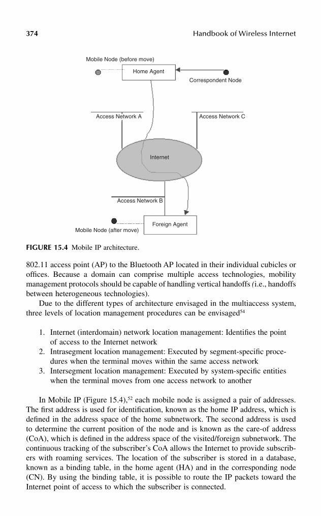
374 Handbook of Wireless Internet
802.11 access point (AP) to the Bluetooth AP located in their individual cubicles oroffices. Because a domain can comprise multiple access technologies, mobilitymanagement protocols should be capable of handling vertical handoffs (i.e., handoffsbetween heterogeneous technologies).
Due to the different types of architecture envisaged in the multiaccess system,three levels of location management procedures can be envisaged54
1. Internet (interdomain) network location management: Identifies the pointof access to the Internet network
2. Intrasegment location management: Executed by segment-specific proce-dures when the terminal moves within the same access network
3. Intersegment location management: Executed by system-specific entitieswhen the terminal moves from one access network to another
In Mobile IP (Figure 15.4),52 each mobile node is assigned a pair of addresses.The first address is used for identification, known as the home IP address, which isdefined in the address space of the home subnetwork. The second address is usedto determine the current position of the node and is known as the care-of address(CoA), which is defined in the address space of the visited/foreign subnetwork. Thecontinuous tracking of the subscriber’s CoA allows the Internet to provide subscrib-ers with roaming services. The location of the subscriber is stored in a database,known as a binding table, in the home agent (HA) and in the corresponding node(CN). By using the binding table, it is possible to route the IP packets toward theInternet point of access to which the subscriber is connected.
FIGURE 15.4 Mobile IP architecture.
Mobile Node (before move)
Home Agent
Correspondent Node
Access Network C Access Network A
Internet
Access Network B
Foreign AgentMobile Node (after move)

Location Management in Mobile Wireless Networks 375
The terminal can be seen from the Internet perspective as a mobile terminal(MT). Once the MT selects an access segment, the access point to the Internetnetwork is automatically defined. The MT is therefore identified by a home addressof the home subnetwork and by a CoA of the access segment. In the target system,location management in the Internet network is based on the main features of MobileIP. Nevertheless, a major difference can be identified between the use of Mobile IPin fixed and mobile networks. In the fixed Internet network, IP packets are routeddirectly to the mobile node, whereas in the integrated system considered in thischapter, packets will be routed up to the appropriate edge router. Once a packetleaves the edge router and reaches the access network, the routing toward the finaldestination will be performed according to the mechanisms adopted by each accesssegment (intrasegment mobility). When the MMT decides to change access segments,its CoA will be changed. Therefore, the new CoA has to be stored in the corre-sponding binding tables. Because these binding tables can be seen as a type oflocation management database, this binding update also can be seen as a form oflocation update on the Internet.
Intersegment location management is used to store information on the accesssegments at a particular time. The information is then used to perform systemregistration, location update, and handover procedures. Using certain parameters,including the condition of the radio coverage and QoS perceived by the user, theMT continuously executes procedures with the objective of selecting the mostsuitable access segment. Any modifications to these parameters could therefore leadto a change of access segment. This implies also a change in the point of access tothe Internet network. Therefore, in order to route these packets correctly it is nec-essary to have information on the active access segment, particularly informationconcerning the edge router that is connected to the node of the access segment.Thus, from the Internet point of view, no additional procedure or database is requiredbecause the information is implicitly contained in the CoA assigned to the MT.
15.8 LOCATION AREA PLANNING
Location area (LA) planning in minimum cost plays an important role in cellularnetworks because of the trade-off caused by paging and registration signaling. Theupper bound on the size of an LA is the service area of a mobile switching center(MSC). In that extreme case, the cost of paging is at its maximum, but no registrationis needed. On the other hand, if each cell is an LA, the paging cost is minimal, butthe registration cost is the largest. In general, the most important component of thesecosts is the load on the signaling resources. Between the extremes lie one or morepartitions of the MSC service area that minimizes the total cost of paging andregistration. In this section, a few approaches are discussed that address LA planning-related issues.
15.8.1 TWO-STEP APPROACH
This approach55 deals with the planning of LAs in a personal communication servicesnetwork (PCSN) to be overlaid on an existing wired network. Given the average

376 Handbook of Wireless Internet
speed of mobile terminals, the number of MSCs, their locations, call handlingcapacity of each MSC, handoff cost between adjacent cells, and call arrival rate, animportant consideration in a PCSN is to identify the cells in every LA to be connectedto the corresponding MSC in a cost-effective manner. While planning a locationarea, a two-step approach is presented, namely, optimization of total system recurringcost (subproblem I), and optimization of hybrid cost (subproblem II). The planningfirst determines the optimum number of cells in an LA from subproblem I. Then itfinds out the exact LAs by assigning cells to the switches, while optimizing thehybrid cost which comprises the handoff cost and the cable cost, in subproblem II.The decomposition of the problem provides a practical way for designing LAs. Asthis approach toward LA planning takes into account both cost and network planningfactors, this unique combination is of great interest to PCSN designers. It developsan optimum network-planning method for a wide range of call-to-mobility ratio(CMR) that minimizes the total system recurring cost, while still ensuring a goodsystem performance. Approximate optimal results, with respect to cell-to-switchassignment, are achievable with a reasonable computational effort that supports theengineered plan of an existing PCSN.
In order to design a feasible PCSN, constraints such as traffic-handling capacityof MSCs and costs related to paging, registration, and cabling should be considered.Utilizing the available information of MTs and the network in a suitable manner, itis possible to devise a technique for planning of location areas in a PCSN thatoptimizes both system-recurring cost and hybrid cost.
This design is not restricted to any particular assumption on the mobility patternof MTs or the mobility model either. Because the optimum LA size decreasessignificantly with the increase in CMR, as the corresponding hike in system cost isvery high, design parameters at BS and MSCs cannot be specified until cell allocationis completed. Finally, channel assignment, which can further improve system per-formance in terms of QoS and improved carrier interference ratio, can only bedetermined once the architecture of the PCSN has been obtained.
15.8.2 LA PLANNING AND SIGNALING REQUIREMENTS
In 2G mobile systems,10 LA planning does not generate significant problems becausethe number of generated LUs (as well as the amount of paging signaling) remainsrelatively low because of the low number of users. For 3G mobile telecommunica-tions systems, several alternative location-tracking techniques have been used (e.g.,based on the use of reporting centers or a dynamic location area managementprotocol). Nevertheless, in UMTS an approach similar to 2G location finding hasbeen used, i.e., the system area is divided into LAs and a called user is located intwo steps (determine the LA within which the user roams and perform paging withinthis LA). The main issue concerning location area planning in 3G mobile telecom-munications systems is the amount of location finding related signaling load (pagingsignaling, location updating, and distributed database queries).
Because the size and shape of an LA affects the signaling requirements due topaging and LU, it is obvious that LA planning should minimize both, if possible.In order to provide a clear view of the relation between the LA planning and theabove-mentioned parameters, we consider two extreme LA planning approaches:

Location Management in Mobile Wireless Networks 377
1. The system area equals an LA. Whenever an MT is called, it is pagedover the whole system coverage area, while no LUs are performed dueto MU movements. In this case, paging signaling load can be enormous,especially during rush hour.
2. The cell area equals an LA. In this case, the location of an MT is deter-mined with accuracy of a single cell area. The need for paging here isminimal; paging does not locate the MT, it just alerts the terminal for theincoming call. However, the number of LUs is expected to be enormousdue to the small cell size and user mobility. A brief description of the LAplanning methods under consideration follows:• LA planning based on heuristic algorithms: This is a method to approx-
imate the optimum LA planning as a set of cells. According to theexample heuristic algorithm used in this chapter, cells are randomlyselected to form LAs.
• LA planning based on area zones and highway topology: Area zonesare defined according to geographical criteria (e.g., city center), andthe approach considers the population distribution and the way thatpeople move via city highways so as to determine the proper LAconfiguration.
• LA planning based on overlapping LA borders: This method can beconsidered as an attempt to improve the previous one by means ofreducing the number of generated LUs. In this case, LAs have over-lapping borders so as to avoid LUs due to MU movements around theLA borders.
• Time-dependent LA configuration: According to this scenario the net-work alters the LA configuration based on either some predefinedtimetable or monitoring of the number of LUs and the number of pagingmessages. The LA configuration here is selected so as to fit the timevariable mobility and traffic conditions.
• LA planning based on MU grouping: This method considers themobility behavior of each individual MU so as to minimize thenumber of LUs generated due to daily MU movements. To apply thismethod, MUs are grouped based on their mobility behavior (e.g.,high mobility MUs) and different LA configuration is determined foreach group.
• LA planning using simulated annealing.56 This research focusing onLA management in wireless cellular networks has minimized the totalpaging and registration cost. This chapter finds an optimal method fordetermining the location areas. To that end, an appropriate objectivefunction is defined with the addition of paging and registration costs.For that purpose, the available network information to formulate arealistic optimization problem is used. In reality, the load (i.e., cost)of paging and registration to the network varies from cell to cell. Analgorithm based on simulated annealing for the solution of the resultingproblem is used.
378 Handbook of Wireless Internet
References
1. Akyildiz, I.F. and Ho, J.S.M., On location management for personal communicationsnetworks, IEEE Communications Magazine, Sept. 1996, pp. 138–145.
2. Rose, C., Minimizing the average cost of paging and registration: a timer-basedmethod, ACM J. Wireless Networks, 109–116, Feb. 1996.
3. Rose, C. and Yates, R., Minimizing the average cost of paging under delay constraints,Wireless Networks, 1, 211–219, 1995.
4. Akyildiz, I.F. and Ho, J.S.M., A mobile user location update and paging mechanismunder delay constraints, Proc. of ACM SIGCOMM, Cambridge, Massachusetts, 1995,pp. 244–255.
5. Akyildiz, I.F., Ho, J.S.M., and Lin, Y.-B., Movement-based location update andselective paging for PCS networks, 1996.
6. Bar-Noy, A. and Kessler, I., Mobile users: to update or not to update? Proc. INFO-COM ’94, June 1994, pp. 570–576.
7. Lyberopoulos, G.L., Markoulidakis, J.G., Polymeros, D.V., Tsirkas, D.F., and Sykas,E.D., Intelligent Paging Strategies for Third Generation Mobile TelecommunicationSystems,
8. Wang, W., Akyildiz, I.F., and Stüber, G.L., Effective paging schemes with delaybounds as QoS constraints in wireless systems, Wireless Networks, 7, 455–466, 2001.
9. Bhattacharjee, P.S., Saha, D., and Mukherjee, A., Paging strategies for future personalcommunication services networks, Proc. 6th Int. Conf. on High Performance Com-puting (HiPC’99), Calcutta, India, Dec. 1999.
10. Markoulidakis, G.L. et al., Evaluation in LA planning in future mobile telecommu-nication systems, Wireless Networks, 1995.
11. Papoulis, A., Probability, Random Variable and Stochastic Processes, 3rd ed.,McGraw-Hill, New York.
12. Wang, W., Akyildiz, I.F., and Stüber, G.L., Reducing the paging costs under delaybounds for PCS networks, Proc. of IEEE WCNC’2000, Sept. 2000.
13. Akyildiz, I.F. and Wang, W., A dynamic location management scheme for nextgeneration multi-tier PCS systems, IEEE Trans. Wireless Commun., Jan. 2002.
14. Sarikaya, B. and Gurivireddy, S., Evaluation of CDMA2000 support for IP micro-mobility handover and paging protocols, IEEE Communications Magazine, May2002, pp. 146–149.
15. Kempf, J. et al., Requirements for layer 2 protocols to support optimized handoverfor IP mobility, IETF draft, July 2001.
16. Kempf, J. et al., Bidirectional edge tunnel handover for IPv6, IETF draft, Sept. 2001.17. Gurivireddy, S., Sarikaya, B., and Krywaniuk, A., Layer-2 aided mobility independent
dormant host alerting protocol, IETF draft, Sept. 200118. Ramanathan S. and Steenstrup, M., A Survey of Routing Techniques for Mobile
Communications Networks, 1996.19. Madhow, U., Honig, M.L., and Steiglitz, K., Optimization of wireless resources for
personal communications mobility tracking, IEEE/ACM Trans. Networking, 3 (6),698–706, 1995.
20. Ketchum, J.W., Routing in cellular mobile radio communication networks, in Routingin Communication Networks, Steenstrup, M., Ed., Prentice-Hall, Englewood Cliffs,NJ, 1995.
21. Mouly, M. and Pautet, M.B., The GSM system for mobile communications, M. Mouly,Palaiseu, France, 1992.
Location Management in Mobile Wireless Networks 379
22. Telecommunications Industry Association, Cellular radio telecommunication inter-system operation, TIA/EIA IS-41B, 1991.
23. Mohan, S. and Jain, R., Two user location strategies for personal communicationsservices, IEEE Personal Commun., First Quarter, 42–50, 1994.
24. Bar-Noy, A. and Kessler, I., Tracking mobile users in wireless communicationsnetworks, IEEE Trans. Infor. Theory, 39 (6), 1877–1886, 1993.
25. Xie, H., Tabbane, S., and Goodman, D.J., Dynamic location area management andperformance analysis, Proc. 43rd IEEE Vehicular Tech. Conf., 1993, pp. 536–539.
26. Birk Y. and Nachman, Y., Using direction and elapsed-time information to reduce thewireless cost of locating mobile units in cellular networks, Wireless Networks, 1 (4),403–412, 1995.
27. Bar-Noy, A., Kessler, I., and Sidi, M., Mobile users: to update or not to update?,Wireless Networks, 1 (2), 175–186, 1995.
28. IETF Mobile-IP Working Group, IPv4 Mobility Support, Working draft, 1995.29. Meier-Hellstern, K. and Alonso, E., The use of SS7 and GSM to support high density
personal communications, Proc. ICC, 1992, pp. 1698–1702.30. Lo, V.N., Wolf, R.S., and Bernhardt, R.C., Expected network database transaction
volume to support personal communications services, 1st International ConferenceUniversal Personal Communications Services, Dallas, 1992.
31. Jain, R. et al., A caching strategy to reduce network impacts of PCS, IEEE J. SelectedAreas Commun., 12 (8), 1434–1444, 1994.
32. Ho, J.S.M. and Akyildiz, I.F., Local anchor scheme for reducing location trackingcosts in PCNs, Proc. ACM MOBICOM, Berkeley, California, 1995, pp. 181–194.
33. Awerbuch, B. and Peleg, D., Concurrent online tracking of mobile users, Proc. ACMSIGCOMM, Zurich, Switzerland, 1991, pp. 221–234.
34. Anantharam, V. et al., Optimization of a database hierarchy for mobility tracking ina personal communications network, Perform. Eval., 20, 287–300, 1994.
35. Badrinath, B.R., Imielinski, T., and Virmani, A., Locating strategies for personalcommunication networks, Proc. Workshop on Networking of Personal Communica-tions Applications, 1992.
36. Ozsu, M.T. and Valduriez, P., Principles of Distributed Systems, Prentice-Hall, Engle-wood Cliffs, NJ, 1991.
37. Dowdy, L.W. and Foster, D.V., Comparative models of the file allocation problem,ACM Comput. Surv., 14 (2), 287–313, 1982.
38. Shivakumar, N. and Widom, J., User profile replication for faster location lookup inmobile environments, Proc. ACM MOBICOM, Berkeley, California, 1995, pp. 161–169.
39. EIA/TIA, Cellular Radio-Telecommunications Intersystem Operations, Tech. rep. IS-41 Revision C, 1995.
40. Tabbane, S., Location management methods for third-generation mobile systems,IEEE Communications Magazine, Aug. 1997, pp. 72–84.
41. Lee, W.C.Y., Mobile Cellular Telecommunications Systems, McGraw-Hill, New York,1989.
42. Wang,, D.C.C., A survey of number mobility techniques for PCS, Proc. IEEE Int.Conference on Personal Communications, Tokyo, Nov. 6–10, 1995.
43. Wang, D.C.C., A survey of number mobility techniques for PCS, Proc. IEEE ICC,1994.
44. Tabbane, S., Database architectures and location strategies for mobility managementin mobile radio systems, Proc. Workshop Multiaccess, Mobility and Teletraffic forPersonal Communications, Paris, France, May 1996.

380 Handbook of Wireless Internet
45. Jabbari, B., Intelligent network concepts in mobile communications, IEEE Commu-nications Magazine, Feb. 1992.
46. Plassmann, D., Location management for MBS, Proc. IEEE VTC, Stockholm, June8–10, 1994, pp. 649–653.
47. Okasaka S. et al., A new location updating method for digital cellular systems, Proc.IEEE VTC ’91, Saint Louis, Missouri, May 1991.
48. Hu, L.-R. and Rappaport, S.S., An adaptive location management scheme for globalpersonal communications, Proc. IEEE Int. Conf. Personal Communications, Tokyo,Nov. 6–10, 1995.
49. RACE II deliverable, Location areas, paging areas and the network architecture,R2066/PTTNL/MF1/DS/P/001/b1, Apr. 1992.
50. Tabbane, S., Comparison between the alternative location strategy (AS) and theclassical location strategy (CS), WINLAB Tech. Rep. 37, Aug. 1992.
51. Tabbane, S., An alternative strategy for location tracking, IEEE JSAC, 13 (5), 1995.52. Perkins, C., IP Mobility Support for IPv4, revised, IETF, draft-ietf-mobileip-rfc2002-
bis-08.txt, Sept. 2001.53. Misra, A. et al., IDMP-based fast handoffs and paging in IP-based 4G mobile net-
works, IEEE Communications Magazine, March 2002, pp 138–145.54. Chan, P.M. et al., Mobility management incorporating fuzzy logic for a heterogeneous
IP environment, IEEE Communications Magazine, Dec. 2001, pp. 42–51.55. Bhattacharjee, P.S. et al., A practical approach for location area planning in a personal
communication services network, Proc. MMT ’98, 1998.56. Demirkol, I. et al., Location area planning in cellular networks using simulated
annealing, Proc. INFOCOM, 2001.
3810-8493-1502-6/03/$0.00+$1.50© 2003 by CRC Press LLC
16 Mobile Ad Hoc Networks: Principles and Practices
Sridhar Radhakrishnan, Gopal Racherla, and David Furuno
CONTENTS
16.1 Introduction ................................................................................................38216.2 A Wireless Ad Hoc Network Application .................................................38416.3 Issues for Protocol Layers in MANETs....................................................386
16.3.1 Application Layer ........................................................................38616.3.2 Transport Layer............................................................................38716.3.3 Network Layer and Routing........................................................38816.3.4 Data Link Layer...........................................................................39116.3.5 Physical Layer .............................................................................394
16.4 MANET Implementation: Related Technologies and Standards ..............39416.4.1 Software Technologies.................................................................395
16.4.1.1 Java and Jini ...............................................................39516.4.1.2 UPnP...........................................................................39716.4.1.3 OSGi ...........................................................................39716.4.1.4 HAVi ...........................................................................39716.4.1.5 P2P Computing ..........................................................398
16.4.2 Network technologies ..................................................................39816.4.2.1 Bluetooth ....................................................................39816.4.2.2 UWB...........................................................................39816.4.2.3 HiperLAN/1 and HiperLAN/2 ...................................39916.4.2.4 IEEE 802.11 ...............................................................39916.4.2.5 IEEE 802.15.3 ............................................................40016.4.2.6 HomeRF .....................................................................401
16.4.3 Hardware Technologies ...............................................................40116.4.3.1 Smart Wireless Sensors66 ...........................................40116.4.3.2 Smart Batteries67.........................................................40116.4.3.3 Software-Defined Radio68 ..........................................40216.4.3.4 GPS69 ..........................................................................402

382 Handbook of Wireless Internet
16.5 Conclusion..................................................................................................402Acknowledgments..................................................................................................402References..............................................................................................................403
16.1 INTRODUCTION
An ad hoc network1,2 is characterized by a collection of hosts that form a network“on-the-fly.” These hosts typically communicate with each other using wirelesschannels; they will communicate with each other also using other hosts as interme-diate hops in the communication path, if necessary. Thus, an ad hoc network is amultihop wireless network wherein each host acts also as a router. A true ad hocnetwork does not have an existing infrastructure to begin with; however, most real-life ad hoc networks only contain subnetworks that may be truly ad hoc. Mobile adhoc networks (MANETs)1–4 are ad hoc networks wherein the wireless hosts havethe ability to move. Mobility of hosts in MANETs has a profound impact on thetopology of the network and its performance. An ad hoc network can be modeledas a graph whose nodes represent the hosts, and an edge exists between a pair ofnodes if the corresponding hosts are in communication range of each other. Such agraph represents the topology of the ad hoc network, and in the case of a MANETthe topology will constant change due to the mobility of the nodes. The complexityof maintaining communication increases with the increase in the rate of change ofthe network topology. The protocols that allow communication on the Internettolerate very small and slow changes in the network topology as routers and hostsare added and removed. However, if applied to MANETs, these protocols wouldfail as the rate of change of topology is much higher. The aim of researchers workingin the area of MANETs has been to develop network protocols that adapt to the fastand unpredictable changes in the network topology. In the rest of the chapter, weuse the terms ad hoc network, wireless ad hoc network, and MANET synonymously;also the terms node and host in a MANET are used interchangeably.
MANETs are characterized by:1
• Dynamic network topology: As the nodes move arbitrarily, the networktopology changes randomly and suddenly. This can result in broken andisolated subnetworks. MANETs need to be resilient and self-healing.
• Bandwidth-constrained, variable capacity, possibly asymmetric links:Wireless links are error-prone and have significantly lower capacity thanwired links, and hence network congestion is more pronounced. Guaran-teed quality of service (QoS) is difficult to accomplish and maintain inMANETs.
• Power-constrained operation: Some or all nodes rely on batteries forenergy.
• Wireless vulnerabilities and limited physical security: MANETs are gen-erally more prone to information and physical security threats than wirednetworks.

Mobile Ad Hoc Networks: Principles and Practices 383
A MANET can be formed using a wireless radio network between a collectionof hosts such as individuals assembled in a lecture hall, pedestrians on a street,soldiers in a battlefield, relief workers in a disaster area, or a fleet of ships andaircraft. The collection of hosts in a MANET need not be homogeneous; for example,the collection in a battlefield environment might include tanks, all-terrain vehicles,transport vehicles, infantry, and aircraft. A MANET need not be isolated or self-contained; one or more nodes in the collection of hosts could be connected to awide area network (WAN), such as the Internet. The nodes that communicate directlywith the nonmobile nodes of the WAN move traffic in and out of the MANET.
The rate of change of topology of a MANET is dependent on the characteristicsof its nodes, as well as the environment in which it is used.5,6 For example, in thecase of a group of business delegates gathering in a conference room, the topologyis fairy stable after an initial setup of multiple new connections to the MANET.When the delegates leave the conference room, the MANET experiences a largenumber of disconnections. In a battlefield environment, where soldiers are constantlymoving in different formations, the topology changes are characterized by increasednumbers of link additions and deletions. Thus the rate of change of topology of theMANET is a function of the number of hosts that join and leave the network (nodeaddition/deletion), as well as the number of connections that are added and removed(edge addition/deletion) as the nodes move in and out of the network.
In Figure 16.1, the possible stages of MANET applications, as a function of therate of connections and disconnections, are illustrated. Applications’ stages (orphases) can be static (low rate of disconnections, low rate of connections), highconnection (low rate of disconnections, high rate of connections), high disconnection(high rate of disconnections, low rate of connections), and chaotic (high rate ofdisconnections, high rate of connections). A single application can be categorizedunder any of these schemes, depending on the phase in the life cycle of the appli-cation. For example, consider a battlefield environment wherein initially the soldiers(each carrying a wireless PDA for communication) are briefed at the field headquar-ters, the connectivity between users is high as they are in close physical proximity,and the rate of disconnections is low as the soldiers remain there until the briefingis over. This phase of the activity is classified as a high connection phase. When thesame set of soldiers move in small groups on the battlefield, the rate of connectionis small as they are not in radio range with all the other soldiers, and the rate ofdisconnection is low because the soldiers are moving together as a group. This phaseof the activity can be classified as static. When the military exercise is over and thesoldiers leave the network, the application is in a high disconnection phase. Whenreinforcements arrive to relieve a group of soldiers, the network is in a chaotic phaseas the rate of disconnections and connections is high.
For a MANET to function well, every node in the network must perform itsrouting duties efficiently. In addition, there must be a high level of cooperationamong nodes that form the ad hoc network. As mentioned earlier, the nodes of thenetwork can be heterogeneous in terms of their communication and computationcapacities. MANET protocols must be designed and implemented with all of the

384 Handbook of Wireless Internet
MANET characteristics and issues discussed here taken into account. Networkprotocol issues that are important for successful deployment of an efficient MANETare discussed in this chapter. In order to better understand, we present a real-lifeapplication that requires the use of a MANET. Section 16.2 describes a MANETapplication involving mobile robots. Section 16.3 highlights issues that must betaken into consideration by the application, transport, network, data link, and phys-ical layers of the protocol stack. When discussing the issues related to each of thelayers, we summarize the state-of-art solutions proposed in the literature. Section16.4 discusses the various technologies and standards that contribute to real-lifeimplementation of MANETs. Section 16.5 summarizes the chapter and presents ourconclusions.
16.2 A WIRELESS AD HOC NETWORK APPLICATION
Consider a team of robots, with communication and computation capabilities, thathave been placed in an unexplored facility thought to contain a contaminator. Thegoal of the robot team is to map the entire terrain and to locate the contaminator.All robots can move around the facility freely, avoiding obstacles in their way; theexception is a single fixed anchor robot that communicates with the external world.Messages are sent between the controller and the anchor robot and such communi-cation is established using the wireless WAN (see Figure 16.2).* The robots form anetwork dynamically and communicate with each other using the wireless channels
FIGURE 16.1 Stages of MANET applications based on rate of connections and disconnections.
* One might imagine the anchor robot at the entrance of a tunnel, while the other robots are inside thetunnel. The anchor robot has the ability to communicate with the WAN.

Mobile Ad Hoc Networks: Principles and Practices 385
without the aid of a fixed infrastructure. Two robots can exchange messages directlyif they are in communication range of each other. The robot team must complete itstask quickly. Due to limited battery life, the robots must be very prudent in powerusage. We assume that an intelligent coordination protocol exists that avoids inspect-ing previously inspected areas. The robots exchange command-and-control messagesapart from data messages that contain the information captured about the terrain.The control messages are sent from the controller to the anchor robot. These mes-sages eventually are delivered from the anchor robot to all the mobile robots. Therobots send video images to the anchor robot upon receiving commands from it. Allmessages are sent reliably, except the video images. This scenario application isvery typical of the MANET environment. The issues that the protocols must addressas a result in this scenario are:
• Network partition is caused due to the host mobility and the associatedpacket losses.
• Mobility may cause changes in the communication path. This may causeout-of-order delivery of packets.
• The transmission range of the hosts is limited and this results in the needfor extensive cooperation among nodes in the MANET for proper deliveryof messages.
• The broadcast nature of the wireless medium allows itself to be vulnerableto snooping and other security risks. It is subject also to frequent packetdistortions due to collisions.
• Batteries carried by the mobile hosts have a limited life.
Figure 16.3 illustrates how the various layers of the OSI protocol stack mustoperate in order to successfully complete a communication session. Each of theselayers is explained in detail in the sections that follow. For the sake of simplicity,the session layer and the presentation layer are assumed to be merged with theapplication layer.
FIGURE 16.2 Mobile robots application.

386 Handbook of Wireless Internet
16.3 ISSUES FOR PROTOCOL LAYERS IN MANETS
In this section, we look at the various issues for the OSI reference model layers forMANETs and briefly describe the functionality of the layers as they apply toMANETs (see Figure 16.3 for an overview). We pay special attention to the appli-cation, transport, network, data link, and physical layers. The OSI reference modelcontains presentation and session layers, which are not described in great detail inthis chapter for the sake of simplicity. A more detailed explanation of the OSIreference model and its layers can be found in Tanenbaum7 and Martin.8
16.3.1 APPLICATION LAYER
The application layer provides network access to applications and protocols com-monly used by end users. These applications and protocols include multimedia(audio/video, file system, and print services), file transfer protocol (FTP), electronicmail (SMTP), telnet, domain name service (DNS), and Web page retrieval (HTTP).Other higher-level issues such as security, privacy, user profiles, authentication, anddata encryption also are handled by the application layer. In the case of ad hocnetworks, the application layer also is responsible for providing location-basedservices.9–12 The presentation layer is responsible for data representation as it appearsto the end user, including character sets (ASCII/EBCIDIC), syntax, and formatting.The protocols associated with the presentation layer include Network Virtual Ter-minal (NVT), AppleTalk Filing Protocol (AFP), and Server Message Block (SMB).The session layer is responsible for data exchange between application processes,including session flow control and error checking.
FIGURE 16.3 Issues to be addressed by each layer of the protocol stack.

Mobile Ad Hoc Networks: Principles and Practices 387
16.3.2 TRANSPORT LAYER
The purpose of the transport layer is to support integrity of data packets from thesource node to the destination node (end-to-end). Transport protocols can be eitherconnection-oriented or connectionless. Connection-oriented transport protocols areneeded for ensuring sequenced data delivery. In order to ensure reliable sequenceddelivery, the transport layer performs multiplexing, segmenting, blocking, concate-nating, error detection and recovery, flow control, and expedited data transfer. Con-nectionless protocols are used if reliability and sequenced data can be traded inexchange for fast data delivery. The transport layer assumes that the network layeris inherently unreliable, as the network layer can drop or lose packets, duplicatepackets, and deliver packets out of order.
The transport layer ensures reliable delivery by the use of acknowledgments andretransmissions. The destination node, after it receives a packet, sends the acknowl-edgment back to the sender. The destination node sometime uses cumulativeacknowledgment wherein a single acknowledgment is used to acknowledge a groupof packets received. The sender, rather than sending a single segment at a time,sometimes sends a group of segments. This group size is referred to as the windowsize. The sender increases its window size as the acknowledgments arrive. TheTransmission Control Protocol (TCP),7,8 which is the most commonly used reliabletransport layer protocol, also takes care of congestion avoidance and control. TheTCP protocol increases its throughput as acknowledgments arrive within a timeperiod called the TCP time interval. If the acknowledgments arrive late, it assumesthat the network is overloaded and reduces its throughput to avoid congesting thenetwork. In contrast, User Datagram Protocol (UDP)7,8 is a connectionless transportprotocol used for applications such as voice-and-video transport and DNS lookup.
In the MANET environment, the mobility of the nodes will almost certainlycause packets to be delivered out of order and a significant delay in the acknowl-edgments is to be expected as a result. In a static MANET environment, the packetlosses are mainly due to errors in the wireless channel. Retransmissions are veryexpensive in terms of the power requirements and also occur more often than inwired networks for the reasons explained previously. In the design of efficienttransport layer protocol for MANETs, the following issues must be taken intoconsideration:
• Window size adjustments have to be made that not only take into accountthe channel errors and the end-to-end delays, but also should adjust basedon the mobility dynamics of the network nodes. As pointed out earlier,in a stable ad hoc network packet losses are mainly due to errors inwireless channel and end-to-end delays.
• Cumulative acknowledgments can be both good and bad. Given the packetlosses expected in MANETs, the loss of a single acknowledgment packetwill result in retransmission of a large number of packets. In a staticMANET environment, there is a significant advantage in using cumulativeacknowledgments. Mechanisms to adjust the acknowledgment schemesbased on the dynamics of the network should be taken into consideration.

388 Handbook of Wireless Internet
• The time-out interval that dictates how long the protocol waits beforebeginning the retransmission should be adjusted based on the dynamicsof the network. Clearly, a shorter time-out interval will increase the num-ber of retransmissions, while longer time-out intervals decrease thethroughput.
• The original TCP congestion control is purely based on acknowledgmentdelays. This does not necessarily work well in the case of MANETs,where the delays are attributed to channel errors, broken links caused bymobility, and the contention at the medium access control (MAC) layerthat is not only dependent on the traffic in the network, but also on thedegree (number of neighbors) of nodes in the network.
Research in the area of transport protocols for MANETs has focused on thedevelopment of feedback mechanisms that enable the transport layer to recognizethe dynamics of the network, adjust its retransmission timer and window size, andperform congestion control with more information on the network. For example,when a session is initiated, the transport layer assumes that the route is availablefor a period of time. When the route changes, the transport layer is informed; thentransmission freezes until a new route is established.13 Several research efforts haveexamined the impact of various routing algorithms on TCP.14–17 All of these studieshave concluded that the route reestablishment time significantly and adverselyimpacts the throughput of the TCP.
For the robot team application, we presume that that the control packets sizesand hence the window sizes are small. The retransmission timer should be kept smalland this will cause command and control packets to be sent constantly so as toensure that the destination node receives it in the midst of constant route changes.
16.3.3 NETWORK LAYER AND ROUTING
The routing algorithms for MANETs have received the most attention in recentyears, and many techniques have been proposed to find a feasible path betweensource and destination node pairs. In the wired environment, the routing protocol7
can either be based on link state or distance vector. In link-state routing, each routerperiodically send a broadcast packet to all the other routers in the network thatcontains information about the adjacent routers. Upon receiving this broadcast mes-sage, each router has complete knowledge of the topology of the network andexecutes the shortest path algorithm (Dijkstra’s algorithm) to determine the routingtable for itself. In the case of distance-vector routing, which is a modification of theBellman-Ford algorithm, each router maintains a vector that contains distances itknows at that point in time (initially infinity for all nodes other than its neighbors)between itself and every other node in the network. Periodically, each node sendsthis vector to all its neighbors and the nodes that receive the vector update theirvectors based on the information contained in the neighbor’s vector.
In MANETs, routing algorithms based on link state and distance vector faceserious issues as outlined below:
Mobile Ad Hoc Networks: Principles and Practices 389
• Executing a link-state protocol would require each node to send informa-tion about its neighborhood as it changes. The number of broadcast mes-sage sent by a node is related to the dynamics of the network. In a highlydynamic network, it is advisable that the nodes send updates based on thestability of a neighbor. It may be even useful to send information on onlythose neighbors that have been newly added or removed from its neigh-borhood since the last broadcast.
• Distributing the distance vector information in a highly dynamic environ-ment is very ineffective. The distances to the nodes keep changing as thenodes move in the network. Constant updates are required for up-to-datedistance information.
• Due to incorrect topological information, both algorithms produce routescontaining loops.
• Both algorithms cause severe drain on batteries due to the excessiveamounts of messages needed to construct routing tables at nodes.
Routing in MANETs involves two important problems: (1) finding a route fromthe source node to the destination node, and (2) maintaining routes when there is atleast one session using the route. MANET routing protocols described in theliterature2 can be either reactive, proactive, hybrid (combination of reactive andproactive), or location based. In a proactive protocol, the nodes in the systemcontinuously monitor the topology changes and update the routing tables, similar tothe link state and distance vector algorithms. There is a significant route managementoverhead in the case of proactive schemes, but a new session can begin as soon asthe request arrives. A reactive protocol, on the other hand, discovers a route as arequest arrives (on-demand). The route discovery process is performed either on aper-packet basis or a per-session basis. When routes are discovered on a per-packetbasis, the routing algorithm has a high probability of sending the packet to thedestination in the presence of high mobility. A routing algorithm that uses the routediscovery process for a session must perform local maintenance of severed or brokenpaths. Location-based routing protocols use the location information about eachnode to perform intelligent routing.
Dynamic Source Routing (DSR)18 is a reactive algorithm similar in concept tosource routing in IP. Before a packet is routed to the destination, the DSR algorithminitiates a route discovery process in which a broadcast packet is sent to all the nodesin the network that are reachable. A node receiving the broadcast packet appendsits address and broadcasts it to its neighbors. When the destination node receivesthe broadcast packet, it uses source routing to send a route request reply packet backto the source. Each intermediate node receiving the route request reply packet simplyforwards it to the next node in the route to the source node address contained in thepacket. Upon discovering the route, the source sends the packets using route infor-mation gathered during the route discovery process. A route cache is maintained atnodes that use information gathered during reception of broadcast packets of thediscovery process. To avoid the route discovery process for every packet that needsto be routed, a route maintenance process is initiated, which keeps track of routechanges and makes local changes to the route cache.

390 Handbook of Wireless Internet
The temporally ordered routing algorithm (TORA)19 maintains a virtual networktopology that is a directed acyclic graph (DAG). The source has an in-degree (numberof arcs coming into the source) of zero. The height of node in the DAG is its distancefrom the source in the DAG. The entire algorithm is based on the maintenance ofthe DAG as the node moves and its height changes. The three phases of the algorithmare route creation, route maintenance, and erasing of invalid routes. Once the DAGis known, the packets are routed along the edges of the DAG.
In a MANET, certain routes are more stable than others because links on thoseroutes are not severed for a period of time. It is important that the routing algorithmsdetermine these routes. To select these routes, each node can advertise its presenceto its neighbors from time to time. Nodes receiving this advertisement increment acounter associated with the node that sends the advertisement. The degree of stabilityis proportional to the value of the counter. Nodes prefer routing through nodesassociated with a higher counter value. This concept has been used in associativity-based routing (ABR).20 A similar concept based on the relative signal strengthbetween nodes has been suggested in signal-stability-based adaptive routing (SSA).21
Destination-sequenced distance vector routing (DSDV)22 is a proactive routingalgorithm that maintains consistent routing information at all nodes in the networkby propagating changes in links. Proactive protocols that build routing tables thatcontain next-hop information for each destination should be very concerned aboutthe possibility of forming loops in certain routes. These loops are due to mobilityof nodes that exchange distance vectors. DSDV is the standard distance vectorprotocol adapted for the MANET environment and is especially equipped to avoidloops in routes. The basic idea to avoid loops is the same as that used for effectiveflooding in wired networks. In each packet, a sequence number is placed and eachnode receiving the packet increases the sequence number by one and forwards it toits neighbor. If a node receives a packet from the same source with a sequencenumber smaller than the one it has seen so far, then the packet is not forwarded.However, care should be taken to purge the sequence number information at eachnode from time to time. Ad hoc on-demand distance vector routing (AODV)23,24 isa routing algorithm that improves the performance of DSDV by minimizing thenumber of broadcast messages. This is done by on-demand route creation.
Proactive algorithms have been shown to perform effectively when the topologyof the network is stable; reactive algorithms are highly effective in finding routes inthe presence of high rates of topological changes. Reactive algorithms require alarge number of broadcast packets to determine the destination. The dynamic span-ning tree (DST) algorithm5 is an efficient protocol that maintains a forest of treescontaining the nodes and performs shortest path routing on the links of the trees. Ithas been shown that reactive routing on the forest of trees significantly reduces thenumber of messages required to find the path to the destinations. A novel conceptcalled connectivity through time is introduced in the DST algorithm wherein if thepath from the source node and the destination node may be absent currently butmay be available in the future, then a path may be formed while the packet is in enroute to the destination node. The DST algorithm also uses a concept termed holdingtime, where a packet is both forwarded and held for a period of time to allow thenode to forward it later to new neighbors with which it may come in contact. The

Mobile Ad Hoc Networks: Principles and Practices 391
holding time allows the implementation of the concept of connectivity through time.The algorithm can be considered a hybrid protocol that is proactive in the sense thatmessages are to be exchanged to maintain the forest of trees and reactive when itcomes to finding the path to the destination on the trees.
Zone Routing Protocol (ZRP)25 is yet another hybrid protocol in which eachnode is associated with a zone of fixed radius r and contains all the nodes within adistance of r from it. ZRP uses proactive routing for routing within a zone andreactive routing to route between nodes belonging to two different zones. The sizeof the radius is adjusted according to the requirements of the application.
Change in the radius of influence (radius of the node’s communication cell)directly affects the reachability of packets in MANETs. Ramanathan and Rosales-Hain26 proposed a novel algorithm that determines the size of the radius of influencefor each node to ensure connectedness, biconnectedness, and other levels of con-nectivity. The overall goals of the algorithm are to keep the radius of influence to aminimum because increase in the radius is directly proportional to the powerexpended. Power-aware routing protocols take into account available power at nodesand find paths containing nodes that have maximum power available in them.
Location-based routing algorithms use location information obtained fromsources such as the Global Positioning System (GPS) to improve the efficiency ofrouting. Location-aided routing (LAR)27 is an example of location-based routing.The LAR algorithm intelligently uses the location information of nodes to limit thesearch of routes in a MANET to a request zone. Two different methods of deter-mining the request zone are supported in LAR.
Royer and Toh,28 Broch et al.,29 Das et al.,30 and Racherla and Radhakrishnan31
compare and contrast several proposed MANET routing algorithms using analyticalmodeling and simulation. Johnson32 was one of the first to analyze issues involvedin routing in MANETs. Obraczka and Tsudik33 have made a similar analysis formulticast routing in MANETs. Mauve et al.34 have surveyed several location-basedrouting algorithms. There have been a number of approaches proposed for theperformance evaluation of ad hoc routing protocols, including simulation and ana-lytical cost modeling.35,36 The network simulator (ns-2)37 and the GloMoSim/Parsec38
are the two most popular MANET simulation tools. Simulation studies have exam-ined the effectiveness of ad hoc routing protocols in terms of number of messagesdelivered, given different traffic loads and dynamics of the network. The otherparameters that were evaluated include routing overhead, sensitivity of the protocolswith increased network traffic, and choice of paths taken with respect to its end-to-end delay and other optimization characteristics. A detailed discussion on MANETrouting protocol performance issues, quantitative metrics for comparing routingalgorithm performance, and appropriate parameters to be considered can be foundin the IETF MANET Charter1 and Perkins.2
16.3.4 DATA LINK LAYER
The data link layer consists of the logical link control (LLC) and the medium accesscontrol (MAC) sublayers. The MAC sublayer is responsible for channel access, andthe LLC is responsible for link maintenance, framing data unit, synchronization,
392 Handbook of Wireless Internet
error detection, and possibly recovery and flow control. The MAC sublayer tries togain access to the shared channel so that the frames that it transmits do not collide(and hence get distorted) with frames sent by the MAC sublayers of other nodessharing the medium. There have been many MAC sublayer protocols suggested inthe literature for exclusive access to shared channels. Some of these protocols arecentralized and others are distributed in nature. With the centralized protocols, thereis a central controller and all other nodes request channel access from the controller.The controller then allocates time slots (or frequencies) to the requesting nodes.These are reservation-based protocols. The nonreservation-based protocols arepurely based on contention and are very suitable for MANETs, where it is impossibleto designate a leader that might be moving all the time. A detailed discussion onwireless MAC schemes can be found in Chandra et al.39
CSMA (Carrier Sense Multiple Access) is a distributed nonreservation-basedMAC layer protocol that was used for packet radio networks wherein the MAC layersenses the carrier for any other traffic and sends the frame immediately if the mediumis free. When the channel is busy, the MAC layer waits for a random time period(which grows exponentially) and then tries to resend the frame after sensing themedium. The CSMA scheme suffers from a few serious problems.39 Assume thatthree nodes — A, B, and C — are in communication range, i.e., node A can hearnode B’s transmissions, B can hear A’s as well as node C’s transmissions, and Ccan hear B’s transmissions. Assume that B is not transmitting any frames, while Aand C have frames to be transmitted to B. A and C will find the channel free andsend frames to B; this will result in a collision at B. This type of problem withCSMA is called the hidden terminal problem. Assume that there is a node D thatis in communication with C. If B has frames to send to A, and C has frames to sendto D, then both B and C will back off even though the frames sent by B and C canarrive at their respective destinations without distortions. This unnecessary backoffis termed the exposed terminal problem. These problems are depicted in Figure 16.4.
Multiple Access with Collision Avoidance (MACA)40 is a distributed reservation-based protocol that tries to remove the two problems that exist in the CSMA protocol.Two control frames named RTS (request-to-send) and CTS (clear-to-send) are usedfor channel access and reservation. Each station (node) that has a frame to transmitsends RTS to the destination along with the length of the message it wants to sendto the destination. It then waits for a CTS frame from the destination. All stationssending an RTS message on the medium defer transmission for collision-free deliv-ery of CTS. If the other stations do not hear the CTS with a specified time interval,then they are allowed to send their requests. The stations hearing CTS defer trans-mission for a period of time required to transmit a frame of the size specified in theCTS. Because each RTS has a source and destination address, the exposed terminalproblem can be eliminated. Because collisions occur at the destination, by the useof CTS the hidden terminal problem can be eliminated. The MACAW41 protocol isan enhancement of MACA that allows stations to choose proper retransmission timeand acknowledgments for LLC activity.
There has been a growing interest in the study of the IEEE 802.11 MAC standardwhich has gained popularity among vendors and users. The 802.11 MAC42 providesaccess control functions such as addressing, access coordination, frame check

Mobile Ad Hoc Networks: Principles and Practices 393
sequence generation, and frame checking. The MAC sublayer performs the address-ing and recognition of frames in support of the LLC. This protocol expands on theMACA protocol with link-level acknowledgments and performs collision avoidance,thus falling into the category of CSMA/CA protocols. All nodes are assumed to betime synchronized in this protocol. Time is divided into time slots which are dividedinto two portions. In the first portion, nodes contend by the exchange of RTS/CTSpairs and backing off if necessary for recontending. In the second portion of the timeslot, the node that has gained channel access sends the frame and all other nodes simplywait for the beginning of the next time interval. It is important to note that the size ofthe frame to be sent is fixed and its size is chosen in a way that it can be sent duringthe allocated second portion of the time interval. If a node has a frame that is smallerin length, then it is padded with additional blanks. Several research efforts43,44 haveconcentrated on extending the IEEE 802.11 MAC for MANETs. One of the mainconcerns in trying to extend the IEEE 802.11 MAC is the problem of time synchroni-zation in a multihop environment, as in the case of MANETs.
There has been growing interest in the design of power-efficient MAC layerprotocols, especially for MANETs. For example, the IEEE 802.11 has a built-inpower-saving feature that allows nodes to awaken themselves during the contentionperiod (the first portion of the time slot) and to go to sleep mode during the secondphase of the time slot if it is either not receiving or transmitting. The PAMAS (PowerAware Multiaccess with Signalling) protocol45 attempts to reduce contention andhence power consumed by use of a special channel. Using this special channel,nodes determine the status of the other channel before transmitting through theregular channel. More information on efficient power usage in wireless systems canbe found in references 46 through 49.
In the case of the 802.15.3 draft,50 the MAC is designed to support fastconnection times, ad hoc networking, data transport with QoS, security, dynamic
FIGURE 16.4 Terminal problems: (a) hidden; (b) exposed.
394 Handbook of Wireless Internet
device membership, and efficient data transfer. The 802.15.3 standard is based onthe concept of a piconet. Each piconet operates in a personal operating space (POS)that is defined as an approximate 10-m envelope around devices in all directions.Each piconet consists of a piconet coordinator (PNC) and devices (DEVs). The802.15.3 is a combination of CSMA/CA and time-division multiple access (TDMA)MACs that use superframes for channel access. Each superframe consists of threeparts: the beacon, the contention access period (CAP), and contention-free period(CFP). The beacon is used for setting the timing allocations and the channel to use,as well as communicating management. The CAP is used to communicate commandsand uses CSMA/CA for access. The CFP is composed of guaranteed time slots(GTS) dedicated for data communication between a pair of DEVs.
16.3.5 PHYSICAL LAYER
The physical (PHY) layer2,7–8 is a very complex layer that deals with the mediumspecification (physical, electrical, and mechanical) for data transmission betweendevices. The PHY layer specifies the operating frequency range, the operatingtemperature range, modulation scheme, channelization scheme, channel switch time,timing, synchronization, symbol coding, interference from other systems, carrier-sensing and transmit/receive operations of symbols, and power requirements foroperations. The PHY layer interacts closely with the MAC sublayer to ensure smoothperformance of the network. The PHY layer for wireless systems (such as MANETs)has special considerations that need to be taken into account:
• The wireless medium is inherently error-prone.• The wireless medium is prone to interference from other wireless and RF
systems in proximity.• Multipath is important to consider when designing a wireless PHY layer,
as the RF propagation environment changes dynamically with time. Mul-tipath results in a composite received signal equal to the vector sum ofthe direct and reflected paths.
• Frequent disconnections may be caused because of the wireless link. Theproblem is compounded when the devices in the network are mobilebecause of handoffs and new route establishment.
PHY layer specifications and its parameters vary depending on the wirelesssystem used. For example, the IEEE 802.11 Standard has a provision for threedifferent PHYs.42 Another example is the emerging draft standard of IEEE 802.15.3for wireless personal area networks; Table 16.1 contains PHY parameters definedfor IEEE 802.15.3.
16.4 MANET IMPLEMENTATION: RELATED TECHNOLOGIES AND STANDARDS
In this section, we explore related hardware, software, and networking technologiesthat may be used for the implementation of MANETs. These technologies providesome or all of the following ad hoc networks features:

Mobile Ad Hoc Networks: Principles and Practices 395
• Distributed processing• Collaborative computing• Dynamic discovery of services and devices• Mobility• Detection of radio beacons and radio proximity• Support for forming groups• Support for wireless connectivity• Self-administration
16.4.1 SOFTWARE TECHNOLOGIES
In this section, we look at software and software framework technologies thatfacilitate implementation of MANETs, and we discuss how these technologies con-tribute to building ad hoc networks:
• Java and Jini51,52
• Universal Plug and Play (UPnP)53
• Open Services Gateway Initiative (OSGI)54
• Home Audio Visual Interoperability (HAVi)55
• Peer-to-Peer (P2P) Computing56
16.4.1.1 Java and Jini
Java is more than a programming language; we explore some related Java technol-ogies later in this section. For our purposes here, we note that the Java program
TABLE 16.1PHY Parameters for IEEE 802.15.3 Draft Standard
Parameter Value/Range/Comments
Operating frequency 2.4 to 2.4835 GHzRange 10 mModulation Quadrature phase shift keying, eight-state trellis-coded modulation,
11 MbpsCoding Differential quadrature phase shift keying, none, 22 MbpsData rate 16/32/64 quadrature amplitude modulation, eight-state trellis-coded
modulation, 33/44/55 MbpsOperating temperature range 0 to 40˚CBase data rate 22 Mbps (uncoded differential quadrature phase shift keying)PHY preamble Multiple periods of 16 symbols constant-amplitude zero-autocorrection
sequenceSymbol rate 11 Mbps ± 25 ppmClock accuracy ± 25 ppmPower-on ramp 2 µsPower-down ramp 2 µsMaximum transmit power limit (United States)
50 mV/m at 3 m in at least 1-MHz resolution

396 Handbook of Wireless Internet
paradigm consists of a set of tools and technologies that are amenable to theimplementation of ad hoc networks, because Java provides:
• Code mobility: Software code implemented on one Java Virtual Machine(JVM) on one node can be moved across the network and directly run onanother node without any change.
• Platform/protocol independence: Java is platform and protocol agnostic.• Remote method invocation (RMI): Software modules can be executed
remotely on a node.• Portability: Java code is portable across all devices that support Java
without any changes.• Security: Java provides byte-code verification and other security features.• Dynamic load of code: Java classes can be downloaded “on the fly.”
Jini is a framework for distributed computing using a set of simple interfacesand protocols. Jini enables spontaneous networks of software services and devicesto assemble into working groups of objects known as federations. Jini enables self-administration and self-healing when devices move dynamically from one federationto another. Jini uses RMI to pass entire Java objects and their code. In addition,RMI provides object serialization, transport, and deserialization of objects. RMI isrobust and supports security protocols. Jini provides the following basic services:
• Discovery service: The discovery and join protocols can be used to joina group of services using a UDP multicast. Each service advertises capa-bilities and provides the required software drivers.
• Lookup service: This is a repository of available services. It stores eachservice as a Java object, and clients can download services on demand.The lookup service provides interfaces for registration, access, search,and removal of services.
• Lease: Leases are resource grants that are time-based between a grantorand a holder. Leases can be cancelled, renewed, and negotiated by thirdparties. Thus, resources are allocated only as long as needed. The networkis self-healing as the resources are granted and released dynamically.
• Event: The Java network event model has been expanded in Jini to workin a distributed system. It supports several delivery models such as push,pull, and filter.
• Transaction: Jini’s transaction model allows for distributed object coor-dination using two-phase commits.
Jini extends its architecture to allow a surrogate that is designed to deal withlegacy and non-Jini devices and resource-limited Java-based devices. The Jini tech-nology surrogate architecture specification defines interfaces and methodology bywhich these components, with the aid of a third party, can participate in a Jininetwork while still maintaining the plug-and-work model of Jini technology. Java-spaces is a Jini Service based on tuple-spaces, which uses a persistent object storefor secure transactions in a simple fashion. It is a unified mechanism by which Java
Mobile Ad Hoc Networks: Principles and Practices 397
objects can be shared, dynamically communicated, and coordinated in the distributedobject stores called spaces. This paradigm lends itself to parallel programming,distributed systems, and cooperating software entity groups.
16.4.1.2 UPnP
Universal Plug and Play is architecture for smart home networking and pervasivepeer-to-peer connectivity of intelligent appliances, wireless devices, and PDAs. It isan extension of device plug and play supported by Microsoft®. It supports transparentnetworking also, and resource and service discovery. UPnP, like all the servicediscovery paradigms, aims to provide all these features to be exercised automaticallywithout any user intervention. UPnP supports standard Internet and TCP/IP-basedprotocols with a view to providing interoperability with existing networks andinfrastructure. UPnP is an open distributed network paradigm that does not defineany APIs. The standard defines device and service descriptions based on commondevice architecture, thus keeping the device and service specificity away from theusers.
16.4.1.3 OSGi
The Open Services Gateway Initiative is supported by more than 50 companies todevelop services gateway architecture. The OSGi Forum is defining a set of APIsfor this purpose and providing a reference implementation of services gatewayarchitecture. A services gateway connects the external network with home-basedinternal networks and devices providing the user with transparency for servicediscovery. The services gateway adds to the usefulness of home networks by allowingservice providers to deliver real-time, new and innovative value added services tothe services gateway. The OSGi based gateway will provide distribution, integrationand management of new and existing services. The OSGi forum is targeting theSOHO/ROBO (Small Office/Home Office and Remote Office/Branch Office) andresidential users.
16.4.1.4 HAVi
Home audio/visual interoperability is a digital consumer electronics and home appli-ances communications standard. HAVi is specifically focused on digital audio/video(A/V) networking for home entertainment products. HAVi provides many of thesemantics required for pervasive and ad hoc networking. An important tenet of thestandard is interoperability among A/V devices from the major home entertainmentconsumer electronics companies. HAVi defines a middleware that manages A/Vstreams, and provides APIs for the development of home A/V software applications.The salient selling point of HAVi is that it provides highly optimized data commu-nication between bandwidth-hungry A/V devices. The HAVi network standard hasbeen architected to integrate seamlessly with other home networks. HAVi providesa distributed software architecture with support for network management, deviceabstraction, interdevice communication, and device user interface management.
398 Handbook of Wireless Internet
16.4.1.5 P2P Computing
Peer-to-peer is a paradigm used for sharing of computing resources (information,CPU power, processing cycles, cache storage, and disk storage for files) and servicesby direct exchange between peer systems. In a P2P environment, computing deviceshave a dual nature and act as clients/servers, assuming the appropriate role requiredby the network. P2P lends itself to user collaboration, edge services (moving datacloser to users across large geographic distances), distributed computing andresources, and intelligent agents. The Open P2P Initiative is a forum that providesmore information on P2P technologies. Examples of P2P software implementations56
include Napster, Gnutella, and Morpheus.
16.4.2 NETWORK TECHNOLOGIES
In this section, we study the following networking technologies that can facilitateimplementation of ad hoc networks:
• Bluetooth57,58
• Ultra-Wideband (UWB)59
• HiperLAN/1 and HiperLAN/260,61
• IEEE 802.11 Wireless LAN42,62–63
• IEEE 802.15.3 Wireless PAN50
• HomeRF64
16.4.2.1 Bluetooth
Bluetooth is a short-range radio technology originally intended as a wireless cablereplacement to connect portable computers, wireless devices, handsets, and headsets.Today, Bluetooth is being used for deploying wireless personal area networks inhomes and offices. Bluetooth business requirements make it necessary to produce apair of units that are below $10. Other requirements include low power usage forrunning on batteries, a lightweight and small form factor.
Bluetooth devices operate in the 2.4-GHz ISM band. There are specifications forpower and spectral emissions and interference to which Bluetooth devices mustadhere.58 It offers three different power classes for operation. The corresponding rangesfor the power classes are 10 (lowest power range), 20, and 100 m (highest power range).Bluetooth uses the concept of a piconet, which is a MANET with a master devicecontrolling one or several slave devices; it allows scatternets wherein a slave device canbe part of multiple piconets. Bluetooth has been designed to handle both voice and datatraffic. Bluetooth specifications provide different application profiles which are usedfor fine-tuning the implementation of the various applications. Bluetooth provides aservice discovery protocol for discovering Bluetooth devices.
16.4.2.2 UWB
Ultra-Wideband, also known as baseband or impulse radio, is a carrier-free radiotransmission technology that uses brief, low power pulses that spread the radio
Mobile Ad Hoc Networks: Principles and Practices 399
energy across a wide spectrum of frequencies. UWB radio can utilize a variety ofmodulation techniques. In one example, pulse position modulation (PPM) transmis-sions consist of precisely timed pulses. In PPM, the transmitter and receiver aretightly coordinated, and information is transferred using the position of the pulses.For FCC-compliant systems, the UWB signal level is comparable to backgroundnoise, and so interference with conventional carrier-based communication systemsis unlikely. To qualify as a UWB communication, the transmitted signal must havea fractional bandwidth of more than 20 percent or occupy more than 500 MHz ofspectrum.
UWB is an emerging technology that has strong advantages over conventionalcarrier-based communications. These advantages include low susceptibility to mul-tipath fading, higher transmission security, low power consumption, simple archi-tecture, and low implementation cost. In addition, UWB provides ranging informa-tion, and in a network can yield position data. UWB has been used for groundpenetration radar and secure communications. The recent publication of the UWBReport and Order by the FCC65 has given rise to a great deal of effort focused oncommercial applications. Examples of UWB applications include collision avoid-ance radar, RF tagging, and geolocation and data communications in personal areanetwork (PAN) and local area network (LAN) environments.
16.4.2.3 HiperLAN/1 and HiperLAN/2
HiperLAN/1 and HiperLAN/2 are wireless LAN (WLAN) standards developed bythe European Telecommunications Standards Institute (ETSI). HiperLAN/1 is awireless equivalent of Ethernet, while HiperLAN/2 has architecture based on wire-less asynchronous transfer mode (ATM). Both standards use dedicated frequencyspectrum at 5 GHz. HiperLAN/1 provides a gross data rate of 23.5 Mbps and a netdata rate of more than 18 Mbps, while HiperLAN/2 provides gross data rates of 6,16, 36, and 54 Mbps, and a maximum of 50 Mbps net data rate. Both standards use10, 100, and 1000 mW of transmit power and have a maximum range of 50 m. Also,the standards provide isochronous and asynchronous services with support for QoS.However, they differ in their channel access and modulation schemes. HiperLAN/1uses dynamic priority-driven channel access, while HiperLAN/2 uses reserved chan-nel access. HiperLAN/1 uses Gaussian minimum shift keying (GMSK) and Hiper-LAN/2 uses orthogonal frequency division multiplexing (OFDM) plus binary phaseshift keying (BPSK), quadrature phase shift keying (QPSK), and QAM (quadratureamplitude) modulation schemes. HiperLAN/1 and HiperLAN/2 support an ad hocnetwork mode of operation.
16.4.2.4 IEEE 802.11
This IEEE family of standards is primarily for indoor and in-building WLANs. Thereare several flavors of this standard. The current available versions are the 802.11a,802.11b, and 802.11g (emerging draft standard) with other versions currently in theworks. The 802.11 standards support ad hoc networking, as well as connectionsusing an access point (AP). The standard provides specifications of the PHY and
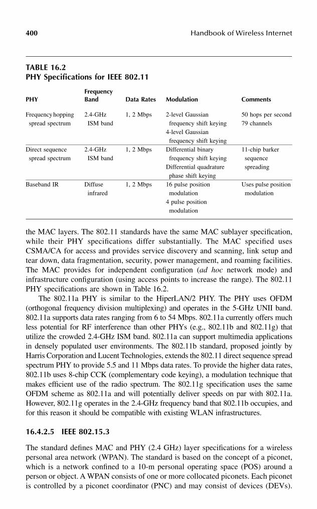
400 Handbook of Wireless Internet
the MAC layers. The 802.11 standards have the same MAC sublayer specification,while their PHY specifications differ substantially. The MAC specified usesCSMA/CA for access and provides service discovery and scanning, link setup andtear down, data fragmentation, security, power management, and roaming facilities.The MAC provides for independent configuration (ad hoc network mode) andinfrastructure configuration (using access points to increase the range). The 802.11PHY specifications are shown in Table 16.2.
The 802.11a PHY is similar to the HiperLAN/2 PHY. The PHY uses OFDM(orthogonal frequency division multiplexing) and operates in the 5-GHz UNII band.802.11a supports data rates ranging from 6 to 54 Mbps. 802.11a currently offers muchless potential for RF interference than other PHYs (e.g., 802.11b and 802.11g) thatutilize the crowded 2.4-GHz ISM band. 802.11a can support multimedia applicationsin densely populated user environments. The 802.11b standard, proposed jointly byHarris Corporation and Lucent Technologies, extends the 802.11 direct sequence spreadspectrum PHY to provide 5.5 and 11 Mbps data rates. To provide the higher data rates,802.11b uses 8-chip CCK (complementary code keying), a modulation technique thatmakes efficient use of the radio spectrum. The 802.11g specification uses the sameOFDM scheme as 802.11a and will potentially deliver speeds on par with 802.11a.However, 802.11g operates in the 2.4-GHz frequency band that 802.11b occupies, andfor this reason it should be compatible with existing WLAN infrastructures.
16.4.2.5 IEEE 802.15.3
The standard defines MAC and PHY (2.4 GHz) layer specifications for a wirelesspersonal area network (WPAN). The standard is based on the concept of a piconet,which is a network confined to a 10-m personal operating space (POS) around aperson or object. A WPAN consists of one or more collocated piconets. Each piconetis controlled by a piconet coordinator (PNC) and may consist of devices (DEVs).
TABLE 16.2PHY Specifications for IEEE 802.11
PHYFrequency Band Data Rates Modulation Comments
Frequency hopping spread spectrum
2.4-GHz ISM band
1, 2 Mbps 2-level Gaussian frequency shift keying
4-level Gaussian frequency shift keying
50 hops per second79 channels
Direct sequence spread spectrum
2.4-GHz ISM band
1, 2 Mbps Differential binary frequency shift keying
Differential quadrature phase shift keying
11-chip barker sequence spreading
Baseband IR Diffuse infrared
1, 2 Mbps 16 pulse position modulation
4 pulse position modulation
Uses pulse position modulation
Mobile Ad Hoc Networks: Principles and Practices 401
The PNC’s functions include the basic timing of the piconet using beacons, managingQoS, managing the power save modes, and security and authentication. The 802.15.3PHY is defined for 2.4 to 2.4835 GHz band and has two defined channel plans. Itsupports five different data rates (11 to 55 Mbps). The base uncoded PHY rate is22 Mbps. Table 16.1 provides other details of the 802.15.3 PHY specifications.
16.4.2.6 HomeRF
The HomeRF Working Group was formed to develop a standard for wireless datacommunications between personal computers and consumer electronics in a homeenvironment. The HomeRF standard is technically solid, simple, secure, and easyto use. HomeRF networks provide a range of up to 150 feet, typically enough forhome networking. HomeRF uses Shared Wireless Access Protocol (SWAP) to pro-vide efficient delivery of voice and data traffic. SWAP uses digital enhanced cordlesstelecommunications (DECT), and the 802.11 FHSS technologies. SWAP uses atransmit power of up to 100 mW and a gross data rate of 2 Mbps. It can support amaximum of 127 devices per network. A SWAP-based system can work as an adhoc network or as a managed network using a connection point.
16.4.3 HARDWARE TECHNOLOGIES
Following is a discussion of the hardware technologies that are helping implementad hoc networks. These technologies offer low power/power aware hardware andminiaturization of memory, processor, and other peripherals.
16.4.3.1 Smart Wireless Sensors66
Smart wireless sensors have added substantially to the applications that MANETsexecute. Sensor-based MANETs can be used in applications such as detectingchemicals, explosives, and toxins in hazardous areas; military reconnaissance; gath-ering geological data in difficult terrain, etc. Being able to make miniature sensorssuch as the ones used in Smart Dust66 has shown that MANETs can be successfullyscaled to deal with thousands of nodes. Sensor networks are exploring the limits ofMANETs in terms of scalability, minimum resource requirements, network resil-ience, fault tolerance, and security. The emerging IEEE 802.15.4 (low rate WPAN)standard70 has been proposed for several smart sensor applications.
16.4.3.2 Smart Batteries67
Mobile devices typically have strong battery and bandwidth constraints. Powerconservation can be achieved on two different fronts: the device and the communi-cation protocols. The power conservation of the device involves reducing the usageof the battery for all the hardware of the device, including the CPU, display, andperipherals. The communication protocols also can be power-aware designs. Smartbatteries have low discharge rates, a long cycle life, a wide operating temperaturerange, and high energy density. Nickel cadmium (NiCad), nickel metal hydride(NiMH), and lithium ion (Li-ion) are the most commonly used for mobile devices.Li-ion batteries have the highest energy density among these technologies.

402 Handbook of Wireless Internet
16.4.3.3 Software-Defined Radio68
Software-defined radio (SDR, or software radio) is a radio that can be controlledusing software. In SDR systems, waveform generation, modulation techniques,wideband or narrowband operation, security functions, and frequency of operationcan be adjusted in software based on the requirements. SDR systems, in essence,provide programmable hardware that increases the flexibility of use and develop-ment. SDR is the Holy Grail of radio design. A SDR system is designed to workwith any existing or developing standard. SDR highlights the various trade-offs inthe design of different radio architectures with a view to improving the radio per-formance, enhance the feature sets, and add new services resulting in a better userexperience. SDR has a vital role in the implementation of MANETs with heteroge-neous hosts that employ different radio technologies.
16.4.3.4 GPS69
Location awareness, as discussed earlier, can be valuable in establishing the routingtopology. Location awareness of nodes distributed in a MANET requires the acqui-sition of information about each node with respect to an absolute or relative locationreference. GPS has been used for obtaining location information of a node in aMANET. GPS is a global positioning system consisting of a group of satellites thatcontinuously broadcast location and timing information while orbiting the earth.Using position triangulation, GPS receivers on Earth calculate the exact location ofthe receiver on an absolute global scale. The location information thus calculated isin reference to the latitude and longitude coordinate system.
16.5 CONCLUSION
In this chapter, we explored principles and practices related to MANETs. We presentedMANET characteristics, their applications, and the issues related to the design andimplementation of MANETs. There has been a significant amount of research done toaddress the various issues associated with MANETs. Many of the issues described inthis chapter must be addressed to ensure successful implementation of a MANET.Clearly, many specialized applications such as the mobile robot application describedin this chapter can benefit significantly by learning from the research in the area ofMANETs. In this chapter, we studied related software, framework, hardware, andnetworking technologies that may contribute to the implementation of MANETs. Thesetools let users implement the various functional blocks of the MANETs.
ACKNOWLEDGMENTS
The authors gratefully acknowledge the support needed in writing this chapter,provided by the School of Computer Science, University of Oklahoma, and thePhotonics Division of General Atomics, San Diego.
Mobile Ad Hoc Networks: Principles and Practices 403
REFERENCES
1. IETF MANET Charter, available at www.ietf.org/html.charters/manet-charter.html,August 2002.
2. Perkins, C.E., Ed., Ad hoc Networking, Addison Wesley, Reading, MA, 2001.3. MANET Paper Collection, available at www.ee.surrey.ac.uk/Personal/G.Aggelou/
MANET_PUBLICATIONS.html, August 2002.4. MANET Resources, available at students.cs.tamu.edu/youngbae/mcrelated.html,
August 2002.5. Radhakrishnan, S. et al., DST – A routing protocol for ad hoc networks using
distributed spanning trees, Proc. IEEE International Conference on Wireless Com-munications and Networking (WCNC '98), 1998.
6. Racherla, G., Algorithms for routing and rerouting in mobile wireless and ad hocnetworks, Ph.D. diss., University of Oklahoma, Norman, 1999.
7. Tanenbaum, A.S., Computer Networks, 3rd ed., Prentice-Hall, Englewood Cliffs, NJ,1996.
8. Martin, M.J., Understanding the Network: A Practical Guide to Internetworking,New Riders, Indiana, 2000.
9. Camp, T., Boleng, J., and Wilcox, L., Location information services in mobile ad hocnetworks, Proc. IEEE International Conference on Communications (ICC), 2002, pp.3318–3324.
10. Capkun, S., Hamdi, M., and Hubaux, J.P., GPS-free positioning in mobile ad hocnetworks, Proc. Hawaii International Conference on System Sciences, January 2001.
11. Niculescu, D. and Nath, B., Ad hoc postioning system, Internet draft, available athttp://www.cs.rutgers.edu/dataman/papers/aps.ps, August 2002.
12. Li, J. et al., A scalable location service for geographic ad hoc routing, Proc. ACMMobicom 2000, Boston.
13. Chandran, K. et al., A feedback based scheme for improving TCP performance in adhoc networks, IEEE Personal Communication Systems Magazine, Special issue onAd Hoc Networks, 8 (1), 34–39, 2001.
14. Ahuja, A. et al., Performance of TCP over different routing protocols in mobile adhoc networks, Proc. IEEE Vehicular Technology Conference (VTC '2000), Vol. 3,Tokyo, May 2000, pp. 2315–2319.
15. Dyer, T.D. and Boppana, R.V., A comparison of TCP performance over three routingprotocols for mobile ad hoc networks, Proc. ACM Symposium on Mobile ad hocNetworking and Computing, October 2001.
16. Gerla, M., Tang, K., and Bagrodia, R., TCP performance in wireless multihop net-works, Proc. IEEE Workshop on Mobile Computing Systems and Applications(WMCSA), February 1999, pp. 41–50.
17. Holland, G. and Vaidya, N.H., Analysis of TCP performance over ad hoc networks,Proc. International Conference on Mobile Computing and Networking (MOBICOM),August 1999.
18. Johnson, D.B. and Maltz, D.A., Dynamic source routing in ad hoc wireless networks,in Mobile Computing, Imielinki, T. and Korth, H. Eds., Kluwer, Dordrecht, 1996, pp.153–181.
19. Park, V.D. and Corson, M.S., A highly adaptive distributed routing algorithm formobile wireless networks, Proc. IEEE INFOCOM, 1997, pp. 1405–1413.
20. Toh, C.-K. Associativity-based routing for ad hoc networks, Wireless Personal Com-mun. J., Special issue on ad hoc Networks, 17 (8), 1466–1487, 1999.
404 Handbook of Wireless Internet
21. Dube, R. et al., Signal stability based adaptive routing (SSA) for ad hoc mobilenetworks, IEEE Personal Commun., 36–45, Feb. 1997.
22. Perkins, C.E. and Bhagwat, P., Highly dynamic destination-sequenced distance-vectorrouting (DSDV) for mobile computers, Comput. Commun. Rev., 24 (4), 234–244,1994.
23. Perkins, C.E. and Royer, E.M., Ad hoc on-demand distance vector routing, Proc.IEEE Workshop on Mobile Computing Systems and Applications (WMCSA), Feb.1999.
24. Perkins, C., Ad hoc on demand distance vector (AODV) routing, Internet draft, draft-ietf-manet-aodv-00.txt, Aug. 2002.
25. Hass, Z. and Pearlman, M., The performance of a new routing protocol for thereconfigurable wireless networks, Proc. International Conference on Communications(ICC 98), June 1998, pp. 156–160.
26. Ramanathan, R. and Rosales-Hain, R., Topology control of multihop wireless net-works using transmit power adjustment, Proc. IEEE InfoCom, Mar. 2000, pp.404–413.
27. Ko, Y. and Vaidya, N., Location-aided routing (LAR) mobile ad hoc networks, Proc.MobiCom 98, Dallas, Oct. 1998.
28. Royer, E.M. and Toh, C.-K., A review of current routing protocols for ad hoc mobilewireless networks, IEEE Personal Communications Magazine, April 1999, pp. 46–55.
29. Broch, J. et al., A performance comparison of multihop wireless ad hoc networkrouting protocols, Proc. 4th Annual ACM/IEEE International Conference on MobileComputing and Networking (MobiCom 98), ACM, Dallas, Oct. 1998.
30. Das, S.R., Perkins, C.E., and Royer, E.M., Performance comparison of two on-demand routing protocols for ad hoc networks, Proc. InfoCom, Mar. 2000, pp. 3–12.
31. Racherla, G. and Radhakrishnan, S., Survey of routing algorithms in ad hoc networks,Proc. 4th World Multiconference on Systemics, Cybernetics and Informatics (SCI2000)/6th International Conference on Information Systems Analysis and Synthesis(ISAS 2000), Orlando, FL, July 23–26, 2000.
32. Johnson, D.B., Routing in ad hoc networks of mobile hosts, Proc. IEEE Workshopon Mobile Computing Systems and Applications, Dec. 1994.
33. Obraczka, K. and Tsudik, G., Multicast routing issues in ad hoc networks, Proc. IEEEInternational Conference on Universal Personal Communication (ICUPC 98), Oct.1998.
34. Mauve, M., Widmer, J., and Hartenstein, H., A survey on position-based routing inmobile ad hoc networks, IEEE Network Magazine, 15 (6), 30–39, 2001.
35. Takai, M., Martin, J., and Bagrodia, R., Effects of wireless physical layer modelingin mobile ad hoc networks, Scalable Networks white paper, http://www.scalable-networks.com/pdf/mobihoc.pdf, Aug. 2002.
36. Golmie, N. and Mouveaux, F., Modeling and simulation of MAC protocols forwireless devices coexistence performance evaluation, Internet draft, Aug. 2002.
37. The network simulator — ns-2, http://www.isi.edu/nsnam/ns/, Aug. 2002.38. GloMoSim home page, http://pcl.cs.ucla.edu/projects/glomosim/, Aug. 2002.39. Chandra, A., Gummalla, V., and Limb, J.O., Wireless medium access control proto-
cols, IEEE Commun. Surv., www.comsoc.org/surveys, Second Quarter, 2000.40. Karn, P., MACA: a new channel access method for packet radio, Proc. ARRL/CRRL
Amateur Radio 9th Computer Networking Conference, Sept. 1990.41. Bharghavan, V. et al., MACAW: a media access protocol for wireless LANs, Proc.
ACM SIGCOMM, Aug. 1994, pp. 212–225.42. IEEE 802.11 Specifications, grouper.ieee.org/groups/802/11/index.html, Aug. 2002.

Mobile Ad Hoc Networks: Principles and Practices 405
43. Chowdary, N. and Radhakrishnan, S., A power efficient enhancement to IEEE 802.11protocol for multihop wireless networks, Technical report, University of Oklahoma,Norman, 2002.
44. Lahiri, K., Raghunathan, A., and Dey, S., Battery efficient architecture for an 802.11MAC processor, Proc. International Conference on Communications (ICC), NewYork, May 2002.
45. Singh, S. and Raghavendra, C., PAMAS – power aware multi-access with signalingfor ad hoc networks, Proc. IEEE International Personal, Indoor and Mobile RadioCommunications Conference, 1998, pp. 153–157.
46. Srisathapornphat, C. and Shen, C.C., Coordinated power conservation for ad hocnetworks, Proc. IEEE International Conference on Communications (ICC), New York,April 28–May 2, 2002.
47. Agarwal, P., Energy Efficient Protocols for Wireless Systems, Proc. IEEE PIMRC98, Sept. 1998.
48. Zorzi, M. and Rao, R,.“Error control and energy consumption in communications fornomadic computing, IEEE Trans. Comput., Mar. 1997.
49. Singh, S., Woo, M., and Raghavendra, C.S., Power-aware routing in mobile ad hocnetworking, Proc. International Conference in Mobile Computing and Networking,1998, pp. 181–190.
50. IEEE 802.15 Working Group for WPAN, http://grouper.ieee.org/groups/802/15/, Aug.2002.
51. Jini Community Resource Page, http://www.jini.org, Aug. 2002.52. Jini Networking Technology, http://wwws.sun.com/software/jini/, Aug. 2002.53. Universal Plug and Play (UPnP) Forum, http://www.upnp.org/, Aug. 2002.54. OSGI Official Website, http://www.osgi.org, Sept. 2001.55. HAVi: Home Audio Video Interoperability home page, http://www.havi.org/, Aug.
2002.56. Open P2P Project, http://www.openp2p.com, Aug. 2002.57. Bray, J. and Sturman, C.F., Bluetooth 1.1: Connect Without Cables, 2nd ed., Prentice-
Hall, Englewood Cliffs, NJ, 2002.58. Bluetooth Official Website, http://www.bluetooth.com, Aug. 2002.59. Ultra Wideband Working Group, http://www.uwb.org, Aug. 2002.60. ETSI, www.etsi.org, Aug. 2002.61. HiperLAN Global Forum 2, http://www.hiperlan2.com/, Aug. 2002.62. Geier, J., Wireless LANs, MacMillan, New York, 2001.63. Nader, S. et al., Ad hoc networks with smart antennas using IEEE 802.11-based
protocols, Proc. IEEE International Conference on Communications (ICC), NewYork, April 28–May 2, 2002.
64. HomeRF Official Website, homerf.org, Aug. 2002.65. FCC home page, www.fcc.gov, Aug. 2002.66. Smart Dust, Autonomous sensing and communication in a cubic millimeter,
http://robotics.eecs.berkeley.edu/~pister/SmartDust/, Aug. 2002.67. Smart Battery Systems Implementers Forum, www.sbs-forum.org, Aug. 2002.68. Software Defined Radio Forum, www.sdrforum.org/, Aug. 2002.69. Trimble: All about GPS, http://www.trimble.com/gps/, Aug. 2002.70. IEEE WPAN Task Group 4, IEEE 802.15.4 draft standard, http://www.ieee802.org/
15/pub/TG4.html, Aug. 2002.

This page intentionally left blank
4070-8493-1502-6/03/$0.00+$1.50© 2003 by CRC Press LLC
17 Managing Location in “Universal” Location-Aware Computing
Sajal K. Das, Amiya Bhattacharya, Abhishek Roy, and Archan Misra
CONTENTS
17.1 Introduction ................................................................................................40717.2 Location Resolution and Management Techniques in Pervasive
Computing Applications ............................................................................40917.2.1 IP Mobility Support over Cellular Systems................................40917.2.2 Mobile Information Services.......................................................41117.2.3 Tracking Systems.........................................................................41117.2.4 Additional Techniques .................................................................413
17.3 Pervasive Computing Requirements and Appropriate LocationRepresentation............................................................................................41517.3.1 Geometric or Symbolic Representation? ....................................417
17.4 “Optimal” Location Tracking and Prediction in Symbolic Space............42017.4.1 The LeZi-Update Algorithm........................................................42117.4.2 Translation of Mobility Profiles during Vertical Handoffs .........422
17.5 Conclusion..................................................................................................423Acknowledgment ...................................................................................................424References..............................................................................................................424
17.1 INTRODUCTION
Models of twenty-first century ubiquitous computing scenarios1 depend not just onthe development of capability-rich mobile devices (such as Web phones or wearablecomputers), but also on the development of automated machine-to-machine com-puting technologies, whereby devices interact with their peers and the networkinginfrastructure, often without explicit operator control. To emphasize the fact thatdevices must be imbued with an inherent consciousness about their current locationand surrounding environment, this computing paradigm also is called sentient2 (orcontext-aware) computing. Context awareness is one of the key characteristics of
408 Handbook of Wireless Internet
applications under this intelligent computing model. If devices can exploit emergingtechnologies to infer the current state of user activity (e.g., whether the user iswalking or driving, at the office, at home, or in a public environment) and thecharacteristics of the user’s environment (e.g., the nearest Spanish-speaking ATM),they can then intelligently manage both the information content and the means ofinformation distribution.
Location awareness is the most important type of context, because the current(or future) location of users strongly influences their information needs. Applicationsin computing and communications utilize such location information in two distinctways:
1. Location-aware computing: In this category, the information obtained bya mobile device or user varies with changes in the user’s location. Themost-common goal on the network side is to automatically retrieve thecurrent or anticipated neighborhood of the mobile user (for appropriateresource provisioning); on the device side, the typical goal is to discoverappropriate local resources. As an example of this category, we can con-sider the case where mobile users would be automatically provided withlocal navigation maps (e.g., floor plans in a museum that the user iscurrently visiting), which are automatically updated as the device changesits current position.
2. Location-independent computing: Here, the network endeavors to providemobile users with a set of consistent applications and services that do notdepend on the specific location of the users or on the access technologyemployed to connect to the backbone information infrastructure. Infor-mation about the user’s location is required only to ensure the appropriateredirection of global resources to the device’s current point of attachment;such applications are not usually interested in the user’s absolute locationbut only in the point of attachment to the communications infrastructure.An example of this is cellular telephony, where mobility managementprotocols are used to provide a mobile user with ubiquitous and location-independent access.
While location-independent computing applications have a fairly mature history,location-aware computing is still at an early stage. Innovative prototypes of location-aware computing environments are still largely experimental and geared towardspecific target environments. The location support systems of different prototypes,as a result, have been largely autonomous and have always remained at the disposalof the system designers. It is important, however, to realize that the full potential oflocation-aware computing can be harnessed only if we develop a globally consistentlocation management architecture that caters to the needs of both location-awareand location-independent applications, and allows the retrieval and manipulation oflocation information obtained by a wide variety of technologies. This is an interestingtechnological challenge, because location-aware and location-independent applica-tions typically face significantly different scalability concerns. In general, location-aware applications do not generate significant scalability issues because they primarily
Managing Location in “Universal” Location-Aware Computing 409
involve local interactions; however, scalability is a critical concern for location-independent network services, which must support access to distributed content bya much larger user set.
In this chapter, we focus on identifying the various requirements that must besatisfied by such a universal location-management infrastructure. We also explainwhy we prefer that such location data be expressed in symbolic format, and thendiscuss the use of information-theoretic algorithms for effectively manipulating suchlocation information. A symbolic representation of location data allows the manage-ment infrastructure to deal with an extremely heterogeneous set of networkingtechnologies, with a wide variety of underlying physical layers and location sensortechnologies. Indeed, the ability to accommodate device heterogeneity and techno-logical diversity is vital to the success of a universal location-management scheme.As our survey of current trends will show, location information in various prototypesdiffers widely in their environment of applicability and the granularity of resolution.Moreover, we shall see how such symbolic information is more amenable to storageand manipulation across heterogeneous databases, and can be exploited to providenecessary functions such as location prediction, location fusion, and location privacy.
The rest of the chapter is organized as follows. Section 17.2 highlights someexamples of location-aware applications and prototype systems. The various loca-tion-related functions that must be realized in a universal location-managementframework designed for pervasive computing models are identified in Section 17.3.Based on this discussion, we explore also the relative merits of alternative schemesfor global location representation. Section 17.4 discusses the novel concept of pathupdate and outlines the LeZi-update algorithm that optimizes the signaling loadsassociated with location tracking. We present ongoing research that extends thisalgorithm to provide translation of location information across heterogeneous net-works and multiple access technologies. Section 17.5 summarizes the chapter anddiscusses open problems.
17.2 LOCATION RESOLUTION AND MANAGEMENT TECHNIQUES IN PERVASIVE COMPUTING APPLICATIONS
To understand the functionality needed in any universal location-management archi-tecture, it is helpful first to evaluate the various proposed application scenarios. Itwill become evident that these applications not only have differing performancerequirements, but also exhibit significant diversity in the technologies that they useto obtain and track location information. Given the abundance of work in this area,we focus only on a selective subset that illustrates the main requirements andchallenges.
17.2.1 IP MOBILITY SUPPORT OVER CELLULAR SYSTEMS
Wireless cellular networks offer the best example of location-management protocolsfor location-independent computing. The cellular architecture employs a two-levelhierarchy for tracking the location of a mobile device as it roams across the cellular

410 Handbook of Wireless Internet
network, and redirects traffic to and from the mobile node’s current point of attach-ment. The entire network is partitioned into a number of distinct registration areas(RA), with a home mobile switching center (HMSC) handling all the incoming andoutgoing calls for the mobile terminals that are homed in its registration area. Eachregistration area has a database, called the visiting location register (VLR), whichstores the precise location of all mobiles currently resident in that RA. A pointer tothe current VLR of a mobile terminal is held at the home location register (HLR),located in the home registration area of the mobile terminal. The first level of mobilitysupport is provided by having the HMSC redirect all arriving calls (after appropriatequery resolution via the HLR and VLR) to the mobile switching center (MSC)serving the current point of attachment of the mobile node.
Because each RA comprises several cells, we need additional location-manage-ment techniques to identify the precise cell in which the mobile node is currentlyresident. The resolution of the mobile node’s (MN) precise cell of attachment isperformed using two complementary techniques, viz., (1) location update or regis-tration, and (2) paging. Location update refers to the process by which the mobilenode proactively informs the network element (the MSC) of its current position (orother information, such as future locations). Conversely, paging is the process bywhich the network element (MSC) initiates a search for the MN in all cells wherethe mobile has a nonzero residence probability. There has been a significant amountof research on improved paging and location update strategies, such as the use ofdistance-based location update strategies or selective paging mechanisms.3
The introduction of packet-based data services over cellular networks and thepredicted move toward IP-based fourth-generation (4G) cellular networks haveresulted in several efforts to introduce protocols for IP-based mobility support.Mobile IP4 is the current standard for IP-based mobility management and providesubiquitous Internet access to an MN without modifying its permanent IP address.Two entities analogous to HLR and VLR, namely, the home agent (HA) and theforeign agent (FA), are used to tunnel packets addressed to this permanent addressto the MN’s current point of attachment. The base Mobile IP protocol, however,suffers from several drawbacks, such as high signaling latency, in the absence of ahierarchical infrastructure. Accordingly, several protocols, such as cellular IP,HAWAII, or IDMP, have been recently proposed for introducing a location-manage-ment hierarchy in IP networks and thereby providing more scalable intradomainmobility support.5
All these schemes express the location of the MN in symbolic form: the MNlocation is essentially expressed in terms of the ID (e.g., IP address of the FA orthe MSC identifier) of the network element to which it is currently attached. Locationupdate and paging schemes operate on this symbolic representation of location; forexample, popular paging strategies consist of a sequential search for an MN over alist of cell IDs. The cellular network illustrates the design of a global locationresolution framework that combines hierarchical call and packet redirection withsuitable paging and registration mechanisms. Of course, the use of such symboliclocation information implies that the location of an MN is resolved only up to thegranularity of the individual cell or subnet of attachment. In Section 17.4, we shalldiscuss the design of a provably optimal location-management algorithm, which

Managing Location in “Universal” Location-Aware Computing 411
uses such symbolic location information to establish optimal paging and locationupdate strategies.
17.2.2 MOBILE INFORMATION SERVICES
Location-aware mobile information services are often touted as the “killer applica-tion” for the first generation of ubiquitous computing. These services are typicallybased on an information service infrastructure that retrieves the current location ofa mobile device, and then provides the device with information and resources thatare local to the MN’s current location. The primary aim of such services is not totrack individual users, but to ensure that a specific network resource is available tousers who are currently “close” to the resource.
One example of this service is the Traveller Information Service being developedas part of the Advanced Traveler Information Systems (ATIS) initiative for smarthighways in several countries (e.g., TravTek in Orlando, SMART Corridor in SantaMonica, and CACS in Japan). We outline the example of Genesis,6 a fairly compre-hensive system under development at the University of Minnesota for the Minne-apolis–St. Paul area. The ATIS server in the Genesis system maintains the masterdatabase, with each road segment associated with a start and end node in the database.Nodes are essentially named objects with location attribute (x,y) coordinatesexpressed in geographical coordinates. Active databases are used with proper choiceof triggers, such as traffic congestion, accidents, road hazards, and constructions anddetours, to support a wide range of spatially correlated queries. Due to the geometricrepresentation of location information, the local environment of a user is definedusing simple spatial queries.
The Cyberguide Project at Georgia Tech7 is an effort to develop an electronictourist guide for both wide area and local environments (such as a building). TheCyberguide architecture uses explicit GPS-based positioning for outdoor environ-ments and infrared-based positioning for indoor environments; the indoor locationresolution technology does not scale well to large coverage areas. Lancaster Uni-versity’s GUIDE project8 is another experimental prototype of local informationservices. It uses a cellular network arrangement, with IEEE 802.11 LANs providingshort-range coverage within a single cell. By making the coverage areas deliberatelydiscontinuous, GUIDE ensures that each cell caters only to mobile nodes within aspecific zone. Because GUIDE simply broadcasts zone-specific information from aLinux-based cell server to all nodes within the corresponding zone, the system doesnot require any explicit location or positioning support and does not need to trackthe movement of individual nodes.
17.2.3 TRACKING SYSTEMS
Tracking applications differ from mobile information services in that they typicallyfocus on the ability to continuously monitor the location of a mobile device. Present-generation tracking applications typically run as global services, where the locationof the mobile nodes must be distributed over wide area networks. Fleet managementapplications are the most-obvious examples of present-day tracking systems. Most

412 Handbook of Wireless Internet
commercial fleet management systems (e.g., Qualcomm’s OmniTRACS product)are based on the GPS technology, which provides the absolute location of a mobiledevice (relative to a geographical coordinate system) at varying levels of precision.Location update schemes in such systems employ dead reckoning, whereby the locationinformation is extrapolated by the system based on velocity information; new updatesare generated when the mobile object deviates from its predicted position by a distancethreshold. A digital map database is maintained in a manner quite similar to that ofATIS, i.e., using path segments and nodes, along with their x,y coordinates. Dependingon need, a portion of this database may be replicated in the memory of the on-boardcomputers. Dynamic attributes and their indexing, spatio-temporal query languages,and uncertainty management are special features of such databases.
The Federal Communication Commission’s (FCC) E911 initiative has made itmandatory for wireless cellular service providers to track the location of phonesmaking emergency 911 calls. While GPS information provides the easiest way ofdetermining location, most cell phones do not possess such technology. The locationof a mobile user in such environments is often determined, typically in geographicalcoordinates, by triangulation technologies based on the relative signal strength ofthe cellular signal at multiple base stations. While GPS is indeed a popular technol-ogy for resolving location, it is applicable only to outdoor computing environments.Due to this limitation, as well as the fact that GPS technology cannot be embeddedor is not available in all computing devices, GPS data cannot be used as the basisof a universal location representation scheme. Recently, several innovative researchprototypes have focused on the problem of location tracking in indoor environments.
An example of such a research prototype is the Active Badge project,9 originallyconceived at the Xerox Palo Alto Research Center. Active badges are low-cost, low-power infrared beacon-emitting devices worn by employees in an office environment.Sensors are distributed in a pico-cellular fashion within the building, and the locationof a badge is determined primarily by the identity of the sensor that reports thebadge within its vicinity. Location management and paging algorithms are used totrack the user’s location, which is essentially expressed in symbolic form (based onthe IDs of the neighboring sensors). While the infrared technology used in activebadges can resolve device location up to the granularity of individual rooms, addi-tional technologies are needed for finer location resolution. For example, ActiveBats10 have been developed to track both position and movement using ultrasonictechnology; this approach can be considered the indoor analog of GPS because itexpresses location in geometric coordinates. Follow-me applications in pervasivecollaborate workspaces require such fine-grained location information; such appli-cations also need efficient location prediction to ensure that computing and commu-nication resources are available to a mobile device in an uninterrupted fashion.
Several other research prototypes have exploited alternative radio technologiesfor indoor location tracking. For example, MIT’s Cricket Location Support System11
requires the mobile devices to proactively report their locations. Such mobile devicesuse sophisticated triangulation mechanisms that monitor both RF and ultrasoundsignals emitted from wall- and ceiling-mounted beacons to resolve their geographicallocation information. Microsoft Research’s RADAR system,12 on the other hand,
Managing Location in “Universal” Location-Aware Computing 413
uses signal-to-noise ratio and signal strength measurements of IEEE 802.11 wirelessLAN radios to resolve the location of indoor mobile nodes to a granularity ofapproximately 3-to-5-meter accuracy. While the accuracy of the resolution can sufferdue to changes in the indoor layout (such as the moving of metal file cabinets), theapproach offers the advantage of location resolution that piggybacks on the wirelessnetworking infrastructure and does not require the extensive installation of newdevices/radios. Pinpoint’s 3D-ID performs indoor position tracking at 1-to-3-meterresolution using proprietary base station and tag hardware in the unregulated ISMband (also used by 802.11 LANs) to measure radio time of flight.
Research prototypes have also used alternative techniques for monitoring userlocation. Electromagnetic sensing techniques (e.g., Raab et al.13) generate axialmagnetic-field pulses from a transmitting antenna in a fixed location and computethe position and orientation of the receiving antennas by measuring the response inthree orthogonal axes to the transmitted field pulse, combined with the constanteffect of the Earth’s magnetic field. While they offer up to 1-mm spatial resolution,they suffer from limited tracking distances and steep implementation costs. Researchprojects also have used stereovision (e.g., Microsoft’s Easy Living14 project forindoor home environments) or ubiquitous pressure-sensing (e.g., Georgia Tech’sSmart Floor proximity location system15) techniques to resolve the location of peoplein indoor environments. While such techniques may not be deployed universally,they do illustrate how the use of diverse location resolution and management tech-niques is a basic reality of pervasive computing architectures.
17.2.4 ADDITIONAL TECHNIQUES
We have recently witnessed research efforts in ad hoc location sensing, where userlocation in wireless environments is estimated without the use of static beacons orsensors that provide a fixed frame of reference. Mobile nodes in such ad hocenvironments essentially act as peers, sharing sensory information with one anotherto progressively converge on a true representation of device location. Doherty etal.16 have presented an algorithmic approach to this problem, as well as a frameworkfor describing error bounds on the computed locations.
Another interesting area of location management research is sensor fusion, wherethe location information is obtained by simultaneously aggregating information frommultiple hierarchical or overlapping sensing technologies. By integrating locationtracking systems with different error distributions, we can often provide increasedaccuracy and precision beyond the capabilities of an individual system. An exampleof such fusion can be found in multisensor collaboration robot localization problems(e.g., Fox et al.17), where information from multiple sensors (such as ultrasonic andlaser rangefinders, cameras, etc.) is integrated using Bayesian or Markovian learningtechniques to develop a “map” of a building.
Table 17.1 shows a selective list of the location-management techniquesemployed in various pervasive computing contexts. We can see that location man-agement prototypes use both geometric and symbolic representations to resolve,track, and predict the location of mobile devices.
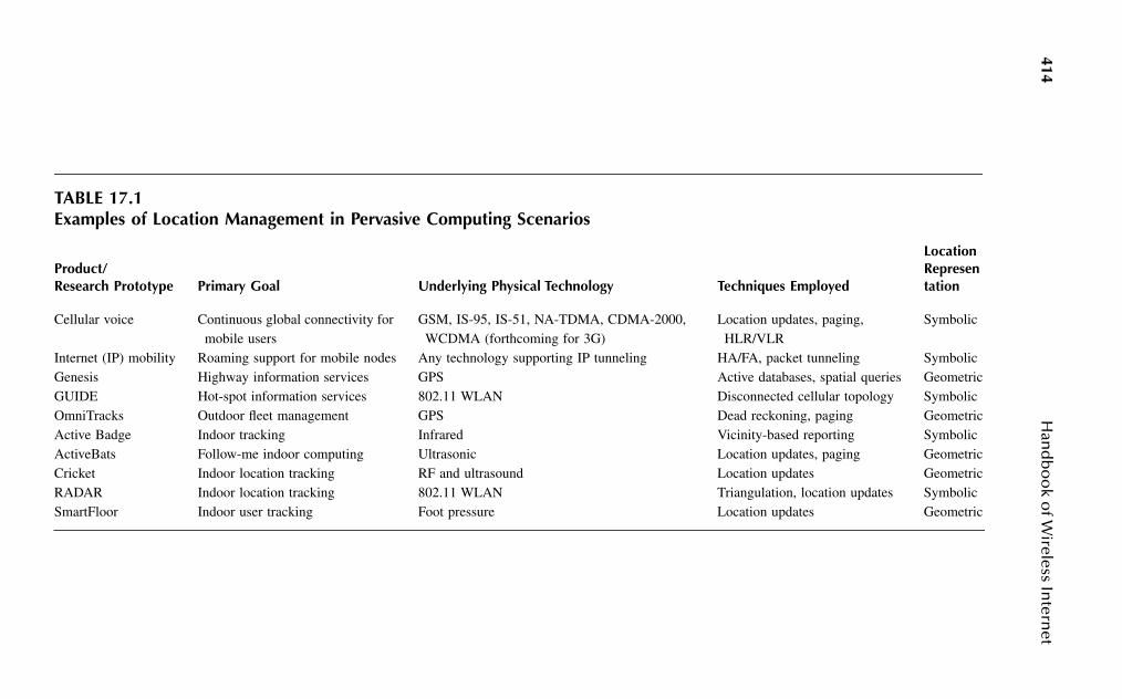
414H
and
bo
ok o
f Wireless In
ternet
TABLE 17.1Examples of Location Management in Pervasive Computing Scenarios
Product/Research Prototype Primary Goal Underlying Physical Technology Techniques Employed
Location Representation
Cellular voice Continuous global connectivity for mobile users
GSM, IS-95, IS-51, NA-TDMA, CDMA-2000, WCDMA (forthcoming for 3G)
Location updates, paging, HLR/VLR
Symbolic
Internet (IP) mobility Roaming support for mobile nodes Any technology supporting IP tunneling HA/FA, packet tunneling SymbolicGenesis Highway information services GPS Active databases, spatial queries GeometricGUIDE Hot-spot information services 802.11 WLAN Disconnected cellular topology SymbolicOmniTracks Outdoor fleet management GPS Dead reckoning, paging GeometricActive Badge Indoor tracking Infrared Vicinity-based reporting SymbolicActiveBats Follow-me indoor computing Ultrasonic Location updates, paging GeometricCricket Indoor location tracking RF and ultrasound Location updates GeometricRADAR Indoor location tracking 802.11 WLAN Triangulation, location updates SymbolicSmartFloor Indoor user tracking Foot pressure Location updates Geometric

Managing Location in “Universal” Location-Aware Computing 415
17.3 PERVASIVE COMPUTING REQUIREMENTS AND APPROPRIATE LOCATION REPRESENTATION
The basic goal of pervasive computing is clear: develop technologies that allowsmart devices to automatically adapt to changing environments and contexts, makingthe environment largely imperceptible to the user. However, the set of candidateapplications and their underlying technologies is anything but uniform! Developinga uniform location-management infrastructure is thus a challenging task. We identifythe following location-related features, which a universal architecture must support:
1. Interoperability across multiple technologies and resolutions: Current pro-totypes for pervasive applications typically choose a specific location-tracking technology that is suitable for their individual needs. A uniformlocation-management architecture must be capable of translating the loca-tion coordinates obtained by such systems into a universal format, whichcan be utilized by various application contexts. For example, cellular land-mobile systems will primarily need to resolve the location of a mobiledevice only up to the point of network attachment. Fleet management andtracking applications may, however, require explicit geometric informa-tion. The mobility management infrastructure should be capable of effi-ciently translating such location information between differentrepresentations, and also at different granularities (e.g., mobile commerceapplications advertising E-coupons may not be interested in the preciseroom in which a user is located inside a hotel).
2. Prediction of future location: Predicting the user’s future location is oftenthe key to developing smart pervasive services. For example, the ATISactive database can be triggered more intelligently by predicting the most-likely routes, and by warning the client about adverse road conditionsalong those routes. Prediction of an individual’s future position in anindoor office can be very helpful in aggressive teleporting (to supportfollow-me applications). In addition to this explicit service-oriented needfor prediction, there is also an implicit need for predictive mobility track-ing from the network infrastructure viewpoint. In several location-inde-pendent computing scenarios, the network must meet stringentperformance and latency bounds as it ensures uninterrupted access toglobal information and services, even as the users change their location.For example, to provide quality-of-service (QoS) guarantees for multime-dia traffic (such as video or audio conferencing) in cellular networks,appropriate bandwidth reservations must be made between the terminaland the serving base station (BS), as well as between the BS and thebackbone network. To meet strict bounds on the handoff delay, the networkalso must proactively reserve resources at the cells where the mobile islikely to move. Because many of the tracking technologies do not them-selves offer such predictive capabilities, the infrastructure must be capableof constructing such predictive patterns based on collective or individualmovement histories.
416 Handbook of Wireless Internet
3. Location fusion and translation: In several pervasive computing scenarios,location tracking is achieved through the combination of multiple tech-nologies and access infrastructures. For example, an office application canresolve the location of a user at different levels of granularity usingdifferent technologies. Thus, the specific building could be identifiedthrough the current wireless LAN cell where the mobile currently resides,whereas an additional ultrasonic system (such as Cricket11) may be usedto identify the precise orientation and room location of the mobile user.Because the user’s complete location reference is obtained only by com-bining these distinct location management systems, our global location-management framework must efficiently fuse and merge location infor-mation from two or more distinct network technologies.
The intelligent management of vertical (or intersystem) handoff, onthe other hand, often requires the ability to translate the mobility andlocation-related information from one frame of reference to another. Forexample, when a user switches from a wireless LAN to an overlaid PCSnetwork, the network must be able to translate the mobility patterns andlocation-prediction attributes from one system to the other, independentof the representation format imposed by each individual system.
4. Scalable and near-optimal signaling traffic: The desire for efficient andprovably optimal location update and paging strategies is not new; therehas indeed been a great deal of work on efficient location-managementstrategies, especially for cellular systems. The pervasive world will how-ever see a quantum jump in the number of mobile nodes (from millionsof cell phones to billions of autonomous pervasive devices) and an evengreater variation in the capability (such as power or memory constraints)of individual devices. We must therefore develop efficient and near-opti-mal signaling mechanisms that minimize any unnecessary signaling loadon both the devices and the networking infrastructure.
5. Security and privacy of location information: Security and privacy man-agement are key challenges in pervasive networking environments; not-withstanding the availability of advanced devices and location-resolutiontechnologies, users will not embrace a pervasive computing model untila scalable infrastructure for appropriately protecting such location infor-mation is in place. The problem is not one of simply making such locationinformation either visible or invisible to specific networks; we must allowthe user to dynamically configure the scope of location visibility, possiblyin multiple representation formats, to individual pervasive services andapplications. For example, a user may wish to expose his precise GPScoordinates to emergency response applications (such as 911), but only amuch coarser view (perhaps at a granularity of 20 miles2) to insurancecompanies trying to monitor his driving profile. Alternatively, the usermay specify his network point of attachment (symbolic information), butnot his precise in-building location (geometric coordinates) to a pervasiveenterprise application.

Managing Location in “Universal” Location-Aware Computing 417
17.3.1 GEOMETRIC OR SYMBOLIC REPRESENTATION?
While different pervasive location tracking and management systems resolve thelocation of a mobile node at different granularities, they can all be classified intotwo classes* (as per the taxonomy of Leonhardt and Magee4) based on the way inwhich they represent the location information of a mobile device:
1. Geometric: The location of the mobile object is specified as an absoluten-dimensional coordinate, with respect to a geographical coordinate sys-tem that is independent of the network topology. The most-common formof geometric data representation in location-aware computing systems isthe use of GPS data, which resolves the latitude and longitude of a mobileon the earth’s surface using a satellite-based triangulation system.
2. Symbolic: The user location data is specified not in absolute terms, butrelative to the topology of the corresponding access infrastructure. Thisform of representation is in widespread use in current telecommunicationsnetworks. For example, the PCS/cellular systems identify the mobilephone using the identity of its serving MSC; in the Internet, the IP addressassociated with a mobile device (implicitly) identifies the sub-net/domain/service provider with which it is currently attached.
The choice between a geometric and symbolic representation is one of thefundamental decisions in the development of a universal location-management archi-tecture. We believe that the symbolic representation is the preferred form, primarilydue to its structured nature. The main advantage of geometric representation is thatit is invariant: because the location information is an intrinsic property of the mobiledevice, it can be uniformly interpreted across heterogeneous environments, and doesnot depend on the topology of the associated networks. In spite of this seemingattractiveness, geometric representation is not appropriate for a universal location-management infrastructure. For one thing, the same reference coordinate system isnot universally applicable. As an example, GPS may be appropriate outdoors butdoes not apply indoors, where ultrasonic or infrared-based indoor positioning sys-tems may use different location coordinates. Moreover, we have demonstrated howdifferent pervasive applications and environments require the location of a mobiledevice at different levels of granularity. Thus, while GPS information may be accu-rate up to 5-m resolution, certain in-room pervasive applications may require trackingat submeter resolutions. Because we cannot practically mandate the universal deploy-ment of a technology that provides location at the finest granularity (the trackingcosts would become prohibitive), we must allow for the coexistence of differentnetworks and access technologies, providing location information at varying reso-lutions. Finally, geometric location-resolution technologies are inapplicable to a large
* There is also the semisymbolic (or hybrid) model,4 which essentially consists of both geometric andabstract (symbolic) representations. While such a model is more expressive, it suffers from the samedrawbacks as the geometric one (the main problem being the need for location-specific hardware on thepervasive device itself).

418 Handbook of Wireless Internet
category of pervasive devices, which may not possess location-resolution hardware(such as GPS devices) due to restrictions on cost and form factors. In contrast,symbolic location information (such as the point of attachment to the network) canbe obtained solely from the capabilities of the infrastructure.
Our preference for the symbolic form of location representation is based on theobservation that most location-independent applications, and a significant numberof location-aware ones, are interested primarily, not in the absolute location of themobile device, but only its position relative to the networking infrastructure. Moreimportantly, the location-independent applications are typically global in scope andcut across multiple network and access technologies. Accordingly, scalability con-cerns for the location-management infrastructure apply primarily to the location-independent component of the pervasive application space. The interaction betweenmobile devices and applications that require the explicit geometric location of suchdevices (such as map-based interactions), is often local and restricted to the accessnetwork. It thus makes sense to base the universal infrastructure on the symbolicrepresentation, allowing each access network to make the appropriate translation togeometric coordinates whenever necessary (rather than the reverse). For example,consider applications such as wireless Internet access that need to resolve the locationof a mobile device only up to the granularity of the point of attachment. Evenapparently location-aware services, such as the Electronic Tourist Guide, are reallyinterested in knowing the user’s location relative to the access infrastructure; amuseum information system needs to know only the current access point servingthe mobile visitor to provide appropriately tailored local content. Similarly, follow-me applications are primarily interested in predicting the device’s future point ofattachment (rather than its absolute position), because the final objective is to makeadvance reservations on the network path to the future point of attachment. Further-more, location data is much more amenable to database storage and retrieval if it isa named object — such an object hierarchy is possible only when location data isexpressed in symbolic form relative to other objects. Because an object hierarchyalso simplifies the computational burden associated with multiresolution processing,the translation of location data across different systems and location databases ismore efficient when stored in symbolic format.
Of course, we must not lose sight of applications, such as dynamic floor maps,which do need geometric location information. Geometric coordinates are clearlybetter suited for answering spatial queries related to physical proximity and con-tainment (e.g., is my device physically located within a designated building?). Asstated earlier, we believe that such specialized geometric queries (e.g., directions tothe nearest ATM or restroom facilities) typically involve “local” resources andinteract with server applications lying within the access domain, especially in per-vasive environments where access networks will have considerably greater intelli-gence. In the future, a user currently located on a street in New York City is likelyto obtain the location of the nearest ATM from a local tourist-guide server, ratherthan relay his request back to a mapping software located on a server in SanFrancisco. While such queries may need to express location in geometric form, itis better to obtain such information either from “local” access-specific technologies,

Managing Location in “Universal” Location-Aware Computing 419
or by appropriate mapping from the universal symbolic location format. It is impor-tant also to not lose sight of the fact that many pervasive applications generatequeries related to topological proximity and containment, where the query issuer isinterested in resources relative to the network topology (i.e., which is the closest[fewest hops or least congested] video server? or, does this printer belong to theresearch division?). Thus, both geometric and symbolic representations appear tobe equally balanced from a query suitability standpoint, with the geometric formatbetter suited to spatial queries and the symbolic one more appropriate for topologicalqueries.
The hierarchical nature of communication networks implies the imposition of alogical hierarchy on the symbolic location representation (which expresses locationrelative to the network layout) as well. As an example, we will consider an IEEE802.11 wireless LAN infrastructure at a university campus, which is overlaid by thewide area cellular PCS infrastructure. For the sake of simplicity, we assume thateach PCS cell consists of multiple 802.11 LANs.* We can then construct a symbolicpositional hierarchy based on the coverage area of each technology, which yieldsthe neighborhood graph shown in Figure 17.1. The top level (corresponding to thecellular network) has eight zones, a, b, c, d, e, f, g, h, connected by neighborhoodrelationship as in the graph shown next to it. The second level zones which corre-spond to the 802.11 LANs may be named a1, a2, …; b1, b2, …; c1, c2, …, wherea1, a2, … are subzones in the zone a and so on.
We now focus on evaluating the suitability of using symbolic information tosatisfy the five requirements enumerated at the beginning of this section. We havealready seen how symbolic information is better suited to requirement 1, because itdoes not need any special support from the wireless access technology. In the restof this chapter, we focus on features 2 and 4, showing how we can develop a path-based location-prediction algorithm (based on symbolic representation) that is prov-ably optimal for stationary mobility patterns. While we are currently working onrequirement 3, the issue of configurable universal location security and privacy,
FIGURE 17.1 A hierarchical map and its top-level graph representation.
* Of course, in general, algorithms for storing and manipulating such symbolic information must allowfor hierarchies with partial or incomplete overlap (e.g., a WLAN may span multiple PCS cells).
bc
d
ef
g
h aa b c
d
ef
gh

420 Handbook of Wireless Internet
although a very interesting problem area in itself, is essentially beyond the scope ofthis chapter. However, symbolic location should clearly be more amenable to locationprivacy; because the user location is specified only relative to the topology of thenetwork infrastructure, precise location of a mobile node is not possible without aknowledge of the physical network topology.
17.4 “OPTIMAL” LOCATION TRACKING AND PREDICTION IN SYMBOLIC SPACE
In this section, we first show how LeZi-Update,18,19 a path-based location updatemechanism, can be used to provide efficient location predicting and tracking ofmobile devices in a symbolic location space. This path-based approach is asymp-totically optimal and outperforms earlier location-management algorithms based onlocation areas (LA), because it exploits the mobility profile associated with individualusers. Moreover, we can store the relevant details of the user’s location history in acompact data structure, and also derive accurate predictions of the relative likelihoodof future locations of the mobile device. Finally, we shall describe our ongoing workon enhancing this algorithm with an efficient location-translation capability fortransferring mobility profiles across heterogeneous systems.
Most mobility management solutions employ a position update technique forlocation management, where the mobile device simply updates its current location(e.g., cell ID or GPS coordinates) whenever it crosses a cell boundary (or otherthresholds such as time or distance). Position update schemes can be viewed as alossy sampling of the true trajectory of the mobile object. Such position-basedschemes do not, however, use these location update samples to construct or predictthe user’s path; in effect, the schemes do not correlate across multiple sample pointsto learn the “pattern of device movement.” The performance of conventional pagingand location update schemes thus depend heavily on the precise parameters of the usermobility model; different algorithms perform better for different mobility models. Ageneric location management scheme must, however, perform well, independent of theindividual mobility patterns followed by different users. Such a generic model must bebased on the weakest set of assumptions on the mobility behavior of individual usersor devices, and must incorporate some form of learning that uses the past history ofthe mobile node to optimize the signaling associated with location tracking.
We assume that the user mobility is “well-behaved,” in that users/devices typi-cally move on some definitive paths that are based on the lifestyle of the mobileuser. According to the activity-based model, trips are considered the basic elementof a user’s long-term mobility profile. Trips in both outdoor and indoor environmentsare categorized by the purpose behind them, such as going to and coming back fromwork, shopping, a walk to a colleague’s cubicle, a lunch-hour visit to the cafeteria,etc. Each trip in the symbolic space then appears as a phrase of symbols. For example,if the location of a user is sampled successively, the mobility profile of a user overthe graph of Figure 17.1 may be expressed by the stream of symbols “aaababbbb-baabccddcbaaaa….” From a computational standpoint, the mobility profile of anyuser can then be represented by a user-specific stationary distribution over the
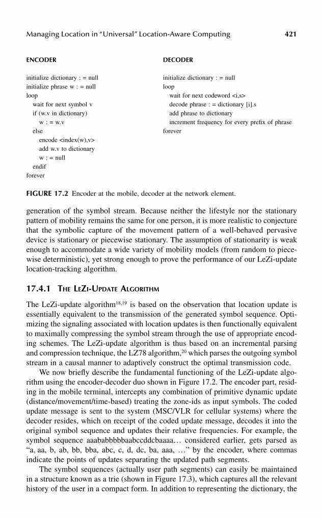
Managing Location in “Universal” Location-Aware Computing 421
generation of the symbol stream. Because neither the lifestyle nor the stationarypattern of mobility remains the same for one person, it is more realistic to conjecturethat the symbolic capture of the movement pattern of a well-behaved pervasivedevice is stationary or piecewise stationary. The assumption of stationarity is weakenough to accommodate a wide variety of mobility models (from random to piece-wise deterministic), yet strong enough to prove the performance of our LeZi-updatelocation-tracking algorithm.
17.4.1 THE LEZI-UPDATE ALGORITHM
The LeZi-update algorithm18,19 is based on the observation that location update isessentially equivalent to the transmission of the generated symbol sequence. Opti-mizing the signaling associated with location updates is then functionally equivalentto maximally compressing the symbol stream through the use of appropriate encod-ing schemes. The LeZi-update algorithm is thus based on an incremental parsingand compression technique, the LZ78 algorithm,20 which parses the outgoing symbolstream in a causal manner to adaptively construct the optimal transmission code.
We now briefly describe the fundamental functioning of the LeZi-update algo-rithm using the encoder-decoder duo shown in Figure 17.2. The encoder part, resid-ing in the mobile terminal, intercepts any combination of primitive dynamic update(distance/movement/time-based) treating the zone-ids as input symbols. The codedupdate message is sent to the system (MSC/VLR for cellular systems) where thedecoder resides, which on receipt of the coded update message, decodes it into theoriginal symbol sequence and updates their relative frequencies. For example, thesymbol sequence aaababbbbbaabccddcbaaaa… considered earlier, gets parsed as“a, aa, b, ab, bb, bba, abc, c, d, dc, ba, aaa, …” by the encoder, where commasindicate the points of updates separating the updated path segments.
The symbol sequences (actually user path segments) can easily be maintainedin a structure known as a trie (shown in Figure 17.3), which captures all the relevanthistory of the user in a compact form. In addition to representing the dictionary, the
ENCODER DECODER
initialize dictionary : = nullinitialize phrase w : = nullloop
wait for next symbol vif (w.v in dictionary)
w : = w.velse
encode <index(w),v>add w.v to dictionaryw : = null
endifforever
initialize dictionary : = nullloop
wait for next codeword <i,s>decode phrase : = dictionary [i].sadd phrase to dictionaryincrement frequency for every prefix of phrase
forever
FIGURE 17.2 Encoder at the mobile, decoder at the network element.

422 Handbook of Wireless Internet
trie can store statistics for contexts explored, resulting in a symbol-wise model forLZ78. Using the stored frequencies, the trie can be used to predict the probabilityof future occupancy in the cell geometry (symbolic space). The paging operationthen consists of a progressive search for the mobile node in a decreasing sequenceof the occupancy probabilities. By storing individual mobility profiles, the LeZi-update algorithm adaptively learns the optimal update and paging scheme for eachindividual mobile node.
The algorithm is asymptotically optimal if the user mobility profile remainsstationary. Information theory, in fact, shows the existence of a lower bound (knownas the entropy rate) on the transmission rate of a stationary sequence of symbols.No lossless compression scheme can reduce the symbol stream to a lower rate;moreover, this lower bound can only be reached asymptotically (using infinitely longsequences of generated symbols). The LeZi-update algorithm, in essence the LZ78compression scheme, can be proved to asymptotically converge to the entropy rate,as long as the mobile moves randomly according to a stationary distribution.
17.4.2 TRANSLATION OF MOBILITY PROFILES DURING VERTICAL HANDOFFS
The LeZi-update algorithm discussed in the previous section leads to efficient andintelligent tracking as long as the user moves within a specific symbolic space(equivalently, access technology). To predict the location attributes of a mobile nodewhen it moves to a different access technology (e.g., when a vertical handoff occursacross access technologies), we need to translate the mobility profile from the currentto the new symbolic space representation. Figure 17.1 provides an illustration ofsuch a scenario. As long as the user moves across the LAN infrastructure, its pathupdate and trie information are stored in the form of strings such as a1, a2, b1, c1,etc. When a vertical handoff occurs (from the LAN to the PCS network), the networkneeds to transfer the mobility profile it has learned after translating it to the new
FIGURE 17.3 Trie for the classic LZ symbolwise model.
a(5)
a(2) b(2)
b(4) c(1) d(2)
a(1) b(2) c(1)
a(1)c(1)a(1)
a a b b
aa ab bb
d
Λ
Managing Location in “Universal” Location-Aware Computing 423
symbol space a, b, c, …. The new space, in general, need not directly overlap withthe old space; for example, we could have a1, b1, and d2 all map to a, and g2, f3,and h4 map to b.
We are currently working on such a translation mechanism, called hierarchicalLeZi-update. The hierarchical algorithm is based on the observation that the entirerelevant movement history of the mobile node in its original symbolic space iscaptured in the stored user-specific trie, Given a mapping from the old space to thenew symbolic space, we should thus be able to manipulate the trie to obtain anequivalent movement history in the new symbolic space. We can then express themobile’s movement history in a new trie, which refers to the symbolic space asso-ciated with the new access infrastructure. The problem of location translation acrossheterogeneous symbolic location coordinates thus reduces to the construction andcommunication of a modified trie structure (using a mapping between the new andold coordinate systems) between heterogeneous networks.
17.5 CONCLUSION
In this chapter, we survey the various ways in which context-aware pervasive com-puting applications are likely to exploit and manage location information; we usethis understanding to debate whether a universal location-management infrastructureshould store location information in a topology-dependent (symbolic) or topology-independent (geometric) format. Our analysis of both location-aware and location-independent applications reveals three important points: (1) different systems andprototypes use a wide variety of location-resolution technologies, (2) a significantnumber of location-based applications are primarily interested in resolving the loca-tion of a mobile node only relative to the connectivity infrastructure, and (3) obtain-ing geographical location coordinates requires varying levels of hardware that areabsent in many pervasive devices. We thus conclude that the universal location-management infrastructure should manipulate location information primarily in astructured, symbolic form. In cases where the geographical coordinates are needed,they may be obtained through the use of access-specific technologies or via appro-priate mapping.
We then consider the objectives of pervasive computing and enumerate thedesirable features of a universal location-management infrastructure. In particular,we believe that location prediction, location translation, signaling optimality, andlocation privacy are four “must-haves” in a practical pervasive infrastructure. Whilethe problem of location privacy is beyond our current scope, we consider the problemof location prediction and signaling optimality in greater detail. We explain how theLeZi-update algorithm uses adaptive learning to optimize the signaling associatedwith location update and paging in a symbolic domain. By treating the movementof a mobile device as a sequence of strings generated according to a stationarydistribution, the algorithm is able to efficiently store a mobile’s entire movementhistory, and also predict future location with asymptotically optimal cost. We finallyturn to the problem of location translation, and give an overview of our ongoingdevelopment of a hierarchical LeZi-update that permits efficient translation of loca-tion profiles between heterogeneous systems.

424 Handbook of Wireless Internet
Our immediate plans for future work include the development and performancetesting of the hierarchical LeZi-update algorithm. We are interested also in theproblem of efficiently translating between symbolic and geometric coordinates inpractical systems. A great deal of work also is needed to standardize protocols forlocation fusion and translation in real-life environments. We hope that the findingsof this chapter serve as a useful starting point for the design and specification offormats for specifying user location, the architecture of location databases, and thedevelopment of intelligent location-reporting protocols.
ACKNOWLEDGMENT
The work of S.K. Das, A. Bhattacharya, and A. Roy is supported by NSF grantsEIA-0086260, EIA-0115885, and IIS-0121297.
References
1. Weiser, M., The computer for the 21st century, Sci. Am., 265 (3), 94–104, 1991.2. Hopper, A., Sentient computing, The Royal Society Clifford Patterson Lecture, 1999,
http://www-lce.eng.cam.ac.uk.3. Yong, V.W.S. and Leung, V.C., Location management for next-generation personal
communications networks, IEEE Network, 14(5), 18–24, Sept.–Oct. 2000.4. Leonhardt, U. and Magee, J., Toward a general location service for mobile environ-
ments, Proc. Int. Workshop on Services in Distributed and Networked Environments,Macau, June 1996, pp. 43–50.
5. Das, S. et al., IDMP: an intradomain mobility management protocol for next gener-ation wireless networks, IEEE Wireless Commun. (formerly IEEE Personal Com-mun.), 9 (3), 38–45, 2002.
6. Shekhar, S. and Liu, D., Genesis and Advanced Traveler Information Systems (ATIS):killer applications for mobile computing?, Proc. NSF MOBIDATA Workshop onMobile and Wireless Information Systems, Rutgers University, NJ, Nov. 1994.
7. Abowd, G.D. et al., Cyberguide: a mobile context-aware tour guide, ACM/BaltzerWireless Networks, 3 (5), 421–433, 1997.
8. Cheverst, K. et al., Experiences of developing and deploying a context-aware touristguide: the GUIDE project, Proc. 6th Ann. Int. Conference on Mobile Computing andNetworking, pp. 1–12, Aug. 1999.
9. Want, R. et al., The Active Badge location system, ACM Trans. Inf. Syst., 10 (1),91–102, 1992.
10. Harter, A. et al., The anatomy of a context-aware application, Proc. 5th Ann. Int.Conference on Mobile Computing and Networking, pp. 59–68, August 1999.
11. Priyantha, N., Chakraborty, A., and Balakrishnan, H., The Cricket location supportsystem, Proc. 6th Ann. Int. Conference on Mobile Computing and Networking,Boston, pp. 32–43, Aug. 2000.
12. Bahl, P. and Padmanabhan, V., RADAR: an in-building RF-based user location andtracking system, Proc. IEEE Infocom, IEEE CS Press, Los Alamitos, California, pp.775–784, 2000.
13. Raab, F. et al., Magnetic position and orientation tracking system, IEEE Trans.Aerospace Electron. Syst., 15(5), 709–718, 1979.
Managing Location in “Universal” Location-Aware Computing 425
14. Krumm, J. et al., Multi-Camera Multi-Person Tracking for Easy Living, Proc. 3rdIEEE Int. Workshop on Visual Surveillance, IEEE Press, Piscataway, NJ, pp. 3–10,2000.
15. Orr, R.J. and Abowd, G.D., The Smart Floor: a mechanism for natural user identifi-cation and tracking, Proc. Conference on Human Factors in Computing Systems,ACM Press, New York, 2000.
16. Doherty, L. et al., Convex position estimation in wireless sensor networks, Proc.Infocom 2001, IEEE CS Press, Los Alamitos, CA, 2001.
17. Fox, D. et al., A probabilistic approach to collaborative multi-robot localization,Autonomous Robots, 325–344, June 2000.
18. Bhattacharya, A. and Das, S.K., LeZi-update: an information-theoretic approach totrack mobile users in PCS networks, Proc. 6th Ann. ACM Int. Conference on MobileComputing and Networking (MobiCom), pp. 1–12, Aug. 1999.
19. Bhattacharya, A. and Das, S.K., LeZi-update: An information-theoretic frameworkfor personal mobility tracking in PCS networks, ACM/Kluwer Wireless Networks J.,8 (2-3), 121–135, 2002.
20. Ziv, J. and Lempel, A., Compression of individual sequences via variable-rate coding,IEEE Trans. Infor. Theory, 24 (5), 530–536, 1978.
21. Perkins, C., IP mobility support, RFC 2002, Internet Engineering Task Force, Oct.1996.
22. Satyanarayan, M., Pervasive computing: vision and challenges, IEEE Personal Com-mun., 8 (4), 10–17, 2001.

This page intentionally left blank

Part IV
Applications

This page intentionally left blank

4290-8493-1502-6/03/$0.00+$1.50© 2003 by CRC Press LLC
18 Mobile and Wireless Internet Services: From Luxury to Commodity
Valerie A. Rosenblatt
CONTENTS
18.1 Introduction ................................................................................................42918.2 Evolution of Mobile Internet Services ......................................................43018.3 Slow Motion over Plain Old Cellular........................................................43118.4 Web Clipping over Pager Networks ..........................................................43218.5 Primitive Digital Data over Packet-Switching Networks..........................43218.6 Moderate Speeds over Wireless WANs .....................................................43418.7 2.5G: Half-Step Forward to Wireless Broadband .....................................43518.8 i-mode: Wireless Internet Phenomenon.....................................................43718.9 3G: Redefining Wireless Internet Services................................................43818.10 High-Speed Wi-Fi: A Different Type of Wireless.....................................43918.11 Applications Are Key to Wireless Internet Growth ..................................441
18.1 INTRODUCTIONIt is now common knowledge that the Internet has radically changed the way peopledo business and live day-to-day life. The Internet has opened new channels ofcommunication within society in very much the same fashion as stone plates,papyrus, and books did. Today, people communicate with their business partnersand clients through e-mail, check inventory and fulfill orders, make travel reserva-tions, take care of their Christmas shopping, conduct research, store information,and accomplish many other vital tasks faster and more efficiently using the Internet.
Similar to the Internet, over the past few years mobile phones have turned intoa mass-market sensation, opening new ways of communicating. People are no longertied to their office desks, home phones, and telephone booths when they need tomake a call. The widespread cellular coverage, at least in Europe, Asia, and NorthAmerica, allows one to make a phone call from a mobile phone practically fromanywhere, and services are only getting better and more accessible. There are alreadyover 600 million mobile phone users in the world, and by 2004 this number isexpected to grow to as many as 1 billion.
430 Handbook of Wireless Internet
But the technological advancement never stops. Humans are constantly tryingto raise the bar and continue to create new ideas and tools to improve their lives. Anew technology uniting wireless capabilities and the Internet concept has emerged— the mobile Internet. Mobile Internet gives users access to data and applications“anytime, anywhere” using mobile devices and wireless networks. Although mobileInternet has yet to live up to the hype and show true benefits and returns that willprove its viability and secure its permanent space in everyday life, mobile Internetalready boasts several success stories that got the attention of the big players in thetechnology industry. The enthusiasm has been accompanied by the introduction ofnew products and services designed to leverage the best attributes of mobile devices’form factor and wireless connectivity. It is undeniable that at a certain time, therewill be more users using wireless technologies than users using PC desktops toconnect to the Internet. The main question is when the proliferation of the wirelessInternet services will hit mass-market capacities. According to many sources, thisrevolution is not that far away. Based on the evaluation of data published by severalmajor research houses, by 2005 the number of devices accessing Internet serviceswirelessly will exceed the number of devices accessing the Internet using wiredtechnologies, opening a whole new world in business as well as personal growthopportunities.
This chapter focuses on the subject of proliferation of the wireless Internet inthe enterprise and consumer markets. Starting first by going over the main historicalevents in the world of the wireless Internet services, the chapter traces the evolutionand underlying ground for wireless Internet services technology. Similar to anytechnological advancement, wireless Internet boasts many success stories along withfallouts from which lessons were learned; you will find examples of both in thischapter. Yet, technology alone is relevant only in science books, and cannot besuccessful without proper applications. This chapter explores how various applica-tions make wireless Internet viable, and not just another over-hyped sensation.
18.2 EVOLUTION OF MOBILE INTERNET SERVICES
The idea of wireless Internet has been around for a while. Many companies haveinvested heavily in developing wireless Internet applications and services, but havefailed to find the silver bullet due to the lack of the most important aspect that couldturn it into an everyday aspect of life: fast, reliable broadband connection. At thedawn of the wireless Internet, many companies emerged with a grand idea ofextending existing Internet content and services to mobile devices, making personaland corporate data and applications services available “anytime, anywhere.” Whilethe idea promised grand success, as was proved by the amount of venture capitalinvested in companies focused on development of mobile and wireless platforms,applications, and services, the most important component was missing: the connec-tion medium with speeds capable of satisfying the end users. Among the companiesthat will go down in history as wireless Internet pioneers will be Metricom, Palm,GoAmerica, OmniSky, and Phone.com.
The evolution of the mobile Internet very much replicates the evolution of thetethered Internet services. The pioneering wired Internet services were very slow

Mobile and Wireless Internet Services: From Luxury to Commodity 431
and expensive. The first computer modems capped at 9.6 kbps data transfer rates.The services have been offered on per-minute bases at very expensive rates, basicallymaking early Internet services unavailable to the wide audience. As time passed, PCmodem technology improved, and today individuals enjoy fast T1 and T3 connec-tions averaging 10 Mbps data transfer rates in their offices and at least 100-kbpsbroadband Internet services on home PCs. Mobile Internet technology is followinga similar pattern. It started with slow speeds and poor coverage and has been slowlygrowing to higher bandwidth and more dense coverage. From the plain old cellularAMPS (Advanced Mobile Phone System) networks that became the base for thefirst wireless data communications, all the way to fast, newer standards like NTTDoCoMo and WiFi, wireless Internet evolved providing faster, more-secure, andmore-reliable data connections with each new technology offering.
18.3 SLOW MOTION OVER PLAIN OLD CELLULAR
In 1969, engineers at Bell Labs developed the cellular telephone technology knownas Advanced Mobile Phone System (AMPS). This system uses the 800-MHz fre-quency band and has been widely deployed in North and South America for mobilevoice communications. Although the AMPS cellular network was designed primarilyfor voice transmission, techniques have been developed to send data over the net-work. In order for the mobile worker to do a database query or check e-mail overa dial-up circuit-switched connection, it was necessary to dial in; establish thecommunication channel through the cellular network, server, mainframe, and data-base; and stay connected while the application is launched and information isretrieved. The process was slow and cumbersome, and oftentimes sending a fax wasfaster and easier. In that sense, the AMPS, in much the same way as the “plain oldtelephone system” used to access the Internet with a trusty 28.8-kbps analog modem,was prone to data loss and high and variable propagation delay, impeding reliabilityand reducing effective throughput.
AMPS wireless data service was similar to a standard cellular phone call, usingthe same channels and the same frequency as the cellular voice call, but withspecialized protocols used by the modems on each end for circuit switched cellulardata. The mobile device required a modem, such as SpeedPaq 336 offered byCompaq, which connected to a cellular phone and supported the necessary cellularprotocols. To send a data signal using AMPS over-the-air protocols, a temporarydedicated path was established for the duration of the communication session. Allsignals flow continuously over the same path, and billing for AMPS data servicewas generally a function of airtime used, typically in 1 minute increments, withcharges based on the user’s selected rate plan. And, just as with a normal phonecall, all applicable long distance charges, roaming charges, and taxes also were billed.
In 1991, U.S. cellular operators initiated an activity to see if they could offer adigital data service for uses like email and telemetry. The analog cellular worked,but the operators did not see the expected return from the subscribers and thetechnology cost was too high. The data throughput offered over the AMPS networkswas very slow, ranging from 2.4 to 14.4 kbps, affected by interference, noise, fading,and overall channel degradation, common RF-related affects, and varied from one
432 Handbook of Wireless Internet
location to another. Dropped calls also were common. Security was another issue.There was a limited amount of the content available for the wireless Internet users.Mainly the AMPS wireless networks were used to connect to the custom buildcorporate gateways that were designed to serve data often in proprietary format.Browsers also were primarily proprietary, and limited standards existed for theMobile Data communications.
18.4 WEB CLIPPING OVER PAGER NETWORKS
In late 1998, Palm came out with the Palm VII device containing a small radio unitthat accessed content servers operated by Palm via the BellSouth Data Network.Because of the high cost wireless transmission, Palm decided to provide only clippedcontent and launched Palm.net service that supported small software apps knownas PQAs (Palm Query Applications) that acted as an interface to the Internet. PQAswere small programs usually 3K in size that a user could load on the Palm VIIdevices. The Palm VII shipped with a slew of PQAs installed, which includedsoftware from ABC News, MapQuest, USA Today, Ticketmaster, The WeatherChannel, and The Wall Street Journal. In addition, users could download any of theother 400 applications provided by the Palm.Net services, allowing them to trackstocks, schedule or reschedule flights, track UPS packages, find restaurants andhotels, find phone numbers, get directions, find ATMs, or look up words in thedictionary. Furthermore, Palm.Net encouraged developers to develop new applica-tions, supporting developer programs.
Palm was very smart to use the pager network provided by the BellSouth DataNetwork, because it was widely available in major cities. However, the page networksoffered very small bandwidth, at very expensive prices. The original Palm.Netservices were offered at $9.99 for the 50 K of data per month or $24.99 for a roomier150 K per month and, depending on the amount of data queries made, for manyusers the bills went up into the hundreds of dollars in just one week of normal use.
In addition, the early device design was also clumsy and inefficient. The unitrequired AAA batteries, which normally lasted a week at most and added additionalmaintenance cost to the device. Preloaded PQAs provided only generic services,and to download additional PQAs, Palm VII users had to establish very expensivedata connection to the Palm.Net servers. Further, the 2 MB available memory onthe device did not provide much room for the PQAs, and users often found them-selves short of memory. Mainly, the price of the device was set at a very high $599.Yet, Palm still got a lot of applause for launching the Palm.Net services and pavingthe road of the early mobile Internet services.
18.5 PRIMITIVE DIGITAL DATA OVER PACKET-SWITCHING NETWORKS
In the early 1990s, the cellular carriers concerned with the decreasing revenue persubscriber saw a considerable opportunity in the provision of the mobile data ser-vices. The operators saw the increasing demand for Internet services and growing
Mobile and Wireless Internet Services: From Luxury to Commodity 433
trends for mobile devices supported by virtual and mobile corporate working envi-ronments. In 1992, all of the leading cellular carriers formed a group to develop adigital service that was in line with the Internet protocols to provide data. It was tobecome CDPD (Cellular Digital Packet Data) and it was designed to address criticalmobile data issues such as roaming, billing, security, and authentication.
CDPD was intelligently designed to use spare radio channels in the AMPSspectrum to carry data in packet form (IP packets). When the end user created arequest to send or receive data, the data was segmented into small sequence-numberspackets by the modem, and sent separately on different paths toward the nearestmodem, where the receiver assembled the packets according to the sequenced order.User charges were typically based on the number of packets transmitted and received,but some carriers offered flat rates with unlimited data. The maximum data rate ofthe CDPD data transmission capped at 19.2 kbps.
The goal of the CDPD service providers was to offer nationwide, seamless,wireless data service, combining the services provided by multiple carriers throughappropriate intercarrier and partnership agreements. Among the carriers participatingare Ameritech Cellular, AT&T Wireless Services, Bell Atlantic, NYNEX, Mobilem,and GTE Mobilnet (PCSI). In addition, some major equipment manufacturers haveparticipated in the CDMA initiative, including Hughes Network Systems, Motorola,Inc., and Sierra Wireless, Inc. Ten years after its conception, CDPD was found inover 209 markets, including 123 metropolitan areas, 43 rural areas, and 43 interna-tional markets, with coverage extending to nearly 39 million people in the UnitedStates, almost 55 percent of the population. GoAmerica, OmniSky and Tellus wereall wireless service resellers using the same CDPD hardware and network configu-rations from the leading carriers. The differences were in the included software, thecustomized Web subsets that each offered and, of course, the price of the plans.
The primary advantage of the CDPD wireless Internet was the full Web-browsingcapability, and not just Web-clipping services. Not only did CDPD offer raw datarates of 19,200 bps, but also it provided full-duplex communications, allowing aradio modem to talk and listen at the same time. This allowed CDPD to handle real-time interactive applications that competing packet networks like RAM and ARDIScould not support due to their half-duplex nature. An ARDIS or RAM radio modemmust switch between transmit and receive, taking up valuable time.
Another packet switching network, ARDIS, started out in the 1980s when Motor-ola built a custom solution for IBM’s nationally distributed technical field-servicecrew. In the early 1990s, when packet-switching technology caught the eye of fast-growing cellular companies, IBM tried to reposition ARDIS as a public wirelessdata network, but never attained the mainstream appeal it was looking for. In 1998,it sold its entire majority position to American Mobile Satellite Corporation (AMSC),which soon was renamed Motient. With a 19.2-kbps access architecture that has apresence in 430 of the top 500 U.S. wireless markets, Motient had inherited sub-stantial network assets. The slow acceptance of wireless data overall was a mixedblessing for the company, which had the most success in the corporate world,especially in the financial verticals.
Motient played its cards right when it teamed up with a Canadian company,Research in Motion (RIM). Together they created something of a wireless phenomenon

434 Handbook of Wireless Internet
with Blackberry devices, which put the power of the “always-on” e-mail into a formfactor as small as a wireless pager. RIM worked well because it was a small devicewith long battery life and great usable design for its purpose as a mobile e-maildevice. But end-user needs evolved, the expectations were changed by the introduc-tion of high-level color Pocket PC devices with larger, easier to read and browseInternet screens, multimedia capabilities, easy synchronization with desktops, andeven faster wireless capabilities. Motient was not able to realize revenues to coverthe costs and was forced to file Chapter 11. Many blame it on the introduction ofthe new 2.5G and 3G networks.
Although the early packet-switching CDPD and Motient networks were a defi-nite upgrade from the AMPS technology, wireless Internet services that it offeredwere still very primitive. The radio environment that CDPD and Motient relied onwas just as delicate as the AMPS, and if the user was out of range of the base station,the radio connection could suddenly be lost. Applications and wireless Internetdevelopers were forced to design an application that could handle intermittentconnections, which increased the system development and maintenance cost. Per-formance was another important issue. With the channel rate of 19.2 kbps, the actualthroughput to the end wireless Internet user was averaging 10 kbps. Moreover, CDPDand Motient networks were still too expensive to be widely accepted by the endusers in the consumer and enterprise market.
Yet, these early packet-switching networks whet the appetite for the wirelessInternet in the consumer and enterprise markets. Carriers definitely caught on theinterest that the wireless data services instigated; however, they realized that in orderto maximize the return on investment, wireless Internet had to become faster andcheaper.
18.6 MODERATE SPEEDS OVER WIRELESS WANS
In 2000, Metricom surfaced with a nationwide advertising campaign convincingindividuals to use their Ricochet wide area networks. The goal of the Ricochet systemwas to provide Internet access through wireless mode at moderate speed close to100 kbps at competitive rates. The Ricochet packet radio network enabled coveragethrough the deployment of a large number of inexpensive packet radios on pole tops,which routed modem packets to a wired access point (WAP), which then connectedto the wired Internet. Ricochet employed spread spectrum, frequency hopping tech-nology across 160 channels in the license-free Part 15 902 to 928 MHz ISM band.
The company was founded in 1985 by Paul Baran, who in 1962 helped createthe Internet. Metricom was able to attract significant capital investment, includingover $500 million from MCI WorldCom and Microsoft cofounder Paul Allen, whoonce talked Bill Gates into dropping out of Harvard to begin a software company.Originally, Metricom provided utility companies with a way to automatically readgas and electric meters; however, the company soon changed course, choosing tooffer wireless Internet access to mobile users. In 1999, the company began to upgradeits 28.8 kbps wireless network to 128 kbps speeds, more than twice as speedy asthe fastest dial-up Internet connection. Metricom managed to wire 17 cities/markets,
Mobile and Wireless Internet Services: From Luxury to Commodity 435
including Manhattan, San Francisco, and other major metropolitan areas, totallingabout 30 million people under the coverage umbrella.
The first version of Ricochet, sold by Metricom through its Web site, operatedat 28.8 kbps and cost subscribers $29.95 per month. The faster system was latersold through a number of providers, such as MCI WorldCom, Juno, SkyTel, andUUNet, and cost subscribers between $60 and $100 per month. Modems were pricedbetween $220 and $250. While most users enjoyed the system’s excellent coveragewithin the 17 metropolitan areas in which Metricom operated, and found the per-formance to be adequate for most Web-based applications, Metricom was never ableto overcome negative market perceptions. By the end of the first quarter of 2001,Metricom counted only about 40,900 subscribers. Among the long laundry list ofproblems were limited coverage, very high costs to expand infrastructure, submega-bit performance, and consumer price sticker shock at $80 per month.
It was clear that Metricom’s wireless Internet access product was viable, and itsRicochet service offering provided the fastest mobile wireless communications solu-tion on the market at the time, but unfortunately for Metricom, the company turnedinto another lesson in mobile Internet history, filing for Chapter 11 in late 2002.Consumer markets, which Metricom heavily targeted, were not willing to pay the$80 per month, and Metricom could not find anyone to finance the already-high $1billion debt accumulated only 2 years after the new mobile Internet services launch.
Other experts in the field suggest that the slow launch and slow spread ofMetricom wireless Internet access services is not a problem of the technology andits high cost, but unsuccessful execution by Metricom’s executives. In other words,the technology was ready for launch and the right customers existed, but the companyfailed to find the right market and distribution strategy. Many blame Metricom’sdismal performance on the company’s wholesale model, which left Metricom at themercy of a handful of resellers, such as WorldCom and Juno. Others said Metricomwas going after the wrong customers the whole time. Metricom was trying toconvince consumers to use mobile Internet services in place of their broadbandInternet connection services in their homes and offices. The problem was that thosewired Internet services were cheaper and offered higher speed at that time. Metricomwould have been more successful in positioning their service as a mobile extensionand field service for mobile workers. So often the success or failure of the mobileInternet services depended not on the quality and cost of the technology, but companyexecution.
18.7 2.5G: HALF-STEP FORWARD TO WIRELESS BROADBAND
The switch from the circuit-switched networks to packet-switched networks pro-voked the carriers to heavily invest in another new generation technology: 2.5G.Based on the digital transmission protocols, the 2.5G is not a single wireless standard,but a collection of several. Bolting on to existing 2G infrastructure built on theoperational GSM, CDMA, TDMA, and PHS standards among others, 2.5G CPRSand CDMA2000 standards are expected to provide faster data speeds up to 171 kbps.
436 Handbook of Wireless Internet
However, among the most-important attributes that 2.5G wireless Internet technol-ogies can offer is wide area coverage. GSM/GPRS is already available in most ofthe United States and is widely available throughout Asia and Europe. AT&Texpected the national rollout of GSM/GPRS to be completed by the end of 2002.If all goes as planned, in the near future mobile phone users will be able to dialfrom their phones anywhere they travel without worrying about coverage areas.Wireless carriers are putting major roaming agreements in place that will break downthe regional use barriers. GSM and GPRS are fairly easy and affordable for thewireless carriers to deploy, and almost become necessary for their survival. Afterall, maximum throughput will not matter if users cannot access the network. Carriersare expected to spend some $2 billion over the next several years, with about 95percent of this spending earmarked for GPRS.
Although GPRS and CDMA2000 definitely offer higher speeds, they still donot provide the true broadband that mobile end users and mobile content providersexpect. While specifications suggest data rates of 144 kbps for CDMA2000 and 171kbps for GPRS, these speeds are theoretical maximums. The important thing to keepin mind is that the maximum 171 kbps throughput is for an entire channel, and eachchannel has to support multiple callers, and within each channel there are multipleframes, and within each frame there are eight time slots. So, in reality users usuallyhit the maximum throughput of 33 kbps. Yet, 2.5G has already created success storiesin the mobile Internet services area. In August 2002, Audiovox launched Thera inconcert with Verizon Wireless — the first American Pocket PC with a built-in phone.Thera was the first PDA with the built-in connectivity to one of the fastest next-generation wireless networks in the United States, offered by Verizon Wireless. TheVerizon Wireless Express Network, using the first phase of the CDMA2000 tech-nology was designed to provide effective data rates of 40 to 60 kbps. With Thera,users can make phone calls, access e-mail and the Internet or network data, as wellas use mobile services applications on demand.
For the most part, at the time of this writing, the 2.5G standards are looked uponas an intermediary step on the way to the true fast-speed wireless Internet accesspromised by 3G technologies. Yet, there are many positives that carriers and wirelessInternet service providers can capitalize on. Some believe that in its glory, 2.5G mayprove to be enough for the consumer, given that the right application will be offered.For consumers, technological advancement is not the main driver for adoption.Instead, viable applications and ease-of-use are two main prerequisites for mass-market acceptance. 2.5G does offer many features to the end user that make it moreusable. With Instant IP access or “always-on” service offered by GPRS, users nolonger need to dial up every time they connect to the wireless data network. Theycan be instantly notified of new messages or information according to their ownpreset preferences. In addition, the “always-on” feature can be used to add loca-tion/proximity and personalization services to customers. Moreover, based on thepacket-switched versus circuit-switched data technologies, with 2.5G users will payfor data volume instead of air time, offering better value. Finally, unlike other earliertechnologies, Metricom’s Ricochet being a good example, 2.5G rollout is timed wellwith other supporting technologies, such as location services through GPS andnetwork-based location; biometrics offering personalization; miniaturization allowing

Mobile and Wireless Internet Services: From Luxury to Commodity 437
integration of more memory, energy, and processing power in portable devices; voicerecognition offering easy access and interface; Bluetooth; Wi-Fi; and others. Manysee 2.5G as a great market experiment powerful enough to open new businessmodels, new entrants, and a whole slew of new business and consumer products andservices.
18.8 I-MODE: WIRELESS INTERNET PHENOMENON
In 1999, Japanese NTT DoCoMo launched the i-mode, which is today consideredthe first wireless Internet service on the way to the 3G mobile systems. i-mode beganas a “WAP-like,” text-based mobile information service provided by NTT DoCoMo.By 2001, there were over 1600 DoCoMo endorsed i-mode sites; some were free,others charged up to $2.50 per month. DoCoMo handles the billing for the officialsites and keeps 9 percent of their revenues. In addition, as of 2001 there were over40,000 “unofficial” i-mode sites. i-mode is a brand, not a technology. The technologyis packet-switched overlay, as opposed to circuit-switched digital voice, and offers“always-on” and “on-demand” access to the Internet without users having to dialup. The technology offers high-speed transmission of data at a reasonable cost. Thetransmission rate is currently only 9.6 kbps, but i-mode already offers multimediaapplications, well-suited 3G devices with color displays, sound, and other multime-dia-supporting features, and a common billing system for all service subscribers.
The i-mode mobile Internet access service has enjoyed phenomenal success inJapan, winning more than 12 million subscribers in a year and a half after its launchand reaching an unbelievable 23 million subscribers by mid-2001, surpassing thenumber of fixed line subscribers.
i-mode wireless Internet service offers a broad variety of consumer services,including entertainment (games, download of music and ring tones, horoscopes,karaoke), multimedia messaging, information (news, weather, market quotes, trans-portation schedules), financial services (bank statements, money transfers, bill pay-ing), database queries (phonebooks, dictionaries, restaurant guides, city informa-tion), and M-commerce (movie tickets, shopping, video rentals). i-mode has attracted700 partner and 30,000 nonaffiliated content/applications providers to its platform,equally to as many as WAP content providers throughout the world. Contrary topopular misconceptions, i-mode does not attract the youth market only; a mere 7percent of subscribers are teenagers, although their revenue per subscriber is higher.E-mail, messaging, and voice are still the driving applications for i-mode.
Several factors, including i-mode’s design, content strategy, business model, andtechnology, have contributed to its success. Simple and functional handsets witheasy-to-read screens, easy navigation through content, ability to prioritize and per-sonalize most-popular content gave users easy access to wireless data and services.Flexible billing systems did not stop end users from using the services, and i-modein return capitalized on the transaction service fees. Content providers were encour-aged also to provide more services. There were no slotting fees, and anyone couldbecome a partner, but only the most-attractive content providers were bound toreceive premium placement.
438 Handbook of Wireless Internet
i-mode is evolving and getting ready to jump into the next 3G stage. There arespeculations that it will make its way into the U.S. market, but as things stand now,there are many cultural and technological differences between the U.S. and Japanesemarkets that will have negative effects on i-mode implementation in the UnitedStates.
18.9 3G: REDEFINING WIRELESS INTERNET SERVICES
Most wireless carriers treat 2.5G as a short-term solution toward the ultimate high-speed 3G mobile data networks. The visions of 3G networks are still evolving,growing in both scope and complexity, considering that it is being defined by allmembers of the wireless value chain, including network operators, service providers,equipment manufacturers, government agencies, and others. The broad definition of3G is focused on the global telecommunications infrastructure that is capable ofsupporting voice, data, and multimedia services over a variety of mobile and fixednetworks. Multimedia support is perhaps the largest, most-important differentiatorof the 3G networks from its wireless data networks predecessors. Among the keyobjectives of the 3G networks are high data-transmission rates from 144 kbps inhigh mobility context to 2 Mbps for stationary wireless connections, interoperabilitywith fixed-line networks, worldwide roaming capability, common billing/user pro-files, location services, and ability to support high-quality multimedia services.
While the switch from the 1G cellular to the 2G digital networks was far morenoticeable from the technology point of view, with the industry focusing on adjustingto a major technological paradigm shift, the move from the 2G to the 3G networksis still a little blurred, with the industry focusing more on the qualitative serviceprovision characteristics, and thus making it harder to agree on specific quantitativestandards. In reality, the promise of 3G does not lie in the technical sophisticationof the system, but rather in the benefits that consumers and providers are hoping toderive from it. The benefits of 3G to consumers focus primarily on two dimensions:convenience and cost. With 3G services in place, consumers will obtain access towider quantity and variety of information and applications from their mobile devices.The 3G devices that will enable access to the 3G services will be enabled withmuch-richer multimedia features, location-based services, and other instrumentalfunctions that will allow the end users to have the best possible experience with thebroadband connection and plethora of content that 3G networks will be able to offer.
Economically, 3G services will be more reachable for mobile end users. One ofthe main complaints from the end users of the previous mobile Internet servicesbased on the CDPD or Metricom technology was very high cost associated withdata transactions. 3G systems are being designed to get the most efficient use of thespectrum, and the tight competition created in the 3G services providers’ field willmost likely result in lower costs and prices.
Three classes of 3G networks are expected to emerge: EDGE, W-CDMA, andCDMA2000. What technology-specific carriers will choose will mostly depend onthe type of current networks that the carriers have. AT&T and most likely theSBC/BellSouth joint venture will follow the EDGE network, which is built on GPRS.Sprint and Verizon, currently using CDMA, are planning to move to CDMA2000.

Mobile and Wireless Internet Services: From Luxury to Commodity 439
W-CDMA is the standard that will most likely be implemented in Europe and Asia,and will come to the United States only if the Asian or European telecoms will moveto the U.S. market through mergers and acquisitions. Unlike CDMA2000, W-CDMAis not backward compatible with the 2G CDMA networks. The incompatibilityensures that Japan and Europe will move to 3G more quickly than the United States.In addition, 3G rollout in the United States will be slower, considering the fragmentedmarket lacking the nationwide infrastructure that Europe and Japan have developed,the widespread and lower-density concentration of mobile users (due to most Amer-icans living in rural areas), and the patched network with at least three competingstandards.
Japan will lead the 3G revolution, with the 3G services rollouts by NTT DoCoMoand its competitor J-Phone. In Europe, the 3G rollouts are planned for the 2003–2004timeframe. Vodaphone plans to offer 3G services in the United Kingdom and H3Gis planning to start providing 3G services in Italy by the end of 2002. In the UnitedStates, both Sprint PCS and Verizon Wireless have announced plans to roll out 3Gservices using CDMA2000 technology in late 2002 or early 2003. However, 3Gtechnology carries certain technological implications associated with the network’supgrade that could slow down the 3G conversion by a year or two.
18.10 HIGH-SPEED WI-FI: A DIFFERENT TYPE OF WIRELESS
Despite the excitement created by the 2.5G and 3G connectivity standards forwireless data services, it is impractical to expect that the 3G revolution will happentomorrow, mainly because the 2.5G and 3G technologies are costly, scarce, not welltested, and still being defined. However, the market is already filled with mobiledevices, such as laptops and PDAs. According to IDC, close to 17 million handheldcompanion units were shipped in 2001. Palm and PocketPC devices experiencedgreat success in the enterprise and consumer markets. At the same time, peoplerealized the efficiency gains brought by the Internet and access to the vast amountsof organized data that it provides. As the workforce is getting more mobile andpeople are realizing the benefits of receiving instant information, the demand for“anytime, anywhere” access to corporate and personal data is bound to increase.
A new wireless standard came into play. 802.11, also called Wi-Fi, has becomethe most popular standard for wireless Internet access technology. Using radiofrequency connections between a base station and devices with add-on or built-in802.11 wireless cards at roughly 1000 feet radius, Wi-Fi gives access to the Internetand remote corporate and personal data without using the wires and cables of aconventional local area network in public places, homes, and offices. The globalpush to adopt 802.11 is based largely on its high bandwidth of 11 Mbps and richuser experience that is comparable to being on a wired company LAN. This standardis open, unlicensed, internationally adopted, interoperable, and supported by everymajor player in the wireless LAN industry. Wireless Ethernet options are availabletoday for most consumer devices, and the next generation of laptops, handheld PCsand PDAs will be wireless Ethernet enabled.

440 Handbook of Wireless Internet
Enterprises have taken the most-prominent role among the early adopters of Wi-Fi wireless LAN technologies. Vertical markets and enterprises accounted for themajority of shipments and will continue to do so. Wi-Fi technology serves as apractical extension to existing broadband and high-bandwidth wired LAN technol-ogies. As enterprises become more convinced that wireless LAN technology addshard and soft dollars to the return on investment, and as Wi-FI devices reach the ITmarket at lower costs and in larger shipments, the industry will see a huge increasein 802.11 adoption in corporate offices, plants, campuses, and other premises. Publicaccess is tagging right behind the corporations, and in the beginning could evenoutrun the corporations while they are ramping up. The main venues for public802.11 access points include coffee houses, with Starbucks leading the pack; hotelswith, Four Seasons and Hilton as the earliest adopters; airports; train terminals;restaurants; and universities.
As in the telecom business, distinct camps of players have formed quickly totake advantage of the unlicensed frequency that Wi-Fi services are using. On thesmaller scale side of business, a number of wireless network companies, also called“microcarriers”by the industry tycoons, are actively building 802.11 networks inpublic spaces installing equipment and leasing space from the landlords. Three-year-old wireless LAN service provider Wi-Fi Metro Inc. expanded on the “hot-spot”concept, providing a large area of wireless Internet connectivity unrestricted byphysical boundaries. The first hot-spot covers roughly an eight-block area of down-town Palo Alto, allowing Wi-Fi Metro subscribers to log on whether they are in theirfavorite cafe or out on the sidewalk.
Then there are service aggregators, who purchase from 802.11 microcarriers ona wholesale basis, integrate these networks together, and sell a single service tocustomers. Boingo, who at launch had the largest wireless broadband footprint inthe world, focuses on the complex integration of hundreds of Wi-Fi wireless Internetproviders around the world into a single service, providing marketing services,customer support, and billing. On the larger scale, this market of course will not bemissed by the carriers. VoiceStream, who recently acquired MobileStar and tookover its large network known for offering the Wi-Fi services at Starbucks, is the firstcarrier to move into the Wi-Fi space. Under the name of T-mobile, VoiceStreamstarted to offer wireless Internet services in California and Nevada, and plans to bein 45 of the top 50 U.S. markets, following with similar branding campaigns of T-Mobile International’s subsidiaries in Germany, the United Kingdom, Austria, andthe Czech Republic.
The popularity of laptop computers and handheld devices is fueling demand forwireless LANs. Many manufacturers, such as IBM, Toshiba, and Sony, are shippinglaptops with built-in Wi-Fi hardware, allowing these machines to connect to a WLANstraight out of the box. IBM has become a leader in constructing wireless LANs,using its unrivalled size to capture market share through its global services division.Already, Microsoft’s Windows® XP operating system supports Wi-Fi, and Microsoftannounced plans to make a wireless portable monitor that uses Wi-Fi technology tolink to the terminal and keyboard.
All this is increasing consumer awareness of WLAN products, accelerating chipsales, and creating demand for WLAN infrastructure. Poor market conditions and

Mobile and Wireless Internet Services: From Luxury to Commodity 441
the lack of next-generation handsets, which has forced mobile operators to delaythe launch of their 3G networks, also gives a boost to Wi-Fi.
18.11 APPLICATIONS ARE KEY TO WIRELESS INTERNET GROWTH
Just like the Internet strategy became indispensable for companies in the early 1990s,wireless strategy is becoming more important for businesses of all types, from smallhome-office operations to large Fortune 100 companies. Declining prices for wirelessaccess and services, changing socioeconomics supporting transformation to an infor-mation-based society, Internet penetration offering users real-time information,handheld devices becoming mainstream, increasing use of mobile phones, highertransmission rates and bandwidths, introduction of new bandwidth-intensive mobiledata applications, and convergence of fixed and wireless communications platforms— all contribute to amplified wireless Internet adoption.
Following the build-out of the mobile Internet infrastructure, new mobile appli-cations will drive unprecedented growth. However, content providers have alreadydiscovered that the mobile Web is not the same as the desktop Web, and unfortunatelythe wheel will have to be reinvented in the wireless Internet services implementation.To give an example of how different the conventional desktop Internet is from thewireless Internet, it is worth analyzing the most-important premise that both servicesare built on. One of the great things about the conventional desktop Internet is thatit disregards location, making the same data accessible no matter where the customeris logging on. Wireless Internet, on the other hand, will become heavily reliant onlocation, offering services and data based on the customer’s location.
As in the case of the conventional Internet, before the users will be able to fullyunderstand the value of the wireless Internet, applications will have to be built thatoffer improved or new ways of accomplishing day-to-day tasks, offer entertainment,and make work and business processes more efficient. End-user surveys show thatamong the most-useful wireless Internet applications are e-mail; location-baseddirections and mapping; location-based Yellow Page services; content delivery,including stocks, news, sports, and weather; instant messaging; and receiving dis-counts and promotions based on location. Location, of course, plays a very importantrole.
A new concept of the wireless Internet Services has started to evolve in the lastfew years. Qualcomm saw enormous opportunity in wireless Internet services, anddebuted the new wireless development platform, Qualcomm’s Binary Runtime Envi-ronment for Wireless (BREW). BREW is an open, end-to-end solution that providestools services for applications developers, device manufacturers, and network oper-ators to lower time-to-market barriers and efficiently develop, deploy, buy, sell,manage, and maintain wireless data applications.
Developers use BREW to build wireless applications quickly, spending minimalresources. Operators use the BREW solution to deploy, manage, maintain, andsupport applications; to provide applications discovery services; and to bill users.BREW reduces costs and risk to network operators and enhances their operational

442 Handbook of Wireless Internet
efficiency by lowering infrastructure and integration costs, reducing time-to-marketwith an end-to-end solution, and increasing operational efficiencies for operators.In early 2002, Verizon Wireless launched the BREW application services, andimmediately saw a 9-percent increase in average data revenue per user.
For mobile phone consumers, the built-in “Mobile Shop” offered with the newBREW-enabled phones allows users to easily find, add, and remove applicationswith just a few clicks. Applications written for BREW offer excellent graphics, speedand action, and real-time interactivity. Already, mobile users can play a game ofgolf, file an expense report, access Zagat’s Restaurant Guide, find a destination map,and get directions, while sitting on the train, in the cab, walking to the office, strollingin the park, or sitting at the beach. BREW offers a categorized search, making iteasier for end users to find any application they need.
As was proved by i-mode in Japan, platforms such as BREW are key to bringingwireless data to the masses in the same fashion that Yahoo!, AOL (the first InternetService Provider to offer consumer services in the United States), CompuServe, andother Internet service providers were instrumental in delivering the Internet to themasses. Carriers see that as well: Verizon Wireless is already offering the 1G black-and-white and color Internet-enabled phones to consumers, and is the first carrierin North America to offer downloadable applications to consumers nationwide.Applications consumers can download over the air on a phone are available nation-ally, and Verizon believes that these services will help it reach its goal to morph thewireless phone into a valuable resource for consumers who want up-to-the minuteinformation to help them manage their life.
4430-8493-1502-6/03/$0.00+$1.50© 2003 by CRC Press LLC
19 Wireless Technology Impacts the Enterprise Network
Andres Llana, Jr.
CONTENTS
19.1 Introduction ................................................................................................44319.2 Wireless Communications .........................................................................44419.3 Wireless Office Services (WOS) ...............................................................44519.4 More Integration.........................................................................................447
19.4.1 Wireless Local Area Networks....................................................44719.5 A New Standard.........................................................................................44819.6 Wireless Internet Access ............................................................................44919.7 Broadband Internet Access ........................................................................44919.8 Who Uses Wireless Technology? ..............................................................450
19.8.1 Consumer Applications................................................................45019.8.2 Transportation ..............................................................................45019.8.3 Health Care ..................................................................................45119.8.4 Manufacturing..............................................................................45119.8.5 Financial.......................................................................................452
19.9 Searching for a Wireless Solution .............................................................45219.10 Summary ....................................................................................................452
19.1 INTRODUCTION
Wireless technology has been with us for many years; however, the application ofthis technology did not begin a very real advance until the mid-1990s. Much of thesuccess of this technology can be traced to the rapid deployment of wireless tech-nology in European countries. In these areas, the deployment of wireless local loop(WLL) systems made it possible to provide an alternative to the lack of a dependablecopper infrastructure. In some countries where subscribers waited years for a tele-phone, the availability of wireless technology reduced the wait time to weeks. Later,as GSM networks began to proliferate, the concept of greater mobility (i.e., mobilehandsets) enabled many more subscribers to move onto the public network without

444 Handbook of Wireless Internet
the requirement for even a terminal in their homes, as was the case with the WLLsystems.
Due to the growing penetration of cellular services, the International Telecom-munications Union projects that by 2008 there will be more mobile than wirelinesubscribers, perhaps as many as a billion cellular subscribers. The fast-paced growthin global wireless services has greatly impacted the expansion of wireless datacommunications. This is not to say that wireless systems in support of data com-munication requirements have not been around for some time; it just was notembraced as an enterprise network solution.
However, with the success of wireless technology in European countries andaround the world, more viable wireless solutions have made their way into themarketplace. Broadly speaking, the driving forces for change can be seen in thegrowth of the Internet, increased user mobility, and pervasive computing, wherecomputer chips now play a greater role in the monitoring and control of variousservice devices. Mobile telephones and pagers have accomplished a great deal insupporting the remote worker’s requirement for maintaining a meaningful informa-tion exchange with corporate headquarters. Applications such as voice messaging,online fax, and online information access have driven wireless data transmission tothe next tier. These applications have served to give the new-age “road warrior” adefinite advantage as a remote worker.
19.2 WIRELESS COMMUNICATIONS
Wireless communications in the United States extend back to the early 1950s whenthe Rural Electrification Administration (REA) sought ways to provide telephoneservice to remote farms and ranches. Early efforts bore little fruit and, as late as1985, the REA was still trying to get a system into operation. However, by the mid-1990s, a rush of new products resulted following the successful deployment of globalanalog cellular mobile telephone service. The most common form of wireless tele-phones came with the application, the CT-10 cordless telephone and later the CT-2digital phone. Wireless internal telecommunications became fairly commonplacewhen AT&T, Ericsson, Nortel, NEC, and Rolm introduced wireless adjunct systemsfor installed PBX systems. These adjunct systems linked to a PBX via separatestation line cards based on the standard 2500 nonelectronic desk telephone (seeFigure 19.1). These add-on systems supported an RF controller that used the ISM(Industrial-Scientific-Medical) 900-MHz frequencies. Remote RF controllers werepositioned around the user’s premises to receive transmissions from roving userswith mobile handsets.
Today, AT&T (Lucent), Ericsson, NEC, Nortel, and Rolm (Siemens) have intro-duced an entirely new generation of wireless PBX products that allows the end userto establish a totally integrated wireless voice and data network. For example, Lucenthas introduced its Definity Wireless Business Systems as well as the TransTalk 9000system. This latter system can be either a dual-zone or single-zone system and cansupport up to 500,000 square feet. A similar two-zone system can be used to support
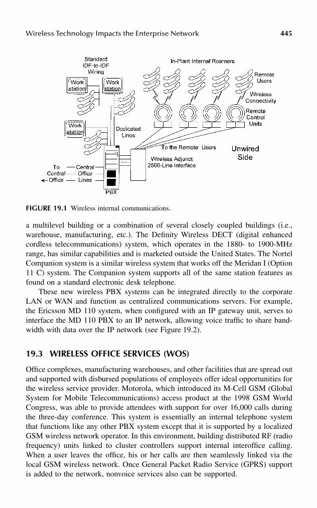
Wireless Technology Impacts the Enterprise Network 445
a multilevel building or a combination of several closely coupled buildings (i.e.,warehouse, manufacturing, etc.). The Definity Wireless DECT (digital enhancedcordless telecommunications) system, which operates in the 1880- to 1900-MHzrange, has similar capabilities and is marketed outside the United States. The NortelCompanion system is a similar wireless system that works off the Meridan I (Option11 C) system. The Companion system supports all of the same station features asfound on a standard electronic desk telephone.
These new wireless PBX systems can be integrated directly to the corporateLAN or WAN and function as centralized communications servers. For example,the Ericsson MD 110 system, when configured with an IP gateway unit, serves tointerface the MD 110 PBX to an IP network, allowing voice traffic to share band-width with data over the IP network (see Figure 19.2).
19.3 WIRELESS OFFICE SERVICES (WOS)
Office complexes, manufacturing warehouses, and other facilities that are spread outand supported with disbursed populations of employees offer ideal opportunities forthe wireless service provider. Motorola, which introduced its M-Cell GSM (GlobalSystem for Mobile Telecommunications) access product at the 1998 GSM WorldCongress, was able to provide attendees with support for over 16,000 calls duringthe three-day conference. This system is essentially an internal telephone systemthat functions like any other PBX system except that it is supported by a localizedGSM wireless network operator. In this environment, building distributed RF (radiofrequency) units linked to cluster controllers support internal interoffice calling.When a user leaves the office, his or her calls are then seamlessly linked via thelocal GSM wireless network. Once General Packet Radio Service (GPRS) supportis added to the network, nonvoice services also can be supported.
FIGURE 19.1 Wireless internal communications.

446 Handbook of Wireless Internet
In the United States, service providers are now pursuing wireless office services(WOS) as a new market niche. In this environment, the service provider establishesa distributed radio system (DRS) throughout the office or multitenant facility inmuch the same way that a PBX system or wireless LAN is configured. In thisscenario, mini base stations (MBS) are interfaced to distributed antennas (DAS),forming the basic infrastructure. The MBS units are linked in much the same wayas in building data networks, which in turn are linked to a central radio. Theadvantage of these carrier-provided solutions is the transparent mobility of the endusers in the system. While in the building or corporate facilities, the end users donot incur any per-minute billing; however, once they leave the premises, they aretreated like regular mobile users and billed accordingly.
In this arrangement, the end user is never out of touch and always within reach,as one assigned telephone number follows the end user both on and off premises.Cellular One on the West Coast is currently offering this service in the San Franciscoarea.
Sprint has begun to offer wireless data service over its PCS network, whichcomprises over 11,000 base stations. This network exceeds the BellSouth WirelessData service and ARIDS combined data networks. The Sprint data network willwork through Sprint PCS smart phones, such as the Nokia, Motorola, or Qualcomm,that support smart set displays. Further, these smart sets, when configured withmicrobrowsers, can be used to access the Internet for e-mail and other abridgedservices. This new data service also provides access to stock quotes and other time-critical information. Kits are available to provide Internet access for laptops or PDAsat 14.4 kbps.
FIGURE 19.2 Wireless PBX system.

Wireless Technology Impacts the Enterprise Network 447
19.4 MORE INTEGRATION
Wireless data communications using a packetized data standard called CellularDigital Packet Data (CDPD) has been getting more use as more wireless applicationsare being deployed. However, this service is limited to low speeds of 19.2 kbps orless, and has been implemented on D-AMPS IS-136 networks. CDPD technologyserves to enhance the existing AMPS cellular infrastructure by detecting unusedcellular channel space in which to transmit data. This allows the operator to maximizethe use of the available physical cell site infrastructure.
While 19.2 kbps may seem slow, it does answer a broad requirement for low-speed transactions aimed at one-way data collection for meter or device reading.This application of CDPD has made it possible to offer many new data-collection-type applications for electric, gas, and water meter reading.
To meet the growing demand for wireless data applications, newer CDPDmodems have made their appearance. For example, Novatel has introduced theMinstrel modem for applications with Palm computing devices. These modems havetheir own IP address and can be used to access the Internet. The modems also supporta built-in TCP/IP stack that can be used for custom software development using thePalm OS®. The Minstrel modem is configured with SmartCode software, Hand-Mail™ and HandWeb™ software, and a modem management package. This newtechnology has resulted in a number of sales terminal applications, field technicianapplications, as well as mobile applications in transportation (e.g., fleet and vehiclemanagement, public safety, and disaster recovery). Handheld terminal applicationsalso have been aided by the introduction of Windows CE software configured withutilities such as Pocket Excel, Pocket Word, Internet Explorer, Scheduler, E-Mail,Calendar, and Task Manager. All of these packages allow mobile workers to becomemore efficient with their time while in transit.
19.4.1 WIRELESS LOCAL AREA NETWORKS
Some of the earliest wireless LAN products were slow by comparison with today’sproducts. For example, in the early 1990s Motorola introduced a product that wasdeveloped around a microcellular design using the 18- to 19-GHz frequency. Thesystem used an intelligent six-sector antenna, which was used for both data receptionand transmission. The antenna supported a scanning system that was used to selectthe best transmission path from its associated terminal to the next terminal in thenetwork. A high-performance RF digital signal processor was used to handle themodulation and demodulation of the 18-GHz carrier using four-level frequency shiftkeying (FSK). This would ultimately support 10 Mbps Ethernet, which was consid-ered fast for the early 1990s.
Wireless LAN technology in the early 1990s was slow to catch on as manynetworks were hardwired; it was not until changes were made in office and facilityarrangements that wireless technology gained acceptance. Because the early productswere unlicensed, they could be used to cover short distances (several hundred feet)within buildings and under a mile between buildings. A good example of such awireless network can be seen in the Jacob Javits Convention Center in New York.

448 Handbook of Wireless Internet
In this application, a wireless LAN was tailored to cover 1.5 million square feet ofconvention center floor space. Distributed smart antennas, which act like mini basestations, are spread around the facility and allow transmission of voice and datathroughout the facility.
19.5 A NEW STANDARD
In 1997, the IEEE standard for wireless networking was finally ratified, establishingan interoperability standard for all vendor products. Essentially, the 802.11 standardmade it possible for companies to introduce a higher performing wireless LANproduct that offers a degree of interoperability. These new products provide wirelessconnectivity starting at the mobile PC level and include products to interface a wiredLAN with wireless desktop PCs and peripherals. Also new to wireless LANs arefirewalls that protect against unauthorized access into the corporate LAN. Thesewireless LAN security devices are based on an IP network layer encryption usingthe IPsec (IP security) standards. Also incorporated as part of these systems are arange of authorization keys, authentication policies, and automatic security proce-dures.
As a group, 802.11 products operate in the 2.4-GHz ISM band with a bit rateof up to 2 Mbps and a fall-back rate of 1 Mbps. Many vendor products can gohigher; for example, Ericsson introduced an 802.11 product line in 1998 that providesa data rate of 3 Mbps.
The Wireless Ethernet Compatibility Alliance (WECA) is developing a seriesof interoperability tests that will allow vendors to test their products to determineif they are interoperable. This is seen as a vital step toward ensuring that when thenew 802 High Rate Direct Sequence (HRDS) standard (2.4 GHz at 11 Mbps) isagreed upon, the WECA will be able certify products for enterprise deployment.HRDS products have been announced by several vendors; for example, Cabletronhas announced an 11-Mbps product for its RoamABOUT wireless LAN product line.
In some sectors, work is in progress on a HyperLAN/2 standard product thatwill support data rates of up to 54 Mbps. These devices will operate in the 5-GHzISM band. Ericsson plans to offer a HyperLAN/2 product that will support an end-user data rate of 20 to 25 Mbps.
Many vendors now offer wireless bridges that provide the capability to linkwireless LAN islands into a contiguous wireless/wired LAN network. Many of thesedevices operate in the ISM band and offer the network administrator a cost-effectivemeans of linking remote “line-of-sight” locations for up to 20 km. A good exampleof such a class of terminals can be seen in Wireless, Inc.’s MicroLink microwaveradio terminal. This device operates in the 2.4-GHz ISM band and supports twomodels: a low-end model at 64 to 256 kbps and a high-end model at 512 and 1024kbps. The terminal can operate at distances of up to 20 km and integrates both voiceand data traffic between locations (see Figure 19.3).
Other vendors with similar terminal products include ADTRAN, which recentlyintroduced its Tracer terminal that will go up to 30 miles and support dual T1s.IOWAVE also provides a similar terminal that supports links of up to 20 miles forabout $12,000 per link.

Wireless Technology Impacts the Enterprise Network 449
19.6 WIRELESS INTERNET ACCESS
In some areas, broadband access to the Internet is gradually getting away from theISDN or dial-up access model. This can be attributed in part to the Federal Com-munications Commission (FCC), which released 300 MHz of spectrum for theUnlicensed National Information Infrastructure (U-NII). The U-NII band is brokendown into three bands: (1) 5.15 to 5.25 GHz for indoor application, (2) 5.25 to 5.35GHz for campus application, and (3) 5.75 to 5.85 GHz for local access of up to 10miles. This new spectrum has resulted in the introduction of a new generation ofwireless Internet routers, also referred to as Internet radios. Internet radios can beset up on rooftops by an ISP to provide direct Internet access via the ISP Internethub. These terminals can be configured in a point-to-point or a point-to-multipointconfiguration. A good example of such terminals can be seen in Wireless Inc.’sWaveNet IP series, which can be used by an ISP to set up a point-to-multipointInternet access arrangement completely outside of the public utility. By controllingthe cost of local loop access, the ISP can offer better rates and higher-speed access.The WaveNet IP arrangement is sometimes referred to as W-DSL because a networkcan support DSL-like access with speeds of up to 512 kbps of symmetrical band-width.
19.7 BROADBAND INTERNET ACCESS
Broadband Internet access is now being offered via licensed 38-GHz Local Multi-point Distribution Services (LMDS) and Local Multipoint Communications Systems
FIGURE 19.3 MicroLink microwave radio terminal.

450 Handbook of Wireless Internet
(LMCS) license holders. These fixed wireless service providers are able to supportfiber-optic network bandwidth without the physical fiber being in place. A goodexample of a broadband wireless LMDS system can be seen in the TRITON InvisibleFiber product line used to deploy a network of rooftop terminals in a consecutivepoint network.
These networks are capable of supporting a 20- to 40-square mile geographicarea, providing local broadband service for an entire metropolitan area. MaxLinkCommunications of Ontario, Canada, has launched an LMDS service in Canadausing a Newbridge LMDS system to offer IP over ATM. Home Telephone, a suc-cessful bidder in the 1998 FCC LMDS spectrum auction, is offering LMDS servicein the Charleston, South Carolina, basic trading area (BTA), using the NewbridgeLMDS system. A similar service is being trialed in San Jose using the TRITONInvisible Fiber product. Initially, this service will be limited to a select user groupwithin an office park and expanded from there.
LMDS broadband services provide the enterprise network designer with a poten-tially more cost-effective option where broadband services are required to supportmultimedia, video, and IP data transport requirements.
19.8 WHO USES WIRELESS TECHNOLOGY?
Some of the largest users of wireless technology can be seen in the transportationand shipping industry; Federal Express and United Parcel are good examples.Another area is that of automated vehicle location systems that are supported througha combination of satellite and landline systems coupled with the Internet.
19.8.1 CONSUMER APPLICATIONS
A good example of a consumer-level system can be seen in the OnStar product beingoffered as an option with some high-end General Motors products, such as theirCadillac automobile product line. The OnStar system is combined with a cellularservice and the GPS tracking system. The system provides a series of end-userservices that includes travel directions, emergency road services, automobileenabling services, personal notification, and theft notification.
The OnStar system uses a GPS tracking device that is installed on the vehicleand allows the OnStar control center to locate a subscriber’s vehicle. Through acellular link with an on-board computer, the control center can detect if the car’sairbags have been deployed. If so, the control center detects a change, and a call tothe subscriber is made to determine if there is a need for assistance. The controlcenter also can remotely open the car doors if the subscriber has locked himself outof the car.
19.8.2 TRANSPORTATION
Qualcomm offers a multilevel vehicle location and monitoring service for largetrucking and transport companies. This service is supported through a combinationof satellite, cellular, and landline services. Trucks with special roof-mounted units

Wireless Technology Impacts the Enterprise Network 451
can be tracked and monitored anywhere within the United States and Canada.Monitoring includes truck system performance, loading and unloading events, aswell as redirection of vehicles for new load pickups. Drivers are able to communicatewith the control center via messaging or cellular wireless contact. Through landlinecontact with the Qualcomm control center, dispatchers are able to dispatch andmanage all company assets deployed on the nation’s highway network.
19.8.3 HEALTH CARE
A surprisingly large number of health care service providers have taken advantageof wireless technology. Good examples of the application of wireless technologycan be seen at Austin Regional Clinic, Indiana Methodist Hospital, St. JosephHospital, Wausau Hospital, and Winthrop-University Hospital, to name a few. Allof these facilities have essentially the same problem: getting to patient information,where and when needed. Many found that they had to take handwritten notes to thenearest nurse station and enter the information manually into a computer terminal.As a result, administrators had to come up with a more-efficient way to operate.
Austin Regional Clinic elected to supply its medical professionals with mobilehandheld computers to record and retrieve patient information in real-time. Theseterminals were linked to the clinic’s Novell Netware LAN using PCMCIA modemcards. A series of wireless distributed access points located throughout the clinicprovided a direct link to the LAN via a corresponding link in the clinic’s commu-nications server. The portable computers used were grid pad, pen-based portablesconfigured with application screens, and allowed medical professionals simplifieddata entry and retrieval. This system eliminated large amounts of paperwork, thusallowing the professionals to function in a paperless environment.
19.8.4 MANUFACTURING
In some manufacturing plants, sensors and programmable logic controllers (PLCs)are used to control many of the processes related to product manufacturing. In manyplaces, these devices are hardwired into high-maintenance networks that need fre-quent attention. In many plants, these networks have been fitted with Ethernetinterfaces as part of a plantwide LAN. However, many plant managers have foundthat they can refit with wireless adapter cards that provide an RF link to wirelessaccess points located around the plant. These arrangements link the PLCs directlyinto the wired LAN and the server, ensuring timely monitoring of all devices.
Avon Products, Inc. faced an expensive problem in extending the LAN in aChicago-area plant’s factory floor. In this facility, production lines were not staticand subject to regular reconfiguration. Furthermore, operator mobility required tosupport 50 production lines along 500 linear feet confounded the problem of rewiringprint stations to support the operators with barcode labels. Instead of rewiring, aseries of printers configured with wireless modems were set up to receive barcodelabel files from print servers. The plant has a series of distributed base stations(terminal servers) that are linked to the LAN and a host system that supports thewireless link between the wireless printers and the LAN. The print servers, which
452 Handbook of Wireless Internet
are linked to the LAN Ethernet, receive barcode files from a VAX computer. Asproduct is being manufactured, barcode information can be sent to the appropriateprint server, where it can then be routed to the proper remote wireless printer.
19.8.5 FINANCIAL
The Pacific Exchange (on the West Coast) and Hull Trading (headquartered inChicago) both opted to deploy wireless terminals on the trading floor to simplifythe trading process. Instead of walking to a static terminal to enter trade information,traders can now do that from their handheld terminals. This innovation permits muchfaster trades, while eliminating many manual steps and the reliance on handwrittennotes.
19.9 SEARCHING FOR A WIRELESS SOLUTION
In planning for the migration to a wireless network arrangement, the planner mustbe certain of his or her plan. Wireless applications require antennas and base stationsto receive and transmit wireless signals between a mobile terminal and a mini basestation. The planner must be certain that antenna coverage can be establishedthroughout the area(s) to be served by the wireless terminals.
While most wireless modems and RF base stations work, many may not beinteroperable between vendor equipment. Because there are so many vendors offer-ing products, the planner needs to be certain of the vendor’s commitment to themarket. Now that the 802.11 standard has been accepted, the planner should notconsider proprietary systems to avoid early obsolescence; many products and ven-dors of the early 1990s that had great products are no longer with us.
Wireless network arrangements provide a great deal of flexibility, but the plannershould limit the migration to a wireless network arrangement to those applicationsthat will produce a reasonable savings in terms of reduced manpower.
Application software requires careful review because much of the softwaredesigned to function over a LAN with standard PCs may not work the same waywith a laptop PC. Furthermore, because many mobile terminals are configured withWindows CE software, one needs to be aware of the differences and their interfaceto the LAN operating system. Where the opportunity for the application of wirelesstechnology is limited, the planner may find opportunities for direct linking of facil-ities to avoid central office dedicated circuit costs for voice and data transport. Withmany of the newer systems on the market, the planner can gain greater reach thanbefore to link company facilities. By working with an ISP provider, many times theplanner can arrange for a rooftop Internet radio to link the ISP hub directly with thecorporate network hub, thus providing much-higher-speed access to the Internet forcorporate network users.
19.10 SUMMARY
Wireless technology has opened up a new range of possibilities for linking theenterprise network than previously available to the network planner. The keys to

Wireless Technology Impacts the Enterprise Network 453
success are proper preplanning and selection of equipment, adherence to establishedstandards with an eye toward the future, and the availability of future systems withhigher throughput options. Careful alignment of applications software is anotherimportant issue as some tailor-made software may be necessary to link legacyapplications.
Enhancing the corporate network to bring it into line with the state of the artshould not be the end-all, but rather an opportunity to reduce operating costs andimprove overall corporate productivity.

This page intentionally left blank

4550-8493-1502-6/03/$0.00+$1.50© 2003 by CRC Press LLC
20 An Efficient WAP-Enabled Transaction Processing Model for Mobile Database Systems
G. Radhamani and Mohammad Umar Siddiqi
CONTENTS
Abstract ..................................................................................................................45520.1 Introduction ................................................................................................45620.2 Background ................................................................................................45620.3 Mobility Applications ................................................................................45920.4 The WAP-Enabled Transaction Model ......................................................46120.5 A Sample Application................................................................................46320.6 Simulation Results .....................................................................................46420.7 Conclusion..................................................................................................467Acknowledgments..................................................................................................467References..............................................................................................................467
ABSTRACT
Advances in computer and telecommunication technologies have made mobile com-puting a reality. In the mobile computing environment, users can perform onlinetransaction processing independent of their physical location. As mobile computingdevices become more and more popular, mobile databases have started gainingpopularity. Hence, software applications have to be redesigned to take advantage ofthis environment while accommodating the new challenges posed by mobility. Anew class of multidatabase (a collection of autonomous and heterogeneous data-bases) that provides access to a large collection of data via a wireless networkingconnection is called mobile data access system. The proposed WAP-enabled trans-action model allows timely and reliable access to heterogeneous databases while

456 Handbook of Wireless Internet
coping with the mobility issue. This model is implemented as a software modulebased on the multilayered approach capable of supporting preexisting global userson the wired network in addition to the mobile users. Various mobility applicationsare discussed briefly and a simple illustrative application is described in detail.Performance of the proposed WAP model is evaluated through simulation using theNokia WAP simulator.
20.1 INTRODUCTION
Advances in wireless communications technology make it possible to realize a dataprocessing paradigm that eliminates geographical constraints from data processingactivities. Multidatabase can be viewed as a database system formed by independentdatabases joined together with a goal of providing uniform access to the local databasemanagement systems (DBMS). The mobile data access system (MDAS) is a multi-database system (MDBS) that is capable of accessing a large amount of data over awireless medium. It is necessary that the MDAS provide timely and reliable access toshared data. The transaction technique presented in Pitoura and Bhargava1 is based onan agent-based distributed computing model. Agents may be submitted from varioussites including mobile stations. There are several multidatabase concurrency controlschemes such as site-graph locking2 and V-Lock.3 None of the reviewed techniqueshandle mobile transactions and long-lived transactions in a multilayered approach, andhence global transactions are not executed as consistent units of computing.
In this chapter, we propose a WAP-enabled transaction model for the MDASthat addresses the deficiencies that exist in the current literature. The model is builton the concept of global transactions in multidatabases. In Bright and coworkers,4
the model uses a hierarchical structure that provides an incrementally concise viewof the data in the form of schemas. The hierarchical data structure of the SummarySchemas Model (SSM) consists of leaf nodes and summary schema nodes. Accessinga lower-most node takes time in the hierarchical structure. However, these systemshave not been designed to cope with the effects of mobility. The goal of this chapteris to present a WAP-enabled transaction model for the MDAS that handles mobiletransactions and long-lived transactions in a multilayered approach.
Section 20.2 gives the background material on Wireless Application Protocol(WAP), mobile computing environment, and mobile database systems. Variousmobility applications are discussed in Section 20.3. The WAP-enabled transactionmodel is introduced in Section 20.4. An implemented sample application of theproposed model is given in Section 20.5. Simulation results of the proposed modelare presented in Section 20.6. Conclusions are given in Section 20.7.
20.2 BACKGROUNDThe WAP architecture provides a scalable and extensible environment for applicationdevelopment for mobile communications devices. This is achieved through a layereddesign of the entire protocol stack. Security in the WAP architecture should enableservices to be extended over potentially mobile networks while also preserving theintegrity of user data. Figure 20.1 summarizes the WAP as a series of layers.5

An Efficient WAP-Enabled Transaction Processing Model 457
The Wireless Application Layer (WAE) is most likely concerned with the deploy-ment of WAP applications. The Wireless Session Protocol (WSP) provides a con-sistent interface to WAE for two types of session services: a connection mode anda connectionless service. When providing connection mode, the WSP utilizes theWireless Transaction Protocol layer. In the case of connectionless mode, the WSPtakes the advantage of the Wireless Datagram Protocol layer.
Wireless Transaction Protocol (WTP) provides transaction services to WAP. Itmanages different classes of transactions for WAP devices: unreliable one-wayrequests, reliable one-way requests, and reliable two-way requests. Wireless Data-gram Protocol (WDP) provides a consistent interface to the higher layers of theWAP architecture so that they need not concern themselves with the exact type ofwireless network the application is running on. Among other capabilities, WDPprovides data error correction. Bearers or wireless communication networks are atthe WAP’s lowest level. Additionally, each layer is allowed to interact with the layerabove and below it.
According to WAP specifications, WTLS is composed by the record protocol,which is a layered protocol. The WTLS record protocol accepts the raw data fromthe upper layers to be transmitted and applies the selected compression and encryp-tion algorithms to the data. Moreover, the record protocol takes care of the dataintegrity and authentication. Received data is decrypted, verified, and decompressed,
FIGURE 20.1 WAP protocol stack.
WML (Wireless Markup Language), WML
WAE (Wireless Application Environment)
WSP (Wireless Session Protocol)
WTLS (Wireless Transport Layer Security)
WDP (Wireless Datagram Protocol)
WTP (Wireless Transaction Protocol)
UDP
IP
Bluetooth3GIS-95GSM D-AMPS
WMLScript

458 Handbook of Wireless Internet
and then handed to the higher layers. The record protocol stack is shown inFigure 20.2. The record protocol is divided into four protocols:
1. Change Cipher Spec Protocol (CCP)2. Handshake Protocol (HP)3. Alert Protocol (AP)4. Wireless Transaction Protocol (WTP)
The change cipher spec is sent to a peer either by the client or the server. When thechange cipher spec message arrives, the sender of the message sets the current writestate to the pending state, and the receiver also sets the current read state to thepending state.6 The change cipher spec message is sent during the handshake phaseafter the security parameters have been agreed on.
Wireless Application Protocol provides a universal open standard for bringingInternet content and advanced services to mobile phones and other wireless devices.Figure 20.3 shows the WAP architecture. Whenever a mobile phone uses WAP, aconnection is created via Wireless Session Protocol (WSP) between the mobile phoneand the gateway. When the user enters the address of the WAP site, the gateway issent a request for the device’s microbrowser using WAP.7 The gateway translatesthe WSP request into a Hypertext Transfer Protocol (HTTP) request and sends it tothe appropriate origin server (or Web server). The Web server then sends back therequested information to the gateway via HTTP. Finally, the gateway translates andcompresses the information, which can then be sent back to the microbrowser inthe mobile phone.
The mobile computing environment is a collection of mobile units (MU) and afixed networking system.3,8 A mobile unit is a mobile computer that varies in size,processing power, and memory, and is capable of connecting to the fixed networkvia a wireless link. A fixed host is a computer in the fixed network, which is notcapable of connecting to a mobile unit. A base station is capable of connecting witha mobile unit and is equipped with a wireless interface. They are known also asmobile support stations (MSS). Base stations, therefore, act as the interface betweenmobile computers and stationed computers. Each MSS can communicate with MUsthat are within its coverage area (a cell). Mobile units can move within a cell orbetween cells, effectively disconnecting from one MSS and connecting to another.At any point in time, an MU can be connected to only one MSS.
FIGURE 20.2 WTLS architecture.
WTLS
WTLS WTLS Change WTLS Alert WirelessHandshake Cipher Spec Protocol TransactionProtocol Protocol Protocol
WTLS Record Protocol
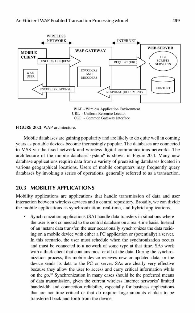
An Efficient WAP-Enabled Transaction Processing Model 459
Mobile databases are gaining popularity and are likely to do quite well in comingyears as portable devices become increasingly popular. The databases are connectedto MSS via the fixed network and wireless digital communications networks. Thearchitecture of the mobile database system9 is shown in Figure 20.4. Many newdatabase applications require data from a variety of preexisting databases located invarious geographical locations. Users of mobile computers may frequently querydatabases by invoking a series of operations, generally referred to as a transaction.
20.3 MOBILITY APPLICATIONSMobility applications are applications that handle transmission of data and userinteraction between wireless devices and a central repository. Broadly, we can dividethe mobile applications as synchronization, real-time, and hybrid applications.
• Synchronization applications (SA) handle data transfers in situations wherethe user is not connected to the central database on a real-time basis. Insteadof an instant data transfer, the user occasionally synchronizes the data resid-ing on a mobile device with either a PC application or (potentially) a server.In this scenario, the user must schedule when the synchronization occursand must be connected to a network of some type at that time. SAs workwith a thick client that contains most or all of the data. During the synchro-nization process, the mobile device receives new or updated data, or thedevice sends its data to the PC or server. SAs are clearly very effectivebecause they allow the user to access and carry critical information whileon the go.10 Synchronization in many cases should be the preferred meansof data transmission, given the current wireless Internet networks’ limitedbandwidth and connection reliability, especially for business applicationsthat are not time critical or that do require large amounts of data to betransferred back and forth from the device.
FIGURE 20.3 WAP architecture.
WIRELESS NETWORK INTERNET
WAE - Wireless Application Environment URL - Uniform Resource Locator
CGI - Common Gateway Interface
MOBILECLIENT
WAP GATEWAY
ENCODED REQUEST
ENCODED RESPONSE
WAEUSER
ENCODERSAND
DECODERS
WEB SERVER
CONTENT
CGISCRIPTS
SERVLETSREQUEST (URL)
RESPONSE (DOCUMENT)
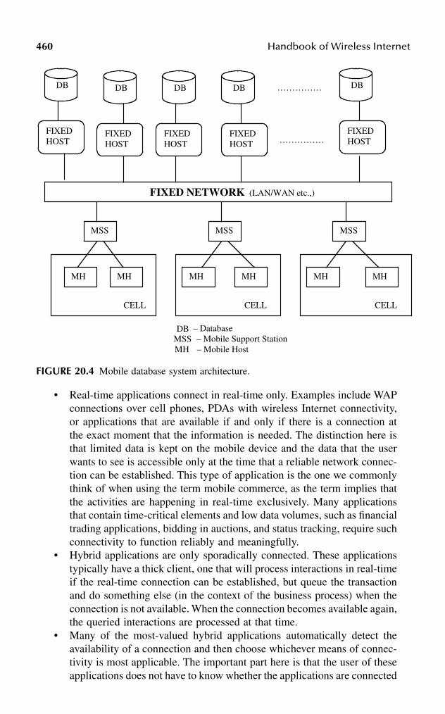
460 Handbook of Wireless Internet
• Real-time applications connect in real-time only. Examples include WAPconnections over cell phones, PDAs with wireless Internet connectivity,or applications that are available if and only if there is a connection atthe exact moment that the information is needed. The distinction here isthat limited data is kept on the mobile device and the data that the userwants to see is accessible only at the time that a reliable network connec-tion can be established. This type of application is the one we commonlythink of when using the term mobile commerce, as the term implies thatthe activities are happening in real-time exclusively. Many applicationsthat contain time-critical elements and low data volumes, such as financialtrading applications, bidding in auctions, and status tracking, require suchconnectivity to function reliably and meaningfully.
• Hybrid applications are only sporadically connected. These applicationstypically have a thick client, one that will process interactions in real-timeif the real-time connection can be established, but queue the transactionand do something else (in the context of the business process) when theconnection is not available. When the connection becomes available again,the queried interactions are processed at that time.
• Many of the most-valued hybrid applications automatically detect theavailability of a connection and then choose whichever means of connec-tivity is most applicable. The important part here is that the user of theseapplications does not have to know whether the applications are connected
FIGURE 20.4 Mobile database system architecture.
……………
……………
C
– Database MSS – Mobile Support Station
MH – Mobile Host
CELL CELLCELL
DB DB DB DB DB
FIXEDHOST
FIXEDHOST
FIXEDHOST
FIXEDHOST
FIXED NETWORK (LAN/WAN etc.,)
MSS MSS MSS
MH MH MH MH MH MH
FIXEDHOST
DB
An Efficient WAP-Enabled Transaction Processing Model 461
or not. The software performing the applications will take care of theconnectivity and render it mostly invisible to the user. Obviously, if weare in need of real-time access to satisfy a query but are not connected,then we will receive an error message. However, most information canbe fetched ahead; it can be synchronized, and it can be available withsome degree of currency although the wireless connection may not beavailable at the exact time of processing.
Each application being designed today falls into one of the categories listed inthis section. It depends on the situation and the real business needs that drive theapplication itself. If a user can satisfy his or her needs with an occasionally connectedapplication, developing such an application is usually much less expensive andcomplex than building a real-time solution. Having the wireless Internet, real-timeconnectivity certainly has some benefits in terms of the data being current, but onemost weigh the disadvantages of such an approach, mostly stemming from the factthat connectivity is not always available in key locations. Handheld devices comein all shapes and sizes, with many more currently being developed in manufacturers’research labs around the globe.
20.4 THE WAP-ENABLED TRANSACTION MODEL
The WAP-enabled transaction model is based on the multilayered approach capableof supporting preexisting global users on the wired network, in addition to mobileusers. The proposed model is implemented as a software module on top of thepreexisting multidatabase management system. In reality, a mobile transaction is nodifferent from a global transaction as far as the MDBS layer is concerned.11 However,a number of factors make it sufficiently different enough to consider it as a separatetype in the MDAS:
• Mobile accessing requires the support of fixed hosts for computations andcommunications.
• Mobile accessing might have to split the processing, with one part exe-cuting on a mobile unit and the other part executing on a fixed host.
• Mobile transactions might have to share state and data. This is a violationof the revered ACID (atomicity, consistency, isolation and durability)transactions-processing assumptions.
• Mobile accessing tends to be long lived. This is a consequence of thefrequent disconnection experienced by the mobile client and the mobilityof the mobile client.
The MDAS, as we envision it, consists of a software module, called a mobileaccessing manger (MAM), implemented above the MDBS layer. The two layerscombine to form the MDAS. The MAM is responsible for managing the submissionof mobile transaction to the MDBS layer and its execution. Thus, the MAM acts asa proxy for the mobile unit, thereby establishing a static presence for the mobileunit on the fixed network.

462 Handbook of Wireless Internet
Our approach is based on the principle that the computation and communicationdemands of an algorithm should be satisfied within the static segment of the systemto the extent possible.12 In this chapter, we attempt to:
• Localize the communication between the fixed host and a mobile hostwithin the same cell
• Reduce the number of wireless messages by downloading most of thecommunication and computation requirements to the fixed segment of thenetwork so that the database access is faster
In the proposed WAP model, communication occurs through the exchange ofmessages between static and mobile hosts. In order to send a message from a mobilehost to another host, either fixed or mobile, the message is first sent to the localMSS over the wireless network. The MSS forwards the message to the local MSSof the other mobile host, which forwards it over the wireless network to the othermobile host if it is meant for a mobile host; otherwise the message is directlyforwarded to the fixed host. The location of a mobile host within the network isneither fixed nor universally known in the network. Thus, when sending a messageto a mobile host the MSS that serves the mobile host must first be determined. EachMSS maintains a list of mobile hosts’ IDs that are local to its cell. When a mobilehost enters a new cell, it sends a join message to the new MSS. The join messageincludes the ID (usually the IP address) of the mobile host. To change location, themobile host also must send a left message to the local MSS. The mobile host neithersends nor receives any further messages within the present cell once the left messagehas been sent. When the MSS receives the left message from the mobile host, itremoves the mobile host ID from its list of local mobile hosts.
Disconnection is often predictable by a mobile host before it occurs. Therefore,in order to disconnect, the mobile host sends a disconnect message to the local MSS.The disconnect message is similar to the leave message; the only difference is thatwhen a mobile host issues a leave message, it is bound to reconnect at some otherMSS at a later time. A mobile host that has issued a disconnect message may ormay not reconnect at any MSS later.
To initiate a mobile access to the database, the mobile host sends a start messageto the MAM. The MAM acknowledges the request by returning a transaction number.Each MSS has a MAM associated with it, and the transaction numbers are assignedin a distributed manner among the MAMs in the system using any distributedordering algorithm.12 The mobile unit tags each accessing request with an ID, whichis composed of the mobile host ID and the transaction number. The access requestmessage is composed of the mobile host ID, the transaction number, and the trans-action operations. To signify the completion of an accessing request, a stop messageis triggered to the MAM, in order to guarantee that the entire transaction as a wholeis submitted to the MDBS.
The WAP-enabled transaction model workflow is as follows:
1. The mobile unit initiates a transaction request. The message is receivedby the MSS, and is forwarded to the associated MAM.
An Efficient WAP-Enabled Transaction Processing Model 463
2. The MAM receives the request from the MSS. This request is logged andthe transaction ID (transaction number along with the mobile host ID) isplaced in the ready list. A transaction proxy is created to execute thetransaction.
3. Now the proxy removes a transaction ID from the ready list and insertsit into the active list. The proxy translates the transaction request and thensubmits the transaction to the MDBS for execution.
4. The request is executed at the MDBS layer, and the results and data arereturned to the proxy.
5. The proxy places the transaction ID in the output list along with the resultsand data to be returned to the mobile host.
6. The MAM initiates a search for the location of the mobile host and theresults are transferred to the mobile unit if it is still connected, and thenthe transaction ID is removed from the ready list.
In applying the proposed WAP model to the MDAS, we may derive the followingbenefits:
• The proposed model decouples the effects of mobility from the MDAS.Hence, any developed concurrency control-and-recovery mechanism canbe readily adopted into our model.
• The MDAS layer does not need to be aware of the mobile nature of somenodes. The accessing speed increases because the mobile transactions aresubmitted to the MDBS interface by the transaction proxies. The MDBSinteracts with the transaction proxy as though it were the mobile unit. Inthe case of a mobile transaction, most of the communication is within thefixed network and, as far as the MDBS is concerned, a static host hasinitiated the transaction.
• The operations of nonmobile users are unaffected by the transactions ofmobile users. The effects of long-lived transactions can be effectively andefficiently handled. Delegating the authority to commit or abort a trans-action on behalf of the mobile host to the transaction proxy can minimizethe effects of long-lived transactions. Thus, transactions initiated by non-mobile users will experience less conflict and, as a consequence, systemthroughput and response times are not severely affected.
In Section 20.5, we present this approach through a sample application to showhow it can be put to work in the real world.
20.5 A SAMPLE APPLICATION
Our work embodies most of the suggestions in the previous section. In this section, wedescribe a sample application. Using this application, we show that in order to createWAP services or applications in a PC, we have to install a System Developers Kit(SDK) and simulator, such as those from Nokia, Ericsson, or Phone.com. For WAPapplications that require database, a WAP-enabled transaction-processing model is more
464 Handbook of Wireless Internet
efficient than other models described in the literature because it is implemented as anadditional layer on top of the MDBS that handles mobile accessing and long-livedtransactions in a multilayered approach. In integration, a local server may be needed,such as the Microsoft Personal Web Server (PWS), IIS, Apache, Xitami, or any othertype of server for testing the access speed in LDBS. A range of database integrationtools can be used for WAP development, such as Microsoft Active Server Pages (ASP),Perl, etc. We have installed Nokia Mobile Internet Toolkit, Version 3.0, which supportsWAP standards, authored by the WAP Forum, as well as other specifications authoredby other organizations, and used ASP for programming.
Normally, the mobile phone emulator is capable of viewing WAP content indifferent ways. It can either load files that are stored in the PC directly or accessfiles stored on Web servers and pretending to be a gateway or access files via a realWAP gateway. We can create a profile that specifies a connection to a particularWAP gateway in connectionless mode, another to the same gateway in secureconnectionless mode, a third to the same gateway over a proxy server, and a fourthto a different-origin server using a direct HTTP connection.
In an attempt to explore the system, application, and user issues associated withthe development of such mobile applications, we have considered the hotel bookingsystem in Malaysia. As this research is relatively new, the default values of variousparameters are educated guesses. Message transmission time has been calculated assum-ing that the static network is a 100-Mbps Ethernet. Current cellular technology offersa limited bandwidth on the order of 10 kbps, whereas current wireless LAN technologyoffers a bandwidth on the order of 10 Mbps; these numbers are most likely to changein the future. The hotel booking system consists of interaction with other hotel databasesas our system needs to access other participating hotel databases to get room availabilityand also to send confirmation to members who book through the system.
The hotel booking process is done through WAP-enabled mobile phones by gettinginput from the member, such as check-in date, duration of stay in the hotel, number ofrooms to book, etc. A member makes a booking to the hotel of his or her choice. Thesystem will automatically check for room availability. If the system check finds thatthere are no rooms available, then the system will cancel the booking, inform the mobileuser of the unsuccessful booking, and request him to book again. We have tested ourWAP-enabled transaction model with a few existing hotel databases. The size of localdatabase at each site, which has a direct effect on the overall performance of the system,can be varied. The global workload may consist of randomly generated global queries,spanning over a random number of sites. Each operation of a subtransaction (read,write, commit, or abort) may require data or acknowledgments sent from the localDBMS. The frequency of messages depends on the quality of the network link. In orderto determine the effectiveness of our WAP-enabled transaction-processing model, sev-eral parameters are varied for different simulation runs.
20.6 SIMULATION RESULTSComparative evaluation of the proposed model has been carried out through simu-lation using the Nokia Mobile Internet Toolkit 3.0.13 The Toolkit window, along witha snippet of ASP coding, is shown in Figure 20.5. Toolkit keeps a time record of all
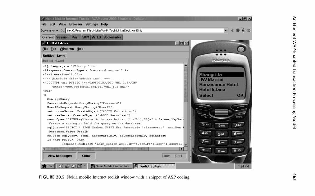
An
Efficien
t WA
P-Enab
led Tran
saction
Processin
g Mo
del
465FIGURE 20.5 Nokia mobile Internet toolkit window with a snippet of ASP coding.
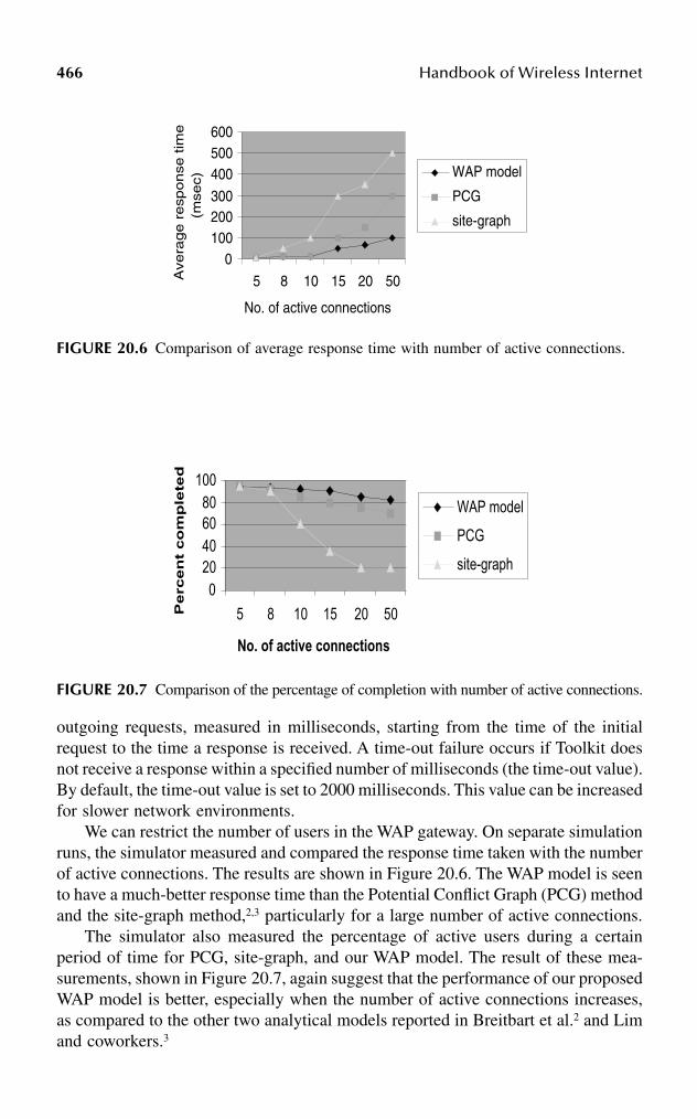
466 Handbook of Wireless Internet
outgoing requests, measured in milliseconds, starting from the time of the initialrequest to the time a response is received. A time-out failure occurs if Toolkit doesnot receive a response within a specified number of milliseconds (the time-out value).By default, the time-out value is set to 2000 milliseconds. This value can be increasedfor slower network environments.
We can restrict the number of users in the WAP gateway. On separate simulationruns, the simulator measured and compared the response time taken with the numberof active connections. The results are shown in Figure 20.6. The WAP model is seento have a much-better response time than the Potential Conflict Graph (PCG) methodand the site-graph method,2,3 particularly for a large number of active connections.
The simulator also measured the percentage of active users during a certainperiod of time for PCG, site-graph, and our WAP model. The result of these mea-surements, shown in Figure 20.7, again suggest that the performance of our proposedWAP model is better, especially when the number of active connections increases,as compared to the other two analytical models reported in Breitbart et al.2 and Limand coworkers.3
FIGURE 20.6 Comparison of average response time with number of active connections.
FIGURE 20.7 Comparison of the percentage of completion with number of active connections.
0100200300
400500600
5 8 10 15 20 50
No. of active connections
Ave
rage r
esp
onse
tim
e
(mse
c)
WAP model
PCG
site-graph
020406080
100
5 8 10 15 20 50
No. of active connections
Pe
rce
nt
co
mp
lete
d
WAP model
PCG
site-graph

An Efficient WAP-Enabled Transaction Processing Model 467
20.7 CONCLUSION
The proposed multilayered WAP model uses the concept of proxy server to managethe execution of mobile transactions. To provide support for mobile transactions, asoftware layer, the Mobile Accessing Manager (MAM), is implemented above thepreexisting multidatabase system. Performance of the system has been evaluated byvarying the number of simultaneous databases using a hotel booking system. Thiswork can be extended to global transactions in a larger context. There is a need foran extensive study on the effects of changing the distribution of data, processingI/O, caching, and communication in the near future.
ACKNOWLEDGMENTS
We would like to thank Dr. Borko Furht for initiating and encouraging this contri-bution.
References
1. Pitoura, E. and Bhargava, E., A framework for providing consistent and recoverableagent-based access to heterogeneous mobile databases, SIGMOD Record, pp. 44–49,1995.
2. Breitbart Y. et al., On rigorous transaction scheduling, IEEE Trans. Software Engi-neering, 17 (9), 954–959, 1991.
3. Lim, J.B., Hurson, A.R., and Ravi, K.M., Concurrent data access in mobile hetero-geneous systems, Hawaii Conference on System Sciences, pp. 1–10, 1999.
4. Bright, M.W., Hurson, A.R., and Pakzad, S., Automated resolution of semantic het-erogeneity in multidatabases, ACM TODS, 19 (2), 212–253, 1994.
5. Liang, J. et al., Research on WAP clients supports SET payment protocol, IEEEWireless Commun., 1 (1), 90–95, February 2002.
6. Radhamani, G. et al., Security issues in WAP WTLS protocol, IEEE Int. Conf.Commun. Circuits Syst., 483–487, July 2002.
7. Komnini, N. and Honary, B., Modified WAP for secure voice and video communi-cation, IEEE 2nd Int. Conf. 3G Mobile Commun. Technol., pp. 33–37, 2001.
8. Dirckze, R.A. and Gruenwald, L., Nomadic transaction management, IEEE Poten-tials, 17 (2), 31–33, 1998.
9. Chung, I. et al., Efficient Cache Management Protocol Based on Data Locality inMobile DBMSs, Springer-Verlag, LNCS 1884, pp. 51–64, 2000.
10. Cap Gemini Ernst & Young, Guide to Wireless Enterprise Application Architecture,John Wiley & Sons, New York, 2002.
11. Segun, K. et al., A Transaction Processing Model for the Mobile Data Access System,LNCS 2127, pp. 112–127, 2001.
12. Badrinath, B.R. et al., Structured distibuted algorithms for mobile hosts, Conf. Dis-tributed Computing Syst., pp. 21–38, 1994.
13. Nokia Mobile Internet Toolkit, Version 3.0: User’s guide, Nokia Ltd., www.forum.nokia.com.
14. Dirckze, R.A. and Gruenwald, L., A pre-serialization transaction management tech-nique for mobile multidatabases, ACM Mobile Networks Appl., 5 (4), 311–321, 2000.

This page intentionally left blank
4690-8493-1502-6/03/$0.00+$1.50© 2003 by CRC Press LLC
21 Mobile Video Telephony
Igor D.D. Curcio*
CONTENTS
21.1 Introduction ................................................................................................46921.2 End-to-End System Architecture ...............................................................47021.3 Mobile Networks for Video Telephony .....................................................47321.4 Standards for Mobile Video Telephony.....................................................474
21.4.1 Circuit-Switched Mobile Video Telephony.................................47521.4.1.1 Media Elements..........................................................47621.4.1.2 System Control and Multiplexing..............................477
21.4.2 Packet-Switched Mobile Video Telephony .................................47921.4.2.1 Media Elements..........................................................48021.4.2.2 System Control ...........................................................48121.4.2.3 Call Control Issues .....................................................482
21.5 Performance Issues in Mobile Video Telephony.......................................48421.5.1 Error Resilience and QoS............................................................48421.5.2 Video QoS Metrics ......................................................................48521.5.3 Video Quality Results for 3G-324M...........................................48721.5.4 SIP Signaling Delay ....................................................................48821.5.5 RTCP Performance ......................................................................491
21.6 Conclusions ................................................................................................493Acknowledgments..................................................................................................493References..............................................................................................................493
21.1 INTRODUCTION
Video telephony is not a new technology. It was proposed two decades ago for homeusage; however, it has not been as successful or accepted as anticipated for technicalreasons, or because of incorrect marketing strategies (including pricing) or unfamil-iarity of users with the technology.
Today, wide usage of Internet technology for searching, browsing, etc., haseducated users toward an increased image and video data fruition and, in general,toward a multimedia scenario where audio, still images, video, text, and other dataare presented together.
* The opinions expressed in this chapter are those of the author and not necessarily those of his employer.

470 Handbook of Wireless Internet
Mobile communications and devices are becoming more and more multimediaoriented. In addition, video and mobile network technologies are mature enough tobe considered a single technology: mobile video technology.
During recent years different standardization organizations, such as the ITU-T(International Telecommunications Union, Telecommunications sector), IETF (Inter-net Engineering Task Force), and 3GPP (Third-Generation Partnership Project), havemade enormous efforts to specify mobile multimedia network architectures, proto-cols, and codecs. Two main applications are enabled by those technology andresearch efforts: (1) mobile multimedia streaming, which has been described inChapter 4 of this book; and (2) mobile video telephony. This chapter is about thestate of the art in mobile video telephony.
A mobile video telephony application or a conversation multimedia application,as defined in 3GPP terminology, brings a new set of challenges:
1. The end-to-end delay requirements are very tight (compared to multimediastreaming).
2. Low-delay requirements restrict the range of techniques that can be usedto provide good error resilience.
3. Mobile devices must have a consistent processing power to run speechand video encoders and decoders simultaneously, in order to processoutgoing and incoming media flows.
In our framework, a mobile video telephony application includes (in addition tomultiple bidirectional media, i.e., speech and video) the use cases where only onemedium is used, i.e., the case where speech only is transmitted and received (Voiceover IP), and the case where video only is transmitted and received (Video over IP).
This chapter is organized as follows: Section 21.2 describes the end-to-endsystem architecture for mobile video telephony systems. Section 21.3 briefly intro-duces the mobile networks for mobile video telephony. Section 21.4 introducesthe current standards for mobile video telephony, based on ITU-T H.324 (forcircuit-switched video telephony) and on IETF SIP (Session Initiation Protocol)(for packet-switched video telephony). Section 21.5 contains some performanceand quality-of-service (QoS) considerations for implementations. Section 21.6concludes this chapter.
21.2 END-TO-END SYSTEM ARCHITECTURE
A mobile video telephony system is a real-time system of the conversational type.It is real-time because the playback of continuous media, such as audio and video,must occur in an isochronous fashion. A video telephony application is differentfrom a streaming application because the former has the following properties:
1. Bidirectional data transfer: The media flow is always carried from a sourcemobile videophone to a destination videophone, and vice versa. In thisperspective, the flow of data is symmetric between the two end-points.

Mobile Video Telephony 471
2. Real-time media encoding: Each videophone must have encoding anddecoding capabilities. Speech and video signals must be encoded andtransmitted in real-time to the other peer end. This requirement impliesthat mobile devices need a higher processing power because of the addi-tional encoding capability (devices for mobile streaming require onlydecoding capability). Real-time encoding must be performed efficientlyand with the shortest delays.
3. Delay sensitivity: Mobile video telephony systems are real-time withconversational features. This implies that a high level of interactivitybetween the two endpoints is a must to guarantee that the system is usablefor speech and video conversations. A conversation can be held only ifthe end-to-end delays are very tight and preferably constant. For instance,the characteristic of conversationality and dialog interactivity between twoparties would be lost in the case of end-to-end delays larger than fewhundred milliseconds. This is the most-critical success factor for a mobilevideo telephony service. In order to guarantee low end-to-end delays,both network and mobile stations must be optimized for processing ofconversational traffic. A very important factor in mobile videophonesystems is error resilience: any mechanism for error detection and cor-rection/concealment must be run within the maximum delay budgetallowed. For this reason, retransmission algorithms at the network orapplication level cannot normally be used, and forward error correction(FEC) or error concealment algorithms are the only possible choice forproviding error resilience against bit errors (or packet losses) producedby the air interface.
A mobile video telephony system consists mainly of two mobile videophones,used by the end users, and the mobile network. Figure 21.1 describes the high-level architecture of a typical mobile video telephony system over an IP-basedmobile network. We will follow an end-to-end approach, analyzing the system inits different parts.
Mobile videophone A is connected to the mobile network through a logical con-nection established between the network and the mobile station addresses called PacketData Protocol (PDP) context. PDP uses physical transport channels in the downlinkand uplink directions to enable data transfer in the two directions. The mobile devicehas the capability to roam (i.e., upon mobility, change the network operator withoutaffecting the received service), provided there is always radio coverage to guaranteethe service. The mobile videophone is equipped with ordinary telephony hardware(microphone and speaker) and video hardware (camera and display).
The speech and video content is created in a live fashion from the microphoneand camera input. This is encoded in real-time by the mobile device and transmittedin the uplink direction toward the network and the other end user. Speech and videodata in the opposite direction (downlink) is conveyed from the network to mobilevideophone A, which performs data decoding and display/playback of video andspeech data. In addition, the videophone sends and receives information for session

472H
and
bo
ok o
f Wireless In
ternet
FIGURE 21.1 A typical mobile video telephony system.

Mobile Video Telephony 473
establishment, QoS control, and media synchronization. The videophone may reactpromptly upon reception of QoS reports, taking appropriate actions for guaranteeingthe best possible media quality at any instant.
The mobile network carries conversational multimedia and control traffic in theuplink and downlink directions, allowing real-time communication between the twomobile videophone users.
Mobile videophone B is placed at the other end of the architecture shown inFigure 21.1. Its functionality is symmetrically identical to that provided by mobilevideophone A.
21.3 MOBILE NETWORKS FOR VIDEO TELEPHONY
In this section we review briefly the mobile network architectures and options thatenable mobile video telephony. The considerations made in Chapter 4, Section 3remain valid also for the case of mobile video telephony. However, because this typeof application is more challenging in terms of end-to-end delays, not all the networkconfigurations presented in Chapter 4 are suited for mobile video telephony. There-fore the main purpose of this section is to select the mobile network channels thatenable video telephony.
Mobile channels can be divided into two categories:
1. Circuit-switched (CS) channels2. Packet-switched (PS) channels
Table 21.1 shows a summary of network channels that can enable mobile videotelephony (the bit rates indicated are maximum, and practical mobile videophoneterminal implementations can have even lower maximum bit rates). In this table, wefind neither GPRS Release ’97 nor EGPRS networks. The reason is that they arenot capable of sustaining conversational real-time traffic because of the high delaybounds compared to those required to support video telephony services.
TABLE 21.1Mobile Network Channels for Video Telephony
Mobile Network CS/PS
Theoretical Maximum Bit Rates
(kbps) Layer 2 Configuration
HSCSD CS 57.6 Transparent modeECSD CS 64.0 Transparent modeUMTS (UTRAN) Release 99 and Release 4
CS 64.0 Transparent mode
UMTS (UTRAN) Release 5 PS 2048.0 Unacknowledged modeUMTS (GERAN) Release 5 Gb mode PS 473.6 Unacknowledged mode
474 Handbook of Wireless Internet
For implementing mobile video telephony both CS and PS bearers can beused. In either case the transmission channel must be transparent. This impliesthat no retransmissions or mechanisms that produce additional delays must beemployed at layer 2 of the mobile network (data link layer). In fact, layer 2 protocoldata units (PDUs) are required to have the smallest header overhead, in order toreduce (or totally avoid) processing delays induced by complex PDU encapsulationand decapsulation. Unacknowledged mode is generally used at the data link layerin packet-switched connections. The PDUs used are slightly more complex thanthose used for the transparent mode, but light enough to allow fast data deliverybetween the two layer-2 peer entities.
UMTS networks allow theoretical maximum bit rates of 2048 kbps. However,the tested CS connections for video telephony for Release ’99 and Release 4networks are up to 64 kbps, as defined in 3GPP.1,46 In these specifications, therecommended bit rates for video telephony services are 32 and 64 kbps, whereasthe offered residual BERs are in the order of 10–4 or 10–6. For PS connections, themaximum bit rates indicated in Table 21.1 are just theoretical. In practice, thetested and implemented maximum bit rates will be much smaller (in the order of384 kbps).
The QoS profile for conversational traffic is defined in the 3GPP specification.2
It is very similar to the profile defined for streaming traffic in Chapter 4, Section3.1.2. However, due to the more-stringent delay requirements for the conversationaltraffic, two key parameters need to be defined differently:
1. Service data unit (SDU) error ratio. The maximum value for this param-eter is defined as 10–2. In other words, whenever erroneous packets arenot delivered to the higher protocol layers and are considered lost themaximum packet loss rate is equal to 1 percent. The corresponding valuedefined in the QoS profile for streaming traffic is ten times larger, i.e.,10 percent. The rationale behind this parameter selection is that a higherpacket loss rate can be allowed for streaming traffic. However, makinguse of higher-layer retransmissions, which can be implemented becausestreaming traffic can tolerate larger end-to-end delays, can reduce thiserror rate. Whenever no retransmissions are allowed, such as in the caseof conversational traffic (i.e., video telephony traffic), a smaller maxi-mum SDU error rate is more appropriate, and conservatively it helps inyielding a better application QoS.
2. Transfer delay. Because the end-to-end delay requirements for mobilevideo telephony are more stringent than for streaming service, the QoSprofile defined for conversational traffic includes delay values that aremore challenging than those allowed for streaming (where lower boundsare equal to 280 ms). For conversational traffic, the lower bound for UMTSbearers (i.e., between the mobile terminal and Core Network gateway) is100 ms, while for Radio Access Bearers (i.e., between the mobile terminaland the Core Network edge node) it is 80 ms.2
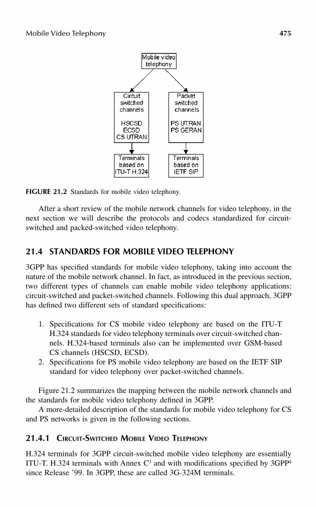
Mobile Video Telephony 475
After a short review of the mobile network channels for video telephony, in thenext section we will describe the protocols and codecs standardized for circuit-switched and packed-switched video telephony.
21.4 STANDARDS FOR MOBILE VIDEO TELEPHONY
3GPP has specified standards for mobile video telephony, taking into account thenature of the mobile network channel. In fact, as introduced in the previous section,two different types of channels can enable mobile video telephony applications:circuit-switched and packet-switched channels. Following this dual approach, 3GPPhas defined two different sets of standard specifications:
1. Specifications for CS mobile video telephony are based on the ITU-TH.324 standards for video telephony terminals over circuit-switched chan-nels. H.324-based terminals also can be implemented over GSM-basedCS channels (HSCSD, ECSD).
2. Specifications for PS mobile video telephony are based on the IETF SIPstandard for video telephony over packet-switched channels.
Figure 21.2 summarizes the mapping between the mobile network channels andthe standards for mobile video telephony defined in 3GPP.
A more-detailed description of the standards for mobile video telephony for CSand PS networks is given in the following sections.
21.4.1 CIRCUIT-SWITCHED MOBILE VIDEO TELEPHONY
H.324 terminals for 3GPP circuit-switched mobile video telephony are essentiallyITU-T. H.324 terminals with Annex C3 and with modifications specified by 3GPP4
since Release ’99. In 3GPP, these are called 3G-324M terminals.
FIGURE 21.2 Standards for mobile video telephony.

476 Handbook of Wireless Internet
The system architecture of a 3G-324M terminal is depicted in Figure 21.3.5 Themandatory elements of this architecture are a wireless interface, the H.223 multiplexerwith Annex A and B,6 and the H.245 system control protocol (version 3 or successive).7
3G-324M terminals are specified to work at bit rates of at least 32 kbps.We will give an overview of the basic building blocks of a 3G-324M terminal,
considering also some implementation guidelines, as described in 3GPP TSGS-SA.8
The reader interested in the differences between H.324 and 3G-324M terminals canfind more information in References 3 and 4. Here we will not emphasize thesedifferences.
21.4.1.1 Media Elements
3G-324M terminals can support a wide set of media. They can be either continuousmedia (speech and video) or discrete media (real-time text). Among the former set,the following codecs can be supported in a mobile terminal:
• AMR (Adaptive MultiRate) narrowband is the mandatory speech codecfor 3G-324M terminals,9 if speech is supported. Speech is encoded at 8kHz sampling frequency and at eight different bit rates ranging from 4.75to 12.20 kbps.
• G.723.1 is the recommended speech codec supported.10 It encodes speechat two bit rates, 5.3 and 6.3 kbps. The G.723.1 codec is needed if inter-operation against GSTN (General Switched Telephone Networks) is arequirement.8
• H.263 video Profile 0 Level 10 is the mandatory codec, if video is sup-ported.11
• MPEG-4 Visual is an optional codec that can be supported at SimpleProfile Level 0.12
• H.261 is another optional video codec13 that can be supported by 3G-324M terminals.
FIGURE 21.3 System architecture of 3G-324M terminals.

Mobile Video Telephony 477
The discrete media defined in 3GPP specifications of circuit-switched videotelephony terminals are in the framework of the optional user data application:
• T.12014 is a protocol that allows multipoint data conferencing for transferof data, images, and sharing of whiteboard and applications.
• T.14015 is a protocol that allows real-time text conversation between two3G-324M terminals. Text sessions can be opened in a stand-alone fashionor simultaneously with speech, video, and other data applications. Furtherinformation about this capability is available in Reference 16.
21.4.1.2 System Control and Multiplexing
In this section a general description of the system control and the multiplexing isgiven. Figure 21.4 shows a more detailed view of the 3G-324M protocol stack.
The control protocol H.2457 provides end-to-end signaling for proper operationof a 3G-324M terminal, capability exchange, and messages to open and fullydescribe the content of logical channels. Most of the control signaling occurs at thebeginning and at the end of the terminal call. The needed bandwidth for H.245signaling is always allocated on-demand by the H.223 multiplexer.5 This ensuresthat most of channel bandwidth is effectively used by the media.
H.324 Annex C3 introduces also the Control Channel Segmentation and Reas-sembly Layer (CCSRL), which is used to split large control channel packets. Thesegmentation is required because successful transmission of large packets at higherror rates may be difficult, and the connection set up may even fail without CCSRL.
Control messages can make use of retransmission for providing guaranteeddelivery. H.324 uses the (Numbered) Simple Retransmission Protocol, or (N)SRP,3
for this functionality.The multiplex protocol H.2236 multiplexes audio, video, data, and control
streams into a single bit stream, and demultiplexes the received bit stream into
FIGURE 21.4 3G-324M protocol stack.
478 Handbook of Wireless Internet
separate bit streams. H.223 should support at least 32-kbps speed toward the wirelessinterface. However, also lower bit rates are possible, especially over GSH-basedchannels (HSCSD, ECSD). The multiplexer consists of an adaptation layer (AL)that exchanges information between the higher layers (i.e., audio/video codecs andsystem control), and a lower layer called the multiplex layer (MUX) that is respon-sible for transferring information received from the AL to the eventual mobilemultilink layer and the physical layer(s). The AL handles the appropriate errordetection and correction, sequence numbering, and retransmission procedures foreach information stream. Three different ALs are specified in the H.223 Recommen-dation, each targeted to a different type of data:
1. The AL1 adaptation layer is designed primarily for transfer of data orcontrol information, which is relatively delay insensitive but requires fullerror correction. However, AL1 does not provide any error control orretransmission procedure, but it relies on higher layers (i.e., (N)SRP) forthis functionality. AL1 works in framed (AL1F) and unframed (AL1U)mode. The former is used for transfer of control data, while the latter isused for user data transfer, such as chat-data or other T.120- or T.140-enabled applications.
2. The AL2 adaptation layer is intended primarily for digital audio, whichis delay sensitive, but may be able to accept occasional errors with onlyminor degradation of performance. AL2 receives data from its higher layer(i.e., an audio codec) and transfers it to the MUX layer after adding an8-bit CRC (Cyclic Redundancy Check) and optional 8-bit sequence num-bers which can be used to detect missing or misdelivered data.
3. The AL3 adaptation layer is designed for the transfer of digital video. Itappends a 16-bit CRC to the data received from its higher layer (i.e., avideo encoder), and it passes information to the MUX layer. AL3 includesoptional provision for retransmission and sequence numbering by meansof an 8- or 16-bit control field. 3GPP recommends encapsulating oneMPEG-4 video packet into an AL3-SDU (Service Data Unit). To avoidadditional delays caused by possible retransmissions, video data can betransferred using the AL2 that uses a smaller packet overhead and doesnot allow retransmission procedures.8
The MUX layer is responsible for mixing the various logical channels from thesending ALs (e.g., data, audio, video, and control) into a single bit stream to beforwarded to the physical layer for transmission. All MUX layer packets are delim-ited using HDLC flags, and include an 8-bit header, which contains, among otherdata, a 3-bit CRC for error detection. The variable-length information field of eachMUX packet can contain 0 or more octets from multiple (segmentable) logicalchannels. To guarantee error resilience and a low delay, MUX packets are recom-mended to be between 100 and 200 bytes (for speech data, this means to encapsulate1 to 3 speech frames into a MUX packet).4
To provide higher error resilience for data transmission over mobile networks,four different H.223 multiplexer levels are defined,6 offering progressively increasing
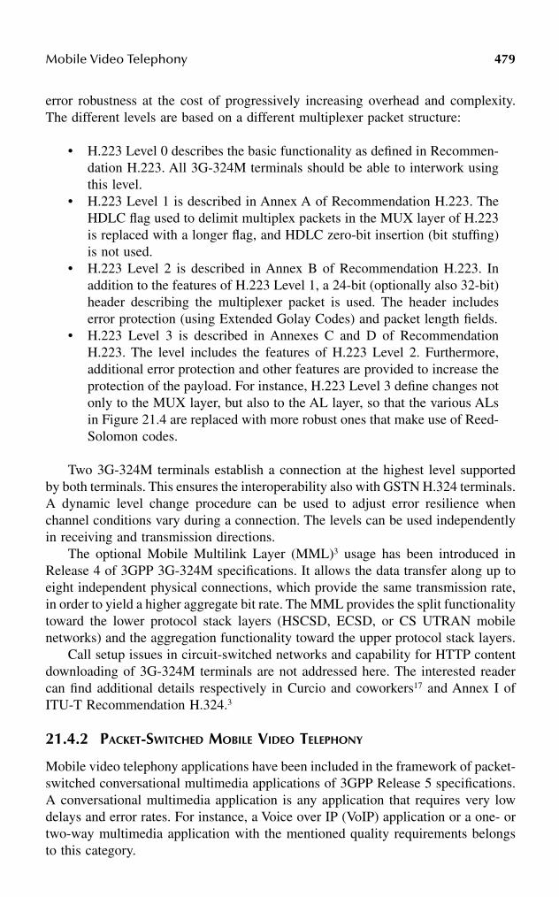
Mobile Video Telephony 479
error robustness at the cost of progressively increasing overhead and complexity.The different levels are based on a different multiplexer packet structure:
• H.223 Level 0 describes the basic functionality as defined in Recommen-dation H.223. All 3G-324M terminals should be able to interwork usingthis level.
• H.223 Level 1 is described in Annex A of Recommendation H.223. TheHDLC flag used to delimit multiplex packets in the MUX layer of H.223is replaced with a longer flag, and HDLC zero-bit insertion (bit stuffing)is not used.
• H.223 Level 2 is described in Annex B of Recommendation H.223. Inaddition to the features of H.223 Level 1, a 24-bit (optionally also 32-bit)header describing the multiplexer packet is used. The header includeserror protection (using Extended Golay Codes) and packet length fields.
• H.223 Level 3 is described in Annexes C and D of RecommendationH.223. The level includes the features of H.223 Level 2. Furthermore,additional error protection and other features are provided to increase theprotection of the payload. For instance, H.223 Level 3 define changes notonly to the MUX layer, but also to the AL layer, so that the various ALsin Figure 21.4 are replaced with more robust ones that make use of Reed-Solomon codes.
Two 3G-324M terminals establish a connection at the highest level supportedby both terminals. This ensures the interoperability also with GSTN H.324 terminals.A dynamic level change procedure can be used to adjust error resilience whenchannel conditions vary during a connection. The levels can be used independentlyin receiving and transmission directions.
The optional Mobile Multilink Layer (MML)3 usage has been introduced inRelease 4 of 3GPP 3G-324M specifications. It allows the data transfer along up toeight independent physical connections, which provide the same transmission rate,in order to yield a higher aggregate bit rate. The MML provides the split functionalitytoward the lower protocol stack layers (HSCSD, ECSD, or CS UTRAN mobilenetworks) and the aggregation functionality toward the upper protocol stack layers.
Call setup issues in circuit-switched networks and capability for HTTP contentdownloading of 3G-324M terminals are not addressed here. The interested readercan find additional details respectively in Curcio and coworkers17 and Annex I ofITU-T Recommendation H.324.3
21.4.2 PACKET-SWITCHED MOBILE VIDEO TELEPHONY
Mobile video telephony applications have been included in the framework of packet-switched conversational multimedia applications of 3GPP Release 5 specifications.A conversational multimedia application is any application that requires very lowdelays and error rates. For instance, a Voice over IP (VoIP) application or a one- ortwo-way multimedia application with the mentioned quality requirements belongsto this category.
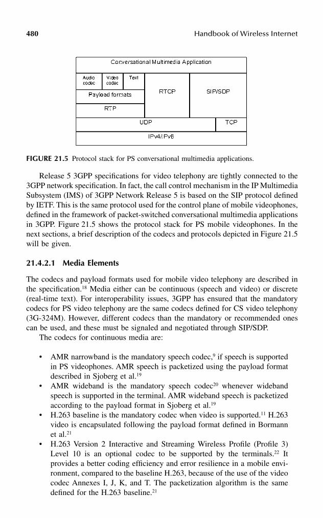
480 Handbook of Wireless Internet
Release 5 3GPP specifications for video telephony are tightly connected to the3GPP network specification. In fact, the call control mechanism in the IP MultimediaSubsystem (IMS) of 3GPP Network Release 5 is based on the SIP protocol definedby IETF. This is the same protocol used for the control plane of mobile videophones,defined in the framework of packet-switched conversational multimedia applicationsin 3GPP. Figure 21.5 shows the protocol stack for PS mobile videophones. In thenext sections, a brief description of the codecs and protocols depicted in Figure 21.5will be given.
21.4.2.1 Media Elements
The codecs and payload formats used for mobile video telephony are described inthe specification.18 Media either can be continuous (speech and video) or discrete(real-time text). For interoperability issues, 3GPP has ensured that the mandatorycodecs for PS video telephony are the same codecs defined for CS video telephony(3G-324M). However, different codecs than the mandatory or recommended onescan be used, and these must be signaled and negotiated through SIP/SDP.
The codecs for continuous media are:
• AMR narrowband is the mandatory speech codec,9 if speech is supportedin PS videophones. AMR speech is packetized using the payload formatdescribed in Sjoberg et al.19
• AMR wideband is the mandatory speech codec20 whenever widebandspeech is supported in the terminal. AMR wideband speech is packetizedaccording to the payload format in Sjoberg et al.19
• H.263 baseline is the mandatory codec when video is supported.11 H.263video is encapsulated following the payload format defined in Bormannet al.21
• H.263 Version 2 Interactive and Streaming Wireless Profile (Profile 3)Level 10 is an optional codec to be supported by the terminals.22 Itprovides a better coding efficiency and error resilience in a mobile envi-ronment, compared to the baseline H.263, because of the use of the videocodec Annexes I, J, K, and T. The packetization algorithm is the samedefined for the H.263 baseline.21
FIGURE 21.5 Protocol stack for PS conversational multimedia applications.
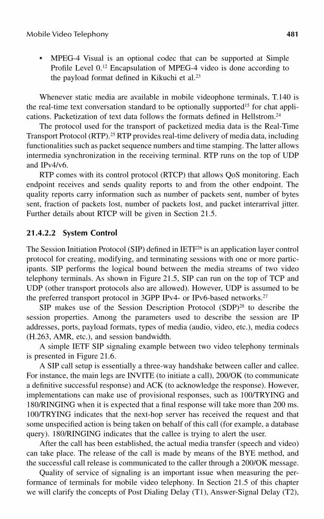
Mobile Video Telephony 481
• MPEG-4 Visual is an optional codec that can be supported at SimpleProfile Level 0.12 Encapsulation of MPEG-4 video is done according tothe payload format defined in Kikuchi et al.23
Whenever static media are available in mobile videophone terminals, T.140 isthe real-time text conversation standard to be optionally supported15 for chat appli-cations. Packetization of text data follows the formats defined in Hellstrom.24
The protocol used for the transport of packetized media data is the Real-TimeTransport Protocol (RTP).25 RTP provides real-time delivery of media data, includingfunctionalities such as packet sequence numbers and time stamping. The latter allowsintermedia synchronization in the receiving terminal. RTP runs on the top of UDPand IPv4/v6.
RTP comes with its control protocol (RTCP) that allows QoS monitoring. Eachendpoint receives and sends quality reports to and from the other endpoint. Thequality reports carry information such as number of packets sent, number of bytessent, fraction of packets lost, number of packets lost, and packet interarrival jitter.Further details about RTCP will be given in Section 21.5.
21.4.2.2 System Control
The Session Initiation Protocol (SIP) defined in IETF26 is an application layer controlprotocol for creating, modifying, and terminating sessions with one or more partic-ipants. SIP performs the logical bound between the media streams of two videotelephony terminals. As shown in Figure 21.5, SIP can run on the top of TCP andUDP (other transport protocols also are allowed). However, UDP is assumed to bethe preferred transport protocol in 3GPP IPv4- or IPv6-based networks.27
SIP makes use of the Session Description Protocol (SDP)28 to describe thesession properties. Among the parameters used to describe the session are IPaddresses, ports, payload formats, types of media (audio, video, etc.), media codecs(H.263, AMR, etc.), and session bandwidth.
A simple IETF SIP signaling example between two video telephony terminalsis presented in Figure 21.6.
A SIP call setup is essentially a three-way handshake between caller and callee.For instance, the main legs are INVITE (to initiate a call), 200/OK (to communicatea definitive successful response) and ACK (to acknowledge the response). However,implementations can make use of provisional responses, such as 100/TRYING and180/RINGING when it is expected that a final response will take more than 200 ms.100/TRYING indicates that the next-hop server has received the request and thatsome unspecified action is being taken on behalf of this call (for example, a databasequery). 180/RINGING indicates that the callee is trying to alert the user.
After the call has been established, the actual media transfer (speech and video)can take place. The release of the call is made by means of the BYE method, andthe successful call release is communicated to the caller through a 200/OK message.
Quality of service of signaling is an important issue when measuring the per-formance of terminals for mobile video telephony. In Section 21.5 of this chapterwe will clarify the concepts of Post Dialing Delay (T1), Answer-Signal Delay (T2),

482 Handbook of Wireless Internet
and Call Release Delay (T3) shown in Figure 21.6. The next section addresses SIPsignaling in 3GPP networks.
21.4.2.3 Call Control Issues
SIP-based mobile applications based on IETF signaling can be implemented in 3GPPRelease ’99 and 4 networks. In this case, only the mobile applications resident inthe mobile terminals run the SIP protocol, while the network is not aware of it.
A further step has been made in 3GPP Release 5 specifications, where SIP hasbeen selected to govern the core call-control mechanism of the whole IP multimediasubsystem. Here, both the network and the mobile terminal implement the SIPprotocol and exchange SIP messages for establishing and releasing calls. This choicehas been made to enable the transition toward all-IP mobile networks. The SIPprotocol in 3GPP Release 5 networks is more complex than the IETF SIP, becauseof factors such as resource reservation or the increased number of involved networkelements. For a deeper understanding of the call control in 3GPP networks, you arerefer to 3GPP.27,29,30 Here we will give an example of SIP signaling for call setupand release between a mobile terminal and a 3GPP network (see Figures 21.7 and21.8).27
The mobile terminal (or UE, user equipment) initiates a call toward the mobileoriginated (MO) network. The UE sends the first INVITE (1) message to the P-CSCF (proxy-call session control function) that works as a call router toward othernetwork elements and the destination mobile terminal. Before the 180/RINGING(19) message is received by the UE, the messages (11–17) are exchanged mainly toallow resource reservation in the network and PDP context activation between the
FIGURE 21.6 Call setup and release using SIP.

Mobile Video Telephony 483
UE and the network. PRACK messages31 play the same role as ACK, but they applyto provisional responses (such as 183/SESSION PROGRESS or 180/RINGING) thatcease to be retransmitted when PRACK is received (more details about reliabilityof SIP messages are available in Section 21.5).
In a 3GPP network, the total number of SIP messages exchanged by the UE forestablishing a call is 12 (plus resource reservation), while a simple IETF call setuprequires 5 SIP messages.
Call release signaling is shown in Figure 21.8. The number of SIP messagesexchanged by the UE is 2 (the same number as in IETF SIP call release), plus therequired signaling to release the PDP contexts resources. In this scenario, messages(2–3) can occur even before BYE (1) and in parallel with procedure 4 (removeresource reservation).
FIGURE 21.7 SIP call setup in 3GPP networks.
M O Network
U E S G S N G G S N P - C S C F
1. INVITE
2. 100 Trying
6. 183 Session Progress
7. PRACK
10. 200 O K (PRACK)
3. INVITE4.100 Trying
5. 183 SessionProgress
8. PRACK
9. 200 O K (PRACK)
11. G P R S:ActivateP D P context
13. G P R S:ActivateP D P
context accept
12. G P R Sinteraction
14. UPDATE
17. 200 O K (UPDATE)
15. UPDATE
16. 200 O K (UPDATE)
19. 180 Ringing
20. PRACK
23. 200 O K (PRACK)
25.200 O K (INVITE)
26. ACK
18. 180 Ringing
21. PRACK
22. 200 O K (PRACK)
24. 200 O K (INVITE)
27. ACK
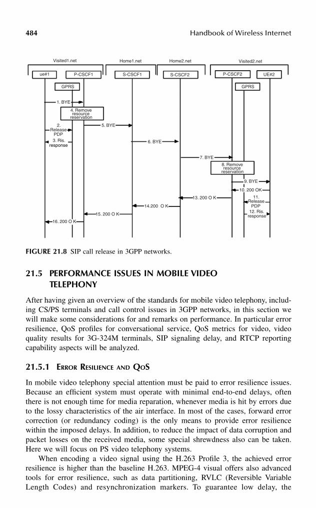
484 Handbook of Wireless Internet
21.5 PERFORMANCE ISSUES IN MOBILE VIDEO TELEPHONY
After having given an overview of the standards for mobile video telephony, includ-ing CS/PS terminals and call control issues in 3GPP networks, in this section wewill make some considerations for and remarks on performance. In particular errorresilience, QoS profiles for conversational service, QoS metrics for video, videoquality results for 3G-324M terminals, SIP signaling delay, and RTCP reportingcapability aspects will be analyzed.
21.5.1 ERROR RESILIENCE AND QOS
In mobile video telephony special attention must be paid to error resilience issues.Because an efficient system must operate with minimal end-to-end delays, oftenthere is not enough time for media reparation, whenever media is hit by errors dueto the lossy characteristics of the air interface. In most of the cases, forward errorcorrection (or redundancy coding) is the only means to provide error resiliencewithin the imposed delays. In addition, to reduce the impact of data corruption andpacket losses on the received media, some special shrewdness also can be taken.Here we will focus on PS video telephony systems.
When encoding a video signal using the H.263 Profile 3, the achieved errorresilience is higher than the baseline H.263. MPEG-4 visual offers also advancedtools for error resilience, such as data partitioning, RVLC (Reversible VariableLength Codes) and resynchronization markers. To guarantee low delay, the
FIGURE 21.8 SIP call release in 3GPP networks.
Visited1.net Home1.net Home2.net Visited2.net
ue#1 P-CSCF1 S-CSCF1 S-CSCF2 P-CSCF2 UE#2
GPRS GPRS
1. BYE
4. Removeresource
reservation
8. Removeresource
reservation
2.Release
PDP3. Ris.
response
16. 200 O K
5. BYE
15. 200 O K
6. BYE
14.200 O K
7. BYE
13. 200 O K
9. BYE
10. 200 OK
11.Release
PDP12. Ris.
response

Mobile Video Telephony 485
specification32 recommends that the video packets must be no larger than 512 bytes. Ingeneral, the smaller the packets, the smaller the amount of video data lost (and thevisual quality loss) in case of packet losses. On the other hand, too-small packetsproduce excessive RTP/UDP/IP header overhead. The choice of the right packet sizeis a trade-off between error resilience, delay, and bandwidth occupancy. The packet sizealso can be changed dynamically on the fly, based on the condition of the network link.
When encoding and packetizing speech data with AMR or AMR-WB, thespecification32 mandates (or forbids) the use of certain codec options:
• Speech data must be packetized using bandwidth-efficient operations. Theencapsulation algorithm19 offers both bit and byte alignment of data. Theformer is more efficient in terms of bandwidth usage.
• Encapsulation of no more than one speech frame into an RTP packet tokeep the delay at the minimum. One AMR speech frame is of 20-msduration. This implies that the packet rate at the videophone terminal is50 packets per second for both incoming and outgoing RTP flows.
• The multichannel session shall not be used.• Interleaving shall not be used. This causes an increase in delay.• Internal CRC shall not be used. Data correction is performed in the lower
layers of the protocol stack. This saves bandwidth.
For the transmission of real-time text using T.140, the use of redundancy codingis recommended to provide a better error resilience.18
At the network level, 3GPP specifications offer the possibility to configure theQoS profile for a conversational multimedia application running over a conversa-tional PDP context. The specification32 defines the recommended target figures forerror rates and delays:
• SDU error ratio (or packet loss rate): 0.7 percent or less for speech and0.01 percent for video.
• Transfer delay: 100 ms for speech and 150 ms for video.
In CS networks, errors in the air interface produce single bit errors in the videopacket payload. A video decoder is generally resilient to bit error rates up to 10–3.In PS networks, errors in the air interface produce erroneous packets that generallyare not forwarded to the higher protocol layers than IP. So, they are regarded as lostpackets. In this case, SDU error ratios as indicated previously can be used to provideenough media resilience from packet losses.
21.5.2 VIDEO QOS METRICS
Adequate techniques for objective and subjective speech and video quality assessmentmust be adopted to guarantee that a given mobile videophone implementation fulfillsa minimum set of QoS requirements. This section focuses on video quality metrics.
When developing mobile video telephony applications the need is to decidewhich fundamental quality parameters should be selected as key parameters in QoS

486 Handbook of Wireless Internet
assessment of video. For this purpose both subjective and objective metrics must beused, because they can be considered complementary. You are referred to Curcio33
for details about subjective metrics. Regarding objective quality metrics, standard-ization bodies have defined some methods. For example, the ANSI34 and ITU35
standards describe some metrics. However, for some of the metrics described inthese documents, the implementation is not straightforward. Despite the effort ofstandardization bodies to define common video quality metrics, often the most-usedobjective method for video quality assessment is the PSNR (Peak Signal-to-NoiseRatio), because it is the easiest to apply to the metrics available. However, other usefulquality metrics can be put to use when developing mobile videophone terminals. Forfurther details on the metrics computation methods, please refer to Curcio.33,36
The quality metrics are categorized into six classes, depending on the type ofinformation they can provide:
1. Frame-based: This set of metrics gives information about the number offrames that have been processed end-to-end. The metrics are• Number of encoded frames• Number of decoded frames• Number of dropped frames• Drop frame rate• Encoding frame rate• Decoding frame rate• Display frame rate• Size of the first INTRA-coded frame
2. Bit rate-based: The objective of these metrics is to provide informationabout the repartition of the channel bandwidth. This information is pre-cious for optimizing system performance. The metrics are• Audio bit rate (obtained by the audio codec)• Video bit rate• Packetization overhead• Application total bit rate (computed as a sum of the above values)
3. Packet-based: These metrics give information about the packets that aregenerated by the RTP packetizer or the H.223 multiplexer:• Number of packets per frame• Size of the packets
4. Loss- or corruption-based: These metrics provide information about theamount of packets lost, or the amount of correctly/incorrectly delivereddata:• Packet loss rate• Correctly delivered data rate• Misdelivered data rate• Bit error rate computation
5. PSNR-based. PSNR is a measure of the difference between the originalframe and the corresponding encoded (or decoded) frame. PSNR-basedmetrics are• PSNR of the video sequence

Mobile Video Telephony 487
• Standard deviation of PSNR• PDF (Probability Density Function) and CDF (Cumulative Density
Function) of PSNR• Representative run for subjective evaluation (when multiple simulation
runs are considered)6. Delay-based. Delay is a very critical issue in mobile video telephony.
Because end-to-end delay is made up of different components, oneapproach would be to measure the different delays and try to optimizethem separately. A set of measurable delays are• Capturing delay• Initial video encoding delay (time required to encode the first INTRA
frame)• Encoding delay for video frames (minimum, average, and maximum)• Packetization delay• Transmission delay (related to the network)• Depacketization delay• Decoding delay for video frames (minimum, average, and maximum)• Display delay• End-to-end delay• PDF and CDF for any of the delay components above• Out of delay constraints rate (to measure the percentage of delay
violation over a fixed threshold T of time)• Delay jitter computed for different delays above (a particularly inter-
esting value is the frame rate jitter)
21.5.3 VIDEO QUALITY RESULTS FOR 3G-324M
To provide an idea of the performance of a videophone in mobile environment; wehave implemented a PC version of 3G-324M terminal and made mobile-to-mobilecalls between two 3G-324M PC terminals through a simulated circuit-switchedWCDMA network at 64 kbps. Table 21.2 summarizes the main simulation param-eters used in our tests.
The error patterns were injected two times into the bit stream to simulate thecase of mobile-to-mobile connection, where two radio links are involved (this is thereason the bit error rates are doubled in Table 21.2).
The results obtained were measured in terms of average PSNR over 10 runs,standard deviation of PSNR, frame rate, delay, bandwidth usage, and visual quality.The reader interested in details about performance of 3G-324M terminals at differentbit rates with service flexibility for WCDMA and HSCSD networks may refer toCurcio and coworkers,17 Hourunranta and Curcio,37 and Curcio and Hourunranta.38
Average PSNR results are shown in Table 21.3.The maximum quality loss achieved at the higher BER is below 0.5 dB, with a
maximum standard deviation below 0.2 dB. The average encoding frame rate was10.2 frames per second. The end-to-end delay from encoding to display (excludingcapturing and network delay) was 140 ms, of which 98 ms was for shaping delay37
and 42 ms was the processing delay. The bandwidth usage is reported in Table 21.4.
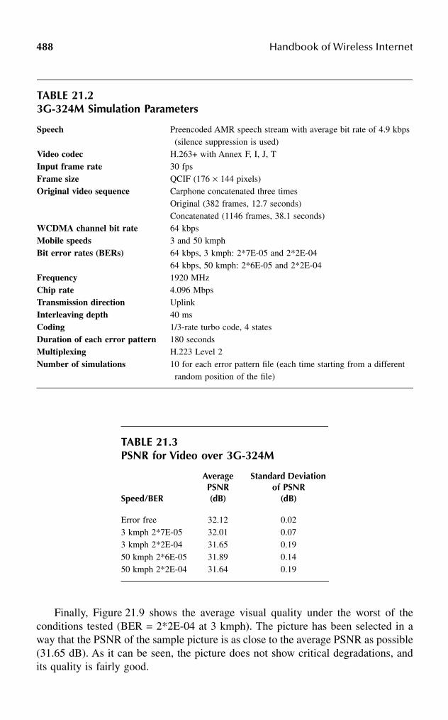
488 Handbook of Wireless Internet
Finally, Figure 21.9 shows the average visual quality under the worst of theconditions tested (BER = 2*2E-04 at 3 kmph). The picture has been selected in away that the PSNR of the sample picture is as close to the average PSNR as possible(31.65 dB). As it can be seen, the picture does not show critical degradations, andits quality is fairly good.
TABLE 21.23G-324M Simulation Parameters
Speech Preencoded AMR speech stream with average bit rate of 4.9 kbps (silence suppression is used)
Video codec H.263+ with Annex F, I, J, TInput frame rate 30 fpsFrame size QCIF (176 × 144 pixels)Original video sequence Carphone concatenated three times
Original (382 frames, 12.7 seconds)Concatenated (1146 frames, 38.1 seconds)
WCDMA channel bit rate 64 kbpsMobile speeds 3 and 50 kmphBit error rates (BERs) 64 kbps, 3 kmph: 2*7E-05 and 2*2E-04
64 kbps, 50 kmph: 2*6E-05 and 2*2E-04Frequency 1920 MHzChip rate 4.096 MbpsTransmission direction UplinkInterleaving depth 40 msCoding 1/3-rate turbo code, 4 statesDuration of each error pattern 180 secondsMultiplexing H.223 Level 2Number of simulations 10 for each error pattern file (each time starting from a different
random position of the file)
TABLE 21.3PSNR for Video over 3G-324M
Speed/BER
Average PSNR (dB)
Standard Deviation of PSNR
(dB)
Error free 32.12 0.023 kmph 2*7E-05 32.01 0.073 kmph 2*2E-04 31.65 0.1950 kmph 2*6E-05 31.89 0.1450 kmph 2*2E-04 31.64 0.19
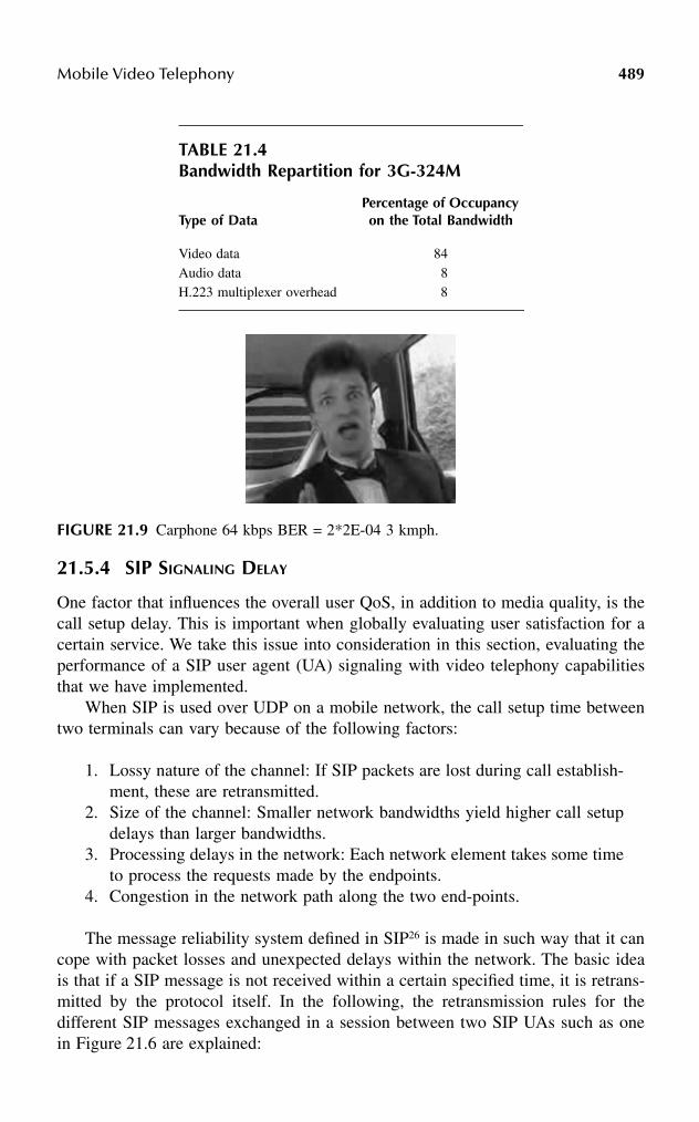
Mobile Video Telephony 489
21.5.4 SIP SIGNALING DELAY
One factor that influences the overall user QoS, in addition to media quality, is thecall setup delay. This is important when globally evaluating user satisfaction for acertain service. We take this issue into consideration in this section, evaluating theperformance of a SIP user agent (UA) signaling with video telephony capabilitiesthat we have implemented.
When SIP is used over UDP on a mobile network, the call setup time betweentwo terminals can vary because of the following factors:
1. Lossy nature of the channel: If SIP packets are lost during call establish-ment, these are retransmitted.
2. Size of the channel: Smaller network bandwidths yield higher call setupdelays than larger bandwidths.
3. Processing delays in the network: Each network element takes some timeto process the requests made by the endpoints.
4. Congestion in the network path along the two end-points.
The message reliability system defined in SIP26 is made in such way that it cancope with packet losses and unexpected delays within the network. The basic ideais that if a SIP message is not received within a certain specified time, it is retrans-mitted by the protocol itself. In the following, the retransmission rules for thedifferent SIP messages exchanged in a session between two SIP UAs such as onein Figure 21.6 are explained:
TABLE 21.4Bandwidth Repartition for 3G-324M
Type of DataPercentage of Occupancy on the Total Bandwidth
Video data 84Audio data 8H.223 multiplexer overhead 8
FIGURE 21.9 Carphone 64 kbps BER = 2*2E-04 3 kmph.

490 Handbook of Wireless Internet
• INVITE method. A SIP UA should retransmit an INVITE request with aninterval that starts at T1 seconds, and doubles after each packet transmission.T1 is an estimate of the round-trip time (RTT). The client stops retransmis-sions if it receives a provisional (1xx) or definitive (2xx) response, or onceit has sent a total of seven request packets. A UA client may send a BYE orCANCEL request after the seventh retransmission (i.e., after 64*T1 seconds).In our implementation the value of T1 is set at 0.5 seconds.
• BYE method. In this case, a SIP client should retransmit requests with anexponential backoff for congestion control reasons. For example, if the firstpacket sent is lost, the second packet is sent T1 seconds later, and eventuallythe next one after 2*T1 seconds (4*T1 seconds, and so on), until the intervalreaches a value T2. Subsequent retransmissions are spaced by T2 seconds.T2 represents the amount of time a BYE server transaction will take torespond to a request, if it does not respond immediately. If the client receivesa provisional response, it continues to retransmit the request, but with aninterval of T2 seconds (this is done to ensure reliable delivery of the finalresponse). Retransmissions cease when the client has sent a total of 11packets (i.e., after T1*64 seconds), or it has received a definitive response.Responses to BYE are not acknowledged via ACK. In our implementationthe values of T1 and T2 are set to 0.5 and 4 seconds, respectively.
• ACK method. ACK is not retransmitted, but in case of loss the UA serverretransmits the 200/OK.
• Informational (provisional) responses (1xx). UA servers do not transmitinformational responses reliably. For instance, our implementation doesnot retransmit informational responses (100/TRYING, 180/RINGING).However, the UA server, which transmits a provisional response, willretransmit it upon reception of a duplicate request.
• Successful responses (2xx). A UA server does not retransmit responsesto BYE. In all the other cases a UA server, which transmits a finalresponse, should retransmit it with the same spacing as the BYE. Responseretransmissions cease when an ACK request is received or the responsehas been transmitted 11 times (i.e., after 64*T1 seconds). The value of afinal response is not changed by the arrival of a BYE or CANCEL request.
In 3GPP Release 5 networks, the timers T1 and T2 are set to different and more-conservative values.
The tests we have run have been performed over a 3GPP Release ’99 networkemulator. The results will be expressed in terms of the following metrics:
• Postdialing delay (PDD). It also is called postselection delay or dial-to-ring delay. This is the time elapsed between the caller clicking the buttonof his terminal to make the call and hearing the terminal ringing. In ourcase the PDD corresponds to the time T1 (see Figure 21.6).
• Answer-signal delay (ASD). This is the time elapsed between the phonebeing picked up and the caller receiving indication of this. In our case theASD corresponds to the time T2 (see Figure 21.6). It must be noted that

Mobile Video Telephony 491
the caller receives notification that the callee has picked up the phonewhen the first receives the 200/OK. However, the call-signaling handshakeis completed when the callee receives the ACK from the caller. This isthe reason we have considered the ASD in this way.
• Call-release delay (CRD). This is the time elapsed between the phonebeing hung up by the releasing party (the caller in our example inFigure 21.6) and a new call can be initiated/received (by the same party).In our tests the CRD corresponds to the time T3.
Results of simulations are shown in Table 21.5. No signaling compression algo-rithms were used. For comparisons between calls over 3GPP Release ’99 networks andcalls in Intranet or WLAN environment, and for further details about SIP signalingdelays, the reader can refer to Curcio and Lundan.39,40
Table 21.6 contains results for SIP call set-up times in the case of restrictedbandwidths. Also in this case, no signaling compression was used. Table 21.5 resultsassumed a bandwidth of 384 kbps; however, in many cases it is better to assume,as we did, that the bearer reserved for SIP signaling is a dedicated one, and ofsmaller size. Also, when running the tests with restricted bandwidth we have injected2 percent packet losses using the NISTNET41 simulator. The figures show that thereis an increase in postdialing delays up to almost one second for network bandwidthsas narrow as 2 kbps.
TABLE 21.5Call Setup Times for SIP Signaling
Call Setup MetricDelay (ms)
Postdialing delay 62Answer-signal delay 45Call-release delay 50
TABLE 21.6Postdialing Delay for SIP Signaling with Limited Bandwidth
Network Bandwidth (kbps)
Delay (ms)
2 9815 4279.2 287
16 16432 11964 78
492 Handbook of Wireless Internet
The results presented in this section are not related to SIP signaling withinRelease 5 of 3GPP specifications, where SIP is part of the call control in the IMS.In this case, the SIP signaling delays are estimated to be larger than those shown,due to the increased complexity of the whole network system.
21.5.5 RTCP PERFORMANCE
The RTCP protocol basics have been introduced in Chapter 4, Section 4.5. We recallthe fact the RTCP is used by a receiver to provide QoS information to the transmittingparty in order to repair the media transmitted or, in general, to take some (possiblyprompt) action to adjust or improve the QoS toward the receiver.
RTCP packets are normally sent with a minimum interval of 5 seconds. However,some applications may benefit from sending a more-frequent feedback. Video tele-phony can certainly benefit from a faster feedback, because this allows a fasterreaction of the sender terminal to provide a better QoS to the receiving terminal.One possible action is to change on the fly the encoding parameters when the packetloss rate increases. This action should be taken as early as possible in the transmittingterminal, and a 5-second interval could be too long a time window to allow a fastreaction, especially if the media to repair is a speech stream.
The new RTP specifications42,43 define a more-flexible use of the RTCP dataflow, allowing more-frequent feedback by reducing the transmission interval to avalue lower than 5 seconds or by fixing the percentage of the RTP session bandwidthreserved for RTCP traffic.
We have run some tests for 1-minute speech and video streams. The former wasencoded using the AMR codec at 12.2 kbps with silence suppression. The latter wasencoded using the H.263+ video codec at 64 kbps. For the speech session themaximum RTCP packet length was 168 bytes (including UDP/IP headers, a senderreport and full SDES), while for the video session the RTCP packet length was 88bytes (including UDP/IP headers, a receiver report and SDES). Results for differentRTCP bandwidth percentages are shown in Tables 21.7 and 21.8.
The leftmost column in Tables 21.7 and 21.8 contains the RTCP bandwidth aspercentage of the RTP session bandwidth, which includes media and headers over-head (including RTP/UDP/IP headers). The second column contains the RTCPbandwidth in kilobits per second. The third column of data is the computed averageRTCP interval between two QoS reports. The last column contains the number ofRTCP packets sent by a receiver during 1 minute of data reception.
The reader can see that the minimum bandwidth occupied by RTCP is below0.2 kbps when a 5-second transmission interval is used. In this case the receiversends only 12 QoS reports. When increasing the bandwidth reserved for RTCP,more-frequent feedback can be sent. For example, for speech traffic, a feedbackmessage every 2.3 seconds would allow 26 QoS reports in one minute. In the sameway for video traffic, a feedback message every 375 ms would allow 160 QoS reportsin one minute. This would let the transmitting terminal have more possibilities toadjust the error resilience properties of the video stream. Theoretically, it could bepossible to have 160 QoS reports for the speech stream as well. However, this wouldimply an RTCP bandwidth of about 2.4 kbps, i.e., over 13 percent of the RTP session

Mobile Video Telephony 493
bandwidth for speech. The reader interested in details about RTCP traffic can referto Curcio and Lundan.44,45
21.6 CONCLUSIONS
Mobile video telephony is enabled by different mobile networks (HSCSD, ECSD,and UMTS). Standards also have been developed by ITU-T, IETF, and 3GPP toallow circuit-switched and packet-switched video telephony (3G-324M and SIP-based).
Video is a new media dimension that affects the current usability paradigms ofmobile devices. In this perspective, new usage models are envisaged for the usersof mobile video telephony. Finally, the success and widespread use of this new typeof application will be certainly influenced not only by technical challenges, but alsoby end-user requirements.
ACKNOWLEDGMENTS
The author would like to express sincere gratitude to his colleagues Ari Hourunranta,Ville Lappalainen, and Miikka Lundan for the cooperation offered.
TABLE 21.7Results for Different RTCP Bandwidth Percentages (AMR Speech)
RTCP Bandwidth (%)
RTCP Bandwidth (kbps)
Average RTCP Interval (ms)
Number of RTCP Packets
1.0 0.19 5000 121.6 0.28 3158 191.9 0.35 2609 232.2 0.39 2308 26
TABLE 21.8Results for Different RTCP Bandwidth Percentages (H.263+ Video)
RTCP Bandwidth (%)
RTCP Bandwidth (kbps)
Average RTCP Interval (ms)
Number of RTCP Packets
0.2 0.14 5000 120.3 0.18 4000 150.5 0.34 2069 291.0 0.67 1053 571.2 0.82 857 701.9 1.31 536 1122.4 1.63 432 1392.8 1.88 375 160

494 Handbook of Wireless Internet
References
1. 3GPP TSG-T, Common test environments for user equipment (UE), Conformancetesting (Release ’99), TS 34.108, v.3.10.0 (2002–12).
2. 3GPP TSGS-SA, QoS concept and architecture (Release 5), TS 23.107, v.5.7.0(2002–12).
3. ITU-T, Terminal for low bit-rate multimedia communication, RecommendationH.324, March 2002.
4. 3GPP TSGS-SA, Codec for circuit switched multimedia telephony service, Modifi-cations to H.324 (Release ’99), TS 26.111, v.3.4.0 (2000–12).
5. 3GPP TSGS-SA, Codec for circuit switched multimedia telephony service, Generaldescription (Release 4), TS 26.110, v.4.1.0 (2001–03).
6. ITU-T, Multiplexing protocol for low bit rate multimedia communication, Recom-mendation H.223, July 2001.
7. ITU-T, Control protocol for multimedia communication, Recommendation H.245(Version 8), July 2001.
8. 3GPP TSGS-SA, Codec(s) for circuit switched multimedia telephony service, Ter-minal implementor’s guide (Release 4), TS 26.911, v.4.1.0 (2001–03).
9. 3GPP TSGS-SA, Mandatory speech codec speech processing functions, AMR speechcodec, General description (Release 5), TS 26.071, v.5.0.0 (2002–06).
10. ITU-T, Dual rate speech coder for multimedia communications transmitting at 5.3and 6.3 kbit/s, Recommendation G.723.1, March 1996.
11. ITU-T, Video coding for low bit rate communication, Recommendation H.263, Feb-ruary 1998.
12. ISO/IEC, Information technology – Coding of audio-visual objects – Part 2: Visual,14496–2, 2001.
13. ITU-T, Video codec for audiovisual services at p x 64 kbits, Recommendation H.261,March 1993.
14. ITU-T, Data protocols for multimedia conferencing, Recommendation T.120, July1996.
15. ITU-T, Protocol for multimedia application text conversation, RecommendationT.140, February 1998.
16. 3GPP TSGS-SA, Global text telephony, Stage 1 (Release 5), TS 22.226, v.5.2.0(2002–03).
17. Curcio, I.D.D., Lappalainen, V., and Mostafa, M.-E., QoS evaluation of 3G-324Mmobile videophones over WCDMA networks, Comput. Networks, 37 (3-4), 425–445,2001.
18. 3GPP TSGS-SA, Packet switched conversational multimedia applications, Defaultcodecs (Release 5), TS 26.235, v.5.1.0 (2002–03).
19. Sjoberg, J. et al., RTP payload format and file storage format for the Adaptive Multi-Rate (AMR) and Adaptive Multi-Rate Wideband (AMR-WB) audio codecs, IETFRFC 3267, March 2002.
20. ITU-T, Wideband coding of speech at around 16 kbits/s using Adaptive Multi-RateWideband (AMR-WB), Recommendation G.722.2, January 2002.
21. Bormann, C. et al., RTP Payload format for the 1998 version of ITU-T Recommen-dation H.263 (H.263+), IETF RFC 2429, October 1998.
22. ITU-T, Video coding for low bit rate communication, Profiles and levels definition,Recommendation H.263 Annex X, April 2001.
23. Kikuchi, Y. et al., RTP payload format for MPEG-4 Audio/Visual streams, IETF RFC3016, November 2000.
Mobile Video Telephony 495
24. Hellstrom, G., RTP Payload for Text Conversation, IETF RFC 2793, May 2000.25. Schulzrinne, H. et al., RTP: A Transport Protocol for Real-Time Applications, IETF
RFC 1889, January 1996.26. Rosenberg, J. et al., SIP: Session Initiation Protocol, IETF RFC 3261, March 2002.27. 3GPP TSG CN, Signaling flows for the IP multimedia call control based on SIP and
SDP, Stage 3 (Release 5), TS 24.228 v.5.3.0 (2002–12).28. Handley, M. and Jacobson, V., SDP: Session description protocol, IETF RFC 2327,
April 1998.29. 3GPP TSG-SSA, IP Multimedia Subsystem (IMS), Stage 2 (Release 5), TS 23.228
v.5.7.0 (2002–12).30. 3GPP TSG CN, IP multimedia call control protocol based on SIP and SDP, Stage 3
(Release 5), TS 24.229 v.5.3.0 (2002–12).31. Rosenberg, J. and Schulzrinne, H., Reliability of Provisional Responses in the Session
Initiation Protocol (SIP), IETF RFC 3262, June 2002.32. 3GPP TSGS-SA, Packet switched conversational multimedia applications, Transport
protocols (Release 5), TS 26.236, v.5.7.0 (2002–12).33. Curcio, I.D.D., Mobile video QoS metrics, Int. J. Comput. Appl., 24 (2), 41–51, 2002.34. ANSI, Digital Transport of One-Way Video Signals – Parameters for Objective
Performance Assessment, T1.801.03, 1996.35. ITU-T, Multimedia communications delay, synchronization and frame rate measure-
ment, Recommendation P.931, December 1998.36. Curcio, I.D.D., Practical Metrics for QoS Evaluation of Mobile Video, Internet and
Multimedia Systems and Applications Conference (IMSA 2000), Las Vegas, 9–23November 2000, pp. 199–208.
37. Hourunranta, A. and Curcio, I.D.D., Delay in Mobile Videophones, IEEE 7th MobileMultimedia Communications Workshop (MoMuC 2000), Tokyo, 23–26 October2000, pp. 1-B-3–1/1-B-3–7.
38. Curcio, I.D.D. and Hourunranta, A., QoS of Mobile Videophones in HSCSD Net-works, IEEE 8th International Conference on Computer Communications and Net-works (ICCCN ’99), Boston, 11–13 October 1999, pp. 447–451.
39. Curcio, I.D.D. and Lundan, M., SIP Call Setup Delay in 3G Networks, IEEE 7thSymposium on Computers and Communication (ISCC ’02), Taormina, Italy, 1–4 July2002, pp. 835–840.
40. Curcio, I.D.D. and Lundan, M., Study of Call Setup in SIP-Based Videotelephony,5th World Multi-Conference on Systemics, Cybernetics and Informatics (SCI 2001),Orlando, 22–25 July 2001, Vol. IV, pp. 1–6.
41. NIST, NISTNet, http://www.antd.nist.gov/nistnet/.42. Schulzrinne, H. et al., RTP: A Transport Protocol for Real-Time Applications, IETF
draft, Work in progress, November 2001.43. Casner, S., SDP Bandwidth Modifiers for RTCP Bandwidth, IETF draft, Work in
progress, November 2001.44. Curcio, I.D.D. and Lundan M., Event-Driven RTCP Feedback for Mobile Multimedia
Applications, IEEE 3rd Finnish Wireless Communications Workshop (FWCW ’02),Helsinki, 29 May 2002.
45. Curcio, I.D.D. and Lundan, M., On RTCP Feedback for Mobile Multimedia Appli-cations, IEEE International Conference on Networking (ICN ’02), Atlanta, 26–29August 2002.
46. 3GPP TSG-T, Common Test Environments for User Equipment (UE), ConformanceTesting (Release 4), TS 34.108, V.4.5.0 (2002-12).

This page intentionally left blank

4970-8493-1502-6/03/$0.00+$1.50© 2003 by CRC Press LLC
22 WAP: Transitional Technology for M-Commerce
Mahesh S. Raisinghani
CONTENTS
Abstract ..................................................................................................................49722.1 Introduction ................................................................................................49822.2 Will WAP-Enabled Phones Dominate the Personal Computer
Marketplace? ..............................................................................................49922.3 WAP: A Global Standard...........................................................................50022.4 Operating Systems for WAP......................................................................50022.5 WAP Forum................................................................................................50222.6 Arguments for WAP...................................................................................50222.7 Arguments against WAP ............................................................................50222.8 Are Mobile Telephones Hazardous to Health? .........................................50322.9 Poor Security? ............................................................................................50322.10 WAP and M-Commerce.............................................................................50422.11 Critical Success Factors for M-Commerce ...............................................504
22.11.1 Speed............................................................................................50422.11.2 Billing ..........................................................................................50522.11.3 Security ........................................................................................505
22.12 Future Impact: Generation “W” in a Wireless World ...............................507References..............................................................................................................509
ABSTRACT
Wireless Application Protocol (WAP) is the most-popular Internet-enabling technol-ogy being adopted en masse by handset manufacturers and service providers alike.The International Data Corporation promises 1 billion cellular telephones worldwideby 2004, with half of them Internet-enabled. This chapter discusses the fast-growingtrend for WAP tools to access the Internet versus the current predominant use ofpersonal computers. The chapter describes also the importance of WAP in the field

498 Handbook of Wireless Internet
of E-commerce, with its popularity leading E-commerce into mobile commerce(M-commerce). Because it works in already existing networks, WAP needs littlemodification in Web content and can be available with ease. Already, there arenumerous companies providing E-commerce services through WAP around theworld, and with the huge mobile telephone subscriber base, the potential forM-commerce is tremendous.
22.1 INTRODUCTION
Trade developed through many stages, from barter in the old days to E-commercetoday. What will be the tool for transactions tomorrow? In the past half decade, theInternet has revolutionized the practice and procedure of trade, giving birth to thenew world of E-commerce. Now people can buy or sell goods and services practically24 hours a day, 7 days a week, if they have access to the Web. Vendors have beenable to tap into markets that were impossible to reach due to remote geographiclocation or other reasons. It is this “anytime, anywhere” technology that has fueledthe new economy.
Although much has been accomplished toward this goal of being able to trade“anytime, anywhere,” personal computer laptops are too bulky for M-commerce.The obvious choice is to empower the mobile telephone to be the preferred tool forM-commerce. The M-commerce phenomenon is centered in Asia and Europe (notthe United States), where mobile telephony is further advanced and PC usage ismuch lower. Nokia, Ericsson, Motorola, and NTT DoCoMo, to name a few — aswell as giants in banking, retail, and travel, including Amazon and Schwab — aredeveloping their mobile E-sites; and all are settling on WAP.
WAP works with all major wireless networks — code division multiple access(CDMA), Global System for Mobile Communications (GSM), time division multipleaccess (TDMA), and Cellular Digital Packet Data (CDPD) — via circuit switched,packet, or short messaging service. It can be built into any operating system, includ-ing Windows CE, Palm OS®, Epoc, or JavaOS. The Japanese mobile operatorDoCoMo is the leader, with the first-mover advantage in bringing mobile Internetservices to market by attracting 10 million subscribers to its i-mode service in lessthan one year. The Palm VII personal digital assistant (PDA) from 3COM can deliverwireless e-mail and information access service in the United States and the UnitedKingdom. Most current mobile Internet services are based on the WAP standard.Microsoft, which came a bit late to the game, gave its grudging approval recentlyby redoing its cellular telephone browser for WAP.1,2
Analysts say such personalized services will be the meat of M-commerce.According to Gartner’s research vice president, Phillip Redman, “the personalizationof content and services that help consumers make their purchasing decisions” willbe pivotal. Information is key to the overall success of M-commerce, and Cellmaniaand BroadVision are two wireless applications based on that premise. Cellmania’smEnterprise is intended to help companies bolster customer relations in part byincreasing the productivity of traveling employees. mEnterprise integrates with acompany’s infrastructure and powers field-service and sales-force automation appli-cations and mobile portals. BroadVision is offering BroadVision Mobile Solution

WAP: Transitional Technology for M-Commerce 499
to help businesses get a better line on the content customers want pushed to handhelddevices by capturing customer data. It also can create home pages that site visitorscan customize to their needs.
22.2 WILL WAP-ENABLED PHONES DOMINATE THE PERSONAL COMPUTER MARKETPLACE?
Everyday there is some news about WAP-enabled phones and their growing usetoward the Internet. Is this growth going to sustain or even surpass people’s expec-tations to become the most-important medium for communication and commerce?Will it lead the static wired E-commerce to wireless M-commerce? Although theonly Internet-enabling technology being adopted en masse by handset manufacturersand service providers is WAP, there are other options such as J2ME (Java 2 MicroEdition), a mobile ASP (application service provider), a Citrix terminal solution,and an OracleMobile solution, all of which totally ignore cellular telephones andpromise to satisfy all of your mobile Internet business needs over a pager. In addition,there are issues with WAP’s Wireless Markup Language (WML), which cannot beread on an HTML browser and vice versa. Is Sun’s J2ME, which allows a smallapplication to run on the telephone so it can be used even when disconnected, agood solution; or is it too small and does it lack too many of the Java standard-edition components needed to create usable applications, as reported by Internetservice vendors (ISVs)? In Sun’s defense, Motorola displayed applications such asexpense reports, e-mail, and calendaring on a Motorola iDEN cellular telephonerunning J2ME.3
In the business-to-business (B2B) environment, real-time mobile access to onlineexchanges, virtual communities, and auctions can be facilitated by M-commerce.Mobile workers such as sales reps, truck drivers, and service personnel will be ableto use the mobile Internet. Medical doctors will be able to use their handheld PDAsto access patient information, information on available drugs, and online orderingand scheduling of prescriptions, clinical tests, and other procedures. Unified mes-saging services will allow mobile workers to use a single device for all their com-munications and interactions; and ubiquitous computing will use online connectionsto communicate exception reports, performance problems, and errors to servicepersonnel.2 Most IT executives are still on the fence, whereas a few early adoptershave settled on proprietary technologies. One example is a women’s accessorycompany, NineWest, which has a non-WAP client/server solution for its field repsand buyers deployed into older Nokia 9000 cellular telephones. Developed by theFinnish company Celesta, it creates smart forms using Short Message Service (SMS)rather than going through an ISP. This solution has reportedly been profitable forNineWest because it alerts headquarters in real-time, rather than through weeklybatch files, when a store carrying its line needs to be restocked.
Similarly, NeoPoint of La Jolla, California, a developer of Web telephones, hascreated a wireless service called myAladdin.com that, among other abilities, canmonitor information such as airline flights or stock performance, and alert a userwhen a flight is delayed or a stock price drops. InfoMove of Kirkland, Washington,

500 Handbook of Wireless Internet
integrates the Global Positioning System (GPS) and text-to-speech technologies tocreate a private-label information service that has been sold to DaimlerChrysler andPaccar, a heavy truck manufacturer. Tekelec makes equipment for wired and wirelesstelecommunications suppliers to enable them to offer value-added services to theircustomers. Because the Federal Communications Commission requires that if youswitch or move, your telephone company must let you keep your old telephonemarket, Tekelec’s local number portability (LDP) software is the best on the marketand with its reseller networks such as Lucent and Tellabs, Tekelec is a strong takeovercandidate.
22.3 WAP: A GLOBAL STANDARD
WAP is a format for displaying Web and other data on the small screens of handhelddevices, specifically cellular telephones. WAP is a set of specifications, developedby the WAP Forum, that lets developers using WML build networked applicationsdesigned for handheld wireless devices. WAP is a standard, similar to the Internetlanguage HTML, which translates the Web site into a format that can be read onthe mobile’s screen. The data is broadcast by the telephone’s network supplier. WAPv1.1 constitutes the first global transparent de facto standard to be embraced by wellover 75 percent of all relevant industry segments. WAP’s key elements include
1. The WAP programming model2. Wireless Markup Language and WML Script3. A microbrowser specification4. Wireless Telephony Application5. The WAP stack.4
WAP is designed to work with most wireless protocols such as CDPD, CDMA,DataTAC, DECT, FLEX, GSM, iDEN, Mobitex, PDC, PHS, ReFLEX, TDMA, andTETRA.
22.4 OPERATING SYSTEMS FOR WAP
WAP is a communications protocol and an application environment. It can be builton any operating system including PalmOS®, EPOC, Windows CE, FLEXOS, OS/9,and JavaOS. WAP provides service interoperability even between different devicefamilies. WAP uses existing Internet standards, and the WAP architecture (illustratedin Figure 22.1) was designed to enable standard off-the-shelf Internet servers toprovide services to wireless devices.
In addition to wireless devices, WAP uses many Internet additions when com-municating standards such as XML, UDP, and IP. WAP wireless protocols are basedon Internet standards such as HTTP and Transport Layer Security (TLS), but havebeen optimized for the unique constraints of the wireless environment. Internetstandards such as HTML, HTTP, TLS, and TCP are inefficient over mobile networks,

WAP: Transitional Technology for M-Commerce 501
requiring large amounts of mainly text-based data to be sent. Standard HTML Webcontent generally cannot be displayed in an effective way on the small screens ofpocket-sized mobile telephones and pagers, and navigation around and betweenscreens is not easy in one-handed mode. HTTP and TCP are not optimized for theintermittent coverage, long latencies, and limited bandwidth associated with wirelessnetworks. HTTP sends its headers and commands in an inefficient text format insteadof compressed binary. Wireless services using these protocols are often slow, costly,and difficult to use. The TLS security standard requires many messages to beexchanged between client and server which, with wireless transmission latencies,results in a very slow response for the user. WAP has been optimized to solve allthese problems, utilizing binary transmission for greater compression of data, andis optimized for long latency and low-to-medium bandwidth. WAP sessions copewith intermittent coverage and can operate over a wide variety of wireless transportsusing IP where it is possible and other optimized protocols where IP is impossible.The WML used for WAP content makes optimum use of small screens; allows easy,one-handed navigation without a full keyboard; and has built-in scalability fromtwo-line text displays through to the full graphic screens on smart telephones andcommunicators.5 Figure 22.2 illustrates the relationship between WAP and the Web.
FIGURE 22.1 WAP architecture.
FIGURE 22.2 WAP and the Web.
WTA ServerWAP Proxy
Filter
Web Server
Filter
WAP Proxy
HTMLWirelessNetwork
WML
WML
WML
WML
WML
ApplicationServer
WebServer
DesktopPC WAP
Server
DatabaseSMS or
Data Call
Corporate NetworkOperatorNetwork
MobilePhone
502 Handbook of Wireless Internet
22.5 WAP FORUM
The WAP Forum is the industry association comprised of more than 200 membersthat has developed the de facto worldwide standard for wireless information andtelephony services on digital mobile telephones and other wireless terminals. Theprimary goal of the WAP Forum is to bring together companies from all segmentsof the wireless industry value-chain to ensure product interoperability and growthof the wireless market. WAP Forum members represent more than 95 percent of theglobal handset market carriers, with more than 100 million subscribers, leadinginfrastructure providers, software developers, and other organizations providingsolutions to the wireless industry (http://www.wapforum.org/).
22.6 ARGUMENTS FOR WAP
WAP is efficient at coping with the limited bandwidth and connection-oriented natureof today’s wireless networks due to its stripped-down protocol stack.2 WAP workswith all major wireless networks and can be built into any operating system, includ-ing Windows CE, PalmOS®, Epoc, or JavaOS. WAP applications are available oversecond-generation Global System for Mobile (GSM) networks albeit only at 14.4kbps. WAP services, however, also work on other platforms, including 2.5G (data-enhanced second generation) networks offering up to 128 kbps beginning in 2001.WAP low data rate services, already available in many European national markets,include SMS wireless e-mail, which can interconnect with the Internet. New productsand services that use the WAP format provide instant access to personal financialdata, flight schedules, news and weather reports, and countless shopping opportu-nities. Finally, WAP gateway’s flexibility enables operators to introduce and bill fornew services easily without having to make changes to existing billing systems.
22.7 ARGUMENTS AGAINST WAP
Although WAP has drawn a tremendous amount of attention in the business andtechnology sector, its huge popularity also has drawn criticism that leads one tothink that WAP will not develop into a major force impacting business and life.According to David Rensin, CTO at Aether Systems, a handheld infrastructuredeveloper in Owings Mills, Maryland, “WAP is dead.” Chief among his complaintswas the necessity for rewriting Web sites in WML for every device a WAP-enabledWeb site is sent to. WML is used as a technique to get content from an HTML Website using WAP to small-screen devices. “You have to rewrite the same Web site fora four-line cell phone display and again for an eight-line display,” and “the problem[with WAP] is content. Redoing a Web page for multiple sites on different devicesis a nightmare,” according to Rensin.1
Handheld devices are more limited than desktop computers in several importantways. Their screens are small, able to display only a few lines of text, and they areoften monochrome instead of color. Their input capabilities are limited to a few
WAP: Transitional Technology for M-Commerce 503
buttons or numbers, and entering data takes extra time. They have less processingpower and memory to work with, their wireless network connections have lessbandwidth, and they are slower than those of computers hard-wired to fast LANs.6
Web applications are traditionally designed based on the assumption that visitorswill have a desktop computer with a large screen and a mouse. A smart telephonecannot display a large color graphic and does not have point-and-click navigationcapabilities. As some analysts say, these limitations will hinder WAP as the choicefor tomorrow’s technology.
22.8 ARE MOBILE TELEPHONES HAZARDOUS TO HEALTH?
All mobile telephones and wireless LAN devices emit microwave radiation at the samefrequencies used to cook food. Now scientists are trying to determine whether end usersare at risk. “We have evidence of possible genetic damage,” says Dr. George Carlo,chairman of Wireless Technology Research LLC (Washington, D.C.), which has beenconducting research into cellular telephones for 6 years. His study found that “usingmobile phones triples the risk of brain cancer.”7 Dr. Kjell Hansson Mild in Swedenstudied radiation risk in 11,000 mobile telephone users. Symptoms such as fatigue,headaches, and burning sensations on the skin were more common among those whomade longer mobile telephone calls. At the same time, there are a growing number ofunconfirmed reports of individuals whose health has been affected after chronic, fre-quent use of mobile telephones, presumably from radiation effects on cells.
There is no evidence so far of mobile phone radiation causing tumor formationor memory impairment in humans. Much more research is needed before any firmconclusions can be drawn. Whatever the effects of using mobile telephones may bein humans, the health risk to an individual user from electromagnetic radiation islikely to be very small indeed, but some individuals may be more prone to radiationside effects than others (http://www.globalchange.com/radiation.htm).
22.9 POOR SECURITY?
Furnishing full protection in a wireless world involves three types of code: (1)encryption algorithms to scramble data, (2) digital certificates to restrict access, and(3) antivirus software. Encryption, the most demanding of the three, follows a fairlysimple equation: the larger the algorithm, the stronger the security, and the moreCPU cycles needed. WAP-enabled telephones do not have the horsepower to handlethe bulky security software designed for PCs. At this point all handheld devices,including PDAs, are vulnerable to any virus that comes along. It is worth notingthat there are currently no known viruses that attack wireless gear, but as mobile IPgains popularity, it will become an increasingly attractive target. “It’s conceivableone could have a worm virus similar to explore.zip that could spread to every person’sdevice in a matter of a few seconds,” says Nachenberg.7
504 Handbook of Wireless Internet
22.10 WAP AND M-COMMERCE
The average mobile telephone is essentially a dumb device: good for allowing peopleto chat, but hopeless when it comes to managing the information that makes people’slives go round. For the past few years, the wireless industry has been engaged in agargantuan effort to change this. The idea is to create a single smart gadget that willallow people to check their e-mail, consult the Internet, plan their schedule, and, ofcourse, make telephone calls; in other words, a combination of an electronic orga-nizer, a personal computer, and a mobile telephone.
Toward M-commerce applications, Sonera of Finland, which has implementedan Apion WAP gateway, is the world’s first telecom operator to launch WAP services(Spring 1999). In addition to providing its own services, the telco/cellco is activelyand rapidly creating partnerships with companies such as Finnair, CNN Interactive,Yellow Pages, Tieto Corporation, and Pohjola.4
In April 2000, a company in California called Everypath started to deliver a newera of freedom in mobility and convenience which enabled a user to shop, purchasegift certificates, bid on auctions, trade stocks, play games, pay bills, purchase finewines, get driving directions, check the calendar, reserve a hotel room, track homeprices, plan a vacation, stay in touch, or order tickets from the palm of the hand orwith the sound of the voice, regardless of the user’s location.
In Japan, NTT DoCoMo has sold more than 1 million of its Internet-based i-mode telephones in the six months since they were launched, and received remark-ably few complaints. The rest of the world’s producers are getting ready for a surgein demand as they release their products over the next few months.
Internet content providers are already tailoring their products for telephone users:getting rid of power-hungry pictures, for example, and distilling long-winded newsstories into the bald facts. Nokia has an alliance with CNN to provide news that hasbeen specifically designed for telephones. NTT DoCoMo reports that there arealready more than 1000 companies providing Web pages for its telephones.8
22.11 CRITICAL SUCCESS FACTORS FOR M-COMMERCE
22.11.1 SPEED
Today, most digital cellular users are limited to circuit-switched data at about 9.6kbps, sufficient for text-based messaging and limited file transfer. This is wheredesktop Internet users were in 1994, when there were just 4 million host computerson-net compared with more than 60 million Internet hosts worldwide in October1999. The next move in the circuit-switched world is high-speed circuit-switcheddata (HSCSD), running at 57.6 kbps. This is sufficient for fully functional Webbrowsing. However, as underlined by analysts such as Gartner Group’s Dataquest,HSCSD is an early adopter scenario that gives operators a competitive edge withcorporations. Essentially, it is profiled for bulky data transfers.
Conversely, General Packet Radio Service (GPRS) is quick and agile. As apacket-switched bearer, it promises “always-on” service at up to 115 kbps (forpractical purposes). At the same time, it sits comfortably on the migration path to
WAP: Transitional Technology for M-Commerce 505
Enhanced Data for GSM Evolution (EDGE), running at up to 384 kbps. So, althoughspeed may be a concern for WAP surfers now, technology will enhance that in thevery near future.4
22.11.2 BILLING
The WAP gateway has been profiled to gather extensive billing detail for each transac-tion, e.g., the download of content (both volume and time), universal resource locators(URLs) visited, and other typical events during a WAP session. This information isstored in a generic, flexible format in a billing log. This, in turn, interfaces to a mediationplatform, which translates it into valid call detail records (CDRs) and passes them tothe billing agency or credit card company’s billing system. The billing could be
1. Transaction-based, where the services are paid according to service usage,with different prices possible for different services
2. Subscription based, with a monthly fee3. Flat rate, with one price for all4. Free, where the content provider may pay the operator for the airtime5. A combination of the four billing options
The billing log receives “billable events” from the event manager. The gateway’sbilling data interface requires only minor tuning to adjust its data formatting fordifferent billing systems. In short, the WAP gateway’s flexibility enables operatorsto introduce and bill for new services easily without having to make changes to theirexisting billing systems. However, service roaming is difficult if transaction-basedbilling is used. The Holy Grail is turning the handheld device into a payment deviceor the equivalent of an electronic wallet. As we move toward the third-generation(3G) mobile standard, also known as Universal Mobile Telecommunications System(UMTS), an International Telecommunication Union (ITU) standard for voice, video,and Internet services licensed in Europe in 2000 and deployed in 2002, airtime ispacket-based with an emphasis on content. The billing possibilities are
1. Monthly fee (similar to the Internet model)2. Amount of data, or time based3. Commercials4. Service transactions5. A combination of these options
Billing is a very market-sensitive problem and one solution is not possible. Withouta doubt, the biggest change will be more choices, and in the end, markets will decidebetween free versus price for M-commerce.
22.11.3 SECURITY
Security is optional in the WAP standard, but is clearly mandatory for E-commerceproviders and users. It may be implemented initially at the Wireless Transport Layer
506 Handbook of Wireless Internet
Security (WTLS) level of the WAP stack. This is the wireless version of industry-standard Transport Layer Security (TLS), equivalent to the widely deployed SecureSockets Layer (SSL) 3.1. As a recent Baltimore Technologies white paper notes, itprovides a secure network connection session between a client and a server, and itmost-commonly appears between a Web browser (in WAP’s case, the handset micro-browser) and a Web server, which can be an existing Internet server that is alsoWAP-enabled.
Full participation in E-commerce requires that the additional security elementsof verified authentication, authorization, and nonrepudiation aree addressed. In realterms, this implies integration with public key infrastructure (PKI) systems that arealready deployed and with new systems in the future. In the wireless arena, thesesystems will be defined in WAP.4 Citing the growth in usage of wireless devices,Richard Yanowitch, VeriSign’s Vice President of Worldwide Marketing, said that hiscompany plans to provide “a complete trust infrastructure to the wireless world.”Key to the plan is an arrangement whereby Motorola will include VeriSign technol-ogy in the browsers that run on Motorola mobile telephones. Other companiesendorsing VeriSign’s plan include RSA Security, BellSouth, Sonera SmartTrust, andResearch In Motion. These companies will leverage the technologies in their ownproducts and services. For instance, technologies and services available from Veri-Sign include:
• Microclient Wireless Personal Trust Agent code for embedding in hand-held devices to enable seamless use of private keys, digital certificates,and digital signatures available to device manufacturers now.
• Short-lived wireless server certificates, “mini-digital certificates,” accord-ing to officials, that are optimized for authentication of wireless devicesand services.
• A gateway-assisted Secure Sockets Layer (SSL) trust model to enablenetwork service providers to substitute wireless certificates for SSL cer-tificates.
• A gateway-assisted public key infrastructure roaming model to enablesmall-footprint devices to digitally sign transactions.
• Subscriber trust services for secure messaging and transactions usingwireless handheld devices.
• Server/gateway trust services designed to allow electronic businessesoperating wireless servers and gateways to deliver secure applications.
• Developer trust services for digitally protecting downloadable content.• Enterprise trust services for wireless, B2B, and B2C applications such as
banking, brokerage, healthcare, and messaging.• Service provider platforms for network operators and applications service
providers to offer VeriSign wireless trust services.
Transaction services offered include Wireless Validation Services for real-timecertificate validation, and Wireless Payment Services, which enable wireless pay-ment applications.9
WAP: Transitional Technology for M-Commerce 507
22.12 FUTURE IMPACT: GENERATION “W” IN A WIRELESS WORLD
A new study by International Data Corporation predicts that the number of wirelessInternet subscribers will jump from 5 million in 2000 to nearly 300 million in just3 years. That would account for more than half of all Internet users worldwide.WAP’s impact on mobile data would be similar to what Netscape’s impact was forthe Internet: to provide an attractive and notionally transparent portal to the cyberworld, which had more than 200 million users in September 1999, in addition tothousands of corporate intranets. For E-commerce providers, that portal provides apotential user base of more than 400 million mobile subscribers worldwide becausethe Internet is ultimately about E-commerce. Although it includes a vast range ofso-called “free” services — e-mail, social networks, consumer networks, a range ofeducational tools, computer games, and more — it is all about global economicactivity and productivity. For the vast majority of fixed-network Internet users, E-commerce is still essentially only 1 to 3 years old; Amazon.com was not a householdword in 1996. Internet banking, brokering, and financial services were not yetdeployed into the mass market.
Yet this E-commerce world of B2B, retail banking, brokering, insurance, finan-cial services, and purchase of almost any good or service is commonplace. There isno reason why the Internet space should not be embraced by mobile users in thesame manner, subject to some differences in their marketing profile.4 Salespeople,for example, are provided, through a wireless database access, the informationneeded to close a deal on the spot. Prices and delivery dates can be checked, orderscan be entered, and even payments can be made without stepping outside thecustomer’s office. That boosts the hit ratio, eliminates paperwork (and low-leveladministrative positions), improves customer service, and speeds cash flow.
Similar to the Internet revolution, this mobile makeover will change forever theway companies do business. Out of the office will no longer mean out of touch. Infact, remote employees may make wireless a way of life, so they do not have to dialin for e-mail and other information. Companies will be able to reinvent businessprocesses, extending them directly to the persons in the field who deal directly withcustomers. Ultimately, companies and carriers could deploy wireless LANs to hotelsand other public places, creating hot spots of high-speed connectivity for M-com-merce. In the future, the ideal mobile device will be a single product suited forstandard network access and services to handle tasks that extend the use of the devicebeyond its hardware-based limitations.
A U.K.-based consultancy’s analyst predicts that 70 percent of current cellularusers in developed countries may be using advanced data services by 2005, with thevalue of the cellular data market overall set to reach $80 billion, from a very lowbase in 1999. The takeoff of cellular data is attracting a host of new players to themobile communications market, including Internet-based companies such asNetscape, Amazon, Excite, Microsoft, IBM, and Cisco. Media companies such asCNN, Reuters, and ITN are examples of earlybird providers.4
As for the United States, the number of people using cellular telephones forwireless data skyrocketed from 3 percent of the online population to 78 percent over

508 Handbook of Wireless Internet
the 12 months from January through December 2001. The main reason for theincrease is that employers are starting to pay for these services, according to a surveyreleased by New York-based Cap Gemini America and Corechange, Inc., a wirelessportal provider based in Boston. Currently, 33 percent of the U.S. online populationuses cellular phones for business purposes. Of that 33 percent, 11 percent (or 3percent of the total online population) uses them for data applications such as e-mail and news, the companies say. By the end of 2001, 78 percent of the U.S. onlinepopulation will be using cellular telephones for data. According to this survey of1000 U.S. Internet users, which was conducted by Greenfield Online, Inc. on behalfof Cap Gemini, 47 percent of those who will begin using cellular telephones toaccess data in the year 2001 said they would do so because someone else, mainlytheir employer, would begin paying for it. “This was the most important reason foradoption of the new technology,” said David Ridemar, head of Cap Gemini America’sE-Business Unit. Of those who will start accessing data with their cell phones in2001, 52 percent said they will use the functionality for a mix of e-mail, personaldata, and business information, 24 percent will use it for e-mail and personal data,and 13 percent will use it for e-mail only.10
Jupiter Communications forecasts a jump in consumer-to-consumer auctionsfrom $3 billion in 1999 sales to $15 billion in 2004. These numbers are significantbecause auctions are a natural match for wireless providers for the following reasons:
• Wireless auctions require much less bandwidth and data than a typicalE-commerce Web site.
• The time-sensitivity of auctions makes it much easier to access over WAP-enabled phones or PDAs such as the Palm VII (compatible with eBay) orResearch in Motion’s 957 wireless handheld compatible with Bid.com.
Indeed, it is suggested by some analysts that cellular subscriber numbers willtop 1 billion by 2004, a substantial number of them WAP-enabled. Clearly, givingmobile users the same mobile data connectivity that fixed network Internet usersenjoy could more than double the potential global Internet market at a stroke.
The Gartner Group’s Nigel Deighton maintains that, given current penetrationsof mobile and Internet markets, the stage is set for a global boom in M-commercethat could largely ignore the PC in favor of mobile devices. He predicts further thatsome 30 to 50 percent of B2B E-commerce will be carried out via a mobile deviceby 2004.4 Motorola, for example, estimates that by 2005 the number of wirelessdevices with Internet access will exceed the number of wired ones. These smart newtelephones will not only give another boost to the sale of mobiles, but they willchange the nature of the Internet economy, making personal computers far-lessimportant, yet at the same time tempting many more people onto the informationsuperhighway.8
I strongly believe that trade cannot be tied to wires. As so much researchindicates, a major part of the workforce is heading toward location independence.The PC-based Internet has already redefined the nature of doing business, givingbirth to popular E-commerce. However, to be truly location independent and to be“anytime, anywhere,” the PC is not the choice for B2B and B2C M-commerce.
WAP: Transitional Technology for M-Commerce 509
Necessity is the mother of all invention. M-commerce is already becoming a neces-sity in this age of the digital economy. In conclusion, the world is betting on M-commerce, in a manner reminiscent of the 1999 United States bet on Internetcommerce. We can safely predict many losers, and a few winners, from the world-wide run to mobile Internet services.
References
1. Schwartz, E., Wireless Application Protocol draws criticism, available at http://www.cnn.com/2000/tech/computing/03/14/wap.critics.idg/index.html, March 14, 2000.
2. Herman, J., The coming revolution in M-commerce, Business CommunicationsReview, October 2000, pp. 24–24.
3. Schwartz, E., WAP: The technology everyone loves to hate, available at www.infoworld.com, June 23, 2000.
4. Murphy, D., The mobile economy becomes a reality, Telecommunications, 33 (11),31–34, 1999.
5. Johnson, A.H., WAP, Computerworld, November 1, 1999, pp. 33–44.6. Furchgott, R., Web to go — sort of: today’s net phones are O.K. for e-mail, but
surfing is a chore, Business Week, February 14, 2000, p. 144.7. Saunders, S. et al., Wireless IP: Ready or Not, Here It Comes, Data Commun., 28
(12), 42–68, 1999.8. Woolridge, A., Survey: telecommunication — in search of smart phones, Economist,
October 1999, 353(8140), pp. 12–16.9. Krill, P., Verisign aims to secure wireless transactions, available at http://www.
cnn.com/2000/TECH/computing/01/19/verisign.secure.idg/index.html, January 19,2000.
10. Trombly, M., Web access via cell phone to skyrocket this year available athttp://www.cnn.com/ 2000/TECH/computing/04/18/data.cell.idg/index.html and http://www.cnn.com/2000/TECH/computing/ 01/19/verisign.secure.idg/index.html, 2000.

This page intentionally left blank

5110-8493-1502-6/03/$0.00+$1.50© 2003 by CRC Press LLC
23 Wireless Internet in Telemedicine
Kevin Hung and Yuan-Ting Zhang
CONTENTS
23.1 Introduction ................................................................................................51223.1.1 Definition of Telemedicine ..........................................................51223.1.2 Areas of Telemedicine Applications ...........................................51223.1.3 The Need for Telemedicine .........................................................51223.1.4 Chapter Overview........................................................................513
23.2 Telemedicine Applications .........................................................................51323.2.1 Brief History of Telemedicine.....................................................51323.2.2 Internet-Based Telemedicine Applications..................................51423.2.3 Importance of Mobility in Telemedicine ....................................515
23.3 Wireless Internet in Telemedicine .............................................................51523.3.1 Telemedicine Using Cellular Technologies.................................51523.3.2 Telemedicine Using Local Wireless Networks ...........................51723.3.3 Telemedicine Using Satellite Communication............................517
23.4 Case Study: WAP in Telemedicine............................................................51823.4.1 Objective ......................................................................................51823.4.2 Method .........................................................................................518
23.4.2.1 System Specification ..................................................51823.4.2.2 Overall Architecture ...................................................52023.4.2.3 Relational Database....................................................52123.4.2.4 Program for WAP Access...........................................52123.4.2.5 ECG Browsing and Feature Extraction .....................52223.4.2.6 Wireless Subsystem....................................................526
23.4.3 Results..........................................................................................52723.4.3.1 Emulation ...................................................................52723.4.3.2 Experience with WAP Phone .....................................527
23.4.4 Discussion ....................................................................................53123.5 Issues to Be Resolved ................................................................................532References..............................................................................................................533
512 Handbook of Wireless Internet
23.1 INTRODUCTION
23.1.1 DEFINITION OF TELEMEDICINE
The term telemedicine consists of two parts. The first part, “tele,” means “at adistance,” so basically telemedicine is the practice of medicine at a distance. Theevolution and emergence of various communications technologies, such as the tele-phone, television, computer network, and wireless communication, have beenenhancing the feasibility and diversity of telemedicine applications over the pastfew decades. Hence, the meaning of telemedicine also is being refined as time goesby.
One of the current definitions of telemedicine is as follows:
Telemedicine involves the use of modern information technology, especially two-wayinteractive audio/video telecommunications, computers, and telemetry, to deliver healthservices to remote patients and to facilitate information exchange between primarycare physicians and specialists at some distance from each other.1
Some might have come across the term “telehealth” and wonder what this hasto do with telemedicine. Telemedicine can be considered a subset of telehealth.According to the World Health Organization (WHO), telemedicine is oriented moretoward the clinical aspect, while telehealth is generally the delivery of health careservices at a distance.2
23.1.2 AREAS OF TELEMEDICINE APPLICATIONS
There are two modes of operation for telemedicine: real-time and store-and-for-ward.3,4 In real-time mode, the information, which can be any combination of audio,images, video, and data, is transmitted to the remote terminal immediately afteracquisition, thus allowing real-time interaction between patients and health carepersonnel. Some examples are consultation with a remote doctor, ambulatory elec-trocardiogram (ECG) monitoring, and instant transmission of ultrasound images.Because real-time applications involve continuous, time-critical informationexchange, high transmission bandwidths are often required, resulting in relativelyhigh operation cost.
In store-and-forward mode, the acquired information is viewed or analyzed ata remote terminal at a later time, so it is less demanding in bandwidth. Diagnosisand clinical management are the main applications of store-and-forward telemedi-cine.4 Some examples of these are transfers of previously recorded ECG and com-puter tomography (CT) scans. Table 23.1 shows some areas of telemedicine.
23.1.3 THE NEED FOR TELEMEDICINE
Why do we need telemedicine? Obviously, it is the only way to deliver medicalservices in cases of emergency in remote, isolated areas where no medical profes-sional is present. Immediate medical advice received at the patients’ side of ateleconsultation system would be valuable and would save lives. Many countries do

Wireless Internet in Telemedicine 513
not lack medical facilities; instead they face the problem of uneven distribution ofthese resources. This problem has triggered the development of telemedicine systemsfor sharing resources between areas. Such systems not only can reduce cost, butalso can eliminate the need for patients or health care staff to travel. For example,many hospitals today are already using a picture archiving and communicationsystem (PACS) and a hospital information system (HIS) for information exchangebetween hospitals and clinics.5
Another motivation for telemedicine development is the world’s aging popula-tion. The number of persons aged 60 years or older is projected to be almost twobillion by 2050, and it will be the first time in human history that the population ofolder persons will be larger than that of children (0 to 14 years).6 These statisticshave triggered the United Nations to discuss many social development issues relatedto meeting the specific needs of the elderly, including requirements for health care.7
The prevalence of chronic conditions among the elderly is generally higher thanamong younger persons.8,9 Because symptoms for chronic illnesses tend to be moresubtle and vague, recognition and diagnosis of disease in the elderly requires a highdegree of alertness. From these it can be seen that telemedicine applications suchas home-based teleconsultation and patient monitoring would definitely be usefulin health care support for the large elderly population.
23.1.4 CHAPTER OVERVIEW
The following sections of this chapter include a brief history of telemedicine and areview of how Internet-based telemedicine emerged. Some past and current tele-medicine applications based on wireless Internet are then described, along with arecent example in detail. Finally, issues in practicing telemedicine with wirelessInternet are discussed.
23.2 TELEMEDICINE APPLICATIONS
23.2.1 BRIEF HISTORY OF TELEMEDICINE
Primitive forms of telemedicine had already been practiced hundreds of years ago.An example is the lepers’ use of bells to warn others to stay way. In the Middle
TABLE 23.1Areas of Telemedicine
Telemedicine Applications
TeleradiologyTelepathologyTeledermatologyTeleoncologyRemote patient monitoring
TelepsychiatryTelecardiologyTele-homecareTele-surgeryTeleconsultation
514 Handbook of Wireless Internet
Ages, information about bubonic plague was transmitted across Europe using bon-fires.4 Some wealthy families back then also sent urine samples to their doctors fordiagnosis.10 The telegraph was used to transmit casualty lists and medical suppliesorders in the American Civil War,11 and also in the early 1900s for medical consul-tations, diagnosis, and transmission of dental x-rays.12,13 A description of using thetelephone to transmit amplified sounds from a stethoscope for remote auscultationappeared in 1910.4,10 In 1920, the Seaman’s Church Institute of New York probablybecame the first organization to provide medical care using radio.
Telemedicine using modern communication technologies only appeared in thepast few decades. The first practices of true telemedicine occurred around the 1950s.An article in 1950 described the transmission of radiologic images between WestChester and Philadelphia using the telephone. Based on this, radiologists at Jean-Talon Hospital, Montreal, set up a teleradiology system in the 1950s. Telemedicineusing interactive video started in 1959, when a two-way closed circuit television(CCTV) was used to transmit neurological examinations and other information atthe University of Nebraska.11 In 1964, they established a link with the Norfolk StateHospital to provide services such as speech therapy, neurological examinations,diagnosis of difficult psychiatric cases, case consultations, and education and train-ing. By the 1960s, the National Aeronautics and Space Administration (NASA) andthe U.S. Indian Health Service deployed a satellite-based telemedicine system, whichincluded mobile examination rooms, x-ray imaging, and ECG facilities, in thePapago Indian reservation. Another early example of mobile telemedicine is theAlaska ATS-6 Satellite Biomedical Demonstration, which assessed the viability ofimproving village health care in Alaska using satellite for video consultation.
23.2.2 INTERNET-BASED TELEMEDICINE APPLICATIONS
Telemedicine has advanced tremendously in the past few years, due to the growthof the Internet and availability of low-cost personal computers (PC). By the mid-1990s, many had started to explore medical applications on the Internet. To begin,PC applications for Web browsing, e-mail access, and file transfer were proposedfor medical information exchange.14 The first telemedicine applications using theInternet operated in store-and-forward mode. As an early example, in 1993 a medicalteam in London transmitted ultrasound images of a fetus to the Fetal TreatmentProgram in San Francisco for surgical opinion.15 In 1996, Yamamoto et al. demon-strated digitization and transmission of radiographic and medical images using ascanner, a digital camera, and PCs connected to the Internet.16 Scanned radiographicimages and digital medical images were stored as JPEG files in a PC, and thentransmitted over the Internet between Hawaii, Tennessee, and Texas using a filetransfer protocol (FTP) program, the World Wide Web, and Prodigy. Connectionsestablished via high-speed local area network (LAN) and via 14.4k baud modemwere tested. Many health care professionals today are still using e-mail and otherforms of store-and-forward technologies for low-cost telemedicine.17,18
The Internet has been used also in remote patient monitoring. Magrabi et al.developed a Web-based longitudinal ECG monitoring system that stored recordedECGs at a Web server for remote offline analysis and viewing.19 Park et al. set up

Wireless Internet in Telemedicine 515
a real-time patient-monitoring system based on 100 Base-T Ethernet LAN.20 Besidesproviding patients’ general information, it allowed doctors to monitor patients’ ECG,respiration, temperature, blood oxygen saturation, and blood pressure in real-time.Teleconferencing facilities also were available. There are other similar Internet-basedsystems that acquire vital signs through a short-range wireless link.21–23
23.2.3 IMPORTANCE OF MOBILITY IN TELEMEDICINE
Advances in telecommunications and mobile computing have stimulated numerousresearches and developments in mobile telemedicine applications over the past fewyears. These applications are becoming more and more feasible as technologiesevolve. Telemedicine is no longer limited to usage only within hospitals and clinics.Its coverage is expanding into homes, workplaces, outdoors, airplanes, and even intoouter space. Mobility is obviously a trend in telemedicine.
Telemedicine is probably the only option in remote, isolated areas where nomedical facility is available. Equipment used would not be stationary, but should bedesigned for long-distance transport and easy setup. Efforts in providing an inte-grated health care service to patients have eventually lead to emphasis in home healthcare, patient monitoring, and other patient-centered telehealth programs. In thesecases, the patients or medical staffs often are not in the hospital, and telemedicinebased on mobile communications acts as a bridge between the two parties. Mobiletelemedicine has been used also in emergencies, where immediate attention andconsultation are needed.
23.3 WIRELESS INTERNET IN TELEMEDICINE
23.3.1 TELEMEDICINE USING CELLULAR TECHNOLOGIES
As mentioned in the last section, mobility has become a factor determining thefeasibility of telemedicine in various cases. Because many of these applications arebased on the Internet, and mobility is required, wireless Internet appears as anattractive option. Modems for cellular data transmission were soon available in the1990s after cellular phones hit the market. A study in 1995 presented the possibilityof wireless teleradiology with some wireless modems commercially available at thattime.24 Files containing computer tomography (CT) and x-ray images that werescanned and stored in a PC were sent to a remote portable notebook via cellularmodem. A Motorola Digital Personal Communicator cellular phone connected theportable wireless modem of the receiving side to the cellular communication system.They tested with Motorola’s pocket modem, based on the CELLect protocol; AT&T’sKeep-In-Touch cellular modem, utilizing the Extra Throughput Cellular (ETC) Pro-tocol; and Megahertz’s card-type modem, which used the Microcom NetworkingProtocol (MNP-10) for circuit-switched connection.
Cellular Digital Packet Data (CDPD), the first digital data application to usepacket data for cellular phones, came out in 1992 to provide wireless data service.Based on TCP/IP protocols, it provides packet data communication at 19.2 kbps.Starting in 1999, Yamamoto’s group attempted viewing CT images on a remote

516 Handbook of Wireless Internet
pocket computer equipped with a wireless digital modem that used the CDPD datanetwork.25,26 In one demonstration they downloaded five sets of CT images, savedin JPEG format, from a Web server to a Hewlett Packard 620LX and to a SharpMobilon 4500, using the Sierra Wireless Air Card 300. Device turn-on time plusdownload time ranged from 4 to 6 minutes, and the image quality was satisfactory.Then in 2001, the group performed similar tests with downloading 12-lead ECGrecordings, which were saved as either JPEG or Internet fax, from the Web serverto a Hewlett-Packard Jornada 680 pocket computer.27
Many GSM phones now have built-in traffic-channel modems. Via a local cable,infrared or BluetoothTM link to the phone, a notebook computer or a personal digitalassistant (PDA) can wirelessly connect to the Internet. A phone equipped with abrowser application also can access the Internet itself. Numerous telemedicine appli-cations have used GSM-based cellular data modems for data transmission. Thefollowing are just some examples.
In 1997, Giovas et al. in Greece investigated the feasibility of store-and-forwardECG transmission from a moving ambulance to a hospital-based station for prehos-pital diagnosis.28 An ambulance was equipped with an ECG recorder connected toa notebook computer, which coupled to a GSM telephone via a PCMCIA data card.Data rate was 9.6 kbps. Curry and Harrop in the United Kingdom also had a similaridea of mobile telemedicine in the ambulance.29 They tested a telemedicine ambu-lance installed with three cameras and a transmitting module, which also was basedon GSM phone data connection at 9.6 kbps. A frame of the digitized video was sentto the hospital every 4 seconds. These pictures were received and displayed by aPC with modem at the A&E department.
The AMBULANCE project in 1998 went a step further.30 Pavlopoulos’ groupdeveloped a portable emergency telemedicine device that supported real-time trans-mission of critical biosignals as well as still images of the patient. The mobile stationconsisted of a notebook computer with CCD camera, a GSM modem from Siemens,and a biosignal monitor. Through TCP/IP over GSM and data rate of 9.6 kbps, three-lead ECG, blood pressure, oxygen saturation, heart rate, temperature, and still imageswere transmitted from the mobile station to the hospital consultation unit.
In the same year, Reponen et al. demonstrated CT examinations on a remotenotebook computer that wirelessly connected to a computer network via a GSMcellular phone.31 The notebook was equipped with a PCMCIA digital cellular datacard that interfaced the computer to the phone. CT images, each 256 kb in JPEGformat, were stored in a network directory in a Linux-based PPP server, whichprovided TCP/IP connections between the notebook and the LAN of the Departmentof Radiology of a hospital in Finland. After dialing into the PPP server, images weredownloaded with an FTP program. At a nominal data rate of 9.6 kbps, averagetransfer time for a single CT slice was 55 seconds. Neuroradiologists’ diagnosesfrom the images at the notebook were the same as that from original images in 66cases and slightly different in two. Two years later, the group carried out similartests with a GSM-based wireless PDA.32 They downloaded the CT images using aNokia 9000 Communicator equipped with FTP software. This time the PPP serverwas set up using Windows® NT remote access service (RAS). The PDA was found
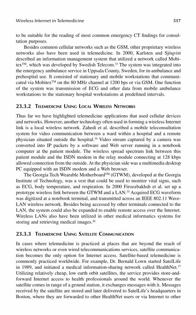
Wireless Internet in Telemedicine 517
to be suitable for the reading of most common emergency CT findings for consul-tation purposes.
Besides common cellular networks such as the GSM, other proprietary wirelessnetworks also have been used in telemedicine. In 2000, Karlsten and Sjöqvistdescribed an information management system that utilized a network called Mobi-texTM, which was developed by Swedish Telecom.33 The system was integrated intothe emergency ambulance service in Uppsala County, Sweden, for in-ambulance andprehospital use. It consisted of stationary and mobile workstations that communi-cated via MobitexTM on the 80 MHz channel at 1200 bps or via GSM. One functionof the system was transmission of ECG and other data from mobile ambulanceworkstations to the stationary hospital workstations at predefined intervals.
23.3.2 TELEMEDICINE USING LOCAL WIRELESS NETWORKS
Thus far we have highlighted telemedicine applications that used cellular devicesand networks. However, another technology often used in forming a wireless Internetlink is a local wireless network. Zahedi et al. described a mobile teleconsultationsystem for video communication between a ward within a hospital and a remotephysician situated outside the hospital.34 Video stream captured by a camera wasconverted into IP packets by a software and Web server running in a notebookcomputer at the patient module. The wireless spread spectrum link between thispatient module and the ISDN modem in the relay module connecting at 128 kbpsallowed connection from the outside. At the physician side was a multimedia desktopPC equipped with an ISDN modem and a Web browser.
The Georgia Tech Wearable MotherboardTM (GTWM), developed at the GeorgiaInstitute of Technology, was a vest that could be used to monitor vital signs, suchas ECG, body temperature, and respiration. In 2000 Firoozbakhsh et al. set up aprototype wireless link between the GTWM and a LAN.35 Acquired ECG waveformwas digitized at a notebook terminal, and transmitted across an IEEE 802.11 Wave-LAN wireless network. Besides being accessed by other terminals connected to theLAN, the system could also be expanded to enable remote access over the Internet.Wireless LANs also have been utilized in other medical informatics systems forstoring and retrieving medical images.36
23.3.3 TELEMEDICINE USING SATELLITE COMMUNICATION
In cases where telemedicine is practiced at places that are beyond the reach ofwireless networks or even wired telecommunications services, satellite communica-tion becomes the only option for Internet access. Satellite-based telemedicine iscommonly practiced worldwide. For example, Dr. Bernald Lown started SatelLifein 1989, and initiated a medical information-sharing network called HealthNet.37
Utilizing relatively cheap, low earth orbit satellites, the service provides store-and-forward Internet access to health professionals around the world. Whenever thesatellite comes in range of a ground station, it exchanges messages with it. Messagesreceived by the satellite are stored and later delivered to SatelLife’s headquarters inBoston, where they are forwarded to other HealthNet users or via Internet to other

518 Handbook of Wireless Internet
Internet users. If users want to surf the Internet, they use a special Web-browsingsoftware to issue requests, which are later processed at headquarters. The desiredinformation is then sent to the users in subsequent message exchanges betweensatellite and users’ stations.
Another recent example is a Web-based PACS developed by Hwang et al. in2000.38 An asymmetric satellite data communication system (ASDCS) allowed aremote hospital to download medical information from the telemedicine center’sserver. The client side had a PC installed with equipment capable of Ku-band andC-band satellite links. The radiological images and patient information could beviewed on a typical Web browser with the help of a Web application written in Java.
23.4 CASE STUDY: WAP IN TELEMEDICINE
23.4.1 OBJECTIVE
As seen in the last section, numerous telemedicine applications are based on theInternet and the mobile phone. Some of the recent examples even reflect the con-vergence of wireless communications and computer network technologies.39 Thistrend also is realized with the emergence of new mobile phones, PDAs, cellularmodems, wireless infrastructure and networks, and mobile application programminglanguages and protocols. There are various application protocols, such as WirelessApplication Protocol (WAP) and i-mode; application technologies, including JavaVersion 2 Micro Edition (J2METM); and operating systems, such as Symbian, PocketPC 2002, and Palm OS®, aimed at supporting various wireless devices.
WAP-enabled devices are now commonly available. As WAP also will be afeature found in various future handheld devices, it is worthwhile to investigate itspossible use in telemedicine. This section describes the implementation and expe-riences with a WAP-based telemedicine system recently developed.40–41 It was testedwith an emulator and with a WAP phone using wireless connections provided by amobile phone service provider in Hong Kong. Store-and-forward monitoring andanalysis of wireless ambulatory ECG and other parameters also were demonstrated.
23.4.2 METHOD
23.4.2.1 System Specification
The WAP programming model is shown in Figure 23.1. A handheld WAP devicecommunicates with a content server, which stores information and responds to theusers’ requests. A WAP gateway translates and passes information between thedevice and the server.42 To access an application stored at the content server, thedevice’s WAP browser first initiates a connection with the gateway before requestingfor content. The gateway converts these requests into HTTP format for the server.After processing, the server sends the content to the gateway, which then translatesit into WAP format for the WAP device. The layers of WAP protocols that governthe communication are shown in Figure 23.2.
To determine which telemedicine applications are feasible with WAP, it is impor-tant to examine the capabilities of a typical WAP device. Such a device has limited
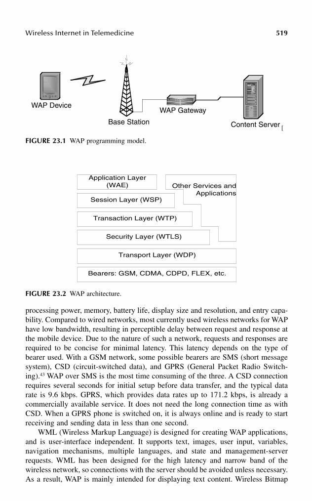
Wireless Internet in Telemedicine 519
processing power, memory, battery life, display size and resolution, and entry capa-bility. Compared to wired networks, most currently used wireless networks for WAPhave low bandwidth, resulting in perceptible delay between request and response atthe mobile device. Due to the nature of such a network, requests and responses arerequired to be concise for minimal latency. This latency depends on the type ofbearer used. With a GSM network, some possible bearers are SMS (short messagesystem), CSD (circuit-switched data), and GPRS (General Packet Radio Switch-ing).43 WAP over SMS is the most time consuming of the three. A CSD connectionrequires several seconds for initial setup before data transfer, and the typical datarate is 9.6 kbps. GPRS, which provides data rates up to 171.2 kbps, is already acommercially available service. It does not need the long connection time as withCSD. When a GPRS phone is switched on, it is always online and is ready to startreceiving and sending data in less than one second.
WML (Wireless Markup Language) is designed for creating WAP applications,and is user-interface independent. It supports text, images, user input, variables,navigation mechanisms, multiple languages, and state and management-serverrequests. WML has been designed for the high latency and narrow band of thewireless network, so connections with the server should be avoided unless necessary.As a result, WAP is mainly intended for displaying text content. Wireless Bitmap
[
FIGURE 23.1 WAP programming model.
FIGURE 23.2 WAP architecture.
WAP Device
Content Server
WAP Gateway
Base Station
Application Layer(WAE)
Session Layer (WSP)
Transaction Layer (WTP)
Security Layer (WTLS)
Transport Layer (WDP)
Bearers: GSM, CDMA, CDPD, FLEX, etc.
Other Services andApplications

520 Handbook of Wireless Internet
Format (WBMP) is a graphics format optimized for efficient transmission over low-bandwidth networks and minimal processing time in WAP devices.
These technical capabilities suggest that use of current WAP devices in telemed-icine is feasible in applications operating in a store-and-forward, client/server, andlow-bandwidth fashion. The displayed information is limited to text and low-reso-lution WBMP static images. When displaying graphical information, it is better tofirst construct the image at the server, thus reducing the usage of memory andprocessing time at the device.
Based on these requirements, a WAP-based telemedicine system has been devel-oped. Applications include viewing of general patient information, previously cap-tured BP and heart rate readings, and recorded ECG waveforms. Other functionsare remote request for doctors’ appointments and general inquiries on clinic andhospital information. Targeted users are both doctors and patients. Figure 23.3 showsgeneral features of the system.
An ECG browsing function is included because of the increasing need forambulatory ECG monitoring. In 1999, heart disease accounted for 30 percent of alldeaths worldwide.44 Monitoring services would allow early detection and diagnosisof pathological symptoms, and thus lead to earlier treatment. A major concern fordisplaying the ECG is the small screen size and low display resolution of a WAPphone. A group has tried displaying ECG on a 160 × 144 pixels LCD gray-scaledisplay of a handheld video game platform, and it was shown that some basic featuressuch as R-R intervals were still recognizable with the user’s selection of the leaddisplayed and time scale used.45 Noting that the display resources on a WAP deviceare similar to those of the game platform, ECG browsing with the WAP-based systemshould be possible.
23.4.2.2 Overall Architecture
The developed system was set up for testing the feasibility of telemedicine withWAP. Figure 23.4 shows the architecture for the connection between a WAP deviceand the content server. Applications were stored in the content server. Part of theuser interface was written in WML and WMLScript, which executed at the WAPdevice after being downloaded from the server. The other part of the application,
FIGURE 23.3 General features of the WAP-based telemedicine system.
User Authenticationand Login
USER MENU
Clinic InformationHospital
Information
Appointments Patient Record
ECG Browsing
BP Browsing
Heart RateBrowsing

Wireless Internet in Telemedicine 521
written in Perl, executed within the Linux-based content server.46 It provided thecommon gateway interface (CGI) for more-complex tasks. Using the GD and CGImodules, the Perl program could dynamically create WBMP graphics and WMLdecks upon requests from the WAP device. Patient data that the applications accessedand manipulated were stored in a relational database system.
23.4.2.3 Relational Database
A relational database is made up of tables and columns that relate to one another.MySQL is a relational database management system (DBMS) that can handle mul-tithreaded operations.47 It also has many application programming interfaces (API),including Perl, TCL, Python, C/C++, JDBC, and ODBC, thus enabling access to thedatabase by applications written in various languages. MySQL uses the StructuredQuery Language (SQL) to manipulate, create, and display data within a database.
For the telemedicine system, a MySQL database system consisting of twodatabases at two different sites was set up to store data, including BP and heart-ratereadings, patient records, clinic and hospital information, doctors’ appointments withpatients, and recorded ECG. One database resided in the content server, and anotherin a remote PC. During WAP access, data was retrieved by the applications throughPerl’s Database Interface (DBI), as shown in Figure 23.4. By specifying permissionsgiven by each database, the application could access data not only in the contentserver, but also data in remote databases. Figure 23.5 shows the entity-relationship(ER) model, which is a high-level conceptual representation of data contained withinthe database.48
23.4.2.4 Program for WAP Access
The flow of the program starts when the user accesses the first WML deck at apredefined site. The following WML decks that the user interacts with are thengenerated by Perl. The user first logs into the WAP site and loads the first card(login.wml), which prompts for username and password. Using CGI with method
FIGURE 23.4 Structure of the system.
Content Server
Database:BP, ECG, Patient Data, Clinic andHospital Information, Appointments
Application:Perl CGI Scripts
WAPGateway
WAPDevice
RequestRequest
Response Response
DBI
ExternalDatabase:BP, ECG,
Patient Data,Clinic andHospital
Information,Appointments

522 Handbook of Wireless Internet
‘post,’ Perl first takes the user inputs. It then accesses the TABLE USER of thedatabase through the DBI. If the user chooses to view patient information, the patientID must be entered. A menu is then generated if the patient ID is valid and accessible.The user has the choice of viewing general information, a single blood pressurereading, a day log of blood pressures, ECG browsing, and heart-rate reading. Theprocess flow is shown in Figure 23.6.
The menu for single blood pressure reading works in a similar way. After a listof BP recording sessions is displayed, the user chooses the session. Perl then searchesthrough TABLE BP, and charts out the date, time, pulse rate, and the systolic,diastolic, and mean pressure values in WML format. The day log for blood pressureallows the user to view all the pressure values of a day in chart or graphical form.To display BP graphs, the program first searches through TABLE BP and stores thenecessary values in a temporary array, which is then used along with the GD moduleto create a WBMP file called by the WML card. Scrollable graphs are presented byupdating the array with a new set of data from the database whenever the userchooses to scroll forward or backward.
When a user browses through the ECG waveform for a specified recordingsession, the program first searches through TABLE ECG for details, such as samplingrate, recording time, and duration. Recorded ECG data for each session is stored ina separate ECG data table named according to the names in TABLE ECG. To displaythe ECG, the program traverses through the ECG data table with a pointer, and loadsthe necessary data points into a temporary array. According to the information inTABLE ECG, it creates a WBMP for each new frame of ECG waveform. The useralso can view the waveform with the choice of time-scale, scroll direction, and scrolldistance. This flow is summarized in Figure 23.7. Inquiry service for hospital andclinic information also is available by accessing TALBES CLINIC and HOSPITAL.
23.4.2.5 ECG Browsing and Feature Extraction
The heart serves as the pump for the circulatory system. The well-coordinatedpumping action of its four chambers are a result of a series of electrical depolariza-tions and repolarizations over different regions of the heart, and these activationsequences establish conduction fields which also extend to the body surface. The
FIGURE 23.5 Entity-relationship model of the database.
PATIENT
HR
ECG
BP
HOSPITAL
ECG_RE
HR_RE
BP_RE
DOCTOR N
N
N
1
1
1
CLINIC
N DOCT_PAT_RE
N
DOCT_CLIN__RE
N
NAppiont
mentN
N
USERS

Wireless Internet in Telemedicine 523
heart can be viewed as an electrical equivalent generator, and at each instant of time,the electrical activity of the heart can be represented by a net equivalent currentdipole located at a point of the heart.49 The thoracic medium can be considered aresistive load, resulting in attenuation of the field with increasing distance from thesource, as well as potential drops measured between two points measured on thebody surface. Measurement of the resulting electrical potentials between different
FIGURE 23.6 Flow of the WAP application; login, patient information menu, and patientgeneral information.
LOGIN CARD(login.wml )
User enters usernameand password
Perl accesses TABLEUSER of the databaseand checks username
and password
VALID?
NO
Perl accesses TABLEUSER to check theaccess level (admin,doctor, patient) of
the user
YES
According to theaccess level, present
the user menu
MENU1.) Patient Info
2.) Appointments
1.) Patient Info
MENUA.) General infoB.) Single blood pressure readC.) Day log of blood pressureD.) ECG browsingE.) Heart rate reading
According to accesslevel, look in TABLE
PATIENT, andlist out patient ID's
for accessible patientinfo
User chooses PatientID
A.) General Info
MENUi.) Name, Birthdateii.) Phone / Faxiii.) Addressiv.) Picture
Look in TABLEPATIENT and
display thecorresponding info
Logout or return menu

524 Handbook of Wireless Internet
sites on the body surface is the ECG, which provides information on the conditionof the heart. Its dynamic range is from 10 µV to 5 mV, and its bandwidth is from0.05 to 1000 Hz; however, 0.05 to 80 Hz is adequate for most monitoring purposes.50
For initial testing of ECG browsing, a Lead I waveform from a subject wassampled at 250 samples per second by a data acquisition unit, stored as delimitednumbers in a file, and loaded into the content server. A Perl program then extractedthe sample points from the file and stored them inside an indexed table in thedatabase. Recording sessions were stored in ECG data tables. Because the display
FIGURE 23.7 Flow of the WAP application; ECG browsing, heart rate reading, andappointments.
D.) ECG browsing
Look in TABLESECG, ECG_RE,and
display ECG_ID,date, and time
User choosesECG_I D
Look in thecorresponding
TABLE that storesthe chosen ECG
session
MENU- scroll direction (forward, backward- scroll distance (0, 0.4s, 1.2s)- time scale (0.5, 1, 2)- analyze ECG (figures on waveform,
figures only in chart)
Logout or return tomenu
NO
View more? YES
Display ECG
Adjust parameters; perform analysis
E.) Heart ratereading
Look in TABLES HRand HR_RE , and
display dates
User chooses dateview
Access TABLE HR and display thecorresponding
readings
Logout or return menu
2.) Appointments
User enters clinic ID
Look in TABLEAPPOINTMENT,
and display thetimetable
User chooses timeslot and confirm
Logout or return tomenu
Look in Table;Conflict?
Modify TABLEAPPOINTMENT
NO
YES
Display warningmessage

Wireless Internet in Telemedicine 525
size and resolution are limited on a WAP device, performing feature extraction wouldfurther enhance the feasibility of using WAP in viewing the acquired data. Todemonstrate this, a QRS detection program was written in Perl, providing estimationof QRS occurrence times and R-R intervals in the recorded ECG. The algorithmused was based on amplitude and first derivative.51
Upon receiving a request for estimating the QRS occurrence times, the programretrieves the ECG data of the specified part of the recording session from thedatabase, and puts it into a one-dimensional array of sample points of the ECG. Forexample, for 9000 sample points, the array is in the form
X[n] = X[0], X[1], X[2], … X[8999]
The first derivative, Y[n], is then calculated at each point of X[n]:
Y[n] = X[n + 1] – X[n – 1], 1 < n < 8998
A QRS candidate occurs when three consecutive points in the Y[n] array exceed apredefined positive slope threshold, TH_POS, and are followed within the next 100ms by two consecutive points which exceed a predefined negative slope threshold,TH_NEG.
Y[i], Y[i + 1], Y[i + 2] > TH_POS
and
Y[j], Y[j+1] < TH_NEG
where (i + 2) < j < (i + 25). The value of 25 is based on the sampling rate of 250samples per second. Each sample interval is
1/250 = 0.004 s
Therefore, the number of samples that corresponds to 100 ms is
0.1/0.004 = 25
Once such a QRS candidate is detected, all X[n] data points that are between theonset of the rising slope and before the end of the descending slope must exceedthe amplitude threshold, TH_AMP, in order to be considered a valid QRS complex.
X[i], X[i + 1], …, X[j + 1] > TH_AMP
Finally, the occurrence times of the highest points in the QRS complexes are putinto an array, which is then used in the dynamic construction of chart or graphicaldisplay in WML and WBMP format (see Figure 23.16).
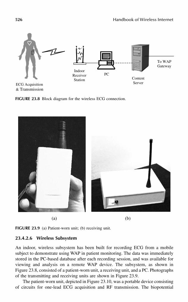
526 Handbook of Wireless Internet
23.4.2.6 Wireless Subsystem
An indoor, wireless subsystem has been built for recording ECG from a mobilesubject to demonstrate using WAP in patient monitoring. The data was immediatelystored in the PC-based database after each recording session, and was available forviewing and analysis on a remote WAP device. The subsystem, as shown inFigure 23.8, consisted of a patient-worn unit, a receiving unit, and a PC. Photographsof the transmitting and receiving units are shown in Figure 23.9.
The patient-worn unit, depicted in Figure 23.10, was a portable device consistingof circuits for one-lead ECG acquisition and RF transmission. The biopotential
FIGURE 23.8 Block diagram for the wireless ECG connection.
FIGURE 23.9 (a) Patient-worn unit; (b) receiving unit.
ECG Acquisition& Transmission
IndoorReceiverStation Content
Server
PC
To WAPGateway
(a) (b)

Wireless Internet in Telemedicine 527
sensed by Ag-AgCl prejelled electrodes was fed into an instrumentation amplifierwith gain of 1000, followed by AC coupling and a Butterworth lowpass filter havingcutoff frequency at 150 Hz. After conditioning, the analog signal was input to a two-stage, SAW-controlled, 433 MHz FM transmitter operating on 3V supply voltagewith transmitting power of 10 mW. A 24-turn helical antenna was used. Figure 23.11shows the receiving unit, which consisted of a double conversion FM Superhetreceiver operating on a 3V supply voltage, an 8-bit analog-to-digital converter(ADC), an 8-bit microcontroller unit (MCU), and interfacing circuits for connectionto a PC via serial port.
The receiver was connected to a 1/4 wavelength whip antenna, and drew 14 mAwhen receiving. Output of the receiver was digitized by the ADC at 240 samplesper second, fed to the MCU, and pushed into the PC’s serial port through an RS232transceiver at a baud rate of 19,200. The program that resided in the PC was writtenin Visual Basic 6.0. During each recording session, assigned a unique identifier, theprogram would read data from the serial port and save it into the PC-based databasethrough ODBC DBI. The program also provided an interface for direct access tothe database. The program interfaces are presented in Figure 23.12.
23.4.3 RESULTS
23.4.3.1 Emulation
All the applications were first tested with an emulation software before using actualWAP phones. The NokiaTM WAP Toolkit was used on a Windows platform to emulatehow the applications would appear on a WAP phone. Applications were loadeddirectly from the server through the Internet. The setup is shown in Figure 23.13.Figures 23.14 to 23.17 are some screenshots of the interface.
23.4.3.2 Experience with WAP Phone
An actual WAP 1.1-compliant phone was used at GSM 1800 MHz through CSD toconnect to the same WAP site. The gateway used in the link was provided by a
FIGURE 23.10 Patient-worn unit.
FIGURE 23.11 Receiving unit.
InstrumentationAmplifier
AC-Coupleand Lowpass
Filter
SignalConditioning
Transmitter
ReceiverSignal
Conditioning8-bit ADC
8-bit 8051MCU
RS232Transceiver
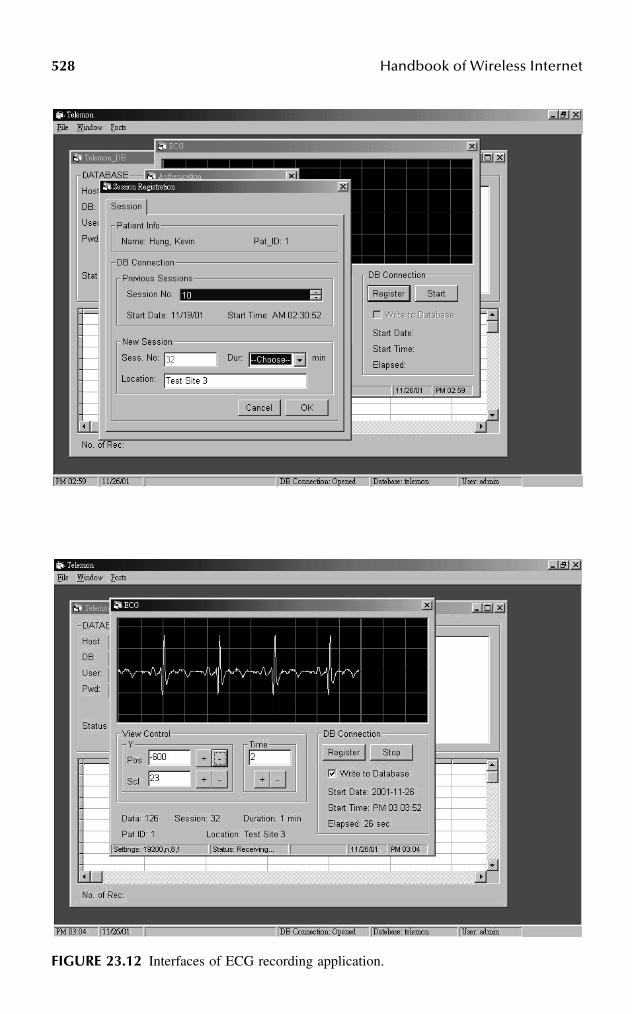
528 Handbook of Wireless Internet
FIGURE 23.12 Interfaces of ECG recording application.

Wireless Internet in Telemedicine 529
FIGURE 23.13 Setup for accessing WAP applications with emulation software.
FIGURE 23.14 (a) Login menu; (b) patient data menu.
FIGURE 23.15 Display of blood pressure readings. (a) readings from a single blood pressuremeasurement; (b) readings within a day; (c) graphical display of systolic pressures within aday; (d) graphical display of diastolic pressures within six hours.
FIGURE 23.16 ECG browsing. (a) ECG browsing with a 2-sec window; (b) ECG browsingwith a 0.5-sec window; (c) ECG browsing with QRS occurrence times estimation functionactivated; (d) Chart for estimated QRS occurrence times and R-R intervals.
ContentServer
InternetEmulatorApplicationon Computer
(a) (b) (c) (d)
(a) (b) (c) (d)

530 Handbook of Wireless Internet
mobile phone service provider in Hong Kong. Figure 23.18 describes the setup, andFigures 23.19 to 23.22 show some screenshots of the interfaces.
The time required for establishing a connection to the site was about 10 to 12seconds. Starting from the time of request for information at the phone, the timerequired for database query, dynamic generation of WML and WBMP, and displayof new information at the device ranged from 3 to 5 seconds on average.
FIGURE 23.17 Display of patient general data.
FIGURE 23.18 Setup for accessing WAP applications with WAP phone.
FIGURE 23.19 User menus.
WAPPhone
InternetBaseStation
ContentServer
WAPGateway

Wireless Internet in Telemedicine 531
23.4.4 DISCUSSION
Viewing and analyzing patient data have been demonstrated on a WAP phone. Thisincluded interactive feature extraction of medical data. Although response time waslong, the feasibility of such a system is expected to improve in the future, as newerversions of the WAP specification will be integrated into 3G mobile phones, whichoperate at a much higher data rate and have more on-board resources.
FIGURE 23.20 Display of blood pressure readings. (a) readings from a single blood pressuremeasurement; (b) BP menu; (c) graphical display of systolic pressures within a day;(d) graphical display of diastolic pressures within six hours.
FIGURE 23.21 ECG browsing. (a) ECG browsing with estimated QRS occurrence times;(b) Chart for estimated QRS occurrence times and R-R intervals.
FIGURE 23.22 Display of patient general data.

532 Handbook of Wireless Internet
An issue of concern, as in all telemedicine applications, is security. The securityfeatures of a WAP-based system are implemented at several levels. WAP implementsmost of its security in WTLS (Wireless Transport Layer Security) protocol, whichis the wireless equivalent of TLS (Transport Layer Security) protocol. Because dataare encrypted between the phone and the gateway (at which point they are decryptedby the gateway before being reencrypted and sent on to the content server over aTLS connection over the Internet), the gateway has access to all of the data indecrypted form. Therefore, using a WAP gateway hosted by a third party is notrecommended for telemedicine applications. The solution is to set up a private WAPgateway for the application.
There is still much room for improvement in this system. One area is to utilizethe push technology provided by WAP 1.2 and higher. WAP-based push can useSMS or cell-broadcast as the bearer to transmit packets over the wireless network.This messaging service will further enhance the feasibility of using WAP for patientmonitoring. When a real-time analysis program detects pathological abnormality inthe recorded data, the content server will be able to send a short message to theWAP devices carried by the doctor or the patient.
The wireless subsystem is being upgraded to use BluetoothTM for transmission.Wireless medical sensors based on conventional infrared or radio frequency trans-mission have been developed by others.52–54 However, the small size and low powerconsumption of the radio module, use of 2.4 GHz frequency hopping spread spec-trum, and the design for short-range transmission makes BluetoothTM an attractiveoption in dynamic monitoring of physiological signals for telemedicine. Some partieshave already integrated the technology into medical applications.55,56 Further testson the telemedicine system will be accessing the site with PDAs and PDA-phones,and connecting with GPRS. The system can be expanded also to a network ofdatabases for resource sharing. Currently, another content server that uses JavaServlet and Extensible Markup Language (XML) has been set up.
23.5 ISSUES TO BE RESOLVED
Because telemedicine involves crucial information exchange over communicationnetworks, security has always been a prominent concern. Security measures shouldbe provided at the network and access levels, and a separate, private network oftenis required. As seen in the examples presented, data transmitted across a telemedicinesystem can be huge files such as high-resolution images, or time-critical information,including video streams and real-time physiological signals. A major bottleneck inusing wireless Internet for applications like these is the low data transfer rate, becausebandwidth provided by wireless communication is still generally lower than thatprovided by wired communication. This problem can even defeat the purpose ofusing telemedicine if the situation is not evaluated carefully before system imple-mentation. One solution is to compress the data before transmission. Various lossyand lossless compression algorithms specifically for telemedicine already have beendeveloped. In cases with lossy compression, the decompressed data should containenough information in order to be qualified for proper clinical diagnosis. All these

Wireless Internet in Telemedicine 533
challenges become even more complicated as new wireless and medical technologiescontinue to emerge.
Inevitably, we are lead to the point where standards for medical informationexchange are needed to ensure reliability, interoperability, and widespread use oftelemedicine. Medical equipment industries and health care organizations haveattempted to develop different standards, such as Digital Imaging and Communica-tions (DICOM) and Health Level Seven (HL7), over the past few decades.57 Despiteall these efforts, there is still a need for a set of standards that are globally accepted.The IEEE 1073, currently still under construction, is a set of standards for medicalequipment communication. Among these, transport standards for wireless commu-nication also are investigated. The third generation of cellular communication is onits way. Data rate will be significantly higher, and 3G devices will have multimediacapability. This will undoubtedly bring telemedicine into a new era. The majorchallenge here is merging it with the existing telemedicine systems and at the sametime conforming to the standards.
REFERENCES
1. Bashshur, R.L., Telemedicine and the health care system, in Telemedicine: Theoryand Practice, Bashshur, R.L., Sanders, J.H., and Shannon, G.W., Eds., Charles CThomas, Springfield, IL, 1977.
2. Darkins, A.W. and Cary, M.A., Telemedicine and Telehealth: Principles, Policies,Performance, and Pitfalls, Springer, New York, 2000.
3. Lin, J.C., Applying telecommunication technology to health-care delivery, IEEE Eng.Med. Biol. Mag., 18 (4), 28, 1999.
4. Craig, J., Introduction, in Introduction to Telemedicine, Wootton, R. and Craig, J.,Eds., Royal Society of Medicine Press, Glasgow, 1999.
5. Huang, H.K, PACS: Basic Principles and Applications, John Wiley & Sons, NewYork, 1999.
6. United Nations, World Population Ageing: 1950–2050, United Nations Publications,New York, 2001.
7. United Nations, The World Aging Situation: Strategies and Policies, United NationsPublication, New York, 1985.
8. Kart, C.S., Metress, E.K., and Metress, S.P., Human Aging and Chronic Disease,Jones and Bartlett, London, 1992.
9. Timiras, P.S., Ed., Physiological Basis of Aging and Geriatrics, CRC Press, BocaRaton, FL, 1994.
10. Sosa-Iudicissa, M., Wootton, R., and Ferrer-Roca, O., History of telemedicine, inHandbook of Telemedicine, Ferrer-Roca, O. and Sosa-Iudicissa, M., Eds., IOS Press,Amsterdam, 1988.
11. Field, M.J., Telemedicine: A Guide to Assessing Telecommunications in Health Care,National Academy Press, Washington, D.C., 1996.
12. Holland, J.J., Classic episodes in telemedicine: treatment by telegraph, J. Telemed.Telecare, 3 (4), 223, 1997.
13. Kenny, E., Classic episodes in telemedicine: diagnosis by telegraph, J. Telemed.Telecare, 4 (4), 223, 1998.
534 Handbook of Wireless Internet
14. McKinney, W.P. and Bunton, G., Exploring the medical applications of the Internet:a guide for beginning users, Am. J. Med. Sci., 306 (3), 141, 1993.
15. Fisk, N.M. et al., Intercontinental fetal surgical consultation with image transmissionvia Internet, Lancet, 341, 1601, 1993.
16. Yamamoto, L.G. et al., Telemedicine using the Internet, Am. J. Emerg. Med., 14 (4),416, 1996.
17. Yamamoto, L.G. and Suh, P.J., Accessing and using the Internet’s World Wide Webfor emergency physicians, Am. J. Emerg. Med., 14 (3), 302, 1996.
18. Della Mea, V., Internet electronic mail: a tool for low-cost telemedicine, J. Telemed.Telecare, 5 (2), 84, 1999.
19. Magrabi, F. et al., Web based longitudinal ECG monitoring, in Proc. 20th Ann. Int.Conf. IEEE EMBS, Chang, H.K. and Zhang, Y.T., Eds., Hong Kong, 20 (3), 1155,1998.
20. Park, S. et al., Real-time monitoring of patients on remote sites, in Proc. 20th Ann.Int. Conf. IEEE EMBS, Chang, H.K. and Zhang, Y.T., Eds., Hong Kong, 20 (3),1321, 1998.
21. Kong, K.Y., Ng, C.Y., and Ong, K., Web-based monitoring of real-time ECG data,Comput. Cardiol., 27, 189, 2000.
22. Pollard, J.K., Rohman, S. and Fry, M.E., A Web-based mobile medical monitoringsystem, in International Workshop on Intelligent Data Acquisition and AdvancedComputing Systems: Technology and Applications, Foros, 32, 2001.
23. Bai, J. et al., A portable ECG and blood pressure telemonitoring system, IEEE Eng.Med. Biol. Mag., 18 (4), 63, 1999.
24. Yamamoto, L.G., Wireless teleradiology and fax using cellular phones and notebookPCs for instant access to consultants, Am. J. Emerg. Med., 13 (2), 184, 1995.
25. Yamamoto, L.G., Instant pocket wireless telemedicine consultations, Pediatrics, 104(3), 670, 1999.
26. Yamamoto, L.G. and Williams, D.R., A demonstration of instant pocket wireless CTteleradiology to facilitate stat neurosurgical consultation and future telemedicineimplications, Am. J. Emerg. Med., 18 (4), 423, 2000.
27. Yamamoto, L.G. and Shirai, L.K., Instant telemedicine ECG consultation with car-diologists using pocket wireless computers, Am. J. Emerg. Med., 19 (3), 248, 2001.
28. Giovas, P. et al., Transmission of electrocardiograms from a moving ambulance, J.Telemed. Telecare, 4 (1), 5, 1998.
29. Curry, G.R. and Harrop, N., The Lancashire telemedicine ambulance, J. Telemed.Telecare, 4 (4), 231, 1998.
30. Pavlopoulos, S. et al., A novel emergency telemedicine system based on wirelesscommunication technology — AMBULANCE, IEEE Trans. Inf. Technol. Biomed., 2(4), 261, 1998.
31. Reponen, J. et al., Digital wireless radiology consultations with a portable computer,J. Telemed. Telecare, 4 (4), 201, 1998.
32. Reponen, J. et al., Initial experience with a wireless personal digital assistant as ateleradiology terminal for reporting emergency computerized tomography scans, J.Telemed. Telecare, 6 (1), 45, 2000.
33. Karlsten, R. and Sjöqvist, B.A., Telemedicine and decision support in emergencyambulances in Uppsala, J. Telemed. Telecare, 6 (1), 2000.
34. Zahedi, E. et al., Design of a Web-based wireless mobile teleconsultation system witha remote control camera, in Proc. 22nd Ann. IEEE EMBS Int. Conf., Enderle, J.D.,Ed., Chicago, 2000.
Wireless Internet in Telemedicine 535
35. Firoozbakhsh, B. et al., Wireless communication of vital signs using the GeorgiaTech Wearable Motherboard, in 2000 IEEE Int. Conf. on Multimedia and Expo, 3,1253, 2000.
36. Pedersen, P.C. et al., Low cost wireless LAN based medical informatics system, inProc. 1st Joint BMES/EMBS Conf., Blanchard, S.M. et al., Eds., Atlanta, 1225, 1999.
37. Groves, T., SatelLife: getting relevant information to the developing world, Br. Med.J., 313 (7072), 1606, 1996.
38. Hwang, S. et al., Development of a Web-based picture archiving and communicationsystem using satellite data communication, J. Telemed. Telecare, 6 (2), 91, 2000.
39. Coiera, E., Guide to Medical Informatics, the Internet and Telemedicine, Chapman& Hall, London, 1997.
40. Hung, K. and Zhang, Y.T., On the feasibility of the usage of WAP devices in tele-medicine, in Proc. 2000 IEEE EMBS Int. Conf. on Information Technology Appli-cations in Biomedicine, Laxminarayan, S., Ed., Arlington, VA, 2000.
41. Hung, K., Zhang, Y.T., Web-based telemedicine applications, in Ann. Conf. of Eng.and the Physical Sci. in Med. and Asia Pacific Conf. on Biomed. Eng., Fremantle,2001.
42. Mann, S., Programming applications with the Wireless Application Protocol: thecomplete developer’s guide, John Wiley & Sons, New York, 1999.
43. Arehart, C., et al., Professional WAP, Wrox Press, Birmingham, 2000, 34.44. World Health Organization, Death by cause, sex and mortality stratum in WHO
Regions, estimates for 1999.45. Rohde, M.M., Bement, S.L. and Lupa, R.S., ECG boy: low-cost medical instrumen-
tation using mass-produced, handheld entertainment computers, Biomed. Inst. Tech.,32 (5), 1998, 497.
46. Cozens, S. and Wainwright, P., Beginning Perl, Wrox Press, Birmingham, 2000.47. DuBois, P., MySQL, New Riders, Indianapolis, 2000.48. Elmasri, R. and Navathe, S.B., Fundamentals of Database Systems, Benjamin/Cum-
mings, Redwood City, CA, 1994.49. Webster, J.G., Medical Instrumentation: Application and Design, 3rd ed., John Wiley
& Sons, New York, 1998.50. Kenedi, R.M., A Textbook of Biomedical Engineering, Blackie & Son, East Kilbride,
1980.51. Friesen, G.M. et al., A comparison of the noise sensitivity of nine QRS detection
algorithms, IEEE Trans. Biomed. Eng., 37 (1), 85, 1990.52. Leung, S.W., Wireless electrode for electrocardiogram (ECG) signal, M.Phil. thesis,
The Chinese University of Hong Kong, 1999.53. Santic, A., Theory and application of diffuse infrared biotelemetry, CRC Crit. Rev.
Biomed. Eng., 18 (4), 289, 1991.54. Yang, B., Rhee, S., and Asada, H.H, A Twenty-four hour tele-nursing system using
a ring sensor, in Proc. 1998 IEEE Int. Conf. Robotics and Automation, Leuven,Belgium, 387, 1988.
55. Berggren, M., Wireless communication in telemedicine using Bluetooth and IEEE802.11b, Master’s thesis, Dept. of Computer Systems, Uppsala University, 2001.
56. Ortivus, http://www.ortivus.com57. Blair, J.S., Overview of Standards Related to the Emerging Health Care Information
Infrastructure, in The Biomedical Engineering Handbook, 2nd ed., Bronzino, J.D.,Ed., CRC Press, Boca Raton, FL, 2000.

This page intentionally left blank

5370-8493-1502-6/03/$0.00+$1.50© 2003 by CRC Press LLC
24 Delivering Music over the Wireless Internet: From Song Distribution to Interactive Karaoke on UMTS Devices
Marco Roccetti, Paola Salomoni, Vittorio Ghini, Stefano Ferretti, and Stefano Cacciaguerra
CONTENTS
Abstract ..................................................................................................................53824.1 Introduction ................................................................................................53824.2 System Issues .............................................................................................54024.3 A Wireless Internet Application for Music Distribution...........................542
24.3.1 Search and Download of Musical Resources .............................54324.3.2 Design Principles .........................................................................54424.3.3 Structuring Karaoke Clips ...........................................................549
24.4 An Experimental Study..............................................................................55124.4.1 UMTS Simulation Model ............................................................55224.4.2 Song-On-Demand: Measurement Architecture and Results .......55324.4.3 Mobile Karaoke: Measurement Architecture and Results ..........556
24.5 Related Work and Comparison ..................................................................55924.5.1 Distribution of Multimedia Resources over the Internet ............55924.5.2 Wireless Access to the Internet ...................................................56024.5.3 Multimedia Synchronization for Delivering Karaoke.................561
24.6 Concluding Remarks..................................................................................562Acknowledgments..................................................................................................564References..............................................................................................................564

538 Handbook of Wireless Internet
ABSTRACT
The pace of developments in wireless technology is enabling a wide range of excitingapplications, including location-aware systems, wearable computers, wireless sensornetworks, and novel use of cellular telephony systems. Many of those applicationsmay play the role of key drivers of future wireless technology provided that theymay guarantee affordable access, ubiquitous reach, and an effective service-deliverymodel. In this challenging scenario, a growing demand is emerging for deliveringmodern multimedia entertainment services to wireless handheld devices on a largescale. In this chapter, we report on our experience in developing a wireless Internetapplication designed to deliver advanced musical services to mobile consumers overUniversal Mobile Telecommunications System (UMTS) links. In essence, our appli-cation allows mobile users to listen to songs and karaoke clips on UMTS-enableddevices by exploiting the Internet as a large musical storehouse. Field trials havebeen conducted that confirm that an adequate structuring of the wireless Internetapplication, along with the use of 3G (third generation) mobile network technologies,may be effective for the delivery of modern musical-entertainment services to mobileconsumers.
24.1 INTRODUCTION
With the advent of the twenty-first century, market forces are accelerating the paceof wireless technology evolution. It is widely anticipated that future mobile userswill enjoy a near-ubiquitous access to high-bandwidth wireless networks.1 Probably,mobile phone services represent the most-prominent example of widespread accessto wireless communication networks. Recently, notable efforts such as i-mode2 andWAP3 have been carried out to exploit phone-based wireless technology along withthe Internet, to provide Web services to mobile users. As of today, unfortunately,those efforts have resulted in little more than e-mail access and limited Web brows-ing. Although this situation is slowly improving, it is easy to envisage that old pricingschemes, along with content not suitably formatted for mobile phones, may limitthe interest of mobile consumers in wireless services.
However, in parallel with the recent improvements of high-bandwidth wirelesscommunications, the wired Internet’s progress has determined a significant innova-tion among music distribution paradigms. The maturing distributed file-sharingtechnology implemented by systems like Napster has enabled the dissemination ofmusical content in digital form, allowing consumers to link to stored music filesfrom around the world.
Hence, with users adopting Internet-enabled cellular phones and similar hand-held devices we may expect that a growing demand may emerge for wireless servicesthat enable mobile consumers to access music content from the large musical store-house represented by the Web.4
In this context, the 3G UMTS technology promises to be one of the milestonesin the process of building an adequate large-scale wireless infrastructure for deliv-ering musical services to mobile consumers. Important advantages of the UMTS
Delivering Music over the Wireless Internet 539
technology amount to the fact that packets originating from UMTS devices can bedirectly transmitted to IP networks (and vice versa), while specific quality of serviceguarantees may be provided over the wireless links. Additionally, UMTS offershigher data rates (up to a few Mbps) and an increased capacity. These data ratesplus compression techniques will allow users to access HTML pages and video/audiostreaming, as well as enhanced multimedia services for laptops and smaller devices.5
Nevertheless, it is well known that even with the adoption of the UMTS tech-nology various technical communication problems may arise due to:
• The time-varying characteristics of the UMTS links• Possible temporary link outages• Protocol interference between the UMTS radio link level protocols and
the Internet transport protocols• Typical high bit error rates of the UMTS radio links
As a result, all the above-mentioned limitations may keep some older applica-tions designed for music distribution over the wired Internet from working efficientlyand effectively when deployed over UMTS-based mobile communications scenarios.
In this chapter, we describe a modern Internet wireless application we havedesigned to support the widespread delivery of musical services to Internet-enabledmobile phones and similar handheld devices over UMTS links. In particular, theprototype implementation of our wireless application allows mobile consumersequipped with UMTS-enabled devices to exploit the Internet as a vast storehouseof music resources, where two different musical services are provided, namely:
1. A mobile song-on-demand distribution service2. A mobile karaoke distribution service
The mobile song-on-demand distribution service permits to mobile users todownload and to listen to MP3 files6 on UMTS devices. Specifically, our wirelessapplication exploits the background traffic class of UMTS to provide its users with(1) a simple and rapid Internet-based mobile access to a music-on-demand downloadservice, (2) a robust and widely available music-on-demand distribution systembased on the technique of replicated Web servers, and (3) the possibility of interac-tively customizing the use of the system.
From a user’s perspective, it is worth noticing that different types of clients mayexploit the developed service. In particular, our wireless application may be exploitedby the following categories of users:
• Music listeners may search for their favorite songs over the Internet, down-load them onto their UMTS devices, and play them at their convenience.
• Music producers may wish to exploit our system to distribute their ownmusic. (At the current state of the art, this type of user needs a regularwireline Internet connection in order to upload musical resources to thesystem.)

540 Handbook of Wireless Internet
• Musical service providers may exploit our system to organize, build, andmaintain structured repositories of musical resources over the Internet foruse by UMTS-enabled consumers.
Karaoke is an MTV-type multimedia entertainment service that has gained muchpopularity in Asia, the United States and Europe. With the advent of the wirelessInternet and of Internet-enabled cellular phones, a growing demand is emerging fordelivering such multimedia entertainment services to wireless handheld devices ona large scale. In this context, the mobile karaoke distribution service we havedeveloped allows mobile users to download and to play multimedia karaoke clipsconstructed out of synchronized multimedia resources, such as music, text, andvideo. A karaoke clip is represented by means of a SMIL (Synchronized MultimediaIntegration Language) file containing the formal specification of the media sched-uling and synchronization activities concerning all the audio, video, and textualresources that compose a karaoke clip.7
The important experiences of P2P systems, such as Napster,8 Freenet,9 andGnutella,10 are at the basis of our music delivery services, but our Internet applicationis essentially new in the sense that it allows a reliable and distributed music sharingservice over wireless UMTS links. As previously mentioned, the choice of adoptingUMTS as the key technology for wireless access to the Internet has posed a set oftechnical challenges which will be discussed later in the chapter.
The reminder of this chapter is organized as follows. In Section 24.2, we discusssome technical obstacles we have surmounted for integrating wireless UMTS accesstechnology with the Internet. In Section 24.3, alongside the operational descriptionof our wireless Internet application we illustrate the design principles we havefollowed to design our system. Section 24.4 reports on a large set of performanceresults we have gathered from experimental trials conducted on the field. Section24.6 provides an insight into some important research areas that have influenced ourwork. Finally, Section 24.7 concludes the chapter.
24.2 SYSTEM ISSUES
The aim of this section is to discuss some technical issues which are at the basis ofthe system we have developed to support the distribution of mobile musical servicesto UMTS-enabled devices.
Some of the most prominent technical issues for the development of our systemare those related to the problems of integrating UMTS wireless access technologywith the Internet. It is well known that choosing UMTS wireless technology as ameans to provide mobile access to the Internet poses a number of obstacles. In thiscontext, the first problem is to decide if advanced TCP/IP (Transmission ControlProtocol/Internet Protocol)-based applications will behave well over UMTS-typeradio communications protocols.11,12 With regard to this fact, it is important to noticethat the Internet TCP/IP protocol stack has not been especially designed for wirelesscommunications. The standard (TCP) provides a sliding window-based ARQ (automatic

Delivering Music over the Wireless Internet 541
repeat request) mechanism that incorporates an adaptive time out strategy for guar-anteeing end-to-end reliable data transmissions between communicating peer nodesover wired connections. Because the ARQ mechanism of TCP essentially uses astop-and-resend control mechanism for ensuring connection reliability, the questionhere is whether this mechanism may trigger a TCP retransmission at the same timethe radio link level control mechanism is retransmitting the same data.
An even more significant problem of mobile wireless is that of temporary linkoutages. If a user enters an area of no signal coverage, there is no way that thestandard TCP protocol may be informed of this link-level outage.13
After having considered all these challenges, an additional problem is strictlyrelated to the internal architecture of those advanced Internet-based applications thatshould be accessed through radio interfaces. Those applications, in fact, must exhibita high rate of robustness and availability, because mobile access to those applicationsshould not be influenced by possible problems occurring on the Internet side.
To overcome these obstacles we adopted a number of important strategies:
1. In order to ensure both the availability and the responsiveness of ourmobile musical service, we have structured our application according tothe special technology of replicated Web servers.14 Following this tech-nology, a software redundancy has been introduced on the Internet sideby replicating the multimedia resources across a certain number of Webservers distributed over the Internet. A typical approach to guaranteeservice responsiveness consists of dynamically binding the service clientto the available server replica with the least-congested connection. Anapproach recently proposed to implement such an adaptive downloadingstrategy on the Internet side amounts to the use of a software mechanism,called the client-centered load distribution (C2LD) mechanism.15 With thisparticular mechanism, each client’s request of a given multimedia resourceis fragmented into a number of subrequests for separate parts of theresource. Each of these subrequests is issued concurrently to a differentavailable replica server, which possesses that resource. The mechanismperiodically monitors the downloading performance of available replicaservers and dynamically selects at run-time those replicas to which theclient subrequests can be sent, based on both the network congestion statusand the replica servers’ workload.
2. Our wireless application has been structured following an all-IP approach,where a wireless session level has been developed additionally (on thetop of the standard TCP protocol) to guarantee connection stability in caseof possible temporary link outages.
3. As the download of musical resources over wireless links may experiencelong duration (and high costs), our wireless application has been designedto exploit the UMTS background service class. This is the UMTS serviceclass with lower costs, because it has been designed for supporting non-interactive, best-effort traffic.

542 Handbook of Wireless Internet
24.3 A WIRELESS INTERNET APPLICATION FOR MUSIC DISTRIBUTION
A comprehensive visual representation of the architecture of the wireless Internetapplication we have developed is reported in Figure 24.1. The client part of oursoftware application, running on the UMTS device, provides users with the possi-bility of searching, downloading, and playing out the desired musical resources.
Musical resources may be of different types, based on the musical service thatis selected by the user. If a consumer wants to enjoy the song-on-demand deliveryservice, then musical resources are represented by simple musical files (typicallyencoded with the MP3 format). Those musical files are stored in different Webservers, geographically distributed over the Internet, which act as music repositories.In general, different Web servers can be managed and administrated by music service
FIGURE 24.1 Wireless application architecture.
ApplicationGateway
DownloadManager Discovery
IS
ServerReplica 1
NetworkGateway
ServerReplica 2
ServerReplica 3
BaseStation
Mobile Terminals
BaseStation
Mobile Terminals
Delivering Music over the Wireless Internet 543
providers, and also may offer different sets of replicated songs. Simply stated, thisreplication scenario can be thought of as a loosely coupled replication system where,potentially, different servers support different sets of musical resources. Needless tosay, each single song may be replicated within a number of different Web servers.
If the selected service amounts to the mobile karaoke, the corresponding musicalresource is represented by a more-complex set of data constituting a karaoke clip.A karaoke clip, in practice, is represented by a textual SMIL-based file with pointersto all the multimedia resources that compose that given clip. All the multimediaresources (specified in the SMIL description file) are stored on different replicatedWeb servers, geographically distributed over the Internet. As in the case for the song-on-demand delivery service, those Web servers perform as redundant repositoriesfor the multimedia resources that compose the karaoke clip of interest. As seen fromFigure 24.1, an intermediate software system (IS) has been interposed between themobile clients and the Internet-based multimedia repositories. The responsibilitiesof the IS are
• Providing each UMTS device with a wireless access point to the Internet-based music distribution service
• Discovering and downloading all those multimedia resources (songs orkaraoke clips) that are requested by a user
In essence, the IS is constructed of three main subsystems: (1) an applicationgateway subsystem, (2) a discovery subsystem, and (3) a download manager. Thosesubsystems cooperate to support the download of musical resources to the mobileconsumer, as detailed in the following discussion.
24.3.1 SEARCH AND DOWNLOAD OF MUSICAL RESOURCES
The client part of our application represents the interface between consumers andservices, and provides a set of search-and-download functions. Taking into accountthat a typical mobile device (such as a UMTS telephone or a PDA) possesses a verylimited memory capacity and disk size, we have made the decision to move all thesearch-and-discovery functions to the IS side. This means that the client part of ourapplication needs the collaboration of all the IS software subsystems to determinewhich musical resources are available, and where they are located. This implies alsothat users must perform the search-and-download activity by stepping through sev-eral different phases.
As an example, a complete search-and-download session for karaoke clips stepsthrough three different phases. In the first phase, a user issues a request for a givenkaraoke clip from his UMTS device to the application gateway subsystem. Therequest may refer either to a specific song title or author. The gateway subsystempasses this request down to the download manager. The download manager asks thediscovery subsystem for the complete list of all the available karaoke clips matchingthe request issued by the user. The discovery subsystem performs the search of theclips requested by the client, and proceeds as follows.
544 Handbook of Wireless Internet
First, the discovery subsystem tries to establish a relationship between the titlesof the songs requested by the user and the SMIL description files that represent therequested songs. (Note that different clips that match the request issued by the usermay be stored in different Web servers.)
Once this activity is completed, the discovery subsystem passes to the user (viathe application gateway) the list of all the clips (and correspondent SMIL files) thatmatch the initial request. Upon receiving this list, the user chooses one of the clips.This choice activates an automatic process to download the corresponding SMILfile. It is the download manager, now equipped with all the relevant informationneeded to locate it, that downloads the SMIL file, and finally delivers it to thesoftware application running on the UMTS device. Upon receiving the SMIL file,the software application running on the UMTS device examines that file and, fol-lowing the specified schedule, calls again for the help of the discovery subsystemand the download manager in order to locate and download all the multimediaresources specified in the SMIL file.
This represents the beginning of the third phase of the discovery/downloadactivity, at the end of which all the multimedia resources are delivered to the UMTSdevice that can perform playback according to the time schedule defined in the SMILfile. It goes without saying that during this final phase it is the responsibility of thediscovery subsystem to individuate the Web locations of all the required multimediaresources, while the download manager carries out the download activity by engag-ing all the different replica servers that maintain a copy of the requested multimediaresources.
Needless to say, in order for the system to work correctly, a preliminary phasemust be carried out, where each karaoke server announces the list of the clips it canmake available for sharing. Each karaoke server that wants to add its own repositoryto our IS system may do that by running a software application called the datacollector, which is in charge of communicating to the discovery subsystem the listof the clips along with the associated multimedia resources.
When the song-on-demand service is used, a similar activity is carried out bythe system, with the only difference being that the intermediate phase when a SMILfile is searched, downloaded, and interpreted is not needed. Simply put, the mobileuser may activate the automatic download of a given song after he has chosen fromthe list submitted to him at the end of the first phase. Figure 24.2 illustrates theprogression of the above-mentioned process (the interface is in Italian), which hasbeen developed in our prototype implementation by resorting to the Visual C++
programming language on a Microsoft® Windows® Pocket PC platform.
24.3.2 DESIGN PRINCIPLES
In this section, we highlight the technical attributes that were significant for thedevelopment of all the software subsystems we have previously introduced.
We have already mentioned that our wireless Internet application exploits astandard TCP-IP stack for carrying out the communications between the applicationgateway subsystem and the client part of our application. According to the adoptedapproach, the client part of our application works as any other Internet-connected

Deliverin
g Mu
sic over th
e Wireless In
ternet
545
FIGURE 24.2 Search and download over the wireless Internet.

546 Handbook of Wireless Internet
device, and the end-to-end connection is guaranteed by using the standard TCPprotocol. However, to circumvent all possible problems due to the time-varyingcharacteristics of the wireless link, our wireless application incorporates a sessionlayer developed on the top of the TCP stack. This additional protocol layer providesstability to the download session, which may suffer from possible link outages.
With this in view, Figure 24.3 shows the protocol stack we have designed anddeveloped to support all gateway-related communications. In particular (as shownin the left-most side of the figure) the gateway subsystem communicates with theclient part of the application over a UMTS link. As seen in the figure, on the UMTSprotocol stack an IP layer, based on the Mobile IP (Version 4) protocol, is imple-mented. On the top of this Mobile IP level, a standard TCP layer has been built.Finally, to circumvent all the network problems due to the radio link layer, theapplication layer built on the top of TCP has been designed as constructed out oftwo different sublayers:
• A session layer devoted to organize and manage a download session whichmay possibly consist of different subsequent communication patterns, inthe face of possible link outages
• An application layer in charge of supporting the different connectionsneeded to search and download songs
It is worth noting that our designed session layer provides users with the pos-sibility of resuming a session that was previously interrupted due to temporary linkoutages. The session management mechanism we have designed and implementedhas a greater importance for the full success of the download activity of musicalresources onto a UMTS device. It is easy to understand that very large files (e.g.,songs of about 5 Mbps) must be delivered to the UMTS terminal, and this must becarried out in the presence of a wireless cellular access, which typically exhibitsscarce connection stability and unpredictable availability. Stated simply, our sessionlayer works as follows: when the UMTS client application opens a connection tothe application gateway, the gateway assigns a unique identifier to this new session.If the gateway eventually detects a network failure (i.e., the TCP connection isclosed), the download status is saved on the gateway side. In particular, a pointer(to the last received byte of the musical resource) is saved, along with the sessionidentifier. At the same time, the identifier of the suspended session is saved at theclient side of the application. As soon as the mobile client application is able toopen a new TCP connection to the gateway, the client application tries to resumethe interrupted session by exploiting the session identifier that was previously saved.
As a final note, it is important to remember that the session management mech-anism we have developed is suitable for recovering sessions that are interrupted dueto temporary link outages, but it is not adequate to recover from system failuresoccurring at the UMTS terminal or at the application gateway subsystem.
The download manager is the real agent responsible for the download process.It has been incorporated in our application built on top of the HTTP protocol. Withthe aim of maximizing service availability and responsiveness, it makes use of theWeb server replica technology14 along with the client-centered load distribution

Deliverin
g Mu
sic over th
e Wireless In
ternet
547
FIGURE 24.3 Wireless Internet application protocol stacks.
Network
Transport
Application
Gateway
TCP
mobileIP
ApplicationLayer
Session management
TCP
IP
ApplicationLayer
TCP
mobileIP
ApplicationLayer
Session management
MobileTerminal
Download Manager
TCP
IP
TCP
DownloadManager
ApplicationLayer
TCP
IP
Web Server Application
Layer
HTTPLayer
C2LD Application
Layer
IP
HTTP Layer
Web Server
Session
Network
Transport
Application
Network
Transport
Application

548 Handbook of Wireless Internet
(C2LD) mechanism.15 The C2LD mechanism implements an effective and reliabledownload strategy that splits the client’s requests into several subrequests for frag-ments of the needed resource. Each of these subrequests is issued concurrently to adifferent available replica server. The C2LD mechanism is designed so as to adaptdynamically to state changes both in the network and Web servers; in essence, it isable to monitor and select at run-time those replicas with best downloading perfor-mances and response times. Figure 24.3 shows the download manager protocol stack.As seen from the figure, the download manager has to communicate with eachdifferent Web server replica, and then forks into different processes for eachrequested resource. Each process uses a C2LD application protocol to carry outdownload activities from different Web server replicas. It is worth noting that theuse of the C2LD mechanism does not force music providers to organize musicalrepositories, which are all perfect replicas of the same list of musical resources. Amusical resource, in fact, may be replicated within only some of the available serverreplicas of our system.
The software component of our developed system that stores and indexes relevantinformation about musical resources is the discovery subsystem. The main respon-sibility of the discovery subsystem is that of performing a sort of naming resolutionfor musical resources that are requested by clients. In particular, it carries out thefolowing activities:
• Accepts users’ requests to establish a formal relationship between themand the corresponding musical resources stored in the system
• Locates the exact Internet location where a given musical resource isstored throughout the entire system composed of replicated Web servers
To carry out this activity, the discovery subsystem calculates for each of themultimedia resources embedded in the system a 32-bit-long identifier (called thechecksum). This value is computed on the basis of the file content and other infor-mation (such as file name, file creation time, file length, song title, and author). Twodifferent indexes are maintained by the discovery subsystem: one is needed to resolveusers’ requests and the other is used to locate the corresponding musical resources.16
We have devised a decentralized method for performing the calculation of thechecksum. According to this scheme, each host server computes the checksum ofits musical files and communicates the results to the discovery system. To minimizeboth the computational and traffic overheads, each server has to run the data collectorlocally to provide the possibility to add or delete the referenced musical resourcesby the discovery system. In essence, the data collector locally performs the checksumcomputation, and after having computed the checksum of all the files that a givenmusic provider wants to distribute, opens a TCP connection toward the discoverysubsystem. As a final task, the data collector application uploads the computedchecksums to the discovery subsystem. It is worth noting that the data collector isimplemented as a Java application to enhance software portability, and also it meetsstandard security constraints, as it can only read from the local file system, but itcannot execute local write operations.
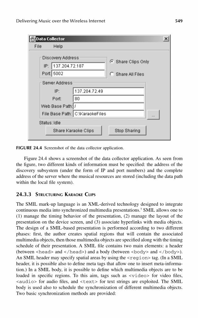
Delivering Music over the Wireless Internet 549
Figure 24.4 shows a screenshot of the data collector application. As seen fromthe figure, two different kinds of information must be specified: the address of thediscovery subsystem (under the form of IP and port numbers) and the completeaddress of the server where the musical resources are stored (including the data pathwithin the local file system).
24.3.3 STRUCTURING KARAOKE CLIPS
The SMIL mark-up language is an XML-derived technology designed to integratecontinuous media into synchronized multimedia presentations.7 SMIL allows one to(1) manage the timing behavior of the presentation, (2) manage the layout of thepresentation on the device screen, and (3) associate hyperlinks with media objects.The design of a SMIL-based presentation is performed according to two differentphases: first, the author creates spatial regions that will contain the associatedmultimedia objects, then those multimedia objects are specified along with the timingschedule of their presentation. A SMIL file contains two main elements: a header(between <head> and </head>) and a body (between <body> and </body>).An SMIL header may specify spatial areas by using the <region> tag. (In a SMILheader, it is possible also to define meta tags that allow one to insert meta-informa-tion.) In a SMIL body, it is possible to define which multimedia objects are to beloaded in specific regions. To this aim, tags such as <video> for video files,<audio> for audio files, and <text> for text strings are exploited. The SMILbody is used also to schedule the synchronization of different multimedia objects.Two basic synchronization methods are provided:
FIGURE 24.4 Screenshot of the data collector application.
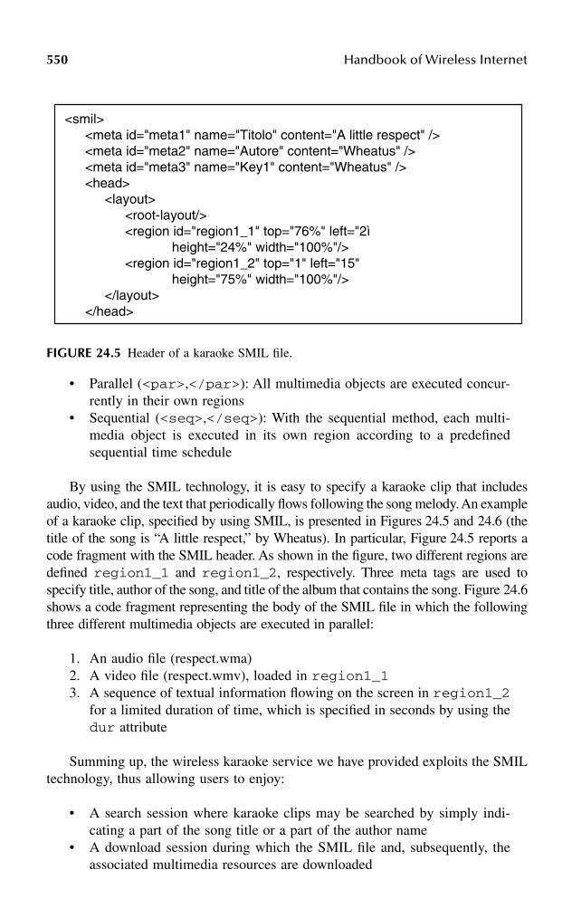
550 Handbook of Wireless Internet
• Parallel (<par>,</par>): All multimedia objects are executed concur-rently in their own regions
• Sequential (<seq>,</seq>): With the sequential method, each multi-media object is executed in its own region according to a predefinedsequential time schedule
By using the SMIL technology, it is easy to specify a karaoke clip that includesaudio, video, and the text that periodically flows following the song melody. An exampleof a karaoke clip, specified by using SMIL, is presented in Figures 24.5 and 24.6 (thetitle of the song is “A little respect,” by Wheatus). In particular, Figure 24.5 reports acode fragment with the SMIL header. As shown in the figure, two different regions aredefined region1_1 and region1_2, respectively. Three meta tags are used tospecify title, author of the song, and title of the album that contains the song. Figure 24.6shows a code fragment representing the body of the SMIL file in which the followingthree different multimedia objects are executed in parallel:
1. An audio file (respect.wma)2. A video file (respect.wmv), loaded in region1_13. A sequence of textual information flowing on the screen in region1_2
for a limited duration of time, which is specified in seconds by using thedur attribute
Summing up, the wireless karaoke service we have provided exploits the SMILtechnology, thus allowing users to enjoy:
• A search session where karaoke clips may be searched by simply indi-cating a part of the song title or a part of the author name
• A download session during which the SMIL file and, subsequently, theassociated multimedia resources are downloaded
FIGURE 24.5 Header of a karaoke SMIL file.
<smil><meta id="meta1" name="Titolo" content="A little respect" /><meta id="meta2" name="Autore" content="Wheatus" /><meta id="meta3" name="Key1" content="Wheatus" /><head>
<layout><root-layout/><region id="region1_1" top="76%" left="2ì
height="24%" width="100%"/><region id="region1_2" top="1" left="15"
height="75%" width="100%"/></layout>
</head>
Delivering Music over the Wireless Internet 551
• A playout session when the SMIL player plays back the multimediaobjects according to the time schedule specified in the SMIL file
24.4 AN EXPERIMENTAL STUDY
This section introduces an experimental study we have conducted in order to assessthe effectiveness of our proposed musical services. We carried out several experi-ments (about 4000) consisting in the download of either a set of MP3-type songsor a set of different karaoke clips, according to the selected service. During theexperimentation of the song-on-demand distribution service, four different replicatedWeb servers were exploited at the Internet side as song repositories, which weredispersed throughout the world; for the mobile karaoke service, we used threedifferent replica servers that were located within a metropolitan scenario.
The communication between the IS and the mobile client was simulated bymeans of an UMTS simulator which was able to produce the transmission delaytime of each frame at the UMTS radio link layer. Detailed information concerningthe experimental models we adopted for our experiments are discussed in the fol-lowing sections.
FIGURE 24.6 Body of a karaoke SMIL file.
<body><par>
<video src="respect.wmv" region="region1_2" fit = "slice" repeatCount="6">
</video><audio src="respect.wma"></audio><seq>
<text begin="6s" dur = "7s" region="region1_1">I tried to discover a little something to make me
</text><text dur = "10s" region="region1_1">
sweeter Oh baby refrain from breaking my heart</text>...<text dur = "4s" region="region1_1">I hear you calling</text><text dur = "17s" region="region1_1">
Oh baby please give a little respect to me.</text>
</seq></par>
</body></smil>
552 Handbook of Wireless Internet
24.4.1 UMTS SIMULATION MODEL
Currently, no real measurements of UMTS wireless data are available; hence, in ourexperiments the communication between the IS system (on the Internet side) andthe mobile client application was carried out through a simulated UMTS network(running the background traffic class). To this aim, a UMTS simulator provided bythe Fondazione Marconi (an Italian public foundation for wireless computing) wasexploited. The UMTS network simulator we used was able to return WirelessNetwork Transmission Time (WNTT) values after simulations, i.e., the time spentto download musical resources, as computed at the UMTS radio link control (RLC)layer.
The simulated transmission of an IP packet over an air interface is illustrated inFigure 24.7. The RLC layer received a PDCP frame composed of an IP data packetto which various headers were added for each different level of the protocol stack(indeed, the PDCP layer was not simulated, for the sake of simplicity).
We conducted experiments with IP packets of different sizes (160, 480, and 960bytes) coming from the Internet. The resulting PDCP frames were then segmentedinto RLC data blocks, each of which was 36 bytes. The result of this segmentationactivity at the RLC level was that 5, 15, and 30 RLC data blocks were needed totransmit IP packets with the dimensions of 160, 480, and 960 bytes, respectively.In summary, if the transmission slot was available, 10, 30, and 60 milliseconds wereneeded to transmit over the air interface IP packets with the dimensions of 160, 480,and 960 bytes, respectively. It goes without saying that the obtained WNTT valuesdepended on some operational parameters, such as the amount of traffic present inthe simulated cell, the number of active clients and their speeds. WNTT measure-ments included the time spent for possible retransmissions at the RLC level.
The main problem that derives from adopting an approach where simulatedresults for RLC frames (traveling over the wireless link) are combined with the realmeasurements obtained for the TCP segments (traveling over the wired Internet) isthat segment errors and resulting retransmissions at the TCP level are not taken intoaccount.
FIGURE 24.7 Segmentation of an IP packet into RLC data blocks.
RLC SDU
3B RLC-Header 1B CRC 32B payload
TCP Packet
20B IP-Header
IP Packet
20B TCP-Header
Payload
SDU TCPTCP Packet
RLC BlocksSegmentation
Reassembly
RLC
Delivering Music over the Wireless Internet 553
To circumvent this problem, our experiments included the possible retransmis-sion time delays incurred at the TCP level obtained by exploiting an external delaymanagement mechanism. This external delay management mechanism was designedto take into account the typical TCP error recovery method based on received ACKs.Simply put, the delay mechanism compared the WNTT values obtained through theUMTS simulation against the time out values computed by TCP. If the simulatedWNTT value was larger than the correspondent TCP time out value, then a retrans-mission must have occurred at the TCP level. In such a case, the WNTT value ofthat particular TCP segment was augmented by an additional value chosen as equalto the next WNTT value extracted from the set of the UMTS-based simulated values.Consequently, the TCP time out value was updated as follows: If a retransmissionat the TCP level was detected according to the method mentioned previously, thenthe subsequent TCP time out value was calculated as the double of the previouslycomputed value. If no retransmission at the TCP level was detected, then the tradi-tional adaptive formula for the calculation of the TCP timeout value, as proposedby Jacobson, was followed.17
The next section presents the two different measurement architectures (alongwith obtained results) we adopted on the Internet side to evaluate the song-on-demand distribution service and the mobile karaoke service we have implemented.
24.4.2 SONG-ON-DEMAND: MEASUREMENT ARCHITECTURE AND RESULTS
To evaluate the efficacy of the song-on-demand distribution service we have devel-oped, we used four different Web servers, geographically distributed over the Inter-net, providing the same set of 40 different songs. The four replica servers werelocated in Finland, Japan, the United States, and New Zealand (see Figure 24.8).Our designed intermediate system, located in Bologna, Italy, was running over aPentium 3 machine (667 MHz, 254 MB RAM) equipped with the Windows 2000Server operating system. The UMTS device, on which the client of our applicationwas running, was emulated by means of a Pentium 2 computer (266 MHz, 128 MBRAM) equipped with the Windows CE operating system.
In order to provide the reader with an approximate idea of the transmission timesexperienced over the considered Internet links, it is worth mentioning that the roundtrip times (RTTs), obtained with the ping routine, between the client and the fourservers measured 70 (Finland), 393 (Japan), 145 (United States) and 491 (NewZealand) milliseconds. As far as the downloading process is concerned, we took twobasic assumptions:
1. MP3 file dimension: In our experiments we used 40 different MP3-basedsongs, whose corresponding file dimension ranged from 3 to 5 MB, whichcorresponds to the average file dimension of the songs maintained in theNapster system.
2. Number of downloads activities: Our software application provides sup-port to two different types of song download services, the first consistingof downloading a single song, the other consisting of downloading a
554 Handbook of Wireless Internet
complete set of songs (song compilation). To evaluate the performanceof our system under both circumstances, we conducted the followingexperiments:• A set of independently replicated experiments consisting in the down-
load of single songs.• A set of independently replicated experiments, with each one consisting
of the download of a set of songs. The number of songs for eachcompilation ranged in the set of 3, 5, and 10. These three values werechosen based on the consideration that the average disk capacity oftypical MP3 players never exceeds 50 MB.
For the sake of brevity, in this chapter we only report the results obtained forthe download of single songs. If interested, you may refer to the work of Roccettiand cowokers18,19 for further details on the results we obtained when song compila-tions were downloaded.
In the following, we report on a large set of results obtained during manyexperimental trials based on the previously mentioned models.
In particular, we begin by presenting the measurements we obtained for ourwireless application on the Internet side. In essence, Wireline Network Transmission
FIGURE 24.8 Web server replicas and clients (big picture: song-on-demand; small picture:mobile karaoke).
Bologna
Helsinki
Sto
ckho
lm
New YorkDetroitSan Francisco
Los Angeles
Tokyo
AucklandBologna
Cesena

Delivering Music over the Wireless Internet 555
Time (WLNTT) values refer to the time spent over the wired Internet links todownload a requested song from the replicated Web servers toward the IS on theInternet side. These measurements have been compared with those that may beobtained by downloading the same MP3-based song with a standard HTTP GETmethod. The first row of Table 24.1 reports those results for MP3 files whose sizeis 5 MB. The second row shows the average WLNTT percentage improvementobtained by our system that exploits the previously mentioned C2LD mechanism,with respect to the standard HTTP protocol. As shown in the table, our systemobtains an average percentage improvement over the fastest HTTP replica, which isequal to 32 percent.
As already mentioned, Wireless Network Transmission Time (WNTT) valuesrefer to the time spent for downloading songs to the mobile devices through thewireless links. (It is worth remembering that these values have been obtained throughUMTS simulations.) Figures 24.9 and 24.10 show the WNTT values for 5 MB- and3 MB-sized songs, depending on the following traffic parameters:
1. The speed at which users move throughout the cell (expressed in km/h)2. The additional traffic in the cell (expressed via Erlang values)
TABLE 24.1Song-On-Demand WLNTT Results
C2LD(4 Servers) HTTP
Finland USA Japan New Zealand
Download time (seconds) 32.547 47.889 122.191 248.740 624.195C2LD improvement (percent) — 32 73.4 86.9 94.7
FIGURE 24.9 Song-on-demand WNTT results for 5-MB-sized songs.
0
200
400
600
800
1000
1200
1400
0 40 70speed (km/h)
tim
e (s
ec)
6 erlang
12 erlang
15 erlang
backgroundtraffic
(erlang)
5 MB
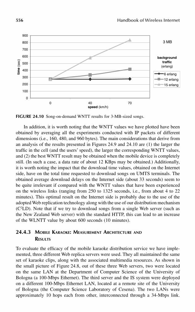
556 Handbook of Wireless Internet
In addition, it is worth noting that the WNTT values we have plotted have beenobtained by averaging all the experiments conducted with IP packets of differentdimensions (i.e., 160, 480, and 960 bytes). The main considerations that derive froman analysis of the results presented in Figures 24.9 and 24.10 are (1) the larger thetraffic in the cell (and the users’ speed), the larger the corresponding WNTT values,and (2) the best WNTT result may be obtained when the mobile device is completelystill. (In such a case, a data rate of about 12 KBps may be obtained.) Additionally,it is worth noting the impact that the download time values, obtained on the Internetside, have on the total time requested to download songs on UMTS terminals. Theobtained average download delays on the Internet side (about 33 seconds) seem tobe quite irrelevant if compared with the WNTT values that have been experiencedon the wireless links (ranging from 250 to 1325 seconds, i.e., from about 4 to 22minutes). This optimal result on the Internet side is probably due to the use of theadopted Web replication technology along with the use of our distribution mechanism(C2LD). Note that if we try to download songs from a single Web server (such asthe New Zealand Web server) with the standard HTTP, this can lead to an increaseof the WLNTT value by about 600 seconds (10 minutes).
24.4.3 MOBILE KARAOKE: MEASUREMENT ARCHITECTURE AND RESULTS
To evaluate the efficacy of the mobile karaoke distribution service we have imple-mented, three different Web replica servers were used. They all maintained the sameset of karaoke clips, along with the associated multimedia resources. As shown inthe small picture of Figure 24.8, out of these three Web servers, two were locatedon the same LAN at the Department of Computer Science of the University ofBologna (a 100-Mbps Ethernet). The third server and the IS system were deployedon a different 100-Mbps Ethernet LAN, located at a remote site of the Universityof Bologna (the Computer Science Laboratory of Cesena). The two LANs wereapproximately 10 hops each from other, interconnected through a 34-Mbps link.
FIGURE 24.10 Song-on-demand WNTT results for 3-MB-sized songs.
0
100
200
300
400
500
600
700
800
900
0 40 70speed (km/h)
tim
e (s
ec)
6 erlang
12 erlang
15 erlang
backgroundtraffic
(erlang)
3 MB
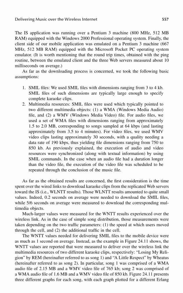
Delivering Music over the Wireless Internet 557
The IS application was running over a Pentium 3 machine (800 MHz, 512 MBRAM) equipped with the Windows 2000 Professional operating system. Finally, theclient side of our mobile application was emulated on a Pentium 3 machine (667MHz, 512 MB RAM) equipped with the Microsoft Pocket PC operating systememulator. (It is worth mentioning that the round trip times, obtained with the pingroutine, between the emulated client and the three Web servers measured about 10milliseconds on average.)
As far as the downloading process is concerned, we took the following basicassumptions:
1. SMIL files: We used SMIL files with dimensions ranging from 3 to 4 kb.SMIL files of such dimensions are typically large enough to specifycomplete karaoke clips.
2. Multimedia resources: SMIL files were used which typically pointed totwo different multimedia objects: (1) a WMA (Windows Media Audio)file, and (2) a WMV (Windows Media Video) file. For audio files, weused a set of WMA files with dimensions ranging from approximately1.5 to 2.0 MB, corresponding to songs sampled at 64 kbps (and lastingapproximately from 3.5 to 4 minutes). For video files, we used WMVvideo clips lasting approximately 30 seconds, with a quality needing adata rate of 190 kbps, thus yielding file dimensions ranging from 750 to850 kb. As previously explained, the execution of audio and videoresources were synchronized (along with textual information) by usingSMIL commands. In the case when an audio file had a duration longerthan the video file, the execution of the video file was scheduled to berepeated through the conclusion of the music file.
As far as the obtained results are concerned, the first consideration is the timespent over the wired links to download karaoke clips from the replicated Web serverstoward the IS (i.e., WLNTT results). Those WLNTT results amounted to quite smallvalues. Indeed, 0.2 seconds on average were needed to download the SMIL files,while 5/6 seconds on average were measured to download the corresponding mul-timedia objects.
Much-larger values were measured for the WNTT results experienced over thewireless link. As in the case of simple song distribution, those measurements weretaken depending on the two traffic parameters: (1) the speed at which users movedthrough the cell, and (2) the additional traffic in the cell.
The WNTT values needed for delivering SMIL files to the mobile device wereas much as 1 second on average. Instead, as the example in Figure 24.11 shows, theWNTT values are reported that were measured to deliver over the wireless link themultimedia resources of two different karaoke clips, respectively: “Losing My Reli-gion” by REM (hereinafter referred to as song 1) and “A Little Respect” by Wheatus(hereinafter referred to as song 2). In particular, song 1 was comprised of a WMAaudio file of 2.15 MB and a WMV video file of 765 kb; song 2 was comprised ofa WMA audio file of 1.6 MB and a WMV video file of 850 kb. Figure 24.11 presentsthree different graphs for each song, with each graph plotted for a different Erlang
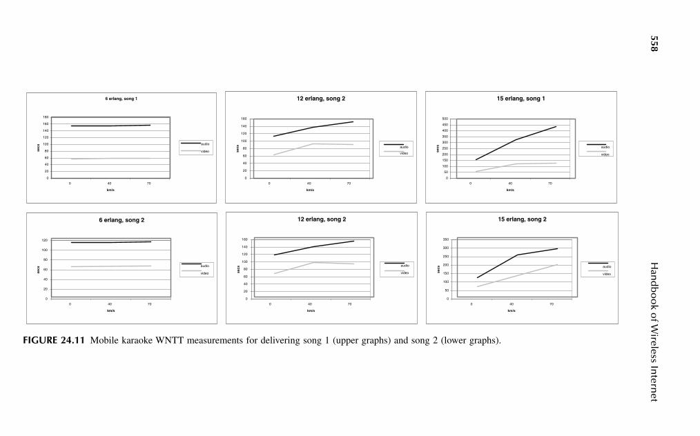
558H
and
bo
ok o
f Wireless In
ternet
FIGURE 24.11 Mobile karaoke WNTT measurements for delivering song 1 (upper graphs) and song 2 (lower graphs).
6 erlang, song 1
0
20
40
60
80
100
120
140
160
180
0 40 70
km/s
secs
audio
video
12 erlang, song 2
0
20
40
60
80
100
120
140
160
0 40 70
km/s
secs audio
video
15 erlang, song 1
0
50
100
150
200
250
300
350
400
450
500
0 40 70
km/s
secs audio
video
6 erlang, song 2
0
20
40
60
80
100
120
0 40 70
km/s
secs
audio
video
12 erlang, song 2
0
20
40
60
80
100
120
140
160
0 40 70
km/s
secs
audio
video
15 erlang, song 2
0
50
100
150
200
250
300
350
0 40 70
km/s
secs audio
video
Delivering Music over the Wireless Internet 559
value. In each graph, the WNTT values needed to deliver the audio and the videofiles are presented separately, through two different curves. Each curve variesdepending on the user speed. (Again, it is worth noting that the WNTT values weplotted were obtained by averaging all the experiments conducted with IP packetsof different dimensions.)
As in the case of simple song distribution, it is easy to notice that (1) as thetraffic in the cell increases, the corresponding WNTT values increase, and (2) thelowest WNTT results may be obtained when the mobile device is still. In addition,the karaoke clip for song 1 was available at the handheld device after an averagetime interval ranging from about 3.5 to 9.5 minutes (220 to 570 seconds), while thekaraoke clip for song 2 was delivered to the UMTS device after an average timeinterval ranging from about 3 to 8 minutes (180 to 490 seconds).
To conclude this section, it is worth noting that the WNTT results obtained forthe mobile karaoke service appear to be better than those obtained with the songdistribution service due to the fact that in the case of mobile karaoke multimediaresources of smaller size were exploited in the field trials. (Further details on thefield trials conducted for the mobile karaoke service may be found in Roccetti et al.20)
24.5 RELATED WORK AND COMPARISON
This section discusses some issues of interest at the basis of the most-relevant designchoices we have made. The issues which are of paramount importance for thedevelopment of our proposed music services are (1) distribution of multimediaresources across the Internet and P2P networking, (2) wireless network access tothe Internet, and (3) multimedia stream synchronization for delivering karaoke clips.
24.5.1 DISTRIBUTION OF MULTIMEDIA RESOURCES OVER THE INTERNET
Recently, there has been much emphasis about the possibility of an effective, secure,and reliable access to multimedia information on the Internet from mobile terminals.This has determined the evolution of architectural solutions and technologies basedon content. In essence, so-called content networks deal with the routing and for-warding of requests and responses for content using upper-level application proto-cols. Typically, data transported in content networks amount to images, movies, andsongs which are often very large in dimension.21–25 Simply put, a content distributionnetwork (CDN) can be seen as a virtual network overlay of the Internet that distrib-utes content by exploiting multiple replicas. A request from a client for a singlecontent item is directed to a good replica, where “good” means that the item isserved to the client quickly compared to the time it would take if that item werefetched from the original server. A typical CDN has some combinations of a content-delivery infrastructure, a request-routing infrastructure, and a distribution infrastruc-ture. The content-delivery infrastructure consists of a set of replicated servers thatdelivers copies of content to users who issue requests for a certain content. Therequest-routing infrastructure consists of mechanisms that enable the connection ofa given client with a selected replica. The distribution infrastructure consists of

560 Handbook of Wireless Internet
mechanisms that copy content from the origin server to the replicas. Finally, a setof software architectural elements constitute the core of the content distributioninternetworking (CDI) infrastructure that uses commonly defined protocols to shareresources so as to reach to the most-distant participants.
It is easy to recognize that the architecture of the wireless Internet applicationwe have developed resembles the above-mentioned CDI technology because itinterconnects a CDN, located in the Internet, with the UMTS network. At the basisof our CDI infrastructure we have set the application gateway, which manages allthe interactions between the UMTS terminals and the wired Internet. Our developedintermediate system (IS), along with the set of all the replica servers, constitutes areal CDN. The content-delivery infrastructure is implemented by means of the replicaservers that store multiple copies of musical resources. The search functionalitiesof the discovery subsystem, integrated with the C2LD downloading mechanism thatoperates by engaging all the available replicas in supplying fragments of therequested song, provide the request-routing infrastructure.
Another important issue related to the design of our wireless Internet applicationis concerned with the use of P2P technologies. Modern P2P technology embracesa class of applications that take advantage of resources, computing cycles, content,and human presence available at the edges of the Internet. Traditionally, a P2Parchitecture comprises a decentralized system where all peers communicate sym-metrically and exhibit equal roles.26
It is possible to observe that our designed system resembles traditional P2Psystems because it aims at sharing multimedia resources anywhere, anytime. How-ever, because accessing decentralized musical resources from UMTS devices entailsoperating in an environment of unstable connectivity, our system rests on a central-ized entity (the application gateway and the download manager), which operateslike a standard wired client with respect to the decentralized replicas. Additionally,our architecture embeds a centralized discovery subsystem that collects the refer-ences for a requested song. This centralized architectural solution provides theadvantage to permit songs to be shared even in the presence of musical content oflarge dimensions, as well as with devices with scarce computational capacity.
24.5.2 WIRELESS ACCESS TO THE INTERNET
It is well known that a typical approach to providing wireless access to the Internetamounts to selecting a specific protocol especially designed for the wireless envi-ronment. A protocol gateway uses this specific wireless protocol to enable theinteraction of the wireless device with the Internet. An example of this type ofsolution is the Wireless Application Protocol (WAP), incorporating a protocol gate-way able to translate requests from the wireless protocol stack to the Web protocols.Moreover, instead of using HTML, WAP uses the Wireless Markup Language(WML), a subset of XML, to recode the Internet content for the wireless device.3
It is important to observe that the application gateway embodied in our proposedarchitecture performs different functions with respect to the protocol gateway of theWAP solution. The WAP-based gateway performs translations from HTML-basedcontent to the proprietary format that is understandable at the mobile terminal.

Delivering Music over the Wireless Internet 561
Contrariwise, our application gateway does not recode content, but simply providesinterconnection between two different CDNs.
Beyond WAP, microbrowser technology continues to move forward with inno-vative solutions such as, for example, i-mode and the Pixo Internet Microbrowser.2,27
Those protocols are specifically aimed at the wireless Internet, because they recodeInternet content for wireless devices and utilize Compact HTML (CHTML) orExtensible Hypertext Markup Language (XHTML) as their markup languages.
Unlike WAP and similar approaches, middleware often offers an alternative tomanually replicating content. Its basic purpose is to transparently transcode contenton the fly without maintaining Web content in multiple formats.27 The ParlayProject,28 the micro version of Java (J2ME),29 the Mobile Execution Environment(MexE),30 the micro edition of JINI (JMatos),31 Online Anywhere,32 and Proxinet,33
along with the use of the Relational Markup Language (RML), are all examples thatfall in the category of middleware-based approaches.
We conclude this overview by mentioning the JXTA technology.34, 35 This is aset of open peer-to-peer protocols that allows any connected device on the networkto communicate according to a peer-to-peer pattern. The focus of JXTA protocolsis on creating a virtual network overlay on top of the Internet, allowing peers todirectly interact independently of their network location, programming language,and different implementations. At the heart of JXTA technology we can find adver-tisements (XML documents) that are exploited to advertise all network resources(from peers to content). Advertisements are exploited to provide a uniform way topublish and discover network resources.
In this context, a final comment is due regarding our choice to design all ourprotocol architecture following an all-IP approach. This approach has the advantageof allowing mobile terminals to function as any other Internet-connected device.However, this choice requires that the end-to-end protocol function continuity bepreserved in the wireless segments, and we must admit that many are the problemsof providing such seamless internetworking between wired and wireless worlds withInternet protocols. Nevertheless, our decision of resorting to an additional sessionlayer, along with the intense experimental monitoring we have conducted, haveshown that the all-IP choice does not cause too many interferences (in terms ofpacket retransmissions) between TCP and the radio link layer. In addition, an all-IPapproach overcomes the interoperability problems which may arise in the case ofproprietary protocol solutions.
24.5.3 MULTIMEDIA SYNCHRONIZATION FOR DELIVERING KARAOKE
One of the main concerns in the design of karaoke systems is the adopted synchro-nization strategy. In fact, it is clear that because a karaoke playout consists of apresentation of synchronized multimedia files, an underlying model is needed forspecifying the synchronization rules to be adopted by different media streams. Toaccomplish this goal, we exploited the SMIL technology (and a SMIL player), butother solutions exist, e.g., the FLIPS model.36 FLIPS is a model developed forspecifying coarse synchronization for flexible presentations supporting a wide rangeof temporal synchronization specifications. It provides algorithms for attaining a

562 Handbook of Wireless Internet
consistent and coherent presentation state in response to user interaction and otherstate-changing events. Another traditional technology for playing back synchronizeddigital data is the MIDI technology that can also be used to play back karaoke clips.In essence, a computer program can play a MIDI-based karaoke file containingmusical data, as well as the lyrics that are displayed on a computer monitor. Hence,MIDI karaoke files are standard MIDI files that may be executed on desktop com-puters. However, the most modern technology for the synchronized playback ofmultimedia data is the MP3 technology. Many vendors today produce MP3 playersthat are designed to display lyrics and other graphics while songs play out. Forexample, the Irock 680 player from Motorola plays out songs in both MP3 and MP3iformats.37 (MP3i is the new interactive format that integrates graphical data withdigital music files.) This allows content such as lyrics, artwork, text notes, photo-graphs, and videos to be displayed as music plays back on a device.
Another important networked technology that has been extensively exploited tosynchronize multimedia streams over the Internet and implement Internet-basedkaraoke systems is the RealMedia technology.38 This is a client/server technologyfor streaming synchronized media on the Internet. For example, Karaoke/SureStreamis a RealSystem feature that allows the RealServer to dynamically adjust the streamfor each listener, depending on the dynamic network conditions of the user’s con-nection.39 SureStream manipulates media streams by providing an encoding frame-work allowing multiple streams at different bit rates to be simultaneously encodedand combined into a single file. Additionally, it provides a client/server mechanismfor detecting changes in bandwidth and translating those changes into combinationsof different streams. Karaoke Online uses the audio streaming technology providedby RealNetworks to deliver music and lyrics to a Web browser.40
Other interesting research experiences are those discussed in Lee and coworkers41 (the SESAME project was presented where scalability issues for karaoke systemswere investigated), and in Liu et al.42 and Tseng and Huang43 (client-server karaokesystems were proposed for video and audio streams that allowed a wired accessthrough the public switched network). Many are the karaoke societies that use SMIL,SureStream, plus other synchronization technologies to implement karaoke systemson a client/server basis for the Internet. Relevant examples are Cyber-Karaoke-On-Demand,44 Karaoke Jukebox,45 StreamKaraoke,46 and finally Streaming21.47 Weconclude by mentioning that all the cited experiences refer either to the wired Internetor to small-sized wireless LAN environments.
24.6 CONCLUDING REMARKS
In this chapter, we have reported on our experience in implementing a wirelessInternet application designed to support the large-scale distribution of musicalresources (from simple songs to synchronized karaoke clips, as shown inFigure 24.12). Our application allows mobile consumers to listen to songs/karaokeclips on handheld UMTS-enabled devices by exploiting the Internet as a vast store-house of music resources. Experimental results were obtained that show that fast,large-scale wireless musical services may be provided by exploiting the UMTS

Delivering Music over the Wireless Internet 563
technology. Measurements have been taken that confirm that both songs and karaokeclips (composed by audio, video, and scrolling text) may be downloaded from theInternet to UMTS devices in a few minutes on average. Whether the role of wirelessnetworks is limited to extending the Internet reach or whether new applications maybe enabled by wireless access are subjects of much discussion.1,48,49 We claim thatour wireless application demonstrates that exciting musical services may be imple-mented profitably using the wireless technology available today.
FIGURE 24.12 A screenshot of the mobile karaoke service.

564 Handbook of Wireless Internet
ACKNOWLEDGMENTS
We wish to thank the Italian MIUR and CNR, the Fondazione Marconi of Bologna,the Department of Computer Science of the University of Bologna, and MicrosoftResearch Europe for the partial financial support of this work.
References
1. Bhagwat, P. and Sreenan, C.J., Eds., Future Wireless Applications, IEEE WirelessCommun., 9 (1), 6–59, 2002.
2. All about i-mode, http://www.nttdocomo.com/index.html, 2001.3. WAP Architecture Specification, http://www1.wapforum.org/tech/terms.asp?doc=
WAP-100-WAPArch-19980430-a.pdf.4. Macedonia, M., Distributed file sharing: barbarians at the gates?, IEEE Comput.,
33(8), 99–101, August 2000.5. UMTS Forum, What is UMTS?, http://www.umts-forum.org/what_is_umts.html.6. MP3 resources by MPEG.ORG, http://www.mpeg.org/MPEG/mp3.html.7. W3 Recommendation, Synchronized Multimedia Integration Language (SMIL) 2.0
Specification, http://www.w3.org/TR/smil20/, 2001.8. Napster official site, http://www.napster.com/9. The Freenet Project, http://freenet.sourceforge.net.
10. Gnutella official site, http://gnutella.wego.com/.11. Staehle, D., Leibnitz, K., and Tsipotis, K., QoS of Internet Access with GPRS, in
Proc. 4th ACM International Workshop on Modeling, Analysis and Simulation ofWireless and Mobile Systems, Rome, 2001, 57–64.
12. Kalden, R., Meirick, I., and Meyer, M., Wireless Internet access based on GPRS,IEEE Personal Commun., 7 (2), 8–18, 2000.
13. Huston, G., TCP in a wireless world, IEEE Internet Computing, 5(2), 82–84, March–April, 2001.
14. Ingham, D., Shrivastava, S.K., and Panzieri, F., Constructing dependable Web ser-vices, IEEE Internet Computing, 4 (1), 25–33, 2000.
15. Ghini, V., Panzieri, F., and Roccetti, M., Client-centered load distribution: a mecha-nism for constructing responsive Web services, in Proc. 34th IEEE Hawaii Interna-tional Conference on System Sciences, Maui, 2001.
16. Roccetti, M. et al., The structuring of a wireless internet application for a music-on-demand service on UMTS device, in Proc. ACM Symposium on Applied Computing,ACM Press, Madrid, 2002, 1066–1073.
17. Jacobson, V., Berkeley TCP evolution from 4.3-Tahoe to 4.3-Reno2, in Proc. 18thInternet Engineering Task Force Meeting, University of British Columbia, Vancouver,1990, 365.
18. Roccetti, M., Ghini, V., and Salomoni, P., Distributing music from IP networks toUMTS terminals: an experimental study, in Proc. 2002 SCS EUROMEDIA Confer-ence, Roccetti, M., Ed., The Society for Modeling and Simulation International,Modena, 2002, 147–154.
19. Roccetti, M. et al., Bringing the wireless Internet to UMTS devices: a case studywith music distribution, to appear in the International Journal of Multimedia Toolsand Applications, Kluwer, 2003.

Delivering Music over the Wireless Internet 565
20. Roccetti, M. et al., MoKa: a wireless Internet application for delivering mobilekaraoke on UMTS devices, in Proc. IASTED International Conference on Commu-nications, Internet and Information Technology, M.H. Hamza, Ed., St. Thomas, VI,November 2002, pp. 346–351.
21. Barbir, A. et al., Known CDN request-routing mechanisms, draft-cain-cdnp-known-request-routing-02.txt, in progress, June 2001.
22. Cain, B. et al., Request-routing requirements for content internetworking, draft-cain-request-routing-req-02.txt, in progress, July 2001.
23. Day., M., A model for content internetworking, draft-day-cdnp-model-05.txt, inprogress, March 2001.
24. Day, M., Gilletti, D., and Rzewskip, P., CDN peering scenarios, draft-day-cdnp-scenarios-03.txt, in progress, March 2001.
25. Green, M. et al., Content internetworking architectural overview, draft-green-cdnp-gen-arch-03.txt, in progress, March 2001.
26. Flammia, G., Peer to peer is not for everyone, IEEE Intelligent Systems, 16(3), 78–79,May-June, 2001.
27. Saha, S., Jamtgaard, M., and Villasenor, J., Bringing the wireless Internet to mobiledevices, IEEE Comput., 34 (6), 54–58, 2001.
28. The Parlay Group, www.parlay.org.29. Java J2ME, http://www.java.sun.com/j2me.30. MexE Forum, http://www.mobilmexe.com.31. JINI Network Technology, http://www.sun.com/jini/index.html.32. Online Anywhere, http://www.onlineanywhere.com/.33. Proxinet, http://www.pumatech.com/proxinet.34. Gong, L., JXTA: a network programming environment, IEEE Internet Computing,
5(3), 88–95, May–June, 2001.35. Project JXTA, http://www.jxta.org.36. FLIPS, http://www.cs.umn.edu/Research/dmc/html/dlearn.html.37. Irock 680 player from Motorola, http://www.motorola.com.38. Real Media, http://www.real.com.39. Real Networks Inc., http://www.realnetworks.com/.40. Karaoke On Line, http://www.thinks.com/karaoke/.41. Lee, Y., Du, D.H.C., and Ma, W., SESAME: A Scalable and ExtenSible Architecture
for Multimedia Entertainment, in Proc. IEEE 20th International Computer Softwareand Applications Conference, Seoul, 1996.
42. Liu, C. et al., The construction of a multimedia application on public network, inProc. SPIE High-Speed Networking and Multimedia Computing Conference, 1994.
43. Tseng, W.H. and Huang, J.H., A high performance video server for karaoke systems,IEEE Trans. Consumer Electr., 40 (3), 609–618, August, 1994.
44. Cyber-Karaoke-On-Demand, http//www.innogate.com.my/ckod.asp.45. KARAOKE JUKEBOX; http://www.peddocko64.freeserve.co.uk.46. StreamKaraoke; http://streamkaraoke.com47. Streaming21, http://www.streaming21.com.48. Lawton, G., Browsing the mobile Internet, IEEE Comput., 34 (12), 18–21, 2001.49. Kanter, T., An open service architecture for adaptive personal mobile communication,
IEEE Personal Commun., 8 (6), 8–17, 2001.

This page intentionally left blank

Index

This page intentionally left blank
569
Index
A
AA, see Application agentAAA servers, see Authentication, accounting, and
administration serversAccess point (AP), 128, 374, 399, 434ACID, see Atomicity, consistency, isolation and
durabilityACK, see AcknowledgmentAcknowledgment (ACK), 317ACL, see Asynchronous connectionless linkActual data rate, 9Adaptation layer (AL), 478Adaptive differential PCM (ADPCM) coding
standards, 154Adaptive multirate (AMR)
codec, 219narrowband, 97, 476, 480speech frame, 485wideband, 97, 480
Adaptive resource management, 248ADC, see Analog-to-digital converterAddress translation
agent (ATA), 237problem, mobility as, 238
Ad hoc network(s), 43energy-efficient routing in, 49flat, 47management, 136
Ad hoc networks, mobile, 381–405issues for protocol layers in MANETs,
386–394application layer, 386data link layer, 391–394network layer and routing, 388–391physical layer, 384transport layer, 387–388
MANET implementation, 394–402hardware technologies, 401–402network technologies, 398–40 1software technologies, 395–398
wireless ad hoc network application, 384–385Ad hoc on-demand distance vector routing
(AODV), 390Adobe, 24ADPCM coding standards, see Adaptive
differential PCM coding standards
ADTRAN, 448Advanced Mobile Phone System (AMPS), 9, 114,
370Advanced Reservation Signaling, 218Advanced Traveler Information Systems (ATIS)
initiative, 411Aether Systems, 502AFP, see AppleTalk Filing ProtocolAgere Systems, 308Airify, 228AL, see Adaptation layerA-law, 154Alert Protocol (AP), 458All-in-one mobile devices, 203Allocation
coarse-grained, 218history-based, 218neighborhood-based, 218
Alternative strategy (AS), 372AM, see Amplitude modulationAmazon, 498, 507AMBULANCE project, 516American Mobile Satellite Corporation (AMSC),
433American National Standards Institution (ANSI),
155, 486Amplitude
modulation (AM), 7shift keying (ASK), 7
AMPS, see Advanced Mobile Phone ServiceAMR, see Adaptive multirateAMSC, see American Mobile Satellite CorporationAnalog-to-digital converter (ADC), 527Anchor
rerouting, preconfigured, 216, 217robot, messages sent between controller and,
384Announce protocol, 130ANSI, see American National Standards InstitutionAnswer-signal delay (ASD), 481, 490Antivirus software, 503Anytime, anywhere communications, goal of, 43Anytime, anywhere Internet connectivity, 78Anytime, anywhere message delivery, 42AODV, see Ad hoc on-demand distance vector
routingAOL, 442
570 Handbook of Wireless Internet
AP, see Access pointAPI, see Application-programming interfaceAppleTalk Filing Protocol (AFP), 386Application(s)
agent (AA), 207Balance Inquiry, 193Check Call, 193development, secure, 190end-user, 246fleet management, 411follow-me, 207frozen, 207gateway, 544hybrid, 460killer, 185mass-market, 32-programming interface (API), 365QoS, 474real-time, 460redesign of, 455service provider (ASP), 499software, alignment of, 453synchronization, 459system-enhancement, 246TCP/IP-based, 540Transmission Adaptation, 117video telephony, 470WAP
flow of, 523, 524setup for accessing, 529, 530
wireless Internet growth and, 441ARC Cores, 23Archiving and communication system, 513Ariel Communications, 69ARM Ltd., 23ARQ, see Automatic repeat requestAS, see Alternative strategyASD, see Answer-signal delayASDCS, see Asymmetric satellite data
communication systemASP, see Application service providerAsymmetrical service, 83Asymmetric satellite data communication system
(ASDCS), 518Asynchronous connectionless link (ACL), 235,
316, 319Asynchronous transfer mode (ATM), 150, 399ATA, see Address translation agentATIS initiative, see Advanced Traveler Information
Systems initiativeATM, see Asynchronous transfer modeAtomicity, consistency, isolation and durability
(ACID), 461AT&T
Keep-In-Touch cellular modem, 515
TDMA used by, 57wireless PBX products introduced by, 444
Auctionstime-sensitivity of, 508wireless, 508
Aurora VLSI, 23Authentication, 63
accounting, and administration (AAA) servers, 161–162
Center, 59end-to-end, 63
Automatic repeat request (ARQ), 540–541Avon Products, Inc., 451
BBAHAMA scheme, 269Balance Inquiry application, 193Baltimore Telepathy, 190Bandwidth, 8
efficiency, 336, 338, 341, 343repartition, 489
Bankingmobile commerce and, 62transaction costs, 26
Baseband specification, 315Base station (BS), 266, 415
arrays, deployment of, 342of paging (BSPs), 355subsystem, 85
Base Station Controllers (BSC), 164, 178Basic service set (BSS), 128, 229Basic service set identification (BSSID), 128,
129Basic trading area (BTA), 450Batteries, smart, 401Bayesian learning, 413Bayesian network, 246Bayes’ rule, 255B2B E-commerce, 508B2B environment, see Business-to-business
environmentBeam-forming techniques, 337Bell Labs layered space–time (BLAST) scheme,
347BellSouth
Data Network, 432VeriSign plan endorsed by, 506
BER, see Bit error rateBillable events, 505Billing possibilities, 505Binary phase shift keying (BPSK), 399Biswas’ scheme, 295, 297, 302Bit error(s), 471
rate (BER), 81, 82, 152

Index 571
quality loss at higher, 487retransmission of voice packets under, 176
ratio, undetected, 92recovery from, 78
BLA, see Boundary location areaBlanket paging, 353BLAST scheme, see Bell Labs layered space–time
schemeBLER, see Block error rateBlock error rate (BLER), 90BLR, see Boundary location registerBluetooth, 127, 228, 232, 516
AP, 374-based services, affordability of, 194core protocol stack, layers of, 309device authentication, 325link
encryption, 325state transitions involved in establishing
and terminating, 321modems, 39networks, 15, 34original aim of, 39packet types, 318protocol stack, 312, 313scatternet, 234security, 321Special Interest Group, 308technology, 14Web site, 308
Bluetooth, wireless communications using, 307–333
additional considerations, 331–332power management, 331–332security, 332
Bluetooth profiles specification, 329–331GAP, 329–330GOEP, 331SDAP, 330SPP, 330
overview, 309–311frequency hopping spread spectrum and
time-division duplexing, 310masters and slaves, 310piconets and scatternets, 310–311
protocol stack, 311–328baseband layer, 314–322L2CAP layer, 325–327LMP layer, 322–325radio layer, 313–314SDP layer, 327–328
Boundary locationarea (BLA), 364register (BLR), 364
BPSK, see Binary phase shift keying
BRAN, see Broadband Radio Access NetworksBranch-point-traversal-based rerouting, 270BREW, see Qualcomm Binary Runtime
Environment for WirelessBroadband
Internet access, 449Radio Access Networks (BRAN), 233wireless, 435
Broadcasting applications, use of satellite communications for, 6, 7
BroadVision, 498BS, see Base stationBSC, see Base Station ControllersBSPs, see Base station of pagingBSS, see Basic service setBSSID, see Basic service set identificationBTA, see Basic trading areaBuffer exhaustion, data loss due to, 116Bundling factor, 177Burst
level blocking performance, 180source model, on–off, 178
Business-to-business (B2B) environment, 499Butterworth lowpass filter, 527
CCable
modems, 220-replacement usage model, 308
CAC, see Channel access codeCache database, 364CAD drawings, 24CAHAN, see Cellular Ad Hoc Augmented
NetworkCalendar, Windows CE software configured with,
447Call
admission control, 247delivery procedures, 370detail records (CDRs), 505-to-mobility ratio (CMR), 368, 376release
delay (CRD), 490signaling, 483
setupdelay, 172, 173procedure, message sizes associated with,
166success, 174times, SIP signaling, 491
signaling channel transport identifier, 160Care-of address (COA), 201, 202, 238Carphone, 489Carrier-to-noise ratio (CNR), 35
572 Handbook of Wireless Internet
Carrier Sense Multiple Access (CSMA), 392Carrier Sense Multiple Access with Collision
Avoidance (CSMA/CA), 35, 232Cascade tunneling, 211CBT, see Core-based treeCCD camera, 516CCP, see Change Cipher Spec ProtocolCCPL, see Cumulative connection path lengthCCSRL, see Control Channel Segmentation and
Reassembly LayerCCTV, see Closed circuit televisionCDF, see Cumulative density functionCDI infrastructure, see Content distribution
internetworking infrastructureCDMA, see Code division multiple accessCD mechanism, see Collision detection
mechanismCDN, see Content distribution networkCDPD, see Cellular Digital Packet DataCDRs, see Call detail recordsCell Boundary Graph, 248Cell forwarding, 280
new connection setup time, 280, 289old connection teardown time, 280, 289rerouting, 270, 281, 293
Cell ID, 246Cellmania, 498Cell phone(s)
caller, frequency channels assigned to, 57loss of, 63radiated power in, 34SIM cards, 71transmissions, interception of, 56users, wireless Internet access wanted by, 57Web, 16
Cell sectorization, 337Cellular Ad Hoc Augmented Network (CAHAN),
47Cellular communications
growth of, 31technology, measurement of progress in, 36
Cellular concept, development of, 114Cellular Digital Packet Data (CDPD), 187, 433,
447, 498, 515Cellular IP, 211Cellular networks, 266, 267
complexity of, 198survey of routing techniques for, 269
Cellular One, 446Cellular phone network, 16Cellular systems, IP mobility support over, 409Cellular Telecommunications Industry
Association, 186Cellular trends, 36CELP, see Code excited linear prediction
Certicom, 63CFP, see Contention-free periodCH, see Corresponding hostChange Cipher Spec Protocol (CCP), 458Channel(s)
access code (CAC), 314, 316, 320allocation packets, 357assignment, dynamic, 336circuit-switched, 473, 475connectionless, 327connection-oriented, 327control, 320error(s)
ARQ protocol and, 153packet losses due to, 117
identifier (CID), 326packet-switched, 473signaling, 327
Check Call application, 193CHTML, see Compact HTMLCID, see Channel identifierCingular, 57Circuit-switched (CS) channels, 473, 475Circuit-switched data (CSD), 37, 519Circuit-switched mobile channels, 81Circuit-switched networks, 9Circuit switching, packet switching versus, 11Cisco, 507Citrix terminal solution, 499CL channel, see Connectionless channelClear-to-send (CTS) control frame, 392Client
-centered load distribution mechanism, 541, 546–548
/server model, 328CLNP, see Cumulative length of new paths formedClock-and-timing-related transactions, 323CLOP, see Cumulative length of old paths torn
downClosed circuit television (CCTV), 514Cluster(s)
architecture, nested, 144effect of node mobility on, 138formation, example of, 143head(s)
critical function of, 139percentage of nodes unmanaged by, 141routing information generated by, 142
Clusteringalgorithm, 137changes, average number of, 140comparisons of, 143cycle, number of control messages exchanged
per, 132, 135graph-based, 136, 139

Index 573
ID, 136, 137, 140location, 130platform, Ninja, 207procedure(s)
interzone, 135intrazone, 133phases of, 131
quasihierarchical, shortcoming of, 145strict, 146
Clustering and roaming techniques for IEEE 802.11 wireless LANs, 127–148
graph-based clustering, 136–142location-based clustering, 130–136quasihierarchical routing, 142–146strict hierarchical routing, 146–147wireless LANs clustering, 128–130
CMR, see Call-to-mobility ratioCN, see Corresponding nodeCNR, see Carrier-to-noise ratioCOA, see Care-of addressCoarse-grained allocation, 218CO channel, see Connection-oriented channelCode
excited linear prediction (CELP), 155malicious, 65
Code division multiple access (CDMA), 7, 57, 187, 337, 344
access technology, 11air interface, 11conversation, interception of, 60phones, 62spread spectrum technology, 60subscriber base of, 37time division, 13WAP and, 498wideband, 9, 86
Coding schemesE-GPRS, 85space–time, 346
Collision detection (CD) mechanism, 232Common Gateway Interface, 459Communication(s)
anytime, anywhere, goal of, 43connectivity, strict hierarchical routing and,
146cooperative, 46infrastructure, 46links, functioning of terminals as endpoints of,
49networks, hierarchical nature of, 419peer-to-peer, 36proximity-based, 43, 44static–static, 267
Compact HTML (CHTML), 561Compaq SpeedPaq 336 modem, 431
Compression algorithm, 154CompuServe, 442Computer(s)
desktop, handheld devices vs., 503laptop, 40, 220, 227, 440notebook, 72
wireless connection of to Internet, 516WLAM modem built into, 32
personal(PC), 514scenarios
location management in pervasive, 414models of, 407
tomography (CT), 512, 515VAX, 452
Computinglocation-aware, 408location-independent, 408sentient, 407
Confidentiality, preservation of, 64Connection
establishment, 323-extension rerouting, 270length
metrics dependent on, 283metrics not dependent on, 283
-oriented (CO) channel, 327-oriented networks, rerouting schemes for, 270
Connectionless (CL) channel, 327Connectionless networks, 266Consumer markets, proliferation of wireless
Internet in, 430Content
cache servers, 94distribution
internetworking (CDI) infrastructure, 560network (CDN), 559
Contention-free period (CFP), 232Contention period (CP), 232Control Channel Segmentation and Reassembly
Layer (CCSRL), 477Cooperative communications, 46Cordless desktop, 308Core-based tree (CBT)
scheme, 296strategy, 292
Core Network, 89, 474Corporate intranets, logging onto, 62Corporations, efforts of to establish wireless
infrastructure, 4Corresponding host (CH), 201Corresponding node (CN), 374Cost information
propagation of, 145updated, 144
CP, see Contention period
574 Handbook of Wireless Internet
CRC, see Cyclic redundancy checkCRD, see Call-release delayCredit card numbers, purging of from mobile
device memory, 64CRM, see Customer Relationship ManagementCrossover
discoveryalgorithm, 275, 276, 277time, 289
point, 274CS channels, see Circuit-switched channelsCSD, see Circuit-switched dataCSMA, see Carrier Sense Multiple AccessCSMA/CA, see Carrier Sense Multiple Access
with Collision AvoidanceCT, see Computer tomographyCTS control frame, see Clear-to-send control
frameCumulative connection path length (CCPL), 295,
300, 301, 302Cumulative density function (CDF), 486Cumulative length of new paths formed (CLNP),
295Cumulative length of old paths torn down (CLOP),
295Customer
Relationship Management (CRM), 26, 192security, PKI systems and, 192
Cyber-Karaoke-On-Demand, 562Cyclic redundancy check (CRC), 152, 317, 478
DDA, see Data agentDAC, see Device access codeDAG, see Directed acyclic graphData
agent (DA), 207collector application, screenshot of, 549decrypted, 457forwarding mechanism, 211link layer, 391loss, network congestion and, 116–medium rate packet, 318path, protocol translators in, 219rate oscillation, 115transfer, bidirectional, 470transmission
high-speed, 33rates, 228
Database(s)architectures, 371cache, 364distributed, 354heterogeneous, 409
Home Location Register, 247initiation of mobile access to, 462location
change in, 352hierarchical organization of, 368
management system (DBMS), 456, 521mobile, 459, 460PC-based, 526queries, 437UPT global, 204VLR, 371
Database systems, WAP-enabled transaction processing model for mobile, 455–467
background, 456–459mobility applications, 459–461sample application, 463–464simulation results, 464–466WAP-enabled transaction model, 461–463
DBI, see Perl Database InterfaceDBMS, see Database management systemDCF, see Distributed coordination functionDecoding strategies, 346DECT, see Digital enhanced cordless
telecommunicationsDelay
answer-signal, 490-based metrics, 487call-release, 490classes, GPRS, 87postdialing, 490
Denial-of-service attack, 67Desktop
computers, handheld devices vs., 503cordless, 308follow-me, 207PCs, dial-up rates of, 4Web browsers, digital certificates deployed on,
63 Destination
-based rerouting, 270-sequenced distance vector routing (DSDV),
390Developer trust services, 506Device
access code (DAC), 314, 316addressing, 314authentication, 332movement, pattern of, 420
DHCP, see Dynamic Host Configuration ProtocolDialogue Expressway 2000 E-Mailconnector,
191Dial-up modems, 220DICOM, see Digital Imaging and CommunicationsDifferential quadrature phase shift keying
(DQPSK), 7

Index 575
Differentiated Services (DiffServ), 153, 213code point (DSCP), 212protocol, 157
DiffServ, see Differentiated ServicesDigital cell phone transmission, interception of, 56Digital certificates, 63, 503Digital content delivery, 25Digital enhanced cordless telecommunications
(DECT), 7, 401, 445Digital Imaging and Communications (DICOM),
533Digital signatures, 190Digital speech signals, transmission of, 36Digital wireless communication, introduction of,
155Dijkstra’s algorithm, 388Directed acyclic graph (DAG), 389Direct routing call model, 160Direct sequence (DS) spread spectrum, 12, 229,
231Discrete Cosine Transform, 106Distance
decay, randomness associated with, 339learning, Web-based, 26vector information, distribution of, 389
Distributed antennas, 446Distributed coordination function (DCF), 231Distributed database, 354, 376Distributed radio system (DRS), 446DNS, see Domain name serviceDoctor, remote, 512DOD reference model, 199Domain
-independent algorithms, 249name service (DNS), 386-specific heuristics, 256
Downlink, buffering required in base station for, 288
Download manager, 543DQPSK, see Differential quadrature phase shift
keyingDrift velocity, 356DRS, see Distributed radio systemDSCP, see DiffServ code pointDSDV, see Destination-sequenced distance vector
routingDSR, see Dynamic Source RoutingDS spread spectrum, see Direct sequence spread
spectrumDST algorithm, see Dynamic spanning tree
algorithmDynamic channel assignment, 336Dynamic Host Configuration Protocol (DHCP),
161Dynamic link characteristics, 115
Dynamic per-host routing, 211Dynamic Source Routing (DSR), 389Dynamic spanning tree (DST) algorithm, 390
EEavesdropping, 58, 59, 60eBay, Palm VII compatibility of with, 508ECC, see Elliptic-curve cryptographyE-commerce
B2B, 508Internet connectivity and, 78
ECSD, see Enhanced Circuit-Switched DataEDGE, see Enhanced Data for Global
EnhancementE-GPRS, see Enhanced General Packet Radio
ServiceEIA/TIA IS-41(c) standard, 290, 291, 293802.11 frame format, standard, 232Electrocardiogram monitoring, 512Electronic commerce, 54Electronic Tourist Guide, 418Elliptic-curve cryptography (ECC), 63E-mail, 7, 26, 56, 429
address, user name extracted from, 203always-on, 434attachments, ability of mobile devices to store,
65Internet connectivity and, 78protocols, 23Windows CE software configured with, 447
Emulation software, setup for accessing WAP applications with, 529
Encapsulation, IP-in-IP, 212Encoding, 57Encryption
algorithms, 503end-to-end, 60keys, 59methods, 54public key, 63translation
SSL-to-WTLS, 67WTLS-SSL, 70
End-to-end authentication, methods for providing, 63
End-to-end encryption, 60End-user applications, 246Engset Model of telephony, 178–179Enhanced Circuit-Switched Data (ECSD), 83
mobile video telephony enabled by, 493networks, bit rates for, 83
Enhanced Data for Global Enhancement (EDGE), 12, 78, 505
Enhanced digital cellular technology, 32
576 Handbook of Wireless Internet
Enhanced General Packet Radio Service (E-GPRS), 85
coding schemes, 85networks, bit rates for, 89QoS profile, 85
Enterprisemarkets, proliferation of wireless Internet in,
430trust services, 506
Enterprise network, impact of wireless technology on, 443–453
broadband Internet access, 449–450more integration, 447–448new standard, 448searching for wireless solution, 452users of wireless technology, 450–452
consumer applications, 450financial, 452health care, 451manufacturing, 451–452transportation, 450–451
wireless communications, 444–445wireless Internet access, 449 wireless office services, 445–446
Entity-relationship (ER) model, 521, 522Entropy rate, 422Entrust Technologies, 189Epoc, 498, 502Equipment
failure, 46radio-scanning, 56, 58
Ericsson, 13, 20, 69, 308, 448mobile E-site developed by, 498System Developers Kit from, 463wireless PBX products introduced by, 444
Erlang values, 555, 557–559ER model, see Entity-relationship modelError(s)
bit, 471channel
ARQ protocol and, 153packet losses due to, 117
checking, 320, 386concealment techniques, 111control, 111, 120correction, 320
bandwidth for, 9code, 153schemes, 321TCP retransmission for, 154
detection, 478header data, 321persistence, 111probabilities, GPRS reliability classes, 87protection, 85
rate(s)cost of higher, 90frame, 111, 112predictor average, 252
ratioSDU, 485service data unit, 474
recovery, 120, 553resilience, 28, 108, 471
QoS and, 404techniques, 78
transmission, 106ETC Protocol, see Extra Throughput Cellular
ProtocolEthernet, 220, 228, 232, 464
connection, 36LAN, 556wireless, 439
ETSI, see European Telecommunications Standards Institute
European Telecommunications Standards Institute (ETSI), 36, 155, 186, 232, 399
Excite, 507Extended Golay Codes, 479Extensible Hypertext Markup Language
(XHTML), 561Extensible Markup Language (XML), 21, 26, 532
documents, 561standards, markup language adhering to, 187
Extra Throughput Cellular (ETC) Protocol, 515
FFA, see Foreign agentFading
fluctuations, 341small-scale, 345
fastConnect procedure, 172initiation of, 166message sizes of, 167use of RLP with, 174
FCC, see Federal Communication CommissionF-CCCH, see Forward common control channelFDDI, see Fiber distributed data interfaceFDMA, see Frequency Division Multiple AccessFEC, see Forward error correctionFederal Communication Commission (FCC), 230,
412, 500FER, see Frame error rateF-FCH, see Forward fundamental channelFH spread spectrum, see Frequency hopping (FH)
spread spectrumFiber distributed data interface (FDDI), 229File transfer protocol (FTP), 199, 386, 514Firepad software, 24
Index 577
First-generation systems, principal characteristics of, 36
First-generation (1G) wireless technologies, 114Flat topology, 132Fleet management applications, 411FLIPS model, 561FM, see Frequency modulationFMDA, see Frequency division multiple accessFollow-me applications, 207Follow-me Desktop, 207Foreign agent (FA), 201, 202, 410
Assisted Handoff draft, 213emulation, 211gateway, 211
Forward common control channel (F-CCCH), 163Forward Erasure Correction (FXC)Forward error correction (FEC), 113, 318, 471Forward fundamental channel (F-FCH), 163Forwarding
agent, 237tables, building of, 144
Forward supplemental channel (F-SCH), 163FPLA, see Future probable location areaFrame
-based metrics, 486check sequence generation, 392–393error rate (FER), 152, 153, 167
definition of, 111packet loss rate versus, 112
relay, 150Framing data unit, 391Freenet, 540Frequency
carriers, 58division multiple access (FDMA), 9, 10, 57, 336hopping (FH) spread spectrum, 11, 229, 231,
310modulation (FM), 7reuse, 345shift keying (FSK), 7, 447
Frozen application, 207F-SCH, see Forward supplemental channelFSK, see Frequency shift keyingFTP, see File transfer protocolFull rerouting, 270, 274, 275
new connection setup time, 274, 289old connection teardown time, 274, 289
Future probable location area (FPLA), 260FXC, see Forward Erasure Correction
GGame theory, 50Gaming consoles, high bandwidth hot spots for
networked, 223
GAP, see Generic access profileGap in WAP, 66Gatekeepers, 159, 160Gateway
-assisted Secure Sockets Layer trust model, 506
foreign agent, 211GPRS Support Node (GGSN), 151network failure detected by, 546protocol, 560WAP-based, 560
Gaussian frequency shift keying (GFSK), 15, 234, 314
Gaussian minimum shift keying (GMSK), 7, 85Gaussian noise, 128General Motors products, OnStar product offered
as option with, 450General Packet Radio Service (GPRS), 12, 38, 61,
151, 368agility of, 504burst level blocking, 180, 181delay classes, 87deployment of, 198enhanced, 85media packet-blocking analysis in, 175network, 84, 152packet size, 177PCU of, 179QoS profile, 85, 86, 91reliability classes in, 87, 88support, addition of to wireless network, 445traffic channel, 179–180Tunneling Protocol (GTP), 208user plane protocol stack, 84VoIP, voice payload design of, 176WAP, 519
General Switched Telephone Networks (GSTN), 476
Generation W, 507Generic access profile (GAP), 329
conformance, 330discovery procedures, 330link management facilities, 330security procedures, 330
Generic object exchange profile (GOEP), 331Geocasting, 40Geographic information systems, 24Geolocation, 41, 48, 49Geometric data representation, 417Georgia Tech Wearable Motherboard (GTWM),
517GERAN, see GSM/EDGE Radio Access NetworkGFSK, see Gaussian frequency shift keyingGGSN, see Gateway GPRS Support NodeGIF format, 97

578 Handbook of Wireless Internet
Global mobility model (GMM), 258Global Positioning System (GPS), 41, 48, 391, 402
appropriate use of, 417positioning-based location services, 193racking system, OnStar, 450services, embedding of in mobile phones, 191technology, 412
Global prediction algorithm, 258Global System for Mobile Communications
(GSM), 10, 36, 57, 115, 151, 187-based CS channels, 475mobile application part, 369modem, 516network(s)
enhancement of, 81proliferation of, 443WAP applications available over, 502
Radio Link Protocol, 82radio transmission, most-salient characteristic
of, 37transmissions, 58variation of TDMA used by, 58Voicestream use of, 57WAP and, 498
Global title translation (GTT), 354GMM, see Global mobility modelGMSK, see Gaussian minimum shift keyingGnutella, 540GoAmerica, 431GOBs, see Group of BlocksGOEP, see Generic object exchange profileGPRS, see General Packet Radio ServiceGPS, see Global Positioning SystemGranularity, 354, 358Graph-based clustering, 136, 139Group of Blocks (GOBs), 106GSM, see Global System for Mobile
CommunicationsGSM/EDGE Radio Access Network (GERAN), 91
networks, user plan protocol stack for, 93peculiarity of, 91
GSTN, see General Switched Telephone NetworksGTP, see GPRS Tunneling ProtocolGTS, see Guaranteed time slotsGTT, see Global title translationGTWM, see Georgia Tech Wearable MotherboardGuaranteed time slots (GTS), 394GUIDE, 411
HH.323
call setupdelay, 172message delay analysis, 170
implementation architecture, 165messages, 160protocol, 158, 159
HA, see Home agentHandheld PCs, 439Handoff(s)
delay, 415number of messages exchanges during, 283techniques, fast, 241vertical
intelligent management of, 416translation of mobility profiles during, 422
Handoff and rerouting in cellular data networks, 265–305
analysis of rerouting schemes, 271–281cell forwarding rerouting, 280–281common handshaking signals for rerouting
schemes, 271–273full rerouting, 273–274partial rerouting, 274–277tree rerouting, 277–280
classification of rerouting schemes, 268–269
mobile–mobile rerouting in connection-oriented networks, 290–295
comparison of rerouting schemes for mobile–mobile connections, 294–295
problems in mobile–mobile rerouting, 291techniques for mobile–mobile rerouting,
291–294performance evaluation of rerouting schemes,
281–290performance of mobile–mobile rerouting,
295–302cumulative connection path length,
300–302number of connections, 302total rerouting distance, 297–299
related work, 269–271Handover(s)
hints of potential, 213latency, 215protocol, 130
Handset manufacturers, most-popular Internet-enabling technology being adopted by, 497
Handshake Protocol (HP), 458Handshaking
rerouting, 272, 273signals, rerouting scheme, 271
HAVi, see Home Audio Visual InteroperabilityHAWAII, 211, 241HCI, see Host Controller InterfaceHDTV, see High definition televisionHeader compression, 91
Index 579
Health care service providers, wireless technology used by, 451
HealthNet, 517Hierarchical location prediction (HLP), 258Hierarchical routing, quasihierarchical routing
versus strict, 145High definition television (HDTV), 107High Priority Protection method (HiPP), 114High-quality voice (HV) information, 318High Rate Direct Sequence (HRDS), 448High-Speed Circuit-Switched Data (HSCSD), 78,
81, 504concept, nontransparent mode, 83mobile video telephony enabled by, 493network(s)
architecture for supporting, 82bit rates for, 82
HiperLan, 36, 228, 232, 233HiPP, see High Priority Protection methodHIS, see Hospital information systemHistory-based allocation, 218HLP, see Hierarchical location predictionHLR, see Home location registerHMSC, see Home mobile switching centerHolding time, 390Home
agent (HA), 238, 241, 374Audio Visual Interoperability (HAVi), 395, 397location register (HLR), 368mobile switching center (HMSC), 410
HomeRF Working Group, 401Hospital information system (HIS), 513Host Controller Interface (HCI), 309, 312Hotel booking process, mobile phone, 464Hot spots, 198, 223HP, see Handshake ProtocolHRDS, see High Rate Direct SequenceHSCSD, see High-Speed Circuit-Switched DataHTML
data, conversion of into WML, 22-NG, see Next-generation HTML
HTTP, see Hypertext Transfer ProtocolHull Trading, wireless terminals deployed by, 452HV information, see High-quality voice
informationHybrid applications, 460Hypertext Transfer Protocol (HTTP), 95–96, 386,
458, 500GET method, 555protocol, application built on top of, 546/TCP/IP packet encapsulation, 96
IIAC, see Inquiry access code
IAPP, see Interaccess Point ProtocolIBM, 234, 308, 507IBSS, see Independent basic service setICEBERG, 206ICEBERG Point of Presence (iPOP), 207ID clustering, 136, 137, 140iDEN, see Integrated Digital Enhanced NetworkIdentifier-to-address mappings, 352IEEE, see Institute of Electrical and Electronic
EngineersIETF, see Internet Engineering Task Forcei-mode phone, 18i-mode wireless Internet service, 437IMS, see IP Multimedia SubsystemIN, see Intelligent networkIncremental redundancy (IR), 85Independent basic service set (IBSS), 230InfoMove, 499Information
browsing, 25dissemination of, 46exchange, 324geography of, 41roaming, 364World Wide Web access to, 150
Infostation(s)many-time, many-where coverage offered by,
46network of, 45system
drive-through, 49elements, 45
Infrared Data Association (IrDA) OBEX layer, 331Infrared (IR) technology, 14Inquiry access code (IAC), 314, 316Instant IP access, 436Institute of Electrical and Electronic Engineers
(IEEE), 35, 36, 228802.11
MAC layer, 136PHY specifications for, 400Wave-LAN wireless network, 517wireless LANs, 127
standard for wireless networking, 448Integrated Digital Enhanced Network (iDEN),
61Integrated Personal Mobility Architecture
(IPMOA), 207, 222Intel, 234, 308Intelligent network (IN), 371Intelligent paging
process, algorithm of, 356scheme, 355–361
Interaccess Point Protocol (IAPP), 130Interference, procedure reducing, 337

580 Handbook of Wireless Internet
Intermediate system (IS), 543, 560karaoke server repository added to, 544responsibilities of, 543
International Data Corporation, 497International Organization for Standardization
(ISO), 106International Telecommunications Union (ITU),
78, 106, 152, 154, 505Recommendations, 156Task Group, 33Telecommunications sector (ITU-T), 470, 475
Internetaccess
broadband, 449fixed, 4mobile, 4, 5point-to-multipoint, 449
-based telemedicine, 513connectivity, 77, 78delay, 157economy, nature of, 508etiquette, 54Explorer, Windows CE software configured
with, 447first telemedicine applications suing, 514networks, wireless, 16reasons for, 53service provider (ISP), 70, 442service vendors (ISVs), 499subscribers, number of 185surfing, 55traffic, 115wireless
connection of notebook computer to, 516protocol, 20
Internet Engineering Task Force (IETF), 89, 110, 153, 186, 199, 204, 242
multimedia architecture framework, 161Resource Reservation Protocol, 212Session Initiation Protocol, 470SIP defined by, 481
Internet Protocol (IP), 150, 176-based mobility, problem of, 236-based networks, 27datagram, 238encapsulation, 200-in-IP encapsulation, 212micromobility, paging and, 365mobility
research studies on, 237support, 409
Multimedia Subsystem (IMS), 89, 480network, best-effort, 153networking, micro-mobility management in,
210
packet(s)experiments with, 552transmission, 99
paging protocols, 365scenario, mobile, 239voice over, see Voice over IP
Intersystem paging, 363Interzone clustering procedure, 135Intrazone routing table, 134IOWAVE, 448IP, see Internet ProtocolIPMOA, see Integrated Personal Mobility
ArchitectureiPOP, see ICEBERG Point of PresenceIR, see Incremental redundancyIrDA OBEX layer, see Infrared Data Association
OBEX layerIR technology, see Infrared technologyIS, see Intermediate systemISDN, 220ISO, see International Organization for
StandardizationISP, see Internet service providerISV, see Internet service vendorsITU, see International Telecommunications UnionITU-T, see International Telecommunications
Union, Telecommunications sector
JJava, 66, 395
application, data collector implemented as, 548
code, wireless device running, 23coprocessors, 23-enabled wireless devices, 18, 23introduction of, 221Servlet, 532Virtual machine, 396
JavaOS, 498, 502JavaScript, 21Java 2 Platform Mobile Edition (J2ME)Jini
discovery service, 396event, 396lease, 396lookup service, 396transaction, 396
Jitter, 80, 90, 156, 215buffer, 157delay, 487tolerance, 153
Joint Video Team (JVT), 109JPEG format, 97Juno, 435

Index 581
JVT, see Joint Video TeamJXTA technology, 561
KKalman filtering algorithm, 258Karaoke, see also Music, delivery of over wireless
Internetdistribution service, 539highlighting, 98server, 544service, screenshot of mobile, 563
Karaoke Jukebox, 562Karaoke Online, 562Killer apps, 32, 185
LLandstar Systems, 193LANs, see Local area networksLA planning, 377Laptop computers, 40, 220, 227, 440LAR, see Location-aided routingLAs, see Location areasLast-meter technologies, 228L2CAP, see Logical Link Control and Adaptation
ProtocolLeast Recently Used (LRU) algorithm, 261LeZi-update algorithm, 254, 255, 421, 424Link
Asynchronous Connectionless, 316encryption, 325, 332maintenance, 391management facilities, 330manager (LM)
Bluetooth device, 322channel, 320connection request transactions, 323
Manager Protocol (LMP), 309state packets (LSP), 131Synchronous Connection Oriented, 315types, 315, 317
Linux-based PPP server, 516LLC, see Logical link controlLM, see Link managerLMCS, see Local Multipoint Communications
SystemsLMDS, see Local Multipoint Distribution ServicesLMM, see Local mobility modelLMP, see Link Manager ProtocolLocal anchoring, 368Local area networks (LANs), 14, see also Wireless
LANconfiguration, hand-over protocol to enable,
130
Ethernet, 556high-speed, 514Novell Netware, 451TCP/IP connections, 516
Local mobility model (LMM), 258Local Multipoint Communications Systems
(LMCS), 449–450Local Multipoint Distribution Services (LMDS),
449Location
-aided routing (LAR), 391areas (LAs), 353, 363, 370
combining paging areas and, 371planning, 375
clustering, 130database
change in, 352hierarchical organization of, 368
-independent computing, 408information, privacy of, 416management, 247, 369
algorithm, 410automatic, 370methods, 354
prediction, 260, 423register, 410-resolution hardware, 418services, GPS positioning-based, 193support, 207tracking, 365
operations of, 352techniques, 366, 376
update (LU), 365, 376Location-aware computing, managing location in
universal, 407–425location resolution and management
techniques in pervasive computing applications, 409–414
additional techniques, 413–414IP mobility support over cellular systems,
409–411mobile information services, 411tracking systems, 411–413
optimal location tracking and prediction in symbolic space, 420–423
LeZi-update algorithm, 421–422translation of mobility profiles during
vertical handoffs, 422–423pervasive computing requirements and
appropriate location representation, 415–420
Location management in mobile wireless networks, 351–380
intelligent paging scheme, 355–361comparison of paging costs, 361

582 Handbook of Wireless Internet
parallel-o-sequential intelligent paging, 359–360
sequential intelligent paging, 358–359intersystem paging, 363–364IP micromobility and paging, 365location area planning, 375–377
LA planning and signaling requirements, 376–377
two–step approach, 375–376location management, 369–375
automatic location management using location area, 370–371
location management in 3G-and-beyond systems, 373–375
manual registration in location management, 370
memory-based location management methods, 372–373
memoryless-based location management methods, 371–372
without location management, 370location update, 365–369
location update dynamic strategies, 367–369
location update static strategies, 366–367
other paging schemes, 362–363reverse paging, 362–363semireverse paging, 363uniform paging, 363
paging, 353–355blanket paging, 353–354different paging procedures, 354–355
Location prediction algorithms for mobile wireless systems, 245–263
domain-independent algorithms, 249–255
LZ-based predictors, 251–255order-K Markov predictor, 250–251other approaches, 255
domain-specific heuristics, 256–260hierarchical location prediction,
258–259mobile motion prediction, 256–257other approaches, 260segment matching, 257–258
preliminaries, 248–249approach, 249movement history, 248–249
Logical link control (LLC), 231, 391Logical Link Control and Adaptation Protocol
(L2CAP), 309LRU algorithm, see Least Recently Used algorithmLSP, see Link state packetsLU, see Location update
Lucent Technologies, 234Wave Around, 129wireless PBX products introduced by, 444
LZ parsing algorithm, 251
MMAC, see Medium Access ControlMACA, see Multiple Access with Collision
AvoidanceMacroblocks
arrangement of, 106coding of, 108
Macromedia, 24Macro–mobility, 209MAI, see Multiple air interfacesMalicious code, 65, 66Malware, 66MAM, see Mobile Accessing ManagerMAN, see Metropolitan area networkMANETs, see Mobile ad hoc networksManufacturing plants, use of PLCs in, 451MAP, see Mobile application partMarkov analysis, 246Markovian learning, 413Markov predictors, 248, 250Markov source, finite state, 252Mass-market applications, 32Mass-market sensation, mobile phones as, 429Master–slave
determination procedure, 160role switch, 323
MC, see Movement circleMCI WorldCom, 434, 435MCM, see Multicarrier ModulationM-commerce, 4, 437, see also WAP, transitional
technology for M-commerceB2B, 509high-speed connectivity for, 507WAP and, 504
MCS, see Modulation and coding schemesMCU, see Microcontroller unitMDAS, see Mobile data access systemMDBS, see Multidatabase systemMean opinion score (MOS), 155Media
conversion, 49encoding, real-time, 471objects, 108server, packet losses tracked by, 117
Medium Access Control (MAC), 116, 391access mode, 128layer, 229
IEEE 802.11, 136scheduling, 120

Index 583
-level PDU, 238service data units (MSDUs), 229sublayer specification, 400
Message(s)applications, 24delivery, anytime, anywhere, 42exchange of during handoff, 283H.323, 160relaying, 47
Metricom, 431, 434, 435, 438Metropolitan area network (MAN), 229MexE, see Mobile Execution EnvironmentMF classification, see Multiple field classificationMH, see Mobile hostMicrobrowser specification, 500Microcontroller unit (MCU), 527MicroLink microwave radio terminal, 449Micro–mobility, 158, 209, 210, 214, 227, 240Microsoft, 234, 308, 507
Active Server Pages, 464, 465Easy Living project, 413NetMeeting, 172, 173, 174, 175Office Suite, 191Personal Web Server (PWS), 464Powerpoint, 191Windows CE, 447, 498Windows Media Audio (WMA), 557Windows Media Player, 106Windows Media Video (WMV), 557Windows NT remote access service, 516Windows Pocket PC platform, 544Windows 2000 Server operating system, 553Windows XP® operating system, 440Word, 191
Microwave transmission, 6Mini base stations, 446Minibrowser, 23Mini-digital certificates, 506MIT Cricket Location Support System, 412, 416MML, see Mobile Multilink LayerMMP, see Mobile motion predictionMMS, see Mobile Management ServerMN, see Mobile nodeMobile Accessing Manager (MAM), 461, 463, 467Mobile ad hoc networks (MANETs), 382Mobile agent technology, 221Mobile application part (MAP), 369Mobile channels
categories of, 473packet-switched, 84
Mobile data access system (MDAS), 456, 463Mobile database system architecture, 460Mobile device(s)
ability of to store e-mail attachments, 65all-in-one, 203
attributes of, 98memory, purging of passwords from, 64
Mobile Execution Environment (MexE), 561Mobile Extensions to RSVP, 216Mobile host (MH), 201, 266, 385Mobile Internet, wireless local access to, 227–244
local access technologies, 228–236data link layer, 231–232802.11 architecture, 229–230802.11 standard, 228–229other related standards, 232–235physical layer, 230–231WLAN interoperability, 235–236
mobility and Internet protocols, 236–242micro-mobility, 240–242mobile IP, 238–239mobile IP problems, 239–240problem of IP-based mobility, 236–237
Mobile IP, 201–203, 208base specification of, 212handover detection, 202–203location registration, 201packet forwarding, 202scenario, 239
Mobile Management Server (MMS), 192Mobile–mobile connections, comparison of
rerouting schemes for, 294Mobile–mobile rerouting, 267, 290, 291Mobile motion prediction (MMP), 256, 259Mobile Multilink Layer (MML), 479Mobile multimedia streaming, 78, 79, 80, 93Mobile network(s)
congestion issues, 80mobility, 81radio link quality, 81
Mobile node (MN), 239Mobile People Architecture, 206Mobile phone(s)
GPS services embedded in, 191radiation, 503standards, basis of, 11users, number of, 185
Mobile robots, 385Mobile Shop, 442Mobile station (MS), 81Mobile streaming client, 80, 81Mobile switching center (MSC), 375, 410Mobile terminal, 353, 363, 375Mobile units (MU), 458Mobile video telephony
standards for, 475system, typical, 472
Mobile Web Services, access to, 26Mobile and wireless Internet services, from luxury
to commodity, 429–442

584 Handbook of Wireless Internet
evolution of mobile Internet services, 430–431high-speed Wi-Fi, 439–441i-mode, 437–438key to wireless Internet growth, 441–442moderate speeds over wireless WANs, 434–435primitive digital data over packet-switching
networks, 432–434slow motion over plain old cellular,
431–4323G, 438–4392.5G, 435–437Web clipping over pager networks, 432
Mobilityforms of, 198importance of in telemedicine, 515IP
-based, problem of, 236research studies on, 237
macro–, 209management, 223, 365
end-to-end, 214optimized, 199
micro–, 209, 210, 214, 227, 241network layer, 199personal, 203prediction, 255support stations (MSSs), 292, 458terminal, 199user, 198
Mobitex, 187Model(s)
burst source, 178cable-replacement usage, 208client/server, 328direct routing call, 160DOD reference, 199Engset, 178–179entity-relationship, 521, 522FLIPS, 561global mobility, 258GSM, 516local mobility, 258OSI, 365SSL trust, 506Summary Schemas, 456UMTS simulation, 552WAP-enabled transaction, 455, 456WAP programming, 187, 500, 519
Modem(s)AT&T Keep-In-Touch cellular, 515Bluetooth, 39cable, 220Compaq SpeedPaq 336, 431dial-up, 220digital, 16
printers configured with wireless, 451receivers, additive noise in, 42telephony, successful feature in, 198WLAN, 32, 34
Modulation and coding schemes (MCS), 85MOS, see Mean opinion scoreMost-probable location area (MPLA), 260Motient networks, 434Motion prediction algorithm (MPA), 256Motorola, 20, 234, 308, 446
Digital Personal Communicator, 515iDEN cellular telephone, 499mobile E-site developed by, 498
Movementcircle (MC), 256, 257track (MT), 256, 257
MPA, see Motion prediction algorithmMPEG
definition of, 107streaming of over lossy networks, 107video
data, 111sequence, 120
MPEG-4AAC, 97profiles, 108Visual, 97
MPLA, see Most-probable location areaMPLS, see Multiprotocol label switchingMS, see Mobile stationMSC, see Mobile switching centerMSDUs, see MAC service data unitsMSOCKS proposal, 214MSSs, see Mobility support stationsMT, see Movement trackMTMR, see Multiple-transmit multiple-receive
communications architecturesMU, see Mobile unitsMultiantenna technology for high-speed wireless
Internet access, 335–350fundamental limits to mobile data access,
336–338capacity and bandwidth efficiency,
336–337pushing limits with multiantenna
technology, 337–338space, 337
implementation, 346–347models, 338–341single-user throughput, 341–344
multiple-transmit multiple-receive architectures, 343–344
receive diversity, 342–343single-user bandwidth efficiency,
341–342

Index 585
transmit diversity, 342system throughput, 344–346
Multicarrier Modulation (MCM), 28Multicast-join-based rerouting, 270Multidatabase system (MDBS), 456, 463Multimedia streaming over mobile networks,
European perspective, 77–104challenges of mobile networks, 80–93end-to-end system architecture, 79–80performance issues of mobile streaming,
98–101bearer considerations, 100link aliveness, 101RTCP, 100–101RTSP signaling issues, 101
standards for mobile streaming, 94–98release 4 PSS, 94–97release 5 PSS, 97–98
Multipath feeding, 115Multiple Access with Collision Avoidance
(MACA), 392Multiple air interfaces (MAI), 17, 18Multiple field (MF) classification, 213Multiple-transmit multiple-receive (MTMR)
communications architectures, 338architectures, 343potential, 346
Multiplexer packet structure, 479Multiplexing, 345Multiplex layer (MUX), 478Multipoint conferencing, network endpoint for,
159Multiprotocol label switching (MPLS), 153Music, delivery of over wireless Internet,
537–565experimental study, 551–559
mobile karaoke, 556–559song-on-demand, 553–556UMTS simulation model, 552–553
related work and comparison, 559–562distribution of multimedia resources over
Internet, 559–560multimedia synchronization for delivering
karaoke, 561–562wireless access to Internet, 560–561
system issues, 540–541wireless Internet application for music
distribution, 542–551design principles, 544–549search and download of musical resources,
543–544structuring karaoke clips, 549–551
Musical files, MP3 format, 542MUX, see Multiplex layermyAladdin.com, 499
N
NACK, see Negative acknowledgmentNapster, 540NASA, see National Aeronautics and Space
AdministrationNA-TDMA, see North American time division
multiple accessNational Aeronautics and Space Administration
(NASA), 514NC, see Number of connectionsNCNR, see Nearest Common Neighbor RoutingNearest Common Neighbor Routing (NCNR), 268NEC, wireless PBX products introduced by, 444Negative acknowledgment (NACK), 317Neighborhood-based allocation, 218NeoPoint, 499Nested cluster architecture, 144NetChaser, 207Netscape, 507Network(s)
ad hocenergy-efficient routing in, 49flat, 47management, 136
ATM, handoff schemes for, 270Bayesian, 246Bluetooth, 15, 34carriers, 22cellular, 16, 266
complexity of, 198survey of routing techniques for, 269
channels, video telephony, 473circuit-switched, 9, 479communication, hierarchical nature of, 419congestion
data loss due to, 116packet losses due to, 117
connectionless, 266connection-oriented, rerouting schemes for,
270content distribution, 559deployment, selection of zone size and, 135digital, 78E-GRPS, bit rates for, 89failure, gateway detection of, 546GERAN, user plan protocol stack for, 93GPRS, 84, 152GSM
enhancement of, 81WAP applications available over, 502
HSCSD, bit rates for, 82impediments, 150Infostation, 45Internet, wireless, 16

586 Handbook of Wireless Internet
IP-based core, 48–50best-effort, 153mobility functions of wireless, 158
layerdata PDUs (N-PDUs), 164, 168mobility, 199
management, 48mobile
ad hoc, 382congestion issues, 80mobility, 81radio link quality, 81
Motient, 434packet-switching, 17, 432partition, 385peer-to-peer topology, 44personal access communications system, 370Personal communication services, 375picocellular, 266public switched telephone, 69quality requirements, 155radio access, 44satellite, 17, 269simulator, 391topology, importance of, 290UMTS, 22
classes defined for, 90, 91GPRS Tunneling Protocol in, 208QoS profile for, 92–93
Virtual Terminal (NVT), 386voice quality, 156wireless, 3G, 105
New connection setup timecell forwarding, 280, 289full rerouting, 274, 289partial rerouting, 277, 289
New Zealand Web server, 556Next-generation HTML (HTML-NG), 186NineWest, 499Ninja clustering platform, 207Node
-based topology, 131mobility, effect of on clusters, 138
Noise code, pseudorandom, 60Nokia, 20, 69, 234, 308, 446
alliance between CNN and, 504mobile E-site developed by, 498Mobile Internet Toolkit, 464, 4659000 Communicator, 5169200 Communicator, 197190, 193System Developers Kit from, 463WAP Toolkit, 527
Nortel, wireless PBX products introduced by, 444
North American time division multiple access (NA-TDMA), 37
Notebook computer, 72wireless connection of to Internet, 516WLAN modem built into, 32
Novell Netware LAN, 451N-PDUs, see Network layer data PDUs(N)SRP, see (Numbered) Simple Retransmission
ProtocolNTT DoCoMo, mobile E-site developed by, 498Number of connections (NC), 295Number-crunching simulation, 139(Numbered) Simple Retransmission Protocol
[(N)SRP], 477, 478NVT, see Network Virtual Terminal
OOFDM, see Orthogonal frequency division
multiplexingOld connection teardown time
cell forwarding, 280, 289full rerouting, 274, 289partial rerouting, 277, 289
OmniSky, 4311G wireless technologies, see First-generation
wireless technologiesOnline Anywhere, 561Online catalogs, 25Online shopping, 56On–off burst source model, 178OnStar system, GPS tracking system with, 450Open Services Gateway Initiative (OSGi), 395, 397Openwave Systems, 70, 71Operator WLAN (OWLAN), 38Optical routing, 150OracleMobile solution, 499Orthogonal frequency division multiplexing
(OFDM), 399OSGi, see Open Services Gateway InitiativeOSI
model, 365protocol stack, 385
Overlay routing, 211OWLAN, see Operator WLAN
PPA, see Profile agentPACCH, see Packet associated control channelPacific Exchange, wireless terminals deployed by,
452Packet(s)
access grant channel, downlink (PAGCH), 165ACL, 319

Index 587
associated control channel (PACCH), 165-based metrics, 486-based transmission, 150broadcast control channel (PBCCH), 165bundling, 177channel allocation, 357data
channels (PDCH), 164–medium rate, 318transfer channel (PDTCH), 165
Data Convergence Protocol (PDCP), 90Data Protocol (PDP), 471definitions, 316delay, RTCP:CNAME, 169forwarding, 202frequency hop selection, 318-handling process, 153IP, experiments with, 552loss(es)
rate, 117, 486visual effect of, 111, 112
paging channel, uplink (PPCH), 164radio networks, survey of routing techniques
for, 269random access channel, uplink (PRACH), 164RTCP, 492SCO, 318size, GPRS, 177structure, multiplexer, 479-switched (PS) channels, 84, 473-switched streaming service (PSS), 94
server, 98service, end-to-end architecture for, 94specifications, 101
switchingcircuit switching versus, 11networks, primitive digital data over, 432technology, 16
types, 317, 318WTLS, 189
Packetization algorithm, 480PACS network, see Personal access
communications system networkPAGCH, see Packet access grant channel,
downlinkPager(s)
network, 432two-way, 19
Pagingareas (PAs), 353, 355, 367, 371base station of, 355blanket, 353costs, 361failures, 359intersystem, 363
IP micromobility and, 365mechanism, perfect, 358procedures, 354requests (PRs), 357reverse, 362scheme, intelligent, 355–361
comparison of paging costs, 361parallel-o-sequential, 359–360sequential, 358–359
semireverse, 363signaling, 376uniform, 363
Palm, 431OS®, 19, 32Query Applications (PQAs), 432VII
compatibility of with eBay, 508personal digital assistant, 498
Palm.Net services, 432PAMAS protocol, see Power Aware Multiaccess
with Signalling protocolPANs, see Personal area networksParallel-o-sequential intelligent paging (PSIP),
358, 359, 360Parsing algorithm, LZ, 251Partial rerouting, 270, 272, 274, 276
new connection setup time, 277, 289old connection teardown time, 277, 289partial reuse efficiency, 277, 289
Partial reuse efficiency, partial rerouting, 277, 289PAs, see Paging areasPasswords, purging of from mobile device
memory, 64Path
extension(s)preconfigured, 216, 217scheme, 271
rerouting, 271Patient general data, display of, 530, 531Pattern of device movement, 420PBCCH, see Packet broadcast control channelPC, see Personal computersPCF, see Point coordination functionPCG, see Potential Conflict GraphPCM, see Pulse Code ModulationPCS infrastructure, 419PCSN, see Personal communication services
networkPCU, see Process control unitPDAs, see Personal digital assistantsPDC, see Personal Digital CellularPDCH, see Packet data channelsPDCP, see Packet Data Convergence ProtocolPDD, see Postdialing delayPDP, see Packet Data Protocol
588 Handbook of Wireless Internet
PDTCH, see Packet data transfer channelPDUs, see Protocol data unitsPeak signal-to-noise ratio (PSNR), 486Peer-to-peer communication, 36Peer-to-Peer (P2P) Computing, 395Peer-to-peer mode, 230PEPs, see Performance enhancing proxiesPerformance enhancing proxies (PEPs), 220Perl
Database Interface (DBI), 521QRS detection program written in, 525
Personal access communications system (PACS) network, 370
Personal area networks (PANs), 14, 308Bluetooth technology used in, 38wireless, 14, 27
Personal communication services network (PCSN), 375
Personal computers (PC), 514, 526, see also Computer
-based database, 526handheld, 439wireless desktop, 448
Personal digital assistants (PDAs), 32, 40, 54, 186, 227, 383
medical doctor use of handheld, 499Palm VII, 498phones, 532
Personal Digital Cellular (PDC), 13, 37Personal identification numbers (PINs), 59Personal information management, 26Personalization support, 207Personal mobility, 203
support, 203system, 222
Personal online IDs (POID), 206Personal operating space (POS), 400PET, see Priority Encoding TransmissionPhase shift keying (PSK), 7Phone(s)
BREW-enabled, 442CDMA, 62conversations, TDMA, 58i-mode, 18landline, 156TDMA, 62Web, 18, 66
Phone.com, 189, 192, 431, 463PhoneOnline.com, 193Picocellular networks, 266Piconets, 310
coordinator (PNC), 394, 400hop frequency, 331
PINs, see Personal identification numbersPixel aspect ratio, 98
PKI, see Public key infrastructurePlain old telephone system, 431PLCs, see Programmable logic controllersPNC, see Piconet coordinatorPN code, see Pseudorandom noise codePNG, see Portable network graphicsPocket Excel, Windows CE software configured
with, 447Pocket Word, Windows CE software configured
with, 447POID, see Personal online IDsPoint coordination function (PCF), 231Polling
cycle, 362scheme, fineness in, 354
Portable network graphics (PNG), 98Portals servers, 94POS, see Personal operating spacePostdecoder buffer, 98Postdialing delay (PDD), 481, 490, 491Potential Conflict Graph (PCG), 466Power
conservation, 401management transactions
hold mode, 324park mode, 324sniff mode, 324
Power Aware Multiaccess with Signalling (PAMAS) protocol, 393
PPCH, see Packet paging channel, uplinkP2P Computing, see Peer-to-Peer ComputingPPM algorithm, see Prediction by partial match
algorithmPPM transmissions, see Pulse position modulation
transmissionsPQAs, see Palm Query ApplicationsPRACH, see Packet random access channel, uplinkPRC, see Pseudorandom codePredecoder buffer, 98Prediction
algorithm, 248, 249, 258location, 260methods, LZ, 255mobility, 255by partial match (PPM) algorithm, 255
Predictor(s)arbitrary binary sequences, 253average error rate, 252LZ-based, 251, 252
Print servers, 451Priority Encoding Transmission (PET), 114Process control unit (PCU), 178Profile(s)
agent (PA), 207-Based Next-Cell Prediction, 218
Index 589
MPEG-4, 108servers, 94
Programmable logic controllers (PLCs), 451Propagation
delay, variable, 431exponent, 345scenario, 340
Protocoladapters, 22data units (PDUs), 238, 322, 473
Proximity-based communications, 43, 44Proxinet, 561Proxy
-call session control function, 482server, 119, 205
PRs, see Paging requestsPS channels, see Packet-switched channelsPseudorandom code (PRC), 12Pseudorandom frequency hop sequence, 318Pseudorandom noise (PN) code, 60PSIP, see Parallel-o-sequential intelligent pagingPSK, see Phase shift keyingPSNR, see Peak signal-to-noise ratioPSS, see Packet-switched streaming servicePSTN, see Public switched telephone networkPublic key encryption, 63Public key infrastructure (PKI), 63, 189
customer security and, 192roaming model, gateway-assisted, 506
Public switched telephone network (PSTN), 69, 152, 222
Pulse Code Modulation (PCM), 154Pulse position modulation (PPM) transmissions,
399PWS, see Microsoft Personal Web Server
QQCELP, see Qualcomm code excited linear
predictionQDU, see Quantization distortion unitQoS, see Quality-of-serviceQPSK, see Quadrature phase shift keyingQRS detection program, 525Quadrature phase shift keying (QPSK), 399Qualcomm, 13, 60, 446
Binary Runtime Environment for Wireless (BREW), 441
code excited linear prediction (QCELP), 155OmniTRACS product, 412vehicle location and monitoring service, 450
Quality of service (QoS), 38, 130, 242, 470algorithms, 28better application, 474classes, 78
control, 471data transport with, 393domain, tunneling across, 212end-to-end, 90error resilience and, 404expectations, 208guarantees, 215, 382, 415information, RTCP and, 491management, 150, 163parameters, 110, 215profile
attributes, 91E-GPRS, 85GPRS, 85, 86streaming media, 99
receiver signal, 130reports, 80, 473, 493requirements, 86, 116, 119signaling, 481support, 214, 215user perception of, 375video, 485
Quantization distortion unit (QDU), 156Quasihierarchical clustering, shortcoming of,
145Quasihierarchical routing, 142Query–update access patterns, 369QWERTY keyboard, 188
RRA, see Registration areasR-ACH, see Reverse access channelRacherla’s scheme, 295, 297, 301Radiation, mobile phone, 503Radio
Access Bearers, 474beacons, detection of, 395block, 164channel(s)
frame propagation delay over, 169GPRS structures of, 164
communications, wireless, 6design, Holy Grail of, 402frequency scanning
analog, 57equipment, 58
frequency (RF) systems, 7link
layer, 561performance, unpredictability in air-link
conditions affecting, 152quality, 81signaling overhead on, 355
Link Control (RLC), 85, 552

590 Handbook of Wireless Internet
Link Protocol (RLP), 82, 89, 90, 151, 152, 163
average TCP packet transmission delay with, 171
function, voice packets and, 163retransmission, 169
network controller (RNC), 17receiver, 7resource allocation, 48-scanning equipment, 56signal strength indication (RSSI)
measurements, 258technology, new, 37transmission system, 7
Randomnesslarge-scale, 339small-scale, 339
RAS, see Remote access serversRAS protocol, see Registration/admission/status
protocolR-CCCH, see Reverse common control channelRDA, see Regularity detection algorithmREA, see Rural Electrification AdministrationRead–write access patterns, 369RealMedia technology, 562Real Network RealVideo, 106RealServer, 562RealSystem, 562Real-time applications, 460Real-time media encoding, 471Real-Time Streaming Protocol (RTSP), 96, 101,
111, 161Real-Time Transport Control Protocol (RTCP),
481bandwidth percentages, 492definition of, 110packets, sending of, 492QoS information provided by, 491
Real-Time Transport Protocol (RTP), 90, 100, 110, 158, 481
header extensions, 110packet sizes, 100/RTCP, 158voice packets, 167
Real-time video, transmission of, 78Receive diversity, 342Receiver Driven Layered Multicast, 112Recognition-compatible voice coding (RECOVC)
speech transcoding, 155RECOVC speech transcoding, see Recognition-
compatible voice coding speech transcoding
Redirect servers, 205Reed Solomon (RS) coding, 113Regional Aware Foreign Agent, 211
Registration/admission/status (RAS) protocol, 160areas (RA), 410
Regularity detection algorithm (RDA), 256Relational Markup Language (RML), 561Reliability classes, GPRS, 87, 88Remote access servers (RAS), 69Remote access service, Microsoft Windows NT,
516Remote method invocation (RMI), 396Request-to-send (RTS) control frame, 392Rerouting
branch-point-traversal-based, 270cell forwarding, 270, 281completion time, 288connection-extension, 270definition of, 266destination-based, 270distance, total, 297, 298EIA/TIA IS-41(c), problem with, 293full, 270, 274, 275handshaking, 272, 273mobile–mobile, 267, 290, 291multicast-join-based, 270NCNR, 276number of user connections established for,
284partial, 270, 272, 274, 276path, 271performance metrics dependent on path length
for, 285process, 268schemes
advantages of, 282classification of, 268, 269comparison of, 282, 283disadvantages of, 282effect of moving distance on number of
connections for, 303handshaking signals for, 271special metrics for, 289
segment-based, 291strategy, Biswas’, 292tree, 268
-group, 270, 277, 278-virtual, 277, 279
two-level picocellular, 292virtual-tree-based, 270
Research in Motion (RIM), 433, 506Residual bit rate ratio, 92Resource
preallocationalgorithms, categories of,
218schemes for, 217
Index 591
Reservation Protocol (RSVP), 212-A, 216-complaint routers, 213messages, end-to-end, 212Mobile Extensions to, 216tunnel, 216
Reverse access channel (R-ACH), 164Reverse common control channel (R-CCCH), 164Reverse fundamental channel (F-SCH), 164Reverse paging, 362Reverse supplemental channel (R-SCH), 164RF system, see Radio frequency systemsRIM, see Research in MotionRing topology, memoryless movement patterns on,
368RLC, see Radio Link ControlRLP, see Radio Link ProtocolRMI, see Remote method invocationRML, see Relational Markup LanguageRNC, see Radio network controllerRoaming information, 364Robots
anchor, 384mobile, 385
Robust header compression (ROHC) algorithm, 90
ROHC algorithm, see Robust header compression algorithm
Rolm, wireless PBX products introduced by, 444Round-trip
delay, 170time (RTT), 489, 553
Routers, RSVP-compliant, 213Routing
algorithms, MANET, 388dynamic per-host, 201, 211location-aided, 391loose source, 200overlay, 211quasihierarchical, 142, 145table(s)
intrazone, 134strict hierarchical routing, 147
triangular, 202, 240R-SCH, see Reverse supplemental channelRS coding, see Reed Solomon codingRSSI measurements, see Radio signal strength
indication measurementsRSVP, see Resource Reservation ProtocolRTCP, see Real-Time Transport Control ProtocolRTCP:CNAME packet, 169, 171RTP, see Real-Time Transport ProtocolRTS control frame, see Request-to-send control
frameRTSP, see Real-Time Streaming Protocol
RTT, see Round-trip timeRural Electrification Administration (REA), 444
SSA, see Synchronization applicationsSAP, see Session Announcement ProtocolSatelLife, 517Satellite
communications, 6network, 17, 269
Scalable polyphony MIDI (SP-MIDI), 98Scalable vector graphics (SVG), 98Scatternet(s), 310
advantages of, 311examples, 312
Scheduler, Windows CE software configured with, 447
Schwab, mobile E-site developed by, 498SCO links, see Synchronous connection-oriented
linksScript compiler, 22Scrollable graphs, 522SDAP, see Service discovery application profileSDK, see System Developers KitSDP, see Session Description ProtocolSDR, see Software-defined radioSDTV, see Standard definition televisionSDU, see Service data unitSearch-and-download activity, 543Secure Enterprise Proxy, 70Secure and Open Mobile Agent (SOMA), 207Secure Sockets Layer (SSL), 64, 189
business use of, 66difference between WTLS and, 65trust model, gateway-assisted, 506-to-WTLS encryption translation, 67
Security, Bluetooth, 321Segment
-based rerouting, 291matching, 257
Semireverse paging, 363Sentient computing, 407Serial port profile (SPP), 330Server(s)
authentication, accounting, and administration, 161–162
content cache, 94/gateway trust services, 506HTTP format, 518karaoke, 544Linux-based PPP, 516media, packet losses tracked by, 117Message Block (SMB), 386portals, 94

592 Handbook of Wireless Internet
print, 451profile, 94proxy, 119, 161, 162, 205PSS, 98redirect, 205remote access, 69streaming, 79UA, 490video, 273WAP gateway, 22Web, 458
New Zealand, 556replicas, 554
Serviceattributes, SDP, 328data unit (SDU), 474, 478discovery application profile (SDAP), 330
EnumerateRemDev, 330ServiceBrowse, 330ServiceSearch, 330TerminatePrimitive, 330
disruption, 284, 290Service Aspects Codec Working Group, 94Serving GPRS Support Node (SGSN), 151Session Announcement Protocol (SAP), 161Session Description Protocol (SDP), 161, 309, 481
service attributes, 328specification, transaction defined in, 328
Session Initiation Protocol (SIP), 89, 152–153, 161, 204, 470
callrelease in 3GPP networks, 484setup, 482, 483
development of, 205IETF, 470macro-mobility registration delay of, 163mobility architecture components, 162proxy server, 161, 162, 205servers, call establishment with, 206signaling
call setup times for, 491delay, 488postdialing delay for, 491VoIP, 162
user agent, 488Session Layer Mobility Management (SLM), 214SGSN, see Serving GPRS Support NodeSH, see Static hostsShadow fading, 341Shadowing, log-normal, 345Shared Wireless Access Protocol (SWAP), 15, 401Shopping carts, 25Short Message Service (SMS), 10, 23, 24, 499Siemens, wireless PBX products introduced by,
444
SIG, see Special Interest GroupSignal
-to-interference-and-noise ratio (SINR), 336, 340
-stability-based adaptive routing (SSA), 390transmission, geography of, 42
Signalingchannel, 327optimality, 423quality of service in, 481
Signaling Radio Burst Protocol (SRBP), 164Signaling System 7 (SS7) protocol, 152SIM, see Subscriber identity moduleSimple Access Object Protocol (SOAP), 26Simulated annealing, LA planning using, 377Simulation
flow chart, MPEG video sequence, 121number-crunching, 139
Single-user bandwidth efficiency, 341SINR, see Signal-to-interference-and-noise ratioSIP, see Session Initiation ProtocolSLM, see Session Layer Mobility ManagementSmart batteries, 401Smart card, 59Smart wireless sensors, 401SMB, see Server Message BlockSMIL, see Synchronized Multimedia Integration
LanguageSMS, see Short Message ServiceSNDCP, see Subnetwork Dependent Convergence
ProtocolSOAP, see Simple Access Object ProtocolSocket endpoints, 214Software
antivirus, 503-defined radio (SDR), 402emulation, setup for accessing WAP
applications with, 529firepad, 24portability, enhancement of, 548Tekelec local number, 500transferring, 25
SOMA, see Secure and Open Mobile AgentSonera SmartTrust, VeriSign plan endorsed by,
506Song-on-demand distribution service, 539, 551Source mobile host–destination mobile host
connection, 292Space–time coding schemes, 346Special Interest Group (SIG), 308Speech decoder, 97SP-MIDI, see Scalable polyphony MIDISPP, see Serial port profileSpread spectrum
direct-sequence, 12, 229, 231

Index 593
frequency hopping, 11, 229, 231, 310technology, 28, 60
Sprint, 190, 438CDMA, used by, 57PCS, 439, 446
SRBP, see Signaling Radio Burst ProtocolSSA, see Signal-stability-based adaptive routingSSL, see Secure Sockets LayerSSM, see Summary Schemas ModelSS7 protocol, see Signaling System 7 protocolStandard definition television (SDTV), 107Star topology, wireless Internet architecture using,
17State matching, 256Static hosts (SH), 266Static–mobile connections, 291Static–static communication, 267Still images, mandatory format for, 97Stock market quotes, 194Stop cell search, 130Streaming
application, 79delay sensitivity, 79offline media encoding, 79one-way data distribution, 79use of UDP protocol by, 117, 120
client, buffer management at, 81media, QoS profile for, 99mobile networks for, 81sessions, session control of, 95
Streaming video over wireless networks, 105–125adaptation by cross layer design, 116–120
application transmission adaptation, 117network and channel condition estimation
and report, 119network layer and link layer transmission
adaptation, 119proxy server, 119–120transport layer transmission adaptation,
117integrating adaptation for streaming video over
wireless networks, 120–121protocols, 110–111streaming video over Internet, 111–114video compression standards, 106–110
H.261, 106H.263, 107–108JVT, 109–110MPEG-1, 107MPEG-2, 107MPEG-4, 108–109
wireless networks and challenges, 114–116asymmetric data rate, 116dynamic link characteristics, 115–116resource contention, 116
StreamKaraoke, 562Strict hierarchical routing
communications connectivity and, 146quasihierarchical routing versus, 145routing tables, 147
Subnetwork Dependent Convergence Protocol (SNDCP), 85
Subscriber identity module (SIM), 59Summary Schemas Model (SSM), 456SureStream, karaoke societies using, 562SVG, see Scalable vector graphicsSWAP, see Shared Wireless Access ProtocolSymbian OS, 19Symmetrical service, 83Synchronization applications (SA), 459Synchronized Multimedia Integration Language
(SMIL), 540description, 543file(s)
body of karaoke, 551header of karaoke, 550WNTT values and, 557
karaoke societies using, 562mark-up language, 549
Synchronous connection-oriented (SCO) links, 235, 315, 318
System Developers Kit (SDK), 463System-enhancement applications, 246
TTalk bursts, average number of, 180Task Manager, Windows CE software configured
with, 447TBF, see Temporary buffer flowTCP, see Transmission Control ProtocolTCP/IP, see Transmission Control
Protocol/Internet ProtocolTD-CDMA, see Time division CDMATDD, see Time-division duplexingTDMA, see Time division multiple accessTekelec local number portability software, 500Telecommunications Industry Association (TIA),
37Telecom Research Programme (TELEREP), 207Telehealth, 512Telemedicine, wireless Internet in, 511–535
areas of telemedicine applications, 512case study, 518–532
discussion, 531–532method, 518–527objective, 518results, 527–530
definition of telemedicine, 512issues to be resolved, 532–533

594 Handbook of Wireless Internet
need for telemedicine, 512–513telemedicine applications, 513–515
history of telemedicine, 513–514importance of mobility in telemedicine,
515Internet-based telemedicine applications,
514–515wireless Internet in telemedicine, 515–518
cellular technologies, 515–517local wireless networks, 517satellite communication, 517–518
Telephony, Engset Model of, 178–179Telepoint cordless systems, 370Teleporting, 198TELEREP, see Telecom Research ProgrammeTemporally ordered routing algorithm (TORA),
389Temporary buffer flow (TBF), 157, 178Terminal
antennas, 345mobility, 199problems, 393
Textcompression algorithms, 246, 247decoder, 97-to-speech technologies, 500timed, 98
Thermal noisepower, 339single-user link and, 341
Third-Generation Partnership Project (3GPP), 78, 470, 483, 484
Third-generation (3G) systems, 105, 2463Com, 234, 3083GPP, see Third-Generation Partnership Project3GPP Network Release 5, 480, 4823G systems, see Third-generation systemsThree-way handshake, 101TIA, see Telecommunications Industry
AssociationTime division CDMA (TD-CDMA), 13Time-division duplexing (TDD), 234, 310,
311Time division multiple access (TDMA), 37, 57,
336, 344, 394battery life, 10FDMA versus, 10North American, 37phones, 58, 62system, advantage of, 10time slots, 81WAP and, 498
Time slots (TS), 84TLS, see Transport Layer SecurityTORA, see Temporally ordered routing algorithm
Toshiba, 234, 308Total rerouting distance (TRD), 295TPC, see Transmit power controlTracking costs, 417Transaction(s)
management applications, 25-processing assumptions, ACID, 461
Transducer, 7Transfer delay, 92, 485Translation
mechanism, 423tables, 278
Transmissiondelay, end-to-end, 156errors, 106speeds, 4
Transmission Control Protocol (TCP), 65, 110, 387connection, identification of, 200error recovery method, 553packet
loss rate, 171transmission delay, 171
retransmission delay, 158round-trip timer, 170three-way handshake, 166timer backoff, 170
Transmission Control Protocol/Internet Protocol (TCP/IP), 96, 540
connections, notebook and LAN, 516early design assumptions, 236protocol suite, 236Transport Layer Security in, 21
Transmitdiversity, 342power control (TPC), 89
Transparent Hierarchical Mobility Agents, 211
Transport Layer Security (TLS), 21, 64, 66, 189, 500
Transport protocols, connection-oriented, 387Travel reservations, 429TRD, see Total rerouting distanceTree
-group rerouting, 270, 278multicast, number of nodes in, 280rerouting, 268, 277–280
implementations, 277–279special metrics, 279–280
scheme, core-based, 296virtual connection, 271, 277
Triangular routing, 202, 240TRITON Invisible Fiber product line, 450TS, see Time slotsTunneling tree, preconfigured, 216, 217Two-way pagers, 19
Index 595
U
UA, see User agentUDDI, see Universal Description, Discovery, and
IntegrationUDP, see User Datagram ProtocolUEP, see Unequal Error ProtectionUI channel, see User isochronous channelUMP, see User mobility patternsUMTS, see Universal Mobile Telecommunications
SystemUnequal Error Protection (UEP), 107, 109, 114Uniform paging, 363Uniform Resource Locator, 459U-NII, see Unlicensed National Information
InfrastructureUniversal Description, Discovery, and Integration
(UDDI), 26Universally unique identifiers (UUIDs), 328Universal Mobile Telecommunications System
(UMTS), 13,78, 505advantages of, 538–539devices, music downloaded onto, 539-enabled devices, listening to karaoke clips on,
538mobile video telephony enabled by, 493network(s), 22
classes defined for, 90, 91GPRS Tunneling Protocol in, 208QoS profile for, 92–93
radio link control, 552simulation(s)
model, 552WNTT values obtained through, 555
Terrestrial Radio Access Network (UTRAN), 85
peculiarity of, 91QoS profile attributes, 91specifications, 89
Universal Personal Telecommunication (UPT), 204
Universal Plug and Play (UPnP), 395, 397Unlicensed National Information Infrastructure
(U-NII), 449Unwired Planet, 20Uplink
buffering required in base station for, 287efficiency, 343
UPnP, see Universal Plug and PlayUPT, see Universal Personal TelecommunicationUsage profiles, cordless telephony, 331US channel, see User synchronous channelUser(s)
agent (UA), 205, 488client, 489
servers, 490SIP, 488
application, frozen, 207asynchronous (UA) channel, 320characteristics, diversity of, 41connections, establishment of for rerouting,
284geography of, 40history, reliance on, 257isochronous (UI) channel, 320mobility
patterns (UMP), 259well-behaved, 420
predicting location of mobile wireless, 245profile management, 48synchronous (US) channel, 320
User Datagram Protocol (UDP), 65, 110, 387User mobility in IP networks, 197–225
personal mobility, 220–222heterogeneity, 220integrated presence, 221–222mobile agents, 221
terminal mobility, 208–220enhancements to support conversational
multimedia, 215–220higher-layer mobility management, 214mobile IP enhancements, 208–214
user mobility, 199–207personal mobility, 203–207terminal mobility, 199–203
UTRAN, see Universal Mobile Telecommunications System Terrestrial Radio Access Network
UUIDs, see Universally unique identifiers
VVariable length coding (VLC) techniques, 106VAX computer, barcode files from, 452VBScript, 21Vector
graphics, 97, 98-sum excited linear predictive coding
(VSELP), 155Venture capital, 430VeriSign wireless trust services, 506Verizon, 190, 438
CDMA used by, 57Wireless, 436, 439, 442
Vertical handoff(s)intelligent management of, 416translation of mobility profiles during, 422
Videocalling, face-to-face, 28camera, 25
596 Handbook of Wireless Internet
compressionalgorithms, 78standards, 106, 107, 109, 110technology, 78
dataend-to-end delivery of compressed, 111MPEG, 111
decoded, 120encoding
delay, 487techniques, scalable, 107
over IP, 470QoS metrics, 485real-time, 78Redundancy Coding Header, 111server, 273streaming architecture, cross layer design,
118Videoconferencing, use of H.263 in, 108Videophone, 471Video telephony, mobile, 469–495
end-to-end system architecture, 470–473mobile networks for video telephony, 473–474performance issues in, 484–493
error resilience and QoS, 484–485RTCP performance, 491–493SIP signaling delay, 488–491video QoS metrics, 485–487video quality results for 3G-324M,
487–488 standards for, 474–483
circuit-switched, 475–479packet-switched, 479–483
Virtual Bottleneck Cell, 218Virtual circuits, 292Virtual connection tree, 271, 277Virtual tree
-based rerouting, 270number of nodes in, 279setup time, 279teardown time, 279
Viruses, 65Visa card holders, WAP location service for, 191Visitor location register (VLR), 353, 368, 410VLC techniques, see Variable length coding
techniquesVLR, see Visitor location registerVodaphone, 439Voice
coding, 151, 154communication, QoS management for, 150decoding, rate of, 177information
high-quality, 318synchronous, 319
packetsdigitized, 153RLP function and, 163RTP, 167
payload design, GPRS VoIP, 176portals, 19quality
inferior, 181network, 156
services, success of wireless, 149signal coding, 156traffic bursts, 179
Voice over IP (VoIP), 150, 470, 479, see also VoIP services
call(s)seamless switched, 373setup, performance of, 166
designer, 177gateways, 222implementation, high-level view of, 165SIP signaling for, 162traffic blocking, 178
Voicestream, 57VoIP, see Voice over IPVoIP services, 149–183, see also Voice over IP
basis of voice coding, 154–155H.323 implementation architecture, 165–175
analysis of RTCP:CNAME packet delay, 169–170
average H.323 call setup delay, 172average TCP packet transmission delay,
171–172delay analysis of H.323 control signaling
over wireless, 168–169experimental verification, 172–175H.323 call setup message delay analysis,
170–171media packet-blocking analysis in GPRS,
175–180network quality requirements, 155–158overview of H.323 protocol, 158–161overview of SIP, 161–163RLP, 163–165wireless networks, 151–154
VSELP, see Vector-sum excited linear predictive coding
WWAE, see Wireless Application EnvironmentWANs, see Wide area networksWAP, see Wireless Application ProtocolWAP, transitional technology for M-commerce,
497–509arguments against WAP, 502–503

Index 597
arguments for WAP, 502critical success factors for M-commerce,
504–506billing, 505security, 505–506speed, 504–505
generation W in wireless world, 507–509global standard, 500mobile telephones and health, 503operating systems for WAP, 500–501security, 503WAP-enabled phones in personal computer
marketplace, 499–500WAP forum, 502WAP and M-commerce, 504
WASPs, see Wireless application service providersWaveNet IP arrangement, 449WBMP, see Wireless Bitmap FormatW-CDMA, see Wideband code division multiple
accessWDP, see Wireless Datagram ProtocolWeb
-based distance learning, 26cell phones, 16-enabled phones, 66page retrieval, 386PCs, 19phones, operation of, 18replica servers, 556server, 458
New Zealand, 556replicas, 554
Service Description Language (WSDL), 26sites
community-based, 191surfing of, 55
WAP and, 501WECA, see Wireless Ethernet Compatibility
AllianceWHO, see World Health OrganizationWide area networks (WANs), 14, 383Wideband code division multiple access (W-
CDMA), 9, 13, 37, 86Wi-Fi, 242, 439Wildfire®, 23Windows, see MicrosoftWired access point, 434Wireless Air Interface Protocol, 152Wireless application(s)
architecture, 542challenges in development of, 23corporate, 25service providers (WASPs), 26
Wireless Application Environment (WAE), 21Wireless Application Layer, 457
Wireless Application Protocol (WAP), 4, 18, 20, 55, 64, see also WAP, transitional technology for M-commerce
application(s)flow of, 523, 524setup for accessing, 529, 530
architecture, 459, 501, 519-based software, developer of, 192-based telemedicine, 518-enabled handsets, 190-enabled transaction model, 455, 456, 462encoder, 22Forum, 189gap in, 66gateway
architectures, 67–71number of users in, 466server, 22
GPRS, 519phone
analysis of patient data on, 531setup for accessing WAP applications with,
530programming model, 187, 500, 519protocol stack, 65rapid growth in, 186stack
layers, 21WTLS level of, 505–506
telephones, speed of present-day, 187topology, 22/Web browser, 99
Wireless application protocol (WAP) and mobile wireless access, 185–194
constraints of WAP-enabled wireless network, 189–190
secure applications development, 190security issues, 189–190
future expansion of technology, 193–194preparing for move forward, 190–191recent WAP developments and applications,
191–193banking and e-commerce, 192e-mail and more, 191–192GPS positioning-based location services,
193information search and retrieval, 191management applications, 192WAP mobile wireless moves ahead, 193
WAP solution benefits, 188–189benefits to manufacturer, 188benefits to service provider, 188developer benefits, 189
wireless application protocol, 186–188Wireless auctions, 508
598 Handbook of Wireless Internet
Wireless Bitmap Format (WBMP), 519–520Wireless broadband, 435Wireless calls, single-link, 156Wireless Datagram Protocol (WDP), 22, 65,
457Wireless device(s)
attack using, 72graphics display capabilities, 55groups of, 18Java-enabled, 18, 23miniaturization of, 8navigation on, 20resolution of, 20security of, 62–66
authentication, 62–63confidentiality, 64–65malicious codes and viruses, 65–66
Wireless Ethernet Compatibility Alliance (WECA), 448
Wireless internal communication, 445Wireless Internet
access technologies, figures of merit for, 34application protocol stacks, 547geolocation as enabler of, 49pioneers, 430services, see Mobile and wireless Internet
services, from luxury to commodityusers of, 54, 55
Wireless Internet, fundamentals of, 3–29future of wireless technology, 27–28modulation techniques, 7–14
generations of wireless systems based on wireless access technologies, 9–11
performance elements of wireless communications, 8–9
3G wireless systems, 11–122.5G wireless systems, 12UMTS, 13–14 wireless system topologies, 7–8
principles of wireless communications, 6–7
wireless devices and standards, 18–23Java-enabled wireless devices, 23WAP, 20–23wireless devices, 18–20
wireless Internet applications, 23–27corporate applications, 25–26messaging applications, 24–25mobile commerce, 25mobile Web services, 26wireless application service providers, 26wireless teaching and learning, 26–27
wireless Internet architectures, 14–18wireless Internet networks, 14–16wireless Internet topologies, 16–18
Wireless Internet security, 53–73security of network infrastructure components,
66–71gap in WAP, 66–67WAP gateway architectures, 67–71
security of transmission methods, 56–61code division multiple access technology,
60–61frequency division multiple access
technology, 57global systems for mobile communications,
58–60other methods, 61time division multiple access technology,
57–58security of wireless devices, 62–66
authentication, 62–63confidentiality, 64–65malicious code and viruses, 65–66
types of applications available, 55–56users of wireless Internet, 54–55
Wireless Internet > wireless + Internet, 31–51framework for technology creation, 39–43
geography of information, 41–42geography of signal transmission, 42–43geography of wireless Internet users, 40–41
research initiatives, 43–50adaptive network architectures, 43–47IP-based core network, 48–50
WLANs and cellular networks, 33–39cellular trends, 36–38personal area networks, 38–39technology gaps, 39uniting WLANs and cellular, 38WLAN trends, 35–36
Wireless LAN (WLAN), 198, 228, 275, 373bit rates, 33, 36carrier frequencies, 36demand for, 440IEEE 802.11, 127interoperability, 235modem, 32, 34operator, 38radio access, 38service prices, 34
Wireless link emulator (WLE), 172Wireless local area network (WLAN), 32, 246Wireless local loop (WLL), 443Wireless Markup Language (WML), 187, 499,
500, 519, 560basis of on XML, 189user input, 188
Wireless Network Transmission Time (WNTT), 555, 556, 558
Wireless office services (WOS), 445, 446
Index 599
Wireless Payment Services, 506Wireless personal area networks (WPANs), 235,
236, 373Wireless Session Protocol (WSP), 21, 457, 458Wireless system(s)
architecture, 15characteristics of generations of, 13topologies
network topology, 7point-to-point, 7
Wireless technologies, first-generation, 114Wireless Telephony Applications (WTA), 188Wireless Transaction Protocol (WTP), 21, 457,
458Wireless Transport Layer Security (WTLS), 21, 64,
189, 505–506difference between SSL and, 65packets, decryption of, 189protocols
Alert Protocol, 458Change Cipher Spec Protocol, 458Handshake Protocol, 458Wireless Transaction Protocol, 458
-SSL encryption translation, 70use of, 66
Wireless Validation Services, 506Wireline Network Transmission Time (WLNTT),
554–555WLAN, see Wireless LANWLE, see Wireless link emulatorWLL, see Wireless local loopWLNTT, see Wireline Network Transmission TimeWMA, see Microsoft Windows Media AudioWML, see Wireless Markup LanguageWMLScript, 520
WMV, see Microsoft Windows Media VideoWNTT, see Wireless Network Transmission TimeWorld Health Organization (WHO), 512World Wide Web, 31, 39Worldwide Web Consortium, 186WOS, see Wireless office servicesWPANs, see Wireless personal area networksWSDL, see Web Service Description LanguageWSP, see Wireless Session ProtocolWTA, see Wireless Telephony ApplicationsWTLS, see Wireless Transport Layer SecurityWTP, see Wireless Transaction Protocol
XXHTML, see Extensible Hypertext Markup
LanguageXML, see Extensible Markup Language
YYahoo!, 442
ZZHLS, see Zone-based hierarchical LSR routingZone
-based hierarchical LSR routing (ZHLS), 130-based topology, 131ID, 131LSPs, 134major components of, 159Routing Protocol (ZRP), 391
ZRP, see Zone Routing ProtocolZucotto Wireless, 23
Related Documents