Winterm ™ 3000 Series Windows ® -based Terminal Administrators Guide

Welcome message from author
This document is posted to help you gain knowledge. Please leave a comment to let me know what you think about it! Share it to your friends and learn new things together.
Transcript

Winterm™ 3000 Series Windows®-based Terminal
Administrators Guide


Winterm 3000 SeriesWindows®-based Terminal Administrators Guide
883628-02 Rev. AMay 2000
Wyse Technology Inc.3471 North First StreetSan Jose, CA 95134-1803

iii
Copyright Notice
© 2000 Wyse Technology Inc. All rights reserved.
This manual and the software and firmware described in it are copyrighted. You may not reproduce, transmit, transcribe, store in a retrieval system, or translate into any language or computer language, in any form or by any means, electronic, mechanical, magnetic, optical, chemical, manual or otherwise, any part of this publication without express written permission.
Trademarks
WYSE is a registered trademark and Winterm is a trademark of Wyse Technology Inc.
ICA 3 is a registered trademark and MetaFrame is a trademark of Citrix Systems Inc.
Microsoft, Windows, Windows CE, Windows NT, and Windows Terminal Server are registered trademarks of Microsoft Corporation.
All other products are trademarks and/or registered trademarks of their respective companies.
The Energy Star emblem does not represent endorsement of any product or service.
Specifications subject to change without notice.
Patents
The Wyse product(s) described herein is(are) covered by U.S. Patent No. 5,918,039 and other patents pending.
Restricted Rights Legend
Use, duplication, or disclosure by the Government is subject to restrictions as set forth in subparagraph (c)(1)(ii) of the Rights in Technical Data and Computer Software clause at DFARS 252.227-7013.

iv
Ordering Information
For availability, pricing, and ordering information in the United States and Canada, call 1-800-GET-WYSE (1-800-438-9973). In all other countries, contact your sales representative.
Wyse Technology Inc.3471 North First StreetSan Jose, CA 95134-1803 U.S.A.
v
EULA for Microsoft® Windows® CE Operating System for Windows-based Terminal Devices
IMPORTANT—READ CAREFULLY
This End User License Agreement (EULA) is a legal agreement between you (either an individual or a single entity) and the manufacturer (MANUFACTURER) of the special purpose computing device (SYSTEM) you acquired which includes certain Microsoft software product(s) installed on the SYSTEM and/or included in the SYSTEM package (SOFTWARE). The SOFTWARE includes computer software, the associated media, any printed materials, and any online or electronic documentation. By installing, copying or otherwise using the SOFTWARE, you agree to be bound by the terms of this EULA. If you do not agree to the terms of this EULA, MANUFACTURER and Microsoft Licensing, Inc. (MS) are unwilling to license the SOFTWARE to you. In such event, you may not use or copy the SOFTWARE, and you should promptly contact MANUFACTURER for instructions on return of the unused product(s) for a refund.
Software License
The SOFTWARE is protected by copyright laws and international copyright treaties, as well as other intellectual property laws and treaties. The SOFTWARE is licensed, not sold.
1. Grant of License
SOFTWARE includes software already installed on the SYSTEM (SYSTEM SOFTWARE) and, if included in the SYSTEM package, software contained on the CD-ROM disk and/or floppy disk(s) labeled “Desktop Software for Microsoft Windows CE” (DESKTOP SOFTWARE). This EULA grants you the following rights to the SOFTWARE:
• SYSTEM SOFTWARE
You may use the SYSTEM SOFTWARE only as installed in the SYSTEM.
• DESKTOP SOFTWARE
DESKTOP SOFTWARE might not be included with your SYSTEM. If DESKTOP SOFTWARE is included with your SYSTEM, you may install and use the component(s) of the DESKTOP SOFTWARE in accordance with the terms of the end user license agreement provided with such component(s). In the absence of a separate end user license agreement for particular component(s) of the DESKTOP SOFTWARE, you may install and use only one (1) copy of such component(s) on a single computer with which you use the SYSTEM.
vi
• Use of Windows CE Operating System for Windows-based Terminal Devices with Microsoft Windows NT Server, Terminal Server Edition
If the SOFTWARE is Windows CE operating system for Windows-based Terminal devices, the following special provisions apply. In order to use the SYSTEM in connection with Windows NT Server, Terminal Server Edition, you must possess (1) a Client Access License for Windows NT Server, Terminal Server Edition and (2) an end user license for Windows NT Workstation or an end user license agreement for Windows NT Workstation for Windows-based Terminal Devices (please refer to the end user license agreement for Windows NT Server, Terminal Server Edition for additional information). MANUFACTURER may have included a Certificate of Authenticity for Windows NT Workstation for Windows-based Terminal Devices with the SYSTEM. In that case, this EULA constitutes an end user license for the version of Windows NT Workstation for Windows-based Terminal Devices indicated on such Certificate of Authenticity.
• Back-up Copy
If MANUFACTURER has not included a back-up copy of the SYSTEM SOFTWARE with the SYSTEM, you may make a single back-up copy of the SYSTEM SOFTWARE. You may use the back-up copy solely for archival purposes.
2. Description of Other Rights and Limitations
• Speech/Handwriting Recognition
If the SYSTEM SOFTWARE includes speech and/or handwriting recognition component(s), you should understand that speech and handwriting recognition are inherently statistical processes; that recognition errors are inherent in the processes; that it is your responsibility to provide for handling such errors and to monitor the recognition processes and correct any errors. Neither MANUFACTURER nor its suppliers shall be liable for any damages arising out of errors in the speech and handwriting recognition processes.
• Limitations on Reverse Engineering, Decompilation and Disassembly
You may not reverse engineer, decompile, or disassemble the SYSTEM SOFTWARE, except and only to the extent that such activity is expressly permitted by applicable law notwithstanding this limitation.
• Single SYSTEM
The SYSTEM SOFTWARE is licensed with the SYSTEM as a single integrated product. The SYSTEM SOFTWARE installed in Read Only Memory (ROM) of the SYSTEM may only be used as part of the SYSTEM.
vii
• Single EULA
The package for the SYSTEM SOFTWARE may contain multiple versions of this EULA, such as multiple translations and/or multiple media versions (e.g., in the user documentation and in the software). Even if you receive multiple versions of the EULA, you are licensed to use only one (1) copy of the SYSTEM SOFTWARE.
• Rental
You may not rent or lease the SOFTWARE.
• Software Transfer
You may permanently transfer all of your rights under this EULA only as part of a sale or transfer of the SYSTEM, provided you retain no copies, you transfer all of the SOFTWARE (including all component parts, the media, any upgrades or backup copies, this EULA and, if applicable, the Certificate(s) of Authenticity), and the recipient agrees to the terms of this EULA. If the SOFTWARE is an upgrade, any transfer must include all prior versions of the SOFTWARE.
• Termination
Without prejudice to any other rights, MANUFACTURER or MS may terminate this EULA if you fail to comply with the terms and conditions of this EULA. In such event, you must destroy all copies of the SOFTWARE and all of its component parts.
3. Upgrades
If the SYSTEM SOFTWARE and this EULA are provided separate from the SYSTEM by MANUFACTURER and the SYSTEM SOFTWARE is on a ROM chip, CD ROM disk(s) or floppy disk(s), and labeled “For ROM Upgrade Purposes Only” (“ROM Upgrade”), you may install one copy of the ROM Upgrade onto the SYSTEM as a replacement copy for the SYSTEM SOFTWARE originally installed on the SYSTEM and use it in accordance with Section 1 of this EULA.
4. Copyright
All title and copyrights in and to the SOFTWARE (including but not limited to any images, photographs, animations, video, audio, music, text and “applets,” incorporated into the SOFTWARE), the accompanying printed materials, and any copies of the SOFTWARE, are owned by MS or its suppliers (including Microsoft Corporation). You may not copy the printed materials accompanying the SOFTWARE. All rights not specifically granted under this EULA are reserved by MS and its suppliers (including Microsoft Corporation).
viii
5. Product Support
Product support for the SOFTWARE is not provided by MS, its parent corporation, Microsoft Corporation, or their affiliates or subsidiaries. For product support, please refer to MANUFACTURER’s support number provided in the documentation for the SYSTEM. Should you have any questions concerning this EULA, or if you desire to contact MANUFACTURER for any other reason, please refer to the address provided in the documentation for the SYSTEM.
6. Export Restrictions
You agree that you will not export or re-export the SOFTWARE to any country, person, or entity subject to U.S. export restrictions. You specifically agree not to export or re-export the SOFTWARE: (i) to any country to which the U.S. has embargoed or restricted the export of goods or services, which as of March 1998 include, but are not necessarily limited to Cuba, Iran, Iraq, Libya, North Korea, Sudan and Syria, or to any national of any such country, wherever located, who intends to transmit or transport the products back to such country; (ii) to any person or entity who you know or have reason to know will utilize the SOFTWARE or portion thereof in the design, development or production of nuclear, chemical or biological weapons; or (iii) to any person or entity who has been prohibited from participating in U.S. export transactions by any federal agency of the U.S. government.
If the SOFTWARE is labeled “North America Only Version” above, on the Product Identification Card, or on the SOFTWARE packaging or other written materials, then the following applies: The SOFTWARE is intended for distribution only in the United States, its territories and possessions (including Puerto Rico, Guam, and U.S. Virgin Islands) and Canada. Export of the SOFTWARE from the United States is regulated under “EI controls” of the Export Administration Regulations (EAR, 15 CFR 730-744) of the U.S. Commerce Department, Bureau of Export Administration (BXA). A license is required to export the SOFTWARE outside the United States or Canada. You agree that you will not directly or indirectly, export or re-export the SOFTWARE (or portions thereof) to any country, other than Canada, or to any person or entity subject to U.S. export restrictions without first obtaining a Commerce Department export license. You warrant and represent that neither the BXA nor any other U.S. federal agency has suspended, revoked or denied your export privileges.
7. Note on Java Support
The SYSTEM SOFTWARE may contain support for programs written in Java. Java technology is not fault tolerant and is not designed, manufactured, or intended for use or resale as on-line control equipment in hazardous environments requiring fail-safe performance, such as in the operation of nuclear facilities, aircraft navigation or communication systems, air traffic control, direct life support machines, or weapons systems, in which the failure of Java technology could lead directly to death, personal injury, or severe physical or environmental damage.
ix
8. Limited Warranty
• Limited Warranty
MANUFACTURER warrants that the SOFTWARE will perform substantially in accordance with the accompanying written materials for a period of ninety (90) days from the date of receipt. Any implied warranties on the SOFTWARE are limited to ninety (90) days. Some states/jurisdictions do not allow limitations on duration of an implied warranty, so the above limitation may not apply to you.
• Customer Remedies
MANUFACTURER’S and its suppliers’ entire liability and your exclusive remedy shall be, at MANUFACTURER’S option, either (a) return of the price paid, or (b) repair or replacement of the SOFTWARE that does not meet the above Limited Warranty and which is returned to MANUFACTURER with a copy of your receipt. This Limited Warranty is void if failure of the SOFTWARE has resulted from accident, abuse, or misapplication. Any replacement SOFTWARE will be warranted for the remainder of the original warranty period or thirty (30) days, whichever is longer.
• No Other Warranties
EXCEPT AS EXPRESSLY PROVIDED IN THE LIMITED WARRANTY SECTION ABOVE, THE SOFTWARE IS PROVIDED TO THE END USER “AS IS” WITHOUT WARRANTY OF ANY KIND, EITHER EXPRESSED OR IMPLIED, INCLUDING, BUT NOT LIMITED TO, WARRANTIES OF NON- INFRINGEMENT, MERCHANTABILITY, AND/OR FITNESS FOR A PARTICULAR PURPOSE. THE ENTIRE RISK OF THE QUALITY AND PERFORMANCE OF THE SOFTWARE IS WITH YOU.
• No Liability for Consequential Damages
MANUFACTURER OR MANUFACTURER’S SUPPLIERS, INCLUDING MS AND ITS SUPPLIERS, SHALL NOT BE HELD TO ANY LIABILITY FOR ANY DAMAGES SUFFERED OR INCURRED BY THE END USER (INCLUDING, BUT NOT LIMITED TO, GENERAL, SPECIAL, CONSEQUENTIAL OR INCIDENTAL DAMAGES INCLUDING DAMAGES FOR LOSS OF BUSINESS PROFITS, BUSINESS INTERRUPTION, LOSS OF BUSINESS INFORMATION AND THE LIKE), ARISING FROM OR IN CONNECTION WITH THE DELIVERY, USE OR PERFORMANCE OF THE SOFTWARE.
If you acquired this EULA in the United States, this EULA is governed by the laws of the State of Washington.
If you acquired this EULA in Canada, this EULA is governed by the laws of the Province of Ontario, Canada. Each of the parties hereto irrevocably attorns to the jurisdiction of the courts of the Province of Ontario and further agrees to commence any litigation which may arise hereunder in the courts located in the Judicial District of York, Province of Ontario.

x
If this EULA was acquired outside the United States, then local law may apply.
Should you have any questions concerning this EULA, please contact the MANUFACTURER of your SYSTEM.
U.S. GOVERNMENT RESTRICTED RIGHTS
The SOFTWARE and documentation are provided with RESTRICTED RIGHTS. Use, duplication, or disclosure by the Government is subject to restrictions as set forth in subparagraph (c)(1)(ii) of the Rights in Technical Data and Computer Software clause at DFARS 252.227-7013 or subparagraphs (c)(1) and (2) of the Commercial Computer Software—Restricted Rights at 48 CFR 52.227- 19, as applicable. MANUFACTURER is Microsoft Corporation/One Microsoft Way/Redmond, WA 98052-6399.

xi
FCC Statement
This equipment has been tested and found to comply with the limits for either Class A or Class B digital devices (refer to “Terminal Requirements Compliance”), pursuant to Part 15 of the FCC Rules. These limits are designed to provide reasonable protection against harmful interference in a residential installation. This equipment generates, uses, and can radiate radio frequency energy and, if not installed and used in accordance with the instructions, may cause harmful interference to radio communications. However, there is no guarantee that interference will not occur in a particular installation. If this equipment does cause harmful interference to radio or television reception, which can be determined by turning the equipment off and on, the user is encouraged to try to correct the interference by one or more of the following measures:
• Reorient or relocate the receiving antenna.
• Increase the separation between the equipment and the receiver.
• Connect the equipment into an outlet on a circuit different from that to which the receiver is connected.
• Consult the dealer or an experienced radio/TV technician for help.
CautionChanges or modifications not covered in this manual must be approved in writing by the manufacturer’s Regulatory Engineering department. Changes or modifications made without written approval may void the user’s authority to operate the equipment.
Terminal Requirements Compliance
FCC Compliance
Models 3200LE, 3320SE, 3350SE, 3360SE, and 3720SE terminals meet Class B requirements.
IEC/EN Compliance
Models 3320SE, 3350SE, 3360SE, and 3720SE terminals meet Class B requirements.
Model 3200LE terminal meets Class B requirements.

xii
Canadian DOC Notices
Refer to the previous section, “Terminal Requirements Compliance,” to find out what model terminal each of the statements below refers to.
Class A
This digital apparatus does not exceed the Class A limits for radio noise emissions from digital apparatus set out in the Radio Interference Regulations of the Canadian Department of Communications.
Le présent appareil numérique n’émet pas de bruits radioélectriques dépassant les limites applicables aux appareils numériques de la classe A prescrites dans le Réglement sur le brouillage radioélectrique édicté par le Ministère des Communications du Canada.
Class B
This digital apparatus does not exceed the Class B limits for radio noise emissions from digital apparatus set out in the Radio Interference Regulations of the Canadian Department of Communications.
Le présent appareil numérique n’émet pas de bruits radioélectriques dépassant les limites applicables aux appareils numériques de la classe B prescrites dans le Réglement sur le brouillage radioélectrique édicté par le Ministère des Communications du Canada.
IEC/EN Notice
This product conforms to the requirements of IEC950 and EN60950.
This product conforms to requirements of EN55022 for Class A equipment or EN55022 for Class B equipment (refer to “Terminal Requirements Compliance”).
Cable Notice
The use of shielded I/O cables is required when connecting this equipment to any and all optional peripheral or host devices. Failure to do so may cause interference and violate FCC and international regulations for electromagnetic interference.
xiii
Control No. 075B
License Agreement
YOU SHOULD CAREFULLY READ THE FOLLOWING TERMS AND CONDITIONS BEFORE USING THIS SOFTWARE (TOGETHER WITH ANY SUPPLIED DOCUMENTATION, HEREAFTER "SOFTWARE"), WHICH IS OWNED BY WYSE TECHNOLOGY INC.OR ITS LICENSORS. USING THIS SOFTWARE INDICATES YOUR ACCEPTANCE OF THE FOLLOWING TERMS AND CONDITIONS. WYSE LICENSORS ARE INTENDED THIRD PARTY BENEFICIARIES UNDER THIS AGREEMENT.
Grant
You may use the Software in or in conjunction with Your Wyse manufactured hardware (Terminal). You have the right to use this Software by loading it onto a computer containing the capability of transferring the Software (in whole or in part) to the Wyse manufactured hardware. You may use the Software in this fashion as many times as necessary, so long as such use is always in conjunction with the Wyse Terminal . You may transfer ownership of the Terminal and equipment, including the right to use the Software to another party so long as that party agrees to accept these terms and conditions.
YOU MAY NOT USE, COPY, MODIFY, TRANSLATE OR TRANSFER THE SOFTWARE, OR MODIFICATION THEREOF, IN WHOLE OR IN PART, EXCEPT AS EXPRESSLY PROVIDED FOR IN THIS LICENSE. YOU MAY NOT DECOMPILE, REVERSE ENGINEER OR OTHERWISE DECODE OR ALTER THE SOFTWARE.
Disclaimer of Warranty
This Software is provided, "AS IS", and is delivered with no warranties, either express or implied.
WYSE MAKES AND YOU RECEIVE NO WARRANTIES ON THE FIRMWARE, EXPRESS, IMPLIED, OR STATUTORY, OR IN ANY OTHER PROVISION OF THIS AGREEMENT OR COMMUNICATION WITH YOU, AND WYSE DISCLAIMS ANY IMPLIED WARRANTIES OF MERCHANTABILITY, NON-INFRINGEMENT AND FITNESS FOR ANY PARTICULAR PURPOSE. WYSE DOES NOT WARRANT THAT THE FUNCTIONS CONTAINED IN THE PRODUCT WILL MEET YOUR REQUIREMENTS OR THAT THE OPERATION WILL BE UNINTERRUPTED OR ERROR FREE.

xiv
SOME STATES DO NOT ALLOW LIMITATIONS ON HOW LONG AN IMPLIED WARRANTY LASTS SO THE ABOVE LIMITATION MAY NOT APPLY TO YOU. THIS WARRANTY GIVES YOU SPECIFIC LEGAL RIGHTS. YOU MAY ALSO HAVE OTHER RIGHTS WHICH VARY FROM STATE TO STATE.
Limit of Liability
UNDER NO CIRCUMSTANCES SHALL WYSE BE LIABLE FOR LOSS OF DATA, COST OF COVER, OR ANY INCIDENTAL OR CONSEQUENTIAL DAMAGES, HOWEVER CAUSED AND ON ANY THEORY OF LIABILITY. THESE LIMITATIONS SHALL APPLY EVEN IF WYSE OR ITS RESELLER HAS BEEN ADVISED OF THE POSSIBILITY OF SUCH DAMAGES, AND NOTWITHSTANDING ANY FAILURE OF ESSENTIAL PURPOSE OF ANY LIMITED REMEDY PROVIDED HEREIN.
YOU AGREE THAT THESE ARE THE ONLY APPLICABLE TERMS OF AGREEMENT BETWEEN US COVERING SOFTWARE AND THAT THEY SUPERSEDE ANY OTHER COMMUNICATIONS (ORAL OR WRITTEN) BETWEEN US RELATING TO THE SOFTWARE.
Export Restrictions
You agree You will not export or transmit the Software to any country to which export is restricted by applicable US law or regulation without the written approval of the appropriate US Government organization.
U.S. Government Restricted Rights
The Software is provided with RESTRICTED RIGHTS. Use, duplication or disclosure by the Government is subject to restrictions as set forth in subparagraph (c)(1)(ii) of the Rights in Technological Data and computer software clause at DFARS 252.227-7013 or in subparagraphs (c)(1) and (2) of the Commercial Computer Software-Restricted Rights at 8 C.F.R. 52-227-19 as applicable. Contractor/Licensor is WYSE Technology Inc.
Contents
About the Administrators GuideGuide Overview xxviiGuide Conventions xxviii
Text Format xxviiiUser Interface Menu Control xxix
Terminal Installation
1 Model 3200LE Terminal InstallationLocating the Terminal 3Connecting the Terminal 3Turning On the Terminal 5
2 Model 3320SE Terminal InstallationLocating the Terminal 7Connecting the Terminal 7Mounting the Terminal 10
Freestanding Desktop Mounting 10Wall Mounting 11
Optional Cable Retaining Clip and Shroud Installation 13Turning On the Terminal 16
xvi
3 Model 3350SE Terminal InstallationLocating the Terminal 17Connecting the Terminal 17Mounting the Terminal 20
Freestanding Desktop Mounting 21Permanent Desktop Mounting 21Wall Mounting 21
Shroud Attachment 23Turning On the Terminal 24
4 Model 3360SE Terminal InstallationLocating the Terminal 25Connecting the Terminal 25Mounting the Terminal 28
Freestanding Desktop Mounting 28Wall Mounting 29
Optional Cable Retaining Clip and Shroud Installation 31Turning On the Terminal 34
5 Model 3720SE Terminal InstallationLocating the Terminal 35Connecting the Terminal 35Turning On the Terminal 37
Display Adjustments 38
Advanced User Interface
6 Initial Terminal SetupUsing the Setup Wizard 45
7 Changing Terminal PropertiesUsing the Terminal Properties Dialog Box 61
Resetting to Factory Defaults 62Terminal Settings Change Dialog Box 63
8 Network ConfigurationUsing the Network Properties Sheet 65
9 Additional Terminal ApplicationsUsing the Apps Properties Sheet for SE Model Terminals 69Using the Apps Properties Sheet for Model 3200LE Terminals 73
xvii
10 ICA Client SettingsUsing the Global ICA Client Settings Dialog Box 76
Setting the Default Hotkeys 76Setting Terminal Preferences 78Setting the Server Location 80Setting Up a SOCKS Firewall 82
Connection Configuration
11 Creating New ConnectionsUsing the New Connection Dialog Box 87
Choosing a Connection Protocol 88Using the Startup Function 88
12 ICA ConnectionsUsing the ICA Connections Wizard 91
Network Connections 92Dial-In Connection 98
13 Dial-Up ConnectionsUsing the Dial-Up Configuration Wizard 101
14 Dial-Up Dialing Properties and ConfigurationUsing the Dialing Properties Dialog Box 105Using the Device Properties Dialog Box 108
Port Settings 109Call Options 110
15 Dial-Up TCP/IP Settings and SecurityUsing the TCP/IP Settings Dialog Box 111Using the Security Settings Dialog Box 113
16 Dial-Up ScriptsUsing the Dial-Up Scripts Dialog Boxes 115
17 RDP ConnectionsUsing the WTS Connection Wizard 119
18 Terminal Emulation ConnectionsUsing the TE Client Connection Wizard 125
xviii
19 TCP/IP Telnet ConfigurationUsing the TCP/IP Telnet Configuration Dialog Box 133
Using the Modem Settings Dialog Box 137Using the Configuration of Serial Cable on Com1 Dialog Box 138
20 Editing ICA ConnectionsUsing the Edit Connection Details Dialog Box 141
Using the Server Properties Sheet 142Using the Applications Properties Sheet 144Using the Logon Properties Sheet 145Using the Window Properties Sheet 146Using the Options Properties Sheet 147Using the Title Properties Sheet 148Using the Firewall Settings Properties Sheet 149
21 Editing RDP, Dial-Up, and Terminal Emulation ConnectionsDial-Up and Terminal Emulation Connections 151RDP Connections 151
Using the Edit Connection Dialog Box 152Using the Net Connections Properties Sheet 153Using the Application Properties Sheet 154
External Devices
22 Devices PropertiesDevices Properties Sheet for SE Model Terminals 160Devices Properties Sheet for LE Model Terminals 162
23 Managing Network AdaptersUsing the Adapters Configuration Dialog Box 166
IP Address Properties Sheet 167Name Server Properties Sheet 168
24 PC Card Adapters for ModemsISDN Settings 172
xix
25 TouchscreensELO Touchscreen 175MicroTouch Touchscreen 177
Hardware Properties Sheet 178Cursor Properties Sheet 179Touch Settings Properties Sheet 181Calibrate Properties Sheet 182
26 Local PrintersLPD Printing 183
Using the LPD Config Dialog Box 184ICA Printing 184
Printers Properties Sheet 184Using the Printer Properties Dialog Box 186
27 PC Card Adapters for Token Ring NetworksUsing the RACORE - Token Ring Adapter Settings Dialog Box 189
28 PC Card Adapters for Wireless NetworksUsing the WaveLAN/IEEE Settings Dialog Box 191
Basic Properties Sheet 191Advanced Properties 193Power Management 195Encryption 196
29 Volume PropertiesUsing the Volume Properties Dialog Box 197
Firmware Upgrades
30 Cable Firmware UpgradesSetup 201Parallel Flash Download Procedure 202
Manual Download 202Auto Download 203
Cable Pinouts 204Parallel Download Cable Pinouts 204
31 FTP Pull Firmware UpgradesUsing the Upgrade Properties Sheet 207
FTP and Bootstrap.exe 210The Upgrade Process 210
xx
32 SNMP Firmware UpgradesUsing the SNMP Network Administration Dialog Box 213The Upgrade Process 216
33 DHCP Firmware UpgradesUsing the Change DHCP Option IDs Dialog Box 219The Upgrade Process 222Manual DHCP Firmware Upgrades 223
Client Security
34 Security PropertiesUsing the Security Properties Sheet 227
35 Terminal AccountsGuest Accounts 233User Accounts 234Administrator Accounts 234Using Terminal Accounts 234
36 Creating Terminal AccountsUsing the Add User Account Dialog Box 235
37 Modifying and Deleting Terminal AccountsUsing the Modify User Account Dialog Box 241Deleting Terminal Accounts 245
38 Terminal LoginLogging Into the Terminal 247
Autologin and Autoconnect 248Autologin 248AutoStart 249
Single Button Connect 249
39 Failover
xxi
Getting Help
40 Windows-based Terminal Specifications
41 How to...
42 Terminal Port Pin Assignments
43 Terminal Connector Pin Assignments
44 Null Modem Cable Pin Assignments
45 Modem AT Commands
46 Noise Suppressor Installation
Appendix
A SNMP Remote Configuration Chart
Glossary
Index

xxii
List of Figures1-1 3200LE Terminal Back Panel Connectors and Indicators 41-2 3200LE Terminal Power Management Button 52-1 3320SE Terminal Back Panel Connectors 82-2 3320SE Freestanding Desktop Mounting 112-3 3320SE Optional Wall Mount Configuration 122-4 3320SE Optional Cable Retaining Clip Installation 142-5 3320SE Optional Shroud Installation 152-6 3320SE Power Management Button 163-1 3350SE Terminal Back Panel Connectors 183-2 3350SE Optional Wall Mount Configuration 223-3 3350SE Power Management Button 244-1 3360SE Terminal Back Panel Connectors 264-2 3360SE Freestanding Desktop Mounting 294-3 3360SE Optional Wall Mount Configuration 304-4 3360SE Optional Cable Retaining Clip Installation 324-5 3360SE Optional Shroud Installation 334-6 3360SE Power Management Button 345-1 3720SE Terminal Back Panel Connectors 365-2 3720SE Terminal Front Panel 385-3 3720SE OSD (On-Screen Display) Menu 395-4 3720SE Recall Mode 416-1 Welcome Dialog Box 466-2 Countdown Dialog Box 476-3 IP Address Dialog Box 486-4 Specify an IP Address Dialog Box 496-5 Optional Information Dialog Box 506-6 Desktop Area and Refresh Frequency Dialog Box 516-7 Local Printer Setup Dialog Box 536-8 Select Printer Port Dialog Box 546-9 Select Printer Model Dialog Box 556-10 Printer Name Dialog Box 566-11 Set Default Printer Dialog Box 576-12 Configure Another Printer Dialog Box 586-13 Finish Dialog Box 596-14 Terminal Settings Change Dialog Box 607-1 Terminal Properties Dialog Box 627-2 System Settings Change Dialog Box 637-3 Terminal Settings Change Dialog Box 648-1 Network Properties Sheet 669-1 Apps Properties Sheet (SE Model Terminals) 709-2 Apps Properties Sheet (LE Model Terminals) 7310-1 Default Hotkeys Properties Sheet 7510-2 Preferences Properties Sheet 7810-3 Server Location Properties Sheet 80
xxiii
10-4 Firewall Settings Properties Sheet 8211-1 New Connection Dialog Box 8711-2 Connection Startup Dialog Box 8912-1 Specify Connection Type Dialog Box 9212-2 Citrix Search Message 9212-3 Select a Citrix Server or Published Application Dialog Box 9312-4 Server Location Dialog Box 9412-5 Add Server Address Dialog Box 9412-6 Select a Title for the ICA Connection Dialog Box 9512-7 Specify an Application Dialog Box 9512-8 Specify Logon Information Dialog Box 9612-9 Select Window Options Dialog Box 9612-10 Compression, Cache, Encryption and Sound Dialog Box 9712-11 Firewall Settings Dialog Box 9812-12 Dial-In Devices Dialog Box 9913-1 Dial-Up Configuration Wizard 1 10213-2 Dial-Up Configuration Wizard 2 10313-3 Dial-Up Configuration Wizard 3 10414-1 Dialing Properties Dialog Box 10614-2 Device Properties Dialog Box 10814-3 Call Options Properties Sheet 11015-1 TCP/IP Settings Dialog Box 11215-2 Security Settings Dialog Box 11316-1 Script Name Dialog Box 11616-2 New Script Name Dialog Box 11616-3 RAS Script Dialog Box 11716-4 Edit Script Line Dialog Box 11817-1 WTS Connection Wizard 1 12017-2 WTS Connection Wizard 2 12117-3 WTS Connection Wizard 3 12217-4 WTS Connection Wizard 4 12318-1 TE Client Connection Wizard - Connection Information 12618-2 TE Client Connection Wizard - Host Information 12818-3 TE Client Connection Wizard - Automate Login Process 12918-4 TE Client Connection Wizard - Printer Port Settings 13018-5 TE Client Connection Wizard - GUI Overrides 13119-1 TCP/IP Telnet Configuration Dialog Box 13319-2 Modem Settings DIalog Box 13719-3 Configuration of Serial Cable on Com1 Dialog Box 13820-1 Edit Connection Details Dialog Box 14120-2 Applications Properties Sheet 14420-3 Logon Properties Sheet 14520-4 Window Properties Sheet 14620-5 Options Properties Sheet 14720-6 Title Properties Sheet 148
xxiv
20-7 Firewall Settings Properties Sheet 14921-1 Edit Connection Dialog Box 15221-2 Application Properties Sheet 15422-1 Devices Properties Sheet (SE Models) 16022-2 Devices Properties Sheet (3200LE) 16223-1 Adapters Configuration Dialog Box 16523-2 IP Address Properties Sheet 16723-3 Name Servers Properties Sheet 16824-1 Add or Change Modem Dialog Box 17024-2 ISDN Settings Dialog Box 17225-1 ELO Touchscreen Dialog Box 17525-2 Microtouch Touchscreen Properties Dialog Box 17725-3 Cursor Properties Sheet 17925-4 Touch Settings Properties Sheet 18125-5 Calibrate Properties Sheet 18226-1 LPD Config Dialog Box 18326-2 Printers Properties Sheet 18526-3 Printer Properties Dialog Box 18727-1 RACORE - Token Ring Adapter Settings Dialog Box 19028-1 WaveLAN/IEEE Settings Dialog Box 19228-2 Advanced Properties Sheet 19328-3 Power Management Properties Sheet 19528-4 Encryption Properties Sheet 19629-1 Volume Properties Dialog Box 19730-1 Download Utility Dialog Box 20330-2 Parallel Download Cable Connectors 20531-1 Upgrade Properties Sheet 20831-2 Firmware Upgrade Dialog Box 1 21131-3 Firmware Upgrade Dialog Box 2 21132-1 SNMP Network Administration Dialog Box 21433-1 Change DHCP Option IDs Dialog Box 22034-1 Security Properties Sheet 22836-1 Add User Account Dialog Box 23637-1 Modify User Account Dialog Box 24237-2 Delete User Account Confirmation Dialog Box 24638-1 Terminal Login Dialog Box 24738-2 Autologin Dialog Box 24838-3 Single Button Connect Dialog Box 25039-1 Failover Message Box 25239-2 Failover Log Window Dialog Box 25242-1 Serial Port 26742-2 Parallel Port (EPP/SPP) 26843-1 10Base-T and 100Base-T Connector 26943-2 VGA Connector 27043-3 USB Connector 27146-1 Noise Suppressor 279
xxv
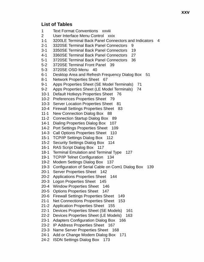
List of Tables1 Text Format Conventions xxviii2 User Interface Menu Control xxix1-1 3200LE Terminal Back Panel Connectors and Indicators 42-1 3320SE Terminal Back Panel Connectors 93-1 3350SE Terminal Back Panel Connectors 194-1 3360SE Terminal Back Panel Connectors 275-1 3720SE Terminal Back Panel Connectors 365-2 3720SE Terminal Front Panel 395-3 3720SE OSD Menu 406-1 Desktop Area and Refresh Frequency Dialog Box 518-1 Network Properties Sheet 679-1 Apps Properties Sheet (SE Model Terminals) 719-2 Apps Properties Sheet (LE Model Terminals) 7410-1 Default Hotkeys Properties Sheet 7610-2 Preferences Properties Sheet 7910-3 Server Location Properties Sheet 8110-4 Firewall Settings Properties Sheet 8311-1 New Connection Dialog Box 8811-2 Connection Startup Dialog Box 8914-1 Dialing Properties Dialog Box 10714-2 Port Settings Properties Sheet 10914-3 Call Options Properties Sheet 11015-1 TCP/IP Settings Dialog Box 11215-2 Security Settings Dialog Box 11416-1 RAS Script Dialog Box 11718-1 Terminal Emulation and Terminal Type 12719-1 TCP/IP Telnet Configuration 13419-2 Modem Settings Dialog Box 13719-3 Configuration of Serial Cable on Com1 Dialog Box 13920-1 Server Properties Sheet 14220-2 Applications Properties Sheet 14420-3 Logon Properties Sheet 14520-4 Window Properties Sheet 14620-5 Options Properties Sheet 14720-6 Firewall Settings Properties Sheet 14921-1 Net Connections Properties Sheet 15321-2 Application Properties Sheet 15522-1 Devices Properties Sheet (SE Models) 16122-2 Devices Properties Sheet (LE Models) 16323-1 Adapters Configuration Dialog Box 16623-2 IP Address Properties Sheet 16723-3 Name Server Properties Sheet 16824-1 Add or Change Modem Dialog Box 17124-2 ISDN Settings Dialog Box 173
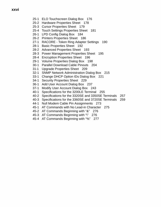
xxvi
25-1 ELO Touchscreen Dialog Box 17625-2 Hardware Properties Sheet 17825-3 Cursor Properties Sheet 17925-4 Touch Settings Properties Sheet 18126-1 LPD Config Dialog Box 18426-2 Printers Properties Sheet 18627-1 RACORE - Token Ring Adapter Settings 19028-1 Basic Properties Sheet 19228-2 Advanced Properties Sheet 19328-3 Power Management Properties Sheet 19528-4 Encryption Properties Sheet 19629-1 Volume Properties Dialog Box 19830-1 Parallel Download Cable Pinouts 20431-1 Upgrade Properties Sheet 20932-1 SNMP Network Administration Dialog Box 21533-1 Change DHCP Option IDs Dialog Box 22134-1 Security Properties Sheet 22936-1 Add User Account Dialog Box 23737-1 Modify User Account Dialog Box 24340-1 Specifications for the 3200LE Terminal 25540-2 Specifications for the 3320SE and 3350SE Terminals 25740-3 Specifications for the 3360SE and 3720SE Terminals 25944-1 Null Modem Cable Pin Assignments 27345-1 AT Commands with No Lead-in Character 27545-2 AT Commands Beginning with “&” 27645-3 AT Commands Beginning with “\” 27645-4 AT Commands Beginning with “%” 277
About the Administrators Guide
The Winterm 3000 Series Windows-based Terminal Administrators Guide contains the information you will need to install, configure, connect, and troubleshoot a WBT (Windows-based Terminal). This guide is written for network system administrators and covers the Models 3200LE, 3320SE, 3350SE, 3360SE, and 3720SE terminals.
Guide Overview
The administrators guide consists of the following chapters:
• Terminal Installation
• Advanced User Interface
• Connection Configuration
• External Devices
• Firmware Upgrades
• Client Security
• Getting Help
This guide contains information about:
• Terminal specifications and installations
• The WBT user interface
• Physical and network connections, and protocols supported
• Firmware upgrades
• Terminal security
• Getting help
xxviii
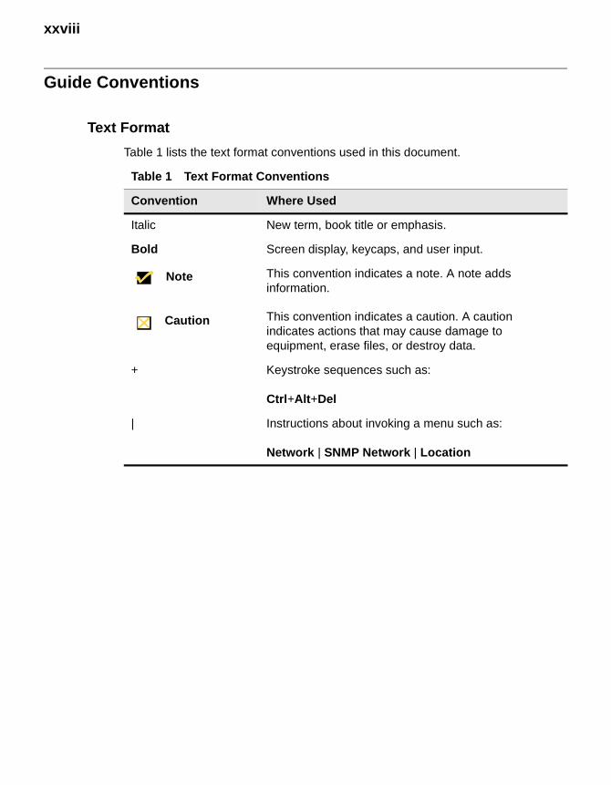
Guide Conventions
Text Format
Table 1 lists the text format conventions used in this document.
Table 1 Text Format Conventions
Convention Where Used
Italic New term, book title or emphasis.
Bold Screen display, keycaps, and user input.
Note This convention indicates a note. A note adds information.
Caution This convention indicates a caution. A caution indicates actions that may cause damage to equipment, erase files, or destroy data.
+ Keystroke sequences such as:
Ctrl+Alt+Del
| Instructions about invoking a menu such as:
Network | SNMP Network | Location
xxix
User Interface Menu Control
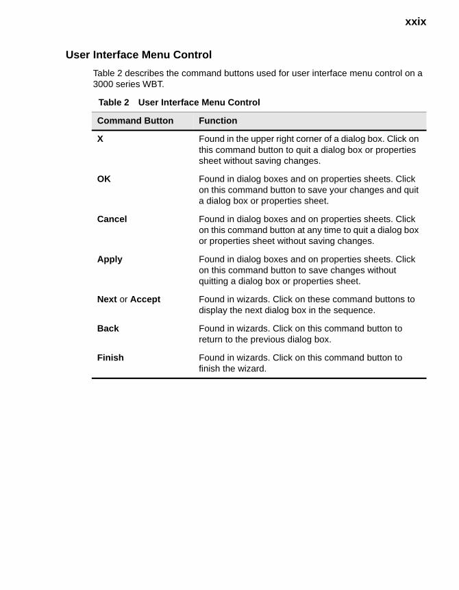
Table 2 describes the command buttons used for user interface menu control on a 3000 series WBT.
Table 2 User Interface Menu Control
Command Button Function
X Found in the upper right corner of a dialog box. Click on this command button to quit a dialog box or properties sheet without saving changes.
OK Found in dialog boxes and on properties sheets. Click on this command button to save your changes and quit a dialog box or properties sheet.
Cancel Found in dialog boxes and on properties sheets. Click on this command button at any time to quit a dialog box or properties sheet without saving changes.
Apply Found in dialog boxes and on properties sheets. Click on this command button to save changes without quitting a dialog box or properties sheet.
Next or Accept Found in wizards. Click on these command buttons to display the next dialog box in the sequence.
Back Found in wizards. Click on this command button to return to the previous dialog box.
Finish Found in wizards. Click on this command button to finish the wizard.

xxx
Terminal Installation
1 Model 3200LE Terminal Installation2 Model 3320SE Terminal Installation3 Model 3350SE Terminal Installation4 Model 3360SE Terminal Installation5 Model 3720SE Terminal Installation

2

1 Model 3200LE Terminal Installation
This section discusses the procedures for installing the 3200LE terminal. The paragraphs below describe how to set up and connect the terminal in the freestanding position.
NoteAn optional wall-mount kit (P/N 920195-01) is available. For more information call 1-800-800-WYSE (9973).
NoteA keyboard and AC power cord are supplied with U.S. models only.
Locating the Terminal
Position the terminal on a clean, horizontal surface that is free from vibration and out of direct sunlight. Refer to “Windows-based Terminal Specifications” for environmental specifications.
Connecting the Terminal
Make all connections to the back panel before connecting the terminal to power. Figure 1-1 shows the back panel connectors.

4 Terminal Installation
Figure 1-1 3200LE Terminal Back Panel Connectors and Indicators
Table 1-1 summarizes the back panel connectors.
Proceed as follows to connect the terminal.
1. Connect the monitor to the Video connector.
2. Connect the keyboard to either USB port.
NoteYou can also connect the keyboard using a USB hub or a multiple-port Digi device.
Table 1-1 3200LE Terminal Back Panel Connectors and Indicators
Connector Description
LED Indicators The 10 or 100 indicator lights to indicate the network type to which the terminal is connected (10/100 Base-T). The Act indicator flashes when there is activity on the line.
Network LAN connector, 10/100Base-T
Headphone Audio output jack for headphones
Microphone Audio input jack for microphones
Video Monitor connector
USB (2) USB ports
Power Power connector
Microphone USBNetworkLEDIndicators
Video Power
Headphone
5
3. Connect the mouse to the Mouse connector on the numeric keypad side of the keyboard.
4. If you will be using a network connection, connect a 10Base-T or 100Base-T network cable to the LAN connector.
5. Connect the power supply cable to the Power connector.
CautionDo not force a connector into its socket. If any undue resistance is encountered, ensure that the connector is oriented correctly to the socket.
6. Plug the AC cord into the power supply, then into an AC outlet.
7. After the cables are connected, install the terminal in its planned location.
Turning On the Terminal
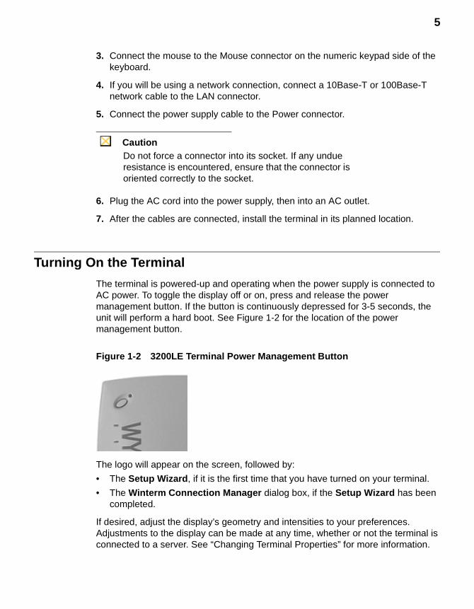
The terminal is powered-up and operating when the power supply is connected to AC power. To toggle the display off or on, press and release the power management button. If the button is continuously depressed for 3-5 seconds, the unit will perform a hard boot. See Figure 1-2 for the location of the power management button.
Figure 1-2 3200LE Terminal Power Management Button
The logo will appear on the screen, followed by:
• The Setup Wizard, if it is the first time that you have turned on your terminal.
• The Winterm Connection Manager dialog box, if the Setup Wizard has been completed.
If desired, adjust the display’s geometry and intensities to your preferences. Adjustments to the display can be made at any time, whether or not the terminal is connected to a server. See “Changing Terminal Properties” for more information.

6 Terminal Installation

2 Model 3320SE Terminal Installation
This section discusses the procedures for installing the 3320SE terminal. The terminal can be freestanding or, optionally, mounted on a wall. The paragraphs below describe how to connect and set up a terminal in both configurations.
NoteOptional wall-mount and cable shroud kits (P/N 920190-01 and P/N 830167-01) are available. For more information call 1-800-800-WYSE (9973).
NoteA keyboard and AC power cord are supplied with U.S. models only.
Locating the Terminal
Position the terminal on a clean, horizontal surface that is free from vibration and out of direct sunlight. Refer to “Windows-based Terminal Specifications” for environmental specifications.
Connecting the Terminal
Make all connections to the back panel before connecting the terminal to power. An optional shroud and cable retaining loop (described in “Optional Cable Retaining Clip and Shroud Installation”) can be installed after the cables are connected and the terminal is mounted in place. Figure 2-1 shows the back panel connectors.
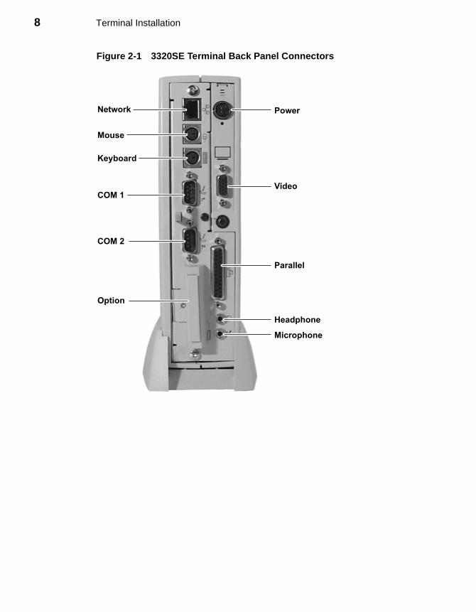
8 Terminal Installation
Figure 2-1 3320SE Terminal Back Panel Connectors
Mouse
Keyboard
COM 2
COM 1
Power
Parallel
Option
Network
Headphone
Microphone
Video

9
The following table summarizes the back panel connectors’ functions.
Proceed as follows to connect the terminal. If necessary, remove the desktop mounting stand (one Phillips-head screw on the bottom).
NoteBefore connecting the cables, decide which mounting configuration will be used and ensure that the cables are of the correct lengths. If permanent desktop or wall-mounting configuration is to be used, drill the desktop mounting holes or install the mounting bracket wall anchors before connecting the cables.
Table 2-1 3320SE Terminal Back Panel Connectors
Connector Description
Network LAN connector, 10/100Base-T
Com1 Serial port 1:
• Can be connected to an external modem.
• Can be used for a direct connection to a local server.
• Can be connected to a serial printer.
Com2 Serial port 2:
• Can be connected to an external modem.
• Can be used for a direct connection to a local server.
• Can be connected to a serial printer.
Parallel Port Local printer output
Video Monitor interface
Keyboard Keyboard interface
Mouse Mouse interface
Power Power module output cable interface
Option PCMCIA card slot
Headphone Audio output for headphones
Microphone Audio input for microphones
10 Terminal Installation
1. Connect the monitor to the Video connector.
2. Connect the keyboard to the Keyboard connector.
3. Connect the mouse to the Mouse connector.
4. If you will be using a network connection, connect a 10Base-T or 100Base-T network cable to the Network connector. Depending on your configuration needs, connect a printer to the parallel port, and/or connect a modem/server serial cable or serial device to the serial ports, as appropriate.
5. Connect the power supply output cable to the Power connector.
CautionDo not force a connector into its socket. If any undue resistance is encountered, ensure that the connector is oriented correctly to the socket.
6. Plug the AC cord into the power supply, then into an AC outlet.
7. After the cables are connected, install the terminal in its planned location, either on a desktop or, optionally, mounted to a wall.
Mounting the Terminal
The terminal can be freestanding or attached to a wall (an optional wall mount kit is required). Instructions for mounting your terminal are provided in the following paragraphs; use the instructions that are appropriate for the desired method of mounting your terminal.
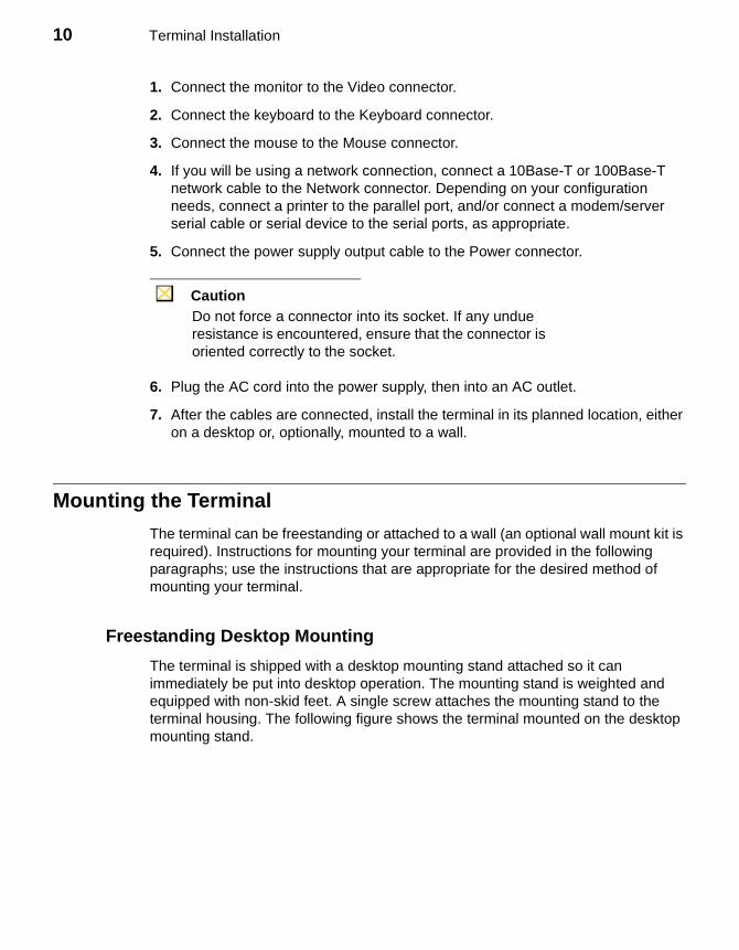
Freestanding Desktop Mounting
The terminal is shipped with a desktop mounting stand attached so it can immediately be put into desktop operation. The mounting stand is weighted and equipped with non-skid feet. A single screw attaches the mounting stand to the terminal housing. The following figure shows the terminal mounted on the desktop mounting stand.

11
Figure 2-2 3320SE Freestanding Desktop Mounting
Wall Mounting
The terminal can be mounted on a wall using the optional wall-mounting bracket. The following figure shows the wall-mount configuration.
NoteIt is best to connect the cables before mounting the terminal on a wall. However, cables can be attached at any convenient time, as long as power is disconnected.
12 Terminal Installation
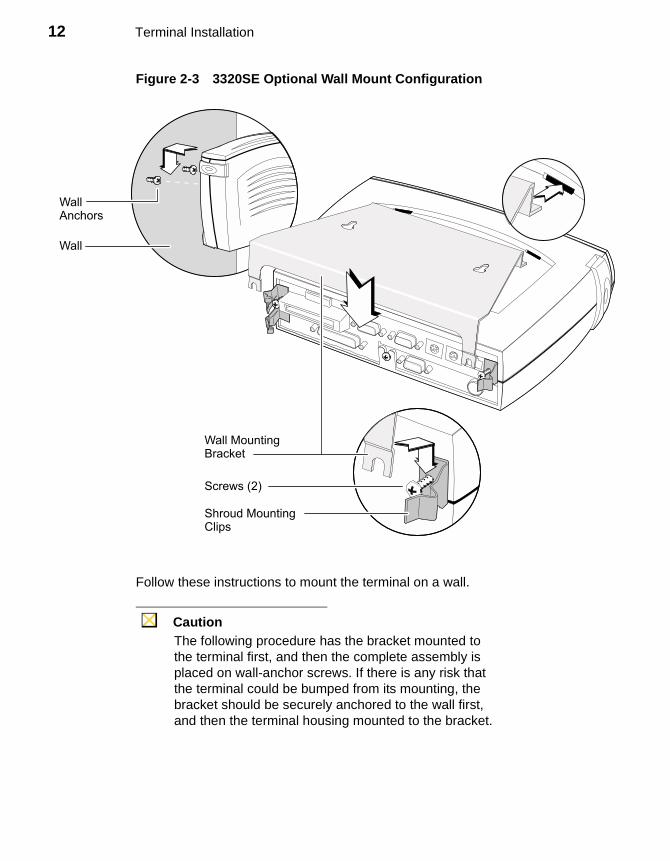
Figure 2-3 3320SE Optional Wall Mount Configuration
Follow these instructions to mount the terminal on a wall.
CautionThe following procedure has the bracket mounted to the terminal first, and then the complete assembly is placed on wall-anchor screws. If there is any risk that the terminal could be bumped from its mounting, the bracket should be securely anchored to the wall first, and then the terminal housing mounted to the bracket.
WallAnchors
Wall
Shroud MountingClips
Screws (2)
Wall MountingBracket
13
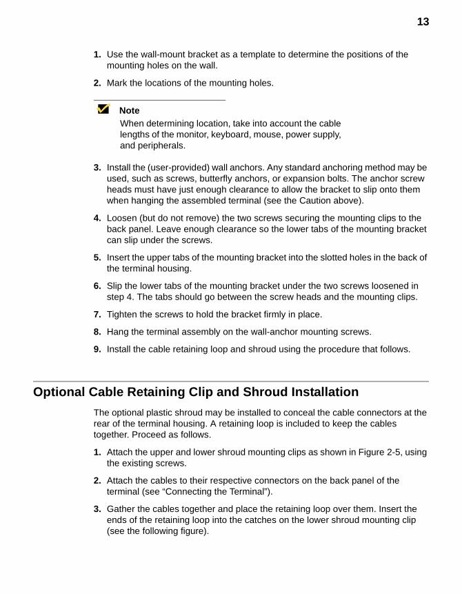
1. Use the wall-mount bracket as a template to determine the positions of the mounting holes on the wall.
2. Mark the locations of the mounting holes.
NoteWhen determining location, take into account the cable lengths of the monitor, keyboard, mouse, power supply, and peripherals.
3. Install the (user-provided) wall anchors. Any standard anchoring method may be used, such as screws, butterfly anchors, or expansion bolts. The anchor screw heads must have just enough clearance to allow the bracket to slip onto them when hanging the assembled terminal (see the Caution above).
4. Loosen (but do not remove) the two screws securing the mounting clips to the back panel. Leave enough clearance so the lower tabs of the mounting bracket can slip under the screws.
5. Insert the upper tabs of the mounting bracket into the slotted holes in the back of the terminal housing.
6. Slip the lower tabs of the mounting bracket under the two screws loosened in step 4. The tabs should go between the screw heads and the mounting clips.
7. Tighten the screws to hold the bracket firmly in place.
8. Hang the terminal assembly on the wall-anchor mounting screws.
9. Install the cable retaining loop and shroud using the procedure that follows.
Optional Cable Retaining Clip and Shroud Installation
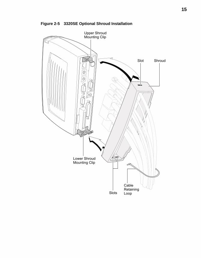
The optional plastic shroud may be installed to conceal the cable connectors at the rear of the terminal housing. A retaining loop is included to keep the cables together. Proceed as follows.
1. Attach the upper and lower shroud mounting clips as shown in Figure 2-5, using the existing screws.
2. Attach the cables to their respective connectors on the back panel of the terminal (see “Connecting the Terminal”).
3. Gather the cables together and place the retaining loop over them. Insert the ends of the retaining loop into the catches on the lower shroud mounting clip (see the following figure).

14 Terminal Installation
Figure 2-4 3320SE Optional Cable Retaining Clip Installation
4. Gently pull the lower ends of the shroud apart and place it over the cables.
5. Place the slots in the lower end (split end) of the shroud under the lower shroud mounting clip, as shown in the following figure.
6. Rotate the upper end of the shroud until the top slot goes over and engages the upper mounting clip, as shown in the following figure.
Retainer Catches
Cable RetainingLoop
15
Figure 2-5 3320SE Optional Shroud Installation
CableRetainingLoop
Upper ShroudMounting Clip
Lower ShroudMounting Clip
Slot
Slots
Shroud

16 Terminal Installation
Turning On the Terminal
The 3320SE terminal is powered-up and operating when the power supply is connected to AC power. To toggle the display off or on, press and release the power management button.
NoteIf the button is continuously depressed for 3-5 seconds, the unit will perform a hard boot.
See the following figure for the location of the power management button.
Figure 2-6 3320SE Power Management Button
The logo will appear on the screen, followed by:
• The Setup Wizard, if it is the first time that you have turned on your terminal.
• The Winterm Connection Manager dialog box, if the Setup Wizard has been completed.
If desired, adjust the display’s geometry and intensities to your preferences. Adjustments to the display can be made at any time, whether or not the terminal is connected to a server. See “Changing Terminal Properties” for more information.
3 Model 3350SE Terminal Installation
This section discusses the procedures for installing the 3350SE enhanced modular terminal. This terminal can be freestanding or, optionally, mounted on a wall. It can instead be permanently mounted on a desktop, if desired. The paragraphs below describe how to connect and set up the terminal in all three configurations.
NoteAn optional wall-mount kit (P/N 920189-01) is available. For more information call 1-800-800-WYSE (9973).
NoteA keyboard and AC power cord are supplied with U.S. models only.
Locating the Terminal
Position the terminal on a clean, horizontal surface that is free from vibration and out of direct sunlight. Refer to “Windows-based Terminal Specifications” for environmental specifications.
Connecting the Terminal
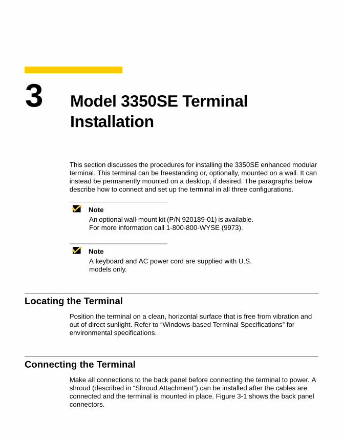
Make all connections to the back panel before connecting the terminal to power. A shroud (described in “Shroud Attachment”) can be installed after the cables are connected and the terminal is mounted in place. Figure 3-1 shows the back panel connectors.
18 Terminal Installation
Figure 3-1 3350SE Terminal Back Panel Connectors
COM 2
Power
Option
Keyboard
Microphone
COM 1
Parallel
Video
Network
Headphone
USB
Mouse
19
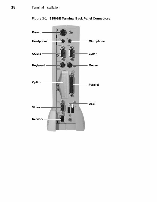
Table 3-1 summarizes the back panel connectors’ functions.
Table 3-1 3350SE Terminal Back Panel Connectors
Connector Description
Network Connector LAN connector, 10/100Base-T
Com1 Serial port 1:
• Can be connected to the external modem or used for direct connection to a local server.
• Can be used for the emergency download of the operating system programs from the host computer.
• Can be connected to a serial printer.
Com2 Serial port 2:
• Can be connected to an external modem.
• Can be used for a direct connection to a local server.
• Can be connected to a serial printer.
Parallel Port Local printer output
Video Monitor interface
Keyboard Keyboard interface
Mouse Mouse interface
Power Power module output cable interface
Card Bus PCMCIA card slot
Headphone Audio output for headphones
Microphone Audio input for microphones
USB Universal Serial Bus
20 Terminal Installation
Proceed as follows to connect the terminal:
NoteBefore connecting the cables, decide which mounting configuration will be used and ensure that the cables are of the correct lengths. If permanent desktop or wall-mounting configuration is to be used, drill the desktop mounting holes or install the mounting bracket wall anchors before connecting the cables.
1. Connect the monitor to the Video connector.
2. Connect the keyboard to the Keyboard connector.
3. Connect the mouse to the Mouse connector.
4. If you will be using a network connection, connect a CAT5 UTP cable to the Network connector. Depending on your configuration needs, connect a printer to the parallel port and/or connect a modem/server serial cable to the serial ports, as appropriate.
5. Connect the power supply output cable to the Power connector.
CautionDo not force a connector into its socket. If any undue resistance is encountered, ensure that the connector is oriented correctly to the socket.
6. Plug the AC cord into the power supply, then into an AC outlet.
7. After the cables are connected, install the terminal in its planned location, either on a desktop or mounted to a wall (see the next section “Mounting the Terminal”).
Mounting the Terminal
The terminal can be freestanding, attached to a wall (an optional wall mount kit is required), or mounted permanently on a desktop. Instructions for mounting your terminal are provided in the following paragraphs; use the instructions that are appropriate for the desired method of mounting your terminal.
21
Freestanding Desktop Mounting
Model 3350SE terminals are built with a desktop mounting stand as part of the housing, so they can immediately be put into desktop operation. The terminal is also weighted and equipped with non-skid feet. “Terminal Features” shows the Model 3350SE terminal.
CautionAlways mount the terminal vertically, with the base down, to ensure proper cooling.
Permanent Desktop Mounting
If desired, the terminal can be permanently mounted on a desktop. Holes in the base plate are threaded to receive the mounting bolts. Two 6 mm (M6) mounting bolts must be provided by the user.
The mounting bolts must not protrude more than 9 mm (3/8 in) through the top of the desktop mounting surface. Damage to the terminal housing and internal components could occur if the mounting bolts protrude past the tops of the guide holes.
Follow these instructions for permanent desktop mounting:
1. Make a template of the desktop mounting holes using the bottom of the terminal, and use it to mark the desktop area where you want to mount the terminal.
2. Drill holes for the mounting bolts through the desktop mounting surface at the marked locations.
3. Place the terminal in position over the holes drilled in the desktop.
4. Insert the mounting bolts up through the holes in the desktop and into the threaded holes in the terminal base plate. Tighten the bolts until snug.
Wall Mounting
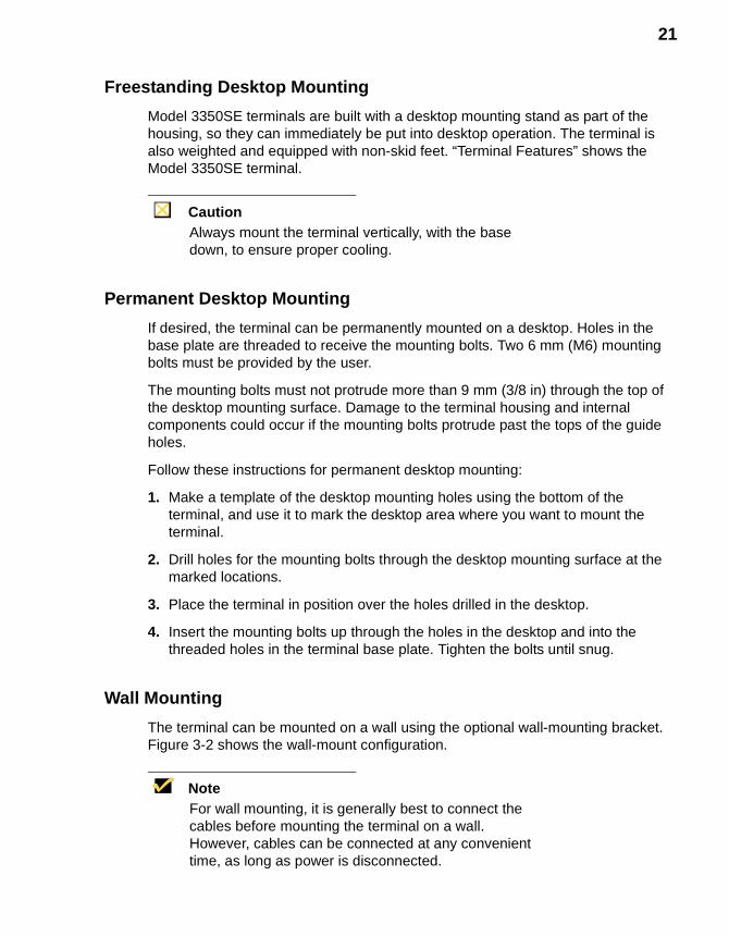
The terminal can be mounted on a wall using the optional wall-mounting bracket. Figure 3-2 shows the wall-mount configuration.
NoteFor wall mounting, it is generally best to connect the cables before mounting the terminal on a wall. However, cables can be connected at any convenient time, as long as power is disconnected.
22 Terminal Installation
Figure 3-2 3350SE Optional Wall Mount Configuration
Follow these instructions to mount the terminal on a wall:
NoteThe following procedure has the bracket mounted to the terminal first, and then the complete assembly is placed on wall anchor screws.
MountingBracket
Tabs
Bolts
23
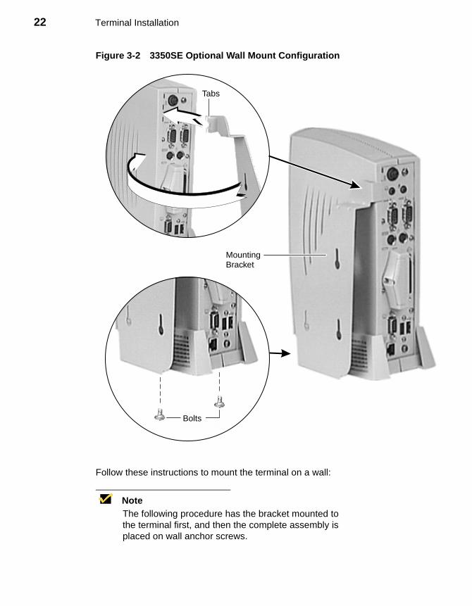
1. Use the wall-mount bracket as a template to determine the positions of the mounting holes on the wall, then mark the locations of the mounting holes.
NoteWhen determining location, take into account the cable lengths of the monitor, keyboard, mouse, power supply, and peripherals.
2. Install the (user-provided) wall anchors. Any standard anchoring method may be used, such as screws, butterfly anchors, or expansion bolts.
3. Install the anchor screws. The anchor screw heads must have just enough clearance to allow the bracket to slip onto them when hanging the assembled terminal (see the Note above).
4. Insert the tabs at the top of the mounting bracket into the slotted holes in the back of the terminal housing.
5. Swing the mounting bracket to the side of the terminal.
6. Insert the mounting bolts up through the holes in the bottom of the mounting bracket and into the threaded holes in the terminal base plate.
7. Tighten the mounting bolts to hold the bracket firmly in place.
8. Hang the terminal assembly on the wall-anchor mounting screws.
9. Install the cable retaining loop and shroud using the procedure below.
Shroud Attachment
A plastic shroud may be installed to conceal the cable connectors at the rear of the terminal housing.
Proceed as follows:
1. Attach the cables to their respective connectors on the back panel of the terminal (see “Connecting the Terminal”).
2. Install the shroud-mounting clips.
3. Gently pull the lower ends of the shroud apart and place it over the cables.
4. Place the slots in the lower end (split end) of the shroud under the lower shroud mounting clip.
5. Rotate the upper end of the shroud until the top slot goes over and engages the upper mounting clip.
24 Terminal Installation
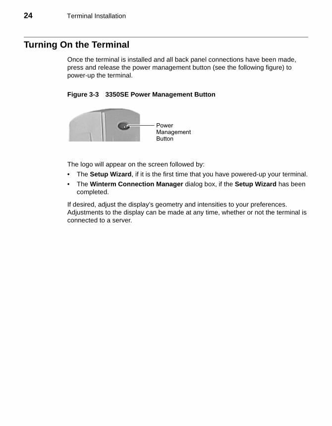
Turning On the Terminal
Once the terminal is installed and all back panel connections have been made, press and release the power management button (see the following figure) to power-up the terminal.
Figure 3-3 3350SE Power Management Button
The logo will appear on the screen followed by:
• The Setup Wizard, if it is the first time that you have powered-up your terminal.
• The Winterm Connection Manager dialog box, if the Setup Wizard has been completed.
If desired, adjust the display’s geometry and intensities to your preferences. Adjustments to the display can be made at any time, whether or not the terminal is connected to a server.
PowerManagementButton
4 Model 3360SE Terminal Installation
This section discusses the procedures for installing the 3360SE terminal. The terminal can be freestanding or, optionally, mounted on a wall. The paragraphs below describe how to connect and set up the terminal in both configurations.
NoteOptional wall-mount and cable shroud kits (P/N 920190-01 and P/N 830167-01) are available. For more information call 1-800-800-WYSE (9973).
NoteA keyboard and AC power cord are supplied with U.S. models only.
Locating the Terminal
Position the terminal on a clean, horizontal surface that is free from vibration and out of direct sunlight. Refer to “Windows-based Terminal Specifications” for environmental specifications.
Connecting the Terminal
Make all connections to the back panel before connecting the terminal to power. An optional shroud and cable retaining loop (described in “Optional Cable Retaining Clip and Shroud Installation”) can be installed after the cables are connected and the terminal is mounted in place. Figure 4-1 shows the back panel connectors.

26 Terminal Installation
Figure 4-1 3360SE Terminal Back Panel Connectors
COM 1
COM 2
Option
Keyboard
Microphone
Headphone
Video
Parallel
Mouse
PowerNetwork
USB
27
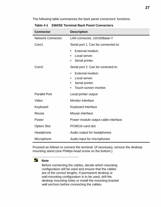
The following table summarizes the back panel connectors’ functions.
Proceed as follows to connect the terminal. (If necessary, remove the desktop mounting stand (one Phillips-head screw on the bottom.)
NoteBefore connecting the cables, decide which mounting configuration will be used and ensure that the cables are of the correct lengths. If permanent desktop or wall-mounting configuration is to be used, drill the desktop mounting holes or install the mounting bracket wall anchors before connecting the cables.
Table 4-1 3360SE Terminal Back Panel Connectors
Connector Description
Network Connector LAN connector, 10/100Base-T
Com1 Serial port 1. Can be connected to:
• External modem.
• Local server.
• Serial printer.
Com2 Serial port 2. Can be conected to:
• External modem.
• Local server.
• Serial printer.
• Touch-screen monitor.
Parallel Port Local printer output
Video Monitor interface
Keyboard Keyboard interface
Mouse Mouse interface
Power Power module output cable interface
Option Slot PCMCIA card slot
Headphone Audio output for headphones
Microphone Audio input for microphones
28 Terminal Installation
1. Connect the monitor to the Video connector.
2. Connect the keyboard to the Keyboard connector.
3. Connect the mouse to the Mouse connector.
4. If you will be using a network connection, connect a 10Base-T or 100Base-T network cable to the Network connector. Depending on your configuration needs, connect a printer to the parallel port, and/or connect a modem/server serial cable to the serial ports, as appropriate.
5. Connect the power supply output cable to the Power connector.
CautionDo not force a connector into its socket. If any undue resistance is encountered, ensure that the connector is oriented correctly to the socket.
6. Plug the AC cord into the power supply, then into an AC outlet.
7. After the cables are connected, install the terminal in its planned location, either on a desktop or mounted to a wall (see the next section “Mounting the Terminal”).
Mounting the Terminal
The terminal can be freestanding or attached to a wall (an optional wall mount kit is required). Instructions for mounting your terminal are provided in the following paragraphs; use the instructions that are appropriate for the desired method of mounting your terminal.
Freestanding Desktop Mounting
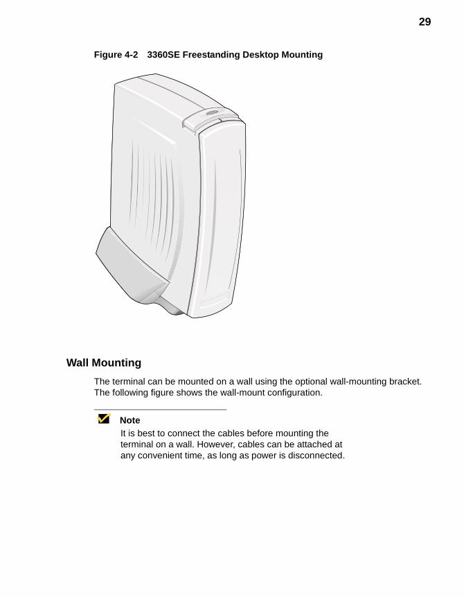
The terminal is shipped with a desktop mounting stand attached so it can immediately be put into desktop operation. The mounting stand is weighted and equipped with non-skid feet. A single screw attaches the mounting stand to the terminal housing. The following figure shows the terminal mounted on the desktop mounting stand.
29
Figure 4-2 3360SE Freestanding Desktop Mounting
Wall Mounting
The terminal can be mounted on a wall using the optional wall-mounting bracket. The following figure shows the wall-mount configuration.
NoteIt is best to connect the cables before mounting the terminal on a wall. However, cables can be attached at any convenient time, as long as power is disconnected.
30 Terminal Installation
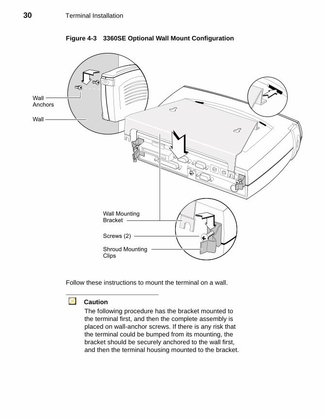
Figure 4-3 3360SE Optional Wall Mount Configuration
Follow these instructions to mount the terminal on a wall.
CautionThe following procedure has the bracket mounted to the terminal first, and then the complete assembly is placed on wall-anchor screws. If there is any risk that the terminal could be bumped from its mounting, the bracket should be securely anchored to the wall first, and then the terminal housing mounted to the bracket.
WallAnchors
Wall
Shroud MountingClips
Screws (2)
Wall MountingBracket

31
1. Use the wall-mount bracket as a template to determine the positions of the mounting holes on the wall.
2. Mark the locations of the mounting holes.
NoteWhen determining location, take into account the cable lengths of the monitor, keyboard, mouse, power supply, and peripherals.
3. Install the (user-provided) wall anchors. Any standard anchoring method may be used, such as screws, butterfly anchors, or expansion bolts. The anchor screw heads must have just enough clearance to allow the bracket to slip onto them when hanging the assembled terminal (see the Caution above).
4. Loosen (but do not remove) the two screws securing the mounting clips to the back panel. Leave enough clearance so the lower tabs of the mounting bracket can slip under the screws.
5. Insert the upper tabs of the mounting bracket into the slotted holes in the back of the terminal housing.
6. Slip the lower tabs of the mounting bracket under the two screws loosened in step 4. The tabs should go between the screw heads and the mounting clips.
7. Tighten the screws to hold the bracket firmly in place.
8. Hang the terminal assembly on the wall-anchor mounting screws.
9. Install the cable retaining loop and shroud using the procedure that follows.
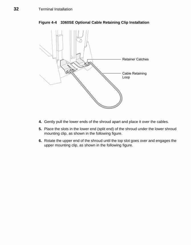
Optional Cable Retaining Clip and Shroud Installation
An optional plastic shroud may be installed to conceal the cable connectors at the rear of the terminal housing. A retaining loop is included to keep the cables together. Proceed as follows.
1. Attach the upper and lower shroud mounting clips as shown in Figure 4-5, using the existing screws.
2. Attach the cables to their respective connectors on the back panel of the terminal (see “Connecting the Terminal”).
3. Gather the cables together and place the retaining loop over them. Insert the ends of the retaining loop into the catches on the lower shroud mounting clip (see the following figure).
32 Terminal Installation
Figure 4-4 3360SE Optional Cable Retaining Clip Installation
4. Gently pull the lower ends of the shroud apart and place it over the cables.
5. Place the slots in the lower end (split end) of the shroud under the lower shroud mounting clip, as shown in the following figure.
6. Rotate the upper end of the shroud until the top slot goes over and engages the upper mounting clip, as shown in the following figure.
Retainer Catches
Cable RetainingLoop
33
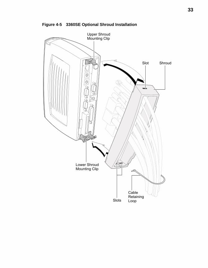
Figure 4-5 3360SE Optional Shroud Installation
CableRetainingLoop
Upper ShroudMounting Clip
Lower ShroudMounting Clip
Slot
Slots
Shroud
34 Terminal Installation
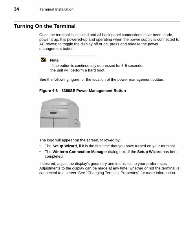
Turning On the Terminal
Once the terminal is installed and all back panel connections have been made, power it up. It is powered-up and operating when the power supply is connected to AC power; to toggle the display off or on, press and release the power management button.
NoteIf the button is continuously depressed for 3-5 seconds, the unit will perform a hard boot.
See the following figure for the location of the power management button.
Figure 4-6 3360SE Power Management Button
The logo will appear on the screen, followed by:
• The Setup Wizard, if it is the first time that you have turned on your terminal.
• The Winterm Connection Manager dialog box, if the Setup Wizard has been completed.
If desired, adjust the display’s geometry and intensities to your preferences. Adjustments to the display can be made at any time, whether or not the terminal is connected to a server. See “Changing Terminal Properties” for more information.
5 Model 3720SE Terminal Installation
The following section discusses installation of the integrated-CRT terminal.
NoteA keyboard and AC power cord are supplied with U.S. models only.
Locating the Terminal
Position the terminal on a clean, horizontal surface that is free from vibration and out of direct sunlight. Allow 75 mm (3 in) of clearance on all sides of the terminal, for air circulation and movement of the tilt/swivel mechanism. Refer to “Windows-based Terminal Specifications” for environmental specifications.
Connecting the Terminal
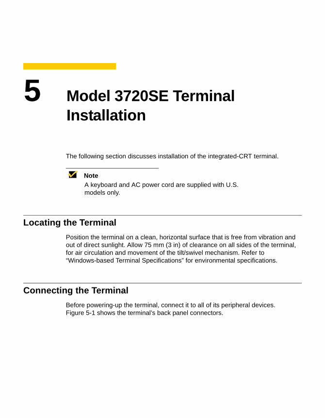
Before powering-up the terminal, connect it to all of its peripheral devices. Figure 5-1 shows the terminal’s back panel connectors.
36 Terminal Installation
Figure 5-1 3720SE Terminal Back Panel Connectors
The following table summarizes the back panel connectors’ functions.
Table 5-1 3720SE Terminal Back Panel Connectors
Connector Description
Network Connector LAN connector, 10/100Base-T
Com1 Serial port 1:
• Can be connected to the external modem or used for direct connection to a local server.
• Can be used for the emergency download of the operating system programs from the host computer.
• Can be connected to a serial printer.
Com2 Serial port 2:
• Can be connected to an external modem.
• Can be used for a direct connection to a local server.
• Can be connected to a serial printer.
• Can be connected to a monitor that supports touch screen.
COM 1
Microphone
Parallel
KeyboardMouse
NetworkPower COM 2 Option
Headphone

37
Follow these instructions to connect the terminal to its peripheral devices:
1. Connect the keyboard to the Keyboard connector.
2. Connect the mouse to the Mouse connector.
3. Plug the AC cord into the back panel of the terminal, then into an AC outlet.
4. Connect a 10Base-T network cable to the Network connector.
The terminal is now ready for operation.
Turning On the Terminal
The 3720SE terminal is powered-up and operating when the power supply is connected to AC power. To toggle the display off or on, press and release the power management button.
NoteIf the button is continuously depressed for 3-5 seconds, the unit will perform a hard boot.
See the figure on the following page for the location of the power management button.
Parallel Port Local printer output
Keyboard Keyboard interface
Mouse Mouse interface
Power AC power cord interface
Option Slot PCMCIA card slot
Headphone Audio output for headphones
Microphone Audio input for microphones
Table 5-1 3720SE Terminal Back Panel Connectors, Continued
Connector Description
38 Terminal Installation
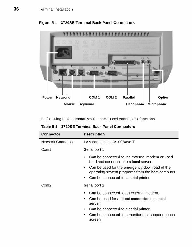
The logo will appear on the screen, followed by:
• The Setup Wizard, if it is the first time that you have turned on your terminal.
• The Winterm Connection Manager dialog box, if the Setup Wizard has been completed.
Make sure that the display’s geometry and intensities are set to your preferences. This can be done at any time, whether or not the terminal is connected to a server. If your terminal is installed with an optional touchscreen, calibrate it now. Refer to“Input Configuration” for the procedure.
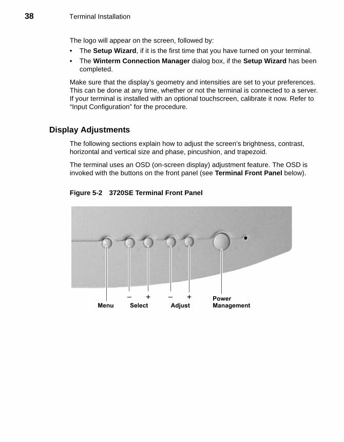
Display Adjustments
The following sections explain how to adjust the screen’s brightness, contrast, horizontal and vertical size and phase, pincushion, and trapezoid.
The terminal uses an OSD (on-screen display) adjustment feature. The OSD is invoked with the buttons on the front panel (see Terminal Front Panel below).
Figure 5-2 3720SE Terminal Front Panel
Menu AdjustPowerManagementSelect
_ _+ +
39
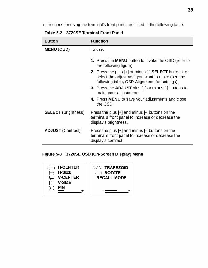
Instructions for using the terminal’s front panel are listed in the following table.
Figure 5-3 3720SE OSD (On-Screen Display) Menu
Table 5-2 3720SE Terminal Front Panel
Button Function
MENU (OSD) To use:
1. Press the MENU button to invoke the OSD (refer to the following figure).
2. Press the plus [+] or minus [-] SELECT buttons to select the adjustment you want to make (see the following table, OSD Alignment, for settings).
3. Press the ADJUST plus [+] or minus [-] buttons to make your adjustment.
4. Press MENU to save your adjustments and close the OSD.
SELECT (Brightness) Press the plus [+] and minus [-] buttons on the terminal’s front panel to increase or decrease the display’s brightness.
ADJUST (Contrast) Press the plus [+] and minus [-] buttons on the terminal’s front panel to increase or decrease the display’s contrast.
H-CENTER
H-SIZE
V-CENTER
V-SIZE
PIN+
TRAPEZOID
ROTATE
RECALL MODE
+
40 Terminal Installation
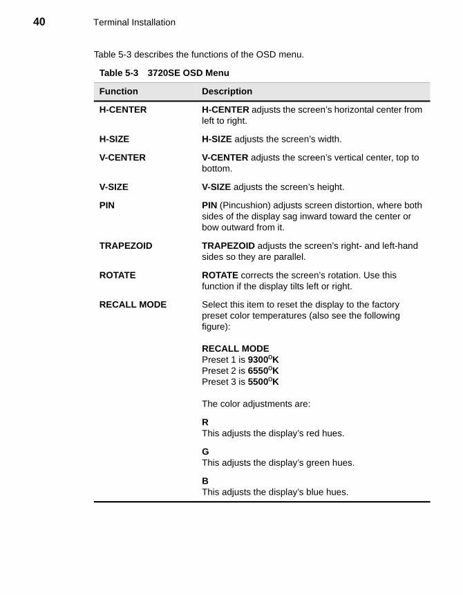
Table 5-3 describes the functions of the OSD menu.
Table 5-3 3720SE OSD Menu
Function Description
H-CENTER H-CENTER adjusts the screen’s horizontal center from left to right.
H-SIZE H-SIZE adjusts the screen’s width.
V-CENTER V-CENTER adjusts the screen’s vertical center, top to bottom.
V-SIZE V-SIZE adjusts the screen’s height.
PIN PIN (Pincushion) adjusts screen distortion, where both sides of the display sag inward toward the center or bow outward from it.
TRAPEZOID TRAPEZOID adjusts the screen’s right- and left-hand sides so they are parallel.
ROTATE ROTATE corrects the screen’s rotation. Use this function if the display tilts left or right.
RECALL MODE Select this item to reset the display to the factory preset color temperatures (also see the following figure):
RECALL MODEPreset 1 is 9300ºKPreset 2 is 6550ºKPreset 3 is 5500ºK
The color adjustments are:
RThis adjusts the display’s red hues.
GThis adjusts the display’s green hues.
BThis adjusts the display’s blue hues.
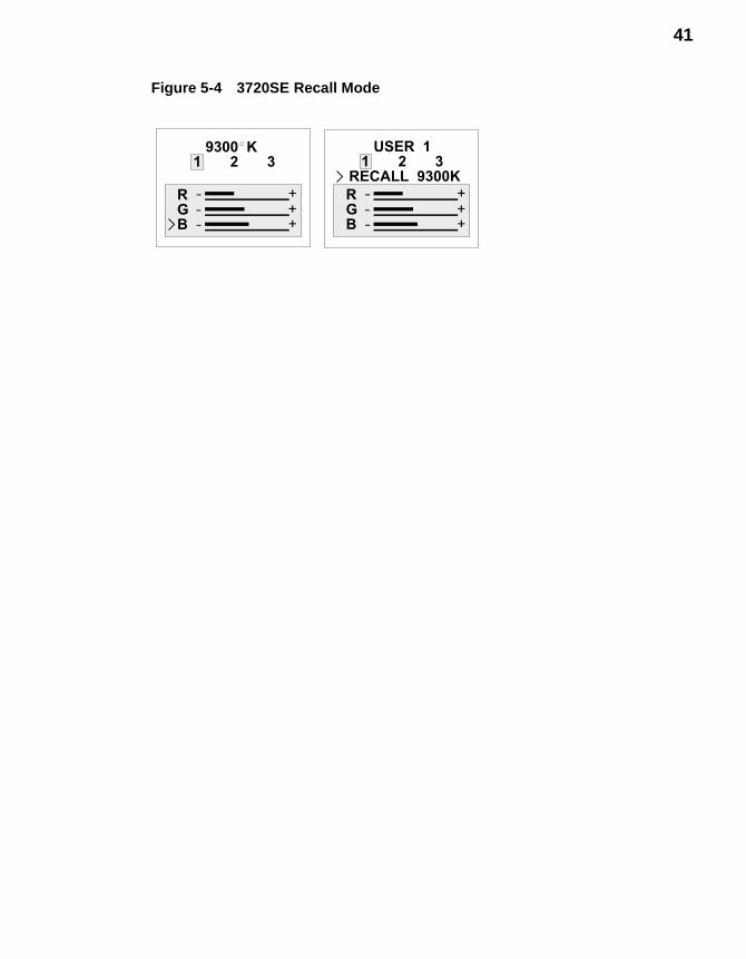
41
Figure 5-4 3720SE Recall Mode
RGB +
++
9300 K1 2 3
RGB +
++
USER 11 2 3
RECALL 9300K

42 Terminal Installation
Advanced User Interface
6 Initial Terminal Setup7 Changing Terminal Properties8 Network Configuration9 Additional Terminal Applications10 ICA Client Settings

44
6 Initial Terminal Setup
The Setup Wizard is used for initial setup of the terminal’s properties. The wizard runs when:
• You power-up your terminal for the first time.
• Your terminal has been restarted with a G key reset.
• A new image has been downloaded to your terminal but is older than the image currently in use.
• You use the Reset the Terminal to Factory-Default Property Settings function on the General properties sheet.
Using the Setup Wizard
The Setup Wizard lets you set terminal network configuration and terminal display parameters. Several dialog boxes display in succession during the process. Each dialog box is self-explanatory. Some dialog boxes are informational and require no user input. Other dialog boxes prompt you for network, printer, and display information. See Figure 6-1 to view the first dialog box of the wizard.
NoteAny future changes can be made using the Terminal Properties dialog box. You can launch this dialog box from the Winterm Connection Manager by pressing the F2 key. See “Resetting Terminal Properties.”

46 Advanced User Interface
Figure 6-1 Welcome Dialog Box
The Welcome dialog box is mostly informational, providing product information. Click on Next to continue with the installation by opening the Countdown dialog box.

47
Figure 6-2 Countdown Dialog Box
The one function the Countdown dialog box carries is a countdown:
• Click on Next during the countdown to zero to continue with the wizard.
• Let the count go to zero to auto configure the terminal.
48 Advanced User Interface
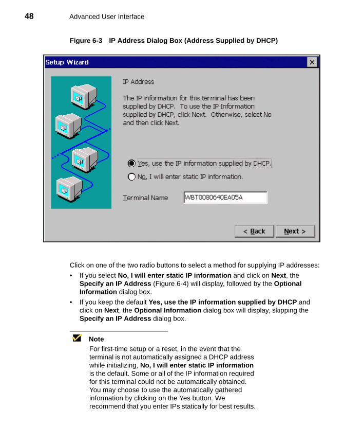
Figure 6-3 IP Address Dialog Box (Address Supplied by DHCP)
Click on one of the two radio buttons to select a method for supplying IP addresses:
• If you select No, I will enter static IP information and click on Next, the Specify an IP Address (Figure 6-4) will display, followed by the Optional Information dialog box.
• If you keep the default Yes, use the IP information supplied by DHCP and click on Next, the Optional Information dialog box will display, skipping the Specify an IP Address dialog box.
NoteFor first-time setup or a reset, in the event that the terminal is not automatically assigned a DHCP address while initializing, No, I will enter static IP information is the default. Some or all of the IP information required for this terminal could not be automatically obtained. You may choose to use the automatically gathered information by clicking on the Yes button. We recommend that you enter IPs statically for best results.
49
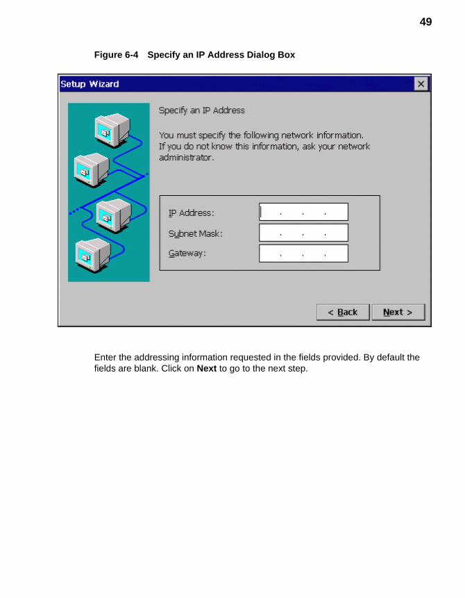
Figure 6-4 Specify an IP Address Dialog Box
Enter the addressing information requested in the fields provided. By default the fields are blank. Click on Next to go to the next step.

50 Advanced User Interface
Figure 6-5 Optional Information Dialog Box
Check a box to enable name resolution:
• Enable DNS - Enables Domain Name Services
• Enable WINS - Windows Internet Naming Services
Enter the information in the text fields that are activated. By default the check boxes are unselected and the text fields are inactivated. Click on Next to go to the next step.
51
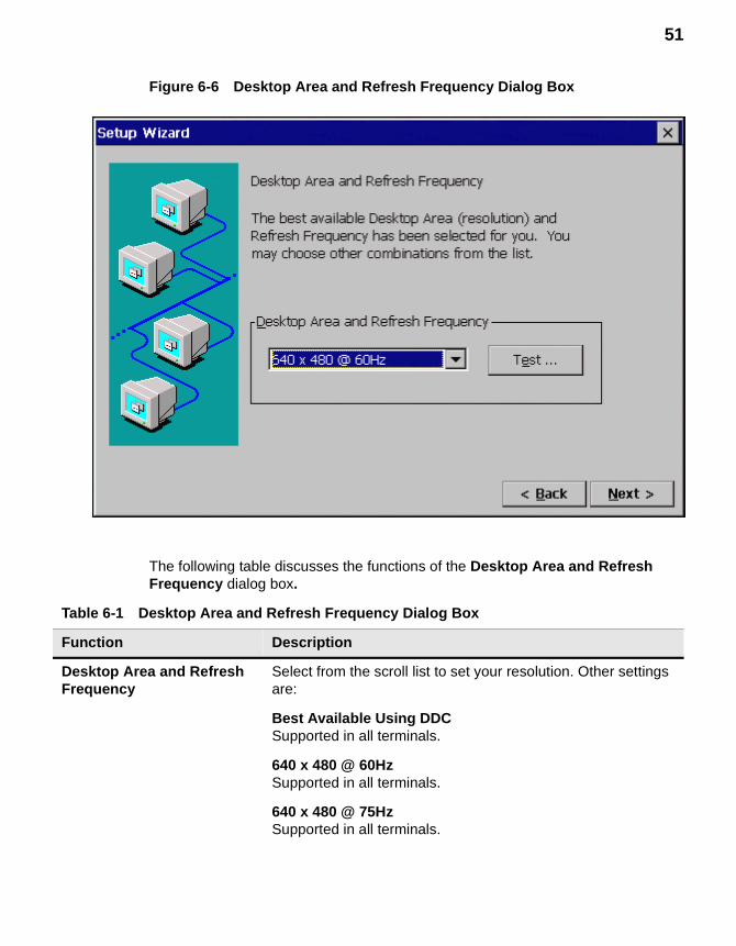
Figure 6-6 Desktop Area and Refresh Frequency Dialog Box
The following table discusses the functions of the Desktop Area and Refresh Frequency dialog box.
Table 6-1 Desktop Area and Refresh Frequency Dialog Box
Function Description
Desktop Area and Refresh Frequency
Select from the scroll list to set your resolution. Other settings are:
Best Available Using DDCSupported in all terminals.
640 x 480 @ 60HzSupported in all terminals.
640 x 480 @ 75HzSupported in all terminals.
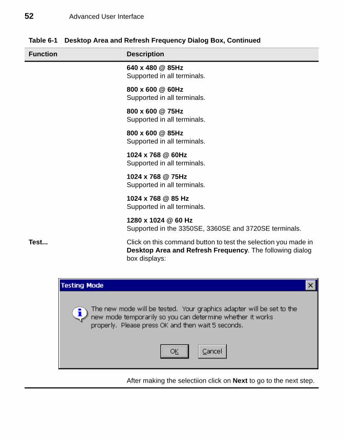
52 Advanced User Interface
640 x 480 @ 85HzSupported in all terminals.
800 x 600 @ 60HzSupported in all terminals.
800 x 600 @ 75HzSupported in all terminals.
800 x 600 @ 85HzSupported in all terminals.
1024 x 768 @ 60HzSupported in all terminals.
1024 x 768 @ 75HzSupported in all terminals.
1024 x 768 @ 85 HzSupported in all terminals.
1280 x 1024 @ 60 HzSupported in the 3350SE, 3360SE and 3720SE terminals.
Test... Click on this command button to test the selection you made in Desktop Area and Refresh Frequency. The following dialog box displays:
After making the selectiion click on Next to go to the next step.
Table 6-1 Desktop Area and Refresh Frequency Dialog Box, Continued
Function Description
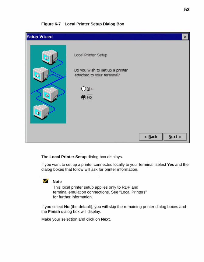
53
Figure 6-7 Local Printer Setup Dialog Box
The Local Printer Setup dialog box displays.
If you want to set up a printer connected locally to your terminal, select Yes and the dialog boxes that follow will ask for printer information.
NoteThis local printer setup applies only to RDP and terminal emulation connections. See “Local Printers” for further information.
If you select No (the default), you will skip the remaining printer dialog boxes and the Finish dialog box will display.
Make your selection and click on Next.

54 Advanced User Interface
Figure 6-8 Select Printer Port Dialog Box
In the Select Printer Port dialog box, select the port to which the printer is connected and click on Next to go to the next step.
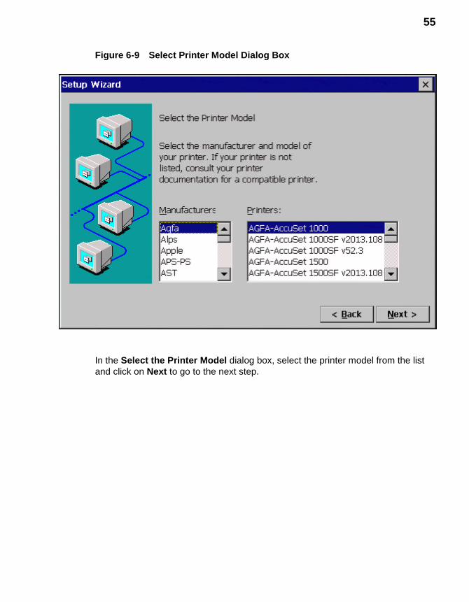
55
Figure 6-9 Select Printer Model Dialog Box
In the Select the Printer Model dialog box, select the printer model from the list and click on Next to go to the next step.
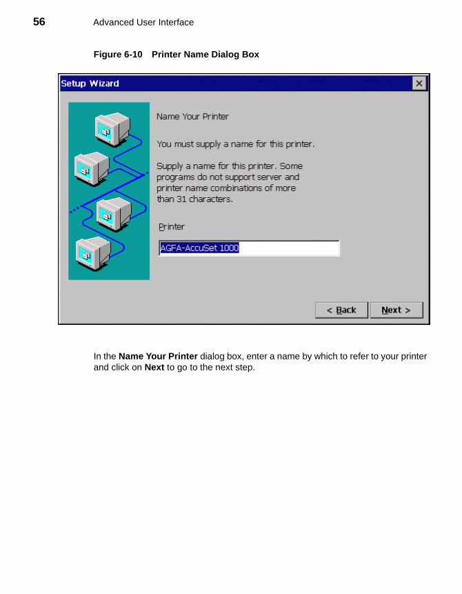
56 Advanced User Interface
Figure 6-10 Printer Name Dialog Box
In the Name Your Printer dialog box, enter a name by which to refer to your printer and click on Next to go to the next step.
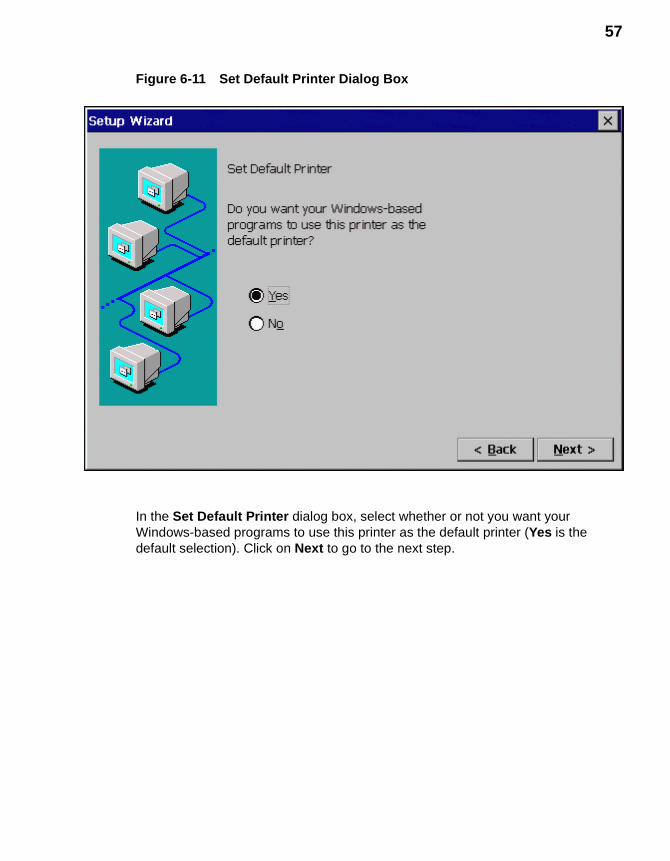
57
Figure 6-11 Set Default Printer Dialog Box
In the Set Default Printer dialog box, select whether or not you want your Windows-based programs to use this printer as the default printer (Yes is the default selection). Click on Next to go to the next step.
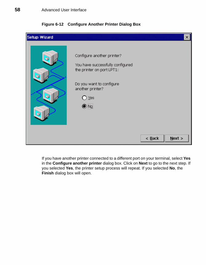
58 Advanced User Interface
Figure 6-12 Configure Another Printer Dialog Box
If you have another printer connected to a different port on your terminal, select Yes in the Configure another printer dialog box. Click on Next to go to the next step. If you selected Yes, the printer setup process will repeat. If you selected No, the Finish dialog box will open.
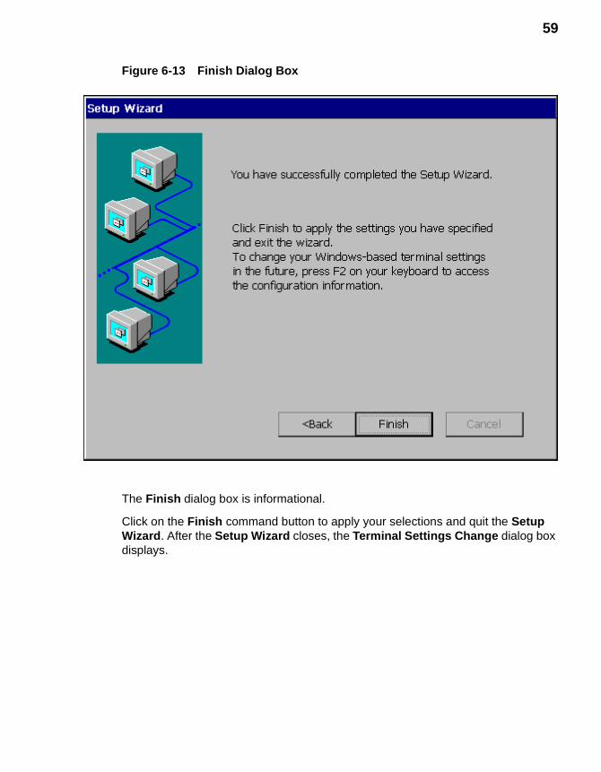
59
Figure 6-13 Finish Dialog Box
The Finish dialog box is informational.
Click on the Finish command button to apply your selections and quit the Setup Wizard. After the Setup Wizard closes, the Terminal Settings Change dialog box displays.
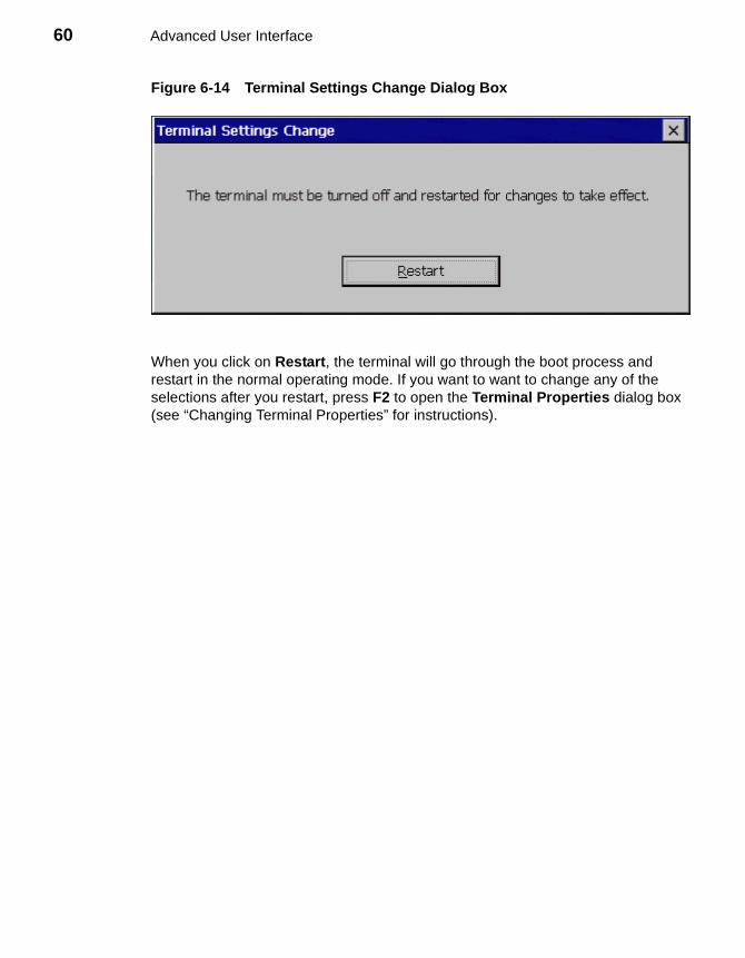
60 Advanced User Interface
Figure 6-14 Terminal Settings Change Dialog Box
When you click on Restart, the terminal will go through the boot process and restart in the normal operating mode. If you want to want to change any of the selections after you restart, press F2 to open the Terminal Properties dialog box (see “Changing Terminal Properties” for instructions).

7 Changing Terminal Properties
Terminal properties can be changed or reconfigured at any time during normal terminal operation using the Terminal Properties dialog box. Figure 7-1 shows this dialog box.
Using the Terminal Properties Dialog Box
Invoke the Terminal Properties dialog box by pressing the F2 key from the Winterm Connection Manager.
The Terminal Properties dialog box consists of a total of 10 properties sheets that can be invoked by clicking on their individual tabs. The following 6 sheets are used to change terminal properties:
• Network - discussed in “Network Configuration.”
• Upgrade - discussed in “FTP Pull Firmware Upgrades.”
• Security - discussed in “Security Properties.”
• Apps - discussed in “Additional Applications.”
• Devices - discussed in “Dial-Up Connections.”
• Printers - discussed in “Local Printers”
The General, SysInfo, Input, and Display properties sheets are discussed in “General Terminal Information” and “Display and Keyboard/Mouse Configuration” in the Winterm 3000 Series WBT Users Guide.
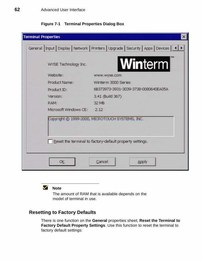
62 Advanced User Interface
Figure 7-1 Terminal Properties Dialog Box
NoteThe amount of RAM that is available depends on the model of terminal in use.
Resetting to Factory Defaults
There is one function on the General properties sheet, Reset the Terminal to Factory Default Property Settings. Use this function to reset the terminal to factory default settings:
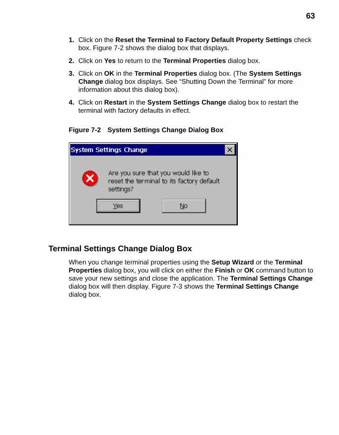
63
1. Click on the Reset the Terminal to Factory Default Property Settings check box. Figure 7-2 shows the dialog box that displays.
2. Click on Yes to return to the Terminal Properties dialog box.
3. Click on OK in the Terminal Properties dialog box. (The System Settings Change dialog box displays. See “Shutting Down the Terminal” for more information about this dialog box).
4. Click on Restart in the System Settings Change dialog box to restart the terminal with factory defaults in effect.
Figure 7-2 System Settings Change Dialog Box
Terminal Settings Change Dialog Box
When you change terminal properties using the Setup Wizard or the Terminal Properties dialog box, you will click on either the Finish or OK command button to save your new settings and close the application. The Terminal Settings Change dialog box will then display. Figure 7-3 shows the Terminal Settings Change dialog box.
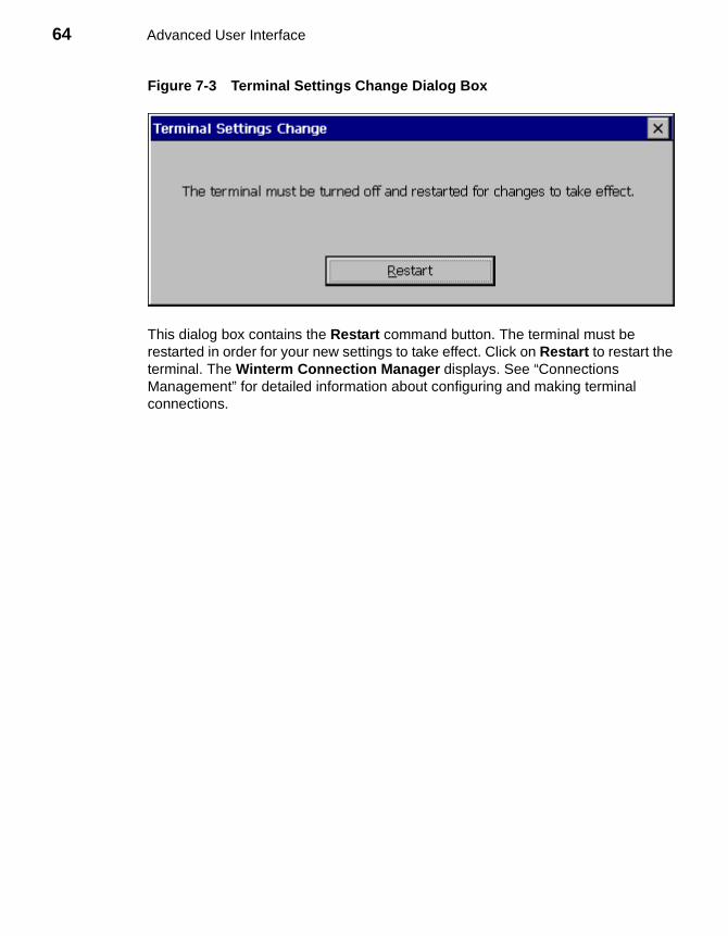
64 Advanced User Interface
Figure 7-3 Terminal Settings Change Dialog Box
This dialog box contains the Restart command button. The terminal must be restarted in order for your new settings to take effect. Click on Restart to restart the terminal. The Winterm Connection Manager displays. See “Connections Management” for detailed information about configuring and making terminal connections.
8 Network Configuration
The Network properties sheet lets you configure your network. See Figure 8-1 to view this properties sheet.
Using the Network Properties Sheet
To invoke this properties sheet:
1. Press F2 to invoke the Terminal Properties dialog box.
2. Click on the Network tab.
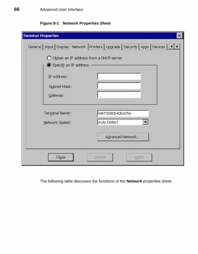
66 Advanced User Interface
Figure 8-1 Network Properties Sheet
The following table discusses the functions of the Network properties sheet.
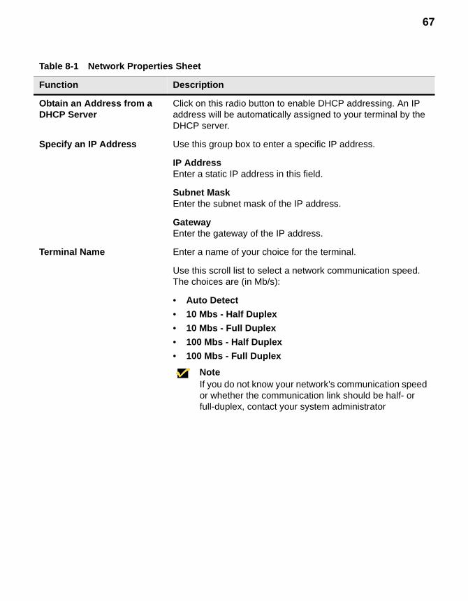
67
Table 8-1 Network Properties Sheet
Function Description
Obtain an Address from a DHCP Server
Click on this radio button to enable DHCP addressing. An IP address will be automatically assigned to your terminal by the DHCP server.
Specify an IP Address Use this group box to enter a specific IP address.
IP AddressEnter a static IP address in this field.
Subnet MaskEnter the subnet mask of the IP address.
GatewayEnter the gateway of the IP address.
Terminal Name Enter a name of your choice for the terminal.
Use this scroll list to select a network communication speed. The choices are (in Mb/s):
• Auto Detect
• 10 Mbs - Half Duplex
• 10 Mbs - Full Duplex
• 100 Mbs - Half Duplex
• 100 Mbs - Full Duplex
NoteIf you do not know your network's communication speed or whether the communication link should be half- or full-duplex, contact your system administrator
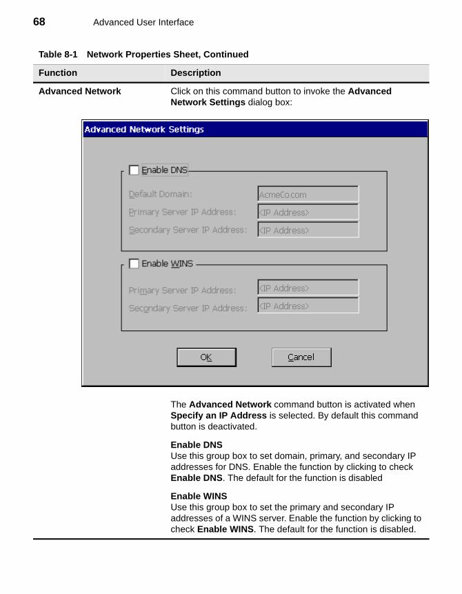
68 Advanced User Interface
Advanced Network Click on this command button to invoke the Advanced Network Settings dialog box:
The Advanced Network command button is activated when Specify an IP Address is selected. By default this command button is deactivated.
Enable DNSUse this group box to set domain, primary, and secondary IP addresses for DNS. Enable the function by clicking to check Enable DNS. The default for the function is disabled
Enable WINSUse this group box to set the primary and secondary IP addresses of a WINS server. Enable the function by clicking to check Enable WINS. The default for the function is disabled.
Table 8-1 Network Properties Sheet, Continued
Function Description
9 Additional Terminal Applications
The Apps properties sheet contains functions for ICA, RDP, virtual port, DHCP, and SNMP management options. See Figure 9-1.
NoteSE model terminals display an Apps properties sheet that is different from that on Model 3200LE terminals.
Using the Apps Properties Sheet for SE Model Terminals
Figure 9-1 shows this properties sheet. To invoke the Apps properties sheet:
1. Press F2 to invoke the Terminal Properties dialog box.
2. Click on the Apps tab in the Terminal Properties dialog box.
Table 9-1 describes the functions of the Apps properties sheet.
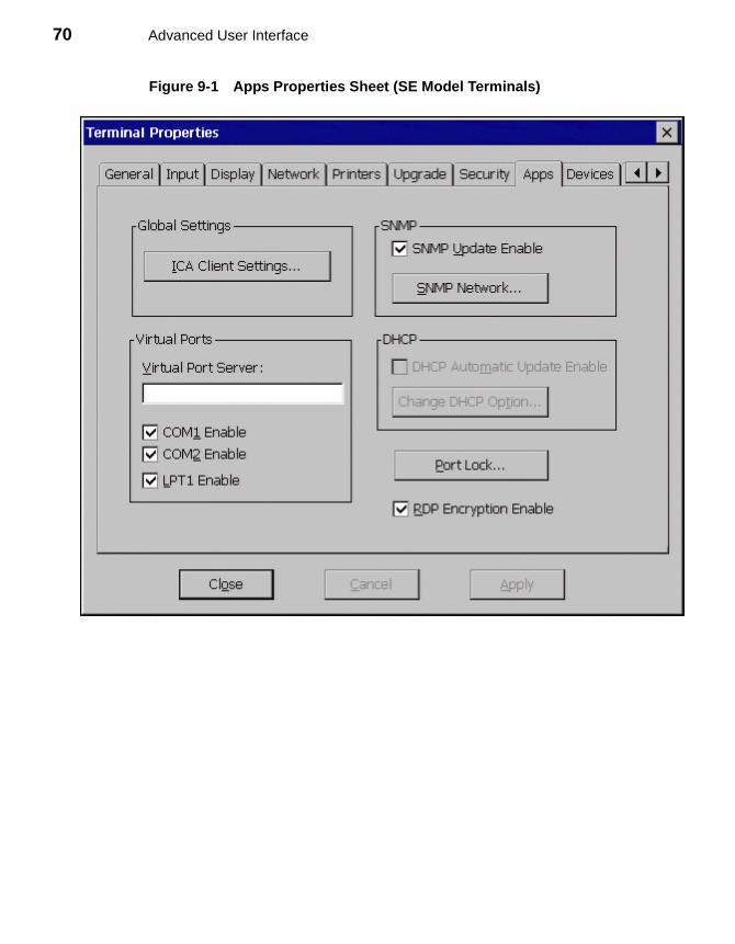
70 Advanced User Interface
Figure 9-1 Apps Properties Sheet (SE Model Terminals)
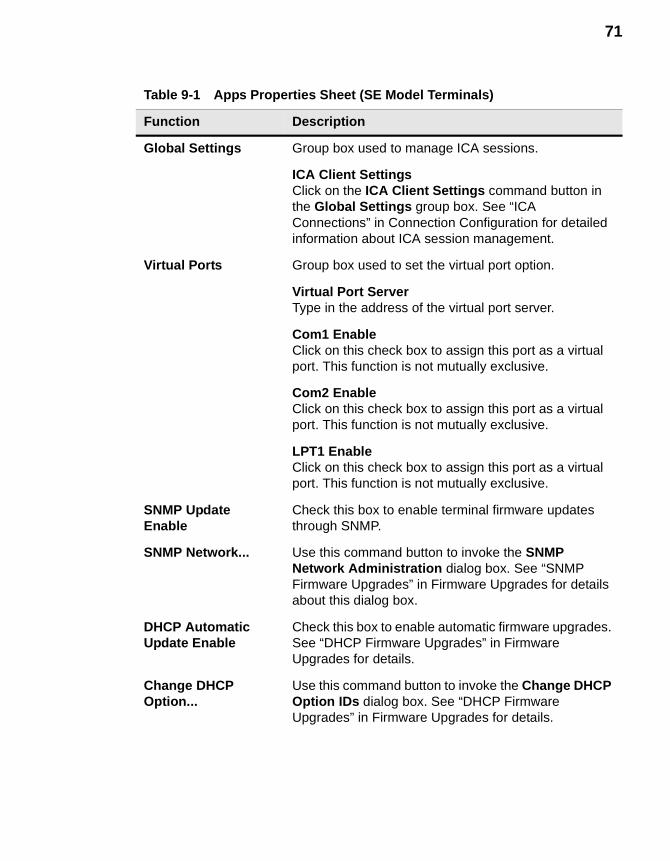
71
Table 9-1 Apps Properties Sheet (SE Model Terminals)
Function Description
Global Settings Group box used to manage ICA sessions.
ICA Client SettingsClick on the ICA Client Settings command button in the Global Settings group box. See “ICA Connections” in Connection Configuration for detailed information about ICA session management.
Virtual Ports Group box used to set the virtual port option.
Virtual Port ServerType in the address of the virtual port server.
Com1 EnableClick on this check box to assign this port as a virtual port. This function is not mutually exclusive.
Com2 EnableClick on this check box to assign this port as a virtual port. This function is not mutually exclusive.
LPT1 EnableClick on this check box to assign this port as a virtual port. This function is not mutually exclusive.
SNMP Update Enable
Check this box to enable terminal firmware updates through SNMP.
SNMP Network... Use this command button to invoke the SNMP Network Administration dialog box. See “SNMP Firmware Upgrades” in Firmware Upgrades for details about this dialog box.
DHCP Automatic Update Enable
Check this box to enable automatic firmware upgrades. See “DHCP Firmware Upgrades” in Firmware Upgrades for details.
Change DHCP Option...
Use this command button to invoke the Change DHCP Option IDs dialog box. See “DHCP Firmware Upgrades” in Firmware Upgrades for details.
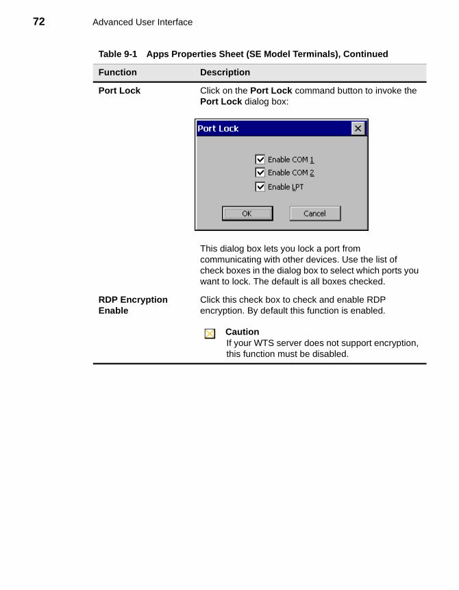
72 Advanced User Interface
Port Lock Click on the Port Lock command button to invoke the Port Lock dialog box:
This dialog box lets you lock a port from communicating with other devices. Use the list of check boxes in the dialog box to select which ports you want to lock. The default is all boxes checked.
RDP Encryption Enable
Click this check box to check and enable RDP encryption. By default this function is enabled.
CautionIf your WTS server does not support encryption, this function must be disabled.
Table 9-1 Apps Properties Sheet (SE Model Terminals), Continued
Function Description
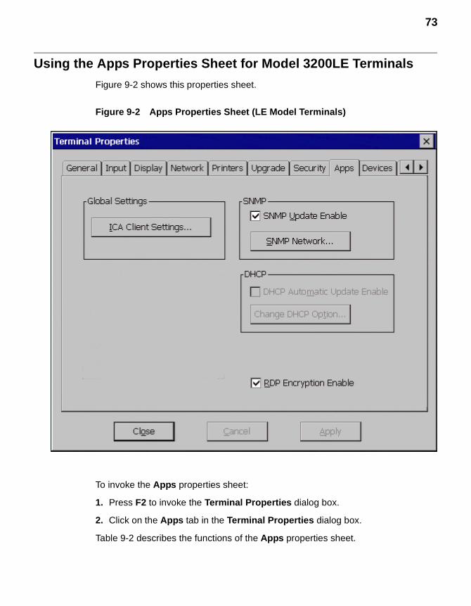
73
Using the Apps Properties Sheet for Model 3200LE Terminals
Figure 9-2 shows this properties sheet.
Figure 9-2 Apps Properties Sheet (LE Model Terminals)
To invoke the Apps properties sheet:
1. Press F2 to invoke the Terminal Properties dialog box.
2. Click on the Apps tab in the Terminal Properties dialog box.
Table 9-2 describes the functions of the Apps properties sheet.
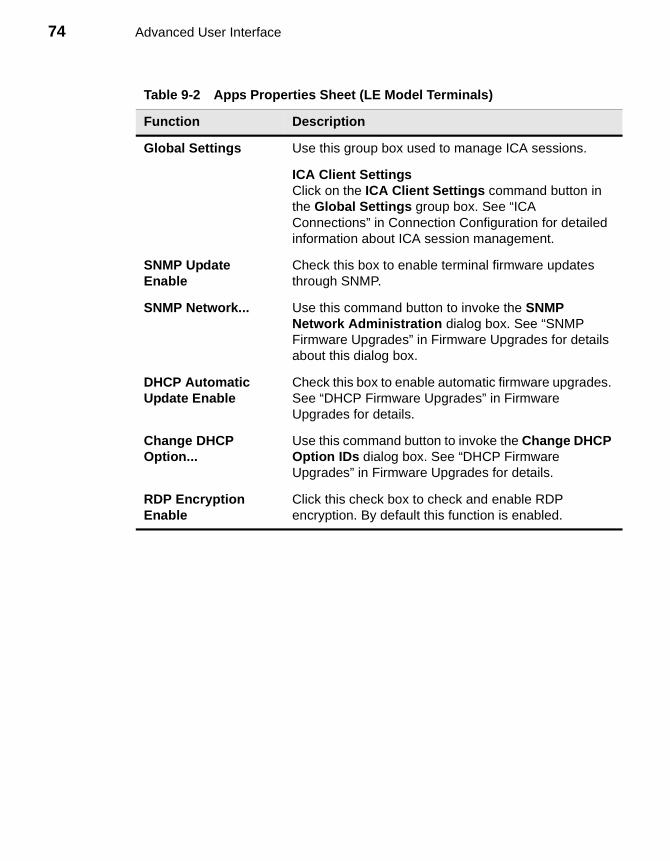
74 Advanced User Interface
Table 9-2 Apps Properties Sheet (LE Model Terminals)
Function Description
Global Settings Use this group box used to manage ICA sessions.
ICA Client SettingsClick on the ICA Client Settings command button in the Global Settings group box. See “ICA Connections” in Connection Configuration for detailed information about ICA session management.
SNMP Update Enable
Check this box to enable terminal firmware updates through SNMP.
SNMP Network... Use this command button to invoke the SNMP Network Administration dialog box. See “SNMP Firmware Upgrades” in Firmware Upgrades for details about this dialog box.
DHCP Automatic Update Enable
Check this box to enable automatic firmware upgrades. See “DHCP Firmware Upgrades” in Firmware Upgrades for details.
Change DHCP Option...
Use this command button to invoke the Change DHCP Option IDs dialog box. See “DHCP Firmware Upgrades” in Firmware Upgrades for details.
RDP Encryption Enable
Click this check box to check and enable RDP encryption. By default this function is enabled.
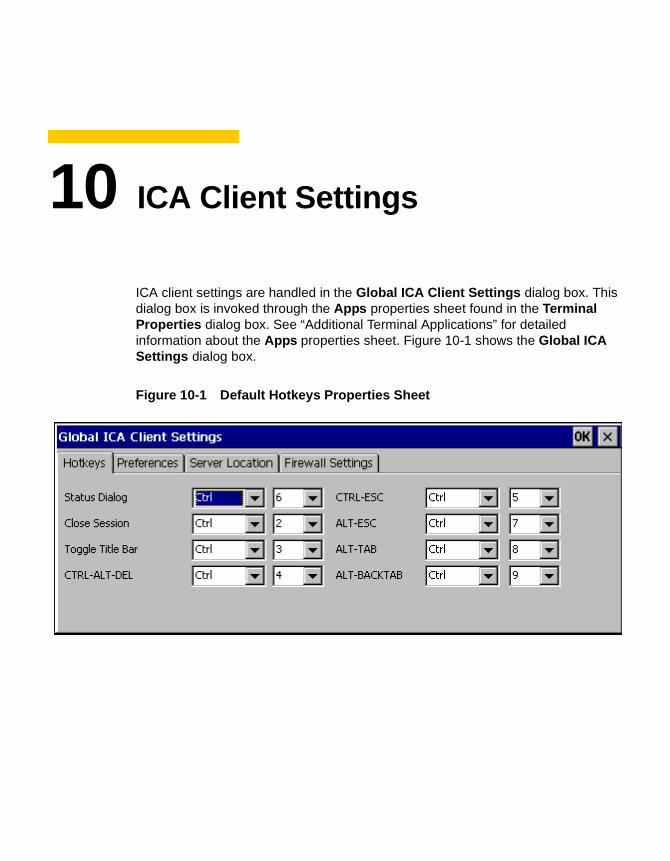
10 ICA Client Settings
ICA client settings are handled in the Global ICA Client Settings dialog box. This dialog box is invoked through the Apps properties sheet found in the Terminal Properties dialog box. See “Additional Terminal Applications” for detailed information about the Apps properties sheet. Figure 10-1 shows the Global ICA Settings dialog box.
Figure 10-1 Default Hotkeys Properties Sheet
76 Advanced User Interface
Using the Global ICA Client Settings Dialog Box
To invoke the Global ICA Settings dialog box:
1. Press F2 to invoke the Terminal Properties dialog box.
2. Click on the Apps tab in the Terminal Properties dialog box.
3. Click on the ICA Client Settings command button in the Global Settings group box.
There are four properties sheets associated with the Global ICA Client Settings dialog box. A description of the functions of each sheet follows.
Setting the Default Hotkeys
Hotkeys can be used during ICA sessions to invoke various functions. Some hotkeys control the behavior of ICA Windows, while others emulate standard Windows hotkeys. To set hotkeys, access the Default Hotkeys properties sheet. It is the default properties sheet for the Global ICA Client Settings dialog box. The following figure shows the Default Hotkeys properties sheet.
Use the pull-down scroll boxes on the Default Hotkey properties sheet to customize default hotkey key sequences. The following table describes the hotkeys.
Table 10-1 Default Hotkeys Properties Sheet
Function Description
Status Dialog This function displays ICA connection status.
Close Session This function disconnects an ICA client from a server and closes the client window on the local desktop. When you use this hotkey, the open session continues to run on the server. If you do not want to leave the session running in a disconnected state, log off.
Toggle Title Bar This function alternately hides and displays the client window title bar:
• Use the title bar to drag the client window to different positions on a local desktop.
• Remove the title bar to maximize your work space.
Ctrl+Alt+Del This hotkey displays the Windows NT Security dialog box.
77
Ctrl+Esc • On WinFrame servers, pressing this key sequence displays the Remote Task List.
• On MetaFrame servers, pressing this key sequence displays the Windows NT Start menu.
Alt+Esc This hotkey cycles the focus through the minimized icons.
Alt+Tab This hotkey cycles sequentially through applications that are open. A window appears to display the applications as you cycle through.
Alt+Backtab This hotkey cycles sequentially through applications that are open in a session, but in the opposite direction.
Table 10-1 Default Hotkeys Properties Sheet, Continued
Function Description
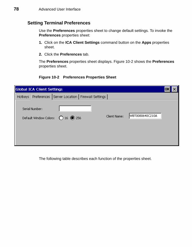
78 Advanced User Interface
Setting Terminal Preferences
Use the Preferences properties sheet to change default settings. To invoke the Preferences properties sheet:
1. Click on the ICA Client Settings command button on the Apps properties sheet.
2. Click the Preferences tab.
The Preferences properties sheet displays. Figure 10-2 shows the Preferences properties sheet.
Figure 10-2 Preferences Properties Sheet
The following table describes each function of the properties sheet.
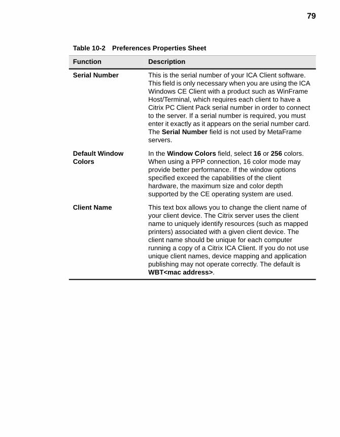
79
Table 10-2 Preferences Properties Sheet
Function Description
Serial Number This is the serial number of your ICA Client software. This field is only necessary when you are using the ICA Windows CE Client with a product such as WinFrame Host/Terminal, which requires each client to have a Citrix PC Client Pack serial number in order to connect to the server. If a serial number is required, you must enter it exactly as it appears on the serial number card. The Serial Number field is not used by MetaFrame servers.
Default Window Colors
In the Window Colors field, select 16 or 256 colors. When using a PPP connection, 16 color mode may provide better performance. If the window options specified exceed the capabilities of the client hardware, the maximum size and color depth supported by the CE operating system are used.
Client Name This text box allows you to change the client name of your client device. The Citrix server uses the client name to uniquely identify resources (such as mapped printers) associated with a given client device. The client name should be unique for each computer running a copy of a Citrix ICA Client. If you do not use unique client names, device mapping and application publishing may not operate correctly. The default is WBT<mac address>.
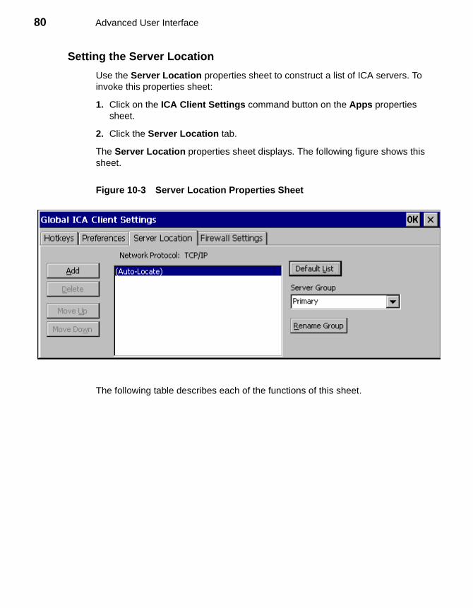
80 Advanced User Interface
Setting the Server Location
Use the Server Location properties sheet to construct a list of ICA servers. To invoke this properties sheet:
1. Click on the ICA Client Settings command button on the Apps properties sheet.
2. Click the Server Location tab.
The Server Location properties sheet displays. The following figure shows this sheet.
Figure 10-3 Server Location Properties Sheet
The following table describes each of the functions of this sheet.
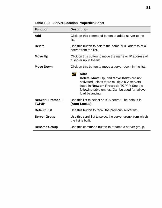
81
Table 10-3 Server Location Properties Sheet
Function Description
Add Click on this command button to add a server to the list.
Delete Use this button to delete the name or IP address of a server from the list.
Move Up Click on this button to move the name or IP address of a server up in the list.
Move Down Click on this button to move a server down in the list.
NoteDelete, Move Up, and Move Down are not activated unless there multiple ICA servers listed in Network Protocol: TCP/IP. See the following table entries. Can be used for failover load balancing.
Network Protocol: TCP/IP
Use this list to select an ICA server. The default is (Auto-Locate).
Default List Use this button to recall the previous server list.
Server Group Use this scroll list to select the server group from which the list is built.
Rename Group Use this command button to rename a server group.
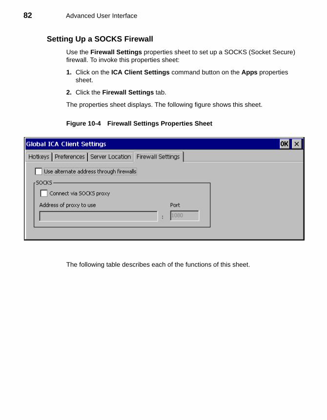
82 Advanced User Interface
Setting Up a SOCKS Firewall
Use the Firewall Settings properties sheet to set up a SOCKS (Socket Secure) firewall. To invoke this properties sheet:
1. Click on the ICA Client Settings command button on the Apps properties sheet.
2. Click the Firewall Settings tab.
The properties sheet displays. The following figure shows this sheet.
Figure 10-4 Firewall Settings Properties Sheet
The following table describes each of the functions of this sheet.
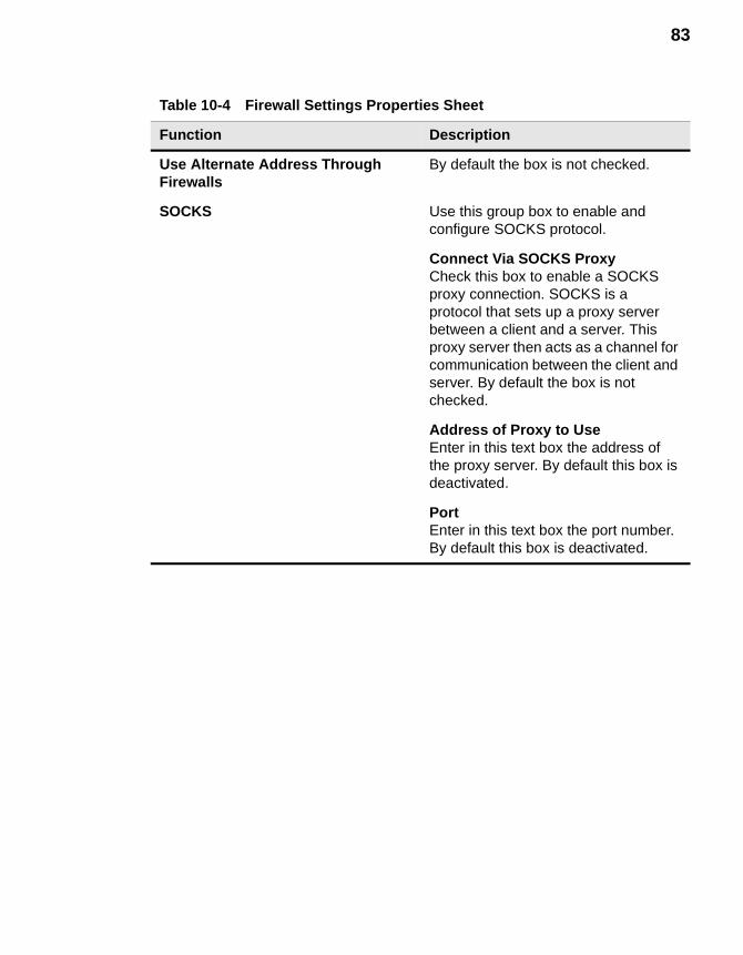
83
Table 10-4 Firewall Settings Properties Sheet
Function Description
Use Alternate Address Through Firewalls
By default the box is not checked.
SOCKS Use this group box to enable and configure SOCKS protocol.
Connect Via SOCKS ProxyCheck this box to enable a SOCKS proxy connection. SOCKS is a protocol that sets up a proxy server between a client and a server. This proxy server then acts as a channel for communication between the client and server. By default the box is not checked.
Address of Proxy to UseEnter in this text box the address of the proxy server. By default this box is deactivated.
PortEnter in this text box the port number. By default this box is deactivated.

84 Advanced User Interface
Connection Configuration
11 Creating New Connections12 ICA Connections13 Dial-Up Connections14 Dial-Up Dialing Properties and Configuration15 Dial-Up TCP/IP Settings and Security16 Dial-Up Scripts17 RDP Connections18 Terminal Emulation Connections19 TCP/IP Telnet Configuration20 Editing ICA Connections21 Editing RDP, Dial-Up, and Terminal Emulation Connections

86
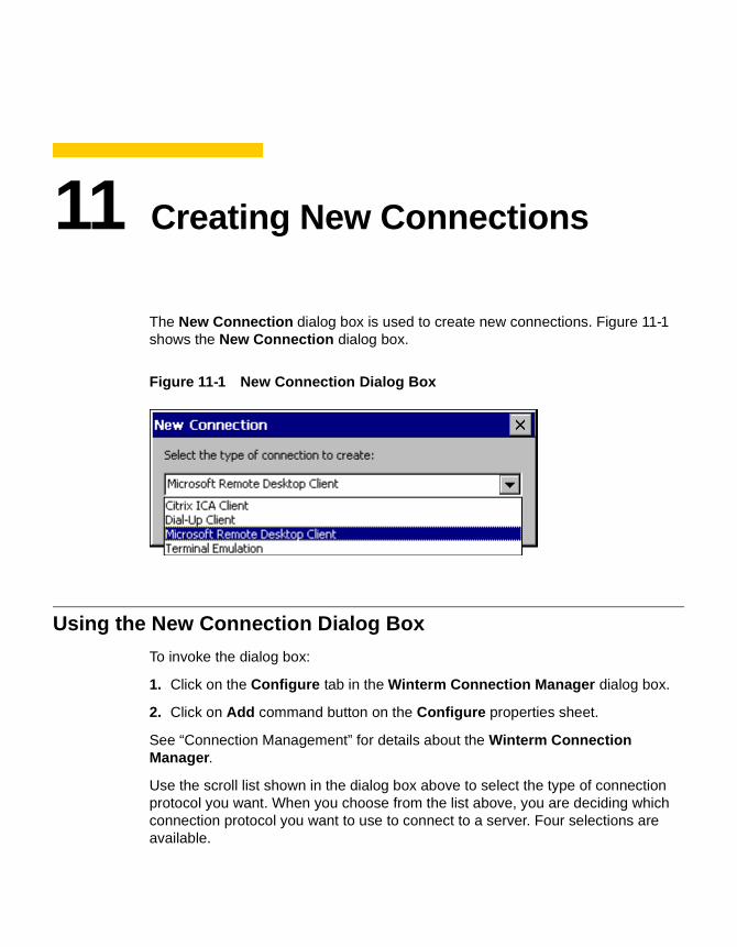
11 Creating New Connections
The New Connection dialog box is used to create new connections. Figure 11-1 shows the New Connection dialog box.
Figure 11-1 New Connection Dialog Box
Using the New Connection Dialog Box
To invoke the dialog box:
1. Click on the Configure tab in the Winterm Connection Manager dialog box.
2. Click on Add command button on the Configure properties sheet.
See “Connection Management” for details about the Winterm Connection Manager.
Use the scroll list shown in the dialog box above to select the type of connection protocol you want. When you choose from the list above, you are deciding which connection protocol you want to use to connect to a server. Four selections are available.

88 Connection Configuration
Choosing a Connection Protocol
The following table describes the differences between the connections available with your WBT.
Once you have made your selection, click on OK to proceed with creating a connection.
Using the Startup Function
Your terminal can be set to automatically connect to a server when you turn your terminal on. This function is set using the Connection Startup dialog box. The following figure shows this dialog box.
Click on one of the two radio buttons in the Startup Options group box (in the Connection Startup dialog box above) to select a start-up option:
Table 11-1 New Connection Dialog Box
Connection Protocol Description
Citrix ICA Client ICA (Independent Computing Architecture) protocol, which connects to an ICA (Winframe/Metaframe) server. See “ICA Connections” for further instructions about how to create this kind of connection.
Dial-Up Client Connects using a modem and PPP (Point-to-Point Protocol). See “Dial-Up Connections” for further instructions about how to create this kind of connection.
Microsoft Remote Desktop Client RDP (Remote Desktop Protocol), which connects to a WTS (Windows Terminal Server) server. See “RDP Connections” for further instructions about how to create this kind of connection.
Terminal Emulation Connects to multiple terminal emulation applications. See “Terminal Emulation Connections” for further instructions about how to create this kind of connection.
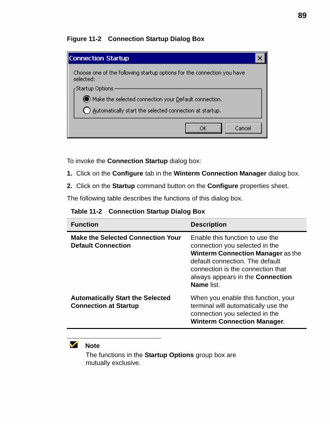
89
Figure 11-2 Connection Startup Dialog Box
To invoke the Connection Startup dialog box:
1. Click on the Configure tab in the Winterm Connection Manager dialog box.
2. Click on the Startup command button on the Configure properties sheet.
The following table describes the functions of this dialog box.
NoteThe functions in the Startup Options group box are mutually exclusive.
Table 11-2 Connection Startup Dialog Box
Function Description
Make the Selected Connection Your Default Connection
Enable this function to use the connection you selected in the Winterm Connection Manager as the default connection. The default connection is the connection that always appears in the Connection Name list.
Automatically Start the Selected Connection at Startup
When you enable this function, your terminal will automatically use the connection you selected in the Winterm Connection Manager.

90 Connection Configuration
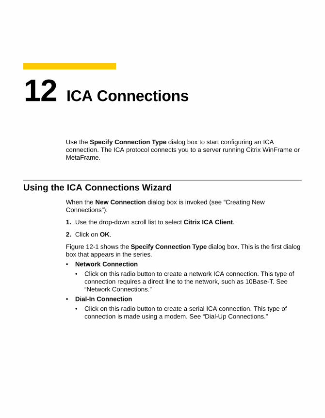
12 ICA Connections
Use the Specify Connection Type dialog box to start configuring an ICA connection. The ICA protocol connects you to a server running Citrix WinFrame or MetaFrame.
Using the ICA Connections Wizard
When the New Connection dialog box is invoked (see “Creating New Connections”):
1. Use the drop-down scroll list to select Citrix ICA Client.
2. Click on OK.
Figure 12-1 shows the Specify Connection Type dialog box. This is the first dialog box that appears in the series.
• Network Connection
• Click on this radio button to create a network ICA connection. This type of connection requires a direct line to the network, such as 10Base-T. See “Network Connections.”
• Dial-In Connection
• Click on this radio button to create a serial ICA connection. This type of connection is made using a modem. See “Dial-Up Connections.”
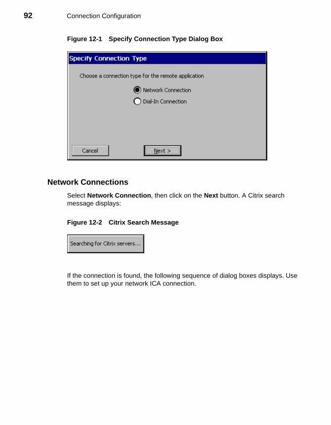
92 Connection Configuration
Figure 12-1 Specify Connection Type Dialog Box
Network Connections
Select Network Connection, then click on the Next button. A Citrix search message displays:
Figure 12-2 Citrix Search Message
If the connection is found, the following sequence of dialog boxes displays. Use them to set up your network ICA connection.
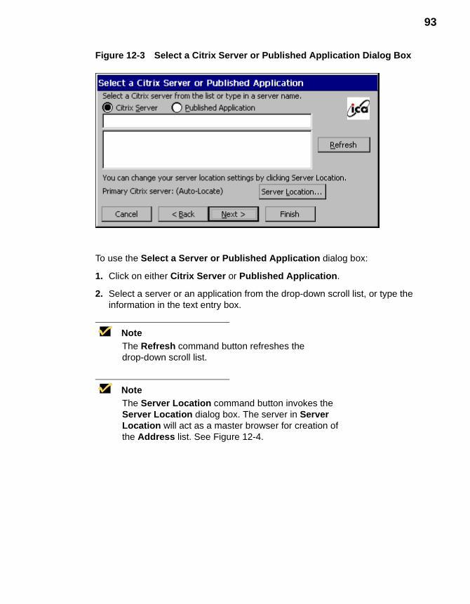
93
Figure 12-3 Select a Citrix Server or Published Application Dialog Box
To use the Select a Server or Published Application dialog box:
1. Click on either Citrix Server or Published Application.
2. Select a server or an application from the drop-down scroll list, or type the information in the text entry box.
NoteThe Refresh command button refreshes the drop-down scroll list.
NoteThe Server Location command button invokes the Server Location dialog box. The server in Server Location will act as a master browser for creation of the Address list. See Figure 12-4.
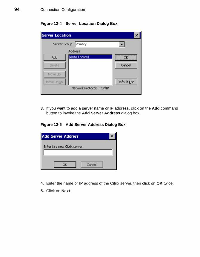
94 Connection Configuration
Figure 12-4 Server Location Dialog Box
3. If you want to add a server name or IP address, click on the Add command button to invoke the Add Server Address dialog box.
Figure 12-5 Add Server Address Dialog Box
4. Enter the name or IP address of the Citrix server, then click on OK twice.
5. Click on Next.
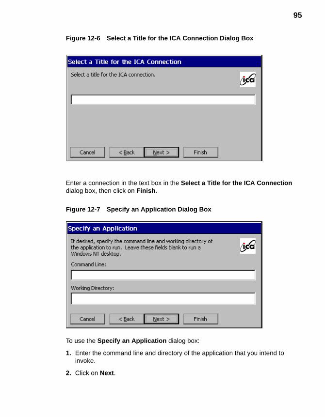
95
Figure 12-6 Select a Title for the ICA Connection Dialog Box
Enter a connection in the text box in the Select a Title for the ICA Connection dialog box, then click on Finish.
Figure 12-7 Specify an Application Dialog Box
To use the Specify an Application dialog box:
1. Enter the command line and directory of the application that you intend to invoke.
2. Click on Next.
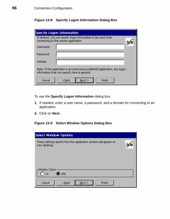
96 Connection Configuration
Figure 12-8 Specify Logon Information Dialog Box
To use the Specify Logon Information dialog box:
1. If needed, enter a user name, a password, and a domain for connecting to an application.
2. Click on Next.
Figure 12-9 Select Window Options Dialog Box
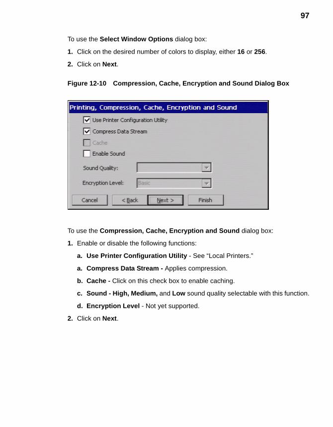
97
To use the Select Window Options dialog box:
1. Click on the desired number of colors to display, either 16 or 256.
2. Click on Next.
Figure 12-10 Compression, Cache, Encryption and Sound Dialog Box
To use the Compression, Cache, Encryption and Sound dialog box:
1. Enable or disable the following functions:
a. Use Printer Configuration Utility - See “Local Printers.”
a. Compress Data Stream - Applies compression.
b. Cache - Click on this check box to enable caching.
c. Sound - High, Medium, and Low sound quality selectable with this function.
d. Encryption Level - Not yet supported.
2. Click on Next.
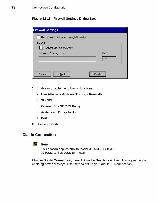
98 Connection Configuration
Figure 12-11 Firewall Settings Dialog Box
1. Enable or disable the following functions:
a. Use Alternate Address Through Firewalls
b. SOCKS
c. Connect Via SOCKS Proxy
d. Address of Proxy to Use
e. Port
2. Click on Finish.
Dial-In Connection
NoteThis section applies only to Model 3320SE, 3350SE, 3360SE, and 3720SE terminals.
Choose Dial-In Connection, then click on the Next button. The following sequence of dialog boxes displays. Use them to set up your dial-in ICA connection.
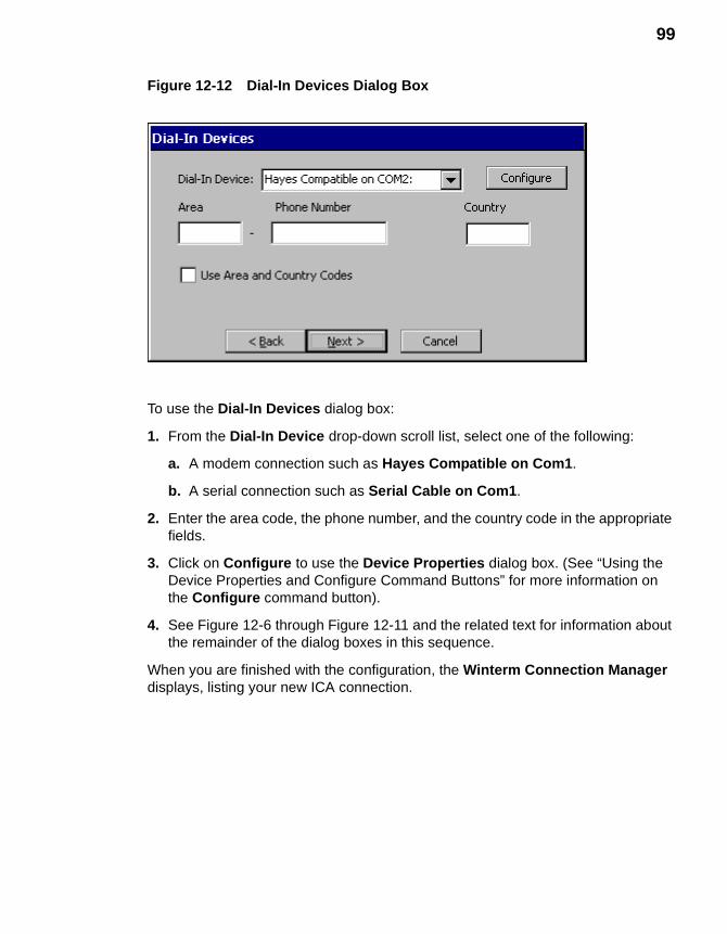
99
Figure 12-12 Dial-In Devices Dialog Box
To use the Dial-In Devices dialog box:
1. From the Dial-In Device drop-down scroll list, select one of the following:
a. A modem connection such as Hayes Compatible on Com1.
b. A serial connection such as Serial Cable on Com1.
2. Enter the area code, the phone number, and the country code in the appropriate fields.
3. Click on Configure to use the Device Properties dialog box. (See “Using the Device Properties and Configure Command Buttons” for more information on the Configure command button).
4. See Figure 12-6 through Figure 12-11 and the related text for information about the remainder of the dialog boxes in this sequence.
When you are finished with the configuration, the Winterm Connection Manager displays, listing your new ICA connection.

100 Connection Configuration
13 Dial-Up Connections
Use the Dial-Up Configuration Wizard to configure a dial-up connection. Dial-up connections use a modem and PPP to connect to a server.
Using the Dial-Up Configuration Wizard
When the New Connection dialog box is invoked:
1. Use the drop-down scroll list to select Dial-Up Client.
2. Click on OK.
Following are the three dialog boxes that display in succession during a dial-up configuration process. When you are finished with the configuration, the new connection will be added to the Connection Name list in the Winterm Connection Manager. See Figure 13-1 to view the first dialog box of the wizard.
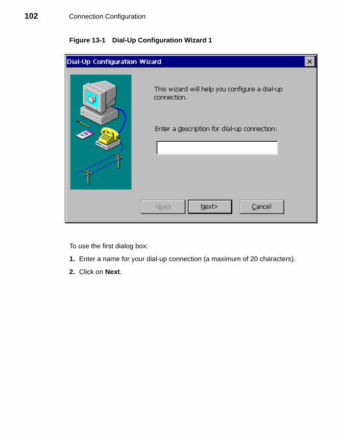
102 Connection Configuration
Figure 13-1 Dial-Up Configuration Wizard 1
To use the first dialog box:
1. Enter a name for your dial-up connection (a maximum of 20 characters).
2. Click on Next.
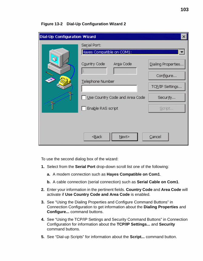
103
Figure 13-2 Dial-Up Configuration Wizard 2
To use the second dialog box of the wizard:
1. Select from the Serial Port drop-down scroll list one of the following:
a. A modem connection such as Hayes Compatible on Com1.
b. A cable connection (serial connection) such as Serial Cable on Com1.
2. Enter your information in the pertinent fields. Country Code and Area Code will activate if Use Country Code and Area Code is enabled.
3. See “Using the Dialing Properties and Configure Command Buttons” in Connection Configuration to get information about the Dialing Properties and Configure... command buttons.
4. See “Using the TCP/IP Settings and Security Command Buttons” in Connection Configuration for information about the TCP/IP Settings... and Security command buttons.
5. See “Dial-up Scripts” for information about the Script... command button.
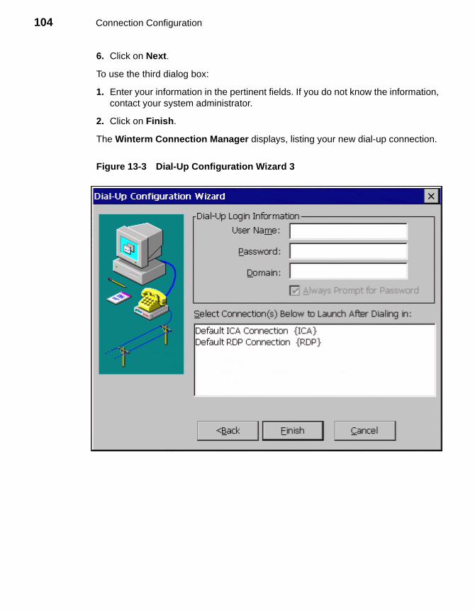
104 Connection Configuration
6. Click on Next.
To use the third dialog box:
1. Enter your information in the pertinent fields. If you do not know the information, contact your system administrator.
2. Click on Finish.
The Winterm Connection Manager displays, listing your new dial-up connection.
Figure 13-3 Dial-Up Configuration Wizard 3
14 Dial-Up Dialing Properties and Configuration
The following sections provide information about some of the elements of theDial-Up Configuration Wizard. This chapter covers dialing properties and device properties. Dialing properties are set using the Dialing Properties dialog box (Figure 14-1). Device properties are set using the Device Properties dialog box (Figure 14-2).
NoteSee “Null Modem Cable Pin Assignments” for a suggested null modem cable for use with your terminal.
Using the Dialing Properties Dialog Box
Use the Dialing Properties dialog box to set the dialing properties for your dial-up connection. See “Dial-Up Connections” to find out how to invoke this dialog box.
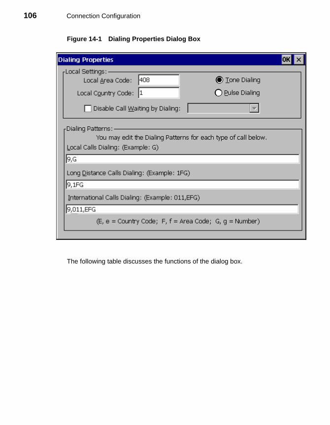
106 Connection Configuration
Figure 14-1 Dialing Properties Dialog Box
The following table discusses the functions of the dialog box.
107
Table 14-1 Dialing Properties Dialog Box
Function Description
Local Settings Set local dialing locale and dialing type in this group box.
Local Area CodeEnter the local area code that you want to use.
Local Country CodeEnter the local country code of the country that you are dialing to. The default for this field is 1.
NoteRefer to a phone directory for country codes.
Disable Call Waiting By Dialing:
1. Click on the check box.
2. Select from the drop-down scroll list one of the following:
• *70,
• 70#,
• 1170,
Tone DialingClick on this radio button to enable tone dialing. Tone Dialing is the default.
Pulse DialingClick on this radio button to enable pulse dialing.

108 Connection Configuration
Using the Device Properties Dialog Box
Use the Device Properties dialog box to configure a device (modem) for a dial-up connection. See “Dial-Up Connections” to find out how to invoke this dialog box.
Figure 14-2 Device Properties Dialog Box
Dialing Patterns Use this group box to set your modem’s dialing patterns.
Local Calls DialingEnter the local call dialing pattern. The default is 9,G.
Local Long Distance Calls DialingEnter the long distance call dialing pattern. The default is 9,1FG.
International Calls DialingEnter the international call dialing pattern. The default is 9,011,EFG.
NoteAn explanation of the lettering scheme for dialing patterns is located below the function International Calls Dialing.
Table 14-1 Dialing Properties Dialog Box, Continued
Function Description
109
The Device Properties dialog box contains two properties sheets:
• Port Settings
• Call Options
The following sections discuss these properties sheets.
Port Settings
See Figure 14-2 to view the Port Settings properties sheet. It is the default of the Device Properties dialog box. The following table discusses the functions of this properties sheet.
Table 14-2 Port Settings Properties Sheet
Function Description
Manual Dial Click on this check box to set up for manual dialing.
Terminals Use this group box to record terminal windowing information:
• Use Terminal Window Before Dialing
• Use Terminal Window After Dialing
Connection Preferences
Use this group box to set modem connection parameters.
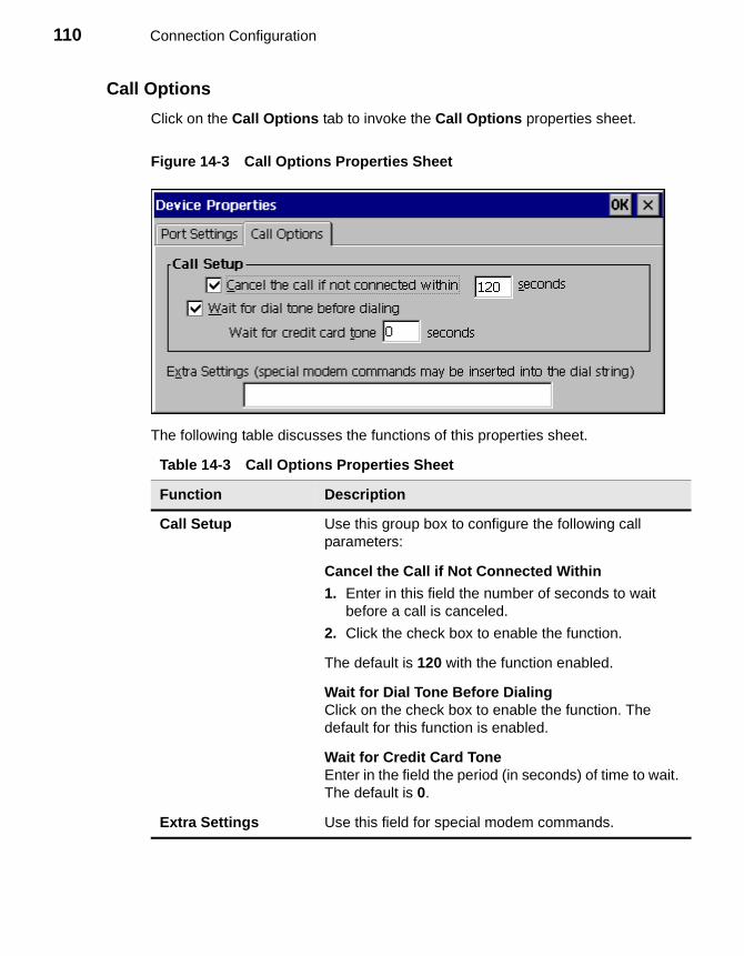
110 Connection Configuration
Call Options
Click on the Call Options tab to invoke the Call Options properties sheet.
Figure 14-3 Call Options Properties Sheet
The following table discusses the functions of this properties sheet.
Table 14-3 Call Options Properties Sheet
Function Description
Call Setup Use this group box to configure the following call parameters:
Cancel the Call if Not Connected Within
1. Enter in this field the number of seconds to wait before a call is canceled.
2. Click the check box to enable the function.
The default is 120 with the function enabled.
Wait for Dial Tone Before DialingClick on the check box to enable the function. The default for this function is enabled.
Wait for Credit Card ToneEnter in the field the period (in seconds) of time to wait. The default is 0.
Extra Settings Use this field for special modem commands.
15 Dial-Up TCP/IP Settings and Security
The following sections provide information about some of the elements of the Dial-Up Configuration Wizard. This chapter covers TCP/IP settings and dial-up security.
Using the TCP/IP Settings Dialog Box
Click on the TCP/IP Settings command button in the second dialog box of theDial-Up Configuration Wizard to set TCP/IP dial-up settings. When this command button is pressed, the TCP/IP Settings dialog box displays. Figure 15-1 shows this dialog box.
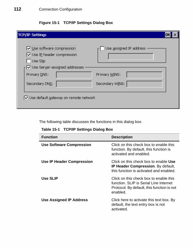
112 Connection Configuration
Figure 15-1 TCP/IP Settings Dialog Box
The following table discusses the functions in this dialog box.
Table 15-1 TCP/IP Settings Dialog Box
Function Description
Use Software Compression Click on this check box to enable this function. By default, this function is activated and enabled.
Use IP Header Compression Click on this check box to enable Use IP Header Compression. By default, this function is activated and enabled.
Use SLIP Click on this check box to enable this function. SLIP is Serial Line Internet Protocol. By default, this function is not enabled.
Use Assigned IP Address Click here to activate this text box. By default, the text entry box is not activated.
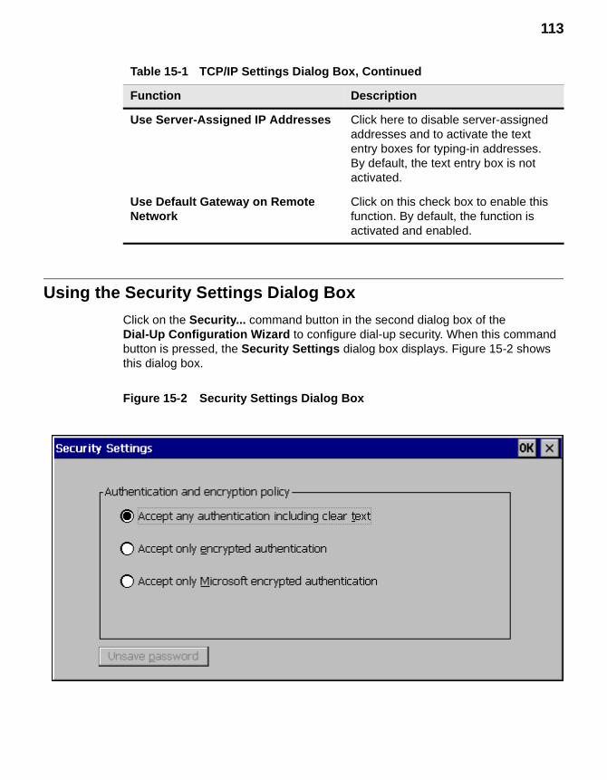
113
Using the Security Settings Dialog Box
Click on the Security... command button in the second dialog box of theDial-Up Configuration Wizard to configure dial-up security. When this command button is pressed, the Security Settings dialog box displays. Figure 15-2 shows this dialog box.
Figure 15-2 Security Settings Dialog Box
Use Server-Assigned IP Addresses Click here to disable server-assigned addresses and to activate the text entry boxes for typing-in addresses. By default, the text entry box is not activated.
Use Default Gateway on Remote Network
Click on this check box to enable this function. By default, the function is activated and enabled.
Table 15-1 TCP/IP Settings Dialog Box, Continued
Function Description
114 Connection Configuration
The following table discusses the functions in this dialog box.
Table 15-2 Security Settings Dialog Box
Function Description
Accept Any Authentication Including Clear Text
Click on this radio button to set your terminal to accept any authentication including clear text. Authentication determines whether a request originated from the correct user or application.
Accept Only Encrypted Authentication
Click on this radio button to set your terminal to accept only encrypted authentication. Encryption is a method of “hiding” data that is transmitted across a network.
Accept Only Microsoft Encrypted Authentication
Click on this radio button to set your terminal to accept only Microsoft encrypted authentication.
16 Dial-Up Scripts
Dial-up RAS (Remote Access Services) scripts are enabled from the Dial-Up Connection Wizard (see “Dial-Up Connections”). RAS facilitates PPP communications between the terminal (based on Windows CE) and other non-Windows operating systems.
Using the Dial-Up Scripts Dialog Boxes
Dial-up scripts dialog boxes are accessed by checking the Enable RAS script box and pressing the Script command button in the second panel of the Dial-Up Connection Wizard. These dialog boxes automate actions that otherwise would be performed in text mode after dialing.
The Script Name dialog box (Figure 16-1) enables you to create a script under a new name, edit an existing script, or delete an existing script. Press the New button to open the New Script Name dialog box (Figure 16-2). Type the script name and press OK. This opens the RAS Script dialog box. You may also open the RAS Script dialog box to edit an existing script by selecting the script and pressing Edit. Table 16-1 describes the RAS Script dialog box. To delete as script, select it and press Delete.
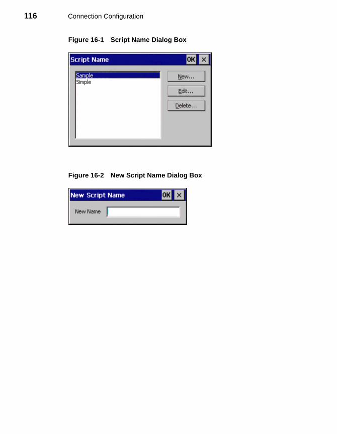
116 Connection Configuration
Figure 16-1 Script Name Dialog Box
Figure 16-2 New Script Name Dialog Box
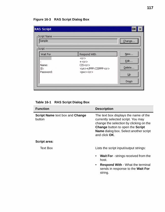
117
Figure 16-3 RAS Script Dialog Box
Table 16-1 RAS Script Dialog Box
Function Description
Script Name text box and Change button
The text box displays the name of the currently selected script. You may change the selection by clicking on the Change button to open the Script Name dialog box. Select another script and click OK.
Script area:
Text Box Lists the script input/output strings:
• Wait For - strings received from the host.
• Respond With - What the terminal sends in response to the Wait For string.
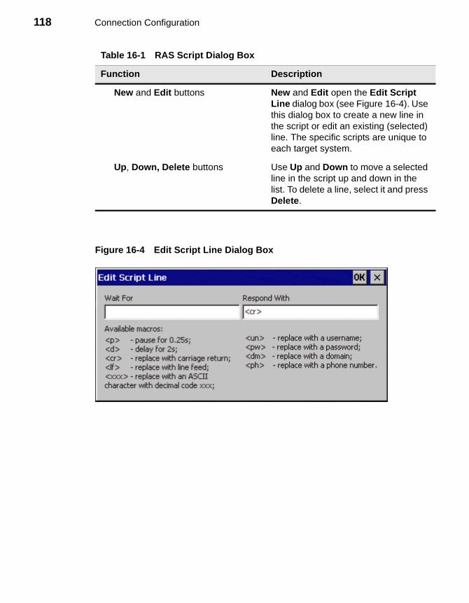
118 Connection Configuration
Figure 16-4 Edit Script Line Dialog Box
New and Edit buttons New and Edit open the Edit Script Line dialog box (see Figure 16-4). Use this dialog box to create a new line in the script or edit an existing (selected) line. The specific scripts are unique to each target system.
Up, Down, Delete buttons Use Up and Down to move a selected line in the script up and down in the list. To delete a line, select it and press Delete.
Table 16-1 RAS Script Dialog Box
Function Description
17 RDP Connections
Use the WTS Connection Wizard to configure an RDP connection. RDP connects to a server running Microsoft WTS (Windows Terminal Server).
Using the WTS Connection Wizard
When the New Connection dialog box is invoked (see “Creating New Connections”):
1. Use the drop-down scroll list to select Microsoft Remote Desktop Client.
2. Click on OK.
Following are the four dialog boxes that display in succession during the configuration process. When you are finished with the wizard, the new connection will be added to the Connection Name list in the Winterm Connection Manager. See Figure 17-1 to view the first dialog box of this wizard.

120 Connection Configuration
Figure 17-1 WTS Connection Wizard 1
To use the first dialog box:
1. Enter a name for your dial-up connection in Name.
2. Enter the name of the server in Server.
3. Check the Low Speed Connection check box if appropriate.
4. Click on Next.
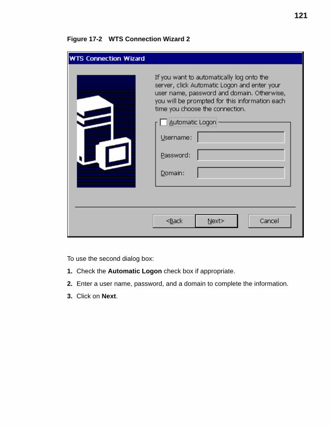
121
Figure 17-2 WTS Connection Wizard 2
To use the second dialog box:
1. Check the Automatic Logon check box if appropriate.
2. Enter a user name, password, and a domain to complete the information.
3. Click on Next.
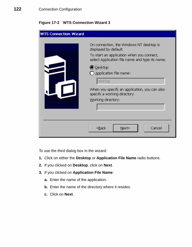
122 Connection Configuration
Figure 17-3 WTS Connection Wizard 3
To use the third dialog box in the wizard:
1. Click on either the Desktop or Application File Name radio buttons.
2. If you clicked on Desktop, click on Next.
3. If you clicked on Application File Name:
a. Enter the name of the application.
b. Enter the name of the directory where it resides.
c. Click on Next.
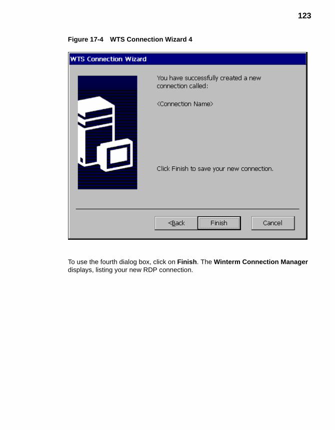
123
Figure 17-4 WTS Connection Wizard 4
To use the fourth dialog box, click on Finish. The Winterm Connection Manager displays, listing your new RDP connection.

124 Connection Configuration
18 Terminal Emulation Connections
NoteThe portions of this chapter that refer to serial, Com1 or Com2, or parallel apply only to Model 3320SE, 3350SE, 3360SE, and 3720SE terminals.
Use the TE Client Connection Wizard to set up a terminal emulation connection. Terminal emulation connections use Telnet to connect to servers.
Using the TE Client Connection Wizard
When the New Connection dialog box is invoked (see “Creating New Connections”):
1. Use the drop-down scroll list to select Terminal Emulation.
2. Click on OK.
Following are the three dialog boxes of this wizard. When you are finished configuring a connection, the new connection will be added to the Connection Name list in the Winterm Connection Manager. See Figure 18-1 to view the first dialog box of this wizard.
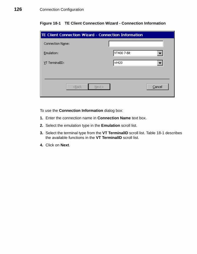
126 Connection Configuration
Figure 18-1 TE Client Connection Wizard - Connection Information
To use the Connection Information dialog box:
1. Enter the connection name in Connection Name text box.
2. Select the emulation type in the Emulation scroll list.
3. Select the terminal type from the VT TerminalID scroll list. Table 18-1 describes the available functions in the VT TerminalID scroll list.
4. Click on Next.

127
Table 18-1 Terminal Emulation and Terminal Type
Terminal Emulation Terminal Type
Select:
VT52, VT100, VT400 7-Bit (default), or VT400 8-Bit
Then select from VT TerminalID:
vt100, vt101, vt102, vt125, vt220, vt240, vt320, vt340, vt420 (default), vt131, or vt132
Select:
ANSI BBS, SCO Console, WY50, WY50+, TVI910, TVI920, TVI925, ADDS A2, HZ1500, or WY60, IBM 3151
The function is deactivated.
Select:
IBM3270
1. Then select from IBM 3270 Model:
3278-2-E, 3278-3-E, 3278-4-E, 3278-5-E, 3279-2, 3279-3, 3279-4, 3279-5, or 3287-1
2. Check the Right Ctrl Acts as Enter Key or the Left Ctrl Acts as Reset Key check boxes if you want these functions enabled for 5250 emulation.
Select:
IBM5250
1. Select from IBM 5250 Model:
5291-1, 5292-2, 5251-11, 3179-2, 3196-A1, 3180-2, 3477-FC, 3477-FG, 3486-BA, 3487-HA, or 3487-HC
2. Check the Right Ctrl Acts as Enter Key, the Left Ctrl Acts as Reset Key, or the IBM5250 Monochrome check boxes if you want these functions enabled for 5250 emulation.
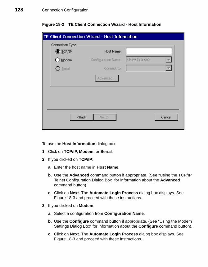
128 Connection Configuration
Figure 18-2 TE Client Connection Wizard - Host Information
To use the Host Information dialog box:
1. Click on TCP/IP, Modem, or Serial:
2. If you clicked on TCP/IP:
a. Enter the host name in Host Name.
b. Use the Advanced command button if appropriate. (See “Using the TCP/IP Telnet Configuration Dialog Box” for information about the Advanced command button).
c. Click on Next. The Automate Login Process dialog box displays. See Figure 18-3 and proceed with these instructions.
3. If you clicked on Modem:
a. Select a configuration from Configuration Name.
b. Use the Configure command button if appropriate. (See “Using the Modem Settings Dialog Box” for information about the Configure command button).
c. Click on Next. The Automate Login Process dialog box displays. See Figure 18-3 and proceed with these instructions.
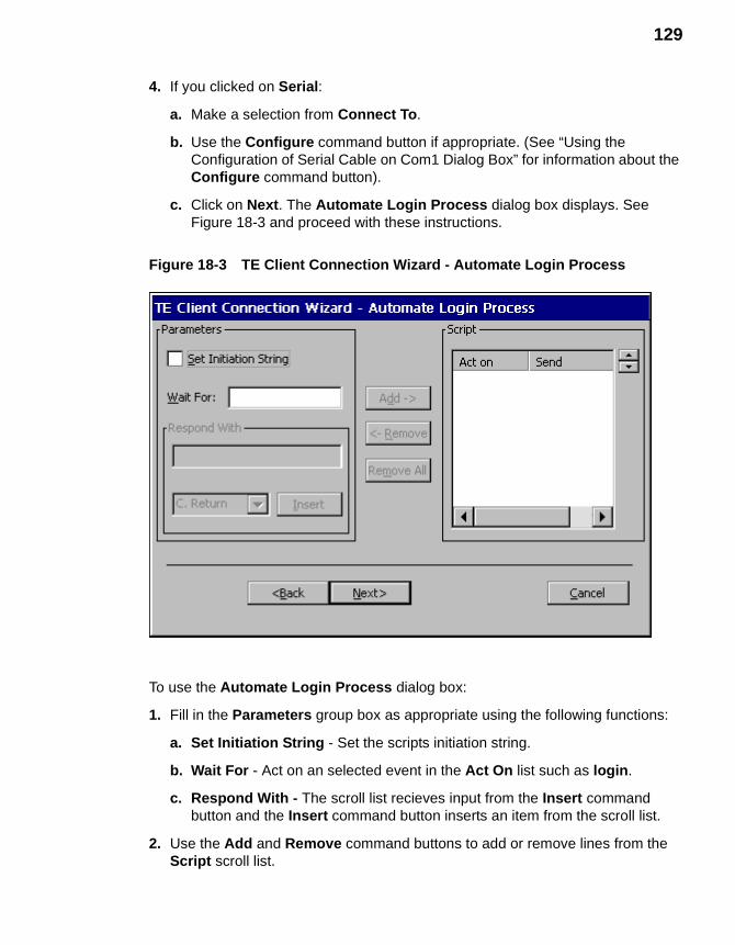
129
4. If you clicked on Serial:
a. Make a selection from Connect To.
b. Use the Configure command button if appropriate. (See “Using the Configuration of Serial Cable on Com1 Dialog Box” for information about the Configure command button).
c. Click on Next. The Automate Login Process dialog box displays. See Figure 18-3 and proceed with these instructions.
Figure 18-3 TE Client Connection Wizard - Automate Login Process
To use the Automate Login Process dialog box:
1. Fill in the Parameters group box as appropriate using the following functions:
a. Set Initiation String - Set the scripts initiation string.
b. Wait For - Act on an selected event in the Act On list such as login.
c. Respond With - The scroll list recieves input from the Insert command button and the Insert command button inserts an item from the scroll list.
2. Use the Add and Remove command buttons to add or remove lines from the Script scroll list.
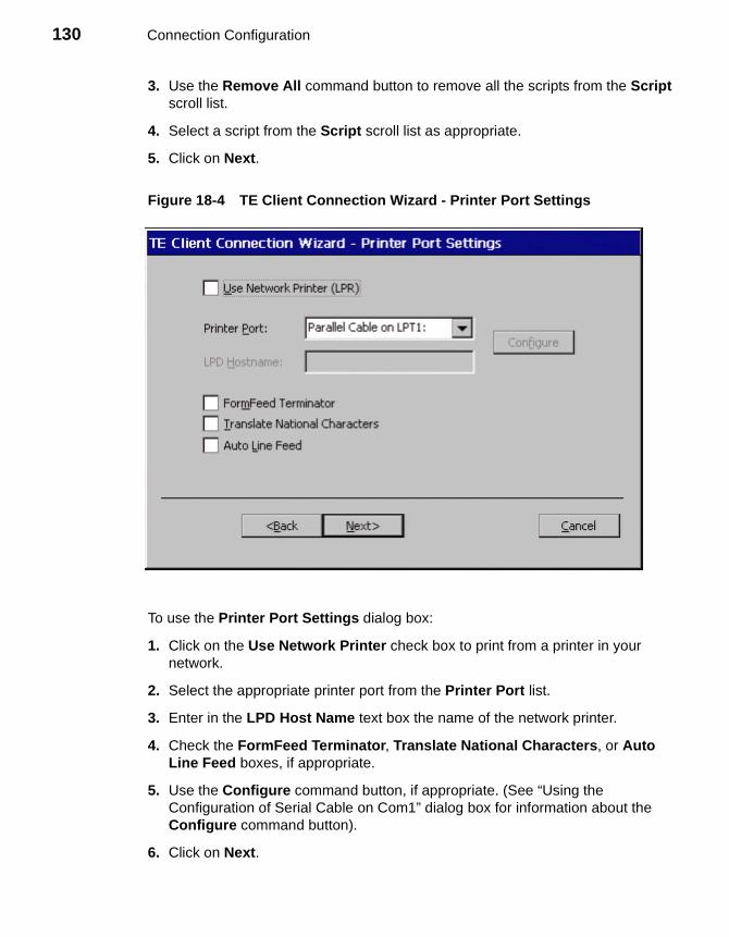
130 Connection Configuration
3. Use the Remove All command button to remove all the scripts from the Script scroll list.
4. Select a script from the Script scroll list as appropriate.
5. Click on Next.
Figure 18-4 TE Client Connection Wizard - Printer Port Settings
To use the Printer Port Settings dialog box:
1. Click on the Use Network Printer check box to print from a printer in your network.
2. Select the appropriate printer port from the Printer Port list.
3. Enter in the LPD Host Name text box the name of the network printer.
4. Check the FormFeed Terminator, Translate National Characters, or Auto Line Feed boxes, if appropriate.
5. Use the Configure command button, if appropriate. (See “Using the Configuration of Serial Cable on Com1” dialog box for information about the Configure command button).
6. Click on Next.
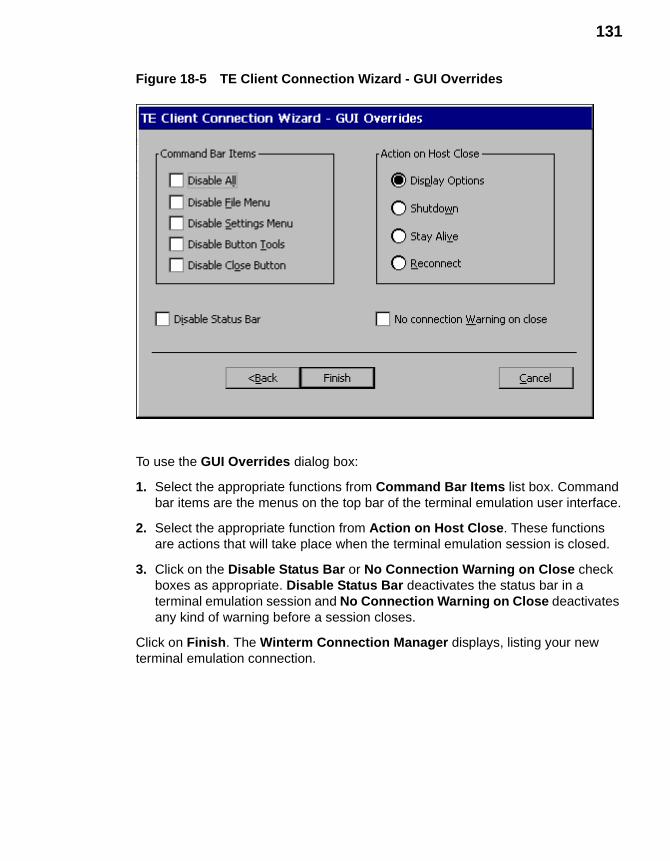
131
Figure 18-5 TE Client Connection Wizard - GUI Overrides
To use the GUI Overrides dialog box:
1. Select the appropriate functions from Command Bar Items list box. Command bar items are the menus on the top bar of the terminal emulation user interface.
2. Select the appropriate function from Action on Host Close. These functions are actions that will take place when the terminal emulation session is closed.
3. Click on the Disable Status Bar or No Connection Warning on Close check boxes as appropriate. Disable Status Bar deactivates the status bar in a terminal emulation session and No Connection Warning on Close deactivates any kind of warning before a session closes.
Click on Finish. The Winterm Connection Manager displays, listing your new terminal emulation connection.

132 Connection Configuration
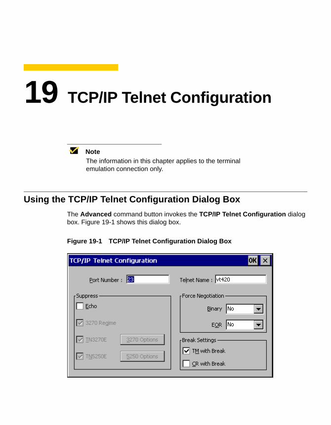
19 TCP/IP Telnet Configuration
NoteThe information in this chapter applies to the terminal emulation connection only.
Using the TCP/IP Telnet Configuration Dialog Box
The Advanced command button invokes the TCP/IP Telnet Configuration dialog box. Figure 19-1 shows this dialog box.
Figure 19-1 TCP/IP Telnet Configuration Dialog Box
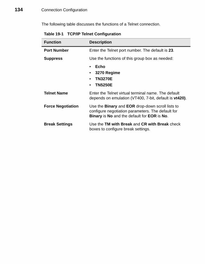
134 Connection Configuration
The following table discusses the functions of a Telnet connection.
Table 19-1 TCP/IP Telnet Configuration
Function Description
Port Number Enter the Telnet port number. The default is 23.
Suppress Use the functions of this group box as needed:
• Echo
• 3270 Regime
• TN3270E
• TN5250E
Telnet Name Enter the Telnet virtual terminal name. The default depends on emulation (VT400, 7-bit, default is vt420).
Force Negotiation Use the Binary and EOR drop-down scroll lists to configure negotiation parameters. The default for Binary is No and the default for EOR is No.
Break Settings Use the TM with Break and CR with Break check boxes to configure break settings.
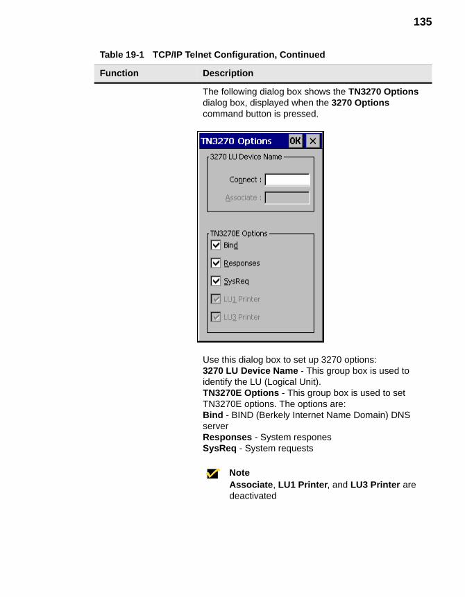
135
The following dialog box shows the TN3270 Options dialog box, displayed when the 3270 Options command button is pressed.
Use this dialog box to set up 3270 options:3270 LU Device Name - This group box is used to identify the LU (Logical Unit).TN3270E Options - This group box is used to set TN3270E options. The options are:Bind - BIND (Berkely Internet Name Domain) DNS serverResponses - System responesSysReq - System requests
NoteAssociate, LU1 Printer, and LU3 Printer are deactivated
Table 19-1 TCP/IP Telnet Configuration, Continued
Function Description
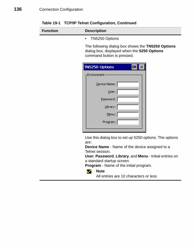
136 Connection Configuration
• TN5250 Options
The following dialog box shows the TN5250 Options dialog box, displayed when the 5250 Options command button is pressed.
Use this dialog box to set up 5250 options. The options are:Device Name - Name of the device assigned to a Telnet session.User, Password, Library, and Menu - Initial entries on a standard startup screen.Program - Name of the initial program.
NoteAll entries are 10 characters or less
Table 19-1 TCP/IP Telnet Configuration, Continued
Function Description
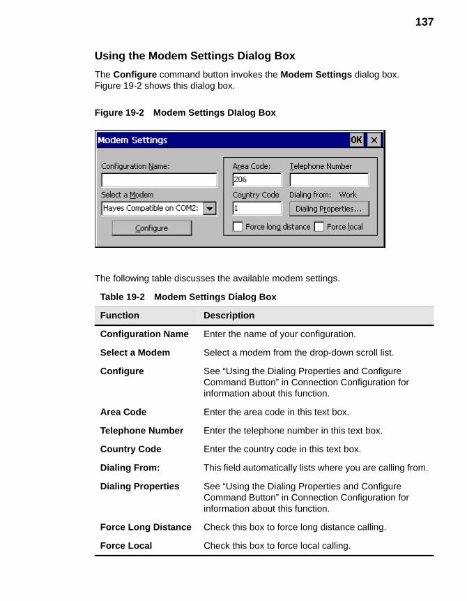
137
Using the Modem Settings Dialog Box
The Configure command button invokes the Modem Settings dialog box. Figure 19-2 shows this dialog box.
Figure 19-2 Modem Settings DIalog Box
The following table discusses the available modem settings.
Table 19-2 Modem Settings Dialog Box
Function Description
Configuration Name Enter the name of your configuration.
Select a Modem Select a modem from the drop-down scroll list.
Configure See “Using the Dialing Properties and Configure Command Button” in Connection Configuration for information about this function.
Area Code Enter the area code in this text box.
Telephone Number Enter the telephone number in this text box.
Country Code Enter the country code in this text box.
Dialing From: This field automatically lists where you are calling from.
Dialing Properties See “Using the Dialing Properties and Configure Command Button” in Connection Configuration for information about this function.
Force Long Distance Check this box to force long distance calling.
Force Local Check this box to force local calling.
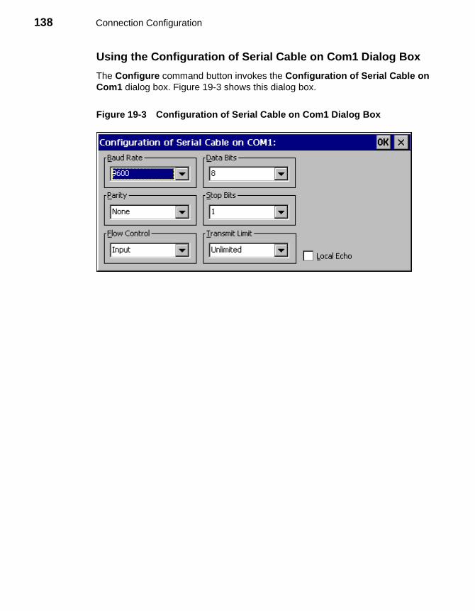
138 Connection Configuration
Using the Configuration of Serial Cable on Com1 Dialog Box
The Configure command button invokes the Configuration of Serial Cable on Com1 dialog box. Figure 19-3 shows this dialog box.
Figure 19-3 Configuration of Serial Cable on Com1 Dialog Box
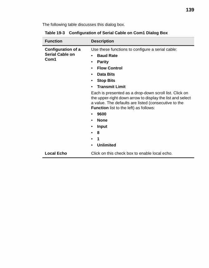
139
The following table discusses this dialog box.
Table 19-3 Configuration of Serial Cable on Com1 Dialog Box
Function Description
Configuration of a Serial Cable on Com1
Use these functions to configure a serial cable:
• Baud Rate
• Parity
• Flow Control
• Data Bits
• Stop Bits
• Transmit Limit
Each is presented as a drop-down scroll list. Click on the upper-right down arrow to display the list and select a value. The defaults are listed (consecutive to the Function list to the left) as follows:
• 9600
• None
• Input
• 8
• 1
• Unlimited
Local Echo Click on this check box to enable local echo.

140 Connection Configuration
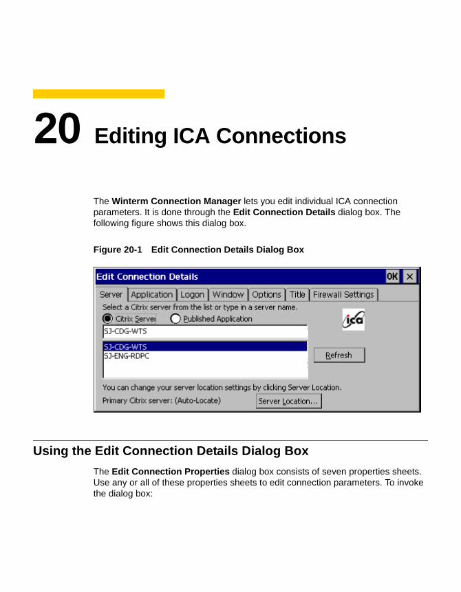
20 Editing ICA Connections
The Winterm Connection Manager lets you edit individual ICA connection parameters. It is done through the Edit Connection Details dialog box. The following figure shows this dialog box.
Figure 20-1 Edit Connection Details Dialog Box
Using the Edit Connection Details Dialog Box
The Edit Connection Properties dialog box consists of seven properties sheets. Use any or all of these properties sheets to edit connection parameters. To invoke the dialog box:
142 Connection Configuration
1. Click on the Configure tab in the Winterm Connection Manager dialog box.
2. Click to select an ICA connection from the Connections Name list.
3. Click on the Edit command button on the Configure properties sheet.
Using the Server Properties Sheet
The Server properties sheet is displayed by default for the dialog box. Table 20-1 describes the functions of the Server properties sheet.
Table 20-1 Server Properties Sheet
Function Description
Select a Citrix Server From the List or Type in a server Name
Click on:
• Citrix ServerEnable this radio button to connect to a Citrix server.
• Published ApplicationEnable this radio button to connect directly to an application.
Server Location Click on this command button to invoke the Server Location Dialog Box.
Server GroupSelect from a scroll list:
• Primary
• Backup 1
• Backup 2
Primary is the default.
AddClick on this command button to add a server to the list.
DeleteClick on this command button to delete a server from the list:
1. Select a server from the list.
2. Click on the Delete command button.
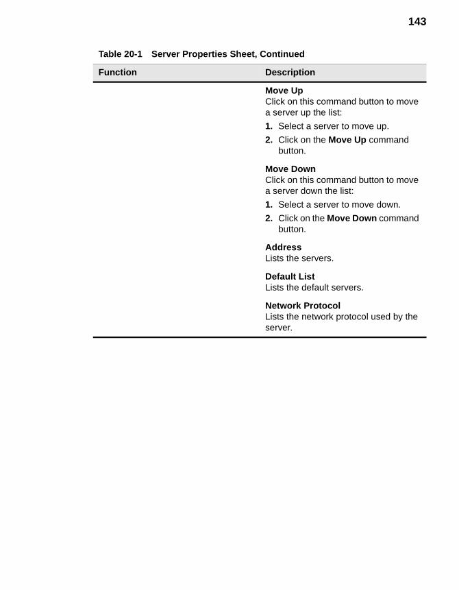
143
Move UpClick on this command button to move a server up the list:
1. Select a server to move up.
2. Click on the Move Up command button.
Move DownClick on this command button to move a server down the list:
1. Select a server to move down.
2. Click on the Move Down command button.
AddressLists the servers.
Default ListLists the default servers.
Network ProtocolLists the network protocol used by the server.
Table 20-1 Server Properties Sheet, Continued
Function Description
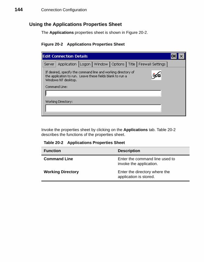
144 Connection Configuration
Using the Applications Properties Sheet
The Applications properties sheet is shown in Figure 20-2.
Figure 20-2 Applications Properties Sheet
Invoke the properties sheet by clicking on the Applications tab. Table 20-2 describes the functions of the properties sheet.
Table 20-2 Applications Properties Sheet
Function Description
Command Line Enter the command line used to invoke the application.
Working Directory Enter the directory where the application is stored.
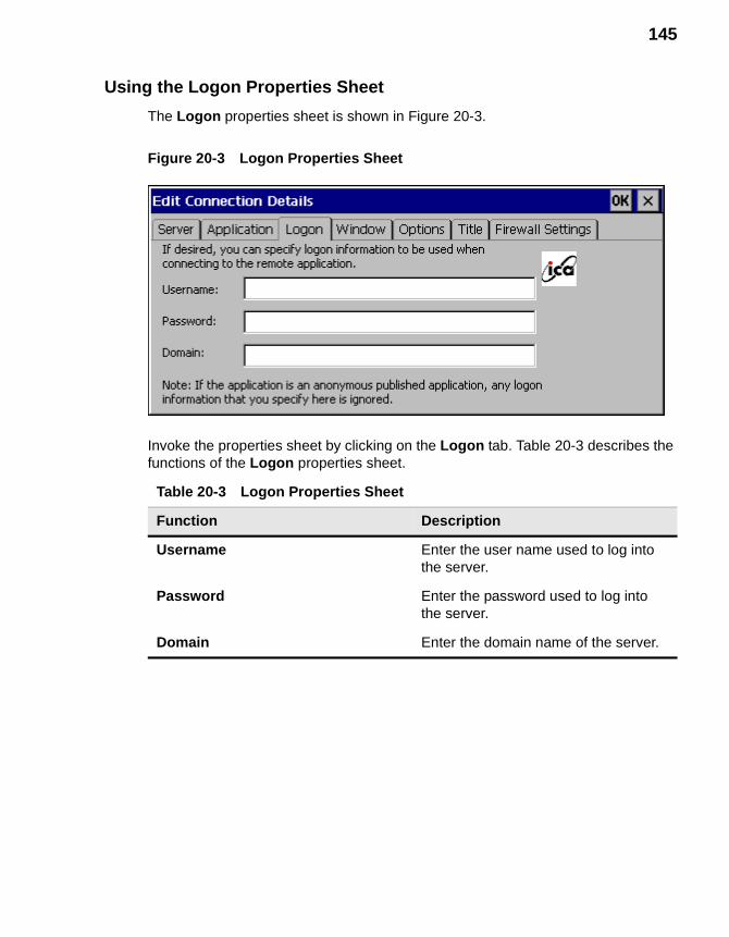
145
Using the Logon Properties Sheet
The Logon properties sheet is shown in Figure 20-3.
Figure 20-3 Logon Properties Sheet
Invoke the properties sheet by clicking on the Logon tab. Table 20-3 describes the functions of the Logon properties sheet.
Table 20-3 Logon Properties Sheet
Function Description
Username Enter the user name used to log into the server.
Password Enter the password used to log into the server.
Domain Enter the domain name of the server.
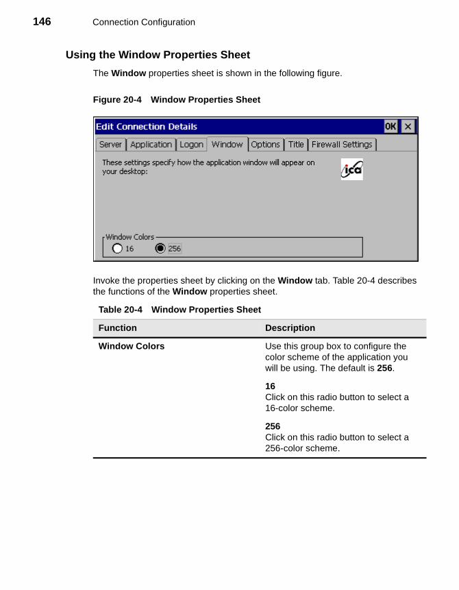
146 Connection Configuration
Using the Window Properties Sheet
The Window properties sheet is shown in the following figure.
Figure 20-4 Window Properties Sheet
Invoke the properties sheet by clicking on the Window tab. Table 20-4 describes the functions of the Window properties sheet.
Table 20-4 Window Properties Sheet
Function Description
Window Colors Use this group box to configure the color scheme of the application you will be using. The default is 256.
16Click on this radio button to select a16-color scheme.
256Click on this radio button to select a 256-color scheme.
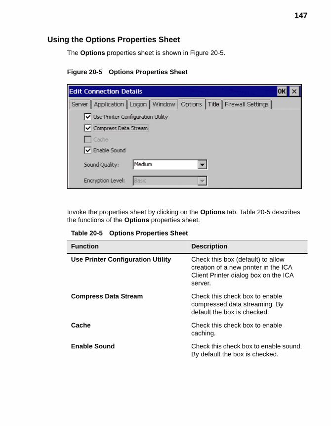
147
Using the Options Properties Sheet
The Options properties sheet is shown in Figure 20-5.
Figure 20-5 Options Properties Sheet
Invoke the properties sheet by clicking on the Options tab. Table 20-5 describes the functions of the Options properties sheet.
Table 20-5 Options Properties Sheet
Function Description
Use Printer Configuration Utility Check this box (default) to allow creation of a new printer in the ICA Client Printer dialog box on the ICA server.
Compress Data Stream Check this check box to enable compressed data streaming. By default the box is checked.
Cache Check this check box to enable caching.
Enable Sound Check this check box to enable sound. By default the box is checked.
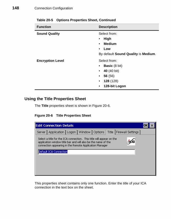
148 Connection Configuration
Using the Title Properties Sheet
The Title properties sheet is shown in Figure 20-6.
Figure 20-6 Title Properties Sheet
This properties sheet contains only one function. Enter the title of your ICA connection in the text box on the sheet.
Sound Quality Select from:
• High
• Medium
• Low
By default Sound Quality is Medium.
Encryption Level Select from:
• Basic (8 bit)
• 40 (40 bit)
• 56 (56)
• 128 (128)
• 128-bit Logon
Table 20-5 Options Properties Sheet, Continued
Function Description
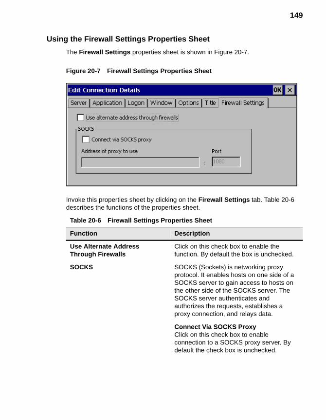
149
Using the Firewall Settings Properties Sheet
The Firewall Settings properties sheet is shown in Figure 20-7.
Figure 20-7 Firewall Settings Properties Sheet
Invoke this properties sheet by clicking on the Firewall Settings tab. Table 20-6 describes the functions of the properties sheet.
Table 20-6 Firewall Settings Properties Sheet
Function Description
Use Alternate Address Through Firewalls
Click on this check box to enable the function. By default the box is unchecked.
SOCKS SOCKS (Sockets) is networking proxy protocol. It enables hosts on one side of a SOCKS server to gain access to hosts on the other side of the SOCKS server. The SOCKS server authenticates and authorizes the requests, establishes a proxy connection, and relays data.
Connect Via SOCKS ProxyClick on this check box to enable connection to a SOCKS proxy server. By default the check box is unchecked.
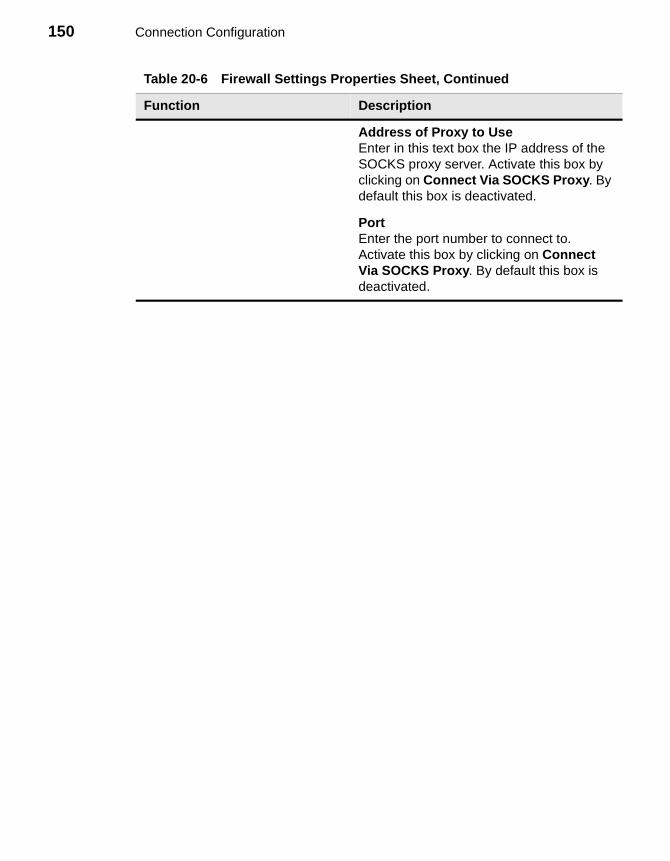
150 Connection Configuration
Address of Proxy to UseEnter in this text box the IP address of the SOCKS proxy server. Activate this box by clicking on Connect Via SOCKS Proxy. By default this box is deactivated.
PortEnter the port number to connect to. Activate this box by clicking on Connect Via SOCKS Proxy. By default this box is deactivated.
Table 20-6 Firewall Settings Properties Sheet, Continued
Function Description
21 Editing RDP, Dial-Up, and Terminal Emulation Connections
Dial-Up and Terminal Emulation Connections
Edit dial-up and terminal emulation connections through the Winterm Connection Manager:
1. Click on the Configure tab.
2. Click to select a connection from the Connection Name list.
3. Click on the Edit command button.
To edit a dial-up connection you invoke the Dial-Up Configuration Wizard. See “Dial-Up Connections” for detailed information about using this wizard. To edit terminal emulation you invoke the TE Client Connection Properties dialog box. See “Terminal Emulation Connections” for detailed information.
RDP Connections
The Winterm Connection Manager lets you edit individual RDP connection parameters. It is done through the Edit Connection dialog box. The following figure shows the Edit Connection dialog box.
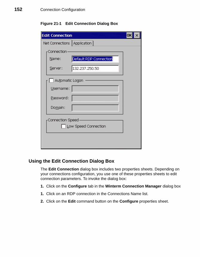
152 Connection Configuration
Figure 21-1 Edit Connection Dialog Box
Using the Edit Connection Dialog Box
The Edit Connection dialog box includes two properties sheets. Depending on your connections configuration, you use one of these properties sheets to edit connection parameters. To invoke the dialog box:
1. Click on the Configure tab in the Winterm Connection Manager dialog box
1. Click on an RDP connection in the Connections Name list.
2. Click on the Edit command button on the Configure properties sheet.
153
Using the Net Connections Properties Sheet
The Net Connections properties sheet is displayed by default for the Edit Connection dialog box. Use this properties sheet to reconfigure the network portion of the connection.
Table 21-1 describes the functions of the Net Connections properties sheet.
Table 21-1 Net Connections Properties Sheet
Function Description
Connection Select a connection from the Connection Name list in the Terminal Connection Manager. Use the following functions to change the connection’s network parameters:
NameEnter the name of the connection in this field. When OK is selected, your changes will be saved and Name will replace what was selected.
ServerEnter the address of the server in this field.
Automatic Logon Click on this check box to enable automatic logon for your terminal. Enabling this function enables the Username, Password, and Domain fields:
UsernameEnter your user name.
PasswordEnter your password.
DomainEnter your domain.
Connection Speed Low Speed ConnectionClick on this to enable low-speed connection. This function is used when connecting with a modem.
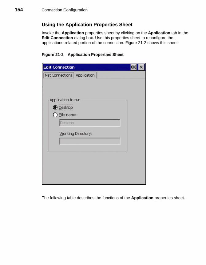
154 Connection Configuration
Using the Application Properties Sheet
Invoke the Application properties sheet by clicking on the Application tab in the Edit Connection dialog box. Use this properties sheet to reconfigure the applications-related portion of the connection. Figure 21-2 shows this sheet.
Figure 21-2 Application Properties Sheet
The following table describes the functions of the Application properties sheet.

155
NoteDesktop and File Name are mutually exclusive. File Name must be selected in order to use the File Name and Working Directory fields.
Table 21-2 Application Properties Sheet
Function Description
Application to Run Select a connection from the Connection Name list in the Terminal Connection Manager. Use the following functions to edit application types:
DesktopClick on this radio button to include a desktop application in your connection parameters.
File NameClick on this radio button to include files you will work in your connection parameters. Enter the name of the file in the field provided.
Working DirectoryEnter the directory path to the file provided in File Name.

156 Connection Configuration
External Devices
22 Devices Properties23 Managing Network Adapters24 PC Card Adapters for Modems25 Touchscreens26 Local Printers27 PC Card Adapters for Token Ring Networks28 PC Card Adapters for Wireless Networks29 Volume Properties

158
22 Devices Properties
There are two different types of Devices properties sheet. Model 3200LE terminals display a one type while all the SE models display another type (see Figure 22-1 and Figure 22-2). The Devices properties sheet for the SE models contain functions for:
• Changing ISDN settings
• Adding modems or changing the configuration of a modem
• Adapter configuration
• Touchscreen configuration
• LPD configuration
• Token ring configuration
• WaveLAN configuration
• Volume configuration
Model 3200LE Devices properties sheets contain functions for:
• Touchscreen configuration
• LPD configuration
• Volume configuration
• WaveLAN configuration
The following sections discuss both properties sheets.
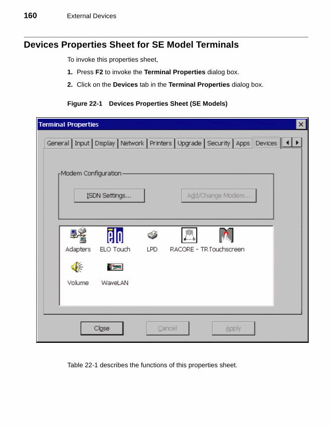
160 External Devices
Devices Properties Sheet for SE Model Terminals
To invoke this properties sheet,
1. Press F2 to invoke the Terminal Properties dialog box.
2. Click on the Devices tab in the Terminal Properties dialog box.
Figure 22-1 Devices Properties Sheet (SE Models)
Table 22-1 describes the functions of this properties sheet.
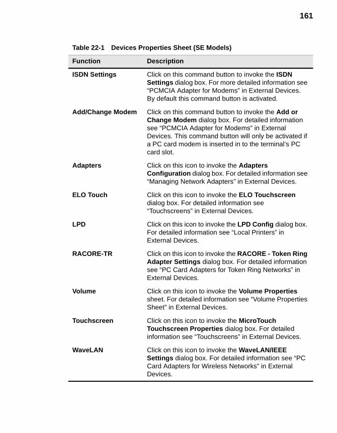
161
Table 22-1 Devices Properties Sheet (SE Models)
Function Description
ISDN Settings Click on this command button to invoke the ISDN Settings dialog box. For more detailed information see “PCMCIA Adapter for Modems” in External Devices. By default this command button is activated.
Add/Change Modem Click on this command button to invoke the Add or Change Modem dialog box. For detailed information see “PCMCIA Adapter for Modems” in External Devices. This command button will only be activated if a PC card modem is inserted in to the terminal’s PC card slot.
Adapters Click on this icon to invoke the Adapters Configuration dialog box. For detailed information see “Managing Network Adapters” in External Devices.
ELO Touch Click on this icon to invoke the ELO Touchscreen dialog box. For detailed information see “Touchscreens” in External Devices.
LPD Click on this icon to invoke the LPD Config dialog box. For detailed information see “Local Printers” in External Devices.
RACORE-TR Click on this icon to invoke the RACORE - Token Ring Adapter Settings dialog box. For detailed information see “PC Card Adapters for Token Ring Networks” in External Devices.
Volume Click on this icon to invoke the Volume Properties sheet. For detailed information see “Volume Properties Sheet” in External Devices.
Touchscreen Click on this icon to invoke the MicroTouch Touchscreen Properties dialog box. For detailed information see “Touchscreens” in External Devices.
WaveLAN Click on this icon to invoke the WaveLAN/IEEE Settings dialog box. For detailed information see “PC Card Adapters for Wireless Networks” in External Devices.
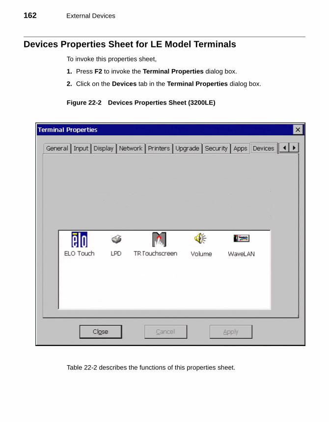
162 External Devices
Devices Properties Sheet for LE Model Terminals
To invoke this properties sheet,
1. Press F2 to invoke the Terminal Properties dialog box.
2. Click on the Devices tab in the Terminal Properties dialog box.
Figure 22-2 Devices Properties Sheet (3200LE)
Table 22-2 describes the functions of this properties sheet.
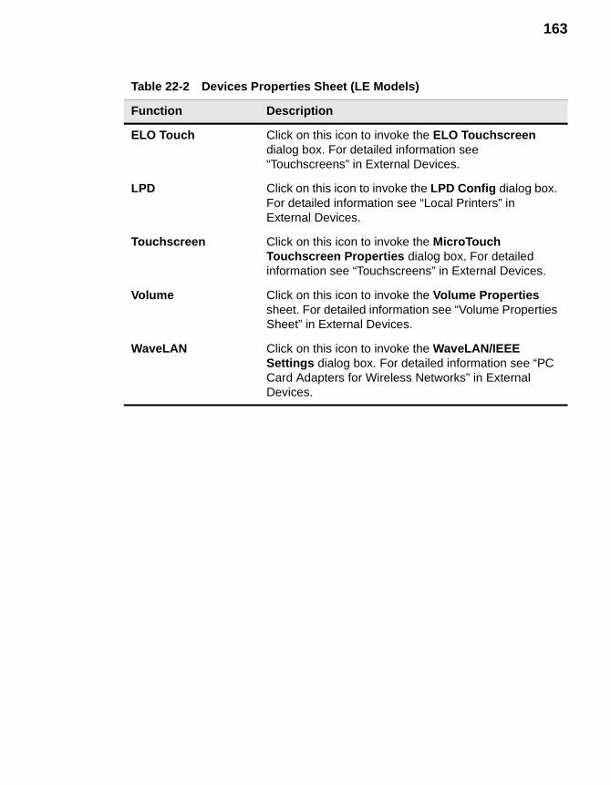
163
Table 22-2 Devices Properties Sheet (LE Models)
Function Description
ELO Touch Click on this icon to invoke the ELO Touchscreen dialog box. For detailed information see “Touchscreens” in External Devices.
LPD Click on this icon to invoke the LPD Config dialog box. For detailed information see “Local Printers” in External Devices.
Touchscreen Click on this icon to invoke the MicroTouch Touchscreen Properties dialog box. For detailed information see “Touchscreens” in External Devices.
Volume Click on this icon to invoke the Volume Properties sheet. For detailed information see “Volume Properties Sheet” in External Devices.
WaveLAN Click on this icon to invoke the WaveLAN/IEEE Settings dialog box. For detailed information see “PC Card Adapters for Wireless Networks” in External Devices.

164 External Devices
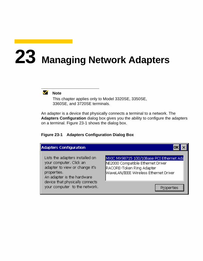
23 Managing Network Adapters
NoteThis chapter applies only to Model 3320SE, 3350SE, 3360SE, and 3720SE terminals.
An adapter is a device that physically connects a terminal to a network. The Adapters Configuration dialog box gives you the ability to configure the adapters on a terminal. Figure 23-1 shows the dialog box.
Figure 23-1 Adapters Configuration Dialog Box
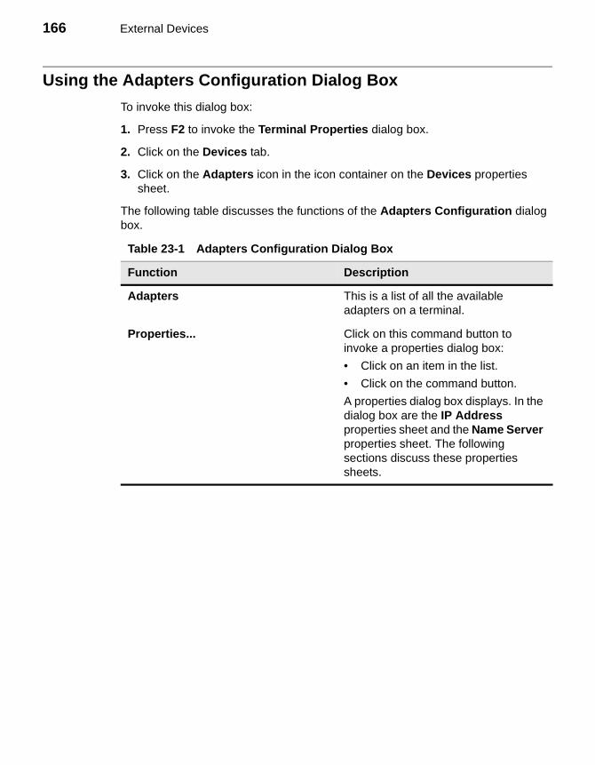
166 External Devices
Using the Adapters Configuration Dialog Box
To invoke this dialog box:
1. Press F2 to invoke the Terminal Properties dialog box.
2. Click on the Devices tab.
3. Click on the Adapters icon in the icon container on the Devices properties sheet.
The following table discusses the functions of the Adapters Configuration dialog box.
Table 23-1 Adapters Configuration Dialog Box
Function Description
Adapters This is a list of all the available adapters on a terminal.
Properties... Click on this command button to invoke a properties dialog box:
• Click on an item in the list.
• Click on the command button.
A properties dialog box displays. In the dialog box are the IP Address properties sheet and the Name Server properties sheet. The following sections discuss these properties sheets.
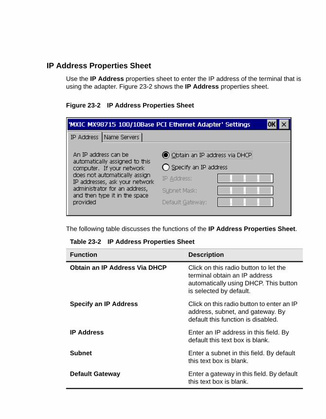
IP Address Properties Sheet
Use the IP Address properties sheet to enter the IP address of the terminal that is using the adapter. Figure 23-2 shows the IP Address properties sheet.
Figure 23-2 IP Address Properties Sheet
The following table discusses the functions of the IP Address Properties Sheet.
Table 23-2 IP Address Properties Sheet
Function Description
Obtain an IP Address Via DHCP Click on this radio button to let the terminal obtain an IP address automatically using DHCP. This button is selected by default.
Specify an IP Address Click on this radio button to enter an IP address, subnet, and gateway. By default this function is disabled.
IP Address Enter an IP address in this field. By default this text box is blank.
Subnet Enter a subnet in this field. By default this text box is blank.
Default Gateway Enter a gateway in this field. By default this text box is blank.
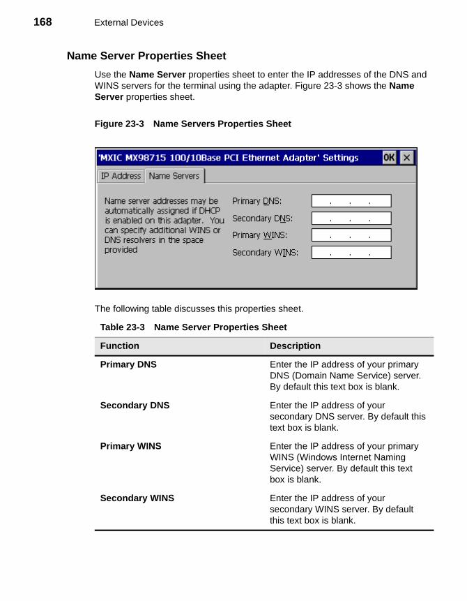
168 External Devices
Name Server Properties Sheet
Use the Name Server properties sheet to enter the IP addresses of the DNS and WINS servers for the terminal using the adapter. Figure 23-3 shows the Name Server properties sheet.
Figure 23-3 Name Servers Properties Sheet
The following table discusses this properties sheet.
Table 23-3 Name Server Properties Sheet
Function Description
Primary DNS Enter the IP address of your primary DNS (Domain Name Service) server. By default this text box is blank.
Secondary DNS Enter the IP address of your secondary DNS server. By default this text box is blank.
Primary WINS Enter the IP address of your primary WINS (Windows Internet Naming Service) server. By default this text box is blank.
Secondary WINS Enter the IP address of your secondary WINS server. By default this text box is blank.

24 PC Card Adapters for Modems
NoteThis chapter applies only to Model 3320SE, 3350SE, 3360SE, and 3720SE terminals.
Your WBT supports PCMCIA adapted modems. This chapter discusses the setup for PCMCIA modems. Figure 24-1 shows the Add or Change Modem dialog box. Use this dialog box to set up a PCMCIA modem.
To invoke the dialog box, click on the Add/Change Modem... command button on the Devices properties sheet.
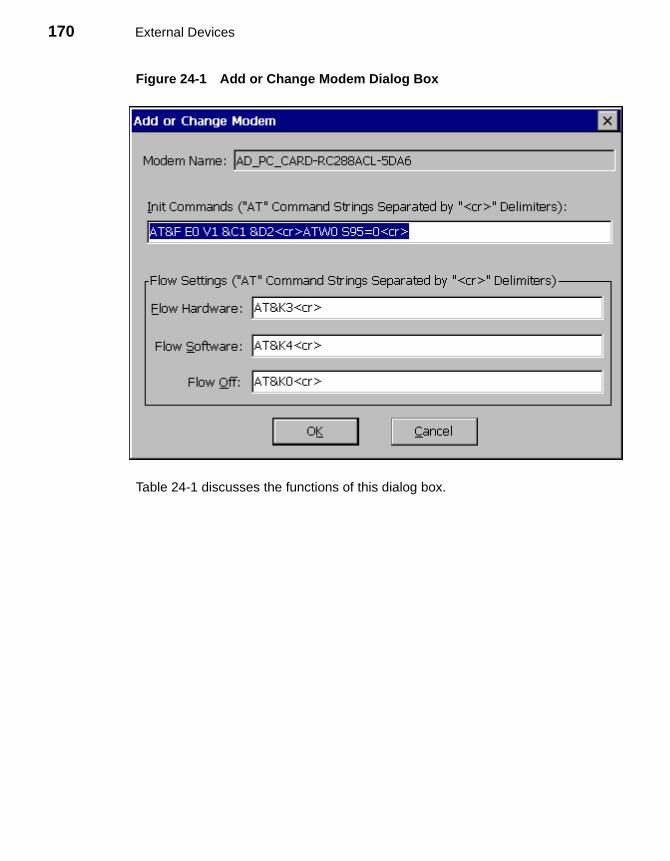
170 External Devices
Figure 24-1 Add or Change Modem Dialog Box
Table 24-1 discusses the functions of this dialog box.
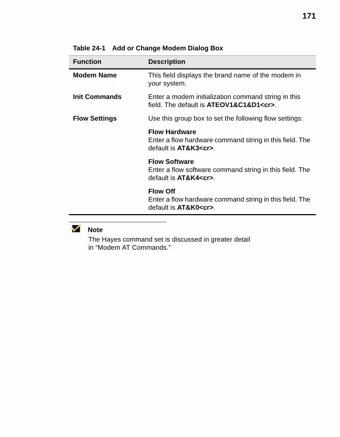
171
NoteThe Hayes command set is discussed in greater detail in “Modem AT Commands.”
Table 24-1 Add or Change Modem Dialog Box
Function Description
Modem Name This field displays the brand name of the modem in your system.
Init Commands Enter a modem initialization command string in this field. The default is ATEOV1&C1&D1<cr>.
Flow Settings Use this group box to set the following flow settings:
Flow HardwareEnter a flow hardware command string in this field. The default is AT&K3<cr>.
Flow SoftwareEnter a flow software command string in this field. The default is AT&K4<cr>.
Flow OffEnter a flow hardware command string in this field. The default is AT&K0<cr>.
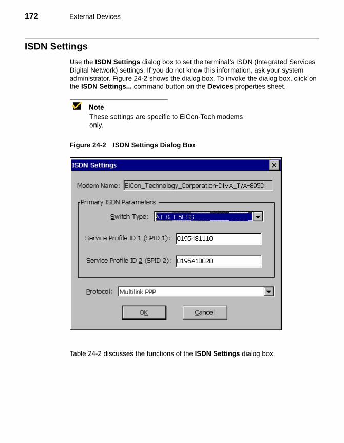
172 External Devices
ISDN Settings
Use the ISDN Settings dialog box to set the terminal’s ISDN (Integrated Services Digital Network) settings. If you do not know this information, ask your system administrator. Figure 24-2 shows the dialog box. To invoke the dialog box, click on the ISDN Settings... command button on the Devices properties sheet.
NoteThese settings are specific to EiCon-Tech modems only.
Figure 24-2 ISDN Settings Dialog Box
Table 24-2 discusses the functions of the ISDN Settings dialog box.
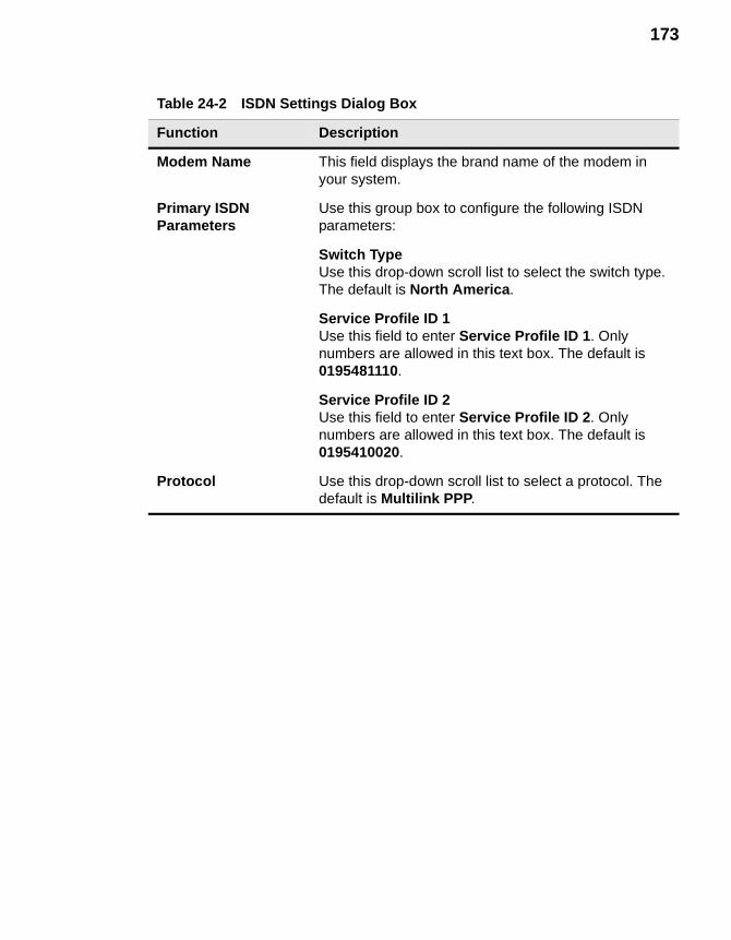
173
Table 24-2 ISDN Settings Dialog Box
Function Description
Modem Name This field displays the brand name of the modem in your system.
Primary ISDN Parameters
Use this group box to configure the following ISDN parameters:
Switch TypeUse this drop-down scroll list to select the switch type. The default is North America.
Service Profile ID 1Use this field to enter Service Profile ID 1. Only numbers are allowed in this text box. The default is 0195481110.
Service Profile ID 2Use this field to enter Service Profile ID 2. Only numbers are allowed in this text box. The default is 0195410020.
Protocol Use this drop-down scroll list to select a protocol. The default is Multilink PPP.

174 External Devices
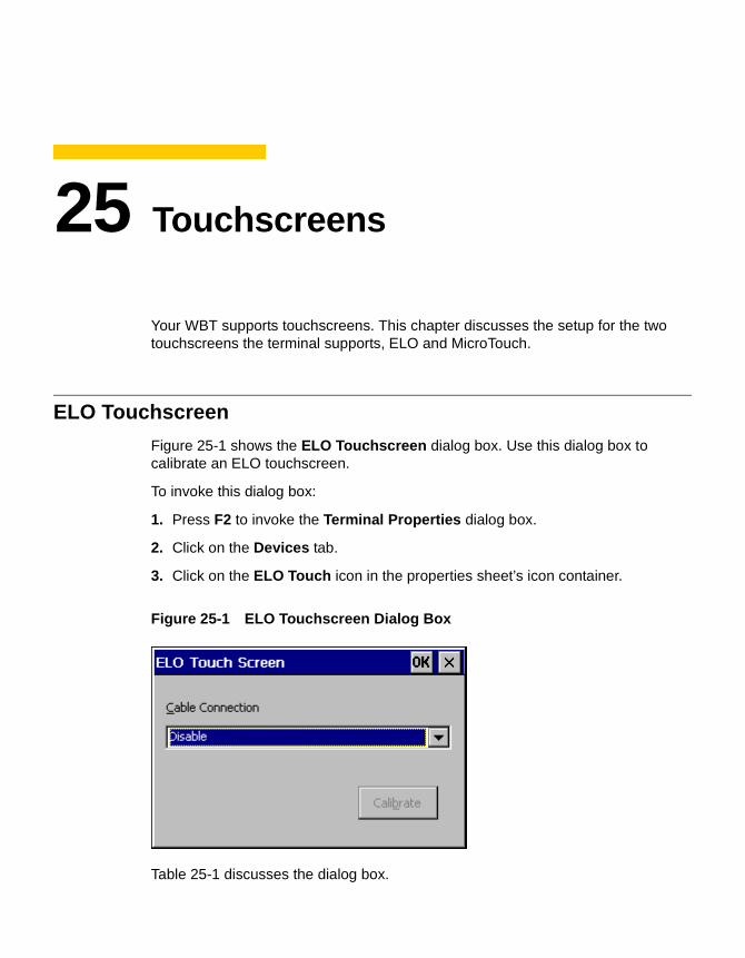
25 Touchscreens
Your WBT supports touchscreens. This chapter discusses the setup for the two touchscreens the terminal supports, ELO and MicroTouch.
ELO Touchscreen
Figure 25-1 shows the ELO Touchscreen dialog box. Use this dialog box to calibrate an ELO touchscreen.
To invoke this dialog box:
1. Press F2 to invoke the Terminal Properties dialog box.
2. Click on the Devices tab.
3. Click on the ELO Touch icon in the properties sheet’s icon container.
Figure 25-1 ELO Touchscreen Dialog Box
Table 25-1 discusses the dialog box.
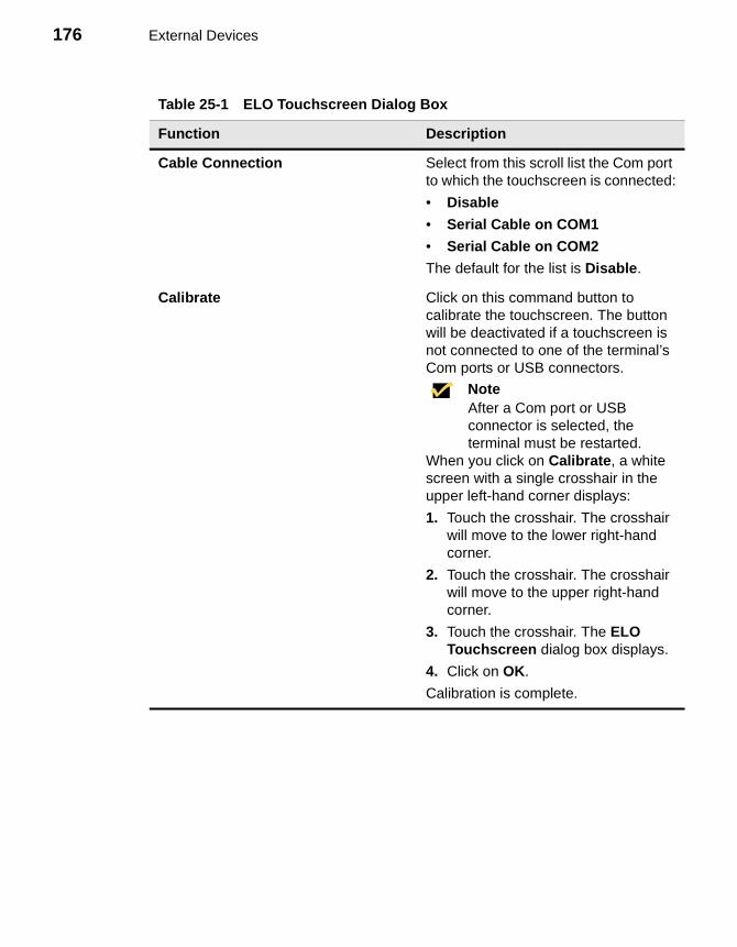
176 External Devices
Table 25-1 ELO Touchscreen Dialog Box
Function Description
Cable Connection Select from this scroll list the Com port to which the touchscreen is connected:
• Disable
• Serial Cable on COM1
• Serial Cable on COM2
The default for the list is Disable.
Calibrate Click on this command button to calibrate the touchscreen. The button will be deactivated if a touchscreen is not connected to one of the terminal’s Com ports or USB connectors.
NoteAfter a Com port or USB connector is selected, the terminal must be restarted.
When you click on Calibrate, a white screen with a single crosshair in the upper left-hand corner displays:
1. Touch the crosshair. The crosshair will move to the lower right-hand corner.
2. Touch the crosshair. The crosshair will move to the upper right-hand corner.
3. Touch the crosshair. The ELO Touchscreen dialog box displays.
4. Click on OK.
Calibration is complete.
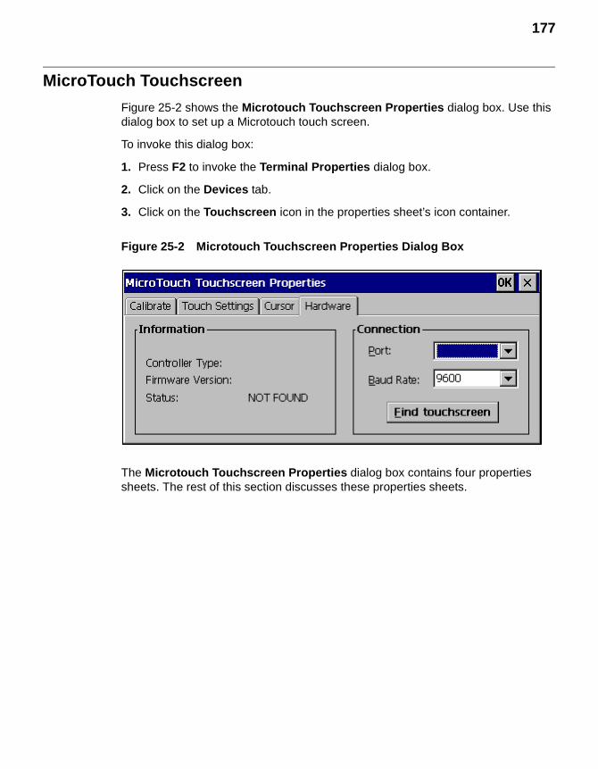
177
MicroTouch Touchscreen
Figure 25-2 shows the Microtouch Touchscreen Properties dialog box. Use this dialog box to set up a Microtouch touch screen.
To invoke this dialog box:
1. Press F2 to invoke the Terminal Properties dialog box.
2. Click on the Devices tab.
3. Click on the Touchscreen icon in the properties sheet’s icon container.
Figure 25-2 Microtouch Touchscreen Properties Dialog Box
The Microtouch Touchscreen Properties dialog box contains four properties sheets. The rest of this section discusses these properties sheets.
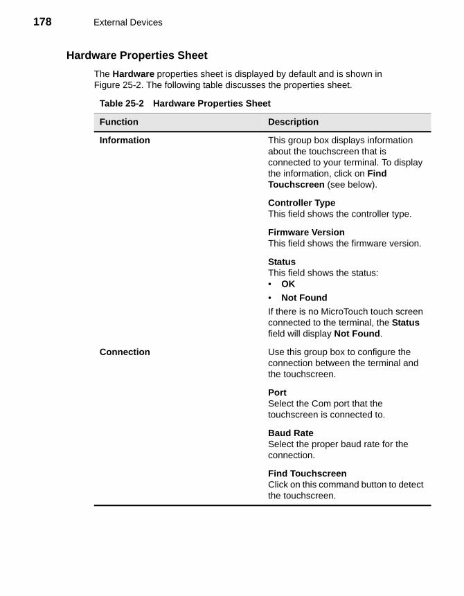
178 External Devices
Hardware Properties Sheet
The Hardware properties sheet is displayed by default and is shown in Figure 25-2. The following table discusses the properties sheet.
Table 25-2 Hardware Properties Sheet
Function Description
Information This group box displays information about the touchscreen that is connected to your terminal. To display the information, click on Find Touchscreen (see below).
Controller TypeThis field shows the controller type.
Firmware VersionThis field shows the firmware version.
StatusThis field shows the status:• OK
• Not Found
If there is no MicroTouch touch screen connected to the terminal, the Status field will display Not Found.
Connection Use this group box to configure the connection between the terminal and the touchscreen.
PortSelect the Com port that the touchscreen is connected to.
Baud RateSelect the proper baud rate for the connection.
Find TouchscreenClick on this command button to detect the touchscreen.
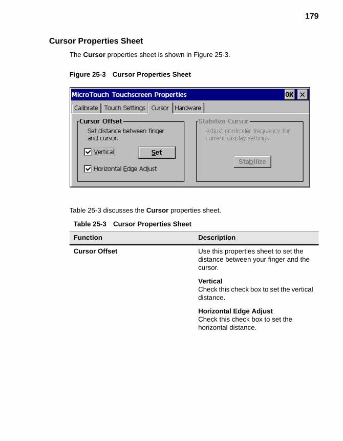
179
Cursor Properties Sheet
The Cursor properties sheet is shown in Figure 25-3.
Figure 25-3 Cursor Properties Sheet
Table 25-3 discusses the Cursor properties sheet.
Table 25-3 Cursor Properties Sheet
Function Description
Cursor Offset Use this properties sheet to set the distance between your finger and the cursor.
VerticalCheck this check box to set the vertical distance.
Horizontal Edge AdjustCheck this check box to set the horizontal distance.
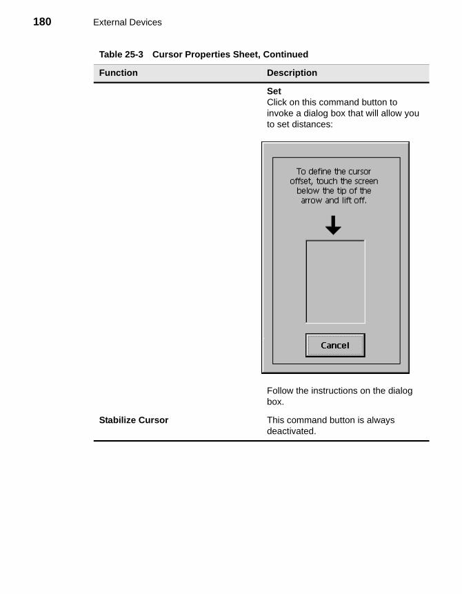
180 External Devices
SetClick on this command button to invoke a dialog box that will allow you to set distances:
Follow the instructions on the dialog box.
Stabilize Cursor This command button is always deactivated.
Table 25-3 Cursor Properties Sheet, Continued
Function Description
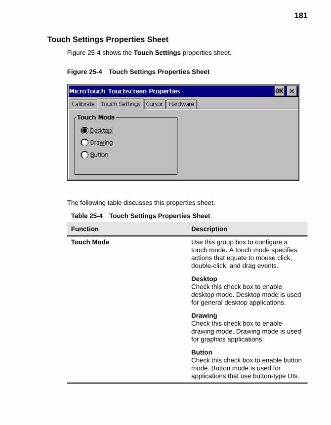
181
Touch Settings Properties Sheet
Figure 25-4 shows the Touch Settings properties sheet.
Figure 25-4 Touch Settings Properties Sheet
The following table discusses this properties sheet.
Table 25-4 Touch Settings Properties Sheet
Function Description
Touch Mode Use this group box to configure a touch mode. A touch mode specifies actions that equate to mouse click, double-click, and drag events.
DesktopCheck this check box to enable desktop mode. Desktop mode is used for general desktop applications.
DrawingCheck this check box to enable drawing mode. Drawing mode is used for graphics applications.
ButtonCheck this check box to enable button mode. Button mode is used for applications that use button-type UIs.
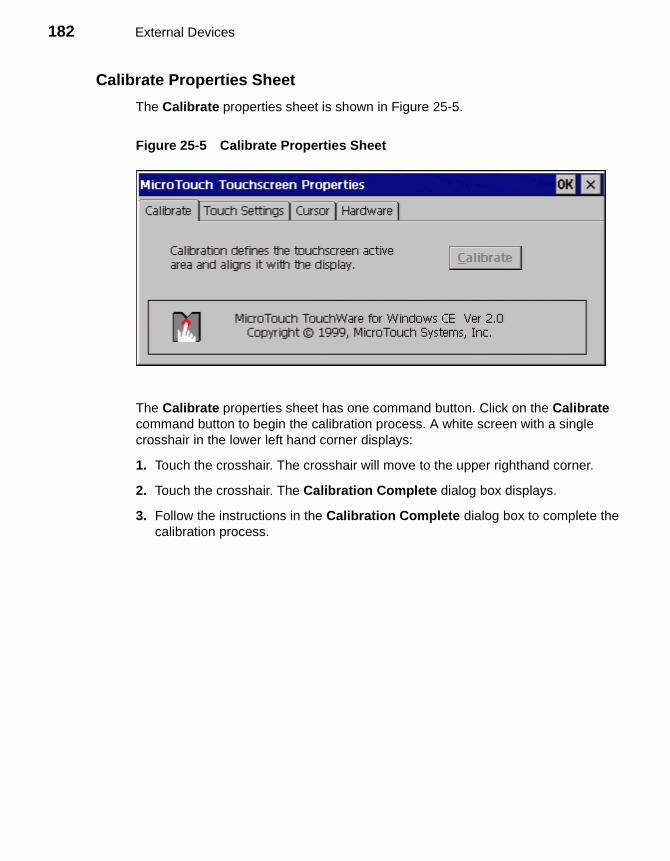
182 External Devices
Calibrate Properties Sheet
The Calibrate properties sheet is shown in Figure 25-5.
Figure 25-5 Calibrate Properties Sheet
The Calibrate properties sheet has one command button. Click on the Calibrate command button to begin the calibration process. A white screen with a single crosshair in the lower left hand corner displays:
1. Touch the crosshair. The crosshair will move to the upper righthand corner.
2. Touch the crosshair. The Calibration Complete dialog box displays.
3. Follow the instructions in the Calibration Complete dialog box to complete the calibration process.
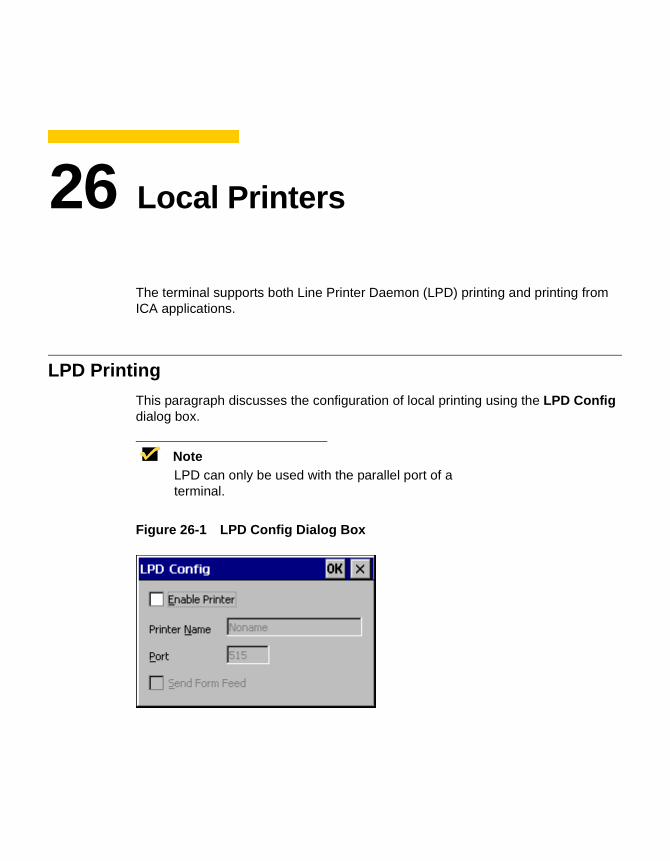
26 Local Printers
The terminal supports both Line Printer Daemon (LPD) printing and printing from ICA applications.
LPD Printing
This paragraph discusses the configuration of local printing using the LPD Config dialog box.
NoteLPD can only be used with the parallel port of a terminal.
Figure 26-1 LPD Config Dialog Box
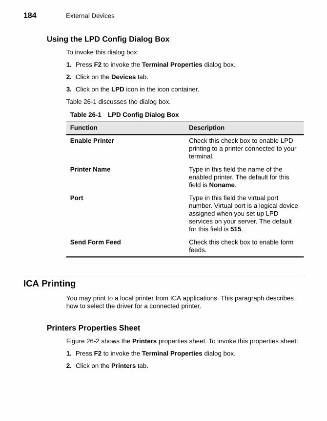
184 External Devices
Using the LPD Config Dialog Box
To invoke this dialog box:
1. Press F2 to invoke the Terminal Properties dialog box.
2. Click on the Devices tab.
3. Click on the LPD icon in the icon container.
Table 26-1 discusses the dialog box.
ICA Printing
You may print to a local printer from ICA applications. This paragraph describes how to select the driver for a connected printer.
Printers Properties Sheet
Figure 26-2 shows the Printers properties sheet. To invoke this properties sheet:
1. Press F2 to invoke the Terminal Properties dialog box.
2. Click on the Printers tab.
Table 26-1 LPD Config Dialog Box
Function Description
Enable Printer Check this check box to enable LPD printing to a printer connected to your terminal.
Printer Name Type in this field the name of the enabled printer. The default for this field is Noname.
Port Type in this field the virtual port number. Virtual port is a logical device assigned when you set up LPD services on your server. The default for this field is 515.
Send Form Feed Check this check box to enable form feeds.
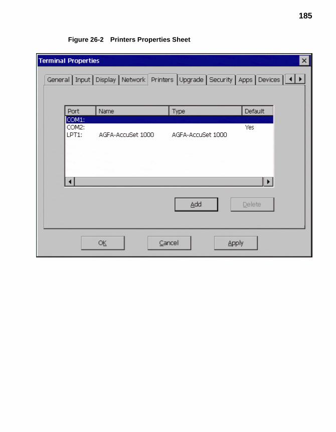
185
Figure 26-2 Printers Properties Sheet
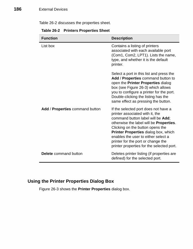
186 External Devices
Table 26-2 discusses the properties sheet.
Using the Printer Properties Dialog Box
Figure 26-3 shows the Printer Properties dialog box.
Table 26-2 Printers Properties Sheet
Function Description
List box Contains a listing of printers associated with each available port (Com1, Com2, LPT1). Lists the name, type, and whether it is the default printer.
Select a port in this list and press the Add / Properties command button to open the Printer Properties dialog box (see Figure 26-3) which allows you to configure a printer for the port. Double-clicking the listing has the same effect as pressing the button.
Add / Properties command button If the selected port does not have a printer associated with it, the command button label will be Add; otherwise the label will be Properties. Clicking on the button opens the Printer Properties dialog box, which enables the user to either select a printer for the port or change the printer properties for the selected port.
Delete command button Deletes printer listing (if properties are defined) for the selected port.
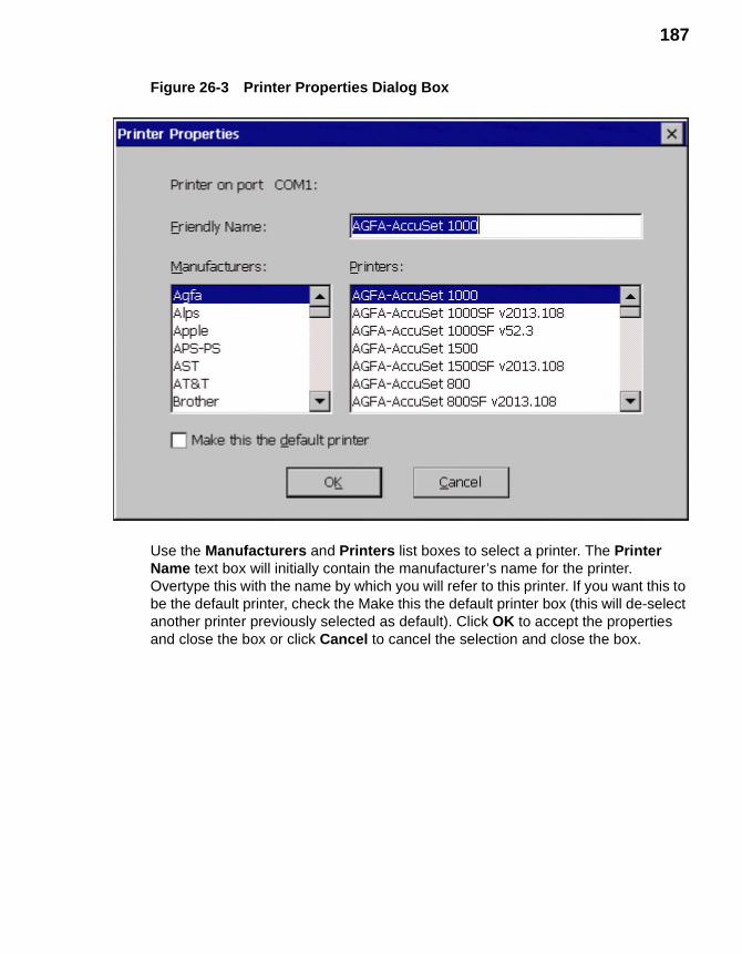
187
Figure 26-3 Printer Properties Dialog Box
Use the Manufacturers and Printers list boxes to select a printer. The Printer Name text box will initially contain the manufacturer’s name for the printer. Overtype this with the name by which you will refer to this printer. If you want this to be the default printer, check the Make this the default printer box (this will de-select another printer previously selected as default). Click OK to accept the properties and close the box or click Cancel to cancel the selection and close the box.

188 External Devices
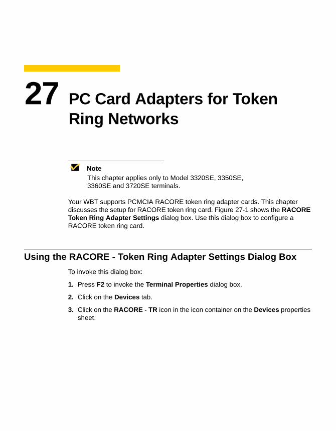
27 PC Card Adapters for Token Ring Networks
NoteThis chapter applies only to Model 3320SE, 3350SE, 3360SE and 3720SE terminals.
Your WBT supports PCMCIA RACORE token ring adapter cards. This chapter discusses the setup for RACORE token ring card. Figure 27-1 shows the RACORE Token Ring Adapter Settings dialog box. Use this dialog box to configure a RACORE token ring card.
Using the RACORE - Token Ring Adapter Settings Dialog Box
To invoke this dialog box:
1. Press F2 to invoke the Terminal Properties dialog box.
2. Click on the Devices tab.
3. Click on the RACORE - TR icon in the icon container on the Devices properties sheet.
190 External Devices
Figure 27-1 RACORE - Token Ring Adapter Settings Dialog Box
Table 27-1 discusses the dialog box.
Table 27-1 RACORE - Token Ring Adapter Settings
Function Description
User Defined MAC Address Use this text field to enter the MAC address of the token ring PC card. The default is 000000000000.
Token Ring Speed Use this group box to select the speed of your token ring network. The default is 16 Megabits/Second
4 Megabits/SecondClick on this radio button if your network is set to a passing speed of 4 megabits.
16 Megabits/SecondClick on this radio button if your network is set to a passing speed of 16 megabits.
28 PC Card Adapters for Wireless Networks
NoteThis chapter applies only to Model 3320SE, 3350SE, 3360SE and 3720SE terminals.
Your WBT supports PCMCIA adapters for WaveLAN wireless networks. This chapter discusses the setup for these adapters. Figure 28-1 shows the WaveLAN/IEEE Settings dialog box.
Using the WaveLAN/IEEE Settings Dialog Box
To invoke this dialog box:
1. Press F2 to invoke the Terminal Properties dialog box.
2. Click on the Devices tab.
3. Click on the WaveLAN icon in the icon container.
The WaveLAN/IEEE Settings dialog box contains four properties sheets. The rest of this section discusses these properties sheets.
Basic Properties Sheet
The Basic properties sheet is the default of the dialog box and is shown in Figure 28-1.
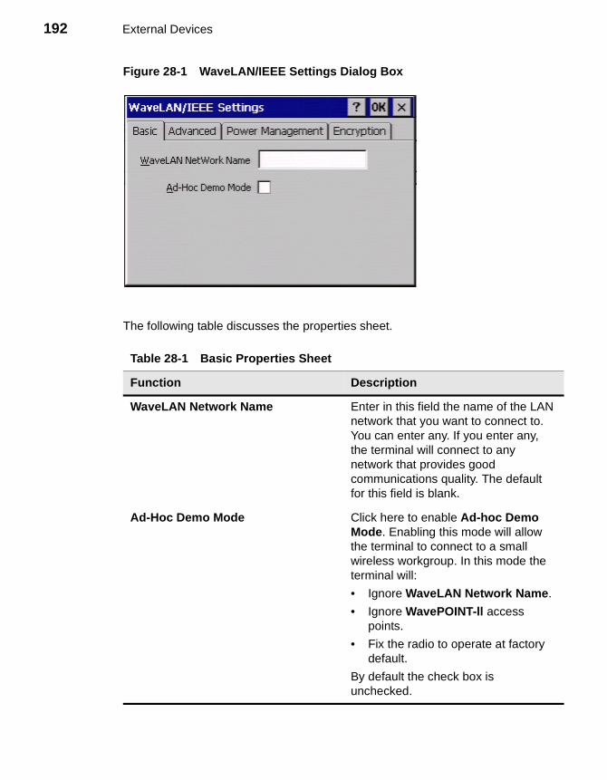
192 External Devices
Figure 28-1 WaveLAN/IEEE Settings Dialog Box
The following table discusses the properties sheet.
Table 28-1 Basic Properties Sheet
Function Description
WaveLAN Network Name Enter in this field the name of the LAN network that you want to connect to. You can enter any. If you enter any, the terminal will connect to any network that provides good communications quality. The default for this field is blank.
Ad-Hoc Demo Mode Click here to enable Ad-hoc Demo Mode. Enabling this mode will allow the terminal to connect to a small wireless workgroup. In this mode the terminal will:
• Ignore WaveLAN Network Name.
• Ignore WavePOINT-ll access points.
• Fix the radio to operate at factory default.
By default the check box is unchecked.
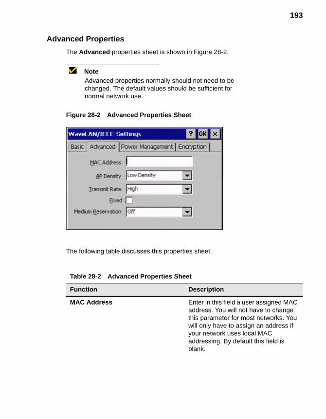
193
Advanced Properties
The Advanced properties sheet is shown in Figure 28-2.
NoteAdvanced properties normally should not need to be changed. The default values should be sufficient for normal network use.
Figure 28-2 Advanced Properties Sheet
The following table discusses this properties sheet.
Table 28-2 Advanced Properties Sheet
Function Description
MAC Address Enter in this field a user assigned MAC address. You will not have to change this parameter for most networks. You will only have to assign an address if your network uses local MAC addressing. By default this field is blank.
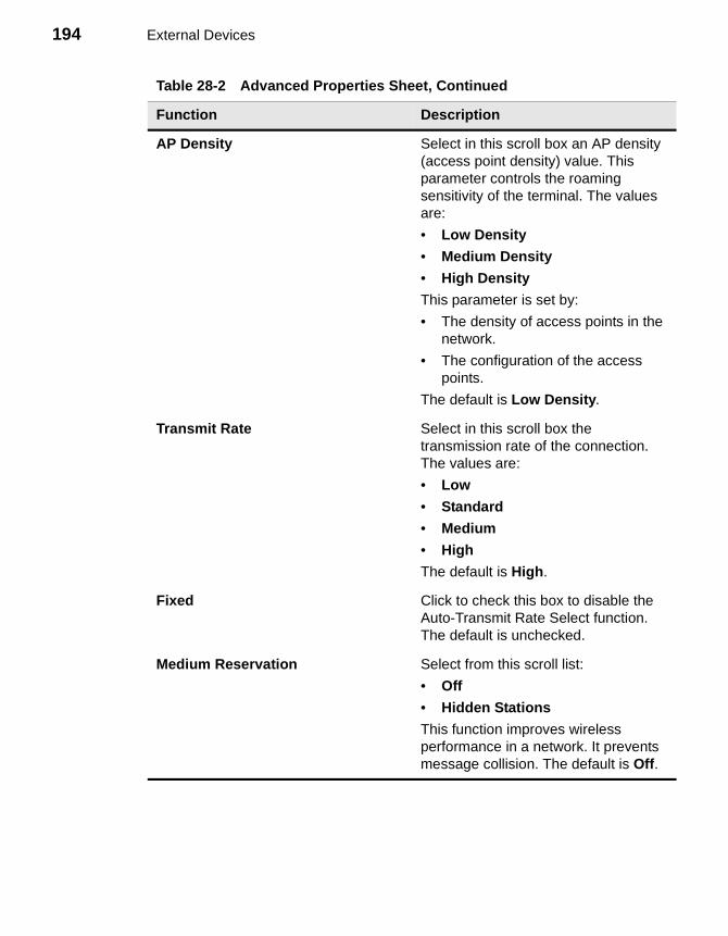
194 External Devices
AP Density Select in this scroll box an AP density (access point density) value. This parameter controls the roaming sensitivity of the terminal. The values are:
• Low Density
• Medium Density
• High Density
This parameter is set by:
• The density of access points in the network.
• The configuration of the access points.
The default is Low Density.
Transmit Rate Select in this scroll box the transmission rate of the connection. The values are:
• Low
• Standard
• Medium
• High
The default is High.
Fixed Click to check this box to disable the Auto-Transmit Rate Select function. The default is unchecked.
Medium Reservation Select from this scroll list:
• Off
• Hidden Stations
This function improves wireless performance in a network. It prevents message collision. The default is Off.
Table 28-2 Advanced Properties Sheet, Continued
Function Description
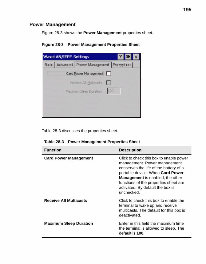
195
Power Management
Figure 28-3 shows the Power Management properties sheet.
Figure 28-3 Power Management Properties Sheet
Table 28-3 discusses the properties sheet.
Table 28-3 Power Management Properties Sheet
Function Description
Card Power Management Click to check this box to enable power management. Power management conserves the life of the battery of a portable device. When Card Power Management is enabled, the other functions of the properties sheet are activated. By default the box is unchecked.
Receive All Multicasts Click to check this box to enable the terminal to wake up and receive multicasts. The default for this box is deactivated.
Maximum Sleep Duration Enter in this field the maximum time the terminal is allowed to sleep. The default is 100.
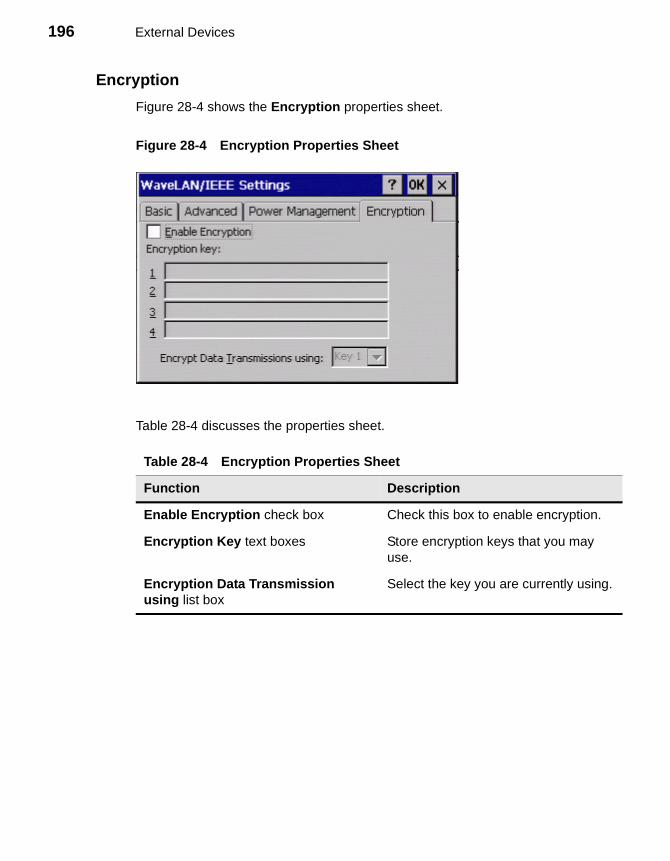
196 External Devices
Encryption
Figure 28-4 shows the Encryption properties sheet.
Figure 28-4 Encryption Properties Sheet
Table 28-4 discusses the properties sheet.
Table 28-4 Encryption Properties Sheet
Function Description
Enable Encryption check box Check this box to enable encryption.
Encryption Key text boxes Store encryption keys that you may use.
Encryption Data Transmission using list box
Select the key you are currently using.
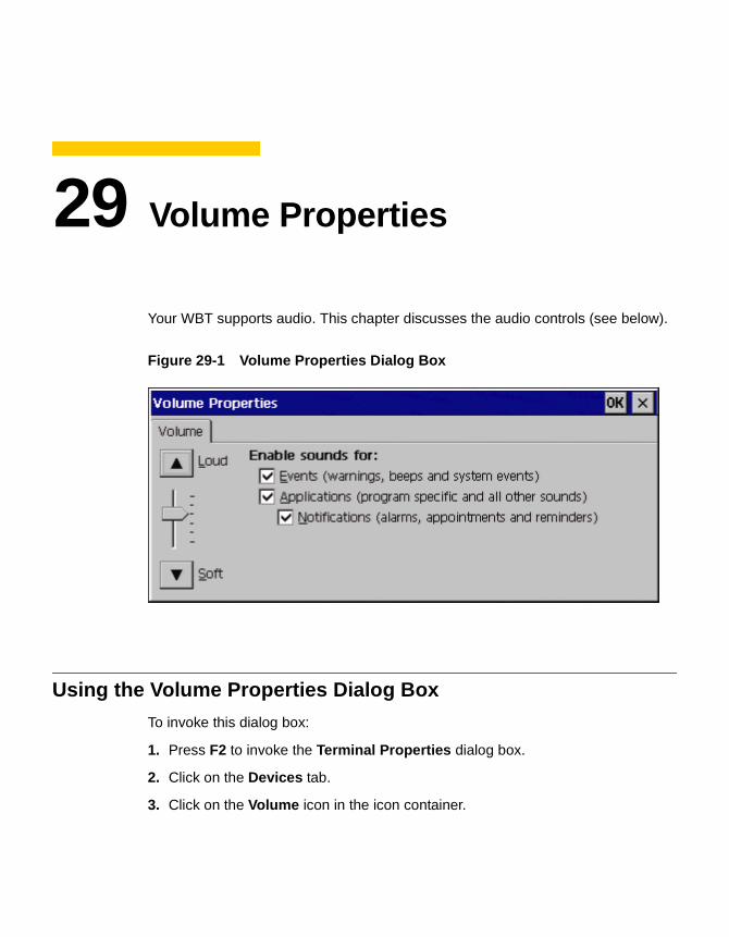
29 Volume Properties
Your WBT supports audio. This chapter discusses the audio controls (see below).
Figure 29-1 Volume Properties Dialog Box
Using the Volume Properties Dialog Box
To invoke this dialog box:
1. Press F2 to invoke the Terminal Properties dialog box.
2. Click on the Devices tab.
3. Click on the Volume icon in the icon container.
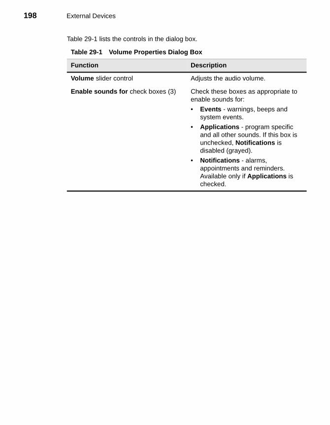
198 External Devices
Table 29-1 lists the controls in the dialog box.
Table 29-1 Volume Properties Dialog Box
Function Description
Volume slider control Adjusts the audio volume.
Enable sounds for check boxes (3) Check these boxes as appropriate to enable sounds for:
• Events - warnings, beeps and system events.
• Applications - program specific and all other sounds. If this box is unchecked, Notifications is disabled (grayed).
• Notifications - alarms, appointments and reminders. Available only if Applications is checked.
Firmware Upgrades
30 Cable Firmware Upgrades31 FTP Pull Firmware Upgrades32 SNMP Firmware Upgrades33 DHCP Firmware Upgrades

200

30 Cable Firmware Upgrades
NoteThis chapter applies only to Model 3320SE, 3350SE, 3360SE and 3720SE terminals.
The following section describes the cable method of firmware download. The cable method for all terminals is parallel download, using a Laplink cable and the MS-DOS xfer.exe program.
CautionDo not power the terminal off during the upgrade.
Setup
The following equipment may be needed, depending on the download procedure used:
• IBM-compatible PC with a CD-ROM drive and a parallel port.
• Terminal firmware upgrade diskette or CD.
• LapLink or equivalent parallel port communications cable (used only if parallel port is used for downloading).
NoteFor convenience, drive D:\ is used here for the CD drive. You should substitute the appropriate drive letter for your PC.
202 Firmware Upgrades
Parallel Flash Download Procedure
This procedure includes both manual and auto download instructions. The download procedure will not work unless your PC is booted to DOS.
1. Record the terminal’s current configuration.
CautionAll previous settings will be lost. Upgrading the firmware defaults the current configuration to the factory default settings.
2. Turn off the terminal.
3. Connect a parallel LapLink cable from the parallel port of your PC to the parallel port of the terminal.
4. Insert the firmware upgrade CD into your PC.
5. Type D:\ at the DOS prompt to select the drive where the download files exist. Use the dir command to find the files.
6. Perform either “Manual Download” or “Auto Download.”
Manual Download
Use the following instructions to perform a manual download.
1. Type xfer <filename.ext> at the DOS prompt
2. Press Enter, and the Download Utility dialog box appears. See the following figure.
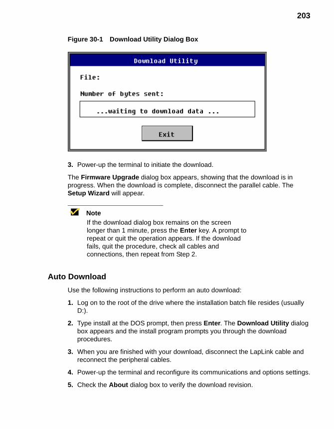
203
Figure 30-1 Download Utility Dialog Box
3. Power-up the terminal to initiate the download.
The Firmware Upgrade dialog box appears, showing that the download is in progress. When the download is complete, disconnect the parallel cable. The Setup Wizard will appear.
NoteIf the download dialog box remains on the screen longer than 1 minute, press the Enter key. A prompt to repeat or quit the operation appears. If the download fails, quit the procedure, check all cables and connections, then repeat from Step 2.
Auto Download
Use the following instructions to perform an auto download:
1. Log on to the root of the drive where the installation batch file resides (usually D:).
2. Type install at the DOS prompt, then press Enter. The Download Utility dialog box appears and the install program prompts you through the download procedures.
3. When you are finished with your download, disconnect the LapLink cable and reconnect the peripheral cables.
4. Power-up the terminal and reconfigure its communications and options settings.
5. Check the About dialog box to verify the download revision.
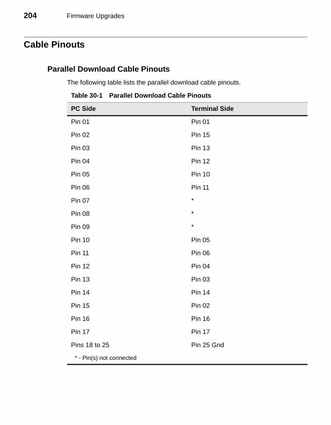
204 Firmware Upgrades
Cable Pinouts
Parallel Download Cable Pinouts
The following table lists the parallel download cable pinouts.
Table 30-1 Parallel Download Cable Pinouts
PC Side Terminal Side
Pin 01 Pin 01
Pin 02 Pin 15
Pin 03 Pin 13
Pin 04 Pin 12
Pin 05 Pin 10
Pin 06 Pin 11
Pin 07 *
Pin 08 *
Pin 09 *
Pin 10 Pin 05
Pin 11 Pin 06
Pin 12 Pin 04
Pin 13 Pin 03
Pin 14 Pin 14
Pin 15 Pin 02
Pin 16 Pin 16
Pin 17 Pin 17
Pins 18 to 25 Pin 25 Gnd
* - Pin(s) not connected
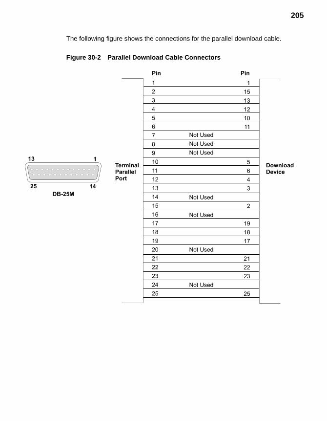
205
The following figure shows the connections for the parallel download cable.
Figure 30-2 Parallel Download Cable Connectors
1
2
3
4
5
6
7
8
9
10
11
12
13
14
15
16
17
18
19
20
21
22
23
24
25
1
15
13
12
10
11
5
6
4
3
2
19
18
17
21
22
23
25
Not Used
Not Used
Not Used
Not Used
Not Used
Not Used
Not Used
DownloadDevice
TerminalParallelPort
Pin Pin
13
25
1
14
DB-25M

206 Firmware Upgrades

31 FTP Pull Firmware Upgrades
Use the Upgrade properties sheet to:
1. Set up a terminal for communication with an FTP server.
2. Perform FTP pull upgrades.
See Figure 31-1.
Using the Upgrade Properties Sheet
To invoke this properties sheet:
1. Press the F2 key.
2. Click on the Upgrade tab in the Terminal Properties dialog box.
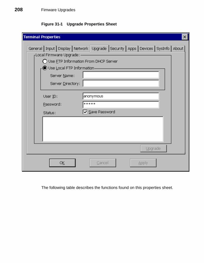
208 Fimware Upgrades
Figure 31-1 Upgrade Properties Sheet
The following table describes the functions found on this properties sheet.

209
Table 31-1 Upgrade Properties Sheet
Function Description
Local Firmware Upgrade
Use this group box to upgrade your terminal’s firmware using an FTP server. The functions are:
Use FTP Information from DHCP ServerSelect this function if you want to get the FTP server and directory information from a DHCP server. Click on this radio button to select the function. By default the function is disabled.
Use Local FTP InformationSelect this function if you want to enter the FTP server you will use for the upgrade. Click on the radio button to select the function. By default the function is enabled.
Server NameEnter the name or IP address of the FTP server where the binary and params.ini reside. The default is blank.
Server DirectoryEnter the directory on the FTP server where the binary and params.ini reside. The default is blank.
User IDEnter your user account in this field. The default is Anonymous.
PasswordEnter your password in this field. The default is *****.
StatusThis display box shows status information about the connection to the FTP server, and the firmware download. Connect and download errors are also reported. The default is blank.
Save PasswordCheck this box to save the entered password in the registry.
Upgrade Click on this command button to initiate the upgrade procedure. By default the button is disabled until an entry is made in the FTP Server field.
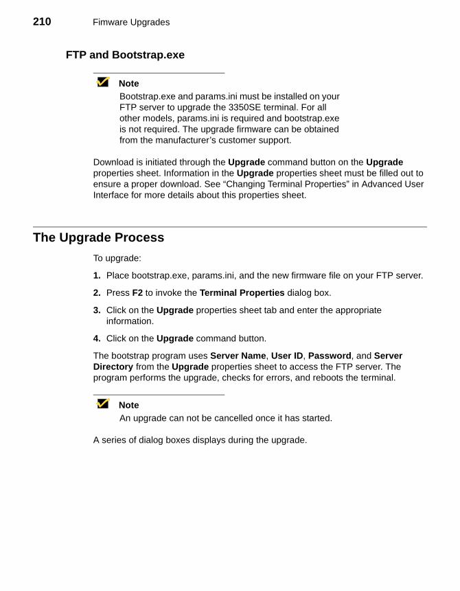
210 Fimware Upgrades
FTP and Bootstrap.exe
NoteBootstrap.exe and params.ini must be installed on your FTP server to upgrade the 3350SE terminal. For all other models, params.ini is required and bootstrap.exe is not required. The upgrade firmware can be obtained from the manufacturer’s customer support.
Download is initiated through the Upgrade command button on the Upgrade properties sheet. Information in the Upgrade properties sheet must be filled out to ensure a proper download. See “Changing Terminal Properties” in Advanced User Interface for more details about this properties sheet.
The Upgrade Process
To upgrade:
1. Place bootstrap.exe, params.ini, and the new firmware file on your FTP server.
2. Press F2 to invoke the Terminal Properties dialog box.
3. Click on the Upgrade properties sheet tab and enter the appropriate information.
4. Click on the Upgrade command button.
The bootstrap program uses Server Name, User ID, Password, and Server Directory from the Upgrade properties sheet to access the FTP server. The program performs the upgrade, checks for errors, and reboots the terminal.
NoteAn upgrade can not be cancelled once it has started.
A series of dialog boxes displays during the upgrade.
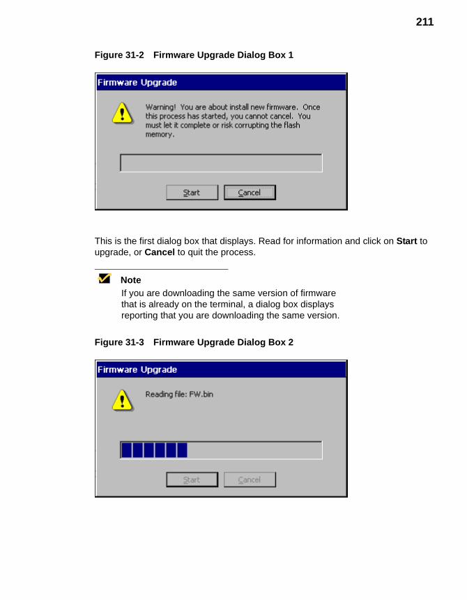
211
Figure 31-2 Firmware Upgrade Dialog Box 1
This is the first dialog box that displays. Read for information and click on Start to upgrade, or Cancel to quit the process.
NoteIf you are downloading the same version of firmware that is already on the terminal, a dialog box displays reporting that you are downloading the same version.
Figure 31-3 Firmware Upgrade Dialog Box 2

212 Fimware Upgrades
Click on Start to begin the download. The process is:
• The image gets read.
• The flash gets erased.
• The image gets written to the flash.
When the upgrade is complete, the terminal will reboot to the Winterm Connection Manager.
NoteIf the image downloaded is a lower version from what is on the terminal, the Setup Wizard will appear.

32 SNMP Firmware Upgrades
Using the SNMP Network Administration Dialog Box
The SNMP Network Administration dialog box contains the functions that you can use to administer to the terminals on your SNMP network. See Figure 32-1.
To invoke this dialog box:
1. Press the F2 key to invoke the Terminal Properties dialog box.
2. Click on the Apps tab to invoke the Apps properties sheet.
3. Click on the SNMP Network Administration command button.
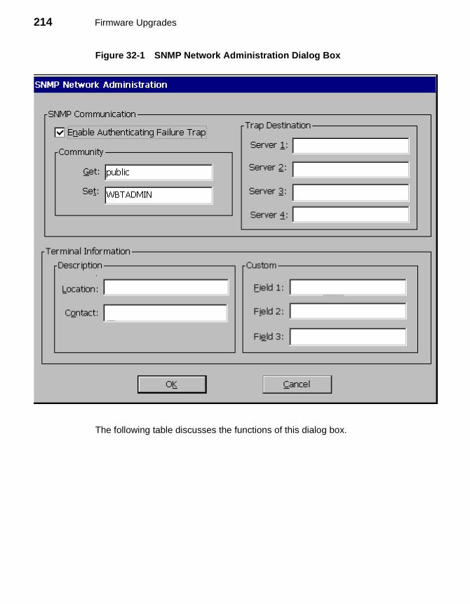
214 Firmware Upgrades
Figure 32-1 SNMP Network Administration Dialog Box
The following table discusses the functions of this dialog box.
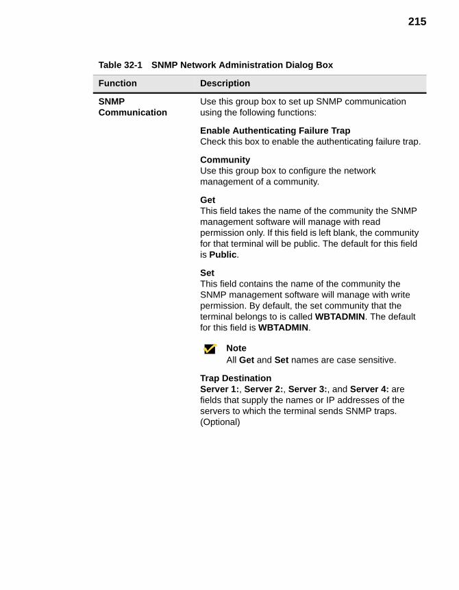
215
Table 32-1 SNMP Network Administration Dialog Box
Function Description
SNMP Communication
Use this group box to set up SNMP communication using the following functions:
Enable Authenticating Failure TrapCheck this box to enable the authenticating failure trap.
CommunityUse this group box to configure the network management of a community.
GetThis field takes the name of the community the SNMP management software will manage with read permission only. If this field is left blank, the community for that terminal will be public. The default for this field is Public.
SetThis field contains the name of the community the SNMP management software will manage with write permission. By default, the set community that the terminal belongs to is called WBTADMIN. The default for this field is WBTADMIN.
NoteAll Get and Set names are case sensitive.
Trap DestinationServer 1:, Server 2:, Server 3:, and Server 4: are fields that supply the names or IP addresses of the servers to which the terminal sends SNMP traps.(Optional)

216 Firmware Upgrades
The Upgrade Process
1. Ensure that the Wyse custom MIB (Management Information Base) is compiled by your SNMP manager.
NoteIn order to initiate an SNMP upgrade, you must know the FTP or TFTP server’s IP address or machine name, and the absolute path to the image on the FTP or TFTP server.
NoteIn the Wyse custom MIB the enterprise number for Wyse is 1.3.6.1.4.1.714.
2. Enable SNMP Update Enable if it is not enabled.
Terminal Information Use this group box to list information about terminals.
DescriptionUse this group box to describe a terminal. (Optional)
LocationType the location of the terminal in this field.
ContactType the name of the administrator of the subject terminal in this field.
CustomUse the following fields to type in any custom message associated with the subject terminal:
• Field 1
• Field 2
• Field 3
Each field will take 16 characters maximum.
Table 32-1 SNMP Network Administration Dialog Box, Continued
Function Description
217
3. Using the SNMP/Network Administrator dialog box, verify that the community and set community names for the terminal match the community and set community names in the SNMP manager.
NoteYou can set the Set Community name for a terminal if you have DHCP enabled by setting DHCP Option 164 to the set community name your SNMP manager uses.
4. Using your SNMP manager:
a. Go to Wyse 1.2.3.8.1.2 (wbt3UpDnLoadTable).
b. Go to Wyse 1.2.3.8.1.2.1.2 (wbt3UpDnLoadID), user defined string.
NoteThe above is used in traps to identify the download operation.
c. Go to Wyse 1.2.3.8.1.2.1.3 (wbt3UpDnLoadOp), and set its value to1 (Download).
d. Go to Wyse 1.2.3.8.1.2.1.4 (wbt3UpDnLoadSrcFile), and set its value to the absolute path of the directory where the image file and params.ini are located.
e. Go to Wyse 1.2.3.8.1.2.1.6 (wbt3UpDnLoadFileType), and set its value to 0 (Binary).
f. Go to Wyse 1.2.3.8.1.2.1.7 (wbt3UpDnLoadProtocol), and set its value to 0 or 1 (FTP or TFTP).
g. Go to Wyse 1.2.3.8.1.2.1.8 (wbt3UpDnLoadFServer), and set its value to the IP address or DNS name of the FTP or TFTP server.
h. Go to Wyse 1.2.3.8.1.4 (wbt3SubmitLoadJob), and set its value to1 (Ready).
Step 4h will initiate an SNMP upgrade to your terminal. If the download is configured properly, the new image will download and the terminal will reboot automatically.
Refer to Chapter 31, FTP Pull Firmware Upgrades, to view the dialog boxes that display during the process.

218 Firmware Upgrades

33 DHCP Firmware Upgrades
Using the Change DHCP Option IDs Dialog Box
Use the Change DHCP Option IDs dialog box to set up DHCP option IDs for terminal administration and upgrade. See Figure 33-1 for a view of this dialog box.
Your terminal uses DHCP and the information on the Change DHCP Option IDs dialog box to:
• Help establish ICA and RDP connections
• Perform automated firmware updates
• Help define terminal emulation connections
• Specify the virtual port server
• Implement remote management of SNMP parameters
To invoke this dialog box:
1. Press the F2 key.
2. Click on the Apps tab.
3. Click on the Change DHCP Option command button.
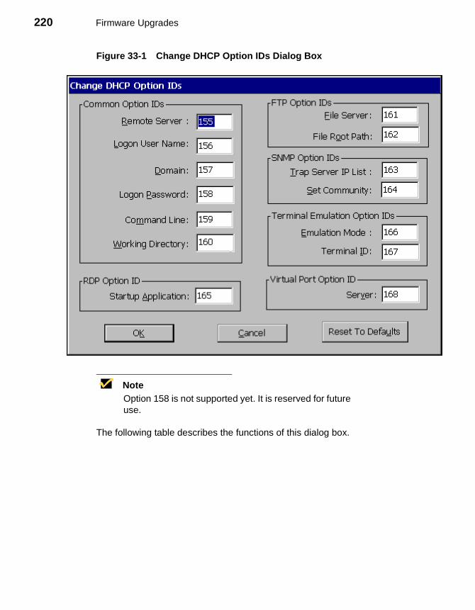
220 Firmware Upgrades
Figure 33-1 Change DHCP Option IDs Dialog Box
NoteOption 158 is not supported yet. It is reserved for future use.
The following table describes the functions of this dialog box.
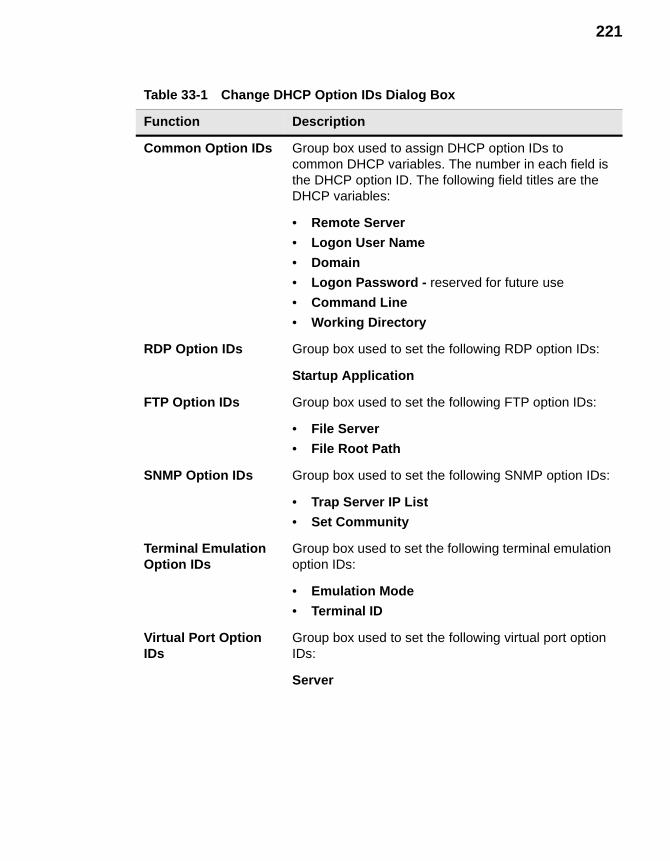
221
Table 33-1 Change DHCP Option IDs Dialog Box
Function Description
Common Option IDs Group box used to assign DHCP option IDs to common DHCP variables. The number in each field is the DHCP option ID. The following field titles are the DHCP variables:
• Remote Server
• Logon User Name
• Domain
• Logon Password - reserved for future use
• Command Line
• Working Directory
RDP Option IDs Group box used to set the following RDP option IDs:
Startup Application
FTP Option IDs Group box used to set the following FTP option IDs:
• File Server
• File Root Path
SNMP Option IDs Group box used to set the following SNMP option IDs:
• Trap Server IP List
• Set Community
Terminal Emulation Option IDs
Group box used to set the following terminal emulation option IDs:
• Emulation Mode
• Terminal ID
Virtual Port Option IDs
Group box used to set the following virtual port option IDs:
Server
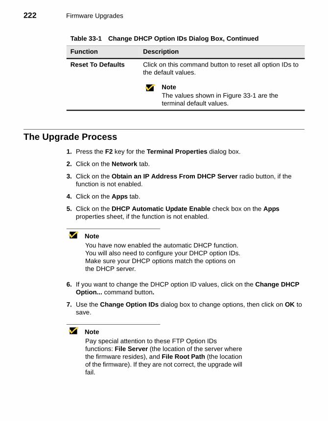
222 Firmware Upgrades
The Upgrade Process
1. Press the F2 key for the Terminal Properties dialog box.
2. Click on the Network tab.
3. Click on the Obtain an IP Address From DHCP Server radio button, if the function is not enabled.
4. Click on the Apps tab.
5. Click on the DHCP Automatic Update Enable check box on the Apps properties sheet, if the function is not enabled.
NoteYou have now enabled the automatic DHCP function. You will also need to configure your DHCP option IDs. Make sure your DHCP options match the options on the DHCP server.
6. If you want to change the DHCP option ID values, click on the Change DHCP Option... command button.
7. Use the Change Option IDs dialog box to change options, then click on OK to save.
NotePay special attention to these FTP Option IDs functions: File Server (the location of the server where the firmware resides), and File Root Path (the location of the firmware). If they are not correct, the upgrade will fail.
Reset To Defaults Click on this command button to reset all option IDs to the default values.
NoteThe values shown in Figure 33-1 are the terminal default values.
Table 33-1 Change DHCP Option IDs Dialog Box, Continued
Function Description
223
NoteYou will need the image, bootstrap.exe (for the Model 3350SE only), and the params.ini files on the FTP server to do the upgrade.
8. Shut down the terminal. See “Shutting Down the Terminal” for more information.
Your terminal will automatically upgrade itself when it is turned on again.
Manual DHCP Firmware Upgrades
1. Follow instruction 1 through 3 and 5 through 8 in “Automatic Firmware Upgrades.”
2. Click on the Upgrade... command button on the Upgrade properties sheet.
This will initiate the firmware upgrade. Once the upgrade is complete, the terminal will reboot to the Setup Wizard.

224 Firmware Upgrades

Client Security
34 Security Properties Sheet35 Terminal Accounts36 Creating Terminal Accounts37 Modifying and Deleting Terminal Accounts38 Terminal Login39 Failover

226

34 Security Properties
Use the Security properties sheet to access security functions and global terminal functions. You can also use this sheet to set up terminal accounts. Figure 34-1 shows the Security properties sheet.
Using the Security Properties Sheet
To invoke the Security properties sheet:
1. Press F2 to invoke the Terminal Properties dialog box.
2. Click on the Security tab.
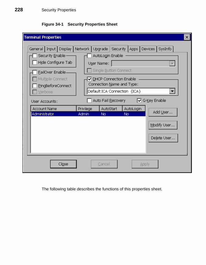
228 Security Properties
Figure 34-1 Security Properties Sheet
The following table describes the functions of this properties sheet.
229
Table 34-1 Security Properties Sheet
Function Description
Security Enable This group box is used to enable terminal security and access connection configurations. It contains the following functions:
Security EnableClick to enable terminal security and deactivate the Hide Configure Tab function. By default this function is disabled.
Hide Configure TabClick to enable. This function hides the Configure tab in the Winterm Connections Manager. By default this function is disabled.
Failover Enable Use this group box to manipulate connection parameters. See “Failover” for more information.
Failover EnableClick to enable the failover function. Enabling this function deactivates the PingBeforeConnect function. and activates Multiple Connect and Verbose functions. By default this function is disabled.
Multiple ConnectClick to enable this function. Failover must be enabled before you can access this function. By default this function is not activated.
PingBeforeConnectClick to enable this function. Enabling this function will activate Verbose. By default this function is disabled.
VerboseClick to enable the Verbose connection function. By default the box is not activated. This function becomes activated when either FailOver or PingBeforeConnect is enabled.
230 Security Properties
AutoLogin Enable This group box is used to configure login parameters. See “Autologin and Autoconnect” for more information about autologin.
AutoLogin EnableClick to enable the function. AutoLogin is enabled only for the user name currently highlighted in the User Accounts list box. Enabling the autologin function activates Single Button Connect. By default the function is disabled.
User NameThis field is activated by enabling AutoLogin Enable. By default the field is blank.
Single Button ConnectClick to enable the function. See the chapter “Terminal Login” for more information. By default the function is not activated.
DHCP Connection Enable
Use this group box to access the DHCP connection list. It contains the following functions:
DHCP Connection EnableClick to enable automatic DHCP connection. Enabling this function activates the Connection Name and Type list. By default this function is enabled.
Connection Name and TypeA scroll list that displays all connections available to your terminal. You must select the connection that will use information supplied by DHCP. By default this function is Default ICA Connection {ICA}.
Auto Fail Recovery Click on the check box to enable the function. Auto Fail Recovery is a function that checks the validity of a disconnect, and closes down a connection if disconnect checks true. By default the function is activated but not enabled.
Table 34-1 Security Properties Sheet, Continued
Function Description
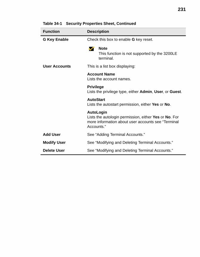
231
G Key Enable Check this box to enable G key reset.
NoteThis function is not supported by the 3200LE terminal.
User Accounts This is a list box displaying:
Account NameLists the account names.
PrivilegeLists the privilege type, either Admin, User, or Guest.
AutoStartLists the autostart permission, either Yes or No.
AutoLoginLists the autologin permission, either Yes or No. For more information about user accounts see “Terminal Accounts.”
Add User See “Adding Terminal Accounts.”
Modify User See “Modifying and Deleting Terminal Accounts.”
Delete User See “Modifying and Deleting Terminal Accounts.”
Table 34-1 Security Properties Sheet, Continued
Function Description

232 Security Properties
35 Terminal Accounts
A terminal account is a group of connection and configuration parameters organized into an account and assigned to a terminal user. Terminal accounts can include specific connections, security enable, password protection, Autologin and/or Autostart and Single Button Connect. The three types of accounts are:
• Guest
• User
• Administrator
Guest Accounts
The Guest account has the fewest amount of privileges. With this account you can not:
• Configure a connection
• Gain access to the password function
With this account type you can:
• Use the Energy Savers, Character Repeat, Mouse, and Keyboard Locale functions
• Adjust display resolution
234 Client Security
User Accounts
With a User account, you will not be able to configure the connection for the account. You will be able to access the password function. You can also:
• Use the Network properties sheet
• Use the Apps properties sheet with the exception of SNMP and DHCP
• Use the Devices properties sheet with the exception of Add/Change Modem
• Use the Input properties sheet
• Use the Display properties sheet
Administrator Accounts
The Administrator account has the greatest amount of privileges. With this account you can:
• Use Enable Password Change (change the password for an account)
• Configure or reconfigure the connection for an account
• Use all the other functions of the terminal
Using Terminal Accounts
Terminal accounts are created and managed by using the Add User..., and Modify User... command buttons. Terminal accounts are deleted using the Delete User... command button. These buttons are found on the Security properties sheet.
NoteThere is a built-in account called Administrator. It can not be deleted or revised. The account’s password can be changed and is <blank> by default. For security purposes, it is recommended that the default administrator password be changed.
For more information about terminal accounts, see:
• “Security Properties”
• “Creating Terminal Accounts”
• “Modifying and Deleting Terminal Accounts”
36 Creating Terminal Accounts
The Add User Account dialog box is used to create terminal accounts. The following figure shows this dialog box.
Using the Add User Account Dialog Box
Use the Add User Account dialog box to set up the parameters for new terminal accounts. To invoke this dialog box:
1. Press F2 while in the Winterm Connection Manager.
2. Click on the Security tab in the Terminal Properties dialog box.
3. Click on the Add User... command button.
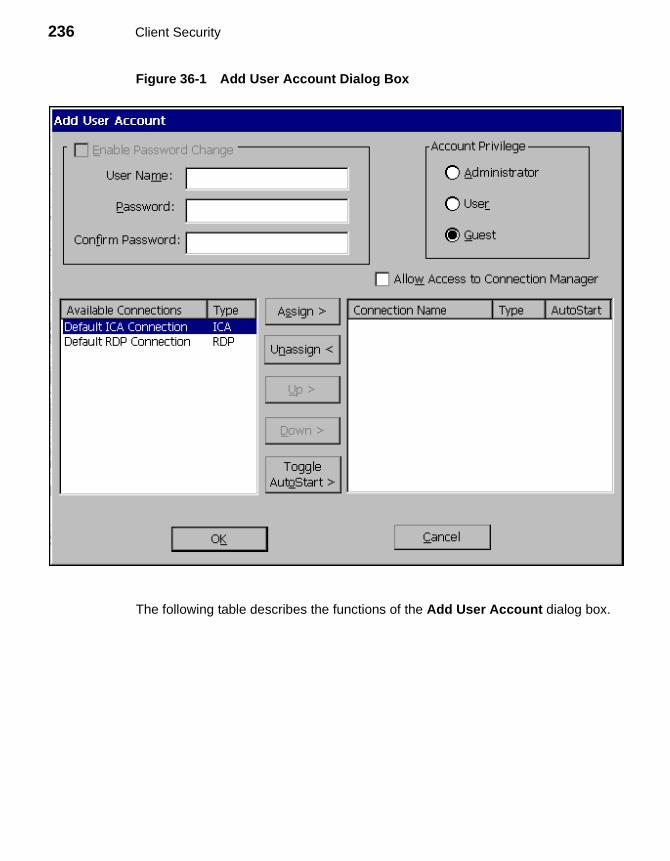
236 Client Security
Figure 36-1 Add User Account Dialog Box
The following table describes the functions of the Add User Account dialog box.
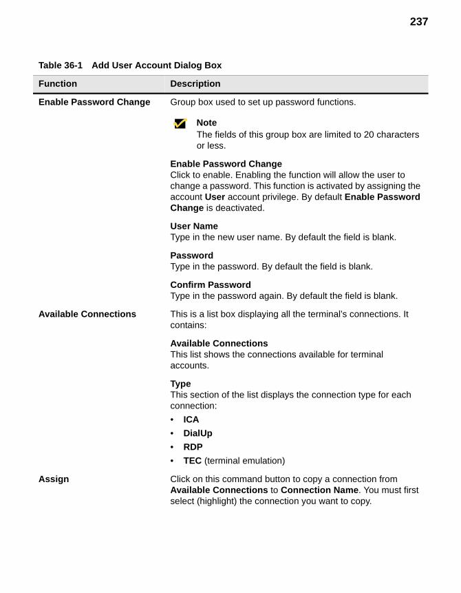
237
Table 36-1 Add User Account Dialog Box
Function Description
Enable Password Change Group box used to set up password functions.
NoteThe fields of this group box are limited to 20 characters or less.
Enable Password ChangeClick to enable. Enabling the function will allow the user to change a password. This function is activated by assigning the account User account privilege. By default Enable Password Change is deactivated.
User NameType in the new user name. By default the field is blank.
PasswordType in the password. By default the field is blank.
Confirm PasswordType in the password again. By default the field is blank.
Available Connections This is a list box displaying all the terminal’s connections. It contains:
Available ConnectionsThis list shows the connections available for terminal accounts.
TypeThis section of the list displays the connection type for each connection:
• ICA
• DialUp
• RDP
• TEC (terminal emulation)
Assign Click on this command button to copy a connection from Available Connections to Connection Name. You must first select (highlight) the connection you want to copy.
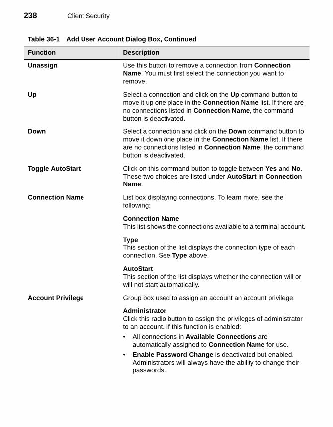
238 Client Security
Unassign Use this button to remove a connection from Connection Name. You must first select the connection you want to remove.
Up Select a connection and click on the Up command button to move it up one place in the Connection Name list. If there are no connections listed in Connection Name, the command button is deactivated.
Down Select a connection and click on the Down command button to move it down one place in the Connection Name list. If there are no connections listed in Connection Name, the command button is deactivated.
Toggle AutoStart Click on this command button to toggle between Yes and No. These two choices are listed under AutoStart in Connection Name.
Connection Name List box displaying connections. To learn more, see the following:
Connection NameThis list shows the connections available to a terminal account.
TypeThis section of the list displays the connection type of each connection. See Type above.
AutoStartThis section of the list displays whether the connection will or will not start automatically.
Account Privilege Group box used to assign an account an account privilege:
AdministratorClick this radio button to assign the privileges of administrator to an account. If this function is enabled:
• All connections in Available Connections are automatically assigned to Connection Name for use.
• Enable Password Change is deactivated but enabled. Administrators will always have the ability to change their passwords.
Table 36-1 Add User Account Dialog Box, Continued
Function Description
239
UserClick this radio button to assign the privilege of user to an account. If User is enabled, Enable Password Change is activated. Administrators can give users the ability to change their password.
GuestClick this radio button to assign the privilege of guest to an account. If Guest is enabled, then Enable Password Change is deactivated. Users with this account type can not change passwords.
Allow Access to Connection Manager
Click on this check box to allow the user of the account to have access to the Winterm Connection Manager. The function will deactivate when you set up an account as an administrator account. By default the function is disabled.
Table 36-1 Add User Account Dialog Box, Continued
Function Description

240 Client Security
37 Modifying and Deleting Terminal Accounts
The Modify User Account dialog box is used to modify and delete terminal accounts. The Delete command button, discussed later in Deleting Terminal Accounts, is used to delete terminal accounts. Figure 37-1 shows the Modify User Account dialog box.
Using the Modify User Account Dialog Box
To invoke this dialog box:
1. Press F2 from the Winterm Connection Manager.
2. Click on the Security tab in the Terminal Properties dialog box.
3. Highlight the account to be modified and click on the Modify User... command button.
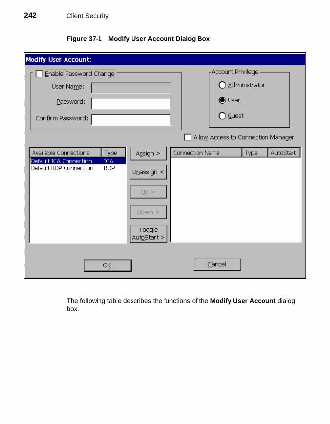
242 Client Security
Figure 37-1 Modify User Account Dialog Box
The following table describes the functions of the Modify User Account dialog box.
243
Table 37-1 Modify User Account Dialog Box
Function Description
Enable Password Change
Group box used to set up password functions.
NoteThe fields of this group box are limited to 20 characters or less.
Enable Password ChangeClick to enable. Enabling the function will allow the user to change a password. This function is activated by assigning the account User account privilege. By default Enable Password Change is deactivated.
User NameDisplays the user name. By default the text box is deactivated.
PasswordType in the password. By default the text box is blank.
Confirm PasswordType in the password again. By default the text box is blank.
Available Connections
This is a list box displaying all the terminal’s connections. It contains:
Available ConnectionsThis list shows the connections available for terminal accounts.
TypeThis section of the list displays the connection type for each connection:
• ICA
• DialUp
• RDP
• TEC (terminal emulation)
Assign Click on this command button to copy a connection from Available Connections to Connection Name. You must first select to highlight the connection you want to copy.
244 Client Security
Unassign Use this button to delete a connection from Connection Name. You must first select to highlight the connection you want to delete.
Up Select a connection and click on the Up command button to move it up one place in the Connection Name list. If there are no connections listed in Connection Name, the button is deactivated.
Down Select a connection and click on the Down command button to move it down one place in the Connection Name list. If there are no connections listed in Connection Name, the button is deactivated.
Toggle AutoStart Click on this command button to toggle between Yes and No. These two choices are listed under AutoStart in Connection Name.
Connection Name List box displaying connections. To learn more, see the following:
Connection NameThis list shows the connections available to a terminal account.
TypeThis section of the list displays the connection type of each connection. See Type above.
AutoStartThis section of the list displays whether the connection will or will not start automatically.
NoteConnection Name, Type and AutoStart comprise a list box. When the Modify User dialog box displays, what appears in this list box is the connection type in the last account that you created.
Table 37-1 Modify User Account Dialog Box, Continued
Function Description
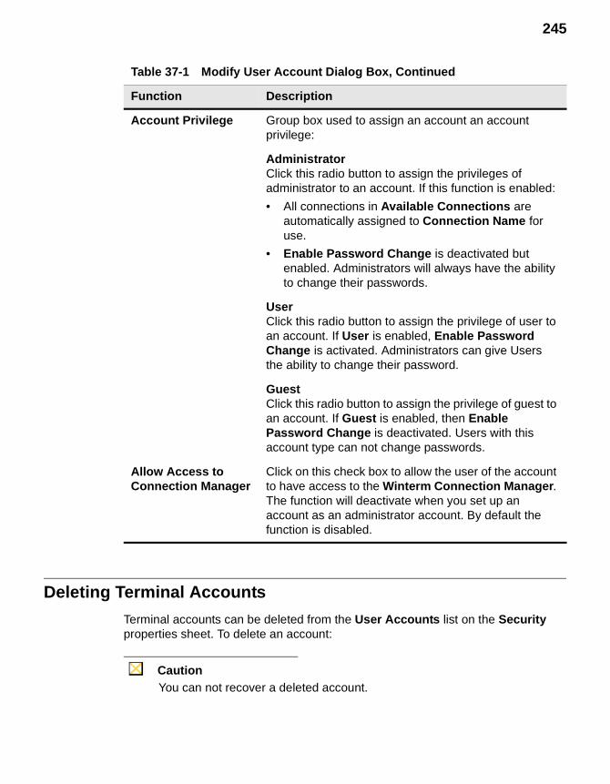
245
Deleting Terminal Accounts
Terminal accounts can be deleted from the User Accounts list on the Security properties sheet. To delete an account:
CautionYou can not recover a deleted account.
Account Privilege Group box used to assign an account an account privilege:
AdministratorClick this radio button to assign the privileges of administrator to an account. If this function is enabled:
• All connections in Available Connections are automatically assigned to Connection Name for use.
• Enable Password Change is deactivated but enabled. Administrators will always have the ability to change their passwords.
UserClick this radio button to assign the privilege of user to an account. If User is enabled, Enable Password Change is activated. Administrators can give Users the ability to change their password.
GuestClick this radio button to assign the privilege of guest to an account. If Guest is enabled, then Enable Password Change is deactivated. Users with this account type can not change passwords.
Allow Access to Connection Manager
Click on this check box to allow the user of the account to have access to the Winterm Connection Manager. The function will deactivate when you set up an account as an administrator account. By default the function is disabled.
Table 37-1 Modify User Account Dialog Box, Continued
Function Description
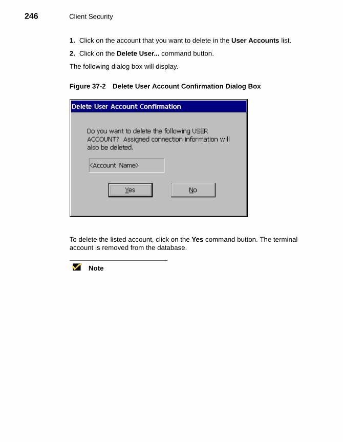
246 Client Security
1. Click on the account that you want to delete in the User Accounts list.
2. Click on the Delete User... command button.
The following dialog box will display.
Figure 37-2 Delete User Account Confirmation Dialog Box
To delete the listed account, click on the Yes command button. The terminal account is removed from the database.
Note
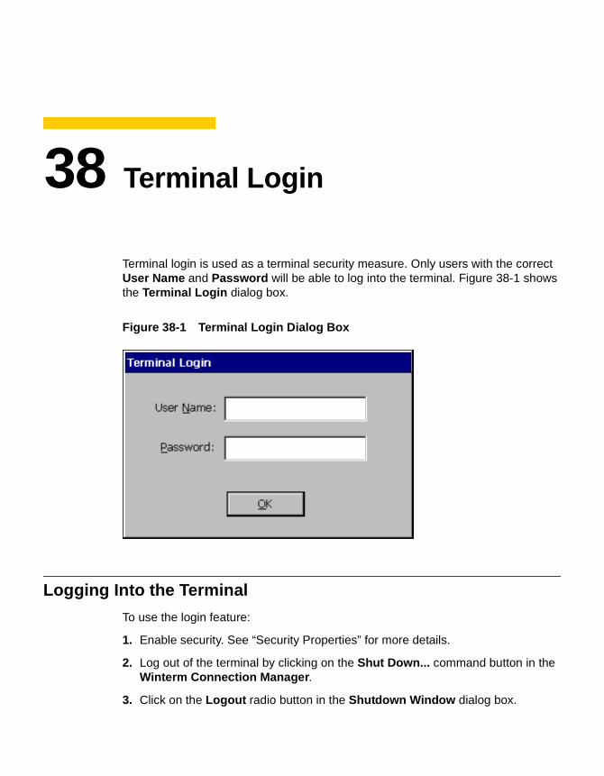
38 Terminal Login
Terminal login is used as a terminal security measure. Only users with the correct User Name and Password will be able to log into the terminal. Figure 38-1 shows the Terminal Login dialog box.
Figure 38-1 Terminal Login Dialog Box
Logging Into the Terminal
To use the login feature:
1. Enable security. See “Security Properties” for more details.
2. Log out of the terminal by clicking on the Shut Down... command button in the Winterm Connection Manager.
3. Click on the Logout radio button in the Shutdown Window dialog box.
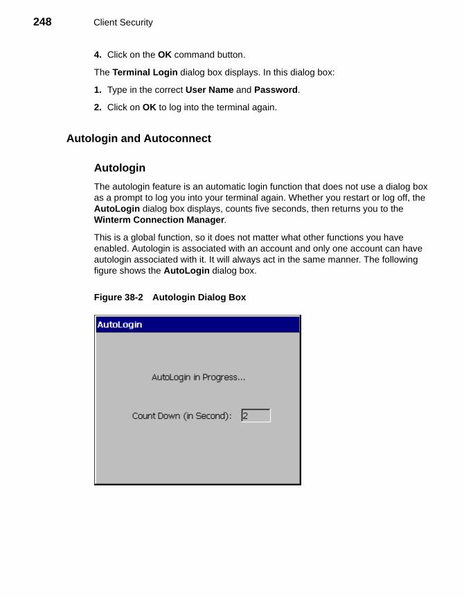
248 Client Security
4. Click on the OK command button.
The Terminal Login dialog box displays. In this dialog box:
1. Type in the correct User Name and Password.
2. Click on OK to log into the terminal again.
Autologin and Autoconnect
Autologin
The autologin feature is an automatic login function that does not use a dialog box as a prompt to log you into your terminal again. Whether you restart or log off, the AutoLogin dialog box displays, counts five seconds, then returns you to the Winterm Connection Manager.
This is a global function, so it does not matter what other functions you have enabled. Autologin is associated with an account and only one account can have autologin associated with it. It will always act in the same manner. The following figure shows the AutoLogin dialog box.
Figure 38-2 Autologin Dialog Box
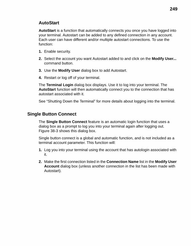
249
AutoStart
AutoStart is a function that automatically connects you once you have logged into your terminal. Autostart can be added to any defined connection in any account. Each user can have different and/or multiple autostart connections. To use the function:
1. Enable security.
2. Select the account you want Autostart added to and click on the Modify User... command button.
3. Use the Modify User dialog box to add Autostart.
4. Restart or log off of your terminal.
The Terminal Login dialog box displays. Use it to log into your terminal. The AutoStart function will then automatically connect you to the connection that has autostart associated with it.
See “Shutting Down the Terminal” for more details about logging into the terminal.
Single Button Connect
The Single Button Connect feature is an automatic login function that uses a dialog box as a prompt to log you into your terminal again after logging out. Figure 38-3 shows this dialog box.
Single button connect is a global and automatic function, and is not included as a terminal account parameter. This function will:
1. Log you into your terminal using the account that has autologin associated with it.
2. Make the first connection listed in the Connection Name list in the Modify User Account dialog box (unless another connection in the list has been made with Autostart).
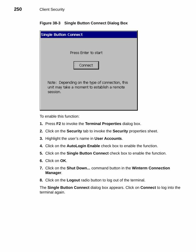
250 Client Security
Figure 38-3 Single Button Connect Dialog Box
To enable this function:
1. Press F2 to invoke the Terminal Properties dialog box.
2. Click on the Security tab to invoke the Security properties sheet.
3. Highlight the user’s name in User Accounts.
4. Click on the AutoLogin Enable check box to enable the function.
5. Click on the Single Button Connect check box to enable the function.
6. Click on OK.
7. Click on the Shut Down... command button in the Winterm Connection Manager.
8. Click on the Logout radio button to log out of the terminal.
The Single Button Connect dialog box appears. Click on Connect to log into the terminal again.
39 Failover
Failover is a connection feature that is enabled using the Security properties sheet. It forces the terminal to “ping” the intended device before making a connection to it. The function operates when FailOver Enable is enabled on the Security properties sheet. Failover is global and wholly automatic to the terminal. It will work regardless of what connection you are trying to make, or what type of account you are logged in using. See “Security Properties” for more information about this function and how to invoke the properties sheet.
NotePing (Packet Internet Groper) is a network utility. It tests communication with nodes in a network by sending packets to each selected node. Ping then waits to receive the echo response from that selected node.
Failover operates as follows:
1. The terminal pings the intended connection, to determine whether or not it is available.
2. If pinging the intended device fails, the terminal pings each successive connection in the list.
3. For each connection:
a. If ping is successful, the connection is made.
b. If ping is not successful, the terminal pings the next connection.
c. If the next connection is a serial connection, ping will stop. Ping will not work on a serial connection. Failover will not continue after encountering a serial connection, but will launch the serial connection if it is valid.
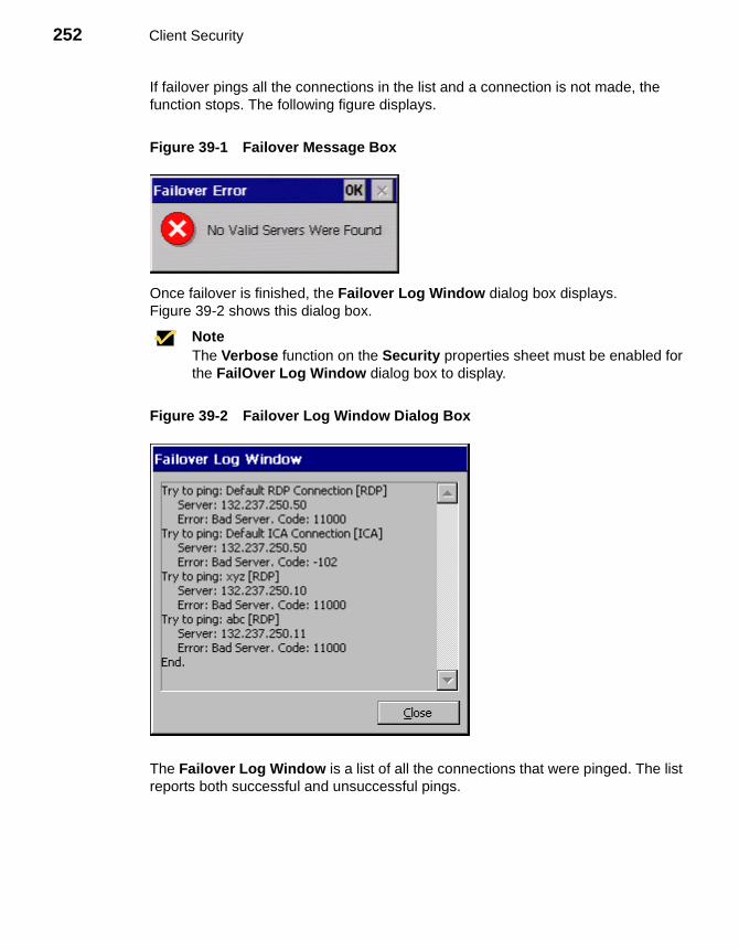
252 Client Security
If failover pings all the connections in the list and a connection is not made, the function stops. The following figure displays.
Figure 39-1 Failover Message Box
Once failover is finished, the Failover Log Window dialog box displays.Figure 39-2 shows this dialog box.
NoteThe Verbose function on the Security properties sheet must be enabled for the FailOver Log Window dialog box to display.
Figure 39-2 Failover Log Window Dialog Box
The Failover Log Window is a list of all the connections that were pinged. The list reports both successful and unsuccessful pings.
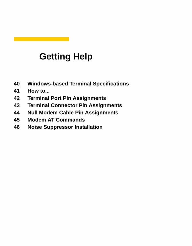
Getting Help
40 Windows-based Terminal Specifications41 How to...42 Terminal Port Pin Assignments43 Terminal Connector Pin Assignments44 Null Modem Cable Pin Assignments45 Modem AT Commands46 Noise Suppressor Installation

254

40 Windows-based Terminal Specifications
The following table lists the specifications for the 3200LE terminal.
Table 40-1 Specifications for the 3200LE Terminal
Specification 3200LE
Power Requirements
Voltage 90 to 264V ac, Worldwide autosensing
Frequency 47-63 Hz
Power Consumption 10.3W operating
Physical Characteristics
Height 3.66 cm (1.44 in)
Width 19.53 cm (7.69 in)
Depth 15.88 cm (6.25 in)
Net Weight .64 kgs (1.44 lbs)
Power Cord 6 ft (1.83m)
Environmental
Operating Temperature 0° to 40°C (32° to 104°F)
Nonoperating Temperature –10° to 60°C (-14° to 140°F)
Operating Humidity 20% to 80% noncondensing
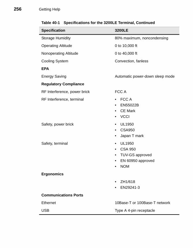
256 Getting Help
Storage Humidity 80% maximum, noncondensing
Operating Altitude 0 to 10,000 ft
Nonoperating Altitude 0 to 40,000 ft
Cooling System Convection, fanless
EPA
Energy Saving Automatic power-down sleep mode
Regulatory Compliance
RF Interference, power brick FCC A
RF Interference, terminal • FCC A
• EN55022B
• CE Mark
• VCCI
Safety, power brick • UL1950
• CSA950
• Japan T mark
Safety, terminal • UL1950
• CSA 950
• TUV-GS approved
• EN 60950 approved
• NOM
Ergonomics
• ZH1/618
• EN29241-3
Communications Ports
Ethernet 10Base-T or 100Base-T network
USB Type A 4-pin receptacle
Table 40-1 Specifications for the 3200LE Terminal, Continued
Specification 3200LE
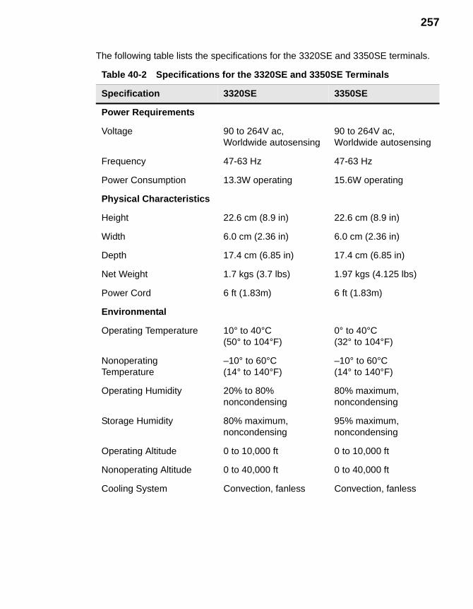
257
The following table lists the specifications for the 3320SE and 3350SE terminals.
Table 40-2 Specifications for the 3320SE and 3350SE Terminals
Specification 3320SE 3350SE
Power Requirements
Voltage 90 to 264V ac, Worldwide autosensing
90 to 264V ac, Worldwide autosensing
Frequency 47-63 Hz 47-63 Hz
Power Consumption 13.3W operating 15.6W operating
Physical Characteristics
Height 22.6 cm (8.9 in) 22.6 cm (8.9 in)
Width 6.0 cm (2.36 in) 6.0 cm (2.36 in)
Depth 17.4 cm (6.85 in) 17.4 cm (6.85 in)
Net Weight 1.7 kgs (3.7 lbs) 1.97 kgs (4.125 lbs)
Power Cord 6 ft (1.83m) 6 ft (1.83m)
Environmental
Operating Temperature 10° to 40°C(50° to 104°F)
0° to 40°C(32° to 104°F)
Nonoperating Temperature
–10° to 60°C(14° to 140°F)
–10° to 60°C(14° to 140°F)
Operating Humidity 20% to 80% noncondensing
80% maximum, noncondensing
Storage Humidity 80% maximum, noncondensing
95% maximum, noncondensing
Operating Altitude 0 to 10,000 ft 0 to 10,000 ft
Nonoperating Altitude 0 to 40,000 ft 0 to 40,000 ft
Cooling System Convection, fanless Convection, fanless
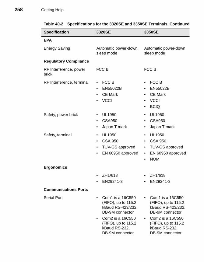
258 Getting Help
EPA
Energy Saving Automatic power-down sleep mode
Automatic power-down sleep mode
Regulatory Compliance
RF Interference, power brick
FCC B FCC B
RF Interference, terminal • FCC B
• EN55022B
• CE Mark
• VCCI
• FCC B
• EN55022B
• CE Mark
• VCCI
• BCIQ
Safety, power brick • UL1950
• CSA950
• Japan T mark
• UL1950
• CSA950
• Japan T mark
Safety, terminal • UL1950
• CSA 950
• TUV-GS approved
• EN 60950 approved
• UL1950
• CSA 950
• TUV-GS approved
• EN 60950 approved
• NOM
Ergonomics
• ZH1/618
• EN29241-3
• ZH1/618
• EN29241-3
Communications Ports
Serial Port • Com1 is a 16C550 (FIFO), up to 115.2 kBaud RS-423/232, DB-9M connector
• Com2 is a 16C550 (FIFO), up to 115.2 kBaud RS-232, DB-9M connector
• Com1 is a 16C550 (FIFO), up to 115.2 kBaud RS-423/232, DB-9M connector
• Com2 is a 16C550 (FIFO), up to 115.2 kBaud RS-232, DB-9M connector
Table 40-2 Specifications for the 3320SE and 3350SE Terminals, Continued
Specification 3320SE 3350SE
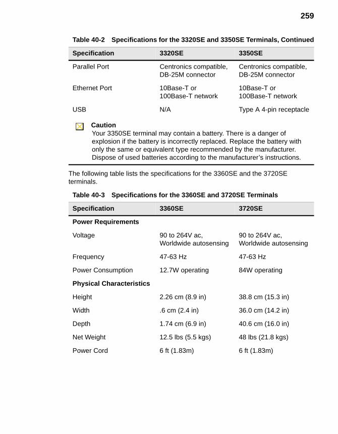
259
The following table lists the specifications for the 3360SE and the 3720SE terminals.
Parallel Port Centronics compatible,DB-25M connector
Centronics compatible,DB-25M connector
Ethernet Port 10Base-T or 100Base-T network
10Base-T or 100Base-T network
USB N/A Type A 4-pin receptacle
CautionYour 3350SE terminal may contain a battery. There is a danger of explosion if the battery is incorrectly replaced. Replace the battery with only the same or equivalent type recommended by the manufacturer. Dispose of used batteries according to the manufacturer’s instructions.
Table 40-3 Specifications for the 3360SE and 3720SE Terminals
Specification 3360SE 3720SE
Power Requirements
Voltage 90 to 264V ac,Worldwide autosensing
90 to 264V ac,Worldwide autosensing
Frequency 47-63 Hz 47-63 Hz
Power Consumption 12.7W operating 84W operating
Physical Characteristics
Height 2.26 cm (8.9 in) 38.8 cm (15.3 in)
Width .6 cm (2.4 in) 36.0 cm (14.2 in)
Depth 1.74 cm (6.9 in) 40.6 cm (16.0 in)
Net Weight 12.5 lbs (5.5 kgs) 48 lbs (21.8 kgs)
Power Cord 6 ft (1.83m) 6 ft (1.83m)
Table 40-2 Specifications for the 3320SE and 3350SE Terminals, Continued
Specification 3320SE 3350SE

260 Getting Help
Environmental
Operating Temperature 0° to 40°C(32° to 104°F)
10° to 40°C(50° to 104°F)
Nonoperating Temperature
-10° to 60°C(-14° to 140°F)
-20° to 60°C(-4° to 140°F)
Operating Humidity 20% to 80% noncondensing
80% maximum, noncondensing
Storage Humidity 80% maximum, noncondensing
80% maximum, noncondensing
Operating Altitude 0 to 10,000 ft 0 to 10,000 ft
Nonoperating Altitude 0 to 40,000 ft 0 to 40,000 ft
Cooling System Convection, fanless Convection, fanless
EPA
Energy Saving Automatic power-down sleep mode
Automatic power-down sleep mode and EPA Energy Star
Regulatory Compliance
RF Interference, power brick
FCC B N/A
RF Interference, terminal • FCC B
• EN55022B
• CE Mark
• VCCI
• FCC B
• EN55022B
• CE Mark
Safety, power brick • UL1950
• CSA950
• Japan T mark
N/A
Table 40-3 Specifications for the 3360SE and 3720SE Terminals, Continued
Specification 3360SE 3720SE
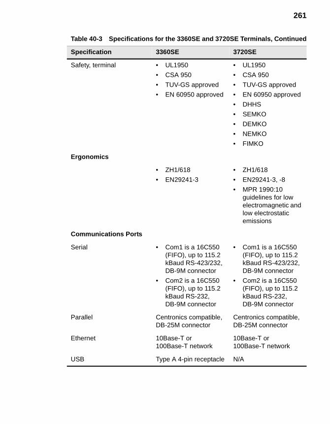
261
Safety, terminal • UL1950
• CSA 950
• TUV-GS approved
• EN 60950 approved
• UL1950
• CSA 950
• TUV-GS approved
• EN 60950 approved
• DHHS
• SEMKO
• DEMKO
• NEMKO
• FIMKO
Ergonomics
• ZH1/618
• EN29241-3
• ZH1/618
• EN29241-3, -8
• MPR 1990:10 guidelines for low electromagnetic and low electrostatic emissions
Communications Ports
Serial • Com1 is a 16C550 (FIFO), up to 115.2 kBaud RS-423/232, DB-9M connector
• Com2 is a 16C550 (FIFO), up to 115.2 kBaud RS-232, DB-9M connector
• Com1 is a 16C550 (FIFO), up to 115.2 kBaud RS-423/232, DB-9M connector
• Com2 is a 16C550 (FIFO), up to 115.2 kBaud RS-232, DB-9M connector
Parallel Centronics compatible,DB-25M connector
Centronics compatible,DB-25M connector
Ethernet 10Base-T or 100Base-T network
10Base-T or 100Base-T network
USB Type A 4-pin receptacle N/A
Table 40-3 Specifications for the 3360SE and 3720SE Terminals, Continued
Specification 3360SE 3720SE

262 Getting Help
41 How to...
Turn off Autologin:
1. Press F2 on your keyboard to invoke the Terminal Properties dialog box.
2. Click on the Security tab in the Terminal Properties dialog box.
3. Click (to uncheck) the AutoLogin Enable check box.
4. Click on the OK command button on the Security properties sheet to return to Winterm Connection Manager.
Check your terminal’s build number and firmware revision:
1. Press F2 on your keyboard to invoke the Terminal Properties dialog box.
2. Read the build number and firmware revision listed in Version: on the General properties sheet.
3. Click on the Close command button on the General properties sheet to return to Winterm Connection Manager.
Adjust your mouse speed:
1. Press F2 on your keyboard to invoke the Terminal Properties dialog box.
2. Click on the Input tab in the Terminal Properties dialog box.
3. Click on the Properties command button in the Mouse group box on the Input properties sheet.
4. Use the Pointer Acceleration and Pointer Speed group boxes in the Mouse Properties dialog box to adjust your mouse speed.
5. Click on the OK command button on the Input properties sheet to return to Winterm Connection Manager.
264 Getting Help
Make a basic PPP connection:
1. Click on the Configure tab in the Winterm Connection Manager to invoke the Configure properties sheet.
2. Click on the Add command button on the Configure properties sheet to invoke the New Connection dialog box.
3. Select from the scroll list Dial-Up Client, then click OK to invoke the Dial-Up Configuration Wizard.
4. Set the minimum parameters for a dial up connection:
a. Enter a name for the connection in Enter a Description for Dial-Up Connection: text box in the first dialog box of the wizard.
b. Enter a telephone number in Telephone Number in the second dialog box of the wizard.
c. Select in the second dialog box of the wizard:
•Serial Port (modem type)
•Use Country Code and Area Code (if appropriate)
•Appropriate Local Settings and Dialing Patterns in the Dialing Properties dialog box (invoked by the Dialing Properties command button)
•Appropriate Port Settings and Call Options in the Device Properties dialog box (invoked by the Configure command button)
d. Select a connection from the Select Connection Below to Launch After Dialing In list box in the third dialog box of the wizard.
e. Click on the Finish command button to return to the Winterm Connection Manager.
The connection will display in the Connections list.
Find a modem that works with your terminal:
Visit the following address to see a list of supported modems:
http://www.wyse.com/service/3000peripheral.htm
Switch between multiple sessions:
• Press Ctrl+Alt+↑ to proceed to the previous session.
• Press Ctrl+Alt+↓ to proceed to the next session.
265
Reset your terminal:
1. Press F2 on your keyboard to invoke the Terminal Properties dialog box.
2. Click on (to check) the Reset the Terminal to Factory Default Property Settings check box.
3. Click on Yes in the System Settings Change dialog box.
or
Reset the terminal to factory default by performing the following steps while the power is still on and while holding down the G key on the keyboard of your terminal:
1. Press and hold the power management button until the LED turns to amber (approximately 3 to 5 seconds).
2. Release the power management button.
3. Wait approximately 7 seconds for the system to reboot.
4. Wait for the Setup wizard to display, then release the G key.
The terminal is reset to factory defaults.
Determine the size of the onboard memory:
1. Press F2 on your keyboard to invoke the Terminal Properties dialog box.
2. Read the firmware revision number listed in RAM: on the General properties sheet.
3. Click on the Close command button on the General properties sheet to return to Winterm Connection Manager.
Configure a local printer:
If you are using the Winframe 1.7/ICA platform:
1. Log in to your Winframe server.
2. Click on Print Manager in Program Manager.
3. Click on Connect to Printer on the Printer menu.
4. Click on Client Network, then Client on the Shared Printer menu.
5. Select your <clientname#port>, then click on OK.

266 Getting Help
If you are using the MetaFrame 1.0/ICA platform:
1. Log in to your MetaFrame server.
2. Click on My Computer in the ICA Session dialog box.
3. Click on Printers, then Add Printer.
4. Select Network Printer Server, then click Next.
5. Click on Client Network, then Client in the Shared Printers dialog box.
6. Select your <clientname#port>, then click on OK.
7. Click Next, then Finish.
If you are using a Winframe 1.8 or MetaFrame 1.8/ICA platform:
1. Log in to your Citrix server.
2. If it is a MetaFrame server:
a. Click on Start, then Programs.
b. Click on MetaFrame, then Tools.
c. Click on ICA Client Printer Configuration.
3. If it is a WinFrame server:
a. Click on ICA Client Printer Configuration in the Administrative Tools program group in the Program Manager.
b. Click on New on the Printer menu to display the Add ICA Client Printer wizard.
c. Follow the steps of the wizard to add your local printer.
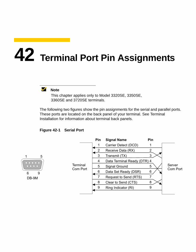
42 Terminal Port Pin Assignments
NoteThis chapter applies only to Model 3320SE, 3350SE, 3360SE and 3720SE terminals.
The following two figures show the pin assignments for the serial and parallel ports. These ports are located on the back panel of your terminal. See Terminal Installation for information about terminal back panels.
Figure 42-1 Serial Port
Pin Signal Name Pin
Carrier Detect (DCD)
Receive Data (RX)
Transmit (TX)
Data Terminal Ready (DTR)
Signal Ground
Data Set Ready (DSR)
Request to Send (RTS)
Clear to Send (CTS)
Ring Indicator (RI)
1
2
3
4
5
6
7
8
9
1
2
3
4
5
6
7
8
9
ServerCom Port
TerminalCom Port
1
6
5
9
DB-9M
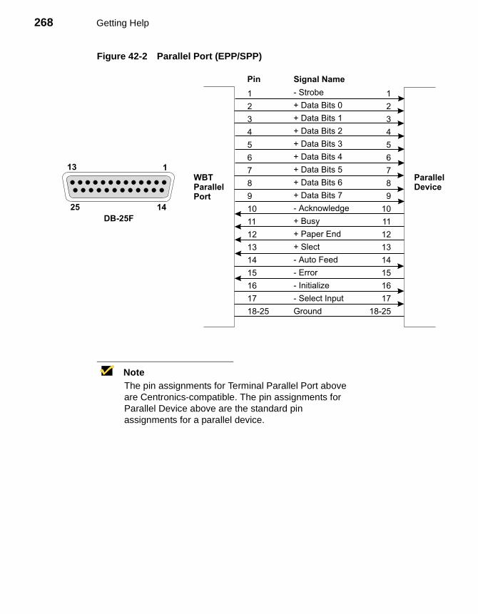
268 Getting Help
Figure 42-2 Parallel Port (EPP/SPP)
NoteThe pin assignments for Terminal Parallel Port above are Centronics-compatible. The pin assignments for Parallel Device above are the standard pin assignments for a parallel device.
1
2
3
4
5
6
7
8
9
10
11
12
13
14
15
16
17
18-25
1
2
3
4
5
6
7
8
9
10
11
12
13
14
15
16
17
18-25
- Strobe
+ Data Bits 0
+ Data Bits 1
+ Data Bits 2
+ Data Bits 3
+ Data Bits 4
+ Data Bits 5
+ Data Bits 6
+ Data Bits 7
- Acknowledge
+ Busy
+ Paper End
+ Slect
- Auto Feed
- Error
- Initialize
- Select Input
Ground
ParallelDevice
WBTParallelPort
Pin Signal Name
13 1
25 14
DB-25F
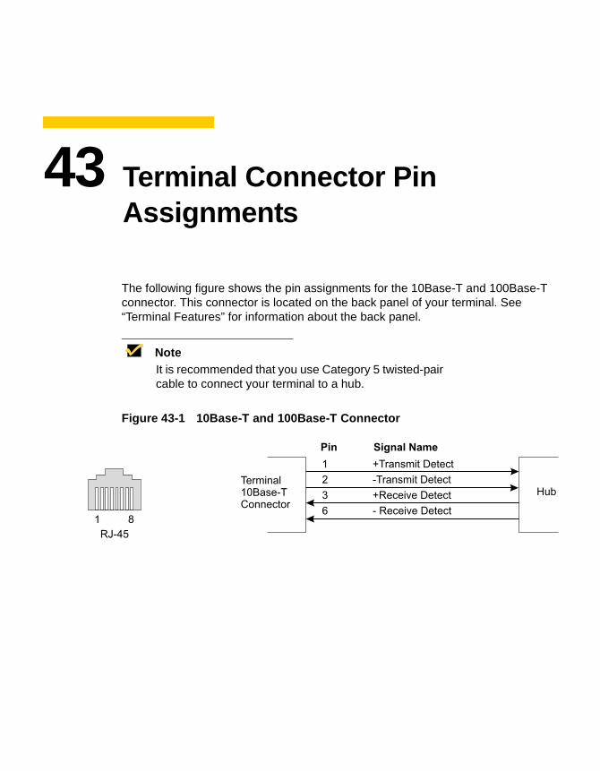
43 Terminal Connector Pin Assignments
The following figure shows the pin assignments for the 10Base-T and 100Base-T connector. This connector is located on the back panel of your terminal. See “Terminal Features” for information about the back panel.
NoteIt is recommended that you use Category 5 twisted-pair cable to connect your terminal to a hub.
Figure 43-1 10Base-T and 100Base-T Connector
Pin Signal Name
1
2
3
6
+Transmit Detect
-Transmit Detect
+Receive Detect
- Receive Detect
HubTerminal10Base-TConnector
1 8
RJ-45
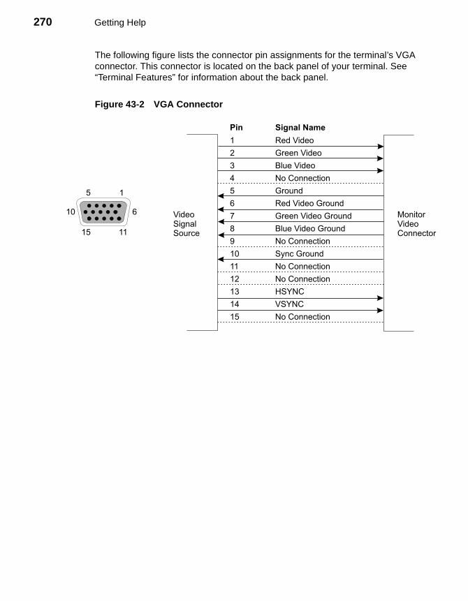
270 Getting Help
The following figure lists the connector pin assignments for the terminal’s VGA connector. This connector is located on the back panel of your terminal. See “Terminal Features” for information about the back panel.
Figure 43-2 VGA Connector
1115
1
2
3
4
5
6
7
8
9
10
11
12
13
14
15
Red Video
Green Video
Blue Video
No Connection
Ground
Red Video Ground
Green Video Ground
Blue Video Ground
No Connection
Sync Ground
No Connection
No Connection
HSYNC
VSYNC
No Connection
MonitorVideoConnector
VideoSignalSource
Pin Signal Name
1
6
5
10
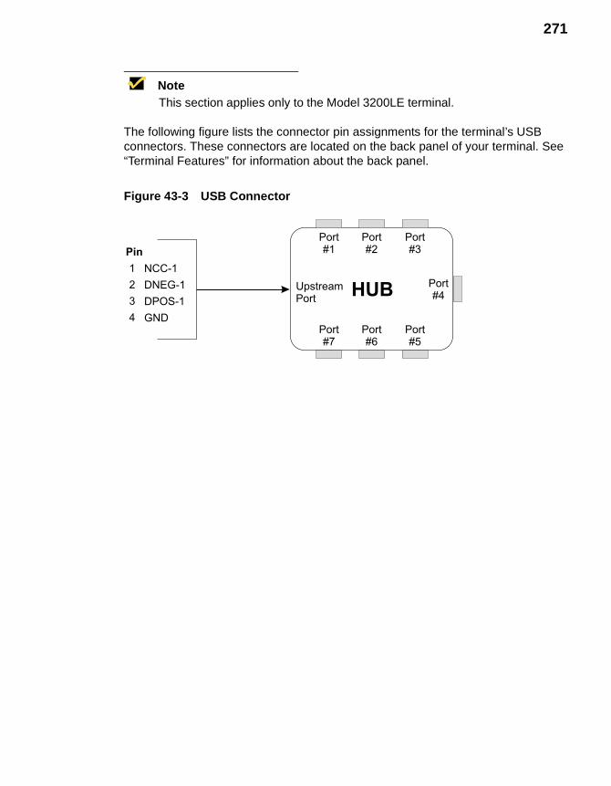
271
NoteThis section applies only to the Model 3200LE terminal.
The following figure lists the connector pin assignments for the terminal’s USB connectors. These connectors are located on the back panel of your terminal. See “Terminal Features” for information about the back panel.
Figure 43-3 USB Connector
UpstreamPort
HUB Port#4
Port#3
Port#1
Port#2
Port#5
Port#7
Port#6
NCC-1
DNEG-1
DPOS-1
GND
1
2
3
4
Pin

272 Getting Help
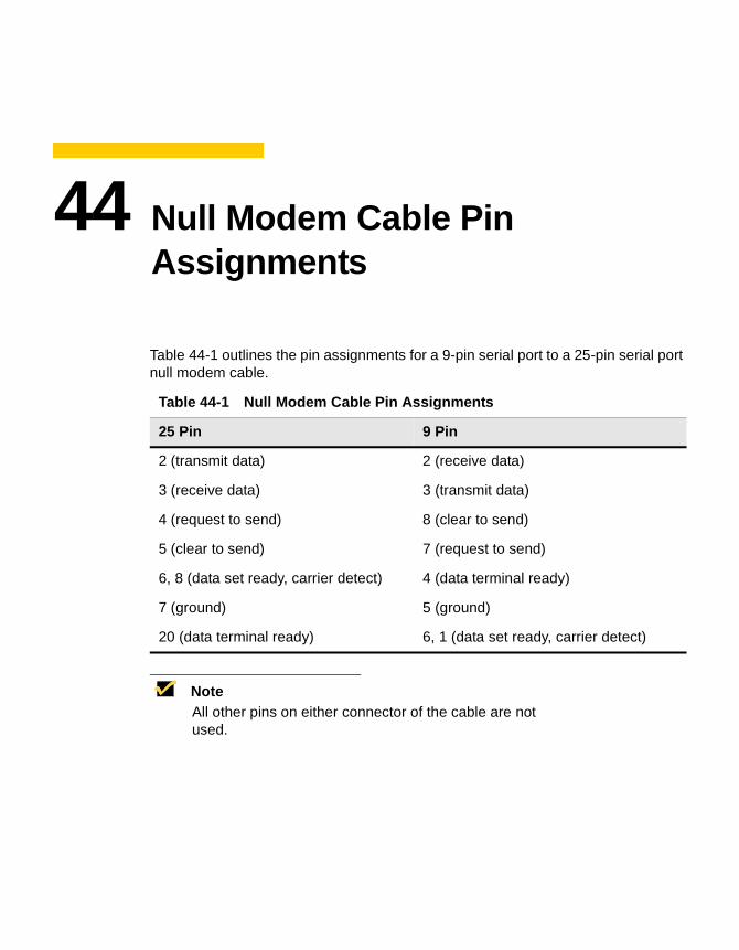
44 Null Modem Cable Pin Assignments
Table 44-1 outlines the pin assignments for a 9-pin serial port to a 25-pin serial port null modem cable.
NoteAll other pins on either connector of the cable are not used.
Table 44-1 Null Modem Cable Pin Assignments
25 Pin 9 Pin
2 (transmit data) 2 (receive data)
3 (receive data) 3 (transmit data)
4 (request to send) 8 (clear to send)
5 (clear to send) 7 (request to send)
6, 8 (data set ready, carrier detect) 4 (data terminal ready)
7 (ground) 5 (ground)
20 (data terminal ready) 6, 1 (data set ready, carrier detect)

274 Getting Help
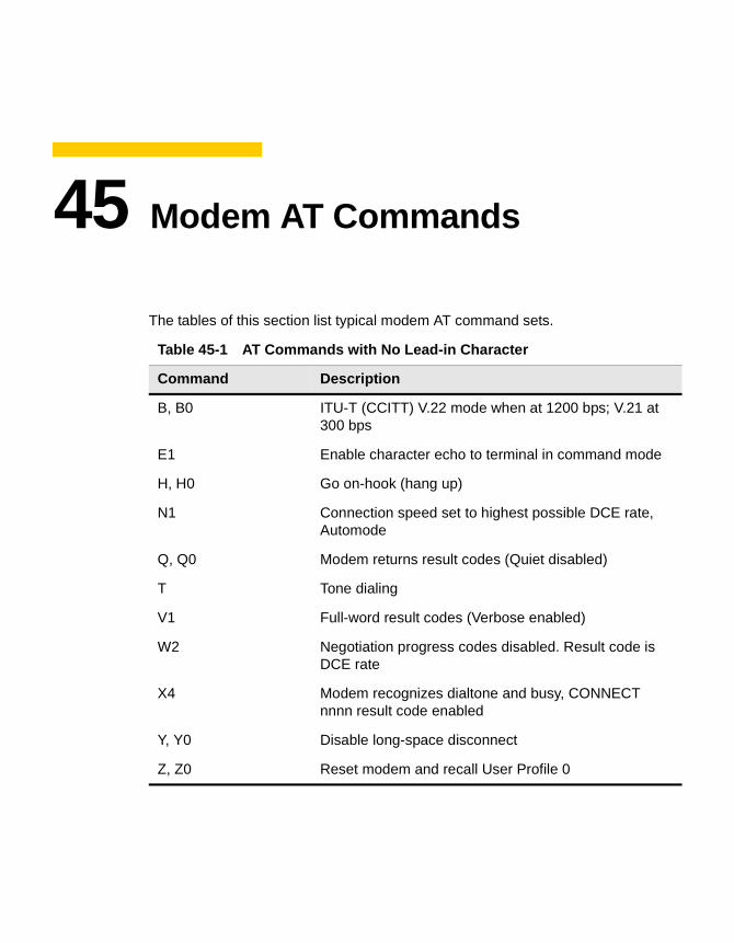
45 Modem AT Commands
The tables of this section list typical modem AT command sets.
Table 45-1 AT Commands with No Lead-in Character
Command Description
B, B0 ITU-T (CCITT) V.22 mode when at 1200 bps; V.21 at 300 bps
E1 Enable character echo to terminal in command mode
H, H0 Go on-hook (hang up)
N1 Connection speed set to highest possible DCE rate, Automode
Q, Q0 Modem returns result codes (Quiet disabled)
T Tone dialing
V1 Full-word result codes (Verbose enabled)
W2 Negotiation progress codes disabled. Result code is DCE rate
X4 Modem recognizes dialtone and busy, CONNECT nnnn result code enabled
Y, Y0 Disable long-space disconnect
Z, Z0 Reset modem and recall User Profile 0
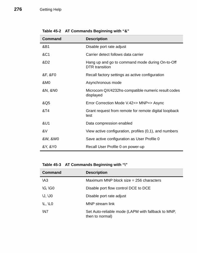
276 Getting Help
Table 45-2 AT Commands Beginning with “&”
Command Description
&B1 Disable port rate adjust
&C1 Carrier detect follows data carrier
&D2 Hang up and go to command mode during On-to-Off DTR transition
&F, &F0 Recall factory settings as active configuration
&M0 Asynchronous mode
&N, &N0 Microcom QX/4232hs-compatible numeric result codes displayed
&Q5 Error Correction Mode V.42=> MNP=> Async
&T4 Grant request from remote for remote digital loopback test
&U1 Data compression enabled
&V View active configuration, profiles (0,1), and numbers
&W, &W0 Save active configuration as User Profile 0
&Y, &Y0 Recall User Profile 0 on power-up
Table 45-3 AT Commands Beginning with “\”
Command Description
\A3 Maximum MNP block size = 256 characters
\G, \G0 Disable port flow control DCE to DCE
\J, \J0 Disable port rate adjust
\L, \L0 MNP stream link
\N7 Set Auto-reliable mode (LAPM with fallback to MNP, then to normal)
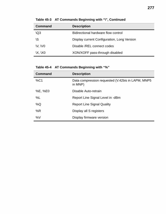
277
\Q3 Bidirectional hardware flow control
\S Display current Configuration, Long Version
\V, \V0 Disable /REL connect codes
\X, \X0 XON/XOFF pass-through disabled
Table 45-4 AT Commands Beginning with “%”
Command Description
%C1 Data compression requested (V.42bis in LAPM, MNP5 in MNP)
%E, %E0 Disable Auto-retrain
%L Report Line Signal Level in -dBm
%Q Report Line Signal Quality
%R Display all S registers
%V Display firmware version
Table 45-3 AT Commands Beginning with “\”, Continued
Command Description

278 Getting Help

46 Noise Suppressor Installation
NoteThis chapter applies only to Model 3350SE terminals.
A noise suppressor (ferrite bead) must be installed on the network cable of your terminal. This installation is necessary to maintain compliance with US FCC B limits and Europe CISPR B EN55022 Class B limits. The noise suppressor is supplied by the manufacturer and should be packed in your terminal’s shipping carton.
Figure 46-1 shows the noise suppressor.
Figure 46-1 Noise Suppressor

280 Getting Help
To install:
1. Open the casing.
2. Fit the casing over the network cable, as close as possible to the back of the cable’s connector.
3. Snap the casing shut.
A SNMP Remote Configuration Chart
The following chart is provided to help network administrators make remote configuration changes to WBTs in a managed network. These changes are made by physically writing to the managed devices using the logical objects listed in the MIB as reference. This chart lists:
• The lower-most subgroup the logical object belongs to
• The object’s name
• What can be written to the object
• Where the UI is modified by the write
NoteFor detailed information about each Wyse MIB group and its objects see the sections SNMP and DHCP Groups, Physical Devices Groups, and Network and Connections Groups in the network administrator’s guide.
You can use Wyse Remote Administrator 3000 or an SNMP management tool and the following chart to remotely affect changes to the terminals in your network.

282 Appendix A
For the Logical Object... You Can Write... To Modify...
wbt3I/ODevice Group
wbt3kbLanguage Any of the following numbers:
0 = English-US1 = English-UK2 = French3 = German4 = Spanish5 = Italian6 = Swedish7 = Danish8 = Norwegian9 = Dutch10 = Belgian-French11 = Finnish12 = Swiss-French13 = Swiss-German14 = Japanese15 = Canadian-French16 = Belgian-Dutch17 = Portuguese18 = Brazilian-ABNT19 = Italian-14220 = Latin-American21 = US-International22 = Canadian-Fr-Multi23 = Canadian-Eng-Multi24 = Spanish-Variation
The Locale scroll list on the Input properties sheet
wbt3CharacterRepeatDelay Any following number (in milliseconds):
2505007501000
The Repeat Delay slide control on the Input properties sheet
wbt3CharacterRepeatRate Any integer from 0 to 31 The Repeat Rate slide control on the Input properties sheet
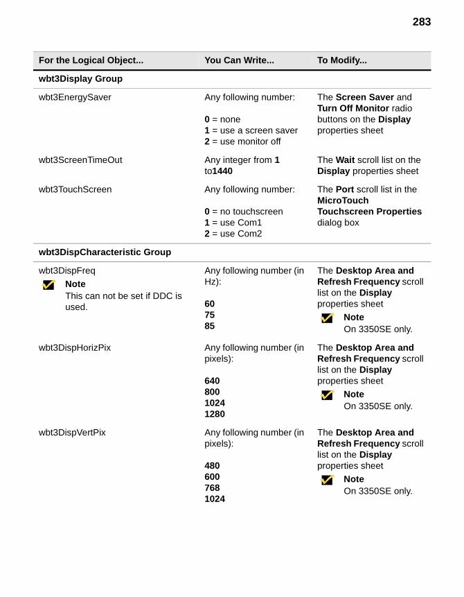
283
wbt3Display Group
wbt3EnergySaver Any following number:
0 = none1 = use a screen saver2 = use monitor off
The Screen Saver and Turn Off Monitor radio buttons on the Display properties sheet
wbt3ScreenTimeOut Any integer from 1 to1440
The Wait scroll list on the Display properties sheet
wbt3TouchScreen Any following number:
0 = no touchscreen1 = use Com12 = use Com2
The Port scroll list in the MicroTouch Touchscreen Properties dialog box
wbt3DispCharacteristic Group
wbt3DispFreq
NoteThis can not be set if DDC is used.
Any following number (in Hz):
607585
The Desktop Area and Refresh Frequency scroll list on the Display properties sheet
NoteOn 3350SE only.
wbt3DispHorizPix Any following number (in pixels):
64080010241280
The Desktop Area and Refresh Frequency scroll list on the Display properties sheet
NoteOn 3350SE only.
wbt3DispVertPix Any following number (in pixels):
4806007681024
The Desktop Area and Refresh Frequency scroll list on the Display properties sheet
NoteOn 3350SE only.
For the Logical Object... You Can Write... To Modify...
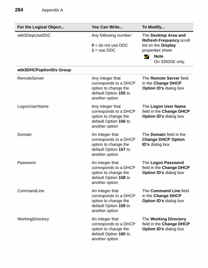
284 Appendix A
wbt3DispUseDDC Any following number:
0 = do not use DDC1 = use DDC
The Desktop Area and Refresh Frequency scroll list on the Display properties sheet
NoteOn 3350SE only.
wbt3DHCPoptionIDs Group
RemoteServer Any integer that corresponds to a DHCP option to change the default Option 155 to another option
The Remote Server field in the Change DHCP Option ID’s dialog box
LogonUserName Any integer that corresponds to a DHCP option to change the default Option 156 to another option
The Logon User Name field in the Change DHCP Option ID’s dialog box
Domain An integer that corresponds to a DHCP option to change the default Option 157 to another option
The Domain field in the Change DHCP Option ID’s dialog box
Password An integer that corresponds to a DHCP option to change the default Option 158 to another option
The Logon Password field in the Change DHCP Option ID’s dialog box
CommandLine An integer that corresponds to a DHCP option to change the default Option 159 to another option
The Command Line field in the Change DHCP Option ID’s dialog box
WorkingDirectory An integer that corresponds to a DHCP option to change the default Option 160 to another option
The Working Directory field in the Change DHCP Option ID’s dialog box
For the Logical Object... You Can Write... To Modify...
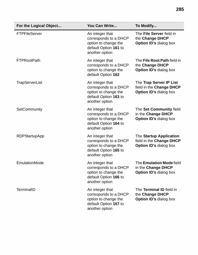
285
FTPFileServer An integer that corresponds to a DHCP option to change the default Option 161 to another option
The File Server field in the Change DHCP Option ID’s dialog box
FTPRootPath An integer that corresponds to a DHCP option to change the default Option 162
The File Root Path field in the Change DHCP Option ID’s dialog box
TrapServerList An integer that corresponds to a DHCP option to change the default Option 163 to another option
The Trap Server IP List field in the Change DHCP Option ID’s dialog box
SetCommunity An integer that corresponds to a DHCP option to change the default Option 164 to another option
The Set Community field in the Change DHCP Option ID’s dialog box
RDPStartupApp An integer that corresponds to a DHCP option to change the default Option 165 to another option
The Startup Application field in the Change DHCP Option ID’s dialog box
EmulationMode An integer that corresponds to a DHCP option to change the default Option 166 to another option
The Emulation Mode field in the Change DHCP Option ID’s dialog box
TerminalID An integer that corresponds to a DHCP option to change the default Option 167 to another option
The Terminal ID field in the Change DHCP Option ID’s dialog box
For the Logical Object... You Can Write... To Modify...
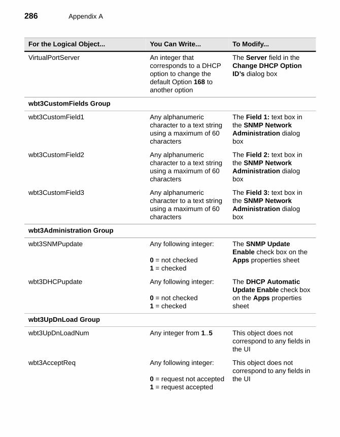
286 Appendix A
VirtualPortServer An integer that corresponds to a DHCP option to change the default Option 168 to another option
The Server field in the Change DHCP Option ID’s dialog box
wbt3CustomFields Group
wbt3CustomField1 Any alphanumeric character to a text string using a maximum of 60 characters
The Field 1: text box in the SNMP Network Administration dialog box
wbt3CustomField2 Any alphanumeric character to a text string using a maximum of 60 characters
The Field 2: text box in the SNMP Network Administration dialog box
wbt3CustomField3 Any alphanumeric character to a text string using a maximum of 60 characters
The Field 3: text box in the SNMP Network Administration dialog box
wbt3Administration Group
wbt3SNMPupdate Any following integer:
0 = not checked1 = checked
The SNMP Update Enable check box on the Apps properties sheet
wbt3DHCPupdate Any following integer:
0 = not checked1 = checked
The DHCP Automatic Update Enable check box on the Apps properties sheet
wbt3UpDnLoad Group
wbt3UpDnLoadNum Any integer from 1..5 This object does not correspond to any fields in the UI
wbt3AcceptReq Any following integer:
0 = request not accepted1 = request accepted
This object does not correspond to any fields in the UI
For the Logical Object... You Can Write... To Modify...
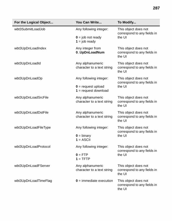
287
wbt3SubmitLoadJob Any following integer:
0 = job not ready1 = job ready
This object does not correspond to any fields in the UI
wbt3UpDnLoadIndex Any integer from 0..UpDnLoadNum
This object does not correspond to any fields in the UI
wbt3UpDnLoadId Any alphanumeric character to a text string
This object does not correspond to any fields in the UI
wbt3UpDnLoadOp Any following integer:
0 = request upload1 = request download
This object does not correspond to any fields in the UI
wbt3UpDnLoadSrcFile Any alphanumeric character to a text string
This object does not correspond to any fields in the UI
wbt3UpDnLoadDstFile Any alphanumeric character to a text string
This object does not correspond to any fields in the UI
wbt3UpDnLoadFileType Any following integer:
0 = binary1 = ASCII
This object does not correspond to any fields in the UI
wbt3UpDnLoadProtocol Any following integer:
0 = FTP1 = TFTP
This object does not correspond to any fields in the UI
wbt3UpDnLoadFServer Any alphanumeric character to a text string
This object does not correspond to any fields in the UI
wbt3UpDnLoadTimeFlag 0 = immediate execution This object does not correspond to any fields in the UI
For the Logical Object... You Can Write... To Modify...
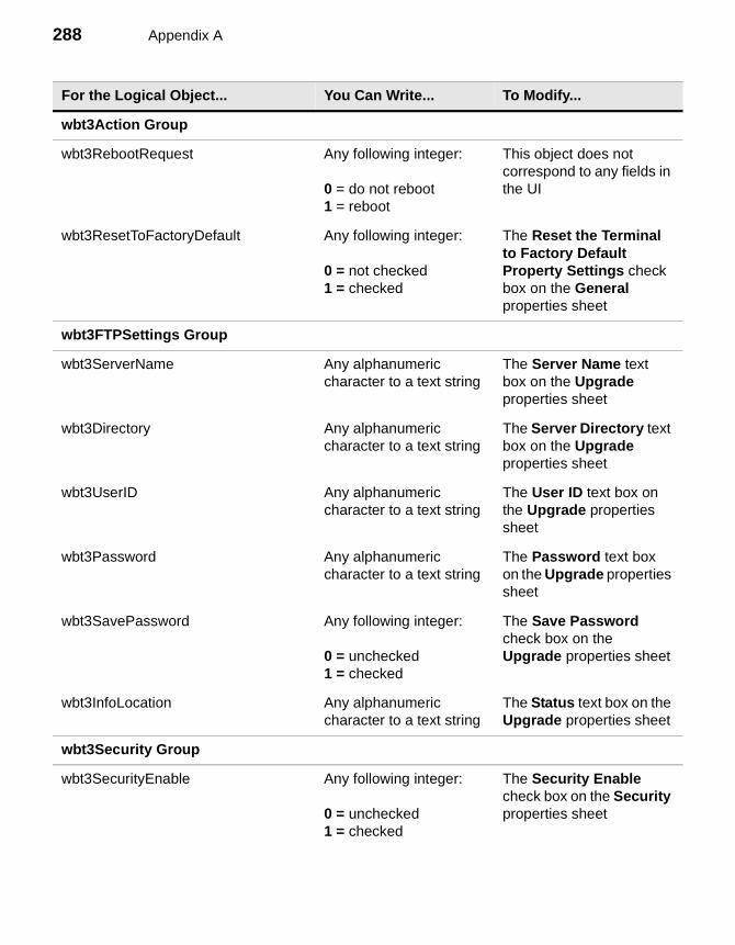
288 Appendix A
wbt3Action Group
wbt3RebootRequest Any following integer:
0 = do not reboot1 = reboot
This object does not correspond to any fields in the UI
wbt3ResetToFactoryDefault Any following integer:
0 = not checked1 = checked
The Reset the Terminal to Factory Default Property Settings check box on the General properties sheet
wbt3FTPSettings Group
wbt3ServerName Any alphanumeric character to a text string
The Server Name text box on the Upgrade properties sheet
wbt3Directory Any alphanumeric character to a text string
The Server Directory text box on the Upgrade properties sheet
wbt3UserID Any alphanumeric character to a text string
The User ID text box on the Upgrade properties sheet
wbt3Password Any alphanumeric character to a text string
The Password text box on the Upgrade properties sheet
wbt3SavePassword Any following integer:
0 = unchecked1 = checked
The Save Password check box on the Upgrade properties sheet
wbt3InfoLocation Any alphanumeric character to a text string
The Status text box on the Upgrade properties sheet
wbt3Security Group
wbt3SecurityEnable Any following integer:
0 = unchecked1 = checked
The Security Enable check box on the Security properties sheet
For the Logical Object... You Can Write... To Modify...
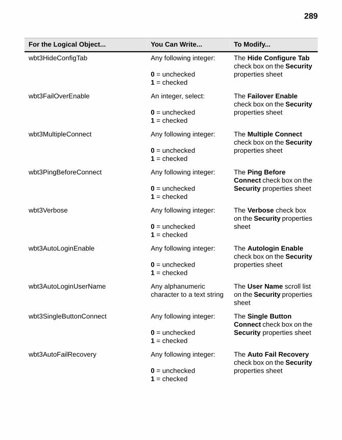
289
wbt3HideConfigTab Any following integer:
0 = unchecked1 = checked
The Hide Configure Tab check box on the Security properties sheet
wbt3FailOverEnable An integer, select:
0 = unchecked1 = checked
The Failover Enable check box on the Security properties sheet
wbt3MultipleConnect Any following integer:
0 = unchecked1 = checked
The Multiple Connect check box on the Security properties sheet
wbt3PingBeforeConnect Any following integer:
0 = unchecked1 = checked
The Ping Before Connect check box on the Security properties sheet
wbt3Verbose Any following integer:
0 = unchecked1 = checked
The Verbose check box on the Security properties sheet
wbt3AutoLoginEnable Any following integer:
0 = unchecked1 = checked
The Autologin Enable check box on the Security properties sheet
wbt3AutoLoginUserName Any alphanumeric character to a text string
The User Name scroll list on the Security properties sheet
wbt3SingleButtonConnect Any following integer:
0 = unchecked1 = checked
The Single Button Connect check box on the Security properties sheet
wbt3AutoFailRecovery Any following integer:
0 = unchecked1 = checked
The Auto Fail Recovery check box on the Security properties sheet
For the Logical Object... You Can Write... To Modify...
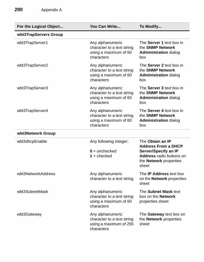
290 Appendix A
wbt3TrapServers Group
wbt3TrapServer1 Any alphanumeric character to a text string using a maximum of 60 characters
The Server 1 text box in the SNMP Network Administration dialog box
wbt3TrapServer2 Any alphanumeric character to a text string using a maximum of 60 characters
The Server 2 text box in the SNMP Network Administration dialog box
wbt3TrapServer3 Any alphanumeric character to a text string using a maximum of 60 characters
The Server 3 text box in the SNMP Network Administration dialog box
wbt3TrapServer4 Any alphanumeric character to a text string using a maximum of 60 characters
The Server 4 text box in the SNMP Network Administration dialog box
wbt3Network Group
wbt3dhcpEnable Any following integer:
0 = unchecked1 = checked
The Obtain an IP Address From a DHCP Server/Specify an IP Address radio buttons on the Network properties sheet
wbt3NetworkAddress Any alphanumeric character to a text string
The IP Address text box on the Network properties sheet
wbt3SubnetMask Any alphanumeric character to a text string using a maximum of 60 characters
The Subnet Mask text box on the Network properties sheet
wbt3Gateway Any alphanumeric character to a text string using a maximum of 255 characters
The Gateway text box on the Network properties sheet
For the Logical Object... You Can Write... To Modify...
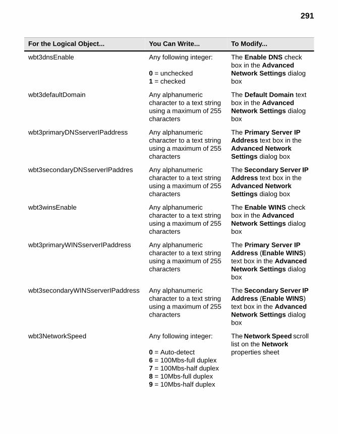
291
wbt3dnsEnable Any following integer:
0 = unchecked1 = checked
The Enable DNS check box in the Advanced Network Settings dialog box
wbt3defaultDomain Any alphanumeric character to a text string using a maximum of 255 characters
The Default Domain text box in the Advanced Network Settings dialog box
wbt3primaryDNSserverIPaddress Any alphanumeric character to a text string using a maximum of 255 characters
The Primary Server IP Address text box in the Advanced Network Settings dialog box
wbt3secondaryDNSserverIPaddres Any alphanumeric character to a text string using a maximum of 255 characters
The Secondary Server IP Address text box in the Advanced Network Settings dialog box
wbt3winsEnable Any alphanumeric character to a text string using a maximum of 255 characters
The Enable WINS check box in the Advanced Network Settings dialog box
wbt3primaryWINSserverIPaddress Any alphanumeric character to a text string using a maximum of 255 characters
The Primary Server IP Address (Enable WINS) text box in the Advanced Network Settings dialog box
wbt3secondaryWINSserverIPaddress Any alphanumeric character to a text string using a maximum of 255 characters
The Secondary Server IP Address (Enable WINS) text box in the Advanced Network Settings dialog box
wbt3NetworkSpeed Any following integer:
0 = Auto-detect6 = 100Mbs-full duplex7 = 100Mbs-half duplex8 = 10Mbs-full duplex9 = 10Mbs-half duplex
The Network Speed scroll list on the Network properties sheet
For the Logical Object... You Can Write... To Modify...
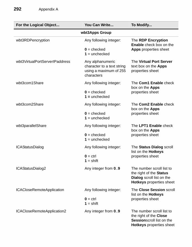
292 Appendix A
wbt3Apps Group
wbt3RDPencryption Any following integer:
0 = checked1 = unchecked
The RDP Encryption Enable check box on the Apps properties sheet
wbt3VirtualPortServerIPaddress Any alphanumeric character to a text string using a maximum of 255 characters
The Virtual Port Server text box on the Apps properties sheet
wbt3com1Share Any following integer:
0 = checked1 = unchecked
The Com1 Enable check box on the Apps properties sheet
wbt3com2Share Any following integer:
0 = checked1 = unchecked
The Com2 Enable check box on the Apps properties sheet
wbt3parallelShare Any following integer:
0 = checked1 = unchecked
The LPT1 Enable check box on the Apps properties sheet
ICAStatusDialog Any following integer:
0 = ctrl1 = shift
The Status Dialog scroll list on the Hotkeys properties sheet
ICAStatusDialog2 Any integer from 0..9 The number scroll list to the right of the Status Dialog scroll list on the Hotkeys properties sheet
ICACloseRemoteApplication Any following integer:
0 = ctrl1 = shift
The Close Session scroll list on the Hotkeys properties sheet
ICACloseRemoteApplication2 Any integer from 0..9 The number scroll list to the right of the Close Sessionscroll list on the Hotkeys properties sheet
For the Logical Object... You Can Write... To Modify...
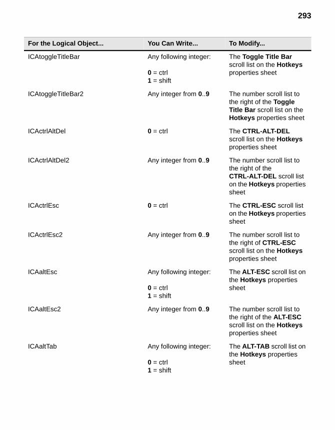
293
ICAtoggleTitleBar Any following integer:
0 = ctrl1 = shift
The Toggle Title Bar scroll list on the Hotkeys properties sheet
ICAtoggleTitleBar2 Any integer from 0..9 The number scroll list to the right of the Toggle Title Bar scroll list on the Hotkeys properties sheet
ICActrlAltDel 0 = ctrl The CTRL-ALT-DEL scroll list on the Hotkeys properties sheet
ICActrlAltDel2 Any integer from 0..9 The number scroll list to the right of the CTRL-ALT-DEL scroll list on the Hotkeys properties sheet
ICActrlEsc 0 = ctrl The CTRL-ESC scroll list on the Hotkeys properties sheet
ICActrlEsc2 Any integer from 0..9 The number scroll list to the right of CTRL-ESC scroll list on the Hotkeys properties sheet
ICAaltEsc Any following integer:
0 = ctrl1 = shift
The ALT-ESC scroll list on the Hotkeys properties sheet
ICAaltEsc2 Any integer from 0..9 The number scroll list to the right of the ALT-ESC scroll list on the Hotkeys properties sheet
ICAaltTab Any following integer:
0 = ctrl1 = shift
The ALT-TAB scroll list on the Hotkeys properties sheet
For the Logical Object... You Can Write... To Modify...
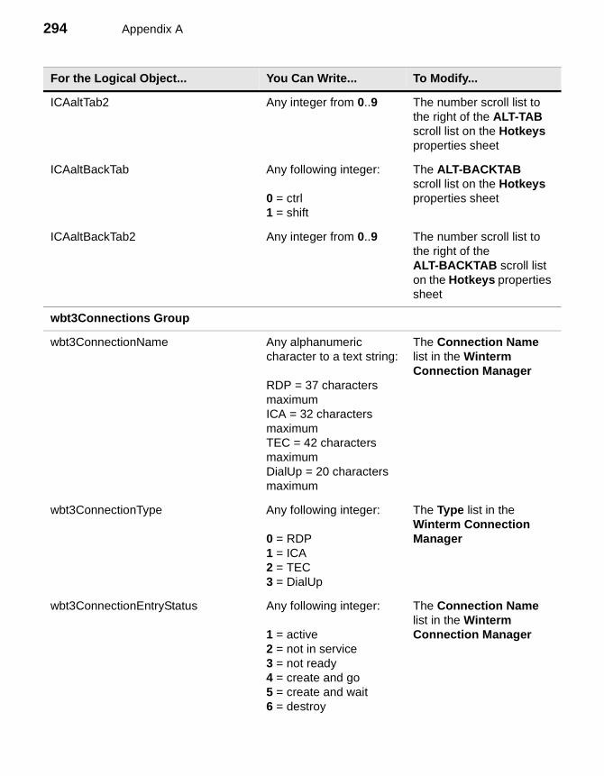
294 Appendix A
ICAaltTab2 Any integer from 0..9 The number scroll list to the right of the ALT-TAB scroll list on the Hotkeys properties sheet
ICAaltBackTab Any following integer:
0 = ctrl1 = shift
The ALT-BACKTAB scroll list on the Hotkeys properties sheet
ICAaltBackTab2 Any integer from 0..9 The number scroll list to the right of the ALT-BACKTAB scroll list on the Hotkeys properties sheet
wbt3Connections Group
wbt3ConnectionName Any alphanumeric character to a text string:
RDP = 37 characters maximumICA = 32 characters maximumTEC = 42 characters maximumDialUp = 20 characters maximum
The Connection Name list in the Winterm Connection Manager
wbt3ConnectionType Any following integer:
0 = RDP1 = ICA2 = TEC3 = DialUp
The Type list in the Winterm Connection Manager
wbt3ConnectionEntryStatus Any following integer:
1 = active2 = not in service3 = not ready4 = create and go5 = create and wait6 = destroy
The Connection Name list in the Winterm Connection Manager
For the Logical Object... You Can Write... To Modify...

295
wbt3RDPConnections Group
wbt3RDPConnServer Any alphanumeric character to a text string using a maximum of 32 characters
The Server text box in the WTS Connection Wizard (number 1)
wbt3RDPConnLowSpeed Any following integer:
0 = not checked1 = checked
The Low Speed Connection check box in WTS Connection Wizard (number 1)
wbt3RDPConnAutoLogon Any following integer:
0 = not checked1 = checked
The Automatic Logon check box in WTS Connection Wizard (number 2)
wbt3RDPConnUserName Any alphanumeric character to a text string using a maximum of 32 characters
The Username text box in WTS Connection Wizard (number 2)
wbt3RDPConnDomain Any alphanumeric character to a text string
The Domain text box in WTS Connection Wizard (number 2)
wbt3RDPConnStartApplication Any following integer:
0 = desktop1 = file name
The Desktop/Application File Name radio buttons in WTS Connection Wizard (number 3)
wbt3RDPConnFilename Any alphanumeric character to a text string using a maximum of 32 characters
The Application File Name text box in WTS Connection Wizard (number 3)
wbt3RDPConnWorkingDir Any alphanumeric character to a text string using a maximum of 32 characters
The Working Directory text box in WTS Connection Wizard (number 3)
For the Logical Object... You Can Write... To Modify...
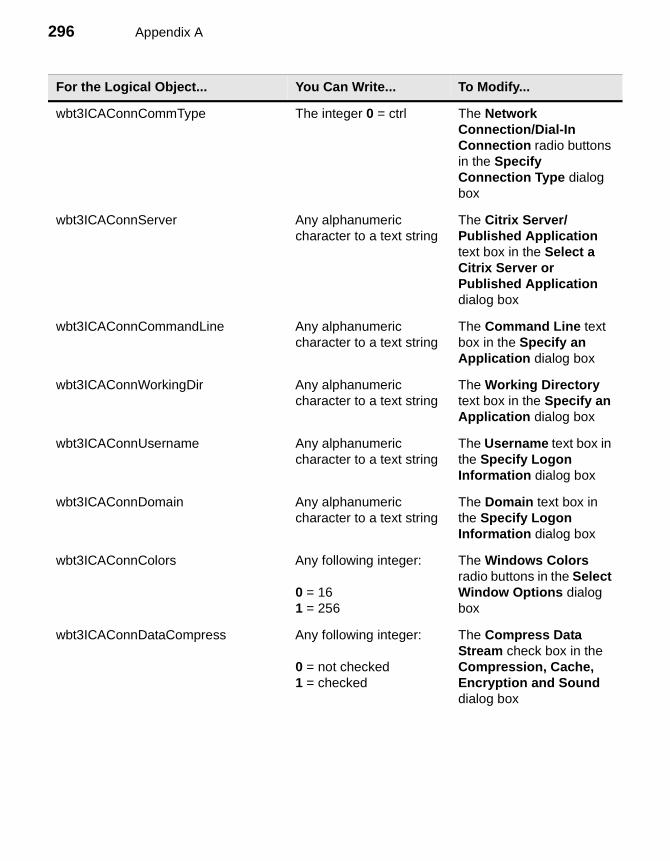
296 Appendix A
wbt3ICAConnCommType The integer 0 = ctrl The Network Connection/Dial-In Connection radio buttons in the Specify Connection Type dialog box
wbt3ICAConnServer Any alphanumeric character to a text string
The Citrix Server/Published Application text box in the Select a Citrix Server or Published Application dialog box
wbt3ICAConnCommandLine Any alphanumeric character to a text string
The Command Line text box in the Specify an Application dialog box
wbt3ICAConnWorkingDir Any alphanumeric character to a text string
The Working Directory text box in the Specify an Application dialog box
wbt3ICAConnUsername Any alphanumeric character to a text string
The Username text box in the Specify Logon Information dialog box
wbt3ICAConnDomain Any alphanumeric character to a text string
The Domain text box in the Specify Logon Information dialog box
wbt3ICAConnColors Any following integer:
0 = 161 = 256
The Windows Colors radio buttons in the Select Window Options dialog box
wbt3ICAConnDataCompress Any following integer:
0 = not checked1 = checked
The Compress Data Stream check box in the Compression, Cache, Encryption and Sound dialog box
For the Logical Object... You Can Write... To Modify...
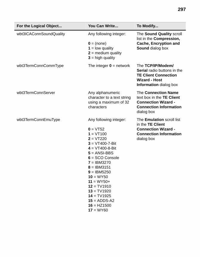
297
wbt3ICAConnSoundQuality Any following integer:
0 = (none)1 = low quality2 = medium quality3 = high quality
The Sound Quality scroll list in the Compression, Cache, Encryption and Sound dialog box
wbt3TermConnCommType The integer 0 = network The TCP/IP/Modem/Serial radio buttons in the TE Client Connection Wizard - Host Information dialog box
wbt3TermConnServer Any alphanumeric character to a text string using a maximum of 32 characters
The Connection Name text box in the TE Client Connection Wizard - Connection Information dialog box
wbt3TermConnEmuType Any following integer:
0 = VT521 = VT1002 = VT2203 = VT400-7-Bit4 = VT400-8-Bit5 = ANSI-BBS6 = SCO Console7 = IBM32708 = IBM31519 = IBM525010 = WY5011 = WY50+12 = TV191013 = TV192014 = TV192515 = ADDS-A216 = HZ150017 = WY60
The Emulation scroll list in the TE Client Connection Wizard - Connection Information dialog box
For the Logical Object... You Can Write... To Modify...
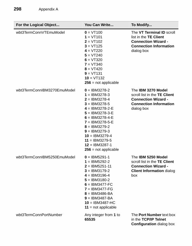
298 Appendix A
wbt3TermConnVTEmuModel 0 = VT1001 = VT1012 = VT1023 = VT1254 = VT2205 = VT2406 = VT3207 = VT3408 = VT4209 = VT13110 = VT132256 = not applicable
The VT Terminal ID scroll list in the TE Client Connection Wizard - Connection Information dialog box
wbt3TermConnIBM3270EmuModel 0 = IBM3278-21 = IBM3278-32 = IBM3278-43 = IBM3278-54 = IBM3278-2-E5 = IBM3278-3-E6 = IBM3278-4-E7 = IBM3278-5-E8 = IBM3279-29 = IBM3279-310 = IBM3279-411 = IBM3279-512 = IBM3287-1256 = not applicable
The IBM 3270 Model scroll list in the TE Client Connection Wizard - Connection Information dialog box
wbt3TermConnIBM5250EmuModel 0 = IBM5291-11 = IBM5292-22 = IBM5251-113 = IBM3179-24 = IBM3196-45 = IBM3180-26 = IBM3477-FC7 = IBM3477-FG8 = IBM3486-BA9 = IBM3487-BA10 = IBM3487-HC11 = not applicable
The IBM 5250 Model scroll list in the TE Client Connection Wizard - Client Information dialog box
wbt3TermConnPortNumber Any integer from 1 to 65535
The Port Number text box in the TCP/IP Telnet Configuration dialog box
For the Logical Object... You Can Write... To Modify...
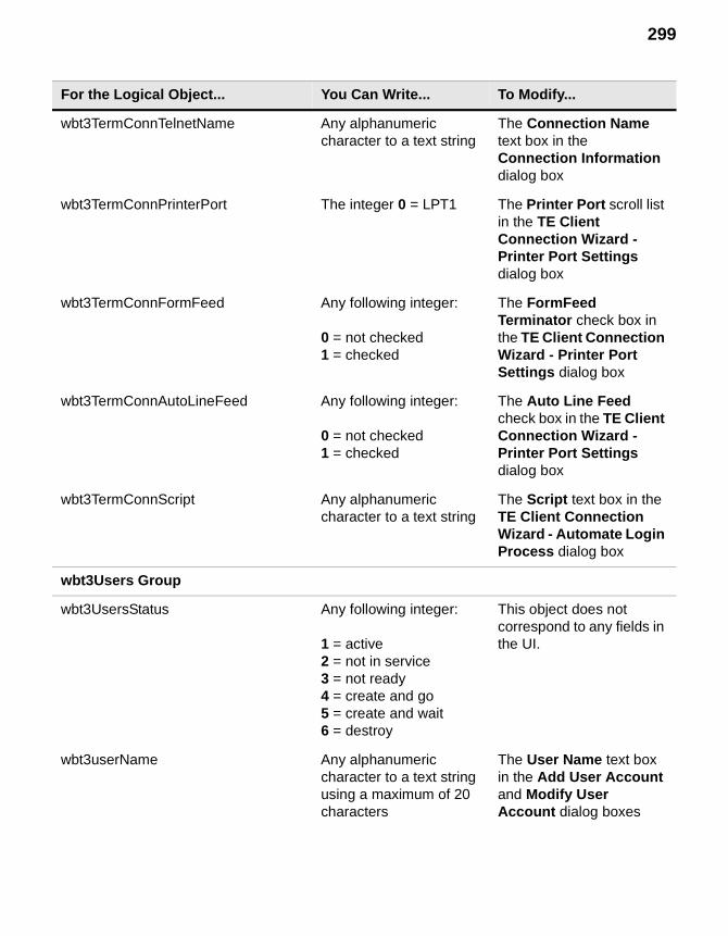
299
wbt3TermConnTelnetName Any alphanumeric character to a text string
The Connection Name text box in the Connection Information dialog box
wbt3TermConnPrinterPort The integer 0 = LPT1 The Printer Port scroll list in the TE Client Connection Wizard - Printer Port Settings dialog box
wbt3TermConnFormFeed Any following integer:
0 = not checked1 = checked
The FormFeed Terminator check box in the TE Client Connection Wizard - Printer Port Settings dialog box
wbt3TermConnAutoLineFeed Any following integer:
0 = not checked1 = checked
The Auto Line Feed check box in the TE Client Connection Wizard - Printer Port Settings dialog box
wbt3TermConnScript Any alphanumeric character to a text string
The Script text box in the TE Client Connection Wizard - Automate Login Process dialog box
wbt3Users Group
wbt3UsersStatus Any following integer:
1 = active2 = not in service3 = not ready4 = create and go5 = create and wait6 = destroy
This object does not correspond to any fields in the UI.
wbt3userName Any alphanumeric character to a text string using a maximum of 20 characters
The User Name text box in the Add User Account and Modify User Account dialog boxes
For the Logical Object... You Can Write... To Modify...
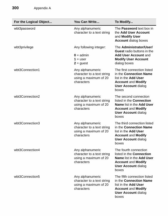
300 Appendix A
wbt3password Any alphanumeric character to a text string
The Password text box in the Add User Account and Modify User Account dialog boxes
wbt3privilege Any following integer:
0 = admin1 = user2 = guest
The Administrator/User/Guest radio buttons in the Add User Account and Modify User Account dialog boxes
wbt3Connection1 Any alphanumeric character to a text string using a maximum of 20 characters
The first connection listed in the Connection Name list in the Add User Account and Modify User Account dialog boxes
wbt3Connection2 Any alphanumeric character to a text string using a maximum of 20 characters
The second connection listed in the Connection Name list in the Add User Account and Modify User Account dialog boxes
wbt3Connection3 Any alphanumeric character to a text string using a maximum of 20 characters
The third connection listed in the Connection Name list in the Add User Account and Modify User Account dialog boxes
wbt3Connection4 Any alphanumeric character to a text string using a maximum of 20 characters
The fourth connection listed in the Connection Name list in the Add User Account and Modify User Account dialog boxes
wbt3Connection5 Any alphanumeric character to a text string using a maximum of 20 characters
The fifth connection listed in the Connection Name list in the Add User Account and Modify User Account dialog boxes
For the Logical Object... You Can Write... To Modify...
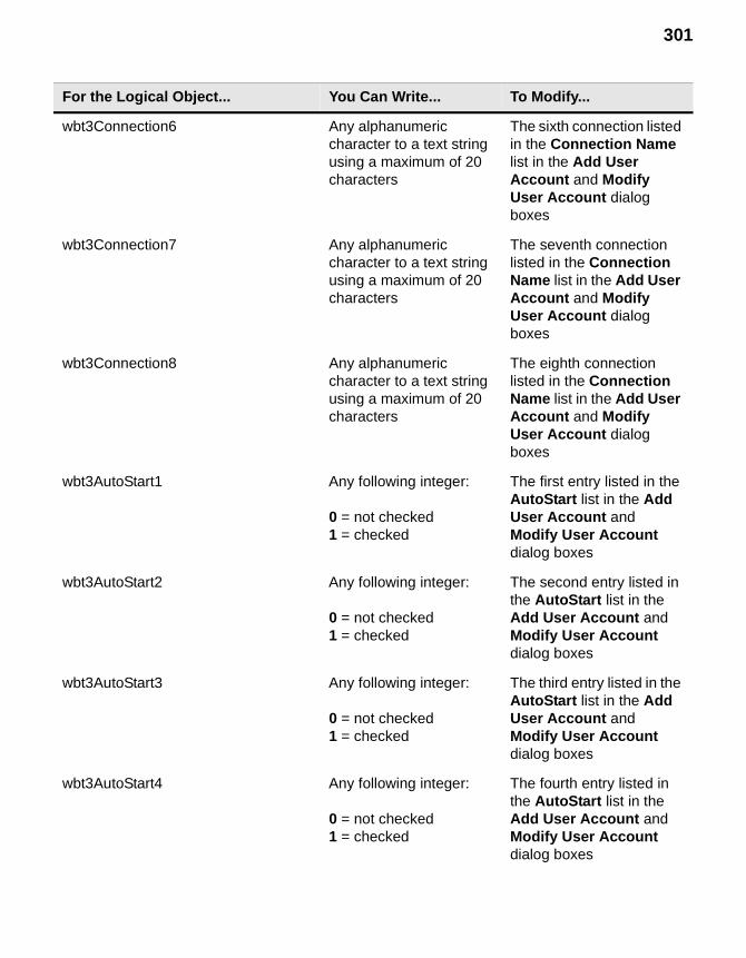
301
wbt3Connection6 Any alphanumeric character to a text string using a maximum of 20 characters
The sixth connection listed in the Connection Name list in the Add User Account and Modify User Account dialog boxes
wbt3Connection7 Any alphanumeric character to a text string using a maximum of 20 characters
The seventh connection listed in the Connection Name list in the Add User Account and Modify User Account dialog boxes
wbt3Connection8 Any alphanumeric character to a text string using a maximum of 20 characters
The eighth connection listed in the Connection Name list in the Add User Account and Modify User Account dialog boxes
wbt3AutoStart1 Any following integer:
0 = not checked1 = checked
The first entry listed in the AutoStart list in the Add User Account and Modify User Account dialog boxes
wbt3AutoStart2 Any following integer:
0 = not checked1 = checked
The second entry listed in the AutoStart list in the Add User Account and Modify User Account dialog boxes
wbt3AutoStart3 Any following integer:
0 = not checked1 = checked
The third entry listed in the AutoStart list in the Add User Account and Modify User Account dialog boxes
wbt3AutoStart4 Any following integer:
0 = not checked1 = checked
The fourth entry listed in the AutoStart list in the Add User Account and Modify User Account dialog boxes
For the Logical Object... You Can Write... To Modify...
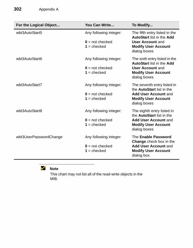
302 Appendix A
NoteThis chart may not list all of the read-write objects in the MIB.
wbt3AutoStart5 Any following integer:
0 = not checked1 = checked
The fifth entry listed in the AutoStart list in the Add User Account and Modify User Account dialog boxes
wbt3AutoStart6 Any following integer:
0 = not checked1 = checked
The sixth entry listed in the AutoStart list in the Add User Account and Modify User Account dialog boxes
wbt3AutoStart7 Any following integer:
0 = not checked1 = checked
The seventh entry listed in the AutoStart list in the Add User Account and Modify User Account dialog boxes
wbt3AutoStart8 Any following integer:
0 = not checked1 = checked
The eighth entry listed in the AutoStart list in the Add User Account and Modify User Account dialog boxes
wbt3UserPasswordChange Any following integer:
0 = not checked1 = checked
The Enable Password Change check box in the Add User Account and Modify User Account dialog box.
For the Logical Object... You Can Write... To Modify...
Glossary 303
Glossary
The following glossary is a list of commonly used terms in this guide.
Term Definition
10Base-T One of several adaptations of the Ethernet (IEEE 802.3) standard for Local Area Networks (LANs). The 10Base-T standard (also called Twisted Pair Ethernet) uses a twisted-pair cable with a maximum length of 100 meters. The cable is thinner and more flexible than the coaxial cable used for the 10Base-2 or 10Base-5 standards.
100Base-T A networking standard that supports data transfer rates up to 100 Mbps (100 megabits per second). 100Base-T is based on the older Ethernet standard. Because it is 10 times faster than Ethernet, it is often referred to as Fast Ethernet. Officially, the 100Base-T standard is IEEE 802.3u. Like Ethernet, 100Base-T is based on the CSMA/CD LAN access method.
CHAP Challenge-Handshake Authentication Protocol. An authentication scheme used by PPP servers to validate the identity of the originator of the connection upon connection or any time later.
CRT Cathode-Ray Tube. A large vacuum tube with a viewing face in which an electron beam is focused and controlled to form characters and other images. A CRT is the display you see on the monitor you use with your terminal.
CTS Clear to Send. Control signal sent from the DCE. It indicates that the DTE may send data. This signal is used in serial connections.
DCE Data Communications Equipment. Devices that provide the functions required to establish, maintain, and terminate a data transmission connection, e.g., a modem.
Glossary 304
DHCP The Dynamic Host Configuration Protocol (DHCP) provides configuration parameters to Internet hosts. DHCP consists of two components: a protocol for delivering host-specific configuration parameters from a DHCP server to a host and a mechanism for allocation of network addresses to hosts.
DHCP is built on a client-server model, where designated DHCP hosts allocate network addresses and deliver configuration parameters to dynamically configured hosts. The term "server" refers to a host providing initialization parameters through DHCP, and the term "client" refers to a host requesting initialization parameters from a DHCP server
DNS Domain Name Service. A general-purpose distributed, replicated, data query service chiefly used on the Internet for translating host names into Internet addresses.
Download To transfer data from a processing unit to an attached device. For example, from a host to the terminal.
DSR Data Set Ready. A hardware signal sent by a communications device to indicate readiness to send and receive data. This signal is used in serial connections.
DTE Data Terminal Equipment. A device that acts as the source and/or destination of data and which controls the communication channel. DTE includes terminals, computers, protocol converters, and multiplexors. DTE is usually connected via an RS-232 serial line to Data Communication Equipment (DCE).
DTR Data Terminal Ready. A hardware signal sent by a terminal to indicate readiness to send and receive data. This signal is used in serial connections.
Ethernet A baseband local area network specification developed jointly by Digital Equipment Corp., Xerox, and Intel to interconnect computer equipment using coaxial cable and transceivers. An Ethernet LAN provides millions of bits per second of capacity for high-speed terminal-to-computer communication or computer-to-computer file transfer.
FCC Federal Communications Commission. The Government body that regulates all telecommunications originating in the U.S., including transmission over telephone lines.
Firmware A computer program or software stored permanently in a PROM or ROM or semi-permanently in an EPROM.
Glossary 305
Flow control The procedure for regulating the flow of data between two devices, flow control prevents the loss of data when one device’s receiving buffer has reached its capacity.
FTP File Transfer Protocol. FTP is a program for transferring files in TCP/IP environments such as the intranet in which a user, acting as a client, downloads files from a remote server. FTP is a core component in TCP/IP system administration and is implemented at the Applications layer with respect to the OSI protocol model. Its operation is based on the Telnet program and TCP.
GUI Graphical User Interface (pronounced “gooey”). The use of pictures rather than just words to represent the input and output of a program. A program with a GUI runs under some windowing system (e.g. Microsoft Windows®). The program displays certain icons, buttons, and dialog boxes in its windows on the screen. The user mainly controls these objects by moving a pointer on the screen (typically controlled by a mouse) and selecting certain objects by pressing buttons on the mouse while the pointer is pointing at them.
Hz Hertz. A unit of frequency equal to 1 cycle per second.
ICA Independent Computing Architecture. A three-part server-based computing technology that separates an application’s logic from its user interface and allows 100% application execution on the server. ICA was developed by Citrix Systems, Inc.
Integrated CRT terminal A terminal with a monitor and connections on the back for a keyboard and mouse.
Interface A shared boundary defined by common physical interconnection characteristics, signal characteristics, and meaning of interchanged signals.
Internet The Internet is a global web of interconnected computers and computer networks that are interconnected under a common set of network protocols that allows them to function as a single large network (see TCP/IP).
Glossary 306
IP address Internet Protocol Address. The 32-bit, 4-byte address assigned to machines with TCP/IP. Every machine that is on the Internet has a unique IP address. This facilitates interconnectivity among a variety of independent host systems.
An IP address is usually represented in dotted decimal notation (called a dotted quad) consisting of 4 parts separated by dots, e.g.:
165.113.245.2
Most machines also have one or more Domain Names (see DNS) that are easier for people to remember.
Intranet A network of WBT’s within a company or organization.
ISDN Integrated Services Digital Network. Evolving switched network standard that provides end-to-end digital voice and data communication services.
kb or kilobit 1,024 bits. Commonly referred to as 1 thousand bits.
kB or kilobyte 1,024 bytes. Commonly referred to as 1 thousand bytes.
kbps or kb/s Kilobits per second. An abbreviation meaning thousands of bits per second.
Load Balancing Services A management add-on to Citrix WinFrame and MetaFrame servers that allows administrators to group multiple WinFrame and/or MetaFrame servers into scalable “server farms” to deliver the best application performance and server resource utilization.
Mb or megabit 1,048,576 bits. Commonly referred to as 1 million bits.
MB Megabytes
Mbps or Mb/s Megabits per second.
MetaFrame The world’s first Server-based Computing software for Microsoft Windows NT 4.0 Server, Terminal Server Edition multi-user software.
MIB Management Information Base. A database of managed objects accessed by network management protocols.
Glossary 307
Modem (Mo)dulator/(dem)odulator. Data communication equipment (DCE) devices that provide connections for computers into the public switched telephone network (PSTN). They convert (modulate) the digital signals of computers into analog signals that can be transmitted over telephone lines. A modem at the other end of the link then demodulates the signals back to digital bits.
Modular terminal Desktop client that works with existing standard monitors.
Network An interconnected group of nodes; a series of points, nodes, or stations connected by communications channels; the assembly of equipment through which connections are made between data stations.
Null modem A cable, typically an RS-232 cable, for connecting serial ports on two computers directly, rather than via modems. Since, according to the specification, both computers should transmit on pin three of their RS-232 connectors and receive on pin two, a null modem cable needs to connect one computer’s pin two to the other’s pin three and vice versa. It also needs to have male connectors at both ends (again, according to the specification).
OSD On Screen Display. A menu that displays on your monitor.
Packet A group of bits (including data and call control signals) transmitted as an identifiable unit on a packet-switched network (PSN).
PAP Password Authentication Protocol. An authentication scheme used by PPP servers to validate the identity of the originator of the connection. PAP applies a two-way handshaking procedure. After the link is established the originator sends an id-password pair to the server. If authentication succeeds the server sends back an acknowledgment; otherwise it either terminates the connection or gives the originator another chance.
Parallel port An input/output port that allows the entire bit pattern for a single character to be sent at one time, usually used to connect a printer to a computer.
Parity check The addition of non-information bits (specifically, parity bits) to make up a transmission block (a number of bits transmitted as unit) that ensures the total number of ones is always either even (even parity) or odd (odd parity). The parity check is used to detect transmission errors.
Glossary 308
PCMCIA Personal Computer Miniature Connector Interface Adapter. Hardware and software standards for credit-card-sized integrated circuit cards.
Ping Packet InterNet Groper. A protocol used in the Transmission Control Protocol (TCP) environment to test whether a node or remote device is communicating on a local area network (LAN) or wide area network (WAN). The protocol provides for transporting an echo response from a host system, a client, or a gateway. It is a useful tool for locating problems on the network related to failed connections and software problems. One datagram is sent every second over the network and any response is displayed.
PPP Point-to-Point Protocol. A serial communication protocol that operates over dialup or leased (dedicated) lines to provide connections into IP networks. It sets up and monitors router sessions and frames the data transmitted over the line.
Protocol A set of formal rules describing how to transmit data, especially across a network. Low-level protocols define the electrical and physical standards to be observed, bit- and byte-ordering, and the transmission and error detection and correction of the bit stream. High level protocols deal with the data formatting, including the syntax of messages, the terminal to computer dialogue, character sets, sequencing of messages, etc.
RAM Random-Access Memory. A mass store that provides fast access to any storage location by means of vertical and horizontal coordinates. Information is written in or read out using the same procedure. The memory cycle time is the same for any location addressed because there is no waiting or sorting time required, as there is when data items are stored sequentially.
RAS Remote Access Services. A service provided by Windows NT that allows most of the services which would be available on a network to be accessed over a modem link. The service includes support for dialup and logon, and then presents the same network interface as the normal network drivers (albeit slightly slower).
RDP Remote Desktop Protocol. A presentation service protocol that governs input and output between a WBT and WTS (Windows Terminal Server). It is based on the T.share protocol.
Glossary 309
RS-232 cable A cable for serial interfaces between the terminal and communications devices, such as a modem. The cable connects to the 9-pin serial port at the back of the terminal. Maximum cable length is 50 feet; maximum signaling rate is 20 Kbits/sec.
RTS/CTS flow control Request to Send/Clear to Send flow control. Enables flow control on the local serial line. RTS is the output of the terminal; CTS is the input to the terminal.
Serial port A connector on a computer to which you can attach a serial line connected to peripherals that communicate using a serial (bit-stream) protocol. The most common type of serial port is a 25-pin D-type connector carrying RS-232 signals. Smaller connectors (e.g. 9-pin D-type) carrying a subset of RS-232 are often used on personal computers.
NoteThe 3200LE terminal does not have a serial port.
Server A computer, or a software package, that provides a specific kind of service (such as access to workstations, printers, and other parts of the network) to client software running on other computers. The term can refer to a particular piece of software, such as a WWW server, or to the machine on which the software is running. A single server machine could have several different server software packages running on it, thus providing many different services to clients on the network.
SNMP Simple Network Management Protocol. The industry standard protocol for managing TCP/IP networks. This protocol queries agents in managed devices and passes information to the management console.
Start bit In asynchronous transmission, the first bit of any given character used to alert the receiving system to recognize the related incoming data.
Stop bit In asynchronous transmission, the last bit of any given character, used to alert the receiving system that transmission of the character is complete.
Glossary 310
TCP/IP Transmission Control Protocol/Internet Protocol. A standard set of protocols that govern the basic workings of the Internet. It was developed by DARPA and implemented in 1982. TCP/IP encompasses both network layer and transport layer protocols (in the OSI model). While TCP and IP specify two protocols at specific protocol layers, TCP/IP is often used to refer to the entire DOD protocol suite based upon these, including Telnet, FTP, UDP and RDP.
Telnet Telnet is the login and terminal emulation program for Transmission Control Protocol/Internet Protocol (TCP/IP) networks such as the Internet. Its primary function is to allow users to log into remote host systems.
Terminal emulation Programs that allow a WBT to act like a particular brand or type of terminal. The WBT thus appears as a terminal to the host computer and accepts the same escape sequences for functions such as cursor positioning and clearing the screen.
Thin-client A low-cost computing device that works in a server-centric computing model. Thin clients typically do not require state-of-the-art, powerful processors and large amounts of RAM and ROM because they access applications from a central server or network. Thin clients can operate in a Server-based Computing environment.
Timeout A time interval within which certain operations must occur; for example, the time allotment for the terminal to connect to a login host. After the timeout, the process can either be repeated or discontinued.
Total Cost of Ownership (TCO) A model that helps IT professionals understand and manage the budgeted (direct) and unbudgeted (indirect) costs incurred for acquiring, maintaining and using an application or a computing system. TCO normally includes training, upgrades, and administration as well as the purchase price. Lowering TCO through single-point control is a key benefit of Server-based Computing.
Touch screen A type of display screen that has a touch-sensitive transparent panel that can sense when someone is touching it, and is able to furnish a computer with precise information as to exactly where on the screen the touch occurred. Touch screens are used with software that uses the information provided by the screen touch to respond to user requests.
Glossary 311
USB Universal Serial Bus. An external peripheral interface standard for communication between computer and external peripherals over an inexpensive cable using biserial transmission. USB works at 12 Mbps with specific consideration for low-cost peripherals. USB cables can be up to 5 meters long.
Virtual Port Incoming Telnet and rlogin connections are not associated with a physical port. Instead, they are associated with a virtual port, port 0, which serves for the duration of the connection. Each virtual port is created with a default set of characteristics. The Define Port commands can be used to customize a virtual port during the Telnet/Rlogin session; however, these customizations can not be saved. The port reverts to the default set of characteristics when the session is closed.
WAN Wide Area Network. A data-communications system covering a large geographic area, usually digital circuits having moderate to high data rates (e.g., 56 to 64 kbps up to 1.5 to 2 Mbps).
WBT Windows-based Terminal. A thin-client device that connects to a Citrix WinFrame or MetaFrame server to provide application access. The key differentiator of a WBT from other type devices is that all the application execution occurs on the server. There is no downloading or local processing of applications at the client.
WinFrame A multi-user Windows application server, based on Windows NT, developed under license from Microsoft. This application was developed by Citrix Systems, Inc.
WINS Windows Internet Naming Service. WINS allows machines to dynamically register their name-to-address mappings. WINS is also a flat name space without the concept of hierarchy and requires each WINS server to maintain a complete database of entries through replication.
Winterm Trademarked logo for Windows-based Terminals manufactured by Wyse Technology Inc.
WTS Windows Terminal Server. A server application that transmits Windows user interface data via a network to a WBT.
X-ON/X-OFF Transmitter On/Transmitter Off. Control characters used for flow control, instructing serial devices to start transmission (X-ON) and stop transmission (X-OFF).

Glossary 312
Index 313
Index
Numerics10Base-T 37, 303
CCard bus
3350SE 19Category 5 twisted pair 269Centronics-compatible 268Com1
3320SE 93350SE 193360SE 273720SE 36
Com23320SE 93350SE 193360SE 273720SE 36
Command buttonPort Lock 72
Command buttonsAccept xxixAdd User 231, 234–235Add/Change Modem 169Advanced (login options) 128Apply xxixBack xxixCancel xxixChange DHCP Option 71, 74, 222Configure 103, 128Default (Server) List 81Delete User 231, 234, 246Dialing Properties 103Edit (connection parameters) 142, 152Finish xxix, 59, 63ICA Client Settings 71, 74, 78Modify User 231, 234, 241Next xxixOK xxix
Restart (terminal) 64Script 103Security 103, 113Shutdown (terminal) 247SNMP Network 71, 74SNMP Network Administration 213Startup (connection) 89TCP/IP Settings 103, 111Upgrade 209–210, 223X xxix
Communication ports3200LE 2563320SE, 3350SE 2583360SE, 3720SE 261
Connection protocolsCitrix ICA Client 88Dial-Up Client 88Microsoft Remote Desktop Client 88Terminal Emulation 88
Control keysAlt+Backtab 77Alt+Esc 77Alt+Tab 77Ctrl+Alt+Del 76Ctrl+Alt+Down Arrow 264Ctrl+Alt+Up Arrow 264Ctrl+Esc 77F2 45, 61, 65, 69, 73, 76, 160, 162, 166,
175, 189
DDialog boxes
About (the terminal) 203Adapters Configuration 165Add or Change Modem 169Add Server Address 94Add User Account 235Automate Login Process 129Change DHCP Option IDs 219Change Option IDs 222Compression, Cache, Encryption and
Sound 97Connection Information 126Connection Startup 88

Index 314
Countdown 47Desktop Area and Refresh Frequency 51Device Properties 105Dialing Properties 105Download Utility 202Edit Connection 151ELO Touchscreen 175Failover Log Window 252Firmware Upgrade 203Global ICA Settings 75Host Information 128ISDN Settings 172Microtouch Touchscreen Properties 177Modify User Account 241New Connection 87, 91, 101, 119, 125Optional Information 48Port Settings 109Printer Port Settings 130RACORE - Token Ring Adapter
Settings 189Security Settings 113Select a Server or Published
Application 93Select a Title for the ICA Connection 95Select Window Options 97Server Location 93SNMP Network Administration 213Specify an Application 95Specify an IP Address 48Specify Connection Type 91Specify Logon Information 96TCP/IP Settings 111TCP/IP Telnet Configuration 133Terminal Login 247Terminal Properties 45, 61, 65, 69, 73,
75–76, 160, 162, 166, 175, 189
Terminal Settings Change 59, 63Welcome 46Winterm Connection Manager 5, 45, 87,
101DOS functions
dir 202xfer.exe 201
FFerrite bead 279Firmware download
cable method 201parallel download 201
FunctionDial-Up Client 101Microsoft Remote Desktop Client 119Terminal Emulation 125
Functions16 Megabits/Second 1904 Megabits/Second 190Accept Any Authentication Including Clear
Text 114Accept Only Encrypted
Authentication 114Accept Only Microsoft Encrypted
Authentication 114Account Name 231Adapters 161, 166Add (command button) 81Add/Change Modem 161Address of Proxy to Use 83, 98Advanced Network 68Allow Access to Connection
Manager 239, 245Application to Run 155Assign (connection) 237, 243Auto Fail Recovery 230AutoLogin 231AutoLogin Enable 230Autologin Enable 250Automatic Logon 153Automatically Start the Selected
Connection at Startup 89AutoStart 231Available Connections 237, 243Baud Rate 178Button 181Cable Connection 176Calibrate 176Call Options 109Call Setup 110Client Name 79Close Remote Application 76

Index 315
Common Option IDs 221Community 215Connect Via SOCKS Proxy 83, 98Connection 153, 178Connection Name 238, 244Connection Name and Type 230Connection Preferences 109Connection Speed 153Controller Type 178Cursor Offset 179Custom 216Default Gateway 167Default Windows Colors 79Delete (connection) 81Desktop 181DHCP Automatic Update Enable 71, 74,
222DHCP Connection Enable 230Dial-In Connection 91Dialing Patterns 108Disable Call Waiting By Dialing 107Drawing 181ELO Touch 161, 163Enable Authenticating Failure Trap 215Enable DNS 50, 68Enable Password Change 234, 237, 243Enable WINS 50, 68Extra Settings 110Failover Enable 229, 251Find Touchscreen 178Firmware Version 178Flow Hardware 171Flow Off 171Flow Settings 171Flow Software 171FTP Option IDs 221G Key Reset Enable 231Get (field) 215Global Settings 71, 74Hide Configure Tab 229Horizontal Edge Adjust 179Information 178Init Commands 171IP Address 167ISDN Settings 161, 172
Local Area Code 107Local Country Code 107Local Settings 107Logout 250LPD 161, 163Make the Selected Connection Your
Default Connection 89Manual Dial 109Modem Name 171, 173Move Down 81Move Up 81Multilink PPP 173Multiple Connect 229Network Connection 91Network Protocol 81No, I will Enter Static IP Information 48Obtain an Address from a DHCP
Server 67Obtain an IP Address From DHCP
Server 222Obtain an IP Address Via DHCP 167Parameters 129Ping Before Connect 229Port 83, 98, 178Port Settings 109Primary DNS 168Primary ISDN Parameters 173Primary WINS 168Privilege 231Properties 166Protocol 173Pulse Dialing 107RACORE-TR 161RDP Encryption Enable 72, 74RDP Option IDs 221Rename Group 81Reset the Terminal to Factory Default
Property Settings 62Reset the Terminal to Factory-Default
Property Settings 45Reset To Defaults 222Respond With 129Secondary DNS 168Secondary WINS 168Security Enable 229
Index 316
Server Group 81Service Profile ID 1 173Service Profile ID 2 173Set (field) 215Set Initiation String 129Single Button Connect 230SNMP Communication 215SNMP Option IDs 221SNMP Update Enable 71, 74SOCKS 83Specify an IP Address 67, 167Stabilize Cursor 180Startup Options 88Status 178Status Dialog 76Subnet 167Switch Type 173Terminal Emulation Option IDs 221Terminal Name 67Toggle AutoConn 238, 244Toggle Title Bar 76Token Ring Speed 190Tone Dialing 107Touch Mode 181Touchscreen 161, 163Unassign (connection) 238, 244Use Alternate Address Through
Firewalls 83, 98Use Assigned IP Address 112Use Default Gateway on Remote
Network 113Use FTP InformationFrom DHCP
Server 209Use IP Header Compression 112Use Local FTP Information 209Use Server-Assigned Addresses 113Use SLIP 112Use Software Compression 112Use Terminal Window After Dialing 109Use Terminal Window Before Dialing 109User Accounts 231User Defined MAC Address 190User Name 230, 247Verbose (connection) 229
Vertical 179Virtual Port Option IDs 221Virtual Port Server 71Virtual Ports 71Volume 161, 163Wait For 129Wait for Credit Card Tone 110Wait for Dial Tone Before Dialing 110WaveLAN 161, 163Yes, Use the IP Information Supplied by
DHCP 48
GG key reset 45
HHeadphone jack
3200LE 43320SE 93350SE 193360SE 273720SE 37
How toAdjust your mouse speed 263Check your terminal’s revision of
software 263Configure a local printer 265Determine the terminal’s memory
size 265Find a modem that works with your
terminal 264Make a basic PPP connection 264Reset your terminal 265Switch between multiple sessions 264Turn off Autologin 263
IICA 219Image file 217ISDN settings 159
Index 317
KKeyboard connector
3320SE 93350SE 193360SE 273720SE 37
MManagement Information Base 216MIB 216Microphone jack
3200LE 43320SE 93350SE 193360SE 273720SE 37
Mouse connector3320SE 93350SE 193360SE 273720SE 37
NNetwork connector
3200LE 43320SE 93350SE 193360SE 273720SE 36
Noise suppressor 279Null modem cable 273
OOption slot
3320SE 93360SE 273720SE 37
PParallel port
3320SE 9
3350SE 193360SE 273720SE 37
Params.ini 217Physical characteristics
3200LE 2553320SE, 3350SE 2573360SE, 3720SE 259
Pin assignments10Base-T and 100Base-T
connectors 269null modem cable 273serial and parallel ports 267USB connectors 271VGA connector 270
Power connector3200LE 43320SE 93350SE 193360SE 273720SE 37
Power requirements3200LE 2553320SE, 3350SE 2573360SE, 3720SE 259
PPP 101Properties sheets
Application 154Apps 61, 69, 75, 213Calibrate 182Call Options 110Configure 87, 89, 142, 152Cursor 179Default Hotkeys 76Devices 61, 159, 166, 189Display 61General 45, 61Input 61IP Address 166Name Server 166Net Connections 153Network 61, 65Preferences 78Printers 61Security 61, 227, 245, 250–251
Index 318
Server Location 80SysInfo 61Touch Settings 181Upgrade 61, 207, 210
Properties sheetsFirewall Settings 82
RRDP 219RDP encryption 69Regulatory compliance
3200LE 2563320SE, 3350SE 2583360SE, 3720SE 260
SSpecifications
3200LE 2553320SE 2573350SE 2573360SE 2593720SE 259
TTelnet 125Terminal accounts
Administrator 234, 238, 245Guest 233, 239, 245User 234, 239, 245
UUSB
3350SE 19USB port
3200LE 4
VVideo connector
3200LE 43320SE 93350SE 193360SE 27
Virtual port 69
WWBT xxviiWBT model numbers
3200LE xxvii3320SE xxvii3350SE xxvii3360SE xxvii3720SE xxvii
WizardsDial-Up Configuration 101, 105, 111Setup 5, 16, 24, 34, 38, 45, 63, 203, 223TE Client Connection 125WTS Connection 119

Index 319
Winterm 3000 Series Windows®-based Terminal Administrators Guide
Written and published by: Wyse Technology Inc., May 2000
Created using FrameMaker®, Acrobat®, and Magellan™
The on-line book is provided in both PDF and HTML versions, presented on both CD-ROM and at www.wyse.com.
Related Documents