Milling, plotting, engraving, drilling, grinding, dispensing, cutting and much more besides with... WinPC-NC Light ...the software that turns your standard PC into a universal stepper motor NC unit Version 2.00 July 2006 © Copyright Burkhard Lewetz, 2006

Welcome message from author
This document is posted to help you gain knowledge. Please leave a comment to let me know what you think about it! Share it to your friends and learn new things together.
Transcript
Milling, plotting, engraving, drilling, grinding, dispensing, cutting and much more besideswith...
WinPC-NCLight
...the software that turns your standard PC into a universal stepper motor NC unit
Version 2.00July 2006
© Copyright Burkhard Lewetz, 2006

WinPC-NC Light
Lawful purchase of the diskette and the manual conveys permission for one person to utilise the WinPC-NC control program. Copying the diskette and the manual or changing any of theindividual files or elements of the manual are forbidden.
Furthermore any unauthorized transmission of the program or extracts of it will be legallyprosecuted by all available means.
The authors reserve all rights to the programs and to the manual, in particular the copyright.
This control program has undergone extremely thorough testing. Nevertheless, it is impossible to give a guarantee for completely fault-free operation. Furthermore, no responsibility can beaccepted for damage caused as a result of using our program.
Despite the most strenuous efforts, it is never possible to completely eliminate all faults.Consequently, we would be grateful to receive feedback from users.
Please note that support assistance and reduced updates are only available for registeredcustomers. In order to be registered please send us a mail indicating version number andserial number (either noted on the CD or visible in the program window) as well as yourcomplete address.
Please register your licence !!!!
Burkhard Lewetz Hardware-Software Brückenstrasse 7D-88074 Meckenbeuren eMail [email protected] Homepage www.lewetz.de July 2006
MS-Windows is a registered trademark of the Microsoft Corporation.AutoSketch, AutoCAD, AutoSketch for Windows are registered trademarks of Autodesk AG.IBM is a registered trademark of the International Business Machines Corporation.CorelDRAW is a registered trademark of the Corel Corporation.Designer is a registered trademark of Micrografx, Borland C++Builder is a registered trademark of Borland International, INC.Other products mentioned by name are trademarks or registered trademarks of their corresponding companies.
2.000
- 2 -

WinPC-NC Light
Table of contents
The structure of this manual................................................................................................5Definitions...........................................................................................................................5Use of typography................................................................................................................6Various versions of WinPC-NC..........................................................................................7
1. What can WinPC-NC Light do ? ...................................................................................8
2. First steps.........................................................................................................................122.1. Requirements to the PC hardware...........................................................................122.2. Possible restrictions during realtime operation........................................................122.3. Installation...............................................................................................................132.4. Launching the program............................................................................................142.5. First steps and test moves........................................................................................152.6. Exiting WinPC-NC..................................................................................................17
3. Operating WinPC-NC Light...........................................................................................183.1. Graphical display of the NC file..............................................................................183.2. Drop-down menus and function keys .....................................................................213.3. The individual menus..............................................................................................223.3.1. FILE menu ...........................................................................................................22
OPEN ...................................................................................................................22OPEN WITHOUT PARAMETERS ....................................................................23EDIT......................................................................................................................23EXIT .....................................................................................................................23
3.3.2. MOVE menu.........................................................................................................23START .................................................................................................................24JOG ......................................................................................................................24JOYSTICK JOG ...................................................................................................26REFERENCE MOVE...........................................................................................27SELECT TOOL ...................................................................................................27
3.3.3. PARAMETERs menu...........................................................................................28SAVE ...................................................................................................................29SAVE AS .............................................................................................................30LOAD ...................................................................................................................30
3.3.4. SPECIAL FUNCTIONS menu ............................................................................30SIGNAL TEST......................................................................................................31MOTOR TEST .....................................................................................................32STATUS INFORMATION...................................................................................33JOYSTICK CALIBRATION................................................................................33CHECK POSITION .............................................................................................34
3.3.5. HELP menu...........................................................................................................35TOPICS.................................................................................................................35DISCLAIMER.......................................................................................................35ABOUT WinPC-NC.............................................................................................35
- 3 -
WinPC-NC Light
4. Parameter settings...........................................................................................................364.1. Tool management....................................................................................................364.2. Speeds......................................................................................................................394.3. Coordinates..............................................................................................................414.4. Data format and associated parameters....................................................................444.5. Miscellaneous parameters........................................................................................474.6. Ports.........................................................................................................................524.7. Signals and dwell times...........................................................................................544.8. Machine parameters ................................................................................................55
5. Initial start-up with the machine.....................................................................................605.1. Connecting the machine...........................................................................................605.1.1. Pin assignment of clock/direction version............................................................615.1.2. Pinning of SMC version.......................................................................................625.2. Determination of axis resolution.............................................................................635.3. Definiton of LPT port..............................................................................................635.4. Determination of move direction ............................................................................655.5. Adjustment of reference switches............................................................................665.6. Sequence and direction of reference move..............................................................685.7. Control of adjustments.............................................................................................685.8. Additional steps.......................................................................................................69
6. Signal wizzard................................................................................................................706.1. Using input and output signals................................................................................706.2. Assignment of inputs...............................................................................................716.3. Assignment of output liness.....................................................................................736.4. Input signals available.............................................................................................746.5. Output signals available...........................................................................................75
7. Additional information....................................................................................................767.1. Interpreters...............................................................................................................767.1.1. HPGL....................................................................................................................767.1.2. Drilling formats....................................................................................................787.2. Error messages.........................................................................................................797.3. Special versions of WinPC-NC...............................................................................82
- 4 -
WinPC-NC Light
The structure of this manual ...This manual provides you with all the information needed for usingWinPC-NC. It is divided into individual chapters, the contents ofwhich are summarised below:
Chapter 1: Brief explanation about WinPC-NC, the possibilities for using it and the hardware requirements.
Chapter 2: Initial start-up procedure, description of how to install the program and how to adjust the initial specific parameters.
Chapter 3: More detailed descriptions of how to operate the program and the individual functions of WinPC-NC.
Chapter 4: Explanation of all parameters and the setting options.
Chapter 5: Initial start-up procedure step by step
Chapter 6: Information concerning definitions and adjustments ofinput/output signals
Chapter 7: Further technical information about the program, about the implemented NC format interpreters, error messages and special versions.
Definitions
Some of the terms used in this manual may require an explanation:
Job file A file with NC data which is read and processed by or WinPC-NC. Depending on the application, the file NC file may contain milling, plotting, drilling data or other
types of data.
Job process The process of reading and processing a job file and the resultant actuation of the machine.
Command An individual instruction in the job file which gives rise to actions by the machine or in WinPC-NC.
Button Mouse clickable field to activate a certain function
Checkbox Box for activating or deactivation a certain parameter or function, e. g. signals. An activated checkbox is marked with a cross.
- 5 -
WinPC-NC Light
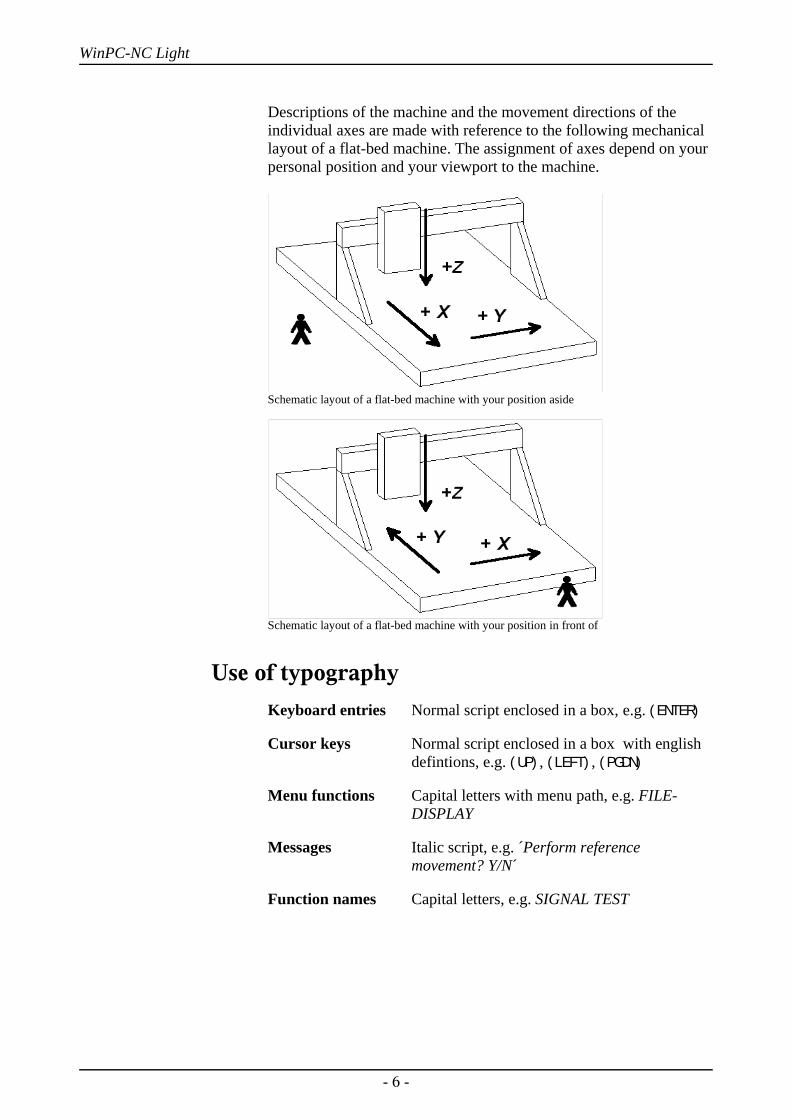
Descriptions of the machine and the movement directions of theindividual axes are made with reference to the following mechanicallayout of a flat-bed machine. The assignment of axes depend on yourpersonal position and your viewport to the machine.
Schematic layout of a flat-bed machine with your position aside
Schematic layout of a flat-bed machine with your position in front of
Use of typography Keyboard entries Normal script enclosed in a box, e.g. (ENTER)
Cursor keys Normal script enclosed in a box with english defintions, e.g. (UP), (LEFT), (PGDN)
Menu functions Capital letters with menu path, e.g. FILE-DISPLAY
Messages Italic script, e.g. ´Perform reference movement? Y/N´
Function names Capital letters, e.g. SIGNAL TEST
- 6 -
WinPC-NC Light
Different versions of WinPC-NCThe controlling program WinPC-NC is available in three differentversions.
Our lowcost program WinPC-NC Light offers all necessary functionsfor beginners, e.g. engraving, milling, drilling and PCB drilling ormanufacturing modelling parts.
WinPC-NC Economy is equipped with additional functions andoffers with up to four axes a lot of special functions and providessupport of extraordinary mechanical components.
This program disposes of much more format interpreters as theversion for beginners.
WinPC-NC Light and Economy are also available for SMC steppercards, i. e. motors are not controlled by clocking/direction signals butby SMC signals.
WinPC-NC Professional is considered as industrial version and runsonly in combination with our external axes controller CPU and istherefore most qualified for all true realtime tasks. The program isfairly independent of windows speed and provides besides utmoststability and reliability additional professional technology functions.
- 7 -
WinPC-NC Light What can WinPC-NC Light do ?
1. What can WinPC-NC Light do ?
Universal program
Does not requireadditionalhardware
WinPC-NC is a software program which takes any standard personalcomputer and turns it into a universal NC control system for up to 3axes.
WinPC-NC Light is operating without any external hardware and isable to control a CNC machine or the drives directly by thecontrolling signals of the LPT printer port of the Windows PC.
Realtime abilities of WinPCNC Light however require a personalcomputer equipped with at least 1 Ghz clocking frequency andoperating systems of Win2000 or WinXP.
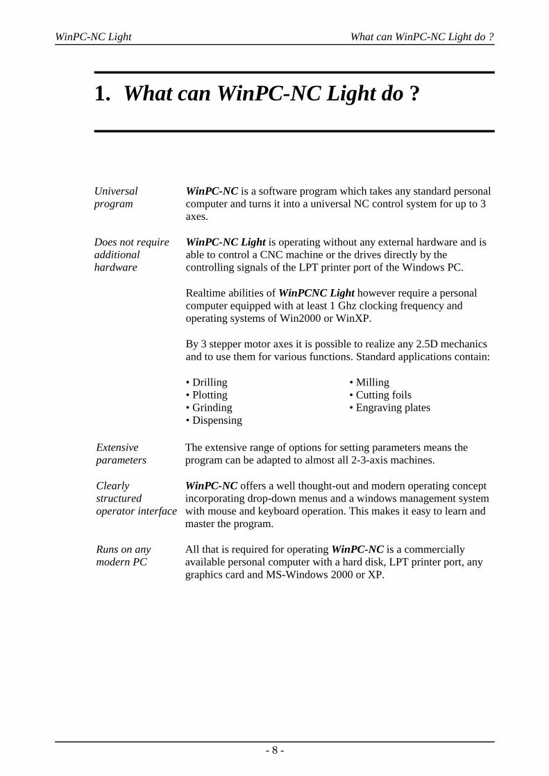
By 3 stepper motor axes it is possible to realize any 2.5D mechanicsand to use them for various functions. Standard applications contain:
• Drilling • Milling• Plotting • Cutting foils• Grinding • Engraving plates• Dispensing
Extensiveparameters
Clearly structuredoperator interface
Runs on anymodern PC
The extensive range of options for setting parameters means theprogram can be adapted to almost all 2-3-axis machines.
WinPC-NC offers a well thought-out and modern operating conceptincorporating drop-down menus and a windows management systemwith mouse and keyboard operation. This makes it easy to learn andmaster the program.
All that is required for operating WinPC-NC is a commerciallyavailable personal computer with a hard disk, LPT printer port, anygraphics card and MS-Windows 2000 or XP.
- 8 -

WinPC-NC Light What can WinPC-NC Light do ?
Sample of a 3 axis milling plant
Special features Special features of WinPC-NC Light :
• 32-bit arithmetic for an almost unlimited working range
• according to industry standards it is controlling byclocking/direction signals any commercial stepper motor cardsand producing stepping frequencies up to 12 kHz
• as an alternative a version for the commonly known SMC steppermotor cards is available, however with restrictions of the carditself
• jog mode in exact steps using the cursor keys or the mouse
• graphical display with scale, zoom, shift, turning and reflectingfunctions
• runs under Win2000 and XP without restrictions (date 6/06)
• axis resolutions, speeds, ramp length for the X/Y and Z-axis canbe set within generous limits.
• reference and limit switch interrogation, max. 5 inputs and 4additional outputs can be set within generous limits on LPT1
• recognizes the common available HPGL and drilling formats
- 9 -
WinPC-NC Light What can WinPC-NC Light do ?
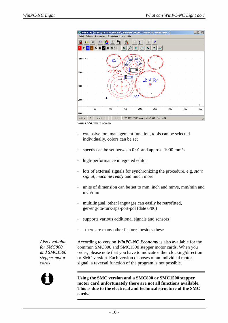
WinPC-NC main screen
• extensive tool management function, tools can be selectedindividually, colors can be set
• speeds can be set between 0.01 and approx. 1000 mm/s
• high-performance integrated editor
• lots of external signals for synchronizing the procedure, e.g. startsignal, machine ready and much more
• units of dimension can be set to mm, inch and mm/s, mm/min andinch/min
• multilingual, other languages can easily be retrofitted,ger-eng-ita-turk-spa-port-pol (date 6/06)
• supports various additional signals and sensors
• ..there are many other features besides these
Also available for SMC800 and SMC1500stepper motorcards
According to version WinPC-NC Economy is also available for thecommon SMC800 and SMC1500 stepper motor cards. When youorder, please note that you have to indicate either clocking/directionor SMC version. Each version disposes of an individual motorsignal, a reversal function of the program is not possible.
i Using the SMC version and a SMC800 or SMC1500 steppermotor card unfortunately there are not all functions available.This is due to the electrical and technical structure of the SMCcards.
- 10 -

WinPC-NC Light What can WinPC-NC Light do ?
Please consider the following restrictions with SMC steppermotor cards :
• limit of the stepping frequency to max. 5kHz
• not more than 3 axes connectable
• all reference switches and additional inputs can only be connectedto one input line on the card.
• further technical details can be obtained by the documentation ofthe SMC cards
- 11 -

WinPC-NC Light First steps
2. First steps
2.1. Requirements to hardwareWinPC-NC Light is able to control a connected CNC machine andthe corresponding drives directly by the LPT printer port. In order tomake this procedure possible, a real time driver has been installed inthe lowest plane of the operating system providing the necessarytimers and mechanisms.
A faultless operation is therefore only guaranteed with Personalcomputers with certain minimum of requirements.
• modern CPU with at least 1GHz clocking frequency (more than 2 Ghz are recommended)
• Windows 2000 or Windows XP operating systems or successingmodels
• at least one true parallel printer port (onboard or by ISA/PCIplugin card)
• standard graphical card, keyboard, mouse, hard disk and othercommon PC implements
Detailed information and tips for selecting the suitable computer canbe learned from further support information documents.
2.2. Possible restrictions during realtime operationA reliable realtime operation under Windows depends on manydifferent factors and can be affected by many running actions.Disturbances by other programs lead normally to an irregular andrough motor run. Sometimes it can happen that the machine will actcompletely uncontrolled.
- 12 -
WinPC-NC Light First steps
Please avoidbackgroundprograms
Ill effects concerning realtime ability...
• access to hard disks, diskettes and network system as well aswireless system actions
• battery loading on notebooks or the constant monitoring andmeasuring of the battery capacity
• virus scan and firewall programs in the background
• Media-Player or other highspeed start-up programs awaiting in thebackground certain user actions.
• dynamic processor clock frequency changing functions likeSpeedStep® or PowerNow®
In general it is recommended to remove or deactivate all programswhich are not required. Notebooks often cause much more problemsthan desktops computers because the essential signals of the printerport often do not meet the electrical requirements.
Detailed information and tips for selecting the suitable unit are givenwith additional support information.
2.3. Installation
User-friendlyinstallation
WinPC-NC is installed using a user-friendly setup program. Pleaseinsert the disk into the drive and wait for automatic installation start.If the installation is not executed, please start the programSETUP.EXE directly from the CD. The installation wizard thenguides you through the entire procedure.
Call up the README file to learn about important changes to theinformation in the manual. These changes are additional featuresincluded after the manual was written.
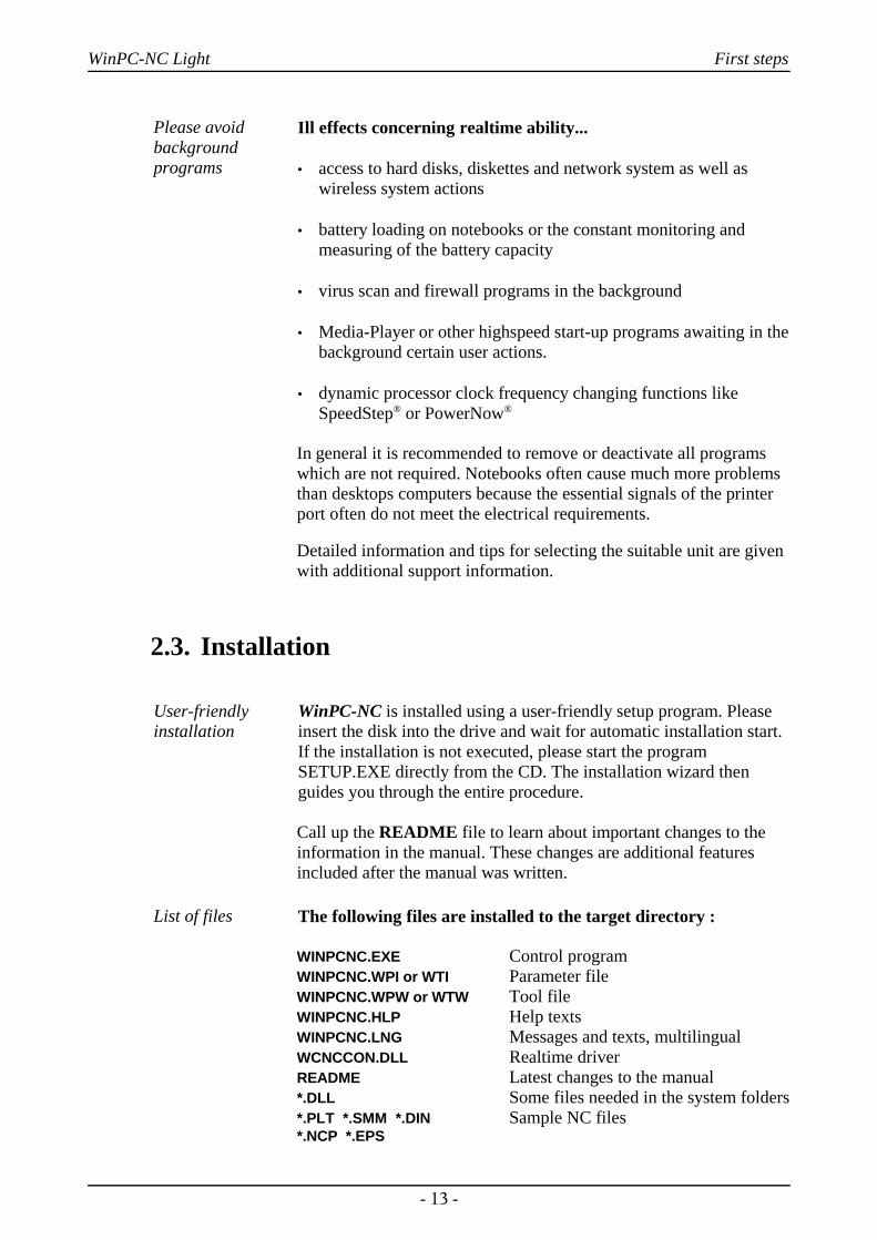
List of files The following files are installed to the target directory :
WINPCNC.EXE Control programWINPCNC.WPI or WTI Parameter fileWINPCNC.WPW or WTW Tool fileWINPCNC.HLP Help textsWINPCNC.LNG Messages and texts, multilingualWCNCCON.DLL Realtime driverREADME Latest changes to the manual*.DLL Some files needed in the system folders*.PLT *.SMM *.DIN Sample NC files*.NCP *.EPS
- 13 -
WinPC-NC Light First steps
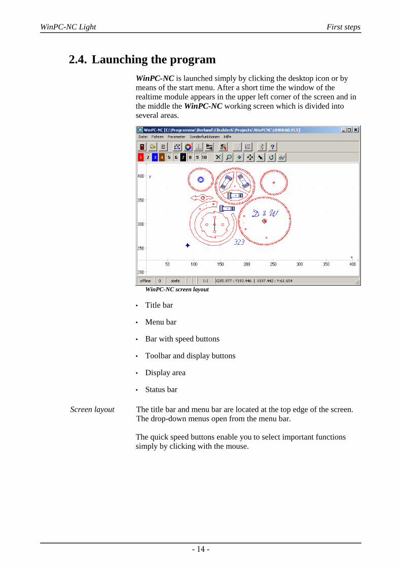
2.4. Launching the programWinPC-NC is launched simply by clicking the desktop icon or bymeans of the start menu. After a short time the window of therealtime module appears in the upper left corner of the screen and inthe middle the WinPC-NC working screen which is divided intoseveral areas.
WinPC-NC screen layout
• Title bar
• Menu bar
• Bar with speed buttons
• Toolbar and display buttons
• Display area
• Status bar
Screen layout The title bar and menu bar are located at the top edge of the screen.The drop-down menus open from the menu bar.
The quick speed buttons enable you to select important functionssimply by clicking with the mouse.
- 14 -
WinPC-NC Light First steps
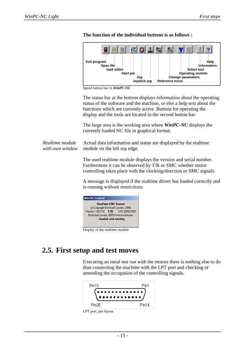
The function of the individual buttons is as follows :
Exit program Help Open file Information load editor Select tool Start job Operating molette Jog Change parameters Joystick jog Reference move
Speed button bar in WinPC-NC
The status bar at the bottom displays information about the operatingstatus of the software and the machine, or else a help text about thefunctions which are currently active. Buttons for operating thedisplay and the tools are located in the second button bar.
The large area is the working area where WinPC-NC displays thecurrently loaded NC file in graphical format.
Realtime modulewith own window
Actual data information and status are displayed by the realtimemodule on the left top edge.
The used realtime module displays the version and serial number.Furthermore it can be observed by T/R or SMC whether motorcontrolling takes place with the clocking/direction or SMC signals.
A message is displayed if the realtime driver has loaded correctly andis running without restrictions.
Display of the realtime module
2.5. First setup and test movesExecuting an intial test run with the motors there is nothing else to dothan connecting the machine with the LPT port and checking oramending the occupation of the controlling signals.
LPT port, pin layout
- 15 -
WinPC-NC Light First steps
WinPC-NC is using the following signals for motor actuation...
Pin 2 direction motor XPin 3 clock motor XPin 4 direction motor YPin 5 clock motor YPin 6 direction motor ZPin 7 clock motor ZPin 8 direction motor 4Pin 9 clock motor 4
i Using a SMC steppermotor card it is not necessary to considerthe exact signal assignment. It is sufficient to utilize a commonlyused printer cable for connecting LPT port and SMC card.
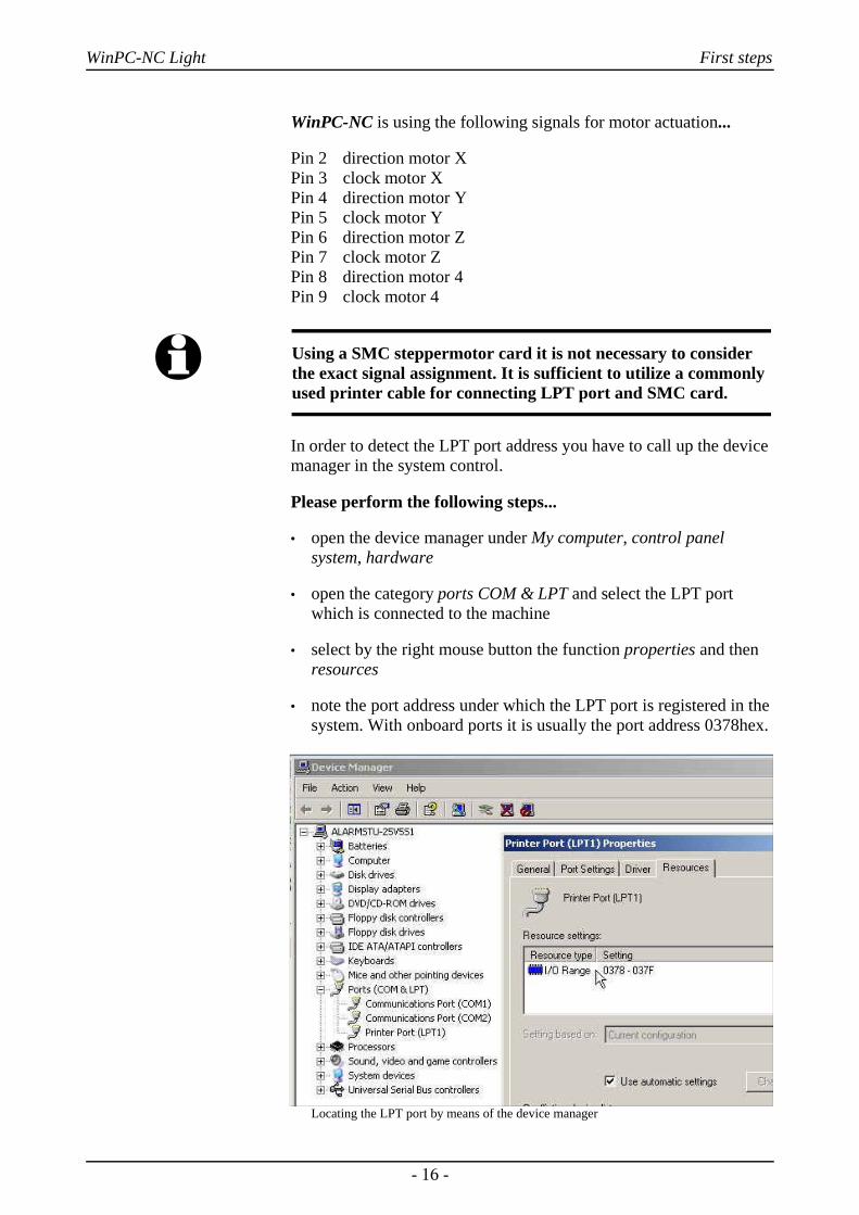
In order to detect the LPT port address you have to call up the devicemanager in the system control.
Please perform the following steps...
• open the device manager under My computer, control panelsystem, hardware
• open the category ports COM & LPT and select the LPT portwhich is connected to the machine
• select by the right mouse button the function properties and thenresources
• note the port address under which the LPT port is registered in thesystem. With onboard ports it is usually the port address 0378hex.
Locating the LPT port by means of the device manager
- 16 -

WinPC-NC Light First steps
The detected port address has to be registered in WinPC-NC underparameter-ports- LPT.port address and complete the process byclicking the function keys SAVE and OK.
After this procedure it should be possible to perfom a simple test runwith function JOG or MOTOR TEST. Please be very careful inperforming and be aware of uncontrolled movements of the machine.
i When first delivered, the LPT port address is registered with0378hex. This applies for nearly all internal ports.
Detailed instructions concerning start-up procedure are given in aseparate chapter.
2.6. Exiting WinPC-NCYou can exit WinPC-NC at any time by clicking the cross in the boxat the top right of the window, or by selecting EXIT from the FILEmenu.
- 17 -
WinPC-NC Light Operating WinPC-NC
3. Operating WinPC-NC
3.1. Graphical display of the NC file
Graphical previewof the NC files
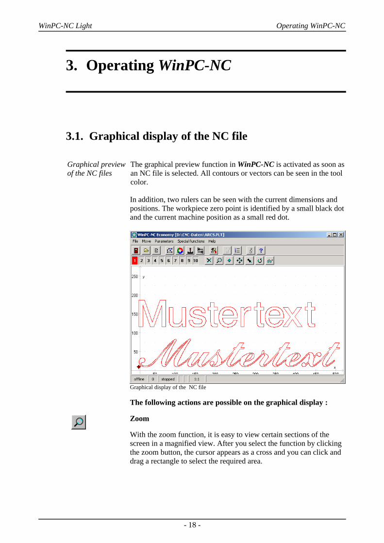
The graphical preview function in WinPC-NC is activated as soon asan NC file is selected. All contours or vectors can be seen in the toolcolor.
In addition, two rulers can be seen with the current dimensions andpositions. The workpiece zero point is identified by a small black dotand the current machine position as a small red dot.
Graphical display of the NC file
The following actions are possible on the graphical display :
Zoom
With the zoom function, it is easy to view certain sections of thescreen in a magnified view. After you select the function by clickingthe zoom button, the cursor appears as a cross and you can click anddrag a rectangle to select the required area.
- 18 -
WinPC-NC Light Operating WinPC-NC
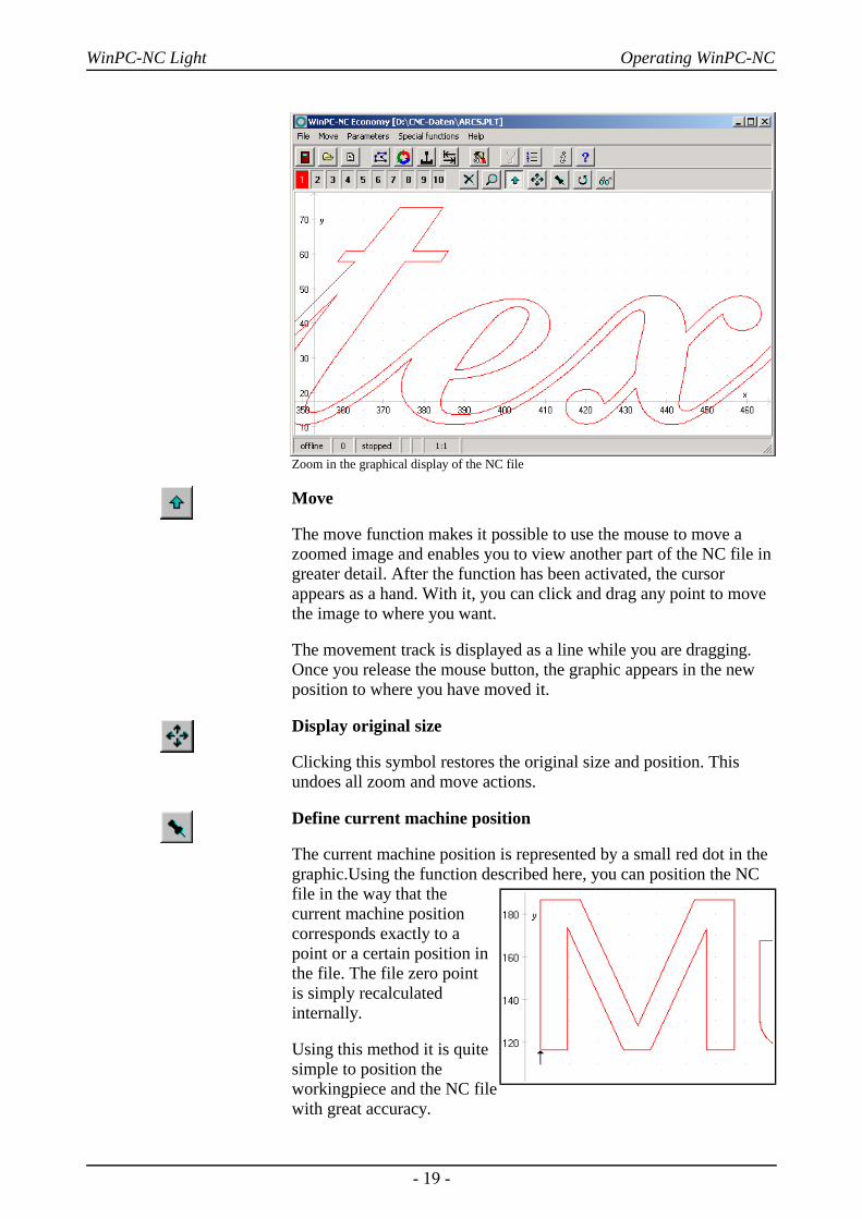
Zoom in the graphical display of the NC file
Move
The move function makes it possible to use the mouse to move azoomed image and enables you to view another part of the NC file ingreater detail. After the function has been activated, the cursorappears as a hand. With it, you can click and drag any point to movethe image to where you want.
The movement track is displayed as a line while you are dragging.Once you release the mouse button, the graphic appears in the newposition to where you have moved it.
Display original size
Clicking this symbol restores the original size and position. Thisundoes all zoom and move actions.
Define current machine position
The current machine position is represented by a small red dot in thegraphic.Using the function described here, you can position the NCfile in the way that thecurrent machine positioncorresponds exactly to apoint or a certain position inthe file. The file zero point is simply recalculatedinternally.
Using this method it is quitesimple to position theworkingpiece and the NC filewith great accuracy.
- 19 -
WinPC-NC Light Operating WinPC-NC
Cancel function
Once a zoom, move or positioning action has been started, it can becancelled by clicking the cancel button. The cursor reverts to itsnormal arrow shape.
Turning data
By clicking the TURN button it is possible to turn the indicated databy 90°. In this way it is easier to place the data on the material.
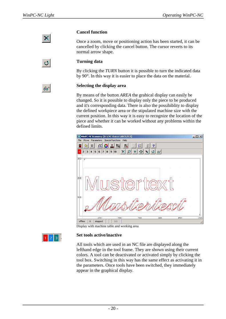
Selecting the display area
By means of the button AREA the grahical display can easily bechanged. So it is possible to display only the piece to be producedand it's corresponding data. There is also the possibiblity to displaythe defined workpiece area or the stipulated machine size with thecurrent position. In this way it is easy to recognize the location of thepiece and whether it can be worked without any problems within thedefined limits.
Display with machine table and working area
Set tools active/inactive
All tools which are used in an NC file are displayed along thelefthand edge in the tool frame. They are shown using their currentcolors. A tool can be deactivated or activated simply by clicking thetool box. Switching in this way has the same effect as activating it inthe parameters. Once tools have been switched, they immediatelyappear in the graphical display.
- 20 -

WinPC-NC Light Operating WinPC-NC
Graphical display with inactive tools
3.2. Drop-down menus and function keys
Modern interface
WinPC-NC has a modern user interface. All functions can beactivated by drop-down menus. In addition, frequently required functions can be activated quickly using the function keys or speedbuttons.
The drop-down menus are divided into several functional groups, e.g.all functions concerned with selecting and editing files are groupedtogether in one menu. All parameters and tools are set using anothermenu.
The menu system is opened or activated by clicking the menu item orpressing one of the shortcut keys for the individual menus.
Additionalfunction keys
Important functions can also be activated using function keys. Thefunction key assignment is fixed and indicated in the menufunctions.
The most important function keys are :
(F1) Activate the help system(F2) Load new NC file(shift-F2) Load parameter file(F3) Start job process(F5) Jog(shift-F5) Joystick jog(F7) Load active or new file into the editor(F8) Start reference move
- 21 -

WinPC-NC Light Operating WinPC-NC
3.3. The individual menusThe following text describes all the menus and functions in detail.
Not all menu items are active all the time. Functions are sometimesunavailable, depending on the program status. For example, it is notpossible to use the joystick if it has not been defined in theparameters.
3.3.1. File menuThe FILE menu combines all functions used for selecting files toprocess and analyse them. In addition, it is also possible to exitWinPC-NC here.
Press the (alt-D) shortcut key to open the file menu.
FILE-OPEN
File selection by menu
The FILE-OPEN menu item calls up an interactive function forselecting a NC file.
File selection dialog box
In the dialog box, it is possible to change drives and folders, as wellas to activate filters for certain file name extensions. The fileselection function can also be activated using function key (F2) or byclicking the open button.
Graphical previewof an NC file
The graphical preview function in WinPC-NC is activated as soon asit is selected. All contours or vectors can be seen in thecorresponding tool color.
- 22 -
Open F2Open without parametersEditor F7
Exit
WinPC-NC Light Operating WinPC-NC
FILE-OPEN WITHOUT PARAMETERSThe second OPEN function only loads the corresponding NC filewithout taking account of any project parameters. All currentparameter settings remain valid.
FILE-EDITOR
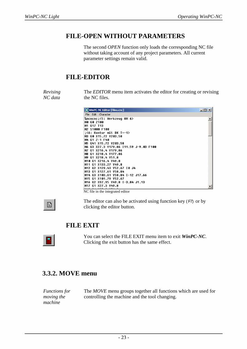
Revising NC data
The EDITOR menu item activates the editor for creating or revisingthe NC files.
NC file in the integrated editor
The editor can also be activated using function key (F7) or byclicking the editor button.
FILE EXITYou can select the FILE EXIT menu item to exit WinPC-NC.Clicking the exit button has the same effect.
3.3.2. MOVE menu
Functions formoving themachine
The MOVE menu groups together all functions which are used forcontrolling the machine and the tool changing.
- 23 -

WinPC-NC Light Operating WinPC-NC
Press the (Alt-F) shortcut key to open the menu.
MOVE-STARTAfter a working file has been loaded, the START menu item can beused for processing the job. Pressing the (F3) key or clicking theSTART button has the same effect.
WinPC-NC controls the X and Y motors during move commands.The Z motor moves up and down during tool movement commands.
Progress display During machining, a window displays the progress as a percentage.In additon the realtime file display is available where the currentperformed command line is marked by a cursor bar.
Display of progress and speed override
A working process can be cancelled by clicking the STOP button inthe progress display window, or by pressing the (ESC) key. Themachine brakes all axes without losing any steps and switches off thespindle and the cooling function.
MOVE JOGThe JOG menu item calls up the manual setup function for themachine. This function can also be accessed by pressing the (F5)
function key or with the jog button.
- 24 -
Start F3
Jog F5Joystick jog shift-F5Reference move F8
Select tool
WinPC-NC Light Operating WinPC-NC
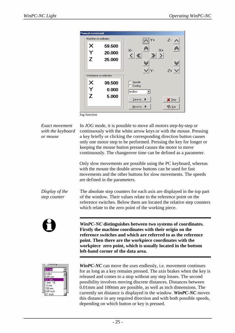
Jog function
Exact movementwith the keyboardor mouse
In JOG mode, it is possible to move all motors step-by-step orcontinuously with the white arrow keys or with the mouse. Pressinga key briefly or clicking the corresponding direction button causesonly one motor step to be performed. Pressing the key for longer orkeeping the mouse button pressed causes the motor to movecontinuously. The changeover time can be defined as a parameter.
Only slow movements are possible using the PC keyboard, whereaswith the mouse the double arrow buttons can be used for fastmovements and the other buttons for slow movements. The speedsare defined in the parameters.
Display of the step counter
The absolute step counters for each axis are displayed in the top partof the window. Their values relate to the reference point on thereference switches. Below them are located the relative step counterswhich relate to the zero point of the working piece.
i WinPC-NC distinguishes between two systems of coordinates.Firstly the machine coordinates with their origin on thereference switches and which are referred to as the referencepoint. Then there are the workpiece coordinates with theworkpiece zero point, which is usually located in the bottomleft-hand corner of the data area.
WinPC-NC can move the axes endlessly, i.e. movement continuesfor as long as a key remains pressed. The axis brakes when the key isreleased and comes to a stop without any step losses. The secondpossibility involves moving discrete distances. Distances between0.01mm and 100mm are possible, as well as inch dimensions. Thecurrently set distance is displayed in the window. WinPC-NC movesthis distance in any required direction and with both possible speeds,depending on which button or key is pressed.
- 25 -

WinPC-NC Light Operating WinPC-NC
In addition to the predefined distances, it is possible to enter anydistance in the text box.
Switchingadditional signals
Clicking the check boxes with the mouse is all that is required toswitch the additional signals drilling spindle and coolant pump. Thisswitches the signals on or off. Both signals are switched off whenyou exit the JOG function.
During manual movement, it is possible to move and store certain help points. After a position has beenreached, it is easy to click the Save button to select therequired point and save it permanently as a parameter.
Moving to saved help points is just as staightforward.All that is required is to click the Move to button and select the required help point. Then the machine moves to it.
Movement in progress can be interrupted at anytime by clicking the Stop button.
The JOG function can be exited by clicking the theExit button.
MOVE JOYSTICK JOGGINGAs an alternative to the mouse and keyboard, it is also possible tomove the machine manually using a connected joystick. This is ofadvantage for observing the movements directly on the machine andsetting exact positions. It is easier to take a joystick to the machinethan keyboard or mouse.
i Prior to use a connected joystick it must be configured in theWindows system and calibrated with a special function.
Jogging withjoystick
When setting up the machine with the joystick, movement in the Xand Y-axis directions can be achieved simply by tilting the controlhandle. Moving the Z-axis requires pressing joystick button 1 aswell.
A help point can also be stored directly at the machine using thejoystick. The stored position can be selected by repeatedly pressingjoystick button 2. To store the position itself, press button 2 at thesame time as holding button 1 pressed.
- 26 -
WinPC-NC Light Operating WinPC-NC
Manual move with joystick
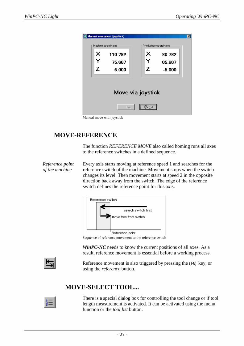
MOVE-REFERENCEThe function REFERENCE MOVE also called homing runs all axesto the reference switches in a defined sequence.
Reference point of the machine
Every axis starts moving at reference speed 1 and searches for thereference switch of the machine. Movement stops when the switchchanges its level. Then movement starts at speed 2 in the oppositedirection back away from the switch. The edge of the referenceswitch defines the reference point for this axis.
Sequence of reference movement to the reference switch
WinPC-NC needs to know the current positions of all axes. As aresult, reference movement is essential before a working process.
Reference movement is also triggered by pressing the (F8) key, orusing the reference button.
MOVE-SELECT TOOL...There is a special dialog box for controlling the tool change or if toollength measurement is activated. It can be activated using the menufunction or the tool list button.
- 27 -
WinPC-NC Light Operating WinPC-NC
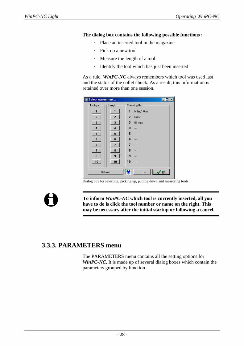
The dialog box contains the following possible functions :• Place an inserted tool in the magazine• Pick up a new tool• Measure the length of a tool• Identify the tool which has just been inserted
As a rule, WinPC-NC always remembers which tool was used lastand the status of the collet chuck. As a result, this information isretained over more than one session.
Dialog box for selecting, picking up, putting down and measuring tools
i To inform WinPC-NC which tool is currently inserted, all youhave to do is click the tool number or name on the right. Thismay be necessary after the initial startup or following a cancel.
3.3.3. PARAMETERS menuThe PARAMETERS menu contains all the setting options forWinPC-NC. It is made up of several dialog boxes which contain theparameters grouped by function.
- 28 -
WinPC-NC Light Operating WinPC-NC
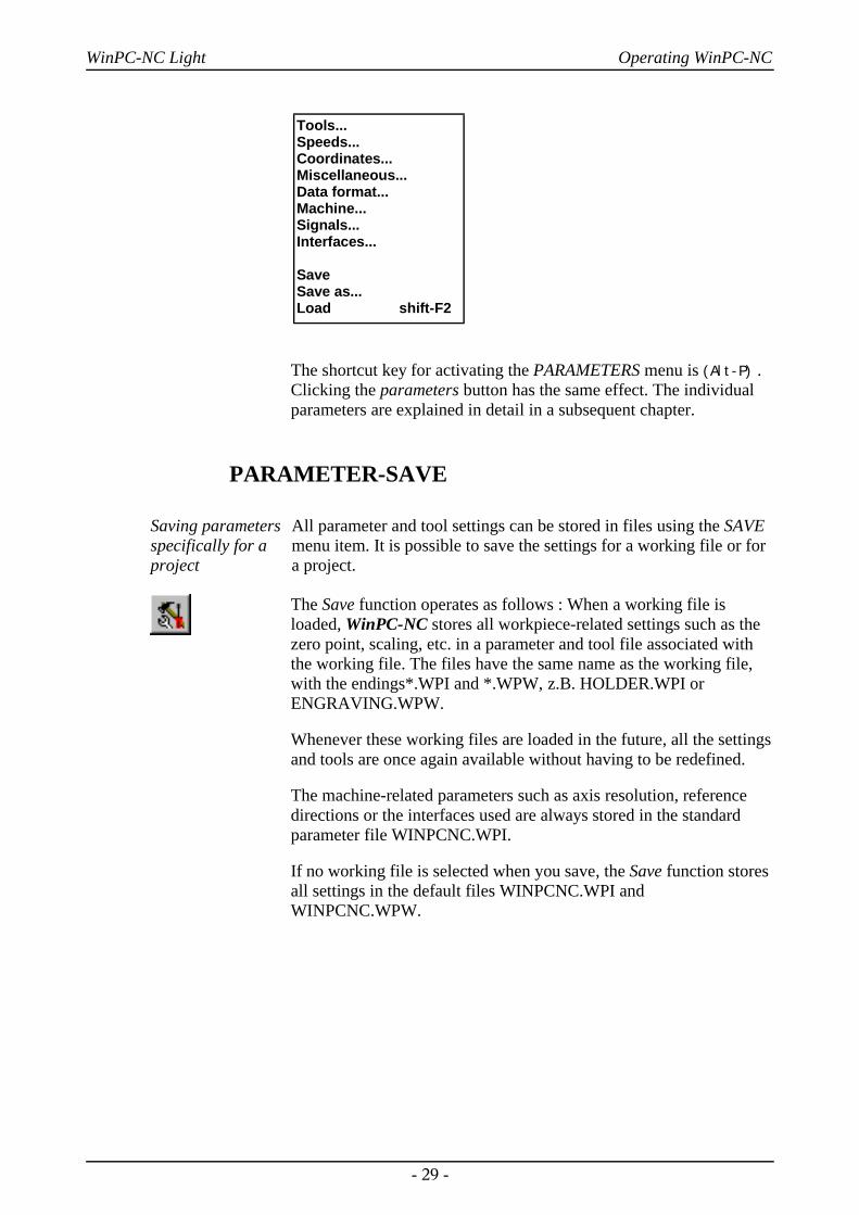
The shortcut key for activating the PARAMETERS menu is (Alt-P) .Clicking the parameters button has the same effect. The individualparameters are explained in detail in a subsequent chapter.
PARAMETER-SAVE
Saving parametersspecifically for aproject
All parameter and tool settings can be stored in files using the SAVEmenu item. It is possible to save the settings for a working file or fora project.
The Save function operates as follows : When a working file isloaded, WinPC-NC stores all workpiece-related settings such as thezero point, scaling, etc. in a parameter and tool file associated withthe working file. The files have the same name as the working file,with the endings*.WPI and *.WPW, z.B. HOLDER.WPI orENGRAVING.WPW.
Whenever these working files are loaded in the future, all the settingsand tools are once again available without having to be redefined.
The machine-related parameters such as axis resolution, referencedirections or the interfaces used are always stored in the standardparameter file WINPCNC.WPI.
If no working file is selected when you save, the Save function storesall settings in the default files WINPCNC.WPI andWINPCNC.WPW.
- 29 -
Tools...Speeds...Coordinates...Miscellaneous...Data format...Machine...Signals...Interfaces...
SaveSave as...Load shift-F2
WinPC-NC Light Operating WinPC-NC
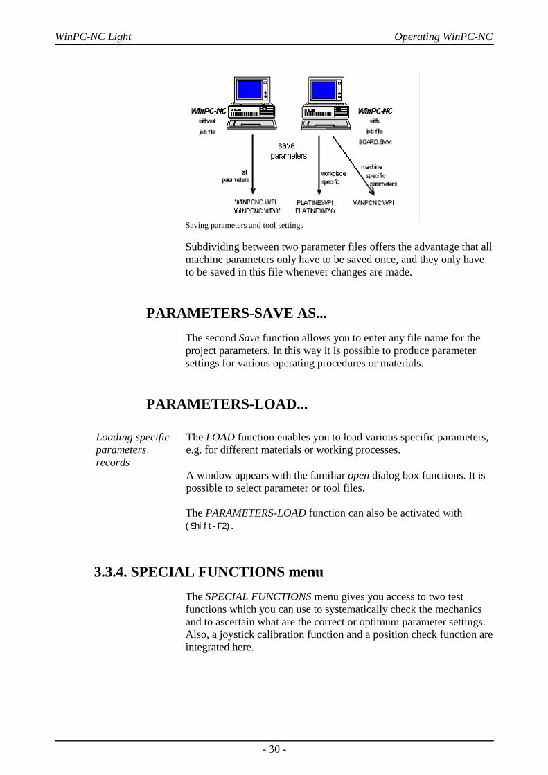
Saving parameters and tool settings
Subdividing between two parameter files offers the advantage that allmachine parameters only have to be saved once, and they only haveto be saved in this file whenever changes are made.
PARAMETERS-SAVE AS...The second Save function allows you to enter any file name for theproject parameters. In this way it is possible to produce parametersettings for various operating procedures or materials.
PARAMETERS-LOAD...
Loading specificparametersrecords
The LOAD function enables you to load various specific parameters,e.g. for different materials or working processes.
A window appears with the familiar open dialog box functions. It ispossible to select parameter or tool files.
The PARAMETERS-LOAD function can also be activated with(Shift-F2).
3.3.4. SPECIAL FUNCTIONS menuThe SPECIAL FUNCTIONS menu gives you access to two testfunctions which you can use to systematically check the mechanicsand to ascertain what are the correct or optimum parameter settings.Also, a joystick calibration function and a position check function areintegrated here.
- 30 -

WinPC-NC Light Operating WinPC-NC
SPECIAL FUNCTIONS-SIGNAL TESTThis test function can be used for checking the axis inputs of thecontroller, i.e. the limit and reference switches, as well as the outputs.
Signal test
Interactive testing of allinputs/outputs
WinPC-NC continuously interrogates the limit switches andreference switches on all supported axes and displays their status.Grayed out switches are not defined.
Black indicates the switch is not active, while red displays that theswitch is activated.
i Definiton of the switches and setup of the switching logic mustbe executed during installation by the signal wizzard underparameter-machine-signals.
The supported additional signals are tested by simply clicking theLED symbols. This switches the outputs on or off.
- 31 -
Signal testMotor testStatus informationJoystick calibrationCheck position
WinPC-NC Light Operating WinPC-NC
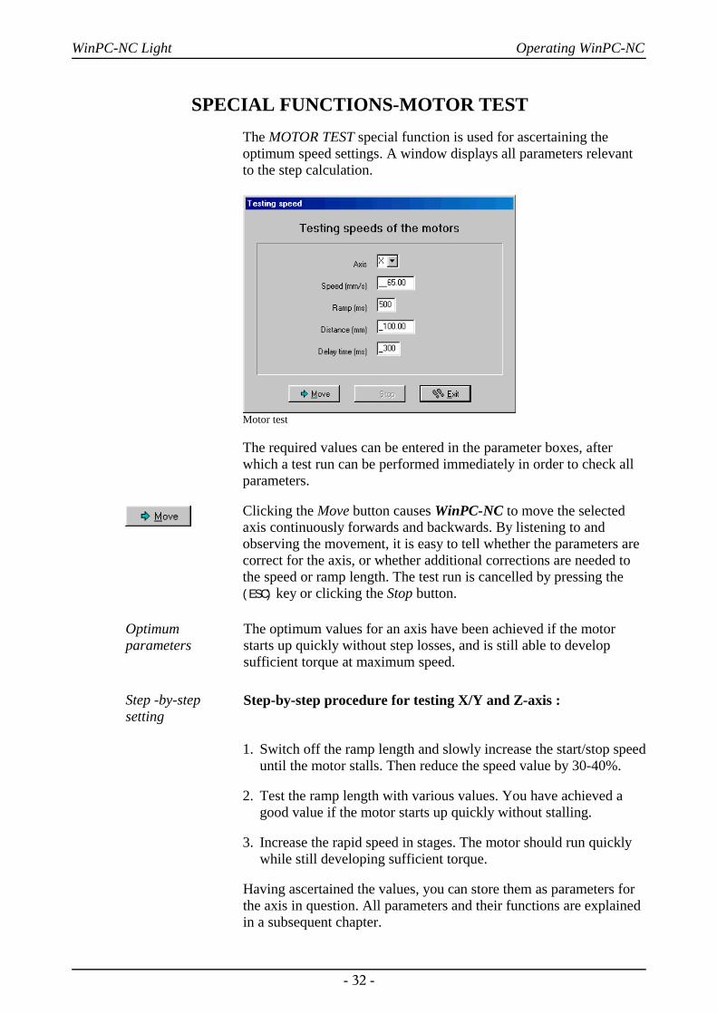
SPECIAL FUNCTIONS-MOTOR TESTThe MOTOR TEST special function is used for ascertaining theoptimum speed settings. A window displays all parameters relevantto the step calculation.
Motor test
The required values can be entered in the parameter boxes, afterwhich a test run can be performed immediately in order to check allparameters.
Clicking the Move button causes WinPC-NC to move the selectedaxis continuously forwards and backwards. By listening to andobserving the movement, it is easy to tell whether the parameters arecorrect for the axis, or whether additional corrections are needed tothe speed or ramp length. The test run is cancelled by pressing the(ESC) key or clicking the Stop button.
Optimumparameters
The optimum values for an axis have been achieved if the motorstarts up quickly without step losses, and is still able to developsufficient torque at maximum speed.
Step -by-stepsetting
Step-by-step procedure for testing X/Y and Z-axis :
1. Switch off the ramp length and slowly increase the start/stop speeduntil the motor stalls. Then reduce the speed value by 30-40%.
2. Test the ramp length with various values. You have achieved agood value if the motor starts up quickly without stalling.
3. Increase the rapid speed in stages. The motor should run quicklywhile still developing sufficient torque.
Having ascertained the values, you can store them as parameters forthe axis in question. All parameters and their functions are explainedin a subsequent chapter.
- 32 -
WinPC-NC Light Operating WinPC-NC
i The optimum parameters for a stepper motor axis depend onmany factors, e.g. the motor characteristic, the type of drive used(spindle or belt) and the load to be moved.
SPECIAL FUNCTIONS-STATUS INFORMATION
Informationen about the realtime module
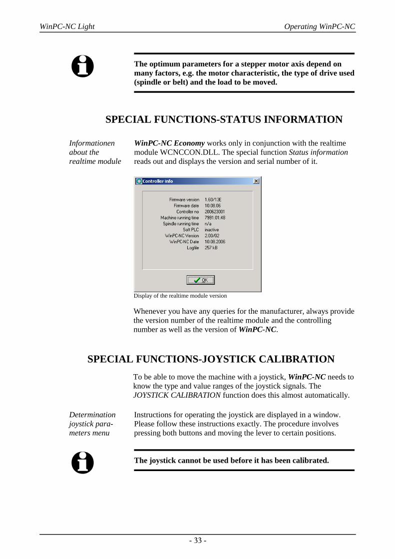
WinPC-NC Economy works only in conjunction with the realtimemodule WCNCCON.DLL. The special function Status informationreads out and displays the version and serial number of it.
Display of the realtime module version
Whenever you have any queries for the manufacturer, always providethe version number of the realtime module and the controllingnumber as well as the version of WinPC-NC.
SPECIAL FUNCTIONS-JOYSTICK CALIBRATIONTo be able to move the machine with a joystick, WinPC-NC needs toknow the type and value ranges of the joystick signals. TheJOYSTICK CALIBRATION function does this almost automatically.
Determinationjoystick para-meters menu
Instructions for operating the joystick are displayed in a window.Please follow these instructions exactly. The procedure involvespressing both buttons and moving the lever to certain positions.
i The joystick cannot be used before it has been calibrated.
- 33 -

WinPC-NC Light Operating WinPC-NC
Joystick calibration
SPECIAL FUNCTIONS – CHECK POSITIONThe CHECK POSITION function is another test function in WinPC-NC. It can be used for checking the accuracy of the referenceswitches.
Result of the position check
Check referenceposition
Relatively small step discrepancies may be due to the switches.Large discrepancies, on the other hand, indicate previous step losses.
It is a good idea to use the CHECK POSITION function if:
• you presume steps have been lost due to a collision
• you want to determine the maximum machining speed for a tool ora material, which means you want to demonstrate whether or notsteps have been lost
• the position was changed during a tool change
i It is only possible to check the reference position if referencemovement was performed previously and there was no canceldue to a limit switch or a stop signal.
- 34 -
WinPC-NC Light Operating WinPC-NC
3.3.5. HELP-menuThere are three items in the help menu:
HELP-TOPICSThe HELP TOPICS function gives you access to the help system. Adialog box appears containing the main selection.
HELP-LIABILITYThe HELP-LIABILITY function displays a text with the licenseconditions and a disclaimer. Please read this information carefullybefore using WinPC-NC.
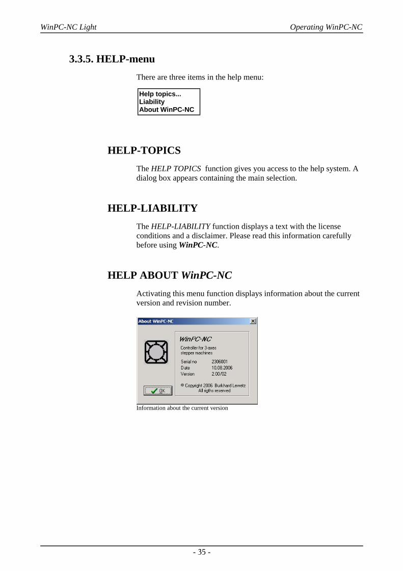
HELP ABOUT WinPC-NCActivating this menu function displays information about the currentversion and revision number.
Information about the current version
- 35 -
Help topics...LiabilityAbout WinPC-NC
WinPC-NC Light Parameter settings
4. Parameter settings
4.1. Tool management
Project-relatedtool management
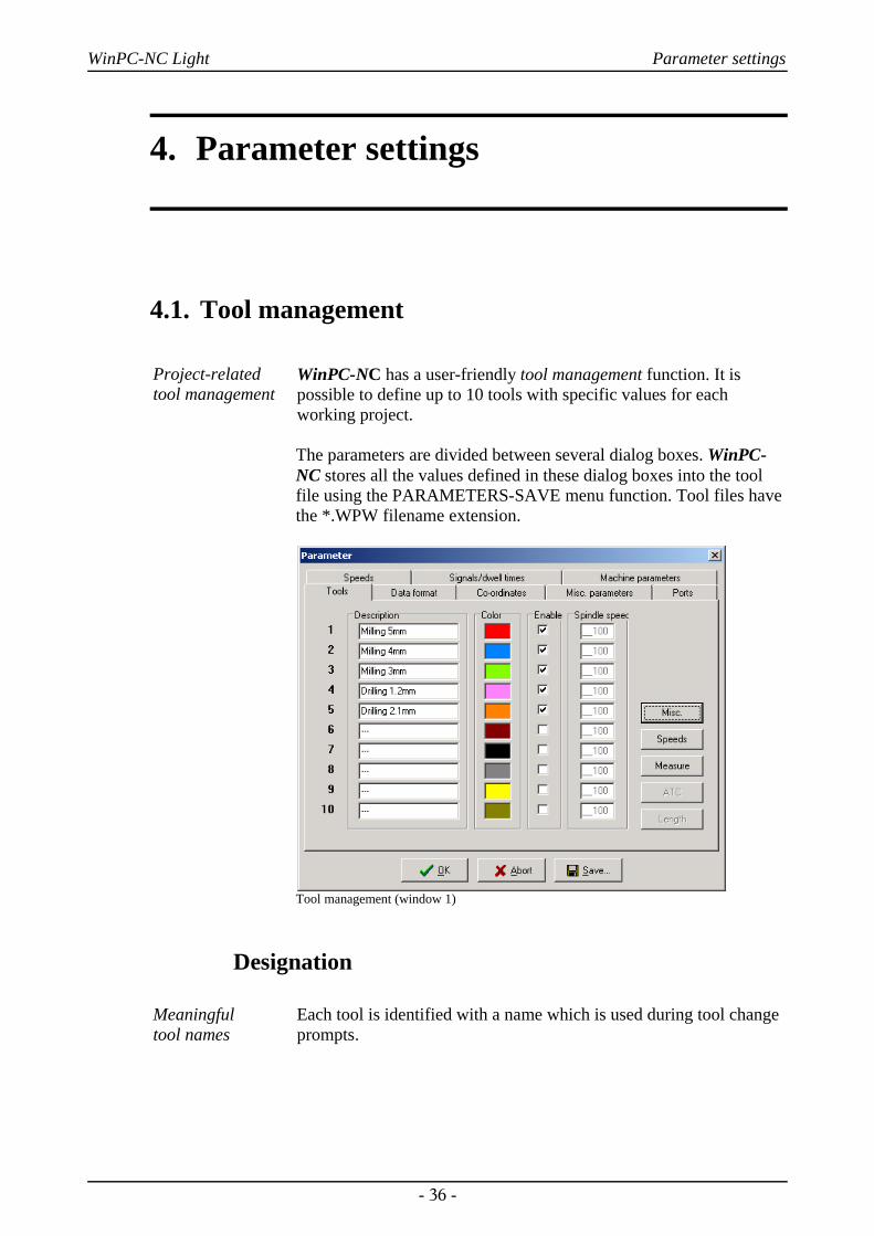
WinPC-NC has a user-friendly tool management function. It ispossible to define up to 10 tools with specific values for eachworking project.
The parameters are divided between several dialog boxes. WinPC-NC stores all the values defined in these dialog boxes into the toolfile using the PARAMETERS-SAVE menu function. Tool files havethe *.WPW filename extension.
Tool management (window 1)
Designation
Meaningful tool names
Each tool is identified with a name which is used during tool changeprompts.
- 36 -

WinPC-NC Light Parameter settings
Color
Colors in thegraphical display
The Color parameter for each tool is used in the graphical display ofthe data. As a result, it is easy to adapt the color display to suit yourown requirements or to harmonize with the CAD program you areusing.
Clicking the colored box opens a dialog box in which you can selecta new color. All colors supported by the current Windows displaysettings can be selected.
Activation
Activating toolsindividually
Each tool can be individually enabled or blocked. Inactive tools aresimply ignored in the graphical display and the commands for themare skipped.
Tool speeds
Tool management (window 2)
Plunge speedThe plunge speed specifies the speed with which each tool is pushedinto the workpiece. It is necessary to consider certain limit valueshere, depending on the material and the tool.
- 37 -

WinPC-NC Light Parameter settings
Advance speedThe advance speed or feed rate defines the working speed for eachtool when the tool is pushed into the workpiece.
This value is irrelevant for straightforward drilling applications.However, if WinPC-NC is used for milling, engraving or grinding,then the maximum feed rate depends on the tool used and thematerial.
Withdrawal speedThe withdrawal speed is used for raising or withdrawing the toolfrom the workpiece.
Brake angleThe brake angle specifies the maximum angle differential forsubsequent movement stages in which movement takes place at fullspeed. The value is entered in degrees.
Deterministicspeed optimization
Between the start and finish of movements, the acceleration andbraking function is only activated if the direction of the next vectordeviates from the previous one by more than the defined brake angle.
An example of this deterministic speed optimization function can beseen in movement around a circle, which consists of lots of littleindividual vectors. The directions of two successive movements areonly slightly different. As a result, the circular path can be moved inone operation at maximum speed.
Brake difference
Braking and acceleration always take place before and after toolmovements. This parameter is irrelevant in straightforward drillingapplications and is ignored.
- 38 -
WinPC-NC Light Parameter settings
Tool dimensions
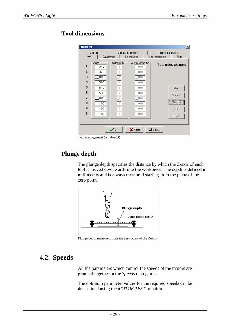
Tool management (window 3)
Plunge depthThe plunge depth specifies the distance by which the Z-axis of eachtool is moved downwards into the workpiece. The depth is defined inmillimeters and is always measured starting from the plane of thezero point.
Plunge depth measured from the zero point of the Z-axis
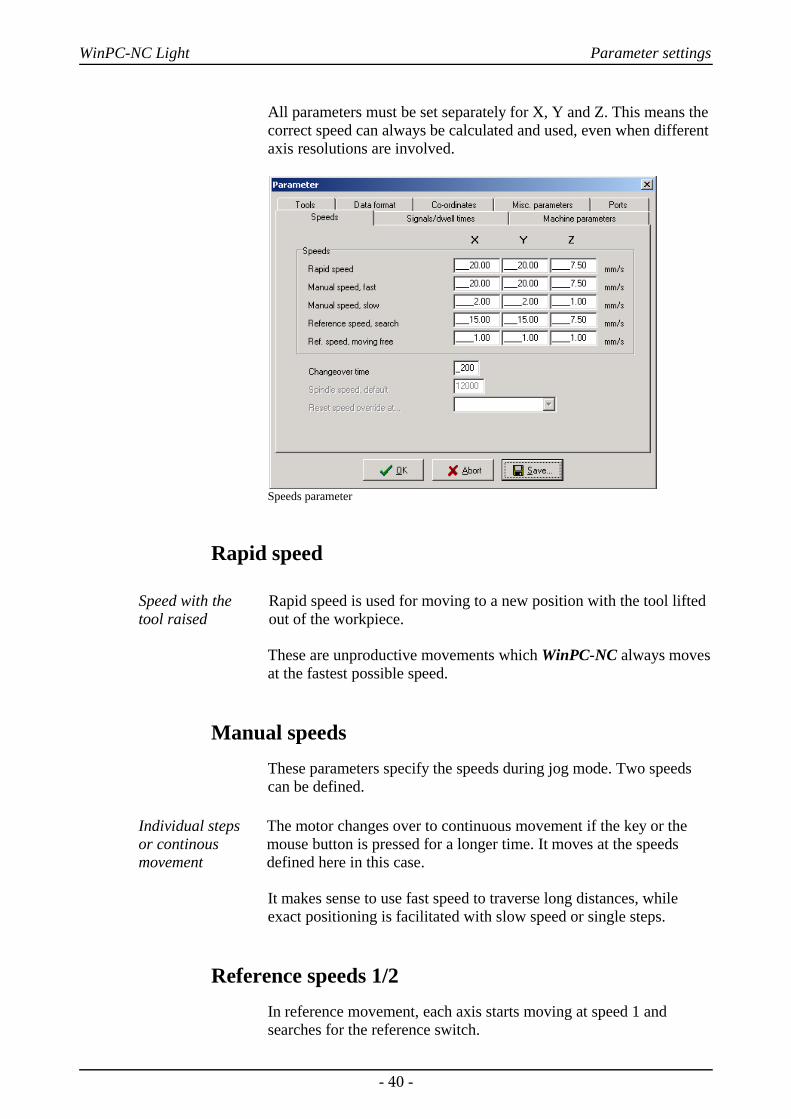
4.2. SpeedsAll the parameters which control the speeds of the motors aregrouped together in the Speeds dialog box.
The optimum parameter values for the required speeds can bedetermined using the MOTOR TEST function.
- 39 -
WinPC-NC Light Parameter settings
All parameters must be set separately for X, Y and Z. This means thecorrect speed can always be calculated and used, even when differentaxis resolutions are involved.
Speeds parameter
Rapid speed
Speed with the tool raised
Rapid speed is used for moving to a new position with the tool liftedout of the workpiece.
These are unproductive movements which WinPC-NC always movesat the fastest possible speed.
Manual speedsThese parameters specify the speeds during jog mode. Two speedscan be defined.
Individual steps or continousmovement
The motor changes over to continuous movement if the key or themouse button is pressed for a longer time. It moves at the speedsdefined here in this case.
It makes sense to use fast speed to traverse long distances, whileexact positioning is facilitated with slow speed or single steps.
Reference speeds 1/2In reference movement, each axis starts moving at speed 1 andsearches for the reference switch.
- 40 -
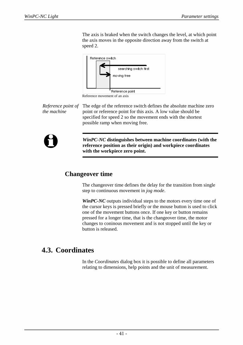
WinPC-NC Light Parameter settings
The axis is braked when the switch changes the level, at which pointthe axis moves in the opposite direction away from the switch atspeed 2.
Reference movement of an axis
Reference point ofthe machine
The edge of the reference switch defines the absolute machine zeropoint or reference point for this axis. A low value should bespecified for speed 2 so the movement ends with the shortestpossible ramp when moving free.
i WinPC-NC distinguishes between machine coordinates (with thereference position as their origin) and workpiece coordinateswith the workpiece zero point.
Changeover timeThe changeover time defines the delay for the transition from singlestep to continuous movement in jog mode.
WinPC-NC outputs individual steps to the motors every time one ofthe cursor keys is pressed briefly or the mouse button is used to clickone of the movement buttons once. If one key or button remainspressed for a longer time, that is the changeover time, the motorchanges to coninous movement and is not stopped until the key orbutton is released.
4.3. CoordinatesIn the Coordinates dialog box it is possible to define all parametersrelating to dimensions, help points and the unit of measurement.
- 41 -

WinPC-NC Light Parameter settings
Setting the working area and the help positions
Machine andworkpiececoordinates
It is necessary to distinguish between two types of positiondefinitions. There are absolute machine coordinates with their zeropoint at the machine reference point. Then there are workpiececoordinates with their origin at the workpiece zero point.
Working area and monitoring working area
Software areamonitoring
The working area defines the section, e. g. for marking materialdimensions. Limits are visible in the graphical display and it isimmediately recognizable whether milling or engraving can beeffected with the material piece. A check is made when job starts.
Maximum plungedepth for Z-axis
The working area for the Z-axis determines the maximum plungedepth to which tools can move without damaging the bed of themachine.
These paramaters are not to be mixed up with the values determiningthe size of the machine table and thereby the maximum moving area.
The unit is millimeters and the distances are measured from themachine reference point (machine coordinates).
Zero pointThe zero point refers to the reference point of the coordinates in theworking file. It is the position with a specific X and Y-axiscoordinate within the NC file, e.g. the left-hand bottom corner. Allprocessing distances are measured from here.
- 42 -

WinPC-NC Light Parameter settings
Working area and help positions
Zero point asorigin of theworkpiececoordinates
The zero point can also be defined manually. To do this, it isnecessary to move to the required position using jog movement andthen save this as the new zero point. The positions of the axes canalso be saved individually.
The unit is millimeters and the lengths represent the absolute distancefrom the machine reference point (machine coordinates).
Park position
Defined positionfor breaks
It is necessary to define a park position if the machine slide is to bemoved out of the working area at certain times. This may benecessary for a tool change, for example, or for clamping theworkpiece.
It is also possible to make this definition during jog movement bymoving into position with the keyboard or mouse.
The parked position can be moved to in jog movement orautomatically during a tool change and at the end of a workingprocess.
The unit is millimeters and the distances are measured from themachine reference point (machine coordinates).
Scaling factorsIt is possible to compensate for calibration differences using thescaling factors. If both the axis resolution and the unit ofmeasurement are set correctly but the machine does not move to theexact length nevertheless, this problem can be corrected using thescaling factors.
The values must be specified to 3 decimal places and are used formultiplying the coordinate values to which the machine is to move. Itaffects the imported NC data only.
- 43 -

WinPC-NC Light Parameter settings
Tool lift
Additionalclearance foravoiding collisions
It is possible to define an additional height above the zero point levelof the Z-axis as a safety clearance. The tool is lifted above the zeropoint by this distance during every unproductive movement withrapid speed and the new height is used as tool lift height.
On the next plunge movement, WinPC-NC first covers the safetyclearance down to the zero point at high speed, before pressing intothe material with the defined plunge speed.
Unit of measurement
Wide range ofpredefined units of measurement
The unit of measurement for working data must be defined using thisparameter. All coordinate values in the working file are related to aparticular dimension.
The possible units are millimeters and inches. HPGL files are usuallyin units of 1/40 mm or 1 mil, while drilling data are usually in 1/100mm or also 1 mil.
Units in the programThe UNITS parameter defines the units for dimensions and speedsused in the graphical display and the parameters.
It is possible to select between three options :
• Millimeters and millimeter/second (mm and mm/s)
• Millimeters and millimeter/minute (mm and mm/min)
• Inch and inches/minute (inch and inch/min)
4.4. Data format and associated parametersWinPC-NC can read and process various data formats. The format ofthe NC file can be selected manually or registered using an automaticrecognition function.
- 44 -

WinPC-NC Light Parameter settings
Data formats and associated parameters
Data formatWinPC-NC understands various NC data formats, and is able toimport these files, display them and perform the movements on themachine. At present, the commonly used plotter format HPGL, andtwo drilling formats are possible.
HPGL is from the well known plotters made by Hewlett Packard andis supported by almost every CAD or drawing program.
Plotting anddrilling formats
The drilling formats are based on the following standards:Sieb&Maier1000, Sieb&Maier3000 and Excellon. In other words, itshould be possible to process working files in these formats withoutany problems.
The appendix contains a list and description of commands in theindividual formats. In the event of problems during processing, forexample if unknown commands or commands which cannot beinterpreted are encountered, then the working file can be analysedusing this description and revised with the editor.
i WinPC-NC usually recognizes the format of the selected fileautomatically.
Automatic identification of the formatUsually most of the supporting NC formats are automaticallyrecognized by WinPC-NC during file opening. It rarely happens that
- 45 -
WinPC-NC Light Parameter settings
errors are produced in this way. If it should be the case they can beeasily eliminated by switching off the identification function and bymanual adjustment of the correct format.
Ignore movement to zero (PA0,0) It is a feature of HPGL files that there is usually a PA0,0 command atthe end of the program to move to the coordinate zero point. This canbe suppressed using this parameter if it is not required.
Invert axesThe X and Y-axes and their coordinates can be mirroredindependently of one another for all formats. A changed parameter isimmediately visible in the graphical display.
Turning of X/Y axesThe NC data can be rotated around the zero point, e. g. for a betterplacement on the material. Rotation always happens in 90 degreesteps.
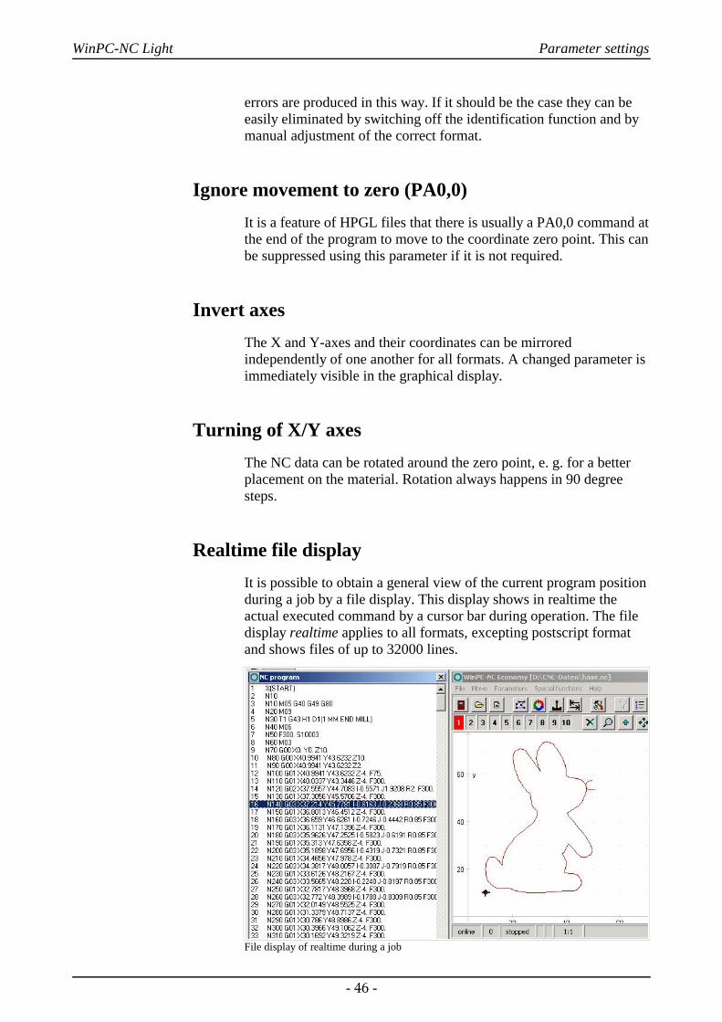
Realtime file displayIt is possible to obtain a general view of the current program positionduring a job by a file display. This display shows in realtime theactual executed command by a cursor bar during operation. The filedisplay realtime applies to all formats, excepting postscript formatand shows files of up to 32000 lines.
File display of realtime during a job
- 46 -

WinPC-NC Light Parameter settings
4.5. Miscellaneous parametersThe miscellaneous parameters include various switches and othersettings which are not assigned to any other group.
Miscellaneous parameters
Start and end positionThis switch specifies where the start and end point of each workingprocess should be located. The machine also moves to the positionafter reference movement.
There are 3 possible start and end positions :
Stop WinPC-NC stops at the reference position after reference movement, and at the last coordinate after each job process
Zero point The machine moves to the defined zero point after reference movement and after each job process.
Park position WinPC-NC moves to the defined parked position after reference movement and after each job process.
It is a good idea to move to a certain position after the workingprocess if space is required in order to change the workpiece.
- 47 -
WinPC-NC Light Parameter settings
Tool change The parameter defines how WinPC-NC handles the tool changecommands during a working process.
There are 4 possibilities for the tool change :
NO No tool change is performed, the entire working process takes place with the current tool
YES Performs the tool change and remains stopped in thecurrent position for every tool change
YES at Performs the tool change and moves to the definedpark position park position for every tool change
NO but use No tool change is performed, although the valuesnew values for plunge depth, plunge speed and feed speed of
the new tool are adopted.
Zero point in fileThe workpiece zero point is the point in the NC file which has itsposition defined in the coordinate parameters.However, it can belocated at various points inside or outside the workpiece and thesepoints are defined here.
Three positions are possible :
Bottom left The zero point is at the smallest X and Y-axis coordinates in the file, normally at the bottom left edge. Mostly used with HPGL files.
Origin of The zero point is at the coordinate origin, i.e.Coordinates where the CAD programs places it for the output. N
This setting is to be recommended if several files are being used on the same workpiece, e.g. routing and drilling a board or when using G code files.
Center The zero point is in the middle of the workpiece, i.e.exactly in the center of the coordinate dimensions in the X and Y-axis directions. This setting is usefulfor processing round workpieces, e.g. plates.
LanguageWinPC-NC is multilingual. The standard version already includes afew languages, and additional languages can easily be bolted on ifrequired. The available languages are listed in a menu.
- 48 -
WinPC-NC Light Parameter settings
According to the status of June 2006 following languages areavailable: german, english, french, spanish, portuguese, italian,turkish and polish.
i The language changeover takes place as soon as you select a newlanguage and click Save.
Automatic reloadThe reload function continuously monitors the date and time of thecurrently loaded file and reloads the newly modified file if there is adiscrepancy.
Using this function, for example, it is possible to edit an NC file inthe drawing program, make continuous changes to it and then, whenyou switch back to WinPC-NC, to be able to check all the changes onthe screen straight away.
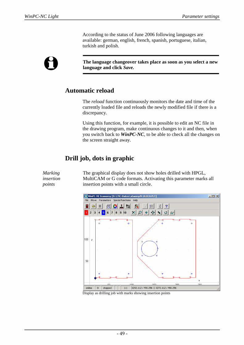
Drill job, dots in graphic
Marking insertion points
The graphical display does not show holes drilled with HPGL,MultiCAM or G code formats. Activating this parameter marks allinsertion points with a small circle.
Display as drilling job with marks showing insertion points
- 49 -

WinPC-NC Light Parameter settings
Z-axis clippingWhen the Z-axis clipping function is activated, WinPC-NC monitorsthe maximum Z-axis depth and cuts off all deeper movements at theworking area limit.
Password and period of validityThis parameter acitvates a password which must be entered prior tochange the parameters or a loaded program. The password is fixed.
The period of validity stipulates the term how long the password isvalid and how long it is not interrogated again.
Skip large NC files
Faster display The analysis function and graphical display may take an extremelylong time with very large NC files. This process can be speeded upby only reading in and displaying the first parts of the file. In such acase, a large cross is superimposed on the graphic display to indicatethat not all of the file is visible.
The following functions are not available in this partial view: Zoom,shift and set position.
Partial display of a file with marking
- 50 -
WinPC-NC Light Parameter settings
Save last positionsWinPC-NC can save the current machine position after eachmovement and job. This is meaningful if the machine works withoutreference switches or if it is not always possible to carry out areference movement.
The position values remain unchanged even after exiting or restartingthe program.
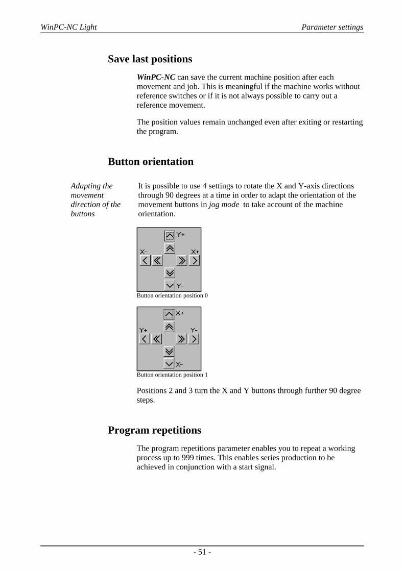
Button orientation
Adapting themovementdirection of thebuttons
It is possible to use 4 settings to rotate the X and Y-axis directionsthrough 90 degrees at a time in order to adapt the orientation of themovement buttons in jog mode to take account of the machineorientation.
Button orientation position 0
Button orientation position 1
Positions 2 and 3 turn the X and Y buttons through further 90 degreesteps.
Program repetitionsThe program repetitions parameter enables you to repeat a workingprocess up to 999 times. This enables series production to beachieved in conjunction with a start signal.
- 51 -
WinPC-NC Light Parameter settings
Smoothing contours
Filter forproducing finercontours
WinPC-NC is equipped with a filter in order to smooth contours andsheets consisting of many small vectors. This is necessary forproducing fine and neat edges.
The paramter defines a factor of 0-2000.
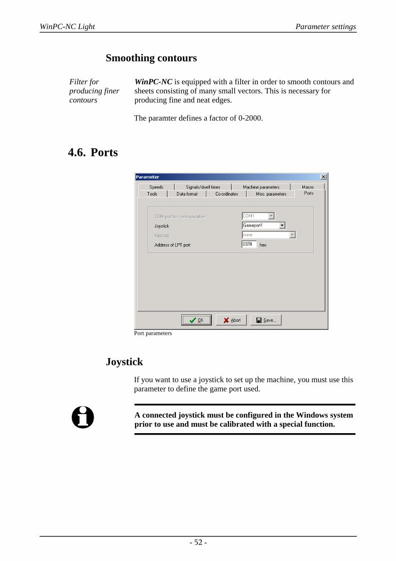
4.6. Ports
Port parameters
JoystickIf you want to use a joystick to set up the machine, you must use thisparameter to define the game port used.
i A connected joystick must be configured in the Windows systemprior to use and must be calibrated with a special function.
- 52 -
WinPC-NC Light Parameter settings
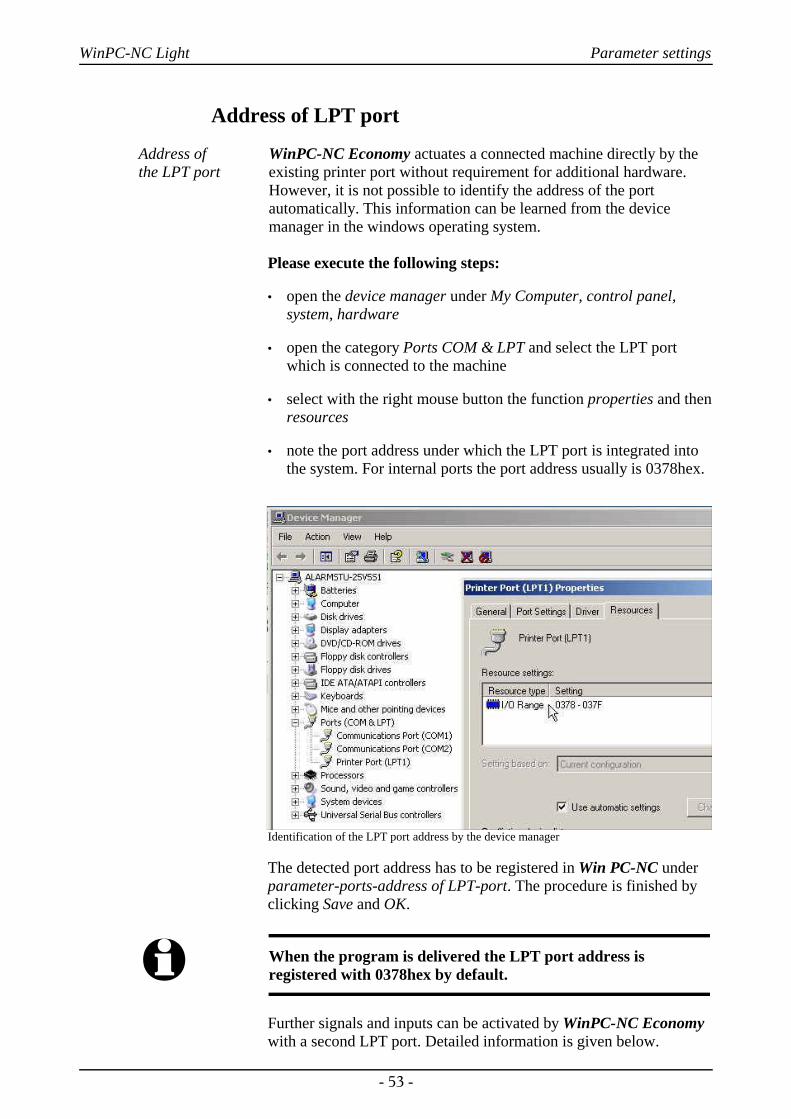
Address of LPT port
Address of the LPT port
WinPC-NC Economy actuates a connected machine directly by theexisting printer port without requirement for additional hardware.However, it is not possible to identify the address of the portautomatically. This information can be learned from the devicemanager in the windows operating system.
Please execute the following steps:
• open the device manager under My Computer, control panel,system, hardware
• open the category Ports COM & LPT and select the LPT portwhich is connected to the machine
• select with the right mouse button the function properties and thenresources
• note the port address under which the LPT port is integrated intothe system. For internal ports the port address usually is 0378hex.
Identification of the LPT port address by the device manager
The detected port address has to be registered in Win PC-NC underparameter-ports-address of LPT-port. The procedure is finished byclicking Save and OK.
i When the program is delivered the LPT port address isregistered with 0378hex by default.
Further signals and inputs can be activated by WinPC-NC Economywith a second LPT port. Detailed information is given below.
- 53 -
WinPC-NC Light Parameter settings
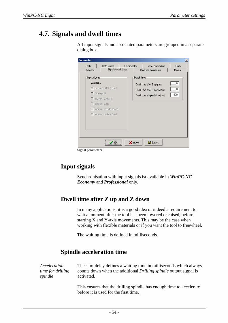
4.7. Signals and dwell timesAll input signals and associated parameters are grouped in a separatedialog box.
Signal parameters
Input signalsSynchronisation with input signals ist available in WinPC-NCEconomy and Professional only.
Dwell time after Z up and Z downIn many applications, it is a good idea or indeed a requirement towait a moment after the tool has been lowered or raised, beforestarting X and Y-axis movements. This may be the case whenworking with flexible materials or if you want the tool to freewheel.
The waiting time is defined in milliseconds.
Spindle acceleration time
Acceleration time for drillingspindle
The start delay defines a waiting time in milliseconds which alwayscounts down when the additional Drilling spindle output signal isactivated.
This ensures that the drilling spindle has enough time to acceleratebefore it is used for the first time.
- 54 -
WinPC-NC Light Parameter settings
4.8. Maschine parametersMachine-specific parameters include all settings which relate to themechanical characteristics of the machine. Only some or even noneof these parameters are present in certain OEM versions of WinPC-NC. Instead, the parameters will have already been set correctly inadvance for the machine in question.
i Always take the greatest possible care when setting or modifyingany machine-specific parameters, in order to avoid machinedefects.
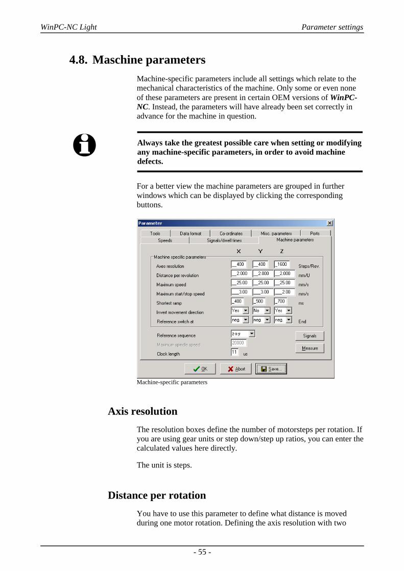
For a better view the machine parameters are grouped in furtherwindows which can be displayed by clicking the correspondingbuttons.
Machine-specific parameters
Axis resolutionThe resolution boxes define the number of motorsteps per rotation. Ifyou are using gear units or step down/step up ratios, you can enter thecalculated values here directly.
The unit is steps.
Distance per rotationYou have to use this parameter to define what distance is movedduring one motor rotation. Defining the axis resolution with two
- 55 -
WinPC-NC Light Parameter settings
parameters offers the advantage that no calculation inaccuracies canarise.
The unit is millimeters with decimal places.
Maximum speedYou should use the MOTOR TEST function to ascertain themaximum speed of each axis. This represents the absolute top limitspeed with which the axis can be moved.
WinPC-NC monitors the speed entries made in all other parameterwindows and always corrects them to the value defined here.
The unit is millimeters with decimal places.
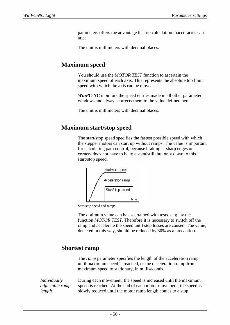
Maximum start/stop speedThe start/stop speed specifies the fastest possible speed with whichthe stepper motors can start up without ramps. The value is importantfor calculating path control, because braking at sharp edges orcorners does not have to be to a standstill, but only down to thisstart/stop speed.
Start/stop speed and ramps
The optimum value can be ascertained with tests, e. g. by thefunction MOTOR TEST. Therefore it is necessary to switch off theramp and accelerate the speed until step losses are caused. The value,detected in this way, should be reduced by 30% as a precaution.
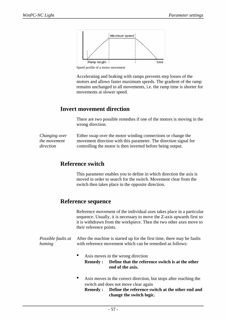
Shortest rampThe ramp parameter specifies the length of the acceleration rampuntil maximum speed is reached, or the deceleration ramp frommaximum speed to stationary, in milliseconds.
Individuallyadjustable ramplength
During each movement, the speed is increased until the maximumspeed is reached. At the end of each motor movement, the speed isslowly reduced until the motor ramp length comes to a stop.
- 56 -
WinPC-NC Light Parameter settings
Speed profile of a motor movement
Accelerating and braking with ramps prevents step losses of themotors and allows faster maximum speeds. The gradient of the rampremains unchanged in all movements, i.e. the ramp time is shorter formovements at slower speed.
Invert movement directionThere are two possible remedies if one of the motors is moving in thewrong direction.
Changing over the movementdirection
Either swap over the motor winding connections or change themovement direction with this parameter. The direction signal forcontrolling the motor is then inverted before being output.
Reference switchThis parameter enables you to define in which direction the axis ismoved in order to search for the switch. Movement clear from theswitch then takes place in the opposite direction.
Reference sequenceReference movement of the individual axes takes place in a particularsequence. Usually, it is necessary to move the Z-axis upwards first soit is withdrawn from the workpiece. Then the two other axes move totheir reference points.
Possible faults athoming
After the machine is started up for the first time, there may be faultswith reference movement which can be remedied as follows:
• Axis moves in the wrong directionRemedy : Define that the reference switch is at the other
end of the axis.
• Axis moves in the correct direction, but stops after reaching the switch and does not move clear againRemedy : Define the reference switch at the other end and
change the switch logic.
- 57 -
WinPC-NC Light Parameter settings
Clocking pulse length
Signal-timing
Controlling stepper motor drives is usually executed by briefclocking impulses. The pulse duration is susceptible by thisparameter and they are always generated for at least 10µsec.
These impulses may be to short to be recognized by the electronicswhen using specific input filters or opto-couplers. Therefore youhave the possibility to prolong this time by parameter. However, ithas to be considered that longer pulse duration may affect calculationperformance and therefore should be avoided.
i If you really have to set the clocking pulse duration, please selectthe smallest possible value in order to guarantee a steady andconstant run of your axes.
Using the SMC version and SMC stepper motor cards the clock pulseduration is without any impact.
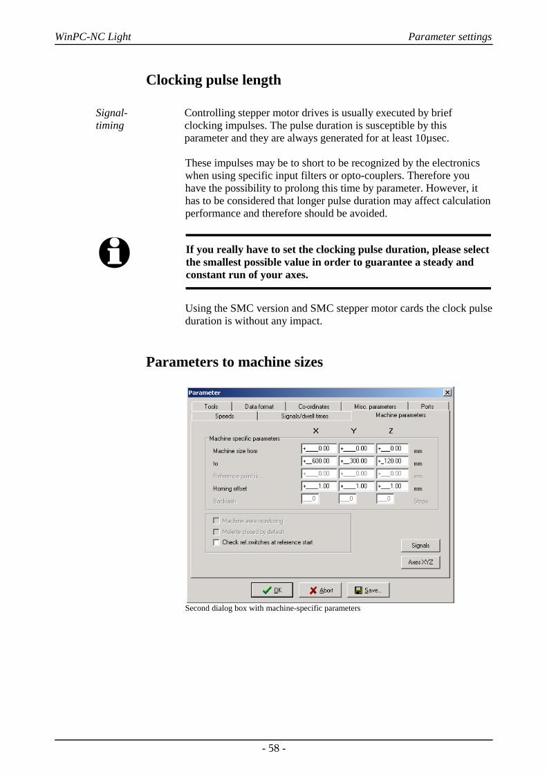
Parameters to machine sizes
Second dialog box with machine-specific parameters
- 58 -

WinPC-NC Light Parameter settings
Machine bed dimensions and area monitoring
Machine size The effective movement area of the machine can be defined usingthese parameters. If area monitoring is activated, WinPC-NC checksand monitors these limits during subsequent movements, includingjog movement.
A parameter activates or deactivates monitoring of this limits.
Reference offset
Safe moving freeof the referenceswitch
To avoid a stop directly at the reference switch's edge after areference and moving free it is possible to determine an additionalpath with the reference offset.This has to be carried out after movingfree from the switch. First after moving the offset the axis is resettedor the defined reference position is adjusted.
Typical values are 0.5 to 1mm additional distances to the switch.
Checking reference switches
Reference moveexclusive withvacant switches
Prior to a reference move the parameter induces WinPC-NC tocheck the switches. Only if each defined switch is vacant a referencemove can take place.
This test makes sense if several reference switches are connected onthe LPT port by a single input line and if it is not possible forWinPC-NC to recognize the axis currently placed on its switch.
In case if the reference move should be rejected due to one or severalactuated switches, it is necessary to move the switches free by thefunction JOG.
Signal wizzard
Userfriendlyadjustment of the signals
By means of the signal wizzard a userfriendly adjustment anddefinition of all inputs and outputs is ensured. As this task is of greatimportance, you will receive detailed information concerningpossibilities in a separat chapter.
- 59 -
WinPC-NC Light Initial start-up with the machine
5. Initial start-up with the machine
Machineadjustment
After software installation on your PC it is necessary to carry outsome start-up processes and corresponding adjustments.
This procedure is only necessary with the initial start-up procedureand generally relates to the adjustment of your machine. In case ifyou have acquired WinPC-NC Light together with the machineeither most of the paramaters are correctly preadjusted or you havereceived an additional disk with the corresponding adjustments. Ifthis is the case the following described procedure can be disregarded.
5.1. Connecting the machineConnecting the machine is made on one or two LPT printer ports ofthe PC and the corresponding cables or adapters have to be used ormanufactured.
i Attention !
Greatest care has to be taken when connecting all cables to thehousing. Following actions can cause serious damage:Incorrect assignment of the signal cable, plug incorrectlyinserted, cables incorrectly connected.
Starting the entire unit is not allowed until all necessary and statespecific safety rules have been accomplished and checked. The useris responsible for unit operation.
i Attention !
For further interrogation of the status emergency stop or readyfor operation it is essential to use one of the inputs. In this way itis possible for the control to stop actuation of output signals ifnecessary. Detailed information is provided in thedocumentation concerning controlling software. Please observeall instructions concerning machine safety.
- 60 -

WinPC-NC Light Initial start-up with the machine
Assignment and application of the possible input/output signalsconcerning the existing port pins is characterized in the followingchapter. For an initial start-up, you do not require any signal input or,to simplify matters, you can use the predefined signals.
i Please note !
The software WinPC-NC Light is a controlling component onlyand used within a unit. In order to obtain a real workingmachine the software has to be completed by PC equipment,working appliance, drive systems and mechanics. The user isresponsible for operation saftey.
LPT port as 25 pole SUB-D-female connector
5.1.1. Pin assignment of clock/direction version:
Pinning LPT 1(clock/direction)
All signals on the LPT printer ports present 5V TTL level.Pinning of the first LPT port is as follows:
Pin 2 output direction motor XPin 3 output clock motor XPin 4 output direction motor YPin 5 output clock motor YPin 6 output direction motor ZPin 7 output clock motor ZPin 8 output direction motor 4 (i.g.tangential axis)Pin 9 output clock motor 4 (i.g. tangential axis)
Pin 1 output drilling spindle on/off (default)Pin 14 output coolant pump on/off (default)Pin 16 output current reduction (default)Pin 17 output job works (default)
Pin 10 input reference switch X (default) Pin 11 input reference switch Y (default)Pin 12 input reference switch Z (default)Pin 13 input sensor/surface block (default)Pin 15 input vacant
Pin 18-25 signal mass (0V GND)
- 61 -

WinPC-NC Light Initial start-up with the machine
User definableadditional in-/outputs
All inputs on pins 10, 11, 12, 13 and 15 as well as the additionaloutputs at pins 1, 14, 16 and 17 are free definable and assignable tothe desired signals. When the software is delivered abovementionned signals are assigned.
5.1.2. Pinning of the SMC version:SMC stepper motor cards are connected to the PC by a commonlyused printing cable. SMC cards have all three reference switchesconnected to pin 11 and there are no additional standarized inputsand outputs available.
Pinning LPT1(SMC)
Pin assignment of the first LPT port as follows :
Pin 2 Data1 1+2 code of the current intensity phase APin 3 Data2 11-no current 01-20% 10-60% 00-100%Pin 4 Data3 dircection of current phase APin 5 Data4 4+5 code of the current intensity phase BPin 6 Data5 11-no current 01-20% 10-60% 00-100%Pin 7 Data6 direction of current phase BPin 8 Data7 7+8 code for motor X/Y/ZPin 9 Data8 00-X 10-Y 01-Z
Pin 1 Strobe adopting the signalsPin 14 output coolant pump on/off (default)Pin 16 output drilling spindle on/off (default)Pin 17 output vacant
Pin 10 input vacantPin 11 input reference switchPin 12 input vacantPin 13 input vacantPin 15 input vacant
Pin 18-25 signal mass (0V GND)
Further technical information concerning controlling SMC cards canbe learned from documentation of the card. If the additional signalsor vacant inputs of LPT1 are to be used by the machine, they have tobe tapped directly on the cable.
- 62 -

WinPC-NC Light Initial start-up with the machine
i Attention !
For safety reasons it is essential to use limit switches on all axes.In order to avoid accidents by contact during operation it isadvisable to install a system for access control, e. g. a protectivehousing or a savety fence. Please connect these safety applianceswith the controlling component and define the correspondinginputs.
5.2. Determination of axis resolutionFor calculating the required distances and speeds it is necessary totell WinPC-NC precisely the defintion of the axis resolution.
Two parametersfor avoidingcalculationinaccuracies
Please open the paramater dialog box parameter - machine anddetermine the exact data of your mechanics and drives for each axisby the first two paramaters.
The paramater axis resolution defines the number of steps orincrements per rotation for the corresponding motor. Please considerthe electronic settings relating to the macro/micro stepping operationand a possibly integrated reduction ratio.
Motorsteps anddistance perrotation
The required value is the number of motorsteps WinPC-NC has tocreate in order to carry out exactly one rotation round the spindle orthe shaft.
The second paramater distance per rotation defines the distancewhich is made exactly by the number of above mentionnedmotorsteps. With spindles it is the spindle rise or with belts or gearracks it is the graduaded circle size of the pinion.
i Incorrectly setted axis resolutions cause dimensionalinaccuracies and inexact speeds.
5.3. Definition of LPT portBy the next step you have to define in WinPC-NC Light the usedLPT port respectively to determine its internal port address.
Ascertainment ofLPT port adress
In order to ascertain the port address you have to activate the devicemanager in the system control. Please carry out the followingactions:
- 63 -

WinPC-NC Light Initial start-up with the machine
1. Open the device manager under My computer, control panel,system, hardware
2. Open the category Ports COM & LPT and select the LPT port towhich the machine is connected.
3. Click with the right mouse button to properties followed byresources
4. Note the port address under which the LPT port is integrated intothe system. With onboard ports it is normally port address0378hex
Identification of the LPT port address by the device manager
The detected port adress has to be registered in WinPC-NC underparamater machine-signals-port addresses followed by clickingSave and OK.
After this process a simple test run with the function JOG MOVE orMOTOR TEST should be possible. Please act with the greatestpossible care and be always aware of uncontrolled machinemovements. If the axes do not move smooth or move at all, justincrease the clock length parameter step by step.
i When delivered the LPT port address is registered under0378hex. This registration applies to most internal ports.
- 64 -

WinPC-NC Light Initial start-up with the machine
5.4. Determination of directionCall the function JOG MOVE and move all axes with the cursorbutton or by mouse clicking to the arrow buttons and check machinedirection.
Each button corresponds to a certain axis or direction. Please startwith axis X.
Arrow keys showing to the right side are to start a positive movementof the X-axis, i.e. following movement to the right of the machine.
Arrow keys showing to the left side are to move the machine left inopposite direction.
If this is not the case, one of the following errors may have occured...
Error Possible cause Solution
Machine doesnot move
Incorrect port
Incorrect port pinning
Maschine off
Port adjustment
Control of pinnings
Check whether motorsare energized andprovide supply
Movement of thewrong axis
Incorrect port pinning Control and adjust theport pinnings
Axis X movesalways inoppositedirection, i.e.moves to the leftby activatedright-hand arrowand the otherway round
Direction signal workswith incorrect logic
Change the parameterINVERT MOVEDIRECTION undermachine parameters
After checking the X-axis a further test of the both other axes isadvisable. If necessary, please correct move direction by parameter.
- 65 -
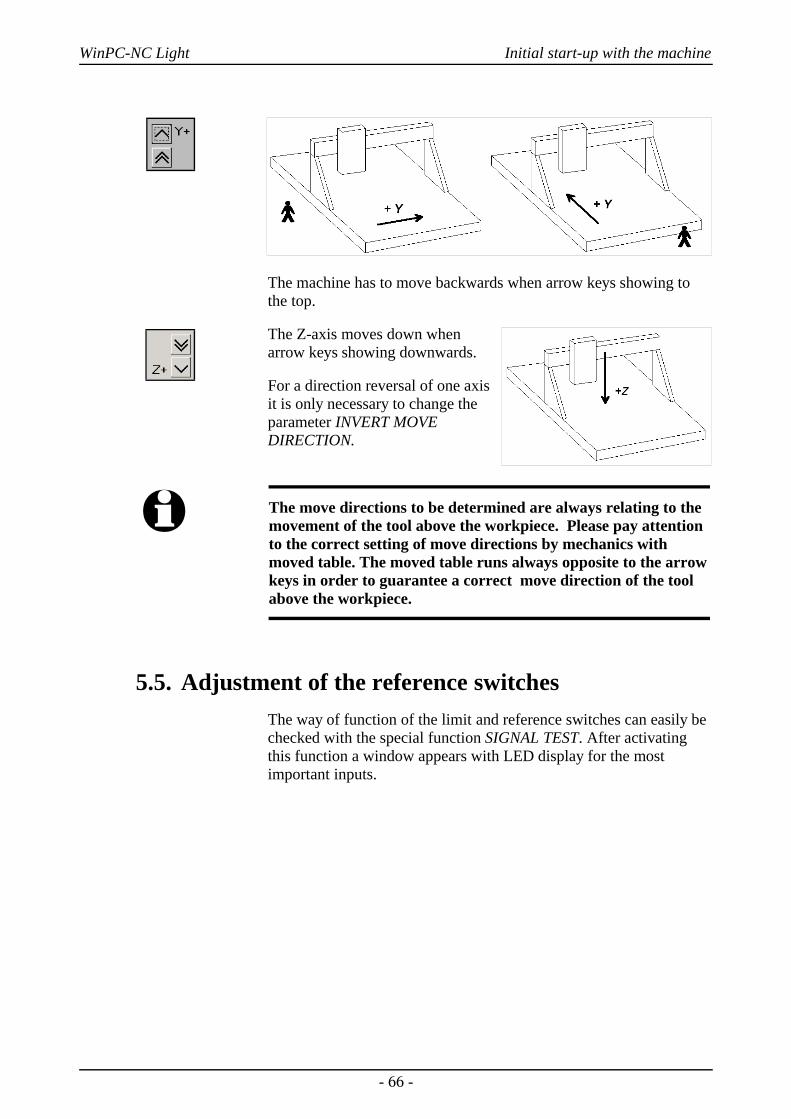
WinPC-NC Light Initial start-up with the machine
The machine has to move backwards when arrow keys showing tothe top.
The Z-axis moves down whenarrow keys showing downwards.
For a direction reversal of one axisit is only necessary to change theparameter INVERT MOVEDIRECTION.
i The move directions to be determined are always relating to themovement of the tool above the workpiece. Please pay attentionto the correct setting of move directions by mechanics withmoved table. The moved table runs always opposite to the arrowkeys in order to guarantee a correct move direction of the toolabove the workpiece.
5.5. Adjustment of the reference switchesThe way of function of the limit and reference switches can easily bechecked with the special function SIGNAL TEST. After activatingthis function a window appears with LED display for the mostimportant inputs.
- 66 -

WinPC-NC Light Initial start-up with the machine
Special function SIGNAL TEST with LED displays of the most important inputs
Manual activatingof the switch
After manual activating the switch of your machine please observethe reactions on the screen. Each change of switch must be clearydisplayed.The LED flashes of the reference switch should change thecolor from black to red.
The definition of the reference switches has been correctlydetermined when the LED is black in unpressed condition andchanges to red in pressed condition.
Depending on the used switch (NO contact – NC contact) theswitching logic may be misapplicated, i.e. red colored with theunpressed switch and black colored with the pressed switch. If this isthe case, a change of the switching logic of the reference switch byparameter is required.
Determination ofswitching logic
Please carry out the following steps :
1. Open parameter dialog box parameter-machine-signals
2. Select the corresponding reference switch in left-hand window
3. Select the inverted entry in the drop-down menu below and acceptthe setting, e.g. change from LPT1 PIN 10 to LPT1 PIN10 INV
4. Save the latest setting and recheck by function SIGNAL TEST
A detailed description of the signal wizzard and the possibilities fordefining and setting the inputs and outputs is listed in the nextchapter.
- 67 -
WinPC-NC Light Initial start-up with the machine
5.6. Sequence and direction of reference moveIn the following step settings for reference move of the machine arestipulated. Please carry out the following steps:
1. Open parameter dialog box parameter-machine
2. Under reference switch at pos./neg. end you have to adjust onwhich axis side the switch is located. If it is not possible to bedirectly ascertained, change again to the function JOG MOVE andcheck by moving and oberserving the position counters and noteto which position the axes move to in the moment when they areapproaching the switch.
3. After the setting of all switches there is nothing else to do thanselecting the reference sequence. The desired sequence can bestipulated in the drop-down menu. Normally it is always the Z-axis which starts moving upon to it's switch followed by the otheraxes.
4. If you intend a reference move of one or several axes into positivedirection, it makes sense to place the machine zero point not at theswitch but define another position by parameter.
5.7. Control of settingsAfter respecting all items a reference move with your machine shouldnot cause any problems. Subsequent to the execution and saving ofall parameter settings please press the function key (F8) or select thecorresponding function by menu.
Reference movefor control
During the reference move all axes run upwards to their switchaccording to the adjusted sequence and then downwards the switchwith reduced speed. Exactly at the switching edge all axes arestopping and marking the reference point.
If this procedure should cause problems or stop with indicating errormessages some of the settings have been incorrectly carried out. Thetabulation below provides additional information concerningdifferent kinds of errors and corresponding solutions.
Error Solution
Axis moves into wrong direction
Define the reference switch at theother end
- 68 -
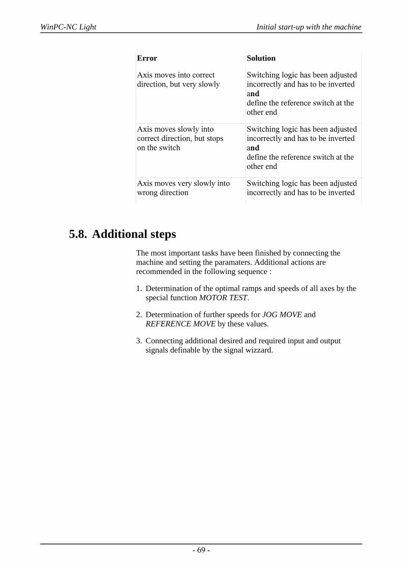
WinPC-NC Light Initial start-up with the machine
Error Solution
Axis moves into correctdirection, but very slowly
Switching logic has been adjustedincorrectly and has to be invertedand define the reference switch at theother end
Axis moves slowly into correct direction, but stops on the switch
Switching logic has been adjustedincorrectly and has to be invertedand define the reference switch at theother end
Axis moves very slowly intowrong direction
Switching logic has been adjustedincorrectly and has to be inverted
5.8. Additional stepsThe most important tasks have been finished by connecting themachine and setting the paramaters. Additional actions arerecommended in the following sequence :
1. Determination of the optimal ramps and speeds of all axes by thespecial function MOTOR TEST.
2. Determination of further speeds for JOG MOVE andREFERENCE MOVE by these values.
3. Connecting additional desired and required input and outputsignals definable by the signal wizzard.
- 69 -

WinPC-NC Light Signal wizzard
6. Signal wizzard
6.1. Using input and output signalsOne of the most essential functions of WinPC-NC is the managementof input and output signals.
Input and outputsignals
By means of inputs many useful functions have been implemented,e.g.
• Monitoring of the axes by limit switches
• Moving reference and thereby calibration of the axes
• Synchonization with various signals, e.g. Start
• Monitoring of the protection hood and savety fences
By means of output signals WinPC-NC is able to control variousadditional appliances or reconcile the process with other components.Examples for outputs are...
• Switching spindle and cooling
• Locking the protection hood during a job
• Switching the dispensing pump
Signal wizzard
- 70 -
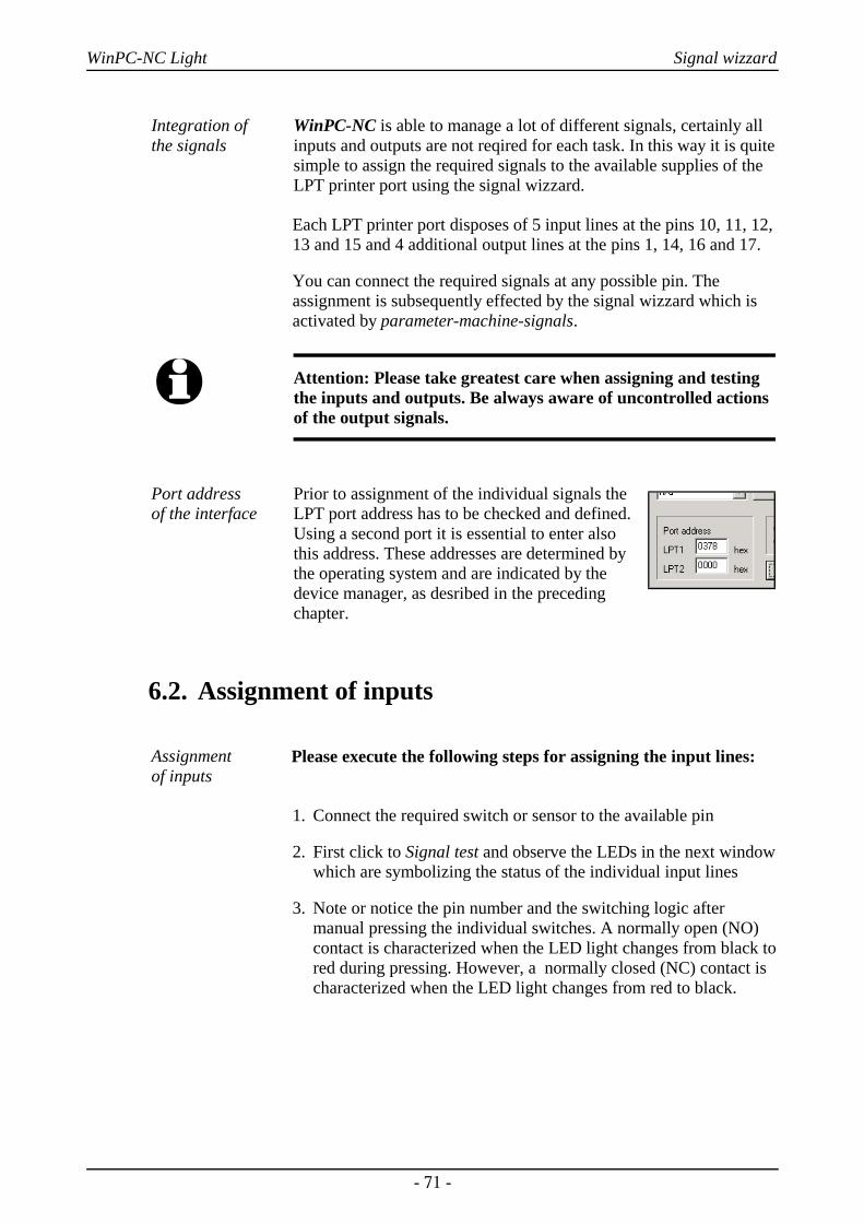
WinPC-NC Light Signal wizzard
Integration of the signals
WinPC-NC is able to manage a lot of different signals, certainly allinputs and outputs are not reqired for each task. In this way it is quitesimple to assign the required signals to the available supplies of theLPT printer port using the signal wizzard.
Each LPT printer port disposes of 5 input lines at the pins 10, 11, 12,13 and 15 and 4 additional output lines at the pins 1, 14, 16 and 17.
You can connect the required signals at any possible pin. Theassignment is subsequently effected by the signal wizzard which isactivated by parameter-machine-signals.
i Attention: Please take greatest care when assigning and testingthe inputs and outputs. Be always aware of uncontrolled actionsof the output signals.
Port address of the interface
Prior to assignment of the individual signals theLPT port address has to be checked and defined.Using a second port it is essential to enter also this address. These addresses are determined bythe operating system and are indicated by thedevice manager, as desribed in the precedingchapter.
6.2. Assignment of inputs
Assignment of inputs
Please execute the following steps for assigning the input lines:
1. Connect the required switch or sensor to the available pin
2. First click to Signal test and observe the LEDs in the next windowwhich are symbolizing the status of the individual input lines
3. Note or notice the pin number and the switching logic aftermanual pressing the individual switches. A normally open (NO)contact is characterized when the LED light changes from black tored during pressing. However, a normally closed (NC) contact ischaracterized when the LED light changes from red to black.
- 71 -
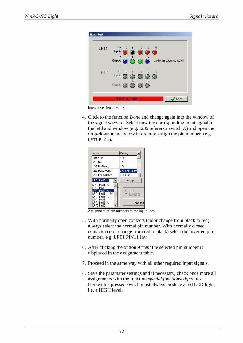
WinPC-NC Light Signal wizzard
Interactive signal testing
4. Click to the function Done and change again into the window ofthe signal wizzard. Select now the corresponding input signal inthe lefthand window (e.g. I235 reference switch X) and open thedrop-down menu below in order to assign the pin number (e.g.LPT1 Pin11).
Assignment of pin numbers to the input lines
5. With normally open contacts (color change from black to red)always select the normal pin number. With normally closedcontacts (color change from red to black) select the inverted pinnumber, e.g. LPT1 PIN11 Inv.
6. After clicking the button Accept the selected pin number isdisplayed in the assignment table.
7. Proceed in the same way with all other required input signals.
8. Save the paramater settings and if necessary, check once more allassignments with the function special functions-signal test.Herewith a pressed switch must always produce a red LED light,i.e. a HIGH level.
- 72 -

WinPC-NC Light Signal wizzard
i With inputs WinPC-NC reacts only to a HIGH level. Please takecare that the switching logic with the possibility for inverting isassigned in the way that an activated switch generates a HIGHlevel.
6.3. Assignment of output lines
Assignment of outputs
The assignment of outputs is similar to the assignment of inputs.Please carry out the following steps :
1. Connect the required cables to the available pins and use forcontrol purposes a LED light or a lamp.
2. Click to Signal test and observe the LEDs in the next windowwhich are symbolizing the status of the individual output lines
Interactive signal testing
3. Click by mouse on to the possible outputs and observe the level ofthe cables. A blue LED light signalizes a LOW level or an outputswitched off. A green LED light signalizes a HIGH level or anoutput switched on. Please note or notice the corresponding pinsas well as the switching logic.
4. Click to the button Done and change again into the window of thesignal wizzard. Select now the corresponding output signal in theright-hand window (e.g. Q242 spindle on/off) and open the drop-down menu below in order to assign the pin number (e.g. LPT1PIN1).
5. After clicking the button Accept the selected pin number isdisplayed in the assignment table.
- 73 -

WinPC-NC Light Signal wizzard
Assignment of the pin number for output lines
6. Proceed in the same way with all other required input signals andfinally save the settings.
6.4. Input signals available
Possible inputs WinPC-NC is able to manage following input signals:
Input signal Assigned actionI255 Start Starts loaded jobI254 Stop Stops immediately each running action with HIGH level,
subsequently another reference move has to be carriedout
I247 Not ready Monitors whether the machine is ready and the drives.With HIGH level each running action is immediatelystopped.
I235-238 Referenceswitch
Reference switch of all 4 axes
I239-242 Limit switch - Limit switch positioned at the negative end of the axisI243-246 Limit switch + Limit switch positioned at the positive end of the axisI229-232 Limit switchSummary
Limit switch inputs, if only one switch is appropriate forboth ends of the axes, e.g. a flexible switch moving ontwo cams. Using these inputs, WinPC-NC is not able torecognize the move direction and obviate continuation ofthe move.
I222 Protection hood Safety function for protection hoods, light screens andaccess controls
I160-169 vacant Signals freely to dispose, with macro programming.
All additional input signals which are indicated in the table arereserved to special functions or only available in WinPC-NCProfessional.
- 74 -
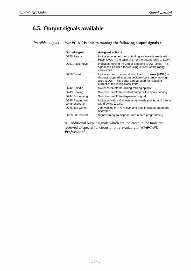
WinPC-NC Light Signal wizzard
6.5. Output signals available
Possible outputs WinPC-NC is able to manage the following output signals :
Output signal Assigned actionsQ255 Ready Indicates whether the controlling software is ready with
HIGH level. In the case of error the output turns to LOW.Q251 Axes move Indicates moving (HIGH) or stopping (LOW) axes. This
signal can be used for reducing current at the ratingclass limits.
Q250 Boost Indicates ramp moving during the run of axes (HIGH) ordisplays stopped axes respectively constantly movingaxes (LOW). This signal can be used for reducingcurrent at the rating class limits.
Q242 Spindle Switches on/off the drilling-/milling spindle.Q243 Cooling Switches on/off the coolant pump or the spray coolingQ244 Dispensing Switches on/off the dispensing signal.Q245 Purging withcompressed air
Indicates with HIGH level an upwards moving and thus awithdrawing Z-axis.
Q246 Job works Job working in HIGH level and thus indicates automaticoperation.
Q220-230 vacant Signals freely to dispose, with macro programming.
All additional output signals which are indicated in the table arereserved to special functions or only available in WinPC-NCProfessional.
- 75 -
WinPC-NC Light Additional Information
7. Additional Information
7.1. InterpretersAt present, interpreters are implemented in WinPC-NC Economy forserveral NC data formats.
• HPGL• Drilling data
7.1.1. HPGL-Interpreter
Plotter data with the HPGLInterpreter
The HPGL interpreter recognizes the most important commands inHPGL plotter language. Successful tests have been carried out withvarious CAD and drawing programs.
Drawings from...
• AutoCAD®
• AutoSketch®
• Eagle®
• HCAM®
• CADdy®
• Malz&Kassner CAD®
Windows HPGLdrivers
...and other CAD systems can be processed without any problems.Furthermore, the interpreter can also work with HPGL data from thestandard Window driver HP-Plotter, which programs such as...
• CorelDRAW®
• Designer®
...and other Windows drawing programs use for preparing their dataand storing data in a file. Alternatively, it is also possible to use adriver for following plotters: HP7475, HP Color Pro or HPDraftmaster.
HPGL Syntax The following commands represent a valid HPGL data file :
PA [x,y[,x,y]]; Move to absolute position(s)PR [x,y[,x,y]]; Move to relative position(s)PU [x,y[,x,y]]; Lift and move tool
- 76 -
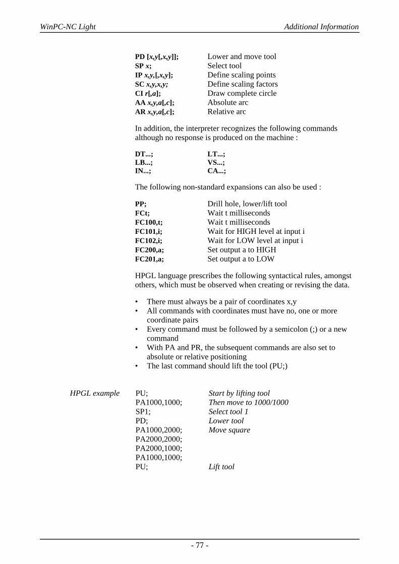
WinPC-NC Light Additional Information
PD [x,y[,x,y]]; Lower and move toolSP x; Select toolIP x,y,[,x,y]; Define scaling pointsSC x,y,x,y; Define scaling factorsCI r[,a]; Draw complete circleAA x,y,a[,c]; Absolute arcAR x,y,a[,c]; Relative arc
In addition, the interpreter recognizes the following commandsalthough no response is produced on the machine :
DT...; LT...;LB...; VS...;IN...; CA...;
The following non-standard expansions can also be used :
PP; Drill hole, lower/lift toolFCt; Wait t millisecondsFC100,t; Wait t millisecondsFC101,i; Wait for HIGH level at input iFC102,i; Wait for LOW level at input iFC200,a; Set output a to HIGHFC201,a; Set output a to LOW
HPGL language prescribes the following syntactical rules, amongstothers, which must be observed when creating or revising the data.
• There must always be a pair of coordinates x,y • All commands with coordinates must have no, one or more
coordinate pairs • Every command must be followed by a semicolon (;) or a new
command• With PA and PR, the subsequent commands are also set to
absolute or relative positioning• The last command should lift the tool (PU;)
HPGL example PU;PA1000,1000;SP1;PD;PA1000,2000;PA2000,2000;PA2000,1000;PA1000,1000;PU;
Start by lifting toolThen move to 1000/1000 Select tool 1Lower toolMove square
Lift tool
- 77 -
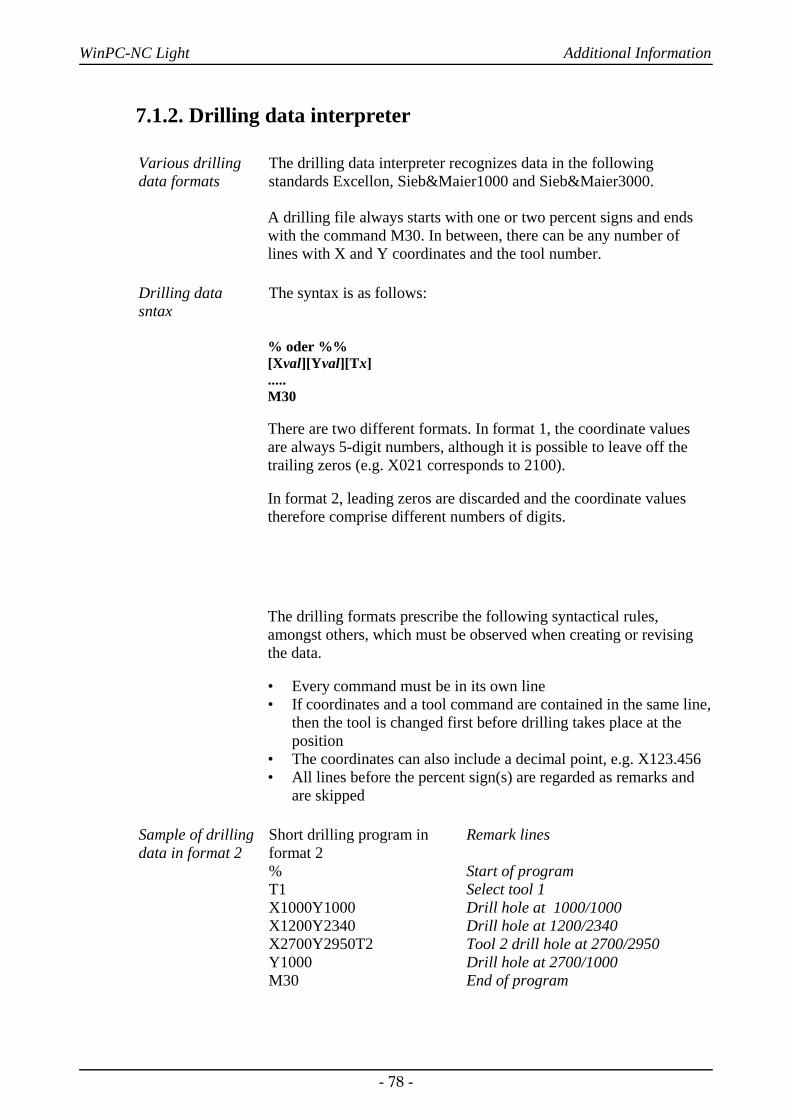
WinPC-NC Light Additional Information
7.1.2. Drilling data interpreter
Various drillingdata formats
The drilling data interpreter recognizes data in the followingstandards Excellon, Sieb&Maier1000 and Sieb&Maier3000.
A drilling file always starts with one or two percent signs and endswith the command M30. In between, there can be any number oflines with X and Y coordinates and the tool number.
Drilling datasntax
The syntax is as follows:
% oder %%[Xval][Yval][Tx].....M30
There are two different formats. In format 1, the coordinate valuesare always 5-digit numbers, although it is possible to leave off thetrailing zeros (e.g. X021 corresponds to 2100).
In format 2, leading zeros are discarded and the coordinate valuestherefore comprise different numbers of digits.
The drilling formats prescribe the following syntactical rules,amongst others, which must be observed when creating or revisingthe data.
• Every command must be in its own line• If coordinates and a tool command are contained in the same line,
then the tool is changed first before drilling takes place at the position
• The coordinates can also include a decimal point, e.g. X123.456 • All lines before the percent sign(s) are regarded as remarks and
are skipped
Sample of drillingdata in format 2
Short drilling program informat 2%T1X1000Y1000X1200Y2340X2700Y2950T2Y1000M30
Remark lines
Start of programSelect tool 1Drill hole at 1000/1000Drill hole at 1200/2340Tool 2 drill hole at 2700/2950Drill hole at 2700/1000End of program
- 78 -

WinPC-NC Light Additional Information
And here is the same example in format 1: (always 5-digit values,with trailing zeros discarded)
Sample of drillingdata in format 1
Short drilling program informat 1%T1X01Y01 X012Y0234X027Y0295T2Y01M30
Remark lines
Start of programSelect tool 1Drill hole at 1000/1000Drill hole at 1200/2340Tool 2 drill hole at 2700/2950Drill hole at 2700/1000End of program
7.2. Error messagesError messages are displayed in a small window in the middle of thescreen during operations in WinPC-NC.Messages in a gray box donot indicate there is a fault, but only provide information.
The following error messages may occur :
• Limit switch reached
The machine has moved on to one of the limit switches. It is necessary to moveback from the switch and perform reference rung again before continuing work.
• Machine not ready
The connected controller or machine is not ready or not switched on. WinPC-NCworks in demo modes.
• HPGL syntax error
There is an invalid HPGL command in the plotter file. It does not correspond to thesyntactical rules and therefore cannot be processed by WinPC-NC.
• Connection canceled
The connection to the DLL-controller is interrupted. This can happen when otherwindow programs or drives interfere with the realtime tasks.
• Status stack full/empty
An internal error has occurred in WinPC-NC. Please report this error to theprogram authors, providing as many details as possible.
• Incorrect parameter
A parameter in the WPI or WPW file is incorrect or the parameter file has beencorrupted.
• Stop signal detected
The stop signal has been detected. Please rectify the fault.
• Go to reference position first
WinPC-NC and the controller always need to know what their current position is.Please always perform reference travel after restarting the program.
- 79 -

WinPC-NC Light Additional Information
• Error xx from controller
An internal error has occurred in WinPC-NC during communcation with therealtime module. Please report this error to the program authors, providing as manydetails as possible.
• Data cannot be displayed
The NC data for the current file cannot be displayed graphically. Either they do notmatch the selected format or they do not contain any tool actions. Another cause forfailure may be that the format identification is switched off or that an incorrect dataformat has been adjusted.
• Tool not yet defined
A tool is needed which has not yet been programmed in the tool managementsystem. The appropriate parameters must always be defined prior to using tools.
• No tool file found
No tool file can be found. WinPC-NC therefore continues to work with defaultvalues.
• Machine is at limit switch
When both limit switches on an axis are defined, WinPC-NC is unable to tell whichswitch has been reached. Please move the axes in question back from the limitswitch manually and then restart reference travel.
• Service code required
The axis controller can no longer be controlled and requires a service code beforecontinuing work. Please contact the supplier.
• Command rejected by controller
An internal error has occurred in WinPC-NC during communication with therealtime module. Please report this error to the program authors, providing as manydetails as possible.
• Maschine not ready
The machine has not been switched on or there is a fault. The NOT READY inputon the axis controller signals this condition.
• Communication failed / Timeout
Communcation of WinPC-NC interferes with the realtime-DLL. Please report thiserror to the program authors, providing as many details as possible.
• Protection hood not closed
The protective hood or another protective device has not been closed and thereforeno process can be started. The machine can still be set up.
• Command rejected during machine movement
There is a fault in the connection between WinPC-NC and the realtime module.Please report this error to the program authors, providing as many details aspossible.
• File with invalid format
The selected file does not match the set data format. Change the parameter or thedata format to HPGL or drilling format.
• Help file not found
The file with the help texts cannot be found. It is called WINPCNC.HLP and mustbe located in the current folder or in the WinPC-NC folder. No help texts can bedisplayed.
- 80 -
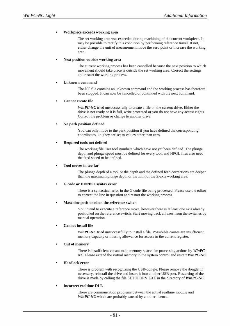
WinPC-NC Light Additional Information
• Workpiece exceeds working area
The set working area was exceeded during machining of the current workpiece. Itmay be possible to rectify this condition by performing reference travel. If not,either change the unit of measurement,move the zero point or increase the workingarea.
• Next position outside working area
The current working process has been cancelled because the next position to whichmovement should take place is outside the set working area. Correct the settingsand restart the working process.
• Unknown command
The NC file contains an unknown command and the working process has thereforebeen stopped. It can now be cancelled or continued with the next command.
• Cannot create file
WinPC-NC tried unsuccessfully to create a file on the current drive. Either thedrive is not ready or it is full, write protected or you do not have any access rights.Correct the problem or change to another drive.
• No park position defined
You can only move to the park position if you have defined the correspondingcoordinates, i.e. they are set to values other than zero.
• Required tools not defined
The working file uses tool numbers which have not yet been defined. The plungedepth and plunge speed must be defined for every tool, and HPGL files also needthe feed speed to be defined.
• Tool moves in too far
The plunge depth of a tool or the depth and the defined feed corrections are deeperthan the maximum plunge depth or the limit of the Z-axis working area.
• G code or DIN/ISO syntax error
There is a syntactical error in the G code file being processed. Please use the editorto correct the line in question and restart the working process.
• Maschine positioned on the reference switch
You intend to execute a reference move, however there is at least one axis alreadypositioned on the reference switch. Start moving back all axes from the switches bymanual operation.
• Cannot install file
WinPC-NC tried unsuccessfully to install a file. Possibible causes are insufficientmemory capacity or missing allowance for access in the current register.
• Out of memory
There is insufficient vacant main memory space for processing actions by WinPC-NC. Please extend the virtual memory in the system control and restart WinPC-NC.
• Hardlock error
There is problem with recognizing the USB-dongle. Please remove the dongle, ifnecessary, reinstall the drive and insert it into another USB port. Restarting of thedrive is made by calling the file SETUPDRV.EXE in the directory of WinPC-NC.
• Incorrect realtime-DLL
There are communcation problems between the actual realtime module andWinPC-NC which are probably caused by another licence.
- 81 -

WinPC-NC Light Additional Information
7.3. Special versions of WinPC-NC
Specialapplications on request
The authors are always grateful for opinions and suggestions.
If required, hardware and software solutions can be worked out foryour special application, or our standard products can be adapted tooptimize their functions for you. Please ask us for a quote withoutobligation.
- 82 -
Related Documents