WINDSHIELD-REAR WINDOW-WINDSHIELD WIPER Page Rear Window 17-4 Windshield 17-1 Page Windshield Wiper 17-5 WINDSHIELD Page Folding Windshield Removal 17-4 General 17-1 Glass Installation 17-1 Page Glass Removal 17-1 Rear View Mirror Bracket 17-3 GLASS REMOVAL The windshields on all models consist of two sheets of glass, some flat and some curved, laminated together to form a one-piece safety glass. All windshields are retained in their respective open ings by rubber weatherstrips channels. The safety type glass is designed with adequate clear ance to prevent stress and strains. When replacing cracked glass resulting from causes other thanL a direct blow or a known instance of temporary misalignment, it is very important that the cause of the breakage be aetermined and the condition corrected. The inside rear view mirror bracket for all models is bonded directly to the windshield glass with a polyvinyl butyral compound through a heat-induction process. Service replacement windshield glass may have the rear view mirror bracket bonded to the windshield glass. In this case, the mirror is simply transferred from the unserviceable windshield to the bracket on the replace ment windshield. If the replacement windshield does not have the mir ror bracket bonded to it, or if on serviceable windshields the bracket bond has been lost, a service kit is available for bracket installation. The kit is available from your local parts distribution center and consists of a rep] ace ment bracket and firm-setting, two-component adhe sive. Installation instructions are included in this section, and also in the kit. NOTE: Do not attempt to remount onginal bracket. For best results, use a replacement bracket with the proper adhesive. CJ Models 1 Cover adjoining painted surfaces to protect finish. 2 Remove windshield wiper arms using wide blade screwdriver. 3 Remove inside rear view mirror from bracket. 4 Remove sun visors and defroster ducts. 5 Starting at top of windshield frame, pull glass weatherstrip away from flange while gently pushing out on glass. 6 Work entire weatherstrip from pinch weld flange and remove glass. GLASS INSTALLATION CJ Models 1 Use 3M Auto Bedding and Glazing Compound or equivalent to apply a 1/16-inch bead of sealer com pletely around weatherstrip in flange cavity. 2 Install weatherstrip on glass. Split in weath erstrip should be centered on bottom edge of glass. 3 Beginnning at bottom of glass, work weath erstrip over flange using a fibre or wooden wand. 4 Apply 3M Windshield Sealer or equivalent sealer between weatherstrip and outside of glass around entire perimeter. 5 Clean off excess sealer. 6 Install inside rear view mirror on bracket. 7 Install defroster ducts and sun visors. 8 Install windshield wiper arms. 9 Test windshield installation for water leaks. 1 1-1 GENERAL

Welcome message from author
This document is posted to help you gain knowledge. Please leave a comment to let me know what you think about it! Share it to your friends and learn new things together.
Transcript

WINDSHIELD-REAR WINDOW-WINDSHIELD WIPER
PageRear Window 17-4Windshield 17-1
PageWindshield Wiper 17-5
WINDSHIELD
PageFolding Windshield Removal 17-4General 17-1Glass Installation 17-1
PageGlass Removal 17-1Rear View Mirror Bracket 17-3
GLASS REMOVAL
The windshieldson all modelsconsistof two sheetsofglass,someflat andsome curved,laminatedtogethertoform a one-piecesafetyglass.
All windshieldsare retainedin their respectiveopenings by rubberweatherstripschannels.
The safetytype glassis designedwith adequateclearance to prevent stress and strains. When replacingcrackedglass resulting from causesother thanL a directblow or a known instanceof temporarymisalignment,itis very important that the cause of the breakagebeaeterminedandthe condition corrected.
The inside rearview mirror bracket for all modelsisbondeddirectly to thewindshieldglasswith apolyvinylbutyral compoundthrough a heat-inductionprocess.
Service replacementwindshield glass may have therearview mirror bracketbondedto the windshieldglass.In this case,the mirror is simply transferredfrom theunserviceablewindshield to the bracketon the replacement windshield.
If the replacementwindshielddoesnot havethe mirror bracketbondedto it, or if on serviceablewindshieldsthe bracketbond hasbeenlost, a servicekit is availablefor bracket installation. The kit is available from yourlocal partsdistribution centerandconsistsof a rep] acement bracket and firm-setting, two-componentadhesive. Installation instructions are included in thissection,and also in the kit.
NOTE: Do not attempt to remount onginal bracket.For best results, use a replacementbracket with theproperadhesive.
CJ Models1 Cover adjoining painted surfaces to protect
finish.2 Removewindshieldwiper armsusingwide blade
screwdriver.3 Removeinsiderearview mirror from bracket.4 Removesun visorsanddefrosterducts.5 Starting at top of windshield frame, pull glass
weatherstripaway from flangewhile gently pushingouton glass.
6 Work entire weatherstrip from pinch weldflangeandremoveglass.
GLASS INSTALLATION
CJ Models1 Use3M Auto Beddingand GlazingCompoundor
equivalent to apply a 1/16-inch bead of sealer completely aroundweatherstripin flangecavity.
2 Install weatherstrip on glass. Split in weatherstripshould becenteredon bottomedgeof glass.
3 Beginnning at bottom of glass, work weatherstripover flangeusinga fibre or woodenwand.
4 Apply 3M Windshield Sealer or equivalentsealerbetweenweatherstripandoutsideof glassaroundentireperimeter.
5 Cleanoff excesssealer.6 Install insiderearview mirror on bracket.7 Install defrosterductsandsunvisors.8 Install windshieldwiper arms.9 Testwindshieldinstallationfor waterleaks.
1 1-1
GENERAL

17-2 WINDSHIELD-REAR WINDOW-WINDSHIELD WIPER
GLASS REMOVAL
Cherokee-Wagoneer-TruckAn interlocking type lip is part of the weatherstrip.The weatherstripshould be 75°F 24°C or abovebe
fore windshieldremoval is attempted.1 Cover adjoining painted surfaces to protect
finish.2 Remove windshield wiper arms using a wide
bladescrewdriver.3 On vehicleswith stainlesssteel mouldings,per
form the following steps.a Removemouldingscrewson thetop andbot
tom of side mouldings.b Removetop corner moulding by lifting bot
tom andpulling outboard.c Tip side mouldingstoward centerof vehicle
andlift off.d Removetop moulding.
4 Slide center moulding clip to left or right andremovebottom mouldings.This will exposethe lockingtype weatherstrip.
5 Use a wedge-shapedfiber or hardwoodstick orwandas shownin figure 17-1 to unlock theweatherstripas shown in figures 17-2 and 17-3. The locking typeweatherstripwithout mouldings is shown in figure 17-3.
6 Unlock the rubber weatherstripstarting at thebottom with a fiber stick or wandfig. 17-4.
Fig. 17-1 Wooden Wand Dimensions Inches
J42670
7 Removeinsiderearview mirror from bracket.8 Usefiber stick to breaksealbetweenwindshield
glassandweatherstrip.9 Usetwo mento removewindshieldfrom weath
erstrip,oneman lifting aswindshieldcomesfree.10 Removeweatherstripfrom opening.11 Inspectweatherstripand clean off sealerfrom
glasscavity andflangecavity.
NOTE: Inspectfor unevensurfacesor irregularities inthe windshieldopeningflange that could causestressdamageto the windshieldglass.
12 If windshield has been removed for reasonsother than damagedglassandwill be reinstalled,cleanhardenedsealerfrom edges.
Fig. 17-2 Windshield Weatherstrip Cross Section-Moulding Removed
UNLOCKEDPOSITION
GLASS OPENINGFLANGE
Fig. 17-3 Windshield Weatherstrip Cross Section
GLASS INSTALLATION
Cherokee-Wagoneer-Truck
NOTE: Windshieldinstallation shouldbe accomplishedin relatively warm surroundingsso that the windshieldweatherstripremainspliable makinginstallation easierand reducing the possibilityof breaking the windshield.
1
LOWER SECTION LOWER SECTIONUNLOCKED POSITION LOCKED POSITION
1/8
60613
ION
3/4I,
R
WEATHERSTRIP60614

WINDSHIELD-REAR WINDOW-WINDSHIELD WIPER 17-3ri
1 Cleanold sealerfrom windshieldopeningflange.2 If removedweatherstripis to bereused,be sure
glasscavity andflange cavity areclean.3 Using 3M Auto BeddingandGlazingCompound
or equivalent, apply a 1/16-inch bead of sealercompletelyaroundweatherstripin flange cavityas showninfigure 17-2.
4 Install weatherstrip on windshield openingflange.
5 Apply aliberal amountof liquid soapsolution inglasscavity of the weatherstrip.
6 With two men working Ofl the outsideof thevehicle,work windshieldinto upperglasscavity andintoeach side.Position woodenwand underbottom of glassandlift windshield up and into lower glasscavity. Checkfor equalside clearances.
7 Use woodenwandto lock weatherstripas shownin lockedpositionfig. 17-2 and17-3.
NOTE: Soap solution should be removed from theweatherstripand glass befbreinstalling sealer.
8 Use 3M Windshield Sealer or equivalent andapply sealerbetweenthe weatherstripandglass on outside of glassaroundentireperimeterfig. 17-2.
NOTE: Excessivesoap solution should be removedfrom the weatherstripbeforeinstalling trim moulding.
9 Bottommouldingsareinstalledoneata time. Tofacilitate installation,place a 1/8-inch diametercord inweatherstripmoulding retaining groove along entirelengthof weatherstrip,leavingenoughcord hangingoutat eachendto permit a good grip on cord.
10 Working first with either left or right bottommoulding,place moulding in groove.
11 Starting at the outside corne:r of the weatherstrip, pull up on cord while lightly tapping top of
moulding with rubbermallet. This will lock the moulding in the weatherstripretaining groove. Continuetheprocessuntil moulding is installed in weatherstrip.Repeat processwith the other bottom moulding, againstartingat the outsidecorner.
12 Install center moulding clip to cover gap between left andright bottom moulding.
13 The one-piecetop moulding is installed in thesamemanner,exceptthat the moulding is tappedupward into retaininggroove.
14 Side and upper corner mouldings can then beinsertedin retaining groove and securedby installingupperand lower screws.
15 Fill gap at upperoutboardcornerbetweentrimmouldingandbody with blacksealer.
16 Clean excess sealer from windshield andmoulding.
17 Installsidemouldingscrews.18 Installwindshieldwiper arms.19 Install inside rearview mirror on bracket.20 Testwindshieldfor waterleaks.
REAR VIEW MIRROR BRACKET INSTALLATION1 Locating windshield mountedrear view mirror
bracket can be accomplishedas shown in figures 17-5and 17-6. Use wax pencil on outsideof glass to locatemountingbracket.
2 If vinyl pad has remainedon the windshieldglass, apply low heat with an electric heatgun untilvinyl softens.Then,peel padfrom glassusingcarenot toscratchor marthe glass surface.
1 Cleanbracketmountingareaof windshieldglassthoroughly. Use a mildly abrasive cleaning powderAjax, Comet,or equivalentappliedto cleancloth saturatedwith alcohol.
2 Remove all traces of cleanserby wiping areawith a papertowel moistenedwith alcohol.
FIg. 17-5 WIndshield Mounted Rear View MirrorBracket Location lnches-CJ Models
J42673
Fig. 17-4 Unlock Rubber Weatherstrip
MOUNTING INSIDEBRACKET EDGE OF
WEATHERSTRIP
60611

17-4 WINDSHIELD-REAR WINDOW-WINDSHIELD WIPER
MOUNTINGBRACKET
Fig. 17-6 Windshield Mounted Rear View MirrorBracket Location lnchos-Cherokee-Wagoneer-Truck
3 Scuffbondingsurfacethe sidewithout the 3/8-inch circular depressionof the mirror bracket with aclean piece of fine grit sandpaper.Apply alcoho] to aclean towel andwipe surfaceclean.
4 Apply a generous amount of the accelerator,suppliedwith the kit, to mirror bracketmounting surface. Allow five minutesto dry.
5 Apply a thin film of acceleratorto windshield.Allow oneminute to dry.
CAUTION: Do not touch surfacesto whichacceleratorhas beenapplied - an imperfectbond could result.
6 Apply one drop of adhesiveat the centerof themirror bracketbondingsurface.Use bottom of adhesivetube to distribute the adhesiveevenly over the entiresurface.
vu
7 Position bottom straightedgeof the bracketonthe horizontal line fig. 17-5 and 17-6. Pressbrackettoglass andhold firmly for oneminute.Be surebracketisproperly locatedas adhesivesetsquickly.
FOLDING WINDSHIELDOn CJ models, the windshield and frame assembly
may be loweredto the hood by removing the knobsateachside of the windshield. When in the lowered position, alwayssecurethe windshield by passingthe strapat thetop of the windshieldthroughtheloop on thehoodanddrawing the strapup firmly.
Removal1 Removenecessarycomponentsfrom windshield
frame.2 Disconnect wiper motor wiring harnessfrom
switch.3 Remove windshield hinge-to-frameattaching
screwsusingTorx Bit Tool J-25359-02.4 Removewindshield holddownknobsandremove
windshieldframe.
Installation1 Positionwindshield frameon vehicleand install
windshield hinge-to-frameattachingscrewsusing TorxBit Tool J-25359-02.
2 Installwindshieldholddownknobs.3 Connectwiper motor wiring harnessto switch.4 Install necessarytop componentsto windshield
frame.
REAR WINDOW
GENERALThe rear window is a one-piece,temperedglass. The
overall size of the glass varies with the differentvehicles.
Cherokee-WagoneerFor service replacementand adjustmentof tailgate
window glass, refer to Section 16-Tailgate-LuggageRack.
Truck Models
For servicereplacementof solid rear glass, refer toWindshieldGlassRemovalor Installation.
The sliding rear window on J-10 andJ-20cabswhichprovidescab ventilationand easeof communicationbetween passengersin the truckcab andcamperbody. It isreplacedas an assembly.
J41 066
WINDSHIELD-REAR WINDOW-WINDSHIELD WIPER 17-5
WINDSHIELD WIPER
Page PageGeneralTwo-Speed Wiper MotorWasher Pump
17-517-7
17-11
Wiper and Washer ContrWiper Arm ReplacementWiper Blades
ols 17-517-517-5
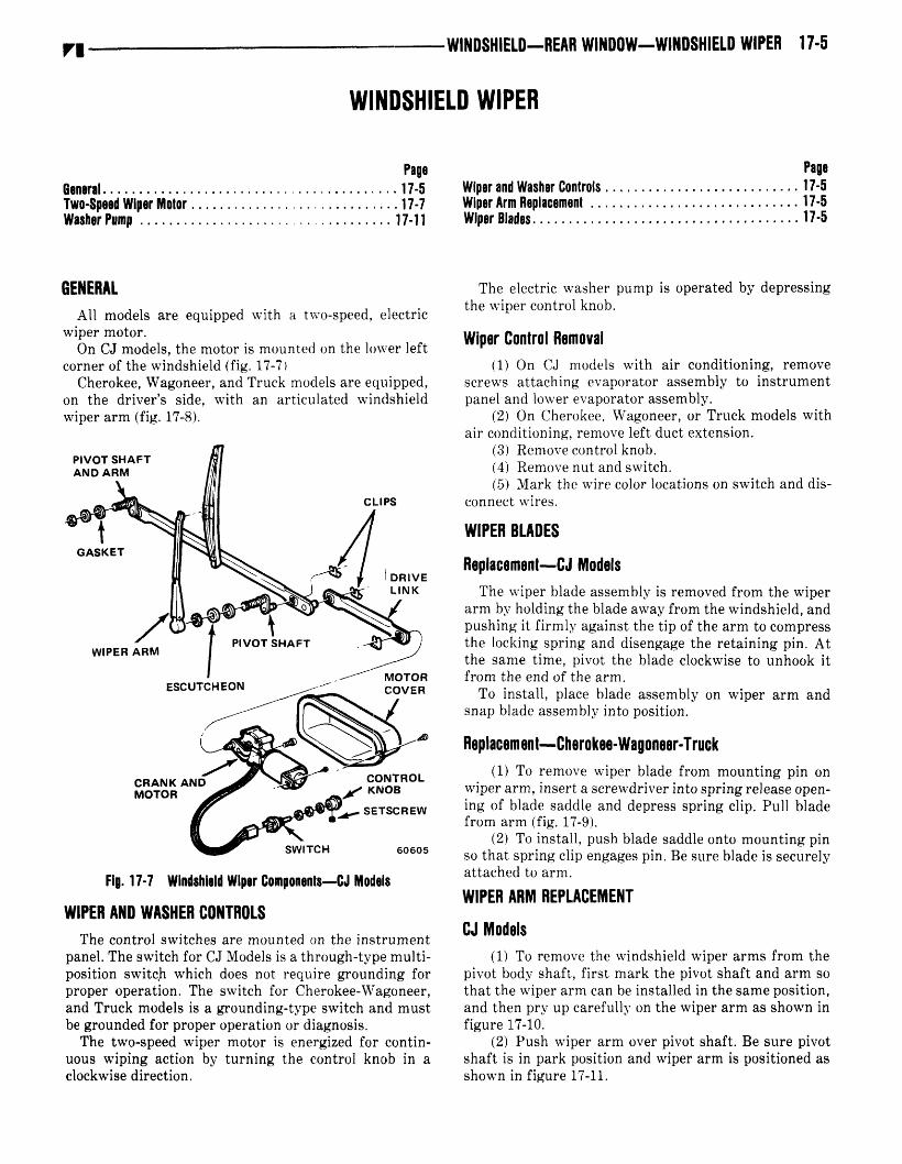
GENERALAll models are equippedwith a two-speed,electric
wiper motor.On CJ models,the motor is mountedon the lower left
corner of the windshieldfig. 17-7Cherokee,Wagoneer,andTruck modelsareequipped,
on the driver’s side, with an articulated windshieldwiperarm fig. 17-8.
FIg. 17-7 WIndshield Wiper Components-CJ Models
WIPER AND WASHER CONTROLSThe control switchesare mounted on the instrument
panel.Theswitch for CJ Models is a through-typemulti-position switch which does not require grounding forproper operation. The switch for Cherokee-Wagoneer,andTruck modelsis a grounding-typeswitch and mustbegroundedfor properoperationor diagnosis.
The two-speedwiper motor is energizedfor continuous wiping action by turning the control knob in aclockwisedirection.
The electric washer pump is operatedby depressingthe wiper control knob.
Wiper Control Removal1 On CJ models with air conditioning, remove
screws attaching evaporatorassembly to instrumentpanelandlower evaporatorassembly.
2 On Cherokee,Wagoneer,or Truck modelswithair conditioning, removeleft duct extension.
3 Removecontrol knob.4 Removenut andswitch.5 Mark the wire color locationson switch anddis
connectwires.
WIPER BLADES
Replacement-CJ ModelsThe wiper bladeassemblyis removedfrom the wiper
arm by holdingthe bladeawayfrom thewindshield,andpushingit firmly againstthe tip of the arm to compressthe locking spring and disengagethe retaining pin. Atthe sametime, pivot the bladeclockwiseto unhook itfrom the end of the arm.
To install, place blade assemblyon wiper arm andsnapbladeassemblyinto position.
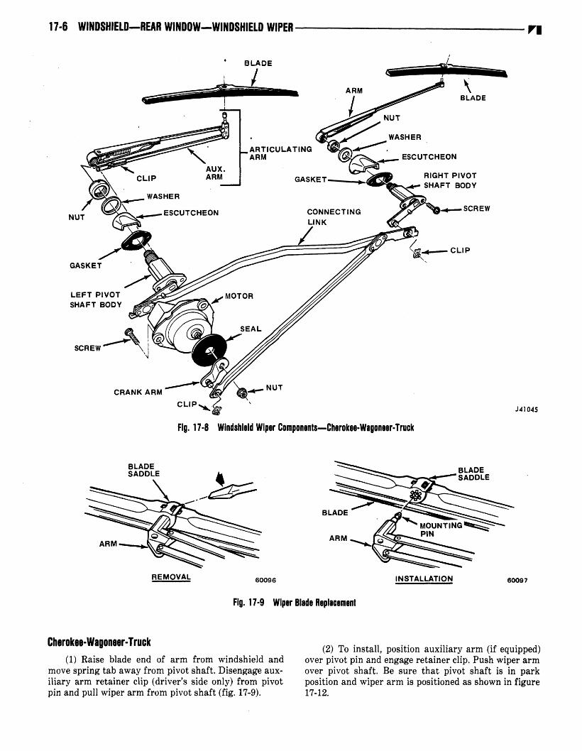
Replacoment-Chorokee-Wagoneer-Truck1 To remove wiper blade from mounting pin on
wiperarm, inserta screwdriverinto springreleaseopening of blade saddleand depressspring clip. Pull bladefrom arm fig. 17-9.
2 To install, pushbladesaddleonto mountingpin60605 so thatspring clip engagespin. Be surebladeis securely
attachedto arm.
WIPER ARM REPLACEMENT
CJ Models1 To remove the windshieldwiper arms from the
pivot body shaft, first mark the pivot shaft andarm sothat the wiper arm canbe installedin thesameposition,and thenpry up carefully on the wiper arm as shown infigure 17-10.
2 Push wiper arm over pivot shaft. Be surepivotshaft is in park positionand wiper arm is positionedasshown in figure 17-11.
vu
PIVOT SHAFTAND ARM
GASKET
CLIPS
WIPER ARM
CONTROLKNOB
SETSCREW
SWITCH
LEFT PIVOTSHAFT BODY
17-6 WINDSHIELD-REAR WINDOW-WINDSHIELD WIPER vu
J4045
______________
60097
BLADESADDLE
FIg. 17-8 WindshIeld Wiper Components-Cherokee-Wagoneer-Truck
Fig. 17-9 WIper Blade Replacement
Cherokee-Wagoneer-Truck1 Raise blade end of arm from windshield and
movespringtab away from pivot shaft.Disengageauxiliary arm retainerclip driver’s side only from pivotpin andpull wiper arm from pivot shaftfig. 17-9.
2 To install, position auxiliary arm if equippedover pivot pin andengageretainerclip. Pushwiper armover pivot shaft. Be sure that pivot shaft is in parkposition andwiper arm is positionedas shownin figure17-12.
B LADE
ARMBLADE
ARTICULATINGARM
AUX.ARM
NUTESCUTCHEON
ESCUTCHEON
GASKET
RIGHT PIVOTSHAFT BODY
SCREW
/
___
CLIP
SCREW
CRANK ARM
CLIP
NUT
ARM
REMOVAL 60096 INSTALLATION

WINDSHIELD-REAR WINDOW-WINDSHIELD WIPER 11-1
TWO-SPEED WIPER MOTOR-CJ MODELS
GeneralThe wiper motor is protectedby a 10-ampfuse in the
fusepanel.When the wiper switch is moved to the low speed
position,currentflows from the fusepanelto terminal Bfig. 17-13of thewiperswitch, throughthe wiperswitchto terminal 2, then throughthe green wire to the motorlow-speedbrushandthrough the armatureto ground.
With the wiper switch in the high speed position,current flows from the fuse panel to terminal B of thewiper switch, through the wiper switch to terminal 3,then throughthe redwire to the motorhigh speedbrushandthroughthe armatureto ground.
When the wiper switch is turned off, current flowsfrom the fuse panel to terminal B of the wiper switch,through the wiper switch to terminal 1, then throughthe black wire to the park contactpoints to the motor
low speedbrush and through the armatureto ground.When the cam on the wiper drive gear opens the parkcontact points, the feed circuit to the motor low speedbrush is interruptedandthe motor is in park.
TWO-SPEED WIPER MOTOR-CHEROKEE-WAGONEERTRUCK
GeneralThe wiper motor is protectedby a 10-ampfuse in the
fuse panel. Whenthe dash switch is moved to the low-speedposition, the circuit betweenterminalsA andF onthe motor are connectedand G ground through theswitch. Currentfrom the batteryflows through aseriesfield coil and is divided. One part passesthrough theshunt field coil to ground at the dashswitch; the otherpart passesthrough the armatureto groundat the dashswitch.
Moving the dash switch to the high-speedpositionopens the shunt field circuit to ground at the dashswitch andkeepsthe armaturecircuit closedto ground.The shunt field current must then pass through a 20-ohm resistor locatedon the back of the wiper terminalboard and then through terminal A that connectsthearmaturecircuit to G groundthroughthedashswitch.
Moving the dash switch to the OFF position opensboth the armatureandshuntfield circuits to groundatthe dashswitch. However,bothof thesecircuits arestillclosedto ground throughthe parkingswitch. Whenthecam on the wiper output gear opens the park switchcontacts, the ground circuit is broken and the wiperbladesare in the parkedposition.
NOTE: The shuntfield is connecteddirectly to groundbypassingthe resistorwith the switchin the off position. ThisiesvIts in low speedoperationduring the parkoperation.
Troubleshooting Procedures-CJ ModelsThe wiper motor may be operatedindependentlyof
the switch to aid in determiningdefectivecomponents.
NOTE: The wiper motormustbe groundedfor properoperationand during all wiper tests.
ri
Fig. 17-12 Wiper Arm Park Position-Cherokee-Wagoneer-Truck
Fig. 17-10 Wiper Arm Removal
DRIVER SIDE2-1/2 INCHES
PASSENGER SIDE31/8 INCHES
60612
Fig. 17-11 Wiper Arm Park Position-CJ Models

17-8 WINDSHIELD-REAR WINDOW-WINDSHIELD WIPER
W
SELECTOR POSITION CJ MODELS CHEROKEE-WAGONEER-TRUCK MODELS
OFF OR PARK 8-1 A-F
LOW SPEED B-2 A-F-G
HIGH SPEED B-3 A-G
WASH B-W W-G
Fig. 17-13 Continuity Test for Wiper Switches
60615
With ignition switch on, check for 12 volts at switchterminal 5 fig. 17-14. If 12-volt test lamp lights butwiper motor does not operate,connecta jumper wirefrom ground strapon motor to a good body ground.Ifmotor still does not operate, disconnectwiring fromswitch. Usingajumperwire, connectswitchterminals2and 5. This connectionshould give low speedoperation.If wiper motor doesnot operatein low speed,thereis anopen in the greenwire, a defectiveinternal motor connectionor a stuck low speedbrush.
To obtain high speed,connectajumperwire betweenterminals3 and5. If wiper motor fails to operate,thereis an open in the red wire, a defectiveinternal motorconnection,or a stuckhigh speedbrush.
With the wiper bladesin a position other thanpark,connecta jumperwire betweenterminals1 and 5. Thewiper bladesshould run on low speedand stop in thepark position. If, after making the jumperconnection,the motor does not run, there is an open in the blackwire, a defective internal motor connection, a misaligned or damagedsetof contactpoints or a badconnection through the park point set to the low speedbrush. If the wiper motor runsbut does not park, thecam on the drive gearis not sufficiently breakingthecontactpoints.
If wiper motor operation is intermittent,a defectivesolderjoint, wiring connection, body ground or wornbrushmaycausethe condition.
Troubleshooting Procadure-Cherokee-Wagoneer-TruckFigure 17-14 illustrates the method of connecting
leadsto the two-speedwiper either for benchoperationor to run wiper independentlyof dashswitch andvehiclewiring wheninstalledin vehicle.
Typical wiper troublesare as follows: wiper inoperative; wiper will not shutoff; wiper operatesonly on fastspeed;wiper shuts off with dash switch in high-speedposition; blades do not return to park position whenwiper is turnedOFF; wiper speednormalat low but toofast in high; intermittentoperationduringnormal wiping cycle.
Troubleshootingproceduresaredivided into two categories: wiper troubleshootingin vehicle; wiper troubleshootingon bench.
Troubleshooting in VehicleIf wiper is inoperative,checkthe following items:* Fuse
vu
G
1
FA
W
* Wiring harnessto motor connections

WINDSHIELD-REAR WINDOW-WINDSHIELD WIPER 17-9V.
MOTOR CASE MUSTBE GROUNDED
N
* Dash switch connectionandground
* Wiper groundstrap
With ignition switch on, check for 12 volts at harnessterminal that connectsto wiper terminal. To dietermineif dashswitch or wiring is at fault, disconnectharnessfrom wiper motor andtry operatingwiper as shown infigure 17-14.If wiper fails to operate,removebodypartsas required,disconnecttransmissionsfrom wiper crankarm, and recheckwiper motoroperation.If wiper motorstill fails to performcorrectly, removewiper motorfromvehicle and check wiper motor accordingto procedureunderTroubleshootingon Bench.
If wiper motor will not shut off, determineif wipermotor has both low and high speeds,slow speedonly orhigh speedonly. It is importantthat the wiper operatesat low speed during parking cycle. High speed motormomentummay carry cam past normal park position,allowing parkcontactpoints to close.
Disconnectwiring harnessfrom wiper motor and tryoperatingwiper independentlyof dashswitch as shownin figure 17-14.
If wiper shuts off correctly with crank arm in parkposition and wiper has both speedsafter performing
J42677
tests,checkthe leadbetweenterminal1 anddashswitchground., and check for defectivedash switch. If wipershutsoff correctly but wiper haslow speedonly, checklead betweenwiper terminal 3 and dashswitch groundand check for defectivedash switch. If wiper shutsoffcorrectly but has high speedonly, check lead betweenwiper terminal 1 and dash switch for open circuit andcheck for defective dash switch. If wiper still fails tooperatecorrectly, remove it from vehicle and check itaccordingto instructionsunderWiper Troubleshootingon bench.
If wiper hasslow speedonly and shutsoff with dashswitch in high-speedposition,reverseharnessleadsthatconnectto wiper terminals 1 and 3 fig. 17-14.
If bladesdo not return to park positionwhenwiper isturned off, check wiper ground strap connectionto vehicle body. Remove wiper from vehicle and check fordirty, bent,or brokenparkswitch contacts.
If wiper speedis normal in low, but too excessiveinhigh speed,removewiper motor from vehicleandcheckfor an defectiveresistor.
If wiper motor operateserratically, check for loosewiper motor ground strap connection or loose dashswitch mounting.
GEAR SHAFT INPARK POSITION LOW SPEED - AS SHOWN
HIGH SPEED - DISCONNECT JUMPER WIRE FROMTERMINAL 3
OFF OR PARK . LEAVE JUMPER WIRE CONNECTED
TO TERMINALS 1 AND 3 BUTDISCONNECT IT FROM GROUND STRAP.WIPER SHOULD STOP WITH GEARSHAFT FLATS AS SHOWN.
Fig. 17-14 Two-Speed Wiper Test Connections-Cherokee-Wagoneer-Truck

11-10 WINDSHIELD-REAR WINDOW-WINDSHIELD WIPER
GEAR TRAINCOVER
WASHER
SEAL.CAP
CRANK ARM
CRANK ARMRETAINING RETAININGNUT CLIP
COVER ANDTERMINAL BOARD
Fig. 17-15 Two-Speed Wiper Motor-Cherokee-Wagoneer-Truck
Troubleshooting on BenchUsing ammetercapableof reading at least 30 am
peres,check feed wire circuit shown in figure 17-14 foropen circuit.
The low speedamp draw with no load should be 4amps; high speedamp draw 3.5 amps; motor stalledcold 12 amps.
If wiper motor is inoperative,connectwiper motor tooperatein low speedand observecurrent draw. If thereadingis zero amps,checkfor loose solder connectionat feed terminal or loose splicejoints. If readingis 1 to1.5 amps,checkfor open armature,sticking brushes,orloosesplice joint. If readingis 11 amps,checkfor brokengear,seizedshaft,or some otherconditionthatwill stallthe wiper.
If wiper motor will not shut off, this condition mayexist if wiper motor has one or both speeds.If wipermotorhas both speeds,check for park switch contactsnot openingor internal wiper motor leadthat connectsto wiper terminal 1 being grounded.If wiper motor haslow speedonly, check for grounding of internal wipermotor lead that connectsto wiper terminal 3 and checkshuntfield coil for grounding. If wiper motorhas highspeedonly, checkfor openin internal wiper motor leadthat connectsto wiper terminal 3 and check for shuntfield opencircuit.
If wiper crank arm does not return to park positionwhen wiper motor is turnedoff, checkfor dirty, bent,orbrokenparkswitch contacts.
If wiper speedis normal in low, but too excessiveinhigh speed,checkfor opencircuit in the 20-ohmresistoron backof wiper terminal board.
If wiper motor operateserratically, check for stickybrushesor loosesplice joints.
If the wiper motor will not shut off or wiper crankarm fails to stop in park position whenjumper wire isremovedfrom ground 1, checkthatparkswitch contactsare opening. Also check for ground in internal motorleadthat connectsto terminal 3.
WIPER MOTOR
CJ Models
Removal with Crash Pad
NOTE: Withoutcrashpad, removewipermotorcover.
1 Remove necessaryto componentsfrom windshieldframe.
2 Remove right and left windshield hoiddownknobsandfold windshielddown.
3 Removeleft accesshole cover.4 Disconnectdrive link from left wiperpivot.5 Disconnect wiper motor wire harnessfrom
switch.6 Remove attaching screws and remove wiper
motor.
Installation With Crash Pad1 Position wiper motor on windshieldframe and
install attachingscrews.2 Connectwipermotorwire harnessto switch.3 Connectdrive link to left wiper pivot.4 Install left accesshole cover.5 Raisewindshield to upright positionand install
right and left windshieldhoiddownknobs.6 Install necessarytop componentson windshield
frame.
Cherokee-Wagoneer-Truck
Removal
1 Disconnectwiper drive link from crank underinstrumentpanel.
2 Disconnectmotorwiresat motorunderhood.3 Removemotor-to-dashmountingscrewsandre
move motor.
GEAR ANDSHAFT
VI
GEAR ANDPINION
END PLATEAND BRUSH
ARMATURE
WASHER
HOUSING
FRONT COVER PLATEAND BOLTS
J42678
WINDSHIELD-REAR WINDOW-WINDSHIELD WIPER 17-11VI
Disassembly
Refer to figure 17-15.1 Clamp crank arm in vise and loosen crank arm
retainingnut.2 Removeseal cap, retaining ring, and end plate
washer.Sealcap shouldbe cleanedandrepackedwith awaterproofgreasebeforeassembly.
3 Punch out the gear box cover retaining rivetsand removecover from gear train. Mark ground straplocation for assemblypurposes.
4 Removeoutput gearand shaft, thenslide intermediategear andpinion off shaft.
Assembly1 When assembling the gear box cover, be sure
cover is locatedproperlyover locating dowel pins.2 Also be sureto install groundstrap.3 Whenassemblingthe crank arm, operatewiper
to parkpositionandinstall crank armon outputshaftsothat identificationmarksline up with those in cover.
4 Clamp crank in vise before securingretainingnut.
Installation1 Position motor on dash and install mounting
screws.2 Connectmotorwiresto motor.3 Connectwiper drive link to motor crank.
WIPER PIVOT SHAFT AND LINKAGE
CJ Models
Removal1 Removerightandleft wiper arms.2 Remove nuts attaching pivots to windshield
frame.3 Removenecessarytop componentsfrom wind
shield frame.4 Remove right and left windshield holddown
knobsandfold windshielddown.
5 Removeright andleft accesshole covers.6 Iisconnect wiper motor drive link from left
wiper pivot.7 Remove wiper pivot shafts and linkage from
accesshole.
installation
1 Install wiper pivot shafts and linkage in windshield frame.
2 Connect wiper motor drive link to left wiperpivot.
3 Install right andleft accesshole covers.4 Raisewindshield to upright positionand install
right andleft windshieldholddown knobs.5 Install nuts attaching pivots to windshield
frame.6 Install rightandleft wiper arms.7 Install necessarytop componentson windshield
frame.
Cherokee-Wagoneor-TruckRemoval
1 Remove wiper arms,pivot shaftnuts, washers,escutcheons,andgaskets.
2 Disconnectdrive armfrom motorcrank.3 Remove individual links wherenecessaryto re
move pivot shaftbodieswithout excessiveinterference.
Installation
1 Installwiper pivot shaftsandlinakge.2 Connectdrive arm to motor crank.3 Install gaskets, escutcheons,washers, pivot
shaftnuts, andwiper arms.
WASHER PUMPThe electricwasherpumpassemblyis mountedin the
water reservoir.The impeller motorcaseis groundedtothe body sheetmetal by a black groundwire. It is energized by a yellow feed wire from the singlebladeterminal on the control switch.
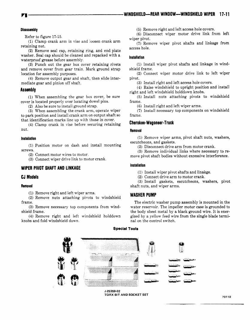
Special Tools
4Ø -
J25359O2TORX BIT AND SOCKET SET
70119

TECHNICAL BULLETIN REFERENCE
Date TB No. Subject Changes Information on Page No.
Related Documents