Mark Russinovich Technical Fellow Windows Azure Session 3-058 Windows Azure Internals

Windows Azure Internals
Feb 25, 2016
Windows Azure Internals. Mark Russinovich Technical Fellow Windows Azure Session 3-058. Agenda. Windows Azure Datacenter Architecture Deploying Services Inside IaaS VMs Maintaining Service Health The Leap Day Outage and Lessons Learned. Windows Azure Datacenter Architecture. - PowerPoint PPT Presentation
Welcome message from author
This document is posted to help you gain knowledge. Please leave a comment to let me know what you think about it! Share it to your friends and learn new things together.
Transcript
Mark RussinovichTechnical FellowWindows AzureSession 3-058
Windows Azure Internals
AgendaWindows Azure Datacenter ArchitectureDeploying ServicesInside IaaS VMsMaintaining Service HealthThe Leap Day Outage and Lessons Learned
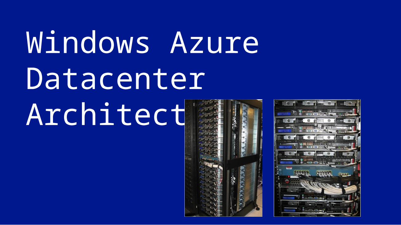
Windows Azure Datacenter Architecture
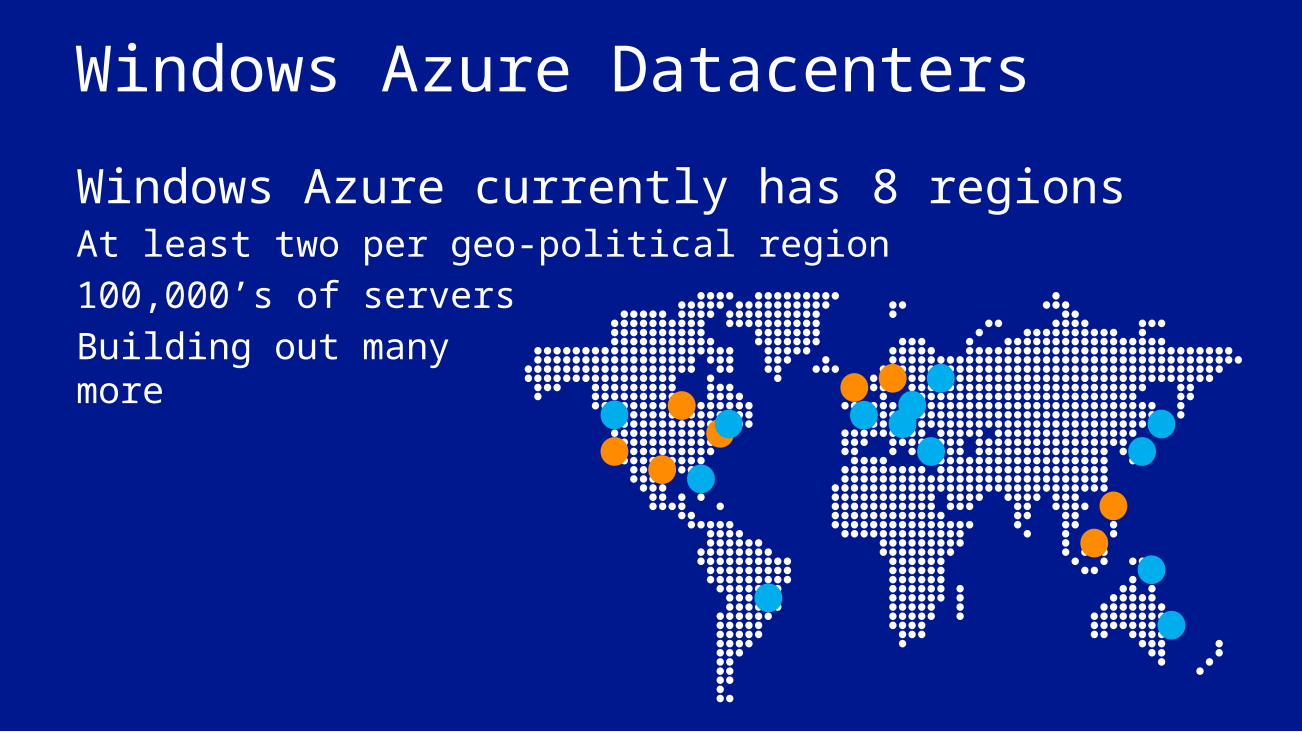
Windows Azure DatacentersWindows Azure currently has 8 regions At least two per geo-political region100,000’s of serversBuilding out manymore

The Fabric Controller (FC) The “kernel” of the cloud operating system
Manages datacenter hardware Manages Windows Azure services
Four main responsibilities: Datacenter resource allocation Datacenter resource
provisioning Service lifecycle management Service health management
Inputs: Description of the hardware and network resources it will control Service model and binaries for cloud applications
ServerKernelProcess
DatacenterFabric ControllerService
Windows Kernel
Server
Word SQL Server
Fabric Controller
Datacenter
ExchangeOnline
SQL Azure
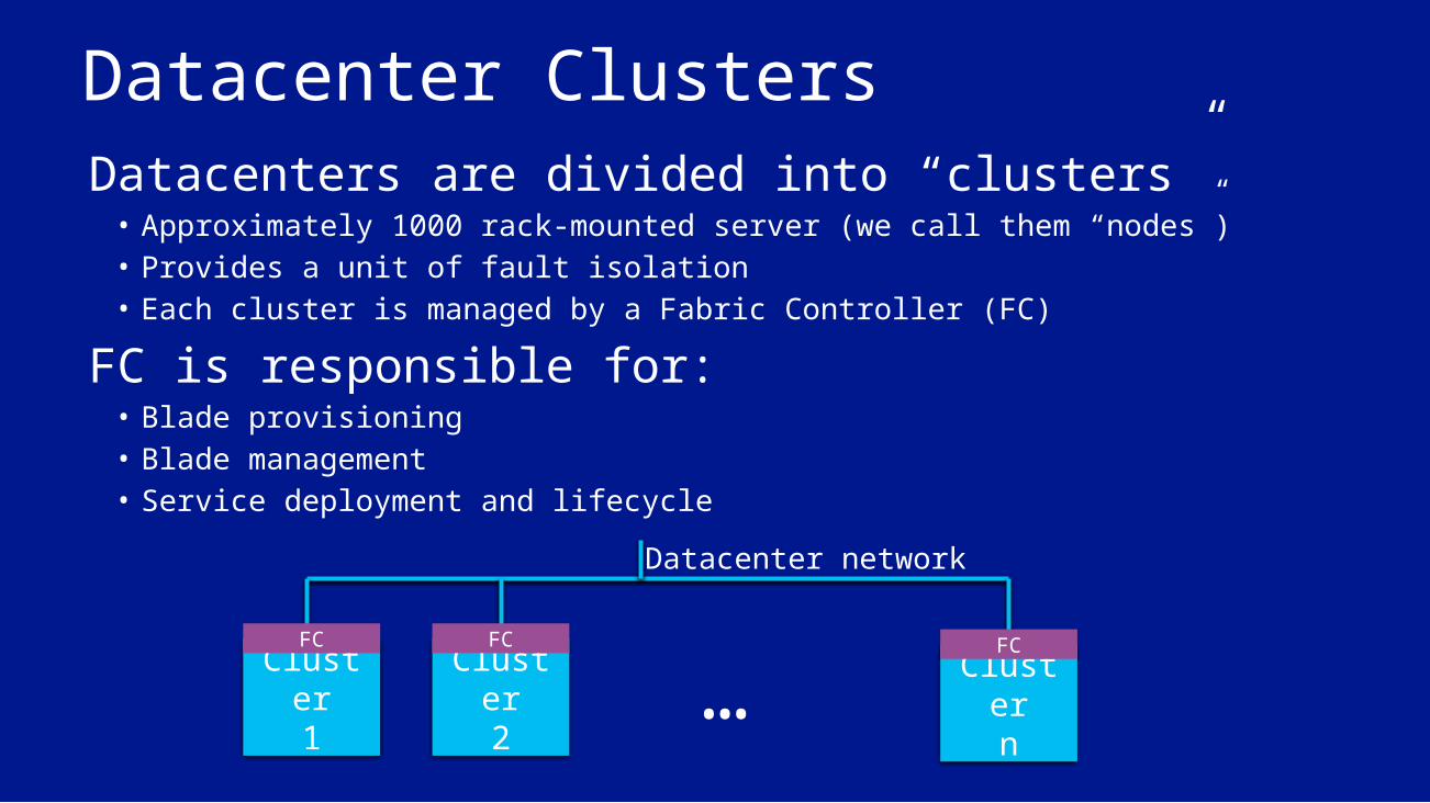
Datacenter ClustersDatacenters are divided into “clusters”• Approximately 1000 rack-mounted server (we call them “nodes”)• Provides a unit of fault isolation• Each cluster is managed by a Fabric Controller (FC)
FC is responsible for:• Blade provisioning• Blade management• Service deployment and lifecycle
Cluster1
Cluster2
Clustern
…Datacenter network
FC FC FC

Inside a Cluster FC is a distributed, stateful application running on nodes (servers)
spread across fault domains Top blades are reserved for FC
One FC instance is the primary and all others keep view of world in sync Supports rolling upgrade, and services continue to run even if FC fails entirely
TOR
FC1
… …
TOR
FC2
… …
TOR
FC3
… …
FC3
TOR
FC4
… …
TOR
FC5
… …
Spine
Nodes
Rack
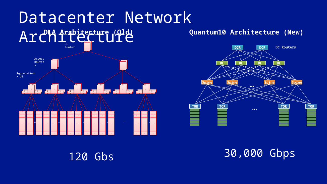
Datacenter Network ArchitectureDLA Architecture (Old) Quantum10 Architecture (New)
TOR TOR TOR TOR
Spine Spine Spine
…
…
DCR DCR
BLBL
Spine
DC Routers
BL BL
30,000 Gbps120 Gbs
40 Nodes
TOR
LB
LB
AGG
Digi
APC
LB
LB
AGG
LB
LB
AGG
LB
LB
AGG
LB
LB
AGG
LB
LB
AGG
20Racks
DC Router
Access Routers
Aggregation + LB
40 Nodes
TOR
Digi
APC
40 Nodes
TOR
Digi
APC
40 Nodes
TOR
Digi
APC
40 Nodes
TOR
Digi
APC
40 Nodes
TOR
Digi
APC
40 Nodes
TOR
Digi
APC
40 Nodes
TOR
Digi
APC
40 Nodes
TOR
Digi
APC
40 Nodes
TOR
Digi
APC
40 Nodes
TOR
Digi
APC
40 Nodes
TOR
Digi
APC
40 Nodes
TOR
Digi
APC
40 Nodes
TOR
Digi
APC
40 Nodes
TOR
Digi
APC
……
20Racks 20Racks 20Racks
…… … …
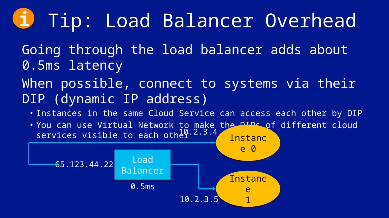
Tip: Load Balancer OverheadGoing through the load balancer adds about 0.5ms latencyWhen possible, connect to systems via their DIP (dynamic IP address)• Instances in the same Cloud Service can access each other by DIP• You can use Virtual Network to make the DIPs of different cloud services
visible to each other
Load Balancer
Instance 0
Instance1
10.2.3.4
10.2.3.5
65.123.44.22
0.5ms
i
Deploying Services
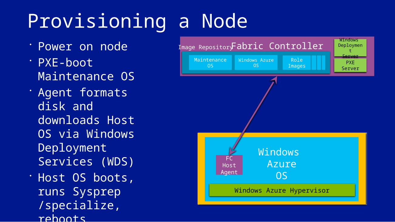
Provisioning a Node Power on node PXE-boot
Maintenance OS Agent formats disk
and downloads Host OS via Windows Deployment Services (WDS)
Host OS boots, runs Sysprep /specialize, reboots
FC connects with the “Host Agent”
Fabric ControllerRole
ImagesRole
ImagesRole
ImagesRole
Images
Image Repository
Maintenance OS
Parent OS
Node
PXEServer
Maintenance OS
Windows AzureOS
Windows Azure
OSFC
Host Agent
Windows Azure Hypervisor
Windows Deploymen
tServer
RDFEService
US-North Central Datacenter
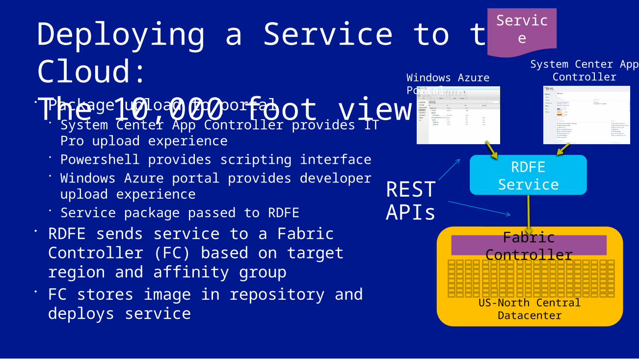
Deploying a Service to the Cloud:The 10,000 foot view Package upload to portal
System Center App Controller provides IT Pro upload experience
Powershell provides scripting interface Windows Azure portal provides developer
upload experience Service package passed to RDFE
RDFE sends service to a Fabric Controller (FC) based on target region and affinity group
FC stores image in repository and deploys service
Fabric Controller
Windows Azure PortalSystem Center App
Controller
Service
RESTAPIs
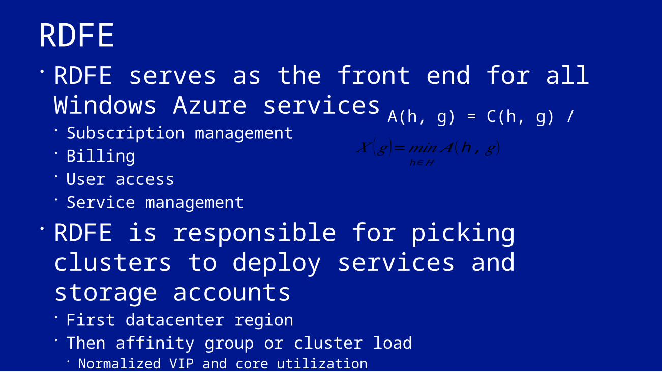
RDFE RDFE serves as the front end for all Windows Azure services Subscription management Billing User access Service management
RDFE is responsible for picking clusters to deploy services and storage accounts First datacenter region Then affinity group or cluster load
Normalized VIP and core utilization
A(h, g) = C(h, g) / 𝑋 (𝑔)=𝑚𝑖𝑛
h∈𝐻𝐴(h ,𝑔)
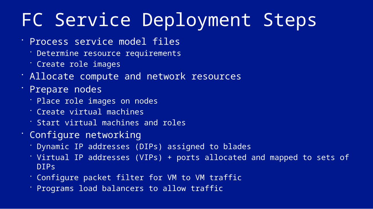
FC Service Deployment Steps Process service model files
Determine resource requirements Create role images
Allocate compute and network resources Prepare nodes
Place role images on nodes Create virtual machines Start virtual machines and roles
Configure networking Dynamic IP addresses (DIPs) assigned to blades Virtual IP addresses (VIPs) + ports allocated and mapped to sets of DIPs Configure packet filter for VM to VM traffic Programs load balancers to allow traffic

Service Resource Allocation Goal: allocate service components to available resources while
satisfying all hard constraints HW requirements: CPU, Memory, Storage, Network Fault domains
Secondary goal: Satisfy soft constraints Prefer allocations which will simplify servicing the host OS/hypervisor Optimize network proximity: pack nodes
Service allocation produces the goal state for the resources assigned to the service components Node and VM configuration (OS, hosting environment) Images and configuration files to deploy Processes to start Assign and configure network resources such as LB and VIPs

Deploying a ServiceRole B
Worker RoleCount: 2
Update Domains: 2Size: Medium
Role AWeb Role (Front End)Count: 3
Update Domains: 3Size: Large
LoadBalance
r10.100.0.36
10.100.0.12210.100.0.185
www.mycloudapp.net
www.mycloudapp.net

Deploying a Role Instance FC pushes role files and configuration information to target node host agent
Host agent creates VHDs Host agent creates VM, attaches VHDs, and starts VM
Guest agent starts role host, which calls role entry point Starts health heartbeat to and gets commands from host agent
Load balancer only routes to external endpoint when it responds to simple HTTP GET (LB probe)

Inside a Deployed Node
Fabric Controller (Primary)
FC Host Agent
Host Partition
Guest Partition
Guest Agent
Guest Partition
Guest Agent
Guest Partition
Guest Agent
Guest Partition
Guest Agent
Physical Node
Fabric Controller (Replica)
Fabric Controller (Replica)…
Role Instance
Role Instance
Role Instance
Role Instance
Trust boundary
Image Repository (OS VHDs, role ZIP files)
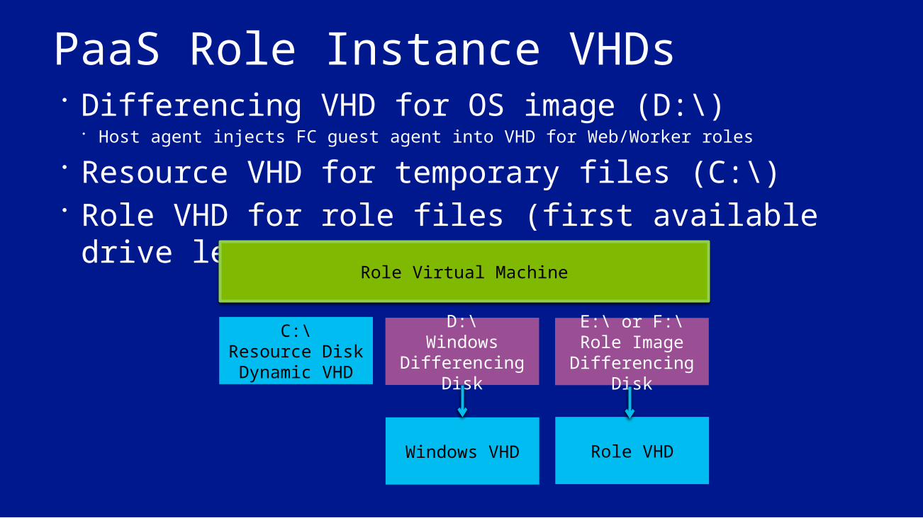
PaaS Role Instance VHDs Differencing VHD for OS image (D:\)
Host agent injects FC guest agent into VHD for Web/Worker roles Resource VHD for temporary files (C:\) Role VHD for role files (first available drive letter
e.g. E:\, F:\)Role Virtual Machine
C:\Resource Disk Dynamic VHD
D:\Windows
Differencing Disk
E:\ or F:\Role Image Differencing
Disk
Windows VHD Role VHD
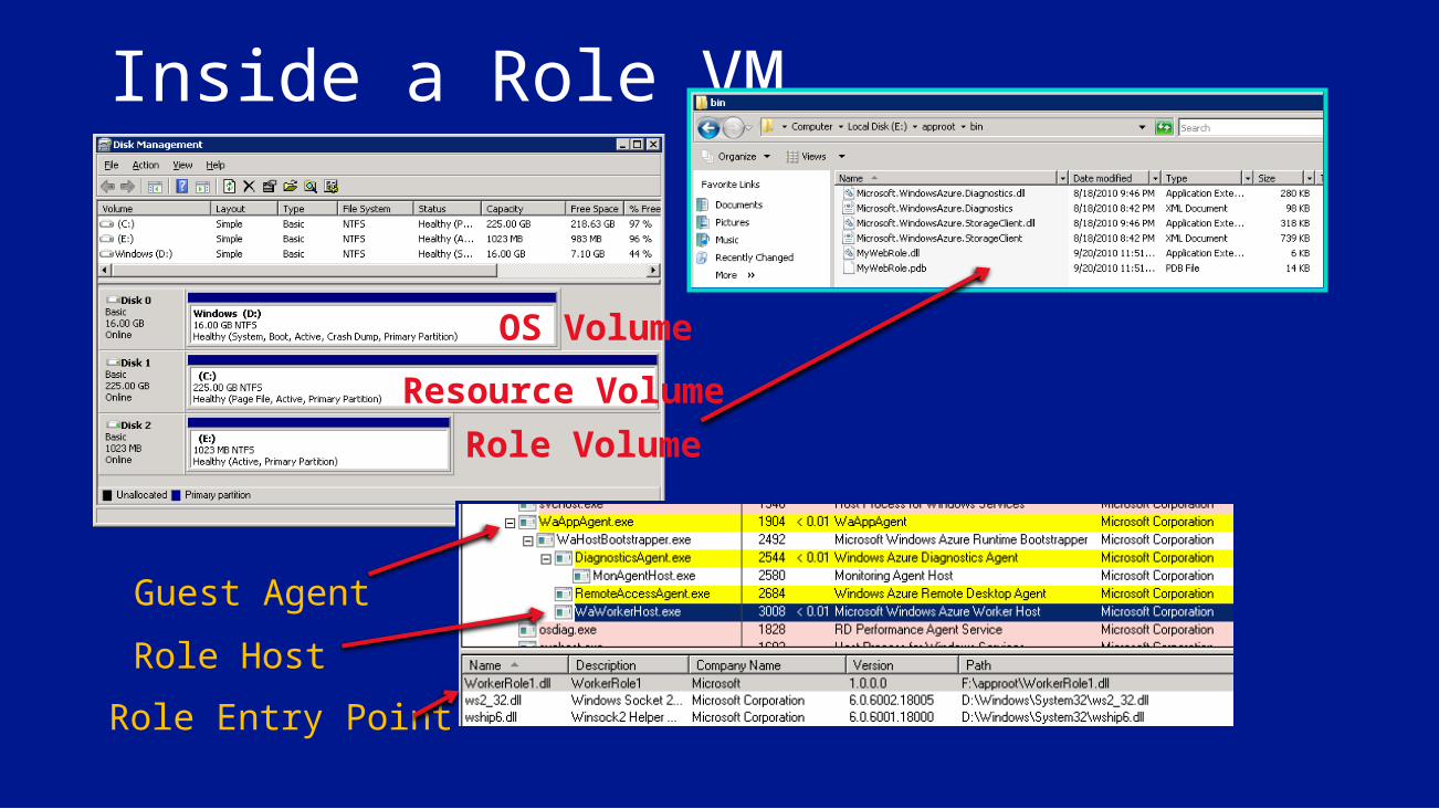
Resource VolumeOS Volume
Role Volume
Inside a Role VM
Guest AgentRole HostRole Entry Point
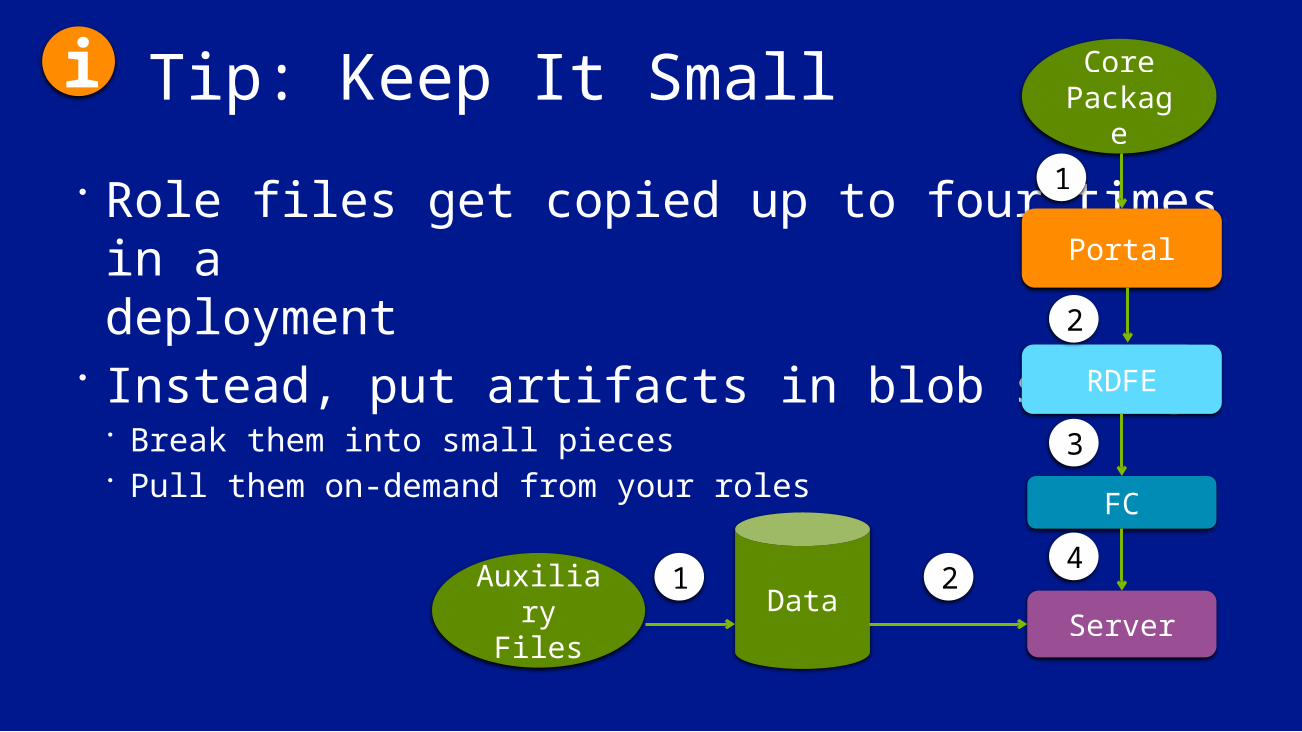
Tip: Keep It Small Role files get copied up to four times in a deployment
Instead, put artifacts in blob storage Break them into small pieces Pull them on-demand from your roles
RDFE
Portal
FC
Server
Core Packag
e1
2
3
4DataAuxiliary
Files
i
1 2

Inside IaaS VMs

Virtual Machine (IaaS) OperationNo standard cached images for IaaS• OS is faulted in from blob
storage during boot• Sysprep /specialize on first
bootDefault cache policy:• OS disk: read+write cache• Data disks: no cache
Local On-Disk Cache
Disk Blob
Local RAM Cache
Virtual Disk Driver
Node
VM
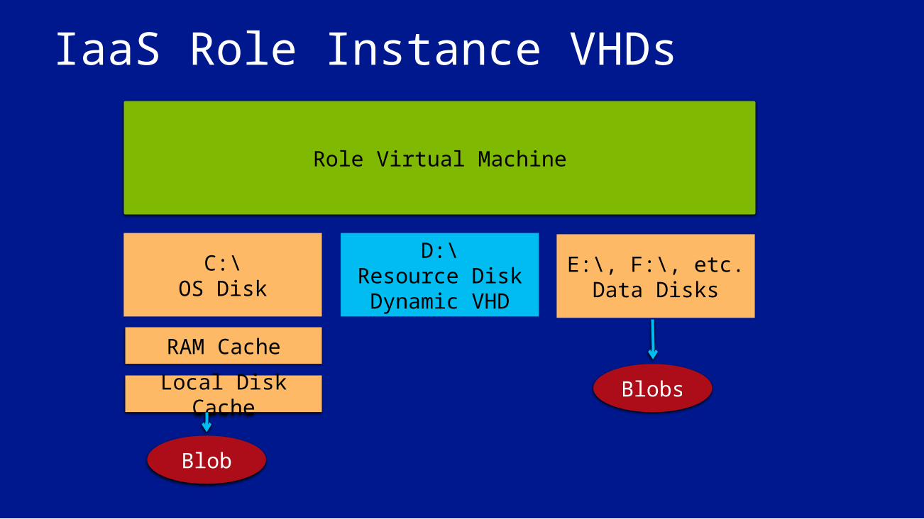
IaaS Role Instance VHDs
Role Virtual Machine
C:\OS Disk
E:\, F:\, etc.Data Disks
D:\Resource Disk Dynamic VHD
RAM Cache
Local Disk Cache Blobs
Blob
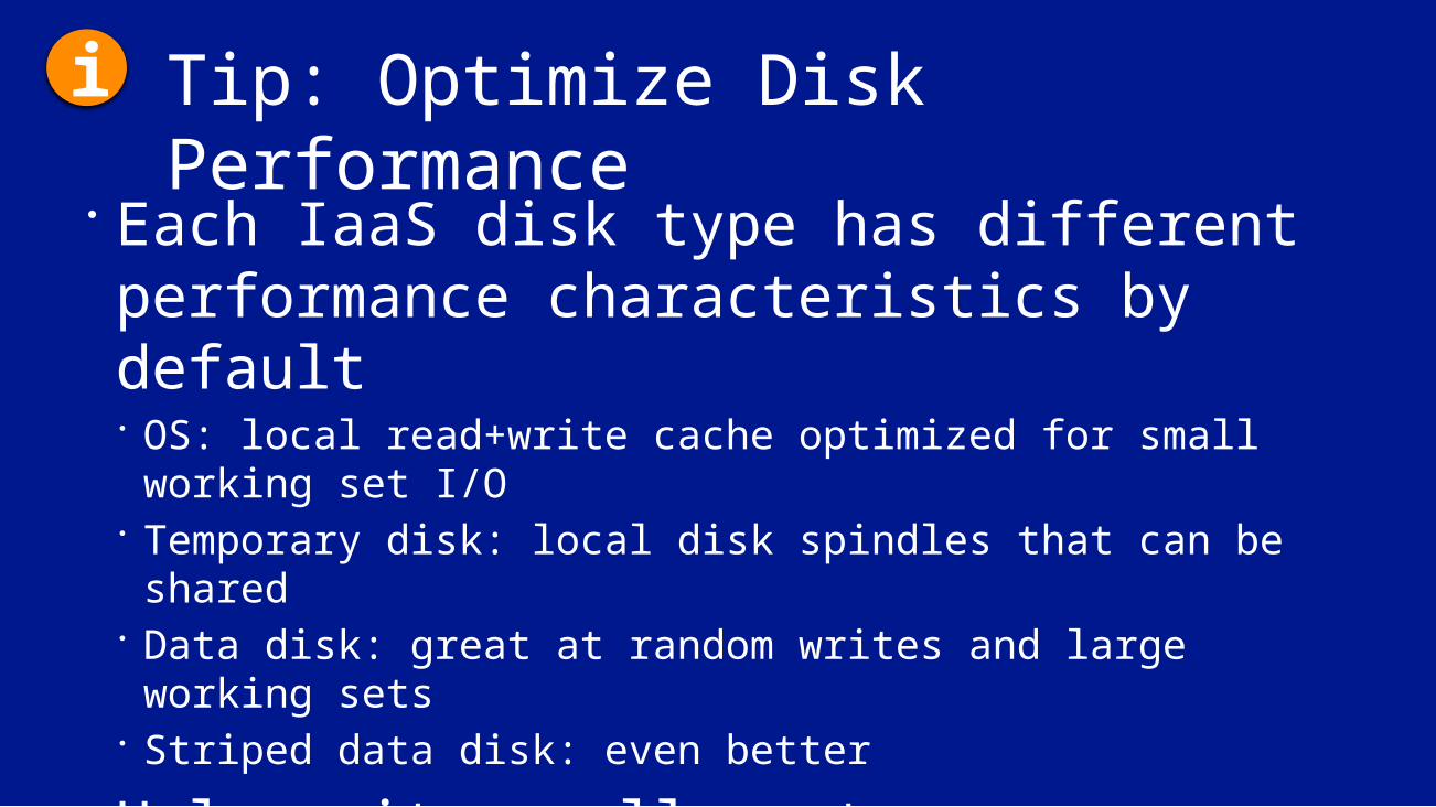
Tip: Optimize Disk Performance Each IaaS disk type has different performance characteristics by default OS: local read+write cache optimized for small working set
I/O Temporary disk: local disk spindles that can be shared Data disk: great at random writes and large working sets Striped data disk: even better
Unless its small, put your application’s data (e.g. SQL database) on striped data disks
i
Updating Services and the Host OS
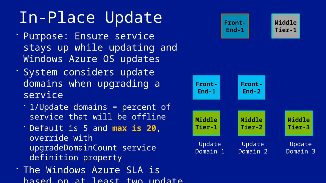
In-Place Update Purpose: Ensure service stays up
while updating and Windows Azure OS updates
System considers update domains when upgrading a service 1/Update domains = percent of
service that will be offline Default is 5 and max is 20, override
with upgradeDomainCount service definition property
The Windows Azure SLA is based on at least two update domains and two role instances in each role
Front-End-1
Front-End-2
Update Domain 1
Update Domain 2
Middle
Tier-1
Middle
Tier-2
Middle
Tier-3
Update Domain 3
Middle Tier-3
Front-End-2Front-End-1
Middle Tier-2Middl
e Tier-1

Tip: Config Updates vs Code UpdatesCode updates:
• Deploys new role image• Creates new VHD• Shutdown old code and start new code
Config updates:• Notification sent to role via RoleEnvironmentChanging• Graceful role shutdown/restart if no response, including startup tasks
For fast update: • Deploy settings
as configuration• Respond to
configuration updates
i
Maintaining Service Health

Node and Role Health Maintenance FC maintains service availability by monitoring the software and hardware health Based primarily on heartbeats Automatically “heals” affected roles/VMs
Problem Fabric Detection Fabric Response
Role instance crashes FC guest agent monitors role termination FC restarts role
Guest VM or agent crashes FC host agent notices missing guest agent heartbeats
FC restarts VM and hosted role
Host OS or agent crashes FC notices missing host agent heartbeat Tries to recover nodeFC reallocates roles to other nodes
Detected node hardware issue Host agent informs FC FC migrates roles to other nodesMarks node “out for repair”
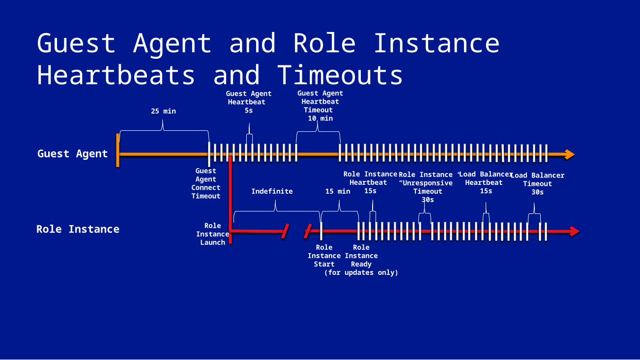
Guest Agent and Role Instance Heartbeats and Timeouts
25 min
GuestAgent
ConnectTimeout
Guest Agent Heartbeat
5s
RoleInstanceLaunch
Indefinite
RoleInstance
Start
RoleInstanceReady
(for updates only)
15 min
Role Instance Heartbeat
15s
Guest Agent Heartbeat Timeout 10 min
Role Instance “Unresponsive”
Timeout30s
Load Balancer Heartbeat
15s
Load BalancerTimeout
30s
Guest Agent
Role Instance
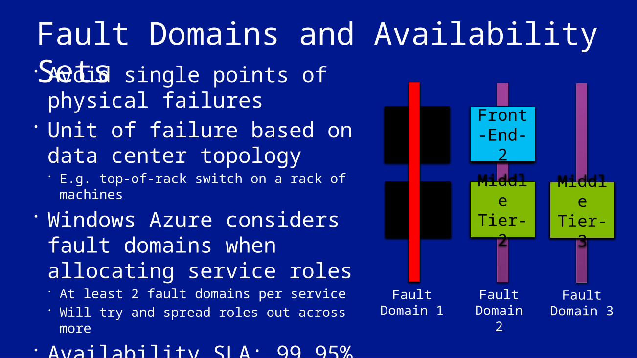
Fault Domains and Availability Sets Avoid single points of
physical failures Unit of failure based on data
center topology E.g. top-of-rack switch on a rack of machines
Windows Azure considers fault domains when allocating service roles At least 2 fault domains per service Will try and spread roles out across more
Availability SLA: 99.95%
Front-End-1
Fault Domain 1
Fault Domain
2
Front-End-2
Middle Tier-2
Middle Tier-1
Fault Domain 3
Middle Tier-3
Front-End-1
Middle Tier-1
Front-End-2
Middle Tier-2
Middle Tier-3
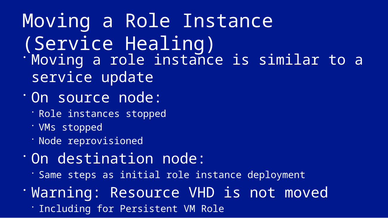
Moving a Role Instance (Service Healing) Moving a role instance is similar to a service update
On source node: Role instances stopped VMs stopped Node reprovisioned
On destination node: Same steps as initial role instance deployment
Warning: Resource VHD is not moved Including for Persistent VM Role
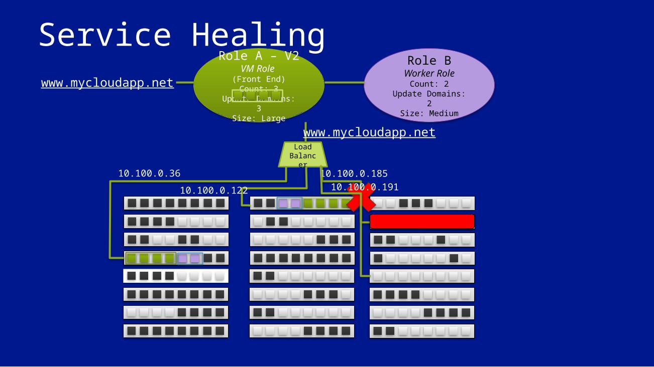
Service HealingRole B
Worker RoleCount: 2
Update Domains: 2Size: Medium
Role A – V2VM Role (Front End)Count: 3
Update Domains: 3Size: Large
LoadBalance
r10.100.0.36
10.100.0.12210.100.0.185
www.mycloudapp.net
www.mycloudapp.net
10.100.0.191
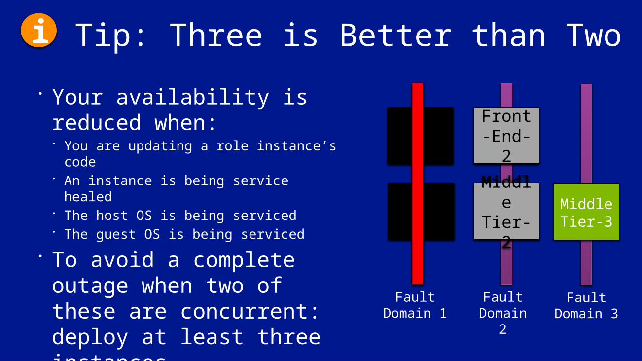
Tip: Three is Better than Two Your availability is
reduced when: You are updating a role instance’s code An instance is being service healed The host OS is being serviced The guest OS is being serviced
To avoid a complete outage when two of these are concurrent: deploy at least three instances
Front-End-1
Fault Domain 1
Fault Domain
2
Front-End-2
Middle Tier-2
Middle Tier-1
Fault Domain 3
Middle Tier-3
Front-End-1
Middle Tier-1
Front-End-2
Middle Tier-2
i
The Leap Day Outage: Cause and Lessons Learned

Tying it all Together: Leap DayOutage on February 29 caused by this line of code:
validToYear = currentDate.Year + 1;
The problem and its resolution highlights:• Network Operations and monitoring• DevOps “on call” model• Cluster fault isolation• Lessons we learned

Windows Azure Network Operations Center
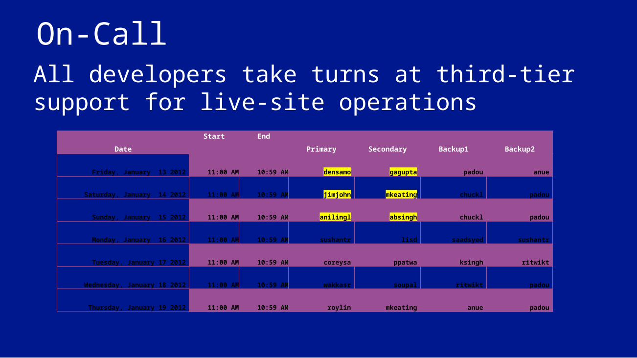
On-CallAll developers take turns at third-tier support for live-site operations
Date
Start End
Primary Secondary Backup1 Backup2
Friday, January 13 2012 11:00 AM 10:59 AM densamo gagupta padou anue
Saturday, January 14 2012 11:00 AM 10:59 AM jimjohn mkeating chuckl padou
Sunday, January 15 2012 11:00 AM 10:59 AM anilingl absingh chuckl padou
Monday, January 16 2012 11:00 AM 10:59 AM sushantr lisd saadsyed sushantr
Tuesday, January 17 2012 11:00 AM 10:59 AM coreysa ppatwa ksingh ritwikt
Wednesday, January 18 2012 11:00 AM 10:59 AM wakkasr soupal ritwikt padou
Thursday, January 19 2012 11:00 AM 10:59 AM roylin mkeating anue padou
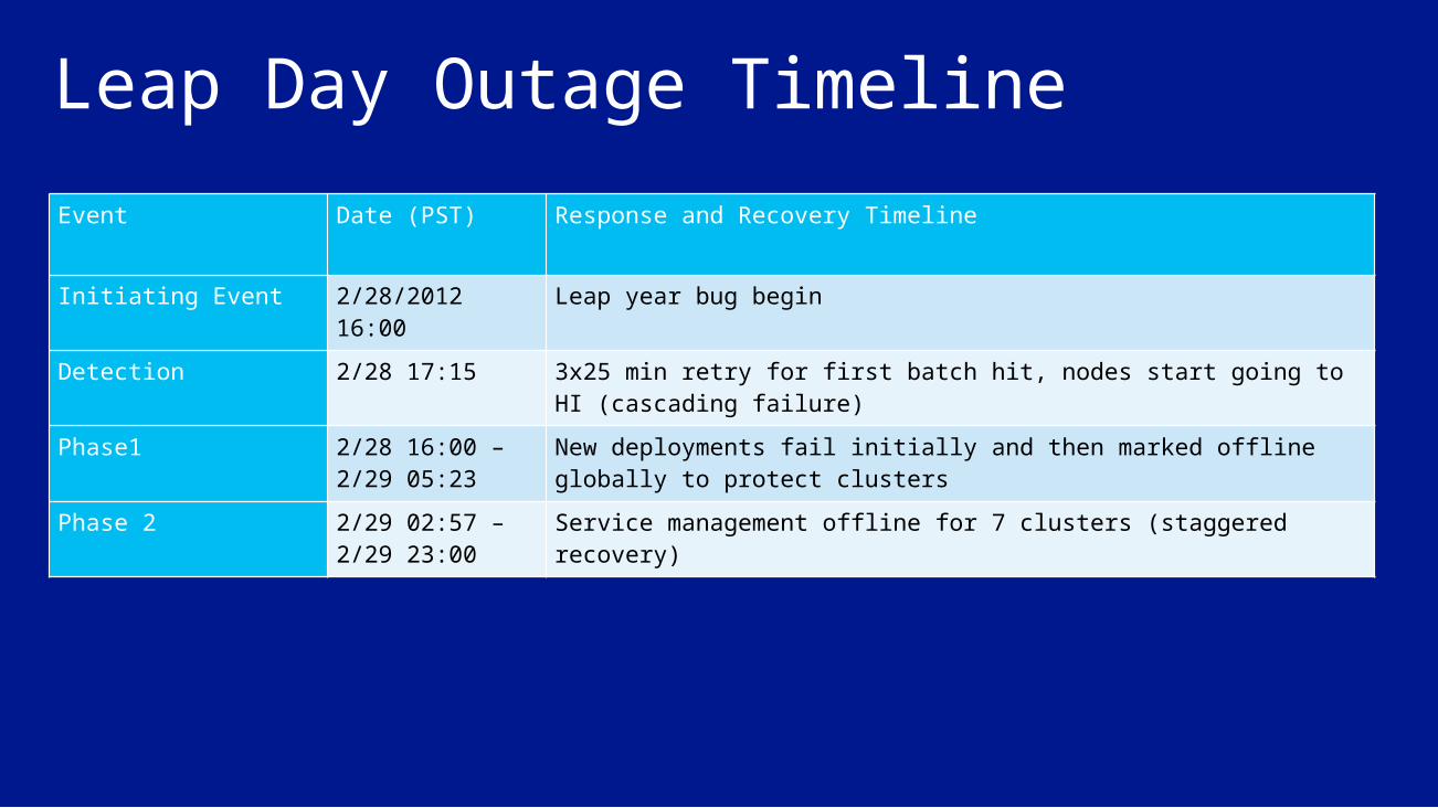
Leap Day Outage TimelineEvent Date (PST) Response and Recovery Timeline
Initiating Event 2/28/2012 16:00 Leap year bug begin
Detection 2/28 17:15 3x25 min retry for first batch hit, nodes start going to HI (cascading failure)
Phase1 2/28 16:00 – 2/29 05:23
New deployments fail initially and then marked offline globally to protect clusters
Phase 2 2/29 02:57 – 2/29 23:00
Service management offline for 7 clusters (staggered recovery)
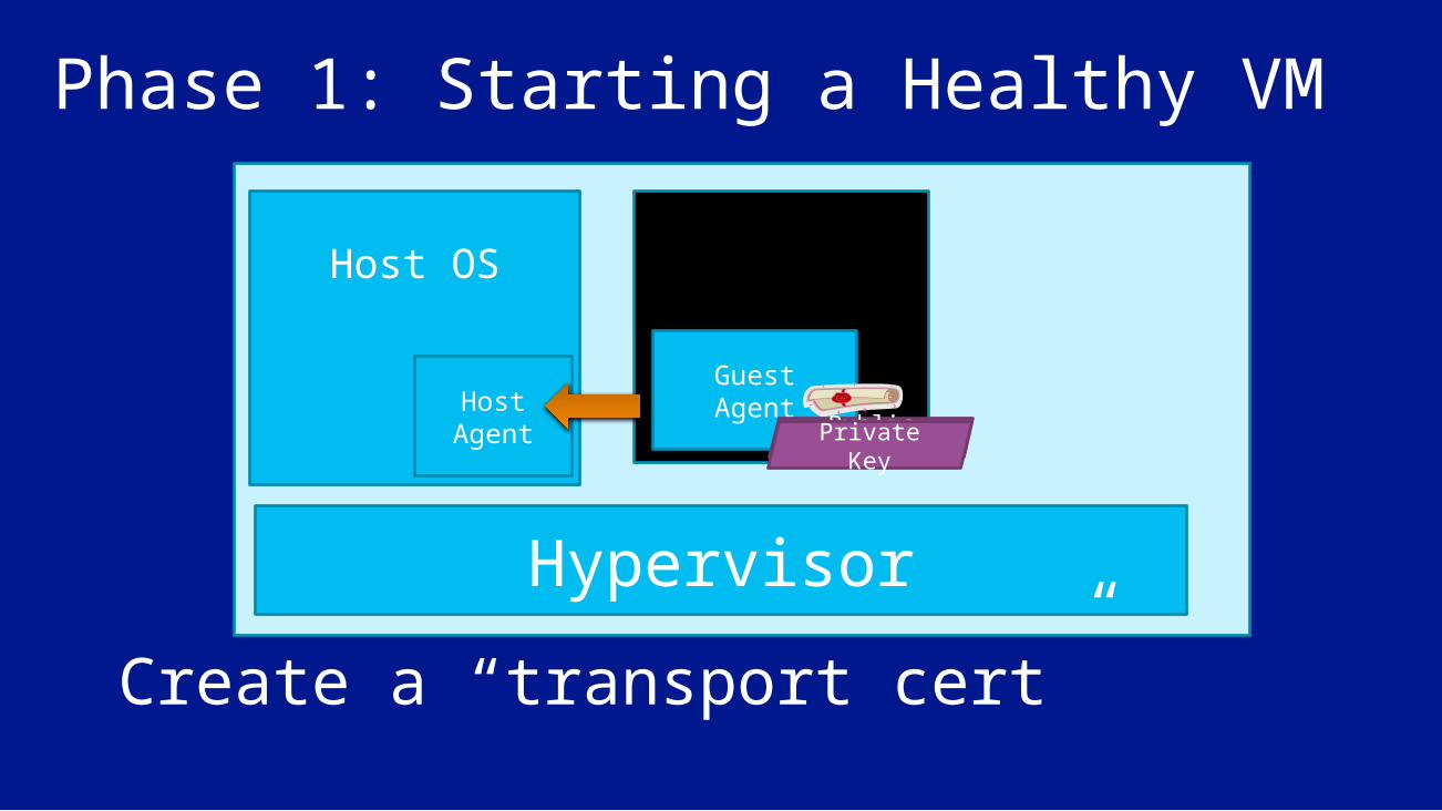
Host OS
Hypervisor
Host Agent
Phase 1: Starting a Healthy VMApplication VM
Guest AgentPublic KeyPrivate
Key
Create a “transport cert”

Host OS
Hypervisor
Host Agent
Phase 1: The Leap Day BugApplication VM
Guest Agent
App VM
Guest Agent
App VM
Guest Agent
After 25 minutes…After 3 attempts…All new VMs fail to start (Service Management)Existing healthy VMs continue to run (until migrated)
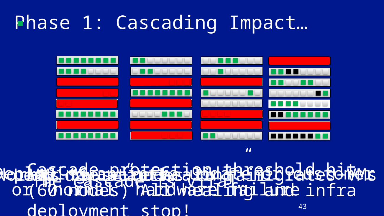
Deploying an infra update or customer VMor “normal” hardware failureVMs cause nodes to failThe cascade is viral…Leap day starts…Normal “Service healing” migrates VMsCascade protection threshold hit (60
nodes) All healing and infra deployment stop!
Phase 1: Cascading Impact…
43
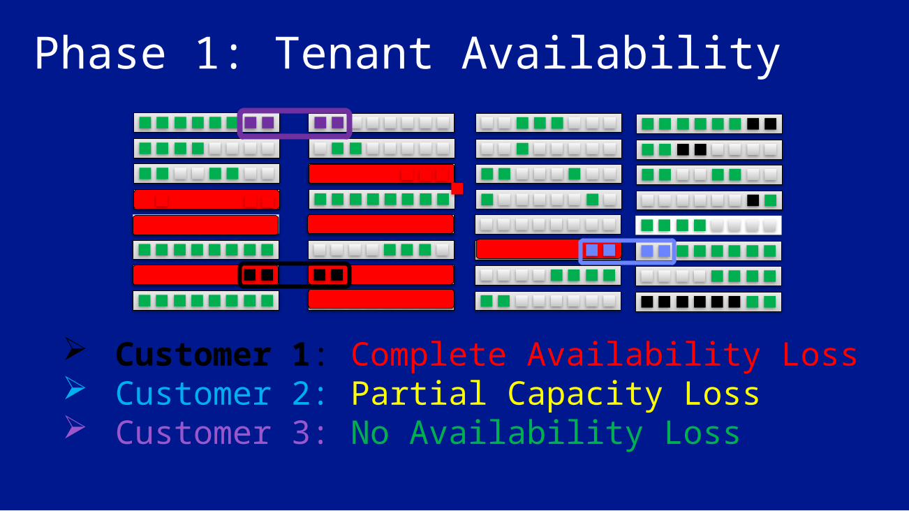
Phase 1: Tenant Availability
Customer 1: Complete Availability Loss Customer 2: Partial Capacity Loss Customer 3: No Availability Loss
Overview of Phase 1 Service Management started failing immediately in all regions
New VM creation, infrastructure deployments, and standard hardware recovery created a viral cascade
Service healing threshold tripped, with customers in different states of availability and capacity
Service Management deliberately de-activated everywhere
Recovery Build and deploy a hotfix to the GA and the HA
Clusters were in two different states: Fully (or mostly) updated clusters (119 GA, 119 HA, 119
OS…) Mostly non-updated clusters (118 GA, 118 HA, 118 OS…)
For updated clusters, we pushed the fix on the new version.
For non-updated clusters, we reverted back and pushed the fix on the old version
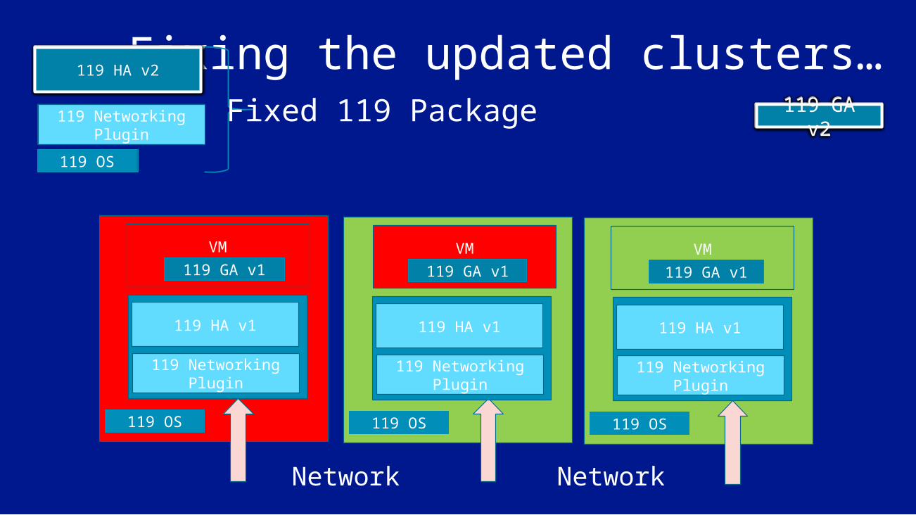
Fixing the updated clusters…
119 HA v1
119 Networking Plugin
VM
Network
119 GA v1
119 OS
119 HA v1
119 Networking Plugin
VM119 GA v1
119 OS
119 HA v1
119 Networking Plugin
VM119 GA v1
119 OS
119 HA v2
119 Networking Plugin
119 OS
119 GA v2Fixed 119 Package119 HA v2
119 Networking Plugin
119 OS
119 HA v2
119 Networking Plugin
119 OS
119 GA v2119 GA v2
Network

Attempted fix for partially updated
clusters…Phase 2 begins
118 HA v1
118 Networking Plugin
VM
Network
118 GA v1
118 OS
118 HA v1
118 Networking Plugin
VM118 GA v1
118 OS
119 HA v1
119 Networking Plugin
VM118 GA v1
119 OS
118 HA v2
119 Networking Plugin
118 OS
Fixed 118 Package118 HA v2
119 Networking Plugin
118 OS
118 HA v2
119 Networking Plugin
118 OS
Network

Overview of Phase 2 Most clusters were repaired completely in Phase 1
7 clusters were moved into an inconsistent state (119 Plugin/Config with 118 Agent) Machines moved into a completely disconnected state
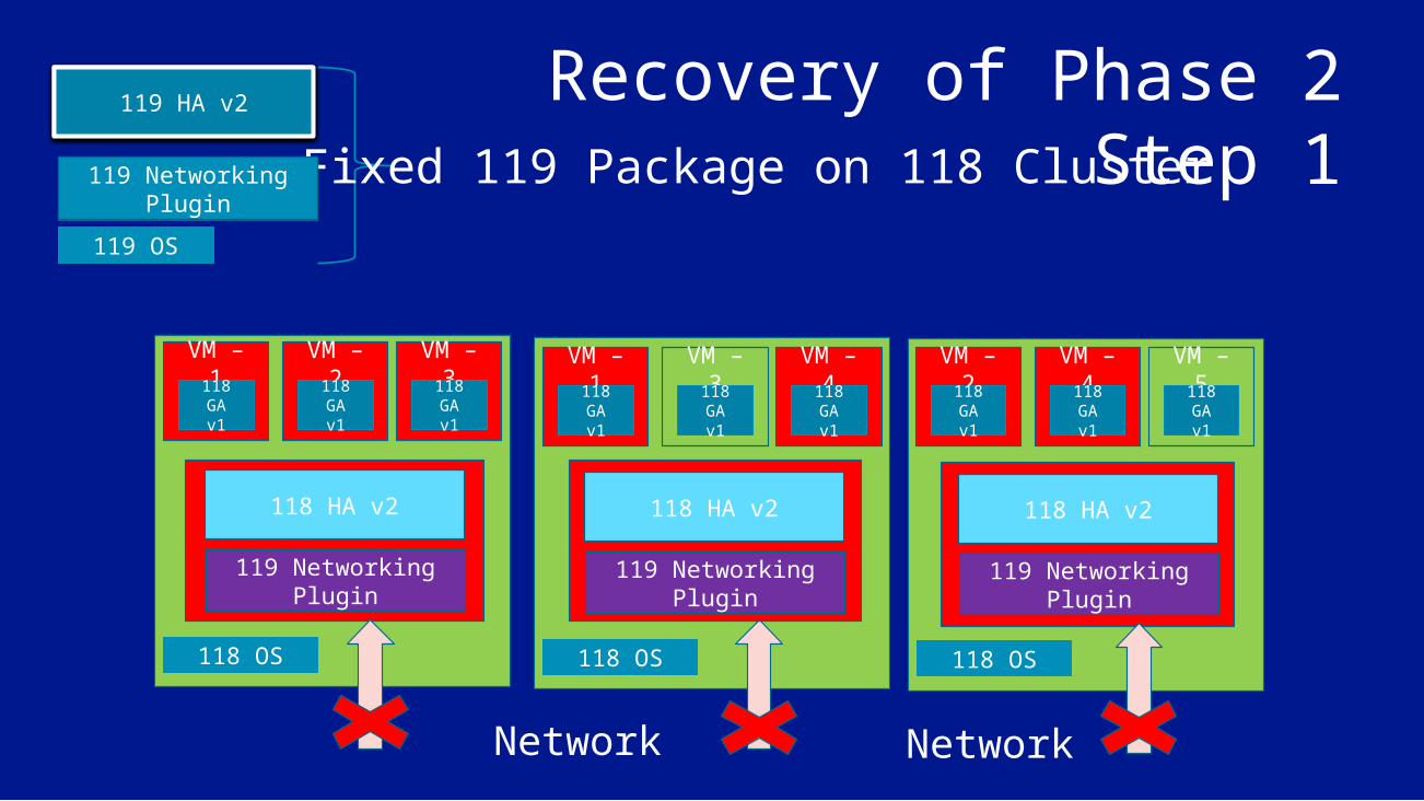
Recovery of Phase 2Step 1
118 HA v2
119 Networking Plugin
VM – 1
Network
118 GA v1
118 OS
118 HA v2
119 Networking Plugin
118 OS
118 HA v2
119 Networking Plugin
118 OS
Network
VM – 2118 GA v1
VM – 3118 GA v1
VM – 1118 GA v1
VM – 3118 GA v1
VM – 4118 GA v1
VM – 2118 GA v1
VM – 4118 GA v1
VM – 5118 GA v1
119 HA v2
119 Networking Plugin
119 OS
Fixed 119 Package on 118 Cluster119 HA v2
119 Networking Plugin
119 OS
119 HA v2
119 Networking Plugin
119 OS
Phase 2: Recovery Step 1 On the seven remaining clusters, we forced update to 119 (119 GA, 119 HA, 119 OS…)
This resulted in cluster-wide reboots Because the OS needed to be updated
Because the VM GAs were mostly unpatched, most machines moved quickly into “Human Investigate” Required additional effort

119 HA v2
119 Networking Plugin
VM – 1
Network
118 GA v1
Recovery of Phase 2Step 2 – Automated Update Script
119 OS
119 HA v2
119 Networking Plugin
119 OS
119 HA v2
119 Networking Plugin
119 OS
Fixed 119 GA
Network
VM – 2118 GA v1
VM – 3118 GA v1
VM – 1118 GA v1
VM – 3118 GA v1
VM – 4118 GA v1
VM – 2118 GA v1
VM – 4118 GA v1
VM – 5118 GA v1
119 GA v2
119 GA v2
119 GA v2
119 GA v2
Automatic update cannot proceedNot enough healthy instances…
119 HA v2
119 Networking Plugin
VM – 1
Network
118 GA v1
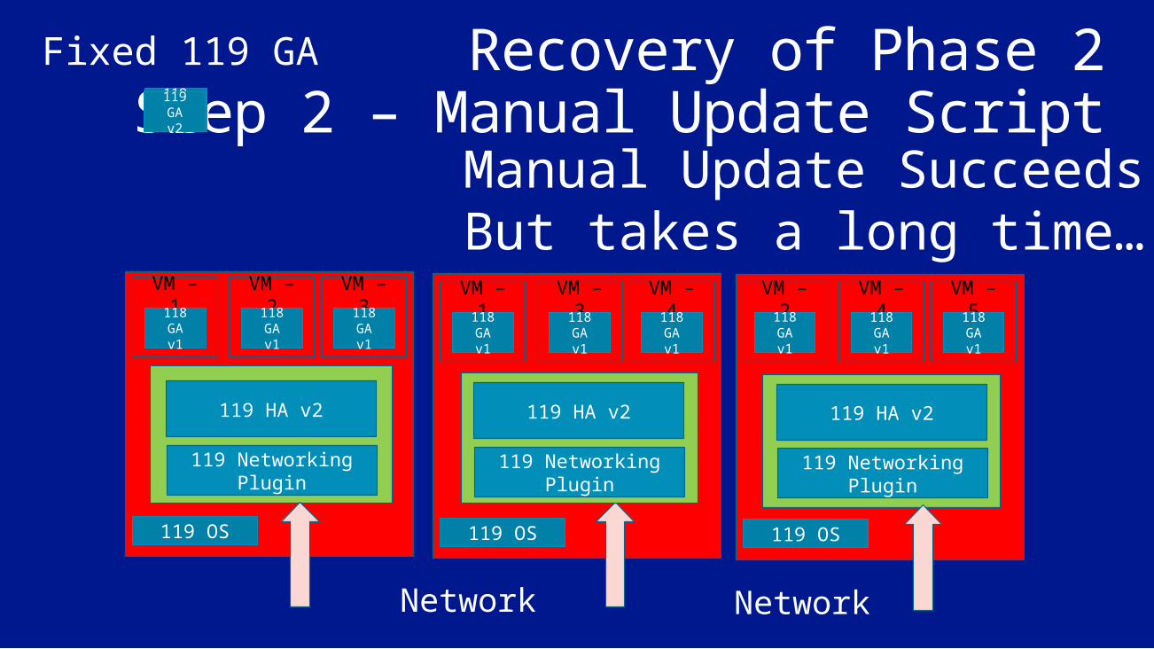
Recovery of Phase 2Step 2 – Manual Update Script
119 OS
119 HA v2
119 Networking Plugin
119 OS
119 HA v2
119 Networking Plugin
119 OS
Fixed 119 GA
Network
VM – 2118 GA v1
VM – 3118 GA v1
VM – 1118 GA v1
VM – 3118 GA v1
VM – 4118 GA v1
VM – 2118 GA v1
VM – 4118 GA v1
VM – 5118 GA v1
119 GA v2
119 GA v2
119 GA v2
119 GA v2
Manual Update SucceedsBut takes a long time…
119 GA v2
119 GA v2
119 GA v2
119 GA v2
119 GA v2

Major Learning Time can be a single point of failure Cascading failures as a side-effect of recovery Partitioning and built-in brakes contained the failure
Need “safe mode” for all services, e.g., read-only
Recovery should be done through the normal path
People need sleep Customer must know what is going on

Conclusion Platform as a Service is all about reducing management and operations overhead
The Windows Azure Fabric Controller is the foundation for Windows Azure compute Provisions machines Deploys services Configures hardware for services Monitors service and hardware health
The Fabric Controller continues to evolve and improve

• Follow us on Twitter @WindowsAzure
• Get Started: www.windowsazure.com/build
Resources
Please submit session evals on the Build Windows 8 App or at http://aka.ms/BuildSessions

© 2012 Microsoft Corporation. All rights reserved. Microsoft, Windows, Windows Vista and other product names are or may be registered trademarks and/or trademarks in the U.S. and/or other countries.The information herein is for informational purposes only and represents the current view of Microsoft Corporation as of the date of this presentation. Because Microsoft must respond to changing market conditions, it should not be interpreted to be a commitment on the part of Microsoft, and Microsoft cannot guarantee the accuracy of any information provided after the date of this presentation. MICROSOFT MAKES NO WARRANTIES, EXPRESS, IMPLIED OR STATUTORY, AS TO THE INFORMATION IN THIS PRESENTATION.
Related Documents