DESIGN FILE COMPIANCE REPORT Thomas Arnold FUTURENERGY 10kW TURBINE Date: 14/09/2012 Page 1 of 44 FuturEnergy Ltd 12 Ettington Park Business Centre Stratford upon Avon Warwickshire CV37 8BT United Kingdon +44(0)1789 450280 Client: TUV NEL Ltd East Kilbride Glasgow G75 0QF Scotland Revision Date Notes Author Approval Signature 01A 14/09/2012 Draft T. Arnold D. Nangle P. Osbourne DESIGN FILE Airforce 10 FuturEnergy 10kW Turbine Thomas Arnold Doug Nangle Date: 14/09/2012

Wind turbine - Design file report
Aug 07, 2015
Welcome message from author
This document is posted to help you gain knowledge. Please leave a comment to let me know what you think about it! Share it to your friends and learn new things together.
Transcript

DESIGN FILE COMPIANCE REPORT Thomas Arnold FUTURENERGY 10kW TURBINE Date: 14/09/2012
Page 1 of 44
FuturEnergy Ltd 12 Ettington Park Business Centre Stratford upon Avon Warwickshire CV37 8BT United Kingdon +44(0)1789 450280
Client: TUV NEL Ltd East Kilbride Glasgow G75 0QF Scotland
Revision Date Notes Author Approval Signature
01A 14/09/2012 Draft T. Arnold D. Nangle P. Osbourne
DESIGN FILE Airforce 10 FuturEnergy 10kW Turbine Thomas Arnold Doug Nangle Date: 14/09/2012

DESIGN FILE COMPIANCE REPORT Thomas Arnold FUTURENERGY 10kW TURBINE Date: 14/09/2012
Page 2 of 44
Table of Contents 1.1 Introduction ..................................................................................................................... 3 2.1 Small Wind Turbine class [Section 6.2.1] ........................................................................ 4 2.2 Wind conditions [Section 6.3] .......................................................................................... 4 3.1 Strength and Safety ........................................................................................................ 5
3.1.1 Simplified load model [Section 7.4] ........................................................................... 5 3.1.2 Stress calculations and Safety factors [Section 7.7 and 7.8] ................................... 11
3.1.2.1 Blade root ......................................................................................................... 13 3.1.2.2 Blades – including outer case, spar and foam core .......................................... 14 3.1.2.3 Shaft – including bearings and brake mechanism ............................................ 15 3.1.2.4 Hub frame ........................................................................................................ 16 3.1.2.5 Nacelle frame ................................................................................................... 17 3.1.2.6 Summary of stresses ........................................................................................ 18
3.1.3 Limit state analysis [Section 7.9.1 BS EN 61400-2] ................................................ 20 3.1.3.1 Blade roots ....................................................................................................... 20 3.1.3.2 Blades .............................................................................................................. 20 3.1.3.3 Shaft – including bearings and brake mechanism ............................................ 21 3.1.3.4 Hub frame ........................................................................................................ 21 3.1.3.5 Nacelle frame ................................................................................................... 21
3.2 Fatigue [Section 7.9.2] .................................................................................................. 22 3.2.1 S-N Curves and Fatigue stress limits for materials ................................................. 26
3.2.1.1 Fiberglass composite ....................................................................................... 26 3.2.1.2 Aluminium Alloy ................................................................................................ 27 3.2.1.3 Steel EN8 ......................................................................................................... 28
3.2.2 Blade root fatigue ................................................................................................... 29 3.2.3 Blades and spar fatigue .......................................................................................... 30 3.2.4 Shaft fatigue ........................................................................................................... 31 3.2.5 Hub frame fatigue ................................................................................................... 32 3.2.6 Nacelle frame fatigue .............................................................................................. 33 3.2.7 Bearing fatigue life .................................................................................................. 34
3.3 Critical deflection analysis [Section 7.9.3] ..................................................................... 36 4.0 Tests to verify design data [Section 9.2 BS EN 61400-2] .............................................. 37
4.1 Measured wind velocity, power, rotational speed and toque ...................................... 37 4.2 Maximum yaw rate .................................................................................................... 37 4.3 Maximum rotational speed ......................................................................................... 37
5.0 Conclusion .................................................................................................................... 37 6.0 References: ................................................................................................................... 38 7.0 Appendix ....................................................................................................................... 41
7.1 Example calculations for Simplified load calculation method...................................... 41 7.1.2 Stress calculation using Simplified load calculation results [reference 3.1.1] ....... 44
DESIGN FILE COMPIANCE REPORT Thomas Arnold FUTURENERGY 10kW TURBINE Date: 14/09/2012
Page 3 of 44
1.1 Introduction The following report has been created to show compliance of the Futurenegy 10kW turbine in regard to the standards and guidelines set out by the TUV NEL group to achieve MCS accrediation. The standards and guidelines specified by TUV NEL require that the relevant British Standard EN 61400-2 sections are met, supported by the British Wind Energy Association – Small Wind Turbine Performance and Safety Standard (29 Feb 2008). Justification of the wind turbine design and performance will be detailed extensively in the report via the model produced in the SolidWorks drawing package, stress analysis calculated in SolidWorks, calculations specified in BS EN 61400-2, detailed materials properties information and explanation of the structural properties of the wind turbine. The report will be structured in accordance with Table 1 of the TUV NEL Guidance Note for Design File Submissions which states the sections of the BS EN 61400-2 to be included
• Section 6.2 SWT classes • Section 6.3.1 Wind conditions - General • Section 7.4 Simplified load model • Section 7.7 Stress calculation • Section 7.8 Safety factors • Section 7.9 Limit state analysis • Section 9.2 Tests to verify design data
Each section will be completed with schematics, detailed drawings and sketches where necessary with assumptions made shown clearly, explained and sources given to provide a comprehensive report. Particular attention will be drawn to the material selection and properties in regard to the safety factors specified and the fatigue calculations carried out. Furthermore, the wind turbine blades will essentially be made from a composite material structure consisting of fibreglass with a foam core. The materials selected and method of production combined with an excellent structural design, provide the blades with extremely high strength and durability properties. However, because of the somewhat unpredictable nature of composite materials in regard to stresses and fatigue, large safety factors and margins will be applied where necessary within the calculations.
DESIGN FILE COMPIANCE REPORT Thomas Arnold FUTURENERGY 10kW TURBINE Date: 14/09/2012
Page 4 of 44
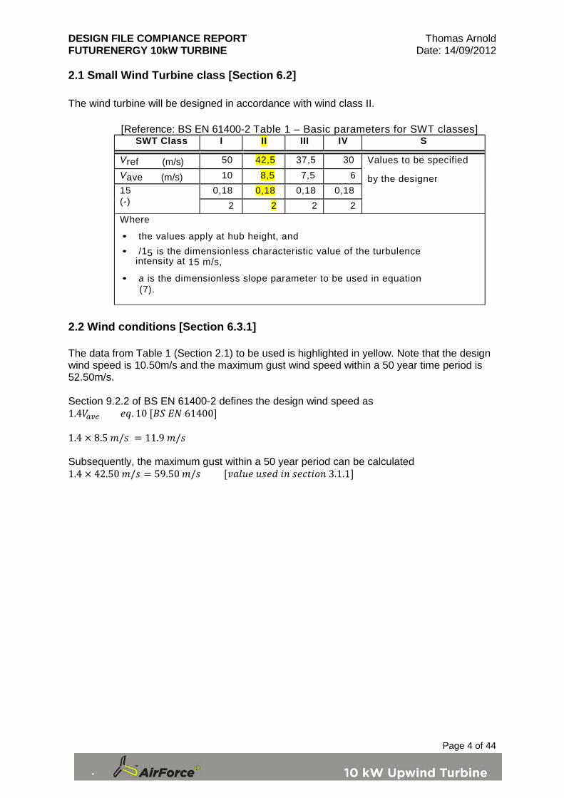
2.1 Small Wind Turbine class [Section 6.2] The wind turbine will be designed in accordance with wind class II.
[Reference: BS EN 61400-2 Table 1 – Basic parameters for SWT classes] SWT Class I II III IV S
Vref (m/s)
50 42,5 37,5 30 Values to be specified
by the designer Vave (m/s)
10 8,5 7,5 6 15 (-)
0,18 0,18 0,18 0,18 2 2 2 2
Where
• the values apply at hub height, and
• /15 is the dimensionless characteristic value of the turbulence intensity at 15 m/s,
• a is the dimensionless slope parameter to be used in equation (7).
2.2 Wind conditions [Section 6.3.1] The data from Table 1 (Section 2.1) to be used is highlighted in yellow. Note that the design wind speed is 10.50m/s and the maximum gust wind speed within a 50 year time period is 52.50m/s. Section 9.2.2 of BS EN 61400-2 defines the design wind speed as 1.4𝑉𝑎𝑣𝑒 𝑒𝑞. 10 [𝐵𝑆 𝐸𝑁 61400] 1.4 × 8.5 𝑚/𝑠 = 11.9 𝑚/𝑠 Subsequently, the maximum gust within a 50 year period can be calculated 1.4 × 42.50 𝑚/𝑠 = 59.50 𝑚/𝑠 [𝑣𝑎𝑙𝑢𝑒 𝑢𝑠𝑒𝑑 𝑖𝑛 𝑠𝑒𝑐𝑡𝑖𝑜𝑛 3.1.1]

DESIGN FILE COMPIANCE REPORT Thomas Arnold FUTURENERGY 10kW TURBINE Date: 14/09/2012
Page 5 of 44
3.1 Strength and Safety The following sections of the report details the calculations carried out to ensure the strength and safety of the wind turbine components meet the minimum requirements. Material data will be specified and assumptions made clear and justified accordingly to certify the calculations carried out as well as the stress analysis calculated by the SolidWorks FEA program. The main components which give the critical load path for the wind turbine will be listed separately in each section, these include;
• Blades – including outer case, spar and foam core • Blade root • Shaft – including bearings and brake mechanism • Hub frame • Nacelle frame
3.1.1 Simplified load model [Section 7.4] The simplified load model method was adopted for the purpose of the design file as it would provide sufficient information on the wind turbine loads. The following calculations were carried out in accordance with BS EN 61400 – 2 section 7.4.
DESIGN FILE COMPIANCE REPORT Thomas Arnold FUTURENERGY 10kW TURBINE Date: 14/09/2012
Page 6 of 44
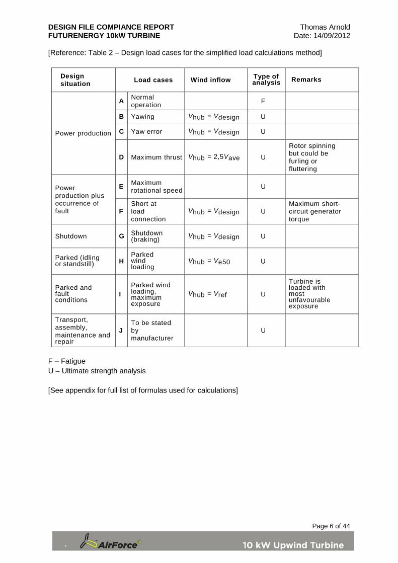
[Reference: Table 2 – Design load cases for the simplified load calculations method]
Design situation Load cases Wind inflow Type of
analysis Remarks
Power production
A Normal operation F
B Yawing Vhub = Vdesign U
C Yaw error Vhub = Vdesign U
D Maximum thrust Vhub = 2,5Vave U
Rotor spinning but could be furling or fluttering
Power production plus occurrence of fault
E Maximum rotational speed U
F Short at load connection
Vhub = Vdesign U Maximum short-circuit generator torque
Shutdown G Shutdown (braking) Vhub = Vdesign U
Parked (idling or standstill) H
Parked wind loading
Vhub = Ve50 U
Parked and fault conditions
I Parked wind loading, maximum exposure
Vhub = Vref U
Turbine is loaded with most unfavourable exposure
Transport, assembly, maintenance and repair
J To be stated by manufacturer
U
F – Fatigue U – Ultimate strength analysis [See appendix for full list of formulas used for calculations]

DESIGN FILE COMPIANCE REPORT Thomas Arnold FUTURENERGY 10kW TURBINE Date: 14/09/2012
Page 7 of 44
Table 3 – Input Parameters Value Units Value Alt
Units
Rotor Diameter 8.00 m 4.000 m
(radius) R
Rotor swept area 50.27 m2
n/a Arotor
Number of Blades 3.00 n/a
n/a B
Blade mass 23.30 Kg
n/a mB
Radial distance from hub centre to blade centre of gravity 1.40 m
n/a Rcog
Mass moment of inertia of blade 45.67 Kgm2
n/a IB
Design Rotor Speed 155.00 RPM 16.232 rad/s ω n
Projected area of blade 1.35 m2
n/a Aproj,blade
V ref, SWT class reference wind speed 37.50 m/s
n/a Vref
V ave, SWT class average wind speed 7.50 m/s
n/a Vave
V 50, SWT class 50 year max gust 52.50 m/s
n/a V50
Design Wind Speed 10.50 m/s
n/a Vdesign
Design Power Output 15.00 Kw
n/a
Tip Speed Ratio 6.00 n/a
n/a λ
Tip Speed 64.93 m/s
n/a
Shaft Torque at rated wind speed 1,065.00 Nm
n/a Qdesign
Hub Height 12.00 m
n/a Zhub
Air Density 1.23 Kg/m3
n/a ρ

DESIGN FILE COMPIANCE REPORT Thomas Arnold FUTURENERGY 10kW TURBINE Date: 14/09/2012
Page 8 of 44
Rotor hub mass 27.00 Kg
n/a mh
Rotor mass 96.90 Kg
n/a mr
Yaw rate 1.00 RPM 0.105 rad/s ω yaw
Distance from rotor centre to first bearing 0.21 m
n/a Lrb
Distance from rotor centre to yaw axis 0.80 m
n/a Lrt
Blade lift coefficient (2.0 to be used if no other data available) 2.00 n/a
n/a Cl,max
Maximum possible rotation speed 300.00 RPM 31.416 Rad/s ω n,max
Mechanical braking torque 1,000.00 Nm
n/a Mbrake
Projected area of tower 6.90 m2
n/a Aproj,tower
Tower force coefficient 1.30 n/a
n/a Cf
Projected area of nacelle (head-on) 0.48 m2
n/a Aproj,nacelle, head-on
Nacelle (side-on and head-on) force coefficient 1.50 n/a
n/a Cf
Projected area of nacelle (side-on) 1.55 m2
n/a Aproj,nacelle, side-on
Mass of the nacelle (excluding blades and hub) 404.00 Kg
n/a mnacelle Distance from rotor axis to hydraulic ram lifting point when tower is horizontal 10.43 m
n/a Llt
Mass of the tilting section of the tower only 1,265.00 Kg
n/a moverhang
Length of tilting tower section from hinge to rotor axis 11.25 m

DESIGN FILE COMPIANCE REPORT Thomas Arnold FUTURENERGY 10kW TURBINE Date: 14/09/2012
Page 9 of 44
Table 4 – Load cases A-J results Load case A: Normal operation
Range, length wise blade root force (21) 17,188.38 N
ΔF zB
Range, Blade root bending moment, edge wise (22) 995.00 Nm
ΔM xB
Range, Blade root bending moment, flap wise (23) 2,130.00 Nm
ΔM yB
Range, axial shaft load (24) 2,396.25 N
ΔF x-shaft
Range, torsion moment on shaft at first bearing (25) 1,103.02 Nm
ΔM x-shaft
Range, Combined bending moment for shaft at first bearing (26) 1,996.75 Nm ΔM shaft
Load case B: Yawing
Bending moment on the blade due to yawing (28) 1,220.54 Nm
M yB
Shaft bending moment due to yawing (30) 2,030.00 Nm M shaft
Load case C: Yaw error
Blade root bending moment due to yaw error (31) 8,714.07 Nm M yB
Load case D: Maximum thrust
Maximum thrust inline with shaft (32) 5,412.59 N F x-shaft
Load case E: Maximum rotational speed
Centrifugal load in the blade root at maximum possible rotor speed (33) 10,338.07 N
F zB Shaft bending moment due to blade loading and unbalance at max speed (34) 328.61 Nm M shaft
Load case F: Short at load connection
Torque on rotor shaft at generator short (35) 1,597.50 Nm
M x-shaft
Blade root bending moment due to generator short (36) 532.50 Nm M xB

DESIGN FILE COMPIANCE REPORT Thomas Arnold FUTURENERGY 10kW TURBINE Date: 14/09/2012
Page 10 of 44
Load case G: Shutdown (Braking)
Torque on rotor shaft during braking and generator load (37) 2,065.00 Nm
M x-shaft
Blade root bending moment during braking and generator load (38) 852.50 Nm M xB
Load case H: Parked wind loading Parked blade root bending moment with 50-year maximum wind exposure (39) 6,837.22 Nm
M yB
Spinning rotor blade bending moment in 50-year maximum wind (40) 6,077.53 Nm
M yB
Shaft thrust load when parked in 50-year maximum wind (41) 10,255.83 N
F x-shaft
Shaft thrust load when spinning in 50-year maximum wind (42), (43) 1,277.87 N
F x-shaft
Tower bending moment from parked rotor (only) in maximum wind 123,070.01 Nm
M tower,rotor
Tower (only) induced bending moment in maximum wind 90,859.09 Nm
M tower
Nacelle (only) induced bending moment in head-on 50-year maximum wind 14,586.08 Nm
M tower,nacelle head-on
Nacelle (only) induced bending moment in side-on 50-year maximum wind 47,100.87 Nm
M tower,nacelle side-on
Combined tower base bending moment in head-on 50-year maximum wind 228,515.18 Nm
M tower,total head-on
Combined tower base bending moment in side-on 50-year maximum wind 261,029.97 Nm M tower,total side-on
Load case J: Transportation, assembly, maintenance and repair
Bending moment on tower when horizontal, supported by hydraulic rams 149,261.94 Nm
M tower
Lifting ram force required 305,085.02 N F ram See appendix for full list of formulas used and example calculations
DESIGN FILE COMPIANCE REPORT Thomas Arnold FUTURENERGY 10kW TURBINE Date: 14/09/2012
Page 11 of 44
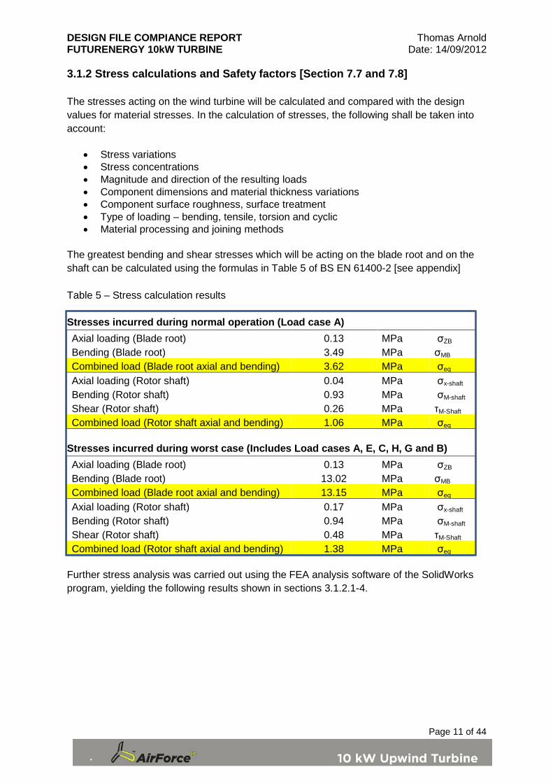
3.1.2 Stress calculations and Safety factors [Section 7.7 and 7.8] The stresses acting on the wind turbine will be calculated and compared with the design values for material stresses. In the calculation of stresses, the following shall be taken into account:
• Stress variations • Stress concentrations • Magnitude and direction of the resulting loads • Component dimensions and material thickness variations • Component surface roughness, surface treatment • Type of loading – bending, tensile, torsion and cyclic • Material processing and joining methods
The greatest bending and shear stresses which will be acting on the blade root and on the shaft can be calculated using the formulas in Table 5 of BS EN 61400-2 [see appendix] Table 5 – Stress calculation results Stresses incurred during normal operation (Load case A) Axial loading (Blade root) 0.13 MPa σZB
Bending (Blade root) 3.49 MPa σMB Combined load (Blade root axial and bending) 3.62 MPa σeq Axial loading (Rotor shaft) 0.04 MPa σx-shaft Bending (Rotor shaft) 0.93 MPa σM-shaft Shear (Rotor shaft) 0.26 MPa τM-Shaft
Combined load (Rotor shaft axial and bending) 1.06 MPa σeq Stresses incurred during worst case (Includes Load cases A, E, C, H, G and B) Axial loading (Blade root) 0.13 MPa σZB
Bending (Blade root) 13.02 MPa σMB Combined load (Blade root axial and bending) 13.15 MPa σeq Axial loading (Rotor shaft) 0.17 MPa σx-shaft Bending (Rotor shaft) 0.94 MPa σM-shaft Shear (Rotor shaft) 0.48 MPa τM-Shaft
Combined load (Rotor shaft axial and bending) 1.38 MPa σeq Further stress analysis was carried out using the FEA analysis software of the SolidWorks program, yielding the following results shown in sections 3.1.2.1-4.
DESIGN FILE COMPIANCE REPORT Thomas Arnold FUTURENERGY 10kW TURBINE Date: 14/09/2012
Page 12 of 44
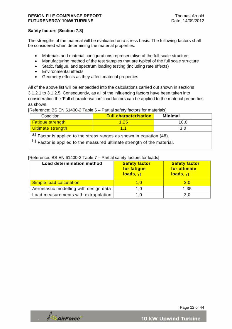
Safety factors [Section 7.8] The strengths of the material will be evaluated on a stress basis. The following factors shall be considered when determining the material properties:
• Materials and material configurations representative of the full-scale structure • Manufacturing method of the test samples that are typical of the full scale structure • Static, fatigue, and spectrum loading testing (including rate effects) • Environmental effects • Geometry effects as they affect material properties
All of the above list will be embedded into the calculations carried out shown in sections 3.1.2.1 to 3.1.2.5. Consequently, as all of the influencing factors have been taken into consideration the ‘Full characterisation’ load factors can be applied to the material properties as shown. [Reference: BS EN 61400-2 Table 6 – Partial safety factors for materials]
Condition Full characterisation Minimal h t i ti Fatigue strength 1,25
) 10,0
b) Ultimate strength 1,1 3,0 a) Factor is applied to the stress ranges as shown in equation (48). b) Factor is applied to the measured ultimate strength of the material.
[Reference: BS EN 61400-2 Table 7 – Partial safety factors for loads]
Load determination method Safety factor for fatigue loads, γf
Safety factor for ultimate loads, γf
Simple load calculation 1,0 3,0 Aeroelastic modelling with design data ( )
1,0 1,35 Load measurements with extrapolation 1,0 3,0

DESIGN FILE COMPIANCE REPORT Thomas Arnold FUTURENERGY 10kW TURBINE Date: 14/09/2012
Page 13 of 44
3.1.2.1 Blade root The blade root will experience the highest stress load in regard to bending moments of the blade. Figures 1 and 2 show the blade root and location of the maximum stress
Figure 1 – cross section of the spar and blade root The maximum stress due to bending will be acting at the blade root of the wind turbine. A calculation was carried out using the formulas detailed in table which gave a stress value of 3.62 MPa at the root. It should be noted that this does not take into consideration the geometry of the blade component which will incur notch factors and consequently stress concentrations at various parts of the root. In order to determine an accurate stress value for the blade root an FEA analysis was carried out using the SolidWorks software package The results calculated in Table 2 were inputted into the SolidWorks model to carry out the analysis. The FEA takes into account material properties, bending, axial and compression forces applied, stress concentrations, stress variations and dimensions of the component to determine the maximum stress. The maximum stress was found to be 60.5 MPa for maximum wind speed which was higher than the maximum stress calculated in Table 3. Figure 2 was generated by the FEA program to show where the maximum stress would occur and the stress variation across the blade root. The greatest stress occurs where it would be expected, the grove of the root, which is the narrowest section and would have the greatest stress concentration. The blade root will be manufactured from Aluminium alloy 6082 T6 which has the following properties: Ultimate tensile stress – 280 MPa Yield stress – 240 MPa Youngs modulus (stiffness) – 70 GPa
60.5 MPa
Figure 2 – Stress variation in the blade root
DESIGN FILE COMPIANCE REPORT Thomas Arnold FUTURENERGY 10kW TURBINE Date: 14/09/2012
Page 14 of 44
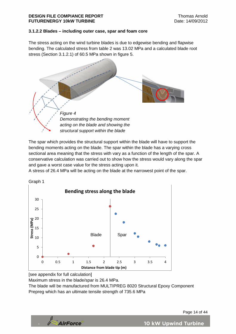
3.1.2.2 Blades – including outer case, spar and foam core The stress acting on the wind turbine blades is due to edgewise bending and flapwise bending. The calculated stress from table 2 was 13.02 MPa and a calculated blade root stress (Section 3.1.2.1) of 60.5 MPa shown in figure 5.
The spar which provides the structural support within the blade will have to support the bending moments acting on the blade. The spar within the blade has a varying cross sectional area meaning that the stress with vary as a function of the length of the spar. A conservative calculation was carried out to show how the stress would vary along the spar and gave a worst case value for the stress acting upon it. A stress of 26.4 MPa will be acting on the blade at the narrowest point of the spar. Graph 1
[see appendix for full calculation] Maximum stress in the blade/spar is 26.4 MPa. The blade will be manufactured from MULTIPREG 8020 Structural Epoxy Component Prepreg which has an ultimate tensile strength of 735.6 MPa
0
5
10
15
20
25
30
0 0.5 1 1.5 2 2.5 3 3.5 4
Stre
ss (M
Pa)
Distance from blade tip (m)
Bending stress along the blade
Figure 4 Demonstrating the bending moment acting on the blade and showing the structural support within the blade
Blade Spar

DESIGN FILE COMPIANCE REPORT Thomas Arnold FUTURENERGY 10kW TURBINE Date: 14/09/2012
Page 15 of 44
3.1.2.3 Shaft – including bearings and brake mechanism The wind turbine low speed shaft will experience significant bending, torsional and axial loading. A calculation was carried out using the formulas detailed in table 5 (see appendix) which gave a stress value of 1.38 MPa acting on the shaft which included bending and axial loading. It should be noted that this does not take into consideration the changing geometry of the shaft component which would cause stress variations along the shaft. In order to determine an accurate stress value for the shaft an FEA analysis was carried out using the SolidWorks software package The results calculated in Table 2 were inputted into the SolidWorks model to carry out the analysis.
Figure 5 – stress on shaft The maximum stress was found to be 188 MPa for maximum wind speed which was higher higher than the maximum stress calculated in Table 3. Figure 5 was generated by the FEA program to show where the maximum stress would occur and the stress variation along the shaft. The results obtained from the FEA software were supported by the previous calculation carried out on the blade root (Section 3.1.2.1) which gave a value of 60.5 MPa. The shaft will be carrying three times this load (three blade roots) which equates to 181.5 MPa. The rotor shaft will be manufactured from Stainless steel EN8 which has the following properties: Ultimate tensile stress –621 MPa Yield stress – 465 MPa Youngs modulus (stiffness) – 207 GPa
Maximum stress 187.95 MPa Arrows represent applied forces
The FEA takes into account material properties, bending, torsional, axial and compression forces applied, stress concentrations, stress variations and dimensions of the
DESIGN FILE COMPIANCE REPORT Thomas Arnold FUTURENERGY 10kW TURBINE Date: 14/09/2012
Page 16 of 44
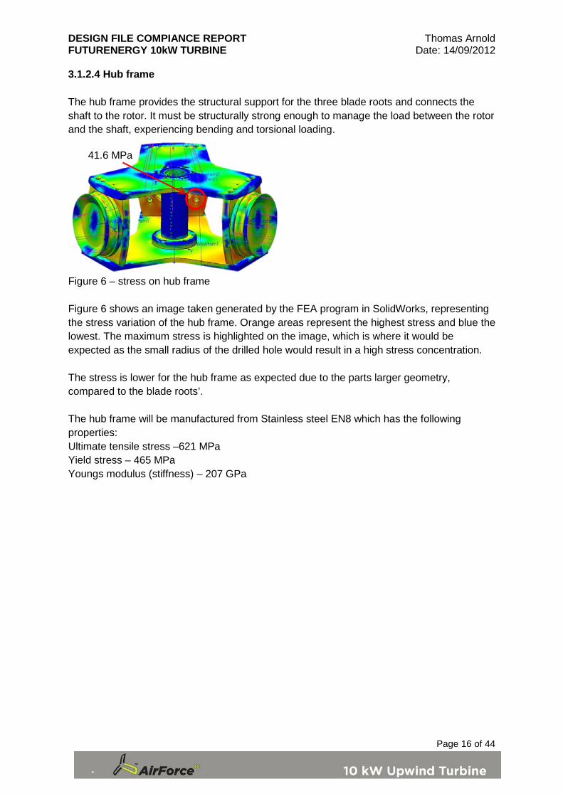
3.1.2.4 Hub frame The hub frame provides the structural support for the three blade roots and connects the shaft to the rotor. It must be structurally strong enough to manage the load between the rotor and the shaft, experiencing bending and torsional loading.
Figure 6 – stress on hub frame Figure 6 shows an image taken generated by the FEA program in SolidWorks, representing the stress variation of the hub frame. Orange areas represent the highest stress and blue the lowest. The maximum stress is highlighted on the image, which is where it would be expected as the small radius of the drilled hole would result in a high stress concentration. The stress is lower for the hub frame as expected due to the parts larger geometry, compared to the blade roots’. The hub frame will be manufactured from Stainless steel EN8 which has the following properties: Ultimate tensile stress –621 MPa Yield stress – 465 MPa Youngs modulus (stiffness) – 207 GPa
41.6 MPa
DESIGN FILE COMPIANCE REPORT Thomas Arnold FUTURENERGY 10kW TURBINE Date: 14/09/2012
Page 17 of 44
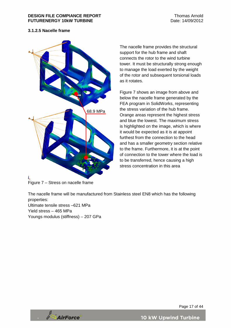
3.1.2.5 Nacelle frame
Figure 7 – Stress on nacelle frame The nacelle frame will be manufactured from Stainless steel EN8 which has the following properties: Ultimate tensile stress –621 MPa Yield stress – 465 MPa Youngs modulus (stiffness) – 207 GPa
68.9 MPa
The nacelle frame provides the structural support for the hub frame and shaft connects the rotor to the wind turbine tower. It must be structurally strong enough to manage the load exerted by the weight of the rotor and subsequent torsional loads as it rotates. Figure 7 shows an image from above and below the nacelle frame generated by the FEA program in SolidWorks, representing the stress variation of the hub frame. Orange areas represent the highest stress and blue the lowest. The maximum stress is highlighted on the image, which is where it would be expected as it is at appoint furthest from the connection to the head and has a smaller geometry section relative to the frame. Furthermore, it is at the point of connection to the tower where the load is to be transferred, hence causing a high stress concentration in this area
DESIGN FILE COMPIANCE REPORT Thomas Arnold FUTURENERGY 10kW TURBINE Date: 14/09/2012
Page 18 of 44
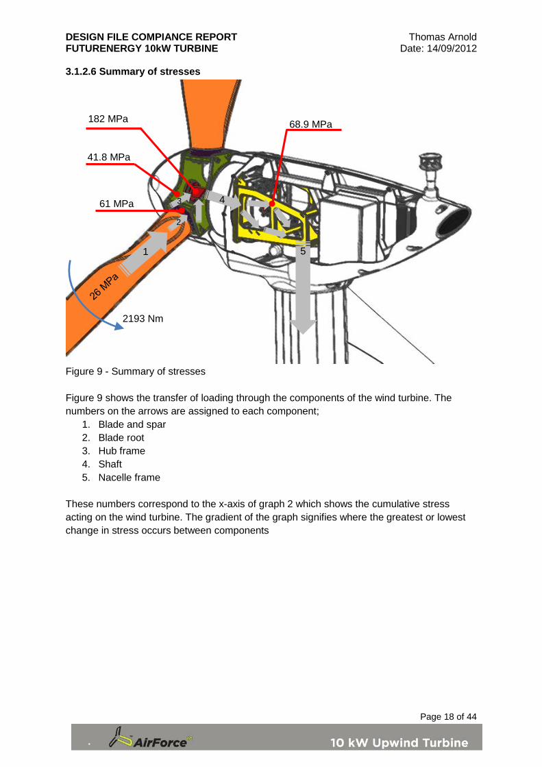
3.1.2.6 Summary of stresses
Figure 9 - Summary of stresses Figure 9 shows the transfer of loading through the components of the wind turbine. The numbers on the arrows are assigned to each component;
1. Blade and spar 2. Blade root 3. Hub frame 4. Shaft 5. Nacelle frame
These numbers correspond to the x-axis of graph 2 which shows the cumulative stress acting on the wind turbine. The gradient of the graph signifies where the greatest or lowest change in stress occurs between components
61 MPa
2193 Nm
41.8 MPa
182 MPa
3
5 1
4
68.9 MPa
2
DESIGN FILE COMPIANCE REPORT Thomas Arnold FUTURENERGY 10kW TURBINE Date: 14/09/2012
Page 19 of 44
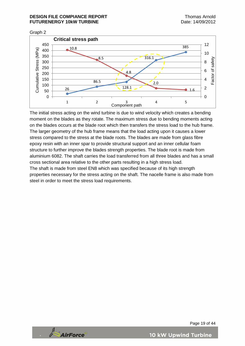
Graph 2
The initial stress acting on the wind turbine is due to wind velocity which creates a bending moment on the blades as they rotate. The maximum stress due to bending moments acting on the blades occurs at the blade root which then transfers the stress load to the hub frame. The larger geometry of the hub frame means that the load acting upon it causes a lower stress compared to the stress at the blade roots. The blades are made from glass fibre epoxy resin with an inner spar to provide structural support and an inner cellular foam structure to further improve the blades strength properties. The blade root is made from aluminium 6082. The shaft carries the load transferred from all three blades and has a small cross sectional area relative to the other parts resulting in a high stress load. The shaft is made from steel EN8 which was specified because of its high strength properties necessary for the stress acting on the shaft. The nacelle frame is also made from steel in order to meet the stress load requirements.
26
86.5 128.1
316.1
385 10.8
8.5
4.8
2.0
1.6
0
2
4
6
8
10
12
050
100150200250300350400450
1 2 3 4 5
Fact
or o
f saf
ety
Cum
ulat
ive
Stre
ss (M
Pa)
Component path
Critical stress path

DESIGN FILE COMPIANCE REPORT Thomas Arnold FUTURENERGY 10kW TURBINE Date: 14/09/2012
Page 20 of 44
3.1.3 Limit state analysis [Section 7.9.1 BS EN 61400-2] The limit state analysis assesses whether the ultimate tensile strength of the materials used for the wind turbine parts are adequate to prevent failure due to stresses acting on the wind turbine. The maximum stress values will be used to assess this combined with safety factors as stated in the BS EN 61400 – 2 document. This is shown by equation 2
𝜎𝑑 =𝑓𝑘𝛾𝑚𝛾𝑓
𝑒𝑞. 2
𝑊ℎ𝑒𝑟𝑒; 𝜎𝑑 𝑖𝑠 𝑡ℎ𝑒 𝑑𝑒𝑠𝑖𝑔𝑛 𝑠𝑡𝑟𝑒𝑠𝑠 𝑓𝑘 𝑖𝑠 𝑡ℎ𝑒 𝑐ℎ𝑎𝑟𝑎𝑐𝑡𝑒𝑟𝑖𝑠𝑡𝑖𝑐 𝑚𝑎𝑡𝑒𝑟𝑖𝑎𝑙 𝑠𝑡𝑟𝑒𝑠𝑠 𝛾𝑚𝑖𝑠 𝑡ℎ𝑒 𝑝𝑎𝑟𝑡𝑖𝑎𝑙 𝑠𝑎𝑓𝑒𝑡𝑦 𝑓𝑎𝑐𝑡𝑜𝑟 𝑓𝑜𝑟 𝑚𝑎𝑡𝑒𝑟𝑖𝑎𝑙𝑠 𝛾𝑓𝑖𝑠 𝑡ℎ𝑒 𝑝𝑎𝑟𝑡𝑖𝑎𝑙 𝑠𝑎𝑓𝑒𝑡𝑦 𝑓𝑎𝑐𝑡𝑜𝑟 𝑓𝑜𝑟 𝑙𝑜𝑎𝑑𝑠 3.1.3.1 Blade roots From equation 2
60.5 𝑀𝑃𝑎 ≤280 𝑀𝑃𝑎
1.1 × 3
60.5 𝑀𝑃𝑎 ≤ 84.85 𝑀𝑃𝑎 Additional factor of safety = 4.63 3.1.3.2 Blades From equation 2
26.4 𝑀𝑃𝑎 ≤735.6 𝑀𝑃𝑎
1.1 × 3
26.4 𝑀𝑃𝑎 ≤ 222.91 𝑀𝑃𝑎 Additional factor of safety = 27.9
DESIGN FILE COMPIANCE REPORT Thomas Arnold FUTURENERGY 10kW TURBINE Date: 14/09/2012
Page 21 of 44
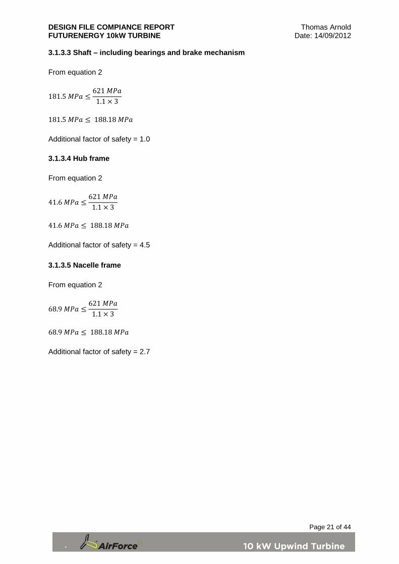
3.1.3.3 Shaft – including bearings and brake mechanism From equation 2
181.5 𝑀𝑃𝑎 ≤621 𝑀𝑃𝑎
1.1 × 3
181.5 𝑀𝑃𝑎 ≤ 188.18 𝑀𝑃𝑎 Additional factor of safety = 1.0 3.1.3.4 Hub frame From equation 2
41.6 𝑀𝑃𝑎 ≤621 𝑀𝑃𝑎
1.1 × 3
41.6 𝑀𝑃𝑎 ≤ 188.18 𝑀𝑃𝑎 Additional factor of safety = 4.5 3.1.3.5 Nacelle frame From equation 2
68.9 𝑀𝑃𝑎 ≤621 𝑀𝑃𝑎
1.1 × 3
68.9 𝑀𝑃𝑎 ≤ 188.18 𝑀𝑃𝑎 Additional factor of safety = 2.7
DESIGN FILE COMPIANCE REPORT Thomas Arnold FUTURENERGY 10kW TURBINE Date: 14/09/2012
Page 22 of 44
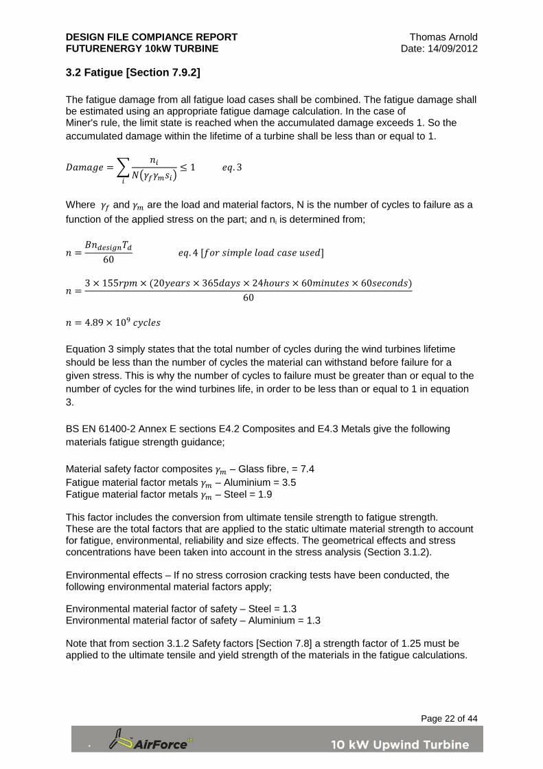
3.2 Fatigue [Section 7.9.2] The fatigue damage from all fatigue load cases shall be combined. The fatigue damage shall be estimated using an appropriate fatigue damage calculation. In the case of Miner's rule, the limit state is reached when the accumulated damage exceeds 1. So the accumulated damage within the lifetime of a turbine shall be less than or equal to 1.
𝐷𝑎𝑚𝑎𝑔𝑒 = �𝑛𝑖
𝑁�𝛾𝑓𝛾𝑚𝑠𝑖�≤ 1 𝑒𝑞. 3
𝑖
Where 𝛾𝑓 and 𝛾𝑚 are the load and material factors, N is the number of cycles to failure as a function of the applied stress on the part; and ni is determined from;
𝑛 =𝐵𝑛𝑑𝑒𝑠𝑖𝑔𝑛𝑇𝑑
60 𝑒𝑞. 4 [𝑓𝑜𝑟 𝑠𝑖𝑚𝑝𝑙𝑒 𝑙𝑜𝑎𝑑 𝑐𝑎𝑠𝑒 𝑢𝑠𝑒𝑑]
𝑛 =3 × 155𝑟𝑝𝑚 × (20𝑦𝑒𝑎𝑟𝑠 × 365𝑑𝑎𝑦𝑠 × 24ℎ𝑜𝑢𝑟𝑠 × 60𝑚𝑖𝑛𝑢𝑡𝑒𝑠 × 60𝑠𝑒𝑐𝑜𝑛𝑑𝑠)
60
𝑛 = 4.89 × 10⁹ 𝑐𝑦𝑐𝑙𝑒𝑠 Equation 3 simply states that the total number of cycles during the wind turbines lifetime should be less than the number of cycles the material can withstand before failure for a given stress. This is why the number of cycles to failure must be greater than or equal to the number of cycles for the wind turbines life, in order to be less than or equal to 1 in equation 3. BS EN 61400-2 Annex E sections E4.2 Composites and E4.3 Metals give the following materials fatigue strength guidance; Material safety factor composites 𝛾𝑚 – Glass fibre, = 7.4 Fatigue material factor metals 𝛾𝑚 – Aluminium = 3.5 Fatigue material factor metals 𝛾𝑚 – Steel = 1.9 This factor includes the conversion from ultimate tensile strength to fatigue strength. These are the total factors that are applied to the static ultimate material strength to account for fatigue, environmental, reliability and size effects. The geometrical effects and stress concentrations have been taken into account in the stress analysis (Section 3.1.2). Environmental effects – If no stress corrosion cracking tests have been conducted, the following environmental material factors apply; Environmental material factor of safety – Steel = 1.3 Environmental material factor of safety – Aluminium = 1.3 Note that from section 3.1.2 Safety factors [Section 7.8] a strength factor of 1.25 must be applied to the ultimate tensile and yield strength of the materials in the fatigue calculations.

DESIGN FILE COMPIANCE REPORT Thomas Arnold FUTURENERGY 10kW TURBINE Date: 14/09/2012
Page 23 of 44
The fatigue calculation will be carried out using data obtained from S-N (Stress-Number of cycles before failure) curves sourced and generated to acquire an endurance limit for 4.89×10⁹ cycles [eq.4]. References will be given in the report stating where the graphs and data are obtained and validating their source. Where graphs and data are unobtainable the material factor stated above will be used to acquire an endurance limit for the material. In both cases, the applied stress and mean stress of the of the component will be used combined with the endurance limit determined for the calculated number of cycles before component failure to generate A Goodman diagram. The Goodman diagram illustrates graphically the fatigue performance of the part and shows the safety factor for each part. The S-N curve graphs show the stress and the corresponding number of cycles before complete failure. This illustrates the principle of Miner’s rule by accumulating the damage incurred to a material for a given number of cycles and the maximum stress that can be applied each cycle. It should be noted that the S-N curves are generated from tested materials and are very accurate sources of fatigue data. It should also be noted that all materials except for steels will eventually fail regardless of how low the stress applied is. Steel alloys however have a maximum stress at which they will last for an infinite number of cycles. Formulas used for numerical analysis
𝜎𝑚𝑒𝑎𝑛 =𝜎𝑚𝑎𝑥𝑖𝑚𝑢𝑚 + 𝜎𝑚𝑖𝑛𝑖𝑚𝑢𝑚
2 𝑒𝑞. 5
𝜎𝑎𝑚𝑝𝑙𝑖𝑡𝑢𝑑𝑒 =
𝜎𝑚𝑎𝑥𝑖𝑚𝑢𝑚 − 𝜎𝑚𝑖𝑛𝑖𝑚𝑢𝑚
2 𝑒𝑞. 6
1
𝑓𝑎𝑐𝑡𝑜𝑟 𝑜𝑓 𝑠𝑎𝑓𝑒𝑡𝑦=𝜎𝑎𝑚𝑝𝑙𝑖𝑡𝑢𝑑𝑒𝜎𝑒𝑛𝑑𝑢𝑟𝑎𝑛𝑐𝑒
+𝜎𝑚𝑒𝑎𝑛
𝜎𝑢𝑙𝑡𝑖𝑚𝑎𝑡𝑒 𝑡𝑒𝑛𝑠𝑖𝑙𝑒 𝑠𝑡𝑟𝑒𝑛𝑔𝑡ℎ 𝑒𝑞. 7
Formulas used for diagrammatical analysis 𝜎𝑚𝑒𝑎𝑛𝑚𝑎𝑥 =
𝜎𝑒𝑛𝑑𝑢𝑟𝑎𝑛𝑐𝑒𝜎𝑒𝑛𝑑𝑢𝑟𝑎𝑛𝑐𝑒
𝜎𝑈𝑙𝑡𝑖𝑚𝑎𝑡𝑒 𝑡𝑒𝑛𝑠𝑖𝑙𝑒 𝑠𝑡𝑟𝑒𝑛𝑔𝑡ℎ+𝜎𝑎𝑚𝑝𝑙𝑖𝑡𝑢𝑑𝑒𝜎𝑚𝑒𝑎𝑛
𝑒𝑞. 8
𝜎𝑎𝑚𝑝𝑙𝑖𝑡𝑢𝑑𝑒𝑚𝑎𝑥 = �𝜎𝑚𝑒𝑎𝑛𝑚𝑎𝑥 × �
𝜎𝑎𝑚𝑝𝑙𝑖𝑡𝑢𝑑𝑒𝜎𝑚𝑒𝑎𝑛
�� + 𝜎𝑚𝑖𝑛𝑖𝑚𝑢𝑚 𝑒𝑞. 9
𝐹𝑎𝑐𝑡𝑜𝑟 𝑜𝑓 𝑠𝑎𝑓𝑒𝑡𝑦 =�𝜎𝑚𝑒𝑎𝑛
2 + 𝜎𝑎𝑝𝑝𝑙𝑖𝑒𝑑2
�𝜎𝑚𝑒𝑎𝑛𝑚𝑎𝑥2 + 𝜎𝑎𝑚𝑝𝑙𝑖𝑡𝑢𝑑𝑒𝑚𝑎𝑥
2→𝑀𝑎𝑥 𝑙𝑜𝑎𝑑 𝑙𝑖𝑛𝑒𝐿𝑜𝑎𝑑 𝑙𝑖𝑛𝑒
𝑒𝑞. 10

DESIGN FILE COMPIANCE REPORT Thomas Arnold FUTURENERGY 10kW TURBINE Date: 14/09/2012
Page 24 of 44
Example calculation; blade root Parameters: Ultimate tensile strength of material = 295 MPa Endurance limit (from S-N curve)/factor of safety (1.3) = 100/1.3 = 77 MPa Stress applied on root = 61 MPa when in full operation and 0 MPa when there is no wind Numerical calculation;
𝜎𝑚𝑒𝑎𝑛 =61 + 0
2= 30.5 𝑀𝑃𝑎
𝜎𝑎𝑚𝑝𝑙𝑖𝑡𝑢𝑑𝑒 =61 − 0
2= 30.5 𝑀𝑃𝑎
1
𝑓𝑎𝑐𝑡𝑜𝑟 𝑜𝑓 𝑠𝑎𝑓𝑒𝑡𝑦=
30.577
+30.5295
→1
𝑓𝑎𝑐𝑡𝑜𝑟 𝑜𝑓 𝑠𝑎𝑓𝑒𝑡𝑦= 0.50;𝑓𝑎𝑐𝑡𝑜𝑟 𝑜𝑓 𝑠𝑎𝑓𝑒𝑡𝑦 = 2.0
Diagrammatical calculation; Graph 3
𝜎𝑚𝑒𝑎𝑛𝑚𝑎𝑥 =77
77295 + 30.5
30.5
= 61.1 𝑀𝑃𝑎
𝜎𝑎𝑚𝑝𝑙𝑖𝑡𝑢𝑑𝑒𝑚𝑎𝑥 = �74.68 × �30.530.5
�� + 0 = 61.1 𝑀𝑃𝑎
𝐹𝑎𝑐𝑡𝑜𝑟 𝑜𝑓 𝑠𝑎𝑓𝑒𝑡𝑦 =√74.682 + 74.682
√30.52 + 30.52= 2.0
295 31
58.01
020406080
100120140160180
0 50 100 150 200 250 300
Stre
ss A
pplie
d (M
Pa)
Mean Stress (MPa)
Modified Goodman fatigue diagram
Yield stress lineModified Goodman lineLoad lineMax load line
α
β
γ
DESIGN FILE COMPIANCE REPORT Thomas Arnold FUTURENERGY 10kW TURBINE Date: 14/09/2012
Page 25 of 44
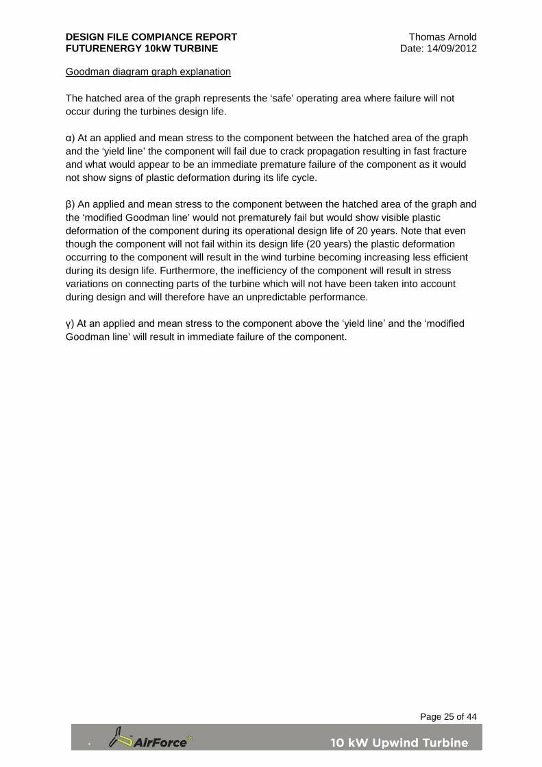
Goodman diagram graph explanation The hatched area of the graph represents the ‘safe’ operating area where failure will not occur during the turbines design life. α) At an applied and mean stress to the component between the hatched area of the graph and the ‘yield line’ the component will fail due to crack propagation resulting in fast fracture and what would appear to be an immediate premature failure of the component as it would not show signs of plastic deformation during its life cycle. β) An applied and mean stress to the component between the hatched area of the graph and the ‘modified Goodman line’ would not prematurely fail but would show visible plastic deformation of the component during its operational design life of 20 years. Note that even though the component will not fail within its design life (20 years) the plastic deformation occurring to the component will result in the wind turbine becoming increasing less efficient during its design life. Furthermore, the inefficiency of the component will result in stress variations on connecting parts of the turbine which will not have been taken into account during design and will therefore have an unpredictable performance. γ) At an applied and mean stress to the component above the ‘yield line’ and the ‘modified Goodman line’ will result in immediate failure of the component.

DESIGN FILE COMPIANCE REPORT Thomas Arnold FUTURENERGY 10kW TURBINE Date: 14/09/2012
Page 26 of 44
3.2.1 S-N Curves and Fatigue stress limits for materials 3.2.1.1 Fiberglass composite GRP – Glass fibre composite
Figure 9 – Composite S-N performance [Page 137 Engineering Composite Materials by Bryan Harris The Institute of Materials 1999] Endurance limit for the blade material at 4.89×10⁹ cycles is 140 MPa To ensure the fatigue calculations take into account a sufficient amount of safety a conservative figure of 100 MPa will be used in the fatigue calculations. BS EN 61400 – 2 states a material factor for fatigue of 7.4 for Fibre glass composites. This would give a fatigue endurance limit of 735.6/7.4 = 99.4 MPa. The composite material used for the blades and spars has excellent structural properties and will perform better structurally compared to traditional fibre glass composites. In regard to Miner’s rule, this would mean that the total damage which could be withstood would equate to 4.89×109 × 140 MPa = 6.846×10¹⁷Pa. In the case of the wind turbine blade the applied stress is 30.5 MPa which equates to an accumulated damage of 4.89×109 × 30.5 MPa = 1.491×10¹⁷Pa. Therefore, the blade could continue to run for a further 6.8×10⁷ cycles past the design life of 20 years. This would give a theoretical life expectancy for the blades of 24 years and 7 months.
5×10
9
140 MPa
DESIGN FILE COMPIANCE REPORT Thomas Arnold FUTURENERGY 10kW TURBINE Date: 14/09/2012
Page 27 of 44
3.2.1.2 Aluminium Alloy
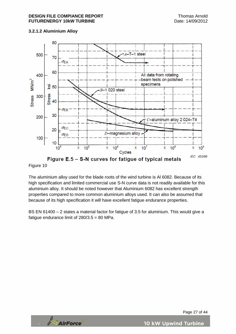
Figure 10 The aluminium alloy used for the blade roots of the wind turbine is Al 6082. Because of its high specification and limited commercial use S-N curve data is not readily available for this aluminium alloy. It should be noted however that Aluminium 6082 has excellent strength properties compared to more common aluminium alloys used. It can also be assumed that because of its high specification it will have excellent fatigue endurance properties. BS EN 61400 – 2 states a material factor for fatigue of 3.5 for aluminium. This would give a fatigue endurance limit of 280/3.5 = 80 MPa.
DESIGN FILE COMPIANCE REPORT Thomas Arnold FUTURENERGY 10kW TURBINE Date: 14/09/2012
Page 28 of 44
3.2.1.3 Steel EN8 Graph 4
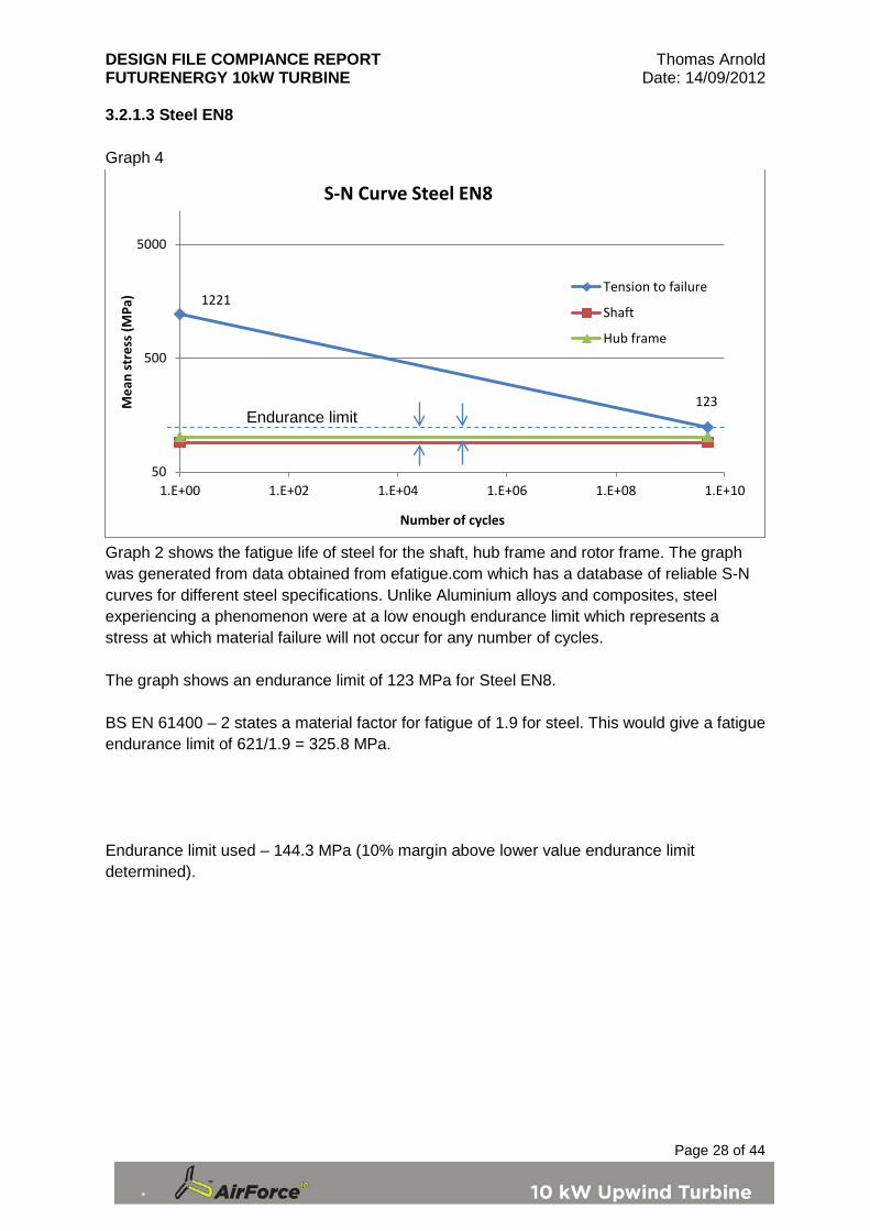
Graph 2 shows the fatigue life of steel for the shaft, hub frame and rotor frame. The graph was generated from data obtained from efatigue.com which has a database of reliable S-N curves for different steel specifications. Unlike Aluminium alloys and composites, steel experiencing a phenomenon were at a low enough endurance limit which represents a stress at which material failure will not occur for any number of cycles. The graph shows an endurance limit of 123 MPa for Steel EN8. BS EN 61400 – 2 states a material factor for fatigue of 1.9 for steel. This would give a fatigue endurance limit of 621/1.9 = 325.8 MPa. Endurance limit used – 144.3 MPa (10% margin above lower value endurance limit determined).
1221
123
50
500
5000
1.E+00 1.E+02 1.E+04 1.E+06 1.E+08 1.E+10
Mea
n st
ress
(MPa
)
Number of cycles
S-N Curve Steel EN8
Tension to failure
Shaft
Hub frame
Endurance limit

DESIGN FILE COMPIANCE REPORT Thomas Arnold FUTURENERGY 10kW TURBINE Date: 14/09/2012
Page 29 of 44
3.2.2 Blade root fatigue Parameters Material – Aluminium 6082 Ultimate tensile strength – 295 MPa / 1.25 = 236 MPa Yield strength – 255 MPa / 1.25 = 204 MPa Cycles to failure – 4.89×10⁹ Fatigue limit – 100 MPa / 1.3 = 77 MPa Stress applied – 30.5 MPa Mean Stress applied – 30.5 MPa Graph 5
Factor of safety = Max load line/Load line Gradient of modified Goodman line (mx+c) 0.326 Gradient of load line 1 Maximum mean stress (MPa) 58.01 Maximum applied stress (MPa) 58.01
Additional factor of safety 1.9
0
20
40
60
80
100
120
140
160
180
0 50 100 150 200 250
Stre
ss A
pplie
d (M
Pa)
Mean Stress (MPa)
Modified Goodman fatigue diagram
Yield stress lineModified Goodman lineLoad lineMax load line

DESIGN FILE COMPIANCE REPORT Thomas Arnold FUTURENERGY 10kW TURBINE Date: 14/09/2012
Page 30 of 44
3.2.3 Blades and spar fatigue Parameters Material – MULTIPREG 8020 Structural Epoxy Component Prepreg Ultimate tensile strength – 571.8 MPa / 1.25 = 457.4 MPa Yield strength – 500 MPa / 1.25 = 400 MPa Cycles to failure – 4.89×10⁹ Fatigue limit – 100 MPa / 1.3 = 76.9 MPa Stress applied – 30.5 MPa Mean Stress applied – 30.5 MPa Graph 6
Factor of safety = Max load line/Load line Gradient of modified Goodman line (mx+c) 0.168 Gradient of load line 1 Maximum mean stress (MPa) 65.85 Maximum applied stress (MPa) 65.85
Additional factor of safety 2.2
0
50
100
150
200
250
300
350
400
450
0 100 200 300 400 500 600
Stre
ss A
pplie
d (M
Pa)
Mean Stress (MPa)
Modified Goodman fatigue diagram
Yield stress lineModified Goodman lineLoad lineMax load line

DESIGN FILE COMPIANCE REPORT Thomas Arnold FUTURENERGY 10kW TURBINE Date: 14/09/2012
Page 31 of 44
3.2.4 Shaft fatigue Parameters Material – Steel EN8 Ultimate tensile strength – 621.0 MPa / 1.25 = 496.8 MPa Yield strength – 500 MPa / 1.25 = 400 MPa Cycles to failure – 4.89×10⁹ Fatigue limit – 143.4 MPa / 1.3 = 111 MPa Stress applied – 90.8 MPa Mean Stress applied – 90.8 MPa Graph 7
Factor of safety = Max load line/Load line Gradient of modified Goodman line (mx+c) 0.223 Gradient of load line 1 Maximum mean stress (MPa) 90.73 Maximum applied stress (MPa) 90.73
Additional factor of safety 1.0
0
50
100
150
200
250
300
350
400
450
0 100 200 300 400 500 600
Stre
ss A
pplie
d (M
Pa)
Mean Stress (MPa)
Modified Goodman fatigue diagram
Yield stress lineModified Goodman lineLoad lineMax load line

DESIGN FILE COMPIANCE REPORT Thomas Arnold FUTURENERGY 10kW TURBINE Date: 14/09/2012
Page 32 of 44
3.2.5 Hub frame fatigue Parameters Material – Steel EN8 Ultimate tensile strength – 621.0 MPa / 1.25 = 496.8 MPa Yield strength – 500 MPa / 1.25 = 400 MPa Cycles to failure – 4.89×10⁹ Fatigue limit – 143.3 MPa / 1.3 = 111 MPa Stress applied – 41.8 MPa Mean Stress applied – 41.8 MPa Graph 8
Factor of safety = Max load line/Load line Gradient of modified Goodman line (mx+c) 0.223 Gradient of load line 1 Maximum mean stress (MPa) 90.73 Maximum applied stress (MPa) 90.73
Additional factor of safety 4.3
0
100
200
300
400
500
600
0 100 200 300 400 500 600
Stre
ss A
pplie
d (M
Pa)
Mean Stress (MPa)
Modified Goodman fatigue diagram
Yield stress lineModified Goodman lineLoad lineMax load line

DESIGN FILE COMPIANCE REPORT Thomas Arnold FUTURENERGY 10kW TURBINE Date: 14/09/2012
Page 33 of 44
3.2.6 Nacelle frame fatigue Parameters Material – Steel EN8 Ultimate tensile strength – 621.0 MPa / 1.25 = 496.8 MPa Yield strength – 500 MPa / 1.25 = 400 MPa Cycles to failure – 4.89×10⁹ Fatigue limit – 143.4 MPa / 1.3 = 111 MPa Stress applied – 34.5 MPa Mean Stress applied – 34.5 MPa Graph 9
Factor of safety = Max load line/Load line Gradient of modified Goodman line (mx+c) 0.223 Gradient of load line 1 Maximum mean stress (MPa) 90.73 Maximum applied stress (MPa) 90.73
Additional factor of safety 2.6
0
100
200
300
400
500
600
0 100 200 300 400 500 600
Stre
ss A
pplie
d (M
Pa)
Mean Stress (MPa)
Modified Goodman fatigue diagram
Yield stress line
Modified GoodmanlineLoad line

DESIGN FILE COMPIANCE REPORT Thomas Arnold FUTURENERGY 10kW TURBINE Date: 14/09/2012
Page 34 of 44
3.2.7 Bearing fatigue life Bearing product data Manufacturer: SKF Metric single row taper roller bearing Inner diameter 60mm Outer diameter 110mm
Figure 11 – SKF product table C=168 kN C0=236 kN Pu=26.5 kN 𝑀𝑖𝑚𝑖𝑚𝑢𝑚 𝑟𝑎𝑑𝑖𝑎𝑙 𝑙𝑜𝑎𝑑 = 0.02 × 𝐶 = 0.02 × 168 = 3.36 𝑘𝑁 Fa = 2396.25 N [reference 61400-2 Calculator, Airforce 10] FR = 17188.38 N [reference 61400-2 Calculator, Airforce 10] e = 0.4 𝐹𝑎𝐹𝑅
=2396
17188= 0.14
When Fa/FR < e take P = FR Therefore P = 17188.38 N Y0 = 0.8
𝑃0 =𝐹𝑅2
+ 𝑌0𝐹𝑎 =17188
2+ 0.8 × 2396 = 10511 𝑁
If P0 is smaller than FR then take P0 as equal to FR. Therefore P0 = 17188 N

DESIGN FILE COMPIANCE REPORT Thomas Arnold FUTURENERGY 10kW TURBINE Date: 14/09/2012
Page 35 of 44
Figure 12 – SKF bearing life calculation The results from figure 12 show a bearing life of L10m 4290 (4.29×10⁹) rotations. The bearing will experience 155𝑟𝑝𝑚
60× 20 × 365 × 24 × 60 × 60 = 1.63 × 10⁹𝑟𝑒𝑣𝑜𝑙𝑢𝑡𝑖𝑜𝑛𝑠
Safety factor = 4.29×10⁹/1.63×109 = 2.6

DESIGN FILE COMPIANCE REPORT Thomas Arnold FUTURENERGY 10kW TURBINE Date: 14/09/2012
Page 36 of 44
3.3 Critical deflection analysis [Section 7.9.3] A calculation was carried out to show that there would not be any mechanical interference between the blade and the tower during operation. Due to the make-up of the blade’s structure and material properties they are extremely stiff and will deflect a minimal amount during operation.
Skin Material: Epoxy/Glass Fibre, Woven Fabric 1581 style
Typ. Str. (MPa): 550
Typ. Mod. (GPa): 17
Poisson's Ratio 0.13
Skin Thickness (mm): 6
Core Type: Divinycell Foam
Core Specification: Divinycell H 80
W Shear Strength (MPa): 1.2
L Shear Strength (MPa): 1.2
W Shear Modulus (MPa): 30
L Shear Modulus (MPa): 30
Panel Size: Length (m): 1
Width (m): 0.1
Thickness (mm): 200
Load Case: Cantilever Support, Point Load (at end)
Total Load (N): 10000
Kb: 0.3333
Ks: 1
Calculated Results:
Bending Stiffness (Nm²): 1.952×10⁶
Shear Stiffness (N): 5.820×10⁵
Maximum Deflection (mm): 3.4
Skin Facing Stress (MPa): 85.9 F.O.S: 6.4
Core Stress (MPa): 0.5155 F.O.S: 2.33
Figure 13 shows the distance between the blade tip and the tower. From this it can be seen that the deflection of 3.4 mm will not cause mechanical interference between the blade and the tower.
Figure 13

DESIGN FILE COMPIANCE REPORT Thomas Arnold FUTURENERGY 10kW TURBINE Date: 14/09/2012
Page 37 of 44
4.0 Tests to verify design data [Section 9.2 BS EN 61400-2] The following tests will be carried out to verify the design calculations
• Design power, Pdesign • Design rotational speed, ndesign • Design shaft torque, Qdesign • Maximum rotational speed, nmax
4.1 Measured wind velocity, power, rotational speed and toque 𝑃𝑑𝑒𝑠𝑖𝑔𝑛 = 3822𝑊 𝜂 = 0.6 + 0.000005 × 3822 = 0.607644 From equation (50) this states an efficiency value for the drive train of 0.607644
𝑄𝑑𝑒𝑠𝑖𝑔𝑛 =30𝑃𝑑𝑒𝑠𝑖𝑔𝑛𝜂 𝜋 𝑛𝑑𝑒𝑠𝑖𝑔𝑛
(51)
𝑄𝑑𝑒𝑠𝑖𝑔𝑛 =30 × 3822
0.607644 × 𝜋 × 155= 387.51 𝑁𝑚
4.2 Maximum yaw rate A worm gear is used to control the slew drive of the wind turbine. Therefore even if complete electrical failure was to occur the turbine would be prevented from yawing due to the worm gear employed in the system. 4.3 Maximum rotational speed The controller will turn the turbine head away from the wind when the rotor speed reaches a limit of 170 RPM. 5.0 Conclusion The Airforce 10 Futurenegy 10 kW turbine complies with all of the relevant sections of the British standard EN 61400 – 2 in order to achieve MCS accreditation in line with TUV NEL group. All structural and fatigue requirements have been met and in most cases with a significant factor of safety in addition to safety factors required for compliance.

DESIGN FILE COMPIANCE REPORT Thomas Arnold FUTURENERGY 10kW TURBINE Date: 14/09/2012
Page 38 of 44
6.0 References: Section Reference Section Headings BS EN 61400-2: 2006 Wind Turbines – Part 2: Design
requirements for small wind turbines 1.1 nel technology for life TUV NEL Guidance Note for Design File
Submissions MCS Microgeneration Certification Scheme: MCS 006 Product Certification Scheme Requirements: Micro and Small Wind Turbines Issue 1.5 2009 MCS Microgeneration Certification Scheme: MCS 011 Product Certification Scheme Requirements: Micro and Small Wind Turbines Issue 1.5 2009
Within whole report British Wind Energy Association Small Wind Turbine Performance Within whole report BS EN ISO 9000: 2005 Quality management systems –
Fundamentals and vocabulary
3.1.2.2, 3.1.3.2, 3.2.3 Ambercomposites, Multipreg 8020, Structural epoxy component Prepreg flexible cure schedules, Issue Reference: TDS/8020/04 – July09
3.1.2.2, 3.1.3.2, 3.2.3 DIAB, Divinycell H, Technical manual October 1 2010
3.2.1.1 Engineering Composite Materials, Bryan Harris, The Institute of Materials, London 1999, Section 6.2 Damage in Composites
3.3 Amber composites calculation
Table Title Reference 1 Basic parameters for
SWT classes BS EN 61400 – 2 Section 6.2 SWT classes, Table 1
2 Design load cases for simplified load
BS EN 61400 – 2 Section 7.4 Simplified load model, 7.4.1 General, Table 2
3 Input parameters Excel spreadsheet title 61400-2 Calculator, Airforce 10 by Doug Nangle
4 Load cases A-J results Excel spreadsheet title 61400-2 Calculator, Airforce 10 by Doug Nangle
5 Stress calculation result
BS EN 61400 – 2 Section 7.7 Stress calculation, Table 5 – Equivalent stresses and Excel spreadsheet title 61400-2 Calculator, Airforce 10 by Doug Nangle
6 Partial safety factors for materials
BS EN 61400 – 2 Section 7.8 Safety factors, 7.8.1 Material factors and requirements, Table 6
7 Partial safety factors for loads
BS EN 61400 – 2 Section 7.8 Safety factors, 7.8.2 Partial safety factors for loads, Table 7

DESIGN FILE COMPIANCE REPORT Thomas Arnold FUTURENERGY 10kW TURBINE Date: 14/09/2012
Page 39 of 44
Figure
Title
Reference
1 Cross section of the spar and root
Solid Works Airforce 10 model (Doug Nangle)
2 Stress variation in the blade root
SolidWorks FEA analysis (Doug Nangle)
3 Demonstrating the bending moment acting on the blade and showing the structural support within the blade
Diagram taken from Solid Works Airforce 10 model (Doug Nangle)
4 Blade – root join SolidWorks FEA analysis (Doug Nangle) 5 Stress on shaft SolidWorks FEA analysis (Doug Nangle) 6 Stress on hub frame SolidWorks FEA analysis (Doug Nangle) 7 Stress on nacelle
frame SolidWorks FEA analysis (Doug Nangle)
8 Summary of stresses
Diagram taken from Solid Works Airforce 10 model (Doug Nangle) and data from Stress calculations
9 S-N curve for glass fibre composites
Composite S-N performance [Page 137 Engineering Composite Materials by Bryan Harris The Institute of Materials 1999]
10 S-N curve for metals
BS EN 61400 - 2 Annex E, E.4.3 Metals, Figure E.5 - S-N curves for fatigue of typical metals
11 SKF bearing product table
www.skf.com/skf/productcatalogue
12 SKF bearing fatigue life calculation
www.skf.com/skf/productcatalogue/jsp
13 Side view of wind turbine to show non-interference between blade and tower
Assembly, 10 kW Airforce wind turbine P-10-0274
DESIGN FILE COMPIANCE REPORT Thomas Arnold FUTURENERGY 10kW TURBINE Date: 14/09/2012
Page 40 of 44
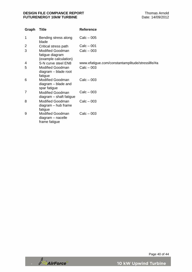
Graph
Title
Reference
1 Bending stress along blade
Calc – 005
2 Critical stress path Calc – 001 3 Modified Goodman
fatigue diagram (example calculation)
Calc – 003
4 S-N curve steel EN8 www.efatigue.com/constantamplitude/stresslife/#a 5 Modified Goodman
diagram – blade root fatigue
Calc – 003
6 Modified Goodman diagram – blade and spar fatigue
Calc – 003
7 Modified Goodman diagram – shaft fatigue
Calc – 003
8 Modified Goodman diagram – hub frame fatigue
Calc – 003
9 Modified Goodman diagram – nacelle frame fatigue
Calc – 003
DESIGN FILE COMPIANCE REPORT Thomas Arnold FUTURENERGY 10kW TURBINE Date: 14/09/2012
Page 41 of 44
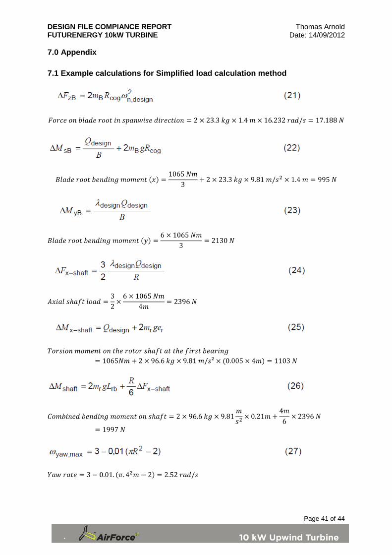
7.0 Appendix 7.1 Example calculations for Simplified load calculation method
𝐹𝑜𝑟𝑐𝑒 𝑜𝑛 𝑏𝑙𝑎𝑑𝑒 𝑟𝑜𝑜𝑡 𝑖𝑛 𝑠𝑝𝑎𝑛𝑤𝑖𝑠𝑒 𝑑𝑖𝑟𝑒𝑐𝑡𝑖𝑜𝑛 = 2 × 23.3 𝑘𝑔 × 1.4 𝑚 × 16.232 𝑟𝑎𝑑/𝑠 = 17.188 𝑁
𝐵𝑙𝑎𝑑𝑒 𝑟𝑜𝑜𝑡 𝑏𝑒𝑛𝑑𝑖𝑛𝑔 𝑚𝑜𝑚𝑒𝑛𝑡 (𝑥) =1065 𝑁𝑚
3+ 2 × 23.3 𝑘𝑔 × 9.81 𝑚/𝑠2 × 1.4 𝑚 = 995 𝑁
𝐵𝑙𝑎𝑑𝑒 𝑟𝑜𝑜𝑡 𝑏𝑒𝑛𝑑𝑖𝑛𝑔 𝑚𝑜𝑚𝑒𝑛𝑡 (𝑦) =6 × 1065 𝑁𝑚
3= 2130 𝑁
𝐴𝑥𝑖𝑎𝑙 𝑠ℎ𝑎𝑓𝑡 𝑙𝑜𝑎𝑑 =32
×6 × 1065 𝑁𝑚
4𝑚= 2396 𝑁
𝑇𝑜𝑟𝑠𝑖𝑜𝑛 𝑚𝑜𝑚𝑒𝑛𝑡 𝑜𝑛 𝑡ℎ𝑒 𝑟𝑜𝑡𝑜𝑟 𝑠ℎ𝑎𝑓𝑡 𝑎𝑡 𝑡ℎ𝑒 𝑓𝑖𝑟𝑠𝑡 𝑏𝑒𝑎𝑟𝑖𝑛𝑔
= 1065𝑁𝑚 + 2 × 96.6 𝑘𝑔 × 9.81 𝑚/𝑠² × (0.005 × 4𝑚) = 1103 𝑁
𝐶𝑜𝑚𝑏𝑖𝑛𝑒𝑑 𝑏𝑒𝑛𝑑𝑖𝑛𝑔 𝑚𝑜𝑚𝑒𝑛𝑡 𝑜𝑛 𝑠ℎ𝑎𝑓𝑡 = 2 × 96.6 𝑘𝑔 × 9.81𝑚𝑠2
× 0.21𝑚 +4𝑚6
× 2396 𝑁
= 1997 𝑁
𝑌𝑎𝑤 𝑟𝑎𝑡𝑒 = 3 − 0.01. (𝜋. 42𝑚 − 2) = 2.52 𝑟𝑎𝑑/𝑠
DESIGN FILE COMPIANCE REPORT Thomas Arnold FUTURENERGY 10kW TURBINE Date: 14/09/2012
Page 42 of 44
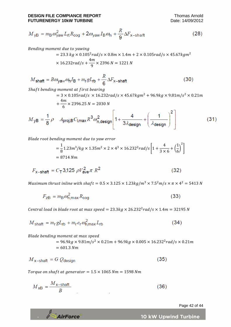
𝐵𝑒𝑛𝑑𝑖𝑛𝑔 𝑚𝑜𝑚𝑒𝑛𝑡 𝑑𝑢𝑒 𝑡𝑜 𝑦𝑎𝑤𝑖𝑛𝑔
= 23.3 𝑘𝑔 × 0.1052𝑟𝑎𝑑/𝑠 × 0.8𝑚 × 1.4𝑚 + 2 × 0.105𝑟𝑎𝑑/𝑠 × 45.67𝑘𝑔𝑚2
× 16.232𝑟𝑎𝑑/𝑠 +4𝑚9
× 2396 𝑁 = 1221 𝑁
𝑆ℎ𝑎𝑓𝑡 𝑏𝑒𝑛𝑑𝑖𝑛𝑔 𝑚𝑜𝑚𝑒𝑛𝑡 𝑎𝑡 𝑓𝑖𝑟𝑠𝑡 𝑏𝑒𝑎𝑟𝑖𝑛𝑔
= 3 × 0.105𝑟𝑎𝑑/𝑠 × 16.232𝑟𝑎𝑑/𝑠 × 45.67𝑘𝑔𝑚2 + 96.9𝑘𝑔 × 9.81𝑚/𝑠2 × 0.21𝑚
+4𝑚6
× 2396.25 𝑁 = 2030 𝑁
𝐵𝑙𝑎𝑑𝑒 𝑟𝑜𝑜𝑡 𝑏𝑒𝑛𝑑𝑖𝑛𝑔 𝑚𝑜𝑚𝑒𝑛𝑡 𝑑𝑢𝑒 𝑡𝑜 𝑦𝑎𝑤 𝑒𝑟𝑟𝑜𝑟
=18
1.23𝑚³/𝑘𝑔 × 1.35𝑚2 × 2 × 43 × 16.2322𝑟𝑎𝑑/𝑠 �1 +4
3 × 6+ �
16�2�
= 8714 𝑁𝑚
𝑀𝑎𝑥𝑖𝑚𝑢𝑚 𝑡ℎ𝑟𝑢𝑠𝑡 𝑖𝑛𝑙𝑖𝑛𝑒 𝑤𝑖𝑡ℎ 𝑠ℎ𝑎𝑓𝑡 = 0.5 × 3.125 × 1.23𝑘𝑔/𝑚3 × 7.52𝑚/𝑠 × 𝜋 × 42 = 5413 𝑁
𝐶𝑒𝑛𝑡𝑟𝑎𝑙 𝑙𝑜𝑎𝑑 𝑖𝑛 𝑏𝑙𝑎𝑑𝑒 𝑟𝑜𝑜𝑡 𝑎𝑡 𝑚𝑎𝑥 𝑠𝑝𝑒𝑒𝑑 = 23.3𝑘𝑔 × 26.2322𝑟𝑎𝑑/𝑠 × 1.4𝑚 = 32195 𝑁
𝐵𝑙𝑎𝑑𝑒 𝑏𝑒𝑛𝑑𝑖𝑛𝑔 𝑚𝑜𝑚𝑒𝑛𝑡 𝑎𝑡 𝑚𝑎𝑥 𝑠𝑝𝑒𝑒𝑑
= 96.9𝑘𝑔 × 9.81𝑚/𝑠2 × 0.21𝑚 + 96.9𝑘𝑔 × 0.005 × 16.2322𝑟𝑎𝑑/𝑠 × 0.21𝑚= 601.3 𝑁𝑚
𝑇𝑜𝑟𝑞𝑢𝑒 𝑜𝑛 𝑠ℎ𝑎𝑓𝑡 𝑎𝑡 𝑔𝑒𝑛𝑒𝑟𝑎𝑡𝑜𝑟 = 1.5 × 1065 𝑁𝑚 = 1598 𝑁𝑚

DESIGN FILE COMPIANCE REPORT Thomas Arnold FUTURENERGY 10kW TURBINE Date: 14/09/2012
Page 43 of 44
𝐵𝑙𝑎𝑑𝑒 𝑟𝑜𝑜𝑡 𝑏𝑒𝑛𝑑𝑖𝑛𝑔 𝑚𝑜𝑚𝑒𝑛𝑡 𝑑𝑢𝑒 𝑡𝑜 𝑔𝑒𝑛𝑒𝑟𝑎𝑡𝑜𝑟 =1598 𝑁𝑚
3= 533 𝑁𝑚
𝑇𝑜𝑟𝑞𝑢𝑒 𝑜𝑛 𝑠ℎ𝑎𝑓𝑡 𝑑𝑢𝑟𝑖𝑛𝑔 𝑏𝑟𝑎𝑘𝑖𝑛𝑔 = 1000 𝑁𝑚 + 1065 𝑁𝑚 = 2065 𝑁𝑚 See spreadsheet for full calculationS Reference Mechanical braking Calc-006
𝐵𝑙𝑎𝑑𝑒 𝑟𝑜𝑜𝑡 𝑏𝑒𝑛𝑑𝑖𝑛𝑔 𝑚𝑜𝑚𝑒𝑛𝑡 𝑑𝑢𝑒 𝑡𝑜 𝑏𝑒𝑛𝑑𝑖𝑛𝑔 𝑎𝑛𝑑 𝑔𝑒𝑛𝑒𝑟𝑎𝑡𝑜𝑟 𝑙𝑜𝑎𝑑
= 533 𝑁𝑚 + 23.3𝑘𝑔 × 9.81𝑚/𝑠2 × 1.4𝑚 = 853 𝑁𝑚
𝑃𝑎𝑟𝑘𝑒𝑑 𝑏𝑙𝑎𝑑𝑒 𝑟𝑜𝑜𝑡 𝑏𝑒𝑛𝑑𝑖𝑛𝑔 𝑚𝑜𝑚𝑒𝑛𝑡 (50 𝑦𝑒𝑎𝑟𝑠 𝑒𝑥𝑝𝑜𝑠𝑢𝑟𝑒)
= 1.5 ×14
1.23𝑘𝑔/𝑚3 × 52.52𝑚/𝑠 × 1.35𝑚2 × 4𝑚 = 6837 𝑁𝑚
𝑆𝑝𝑖𝑛𝑛𝑖𝑛𝑔 𝑟𝑜𝑡𝑜𝑟 𝑏𝑙𝑎𝑑𝑒 𝑏𝑒𝑛𝑑𝑖𝑛𝑔 𝑚𝑜𝑚𝑒𝑛𝑡 (50 𝑦𝑒𝑎𝑟𝑠 𝑒𝑥𝑝𝑜𝑠𝑢𝑟𝑒)
= 2 ×16
1.23𝑘𝑔/𝑚3 × 52.52𝑚/𝑠 × 1.35𝑚2 × 4𝑚 = 6078 𝑁𝑚
𝑆ℎ𝑎𝑓𝑡 𝑡ℎ𝑟𝑢𝑠𝑡 𝑙𝑜𝑎𝑑 𝑝𝑎𝑟𝑘𝑒𝑑 (50 𝑦𝑒𝑎𝑟𝑠 𝑒𝑥𝑝𝑜𝑠𝑢𝑟𝑒)
= 3 × 1.5 ×12
1.23𝑘𝑔/𝑚3 × 52.52𝑚/𝑠 × 1.35𝑚2 = 10256 𝑁𝑚
𝑆ℎ𝑎𝑓𝑡 𝑡ℎ𝑟𝑢𝑠𝑡 𝑙𝑜𝑎𝑑 𝑠𝑝𝑖𝑛𝑛𝑖𝑛𝑔 (50 𝑦𝑒𝑎𝑟𝑠 𝑒𝑥𝑝𝑜𝑠𝑢𝑟𝑒)
= 0.17 × 3 × 1.35𝑚2 × 1.23𝑘𝑔/𝑚3 × 52.52𝑚/𝑠 = 13322 𝑁
𝐿𝑜𝑎𝑑 = 1.3 ×12
1.23𝑘𝑔/𝑚3 × 52.5𝑚/𝑠 × 50.27𝑚2 = 2110 𝑁
DESIGN FILE COMPIANCE REPORT Thomas Arnold FUTURENERGY 10kW TURBINE Date: 14/09/2012
Page 44 of 44
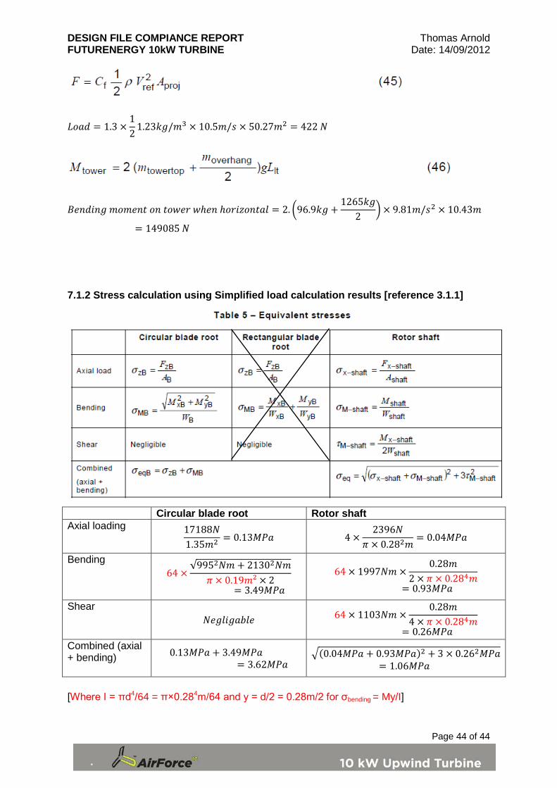
𝐿𝑜𝑎𝑑 = 1.3 ×12
1.23𝑘𝑔/𝑚3 × 10.5𝑚/𝑠 × 50.27𝑚2 = 422 𝑁
𝐵𝑒𝑛𝑑𝑖𝑛𝑔 𝑚𝑜𝑚𝑒𝑛𝑡 𝑜𝑛 𝑡𝑜𝑤𝑒𝑟 𝑤ℎ𝑒𝑛 ℎ𝑜𝑟𝑖𝑧𝑜𝑛𝑡𝑎𝑙 = 2. �96.9𝑘𝑔 +1265𝑘𝑔
2� × 9.81𝑚/𝑠2 × 10.43𝑚
= 149085 𝑁 7.1.2 Stress calculation using Simplified load calculation results [reference 3.1.1]
Circular blade root Rotor shaft Axial loading 17188𝑁
1.35𝑚2 = 0.13𝑀𝑃𝑎 4 ×2396𝑁
𝜋 × 0.282𝑚= 0.04𝑀𝑃𝑎
Bending 64 ×
√9952𝑁𝑚 + 21302𝑁𝑚𝜋 × 0.19𝑚² × 2
= 3.49𝑀𝑃𝑎
64 × 1997𝑁𝑚 ×0.28𝑚
2 × 𝜋 × 0.284𝑚= 0.93𝑀𝑃𝑎
Shear 𝑁𝑒𝑔𝑙𝑖𝑔𝑎𝑏𝑙𝑒 64 × 1103𝑁𝑚 ×
0.28𝑚4 × 𝜋 × 0.284𝑚
= 0.26𝑀𝑃𝑎 Combined (axial + bending) 0.13𝑀𝑃𝑎 + 3.49𝑀𝑃𝑎
= 3.62𝑀𝑃𝑎 �(0.04𝑀𝑃𝑎 + 0.93𝑀𝑃𝑎)2 + 3 × 0.262𝑀𝑃𝑎
= 1.06𝑀𝑃𝑎
[Where I = πd4/64 = π×0.284m/64 and y = d/2 = 0.28m/2 for σbending = My/I]
Related Documents