Title: Wind Energy Technology Applied to High Rise Buildings Authors: Samuel W Chung, Research Associate Professor, University of Utah Shiping Zhang, Graduate Student, McGill University Subjects: Sustainability/Green/Energy Wind Engineering Keywords: Renewable Energy Wind Publication Date: 2011 Original Publication: CTBUH 2011 Seoul Conference Paper Type: 1. Book chapter/Part chapter 2. Journal paper 3. Conference proceeding 4. Unpublished conference paper 5. Magazine article 6. Unpublished © Council on Tall Buildings and Urban Habitat / Samuel W Chung; Shiping Zhang ctbuh.org/papers

Welcome message from author
This document is posted to help you gain knowledge. Please leave a comment to let me know what you think about it! Share it to your friends and learn new things together.
Transcript
Title: Wind Energy Technology Applied to High Rise Buildings
Authors: Samuel W Chung, Research Associate Professor, University of UtahShiping Zhang, Graduate Student, McGill University
Subjects: Sustainability/Green/EnergyWind Engineering
Keywords: Renewable EnergyWind
Publication Date: 2011
Original Publication: CTBUH 2011 Seoul Conference
Paper Type: 1. Book chapter/Part chapter2. Journal paper3. Conference proceeding4. Unpublished conference paper5. Magazine article6. Unpublished
© Council on Tall Buildings and Urban Habitat / Samuel W Chung; Shiping Zhang
ctbuh.org/papers

TS15-02
Wind Energy Technology Applied to High Rise Buildings
Samuel W. Chung1 ,Shiping Zhang2 1 School of Architecture, University of Utah, Salt Lake City, Utah, USA , [email protected]
2 College of Engineering, McGill University, Montreal, Canada
Samuel W. (Suk Wha) Chung Biography Dr. Samuel W. Chung, a research associate professor of structural mechanics at the school of architecture, University of Utah in the United States, went through various career tracks in his professional life. He started as a research engineer in the shell structural stability problems after earned his Ph.D. from the University of Illinois at Chicago, then a stress analyst for nuclear power plants in his earlier years. He then moved into entrepreneurial activities, formulated Presstec Industries,
Inc., Cicero Steel Corporation and Cicero Engineering Services, Inc. During his entrepreneurial life, he never stopped academic and teaching activities, published technical articles and teaching mechanics and mathematics. Dr. Chung is known as a structural mechanician but he also spent many years as an aviator, private airplane pilot and an instructor. He is also known as a newspaper columnist, wrote many articles in the areas of buildings, energy, aviation and technology. He spends considerable time for practice and writing of skiing and ice skating.
Zhang, Shiping Biography Mr. Shiping Zhang is a graduate student at the CFD Lab of mechanical engineering department, McGill University in Montreal, Canada. He graduated from Beijing Institute of Technology in the school of mechanical engineering. His
major interest among others are computational fluid dynamics and computational fracture mechanics as well as fluid-structure interaction.
Abstract
The self sufficient sustainable energy is required more than ever for the high rise buildings. To achieve the goal of net-zero energy, we are adopting the modified Darrieus-type windmill, a vertical axis wind turbine, to be located on the top of the buildings where the elevation will provide highest possible location for the highest speed of the wind is expected. The system will be incorporated directly with the elevated water, oil and gas storage facilities, charging air compressor and vacuum pumps without the use of electricity generated by nuclear or fossil plants, it will also generate enough of electricity for the use of its own buildings. The elevated storage of the products can serve as pumping stations thus can eliminate electricity driven pumps and motors. Also the VAWT system will reduce considerable maintenance cost by locating all of the storage and generating equipments on the floor level where the equipments are anchored, compare to the horizontal axis wind turbine which locates all of generating equipments at the higher location right behind the blade axis.
Key Words: Wind Mechanics, Gamma Function, Vertical Axis Wind Turbine, Storage of Wind energy, Elevated Storage Systems of water and petroleum products, Air compressor, Vacuum pump.
275
CTBUH 2011 World Conference October 10-12, 2011, COEX, Seoul, KOREA_____________________________________________________________________________________________________________________________________________________________
______________________________________________________________________________________________________________________________________________________________
1. Introduction In this investigation we will use a modified Darrieus-type vertical wind turbine, which is not widely used but has been in existence for decades since it was first invented by a French engineer G.J.M. Darrieus in 1920. It has advantages in the efficiency of turbine operation as well as aerodynamic performance. We will also use a spheroidal-type elevated water storage tank as a basic frame of supporting structure with vertical axis wind turbine (VAWT)-type blades attached to the existing or new tanks. As shown in Figure 1, top flange is installed on the top of the spheroidal shell and the bottom flange is installed at the transition from the spheroid to the cylindrical support. The blades are connected to the flanges at both ends, thus the flanges are free to rotate horizontally. The connections between the flanges and blades will then take static and dynamic loads due to the blades taking the wind pressure as well as the dead load of its own weight, the maximum wind loads specified by the codes of International Building Code (IBC) American Water Works Association (AWWA), American Institute of Steel Construction (AISC), and American Society of Mechanical Engineers (ASME) or equivalent in other countries. We thus utilize its unique shape. First round in horizontal section and elevated at the higher level, so higher wind velocity is expected. The round shape of the tank came from the membrane theory of shell structures so that the shell plates will take tensile stress only. Installing the vertical blades around the circular shape of storage tank will be beneficial to the nature of axisymmetric configuration. The wind velocity is estimated exponentially faster at the higher elevation such as the top of hi-rise building, we will thus take advantage of the height of sky scrapers.
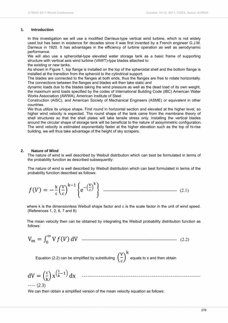
2. Nature of Wind The nature of wind is well described by Weibull distribution which can best be formulated in terms of the probability function as described subsequently: The nature of wind is well described by Weibull distribution which can best formulated in terms of the probability function described as follows:
V e
V ------------------------------------------------ (2.1)
where k is the dimensionless Weibull shape factor and c is the scale factor in the unit of wind speed. (References 1, 2, 6, 7 and 8)
The mean velocity then can be obtained by integrating the Weibull probability distribution function as follows:
V V dV -------------------------------------------------------------- (2.2)
Equation (2.2) can be simplified by substituting V
equals to x and then obtain
dV x dx ------------------------------------------------------------------- (2.3) We can then obtain a simplified version of the mean velocity equation as follows:
276
CTBUH 2011 World Conference October 10-12, 2011, COEX, Seoul, KOREA_____________________________________________________________________________________________________________________________________________________________
______________________________________________________________________________________________________________________________________________________________
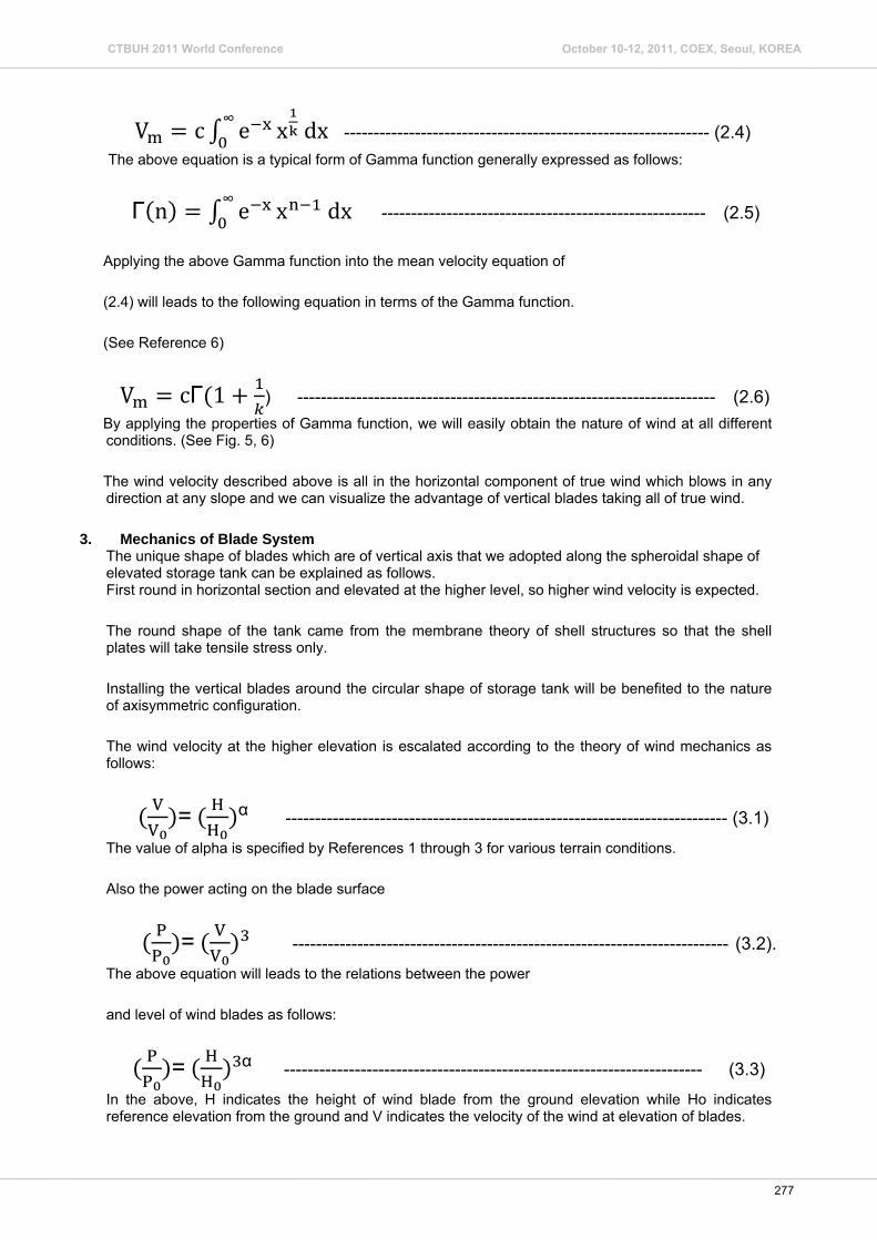
V c e∞ x dx -------------------------------------------------------------- (2.4) The above equation is a typical form of Gamma function generally expressed as follows:
Γ n e∞ x dx ------------------------------------------------------- (2.5)
Applying the above Gamma function into the mean velocity equation of
(2.4) will leads to the following equation in terms of the Gamma function.
(See Reference 6)
V cΓ 1 ) ----------------------------------------------------------------------- (2.6) By applying the properties of Gamma function, we will easily obtain the nature of wind at all different conditions. (See Fig. 5, 6)
The wind velocity described above is all in the horizontal component of true wind which blows in any direction at any slope and we can visualize the advantage of vertical blades taking all of true wind.
3. Mechanics of Blade System The unique shape of blades which are of vertical axis that we adopted along the spheroidal shape of elevated storage tank can be explained as follows. First round in horizontal section and elevated at the higher level, so higher wind velocity is expected.
The round shape of the tank came from the membrane theory of shell structures so that the shell plates will take tensile stress only.
Installing the vertical blades around the circular shape of storage tank will be benefited to the nature of axisymmetric configuration.
The wind velocity at the higher elevation is escalated according to the theory of wind mechanics as follows:
VV
= HH
α --------------------------------------------------------------------------- (3.1) The value of alpha is specified by References 1 through 3 for various terrain conditions.
Also the power acting on the blade surface
PP
= VV
-------------------------------------------------------------------------- (3.2). The above equation will leads to the relations between the power
and level of wind blades as follows:
PP
= HH
α ----------------------------------------------------------------------- (3.3) In the above, H indicates the height of wind blade from the ground elevation while Ho indicates reference elevation from the ground and V indicates the velocity of the wind at elevation of blades.
277
CTBUH 2011 World Conference October 10-12, 2011, COEX, Seoul, KOREA_____________________________________________________________________________________________________________________________________________________________
______________________________________________________________________________________________________________________________________________________________

Because of the vertical arrangement of blades in VAWT, the blades will take wind power from all direction, which is of great advantage.
We will also find greater torque at the bottom flange due to the long arm length provided by the spheroidal shape configuration, the torque will be geared to various machineries including the turbine generator, air compressor, refrigeration compressor, vacuum pump etc.
The circular turbine generator can be installed around the stem pipe of the water tank at upper level, taking advantage of it’s cylindrical shape while all other gear boxes are connected by means of vertical shafts connected at the bottom flange.
4. Blade Stress Analysis
The blades are of high strength light weight materials thus advanced composite materials being used in the space structures are highly recommended. (Reference 4, 11 and 12)
The composite materials are a mixture of fibers with high tensile strength embedded in the mixture of plastics; it is therefore non-homogeneous and anisotropic materials. (Reference 4)
The anisotropic materials are described in the theory of mechanics as the generalized Hook’s law:
σσστττ
E E … … … … EE E … … … … EE E … … … … EE E … … … … EE E … … … … EE E … … … … E
εεε
------------------------------- (4.1)
In the above, ( σ ) and ( τ ) are normal and shear stresses and ( ) and ( ) are normal and shear strains respectively. Eij are Young’s modulus of different directions in i = 1, 2, -, 6 and j = 1, 2, - ,6 and also Eij = Eji from the equilibrium condition. The anisotropic materials are, unlike the ordinary isotropic materials such as aluminum or steel, directional and further analysis is necessary to incorporate the directional properties.
The vertical blades are as shown in the Fig.4; half circular shape channel laterally bent according the configuration of spheroidal water tanks located inside of blades (See Fig. 1, 2, 3)
There are 8 blades, all connected by 1/2” x 12” flat bar of horizontal stabilizer. (Fig. 3 and 4)
Each blade is subjected to wind pressure as shown the figures and must be designed for the static and dynamic loads due to the incoming wind pressure and vibration of the blade rotation.
The incoming wind pressure will act as a uniform lateral load on the curved beam clamped at both ends of blade flange connections at top and bottom. (See Fig 4)
The blade or curved beam in this case will then subject to severe torsional stress in addition to flexural stress and further investigations are required.
Dynamic analysis also is necessary for the blade stress analysis alone but also for the flange design as well as the flange blade connections.
278
CTBUH 2011 World Conference October 10-12, 2011, COEX, Seoul, KOREA_____________________________________________________________________________________________________________________________________________________________
______________________________________________________________________________________________________________________________________________________________
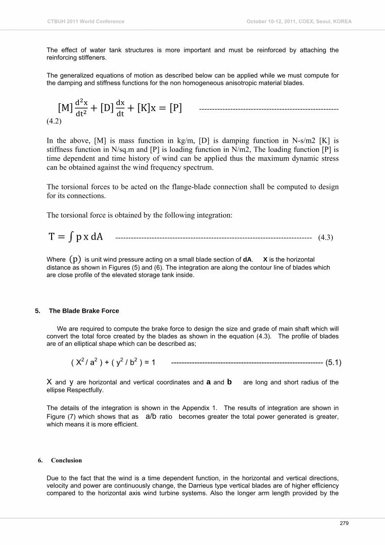
The effect of water tank structures is more important and must be reinforced by attaching the reinforcing stiffeners.
The generalized equations of motion as described below can be applied while we must compute for the damping and stiffness functions for the non homogeneous anisotropic material blades.
M D K x P ------------------------------------------------------ (4.2)
In the above, [M] is mass function in kg/m, [D] is damping function in N-s/m2 [K] is stiffness function in N/sq.m and [P] is loading function in N/m2, The loading function [P] is time dependent and time history of wind can be applied thus the maximum dynamic stress can be obtained against the wind frequency spectrum.
The torsional forces to be acted on the flange-blade connection shall be computed to design for its connections.
The torsional force is obtained by the following integration:
T p x dA ---------------------------------------------------------------------------- (4.3)
Where p is unit wind pressure acting on a small blade section of dA. X is the horizontal distance as shown in Figures (5) and (6). The integration are along the contour line of blades which are close profile of the elevated storage tank inside.
5. The Blade Brake Force
We are required to compute the brake force to design the size and grade of main shaft which will convert the total force created by the blades as shown in the equation (4.3). The profile of blades are of an elliptical shape which can be described as;
( X2 / a2 ) + ( y2 / b2 ) = 1 ----------------------------------------------------------- (5.1)
X and y are horizontal and vertical coordinates and a and b are long and short radius of the ellipse Respectfully.
The details of the integration is shown in the Appendix 1. The results of integration are shown in Figure (7) which shows that as a/b ratio becomes greater the total power generated is greater, which means it is more efficient.
6. Conclusion
Due to the fact that the wind is a time dependent function, in the horizontal and vertical directions, velocity and power are continuously change, the Darrieus type vertical blades are of higher efficiency compared to the horizontal axis wind turbine systems. Also the longer arm length provided by the
279
CTBUH 2011 World Conference October 10-12, 2011, COEX, Seoul, KOREA_____________________________________________________________________________________________________________________________________________________________
______________________________________________________________________________________________________________________________________________________________

spheroidal or elliptical shape blades will create more torsional force on the rotating turbine generator and other energy generating and storage equipments such as air and refrigeration compressors. For high rise buildings the system will create exponentially strong wind velocity as well as wind pressure as the height of the system compared to the original reference altitude is higher and consequently strong torsional forces to generate the energy required for net zero purpose. The system will however require intensive studies on the structural integrity of each component, the authors described limited basic mechanics in the presentation and further theoretical as well as experimental tasks are necessary. Among other components, the importance on the design of flanges shall be emphasized together with the blade connections and the dynamic response.. The system proposed by the authors can also be used for a municipal and or a farm house facility.
REFERENCES
[1] R.Guzzi, C.G. Justus, 1988, Physical Climatology for Solar and Wind Energy, pp291-3411, World Scientific
[2] L.L. Ferris, 1990, Wind Energy Conversion Systems, pp97-160, PrenticeHall
[3] D.A. Sperra, 1995, Wind Turbine Technology, pp262-291, ASME Press
[4] J. Wijker, 2007, Space Structures, pp27-44 and pp164-172, Springer
[5] R. Bruce Hopkins, Bruce Hopkins, 1987, Design Analysis of Shafts and Beams, pp430-439, Robert Kriegler Publishing Co.
[6] Larry Andrews,1985, Special Functions for Engineers and Applied Mathematicians, pp50-67, Macmillan Publishing Co.
[7] Paul Gipe, 2004, Wind Power, pp85, Chelsea Green Publishing Co.
[8] Sathyajith Mathew, 2005, Wind Energy, pp17-19, pp89-99, Springer
[9] William Segui, 2007, Steel Structures, pp443-460, Thomson Publishing
[10] Charles Salmon and John Jonson, 1996, Steel Structures, pp424-465, Prentice Hall
[11] J.N. Reddy, A.Miravete, 1995, Composite Laminates, pp11-24, CRC Press
[12] J. Ambrose and P. Tripeny, 2006, Simplified Engineering for Architects and Builders, pp563-567, John Wiley and Sons, Inc.
[13] Widera and Chung, 1972, A Theory of Non-Homogeneous Anisotropic Cylindrical Shells, pp14-30, Journal of Composite Material
280
CTBUH 2011 World Conference October 10-12, 2011, COEX, Seoul, KOREA_____________________________________________________________________________________________________________________________________________________________
______________________________________________________________________________________________________________________________________________________________
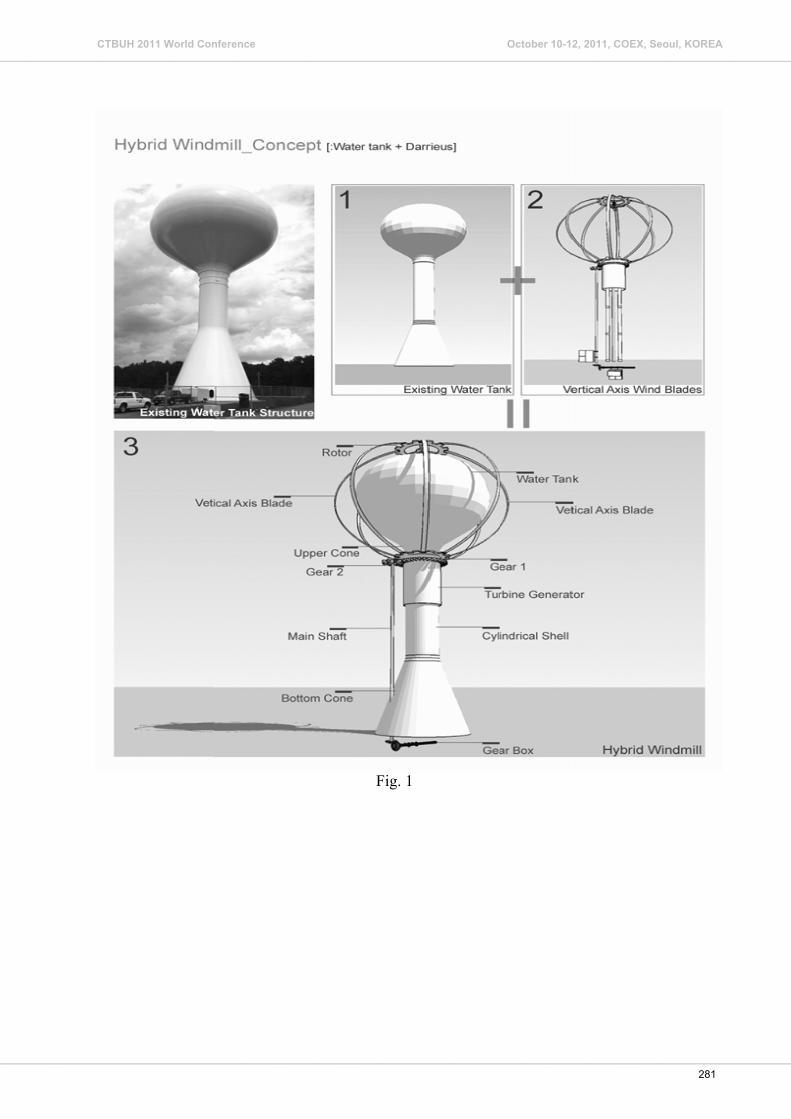
Fig. 1
281
CTBUH 2011 World Conference October 10-12, 2011, COEX, Seoul, KOREA_____________________________________________________________________________________________________________________________________________________________
______________________________________________________________________________________________________________________________________________________________

Fig.2
282
CTBUH 2011 World Conference October 10-12, 2011, COEX, Seoul, KOREA_____________________________________________________________________________________________________________________________________________________________
______________________________________________________________________________________________________________________________________________________________
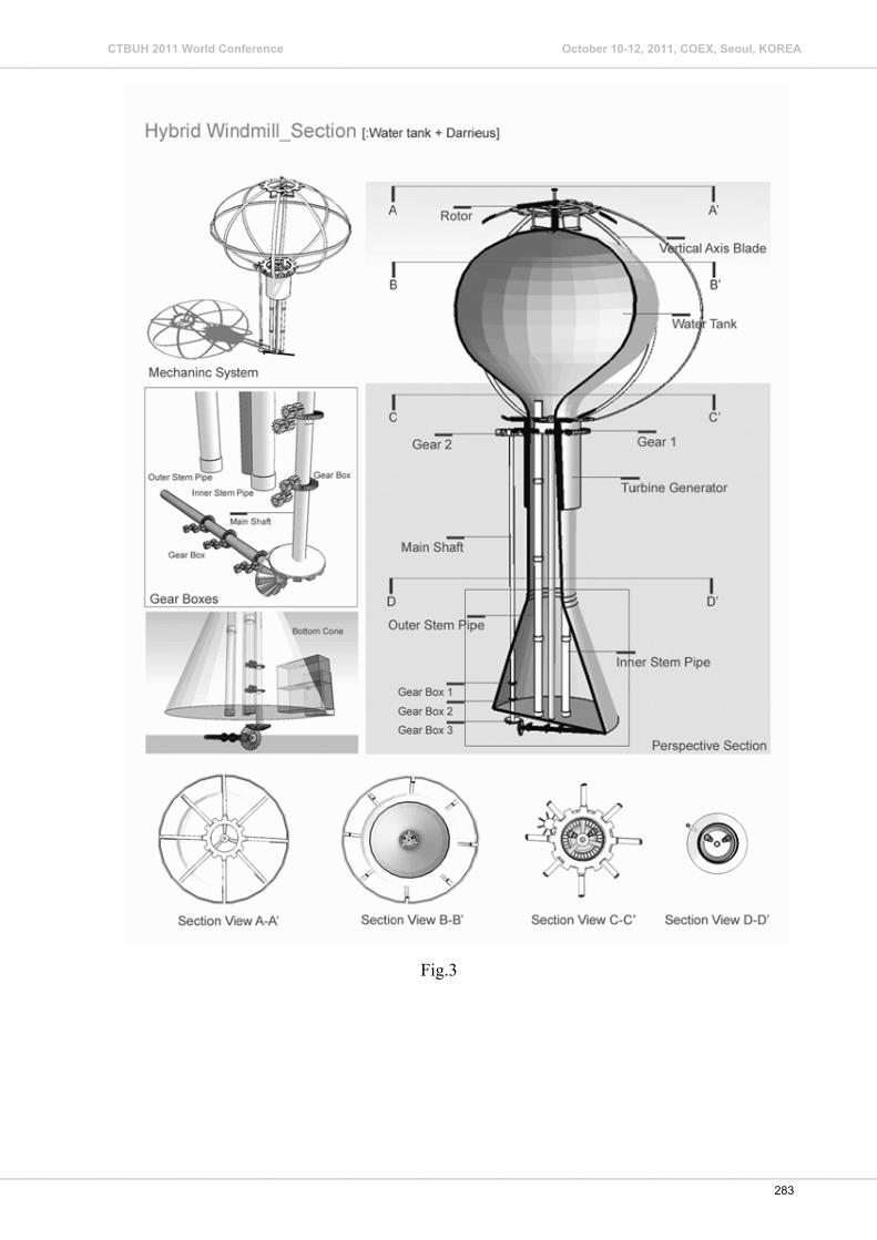
Fig.3
283
CTBUH 2011 World Conference October 10-12, 2011, COEX, Seoul, KOREA_____________________________________________________________________________________________________________________________________________________________
______________________________________________________________________________________________________________________________________________________________

Fig. 4
284
CTBUH 2011 World Conference October 10-12, 2011, COEX, Seoul, KOREA_____________________________________________________________________________________________________________________________________________________________
______________________________________________________________________________________________________________________________________________________________

285
CTBUH 2011 World Conference October 10-12, 2011, COEX, Seoul, KOREA_____________________________________________________________________________________________________________________________________________________________
______________________________________________________________________________________________________________________________________________________________

Figure 7
Curves of a/b ratio against integrated torque
0
100
200
300
400
500
600
0 1 2 3 4
a/b ratio
integrated torque
286
CTBUH 2011 World Conference October 10-12, 2011, COEX, Seoul, KOREA_____________________________________________________________________________________________________________________________________________________________
______________________________________________________________________________________________________________________________________________________________

Appendix 1 The integration of torque stress on elliptical blade could be as follows:
T pxdA= ∫ (1)
The shape of the elliptical blade could be described by elliptical parameter equation: cossin
x ay b
θθ
= ⋅⎧⎨ = ⋅⎩
(2)
Then the integration procedures could be as follows, from (1), we can get: 2
04 1 '
aT px y dx= ⋅ +∫ (3)
Then substitute (2) into (3),
( )2 20
2 22
cos4 cos 1 sinsin
bT p a a daπ
θθ θ θθ
= ⋅ + ⋅ ⋅ ⋅ −∫ (4)
After some transformation, we can get:
( )0 2 2 2 2
2
4 sin sinT p a a b b dπ θ θ= − − +∫ (5)
Let t denote sin θ here, (0,1)t ∈ , substitute t into (5), then it could be:
( )1 2 2 2 2
04T p a a b t b dt= − − +∫ (6)
After transformation, the final integration form has been obtained as follow:
2 2 22 2 2 2
2 2 2 2 2 2
114 ln
2 20
t b b bT p a a b t t ta b a b a b
⎡ ⎤⎛ ⎞⎢ ⎥= ⋅ ⋅ − ⋅ + + ⋅ ⋅ + +⎜ ⎟⎜ ⎟− − −⎢ ⎥⎝ ⎠⎣ ⎦
(7)
287
CTBUH 2011 World Conference October 10-12, 2011, COEX, Seoul, KOREA_____________________________________________________________________________________________________________________________________________________________
______________________________________________________________________________________________________________________________________________________________
Related Documents


