CHEMICAL ENGINEERING TRANSACTIONS VOL. 56, 2017 A publication of The Italian Association of Chemical Engineering Online at www.aidic.it/cet Guest Editors: Jiří Jaromír Klemeš, Peng Yen Liew, Wai Shin Ho, Jeng Shiun Lim Copyright © 2017, AIDIC Servizi S.r.l., ISBN 978-88-95608-47-1; ISSN 2283-9216 Wind Energy Harvesting from Wind-Induced Vibration Nurshafinaz Mohd Maruai*, Mohamed Sukri Mat Ali, Mohamad Hafiz Ismail, Nor Aniezan Mohd Ihsan, Farah Nurhanis Hassan Sadzli, Sheikh Ahmad Zaki Shaikh Salim Wind Engineering for Urban, Artificial, Man-made Environment, Malaysia-Japan International Institute of Technology (MJIIT), Universiti Teknologi Malaysia, 54100 Kuala Lumpur, Malaysia [email protected] Wind power is a clean energy source and alternative to the non-renewable type of energy sources. One of the challenges in utilizing wind energy is to efficiently harvest the wind energy into a usable electrical power, especially in the regions with low wind speed. This study aims to assess the possibility of harvesting wind energy by using the concept of flow induced vibration of a bluff body. A thin flat plate is introduced downstream of the cylinder as a simple but effective passive wind control. Three conditions have been tested to evaluate its effects on wind energy harvesting: isolated cylinder, flat plate with vibrating cylinder and cylinder with vibrating flat plate. The wind-body interaction is simulated using mesh motion technique available in OpenFOAM, an open source code for Computational Fluid Dynamics, while the harvested energy is calculated based on the work done by the single degree of freedom (SDOF) vibrating body. The study found that the vibrating cylinder with flat plate harvests more energy than the isolated cylinder and the fixed cylinder with vibrating flat plate for a relatively wider range of wind speeds. This is due to the generated transverse force on the cylinder is higher than the transverse force generated on the flat plate. The highest energy produced by the vibrating cylinder with a flat plate is Pgen = 86.97 mW at reduced velocity, UR = 11, which is 4 times larger than for isolated cylinder with Pgen = 24.50 mW at UR = 20. For the case of a cylinder with vibrating flat plate, the energy produced is very small with Pgen = 0.6972 mW at UR = 10. The energy produced by the vibrating body is closely related not only to the wind velocity and vibration amplitude but also highly dependent on the rate at which the vibration occurs (frequency) and the phase difference between vibration and the generated force on the body. In the present study, the vibrating cylinder with flat plate appears to be the best configuration to harvest wind energy compared to the other configurations at reduced velocity UR = (9-11). 1. Introduction The demand for sustainable and renewable energy is escalated with the increasing utilization of electronic devices over the years (Kausar et al., 2014). Nowadays, the deployment of electronic devices especially sensors has become a necessity not only for vehicle systems and medical appliances but also in engineering structures. Structural health monitoring system is one of the most benefited sectors from the advances of technology in these sensors (Balageas et al., 2006). The development of high-rise buildings, bridges, and pipeline risers are equipped with these sensors for their health monitoring purposes. Currently, the main power source for the sensors is the conventional battery, which has finite lifespan. The issue arises from this nature is the cost for maintenance of battery replacement and also the disposal of that used battery is expected to worsen the land and water pollution. Hence, it is important to provide a clean energy to empower these sensors. One of the most promising resource of clean energy with very low environmentally impact is wind energy (Oh et al., 2010). Wind energy appears as one of the solution to the problem regarding the issues related to reducing the battery usage as the main source power for sensors (Seah et al., 2011). The conventional wind turbine has always been associated with the wind energy harvesting and the miniaturization of it has also been attempted to suit the application of small electronic devices (Howey et al., 2011). This current study, however, intends to introduce another means of harvesting the wind energy, which is from flow-induced vibration. Flow-induced vibration (FIV) is originally one of the undesirable instabilities that concern the aerodynamicist since a decade ago (King, 1977). DOI: 10.3303/CET1756076 Please cite this article as: Mohd Maruai N., Ali M.S.M., Ismail M.H., Mohd Ihsan N.A., Sadzli F.N.H., Salim S.A.Z.S., 2017, Wind energy harvesting from wind-induced vibration, Chemical Engineering Transactions, 56, 451-456 DOI:10.3303/CET1756076 451

Welcome message from author
This document is posted to help you gain knowledge. Please leave a comment to let me know what you think about it! Share it to your friends and learn new things together.
Transcript
CHEMICAL ENGINEERING TRANSACTIONS
VOL. 56, 2017
A publication of
The Italian Association of Chemical Engineering Online at www.aidic.it/cet
Guest Editors: Jiří Jaromír Klemeš, Peng Yen Liew, Wai Shin Ho, Jeng Shiun Lim Copyright © 2017, AIDIC Servizi S.r.l.,
ISBN 978-88-95608-47-1; ISSN 2283-9216
Wind Energy Harvesting from Wind-Induced Vibration
Nurshafinaz Mohd Maruai*, Mohamed Sukri Mat Ali, Mohamad Hafiz Ismail,
Nor Aniezan Mohd Ihsan, Farah Nurhanis Hassan Sadzli, Sheikh Ahmad Zaki
Shaikh Salim
Wind Engineering for Urban, Artificial, Man-made Environment, Malaysia-Japan International Institute of Technology
(MJIIT), Universiti Teknologi Malaysia, 54100 Kuala Lumpur, Malaysia
Wind power is a clean energy source and alternative to the non-renewable type of energy sources. One of the
challenges in utilizing wind energy is to efficiently harvest the wind energy into a usable electrical power,
especially in the regions with low wind speed. This study aims to assess the possibility of harvesting wind energy
by using the concept of flow induced vibration of a bluff body. A thin flat plate is introduced downstream of the
cylinder as a simple but effective passive wind control. Three conditions have been tested to evaluate its effects
on wind energy harvesting: isolated cylinder, flat plate with vibrating cylinder and cylinder with vibrating flat plate.
The wind-body interaction is simulated using mesh motion technique available in OpenFOAM, an open source
code for Computational Fluid Dynamics, while the harvested energy is calculated based on the work done by
the single degree of freedom (SDOF) vibrating body. The study found that the vibrating cylinder with flat plate
harvests more energy than the isolated cylinder and the fixed cylinder with vibrating flat plate for a relatively
wider range of wind speeds. This is due to the generated transverse force on the cylinder is higher than the
transverse force generated on the flat plate. The highest energy produced by the vibrating cylinder with a flat
plate is Pgen = 86.97 mW at reduced velocity, UR = 11, which is 4 times larger than for isolated cylinder with Pgen
= 24.50 mW at UR = 20. For the case of a cylinder with vibrating flat plate, the energy produced is very small
with Pgen = 0.6972 mW at UR = 10. The energy produced by the vibrating body is closely related not only to the
wind velocity and vibration amplitude but also highly dependent on the rate at which the vibration occurs
(frequency) and the phase difference between vibration and the generated force on the body. In the present
study, the vibrating cylinder with flat plate appears to be the best configuration to harvest wind energy compared
to the other configurations at reduced velocity UR = (9-11).
1. Introduction
The demand for sustainable and renewable energy is escalated with the increasing utilization of electronic
devices over the years (Kausar et al., 2014). Nowadays, the deployment of electronic devices especially sensors
has become a necessity not only for vehicle systems and medical appliances but also in engineering structures.
Structural health monitoring system is one of the most benefited sectors from the advances of technology in
these sensors (Balageas et al., 2006). The development of high-rise buildings, bridges, and pipeline risers are
equipped with these sensors for their health monitoring purposes. Currently, the main power source for the
sensors is the conventional battery, which has finite lifespan. The issue arises from this nature is the cost for
maintenance of battery replacement and also the disposal of that used battery is expected to worsen the land
and water pollution. Hence, it is important to provide a clean energy to empower these sensors. One of the most
promising resource of clean energy with very low environmentally impact is wind energy (Oh et al., 2010).
Wind energy appears as one of the solution to the problem regarding the issues related to reducing the battery
usage as the main source power for sensors (Seah et al., 2011). The conventional wind turbine has always
been associated with the wind energy harvesting and the miniaturization of it has also been attempted to suit
the application of small electronic devices (Howey et al., 2011). This current study, however, intends to introduce
another means of harvesting the wind energy, which is from flow-induced vibration. Flow-induced vibration (FIV)
is originally one of the undesirable instabilities that concern the aerodynamicist since a decade ago (King, 1977).
DOI: 10.3303/CET1756076
Please cite this article as: Mohd Maruai N., Ali M.S.M., Ismail M.H., Mohd Ihsan N.A., Sadzli F.N.H., Salim S.A.Z.S., 2017, Wind energy harvesting from wind-induced vibration, Chemical Engineering Transactions, 56, 451-456 DOI:10.3303/CET1756076
451
The interaction of flow over an elastic bluff body leads to a significant transverse motion when the natural
frequency of the body coincides with the frequency of the motion. Many efforts have been put into suppressing
and mitigating this phenomenon as it may cause the destruction of structures (Kawabata and Takahashi, 2013).
Due to the advancing technology of sensors the responsibility to maximize the utilization of ambient resources
is challenging. Numerous studies have been conducted to prove the feasibility of FIV as a mean of new wind
energy harvesting. Intensive studies of FIV from water flow by Bernitsas et al. (2008) have been conducted
using a circular cylinder with passive turbulence control. Jung et al. (2011), on the other hand, exploit the concept
of wake galloping to harvest the wind energy for bridge monitoring system. Other researchers, which have also
exhibit interesting findings in harvesting the energy utilizing FIV are Koide et al. (2011) and Weinstein et al.
(2012).
This current study aims to assess the possibility of harvesting the wind energy using a square cylinder and a
flat plate, separately or both in tandem. A square cylinder is susceptible to both vortex-induced vibration (VIV)
and galloping or pure galloping (Parkinson and Brooks, 1961). The behaviour of FIV is highly dependent on the
damping of the body. High damping body excites earlier than the light damped body and has the VIV feature,
which appears to be more appropriate for the harvesting purpose. It is very important to be able to harvest
energy at low wind speed especially in a country with the tropical climate like Malaysia, which is experiencing
average wind velocity 0-2 ms-1. A body with relatively high damping ratio is numerically investigated to predict
the body excitation that consequently affects the energy extracted from FIV.
2. Numerical Approach
In this paper, flow simulations are conducted by an open source software of Computational Fluid Dynamics
(CFD), OpenFOAM. The flow is modelled based on the conversion law of mass in predefined volume. The flow
solutions are retrieved using the Unsteady Reynolds Averaged Navier-Stokes (URANS) equations. Following
Menter (1994) the turbulence model of SST (k-ω) is deployed to determine the stress tensor and consequently
the Navier-Stokes (N-S) equations is solved. Here an incompressible air flow is considered. The inlet is set with
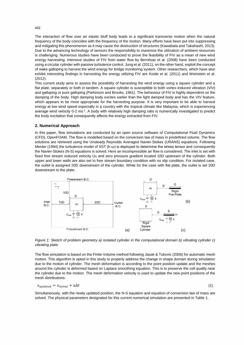
fixed free stream reduced velocity UR and zero pressure gradient located 10D upstream of the cylinder. Both
upper and lower walls are also set to free stream boundary condition with no slip condition. For isolated case,
the outlet is assigned 20D downstream of the cylinder. While for the case with flat plate, the outlet is set 20D
downstream to the plate.
(a)
(b)
(c)
Figure 1: Sketch of problem geometry a) isolated cylinder in the computational domain b) vibrating cylinder c)
vibrating plate.
The flow simulation is based on the Finite Volume method following Jasak & Tukovic (2006) for automatic mesh
motion. This algorithm is opted in this study to properly address the change in shape domain during simulation
due to the motion of cylinder. The mesh deformation is according to the point position update and the meshes
around the cylinder is deformed based on Laplace smoothing equation. This is to preserve the cell quality near
the cylinder due to the motion. The mesh deformation velocity is used to update the new point positions of the
mesh distributions:
𝑥𝑢𝑝𝑑𝑎𝑡𝑒𝑑 = 𝑥𝑖𝑛𝑖𝑡𝑖𝑎𝑙 + 𝑢Δ𝑡 (1)
Simultaneously, with the newly updated position, the N-S equation and equation of conversion law of mass are
solved. The physical parameters designated for this current numerical simulation are presented in Table 1.
452
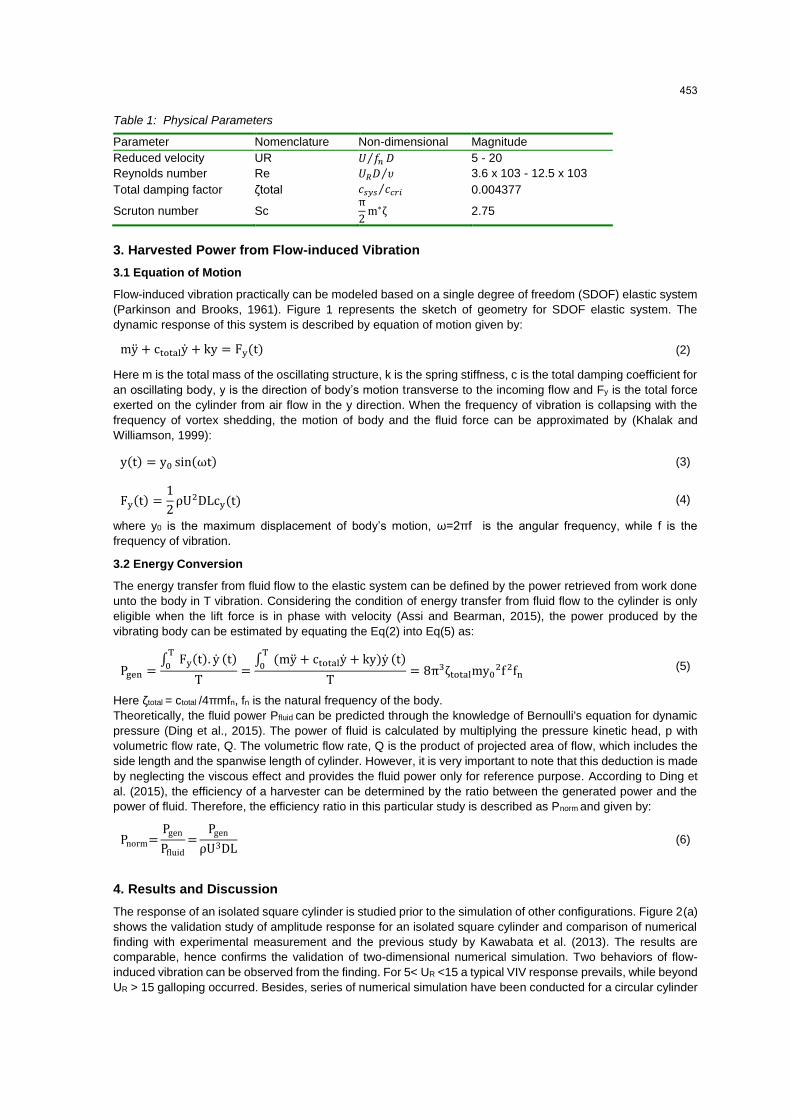
Table 1: Physical Parameters
Parameter Nomenclature Non-dimensional Magnitude
Reduced velocity UR 𝑈 𝑓𝑛⁄ 𝐷 5 - 20
Reynolds number Re 𝑈𝑅𝐷 𝜐⁄ 3.6 x 10³ - 12.5 x 10³
Total damping factor ζtotal 𝑐𝑠𝑦𝑠 𝑐𝑐𝑟𝑖⁄ 0.004377
Scruton number Sc π
2m∗ζ 2.75
3. Harvested Power from Flow-induced Vibration
3.1 Equation of Motion
Flow-induced vibration practically can be modeled based on a single degree of freedom (SDOF) elastic system
(Parkinson and Brooks, 1961). Figure 1 represents the sketch of geometry for SDOF elastic system. The
dynamic response of this system is described by equation of motion given by:
my + ctotaly + ky = Fy(t) (2)
Here m is the total mass of the oscillating structure, k is the spring stiffness, c is the total damping coefficient for
an oscillating body, y is the direction of body’s motion transverse to the incoming flow and Fy is the total force
exerted on the cylinder from air flow in the y direction. When the frequency of vibration is collapsing with the
frequency of vortex shedding, the motion of body and the fluid force can be approximated by (Khalak and
Williamson, 1999):
y(t) = y0 sin(ωt) (3)
Fy(t) =1
2ρU2DLcy(t) (4)
where y0 is the maximum displacement of body’s motion, ω=2πf is the angular frequency, while f is the
frequency of vibration.
3.2 Energy Conversion
The energy transfer from fluid flow to the elastic system can be defined by the power retrieved from work done
unto the body in T vibration. Considering the condition of energy transfer from fluid flow to the cylinder is only
eligible when the lift force is in phase with velocity (Assi and Bearman, 2015), the power produced by the
vibrating body can be estimated by equating the Eq(2) into Eq(5) as:
Pgen =∫ Fy(t). y
T
0(t)
T=
∫ (my + ctotaly + ky)yT
0(t)
T= 8π3ζtotalmy0
2f 2fn (5)
Here ζtotal = ctotal /4πmfn, fn is the natural frequency of the body.
Theoretically, the fluid power Pfluid can be predicted through the knowledge of Bernoulli's equation for dynamic
pressure (Ding et al., 2015). The power of fluid is calculated by multiplying the pressure kinetic head, p with
volumetric flow rate, Q. The volumetric flow rate, Q is the product of projected area of flow, which includes the
side length and the spanwise length of cylinder. However, it is very important to note that this deduction is made
by neglecting the viscous effect and provides the fluid power only for reference purpose. According to Ding et
al. (2015), the efficiency of a harvester can be determined by the ratio between the generated power and the
power of fluid. Therefore, the efficiency ratio in this particular study is described as Pnorm and given by:
Pnorm=Pgen
Pfluid
=Pgen
ρU3DL (6)
4. Results and Discussion
The response of an isolated square cylinder is studied prior to the simulation of other configurations. Figure 2(a)
shows the validation study of amplitude response for an isolated square cylinder and comparison of numerical
finding with experimental measurement and the previous study by Kawabata et al. (2013). The results are
comparable, hence confirms the validation of two-dimensional numerical simulation. Two behaviors of flow-
induced vibration can be observed from the finding. For 5< UR <15 a typical VIV response prevails, while beyond
UR > 15 galloping occurred. Besides, series of numerical simulation have been conducted for a circular cylinder
453
for comparison with the VIV response of square cylinder. The magnitude of amplitude response for circular
cylinder evidently is very low and did not surpass the amplitude response of the square cylinder. Theoretically,
a square cylinder is more appropriate geometry for the harvesting purpose. Figure 2(b) shows the comparison
of the amplitude response of the three configurations. The vibrating cylinder with flat plate has significant high
amplitude compared to the isolated case and vibrating plate. The root-mean-square (rms) of the transverse
amplitude reached the highest at UR = 10.3 with yrms/D = 0.145. While for the case of vibrating plate, the vibration
is very low and nearly suppressed.
a) Preliminary study of an isolated cylinder. b) Comparison of the three configurations.
Figure 2: Amplitude responses of flow-induced vibration.
The dominant frequency of vibration is determined based on the Fast Fourier Transform (FFT) equation. The
results for all configurations are plotted in Figure 3. An abrupt collapse of frequency pattern for the isolated
cylinder at UR = 15 confirms the galloping behavior. Starting from that point onwards, the amplitude of vibration
is increased significantly (see Figure 2(b)). The lock-in synchronization is well observed within a relatively wider
range for vibrating cylinder with a flat plate at 9 < UR < 11 as compared to two other cases. Although for isolated
cylinder, the lock-in behavior is very remarkable at high velocity but it is important to note that the purpose of
this current study is to find the best configuration to harvest the energy from a relatively low velocity. Hence, an
isolated vibrating cylinder alone is not competent to harvest useful energy at the low-speed region.
The energy transfer between the fluid force and vibrating body can be assessed by the phase lag between them.
Figure 4 shows the phase lag between the displacement of the body and vortex shedding. According to Assi
and Bearman (2015), the vibration occurs only when the phase lag between 0o and 180o and therefore the
energy transfer is permissible. For vibrating cylinder with a flat plate, the phase lag is increasing with reduced
velocity in the VIV lock-in region, while for isolated cylinder the phase lag efficiently increases in the galloping
region.
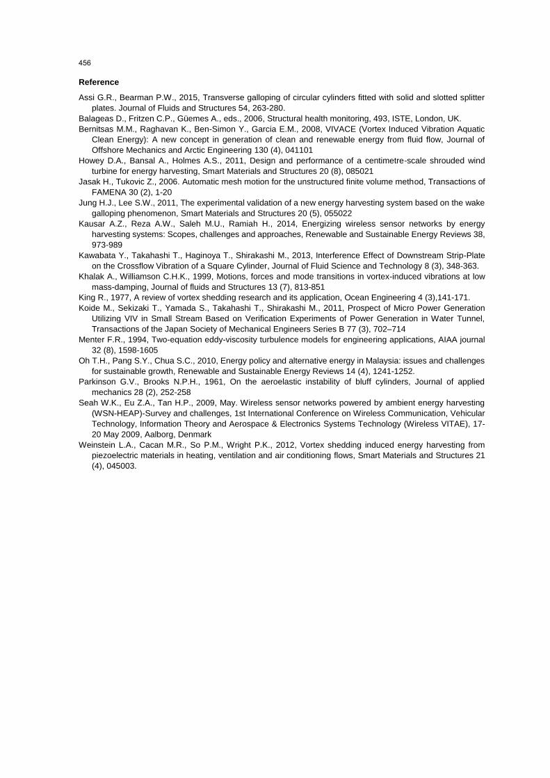
The expected power to be accessible for harvesting purpose from these configurations are calculated based on
Eq(5). All results are plotted in Figure 5. The pattern of power response over reduced velocity is in accordance
with the amplitude response for VIV response. The accessible power is increased with the reduced velocity, UR
during VIV lock-in synchronization. Vibrating cylinder with plate configuration shows the highest accessible
power Pgen = 86.97 mW at UR = 11. Whereas for isolated cylinder and vibrating plate a very low power is expected
to be harvested in comparison with the vibrating cylinder with a flat plate. Figure 6 shows the comparison of
harvester efficiency between the three considered configurations.
Based on the amplitude response in Figure 1(b) the accessible power in the galloping region for an isolated
cylinder is theoretically anticipated to be higher than during the VIV lock-in. Although it has met the expectation
of generating relatively more energy during that region, the efficiency ratio is lower than in the VIV region. Figure
6 has shown that it is more efficient to harvest the energy within the VIV region than galloping for an isolated
cylinder. This is also favorable for low wind speed condition due to the nature of galloping, which requires high
onset speed (Jung et al., 2011). In contrast, the cylinder with vibrating flat plate has very low potential to generate
electricity compared to other configurations. Nevertheless, flat plate has been a popular geometry for the
piezoelectric harvester. Owing to its robust shape, the demand for this type of harvester is increasing by year
for monitoring purpose (Weinstein et al., 2012). On the other hand, the vibrating cylinder with a flat plate is
observed as a good prospect to harvest an ample useful energy for low wind speed condition. This configuration
is not only feasible to harvest comparatively more energy but also scores high in efficiency.
454
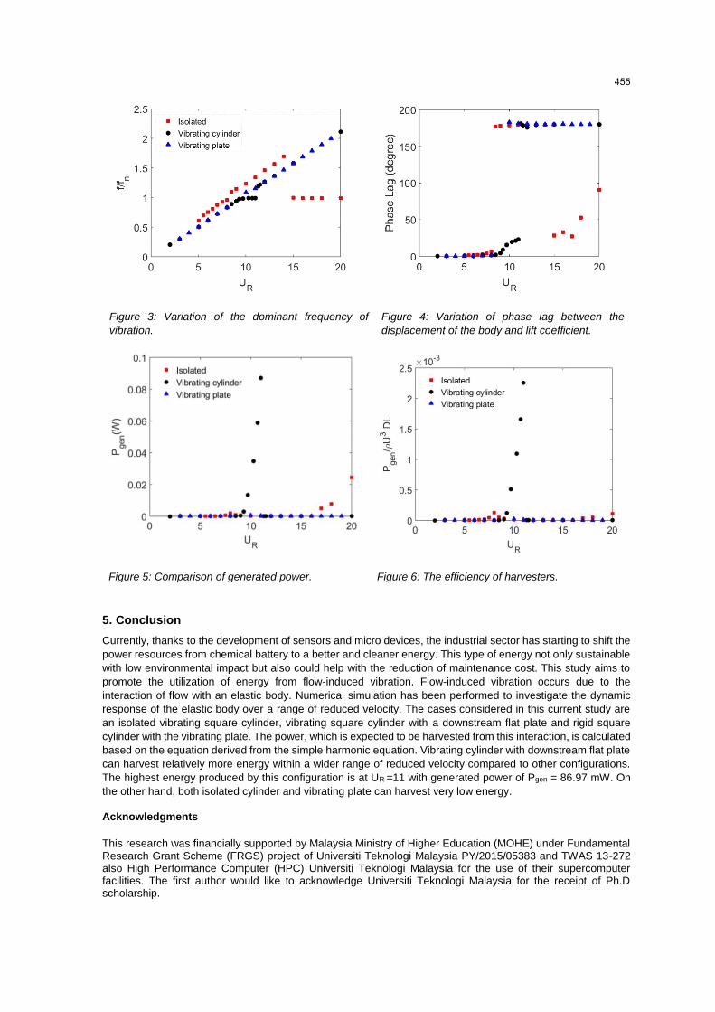
Figure 3: Variation of the dominant frequency of
vibration.
Figure 4: Variation of phase lag between the
displacement of the body and lift coefficient.
Figure 5: Comparison of generated power. Figure 6: The efficiency of harvesters.
5. Conclusion
Currently, thanks to the development of sensors and micro devices, the industrial sector has starting to shift the
power resources from chemical battery to a better and cleaner energy. This type of energy not only sustainable
with low environmental impact but also could help with the reduction of maintenance cost. This study aims to
promote the utilization of energy from flow-induced vibration. Flow-induced vibration occurs due to the
interaction of flow with an elastic body. Numerical simulation has been performed to investigate the dynamic
response of the elastic body over a range of reduced velocity. The cases considered in this current study are
an isolated vibrating square cylinder, vibrating square cylinder with a downstream flat plate and rigid square
cylinder with the vibrating plate. The power, which is expected to be harvested from this interaction, is calculated
based on the equation derived from the simple harmonic equation. Vibrating cylinder with downstream flat plate
can harvest relatively more energy within a wider range of reduced velocity compared to other configurations.
The highest energy produced by this configuration is at UR =11 with generated power of Pgen = 86.97 mW. On
the other hand, both isolated cylinder and vibrating plate can harvest very low energy.
Acknowledgments
This research was financially supported by Malaysia Ministry of Higher Education (MOHE) under Fundamental Research Grant Scheme (FRGS) project of Universiti Teknologi Malaysia PY/2015/05383 and TWAS 13-272 also High Performance Computer (HPC) Universiti Teknologi Malaysia for the use of their supercomputer facilities. The first author would like to acknowledge Universiti Teknologi Malaysia for the receipt of Ph.D scholarship.
455
Reference
Assi G.R., Bearman P.W., 2015, Transverse galloping of circular cylinders fitted with solid and slotted splitter
plates. Journal of Fluids and Structures 54, 263-280.
Balageas D., Fritzen C.P., Güemes A., eds., 2006, Structural health monitoring, 493, ISTE, London, UK.
Bernitsas M.M., Raghavan K., Ben-Simon Y., Garcia E.M., 2008, VIVACE (Vortex Induced Vibration Aquatic
Clean Energy): A new concept in generation of clean and renewable energy from fluid flow, Journal of
Offshore Mechanics and Arctic Engineering 130 (4), 041101
Howey D.A., Bansal A., Holmes A.S., 2011, Design and performance of a centimetre-scale shrouded wind
turbine for energy harvesting, Smart Materials and Structures 20 (8), 085021
Jasak H., Tukovic Z., 2006. Automatic mesh motion for the unstructured finite volume method, Transactions of
FAMENA 30 (2), 1-20
Jung H.J., Lee S.W., 2011, The experimental validation of a new energy harvesting system based on the wake
galloping phenomenon, Smart Materials and Structures 20 (5), 055022
Kausar A.Z., Reza A.W., Saleh M.U., Ramiah H., 2014, Energizing wireless sensor networks by energy
harvesting systems: Scopes, challenges and approaches, Renewable and Sustainable Energy Reviews 38,
973-989
Kawabata Y., Takahashi T., Haginoya T., Shirakashi M., 2013, Interference Effect of Downstream Strip-Plate
on the Crossflow Vibration of a Square Cylinder, Journal of Fluid Science and Technology 8 (3), 348-363.
Khalak A., Williamson C.H.K., 1999, Motions, forces and mode transitions in vortex-induced vibrations at low
mass-damping, Journal of fluids and Structures 13 (7), 813-851
King R., 1977, A review of vortex shedding research and its application, Ocean Engineering 4 (3),141-171.
Koide M., Sekizaki T., Yamada S., Takahashi T., Shirakashi M., 2011, Prospect of Micro Power Generation
Utilizing VIV in Small Stream Based on Verification Experiments of Power Generation in Water Tunnel,
Transactions of the Japan Society of Mechanical Engineers Series B 77 (3), 702–714
Menter F.R., 1994, Two-equation eddy-viscosity turbulence models for engineering applications, AIAA journal
32 (8), 1598-1605
Oh T.H., Pang S.Y., Chua S.C., 2010, Energy policy and alternative energy in Malaysia: issues and challenges
for sustainable growth, Renewable and Sustainable Energy Reviews 14 (4), 1241-1252.
Parkinson G.V., Brooks N.P.H., 1961, On the aeroelastic instability of bluff cylinders, Journal of applied
mechanics 28 (2), 252-258
Seah W.K., Eu Z.A., Tan H.P., 2009, May. Wireless sensor networks powered by ambient energy harvesting
(WSN-HEAP)-Survey and challenges, 1st International Conference on Wireless Communication, Vehicular
Technology, Information Theory and Aerospace & Electronics Systems Technology (Wireless VITAE), 17-
20 May 2009, Aalborg, Denmark
Weinstein L.A., Cacan M.R., So P.M., Wright P.K., 2012, Vortex shedding induced energy harvesting from
piezoelectric materials in heating, ventilation and air conditioning flows, Smart Materials and Structures 21
(4), 045003.
456
Related Documents
![Hybrid Solar-Wind Energy Harvesting for Embedded ...gsharma/papers/HadiHybSolarWindH… · range can be powered from piezoelectric [21], thermal [22], microbial [23], RF [24], wind](https://static.cupdf.com/doc/110x72/5f203788f639433c210df263/hybrid-solar-wind-energy-harvesting-for-embedded-gsharmapapershadihybsolarwindh.jpg)


