Migration from WiMAX Release 1 to WiMAX Release 2 August 2010

WiMAX Migration From Release 1 to Release 2
Sep 14, 2014
Welcome message from author
This document is posted to help you gain knowledge. Please leave a comment to let me know what you think about it! Share it to your friends and learn new things together.
Transcript

Migration from
WiMAX Release 1 to WiMAX Release 2
August 2010

Migration from WiMAX Release 1 to WiMAX Release 2
2 of 12
Table of Contents Migration from WiMAX Release 1 to WiMAX Release 2 ....................................................................... 1
1. Introduction .................................................................................................................................... 3
2. Network Planning Recommendations ............................................................................................ 3
3. Support of Release 1 Terminals .................................................................................................... 4
4. Transition Phases .......................................................................................................................... 4
5. Migration Scenarios ....................................................................................................................... 5
5.1. Migration from Reuse 3 (1x3x3, 3x10 MHz) ........................................................................... 7 5.2. Migration from Reuse 1 (1x3x1, 2x10 MHz overlay) ............................................................... 8
5.3. Migration from Reuse 2 (1x4x2, 2x10 MHz) ........................................................................... 9
6. Performance enhancement during migration from WiMAX Release 1 to WiMAX Release 2 ....... 11
7. References .................................................................................................................................. 12
Appendix A: Frequency Planning Options for 20 MHz Initial Allocation ........................................... 12
Table of Figures Figure 1. Same carrier migration (mixed mode) .................................................................................... 5
Figure 2. Migration to Release 2 with addition of 10 MHz channel ....................................................... 6
Figure 3. Migration from Reuse 3 with addition of 10 MHz channel ...................................................... 7
Figure 4. Migration from Reuse 3 with addition of 20 MHz channel ...................................................... 8
Figure 5. Migration from Reuse 1 with addition of 10 MHz channel ...................................................... 8
Figure 6. Migration from Reuse 1 with addition of 20 MHz channel ...................................................... 9
Figure 7. Migration from Reuse 2 with addition of 10 MHz channel .................................................... 10
Figure 8. Migration from Reuse 2 with addition of 20 MHz channel .................................................... 10
Figure 9. Mixed mode performance of Release 1 and Release 2 ....................................................... 11
Figure 10. (A) 4-Sector – 1x4x2, (B) 3-Sector – 2x3x2, (C) 3-Sector – 1x3x1 .................................... 12

Migration from WiMAX Release 1 to WiMAX Release 2
3 of 12
1. Introduction
The WiMAX Forum is accelerating its development efforts to produce Release 2 equipment based on the
upcoming IEEE Standard 802.16m [1]. The new release will offer significant coverage and capacity
improvements over WiMAX Release 1. The development timeline for Release 2 targets early engineering trials
by mid-2011, with WiMAX Forum certification of equipment by the end of 2011, early commercial availability by
mid-2012, and general commercial availability with rich terminal offerings in 2013. Release 2 service offers a
low-cost solution with seamless migration from Release 1 [1][2]. The Release 2 base station (BS) will provide
full support for Release 1 terminals already deployed using the Release 1 network.
This paper provides basic recommendations for migration from Release 1 to Release 2, assuming that the
migration starts from specific typical WiMAX network deployment scenarios.
2. Network Planning Recommendations
A WiMAX Release 2 system has better cell coverage than one based on Release 1. Therefore, no major
network planning redesign, such as changes to BS location and antenna height, is required. Also, the BS
antenna subsystem and installations, such as cabling, antennas and power amplifiers, will be fully reusable
with minor or no change for Release 2. Core network elements, such as servers and access server network
(ASN) gateways, can be reused with Release 2. The main change will be to swap the channel cards and
perform some software upgrades in certain units. No more than 5% incremental capital expenditure for
migrating from Release 1 to Release 2 is expected.
Fractional frequency reuse (FFR) and segmentation functionality are supported by the Release 2
subchannelization mechanism. Therefore, Release 2 BSs support various sectorization schemes, such as 3-
and 4-sector configurations, while at the same time supporting Reuse 1 operation.
No new coexistence issues will arise between WiMAX networks of the same operator or different operators
(Release 2 – Release 2, or Release 1 – Release 2), as long as reasonable coordination of parameters
between the networks is maintained. As is typically the case for WiMAX Release 1 networks, coordination with
regards to WiMAX frame alignment (including matching downlink-to-uplink ratio), control and data zone
Migration from WiMAX Release 1 to WiMAX Release 2
4 of 12
alignment, and segmentation zone alignment (FFR case) should be sufficient for providing same coexistence
results in the case of Release 2.
3. Support of Release 1 Terminals
A variety of Release 1 terminals have been widely deployed and are operational in more than hundred
WiMAX network deployments worldwide. All Release 1 terminals will operate in the new Release 2 network
without performance degradation since Release 2 networks are backward compatible to Release 1 and all
Release 1 terminals are interoperable in Release 2 networks. Some Release 1 terminals may be capable of
supporting two or more radio access technologies (RATs), such as Wi-Fi, 2G, 3G, EVDO and 3GPP LTE. We
do not expect new inter-RAT issues caused by the migration from Release 1 to Release 2.
The terminals in a Release 2 network can be classified into three categories:
• Cat 1: Supports Release 1 functionality only (but can work in a Release 2 network)
• Cat 2: These devices are Release 2 devices that are backward compatible to Release 1 and can
operate in Release 1 mode.
• Cat 3: Can support only Release 2 functionality
4. Transition Phases
This section addresses transition phases for migration to Release 2. The assumption here is that no
additional spectrum is allocated for the migration. Operators can start transitioning existing Release 1 BSs to
Release 2 BSs one BS at a time. Both Release 1 and Release 2 BSs can coexist in the same network during
the transition process. Release 2 BSs are configured to support a mix of Cat 1, Cat 2 and Cat 3 terminals.
Transition to Release 2 can be done with minimum down time. In most cases, the only change will be
swapping a Release 1 channel card with a Release 2 channel card. All other equipment should be reusable
without any change or with only minor changes. Cat 1 terminals will naturally hand over to the legacy zone of
the BS. Cat 2 terminals would be in Release 1 mode prior to over the transition and will be signaled to move to
Release 2 mode afterwards. Cat 3 terminals can then be introduced when sufficient Release 2 BS coverage is
available.
Cat 1 and Cat 2 terminals can hand over and roam freely across the coexisting Release 1 and Release 2
networks. Cat 3 terminals cannot roam into areas without Release 2 coverage.
Once a segment of the network has fully transitioned to Release 2, Cat 1 terminals should be gradually
phased out. Once all Cat 1 terminals are phased out, the network should be re-tuned to a pure Release 2
operation.
Migration from WiMAX Release 1 to WiMAX Release 2
5 of 12
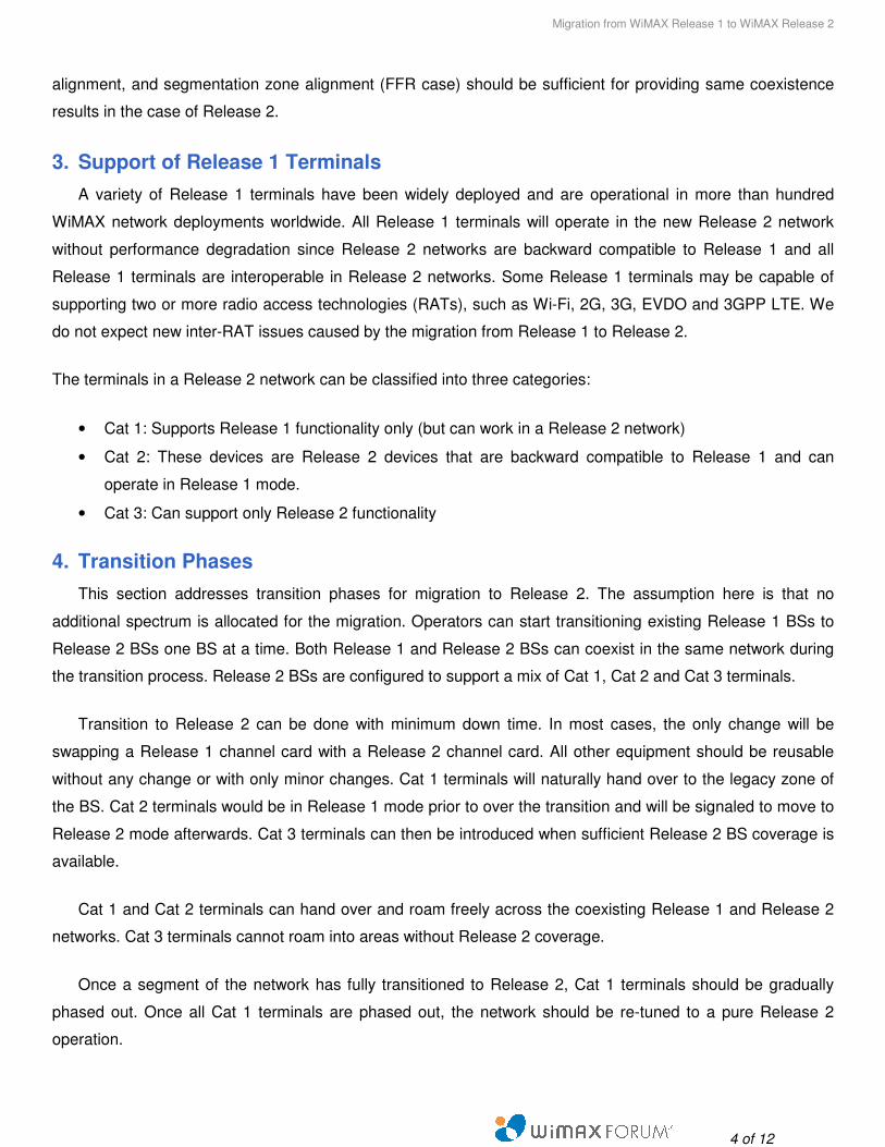
Figure 1. Same carrier migration (mixed mode)
Figure 1 shows the transition phases in the frame structure from only Release 1 to only Release 2 with an
intermediate phase in which both Release 1 and Release 2 terminals are supported. The resource partitioning
generally targets support for a mixture of terminal categories. Figure 1 illustrates a scenario in which three DL
subframes are allocated to Release 2 operation. During the mixed-mode stage, the BS needs to use the same
Release 1 UL PUSC subchannelization across Release 1 and Release 2 zones in order to guarantee the same
coverage for Release 1 terminals.
5. Migration Scenarios
In many cases, the migration is planned when additional spectrum is available for network capacity
improvement. A simple migration scenario of this type occurs when an additional RF carrier of 10 MHz
becomes available at the time of migration to Release 2 for a legacy Release 1 system based on a 10 MHz
channel used in a Reuse 3 configuration.
Figure 2 illustrates how terminals are served, in this case, by BSs before and after migration. Initially, only 10
MHz Release 1 terminals are operating in the network. As demand for service is increasing, one additional
10MHz channel can be used for migration expansion. In this scenario, the old 10 MHz channel is operating in
Release 1/Release 2 mixed mode and able to serve both Release 1 and Release 2 terminals. The new 10
MHz carrier is dedicated to Release 2 mode of operation only and serving the Release 2 terminals. For more
details on Release 2 support accommodating both legacy terminals and Release 2 terminals please see Figure
1.
Assuming that the two carriers use the same relevant frame configuration parameters, and DL/UL subframe
ratio of the two carriers are fully aligned, smooth transition can be done through utilization of a simple 10+10
Rel. 1
Rel.1/Rel.2
Rel. 2

Migration from WiMAX Release 1 to WiMAX Release 2
6 of 12
MHz multi-carrier operation supported in IEEE 802.16m. According to this scheme, there is no impact on
synchronization and no interference resulting from the new carrier. Moreover, from the viewpoint of legacy
Release 1 terminals, the upgraded system is fully backward compatible with Release 1.
Figure 2. Migration to Release 2 with addition of 10 MHz channel
Migration of a WiMAX Release 1 network, with various spectrum scenarios and reuse configurations, to
Release 2 is supported through IEEE 802.16m advanced multicarrier and mixed mode. WiMAX Release 2
defines various device categories primarily based on performance-based parameters targeting various peak
data rates in difference categories. In addition to performance-based parameters, such as total allocated
bandwidth and number of data streams, other parameters directly related to the operational scenarios, such as
number of aggregating carriers, intra/inter-band and contigious/non-contiguous configurations, are considered
as categorization parameters not directly related to the peak performance.
In the remainder of this section, a number of typical spectrum-related operational scenarios are identified and
migration recommendations related to those are described. More specifically, the following scenarios are
covered:
1. Migration from Reuse 3 (1x3x3, 3x10 MHz), additional 10 and 20 MHz slot 2. Migration from Reuse 1 (1x3x1, 2x10 MHz overlay), additional 10 and 20 MHz slot 3. Migration from Reuse 2 (1x4x2, 2x10 MHz), additional 10 and 20 MHz slot
An intra-band non-contiguous configuration is considered, without loss of generality. Also, additional allocation
sizes of larger than 20 MHz (in the case of Reuse 1 and 3) and larger than 10 MHz (in the case of Reuse 2)
are not covered. Those cases can be covered by simple generalization of other scenarios included here.
Migration scenarios with various Reuse factors without additional spectrum allocations are addressed in the
generic case covered in Section 4.

Migration from WiMAX Release 1 to WiMAX Release 2
7 of 12
5.1. Migration from Reuse 3 (1x3x3, 3x10 MHz)
Figure 3 shows the frame structure associated with migration from Reuse 3 when an additional 10 MHz
channel is available at the time of migration. Here, device categories with 10+10 MHz multi-carrier
aggregation, 10 MHz single-carrier and legacy devices are interoperating in the system.
In the case that multi-carrier 10+10 MHz devices also support 20 MHz 2K FFT channel bandwidth, Release 2
20 MHz channel BSs may serve these devices as well in a roaming scenario.
10 MHz10 MHz
10 MHz
10 MHz
Figure 3. Migration from Reuse 3 with addition of 10 MHz channel
In the case of availability of additional 20 MHz slot, one approach could be to use the 20 MHz spectrum to
overlay two 10 MHz channels with Reuse 1. In this case, Figure 3 can be simply generalized to have F5 as the
second 10 MHz Release 2 channel with Reuse 1 configuration. The advantage of this approach is that the
multi-carrier complexity of Release 2 devices remains as 10+10 MHz.
An alternative to the approach above is to use the additional 20 MHz spectrum for a single 20 MHz Release 2
channel with Reuse 1 configuration. Figure 4 shows the frame structure associated with this migration
scenario. In this case, devices categories with 10+20 MHz multi-carrier aggregation, 10 MHz and 20 MHz
single-carrier and 10 MHz legacy devices are interoperating in the system. In multi-carrier devices, multi-carrier
switching can be used as an alternative to multi-carrier aggregation for lower cost solutions.

Migration from WiMAX Release 1 to WiMAX Release 2
8 of 12
10 MHz10 MHz
10 MHz
20 MHz
Figure 4. Migration from Reuse 3 with addition of 20 MHz channel
5.2. Migration from Reuse 1 (1x3x1, 2x10 MHz overlay)
This section considers the Reuse 1 overlay scenario on 2 of 10 MHz channels. Please refer to Annex A for
more details on frequency planning. Figure 5 shows the frame structure associated with migration from Reuse
1 when an additional 10 MHz channel is available at the time of migration. In here, device categories with
10+10 MHz multi-carrier aggregation, 10 MHz single-carrier and legacy devices are interoperating in the
system.
In the case that multi-carrier 10+10 MHz devices also support 20 MHz 2K FFT channel bandwidth, Release 2
20 MHz channel BSs may serve these devices as well in a roaming scenario.
10 MHz10 MHz
10 MHz
Figure 5. Migration from Reuse 1 with addition of 10 MHz channel
Migration from WiMAX Release 1 to WiMAX Release 2
9 of 12
In the case of availability of additional 20 MHz slot, one approach could be to use the 20 MHz spectrum to
overlay two 10 MHz channels with Reuse 1. In this case, Figure 5 can be simply generalized to have F5 as
the second 10 MHz Release 2 channel with Reuse 1 configuration. The advantage of this approach is that the
multi-carrier complexity of Release 2 devices remains as 10+10 MHz.
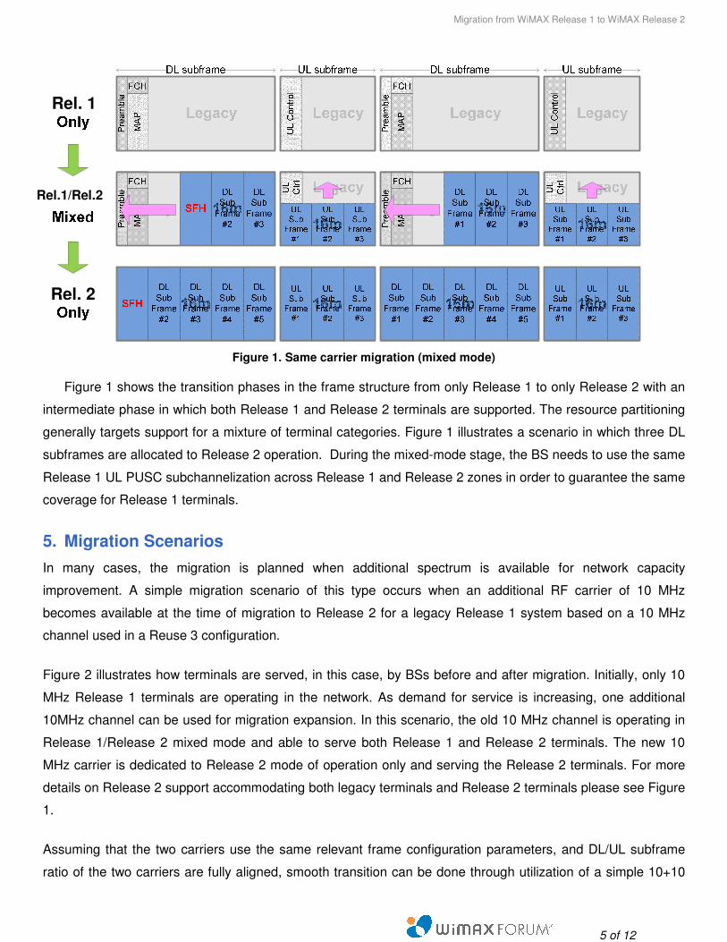
An alternative to the approach above is to use the additional 20 MHz spectrum for a single 20 MHz Release 2
channel with Reuse 1 configuration. Figure 6 shows the frame structure associated with this migration
scenario. In this case, devices with 10+10 MHz and 10+20 MHz (10+10+20 MHz not shown in the figure) multi-
carrier aggregation, 10 MHz and 20 MHz single-carrier devices, and 10 MHz legacy devices are interoperating
in the system. In multi-carrier devices, multi-carrier switching can be used as an alternative to multi-carrier
aggregation for lower cost solutions.
10 MHz10 MHz
20 MHz
Figure 6. Migration from Reuse 1 with addition of 20 MHz channel
5.3. Migration from Reuse 2 (1x4x2, 2x10 MHz)
This section considers the Reuse 2 scenario using two 10 MHz channels. Please refer to Annex A for more
details on frequency planning. Figure 7 shows the frame structure associated with migration from Reuse 2
when an additional 10 MHz channel is available at the time of migration. In this case, device with 10+10 MHz
multi-carrier aggregation, 10 MHz single-carrier devices, and legacy devices are interoperating in the system.
In the case that multi-carrier 10+10 MHz devices also support 20 MHz 2K FFT channel bandwidth, Release 2
20 MHz channel BSs may serve these devices as well in a roaming scenario.

Migration from WiMAX Release 1 to WiMAX Release 2
10 of 12
10 MHz10 MHz
10 MHz
Figure 7. Migration from Reuse 2 with addition of 10 MHz channel
In the case of availability of additional 20 MHz slot, one approach could be to use the 20 MHz spectrum to
overlay two 10 MHz channels with Reuse 1. In this case, Figure 7 can be simply generalized to have F5 as the
second 10 MHz Release 2 channel with Reuse 1 configuration. The advantage of this approach is that the
multi-carrier complexity of Release 2 devices remains as 10+10 MHz.
An alternative to the approach above is to use the additional 20 MHz spectrum for a single 20 MHz Release 2
channel with Reuse 1 configuration. Figure 8 shows the frame structure associated with this migration
scenario. In this case, devices with 10+20 MHz multi-carrier aggregation, 10 MHz and 20 MHz single-carrier
devices, and 10 MHz legacy devices are interoperating in the system. In multi-carrier devices, multi-carrier
switching can be used as an alternative to multi-carrier aggregation for lower cost solutions.
10 MHz10 MHz
20 MHz
Figure 8. Migration from Reuse 2 with addition of 20 MHz channel
Migration from WiMAX Release 1 to WiMAX Release 2
11 of 12
6. Performance enhancement during migration from WiMAX Release 1 to WiMAX
Release 2
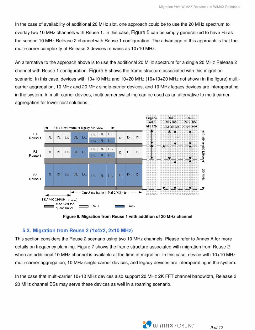
System capacity depends upon the partitioning among the Release 1 and Release 2 zones. Figure 9 shows
the relative DL average sector throughput, peak sector throughput, and 5%-tile cell edge user throughput
based on simulation results according to the IEEE 802.16m evaluation methodology. As the Release 2 zone
expands, the system performance will increase accordingly. For example, compared to the case of Release 1
only, a 2:3 Release 1:Release 2 mix would bring 20%/40%/60% performance gain in the average/peak/edge
throughputs, respectively. Likewise, pure Release 2 will see a 60%/80%/130% improvement over pure
Release 1.
100%
140%
166%
201%
234%
0%
20%
40%
60%
80%
100%
120%
140%
160%
180%
200%
220%
240%
260%
16e only 3:2 2:3 1:4 16m only
Sector Average
Sector Peak
5% Edge
DL:UL = 5:3, DL MIMO 4x2Sector AverageSector AverageSector AverageSector Average
Sector PeakSector PeakSector PeakSector Peak
5% Edge5% Edge5% Edge5% Edge
100%100%100%100% 140%140%140%140% 166%166%166%166% 201%201%201%201% 234%234%234%234%
Figure 9. Mixed mode performance of Release 1 and Release 2
Table 1 shows the performance improvement when migrating from WiMAX Release 1 to WiMAX Release 2.
For the simulation results in Table 1, the IMT-Advanced UMi test environment is assumed, with 29:18 DL:UL
frame ratio for both Release 1 and Release 2 networks.
Table 1. Performance Improvement
WiMAX Release Bandwidth Sector/site throughput (Mb/s) Site spectral efficiency (b/s/Hz/site)
Release 1, 2x2 10+10 MHz 9.74/58.4 4.73
Release 1, 4x2 10+10 MHz 11.27/67.6 5.48
Release 2, 4x2 20 MHz 37.33/112.0 9.08
Rel.1 Only Rel. 2 Only
Migration from WiMAX Release 1 to WiMAX Release 2
12 of 12
7. References
[1] IEEE P802.16m/D7, DRAFT Amendment to IEEE Standard for Local and metropolitan area networks –
Part 16: Air Interface for Broadband Wireless Access Systems.
[2] IEEE Std 802.16-2009, IEEE Standard for Local and metropolitan area networks – Part 16: Air Interface for
Broadband Wireless Access Systems, 29 May 2009.
[3] DRAFT-T23-001-R010v09-B, WiMAX Forum™ Mobile System Profile, Working Group Approved Revision,
17 May 2010.
Appendix A: Frequency Planning Options for 20 MHz Initial Allocation
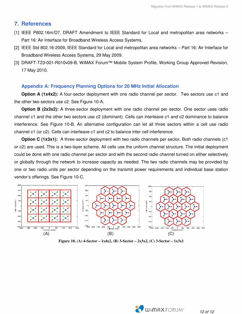
Option A (1x4x2): A four-sector deployment with one radio channel per sector. Two sectors use c1 and
the other two sectors use c2. See Figure 10-A.
Option B (2x3x2): A three-sector deployment with one radio channel per sector. One sector uses radio
channel c1 and the other two sectors use c2 (dominant). Cells can interleave c1 and c2 dominance to balance
interference. See Figure 10-B. An alternative configuration can let all three sectors within a cell use radio
channel c1 (or c2). Cells can interleave c1 and c2 to balance inter cell interference.
Option C (1x3x1): A three-sector deployment with two radio channels per sector. Both radio channels (c1
or c2) are used. This is a two-layer scheme. All cells use the uniform channel structure. The initial deployment
could be done with one radio channel per sector and with the second radio channel turned on either selectively
or globally through the network to increase capacity as needed. The two radio channels may be provided by
one or two radio units per sector depending on the transmit power requirements and individual base station
vendor’s offerings. See Figure 10-C.
(A) (B) (C)
Figure 10. (A) 4-Sector – 1x4x2, (B) 3-Sector – 2x3x2, (C) 3-Sector – 1x3x1
Related Documents