Version: 2. 1 Publication Date: 20-Nov-13 WiMAX Customer Premise Equipment Installation

Welcome message from author
This document is posted to help you gain knowledge. Please leave a comment to let me know what you think about it! Share it to your friends and learn new things together.
Transcript

Version: 2. 1 Publication Date: 20-Nov-13
WiMAX Customer Premise Equipment Installation
WiMAX Customer Premise Equipment Installation 2
Revision History
Date Version Description of Changes
16-Apr-12 1.0 First public release.
10-May-12 1.1 Installer Portal URL changed to https; WMI URL changed to IP address only.
Installer Portal activation instructions revised.
QoI parameters updated to May, 2012 values.
WMI Status topics added.
23-May-12 1.2 Added WiMAX CPE Installation QuickStart guide as a source for QoI pa rameters.
12-Jul-12 1.3 Added sealing gland instructions.
16-Aug-12 1.4 Changed Xplornet Xcessories to Xplornet Installation Essentials.
Replaced Installer Safety Standards with updated version.
Added Basic and Enhanced Installations topic to the Preparing for the Site Visit
chapter.
Changed Personal Information in the Preparing for the Site Visit chapter to Required
Information, edited the content.
15-Oct-12 1.5 Updated the Resetting the CPE Base Stations topics.
Added topics for identifying the base station.
7-Dec-12 1.6 Added the Static IP Addresses topic, modified the Activating the Service topic to
incorporate static IP address process.
2-Apr-13 1.7 Changed illustrations in Safety: First to Last, Do It Well topics and Installer Safety
Standards appendix.
Updated rate plans in Quality of Installation Parameters appendix to April-13
programs.
16-Apr-13 2.0 Removed CPE-specific information and moved that information to CPE-specific
installation guides.
Changes from 1.7:
Added Building Codes and Safety Standards topic to the Preparing for the Site Visit
chapter.
Added Installing the Mounting Platform chapter.
Added Environment topic to Xplornet Installer Safety Standards appendix.
20-Nov-13 2.1 Standardized Required Information and Meeting Your Customer topics.
Updated EORN QoI parameters in Quality of Installation Parameters appendix.
WiMAX Customer Premise Equipment Installation 3
Contents
1. Overview .................................................................................................................................................... 5
2. Preparing for the Site Visit ........................................................................................................................ 6
Safety: First to Last ....................................................................................................................................... 7
Required Information ................................................................................................................................... 8 Need-to-Know A nswers: ..............................................................................................................................8 Must Have Downloads: ................................................................................................................................9
Equipment ................................................................................................................................................. 10
Material ..................................................................................................................................................... 11
Tools .......................................................................................................................................................... 12
Base Stations.............................................................................................................................................. 13 Finding the La t-Longs ................................................................................................................................ 13 Finding the Direction to a Base Sta tion from the Site ..................................................................................... 15
Basic and Enhanced Installations ................................................................................................................ 22
Building Codes and Safety Standards .......................................................................................................... 23
DHCP.......................................................................................................................................................... 24
3. Performing the Site Survey .....................................................................................................................25
On Approach .............................................................................................................................................. 26
Meeting Your Customer ............................................................................................................................. 27
Locating the Base Stations.......................................................................................................................... 28
Locating the Ground Point.......................................................................................................................... 29
Approved Building Ground Points............................................................................................................... 30
Unacceptable Ground Points ...................................................................................................................... 31
CPE Location Requirements........................................................................................................................ 32
4. Installing a Mounting Platform ...............................................................................................................34
Types of Mounting Platforms ..................................................................................................................... 35
Mounting Hardware ................................................................................................................................... 36
Building Codes and Safety Standards .......................................................................................................... 37
Need to Know ............................................................................................................................................ 38 Customer Approval ................................................................................................................................... 38 Loca tion, Loca tion, Loca tion ....................................................................................................................... 38 Lag Screws ............................................................................................................................................... 40 Holes ...................................................................................................................................................... 41 Building I nteg rity ...................................................................................................................................... 42
Installing a Mast Bracket on a Wall ............................................................................................................. 44 Installing a Mast Bracket in Lap S iding ......................................................................................................... 44 Installing a Mast Bracket in Brick or Concrete ............................................................................................... 46
Installing a Mast Tube ................................................................................................................................ 49
Installing Side Stays .................................................................................................................................... 50
WiMAX Customer Premise Equipment Installation 4
Installing on a Roof..................................................................................................................................... 52 Penetra ting Roof Mount Installation ............................................................................................................ 52 Non-penetra ting Roof Mount Installation ..................................................................................................... 54
Installing a Pole .......................................................................................................................................... 55 Tools and Ma terials ................................................................................................................................... 55 Loca tion .................................................................................................................................................. 56 Procedure ................................................................................................................................................ 56
Level Check: All Mounting Platforms and Ins tallations ................................................................................ 58
5. Activating the Service..............................................................................................................................59
Latitude and Longitude............................................................................................................................... 60
Activating the Service, Part 1...................................................................................................................... 61
Activating the Service, Part 2...................................................................................................................... 63 Static IP A ddress ....................................................................................................................................... 65
Quality Checklist ........................................................................................................................................ 66
Finishing Touches ....................................................................................................................................... 67
Appendix A: Quality of Installation Parameters...........................................................................................68
National Program ....................................................................................................................................... 69
Broadband Canada Federal Broadband Stimulus (FBS) Program ................................................................. 70
Eastern Ontario Regional Network (EORN) Program ................................................................................... 71
Appendix X: Xplornet Installer Safety Standards .........................................................................................72
Safety: First to Last ..................................................................................................................................... 73
Dress Code ................................................................................................................................................. 74
Ladders ...................................................................................................................................................... 75
Working Off Ground ................................................................................................................................... 76
Environment .............................................................................................................................................. 77
Power ........................................................................................................................................................ 78
Electromagnetic Radiation ......................................................................................................................... 79
Driving ....................................................................................................................................................... 80
CPE Considerations .................................................................................................................................... 81
WiMAX Customer Premise Equipment Installation 5
1. Overview
Because WiMAX is a regulated standard, manufacturers must conform to a strict set of specifications. As a
result, Xplornet can use customer premise equipment (CPE) from a variety of vendors without affecting the
quality of the WiMAX service.
The WiMAX Customer Premise Equipment Installation guide is for installers of WiMAX CPEs that are deployed
by Xplornet. The WiMAX Customer Premise Equipment Installation guide covers information that is common
to all WiMAX CPE. It must be used in conjunction with the installation guide that provides information specific
to the CPE you are installing.
Refer to the WiMAX Customer Premise Equipment Installation guide for information on:
Preparing for a site visit
Performing a site survey
General mounting guidelines and requirements
Service activation
Quality of Installation tables
Safety standards
Refer to the CPE-specific installation guide for information on:
CPE-specific components, interfaces, and indicators
CPE-specific support of static IP addresses
CPE-specific mounting instructions
CPE-specific cabling and grounding
CPE-specific alignment
CPE-specific instructions for connecting your customer’s computer to the CPE

WiMAX Customer Premise Equipment Installation 6
2. Preparing for the Site Visit
To prepare for a site visit, you need to:
Review the safety guidelines.
Gather all information.
Download required documentation.
Ensure you have all required equipment, tools, and materials.
Establish directions to available base stations.
Review the criteria for basic and enhanced installations.
Review the relevant building codes.
Configure your computer for DHCP.
Taking a few minutes to review these preparations now is the alternative to losing many hours and dollars if you
are missing some critical information or equipment when you arrive at the site .
WiMAX Customer Premise Equipment Installation 7
Safety: First to Last
When preparing for a site visit, travelling to and from the site, and especially when on -site, consider safety
at all times:
Your safety
The customer’s safety
The safety of the customer’s home and equipment
Review Xplornet’s Installer Safety Standards carefully. They are provided as an appendix to this guide.
The certification exam includes several questions about the information in the Standards.
Follow the Installer Safety Standards as well as any Federal and Provincial standards that apply. Where
different standards address the same point, the stricter and more specific standard applies.
WiMAX Customer Premise Equipment Installation 8
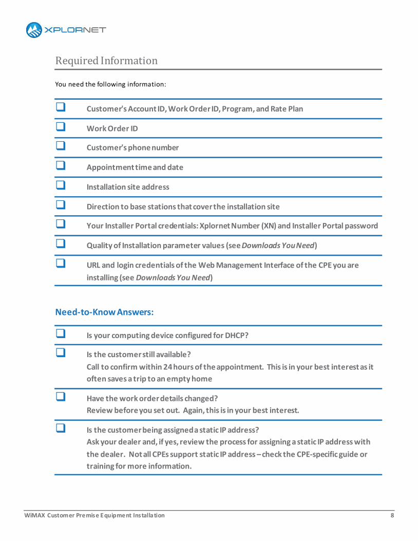
Required Information
You need the following information:
Customer's Account ID, Work Order ID, Program, and Rate Plan
Work Order ID
Customer's phone number
Appointment time and date
Installation site address
Direction to base stations that cover the installation site
Your Installer Portal credentials: Xplornet Number (XN) and Installer Portal password
Quality of Installation parameter values (see Downloads You Need)
URL and login credentials of the Web Management Interface of the CPE you are
installing (see Downloads You Need)
Need-to-Know Answers:
Is your computing device configured for DHCP?
Is the customer still available?
Call to confirm within 24 hours of the appointment. This is in your best interest as it
often saves a trip to an empty home
Have the work order details changed?
Review before you set out. Again, this is in your best interest.
Is the customer being assigned a static IP address?
Ask your dealer and, if yes, review the process for assigning a static IP address with
the dealer. Not all CPEs support static IP address – check the CPE-specific guide or
training for more information.
WiMAX Customer Premise Equipment Installation 9
Must Have Downloads:
Download the WiMAX Customer Premise Equipment Installation guide from the Xplornet University
Library. The guide is the only source for both the Xplornet Installer Safety Standards and the WiMAX
Quality of Installation Parameters.
Also from the Xplornet University Library, be sure to obtain the URL and login credentials for the Web
Management Interface (WMI) of the CPE you are installing.
You cannot complete the installation without the Quality of Installation parameters and the WMI information.
WiMAX Customer Premise Equipment Installation 10
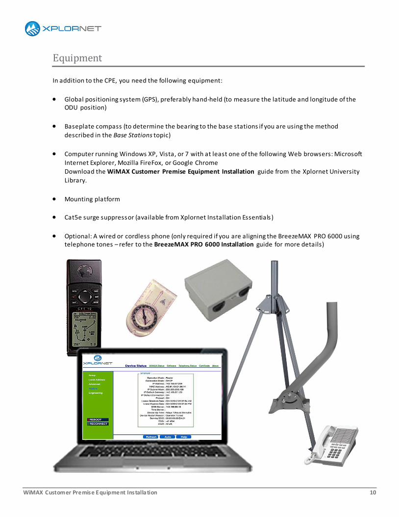
Equipment
In addition to the CPE, you need the following equipment:
Global positioning system (GPS), preferably hand-held (to measure the latitude and longitude of the ODU position)
Baseplate compass (to determine the bearing to the base stations if you are using the method
described in the Base Stations topic)
Computer running Windows XP, Vista, or 7 with at least one of the following Web browsers: Microsoft
Internet Explorer, Mozilla FireFox, or Google Chrome
Download the WiMAX Customer Premise Equipment Installation guide from the Xplornet University
Library.
Mounting platform
Cat5e surge suppressor (available from Xplornet Installation Essentials )
Optional: A wired or cordless phone (only required if you are aligning the BreezeMAX PRO 6000 using telephone tones – refer to the BreezeMAX PRO 6000 Installation guide for more details)

WiMAX Customer Premise Equipment Installation 11
Material
The CPE includes an Ethernet cable for connecting the IDU to the customer's computing equipment. You
also need:
Xplornet-approved, outdoor-rated, pre-terminated, shielded Cat5e Ethernet cable with integrated
ground wire for connecting the surge suppressor to the ODU.*
o Exception: BreezeMAX PRO 3000, which requires a specialty cable with an integral sealing gland
assembly. *
Xplornet-approved outdoor-rated, pre-terminated, shielded Cat5e Ethernet cable for connecting the
surge suppressor to the IDU *
12AWG solid copper ground wire *
Outdoor silicone sealant (for holes drilled when wall -mounting the platform, and for the point of entry
hole)
A tar-based sealant (for holes drilled when roof-mounting the platform)
Cable ties*, cable clips *
Hardware for installing the mounting platform; refer to the Installing a Mounting Platform chapter for
details
* Your Dealer can purchase all materials marked with an asterisk from Xplornet Installation Essentials.
Use Xplornet-
approved materials
only.

WiMAX Customer Premise Equipment Installation 12
Tools
You need tools to:
Install the mounting platform
Mount the ODU
Cut and strip ground wire
Attach cable ties and cable clips to the mounting platform and building
Remove and install the ODU sealing gland (size varies with CPE but adjustable pliers able to open to
2in–5cm is recommended)
Drill a 3/4" point of entry into the building, for the Cat5e Ethernet cable
A typical toolset includes:
Ladder
Hammer
Rubber mallet
Hacksaw
Wire cutters/strippers
Screwdrivers (Medium blade, #2 Phillips, #2 Robertson)
Spirit level
Caulking gun
Pencil
Gloves
Power drill with appropriate bits (for wood and masonry structures)
Socket set and wrenches (metric and imperial)

WiMAX Customer Premise Equipment Installation 13
Base Stations
Any base station within 18mi–30km of the site may be
able to provide coverage.
Before you leave for the site, you must have a way to
establish the direction to these base stations when you
are at the site.
If you have a GPS that allows you to save locations and
point to them when you are at another location, then
you can go to each base station in your region and save
the position of the base station. Then, when you are at
the site, you can use the saved locations to find the
direction to each base station from the site.
We provide an alternative method here. It has several
advantages: it has withstood the test of time (hundreds
of years), it uses simple devices (no electronics or
batteries to fail), and the total cost is under $20. You
only need a map, a ruler, and a compass.
Finding the Lat-Longs
The first step in this method is to determine the latitude and longitude (lat-long) of the site and the lat-
longs of all base stations that are within range of the site.
Lat-Long of the site:
There are several web sites,
dishpointer.com for example, that provide
the lat-long of a site given the address.
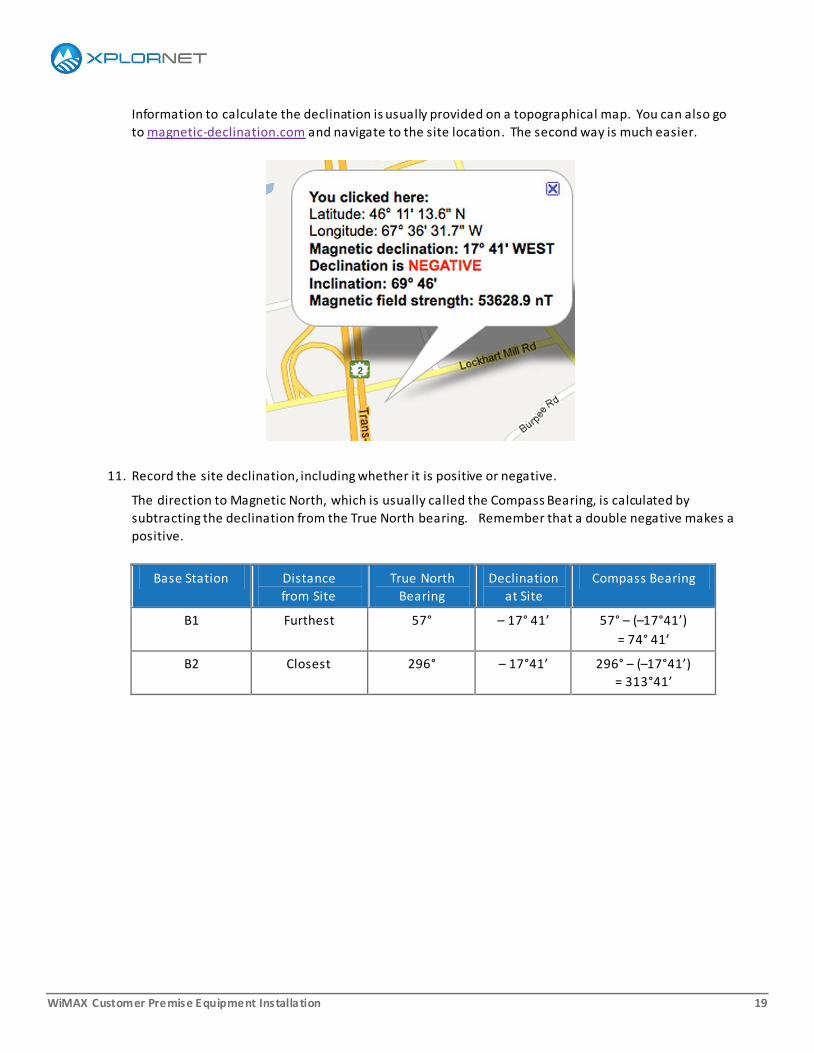
For instance, the illustration shows the
dishpointer.com information for a site at
300 Lockhart Mills Road in Woodstock,
New Brunswick. The latitude is 46.1876°
and the longitude is -67.6089°.
A negative longitude indicates that the
location is West of the Prime Meridian
while a positive latitude indicates that the
location is North of the Equator.

WiMAX Customer Premise Equipment Installation 14
Lat-Long of the base stations:
In many cases, the base stations do not have a civic address. Your dealer may already know the lat-longs
of base stations that serve the customer’s site , or the Dealer Support Group (1-866-841-6004 or
[email protected]) may be able to identify them.
If no one can identify all the base stations that might cover the customer, use the Xplornet Coverage Tool.
Given the site address, the Coverage Tool provides the lat -long of the site and all base stations that are
within range of the site.
The Xplornet Coverage Tool user guide provides the instructions you need to download and use the tool.
You can download the user guide from the Xplornet University Library. You need login credentials to run
the tool – the form to request credentials is also available in the Xplornet University Library.
WiMAX Customer Premise Equipment Installation 15
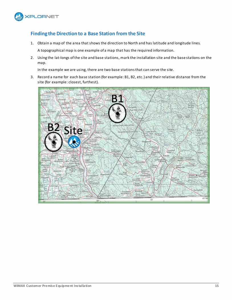
Finding the Direction to a Base Station from the Site
1. Obtain a map of the area that shows the direction to North and has latitude and longitude lines.
A topographical map is one example of a map that has the required information.
2. Using the lat-longs of the site and base stations, mark the installation site and the base stations on the
map.
In the example we are using, there are two base stations that can serve the site.
3. Record a name for each base station (for example: B1, B2, etc.) and their relative distance from the
site (for example: closest, furthest).
WiMAX Customer Premise Equipment Installation 16
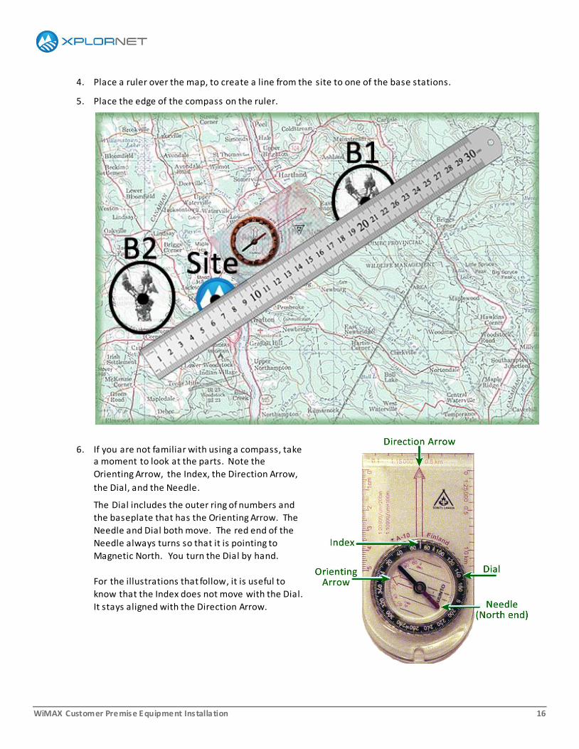
4. Place a ruler over the map, to create a line from the site to one of the base stations.
5. Place the edge of the compass on the ruler.
6. If you are not familiar with using a compass, take a moment to look at the parts. Note the
Orienting Arrow, the Index, the Direction Arrow,
the Dial, and the Needle.
The Dial includes the outer ring of numbers and
the baseplate that has the Orienting Arrow. The
Needle and Dial both move. The red end of the
Needle always turns so that it is pointing to
Magnetic North. You turn the Dial by hand.
For the illustrations that follow, it is useful to
know that the Index does not move with the Dial.
It stays aligned with the Direction Arrow.
WiMAX Customer Premise Equipment Installation 17
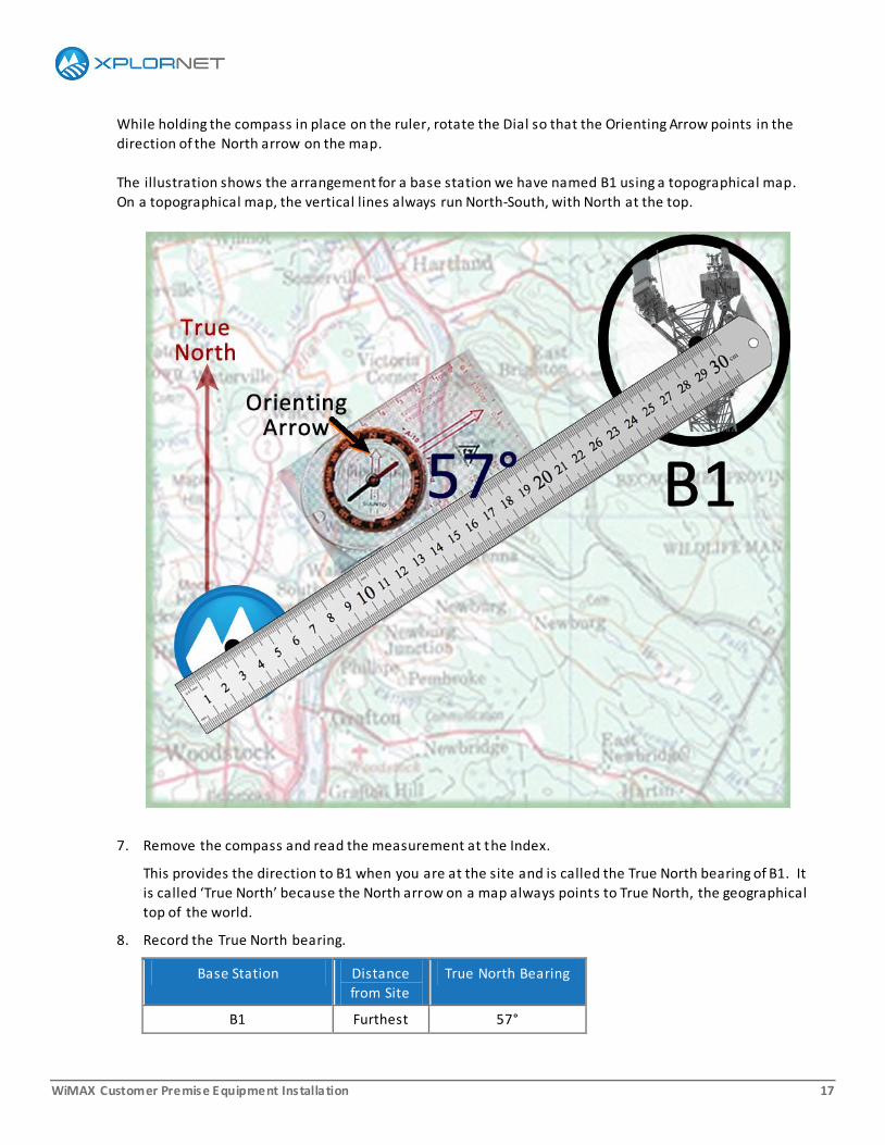
While holding the compass in place on the ruler, rotate the Dial so that the Orienting Arrow points in the
direction of the North arrow on the map.
The illustration shows the arrangement for a base station we have named B1 using a topographical map.
On a topographical map, the vertical lines always run North-South, with North at the top.
7. Remove the compass and read the measurement at the Index.
This provides the direction to B1 when you are at the site and is called the True North bearing of B1. It
is called ‘True North’ because the North arrow on a map always points to True North, the geographical
top of the world.
8. Record the True North bearing.
Base Station Distance
from Site
True North Bearing
B1 Furthest 57°
WiMAX Customer Premise Equipment Installation 18
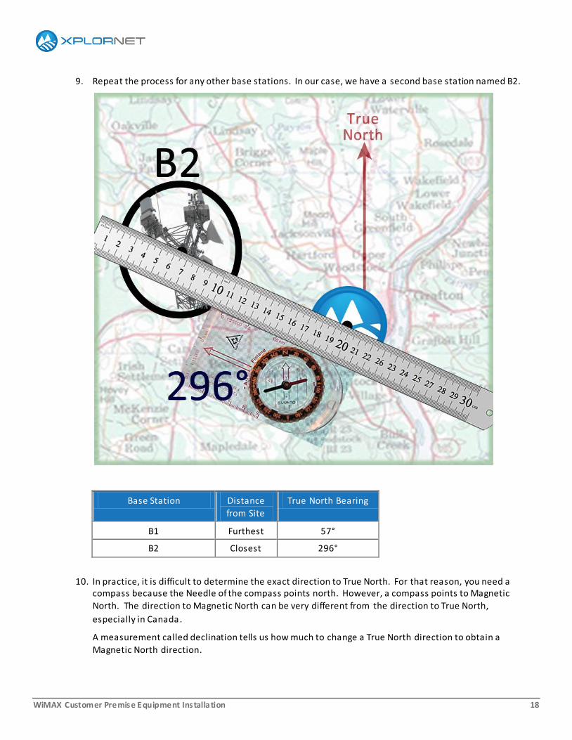
9. Repeat the process for any other base stations. In our case, we have a second base station named B2.
Base Station Distance
from Site
True North Bearing
B1 Furthest 57°
B2 Closest 296°
10. In practice, it is difficult to determine the exact direction to True North. For that reason, you need a compass because the Needle of the compass points north. However, a compass points to Magnetic
North. The direction to Magnetic North can be very different from the direction to True North,
especially in Canada.
A measurement called declination tells us how much to change a True North direction to obtain a
Magnetic North direction.
WiMAX Customer Premise Equipment Installation 19
Information to calculate the declination is usually provided on a topographical map. You can also go
to magnetic-declination.com and navigate to the site location. The second way is much easier.
11. Record the site declination, including whether it is positive or negative.
The direction to Magnetic North, which is usually called the Compass Bearing, is calculated by
subtracting the declination from the True North bearing. Remember that a double negative makes a
positive.
Base Station Distance
from Site
True North
Bearing
Declination
at Site
Compass Bearing
B1 Furthest 57° – 17° 41’ 57° – (–17°41’)
= 74° 41’
B2 Closest 296° – 17°41’ 296° – (–17°41’)
= 313°41’

WiMAX Customer Premise Equipment Installation 20
12. When you get to the site, set the compass Dial so that the Index is at
the Compass Bearing of the base
station that you want to find the
direction to.
In the illustration, we want to know
where B1 is so we have set the Dial
at 74°. If we had a very large
compass, we could probably get
closer to the actual value of 74°41’,
but 74° is close enough.
13. To establish the direction to the base station:
a. With the Index set to the Compass Bearing of the base station (74° for B1), hold the compass in
front of you with the Direction Arrow pointing away from you.
b. Keeping the compass horizontal so that the Needle is free to rotate, turn yourself until the North
end of the Needle (red) is centred in the Orienting Arrow.
The Direction Arrow now points at the base station.

WiMAX Customer Premise Equipment Installation 21
A Last Note:
Sometimes you may need to convert degrees from one form to another. The instructions provided in the
Latitude and Longitude topic of the Activating the Service chapter may help with this. Otherwise, there
are many online resources.
WiMAX Customer Premise Equipment Installation 22
Basic and Enhanced Installations
The specifications for basic and enhanced installations are provided at:
http://www.xplornet.com/how-it-works/satellite-basic-and-enhanced-installation/
You need to be familiar with these specifications or take a copy with you to the site because it is your
responsibility to determine if an installation is basic or enhanced. Usually, it is not possible to tell if an
installation falls outside of a basic installation until you are on-site.
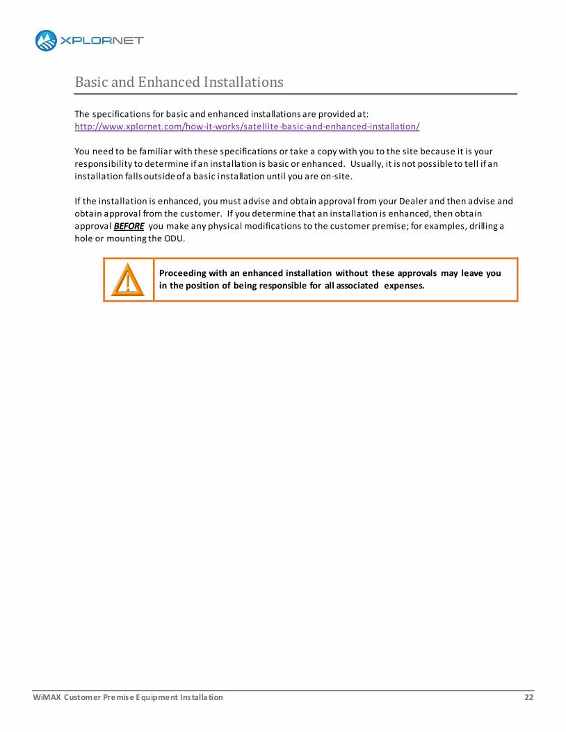
If the installation is enhanced, you must advise and obtain approval from your Dealer and then advise and
obtain approval from the customer. If you determine that an installation is enhanced, then obtain
approval BEFORE you make any physical modifications to the customer premise; for examples, drilling a
hole or mounting the ODU.
Proceeding with an enhanced installation without these approvals may leave you
in the position of being responsible for all associated expenses.

WiMAX Customer Premise Equipment Installation 23
Building Codes and Safety Standards
Xplornet Installers are expected to be aware of and adhere to all national, regional, and local building
codes. In particular, you must pay special attention to the codes when you are fastening hardware to
buildings and when you are installing electrical cables and grounds.
Similarly, Xplornet Installers are expected to be aware of and adhere to all national, regional, and local
safety standards.
If you find a point that is covered more than once, then apply the code or standard that is more stringent
or more specific.
In some regions, and especially in the case of enhanced installations, you may need to obtain a building
permit.

WiMAX Customer Premise Equipment Installation 24
DHCP
Your computing device must be configured for DHCP (Dynamic Host Configuration Protocol) to run both
the Web Management Interface (WMI) of the CPE and the Xplornet Installer Portal.
DHCP is the default configuration for most computing devices. However, it is worth verifying now that
your device is configured for DHCP because, if it is not, you cannot complete installation. Configuration is
done slightly differently in the three supported operating systems: Windows XP, Windows Vista, and
Windows 7. However, there are many resources on the Internet that provide deta iled instructions.
WiMAX Customer Premise Equipment Installation 25
3. Performing the Site Survey
Performing a thorough site survey is like laying a solid foundation. On the surface, little seems to be happening
but the overall success of the entire installation rests upon it.
To survey the site:
Evaluate the surrounding landscape as you approach the site.
Engage the customer before examining the site.
Determine the location of the base stations.
Locate an approved ground point.
Review and use the ODU Location Requirements Checklist.

WiMAX Customer Premise Equipment Installation 26
On Approach
As you approach the customer site, note the location of:
Power lines, both local distribution poles and high tension transmission towers
High points such as hills, silos, or a nearby forest
Flat and lowlands such as fields, lakes, or valleys

WiMAX Customer Premise Equipment Installation 27
Meeting Your Customer
When you first arrive, ask to speak to the person whose name is on the work order. This is your customer.
When you first meet your customer:
1. Introduce yourself.
Clearly state your full name, the name of your company, and the reason you are there.
2. Offer a business card or, if you don’t have one, your contact information.
3. At all times, be polite and listen carefully. Look and act professional.
4. Explain the installation process:
o Site survey
o Mounting the ODU
o Installing cables and grounds
o Aligning the CPE
o Activating the service
5. Ask if they have any preferred locations for the ODU, and locations where they do not want the ODU.
When you have completed the site survey, check back with your customer to confirm that they
approve of the location of the ODU. If they are hesitant, explain the tradeoffs from a service
perspective.
WiMAX Customer Premise Equipment Installation 28
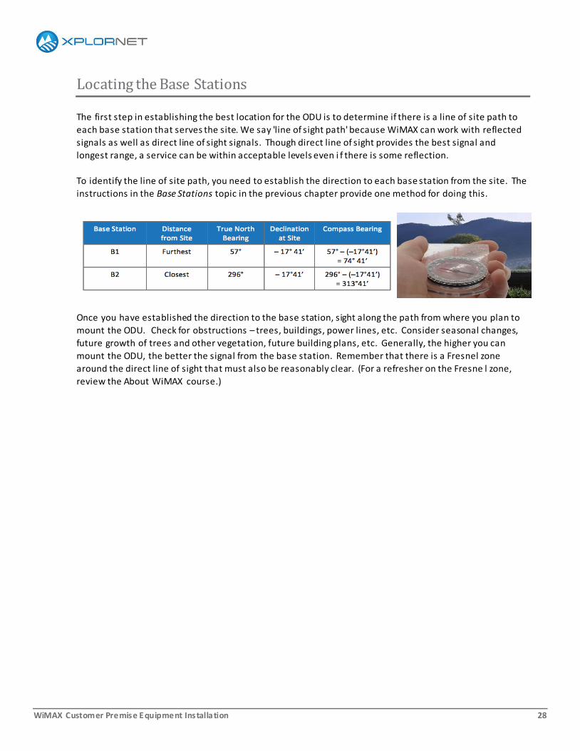
Locating the Base Stations
The first step in establishing the best location for the ODU is to determine if there is a line of site path to
each base station that serves the site. We say 'line of sight path' because WiMAX can work with reflected
signals as well as direct line of sight signals. Though direct line of sight provides the best signal and
longest range, a service can be within acceptable levels even i f there is some reflection.
To identify the line of site path, you need to establish the direction to each base station from the site. The
instructions in the Base Stations topic in the previous chapter provide one method for doing this.
Once you have established the direction to the base station, sight along the path from where you plan to
mount the ODU. Check for obstructions – trees, buildings, power lines, etc. Consider seasonal changes,
future growth of trees and other vegetation, future building plans, etc. Generally, the higher you can
mount the ODU, the better the signal from the base station. Remember that there is a Fresnel zone
around the direct line of sight that must also be reasonably clear. (For a refresher on the Fresne l zone,
review the About WiMAX course.)

WiMAX Customer Premise Equipment Installation 29
Locating the Ground Point
The location of an approved ground point can impact the location of the ODU mount almost as much as
the location of the base station. Xplornet has established grounding standards which must be adhered to
in every detail.
Why is grounding so important?
Proper grounding prevents: o The destruction of electrical components
o Electric shocks from superimposed voltage from lightning, voltage transients, and contact with
higher voltage systems
Proper grounding reduces:
o Static charges that can diminish the performance of electronic equipment
Proper grounding is:
o Required by the Canadian Electrical Code (CEC) – All lead-in cables must be protected using an
antenna discharge unit (that is, the Xplornet-approved surge suppressor)
o Required on both the ODU and the mounting platform
o Defined by the CEC or local electrical code, whichever is higher
WiMAX Customer Premise Equipment Installation 30
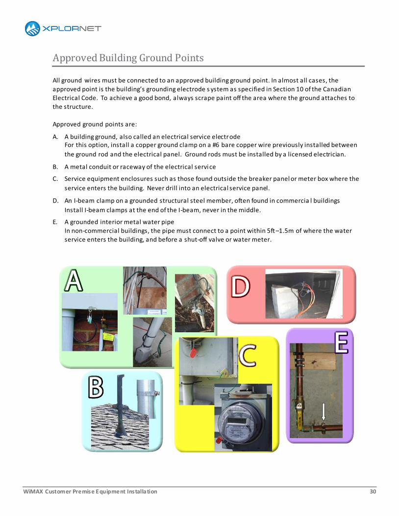
Approved Building Ground Points
All ground wires must be connected to an approved building ground point. In almost all cases, the
approved point is the building’s grounding electrode s ystem as specified in Section 10 of the Canadian
Electrical Code. To achieve a good bond, always scrape paint off the area where the ground attaches to
the structure.
Approved ground points are:
A. A building ground, also called an electrical service electrode For this option, install a copper ground clamp on a #6 bare copper wire previously installed between
the ground rod and the electrical panel. Ground rods must be installed by a licensed electrician.
B. A metal conduit or raceway of the electrical servi ce
C. Service equipment enclosures such as those found outside the breaker panel or meter box where the
service enters the building. Never drill into an electrical service panel.
D. An I-beam clamp on a grounded structural steel member, often found in commercia l buildings
Install I-beam clamps at the end of the I-beam, never in the middle.
E. A grounded interior metal water pipe
In non-commercial buildings, the pipe must connect to a point within 5ft –1.5m of where the water
service enters the building, and before a shut-off valve or water meter.
WiMAX Customer Premise Equipment Installation 31
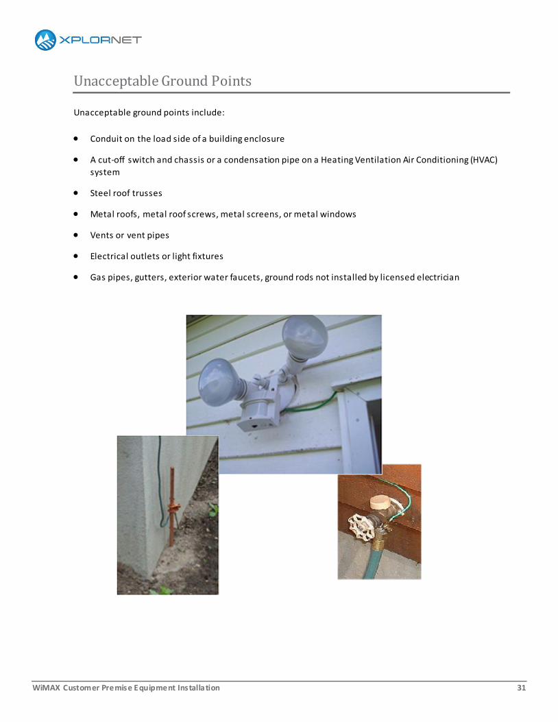
Unacceptable Ground Points
Unacceptable ground points include:
Conduit on the load side of a building enclosure
A cut-off switch and chassis or a condensation pipe on a Heating Ventilation Air Conditioning (HVAC)
system
Steel roof trusses
Metal roofs, metal roof screws, metal screens, or metal windows
Vents or vent pipes
Electrical outlets or light fixtures
Gas pipes, gutters, exterior water faucets, ground rods not installed by licensed electrician
WiMAX Customer Premise Equipment Installation 32
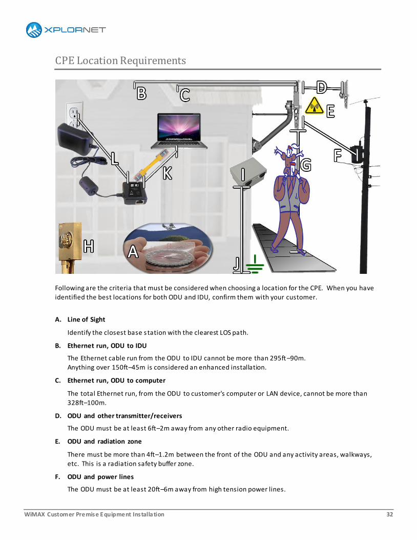
CPE Location Requirements
Following are the criteria that must be considered when choosing a location for the CPE. When you have
identified the best locations for both ODU and IDU, confirm them with your customer.
A. Line of Sight
Identify the closest base station with the clearest LOS path.
B. Ethernet run, ODU to IDU
The Ethernet cable run from the ODU to IDU cannot be more than 295ft –90m.
Anything over 150ft–45m is considered an enhanced installation.
C. Ethernet run, ODU to computer
The total Ethernet run, from the ODU to customer's computer or LAN device, cannot be more than
328ft–100m.
D. ODU and other transmitter/receivers
The ODU must be at least 6ft–2m away from any other radio equipment.
E. ODU and radiation zone
There must be more than 4ft–1.2m between the front of the ODU and any activity areas, walkways,
etc. This is a radiation safety buffer zone.
F. ODU and power lines
The ODU must be at least 20ft–6m away from high tension power lines.

WiMAX Customer Premise Equipment Installation 33
G. ODU and clearance
The bottom of the ODU must be at least 10ft–3m above any walkway or activity area.
H. ODU and electrical service
The ODU must be at least 3ft–1m away from electrical service entrances or panels.
I. Surge suppressor and building ground
The surge suppressor must be within 20ft–6m of the building ground point (J).
Xplornet understands that there are exceptional cases where strict compliance to this standard is not
possible. In these cases, you can proceed with the installation on a best -effort basis; that is, by
complying with the standard to the greatest extent possible.
When Xplornet audits an installation that does not comply with our standard, the installation will pass
if it is clear, through explanation or evidence, that it was not possible to comply with the standard.
Otherwise, the installation will fail the audit.
K. IDU location
The IDU must be at least 8in–20cm from people or other equipment.
L. IDU power
AC power must be within 3ft–1m of the IDU or PoE adapter.
WiMAX Customer Premise Equipment Installation 34
4. Installing a Mounting Platform v1.4, 4-Jun-13
A mounting platform is the structure that supports the outdoor unit (ODU). This chapter covers the rules,
regulations, and guidelines to follow when installing a mounting platform.
This chapter is applicable to all CPEs, regardless of manufacturer or service. Installation instructions for CPE-
specific ODUs are covered in CPE-specific installation guides.
WiMAX Customer Premise Equipment Installation 35
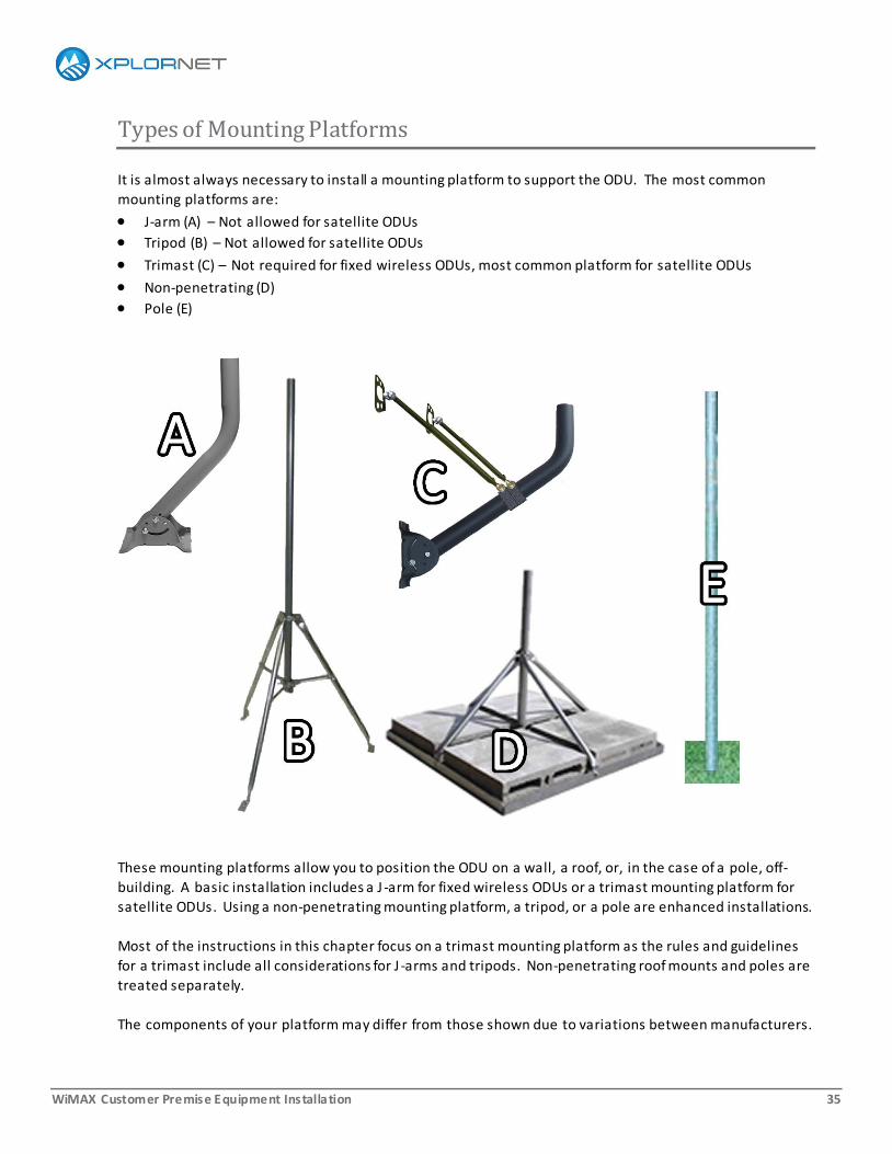
Types of Mounting Platforms
It is almost always necessary to install a mounting platform to support the ODU. The most common
mounting platforms are:
J-arm (A) – Not allowed for satellite ODUs
Tripod (B) – Not allowed for satellite ODUs
Trimast (C) – Not required for fixed wireless ODUs, most common platform for satellite ODUs
Non-penetrating (D)
Pole (E)
These mounting platforms allow you to position the ODU on a wall, a roof, or, in the case of a pole, off-
building. A basic installation includes a J -arm for fixed wireless ODUs or a trimast mounting platform for
satellite ODUs. Using a non-penetrating mounting platform, a tripod, or a pole are enhanced installations.
Most of the instructions in this chapter focus on a trimast mounting platform as the rules and guidelines
for a trimast include all considerations for J -arms and tripods. Non-penetrating roof mounts and poles are
treated separately.
The components of your platform may differ from those shown due to variations between manufacturers.
WiMAX Customer Premise Equipment Installation 36
Mounting Hardware
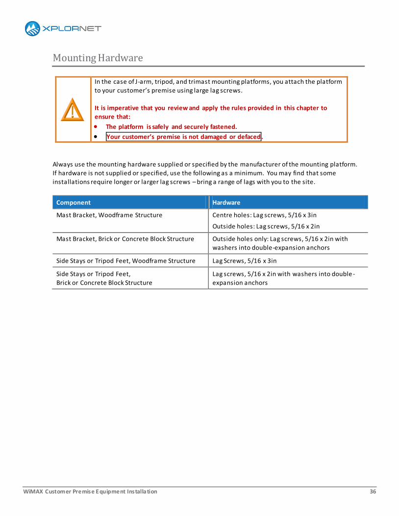
In the case of J-arm, tripod, and trimast mounting platforms, you attach the platform
to your customer’s premise using large lag screws.
It is imperative that you review and apply the rules provided in this chapter to
ensure that:
The platform is safely and securely fastened.
Your customer’s premise is not damaged or defaced.
Always use the mounting hardware supplied or specified by the manufacturer of the mounting platform.
If hardware is not supplied or specified, use the following as a minimum. You may find that some
installations require longer or larger lag screws – bring a range of lags with you to the site.
Component Hardware
Mast Bracket, Woodframe Structure Centre holes: Lag screws, 5/16 x 3in
Outside holes: Lag screws, 5/16 x 2in
Mast Bracket, Brick or Concrete Block Structure Outside holes only: Lag screws, 5/16 x 2in with
washers into double-expansion anchors
Side Stays or Tripod Feet, Woodframe Structure Lag Screws, 5/16 x 3in
Side Stays or Tripod Feet,
Brick or Concrete Block Structure
Lag screws, 5/16 x 2in with washers into double -
expansion anchors

WiMAX Customer Premise Equipment Installation 37
Building Codes and Safety Standards
Xplornet Installers are expected to be aware of and adhere to all national, regional, and local building
codes. In particular, you must pay special attention to the codes when you are fastening hardware to
buildings and when you are installing electrical cables and groun ds. In some regions, and especially in the
case of enhanced installations, you may need to obtain a building permit.
Similarly, Xplornet Installers are expected to be aware of and adhere to the Xplornet Installer Safety
Standards as well as any Federal and Provincial standards that apply. The Xplornet Installer Safety
Standards are provided in an appendix to this guide.
Where different standards address the same point, the stricter and more specific standard applies.

WiMAX Customer Premise Equipment Installation 38
Need to Know
Here are the things you need to know before beginning installation of a mounting platform.
Customer Approval
Ensure that your customer approves the location.
If not:
Identify at least one other location.
Explain the trade-offs of each location.
Help your customer decide.
Location, Location, Location
Ensure that the location provides a clear line of sight between the ODU and satellite or base station,
taking into consideration seasonal changes and the foreseeable future.
WiMAX Customer Premise Equipment Installation 39
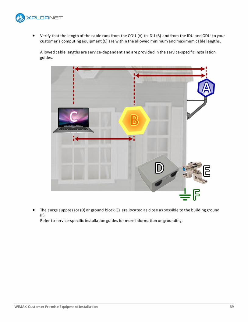
Verify that the length of the cable runs from the ODU (A) to IDU (B) and from the IDU and ODU to your
customer’s computing equipment (C) are within the allowed minimum and maximum cable lengths.
Allowed cable lengths are service-dependent and are provided in the service-specific installation
guides.
The surge suppressor (D) or ground block (E) are located as close as possible to the building ground (F).
Refer to service-specific installation guides for more information on grounding.
WiMAX Customer Premise Equipment Installation 40
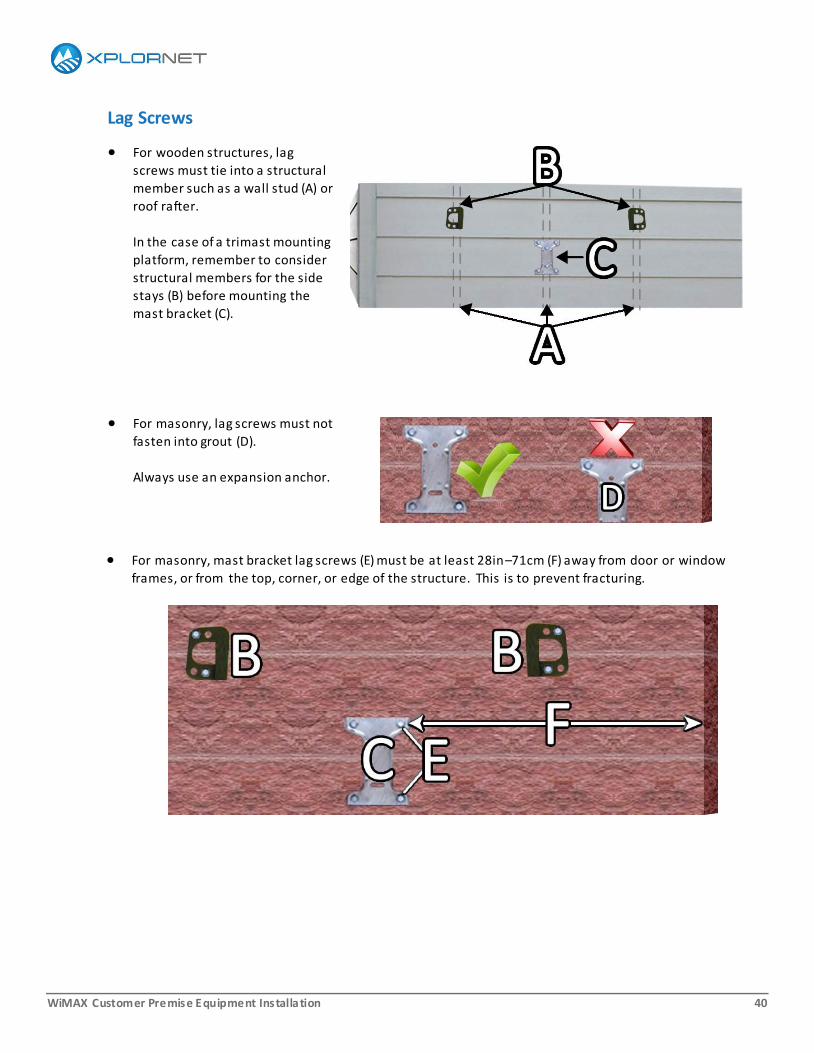
Lag Screws
For wooden structures, lag
screws must tie into a structural
member such as a wall stud (A) or
roof rafter.
In the case of a trimast mounting
platform, remember to consider
structural members for the side
stays (B) before mounting the
mast bracket (C).
For masonry, lag screws must not
fasten into grout (D).
Always use an expansion anchor.
For masonry, mast bracket lag screws (E) must be at least 28in–71cm (F) away from door or window
frames, or from the top, corner, or edge of the structure. This is to prevent fracturing.
WiMAX Customer Premise Equipment Installation 41
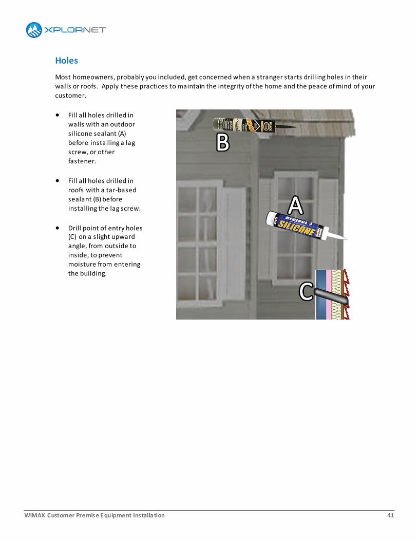
Holes
Most homeowners, probably you included, get concerned when a stranger starts drilling holes in their
walls or roofs. Apply these practices to maintain the integrity of the home and the peace of mind of your
customer.
Fill all holes drilled in
walls with an outdoor
silicone sealant (A)
before installing a lag
screw, or other
fastener.
Fill all holes drilled in
roofs with a tar-based
sealant (B) before
installing the lag screw.
Drill point of entry holes (C) on a slight upward
angle, from outside to
inside, to prevent
moisture from entering
the building.
WiMAX Customer Premise Equipment Installation 42
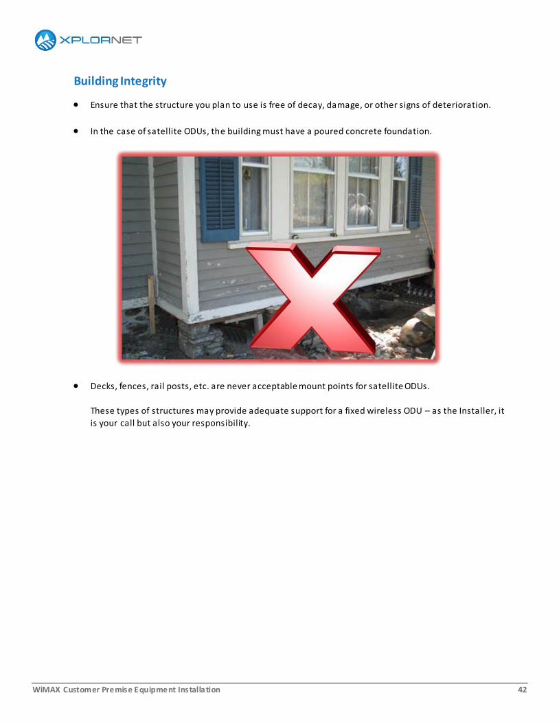
Building Integrity
Ensure that the structure you plan to use is free of decay, damage, or other signs of deterioration.
In the case of satellite ODUs, the building must have a poured concrete foundation.
Decks, fences, rail posts, etc. are never acceptable mount points for satellite ODUs.
These types of structures may provide adequate support for a fixed wireless ODU – as the Installer, it
is your call but also your responsibility.
WiMAX Customer Premise Equipment Installation 43
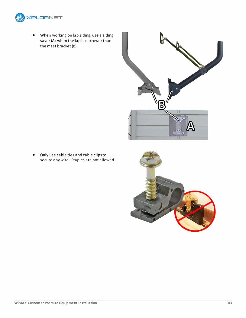
When working on lap siding, use a siding
saver (A) when the lap is narrower than
the mast bracket (B).
Only use cable ties and cable clips to secure any wire. Staples are not allowed.
WiMAX Customer Premise Equipment Installation 44
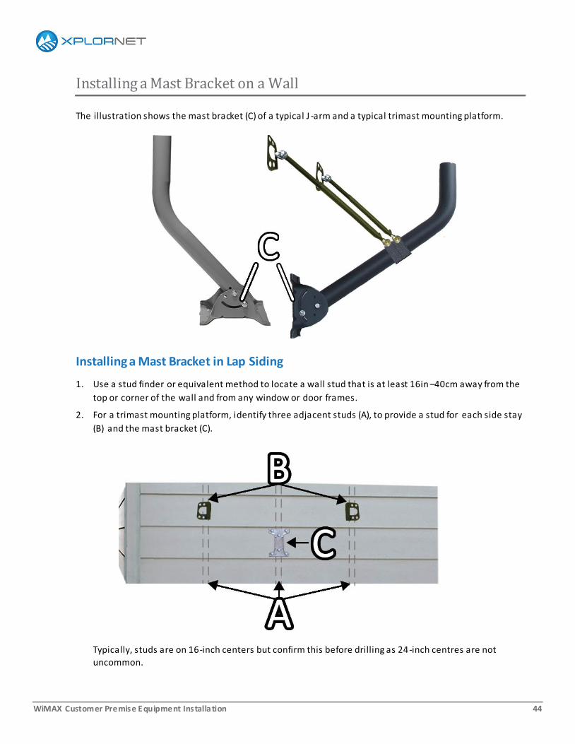
Installing a Mast Bracket on a Wall
The illustration shows the mast bracket (C) of a typical J -arm and a typical trimast mounting platform.
Installing a Mast Bracket in Lap Siding
1. Use a stud finder or equivalent method to locate a wall stud that is at least 16in –40cm away from the
top or corner of the wall and from any window or door frames.
2. For a trimast mounting platform, identify three adjacent studs (A), to provide a stud for each side stay
(B) and the mast bracket (C).
Typically, studs are on 16-inch centers but confirm this before drilling as 24-inch centres are not
uncommon.

WiMAX Customer Premise Equipment Installation 45
For a J-arm, only one stud is required, for the mast bracket.
Post and beam, lath and plaster, mobile homes, and steel structures are all examples of
buildings that do not follow standard wood frame construction practices. Structural
members may not be on 16- or 24-inch centres, and may not be conventional studs at all.
3. If the mast bracket (C) is wider than the siding, install a siding saver (D) before mounting the mast
bracket.
4. Position the mast bracket so that at least two mounting holes align with the stud (E).
5. Level the mast bracket (F) and mark the mounting holes (G).
The mast bracket must be plumb as it can be very difficult to align the CPE if it is not. Double-check
the level at each step and adjust as required.
6. Remove the mast bracket and pre-tap the holes using a drill appropriate for the size of the lag screws
recommended by the manufacturer.
7. Fill the holes with outdoor silicone sealant (H), position the mast bracket over the holes, and install
the lag screws (I).
WiMAX Customer Premise Equipment Installation 46
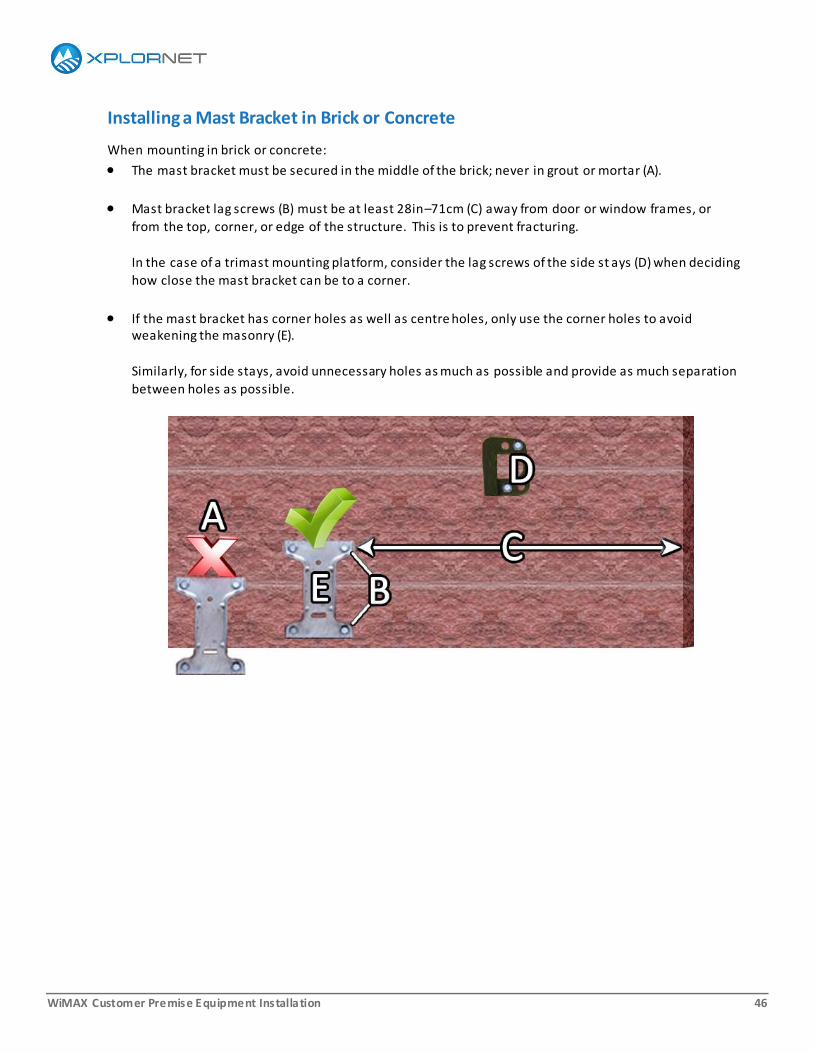
Installing a Mast Bracket in Brick or Concrete
When mounting in brick or concrete:
The mast bracket must be secured in the middle of the brick; never in grout or mortar (A).
Mast bracket lag screws (B) must be at least 28in–71cm (C) away from door or window frames, or
from the top, corner, or edge of the structure. This is to prevent fracturing.
In the case of a trimast mounting platform, consider the lag screws of the side st ays (D) when deciding
how close the mast bracket can be to a corner.
If the mast bracket has corner holes as well as centre holes, only use the corner holes to avoid weakening the masonry (E).
Similarly, for side stays, avoid unnecessary holes as much as possible and provide as much separation
between holes as possible.
WiMAX Customer Premise Equipment Installation 47
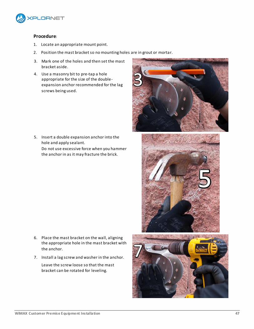
Procedure:
1. Locate an appropriate mount point.
2. Position the mast bracket so no mounting holes are in grout or mortar.
3. Mark one of the holes and then set the mast
bracket aside.
4. Use a masonry bit to pre-tap a hole appropriate for the size of the double-
expansion anchor recommended for the lag
screws being used.
5. Insert a double expansion anchor into the
hole and apply sealant.
Do not use excessive force when you hammer
the anchor in as it may fracture the brick.
6. Place the mast bracket on the wall, aligning the appropriate hole in the mast bracket with
the anchor.
7. Install a lag screw and washer in the anchor.
Leave the screw loose so that the mast
bracket can be rotated for leveling.
WiMAX Customer Premise Equipment Installation 48
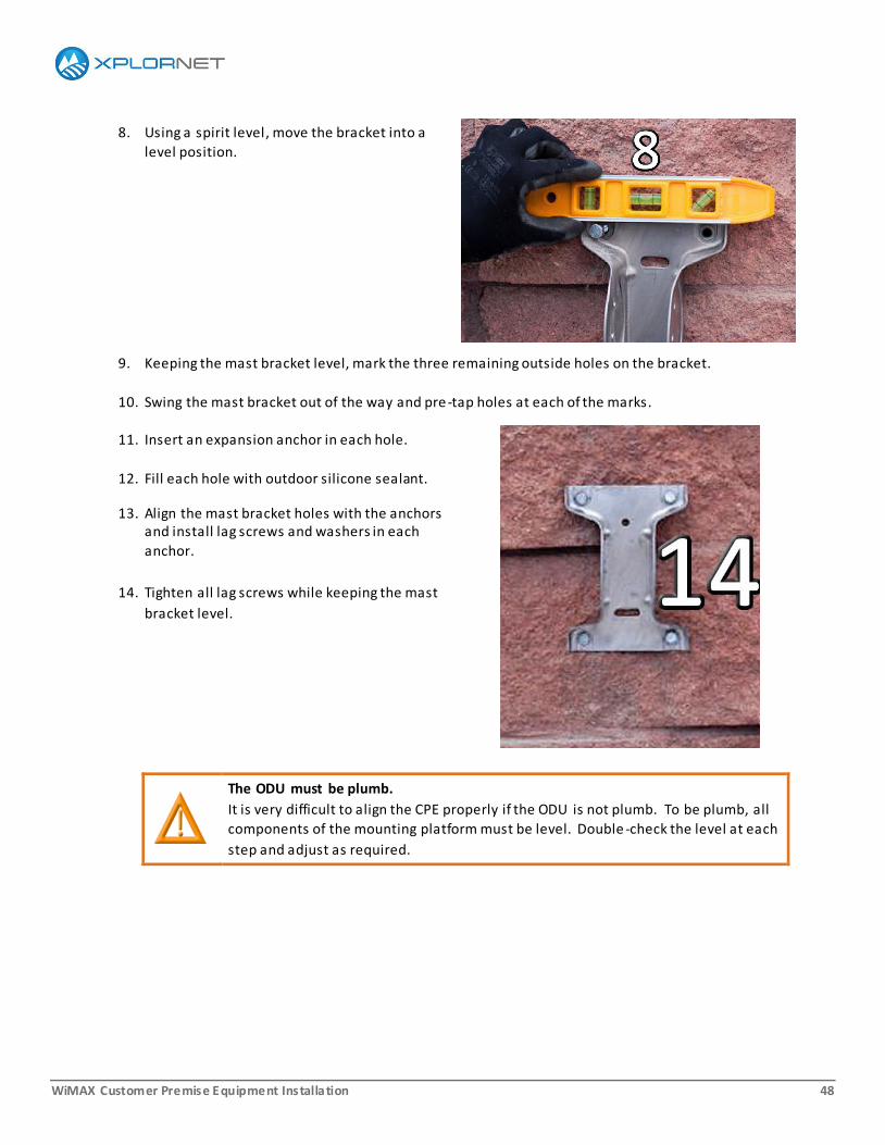
8. Using a spirit level, move the bracket into a
level position.
9. Keeping the mast bracket level, mark the three remaining outside holes on the bracket.
10. Swing the mast bracket out of the way and pre-tap holes at each of the marks.
11. Insert an expansion anchor in each hole.
12. Fill each hole with outdoor silicone sealant.
13. Align the mast bracket holes with the anchors and install lag screws and washers in each
anchor.
14. Tighten all lag screws while keeping the mast
bracket level.
The ODU must be plumb.
It is very difficult to align the CPE properly if the ODU is not plumb. To be plumb, all
components of the mounting platform must be level. Double -check the level at each
step and adjust as required.
WiMAX Customer Premise Equipment Installation 49
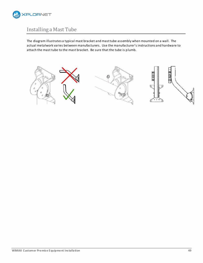
Installing a Mast Tube
The diagram illustrates a typical mast bracket and mast tube assembly when mounted on a wall. The
actual metalwork varies between manufacturers. Use the manufacturer’s instructions and hardware to
attach the mast tube to the mast bracket. Be sure that the tube is p lumb.

WiMAX Customer Premise Equipment Installation 50
Installing Side Stays
Apply the following rules when installing sides stays but also refer to the manufacturer’s instructions and
hardware specifications. These rules only apply to a trimast mounting platform as it is the only platform
with side stays.
For wood frame construction, side stays (A) must mount into structural members (B).
For masonry, mast bracket lag screws (C) must be at least 28in–71cm (D) away from door or window frames, or from the top, corner, or edge of the structure.
For side stays (E), avoid unnecessary holes as much as possible and provide as much separation
between holes as possible.
WiMAX Customer Premise Equipment Installation 51
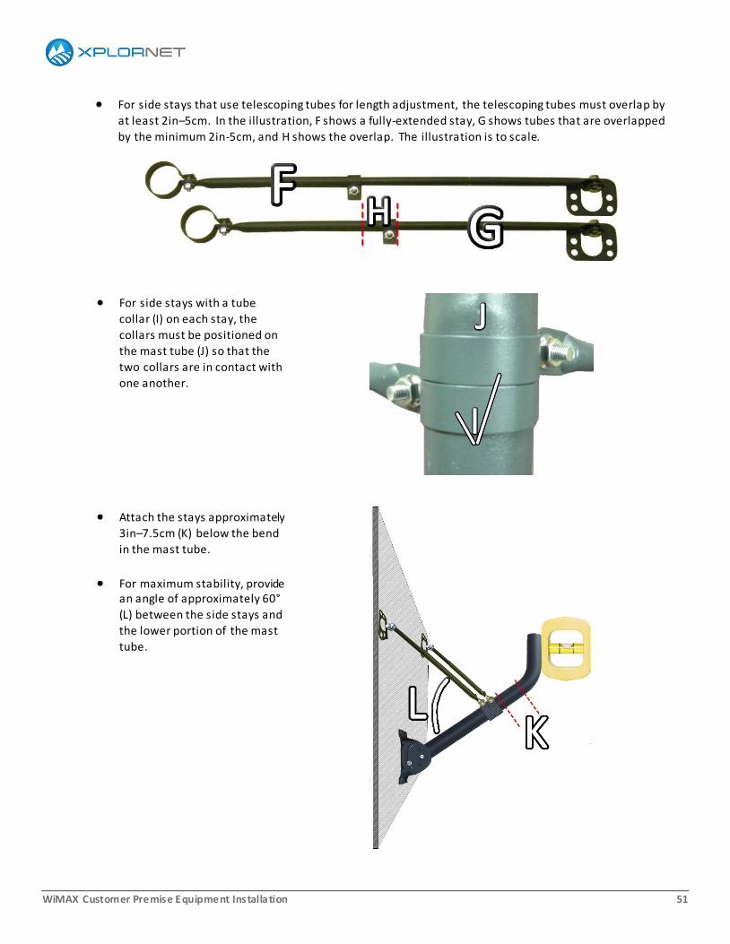
For side stays that use telescoping tubes for length adjustment, the telescoping tubes must overlap by
at least 2in–5cm. In the illustration, F shows a fully-extended stay, G shows tubes that are overlapped
by the minimum 2in-5cm, and H shows the overlap. The illustration is to scale.
For side stays with a tube
collar (I) on each stay, the
collars must be positioned on
the mast tube (J) so that the
two collars are in contact with
one another.
Attach the stays approximately
3in–7.5cm (K) below the bend
in the mast tube.
For maximum stability, provide an angle of approximately 60°
(L) between the side stays and
the lower portion of the mast
tube.
WiMAX Customer Premise Equipment Installation 52
Installing on a Roof
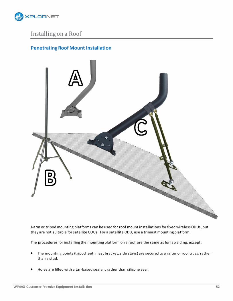
Penetrating Roof Mount Installation
J-arm or tripod mounting platforms can be used for roof mount installations for fixed wireless ODUs, but
they are not suitable for satellite ODUs. For a satellite ODU, use a trimast mounting platform.
The procedures for installing the mounting platform on a roof are the same as for lap siding, except:
The mounting points (tripod feet, mast bracket, side stays) are secured to a rafter or roof truss, rather
than a stud.
Holes are filled with a tar-based sealant rather than silicone seal.

WiMAX Customer Premise Equipment Installation 53
To find a rafter or truss:
Use a rubber mallet to sound the roof.
Look for exposed rafters in open soffits .
Measure from the gable edge after confirming the distance between rafters or trusses
WiMAX Customer Premise Equipment Installation 54
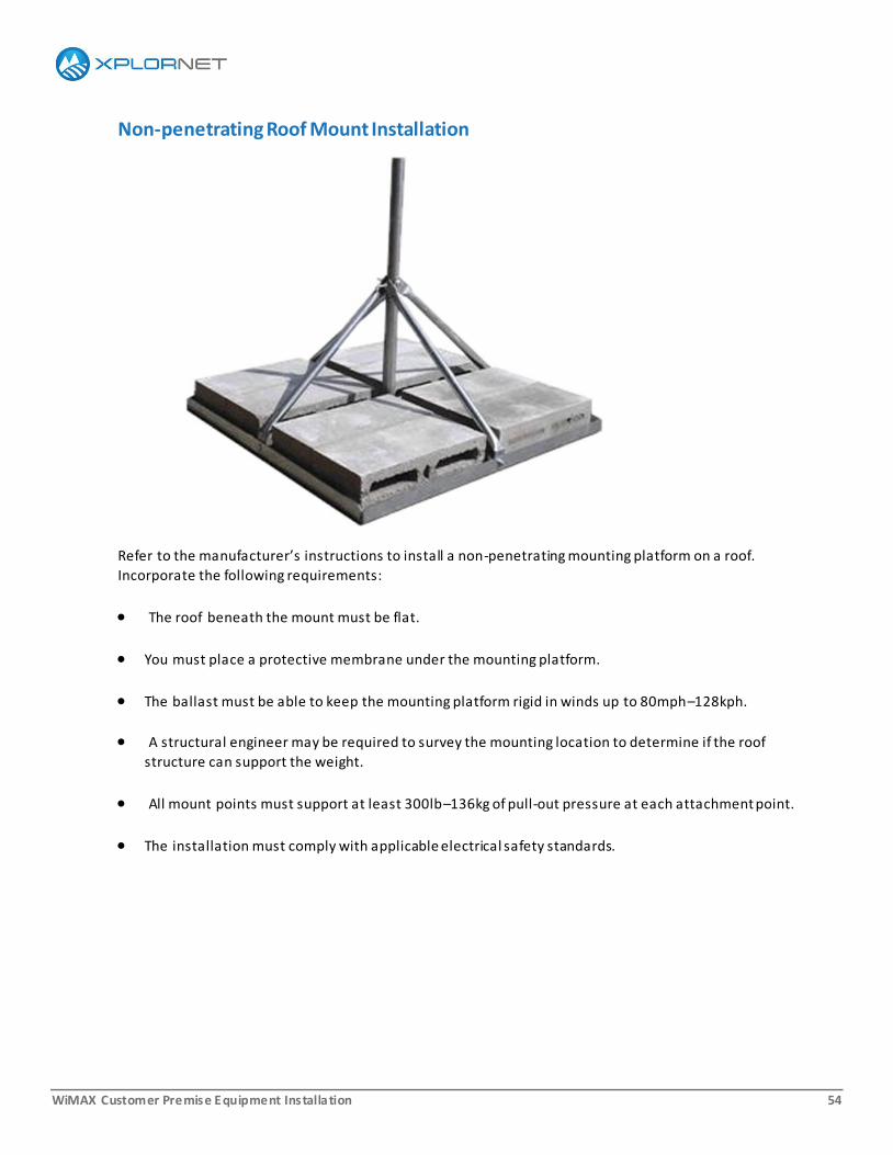
Non-penetrating Roof Mount Installation
Refer to the manufacturer’s instructions to install a non-penetrating mounting platform on a roof.
Incorporate the following requirements:
The roof beneath the mount must be flat.
You must place a protective membrane under the mounting platform.
The ballast must be able to keep the mounting platform rigid in winds up to 80mph–128kph.
A structural engineer may be required to survey the mounting location to determine if the roof
structure can support the weight.
All mount points must support at least 300lb–136kg of pull-out pressure at each attachment point.
The installation must comply with applicable electrical safety standards.

WiMAX Customer Premise Equipment Installation 55
Installing a Pole
All underground utility lines must be marked by the local utility company or government building inspector before you begin a pole mount installation.
Ensure that a pole mount installation does not require a building permit before proceeding.
Tools and Materials
In addition to the tools and materials identified in the Preparing for a Site Visit chapter, you need the
following for a pole mount installation:
Shovel or post-hole digger
Post spirit level
Anti-spin device
(The mast bracket of a trimast mounting platform can be used.)
PVC conduit (if using non-flooded cable)
Quick-setting concrete mix sufficient to fill the hole
WiMAX Customer Premise Equipment Installation 56
Schedule 40 galvanized steel pipe having an outside diameter of 2 3/8in.
The ODU may need an adapter in order to mate with the pipe.
The length of pipe depends on your latitude and the type of service.
o For satellite, as you go further north, the elevation of a satellite drops, and the length of pipe must
be longer given the same terrain. A pipe that provides 6ft –2m above ground usually works in
southern Canada.
o For fixed wireless, the elevation of a base station can be very low and longer po les may be
required.
Any pipe that extends over 10ft–3m above ground must be guyed in three places.
Location
The ground must be firm and not prone to flooding.
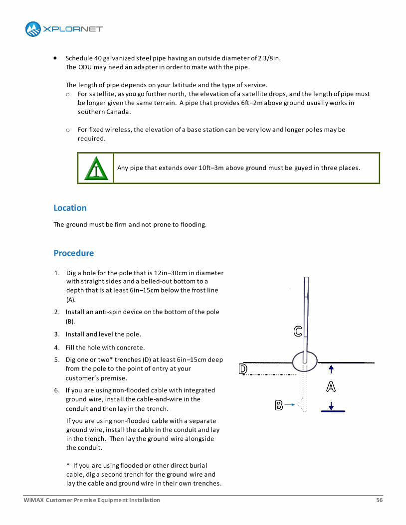
Procedure
1. Dig a hole for the pole that is 12in–30cm in diameter with straight sides and a belled-out bottom to a
depth that is at least 6in–15cm below the frost line
(A).
2. Install an anti-spin device on the bottom of the pole
(B).
3. Install and level the pole.
4. Fill the hole with concrete.
5. Dig one or two* trenches (D) at least 6in–15cm deep
from the pole to the point of entry at your
customer’s premise.
6. If you are using non-flooded cable with integrated
ground wire, install the cable-and-wire in the
conduit and then lay in the trench.
If you are using non-flooded cable with a separate
ground wire, install the cable in the conduit and lay
in the trench. Then lay the ground wire alongside
the conduit.
* If you are using flooded or other direct burial
cable, dig a second trench for the ground wire and
lay the cable and ground wire in their own trenches.

WiMAX Customer Premise Equipment Installation 57
7. Protect the cable at both ends of the trench with conduit sweeps that extend from the bottom of the
trench to at least 6in–15cm above the ground surface.
8. Backfill the trench(es).
WiMAX Customer Premise Equipment Installation 58
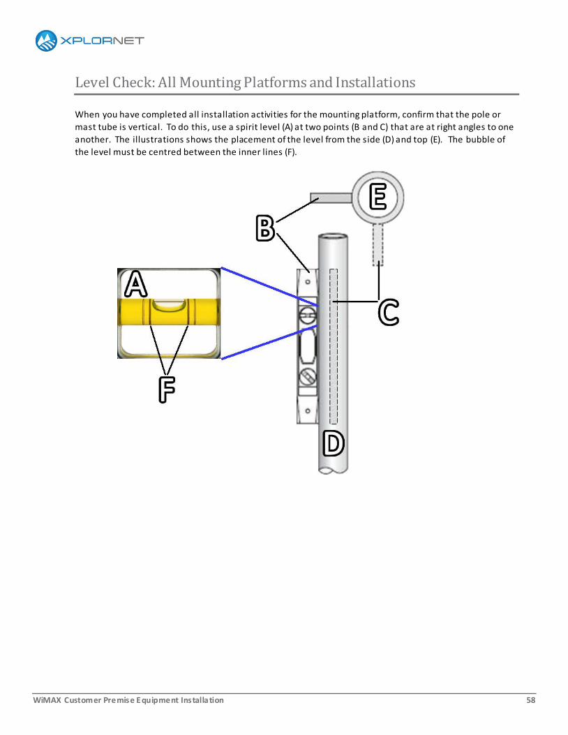
Level Check: All Mounting Platforms and Installations
When you have completed all installation activities for the mounting platform, confirm that the pole or
mast tube is vertical. To do this, use a spirit level (A) at two points (B and C) that are at right angles to one
another. The illustrations shows the placement of the level from the side (D) and top (E). The bubble of
the level must be centred between the inner lines (F).
WiMAX Customer Premise Equipment Installation 59
5. Activating the Service
To activate the service, you need:
Your Xplornet Number (XN) and Installer Portal password
Your customer's Account ID
The Work Order ID
The latitude and longitude of the ODU
WiMAX Customer Premise Equipment Installation 60
Latitude and Longitude
Network software uses the latitude and longitude you enter through the Installer Portal to calculate the
acceptable QoI values for your installation. For best results, measure the latitude and longitude of the
ODU as close to the actual location as possible, but no more than 200ft–60m away from the ODU.
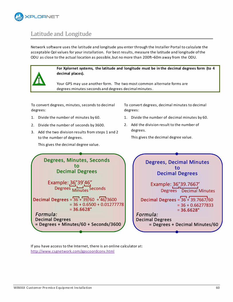
For Xplornet systems, the latitude and longitude must be in the decimal degrees form (to 4
decimal places).
Your GPS may use another form. The two most common alternate forms are
degrees:minutes:seconds and degrees decimal minutes .
To convert degrees, minutes, seconds to decimal
degrees:
1. Divide the number of minutes by 60.
2. Divide the number of seconds by 3600.
3. Add the two division results from steps 1 and 2
to the number of degrees.
This gives the decimal degree value.
To convert degrees, decimal minutes to decimal
degrees:
1. Divide the number of decimal minutes by 60.
2. Add the division result to the number of
degrees.
This gives the decimal degree value.
If you have access to the Internet, there is an online calculator at:
http://www.csgnetwork.com/gpscoordconv.html

WiMAX Customer Premise Equipment Installation 61
Activating the Service, Part 1
Part 1 of Activating the Service takes you from logging into the Installer Portal to opening the work order.
Part 2 covers the steps you take to initiate service activation.
1. Connect your computer directly to the IDU.
2. Open a browser.
Supported browsers are: Internet Explorer 8 and 9, Firefox, and Chrome.
3. In the URL field, enter: https://InstallerPortal.Xplornet.com
4. When the Installer Portal login page opens:
a. Enter your XN in the User Name field.
b. Enter your Installer Portal password in the Password field.
5. Click Log In.
The Account ID page opens.
To change to a French version of the Activation pages, click Francais at the top right of the page.
6. Enter your customer's Account ID in the Account ID field.
7. Click Submit.
A Provisioning Records page opens.

WiMAX Customer Premise Equipment Installation 62
8. Scan the list of records and click the Work Order ID hyperlink for this installation.
A work order summary page opens. Proceed to Part 2 of Activating the Service.

WiMAX Customer Premise Equipment Installation 63
Activating the Service, Part 2
Part 1 of Activating the Service brought you to the point where the Word Order Summary page is open.
Part 2 completes service activation.
9. Values for work order type, the platform code and name, the promotion code, and the rate plan are
displayed on the Work Order Summary page.
For a new WiMAX installation, the Work Order Type is New Install and the Platform Code is FWA.
If any values are incorrect, click Cancel and contact your Dealer.
If all values are good, click Continue.
The Provisioning page opens.
10. Enter the latitude and longitude of the ODU, in decimal degrees to 4 decimal places .
Enter the longitude as a negative number.
11. Click Submit.
Click Submit once only.
The network is collecting and analyzing the Quality of Installation values for the CPE. This can take
several minutes

WiMAX Customer Premise Equipment Installation 64
12. When the analysis is complete, three different pages can open:
a. QoI Validation Error:
This indicates a network error.
Click Retry.
If the problem persists, note the Status Code and contact the Dealer Support Group.
b. QoI Validation Failure:
This indicates unacceptable QoI levels at the ODU. The parameters and values used are the same
as the ones you used to determine acceptability.
Click Retry.
If the QoI Validation Failure page opens again, call the Dealer Support Group to verify that the
provisioning system is working. If it is, follow the troubleshooting guidelines provided in the
Aligning the CPE chapter of the CPE-specific installation guide.
c. Confirmation:
This indicates that the QoI values are acceptable.
Continue to the next step.
13. Click Submit.
The Completion page opens.
14. On the Completion page:
a. If your customer ordered email accounts, the provisioned email addresses are displayed. If any
show a Failed status, contact the Dealer Support Group. Otherwise, advise your customer of the
addresses.
b. Add Notes if applicable. For example, "Customer has large, but friendly, dogs."
c. Click Complete Work Order.
For the BreezeMAX PRO 3000 only, the network checks the CPE to see if the CPE firmware is up-to-
date:
If the firmware is up-to-date, a message opens confirming that it is up to date.
The service is activated and you can log out of the Installer Portal.
If the CPE firmware is not up-to-date, a message indicates that the firmware is being updated and
an indicator bar shows the progress of the update. The update can take up to 15 minutes, during
which time the CPE can reboot several times.
During the update, it is very important that the power remain on and that you do not
use the WMI or close the browser window.
If the firmware update is successful, a confirmation message displays when the update
completes. The service is activated and you can log out of the Installer Portal.
If the firmware update is not successful, an error message displays.
Contact the Dealer Support Group.
WiMAX Customer Premise Equipment Installation 65
15. When the Completion page closes, open a web page and verify that you can surf the net.
Use a page with frequently updated content to ensure that your browser is actually surfing the web
and not accessing old content saved on your computer. For examples, try cbc.ca or ctv.ca.
If you can surf, you are done.
If you cannot surf, call the Dealer Support Group.
Static IP Address
If the customer has ordered a static IP address, then:
1. Refer to the static IP address details in the CPE-specific installation guide.
2. Call the Dealer Support Group (1-866-841-6004) and work with them to configure the customer’s
computer for static IP.
OR
Have your customer call Customer Service (1-866-841-6001) for instructions.
WiMAX Customer Premise Equipment Installation 66
Quality Checklist
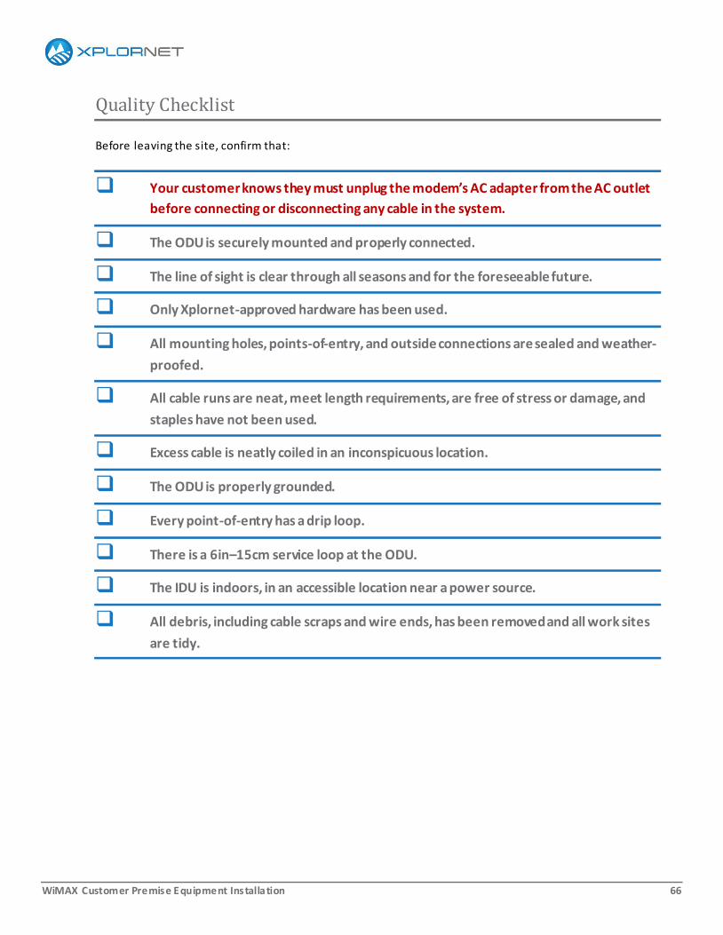
Before leaving the site, confirm that:
Your customer knows they must unplug the modem’s AC adapter from the AC outlet
before connecting or disconnecting any cable in the system.
The ODU is securely mounted and properly connected.
The line of sight is clear through all seasons and for the foreseeable future.
Only Xplornet-approved hardware has been used.
All mounting holes, points-of-entry, and outside connections are sealed and weather-
proofed.
All cable runs are neat, meet length requirements, are free of stress or damage, and
staples have not been used.
Excess cable is neatly coiled in an inconspicuous location.
The ODU is properly grounded.
Every point-of-entry has a drip loop.
There is a 6in–15cm service loop at the ODU.
The IDU is indoors, in an accessible location near a power source.
All debris, including cable scraps and wire ends, has been removed and all work sites
are tidy.

WiMAX Customer Premise Equipment Installation 67
Finishing Touches
Finally, obtain your customer’s approval of both your work and the service:
Review the physical installation with your customer.
Confirm that your customer is satisfied with your work: the location of the ODU and
IDU, and the look of cabling, holes, entry points, and work sites.
Make sure that your customer knows his or her Xplornet Account ID and their
Customer Portal username and password.
If your customer has Xplornet email, make sure they know their username and
password and how to access the Xplornet web page on email instructions.
Ask your customer for approval to bookmark the Customer Portal page (https://na10.sa lesforce.com/secur/log in_porta l.jsp?orgId=00DA0000000Y159&porta lId=060A000
0000LiGS) and the Webmail page (http://smtp.xplornet.com/mail? nimlet=showlog in).
Provide your customer with the information necessary to contact Xplornet Technical
Support (1-866-841-6001; [email protected]).
Optionally, you can provide contact information for local technical support services.
If you have any comments on any of the on-line or instructor-led courses or the installation
documentation, we’d be happy to hear from you. Email us at [email protected].

WiMAX Customer Premise Equipment Installation 68
Appendix A: Quality of Installation Parameters
All Xplornet Internet services are offered through a number of programs, with each program tailored for a
specific user group. The programs are:
National Program
Broadband Canada Federal Broadband Stimulus Program
Eastern Ontario Regional Network Program
Programs are often delivered at different bandwidths depending on the network infrastructure serving the
customer.
Each program also offers several rate plans to provide flexibility in the service offerings for the program.
Quality of Installation (QoI) parameters have been defined for the WiMAX service and acceptable values
for the QoI parameters are set for each rate plan. A service is unacceptable if a measured value fails to
meet the specified value.
Refer to the following tables for the acceptable QoI values for each rate plan.
WiMAX Customer Premise Equipment Installation 69
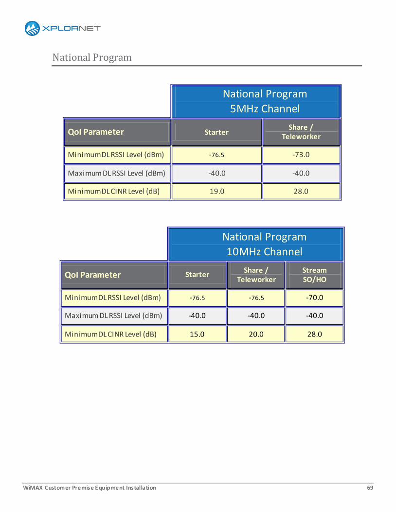
National Program
National Program
5MHz Channel
QoI Parameter Starter Share /
Teleworker
Minimum DL RSSI Level (dBm) -76.5 -73.0
Maximum DL RSSI Level (dBm) -40.0 -40.0
Minimum DL CINR Level (dB) 19.0 28.0
National Program
10MHz Channel
QoI Parameter Starter Share /
Teleworker Stream SO/HO
Minimum DL RSSI Level (dBm) -76.5 -76.5 -70.0
Maximum DL RSSI Level (dBm) -40.0 -40.0 -40.0
Minimum DL CINR Level (dB) 15.0 20.0 28.0
WiMAX Customer Premise Equipment Installation 70
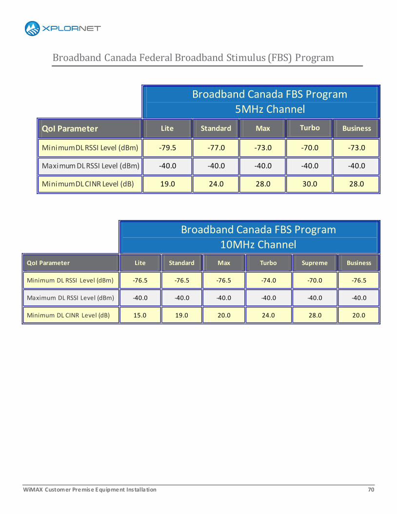
Broadband Canada Federal Broadband Stimulus (FBS) Program
Broadband Canada FBS Program
5MHz Channel
QoI Parameter Lite Standard Max Turbo Business
Minimum DL RSSI Level (dBm) -79.5 -77.0 -73.0 -70.0 -73.0
Maximum DL RSSI Level (dBm) -40.0 -40.0 -40.0 -40.0 -40.0
Minimum DL CINR Level (dB) 19.0 24.0 28.0 30.0 28.0
Broadband Canada FBS Program
10MHz Channel
QoI Parameter Lite Standard Max Turbo Supreme Business
Minimum DL RSSI Level (dBm) -76.5 -76.5 -76.5 -74.0 -70.0 -76.5
Maximum DL RSSI Level (dBm) -40.0 -40.0 -40.0 -40.0 -40.0 -40.0
Minimum DL CINR Level (dB) 15.0 19.0 20.0 24.0 28.0 20.0
WiMAX Customer Premise Equipment Installation 71
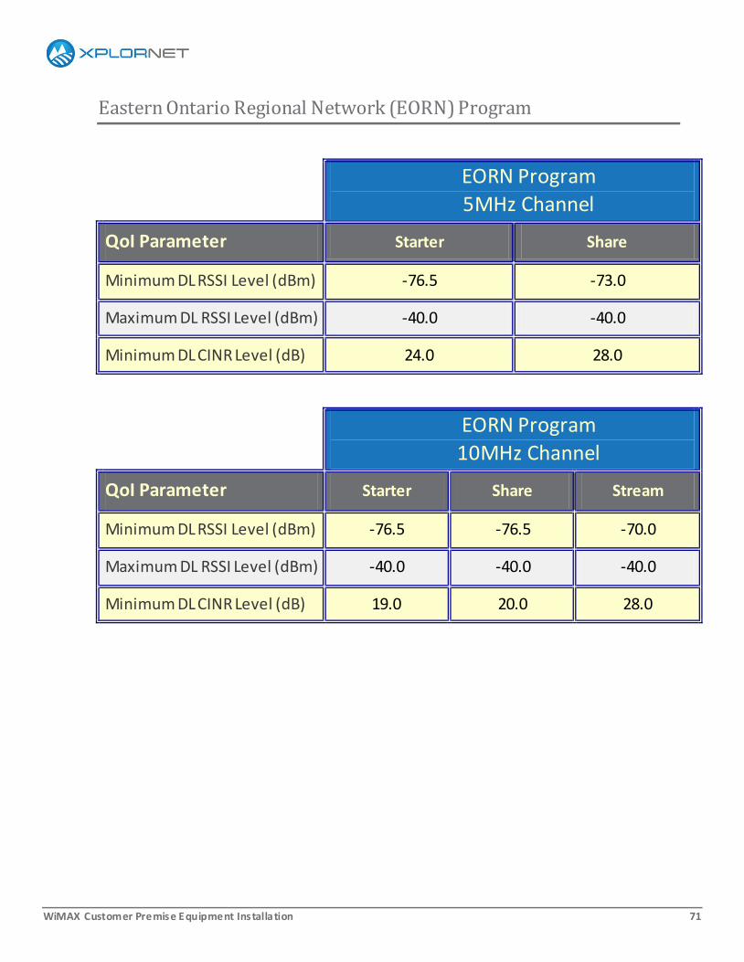
Eastern Ontario Regional Network (EORN) Program
EORN Program
5MHz Channel
QoI Parameter Starter Share
Minimum DL RSSI Level (dBm) -76.5 -73.0
Maximum DL RSSI Level (dBm) -40.0 -40.0
Minimum DL CINR Level (dB) 24.0 28.0
EORN Program
10MHz Channel
QoI Parameter Starter Share Stream
Minimum DL RSSI Level (dBm) -76.5 -76.5 -70.0
Maximum DL RSSI Level (dBm) -40.0 -40.0 -40.0
Minimum DL CINR Level (dB) 19.0 20.0 28.0

WiMAX Customer Premise Equipment Installation 72
Appendix X: Xplornet Installer Safety Standards v2.0, 5-May-13
The purpose of Xplornet’s Installer Safety Standards is to provide a framework for your work that ensures a
healthier, happier experience for you and your customer.
The topics covered in the Installer Safety Standards are:
Safety: First to Last
Dress Code
Ladders
Working Off Ground
Environment
Power
Electromagnetic Radiation
Driving
CPE Guidelines
WiMAX Customer Premise Equipment Installation 73
Safety: First to Last
When preparing for a site visit, travelling
to and from the site, and especially when
on-site, consider safety at all times:
Your safety
The customer’s safety
The safety of the customer’s home
and equipment
Follow Xplornet’s Installer Safety
Standards as well as any Federal and
Provincial standards that apply.
Where different standards address the
same point, the stricter and more
specific standard applies.

WiMAX Customer Premise Equipment Installation 74
Dress Code
No loose clothing or jewelry
Steel-toed boots and
gloves are
recommended
With power tools, use
protective eye wear
and ear plugs
For overhead work, wear a hard hat
Avoid any drugs that
may impair your
senses or judgement
– read the labels
carefully
WiMAX Customer Premise Equipment Installation 75
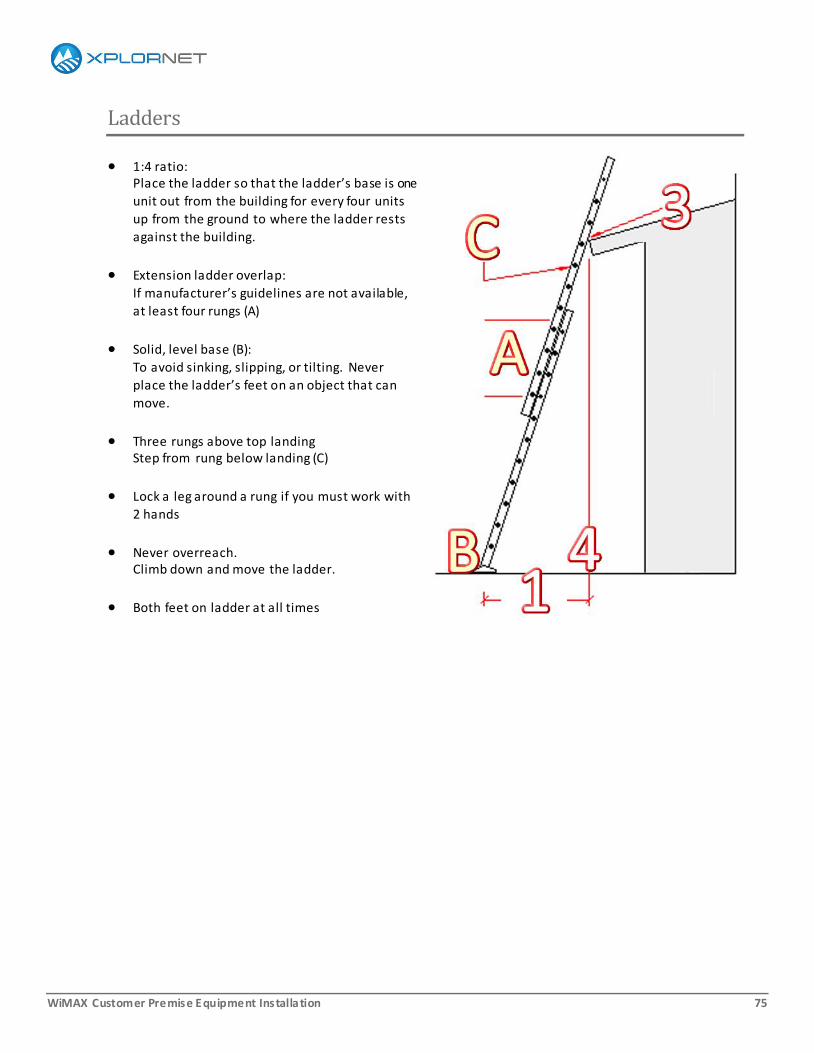
Ladders
1:4 ratio: Place the ladder so that the ladder’s base is one
unit out from the building for every four units
up from the ground to where the ladder rests
against the building.
Extension ladder overlap:
If manufacturer’s guidelines are not available,
at least four rungs (A)
Solid, level base (B):
To avoid sinking, slipping, or tilting. Never
place the ladder’s feet on an object that can
move.
Three rungs above top landing Step from rung below landing (C)
Lock a leg around a rung if you must work with
2 hands
Never overreach. Climb down and move the ladder.
Both feet on ladder at all times

WiMAX Customer Premise Equipment Installation 76
Working Off Ground
Safety harness and fall arrest equipment required
as per Provincial Workplace
Health and Safety
Regulations
Non-standard height
(installation qualifies for an
enhanced installation):
o Structure is 21ft–6.5m
or higher
o Workplace is not
accessible with a 25ft–
7.5m ladder
Any mast over 10ft–3m
must be guyed at 3 points.
WiMAX Customer Premise Equipment Installation 77
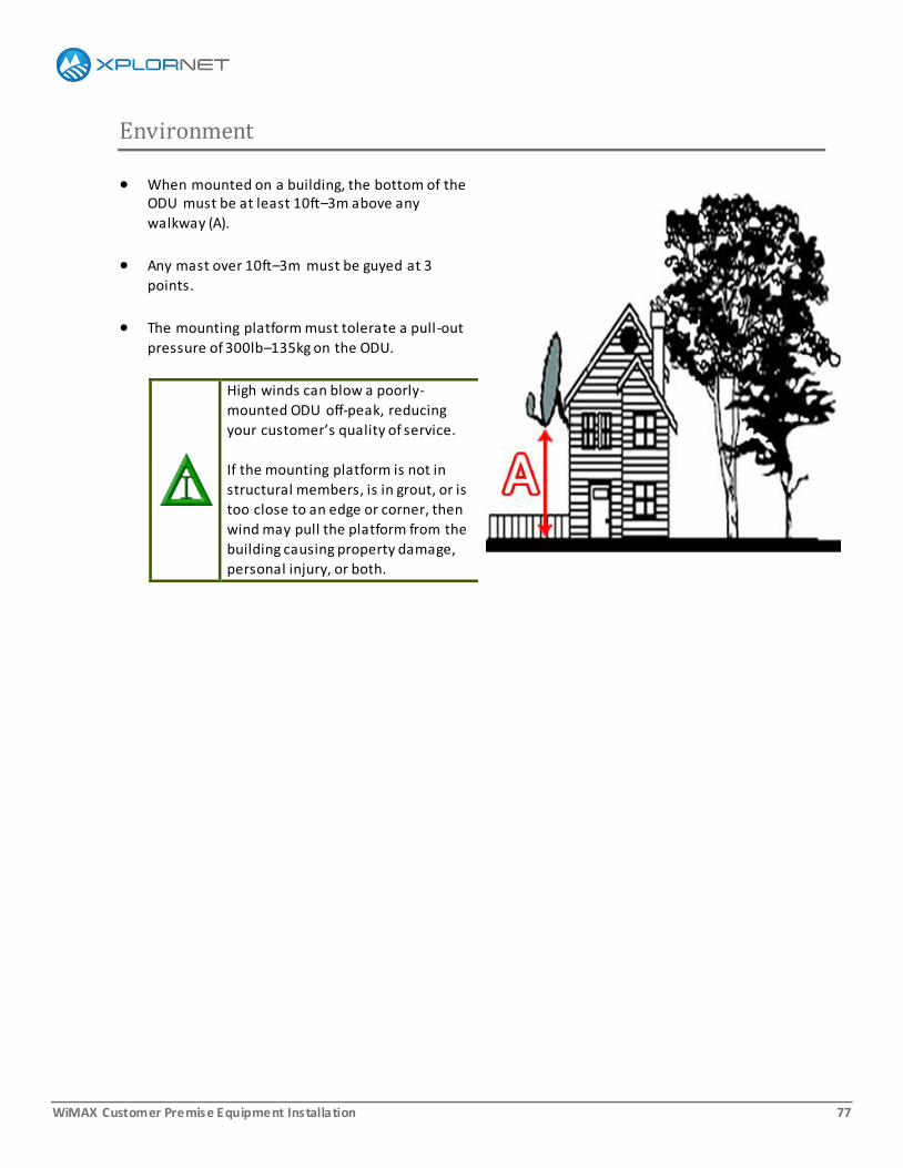
Environment
When mounted on a building, the bottom of the ODU must be at least 10ft–3m above any
walkway (A).
Any mast over 10ft–3m must be guyed at 3
points.
The mounting platform must tolerate a pull-out
pressure of 300lb–135kg on the ODU.
High winds can blow a poorly-
mounted ODU off-peak, reducing
your customer’s quality of service.
If the mounting platform is not in
structural members, is in grout, or is
too close to an edge or corner, then
wind may pull the platform from the
building causing property damage,
personal injury, or both.
WiMAX Customer Premise Equipment Installation 78
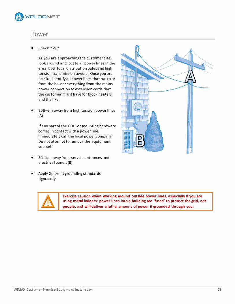
Power
Check it out
As you are approaching the customer site,
look around and locate all power lines in the
area, both local distribution poles and high
tension transmission towers. Once you are
on-site, identify all power lines that run to or
from the house: everything from the mains
power connection to extension cords that
the customer might have for block heaters
and the like.
20ft–6m away from high tension power lines
(A)
If any part of the ODU or mounting hardware
comes in contact with a power line,
immediately call the local power company.
Do not attempt to remove the equipment
yourself.
3ft–1m away from service entrances and electrical panels (B)
Apply Xplornet grounding standards
rigorously
Exercise caution when working around outside power lines, especially if you are using metal ladders: power lines into a building are ‘fused’ to protect the grid, not
people, and will deliver a lethal amount of power if grounded through you.
WiMAX Customer Premise Equipment Installation 79
Electromagnetic Radiation
Location must comply with Health Canada’s Safety Code 6 guidelines : ODU must be at least 4ft–120cm from all persons
WiMAX Customer Premise Equipment Installation 80
Driving
All Xplornet Installers must have a valid driver's licence and must adhere to the Distracted Driver
regulations in force in your region. For more information on the Distracted Driver regulations, check your
provincial vehicle regulations.
When transporting equipment in your vehicle, take care to store the equipment in a way that prevents
exposure to rain and snow, the weight and pressure of other objects, or movement.

WiMAX Customer Premise Equipment Installation 81
CPE Considerations
In general, there are no user-serviceable parts in any of the customer premise equipment used in Xplornet
services. Do not open either the indoor or outdoor uni ts as some components can have residual high
voltage.
Related Documents