Wilson Boiler Blowdown Systems and Equipment 712-202-1610 wilsonblowdown.com Engineering WILSON

Welcome message from author
This document is posted to help you gain knowledge. Please leave a comment to let me know what you think about it! Share it to your friends and learn new things together.
Transcript
WilsonBoilerBlowdownSystemsand Equipment
712-202-1610 wilsonblowdown.com
Eng i n eer i n g
W I L S O N
Wilson Engineering | Blowdown Separator Systems | 712-202-1610 | wilsonblowdown.com
Wilson EngineeringComplete Boiler Blowdown Systems and EquipmentOver 60 Years Of Experience In Safe And Efficient Handling Of Boiler Blowoff
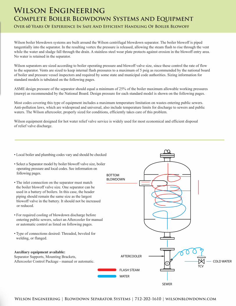
Wilson boiler blowdown systems are built around the Wilson centrifugal blowdown separator. The boiler blowoff is piped tangentially into the separator. In the resulting vortex the pressure is released, allowing the steam flash to rise through the vent while the water and sludge fall through the drain. A stainless steel wear plate protects against erosion in the blowoff entry area. No water is retained in the separator.
Wilson separators are sized according to boiler operating pressure and blowoff valve size, since these control the rate of flow to the separator. Vents are sized to keep internal flash pressures to a maximum of 5 psig as recommended by the national board of boiler and pressure vessel inspectors and required by some state and municipal code authorities. Sizing information for standard models is tabulated on the following pages.
ASME design pressure of the separator should equal a minimum of 25% of the boiler maximum allowable working pressures (mawp) as recommended by the National Board. Design pressure for each standard model is shown on the following pages.
Most codes covering this type of equipment includes a maximum temperature limitation on wastes entering public sewers. Anti-pollution laws, which are widespread and universal, also include temperature limits for discharge to sewers and public waters. The Wilson aftercooler, properly sized for conditions, efficiently takes care of this problem.
Wilson equipment designed for hot water relief valve service is widely used for most economical and efficient disposalof relief valve discharge.
• Local boiler and plumbing codes vary and should be checked
• Select a Separator model by boiler blowoff valve size, boiler operating pressure and local codes. See information on following pages.
• The inlet connection on the separator must match the boiler blowoff valve size. One separator can be used in a battery of boilers. In this case, the header piping should remain the same size as the largest blowoff valve in the battery. It should not be increased or reduced.
• For required cooling of blowdown discharge before entering public sewers, select an Aftercooler for manual or automatic control as listed on following pages.
• Type of connections desired: Threaded, beveled for welding, or flanged.
Auxiliary equipment available:Separator Supports, Mounting Brackets,Aftercooler Control Package - manual or automatic.
T
AFTERCOOLER
TCV
COLD WATER
SEWER
BOTTOMBLOWDOWN
FLASH STEAM
WATER
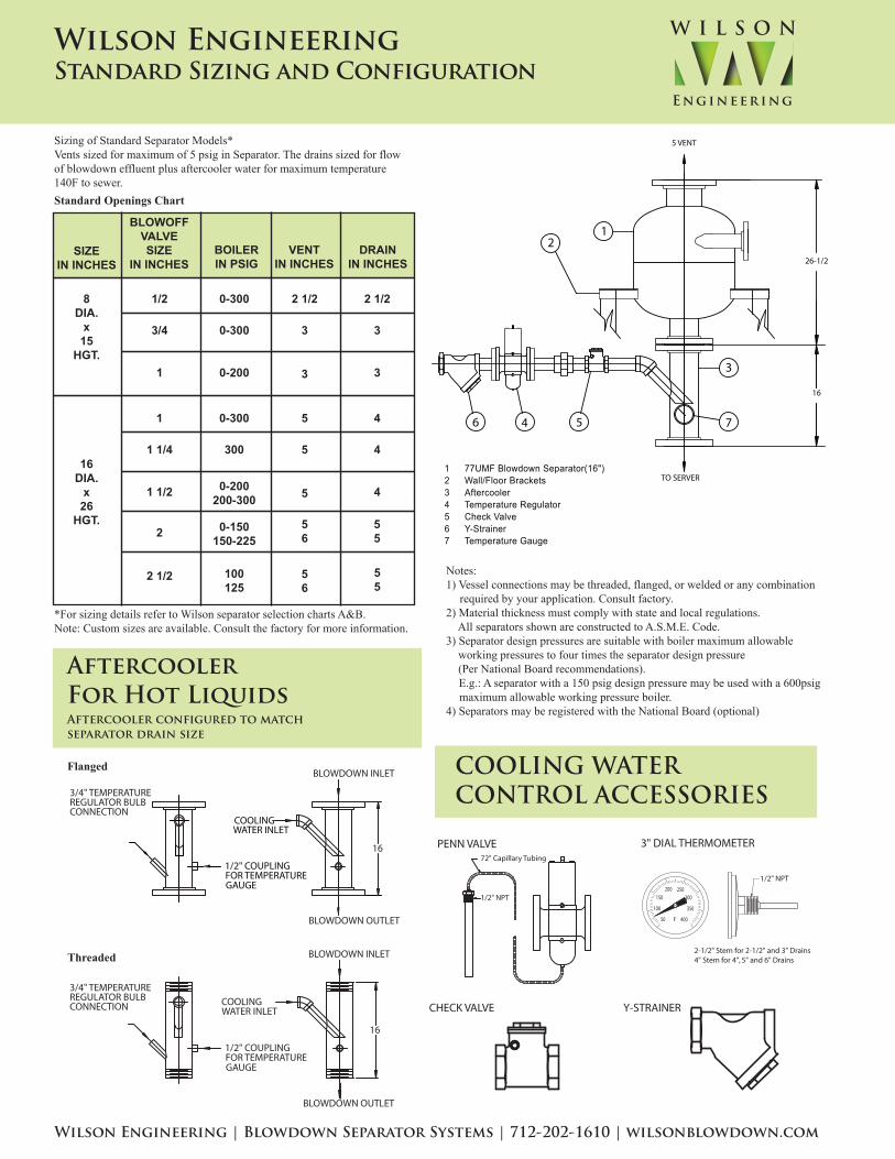
Sizing of Standard Separator Models*Vents sized for maximum of 5 psig in Separator. The drains sized for flowof blowdown effluent plus aftercooler water for maximum temperature140F to sewer.
*For sizing details refer to Wilson separator selection charts A&B.Note: Custom sizes are available. Consult the factory for more information.
Standard Openings Chart
Threaded
Flanged
Wilson Engineering | Blowdown Separator Systems | 712-202-1610 | wilsonblowdown.com
Wilson EngineeringStandard Sizing and Configuration
AftercoolerFor Hot LiquidsAftercooler configured to matchseparator drain size
COOLING WATERCONTROL ACCESSORIES
Notes:1) Vessel connections may be threaded, flanged, or welded or any combination required by your application. Consult factory.2) Material thickness must comply with state and local regulations. All separators shown are constructed to A.S.M.E. Code.3) Separator design pressures are suitable with boiler maximum allowable working pressures to four times the separator design pressure (Per National Board recommendations). E.g.: A separator with a 150 psig design pressure may be used with a 600psig maximum allowable working pressure boiler.4) Separators may be registered with the National Board (optional)
TO SERVER
5 VENT
3
7
12
26-1/2
16
546
1 77UMF Blowdown Separator(16")2 Wall/Floor Brackets3 Aftercooler4 Temperature Regulator5 Check Valve6 Y-Strainer7 Temperature Gauge
SIZEIN INCHES
8DIA.
x15
HGT.
1/2
3/4
1
0-300
0-300
0-200
2 1/2
3
3
2 1/2
3
3
BLOWOFFVALVESIZE
IN INCHESBOILERIN PSIG
VENTIN INCHES
DRAININ INCHES
16DIA.
x26
HGT.
1
1 1/4
1 1/2
0-300
300
5
5
5
4
4
4
2 0-150150-225
0-200200-300
56
55
2 1/2 100125
56
55
Eng i n eer i ng
W I L S O N
3/4" TEMPERATUREREGULATOR BULBCONNECTION
BLOWDOWN OUTLET
BLOWDOWN INLET
FOR TEMPERATURE1/2" COUPLING
GAUGE
COOLINGWATER INLET
16
BLOWDOWN OUTLET
BLOWDOWN INLET
FOR TEMPERATURE1/2" COUPLING
GAUGE
COOLINGWATER INLET
16
PENN VALVE 3" DIAL THERMOMETER
2-1/2" Stem for 2-1/2" and 3" Drains4" Stem for 4", 5" and 6" Drains
1/2" NPT
1/2" NPT
72" Capillary Tubing
CHECK VALVE Y-STRAINER
50
100
150200 250
300
350
400�F
3/4" TEMPERATUREREGULATOR BULBCONNECTION

1403 SW 7th Street, Atlantic, Iowa 50022 TEL 712-202-1610 FAX 712-243-3440
Additional Wilson Products
Continuous BlowdownHeat Recovery System
Exhaust Heads
Have Questions Or Need Help Specifying This Equipment?Email: [email protected]
Need Help With An Existing System Or Parts?Email: [email protected]
Looking For A Local Representative?Email: [email protected]
Literature Available For Download At wilsonblowdown.com
Eng i n eer i n g
W I L S O N
Blowdown Tanks
Related Documents