APRIL 28, 2020 BACHELOR’S DEGREE IN INDUSTRIAL ELECTRONICS AND AUTOMATIC CONTROL ENGINEERING BACHELOR’S THESIS Authors: Guillem CORNELLA BARBA Eudald SANGENÍS RAFART Supervisors: Prof. Leslie TEKAMP WIFI REMOTE CONTROLLED RC CAR COMMANDED BY A C# APPLICATION & THE ESP32 WIFI MODULE

Welcome message from author
This document is posted to help you gain knowledge. Please leave a comment to let me know what you think about it! Share it to your friends and learn new things together.
Transcript
APRIL 28, 2020
BACHELOR’S DEGREE IN INDUSTRIAL
ELECTRONICS AND AUTOMATIC CONTROL
ENGINEERING
BACHELOR’S THESIS
Authors:
Guillem CORNELLA BARBA
Eudald SANGENÍS RAFART
Supervisors:
Prof. Leslie TEKAMP
WIFI REMOTE CONTROLLED RC CAR
COMMANDED BY A C# APPLICATION
& THE ESP32 WIFI MODULE

Wi-Fi Robot Guillem CORNELLA & Eudald SANGENIS
1
Contents
1. Abstract ................................................................................................................................. 5
2. Acknowledgements ............................................................................................................... 6
3. Scope ..................................................................................................................................... 7
4. Introduction........................................................................................................................... 8
5. List of materials ..................................................................................................................... 9
6. Hardware ............................................................................................................................. 10
6.1. Esp32 ........................................................................................................................... 10
6.2. Motor driver ................................................................................................................ 11
6.3. Servos .......................................................................................................................... 13
6.3.1. Steer control ........................................................................................................ 13
6.3.2. Camera control .................................................................................................... 14
6.4. Power supply – Battery ............................................................................................... 14
6.5. Ultrasonic Sensor ........................................................................................................ 15
7. Wi-Fi communications ......................................................................................................... 16
7.1. Wireless technology .................................................................................................... 16
7.2. Frequencies ................................................................................................................. 16
7.3. Wi-Fi security protocols............................................................................................... 16
7.4. Structure ...................................................................................................................... 17
7.5. TCP/UPD protocols. ..................................................................................................... 18
7.6. University Wi-Fi networks ........................................................................................... 20
8. Application Code ................................................................................................................. 21
8.1. Libraries: ...................................................................................................................... 21
8.1.1. NuGet libraries: ................................................................................................... 22
8.1.2. System libraries ................................................................................................... 22
8.2. Camera characteristics & code .................................................................................... 23
8.3. Controller code ............................................................................................................ 26
8.3.1. Keyboard ............................................................................................................. 26
8.3.2. Xbox Controller .................................................................................................... 28
9. Arduino code ....................................................................................................................... 30
9.1. Libraries ....................................................................................................................... 30
9.2. Variables ...................................................................................................................... 30
9.3. Setup ........................................................................................................................... 30
9.4. Loop ............................................................................................................................. 31
10. Building the robot ........................................................................................................... 33

Wi-Fi Robot Guillem CORNELLA & Eudald SANGENIS
2
10.1. Research and purchasing of materials .................................................................... 33
10.2. Disassembling the RC car ........................................................................................ 33
10.3. Designing a 3D support ........................................................................................... 33
10.4. First connections on the breadboard and first test ................................................ 34
10.5. Welding the components to the PCB circuit board ................................................. 34
10.6. Building the 3D supports ......................................................................................... 35
10.7. Assembling of all the parts ...................................................................................... 36
10.8. Electrical diagram .................................................................................................... 36
10.8.1. Current analysis of the servo motors .................................................................. 37
10.8.2. Current analysis of the DC motors ...................................................................... 39
10.9. Current consumption .............................................................................................. 40
10.10. Test .......................................................................................................................... 41
11. Problems detected and solutions developed .................................................................. 42
12. Conclusions...................................................................................................................... 44
Bibliography ................................................................................................................................ 45
Figures
Figure 1.- ESP32 DEVKITV1 real photography of the device [4] .................................................. 10 Figure 2.- ESP32 DEVKIT V1 - DOIT, version with 30 GPIOs, PINOUT scheme [5] ....................... 10 Figure 3.- Pulse Width Modulation explanation ......................................................................... 11 Figure 4.- H-Bridge. Using switches to control the rotation direction ........................................ 11 Figure 5.- This is the module L298N with two terminal blocks for the motors A and B, and one
terminal block for the GND pin, the VCC to power the motor and a 5V pin (input or
output)................................................................................................................................. 12 Figure 6.- Input pins of the L298N driver. From left to right: ENA, IN1, IN2, IN3, IN4, ENB. ...... 12 Figure 7.- L298N block diagram ................................................................................................... 12 Figure 8.- SG90 servomotor [9] ................................................................................................... 13 Figure 9.- SG90 servo inside the cavity of the LG-ZJO4 servo ..................................................... 13 Figure 10.- LAEGENDARY servo the LG-ZJ04 [10] ....................................................................... 13 Figure 11.- MG996R servo [11] ................................................................................................... 14 Figure 12.- LiPo battery, 7.4V & 1600 mAh [12] ......................................................................... 14 Figure 13.- Max-Sonar-EZ Ultrasonic sensor ............................................................................... 15 Figure 14.- What is the difference between 2.4 GHz and 5 GHz Wi-Fi? [14] .............................. 16 Figure 15.- Network structure ..................................................................................................... 17 Figure 16.- IoT protocol stack options [16] ................................................................................. 18 Figure 17.- UCCS-Wireless details ............................................................................................... 20 Figure 18.- UCCS-Guest details .................................................................................................... 20 Figure 19.- eduroam details ........................................................................................................ 20 Figure 20.- Code structure........................................................................................................... 21 Figure 21.- AMCREST IP2M-841B [19] ......................................................................................... 23 Figure 22.- Video Surveillance IP Camera 2500 [20] ................................................................... 24

Wi-Fi Robot Guillem CORNELLA & Eudald SANGENIS
3
Figure 23.- Keyboard Controller application interface ................................................................ 26 Figure 24.- IP Window interface .................................................................................................. 27 Figure 25.- Interface of the program with the Xbox Controller .................................................. 28 Figure 26.- Photo of the materials, components, and tools ....................................................... 33 Figure 27.- RC Car without its cover protection .......................................................................... 33 Figure 28.- RC Car disassembled ................................................................................................. 33 Figure 29.- 3D-designed support. Screenshot from the 3D-Builder Software ............................ 34 Figure 30.- Testing the components on the breadboard before welding them together .......... 34 Figure 31.- Photo of the components welded to a PCB .............................................................. 34 Figure 32.- Support to fit the battery inside and the modules on top. Screenshot from the ‘3D-
Builder software’ ................................................................................................................. 35 Figure 33.- Support created to fit the phone inside .................................................................... 35 Figure 34.- Cavity designed to fit the servomotor ...................................................................... 35 Figure 35.- Photo of the new support designed with methacrylate ........................................... 35 Figure 36.- Final prototype of the robot ..................................................................................... 36 Figure 37.- Electrical scheme of the robot. Designed using 'EasyEDA Software' ........................ 36 Figure 38.- Current analysis of the servomotors without any load applied (without touching the
floor and without a phone on its support). Blue: Position of the servo 1, Red: Position of
the servo 2, Green: Value of the servo 1 current, Orange: Value of the servo 2 current,
Magenta: Average value of the currents from both servos. ..... X_axis: test points, Y_axis:
Current (mA) ........................................................................................................................ 38 Figure 39.- Current analysis of the servomotors with load applied (without touching the floor
and with a phone on its support). Blue: Position of the servo 1, Red: Position of the servo
2, Green: Value of the servo 1 current, Orange: Value of the servo 2 current, Magenta:
Average value of the currents from both servos. X_axis: test points, Y_axis: Current (mA)
............................................................................................................................................. 38 Figure 40.- Current analysis of the DC motors without load applied (without touching the
floor). Blue: Current running from the battery to the motor driver. Red: Mean current of
the motors at maximum speed. Y_axis (mA) ...................................................................... 39 Figure 41.- Aerial footage of the circuit designed to test the robot ........................................... 41 Figure 42.- The robot running on the street and being controlled from one bedroom. ............ 41
Tables
Table 1.- Schedule of the project's timelines ................................................................................ 7 Table 2.- List of materials and costs .............................................................................................. 9 Table 3.- Colors from the servos and their functionality ............................................................ 14 Table 4.- Summary of Wi-Fi Security, GRANDMETRIC ................................................................ 17 Table 5.- TCP vs UDP protocols [17] ............................................................................................ 18 Table 6.- Connectivity of all the devices used with the UCCS and home networks. ................... 20 Table 7.- Current consumption of the robot ............................................................................... 40
Codes
Code 1.- Import MaterialDesingColors NuGet package in the App.xaml .................................... 22 Code 2.- Import VisioForge & OpenJigWare NuGet package in the MainWindow.xaml ............ 22 Code 3.- System libraries that were needed ............................................................................... 23 Code 4.- XAML implementation of the VisioForge library to create the view ............................ 24 Code 5.- XAML implementation to create the viewing interface. .............................................. 24

Wi-Fi Robot Guillem CORNELLA & Eudald SANGENIS
4
Code 6.- Headers of the functions to control the camera. ......................................................... 24 Code 7.- Fragment of the” Connect function”. ........................................................................... 25 Code 8.- Fragment of the” Disconnect function”. ....................................................................... 25 Code 9.- Fragment of the” Snapshot function”. .......................................................................... 25 Code 10.- Fragment of the “Record function”. ........................................................................... 26 Code 11.- Controlling the keyboard ............................................................................................ 27 Code 12.- Sending information using an UDP protocol when the key 'A' is pressed .................. 27 Code 13.- Creating a timer object and setting it up .................................................................... 28 Code 14.- Timer Tick function ..................................................................................................... 29 Code 15.- Joystick Check Data function ...................................................................................... 29 Code 16.- Including libraries ........................................................................................................ 30 Code 17.- Defining the router variables ...................................................................................... 30 Code 18.- Beginning the Wi-Fi connection .................................................................................. 30 Code 19.- While loop, waiting for the connection to be stablished ........................................... 31 Code 20.- Initializing the UDP protocol ....................................................................................... 31 Code 21.- Receiving data from the C# app .................................................................................. 31 Code 22.- String conversion into int variables ............................................................................ 31 Code 23.- How to light the LEDs .................................................................................................. 32 Code 24.- Instructions given to the robot to go forward ............................................................ 32 Code 25.- Enabling the motors .................................................................................................... 32 Code 26.- For loop that calculates the servomotors current draw ............................................. 37 Code 27.- Program that calculates the current drawn from the DC motors using the sensor
ACS712 ................................................................................................................................ 39
Wi-Fi Robot Guillem CORNELLA & Eudald SANGENIS
5
1. Abstract
English: In this project a Wi-Fi controlled robot will be constructed taking an RC car as a starting
point. The robot will be controlled through a Windows application coded in C# language, which
will be connected to the ESP32 Wi-Fi module, programmed in Arduino language, to give
instructions to the robot. The user will be allowed to access an IP camera placed in the robot to
get live images of its vision while controlling it via a computer and an Xbox controller.
Català: En aquest treball es pretén construir un robot a partir d’un cotxe teledirigit que serà
controlat mitjançant Wi-Fi. El robot es controlarà des d’una aplicació Windows programada en
llenguatge C#, que es connectarà amb el mòdul Wi-Fi ESP32 programat en llenguatge Arduino,
per tal de donar instruccions al robot. El robot conté una càmera IP per la qual el seu operador
pot accedir en directe a la visió del robot i el pot controlar des del seu PC mitjançant un
controlador Xbox.
Castellano: En este trabajo se pretende construir un robot a partir de un coche teledirigido que
será controlado mediante Wi-Fi. El robot se controlará desde una aplicación Windows
programada en lenguaje C#, que se conectará con el módulo WiFi ESP32 programado en
lenguaje Arduino, para dar instrucciones al robot. El robot contiene una cámara IP con lo cual su
operador puede acceder en directo a la visión del robot y lo puede controlar desde su PC
mediante un controlador Xbox.
Wi-Fi Robot Guillem CORNELLA & Eudald SANGENIS
6
2. Acknowledgements
We would like to express our very great appreciation to Professor Leslie Tekamp for his valuable
and constructive suggestions during the planning and development of this research work. His
willingness to give his time so generously has been very much appreciated.
We would also like to thank the “Balsells Scholarship” [1] staff for enabling us to come to UCCS
to pursue our bachelor’s thesis and for providing all the necessary materials to complete the
project.
We are also grateful for the assistance given by Cody Ensanian from the UCCS OIT Help Desk,
who efficiently solved all our problems with the Wi-Fi connectivity.
Wi-Fi Robot Guillem CORNELLA & Eudald SANGENIS
7
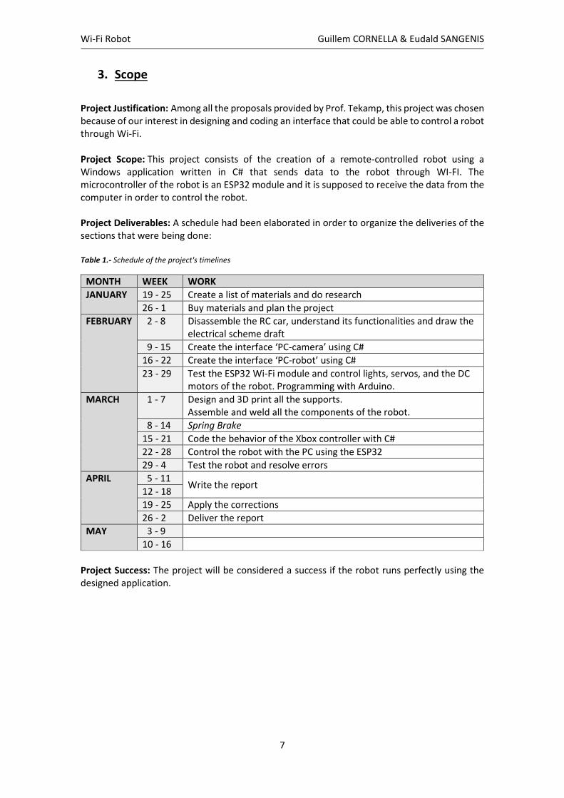
3. Scope
Project Justification: Among all the proposals provided by Prof. Tekamp, this project was chosen because of our interest in designing and coding an interface that could be able to control a robot through Wi-Fi. Project Scope: This project consists of the creation of a remote-controlled robot using a Windows application written in C# that sends data to the robot through WI-FI. The microcontroller of the robot is an ESP32 module and it is supposed to receive the data from the computer in order to control the robot. Project Deliverables: A schedule had been elaborated in order to organize the deliveries of the sections that were being done: Table 1.- Schedule of the project's timelines
MONTH WEEK WORK
JANUARY 19 - 25 Create a list of materials and do research
26 - 1 Buy materials and plan the project
FEBRUARY 2 - 8 Disassemble the RC car, understand its functionalities and draw the electrical scheme draft
9 - 15 Create the interface ‘PC-camera’ using C#
16 - 22 Create the interface ‘PC-robot’ using C#
23 - 29 Test the ESP32 Wi-Fi module and control lights, servos, and the DC motors of the robot. Programming with Arduino.
MARCH 1 - 7 Design and 3D print all the supports. Assemble and weld all the components of the robot.
8 - 14 Spring Brake
15 - 21 Code the behavior of the Xbox controller with C#
22 - 28 Control the robot with the PC using the ESP32
29 - 4 Test the robot and resolve errors
APRIL 5 - 11 Write the report
12 - 18
19 - 25 Apply the corrections
26 - 2 Deliver the report
MAY 3 - 9
10 - 16
Project Success: The project will be considered a success if the robot runs perfectly using the designed application.
Wi-Fi Robot Guillem CORNELLA & Eudald SANGENIS
8
4. Introduction
The main goal of this project is to design a robot that can be controlled using Wi-Fi. The emphasis
of this prototype is put on the coding, focusing on C# and C/C++ languages. The robot
communicates with the computer with a Wi-Fi module and the computer sends packages of
information to the robot in order to control its movements and actions. A camera is also
included, so that the operator of the robot can see where it is going in real time.
Lately, the use of robots is extremely increasing, and it is expected that “Robots could replace
up to 20 million factory jobs by 2030” [2]. Even though the focus has been recently put on
autonomous robots, the remotely controlled robots are also of a great interest. There are
several activities where robots need to be human-guided, such as military operations, bomb
detection, defusing activities or even when working in hazardous environments.
A research on remote controlled robots that use Wi-Fi communications will be carried out.
Firstly, an investigation will be done in order to understand the Wi-Fi protocols that are mainly
used in Robotics. An analysis of their limitations and capabilities will also be executed in order
to select the best option for our project. Then an analysis of the RC car will be carried out,
disassembling the robot’s parts in order to understand its structure and to select the materials
and modules needed for its conversion into a robot. After that, the code will be written regarding
the materials bought, and the components that will be used to run the robot will be weld and
assembled. Finally, the robot will be tested and afterwards the report will be written.
The reasons to conduct this project are sundry, yet as Robotics students, we basically wanted to
do research on remote controlled robots and to enhance our knowledge on C/C++/C# coding
languages. Moreover, the project is documented step by step so that anyone can be able to build
their own robot, learn coding and even learn how Wi-Fi communications work. This research is
important, not just for us, but for anyone who would like to develop their own robot and to have
some guidance in doing so.

Wi-Fi Robot Guillem CORNELLA & Eudald SANGENIS
9
5. List of materials
Table 2.- List of materials and costs
PRODUCT COST/UNIT Qnty. Cost
Arduino Mega 14,99 2 29,98
Arduino pack 34,99 2 69,98
Welding pack 19,99 2 39,98
1:10 Scale Large RC Car 164,97 1 164,97
ESP8266 Wi-Fi module 12,99 2 25,98
Arduino wires 6,98 2 13,96
4 Channel DC 5V Relay Module 7,99 2 15,98
Converter motors 7,49 2 14,98
AMCREST Camera 84,99 2 169,98
L298N Motor Drive 8,89 4 35,56
Arduino Motor Shield 19,99 4 79,96
PCBs 9,99 2 19,98
Servo motor big 19,99 1 19,99
Servo camera support 12,9 1 12,9
XBOX Controller 16,8 1 16,8
Wi-Fi router 37,98 1 37,98
12 V power bank 33,99 1 33,99
IP camera 44,99 1 44,99
Cisco camera 299 1 299
TOTAL PAYED BY UNI 1146,94
TOTAL PAYED BY UNI (INCLUDING RETURNS) 677,96
AC/DC power adapter 12,9 1 12,9
Power bank red 15,99 1 15,99
Power bank black 12,99 1 12,99
Electrical wire 8,38 1 8,38
Switches 6,99 1 6,99
Welding tube 8,79 1 8,79
ESP32 module 14,89 1 14,89
Capacitors pack 10,62 1 10,62
PAYED BY US 91,55
COST TOTAL AMAZON STUFF 1238,49
COST MINUS RETURNED STUFF 769,51
COST MINUS NOT USED STUFF 615,71
COST OF THE ROBOT 615,71
NOT USED
RETURNED

Wi-Fi Robot Guillem CORNELLA & Eudald SANGENIS
10
6. Hardware
6.1. Esp32
In order to communicate the computer with the robot, a Wi-Fi module was used. Specifically,
the model ESP-WROOM-32 or ESP32 DEVKITV1 [3] was chosen because of its features and
because it can be easily embedded with Arduino.
ESP32 can interface with other systems to provide Wi-Fi and Bluetooth functionality through its
SPI / SDIO or I2C / UART interfaces. Some of the ESP32 chip specifications were:
• The ESP32 is dual core, this means it has 2 processors.
• It has Wi-Fi and Bluetooth built in.
• It runs 32-bit programs.
• The clock frequency can go up to 240MHz and it has a 512 kB RAM.
• This board has 30 pins, 15 in each row.
• It also has wide variety of peripherals available, like capacitive touch, ADCs, DACs,
UART, SPI, I2C and much more.
• It comes with built-in hall effect sensor and built-in temperature sensor.
Figure 1.- ESP32 DEVKITV1 real photography of the device [4]
Figure 2.- ESP32 DEVKIT V1 - DOIT, version with 30 GPIOs, PINOUT scheme [5]
Wi-Fi Robot Guillem CORNELLA & Eudald SANGENIS
11
6.2. Motor driver
In order to control the DC motors of the robot with Arduino, a motor driver module “L298N,
PWM, H-Bridge” [6] was needed. Hence in this section, the functionality of this driver will be
explained. [7]
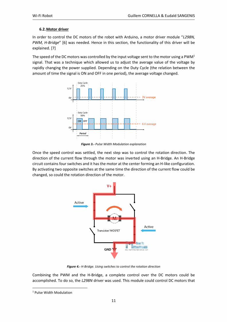
The speed of the DC motors was controlled by the input voltage sent to the motor using a PWM1
signal. That was a technique which allowed us to adjust the average value of the voltage by
rapidly changing the power supplied. Depending on the Duty Cycle (the relation between the
amount of time the signal is ON and OFF in one period), the average voltage changed.
Figure 3.- Pulse Width Modulation explanation
Once the speed control was settled, the next step was to control the rotation direction. The
direction of the current flow through the motor was inverted using an H-Bridge. An H-Bridge
circuit contains four switches and it has the motor at the center forming an H-like configuration.
By activating two opposite switches at the same time the direction of the current flow could be
changed, so could the rotation direction of the motor.
Figure 4.- H-Bridge. Using switches to control the rotation direction
Combining the PWM and the H-Bridge, a complete control over the DC motors could be
accomplished. To do so, the L298N driver was used. This module could control DC motors that
1 Pulse Width Modulation

Wi-Fi Robot Guillem CORNELLA & Eudald SANGENIS
12
had voltages between 5 and 35 V, with a peak current up to 2A. The motors were the “390
brushed motors - PART NUMBER LG-DJ01” [8] and they could receive a maximum input voltage
of 7.4 V.
Figure 5.- This is the module L298N with two terminal blocks for the motors A and B, and one terminal block for the GND pin, the VCC to power the motor and a 5V pin (input or output).
If the <Motor VCC> was lower than 12 V, then the jumper regulator must have been set, and
this means that the +5V pin had to be used as an Output. Whereas if the <Motor VCC> was
higher than 12 V, the jumper must have been removed and the +5V pin had to be used as an
Input.
Then, there were the logic control inputs, which could be used to control the speed of the motors
(ENA & ENB) and the rotation direction (IN1, IN2, IN3, IN4). The Enable A and Enable B are PWM
pins, which means that if the jumpers were removed the speed of the motors could be
controlled by the supplied voltage to that pin. And if a jumper was present on these pins, the
motors would work at maximum speed. Whereas if these pins were connected to ground, the
motors would be disabled.
Figure 6.- Input pins of the L298N driver. From left to right: ENA, IN1, IN2, IN3, IN4, ENB.
Figure 7.- L298N block diagram
Wi-Fi Robot Guillem CORNELLA & Eudald SANGENIS
13
The other 4 inputs were used to control the rotation direction of the motor:
As for the motor A, the Input 1 and Input 2 pins were used, and for the motor B; the inputs 3
and 4. These pins were equivalent to the H-bridge switches. To go forward, the input 1 must
have been LOW and the input 2 HIGH. To go backwards, the input 1 must have been HIGH and
the input 2 LOW. When both inputs were the same, the motors stopped.
6.3. Servos
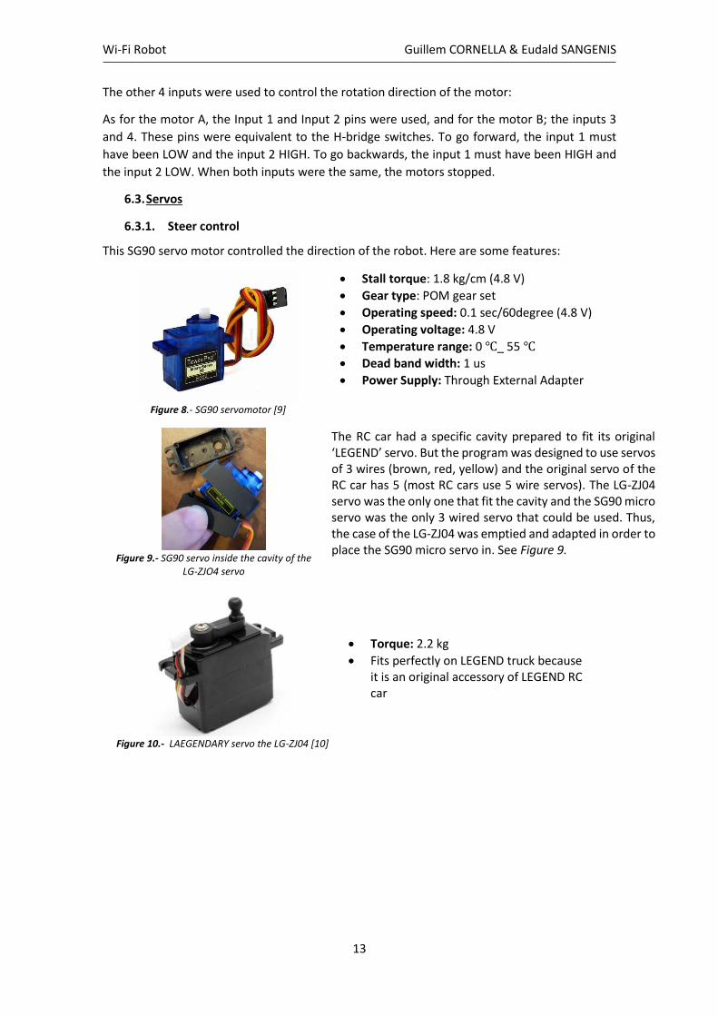
6.3.1. Steer control
This SG90 servo motor controlled the direction of the robot. Here are some features:
Figure 8.- SG90 servomotor [9]
• Stall torque: 1.8 kg/cm (4.8 V)
• Gear type: POM gear set
• Operating speed: 0.1 sec/60degree (4.8 V)
• Operating voltage: 4.8 V
• Temperature range: 0 ℃_ 55 ℃
• Dead band width: 1 us
• Power Supply: Through External Adapter
Figure 9.- SG90 servo inside the cavity of the
LG-ZJO4 servo
The RC car had a specific cavity prepared to fit its original ‘LEGEND’ servo. But the program was designed to use servos of 3 wires (brown, red, yellow) and the original servo of the RC car has 5 (most RC cars use 5 wire servos). The LG-ZJ04 servo was the only one that fit the cavity and the SG90 micro servo was the only 3 wired servo that could be used. Thus, the case of the LG-ZJ04 was emptied and adapted in order to place the SG90 micro servo in. See Figure 9.
Figure 10.- LAEGENDARY servo the LG-ZJ04 [10]
• Torque: 2.2 kg
• Fits perfectly on LEGEND truck because it is an original accessory of LEGEND RC car
Wi-Fi Robot Guillem CORNELLA & Eudald SANGENIS
14
6.3.2. Camera control
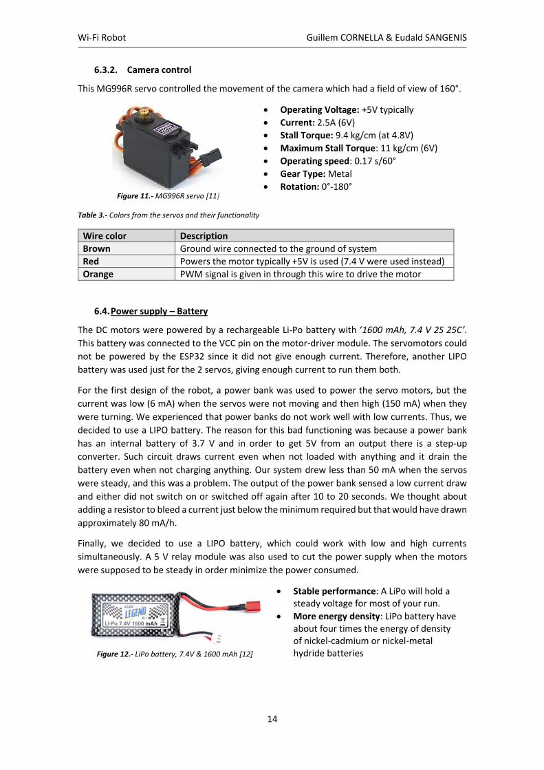
This MG996R servo controlled the movement of the camera which had a field of view of 160°.
Figure 11.- MG996R servo [11]
• Operating Voltage: +5V typically
• Current: 2.5A (6V)
• Stall Torque: 9.4 kg/cm (at 4.8V)
• Maximum Stall Torque: 11 kg/cm (6V)
• Operating speed: 0.17 s/60°
• Gear Type: Metal
• Rotation: 0°-180°
Table 3.- Colors from the servos and their functionality
Wire color Description
Brown Ground wire connected to the ground of system
Red Powers the motor typically +5V is used (7.4 V were used instead)
Orange PWM signal is given in through this wire to drive the motor
6.4. Power supply – Battery
The DC motors were powered by a rechargeable Li-Po battery with ‘1600 mAh, 7.4 V 2S 25C’.
This battery was connected to the VCC pin on the motor-driver module. The servomotors could
not be powered by the ESP32 since it did not give enough current. Therefore, another LIPO
battery was used just for the 2 servos, giving enough current to run them both.
For the first design of the robot, a power bank was used to power the servo motors, but the
current was low (6 mA) when the servos were not moving and then high (150 mA) when they
were turning. We experienced that power banks do not work well with low currents. Thus, we
decided to use a LIPO battery. The reason for this bad functioning was because a power bank
has an internal battery of 3.7 V and in order to get 5V from an output there is a step-up
converter. Such circuit draws current even when not loaded with anything and it drain the
battery even when not charging anything. Our system drew less than 50 mA when the servos
were steady, and this was a problem. The output of the power bank sensed a low current draw
and either did not switch on or switched off again after 10 to 20 seconds. We thought about
adding a resistor to bleed a current just below the minimum required but that would have drawn
approximately 80 mA/h.
Finally, we decided to use a LIPO battery, which could work with low and high currents
simultaneously. A 5 V relay module was also used to cut the power supply when the motors
were supposed to be steady in order minimize the power consumed.
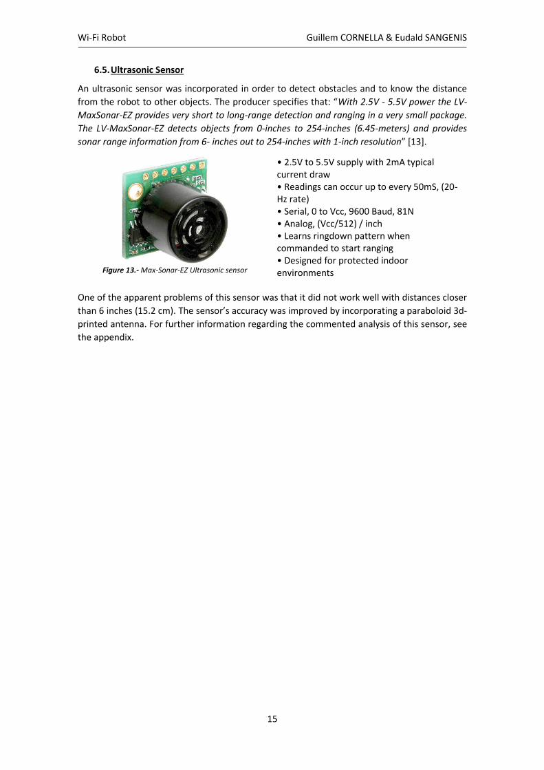
Figure 12.- LiPo battery, 7.4V & 1600 mAh [12]
• Stable performance: A LiPo will hold a steady voltage for most of your run.
• More energy density: LiPo battery have about four times the energy of density of nickel-cadmium or nickel-metal hydride batteries
Wi-Fi Robot Guillem CORNELLA & Eudald SANGENIS
15
6.5. Ultrasonic Sensor
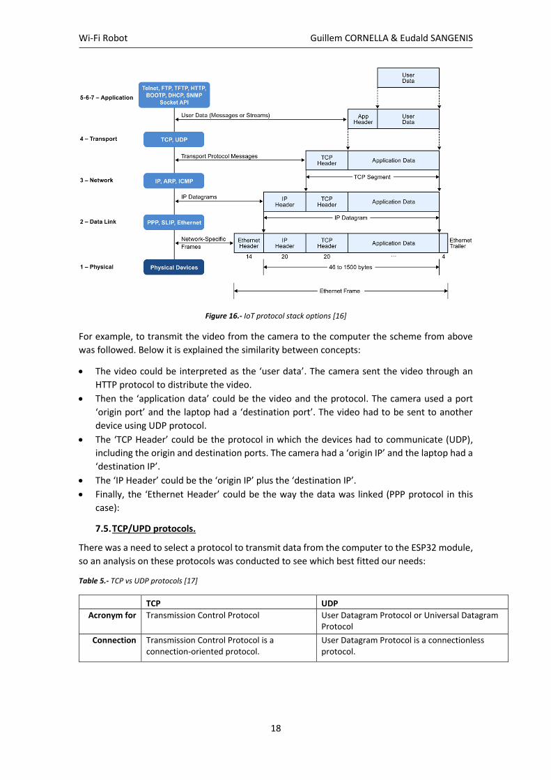
An ultrasonic sensor was incorporated in order to detect obstacles and to know the distance
from the robot to other objects. The producer specifies that: “With 2.5V - 5.5V power the LV-
MaxSonar-EZ provides very short to long-range detection and ranging in a very small package.
The LV-MaxSonar-EZ detects objects from 0-inches to 254-inches (6.45-meters) and provides
sonar range information from 6- inches out to 254-inches with 1-inch resolution” [13].
Figure 13.- Max-Sonar-EZ Ultrasonic sensor
• 2.5V to 5.5V supply with 2mA typical current draw • Readings can occur up to every 50mS, (20-Hz rate) • Serial, 0 to Vcc, 9600 Baud, 81N • Analog, (Vcc/512) / inch • Learns ringdown pattern when commanded to start ranging • Designed for protected indoor environments
One of the apparent problems of this sensor was that it did not work well with distances closer
than 6 inches (15.2 cm). The sensor’s accuracy was improved by incorporating a paraboloid 3d-
printed antenna. For further information regarding the commented analysis of this sensor, see
the appendix.

Wi-Fi Robot Guillem CORNELLA & Eudald SANGENIS
16
7. Wi-Fi communications
7.1. Wireless technology
To do this project, a research on Wi-Fi communications was carried out since an ESP32 module
was used in addition to an IP Camera. In the next section, there is some explanation on Wi-Fi:
Wi-Fi networks transmit information over the air using radio waves, which are a type of
electromagnetic radiation with wavelengths in the electromagnetic spectrum longer than
infrared light. Wi-Fi radio waves typically have the frequency of either 2.4 GHz or 5 GHz.
The typical range of a standard Wi-Fi network can reach up to 100 meters in the open air.
Buildings and other materials reflect the signal however, making most Wi-Fi networks far
narrower than that. The strength of the antenna and the frequency broadcast can also impact
the effective range of the network. Higher frequencies like 5 GHz and 60 GHz have far shorter
effective ranges than 2.4 GHz.
Everyone within a network’s range and a compatible Wi-Fi device can detect the network and
attempt to connect to it. That is what allows it to operate in both private and public settings, but
it does raise concerns over security. That is why standards like WPA, WPA2 and WPA3 exist.
7.2. Frequencies
Each frequency range has several channels which wireless devices can operate on, helping to
spread the load so that individual devices do not see their signals crowded or interrupted by
other traffic. The biggest difference between the two frequency bands is the fact that the 5 GHz
signal is only about half the range of the 2.4 GHz signal. The 2.4 GHz signal has more trouble
penetrating walls and solid objects. On the other hand, the 5 GHz band is far less crowded than
the 2.4 GHz band, which is a huge advantage in heavily populated urban areas where Wi-Fi
networks are virtually everywhere.
Figure 14.- What is the difference between 2.4 GHz and 5 GHz Wi-Fi? [14]
Since the 2.4 GHz band had more range, the robot worked with this bandwidth, so that the robot
could be controlled from the office and it could run in the backyard.
7.3. Wi-Fi security protocols
Wi-Fi security protocols prevent unauthorized access or damage to computers using wireless
networks. The most basic wireless security is Wired Equivalent Privacy (WEP). WEP was
superseded by Wi-Fi Protected Access (WPA) and Wi-Fi Protected Access II (WPA2). Soon, WPA2
will be superseded by WPA3, which uses even stronger encryption and mitigates security issues
posed by weak passwords.

Wi-Fi Robot Guillem CORNELLA & Eudald SANGENIS
17
Table 4.- Summary of Wi-Fi Security, GRANDMETRIC
The UCCS university Wi-Fi is WPA2-Enterprise. “This kind of security requires a RADIUS server,
which handles the task of authenticating network users’ access. The actual authentication
process is based on the 802.1X policy and comes in several different systems labelled EAP.
Because each device is authenticated before it connects, a personal, encrypted tunnel is
effectively created between the device and the network.” [15]
Some problems were faced due to this kind of security; hence the project was tested at home.
7.4. Structure
The router created a LAN2 to be able to interconnect the applications without the need of using
a WAN3 network.
Figure 15.- Network structure
The main purpose of the project consisted of the C# application sending a packet of data to the
ESP32 module through Wi-Fi. Then, the ESP32 interpreted the packet and gave the necessary
information to the outputs. But to send this data, it had to go through different layers of the
Internet which will be explained next:
2 Local Area Network: is a computer network that interconnects computers within a limited area. 3 Wide Area Network: is a telecommunications network that extends over a large geographical area for the primary purpose of computer networking.
Wi-Fi Robot Guillem CORNELLA & Eudald SANGENIS
18
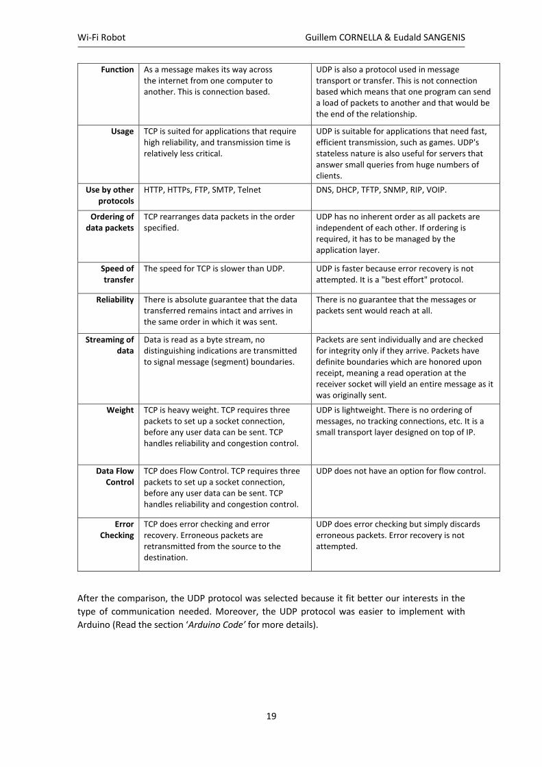
Figure 16.- IoT protocol stack options [16]
For example, to transmit the video from the camera to the computer the scheme from above
was followed. Below it is explained the similarity between concepts:
• The video could be interpreted as the ‘user data’. The camera sent the video through an
HTTP protocol to distribute the video.
• Then the ‘application data’ could be the video and the protocol. The camera used a port
‘origin port’ and the laptop had a ‘destination port’. The video had to be sent to another
device using UDP protocol.
• The ‘TCP Header’ could be the protocol in which the devices had to communicate (UDP),
including the origin and destination ports. The camera had a ‘origin IP’ and the laptop had a
‘destination IP’.
• The ‘IP Header’ could be the ‘origin IP’ plus the ‘destination IP’.
• Finally, the ‘Ethernet Header’ could be the way the data was linked (PPP protocol in this
case):
7.5. TCP/UPD protocols.
There was a need to select a protocol to transmit data from the computer to the ESP32 module,
so an analysis on these protocols was conducted to see which best fitted our needs:
Table 5.- TCP vs UDP protocols [17]
TCP UDP
Acronym for Transmission Control Protocol User Datagram Protocol or Universal Datagram Protocol
Connection Transmission Control Protocol is a connection-oriented protocol.
User Datagram Protocol is a connectionless protocol.
Wi-Fi Robot Guillem CORNELLA & Eudald SANGENIS
19
Function As a message makes its way across the internet from one computer to another. This is connection based.
UDP is also a protocol used in message transport or transfer. This is not connection based which means that one program can send a load of packets to another and that would be the end of the relationship.
Usage TCP is suited for applications that require high reliability, and transmission time is relatively less critical.
UDP is suitable for applications that need fast, efficient transmission, such as games. UDP's stateless nature is also useful for servers that answer small queries from huge numbers of clients.
Use by other protocols
HTTP, HTTPs, FTP, SMTP, Telnet DNS, DHCP, TFTP, SNMP, RIP, VOIP.
Ordering of data packets
TCP rearranges data packets in the order specified.
UDP has no inherent order as all packets are independent of each other. If ordering is required, it has to be managed by the application layer.
Speed of transfer
The speed for TCP is slower than UDP. UDP is faster because error recovery is not attempted. It is a "best effort" protocol.
Reliability There is absolute guarantee that the data transferred remains intact and arrives in the same order in which it was sent.
There is no guarantee that the messages or packets sent would reach at all.
Streaming of data
Data is read as a byte stream, no distinguishing indications are transmitted to signal message (segment) boundaries.
Packets are sent individually and are checked for integrity only if they arrive. Packets have definite boundaries which are honored upon receipt, meaning a read operation at the receiver socket will yield an entire message as it was originally sent.
Weight TCP is heavy weight. TCP requires three packets to set up a socket connection, before any user data can be sent. TCP handles reliability and congestion control.
UDP is lightweight. There is no ordering of messages, no tracking connections, etc. It is a small transport layer designed on top of IP.
Data Flow Control
TCP does Flow Control. TCP requires three packets to set up a socket connection, before any user data can be sent. TCP handles reliability and congestion control.
UDP does not have an option for flow control.
Error Checking
TCP does error checking and error recovery. Erroneous packets are retransmitted from the source to the destination.
UDP does error checking but simply discards erroneous packets. Error recovery is not attempted.
After the comparison, the UDP protocol was selected because it fit better our interests in the
type of communication needed. Moreover, the UDP protocol was easier to implement with
Arduino (Read the section ‘Arduino Code’ for more details).
Wi-Fi Robot Guillem CORNELLA & Eudald SANGENIS
20
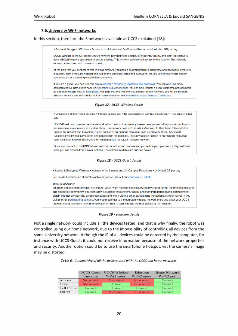
7.6. University Wi-Fi networks
In this section, there are the 3 networks available at UCCS explained [18]:
Figure 17.- UCCS-Wireless details
Figure 18.- UCCS-Guest details
Figure 19.- eduroam details
Not a single network could include all the devices tested, and that is why finally, the robot was
controlled using our home network, due to the impossibility of controlling all devices from the
same University network. Although the IP of all devices could be detected by the computer, for
instance with UCCS-Guest, it could not receive information because of the network properties
and security. Another option could be to use the smartphone hotspot, yet the camera’s image
may be distorted.
Table 6.- Connectivity of all the devices used with the UCCS and home networks.
Wi-Fi Robot Guillem CORNELLA & Eudald SANGENIS
21
8. Application Code
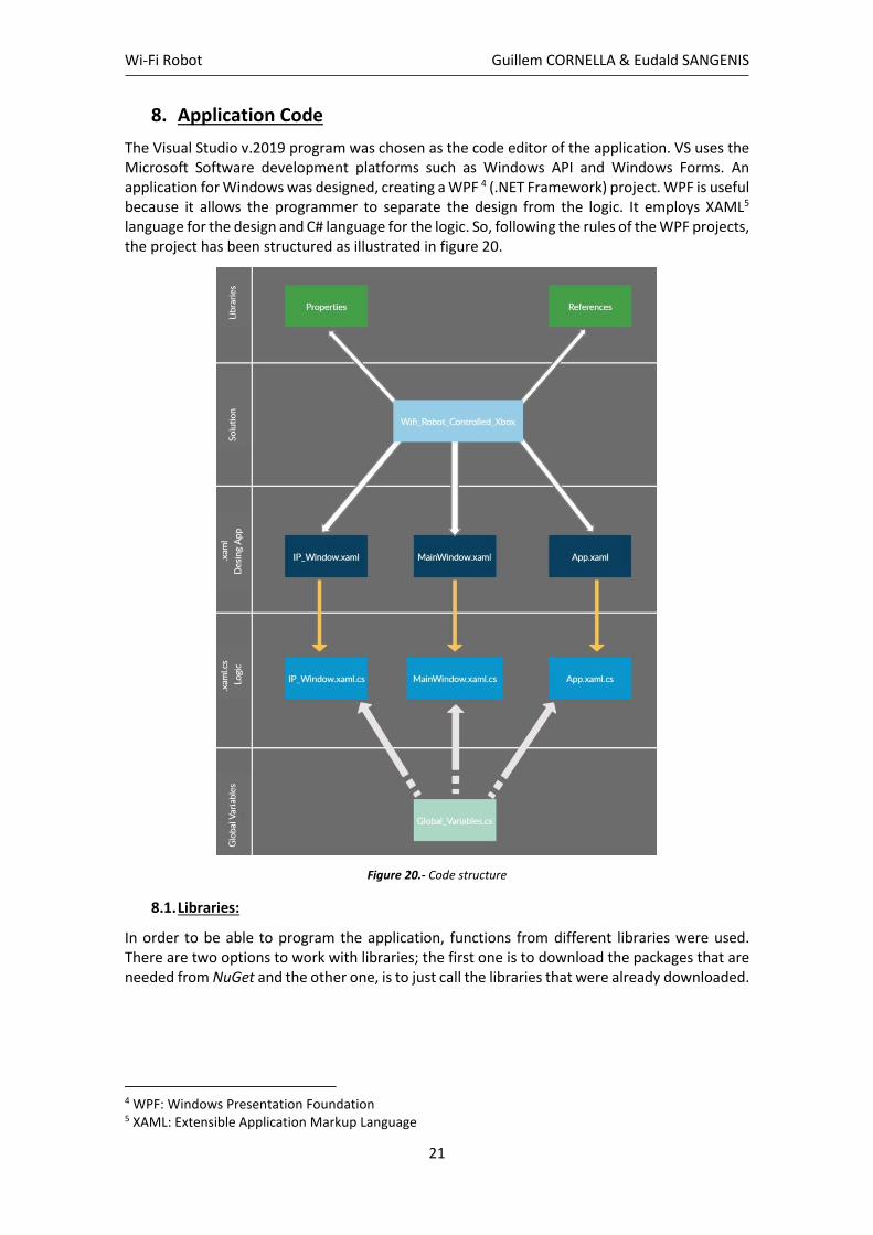
The Visual Studio v.2019 program was chosen as the code editor of the application. VS uses the Microsoft Software development platforms such as Windows API and Windows Forms. An application for Windows was designed, creating a WPF 4 (.NET Framework) project. WPF is useful because it allows the programmer to separate the design from the logic. It employs XAML5 language for the design and C# language for the logic. So, following the rules of the WPF projects, the project has been structured as illustrated in figure 20.
Figure 20.- Code structure
8.1. Libraries:
In order to be able to program the application, functions from different libraries were used. There are two options to work with libraries; the first one is to download the packages that are needed from NuGet and the other one, is to just call the libraries that were already downloaded.
4 WPF: Windows Presentation Foundation 5 XAML: Extensible Application Markup Language
Wi-Fi Robot Guillem CORNELLA & Eudald SANGENIS
22
8.1.1. NuGet libraries:
To develop the GUI6 some Nu packages from NuGet had to be installed. Usually, when these packages are installed, they are added automatically to references. However, if they have already been installed and a new project is created, the .dll 7 document must be added to references. To build the application some packages had to be installed:
• MaterialDesingColors: to have templates to design the interface.
• VisioForge: to reproduce the video in the API8.
• SharpDx: to install the Nu package SharpDX.Input.
• SharpDX.Input: to read inputs from the COM (Xbox Controller).
• OpenJiWare: to interpret the values from the Xbox Controller.
Since the MaterialDesingColors, was related to the design of the GUI, it had to be called through the App.xaml as illustrated in the following code fragment:
Code 1.- Import MaterialDesingColors NuGet package in the App.xaml
Nevertheless, it was easier to install the other packages in the libraries. For instance, in the MainWindow.xaml, the following ones were used:
Code 2.- Import VisioForge & OpenJigWare NuGet package in the MainWindow.xaml
Finally, there was no need to call the SharpDX.Input, but it had to be installed to avoid a
breakdown of the program. This error happened because inside the OpenJiWare library there
are references to commands from SharpDX.Input.
8.1.2. System libraries
The System libraries contained fundamental classes that define commonly used values,
references data types, events and event handlers, interfaces, attributes, and processing
exceptions. In the program, only the following ones were needed:
6 GUI: Graphical user interface 7 .dll: Dynamic Link Library 8 API: Application programming interface
Wi-Fi Robot Guillem CORNELLA & Eudald SANGENIS
23
Code 3.- System libraries that were needed
• System.Windows.Controls: It provided classes to create elements that enable a user to
interact with an application.
• System.Text: It contained classes that represent ASCII and Unicode character encoding
to treat the data.
• System.Timers: The timer was useful to call the function to read the values from the
Xbox Controller every 40 ms.
• System.Net.Sockets: The Socket library was necessary to establish the UDP connection
between the robot and the application.
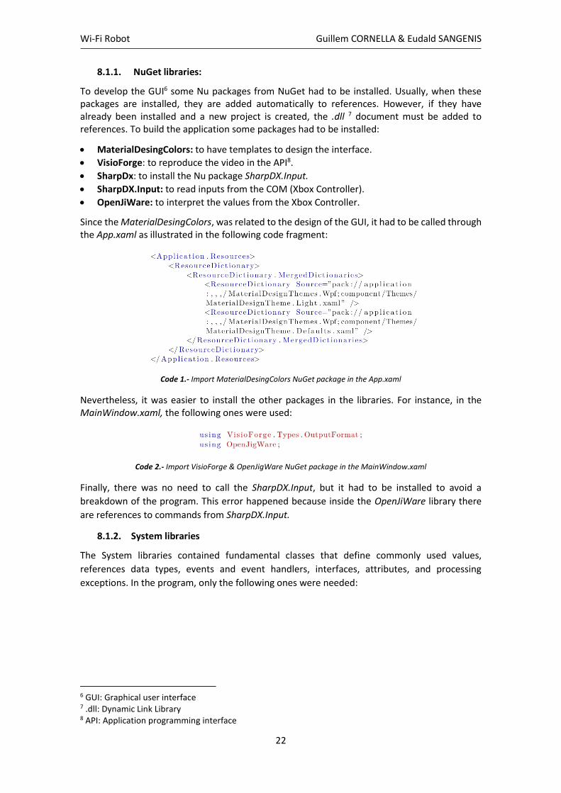
8.2. Camera characteristics & code
The camera used to display the robot’s vision should have had these specifications:
• Being able to connect as an IP Camera
• Being able to connect to 2.4 GHz bandwidth
• Being able to connect to Wi-Fi with a security WPA2
Knowing these details, the AMCREST IP2M-841B was bought (see figure 21). This camera
allowed the control of the video, besides the control of the pan, the tilt, and the zoom.
Figure 21.- AMCREST IP2M-841B [19]
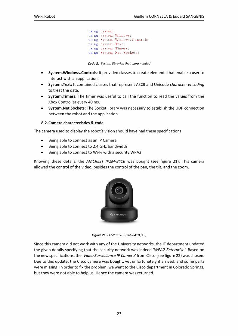
Since this camera did not work with any of the University networks, the IT department updated
the given details specifying that the security network was indeed ‘WPA2-Enterprise’. Based on
the new specifications, the ‘Video Surveillance IP Camera’ from Cisco (see figure 22) was chosen.
Due to this update, the Cisco camera was bought, yet unfortunately it arrived, and some parts
were missing. In order to fix the problem, we went to the Cisco department in Colorado Springs,
but they were not able to help us. Hence the camera was returned.

Wi-Fi Robot Guillem CORNELLA & Eudald SANGENIS
24
Figure 22.- Video Surveillance IP Camera 2500 [20]
Finally, the mobile phone camera was selected. The article titled “Using an Android phone as a
webcam” from GitHub [21] suggested to download the ‘IP Webcam’ [22] from the Play Store. It
was a perfect solution since the mobile phone could connect to the UCCS-Guest, UCCS-Wireless
and eduroam networks. How was the camera connected to the PC?
Firstly, the library of the VisioForge was called:
Code 4.- XAML implementation of the VisioForge library to create the view
When the library was implemented, the viewing settings of the camera were designed in the
GUI.
Code 5.- XAML implementation to create the viewing interface.
Then there was the behind code of the design in the MainWindow.xaml.cs document: Four
‘event’ functions were created to detect when buttons were pressed. The following fragment of
code shows the headers of these event functions:
Code 6.- Headers of the functions to control the camera.
Connect: The first one was used to establish a connection between the application and the
phone and to display the image. The communication was made through a URL9 given by the IP
Webcam App. In the following fragment of the” Connect” function it is explained how to connect
the camera.
9 URL: Uniform Recurs Location colloquially termed a web address is a reference to a web resource that specifies its location on a computer network
Wi-Fi Robot Guillem CORNELLA & Eudald SANGENIS
25
Code 7.- Fragment of the” Connect function”.
Disconnect: The second one was used to cut the connection and disable the video when the
Disconnect Button was pressed. So, when the method” Stop()”was used, the connection
stopped.
Code 8.- Fragment of the” Disconnect function”.
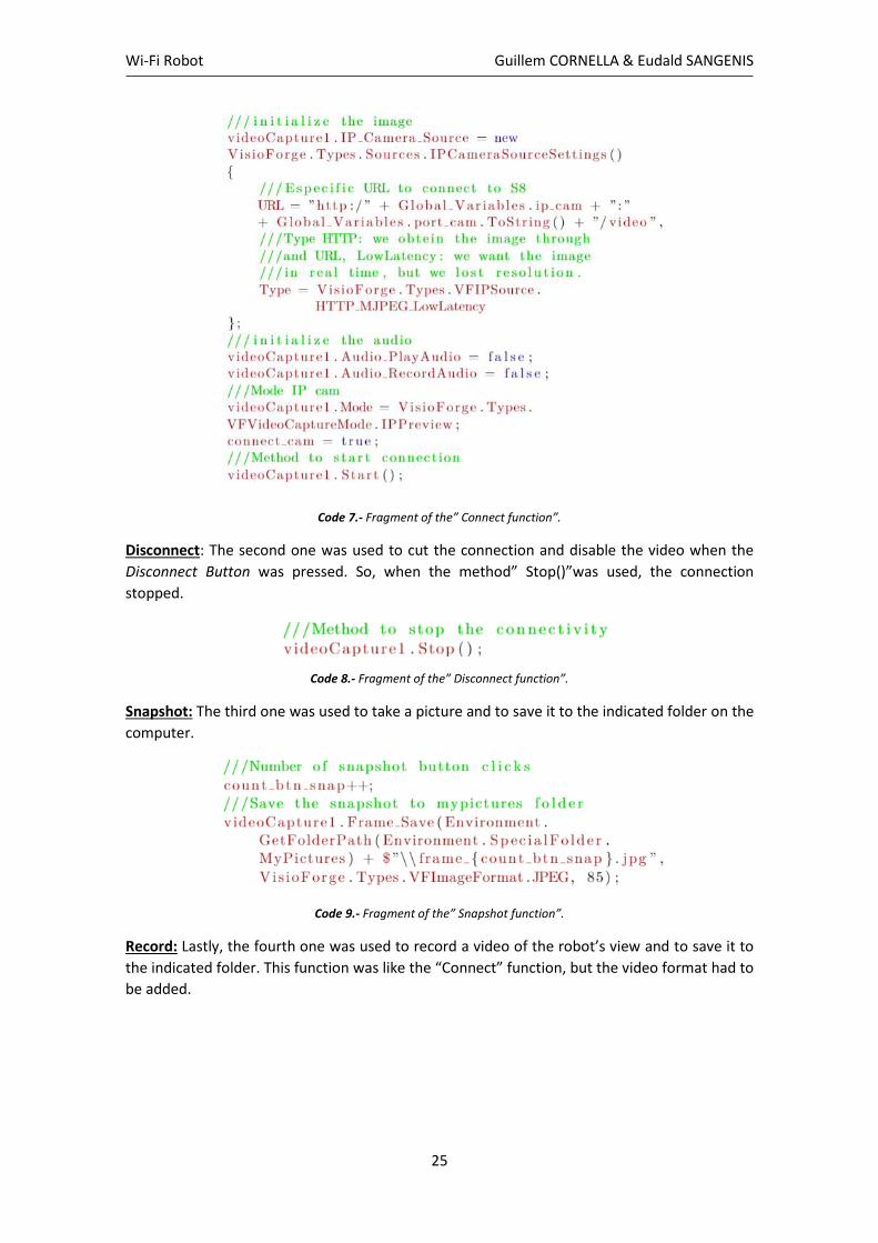
Snapshot: The third one was used to take a picture and to save it to the indicated folder on the
computer.
Code 9.- Fragment of the” Snapshot function”.
Record: Lastly, the fourth one was used to record a video of the robot’s view and to save it to
the indicated folder. This function was like the “Connect” function, but the video format had to
be added.

Wi-Fi Robot Guillem CORNELLA & Eudald SANGENIS
26
Code 10.- Fragment of the “Record function”.
8.3. Controller code
In order to be able to control the robot, two applications were designed. The first interface used
the keyboard keys to control the robot and the second one, which was used more often, used
an Xbox controller.
8.3.1. Keyboard
An application was designed to send data to the ESP32 module. The main problem faced was
the maneuverability of the robot. When data was sent through the UDP protocol, packages of
information were sent for instance saying; ‘move forward x distance’ when the event of the key
“w” was key up.
This was a problem since the robot could not change the direction unless it had moved the “x”
distance first. Moreover, the velocity nor the camera spin could be controlled since there was
no joystick.
Figure 23.- Keyboard Controller application interface

Wi-Fi Robot Guillem CORNELLA & Eudald SANGENIS
27
The following fragment of code illustrates how to declare a private function to raise button
events when keys are pressed:
Code 11.- Controlling the keyboard
And the next fragment of code is an example of how it was able to send the commands to the
ESP32 when button ‘A’ was pressed.
Code 12.- Sending information using an UDP protocol when the key 'A' is pressed
To connect to the IP and the port of the ESP32 device, the IPWindow was designed (see on figure
24). Its functionality was based on entering the values manually and saving them to the
GlobalVariablesclass by clicking the” Apply ” button.
Figure 24.- IP Window interface
Wi-Fi Robot Guillem CORNELLA & Eudald SANGENIS
28
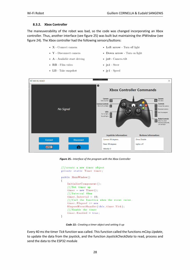
8.3.2. Xbox Controller
The maneuverability of the robot was bad, so the code was changed incorporating an Xbox
controller. Thus, another interface (see figure 25) was built but maintaining the IPWindow (see
figure 24). The Xbox controller had the following sensors/buttons:
Figure 25.- Interface of the program with the Xbox Controller
Code 13.- Creating a timer object and setting it up
Every 40 ms the timer Tick function was called. This function called the functions mCJoy.Update,
to update the data from the joystick, and the function JoystickCheckData to read, process and
send the data to the ESP32 module

Wi-Fi Robot Guillem CORNELLA & Eudald SANGENIS
29
Code 14.- Timer Tick function
The function was divided in different values (arrows, buttons, RB and LB buttons, joystick
values…). The following fragment gives an idea of how the program worked. It shows how to call
the function Connect if the ‘X’ button is pressed, how to obtain the joystick information, and
how to send the information through the UDP protocol.
Code 15.- Joystick Check Data function
The complete code is available on GitHub [23].

Wi-Fi Robot Guillem CORNELLA & Eudald SANGENIS
30
9. Arduino code
The purpose of this section is to explain how the Arduino code works step by step.
// UDP WIFI TRANSMISSION BETWEEN ARDUINO AND VISUAL STUDIO
// WIFI ROBOT CONTROLLED USING A XBOX CONTROLLER
// EUDALD SANGENÍS & GUILLEM CORNELLA
Once the Arduino program was opened, the board esp32 had to installed. 1. In your Arduino IDE, go to File> Preferences. 2. Copy https://dl.espressif.com/dl/package_esp32_index.json into the “Additional Board
Manager URLs” field. Then, click the “OK” button. 3. Open the Boards Manager. Go to Tools > Board > Boards Manager… 4. Search for ESP32 and press install button for the “ESP32 by Espressif Systems“. 5. It should be installed after a few seconds.
9.1. Libraries
The next step then was to install and declare the libraries. #include <WiFiUdp.h>
#include <WiFi.h>
#include <ESP32Servo.h>
#include <MapFloat.h>
Code 16.- Including libraries
- <WiFiUdp.h> This library created a named instance of the Wi-Fi UDP class that could send and receive UDP messages. On AVR based boards, outgoing UDP packets are limited to 72 bytes in size currently.
- <WiFi.h> This one allowed the connection to the network using the ssid (name given to the router) and de pswd (password from the router). This library did not support WPA2-Enterprise or this kind of network security.
- <ESP32Servo.h> It allowed ESP32 boards to control servo motors using Arduino semantics. This library could control many types of servos. It used the ESP32 PWM timers.
- <MapFloat.h> This library contained the mapFloat function which re-mapped a floating-point number from one range to another.
9.2. Variables
After declaring the libraries, the next step was to define the variables that were used. The declaration of variables can be seen on the annex (Arduino Code), but here there is an example: const char* ssid = "name_of_router ";
const char* password = "password_goes_here"; Code 17.- Defining the router variables
9.3. Setup
The connection between the Wi-Fi module and the network needed to be completed. The begin method was called on the Wi-Fi object, passing as arguments the SSID and the password variables. This line started the connection to the network:
WiFi.begin(ssid, password);
Code 18.- Beginning the Wi-Fi connection
Wi-Fi Robot Guillem CORNELLA & Eudald SANGENIS
31
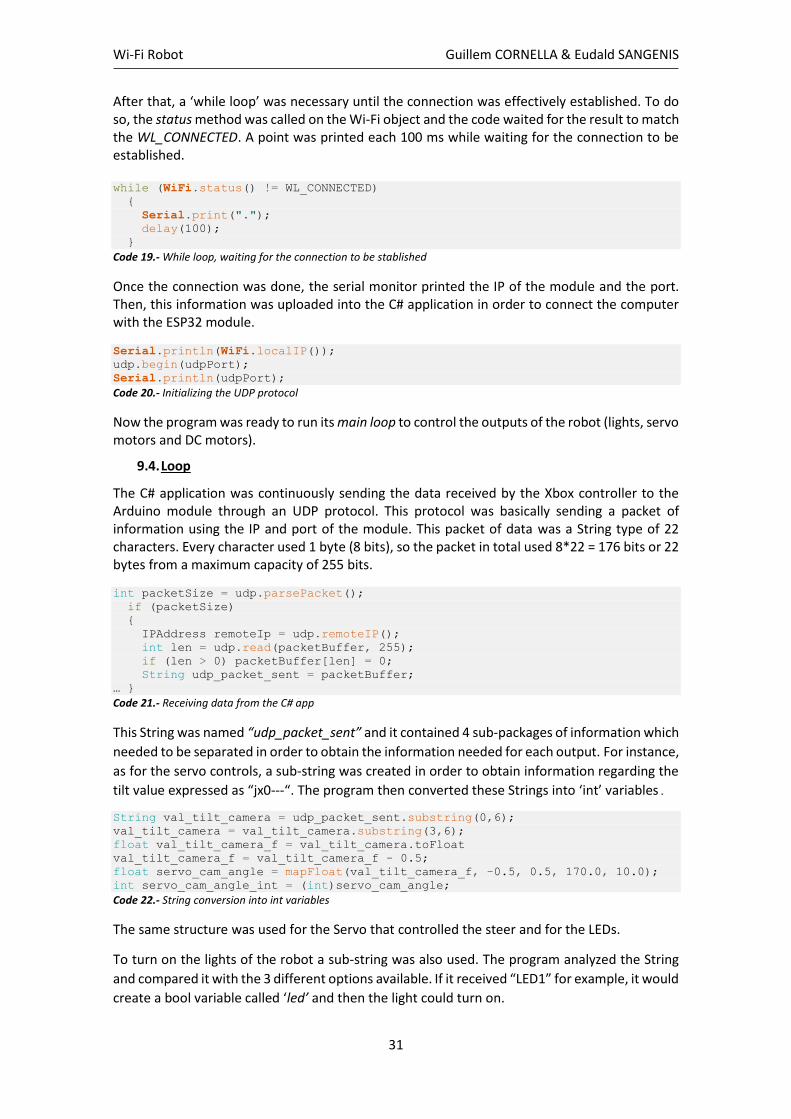
After that, a ‘while loop’ was necessary until the connection was effectively established. To do so, the status method was called on the Wi-Fi object and the code waited for the result to match the WL_CONNECTED. A point was printed each 100 ms while waiting for the connection to be established. while (WiFi.status() != WL_CONNECTED)
{
Serial.print(".");
delay(100);
}
Code 19.- While loop, waiting for the connection to be stablished
Once the connection was done, the serial monitor printed the IP of the module and the port. Then, this information was uploaded into the C# application in order to connect the computer with the ESP32 module.
Serial.println(WiFi.localIP());
udp.begin(udpPort);
Serial.println(udpPort);
Code 20.- Initializing the UDP protocol
Now the program was ready to run its main loop to control the outputs of the robot (lights, servo motors and DC motors).
9.4. Loop
The C# application was continuously sending the data received by the Xbox controller to the Arduino module through an UDP protocol. This protocol was basically sending a packet of information using the IP and port of the module. This packet of data was a String type of 22 characters. Every character used 1 byte (8 bits), so the packet in total used 8*22 = 176 bits or 22 bytes from a maximum capacity of 255 bits.
int packetSize = udp.parsePacket();
if (packetSize)
{
IPAddress remoteIp = udp.remoteIP();
int len = udp.read(packetBuffer, 255);
if (len > 0) packetBuffer[len] = 0;
String udp_packet_sent = packetBuffer;
… }
Code 21.- Receiving data from the C# app
This String was named “udp_packet_sent” and it contained 4 sub-packages of information which
needed to be separated in order to obtain the information needed for each output. For instance,
as for the servo controls, a sub-string was created in order to obtain information regarding the
tilt value expressed as “jx0---“. The program then converted these Strings into ‘int’ variables.
String val_tilt_camera = udp_packet_sent.substring(0,6);
val_tilt_camera = val_tilt_camera.substring(3,6);
float val_tilt_camera_f = val_tilt_camera.toFloat
val_tilt_camera_f = val_tilt_camera_f - 0.5;
float servo_cam_angle = mapFloat(val_tilt_camera_f, -0.5, 0.5, 170.0, 10.0);
int servo_cam_angle_int = (int)servo_cam_angle;
Code 22.- String conversion into int variables
The same structure was used for the Servo that controlled the steer and for the LEDs.
To turn on the lights of the robot a sub-string was also used. The program analyzed the String
and compared it with the 3 different options available. If it received “LED1” for example, it would
create a bool variable called ‘led’ and then the light could turn on.

Wi-Fi Robot Guillem CORNELLA & Eudald SANGENIS
32
//LEDS ON - LEDS OFF
String light = udp_packet_sent.substring(18,22);
if (light=="LED1"){
led = true;
digitalWrite(LED,HIGH);
}
else if (light=="LED2"){
led = false;
digitalWrite(LED, LOW);
}
else if (light=="LED0"){
digitalWrite(LED,LOW);
if (led==true) digitalWrite(LED,HIGH);
else digitalWrite(LED,LOW);
}
Code 23.- How to light the LEDs
In order to go forward and backward, the first step was to convert the string received by the
computer into an ‘int’ variable, the same procedure used for the servos. Then, the program
distinguished from positive values (forward) and negative values (backwards), ranged between
-0.5 and 0.5. Finally, the code was mapped to reconvert the float value into the speed value,
which was saved as an ‘int’.
// to go FORWARD
else if (val_vel_f > 0.1)
{
// Set Motor A forward:
digitalWrite(in1, LOW);
digitalWrite(in2, HIGH);
// Set Motor B forward:
digitalWrite(in3, LOW);
digitalWrite(in4, HIGH);
float motorSpeedA_f = mapFloat(val_vel_f, 0.1, 0.5, 400.0, 1000.0);
float motorSpeedB_f = mapFloat(val_vel_f, 0.1, 0.5, 400.0, 1000.0);
motorSpeedA = (int)motorSpeedA_f;
motorSpeedB = (int)motorSpeedB_f;
}
Code 24.- Instructions given to the robot to go forward
The last lines of the code enabled both motors (enA), which ran at a specific speed
(motorSpeedA).
analogWrite(enA, motorSpeedA); // Send PWM signal to motor A
analogWrite(enB, motorSpeedB); // Send PWM signal to motor B
Code 25.- Enabling the motors
Wi-Fi Robot Guillem CORNELLA & Eudald SANGENIS
33
10. Building the robot
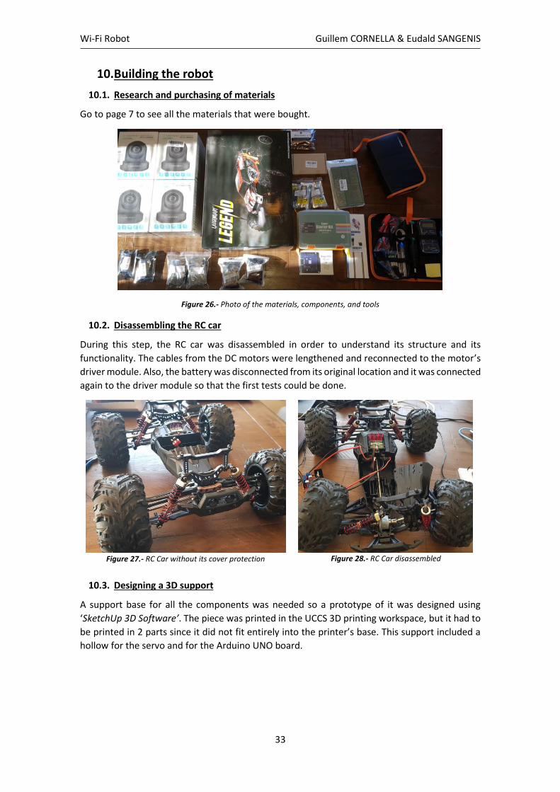
10.1. Research and purchasing of materials
Go to page 7 to see all the materials that were bought.
Figure 26.- Photo of the materials, components, and tools
10.2. Disassembling the RC car
During this step, the RC car was disassembled in order to understand its structure and its
functionality. The cables from the DC motors were lengthened and reconnected to the motor’s
driver module. Also, the battery was disconnected from its original location and it was connected
again to the driver module so that the first tests could be done.
Figure 27.- RC Car without its cover protection
Figure 28.- RC Car disassembled
10.3. Designing a 3D support
A support base for all the components was needed so a prototype of it was designed using
‘SketchUp 3D Software’. The piece was printed in the UCCS 3D printing workspace, but it had to
be printed in 2 parts since it did not fit entirely into the printer’s base. This support included a
hollow for the servo and for the Arduino UNO board.
Wi-Fi Robot Guillem CORNELLA & Eudald SANGENIS
34
Figure 29.- 3D-designed support. Screenshot from the 3D-Builder Software
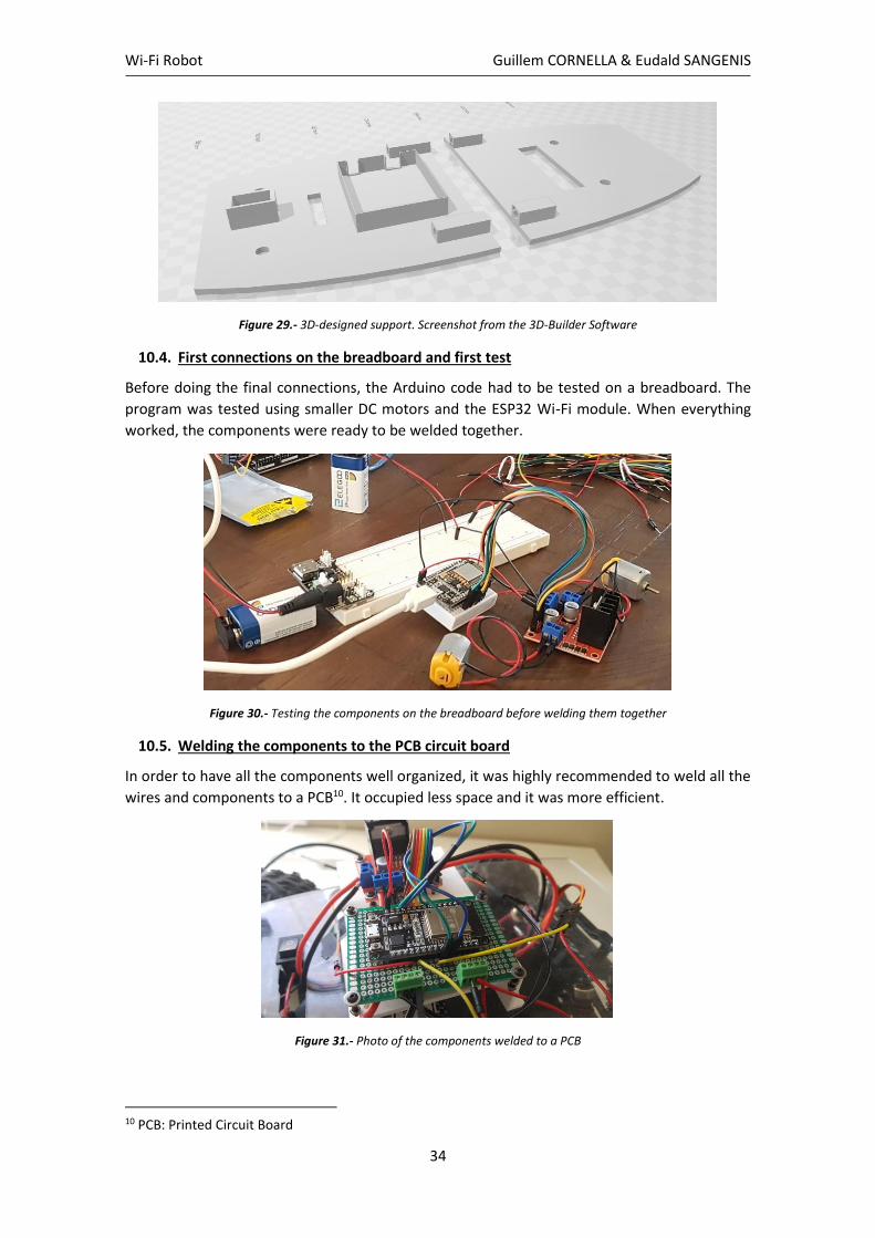
10.4. First connections on the breadboard and first test
Before doing the final connections, the Arduino code had to be tested on a breadboard. The
program was tested using smaller DC motors and the ESP32 Wi-Fi module. When everything
worked, the components were ready to be welded together.
Figure 30.- Testing the components on the breadboard before welding them together
10.5. Welding the components to the PCB circuit board
In order to have all the components well organized, it was highly recommended to weld all the
wires and components to a PCB10. It occupied less space and it was more efficient.
Figure 31.- Photo of the components welded to a PCB
10 PCB: Printed Circuit Board
Wi-Fi Robot Guillem CORNELLA & Eudald SANGENIS
35
10.6. Building the 3D supports
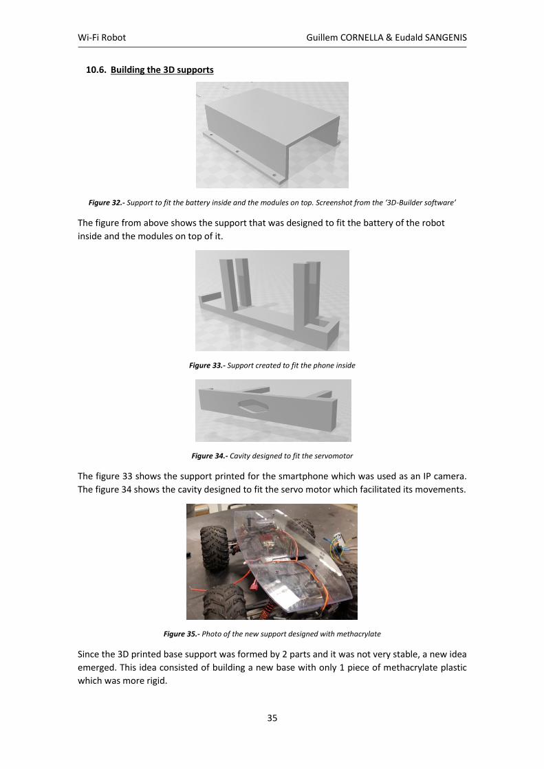
Figure 32.- Support to fit the battery inside and the modules on top. Screenshot from the ‘3D-Builder software’
The figure from above shows the support that was designed to fit the battery of the robot
inside and the modules on top of it.
Figure 33.- Support created to fit the phone inside
Figure 34.- Cavity designed to fit the servomotor
The figure 33 shows the support printed for the smartphone which was used as an IP camera.
The figure 34 shows the cavity designed to fit the servo motor which facilitated its movements.
Figure 35.- Photo of the new support designed with methacrylate
Since the 3D printed base support was formed by 2 parts and it was not very stable, a new idea
emerged. This idea consisted of building a new base with only 1 piece of methacrylate plastic
which was more rigid.
Wi-Fi Robot Guillem CORNELLA & Eudald SANGENIS
36
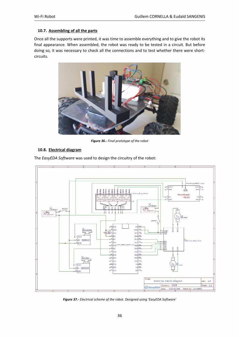
10.7. Assembling of all the parts
Once all the supports were printed, it was time to assemble everything and to give the robot its
final appearance. When assembled, the robot was ready to be tested in a circuit. But before
doing so, it was necessary to check all the connections and to test whether there were short-
circuits.
Figure 36.- Final prototype of the robot
10.8. Electrical diagram
The EasyEDA Software was used to design the circuitry of the robot:
Figure 37.- Electrical scheme of the robot. Designed using 'EasyEDA Software'
Wi-Fi Robot Guillem CORNELLA & Eudald SANGENIS
37
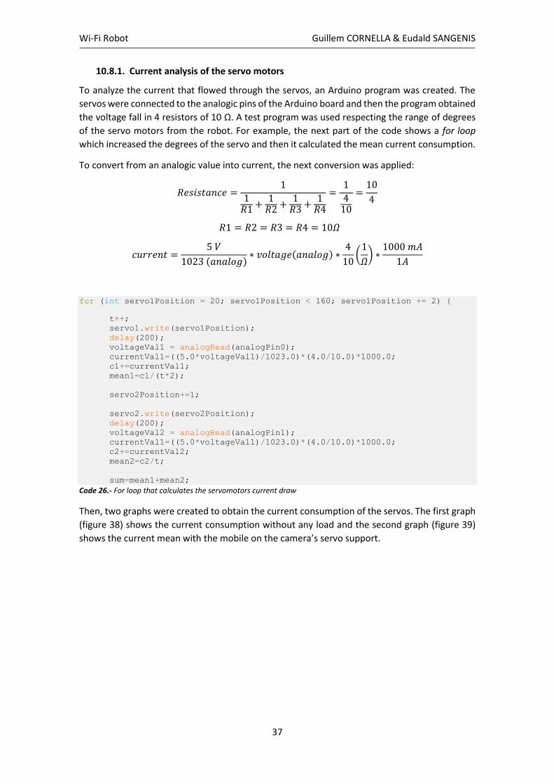
10.8.1. Current analysis of the servo motors
To analyze the current that flowed through the servos, an Arduino program was created. The
servos were connected to the analogic pins of the Arduino board and then the program obtained
the voltage fall in 4 resistors of 10 Ω. A test program was used respecting the range of degrees
of the servo motors from the robot. For example, the next part of the code shows a for loop
which increased the degrees of the servo and then it calculated the mean current consumption.
To convert from an analogic value into current, the next conversion was applied:
𝑅𝑒𝑠𝑖𝑠𝑡𝑎𝑛𝑐𝑒 =1
1𝑅1 +
1𝑅2 +
1𝑅3 +
1𝑅4
=1
410
=10
4
𝑅1 = 𝑅2 = 𝑅3 = 𝑅4 = 10𝛺
𝑐𝑢𝑟𝑟𝑒𝑛𝑡 =5 𝑉
1023 (𝑎𝑛𝑎𝑙𝑜𝑔)∗ 𝑣𝑜𝑙𝑡𝑎𝑔𝑒(𝑎𝑛𝑎𝑙𝑜𝑔) ∗
4
10(
1
𝛺) ∗
1000 𝑚𝐴
1𝐴
for (int servo1Position = 20; servo1Position < 160; servo1Position += 2) {
t++;
servo1.write(servo1Position);
delay(200);
voltageVal1 = analogRead(analogPin0);
currentVal1=((5.0*voltageVal1)/1023.0)*(4.0/10.0)*1000.0;
c1+=currentVal1;
mean1=c1/(t*2);
servo2Position+=1;
servo2.write(servo2Position);
delay(200);
voltageVal2 = analogRead(analogPin1);
currentVal1=((5.0*voltageVal1)/1023.0)*(4.0/10.0)*1000.0;
c2+=currentVal2;
mean2=c2/t;
sum=mean1+mean2;
Code 26.- For loop that calculates the servomotors current draw
Then, two graphs were created to obtain the current consumption of the servos. The first graph
(figure 38) shows the current consumption without any load and the second graph (figure 39)
shows the current mean with the mobile on the camera’s servo support.

Wi-Fi Robot Guillem CORNELLA & Eudald SANGENIS
38
10.8.1.1. Without load
Figure 38.- Current analysis of the servomotors without any load applied (without touching the floor and without a phone on its support). Blue: Position of the servo 1, Red: Position of the servo 2, Green: Value of the servo 1 current,
Orange: Value of the servo 2 current, Magenta: Average value of the currents from both servos. X_axis: test points, Y_axis: Current (mA)
The current observed had a lot of pikes [24], so an average value was calculated by program
(Mean_sum). The mean current consumption was 150 mA for both servos running at the same
time. When the servos stopped, the current consumption reduced at approximately 6 mA.
An initial current peak could be seen when powering on for the first time. That is because every
motor needs more power when starting in order to overcome the inertia of its rotor and the
load connected to it. Once the motor started turning it generated a voltage which opposed the
power supplied, so the effective voltage was lower, and current dropped.
The maximum current peak went up to 600 mA, nothing that the LIPO battery could not supply.
10.8.1.2. With load
Figure 39.- Current analysis of the servomotors with load applied (without touching the floor and with a phone on its support). Blue: Position of the servo 1, Red: Position of the servo 2, Green: Value of the servo 1 current, Orange:
Value of the servo 2 current, Magenta: Average value of the currents from both servos. X_axis: test points, Y_axis: Current (mA)
Wi-Fi Robot Guillem CORNELLA & Eudald SANGENIS
39
When the camera was added to its support, the current consumption increased up to 175 mA.
The steering servo was not tested with load since it was difficult to move the wheels when the
car was stopped. But the current could increase up to 200 mA.
10.8.2. Current analysis of the DC motors
The current consumption of the DC motors could not be calculated using a multimeter due to
its limited range, that is why it was analyzed using the Arduino ‘Serial Plotter’ and the sensor
ACS712 [25]:
𝐶𝑢𝑟𝑟𝑒𝑛𝑡 (𝑚𝐴) =[𝐴𝑛𝑎𝑙𝑜𝑔𝑉𝑎𝑙𝑢𝑒
1024∗ 5000 (𝑚𝑉)] − 𝑂𝑓𝑓𝑠𝑒𝑡𝑉𝑎𝑙𝑢𝑒 (𝑚𝑉)
𝑆𝑒𝑛𝑠𝑖𝑡𝑖𝑣𝑖𝑡𝑦 (𝑚𝑉𝐴 ) ∗
1 (𝐴)1000 (𝑚𝐴)
Then the next code was written in order to show the results in the ‘Serial Plotter’.
// Variables used and declaration of values
const int currentPin = A0;
int sensitivity = 100; //it is a 20A type sensor
int adcValue= 0;
int offsetVoltage = 2500; // value in mV
double adcVoltage = 0;
double currentValue = 0;
// Then the calculations
adcValue = analogRead(currentPin);
adcVoltage = (adcValue / 1024.0) * 5000;
currentValue = ((adcVoltage - offsetVoltage) / (sensitivity/1000));
Serial.println(currentValue);
Code 27.- Program that calculates the current drawn from the DC motors using the sensor ACS712
10.8.2.1. Without friction
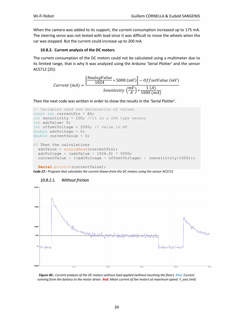
Figure 40.- Current analysis of the DC motors without load applied (without touching the floor). Blue: Current running from the battery to the motor driver. Red: Mean current of the motors at maximum speed. Y_axis (mA)
Wi-Fi Robot Guillem CORNELLA & Eudald SANGENIS
40
In the latest version, a relay was included, so that when the joystick that controlled the speed
was in the center position (robot stopped) the power supplied to the motors was cut. Including
the relay meant saving up current and decreasing the power consumption.
The figure 40 has 4 parts:
1. Powering on the motors:
A first peak of high current can be seen when starting the motors from 0 to maximum speed.
The peak’s maximum value is 5 A and then it stabilizes to 1.1 A approximately. DC motors draw
more current at their start because when the motors are running at normal speed, they create
back emf 11 which reduces the drawing current. So initially when DC motor are powered there is
no back emf so current drawn is higher.
2. Running at maximum speed:
The mean value of the current drawn when the motors are running at maximum speed is in
between 1 A and 1.2 A.
3. Setting the joystick to its center:
When running at maximum speed, the joystick went back to its center, hence the plot goes back
to 0 A due to the relay. The wheels were still running for some seconds although the power was
cut.
4. Running again while the motors were turning
Finally, while the motors were still slowing down, the joystick was moved to its maximum
position, hence the current peak is lower than the first one (3 A). That is because there was back
emf that reduced the drawing current.
10.8.2.2. With friction
There is no data gathered with the DC motors with load since the robot could not be in touch
with the floor while obtaining serial data with Arduino. But depending on the terrain and the
elevation, the current consumption is estimated to be higher, probably from 2 A to 2.5 A.
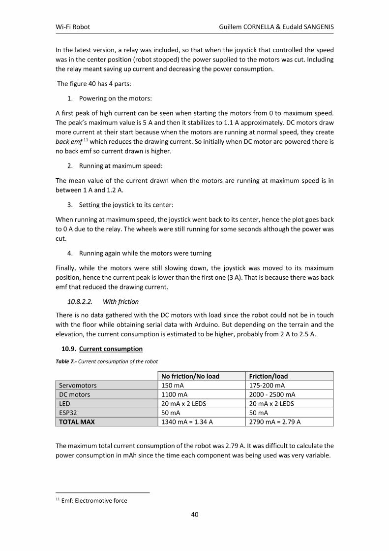
10.9. Current consumption
Table 7.- Current consumption of the robot
No friction/No load Friction/load
Servomotors 150 mA 175-200 mA
DC motors 1100 mA 2000 - 2500 mA
LED 20 mA x 2 LEDS 20 mA x 2 LEDS
ESP32 50 mA 50 mA
TOTAL MAX 1340 mA = 1.34 A 2790 mA = 2.79 A
The maximum total current consumption of the robot was 2.79 A. It was difficult to calculate the
power consumption in mAh since the time each component was being used was very variable.
11 Emf: Electromotive force

Wi-Fi Robot Guillem CORNELLA & Eudald SANGENIS
41
10.10. Test
Figure 41.- Aerial footage of the circuit designed to test the robot
Figure 42.- The robot running on the street and being controlled from one bedroom.
Wi-Fi Robot Guillem CORNELLA & Eudald SANGENIS
42
11. Problems detected and solutions developed
- The ESP8266 did not have enough output pins. For this project, a total of 9 output pins were
needed and the ESP8266 module only allowed 7 pins to work perfectly as outputs.
Considering that the robot might include extra sensors such as the ultrasonic sensor or other
modules, some pins should remain available. Hence, the Wi-Fi module used was the ESP32
which has more than 20 output pins.
- A power bank was used to power the servos, but it blew up when it needed to supply low
and high currents that were rapidly changing. Due to their electrical characteristics, the
commercial power banks are not prepared to work with low currents and since the servo
motors worked in a current range from 6 mA to 200 mA approximately, a LiPo battery was
used instead. With the LiPo battery there were no problems with the power supply, and it
occupied less space.
- In order to choose a proper battery to power the servos, the current that the servos drew
had to be analyzed. To do so, an Arduino code was written and after doing the required
connections the maximum current worked out being 175 mA. Since the RC car came with 2
LiPo batteries, one of them was used to power the servos. That battery delivered 1600 mAh
so theoretically the servos could run for 9h.
- The heat sink on the motor driver module heated a bit while the robot ran on ascendant
sloping surfaces or on irregular surfaces such as grass or soil. That is why a current analysis
of the DC motors was done in order to detect the reason of this heating. After gathering the
current data, it was observed that the maximum current could be 2.79 A with peaks of 5 A.
That was a problem because the module L982N allowed a maximum current draw through
each output of 3A. When the robot received its first moving signal after being steady, a 5A
peak was present, hence the heating of the driver which could only accept 3 A as its
maximum value. A solution to decrease the heating the use of a 5 V relay module to cut the
power to the motors when the robot was stopped. However, the first current peak
remained.
- The servo that controlled the steer of the car had 5 wires and a 3-wired servo was needed.
Owing to this fact and the impossibility of reconverting the 5-wired servo into a 3-wired
servo, a small 3-wired servo ‘SG90’ was used instead, placing it inside the original 5-wired
servo’s case. This was a functional solution, although the torque decreased.
- The university’s Wi-Fi network is secure, and it has WPA2-Enterprise encryption. This kind
of protection did not allow the ESP8266 module to connect to the Internet. The ESP32
module theoretically could connect through this kind of network, however the programs
that were tried did not work properly.
- In order to be able to connect to the university’s Wi-Fi network (UCCS-Wireless, UCCS-Guest
or eduroam), a personalized router might be needed on Campus. The IT staff could have set
up a router just for a specific class/project so that anyone could be able to connect to the
internet but with some restrictions. Yet finally, our robot was controlled with the home
network and it did not need to go through the security protocols.

Wi-Fi Robot Guillem CORNELLA & Eudald SANGENIS
43
- Several cameras were tried before selecting the smartphone. An Amcrest IP camera was
bought, nevertheless, it did not connect to university’s Wi-Fi since it did not support WPA2-
Enterprise. That is why a Cisco IP camera that supported this kind of encryption was bought,
yet it arrived without its components, thus it could not be tested. Finally, the phone app “IP
CAMERA” was used because it worked, and everyone has a phone.

Wi-Fi Robot Guillem CORNELLA & Eudald SANGENIS
44
12. Conclusions
The purpose of the experiment was to build a Wi-Fi remote controlled robot from a RC car and
to create an interface which could facilitate its control. The RC car was controlled by RF, yet it
was disassembled in order to convert it into a robot that could be controlled by Wi-Fi signals.
After doing some tests and research, the ESP32 Wi-Fi module was chosen as the main controller
for the robot. The most important components of the robot have been the ESP32, the DC motor
driver module L982N, the LiPo battery, the relay and the servo motors.
One of the major findings was that the ESP32 is the most useful and capable controller for Wi-Fi
operations. It has more than 20 outputs and the capability of accessing encrypted Wi-Fi
networks, although it was not done in this project. As for the L982N module, it has been
demonstrated that it may not be the best motor driver module to use, since it presented a lot
of dissipation in its heat sink due to its limited current tolerance. If the project could be done
again, the ‘Elecrow Dual H-Bridge DC Motor Controller’ would be used for its high current
tolerance (8 A). Also, regarding the power supply, a LiPo battery was used instead of a power
bank because it tolerated a wider range of currents, as opposed to the power bank that is
designed to supply high currents.
The hypothesis has been accomplished without major problems; the C# interface works
properly, the Arduino code works perfectly too, and the electrical assembly seems to work
efficiently.
After the robot was built, there was time to think for possible improvements that could be done
in the future. The first one would be the incorporation of the ‘Tap Strap’ [26] device to control
the actions of the robot with hand-gestures. The second thing to improve would be the change
on the robot’s code in order to allow it to access encrypted Wi-Fi networks. The third
improvement would be the design of a smarter way to avoid the heating of the L982N driver,
perhaps using different modules in order to enhance the electrical efficiency. The fourth one
would be the use of the original RC car 5-wired servo instead of the SG90 3-wired servo, so that
the robot could have a higher torque. And finally, a computer vision system would be added in
the next prototype, besides an autonomous driving system.
Wi-Fi Robot Guillem CORNELLA & Eudald SANGENIS
45
Bibliography
[1] Balsells Scholarship,
https://www.uccs.edu/balsellseng/
[2] BBC News, “Robots 'to replace up to 20 million factory jobs' by 2030”,
https://www.bbc.com/news/business-48760799
[3] ESP32 module, Amazon,
https://amzn.to/2z9vUoV
[4] ESPRESSIF, ESP32 “A Different IoT Power and Performance”,
https://www.espressif.com/en/products/hardware/esp32/overview
[5] Random Nerd Tutorials, “Getting Started with the ESP32 Development Board”,
https://randomnerdtutorials.com/getting-started-with-esp32/
[6] L982N Motor Driver Module, Amazon,
https://amzn.to/2VjT3xy
[7] Interface L298N DC Motor Driver Module with Arduino,
https://lastminuteengineers.com/l298n-dc-stepper-driver-arduino-tutorial/
[8] DC motors used, LAEGENDARY
https://laegendary.com/products/rc-car-390motor-includes-gear-accessory-spare-parts-25-
dj01-for-legend-rc-car
[9] SG90 servo, DATASHEET,
http://www.ee.ic.ac.uk/pcheung/teaching/DE1_EE/stores/sg90_datasheet.pdf
[10] LG-ZJ04 servo, LAEGENDARY
https://laegendary.com/products/rc-car-5-wires-servo-accessory-spare-parts-25-zj04-for-
legend-rc-car
[11] MG996R servo, DATASHEET,
https://components101.com/motors/mg996r-servo-motor-datasheet
[12] LiPo battery, LAEGENDARY parts,
https://laegendary.com/collections/rc-car-parts/products/rc-cars-1pc-7-4v-1600mah-25c-t-
connector-li-polymer-rechargeable-battery-for-legend-high-speed-remote-control-truck-
accessory-supplies
[13] MB1010 LV-MaxSonar-EZ1, Ultrasonic sensor DATASHEET,
https://www.maxbotix.com/Ultrasonic_Sensors/MB1010.htm
[14] What is the difference between 2.4 GHz and 5 GHz Wi-Fi?, NETGEAR,
https://laegendary.com/products/rc-car-5-wires-servo-accessory-spare-parts-25-zj04-for-legend-rc-car

Wi-Fi Robot Guillem CORNELLA & Eudald SANGENIS
46
https://kb.netgear.com/29396/What-is-the-difference-between-2-4-GHz-and-5-GHz-wireless-
frequencies
[15] WPA-2 Enterprise encryption, SECUREW2,
https://www.securew2.com/solutions/wpa2-enterprise-and-802-1x-simplified/
[16] TCP/IP protocol stack, MICRIUM,
https://www.micrium.com/iot/internet-protocols/
[17] TCP vs UDP comparison, DIFFEN,
https://www.diffen.com/difference/TCP_vs_UDP
[18] UCCS Wireless networks, UCCS webpage
https://wireless.uccs.edu/:
[19] IP Camera used to display the video, AMCREST IP2M-841B
https://amzn.to/3apIo8S
[20] Cisco IP Camera, CIVS-IPC-2500 - Cisco 1000 Series Routers
https://bit.ly/2XUIbbp
[21] Using an Android phone as a webcam, GITHUB, from paolorotolo:
https://github.com/OctoPrint/OctoPrint/wiki/Using-an-Android-phone-as-a-webcam
[22] IP Webcam App, Google Play Store,
https://play.google.com/store/apps/details?id=com.pas.webcam&hl=ca
[23] Cornella, G. and Sangenís, E., “Wi-Fi robot controlled through Xbox controller.”
https://github.com/eudald-sangenis/WIFI_Robot_Controlled_Xbox
[24] Servo current peaks
http://www.bhabbott.net.nz/Servo.html
[25] Current sensor ACS712,
https://www.sparkfun.com/datasheets/BreakoutBoards/0712.pdf
[26] Meet Tap – Tap Strap hand gesture device
www.tapwithus.com
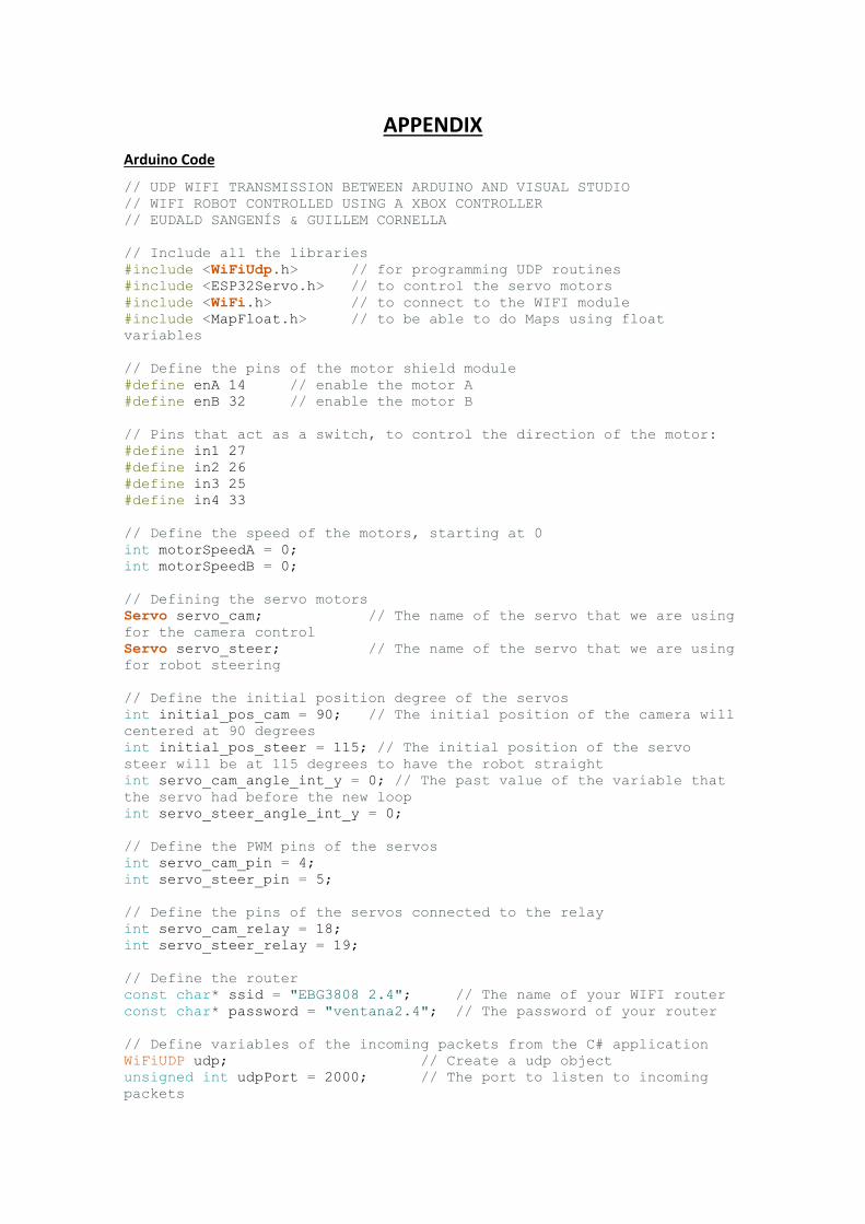
APPENDIX
Arduino Code
// UDP WIFI TRANSMISSION BETWEEN ARDUINO AND VISUAL STUDIO
// WIFI ROBOT CONTROLLED USING A XBOX CONTROLLER
// EUDALD SANGENÍS & GUILLEM CORNELLA
// Include all the libraries
#include <WiFiUdp.h> // for programming UDP routines
#include <ESP32Servo.h> // to control the servo motors
#include <WiFi.h> // to connect to the WIFI module
#include <MapFloat.h> // to be able to do Maps using float
variables
// Define the pins of the motor shield module
#define enA 14 // enable the motor A
#define enB 32 // enable the motor B
// Pins that act as a switch, to control the direction of the motor:
#define in1 27
#define in2 26
#define in3 25
#define in4 33
// Define the speed of the motors, starting at 0
int motorSpeedA = 0;
int motorSpeedB = 0;
// Defining the servo motors
Servo servo_cam; // The name of the servo that we are using
for the camera control
Servo servo_steer; // The name of the servo that we are using
for robot steering
// Define the initial position degree of the servos
int initial_pos_cam = 90; // The initial position of the camera will
centered at 90 degrees
int initial_pos_steer = 115; // The initial position of the servo
steer will be at 115 degrees to have the robot straight
int servo_cam_angle_int_y = 0; // The past value of the variable that
the servo had before the new loop
int servo_steer_angle_int_y = 0;
// Define the PWM pins of the servos
int servo_cam_pin = 4;
int servo_steer_pin = 5;
// Define the pins of the servos connected to the relay
int servo_cam_relay = 18;
int servo_steer_relay = 19;
// Define the router
const char* ssid = "EBG3808 2.4"; // The name of your WIFI router
const char* password = "ventana2.4"; // The password of your router
// Define variables of the incoming packets from the C# application
WiFiUDP udp; // Create a udp object
unsigned int udpPort = 2000; // The port to listen to incoming
packets

char packetBuffer[50]; // Set up a buffer for incoming
packets (abans era[50])
// Other definitions
#define LED 2 // Defining a LED connected to the
GPIO 2
bool led; // Define the variable "led" as a
bool
// Write the code to initialize the board, create the SETUP
void setup() {
Serial.begin(115200); // Sets the data rate in bits per second
(baud) for serial data transmission.
delay(500); // Wait for 500ms
pinMode(enA, OUTPUT); // Define the pins of the motor shield as
outputs
pinMode(enB, OUTPUT);
pinMode(in1, OUTPUT);
pinMode(in2, OUTPUT);
pinMode(in3, OUTPUT);
pinMode(in4, OUTPUT);
pinMode(LED, OUTPUT); // Define the LED that will act as the
robot's lights
pinMode(servo_cam_pin,OUTPUT);
pinMode(servo_steer_pin,OUTPUT);
pinMode(servo_cam_relay,OUTPUT);
pinMode(servo_steer_relay,OUTPUT);
servo_cam.attach(servo_cam_pin); // Attach the servo to the
pin GPIO 4, the same as D2 for the ESP8266 module
servo_steer.attach(servo_steer_pin); // Attach the servo to the
pin GPIO 5, the same as D1 for the ESP8266 module
servo_cam.write(initial_pos_cam); // Set the initial position
to 0º
servo_steer.write(initial_pos_steer); // Set the initial position
to 45º
digitalWrite(LED, LOW); // Turn off the Led On Board
// Wifi configuration and connection:
WiFi.begin(ssid, password); // Connect to your WiFi router
Serial.println(""); // Print a blank space
Serial.print("Connecting"); // Print "Connecting" to the
Serial Monitor
while (WiFi.status() != WL_CONNECTED) // Make the Led Flash while
connecting to the wifi router
{
Serial.print("."); // Print a dot "." while
trying to connect
digitalWrite(LED, LOW); // Turn off the LED on board
delay(250); // Wait for 250ms
digitalWrite(LED, HIGH); // Turn on the LED on board
delay(250); // Wait for 250ms
}
// If successfully connected to the wifi router, the IP Address and
port are displayed in the serial monitor
Serial.println("");
Serial.print("Successfully connected to : ");
Serial.println(ssid);

Serial.print("NodeMCU IP address : ");
Serial.println(WiFi.localIP());
udp.begin(udpPort); // Once connection is established,
you can start listening to incoming packets.
Serial.print("Local Port : ");
Serial.println(udpPort); // Print the number of the port
that's going to be used
}
// Write the loop code to run the program
void loop()
{
receive_packet();
}
// Waiting to receive incoming UDP packets
void receive_packet()
{
int packetSize = udp.parsePacket();
if (packetSize) {
IPAddress remoteIp = udp.remoteIP();
int len = udp.read(packetBuffer, 255);
if (len > 0) packetBuffer[len] = 0;
String udp_packet_sent = packetBuffer; // String that
contains all the data sent by C#.
Serial.print("UDP packet sent by PC:");
Serial.println(udp_packet_sent); // Print in the serial
monitor the long string containing all the information
// SERVO CAMERA MOVEMENT
String val_tilt_camera = udp_packet_sent.substring(0,6);//
Creating a substring from the packet sent to obtain information
regarding the tilt value "jx0---"
val_tilt_camera = val_tilt_camera.substring(3,6); //
Creating a substring again to obtain the numeric variables and
removing the letters "jx0"
float val_tilt_camera_f = val_tilt_camera.toFloat(); //
Converting the String into a float variable
val_tilt_camera_f = val_tilt_camera_f - 0.5; //
Substracting 0.5 to the value so we can have 0 in the the center, -0.5
the minimum, and 0.5 the maximum
Serial.print("Value of the camera sent by c#:");
Serial.println(val_tilt_camera_f);
float servo_cam_angle = mapFloat(val_tilt_camera_f, -0.5, 0.5,
170.0, 10.0); // Maping the value obtained, -0.5 in the joystick
equals 170º and 0.5 equals 10º
int servo_cam_angle_int = (int)servo_cam_angle; //
Converting the value in degrees into an <int> variable
if (servo_cam_angle_int == servo_cam_angle_int_y){
digitalWrite(servo_cam_relay,LOW);
servo_cam.detach();
Serial.println("Servo camera OFF");
delay(200);
}
else if (servo_cam_angle_int != servo_cam_angle_int_y){
digitalWrite(servo_cam_relay,HIGH);
servo_cam.attach(servo_cam_pin);
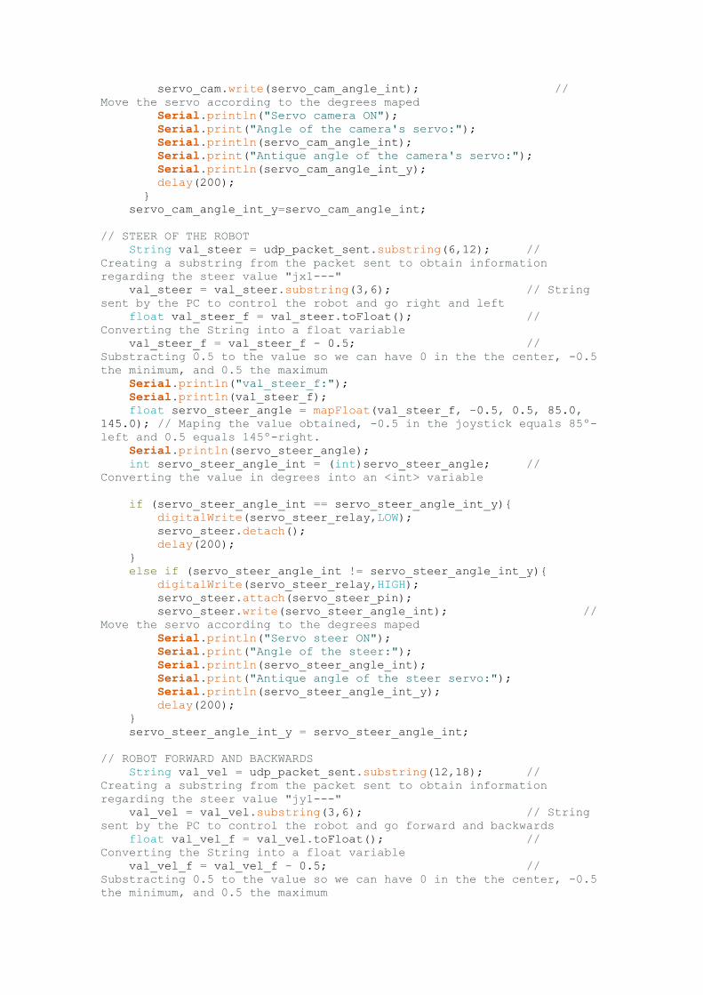
servo_cam.write(servo_cam_angle_int); //
Move the servo according to the degrees maped
Serial.println("Servo camera ON");
Serial.print("Angle of the camera's servo:");
Serial.println(servo_cam_angle_int);
Serial.print("Antique angle of the camera's servo:");
Serial.println(servo_cam_angle_int_y);
delay(200);
}
servo_cam_angle_int_y=servo_cam_angle_int;
// STEER OF THE ROBOT
String val_steer = udp_packet_sent.substring(6,12); //
Creating a substring from the packet sent to obtain information
regarding the steer value "jx1---"
val_steer = val_steer.substring(3,6); // String
sent by the PC to control the robot and go right and left
float val_steer_f = val_steer.toFloat(); //
Converting the String into a float variable
val_steer_f = val_steer_f - 0.5; //
Substracting 0.5 to the value so we can have 0 in the the center, -0.5
the minimum, and 0.5 the maximum
Serial.println("val_steer_f:");
Serial.println(val_steer_f);
float servo_steer_angle = mapFloat(val_steer_f, -0.5, 0.5, 85.0,
145.0); // Maping the value obtained, -0.5 in the joystick equals 85º-
left and 0.5 equals 145º-right.
Serial.println(servo_steer_angle);
int servo_steer_angle_int = (int)servo_steer_angle; //
Converting the value in degrees into an <int> variable
if (servo_steer_angle_int == servo_steer_angle_int_y){
digitalWrite(servo_steer_relay,LOW);
servo_steer.detach();
delay(200);
}
else if (servo_steer_angle_int != servo_steer_angle_int_y){
digitalWrite(servo_steer_relay,HIGH);
servo_steer.attach(servo_steer_pin);
servo_steer.write(servo_steer_angle_int); //
Move the servo according to the degrees maped
Serial.println("Servo steer ON");
Serial.print("Angle of the steer:");
Serial.println(servo_steer_angle_int);
Serial.print("Antique angle of the steer servo:");
Serial.println(servo_steer_angle_int_y);
delay(200);
}
servo_steer_angle_int_y = servo_steer_angle_int;
// ROBOT FORWARD AND BACKWARDS
String val_vel = udp_packet_sent.substring(12,18); //
Creating a substring from the packet sent to obtain information
regarding the steer value "jy1---"
val_vel = val_vel.substring(3,6); // String
sent by the PC to control the robot and go forward and backwards
float val_vel_f = val_vel.toFloat(); //
Converting the String into a float variable
val_vel_f = val_vel_f - 0.5; //
Substracting 0.5 to the value so we can have 0 in the the center, -0.5
the minimum, and 0.5 the maximum

Serial.print("Value of the velocity:");
Serial.println(val_vel_f);
//LEDS ON - LEDS OFF
String light = udp_packet_sent.substring(18,22); //
Creating a substring from the packet sent to obtain information
regarding the LED value "LED-"
if (light=="LED1"){ // When
the substring analyzed is "LED1" then light on the LED
led = true;
digitalWrite(LED,HIGH);
}
else if (light=="LED2"){ // When
the substring analyzed is "LED2" then light off the LED
led = false;
digitalWrite(LED, LOW);
}
else if (light=="LED0"){ // When
the substring analyzed is "LED0", if the LED was on, turn it off, and
vice versa.
digitalWrite(LED,LOW);
if (led==true) digitalWrite(LED,HIGH);
else digitalWrite(LED,LOW);
}
// Y-axis used for forward and backward control
// to go BACKWARDS
if (val_vel_f < -0.1) {
// Set Motor A backward
digitalWrite(in1, HIGH);
digitalWrite(in2, LOW);
// Set Motor B backward
digitalWrite(in3, HIGH);
digitalWrite(in4, LOW);
// Convert the declining Y-axis readings for going backwards, -
0.1 equals 400 and -0.5 equals 1000. The PWM signal is increasing the
motor speed.
float motorSpeedA_f = mapFloat(val_vel_f, -0.1, -0.5, 400.0,
1000.0);
float motorSpeedB_f = mapFloat(val_vel_f, -0.1, -0.5, 400.0,
1000.0);
motorSpeedA = (int)motorSpeedA_f; // convert the float
variable of the speed of the motor A to an int
motorSpeedB = (int)motorSpeedB_f; // convert the float
variable of the speed of the motor B to an int
}
// to go FORWARD
else if (val_vel_f > 0.1) {
// Set Motor A forward
digitalWrite(in1, LOW);
digitalWrite(in2, HIGH);
// Set Motor B forward
digitalWrite(in3, LOW);
digitalWrite(in4, HIGH);
// Convert the growing Y-axis readings for going forward, 0.1
equals 400 and 0.5 equals 1000. The PWM signal is increasing the motor
speed.
float motorSpeedA_f = mapFloat(val_vel_f, 0.1, 0.5, 400.0,
1000.0);
float motorSpeedB_f = mapFloat(val_vel_f, 0.1, 0.5, 400.0,
1000.0);
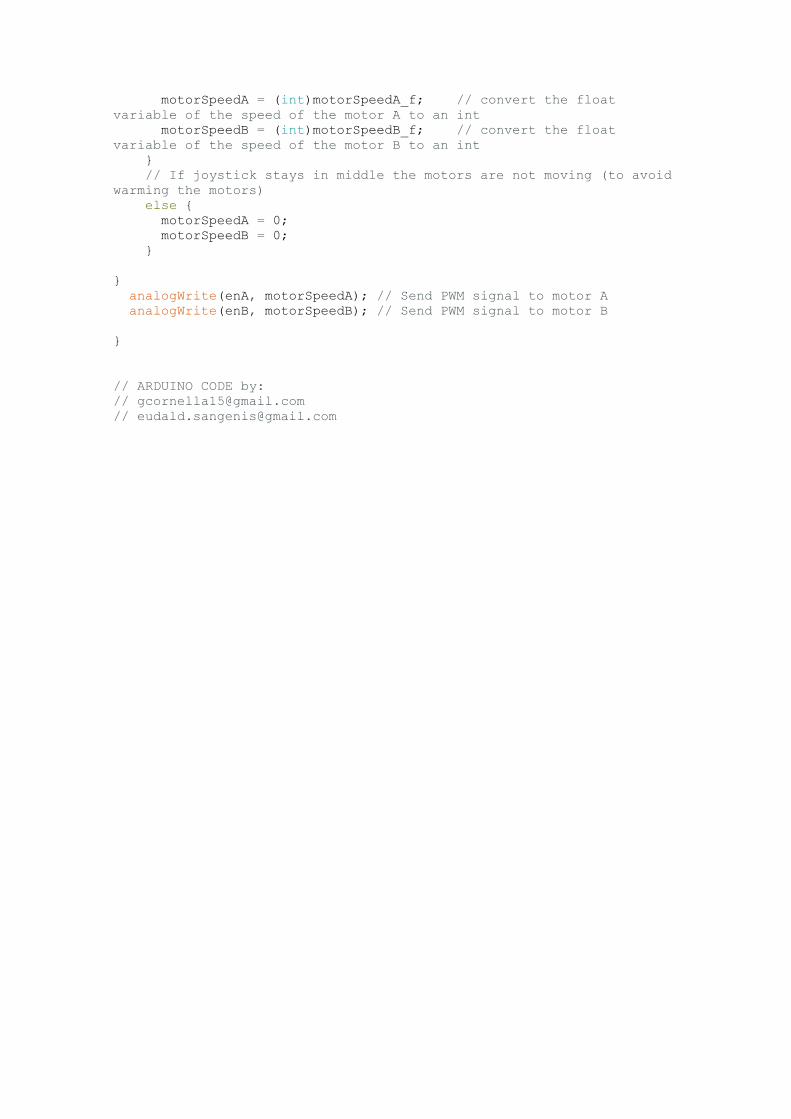
motorSpeedA = (int)motorSpeedA_f; // convert the float
variable of the speed of the motor A to an int
motorSpeedB = (int)motorSpeedB_f; // convert the float
variable of the speed of the motor B to an int
}
// If joystick stays in middle the motors are not moving (to avoid
warming the motors)
else {
motorSpeedA = 0;
motorSpeedB = 0;
}
}
analogWrite(enA, motorSpeedA); // Send PWM signal to motor A
analogWrite(enB, motorSpeedB); // Send PWM signal to motor B
}
// ARDUINO CODE by:
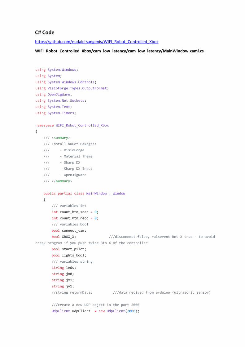
C# Code
https://github.com/eudald-sangenis/WIFI_Robot_Controlled_Xbox
WIFI_Robot_Controlled_Xbox/cam_low_latency/cam_low_latency/MainWindow.xaml.cs
using System.Windows;
using System;
using System.Windows.Controls;
using VisioForge.Types.OutputFormat;
using OpenJigWare;
using System.Net.Sockets;
using System.Text;
using System.Timers;
namespace WIFI_Robot_Controlled_Xbox
{
/// <summary>
/// Install NuGet Pakages:
/// - VisioForge
/// - Material Theme
/// - Sharp DX
/// - Sharp DX Input
/// - OpenJigWare
/// </summary>
public partial class MainWindow : Window
{
/// variables int
int count_btn_snap = 0;
int count_btn_recd = 0;
/// variables bool
bool connect_cam;
bool XBOX_X; ///disconnect false, raisevent Bnt X true - to avoid
break program if you push twice Btn X of the controller
bool start_pilot;
bool lights_bool;
/// variables string
string leds;
string jx0;
string jx1;
string jy1;
//string returnData; ///data recived from arduino (ultrasonic sensor)
///create a new UDP object in the port 2000
UdpClient udpClient = new UdpClient(2000);
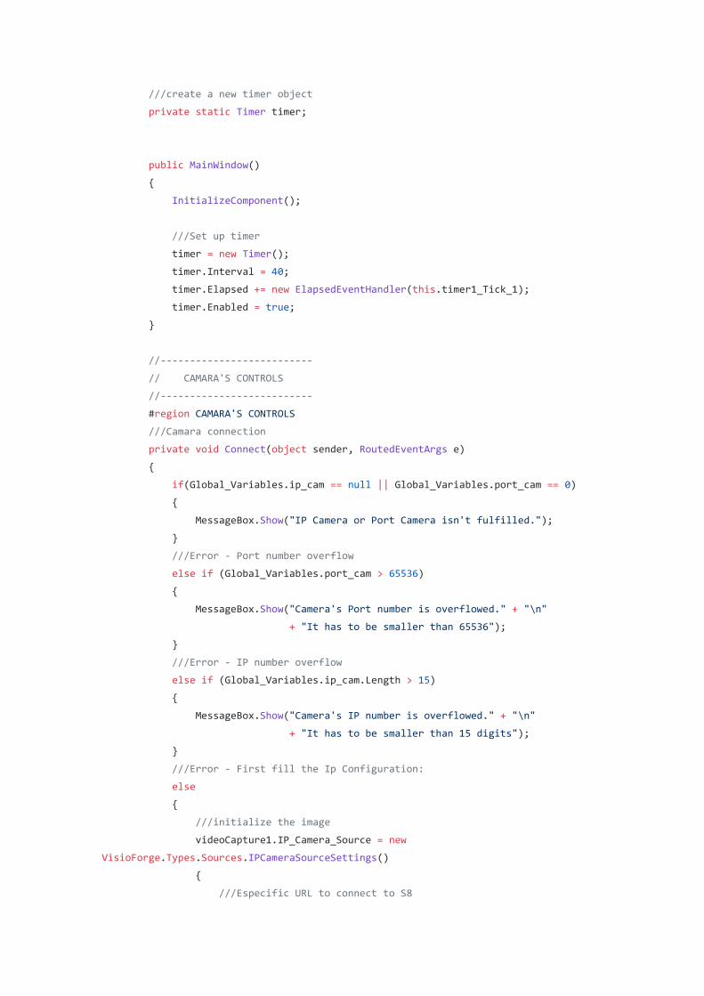
///create a new timer object
private static Timer timer;
public MainWindow()
{
InitializeComponent();
///Set up timer
timer = new Timer();
timer.Interval = 40;
timer.Elapsed += new ElapsedEventHandler(this.timer1_Tick_1);
timer.Enabled = true;
}
//--------------------------
// CAMARA'S CONTROLS
//--------------------------
#region CAMARA'S CONTROLS
///Camara connection
private void Connect(object sender, RoutedEventArgs e)
{
if(Global_Variables.ip_cam == null || Global_Variables.port_cam == 0)
{
MessageBox.Show("IP Camera or Port Camera isn't fulfilled.");
}
///Error - Port number overflow
else if (Global_Variables.port_cam > 65536)
{
MessageBox.Show("Camera's Port number is overflowed." + "\n"
+ "It has to be smaller than 65536");
}
///Error - IP number overflow
else if (Global_Variables.ip_cam.Length > 15)
{
MessageBox.Show("Camera's IP number is overflowed." + "\n"
+ "It has to be smaller than 15 digits");
}
///Error - First fill the Ip Configuration:
else
{
///initialize the image
videoCapture1.IP_Camera_Source = new
VisioForge.Types.Sources.IPCameraSourceSettings()
{
///Especific URL to connect to S8
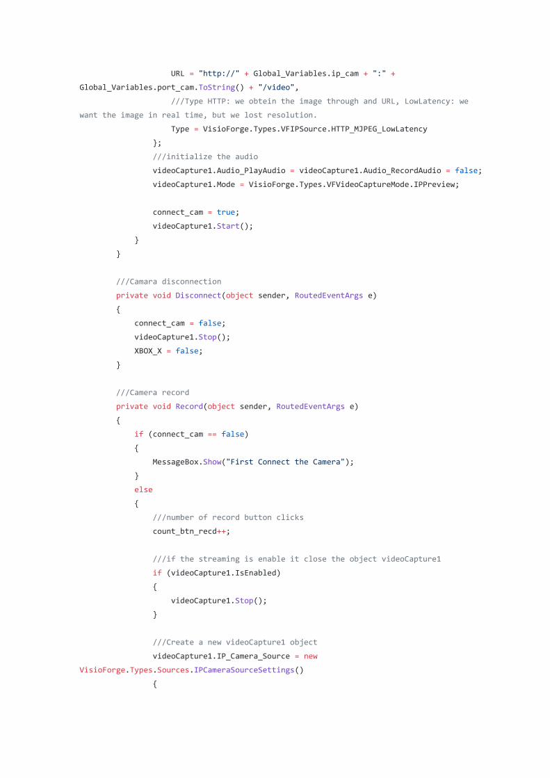
URL = "http://" + Global_Variables.ip_cam + ":" +
Global_Variables.port_cam.ToString() + "/video",
///Type HTTP: we obtein the image through and URL, LowLatency: we
want the image in real time, but we lost resolution.
Type = VisioForge.Types.VFIPSource.HTTP_MJPEG_LowLatency
};
///initialize the audio
videoCapture1.Audio_PlayAudio = videoCapture1.Audio_RecordAudio = false;
videoCapture1.Mode = VisioForge.Types.VFVideoCaptureMode.IPPreview;
connect_cam = true;
videoCapture1.Start();
}
}
///Camara disconnection
private void Disconnect(object sender, RoutedEventArgs e)
{
connect_cam = false;
videoCapture1.Stop();
XBOX_X = false;
}
///Camera record
private void Record(object sender, RoutedEventArgs e)
{
if (connect_cam == false)
{
MessageBox.Show("First Connect the Camera");
}
else
{
///number of record button clicks
count_btn_recd++;
///if the streaming is enable it close the object videoCapture1
if (videoCapture1.IsEnabled)
{
videoCapture1.Stop();
}
///Create a new videoCapture1 object
videoCapture1.IP_Camera_Source = new
VisioForge.Types.Sources.IPCameraSourceSettings()
{

URL = "http://" + Global_Variables.ip_cam + ":" +
Global_Variables.port_cam.ToString() + "/video",
Type = VisioForge.Types.VFIPSource.HTTP_MJPEG_LowLatency
};
///Audio Settings
videoCapture1.Audio_PlayAudio = videoCapture1.Audio_RecordAudio = false;
///save the video to myvideos folder with the name of
vid_{count_btn_recd}.mp4
videoCapture1.Output_Filename =
Environment.GetFolderPath(Environment.SpecialFolder.MyVideos) +
$"\\vid_{count_btn_recd}.mp4";
///Output video format
videoCapture1.Output_Format = new VFWMVOutput();
///Type of video
videoCapture1.Mode = VisioForge.Types.VFVideoCaptureMode.IPCapture;
videoCapture1.Start();
}
}
///Camara snapshoot
private void Snapshot(object sender, RoutedEventArgs e)
{
if (connect_cam == false)
{
MessageBox.Show("First Connect the Camera");
}
else
{
///number of snapshot button clicks
count_btn_snap++;
///save the snapshot to mypictures folder with the name of
frame_{count_btn_snap}.jpg
videoCapture1.Frame_Save(Environment.GetFolderPath(Environment.SpecialFolder.MyPictures)
+ $"\\frame_{count_btn_snap}.jpg", VisioForge.Types.VFImageFormat.JPEG, 85);
}
}
#endregion CAMARA'S CONTROLS
//--------------------------
// IP CONFING WINDOW
//--------------------------
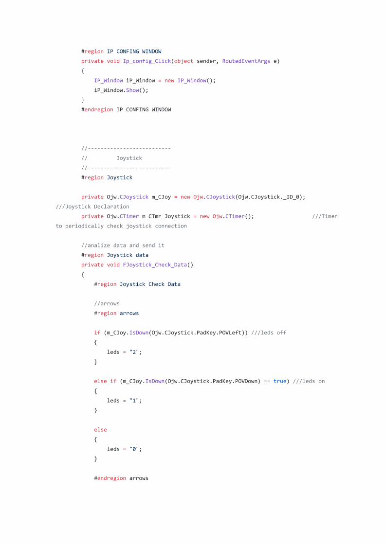
#region IP CONFING WINDOW
private void Ip_config_Click(object sender, RoutedEventArgs e)
{
IP_Window iP_Window = new IP_Window();
iP_Window.Show();
}
#endregion IP CONFING WINDOW
//--------------------------
// Joystick
//--------------------------
#region Joystick
private Ojw.CJoystick m_CJoy = new Ojw.CJoystick(Ojw.CJoystick._ID_0);
///Joystick Declaration
private Ojw.CTimer m_CTmr_Joystick = new Ojw.CTimer(); ///Timer
to periodically check joystick connection
//analize data and send it
#region Joystick data
private void FJoystick_Check_Data()
{
#region Joystick Check Data
//arrows
#region arrows
if (m_CJoy.IsDown(Ojw.CJoystick.PadKey.POVLeft)) ///leds off
{
leds = "2";
}
else if (m_CJoy.IsDown(Ojw.CJoystick.PadKey.POVDown) == true) ///leds on
{
leds = "1";
}
else
{
leds = "0";
}
#endregion arrows
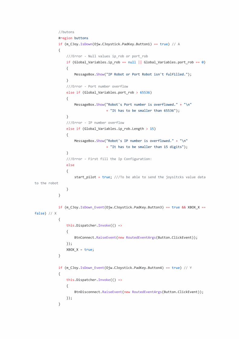
//butons
#region buttons
if (m_CJoy.IsDown(Ojw.CJoystick.PadKey.Button1) == true) // A
{
///Error - Null values ip_rob or port_rob
if (Global_Variables.ip_rob == null || Global_Variables.port_rob == 0)
{
MessageBox.Show("IP Robot or Port Robot isn't fulfilled.");
}
///Error - Port number overflow
else if (Global_Variables.port_rob > 65536)
{
MessageBox.Show("Robot's Port number is overflowed." + "\n"
+ "It has to be smaller than 65536");
}
///Error - IP number overflow
else if (Global_Variables.ip_rob.Length > 15)
{
MessageBox.Show("Robot's IP number is overflowed." + "\n"
+ "It has to be smaller than 15 digits");
}
///Error - First fill the Ip Configuration:
else
{
start_pilot = true; ///To be able to send the joysitcks value data
to the robot
}
}
if (m_CJoy.IsDown_Event(Ojw.CJoystick.PadKey.Button3) == true && XBOX_X ==
false) // X
{
this.Dispatcher.Invoke(() =>
{
BtnConnect.RaiseEvent(new RoutedEventArgs(Button.ClickEvent));
});
XBOX_X = true;
}
if (m_CJoy.IsDown_Event(Ojw.CJoystick.PadKey.Button4) == true) // Y
{
this.Dispatcher.Invoke(() =>
{
BtnDisconnect.RaiseEvent(new RoutedEventArgs(Button.ClickEvent));
});
}
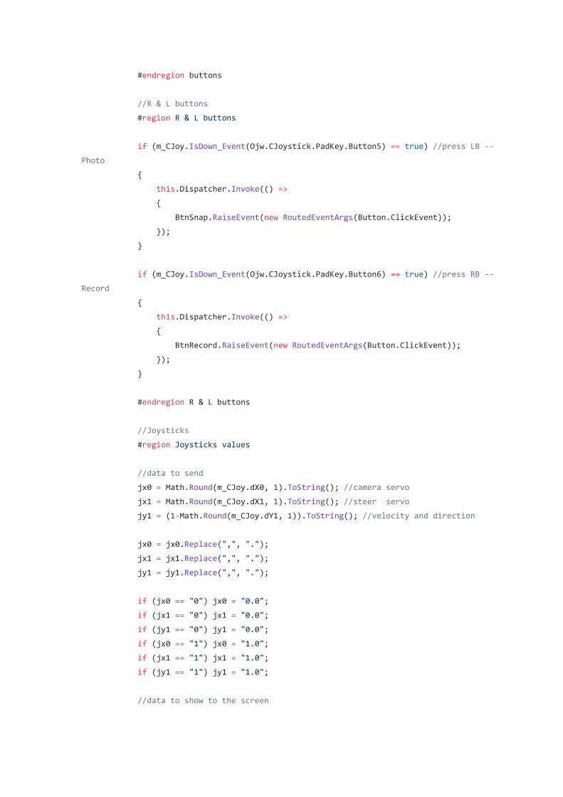
#endregion buttons
//R & L buttons
#region R & L buttons
if (m_CJoy.IsDown_Event(Ojw.CJoystick.PadKey.Button5) == true) //press LB --
Photo
{
this.Dispatcher.Invoke(() =>
{
BtnSnap.RaiseEvent(new RoutedEventArgs(Button.ClickEvent));
});
}
if (m_CJoy.IsDown_Event(Ojw.CJoystick.PadKey.Button6) == true) //press RB --
Record
{
this.Dispatcher.Invoke(() =>
{
BtnRecord.RaiseEvent(new RoutedEventArgs(Button.ClickEvent));
});
}
#endregion R & L buttons
//Joysticks
#region Joysticks values
//data to send
jx0 = Math.Round(m_CJoy.dX0, 1).ToString(); //camera servo
jx1 = Math.Round(m_CJoy.dX1, 1).ToString(); //steer servo
jy1 = (1-Math.Round(m_CJoy.dY1, 1)).ToString(); //velocity and direction
jx0 = jx0.Replace(",", ".");
jx1 = jx1.Replace(",", ".");
jy1 = jy1.Replace(",", ".");
if (jx0 == "0") jx0 = "0.0";
if (jx1 == "0") jx1 = "0.0";
if (jy1 == "0") jy1 = "0.0";
if (jx0 == "1") jx0 = "1.0";
if (jx1 == "1") jx1 = "1.0";
if (jy1 == "1") jy1 = "1.0";
//data to show to the screen
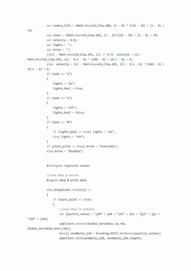
var camera_tilt = (Math.Round(m_CJoy.dX0, 1) - 0) * (170 - 10) / (1 - 0) +
10;
var steer = (Math.Round(m_CJoy.dX1, 1) - 0)*(110 - 70) / (1 - 0) + 70;
var velocity = 0.0;
var lights = "";
var drive = "";
if((1 - Math.Round(m_CJoy.dY1, 1)) >= 0.5) velocity = ((1 -
Math.Round(m_CJoy.dY1, 1)) - 0.5 - 0) * (100 - 0) / (0.5 - 0) + 0;
else velocity = ((1 - Math.Round(m_CJoy.dY1, 1)) - 0.5 - 0) * (100 - 0) /
(0.5 - 0) + 0;
if (leds == "1")
{
lights = "on";
lights_bool = true;
}
if (leds == "2")
{
lights = "off";
lights_bool = false;
}
if (leds == "0")
{
if (lights_bool == true) lights = "on";
else lights = "off";
}
if (start_pilot == true) drive = "Available";
else drive = "Disable";
#endregion Joysticks values
//Send data & recive
#region Send & print data
this.Dispatcher.Invoke(() =>
{
if (start_pilot == true)
{
//send data to arduino
var joystick_values = "jx0" + jx0 + "jx1" + jx1 + "jy1" + jy1 +
"LED" + leds;
udpClient.Connect(Global_Variables.ip_rob,
Global_Variables.port_rob);
Byte[] sendBytes_jx0 = Encoding.ASCII.GetBytes(joystick_values);
udpClient.Send(sendBytes_jx0, sendBytes_jx0.Length);
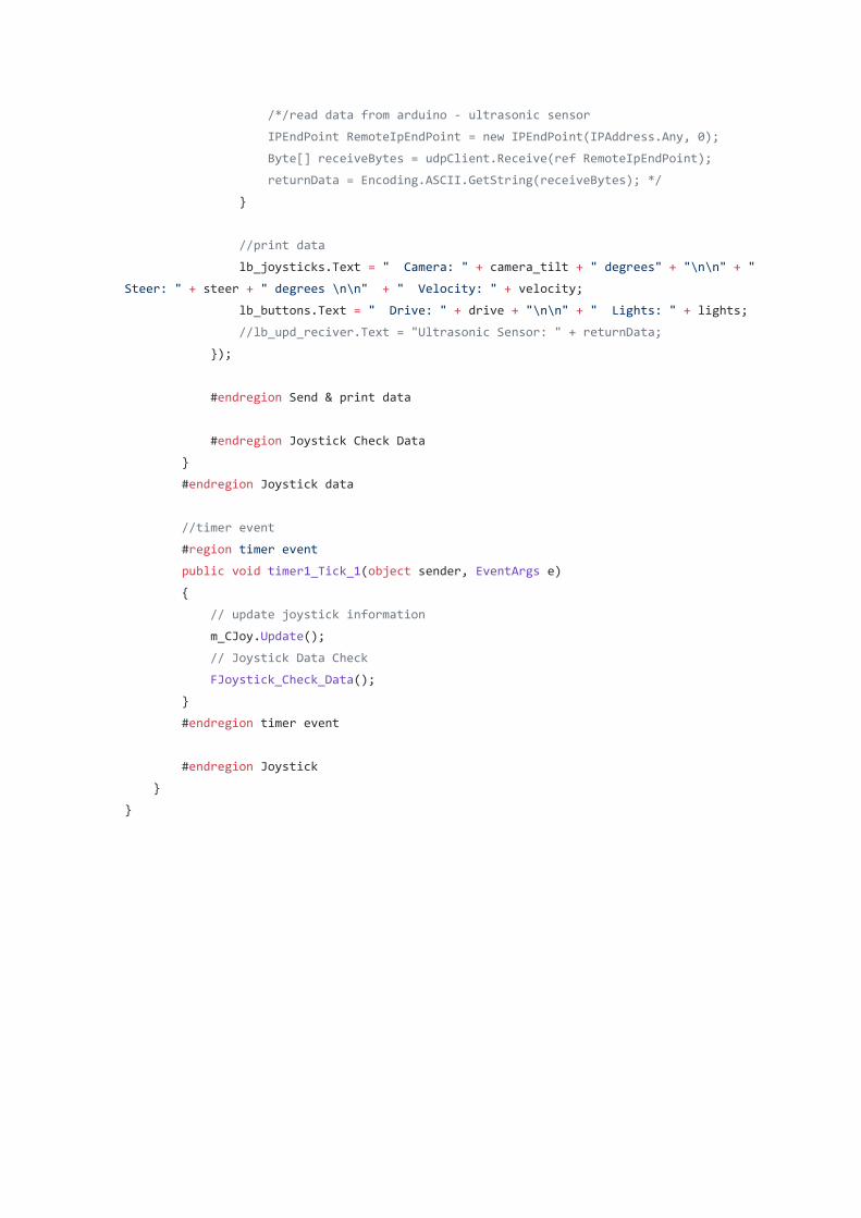
/*/read data from arduino - ultrasonic sensor
IPEndPoint RemoteIpEndPoint = new IPEndPoint(IPAddress.Any, 0);
Byte[] receiveBytes = udpClient.Receive(ref RemoteIpEndPoint);
returnData = Encoding.ASCII.GetString(receiveBytes); */
}
//print data
lb_joysticks.Text = " Camera: " + camera_tilt + " degrees" + "\n\n" + "
Steer: " + steer + " degrees \n\n" + " Velocity: " + velocity;
lb_buttons.Text = " Drive: " + drive + "\n\n" + " Lights: " + lights;
//lb_upd_reciver.Text = "Ultrasonic Sensor: " + returnData;
});
#endregion Send & print data
#endregion Joystick Check Data
}
#endregion Joystick data
//timer event
#region timer event
public void timer1_Tick_1(object sender, EventArgs e)
{
// update joystick information
m_CJoy.Update();
// Joystick Data Check
FJoystick_Check_Data();
}
#endregion timer event
#endregion Joystick
}
}
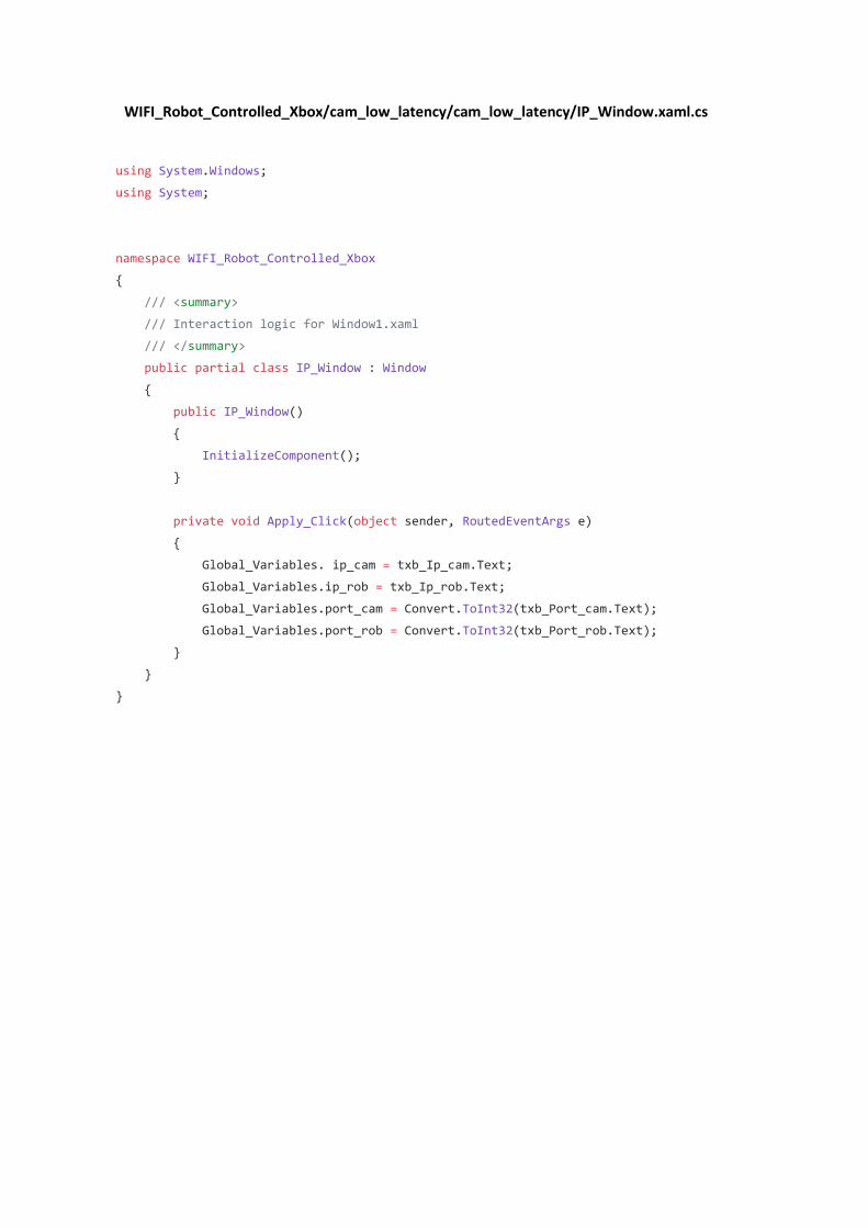
WIFI_Robot_Controlled_Xbox/cam_low_latency/cam_low_latency/IP_Window.xaml.cs
using System.Windows;
using System;
namespace WIFI_Robot_Controlled_Xbox
{
/// <summary>
/// Interaction logic for Window1.xaml
/// </summary>
public partial class IP_Window : Window
{
public IP_Window()
{
InitializeComponent();
}
private void Apply_Click(object sender, RoutedEventArgs e)
{
Global_Variables. ip_cam = txb_Ip_cam.Text;
Global_Variables.ip_rob = txb_Ip_rob.Text;
Global_Variables.port_cam = Convert.ToInt32(txb_Port_cam.Text);
Global_Variables.port_rob = Convert.ToInt32(txb_Port_rob.Text);
}
}
}
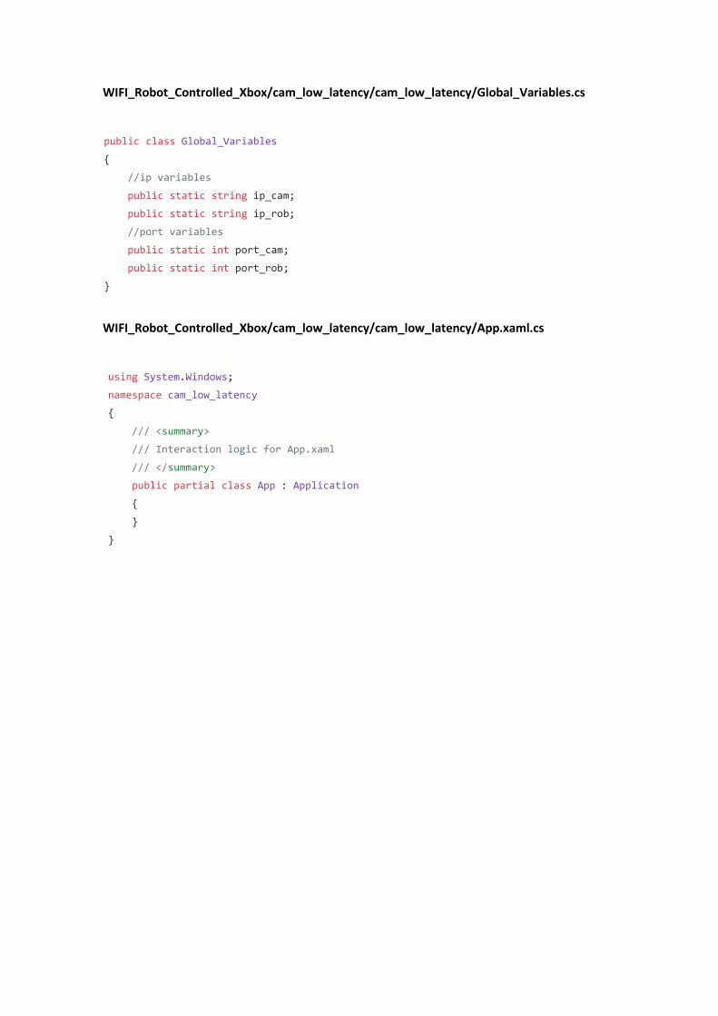
WIFI_Robot_Controlled_Xbox/cam_low_latency/cam_low_latency/Global_Variables.cs
public class Global_Variables
{
//ip variables
public static string ip_cam;
public static string ip_rob;
//port variables
public static int port_cam;
public static int port_rob;
}
WIFI_Robot_Controlled_Xbox/cam_low_latency/cam_low_latency/App.xaml.cs
using System.Windows;
namespace cam_low_latency
{
/// <summary>
/// Interaction logic for App.xaml
/// </summary>
public partial class App : Application
{
}
}
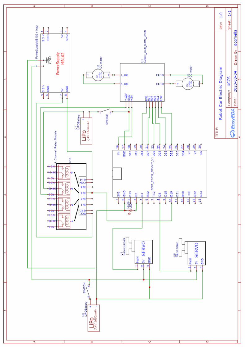
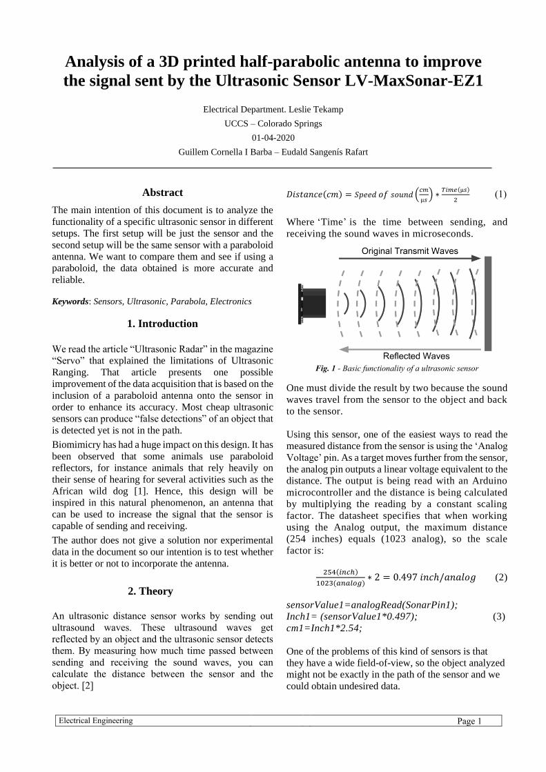
Electrical Engineering Page 1
Analysis of a 3D printed half-parabolic antenna to improve
the signal sent by the Ultrasonic Sensor LV-MaxSonar-EZ1
Electrical Department. Leslie Tekamp
UCCS – Colorado Springs
01-04-2020
Guillem Cornella I Barba – Eudald Sangenís Rafart
Abstract
The main intention of this document is to analyze the
functionality of a specific ultrasonic sensor in different
setups. The first setup will be just the sensor and the
second setup will be the same sensor with a paraboloid
antenna. We want to compare them and see if using a
paraboloid, the data obtained is more accurate and
reliable.
Keywords: Sensors, Ultrasonic, Parabola, Electronics
1. Introduction
We read the article “Ultrasonic Radar” in the magazine
“Servo” that explained the limitations of Ultrasonic
Ranging. That article presents one possible
improvement of the data acquisition that is based on the
inclusion of a paraboloid antenna onto the sensor in
order to enhance its accuracy. Most cheap ultrasonic
sensors can produce “false detections” of an object that
is detected yet is not in the path.
Biomimicry has had a huge impact on this design. It has
been observed that some animals use paraboloid
reflectors, for instance animals that rely heavily on
their sense of hearing for several activities such as the
African wild dog [1]. Hence, this design will be
inspired in this natural phenomenon, an antenna that
can be used to increase the signal that the sensor is
capable of sending and receiving.
The author does not give a solution nor experimental
data in the document so our intention is to test whether
it is better or not to incorporate the antenna.
2. Theory
An ultrasonic distance sensor works by sending out
ultrasound waves. These ultrasound waves get
reflected by an object and the ultrasonic sensor detects
them. By measuring how much time passed between
sending and receiving the sound waves, you can
calculate the distance between the sensor and the
object. [2]
𝐷𝑖𝑠𝑡𝑎𝑛𝑐𝑒(𝑐𝑚) = 𝑆𝑝𝑒𝑒𝑑 𝑜𝑓 𝑠𝑜𝑢𝑛𝑑 (𝑐𝑚
µ𝑠) ∗
𝑇𝑖𝑚𝑒(µ𝑠)
2 (1)
Where ‘Time’ is the time between sending, and
receiving the sound waves in microseconds.
Fig. 1 - Basic functionality of a ultrasonic sensor
One must divide the result by two because the sound
waves travel from the sensor to the object and back
to the sensor.
Using this sensor, one of the easiest ways to read the
measured distance from the sensor is using the ‘Analog
Voltage’ pin. As a target moves further from the sensor,
the analog pin outputs a linear voltage equivalent to the
distance. The output is being read with an Arduino
microcontroller and the distance is being calculated
by multiplying the reading by a constant scaling
factor. The datasheet specifies that when working
using the Analog output, the maximum distance
(254 inches) equals (1023 analog), so the scale
factor is:
254(𝑖𝑛𝑐ℎ)
1023(𝑎𝑛𝑎𝑙𝑜𝑔)∗ 2 = 0.497 𝑖𝑛𝑐ℎ/𝑎𝑛𝑎𝑙𝑜𝑔 (2)
sensorValue1=analogRead(SonarPin1);
Inch1= (sensorValue1*0.497); (3)
cm1=Inch1*2.54;
One of the problems of this kind of sensors is that
they have a wide field-of-view, so the object analyzed
might not be exactly in the path of the sensor and we
could obtain undesired data.

Electrical Engineering Page 2
Fig. 2 - The wide field-of-view of a typical ultrasonic transducer
means that it will "see" objects that are not in the path of the robot
[3]
Fig. 3 - Both the originating energy and the echo fall off at 1/r2
rates. [3]
3. Experimental method
To analyze the data, we prepared a setting with a 1m
meter, 2 black lines to represent the focus direction of
the sensor and a box lid. There are 2 experiments; the
first one is intended to obtain the distance between the
sensor and one object, and the second one is to recreate
a field of view to see if the sensor has a wide or narrow
field-of-view.
Fig. 4. Photo of the experimental methodology used in order to
detect different distances from the sensor to 2 different objects
(rectangular and cylinder)
In the first one, we put a rectangular object in different
distances and then we tried to create a boundary
between ‘object detected’ and ‘object not detected’ to
try to establish the field of view. We also did it with a
cylindric object, because we experienced that the data
obtained varies depending on the shape of the object.
4. LV-MaxSonar-EZ1
The information provided by the producer [2] specifies
that: “LV-MaxSonar-EZ1 is a great choice to use where
sensitivity is needed along with side object rejection.
The original LV-MaxSonar-EZ products were the first
low cost, high quality ultrasonic distance sensors to
offer easy to use outputs, no sensor dead zone,
calibrated beam patterns, stable range readings, low
power demands, and a host of other features. The LV-
MaxSonar-EZ1 is our most popular indoor ultrasonic
sensor and is a good, low-cost starting place for a
customer not sure of which LV-MaxSonar-EZ sensor
to use”.
4.1 Characteristics
[2] “With 2.5V - 5.5V power the LV-MaxSonar-EZ
provides very short to long-range detection and ranging
in a very small package. The LV-MaxSonar-EZ detects
objects from 0-inches to 254-inches (6.45-meters) and
provides sonar range information from 6- inches out to
254-inches with 1-inch resolution”.
Features:
• 2.5V to 5.5V supply with 2mA typical current draw
• Readings can occur up to every 50mS, (20-Hz rate)
• Serial, 0 to Vcc, 9600 Baud, 81N
• Analog, (Vcc/512) / inch
• Learns ringdown pattern when commanded to start
ranging
• Designed for protected indoor environments
One of the apparent problems of this sensor is that it
does not work well with distances closer than 6 inches
(15.2 cm).
4.2 Data obtained
Fig. 5 - Data obtained by the sensor without the paraboloid. [x-
axis: test points, y-axis: Distance between the sensor and the
testing object in ‘cm’] {Black: Analogic data acquired using
Arduino Serial Monitor, Red: The value that the sensor should
have read, Blue: The average value or mean data analysis of the
data acquired}
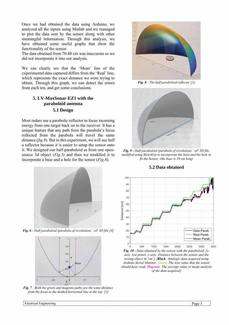
Electrical Engineering Page 3
Once we had obtained the data using Arduino, we
analyzed all the inputs using Matlab and we managed
to plot the data sent by the sensor along with other
meaningful information. Through this analysis, we
have obtained some useful graphs that show the
functionality of the sensor.
The data obtained from 70-80 cm was inaccurate so we
did not incorporate it into our analysis.
We can clearly see that the ‘Mean’ line of the
experimental data captured differs from the ‘Real’ line,
which represents the exact distance we were trying to
obtain. Through this graph, we can detect the errors
from each ten, and get some conclusions.
5. LV-MaxSonar-EZ1 with the
paraboloid antenna 5.1 Design
Most radars use a parabolic reflector to focus incoming
energy from one target back on to the receiver. It has a
unique feature that any path from the parabola’s focus
reflected from the parabola will travel the same
distance (fig.6). But in this experiment, we will use half
a reflector because it is easier to setup the sensor onto
it. We designed our half-paraboloid as from one open-
source 3d object (Fig.5) and then we modified it to
incorporate a base and a hole for the sensor (Fig.8).
Fig. 6 - Half paraboloid (parabola of revolution) ‘.stl' 3D file [4]
Fig. 7 - Both the green and magenta paths are the same distance
from the focus to the dashed horizontal line at the top. [1]
Fig. 8 - The half paraboloid reflector [1]
Fig. 9 - Half paraboloid (parabola of revolution) ‘.stl' 3D file,
modified using SketchUp to incorporate the base and the hole to
fit the Sensor. (the base is 10 cm long)
5.2 Data obtained
Fig. 10 - Data obtained by the sensor with the paraboloid. [x-
axis: test points, y-axis: Distance between the sensor and the
testing object in ‘cm’] {Black: Analogic data acquired using
Arduino Serial Monitor, Green: The true value that the sensor
should have read, Magenta: The average value or mean analysis
of the data acquired}
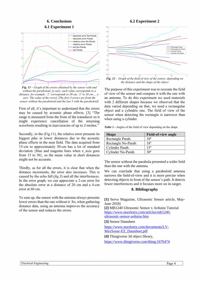
Electrical Engineering Page 4
6. Conclusions
6.1 Experiment 1
Fig. 11 – Graph of the errors obtained by the sensor with and
without the paraboloid. [x-axis: each value corresponds to a
distance, for example, ‘2’ corresponds to 20 cm, ‘3’ to 30 cm…, y-
axis: The value of the error] {The first 3 errors are from the
sensor without the paraboloid and the last 3 with the paraboloid}
First of all, it’s important to understand that the errors
may be caused by acoustic phase effects. [3] “The
range is measured from the front of the transducer so it
might experience cancellation of the returning
waveform resulting in inaccuracies of up to 2-inches.”
Secondly, in the (Fig.11), the relative error presents its
biggest pike in lower distances due to the acoustic
phase effects in the near field. The data acquired from
15-cm to approximately 30-cm has a lot of standard
deviation {blue and magenta lines when x_axis goes
from 15 to 30}, so the mean value in short distances
might not be accurate.
Thirdly, as for all the errors, it is clear that when the
distance increments, the error also increases. This is
caused by the echo fall (fig.3) and all the interferences.
In the error graph, we can appreciate a 2-cm error for
the absolute error at a distance of 20 cm and a 4-cm
error at 60 cm.
To sum up, the sensor with the antenna always presents
lower errors than the one without it. So, when gathering
distance data, using an antenna improves the accuracy
of the sensor and reduces the errors.
6.2 Experiment 2
Fig. 12 - Graph of the field of view of the sensor, depending on
the distance and the shape of the object
The purpose of this experiment was to recreate the field
of view of the sensor and compare it with the one with
an antenna. To do this experiment we used materials
with 2 different shapes because we observed that the
data varied depending on that, we used a rectangular
object and a cylindric one. The field of view of the
sensor when detecting the rectangle is narrower than
when using a cylinder.
Table 1 - Angles of the field of view depending on the shape
Shape Field-of-view angle
Rectangle Parab. 10º
Rectangle No-Parab. 18º
Cylinder Parab. 15º
Cylinder No-Parab. 30º
The sensor without the parabola presented a wider field
than the one with the antenna.
We can conclude that using a paraboloid antenna
narrows the field-of-view and it is more precise when
detecting objects in front of the sensor’s path. It detects
fewer interferences and it focuses more on its target.
8. Bibliography
[1] Servo Magazine, Ultrasonic Sensor article, May-
June 2018]
[2] MB1240 Ultrasonic Sensor x Arduino Tutorial
https://www.maxbotix.com/articles/mb1240-
ultrasonic-sensor-arduino.htm
[3] Sensor Datasheet
https://www.maxbotix.com/documents/LV-
MaxSonar-EZ_Datasheet.pdf
[4] Thingiverse 3d object library,
https://www.thingiverse.com/thing:1676474
Related Documents