WiFi and LAA Coexistence: Improvements for WiFi’s Performance by Aliasghar Keyhanian, B.Sc. A thesis submitted to the Faculty of Graduate and Postdoctoral Affairs in partial fulfillment of the requirements for the degree of Master of Applied Science in Electrical Engineering Ottawa-Carleton Institute for Electrical and Computer Engineering Department of Systems and Computer Engineering Carleton University Ottawa, Ontario August, 2017 c Copyright Aliasghar Keyhanian, 2017

Welcome message from author
This document is posted to help you gain knowledge. Please leave a comment to let me know what you think about it! Share it to your friends and learn new things together.
Transcript
WiFi and LAA Coexistence: Improvements forWiFi’s Performance
by
Aliasghar Keyhanian, B.Sc.
A thesis submitted to the
Faculty of Graduate and Postdoctoral Affairs
in partial fulfillment of the requirements for the degree of
Master of Applied Science in Electrical Engineering
Ottawa-Carleton Institute for Electrical and Computer Engineering
Department of Systems and Computer Engineering
Carleton University
Ottawa, Ontario
August, 2017
c©Copyright
Aliasghar Keyhanian, 2017

The undersigned hereby recommends to the
Faculty of Graduate and Postdoctoral Affairs
acceptance of the thesis
WiFi and LAA Coexistence: Improvements for WiFi’sPerformance
submitted by Aliasghar Keyhanian, B.Sc.
in partial fulfillment of the requirements for the degree of
Master of Applied Science in Electrical Engineering
Professor ”A. Nayak”
Professor I. Lambadaris, Thesis Supervisor
Professor ”I. D. Marsland”
Professor Roshdy Hafez, Committee Chair,Department of Systems and Computer Engineering
Ottawa-Carleton Institute for Electrical and Computer Engineering
Department of Systems and Computer Engineering
Carleton University
August, 2017
ii

Abstract
As the demand for mobile data traffic increased significantly in the past few years,
the Mobile Network Operators (MNOs) are considering different solutions to increase
the network capacity. Since the licensed spectrum is scarce and expensive, deploying
LTE in the unlicensed band can be a promising method to accommodate the market
need for mobile data. However, LTE has to coexist with other heterogeneous network,
especially WiFi, preexisting in the unlicensed medium. This coexistence can introduce
a significant performance degradation for currently deployed WiFi networks. In this
study, emphasis is given in analyzing the performance of WiFi and LTE coexistence
scenario both analytically and through simulation. To this end, a number of solutions
are proposed to increase the performance of WiFi.
Firstly, a numerical analysis is performed to mathematically formulate the prob-
lem of coexistence between WiFi and LTE. Results show that LTE can outperform
WiFi in terms of gaining access to the medium. Therefore, several modifications
in the WiFi network have been studied (e.g. maximum packet length) to allow the
WiFi network to achieve a fair share of the bandwidth while coexisting with LTE. The
study is complemented with a heuristic approach that allows to efficiently calculate
the payload length of WiFi packets. Specifically, the packet size is being determined
on the fly according to the number of existing WiFi and LTE communicating de-
vices. Finally, an alternative approach to compensate for the WiFi degradation in a
coexistence scenario is proposed based on link adaptation. In particular, a number
of enhancements in WiFi link adaptation is proposed to increase its adaptability in
case of coexistence with LAA-LTE.
iii
I want to dedicate this thesis to my parents Maryam and Ali who have always
encouraged me for new adventures like this one. I wish that this accomplishment
make your dreams come true when you tried your best to give me the best
education possible.
iv
Acknowledgments
First of all, I am thankful to the merciful God for helping me to begin, continue and
finish my work.
I would like to acknowledge the help and support of Dr. I. Lambadaris, my thesis
supervisor, for guiding me in my research area and helping me complete my program
requirements. I would also wish to express my sincere thanks to Dr. A. Leivadeas for
providing me extra academic support to achieve my research goals.
Finally, I express my sincere thanks to my parents for all of their encouragements
towards the completion of this study.
v

Preface
This thesis is the final work of my Master of Science program at the department of
System and Computer Engineering in Carleton University from the Fall 2015 until the
Summer 2017. It displays my results for the Coexistence of WiFi and LTE networks
in the unlicensed spectrum. This emerging coexistence is very essential to expand
the network capacity. Therefore it is my passion to try to facilitate this coexistence
in my study.
In fact, I could not achieve my current success without the help of a few number
of people. First, I am very grateful for the academic and financial support of my
supervisor, Dr. I. Lambadaris, toward the completion of my program. Second, I
would like to express my deep appreciation for the academic help and guidance of Dr.
A. Leivadeas.
vi
Table of Contents
Abstract iii
Acknowledgments v
Preface vi
Table of Contents vii
List of Tables ix
List of Figures x
1 Introduction 1
1.1 LTE-U and LAA Operations . . . . . . . . . . . . . . . . . . . . . . . 3
1.2 Link Adaptation . . . . . . . . . . . . . . . . . . . . . . . . . . . . . 4
1.3 Thesis Contribution . . . . . . . . . . . . . . . . . . . . . . . . . . . . 6
1.4 Thesis Organization . . . . . . . . . . . . . . . . . . . . . . . . . . . . 7
2 Related Work 8
2.1 Coexistence of Heterogeneous Networks . . . . . . . . . . . . . . . . . 8
2.2 WiFi Link adaptation . . . . . . . . . . . . . . . . . . . . . . . . . . 11
2.2.1 SNR based Link Adaptation . . . . . . . . . . . . . . . . . . . 11
2.2.2 Frame loss based Link Adaptation . . . . . . . . . . . . . . . . 12
2.3 Link Adaptation in LTE . . . . . . . . . . . . . . . . . . . . . . . . . 14
3 Theoretical Evaluations 17
3.1 WiFi Performance without Interference . . . . . . . . . . . . . . . . 17
3.2 Coexistence Performance of WiFi and LAA . . . . . . . . . . . . . . 20
3.2.1 Analytical Evaluation for LBT . . . . . . . . . . . . . . . . . . 21
vii
3.2.2 Analytical Evaluation of Coexistence . . . . . . . . . . . . . . 22
3.3 Numerical Analysis of WiFi and LAA Coexistence . . . . . . . . . . . 24
3.3.1 Performance Analysis for Fair Coexistence of WiFi and LTE-LAA 26
3.4 Allocation of Users between the two RANs . . . . . . . . . . . . . . . 32
4 Link Adaptation Considerations 35
4.1 Overview of Matlab Simulator . . . . . . . . . . . . . . . . . . . . . . 35
4.2 Original Minstrel Algorithm . . . . . . . . . . . . . . . . . . . . . . . 38
4.2.1 Retry Chain . . . . . . . . . . . . . . . . . . . . . . . . . . . . 38
4.2.2 Rate Selection . . . . . . . . . . . . . . . . . . . . . . . . . . . 38
4.2.3 Statistics Calculation . . . . . . . . . . . . . . . . . . . . . . . 38
4.3 Enhanced Minstrel Implementation . . . . . . . . . . . . . . . . . . . 39
4.4 Mutual Information Implementation . . . . . . . . . . . . . . . . . . 41
4.5 Results and Discussions . . . . . . . . . . . . . . . . . . . . . . . . . 43
4.5.1 Performance Verification of Link Adaptation in WiFi (1 AP 1
STA) . . . . . . . . . . . . . . . . . . . . . . . . . . . . . . . . 44
4.5.2 Performance Verification of Link Adaptation in WiFi (1 AP 5
stations) . . . . . . . . . . . . . . . . . . . . . . . . . . . . . . 45
4.5.3 Performance Evaluation of WiFi and LAA coexistence (1
AP/BS 1 station/UE) . . . . . . . . . . . . . . . . . . . . . . 46
4.5.4 Performance Evaluation of WiFi and LAA coexistence (1
AP/BS 5 stations/UEs) . . . . . . . . . . . . . . . . . . . . . 47
4.5.5 Equalizing performance in WiFi and LAA coexistence . . . . . 49
5 Conclusion and Future Works 54
List of References 56
viii

List of Tables
1.1 MCS Index, Modulation Scheme and coding scheme . . . . . . . . . . 6
2.1 The 4-BIT CQI Table in LTE . . . . . . . . . . . . . . . . . . . . . . 16
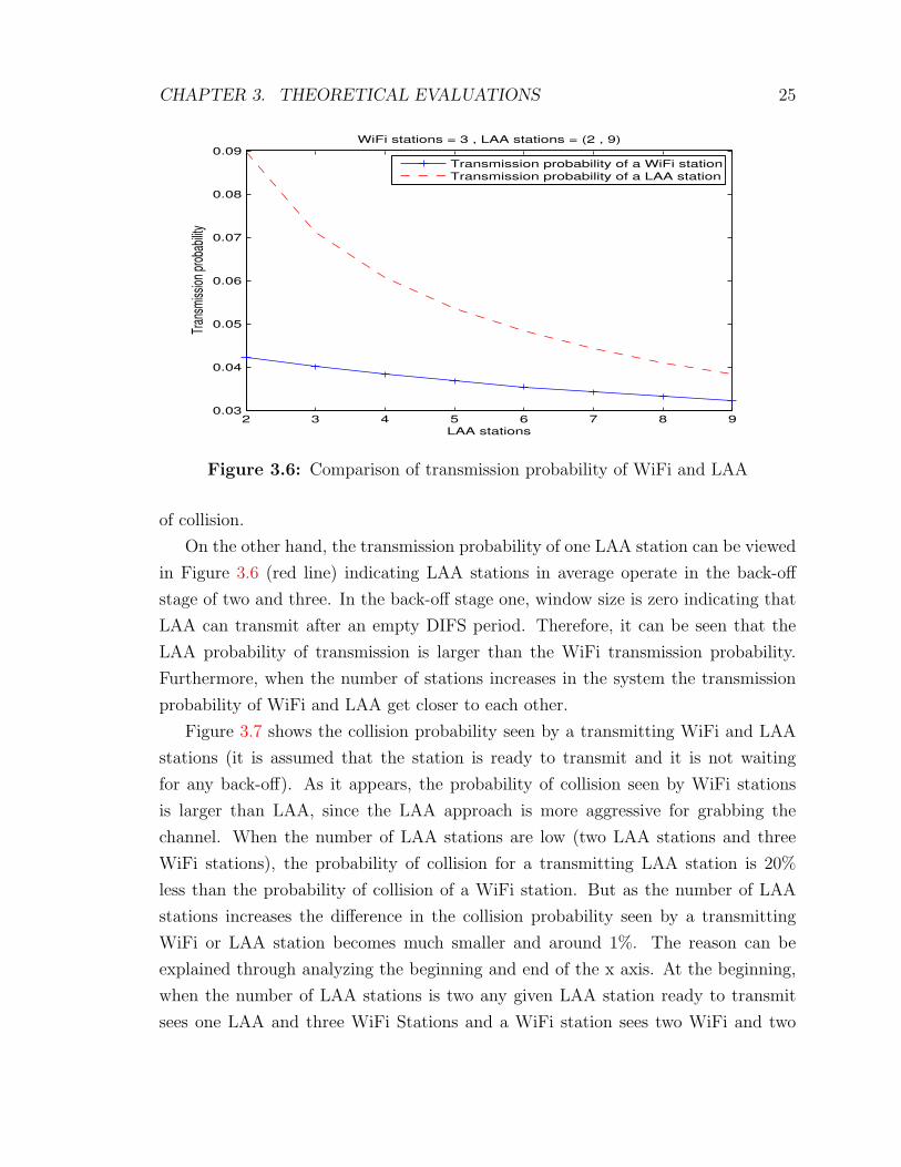
3.1 Transmission and collision probability of WiFi and LAA for different
number of stations in each network . . . . . . . . . . . . . . . . . . . 27
3.2 Simulation Parameters . . . . . . . . . . . . . . . . . . . . . . . . . . 33
4.1 Minstrel Retry Chain (T: highest throughput, t: second highest
throughput, P: highest probability, B: Base Rate, S: sample rate) . . 39
4.2 Starting Rate to SNR association . . . . . . . . . . . . . . . . . . . . 40
4.3 Enhanced Minstrel Retry Chain (T: highest throughput, t: second
highest throughput, P: highest probability, P-1: Second highest prob-
ability, S: sample rate) . . . . . . . . . . . . . . . . . . . . . . . . . . 41
ix

List of Figures
1.1 Constellation Diagrams for Different Modulation Schemes . . . . . . . 5
2.1 Link Adaptation in LTE Operation . . . . . . . . . . . . . . . . . . . 15
3.1 Markov chain model for the CSMA/CA [1] . . . . . . . . . . . . . . 18
3.2 Time required for a successful transmission . . . . . . . . . . . . . . 19
3.3 Time required for a collision . . . . . . . . . . . . . . . . . . . . . . . 20
3.4 Markov chain model for the Cat4 LBT [2] . . . . . . . . . . . . . . . 21
3.5 System model for the coexistence of WiFi and LTE. Solid connectors
show the current attachments and dashed connectors display the po-
tential connections. . . . . . . . . . . . . . . . . . . . . . . . . . . . . 23
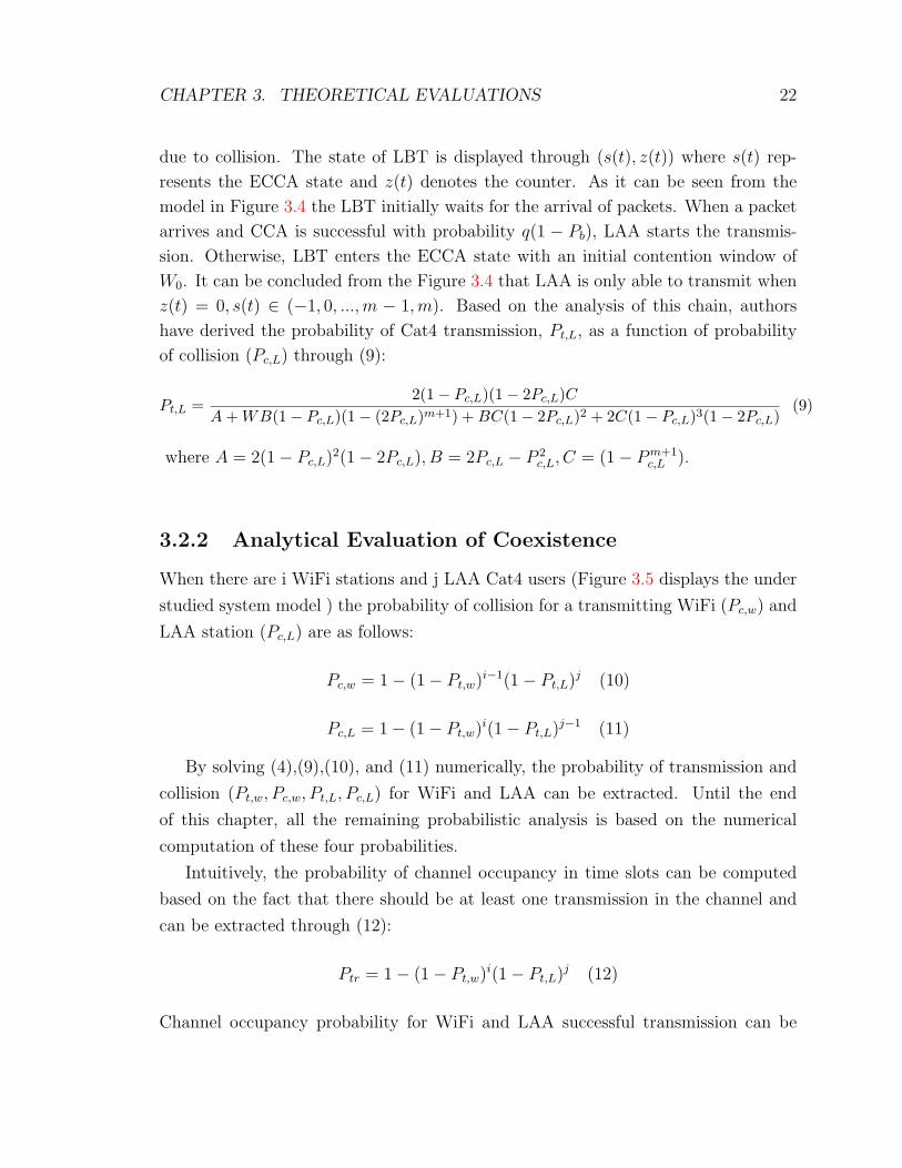
3.6 Comparison of transmission probability of WiFi and LAA . . . . . . 25
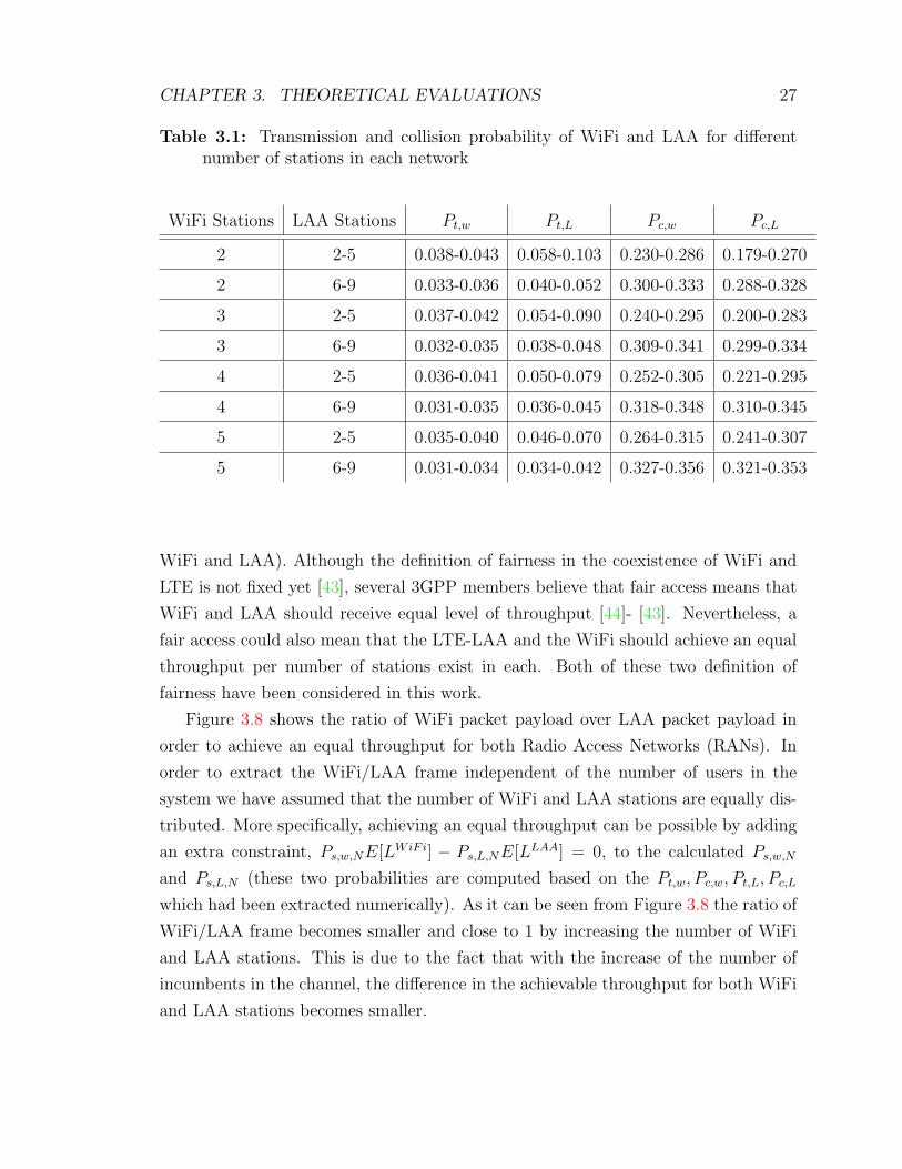
3.7 Comparison of collision probability of WiFi and LAA . . . . . . . . . 26
3.8 Packet length ratio of WiFi over LAA for having equal throughput.
The number of users for both networks are the same. . . . . . . . . . 28
3.9 Average throughput difference of WiFi and LAA for different num-
bers of α within (−2, 2) and c within (0, 2). Fairness criterion: WiFi
throughput = LAA throughput . . . . . . . . . . . . . . . . . . . . . 29
3.10 LAA/WiFi average throughput ratio for changing packet size based on
heuristic approach versus the fixed packet size (LAA users are varying
from 3 to 9 and the ratio is the average of all cases). Fairness criterion:
WiFi throughput = LAA throughput . . . . . . . . . . . . . . . . . . 30
3.11 Average throughput difference of WiFi and LAA for different num-
bers of α within (−2, 2) and c within (0, 2). Fairness criterion: WiFi
throughput per number of station = LAA throughput per number of
station . . . . . . . . . . . . . . . . . . . . . . . . . . . . . . . . . . . 31
x
3.12 LAA/WiFi average throughput ratio for changing packet size based on
heuristic approach versus the fixed packet size (LAA users are varying
from 3 to 9 and the ratio is the average of all cases). Fairness criterion:
WiFi throughput per number of station = LAA throughput per number
of station . . . . . . . . . . . . . . . . . . . . . . . . . . . . . . . . . 32
3.13 Comparison of three approaches: i)Random allocation of users,
ii)Optimal allocation of users upon arrivals, iii)Optimal allocation of
users upon both arrivals and departures . . . . . . . . . . . . . . . . 34
4.1 SNR to Mutual Information Mapping . . . . . . . . . . . . . . . . . 42
4.2 Minstrel performance in terms of a) Throughput and b) PER with
increasing distance . . . . . . . . . . . . . . . . . . . . . . . . . . . . 44
4.3 Minstrel performance in terms of a) Throughput and b) PER with
increasing distance . . . . . . . . . . . . . . . . . . . . . . . . . . . . 45
4.4 WiFi and LAA coexistence performance in terms of a) Throughput
and b) PER with increasing distance . . . . . . . . . . . . . . . . . . 46
4.5 WiFi and LAA coexistence performance in terms of a) Throughput
and b) PER with increasing distance . . . . . . . . . . . . . . . . . . 48
4.6 WiFi and LAA coexistence performance in terms of a) Throughput
and b) PER with increasing offset distance between AP and BS . . . 50
4.7 WiFi and LAA coexistence performance in terms of a) Throughput
and b) PER with LAA sending 2 subframes. . . . . . . . . . . . . . . 51
4.8 WiFi and LAA coexistence performance in terms of a) Throughput
and b) PER with LAA sending 1 subframes. . . . . . . . . . . . . . . 51
4.9 WiFi and LAA coexistence performance in terms of a) Throughput and
b) PER with no link adaptation activated and with equal transmission
times . . . . . . . . . . . . . . . . . . . . . . . . . . . . . . . . . . . . 52
4.10 WiFi and LAA coexistence performance in terms of a) Throughput and
b) PER with link adaptation activated and with equal transmission times 53
xi
xii
List of Acronyms
AARF Adaptive Auto Rate Fallback
ABS Almost-Blank Subframe
ACK Acknowledgement
AMC Adaptive Modulation and Coding
AP Access Point
ARF Auto Rate Fallback
A-RTS Adaptive Ready to send
AWGN Additive White Guassian Noise
BARA Beacon Auto Rate Adaptation
BEB Binary Exponential Backoff
BLER Block Error Rate
BPSK Binary Phase Shift Keying
BS Base Station
CARA Collision Aware Rate Adaptation
CCA Clear Channel Assessment
CQI Channel Quality Indicator
CSAT Carrier Sense Adaptive Transmission
CS Carrier Sense
CSI Channel State Information
CSMA/CA Carrier Sense Multiple Access with Collision Avoidance
CTS Clear to Send
CW Contention Window
xiii
DCF Distributed Coordination Function
DIFS Distributed Coordination Function Interframe Space
DL Downlink
ECCA Extended CCA
EDCA Enhanced Distributed Channel Access
eICIC enhanced Inter-Cell Interference Coordination
eNB Evolved Node B
ETSI European Telecommunications Standards Institute
EWMA Exponential Weighting Moving Average
FDD Frequency Division Duplexing
FEC Forward Error Correction
LAA License Assisted Access
LBT Listen before Talk
LTE Long Term Evolution
LTE-U LTE Unlicensed
MAC Media Access Control
MCS Modulation and Coding scheme
MI Mutual Information
MNO Mobile Network Operator
NACK Negative Acknowledgement
OAR Opportunistic Auto Rate
OFDM Orthogonal Frequency Division Multiplexing
OFDMA Orthogonal Frequency Division Multiple Access
PAPR Peak-to-Average Power Ratio
PER Packet Error Rate
QAM Quadrature Amplitude Modulation
QPSK Quadrature Phase Shift Keying
RAN Radio Access Network

xiv
RB Resource Block
RBAR Receiver Based Auto Rate
RF Radio Frequency
RLAN Radio Local Area Network
RTS Ready to Send
SC-FDMA Single Carrier Frequency Division Multiple Access
SDN Software Defined Networking
SIFS Short Interframe Space
SINR Signal to Interference and Noise Ratio
SNR Signal to Noise Ratio
TBS Transport Block Size
TDD Time Division Duplexing
TDM Time Division Multiplexing
UE User Equipment
UL Uplink
WiFi MU WiFi Medium Utilization
WLAN Wireless Local Area Network

Chapter 1
Introduction
Currently, the demand for mobile data traffic is growing too fast. Accommodating
this growth, enforced the Mobile Network Operators (MNOs) to investigate different
solutions to increase the network capacity. Licensed wireless medium is too expen-
sive and the physical layer is reaching its theoretical potential. Therefore, using the
unlicensed spectrum is deemed unavoidable to meet the market needs for mobile com-
munication. Previously, this usage was limited to offloading the mobile traffic onto
WiFi networks which have ubiquitous deployment and comparably low cost. Re-
cently, besides the data offloading, mobile operators are also looking to operate LTE
in the unlicensed spectrum, an approach known as LTE unlicensed (LTE-U) [3] or
License-Assisted Access (LAA). However, this deployment can have a huge impact on
the operation of WiFi and introduces several challenges for both networks to grate-
fully coexist in a shared spectrum. Understanding the coexistence challenges for both
WiFi and LTE networks requires a closer look in their operation in the Physical and
Mac Layers.
In a LTE network, User Equipment (UE) is synchronous to the base station or
eNB. Wireless communication in Downlink (DL) and Uplink (UL) can be performed
simultaneously or sequentially whether Frequency Division Duplexing (FDD) mode
or Time Division Duplexing (TDD) method is followed [4]. In the physical layer,
LTE uses Orthogonal Frequency Division Multiple Access (OFDMA) technology in
the downlink direction allowing the transmission to several users at the same time.
This technology enables the eNB to determine the resource block allocation to mul-
tiple users in the frequency-time space. This technique can increase the throughput
significantly since every user in the LTE network is experiencing varying channel con-
ditions over different frequency-time blocks. Since UEs are more vulnerable to power
1

CHAPTER 1. INTRODUCTION 2
consumption due to their dependence on batteries, LTE employs Single Carrier Fre-
quency Division Multiple Access (SC-FDMA) technology in the uplink transmission.
SC-FDMA offers a lower Peak-to-Average Power Ratio (PAPR) which enhance mo-
bile devices to have a lower cost for power amplifiers and a better transmit power
efficiency.
Unlike the LTE, accessing the medium by WiFi is contention based utilizing the
Distributed Coordination Function (DCF) or Enhanced Distributed Channel Access
(EDCA) procedure. DCF and EDCA use Carrier Sense Multiple Access with Col-
lision Avoidance (CSMA/CA) protocol accompanied by a random back off time in
a busy medium situation [4]. The goal of CSMA/CA is to decrease the collision
probability among multiple stations trying to access the medium. If a station wants
to transmit a block of data it should sense the medium to specify that whether the
medium is busy or idle. Carrier sense (CS) mechanism determines the state of the
medium (busy or idle) through physical and virtual Carrier Sense functions. If the
medium determined to be idle DCF or EDCA operation may continue. Otherwise the
transmitting station should wait until the end of the current transmission. WiFi also
transmit beacon frames periodically to broadcast the presence of a Wireless Local
Area Network (WLAN). Beacons also follow the CSMA/CA procedure to access the
channel. When the number of competing stations increases, the collision probability
will get closer to one resulting in a poor performance compared to the centralized
LTE operation. Moreover, WiFi physical layer uses Orthogonal Frequency Division
Multiplexing (OFDM) technology for both DL and UL directions. OFDM used in
WiFi has a different subcarrier granularity and spacing from the LTE physical layer
making their waveforms non-orthogonal. This non-orthogonality can further cause
interference problems within different carriers in the shared spectrum.
Both networks need to coexist peacefully in the shared medium to achieve the
highest performance and lowest interference. Therefore, the LTE operation should be
revised in order not to degrade the performance of WiFi network to an unacceptable
level. Qualcomm originally developed LTE-U as a revision to LTE operation while
Ericsson uses LAA to introduce similar technology. Mobile operators are interested
in these two technologies to boost the capacity and coverage of the LTE network by
carrier aggregation. Users on the other hand benefit from LTE-U and LAA through
the increase in their peak data ratio. Both technologies try to break the LTE cycling
in some periods of time allowing WiFi to transmit in the free medium. These two

CHAPTER 1. INTRODUCTION 3
technologies are introduced in the following.
1.1 LTE-U and LAA Operations
LTE-U small cells will search the unlicensed spectrum to find the least busy channel
available for offloading their traffic when the licensed spectrum is not sufficient [5].
Also in the case of interference in the operating channel, LTE-U will switch to another
clean channel to continue the transmission. LTE-U uses Carrier Sensing Adaptive
Transmission (CSAT) algorithm when there is no free channel available for transmis-
sion and the load of system is high (high data traffic). This algorithm enables Time
Division Multiplexing (TDM) to share a same channel with other Access Points (APs).
CSAT also tries to bring fairness in the sharing of the channel with other neighboring
WiFi APs and avoid dominating the channel. For transmitting in a TDM manner,
CSAT will observe the medium for a comparably long period (from tens of millisec-
onds up to 200ms) to estimate the WiFi utilization and based on the observation, the
algorithm will switch the LTE cycling on and off. More specifically, a time cycle will
be defined by CSAT to allow transmission for a certain time periods. In the remaining
time of the cycle, LTE will be silent to permit the communication for other neigh-
boring APs. Furthermore LTE transmission time, Ton, will be updated according to
WiFi Medium Utilization (WiFi MU). If WiFi MU is larger than a certain threshold,
Ton will be decremented until reaching the Ton,min. Otherwise, Ton will be increased
until the Ton,max bound. Ton,min is defined to ensure that LTE will receive a fair share
of the medium and Ton,max allows CSAT to sense the WiFi activity [6]. The main
difference of the CSAT algorithm with CSMA protocol used in WiFi is the longer
latency caused by avoiding channels which is currently in the usage of WiFi. CSAT
is compatible with the release of 10/11 UE Physical and MAC layer standards [7].
On the other hand, LAA uses Listen Before Talk (LBT) technique to resolve the
accessing problem in the coexistence of WiFi and LTE. LBT uses Clear Channel
Assessment (CCA) procedure to resolve the contention for accessing the medium. In
this procedure the energy level on the channel is estimated before the transmission
to identify whether the medium is busy or idle. Starting the transmission requires
that the medium is sensed idle for a random back-off phase consisting of N CCA
periods. Every CCA period has a 9µs duration. Number N refers to a counter
selected randomly from the contention window interval (0, CW ). The back-off timer
CHAPTER 1. INTRODUCTION 4
decrements after each CCA idle period. In the case that the energy is detected
to be greater than a specific threshold while in the back-off procedure, the counter
freezes. The counter can resume the decreasing only when the medium is sensed
idle for a defer-period. Defer-period is made up of a silent duration similarly with
the Distributed Coordination Function Interframe Space (DIFS) period in WiFi. If
the transmission is unsuccessful (receiving a Negative Acknowledgement (NACK))
the contention window will be doubled to reach a predefined maximum level. Else,
the contention window will reset to the minimum value [8]. After the completion of
the random back-off and the subsequent transmission, a new random back-off will be
chosen from the contention window for the next transmission.
Some regions like Japan and Europe mandated applying specific LBT operations
for LTE transmission in the unlicensed band. For example, The European Telecom-
munications Standards Institute (ETSI) that places limitations on Radio Local Area
Network (RLAN) has specified CCA requirements for different groups of equipment.
On the other hand, in the United States, China and Korea there are no mandated
CCA requirements for LTE and WiFi coexistence in the unlicensed medium.
One important feature in both WiFi and LTE networks is the link adaptation
technique. In the following, this technique is described and indicated how it enables
the wireless networks to improve their performance. One of the thesis goal is to en-
hance this technique for the WiFi network to facilitate the WiFi and LTE coexistence
in the shared spectrum.
1.2 Link Adaptation
Link Adaptation for wireless transmissions can lead to a comparable increase in
throughput and higher spectrum efficiency. Link Adaptation algorithms main inten-
tion is to adapt to channel variation by changing link parameters such as Modulation
and Coding scheme (MCS) and transmission power [9]. Data bits can be modulated
with different MCS representing various degrees of robustness and efficiency. Higher
MCS has higher efficiency in terms of throughput. Thus, there are more bit patterns
and symbols in a same carrier signal. This is done by sharper encoding of the fre-
quency, phase and amplitude. Increasing the efficiency comes with the cost of lower
robustness, making the carrier signal more vulnerable to poor channel condition and
CHAPTER 1. INTRODUCTION 5
(a) BPSK (b) QPSK (c) 16 QAM
Figure 1.1: Constellation Diagrams for Different Modulation Schemes
signal fading [10]. Therefore, to achieve the best performance the MCS should be cho-
sen dynamically based on the variation of channel condition. Link Adaptation has
been studied for a long time because of its role in improving network performance.
The freedom degree for most algorithms is the different MCSs available for a given
transmission. Usually, when the Signal to Interference and Noise Ratio (SINR) is
measured, the highest MCS satisfying the measured value will be chosen.
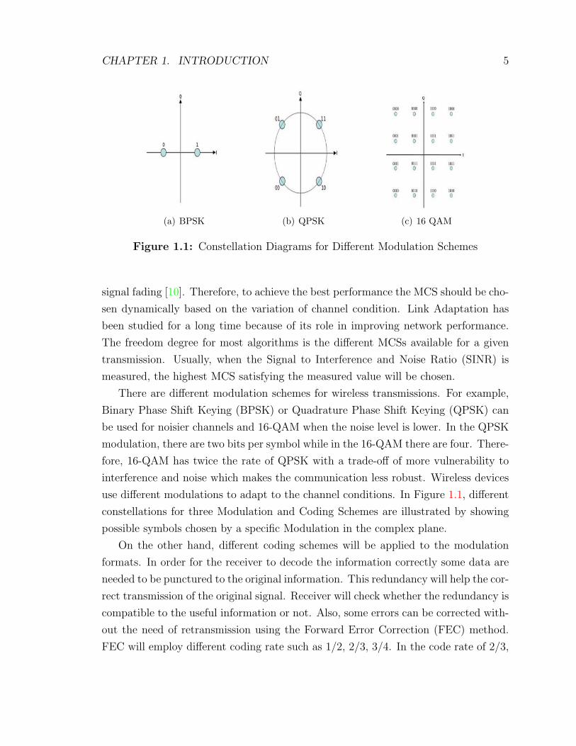
There are different modulation schemes for wireless transmissions. For example,
Binary Phase Shift Keying (BPSK) or Quadrature Phase Shift Keying (QPSK) can
be used for noisier channels and 16-QAM when the noise level is lower. In the QPSK
modulation, there are two bits per symbol while in the 16-QAM there are four. There-
fore, 16-QAM has twice the rate of QPSK with a trade-off of more vulnerability to
interference and noise which makes the communication less robust. Wireless devices
use different modulations to adapt to the channel conditions. In Figure 1.1, different
constellations for three Modulation and Coding Schemes are illustrated by showing
possible symbols chosen by a specific Modulation in the complex plane.
On the other hand, different coding schemes will be applied to the modulation
formats. In order for the receiver to decode the information correctly some data are
needed to be punctured to the original information. This redundancy will help the cor-
rect transmission of the original signal. Receiver will check whether the redundancy is
compatible to the useful information or not. Also, some errors can be corrected with-
out the need of retransmission using the Forward Error Correction (FEC) method.
FEC will employ different coding rate such as 1/2, 2/3, 3/4. In the code rate of 2/3,

CHAPTER 1. INTRODUCTION 6
two out of three bits is useful information and one bit is added redundancy. In the
high channel quality case the coding rate will be close to one reducing the redundant
bits to achieve a higher goodput (number of useful bits transmitted to a receiver per
unit of time. Useful bits exclude the overheads and added bits for encoding). The
different modulation and coding schemes used in WiFi communication is shown in
the Table 1.1. As it can be seen from the Table, different coding can be applied to
the same modulation scheme.
Table 1.1: MCS Index, Modulation Scheme and coding scheme
MCS Index Modulation Scheme Coding Scheme
0 BPSK 1/2
1 QPSK 1/2
2 QPSK 3/4
3 16-QAM 1/2
4 16-QAM 3/4
5 64-QAM 2/3
6 64-QAM 3/4
7 64-QAM 5/6
8 256-QAM 3/4
9 256-QAM 5/6
1.3 Thesis Contribution
In this work, the coexistence of WiFi and LTE in the case that LTE is operating
under LAA protocol has been studied. Moreover, by increasing the WiFi’s packet
payload dynamically and through optimization, a higher level of fairness is tried to be
achieved. Furthermore, link adaptation algorithms associated with these technologies
are explored emphasizing on enhancing the WiFi’s link adaptation performance in the
case of coexistence. The main contributions of this thesis are as follows:
CHAPTER 1. INTRODUCTION 7
1. Changing the WiFi packet payload optimally and heuristically to achieve fair-
ness in the saturation condition.
2. Allocation of incoming users between WiFi and LTE in order to minimize the
performance gap within the two technologies.
3. Proposing enhancements in WiFi link adaptation technique to facilitate the
coexistence.
1.4 Thesis Organization
In the next chapter the related work in the field of coexistence of Heterogeneous
Networks is studied focusing mainly on LTE and WiFi. These works are accompanied
by the researches performed in the link adaptation technique for WiFi and LTE
technologies. In Chapter 3, the theoretical evaluation of WiFi and LTE are discussed.
Moreover, the numerical analysis of the fair coexistence of WiFi and LTE is presented.
Chapter 4 studies specifically the Minstrel algorithm with some applied changes.
Furthermore, some features of the LTE link adaptation algorithm, called Mutual
Information, are explored. Moreover, two sets of experiments are performed and the
associated results are discussed. Finally, in Chapter 5 the conclusion and future works
are presented.

Chapter 2
Related Work
In this chapter, the background work in the concept of coexistence of heterogeneous
networks is reviewed targeting the focus on the coexistence of WiFi and LTE networks.
Furthermore, link adaptation technique as a improving network performance tool is
explored both in WiFi and LTE.
2.1 Coexistence of Heterogeneous Networks
The coexistence of heterogeneous networks operating in a shared spectrum has been
well studied in the literature from different aspects. In [11] the coexistence of WiFi
with Radio Frequency (RF) interferences from devices like Bluetooth headsets and
cordless phones has been investigated. The research shows that 802.11 network is
very vulnerable to interferences of other devices activating in its bandwidth. Some
extreme cases showed that links in WiFi networks can be interrupted with signals
which have only 1/1000 power level of 802.11 signals. In [12] the coexistence of WiFi
and ZigBee is under consideration. ZigBee is considered a big source of interference
for WiFi communication. One major problem in this coexistence is that WiFi APs are
unable to identify the transmission of ZigBee devices since the transmitted packets
in ZigBee has a 20 dB lower power compared to WiFi packets. The unawareness
of their coexistence will result in a big probability of collision resulting in a poor
performance for both networks. Furthermore, the coexistence between WiFi and
WiMAX has been studied in [13] focusing on coexistence interference problems due
to simultaneous operation of several radio frequencies.
Coexistence of LTE and WiFi without any modification to both networks has
been studied in a paper [14] published by Nokia Research. In this work, LTE and
8
CHAPTER 2. RELATED WORK 9
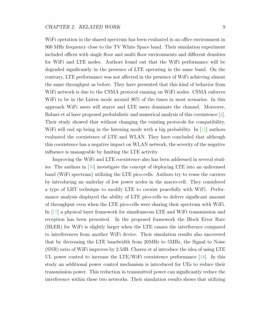
WiFi operation in the shared spectrum has been evaluated in an office environment in
900 MHz frequency close to the TV White Space band. Their simulation experiment
included offices with single floor and multi floor environments and different densities
for WiFi and LTE nodes. Authors found out that the WiFi performance will be
degraded significantly in the presence of LTE operating in the same band. On the
contrary, LTE performance was not affected in the presence of WiFi achieving almost
the same throughput as before. They have presented that this kind of behavior from
WiFi network is due to the CSMA protocol running on WiFi nodes. CSMA enforces
WiFi to be in the Listen mode around 96% of the times in most scenarios. In this
approach WiFi users will starve and LTE users dominate the channel. Moreover,
Babaei et al have proposed probabilistic and numerical analysis of this coexistence [4].
Their study showed that without changing the existing protocols for compatibility,
WiFi will end up being in the listening mode with a big probability. In [15] authors
evaluated the coexistence of LTE and WLAN. They have concluded that although
this coexistence has a negative impact on WLAN network, the severity of the negative
influence is manageable by limiting the LTE activity.
Improving the WiFi and LTE coexistence also has been addressed in several stud-
ies. The authors in [16] investigate the concept of deploying LTE into an unlicensed
band (WiFi spectrum) utilizing the LTE pico-cells. Authors try to reuse the carriers
by introducing an underlay of low power nodes in the macro-cell. They considered
a type of LBT technique to modify LTE to coexist peacefully with WiFi. Perfor-
mance analysis displayed the ability of LTE pico-cells to deliver significant amount
of throughput even when the LTE pico-cells were sharing their spectrum with WiFi.
In [17] a physical layer framework for simultaneous LTE and WiFi transmission and
reception has been presented. In the proposed framework the Block Error Rate
(BLER) for WiFi is slightly larger when the LTE causes the interference compared
to interferences from another WiFi device. Their simulation results also uncovered
that by decreasing the LTE bandwidth from 20MHz to 5MHz, the Signal to Noise
(SNR) ratio of WiFi improves by 2.5dB. Chavez et al introduce the idea of using LTE
UL power control to increase the LTE/WiFi coexistence performance [18]. In this
study an additional power control mechanism is introduced for UEs to reduce their
transmission power. This reduction in transmitted power can significantly reduce the
interference within these two networks. Their simulation results shows that utilizing
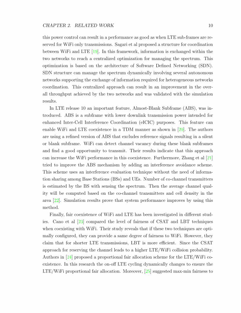
CHAPTER 2. RELATED WORK 10
this power control can result in a performance as good as when LTE sub-frames are re-
served for WiFi only transmissions. Sagari et al proposed a structure for coordination
between WiFi and LTE [19]. In this framework, information is exchanged within the
two networks to reach a centralized optimization for managing the spectrum. This
optimization is based on the architecture of Software Defined Networking (SDN).
SDN structure can manage the spectrum dynamically involving several autonomous
networks supporting the exchange of information required for heterogeneous networks
coordination. This centralized approach can result in an improvement in the over-
all throughput achieved by the two networks and was validated with the simulation
results.
In LTE release 10 an important feature, Almost-Blank Subframe (ABS), was in-
troduced. ABS is a subframe with lower downlink transmission power intended for
enhanced Inter-Cell Interference Coordination (eICIC) purposes. This feature can
enable WiFi and LTE coexistence in a TDM manner as shown in [20]. The authors
are using a refined version of ABS that excludes reference signals resulting in a silent
or blank subframe. WiFi can detect channel vacancy during these blank subframes
and find a good opportunity to transmit. Their results indicate that this approach
can increase the WiFi performance in this coexistence. Furthermore, Zhang et al [21]
tried to improve the ABS mechanism by adding an interference avoidance scheme.
This scheme uses an interference evaluation technique without the need of informa-
tion sharing among Base Stations (BSs) and UEs. Number of co-channel transmitters
is estimated by the BS with sensing the spectrum. Then the average channel qual-
ity will be computed based on the co-channel transmitters and cell density in the
area [22]. Simulation results prove that system performance improves by using this
method.
Finally, fair coexistence of WiFi and LTE has been investigated in different stud-
ies. Cano et al [23] compared the level of fairness of CSAT and LBT techniques
when coexisting with WiFi. Their study reveals that if these two techniques are opti-
mally configured, they can provide a same degree of fairness to WiFi. However, they
claim that for shorter LTE transmissions, LBT is more efficient. Since the CSAT
approach for reserving the channel leads to a higher LTE/WiFi collision probability.
Authors in [24] proposed a proportional fair allocation scheme for the LTE/WiFi co-
existence. In this research the on-off LTE cycling dynamically changes to ensure the
LTE/WiFi proportional fair allocation. Moreover, [25] suggested max-min fairness to
CHAPTER 2. RELATED WORK 11
optimize the LTE-off cycling periods to maximize the minimum weighted throughput
of LTE/WiFi. Authors have introduced a weighting factor η to balance the resources
allocated to WiFi and LTE. For example, if the network operators are concerned
about the WiFi throughput, by selecting a large value for η more resources will be
allocated to WiFi by increasing the LTE-off period. Similar to these works, this thesis
has tried to increase the WiFi’s performance by increasing it’s transmission time by
sending larger packets.
2.2 WiFi Link adaptation
Link adaptation literature can be categorized into two main groups. The first group
aims to adapt the link via statistics of frame loss. In this approach the statistics
of success and failure of previous transmission will be used in order to adapt the
link for future transmission. These groups will increase the rate of transmission in
the period of having a high successful transmission history and will decrease the bit-
rate when failures become frequent. However, the second approach will consider the
received information as a base parameter for future link adaptation. In this group of
algorithms, bit-rate will increase when the received signal has a high SNR and will
decrease when signal strength is low. For both cases several important researches
have been studied and are presented below.
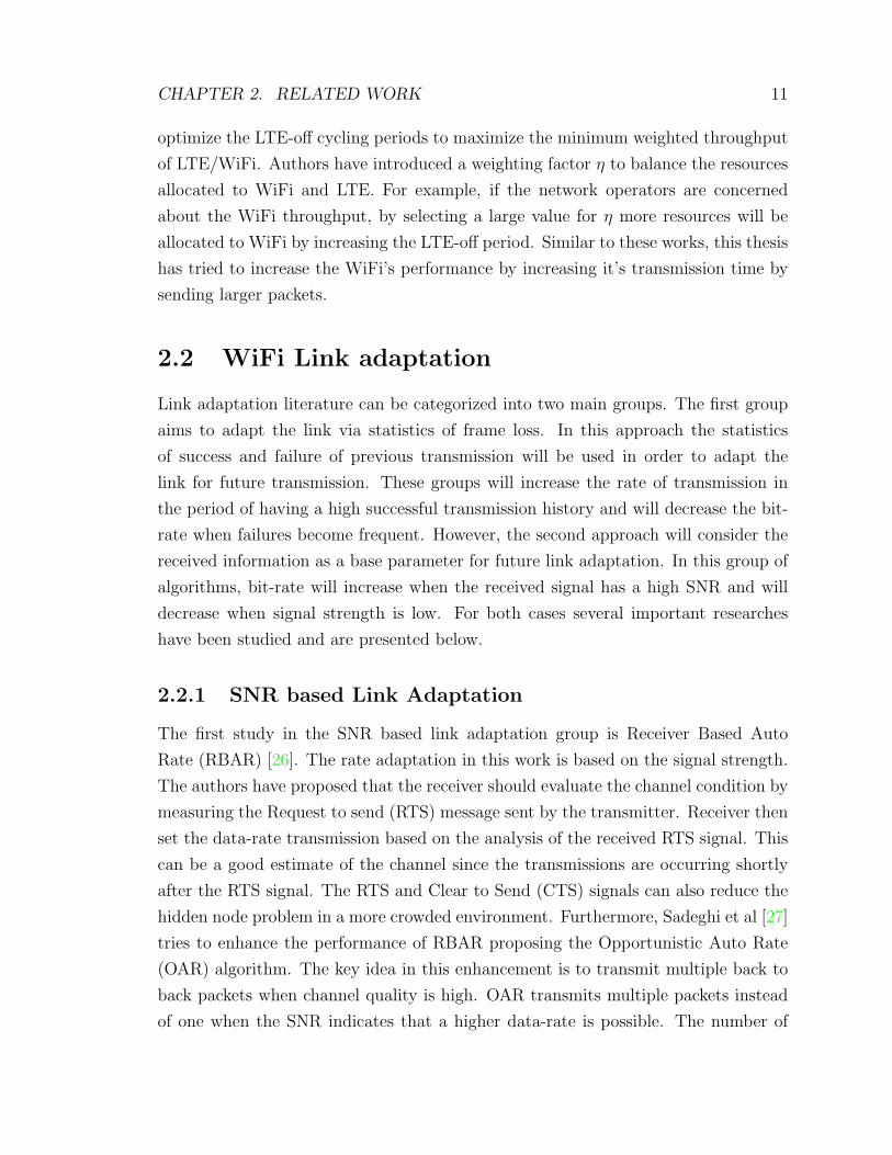
2.2.1 SNR based Link Adaptation
The first study in the SNR based link adaptation group is Receiver Based Auto
Rate (RBAR) [26]. The rate adaptation in this work is based on the signal strength.
The authors have proposed that the receiver should evaluate the channel condition by
measuring the Request to send (RTS) message sent by the transmitter. Receiver then
set the data-rate transmission based on the analysis of the received RTS signal. This
can be a good estimate of the channel since the transmissions are occurring shortly
after the RTS signal. The RTS and Clear to Send (CTS) signals can also reduce the
hidden node problem in a more crowded environment. Furthermore, Sadeghi et al [27]
tries to enhance the performance of RBAR proposing the Opportunistic Auto Rate
(OAR) algorithm. The key idea in this enhancement is to transmit multiple back to
back packets when channel quality is high. OAR transmits multiple packets instead
of one when the SNR indicates that a higher data-rate is possible. The number of
CHAPTER 2. RELATED WORK 12
packets transmitted in this way is in proportion with the achievable data rate over
lowest rate ratio. Applying OAR results in assigning the same time to a sender as if
was sending at the base rate, which leads to sufficient time for transmitting several
packets according to the channel conditions. While RBAR and OAR may have good
performances, they are not compatible with the 802.11 standard and implementing
such algorithms requires some modification in the 802.11 standard [28].
The BEACON Auto Rate Adaptation (BARA) can be used [10] to determine the
appropriate bit-rate especially when RTS/CTS exchange is disabled. The goal in this
research is to use the transmitted beacon frames for estimating the channel conditions.
Based on the received beacon frame information such as SNR and signal strength,
sender determines the bit-rate for the transmission. Moreover they propose that a
sending station listens to the transmitting packets in its environment to understand
the channel conditions in real time. However, since beacon frames are transmitted
with fairly long periods compared to the channel variation frequency they will not
completely decode the channel status during the transmission..
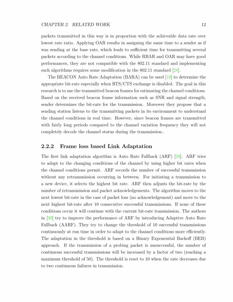
2.2.2 Frame loss based Link Adaptation
The first link adaptation algorithm is Auto Rate Fallback (ARF) [29]. ARF tries
to adapt to the changing conditions of the channel by using higher bit rates when
the channel conditions permit. ARF records the number of successful transmission
without any retransmission occurring in between. For initiating a transmission to
a new device, it selects the highest bit rate. ARF then adjusts the bit-rate by the
number of retransmission and packet acknowledgements. The algorithm moves to the
next lowest bit-rate in the case of packet loss (no acknowledgement) and move to the
next highest bit-rate after 10 consecutive successful transmissions. If none of these
conditions occur it will continue with the current bit-rate transmission. The authors
in [30] try to improve the performance of ARF by introducing Adaptive Auto Rate
Fallback (AARF). They try to change the threshold of 10 successful transmissions
continuously at run time in order to adapt to the channel conditions more efficiently.
The adaptation in the threshold is based on a Binary Exponential Backoff (BEB)
approach. If the transmission of a probing packet is unsuccessful, the number of
continuous successful transmissions will be increased by a factor of two (reaching a
maximum threshold of 50). The threshold is reset to 10 when the rate decreases due
to two continuous failures in transmission.
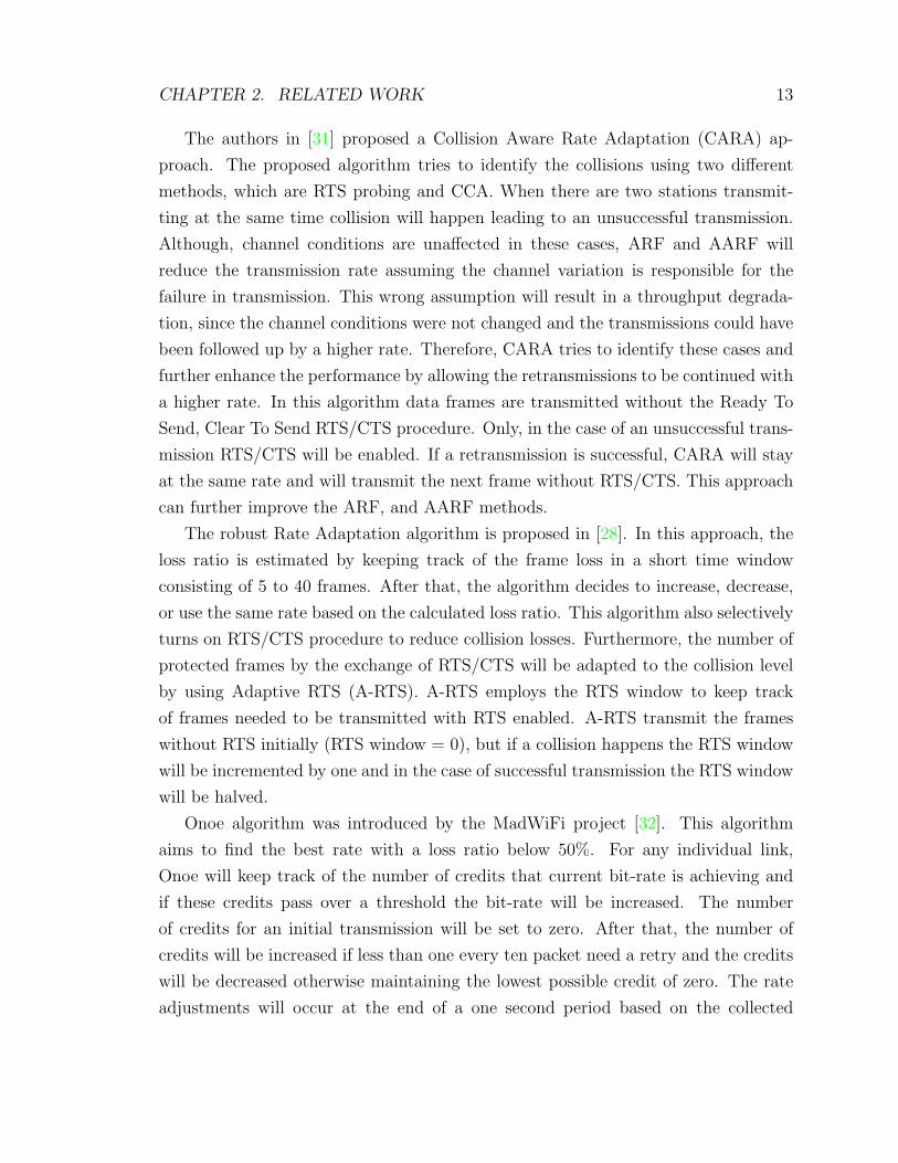
CHAPTER 2. RELATED WORK 13
The authors in [31] proposed a Collision Aware Rate Adaptation (CARA) ap-
proach. The proposed algorithm tries to identify the collisions using two different
methods, which are RTS probing and CCA. When there are two stations transmit-
ting at the same time collision will happen leading to an unsuccessful transmission.
Although, channel conditions are unaffected in these cases, ARF and AARF will
reduce the transmission rate assuming the channel variation is responsible for the
failure in transmission. This wrong assumption will result in a throughput degrada-
tion, since the channel conditions were not changed and the transmissions could have
been followed up by a higher rate. Therefore, CARA tries to identify these cases and
further enhance the performance by allowing the retransmissions to be continued with
a higher rate. In this algorithm data frames are transmitted without the Ready To
Send, Clear To Send RTS/CTS procedure. Only, in the case of an unsuccessful trans-
mission RTS/CTS will be enabled. If a retransmission is successful, CARA will stay
at the same rate and will transmit the next frame without RTS/CTS. This approach
can further improve the ARF, and AARF methods.
The robust Rate Adaptation algorithm is proposed in [28]. In this approach, the
loss ratio is estimated by keeping track of the frame loss in a short time window
consisting of 5 to 40 frames. After that, the algorithm decides to increase, decrease,
or use the same rate based on the calculated loss ratio. This algorithm also selectively
turns on RTS/CTS procedure to reduce collision losses. Furthermore, the number of
protected frames by the exchange of RTS/CTS will be adapted to the collision level
by using Adaptive RTS (A-RTS). A-RTS employs the RTS window to keep track
of frames needed to be transmitted with RTS enabled. A-RTS transmit the frames
without RTS initially (RTS window = 0), but if a collision happens the RTS window
will be incremented by one and in the case of successful transmission the RTS window
will be halved.
Onoe algorithm was introduced by the MadWiFi project [32]. This algorithm
aims to find the best rate with a loss ratio below 50%. For any individual link,
Onoe will keep track of the number of credits that current bit-rate is achieving and
if these credits pass over a threshold the bit-rate will be increased. The number
of credits for an initial transmission will be set to zero. After that, the number of
credits will be increased if less than one every ten packet need a retry and the credits
will be decreased otherwise maintaining the lowest possible credit of zero. The rate
adjustments will occur at the end of a one second period based on the collected
CHAPTER 2. RELATED WORK 14
transmission statistics. Therefore, it can be concluded that Onoe is not sensitive to
the fast changes, incapable of adapting to the fast channel variation.
Sample Rate algorithm is proposed in [33]. Sample Rate tries the highest possible
bit-rate for a starting link. If four consecutive unsuccessful transmissions happen for
a bit-rate the usage of current bit-rate will be stopped. Every tenth packet, a sample
bit-rate from the set of bit-rates higher than the current one will be selected for trans-
mission. Moreover, Sample Rate calculates the transmission time for each bit-rate
over a window size of 10 seconds. Based on the calculated statistics, the Sample Rate
will adjust the bit-rate for the wireless link. A similar approach to Sample Rate is the
Minstrel Algorithm [34]. However, while Sample Rate selects the rate with the lowest
transmission time, Minstrel algorithm selects the rate with the highest throughput.
In particular, Minstrel uses a multirate retry chain, consisting of four different rates
(highest throughput, second highest throughput, highest probability success, lowest
throughput) [35] using a fixed number of retry attempts for each rate. Similar to
Sample Rate every 10th packet it sends a random rate to evaluate the transmission of
the rest of the available rates. Every 0.1 sec it performs a statistics calculation using
an Exponential Weighting Moving Average (EWMA) method to take into considera-
tions the statistics of previous 0.1 sec intervals. Due to the efficiency of the Minstrel
algorithm and its ability to adapt on the changing medium conditions, it has been
selected as the Link adaptation algorithm for WiFi in this study.
2.3 Link Adaptation in LTE
Link adaptation in LTE is also similar with WiFi, and involves selecting the modula-
tion and coding scheme (MCS) to achieve the maximum data rate possible for each
transmission to the UE [36]. However, in contrast with WiFi an adaptive modula-
tion and coding (AMC) technology is used for LTE, enabling high spectral efficiency
communication within the network [37]. In order to perform AMC operation in LTE,
suitable feedback must be delivered from the UE back to the eNB.
This feedback is supplied through the Channel Quality Indicators (CQIs). The
CQI value is an index that is correlated with the maximum throughput that can be
achieved by properly choosing a pair of modulation and coding schemes meeting a
target BLER Probability (e.g. 1%, 10%). Hence, link adaptation is put into effect
by using a suitable CQI selection technique. The CQI is obtained by the UE with

CHAPTER 2. RELATED WORK 15
Figure 2.1: Link Adaptation in LTE Operation
respect to the Channel State Information (CSI) as depicted in Figure 2.1.
The general execution of the link adaptation mechanism for LTE is as follows [38]
:
• Firstly, the noise variance and the channel matrix H should be extracted based
on current channel condition.
• The post SINRs are computed for all subcarriers.
• With the SINRs it is possible to estimate a link quality metric to translate the
CSI.
• The calculated metric is then mapped to a related reference BLER for the
ongoing modulation and coding scheme utilizing the CQI search loop and a
preexisting look-up table.
• The CQI search is established by repeating step (3) and (4) till the current CQI
delivers BLER less than a threshold of a target BLER (e.g. 5%).
• The chosen CQI will be reported back to the transmitter.
Effective SNR is the most frequent link quality metric. It is interpreted as the SNR
observed by the codeword as if it were sent over a flat-fading channel [39]. A high SNR
value results in a higher order modulation schemes having a higher spectral efficiency
(e.g. 64QAM). On the contrary, with a low SNR value a lower order modulation
scheme like QPSK will be used.

CHAPTER 2. RELATED WORK 16
Table 2.1: The 4-BIT CQI Table in LTE
CQI Index Modulation Code Rate ×1024 Efficiency (bits/s/Hz)
0 Out of range 1 QPSK 78 0.1526
2 QPSK 120 0.2344
3 QPSK 193 0.3770
4 QPSK 308 0.6016
5 QPSK 449 0.8770
6 QPSK 602 1.1758
7 16QAM 378 1.4766
8 16QAM 490 1.9141
9 16QAM 616 2.4063
10 64QAM 466 2.7305
11 64QAM 567 3.3223
12 64QAM 666 3.9023
13 64QAM 772 4.5234
14 64QAM 873 5.1152
15 64QAM 948 5.5547
The SNR-BLER relationship in Additive White Guassian Noise (AWGN) channel
can be extracted by simulation utilizing the modulation and coding schemes (MCS)
determined in the CQI table as displayed in Table 2.1 (Table 7.2.3-1 TS 136 213
V12.4.0 [40]).
Several link adaptation algorithms have been proposed for LTE. However, the
Mutual Information approach [41], which follows the step above, presents the best
performance. To this end, the MI algorithm has been selected in our simulations in
order to compare the performance of the coexistence. In the simulation the Mutual
Information approach (MI) which follows the steps above has been implemented as
the LTE link adaptation technique.
Chapter 3
Theoretical Evaluations
In this chapter, a theoretical evaluation of the WiFi throughput performance when
operating alone and when coexists with LAA-LTE is presented. Furthermore, results
and discussions for numerical analysis based on the theoretical evaluations are
displayed.
3.1 WiFi Performance without Interference
Bianchi has presented a well-known analytical model for WiFi in [1]. In this study,
the CSMA/CA procedure performed at the MAC layer has been modeled based on
the Markov Chain concept. In the proposed model n WiFi stations are communi-
cating in an ideal channel condition. Therefore, it can be concluded that any packet
transmitted in this scenario will either be received successfully or will collide with
another packet resulting in a transmission failure. All the stations are operating in
a saturation mode condition meaning that after every transmission there is another
packet in the queue (the probability of arriving packets in the queue, q, is 1). In the
steady state every station will send a packet with probability Pt,w. For simplicity it
has been assumed that in any given transmission attempt the collision probability
seen by a transmitting station, Pc,w or simply P in Figure 3.1, is independent and
constant. Pc,w can be calculated based on the fact, that in a time slot the probability
of collision for a transmitting station is equal to the probability that one or more
than one of the n− 1 remaining stations transmit at the same time. Therefore:
Pc,w = 1− (1− Pt,w)n−1 (1)
17

CHAPTER 3. THEORETICAL EVALUATIONS 18
Figure 3.1: Markov chain model for the CSMA/CA [1]
and the probability of having at least one transmission in a slot time, Ptr,w, and
having a successful transmission, Ps,w, in the under study network can be calculated
through (2) and (3) respectively:
Ptr,w,N = 1− (1− Pt,w)n (2)
Ps,w,N = nPt,w(1− Pt,w)n−1 (3)
Also, the probability of collision in the overall network has been calculated in Bianchi’s
Markov chain Model in Figure 3.1 through the modeling of the back-off mechanism
in CSMA/CA.
As it can be seen from this model, with every consecutive failure in transmissions
the back-off window changes fromWi toWi+1 till the maximum back-off window (WM)
is reached, where Wi+1 = 2Wi. On the other hand, after a successful transmission
the back-off window resets to the initial minimum value. The back-off counter also
reduces by one after an idle time slot with probability 1 (the probability of channel
being occupied, Pb is zero in an idle time slot after the transmission). Pt,w can be
computed based on the probabilistic analysis of the chain in Bianchi’s study through
CHAPTER 3. THEORETICAL EVALUATIONS 19
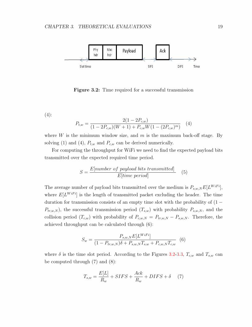
Figure 3.2: Time required for a successful transmission
(4):
Pt,w =2(1− 2Pc,w)
(1− 2Pc,w)(W + 1) + Pc,wW (1− (2Pc,w)m)(4)
where W is the minimum window size, and m is the maximum back-off stage. By
solving (1) and (4), Pt,w and Pc,w can be derived numerically.
For computing the throughput for WiFi we need to find the expected payload bits
transmitted over the expected required time period.
S =E[number of payload bits transmitted]
E[time period](5)
The average number of payload bits transmitted over the medium is Ps,w,NE[LWiFi],
where E[LWiFi] is the length of transmitted packet excluding the header. The time
duration for transmission consists of an empty time slot with the probability of (1−
Ptr,w,N), the successful transmission period (Ts,w) with probability Ps,w,N , and the
collision period (Tc,w) with probability of Pc,w,N = Ptr,w,N − Ps,w,N . Therefore, the
achieved throughput can be calculated through (6):
Sw =Ps,w,NE[LWiFi]
(1− Ptr,w,N)δ + Ps,w,NTs,w + Pc,w,NTc,w
(6)
where δ is the time slot period. According to the Figures 3.2-3.3, Tc,w and Ts,w can
be computed through (7) and (8):
Ts,w =E[L]
Rw
+ SIFS +Ack
Rw
+DIFS + δ (7)

CHAPTER 3. THEORETICAL EVALUATIONS 20
Figure 3.3: Time required for a collision
Tc,w =E[L]
Rw
+DIFS + δ (8)
where E[L] is the packet length including the header, Rw is the transmission rate,
DIFS is the DCF interframe space, SIFS is the short interframe space, and Ack is
the length of the acknowledgement frame.
3.2 Coexistence Performance of WiFi and LAA
In this part the performance of WiFi coexisting with LAA is analyzed. More specifi-
cally, the study focus on the medium access technique of both technologies which is
CSMA/CA for WiFi and LBT for LAA. Among the different channel access schemes
in LAA the thesis considers only the Category 4 (Cat4) [42] scheme which is more
similar to WiFi CSMA/CA and therefore more compatible in the coexistence.
Cat4 LBT performs CCA in case of new transmission. If the channel is idle
during CCA, LAA transmits immediately. Else, LAA enters in an extended CCA
state (ECCA) starting with an initial contention window (CWmin) of 32. The CW
doubles each time reaching the maximum CW (CWM) size of 1024 when transmissions
fail consecutively (like CSMA/CA procedure to reduce the collision probability). If
another unsuccessful transmission happens after reaching the CWM the contention
window will reset to CWmin. LAA can transmit only after the random number that
has been selected from (0, CW ), decrements toward reaching zero.
Based on the analysis of the Cat4 mechanism above, it can be concluded that it
differs from CSMA/CA in two main parts. Firstly, CSMA/CA unlike Cat4 will not
begin the transmission immediately after the CCA is successful (it has to select a
random number and counts down to zero). Secondly, CSMA/CA does not restart to
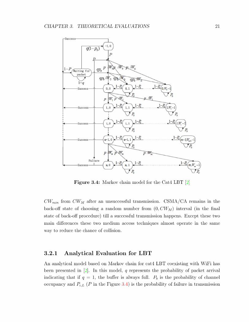
CHAPTER 3. THEORETICAL EVALUATIONS 22
due to collision. The state of LBT is displayed through (s(t), z(t)) where s(t) rep-
resents the ECCA state and z(t) denotes the counter. As it can be seen from the
model in Figure 3.4 the LBT initially waits for the arrival of packets. When a packet
arrives and CCA is successful with probability q(1 − Pb), LAA starts the transmis-
sion. Otherwise, LBT enters the ECCA state with an initial contention window of
W0. It can be concluded from the Figure 3.4 that LAA is only able to transmit when
z(t) = 0, s(t) ∈ (−1, 0, ...,m − 1,m). Based on the analysis of this chain, authors
have derived the probability of Cat4 transmission, Pt,L, as a function of probability
of collision (Pc,L) through (9):
Pt,L =2(1− Pc,L)(1− 2Pc,L)C
A+WB(1− Pc,L)(1− (2Pc,L)m+1) +BC(1− 2Pc,L)2 + 2C(1− Pc,L)3(1− 2Pc,L)(9)
where A = 2(1− Pc,L)2(1− 2Pc,L), B = 2Pc,L − P 2
c,L, C = (1− Pm+1
c,L ).
3.2.2 Analytical Evaluation of Coexistence
When there are i WiFi stations and j LAA Cat4 users (Figure 3.5 displays the under
studied system model ) the probability of collision for a transmitting WiFi (Pc,w) and
LAA station (Pc,L) are as follows:
Pc,w = 1− (1− Pt,w)i−1(1− Pt,L)
j (10)
Pc,L = 1− (1− Pt,w)i(1− Pt,L)
j−1 (11)
By solving (4),(9),(10), and (11) numerically, the probability of transmission and
collision (Pt,w, Pc,w, Pt,L, Pc,L) for WiFi and LAA can be extracted. Until the end
of this chapter, all the remaining probabilistic analysis is based on the numerical
computation of these four probabilities.
Intuitively, the probability of channel occupancy in time slots can be computed
based on the fact that there should be at least one transmission in the channel and
can be extracted through (12):
Ptr = 1− (1− Pt,w)i(1− Pt,L)
j (12)
Channel occupancy probability for WiFi and LAA successful transmission can be

CHAPTER 3. THEORETICAL EVALUATIONS 23
Figure 3.5: System model for the coexistence of WiFi and LTE. Solid connectorsshow the current attachments and dashed connectors display the potential con-nections.
calculated through the following equations respectively :
Ps,w,N = iPt,w(1− Pt,w)i−1(1− Pt,L)
j (13)
Ps,L,N = jPt,L(1− Pt,L)j−1(1− Pt,w)
i (14)
In our specific model, the collision probability consists of three different events of:
1) WiFi unsuccessful transmission due to WiFi stations collision, 2) LAA failure
because of LAA stations collision, and 3) collision between WiFi and LAA stations.
The probability of these three events is derived below respectively [2]:
Pc,w,N = (1− (1− Pt,w)i − iPt,w(1− Pt,w)
i−1)(1− Pt,L)j (15)
Pc,L,N = (1− (1− Pt,L)j − jPt,L(1− Pt,L)
j−1)(1− Pt,w)i (16)
Pc,wL,N = Ptr − Ps,w,N − Pc,w,N − Ps,L,N − Pc,L,N (17)
For computing the achievable throughput for WiFi and LAA, we have to followthe same logic of equation (5) and (6). The only difference now is that the timeinterval for a successful transmission has to include three more time durations besidethe previously mentioned ones. These three new periods are the time duration for

CHAPTER 3. THEORETICAL EVALUATIONS 24
successful transmission of LAA (Ts,L) with probability of Ps,L,N , the time duration ofcollision within two LAA stations (Tc,L) with probability Pc,L,N , and the period for acollision among WiFi and LAA, max(Tc,L, Tc,w), with probability Pc,wL,N . Therefore,the achievable throughput for WiFi and LAA can be derived from [2] :
Sw =Ps,w,NE[LWiFi]
(1− Ptr)δ + Ps,w,NTs,w + Ps,L,NTs,L + Pc,w,NTc,w + Pc,L,NTc,L + Pc,wL,Nmax(Tc,w, Tc,L)(18)
SL =Ps,L,NE[LLAA]
(1− Ptr)δ + Ps,w,NTs,w + Ps,L,NTs,L + Pc,w,NTc,w + Pc,L,NTc,L + Pc,wL,Nmax(Tc,w, Tc,L)(19)
where Ts,L, Tc,L are the time duration required for successful and unsuccessful
transmissions in LBT and can be found from the following equations:
Ts,L =E[L]
RL
+Ack
RL
+DIFS + δ (20)
Tc,L =E[L]
RL
+Nack
RL
+DIFS + δ (21)
3.3 Numerical Analysis of WiFi and LAA Coexis-
tence
In this part the numerical results of different combination of WiFi and LAA users
is shown in order to validate the operation of the back-off stage mechanism of the
two networks. Specifically, the results for the transmission and collision probability
of WiFi and LAA stations are presented. For finding the transmission and collision
probabilities we solved the (4),(9),(10), and (11) numerically for different combination
of number of users in the two technologies.
Figure 3.6 illustrates the transmission probability of one WiFi station (blue line).
Since WiFi will choose a back-off window size of 32 the transmission probability of
one WiFi station in an empty time slot is low. Based on the calculated numbers it can
be decided that WiFi stations are mainly operating in the first and second back-off
stage. The average transmission probability of a WiFi station operating in the first
back-off stage is 0.0625 since the window size is 32 (Pt,w = 1/16 = 0.0625). The
average probability is calculated under the assumption that each station belonging to
WiFi or LAA has the same probability of transmission and face the same probability
CHAPTER 3. THEORETICAL EVALUATIONS 25
2 3 4 5 6 7 8 90.03
0.04
0.05
0.06
0.07
0.08
0.09
Tran
smis
sion
pro
babi
lity
LAA stations
WiFi stations = 3 , LAA stations = (2 , 9)
Transmission probability of a WiFi station
Transmission probability of a LAA station
Figure 3.6: Comparison of transmission probability of WiFi and LAA
of collision.
On the other hand, the transmission probability of one LAA station can be viewed
in Figure 3.6 (red line) indicating LAA stations in average operate in the back-off
stage of two and three. In the back-off stage one, window size is zero indicating that
LAA can transmit after an empty DIFS period. Therefore, it can be seen that the
LAA probability of transmission is larger than the WiFi transmission probability.
Furthermore, when the number of stations increases in the system the transmission
probability of WiFi and LAA get closer to each other.
Figure 3.7 shows the collision probability seen by a transmitting WiFi and LAA
stations (it is assumed that the station is ready to transmit and it is not waiting
for any back-off). As it appears, the probability of collision seen by WiFi stations
is larger than LAA, since the LAA approach is more aggressive for grabbing the
channel. When the number of LAA stations are low (two LAA stations and three
WiFi stations), the probability of collision for a transmitting LAA station is 20%
less than the probability of collision of a WiFi station. But as the number of LAA
stations increases the difference in the collision probability seen by a transmitting
WiFi or LAA station becomes much smaller and around 1%. The reason can be
explained through analyzing the beginning and end of the x axis. At the beginning,
when the number of LAA stations is two any given LAA station ready to transmit
sees one LAA and three WiFi Stations and a WiFi station sees two WiFi and two

CHAPTER 3. THEORETICAL EVALUATIONS 26
2 3 4 5 6 7 8 90.2
0.22
0.24
0.26
0.28
0.3
0.32
0.34
0.36
Col
lisio
n pr
obab
ility
LAA stations
WiFi stations = 3 , LAA stations = (2 , 9)
Collision probability of a transmitting WiFi station
Collision probability of a transmitting LAA station
Figure 3.7: Comparison of collision probability of WiFi and LAA
LAA stations in the network. But at the end, when the number of LAA stations is
nine a transmitting LAA station sees eight LAA and three WiFi and a WiFi stations
sees two WiFi and nine LAA. It is apparent that the difference in the second case
within the collision probability of WiFi and LAA stations is much smaller than the
first case.
In the Table 3.1 the transmission and collision probability of LAA and WiFi is
shown for different combination of number of stations in each network within (2, 5)
for WiFi and (2, 9) for LAA. We can draw a conclusion that same behavior goes for
the different number of stations of WiFi. Also the transmission probability of WiFi
and LAA reduces by the increase in the number of WiFi stations. On the other hand,
the collision probability increases by the increase in WiFi stations.
3.3.1 Performance Analysis for Fair Coexistence of WiFi and
LTE-LAA
In this part, our goal is to make the coexistence of WiFi and LAA fair through
changing the maximum packet size in the WiFi network as our first contribution in
this work (since LAA employs fixed blocks of frequency-time in it’s physical layer,
the packet length for LAA cannot be adapted easily for having a fair coexistence of
CHAPTER 3. THEORETICAL EVALUATIONS 27
Table 3.1: Transmission and collision probability of WiFi and LAA for differentnumber of stations in each network
WiFi Stations LAA Stations Pt,w Pt,L Pc,w Pc,L
2 2-5 0.038-0.043 0.058-0.103 0.230-0.286 0.179-0.270
2 6-9 0.033-0.036 0.040-0.052 0.300-0.333 0.288-0.328
3 2-5 0.037-0.042 0.054-0.090 0.240-0.295 0.200-0.283
3 6-9 0.032-0.035 0.038-0.048 0.309-0.341 0.299-0.334
4 2-5 0.036-0.041 0.050-0.079 0.252-0.305 0.221-0.295
4 6-9 0.031-0.035 0.036-0.045 0.318-0.348 0.310-0.345
5 2-5 0.035-0.040 0.046-0.070 0.264-0.315 0.241-0.307
5 6-9 0.031-0.034 0.034-0.042 0.327-0.356 0.321-0.353
WiFi and LAA). Although the definition of fairness in the coexistence of WiFi and
LTE is not fixed yet [43], several 3GPP members believe that fair access means that
WiFi and LAA should receive equal level of throughput [44]- [43]. Nevertheless, a
fair access could also mean that the LTE-LAA and the WiFi should achieve an equal
throughput per number of stations exist in each. Both of these two definition of
fairness have been considered in this work.
Figure 3.8 shows the ratio of WiFi packet payload over LAA packet payload in
order to achieve an equal throughput for both Radio Access Networks (RANs). In
order to extract the WiFi/LAA frame independent of the number of users in the
system we have assumed that the number of WiFi and LAA stations are equally dis-
tributed. More specifically, achieving an equal throughput can be possible by adding
an extra constraint, Ps,w,NE[LWiFi] − Ps,L,NE[LLAA] = 0, to the calculated Ps,w,N
and Ps,L,N (these two probabilities are computed based on the Pt,w, Pc,w, Pt,L, Pc,L
which had been extracted numerically). As it can be seen from Figure 3.8 the ratio of
WiFi/LAA frame becomes smaller and close to 1 by increasing the number of WiFi
and LAA stations. This is due to the fact that with the increase of the number of
incumbents in the channel, the difference in the achievable throughput for both WiFi
and LAA stations becomes smaller.

CHAPTER 3. THEORETICAL EVALUATIONS 28
2 3 4 5 6 7 81
1.2
1.4
1.6
1.8
2
2.2
2.4
2.6
nimber of users for WiFi=LAA
Ratio o
f fr
am
e length
the ratio of (WiFi Frame/LAA Frame) for equalized throughput
Figure 3.8: Packet length ratio of WiFi over LAA for having equal throughput. Thenumber of users for both networks are the same.
The performance gap can be calculated byWiFi throughput
LAA throughput, which is a function
ofPs,w,N
Ps,L,N
andWiFiFrame
LAAFrame. The Ps,L,N , Ps,w,N probabilities do not only depend on
MAC layer parameters, such as minimum and maximum back-off window sizes, but
also depends on the number of WiFi and LAA stations.
Previously, we found the WiFi/LAA frame ratio by doing a numerical analysis.
But there can be another approach that we can skip the finding for an exact value for
WiFi Frame in order to have same throughput with LAA (Fairness criterion: equal
WiFi and LAA throughput). Instead, a heuristic approach for calculating a sub-
optimal WiFi/LAA frame ratio can be utilized based onNumber of WiF i stations
Number of LAA stations.
In detail, we introduce two parameters c and α to compute the WiFi Frame in the
following way:
WiFiFrame
LAAFrame= c× (
Number of WiF i stations
Number of LAA stations)α
In this equation c compensates for the performance gap between one WiFi and one
LAA station. α on the other hand, compensates the different ratio of number of
users in WiFi and LTE. After that, c and α are appropriately fine-tuned to minimize
CHAPTER 3. THEORETICAL EVALUATIONS 29
00.5
11.5
2
−2
−1
0
1
20
2
4
6
8
10
x 106
(c)(α)
Thro
ughput D
iffe
rence (
bit/s
)
Figure 3.9: Average throughput difference of WiFi and LAA for different numbersof α within (−2, 2) and c within (0, 2). Fairness criterion: WiFi throughput =LAA throughput
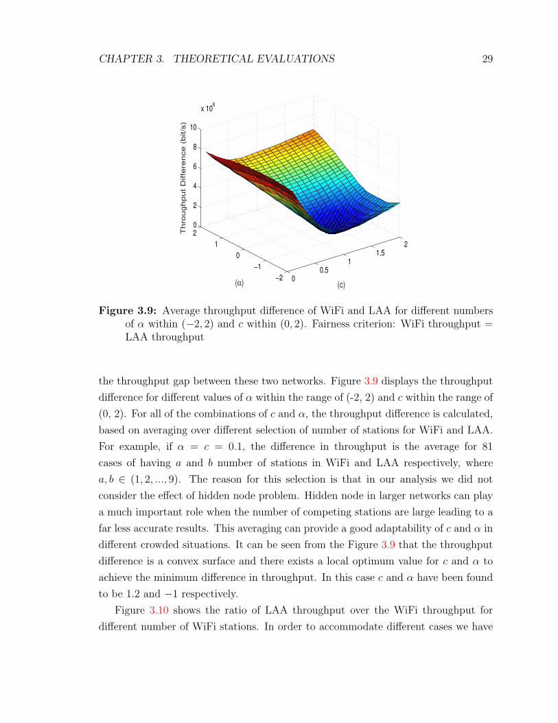
the throughput gap between these two networks. Figure 3.9 displays the throughput
difference for different values of α within the range of (-2, 2) and c within the range of
(0, 2). For all of the combinations of c and α, the throughput difference is calculated,
based on averaging over different selection of number of stations for WiFi and LAA.
For example, if α = c = 0.1, the difference in throughput is the average for 81
cases of having a and b number of stations in WiFi and LAA respectively, where
a, b ∈ (1, 2, ..., 9). The reason for this selection is that in our analysis we did not
consider the effect of hidden node problem. Hidden node in larger networks can play
a much important role when the number of competing stations are large leading to a
far less accurate results. This averaging can provide a good adaptability of c and α in
different crowded situations. It can be seen from the Figure 3.9 that the throughput
difference is a convex surface and there exists a local optimum value for c and α to
achieve the minimum difference in throughput. In this case c and α have been found
to be 1.2 and −1 respectively.
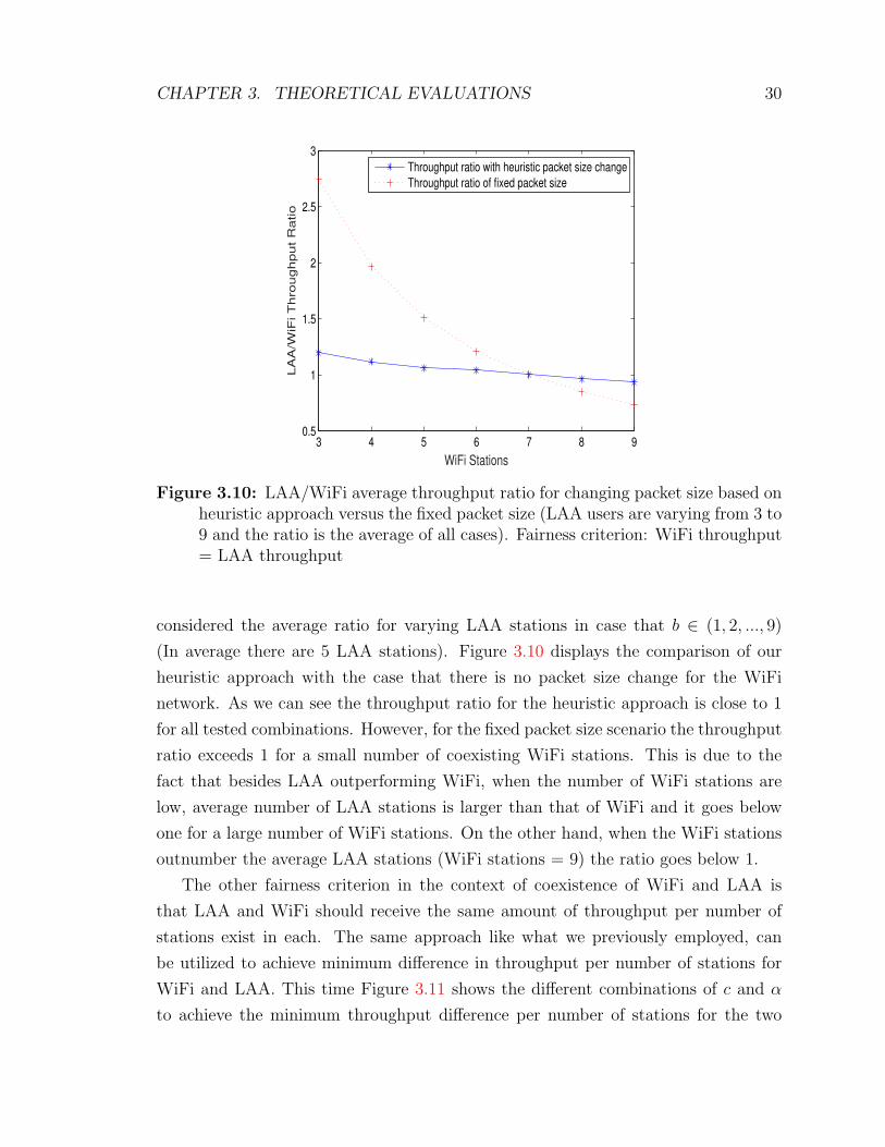
Figure 3.10 shows the ratio of LAA throughput over the WiFi throughput for
different number of WiFi stations. In order to accommodate different cases we have
CHAPTER 3. THEORETICAL EVALUATIONS 30
3 4 5 6 7 8 90.5
1
1.5
2
2.5
3
WiFi Stations
LA
A/W
iFi T
hro
ughput R
atio
Throughput ratio with heuristic packet size change
Throughput ratio of fixed packet size
Figure 3.10: LAA/WiFi average throughput ratio for changing packet size based onheuristic approach versus the fixed packet size (LAA users are varying from 3 to9 and the ratio is the average of all cases). Fairness criterion: WiFi throughput= LAA throughput
considered the average ratio for varying LAA stations in case that b ∈ (1, 2, ..., 9)
(In average there are 5 LAA stations). Figure 3.10 displays the comparison of our
heuristic approach with the case that there is no packet size change for the WiFi
network. As we can see the throughput ratio for the heuristic approach is close to 1
for all tested combinations. However, for the fixed packet size scenario the throughput
ratio exceeds 1 for a small number of coexisting WiFi stations. This is due to the
fact that besides LAA outperforming WiFi, when the number of WiFi stations are
low, average number of LAA stations is larger than that of WiFi and it goes below
one for a large number of WiFi stations. On the other hand, when the WiFi stations
outnumber the average LAA stations (WiFi stations = 9) the ratio goes below 1.
The other fairness criterion in the context of coexistence of WiFi and LAA is
that LAA and WiFi should receive the same amount of throughput per number of
stations exist in each. The same approach like what we previously employed, can
be utilized to achieve minimum difference in throughput per number of stations for
WiFi and LAA. This time Figure 3.11 shows the different combinations of c and α
to achieve the minimum throughput difference per number of stations for the two

CHAPTER 3. THEORETICAL EVALUATIONS 31
0
0.5
1
1.5
2
−2
−1
0
1
20
0.5
1
1.5
2
x 106
(c)(α)
Thro
ughput D
iffe
rence (
bit/s
)
Figure 3.11: Average throughput difference of WiFi and LAA for different numbersof α within (−2, 2) and c within (0, 2). Fairness criterion: WiFi throughput pernumber of station = LAA throughput per number of station
technologies. Comparing with the Figure 3.9, we can observe that the throughput
difference is significantly lower for the Figure 3.11. Such behavior can be explained
through the absence of unbalanced number of WiFi and LAA stations in the shared
channel. For the latter fairness criterion the optimum value for c and α have been
found to be 1.3 and 0 respectively. Optimum alpha being zero means that now the
WiFi/LAA frame ratio is independent of the number of stations in each RAN. This is
a reasonable finding since we have already considered the effect of number of stations
in each network.
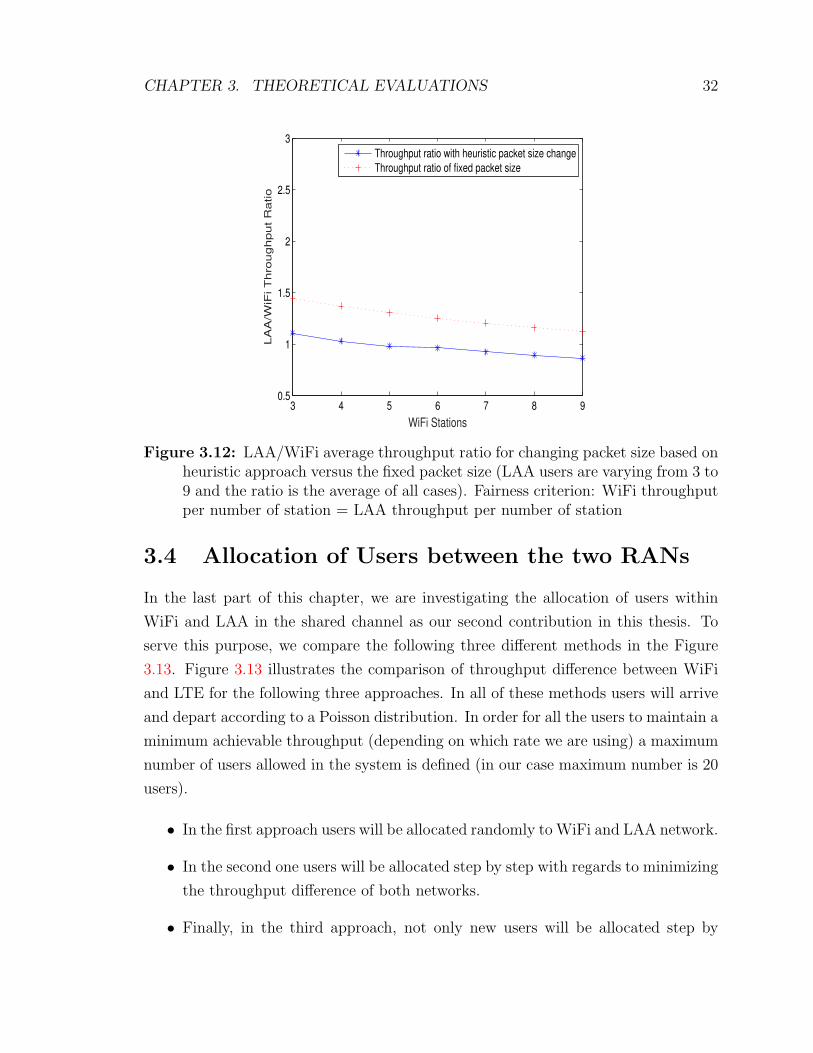
Figure 3.12 depicts the ratio of LAA/WiFi throughput for the fairness criterion
stated above. Like the Figure 3.10 the ratio of LAA/WiFi throughput is the average
of varying LAA users to cover different scenarios. The proposed heuristic approach
outperforms the fixed packet size in terms of fairness. However, the difference is not
that large compared to the previous Figure 3.10 due to the nonexistence of unbalanced
number of stations in the two RANs.
CHAPTER 3. THEORETICAL EVALUATIONS 32
3 4 5 6 7 8 90.5
1
1.5
2
2.5
3
WiFi Stations
LA
A/W
iFi T
hro
ughput R
atio
Throughput ratio with heuristic packet size change
Throughput ratio of fixed packet size
Figure 3.12: LAA/WiFi average throughput ratio for changing packet size based onheuristic approach versus the fixed packet size (LAA users are varying from 3 to9 and the ratio is the average of all cases). Fairness criterion: WiFi throughputper number of station = LAA throughput per number of station
3.4 Allocation of Users between the two RANs
In the last part of this chapter, we are investigating the allocation of users within
WiFi and LAA in the shared channel as our second contribution in this thesis. To
serve this purpose, we compare the following three different methods in the Figure
3.13. Figure 3.13 illustrates the comparison of throughput difference between WiFi
and LTE for the following three approaches. In all of these methods users will arrive
and depart according to a Poisson distribution. In order for all the users to maintain a
minimum achievable throughput (depending on which rate we are using) a maximum
number of users allowed in the system is defined (in our case maximum number is 20
users).
• In the first approach users will be allocated randomly to WiFi and LAA network.
• In the second one users will be allocated step by step with regards to minimizing
the throughput difference of both networks.
• Finally, in the third approach, not only new users will be allocated step by
CHAPTER 3. THEORETICAL EVALUATIONS 33
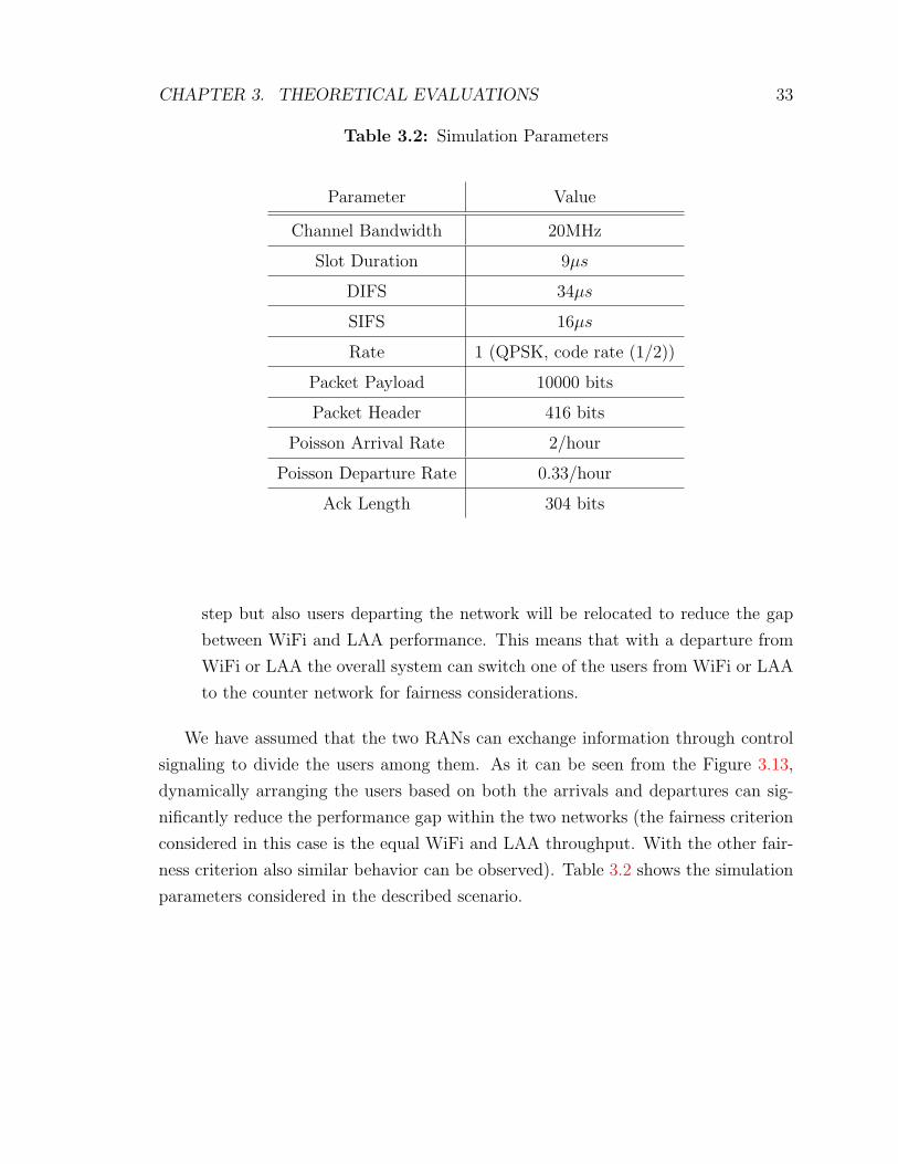
Table 3.2: Simulation Parameters
Parameter Value
Channel Bandwidth 20MHz
Slot Duration 9µs
DIFS 34µs
SIFS 16µs
Rate 1 (QPSK, code rate (1/2))
Packet Payload 10000 bits
Packet Header 416 bits
Poisson Arrival Rate 2/hour
Poisson Departure Rate 0.33/hour
Ack Length 304 bits
step but also users departing the network will be relocated to reduce the gap
between WiFi and LAA performance. This means that with a departure from
WiFi or LAA the overall system can switch one of the users from WiFi or LAA
to the counter network for fairness considerations.
We have assumed that the two RANs can exchange information through control
signaling to divide the users among them. As it can be seen from the Figure 3.13,
dynamically arranging the users based on both the arrivals and departures can sig-
nificantly reduce the performance gap within the two networks (the fairness criterion
considered in this case is the equal WiFi and LAA throughput. With the other fair-
ness criterion also similar behavior can be observed). Table 3.2 shows the simulation
parameters considered in the described scenario.

CHAPTER 3. THEORETICAL EVALUATIONS 34
0 2 4 6 8 10 12 14 16 18 200
0.5
1
1.5
2
2.5
3
3.5
4x 10
6
Th
rou
gh
pu
t D
iffe
ren
ce
(b
its/s
)
Time (h)
Throughput difference in random approach
Throughput difference in optimal arrival allocation
Throughput difference in optimal arrival and departure allocation
Figure 3.13: Comparison of three approaches: i)Random allocation of users,ii)Optimal allocation of users upon arrivals, iii)Optimal allocation of users uponboth arrivals and departures
Chapter 4
Link Adaptation Considerations
In the previous chapter we analyzed the throughput performance achieved in coexis-
tence considering a static and identical rate for both RANs. However, in a realistic
environment appropriate link adaptation algorithms are applied that allow to better
utilize the available spectrum. To this end, in this chapter, we analyze the link adap-
tation mechanism applied in WiFi and propose a number of enhancements towards
reducing the performance gap with the LTE. Specifically, the Minstrel algorithm is
selected as the link adaptation approach in WiFi, due to it’s widely usage in wire-
less drivers such as Madwifi, Ath5, Ath9 [45]. Minstrel also shows good performance
compared to the other link adaptation techniques [46]. Hence, an enhanced Minstrel
algorithm is proposed to better interpret the conditions of the coexistence in the wire-
less medium. Furthermore, the Mutual Information algorithm, the LTE link adaption
technique, will be discussed.
4.1 Overview of Matlab Simulator
The simulator used is an event based simulator written in Matlab and can support
experimentations in the IEEE 802.11 and the coexistence of WiFi with LAA. The
main functionalities of WiFi and LAA supported by the simulator are as follows:
WiFi:
• Physical Layer:
– Most aspects of the 802.11ac specifications are already implemented.
– The full set of 802.11 TGn channel models from A to F can be selected
35

CHAPTER 4. LINK ADAPTATION CONSIDERATIONS 36
• MAC and Higher Layers:
– Simulations involve one AP
– Two traffic models are supported: i) full buffer, ii) simple Poisson model
(i.e. packets/second).
– A CSMA/CA algorithm with binary exponentially back off is imple-
mented.
LAA:
• Physical Layer:
– A detailed SINR computation per subcarrier is used.
• MAC and Higher Layers:
– A Listen Before Talk (LBT) algorithm is implemented with binary expo-
nential backoff.
The simulator follows a simple event sequence to drive the whole simulation. The
events represent a specific action that needs to be performed by PHY and MAC layers.
Each involved device needs to take appropriate actions when an event is raised. An
example is when an event is triggered to schedule the start or stop of a transmission.
Furthermore, according to the event triggered each device updates an internal state
regarding its status (e.g. transmit, receive, idle, etc.).
For the execution of the simulator a main class needs to be run. The main
class gets as input two configuration files one for the WiFi and one for the LAA.
Otherwise, the WiFi configuration file can be the only input. These configurations
files contain the necessary parameters that need to be set for the two technologies.
Following, we refer the main parameters configured for WiFi and LAA:
WiFi configuration parameters:
• Number of Stations (STAs)
• Distance between AP and STAs

CHAPTER 4. LINK ADAPTATION CONSIDERATIONS 37
• Channel bandwidth
• Guard interval
• Channel parameters (e.g. TGn channel modes, speed of the moving device)
• Traffic model for the uplink and downlink
• Activation of Link adaptation or using a fixed Modulation and Coding scheme
(MCS)
• Transmission power
• Packet length
LAA configuration parameters:
• Number of user equipments (UE)
• Packet Length
• Offset distance between AP and BS
• Distance between UE and BS
• Number of subframes in uplink and downlink
• Traffic model for the uplink and downlink
• Activation of Link adaptation or using a fixed MCS
• Speed of the moving device
The main class parse the configuration files and set the experimentation environ-
ment accordingly.It checks if only the WiFi configuration file is provided and creates
an environment with a single AP, otherwise it proceeds with the creation of both WiFi
and LAA. Following the channel is created according to the information provided by
the configuration files. Moreover, the set of the events that need to be triggered are
also generated (e.g. packet generation, transmission duration, etc.). Then the actual
simulation takes place. While executing the simulation, the events are triggered and
the necessary actions are initiated from the involved devices.
CHAPTER 4. LINK ADAPTATION CONSIDERATIONS 38
4.2 Original Minstrel Algorithm
Minstrel algorithm has been developed by the Madwifi project [34]. The theory
behind the Minstrel Algorithm is that the algorithm can select the optimum rate by
statistically calculating which bit-rate will result in the best throughput. Minstrel’s
operation can be classified into three main parts: I) Retry Chain, II) Rate Selection
and III) Statistics Computation.
4.2.1 Retry Chain
Retry chain allows Minstrel to adapt to current channel variations. Specifically, retry
chain consists of a table with four rate/count pairs. Minstrel will first send the packet
with rate R1 retransmitting C1 times if the packet is lost. After C1 unsuccessful
retransmissions the second rate R2 will be used for C2 times and so on until all four
pairs are tried. Rates R1 and R2 are set with the MCS indexes that can achieve the
highest and second highest expected throughput. R3 uses the rate with the highest
success probability and R4 is the base rate.
4.2.2 Rate Selection
The transmission during the Minstrel implementation are categorized into two differ-
ent cases: 1) 90% of the transmissions are following a normal mode, where packets are
sent according to the four rate/count pairs in the retry chain 2) 10% of the transmis-
sions follow a sampling mode, where a sample rate from the existing rates (excluding
the four rates already being in the retry chain) is selected randomly. Minstrel also
initialize the transmission based on a random rate. The goal of this approach is to
gather statistics about the achieved throughput and probability of success for the rest
of the algorithms. Table 4.1, provides information of how retry chain table changes
according to the current transmission mode and if the sample rate is higher than the
highest throughput in the retry chain or not.
4.2.3 Statistics Calculation
Every 100ms Minstrel updates the probability of success and the effective throughput
for every rate. To do so it employs an Exponentially Weighted Moving Average

CHAPTER 4. LINK ADAPTATION CONSIDERATIONS 39
Table 4.1: Minstrel Retry Chain (T: highest throughput, t: second highest through-put, P: highest probability, B: Base Rate, S: sample rate)
Retry Index 1 2 3 4
No Sampling T t P B
Sample Higher S T t P
Sample Lower T S t P
(EWMA) approach to calculate the necessary statistics and update the retry chain. In
detail, first the probability of success for the 100ms period for every rate is calculated
by:
P =number of successful transmissions
total number of transmissions
afterwards, the EWMA probability is calculated as follows:
PEWMA = PEWMA × α + P × (1− α)
So the success probability is updated every 100ms taking into consideration both the
success probability of the current 100ms interval as well as the past intervals, using
the EWMA factor α, which denotes the weight that is given to the recent probability
of success P . The value of α is set equal to 0.75. Finally, the effective throughput is
calculated using the flowing formula:
Sw = PEWMA ×Number of transmitted bits
100ms
According to the new values of the effective throughput and success probability, Min-
strel algorithm updates the retry chain for the next 100ms interval.
4.3 Enhanced Minstrel Implementation
In order to increase the efficiency of Minstrel algorithm in the coexistence scenario,
we have modified some features of the Minstrel algorithm as our last contribution in
this work. First of all, the starting rate for a transmission is chosen based on the
SNR at association time using Table 4.2. The purpose is to choose a starting rate

CHAPTER 4. LINK ADAPTATION CONSIDERATIONS 40
Table 4.2: Starting Rate to SNR association
MCS SNR
0 2
1 5
2 9
3 11
4 15
5 18
6 20
7 25
8 29
9 31
that is reliable so we don’t have to rely on sampling to converge to a working rate.
All lower rates are given a 100% starting probability and all higher rates are given a
0% starting probability.
Secondly, we replace the fourth rate (base rate) with the second highest probability
rate. The table 4.3 shows the selection of rates in the Enhanced Minstrel. The
reason for this change is that in the coexistence scenario we anticipate to have a
lot of collisions. Original Minstrel can not differentiate between the failures due to
collisions and failures due to bad channel conditions. Thus, it would falsely reduce
the transmission rate in the case of collisions while the channel condition may be
good. On the other hand, transmission with the base rate is taking a longer period
compared to the higher rates resulting in a bigger probability of failure due to collision.
Therefore, employing the second highest probability rate can considerably increase
the Minstrel’s performance in the coexistence. In our particular implementation we
set all count pairs equal to 2 giving a maximum number of retransmissions up to 8.
Finally, as the last improvement, we propose a round robin selection of rates in the
sampling mode with initializing at the highest rate to faster build a good statistics

CHAPTER 4. LINK ADAPTATION CONSIDERATIONS 41
Table 4.3: Enhanced Minstrel Retry Chain (T: highest throughput, t: second highestthroughput, P: highest probability, P-1: Second highest probability, S: samplerate)
Retry Index 1 2 3 4
No Sampling T t P P-1
Sample Higher S T t P
Sample Lower T S t P
for different available rates.
4.4 Mutual Information Implementation
For LTE-LAA the Mutual Information (MI) algorithm is selected as the link
adaptation approach. MI algorithm tries to find out the optimal CQI index within
four major steps: 1) SINR calculations, 2) SINR to MI mapping, 3) MI to efficiency
mapping and 4) Efficiency to CQI.
1. SINR Calculation
The very first step for starting the MI algorithm is the SINR computation
per subcarrier. For this step we assume that we have knowledge of the noise
variance and the channel matrix.
2. SINR to MI mapping
The second step in MI algorithm is the SINR to MI mapping, which actually
shows how many information bits a symbol can support in an AWGN channel.
Such a mapping is provided in Figure 4.1. So after calculating the average
SINR per subcarrier, we find out which Modulation scheme actually results
the highest MI. After that the selected modulation is used by the BS for the

CHAPTER 4. LINK ADAPTATION CONSIDERATIONS 42
Figure 4.1: SNR to Mutual Information Mapping
new rate.
3. MI to efficiency mapping
Figure 4.1 provides an ideal mapping between the SINR and MI. However,
because of non-ideal decoding, in practice the actual information bits that the
channel can transmit is less. For this reason, a second mapping takes place
called MI to efficiency mapping. The gap between the ideal mapping and the
second mapping relies on both the code block size and the target BLER needed
for transmission.
4. Efficiency to CQI
The computed efficiency is used to get a proper transport block size with respect
CHAPTER 4. LINK ADAPTATION CONSIDERATIONS 43
to the tables provided by the 3GPP [40], by considering the number of Resource
Blocks (RBs) assigned to the transmission. Following, the obtained Transport
Block Size (TBS) efficiency is rounded down to the nearest efficiency in Table
2.1 to choose the optimal CQI.
4.5 Results and Discussions
In this section, we evaluate the efficiency of the link adaptations algorithms for
different communication conditions. Two experiments are carried out: i) in the first
experiment we evaluate the performance of our enhanced Minstrel algorithm over the
original Minstrel while, ii) in the second experiment we explore the coexistence of
WiFi and LAA when Link Adaptation is activated and when not. The experiments
are arranged as follows:
1. Experiment 1
An extended number of simulations were carried out to evaluate the per-
formance increase achieved when using the enhanced Minstrel algorithm. Only
WiFi is considered in this set of experiments. The enhanced Minstrel algorithm
is compared against a basic Minstrel implementation presented in [46] and a
WiFi operation with no link adaptation activated using a fixed MCS index
of 3. Specifically, we evaluate the achieved throughput and packet error rate
performance when changing i) the distance between the AP and the stations,
and ii)the number of stations associated with the AP.
2. Experiment 2
The second set of experiments consider the coexistence of WiFi and LAA. The
goal is to identify possible problems in performance when the two technologies
operate together, and what are the benefits of activating the link adaptation
in their performance. Similar, we evaluate the performance achieved mainly in
terms of throughput when changing i) the distance between the AP/BS and
stations/UEs, and ii)the number of stations/UEs associated with the AP/BS.

CHAPTER 4. LINK ADAPTATION CONSIDERATIONS 44
5 10 15 20 25 300
5
10
15
20
25
30T
hro
ug
hp
ut
(Mb
ps)
Distance (m)
WiFi MCS 3
WiFi Minstrel
WiFi Enhanced Minstrel
5 10 15 20 25 300
0.05
0.1
0.15
PE
R
Distance (m)
WiFi MCS 3
WiFi Minstrel
WiFi Enhanced Minstrel
Figure 4.2: Minstrel performance in terms of a) Throughput and b) PER withincreasing distance
4.5.1 Performance Verification of Link Adaptation in WiFi
(1 AP 1 STA)
First we evaluate the performance of the enhanced Minstrel implementation, when in-
creasing the distance between the station and the AP from 5m to 30m with a step of 5.
As was expected the throughput drops with the distance and the Packet Error
Rate (PER) increases. Our proposed Minstrel implementation, however shows a
better performance especially after 15m distance. The enhancements proposed make
Minstrel more robust when the distance increases by finding a better rate than the
common Minstrel implementation. The better performance is illustrated both in
terms of throughput and PER in Figure 4.2. Specifically, the enhanced Minstrel
depicts an increase in throughput of about 1Mbps and a decrease in PER of about
1%. On the other hand, when we do not consider any link adaptation scheme (blue
line in Figure 8) the throughput remains almost stable for the different examined
distances with a small decrease in throughput for 25m and 30m which is corroborated
by the increase noticed in PER.
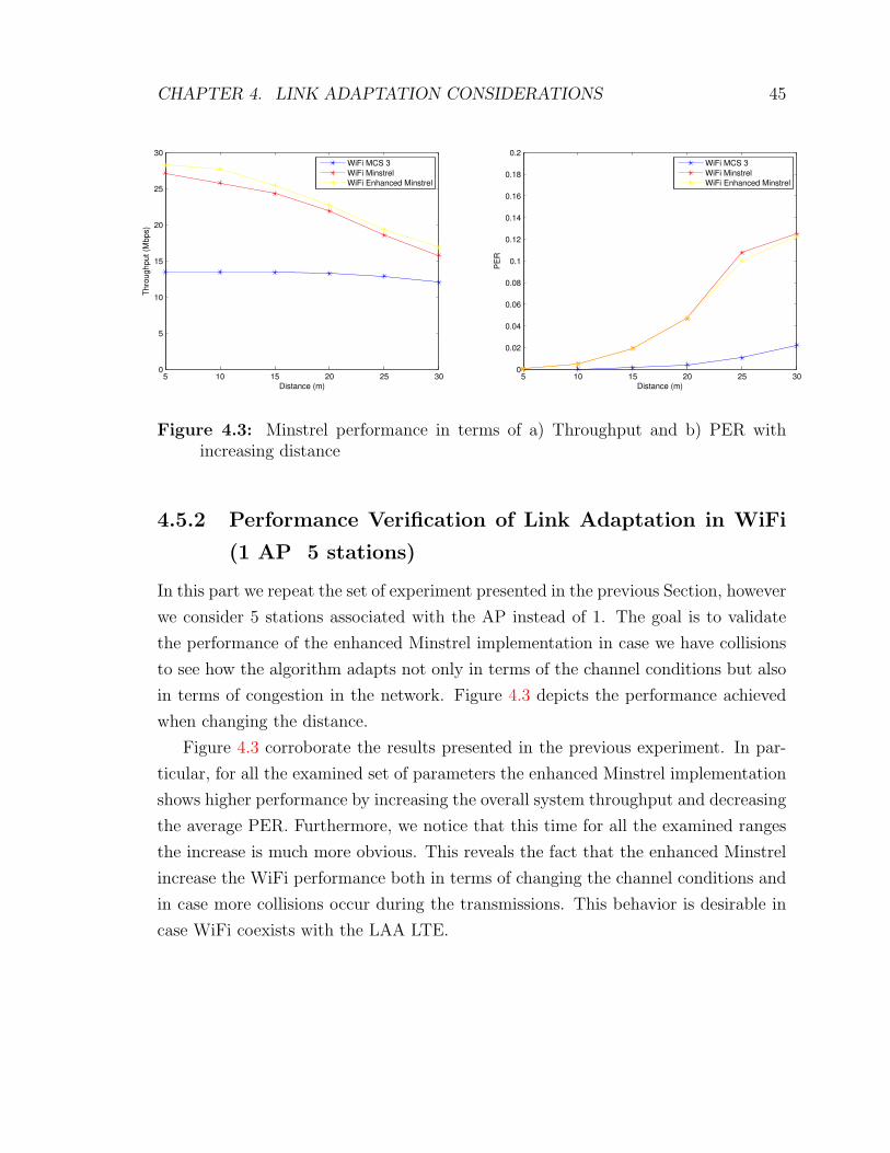
CHAPTER 4. LINK ADAPTATION CONSIDERATIONS 45
5 10 15 20 25 300
5
10
15
20
25
30T
hro
ug
hp
ut
(Mb
ps)
Distance (m)
WiFi MCS 3
WiFi Minstrel
WiFi Enhanced Minstrel
5 10 15 20 25 300
0.02
0.04
0.06
0.08
0.1
0.12
0.14
0.16
0.18
0.2
PE
R
Distance (m)
WiFi MCS 3
WiFi Minstrel
WiFi Enhanced Minstrel
Figure 4.3: Minstrel performance in terms of a) Throughput and b) PER withincreasing distance
4.5.2 Performance Verification of Link Adaptation in WiFi
(1 AP 5 stations)
In this part we repeat the set of experiment presented in the previous Section, however
we consider 5 stations associated with the AP instead of 1. The goal is to validate
the performance of the enhanced Minstrel implementation in case we have collisions
to see how the algorithm adapts not only in terms of the channel conditions but also
in terms of congestion in the network. Figure 4.3 depicts the performance achieved
when changing the distance.
Figure 4.3 corroborate the results presented in the previous experiment. In par-
ticular, for all the examined set of parameters the enhanced Minstrel implementation
shows higher performance by increasing the overall system throughput and decreasing
the average PER. Furthermore, we notice that this time for all the examined ranges
the increase is much more obvious. This reveals the fact that the enhanced Minstrel
increase the WiFi performance both in terms of changing the channel conditions and
in case more collisions occur during the transmissions. This behavior is desirable in
case WiFi coexists with the LAA LTE.

CHAPTER 4. LINK ADAPTATION CONSIDERATIONS 46
5 10 15 20 25 300
10
20
30
40
50
60
70
80
90T
hro
ug
hp
ut
(Mb
ps)
Distance (m)
WiFi MCS 3
WiFi Minstrel
WiFi Enhanced Minstrel
LAA MCS 4
LAA Mutual Information
5 10 15 20 25 300
0.01
0.02
0.03
0.04
0.05
0.06
0.07
0.08
0.09
0.1
PE
R
Distance (m)
WiFi MCS 3
WiFi Minstrel
WiFi Enhanced Minstrel
LAA MCS 4
LAA Mutual Information
Figure 4.4: WiFi and LAA coexistence performance in terms of a) Throughput andb) PER with increasing distance
4.5.3 Performance Evaluation of WiFi and LAA coexistence
(1 AP/BS 1 station/UE)
In this section, we also include the LAA LTE during the simulations. In the following,
we evaluate the performance achieved for changing the distance again. However, we
do not only evaluate the performance of the enhanced Minstrel implementation but
also the coexistence aspects for WiFi with LAA LTE.
Figure 4.4 shows the performance achieved when WiFi coexists with LAA LTE
and the distance is increased. Six different cases are examined :
a) WiFi without considering any link adaptation scheme using an MCS index of
3, coexisting with LAA LTE using also a fixed MCS index of 4.
b) WiFi operating with Enhanced Minstrel along with LAA LTE using a fixed
MCS index of 4.
c) WiFi operating with base Minstrel along with LAA LTE using a fixed MCS
index of 4.
d) WiFi without considering any link adaptation scheme using an MCS index of
3 coexisting with LAA LTE using the Mutual Information algorithm.
e) WiFi operating with Enhanced Minstrel along with LAA LTE using Mutual
Information.
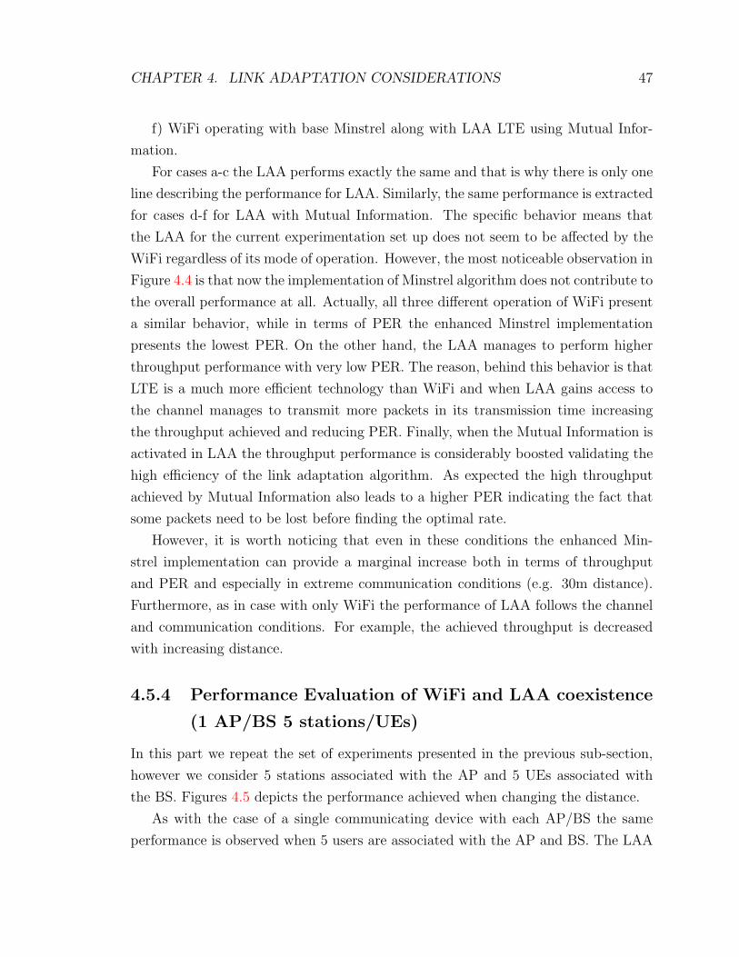
CHAPTER 4. LINK ADAPTATION CONSIDERATIONS 47
f) WiFi operating with base Minstrel along with LAA LTE using Mutual Infor-
mation.
For cases a-c the LAA performs exactly the same and that is why there is only one
line describing the performance for LAA. Similarly, the same performance is extracted
for cases d-f for LAA with Mutual Information. The specific behavior means that
the LAA for the current experimentation set up does not seem to be affected by the
WiFi regardless of its mode of operation. However, the most noticeable observation in
Figure 4.4 is that now the implementation of Minstrel algorithm does not contribute to
the overall performance at all. Actually, all three different operation of WiFi present
a similar behavior, while in terms of PER the enhanced Minstrel implementation
presents the lowest PER. On the other hand, the LAA manages to perform higher
throughput performance with very low PER. The reason, behind this behavior is that
LTE is a much more efficient technology than WiFi and when LAA gains access to
the channel manages to transmit more packets in its transmission time increasing
the throughput achieved and reducing PER. Finally, when the Mutual Information is
activated in LAA the throughput performance is considerably boosted validating the
high efficiency of the link adaptation algorithm. As expected the high throughput
achieved by Mutual Information also leads to a higher PER indicating the fact that
some packets need to be lost before finding the optimal rate.
However, it is worth noticing that even in these conditions the enhanced Min-
strel implementation can provide a marginal increase both in terms of throughput
and PER and especially in extreme communication conditions (e.g. 30m distance).
Furthermore, as in case with only WiFi the performance of LAA follows the channel
and communication conditions. For example, the achieved throughput is decreased
with increasing distance.
4.5.4 Performance Evaluation of WiFi and LAA coexistence
(1 AP/BS 5 stations/UEs)
In this part we repeat the set of experiments presented in the previous sub-section,
however we consider 5 stations associated with the AP and 5 UEs associated with
the BS. Figures 4.5 depicts the performance achieved when changing the distance.
As with the case of a single communicating device with each AP/BS the same
performance is observed when 5 users are associated with the AP and BS. The LAA
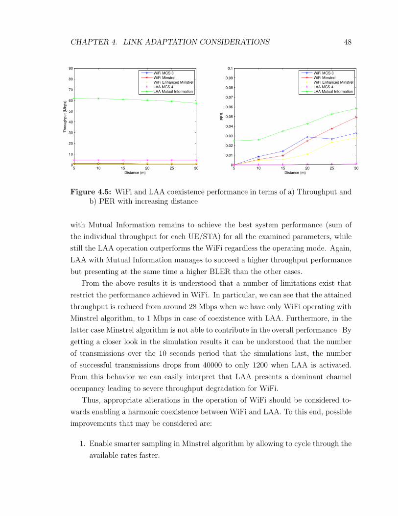
CHAPTER 4. LINK ADAPTATION CONSIDERATIONS 48
5 10 15 20 25 300
10
20
30
40
50
60
70
80
90T
hro
ug
hp
ut
(Mb
ps)
Distance (m)
WiFi MCS 3
WiFi Minstrel
WiFi Enhanced Minstrel
LAA MCS 4
LAA Mutual Information
5 10 15 20 25 300
0.01
0.02
0.03
0.04
0.05
0.06
0.07
0.08
0.09
0.1
PE
R
Distance (m)
WiFi MCS 3
WiFi Minstrel
WiFi Enhanced Minstrel
LAA MCS 4
LAA Mutual Information
Figure 4.5: WiFi and LAA coexistence performance in terms of a) Throughput andb) PER with increasing distance
with Mutual Information remains to achieve the best system performance (sum of
the individual throughput for each UE/STA) for all the examined parameters, while
still the LAA operation outperforms the WiFi regardless the operating mode. Again,
LAA with Mutual Information manages to succeed a higher throughput performance
but presenting at the same time a higher BLER than the other cases.
From the above results it is understood that a number of limitations exist that
restrict the performance achieved in WiFi. In particular, we can see that the attained
throughput is reduced from around 28 Mbps when we have only WiFi operating with
Minstrel algorithm, to 1 Mbps in case of coexistence with LAA. Furthermore, in the
latter case Minstrel algorithm is not able to contribute in the overall performance. By
getting a closer look in the simulation results it can be understood that the number
of transmissions over the 10 seconds period that the simulations last, the number
of successful transmissions drops from 40000 to only 1200 when LAA is activated.
From this behavior we can easily interpret that LAA presents a dominant channel
occupancy leading to severe throughput degradation for WiFi.
Thus, appropriate alterations in the operation of WiFi should be considered to-
wards enabling a harmonic coexistence between WiFi and LAA. To this end, possible
improvements that may be considered are:
1. Enable smarter sampling in Minstrel algorithm by allowing to cycle through the
available rates faster.
CHAPTER 4. LINK ADAPTATION CONSIDERATIONS 49
2. Change the long term probability factor when calculating the EWMA proba-
bility of success
3. Sample higher rates more often to move to higher rates faster.
4. Find the optimal distance between AP and BS to maximize throughput and
PER performance.
5. Reduce the allocated transmission time for LAA LTE.
6. Increase the packet size used for WiFi.
The 1-3 propositions may yield to better results but they involve a considerable
overhead that actually may not be applicable in a real environment. Besides, the main
problem identified is the performance degradation due to the increased number of
collisions and the excessive amount of channel occupancy that LAA causes. Towards
this extend, we examine the 4-6 propositions only.
4.5.5 Equalizing performance in WiFi and LAA coexistence
In the first set of experiments of this section we increase the distance between the
AP and the BS and we evaluate the performance achieved. The results are shown
in Figure 4.6, where the offset distance between the AP and BS increases from 10 to
100m with a step of 10m.
From the Figure 4.6 we can draw the following conclusions. For the specific set-up
the performance of LAA seems to be unaffected from WiFi for the different distances
between AP and BS. Furthermore, the performance of WiFi starts to increase for
an offset distance of 90m and only at 100m the performance achieved is similar with
the one attained when only WiFi is operating. In the same manner, PER starts
decreasing when the offset distance increases as less collisions are happening in the
medium. The small increase observed for the Minstrel algorithm for 90 and 100m
is due to the fact that now the packet losses are not caused by the collisions but
due to the fact the Minstrel algorithm actually can now sample more rates that do
not necessary lead to a successful transmission. However, the specific solution is
not applicable to a real environment, where the AP and BS are supposed to coexist
together in close proximity (i.e. office environment).
CHAPTER 4. LINK ADAPTATION CONSIDERATIONS 50
10 20 30 40 50 60 70 80 90 1000
5
10
15
20
25
30T
hro
ughput (M
bps)
Offset (m)
WiFi MCS 3
WiFi Minstrel
WiFi Enhanced Minstrel
LAA MCS 4
10 20 30 40 50 60 70 80 90 1000
0.01
0.02
0.03
0.04
0.05
0.06
0.07
0.08
0.09
0.1
PE
R
Offset (m)
WiFi MCS 3
WiFi Minstrel
WiFi Enhanced Minstrel
LAA MCS 4
Figure 4.6: WiFi and LAA coexistence performance in terms of a) Throughput andb) PER with increasing offset distance between AP and BS
In the second set of experiments the transmission time of LAA is reduced. In
the previous experiments we considered that once LAA gains access to the medium a
maximum transmission of 4ms occurs or 4 subframes are transmitted. In the following,
we examine how the attained throughput changes when LAA transmits for shorter
times (i.e. for 2 subframes and 1 subframe or 2ms and 1ms respectively). For the
following results only the distance between the communicating devices with the AP
and BS is assumed to change. Finally, to better illustrate the difference in throughput
between WiFi and LAA we do not consider the activation of the Mutual Information
algorithm for LAA.
From Figures 4.7 and 4.8 we can see that the gap in the performance between
WiFi and LAA is decreased as the allocated transmission time for LAA is reduced.
Actually, the throughput for WiFi is slightly higher than the throughput for LAA
when we consider LAA transmissions with only one subframe. However, even in this
case Minstrel is not able to contribute in the overall throughput performance. The
reason, is that again the number of transmissions for WiFi, and thus the load, is
very low and cannot take advantage of the higher rates that can be selected from
Minstrel algorithm. Once again, the enhanced Minstrel implementation can provide
a marginal performance improvement compared with the base Minstrel.
As proved in Chapter 3, in order to achieve a fair coexistence between WiFi and

CHAPTER 4. LINK ADAPTATION CONSIDERATIONS 51
5 10 15 20 25 300
1
2
3
4
5
6
7
Th
rou
gh
pu
t (M
bp
s)
Distance (m)
WiFi MCS 3
WiFi Minstrel
WiFi Enhanced Minstrel
LAA MCS 4
5 10 15 20 25 300
0.01
0.02
0.03
0.04
0.05
0.06
0.07
0.08
0.09
0.1
PE
R
Distance (m)
WiFi MCS 3
WiFi Minstrel
WiFi Enhanced Minstrel
LAA MCS 4
Figure 4.7: WiFi and LAA coexistence performance in terms of a) Throughput andb) PER with LAA sending 2 subframes.
5 10 15 20 25 300
1
2
3
4
5
6
7
Th
rou
gh
pu
t (M
bp
s)
Distance (m)
WiFi MCS 3
WiFi Minstrel
WiFi Enhanced Minstrel
LAA MCS 4
5 10 15 20 25 300
0.02
0.04
0.06
0.08
0.1
0.12
PE
R
Distance (m)
WiFi MCS 3
WiFi Minstrel
WiFi Enhanced Minstrel
LAA MCS 4
Figure 4.8: WiFi and LAA coexistence performance in terms of a) Throughput andb) PER with LAA sending 1 subframes.
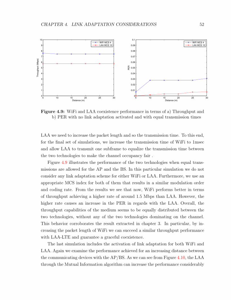
CHAPTER 4. LINK ADAPTATION CONSIDERATIONS 52
5 10 15 20 25 300
1
2
3
4
5
6
7
8
9
10T
hro
ug
hp
ut
(Mb
ps)
Distance (m)
WiFi MCS 4
LAA MCS 10
5 10 15 20 25 300
0.01
0.02
0.03
0.04
0.05
0.06
0.07
0.08
0.09
0.1
PE
R
Distance (m)
WiFi MCS 4
LAA MCS 10
Figure 4.9: WiFi and LAA coexistence performance in terms of a) Throughput andb) PER with no link adaptation activated and with equal transmission times
LAA we need to increase the packet length and so the transmission time. To this end,
for the final set of simulations, we increase the transmission time of WiFi to 1msec
and allow LAA to transmit one subframe to equalize the transmission time between
the two technologies to make the channel occupancy fair .
Figure 4.9 illustrates the performance of the two technologies when equal trans-
missions are allowed for the AP and the BS. In this particular simulation we do not
consider any link adaptation scheme for either WiFi or LAA. Furthermore, we use an
appropriate MCS index for both of them that results in a similar modulation order
and coding rate. From the results we see that now, WiFi performs better in terms
of throughput achieving a higher rate of around 1.5 Mbps than LAA. However, the
higher rate causes an increase in the PER in regards with the LAA. Overall, the
throughput capabilities of the medium seems to be equally distributed between the
two technologies, without any of the two technologies dominating on the channel.
This behavior corroborates the result extracted in chapter 3. In particular, by in-
creasing the packet length of WiFi we can succeed a similar throughput performance
with LAA-LTE and guarantee a graceful coexistence.
The last simulation includes the activation of link adaptation for both WiFi and
LAA. Again we examine the performance achieved for an increasing distance between
the communicating devices with the AP/BS. As we can see from Figure 4.10, the LAA
through the Mutual Information algorithm can increase the performance considerably

CHAPTER 4. LINK ADAPTATION CONSIDERATIONS 53
5 10 15 20 25 300
5
10
15
20
25
30T
hro
ug
hp
ut
(Mb
ps)
Distance (m)
WiFi Minstrel
WiFi Enhanced Minstrel
LAA Mutual Information
5 10 15 20 25 300
0.05
0.1
0.15
PE
R
Distance (m)
WiFi Minstrel
WiFi Enhanced Minstrel
LAA Mutual Information
Figure 4.10: WiFi and LAA coexistence performance in terms of a) Throughputand b) PER with link adaptation activated and with equal transmission times
more than WiFi. This has to do with the fact that link adaptation algorithms for
LTE are much more efficient than WiFi. Mutual Information algorithm is more
dynamic and adaptive than Minstrel, since it manages to change the MCS after
every transmission by providing the necessary feedback to the BS. On the other
hand, Minstrel updates his retry chain every 0.1 sec which is not that often in a
scenario were full buffer is assumed and packets are continuously generated from the
AP. Furthermore, link adaptation in LTE offers more granularity since there is a
wider range of MCS indexes that may be selected in comparison with only 8 MCS
Indexes that Minstrel can select in the particular simulations. However, even in this
scenario the Enhanced Minstrel algorithm manages to present a higher throughput
performance than the base Minstrel, validating the fact that it performs better in an
environment with high probability of collisions. It is worth to mention that around
70% of the performance improvement in the enhanced Minstrel is due to the second
improvement (substitution of base rate with the second highest probability rate in the
last trial). The first and last modifications on the other hand, are only responsible for
the remaining 30% of the improvement. These portions of improvements are highly
dependent of the length of simulation. For example for a shorter simulation, the effect
of the second improvement will reduce, while the remaining two improvements will
grow in importance.
Chapter 5
Conclusion and Future Works
As a conclusion, fair coexistence of WiFi-LAA is very essential for both technologies
to have a satisfactory share of the unlicensed band. Currently, the proposed schemes
for LBT/LAA can outperform WiFi in utilizing the channel, and therefore cannot
guarantee the WiFi fair share from the network. In this work, we have investigated
two important notions of fairness in the attained throughput for both networks. The
two fairness criteria are the equal throughput for WiFi and LAA separately, and
the equal throughput per number of stations communicating in them. Our numerical
experiments included changing the maximum packet size both optimally and heuristi-
cally for the WiFi network to achieve a fair share from the network in the saturation
condition. Moreover, we analyzed the user allocation to both networks (assuming
users are equipped with transceivers and receivers from both technologies) in order
to achieve a fair coexistence in terms of achievable throughput.
Our results indicate that by proper tuning the maximum packet size for the WiFi
network a fair share for the WiFi network is achievable. Also, proper allocation of
adaptable users within the two technologies can further increase the fairness for the
LAA/WiFi coexistence. This allocation of users can be performed by an information
exchange within the WiFi access point and the base station through the control links
at the cost of small signaling overhead.
Finally, we investigated the link adaptation technique to increase the performance
of WiFi network. We proposed an enhanced Minstrel algorithm to improve the WiFi’s
performance when operating alone and in the case of coexistence. Our findings for the
first case, not only indicated that the proposed enhanced Minstrel outperforms the
original Minstrel, but also improves the WiFi’s performance significantly compared
to the case that no link adaptation is activated. However, inspired by the numerical
54
CHAPTER 5. CONCLUSION AND FUTURE WORKS 55
analysis we validated the fact that by increasing the packet length of WiFi a consid-
erable increase of WiFi throughput can be achieved. Specifically, when the packet
length of the two technologies are equalized the enhanced Minstrel implementation
can increase the overall throughput by 5 Mbps.
In the performed experiments, we have changed the distance between the com-
municating devices both in WiFi and LTE-LAA. We tried to illustrate how the per-
formance changes when WiFi AP and the LTE eNB are further apart from their
associated devices. We also considered the effects for different distances of WiFi
AP and LTE eNB. However, the distance is not the only indicator of the network
performance. There exists several other important disregarded factors such as the
transmission power, speed of the users, different channel environment (e.g. office ver-
sus an open area) and etc. that play an important role in this coexistence. Moreover
we only considered the small networks in our analysis with small number of stations
due to the simplicity of our model. Therefore, the behavior of larger networks stayed
uninvestigated. Hopefully, we will cover these remaining aspects in our future work.
List of References
[1] G. Bianchi, “Performance analysis of the ieee 802.11 distributed coordinationfunction,” IEEE Journal on selected areas in communications, vol. 3, pp. 535–547, 2000.
[2] Y. Gao, X. Chu, and J. Zhang, “Performance analysis of laa and wifi coexistencein unlicensed spectrum based on markov chain,” in Global Communications Con-ference (GLOBECOM), pp. 1–6, 2016.
[3] H. Cengis, M. K. Marina, and U. Challita, “On lte-wifi coexistence and inter-operator spectrum sharing in unlicensed bands: altruism, cooperation and fair-ness,” in In Proceedings of the 17th ACM International Symposium on MobileAd Hoc Networking and Computing, pp. 111–120, 2016.
[4] A. Babaei, J. Andreoli-Fang, Y. Pang, and B. Hamzeh, “On the impact of lte-uon wi-fi performance,” International Journal of Wireless Information Networks,vol. 22, pp. 336–344, 2015.
[5] “Lte in unlicensed spectrum: Harmonious coexistence with wi-fi.” https://www.qualcomm.com/documents/lte-unlicensed-coexistence-whitepaper. Ac-cessed: 2017-02-20.
[6] “Lte-u technology and coexistence.” http://www.lteuforum.org/uploads/3/5/6/8/3568127/lte-u_coexistence_mechansim_qualcomm_may_28_2015.pdf. Accessed: 2017-02-21.
[7] W. Xuyu, S. Mao, and M. X. Gong, “A survey of lte wi-fi coexistence in un-licensed bands,” GetMobile: Mobile Computing and Communications, vol. 20,pp. 17–23, 2017.
[8] A. Mukherjee, J. Cheng, S. Falahati, H. Koorapaty, R. Karaki, L. Falconetti,and D. Larsson, “Licensed-assisted access lte: Coexistence with ieee 802.11 andthe evolution toward 5g,” IEEE Communications Magazine, vol. 54, pp. 50–57,2016.
[9] H. J. Zhu and D. Kidston, “The impact of link adaptation on wifi 802.11 n,” inNetworking, Architecture and Storage (NAS), pp. 1–5, 2016.
[10] S. Wu, S. Biaz, B. Qi, and K. Zhang, “Bara: a sender based rate adaptation inwireless networks,” in Proceedings of the 45th annual southeast regional confer-ence, pp. 179–184, 2007.
56
57
[11] R. Gummadi, D. Wetherall, B. Greenstein, and S. Seshan, “Understanding andmitigating the impact of rf interference on 802.11 networks,” ACM SIGCOMMComputer Communication, vol. 37, pp. 385–396, 2007.
[12] X. Zhang and K. G. Shin, “Enabling coexistence of heterogeneous wireless sys-tems: Case for zigbee and wifi,” in Proceedings of the Twelfth ACM InternationalSymposium on Mobile Ad Hoc Networking and Computing, p. 6, 2011.
[13] J. Zhu, A. Waltho, X. Yang, and X. Guo, “Multi-radio coexistence: Challengesand opportunities,” in Computer Communications and Networks, 2007. ICCCN2007. Proceedings of 16th International Conference on IEEE, pp. 358–364, 2007.
[14] M. A. Cavalcante, E. Almedia, R. D. Vieira, F. Chavez, R. Paiva, F. Abinader,S. Choudhuri, E. Tuomaala, and K. Doppler, “Performance evaluation of lteand wi-fi coexistence in unlicensed bands,” in Vehicular Technology Conference(VTC Spring) IEEE 77th, pp. 1–6, 2013.
[15] T. Nihtila, V. Tykhomyrov, O. Alanen, M. A. Uusitalo, A. Mangalvedhe,M. Moisio, S. Iraji, R. Ratasuk, and N. Mangalvedhe, “System performanceof lte and ieee 802.11 coexisting on a shared frequency band,” in Wireless Com-munications and Networking Conference (WCNC), pp. 1038–1043, 2013.
[16] R. Ratasuk, M. A. Uusitalo, N. Mangalvedhe, A. Sorri, S. Iraji, C. Wijting, andA. Ghosh, “License-exempt lte deployment in heterogeneous network,” in Inter-national Symposium on Wireless Communication Systems (ISWCS), pp. 246–250, 2012.
[17] R. C. Paiva, P. Papadimitriou, and S. Choudhury, “A physical layer frameworkfor interference analysis of lte and wi-fi operating in the same band,” in Signals,Systems and Computers, on Asilomar Conference, pp. 1204–1209, 2013.
[18] S. F. Chaves, E. Almedia, R. D. Vieira, A. M. Cavalcante, F. M. Abinader,S. Choudhury, and K. Doppler, “Lte ul power control for the improvement oflte/wi-fi coexistence,” in Vehicular Technology Conference (VTC Fall), IEEE78th, pp. 1–6, 2013.
[19] S. Sagari, S. Baysting, D. Saha, I. Seskar, W. Trappe, and D. Raychaudhuri,“Coordinated dynamic spectrum management of lte-u and wi-fi networks,” inDynamic Spectrum Access Networks (DySPAN), IEEE International Symposiumon, pp. 209–220, 2015.
[20] E. Almeida, A. M. Cavalcante, R. C. Paiva, S. Chaves, F. M. Abinader, R. D.Vieira, S. Choudhury, E. Tuomaala, and K. Doppler, “Enabling lte/wifi coexis-tence by lte blank subframe allocation,” in Communications (ICC) IEEE Inter-national Conference on, pp. 5083–5088, 2013.
[21] H. Zhang, X. Chu, W. Guo, and S. Wang, “Coexistence of wi-fi and heteroge-neous small cell networks sharing unlicensed spectrum,” IEEE CommunicationsMagazine, vol. 53, pp. 158–164, 2015.

58
[22] S. Wang, W. Guo, and M. D. McDonnell, “Downlink interference estimationwithout feedback for heterogeneous network interference avoidance,” in Telecom-munications (ICT), 21st International Conference on, pp. 82–87, 2014.
[23] C. Cano and D. Leith, “Unlicensed lte/wifi coexistence: Is lbt inherently fairerthan csat?,” in Communications (ICC), IEEE International Conference, pp. 1–6,2016.
[24] C. Cano and D. Leith, “Coexistence of wifi and lte in unlicensed bands: Aproportional fair allocation scheme,” in IEEE ICC 2015 Workshop on LTE inUnlicensed Bands: Potentials and Challenges, London, UK, pp. 2288–2293, 2015.
[25] X. Wang, Q. S. Tony, M. Sheng, and J. Li, “Throughput and fairness analysisof wi-fi and lte-u in unlicensed band.,” in IEEE Journal on Selected Areas inCommunications 35.1, pp. 63–78, 2017.
[26] G. Holland, N. Vaidya, and P. Bahl, “A rate-adaptive mac protocol for multi-hopwireless networks,” in Proceedings of the 7th annual international conference onMobile computing and networking. ACM, pp. 236–251, 2001.
[27] B. Sadeghi, V. Kanodia, and A. Sabharwal, “Opportunistic media access for mul-tirate ad hoc networks,” in Proceedings of the 8th annual international conferenceon Mobile computing and networking. ACM, pp. 24–35, 2002.
[28] S. H. Wong, H. Yang, S. Lu, and V. Bharghavan, “Robust rate adaptation for802.11 wireless networks,” in Proceedings of the 12th annual international con-ference on Mobile computing and networking. ACM, pp. 146–157, 2006.
[29] A. Kamerman and L. Monteban, “Wavelan ii: A high-performance wireless lanfor the unlicensed band,” Bell Labs Technical Journal, vol. 2, pp. 118–133, 1997.
[30] M. Lacage, M. Manshaei, and T. Turletti, “Ieee 802.11 rate adaptation: A practi-cal approach,” in Proceedings of the 7th ACM international symposium on Mod-eling, analysis and simulation of wireless and mobile systems, p. 126 134, 2004.
[31] J. Kim, S. Kim, S. Choi, and D. Qiao, “Cara: Collision-aware rate adaptationfor ieee 802.11 wlans,” Infocom, vol. 6, pp. 1–11, 2006.
[32] “Madwifi.” http://sourceforge.net/projects/madwifi. Accessed: 2017-02-26.
[33] J. Bicket, “Bit-rate selection in wireless networks,” in MIT Master’s Thesis,2005.
[34] “Minstrel specification, madwifi project.”
[35] F. Tramarin, S. Vitturi, and M. Luvisotto, “Improved rate adaptation strate-gies for real-time industrial ieee 802.11 n wlans,” in IEEE 20th conference onEmerging Technologies and Factory Automation(ETFA), pp. 1–8, 2015.
[36] X. Chen, H. Yi, H. Luo, and H. Yu, “A novel cqi calculation scheme in lte and lte-a systems,” in Proceedings of the IEEE International Wireless Communicationsand Signal Processing (WCSP), pp. 1–5, 2011.
59
[37] J. Jian, M. Peng, Y. Li, and Y. Wei, “Measurement-based optimizing algorithmfor modulation and coding scheme selection in downlink lte self-organizing net-works,” in Proceedings of the IEEE International Conference on Wireless Infor-mation Technology and Systems (ICWITS), pp. 1–4, 2012.
[38] M. Shahab, “Efficient channel quality indicator reporting schemes in lte withreduced signalling overhead,” in the 38th International Conference on Telecom-munications and Signal Processing (TSP), pp. 123–128, 2015.
[39] S. N. Donthi and N. Mehta, “An accurate model for eesm and its application toanalysis of cqi feedback schemes and scheduling in lte,” IEEE Transactions onWireless Communications, vol. 10, pp. 3436–3448, 2011.
[40] “Lte: Evolved universal terrestrial access (e-utra); physical layer procedures.”ETSI TS 136 213 V12.4.0.
[41] K. Sayana and J. Zhuang, “Link performance abstraction based on mean mu-tual information per bit (mmib) of the llr channel,” in IEEE 802.16 BroadbandWireless Access Working Group, Standardization Document, 2007.
[42] 3rd Generation Partnership Project TR 36.889, “Study on licensed-assisted ac-cess to unlicensed spectrum; (release 13),” 2015.
[43] B. Chen, J. Chen, Y. Gao, and J. Zhang, “Coexistence of lte-laa and wi-fi on 5ghz with corresponding deployment scenarios: A survey,” IEEE CommunicationsSurveys and Tutorials 19.1, vol. 1, pp. 7–32, 2017.
[44] C. Cano, D. Lopez-Perez, H. Claussen, and D. J. Leith, “Using lte in unli-censed bands: potential benefits and coexistence issues,” in IEEE Communica-tions Magazine 54.12, pp. 116–123, 2016.
[45] D. Xia, J. Hart, and Q. Fu, “On the performance of rate control algorithm min-strel,” in Personal Indoor and Mobile Radio Communications (PIMRC), pp. 406–412, 2012.
[46] D. Xia, J. Hart, and Q. Fu, “Evaluation of the minstrel rate adaptation algorithmin ieee 802.11g wlans,” in Proceedings of the IEEE International Conference onCommunications (ICC), pp. 2223–2228, 2013.
Related Documents