Welcome message from author
This document is posted to help you gain knowledge. Please leave a comment to let me know what you think about it! Share it to your friends and learn new things together.
Transcript

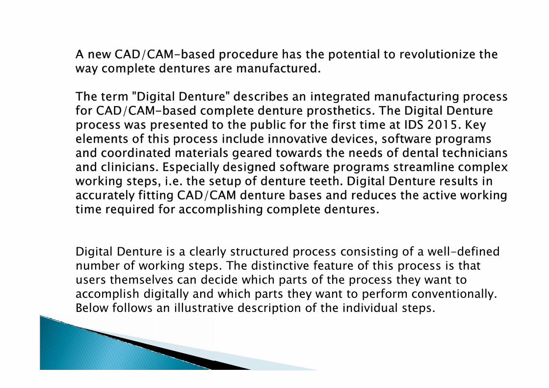
Digital Denture is a clearly structured process consisting of a well-defined number of working steps. The distinctive feature of this process is that users themselves can decide which parts of the process they want to accomplish digitally and which parts they want to perform conventionally. Below follows an illustrative description of the individual steps.
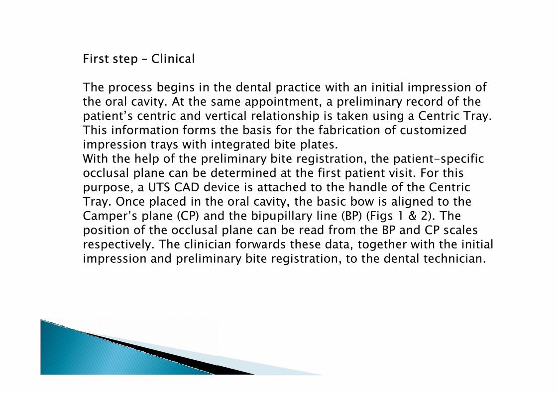
The process begins in the dental practice with an initial impression of the oral cavity. At the same appointment, a preliminary record of the patient’s centric and vertical relationship is taken using a Centric Tray. This information forms the basis for the fabrication of customized impression trays with integrated bite plates. With the help of the preliminary bite registration, the patient-specific occlusal plane can be determined at the first patient visit. For this purpose, a UTS CAD device is attached to the handle of the Centric Tray. Once placed in the oral cavity, the basic bow is aligned to the Camper’s plane (CP) and the bipupillary line (BP) (Figs 1 & 2). The position of the occlusal plane can be read from the BP and CP scales respectively. The clinician forwards these data, together with the initial impression and preliminary bite registration, to the dental technician.

Establishing the patient-specific relation of the temporary bite record to Camper’s plane (CP) using a UTS CAD
Establishing the patient-specific relation of the temporary bite record to the bipupillary line (BP) using a UTS CAD
The digital workflow can be entered as early as with the fabrication of the customized bite plates – no need for models or a physical articulator. The impressions and bite registrations are digitized one after the other using a scanning device. The two virtual models are set into relation with the data of the preliminary bite registration. For this purpose, the exclusive “Digital Denture Professional” design software guides the user through the menu step by step. First, the position of the occlusal plane is defined. The CP and BP values defined by the clinician are entered into the virtual UTS CAD (Fig. 3).

The provisional occlusal plane for the bite record is established using the patient-specific BP and CP values and included in the design.

The patient-specific occlusal plane is determined. During the design process, a uniform offset space to allow for the later application of impression material can be defined for the entire basal surface of the bite plate. In addition, the design software includes the newly designed Gnathometer CAD needle-point tracing appliance utilized for the design of the bite rim (Fig. 4).
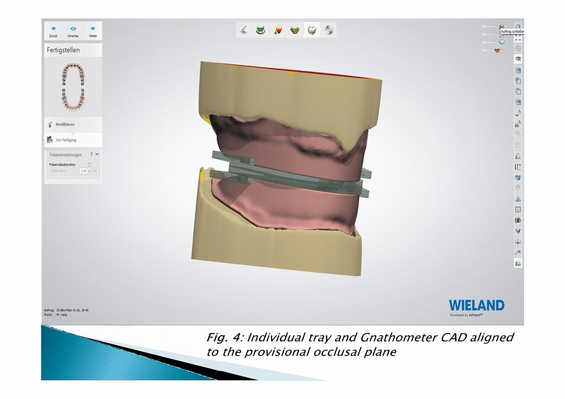
Individual tray and Gnathometer CAD aligned to the provisional occlusal plane
Milling is carried out using a Zenotec select ion milling unit – the latest member of the Zenotec select family. The acrylic particles produced during dry milling have a static charge and, as a result, they stick to the surfaces of the milling chamber. Zenotec select ion is equipped with nozzles directed towards the milling tools and acrylic blanks. These nozzles supply ionized compressed air during the milling procedure. The compressed air neutralizes the static charge and the acrylic particles can be easily evacuated. As a result, clean uncontaminated milling chamber surfaces and milling materials are ensured at all times.
Upon completion of the milling procedure, the bite plates are conveniently removed from the disc and any sharp edges smoothed out. The connection to the Gnathometer CAD has been accurately transferred from the design to the bite plate so that the needle-point tracing appliance can be directly attached (Fig. 5).

CAM-based custom tray for needle point registration
The dentist now creates the functional impressions. The basal surface of the bite plate is wetted with a commercially available tray adhesive. Subsequently, a closed-tray impression is taken while the patient is performing functional movements. The position of the occlusal plane may be checked another time using the UTS CAD and corrected as necessary. The maxillomandibular relation is determined using the Gnathometer CAD needle point tracing device, which simply clicks into the milled biting plate. The vertical height of both jaws is set by adjusting the thread of the tracing stylus. Fig. 6 shows a typical needle point tracing record.
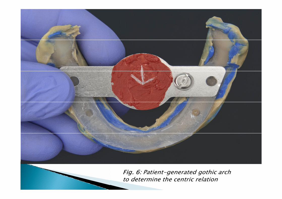
Patient-generated gothic arch to determine the centric relation

After the centric relation between the upper and lower jaw has been determined, the bite plates are immobilized using a registration silicone. Lastly, the patient’s esthetic lines – e.g. midline, canine-to-canine line, lip closure line and smile line – are marked on the record (Fig. 7). This information assists the dental technician in setting up the anterior teeth in line with the patient’s specific esthetic characteristics.
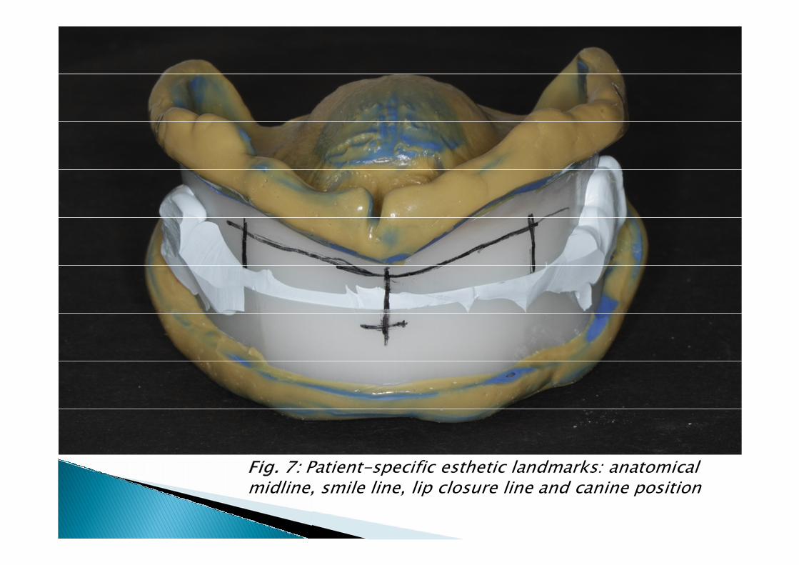
Patient-specific esthetic landmarks: anatomical midline, smile line, lip closure line and canine position
The immobilized record and the functional impressions are scanned to generate the functional models for the final dentures. Using the digital UTS CAD function, the definite final position of the occlusal plane is determined, or corrected (Fig. 8).
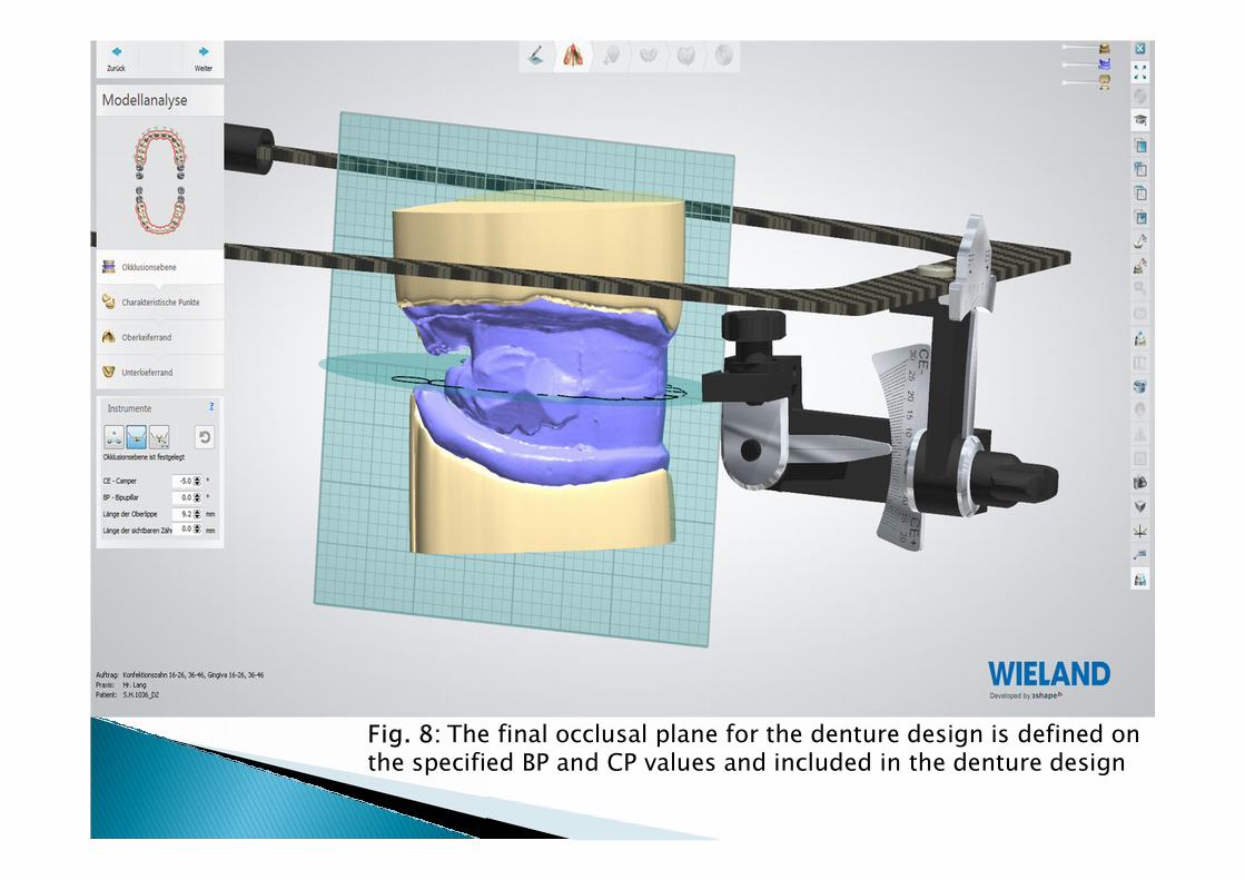
The final occlusal plane for the denture design is defined on the specified BP and CP values and included in the denture design
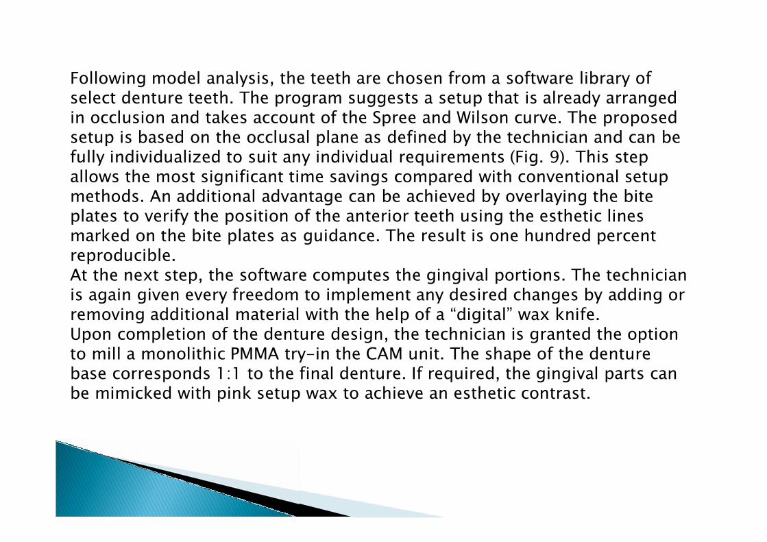
Following model analysis, the teeth are chosen from a software library of select denture teeth. The program suggests a setup that is already arranged in occlusion and takes account of the Spree and Wilson curve. The proposed setup is based on the occlusal plane as defined by the technician and can be fully individualized to suit any individual requirements (Fig. 9). This step allows the most significant time savings compared with conventional setup methods. An additional advantage can be achieved by overlaying the bite plates to verify the position of the anterior teeth using the esthetic lines marked on the bite plates as guidance. The result is one hundred percent reproducible. At the next step, the software computes the gingival portions. The technician is again given every freedom to implement any desired changes by adding or removing additional material with the help of a “digital” wax knife. Upon completion of the denture design, the technician is granted the option to mill a monolithic PMMA try-in the CAM unit. The shape of the denture base corresponds 1:1 to the final denture. If required, the gingival parts can be mimicked with pink setup wax to achieve an esthetic contrast.
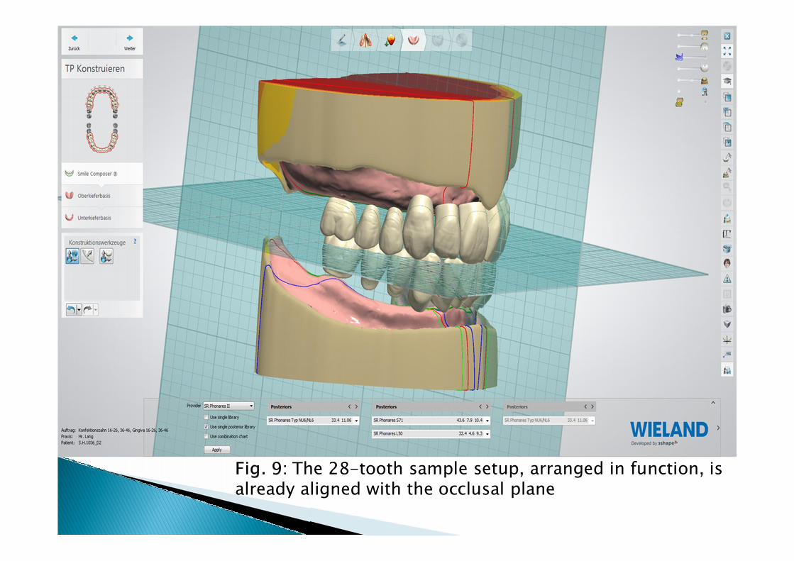
The 28-tooth sample setup, arranged in function, is already aligned with the occlusal plane
Occlusion, phonetics, esthetics and suction effect are checked at the try-in, similar to conventional wax try-ins (Fig. 10). If necessary, desired corrections to the position of the teeth can be marked on the try-in denture or on a digital photograph, or, alternatively, directly communicated to the technician. The technician uses this information to modify the design accordingly.
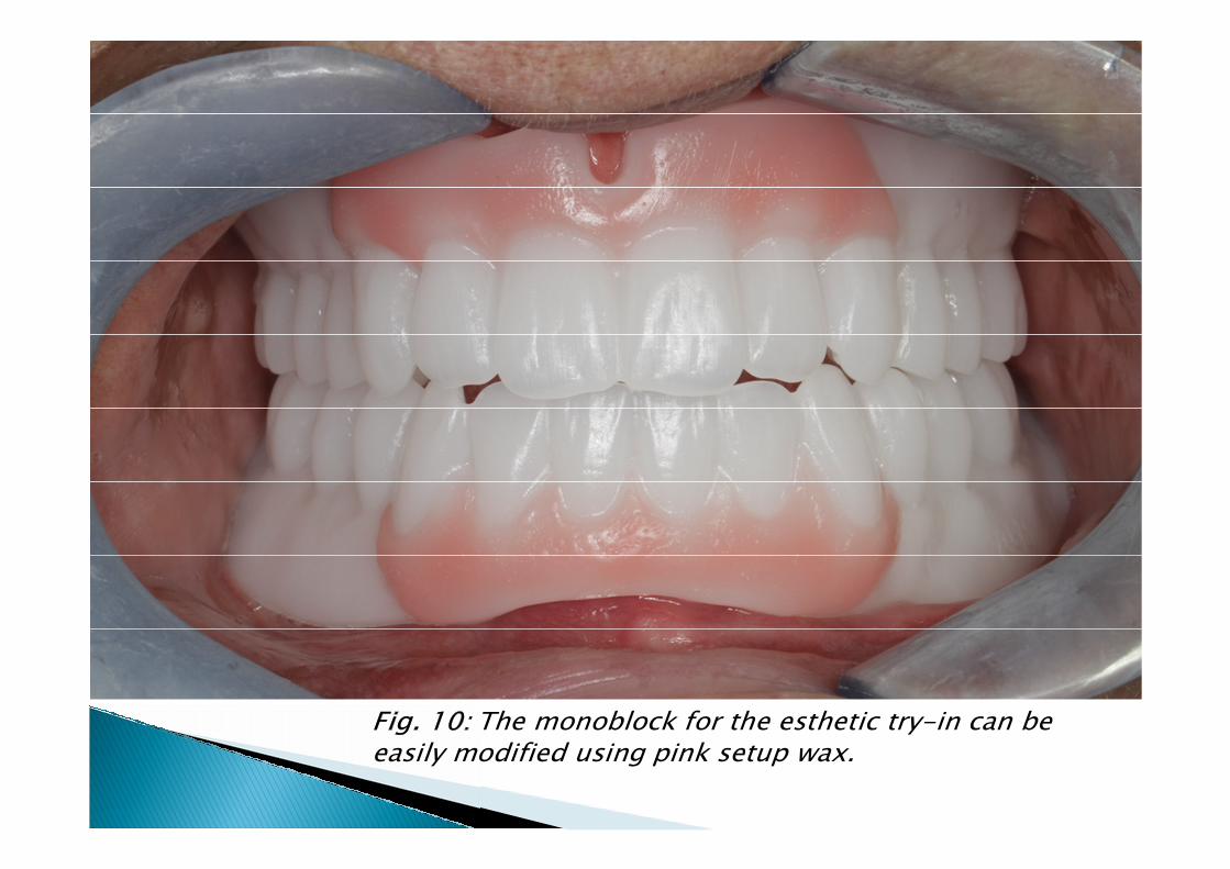
The monoblock for the esthetic try-in can be easily modified using pink setup wax.

The technician calls up the saved denture design and implements any modifications as required. Before the output files of the final denture base are created for manufacturing in the CAM unit, the CAD software automatically computes an additional positioning jig that depicts the occlusal surfaces and incisal edges of the maxillary and mandibular teeth (Fig. 11). This information is then fed into the CAM software to mill the dentures in the Zenotec select ion milling unit.If conventional methods are used, the denture teeth often have to be manually reduced at the basal surface using a handheld grinder, because the vertical dimension between the maxillary and mandibular teeth is in many cases too short.
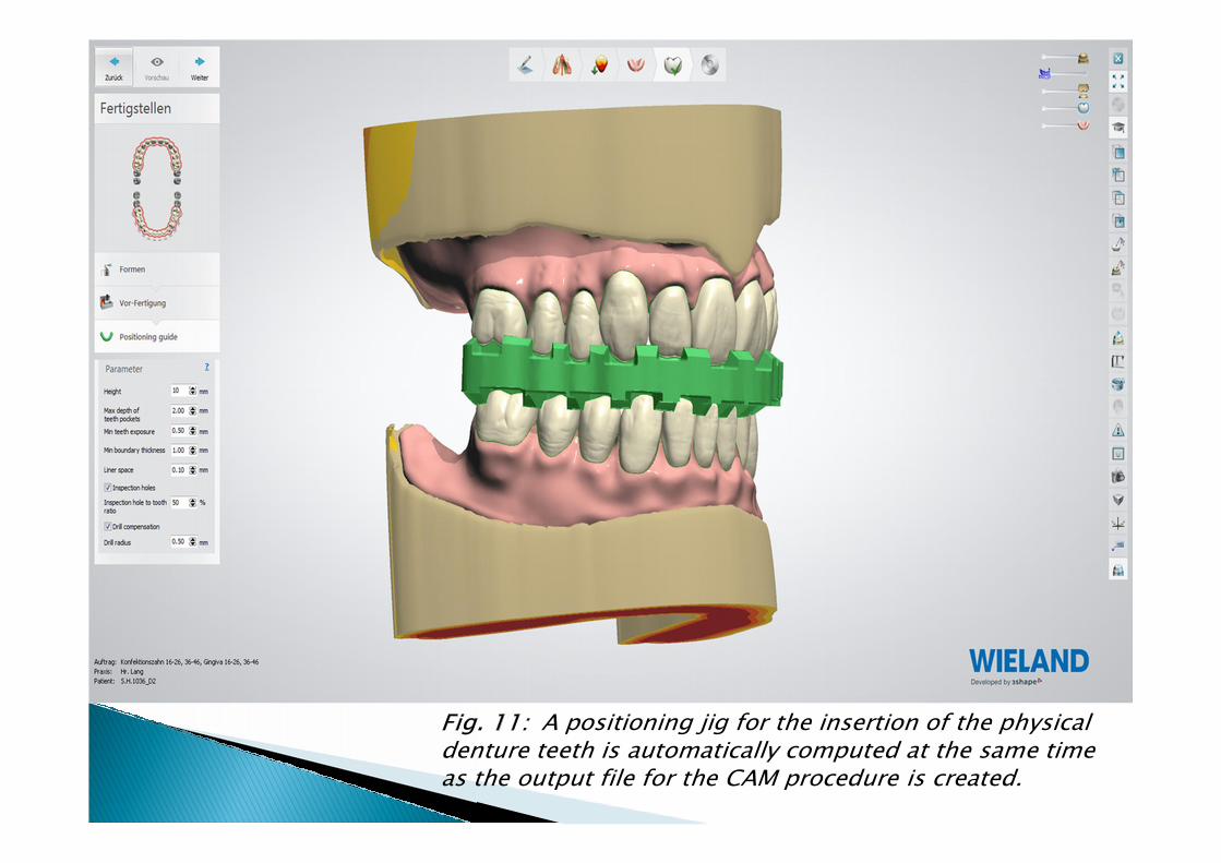
A positioning jig for the insertion of the physical denture teeth is automatically computed at the same time as the output file for the CAM procedure is created.
The CAD/CAM manufacturing process addresses this situation by cutting two repositioning grooves into the IvoBase CAD for Zenotecdisc. As a result, the disc can be secured only in one position using an especially designed disc holder. Then, in the first milling run, the denture base is milled from the top surface to its final shape including the holes for the placement of the physical teeth. After that, the disc is removed. The pre-fabricated denture teeth are polymerized to the denture base using IvoBase CAD Bond and the positioning jig computed and prepared beforehand (Fig. 12).
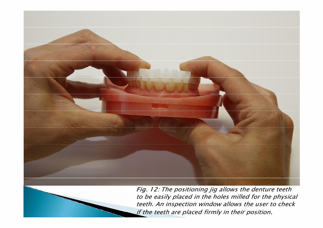
The positioning jig allows the denture teeth to be easily placed in the holes milled for the physical teeth. An inspection window allows the user to check if the teeth are placed firmly in their position.
The positioning jig is used to verify the correct placement of the teeth. To conduct the second milling run, this time on the basal surface, the disc is again secured to the disc holder in exactly the same position as before (Fig. 13). Now, if individual teeth turn out to be too long, the excess will be ground away during the second milling run. The result of the milling process is a CAD/CAM denture that can be polished to a high gloss using familiar methods.
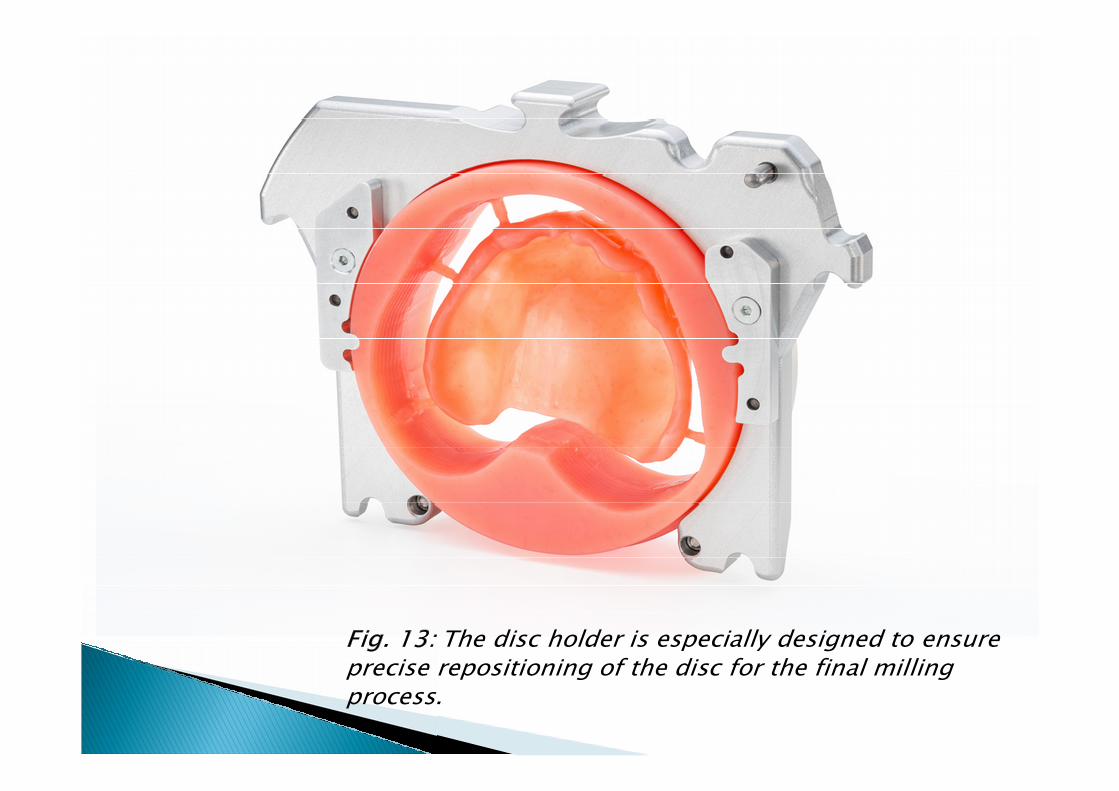
The disc holder is especially designed to ensure precise repositioning of the disc for the final milling process.
Incorporating the final dentures is carried out in the same way as the incorporation of conventional dentures (Fig. 14). Particularly noteworthy is the excellent basal fit of the dentures. As the manufacturing process is not affected by polymerization shrinkage or any other thermal influences and results in the precision typical of CAD/CAM methods, the dentures exhibit an exceptional accuracy of fit and provide an outstanding suction effect.
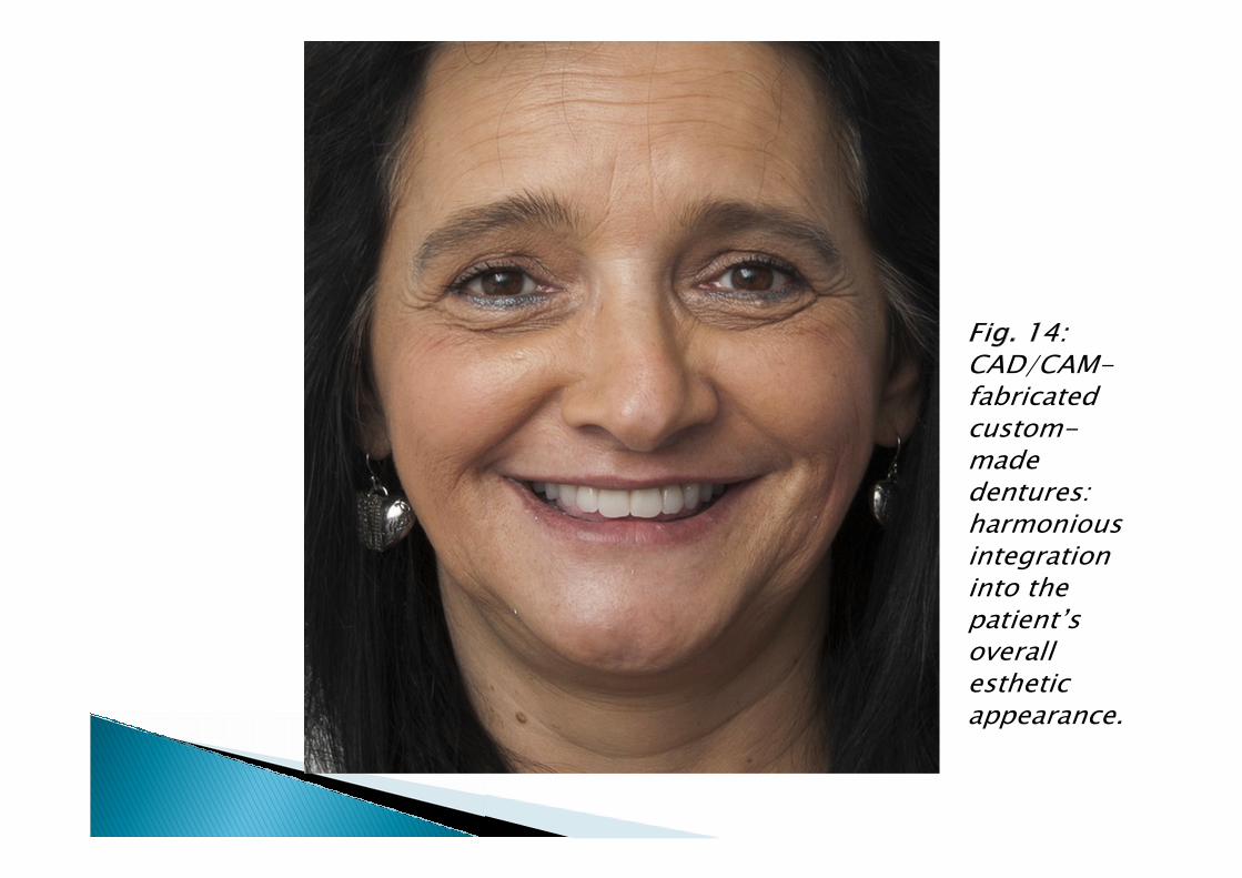
CAD/CAM-fabricated custom-made dentures: harmonious integration into the patient’s overall estheticappearance.
The trend towards digitization is not a new or unknown phenomenon in dentistry. Digital technology has started to make inroads into fixed dental prosthetcis several years ago and has advanced successfully. It was therefore only a question of time until it would also start to gain a foothold in removable prosthetics. The Digital Denture process may represent an essential milestone in the advance of dental technology in fixed prosthetics. And this trend is said to continue: additional indications will advance the modernization of removable prosthetics and the efficiency of the manufacturing processes will be consistently optimized.
For more Information, contact:
Related Documents