Metamaterial Research Updates from China RESEARCH ARTICLE Wideband RCS reduction of thin metallic edges mediated by spoof surface plasmon polaritons Xinghua Li 1 , Mingde Feng 1,* , Jiafu Wang 1,** , Xinmin Fu 1 , Yajuan Han 1 , Sai Sui 1 , Yongqiang Pang 2 , and Shaobo Qu 1 1 Department of Basic Sciences, Air Force Engineering University, Xi’an, Shaanxi 710051, PR China 2 School of Electronics and Information Engineering, Xi’an Jiaotong University, Xi’an, Shaanxi 710049, PR China Received: 17 October 2020 / Accepted: 25 December 2020 Abstract. The back-scattering from front edge diffraction contributes significantly to mono-static radar cross section under TE-polarization when the specular reflection of an object is eliminated by elaborate shaping. With the aim to suppress the back-scattering of thin metallic edge, we propose to achieve wideband radar cross section (RCS) reduction by integrating an absorbing structure (AS) in front of the edge. The unit cell of AS is composed of a longitudinal array of metallic strips with linearly decreasing lengths. Under TE-polarized illumination, spoof surface plasmon polariton (SSPP) can be excited with high efficiency. Due to the deep-subwavelength property of SSPP, electromagnetic waves are highly confined around the AS, leading to strong local field enhancement and hence to wideband absorption. In this way, back-scattering of the edge is suppressed and the mono-static RCS can be reduced significantly over wide band. To verify this method, we designed, fabricated and measured a prototype. The results of both simulation and measurement indicate that our proposal can significantly suppress edge scattering, whose RCS reduction more than 10 dB achieves at range of 8.8–17.8 GHz under TE polarization. This work provides a new alternative of suppressing edge diffraction and may find applications in electromagnetic compatibility, radar stealth, etc. Keywords: Edge diffraction / radar cross section reduction / radar absorbing structure / spoof surface plasmon polaritons 1 Introduction The edge diffraction as potential scattering source is existed extensively on discontinuous surfaces or bound- aries, which can be interpreted by the impedance mismatch between the object edges and their surroundings. In fact, the radar echoes of edge diffraction is only a minor part compared to that of specular reflection. However, when the specular reflection is effectively controlled by the shape design and radar absorber material or the incident plane wave is in a grazing condition, the edge diffraction becomes the major contributor to radar cross section (RCS). For engineering applications, it is crucial to reduce RCS caused by the edge diffraction that in order to improve the performance of the research targets [1–3]. The edge diffraction can be suppressed by the combination of shaping geometry and designing material property [4,5]. Methods for suppressing edge diffraction include the use of edge serration [6–8], edge corrugations [9], resistive tapers loading [10–12], and edge coatings [13,14], which have received considerable attention. Other related works have involved using the impedance surface to redirect the back-scattering, orto guide the surface waves toward or away from the hypotenuse [15,16]. The focus of methods following the shape design principle is the deflection of edge diffraction, which may deteriorate other engineering indicators, such as weight or aerodynamic performance [5,15]. For material property design, resistive tapers loading is an attractive method for suppressing the edge diffraction by providing a gradual transition from a metallic edge to free space, which is of a remarkable interest for many stealth engineers [17]. However, it also suffers from an obvious limitation of narrow bandwidth.In fact, the wideband suppression of edge diffraction is not only highly demanded but also challenged for many engineering applications. Note that spoof surface plasmon polariton (SSPP) is serving for wideband absorption by virtue of deep-subwavelength and strong local field enhancement properties [18]. The wideband absorption of periodically arranged SSPP framework has been introduced in several recent reference papers [19–24]. In this work, we expand on * e-mail: [email protected] ** e-mail: [email protected] EPJ Appl. Metamat. 8, 8 (2021) © X. Li et al., published by EDP Sciences, 2021 https://doi.org/10.1051/epjam/2020018 Available online at: epjam.edp-open.org This is an Open Access article distributed under the terms of the Creative Commons Attribution License (https://creativecommons.org/licenses/by/4.0), which permits unrestricted use, distribution, and reproduction in any medium, provided the original work is properly cited.

Welcome message from author
This document is posted to help you gain knowledge. Please leave a comment to let me know what you think about it! Share it to your friends and learn new things together.
Transcript

EPJ Appl. Metamat. 8, 8 (2021)© X. Li et al., published by EDP Sciences, 2021https://doi.org/10.1051/epjam/2020018
Available online at:epjam.edp-open.org
Metamaterial Research Updates from China
RESEARCH ARTICLE
Wideband RCS reduction of thin metallic edges mediatedby spoof surface plasmon polaritonsXinghua Li1, Mingde Feng1,*, Jiafu Wang1,**, Xinmin Fu1, Yajuan Han1, Sai Sui1, Yongqiang Pang2,and Shaobo Qu1
1 Department of Basic Sciences, Air Force Engineering University, Xi’an, Shaanxi 710051, PR China2 School of Electronics and Information Engineering, Xi’an Jiaotong University, Xi’an, Shaanxi 710049, PR China
* e-mail: f** e-mail:
This is anO
Received: 17 October 2020 / Accepted: 25 December 2020
Abstract. The back-scattering from front edge diffraction contributes significantly to mono-static radar crosssection under TE-polarization when the specular reflection of an object is eliminated by elaborate shaping.Withthe aim to suppress the back-scattering of thin metallic edge, we propose to achieve wideband radar cross section(RCS) reduction by integrating an absorbing structure (AS) in front of the edge. The unit cell of AS is composedof a longitudinal array of metallic strips with linearly decreasing lengths. Under TE-polarized illumination, spoofsurface plasmon polariton (SSPP) can be excited with high efficiency. Due to the deep-subwavelength propertyof SSPP, electromagnetic waves are highly confined around the AS, leading to strong local field enhancementand hence to wideband absorption. In this way, back-scattering of the edge is suppressed and the mono-staticRCS can be reduced significantly over wide band. To verify this method, we designed, fabricated andmeasured aprototype. The results of both simulation andmeasurement indicate that our proposal can significantly suppressedge scattering, whose RCS reductionmore than 10 dB achieves at range of 8.8–17.8 GHz under TE polarization.This work provides a new alternative of suppressing edge diffraction and may find applications inelectromagnetic compatibility, radar stealth, etc.
Keywords: Edge diffraction / radar cross section reduction / radar absorbing structure /spoof surface plasmon polaritons
1 Introduction
The edge diffraction as potential scattering source isexisted extensively on discontinuous surfaces or bound-aries, which can be interpreted by the impedance mismatchbetween the object edges and their surroundings. In fact,the radar echoes of edge diffraction is only a minor partcompared to that of specular reflection. However, when thespecular reflection is effectively controlled by the shapedesign and radar absorber material or the incident planewave is in a grazing condition, the edge diffraction becomesthe major contributor to radar cross section (RCS). Forengineering applications, it is crucial to reduce RCS causedby the edge diffraction that in order to improve theperformance of the research targets [1–3].
The edge diffraction can be suppressed by thecombination of shaping geometry and designing materialproperty [4,5]. Methods for suppressing edge diffractioninclude the use of edge serration [6–8], edge corrugations
[email protected]@126.com
penAccess article distributed under the terms of the CreativeComwhich permits unrestricted use, distribution, and reproduction
[9], resistive tapers loading [10–12], and edge coatings[13,14], which have received considerable attention. Otherrelated works have involved using the impedance surface toredirect the back-scattering, orto guide the surface wavestoward or away from the hypotenuse [15,16]. The focus ofmethods following the shape design principle is thedeflection of edge diffraction, which may deteriorate otherengineering indicators, such as weight or aerodynamicperformance [5,15]. For material property design, resistivetapers loading is an attractive method for suppressing theedge diffraction by providing a gradual transition from ametallic edge to free space, which is of a remarkable interestfor many stealth engineers [17]. However, it also suffersfrom an obvious limitation of narrow bandwidth.In fact,the wideband suppression of edge diffraction is not onlyhighly demanded but also challenged for many engineeringapplications. Note that spoof surface plasmon polariton(SSPP) is serving for wideband absorption by virtue ofdeep-subwavelength and strong local field enhancementproperties [18]. The wideband absorption of periodicallyarranged SSPP framework has been introduced in severalrecent reference papers [19–24]. In this work, we expand on
monsAttribution License (https://creativecommons.org/licenses/by/4.0),in any medium, provided the original work is properly cited.
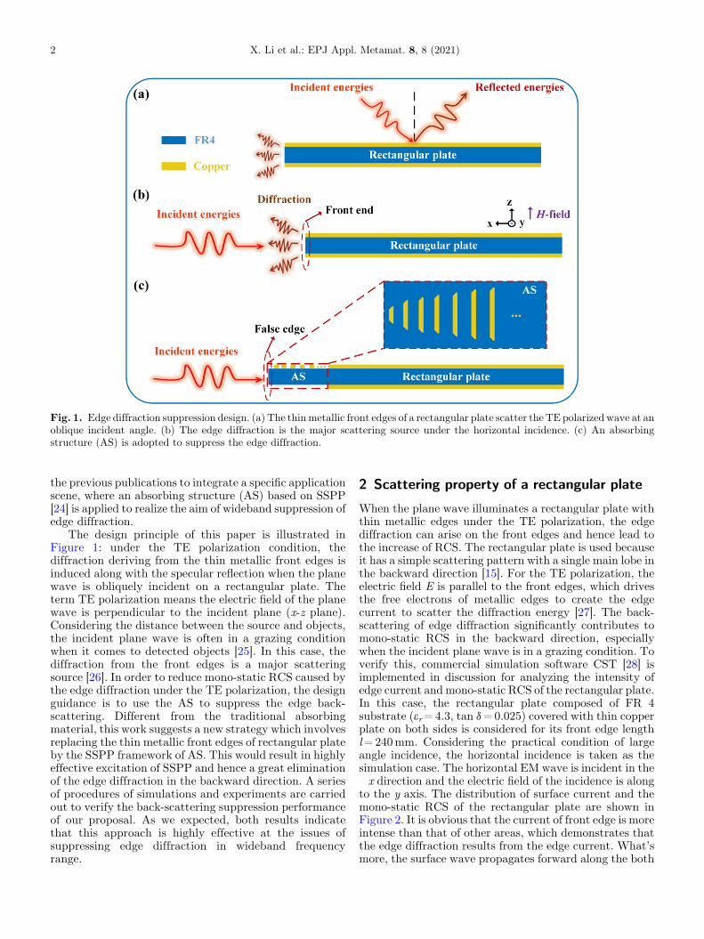
Fig. 1. Edge diffraction suppression design. (a) The thinmetallic front edges of a rectangular plate scatter the TE polarized wave at anoblique incident angle. (b) The edge diffraction is the major scattering source under the horizontal incidence. (c) An absorbingstructure (AS) is adopted to suppress the edge diffraction.
2 X. Li et al.: EPJ Appl. Metamat. 8, 8 (2021)
the previous publications to integrate a specific applicationscene, where an absorbing structure (AS) based on SSPP[24] is applied to realize the aim of wideband suppression ofedge diffraction.
The design principle of this paper is illustrated inFigure 1: under the TE polarization condition, thediffraction deriving from the thin metallic front edges isinduced along with the specular reflection when the planewave is obliquely incident on a rectangular plate. Theterm TE polarization means the electric field of the planewave is perpendicular to the incident plane (x-z plane).Considering the distance between the source and objects,the incident plane wave is often in a grazing conditionwhen it comes to detected objects [25]. In this case, thediffraction from the front edges is a major scatteringsource [26]. In order to reduce mono-static RCS caused bythe edge diffraction under the TE polarization, the designguidance is to use the AS to suppress the edge back-scattering. Different from the traditional absorbingmaterial, this work suggests a new strategy which involvesreplacing the thin metallic front edges of rectangular plateby the SSPP framework of AS. This would result in highlyeffective excitation of SSPP and hence a great eliminationof the edge diffraction in the backward direction. A seriesof procedures of simulations and experiments are carriedout to verify the back-scattering suppression performanceof our proposal. As we expected, both results indicatethat this approach is highly effective at the issues ofsuppressing edge diffraction in wideband frequencyrange.
2 Scattering property of a rectangular plate
When the plane wave illuminates a rectangular plate withthin metallic edges under the TE polarization, the edgediffraction can arise on the front edges and hence lead tothe increase of RCS. The rectangular plate is used becauseit has a simple scattering pattern with a single main lobe inthe backward direction [15]. For the TE polarization, theelectric field E is parallel to the front edges, which drivesthe free electrons of metallic edges to create the edgecurrent to scatter the diffraction energy [27]. The back-scattering of edge diffraction significantly contributes tomono-static RCS in the backward direction, especiallywhen the incident plane wave is in a grazing condition. Toverify this, commercial simulation software CST [28] isimplemented in discussion for analyzing the intensity ofedge current andmono-static RCS of the rectangular plate.In this case, the rectangular plate composed of FR 4substrate (er=4.3, tan d=0.025) covered with thin copperplate on both sides is considered for its front edge lengthl=240mm. Considering the practical condition of largeangle incidence, the horizontal incidence is taken as thesimulation case. The horizontal EM wave is incident in the�x direction and the electric field of the incidence is alongto the y axis. The distribution of surface current and themono-static RCS of the rectangular plate are shown inFigure 2. It is obvious that the current of front edge is moreintense than that of other areas, which demonstrates thatthe edge diffraction results from the edge current. What’smore, the surface wave propagates forward along the both

X. Li et al.: EPJ Appl. Metamat. 8, 8 (2021) 3
side edges but has few effect on the backward edgediffraction [2]. Hence, it can be concluded that the frontedge diffraction is major scattering source which is crucialto be suppressed. The value of mono-static RCS caused bythe edge diffraction is large enough, even for the smallrectangular plate. In order to reduce mono-static RCS ofthin metallic edges, the AS is applied to the specific scene,where the SSPP framework can only be arranged in a singledirection to replaced the thin metallic front edges of the
Fig. 3. (a) Calculated dispersion of a configuration consisting of sabsorbing structure (AS). Dimension parameters: p=12.0mm,t = 2.0mm. (c) Absorption spectra of the AS.
Fig. 2. Schematic of a rectangular plate for its front edge lengthl=240mm. (a) The surface current distribution of the rectan-gular plate. (b) Mono-static RCS of the rectangular plate.
rectangular plate. The configuration of the AS has goodabsorption performance, which is the foundation of wholedesign process for the RCS reduction of edge diffraction.
3 Absorbing structure design and simulation
The AS is created by several metallic strips with linearlydecreasing lengths etched on dielectric substrate with ametal ground as shown in Figure 3b. At microwavefrequencies, the framework of AS have been demonstratedto support the highly effective excitation of SSPP andhence to absorb the electromagnetic wave in widebandfrequency by virtue of the deep-subwavelength and stronglocal field enhancement properties of SSPP. Here weemployed such strips to construct the desired absorbingframework. The metal used in the model is copper with theelectric conductivity of 5.8� 107 S/m, while the relativepermittivity and the loss tangent of the dielectric substrateare 4.3 and 0.025. According to reference [28], theabsorption peak is related to the length of metallic stripsand is nearly equals to the asymptotic frequency plotted inthe dispersion curve of a configuration consisting of severalmetallic strips of the same length r as shown in Figure 3a.With the increased length r from 4.7 to 10mm, theabsorption peak decreased from 18.5 to 8.8GHz. Thesemetallic strips with different lengths are integrated into theAS, which guaranteed the wideband absorption of theframework. The bottom strip of AS is selected to be 10mm,and in order to make the impedance match well between
everal metallic strips of the same length r. (b) Schematic of theh=29.0mm, lt=1.0mm, lb=10.0mm, d=0.2mm, g=0.2mm,
Fig. 4. (a) Schematic of the AS plate. (b) The mono-static RCS of rectangular plate loaded with and without AS. (c) Simulatedelectric and magnetic field distribution of a AS unit cell at 9, 12 and 15GHz respectively.
4 X. Li et al.: EPJ Appl. Metamat. 8, 8 (2021)
the AS and its surroundings, the length of top strip isdecreased to 1mm. Due to the existence of themetal backplane, the absorptionA(v) can be characterizedby A(v)= 1�R(v), where R(v) is the reflectanceand has the form of R(v)= |S11|
2 [28]. Numericalsimulation is performed by using the Frequency Domainsolver in the CST 2018, and the unit cell boundarycondition is employed along x-axis and y-axis directions.The simulation result is shown in Figure 3c, where the ASactually possess a good absorption performance with A(v)above 90% in 8.8–18.5GHz. It should be noted that thereare two points need to be discussed. One is that the goodabsorption is obtained in a common scene where the AScan be arranged in an infinite period along two directions.But in the application scene studied in this work, theconfiguration of AS can only be finite period along thesingle direction, which may degrade the absorptionperformance over wideband frequency range. The otherone is that the framework has many distinct advantages,among which the obvious properties are thin, light and easyimplementation. In addition, besides the absorption, agood impedance match can be achieved between theframework and the surrounding due to the decreased fillingratio of the top metallic strips, which avoids the extrascattering caused by the framework itself.
4 Scattering simulations and measurement
In the scene of edge diffraction, the metallic front edges ofa rectangular plate are major scattering source, whichneed to be disposed. A direct way is to replace the frontedges using the AS. Based on this, the configuration isfinite periodic arranged in front of the metallic edges along
the x axis direction shown in Figure 4a. The completeplate (AS plate) is located in the x-y plane, with the samedimension as the rectangular plate unloaded with the AS.Suppression performance of the configuration is numericalcalculated in the open (add space) boundaries using TimeDomain solver in the CST 2018. The simulation result ofmono-static RCS is indicated in Figure 4b. It can be seenthat a lower mono-static RCS of AS plate is acquiredcompared with that of unloaded plate, with the RCSreduction over 10 dB in 8.8–17.5GHz. Note that thesuppression bandwidth in this scene is narrow than theabsorbing frequency range just mentioned, which alsoverifies that the absorption of AS is effected by the finiteperiodic arrangement.
To further understand the suppression mechanism ofthe AS plate, the electric and magnetic field distributionsat some frequencies are depicted in Figure 4c. It is obviousthat the electromagnetic field is confined around the ASunit cells. As the frequency increases, the local field regionmoves gradually towards the top-side from the bottomcorrespondingly. Therefore, it can be concluded that theSSPP is excited with high efficiency, and its deep-subwavelength property leads to strong local fieldenhancement and hence to wideband absorption. In sum,we can primarily confirm that the proposal using the AS tosuppress the edge diffraction is feasible. It should be notedthat the AS is very good for the TE polarized incidence, butnot as efficient for TM polarized incidence. That is becausethe electric field of the TM polarized incidence is notparallel to the metallic strips of the AS, which can noteffectively excite the SSPP on the AS and hence can nothave a good performance of absorption. In other words, theAS only works under TE polarization rather than TMpolarization.

Fig. 5. (a) The photo of the fabricated prototype. (b) Measured environment. (c) The mono-static RCS of rectangular plate loadedwith and without AS, and RCS reduction between the two plates. (d) Comparison of simulated and measured RCS reduction.
X. Li et al.: EPJ Appl. Metamat. 8, 8 (2021) 5
For further verification, the AS plate with a largedimension is fabricated using Print Circuit Board (PCB)technique. The prototype is 500� 90mm, which has fortyAS unit cells fixed in front of the metallic edges. Aphotograph of the fabricated prototype is shown inFigure 5a. The measurement was performed in a micro-wave anechoic chamber as shown in Figure 5b. Themeasured curves of mono-static RCS associated with ASplate and unloaded plate for the same size is presented inFigure 5c. It is obvious that the average value of mono-static RCS of the rectangular plate loaded with AS is lowerthan that of unloaded one, and a reduction over 10 dB from9.0 to 17.8GHz is obtained, which is roughly in line withthe simulated results seen in Figure 5d. Based on this, it canbe concluded that the special framework of AS is actuallyeffective at suppressing edge diffraction over widebandfrequency range under the TE polarization.
5 Conclusion
In summary, a special SSPP framework has been selectedto suppress the edge diffraction over wideband frequencyrange under the TE polarization. In order to reduce thediffraction from the metallic front edges of a rectangularFR4 dielectric plate with thin copper plate on its bothsides, an AS unit cell containing several metal strips withtheir length tapered linearly from the bottom to the top hasbeen then analyzed, which is demonstrated to possess agood absorption performance. With highly efficient
excitation of SSPP, the wideband suppression for the edgediffraction has been realized by the AS. Both thesimulation and measurement results verified the feasibilityof the method using the SSPP framework to suppress edgediffraction. In addition, the design can be incorporated intomany applications, such as improving the stealth ofaircraft, reducing coupling between the antennas, andimproving EM compatibility. What’s more, this work onlyfocused on reducing TE polarized scattering, and theincident angle is also limited. So in the next step, we cankeep on designing a configuration which is independent onthe polarization and the incident angle to suppress the edgediffraction.
The authors are grateful to the supports from the NationalNatural Science Foundation of China (Grant numbers 61671466,61971435).
References
1. J.D. Edmunds, M.C. Taylor, A.P. Hibbins, J.R. Sambles, I.J.Youngs, Babinet’s principle and the band structure of surfacewaves on patterned metal arrays, J. Appl. Phys. 107, 638(2010)
2. E. Knott, J. Shaeffer, M. Tuley, in Radar cross section(Artech House, Inc., Norwood, MA, 1985), pp. 23–61
3. F. Costa, S. Genovesi, A. Monorchio, A frequency selectiveabsorbing ground plane for low-RCS microstrip antennaarrays. 126, 317 (2012)

6 X. Li et al.: EPJ Appl. Metamat. 8, 8 (2021)
4. J. Kappa, Z. Dang, D. Sokoluk, M. Rahm, Analysis of codingmetasurfaces for incident radiation at oblique incidenceangles, OSA Contin. 2, 2172 (2019)
5. K. Zikidis, A. Skondras, C. Tokas, Low observable principles,stealth aircraft and anti-stealth technologies, in 2nd Int’lConf. on Applications of Mathematics and Informatics inMilitary Sciences (AMIMS), (2014)
6. D. Jenn, Radar and laser cross section engineering (Ameri-can Institute of Aeronautics and Astronautics, Inc. 2005)
7. W.-H. Choi, B.-S. Kwak, Y.-W. Nam, Radar absorbingserrated edge for broadband radar cross section reduction,Microw. Opt. Technol. Lett. 62, 1112 (2020)
8. L. Zhanhe, H. Peilin, W. Zhe, G. Xu, Analysis of scatteringfrom serrated edge plate on aircraft with MLFMA, J. BeijingUniv. Aeronaut. Astronaut. 34, 499 (2008)
9. W.-S. Lee, S.-J. Lee, D.-J. Lee, W.-S. Lee, J.-W. Yu, TEscattering from concaved wedges with longitudinalcorrugations, IEEE Trans. Antennas Propag. 61, 2355(2013)
10. M. Gustafsson, RCS reduction of integrated antenna arrayswith resistive sheets, J. Electromagn. Waves Appl. 20, 27(2006)
11. M. Gustafsson, Surface integrated dipole arrays with taperedresistive edge sheets, J. Electromagn. Waves Appl. 21,713 (2007)
12. H.Y. Chen, L.J. Deng, P.H. Zhou, J.L. Xie, Taperedimpedance loading for suppression of edge scattering, IETMicrow. Antennas Propag. 5, 1744 (2011)
13. F.C. Smith, Edge coatings that reduce monostatic RCS, IEEProc. Radar Sonar Navig. 149, 310 (2002)
14. Y.W. Nam, J.H. Choi, M.S. Jang, W.J. Lee, C.G. Kim,Radar-absorbing structure with nickel-coated glass fabricand its application to a wing airfoil model, Compos. Struct.180, 507 (2017)
15. Q. Ryan, D.F. Sievenpiper, Alteration of electromagneticscattering using hard and soft anisotropic impedancesurfaces, IEEE Trans. Antennas Propag. 63, 4593 (2015)
16. H. Hou, J. Long, J. Wang, D.F. Sievenpiper, Reducedelectromagnetic edge scattering using inhomogeneous aniso-tropic impedance surfaces, IEEE Trans. Antennas Propag.65, 1193 (2017)
17. H.Y. Chen, Z.W. Zhu, L.J. Lu, Y. Guan, J.L. Xie, L.J. Deng,Design and implementation of the tapered resistive sheets tocontrol edge scattering, J. Appl. Phys. 115, 164906 (2014)
18. Y. Pang, J.Wang, H.Ma, M. Feng, Y. Li, Z. Xu et al., Spatialk-dispersion engineering of spoof surface plasmon polaritonsfor customized absorption, Sci. Rep. 6, 29429 (2016)
19. Y. Shen, J. Zhang, B. Dong, Y. Pang, J. Wang, H. Ma et al.,Plasmonic absorbing structure using horizontal bent-wirearray for low-frequency absorption enhancement, Opt.Commun. 443, 90 (2019)
20. Y. Han, S. Gong, J. Wang, Y. Li, S. Qu, J. Zhang, ReducingRCS of patch antennas via dispersion engineering ofmetamaterial absorbers. IEEE Trans. Antennas Propag.68, 1419 (2020)
21. Y. Fan, J. Wang, X. Fu, Y. Li, Y. Pang, L. Zheng et al.,Recent developments of metamaterials/metasurfaces forRCS reduction, EPJ Appl. Metamater. 6, 15 (2019)
22. Y. Han, W. Jiang, J. Wang, S. Gong, Y. Li, L. Zheng, J.Zhang, A. Zhang, S. Qu, Multi-functional sandwich structurewith metamaterial antenna lattice cores: protection, radia-tion and absorption, IET Microw. Antennas Propag. 14, 593(2020)
23. R. Zhu, J. Wang, S. Sui, Y. Meng, S. Qu, Widebandabsorbing plasmonic structures via profile optimizationbased on genetic algorithm, Front. Phys. 8, 231 (2020)
24. F. Ding, Y. Cui, X. Ge, Y. Jin, S. He, Ultra-broadbandmicrowave metamaterial absorber, Appl. Phys. Lett. 100,103506 (2012)
25. Y. Zhou, X.-Y. Cao, J. Gao, S. Li, X. Liu, RCS reduction forgrazing incidence based on coding metasurface, Electron.Lett. 53, 1381 (2017)
26. P.Y. Ufifimtsev, Method of edge waves in the physical theoryof diffraction (U.S. Air Force, Foreign Technology Division,Dayton, OH, 1971)
27. C. Haiyan, X. Jianliang, Z. Zhiwei, D. Longjiang, Method oftapered resistive sheet loading for controlling edge scattering,Microw. Opt. Technol. Lett. 55, 1992 (2013)
28. Z. Wang, X. Fu, J. Wang, Y. Fan, S. Qu, Multi-octave RCSreduction via integrated dispersion engineering of polariza-tion-conversion metasurface and metamaterial absorber, J.Phys. D Appl. Phys. 3, 53 (2019)
Cite this article as: Xinghua Li, Mingde Feng, Jiafu Wang, Xinmin Fu, Yajuan Han, Sai Sui, Yongqiang Pang, Shaobo Qu,Wideband RCS reduction of thin metallic edges mediated by spoof surface plasmon polaritons, EPJ Appl. Metamat. 8, 8 (2021)
Related Documents