WIDEBAND-FM DEMODULATION FOR LARGE WIDEBAND TO NARROWBAND CONVERSION FACTORS VIA MULTIRATE FREQUENCY TRANSFORMATIONS Wenjing Liu and Balu Santhanam School of ECE University of New Mexico Email: wenjing, [email protected] Abstract—Existing approaches for wideband FM demodulation are based on negative feedback, frequency tracking or multirate signal processing and heterodyning. Prior work that utilizes mul- tirate frequency transformations for wideband-FM demodulation is impractical for large wideband to narrowband conversion factors such as those needed in DRFM systems. In this paper, we present a frequency transformation approach to wideband FM demodulation, using multirate systems, that can accommodate large conversion factors. Index Terms—Wideband signal, frequency demodulation, mul- tirate systems, heterodying, adaptive linear prediction I. I NTRODUCTION Frequency modulation signals are time-varying sinusoids of the form: s (t)= A cos t −∞ ω i (τ ) dτ + θ 1 , (1) where the instantaneous amplitude (IA) remains constant while the instantaneous frequency (IF) is given by ω i (t)= ω c + ω m q i (t), (2) where q i (t) is the normalized baseband modulated signal, and for sinusoidal FM it becomes ω i (t)= ω c + ω m cos(ω f t + θ 2 ). (3) Sinusoidal FM signals can be expressed via Bessel function as s (t)= A +∞ n=−∞ J n (β) cos (ω c t + nω m t) , (4) where J n is the n th order cylindrical Bessel function of the first kind. The modulation index of sinusoidal FM is defined as the ratio β = ω m /ω f and the associated carson’s bandwidth is given by B = 2(β + 1)ω f . (5) If β 1, then it corresponds to the traditional wideband FM setting, where the carrier-to-information-bandwidth ratio This research is supported by the Airforce Research Laboratory through FA9453-14-1-0234, Steven Lane, USAF, email:[email protected] (CR/IB) and the carrier-to-frequency deviation ratio (CR/FD) are defined respectively as CR IB = ω c ω f CR FD = ω c ω m . (6) Signals in this category are widely used in applications such as speech formant tracking and analysis [1], satellite communication [2] and DRFM system [3]. However, most conventional demodulation techniques only perform well un- der the narrowband assumptions of the signal where the two parameters CR/IB and CR/FD are usually large, and fail in the wideband setting. For example, the Hilbert transform requires a relatively large carrier frequency of the signal to form an accurate analytic signal approximation. Larger ratios of CR/IB and CR/FD are beneficial for the analytic approximation and hence help to improve the demodulation. In this paper, a general approach that involves multirate systems as well as heterodyning is proposed for wideband FM demodulation that usually has a: 1) β> 2; 2) large information bandwidth. The adaptive linear predictive IF tracking technique as described in [4] is chosen as the demodulation method for implementing the proposed approach. In fact, it can be integrated with other existing FM demodulation methods, such as the zero-crossing approach according to [5], [6] and feedback demodulation as mentioned in [7], serving as a general framework for dealing with wideband FM. In this paper, we demonstrate that large wideband to narrowband conversion factors are feasible using the proposed system with designs that are realizable. II. MULTIRATE AND HETERODYNING SYSTEM The motivation for incorporating the multirate and heterody- ing systems into the demodulation framework is to apply multirate frequency transformations (MFT) that first compress the spectrum of wideband FM signals and then shift them into an optimal region with large CR/IB and CR/FD ratios, where existing demodulation techniques perform well. A. Prior Work Using the scaling property of the Fourier transform, com- pression in frequency domain is equivalent to expansion in the 2015 IEEE Signal Processing and Signal Processing Education Workshop (SP/SPE) 978-1-4673-9169-6/15/$31.00 ©2015 IEEE 97

Welcome message from author
This document is posted to help you gain knowledge. Please leave a comment to let me know what you think about it! Share it to your friends and learn new things together.
Transcript
WIDEBAND-FM DEMODULATION FOR LARGEWIDEBAND TO NARROWBAND CONVERSION
FACTORS VIA MULTIRATE FREQUENCYTRANSFORMATIONS
Wenjing Liu and Balu SanthanamSchool of ECE
University of New Mexico
Email: wenjing, [email protected]
Abstract—Existing approaches for wideband FM demodulationare based on negative feedback, frequency tracking or multiratesignal processing and heterodyning. Prior work that utilizes mul-tirate frequency transformations for wideband-FM demodulationis impractical for large wideband to narrowband conversionfactors such as those needed in DRFM systems.
In this paper, we present a frequency transformation approachto wideband FM demodulation, using multirate systems, that canaccommodate large conversion factors.
Index Terms—Wideband signal, frequency demodulation, mul-tirate systems, heterodying, adaptive linear prediction
I. INTRODUCTION
Frequency modulation signals are time-varying sinusoids of
the form:
s (t) = A cos
(∫ t
−∞ωi (τ) dτ + θ1
), (1)
where the instantaneous amplitude (IA) remains constant
while the instantaneous frequency (IF) is given by
ωi (t) = ωc + ωmqi(t), (2)
where qi(t) is the normalized baseband modulated signal, and
for sinusoidal FM it becomes
ωi (t) = ωc + ωmcos(ωf t+ θ2). (3)
Sinusoidal FM signals can be expressed via Bessel function
as
s (t) = A+∞∑
n=−∞Jn (β) cos (ωct+ nωmt) , (4)
where Jn is the nth order cylindrical Bessel function of the
first kind. The modulation index of sinusoidal FM is defined
as the ratio β = ωm/ωf and the associated carson’s bandwidth
is given by
B = 2(β + 1)ωf . (5)
If β � 1, then it corresponds to the traditional wideband
FM setting, where the carrier-to-information-bandwidth ratio
This research is supported by the Airforce Research Laboratory throughFA9453-14-1-0234, Steven Lane, USAF, email:[email protected]
(CR/IB) and the carrier-to-frequency deviation ratio (CR/FD)
are defined respectively as
CR
IB=
ωc
ωf
CR
FD=
ωc
ωm. (6)
Signals in this category are widely used in applications
such as speech formant tracking and analysis [1], satellite
communication [2] and DRFM system [3]. However, most
conventional demodulation techniques only perform well un-
der the narrowband assumptions of the signal where the two
parameters CR/IB and CR/FD are usually large, and fail in the
wideband setting. For example, the Hilbert transform requires
a relatively large carrier frequency of the signal to form an
accurate analytic signal approximation. Larger ratios of CR/IB
and CR/FD are beneficial for the analytic approximation and
hence help to improve the demodulation. In this paper, a
general approach that involves multirate systems as well as
heterodyning is proposed for wideband FM demodulation that
usually has a: 1) β > 2; 2) large information bandwidth. The
adaptive linear predictive IF tracking technique as described
in [4] is chosen as the demodulation method for implementing
the proposed approach. In fact, it can be integrated with other
existing FM demodulation methods, such as the zero-crossing
approach according to [5], [6] and feedback demodulation as
mentioned in [7], serving as a general framework for dealing
with wideband FM. In this paper, we demonstrate that large
wideband to narrowband conversion factors are feasible using
the proposed system with designs that are realizable.
II. MULTIRATE AND HETERODYNING SYSTEM
The motivation for incorporating the multirate and heterody-
ing systems into the demodulation framework is to apply
multirate frequency transformations (MFT) that first compress
the spectrum of wideband FM signals and then shift them into
an optimal region with large CR/IB and CR/FD ratios, where
existing demodulation techniques perform well.
A. Prior WorkUsing the scaling property of the Fourier transform, com-
pression in frequency domain is equivalent to expansion in the
2015 IEEE Signal Processing and Signal Processing Education Workshop (SP/SPE)
978-1-4673-9169-6/15/$31.00 ©2015 IEEE 97
time domain expressed as
y(t) = x(at) ⇐⇒ Y (ω) = X(ωa
), (7)
where a = 1/R < 1 is the factor of frequency compression.
Then IF of the compressed signal becomes a scaled version
of the input IF by a factor R expressed as
ωi(t) =ωi(t)
R=
ωc
R+
ωm
Rqi
(t
R
). (8)
Note that for compressed signal, the carrier frequency is also
scaled by the same factor R, which is undesirable since the
ratios CR/FD and CR/IB that we wish to increase still remain
invariant. Hence the heterodying operator is cascaded right
after the compression process in order to upshift the carrier
frequency to a higher level where we can attain larger CR/FD
and CR/IB ratios. The output of the heterodyne module is
given by
yush(t) = [y (t) cos (ωdt)] ∗ hBPF (t) , (9)
where ∗ denotes the convolution, ωd refers to the amount
of frequency translation and hBPF (t) represents the impulse
response of the bandpass filter. Specific for the case of
sinusoidal FM, it can be further simplified as
yush(t) � 1
2A cos
(φ
(t
R
)), (10)
where φ(t) denotes the phase of the original FM signal. The
resultant signal that has a scaled information bandwidth with
a higher CR/IB then passes through the demodulation block
for IF extraction. Eventually, the IF estimate of the original
signal is evaluated by
ωouti (t) = R (ωi (Rt)− ωd) , (11)
where ωi(t) is the IF of the compressed signal.
As for discrete-time signals, compression and expansion can
be substituted by the corresponding multirate operations of
interpolation and decimation as described in [8] with their
properties carried over to their discrete counterparts. The block
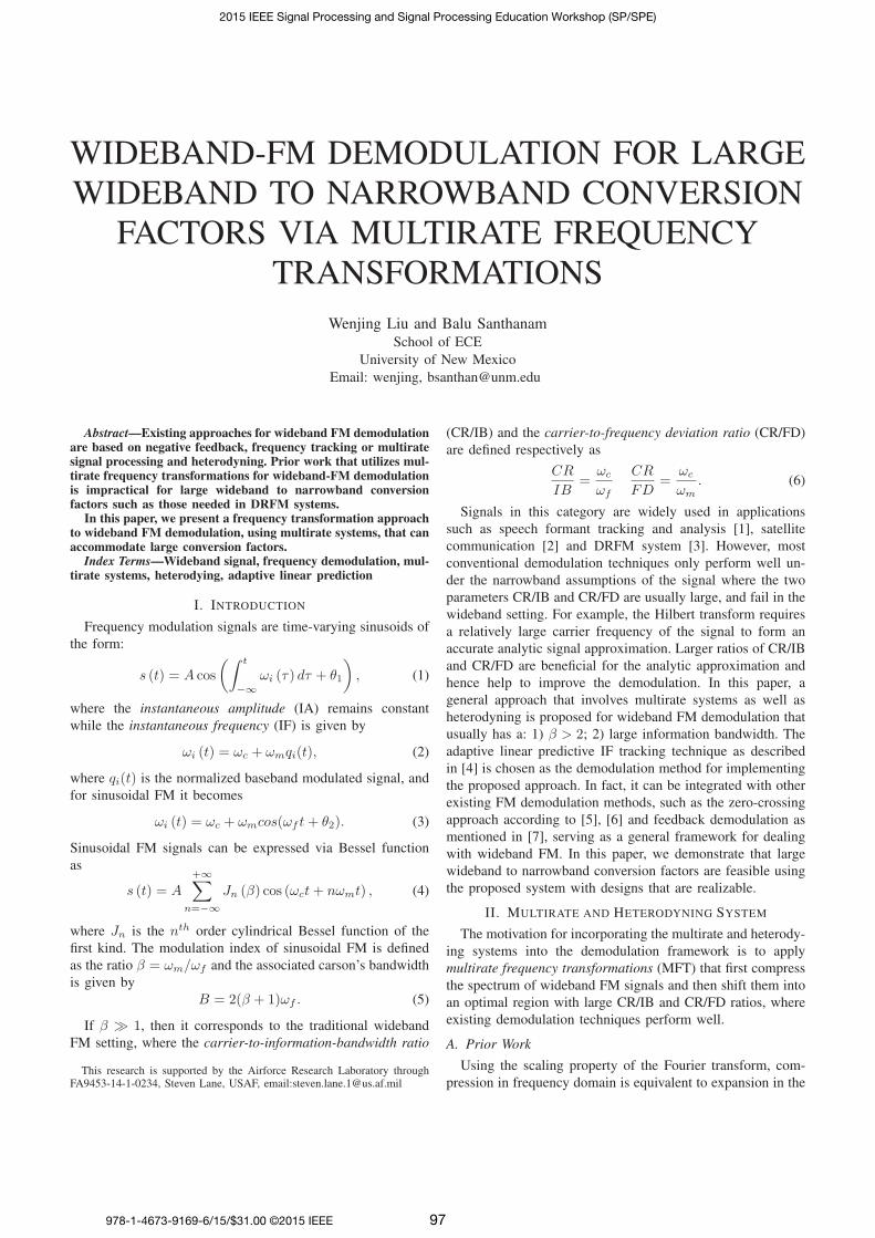
diagram of such a MFT framework in prior work [9] is
illustrated by Fig. 1.
Interpolating the input signal will result in the reduction
of both the frequency deviation and information bandwidth
by a factor of R. Similar to increasing the sampling rate,
the IF of the interpolated signal becomes slow-varying and
the assumption that the message signal remains constant over
the carrier period is more likely to hold, which will boost
the performances of conventional demodulation algorithms.
Meanwhile, heterodying serves the purpose of increasing the
ratios of CR/FD and CR/IB by compensating for the scaled
carrier frequency. By passing through the heterodying process,
the CR/FD and the CR/IB of yush(t) are given by[CR
FD
]out
=
[CR
FD
]in
+Rωd
ωm(12)
[CR
IB
]out
=
[CR
IB
]in
+Rωd
ωf. (13)
Fig. 1. Block diagram of the prior MFT framework in [9]. The widebandsignal is first sampled above the Nyquist rate, interpolated by a factor Rand then heterodyned via multiplying cos(ωdn), followed by a discrete FIRbandpass filter with a scaling module based on (10) to achieve MFT. Thenit goes through a demodulation block to obtain the IF estimation of thecompressed heterodyned signal. To estimate IF of the original signal, thecompressed heterodyned IF is then shifted back by subtracting ωd, decimatedby R and scaled back approapriately according to (8), followed by the DACmodule.
B. Constraints of Prior MFT System
As we look further into this framework, an important ques-
tion regarding the selection of the conversion factor R arises.
Specifically prior work [9] only deals with small multirate
compression factors. However, larger factors over hundred or
thousand can be supported by current high-speed DSP with
large memory, as in the case of DRFM system design. It is
intuitive to expect a further reduction in the demodulation error
since the gain brought by frequency compression should be
extendable through the use of a larger factor. But for really
large factors R, the passband of the lowpass filter in the
multirate operation and that of the heterodyne-BPF operation
will be scaled by R. For example, if R = 1000, we require a
lowpass filter with cut-off frequency at π/1000 and a bandpass
filter with a passband edge less than or equal to of π/1000.
However, filters with such narrow passbands are unrealistic
for direct implementation by any structure1. Thus the design
of BPF within the previous MFT framework becomes the
bottleneck that constrains the use of a very large factor.
C. Proposed System
In order to reduce the burden placed on the practical
implementation of the bandpass filter, we first consider a
different MFT framework where the order of the interpolation
operator and the heterodyning operator are exchanged. Due to
the switch of interpolation and heterodying, the CR/FD and
CR/IB parameters under this MFT framework are given by[CR
FD
]out
=
[CR
FD
]in
+ωd
ωm(14)
[CR
IB
]out
=
[CR
IB
]in
+ωd
ωf. (15)
1Narrow passband implies clustered poles and zeros that result in sensitivityand stability issues of digital filters as described in [10].
2015 IEEE Signal Processing and Signal Processing Education Workshop (SP/SPE)
98
By comparing these ratios with (12) and (13), note that the
upshift frequency ωd in this case needs to be large enough
such that the ratios of CR/FD and CR/IB still stay at high
level. However, ωd cannot be too large such that the resultant
carrier frequency after heterodying exceeds one half of the
sampling rate, we otherwise will need to interpolate the signal
first by an appropriate factor in order to perform discrete-time
bandpass filtering after heterodyning. Hence the practical im-
plementation of MFT framework for a large conversion factor
is not as simple as just exchanging the order of interpolation
and heterodyning. Actually, an interpolation operation is still
required prior to the heterodying with an appropriate factor
that depends on the upshift frequency ωd and the sampling
frequency of the original wideband FM signal. This implies
that the overall interpolation factor can be split into two with
the first one prior to the frequency translation and the other
one right after. Then upshifting by a frequency ωd that is not
too large would result in a relatively small factor for the first
interpolation, lessening the burden of the heterodyne-BPF.
(a)
(b)
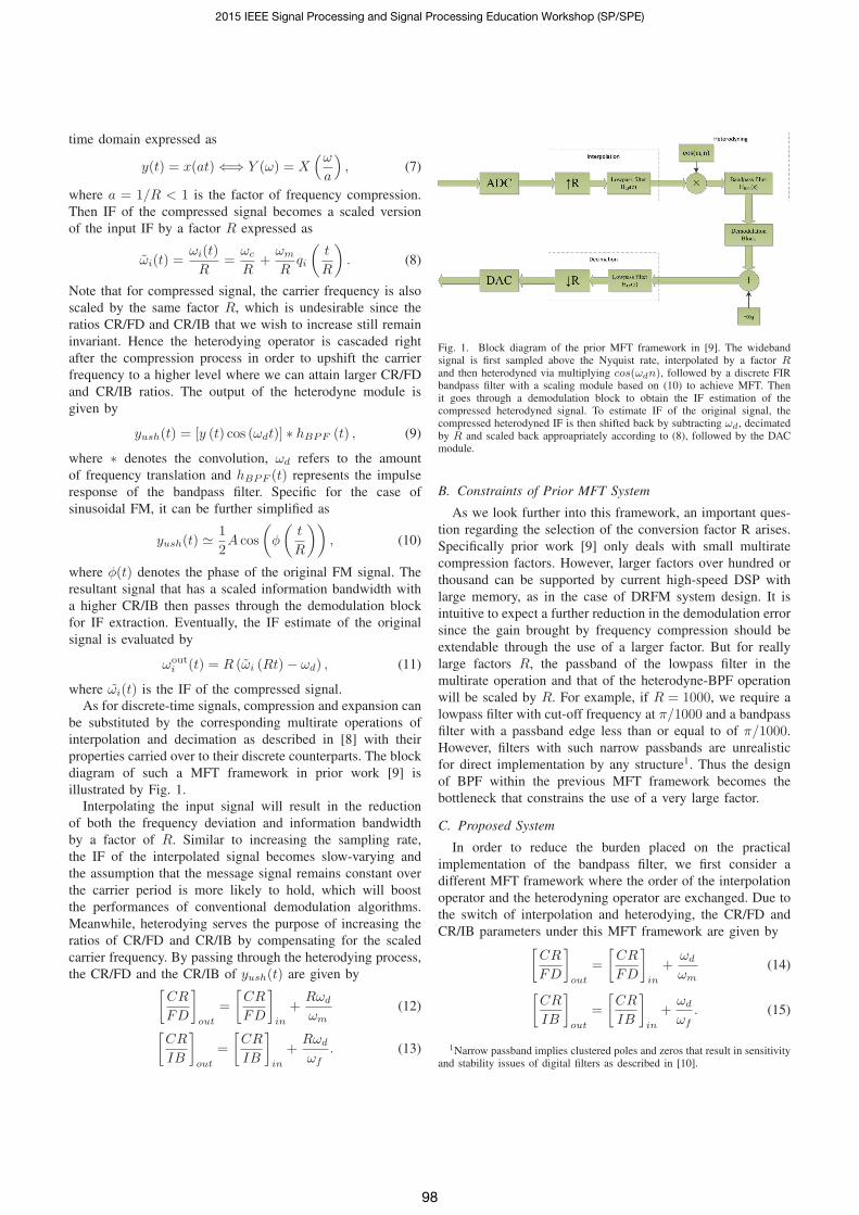
Fig. 2. (a) Block diagram of the proposed MFT framework for large widebandto narrowband conversion factors. The interpolation module of the priorframework is separated into two with one in fornt of the heterodyning moduleand the other one right after. The first interpolation module has a relativelysmall upsampling rate of R1 which is appropriately chosen such that thediscrete BPF can be implemented within the range of half the sampling rateafter heterodyning the signal with a frequency translation of ωd. The relativelysmall R1 would result in a wider passband for the discrete bandpass filter,thus reducing the its design of complexity. (b) Multistage implementation forinterpolation modules in 2(a) based on Noble identity. Note that multistageimplementation for the corresponding decimation modules can be realized ina similar fashion.
In this paper, we propose a MFT framework for large con-
version factors illustrated in Fig. 2(a) that achieves a practical
design of the heterodyne-BPF. As previously discussed, the
interpolation module of prior framework is separated into two
with one in fornt of the heterodyning module and the other one
right after in the proposed framework. The first interpolation
module has a relatively small upsampling rate of R1 which
is appropriately chosen such that the discrete BPF can be
implemented within the range of half the sampling rate after
heterodyning the signal with a frequency translation of ωd.
The relatively small R1 would result in a wider passband
for the discrete bandpass filter, thus reducing the its design
of complexity. In general, there is a sacrifice in terms of
achievable CR/IB and CR/FD ratios for the proposed MFT
framework, however, the system suggested in prior work does
not realize large conversion factors, due to the placement of
impractical constraints on the BPF design.
To further relax the constraint imposed on filter design, we
first note that the lowpass filters in the multirate structure can
be implemented efficiently using the multirate noble identitiesmentioned in [8]. As shown by Fig. 2(b), the original one stage
multirate structure is equivalent to multistage implementation
with R factorized into smaller integer factor corresponding to
each stage. As a result, the lowpass filter corresponding to
each stage will have much larger cut-off frequency and thus a
wider passband. Therefore we can conclude that the use of a
large conversion factor is primarily constrained by unrealistic
requirements on the heterodyne-BPF, which can not be easily
relaxed as in the case of the lowpass filter within the multirate
structure.
The heterodyne-BPF also plays a crucial role when we take
noise into consideration. Since the spectrum of the wideband
FM have an infinite number of spectral components, the
passband for the heterodyne-BPF is required to cover the
scaled spectrum as much as possible in order to reduce the
distortion caused by loss of spectrum when the noise is in-
considerable. In the presense of observable noise, however, the
noise introduced by covering wider ranges may significantly
corrupt the IF estimate. Due to this fact, the passband width of
the heterodyne-BPF needs to be optimized around the Carson
bandwidth to appropriately trade-off harmonic distortion and
noise related distortion [11].
In addition, a binomial smoothing module is incorporated
into the proposed framework as shown in Fig. 2(a), to further
reduce the effects of noise. Even though the FM signal is
wideband, the IF waveform itself is not necessarily wideband
in nature. In many cases, the wideband FM is primarily
generated by a large modulation index while the IF still
remains in the narrowband range. Under this assumption, by
applying the binomial smoothing we can efficiently filter out
the high frequency noise in the corrupted IF estimation. When
the SNR is high, the improvement becomes extremely evident
as we shall see later. Usually we would expect a gain between
5 dB and 10 dB in the scenario of relatively high SNR.
III. ADAPTIVE LINEAR PREDICTIVE IF TRACKING
According to the Wiener-Hopf equations [12], the optimal
coeffcients of a linear predictor are given by
wopt = R−1xx rdx, (16)
where wopt denotes the optimal tap weight vector, Rxx
denotes the input correlation matrix and rdx denotes the
2015 IEEE Signal Processing and Signal Processing Education Workshop (SP/SPE)
99
cross-correlation between input vector and desired signal. As
summarized in [4], the prediction error filter is given by:
E (z) = 1−L∑
l=1
goptl z−l, (17)
where{goptl
}L
l=1are the coefficients of the corresponding
optimal predictor. Conditioned on the small prediction error
assumption and the further assumption that the message signal
remains essentially invariant over the sampling range of the
linear prediction filter, we end up with the approximation in
[13] through (17) given by
L∑l=1
gl (k) exp {−jl [wc +m (k)]} � 1, (18)
where gl(k) is the weight coefficient of tap l at time index kand m(k) is the sample of the message signal at time index
k. Then the IF of the signal of interest can be estimated by
executing the following steps: 1) Compute the coefficients of
the prediction error filter; 2) Obtain the roots of the coefficient
polynomial; 3) Calculate the phase argument of the complex
conjugate pole location of the corresponding roots.
In the previous work of Asilomar [4], adaptive algorithms
such as AS-LMS and AF-RLS have been incorporated into
the structure of linear predictor and compared with each other
based on the demodulation error. However, for both algorithms
the step-size or the forgetting factor need to be truncated
to remain within certain range . In this paper, we choose
the generalized normalized gradient descent (GNGD) [14]
for coefficients update of the linear predictor, which avoids
truncation of the adaptively adjusted step-size. The algorithm
for this GNGD linear predictive filter is summrized via
e (k) = x (k + 1)−L∑
l=1
gl (k)x (k − L+ 1) (19)
β (k) = β(k − 1)− ραe(k)e(k − 1)xT (k)x(k − 1)
(‖x(k)‖22 + β(k))2(20)
η (k) =α
‖x(k)‖22 + β(k)(21)
g(k + 1) = g(k) + η(k)e(k)x(k), (22)
where x(k) and g(k) denote the vectors of input and tap
weights at time index k respectively, α is the step-size parame-
ter and ρ is the offset learning rate parameter. The merit of the
GNGD algorithm lies in that the adaptation of its learning rate
provides compensation for the assumptions in the derivation
of NLMS. Due to its robustness and stability, the GNGD is
well-suited for narrowband nonstationary signal environments.
IV. SIMULATION RESULTS
In this section, we present demodulation results using the
proposed and prior MFT frameworks respectively under both
noise free and noisy environments. Note that the demodulation
performance is judged by the normalized RMS IF demodula-tion error (NRMSE) throughout this section.
0 1 2 3 4 5 6 7 8−70
−65
−60
−55
−50
−45
−40
−35
−30
log2(R)
()
L=512
L=512L=1024
L=4098L=2048
L=1024
(a)
0 1 2 3 4 5 6 7 8−70
−65
−60
−55
−50
−45
−40
−35
−30
log2(R)
()
L=256
L=512
L=512
L=256
(b)
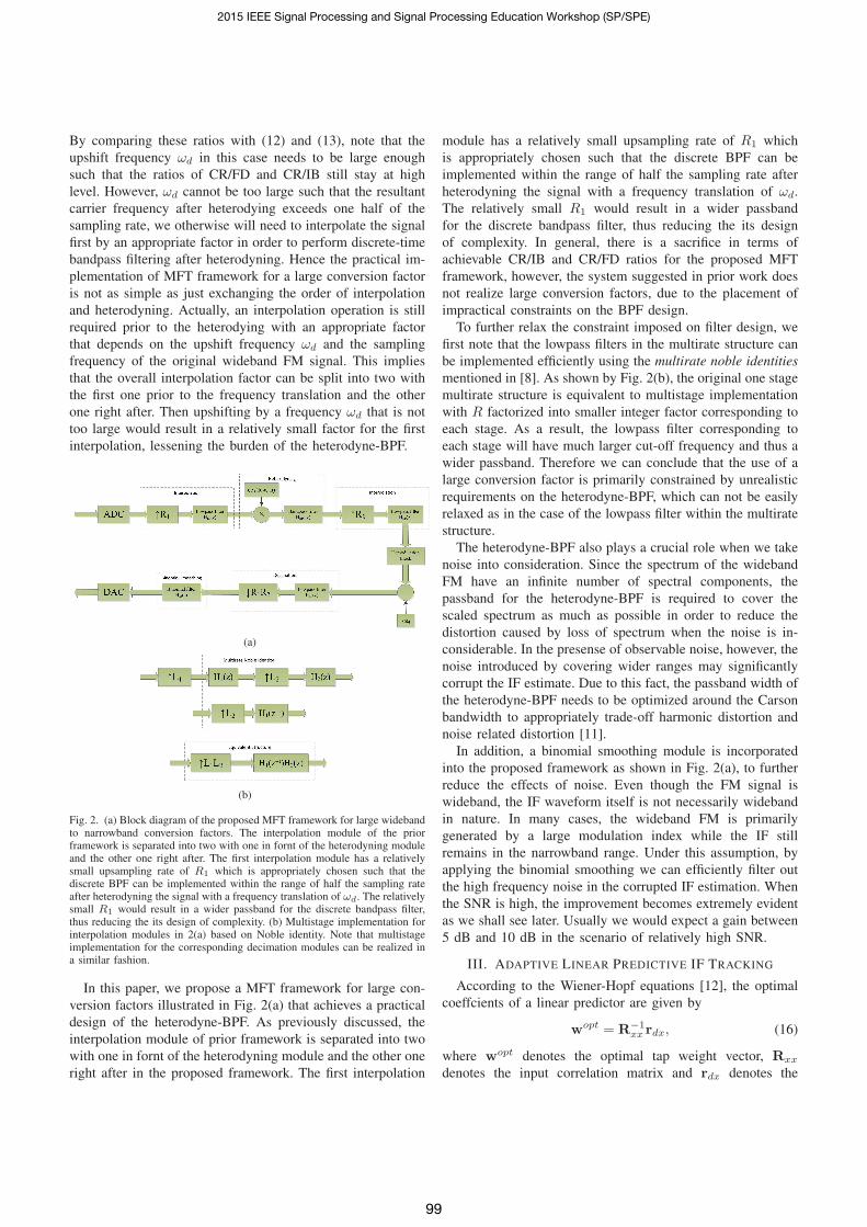
Fig. 3. Comparison between performances of both MFT frameworks undernoise free environments. (a) Performance of the prior MFT framework withR specifying the multirate factor and L specifying the order of BPF. (b)Performance of the proposed MFT framework with R specifying the multiratefactor and L specifying the order of BPF.
We first look at the example of a wideband sinusoidal FM
signal that has a modulation index of 10 and the CR/IB of
20. Under a noise free environment, the performance of the
prior MFT framework is illustrated by Fig. 3(a). Note that
the performance associated with R = 1, i.e, the origin of
the performance curve corresponds to direct demodulation
by GNGD without MFT, while ωd is the normalized upshift
radian frequency translation in the range of [0, π]. By applying
a large conversion factor of R = 128, a reduction of around 40
dB in the demodulation error over direct GNGD demodulation
is attained. The result of Fig. 3(a) confirms the claim that
a large conversion factor strengthens the effect achieved by
frequency compression thus leading to significant reduction
in the demodulation error. Moreover, it reflects the fact that
the use of a larger factor requires a very high order FIR
bandpass filter with a satisfactory frequency response. For
example, R = 128, demands the order of FIR bandpass filter
to be as high as 4096, which results in unrealistic parameters
for the narrow passband. This constraint seriously limits the
implementation in a practical system for large factors.
0 0.1 0.2 0.3 0.4 0.5 0.6 0.7 0.8 0.9
−120
−100
−80
−60
−40
−20
0
Normalized Frequency
Mag
nitu
de (d
B)
Frequency Response of FIR Bandpass Filter
(a)
0 0.1 0.2 0.3 0.4 0.5 0.6 0.7 0.8 0.9
−100
−80
−60
−40
−20
0
Normalized Frequency
Mag
nitu
de (d
B)
Frequency Response of FIR Bandpass Filter
(b)
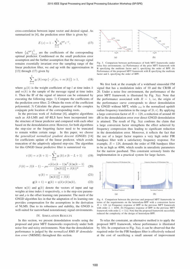
Fig. 4. Comparison between the previous and proposed MFT frameworks interms of the requirements on the heterodyne-BPF with a conversion factorR = 128. (a) Frequency response of BPF in the previous MFT frameworkwith order L = 4096. (b) Frequency response of BPF in the previous MFTframework with order L = 512. Note that the proposed framework succesfullyreduced the complexity of the design of heterodyne-BPF.
To relax the constraint, an alternative method is to apply the
proposed MFT framework, whose performance is illustrated
by 3(b). In comparison to Fig. 3(a), it can be observed that the
required order for the FIR bandpass filter is effectively reduced
at the cost of sacrificing a small amount of improvement
2015 IEEE Signal Processing and Signal Processing Education Workshop (SP/SPE)
100
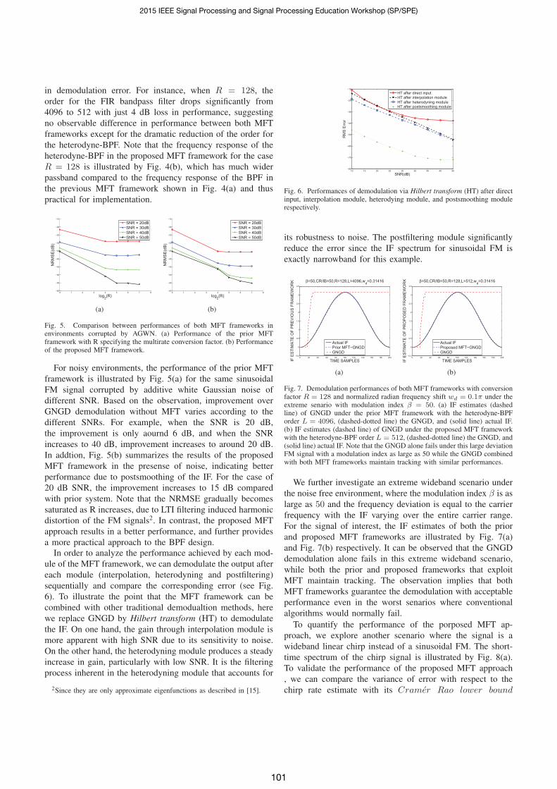
in demodulation error. For instance, when R = 128, the
order for the FIR bandpass filter drops significantly from
4096 to 512 with just 4 dB loss in performance, suggesting
no observable difference in performance between both MFT
frameworks except for the dramatic reduction of the order for
the heterodyne-BPF. Note that the frequency response of the
heterodyne-BPF in the proposed MFT framework for the case
R = 128 is illustrated by Fig. 4(b), which has much wider
passband compared to the frequency response of the BPF in
the previous MFT framework shown in Fig. 4(a) and thus
practical for implementation.
0 1 2 3 4 5 6 7 8−60
−55
−50
−45
−40
−35
−30
−25
−20
−15
log2(R)
NR
MSE
(dB)
SNR = 20dBSNR = 30dBSNR = 40dBSNR = 50dB
(a)
0 1 2 3 4 5 6 7 8−60
−55
−50
−45
−40
−35
−30
−25
−20
−15
log2(R)
NR
MSE
(dB)
SNR = 20dBSNR = 30dBSNR = 40dBSNR = 50dB
(b)
Fig. 5. Comparison between performances of both MFT frameworks inenvironments corrupted by AGWN. (a) Performance of the prior MFTframework with R specifying the multirate conversion factor. (b) Performanceof the proposed MFT framework.
For noisy environments, the performance of the prior MFT
framework is illustrated by Fig. 5(a) for the same sinusoidal
FM signal corrupted by additive white Gaussian noise of
different SNR. Based on the observation, improvement over
GNGD demodulation without MFT varies according to the
different SNRs. For example, when the SNR is 20 dB,
the improvement is only aournd 6 dB, and when the SNR
increases to 40 dB, improvement increases to around 20 dB.
In addtion, Fig. 5(b) summarizes the results of the proposed
MFT framework in the presense of noise, indicating better
performance due to postsmoothing of the IF. For the case of
20 dB SNR, the improvement increases to 15 dB compared
with prior system. Note that the NRMSE gradually becomes
saturated as R increases, due to LTI filtering induced harmonic
distortion of the FM signals2. In contrast, the proposed MFT
approach results in a better performance, and further provides
a more practical approach to the BPF design.In order to analyze the performance achieved by each mod-
ule of the MFT framework, we can demodulate the output after
each module (interpolation, heterodyning and postfiltering)
sequentially and compare the corresponding error (see Fig.
6). To illustrate the point that the MFT framework can be
combined with other traditional demodualtion methods, here
we replace GNGD by Hilbert transform (HT) to demodulate
the IF. On one hand, the gain through interpolation module is
more apparent with high SNR due to its sensitivity to noise.
On the other hand, the heterodyning module produces a steady
increase in gain, particularly with low SNR. It is the filtering
process inherent in the heterodyning module that accounts for
2Since they are only approximate eigenfunctions as described in [15].
10 15 20 25 30 35 40 45 50−80
−70
−60
−50
−40
−30
−20
−10
SNR(dB)
RM
S Er
ror
HT after direct inputHT after interpolation moduleHT after heterodyning moduleHT after postsmoothing module
Fig. 6. Performances of demodulation via Hilbert transform (HT) after directinput, interpolation module, heterodying module, and postsmoothing modulerespectively.
its robustness to noise. The postfiltering module significantly
reduce the error since the IF spectrum for sinusoidal FM is
exactly narrowband for this example.
0 20 40 60 80 100 120 140 160 180 200−0.5
0
0.5
1
1.5
2
2.5
3
3.5
TIME SAMPLESIF E
STIM
ATE
OF
PREV
IOU
S FR
AMEW
OR
K β=50,CR/IB=50,R=128,L=4096,wd=0.31416
Actual IFPrior MFT−GNGDGNGD
(a)
0 20 40 60 80 100 120 140 160 180 200−0.5
0
0.5
1
1.5
2
2.5
3
3.5
TIME SAMPLESIF E
STIM
ATE
OF
PRO
POSE
D F
RAM
EWO
RK β=50,CR/IB=50,R=128,L=512,wd=0.31416
Actual IFProposed MFT−GNGDGNGD
(b)
Fig. 7. Demodulation performances of both MFT frameworks with conversionfactor R = 128 and normalized radian frequency shift wd = 0.1π under theextreme senario with modulation index β = 50. (a) IF estimates (dashedline) of GNGD under the prior MFT framework with the heterodyne-BPForder L = 4096, (dashed-dotted line) the GNGD, and (solid line) actual IF.(b) IF estimates (dashed line) of GNGD under the proposed MFT frameworkwith the heterodyne-BPF order L = 512, (dashed-dotted line) the GNGD, and(solid line) actual IF. Note that the GNGD alone fails under this large deviationFM signal with a modulation index as large as 50 while the GNGD combinedwith both MFT frameworks maintain tracking with similar performances.
We further investigate an extreme wideband scenario under
the noise free environment, where the modulation index β is as
large as 50 and the frequency deviation is equal to the carrier
frequency with the IF varying over the entire carrier range.
For the signal of interest, the IF estimates of both the prior
and proposed MFT frameworks are illustrated by Fig. 7(a)
and Fig. 7(b) respectively. It can be observed that the GNGD
demodulation alone fails in this extreme wideband scenario,
while both the prior and proposed frameworks that exploit
MFT maintain tracking. The observation implies that both
MFT frameworks guarantee the demodulation with acceptable
performance even in the worst senarios where conventional
algorithms would normally fail.
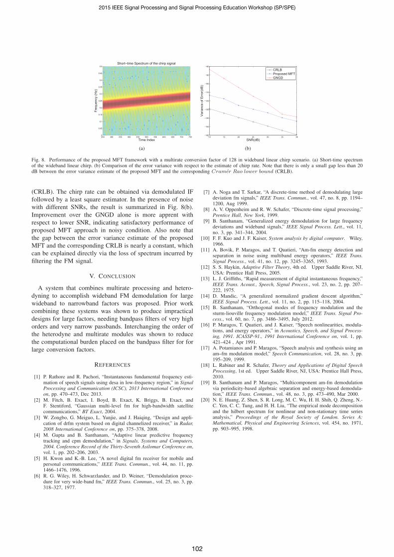
To quantify the performance of the porposed MFT ap-
proach, we explore another scenario where the signal is a
wideband linear chirp instead of a sinusoidal FM. The short-
time spectrum of the chirp signal is illustrated by Fig. 8(a).
To validate the performance of the proposed MFT approach
, we can compare the variance of error with respect to the
chirp rate estimate with its Cramer Rao lower bound
2015 IEEE Signal Processing and Signal Processing Education Workshop (SP/SPE)
101
250 300 350 400 450 500 550 600 650 700 7500
0.05
0.1
0.15
0.2
0.25
0.3
0.35
0.4
0.45
0.5
Time Index
Short−time Spectrum of the chirp signal
Freq
uenc
y (H
z)
(a)
10 15 20 25 30 35 40−160
−150
−140
−130
−120
−110
−100
−90
−80
SNR(dB)
Varia
nce
of E
rror(d
B)
CRLBProposed MFTGNGD
(b)
Fig. 8. Performance of the proposed MFT framework with a multirate conversion factor of 128 in wideband linear chirp scenario. (a) Short-time spectrumof the wideband linear chirp. (b) Comparison of the error variance with respect to the estimate of chirp rate. Note that there is only a small gap less than 20dB between the error variance estimate of the proposed MFT and the corresponding Cramer Rao lower bound (CRLB).
(CRLB). The chirp rate can be obtained via demodulated IF
followed by a least square estimator. In the presence of noise
with different SNRs, the result is summarized in Fig. 8(b).
Improvement over the GNGD alone is more apprent with
respect to lower SNR, indicating satisfactory performance of
proposed MFT approach in noisy condition. Also note that
the gap between the error variance estimate of the proposed
MFT and the corresponding CRLB is nearly a constant, which
can be explained directly via the loss of spectrum incurred by
filtering the FM signal.
V. CONCLUSION
A system that combines multirate processing and hetero-
dyning to accomplish wideband FM demodulation for large
wideband to narrowband factors was proposed. Prior work
combining these systems was shown to produce impractical
designs for large factors, needing bandpass filters of very high
orders and very narrow passbands. Interchanging the order of
the heterodyne and multirate modules was shown to reduce
the computational burden placed on the bandpass filter for for
large conversion factors.
REFERENCES
[1] P. Rathore and R. Pachori, “Instantaneous fundamental frequency esti-mation of speech signals using desa in low-frequency region,” in SignalProcessing and Communication (ICSC), 2013 International Conferenceon, pp. 470–473, Dec 2013.
[2] M. Fitch, B. Exact, I. Boyd, B. Exact, K. Briggs, B. Exact, andF. Stentiford, “Gaussian multi-level fm for high-bandwidth satellitecommunications,” BT Exact, 2004.
[3] W. Zongbo, G. Meiguo, L. Yunjie, and J. Haiqing, “Design and appli-cation of drfm system based on digital channelized receiver,” in Radar,2008 International Conference on, pp. 375–378, 2008.
[4] M. Gupta and B. Santhanam, “Adaptive linear predictive frequencytracking and cpm demodulation,” in Signals, Systems and Computers,2004. Conference Record of the Thirty-Seventh Asilomar Conference on,vol. 1, pp. 202–206, 2003.
[5] H. Kwon and K.-B. Lee, “A novel digital fm receiver for mobile andpersonal communications,” IEEE Trans. Commun., vol. 44, no. 11, pp.1466–1476, 1996.
[6] R. G. Wiley, H. Schwarzlander, and D. Weiner, “Demodulation proce-dure for very wide-band fm,” IEEE Trans. Commun., vol. 25, no. 3, pp.318–327, 1977.
[7] A. Noga and T. Sarkar, “A discrete-time method of demodulating largedeviation fm signals,” IEEE Trans. Commun., vol. 47, no. 8, pp. 1194–1200, Aug 1999.
[8] A. V. Oppenheim and R. W. Schafer, “Discrete-time signal processing,”Prentice Hall, New York, 1999.
[9] B. Santhanam, “Generalized energy demodulation for large frequencydeviations and wideband signals,” IEEE Signal Process. Lett., vol. 11,no. 3, pp. 341–344, 2004.
[10] F. F. Kuo and J. F. Kaiser, System analysis by digital computer. Wiley,1966.
[11] A. Bovik, P. Maragos, and T. Quatieri, “Am-fm energy detection andseparation in noise using multiband energy operators,” IEEE Trans.Signal Process., vol. 41, no. 12, pp. 3245–3265, 1993.
[12] S. S. Haykin, Adaptive Filter Theory, 4th ed. Upper Saddle River, NJ,USA: Prentice Hall Press, 2005.
[13] L. J. Griffiths, “Rapid measurement of digital instantaneous frequency,”IEEE Trans. Acoust., Speech, Signal Process., vol. 23, no. 2, pp. 207–222, 1975.
[14] D. Mandic, “A generalized normalized gradient descent algorithm,”IEEE Signal Process. Lett., vol. 11, no. 2, pp. 115–118, 2004.
[15] B. Santhanam, “Orthogonal modes of frequency modulation and thesturm-liouville frequency modulation model,” IEEE Trans. Signal Pro-cess., vol. 60, no. 7, pp. 3486–3495, July 2012.
[16] P. Maragos, T. Quatieri, and J. Kaiser, “Speech nonlinearities, modula-tions, and energy operators,” in Acoustics, Speech, and Signal Process-ing, 1991. ICASSP-91., 1991 International Conference on, vol. 1, pp.421–424 , Apr 1991.
[17] A. Potamianos and P. Maragos, “Speech analysis and synthesis using anam–fm modulation model,” Speech Communication, vol. 28, no. 3, pp.195–209, 1999.
[18] L. Rabiner and R. Schafer, Theory and Applications of Digital SpeechProcessing, 1st ed. Upper Saddle River, NJ, USA: Prentice Hall Press,2010.
[19] B. Santhanam and P. Maragos, “Multicomponent am-fm demodulationvia periodicity-based algebraic separation and energy-based demodula-tion,” IEEE Trans. Commun., vol. 48, no. 3, pp. 473–490, Mar 2000.
[20] N. E. Huang, Z. Shen, S. R. Long, M. C. Wu, H. H. Shih, Q. Zheng, N.-C. Yen, C. C. Tung, and H. H. Liu, “The empirical mode decompositionand the hilbert spectrum for nonlinear and non-stationary time seriesanalysis,” Proceedings of the Royal Society of London. Series A:Mathematical, Physical and Engineering Sciences, vol. 454, no. 1971,pp. 903–995, 1998.
2015 IEEE Signal Processing and Signal Processing Education Workshop (SP/SPE)
102
Related Documents