r THE & GENERAL RADIO Experimenter VOLUME 43 NUMBERS 11 ,12 NOVEMBER / DECEMBER 1969 IET LABS, Inc in the GenRad tradition 534 Main Street, Westbury, NY 11590 www.ietlabs.com TEL: (516) 334-5959 • (800) 899-8438 • FAX: (516) 334-5988

Welcome message from author
This document is posted to help you gain knowledge. Please leave a comment to let me know what you think about it! Share it to your friends and learn new things together.
Transcript
r
THE & GENERAL RADIO ~
Experimenter VOLUME 43
NUMBERS 11,12 NOVEMBER / DECEMBER 1969
IET LABS, Inc in the GenRad tradition
534 Main Street, Westbury, NY 11590 www.ietlabs.com
TEL: (516) 334-5959 • (800) 899-8438 • FAX: (516) 334-5988
GENERAL ~~~ ~ Experimenter
VOLUME 43 N UMBE RS 11 ,12 NOV EMBER / DECEMBER 1969
Why Computers in Measurement Systemsi' .3
Search for a better Transformer . . 5
Five-Terminal , l -MHz Automatic Capacitance Bridge . . 6
Versatile Resistance Bridge . 8
Wideband 20·dB / Range Ac Millivoltmeter 10
The Gene,,,, Rddio Expuinw:"'tr is mailed without charge to engineers. scientists, technicians. educators, and o the,., inulrosted in the instruments and techniques of electrical and electronics meas· urements. Address all corresoondence \0 Editor. CeOler<li Raf/io Experimul lu, General Radio Co., West Concord, Mass. 01781.
© 1969 - Gen.rll Radio Company, West Concord, MH' .. USA
~. ,,~ .
•
In the lead anicle 01 this Experimenter we have laken issue with II view held by many people - that computers are intelligent The aMide is presented with the hope thai the aura lhal surrounds c:ompu leB, in genetal , will be reduced and Ihal compulen will be accorded Ihe respecl due them, but only to the extent that it is deserved.
II . however, computers life more wily than we a re prepared to admit, we hasten to draw attention to our cover. By a\signing to II
computei'" the slight human Ifltilty 01 repeating itself,and also attributing to it asmall sense of human l:indntl!S$, we have made it serveour purpose. For. unlil:e ourelfin opera. t or, who forgot what S8iI$On of the year it is. our computer has "remembered" and sti rred
itself to spool: !O( 1111 of us al General Radio. To a ll our readers, wherever you li re, we
slocerely hope you will join with us in this special season. to count our blessings and to give thanl:s'O( all that is good. We wish you, one and all. "SEASONS GA EET INGS ...
C. E. White EditOl'"
IET LABS, Inc in the GenRad tradition
534 Main Street, Westbury, NY 11590 www.ietlabs.com
TEL: (516) 334-5959 • (800) 899-8438 • FAX: (516) 334-5988
Why Computers In Measurement Systems? "Computers are smart? " · is II question raised quite often
even by people who have knowledge of, access 10, or control of computers. Of course computers aren't smart -they are clever tools that reflect the intellect of the special group of people who have wedded themselves to these machines. For the past two decades, many in this special group have devoted themselves to the specific task of forging an alliance of computers, humans, and measurement instruments.
Just why shou ld all this effort be expended in this direction? Well , first lei 's review some of the advantages and disadvantages of the simple combina tion of measuring instrument and opera tor. The operator's mind is able to grasp the significance of data derived from the instrument, to recognize patterns in the observed test data, and to react in the appropriate and positive manner. All this can be done, but not for any prolonged int erval o f time, and not very fast. Fatigue sets in, the operator's mind is less responsive to signals, and the opera tor's usefullness deteriorates rapidly , On the other hand, a computer is not susceptible to fatique (exclUSive of electronic or mechanical deterioration). Properly programmed, the computer can perform all the above functions - fasler~
But even with its ability to stoTeoll the knowledge derived by the operator from training and ex perience, the computer is merely an electromecha nical $lo~e, incapable of thinking, analyzing, and reacting to a problem for which we have not supplied instructions. Why then is it so important to utilize the services of the comput er? Let 's look at a few specific
, I;
o o o
, - " , - " , \\ ; \\ I; \\ I
o o o
, - . , " , - " \ ; \ I \\ /1
o o o
NOVEMBER/DECEMBER t969
,
,
,
advantages of the combination of compu ter, operator, and measuring instrument : • Instrument operation can be faster,
• More data can be derived in a given time interval.
• Comparisons of derived data with built-in reference standards, tolerances, or specifications are quicker by orders of magnitu de. • Provided bilateral interfacing has been built into the system, the operator maintains strict control of test operations.
• Systematic errors due to operator bias are eliminated.
• Test data can be displayed automatically in any ofseveral forms - paper or magnetic tape, punched cilIds, line printers or teletypewriters , automatic graphic recorders or X-Y plotters , etc.
The advantages inherent in co mpatIble mterfacing between the units o f the combination are more apparent as we trace t he grow th in complexi ty of measurements and realize the need to perform and interpret measurements more quickly.
Measurement Systems are COMPLEXl
Development of manual-measurement techniques has progressed from single-point measurements of simple parametcrs to swept measurcments with automatic ' readout and ' A~cord lnK to Hughes Air<:raft pUblication Vector (Fin! Qua.-ter 1969), " The cred ent ials of any mltChlne thai believes 1 ... 1 "" 10 are suspec l . "
\ I o
\ I o
/ 1 • o
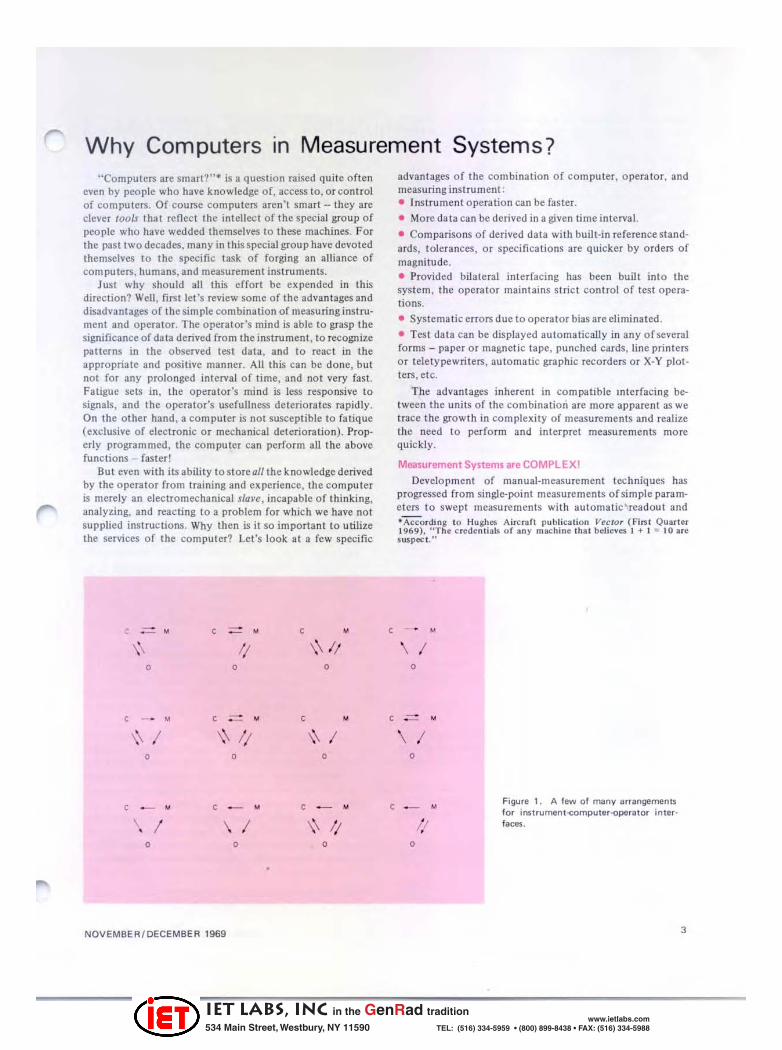
Figure 1. A few of manv arrangements for instrument<OmPUler--operalOr in ter · f8Ce$ .
3
IET LABS, Inc in the GenRad tradition
534 Main Street, Westbury, NY 11590 www.ietlabs.com
TEL: (516) 334-5959 • (800) 899-8438 • FAX: (516) 334-5988
data displays followed by analysis of these dllta by comparison with recorded sIand3rd performance dala. The co mp!exily of the latter techn ique is sufficient to overtax the abili ty of an opera tor.
As measurement tech niques have evolved there has been a metamorphosis in the systems and techniques of recording and applying measurement data. The simple inspection data sheet I hal displayed a measurement result vis-a-vis a reference stan dard , and alerted an o perat or to make a quality evaluation to accept or reject the inspected item, has now cha nged int o the au to matic visual presentation and analysis of data. In suc h a system , umts tcSled are automatically accepted or rejected. adj usted from out-o f-t olerance conditions to within tolerance (if feasible), Of the computer may alter tho,: test sequencing for funher analysis o r action. For specific applica tIOns, the interfaces ca n bc unilaterJI o r bilateral I and in any number of 3rrangements, some of wroch arc ~hown in Figure I.
At this point it would be wise to define two terms prevalent in the work of coupling com puters, instruments, 3nd opera tors. CQmputer-ossiSled refer.>; to the general case of the combina tion of computer and instrument syste m in which the compu ter does not exereise control of the lest 3genda, reac ts passively to record d:lta for analysis. and alerts the oper,lIor to take cert:l1n actions. The term computercOlltrolled signifies both indirec t :md direcl control by the computer over the measurement system and test process. The computer asserts authonty over the measurement system by transmitting command pulses to programmed measuring equipmen t and control units. In each case, assis t o r control , the computer memory has stored within it aU the instru cti ons required to conduct the tes t program.
Programmable Instruments Don' t Just Happen Along Modern instrument deSigners must consider problems
such as these if they wish to incorporate an instrument inlO a programmed measuremen t system:
Program mi ng circuitry or units must not be susceptible to shock. vibration. temperature, noise or any o ther environmcnt:ll condi tion that cou ld give rise to errors in program signals.
Very short time comma nds. of th e order of nanoseconds. could be delayed effectively by inadvertent introduction of long-line con necti ons.
Int<'rfacing between units must be compatible physi-call y, electrically. and mechanically.
Unless these problems and others ure solved , progra mming an IIlstrumenl docs not necessarily make an instrument a bellcr one. Many measuring instruments, bllt not all , are programmable.
DeSign of a practical compu ter-controlled measurement system was outl ined by M. L. Fichtenbaum ofGeneral Radio recently during a GR measurementscminar."2 He approached the problem in th is manner:
'Be:lIIY. R. W .. "Shori Dillcussion o f Error \( educ lion in NetworkParametel Me:r.uremcnI Th,ough Com p~ltrirrd Automation." PrQg. ~.JS lit Rud"o Science _ 1966·1"6". (Commission I Report) URSI X VI Ih Genern l AMembly. O n a"'H. AUKUS I 1969.
2Hchtenbaum. M. L.. "Computers In Inu,umen l S~lem5." G~neral l<adio Aulomatlc·impedance·Measu,emen t Seminar. May 1969 (un· published).
4
Evaluate the measurement requirements in tenns of what can and can not be done. A system proposal ma y call for straight forward tasks: il may also deman d meusurements that are im practical.
Check whether there is ava ilable hardware to perform the measurement functIOns. Is it possible to modify existing instruments, or to make measurements from which the computer can calculale Ihe required information? What would be the cost o f developing any specialpurpose equipment?
Decide with the user o n final system specifications. It is likely th3t th e system designer does not know all abou t the user's needs; it is also likely that the user does not know all the system designer's limitations and capabilities.
Choose a specific hardware configuration. With the final instrumen tat io n defined, the interface necessary to tie the instruments to the comput er can be designed . Typically, an interface will consist o f enough standard modules to t ransfer all necessary data between computer and instruments, plus one or two "special " modules to perform functions specific to Ihe system.
Consider the three main areas in software devt'lopment. Each instrument in the system has associated with it program segments to con trol the instrument and to translate data between instrument and computer formats. In most cases. thL'Se "instru ment modulc" programs can be developed for usc with one instrument and used essentially unchanged in all systems tha,,- use the instrument. Each system will have a unique "main-li ne" program to perform the test functio ns requircd. These mclude thc initial setup (of limits. ranges. etc). the SC(IUenCC through test configul1lt ions. :.nd prcsen,:.tion of data in the proper form.
Diagnostic programs, both for initial checkout of the systcm and its com ponents and as a maintenance aid for malfunctions. must be wri tten. Thc ability of the computer to perform a preprogrammed self-test scquencc and to intcrprct the results is a great aid when hardware problems :lrl' 10 bc isolated.
Final checkou t of the system should allcmpt to sim ulate many possible ope rating conditio ns. II is possible th31 errors in programming or marginal hardware will show up only under spccbl conditions: the chec kout procedures sho uld be designed to cover as many varied sets of condilions liS possible.
It is import an t to cducate the user in Ihe o peration and capabilities of the system. The complC'xit y o f a system con taining a compu ter and the great variety o f featurcs availablc with Ihe com puter as a system clement requ ire thaI the user understand thc syste m ifhe is to employ it to its maximum capa.bili t ies.
In August. P. H. Goebel described to an audience al Wescon] a successful working combina ti on o f instrument, operator. and computer designed for usc in General Radio 's production progr:.ms. We plan to have more information on this developmenl in a forthcoming issue of the Experimenrer.
] GOebc l. P. It .. ' ·Compute,·Controlled On·Une Tes ting and InSPKt ion." 1969 II'''SCOIl T"ch"icuf Pap .. n. S .. s.rio" 8. Augus t 19-22. 1969.
GENERAL RADIO Experimenter
IET LABS, Inc in the GenRad tradition
534 Main Street, Westbury, NY 11590 www.ietlabs.com
TEL: (516) 334-5959 • (800) 899-8438 • FAX: (516) 334-5988

Search for a Better Transformer Far back, in the com parative an tiquity of June 1926,
General Radio was very much interested in the problems of transformer design. I During the years thai followed we never relaxed our interest, nor our desire to leU our readers about what is considered good design.
Burke noted in 1926 the difficulty of designing .ratio transformers for undistorled response over extreme ranges of frequency 100 10 5000 Hz! Among other things, he demonstrated the importance of matching transformer impedances 10 the signal sou rce and to the load. These elementary problems are still with us.
A recent problem was to design a ratio transformer for stable operation al I MHz and with low leakage impedance. Why? Well - we knew that a transformer could provide an excellent means of decade ranging for the new GR 1682 Automatic Capaci tance Bridge." Since there did not appear to be one available commercially, we continued our research into methods and means of devising such a uni t.
During several sessions with GR engineer Dick Sett e, the Experimenter editor was able to trace the progress made, from the first round-table discussions, through the preliminary design stages, to the final production models of the finished products. Note the use of the plural term - the final resuit was not one but two devices. each unique for its own function in the capacitance bridge.
The problems, as presented by Sette, were to supply a maximum stabili ty to a wide rangc of measuremcnts at I MHz and to achieve good accuracy at the UN KNOWN position 4 feet away. Thoughts of using compu ting amplifiers were considered and then dropped because of cost and state-of-t he-art development.
II was considered necessary to use different transformers for each range, 10 overcome switching difficulties. With transformers of 10: I ratio, it was a simple task to reverse windings, effecting a 10: I ratio of the standard for the lowest range and a I: 10 ratio for the highest range. The greatest over-all range could be established at 100: I , by the cascading of transformers, without sacrificing "accuracy" capability of 1%. Past experiences of GR engineers Smiley, Hersh, Holtje, lIa11, and Fulks were drawn upon, and constructive ideas for a very low leakage-impedance design were obtained. The design problem posed was: how to achieve maximum electrical coupling of one winding with the other.
The first approach considered was a toroidal core, bifilaI wound (Figure I). with a twisted II-wire cable wound uniformly around the toroid. The result was a 10: I ratio transformer, tightly-coupJed but not satisfactory for use at veT}' high frequencies.
In the second design, use of cup cores in a toroid ( Figure 2a) resulted in better coupling. Rewinding, as in Figure 2b, improved the coupling.
The third approach (Figure 3), in which we used a multi-conductor shielded cable that provided very low
'See pBl!~ 6.
lllurke, C. T .. "Amplili ~ r Ius and Ou ts." ae.u!rol Radio ExperImenter, June t9"26.
NDVEMBERfOECEMBER 1969
r> M'''''''' IS .. .. •• I) .. .. ,,.
Fig,.ore 1. Simple design for 10 :1 ratio traosforl1lel'".
tE:J3--IT[3j :.'~"~ ..
t ' l ., j
H~:~:'11H; ~·;ii:-n, " .. " .. \( .. .. .. ..
.. '0 ............ " ..
Figure 2. Use of cup cores for an improved design.
. .... •
Figure 3. Multi-conduclOf shielded-cable winding.
•. "",. <
r--'·~~ . . ~ .....
Figure <I. F lat-conductor transformer·winding design.
5
IET LABS, Inc in the GenRad tradition
534 Main Street, Westbury, NY 11590 www.ietlabs.com
TEL: (516) 334-5959 • (800) 899-8438 • FAX: (516) 334-5988
-,
semble, and the coil had high capacitance loading. The latter problem was a serious detriment inasmuch as it increased the driving requirements excessively.
Figu,. 5. Compone!'lt$ and _mbly of production-model design of 10 1 ,.I;otr_former.
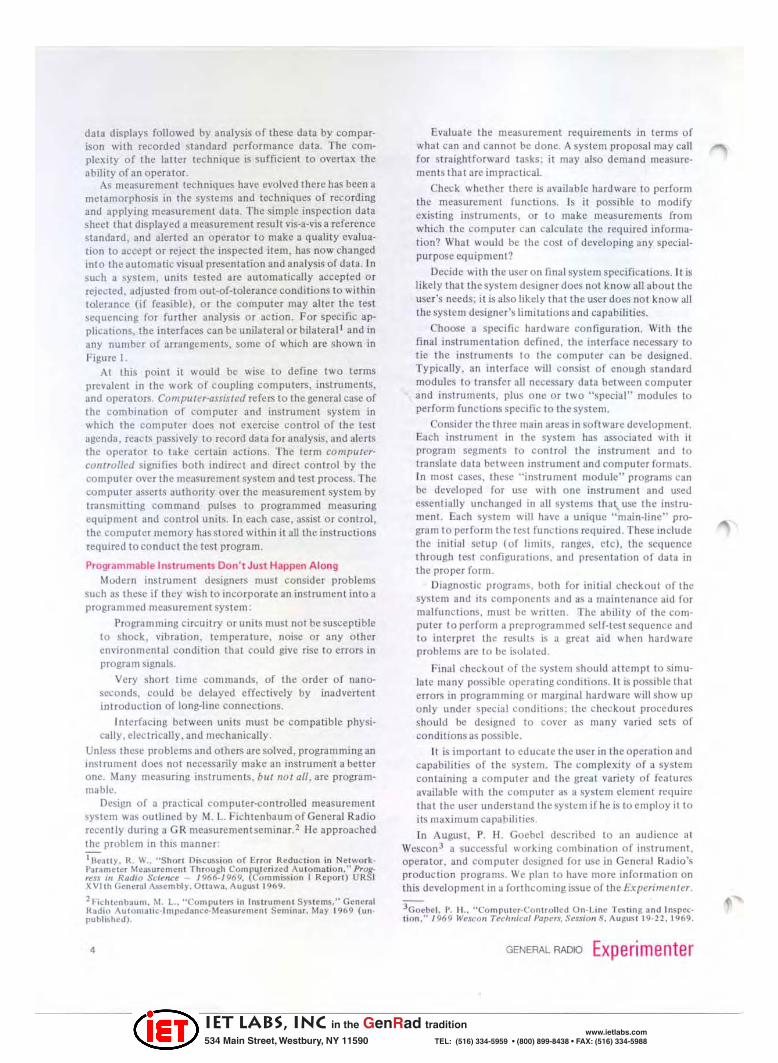
Finally , the decision was made to go to a machined-core design. A splil. hollow, brass bobbin was made lind used as a single turn. The bobbin was silver-pla ted to minimize skin effects at 1 MHz. To improvise leads for the single turn , the casting that held the bobbins was made with self-circuit leads (horns) that penetrated the mounting board for ease of connection. Ten turns were wound on the bobbin, which was sweated into place in the casting. Figure 5 illustrates the assembly. In order to SWitch the leads, to provide the desired ratio direction. reed relays were con nected to the circuitry.
Figur.6. Mid-range Inmsformer pl"oduclion model.
We st ill had the requIrement for the mid-range I : I coupling transformer. A simple, balanced. I: I ratio Imnsformer was constructed (Figure 6), consisting o f a Triax cable wound around a core. The o uter and inner shields were used as conductors, the inner conductor was ignored. This technique provided a transformer, simple to manufac' ture , with one conductor completely surrounded by the second, assuring maximum coupling.
leakage, encouraged further development. The fourth approach was patterned after a dCSlgn technique engineered by Calvert." We used a nat conductor, separated from the adjacent conductor by a dielectric sheet (Figure 4). Unfortunately, this transformer proved difficult to as-
These development chores completed In a satisfactory fashion, manufactunng was able to move out on the final construct ion of the new GR 1682 Automatic Capacitance Bridge.
1 US ". Ien l No. 1.659.845 tiSi,ned 1o Wlyne·Kerr Laboralories. Lid.
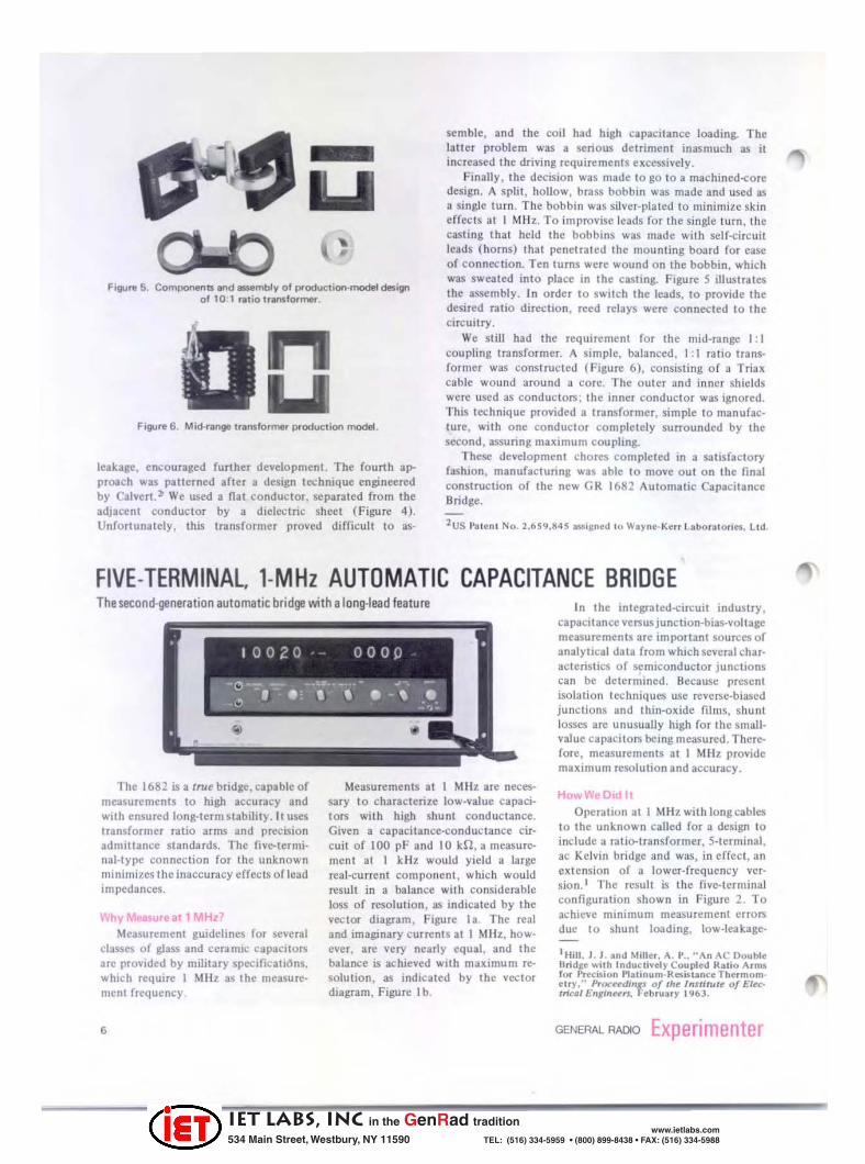
FIVE-TERMINAL. '-MHz AUTOMATIC CAPACITANCE BRIDGE The second·generation automatic bridge with a long·lead feature
The 1682 is a true bndge, capable of measurements to high accuracy and with ensured long-term stability. II uses transformer ratio arms and precision admittance standardS. The fivc-termi· nal-type connection for the unknown minimizes thcinaccuf3cy effects of lead Impedances.
Ihy~. .teat 1 MHz: Measurement guidelines for several
classes of glass and ceramic CapacItors arc provided by military specifieall6ns. whIch require 1 MHz as the measurement frequency.
•
Measurements at I Mllz are necessary to cha racterize low-value capacitors with high shUnt conductance. Given a capacilance-conductance circuit of 100 pF and 10 HZ, a measurement at I kHz would yield a large real-current component , which would result in a balance with considerable loss of resolution , :lS indicated by the vector diagram. Figure la. The real and imagmary currents at 1 Mllz. however, are very nearly equal, and the balance 15 achieved With maximum resolu tion , as indicated by the vector dlagmm, Figure lb.
In the integrated-circuit industry, ca pacit anee versus Junction-bias-voltage measurements are important sources of analyllcal data from which several characteristiCS of semiconductor Junctions can be determined. Because present isolation techniques use reverse-biased junclions lind thin-oxide films, shunt losses are unusually high for the small· value capacitors being measured. Therefore, measurements at 1 MHz provide maximum resolution and accuracy.
How On It
Operation at I MHz with long cables to the unknown called for 3 design 10 include a tntio-tmnsformer, S-termi nal , ac Kelvin bridge and was, in effect, an extension of a lower-frequency vcr· sion.1 The result is the five-terminal configuration shown in Figure 2. To achieve minimum measurement errors due to shunt loading, low-Ieakage-
I Hill , J . J . and Miller. A. 1' .. "An AC Double lIrid,e " 'ith Inductively Coopted 1(11;0 Arms for I'recO!.ion l'Ial;nl.lm·l(ais I3I1ceThermom e lry." Proceedl",t o/the Institute 0/ Electrl~' E",lnurt. February 1963.
GENERAL RADIO Experimenter
IET LABS, Inc in the GenRad tradition
534 Main Street, Westbury, NY 11590 www.ietlabs.com
TEL: (516) 334-5959 • (800) 899-8438 • FAX: (516) 334-5988
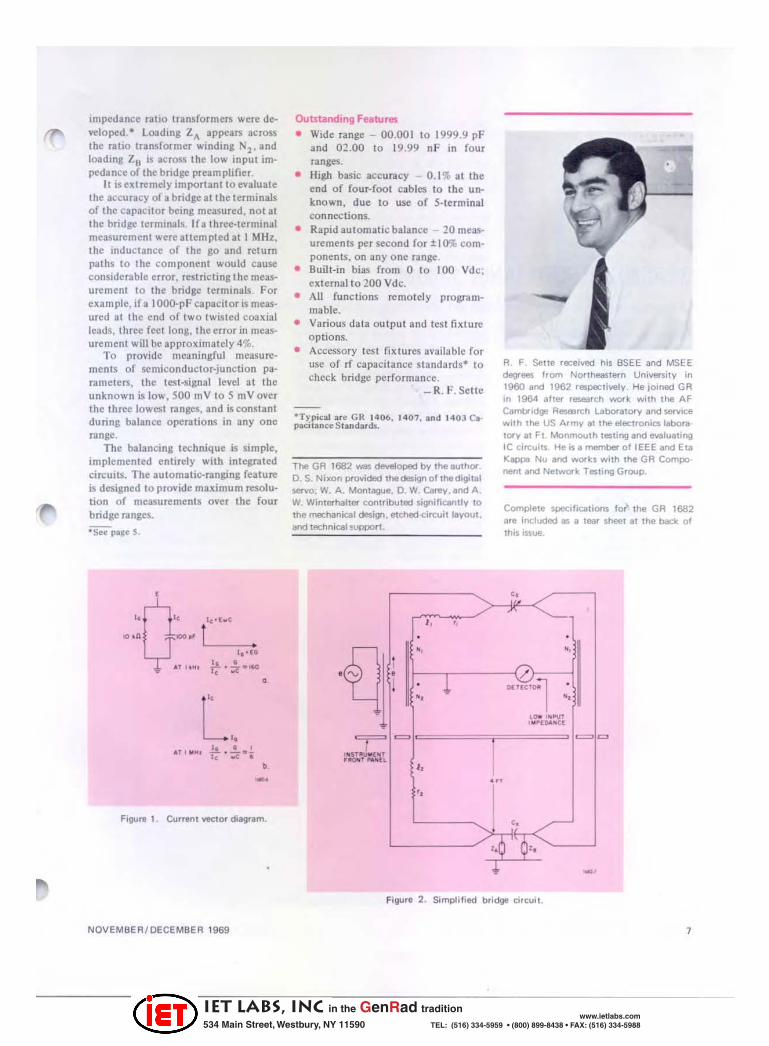
impedance ratio transformers were devel oped.· loading ZA appears across the ra tio transformer winding N2, and loa dl llJ, Zn is across the lo w input impedance of the bridge ptea m plifier,
It IS ext re mely important to evaluate the accuracy of a bridge at the terminals of the ca pacilOT being measured . not at the bridge terminals. lfa three-terminal measurement were attempted at I MHz, the ind uctance of the go and return paths to the com ponent would cause considerable error, restricting the measurement to the bridge terminals. For exa mple, if a I OOo.pF capacit or is measured at the end o f two twisted coaxial leads, three fect long, t he error in measurement will be approximatcly 4%.
To provide me:mingful measurements of semiconductor-junction parameters, the testoSignal level at the unkno wn is low , 500 mV to 5 mVover the three lo west ranges, and is constant du ring balance operations in any one range.
The ba lancing technique is Simple, implemented entirely with integrated circUits. The auto matic-ranging feature is designed 10 provide maximum resolution of measurements over the four bridge ranges.
· See pale S.
1~ · h.C
!1 • r.· zr- 14O
,
"
" AT, " ~I .!!. . .!.. .. -
1< .. e • b -
Figur, I . Current vec:tor diaglllm.
NOVEMBEA / OECEMBEA 1969
Outstanding Features
• Wide range - 00.001 to 1999.9 pF and 02 .00 to 19.99 nF in four ranges.
• liigh basic accuracy 0 .1% at the end of four-foot cables to the un· known , due to use of S-Icrminal connections.
• Rapid automatic balance 20 mcasurements per second for :t I 0% com· ponents, on any one range.
• Buil t·in bias from 0 to 100 Vd c; extemal to 200 Vdc.
• All functions rcmotely progra mmable.
• Various data outpu t and test fixture options.
• Accessory tesl fixtures available for use of rf capacitance standard s· 10
check bridge performance. _ R. F. Sette
·Typical I re GR 1406. 1407, Ind 140) ea· paci IInee Siandirds.
The GR 1682 was developed b V the IlI,IIhO( O. S. Nixon provided thede:sign of the digital servo; W. A. Montague. O. W. Carey. Ind A, W, Wintemaller contributed signilicanlly 10 the mechanical design. etched circuitllyout, and tech nical !vPPOrt.
" " . -,
• •
~ . • -, 't1 <=J ' ..
" " "
, .. ,
--A F. Selle received his 8SEE 8nd MSEE degrees from Northeastern University in 1960 ,nd 1962 respectively. He joined GA in 1964 ,ftef reseorch work with the AF C8mbridgl:! Aasmrch LaborllOl"Y 8nd $efVice wi th the US Army II the electronicslabolll tory It Ft Monmot.lth tes ting and 8Yaluating IC circuits He is, member of IEEE and Eta l(appi'I Nu ,nd ..... ork.s wi th the GA Compo· rtef11 and Network. Tasting Group.
Complete specifications fo~ the GR 1682 'rl included lIS 8 tear sheet al the back: of this iSSue.
" ./ , . -,
/ D(TlcrOlll .
-, LOIO ' ~ OVT , " l'[o.&"C(
= =
" , "" ··6 . 0" .I- -
Figure 2 . Simplified bridge corcu".
7
IET LABS, Inc in the GenRad tradition
534 Main Street, Westbury, NY 11590 www.ietlabs.com
TEL: (516) 334-5959 • (800) 899-8438 • FAX: (516) 334-5988
VERSATILE RESISTANCE BRIDGE A self-contained resistance-measu ring system with laboratory accuracy and production speed
The demand for reliability in prescnt complex electronic equipment emphasizes the need for large·volume resistor tcsting. Measurements of resistors to parts-per-million accuracy formerly were made on a Kelvin or Wheatstone bridge that required man· ual balancing. Today lhe old highaccuracy measurement techniques arc too slow.
The need for faster measurements was recognized at General Radio morc than a decade ago. As a result. the 1652·A Resistance Limit Bridge t was
IUague, W. M., Jr .. "Verutile Resluance Limit Bridge Doubl es a5 Laboralory Stand· ard," GR £x~rlmt""~r, January 1952.
developed for usc at GR and lalcr offered for general sale because of its versatility. No bridge balance was required. Percentage deviation of the unknown resistor from an adjustable internal standard was indicated but accuracy was limited to 0.2%.
Continued demand for an improved economical resistor-tcsting device that offered greater versatility , speed , accumcy. and more automatic featun.'S than the 1652 was the incentive to develop our la test resistance limit bridge.2
lSlpila. R. T., "A Res is tance De-'i~tion Bridge Utilizing a Photo Chopper DC Am· plifier:' MtT Mas ter's Thes is, H ec trieal En· gineering. June 1966.
Some Features Improved fea tures of the G R 1662
Resistance Limit Bridge, which su persedes the G R 1652-A Bridge , include:
• Resistance range from I n to III Mfl.
• Companson precision to 100 parts per million.
• Five deviatIOn ranges from 0.3% to 30% full scale.
• Internal·rcslstance-standard limit of error better than O.O:!%.
• Operating rale up to 4 measurements per second
• Four-terminal Kelv1l1 connections.
• Linear analog output voltage to
~[LVI " Ill iDG E
" ...... " .. • c ...... \..
8
"
D£T[ctOll AMP LIFIER
,----------, r--;r-~ I "" ....... "". I OC h P,,,,,.
'Tc----{>-1c--('------'---J >--'r-" -------1
"'1------------1
" ... B COIO PAIIAlOII
.. ...."
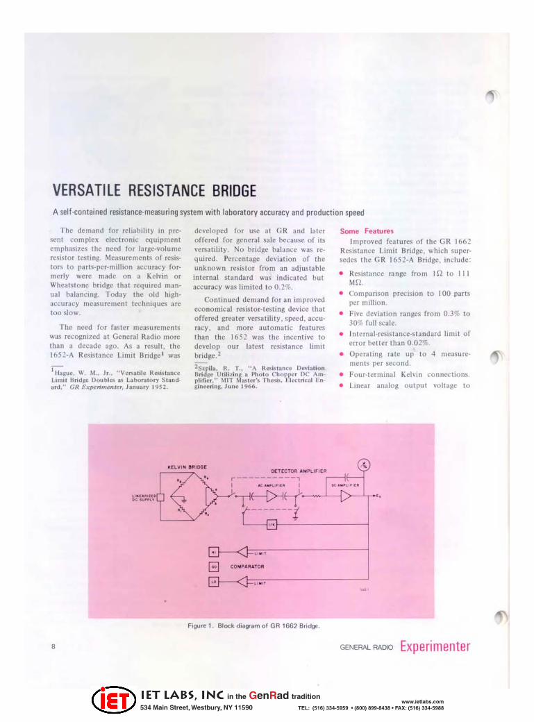
Figure 1. Block diagram of GR 1662 Bridge.
GENERAL RADIO Experimenter
IET LABS, Inc in the GenRad tradition
534 Main Street, Westbury, NY 11590 www.ietlabs.com
TEL: (516) 334-5959 • (800) 899-8438 • FAX: (516) 334-5988
drive DVM's, limit compa rators, de recorders.
• HI-GO- LO limit indica tion by panel lights.
• Manually-preset or external-prognlmmable limiti ng.
• Less than 12 mW dissipated in unknown (minimizes self-hea ting effect on low-power devices). The block diagram of th e GR 1662
bridge, Figure I, shows the basic elements of the instrument : a dc generator, an active Kelvin bridge, a detector amplifier, and the HI , GO, LO limit circuitry.
The floa ting dc generator is gua rded and shielded to reduce stray leakage pa ths to ground, thereby preserving bridge accuracy even at the mnge extremes. The Kelvin bridge consists of exceptionally stable and highaccut1lcy resistors adjusted to better than 0.01%. The bridge circuit is linearized by means of feedback to the dc source to measure the resistance deviation as a percent of the s tandard.
Inner Workings
When the ratio R l /R'l does not equal RxlRs, an unbalance-error signal results. Depending on the unbalance, this error voltage can be quite small. It must be amplified to a useful level so that it can be displayed on a denection
NOVEMBER/DECEMBER 1969
meter as the percent difference between the standard and the unknown resis tor. A highly sensitive photo-chopper amplifier is used as the detector amplifier to provide high gain and to minimize drift and noise. The dc input is conve rted into ac by the photochopper. It is then 3mplified by a dc amplifier that is also used as a Miller integrator to provide an effective fil ter for the demodulated signal. Th e gain o f the detector amplifier is stabilized by feedback around the over-all system. The deviation voltage is indica ted on a zero-centered meter and by the analog-voltage output.
In addition to the percent-deviation meter readout, a HI -GO- LO indication is also available. The o utput voltage is fed to a set of analog comparators where it is com pared to some preset voltage level to determine if the resistance measured by the bridge is higher, lower, or within the selected tolerance.
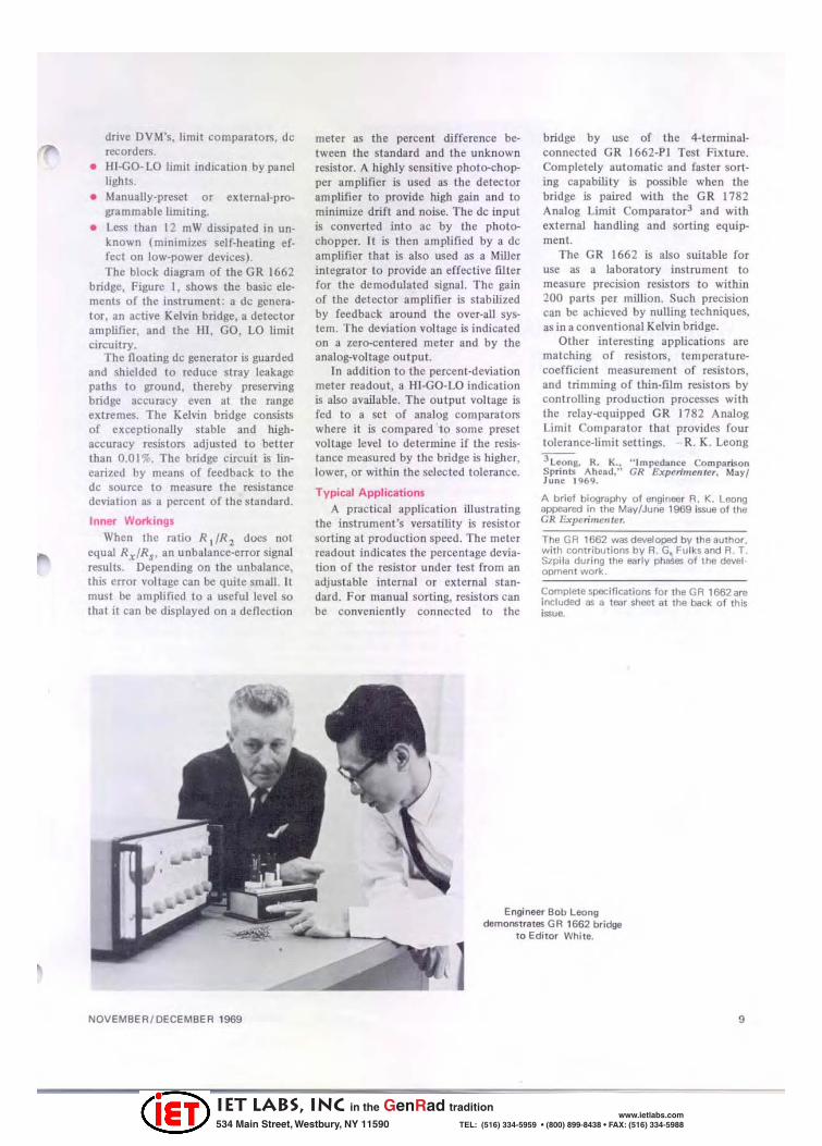
Typical Applications A practical applicatio n illustrating
the instru ment's versatility is resistor sorting at production speed. The meter readout indicates the percentage devialion of the resistor under test from an adj ustable internal or external standard. For manual sorting, resistors can be convenientl y connected to the
bridge by use of the 4-terminalconnected GR 1662-PI Test Fixture. Completely automatic and faster sorting capabili ty is possible when the bridge is paired with the GR 1782 Analog Limit Compara tor l an d with external handling and sorting equipment .
The GR 1662 is also suitable for use as a laboratory instrument to measu re prcdsion resistors to withi n 200 parts per million. Such precision can be achieved by nulling techniques, as in a conventional Kelvin bridge.
Other interesti ng applications are matching of resis tors, tempera turecoefficient measuremen t o f resistolS, and trimming of thin-film resistors by controUing production processes with the relay-cquipped GR 1782 Analog Limit Comparator that provides fo ur tolerance-limit settings. - R. K. Leong
lLeong, 11.. K .. " Impedance Comparison Sprinlll AheBd." GR Experimenter. May/ J une 1969.
A brief biography of engineer R. K. Leong appeared in lhe Mav/June 1969 issue of the CR Experimenter.
The GR 1662 was developed bV the author. with contributions bV R. G, FulkS and R. T. $zpila during the earlv phases of the devel · OPment work.
Complete specifications for the GR 1562 are included as a tear shoot al the back of this issue.
Engineer Bob Leong demof"lStrllle5 GR 1662 bridge
to Edi tor White.
] 9
IET LABS, Inc in the GenRad tradition
534 Main Street, Westbury, NY 11590 www.ietlabs.com
TEL: (516) 334-5959 • (800) 899-8438 • FAX: (516) 334-5988
WIDE8AND 20-d8/RANGE AC MILLIVOLTMETER
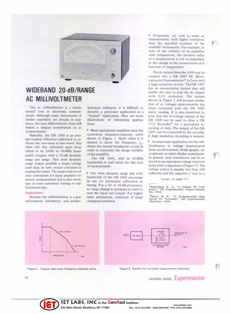
The ae millivoltmeter is a fundamental tool in electronic measurements. Allhough many instruments of similar capability are already in existance, the new millivoltmeter from OR makes a unique contribution to ae measurements.
Basically, the GR 1808 is an average-reading voltmeter calibrated to indicate the rms-value of sine waves. BUI what sels this voltmeter apart from olhers is its IO-Hz 10 IO·MHz bandwidth coupled with a 2<k1 B dynamic range per range. This wide dynamic range makes possible a single voltage scale that, in tum, avoids confusion in reading the meter. The single scale is not only convenient for many amplifier response measurements but is also necessary in some automatic testing or cali· bration set-ups.
Applications Because the millivoltmeter is a gen
eral-purpose, laboratory- and produc-
... '''''' Y'
tion-type vohmeter it is difficult to describe a particular application as a "typical" application_ Here are some illustrations of interesting applications:
• Most operational amplifielS have the open-loop frequency-response curve shown in Figure 1_ Quite often it is desired to know the frequency, fl' where the second breakpoint occurs in order to maximize the design stability of the amplifier_
The GR 1808, with its IO-MHz bandwidth, is well suited for this type of measurement.
• The wide dynamic range and wide bandwidth of the GR 1808 encourage its use for altenuator calibration or testing. For a 10- or 20-<1 8 attenuator, no range change is necessary in order to read the input and o utput . For higher value attenuators, minimum of range changing is involved.
• Frequently, we wish 10 make ac measurements with higher resolution than the specified accuracy of the available instruments. For example, in tests of the stability of an amplifier with temperature, the absolute value of a measurement is not 50 Important as the change in the measurement as a function of temperature.
The dc output from the 1808 may be coupled into a GR 1807 DC Microvolt meter/Nanoam meter l to form such a high resolution system. TheGR 1807 has an interpolation fealure that will enable the user to read the dc output with 0.1 % resolution . The system shown in Figure 2 will increase resolution of ac voltages approximately ten times compared with the GR 1808 meter readi ng_ It is also important 10 note thai the dc-voltage output of the GR 1808 can be used to drive a GR 1522 Recorderl for a permanent recording of data. The output of the GR 1807 can be connected to the recorder if high resolution recording is desired_
• An important application for the millivoltmeter is voltage measurement from accelerometers, sLrain gauges, microphones or other similar transducers. In general, such transducers can be reduced to an equivalent-voltage source in series with a capacitance (Figure 3). The voltage source is usually less than 100 millivolts and the capaci lor C may be a
(cont. on page 11)
I Satekdj ial'l , K. G .• "A Unique DC Vollmeier," GR Experimenter. AuguSC·Seplember, 1968.
lRM~h. M. W •• "A Prognmmabte HighSpeed DC Retorder." GR ExperimtMt" MI)'/June 1969.
.",.a'
• , " w' G. '_ 1---t---!--0-.. " •• ,,,",_0< .... , ....
• "'. ''''' ''~
" -, Figure 1. Typictl open-loop fTequency-response curve.
10
TO"u, '''T( .I'OU''Gfi
OHI.f.T -,
Figur. 2. SYSIem for 'nc~ased measur.men l resoluliOfl.
GENERAL RADIO Experimenter
IET LABS, Inc in the GenRad tradition
534 Main Street, Westbury, NY 11590 www.ietlabs.com
TEL: (516) 334-5959 • (800) 899-8438 • FAX: (516) 334-5988
few hundred to a few thousand picofarads.
To measure the output of such a device with reasonable accuracy (1 %-5%), It is essential to have a voltmeter with very low input capacitance. The GR 1808 millivoltmeter with a Tek· tronix P6008 probe and GR 1808·PI Probe Adaptor becomes an ideal combination for such measurements. The input capaci lance of the probe will be approxjrnately 7.5 pF and the sensi· tlVlty of the resulti ng combination will be 15m Y for full«ale deflection.
Theory of Operation
Figure 4 shows the block diagram of the GR 1808. The input buffer uses a Iield-effect transistor in order to achieve the high input impedance of the instrument. Both allenuator No. I and a!ten uator No.2 are resistive ty pe with capacitive frequency compensa· tion. Attenuator No. I is used on the ISO·Yand IS·Y ranges, and all switch· ing is done by mea ns of reed relays. This keeps high level IC signals from the sensitive detector circuits.
In order to achieve maximum sta· bility, the gam of the 20-d 8 amplifier is never changed. Instead, attenuator No. 2 provides the proper signal levels for aU nlnges.
I I
I 1 ',."eAl L __ ..J u u tOU«I!
The heart o f GR's new voltmeter is the ac-to-dc converter shown in Figure 5. Diodes CR I :lnd CR2 form a fullwave rectifier circui t. The dc-outp ut voltage (read by the meter) is proportional to the difference between the rectified voltages VI and V"l ' An important feature o f Ihis type of converter is the fact that nonlinear effects due to the diodes are eliminated from accuracy consideratio ns, because the diodes are inside the feed· back loop of amplifier A. The unbalance-leakage currents of these diodes are small enough to justify neglecti ng their effect since only the unbalance leakage curren t enlen the accurncy considerations.
The key to the wideband and wide dynantic range of Uus converter is am plifier A. It has high open-loop voltage gain even at 10 MHz, to provide sharp rise and faU times at its output. Since most diodes will require 0.3 to O.S volt to draw alleas! O. I-rnA current, sharp rise/fall times are especially necessary at low leveJ and high frequencies if errors are to be avoided.
The GR 1808 AC Millivoltmeter is not just another ac voltmeter; it is a distinct contribution to this basic branch of electronic measurements.
K. G. Balekdjian
'. '
Figu,. 3. Suggested ~urernent synem for trarl$duoer response.
It-. TO ,_v ATrUO .... 'OfI r ET 811"[11 "TE"U"O~ eoooSTU l ~'OC
'".~, ." " " I'LIfI(1I ~, GA l" CO" "fllrUI ~ .. tr ""'l"'U , ......... " [Ttl!
0 ...... ~ .. " .. C,Ilt'U" ' ........ " .... •• u' -
Figure 4 . Block diagram of GR 1808 Millivohmel ....
NOVEMBER/DECEMBER 1969
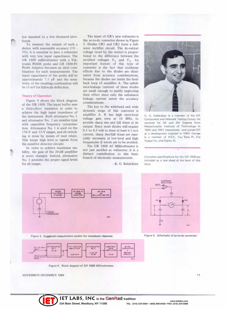
Ie:. G. Balelcdjian Is a member of the GR Component and Network Testing Group. He received his SB and SM Degrees from Massaochusetts Institute of Technology In 1955 and 1957 respectively and joinod GR as " developmenl engineer in 1964. George is " member 01 IEEE. Tau Beta Pi. Eta Kappa Nu. and Sigma Xi.
Completespecilications fO( the GR 1808ar. Included as a lear sheet al the back of this ISSUe..
" 'IKU" O . .. ·Uro(II
, •• Ul
"
'"'~, .. .-}-0-{ --.-
Y, Y,
"
Figure 5. Schematic of .c.,O« convener.
11
IET LABS, Inc in the GenRad tradition
534 Main Street, Westbury, NY 11590 www.ietlabs.com
TEL: (516) 334-5959 • (800) 899-8438 • FAX: (516) 334-5988
ALBUOUERQUE ATLANTA BOSTON BRIOOEPORT BUABANK
'CHICAGO CLEVELANO COCOA BEACH
'OALLAS OAYTON
!iO!i 765·1 (lg7 ~6336183
617 848«io!iO 20337Hl111i5 713899 2644 312 992.()8()() 216886-0150 800 2415122 214 637 2240 613434·81179
GENERAL RADIO WEST CONCORD. MASSACHUSETTS01781
6173ES4400
SALES ANO SERVICE
OENVER OETROIT GREENSBORO GROTON HARTFORO HOUSTON HUNTSVILLE INOIANAPOLIS
' LOS ANGELES
3034.<117"'225 3132611750 9'9 288 43'6 203 445-3445 20J 6582496 "3464 5"2 800 2415122 311 638-3901 "4 54().Q183O
INTERNATIONAL DIVISION
'NEW YORK (Ny,712964-2122 (NJI 201 943--3'40
P1-IILAOELPHIA 2'5646--8030 ROCHESTEA 315454-9323 SAN OIEGO 714 540-91:130
'SAN FRANCISCO 4'5948-8233 SEATTLE 206 7474U90 SYRACUSE 3'5454-9323
·WASHINGTON. BALTIMOAE JIll 88'-5333
WEST CONCORO, MASSACHUSETTS01781, USA
. -""''''- '-'' _ .. --......... -..,. -'-'~ .. -----_ .... _ ... _ .. -_ .. ~._-_._-'--~" _ ..... ---_. -,-
~-'-'_'DI DlOOOCIlA.OC R ......... OC
~~_ .0-.... _ -,-
_ ...... __ ... _ . co ... _~_ ... c
----_._-~----_. __ co , ..
' .. ._-•• 0<lil ..... ."-~-
""" '-' .. . . .... _ ... -
_._u "_ .. c-. -... -lllO'1aUC 01' _
U~ .... ,-_co , .. -_. "--,_._ .... _'-.. ,-,~~ • __ e-
•• --""' .... -'-"-------, c __ o. .. -_ .... u. _c. .. . -
' GENERAL RAOIO COMPANY IOVIII5IASI __ 1,<:>0_, ..... ,._
...... , .. ------
"'"' --,-_ .. _-.. ..... ,'--.-0' -
M~ _ .. _--Oftun -.-
... , ... ,,~ __ v ... _
---, _A_""" -
_fWA<-_."'" --,-, -~ • ___ u -...TZ ......... ... __ co ....
,-_nllK_ • __ e-
",q_ ..... --
·11_ ..... _ .. _ ....... 0"_
GENERAL RADIO
Experimenter WEST CONCORo, MASSACHUSETTS 0178 1
011 ..... he ... "o ... r corr.." ne ..... end MId ... - .........
compeny or o'~nlletlon. de.,e" ..... nl, slO_1 o. P.O.
bo". city, SI.,e .• nd rip code7 It nOI, .,1._ clip th •
• dd,esl lebel On Ihl. I ...... end '.I ... 'n II to ... with co. ·
rectlonl Ot", II yo ... p,.I.,. w.l,e "" .• Poucerd will do.
"':" ' . ...
IET LABS, Inc in the GenRad tradition
534 Main Street, Westbury, NY 11590 www.ietlabs.com
TEL: (516) 334-5959 • (800) 899-8438 • FAX: (516) 334-5988
Related Documents