© 2013 Cisco and/or its affiliates. All rights reserved. This document is Cisco Public Information. Page 1 of 47 White Paper Nexus 7000 FabricPath White Paper Version 2.0 (10/09/2013)

Welcome message from author
This document is posted to help you gain knowledge. Please leave a comment to let me know what you think about it! Share it to your friends and learn new things together.
Transcript
© 2013 Cisco and/or its affiliates. All rights reserved. This document is Cisco Public Information. Page 1 of 47
White Paper
Nexus 7000 FabricPath White Paper
Version 2.0 (10/09/2013)

© 2013 Cisco and/or its affiliates. All rights reserved. This document is Cisco Public Information. Page 2 of 47
1. Introduction.......................................................................................................................................................... 3
2. Cisco FabricPath - An Ethernet Fabric .............................................................................................................. 3 2.1 Layer 2 Technology Evolution......................................................................................................................... 3 2.2 Benefits of an Ethernet Fabric ........................................................................................................................ 5
3. FabricPath System Architecture......................................................................................................................... 5 3.1 Software Architecture...................................................................................................................................... 6 3.2 FabricPath Interfaces...................................................................................................................................... 7 3.3 FabricPath VLANs .......................................................................................................................................... 7
4. Basic FabricPath Data-Plane Operation ............................................................................................................ 9 4.1 Basic Data Plane Operation ........................................................................................................................... 9 4.2 FabricPath Encapsulation............................................................................................................................. 10 4.3. Multidestination Frame Encapsulation......................................................................................................... 12 4.4. FabricPath Forwarding Decisions................................................................................................................ 12
5. FabricPath Routing Control Plane ................................................................................................................... 13 5.1 Switch ID Allocation ...................................................................................................................................... 13 5.2 FabricPath IS-IS ........................................................................................................................................... 13 5.3 Unicast Routing ............................................................................................................................................ 14 5.4 Multidestination Trees................................................................................................................................... 14 5.5 IP Multicast Routing...................................................................................................................................... 15 5.6 FabricPath Multitopology .............................................................................................................................. 17 5.7 Overload ....................................................................................................................................................... 18
6. MAC Address Learning ..................................................................................................................................... 19 6.1 Conversational MAC Learning ...................................................................................................................... 19 6.2 MAC Learning in a Mixed M-Series/F-Series VDC ....................................................................................... 20 6.3 MAC Learning with VPC+ ............................................................................................................................. 21 6.4 Proxy Layer 2 Learning................................................................................................................................. 21 6.5 Changes in Local MAC Learning .................................................................................................................. 22
7. FabricPath Packet Forwarding ......................................................................................................................... 22 7.1 Packet Flow Example ................................................................................................................................... 23 7.2 Known Unicast Forwarding ........................................................................................................................... 31 7.3 VLAN Membership and FabricPath Forwarding ........................................................................................... 32 7.4 Multidestination Traffic Forwarding ............................................................................................................... 33 7.5 IP Multicast Forwarding ................................................................................................................................ 34
8. FabricPath Interaction with Spanning Tree..................................................................................................... 38 8.1 Forwarding TCNs.......................................................................................................................................... 39
9. VPC+ ................................................................................................................................................................... 40 9.1 Basics of VPC+............................................................................................................................................. 40 9.2 VPC+ Peer Keepalive Configuration............................................................................................................. 42 9.3 Active/Active HSRP Forwarding ................................................................................................................... 44
10. Anycast HSRP .................................................................................................................................................. 44
11. Conclusion ....................................................................................................................................................... 46
© 2013 Cisco and/or its affiliates. All rights reserved. This document is Cisco Public Information. Page 3 of 47
This document provides a detailed discussion of the FabricPath technology available on Nexus 7000 Series
switches running NX-OS software. Key topics include FabricPath system architecture, control plane and data-
plane operation, and VPC+.
1. Introduction
This document discusses the FabricPath functionality and operation on the Nexus 7000 Series switches running
NX-OS software. This document assumes an understanding of the core architecture and operation of the Nexus
7000 platform, as well as general familiarity with the function and operation of standard Layer 2 and Layer 3
unicast and multicast forwarding implementations.
2. Cisco FabricPath - An Ethernet Fabric
Cisco FabricPath technology on the Nexus 7000 switches introduces new capabilities and design options that
allow network operators to create Ethernet fabrics that maximize bandwidth availability, provide design flexibility,
and simplify and cost-reduce network and application deployment and operation.
FabricPath leverages many of the best characteristics of traditional Layer 2 and Layer 3 technologies, combining
them into a new control-plane and data-plane implemenation that combines the plug-and-play deployment model
of a bridged Spanning Tree environment with the stability, reconvergence characteristics, and ability to leverage
multiple parallel paths typical of a Layer 3 routed environment. The result is a scalable, flexible, and highly-
available Ethernet fabric suitable for the most demanding Data Center environments.
2.1 Layer 2 Technology Evolution Until recently, virtually every modern Layer 2 network implemented the Spanning Tree Protocol (STP) to build a
loop-free topology. While STP serves a critical function in these Layer 2 networks, it is also frequently the cause of
a variety of issues, both operational and architectural.
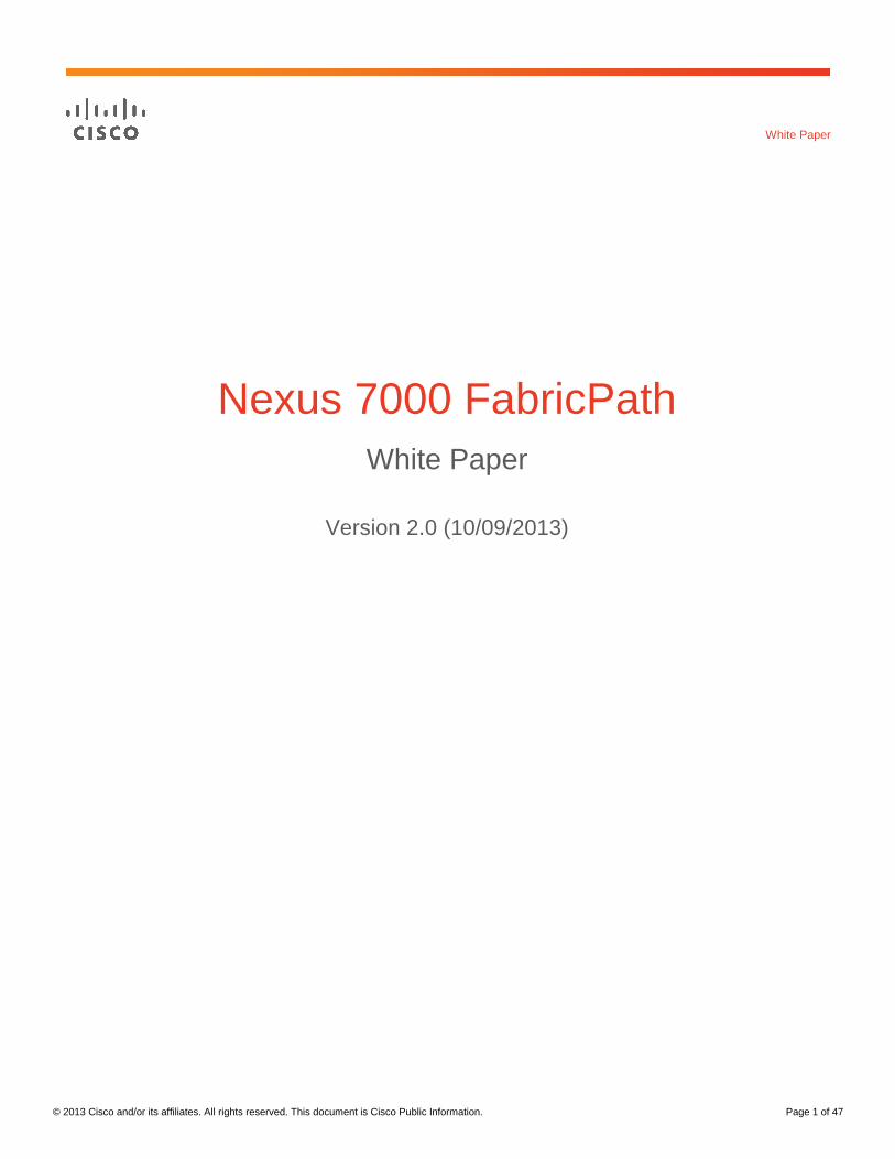
One negative aspect of STP behavior is its inability to leverage parallel forwarding paths. STP forms a forwarding
tree, rooted at a single device, along which all data-plane traffic must flow. Adding parallel paths serves as a
redundancy mechanism, but adding more than one such path has little benefit - STP blocks any additional paths,
as shown in Figure 1.
Figure 1. Spanning Tree Blocks Parallel Paths
© 2013 Cisco and/or its affiliates. All rights reserved. This document is Cisco Public Information. Page 4 of 47
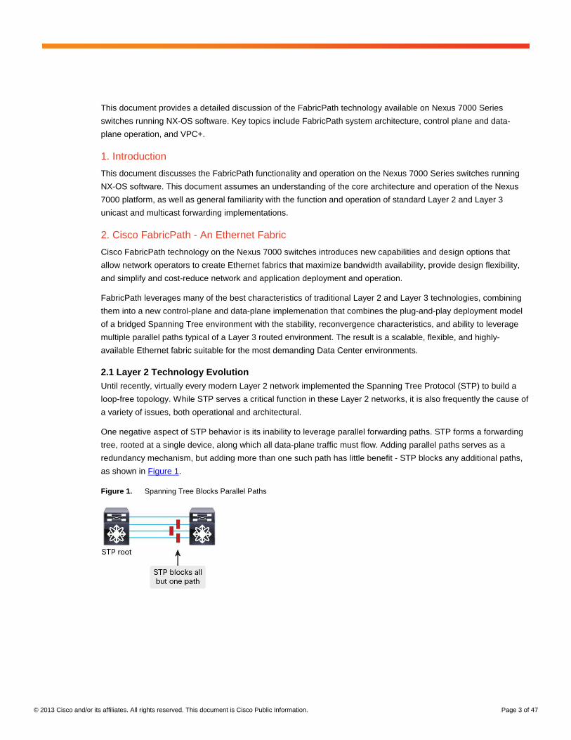
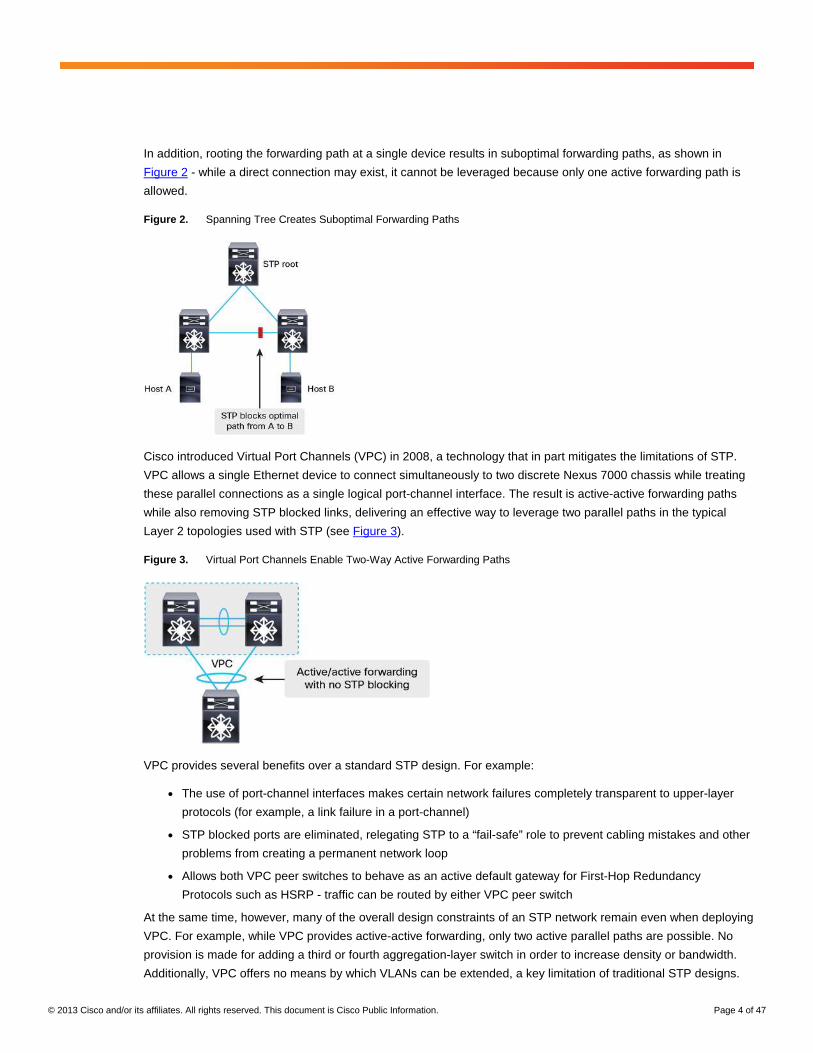
In addition, rooting the forwarding path at a single device results in suboptimal forwarding paths, as shown in
Figure 2 - while a direct connection may exist, it cannot be leveraged because only one active forwarding path is
allowed.
Figure 2. Spanning Tree Creates Suboptimal Forwarding Paths
Cisco introduced Virtual Port Channels (VPC) in 2008, a technology that in part mitigates the limitations of STP.
VPC allows a single Ethernet device to connect simultaneously to two discrete Nexus 7000 chassis while treating
these parallel connections as a single logical port-channel interface. The result is active-active forwarding paths
while also removing STP blocked links, delivering an effective way to leverage two parallel paths in the typical
Layer 2 topologies used with STP (see Figure 3).
Figure 3. Virtual Port Channels Enable Two-Way Active Forwarding Paths
VPC provides several benefits over a standard STP design. For example:
● The use of port-channel interfaces makes certain network failures completely transparent to upper-layer
protocols (for example, a link failure in a port-channel)
● STP blocked ports are eliminated, relegating STP to a “fail-safe” role to prevent cabling mistakes and other
problems from creating a permanent network loop
● Allows both VPC peer switches to behave as an active default gateway for First-Hop Redundancy
Protocols such as HSRP - traffic can be routed by either VPC peer switch
At the same time, however, many of the overall design constraints of an STP network remain even when deploying
VPC. For example, while VPC provides active-active forwarding, only two active parallel paths are possible. No
provision is made for adding a third or fourth aggregation-layer switch in order to increase density or bandwidth.
Additionally, VPC offers no means by which VLANs can be extended, a key limitation of traditional STP designs.
© 2013 Cisco and/or its affiliates. All rights reserved. This document is Cisco Public Information. Page 5 of 47
2.2 Benefits of an Ethernet Fabric With FabricPath, you can create a flexible Ethernet fabric that eliminates many of the constraints of STP. At the
control plane, FabricPath uses a Shortest-Path First (SPF) routing protocol to determine reachability and select
the best path or paths to any given destination in the FabricPath domain. In addition, the FabricPath data-plane
introduces capabilities that ensure the network remains stable, and provides scalable, hardware-based learning
and forwarding capabilities not bound by software or CPU capacity.
Benefits of deploying a FabricPath-based Ethernet fabric include:
● Simplify and cost-reduce deployment and operation - FabricPath provides plug-and-play simplicity with
minimal configuration. Application deployment becomes simpler while troubleshooting remains
straightforward and transparent.
● Maximize flexibility - FabricPath removes many of the design constraints associated with STP, enabling
simplified workload mobility, network clustering applications, and VLAN extension.
● Increase available bandwidth - With capabilities such as equal-cost multipathing (ECMP) and multitopology
forwarding, FabricPath enables you to leverage all available bandwidth in the network.
● Increase availability - FabricPath provides fast reconvergence and fault-domain isolation, insulating end
users and applications from changes in the network.
In other words, while FabricPath benefits the server and application teams by providing a transparent network
fabric that breaks down application silos, permits workload mobility, and provides maximum deployment flexibility,
it also benefits the network operations team by reducing inter-team dependencies, streamlining deployment and
configuration, and simplifying network maintenance and troubleshooting.
3. FabricPath System Architecture
The Nexus 7000 system provides a highly-available, fully modularized FabricPath control plane implementation
along with a fully distributed hardware-based data-plane implementation. Every control-plane protocol and
functional block related to FabricPath runs in its own protected memory space, providing stability and fault-
isolation. Because of the distributed nature of the Nexus 7000 system, some processes run on the Supervisor
Engine while others run on the individual I/O modules. Figure 4 shows the basic Nexus 7000 FabricPath system
architecture.

© 2013 Cisco and/or its affiliates. All rights reserved. This document is Cisco Public Information. Page 6 of 47
Figure 4. FabricPath System Architecture
The various FabricPath-related components, as well as certain key infrastructure components, run as independent
processes on the Supervisor Engine. Many of the supervisor engine processes run on a per-Virtual Device
Context (VDC) basis, providing independent process state, protected memory, and process restartability across all
configured VDCs. Other infrastructure components are global in scope and run on the I/O modules, serving the
needs of all VDCs.
3.1 Software Architecture This section describes each of the key control-plane components and processes related to FabricPath, as shown
in Figure 4.
The following components run on the Supervisor Engine, on a per-VDC basis:
● FabricPath IS-IS - SPF routing protocol process that forms the core of the FabricPath control plane
● DRAP - Dynamic Resource Allocation Protocol, an extension to FabricPath IS-IS that ensures
network-wide unique and consistent Switch IDs and FTAG values
● IGMP - Provides IGMP snooping support on FabricPath edge switches for building multicast forwarding
database
● U2RIB - Unicast Layer 2 RIB, containing the “best” unicast Layer 2 routing information
● M2RIB - Multicast Layer 2 RIB, containing the “best” multicast Layer 2 routing information
● L2FM - Layer 2 forwarding manager, managing the MAC address table
● MFDM - Multicast forwarding distribution manager, providing shim between platform-independent control-
plane processes and platform-specific processes on I/O modules
These components are global in scope and run on each of the I/O modules, processing forwarding information
from each VDC and programming it into the I/O module hardware:
● U2FIB - Unicast Layer 2 FIB, managing the hardware version of the unicast Layer 2 RIB
● M2FIB - Multicast Layer 2 FIB, managing the hardware version of the multicast Layer 2 RIB
● MTM - MAC table manager, managing the hardware version of the MAC address table

© 2013 Cisco and/or its affiliates. All rights reserved. This document is Cisco Public Information. Page 7 of 47
Each I/O module has hardware specifically designed to perform FabricPath forwarding lookups and other
functions. The primary hardware tables associated with FabricPath forwarding include:
● Switch table - Contains Switch IDs and next-hop interfaces
● MAC address table - Contains local and remote MAC address entries
● Other hardware - Variety of other table memories, hardware registers, etc. required for FabricPath
forwarding
3.2 FabricPath Interfaces Every interface involved in FabricPath switching falls into one of two categories (see Figure 5):
● FabricPath edge port - FabricPath edge ports are interfaces at the edge of the FabricPath domain. These
interfaces run Classic Ethernet, or CE, and behave exactly like normal Ethernet ports. You can attach any
CE device to the FabricPath fabric by connecting it to a FabricPath edge port. FabricPath switches perform
MAC learning on edge ports and frames transmitted on edge ports are standard IEEE 802.3 Ethernet
frames. You can configure an edge port as an access port or as an IEEE 802.1Q trunk.
● FabricPath core port - FabricPath core ports always forward Ethernet frames encapsulated in a
FabricPath header. Ethernet frames transmitted on a FabricPath interface always carry an IEEE 802.1Q
tag and therefore can conceptually be thought of as a trunk port.
Figure 5. FabricPath Edge Ports and Fabricpath Core Ports
3.3 FabricPath VLANs By default, when you create VLANs on the Nexus 7000, the VLAN operates in Classic Ethernet, or CE, mode. One
of the first tasks you perform when configuring FabricPath is to define one or more VLANs as FabricPath-mode
VLANs.
Only FabricPath-mode VLANs are carried over FabricPath interfaces. Note however that FabricPath edge ports
(i.e., CE interfaces) may belong to FabricPath VLANs, and in fact any FabricPath edge ports must belong to
FabricPath VLANs in order for traffic from CE devices to be bridged into the FabricPath domain.
Note that the mode (CE or FabricPath) of a given VLAN has only VDC-local significance. Other VDCs, or other
switches in the network, have no knowledge of the mode of a VLAN on any other switches. If you define a range of
VLANs on a CE switch and then you connect that switch to a FabricPath edge port, the FabricPath switches will
have the same VLAN IDs defined, but with the VLAN mode configured as FabricPath, as shown in Figure 6.

© 2013 Cisco and/or its affiliates. All rights reserved. This document is Cisco Public Information. Page 8 of 47
Figure 6. FabricPath VLAN Mode
Note that beginning in NX-OS release 5.2(1), only ports on an F-Series I/O module can belong to FabricPath
VLANs - therefore, both FabricPath edge ports and FabricPath core ports must be F-Series interfaces in
FabricPath VLANs; M-Series I/O module interfaces cannot be configured as switchports in a FabricPath-mode
VLAN.
3.3.1 Bridging Between M-Series and F-Series ports in a FabricPath Environment
Beginning in NX-OS release 5.2(1), if bridging between M-Series CE ports and F-Series FabricPath ports is
required, you must create two separate VDCs and interconnect them using external cables. Figure 7 illustrates
bridging M-Series ports in VLAN 10 into a FabricPath environment using two VDCs.
Figure 7. Bridging M-Series CE Traffic into FabricPath

© 2013 Cisco and/or its affiliates. All rights reserved. This document is Cisco Public Information. Page 9 of 47
4. Basic FabricPath Data-Plane Operation
This section provides a high-level view of FabricPath operation, introducing several of the key concepts of
FabricPath forwarding. Later sections of this document describe the operation of FabricPath in greater detail.
4.1 Basic Data Plane Operation Figure 8 illustrates the basics of FabricPath data-plane forwarding.
Figure 8. FabricPath Data Plane Forwarding
For the purposes of this example, assume that all control-plane routing information already exists, and data-plane
MAC address learning for Host A and Host B has already occurred.
The following steps provide the basics of FabricPath data-plane operation:
1. Host A sends a CE frame, sourced from MAC A and destined to MAC B. The ingress FabricPath switch
receives the frame in a FabricPath-mode VLAN on a FabricPath edge port and performs a MAC address table
lookup on the DMAC.
2. The MAC lookup result indicates the frame should be sent to FabricPath switch S20. The ingress FabricPath
switch encapsulates the frame in a FabricPath header for forwarding on a FabricPath core port, with a
destination Switch ID of S20.
S10 has two equal-cost paths to reach S20. One of the paths is selected using a hash function, with input from the packet data (source and destination IP plus Layer 4 ports by default).
3. Other FabricPath switches simply forward the frame based on their routing table (“what is the best path to
S20?”).
4. When S20 receives the frame, it removes the FabricPath header and forwards the frame as a Classic
Ethernet frame on the FabricPath edge port where Host B is connected.
© 2013 Cisco and/or its affiliates. All rights reserved. This document is Cisco Public Information. Page 10 of 47
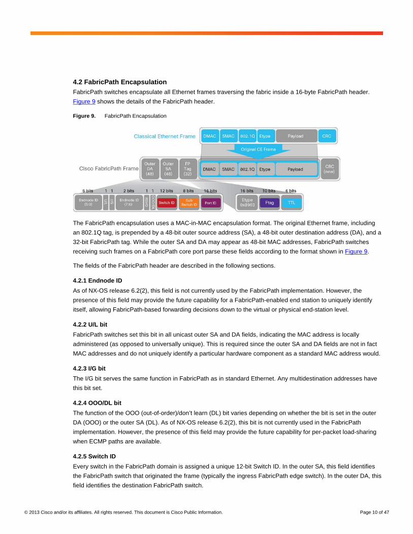
4.2 FabricPath Encapsulation FabricPath switches encapsulate all Ethernet frames traversing the fabric inside a 16-byte FabricPath header.
Figure 9 shows the details of the FabricPath header.
Figure 9. FabricPath Encapsulation
The FabricPath encapsulation uses a MAC-in-MAC encapsulation format. The original Ethernet frame, including
an 802.1Q tag, is prepended by a 48-bit outer source address (SA), a 48-bit outer destination address (DA), and a
32-bit FabricPath tag. While the outer SA and DA may appear as 48-bit MAC addresses, FabricPath switches
receiving such frames on a FabricPath core port parse these fields according to the format shown in Figure 9.
The fields of the FabricPath header are described in the following sections.
4.2.1 Endnode ID
As of NX-OS release 6.2(2), this field is not currently used by the FabricPath implementation. However, the
presence of this field may provide the future capability for a FabricPath-enabled end station to uniquely identify
itself, allowing FabricPath-based forwarding decisions down to the virtual or physical end-station level.
4.2.2 U/L bit
FabricPath switches set this bit in all unicast outer SA and DA fields, indicating the MAC address is locally
administered (as opposed to universally unique). This is required since the outer SA and DA fields are not in fact
MAC addresses and do not uniquely identify a particular hardware component as a standard MAC address would.
4.2.3 I/G bit
The I/G bit serves the same function in FabricPath as in standard Ethernet. Any multidestination addresses have
this bit set.
4.2.4 OOO/DL bit
The function of the OOO (out-of-order)/don’t learn (DL) bit varies depending on whether the bit is set in the outer
DA (OOO) or the outer SA (DL). As of NX-OS release 6.2(2), this bit is not currently used in the FabricPath
implementation. However, the presence of this field may provide the future capability for per-packet load-sharing
when ECMP paths are available.
4.2.5 Switch ID
Every switch in the FabricPath domain is assigned a unique 12-bit Switch ID. In the outer SA, this field identifies
the FabricPath switch that originated the frame (typically the ingress FabricPath edge switch). In the outer DA, this
field identifies the destination FabricPath switch.

© 2013 Cisco and/or its affiliates. All rights reserved. This document is Cisco Public Information. Page 11 of 47
4.2.6 Sub-Switch ID
In releases prior to NX-OS 6.1(2), the sub-switch ID (sSID) field identifies the source or destination VPC+ port-
channel interface associated with a particular VPC+ switch pair. FabricPath switches running VPC+ use this field
to identify the specific VPC+ port-channel on which traffic is to be forwarded. The sSID value is locally significant
to each VPC+ switch pair. Note that, because this field is 8 bits, using the sSID to identify VPC+ port-channels
imposes a limit of roughly 250 VPC+ port-channels per VPC+ switch pair (244 to be precise).
Beginning in NX-OS release 6.1(2), a configuration option provides a mechanism to remove the 244 VPC+ port-
channel limit. For more information on VPC+ and this configuration option, see Section 9, “VPC+”, on page 40.
In the absence of VPC+, this field is always set to 0.
4.2.7 Port ID
The port ID, also known as the Local Identifier (LID), can be used to identify the specific physical or logical
interface on which the frame was sourced or is destined. When used, the value is locally significant to each
switch. This field in the outer DA allows the egress FabricPath switch to forward the frame to the appropriate edge
interface without requiring a MAC address table lookup. For frames sourced from or destined to a VPC+ port-
channel, this field is set to a common value shared by both VPC+ peer switches, and the sSID is used by default
to select the outgoing port instead.
4.2.8 EtherType
The EtherType value for FabricPath encapsulated frames is 0x8903.
4.2.9 FTAG
The function of the forwarding tag, or FTAG, depends on whether a particular frame is unicast or multidestination.
In the case of unicast frames, the FTAG identifies the FabricPath topology the frame is traversing. In NX-OS
releases prior to 6.2(2), only a single topology is supported, and this value is always set to one (1). As of NX-OS
6.2(2), Nexus 7000 switches support up to 8 FabricPath topologies. The system selects a unique FTAG for each
topology configured.
In the case of multidestination frames, the FTAG identifies which multidestination forwarding tree in a given
topology the frame should traverse. Beginning in NX-OS 6.2(2), Nexus 7000 switches support two multidestination
trees per topology. The system selects the FTAG value for each multidestination tree. For more information about
FabricPath multidestination trees, see Section 5.4, “Multidestination Tree”, on page 14.
4.2.10 TTL
The Time to Live (TTL) field serves the same purpose in FabricPath as it does in traditional IP forwarding - each
switch hop decrements the TTL by 1, and frames with an expired TTL are discarded. The TTL in FabricPath
prevents Layer 2 bridged frames from looping endlessly in the event that a transitory loop occurs (such as during a
reconvergence event). As of NX-OS release 5.2(1), ingress FabricPath edge switches set the TTL to 32 for all
frames.
Beginning in NX-OS release 6.2(2), you can change the default TTL independently for unicast and multicast
frames using the fabricpath ttl command:
● Broadcast and unknown unicast frames use the unicast TTL setting
● IPv4/IPv6 and non-IP multicast frames use the multicast TTL setting

© 2013 Cisco and/or its affiliates. All rights reserved. This document is Cisco Public Information. Page 12 of 47
4.3. Multidestination Frame Encapsulation While the format for the outer SA is the same for known unicast frames and multidestination frames, there are two
key differences in the format of the outer DA used for known unicast versus multidestination frames. The following
rules apply to the outer DA used for multidestination frames, based on the type of multidestination frame in
question:
● For broadcast and multicast frames, the inner DA (all-ones broadcast MAC address, or multicast MAC
address) is copied in its entirety to the outer DA. In other words, the inner DA and the outer DA of a
broadcast or multicast frame are identical.
● For unknown unicast frames, a reserved multicast address (01:0F:FF:C1:01:C0) is used as the outer DA
4.4. FabricPath Forwarding Decisions A FabricPath switch uses different lookups and forwarding logic to forward frames, depending on the role that
particular switch plays relative to the traffic flow. There are three general FabricPath switch types, illustrated in
Figure 10:
● Ingress FabricPath switch - Receives a CE frame from a FabricPath edge port. An ingress FabricPath
switch uses a MAC table lookup to identify the destination SID, and a Switch ID table lookup to determine
on which next-hop interface frames destined to that SID should be forwarded.
● Core FabricPath switch - Receives a FabricPath-encapsulated frame on a FabricPath core port and uses
a Switch ID table lookup to determine on which next-hop interface frames destined to that SID should be
forwarded.
● Egress FabricPath switch - Receives a FabricPath-encapsulated frame on a FabricPath core port, uses a
Switch ID table to determine that it is the egress FabricPath switch, and uses the LID value in the outer DA,
or a MAC address table lookup, to determine on which FabricPath edge port the frame should be
forwarded.
Figure 10. FabricPath Switch Roles
Later sections of this document discuss the details of each of these forwarding lookups for different traffic types.
© 2013 Cisco and/or its affiliates. All rights reserved. This document is Cisco Public Information. Page 13 of 47
5. FabricPath Routing Control Plane
This section discusses the various components that make up the FabricPath control plane.
5.1 Switch ID Allocation FabricPath implements a resource-allocation protocol called DRAP that automatically provisions key parts of the
FabricPath namespace, specifically Switch IDs and FTAGs.
When a FabricPath switch brings up its FabricPath interfaces, the system forms an IS-IS adjacency to the
connected FabricPath switch and the switches begin a negotiation process that ensures that all FabricPath
switches have a unique Switch ID, and that the type and number of FTAG values in use are consistent. While this
negotiation occurs, the FabricPath interfaces are brought up but the interfaces are not added to the FabricPath
topology and no data-plane traffic is passed on the interfaces.
Every switch must have a unique Switch ID in order to participate in the FabricPath domain. A new switch initially
selects a random Switch ID and checks to see if that value is already in use. If a conflict is detected, DRAP
allocates a different value until no conflict exists.
While the FabricPath network automatically ensures each switch has a unique Switch ID, a configuration
command is provided for the network administrator to statically assign a Switch ID to a FabricPath switch. If you
choose to manually configure Switch IDs, be certain that each switch has a unique value - any switch with a
conflicting ID will suspend data-plane forwarding on FabricPath interfaces as long as a conflict exists.
5.2 FabricPath IS-IS FabricPath IS-IS replaces STP as the control-plane protocol within the FabricPath domain. In other words,
FabricPath IS-IS determines the forwarding topology instead of STP.
IS-IS is an industry standard link-state routing protocol. The FabricPath IS-IS implementation is based on the
ISO/IEC 10589 specification, implemented as a single-level IS-IS domain and extended through the definition of
FabricPath-specific Type-Length-Value (TLV) fields.
Several characteristics of IS-IS make it ideally suited for use as a Layer 2 forwarding protocol:
● Has no IP dependency - IS-IS does not require IP reachability in order to form adjacency between
devices. While the majority of modern networks do provide IP connectivity for network infrastructure, using
IS-IS ensures that no strict requirement for in-band IP connectivity among switches exists.
● Easily extensible - Using custom TLVs, IS-IS devices can exchange information about virtually anything.
In the case of Layer 3 IS-IS, routers exchange IP prefix reachability. In the case of FabricPath, switches
exchange Switch ID reachability.
● Provides SPF routing - SPF routing protocols have been proven to be scalable, flexible, and fast to
converge. In addition, IS-IS supports equal-cost multipath (ECMP) forwarding, allowing data-plane packets
to follow any available parallel path rather than restricting forwarding to a single path.
While IS-IS forms the basis of FabricPath, enabling FabricPath in your network requires no specific knowledge of
IS-IS - the configuration is plug-and-play. Much as a network operator simply “turns on” STP and interconnects
switches, you can enable FabricPath on interfaces and begin forwarding through the FabricPath fabric with
minimal configuration.
© 2013 Cisco and/or its affiliates. All rights reserved. This document is Cisco Public Information. Page 14 of 47
5.3 Unicast Routing Once adjacencies are built and routing information exchanged, the FabricPath IS-IS process passes its routes to
the Unicast Layer 2 Routing Information Base (U2RIB), which determines the “best” route for each destination
SID. By default, if multiple equal-cost paths exist to a particular SID, the U2RIB can install as many as 16 next-hop
interfaces for that destination. You can modify the number of next-hops the U2RIB installs using the
maximum-paths command in FabricPath-domain configuration mode.
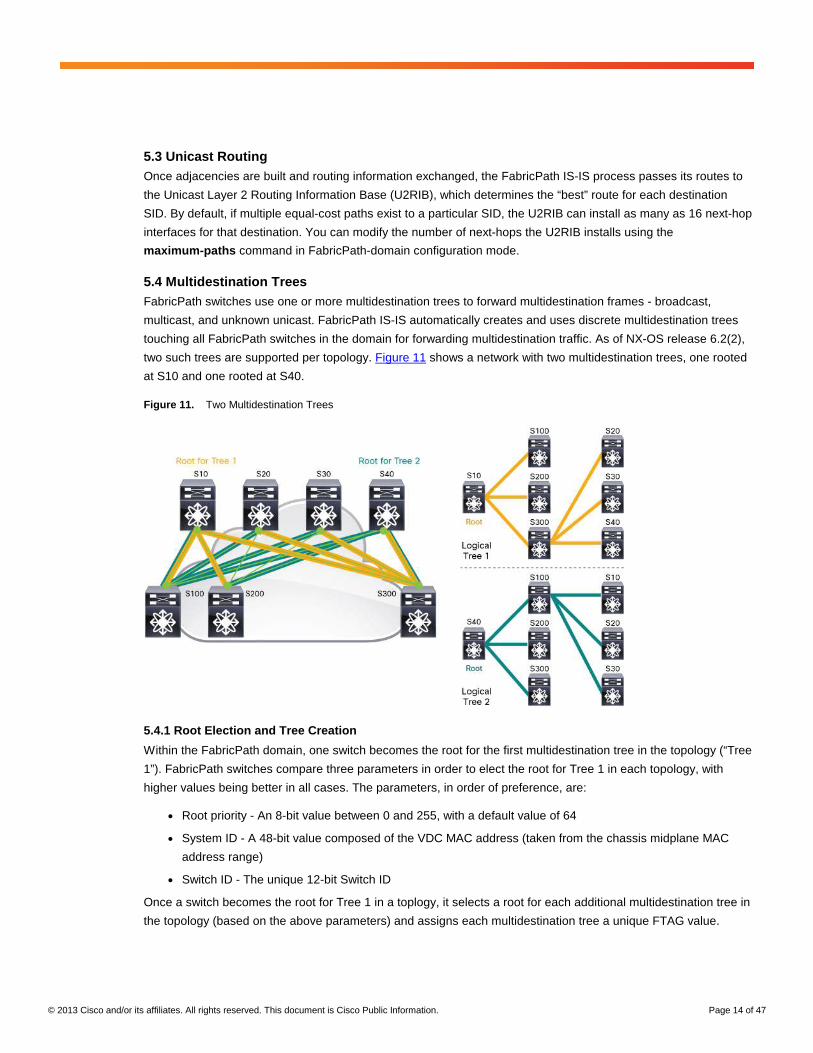
5.4 Multidestination Trees FabricPath switches use one or more multidestination trees to forward multidestination frames - broadcast,
multicast, and unknown unicast. FabricPath IS-IS automatically creates and uses discrete multidestination trees
touching all FabricPath switches in the domain for forwarding multidestination traffic. As of NX-OS release 6.2(2),
two such trees are supported per topology. Figure 11 shows a network with two multidestination trees, one rooted
at S10 and one rooted at S40.
Figure 11. Two Multidestination Trees
5.4.1 Root Election and Tree Creation
Within the FabricPath domain, one switch becomes the root for the first multidestination tree in the topology (“Tree
1”). FabricPath switches compare three parameters in order to elect the root for Tree 1 in each topology, with
higher values being better in all cases. The parameters, in order of preference, are:
● Root priority - An 8-bit value between 0 and 255, with a default value of 64
● System ID - A 48-bit value composed of the VDC MAC address (taken from the chassis midplane MAC
address range)
● Switch ID - The unique 12-bit Switch ID
Once a switch becomes the root for Tree 1 in a toplogy, it selects a root for each additional multidestination tree in
the topology (based on the above parameters) and assigns each multidestination tree a unique FTAG value.
© 2013 Cisco and/or its affiliates. All rights reserved. This document is Cisco Public Information. Page 15 of 47
While FabricPath IS-IS will automatically select root switches for each multidestination tree in each topology, you
can influence the root election using the root-priority command. We recommend configuring more centrally-
connected switches as the roots (e.g., use aggregation or spine switches as the roots as opposed to access or
leaf switches).
5.5 IP Multicast Routing While broadcast, non-IP multicast, and unknown unicast traffic in FabricPath is flooded to all FabricPath edge
ports in the input VLAN, IP multicast traffic is by default constrained to only those FabricPath edge ports that have
either an interested multicast receiver or a multicast router attached.
FabricPath edge switches use IGMP snooping to examine specific control-plane packets - IGMP packets sent by
hosts communicating their group membership, and periodic IGMP queries and PIM hellos sent by multicast
routers - to determine which edge ports require delivery of multicast data-plane traffic. A FabricPath edge switch
performs IGMP snooping exactly as any other NX-OS switch: the IGMP packet is redirected to the supervisor
CPU, analyzed, and an IGMP snooping forwarding entry is created, updated, or removed in the hardware.
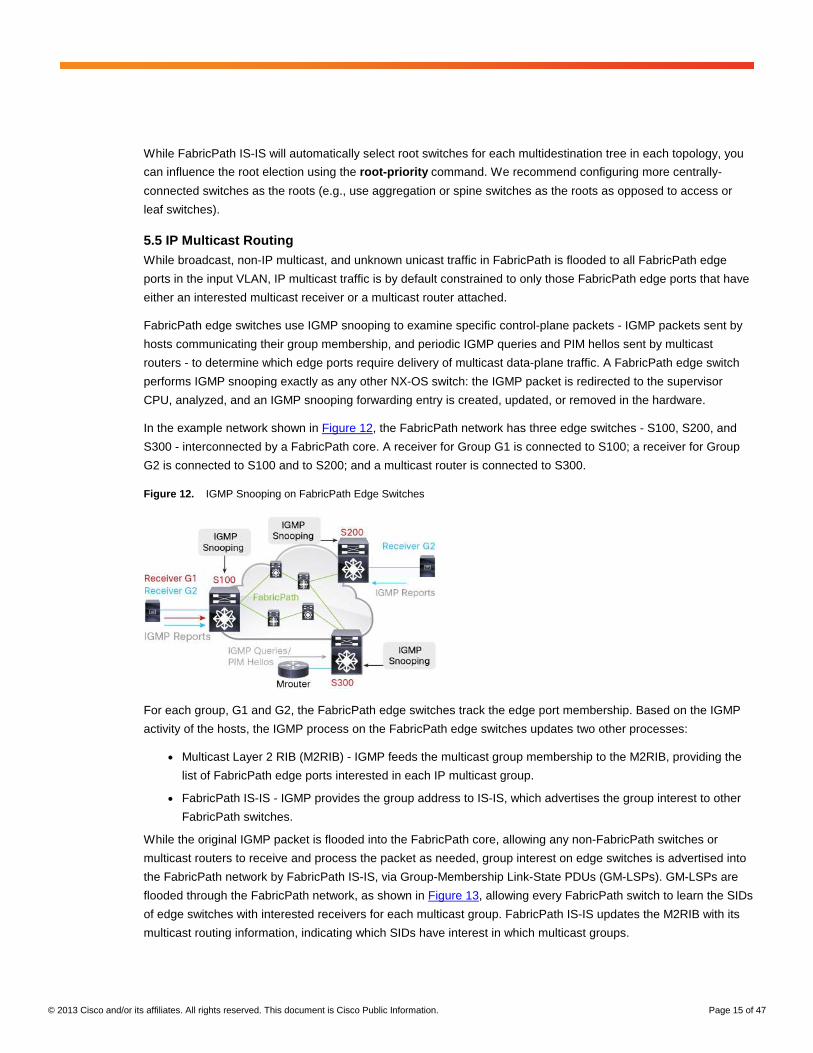
In the example network shown in Figure 12, the FabricPath network has three edge switches - S100, S200, and
S300 - interconnected by a FabricPath core. A receiver for Group G1 is connected to S100; a receiver for Group
G2 is connected to S100 and to S200; and a multicast router is connected to S300.
Figure 12. IGMP Snooping on FabricPath Edge Switches
For each group, G1 and G2, the FabricPath edge switches track the edge port membership. Based on the IGMP
activity of the hosts, the IGMP process on the FabricPath edge switches updates two other processes:
● Multicast Layer 2 RIB (M2RIB) - IGMP feeds the multicast group membership to the M2RIB, providing the
list of FabricPath edge ports interested in each IP multicast group.
● FabricPath IS-IS - IGMP provides the group address to IS-IS, which advertises the group interest to other
FabricPath switches.
While the original IGMP packet is flooded into the FabricPath core, allowing any non-FabricPath switches or
multicast routers to receive and process the packet as needed, group interest on edge switches is advertised into
the FabricPath network by FabricPath IS-IS, via Group-Membership Link-State PDUs (GM-LSPs). GM-LSPs are
flooded through the FabricPath network, as shown in Figure 13, allowing every FabricPath switch to learn the SIDs
of edge switches with interested receivers for each multicast group. FabricPath IS-IS updates the M2RIB with its
multicast routing information, indicating which SIDs have interest in which multicast groups.

© 2013 Cisco and/or its affiliates. All rights reserved. This document is Cisco Public Information. Page 16 of 47
Figure 13. Group Membership Advertised into FabricPath Using GM-LSPs
The M2RIB combines the information learned from IGMP snooping with that learned from FabricPath IS-IS GM-
LSPs, to determine the final output interface list (OIL) for each multicast group. Therefore, the OIL for a given
multicast group on a given FabricPath switch is the combination of:
● All output interfaces (OIFs) learned from IGMP snooping (local FabricPath edge ports with interested
receivers)
● All OIFs leading to other FabricPath switches with interested receivers, tracked on a per-multidestination
tree basis
In other words, the combination of IGMP snooping and FabricPath IS-IS GM-LSPs serves to create control-plane
multicast state for the FabricPath domain.
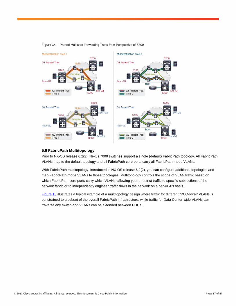
Because any given IP multicast packet in a FabricPath network always traverses only one of the available
multidestination trees, the M2RIB tracks the FabricPath core-port OIFs on a per-multidestination tree basis by
default, deriving multiple OILs that combine any local edge-port OIFs with the OIFs used to reach each FabricPath
SID with group interest on each multidestination tree. Figure 14 illustrates the pruned multicast forwarding trees
that the M2RIB derives for each group, on a per-multidestination tree basis, as seen from the perspective of switch
S300.
© 2013 Cisco and/or its affiliates. All rights reserved. This document is Cisco Public Information. Page 17 of 47
Figure 14. Pruned Multicast Forwarding Trees from Perspective of S300
5.6 FabricPath Multitopology Prior to NX-OS release 6.2(2), Nexus 7000 switches support a single (default) FabricPath topology. All FabricPath
VLANs map to the default topology and all FabricPath core ports carry all FabricPath-mode VLANs.
With FabricPath multitopology, introduced in NX-OS release 6.2(2), you can configure additional topologies and
map FabricPath-mode VLANs to those topologies. Multitopology controls the scope of VLAN traffic based on
which FabricPath core ports carry which VLANs, allowing you to restrict traffic to specific subsections of the
network fabric or to independently engineer traffic flows in the network on a per-VLAN basis.
Figure 15 illustrates a typical example of a multitopology design where traffic for different “POD-local” VLANs is
constrained to a subset of the overall FabricPath infrastructure, while traffic for Data Center-wide VLANs can
traverse any switch and VLANs can be extended between PODs.

© 2013 Cisco and/or its affiliates. All rights reserved. This document is Cisco Public Information. Page 18 of 47
Figure 15. FabricPath Multitopology Example
Within the context of each FabricPath topology, you can independently control FabricPath IS-IS parameters such
as link metrics on a per interface basis, providing complete control over the forwarding behavior of each topology.
FabricPath multitopology also provides per-topology control of multidestination frame forwarding, since each
topology maintains independent multidestination root switches and forwarding trees.
5.7 Overload NX-OS release 6.2(2) introduces support for FabricPath IS-IS “overload.” The implementation is based on the
corresponding Layer 3 IS-IS overload capability, specified in RFC 3277.
A FabricPath switch signals overload by setting the Overload Bit in the LSPs it sends to its neighbors. When a
FabricPath switch receives LSPs with the Overload Bit set, it will not include the advertising node in its SPF runs
and therefore will not use that node as a transit path for unicast forwarding nor as a root candidate or parent
switch for the purposes of calculating multidestination forwarding trees. Note however that other switches continue
to forward traffic to the overloaded node when that node is the final destination for the traffic (for example, for
packets destined to an edge port on the overloaded node).
Two configurable options are available for the overload functionality, both configured in FabricPath domain
configuration mode:
● Set overload on startup - Sets the overload bit in LSPs for a fixed duration after a VDC comes online. This
option prevents the switch from being used as a transit node until it has fully converged after a reboot, and
then automatically reinserts the switch into the topology.
● Set overload always - Sets the overload bit permanently until the configuration is removed. This option
prevents the switch from being used as a transit node, typically so it can be removed from the network for
planned maintenance or other reasons.

© 2013 Cisco and/or its affiliates. All rights reserved. This document is Cisco Public Information. Page 19 of 47
6. MAC Address Learning
FabricPath edge switches maintain two key forwarding tables - a traditional MAC address table, along with a
Switch ID table. While in many respects the MAC address table in FabricPath edge switches resembles the MAC
table used in Classic Ethernet, there are some important differences.
In CE, when a switch receives an Ethernet frame, it unconditionally populates the MAC table with the source MAC
address of the frame. Additionally, forwarding in a CE switch is always based on the destination MAC address: if
the MAC address is already learned, the frame is constrained to the port where that MAC is learned; if the MAC is
unknown, or the frame is a broadcast, the frame is flooded to all ports in the VLAN where it was received.
The side-effect of this behavior in CE networks is that every switch that has a port in a particular VLAN will learn
every MAC address in that VLAN. One potential downside of this behavior is that MAC address tables can become
saturated with entries that are never used, and the overall MAC scalability of the network can be limited by the
size of the smallest MAC address table supported among all the switches.
In contrast, FabricPath introduces new MAC-address learning rules that optimize the learning process within the
fabric, and help conserve MAC table space on the edge switches. This technique, known as conversational
learning, occurs automatically in FabricPath-mode VLANs.
6.1 Conversational MAC Learning The first general rule of FabricPath MAC learning is that only FabricPath edge switches populate the MAC table
and use MAC table lookups to forward frames. FabricPath core switches generally do not learn any MAC
addresses at all - all frame forwarding within the fabric is based on the outer DA (and more specifically, the
destination SID) of the FabricPath header.
Each FabricPath edge switch distinguishes between two types of MAC address table entry, local and remote, as
shown in Figure 16:
● Local MAC entry - A MAC entry for a device directly connected to the switch
● Remote MAC entry - A MAC entry for a device connected to a different FabricPath switch
Figure 16. Local and Remote MAC Entries
FabricPath switches follow specific MAC learning rules based on the type of frame being processed. For Ethernet
frames received from a directly-connected access or trunk port, the switch unconditionally learns the source MAC
address as a local MAC entry, much as an STP switch would.
© 2013 Cisco and/or its affiliates. All rights reserved. This document is Cisco Public Information. Page 20 of 47
However, for unicast frames received with FabricPath encapsulation, the switch only learns the source MAC
address of the frame as a remote MAC entry if the destination MAC address matches an already-learned local
MAC entry. In other words, the switch only learns remote MAC addresses if the remote device is having a
bidirectional “conversation” with a locally connected device - unknown unicast frames being flooded in the
FabricPath network do not necessarily trigger learning on edge switches.
In addition, broadcast frames do not trigger learning on edge switches. However, broadcast frames are used to
update any existing MAC entries already in the table - for example, if a host moves from one switch to another and
sends a gratuitous ARP (or any other flooded frame) to update the Layer 2 forwarding tables, FabricPath switches
receiving that broadcast will update an existing entry for the source MAC address.
Lastly, multicast frames (whether IP or non-IP multicast) trigger learning on FabricPath switches (both edge and
core) by default, since several key LAN protocols (such as HSRP) rely on source MAC learning from multicast
frames to facilitate proper forwarding.
Note that while the preceding discussion refers to switch learning behavior, in fact in the Nexus 7000
implementation, conversational learning happens at the granularity of each individual forwarding engine ASIC.
Each of those forwarding engines performs local and remote MAC learning independently, based on the
bidirectional conversations occurring across its pair of interfaces.
● On F1 I/O modules, a single forwarding engine ASIC controls a pair of front-panel 10G interfaces
(e.g., e1/1-2, e1/3-4, e1/5-6, etc.) - there are 16 independent forwarding engines on each F1 I/O module.
● On F2/F2E I/O modules, a single forwarding engine ASIC controls 4 front-panel 10G interfaces
(e.g., e1/1-4, e1/5-8, etc.) - there are 12 independent forwarding engine on each F2/F2E I/O module.
There are several other special MAC learning cases in a FabricPath network discussed in the following sections:
1. Nexus 7000 chassis with a mix of M-Series and F-Series I/O modules in the same VDC
2. VPC+ peer switches
3. Proxy Layer 2 learning
6.2 MAC Learning in a Mixed M-Series/F-Series VDC Many typical network designs introduce the Layer 2/Layer 3 boundary at the aggregation layer. Since F-Series I/O
modules do not perform Layer 3 switching in a mixed M/F VDC, such designs must include one or more M-Series
I/O modules in the VDC to provide the interVLAN and egress routing functionality.
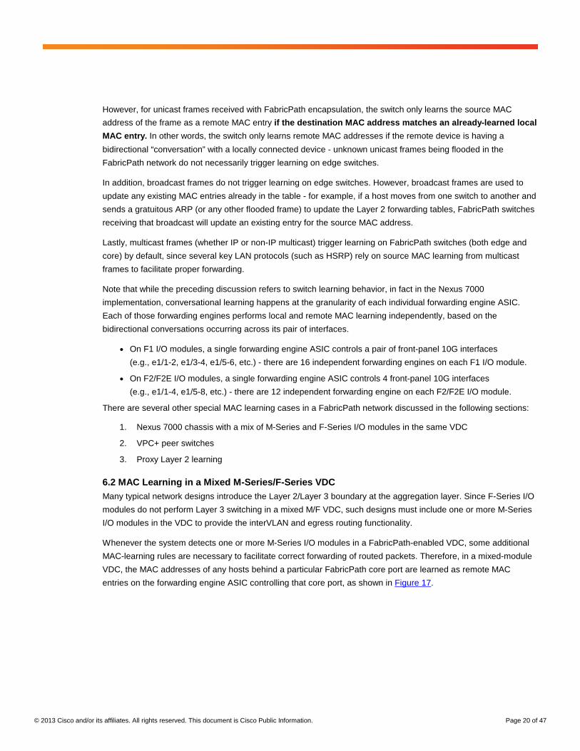
Whenever the system detects one or more M-Series I/O modules in a FabricPath-enabled VDC, some additional
MAC-learning rules are necessary to facilitate correct forwarding of routed packets. Therefore, in a mixed-module
VDC, the MAC addresses of any hosts behind a particular FabricPath core port are learned as remote MAC
entries on the forwarding engine ASIC controlling that core port, as shown in Figure 17.
© 2013 Cisco and/or its affiliates. All rights reserved. This document is Cisco Public Information. Page 21 of 47
Figure 17. M1/F1 MAC Learning
This is required so that the F-Series modules can properly encapsulate frames that are routed into the FabricPath
network by M-Series modules (which cannot natively perform FabricPath encapsulation). Note that in NX-OS
release 6.2(2), the proxy L2 learning capability introduces an alternative method of MAC learning in a mixed M/F
VDC running FabricPath, significantly increasing the MAC scale of the FabricPath domain. For more information,
see section 6.4, “Proxy Layer 2 Learning.”
6.3 MAC Learning with VPC+ Since VPC+ port-channels are effectively FabricPath edge ports, local MAC entries are learned unconditionally for
any hosts or switches connected via VPC+. VPC+ introduces several additional MAC-learning rules. In addition, to
ensure correct forwarding behavior, VPC+ MAC entries must by synchronized across all forwarding engine ASICs
in the VDC, as well as between the VPC+ peer switches. Therefore, a VPC+ environment may not scale to as
many connected host entries as a native FabricPath environment.
Note that the aforementioned limitation applies only for VPC+ peer switches that have one or more VPC+ port-
channels configured. If VPC+ is enabled only to provide active-active FHRP functionality, only the behavior
described in Section 6.2, “MAC Learning in a Mixed M-Series/F-Series VDC”, on page 20, applies.
6.4 Proxy Layer 2 Learning While conversational learning can reduce the requirement to learn MAC addresses on edge switches, one limiting
factor in scaling FabricPath networks is the MAC learning requirements imposed on the Layer 2/Layer 3 boundary
device that provides interVLAN and/or North-South routing functions. Because the L2/L3 boundary switch typically
communicates with all hosts in the network, even with conversational learning that switch must learn the MAC
address of all those hosts. With F-Series modules at the L2/L3 boundary, this requirement can limit the overall
host scale the FabricPath domain can support.
Starting in NX-OS release 6.2(2), you can leverage the larger capacity of the MAC address table in M-series
modules by leveraging the proxy L2 learning capability. Any mixed M-Series + F-Series VDC can use proxy L2
learning to shift the burden of learning all host MACs from the smaller F-Series MAC table to the larger M-Series
MAC table, increasing the overall host scale supported by the FabricPath domain.
When you enable proxy L2 learning in a mixed M+F VDC, the system relies on the M-Series modules for all
interVLAN and North-South routing decisions, and the egress MAC table lookup on the M-Series module drives
the destination FabricPath SID used by the egress F-Series module when performing the FabricPath
encapsulation.
© 2013 Cisco and/or its affiliates. All rights reserved. This document is Cisco Public Information. Page 22 of 47
One side effect of using the M-Series MAC table instead of the F-Series MAC table in FabricPath is that all
FabricPath-encapsulated frames sent on core ports are sent with a null LID (0) value. See section 6.5, “Changes
in Local MAC Learning”, for more information.
6.5 Changes in Local MAC Learning More recent NX-OS software releases introduce a key change to the MAC learning rules for FabricPath in order to
enable larger scale FabricPath domains. Beginning in NX-OS release 6.1(2) for F2 and F2E modules, and in NX-
OS release 6.2(2) for F1 modules, FabricPath automatically synchronizes all local MAC addresses learned on
edge ports to all the FabricPath core ports to facilitate ingress MAC-based lookups for incoming FabricPath
encapsulated frames.
The change allows Nexus 7000 edge switches to properly forward FabricPath-encapsulated frames with a null LID
(without the local MAC addresses available in FabricPath core ports, frames with a null LID are flooded to all ports
in the VLAN). This change in the core port MAC table programming enables the increased FabricPath domain
MAC scale provided by the Proxy Layer 2 forwarding capability. Because of the requirement to have the local MAC
entries synchronized to the FabricPath core ports in order to forward FabricPath-encapsulated frames with a null
LID without flooding, you must ensure that all edge switches run appropriate software before enabling proxy Layer
2 learning at the Layer 2/Layer 3 boundary.
The synchronization of local MAC addresses also enables Nexus 7000 switches to support more than 244 VPC+
port-channel interfaces, as described in section 9, “VPC+.”
7. FabricPath Packet Forwarding
The following sections provide a complete description of the FabricPath frame forwarding process. The
assumption in this example is that the FabricPath network has converged and full routing information has been
exchanged, but no MAC address learning has occurred. Note that the behavior described in this section assumes
a default configuration.
Assume that Host A and Host B are CE devices attached to FabricPath edge ports that belong to FabricPath-
mode VLAN 10. The process consists of Host A sending an ARP request for Host B; Host B responding to Host A
with a unicast ARP reply; and Host A sending unicast data to Host B.

© 2013 Cisco and/or its affiliates. All rights reserved. This document is Cisco Public Information. Page 23 of 47
7.1 Packet Flow Example 7.1.1 Broadcast ARP Request
Figure 18 shows the network topology and steps for this section.
Figure 18. Network Topology and Steps: Broadcast ARP Request
1. Host A wants to communicate with Host B, another device in the same IP subnet. Host A therefore transmits
an ARP request for the IP address of Host B. This frame is a standard Ethernet frame with a source MAC
(SMAC) address of Host A and an all-ones broadcast destination MAC (FFFF.FFFF.FFFF).
2. S100, a FabricPath edge switch, receives the frame on FabricPath edge port e1/13 in FabricPath-mode VLAN
10. S100 performs both a source and destination MAC address table lookup in VLAN 10 for the frame.
The source MAC lookup for {VLAN 10, MAC A} returns a miss, causing the forwarding engine on S100 to unconditionally learn MAC A as a local MAC entry for port e1/13 in VLAN 10.
In NX-OS releases prior to 6.1(2) or 6.2(2) (for F2/F2E and F1, respectively), MAC A is learned only on the forwarding engine ASIC associated with e1/13; other forwarding engines in the system do not learn MAC A. In NX-OS releases 6.1(2) or 6.2(2) and later, MAC A is also synchronized to all forwarding engines with FabricPath core ports, as described in section 6.5, “Changes in Local MAC Learning.” Figure 19 shows the MAC address table on S100 after Host A sends a broadcast ARP.
Figure 19. MAC Address Table on S100 After Broadcast ARP Request from Host A
S100# show mac address-table dynamic
Legend:
* - primary entry, G - Gateway MAC, (R) - Routed MAC, O - Overlay MAC
age - seconds since last seen,+ - primary entry using vPC Peer-Link
VLAN MAC Address Type age Secure NTFY Ports/SWID.SSID.LID
---------+-----------------+--------+---------+------+----+------------------
* 10 0000.0000.000a dynamic 30 F F Eth1/13
S100#

© 2013 Cisco and/or its affiliates. All rights reserved. This document is Cisco Public Information. Page 24 of 47
The destination MAC lookup indicates the frame is broadcast, causing the forwarding engine to flood the frame in VLAN 10. Any additional edge ports in VLAN 10 on S100 receive the frame. In addition, S100 must select a multidestination tree on which to flood the frame into the FabricPath core.
3. S100 selects one of the multidestination trees to forward the broadcast frame. As a general rule, FabricPath
switches use a hash function (default is source and destination IP plus Layer 4 ports) to select which tree to
use when forwarding broadcast, non-IP multicast, and unknown unicast traffic inside the fabric (VPC+
imposes some constraints to this behavior, as discussed in Section 9, “VPC+”, on page 40). Note however
that F1 modules always use Tree 1 for forwarding broadcast, non-IP multicast, and unknown unicast frames,
again with the exception of VPC+.
In this example, assume S100 selects Tree 1 to forward the broadcast frame. S100 performs a multidestination lookup for Tree 1 to determine on which interfaces the frame must be flooded. Tree 1 on S100 consists of a single link, interface port-channel 10 (po10). S100 floods the original broadcast frame on po10, encapsulated in a new FabricPath header. Figure 20 shows the forwarding information for multidestination Tree 1 on S100, indicating that all other FabricPath switches are reached only through interface port-channel 10 in multidestination tree 1 (FTAG 1).
Figure 20. FabricPath Multidestination Forwarding Tree (Tree 1) on S100
S100# show fabricpath multicast trees ftag 1
(ftag/1, topo/0, Switch-id 10), uptime: 20:50:11, isis
Outgoing interface list: (count: 1, '*' is the preferred interface)
* Interface port-channel10, [admin distance/115] uptime: 20:50:11, isis
(ftag/1, topo/0, Switch-id 20), uptime: 20:50:11, isis
Outgoing interface list: (count: 1, '*' is the preferred interface)
* Interface port-channel10, [admin distance/115] uptime: 17:42:18, isis
(ftag/1, topo/0, Switch-id 200), uptime: 20:50:11, isis
Outgoing interface list: (count: 1, '*' is the preferred interface)
* Interface port-channel10, [admin distance/115] uptime: 18:11:22, isis
(ftag/1, topo/0, Switch-id 40), uptime: 18:44:56, isis
Outgoing interface list: (count: 1, '*' is the preferred interface)
* Interface port-channel10, [admin distance/115] uptime: 17:42:18, isis
(ftag/1, topo/0, Switch-id 30), uptime: 18:44:53, isis
Outgoing interface list: (count: 1, '*' is the preferred interface)
* Interface port-channel10, [admin distance/115] uptime: 17:42:18, isis
(ftag/1, topo/0, Switch-id 300), uptime: 17:42:19, isis
Outgoing interface list: (count: 1, '*' is the preferred interface)
* Interface port-channel10, [admin distance/115] uptime: 17:42:18, isis
Found total 6 route(s)
S100#
© 2013 Cisco and/or its affiliates. All rights reserved. This document is Cisco Public Information. Page 25 of 47
The FabricPath header for the frame consists of the following parameters:
● Outer DA: The outer DA for a broadcast frame uses the same MAC address as the inner frame, that is, the
all-ones broadcast MAC.
● Outer SA: The outer SA identifies the FabricPath source switch ID (SID), sub-switch ID (sSID), and port ID
(or local ID, LID). In this example, the SID is 100, the sSID is 0, and the LID is 12 (a locally significant value
associated with e1/13 on S100).
● FabricPath Tag: The EtherType is FabricPath (0x8903), the Forwarding Tag (FTAG) is 1 (identifying
multidestination Tree 1), and the TTL is 32 (default).
4. The FabricPath-encapsulated frame reaches the neighboring switch, S10, which performs a lookup for the
frame. S10 uses the values in the FabricPath header to make a forwarding decision. Because the frame is
broadcast, the switch uses the FTAG value already populated by S100 to identify which multidestination tree
the frame is traversing.
On S10, three links belong to Tree 1, interface port-channel 100 (po100, connected to S100), interface port-channel 200 (po200, connected to S200) and interface port-channel 300 (po300, connected to S300). Since the frame arrived on po100, S10 decrements the TTL and floods the frame on the remaining two links belonging to Tree 1. Note that no MAC learning occurs on S10 based on this action.
5. S200 and S300 receive the FabricPath-encapsulated frame and perform a lookup. On S200, no additional
interfaces belong to Tree 1. If any FabricPath edge ports in VLAN 10 exist, the switch removes the FabricPath
header and floods the original broadcast Ethernet frame on those ports. Note that no MAC learning occurs on
200 based on these actions.
On S300, the frame arrives on port-channel 10 and three additional interfaces belong to Tree 1, port-channel 20 (po20, connected to S20), port-channel 30 (po30, connected to S30), and port-channel 40 (po40, connected to S40). S300 decrements the TTL and floods the frame on those links. Note that no MAC learning occurs on S300 based on this action.
On S20, S30, and S40, no interfaces other than the one on which the frame was received belong to multidestination Tree 1, and no FabricPath edge ports exist in VLAN 10 on these switches. Therefore, these three switches discard the frame. Note that no MAC learning occurs on these switches based on these actions.
6. In addition to flooding the FabricPath-encapsulated frame on Tree 1, if any FabricPath edge ports in VLAN 10
exist, S300 removes the FabricPath header and floods the original broadcast Ethernet frame on those ports.
Note that no MAC learning occurs on S300 based on these actions.
In this case, the broadcast ARP request from Host A to Host B is received by Host B based on the broadcast flooding behavior of S300. However, the only switch in the FabricPath network that learned MAC A based on the SMAC of the broadcast frame is S100.
© 2013 Cisco and/or its affiliates. All rights reserved. This document is Cisco Public Information. Page 26 of 47
7.1.2 Unicast ARP Response
Figure 21 shows the network topology and steps for this section.
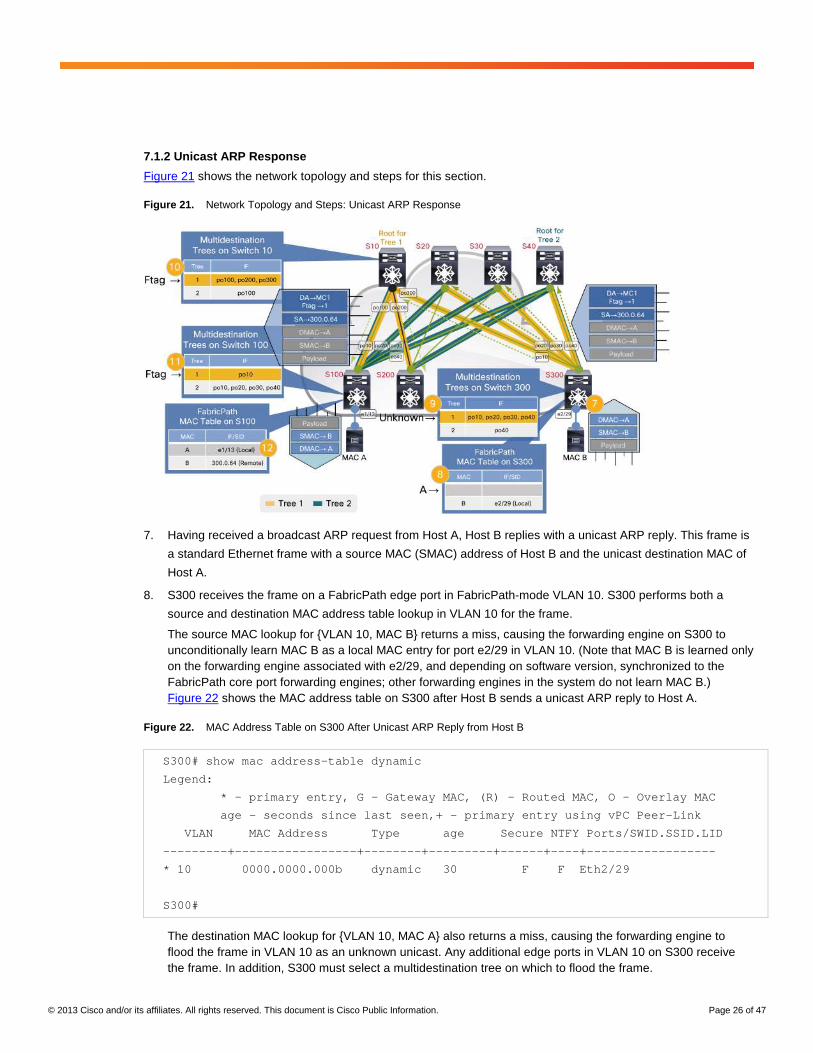
Figure 21. Network Topology and Steps: Unicast ARP Response
7. Having received a broadcast ARP request from Host A, Host B replies with a unicast ARP reply. This frame is
a standard Ethernet frame with a source MAC (SMAC) address of Host B and the unicast destination MAC of
Host A.
8. S300 receives the frame on a FabricPath edge port in FabricPath-mode VLAN 10. S300 performs both a
source and destination MAC address table lookup in VLAN 10 for the frame.
The source MAC lookup for {VLAN 10, MAC B} returns a miss, causing the forwarding engine on S300 to unconditionally learn MAC B as a local MAC entry for port e2/29 in VLAN 10. (Note that MAC B is learned only on the forwarding engine associated with e2/29, and depending on software version, synchronized to the FabricPath core port forwarding engines; other forwarding engines in the system do not learn MAC B.) Figure 22 shows the MAC address table on S300 after Host B sends a unicast ARP reply to Host A.
Figure 22. MAC Address Table on S300 After Unicast ARP Reply from Host B
S300# show mac address-table dynamic
Legend:
* - primary entry, G - Gateway MAC, (R) - Routed MAC, O - Overlay MAC
age - seconds since last seen,+ - primary entry using vPC Peer-Link
VLAN MAC Address Type age Secure NTFY Ports/SWID.SSID.LID
---------+-----------------+--------+---------+------+----+------------------
* 10 0000.0000.000b dynamic 30 F F Eth2/29
S300#
The destination MAC lookup for {VLAN 10, MAC A} also returns a miss, causing the forwarding engine to flood the frame in VLAN 10 as an unknown unicast. Any additional edge ports in VLAN 10 on S300 receive the frame. In addition, S300 must select a multidestination tree on which to flood the frame.
© 2013 Cisco and/or its affiliates. All rights reserved. This document is Cisco Public Information. Page 27 of 47
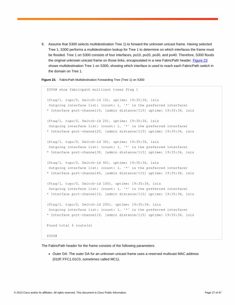
9. Assume that S300 selects multidestination Tree 1) to forward the unknown unicast frame. Having selected
Tree 1, S300 performs a multidestination lookup for Tree 1 to determine on which interfaces the frame must
be flooded. Tree 1 on S300 consists of four interfaces, po10, po20, po30, and po40. Therefore, S300 floods
the original unknown unicast frame on those links, encapsulated in a new FabricPath header. Figure 23
shows multidestination Tree 1 on S300, showing which interface is used to reach each FabricPath switch in
the domain on Tree 1.
Figure 23. FabricPath Multidestination Forwarding Tree (Tree 1) on S300
S300# show fabricpath multicast trees ftag 1
(ftag/1, topo/0, Switch-id 10), uptime: 19:35:36, isis
Outgoing interface list: (count: 1, '*' is the preferred interface)
* Interface port-channel10, [admin distance/115] uptime: 19:35:36, isis
(ftag/1, topo/0, Switch-id 20), uptime: 19:35:36, isis
Outgoing interface list: (count: 1, '*' is the preferred interface)
* Interface port-channel20, [admin distance/115] uptime: 19:35:36, isis
(ftag/1, topo/0, Switch-id 30), uptime: 19:35:36, isis
Outgoing interface list: (count: 1, '*' is the preferred interface)
* Interface port-channel30, [admin distance/115] uptime: 19:35:36, isis
(ftag/1, topo/0, Switch-id 40), uptime: 19:35:36, isis
Outgoing interface list: (count: 1, '*' is the preferred interface)
* Interface port-channel40, [admin distance/115] uptime: 19:35:36, isis
(ftag/1, topo/0, Switch-id 100), uptime: 19:35:36, isis
Outgoing interface list: (count: 1, '*' is the preferred interface)
* Interface port-channel10, [admin distance/115] uptime: 19:35:36, isis
(ftag/1, topo/0, Switch-id 200), uptime: 19:35:36, isis
Outgoing interface list: (count: 1, '*' is the preferred interface)
* Interface port-channel10, [admin distance/115] uptime: 19:35:36, isis
Found total 6 route(s)
S300#
The FabricPath header for the frame consists of the following parameters:
● Outer DA: The outer DA for an unknown unicast frame uses a reserved multicast MAC address
(010F.FFC1.01C0, sometimes called MC1).

© 2013 Cisco and/or its affiliates. All rights reserved. This document is Cisco Public Information. Page 28 of 47
● Outer SA: The outer SA identifies the FabricPath source switch ID (SID), sub-switch ID (sSID), and port ID
(or local ID, LID). In this example, the SID is 300, the sSID is 0, and the LID is 64 (a locally unique value
associated with e2/29 on S300).
● FabricPath Tag: The EtherType is FabricPath (0x8903), the Forwarding Tag (FTAG) is 1 (identifying
multidestination Tree 1), and the TTL is 32 (default).
10. The FabricPath-encapsulated frames reach the neighboring switches (S10, S20, S30, and S40) which
perform a lookup for the frame. Each switch uses the values in the FabricPath header to make a forwarding
decision. Because the frame is unknown unicast, these switches use the FTAG value already populated by
S300 to identify which multidestination tree the frame is traversing.
On S20, S30, and S40, no interfaces other than the one on which the frame was received belong to multidestination Tree 1, and no FabricPath edge ports exist in VLAN 10 on these switches. Therefore, these three switches discard the frame. Note that no MAC learning occurs on these switches based on these actions.
On S10, two additional links belong to Tree 1, po100 (connected to S100) and po200 (connected to S200). S10 decrements the TTL and floods the frame on those links. Note that no MAC learning occurs on S10 based on this action.
11. S100 and S200 receive the FabricPath-encapsulated frame and perform a lookup. On S200, no additional
interfaces belong to Tree 1. If any FabricPath edge ports in VLAN 10 exist, this switch removes the
FabricPath header and floods the original unicast Ethernet frame on those ports. Note that no MAC learning
occurs on S200 based on these actions.
12. On S100, no additional links belong to Tree 1. However, because there are FabricPath edge ports in VLAN
10, S100 removes the FabricPath header and floods the original unicast Ethernet frame on those ports. On
each egress forwarding engine, MAC lookups determine whether the DMAC is a known local MAC address; if
so, the SMAC is learned as a remote MAC entry, using the values in the outer SA to populate the entry.
On the forwarding engine ASIC where Host A is attached, since the inner DMAC (MAC A) is already known as a local MAC entry, the inner SMAC (MAC B) is learned, with a SID/sSID/LID of 300.0.64. Figure 24 shows the output of the MAC address table after S100 learns MAC B. Note that no MAC learning occurs on any of the other forwarding engines in the switch.
Figure 24. MAC Address Table on S100 After Unicast ARP Reply from Host B
S100# show mac address-table dynamic
Legend:
* - primary entry, G - Gateway MAC, (R) - Routed MAC, O - Overlay MAC
age - seconds since last seen,+ - primary entry using vPC Peer-Link
VLAN MAC Address Type age Secure NTFY Ports/SWID.SSID.LID
---------+-----------------+--------+---------+------+----+------------------
* 10 0000.0000.000a dynamic 240 F F Eth1/13
10 0000.0000.000b dynamic 30 F F 300.0.64
S100#
At this point, the unicast ARP reply from Host B to Host A is received by Host A, with MAC A learned on S100 and MAC B learned on both S100 and S300.
© 2013 Cisco and/or its affiliates. All rights reserved. This document is Cisco Public Information. Page 29 of 47
7.1.3 Unicast Data
Figure 25 shows the network topology and steps for this section.
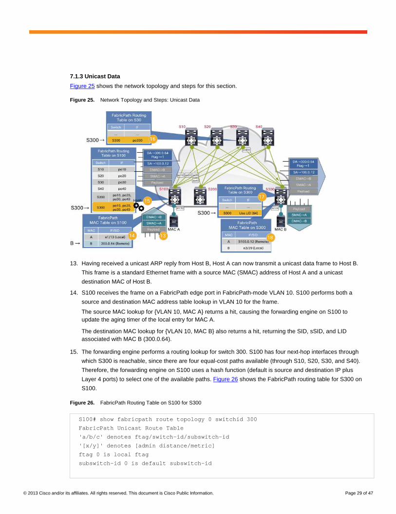
Figure 25. Network Topology and Steps: Unicast Data
13. Having received a unicast ARP reply from Host B, Host A can now transmit a unicast data frame to Host B.
This frame is a standard Ethernet frame with a source MAC (SMAC) address of Host A and a unicast
destination MAC of Host B.
14. S100 receives the frame on a FabricPath edge port in FabricPath-mode VLAN 10. S100 performs both a
source and destination MAC address table lookup in VLAN 10 for the frame.
The source MAC lookup for {VLAN 10, MAC A} returns a hit, causing the forwarding engine on S100 to update the aging timer of the local entry for MAC A.
The destination MAC lookup for {VLAN 10, MAC B} also returns a hit, returning the SID, sSID, and LID associated with MAC B (300.0.64).
15. The forwarding engine performs a routing lookup for switch 300. S100 has four next-hop interfaces through
which S300 is reachable, since there are four equal-cost paths available (through S10, S20, S30, and S40).
Therefore, the forwarding engine on S100 uses a hash function (default is source and destination IP plus
Layer 4 ports) to select one of the available paths. Figure 26 shows the FabricPath routing table for S300 on
S100.
Figure 26. FabricPath Routing Table on S100 for S300
S100# show fabricpath route topology 0 switchid 300
FabricPath Unicast Route Table
'a/b/c' denotes ftag/switch-id/subswitch-id
'[x/y]' denotes [admin distance/metric]
ftag 0 is local ftag
subswitch-id 0 is default subswitch-id

© 2013 Cisco and/or its affiliates. All rights reserved. This document is Cisco Public Information. Page 30 of 47
FabricPath Unicast Route Table for Topology-Default
1/300/0, number of next-hops: 4
via Po10, [115/40], 0 day/s 19:07:39, isis_fabricpath-default
via Po20, [115/40], 0 day/s 19:07:40, isis_fabricpath-default
via Po30, [115/40], 0 day/s 19:07:40, isis_fabricpath-default
via Po40, [115/40], 0 day/s 19:07:40, isis_fabricpath-default
S100#
Suppose that the hash result for S300 on S100 returns interface po30, the port-channel interface connected to S30. S100 forwards the frame on po30, encapsulated in a new FabricPath header. The FabricPath header consists of the following parameters:
● Outer DA: The outer DA for a known unicast frame uses the FabricPath destination SID, sSID, and LID
returned from the MAC address table lookup for MAC B (in this case, 300.0.64).
● Outer SA: The outer SA identifies the FabricPath source SID, sSID, and LID of the frame (in this case,
100.0.12).
● FabricPath Tag: The EtherType is FabricPath (0x8903), the FTAG is 1 (identifying FabricPath topology 1),
and the TTL is 32 (default).
16. S30 receives the FabricPath-encapsulated frame and performs a routing lookup based on the destination SID
contained in the outer DA (300 in this case). S30 has a single next-hop interface for S300, interface po300, as
shown in Figure 27.
Figure 27. FabricPath Routing Table on S30 for S300
S30# show fabricpath route topology 0 switchid 300
FabricPath Unicast Route Table
'a/b/c' denotes ftag/switch-id/subswitch-id
'[x/y]' denotes [admin distance/metric]
ftag 0 is local ftag
subswitch-id 0 is default subswitch-id
FabricPath Unicast Route Table for Topology-Default
1/300/0, number of next-hops: 1
via Po300, [115/20], 0 day/s 02:27:14, isis_fabricpath-default
S30#
S30 decrements the TTL in the FabricPath header and forwards the frame on interface po300. Note that no MAC learning occurs on S30 based on this action.
© 2013 Cisco and/or its affiliates. All rights reserved. This document is Cisco Public Information. Page 31 of 47
17. S300 receives the FabricPath-encapsulated frame and performs a routing lookup based on the destination
SID contained in the outer DA - the lookup indicates that S300 is the egress FabricPath switch. Depending on
the software version, S300 uses either the LID in the FabricPath header, or a MAC address table lookup, to
determine on which physical edge interface the frame should be forwarded (in this case, either the LID value
of 64, or the egress MAC table result, indicates the frame should be sent on interface e2/29).
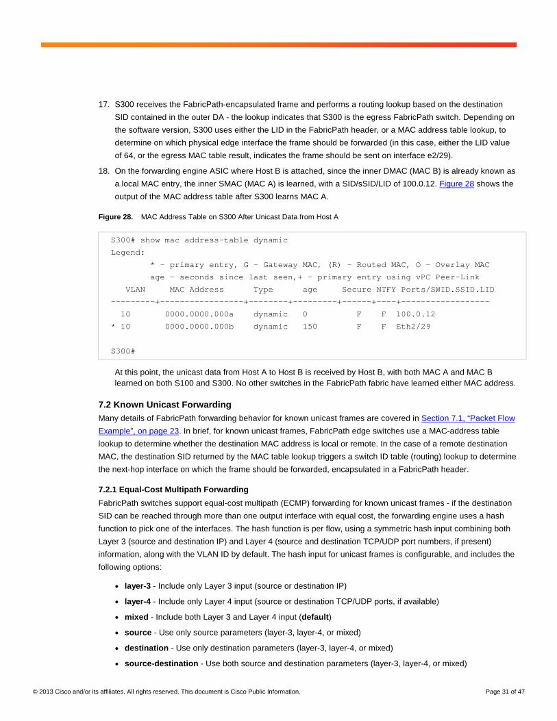
18. On the forwarding engine ASIC where Host B is attached, since the inner DMAC (MAC B) is already known as
a local MAC entry, the inner SMAC (MAC A) is learned, with a SID/sSID/LID of 100.0.12. Figure 28 shows the
output of the MAC address table after S300 learns MAC A.
Figure 28. MAC Address Table on S300 After Unicast Data from Host A
S300# show mac address-table dynamic
Legend:
* - primary entry, G - Gateway MAC, (R) - Routed MAC, O - Overlay MAC
age - seconds since last seen,+ - primary entry using vPC Peer-Link
VLAN MAC Address Type age Secure NTFY Ports/SWID.SSID.LID
---------+-----------------+--------+---------+------+----+------------------
10 0000.0000.000a dynamic 0 F F 100.0.12
* 10 0000.0000.000b dynamic 150 F F Eth2/29
S300#
At this point, the unicast data from Host A to Host B is received by Host B, with both MAC A and MAC B learned on both S100 and S300. No other switches in the FabricPath fabric have learned either MAC address.
7.2 Known Unicast Forwarding Many details of FabricPath forwarding behavior for known unicast frames are covered in Section 7.1, “Packet Flow
Example”, on page 23. In brief, for known unicast frames, FabricPath edge switches use a MAC-address table
lookup to determine whether the destination MAC address is local or remote. In the case of a remote destination
MAC, the destination SID returned by the MAC table lookup triggers a switch ID table (routing) lookup to determine
the next-hop interface on which the frame should be forwarded, encapsulated in a FabricPath header.
7.2.1 Equal-Cost Multipath Forwarding
FabricPath switches support equal-cost multipath (ECMP) forwarding for known unicast frames - if the destination
SID can be reached through more than one output interface with equal cost, the forwarding engine uses a hash
function to pick one of the interfaces. The hash function is per flow, using a symmetric hash input combining both
Layer 3 (source and destination IP) and Layer 4 (source and destination TCP/UDP port numbers, if present)
information, along with the VLAN ID by default. The hash input for unicast frames is configurable, and includes the
following options:
● layer-3 - Include only Layer 3 input (source or destination IP)
● layer-4 - Include only Layer 4 input (source or destination TCP/UDP ports, if available)
● mixed - Include both Layer 3 and Layer 4 input (default)
● source - Use only source parameters (layer-3, layer-4, or mixed)
● destination - Use only destination parameters (layer-3, layer-4, or mixed)
● source-destination - Use both source and destination parameters (layer-3, layer-4, or mixed)

© 2013 Cisco and/or its affiliates. All rights reserved. This document is Cisco Public Information. Page 32 of 47
● symmetric - Source and destination tuples are sorted before being input to the hash function
(source→destination and destination→source flows hash identically) (default)
● xor - Exclusive OR of source and destination tuples taken before being input to the hash function
● include-vlan - Option to include the VLAN ID of the frame (default)
● rotate-amount - Specifies number of bytes to rotate the hash string before being input to the hash function
In order to avoid hash polarization, each FabricPath switch automatically rotates the hash input some number of
bytes (influenced by the VDC MAC address of the FabricPath switch) to ensure that otherwise identical hash input
values return different hash results on different FabricPath switches.
7.3 VLAN Membership and FabricPath Forwarding When a frame is carried across a FabricPath core port, the frame always includes an IEEE 802.1Q tag with the
original VLAN ID of the frame (regardless of whether the FabricPath edge port it arrived on was an access port or
an 802.1Q trunk). Therefore, FabricPath core ports behave as 802.1Q trunks, and VLAN ID is still used inside the
FabricPath core to control forwarding and flooding behavior, very much as it is in CE networks.
Note however that FabricPath trunks carry traffic only for FabricPath-mode VLANs; CE-mode VLANs cannot be
carried over a FabricPath core port. In addition, instead of using “VLAN allowed lists” to control which VLANs are
carried on a core port, the act of mapping VLAN IDs to a FabricPath topology, and the corresponding assignment
of core ports to that topology, controls which VLANs are carried on which FabricPath trunks. In NX-OS releases
prior to6.2(2), only a single default topology is supported and all FabricPath core ports carry all FabricPath-mode
VLANs configured on the switch. Beginning in NX-OS release 6.2(2), you can configure multiple topologies and
map different FabricPath VLANs to each topology to control on which core ports the switch sends VLAN traffic.
While conceptually every FabricPath VLAN is carried on every core port belonging to the topology to which that
VLAN is mapped, in practice, the presence or absence of a particular VLAN ID in the VLAN database of a
particular switch can influence whether traffic for a particular VLAN will traverse a particular FabricPath switch. In
fact, each FabricPath switch explicitly advertises its interest in each VLAN configured on the switch. The
advertising of VLAN interest mimics the mechanism used to constrain IP multicast traffic, as described in
Section 5.5, “IP Multicast Routing”, on page 15.
When a switch advertises its interest in a VLAN, it floods a Group Membership LSP (GM-LSP) through the
FabricPath domain, advertising its interest to other switches. Other FabricPath switches build forwarding state for
multidestination frames on a per-VLAN basis, constraining multidestination traffic to only those core ports that
need it, helping to conserve link bandwidth in the fabric.
Prior to NX-OS release 6.2(2), a switch advertises interest in a VLAN based on whether that VLAN exists on that
switch. If the VLAN exists, the switch will advertise interest and neighbor switches will forward multidestination
frames for that VLAN. If the VLAN does not exist, the switch does not advertise interest, and neighboring switches
will not forward multidestination frames for that VLAN on core ports connected to that switch.
Use care in using this behavior to control where VLAN traffic propagates, as VLAN traffic will not transit a
particular FabricPath switch if either the VLAN does not exist or the VLAN is not configured for FabricPath mode.
© 2013 Cisco and/or its affiliates. All rights reserved. This document is Cisco Public Information. Page 33 of 47
Beginning in NX-OS release 6.2(2), you can further refine the advertisement of switch interest in multidestination
traffic for a VLAN. Use the vlan-pruning configuration command (under FabricPath domain configuration mode)
to base VLAN interest not just on the existence of the VLAN in the VLAN database, but also based on the STP
forwarding state of the CE edge ports in that VLAN. If no edge ports are in the forwarding state for a given VLAN,
the switch withdraws interest in that VLAN, preventing other switches from sending multidestination frames for that
VLAN toward the switch. This enhancement reduces unnecessary flood traffic on edge switches without requiring
changes to the VLAN database on those switches.
7.4 Multidestination Traffic Forwarding This section discusses how multidestination frames, other than IP multicast, are forwarded in FP. Note that many
details of multidestination traffic forwarding behavior have already been covered in Section 7.1, “Packet Flow
Example”, on page 23. Forwarding for IP multicast is discussed in Section 7.5, “IP Multicast Forwarding”, on
page 34.
7.4.1 Data Plane Tree Selection
When a FabricPath edge switch receives a multidestination frame on a FabricPath edge port, it selects one of the
available multidestination trees to forward the frame based on a hash function. In a VPC+ environment, a VPC+
peer switch still uses a hash function to select a multidestination tree, but only trees for which that peer switch has
an affinity are used. (Note that on F1 I/O modules, broadcast, unknown unicast, and non-IP multicast always use
Tree 1, except in the case of VPC+.)
Once the switch determines which multidestination tree a frame will traverse, it encapsulates the frame in a
FabricPath header, populating the outer SA and DA with the appropriate values and populating the FTAG field in
the FabricPath tag with the unique value associated with that multidestination tree.
In a generic sense, the frame is then flooded on any FabricPath interfaces that belong to that tree, and other
FabricPath switches receiving the frame will further flood the frame based on the topology of that multidestination
tree.
More specifically, FabricPath IS-IS maintains flooding state for two specific cases in order to optimize frame
delivery and limit unnecessary flooding.
● For all flood frames, each switch advertises its interest in FabricPath VLANs - if a switch has not advertised
interest, flood traffic for that VLAN is not forwarded to it.
● For IP multicast, the IGMP snooping database on FabricPath edge switches is provided to IS-IS and group
interest is advertised in FabricPath IS-IS, ensuring that IP multicast data only reaches those switches with
interested receivers.
7.4.2 Unknown Unicast Forwarding
Many details of FabricPath forwarding behavior for unknown unicast frames are covered in Section 7.1.2, “Unicast
ARP Response”, on page 26. In brief, FabricPath edge switches use a hash function to select a multidestination
tree to forward unknown unicast frames (note that F1 I/O modules always use Tree 1 for unknown unicast, except
in the case of VPC+).
When a destination MAC-address table lookup returns a miss, a FabricPath edge switch triggers a lookup to
determine which interfaces belong to the selected multidestination tree. The frame is then flooded to any other
FabricPath edge ports in the same VLAN, as well as flooded on any FabricPath core ports belonging to the
selected multidestination tree, encapsulated in a FabricPath header.

© 2013 Cisco and/or its affiliates. All rights reserved. This document is Cisco Public Information. Page 34 of 47
Unlike known unicast, where the outer DA is populated with the destination SID, sSID, and LID, in the case of
unknown unicast the outer DA is a reserved multicast MAC address known as “MC1” (010F.FFC1.01C0).
FabricPath switches receiving frames with an outer DA of MC1 perform a multidestination tree lookup to determine
on which interfaces to flood the frame. In other words, the ingress FabricPath switch determines which
multidestination tree the frame will traverse, and other FabricPath switches simply flood the frame on any
interfaces belonging to that tree.
FabricPath edge switches do not perform MAC learning based on unknown unicast frames.
7.4.3 Broadcast Forwarding
Many details of FabricPath forwarding behavior for broadcast frames are covered in Section 7.1.7.1.1, “ Broadcast
ARP Request”, on page 23. In brief, FabricPath edge switches use a hash function to select a multidestination tree
to forward broadcast frames (note that F1 I/O modules always use Tree 1 for broadcast, except in the case of
VPC+).
When a destination MAC-address table lookup determines the DMAC is broadcast, a FabricPath edge switch
triggers a lookup to determine which interfaces belong to the selected multidestination tree. The frame is then
flooded to any other FabricPath edge ports in the same VLAN, as well as flooded on any FabricPath core ports
belonging to the selected multidestination tree, encapsulated in a FabricPath header.
For broadcast frames, the outer DA remains the all-ones broadcast address (FFFF.FFFF.FFFF). FabricPath
switches receiving frames destined to the broadcast MAC perform a multidestination tree lookup to determine on
which interfaces to flood the frame. In other words, the ingress FabricPath switch determines which
multidestination tree the frame will traverse, and other FabricPath switches simply flood the frame on any
interfaces belonging to that tree.
FabricPath edge switches do not perform MAC learning based on broadcast frames.
7.4.4 Non-IP Multicast Forwarding
Non-IP multicast forwarding behavior is identical to broadcast forwarding in virtually every respect. The outer DA of
a FabricPath frame carrying a non-IP multicast frame remains the same as the inner destination MAC address.
One key difference between broadcast and non-IP multicast forwarding however is that FabricPath edge switches
do perform remote MAC learning based on non-IP multicast frames.
7.5 IP Multicast Forwarding As with other multidestination frames, FabricPath edge switches use a hash function to determine which
multidestination tree IP multicast packets (those packets with a Class D destination IP address) should traverse.
While FabricPath frames are forwarded at Layer 2, Nexus 7000 F-Series I/O modules use Layer 3 and Layer 4
information from the packet as input to the hash, and forwarding is based on the group IP address.
7.5.1 IP Multicast Load-Sharing Hash
When a FabricPath edge switch receives an IP multicast frame, it uses a hash function to pick one of the available
multidestination trees. The hash function is per-flow, using a symmetric hash input combining both Layer 3 (source
and destination IP) and Layer 4 (source and destination TCP/UDP port numbers, if present) information, as well as
VLAN ID. The hash input for multicast frames is configurable, and includes the following options:
● source - Use only Layer 3 and Layer 4 source parameters
● destination - Use only Layer 3 and Layer 4 destination parameters
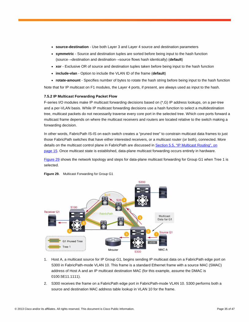
© 2013 Cisco and/or its affiliates. All rights reserved. This document is Cisco Public Information. Page 35 of 47
● source-destination - Use both Layer 3 and Layer 4 source and destination parameters
● symmetric - Source and destination tuples are sorted before being input to the hash function
(source→destination and destination→source flows hash identically) (default)
● xor - Exclusive OR of source and destination tuples taken before being input to the hash function
● include-vlan - Option to include the VLAN ID of the frame (default)
● rotate-amount - Specifies number of bytes to rotate the hash string before being input to the hash function
Note that for IP multicast on F1 modules, the Layer 4 ports, if present, are always used as input to the hash.
7.5.2 IP Multicast Forwarding Packet Flow
F-series I/O modules make IP multicast forwarding decisions based on (*,G) IP address lookups, on a per-tree
and a per-VLAN basis. While IP multicast forwarding decisions use a hash function to select a multidestination
tree, multicast packets do not necessarily traverse every core port in the selected tree. Which core ports forward a
multicast frame depends on where the multicast receivers and routers are located relative to the switch making a
forwarding decision.
In other words, FabricPath IS-IS on each switch creates a “pruned tree” to constrain multicast data frames to just
those FabricPath switches that have either interested receivers, or a multicast router (or both), connected. More
details on the multicast control plane in FabricPath are discussed in Section 5.5, “IP Multicast Routing”, on
page 15. Once multicast state is established, data-plane multicast forwarding occurs entirely in hardware.
Figure 29 shows the network topology and steps for data-plane multicast forwarding for Group G1 when Tree 1 is
selected.
Figure 29. Multicast Forwarding for Group G1
1. Host A, a multicast source for IP Group G1, begins sending IP multicast data on a FabricPath edge port on
S300 in FabricPath-mode VLAN 10. This frame is a standard Ethernet frame with a source MAC (SMAC)
address of Host A and an IP multicast destination MAC (for this example, assume the DMAC is
0100.5E11.1111).
2. S300 receives the frame on a FabricPath edge port in FabricPath-mode VLAN 10. S300 performs both a
source and destination MAC address table lookup in VLAN 10 for the frame.

© 2013 Cisco and/or its affiliates. All rights reserved. This document is Cisco Public Information. Page 36 of 47
The source MAC lookup triggers an unconditional new learn or updates an existing entry for MAC A. The destination MAC lookup indicates the frame is IP multicast, causing the forwarding engine to use a hash function to select a multidestination tree on which to forward the frame.
Suppose the hash function selects Tree 1. The forwarding engine next performs a (*,G) IP-based lookup for the frame for Tree 1 in VLAN 10. Recall from Section 5.5, “IP Multicast Routing”, on page 15, that this forwarding entry will contain an output interface list (OIL) that combines:
● Any edge ports with interested receivers or multicast routers (learned via IGMP snooping)
● Any FabricPath core ports in Tree 1 through which other edge switches with interested receivers or
multicast routers may be reached
In this case, there are two output interfaces (OIFs) in the OIL - the edge port with the multicast router attached, and the FabricPath core port in Tree 1 through which S100 may be reached.
3. S300 forwards the IP multicast frame on all the OIFs returned by the forwarding engine lookup. On the
FabricPath edge port connected to the multicast router, S300 transmits a standard Ethernet frame. On the
FabricPath core port connected to S20, S300 transmits the original multicast frame encapsulated in a new
FabricPath header. The FabricPath header for the frame consists of the following parameters:
● Outer DA: The outer DA for an IP multicast frame uses the same MAC address as the inner frame (in this
case, 0100.5E11.1111).
● Outer SA: The outer SA identifies the FabricPath source switch ID (SID), sub-switch ID (sSID), and port ID
(or local ID, LID). In this example, the SID is 300, the sSID is 0, and the LID is 29 (a locally significant value
associated with e2/30 on S300).
● FabricPath Tag: The EtherType is FabricPath (0x8903), the Forwarding Tag (FTAG) is 1 (identifying
multidestination Tree 1), and the TTL is 32 (default).
4. The FabricPath-encapsulated frame reaches the neighboring switch, S20, which performs a lookup for the
frame. S20 uses the values in the FabricPath header to make a forwarding decision.
Because the frame is IP multicast, the switch uses the FTAG value already populated by S300 to identify which multidestination tree the frame is traversing (Tree 1). S20 performs a (*,G) IP-based lookup for the frame for Tree 1 in VLAN 10. In this case, there is a single OIF, the FabricPath core port in Tree 1 through which S100 may be reached. S20 decrements the TTL and forwards the otherwise unchanged frame.
Notice that S20 does not forward the frame on the FabricPath core port connected to S200, even though that port is part of Tree 1. This illustrates how for each IP multicast group, FabricPath IS-IS maintains a pruned forwarding tree consisting of just those core ports through which switches with interested receivers may be reached. Since S200 does not have a receiver for Group G1, that core port is pruned from the G1 forwarding tree.
5. Forwarding continues along Tree 1 until the FabricPath-encapsulated frame arrives at S100. S100 performs a
lookup for the frame, using the values in the FabricPath header to make a forwarding decision. Because the
frame is IP multicast, the switch uses the FTAG value in the frame to identify which multidestination tree the
frame is traversing (Tree 1). S100 performs a (*,G) IP-based lookup for the frame for Tree 1 in VLAN 10.
6. In this case, there is a single OIF, the FabricPath edge port with the multicast receiver for G1 attached. S100
strips off the FabricPath encapsulation and forwards the original multicast frame as a standard Ethernet frame
on the FabricPath edge port.
Figure 30 shows the same network topology as the previous example, but illustrates the steps for data-plane
multicast forwarding for Group G1 when Tree 2 is selected.
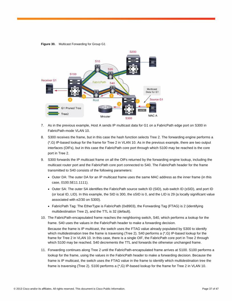
© 2013 Cisco and/or its affiliates. All rights reserved. This document is Cisco Public Information. Page 37 of 47
Figure 30. Multicast Forwarding for Group G1
7. As in the previous example, Host A sends IP multicast data for G1 on a FabricPath edge port on S300 in
FabricPath-mode VLAN 10.
8. S300 receives the frame, but in this case the hash function selects Tree 2. The forwarding engine performs a
(*,G) IP-based lookup for the frame for Tree 2 in VLAN 10. As in the previous example, there are two output
interfaces (OIFs), but in this case the FabricPath core port through which S100 may be reached is the core
port in Tree 2.
9. S300 forwards the IP multicast frame on all the OIFs returned by the forwarding engine lookup, including the
multicast router port and the FabricPath core port connected to S40. The FabricPath header for the frame
transmitted to S40 consists of the following parameters:
● Outer DA: The outer DA for an IP multicast frame uses the same MAC address as the inner frame (in this
case, 0100.5E11.1111).
● Outer SA: The outer SA identifies the FabricPath source switch ID (SID), sub-switch ID (sSID), and port ID
(or local ID, LID). In this example, the SID is 300, the sSID is 0, and the LID is 29 (a locally significant value
associated with e2/30 on S300).
● FabricPath Tag: The EtherType is FabricPath (0x8903), the Forwarding Tag (FTAG) is 2 (identifying
multidestination Tree 2), and the TTL is 32 (default).
10. The FabricPath-encapsulated frame reaches the neighboring switch, S40, which performs a lookup for the
frame. S40 uses the values in the FabricPath header to make a forwarding decision.
Because the frame is IP multicast, the switch uses the FTAG value already populated by S300 to identify which multidestination tree the frame is traversing (Tree 2). S40 performs a (*,G) IP-based lookup for the frame for Tree 2 in VLAN 10. In this case, there is a single OIF, the FabricPath core port in Tree 2 through which S100 may be reached. S40 decrements the TTL and forwards the otherwise unchanged frame.
11. Forwarding continues along Tree 2 until the FabricPath-encapsulated frame arrives at S100. S100 performs a
lookup for the frame, using the values in the FabricPath header to make a forwarding decision. Because the
frame is IP multicast, the switch uses the FTAG value in the frame to identify which multidestination tree the
frame is traversing (Tree 2). S100 performs a (*,G) IP-based lookup for the frame for Tree 2 in VLAN 10.

© 2013 Cisco and/or its affiliates. All rights reserved. This document is Cisco Public Information. Page 38 of 47
12. In this case, there is a single OIF, the FabricPath edge port with the multicast receiver for G1 attached. S100
strips off the FabricPath encapsulation and forwards the original multicast frame as a standard Ethernet frame
on the FabricPath edge port.
Notice that S100 does not forward the frame on the FabricPath core port connected to S10, even though that port is part of Tree 2. This illustrates how for each IP multicast group, FabricPath IS-IS maintains a pruned forwarding tree consisting of just those core ports through which switches with interested receivers may be reached. Since S10, S20, and S200 do not have a receiver for Group G1, the core port connected to S10 is pruned from the G1 forwarding tree.
8. FabricPath Interaction with Spanning Tree
FabricPath supports not only direct Classic Ethernet host connections but also connection of traditional Spanning-
Tree switches to FabricPath edge ports. By default, FabricPath switches transmit and process STP BPDUs on
FabricPath edge ports (you can modify this behavior using features such as BPDU guard and BPDU filter), and
therefore participate in building the STP forwarding topology in each connected STP domain.
However, BPDUs, including TCNs, are not transmitted on FabricPath core ports and no BPDUs are forwarded or
tunneled through the FabricPath domain by default (a configuration option to forward TCNs through FabricPath is
discussed in Section 8.1, “Forwarding TCNs”, on page 39). Therefore, FabricPath isolates each STP domain and
topology changes in one STP domain are not propagated to other domains connected to the same FabricPath
fabric.
This isolation is accomplished by having the entire FabricPath domain appear as a single STP bridge to any
connected STP domains, as shown in Figure 31. In order to appear as one STP bridge, all FabricPath bridges
share a common bridge ID, or BID (C84C.75FA.6000). This BID is statically defined and is not user-configurable.
Figure 31. FabricPath Domain Appears as One Logical Bridge to Each STP Domain
Each FabricPath edge switch must be configured as root for all FabricPath VLANs. If you are connecting STP
devices to the FabricPath fabric, make sure you configure all edge switches as STP root by using the
spanning-tree vlan x root primary command (or manually configure the bridge priority on each switch to force the
switch to be root). Additionally, if multiple FabricPath edge switches connect to the same STP domain, make sure
that those edge switches use the same bridge priority value.
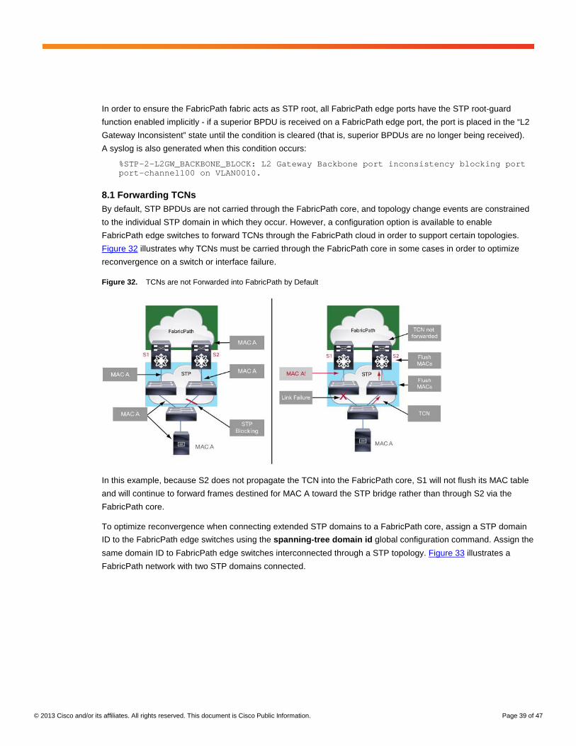
© 2013 Cisco and/or its affiliates. All rights reserved. This document is Cisco Public Information. Page 39 of 47
In order to ensure the FabricPath fabric acts as STP root, all FabricPath edge ports have the STP root-guard
function enabled implicitly - if a superior BPDU is received on a FabricPath edge port, the port is placed in the “L2
Gateway Inconsistent” state until the condition is cleared (that is, superior BPDUs are no longer being received).
A syslog is also generated when this condition occurs:
%STP-2-L2GW_BACKBONE_BLOCK: L2 Gateway Backbone port inconsistency blocking port port-channel100 on VLAN0010.
8.1 Forwarding TCNs By default, STP BPDUs are not carried through the FabricPath core, and topology change events are constrained
to the individual STP domain in which they occur. However, a configuration option is available to enable
FabricPath edge switches to forward TCNs through the FabricPath cloud in order to support certain topologies.
Figure 32 illustrates why TCNs must be carried through the FabricPath core in some cases in order to optimize
reconvergence on a switch or interface failure.
Figure 32. TCNs are not Forwarded into FabricPath by Default
In this example, because S2 does not propagate the TCN into the FabricPath core, S1 will not flush its MAC table
and will continue to forward frames destined for MAC A toward the STP bridge rather than through S2 via the
FabricPath core.
To optimize reconvergence when connecting extended STP domains to a FabricPath core, assign a STP domain
ID to the FabricPath edge switches using the spanning-tree domain id global configuration command. Assign the
same domain ID to FabricPath edge switches interconnected through a STP topology. Figure 33 illustrates a
FabricPath network with two STP domains connected.

© 2013 Cisco and/or its affiliates. All rights reserved. This document is Cisco Public Information. Page 40 of 47
Figure 33. Two Spanning-Tree Domains
Suppose a TCN is generated in STP domain 1. Other FabricPath edge switches connected to the same STP
domain should receive the TCN through the FabricPath core in order to flush their MAC tables. In addition, those
edge switches must propagate the TCN back into the STP domain to facilitate reconvergence on other STP
switches. For example, in Figure 33, if S2 receives a TCN from an edge port, it should forward the TCN into
FabricPath so that S1 can flush its MAC entries and also forward the TCN back into the STP domain.
At the same time, FabricPath edge switches connected to other STP domains also need to receive the TCN so
they can flush any entries associated with the originating STP domain, but there is no need to forward such TCNs
into their own STP domains. For example, in Figure 33, if S3 receives a TCN from STP domain 1, it should flush
its MAC entries for S1 and S2 but it should not forward the TCN into STP domain 2. Because the TCN flooded into
FabricPath from S2 originated from a different STP domain ID, S3 and S4 will not propagate the TCN into STP
domain 2.
9. VPC+
FabricPath extends the benefits of Virtual Port-Channel (VPC) to a FabricPath environment with the introduction of
VPC+. Just like VPC, VPC+ provides active-active uplink capability for dual-homed hosts as well as for traditional
CE network infrastructure such as STP switches, routers, and services (such as firewalls and load balancers). As
long as the connected device supports port-channels (also known as EtherChannel, link aggregation [LAG], etc.),
the device can benefit from VPC+. VPC+ supports both dynamic (negotiated through LACP) and static (‘nailing
up’) port-channels that connect from a single CE device to a pair of FabricPath switches.
9.1 Basics of VPC+ The hardware and software configuration for VPC+ is virtually identical to that of traditional VPC. There are only a
few key differences:
● You must configure a FabricPath switch ID (SID) under the VPC domain (fabricpath switch-id x) - This
SID acts as a virtual switch that the VPC+ peers present to the network (more details below).
● You must use F-Series interfaces as the VPC+ peer link
● The VPC+ peer link must be configured as a FabricPath core port (switchport mode fabricpath)

© 2013 Cisco and/or its affiliates. All rights reserved. This document is Cisco Public Information. Page 41 of 47
Figure 34 illustrates how VPC+ introduces a virtual switch into the FabricPath network.
Figure 34. VPC+ Introduces a Virtual Switch into the FabricPath Topology
S1 and S2 are the VPC+ peer switches. Both a peer link and a keepalive link are required between these switches
(just as in VPC). The VPC+ peer link must consist of interfaces on F-Series I/O modules and must be configured
as a FabricPath core port. Options for the VPC+ peer keepalive link are described in Section 9.2, “VPC+ Peer
Keepalive Configuration”, on page 42.
The VPC+ virtual SID you configure under the VPC domain must be unique in the FabricPath domain - no other
physical switch should use that SID, and no other VPC domain should use the same virtual SID.
The virtual SID is used by the VPC+ peers to populate the outer-SA SID field in all FabricPath-encapsulated
frames originating from a VPC+ port-channel. In addition, by default, a VPC+-domain specific sub-switch ID (sSID)
identifies the specific originating VPC+ port-channel. The port ID (or local ID, LID) associated with MAC addresses
originating from a VPC+ port-channel is set to a value shared by both VPC+ peer switches. Figure 35 illustrates
how the FabricPath outer-SA fields are populated in a VPC+ environment.
Figure 35. Outer-SA Fields in VPC+

© 2013 Cisco and/or its affiliates. All rights reserved. This document is Cisco Public Information. Page 42 of 47
Notice that the VPC+ virtual SID (4) and the shared LID value (4513) are the same in the outer-SA field for frames
sourced from either VPC+-attached switch. However, the sSID differs, since this field uniquely identifies each
VPC+ port-channel interface in the VPC+ domain. Once other FabricPath switches learn MAC A and MAC B as
remote MAC entries, any frames forwarded back toward the VPC+ domain use the virtual SID as the destination.
When the frames arrive at either VPC+ peer switch (S1 or S2), the sSID value identifies on which output VPC+
port-channel the frame should be forwarded.
Because the sSID field is 8 bits, using the sSID to uniquely identify VPC+ port-channels imposes a limit of roughly
244 VPC+ port-channels per VPC+ switch pair. Beginning in NX-OS release 6.1(2), use the no port-channel limit
command in VPC domain configuration mode to remove the 244 VPC+ port-channel limit for F2/F2E modules
(note that F1 modules do not support this configuration option and are limited to a maximum of 244 VPC+ port-
channels).
When you configure this option, the switch uses the local MAC addresses synchronized to the FabricPath core
ports, instead of the sSID in the FabricPath encapsulation, to select the destination VPC+ port-channel, removing
the need to populate or carry the sSID in the FabricPath encapsulation. For more details on the synchronization of
local MAC address entries to FabricPath core ports, see section 6.5, “Changes in Local MAC Learning.”
9.2 VPC+ Peer Keepalive Configuration The VPC+ peer keepalive link can use any of the usual methods for keepalive connectivity (direct connection,
supervisor mgmt0 interface, etc.). For direct connections, you can use M-Series I/O module interfaces, if you have
M-Series modules in the VDC, or you can use F-Series I/O module interfaces.
When using direct connections on M-Series or F2/F2E interfaces, configure IP addresses on each end of the
connection and if possible define a separate dedicated VRF for the peer keepalive connectivity (note that VRF
configuration requires a Layer 3 Enterprise Services license).
When using direct connections on F1 interfaces, define a dedicated VLAN ID for peer-keepalive connectivity, then
define a VLAN interface (SVI) on each switch and configure an IP address and, if possible, a dedicated VRF.
Additionally, make sure to add the management configuration command under the SVIs to allow the SVI to
remain in the up state even if no M-Series I/O modules are present. Figure 36 shows a topology that uses F1 I/O
module interfaces for the peer keepalive link, while Figure 37 shows the peer keepalive-specific configuration on
each VPC+ peer.
Figure 36. Using F1 Interfaces for VPC+ Peer Keepalive Connectivity
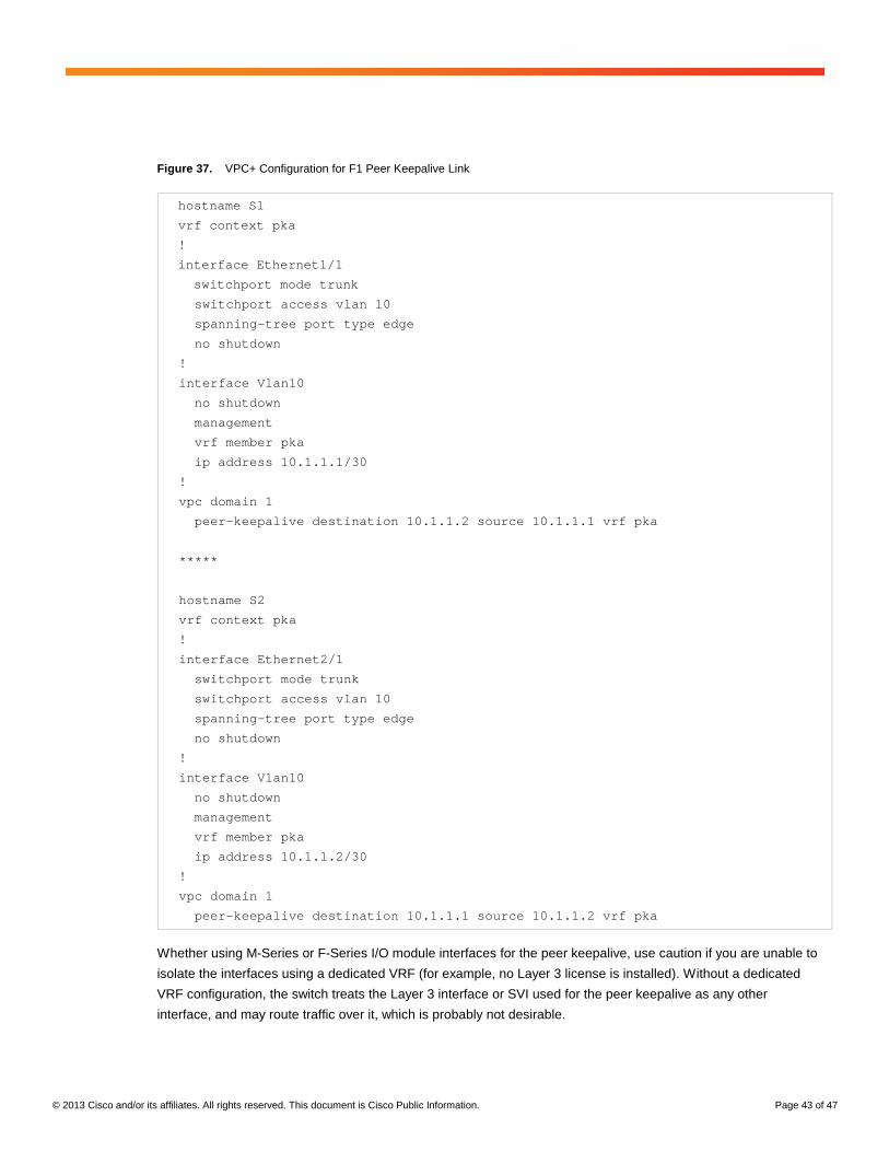
© 2013 Cisco and/or its affiliates. All rights reserved. This document is Cisco Public Information. Page 43 of 47
Figure 37. VPC+ Configuration for F1 Peer Keepalive Link
hostname S1
vrf context pka
!
interface Ethernet1/1
switchport mode trunk
switchport access vlan 10
spanning-tree port type edge
no shutdown
!
interface Vlan10
no shutdown
management
vrf member pka
ip address 10.1.1.1/30
!
vpc domain 1
peer-keepalive destination 10.1.1.2 source 10.1.1.1 vrf pka
*****
hostname S2
vrf context pka
!
interface Ethernet2/1
switchport mode trunk
switchport access vlan 10
spanning-tree port type edge
no shutdown
!
interface Vlan10
no shutdown
management
vrf member pka
ip address 10.1.1.2/30
!
vpc domain 1
peer-keepalive destination 10.1.1.1 source 10.1.1.2 vrf pka
Whether using M-Series or F-Series I/O module interfaces for the peer keepalive, use caution if you are unable to
isolate the interfaces using a dedicated VRF (for example, no Layer 3 license is installed). Without a dedicated
VRF configuration, the switch treats the Layer 3 interface or SVI used for the peer keepalive as any other
interface, and may route traffic over it, which is probably not desirable.
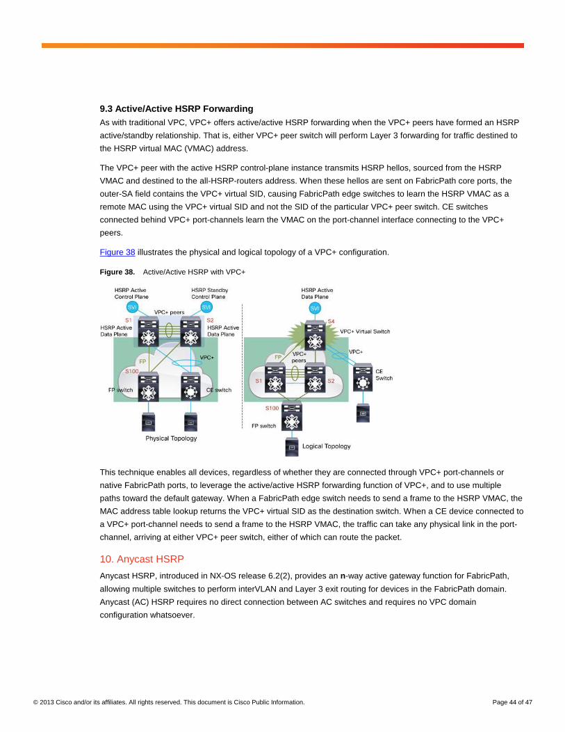
© 2013 Cisco and/or its affiliates. All rights reserved. This document is Cisco Public Information. Page 44 of 47
9.3 Active/Active HSRP Forwarding As with traditional VPC, VPC+ offers active/active HSRP forwarding when the VPC+ peers have formed an HSRP
active/standby relationship. That is, either VPC+ peer switch will perform Layer 3 forwarding for traffic destined to
the HSRP virtual MAC (VMAC) address.
The VPC+ peer with the active HSRP control-plane instance transmits HSRP hellos, sourced from the HSRP
VMAC and destined to the all-HSRP-routers address. When these hellos are sent on FabricPath core ports, the
outer-SA field contains the VPC+ virtual SID, causing FabricPath edge switches to learn the HSRP VMAC as a
remote MAC using the VPC+ virtual SID and not the SID of the particular VPC+ peer switch. CE switches
connected behind VPC+ port-channels learn the VMAC on the port-channel interface connecting to the VPC+
peers.
Figure 38 illustrates the physical and logical topology of a VPC+ configuration.
Figure 38. Active/Active HSRP with VPC+
This technique enables all devices, regardless of whether they are connected through VPC+ port-channels or
native FabricPath ports, to leverage the active/active HSRP forwarding function of VPC+, and to use multiple
paths toward the default gateway. When a FabricPath edge switch needs to send a frame to the HSRP VMAC, the
MAC address table lookup returns the VPC+ virtual SID as the destination switch. When a CE device connected to
a VPC+ port-channel needs to send a frame to the HSRP VMAC, the traffic can take any physical link in the port-
channel, arriving at either VPC+ peer switch, either of which can route the packet.
10. Anycast HSRP
Anycast HSRP, introduced in NX-OS release 6.2(2), provides an n-way active gateway function for FabricPath,
allowing multiple switches to perform interVLAN and Layer 3 exit routing for devices in the FabricPath domain.
Anycast (AC) HSRP requires no direct connection between AC switches and requires no VPC domain
configuration whatsoever.

© 2013 Cisco and/or its affiliates. All rights reserved. This document is Cisco Public Information. Page 45 of 47
AC HSRP uses the following mechanisms to implement the n-way active gateway function:
● All AC HSRP switches share a virtual gateway IP address for each VLAN/SVI, exactly as in traditional
HSRP
● All AC HSRP switches share a virtual gateway MAC address for one or more VLANs/SVIs, exactly as in
traditional HSRP
● All AC HSRP switches advertise reachability to an Anycast SID (ASID), a virtual SID shared by all the AC
HSRP switches
In the control plane, one of the AC HSRP switches assumes the Active state, one the Standby state, and any
others the Listen state, as shown in Figure 39.
Figure 39. Anycast HSRP Control Plane State
The Active switch processes all ARP requests for the virtual gateway IP address, responding with the virtual MAC
address. In addition, the Active switch sources HSRP Hello packets from the ASID so that the virtual MAC is
learned by other switches as connected to the ASID, as shown in Figure 40.

© 2013 Cisco and/or its affiliates. All rights reserved. This document is Cisco Public Information. Page 46 of 47
Figure 40. Anycast HSRP Hellos
Other FabricPath switches treat the ASID as they do any other SID - they install a route and can forward traffic
destined to the ASID using multiple parallel paths (ECMP) if available. Figure 41 illustrates the resulting state in
other FabricPath switches in an Anycast HSRP environment - for example, edge switch S100 has 4-way ECMP
toward the ASID and will load share traffic destined to the HSRP virtual MAC across all four paths.
Figure 41. ECMP for the Anycast SID
AC HSRP delivers a significant advantage with respect to failure detection because the availability of a given AC
HSRP switch is based on FabricPath IS-IS reachability, not expiring HSRP dead timers. For example, if an AC
HSRP switch fails, the IS-IS adjacencies are immediately lost on neighbor switches and reachability of the ASID
through those switches is withdrawn and the remaining AC HSRP switches can transition state immediately as
necessary.
11. Conclusion
As illustrated in this document, the FabricPath technology available on Nexus 7000 Series switches running NX-
OS software introduces new control-plane and data-plane capabilities that allow network operators to create
Ethernet fabrics that increase maximize bandwidth availability, provide design flexibility, and simplify and cost-
reduce network and application deployment and operation.
Additional information about FabricPath is available online at: http://www.cisco.com/go/fabricpath.

© 2013 Cisco and/or its affiliates. All rights reserved. This document is Cisco Public Information. Page 47 of 47
Printed in USA C11-687554-01 11/13
Related Documents