/^S'O RENEWABLE ENERGY A REPORT LIBRARY PLEASE RETURN MAY! 11184 GEOTHERMAL HEATING SYSTEM FOR THE FIRST NATIONAL BANK OF WHITE SULPHUR SPRINGS, MONTANA Prepared for MONTANA DEPARTMENT of NATURAL RESOURCES and CONSERVATION

White sulphur springs geothermal well
Jul 13, 2015
Welcome message from author
This document is posted to help you gain knowledge. Please leave a comment to let me know what you think about it! Share it to your friends and learn new things together.
Transcript

/^S'O RENEWABLE ENERGYA REPORT LIBRARY
PLEASE RETURNMAY! 11184
GEOTHERMAL HEATING SYSTEM
FOR THE FIRST NATIONAL BANK
OF WHITE SULPHUR SPRINGS, MONTANA
Prepared for
MONTANA DEPARTMENT of NATURAL RESOURCES and CONSERVATION

JUNl3t984
FEB 1 51989MAR 3 } 1993
MONTANA STATE LIBRARYS 333.88 N7gh 1 980 c. 1 QroveQaothermal heating system lor the Ftr»t
3 0864 00047134 5

GEOTIIERMAL HEATING SYSTEM FOR THE FIRST NATIONAL PANK OF
VmiTE SULPHUR SPRINGS, MONTANA
Prepared by
Michael Grove Darrel E. DunnFirst National Bank Earth Science Services, Inc.
White Sulphur Springs, 1115 North 7th AvenueMT 59645 Bozeman, MT 59715
August, 1980
Prepared for
Montana Department of Natural Resources and Conservation32 South Ewing, Helena, Montana 59620
Renewable Energy and Conservation ProgramGrant Agreement Number 503-771
Available from
Montana State Library, 1515 East Sixth AvenueJustice and State Library Building, Helena, Montana 59620
This report was prepared under an agreement funded by the Montana Department ofNatural Resources and Conservation. Neither the Department, nor any of its
employees makes any warranty, express or implied, or assumes any legal liability or
responsibility for the accuracy, completeness, or usefulness of any informationapparatus, product, or process disclosed, or represents that its use would not
infringe on privately owned rights. Reference herein to any specific commercialproduct, process, or service by trade name, trademark, manufacturer, or otherwise,
does not necessarily constitute or imply its endorsement, recommendation, or
favoring by the Department of Natural Resources and Conservation or any employee
thereof. The reviews and opinion of authors expressed herein do not necessarily
state or reflect those of the Department or any employee thereof.

A>-
RENEWABLE ENERGY PROJECT SPOTLIGHTFOR THE GEOTHERMAL HEATING SYSTEM
OF THE 1ST NATIONAL BANKWHITE SULPHUR SPRINGS
PURPOSE : This project was to explore the geothermal resource ofWhite Sulphur Springs, Montana and to design and develop a directheating system for the new bank building.
LOCATION : First National Bank of White Sulphur Springs, 205 WestMain Street, White Sulphur Springs, Montana.
PROJECT : The new bank building was constructed on the specificsite which has many hot springs, from which the town derived Itsname. The project Involved the drilling of a 895 foot well forgeophysical data and actual pumping of the hot water comes fromperforated fiberglass well casing, manufactured by the FiberfastCompany, from the 95 foot to the 395 foot levels. The water Ispumped from the well-head at 127 degrees Fahrenheit into thebuilding to its forced air type heating system. The geothermalwater flows through a series of fine tube colls manufactured byTrane Company and the controls are made by the Honeywell Company.The water leaves the building at 116 degrees Fahrenheit and istransported via PVC pipe underground to an adjoining motel forits use for space heating and its swimming pool.
The system uses a maximum flow rdte of 65 gallons per min-ute and is providing ^minimum of 80% of the heat for the buildingfor a savings of at least 150 barrels of oil per year or theequivalent of the heating of four residential homes.
The long range objective of this project was to providedata for further utilization of the geothermal resource at WhiteSulphur Springs, Montana. Approximately $15,000.00 or over 25%of the total project cost is directly attributable to resourceda.ta and analyzatlon. Much benefit was gained from this asevidenced by further proposals for heating of other buildingsin town, which are now in process.
SYST E M PERFORMANCE : The new bank building was completed andopened to the public in the fall of 1978. The geothermal heatingsystem was finalized and came operational in the spring of 1980.All systems are working we'll aflfd as the temperature drops theneed for the geothermal increases. As the water flows fasterits temperature increases makirig the system more efficient asthe need rises
.
The geothermal system is 100% backed up by a series ofelectric roils.

ECONOMIC EVALUATION ; The total cost of the project was $56,140.00Engineering and legal totalled $A,097.00, well drilling and casingand development $35,419.00, heating coils and systems $14,079.00with $2,545.00 for administration and travel. Of the total,43,500.00 was covered by grant funds.
%
Using the 80% efficiency factor it Is anticipated that thepayoff will b|t 15 years using constant costs and interest rates.By deducting those costs directly attributable to resourceanalyzation of $15,000.00, the payback period would be cut to10 years.
VIEWING t IMES : The project can be seen any business day betweenthe hours of 10:00 a.m. and 3:00 p.m. Other times by contactingMichael E. Grove at 547-3331.

C ON'E BR•ILCtNCS
ENOiNE BRINOMONTANA
D/^J ees-zs
<i^<D///SrAf/tC
W, S. S /sS/ NA//0/^^C SA//KCOMMUTATION
sysr€/€ 3C/f€M4//C
OK. av
tM
ny 3
< O
^•v.•>
\
^t'/'
!1

FIRST NATIONAL BANK OF WHITE SULPHUR SPRINGSTHERMAL WATER WELL GEOLOGIC REPORT
SUMMARY AND ANALYSIS
INTRODUCTION
The purpose of this report is to present the geologic and hydro! ogic data
obtained from the First National Bank of White Sulphur Springs thermal water
well, hereafter called the Well. The Well is located near the southeast corner
of the First National Bank property which is north of Main Street in the north-
east of the northeast of the northeast quarter of section 13, T9N, R6E, Meagher
County. This report is based on the information obtained from the Well and a
brief inspection of some pertinent published geologic reports. I will briefly
describe the information obtained from the Well and present an analysis of that
information.
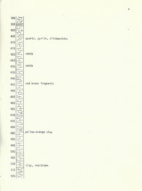
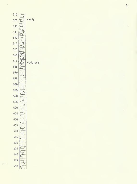
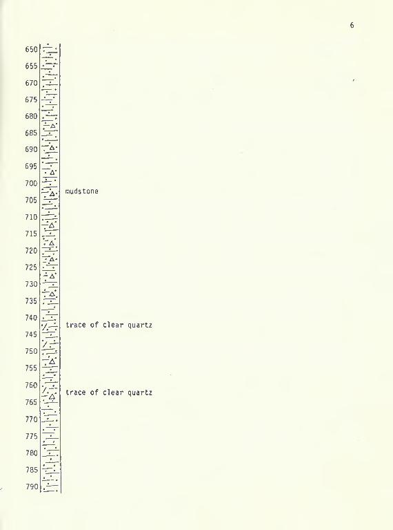
LITH0L06Y
No samples were caught for the portion of the hole from the ground surface
to 35 feet. Consequently, no discription is available for this interval. From
35 feet to the total depth of the hole, 875 feet, the subsurface material was
predominately gray mudstone with varying amounts of pyrite. Some of this mud-
stone was soft, but most was very hard because it was very well indurated. The
most indurated mudstone could have been called argillite. In the interval
between 168 feet and 265 feet, the subsurface material was approximately 50
percent silica-cemented quartz sandstone. A few thin beds of sandstone are
present above this section and also below it to about 400 feet depth. Yellow,
orange and redish brown clay was reported in the vincinity of 500 feet depth.
Considerable pyrite was found associated with all of the subsurface materials;
it occurs as aggregates disseminated throughout the materials and as vein filling.
Some of the pyrite showed well developed crystal faces suggesting growth in
open fractures. None of the subsurface material was found to be porous; con-
sequently, all of the void space in the subsurface must be open fractures. None
of the subsurface materials reacted with dilute hydrochloric acid indicating that
it is not calcareous. A few calcareous chips were found in the samples, but
these were thought to be derived from surfical material that caved into the mud
pits and was circulated into the hole. All of the subsurface materials found
are consistant with the lithology of the Greyson Shale.
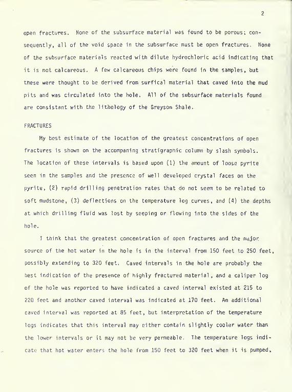
FRACTURES
My best estimate of the location of the greatest concentrations of open
fractures is shown on the accompaning stratigraphic column by slash symbols.
The location of these intervals is based upon (1) the amount of loose pyrite
seen in the samples and the presence of well developed crystal faces on the
pyrite, (2) rapid drilling penetration rates that do not seem to be related to
soft mudstone, (3) deflections on the temperature log curves, and (4) the depths
at which drilling fluid was lost by seeping or flowing into the sides of the
hole.
I think that the greatest concentration of open fractures and the major
source of the hot water in the hole is in the interval from 150 feet to 250 feet,
possibly extending to 320 feet. Caved intervals in the hole are probably the
best indication of the presence of highly fractured material, and a caliper log
of the hole was reported to have indicated a caved interval existed at 215 to
220 feet and another caved interval was indicated at 170 feet. An additional
caved interval was reported at 85 feet, but interpretation of the temperature
logs indicates that this interval may either contain slightly cooler water than
the lower intervals or it may not be very permeable. The temperature logs indi-
cate that hot water enters the hole from 150 feet to 320 feet when it is pumped.
and the hotest inflow may be in the interval from J50 feet to 190 feet (in the
vinclnity of the caved interval at 170 feet). In addition, an anomalous penetra-
tion rate between 240 feet and 245 feet suggests the presence of open fractures'
there. Some drilling fluid was lost from the hole when it reached a depth of
255 feet, and circulation was lost when the depth of the hole reached 276 feet.
At this latter depth the well was pumped at a rate of approximately 45 gallons
per minute (gpm), and very little drawdown was observed. Consequently, the
rocks above 276 feet must contain highly fractured zones which are very permeable.
It is noteworthy that this major fracturing is associated with the interval
that contains the silica-cemented quartz sandstone layers. The top of the
sandstone-bearing interval is at 168 feet and the base is at 265 feet, which is
the interval that includes the depths that are thought to contain the greatest
concentration of fracture-permeability. This observation is in correspondence
with information from the temperature logs and indicates that the sandstones
tend to contain more open fractures than the mudstones in the subsurface.
PUMP TEST
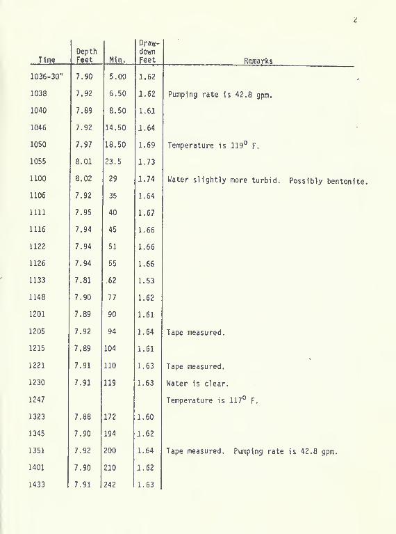
The Well was pump tested on August 12, 1978. The interval tested was from
the bottom of the surface casing at 100 feet to the top of the cement plug at
approximately 330 feet. The Well was first pumped at about 43 gallons per
minute (gpm) for a period of about 10 minutes. Then the pump was stopped be-
cause I was having difficulty measuring the water level in the Well. The Well
was allowed to recover for about 25 minutes. This initial pumping was probably
fortunate, because it served to remove relatively cool water from the Well and
thereby removed the effect of replacing cold water by hot water on the subsequent
water level measurements. The actual pump test began at 10:31 A.M., and the
Well was pumped at 42.8 gpm for 605 minutes (about 10 hours). Then the pumping

rate was increased to 79.5 gpm for an additional 400 minutes (6.67 hours). After
the pump was stopped, the recovery of the water level was measured for 69 minutes.
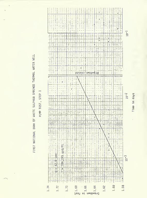
The results of the pump test are best illustrated by the time-drawdown graphs
which are presented near the end of this report.
Transmissivity, which is a measure of the ability of the aquifer to transmit
water, was estimated from the time-drawdown graphs. Three different values for
transmissivity were obtained: one from the initial pumping rate, a second from
the stepped-up pumping rate in the later part of the pump test, and a third from
the water level recovery measurements that were made after the pump was stopped.
These values were 182,000, 103,000, and 262,000 gpd/ft respectively. It is my
opinion that 103,000 is the best estimate of transmissivity because itis based
upon the graph with the least amount of scatter. The value for well loss co-
efficient calculated from the pump test is 0.00022, which is a fairly high value.
It suggests that the lost circulation material used during the drilling of the
hole may be partially plugging fractures and causing a high well loss.
Inspection of the time drawdown curves shows that drawdown ceased after
29 to 35 minutes in the first pumping step and after 41 to 51 minutes in the
second pumping step. One possible explanation for this stablization of draw-
down is that a "recharge" boundary exists in the vicinity of the Well. This
apparent boundary may be a more permeable part of the aquifer; indeed, it may be
an indication that the major "conduit" which serves to bring the hot water up
from depth is nearby. Another possibility is that this effect is caused by the
presence of the lost circulation material in the aquifer; however, I think that
the stabilization of water level would have occurred sooner if lost circulation
material were responsible. Whatever the cause of the stabilization, the pump
test results indicate that the water level in the Well is likely to decline very
little after the first hour of pumping at low pumping rates. With regard to the

ability of the well to supply water at 50 gpm for heating the bank, calculations
using the aforementioned values for transmissivity and well loss indicate that
the drawdown in the Well would be only about 1.22 feet. However, since this
pump test put very little stress on the aquifer, I think the results should be
used cautiously; and I recommend that a pump be set at least 15 feet below
ground level. Furthermore, since there will be some heat loss near ground level,
you might consider setting the pump near the bottom of the surface casing and
even introducing a seal above the pump to reduce the cooling effect of near-
surface heat exchange.
Before the pump test started, I measured (1) the water level in the pit
that serves the Spa Motel, (2) the water level in the ditch north of the Well
which carries hot water to the north fork of the Smith River, and (3) the water
level In the concrete pipe that carries water away from the fill area south of
Main Street. I found that the water level in the Spa Motel pit declined 0.045
feet during the pumping period, the water level in the ditch north of the Well
did not decline during the pumping period, and the water level in the concrete
pipe declined 0.11 feet. These observations indicate that pumping the Well
at low rates will not effect the flow in the ditch north of the Well. The decline
in water level in the Spa Motel pit was likely to have been caused by the pumping
of water from the pit itself which was occurring during the pump test period.
Whatever the cause, the water level in the pit did not decline much; and pumping
from the Well at low rates probably will have no significant effect upon the
productivety of the pit. The decline in flow rate from the fill area is puzzling;
but since the fill area is farther from the Well than the Spa Motel pit, it seems
unlikely that the decline was caused by pumping from the Well. However, I need
more information on the usual flow regimen of the ditch from the fill area before
I could make a reasonably good estimate of the effect of the Well on that ditch.

The temperature of the water was measured during the pump test. The meas-
urements were taken at the discharge end of a hose that carried the water to the
Main Street gutter. The temperature of the water near the beginning of the test
period was 119° F. After 136 minutes pumping, the temperature was 117° F. The
change from 119° F to 117° F is so small that I doubt if it should be considered
significant. Consequently, although the temperature measurements declined
during the test, the decline does not seem to exceed that which could be pro-
duced by measurement error and variations in heat loss from the discharge hose.
FLOW SYSTEM
The Well has provided some information on the nature of the thermal water
system in the area. An important consideration is whether the relatively low
temperatures measured near the bottom of the hole reflect natural low tempera-
ture of the rock and water at that depth or whether they are a result of the
invasion of cool bore hole fluid into the fractures at that depth. I do not
think that the cool temperatures at the bottom of the hole were a result of
settling of cool water from the top of the hole to the bottom, because this
water would have had to pass through the high temperature zone indicated on the
static temperature logs between 100 and 200 feet. Hypothetical conditions which
may be considered for the bottom portion of the hole are as follows: (1) the
rock in the bottom portion of the hole is permeable and contains hot water,
(2) the rock in the bottom of the hole is permeable and contains cold water,
(3) the rock in the bottom of the hole is low permeable material and contains
hot water, and (4) the rock in the bottom of the hole is low permeable material
and contains relatively cool water. I think that the first hypothesis (that
the rock in the bottom part of the hole is permeable and contains hot water)
may be rejected, because if this condition existed, the bottom of the hole

would have responded like the top of the hole when the temperature logs were
run, and high temperatures would have been measured at the bottom of the hole.
I think the second hypothesis may be rejected because relatively cool water
coming from permeable material in the bottom of the hole would have produced
cooler water near the top of the hole during the time the Well was simulta-
neously being pumped and temperature logged. The temperature logs show that
the (non-pumping) temperature in the upper part of the hole is very close to
the pumping temperatures. I think that the third hypothesis (that the rock in
the lower part of the hole has a low permeability but contains hot water) is
not consistant with heat flow considerations. Low permeability prevents any
rapid resupply of heat to the rock by water flowing through the rock in a nat-
ural flow system. Consequently, I think the rock may be maintained at a re-
latively cool temperature by conduction of heat away from that part of the
system. This heat flow is the result of the natural thermal gradient between
rock and water in the warmer part of the ground water system and the surrounding
cooler part of the system. Even if it is hypothesized that the thermal water
flow in the area is vertical and the hot water in the shallow permeable beds
has arrived by being transmitted upward through less permeable beds below it,
the observation are not consistant with the hypothesis; because this would imply
a relatively high hydraulic head gradient through the low permeable material
which in turn would produce flow between the bottom of the hole and the top of
the hole while the hole was not being pumped. Such flow would tend to cause
any cool water introduced from the hole into the low permeable rocks to move
out of the low permeable rocks during the non-pumping period and non-pumping
temperature measured near the bottom of the hole would not be low. The fourth
hypothesis (that the rocks in the lower part of the hole have a low permeability
and contain relatively cool water) seems to be consistant with the temperature

8
logs and other Information obtained from the Well and with heat-flow consider-
ations. Low permeable portions of thermal ground water systems should tend to
be cooler than associated high permeable portions of the system because they '
can not conduct a high volumetric flow rate of hot water. Therefore, the heat
supply is less and the low permeable portion of the system will tend to remain
cooler because of the conduction of heat caused by the temperature gradient
between this part of the system and nearby cool parts of the system.
I think that the correspondence between permeability and the quartz sand-
stone beds is not a coincidence. The probability that this well would acciden-
tally be drilled at a location where the boundaries of the sandstone interval
and the boundaries of an inclined sheer zone would coincide is too low. I think
the fractured sandstone simply tends to be more permeable than the associated
fractured mudstone. If this is the case, and the sandstone layer is nearly hori-
zontal, then any horizontal component in the hydraulic head gradient in the
system will tend to produce a large horizontal movement of water along the bed.
Consequently, the bed would tend to cause hot water to move horizontally away
from the hottest part of the system before it continues its upward movement
toward discharge areas at the ground surface. Therefore, hot water is prob-
ably flowing horizontally through this sandstone interval away from the central
part of the thermal ground water system where the water is moving upward from
the heat source at depth, I would expect the water In the sandstone to become
hotter as this source Is approached, and water In the mudstone above the sand-
stone Interval should also become hotter toward the source. Consequently, the
source is probably south, southeast, or east of the Well, because water that
has come to the surface in the hot springs area southeast of the Well has been
reported to be hotter than any water found In the Well. Weed U896) visited the
area near the end of the last century and reported that the water Issued from

nine large springs and several seepages whose combined flow was estimated at
13,000 gallons per hour (217 gpm) and he said that water used to supply public
baths had a temperature of 123J5° F (51° C). Since the hottest temperature
measured at the Well was 119° F, the water mast become hotter as the old thermal
spring area is approached.
CONCLUSIONS
Information obtained from this thermal water well indicates that 50 gallons
per minute may be obtained from the Well without producing adverse affects on the
supply of hot water to nearby springs; however, the decline in flow from the fill
area south of Main Street during the pump test remains unexplained. Since the
Well was pumped over ten hours and the temperature of the water declined only
slightly or not at all, and since the Well is probably drawing in water from
hotter more permeable parts of the thermal ground water system, it seems fairly
unlikely that the temperature of the water from the Well will decline when it is
pumped for long periods of time to heat the First National Bank building. How-
ever, a temperature decline can not be completely ruled out.
Since sandstone layers located at depths between 150 and 265 feet at the
Well site may be conducting hot water away from the source area, it seems likely
that these same sandstone layers may be tapped for hot water elsewhere in the
vicinity; and the closer the well is to the source area the hotter the water
will be.
If further exploration in the area is desired, one approach would be to
drill shallow wells to this sandstone interval and measure the temperature of
the water encountered in the wells and the hydraulic head of the system at the
well sites. Both temperature and head should increase as the source is approached;
of course the temperature of the water must be taken into consideration when the
head is measured. Having found the location of the hottest water and highest

10
head In the sandstone aquifer, further exploration could be pursued by drilling
one or more deep tests. If the hot water is rising essentially vertically from
a deep seated heat source, then a deep test in the maximal area indicated by the
shallow test wells should be successful. However, if the direction of the rise
is affected by an inclined fault or sheer zone, then more than one well might
be required to explore the deep subsurface. Such exploration would be expensive.
However, the deeper water is likely to be much hotter than the water that arrives
at the surface because of heat loss due to heat transfer near the surface and
because of mixing with cooler surface waters near the surface.
REFERENCES CITED
Weed, W. H. (1896): Geology of the Castle Mountain mining district; U. S.
Geological Survey Bulletin 139.

APPENDIX

FIRST NATIONAL BANK, WHITE SULPHUR SPRINGS ii
5
10
15
20
25
30
35
40
45
50
55
60
65
70
75
80
85
90
95
100
105
110
115
120
125
130
;vi^
^ A
rA
~A
v.-t
~A
A
l=-r muds tone
*. sandstone
A pyrite
/ permeable fractureslikely
siliceous sandstone
hard mudstone, trace pyrite, possibly fractured
hard mudstone
hard mudstone, aa
mudstone with pyrite aggregates and veinlets
soft mudstone
mudstone, moderately soft
mudstone,
sandstone
mudstone, moderately soft
mudstone, hard
mudstone, fairly soft
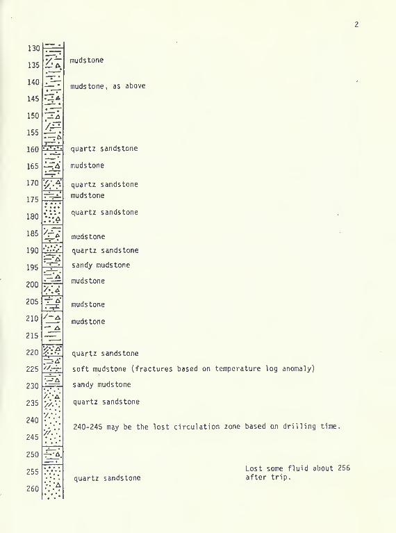
muds tone
^— ' muds tone, as above
130
135
140
145
150
155

260
265
270
275
280
285
290
295
300
305
310
315
320
325
330
335
340
345
350
355
360
365
370
375
380]
385
390
. ..^.
—'A*
•— /^.
-A
mudstone
muds tone
mudstone
mudstone
mudstone
quartz sandstone
mudstone
shale, black (may cave, watch hole diameter)
Lost circulation at 276 .
after trip.
—•A
7^'
. sandy
390
520
'—\. muds tone
650
655
670
675
680
685
690
695
700
705
710
715
720
725
730
735
740
745
750
755
760
765
770
775
780
785
790

790
795
800
805
810
815
820
825
830
835
840
FIRST NATIONAL BANK OF WHITE SULPHUR SPRINGSTHERMAL WATER WELL GEOLOGIC REPORT
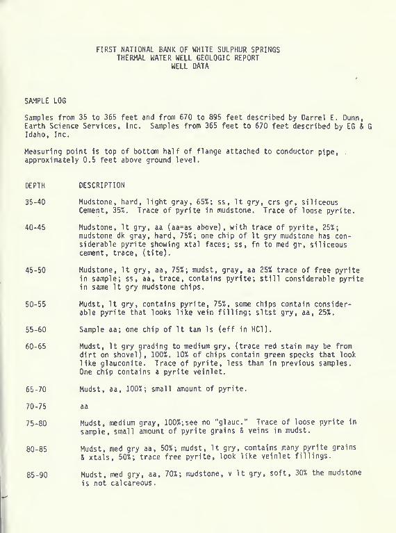
WELL DATA
SAMPLE LOG
Samples from 35 to 365 feet and from 670 to 895 feet described by Darrel E. Dunn,Earth Science Services, Inc. Samples from 365 feet to 670 feet described by EG & 6Idaho, Inc.
Measuring point is top of bottom half of flange attached to conductor pipe, .
approximately 0.5 feet above ground level.
DEPTH DESCRIPTION
35-40 Mudstone, hard, light gray, 65%; ss. It gry, crs gr, siliceousCement, 35%. Trace of pyrite in mudstone. Trace of loose pyrite.
40-45 Mudstone, It gry, aa (aa=as above), with trace of pyrite, 25%;mudstone dk gray, hard, 75%; one chip of It gry mudstone has con-siderable pyrite showing xtal faces; ss, fn to med gr, siliceouscement, trace, (tite).
45-50 Mudstone, It gry, aa, 75%; mudst, gray, aa 25% trace of free pyritein sample; ss , aa, trace, contains pyrite; still considerable pyritein same It gry mudstone chips.
50-55 Mudst, It gry, contains pyrite, 75%, some chips contain consider-able pyrite that looks like vein filling; sltst gry, aa, 25%.
55-60 Sample aa; one chip of It tan Is (eff in HCl).
60-65 Mudst, It gry grading to medium gry, (trace red stain may be from
dirt on shovel), 100%. 10% of chips contain green specks that looklike glauconite. Trace of pyrite, less than In previous samples.
One chip contains a pyrite veinlet.
65-70 Mudst, aa, 100%; small amount of pyrite.
70-75 aa
75-80 Mudst, medium gray, 100%;see no "glauc." Trace of loose pyrite in
sample, small amount of pyrite grains & veins in mudst.
80-85 Mudst, med gry aa, 50%; mudst. It gry, contains many pyrite grains
& xtals, 50%; trace free pyrite, look like veinlet fillings.
85-90 Mudst, med gry, aa, 70%; mudstone, v It gry, soft, 30% the mudstone
is not calcareous.

90-95 Mudst, med gray, aa, 10%; mudstone, v It gry, aa, 5%; mudst, v It
gry, speckled, specs are probably pyrite or similar mineral (chips
contain as much as 20% "pyrite" specs), moderately soft.
95-100 Mudst, It gry to med gry, a few grains contain much pyrite.
100-105 Mudst, med gry, 100%, a flat surface of one grain is coated withpyrite. Trace of poorly sorted ss , silt to crs grains, crs grains
well rounded, trace loose pyrite.
105-110 Mudst, light gry, moderately soft, speckled, specks look green to
blk, specs prob sulfide mineral, 100%.
110-115 aa
115-120 Mudst, med gry, hard, contains medium amount of pyrite in grains,aggregates & veinlets, one grain face is coated with pyrite xtalssuggesting open fracture, 100%.
120-125 aa, no coated surfaces, but several chips of loose pyrite.
125-130 Mudst, med gry, aa, SOX; mudst, It gry, fairly soft, speckledwith pyrite xtals, few pyrite veinlets, 50%.
130-135 Mudst, It gry to med gry, medium amount of pyrite xtals, aggre-gates, veinlets, 100%. Trace loose pyrite chips.
135-140 Mudst aa, only a small amount of pyrite, mudst contains some fn
sd size grains, 100%.
140-145 Mudst, aa, 100%. One chip fn xln, rk, qtz prob greater than 10%,contains considerable pyrite, possibly vein filling igneous rock.
145-150 Mudst, aa, slightly more pyrite, 100% (few pieces of fairly soft.It gry, mudst)
.
150-155 Mudst, aa, 100%; trace loose pyrite chips (aggregates of xtals);trace quartzite, clear qtz, fn to med xln.
155-160 Mudst, aa, 75%; ss, fn to med gr, silica cement, tite, med gry,no reaction w HCl , contains some soft white grains (kaolinite ?),a few chips contain pyrite, most do not, 25%.
160-165 Mudst, It to med gry, contains a small amount of pyrite as xtalsand aggregates, 100%. No loose pyrite or veinlets.
165-170 Mudst, aa, 75%; ss, v fn to med gr. It (jry, siliceous cement,
tite, no reaction w HCl, some soft white grains (kaolinite ?),
small amount of pyrite aggregates and xtals.
170-175 Mudst, It gry, w pyrite specks, 25%; mudst, med gry, 25%; ss
,
v fn to fn gr, med gry, tite, no pyrite, siliceous cement, 50%;
trace ss, med gr, with pyrite, tite.

175-180 Ss, V fn to fn gr, aa, lOX; ss, med gry, poorly sorted, v fn to
med gr, siliceous cement, no reaction w HCl. tite, few grains,
soft wh (kaolinite ?). ss contains no pyrite, 90%.
180-185 Mudst, white with v small grn & blk specs, medium soft, 50%; ss,
V fn to med gr, aa, 50%; Small amount of loose pyrite aggregates.
Small amount of pyrite aggregates in the very fn to med gr ss.
185-190 aa, no loose pyrite.
190-195 Mudst, med to dk gry, sandy (v fn grains), very few pyrite xtals,
100%; no loose pyrite.
195-200 Mudst, It gry to med gry, very small amount of pyrite, 90%; ss,
med gray, v fn to med gr, tite, siliceous cement, no reaction w
HCl , no pyrite, 10%.
200-205 Mudst, It gry, speckled w pyrite, 50%; ss, med gry, medium grained,
contains few soft white grains (kaolinite ?), tite, siliceous
cement, no reaction w HCl, one chip has pyrite coating on flat
surface, one chip contains irregular shaped pyrite veinlet, 50%;
trace of loose pyrite in sample.
205-210 Mudst, aa, 50%; mudst, med gry, sdy, siliceous cement, tite, no
reaction w HCl, one chip contains zoned vein w light colored
pyrite (?) in center and dark brownish-gold colored mineral on
sides, some chips contain Irregular aggregates of pyrite, 50%.
210-215 Mudst, aa, 50%; mudst, sdy, aa, 50%.
215-220 Mudst, It gry, aa, 25%; ss , med gry, poorly sorted, fn to med gr,
contains white, soft grains (kaolinite ?), 2 chips contain flat
surfaces coated w pyrite, siliceous cement, no reaction w HCl, 75%.
Few loose chips of pyrite.
220-225 Mudst, med gry, sdy, 50%; mudst. It gry, soft, with specks of pyrite
(?), 25%; ss, med to crs gr, med gry, contains grains of soft white
material (kaolinite ?), tite, contains a small amount of irregular
aggregates of pyrite, 25%.
225-230 Mudst, It gry, soft aa, 10%; mudst, sdy, aa, 75%; mudst. It gry,
w specks of pyrite, hard, 15%. No loose pyrite in sample.
230-235 Ss, med gry, poorly sorted, silt to fn gr size, siliceous cement,
no reaction w HCl, 100%; tr ss, med grained, w pyrite aggregates;
trace loose pyrite in sample.
235-240 aa
240-245 aa
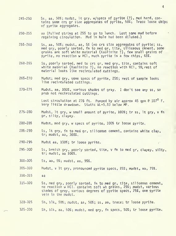
245-250 Ss, aa, 50%; mudst, It gry, w/specs of p^rtte C?), jned hard, con-
tains some crs gr size aggregates of pynte, 50%; Trace loose chtps
of pyrtte aggregates.
250-255 aa (Pulled string at 255 to go to lunch. Lost some mud before
regaining circulation. Mud In hole had been diluted.)
255-260 Ss, aa, 50%; mudst, aa, 5% (no crs size aggregates of pyrite; ss,
med gry, poorly sorted, fn to med gr, tite, siliceous cement, some
grains are soft white material (Kaolinite ?), few small grains ofpyrite, no reaction w HCl , much pyrite in a few chips, 45%.
260-265 Ss, poorly sorted, med to crs gr, med gry, tite, contains softwhite material (Kaolinite ?), no reaction with HCl, 5%; rest ofmaterial looks like recirculated cuttings.
265-270 Mudst; med gry, some specs of pyrite, 25%; rest of sample lookslike recirculated cuttings.
270-275 Mudst, aa, 100%, various shades of gray. I don't see any ss, soprob not recirculated cuttings.
Lost circulation at 276 ft. Pumped by air approx 45 gpm P 107° F.
Very little drawdown. Static WL=5.53 below MP.
275-280 Mudst, It gry, w small amount of pyrite, 100%; tr ss, It gry, v fn
gr, silty, clayey.
280-285 Mudst, med gry, w specs of pyrite, 100% tr loose pyrite.
285-290 Ss, It gry, fn to med gr, siliceous cement, contains white clay,tr; mudst, aa, 100%.
290-295 Mudst aa, 100%; tr loose pyrite.
295-300 Ss, brnish gry, poorly sorted, tite, v fn to med gr, clayey, silty,tr; mudst, aa 100%.
300-305 Ss, aa, 5%; mudst, aa, 95%.
305-310 Mudst, v It gry, pronounced pyrite specs, 25%; mudst, aa, 75%.
310-315 aa
315-320 Ss, med gry, poorly sorted, fn to med gr, tite, siliceous cement,no reaction w HCl. contains soft wh grains, 25%; mudst, variousshades of gray, various degrees of pyrite specs, 75%, one pyritevein in the mudst.
320-325 Sh, blk, 50%; mudst, aa, 50%; ss , aa, trace; tr loose pyrite.
325-330 Sh, blk, aa, 50%; mudst, med gry, fn specs, 50%; tr loose pyrite.

330-335 Mudst, med gry, aa, 60X; sh, blk, aa, 15%; jnudst, jned gry, w blmottles & laminae, 25%;
335-340 Mudst, mottled, aa, 95%; sh, blk, aa, 5%; mottled sh contains smallamt of pyrite aggregates and veinlets; tr loose pyrite.
340-345 Mudst, med gry, 95%; sh, blk, aa, 5%; tr ss, aa; med gry mudstcontains a pyrite veinlet.
345-350 Mudst, aa 100%.
350-355 aa
355-360 Mudst, various shades of gry, variously speckled w pyrite, 100%.
360-365 Mudst, aa 95%; angular fragments of clear, colorless qtz, 5%; morepyrite than usual assoc w mudst/veinlets & loose chips.
365-370 Mudst, gry, 60%; mudst blk 35%; pyrite, 5%.
370-375 Mudst, gry; pyrite. Frags smaller than 365-370.
375-380 Mudst, blk; some carbonate.
380-385 Mudst, blk; no HCl reaction.
385-390 Mudst, blk, 50%; mudst gry, 50%; no HCl reaction.
390-395 Mudst, gry; pyrite; sd, crs and fine, gry; rust, fn sd size particles,10%; no HCl reaction.
395-400 Mudst (?), gry speckled w blk, appears crystalline; pyrite; noHCl reaction.
400-405 Mudst (?), grn-gry, 60%; mudst, gry, 40%; 1 crystal (?) qtz, Ig sdsize; no HCl reaction.
^ 405-410 Mudst, gry; qtz; pyrite; slick on sides; no HCl reaction.
410-415 Mudst, gry; pyrite; plastic fines, brn (drilling mud??); no HCl
reaction.
415-420 Mudst, gry; no HCl reaction.
420-425 Mudst, gry to grn-gry; no HCl reaction.
425-430 No description
430-435 Mudst, gry to grn-gry; chert?; no HCl reaction.
435-440 Fine sands & non-plastic fines, yellow-brn. Poor cutting return.
440-445 Mudst, brn, 50%; mudst, blk, 50%; non-plastic fines.

445-450 Mudst, gry, 75%; mudst, blk, 20%; pyrite; red-brn frags consllld
clay; no HCl reaction.
450-455 Mudst, gry 85%; mudst, blk, 10%; red-brn frags consolid clay, 5%;
some pastic fines, brn (drilling mud??); no HCl reaction.
455-460 No description.
460-465 Mudst, gry, 90%; mudst, blk, 5%; red-brn frags, 5%; no HCl reaction.
465-470 Mudst, gry, 75%; mudst blk 25%; pyrite; feldspar, white ??; no HClreaction.
470-475 Mudst, gry, 90%; laminated consolidated clay; pyrite; no HCl reaction.
475-480 Mudst, gry, 85%; mudst, blk, 15%; no HCl reaction.
480-485 Mudst, gry; pyrite; no HCl reaction.
485-490 Mudst, gry, 25%; clay, yellow-orange, 25%; poor return of cutting;no HCl reaction.
490-495 Clay, yellow-orange.
495-500 Mudst, blk, 33%; mudst, gry. 34%; clay, red-brn, 33%; no HCl reaction.
500-505 aa
505-510 Mudst, blk and gry, 60%; clay, red-brn, consolidated, 40%; no HCl
reaction.
510-515 aa
515-520 Mudst, aa, 75%; clay, aa, 25%; no HCl reaction.
520-525 Mudst, gry, 75%; mudst, blk, 20%; clay, brn, 5%; pyrite.
525-530 aa
530-535 Mudst, gry, 90%; mudst, blk, 5%; clay, brn, 5%; pyrite; no HCl
reaction.
535-540 aa
540-545 aa
545-550 aa
550-555 aa
555-560 Mudst, gry, 60%; mudst, blk, 40%, pyrite; no HCl reaction.
560-580 Mudst, dark.
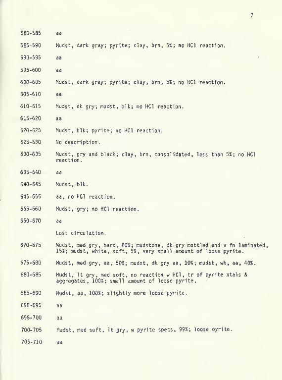
580-585 aa
585-590 Mudst, dark gray; pyrlte; clay, brn, 5%; no HCl reaction.
590-595 aa
595-600 aa
600-605 Mudst, dark gray; pyrite; clay, brn, 555; no HCl reaction.
605-610 aa
610-615 Mudst, dk gry; mudst, blk; no HCl reaction.
615-620 aa
620-625 Mudst, blk; pyrite; no HCl reaction.
625-630 No description.
630-635 Mudst, gry and black; clay, brn, consolidated, less than 5%; no HClreaction.
635-640 aa
640-645 Mudst, blk.
645-655 aa, no HCl reaction.
655-660 Mudst, gry; no HCl reaction.
660-670 aa
Lost circulation.
670-675 Mudst, med gry, hard, 80%; mudstone, dk gry mottled and v fn laminated,15%; mudst, white, soft, 5%, y/ery small amount of loose pyrite.
675-680 Mudst, med gry, aa, 50%; mudst, dk gry aa, 10%; mudst, wh, aa, 40%.
680-685 Mudst, It gry, med soft, no reaction w HCl, tr of pyrite xtals &
aggregates, 100%; small amount of loose pyrite.
685-690 Mudst, aa, 100%; slightly more loose pyrite.
690-695 aa
695-700 aa
700-705 Mudst, med soft. It gry, w pyrite specs, 99%; loose pyrite.
705-710 aa

710-715 Mudst, med gry w specs and aggregates of pyrlte, jnottled, no reaction
w HCl, 25%; mudst, It gry, aa, 74%; loose pyrlte, 1%.
715-720 Mudst, med gry, aa, iOO%; some loose pyrlte.
720-725 Mudst, med gry, aa, 50%; mudst It gry as In 700-705, 50%; some loose
pyrite.
725-730 Mudst, dk gry, no reaction w HCl, 25%; mudst, med gry, aa, 50%; mudst.
It gry, soft, no reaction w HCl, one pyrlte veinlet; small amount of
loose pyrite.
730-735 Mudst, dk gry, aa, 75%; mudst. It gry, aa, 25%; small amt of loose
pyrite.
735-740 Mudst, v dk gry, 30%; misc mudst & ss, prob cavings and/or recirculated
material.
740-745 Mudst, v dk gry, aa, 20%; misc mudst 80%; many loose aggregates of
clear quartz (vein quartz?); trace of bright red soft material
(Fe-oxide?), no reaction w HCl; trace of yellow material, soft,
translucent, no reaction w HCl; small amount of loose pyrite aggre-
gates.
745-750 Mudst, vdk gry to black, aa, 50%, contains pyrite; mudst, med gry,
50% trace clear qtz, aa.
750-755 aa, no clear qtz, one pyrite veinlet in med gry mudst.
755-760 aa
760-765 aa, tr loose pyrite, tr clr qtz.
765-770 aa
770-775 aa, no loose pyrite
775-780 aa, no clr qtz
780-785 Mudst, v dk gry to blk, aa, 75%; mudst, med gry, aa, 25%.
785-790 aa
790-795 Mudst, v It gry w pyrite specs; 50%; mudst, v dk gry to blk, aa,
25%; mudst, med gry, aa, 25%.
795-800 aa, tr loose pyrite.
800-805 Mudst, med gry (new lithology), 75%; mudst, y dk gry to blk, aa,
25%; mudst, v It gry to blk, aa, 25%; mudst, v It gry, aa, 25%.
805-810 Mudst, v It gry, aa, w a few pyrite veinlets, 80%; mudst, v dk gry
to blk, aa, 10%; mudst, med gry, aa, 10%.

810-815 Mudst, jDed gry, w pyrlte specs & yeinlets, 90%; jntsc jnudst, 10%-,
tr loose pyrtte.
815-820

PUMP TEST
White Sulphur Springs Ftrst National Bank, Well #.1
August 12, 1978
Measurements by Darrel E. Dunn.
Measuring point is top of fiberglass casing, which is 0.86 ft. above flange.Flange was measuring point when drilling well. Measured by electic sounderunless otherwise noted.
TimeDepthFeet
Time

Time

Time
to
cc
o
<:zo
^93^ Ul UAAOpMejQ

uMopMejQ lenpisay

CM CVJ

dp6«i6i)U93 'aJn^eaaduiai
S901 3«niVM3dW3i


15 copies of this public document were published at
an estimated cost of $3.67 per copy, for a total cost of
$55.00, which includes $55.00 for printing and $.00 for
distribution.

Related Documents