WHITE PAPER: OPEN RACK SOLUTION BLUEPRINT EDITOR(S): Esa Hietto, Nokia Solutions and Networks OY Samuli Toivola, Nokia Solutions and Networks OY

Welcome message from author
This document is posted to help you gain knowledge. Please leave a comment to let me know what you think about it! Share it to your friends and learn new things together.
Transcript

WHITE PAPER: OPEN RACK SOLUTION
BLUEPRINT
EDITOR(S):
Esa Hietto, Nokia Solutions and Networks OY
Samuli Toivola, Nokia Solutions and Networks OY
PAGE 2
Executive Summary
This document describes the main characteristics of Open Rack configurations for compute, storage and hybrid
installations. Examples of rack configurations, including power feed and networking, are provided.
Table of Contents

PAGE 3
Introduction 4
1 Open Rack deployment options 5
Open Rack building blocks 6
Server configuration options 7
JBOD configuration options 9
Rack configuration options 10
Rack configuration Block types 11
Rack mechanical and power options 18
2 Conclusion 20
3 Glossary 20
4 References 20
5 License 21
6 About Open Compute Foundation 21
7 Appendix A. [Title] 22

PAGE 4
Introduction
This document describes different options in configuring Nokia Open Rack systems. Nokia Build to Order model
(BtO) allows users to configure server, JBOD and rack level configurations from pre-validated components,
which are selectable in Nokia configurator tool. Configurations can be defined in ways that best fits user
requirements. The tool will generate a detailed asset file of the complete system, which the integrating factory
will use to build the defined configuration. Servers, JBOD’s, switches, power distribution units and the related
cabling are all factory integrated and tested, after which the system is packed and delivered to customer site in
turnkey mode. The customer only needs to power up the system and use Nokia data center manager (NADCM) to
upload device MAC addresses and IP plan from asset file and start automated deployment for the Hardware
configuration.
PAGE 5
1 Open Rack deployment options
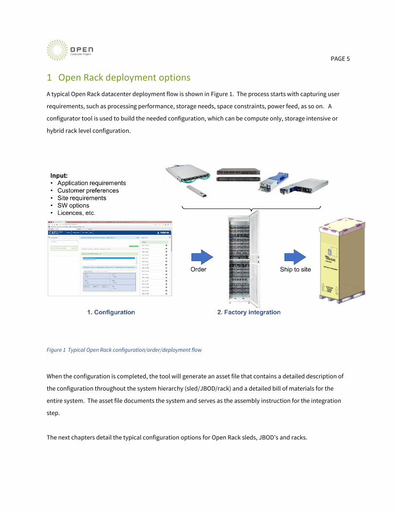
A typical Open Rack datacenter deployment flow is shown in Figure 1. The process starts with capturing user
requirements, such as processing performance, storage needs, space constraints, power feed, as so on. A
configurator tool is used to build the needed configuration, which can be compute only, storage intensive or
hybrid rack level configuration.
Figure 1 Typical Open Rack configuration/order/deployment flow
When the configuration is completed, the tool will generate an asset file that contains a detailed description of
the configuration throughout the system hierarchy (sled/JBOD/rack) and a detailed bill of materials for the
entire system. The asset file documents the system and serves as the assembly instruction for the integration
step.
The next chapters detail the typical configuration options for Open Rack sleds, JBOD’s and racks.

PAGE 6
Open Rack building blocks
Open Rack configurations uses the following hardware building block types:
• Rack: provides mounting positions for Open Rack HW products
• Power Shelf: Feeds power from the site power feed to Nokia Open Rack HW building blocks
• Server node: 2 OU 1/3 shelf dual socket Purley based server including interconnection adapters,
security modules, storage devices, cooling, power and HW management
• Ethernet Switches provides interconnection between server nodes and aggregation switches and
routers
• Interconnection products:
o MSA compliant SFP, SFP+, SFP28, QSFP, QSFP28 pluggable transceivers
o SFP+/SFP28/QSFP/QSFP28 Direct Attach Cables (passive copper)
o SFP+/SFP28/QSFP/QSFP28 Active Optical Cables
o QSFP to 4x SFP+, QSFP28 to 4x SFP28 and QSFP28 to 2x QSFP28 break out cable (passive
copper)
Figure 2 Open Rack building blocks

PAGE 7
Server configuration options
Telco NFV optimized Open Rack server is a dual-socket 2 OU and 1/3 shelf server barebone. It supports Intel
Xeon Purley platform processor(s) and up to 12x DDR4 RDIMM modules max. 2933 MT/s. A single node is capable
of supporting 165W TDP processors.
OCP mezzanine slot supports dual port NICs up to 100Gb Ethernet. Mezzanine slot has PCIe x16 connection
towards Socket 0. In addition, there are two PCIe card slots for flexible expansion use, both with PCIe x16
connections. Lower expansion slot is connected to Socket 0 and upper slot to Socket 1. Barebone has two 2,5”
bays for SATA or NVMe devices from U.2 interface and two M.2 slots with SATA and NVMe interfaces.
The different configuration options of an Open Rack server sled are illustrated in Figure 3.
Figure 3 Open Rack Server sled configuration options
Some of the key choices in configuring a server are described below.
• Server barebone

PAGE 8
o Server motherboard with or without QAT (Lewisburg PCH C627 or C621)
• CPU and memory options
• NIC card options for OCP mezzanine and PCIE FHHL slots
• Storage controller RAID and HBA options
• Accelerator options
• Local storage options dual 2.5” U.2 NVMe/SATA devices + dual M.2 devices

PAGE 9
JBOD configuration options
JBOD node is 2 OU and full width unit that has three independent drive sleds for storage devices. Tool-less
design allows users to upgrade, maintain and replace the devices with ease.
The JBOD implementation consists of 3 identical disk sleds each with a capacity of 15 drives.
Both 3,5” and 2,5” drives are supported. With 2,5” form factor drives heights of 7 mm, 10 mm and 15mm are
supported. Both form factors have own type of mechanical fittings / disc carriers for the easy drive insertion and
removal. With these form factors both HDDs and SSDs with either SATA or SAS interface are supported. With
these features the JBOD allows equipping of disks according to each needed configuration.
The SAS interface chaining will allow several different configuration options.
Figure 4 Open Rack JBOD configuration options
Some of the key choices in configuring a JBOD are described below.
• Each three storage “sled” inside JBOD are independent
• 15 x hot swap bays for 2.5” / 3.5” devices in each sled
• Total 45x storage bays for either SATA or SAS HDD or SSDs

PAGE 10
Rack configuration options
Build to order model (BtO) allows user to configure server and JBOD configurations from validated components
that are available in BtO tool. Those L10 level configurations could be used with selected rack layout that fits
best for users’ requirements. Available rack space is divided in to four identical 8 OU areas that are called as
“Block”. Different block types are available to be selected from for each four rack locations. This gives flexibility
of different rack layout options that are filled with user specified L10 level server and JBOD configurations.
In addition to that user need to select required power feed option and whether to use payload and management
switches delivered together with rack or not. Selected options will be used to build rack system together with
required rack mechanics and cables.
Cabling will be factory integrated based on selected block types and tested with configured devices. Partially
configured rack systems support future expansions with full rack cabling that makes expansion device
installation straightforward. Seismic kit, Door set, Side panel set, and spine switch reservation are optional
items that user can select.
Figure 5 Open Rack system level configuration options

PAGE 11
Rack configuration Block types
Build-to-order (BtO) rack is available with flexible configurations. Rack cabling is defined selecting required
block types in three or four identical rack areas. Based on these definitions BtO rack system can be ordered in a
complete, factory-integrated rack system.
Figure 6 Available blocks for BtO templates in 42OU and 36OU racks

PAGE 12
OR19 BtO configurations use 42 OU or 36 OU Open Rack v2 rack frame which color is white. These rack systems
are available with three different power feed options and use always two power zone rack configurations. Rack
has support for seismic kit that improves rack seismic characteristics for NEBS Zone 4 compliancy with 850kg
(42OU) / 750kg (36OU) IT load.
42OU rack have 4 OU area in the middle of rack that is reserved for Leaf and HW-management switches. Optional
spine switch option is available in position OU41 and this option blocks other use for this location. Two 3 OU
areas are reserved for power feed. Remaining locations inside the rack are reserved for IT gears.
36OU rack have 4 OU area in the middle of rack that is reserved for Leaf and HW-management switches. Optional
spine switch option is available in position OU24 that is dedicated for Spine use. Two 3 OU areas are reserved for
power feed. Remaining locations inside the rack are reserved for IT gears.
IT gear space is divided in three (36OU) or four (42OU) identical 4x 2 OU blocks inside rack frame which are
available for node installation. Cabling inside one block is defined with block templates. Block templates has
three (36OU) / four (42OU) possible locations inside the rack (block 1 to block 4) and switch port usage is
different for each rack location to avoid overlapping switch ports.
Compute block template (4x 25GbE)
Compute block template supports 1-4 Compute triplets. Supported Compute server nodes should have 4x25GbE
connection towards Leaf switches and one management connection towards HW-management switch.
Compute template always includes cabling for all 4 Compute node triplets inside template even when partially
equipped.

PAGE 13
Figure 7 Compute block connectivity principle
Storage 3 block template (4x 25GbE)
Storage 3 block template supports 1x Storage Controller triplet and 3x JBODs. Supported Storage Controller
nodes should have 4x25GbE connection towards Leaf switches and one management connection towards HW-
management switch. Each JBOD in this template has two miniSAS cables connected towards dedicated Storage
Controller node inside the same template. Two additional mini-SAS cables connect three drive sleds together
inside one JBOD. Each single Storage Controller node controls all 45 device slots inside one JBOD node. Storage
3 template fully reserves one block from rack.

PAGE 14
Figure 8 Storage 3 block connectivity principle
Storage 1 block template (4x 25GbE)
Storage 1 block template supports 2x Storage Controller triplets and 2x JBODs. There are two independent
Storage Controller triplet / JBOD configurations inside this block template. Supported Storage Controller nodes
should have 4x25GbE connection towards Leaf switches and one management connection towards HW-
management switch. Each JBOD sled with Storage 1 template has two miniSAS cables connected towards
dedicated Storage Controller node inside the same template. Each single Storage Controller node controls 15
device slots inside JBOD node. Storage 1 template fully reserves one block from rack.
PAGE 15
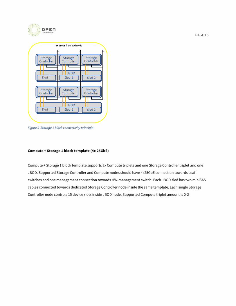
Figure 9 Storage 1 block connectivity principle
Compute + Storage 1 block template (4x 25GbE)
Compute + Storage 1 block template supports 2x Compute triplets and one Storage Controller triplet and one
JBOD. Supported Storage Controller and Compute nodes should have 4x25GbE connection towards Leaf
switches and one management connection towards HW-management switch. Each JBOD sled has two miniSAS
cables connected towards dedicated Storage Controller node inside the same template. Each single Storage
Controller node controls 15 device slots inside JBOD node. Supported Compute triplet amount is 0-2
PAGE 16
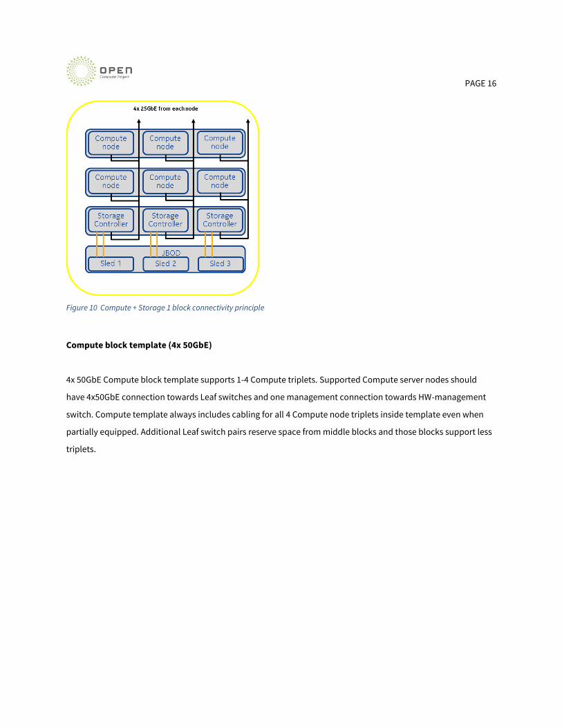
Figure 10 Compute + Storage 1 block connectivity principle
Compute block template (4x 50GbE)
4x 50GbE Compute block template supports 1-4 Compute triplets. Supported Compute server nodes should
have 4x50GbE connection towards Leaf switches and one management connection towards HW-management
switch. Compute template always includes cabling for all 4 Compute node triplets inside template even when
partially equipped. Additional Leaf switch pairs reserve space from middle blocks and those blocks support less
triplets.

PAGE 17
Figure 11 Compute (4x 50GbE) block connectivity principle
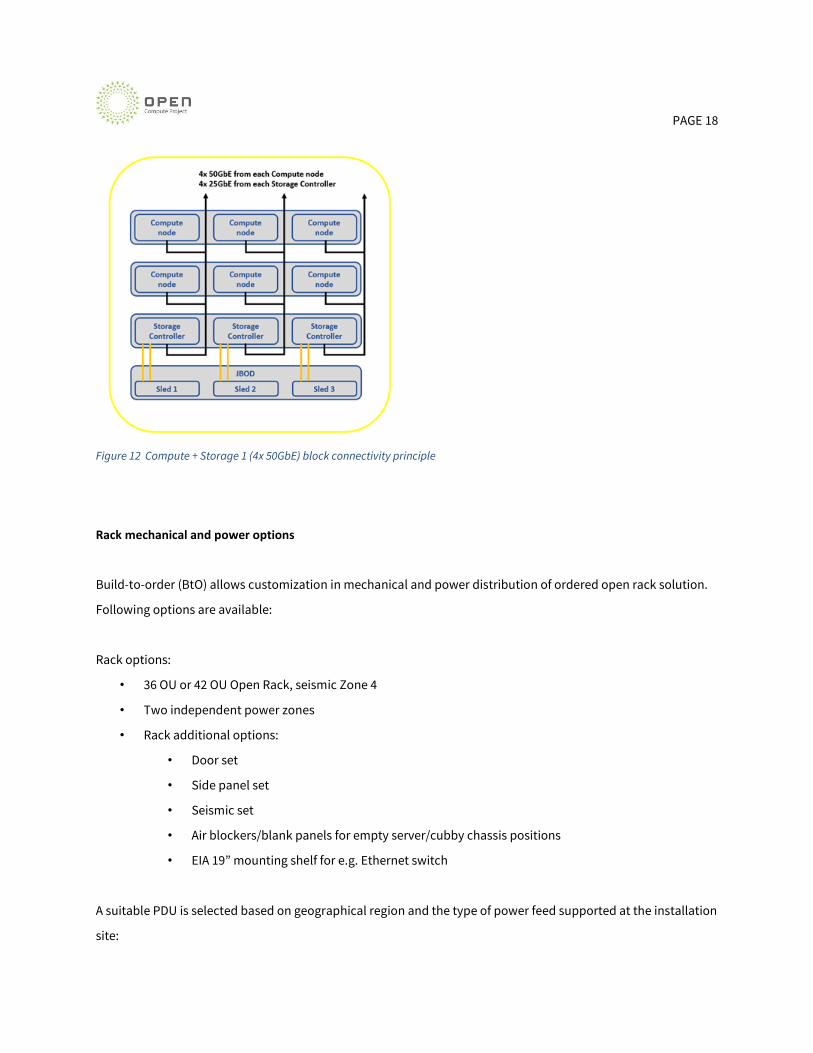
Compute + Storage 1 block template (4x 50GbE)
4x 50GbE Compute + Storage 1 block template supports 2x Compute triplets and one Storage Controller triplet
and one JBOD. Supported Storage Controller should have 4x25GbE connection towards Leaf switches. Compute
nodes should have 4x 50GbE connection towards Leaf switches and both having one management connection
towards HW-management switch. Each JBOD sled have two miniSAS cables connected towards dedicated
Storage Controller node inside the same template. Each single Storage Controller node controls 15 device slots
inside JBOD node. Supported Compute triplet amount is 0-2.
PAGE 18
Figure 12 Compute + Storage 1 (4x 50GbE) block connectivity principle
Rack mechanical and power options
Build-to-order (BtO) allows customization in mechanical and power distribution of ordered open rack solution.
Following options are available:
Rack options:
• 36 OU or 42 OU Open Rack, seismic Zone 4
• Two independent power zones
• Rack additional options:
• Door set
• Side panel set
• Seismic set
• Air blockers/blank panels for empty server/cubby chassis positions
• EIA 19” mounting shelf for e.g. Ethernet switch
A suitable PDU is selected based on geographical region and the type of power feed supported at the installation
site:

PAGE 19
• 415 VAC, 3P, 32 A
• 208 VAC, 3P, 40 A
• -48 VDC
There are two power shelf options available (AC/DC). Maximum allowed configuration power consumption
depends on selected power system:
• 208/415V AC, 25kW per rack
• ETSI -48V DC, 17.4kW per rack
Empty rack positions are equipped with blank panels that prevent air circulation between rack front and rear.
Airflow thru unused server positions inside three bay shelf can be blocked using server blank panels. Airflow thru
the slots between Ethernet switches are blocked with cable management accessory that also blocks the airflow.
PAGE 20
2 Conclusion
Open Rack data center deployments come in large variety of use cases and system requirements. A good degree
of flexibility is mandatory in configuring the HW for optimized TCO, performance, site power distribution
variants and overall competitiveness. The Nokia configurator tool allows scaling the system from small number
of servers to multiple racks, while allowing tailoring of the HW configuration of each server according to
customer needs.
3 Glossary
BtO: Built to Order
OCP: Open Compute Project
RMC: Rack Management Controller
4 References
1. Open Rack server specification: https://www.opencompute.org/documents/nokia-telco-enhanced-
openrack-server-specification
2. Open compute marketplace: https://www.opencompute.org/products

PAGE 21
5 License
© Copyright Nokia Solutions and Networks Oy 2020 All rights reserved.
This work is licensed under a Creative Commons Attribution-ShareAlike 4.0 International License.
6 About Open Compute Foundation
The Open Compute Project Foundation is a 501(c)(6) organization which was founded in 2011 by Facebook,
Intel, and Rackspace. Our mission is to apply the benefits of open source to hardware and rapidly increase the pace of innovation in, near and around the data center and beyond. The Open Compute Project (OCP)
is a collaborative community focused on redesigning hardware technology to efficiently support the growing demands on compute infrastructure. For more information about OCP, please visit us at
http://www.opencompute.org

PAGE 22
7 Appendix A. [Title]
Related Documents


