WHITE BOARD CLEANER USING GESTURE SENSOR *S. Madhusudhana *S. Sachin *University B.D.T.College of Engineering Davanagere – 577004 ABSTRACT. Teaching and learning in schools have been done over the years by writing on boards and different methods of cleaning writing boards have been developed in the past. This paper presents the design and construction of a remote controlled motorized white board cleaner. The system consists of four basic units: the gesture sensing circuit, signaling conditioning/ control unit and the cleaner unit. The operation of the system is centered on AT89552 microcontroller and is such that depending on the hand movement, the direction of the cleaner is also controlled via the gesture recognition. Thesystemmakes the teaching efficient and flexible INTRODUCTION 1.1 GENERAL INTRODUCTION: The history of teaching dates back to the very beginning of mankind and from the early man experience and knowledge were passed down from generation to generation. This was evident in the ability of our ancestors to survive and make tools out of stones and woods (Microsoft Encarta 2009). The materials used in teaching have also evolved alongside with the teaching and learning methods. Writings were earlier done on sand, walls, slates made out of wood, chalkboards and in recent times on white boards and electronic boards. The white board has been largely adopted into many other sectors of human endeavor besides teaching because of its many advantages over the chalkboard (Wikipedia 2012a, 2012b). In the most recent times, wireless remote controls have found great applications in the field of robotics engineering and this is displayed in the use of remotes to control the movements of robots and their body parts. Other areas of application include cable and satellite boxes, digital video disc players and home audio receivers. In an average household, a remote control is being used at least once or twice in an hour (Horowitz 1995). To facilitate effective and efficient teaching with white boards, different methods of cleaning the boards have been employed. In this paper, the design and implementation of a white board with motorized cleaner is presented as an introduction to the automation of the teaching process easing and reducing the task of clearing the board as it cleans itself via gesture recognition. 1.2 LITERATURE SURVEY: Sensor based touch less solutions become more popular after the recent success of touch screen interfaces. Mechaless [1]

Welcome message from author
This document is posted to help you gain knowledge. Please leave a comment to let me know what you think about it! Share it to your friends and learn new things together.
Transcript
WHITE BOARD CLEANER USING GESTURE SENSOR*S. Madhusudhana *S. Sachin *University B.D.T.College of Engineering Davanagere – 577004
ABSTRACT. Teaching and learning in schools have been done over theyears by writing on boards and different methods of cleaning writing boards have been developedin the past. This paper presents the design and construction of a remote controlled motorized white board cleaner. The system consistsof four basic units: the gesture sensing circuit, signaling conditioning/ control unit and thecleaner unit. The operation of thesystem is centered on AT89552 microcontroller and is such that depending on the hand movement, the direction of the cleaner is also controlled via the gesture recognition. Thesystemmakes the teaching efficient and flexible
INTRODUCTION
1.1 GENERAL INTRODUCTION: The history of teaching datesback to the very beginning ofmankind and from the early manexperience and knowledge werepassed down from generation togeneration. This was evident inthe ability of our ancestors tosurvive and make tools out ofstones and woods (MicrosoftEncarta 2009). The materials usedin teaching have also evolvedalongside with the teaching andlearning methods. Writings wereearlier done on sand, walls,slates made out of wood,chalkboards and in recent times on
white boards and electronicboards. The white board has beenlargely adopted into many othersectors of human endeavor besidesteaching because of its manyadvantages over the chalkboard(Wikipedia 2012a, 2012b). In themost recent times, wireless remotecontrols have found greatapplications in the field ofrobotics engineering and this isdisplayed in the use of remotes tocontrol the movements of robotsand their body parts. Other areasof application include cable andsatellite boxes, digital videodisc players and home audioreceivers. In an averagehousehold, a remote control isbeing used at least once or twicein an hour (Horowitz 1995). Tofacilitate effective and efficientteaching with white boards,different methods of cleaning theboards have been employed. In thispaper, the design andimplementation of a white boardwith motorized cleaner ispresented as an introduction tothe automation of the teachingprocess easing and reducing thetask of clearing the board as itcleans itself via gesturerecognition.
1.2 LITERATURE SURVEY: Sensor based touch less solutions become more popular after the recent success of touch screen interfaces. Mechaless [1]
provide a hardware solution. They use an active infrared arrangementwith multiple IR LEDs and a sensorthat is used to calculate the distance of an object from each LED by timing pulse to reception interval. They propose use of their touch less interface in wall-mounted gesture switches (increase / decrease a control by up / down hand movement) or in a remote control with a touch less joystick‟. One of many infrared proximity array systems is being developed by Pyreos [2]. A 3-dimensional map of the scene is created by analyzing reflections of emitted infrared light captured by an infrared array. Each pixel can read range, as with simple infrared range-finders. Interestingly, the research group develops a near-field touch less, free air touchpad-like device, where position of a finger in front of the sensor is tracked precisely and analysed. An ultrasonic realization of a touch less pointing interfaceis proposed by Chiu et al [3]. In this case an array of ultrasonic receivers creates an image-like output based on reflections received from a pointing object.
1.3 OBJECTIVE OF THE WORK:
To design a gesture sensor fornon-contact or motorised control of the white board cleaner. To write a program, for a microcontroller to control the
direction of rotation of DC motor for different inputs.
MATERIALS AND METHODS
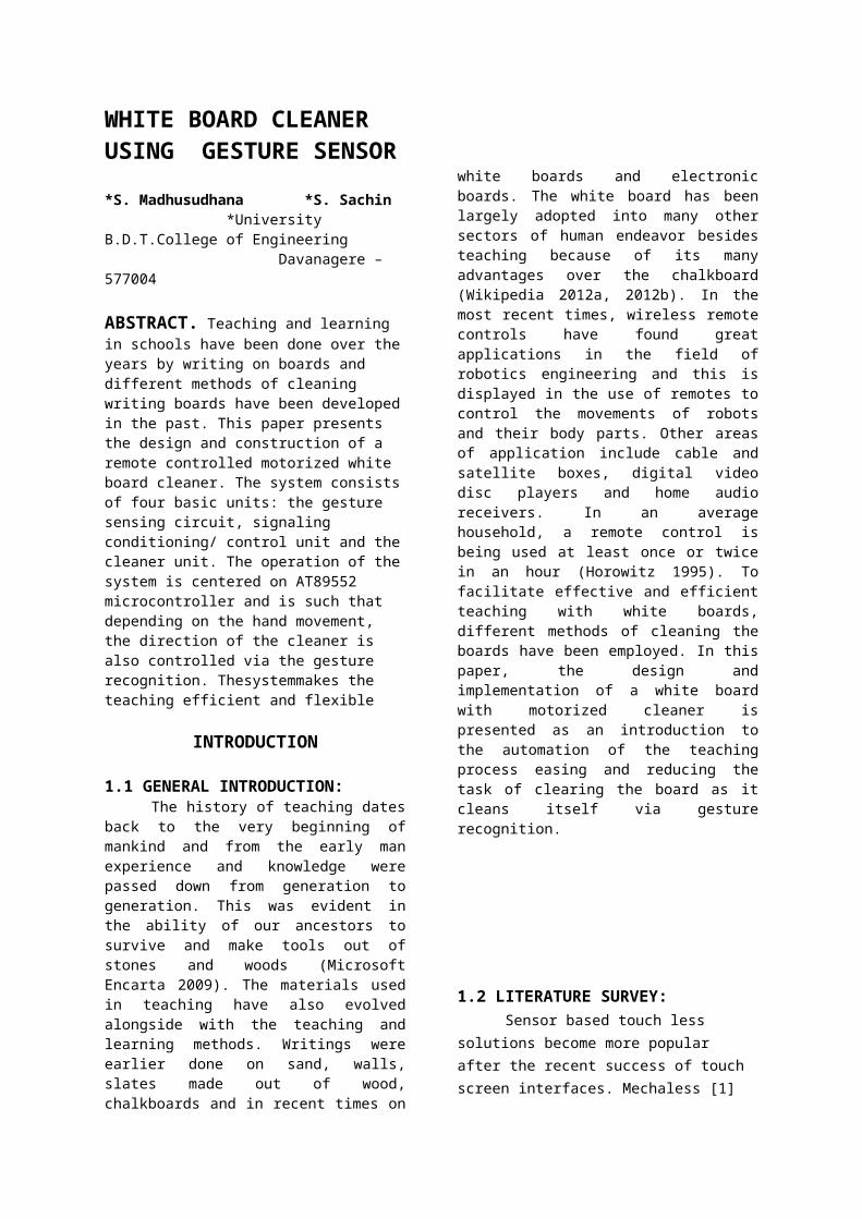
2.1 BLOCK DIAGRAM:
Figure 2.1: Block diagram of white board cleaner using gesture sensor
GESTURE SENSOR: This unique passiveminiaturized IR sensor arraytechnology stands out from allother Gesture Sensors due to itshigh accuracy and low powerrequirements, making it ideal forbattery powered products likemobile phones and tablet PCs.Capable of running off low voltagepower supply rails, this GestureSensor uses just micro-Amps ofpower when accurately detectingthe position of a user’s hand infront of it. Any speed of hand orfinger movement can be detectedfrom around 0-20cm in front of thesensor, bringing the dream oftouch-less control of mobiledevices in three dimensions to areality.
MICROCONTROLLER: It is the heart of theproject. It is used to control thewhite board mechanism. Theinput/output ports of themicrocontroller are used for thispurpose. The gesture input fromthe 2 IR sensors will be given tothe microcontroller. Depending onthe input, the clockwise and anti-
clockwise movement of the gearmotor will be decided. This isdone by the program downloadedinto the microcontroller.
DRIVER CIRCUIT: As we know the output ofAT89S52 circuit is 5V, whichcannot drive the gear motor. Sothe driver circuit is used toincrease the signal. A drivercircuit increases the DC level toa required value say 9V/12V. This9V/12V is much more enough tooperate the white board mechanism.
THE CLEANING UNIT: The board is made fromFoam sheet. A roller is placed inthe frame to allow the freemovement of the cleaner on it. Thecleaner is made from Foam sheetcovered with sponge. The cleaneris designed in such a way that thebi-directional rotation of themotor is translated to the cleanerwhich then results in thehorizontal cleaning movement ofthe cleaner. The gear motors arefixed to the wiper tightly andheld on to the board.
2.2 HARDWARE DESCRIPTION:
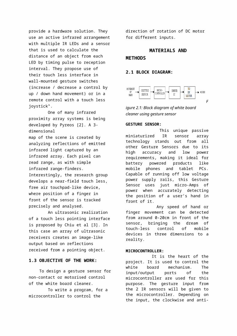
2.2.1 GESTURE SENSOR: IR sensors or the gesturesensors can be made with the helpof IR LED and photodiode. If weplace the IR LED and thephotodiode side by side, closetogether, the radiation from theIR LED will get emitted straightin the direction to which the IRLED is pointing towards, and so isthe photodiode, and hence therewill be no incidence of theradiation on the photodiode(fig2.2) The radiation emitted bythe IR LED is reflected back on
the photodiode by an object.Closer the object, higher will bethe intensity of the incidentradiation on the photodiode. Thisintensity is made analogous to avoltage by a circuit, which isthen used to determine thedistance, thus also called asproximity sensors. Proximity sensors find usein Touch Screen phones, apart frommany other devices. In a TouchScreen Phone, the touch screenneeds to disabled when it is heldnear the ear, while in use, sothat even if the cheek makescontact with the tough screen,there is no effect.
Figure 2.2: Working principle of gesture sensor
Hence the major components for a gesture sensor are IR LED and a photodiode. These two are briefly explained below:
IR LED: The diode that emits lightis called LED. The basic operationof the light emitting diode is as follows. When the device is forward biased, electrons pass thePN junctions from the N-type material and recombine with the holes in the P-type material. Freeelectrons in the conduction band are at a higher energy level than the holes in the valance band. When the recombination takes place, the recombining electrons
release energy in the form of heatand light. A large exposed surfacearea on the layer of the semi-conductive material permits thephotons to be emitted as visiblelight. This process is called“ELECTROLUMINANCE”. Variousimpurities are added during dopingprocess to establish thewavelength of the light emittedlight. The wavelength determinesthe colour of the light and if itis visible or invisible (infrared). LED’s are made up ofGallium Arsenide (GaAs), GalliumArsenide Phosphide (GaAsP) orGallium Phosphide (GaP). Siliconand Germanium are not used becausethey are essentially heatproducing materials are very poorat producing light. GaAs LED’semit infra red radiation, which isinvisible, GaAsP produces eitherred or yellow visible light andGaP emits red or green visiblelight. LED’s that emit blue lightare also available. Red is themost common.
PHOTODIODE: A photodiode is a type ofdiode which detects light. We canthink of it as having a very highresistance when no light isfalling on it. As we increase theintensity of light incident on it,the current through it graduallyincreases too. So, by increasingthe incident light on aphotodiode, we convert it into anormal low value resistor, whichconducts current. We should note
here that a photodiode looksexactly like an LED, sometimes,with a dark blue or black film onthe outer casing, but we make useof it in reverse bias, that meansopposite in configuration as inthe case of an LED. This gesture sensor is theinput unit in our project. Withits working principle explainedabove, it can easily sense thehand motion and correspondingoutput is obtained.
2.2.2 OPAMP [LM358]: The LM358 series consistsof two independent, high gain,internally frequency compensatedoperational amplifiers which weredesigned specifically to operatefrom a single power supply over awide range of voltages. Operationfrom split power supplies is alsopossible and the low power supplycurrent drain is independent ofthe magnitude of the power supplyvoltage. Application areas includetransducer amplifiers, dc gainblocks and all the conventional opamp circuits which now can be moreeasily implemented in single powersupply systems. For example, theLM358 series can be directlyoperated off of the standard +5Vpower supply voltage which is usedin digital systems and will easilyprovide the required interfaceelectronics without requiring theadditional ±15V power supplies.
The working of gesture sensor unitis centered on Op-amp LM358. Hereit is used as a comparator, forcomparing input voltage with the
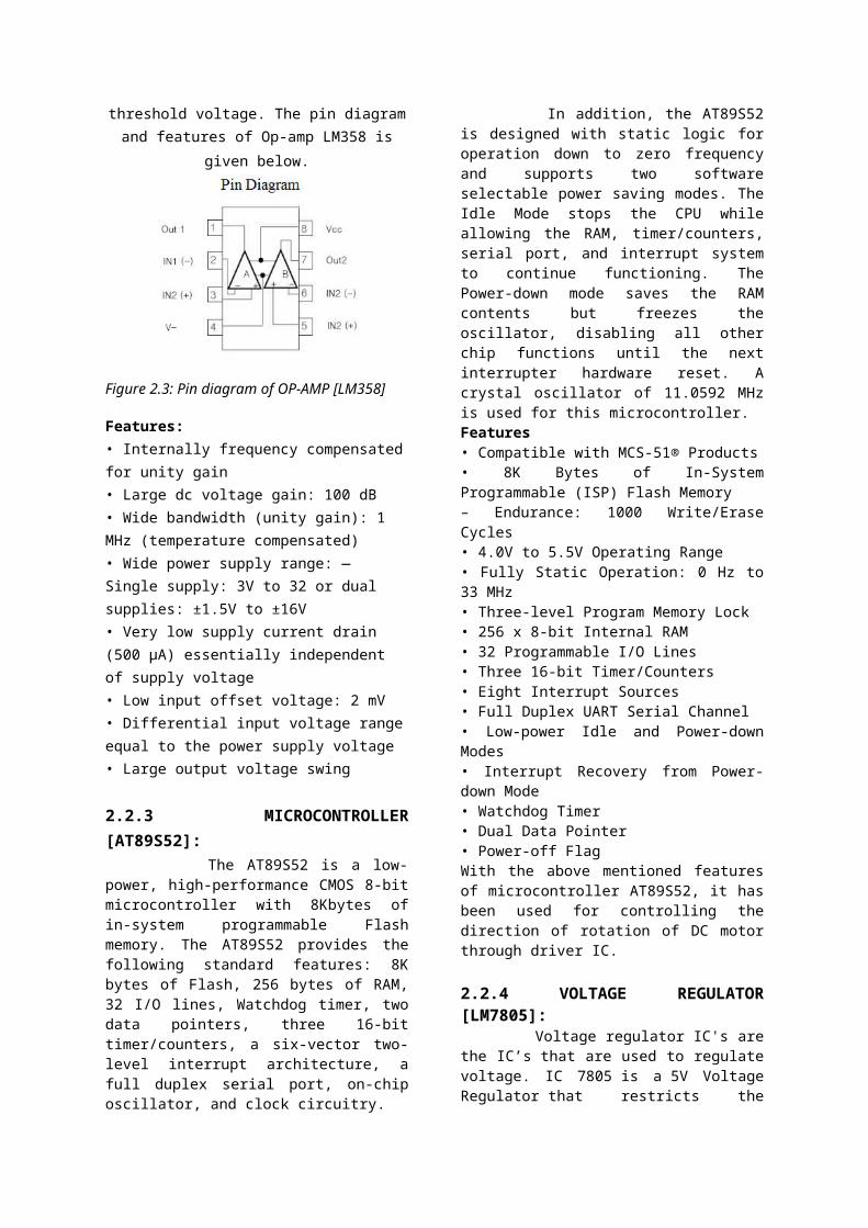
threshold voltage. The pin diagramand features of Op-amp LM358 is
given below.
Figure 2.3: Pin diagram of OP-AMP [LM358]
Features:• Internally frequency compensatedfor unity gain• Large dc voltage gain: 100 dB• Wide bandwidth (unity gain): 1 MHz (temperature compensated)• Wide power supply range: — Single supply: 3V to 32 or dual supplies: ±1.5V to ±16V• Very low supply current drain (500 μA) essentially independent of supply voltage• Low input offset voltage: 2 mV• Differential input voltage rangeequal to the power supply voltage• Large output voltage swing
2.2.3 MICROCONTROLLER[AT89S52]: The AT89S52 is a low-power, high-performance CMOS 8-bitmicrocontroller with 8Kbytes ofin-system programmable Flashmemory. The AT89S52 provides thefollowing standard features: 8Kbytes of Flash, 256 bytes of RAM,32 I/O lines, Watchdog timer, twodata pointers, three 16-bittimer/counters, a six-vector two-level interrupt architecture, afull duplex serial port, on-chiposcillator, and clock circuitry.
In addition, the AT89S52is designed with static logic foroperation down to zero frequencyand supports two softwareselectable power saving modes. TheIdle Mode stops the CPU whileallowing the RAM, timer/counters,serial port, and interrupt systemto continue functioning. ThePower-down mode saves the RAMcontents but freezes theoscillator, disabling all otherchip functions until the nextinterrupter hardware reset. Acrystal oscillator of 11.0592 MHzis used for this microcontroller.Features• Compatible with MCS-51® Products• 8K Bytes of In-SystemProgrammable (ISP) Flash Memory– Endurance: 1000 Write/EraseCycles• 4.0V to 5.5V Operating Range• Fully Static Operation: 0 Hz to33 MHz• Three-level Program Memory Lock• 256 x 8-bit Internal RAM• 32 Programmable I/O Lines• Three 16-bit Timer/Counters• Eight Interrupt Sources• Full Duplex UART Serial Channel• Low-power Idle and Power-downModes• Interrupt Recovery from Power-down Mode• Watchdog Timer• Dual Data Pointer• Power-off FlagWith the above mentioned featuresof microcontroller AT89S52, it hasbeen used for controlling thedirection of rotation of DC motorthrough driver IC.
2.2.4 VOLTAGE REGULATOR[LM7805]: Voltage regulator IC's arethe IC’s that are used to regulatevoltage. IC 7805 is a 5V VoltageRegulator that restricts the
voltage output to 5V and draws5V regulated power supply. Itcomes with provision to add heatsink. The maximum value for inputto the voltage regulator is 35V.It can provide a constant steadyvoltage flow of 5V for highervoltage input till threshold limitof 35V. If the voltage input ismore, then excess electricity isliberated as heat from 7805 IC.
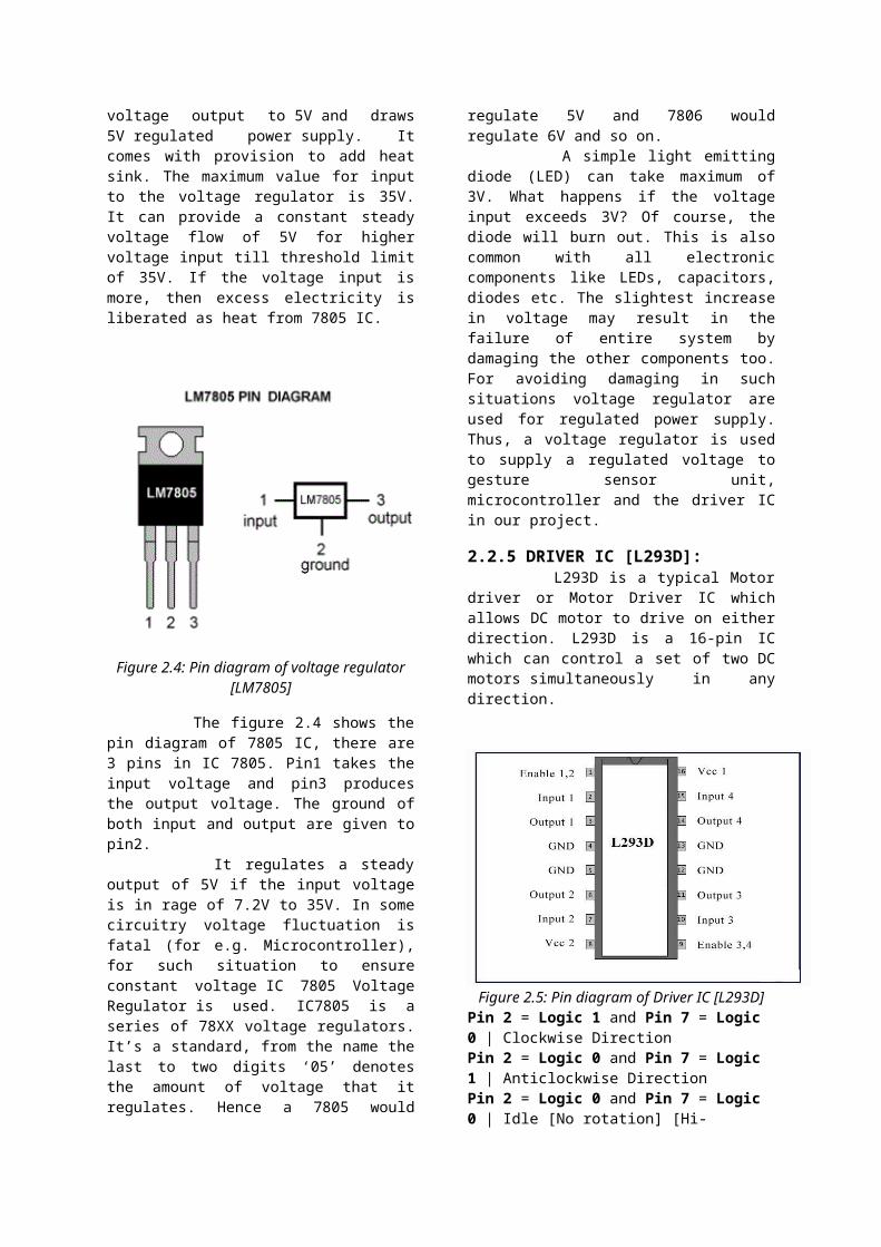
Figure 2.4: Pin diagram of voltage regulator[LM7805]
The figure 2.4 shows thepin diagram of 7805 IC, there are3 pins in IC 7805. Pin1 takes theinput voltage and pin3 producesthe output voltage. The ground ofboth input and output are given topin2. It regulates a steadyoutput of 5V if the input voltageis in rage of 7.2V to 35V. In somecircuitry voltage fluctuation isfatal (for e.g. Microcontroller),for such situation to ensureconstant voltage IC 7805 VoltageRegulator is used. IC7805 is aseries of 78XX voltage regulators.It’s a standard, from the name thelast to two digits ‘05’ denotesthe amount of voltage that itregulates. Hence a 7805 would
regulate 5V and 7806 wouldregulate 6V and so on. A simple light emittingdiode (LED) can take maximum of3V. What happens if the voltageinput exceeds 3V? Of course, thediode will burn out. This is alsocommon with all electroniccomponents like LEDs, capacitors,diodes etc. The slightest increasein voltage may result in thefailure of entire system bydamaging the other components too.For avoiding damaging in suchsituations voltage regulator areused for regulated power supply.Thus, a voltage regulator is usedto supply a regulated voltage togesture sensor unit,microcontroller and the driver ICin our project.
2.2.5 DRIVER IC [L293D]: L293D is a typical Motordriver or Motor Driver IC whichallows DC motor to drive on eitherdirection. L293D is a 16-pin ICwhich can control a set of two DCmotors simultaneously in anydirection.
Figure 2.5: Pin diagram of Driver IC [L293D]Pin 2 = Logic 1 and Pin 7 = Logic 0 | Clockwise DirectionPin 2 = Logic 0 and Pin 7 = Logic 1 | Anticlockwise DirectionPin 2 = Logic 0 and Pin 7 = Logic 0 | Idle [No rotation] [Hi-
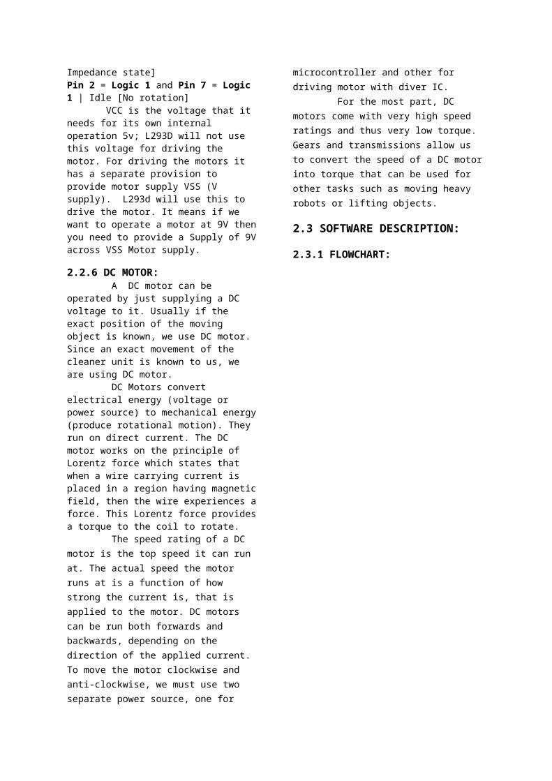
Impedance state]Pin 2 = Logic 1 and Pin 7 = Logic 1 | Idle [No rotation] VCC is the voltage that it needs for its own internal operation 5v; L293D will not use this voltage for driving the motor. For driving the motors it has a separate provision to provide motor supply VSS (V supply). L293d will use this to drive the motor. It means if we want to operate a motor at 9V thenyou need to provide a Supply of 9Vacross VSS Motor supply.
2.2.6 DC MOTOR: A DC motor can be operated by just supplying a DC voltage to it. Usually if the exact position of the moving object is known, we use DC motor. Since an exact movement of the cleaner unit is known to us, we are using DC motor. DC Motors convert electrical energy (voltage or power source) to mechanical energy(produce rotational motion). They run on direct current. The DC motor works on the principle of Lorentz force which states that when a wire carrying current is placed in a region having magneticfield, then the wire experiences aforce. This Lorentz force providesa torque to the coil to rotate. The speed rating of a DC motor is the top speed it can run at. The actual speed the motor runs at is a function of how strong the current is, that is applied to the motor. DC motors can be run both forwards and backwards, depending on the direction of the applied current. To move the motor clockwise and anti-clockwise, we must use two separate power source, one for
microcontroller and other for driving motor with diver IC. For the most part, DC motors come with very high speed ratings and thus very low torque. Gears and transmissions allow us to convert the speed of a DC motorinto torque that can be used for other tasks such as moving heavy robots or lifting objects.
2.3 SOFTWARE DESCRIPTION:
2.3.1 FLOWCHART:
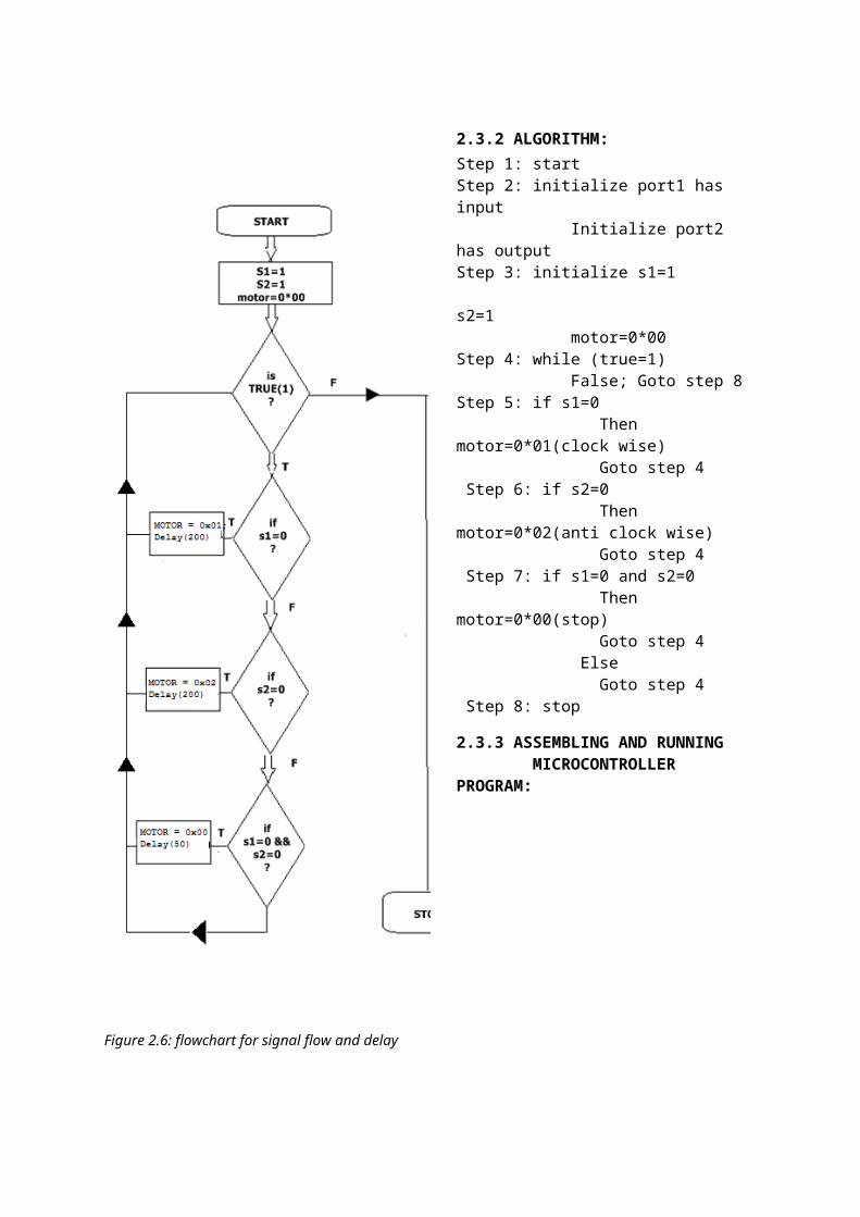
Figure 2.6: flowchart for signal flow and delay
2.3.2 ALGORITHM:Step 1: startStep 2: initialize port1 has input Initialize port2 has outputStep 3: initialize s1=1 s2=1 motor=0*00Step 4: while (true=1) False; Goto step 8Step 5: if s1=0 Then motor=0*01(clock wise) Goto step 4 Step 6: if s2=0 Then motor=0*02(anti clock wise) Goto step 4 Step 7: if s1=0 and s2=0 Then motor=0*00(stop) Goto step 4 Else Goto step 4 Step 8: stop
2.3.3 ASSEMBLING AND RUNNING MICROCONTROLLER PROGRAM:
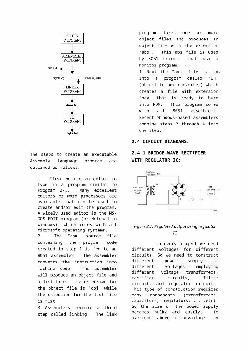
The steps to create an executableAssembly language program areoutlined as follows.
1. First we use an editor totype in a program similar toProgram 2-1. Many excellenteditors or word processors areavailable that can be used tocreate and/or edit the program.A widely used editor is the MS-DOS EDIT program (or Notepad inWindows), which comes with allMicrosoft operating systems.2. The “asm” source filecontaining the program codecreated in step 1 is fed to an8051 assembler. The assemblerconverts the instruction intomachine code. The assemblerwill produce an object file anda list file. The extension forthe object file is “obj” whilethe extension for the list fileis “1st”.3. Assemblers require a thirdstep called linking. The link
program takes one or moreobject files and produces anobject file with the extension“abs”. This abs file is usedby 8051 trainers that have amonitor program.4. Next the “abs” file is fedinto a program called “OH”(object to hex converter) whichcreates a file with extension“hex” that is ready to burninto ROM. This program comeswith all 8051 assemblers.Recent Windows-based assemblerscombine steps 2 through 4 intoone step.
2.4 CIRCUIT DIAGRAMS:
2.4.1 BRIDGE-WAVE RECTIFIER WITH REGULATOR IC:
Figure 2.7: Regulated output using regulatorIC
In every project we needdifferent voltages for differentcircuits. So we need to constructdifferent power supply ofdifferent voltages employingdifferent voltage transformers,rectifier circuits, filtercircuits and regulator circuits.This type of construction requiresmany components (transformers,capacitors, regulators.......etc).So the size of the power supplybecomes bulky and costly. Toovercome above disadvantages by
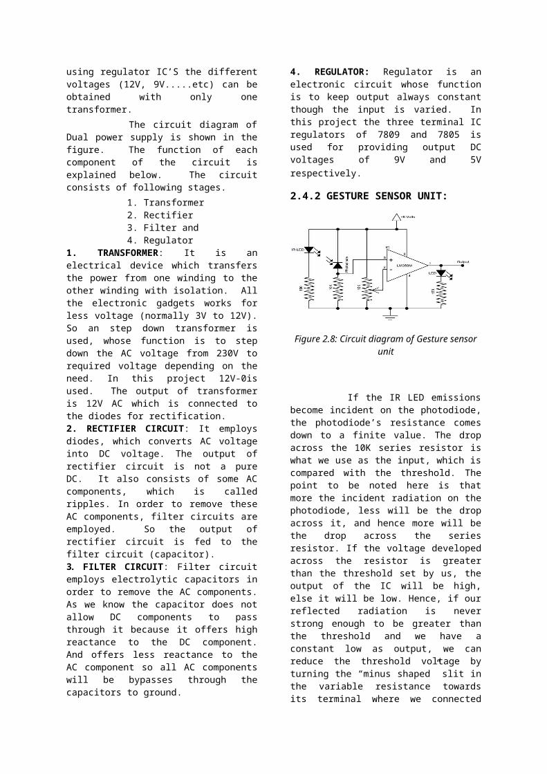
using regulator IC’S the differentvoltages (12V, 9V.....etc) can beobtained with only onetransformer. The circuit diagram ofDual power supply is shown in thefigure. The function of eachcomponent of the circuit isexplained below. The circuitconsists of following stages. 1. Transformer 2. Rectifier 3. Filter and 4. Regulator1. TRANSFORMER: It is anelectrical device which transfersthe power from one winding to theother winding with isolation. Allthe electronic gadgets works forless voltage (normally 3V to 12V).So an step down transformer isused, whose function is to stepdown the AC voltage from 230V torequired voltage depending on theneed. In this project 12V-0isused. The output of transformeris 12V AC which is connected tothe diodes for rectification.2. RECTIFIER CIRCUIT: It employsdiodes, which converts AC voltageinto DC voltage. The output ofrectifier circuit is not a pureDC. It also consists of some ACcomponents, which is calledripples. In order to remove theseAC components, filter circuits areemployed. So the output ofrectifier circuit is fed to thefilter circuit (capacitor).3. FILTER CIRCUIT: Filter circuitemploys electrolytic capacitors inorder to remove the AC components.As we know the capacitor does notallow DC components to passthrough it because it offers highreactance to the DC component.And offers less reactance to theAC component so all AC componentswill be bypasses through thecapacitors to ground.
4. REGULATOR: Regulator is anelectronic circuit whose functionis to keep output always constantthough the input is varied. Inthis project the three terminal ICregulators of 7809 and 7805 isused for providing output DCvoltages of 9V and 5Vrespectively.
2.4.2 GESTURE SENSOR UNIT:
Figure 2.8: Circuit diagram of Gesture sensorunit
If the IR LED emissionsbecome incident on the photodiode,the photodiode’s resistance comesdown to a finite value. The dropacross the 10K series resistor iswhat we use as the input, which iscompared with the threshold. Thepoint to be noted here is thatmore the incident radiation on thephotodiode, less will be the dropacross it, and hence more will bethe drop across the seriesresistor. If the voltage developedacross the resistor is greaterthan the threshold set by us, theoutput of the IC will be high,else it will be low. Hence, if ourreflected radiation is neverstrong enough to be greater thanthe threshold and we have aconstant low as output, we canreduce the threshold voltage byturning the “minus shaped” slit inthe variable resistance towardsits terminal where we connected
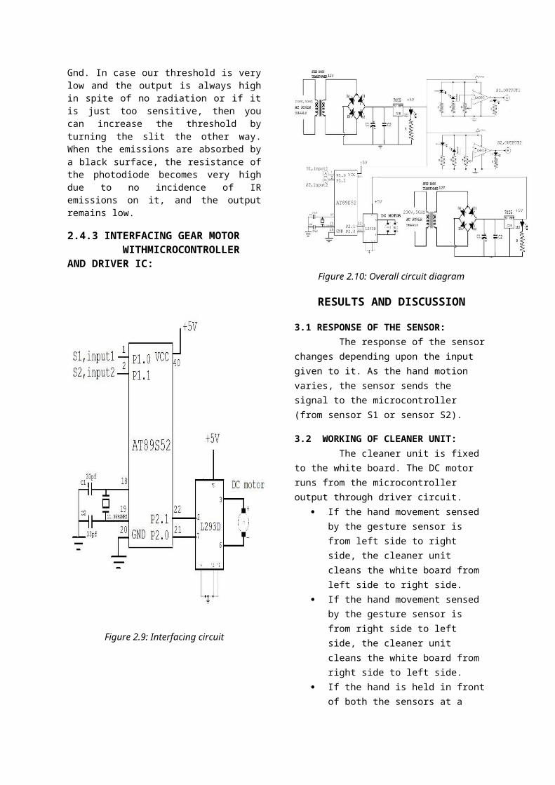
Gnd. In case our threshold is verylow and the output is always highin spite of no radiation or if itis just too sensitive, then youcan increase the threshold byturning the slit the other way.When the emissions are absorbed bya black surface, the resistance ofthe photodiode becomes very highdue to no incidence of IRemissions on it, and the outputremains low.
2.4.3 INTERFACING GEAR MOTOR WITHMICROCONTROLLER AND DRIVER IC:
Figure 2.9: Interfacing circuit
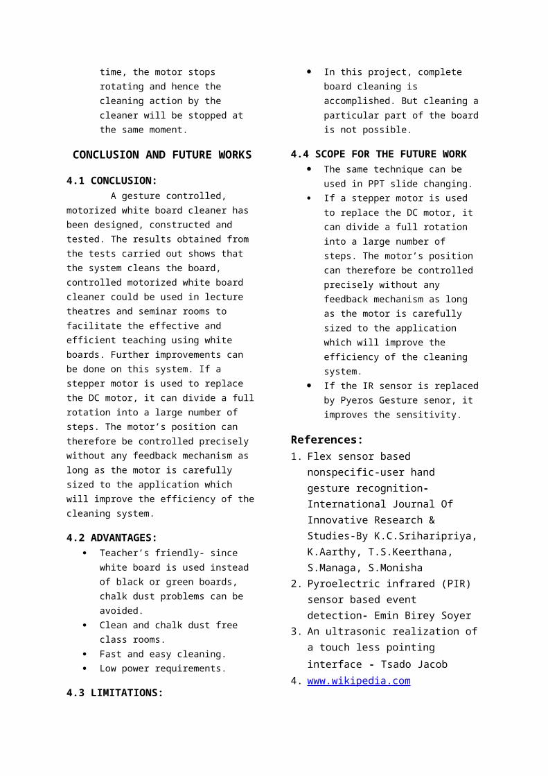
Figure 2.10: Overall circuit diagram
RESULTS AND DISCUSSION
3.1 RESPONSE OF THE SENSOR: The response of the sensorchanges depending upon the input given to it. As the hand motion varies, the sensor sends the signal to the microcontroller (from sensor S1 or sensor S2).
3.2 WORKING OF CLEANER UNIT: The cleaner unit is fixed to the white board. The DC motor runs from the microcontroller output through driver circuit.
If the hand movement sensed by the gesture sensor is from left side to right side, the cleaner unit cleans the white board from left side to right side.
If the hand movement sensed by the gesture sensor is from right side to left side, the cleaner unit cleans the white board from right side to left side.
If the hand is held in frontof both the sensors at a
time, the motor stops rotating and hence the cleaning action by the cleaner will be stopped at the same moment.
CONCLUSION AND FUTURE WORKS
4.1 CONCLUSION: A gesture controlled, motorized white board cleaner has been designed, constructed and tested. The results obtained from the tests carried out shows that the system cleans the board, controlled motorized white board cleaner could be used in lecture theatres and seminar rooms to facilitate the effective and efficient teaching using white boards. Further improvements can be done on this system. If a stepper motor is used to replace the DC motor, it can divide a fullrotation into a large number of steps. The motor’s position can therefore be controlled precisely without any feedback mechanism as long as the motor is carefully sized to the application which will improve the efficiency of thecleaning system.
4.2 ADVANTAGES: Teacher’s friendly- since
white board is used instead of black or green boards, chalk dust problems can be avoided.
Clean and chalk dust free class rooms.
Fast and easy cleaning. Low power requirements.
4.3 LIMITATIONS:
In this project, complete board cleaning is accomplished. But cleaning aparticular part of the boardis not possible.
4.4 SCOPE FOR THE FUTURE WORK The same technique can be
used in PPT slide changing. If a stepper motor is used
to replace the DC motor, it can divide a full rotation into a large number of steps. The motor’s position can therefore be controlled precisely without any feedback mechanism as long as the motor is carefully sized to the application which will improve the efficiency of the cleaning system.
If the IR sensor is replacedby Pyeros Gesture senor, it improves the sensitivity.
References:1. Flex sensor based
nonspecific-user hand gesture recognition- International Journal Of Innovative Research & Studies-By K.C.Sriharipriya,K.Aarthy, T.S.Keerthana, S.Managa, S.Monisha
2. Pyroelectric infrared (PIR) sensor based event detection- Emin Birey Soyer
3. An ultrasonic realization ofa touch less pointing interface - Tsado Jacob
4. www.wikipedia.com

5. www.maxembedded.com/how-to- build-IRsensor.
6. Atmel/Datasheets7.Texas Instruments/Datasheets
Related Documents