When Sound Waves meet Solid Surfaces Applications of wave phenomena in room acoustics By Yum Ji CHAN MSc (COME) candidate TU Munich

When Sound Waves meet Solid Surfaces
Jan 01, 2016
When Sound Waves meet Solid Surfaces. Applications of wave phenomena in room acoustics By Yum Ji CHAN MSc (COME) candidate TU Munich. 0 Introduction. Phemonena of sound waves Equipments on surfaces to control sound intensity Applications in room acoustics - PowerPoint PPT Presentation
Welcome message from author
This document is posted to help you gain knowledge. Please leave a comment to let me know what you think about it! Share it to your friends and learn new things together.
Transcript

When Sound WavesmeetSolid Surfaces
Applications of wave phenomena in room acoustics
By Yum Ji CHANMSc (COME) candidateTU Munich
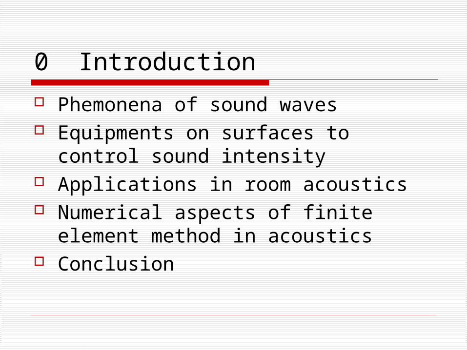
0 Introduction
Phemonena of sound waves Equipments on surfaces to control
sound intensity Applications in room acoustics Numerical aspects of finite element
method in acoustics Conclusion
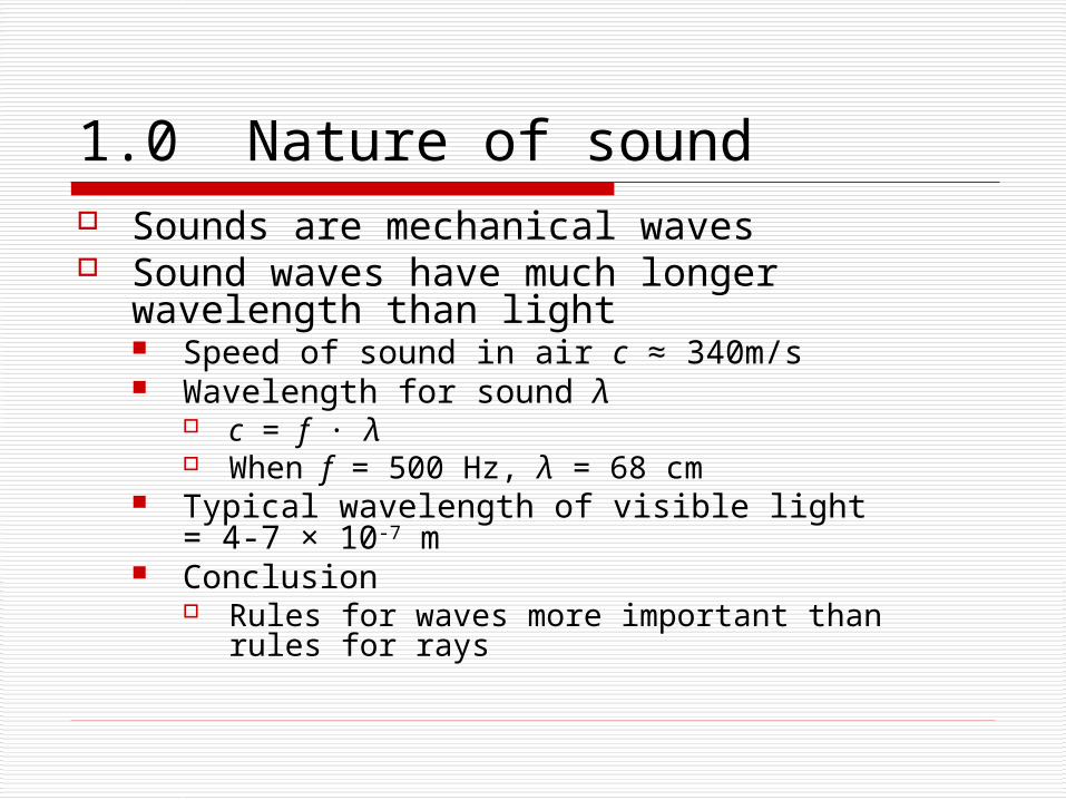
1.0 Nature of sound Sounds are mechanical waves Sound waves have much longer wavelength
than light Speed of sound in air c ≈ 340m/s Wavelength for sound λ
c = f · λ When f = 500 Hz, λ = 68 cm
Typical wavelength of visible light= 4-7 × 10⁻⁷ m
Conclusion Rules for waves more important than rules for
rays
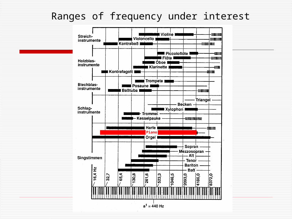
Ranges of frequency under interest
Piano

1.1 Measurement of Sound intensity
Acoustic pressure in terms of sound pressure level (SPL)
Unit: decibel (dB), pref = 2 × 10⁻⁵ Pa Acoustic power More parameters are necessary in
noise measurements (out of the scope)
refp
pSPL log20
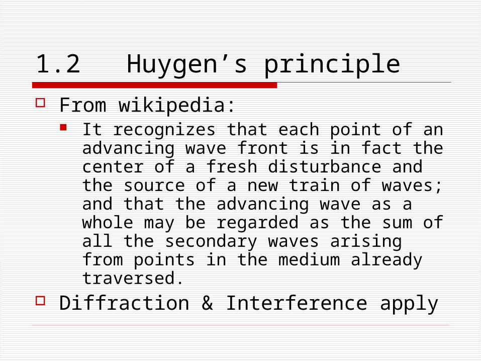
1.2 Huygen’s principle From wikipedia:
It recognizes that each point of an advancing wave front is in fact the center of a fresh disturbance and the source of a new train of waves; and that the advancing wave as a whole may be regarded as the sum of all the secondary waves arising from points in the medium already traversed.
Diffraction & Interference apply

1.3 Diffraction & Interference
Edge interference due to finite plates Reflection on flat surface: Deviation
from ray-like behaviour
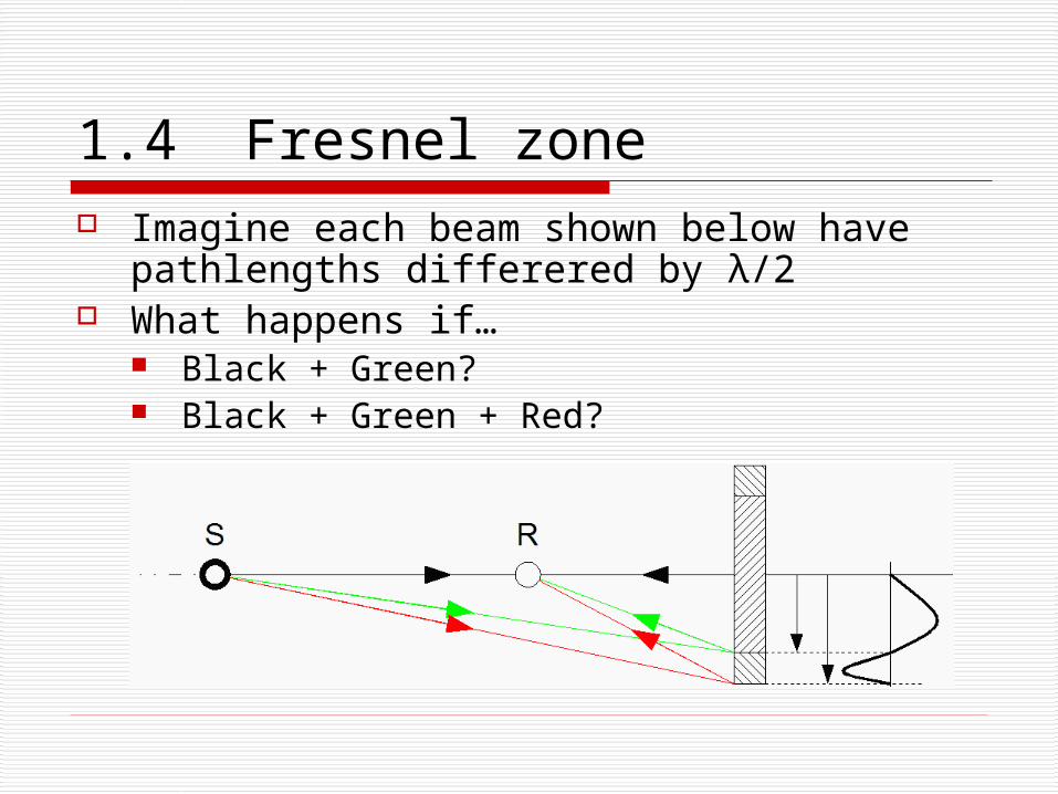
1.4 Fresnel zone Imagine each beam shown below have
pathlengths differered by λ/2 What happens if…
Black + Green? Black + Green + Red?
1.5 Conclusion drawn from experiment
Theory for reflectors in sound is more complicated than those for light
Sizing is important for reflectors
2.0 Elements controlling sound in a room
Reflectors Diffusers Absorbers

2.1 Weight of Reflectors Newton’s second law of motion:
Difference in acoustic pressure = acceleration
Mass is the determining factor at a wide frequency range
Transmitted energy (i.e. Absorption in rooms) is higher At low frequencies When the plate is not heavy enough
dt
dvMpp 21
22p M u k

2.2 Size of Reflectors
Never too small Diffraction Absorption
No need to be too big Imagine a mirror for light!
Example worksheet
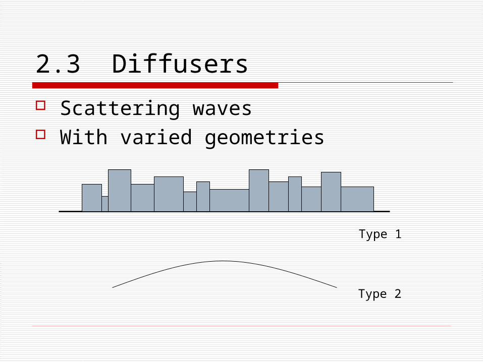
2.3 Diffusers
Scattering waves With varied geometries
Type 1
Type 2

2.4 Absorbers Apparent solution: Fabrics and porous
materials Reality: it is effective only at HF range Needed in rooms where sound should be
damped heavily (e.g. lecture rooms) Because clothes are present
Other absorbers make use of principles in STRUCTURAL DYNAMICS
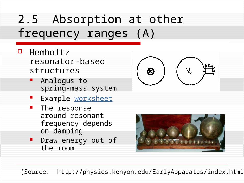
2.5 Absorption at other frequency ranges (A) Hemholtz
resonator-based structures Analogus to spring-
mass system Example worksheet The response
around resonant frequency depends on damping
Draw energy out of the room
(Source: http://physics.kenyon.edu/EarlyApparatus/index.html)
2.6 Absorption at other frequency ranges (B)
Low frequency absorbers Plate absorbers, make use of bending
waves Composite board resonators (VPR in
German)
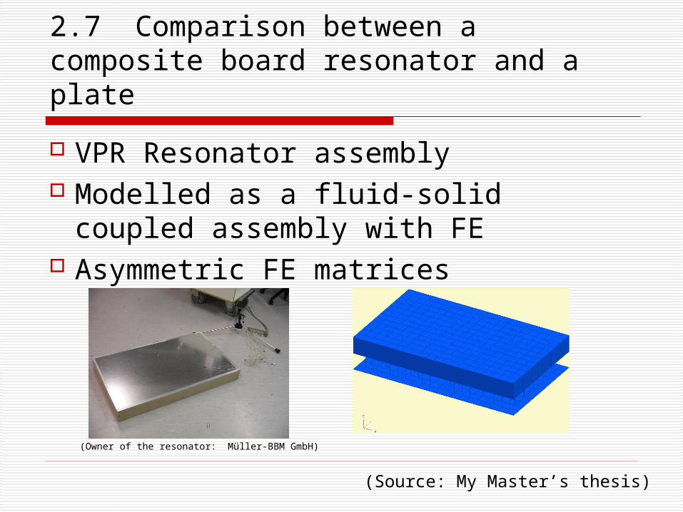
2.7 Comparison between a composite board resonator and a plate
VPR Resonator assembly Modelled as a fluid-solid coupled
assembly with FE Asymmetric FE matrices
(Source: My Master’s thesis)
(Owner of the resonator: Müller-BBM GmbH)
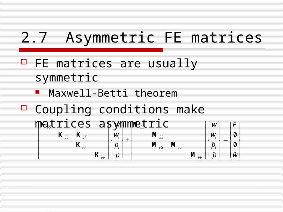
2.7 Asymmetric FE matrices
FE matrices are usually symmetric Maxwell-Betti theorem
Coupling conditions make matrices asymmetric
w
F
p
p
w
w
p
p
w
w
i
i
FF
FFFS
SS
SS
i
i
FF
FF
SFSS
SS
0
0
M
MM
M
M
K
K
KK
K
2.7 Comparison between a composite board resonator and a plate
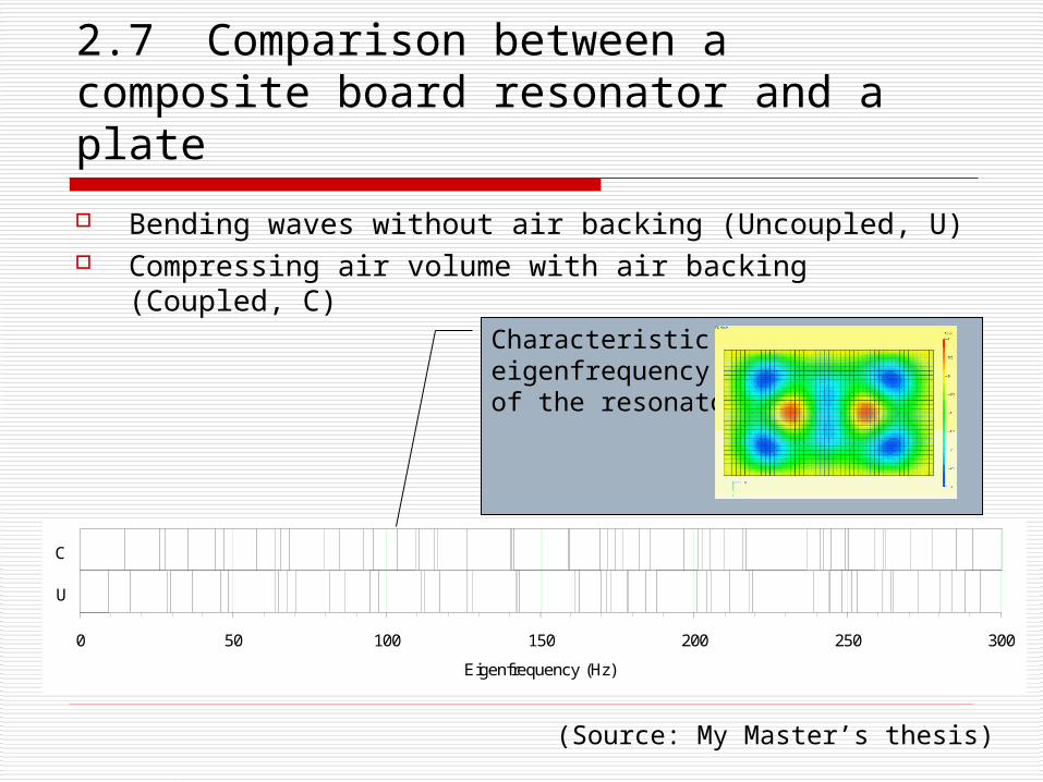
Bending waves without air backing (Uncoupled, U) Compressing air volume with air backing (Coupled, C)
(Source: My Master’s thesis)
0 50 100 150 200 250 300
U
C
Eigenfrequency (Hz)
Characteristiceigenfrequencyof the resonator
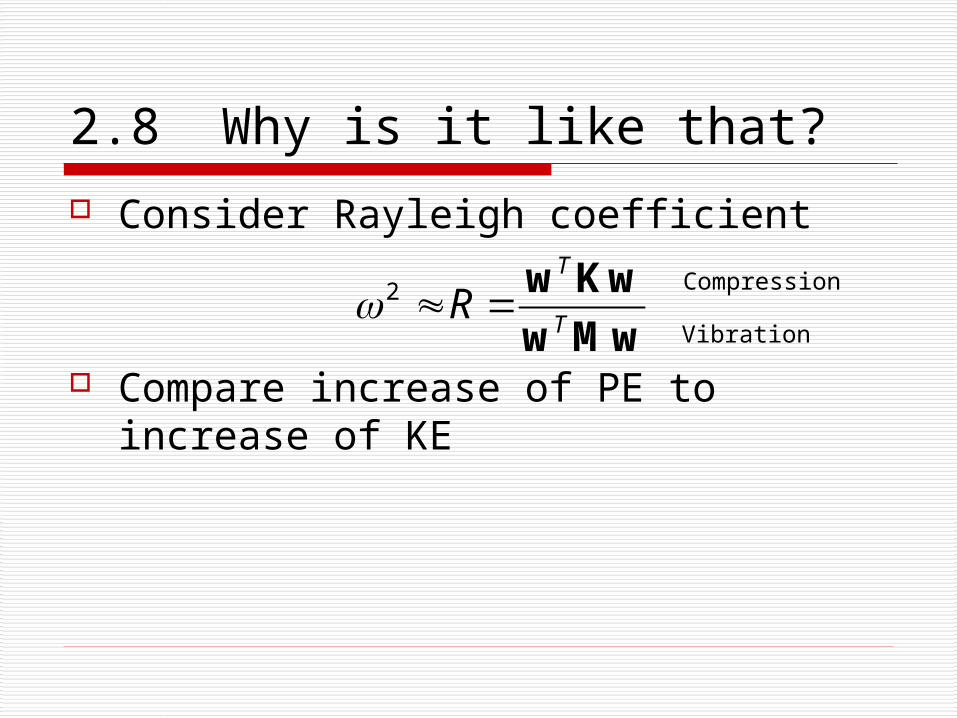
2.8 Why is it like that?
Consider Rayleigh coefficient
Compare increase of PE to increase of KE
2T
TR
w Kw
w Mw Vibration
Compression
3 Parameters in room acoustics
Reverberation time Clarity / ITDG (Initial time delay gap) Binaural parameter
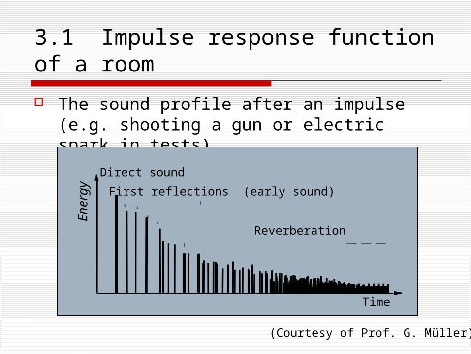
3.1 Impulse response function of a room
The sound profile after an impulse (e.g. shooting a gun or electric spark in tests)
Time
Direct sound
First reflections (early sound)
Reverberation
1 2
3
4Energy
Time
(Courtesy of Prof. G. Müller)

3.2 Reverberation time The most important parameter in general applications Definition: SPL drop of 60 dB
Formula drawn by Sabine
Depends on volume of the room and “the equivalent absorptive area” of the room
Samples to listen: Rooms with extremely long RT: Reverberant room
(Courtesy of Müller-BBM)
S
VT
161.060
60log200
60
t
Tt
p
p
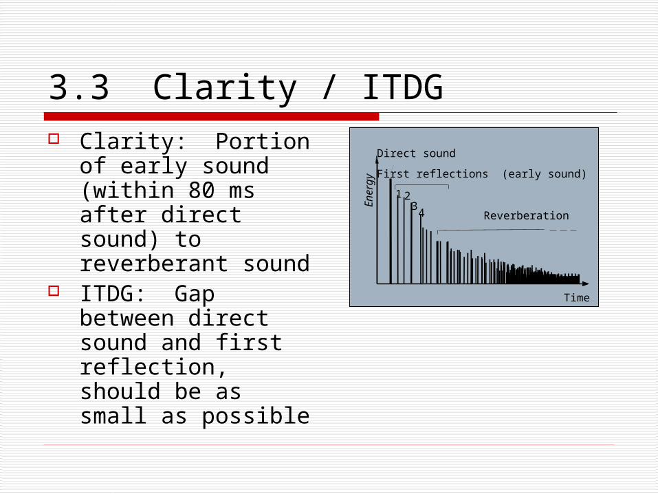
3.3 Clarity / ITDG Clarity: Portion of
early sound (within 80 ms after direct sound) to reverberant sound
ITDG: Gap between direct sound and first reflection, should be as small as possible
Time
Direct sound
First reflections (early sound)
Reverberation
1 23
4
Energy
Time
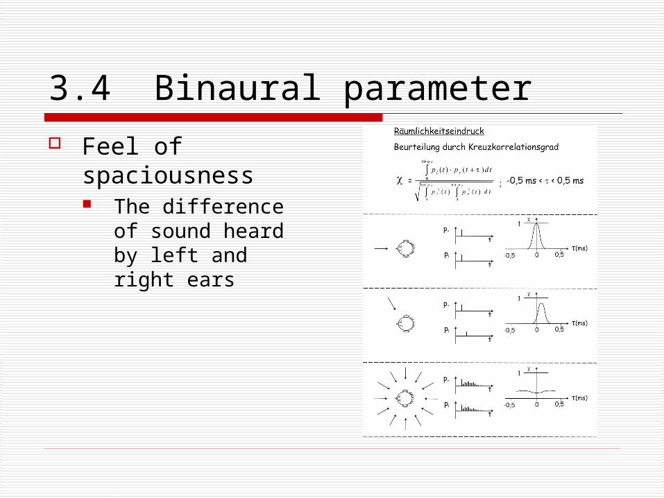
3.4 Binaural parameter Feel of
spaciousness The difference of
sound heard by left and right ears
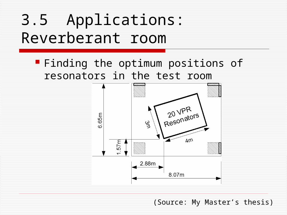
3.5 Applications: Reverberant room
Finding the optimum positions of resonators in the test room
(Source: My Master’s thesis)
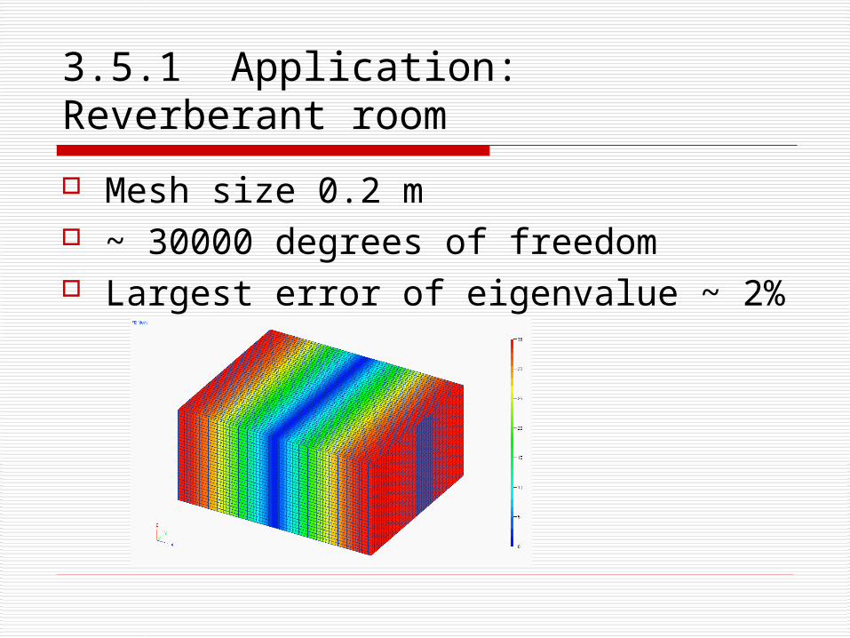
3.5.1 Application: Reverberant room
Mesh size 0.2 m ~ 30000 degrees of freedom Largest error of eigenvalue ~ 2%
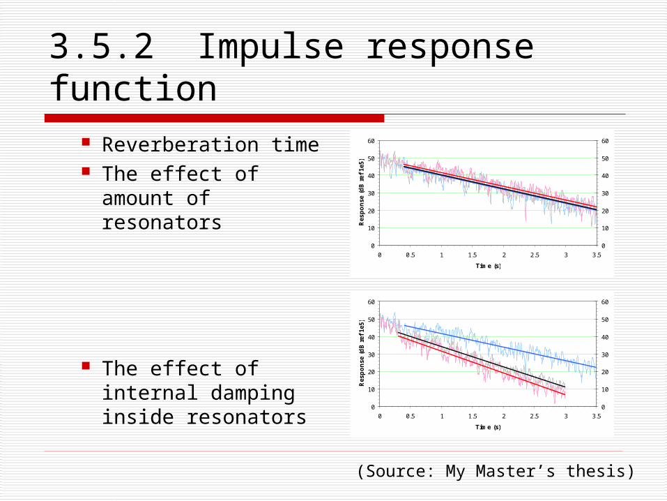
3.5.2 Impulse response function
Reverberation time The effect of amount
of resonators
The effect of internal damping inside resonators
0
10
20
30
40
50
60
0 0.5 1 1.5 2 2.5 3 3.5
Time (s)
Res
po
nse
(d
B r
ef 1
e5)
0
10
20
30
40
50
60
0
10
20
30
40
50
60
0 0.5 1 1.5 2 2.5 3 3.5
Time (s)
Res
po
nse
(d
B r
ef 1
e5)
0
10
20
30
40
50
60
(Source: My Master’s thesis)
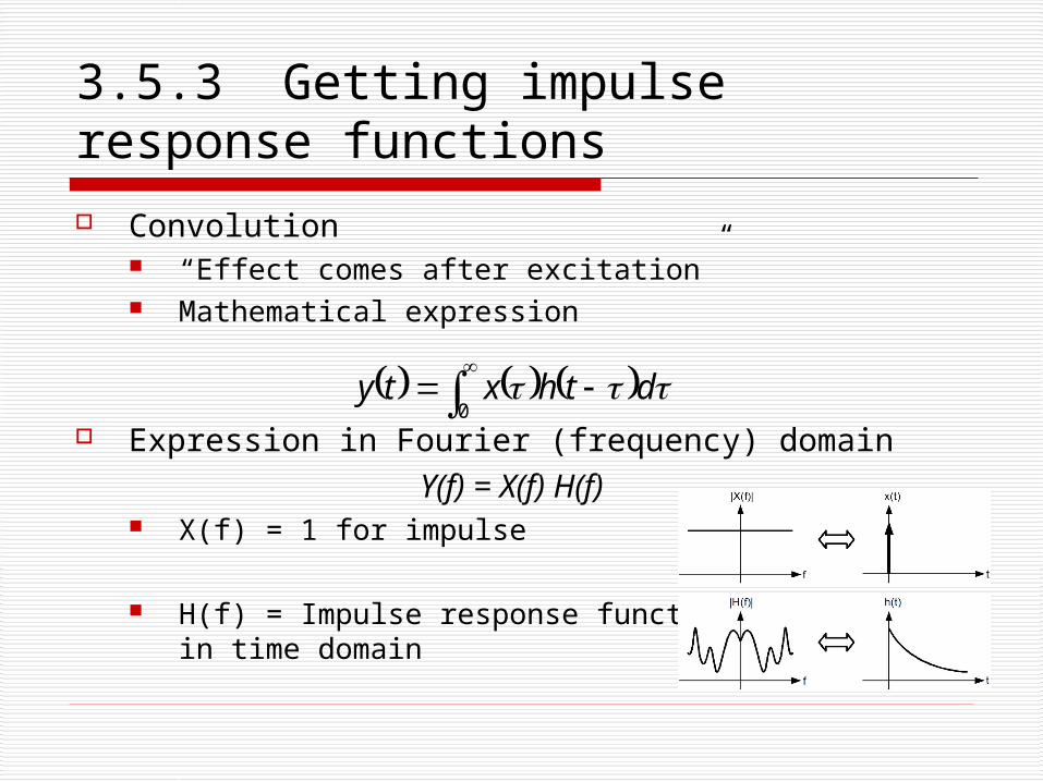
3.5.3 Getting impulse response functions Convolution
“Effect comes after excitation” Mathematical expression
Expression in Fourier (frequency) domainY(f) = X(f) H(f)
X(f) = 1 for impulse
H(f) = Impulse response functionin time domain
0 dthxty
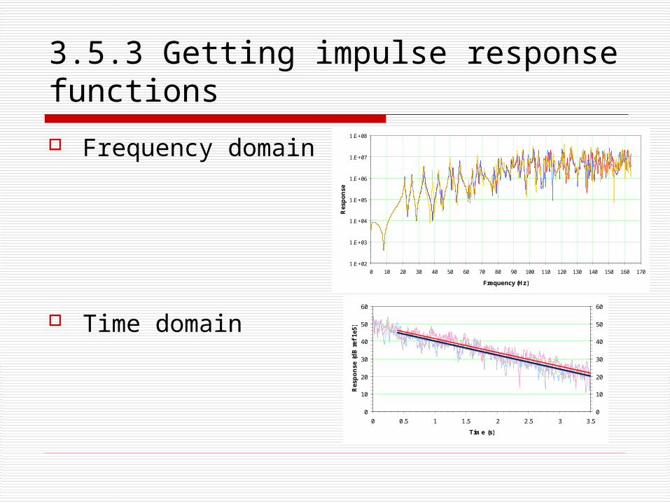
3.5.3 Getting impulse response functions
Frequency domain
Time domain
1.E+02
1.E+03
1.E+04
1.E+05
1.E+06
1.E+07
1.E+08
0 10 20 30 40 50 60 70 80 90 100 110 120 130 140 150 160 170
Frequency (Hz)
Res
po
nse
0
10
20
30
40
50
60
0 0.5 1 1.5 2 2.5 3 3.5
Time (s)
Res
po
nse
(d
B r
ef 1
e5)
0
10
20
30
40
50
60
3.6 Are these all?
Amount of parameters are increasing Models are still necessary to be built
for “acoustic delicate” rooms Concert halls
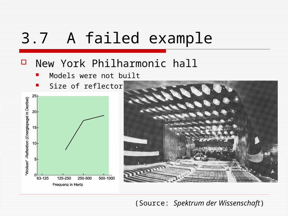
3.7 A failed example New York Philharmonic hall
Models were not built Size of reflectors
(Source: Spektrum der Wissenschaft)
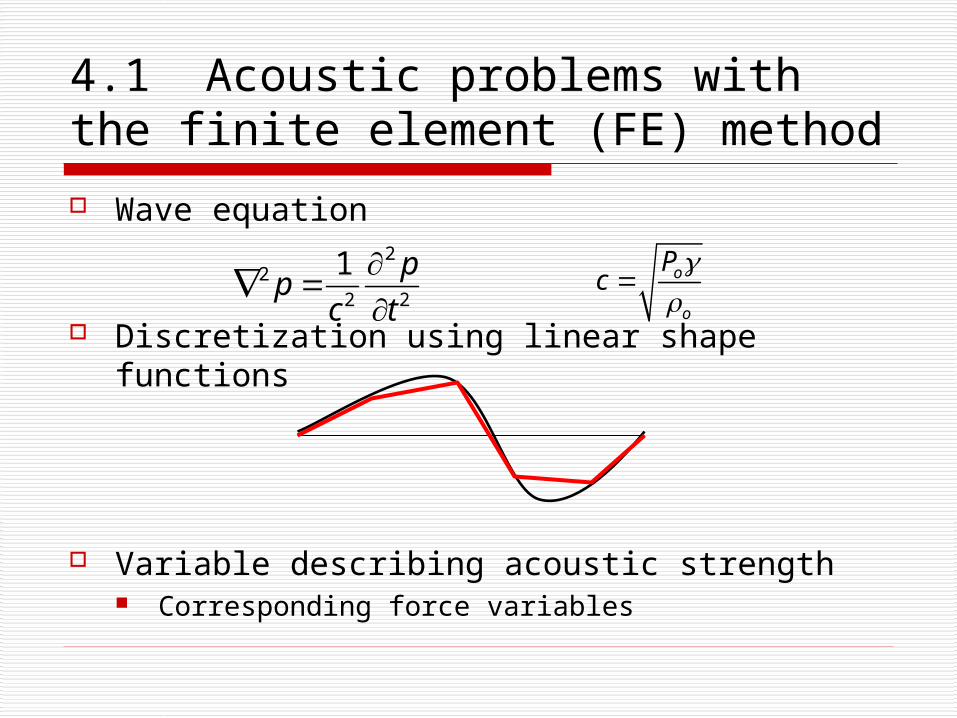
4.1 Acoustic problems with the finite element (FE) method
Wave equation
Discretization using linear shape functions
Variable describing acoustic strength Corresponding force variables
22
2 2
1 pp
c t
o
o
Pc
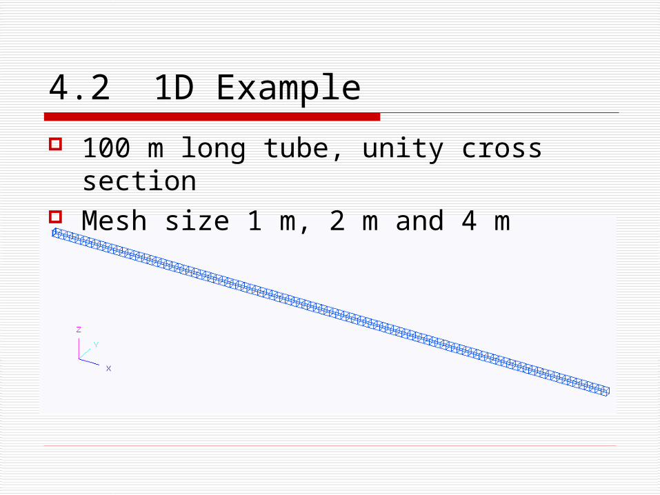
4.2 1D Example
100 m long tube, unity cross section Mesh size 1 m, 2 m and 4 m
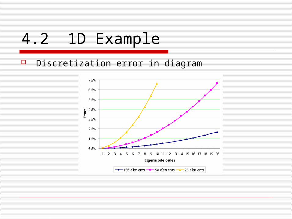
4.2 1D Example Discretization error in diagram
0.0%
1.0%
2.0%
3.0%
4.0%
5.0%
6.0%
7.0%
1 2 3 4 5 6 7 8 9 10 11 12 13 14 15 16 17 18 19 20
Eigenmode order
Err
or
100 elements 50 elements 25 elements
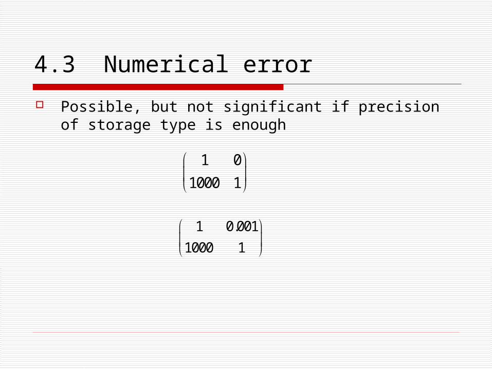
4.3 Numerical error
Possible, but not significant if precision of storage type is enough
1 0
1000 1
1 0.001
1000 1

5 Conclusion
Is acoustics a science or an art?`

Related Documents


![17.2 Sound Waves: In Halliday and Resnick: Longitudinal waves are sound waves! Chapter 17: [Sound] Waves-(II) Sound waves propagate in gases. Can they.](https://static.cupdf.com/doc/110x72/56649eb25503460f94bb9375/172-sound-waves-in-halliday-and-resnick-longitudinal-waves-are-sound-waves.jpg)


