Welcome message from author
This document is posted to help you gain knowledge. Please leave a comment to let me know what you think about it! Share it to your friends and learn new things together.
Transcript


4
www.saispa.com
179241.12
WHEEL MOTORS TECHNICAL CATALOGUE CATALOGO TECNICO MOTORI RUOTA
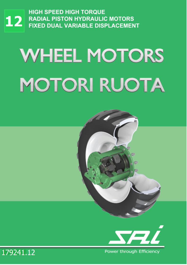
WHEEL MOTORS
MOTORI RUOTA
TECHNICAL CATALOGUE
CATALOGO TECNICO
INDEX
INDICE
6 GENERAL INFORMATION
INFORMAZIONI GENERALI
22 WHEEL MOTORS WITHOUT GEARBOX
MOTORI RUOTA SENZA RIDUTTORE 23 P1G P1G F30D
27 P2G P2G F32
31 BD2 BD2 F32
35 WR SERIES
SERIE WR
36 RADIAL LOAD GRAPHS / GRAFICI DI CARICO RADIALE
37 GM05 WR6B
39 GM1 WR6B
41 BD1 WR6B BV1 WR6B
44 GM05 WR10
46 GM1 WR10
48 BD1 WR10 BV1 WR10
51 GM1 WR20
53 BD1 WR20 BV1 WR20
56 GM2 WR20 58 BD2 WR20 BV2 WR20

5
www.saispa.com
179241.12
WHEEL MOTORS TECHNICAL CATALOGUE CATALOGO TECNICO MOTORI RUOTA
62 K SERIES
SERIE K
63 RADIAL LOAD GRAPHS / GRAFICI DI CARICO RADIALE
64 GK3 GFK3R
67 BDK3 BDFK3R BVK3 BVFK3R
71 GK3A GFK3AR
74 BDK3A BDFK3AR BVK3A BVFK3AR
78 GK4 GFK4
80 BDK4 BDFK4 BVK4 BVFK4
84 G3 - G3A SERIES
SERIE G3 - G3A
85 RADIAL LOAD GRAPHS / GRAFICI DI CARICO RADIALE
86 GM05 G3 GM05 F10L G3
89 GM1 G3 GM1 F10L G3
92
BD1 G3 BD1 F10L G3
BV1 G3 BV1 F10L G3
96 GM05 G3A GM05 F10L G3A
99 GM1 G3A GM1 F10L G3A
102
BD1 G3A BD1 F10L G3A
BV1 G3A BV1 F10L G3A
107 TS SERIES
SERIE TS
108 RADIAL LOAD GRAPHS / GRAFICI DI CARICO RADIALE
109 TS8W TS8WF
112 TS8DW TS8DWF TS8VW TS8VWF
116 DISTRIBUTORS
DISTRIBUTORI
118 WHEEL APPLICATION DATASHEET
119
APPLICATION DATASHEET
6
www.saispa.com
179241.12
WHEEL MOTORS TECHNICAL CATALOGUE CATALOGO TECNICO MOTORI RUOTA
GENERAL INFORMATION Introduction Read and store this technical catalogue carefully. The information in it contained will be needed to correctly select the product. The manufacturer has designed the components in order to en-sure safe usage conditions.
INFORMAZIONI GENERALI Introduzione Leggere e conservare con cura il presente catalogo tecnico. Le informazioni in esso contenute vi saranno indispensabili per ope-rare in modo corretto. Il costruttore ha progettato i componenti allo scopo di garantire condizioni di utilizzo sicure.
Purpose of the catalogue This catalogue is aimed to present the products in it contained to aid in the selection of the most suitable component for the re-quired application. SAI hydraulic motors will not be held liable for damages, accidents or drawbacks resulting to the failure to comply to the instructions given in this manual. SAI will also not be held liable for the modi-fication and/or installation of non-authorized accessories.
Scopo del catalogo Questo catalogo ha lo scopo di presentare i prodotti in esso conte-nuti per coadiuvare la selezione del componente più adeguato all’applicazione richiesta. SAI non si ritiene responsabile di eventuali guasti, incidenti od inconvenienti vari dovuti alla non osservanza delle prescrizioni contenute nel presente manuale. Lo stesso dicasi per l’esecuzione di modifiche, variazioni e/o installazione di accessori non autoriz-zati.
Updating the catalogue It is recommended to constantly keep this catalogue updated by
adding amendments, updates or modifications made by the man-
ufacturer. New pages will be sent in the event of minor changes
and it will be up to the user to integrate them within the cata-
logue, replacing the existing ones in the related chapters or para-
graphs. A revised copy of the catalogue will be sent to replace the
existing version in the event of substantial changes to the compo-
nents. At which point the old version of the catalogue must be
destroyed.
Aggiornamento del catalogo Si raccomanda di mantenere il presente catalogo costantemente aggiornato, integrandolo con eventuali emendamenti, aggiunte o modifiche pervenute dal costruttore. In caso di modifiche di lieve entità verranno inviate le pagine nuove e sarà cura dell’utente provvedere alle loro integrazioni nel catalogo, sostituendo quelle esistenti nei capitoli o nei paragrafi interessati. In caso di modifiche sostanziali ai componenti verrà inviata una
copia di revisione del catalogo in sostituzione di quella esistente
che dovrà essere distrutta.
INTRODUCTION TO THE CATALOGUE AND SYMBOLS USED This catalogue consists of:
A topic index; An introduction page; Texts and warnings divided into chapters, paragraphs and subsections.
SYMBOLS INDICATING DANGEROUS SITUATIONS OR VERY IM-PORTANT INFORMATION.
CONSULTAZIONE DEL CATALOGO E SIMBOLOGIA UTILIZZATA Il presente manuale è costituito da:
Un indice analitico degli argomenti; Una pagina di introduzione; Testi e avvertenze suddivisi in capitoli, paragrafi e sottopara-grafi.
SIMBOLI CHE INDICANO SITUAZIONI PERICOLOSE O INFORMA-ZIONI MOLTO IMPORTANTI.
WARNING! Indicates risky situations for people, refers to accident prevention and suggests behavioral procedures.
ATTENZIONE! Indica le situazioni di rischio per le persone, richiama norme antinfortunistiche e suggerisce procedure compor-tamentali.
NOTE! Indicates useful information for the consultation of the manual and the smooth operation of the machine.
NOTA BENE! Indica le notizie utili per la consultazione del manuale e per il buon funzionamento della macchina.

7
www.saispa.com
179241.12
WHEEL MOTORS TECHNICAL CATALOGUE CATALOGO TECNICO MOTORI RUOTA
COMMON DEFINITIONS
In this catalogue and most of the SAI documents the following
specific terminology is used to describe specific key points of the
SAI products.
The peak values indicate the maximum working conditions that
the product can withstand. This means that the component can in
fact work at its peak working conditions for a period of time that
does not exceed 1% per minute and not more than 10 times per
hour.
The continuous working condition values are the ones that can be
applied continuously without harming the product. This means
that it is the working conditions at which the component can run
until the end of its calculated lifetime.
DEFINIZIONI COMUNI
In questo catalogo e nella maggior parte dei documenti SAI, ven-
gono utilizzati termini specifici per descrivere punti salienti dei
prodotti SAI.
I valori di picco indicano le condizioni di lavoro massime di opera-
zione che il prodotto può supportare. Questo significa che il com-
ponente può lavorare nelle condizioni di picco indicate un periodo
di tempo che non superi l’1% al minuto e non superi le 10 volte
per ora.
I valori in continuo sono quelli che possono essere applicati in
maniera continua senza danneggiare il prodotto. Questo significa
quindi che sono le condizioni di lavoro che il componente può
sopportare in maniera continua fino al termine della vita calcolata
del prodotto in questione.
COMMON HYDRAULIC FORMULA
FORMULE IDRAULICHE COMUNI
Torque Coppia
Power Potenza
Shaft speed Velocità albero
Motor displacement Cilindrata motore
Required pump flow rate Portata di pompa richiesta
portata
Portata
Wheel speed Velocità alla ruota

8
www.saispa.com
179241.12
WHEEL MOTORS TECHNICAL CATALOGUE CATALOGO TECNICO MOTORI RUOTA
CRANKSHAFT DESIGN RADIAL PISTON MOTORS
The main characteristics of this type of design are the high me-
chanical efficiency, especially at start up, and high volumetric
efficiency.
A number of features distinguish SAI motors from the other radial
piston designs:
MOTORI IDRAULICI AD ALBERO ECCENTRICO
Le caratteristiche di questo tipo di motore sono l’alto rendimento
meccanico, in particolare allo spunto, e l’alto rendimento volume-
trico.
Le caratteristiche che distinguono i motori SAI rispetto ad altri di
questo genere sono:
1 2 3
Fixed displacement, 5 piston motor.
Motore a cilindrata fissa a 5 pistoni.
7 8
13
4 9
11
6 14
5
12
10
Fixed displacement, 7 piston motor. Motore a cilindrata fissa a 7 pistoni

9
www.saispa.com
179241.12
WHEEL MOTORS TECHNICAL CATALOGUE CATALOGO TECNICO MOTORI RUOTA
Swivelling cylinder: the cylinder (1) always remains aligned with
the eccentric (3) of the crank, thus eliminating the stress be-
tween the walls of the piston (2) and the cylinder. The articula-
tion of the cylinder is done by the trunnions (4) that ensure low
specific loads.
Piston: the pistons transfer the load to the shaft through an hy-
drostatic bearing (5). This bearing reduces the contact between
metals and ensures an optimal lubrication and lowers the friction.
Piston retaining rings (6): ensure the contact between the foot of
the piston and the shaft in all working conditions, even in the
event of cavitation.
Axial distribution rotary (8): ensures an optimal distribution of the
oil with short ducts with a wide diameter in order to reduce the
power loss when high flow is present. The high volumetric effi-
ciency and the recovery of the tolerances by the seals ensure an
optimal functionality throughout the entire life of the product and
in conditions of thermal shock.
Interchangeable distributor (7): a wide range of distributors is
available for different SAI motors with various pressure and flow
control valves.
Radial injection cylinder feed (9): eliminates direct hydraulic axial
load on the motor body. These are also larger compared to previ-
ous SAI products to reduce power loss with high flow rates.
Stronger casting (10): to allow higher internal and external load
capacity and bear higher stress levels compared to previous prod-
ucts.
Larger cylinder trunnions (4) : for increased resistance and re-
duced specific loads compared to previous SAI products.
Spigots with hydraulic balancer (11): to reduce friction and wear.
This also allows for a lower heat generation, allowing the product
to work with higher powers and higher performances, thus im-
proving efficiency.
Planetary wheel gearbox (12):
The torque and speed of the motor are transformed by a single
stage planetary gearbox.
This allows the unit to reach higher admissible radial loads and
transmissible torques compared to the normal direct motors.
Brake (13): The gearbox can be supplied with a hydraulic nega-
tive disc brake integrated in its design.
Hub (14): The wheel hub can have different dimensions and
shapes allow the unit to be coupled with the various types of
wheel in commerce.
Cilindro oscillante: il cilindro (1) rimane sempre allineato con
l’eccentrico (3) dell’albero, eliminando così sollecitazioni tra le
pareti del pistone (2) e del cilindro. L’articolazione del cilindro
avviene mediante i codoli (4) che assicurano carichi specifici ri-
dotti.
Pistone: i pistoni trasferiscono il carico all’albero tramite il cusci-
netto idrostatico (5). Questo cuscinetto riduce il contatto fra i
metalli assicurando una lubrificazione ottimale e riducendo la
frizione.
Anelli di ritegno pistoni (6): assicurano il contatto tra il piede del
pistone e l’albero in tutte le condizioni di funzionamento, anche in
caso di cavitazione.
Rotante a distribuzione assiale (8): assicura una distribuzione
ottimale con passaggi corti a diametro largo per una minor perdita
di potenza con portate elevate; l’elevato rendimento volumetrico
ed il recupero delle tolleranze da parte delle tenute assicurano
un’ottimale funzionalità per l’intera vita del motore ed in condizio-
ni di shock termico.
Distributore intercambiabile (7): SAI dispone di un’ampia gamma
di distributori con varie valvole di pressione e portata.
Alimentazione cilindri con iniezione radiale (9): elimina il carico
assiale idraulico diretto sul corpo motore. Questi sono anche più
larghi rispetto alle versioni SAI precedenti per ridurre la perdita di
potenza con alti flussi.
Fusioni più resistenti (10): permettono una capacità di carico
interna ed esterna maggiore e sostengono meglio sollecitazioni
rispetto alle versioni precedenti.
Codoli cilindri maggiorati (4): per maggior resistenza e riduzione
dei carichi specifici rispetto a versioni SAI precedenti.
Codoli con bilanciamento idraulico (11): per ridurre attrito ed
usura. Questo permette anche una riduzione della generazione di
calore, permettendo al prodotto di lavorare con potenze maggiori,
quindi migliorando le efficienze.
Riduttore planetario ruota (12):
La coppia e la velocità del motore vengono trasformate da un
riduttore planetario monostadio ruota.
Questo permette di ottenere un incremento dei carichi radiali
sopportabili e delle coppie trasmissibili rispetto ai motori diretti.
Freno (13): Il riduttore può essere predisposto con freno idraulico
negativo a dischi integrato al suo interno.
Mozzo (14): Il mozzo di uscita può avere più forme e dimensioni
per permettere l’accoppiamento con vari tipi di ruota in commer-
MAXIMUM MOTOR TORQUE
F - traction force (N)
W - vehicle weight (kg)
T - motor torque (Nm)
D - external wheel diameter (m)
n - number of hydraulic motors
R - sin (slope angle°) or
traction resistance (%)
COPPIA MASSIMA DEL MOTORE
F - sforzo di tiro (N)
W - peso del veicolo (kg)
T - coppia motore (Nm)
D - diametro esterno ruota (m)
n - numero di motori idraulici
R - sen (angolo di pendenza°)
oppure resistenza all’avanza-
mento (%)

10
www.saispa.com
179241.12
WHEEL MOTORS TECHNICAL CATALOGUE CATALOGO TECNICO MOTORI RUOTA
DISPLACEMENT VARIATION
Over the years SAI has developed a wide range of dual and varia-
ble displacement motors whilst keeping the outside dimensions
the same within the size of the fixed displacement motor series
originally made by SAI.
The dual and variable displacement motor technology satisfies a
wide operational range request. The same power can be utilized
from high torque-low speed to high speed-low torque working
conditions.
With the SAI technological advances the user can optimize the
operating range of the application by adjusting the starting torque
and the speed to meet the requirements of the application.
The displacement variation can occur whilst the vehicle is in mo-
tion and loaded, thus eliminating the need to stop the rotation of
the motor to change the displacement of the motor. Thanks to
the design of the motors, SAI can, where possible, provide the
motors with a minimum displacement equal to 0 cc/rev.
WORKING KNOWLEDGE
The displacement change is done by varying the stroke (2 x e) of the pistons, whilst keeping the bore and the number of “active” pistons unchanged. This makes it possible to change displacement in motion. The “reaction time”, or the time needed to change displacement, is specific for each application. SAI can supply mo-tors with various reaction times. Real displacement = Nominal displacement= where: d = cylinders bore nc = n° of cylinders e = eccentricity (= ½ stroke) i = reduction ratio of the gearbox
CAMBIAMENTO DI CILINDRATA Negli ultimi anni SAI ha sviluppato un’ampia gamma di motori di cilindrata doppia e variabile, mantenendo però le dimensioni della serie dei motori a cilindrata fissa SAI. La tecnologia dei motori a cilindrata doppia e variabile soddisfa la richiesta di funzionamento in un ampio range. La stessa potenza può essere utilizzata dalle massime coppie a bassa velocità fino alle massime velocità alle alte coppie. Con la tecnologia SAI, l’utilizzatore può ottimizzare la gamma prestazionale dell’applicazione incrementando coppia di spunto e velocità in modo da ottenere i requisiti più estremi dell’applicazio-ne. La variazione di cilindrata può essere effettuata mentre il veicolo è in movimento o sotto carico, eliminando quindi la necessità di fermare la rotazione del motore per cambiarne la cilindrata. Grazie al design dei suoi motori, SAI può, ove possibile, offrire i motori con una cilindrata minima di 0 cc/rev. NOZIONI DI FUNZIONAMENTO Nei motori SAI, il cambio di cilindrata si ricava variando la corsa (2 x e) dei pistoni, mantenendo invariato l’alesaggio e il numero di pistoni “attivi”. Questo permette il cambio di cilindrata in movi-mento. Il “tempo di reazione”, o tempo necessario per cambiare la cilindrata, è specifico per ogni applicazione. SAI può fornire motori con tempi di reazione diversi. Cilindrata reale = Cilindrata nominale = dove: d = alesaggio dei cilindri nc = n° di cilindri e = eccentricità (= ½ corsa) i = rapporto di riduzione del riduttore
Dual or variable displacement, 7 piston motor.
Motore a cilindrata doppia o variabile a 7 pistoni

11
www.saispa.com
179241.12
WHEEL MOTORS TECHNICAL CATALOGUE CATALOGO TECNICO MOTORI RUOTA
DUAL DISPLACEMENT MOTOR This type of control switches between two displacement positions: minimum and maximum. The change of position of the directional valve occurs via a pilot signal PIL(c), . When there is no pressure in the pilot line, the valve maintains (or changes it into) maximum displacement. When the pressure in the pilot line is between 20 and 30 bar, the valve shifts the spool, changing the displacement to minimum. Pilot pressure is affected by the case pressure and the motor speed. The crankshaft eccentricity moves from maximum to minimum (and back), enabling the motor to switch displacement whilst running with no shock to the system. The valves in the scheme are integrated in the motor. Ratio between maximum and minimum displacement is available on all models as follows: 1:2 – 1:3 – 1:4.
MOTORI A DOPPIA CILINDRATA Questo tipo di controllo permette la variazione di cilindrata fra due posizioni: massima e minima. Tramite un segnale di pilotaggio PIL(c) si cambia la posizione della valvola direzionale. Quando non vi è più pressione nella linea di pilotaggio, la valvola mantiene (o varia verso) la massima cilindrata. Quando la pressione nella linea di pilotaggio è tra i 20 ed i 30 bar, la valvola sposta la spola cambiando la cilindrata alla minima. La pressione di pilotaggio subisce l’effetto della pressione in carcassa e della velocità del motore. L’eccentricità dell’albero si muove dalla massima alla minima posizione (e vice versa), permettendo al motore di cambiare cilindrata mentre è in funzione senza urti al sistema. Le valvole nello schema sono integrate al motore. Il rapporto tra cilindrata massima e minima è disponibile in tutti i modelli come segue: 1:2 - 1:3 - 1:4.
VARIABLE DISPLACEMENT MOTOR The variable displacement motor package includes: 1. Electroproportional valve driven by the controller 2. Angular sensor, used to measure the oscillation angle of
the cylinders 3. Electronic controller, used for elaborating signals and
control the electroproportional valve. 4. Potentiometer. This allows the user to set the required
displacement. The control logic used by the CPU is of proportional-integral-derivative type (PID).
The user requires a displacement through the potentiometer. The controller (CPU) compares the displacement request with the motor measured displacement and adjusts it varying the motor eccentricity through the electroproportional valve.
MOTORE A CILINDRATA VARIABILE Il pacchetto del motore a cilindrata variabile include: 1. Valvola elettroproporzionale controllata dalla centralina 2. Sensore angolare, usato per misurare l’angolo d’oscillazio-
ne dei cilindri 3. Centralina elettronica, usata per elaborare i segnali e
comandare l’elettrovalvola. 4. Potenziometro. Questo permette all’utilizzatore di mante-
nere la cilindrata richiesta. La logica di controllo del CPU è del tipo proporzionale-integrale-derivativa (PID).
L’utilizzatore richiede una cilindrata dal potenziometro. La centralina (CPU) compara la cilindrata richiesta con la cilindrata misurata del motore e l’aggiusta variandone l’eccentricità attraver-so la valvola elettroproporzionale.
Maximum displacement
Minimum displacement Drain
Pilot 1/4” BSP
(C)
A B

12
www.saispa.com
179241.12
WHEEL MOTORS TECHNICAL CATALOGUE CATALOGO TECNICO MOTORI RUOTA
HIGH STARTING TORQUE The design of the radial piston motor with crankshaft and oscillat-ing cylinders ensures very high starting torque efficiencies, espe-cially at high pressures which are required in most mobile applica-tions. The mechanical efficiency of the SAI motor is typically higher than 90% at 400 bar. The high starting torque is usually required when the vehicle is at standstill or during low speed operations. For example when the mobile application accelerates from standstill or when it has to overcome an obstacle or a slope. The motors with a high starting torque, therefore, improve vehicle perfor-mances and reduce energy consumption, especially with frequent start-stop working cycles.
ELEVATA COPPIA DI SPUNTO
Il design del motore a pistoni radiali ad albero a gomito con cilin-
dri oscillanti assicura un’elevata coppia di spunto, specialmente ad
alte pressioni, fattore indispensabile nelle applicazioni mobili. Il
rendimento meccanico tipico supera 90% a 400 bar. Solitamente
l’elevata coppia di spunto è richiesta quando il veicolo è fermo o
durante velocità basse. Per esempio quando un’applicazione mobi-
le accelera da ferma o se deve superare un ostacolo o una pen-
denza. I motori con elevate coppie di spunto, quindi, migliorano le
performance e riducono i consumi energetici specialmente in cicli
di lavoro con frequenti partenze ed arresti.
High starting torque enables larger obstacles and steeper slopes to be overcome.
Una coppia di spunto elevata consente di superare ostacoli più grandi e pendenze più ripide.
HIGH VOLUMETRIC EFFICIENCY SAI motors have very high volumetric efficiency levels in all work-ing conditions. The seal system used ensures the maintenance of the volumetric efficiency even when the surfaces present signs of being worn over time. The combination of high volumetric and mechanical efficiencies ensure a lower heat generation from the motors, which enables a reduction or, in some cases, removal of the heat exchanger. NOISE LEVELS SAI motors are extremely silent. The noise level can be reduced further with back pressure of 5-10 bar. Please note that the structure and connections can be very efficient sound propagators and amplifiers. The motors are available, on request, with a special distributor which ensures silent working conditions within wide operational ranges. Please contact the SAI Technical Department for further infor-mation. ALLOWABLE BACK PRESSURE
The motors are capable of operating with high back pressures
with high efficiency, e.g. for series circuit applications.
The allowable pressures vary in function of the piston diameter
and other factors. If the motors are required for an application
with back pressure contact the SAI Technical Department for
further details. Typical allowable back pressure values are
Port A Port B
Continuous 210 bar 140 bar
Peak 350 bar 350 bar
Port A+B
Continuous 350 bar
Peak 700 bar
Pressure values have to be within the ones on the technical datasheet.
RENDIMENTO VOLUMETRICO ELEVATO
I motori hanno rendimenti volumetrici molto elevati in tutte le
condizioni di lavoro.
Il sistema di tenute utilizzato assicura il mantenimento del rendi-
mento volumetrico anche con usura delle superfici nel tempo.
La combinazione dei rendimenti volumetrici e meccanici elevati
fanno sì che i motori producano meno calore, consentendo spesso
una riduzione dimensionale o l’eliminazione in alcuni casi dello
scambiatore di calore.
RUMOROSITÀ
I motori SAI sono estremamente silenziosi.
Il livello di rumorosità può essere abbassato ulteriormente con
una contropressione di 5-10 bar. Si noti che le tubazioni e le strut-
ture portanti possono essere efficaci propagatori ed amplificatori
di rumore.
Sono disponibili, su richiesta, distributori speciali che permettono
al motore di lavorare più silenziosamente entro ampie gamme di
esercizio. Contattare l’Ufficio Tecnico SAI per maggiori informazio-
ni.
CONTRO PRESSIONE AMMISSIBILE
I motori possono lavorare con contro pressioni elevate con buon
rendimento, per esempio, in applicazioni con circuito in serie.
Le pressioni consentite variano in funzione del diametro dei pisto-
ni ed altri fattori.
Qualora i motori dovessero lavorare con contro pressioni elevate,
si prega di consultare l’Ufficio Tecnico SAI.
Valori tipici di contro pressione consentiti sono:
Port A Port B
In continuo 210 bar 140 bar
Picco 350 bar 350 bar
Port A+B
In continuo 350 bar
Picco 700 bar
I valori di pressione devono rimanere all’interno dei valori della
scheda tecnica.
CHARACTERISTICS AND INDICATIONS CARATTERISTICHE ED INDICAZIONI

13
www.saispa.com
179241.12
WHEEL MOTORS TECHNICAL CATALOGUE CATALOGO TECNICO MOTORI RUOTA
HYDRAULIC FLUIDS
MINERAL OILS SAI suggests to use good quality hydraulic mineral oil, preferably with additives for high pressure, anti-corrosive, anti-wear and anti-foaming. The hydraulic fluid used has to be chosen in order for the viscosity is within the indicated range to the normal working temperature conditions.
Admissible temperature range: Ideal: +30°C to +50°C Allowable: -20°C to +80°C On request our motors can be manufactured to operate at lower (down to -40°C) or higher (up to +120°C) temperatures.
Operating viscosity range: Ideal: 40 cSt to 60 cSt Allowable: 10 cSt to 150 cSt
FLUIDI IDRAULICI
OLI MINERALI SAI suggerisce l’uso di olio idraulico minerale di buona qualità, preferibilmente con additivi per pressioni alte, anti-corrosione anti-usura e anti-schiuma. Il fluido idraulico utilizzato va scelto in modo che la viscosità rientri nella gamma indicata alla temperatu-ra normale di funzionamento.
Temperature ammissibili: Ottimale: +30°C a +50°C Ammissibile: -20°C a +80°C Su richiesta si possono produrre motori per il funzionamento a temperature inferiori (fino -40°C) o superiori (fino 120°C).
Viscosità dell’olio: Ottimale: 40 cSt a 60 cSt Ammissibile: 10 cSt a 150 cSt
CAVITATION RESISTANCE
The piston retaining rings ensure that the pistons remain in full
contact with the eccentric, no matter what the pressure conditions
inside the cylinders or the motor casing are.
The retaining force counteracts continuously the separating force,
thus preventing lifting, tilting or hammering of the piston during
cavitation.
MOTOR CASE PRESSURE
Continuous pressure 1 bar
Peak pressure 5 bar
In case of high pressure shaft seals
(option A)
Continuous pressure 5 bar
Peak pressure 15 bar
TORQUE
The theoretical torque of the motor may be obtained by multiply-
ing the specific torque given in the tables by the delta-p value
required.
The graph below shows the variation in output torque due to the
RESISTENZA ALLA CAVITAZIONE
Gli anelli di ritegno dei pistoni assicurano che questi rimangano in
contatto completo con l’eccentrico indifferentemente dalle condi-
zioni di pressione dentro i cilindri o nel corpo motore.
La forza di ritegno contrasta in maniera continua la forza di sepa-
razione, quindi prevenendo il sollevamento, ribaltamento o martel-
lamento dei pistoni durante la cavitazione.
PRESSIONE MOTORE IN CARCASSA
Pressione continua 1 bar
Pressione di picco 5 bar
In caso ci sia anello di tenuta ad alta pressione
(opzione A)
Pressione continua 5 bar
Pressione di picco 15 bar
COPPIA
La coppia teorica del motore può essere ottenuta moltiplicando la
coppia specifica data nelle tabelle per il valore di delta-p richiesto.
Il grafico sottostante dimostra la variazione di coppia in uscita
dovuta ai pistoni mentre l’albero compie una rivoluzione di 360°.
Graph refers to 5 piston motors.
Grafico riferito a motori a 5 pistoni.
Theoretical torque Coppia teorica
Torque output Coppia erogata
100%
0° 72° 144° 216° 288° 360°

14
www.saispa.com
179241.12
WHEEL MOTORS TECHNICAL CATALOGUE CATALOGO TECNICO MOTORI RUOTA
FIRE RESISTANT FLUIDS
(i) Synthetic fluids: (phosphate esters, polyes-ters, …). These fluids have similar characteris-tics to mineral oils and the same temperature and viscosity ranges are applicable. These kinds of fluids may, however, require seals of suitable material (such as FKM seals) which are
available on request. (ii) Water based fluids: (water-oil emulsions,
water-glycol solutions, …) due to the low vis-cosity of these fluids the lifetime of the compo-nents is reduced.
Drain line position The position of the drain line must be placed in such a way that there is always sufficient oil in the casing for the lubrication of the shaft bearing. If the motor has to be installed with the shaft in horizontal position, the drain line should be connected to the uppermost drain line hole. If the motor is installed with the shaft pointing upwards, the mo-tor casing has to be entirely filled with oil and the drain line has to be connected in such a way that no air can enter the motor to avoid the bearing on the motor body to work without lubrication.
FLUIDI NON INFIAMMABILI
(i) Fluidi sintetici: (estero fosfati, poliesteri, …). Questi fluidi hanno caratteristiche simili agli oli mi-nerali e sono applicabili alle stesse gamme di tem-peratura e viscosità. Possono essere comunque necessarie tenute di materiale adatto (es. Tenute in FKM) disponibili su richiesta.
(ii) Fluidi a base di acqua: (emulsioni acqua-olio, soluzioni acqua-glicole, …) a causa della bassa vi-scosità di questi fluidi la durata dei componenti è ridotta.
Posizione del drenaggio La linea di drenaggio deve essere posizionata in maniera che ci sia sempre olio in carcassa sufficiente per lubrificare i cuscinetti dell’albero. Se il motore è installato con l’albero orizzontale, la linea di drenaggio deve essere collegata al foro di drenaggio su-periore. Se il motore è installato con l’albero verso l’alto, il corpo motore deve essere interamente riempito con olio prima dell’in-stallazione e la linea di drenaggio deve essere collegata in manie-ra che non entri aria nel corpo motore; questo per evitare che il cuscinetto nel corpo motore lavori a secco.
Lubrificazione del riduttore
Per i gruppi ruota che incorporano un riduttore, come standard è prevista la configurazione “OLIO SEPARATO”, in questo caso per il riduttore consigliamo “ISO VG 220 SAE 90 EP”. Le quantità d’olio a catalogo sono indicative. Nei riduttori con montaggio orizzontale consigliamo di riempire la carcassa ridutto-re al 50%. Nei riduttori con montaggio verticale consigliamo di riempire la carcassa al 100% per lubrificare il cuscinetto che rima-ne sul lato superiore. Nella configurazione “OLIO UNICO”, l’olio idraulico viene utilizzato anche nel lato riduttore e le camere “carcassa motore” e “carcassa riduttore” risultano comunicanti. Dopo la messa in funzione bisogna verificare periodicamente il livello del lubrificante ed effettuare rabbocchi qualora fosse ne-cessario. La prima sostituzione di olio deve avvenire dopo 150 ore di funzionamento. Le successive sostituzioni dovranno essere effettuate ogni 2000-4000 ore o un anno di funzionamento, a seconda di quello che si raggiunge prima.
Gearbox lubrication
For the wheel motors with a gearbox, the standard configuration is "SEPARATED OIL", in this case we recommend for the gearbox "ISO VG 220 SAE 90 EP". The gearbox oil capacity in this catalogue are approximate. For gearboxes with horizontal mounting we recommend to fill with 50% of the capacity. For gearboxes with vertical mounting we recommend to fill 100% the housing to lubricate the bearing on the upper side. In the configuration "SHARED OIL", hydraulic oil is used also into the gearbox and the motor housing is in communication with the gearbox housing. After the initial start up please verify the level of the lubricant periodically and top up whenever necessary. The first oil change has to be made after 150 hours of operation. The following changes must be performed after 2000-4000 hours, or one year of operation, whichever comes first.

15
www.saispa.com
179241.12
WHEEL MOTORS TECHNICAL CATALOGUE CATALOGO TECNICO MOTORI RUOTA
Viscosities can be COMPARED horizontally only. For example, the following oils have similar viscosities: ISO 460, AGMA 7 AND SAE GEAR OIL 140. The relationships between temperature and viscosity are based on 95 VI oils and are usable only for mono grade engine oils, gear oils and other 95 VI oils. Crankcase oils and gear oils are based on 100°C viscosity. The “W” grades are classified on low temperature properties. ISO and AGMA grade oils are based on 40°C viscosity.
Le viscosità possono essere confrontate in maniera orizzontale. Per esempio, i seguenti oli hanno viscosità simili: ISO 460, AGMA7 e SAE GEAR OIL 140. Le relazioni tra viscosità e temperatura sono basate su oli 95 VI e sono utilizzabili solo per oli mono grado per motori a combustione interna, oli per ingranaggi ed altri oli 95 VI. Gli oli per carter ed oli per ingranaggi sono basati su viscosità 100°C. I gradi “W” sono classificati a basse temperature. Gli oli di grado ISO e AGMA sono basati a viscosità 40°C.
SUS SUS 210°F 100°F
VISCOSITY REFERENCE TABLE TABELLA DI RIFERIMENTO VISCOSITÀ
GRADE SYSTEMS SISTEMI DI CLASSIFICAZIONE
SAYBOLT VISCOSITIES VISCOSITÀ SAYBOLT
cSt cSt 40°C 100°C SAE SAE
ISO AGMA ENGINE OIL GEAR OIL
KINEMATIC VISCOSITIES VISCOSITÀ CINEMATICHE
ISO viscosity grading system.
Sistema ISO di classificazione viscosità.
16
www.saispa.com
179241.12
WHEEL MOTORS TECHNICAL CATALOGUE CATALOGO TECNICO MOTORI RUOTA
START UP Before connecting the pipes, make sure that they are clean and that there is no rust. Before the initial start up, fill the motor and the gearbox with oil. In the shared oil versions the motor has no shaft seal between motor and gearbox, therefore the unit can be filled either from the drain line in the motor cover or the one on the gearbox body. In the separated oil versions the motor has to be filled with hy-draulic oil from one of the drain lines on the motor cover and the gearbox has to be filled with gearbox oil from one of the drain lines on the gearbox body. On the first start up remove all air from the hydraulic circuit. Make sure that there are no oil leaks from the joints and from the body.
The products are tested at the factory and do not need a testing period.
FILTRATION SAI recommends using filters with gradation up to 25 µm, prefer-ably 10 µm. SAI products have a good resistance to contaminated oil; however filter efficiency and therefore clean oil, are important for the cor-rect functioning and reliability of all the components in the hy-draulic system. The efficiency of the filtering agents is greatly reduced with a progressive accumulation of filtered particles, therefore the filters have to be regularly checked. It is recommended to pay close attention at the first start up of the hydraulic system or in the event of a replacement of any component for damage or exces-sive usage. It is advisable to follow the filter manufacturer’s rec-ommendations for its life span and cleaning or substitution cycles.
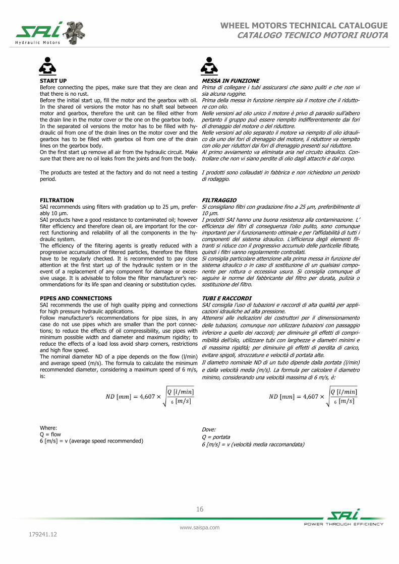
PIPES AND CONNECTIONS SAI recommends the use of high quality piping and connections for high pressure hydraulic applications. Follow manufacturer’s recommendations for pipe sizes, in any case do not use pipes which are smaller than the port connec-tions; to reduce the effects of oil compressibility, use pipes with minimum possible width and diameter and maximum rigidity; to reduce the effects of a load loss avoid sharp corners, restrictions and high flow speed. The nominal diameter ND of a pipe depends on the flow (l/min) and average speed (m/s). The formula to calculate the minimum recommended diameter, considering a maximum speed of 6 m/s, is: Where: Q = flow 6 [m/s] = v (average speed recommended)
MESSA IN FUNZIONE Prima di collegare i tubi assicurarsi che siano puliti e che non vi sia alcuna ruggine. Prima della messa in funzione riempire sia il motore che il ridutto-re con olio. Nelle versioni ad olio unico il motore è privo di paraolio sull’albero pertanto il gruppo può essere riempito indifferentemente dai fori di drenaggio del motore o del riduttore. Nelle versioni ad olio separato il motore va riempito di olio idrauli-co da uno dei fori di drenaggio del motore, il riduttore va riempito con olio per riduttori dai fori di drenaggio presenti sul riduttore. Al primo avviamento va eliminata aria nel circuito idraulico. Con-trollare che non vi siano perdite di olio dagli attacchi e dal corpo.
I prodotti sono collaudati in fabbrica e non richiedono un periodo di rodaggio.
FILTRAGGIO Si consigliano filtri con gradazione fino a 25 µm, preferibilmente di 10 µm. I prodotti SAI hanno una buona resistenza alla contaminazione. L’ efficienza dei filtri di conseguenza l’olio pulito, sono comunque importanti per il funzionamento ottimale e per l’affidabilità di tutti i componenti del sistema idraulico. L’efficienza degli elementi fil-tranti si riduce con il progressivo accumulo delle particelle filtrate, quindi i filtri vanno regolarmente controllati. Si consiglia particolare attenzione alla prima messa in funzione del sistema idraulico o in caso di sostituzione di un qualsiasi compo-nente per rottura o eccessiva usura. Si consiglia comunque di seguire le norme del fabbricante del filtro per durata, pulizia o sostituzione del filtro.
TUBI E RACCORDI SAI consiglia l’uso di tubazioni e raccordi di alta qualità per appli-cazioni idrauliche ad alta pressione. Attenersi alle indicazioni dei costruttori per il dimensionamento
delle tubazioni, comunque non utilizzare tubazioni con passaggio
inferiore a quello dei raccordi; per diminuire gli effetti di compri-
mibilità dell’olio, utilizzare tubi con larghezze e diametri minimi e
di massima rigidità; per diminuire gli effetti di perdita di carico,
evitare spigoli, strozzature e velocità di portata alte.
Il diametro nominale ND di un tubo dipende dalla portata (l/min)
e dalla velocità media (m/s). La formula per calcolare il diametro
minimo, considerando una velocità massima di 6 m/s, è:
Dove:
Q = portata
6 [m/s] = v (velocità media raccomandata)
6 6

17
www.saispa.com
179241.12
WHEEL MOTORS TECHNICAL CATALOGUE CATALOGO TECNICO MOTORI RUOTA
SPECIAL CONDITIONS OF USE: FREE WHEELING
All SAI motors can be disconnected from the hydraulic circuit and
driven externally for applications where freewheeling, free fall or
breakdowns may be present.
The diagrams below show some possible circuit configurations for
motor disconnection and/or operation in freewheeling:
CONDIZIONI SPECIALI D’USO: RUOTA LIBERA
Tutti i motori SAI possono essere disconnessi dal circuito idraulico
ed essere azionati esternamente per applicazioni dove ruota libe-
ra, caduta libera pesi, movimentazione o avaria sono presenti.
I diagrammi sottostanti indicano alcune configurazioni possibili di
circuito per lo scollegamento del motore e/o funzionamento a
ruota libera:
A: Freewheeling with oil in the circuit. This condition is suita-
ble only for low speeds. With the speed increase it will be neces-
sary to pressurize the inlet to prevent noise due to cavitation.
B: Freewheeling with air in the circuit. This condition is ideal
for high speed freewheeling applications. The transition from or to
normal operation must be done at low speed and low pressure
while the pistons are emptying or filling with oil.
C: “Short circuit” freewheeling. The motor runs with the inlet
and outlet ports connected. This condition is suitable to applica-
tions that require speed control with a throttle.
WARNING!
Danger of overheating in unfavourable conditions, especially with
throttle.
D: “Vacuum freewheeling”. This is the favourable freewheeling
condition for fixed displacement motors, especially for very high
speeds. The check valves allow the oil to be expelled from the
pistons which subsequently operate under vacuum conditions.
The motors can operate in these conditions for several hours
without being damaged or overheating. Torque absorption is
constant with speed and equivalent to 2 - 3 bar of pressure.
The transition from or to normal operation must be done at low
speed and low pressure while the pistons are emptying or filling
with oil.
For further information on the T and B series motors, please con-
tact the SAI Technical Department.
* BOOST PRESSURE SHOULD BE PROVIDED TO AVOID CAVITATION
A: Ruota libera con olio nel circuito. Questa condizione è
adatta solo per velocità ridotte. Con l’aumento di velocità sarà
necessario pressurizzare la porta di mandata per evitare rumorosi-
tà causata da cavitazione.
B: Ruota libera con aria in circolazione. Questa condizione
risulta ideale per velocità elevate. La transazione da o in funziona-
mento normale deve essere effettuata a velocità ridotta e pressio-
ne ridotta mentre si svuotano o si riempiono i pistoni.
C: Ruota libera in “corto circuito”. Il motore ruota con i canali
di mandata e ritorno collegati. Questa condizione è adatta ad
applicazioni che richiedono il controllo della velocità tramite stroz-
zatura.
ATTENZIONE!
Pericolo di surriscaldamento in condizioni sfavorevoli, specialmen-
te con strozzature.
D: Ruota libera “sotto vuoto”. Questa condizione è la più
indicata per funzionamento a ruota libera dei motori a cilindrata
fissa, specialmente per velocità molto elevate. Le valvole consen-
tono lo svuotamento dei pistoni che poi operano sotto vuoto. I
motori sono in grado di operare in queste condizioni per diverse
ore senza danneggiamento o surriscaldamento. La coppia assorbi-
ta è costante con la velocità ed equivale ad una pressione di 2 - 3
bar.
La transazione da o in funzionamento normale deve essere effet-
tuata a velocità ridotta e pressione ridotta mentre si svuotano o si
riempiono i pistoni.
Per maggiori informazioni per i motori delle serie T e B, contattare
l’Ufficio Tecnico SAI.
* UNA PRESSIONE DI CARICO DEVE ESSERE FORNITA PER EVITARE CAVITAZIONE.
*

18
www.saispa.com
179241.12
WHEEL MOTORS TECHNICAL CATALOGUE CATALOGO TECNICO MOTORI RUOTA
BEARING LIFETIME (ISO 281:1990)
The bearing lifetimes given in this catalogue and in most SAI
official documentations are L10 lifetimes.
The L10 lifetime is the period of work after which 10% of the
bearings can be expected to show signs of wear.
The average lifetime of the bearing, L50 lifetime (where 50% show
signs o wear), is approximately 5 times the L10 value.
To determine the lifetime of the bearings in an application, the
values of constant or average pressures and speeds should be
used, not peak or maximum values.
The continuous operating pressures of any motor should be cho-
sen in function of the desired motor lifetime which can be calcu-
lated from the bearing lifetime graphs supplied in the technical
documentation.
VITA CUSCINETTI (ISO 281:1990)
La vita dei cuscinetti descritta in questo catalogo e in molte delle
documentazioni ufficiali SAI corrisponde a L10.
La vita è il periodo di lavoro dopo il quale 10% dei cuscinetti
cominciano a presentare segni di usura.
La vita media del cuscinetto, L50 (dove il 50% dei cuscinetti pre-
senta segni di usura), è approssimativamente 5 volte il valore di
L10)
Per determinare la vita dei cuscinetti in qualsivoglia applicazione
saranno necessari i valori di pressione e velocità costanti o medie,
non di picco o valori massimi.
Le pressioni di lavoro continue di un motore dovrebbero essere
selezionate in funzione della vita del motore desiderata dai grafici
di vita dei cuscinetti forniti nelle documentazioni tecniche.
In any motor series the larger displacement models generally have shorter bearing lifetimes. This is due to the larger diameter pistons which creates higher bearing loads. The smaller displacement motors of any series are suitable for heavy duty applications, whereas the larger displacement motors are more suitable for high torque applications but with reduced continuous or average power.
WORKING CYCLE FACTOR
Non-stop operation sometimes causes shorter than calculated
lifetimes. This is due to increases in oil temperature and/or con-
tamination combined with a decrease in viscosity when operating
continuously for long periods. If, however, the hydraulic system is
continuously monitored, then the working cycle factor may be
disregarded.
In qualsiasi serie di motore i modelli con cilindrata maggiore sono
generalmente caratterizzate da una minore vita dei cuscinetti.
Questo è dovuto al diametro maggiore dei pistoni che genera
carichi più elevati sul cuscinetto.
I motori con cilindrata minore di qualsiasi serie sono più indicati
per applicazioni pesanti, mentre i motori con cilindrata maggiore
sono più indicati per applicazioni dove è necessario un’elevata
coppia ma potenze continue o medie ridotte.
FATTORE CICLO DI LAVORO
A volte l’operazione continuata causa vite più brevi di quelle ini-
zialmente calcolate. Questo è dovuto ad aumenti di temperatura
dell’olio e/o contaminazione abbinate alla riduzione della viscosità
quando in operazione in maniera continua per lunghi periodi di
tempo. Se, però, il sistema idraulico è monitorato in maniera co-
stante, il fattore ciclo di lavoro può essere ignorato.
MOTOR BEARING TYPE TIPOLOGIE DI CUSCINETTO MOTORE
Cylindrical roller bearings H
Cuscinetti rulli cilindrici
Reinforced spherical roller bearings FG
Cuscinetti rulli a botte rinforzati
Spherical roller bearings G
Cuscinetti rulli a botte

19
www.saispa.com
179241.12
WHEEL MOTORS TECHNICAL CATALOGUE CATALOGO TECNICO MOTORI RUOTA
SAI BEARING LIFETIME GRAPHS
These graphs are found in every SAI leaflet and in the catalogues
and are used to determine the lifetime of a given motor for a
given pressure input and speed output.
The graphs work as follows:
1. Choose the piston diameter on graph A
2. Define the intersection with the pressure curve
3. Define the speed on graph B
4. Determine the lifetime using the curve on graph B found on
the intersection between 2 and 3, indicated with
I GRAFICI DI VITA SAI
Questi grafici sono riportati in tutti i leaflet SAI e nei cataloghi e
sono utilizzati per determinare la vita del motore in questione
utilizzando una data pressione in ingresso ed una velocità in usci-
ta.
I grafici funzionano nel seguente modo:
1. Selezionare il diametro del pistone nel grafico A
2. Definire l’intersezione con la curva di pressione
3. Definire la velocità nel grafico B
4. Determinare la vita usando la curva nel grafico B che si
trova nel punto di intersezione tra 2 e 3, indicato con
Bearings lifetime calculation of the gearbox: Permissible loads are calculated for different steps of lifetime L10 according to ISO 281:1990. L10: lifetime of the bearing system in millions of revolutions. L10 value can be converted in hours L10h using the formula*. Permissible radial load in dynamic conditions at the maximum torque allowed by the gearbox. N.B. Diagrams are influenced by the shaft permissible radial loads.
Calcolo durata cuscinetti del riduttore: I carichi ammissibili sono calcolati per le diverse fasi del ciclo di vita L10 secondo ISO 281:1990. L10: durata del sistema di cuscinetti in milioni di giri. Il valore L10 può essere convertito in ore L10h utilizzando la se-guente formula*. Carico radiale ammissibile in condizioni dinamiche e con la coppia massima tollerata dal riduttore. N.B. I diagrammi sono influenzati dai carichi radiali ammissibili dell’albero.
10
6
10h L60n
10L
n: speed in rpm n: velocità in rpm
*
Ma
xim
um
ra
dia
l lo
ad
[N
] M
ass
imo
ca
rico
ra
dia
le [
N]
Load position [mm] Posizione di carico [mm]

20
www.saispa.com
179241.12
WHEEL MOTORS TECHNICAL CATALOGUE CATALOGO TECNICO MOTORI RUOTA
DISTRIBUTOR COVER ORIENTATION SAI motors can be provided with the distributor cover orientated in any of the following directions. These are selectable among the following positions: DM1 for position 1, DM2 for position 2 etc. This position has to be stated at the end of the full description of the motor. If no specification is made the standard position is DM1.
ORIENTAMENTO COPERCHIO DISTRIBUTORE
I motori SAI possono essere forniti con il coperchio distributore
orientato in diverse direzioni selezionabili tra le seguenti:
DM1 per posizione 1, DM2 per posizione 2 ecc.
Questa posizione va segnalata alla fine della descrizione del pro-
dotto.
Se non vi è nessuna indicazione la posizione standard è DM1.
DIRECTION OF SHAFT ROTATION
All SAI motors are bidirectional. The direction of the rotation of
the shaft is determined by the direction of the oil flow.
The standard motor configuration is set to have the input flow
through port A which causes the shaft to move clockwise, taking
the shaft as the focal point.
Should the oil flow be supplied through port B, the shaft will turn
anti-clockwise.
All SAI motors can be supplied with the shaft rotating anti-
clockwise. Should this option be needed it has to be pointed out in
the order as instructed in the order codes tables.
SENSO DI ROTAZIONE DELL’ALBERO
Tutti i motori SAI sono bidirezionali. Il senso di rotazione dell’albe-
ro è determinato dalla portata dell’olio.
La configurazione standard del motore è impostata in tale maniera
da avere la portata in entrata dalla porta A, causando la rotazione
in senso orario dell’albero, prendendo come punto focale l’albero
in questione.
Se la portata in entrata dell’olio dovesse essere dalla porta B,
l’albero avrà una rotazione in senso antiorario.
Tutti i motori SAI possono essere forniti con il senso di rotazione
dell’albero impostato in senso antiorario. Se questa opzione do-
vesse essere necessaria deve essere specificata al momento
dell’ordine come descritto nelle tabelle di codici d’ordine.
Seven piston motor. Motore a sette pistoni.
Five piston motor. Motore a cinque pistoni.
Position 2 Posizione 2
DM2
Position 3 Posizione 3
DM3
Position 4 Posizione 4
DM4
Position 5 Posizione 5
DM5
Position 1 Posizione 1
DM1
Position 1 Posizione 1
DM1
Position 2 Posizione 2
DM3
Position 3 Posizione 3
DM6

21
www.saispa.com
179241.12
WHEEL MOTORS TECHNICAL CATALOGUE CATALOGO TECNICO MOTORI RUOTA
22
www.saispa.com
179241.12
WHEEL MOTORS TECHNICAL CATALOGUE CATALOGO TECNICO MOTORI RUOTA
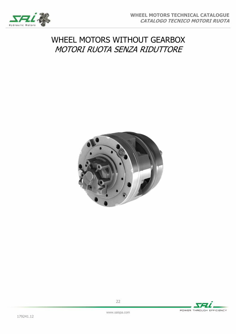
WHEEL MOTORS WITHOUT GEARBOX MOTORI RUOTA SENZA RIDUTTORE

23
www.saispa.com
179241.12
WHEEL MOTORS TECHNICAL CATALOGUE CATALOGO TECNICO MOTORI RUOTA
P1G 30/A P1G F30D
100 130 150 175 200 220 250 300
Displacement [cc/rev] 99 129 154 172 201 222 243 290
Cilindrata
Bore [mm] 28 32 35 37 40 42 44 48
Alesaggio
Stroke [mm] 32 32 32 32 32 32 32 32
Corsa
Specific torque [Nm/bar] 1,58 2,05 2,45 2,74 3,20 3,50 3,87 4,62
Coppia specifica
Peak pressure ⁽¹⁾ [bar] 425 400 400 375 350 350 350 300
Pressione di picco ⁽¹⁾
Peak power ⁽²⁾ [kW] 48
Potenza di picco ⁽²⁾
Continuous speed ⁽³⁾ [rpm] 550 550 550 550 550 550 450 350
Velocità in continuo ⁽³⁾
Maximum speed ⁽³⁾ [rpm] 1000 1000 1000 900 800 700 700 650
Velocità massima ⁽³⁾
Approximative weight with hub [kg] 36
unit Approximative weight with brake [kg] 44
unit
Peso approssimativo con mozzo unità Peso approssimativo con freno unità
Maximum casing pressure
[bar]
1 continuous
Admissible temperatures
[°C]
-20 minimum
continuo minimo
Pressione massima in carcassa 5 peak
Temperature ammissibili +80 maximum
picco massimo
Type of brake
Positive drum brake Static braking torque [Nm] 2000
Tipo di freno Freno positivo a tamburo Coppia di frenatura statica
Unit oil capacity [l] 0,8
Maximum cable force [N] 1800
Capacità olio corpo unità Massimo tiro del cavo
Brake pilot volume [cm³] 6,5
Maximum brake pilot pressure [bar] 100
Volume pilotaggio freno Pressione massima pilotaggio
Bolt torque setting [Nm]
110,0 coarse 118,0 fine Suggested bolt type M14 8,8
Coppia serraggio viti 135,0 grosso 148,0 fine Viti suggerite
NOTES / NOTE (1) For higher peak pressure please contact the SAI Technical Department
(1) Per pressioni di picco maggiori contattare l'Ufficio Tecnico SAI
(2) For higher peak power please contact the SAI Technical Department
(2) Per potenze di picco maggiori contattare l'Ufficio Tecnico SAI
(3) For higher continuous and maximum speeds please contact the SAI Technical Department
(3) Per velocità maggiori in continuo e massime contattare l’Ufficio Tecnico SAI
WHEEL MOTORS TECHNICAL CATALOGUE CATALOGO TECNICO MOTORI RUOTA
24
www.saispa.com
179241.12
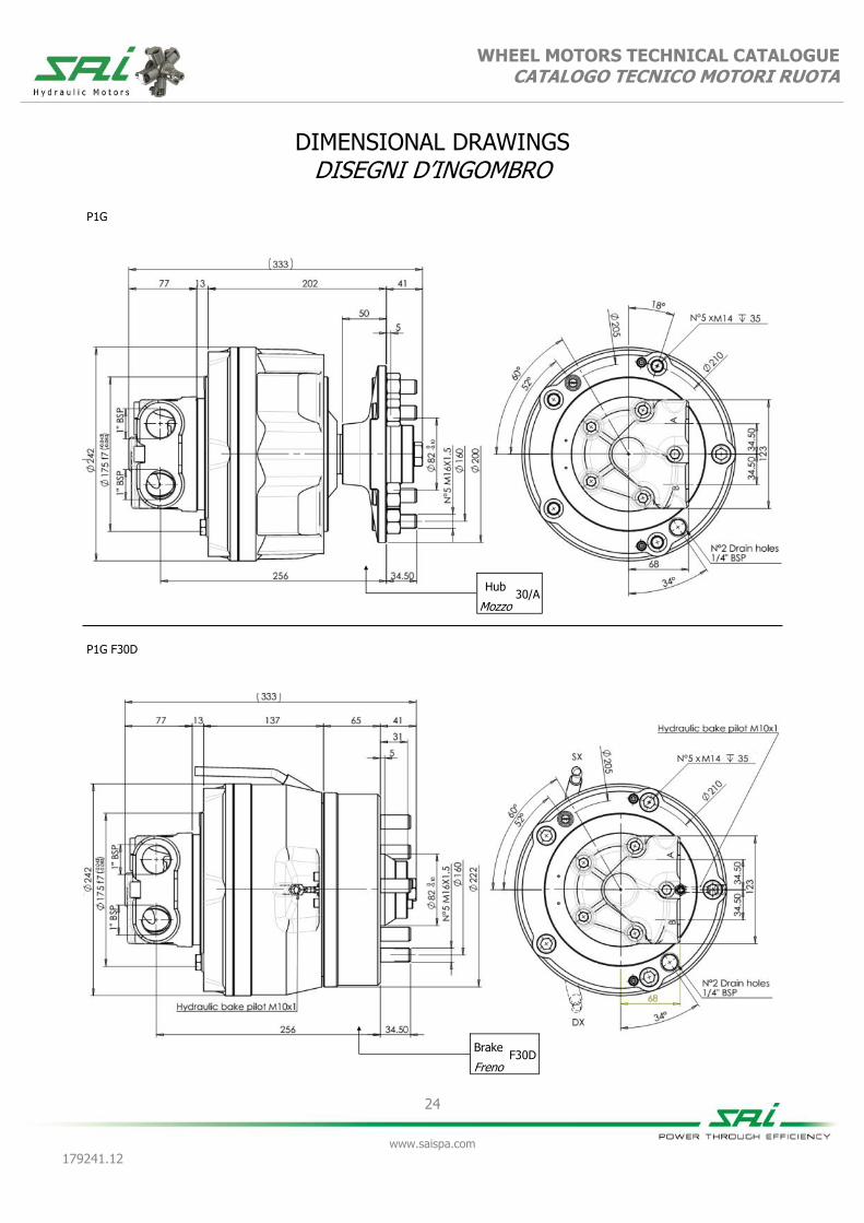
DIMENSIONAL DRAWINGS DISEGNI D’INGOMBRO
P1G F30D
P1G
Hub 30/A
Mozzo
N°5 x
Brake F30D
Freno
N°5 x

WHEEL MOTORS TECHNICAL CATALOGUE CATALOGO TECNICO MOTORI RUOTA
25
www.saispa.com
179241.12
GRAPHS GRAFICI
Ma
xim
um
ra
dia
l lo
ad
[N
] M
ass
imo
ca
rico
ra
dia
le [
N]
Load Position [mm] Posizione di carico [mm]
P1G 30/A
Ma
xim
um
ra
dia
l lo
ad
[N
] M
ass
imo
ca
rico
ra
dia
le [
N]
Load Position [mm] Posizione di carico [mm]
P1G F30D
Bearing lifetime has been estima-ted according to L10 (according to ISO 281:1990).
La durata è stata calcolata in accor-do con la formula L10 (secondo ISO 281:1990).
Bearing lifetime has been estima-ted according to L10 (according to ISO 281:1990).
La durata è stata calcolata in accor-do con la formula L10 (secondo ISO 281:1990).
Working pressure: 200 bar
Displacement: 201 cc
Pressione di lavoro: 200 bar Cilindrata : 201 cc
Working pressure: 200 bar
Displacement: 201 cc
Pressione di lavoro: 200 bar Cilindrata: 201 cc

26
www.saispa.com
179241.12
WHEEL MOTORS TECHNICAL CATALOGUE CATALOGO TECNICO MOTORI RUOTA
ORDER CODES CODICI D’ORDINE
Example
Esempio
P1G 200 2HGP D40
(standard)
P1G 200 2HGPV D40L F30DSX
(options: FKM seals and anti-clockwise sense of rotation)
(opzioni: tenute in FKM e direzione d'uscita in rotazione anti-oraria)
1 Displacement see table 1 Cilindrata vedere tabella
2 Additional options
V = FKM seals
2 Opzioni aggiuntive
V = tenute in FKM
I = breath valve I = valvola di sfiato
A = high pressure shaft seal A = anello di tenuta alta pres-sione
RS = integrated speed sensor RS = sensore velocità integrato
3 Distributor see distributors section
3 Distributore vedere sezione distributori
D40 standard D40 standard
4
Direction of rotation (viewed from the output side) with input flow in port A, output in B.
No code = clockwise rotation
4
Direzione d'uscita (visto dal lato d'uscita) con por-tata in ingresso in porta A, uscita in porta B.
Nessun codice
= rotazione oraria
L = anti-clockwise rota-tion
L = rotazione anti-oraria
5 Distributor cover orientation
No code = position 1
5 Orientamento coperchio distributore
Nessun codice
= posizione 1
DM2 = position 2 DM2 = posizione 2
DM3 = position 3 DM3 = posizione 3
DM4 = position 4 DM4 = posizione 4
DM5 = position 5 DM5 = posizione 5
6 Brake or hub option
30/A = hub 30/A
6 Opzione freno
30/A = mozzo 30/A
F30DSX = F30D brake left F30DSX = freno F30D sinistro
F30DDX = F30D brake right F30DDX = freno F30D destro
7 Brake cable lenght
1600 mm
7 Lunghezza del cavo freno
1600 mm
2195 mm 2195 mm
6000 mm 6000 mm
1 2 3 4 5 6 7
P1G + + 2HGP + + D40 + + + +

27
www.saispa.com
179241.12
WHEEL MOTORS TECHNICAL CATALOGUE CATALOGO TECNICO MOTORI RUOTA
P2G 22/B P2G F32
200 250 300 350 420 500 600
Displacement [cc/rev] 192 251 304 347 425 493 565
Cilindrata
Bore [mm] 35 40 44 47 52 56 60
Alesaggio
Stroke [mm] 40
Corsa
Specific torque [Nm/bar] 3,00 3,92 4,84 5,52 6,77 7,85 9,50
Coppia specifica
Peak pressure ⁽¹⁾ [bar] 425 425 400 375 350 350 300
Pressione di picco ⁽¹⁾
Peak power ⁽²⁾ [kW] 59
Potenza di picco ⁽²⁾
Continuous speed ⁽³⁾ [rpm] 550 550 500 500 450 450 450
Velocità in continuo ⁽³⁾
Maximum speed ⁽³⁾ [rpm] 800 800 750 750 750 700 700
Velocità massima ⁽³⁾
Approximative weight with hub [kg] 58
unit Approximative weight with brake [kg] 61
unit
Peso approssimativo con mozzo unità Peso approssimativo con freno unità
Maximum casing pressure
[bar]
1 continuous
Admissible temperatures
[°C]
-20 minimum
continuo minimo
Pressione massima in carcassa 5 peak
Temperature ammissibili +80 maximum
picco massimo
Type of brake
Positive drum brake Static braking torque [Nm] 2000
Tipo di freno Freno positivo a tamburo Coppia di frenatura statica
Unit oil capacity [l] 0,8
Maximum cable force [N] 800
Capacità olio corpo unità Massimo tiro del cavo
Brake pilot volume [cm³] 6,5
Maximum brake pilot pressure [bar] 100
Volume pilotaggio freno Pressione massima pilotaggio
Bolt torque setting [Nm]
69,0 coarse 72,0 fine Suggested bolt type M12 8,8
Coppia serraggio viti 85,0 grosso 89,0 fine Viti suggerite
NOTES / NOTE (1) For higher peak pressure please contact the SAI Technical Department
(1) Per pressioni di picco maggiori contattare l'Ufficio Tecnico SAI
(2) For higher peak power please contact the SAI Technical Department
(2) Per potenze di picco maggiori contattare l'Ufficio Tecnico SAI
(3) For higher continuous and maximum speeds please contact the SAI Technical Department
(3) Per velocità maggiori in continuo e massime contattare l’Ufficio Tecnico SAI

WHEEL MOTORS TECHNICAL CATALOGUE CATALOGO TECNICO MOTORI RUOTA
28
www.saispa.com
179241.12
DIMENSIONAL DRAWINGS DISEGNI D’INGOMBRO
P2G F32
P2G
Hub 22/B
Mozzo
Brake F32
Freno
N°5 x
N°5 x

WHEEL MOTORS TECHNICAL CATALOGUE CATALOGO TECNICO MOTORI RUOTA
29
www.saispa.com
179241.12
GRAPHS GRAFICI
Ma
xim
um
ra
dia
l lo
ad
[N
] M
ass
imo
ca
rico
ra
dia
le [
N]
Load Position [mm] Posizione di carico [mm]
P2G 22/B
Ma
xim
um
ra
dia
l lo
ad
[N
] M
ass
imo
ca
rico
ra
dia
le [
N]
Load Position [mm] Posizione di carico [mm]
P2G F32
Bearing lifetime has been estima-ted according to L10 (according to ISO 281:1990).
La durata è stata calcolata in accor-do con la formula L10 (secondo ISO 281:1990).
Bearing lifetime has been estima-ted according to L10 (according to ISO 281:1990).
La durata è stata calcolata in accor-do con la formula L10 (secondo ISO 281:1990).
Working pressure: 200 bar
Displacement: 595 cc
Pressione di lavoro: 200 bar Cilindrata: 595 cc
Working pressure: 200 bar
Displacement: 595 cc
Pressione di lavoro: 200 bar Cilindrata: 959 cc

30
www.saispa.com
179241.12
WHEEL MOTORS TECHNICAL CATALOGUE CATALOGO TECNICO MOTORI RUOTA
ORDER CODES CODICI D’ORDINE
Example
Esempio
P2G 200 2HGPD D40
(standard)
P2G 200 2HGPD D40 F30DSX
(options: FKM seals and anti-clockwise sense of rotation)
(opzioni: tenute in FKM e direzione d'uscita in rotazione anti-oraria)
1 Displacement see table 1 Cilindrata vedere tabella
2 Additional options
V = FKM seals
2 Opzioni aggiuntive
V = tenute in FKM
I = breath valve I = valvola di sfiato
A = high pressure shaft seal A = anello di tenuta alta pres-sione
RS = integrated speed sensor RS = sensore velocità integrato
3 Distributor see distributors section
3 Distributore vedere sezione distributori
D40 standard D40 standard
4
Direction of rotation (viewed from the output side) with input flow in port A, output in B.
No code = clockwise rotation
4
Direzione d'uscita (visto dal lato d'uscita) con portata in ingresso in porta A, uscita in porta B.
Nessun codice
= rotazione oraria
L = anti-clockwise rota-tion
L = rotazione anti-oraria
5 Distributor cover orientation
No code = position 1
5 Orientamento coperchio distributore
Nessun codice
= posizione 1
DM2 = position 2 DM2 = posizione 2
DM3 = position 3 DM3 = posizione 3
DM4 = position 4 DM4 = posizione 4
DM5 = position 5 DM5 = posizione 5
6 Brake or hub option
22/B = hub 22/B
6 Opzione freno
22/B = mozzo 22/B
F32SX = F32 brake left F32SX = freno F32 sinistro
F32DX = F32 brake right F32DX = freno F32 destro
7 Brake cable lenght 1305 mm
7 Lunghezza del cavo freno
1305 mm
1500 mm 1500 mm
1 2 3 4 5 6 7
P2G + + 2HGPD + + D40 + + + +

31
www.saispa.com
179241.12
WHEEL MOTORS TECHNICAL CATALOGUE CATALOGO TECNICO MOTORI RUOTA
BD2 22/B BD2 F32
250 65 250 125 350 90 350 175 500 125 500 250
Displacement [cc/rev] 251 63 251 126 347 87 347 173 493 123 493 246
Cilindrata
Bore [mm] 40 40 47 47 56 56
Alesaggio
Stroke [mm] 40 10 40 20 40 10 40 20 40 10 40 10
Corsa
Specific torque [Nm/bar] 4,00 1,00 4,00 2,00 5,50 1,40 5,50 2,80 7,80 2,00 7,85 3,91
Coppia specifica
Peak pressure ⁽¹⁾ [bar] 425 425 375 375 350 350
Pressione di picco ⁽¹⁾
Peak power ⁽²⁾ [kW] 75 65 75 65 75 65 75 65 75 62 75 65
Potenza di picco ⁽²⁾
Continuous speed ⁽³⁾ [rpm] 700 1500 700 1500 700 1500 700 1500 400 1500 400 800
Velocità in continuo ⁽³⁾
Maximum speed ⁽³⁾ [rpm] 1000 2400 1000 1800 1000 2200 1000 1800 800 2200 800 1600
Velocità massima ⁽³⁾
Approximative weight with hub [kg] 58
unit Approximative weight with brake [kg] 61
unit
Peso approssimativo con mozzo unità Peso approssimativo con freno unità
Maximum casing pressure
[bar]
1 continuous
Admissible temperatures
[°C]
-20 minimum
continuo minimo
Pressione massima in carcassa 5 peak
Temperature ammissibili +80 maximum
picco massimo
Type of brake
Positive drum brake Static braking torque [Nm] 2000
Tipo di freno Freno positivo a tamburo Coppia di frenatura statica
Motor oil capacity [l] 3
Maximum cable force [N] 800
Capacità olio motore Massimo tiro del cavo
Volume pilot change displace-ment
[cm³] 5,568
Pilot pressure change displace-ment
[bar]
25 minimum
minimo
Volume pilotaggio cambio cilin-drata
Pressione di pilotaggio cambio cilindrata
35 maximum
massimo
Brake pilot volume [cm³] 6,5
Maximum cylinder pressure [bar] 100
Volume pilotaggio freno Pressione massima cilindro
Suggested bolt type
M18 8,8
Maximum brake pilot pressure
[bar] 100 Viti suggerite
Pressione massima pilotaggio freno
Bolt torque setting [Nm]
235,0 coarse 248,0 fine
Coppia serraggio viti 290,0 grosso 310,0 fine
NOTES / NOTE (1) For higher peak pressure please contact the SAI Technical Department
(1) Per pressioni di picco maggiori contattare l'Ufficio Tecnico SAI
(2) For higher peak power please contact the SAI Technical Department
(2) Per potenze di picco maggiori contattare l'Ufficio Tecnico SAI
(3) For higher continuous and maximum speeds please contact the SAI Technical Department
(3) Per velocità maggiori in continuo e massime contattare l’Ufficio Tecnico SAI
WHEEL MOTORS TECHNICAL CATALOGUE CATALOGO TECNICO MOTORI RUOTA
32
www.saispa.com
179241.12
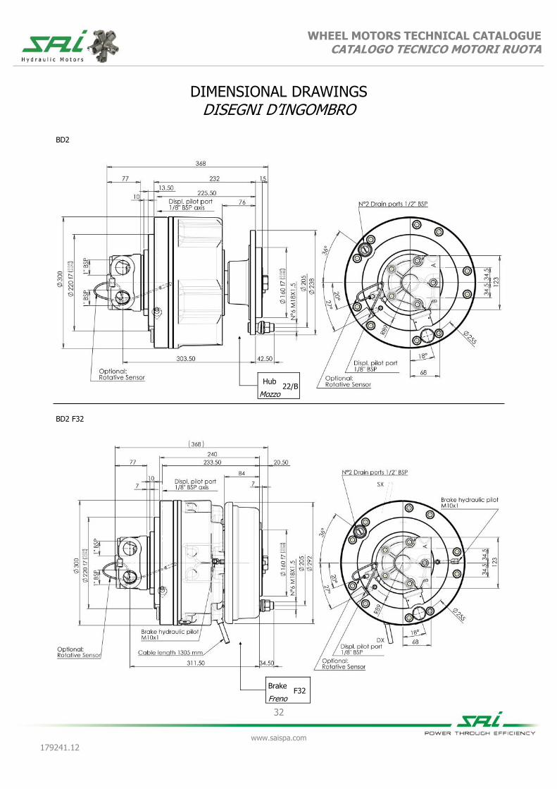
DIMENSIONAL DRAWINGS DISEGNI D’INGOMBRO
BD2 F32
BD2
Hub 22/B
Mozzo
Brake F32
Freno

WHEEL MOTORS TECHNICAL CATALOGUE CATALOGO TECNICO MOTORI RUOTA
33
www.saispa.com
179241.12
GRAPHS GRAFICI
Ma
xim
um
ra
dia
l lo
ad
[N
] M
ass
imo
ca
rico
ra
dia
le [
N]
Load Position [mm] Posizione di carico [mm]
BD2 22/B
Ma
xim
um
ra
dia
l lo
ad
[N
] M
ass
imo
ca
rico
ra
dia
le [
N]
Load Position [mm] Posizione di carico [mm]
BD2 F32
Bearing lifetime has been estima-ted according to L10 (according to ISO 281:1990).
La durata è stata calcolata in accor-do con la formula L10 (secondo ISO 281:1990).
Bearing lifetime has been estima-ted according to L10 (according to ISO 281:1990).
La durata è stata calcolata in accor-do con la formula L10 (secondo ISO 281:1990).
Working pressure: 200 bar
Displacement: 493 cc
Pressione di lavo-ro: 200 bar Cilindrata: 493 cc
Working pressure: 200 bar
Displacement: 493 cc
Pressione di lavoro: 200 bar Cilindrata: 493 cc

34
www.saispa.com
179241.12
WHEEL MOTORS TECHNICAL CATALOGUE CATALOGO TECNICO MOTORI RUOTA
ORDER CODES CODICI D’ORDINE
Example
Esempio
BD2 500 125 2HGPMD D40
(standard)
BD2 500 125 2HGPMD D40L F30DSX
(options: FKM seals and anti-clockwise sense of rotation)
(opzioni: tenute in FKM e direzione d'uscita in rotazione anti-oraria)
1 Maximum displacement
see table 1 Cilindrata massima
vedere tabella
2 Minimum displacement
see table 2 Cilindrata minima
vedere tabella
3 Additional options
V = FKM seals
3 Opzioni aggiuntive
V = tenute in FKM
I = breath valve I = valvola di sfiato
RS = rotative sensor RS = sensore rotativo
4 Distributor see distributors section
4 Distributore vedere sezione distributori
D40 standard D40 standard
5
Direction of rotation (viewed from the output side) with input flow in port A, output in B.
No code = clockwise rotation
5
Direzione d'uscita (visto dal lato d'uscita) con portata in ingresso in porta A, uscita in porta B.
Nessun codice
= rotazione oraria
L = anti-clockwise rota-tion
L = rotazione anti-oraria
6 Distributor cover orientation
No code = position 1
6 Orientamento coperchio distributore
Nessun codice
= posizione 1
DM2 = position 2 DM2 = posizione 2
DM3 = position 3 DM3 = posizione 3
DM4 = position 4 DM4 = posizione 4
DM5 = position 5 DM5 = posizione 5
7 Brake or hub option
22/B = hub 22/B
7 Opzione freno
22/B = mozzo 22/B
F32SX = F32 brake left F32SX = freno F32 sinistro
F32DX = F32 brake right F32DX = freno F32 destro
1 2 3 4 5 6 7
BD2 + + + 2HGPMD + + D40 + + +

35
www.saispa.com
179241.12
WHEEL MOTORS TECHNICAL CATALOGUE CATALOGO TECNICO MOTORI RUOTA
WR SERIES SERIE WR
WR6B WR10 WR20
Maximum continuous torque [Nm]
3000 6500 9650
Coppia continua massima
Peak torque [Nm]
4200 10000 14300
Coppia di picco
Reduction ratio
5:1 4,80:1 6,60:1
Rapporto di riduzione
Maximum braking torque [Nm]
3000 7000 10000
Coppia frenante massima
Brake pilot pressure [bar]
minimum 18 15 15
minimo
Pressione pilotaggio freno maximum 60 60 60
massimo
Gearbox weight [kg] 47 75 90
Peso riduttore
Type of brake
Negative disk brake Negative disk brake Negative disk brake
Tipo di freno Freno a dischi negativo Freno a dischi negativo Freno a dischi negativo
GM05 GM05 GM1
Applicable motors
Motori applicabili
GS05* GS05* GS1*
GM1 GM1 BD1
GS1* GS1* BV1
BD1 BD1 GM2
BV1 BV1 GS2*
BD2
BV2
* For further information on the use of the high speed GS series motors on these gearboxes please contact the SAI Technical Department.
* Per maggiori informazioni sull’utilizzo dei motori ad alta velocità della serie GS contatta-re l’Ufficio Tecnico SAI

36
www.saispa.com
179241.12
WHEEL MOTORS TECHNICAL CATALOGUE CATALOGO TECNICO MOTORI RUOTA
Ma
xim
um
ra
dia
l lo
ad
[N
] M
ass
imo
ca
rico
ra
dia
le [
N]
Load position [mm] Posizione di carico [mm]
WR6B
Ma
xim
um
ra
dia
l lo
ad
[N
] M
ass
imo
ca
rico
ra
dia
le [
N]
Load position [mm] Posizione di carico [mm]
WR10
Ma
xim
um
ra
dia
l lo
ad
[N
] M
ass
imo
ca
rico
ra
dia
le [
N]
Load position [mm] Posizione di carico [mm]
WR20
GRAPHS GRAFICI

37
www.saispa.com
179241.12
WHEEL MOTORS TECHNICAL CATALOGUE CATALOGO TECNICO MOTORI RUOTA
GM05 + WR6B
200 300 400 450 600 650 750 850 950
Equivalent displacement ⁽¹⁾ [cc/rev] 196 295 369 430 577 645 754 831 954
Cilindrata equivalente ⁽¹⁾
Reduction ratio 5:1
Rapporto di riduzione
Bore [mm] 25 25 28 37 35 37 40 42 45
Alesaggio
Stroke [mm] 16 24 24 16 24 24 24 24 24
Corsa
Specific torque [Nm/bar] 3,10 4,70 5,90 6,85 9,15 10,25 12,00 13,20 15,20
Coppia specifica
Peak pressure ⁽²⁾ [bar] 450 450 425 375 400 375 325 315 275
Pressione di picco ⁽²⁾
Peak power ⁽³⁾ [kW] 20 20 33 33 33 33 33 33 33
Potenza di picco ⁽³⁾
Continuous speed ⁽⁴⁾ [rpm] 140 140 140 140 130 130 130 120 120
Velocità in continuo ⁽⁴⁾
Maximum speed ⁽⁴⁾ [rpm] 200 200 200 200 180 180 180 160 160
Velocità massima ⁽⁴⁾
Approximative weight [kg] 72
unit Type of brake Negative disc brake
Peso approssimativo unità Tipo di freno Freno a dischi negativo
Maximum casing pressure
[bar]
1 continuous
Admissible temperatures
[°C]
-20 minimum
continuo minimo
Pressione massima in carcassa 5 peak
Temperature ammissibili +80 maximum
picco massimo
Motor oil capacity [l] 0,8
Static braking torque ⁽⁵⁾ [Nm] 3000
Capacità olio motore Coppia di frenatura statica ⁽⁵⁾
Gearbox oil capacity [l] 0,5
Minimum brake pilot pressure [bar] 18
Capacità olio riduttore Pressione minima pilotaggio freno
Brake pilot volume [cm³] 14
Maximum brake pilot pressure
[bar] 60
Volume pilotaggio freno Pressione massima pilotaggio freno
Bolt torque setting [Nm]
287,0 coarse 303,0 fine Suggested bolt type M16 12.9
Coppia serraggio viti 357,0 grosso 382,0 fine Viti suggerite
NOTES / NOTE (1) Equivalent displacement = motor displacement x reduction ratio of gearbox (5:1)
(1) Cilindrata Equivalente = cilindrata motore x rapporto di riduzione del riduttore (5:1)
(2) For higher peak pressures please contact the SAI Technical Department.
(2) Per pressioni di picco maggiori contattare l'Ufficio Tecnico SAI
(3) For higher peak power please contact the SAI Technical Department.
(3) Per potenze di picco maggiori contattare l'Ufficio Tecnico SAI.
(4) For higher continuous and maximum speeds please contact the SAI Technical Department
(4) Per velocità in continuo e massime maggiori contattare l'Ufficio Tecnico SAI
(5) If the brake is engaged for a long time, the braking torque could increase considerably. The brake requires to be periodically engaged and disengaged to maintain the desired
performances.
(5) Quando il freno rimane ingaggiato per un lungo periodo di tempo la coppia frenante può aumentare considerevolmente. Si consiglia periodicamente di pilotare il freno in modo da garantire i dati dichiarati.

WHEEL MOTORS TECHNICAL CATALOGUE CATALOGO TECNICO MOTORI RUOTA
38
www.saispa.com
179241.12
DIMENSIONAL DRAWINGS DISEGNI D’INGOMBRO
GM05 + WR6B
GM05
UNIT DISPLACEMENT - CILINDRATA UNITÀ L10 LIFETIME - VITA L10
PR
ESSU
RE -
PR
ESSIO
NE (
bar)
PISTON DIAMETER - DIAMETRO PISTONE (Ø mm)
HO
UR
S -
ORE
UNIT SPEED - VELOCITÀ DELL’UNITÀ (rpm)
100
200
500 1.000 2.000 5.000
10.000 20.000 50.000
100.000 200.000
500.000 1.000.000
25 27 29 31 33 35 37 39 41 43 45
0 40 80 120 160 200 240
GRAPHS GRAFICI
N°5 x
300
25
400
28
600
35
650
37
750
40
850
42
950
45
Bearing lifetime has been estimated according to L10 (according to ISO 281:1990). The following graph has been plotted using the stroke of 24 mm. Please contact the SAI Technical Department for other graphs relating to this product.
La durata è stata calcolata in accordo con la formula L10 (secondo ISO 281:1990). Il grafico che segue è stato ricavato usando la corsa di 24 mm. Vi preghiamo di contattare l’Ufficio Tecnico SAI per altri grafici relativi a questo prodotto.
39
www.saispa.com
179241.12
WHEEL MOTORS TECHNICAL CATALOGUE CATALOGO TECNICO MOTORI RUOTA
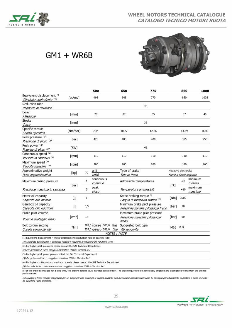
GM1 + WR6B
500 650 775 860 1000
Equivalent displacement ⁽¹⁾ [cc/rev] 495 645 770 860 1005
Cilindrata equivalente ⁽¹⁾
Reduction ratio 5:1
Rapporto di riduzione
Bore [mm] 28 32 35 37 40
Alesaggio
Stroke [mm] 32
Corsa
Specific torque [Nm/bar] 7,84 10,27 12,26 13,69 16,00
Coppia specifica
Peak pressure ⁽²⁾ [bar] 425 400 400 375 250
Pressione di picco ⁽²⁾
Peak power ⁽³⁾ [kW] 48
Potenza di picco ⁽³⁾
Continuous speed ⁽⁴⁾ [rpm] 110 110 110 110 110
Velocità in continuo ⁽⁴⁾
Maximum speed ⁽⁴⁾ [rpm] 200 200 200 180 160
Velocità massima ⁽⁴⁾
Approximative weight [kg] 79
unit Type of brake Negative disc brake
Peso approssimativo unità Tipo di freno Freno a dischi negativo
Maximum casing pressure
[bar]
1 continuous
Admissible temperatures
[°C]
-20 minimum
continuo minimo
Pressione massima in carcassa 5 peak
Temperature ammissibili +80 maximum
picco massimo
Motor oil capacity [l] 1
Static braking torque ⁽⁵⁾ [Nm] 3000
Capacità olio motore Coppia di frenatura statica ⁽⁵⁾
Gearbox oil capacity [l] 0,5
Minimum brake pilot pressure [bar] 18
Capacità olio riduttore Pressione minima pilotaggio freno
Brake pilot volume [cm³] 14
Maximum brake pilot pressure
[bar] 60
Volume pilotaggio freno Pressione massima pilotaggio freno
Bolt torque setting [Nm]
287,0 coarse 303,0 fine Suggested bolt type M16 12.9
Coppia serraggio viti 357,0 grosso 382,0 fine Viti suggerite
NOTES / NOTE (1) Equivalent displacement = motor displacement x reduction ratio of gearbox (5:1)
(1) Cilindrata Equivalente = cilindrata motore x rapporto di riduzione del riduttore (5:1)
(2) For higher peak pressures please contact the SAI Technical Department.
(2) Per pressioni di picco maggiori contattare l'Ufficio Tecnico SAI
(3) For higher peak power please contact the SAI Technical Department.
(3) Per potenze di picco maggiori contattare l'Ufficio Tecnico SAI.
(4) For higher continuous and maximum speeds please contact the SAI Technical Department
(4) Per velocità in continuo e massime maggiori contattare l'Ufficio Tecnico SAI
(5) If the brake is engaged for a long time, the braking torque could increase considerably. The brake requires to be periodically engaged and disengaged to maintain the desired
performances.
(5) Quando il freno rimane ingaggiato per un lungo periodo di tempo la coppia frenante può aumentare considerevolmente. Si consiglia periodicamente di pilotare il freno in modo da garantire i dati dichiarati.

WHEEL MOTORS TECHNICAL CATALOGUE CATALOGO TECNICO MOTORI RUOTA
40
www.saispa.com
179241.12
DIMENSIONAL DRAWINGS DISEGNI D’INGOMBRO
GM1 + WR6B
Bearing lifetime has been estimated according to L10 (according to ISO 281:1990).
La durata è stata calcolata in accordo con la formula L10 (secondo ISO 281:1990).
GM1
UNIT DISPLACEMENT - CILINDRATA UNITÀ L10 LIFETIME - VITA L10
PR
ESSU
RE -
PR
ESSIO
NE (
bar)
PISTON DIAMETER - DIAMETRO PISTONE (Ø mm)
HO
UR
S -
ORE
UNIT SPEED - VELOCITÀ DELL’UNITÀ (rpm)
28 33 38 43 48
0 40 80 120 160 200 240
500
28
650
32
775
35
860
37
1000
40
100
200
500 1.000 2.000 5.000
10.000 20.000 50.000
100.000 200.000
500.000 1.000.000
GRAPHS GRAFICI

41
www.saispa.com
179241.12
WHEEL MOTORS TECHNICAL CATALOGUE CATALOGO TECNICO MOTORI RUOTA
BD1+WR6B (dual displacement / cilindrata doppia)
BV1+WR6B (variable displacement /cilindrata variabile)
500 270 875 225 875 400 1250 300 1250 600
Equivalent displacement ⁽¹⁾ [cc/rev] 510 270 860 215 880 380 1215 305 1215 608
Cilindrata equivalente ⁽¹⁾
Reduction ratio 5:1
Rapporto di riduzione
Bore [mm] 37 37 37 37 44 44 44 44 44 44
Alesaggio
Stroke [mm] 19 10 32 8 23 10 32 8 32 16
Corsa
Specific torque [Nm/bar] 8,10 4,50 13,68 3,50 14,00 6,04 19,40 4,85 19,50 9,67
Coppia specifica
Peak pressure ⁽²⁾ [bar] 425 425 310 400 300 400 215 375 215 375
Pressione di picco ⁽²⁾
Peak power ⁽³⁾ [kW] 55 42 55 42 55 42 55 42 55 42
Potenza di picco ⁽³⁾
Continuous speed ⁽⁴⁾ [rpm] 100 250 100 250 100 250 100 250 100 250
Velocità in continuo ⁽⁴⁾
Maximum speed ⁽⁴⁾ [rpm] 250 250 200 250 200 250 170 250 170 250
Velocità massima ⁽⁴⁾
Approximative weight [kg] 85
unit Type of brake Negative disc brake
Peso approssimativo unità Tipo di freno Freno a dischi negativo
Maximum casing pressure
[bar]
1 continuous
Admissible temperatures
[°C]
-20 minimum
continuo minimo
Pressione massima in carcassa 5 peak
Temperature ammissibili +80 maximum
picco massimo
Motor oil capacity [l] 1,5
Static braking torque ⁽⁵⁾ [Nm] 3000
Capacità olio motore Coppia di frenatura statica ⁽⁵⁾
Gearbox oil capacity [l] 0,5
Minimum brake pilot pressure [bar] 18
Capacità olio riduttore Pressione minima pilotaggio freno
Brake pilot volume [cm³] 14
Maximum brake pilot pressure
[bar] 60
Volume pilotaggio freno Pressione massima pilotaggio freno
Volume pilot change displace-ment
[cm³] 2,12 Pilot pressure change displace-ment
[bar]
25
minimum
Volume pilotaggio cambio cilin-drata
minimo
Suggested bolt type M16 12.9
Pressione di pilotaggio cambio cilindrata
35 maximum
Viti suggerite massimo
Bolt torque setting
[Nm] 287,0 coarse 303,0 fine
Coppia serraggio viti 357,0 grosso 382,0 fine
NOTES / NOTE (1) Equivalent displacement = motor displacement x reduction ratio of gearbox
(5:1) (4) For higher continuous and maximum speeds please contact the SAI Technical Department
(1) Cilindrata Equivalente = cilindrata motore x rapporto di riduzione del riduttore (5:1) (4) Per velocità in continuo e massime maggiori contattare l'Ufficio Tecnico SAI
(2) For higher peak pressures please contact the SAI Technical Department. (5) If the brake is engaged for a long time, the braking torque could increase considerably.
The brake requires to be periodically engaged and disengaged to maintain the desired perfor-mances.
(2) Per pressioni di picco maggiori contattare l'Ufficio Tecnico SAI (5) Quando il freno rimane ingaggiato per un lungo periodo di tempo la coppia frenante può aumentare considerevolmente. Si consiglia periodicamente di pilotare il freno in modo da garantire i dati dichiarati.
(3) For higher peak power please contact the SAI Technical Department.
(3) Per potenze di picco maggiori contattare l'Ufficio Tecnico SAI.

WHEEL MOTORS TECHNICAL CATALOGUE CATALOGO TECNICO MOTORI RUOTA
42
www.saispa.com
179241.12
DIMENSIONAL DRAWINGS DISEGNI D’INGOMBRO
BD1 + WR6B
BV1 + WR6B

WHEEL MOTORS TECHNICAL CATALOGUE CATALOGO TECNICO MOTORI RUOTA
43
www.saispa.com
179241.12
GRAPHS GRAFICI
Bearing lifetime has been estimated according to L10 (according to ISO 281:1990). The following graph has been plotted using the maximum displa-cements with the stroke of 32 mm. Please contact the SAI Tech-nical Department for other graphs relating to this product.
La durata è stata calcolata in accordo con la formula L10 (secondo ISO 281:1990). Il grafico che segue è stato ricavato usando le cilindrate massime e la corsa di 32 mm. Vi preghiamo di contattare l’Ufficio Tecnico SAI per altri grafici relativi a questo prodotto.
BD1/BV1
UNIT DISPLACEMENT - CILINDRATA UNITÀ L10 LIFETIME - VITA L10
PR
ESSU
RE -
PR
ESSIO
NE (
bar)
PISTON DIAMETER - DIAMETRO PISTONE (Ø mm)
HO
UR
S -
ORE
UNIT SPEED - VELOCITÀ DELL’UNITÀ (rpm)
35 37 39 41 43 45
0 40 80 120 160 200 240 280 320 360 400
100
200
500 1.000 2.000 5.000
10.000 20.000 50.000
100.000 200.000
500.000 1.000.000
BD1/BV1
UNIT DISPLACEMENT - CILINDRATA UNITÀ L10 LIFETIME - VITA L10
PR
ESSU
RE -
PR
ESSIO
NE (
bar)
PISTON DIAMETER - DIAMETRO PISTONE (Ø mm)
HO
UR
S -
ORE
UNIT SPEED - VELOCITÀ DELL’UNITÀ (rpm)
100 bar
50 bar
35 37 39 41 43 45
0 40 80 120 160 200 240 280 320 360 400
875
37
1250
44
100
200
500 1.000 2.000 5.000
10.000 20.000 50.000
100.000 200.000
500.000 1.000.000
Bearing lifetime has been estimated according to L10 (according to ISO 281:1990). The following graph has been plotted using the minimum displa-cements with the stroke of 16 mm. Please contact the SAI Tech-nical Department for other graphs relating to this product.
La durata è stata calcolata in accordo con la formula L10 (secondo ISO 281:1990). Il grafico che segue è stato ricavato usando le cilindrate minime e la corsa di 16 mm. Vi preghiamo di contattare l’Ufficio Tecnico SAI per altri grafici relativi a questo prodotto.
600
44

44
www.saispa.com
179241.12
WHEEL MOTORS TECHNICAL CATALOGUE CATALOGO TECNICO MOTORI RUOTA
GM05 + WR10
200 300 350 400 550 620 725 775 900
Equivalent displacement ⁽¹⁾ [cc/rev] 187 283 355 412 552 619 724 772 916
Cilindrata equivalente ⁽¹⁾
Reduction ratio 4,8:1
Rapporto di riduzione
Bore [mm] 25 25 28 37 35 37 40 42 45
Alesaggio
Stroke [mm] 16 24 24 16 24 24 24 24 24
Corsa
Specific torque [Nm/bar] 2,98 4,51 5,66 6,56 8,78 9,84 11,52 12,29 14,59
Coppia specifica
Peak pressure ⁽²⁾ [bar] 450 450 425 375 400 375 325 315 280
Pressione di picco ⁽²⁾
Peak power ⁽³⁾ [kW] 20 20 33 33 33 33 33 33 33
Potenza di picco ⁽³⁾
Continuous speed ⁽⁴⁾ [rpm] 145 145 145 145 135 135 135 125 125
Velocità in continuo ⁽⁴⁾
Maximum speed ⁽⁴⁾ [rpm] 200 200 200 200 185 185 185 165 165
Velocità massima ⁽⁴⁾
Approximative weight [kg] 97
unit Type of brake Negative disc brake
Peso approssimativo unità Tipo di freno Freno a dischi negativo
Maximum casing pressure
[bar]
1 continuous
Admissible temperatures
[°C]
-20 minimum
continuo minimo
Pressione massima in carcassa 5 peak
Temperature ammissibili +80 maximum
picco massimo
Motor oil capacity [l] 0,8
Static braking torque ⁽⁵⁾ [Nm] 7000
Capacità olio motore Coppia di frenatura statica ⁽⁵⁾
Gearbox oil capacity [l] 0,75
Minimum brake pilot pressure [bar] 15
Capacità olio riduttore Pressione minima pilotaggio freno
Brake pilot volume [cm³] 37,5
Maximum brake pilot pressure
[bar] 60
Volume pilotaggio freno Pressione massima pilotaggio freno
Bolt torque setting [Nm]
767,0 coarse 799,0 fine Suggested bolt type M22 12.9
Coppia serraggio viti 958,0 grosso 1008,0 fine Viti suggerite
NOTES / NOTE (1) Equivalent displacement = motor displacement x reduction ratio of gearbox (4,8:1)
(1) Cilindrata Equivalente = cilindrata motore x rapporto di riduzione del riduttore (4,8:1)
(2) For higher peak pressures please contact the SAI Technical Department.
(2) Per pressioni di picco maggiori contattare l'Ufficio Tecnico SAI
(3) For higher peak power please contact the SAI Technical Department.
(3) Per potenze di picco maggiori contattare l'Ufficio Tecnico SAI.
(4) For higher continuous and maximum speeds please contact the SAI Technical Department
(4) Per velocità in continuo e massime maggiori contattare l'Ufficio Tecnico SAI
(5) If the brake is engaged for a long time, the braking torque could increase considerably. The brake requires to be periodically engaged and disengaged to maintain the desired
performances.
(5) Quando il freno rimane ingaggiato per un lungo periodo di tempo la coppia frenante può aumentare considerevolmente. Si consiglia periodicamente di pilotare il freno in modo da garantire i dati dichiarati.

WHEEL MOTORS TECHNICAL CATALOGUE CATALOGO TECNICO MOTORI RUOTA
45
www.saispa.com
179241.12
DIMENSIONAL DRAWINGS DISEGNI D’INGOMBRO
GM05 + WR10
Bearing lifetime has been estimated according to L10 (according to ISO 281:1990). The following graph has been plotted using the stroke of 24 mm. Please contact the SAI Technical Department for other graphs relating to this product.
La durata è stata calcolata in accordo con la formula L10 (secondo ISO 281:1990). Il grafico che segue è stato ricavato usando la corsa di 24mm. Vi preghiamo di contattare l’Ufficio Tecnico SAI per altri grafici relativi a questo prodotto.
N°5 x
GM05
UNIT DISPLACEMENT - CILINDRATA UNITÀ L10 LIFETIME - VITA L10
PR
ESSU
RE -
PR
ESSIO
NE (
bar)
PISTON DIAMETER - DIAMETRO PISTONE (Ø mm)
HO
UR
S -
ORE
UNIT SPEED - VELOCITÀ DELL’UNITÀ (rpm)
100
200
500 1.000 2.000 5.000
10.000 20.000 50.000
100.000 200.000
500.000 1.000.000
25 27 29 31 33 35 37 39 41 43 45
0 40 80 120 160 200 240
300
25
350
28
550
35
620
37
725
40
775
42
900
45
GRAPHS GRAFICI

46
www.saispa.com
179241.12
WHEEL MOTORS TECHNICAL CATALOGUE CATALOGO TECNICO MOTORI RUOTA
GM1 + WR10
500 620 750 800 950 1050 1150 1400 1500
Equivalent displacement ⁽¹⁾ [cc/rev] 475 619 739 825 964 1060 1166 1392 1507
Cilindrata equivalente ⁽¹⁾
Reduction ratio 4,8:1
Rapporto di riduzione
Bore [mm] 28 32 35 37 40 42 44 48 50
Alesaggio
Stroke [mm] 32
Corsa
Specific torque [Nm/bar] 7,53 9,83 11,76 13,14 15,36 16,93 18,59 22,12 24,00
Coppia specifica
Peak pressure ⁽²⁾ [bar] 425 400 400 375 350 350 350 300 280
Pressione di picco ⁽²⁾
Peak power ⁽³⁾ [kW] 48
Potenza di picco ⁽³⁾
Continuous speed ⁽⁴⁾ [rpm] 115 115 115 115 115 115 90 70 70
Velocità in continuo ⁽⁴⁾
Maximum speed ⁽⁴⁾ [rpm] 200 200 200 185 165 145 145 135 125
Velocità massima ⁽⁴⁾
Approximative weight [kg] 102
unit Type of brake Negative disc brake
Peso approssimativo unità Tipo di freno Freno a dischi negativo
Maximum casing pressure
[bar]
1 continuous
Admissible temperatures
[°C]
-20 minimum
continuo minimo
Pressione massima in carcassa 5 peak
Temperature ammissibili +80 maximum
picco massimo
Motor oil capacity [l] 1
Static braking torque ⁽⁵⁾ [Nm] 7000
Capacità olio motore Coppia di frenatura statica ⁽⁵⁾
Gearbox oil capacity [l] 0,75
Minimum brake pilot pressure [bar] 15
Capacità olio riduttore Pressione minima pilotaggio freno
Brake pilot volume [cm³] 37,5
Maximum brake pilot pressure
[bar] 60
Volume pilotaggio freno Pressione massima pilotaggio freno
Bolt torque setting [Nm]
767,0 coarse 799,0 fine Suggested bolt type M22 12.9
Coppia serraggio viti 958,0 grosso 1008,0 fine Viti suggerite
NOTES / NOTE (1) Equivalent displacement = motor displacement x reduction ratio of gearbox (4,8:1)
(1) Cilindrata Equivalente = cilindrata motore x rapporto di riduzione del riduttore (4,8:1)
(2) For higher peak pressures please contact the SAI Technical Department.
(2) Per pressioni di picco maggiori contattare l'Ufficio Tecnico SAI
(3) For higher peak power please contact the SAI Technical Department.
(3) Per potenze di picco maggiori contattare l'Ufficio Tecnico SAI.
(4) For higher continuous and maximum speeds please contact the SAI Technical Department
(4) Per velocità in continuo e massime maggiori contattare l'Ufficio Tecnico SAI
(5) If the brake is engaged for a long time, the braking torque could increase considerably. The brake requires to be periodically engaged and disengaged to maintain the desired
performances.
(5) Quando il freno rimane ingaggiato per un lungo periodo di tempo la coppia frenante può aumentare considerevolmente. Si consiglia periodicamente di pilotare il freno in modo da garantire i dati dichiarati.
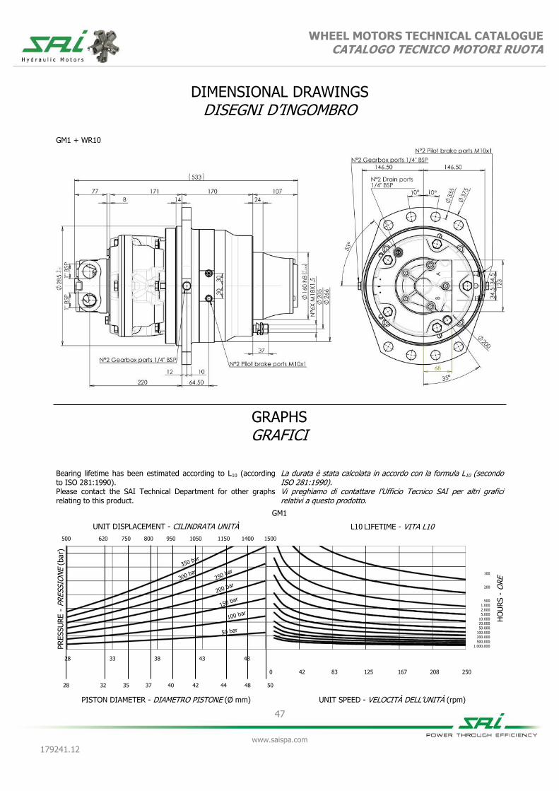
WHEEL MOTORS TECHNICAL CATALOGUE CATALOGO TECNICO MOTORI RUOTA
47
www.saispa.com
179241.12
DIMENSIONAL DRAWINGS DISEGNI D’INGOMBRO
GM1 + WR10
Bearing lifetime has been estimated according to L10 (according to ISO 281:1990). Please contact the SAI Technical Department for other graphs relating to this product.
La durata è stata calcolata in accordo con la formula L10 (secondo ISO 281:1990). Vi preghiamo di contattare l’Ufficio Tecnico SAI per altri grafici relativi a questo prodotto.
GM1
UNIT DISPLACEMENT - CILINDRATA UNITÀ L10 LIFETIME - VITA L10
PR
ESSU
RE -
PR
ESSIO
NE (
bar)
PISTON DIAMETER - DIAMETRO PISTONE (Ø mm)
HO
UR
S -
ORE
UNIT SPEED - VELOCITÀ DELL’UNITÀ (rpm)
28 33 38 43 48
0 42 83 125 167 208 250
500
28
620
32
750
35
800
37
950
40
100
200
500 1.000 2.000 5.000
10.000 20.000 50.000
100.000 200.000
500.000 1.000.000
1050
42
1150
44
1500
50
1400
48
GRAPHS GRAFICI

48
www.saispa.com
179241.12
WHEEL MOTORS TECHNICAL CATALOGUE CATALOGO TECNICO MOTORI RUOTA
BD1+WR10 (dual displacement / doppia cilindrata)
BV1+WR10 (variable displacement / cilindrata variabile)
500 250 800 200 850 375 1200 300 1200 600
Equivalent displacement ⁽¹⁾ [cc/rev] 489 259 825 206 845 365 1166 292 1166 584
Cilindrata equivalente ⁽¹⁾
Reduction ratio 4,8:1
Rapporto di riduzione
Bore [mm] 37 37 37 37 44 44 44 44 44 44
Alesaggio
Stroke [mm] 19 10 32 8 23 10 32 8 32 16
Corsa
Specific torque [Nm/bar] 7,80 4,11 13,14 3,29 13,36 5,81 18,59 4,65 18,59 9,29
Coppia specifica
Peak pressure ⁽²⁾ [bar] 425 425 400 400 400 400 375 375 375 375
Pressione di picco ⁽²⁾
Peak power ⁽³⁾ [kW] 55 42 55 42 55 42 55 42 55 42
Potenza di picco ⁽³⁾
Continuous speed ⁽⁴⁾ [rpm] 100 200 100 200 100 200 100 200 100 200
Velocità in continuo ⁽⁴⁾
Maximum speed ⁽⁴⁾ [rpm] 200 200 200 200 200 200 175 200 175 200
Velocità massima ⁽⁴⁾
Approximative weight [kg] 110
unit Type of brake Negative disc brake
Peso approssimativo unità Tipo di freno Freno a dischi negativo
Maximum casing pressure
[bar]
1 continuous
Admissible temperatures
[°C]
-20 minimum
continuo minimo
Pressione massima in carcassa 5 peak
Temperature ammissibili +80 maximum
picco massimo
Motor oil capacity [l] 1,5
Static braking torque ⁽⁵⁾ [Nm] 7000
Capacità olio motore Coppia di frenatura statica ⁽⁵⁾
Gearbox oil capacity [l] 0,75
Minimum brake pilot pressure [bar] 15
Capacità olio riduttore Pressione minima pilotaggio freno
Brake pilot volume [cm³] 37,5
Maximum brake pilot pressure [bar] 60
Volume pilotaggio freno Pressione massima pilotaggio
Volume pilot change displace-ment
[cm³] 2,12 Pilot pressure change displace-ment
[bar] 25
minimum
Volume pilotaggio cambio cilin- minimo
Suggested bolt type M22 12.9
Pressione di pilotaggio cambio cilindrata
35 maximum
Viti suggerite massimo
Bolt torque setting [Nm]
767,0 coarse 799,0 fine
Coppia serraggio viti 958,0 grosso 1008,0 fine
NOTES / NOTE
(1) Equivalent displacement = motor displacement x reduction ratio of gearbox (4,8:1) (4) For higher continuous and maximum speeds please contact the SAI Technical De-
partment (1) Cilindrata Equivalente = cilindrata motore x rapporto di riduzione del riduttore (4,8:1) (4) Per velocità in continuo e massime maggiori contattare l'Ufficio Tecnico SAI
(2) For higher peak pressures please contact the SAI Technical Department. (5) If the brake is engaged for a long time, the braking torque could increase considerably.
The brake requires to be periodically engaged and disengaged to maintain the desired performances.
(2) Per pressioni di picco maggiori contattare l'Ufficio Tecnico SAI (5) Quando il freno rimane ingaggiato per un lungo periodo di tempo la coppia frenante può aumentare considerevolmente. Si consiglia periodicamente di pilotare il freno in modo da garantire i dati dichiarati.
(3) For higher peak power please contact the SAI Technical Department. (3) Per potenze di picco maggiori contattare l'Ufficio Tecnico SAI.

WHEEL MOTORS TECHNICAL CATALOGUE CATALOGO TECNICO MOTORI RUOTA
49
www.saispa.com
179241.12
DIMENSIONAL DRAWINGS DISEGNI D’INGOMBRO
BD1 + WR10
BV1 + WR10

WHEEL MOTORS TECHNICAL CATALOGUE CATALOGO TECNICO MOTORI RUOTA
50
www.saispa.com
179241.12
Bearing lifetime has been estimated according to L10 (according to ISO 281:1990). The following graph has been plotted using the maximum displa-cements with the stroke of 32 mm. Please contact the SAI Tech-nical Department for other graphs relating to this product.
La durata è stata calcolata in accordo con la formula L10 (secondo ISO 281:1990). Il grafico che segue è stato ricavato usando le cilindrate massime e la corsa di 32 mm. Vi preghiamo di contattare l’Ufficio Tecnico SAI per altri grafici relativi a questo prodotto.
GRAPHS GRAFICI
BD1/BV1
UNIT DISPLACEMENT - CILINDRATA UNITÀ L10 LIFETIME - VITA L10
PR
ESSU
RE -
PR
ESSIO
NE (
bar)
PISTON DIAMETER - DIAMETRO PISTONE (Ø mm)
HO
UR
S -
ORE
UNIT SPEED - VELOCITÀ DELL’UNITÀ (rpm)
35 37 39 41 43 45
0 42 83 125 167 208 250 292 333 375 417
100
200
500 1.000 2.000 5.000
10.000 20.000 50.000
100.000 200.000
500.000 1.000.000
BD1/BV1
UNIT DISPLACEMENT - CILINDRATA UNITÀ L10 LIFETIME - VITA L10
PR
ESSU
RE -
PR
ESSIO
NE (
bar)
PISTON DIAMETER - DIAMETRO PISTONE (Ø mm)
HO
UR
S -
ORE
UNIT SPEED - VELOCITÀ DELL’UNITÀ (rpm)
100 bar
50 bar
35 37 39 41 43 45
0 42 83 125 167 208 250 292 333 375 417
800
37
1200
44
100
200
500 1.000 2.000 5.000
10.000 20.000 50.000
100.000 200.000
500.000 1.000.000
Bearing lifetime has been estimated according to L10 (according to ISO 281:1990). The following graph has been plotted using the minimum displa-cements with the stroke of 16 mm. Please contact the SAI Tech-nical Department for other graphs relating to this product.
La durata è stata calcolata in accordo con la formula L10 (secondo ISO 281:1990). Il grafico che segue è stato ricavato usando le cilindrate minime e la corsa di 16 mm. Vi preghiamo di contattare l’Ufficio Tecnico SAI per altri grafici relativi a questo prodotto.
600
44

51
www.saispa.com
179241.12
WHEEL MOTORS TECHNICAL CATALOGUE CATALOGO TECNICO MOTORI RUOTA
GM1 + WR20
650 850 1000 1100 1300 1450 1600 1900 2050
Equivalent displacement ⁽¹⁾ [cc/rev] 653 851 1016 1135 1326 1458 1603 1914 2072
Cilindrata equivalente ⁽¹⁾
Reduction ratio 6,6:1
Rapporto di riduzione
Bore [mm] 28 32 35 37 40 42 44 48 50
Alesaggio
Stroke [mm] 32
Corsa
Specific torque [Nm/bar] 10,35 13,52 16,17 18,07 21,12 23,28 25,56 30,41 33,00
Coppia specifica
Peak pressure ⁽²⁾ [bar] 425 400 400 375 350 350 350 300 280
Pressione di picco ⁽²⁾
Peak power ⁽³⁾ [kW] 48
Potenza di picco ⁽³⁾
Continuous speed ⁽⁴⁾ [rpm] 80 80 80 80 80 80 65 50 50
Velocità in continuo ⁽⁴⁾
Maximum speed ⁽⁴⁾ [rpm] 150 150 150 135 120 105 105 95 90
Velocità massima ⁽⁴⁾
Approximative weight [kg] 117
unit Type of brake Negative disc brake
Peso approssimativo unità Tipo di freno Freno a dischi negativo
Maximum casing pressure
[bar]
1 continuous
Admissible temperatures
[°C]
-20 minimum
continuo minimo
Pressione massima in carcassa 5 peak
Temperature ammissibili +80 maximum
picco massimo
Motor oil capacity [l] 1
Static braking torque ⁽⁵⁾ [Nm] 10000
Capacità olio motore Coppia di frenatura statica ⁽⁵⁾
Gearbox oil capacity [l] 1
Minimum brake pilot pressure [bar] 15
Capacità olio riduttore Pressione minima pilotaggio freno
Brake pilot volume [cm³] 37,5
Maximum brake pilot pressure
[bar] 60
Volume pilotaggio freno Pressione massima pilotaggio freno
Bolt torque setting [Nm]
767,0 coarse 799,0 fine Suggested bolt type M22 12.9
Coppia serraggio viti 958,0 grosso 1008,0 fine Viti suggerite
NOTES / NOTE (1) Equivalent displacement = motor displacement x reduction ratio of gearbox (6,6:1)
(1) Cilindrata Equivalente = cilindrata motore x rapporto di riduzione del riduttore (6,6:1)
(2) For higher peak pressures please contact the SAI Technical Department.
(2) Per pressioni di picco maggiori contattare l'Ufficio Tecnico SAI
(3) For higher peak power please contact the SAI Technical Department.
(3) Per potenze di picco maggiori contattare l'Ufficio Tecnico SAI.
(4) For higher continuous and maximum speeds please contact the SAI Technical Department
(4) Per velocità in continuo e massime maggiori contattare l'Ufficio Tecnico SAI
(5) If the brake is engaged for a long time, the braking torque could increase considerably. The brake requires to be periodically engaged and disengaged to maintain the desired
performances.
(5) Quando il freno rimane ingaggiato per un lungo periodo di tempo la coppia frenante può aumentare considerevolmente. Si consiglia periodicamente di pilotare il freno in modo da garantire i dati dichiarati.

WHEEL MOTORS TECHNICAL CATALOGUE CATALOGO TECNICO MOTORI RUOTA
52
www.saispa.com
179241.12
DIMENSIONAL DRAWINGS DISEGNI D’INGOMBRO
GM1 + WR20
Bearing lifetime has been estimated according to L10 (according to ISO 281:1990). Please contact the SAI Technical Department for other graphs relating to this product.
La durata è stata calcolata in accordo con la formula L10 (secondo ISO 281:1990). Vi preghiamo di contattare l’Ufficio Tecnico SAI per altri grafici relativi a questo prodotto.
GM1
UNIT DISPLACEMENT - CILINDRATA UNITÀ L10 LIFETIME - VITA L10
PR
ESSU
RE -
PR
ESSIO
NE (
bar)
PISTON DIAMETER - DIAMETRO PISTONE (Ø mm)
HO
UR
S -
ORE
UNIT SPEED - VELOCITÀ DELL’UNITÀ (rpm)
28 33 38 43 48
0 30 60 91 121 151 182
650
28
850
32
1000
35
1100
37
1300
40
100
200
500 1.000 2.000 5.000
10.000 20.000 50.000
100.000 200.000
500.000 1.000.000
1450
42
1600
44
2050
50
1900
48
GRAPHS GRAFICI

53
www.saispa.com
179241.12
WHEEL MOTORS TECHNICAL CATALOGUE CATALOGO TECNICO MOTORI RUOTA
BD1+WR20 (dual displacement / doppia cilindrata)
BV1+WR20 (variable displacement / cilindrata variabile)
685 350 1100 300 1150 500 1600 400 1600 800
Equivalent displacement ⁽¹⁾ [cc/rev] 673 356 1135 283 1154 502 1603 402 1603 802
Cilindrata equivalente ⁽¹⁾
Reduction ratio 6,6:1
Rapporto di riduzione
Bore [mm] 37 37 37 37 44 44 44 44 44 44
Alesaggio
Stroke [mm] 19 10 32 8 23 10 32 8 32 16
Corsa
Specific torque [Nm/bar] 10,73 5,65 18,07 4,52 18,37 7,99 25,56 6,39 25,56 12,73
Coppia specifica
Peak pressure ⁽²⁾ [bar] 425 425 400 400 400 400 375 375 375 375
Pressione di picco ⁽²⁾
Peak power ⁽³⁾ [kW] 55 42 55 42 55 42 55 42 55 42
Potenza di picco ⁽³⁾
Continuous speed ⁽⁴⁾ [rpm] 75 150 75 150 75 150 75 150 75 150
Velocità in continuo ⁽⁴⁾
Maximum speed ⁽⁴⁾ [rpm] 150 150 150 150 150 150 125 150 125 150
Velocità massima ⁽⁴⁾
Approximative weight [kg] 125
unit Type of brake Negative disc brake
Peso approssimativo unità Tipo di freno Freno a dischi negativo
Maximum casing pressure
[bar]
1 continuous
Admissible temperatures
[°C]
-20 minimum
continuo minimo
Pressione massima in carcassa 5 peak
Temperature ammissibili +80 maximum
picco massimo
Motor oil capacity [l] 1,5
Static braking torque ⁽⁵⁾ [Nm] 10000
Capacità olio motore Coppia di frenatura statica ⁽⁵⁾
Gearbox oil capacity [l] 1
Minimum brake pilot pressure [bar] 15
Capacità olio riduttore Pressione minima pilotaggio freno
Brake pilot volume [cm³] 37,5
Maximum brake pilot pressure [bar] 60
Volume pilotaggio freno Pressione massima pilotaggio
Volume pilot change displace-ment
[cm³] 2,12
Pilot pressure change displace-ment
[bar] 25
minimum
Volume pilotaggio cambio cilin- minimo
Suggested bolt type M22 12.9
Pressione di pilotaggio cambio cilindrata
35 maximum
Viti suggerite massimo
Bolt torque setting [Nm]
767,0 coarse 799,0 fine
Coppia serraggio viti 958,0 grosso 1008,0 fine
NOTES / NOTE
(1) Equivalent displacement = motor displacement x reduction ratio of gearbox (6,6:1) (4) For higher continuous and maximum speeds please contact the SAI Technical De-
partment (1) Cilindrata Equivalente = cilindrata motore x rapporto di riduzione del riduttore (6,6:1) (4) Per velocità in continuo e massime maggiori contattare l'Ufficio Tecnico SAI
(2) For higher peak pressures please contact the SAI Technical Department. (5) If the brake is engaged for a long time, the braking torque could increase considerably.
The brake requires to be periodically engaged and disengaged to maintain the desired performances.
(2) Per pressioni di picco maggiori contattare l'Ufficio Tecnico SAI (5) Quando il freno rimane ingaggiato per un lungo periodo di tempo la coppia frenante può aumentare considerevolmente. Si consiglia periodicamente di pilotare il freno in modo da
(3) For higher peak power please contact the SAI Technical Department. (3) Per potenze di picco maggiori contattare l'Ufficio Tecnico SAI.

WHEEL MOTORS TECHNICAL CATALOGUE CATALOGO TECNICO MOTORI RUOTA
54
www.saispa.com
179241.12
DIMENSIONAL DRAWINGS DISEGNI D’INGOMBRO
BD1 + WR20
BV1 + WR20

WHEEL MOTORS TECHNICAL CATALOGUE CATALOGO TECNICO MOTORI RUOTA
55
www.saispa.com
179241.12
Bearing lifetime has been estimated according to L10 (according to ISO 281:1990). The following graph has been plotted using the maximum displa-cements with the stroke of 32 mm. Please contact the SAI Tech-nical Department for other graphs relating to this product.
La durata è stata calcolata in accordo con la formula L10 (secondo ISO 281:1990). Il grafico che segue è stato ricavato usando le cilindrate massime e la corsa di 32 mm. Vi preghiamo di contattare l’Ufficio Tecnico SAI per altri grafici relativi a questo prodotto.
GRAPHS GRAFICI
BD1/BV1
UNIT DISPLACEMENT - CILINDRATA UNITÀ L10 LIFETIME - VITA L10
PR
ESSU
RE -
PR
ESSIO
NE (
bar)
PISTON DIAMETER - DIAMETRO PISTONE (Ø mm)
HO
UR
S -
ORE
UNIT SPEED - VELOCITÀ DELL’UNITÀ (rpm)
35 37 39 41 43 45
0 30 60 91 121 152 182 212 242 273 303
100
200
500 1.000 2.000 5.000
10.000 20.000 50.000
100.000 200.000
500.000 1.000.000
BD1/BV1
UNIT DISPLACEMENT - CILINDRATA UNITÀ L10 LIFETIME - VITA L10
PR
ESSU
RE -
PR
ESSIO
NE (
bar)
PISTON DIAMETER - DIAMETRO PISTONE (Ø mm)
HO
UR
S -
ORE
UNIT SPEED - VELOCITÀ DELL’UNITÀ (rpm)
100 bar
50 bar
35 37 39 41 43 45
0 30 60 91 121 152 182 212 242 273 303
1100
37
1600
44
100
200
500 1.000 2.000 5.000
10.000 20.000 50.000
100.000 200.000
500.000 1.000.000
Bearing lifetime has been estimated according to L10 (according to ISO 281:1990). The following graph has been plotted using the minimum displa-cements with the stroke of 16 mm. Please contact the SAI Tech-nical Department for other graphs relating to this product.
La durata è stata calcolata in accordo con la formula L10 (secondo ISO 281:1990). Il grafico che segue è stato ricavato usando le cilindrate minime e la corsa di 16 mm. Vi preghiamo di contattare l’Ufficio Tecnico SAI per altri grafici relativi a questo prodotto.
800
44

56
www.saispa.com
179241.12
WHEEL MOTORS TECHNICAL CATALOGUE CATALOGO TECNICO MOTORI RUOTA
GM2 + WR20
1250 1650 2000 2300 2800 3250 3750 4100
Equivalent displacement ⁽¹⁾ [cc/rev] 1267 1656 2006 2290 2805 3253 3729 4111
Cilindrata equivalente ⁽¹⁾
Reduction ratio 6,6:1
Rapporto di riduzione
Bore [mm] 35 40 44 47 52 56 60 63
Alesaggio
Stroke [mm] 40
Corsa
Specific torque [Nm/bar] 20,21 26,40 31,94 36,45 44,65 51,74 53,40 65,49
Coppia specifica
Peak pressure ⁽²⁾ [bar] 425 425 400 375 325 280 245 220
Pressione di picco ⁽²⁾
Peak power ⁽³⁾ [kW] 59
Potenza di picco ⁽³⁾
Continuous speed ⁽⁴⁾ [rpm] 80 80 80 80 70 70 65 60
Velocità in continuo ⁽⁴⁾
Maximum speed ⁽⁴⁾ [rpm] 150 150 150 135 120 105 105 95
Velocità massima ⁽⁴⁾
Approximative weight [kg] 117
unit Type of brake Negative disc brake
Peso approssimativo unità Tipo di freno Freno a dischi negativo
Maximum casing pressure
[bar]
1 continuous
Admissible temperatures
[°C]
-20 minimum
continuo minimo
Pressione massima in carcassa 5 peak
Temperature ammissibili +80 maximum
picco massimo
Motor oil capacity [l] 1
Static braking torque ⁽⁵⁾ [Nm] 10000
Capacità olio motore Coppia di frenatura statica ⁽⁵⁾
Gearbox oil capacity [l] 1
Minimum brake pilot pressure [bar] 15
Capacità olio riduttore Pressione minima pilotaggio freno
Brake pilot volume [cm³] 37,5
Maximum brake pilot pressure
[bar] 60
Volume pilotaggio freno Pressione massima pilotaggio freno
Bolt torque setting [Nm]
767,0 coarse 799,0 fine Suggested bolt type M22 12.9
Coppia serraggio viti 958,0 grosso 1008,0 fine Viti suggerite
NOTES / NOTE (1) Equivalent displacement = motor displacement x reduction ratio of gearbox (6,6:1)
(1) Cilindrata Equivalente = cilindrata motore x rapporto di riduzione del riduttore (6,6:1)
(2) For higher peak pressures please contact the SAI Technical Department.
(2) Per pressioni di picco maggiori contattare l'Ufficio Tecnico SAI
(3) For higher peak power please contact the SAI Technical Department.
(3) Per potenze di picco maggiori contattare l'Ufficio Tecnico SAI.
(4) For higher continuous and maximum speeds please contact the SAI Technical Department
(4) Per velocità in continuo e massime maggiori contattare l'Ufficio Tecnico SAI
(5) If the brake is engaged for a long time, the braking torque could increase considerably. The brake requires to be periodically engaged and disengaged to maintain the desired
performances.
(5) Quando il freno rimane ingaggiato per un lungo periodo di tempo la coppia frenante può aumentare considerevolmente. Si consiglia periodicamente di pilotare il freno in modo da garantire i dati dichiarati.

WHEEL MOTORS TECHNICAL CATALOGUE CATALOGO TECNICO MOTORI RUOTA
57
www.saispa.com
179241.12
DIMENSIONAL DRAWINGS DISEGNI D’INGOMBRO
GM2 + WR20
GRAPHS GRAFICI
Bearing lifetime has been estimated according to L10 (according to ISO 281:1990). Please contact the SAI Technical Department for other graphs relating to this product.
La durata è stata calcolata in accordo con la formula L10 (secondo ISO 281:1990). Vi preghiamo di contattare l’Ufficio Tecnico SAI per altri grafici relativi a questo prodotto.
GM2
UNIT DISPLACEMENT - CILINDRATA UNITÀ L10 LIFETIME - VITA L10
PR
ESSU
RE -
PR
ESSIO
NE (
bar)
PISTON DIAMETER - DIAMETRO PISTONE (Ø mm)
HO
UR
S -
ORE
UNIT SPEED - VELOCITÀ DELL’UNITÀ (rpm)
35 40 45 50 55 60
0 30 60 91 121 152 182 212 242 273 303
100
200
500 1.000 2.000 5.000
10.000 20.000 50.000
100.000 200.000
500.000 1.000.000
1250
35
1650
40
2000
44
2300
47
2800
52
3250
56
4100
63
3750
60

58
www.saispa.com
179241.12
WHEEL MOTORS TECHNICAL CATALOGUE CATALOGO TECNICO MOTORI RUOTA
BD2+WR20 (dual displacement / doppia cilindrata)
BV2+WR20 (variable displacement / cilindrata variabile)
1700 450 1700 800 2300 600 2300 1150 3300 800 3300 1600
Equivalent displacement ⁽¹⁾ [cc/rev] 1656 415 1656 831 2290 574 2290 1141 3253 811 3253 1623
Cilindrata equivalente ⁽¹⁾
Reduction ratio 6,6:1
Rapporto di riduzione
Bore [mm] 40 40 47 47 56 56
Alesaggio
Stroke [mm] 40 10 40 20 40 10 40 20 40 10 40 20
Corsa
Specific torque [Nm/bar] 26,40 6,60 26,40 13,20 36,30 9,24 36,30 18,48 51,48
13,20
51,48 25,74 Coppia specifica
Peak pressure ⁽²⁾ [bar] 425 425 425 425 375 375 375 375 280 350 280 375
Pressione di picco ⁽²⁾
Peak power ⁽³⁾ [kW] 75 65 75 65 75 65 75 65 75 65 75 65
Potenza di picco ⁽³⁾
Continuous speed ⁽⁴⁾ [rpm] 100 150 100 150 100 150 100 150 60 150 60 150
Velocità in continuo ⁽⁴⁾
Maximum speed ⁽⁴⁾ [rpm] 150 150 150 150 150 150 150 150 120 150 120 150
Velocità massima ⁽⁴⁾
Approximative weight [kg] 140
unit Type of brake Negative disc brake
Peso approssimativo unità Tipo di freno Freno a dischi negativo
Maximum casing pressure
[bar]
1 continuous
Admissible temperatures
[°C]
-20 minimum
continuo minimo
Pressione massima in carcassa 5 peak
Temperature ammissibili +80 maximum
picco massimo
Motor oil capacity [l] 3
Static braking torque ⁽⁵⁾ [Nm] 10000
Capacità olio motore Coppia di frenatura statica ⁽⁵⁾
Gearbox oil capacity [l] 1
Minimum brake pilot pressure [bar] 15
Capacità olio riduttore Pressione minima pilotaggio freno
Brake pilot volume [cm³] 37,5
Maximum brake pilot pressure [bar] 60
Volume pilotaggio freno Pressione massima pilotaggio
Volume pilot change displace-ment
[cm³] 5,568
Pilot pressure change displace-ment
[bar] 25
minimum
Volume pilotaggio cambio cilin- minimo
Suggested bolt type M22 12.9
Pressione di pilotaggio cambio cilindrata
35 maximum
Viti suggerite massimo
Bolt torque setting [Nm]
767,0 coarse 799,0 fine
Coppia serraggio viti 958,0 grosso 1008,0 fine
NOTES / NOTE
(1) Equivalent displacement = motor displacement x reduction ratio of gearbox (6,6:1) (4) For higher continuous and maximum speeds please contact the SAI Technical De-
partment (1) Cilindrata Equivalente = cilindrata motore x rapporto di riduzione del riduttore (6,6:1) (4) Per velocità in continuo e massime maggiori contattare l'Ufficio Tecnico SAI
(2) For higher peak pressures please contact the SAI Technical Department. (5) If the brake is engaged for a long time, the braking torque could increase considerably.
The brake requires to be periodically engaged and disengaged to maintain the desired performances.
(2) Per pressioni di picco maggiori contattare l'Ufficio Tecnico SAI (5) Quando il freno rimane ingaggiato per un lungo periodo di tempo la coppia frenante può aumentare considerevolmente. Si consiglia periodicamente di pilotare il freno in modo
(3) For higher peak power please contact the SAI Technical Department. (3) Per potenze di picco maggiori contattare l'Ufficio Tecnico SAI.

WHEEL MOTORS TECHNICAL CATALOGUE CATALOGO TECNICO MOTORI RUOTA
59
www.saispa.com
179241.12
DIMENSIONAL DRAWINGS DISEGNI D’INGOMBRO
BD2 + WR20
BV2 + WR20

WHEEL MOTORS TECHNICAL CATALOGUE CATALOGO TECNICO MOTORI RUOTA
60
www.saispa.com
179241.12
Bearing lifetime has been estimated according to L10 (according to ISO 281:1990). The following graph has been plotted using the maximum displa-cements with the stroke of 40 mm. Please contact the SAI Tech-nical Department for other graphs relating to this product.
La durata è stata calcolata in accordo con la formula L10 (secondo ISO 281:1990). Il grafico che segue è stato ricavato usando le cilindrate massime e la corsa di 40 mm. Vi preghiamo di contattare l’Ufficio Tecnico SAI per altri grafici relativi a questo prodotto.
GRAPHS GRAFICI
BD2/BV2
UNIT DISPLACEMENT - CILINDRATA UNITÀ L10 LIFETIME - VITA L10
PR
ESSU
RE -
PR
ESSIO
NE (
bar)
PISTON DIAMETER - DIAMETRO PISTONE (Ø mm)
HO
UR
S -
ORE
UNIT SPEED - VELOCITÀ DELL’UNITÀ (rpm)
40 42 44 46 48 50 52 54 56
0 30 60 91 121 152 182 212 242 273 303
100
200
500 1.000 2.000 5.000
10.000 20.000 50.000
100.000 200.000
500.000 1.000.000
BD2/BV2
UNIT DISPLACEMENT - CILINDRATA UNITÀ L10 LIFETIME - VITA L10
PR
ESSU
RE -
PR
ESSIO
NE (
bar)
PISTON DIAMETER - DIAMETRO PISTONE (Ø mm)
HO
UR
S -
ORE
UNIT SPEED - VELOCITÀ DELL’UNITÀ (rpm)
100 bar
50 bar
40 42 44 46 48 50 52 54 56
1700
40
2300
47
100
200
500 1.000 2.000 5.000
10.000 20.000 50.000
100.000 200.000
500.000 1.000.000
Bearing lifetime has been estimated according to L10 (according to ISO 281:1990). The following graph has been plotted using the minimum displa-cements with the stroke of 20 mm. Please contact the SAI Tech-nical Department for other graphs relating to this product.
La durata è stata calcolata in accordo con la formula L10 (secondo ISO 281:1990). Il grafico che segue è stato ricavato usando le cilindrate minime e la corsa di 20 mm. Vi preghiamo di contattare l’Ufficio Tecnico SAI per altri grafici relativi a questo prodotto.
800
40
0 30 60 91 121 152 182 212 242 273 303
3300
56
1150
47
1600
56

61
www.saispa.com
179241.12
WHEEL MOTORS TECHNICAL CATALOGUE CATALOGO TECNICO MOTORI RUOTA
ORDER CODES CODICI D’ORDINE
Example
Esempio
GM05 600 U D40 WR6B
(standard)
GM05 600 U D40LDM2 WR6B
(options: anti-clockwise sense of rotation)
(opzioni: direzione d'uscita in rotazione anti-oraria)
1 Motor type 1 Tipo motore
2 Displacement see table 2 Cilindrata vedere tabella
3 Lubrication options O = separated oil
3 Opzioni lubrificazione O = olio separato
U = shared oil U = olio unico
4 Distributor see distributors section
4 Distributore vedere sezione distributori
D40 standard D40 standard
5
Direction of rotation (viewed from the output side) with input flow in port A, output in B.
No code = clockwise rotation
5
Direzione d'uscita (visto dal lato d'uscita) con portata in ingresso in porta A, uscita in porta B.
Nessun codice
= rotazione oraria
L = anti-clockwise rota-tion
L = rotazione anti-oraria
6 Distributor cover orientation
No code = position 1
6 Orientamento coperchio distributore
Nessun codice
= posizione 1
DM2 = position 2 DM2 = posizione 2
DM3 = position 3 DM3 = posizione 3
DM4 = position 4 DM4 = posizione 4
DM5 = position 5 DM5 = posizione 5
7 WR series
WR6B
7 Serie WR
WR6B
WR10 WR10
WR20 WR20
1 2 3 4 5 6 7 8 9
+ + + + + + + +
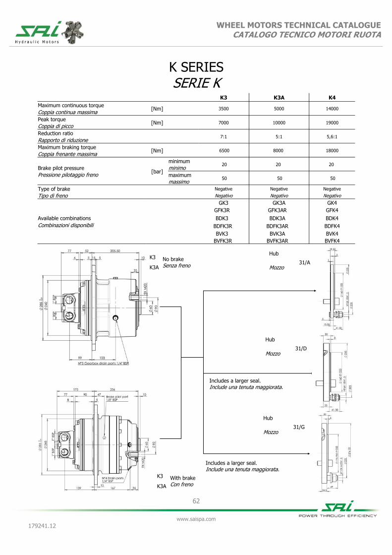
62
www.saispa.com
179241.12
WHEEL MOTORS TECHNICAL CATALOGUE CATALOGO TECNICO MOTORI RUOTA
K SERIES SERIE K
K3 K3A K4
Maximum continuous torque [Nm]
3500 5000 14000
Coppia continua massima
Peak torque [Nm]
7000 10000 19000
Coppia di picco
Reduction ratio
7:1 5:1 5,6:1
Rapporto di riduzione
Maximum braking torque [Nm]
6500 8000 18000
Coppia frenante massima
Brake pilot pressure [bar]
minimum 20 20 20
minimo
Pressione pilotaggio freno maximum 50 50 50
massimo
Type of brake
Negative Negative Negative
Tipo di freno Negativo Negativo Negativo
GK3 GK3A GK4
Available combinations
Combinazioni disponibili
GFK3R GFK3AR GFK4
BDK3 BDK3A BDK4
BDFK3R BDFK3AR BDFK4
BVK3 BVK3A BVK4
BVFK3R BVFK3AR BVFK4
Hub
31/A Mozzo
Hub
31/D Mozzo
K3 No brake Senza freno K3A
K3 With brake Con freno K3A
Hub
31/G Mozzo
Includes a larger seal. Include una tenuta maggiorata.
Includes a larger seal. Include una tenuta maggiorata.

63
www.saispa.com
179241.12
WHEEL MOTORS TECHNICAL CATALOGUE CATALOGO TECNICO MOTORI RUOTA
Ma
xim
um
ra
dia
l lo
ad
[N
] M
ass
imo
ca
rico
ra
dia
le [
N]
Load position [mm] Posizione di carico [mm]
K3
Ma
xim
um
ra
dia
l lo
ad
[N
] M
ass
imo
ca
rico
ra
dia
le [
N]
Load position [mm] Posizione di carico [mm]
K3A
Ma
xim
um
ra
dia
l lo
ad
[N
] M
ass
imo
ca
rico
ra
dia
le [
N]
Load position [mm] Posizione di carico [mm]
K4
GRAPHS GRAFICI

64
www.saispa.com
179241.12
WHEEL MOTORS TECHNICAL CATALOGUE CATALOGO TECNICO MOTORI RUOTA
GK3 GFK3R
700 900 1000 1200 1400 1600 1700 2000 2200
Equivalent displacement ⁽¹⁾ [cc/rev] 690 901 1078 1204 1407 1552 1703 2027 2199
Cilindrata equivalente ⁽¹⁾
Reduction ratio 7:1
Rapporto di riduzione
Bore [mm] 28 32 35 37 40 42 44 48 50
Alesaggio
Stroke [mm] 32
Corsa
Specific torque [Nm/bar] 10,98 14,34 17,15 19,17 22,40 24,70 27,10 32,26 35,00
Coppia specifica
Peak pressure ⁽²⁾ [bar] 425 400 400 365 310 280 255 215 200
Pressione di picco ⁽²⁾
Peak power ⁽³⁾ [kW] 48
Potenza di picco ⁽³⁾
Continuous speed ⁽⁴⁾ [rpm] 78 78 78 78 78 78 64 50 50
Velocità in continuo ⁽⁴⁾
Maximum speed ⁽⁴⁾ [rpm] 150 150 150 130 103 100 100 100 90
Velocità massima ⁽⁴⁾
Approximative weight [kg] 75
unit Type of brake Negative disc brake
Peso approssimativo unità Tipo di freno Freno a dischi negativo
Maximum casing pressure
[bar]
1 continuous
Admissible temperatures
[°C]
-20 minimum
continuo minimo
Pressione massima in carcassa 5 peak
Temperature ammissibili +80 maximum
picco massimo
Motor oil capacity [l] 1,5
Static braking torque ⁽⁵⁾ [Nm] 6500
Capacità olio motore Coppia di frenatura statica ⁽⁵⁾
Gearbox oil capacity [l] 1,7
Minimum brake pilot pressure [bar] 20
Capacità olio riduttore Pressione minima pilotaggio freno
Brake pilot volume [cm³] 3,9
Maximum brake pilot pressure
[bar] 60
Volume pilotaggio freno Pressione massima pilotaggio freno
Bolt torque setting [Nm]
767,0 coarse 799,0 fine Suggested bolt type M22 12.9
Coppia serraggio viti 958,0 grosso 1008,0 fine Viti suggerite
NOTES / NOTE (1) Equivalent displacement = motor displacement x reduction ratio of gearbox (7:1)
(1) Cilindrata Equivalente = cilindrata motore x rapporto di riduzione del riduttore (7:1)
(2) For higher peak pressures please contact the SAI Technical Department.
(2) Per pressioni di picco maggiori contattare l'Ufficio Tecnico SAI
(3) For higher peak power please contact the SAI Technical Department.
(3) Per potenze di picco maggiori contattare l'Ufficio Tecnico SAI.
(4) For higher continuous and maximum speeds please contact the SAI Technical Department
(4) Per velocità in continuo e massime maggiori contattare l'Ufficio Tecnico SAI
(5) If the brake is engaged for a long time, the braking torque could increase considerably. The brake requires to be periodically engaged and disengaged to maintain the desired
performances.
(5) Quando il freno rimane ingaggiato per un lungo periodo di tempo la coppia frenante può aumentare considerevolmente. Si consiglia periodicamente di pilotare il freno in modo da garantire i dati dichiarati.

WHEEL MOTORS TECHNICAL CATALOGUE CATALOGO TECNICO MOTORI RUOTA
65
www.saispa.com
179241.12
DIMENSIONAL DRAWINGS DISEGNI D’INGOMBRO
GK3
GFK3R
Hub 31/A
Mozzo
Hub 31/A
Mozzo

WHEEL MOTORS TECHNICAL CATALOGUE CATALOGO TECNICO MOTORI RUOTA
66
www.saispa.com
179241.12
GRAPHS GRAFICI
Bearing lifetime has been estimated according to L10 (according to ISO 281:1990). Please contact the SAI Technical Department for other graphs relating to this product.
La durata è stata calcolata in accordo con la formula L10 (secondo ISO 281:1990). Vi preghiamo di contattare l’Ufficio Tecnico SAI per altri grafici relativi a questo prodotto.
GK3/GFK3R
UNIT DISPLACEMENT - CILINDRATA UNITÀ L10 LIFETIME - VITA L10
PR
ESSU
RE -
PR
ESSIO
NE (
bar)
PISTON DIAMETER - DIAMETRO PISTONE (Ø mm)
HO
UR
S -
ORE
UNIT SPEED - VELOCITÀ DELL’UNITÀ (rpm)
28 33 38 43 48
0 28 57 86 114 143 171
700
28
900
32
1000
35
1200
37
1400
40
100
200
500 1.000 2.000 5.000
10.000 20.000 50.000
100.000 200.000
500.000 1.000.000
1600
42
1700
44
2200
50
2000
48

67
www.saispa.com
179241.12
WHEEL MOTORS TECHNICAL CATALOGUE CATALOGO TECNICO MOTORI RUOTA
BDK3 (dual displacement without brake / cilindrata doppia senza freno)
BDFK3R (dual displacement with brake / cilindrata doppia con freno) BVK3 (variable displacement without brake / cilindrata variabile senza freno)
BVFK3R (variable displacement with brake / cilindrata variabile con freno)
700 375 1200 300 1200 550 1700 425 1700 850
Equivalent displacement ⁽¹⁾ [cc/rev] 714 378 1204 301 1232 532 1701 427 1701 851
Cilindrata equivalente ⁽¹⁾
Reduction ratio 7:1
Rapporto di riduzione
Bore [mm] 37 37 37 37 44 44 44 44 44 44
Alesaggio
Stroke [mm] 19 10 32 8 23 10 32 8 32 16
Corsa
Specific torque [Nm/bar] 11,38 5,99 19,17 4,79 19,48 8,47 27,10 6,78 27,10 13,55
Coppia specifica
Peak pressure ⁽²⁾ [bar] 425 425 370 400 355 400 250 375 250 375
Pressione di picco ⁽²⁾
Peak power ⁽³⁾ [kW] 55 42 55 42 55 42 55 42 55 42
Potenza di picco ⁽³⁾
Continuous speed ⁽⁴⁾ [rpm] 70 200 70 200 70 200 70 200 70 200
Velocità in continuo ⁽⁴⁾
Maximum speed ⁽⁴⁾ [rpm] 200 500 140 500 140 400 120 400 120 350
Velocità massima ⁽⁴⁾
Approximative weight [kg] 75
unit Type of brake Negative disc brake
Peso approssimativo unità Tipo di freno Freno a dischi negativo
Maximum casing pressure
[bar]
1 continuous
Admissible temperatures
[°C]
-20 minimum
continuo minimo
Pressione massima in carcassa 5 peak
Temperature ammissibili +80 maximum
picco massimo
Motor oil capacity [l] 1,5
Static braking torque ⁽⁵⁾ [Nm] 6500
Capacità olio motore Coppia di frenatura statica ⁽⁵⁾
Gearbox oil capacity [l] 1,7
Minimum brake pilot pressure [bar] 20
Capacità olio riduttore Pressione minima pilotaggio freno
Brake pilot volume [cm³] 3,9
Maximum brake pilot pressure [bar] 60
Volume pilotaggio freno Pressione massima pilotaggio
Volume pilot change displace-ment
[cm³] 2,12
Pilot pressure change displace-ment
[bar] 25
minimum
Volume pilotaggio cambio cilin- minimo
Suggested bolt type M22 8,8
Pressione di pilotaggio cambio cilindrata
35 maximum
Viti suggerite massimo
Bolt torque setting [Nm]
454,0 coarse 474,0 fine
Coppia serraggio viti 568,0 grosso 597,0 fine
NOTES / NOTE
(1) Equivalent displacement = motor displacement x reduction ratio of gearbox (7:1) (4) For higher continuous and maximum speeds please contact the SAI Technical De-
partment (1) Cilindrata Equivalente = cilindrata motore x rapporto di riduzione del riduttore (7:1) (4) Per velocità in continuo e massime maggiori contattare l'Ufficio Tecnico SAI
(2) For higher peak pressures please contact the SAI Technical Department. (5) If the brake is engaged for a long time, the braking torque could increase considerably.
The brake requires to be periodically engaged and disengaged to maintain the desired performances.
(2) Per pressioni di picco maggiori contattare l'Ufficio Tecnico SAI (5) Quando il freno rimane ingaggiato per un lungo periodo di tempo la coppia frenante può aumentare considerevolmente. Si consiglia periodicamente di pilotare il freno in modo da garantire i dati dichiarati.
(3) For higher peak power please contact the SAI Technical Department. (3) Per potenze di picco maggiori contattare l'Ufficio Tecnico SAI.

WHEEL MOTORS TECHNICAL CATALOGUE CATALOGO TECNICO MOTORI RUOTA
68
www.saispa.com
179241.12
DIMENSIONAL DRAWINGS DISEGNI D’INGOMBRO
BDK3
BDFK3R
Hub 31/A
Mozzo
Hub 31/A
Mozzo

WHEEL MOTORS TECHNICAL CATALOGUE CATALOGO TECNICO MOTORI RUOTA
69
www.saispa.com
179241.12
DIMENSIONAL DRAWINGS DISEGNI D’INGOMBRO
BVK3
BVFK3R
Hub 31/A
Mozzo
Hub 31/A
Mozzo

WHEEL MOTORS TECHNICAL CATALOGUE CATALOGO TECNICO MOTORI RUOTA
70
www.saispa.com
179241.12
GRAPHS GRAFICI
Bearing lifetime has been estimated according to L10 (according to ISO 281:1990). The following graph has been plotted using the maximum displa-cements with the stroke of 32 mm. Please contact the SAI Tech-nical Department for other graphs relating to this product.
La durata è stata calcolata in accordo con la formula L10 (secondo ISO 281:1990). Il grafico che segue è stato ricavato usando le cilindrate massime e la corsa di 32 mm. Vi preghiamo di contattare l’Ufficio Tecnico SAI per altri grafici relativi a questo prodotto.
BDK3/BDFK3R/BVK3/BVFK3R
UNIT DISPLACEMENT - CILINDRATA UNITÀ L10 LIFETIME - VITA L10
PR
ESSU
RE -
PR
ESSIO
NE (
bar)
PISTON DIAMETER - DIAMETRO PISTONE (Ø mm)
HO
UR
S -
ORE
UNIT SPEED - VELOCITÀ DELL’UNITÀ (rpm)
35 37 39 41 43 45
0 29 57 86 114 143 171 200 229 257 286
100
200
500 1.000 2.000 5.000
10.000 20.000 50.000
100.000 200.000
500.000 1.000.000
BDK3/BDFK3R/BVK3/BVFK3R
UNIT DISPLACEMENT - CILINDRATA UNITÀ L10 LIFETIME - VITA L10
PR
ESSU
RE -
PR
ESSIO
NE (
bar)
PISTON DIAMETER - DIAMETRO PISTONE (Ø mm)
HO
UR
S -
ORE
UNIT SPEED - VELOCITÀ DELL’UNITÀ (rpm)
100 bar
50 bar
35 37 39 41 43 45
0 29 57 86 114 143 171 200 229 257 286
1200
37
1700
44
100
200
500 1.000 2.000 5.000
10.000 20.000 50.000
100.000 200.000
500.000 1.000.000
Bearing lifetime has been estimated according to L10 (according to ISO 281:1990). The following graph has been plotted using the minimum displa-cements with the stroke of 16 mm. Please contact the SAI Tech-nical Department for other graphs relating to this product.
La durata è stata calcolata in accordo con la formula L10 (secondo ISO 281:1990). Il grafico che segue è stato ricavato usando le cilindrate minime e la corsa di 16 mm. Vi preghiamo di contattare l’Ufficio Tecnico SAI per altri grafici relativi a questo prodotto.
850
44

71
www.saispa.com
179241.12
WHEEL MOTORS TECHNICAL CATALOGUE CATALOGO TECNICO MOTORI RUOTA
GK3A GFK3AR
500 650 750 850 1000 1150 1200 1450 1550
Equivalent displacement ⁽¹⁾ [cc/rev] 493 643 770 860 1005 1108 1216 1448 1571
Cilindrata equivalente ⁽¹⁾
Reduction ratio 5:1
Rapporto di riduzione
Bore [mm] 28 32 35 37 40 42 44 48 50
Alesaggio
Stroke [mm] 32
Corsa
Specific torque [Nm/bar] 7,84 10,24 12,25 13,69 16,00 17,64 19,36 23,04 25,00
Coppia specifica
Peak pressure ⁽²⁾ [bar] 425 400 400 375 350 350 350 300 280
Pressione di picco ⁽²⁾
Peak power ⁽³⁾ [kW] 48
Potenza di picco ⁽³⁾
Continuous speed ⁽⁴⁾ [rpm] 110 110 110 110 110 110 90 70 70
Velocità in continuo ⁽⁴⁾
Maximum speed ⁽⁴⁾ [rpm] 200 200 200 180 160 140 140 130 130
Velocità massima ⁽⁴⁾
Approximative weight [kg] 75
unit Type of brake Negative disc brake
Peso approssimativo unità Tipo di freno Freno a dischi negativo
Maximum casing pressure
[bar]
1 continuous
Admissible temperatures
[°C]
-20 minimum
continuo minimo
Pressione massima in carcassa 5 peak
Temperature ammissibili +80 maximum
picco massimo
Motor oil capacity [l] 1,5
Static braking torque ⁽⁵⁾ [Nm] 8200
Capacità olio motore Coppia di frenatura statica ⁽⁵⁾
Gearbox oil capacity [l] 1,7
Minimum brake pilot pressure [bar] 20
Capacità olio riduttore Pressione minima pilotaggio freno
Brake pilot volume [cm³] 3,9
Maximum brake pilot pressure
[bar] 50
Volume pilotaggio freno Pressione massima pilotaggio freno
Bolt torque setting [Nm]
767,0 coarse 799,0 fine Suggested bolt type M22 12.9
Coppia serraggio viti 958,0 grosso 1008,0 fine Viti suggerite
NOTES / NOTE (1) Equivalent displacement = motor displacement x reduction ratio of gearbox (5:1)
(1) Cilindrata Equivalente = cilindrata motore x rapporto di riduzione del riduttore (5:1)
(2) For higher peak pressures please contact the SAI Technical Department.
(2) Per pressioni di picco maggiori contattare l'Ufficio Tecnico SAI
(3) For higher peak power please contact the SAI Technical Department.
(3) Per potenze di picco maggiori contattare l'Ufficio Tecnico SAI.
(4) For higher continuous and maximum speeds please contact the SAI Technical Department
(4) Per velocità in continuo e massime maggiori contattare l'Ufficio Tecnico SAI
(5) If the brake is engaged for a long time, the braking torque could increase considerably. The brake requires to be periodically engaged and disengaged to maintain the desired
performances.
(5) Quando il freno rimane ingaggiato per un lungo periodo di tempo la coppia frenante può aumentare considerevolmente. Si consiglia periodicamente di pilotare il freno in modo da garantire i dati dichiarati.

WHEEL MOTORS TECHNICAL CATALOGUE CATALOGO TECNICO MOTORI RUOTA
72
www.saispa.com
179241.12
DIMENSIONAL DRAWINGS DISEGNI D’INGOMBRO
GK3A
GFK3AR
Hub 31/A
Mozzo
Hub 31/A
Mozzo

WHEEL MOTORS TECHNICAL CATALOGUE CATALOGO TECNICO MOTORI RUOTA
73
www.saispa.com
179241.12
GRAPHS GRAFICI
Bearing lifetime has been estimated according to L10 (according to ISO 281:1990). Please contact the SAI Technical Department for other graphs relating to this product.
La durata è stata calcolata in accordo con la formula L10 (secondo ISO 281:1990). Vi preghiamo di contattare l’Ufficio Tecnico SAI per altri grafici relativi a questo prodotto.
GK3A/GFK3AR
UNIT DISPLACEMENT - CILINDRATA UNITÀ L10 LIFETIME - VITA L10
PR
ESSU
RE -
PR
ESSIO
NE (
bar)
PISTON DIAMETER - DIAMETRO PISTONE (Ø mm)
HO
UR
S -
ORE
UNIT SPEED - VELOCITÀ DELL’UNITÀ (rpm)
28 33 38 43 48
0 40 80 120 160 200 240
500
28
650
32
750
35
850
37
1000
40
100
200
500 1.000 2.000 5.000
10.000 20.000 50.000
100.000 200.000
500.000 1.000.000
1150
42
1200
44
1550
50
1450
48

74
www.saispa.com
179241.12
WHEEL MOTORS TECHNICAL CATALOGUE CATALOGO TECNICO MOTORI RUOTA
BDK3A (dual displacement without brake / cilindrata doppia senza freno)
BDFK3AR (dual displacement with brake / cilindrata doppia con freno)
BVK3A (variable displacement without brake / cilindrata variabile senza freno)
BVFK3AR (variable displacement with brake / cilindrata variabile con freno)
500 250 850 215 875 400 1250 300 1250 625
Equivalent displacement ⁽¹⁾ [cc/rev] 510 270 874 215 880 380 1216 304 1216 608
Cilindrata equivalente ⁽¹⁾
Reduction ratio 5:1
Rapporto di riduzione
Bore [mm] 37 37 37 37 44 44 44 44 44 44
Alesaggio
Stroke [mm] 19 10 32 8 23 10 32 8 32 16
Corsa
Specific torque [Nm/bar] 8,12 4,28 13,50 3,42 13,90 6,04 19,36 4,84 19,36 9,68
Coppia specifica
Peak pressure ⁽²⁾ [bar] 425 425 400 400 400 400 350 350 350 350
Pressione di picco ⁽²⁾
Peak power ⁽³⁾ [kW] 55 42 55 42 55 42 55 42 55 42
Potenza di picco ⁽³⁾
Continuous speed ⁽⁴⁾ [rpm] 100 300 100 300 100 300 100 300 100 300
Velocità in continuo ⁽⁴⁾
Maximum speed ⁽⁴⁾ [rpm] 300 300 200 300 200 300 170 300 170 300
Velocità massima ⁽⁴⁾
Approximative weight [kg] 75
unit Type of brake Negative disc brake
Peso approssimativo unità Tipo di freno Freno a dischi negativo
Maximum casing pressure
[bar]
1 continuous
Admissible temperatures
[°C]
-20 minimum
continuo minimo
Pressione massima in carcassa 5 peak
Temperature ammissibili +80 maximum
picco massimo
Motor oil capacity [l] 1,5
Static braking torque ⁽⁵⁾ [Nm] 8200
Capacità olio motore Coppia di frenatura statica ⁽⁵⁾
Gearbox oil capacity [l] 1,7
Minimum brake pilot pressure [bar] 20
Capacità olio riduttore Pressione minima pilotaggio freno
Brake pilot volume [cm³] 3,9
Maximum brake pilot pressure [bar] 60
Volume pilotaggio freno Pressione massima pilotaggio
Volume pilot change displace-ment
[cm³] 2,12
Pilot pressure change displace-ment
[bar] 25
minimum
Volume pilotaggio cambio cilin- minimo
Suggested bolt type M22 12.9
Pressione di pilotaggio cambio cilindrata
35 maximum
Viti suggerite massimo
Bolt torque setting [Nm]
767,0 coarse 799,0 fine
Coppia serraggio viti 958,0 grosso 1008,0 fine
NOTES / NOTE
(1) Equivalent displacement = motor displacement x reduction ratio of gearbox (5:1) (4) For higher continuous and maximum speeds please contact the SAI Technical De-
partment (1) Cilindrata Equivalente = cilindrata motore x rapporto di riduzione del riduttore (5:1) (4) Per velocità in continuo e massime maggiori contattare l'Ufficio Tecnico SAI
(2) For higher peak pressures please contact the SAI Technical Department. (5) If the brake is engaged for a long time, the braking torque could increase considerably.
The brake requires to be periodically engaged and disengaged to maintain the desired performances.
(2) Per pressioni di picco maggiori contattare l'Ufficio Tecnico SAI (5) Quando il freno rimane ingaggiato per un lungo periodo di tempo la coppia frenante può aumentare considerevolmente. Si consiglia periodicamente di pilotare il freno in modo da garantire i dati dichiarati.
(3) For higher peak power please contact the SAI Technical Department. (3) Per potenze di picco maggiori contattare l'Ufficio Tecnico SAI.

WHEEL MOTORS TECHNICAL CATALOGUE CATALOGO TECNICO MOTORI RUOTA
75
www.saispa.com
179241.12
DIMENSIONAL DRAWINGS DISEGNI D’INGOMBRO
BDK3A
BDFK3AR
Hub 31/A
Mozzo
Hub 31/A
Mozzo

WHEEL MOTORS TECHNICAL CATALOGUE CATALOGO TECNICO MOTORI RUOTA
76
www.saispa.com
179241.12
DIMENSIONAL DRAWINGS DISEGNI D’INGOMBRO
BVK3A
BVFK3AR
Hub 31/A
Mozzo
Hub 31/A
Mozzo

WHEEL MOTORS TECHNICAL CATALOGUE CATALOGO TECNICO MOTORI RUOTA
77
www.saispa.com
179241.12
GRAPHS GRAFICI
Bearing lifetime has been estimated according to L10 (according to ISO 281:1990). The following graph has been plotted using the maximum displa-cements with the stroke of 32 mm. Please contact the SAI Tech-nical Department for other graphs relating to this product.
La durata è stata calcolata in accordo con la formula L10 (secondo ISO 281:1990). Il grafico che segue è stato ricavato usando le cilindrate massime e la corsa di 32 mm. Vi preghiamo di contattare l’Ufficio Tecnico SAI per altri grafici relativi a questo prodotto.
BDK3A/BDFK3AR/BVK3A/BVFK3AR
UNIT DISPLACEMENT - CILINDRATA UNITÀ L10 LIFETIME - VITA L10
PR
ESSU
RE -
PR
ESSIO
NE (
bar)
PISTON DIAMETER - DIAMETRO PISTONE (Ø mm)
HO
UR
S -
ORE
UNIT SPEED - VELOCITÀ DELL’UNITÀ (rpm)
35 37 39 41 43 45
0 29 57 86 114 143 171 200 229 257 286
100
200
500 1.000 2.000 5.000
10.000 20.000 50.000
100.000 200.000
500.000 1.000.000
BDK3A/BDFK3AR/BVK3A/BVFK3AR
UNIT DISPLACEMENT - CILINDRATA UNITÀ L10 LIFETIME - VITA L10
PR
ESSU
RE -
PR
ESSIO
NE (
bar)
PISTON DIAMETER - DIAMETRO PISTONE (Ø mm)
HO
UR
S -
ORE
UNIT SPEED - VELOCITÀ DELL’UNITÀ (rpm)
100 bar
50 bar
35 37 39 41 43 45
0 40 80 120 160 200 240 280 320 360 400
850
37
1200
44
100
200
500 1.000 2.000 5.000
10.000 20.000 50.000
100.000 200.000
500.000 1.000.000
Bearing lifetime has been estimated according to L10 (according to ISO 281:1990). The following graph has been plotted using the minimum displa-cements with the stroke of 16 mm. Please contact the SAI Tech-nical Department for other graphs relating to this product.
La durata è stata calcolata in accordo con la formula L10 (secondo ISO 281:1990). Il grafico che segue è stato ricavato usando le cilindrate minime e la corsa di 16 mm. Vi preghiamo di contattare l’Ufficio Tecnico SAI per altri grafici relativi a questo prodotto.
800
44

78
www.saispa.com
179241.12
WHEEL MOTORS TECHNICAL CATALOGUE CATALOGO TECNICO MOTORI RUOTA
1120 1400 1700 1950 2400 2800 3200 3500
Equivalent displacement ⁽¹⁾ [cc/rev] 1078 1407 1703 1943 2379 2759 3167 3491
Cilindrata equivalente ⁽¹⁾
Reduction ratio 5,6:1
Rapporto di riduzione
Bore [mm] 35 40 44 47 52 56 60 63
Alesaggio
Stroke [mm] 40
Corsa
Specific torque [Nm/bar] 17,15 22,40 27,10 30,93 37,86 43,90 50,40 55,57
Coppia specifica
Peak pressure ⁽⁵⁾ [bar] 425 425 400 375 350 350 300 280
Pressione di picco ⁽⁵⁾
Peak power ⁽²⁾ [kW] 59
Potenza di picco ⁽²⁾
Continuous speed ⁽⁶⁾ [rpm] 125 125 89 89 80 80 80 71
Velocità in continuo ⁽⁶⁾
Maximum speed ⁽⁶⁾ [rpm] 185 175 135 135 134 125 125 115
Velocità massima ⁽⁶⁾
Approximative weight [kg] 166
unit Gearbox oil capacity [l] 3,5
Peso approssimativo unità Capacità olio riduttore
Maximum casing pressure
[bar]
1 continuous
Motor oil capacity ⁽³⁾
[l] 2 continuo Capacità olio motore ⁽³⁾
Pressione massima in carcassa 5 peak
Type of brake Negative disc brake
picco Tipo di freno Freno a dischi negativo
Admissible temperatures
[°C]
-20 minimum
Static braking torque ⁽⁴⁾
[Nm] 18000 minimo Coppia di frenatura statica ⁽⁴⁾
Temperature ammissibili +80 maximum
Minimum brake pilot pressure
[bar] 20 massimo Pressione min. pilotaggio freno
Suggested bolt type M22 12.9
Maximum brake pilot pressure [bar] 50
Viti suggerite Pressione max. pilotaggio freno
Bolt torque setting [Nm]
767,0 coarse 799,0 fine Brake pilot volume [cm³] 37,5
Coppia serraggio viti 958,0 grosso 1008,0 fine Volume pilotaggio freno
NOTES / NOTE (1) Equivalent displacement = motor displacement x reduction ratio of the gearbox (5,6:1)
(1) Cilindrata equivalente = cilindrata motore x rapporto di riduzione del riduttore (5,6:1)
(2) For higher peak power please contact the SAI Technical Department.
(2) Per potenza di picco maggiore contattare l'Ufficio Technico SAI.
(3) The motor, the brake and the gearbox can either share the lubricating oil or be separated. The standard is with separated oil and has a 0,3 bar safety valve.
(3) Il motore, il freno ed il riduttore possono condividere lo stesso olio di lubrificazione. L'opzione standard è a olio separato e presenta la valvola di sicurezza da 0,3 bar.
(4) If the brake is engaged for a long time, the braking torque could increase considerably. The brake requires to be periodically engaged and disengaged to maintain the desired
performances.
(4) Quando il freno rimane ingaggiato per un lungo periodo di tempo la coppia frenante può aumentare considerevomente. Si consiglia periodicamente di pilotare il freno in modo da garantire i dati dichiarati.
(5) For higher peak pressures please contact the SAI Technical Department.
(5) Per pressione di picco maggiore contattare l'Ufficio Technico SAI.
(6) For higher continuous and maximum speeds please contact the SAI Technical Department. Maximum speeds can reach up to 250 rpm.
(6) Per velocità in continuo e massime contattare l'Ufficio Tecnico SAI. Le velocità massime possono raggiungere 250 rpm.
GK4 GFK4

WHEEL MOTORS TECHNICAL CATALOGUE CATALOGO TECNICO MOTORI RUOTA
79
www.saispa.com
179241.12
DIMENSIONAL DRAWINGS DISEGNI D’INGOMBRO
GK4 - GFK4
GRAPHS GRAFICI
Bearing lifetime has been estimated according to L10 (according to ISO 281:1990). Please contact the SAI Technical Department for other graphs relating to this product.
La durata è stata calcolata in accordo con la formula L10 (secondo ISO 281:1990). Vi preghiamo di contattare l’Ufficio Tecnico SAI per altri grafici relativi a questo prodotto.
GK4/GFK4
UNIT DISPLACEMENT - CILINDRATA UNITÀ L10 LIFETIME - VITA L10
PR
ESSU
RE -
PR
ESSIO
NE (
bar)
PISTON DIAMETER - DIAMETRO PISTONE (Ø mm)
HO
UR
S -
ORE
UNIT SPEED - VELOCITÀ DELL’UNITÀ (rpm)
35 40 45 50 55 60
0 18 36 54 71 89 107 125 143 161 179
100
200
500 1.000 2.000 5.000
10.000 20.000 50.000
100.000 200.000
500.000 1.000.000
1120
35
1400
40
1700
44
1950
47
2400
52
2800
56
3500
63
3200
60

80
www.saispa.com
179241.12
WHEEL MOTORS TECHNICAL CATALOGUE CATALOGO TECNICO MOTORI RUOTA
BDK4 (dual displacement without brake / cilindrata doppia senza freno)
BDFK4 (dual displacement with brake / cilindrata doppia con freno)
BVK4 (variable displacement without brake / cilindrata variabile senza freno)
BVFK4 (variable displacement with brake / cilindrata variabile con freno)
1400 350 1400 700 1950 500 1950 1000 2800 700 2800 1400
Equivalent displacement ⁽¹⁾ [cc/rev] 1407 352 1407 705 1943 487 1943 972 2759 688 2759 1377
Cilindrata equivalente ⁽¹⁾
Reduction ratio 5,6:1
Rapporto di riduzione
Bore [mm] 40 40 40 40 47 47 47 47 56 56 56 56
Alesaggio
Stroke [mm] 40 10 40 20 40 10 40 20 40 10 40 20
Corsa
Specific torque [Nm/bar] 22,40 5,60 22,40 11,20 30,93 7,73 30,80 15,40 43,90 10,98 43,90 21,95
Coppia specifica
Peak pressure ⁽²⁾ [bar] 425 425 425 425 375 375 375 375 350 350 350 350
Pressione di picco ⁽²⁾
Peak power ⁽³⁾ [kW] 75 65 75 65 75 65 75 65 75 65 75 65
Potenza di picco ⁽³⁾
Continuous speed ⁽⁴⁾ [rpm] 125 260 125 260 125 260 125 260 70 260 70 140
Velocità in continuo ⁽⁴⁾
Maximum speed ⁽⁴⁾ [rpm] 175 300 175 300 175 300 175 300 140 300 140 285
Velocità massima ⁽⁴⁾
Approximative weight [kg] 166
unit Gearbox oil capacity [l] 3,5
Peso approssimativo unità Capacità olio riduttore
Maximum casing pressure
[bar]
1 continuous
Motor oil capacity ⁽³⁾ [l] 2
continuo
Pressione massima in carcassa 5 peak
Type of brake Negative disc brake
picco Freno a dischi negativo
Admissible temperatures [°C] -20 minimum
Static braking torque ⁽⁴⁾ [Nm] 18000
Admissible temperatures Coppia di frenatura statica ⁽⁴⁾
Temperature ammissibili [°C] +80 maximum
Minimum brake pilot pressure [bar] 20
Temperature ammissibili Pressione min. pilotaggio freno
Suggested bolt type M22 12.9
Maximum brake pilot pressure [bar] 50
Viti suggerite Pressione max. pilotaggio freno
Bolt torque setting [Nm]
767,0 coarse 799,0 fine Brake pilot volume [cm³] 37,5
Coppia serraggio viti 958,0 grosso 1008,0 fine
NOTES / NOTE (1) Equivalent displacement = motor displacement x reduction ratio of gearbox
(5,6:1) (4) For higher continuous and maximum speeds please contact the SAI Technical Department
Maximum speeds can reach up to 250 rpm. (1) Cilindrata Equivalente = cilindrata motore x rapporto di riduzione del riduttore (5,6:1)
(4) Per velocità in continuo e massime maggiori contattare l'Ufficio Tecnico SAI. Le velocità massime possono raggiungere 250 rpm.
(2) For higher peak pressures please contact the SAI Technical Department. (5) If the brake is engaged for a long time, the braking torque could increase considerably.
The brake requires to be periodically engaged and disengaged to maintain the desired perfor-mances.
(2) Per pressioni di picco maggiori contattare l'Ufficio Tecnico SAI (5) Quando il freno rimane ingaggiato per un lungo periodo di tempo la coppia frenante può aumentare considerevolmente. Si consiglia periodicamente di pilotare il freno in modo da garantire i dati dichiarati.
(3) For higher peak power please contact the SAI Technical Department.
(3) Per potenze di picco maggiori contattare l'Ufficio Tecnico SAI.

WHEEL MOTORS TECHNICAL CATALOGUE CATALOGO TECNICO MOTORI RUOTA
81
www.saispa.com
179241.12
DIMENSIONAL DRAWINGS DISEGNI D’INGOMBRO
BDK4 - BDFK4
BVK4 - BVFK4

WHEEL MOTORS TECHNICAL CATALOGUE CATALOGO TECNICO MOTORI RUOTA
82
www.saispa.com
179241.12
BDK4/BDFK4/BVK4/BVFK4
UNIT DISPLACEMENT - CILINDRATA UNITÀ L10 LIFETIME - VITA L10
PR
ESSU
RE -
PR
ESSIO
NE (
bar)
PISTON DIAMETER - DIAMETRO PISTONE (Ø mm)
HO
UR
S -
ORE
UNIT SPEED - VELOCITÀ DELL’UNITÀ (rpm)
40 42 44 46 48 50 52 54 56
0 18 36 54 71 89 107 125 143 161 179
100
200
500 1.000 2.000 5.000
10.000 20.000 50.000
100.000 200.000
500.000 1.000.000
BDK4/BDFK4/BVK4/BVFK4
UNIT DISPLACEMENT - CILINDRATA UNITÀ L10 LIFETIME - VITA L10
PR
ESSU
RE -
PR
ESSIO
NE (
bar)
PISTON DIAMETER - DIAMETRO PISTONE (Ø mm)
HO
UR
S -
ORE
UNIT SPEED - VELOCITÀ DELL’UNITÀ (rpm)
100 bar
50 bar
40 42 44 46 48 50 52 54 56
1400
40
1950
47
100
200
500 1.000 2.000 5.000
10.000 20.000 50.000
100.000 200.000
500.000 1.000.000
Bearing lifetime has been estimated according to L10 (according to ISO 281:1990). The following graph has been plotted using the minimum displa-cements with the stroke of 20 mm. Please contact the SAI Tech-nical Department for other graphs relating to this product.
La durata è stata calcolata in accordo con la formula L10 (secondo ISO 281:1990). Il grafico che segue è stato ricavato usando le cilindrate minime e la corsa di 20 mm. Vi preghiamo di contattare l’Ufficio Tecnico SAI per altri grafici relativi a questo prodotto.
700
40
0 18 36 54 71 89 107 125 143 161 179
2800
56
1000
47
1400
56
GRAPHS GRAFICI
Bearing lifetime has been estimated according to L10 (according to ISO 281:1990). The following graph has been plotted using the maximum displa-cements with the stroke of 40 mm. Please contact the SAI Tech-nical Department for other graphs relating to this product.
La durata è stata calcolata in accordo con la formula L10 (secondo ISO 281:1990). Il grafico che segue è stato ricavato usando le cilindrate massime e la corsa di 40 mm. Vi preghiamo di contattare l’Ufficio Tecnico SAI per altri grafici relativi a questo prodotto.

83
www.saispa.com
179241.12
WHEEL MOTORS TECHNICAL CATALOGUE CATALOGO TECNICO MOTORI RUOTA
ORDER CODES CODICI D’ORDINE
Example
Esempio
GFK3 700 31A U D40
(standard)
GFK3 700 31A V U D40L DM5
(options: FKM seals, anti-clockwise sense of rotation and DM5 orientation)
(opzioni: tenute in FKM, direzione d'uscita in rotazione anti-oraria e orientamento DM5)
1 Motor type
G = fixed displacement
1
G = cilindrata fissa
Tipologia di motori BD = dual displacement BD = doppia cilindrata
BV = variable displacement BV = cilindrata variabile
2 Brake option No code = no brake
2 Opzione freno Nessun codice
= nessun freno
F = brake F = freno
3 Gearbox series
K3 = not available with bra-ke option. Reduction ratio 7:1. Compact
3 Serie riduttore
K3 =
non disponibile con opzione freno. Rappor-to di riduzione 7:1. Compatto
K3A = not available with bra-ke option. Reduction ratio 5:1. Compact
K3A =
non disponibile con opzione freno. Rappor-to di riduzione 5:1. Compatto
K3R = reduction ratio 7:1. K3R = rapporto di riduzione 7:1.
K3AR = reduction ratio 5:1 K3AR = rapporto di riduzione 5:1.
K4 = reduction ratio 5,6:1 K4 = rapporto di riduzione 5,6:1
4 Displacement see table 4 Cilindrata vedere tabella
5 Hub options Only K3 and K3A series
31A = hub 31/A
5 Opzioni mozzo Solo serie K3 e K3A
31A = mozzo 31/A
31D = hub 31/D, includes a larger seal.
31D = mozzo 31/D, include tenuta maggiorata.
31G = hub 31/G, includes a larger seal.
31G = mozzo 31/G, include tenuta maggiorata.
6 Options V = FKM seals
6 Opzioni V = tenute in FKM
I = breath valve I = breath valve
7 Lubrication options
O = separated oil
7 Opzioni lubrificazione
O = olio separato
U =
shared oil, max. cont. case press. 0.5 bar and max. peak press. 1.5 bar for hubs 31/D and 31/G.
U =
olio unico, max. press. cont. in carcassa 0.5 bar e max. press. picco 1.5 bar per mozzi 31/D e 31/G.
8 Distributor see distributors section
8 Distributore vedere sezione distributori
D40 standard D40 standard
9
Direction of rotation (viewed from the output side) with input flow in port A, output in B.
No code = clockwise rotation
9
Direzione d'uscita (visto dal lato d'uscita) con por-tata in ingresso in porta A, uscita in porta B.
Nessun codice
= rotazione oraria
L = anti-clockwise rota-tion
L = rotazione anti-oraria
10
Distributor cover orientation Only GK3, GK3A and GK4 se-
ries.
No code = position 1
10
Orientamento coperchio distributore Solo serie GK3, GK3A e GK4.
Nessun codice
= posizione 1
DM2 = position 2 DM2 = posizione 2
DM3 = position 3 DM3 = posizione 3
DM4 = position 4 DM4 = posizione 4
DM5 = position 5 DM5 = posizione 5
1 2 4 5 6 7 8 9 3 10
G + + + + + + D40 + + K3R +
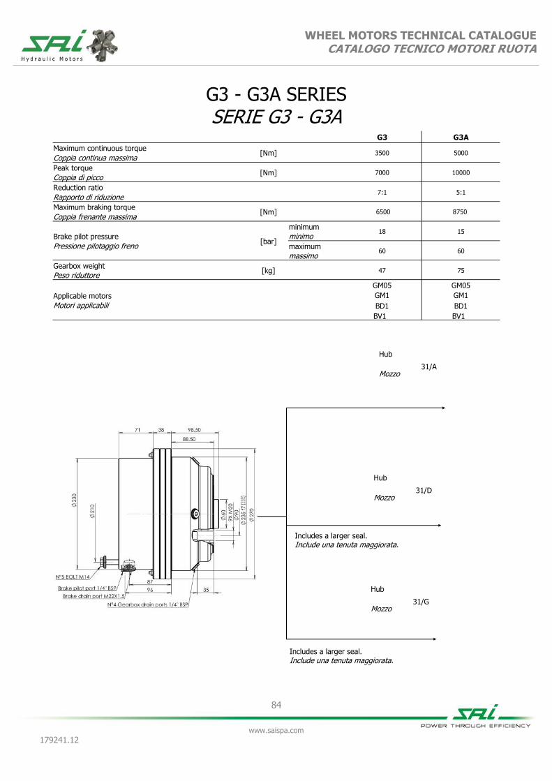
84
www.saispa.com
179241.12
WHEEL MOTORS TECHNICAL CATALOGUE CATALOGO TECNICO MOTORI RUOTA
G3 G3A
Maximum continuous torque [Nm]
3500 5000
Coppia continua massima
Peak torque [Nm]
7000 10000
Coppia di picco
Reduction ratio
7:1 5:1
Rapporto di riduzione
Maximum braking torque [Nm]
6500 8750
Coppia frenante massima
Brake pilot pressure [bar]
minimum 18 15
minimo
Pressione pilotaggio freno maximum 60 60
massimo
Gearbox weight [kg] 47 75
Peso riduttore
Applicable motors
GM05 GM05
GM1 GM1
Motori applicabili BD1 BD1
BV1 BV1
G3 - G3A SERIES SERIE G3 - G3A
Hub
31/A Mozzo
Hub
31/D Mozzo
Hub
31/G Mozzo
Includes a larger seal. Include una tenuta maggiorata.
Includes a larger seal. Include una tenuta maggiorata.
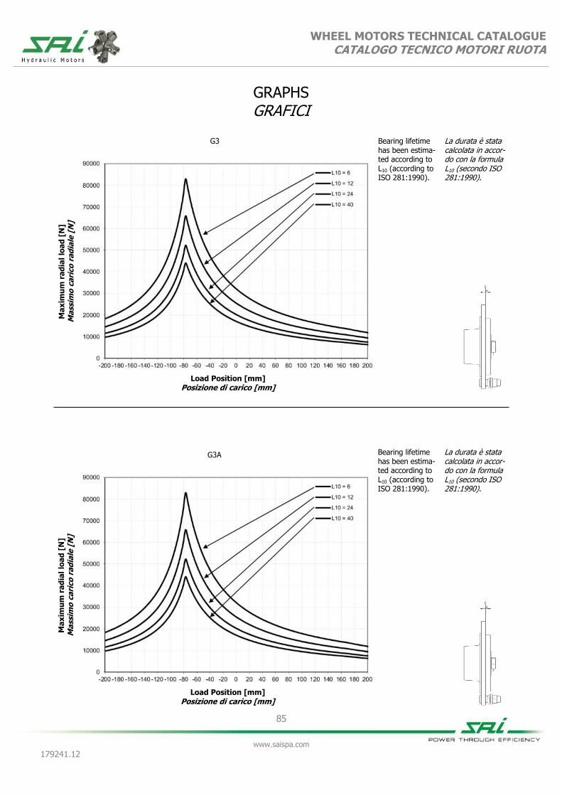
WHEEL MOTORS TECHNICAL CATALOGUE CATALOGO TECNICO MOTORI RUOTA
85
www.saispa.com
179241.12
GRAPHS GRAFICI
Ma
xim
um
ra
dia
l lo
ad
[N
] M
ass
imo
ca
rico
ra
dia
le [
N]
Load Position [mm] Posizione di carico [mm]
G3 Bearing lifetime has been estima-ted according to L10 (according to ISO 281:1990).
La durata è stata calcolata in accor-do con la formula L10 (secondo ISO 281:1990).
Ma
xim
um
ra
dia
l lo
ad
[N
] M
ass
imo
ca
rico
ra
dia
le [
N]
Load Position [mm] Posizione di carico [mm]
G3A Bearing lifetime has been estima-ted according to L10 (according to ISO 281:1990).
La durata è stata calcolata in accor-do con la formula L10 (secondo ISO 281:1990).

86
www.saispa.com
179241.12
WHEEL MOTORS TECHNICAL CATALOGUE CATALOGO TECNICO MOTORI RUOTA
GM05 + G3 GM05 + F10L + G3
275 400 520 600 800 900 1050 1150 1350
Equivalent displacement ⁽¹⁾ [cc/rev] 275 412 517 602 808 903 1056 1164 1336
Cilindrata equivalente ⁽¹⁾
Reduction ratio 7:1
Rapporto di riduzione
Bore [mm] 25 25 28 37 35 37 40 42 45
Alesaggio
Stroke [mm] 16 24 24 16 24 24 24 24 24
Corsa
Specific torque [Nm/bar] 4,38 6,56 8,24 9,58 12,86 14,37 16,82 18,49 21,26
Coppia specifica
Peak pressure ⁽²⁾ [bar] 450 450 425 375 400 375 325 325 280
Pressione di picco ⁽²⁾
Peak power ⁽³⁾ [kW] 20 20 33 33 33 33 33 33 33
Potenza di picco ⁽³⁾
Continuous speed ⁽⁴⁾ [rpm] 100 100 100 100 90 90 90 85 85
Velocità in continuo ⁽⁴⁾
Maximum speed ⁽⁴⁾ [rpm] 140 140 140 140 125 125 125 110 110
Velocità massima ⁽⁴⁾
Approximative weight no brake [kg] 42
unit Approximative weight with brake [kg] 56
unit
Peso approssimativo senza freno unità Peso approssimativo con freno unità
Maximum casing pressure
[bar]
1 continuous
Admissible temperatures
[°C]
-20 minimum
continuo minimo
Pressione massima in carcassa 5 peak
Temperature ammissibili +80 maximum
picco massimo
Motor oil capacity [l] 0,8
Type of brake Negative disc brake
Capacità olio motore Tipo di freno Freno a dischi negativo
Gearbox oil capacity [l] 1,7
Static braking torque ⁽⁵⁾ [Nm] 6500
Capacità olio riduttore Coppia di frenatura statica ⁽⁵⁾
Brake oil capacity [l] 0,45
Minimum brake pilot pressure [bar] 35
Capacità olio freno Pressione minima pilotaggio freno
Brake pilot volume
[cm³] 65,1
Maximum brake pilot pressure
[bar] 60
Volume pilotaggio freno Pressione massima pilotaggio freno
Bolt torque setting [Nm]
68,0 coarse 71,0 fine Suggested bolt type M10 12.9
Coppia serraggio viti 84,0 grosso 89,0 fine Viti suggerite
NOTES / NOTE (1) Equivalent displacement = motor displacement x reduction ratio of gearbox (7:1)
(1) Cilindrata Equivalente = cilindrata motore x rapporto di riduzione del riduttore (7:1)
(2) For higher peak pressures please contact the SAI Technical Department.
(2) Per pressioni di picco maggiori contattare l'Ufficio Tecnico SAI
(3) For higher peak power please contact the SAI Technical Department.
(3) Per potenze di picco maggiori contattare l'Ufficio Tecnico SAI.
(4) For higher continuous and maximum speeds please contact the SAI Technical Department
(4) Per velocità in continuo e massime maggiori contattare l'Ufficio Tecnico SAI
(5) If the brake is engaged for a long time, the braking torque could increase considerably. The brake requires to be periodically engaged and disengaged to maintain the desired
performances.
(5) Quando il freno rimane ingaggiato per un lungo periodo di tempo la coppia frenante può aumentare considerevolmente. Si consiglia periodicamente di pilotare il freno in modo da garantire i dati dichiarati.

WHEEL MOTORS TECHNICAL CATALOGUE CATALOGO TECNICO MOTORI RUOTA
87
www.saispa.com
179241.12
DIMENSIONAL DRAWINGS DISEGNI D’INGOMBRO
GM05 + G3
GM05 + F10L + G3

WHEEL MOTORS TECHNICAL CATALOGUE CATALOGO TECNICO MOTORI RUOTA
88
www.saispa.com
179241.12
Bearing lifetime has been estimated according to L10 (according to ISO 281:1990).
La durata è stata calcolata in accordo con la formula L10 (secondo ISO 281:1990).
GRAPHS GRAFICI
GM05
UNIT DISPLACEMENT - CILINDRATA UNITÀ L10 LIFETIME - VITA L10
PR
ESSU
RE -
PR
ESSIO
NE (
bar)
PISTON DIAMETER - DIAMETRO PISTONE (Ø mm)
HO
UR
S -
ORE
UNIT SPEED - VELOCITÀ DELL’UNITÀ (rpm)
100
200
500 1.000 2.000 5.000
10.000 20.000 50.000
100.000 200.000
500.000 1.000.000
25 27 29 31 33 35 37 39 41 43 45
0 29 57 86 114 143 171 200 229 257 286
400
25
520
28
800
35
900
37
1050
40
1150
42
1350
45
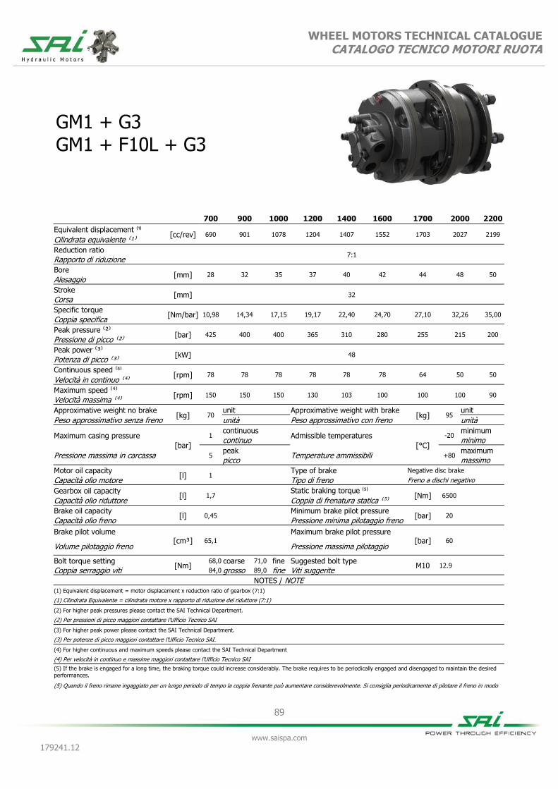
89
www.saispa.com
179241.12
WHEEL MOTORS TECHNICAL CATALOGUE CATALOGO TECNICO MOTORI RUOTA
GM1 + G3 GM1 + F10L + G3
700 900 1000 1200 1400 1600 1700 2000 2200
Equivalent displacement ⁽¹⁾ [cc/rev] 690 901 1078 1204 1407 1552 1703 2027 2199
Cilindrata equivalente ⁽¹⁾
Reduction ratio 7:1
Rapporto di riduzione
Bore [mm] 28 32 35 37 40 42 44 48 50
Alesaggio
Stroke [mm] 32
Corsa
Specific torque [Nm/bar] 10,98 14,34 17,15 19,17 22,40 24,70 27,10 32,26 35,00
Coppia specifica
Peak pressure ⁽²⁾ [bar] 425 400 400 365 310 280 255 215 200
Pressione di picco ⁽²⁾
Peak power ⁽³⁾ [kW] 48
Potenza di picco ⁽³⁾
Continuous speed ⁽⁴⁾ [rpm] 78 78 78 78 78 78 64 50 50
Velocità in continuo ⁽⁴⁾
Maximum speed ⁽⁴⁾ [rpm] 150 150 150 130 103 100 100 100 90
Velocità massima ⁽⁴⁾
Approximative weight no brake [kg] 70
unit Approximative weight with brake [kg] 95
unit
Peso approssimativo senza freno unità Peso approssimativo con freno unità
Maximum casing pressure
[bar]
1 continuous
Admissible temperatures
[°C]
-20 minimum
continuo minimo
Pressione massima in carcassa 5 peak
Temperature ammissibili +80 maximum
picco massimo
Motor oil capacity [l] 1
Type of brake Negative disc brake
Capacità olio motore Tipo di freno Freno a dischi negativo
Gearbox oil capacity [l] 1,7
Static braking torque ⁽⁵⁾ [Nm] 6500
Capacità olio riduttore Coppia di frenatura statica ⁽⁵⁾
Brake oil capacity [l] 0,45
Minimum brake pilot pressure [bar] 20
Capacità olio freno Pressione minima pilotaggio freno
Brake pilot volume [cm³] 65,1
Maximum brake pilot pressure [bar] 60
Volume pilotaggio freno Pressione massima pilotaggio
Bolt torque setting [Nm]
68,0 coarse 71,0 fine Suggested bolt type M10 12.9
Coppia serraggio viti 84,0 grosso 89,0 fine Viti suggerite
NOTES / NOTE (1) Equivalent displacement = motor displacement x reduction ratio of gearbox (7:1)
(1) Cilindrata Equivalente = cilindrata motore x rapporto di riduzione del riduttore (7:1)
(2) For higher peak pressures please contact the SAI Technical Department.
(2) Per pressioni di picco maggiori contattare l'Ufficio Tecnico SAI
(3) For higher peak power please contact the SAI Technical Department.
(3) Per potenze di picco maggiori contattare l'Ufficio Tecnico SAI.
(4) For higher continuous and maximum speeds please contact the SAI Technical Department
(4) Per velocità in continuo e massime maggiori contattare l'Ufficio Tecnico SAI
(5) If the brake is engaged for a long time, the braking torque could increase considerably. The brake requires to be periodically engaged and disengaged to maintain the desired
performances.
(5) Quando il freno rimane ingaggiato per un lungo periodo di tempo la coppia frenante può aumentare considerevolmente. Si consiglia periodicamente di pilotare il freno in modo

WHEEL MOTORS TECHNICAL CATALOGUE CATALOGO TECNICO MOTORI RUOTA
90
www.saispa.com
179241.12
DIMENSIONAL DRAWINGS DISEGNI D’INGOMBRO
GM1 + G3
GM1 + F10L + G3

WHEEL MOTORS TECHNICAL CATALOGUE CATALOGO TECNICO MOTORI RUOTA
91
www.saispa.com
179241.12
GRAPHS GRAFICI
Bearing lifetime has been estimated according to L10 (according to ISO 281:1990).
La durata è stata calcolata in accordo con la formula L10 (secondo ISO 281:1990).
GM1
UNIT DISPLACEMENT - CILINDRATA UNITÀ L10 LIFETIME - VITA L10
PR
ESSU
RE -
PR
ESSIO
NE (
bar)
PISTON DIAMETER - DIAMETRO PISTONE (Ø mm)
HO
UR
S -
ORE
UNIT SPEED - VELOCITÀ DELL’UNITÀ (rpm)
28 33 38 43 48
0 28 57 86 114 143 171
700
28
900
32
1000
35
1200
37
1400
40
100
200
500 1.000 2.000 5.000
10.000 20.000 50.000
100.000 200.000
500.000 1.000.000
1600
42
1700
44
2200
50
2000
48

92
www.saispa.com
179241.12
WHEEL MOTORS TECHNICAL CATALOGUE CATALOGO TECNICO MOTORI RUOTA
BD1 + G3 (dual displacement without brake / cilindrata doppia senza freno) BV1 + G3 (variable displacement without brake / cilindrata variabile senza freno) BD1 + F10L + G3 (dual displacement with brake / cilindrata doppia con freno) BV1 + F10L + G3 (variable displacement with brake / cilindrata variabile con freno)
700 375 1200 300 1200 550 1700 425 1700 850
Equivalent displacement ⁽¹⁾ [cc/rev] 714 378 1204 301 1232 532 1701 427 1701 851
Cilindrata equivalente ⁽¹⁾
Reduction ratio 7:1
Rapporto di riduzione
Bore [mm] 37 37 37 37 44 44 44 44 44 44
Alesaggio
Stroke [mm] 19 10 32 8 23 10 32 8 32 16
Corsa
Specific torque [Nm/bar] 11,40 6,30 19,20 4,80 19,55 8,45 27,07 6,79 27,30 13,51
Coppia specifica
Peak pressure ⁽²⁾ [bar] 425 425 370 400 355 400 250 375 250 375
Pressione di picco ⁽²⁾
Peak power ⁽³⁾ [kW] 50 42 50 42 50 42 50 42 50 42
Potenza di picco ⁽³⁾
Continuous speed ⁽⁴⁾ [rpm] 70 200 70 200 70 200 70 200 70 200
Velocità in continuo ⁽⁴⁾
Maximum speed ⁽⁴⁾ [rpm] 200 200 140 200 140 200 120 200 120 200
Velocità massima ⁽⁴⁾
Approximative weight no brake [kg] 70
unit Approximative weight with brake [kg] 95
unit
Peso approssimativo senza freno unità Peso approssimativo con freno unità
Maximum casing pressure
[bar]
1 continuous
Admissible temperatures
[°C]
-20 minimum
continuo minimo
Pressione massima in carcassa 5 peak
Temperature ammissibili +80 maximum
picco massimo
Motor oil capacity [l] 1,5
Type of brake Negative disc brake
Capacità olio motore Tipo di freno Freno a dischi negativo
Gearbox oil capacity [l] 1,7
Static braking torque ⁽⁵⁾ [Nm] 6500
Capacità olio riduttore Coppia di frenatura statica ⁽⁵⁾
Brake oil capacity [l] 0,45
Minimum brake pilot pressure [bar] 20
Capacità olio freno Pressione minima pilotaggio freno
Brake pilot volume
[cm³] 65,1
Maximum brake pilot pressure
[bar] 60
Volume pilotaggio freno Pressione massima pilotaggio freno
Bolt torque setting [Nm]
68,0 coarse 71,0 fine Suggested bolt type M10 12.9
Coppia serraggio viti 84,0 grosso 89,0 fine Viti suggerite
NOTES / NOTE (1) Equivalent displacement = motor displacement x reduction ratio of gearbox (7:1)
(1) Cilindrata Equivalente = cilindrata motore x rapporto di riduzione del riduttore (7:1)
(2) For higher peak pressures please contact the SAI Technical Department.
(2) Per pressioni di picco maggiori contattare l'Ufficio Tecnico SAI
(3) For higher peak power please contact the SAI Technical Department.
(3) Per potenze di picco maggiori contattare l'Ufficio Tecnico SAI.
(4) For higher continuous and maximum speeds please contact the SAI Technical Department
(4) Per velocità in continuo e massime maggiori contattare l'Ufficio Tecnico SAI
(5) If the brake is engaged for a long time, the braking torque could increase considerably. The brake requires to be periodically engaged and disengaged to maintain the desired performances.
(5) Quando il freno rimane ingaggiato per un lungo periodo di tempo la coppia frenante può aumentare considerevolmente. Si consiglia periodicamente di pilotare il freno in modo da garantire i dati dichiarati.

WHEEL MOTORS TECHNICAL CATALOGUE CATALOGO TECNICO MOTORI RUOTA
93
www.saispa.com
179241.12
DIMENSIONAL DRAWINGS DISEGNI D’INGOMBRO
BD1 + G3
BD1 + F10L + G3
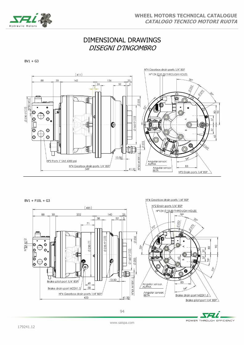
WHEEL MOTORS TECHNICAL CATALOGUE CATALOGO TECNICO MOTORI RUOTA
94
www.saispa.com
179241.12
DIMENSIONAL DRAWINGS DISEGNI D’INGOMBRO
BV1 + G3
BV1 + F10L + G3

WHEEL MOTORS TECHNICAL CATALOGUE CATALOGO TECNICO MOTORI RUOTA
95
www.saispa.com
179241.12
GRAPHS GRAFICI
Bearing lifetime has been estimated according to L10 (according to ISO 281:1990). The following graph has been plotted using the maximum displa-cements with the stroke of 32 mm. Please contact the SAI Tech-nical Department for other graphs relating to this product.
La durata è stata calcolata in accordo con la formula L10 (secondo ISO 281:1990). Il grafico che segue è stato ricavato usando le cilindrate massime e la corsa di 32 mm. Vi preghiamo di contattare l’Ufficio Tecnico SAI per altri grafici relativi a questo prodotto.
BD1/BV1
UNIT DISPLACEMENT - CILINDRATA UNITÀ L10 LIFETIME - VITA L10
PR
ESSU
RE -
PR
ESSIO
NE (
bar)
PISTON DIAMETER - DIAMETRO PISTONE (Ø mm)
HO
UR
S -
ORE
UNIT SPEED - VELOCITÀ DELL’UNITÀ (rpm)
35 37 39 41 43 45
0 29 57 86 114 143 171 200 229 257 286
100
200
500 1.000 2.000 5.000
10.000 20.000 50.000
100.000 200.000
500.000 1.000.000
BD1/BV1
UNIT DISPLACEMENT - CILINDRATA UNITÀ L10 LIFETIME - VITA L10
PR
ESSU
RE -
PR
ESSIO
NE (
bar)
PISTON DIAMETER - DIAMETRO PISTONE (Ø mm)
HO
UR
S -
ORE
UNIT SPEED - VELOCITÀ DELL’UNITÀ (rpm)
100 bar
50 bar
35 37 39 41 43 45
0 29 57 86 114 143 171 200 229 257 286
1200
37
1700
44
100
200
500 1.000 2.000 5.000
10.000 20.000 50.000
100.000 200.000
500.000 1.000.000
Bearing lifetime has been estimated according to L10 (according to ISO 281:1990). The following graph has been plotted using the minimum displa-cements with the stroke of 16 mm. Please contact the SAI Tech-nical Department for other graphs relating to this product.
La durata è stata calcolata in accordo con la formula L10 (secondo ISO 281:1990). Il grafico che segue è stato ricavato usando le cilindrate minime e la corsa di 16 mm. Vi preghiamo di contattare l’Ufficio Tecnico SAI per altri grafici relativi a questo prodotto.
850
44

96
www.saispa.com
179241.12
WHEEL MOTORS TECHNICAL CATALOGUE CATALOGO TECNICO MOTORI RUOTA
GM05 + G3A GM05 + F10L + G3A
200 300 400 450 600 650 750 800 950
Equivalent displacement ⁽¹⁾ [cc/rev] 195 295 370 430 575 645 755 805 955
Cilindrata equivalente ⁽¹⁾
Reduction ratio 5:1
Rapporto di riduzione
Bore [mm] 25 25 28 37 35 37 40 42 45
Alesaggio
Stroke [mm] 16 24 24 16 24 24 24 24 24
Corsa
Specific torque [Nm/bar] 3,10 4,70 5,90 6,85 9,19 10,27 12,00 13,23 15,20
Coppia specifica
Peak pressure ⁽²⁾ [bar] 450 450 425 400 375 375 325 325 280
Pressione di picco ⁽²⁾
Peak power ⁽³⁾ [kW] 20 20 33 33 33 33 33 33 33
Potenza di picco ⁽³⁾
Continuous speed ⁽⁴⁾ [rpm] 140 140 140 140 130 130 130 120 120
Velocità in continuo ⁽⁴⁾
Maximum speed ⁽⁴⁾ [rpm] 200 200 200 200 180 180 180 160 160
Velocità massima ⁽⁴⁾
Approximative weight no brake [kg] 44
unit Approximative weight with brake [kg] 55
unit
Peso approssimativo senza freno unità Peso approssimativo con freno unità
Maximum casing pressure
[bar]
1 continuous
Admissible temperatures
[°C]
-20 minimum
continuo minimo
Pressione massima in carcassa 5 peak
Temperature ammissibili +80 maximum
picco massimo
Motor oil capacity [l] 0,8
Type of brake Negative disc brake
Capacità olio motore Tipo di freno Freno a dischi negativo
Gearbox oil capacity [l] 1,7
Static braking torque ⁽⁵⁾ [Nm] 8750
Capacità olio riduttore Coppia di frenatura statica ⁽⁵⁾
Brake oil capacity [l] 0,45
Minimum brake pilot pressure [bar] 20
Capacità olio freno Pressione minima pilotaggio freno
Brake pilot volume
[cm³] 65,1
Maximum brake pilot pressure
[bar] 60
Volume pilotaggio freno Pressione massima pilotaggio freno
Bolt torque setting [Nm]
68,0 coarse 71,0 fine Suggested bolt type M10 12.9
Coppia serraggio viti 84,0 grosso 89,0 fine Viti suggerite
NOTES / NOTE (1) Equivalent displacement = motor displacement x reduction ratio of gearbox (5:1)
(1) Cilindrata Equivalente = cilindrata motore x rapporto di riduzione del riduttore (5:1)
(2) For higher peak pressures please contact the SAI Technical Department.
(2) Per pressioni di picco maggiori contattare l'Ufficio Tecnico SAI
(3) For higher peak power please contact the SAI Technical Department.
(3) Per potenze di picco maggiori contattare l'Ufficio Tecnico SAI.
(4) For higher continuous and maximum speeds please contact the SAI Technical Department
(4) Per velocità in continuo e massime maggiori contattare l'Ufficio Tecnico SAI
(5) If the brake is engaged for a long time, the braking torque could increase considerably. The brake requires to be periodically engaged and disengaged to maintain the desired performances.
(5) Quando il freno rimane ingaggiato per un lungo periodo di tempo la coppia frenante può aumentare considerevolmente. Si consiglia periodicamente di pilotare il freno in modo da garantire i dati dichiarati.

WHEEL MOTORS TECHNICAL CATALOGUE CATALOGO TECNICO MOTORI RUOTA
97
www.saispa.com
179241.12
DIMENSIONAL DRAWINGS DISEGNI D’INGOMBRO
GM05 + G3A
N°5 x
GM05 + F10L + G3A

WHEEL MOTORS TECHNICAL CATALOGUE CATALOGO TECNICO MOTORI RUOTA
98
www.saispa.com
179241.12
GRAPHS GRAFICI
Bearing lifetime has been estimated according to L10 (according to ISO 281:1990). The following graph has been plotted using the stroke of 24 mm. Please contact the SAI Technical Department for other graphs relating to this product.
La durata è stata calcolata in accordo con la formula L10 (secondo ISO 281:1990). Il grafico che segue è stato ricavato usando la corsa di 24 mm. Vi preghiamo di contattare l’Ufficio Tecnico SAI per altri grafici relativi a questo prodotto.
GM05
UNIT DISPLACEMENT - CILINDRATA UNITÀ L10 LIFETIME - VITA L10
PR
ESSU
RE -
PR
ESSIO
NE (
bar)
PISTON DIAMETER - DIAMETRO PISTONE (Ø mm)
HO
UR
S -
ORE
UNIT SPEED - VELOCITÀ DELL’UNITÀ (rpm)
100
200
500 1.000 2.000 5.000
10.000 20.000 50.000
100.000 200.000
500.000 1.000.000
25 27 29 31 33 35 37 39 41 43 45
0 29 57 86 114 143 171 200 229 257 286
400
25
520
28
800
35
900
37
1050
40
1150
42
1350
45
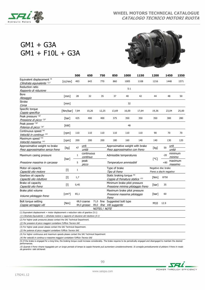
99
www.saispa.com
179241.12
WHEEL MOTORS TECHNICAL CATALOGUE CATALOGO TECNICO MOTORI RUOTA
GM1 + G3A GM1 + F10L + G3A
500 650 750 850 1000 1150 1200 1450 1550
Equivalent displacement ⁽¹⁾ [cc/rev] 493 643 770 860 1005 1108 1216 1448 1571
Cilindrata equivalente ⁽¹⁾
Reduction ratio 5:1
Rapporto di riduzione
Bore [mm] 28 32 35 37 40 42 44 48 50
Alesaggio
Stroke [mm] 32
Corsa
Specific torque [Nm/bar] 7,84 10,26 12,25 13,69 16,00 17,64 19,36 23,04 25,00
Coppia specifica
Peak pressure ⁽²⁾ [bar] 425 400 400 375 350 350 350 300 280
Pressione di picco ⁽²⁾
Peak power ⁽³⁾ [kW] 48
Potenza di picco ⁽³⁾
Continuous speed ⁽⁴⁾ [rpm] 110 110 110 110 110 110 90 70 70
Velocità in continuo ⁽⁴⁾
Maximum speed ⁽⁴⁾ [rpm] 200 200 200 180 160 140 140 130 120
Velocità massima ⁽⁴⁾
Approximative weight no brake [kg] 47
unit Approximative weight with brake [kg] 59
unit
Peso approssimativo senza freno unità Peso approssimativo con freno unità
Maximum casing pressure
[bar]
1 continuous
Admissible temperatures
[°C]
-20 minimum
continuo minimo
Pressione massima in carcassa 5 peak
Temperature ammissibili +80 maximum
picco massimo
Motor oil capacity [l] 1
Type of brake Negative disc brake
Capacità olio motore Tipo di freno Freno a dischi negativo
Gearbox oil capacity [l] 1,7
Static braking torque ⁽⁵⁾ [Nm] 8750
Capacità olio riduttore Coppia di frenatura statica ⁽⁵⁾
Brake oil capacity [l] 0,45
Minimum brake pilot pressure [bar] 35
Capacità olio freno Pressione minima pilotaggio freno
Brake pilot volume
[cm³] 65,1
Maximum brake pilot pressure
[bar] 60
Volume pilotaggio freno Pressione massima pilotaggio freno
Bolt torque setting [Nm]
68,0 coarse 71,0 fine Suggested bolt type M10 12.9
Coppia serraggio viti 84,0 grosso 89,0 fine Viti suggerite
NOTES / NOTE (1) Equivalent displacement = motor displacement x reduction ratio of gearbox (5:1)
(1) Cilindrata Equivalente = cilindrata motore x rapporto di riduzione del riduttore (5:1)
(2) For higher peak pressures please contact the SAI Technical Department.
(2) Per pressioni di picco maggiori contattare l'Ufficio Tecnico SAI
(3) For higher peak power please contact the SAI Technical Department.
(3) Per potenze di picco maggiori contattare l'Ufficio Tecnico SAI.
(4) For higher continuous and maximum speeds please contact the SAI Technical Department
(4) Per velocità in continuo e massime maggiori contattare l'Ufficio Tecnico SAI
(5) If the brake is engaged for a long time, the braking torque could increase considerably. The brake requires to be periodically engaged and disengaged to maintain the desired
performances.
(5) Quando il freno rimane ingaggiato per un lungo periodo di tempo la coppia frenante può aumentare considerevolmente. Si consiglia periodicamente di pilotare il freno in modo da garantire i dati dichiarati.
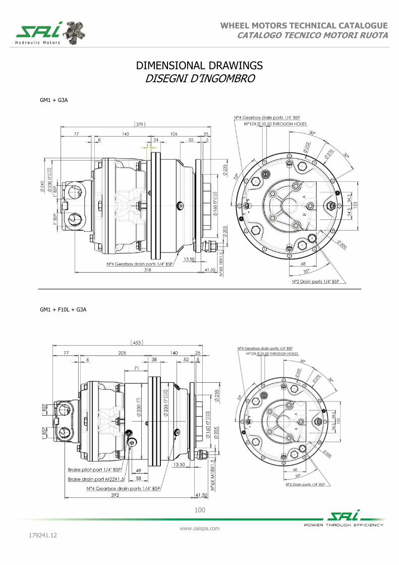
WHEEL MOTORS TECHNICAL CATALOGUE CATALOGO TECNICO MOTORI RUOTA
100
www.saispa.com
179241.12
DIMENSIONAL DRAWINGS DISEGNI D’INGOMBRO
GM1 + G3A
GM1 + F10L + G3A

WHEEL MOTORS TECHNICAL CATALOGUE CATALOGO TECNICO MOTORI RUOTA
101
www.saispa.com
179241.12
GRAPHS GRAFICI
Bearing lifetime has been estimated according to L10 (according to ISO 281:1990). Please contact the SAI Technical Department for other graphs relating to this product.
La durata è stata calcolata in accordo con la formula L10 (secondo ISO 281:1990). Vi preghiamo di contattare l’Ufficio Tecnico SAI per altri grafici relativi a questo prodotto.
GM1
UNIT DISPLACEMENT - CILINDRATA UNITÀ L10 LIFETIME - VITA L10
PR
ESSU
RE -
PR
ESSIO
NE (
bar)
PISTON DIAMETER - DIAMETRO PISTONE (Ø mm)
HO
UR
S -
ORE
UNIT SPEED - VELOCITÀ DELL’UNITÀ (rpm)
28 33 38 43 48
0 40 80 120 160 200 240 280 320 360 400
500
28
650
32
750
35
850
37
1000
40
100
200
500 1.000 2.000 5.000
10.000 20.000 50.000
100.000 200.000
500.000 1.000.000
1150
42
1200
44
1550
50
1450
48

102
www.saispa.com
179241.12
WHEEL MOTORS TECHNICAL CATALOGUE CATALOGO TECNICO MOTORI RUOTA
BD1 + G3A (dual displacement without brake / cilindrata doppia senza freno) BV1 + G3A (variable displacement without brake / cilindrata variabile senza freno) BD1 + F10L + G3A (dual displacement with brake / cilindrata doppia con freno) BV1 + F10L + G3A (variable displacement with brake / cilindrata variabile con freno)
500 250 850 215 875 400 1250 300 1250 625
Equivalent displacement ⁽¹⁾ [cc/rev] 510 270 860 215 880 380 1215 305 1215 608
Cilindrata equivalente ⁽¹⁾
Reduction ratio 5:1
Rapporto di riduzione
Bore [mm] 37 37 37 37 44 44 44 44 44 44
Alesaggio
Stroke [mm] 19 10 32 8 23 10 32 8 32 16
Corsa
Specific torque [Nm/bar] 8,11 4,30 13,69 3,42 14,00 6,04 19,34 4,85 19,40 9,65
Coppia specifica
Peak pressure ⁽²⁾ [bar] 425 425 400 400 300 400 375 375 375 375
Pressione di picco ⁽²⁾
Peak power ⁽³⁾ [kW] 55 42 55 42 55 42 55 42 55 42
Potenza di picco ⁽³⁾
Continuous speed ⁽⁴⁾ [rpm] 100 300 100 300 100 300 100 300 100 300
Velocità in continuo ⁽⁴⁾
Maximum speed ⁽⁴⁾ [rpm] 300 300 200 300 200 300 170 300 170 300
Velocità massima ⁽⁴⁾
Approximative weight no brake [kg] 55
unit Approximative weight with brake [kg] 67
unit
Peso approssimativo senza freno unità Peso approssimativo con freno unità
Maximum casing pressure
[bar]
1 continuous
Admissible temperatures
[°C]
-20 minimum
continuo minimo
Pressione massima in carcassa 5 peak
Temperature ammissibili +80 maximum
picco massimo
Motor oil capacity [l] 1,5
Type of brake Negative disc brake
Capacità olio motore Tipo di freno Freno a dischi negativo
Gearbox oil capacity [l] 1,7
Static braking torque ⁽⁵⁾ [Nm] 8750
Capacità olio riduttore Coppia di frenatura statica ⁽⁵⁾
Brake oil capacity [l] 0,45
Minimum brake pilot pressure [bar] 20
Capacità olio freno Pressione minima pilotaggio freno
Brake pilot volume [cm³] 65,1
Maximum brake pilot pressure [bar] 60
Volume pilotaggio freno Pressione massima pilotaggio
Bolt torque setting [Nm]
68,0 coarse 71,0 fine Suggested bolt type M10 12.9
Coppia serraggio viti 84,0 grosso 89,0 fine Viti suggerite
NOTES / NOTE (1) Equivalent displacement = motor displacement x reduction ratio of gearbox (5:1)
(1) Cilindrata Equivalente = cilindrata motore x rapporto di riduzione del riduttore (5:1)
(2) For higher peak pressures please contact the SAI Technical Department.
(2) Per pressioni di picco maggiori contattare l'Ufficio Tecnico SAI
(3) For higher peak power please contact the SAI Technical Department.
(3) Per potenze di picco maggiori contattare l'Ufficio Tecnico SAI.
(4) For higher continuous and maximum speeds please contact the SAI Technical Department
(4) Per velocità in continuo e massime maggiori contattare l'Ufficio Tecnico SAI
(5) If the brake is engaged for a long time, the braking torque could increase considerably. The brake requires to be periodically engaged and disengaged to maintain the desired
performances.
(5) Quando il freno rimane ingaggiato per un lungo periodo di tempo la coppia frenante può aumentare considerevolmente. Si consiglia periodicamente di pilotare il freno in modo da

WHEEL MOTORS TECHNICAL CATALOGUE CATALOGO TECNICO MOTORI RUOTA
103
www.saispa.com
179241.12
DIMENSIONAL DRAWINGS DISEGNI D’INGOMBRO
BD1 + G3A
BD1 + F10L + G3A

WHEEL MOTORS TECHNICAL CATALOGUE CATALOGO TECNICO MOTORI RUOTA
104
www.saispa.com
179241.12
DIMENSIONAL DRAWINGS DISEGNI D’INGOMBRO
BV1 + G3A
BV1 + F10L + G3A

WHEEL MOTORS TECHNICAL CATALOGUE CATALOGO TECNICO MOTORI RUOTA
105
www.saispa.com
179241.12
GRAPHS GRAFICI
Bearing lifetime has been estimated according to L10 (according to ISO 281:1990). The following graph has been plotted using the maximum displa-cements with the stroke of 32 mm. Please contact the SAI Tech-nical Department for other graphs relating to this product.
La durata è stata calcolata in accordo con la formula L10 (secondo ISO 281:1990). Il grafico che segue è stato ricavato usando le cilindrate massime e la corsa di 32 mm. Vi preghiamo di contattare l’Ufficio Tecnico SAI per altri grafici relativi a questo prodotto.
BDK3A/BDFK3AR/BVK3A/BVFK3AR
UNIT DISPLACEMENT - CILINDRATA UNITÀ L10 LIFETIME - VITA L10
PR
ESSU
RE -
PR
ESSIO
NE (
bar)
PISTON DIAMETER - DIAMETRO PISTONE (Ø mm)
HO
UR
S -
ORE
UNIT SPEED - VELOCITÀ DELL’UNITÀ (rpm)
35 37 39 41 43 45
0 29 57 86 114 143 171 200 229 257 286
100
200
500 1.000 2.000 5.000
10.000 20.000 50.000
100.000 200.000
500.000 1.000.000
BDK3A/BDFK3AR/BVK3A/BVFK3AR
UNIT DISPLACEMENT - CILINDRATA UNITÀ L10 LIFETIME - VITA L10
PR
ESSU
RE -
PR
ESSIO
NE (
bar)
PISTON DIAMETER - DIAMETRO PISTONE (Ø mm)
HO
UR
S -
ORE
UNIT SPEED - VELOCITÀ DELL’UNITÀ (rpm)
100 bar
50 bar
35 37 39 41 43 45
0 40 80 120 160 200 240 280 320 360 400
850
37
1200
44
100
200
500 1.000 2.000 5.000
10.000 20.000 50.000
100.000 200.000
500.000 1.000.000
Bearing lifetime has been estimated according to L10 (according to ISO 281:1990). The following graph has been plotted using the minimum displa-cements with the stroke of 16 mm. Please contact the SAI Tech-nical Department for other graphs relating to this product.
La durata è stata calcolata in accordo con la formula L10 (secondo ISO 281:1990). Il grafico che segue è stato ricavato usando le cilindrate minime e la corsa di 16 mm. Vi preghiamo di contattare l’Ufficio Tecnico SAI per altri grafici relativi a questo prodotto.
800
44

106
www.saispa.com
179241.12
WHEEL MOTORS TECHNICAL CATALOGUE CATALOGO TECNICO MOTORI RUOTA
ORDER CODES CODICI D’ORDINE
Example
Esempio
GM05 600 U D40 G3
(standard)
GM05 600 U D40L G3A
(options: anti-clockwise sense of rotation)
(opzioni: direzione d'uscita in rotazione anti-oraria)
1 Motor type 1 Tipo motore
2 Displacement see table 2 Cilindrata vedere tabella
3 Lubrication options
O = separated oil
3 Opzioni lubrificazione
O = olio separato
U =
shared oil, max. cont. case press. 0.5 bar and max. peak press. 1.5 bar for hubs 31/D and 31/G.
U =
olio unico, max. press. cont. in carcassa 0.5 bar e max. press. picco 1.5 bar per mozzi 31/D e 31/G.
4 Distributor see distributors section
4 Distributore vedere sezione distributori
D40 standard D40 standard
5
Direction of rotation (viewed from the output side) with input flow in port A, output in B.
No code = clockwise rotation
5
Direzione d'uscita (visto dal lato d'uscita) con portata in ingresso in porta A, uscita in porta B.
Nessun codice
= rotazione oraria
L = anti-clockwise rota-tion
L = rotazione anti-oraria
6 Distributor cover orientation
No code = position 1
6 Orientamento coperchio distributore
Nessun codice
= posizione 1
DM2 = position 2 DM2 = posizione 2
DM3 = position 3 DM3 = posizione 3
DM4 = position 4 DM4 = posizione 4
DM5 = position 5 DM5 = posizione 5
7 G series G3 = reduction ratio 7:1
7 Serie G G3 = rapporto di riduzione 7:1
G3A = reduction ratio 5:1 G3A = rapporto di riduzione 5:1
8 Hub option Opzione mozzo 8
No code = no hub Nessun codice
= nessun mozzo
31A = standard 31A = standard
31D = hub 31/D, includes a larger seal.
31D = mozzo 31/D, include tenuta maggiorata.
31G = hub 31/G, includes a larger seal.
31G = mozzo 31/G, include tenuta maggiorata.
1 2 3 4 5 6 7 8
+ + + + + + +

107
www.saispa.com
179241.12
WHEEL MOTORS TECHNICAL CATALOGUE CATALOGO TECNICO MOTORI RUOTA
W OUTPUT USCITA W
BRAKE (F) Optional
FIXED DISPLACEMENT CILINDRATA FISSA
TS8
HYDRAULIC INPUT INPUT IDRAULICO
MECHANIC OUTPUT OUTPUT MECCANICO
FRENO (F) Opzionale
TS SERIES SERIE TS

108
www.saispa.com
179241.12
WHEEL MOTORS TECHNICAL CATALOGUE CATALOGO TECNICO MOTORI RUOTA
10
6
10h L60n
10L
n: speed in rpm n: velocità in rpm
Bearings lifetime calculation: Permissible loads are calculated for different steps of lifetime L10 according to ISO 281:1990. L10: lifetime of the bearing system in millions of revolutions. L10 value can be converted in hours L10h using the formula*. Permissible radial load in dynamic conditions and at maximum torque of 43000 Nm. N.B. Diagrams are influenced by the shaft permissible radial loads.
Calcolo durata cuscinetti: I carichi ammissibili sono calcolati per le diverse fasi del ciclo di vita L10 secondo ISO 281:1990. L10: durata del sistema di cuscinetti in milioni di giri. Il valore L10 può essere convertito in ore L10h utilizzando la se-guente formula*. Carico radiale ammissibile in condizioni dinamiche e con una cop-pia massima di 43000 Nm. N.B. I diagrammi sono influenzati dai carichi radiali ammissibili dell’albero.
*
GRAPHS GRAFICI
400
350
300
250
200
150
100
50
0
Ma
xim
um
ra
dia
l lo
ad
[k
N]
Ma
ssim
o c
ari
co
ra
dia
le [
kN
]
-500 -400 -300 -200 -100 0 100
L10 = 1
L10 = 3
L10 = 5
L10 = 10
-800 -700 -600
Load Position [mm] Posizione di carico [mm]
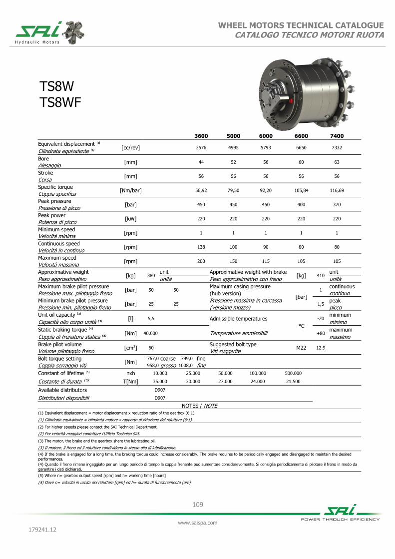
109
www.saispa.com
179241.12
WHEEL MOTORS TECHNICAL CATALOGUE CATALOGO TECNICO MOTORI RUOTA
TS8W TS8WF
3600 5000 6000 6600 7400
Equivalent displacement ⁽¹⁾ [cc/rev]
3576
4995
5793
6650
7332
Cilindrata equivalente ⁽¹⁾
Bore [mm]
44
52
56
60
63
Alesaggio
Stroke [mm]
56
56
56
56
56
Corsa
Specific torque [Nm/bar]
56,92
79,50
92,20
105,84
116,69
Coppia specifica
Peak pressure [bar]
450
450
450
400
370
Pressione di picco
Peak power [kW]
220
220
220
220
220
Potenza di picco
Minimum speed [rpm]
1
1
1
1
1
Velocità minima
Continuous speed [rpm]
138
100
90
80
80
Velocità in continuo
Maximum speed [rpm]
200
150
115
105
105
Velocità massima
Approximative weight [kg] 380
unit Approximative weight with brake [kg] 410
unit
Peso approssimativo unità Peso approssimativo con freno unità
Maximum brake pilot pressure [bar] 50 50
Maximum casing pressure
[bar]
1 continuous
Pressione max. pilotaggio freno (hub version) continuo
Minimum brake pilot pressure [bar] 25 25
Pressione massima in carcassa 1,5
peak
Pressione min. pilotaggio freno (versione mozzo) picco
Unit oil capacity ⁽³⁾ [l] 5,5 Admissible temperatures
°C
-20 minimum
Capacità olio corpo unità ⁽³⁾ minimo
Static braking torque ⁽⁴⁾ [Nm] 40.000 Temperature ammissibili +80
maximum
Coppia di frenatura statica ⁽⁴⁾ massimo
Brake pilot volume [cm3] 60
Suggested bolt type M22 12.9
Volume pilotaggio freno Viti suggerite
Bolt torque setting [Nm]
767,0 coarse 799,0 fine
Coppia serraggio viti 958,0 grosso 1008,0 fine
Constant of lifetime ⁽⁵⁾ nxh 10.000 25.000 50.000 100.000 500.000
Costante di durata ⁽⁵⁾ T[Nm] 35.000 30.000 27.000 24.000 21.500
Available distributors D907
Distributori disponibili D907
NOTES / NOTE (1) Equivalent displacement = motor displacement x reduction ratio of the gearbox (6:1).
(1) Cilindrata equivalente = cilindrata motore x rapporto di riduzione del riduttore (6:1).
(2) For higher speeds please contact the SAI Technical Department.
(2) Per velocità maggiori contattare l'Ufficio Technico SAI.
(3) The motor, the brake and the gearbox share the lubricating oil.
(3) Il motore, il freno ed il riduttore condividono lo stesso olio di lubrificazione.
(4) If the brake is engaged for a long time, the braking torque could increase considerably. The brake requires to be periodically engaged and disengaged to maintain the desired
performances.
(4) Quando il freno rimane ingaggiato per un lungo periodo di tempo la coppia frenante può aumentare considerevomente. Si consiglia periodicamente di pilotare il freno in modo da
garantire i dati dichiarati.
(5) Where n= gearbox output speed [rpm] and h= working time [hours]
(5) Dove n= velocità in uscita del riduttore [rpm] ed h= durata di funzionamento [ore]

WHEEL MOTORS TECHNICAL CATALOGUE CATALOGO TECNICO MOTORI RUOTA
110
www.saispa.com
179241.12
DIMENSIONAL DRAWINGS DISEGNI D’INGOMBRO
TS8WF
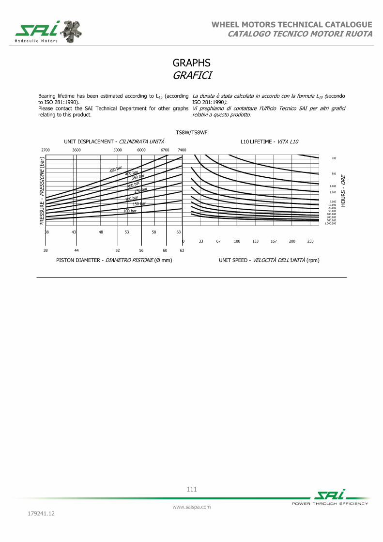
WHEEL MOTORS TECHNICAL CATALOGUE CATALOGO TECNICO MOTORI RUOTA
111
www.saispa.com
179241.12
GRAPHS GRAFICI
TS8W/TS8WF
UNIT DISPLACEMENT - CILINDRATA UNITÀ L10 LIFETIME - VITA L10
PR
ESSU
RE -
PR
ESSIO
NE (
bar)
PISTON DIAMETER - DIAMETRO PISTONE (Ø mm)
HO
UR
S -
ORE
UNIT SPEED - VELOCITÀ DELL’UNITÀ (rpm)
100 bar
38 43 48 53 58 63
0 33 67 100 133 167 200 233
2700
38
6000
56
200
500
1.000
2.000
5.000
10.000 20.000 50.000
100.000 200.000
500.000 1.000.000
Bearing lifetime has been estimated according to L10 (according to ISO 281:1990). Please contact the SAI Technical Department for other graphs relating to this product.
La durata è stata calcolata in accordo con la formula L10 (secondo ISO 281:1990). Vi preghiamo di contattare l’Ufficio Tecnico SAI per altri grafici relativi a questo prodotto.
3600
44
5000
52
6700
60
7400
63
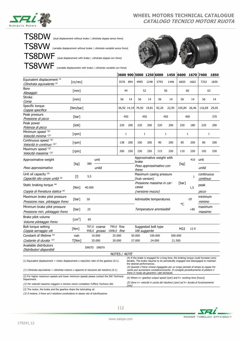
112
www.saispa.com
179241.12
WHEEL MOTORS TECHNICAL CATALOGUE CATALOGO TECNICO MOTORI RUOTA
TS8DW (dual displacement without brake / cilindrata doppia senza freno) TS8VW (variable displacement without brake / cilindrata variabile senza freno) TS8DWF (dual displacement with brake / cilindrata doppia con freno) TS8VWF (variable displacement with brake / cilindrata variabile con freno) 3600 900 5000 1250 6000 1450 6600 1670 7400 1850
Equivalent displacement ⁽¹⁾ [cc/rev] 3576 894 4995 1248 5793 1446 6650 1662 7332 1830
Cilindrata equivalente ⁽¹⁾
Bore [mm] 44 52 56 60 63
Alesaggio
Stroke [mm] 56 14 56 14 56 14 56 14 56 14
Corsa
Specific torque [Nm/bar] 56,92 14,19 79,50 19,81 92,20 22,95 105,84 26,46 116,69 29,05
Coppia specifica
Peak pressure [bar] 450 450 450 400 370
Pressione di picco
Peak power [kW] 220 200 220 200 220 200 220 180 220 200
Potenza di picco
Minimum speed ⁽²⁾ [rpm] 1 1 1 1 1
Velocità minima ⁽²⁾
Continuous speed ⁽²⁾ [rpm] 138 200 100 200 90 200 85 200 80 200
Velocità in continuo ⁽²⁾
Maximum speed ⁽²⁾ [rpm] 200 250 150 250 115 250 110 250 105 250
Velocità massima ⁽²⁾
Approximative weight
[kg] 380
unit Approximative weight with brake
[kg]
410 unit
Peso approssimativo unità Peso approssimativo con freno
unità
Unit oil capacity ⁽³⁾ [l] 5,5
Maximum casing pressure
[bar]
1 continuous
Capacità olio corpo unità ⁽³⁾ (hub version) continuo
Static braking torque ⁽⁴⁾ [Nm] 40.000
Pressione massima in car-cassa 1,5
peak
Coppia di frenatura statica ⁽⁴⁾ (versione mozzo) picco
Maximum brake pilot pressure [bar] 50
Admissible temperatures
°C
-20 minimum
Pressione max. pilotaggio freno minimo
Minimum brake pilot pressure [bar] 25
Temperature ammissibili +80
maximum
Pressione min. pilotaggio freno massimo
Brake pilot volume [cm3] 60
Volume pilotaggio freno
Bolt torque setting [Nm]
767,0 coarse 799,0 fine Suggested bolt type M22 12.9
Coppia serraggio viti 958,0 grosso 1008,0 fine Viti suggerite
Constant of lifetime ⁽⁵⁾ nxh 10.000 25.000 50.000 100.000 500.000
Costante di durata ⁽⁵⁾ T[Nm] 35.000 30.000 27.000 24.000 21.500
Available distributors D907D D907V
Distributori disponibili
NOTES / NOTE
(1) Equivalent displacement = motor displacement x reduction ratio of the gearbox (6:1). (4) If the brake is engaged for a long time, the braking torque could increase consi-
derably. The brake requires to be periodically engaged and disengaged to maintain the desired performances.
(1) Cilindrata equivalente = cilindrata motore x rapporto di riduzione del riduttore (6:1). (4) Quando il freno rimane ingaggiato per un lungo periodo di tempo la coppia fre-nante può aumentare considerevomente. Si consiglia periodicamente di pilotare il freno in modo da garantire i dati dichiarati.
(2) For higher maximum speeds and lower minimum speeds please contact the SAI Technical
Department. (5) Where n= gearbox output speed [rpm] and h= working time [hours]
(2) Per velocità massime maggiori e minime minori contattare l'Ufficio Technico SAI. (5) Dove n= velocità in uscita del riduttore [rpm] ed h= durata di funzionamento [ore]
(3) The motor, the brake and the gearbox share the lubricating oil.
(3) Il motore, il freno ed il riduttore condividono lo stesso olio di lubrificazione.

WHEEL MOTORS TECHNICAL CATALOGUE CATALOGO TECNICO MOTORI RUOTA
113
www.saispa.com
179241.12
DIMENSIONAL DRAWINGS DISEGNI D’INGOMBRO
TS8DWF
TS8VWF

WHEEL MOTORS TECHNICAL CATALOGUE CATALOGO TECNICO MOTORI RUOTA
114
www.saispa.com
179241.12
GRAPHS GRAFICI
TS8DW/TS8DWF/TS8VW/TS8VWF
UNIT DISPLACEMENT - CILINDRATA UNITÀ L10 LIFETIME - VITA L10
PR
ESSU
RE -
PR
ESSIO
NE (
bar)
PISTON DIAMETER - DIAMETRO PISTONE (Ø mm)
HO
UR
S -
ORE
UNIT SPEED - VELOCITÀ DELL’UNITÀ (rpm)
100 bar
38 43 48 53 58 63
0 33 67 100 133 167 200 233 267
2700
38
6000
56
200
500
1.000
2.000
5.000
10.000 20.000 50.000
100.000 200.000
500.000 1.000.000
3600
44
5000
52
6700
60
7400
63
TS8DW/TS8DWF/TS8VW/TS8VWF
UNIT DISPLACEMENT - CILINDRATA UNITÀ L10 LIFETIME - VITA L10
PR
ESSU
RE -
PR
ESSIO
NE (
bar)
PISTON DIAMETER - DIAMETRO PISTONE (Ø mm)
HO
UR
S -
ORE
UNIT SPEED - VELOCITÀ DELL’UNITÀ (rpm)
100 bar
38 43 48 53 58 63
0 33 67 100 133 167 200 233 267
700
38
1450
56
200
500
1.000
2.000
5.000
10.000 20.000 50.000
100.000 200.000
500.000 1.000.000
900
44
1250
52
1700
60
1850
63
Bearing lifetime has been estimated according to L10 (according to ISO 281:1990). The following graph has been plotted using the maximum displa-cements with the stroke of 56 mm. Please contact the SAI Tech-nical Department for other graphs relating to this product.
La durata è stata calcolata in accordo con la formula L10 (secondo ISO 281:1990). Il grafico che segue è stato ricavato usando le cilindrate massime e la corsa di 56 mm. Vi preghiamo di contattare l’Ufficio Tecnico SAI per altri grafici relativi a questo prodotto.
Bearing lifetime has been estimated according to L10 (according to ISO 281:1990). The following graph has been plotted using the minimum displa-cements with the stroke of 14 mm. Please contact the SAI Tech-nical Department for other graphs relating to this product.
La durata è stata calcolata in accordo con la formula L10 (secondo ISO 281:1990). Il grafico che segue è stato ricavato usando le cilindrate minime e la corsa di 14 mm. Vi preghiamo di contattare l’Ufficio Tecnico SAI per altri grafici relativi a questo prodotto.

115
www.saispa.com
179241.12
WHEEL MOTORS TECHNICAL CATALOGUE CATALOGO TECNICO MOTORI RUOTA
ORDER CODES CODICI D’ORDINE
1 Type of displacement
No code = fixed displace-ment
1 Tipo di cilindrata
Nessun codice = cilindrata fissa
D = double displac-ment
D = doppia cilindrata
V = variable displa-cement
V = cilindrata variabile
2 Brake option F = brake 2 Opzione freno F = freno
3 Displacement see table 3 Cilindrata vedere tabella
4 Distributor
D907 = For TS8W and TS8WF
Distributore
D907 = per TS8W e TS8WF
4 D907D = For TS8DW and TS8DWF
D907D = per TS8DW e TS8DWF
D907V = For TS8VW and TS8VWF
D907V = per TS8VW e TS8VWF
5 Options
V = FKM seals
5 Opzioni
V = tenute in FKM
I = breath valve I = valvola di sfiato
RS = rotative sensor RS = sensore rotativo
6
Direction of rotation (viewed from the output side) with input flow in port A, out-put in B.
No code = clockwise rotation 6
Direzione d'uscita (visto dal lato d'usci-ta) con portata in ingresso in porta A, uscita in porta B.
Nessun codice = rotazione oraria
L = anti-clockwise rotation
L = rotazione anti-oraria
7 Distributor cover orientation
No code = position 1
7 Orientamento coperchio distributore
Nessun codice = posizione 1
DM2 = position 2 DM2 = posizione 2
DM3 = position 3 DM3 = posizione 3
Example / Esempio
TS8W 6000 D907 (standard)
TS8VWF 6000 D907V VL (Options: FKM seals and direction anti-clockwise of the rotation) (Opzioni: Tenute in FKM e direzione d’uscita in rotazione anti-oraria)
1 2 3 4 5 6 7
TS8 + + W + + + D907 + + +
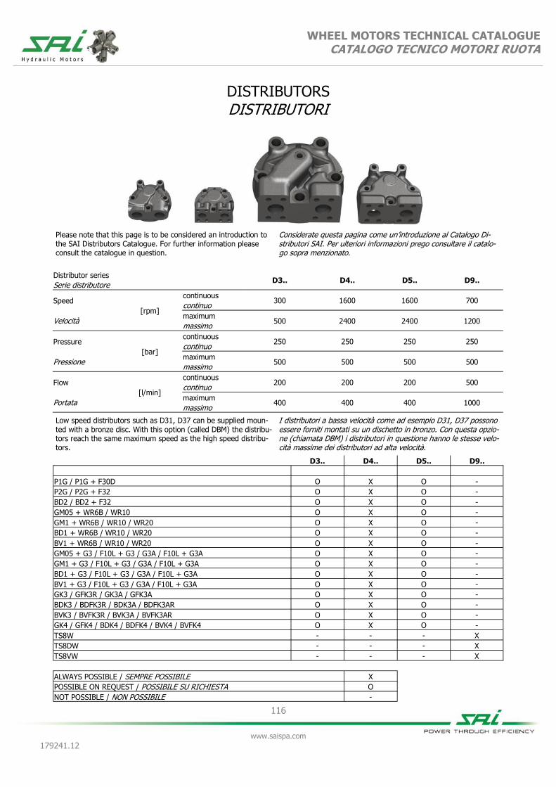
116
www.saispa.com
179241.12
WHEEL MOTORS TECHNICAL CATALOGUE CATALOGO TECNICO MOTORI RUOTA
DISTRIBUTORS DISTRIBUTORI
Distributor series D3.. D4.. D5.. D9..
Serie distributore
Speed
[rpm]
continuous 300 1600 1600 700
continuo
Velocità maximum
500 2400 2400 1200 massimo
Pressure
[bar]
continuous 250 250 250 250
continuo
Pressione maximum
500 500 500 500 massimo
Flow
[l/min]
continuous 200 200 200 500
continuo
Portata maximum
400 400 400 1000 massimo
D3.. D4.. D5.. D9..
P1G / P1G + F30D O X O -
P2G / P2G + F32 O X O -
BD2 / BD2 + F32 O X O -
GM05 + WR6B / WR10 O X O -
GM1 + WR6B / WR10 / WR20 O X O -
BD1 + WR6B / WR10 / WR20 O X O -
BV1 + WR6B / WR10 / WR20 O X O -
GM05 + G3 / F10L + G3 / G3A / F10L + G3A O X O -
GM1 + G3 / F10L + G3 / G3A / F10L + G3A O X O -
BD1 + G3 / F10L + G3 / G3A / F10L + G3A O X O -
BV1 + G3 / F10L + G3 / G3A / F10L + G3A O X O -
GK3 / GFK3R / GK3A / GFK3A O X O -
BDK3 / BDFK3R / BDK3A / BDFK3AR O X O -
BVK3 / BVFK3R / BVK3A / BVFK3AR O X O -
GK4 / GFK4 / BDK4 / BDFK4 / BVK4 / BVFK4 O X O -
TS8W - - - X
TS8DW - - - X
TS8VW - - - X
ALWAYS POSSIBLE / SEMPRE POSSIBILE X
POSSIBLE ON REQUEST / POSSIBILE SU RICHIESTA O
NOT POSSIBLE / NON POSSIBILE -
Low speed distributors such as D31, D37 can be supplied moun-ted with a bronze disc. With this option (called DBM) the distribu-tors reach the same maximum speed as the high speed distribu-tors.
I distributori a bassa velocità come ad esempio D31, D37 possono essere forniti montati su un dischetto in bronzo. Con questa opzio-ne (chiamata DBM) i distributori in questione hanno le stesse velo-cità massime dei distributori ad alta velocità.
Please note that this page is to be considered an introduction to the SAI Distributors Catalogue. For further information please consult the catalogue in question.
Considerate questa pagina come un’introduzione al Catalogo Di-stributori SAI. Per ulteriori informazioni prego consultare il catalo-go sopra menzionato.
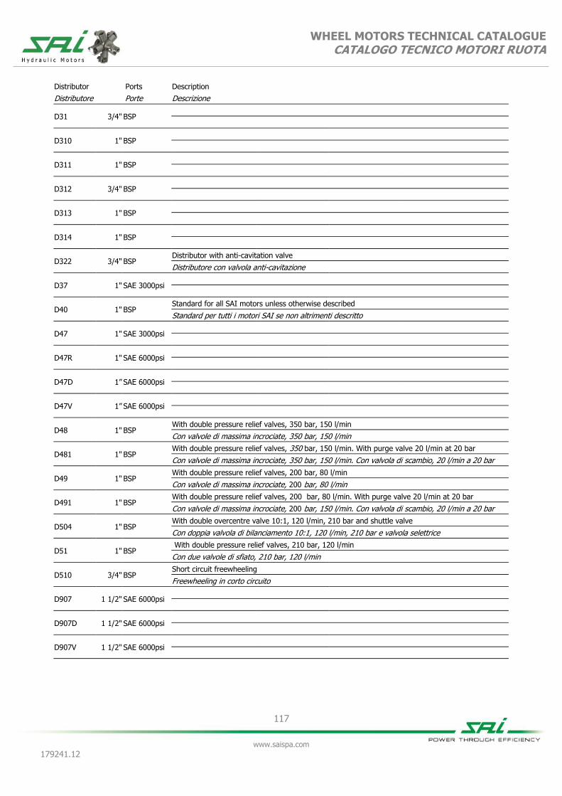
117
www.saispa.com
179241.12
WHEEL MOTORS TECHNICAL CATALOGUE CATALOGO TECNICO MOTORI RUOTA
Distributor Ports Description
Distributore Porte Descrizione
D31 3/4" BSP
D310 1" BSP
D311 1" BSP
D312 3/4" BSP
D313 1" BSP
D314 1" BSP
D322 3/4" BSP Distributor with anti-cavitation valve
Distributore con valvola anti-cavitazione
D37 1" SAE 3000psi
D40 1" BSP Standard for all SAI motors unless otherwise described
Standard per tutti i motori SAI se non altrimenti descritto
D47 1" SAE 3000psi
D47R 1" SAE 6000psi
D47D 1” SAE 6000psi
D47V 1” SAE 6000psi
D48 1" BSP With double pressure relief valves, 350 bar, 150 l/min
Con valvole di massima incrociate, 350 bar, 150 l/min
D481 1" BSP With double pressure relief valves, 350 bar, 150 l/min. With purge valve 20 l/min at 20 bar
Con valvole di massima incrociate, 350 bar, 150 l/min. Con valvola di scambio, 20 l/min a 20 bar
D49 1" BSP With double pressure relief valves, 200 bar, 80 l/min
Con valvole di massima incrociate, 200 bar, 80 l/min
D491 1" BSP With double pressure relief valves, 200 bar, 80 l/min. With purge valve 20 l/min at 20 bar
Con valvole di massima incrociate, 200 bar, 150 l/min. Con valvola di scambio, 20 l/min a 20 bar
D504 1" BSP With double overcentre valve 10:1, 120 l/min, 210 bar and shuttle valve
Con doppia valvola di bilanciamento 10:1, 120 l/min, 210 bar e valvola selettrice
D51 1" BSP With double pressure relief valves, 210 bar, 120 l/min
Con due valvole di sfiato, 210 bar, 120 l/min
D510 3/4" BSP Short circuit freewheeling
Freewheeling in corto circuito
D907 1 1/2" SAE 6000psi
D907D 1 1/2" SAE 6000psi
D907V 1 1/2" SAE 6000psi
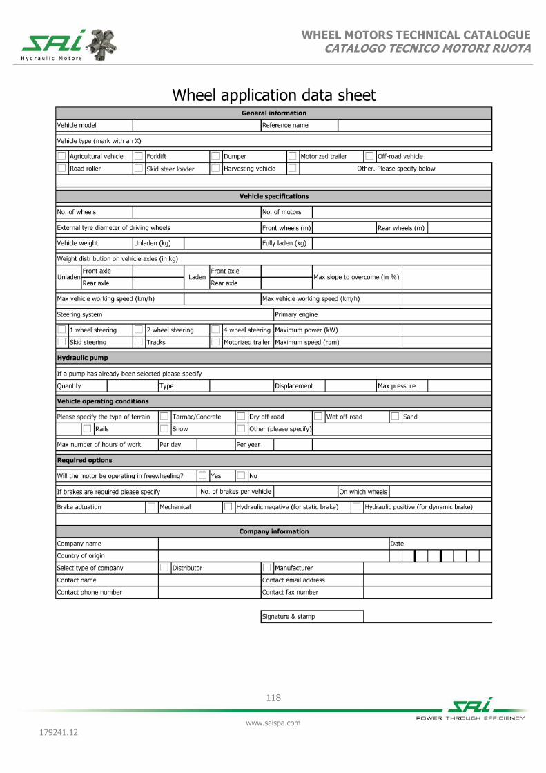
118
www.saispa.com
179241.12
WHEEL MOTORS TECHNICAL CATALOGUE CATALOGO TECNICO MOTORI RUOTA

119
www.saispa.com
179241.12
WHEEL MOTORS TECHNICAL CATALOGUE CATALOGO TECNICO MOTORI RUOTA


Related Documents