WHEEL LOADERS FOR HQ180 USER’S MANUAL

Welcome message from author
This document is posted to help you gain knowledge. Please leave a comment to let me know what you think about it! Share it to your friends and learn new things together.
Transcript

WHEEL LOADERS FOR HQ180
USER’S MANUAL
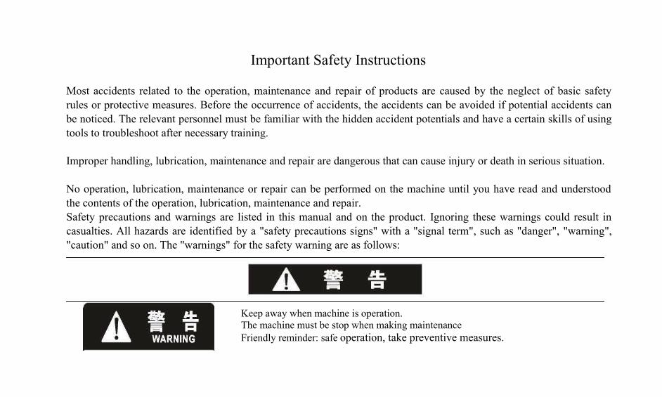
Keep away when machine is operation.The machine must be stop when making maintenanceFriendly reminder: safe operation, take preventive measures.
Important Safety Instructions
Most accidents related to the operation, maintenance and repair of products are caused by the neglect of basic safetyrules or protective measures. Before the occurrence of accidents, the accidents can be avoided if potential accidents canbe noticed. The relevant personnel must be familiar with the hidden accident potentials and have a certain skills of usingtools to troubleshoot after necessary training.
Improper handling, lubrication, maintenance and repair are dangerous that can cause injury or death in serious situation.
No operation, lubrication, maintenance or repair can be performed on the machine until you have read and understoodthe contents of the operation, lubrication, maintenance and repair.Safety precautions and warnings are listed in this manual and on the product. Ignoring these warnings could result incasualties. All hazards are identified by a "safety precautions signs" with a "signal term", such as "danger", "warning","caution" and so on. The "warnings" for the safety warning are as follows:
In the forward back commutation, should first step the brake pedal, after waiting for the vehicleto a complete stop, after walking hydraulic unloading, and the reversing again. Otherwise willreduce the service life of the vehicle, cause serious accidents.
Not read and understand the use of maintenance manual instructions and warnings,manipulation of the loader or work on this loader is not allowed. Violation or regardless of thewarning, could lead to injuries. Strictly abide by the operation procedure is the responsibility ofthe driver.
we can not predict every dangerous working environment, so the warnings in this manual and on the product can not beexhaustive. If you are using a tool, program, operation method or operating technique that is not specificallyrecommended by us., you should pay attention to the safety of your own or others. You should ensure that the operation,lubrication, maintenance and repair procedures you choose will not damage the machine or make it unsafe.The instructions, figures and illustrations in this manual are prepared on the basis of the most up-to-date informationavailable at that time. The details of this machine are subject to change due to continuous improvement in design thatmay not be reflected in this manual. For the most up-to-date information on the machine or for questions concerning thematerial covered in this manual, please contact us., or its dealers.This manual covers the loader and its equipment only. For information regarding maintenance and repair of the engine,please refer to the Users' Manul of the engine.
Preface......................................................1Name of each part of the machine...........3Machine and component type................. 4Safety Precautions...................................5Do Not Operate....................................... 6ROPS.......................................................6Safety belt................................................6High pressure accumulator......................7Start a power supply................................8Pressurization system..............................8Work tools in replacement...................... 9No loitering............................................. 9Device startup........................................10Compressed air and water..................... 12Hydraulic oil penetration.......................12Oil leakage of hydraulic joint................13Inhalation of hydraulic oil.....................13Treatment of waste................................13General precautions for safety...............14Application and main technical.............31Operation Manual..................................37Loader operation........................................... 39
Table of ContentsOperating mechanism....................................45Machinery operation......................................56Discharge operation.......................................57Park of machine.............................................58Storage of machine........................................59Transport of machine.....................................61Drag of machine.............................................61Maintenance Manual......................................64Running-in of new vehicle.............................68Regular maintenance......................................70Technical specification for lubricating oil......77Technical specification for oil........................78Important maintenance procedures….............80Diesel Engine System.....................................81Transmission system.......................................87Hydraulic system….........................................91Braking System...............................................95Electrical System…........................................96Air Conditioning System..............................100Other maintenance........................................101Failure and exclusion....................................102

1
1PrefaceThis manual contains a number of important
instructions for operating, lubricating, maintaining,inspecting and commissioning the machine and is apermanent and important part of the machine.
This manual should be stored in a safe and clean place foreasy reading. The manual should be ensured in goodcondition and it should not be removed from the machinewhen it is resold or rented.
Please read this manual carefully so that the machine can beoperated and maintained correctly to avoid possible personalinjury or machine damage. The operator should be able tocorrectly operate the machine and ensure safety.
Please do not use the machine at will except for the purposesdescribed in the manual. If you want to modify or add otherspecial equipment in case of special needs, please contactyour sales personnel for confirmation; otherwise, all resultscaused by unauthorized change should be borne by yourself.
For users who operate and maintain the machine inaccordance with the instructions given in this manual, ., willprovide a full“three guarantees”
according to its policies. But if the machine is misused orintentionally performed operations other than those specifiedby the manufacturer, the “three guarantees” shall be voidand field maintenance may also be denied. Only personswho have been trained or have had some operationalexperience are allowed to operate the machine, and onlyprofessionals are allowed to inspect and maintain the machine.
Pease correctly record the product model, product serialnumber, engine serial number and main part number. Ifthe machine is stolen, it is necessary to report and trace tothe local judiciary by these numbers. These numbers arealso required by your dealer when you need to orderparts or want to know the condition of your machine. Ifthis manual is stored in the machine, please record thecorrect number in a safe place outside themachine.
Safety
The precautions on basic safety are listed in safetyprecautions. In addition, the machine location of the warningsymbols and signs used on the machine is alsoindicated.Please read and understand the basic precautionslisted in the safety precautions before operating, lubricating,maintaining or repairing this machine.
2
1Operation
This section contains information on instruments, machinecontrol device, working device joystick, transport and drag.It's used for reference and review for new drivers andexperienced drivers that should be placed on your side forconstant reading and learning.
The driver is guided by a graphical description of the correctoperation procedures for checking, starting, operating andstopping the machine.
The operation techniques described in this manual are basicskills. As operators become more knowledgeable about themachine and its performance, their operational skills andtechniques will be improved.
Maintenance
The section of maintenance is the guidance contents for theprotection of the machine. The stepwise illustration isclassified according to the maintenance cycle. Maintenanceitems without a specific cycle are listed under "Other". Itemsin the "Regular maintenance" shall reference the followingdetailed description.
Maintenance cycle
A chronograph is used to determine the maintenance cycle. Ifa calendar (days, weeks, months) is more convenient thatshows approximate cycle as that of chronograph, a calendarcan be used to replace the chronograph. The recommendedmaintenance work should be carried out at the first expirationdate of the above two methods.
In extremely severe, dusty or humid working conditions,there is a need for more frequent lubrication maintenancethan specified in "Regular maintenance". During maintenance,the maintenance items listed in the original requirementsshould be repeated. For example, during a 500-hourmaintenance project, the maintenance items listed in 250working hours, 50 working hours, every 10 hours or everyday should be performed simultaneously.
All information, diagrams, and specifications of thismanual are current as of the date of publication. TheCompany reserves the right to make changes withoutnotice.
3
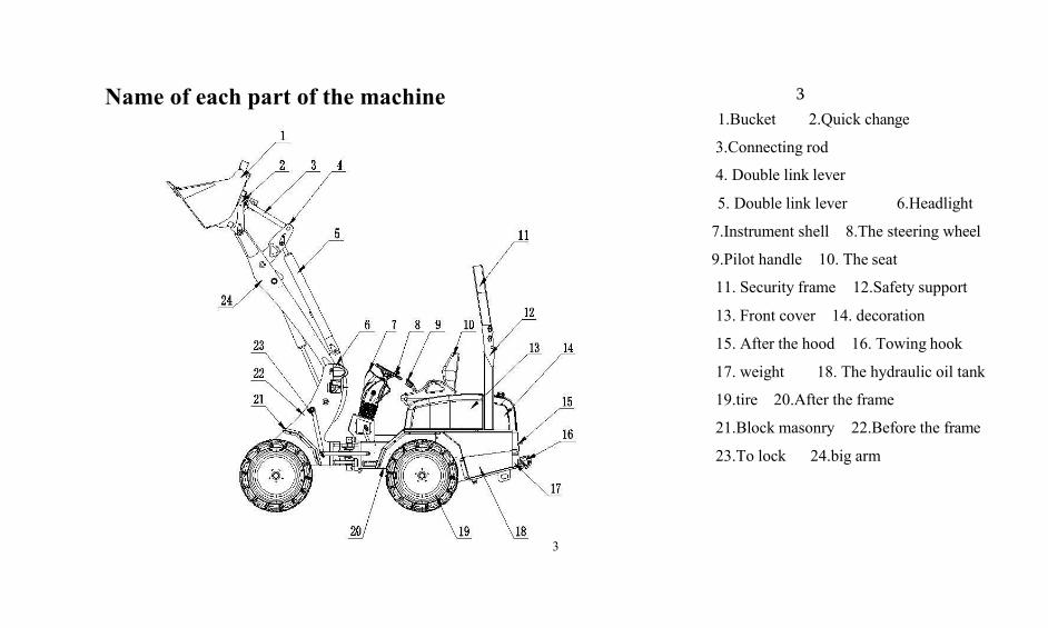
Name of each part of the machine 31.Bucket 2.Quick change
3.Connecting rod
4. Double link lever
5. Double link lever 6.Headlight
7.Instrument shell 8.The steering wheel
9.Pilot handle 10. The seat
11. Security frame 12.Safety support
13. Front cover 14. decoration
15. After the hood 16. Towing hook
17. weight 18. The hydraulic oil tank
19.tire 20.After the frame
21.Block masonry 22.Before the frame
23.To lock 24.big arm
4
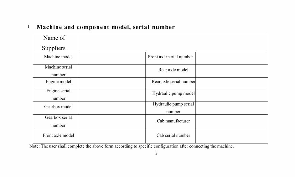
1 Machine and component model, serial number
Name of
SuppliersMachine model Front axle serial number
Machine serial
numberRear axle model
Engine model Rear axle serial number
Engine serial
numberHydraulic pump model
Gearbox model Hydraulic pump serial
numberGearbox serial
numberCab manufacturer
Front axle model Cab serial number
Note: The user shall complete the above form according to specific configuration after connecting the machine.
5
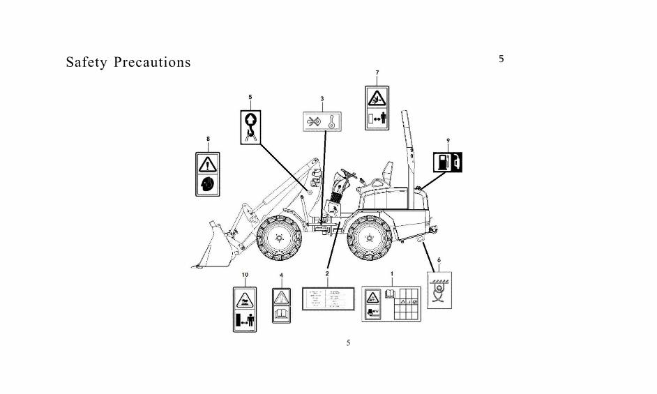
Safety Precautions 5
6
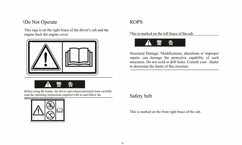
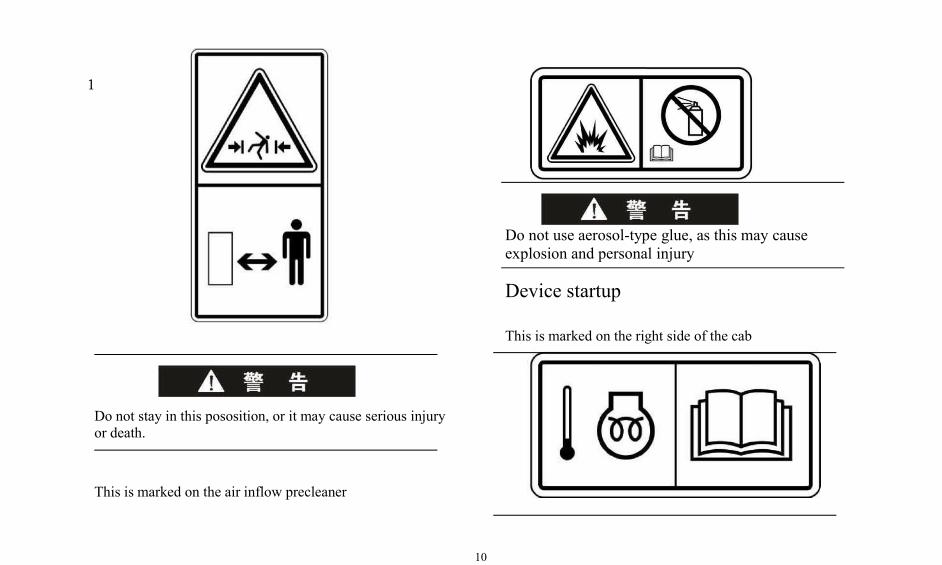
1Do Not OperateThis sign is on the right brace of the driver's cab and theengine back the engine cover
Before using the loader, the driver and related personnel must carefullyread the operating instructions supplied with us and follow theinstructions given in the manual.
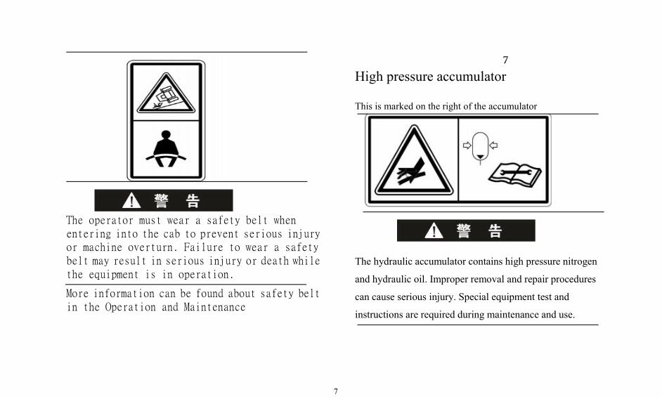
ROPS
This is marked on the left brace of the cab
Structural Damage: Modifications, alterations or improperrepairs can damage the protective capability of suchstructures. Do not weld or drill holes. Consult your . dealerto determine the limits of this structure.
Safety belt
This is marked on the front right brace of the cab.
7
7
High pressure accumulator
This is marked on the right of the accumulator
The operator must wear a safety belt whenentering into the cab to prevent serious injuryor machine overturn. Failure to wear a safetybelt may result in serious injury or death whilethe equipment is in operation.
More information can be found about safety beltin the Operation and Maintenance
The hydraulic accumulator contains high pressure nitrogen
and hydraulic oil. Improper removal and repair procedures
can cause serious injury. Special equipment test and
instructions are required during maintenance and use.
8
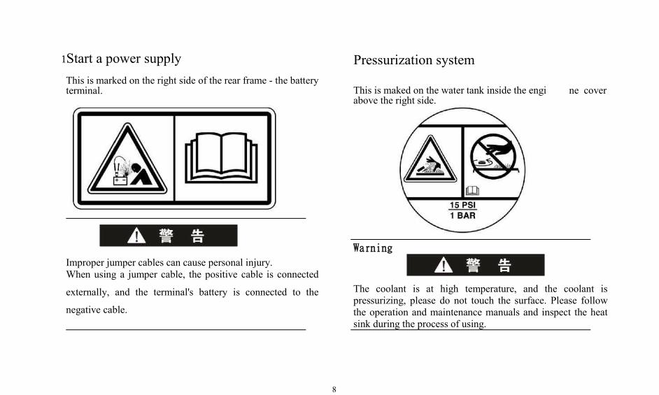
1Start a power supplyThis is marked on the right side of the rear frame - the batteryterminal.
Pressurization system
ne cover
Improper jumper cables can cause personal injury.When using a jumper cable, the positive cable is connected
externally, and the terminal's battery is connected to the
negative cable.
Warning
The coolant is at high temperature, and the coolant ispressurizing, please do not touch the surface. Please followthe operation and maintenance manuals and inspect the heatsink during the process of using.
This is maked on the water tank inside the engiabove the right side.
9
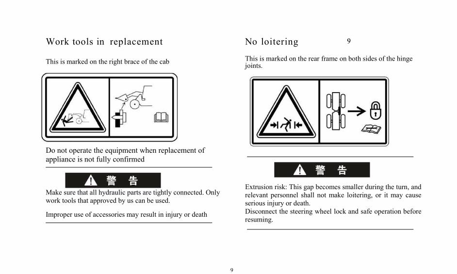
Work tools in replacement
This is marked on the right brace of the cab
Do not operate the equipment when replacement ofappliance is not fully confirmed
Make sure that all hydraulic parts are tightly connected. Onlywork tools that approved by us can be used.
Improper use of accessories may result in injury or death
No loitering 9
This is marked on the rear frame on both sides of the hingejoints.
Extrusion risk: This gap becomes smaller during the turn, andrelevant personnel shall not make loitering, or it may causeserious injury or death.Disconnect the steering wheel lock and safe operation beforeresuming.
10
1
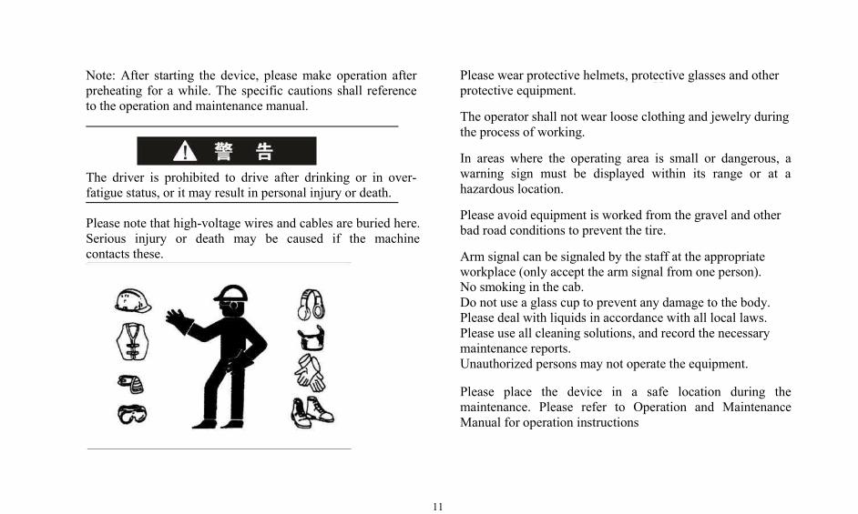
Do not use aerosol-type glue, as this may causeexplosion and personal injury
Device startup
This is marked on the right side of the cab
Do not stay in this pososition, or it may cause serious injuryor death.
This is marked on the air inflow precleaner
11
11Note: After starting the device, please make operation afterpreheating for a while. The specific cautions shall referenceto the operation and maintenance manual.
The driver is prohibited to drive after drinking or in over-fatigue status, or it may result in personal injury or death.
Please note that high-voltage wires and cables are buried here.Serious injury or death may be caused if the machinecontacts these.
Please wear protective helmets, protective glasses and otherprotective equipment.
The operator shall not wear loose clothing and jewelry duringthe process of working.
In areas where the operating area is small or dangerous, awarning sign must be displayed within its range or at ahazardous location.
Please avoid equipment is worked from the gravel and otherbad road conditions to prevent the tire.
Arm signal can be signaled by the staff at the appropriateworkplace (only accept the arm signal from one person).No smoking in the cab.Do not use a glass cup to prevent any damage to the body.Please deal with liquids in accordance with all local laws.Please use all cleaning solutions, and record the necessarymaintenance reports.Unauthorized persons may not operate the equipment.
Please place the device in a safe location during themaintenance. Please refer to Operation and MaintenanceManual for operation instructions
12
1Compressed air and waterCompressed air and water may blow out debris or hot water;Debris or hot water may cause personal injury.
Protective clothing, protective shoes and goggles should beworn in order to prevent the injury of the body bycompressed air and water.
Maximum air pressure cleaning must be reduced to 205 kPa.
Hydraulic oil penetrationThe hydraulic system pressure of the equipment is 20Mpa.Long time high pressure may cause oil leakage in the tubing.Therefore, please hang all the gears to the neutral gear so thatthe hydraulic oil can return within the tubing when stoppingthe equipment.
All the high-pressure tubing of the equipment are importedequipment processing with good pressure-resistant propertiesand long service life.
Do not disassemble the hydraulic tubing at will. If there ispressure in the tubing, personal injury may occur during
disassembly. If you want to disassemble the tubing, pleaserelieve the tubing pressure according to the operatingprocedures of Service Manual.
Before disassembling the tubing, please use a cardboard toblock it for leakage checking. The high pressure of the leakedhydraulic oil can penetrate human tissue.
Hydraulic oil penetration can cause serious injury or evendeath.
If hydraulic oil is injected into your skin, you must be treatedimmediately.
13
13Oil leakage of hydraulic joint
When there is leakage of hydraulic joint, please pay attentionto ensure the hydraulic oil will not eject during thedisassembly. The high pressure of the leaked hydraulic oilcan penetrate human tissue. Please prepare the hydraulic oilcontainer before disassembling.
Precautions:Please prepare the hydraulic oil container beforedisassembling.Please prepare the appropriate tools before disassembling.Please dispose the discarded hydraulic oil according to alllocal regulations.
Inhalation of hydraulic oil
Exhaust system can only start or run the engine ingood air flow. If i t ' s operated in indoor, theengine's exhaust shall be connected to cargo thattowards the outside.
Treatment of waste
Inappropriate disposal of waste can be a threat to theenvironment. Potential harmful liquids should be disposed inaccordance with local regulations. Waste hydraulic oilshould be installed with a sealed container. It can not fall tothe ground to prevent water pollution.
14
1General precautions for safety
All fuel, most lubricants and mixed solution of some coolantsare combustible. Fuel leakage to hot surfaces or electricalcomponents may cause a fire.
Do not smoke when refueling or servicing the fuel system.Do not refuel or maintain near flames or spark areas. Theengine must be switched off before refueling, and it shall fillfuel out of doors.
Clean and tighten all electrode connections. Check whetherthere is loose or worn wire every day. Tighten loose wires,repair or replace worn wires before starting up.
Store fuel and lubricants in containers marked with theappropriate labels to prevent non-personnel use.
Place oil wiping cloth or other combustible material in aprotective container and in a safe place.
Do not conduct welding or flame cutting of pipes that containflammable liquids.
Do not operate the machine near open flame.
Make sure the battery is away from open flames or sparks.Do not smoke in places where the battery is charging.When using the normal machine of negative groundingsystem to start the machine, you must follow the correctprocedures for operation, or it may cause an explosion,resulting in personal injury.
Do not charge the frozen battery to avoid causing anexplosion.
15
High pressure oil
Compressed airCompressed air can cause personal injury. Whenusing compressed air to make air cleaning, pleasewear a mask, protective clothing and safety shoes.
WARNING: Avoid high-pressure oil burns. Whenservicing or replacing the tubing of the hydraulic system,please lower the load and relieve pressure and make
sure the oil has cooled down. Hy1d5raulic oil splashedunder pressure can cause serious damage to the skin.
Please be careful when disassembling hydraulic lines orfittings. When the oil is ejected, the released high-pressure oilmay cause hose loosening.
Please wear safety glasses and leather gloves to check forleaks. Please use a board or cardboard rather than bare handsto check for leaks.
Even if the vacuum-pressure liquid leakage may alsopenetrate the muscles, resulting in personal injury. If you gotthe sprayed high-pressure oil, you should immediatelycontact the doctor for treatment.
Safe disposal of liquid wasteInappropriate waste liquid handling will be hazardous to theenvironment and ecology. Please observe local regulationswhen handling the waste liquid.
Please hold the liquid spilled from the machine duringinspection, maintenance, testing, adjustment and repair in thecontainer.
16
1Prepare the appropriate container for the collection of liquidsbefore opening any liquid chamber or disassembling anycomponent that contains liquid.
Please use an appropriate container when the liquid isdischarged. Do not use food or drink containers, as it maycause misuse by others.
Precautions when using theaccumulator
Accumulator is a dangerous object that contains high-pressure nitrogen. So it is necessary for you to read thefollowing requirements and pay attention to the appropriateuse of accumulator.
The accumulator must be inspected before filling withnitrogen. Please do not refill gas if the accumulator is notinstalled with nameplate, the words on the nameplate are noteasy to identify for type, the stamp mark is incomplete or cannot be identified, there is any defect on the shell that can notguarantee the safe use.
Accumulator can only be filled with nitrogen, and it is strictlyprohibited filling oxygen, compressed air or other flammable
gases to avoid causing an explosion.
Nitrogen filling should be carried out slowly to preventbreakage of the capsule.
The accumulator valve should be mounted vertically thatmust be firmly fixed to the bracket. Please do not fix theaccumulator by welding.
Do not drill any holes in the accumulator, or carry any openflame or heat source near the accumulator.
Do not do any welding work on the accumulator.
Accumulator is a high-pressure container, and it should bereplaced and maintained by professionals.
The gas must be released before discarding the accumulator.
Asbestos
It is a threat to health if asbestos dust is inhaled into humanbody. This machine does not contain asbestos. However, it isrecommended that accessories and spare parts supplied by us.,be used. If you need to deal with materials
17
17containing asbestos fibers, please observe the followingguidelines:
Do not use compressed air when making cleaning. Water canbe used to sink the dust.A vacuum cleaner with high filtration efficiency can be used.Do not grind materials that contain asbestos dust.The machine should be operated in the upper air outlet ifpossible. Environmental regulations should be observedwhen handling asbestos.
Please take a bath after exposure to asbestos.Please use an effective protective mask if necessary.
Cooling liquid
The cooling liquid of engine is high during the operation ofengine, and the cooling liquid cools the engine. All oilradiators contain a hot cooling liquid.
Any contact with the engine and the radiator can cause severeburns.
Please stop the engine when checking the cooling liquid level.
Check the cooling liquid inside the engine, and add thecooling liquid according to the engine manual.
Adjustment cooling system contains fluoride that will causeharm to humans. It's not allowed to contact with skin, eyesand mouth.
Storage battery
Storage battery may produce flammable fumes or gases thatmay cause an explosion. Please keep it away from sparks andopen flames.
Do not place metal on the battery, or it may lead to batteryexplosion that caused by short-circuit.
The electrolyte in the battery is an acidic substance that cancause serious injury if it contacts the skin and eyes.
Please wear protective goggles and protective clothing whenmaintaining thee battery. Once the electrolyte contacts theskin and eyes, please immediately wash the skin with plentyof water, use soda or lime to neutralize acidity, use water toflush for 10-15 minutes, and immediately accept thetreatment.
18
1Ether
Do not start the machine with ether. Any attempt to start theengine with either may result in serious damage to the engineor personal injury or death.
Pipes, rigid tubes and hoses
Do not bend or hammer high pressure pipes. Do not installabnormally bent or damaged pipes or hoses on the machine.
Please timely repair any loose or damaged fuel andlubricating lines, hard pipes and hoses of the hydraulicsystem. Leakage may result in fire. Please contact your dealerfor repairs or replacements.
Please make replacement if there are any of the followingproblems.Joint damage or leakage.Outer wear or tear of joint, or bareness of reinforced steelwireThe hose is partially raised.The hose has a pronounced twist or bias.Hose reinforcement steel wire is embedded in the outer layer.Dislocation of the end connector.
Ensure that all clamps, guard board, and heat shields areproperly installed to avoid overheating that caused byvibration or friction of other parts.
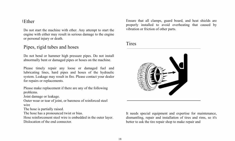
Tires
It needs special equipment and expertise for maintenance,dismantling, repair and installation of tires and rims, so it'sbetter to ask the tire repair shop to make repair and
19
maintenance. Inflatable tires may be exploded due to the gasheating and combustion of internal tires. Generally it iscaused by the heating or welding of rims, any external flames,or gas expansion or combustion that caused by too frequentbraking.
Tire explosions is much more powerful than deflating.Explosions may cause tires, rims and transmission parts to be500m away from the machine. Explosive force and debrismay cause casualties and property damage.
Keep away from heated tires. Keep a minimum distance. (Atleast 15 meters)
It is recommended to use dry nitrogen to fill the tires. If thereis air inside the tire, it is suggested to use nitrogen for airpressure adjustment. Nitrogen can be mixed withatmospheric gases. Nitrogen-filled tires can reduce thepossibility of an explosion, because nitrogen is non-flammable. Likewise, nitrogen can help prevent oxidation,rubber aging and rim component corrosion.
Please avoid excessive inflation. The correct inflatableequipment and equipment use are required for training.Incorrect or improper use of the equipment can result in tire
failure or rim damage. 19
Improper tire rim maintenance may cause tire blasting, whichcan cause serious injury or death. Only trained personnel whouse the correct tools and the correct procedures can makemaintenance of the tires and rims.
Protection Device of Cab
The ROPS and FOPS of the our. products are located insidethe cab frame structure.
If it is damaged by falling objects or tipping, its strength willbe reduced that can't meet normal functions. In case of this,please contact the dealer designated by us. to consult therepair method.
Even if the ROPS is installed, only when the operator isfastened with the safety belt can he get effective protection.Always fasten the safety belt during the machine operation.
It is strictly forbidden to drill or weld inside or outside thecab to avoid damage to the built-in RPS.
20
1When you want to modify the cab due to some reason, pleaseconsult us. to avoid possible damage to ROPS.
Interior space of the cab
This . machine is fitted with a cab that meets industrystandards: "SAE J154" and ISO 3411, which specifies the cabspace requirements.
No modification of the cab shall encroach on the specifiedspace. The addition of radios, fire extinguishers and otherequipment shall be installed in such a manner that theprescribed space can be maintained. Any objects carried intothe cab shall not occupy the specified space. Lunch boxes orother bulk items must be fixed. In the case of driving inuneven surfaces or in the case of machine tipping, these itemsshall not cause the danger of impact.
Locking device of bogie
Please connect the locking device of bogie when lifting andtransporting the machine. The bogie locking device must also
be connected during maintenance work near the hinge joint.
Please separate the locking devices of the bogie beforeoperating the machine.
Precautions of accessories
The installation and commissioning must be carried out byqualified personnel. The operator should be trained that makeoperation and maintenance in strict accordance with themanual of accessories.
When installing and using spare accessories, please read theinstructions, manuals on accessories and the informationabout the accessories in the manual.
Incorrect installation of accessories or options will not onlyresult in safety problems, and will also adversely affect theoperation of the machine and the service life of theequipment.
Do not climb up or climb down the machine while carryingtools or other items. Please use a rope to hang the requiredtools onto the platform.
21
Do not use accessories not approved by us. The use ofunauthorized accessories may result in safety problems thatare not conducive to the normal operation of the machine andaffect the service life.
Any modification of the accessories is strictly prohibitedwithout permission, or it's at your own risk.
we. shall not be liable for damage accidents or machinedamage that caused by the use of unapprovedaccessories.
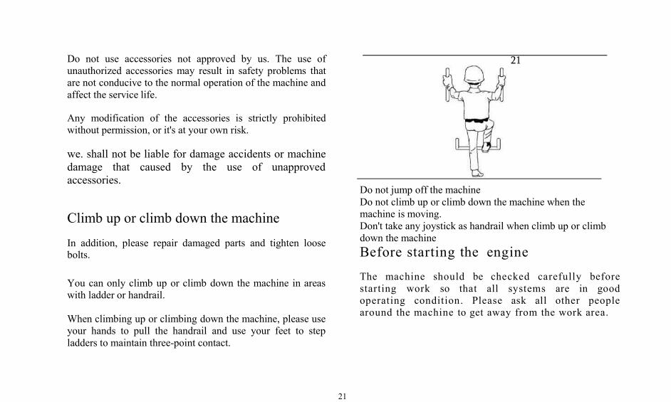
Climb up or climb down the machine
In addition, please repair damaged parts and tighten loosebolts.
You can only climb up or climb down the machine in areaswith ladder or handrail.
When climbing up or climbing down the machine, please useyour hands to pull the handrail and use your feet to stepladders to maintain three-point contact.
21
Do not jump off the machineDo not climb up or climb down the machine when themachine is moving.Don't take any joystick as handrail when climb up or climbdown the machineBefore starting the engineThe machine should be checked carefully beforestarting work so that all systems are in goodoperating condition. Please ask all other peoplearound the machine to get away from the work area.
22
1Know your machineYou should be able to operate all the equipment on themachine.
You should understand the purpose of all control systems,meters and lights.
You should know the rated load, speed range, braking andsteering characteristics, maximum size and radius of turningcircle, and the height of the working place.
Please remember that rain, snow, ice, gravel and soft surfacescan change the machine's ability to work.
Study the safety signs on the machine (DANGER,WARNING and CAUTION) and other signs.
Know your work area
Please know about the area you are about to work assoon as possible.
Please check: the location of the slope, the ditch, the fallingobjects or suspension, soil conditions (soft or hard), water
and marsh areas, rocks and stumps, buried foundations,pillars or wall boundaries, boundaries that bury rubbish orfilling boundaries, holes, obstructions, mud or ice, volume oftraffic, dust, smoke, fog, buried or suspended electric wire,gas, telephone, water, sewage or other public pipelines.
Please mark the public facilities, close or relocate thefacilities before commencing work.
Please remove dirt and fine sand from the shoes beforeboarding the machine.
Check whether the structural parts or the covering parts aredamaged or deformed by impact.
Check whether all safety guards, such as doors, guards,covers, etc. are installed correctly to avoid injury of movingparts. Please make timely repair if they are damaged.
Check the hydraulic system for oil leakage, and checkwhether there is abrasion of the hose and steel pipe.
Check whether all fasteners are loose or missing.
Check the electric harness for wear and abrasion, whether theinsurance is intact, and whether the connector is securely
23
23fastened.
Check whether the oil level of engine and fuel system isnormal, and timely drain the water or sediment in the oil-water separator.
Replace any damaged or missing parts and lubricate thelubrication points as specified in the regular maintenancesheet.
Remove any loose material from the cab, because loosematerial may affect the handling and cause an accident.
Ensure that all window cleaning and wipers on the machinecab are working properly.
Adjust the seat to the appropriate position. Please checkwhether the seat safety belt and safety belt fixation device aredamaged. Safety belt must be replaced after using for threeyears.
For machine, adjust the seat so that the driver can step on thepedal when his back against the seat.
Ensure that the machine lighting system is working properly,and the workplace has sufficient lighting.
Check that the locking device of the machine bogie is firmlylocked in the "released" position.
Starting of the engineIf the label of "Do Not Operate" is attached to the joystick, itis absolutely not allowed to start the engine.
Make sure that the operator is on the seat and that the Safetybelt is securely fastened before starting the engine.
Before starting the machine, please make sure that thehydraulic pilot handle is in the disengaged position, ensurethat the other control handles are in the neutral position, andapply the parking brake.
Please use horn for warning when starting the engine. Pleaseobserve pressure gauges, meters and warning lights afterstarting the engine to make sure that they are working welland that the readings are within the operating range.
Please confirm the safety of the surroundings, identify thedirection you want to travel and the relationship between thepedal and joystick before driving the machine.
Observe and carefully listen whether there is any failure
24
1within the machine. In case of failure or abnormal situation,please immediately stop the machine to solve the problemsbefore the further operation.
Smoke discharging from the engine can causei l lness or death.
If it is necessary to start the engine in a closed or poorlyventilated area, please open the doors and windows to ensureadequate ventilation to prevent gas poisoning. If openingdoors and windows still do not provide sufficient ventilation,installment of a fan is required.
Before operating the machineThere shall be no persons on and around the machine. Pleasefasten the safety belt.
Ensure that all windows, lampshades and reversing mirror areclean. Please fix the opening or closing doors and windows.
Adjust the position of the rearview mirror so that there is thebest view from the operator's seat.
Clear all obstructions on the travel path of the machine.Beware of high voltage power lines, ditches and other
hazardous materials.
Ensure that the speaker, reversing alarm and other alarmdevices of the machine can work normally.
Machine operationBefore driving on public roads, please check whether themachine complies with laws and regulations of the local road.Please obtain the road driving permit from relevantadministrative departments.
Please observe local road traffic regulations when travelingon roads.
Please avoid working under the cliff edge, dams or mounds,or roads without enough supporting capacity or areas withoverhanging objects to prevent collapse.
Please keep the correct posture on the seat. If you makemachine operation when you are not properly seated on theseat or leave the seat, an accident may be caused.
No riding is permitted unless additional seats, safety belt andROPS are available,
25
25Before starting work, please slowly drive the machine toopen space, check whether all joysticks and the protectivedevice are working properly.
During the operation, if you find any items on the machineneeds repair (noise, vibration, odor, incorrect instrumentdisplay, leaks, oil spills, etc.) you should make reports of theitems that need repairs immediately.
Dust, heavy rain, fog, etc. will blur the line of sight. Pleasekeep the windows, mirrors and lamps clean and in goodcondition. When the visibility drops, please reduce the speedand use the appropriate light.
If you drive or operate the machine in an area without goodview or a crowded area, please use a signaler to keep thesignaler in sight and to coordinate the hand signal.
Please adjust the height of the working device of lower hingepin of big arm from the ground of 450-500mm for walking.
Avoid hitting the barriers on the top of the machine whileoperating the machine.
Do not lift the bucket and excavate at the top of the machine.If the machine may be on a site where there is a danger of
touching the cable, please consult with the electric powercompany before starting work to check the feasibility of theaction as determined by the applicable regulations.
Avoid anything that could cause the machine to roll over.When working on hills, embankments or slopes, the machinemay tip over.
The machine may also tip over when going through a ditch,mound or other accidental obstruction.
The machine shall go straight up and down on the slope. Itneither should turn on the slope nor breadthwise walk on theslope to prevent tipping.
Please remove the material immediately and drive themachine down the mountain slope if the machine starts toslide down on the slope.
When the machine goes downhill, it is forbidden to turn offthe engine or to slide slope in neutral gear, otherwise it willcause serious accident or casualty.
In order to prevent the machine from overturning or damagesto the working device due to overload, the machine load mustbe kept within the specified maximum load. When themachine is used, it must not exceed its specified capacity.
26
1Do not use a bucket or big arm for hoisting. The machine canonly assume the specified work, and other operations beyondthe scope of use will damage the machine. See the Purposeand Main Technical Performance and Parameters forspecified operations.
It is forbidden to hang the hoisting rope directly on thebucket teeth to lift the weight.
It is forbidden use the loader to lift personnel. It is also notallowed to take the loader as the operator's work platform.No one is allowed to ride on the bucket.
Please be very careful when working near high voltage lines.
Park of machine
Please choose a flat ground where there is no risk of fallingrocks or landslides when parking the machine. If the terrain islow, it shouldn't have the danger of flooding. Please choose aflat ground where there is no risk of falling rocks orlandslides when parking the machine. If the terrain is low, itshouldn't have the danger of flooding.
It can cause serious accident or death when contacting with
the cable. Please use any part of the machine to close toapproach the wire. The top of the machine should be checkedto see the exact distance among the wires, machine and theground. If possible, it is best to disconnect the power supplyand ask the signaler for guidance.
If the parts of the machine contact with the high voltagepower supply: Warn other people not to touch the machineand stay away from the machine.
If you can separate the contacts, please change the operationthat causes contact with the high voltage power supply andleave the machine out of the hazardous area.
If you can not cut off the contact, please stay in the machineuntil the power sector cut off the wire and inform you that thepower supply has been broken up.
If you are forced to leave the machine in case that highvoltage power supply cause an extreme situation like firehazard, please do not go out of the machine step by step butto close your feet to jump off the machine and power to asafe distance.
When towing the machine, please ensure that the trailer hassufficient strength. The trailer can only be connected to the

27
drawbar and hinge, and it is prohibited any personnel acrosson the wire rope or the like between the trailer and the towedcar.
Please make sure there is no one between the machine andthe trailer before towing the machine. The lead frame ortraction pin of the traction equipment should be aligned withthe drawbar on the machine.
If it is necessary to park the machine on a slope, please placethe stopper under the wheel to prevent the machine frommoving.
Do not park the machine on the construction road. If youhave to park in these places, you must use banners during theday and signal lights or flashlight during the night to remindother people or vehicles in accordance with the localregulations.
When the machine stops, please lower the work unit to thefloor.
Please place the hydraulic pilot handle in the neutral positionand the other controlling handles in the neutral position.
Implement parking brake. 27
Keep the engine in idle running for 5 minutes to allow it tocool down gradually. Stop the engine and remove the key.
Switch the battery negative to the OFF position to avoiddischarging due to battery short circuit, current outflow ofbatteries through some elements or any damage of batteries.
When you leave the machine, please use the key to lock allthe equipment. Take the key off and carry it with you.
Lower the working device when the engineis turned off
Before lowering the work unit, make sure that no one isaround the machine.
Note: For a machine with an electro-hydraulic joystick, theengine start switch must be in the ON position in order tolower the working device. After lowering the working device,please turn the engine start switch to the OFF position.
Move all the joysticks to the "DOWN" position to lower
28
1the work device to the floor or to the trailer. When thejoystick is released, they will return to the "Maintain"position.
Storage of accessories
Please securely keep accessories and tools to prevent seriousinjury or death due to their dumping. Keep kids andspectators away from the storage area
Safely maintain the machinePreparation of work area
Choose a clean and flat area with sufficient space, adequatelight and good ventilation for repair work. Clean the workfloor, wipe off fuel oil, oil and water, and pave sand or otherabsorbent material on a slippery floor. Keep the work areaclean and dry.
Properly support the mechanism
During the work, accessories or instruments are generally at aposition that barely above the ground. If you must work on or
under the lifted mechanism or accessories, please securelysupport the machine or accessories.
The mechanism must be supported on a solid support.
Do not work with the mechanism only with a single support.
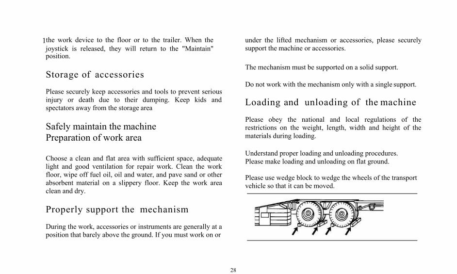
Loading and unloading of the machine
Please obey the national and local regulations of therestrictions on the weight, length, width and height of thematerials during loading.
Understand proper loading and unloading procedures.Please make loading and unloading on flat ground.
Please use wedge block to wedge the wheels of the transportvehicle so that it can be moved.
29
Use a ramp with suitable size, enough strength, low-angleand appropriate height. Ensure that the ramp is non-slip andfree of mud.
Keep the spectators away.
Fix all working devices and place them in the transportposition.
Lifting of machine
Check the machine nameplate to understand the weight of themachine before lifting.Fix the front and rear frames with the frame fixing lever sothat the machine can not rotate.
Use appropriate ropes and spreaders for lifting, and maintainthe machine level during lifting.
The lifting appliance should be large enough to preventdamage to the machine during the lifting process.
Welding operation 29
The person conducting the welding operation must hold aprofessional certificate that makes welding in a area withsuitable equipment. The operator must observe the followingprecautions during welding:
1. In order to avoid damage to electrical components, whenmaking welding of the machine, please park the machine on aflat ground, implement parking brake, disconnect the powerswitch and plug connector of instrumentation system,otherwise it will burn the components of instrument panel.2. Remove the oil paints where needs welding to preventthe generation of harmful gases.
3. Do not adsorb the dust of oil paint.
4. It is prohibited to make welding on the pipes near rubberhoses, wires or with pressure.
5. Please wear protective goggles and protective clothingwhen making welding.
6. Please keep good ventilation of the welding workplace.
30
17. Clean all flammable materials, and work site must beequipped with fire extinguishers.
Regular machine cleaning
In order to avoid possible injury or damage to the machine,the machine should be cleaned regularly to removeaccumulated butter, oil or debris, and keep a clean engineroom, radiator, accumulator, hydraulic pipe, fuel tank, andcab.
Please wear non-slip shoes to prevent slipping on the wetsurface when making cleaning. Avoid being impacted byhigh-pressure water to avoid injury when using high-pressurewater to wash machine. Please avoid dirt or sludge splashinto the eyes.
It is prohibited to use a high-pressure water gun or otherwater-jet tool to flush items in the cab. The items in the cabcan only be scrubbed, otherwise it will cause electricalsystem failure
Disconnect the battery main switch after the machine isstopped, or it may cause the electrical system failure.
Noise and vibration
Noise
For the cab provided by us., the noise tested outside themachine according to the work cycle procedures specified inthe ISO-6395 standard is 11dB.
Vibration level
Note: The vibrations of the body produced by the machineare largely influenced by different factors, such as workingmethods, road conditions and driving speed.

31
Application and main technicalparametersApplication
The loader is a small wheeled engineering machinery thatmainly loads and unloads bulk materials. It is suitable forconstruction, municipal engineering, urban and rural gardens,lime kiln, battlefield, cement plants, stone factory,prefabricated plants and other construction sites for loadingand unloading, bulldozing, lifting and traction operations. Itis a high-efficient engineering machinery withmulti-purposes.
The loader is an ordinary engineering machinery that doesnot apply to flammable, explosive, high dust or toxic gasenvironment.
31
Working environment requirements
Altitude:<3000m
Ambient temperature: -15° C-40° C (without additionalauxiliary cold start device)
Fording depth: <630mmCaution: Precautions for handling, care and safety proceduresgiven in this manual apply only if the machine is used for itsintended purpose. If this machine is outside the scope of thismanual, we. will not assume any responsibility for safety.And the safety responsibilities in such operations shall beborne by the user.
In no case can people perform operations that prohibited bythis manual.
32
1
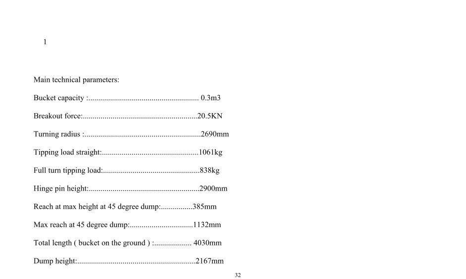
Main technical parameters:
Bucket capacity :........................................................ 0.3m3
Breakout force:..........................................................20.5KN
Turning radius :...........................................................2690mm
Tipping load straight:.................................................1061kg
Full turn tipping load:.................................................838kg
Hinge pin height:........................................................2900mm
Reach at max height at 45 degree dump:................385mm
Max reach at 45 degree dump:................................1132mm
Total length ( bucket on the ground ) :................... 4030mm
Dump height:............................................................2167mm
33
3537
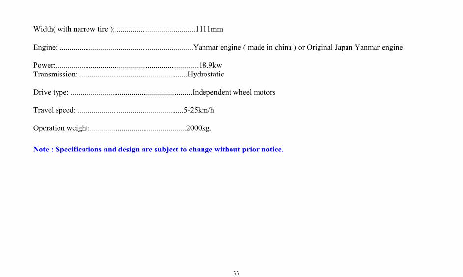
Width( with narrow tire ):.........................................1111mm
Engine: ....................................................................Yanmar engine ( made in china ) or Original Japan Yanmar engine
Power:.........................................................................18.9kwTransmission: .......................................................Hydrostatic
Drive type: ..............................................................Independent wheel motors
Travel speed: ......................................................5-25km/h
Operation weight:.................................................2000kg.
Note : Specifications and design are subject to change without prior notice.
34
3O8 p e r a t i o n M a n u a l
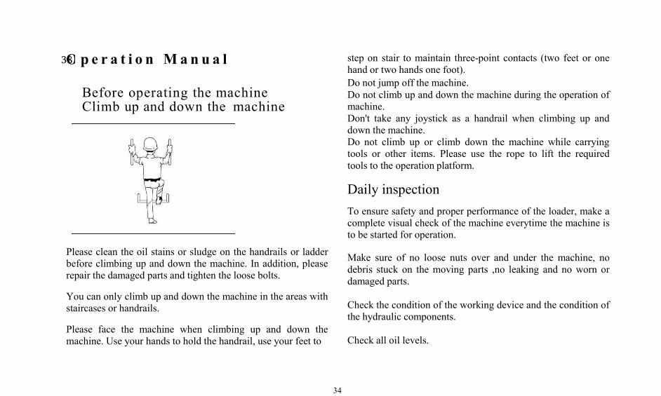
Before operating the machineClimb up and down the machine
step on stair to maintain three-point contacts (two feet or onehand or two hands one foot).Do not jump off the machine.Do not climb up and down the machine during the operation ofmachine.Don't take any joystick as a handrail when climbing up anddown the machine.Do not climb up or climb down the machine while carryingtools or other items. Please use the rope to lift the requiredtools to the operation platform.
Daily inspectionTo ensure safety and proper performance of the loader, make acomplete visual check of the machine everytime the machine isto be started for operation.
Please clean the oil stains or sludge on the handrails or ladderbefore climbing up and down the machine. In addition, pleaserepair the damaged parts and tighten the loose bolts.
You can only climb up and down the machine in the areas withstaircases or handrails.
Please face the machine when climbing up and down themachine. Use your hands to hold the handrail, use your feet to
Make sure of no loose nuts over and under the machine, nodebris stuck on the moving parts ,no leaking and no worn ordamaged parts.
Check the condition of the working device and the condition ofthe hydraulic components.
Check all oil levels.
35
Machine control and instrumentationStarting switch
Starting switch (also known as electric lock) is located on theright side of the cab, and it can be divided into four gears alongclockwise direction.
1. Auxiliary --- The gear that rotates along counterclockwiseafter inserting the starting switch key. The gear isautomatically reset (it will automatically turn back to OFFwhen it is released.) This gear is not currently used.
2. 0FF--When this gear, the engine shut down because the oilcircuit is cut off, and the machine's power control circuit is cutoff.
3.ON—The first gear that rotates along clockwise directionafter inserting the starting switch key. Electrical system of themachine work properly due to the recovery of power supplywhen in this gear.
4. START----The second gear that 3r9otates along clockwisedirection after inserting the starting switch key. In this gear, thestarting dynamo work so that starts the engine. Please thestarting switch key immediately after successfully starting theengine, this gear can not be maintained automatically. Afterreleasing, the starting switch key will automatically back to theroutine inspection that turns to the ON gear of starting switch.
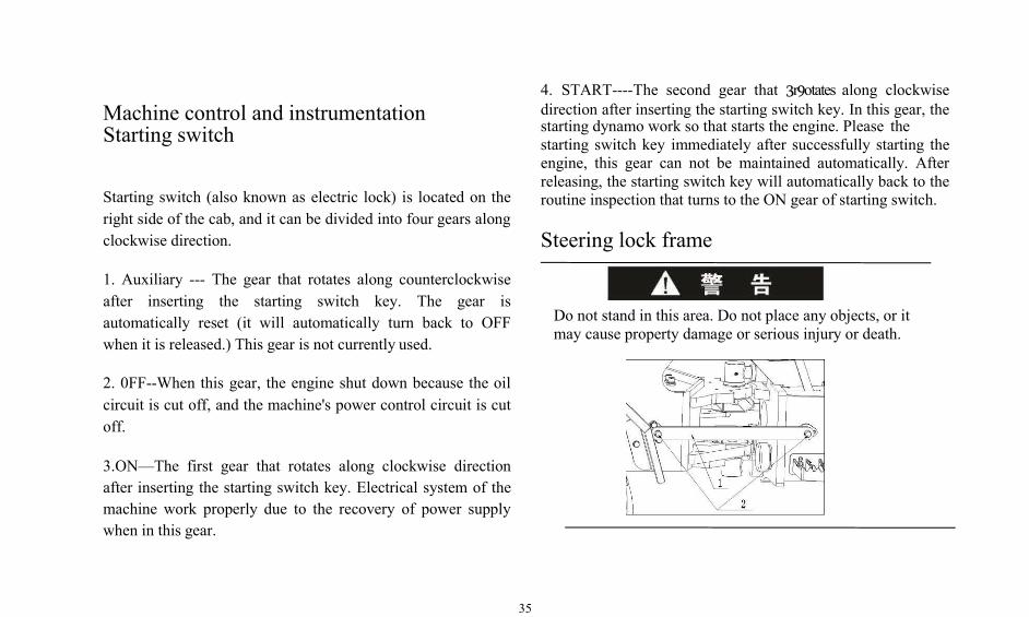
Steering lock frame
Do not stand in this area. Do not place any objects, or itmay cause property damage or serious injury or death.
36
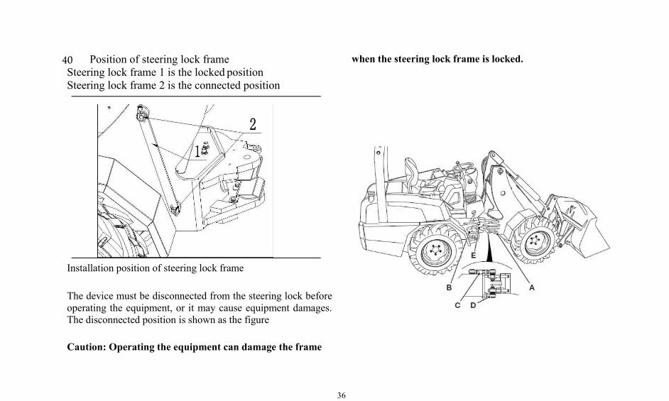
40 Position of steering lock frameSteering lock frame 1 is the locked positionSteering lock frame 2 is the connected position
Installation position of steering lock frame
The device must be disconnected from the steering lock beforeoperating the equipment, or it may cause equipment damages.The disconnected position is shown as the figure
Caution: Operating the equipment can damage the frame
when the steering lock frame is locked.
37
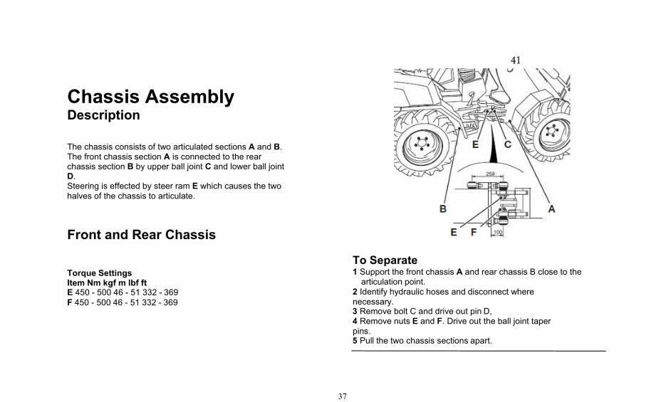
Chassis AssemblyDescription
The chassis consists of two articulated sections A and B.The front chassis section A is connected to the rearchassis section B by upper ball joint C and lower ball jointD.Steering is effected by steer ram E which causes the twohalves of the chassis to articulate.
Front and Rear Chassis
Torque SettingsItem Nm kgf m lbf ftE 450 - 500 46 - 51 332 - 369F 450 - 500 46 - 51 332 - 369
41
To Separate1 Support the front chassis A and rear chassis B close to thearticulation point.
2 Identify hydraulic hoses and disconnect wherenecessary.3 Remove bolt C and drive out pin D,4 Remove nuts E and F. Drive out the ball joint taperpins.5 Pull the two chassis sections apart.

38
Seat
The loader's seats provided by us are selected in accordancewith ISO7096 standard.The seat is an adjustable seat, so that the operator can step onthe accelerator and brake in a comfortable method.
Mechanical structure
Backrest - The backrest is freeto move forward or backward
Backwards of catch bar is to increase comfort ofoperator.
The rotary button 3 is used to adjust the angular positionof the armrest during operation.
After lifting the lever 5, the seat can beslid forward or backward to theproper position.
Adjustment of the backrest angle - pull the lever upand adjust the required angle of the backrest, releasethe lever to lock the backrest adjustment position.
Safety belt
39
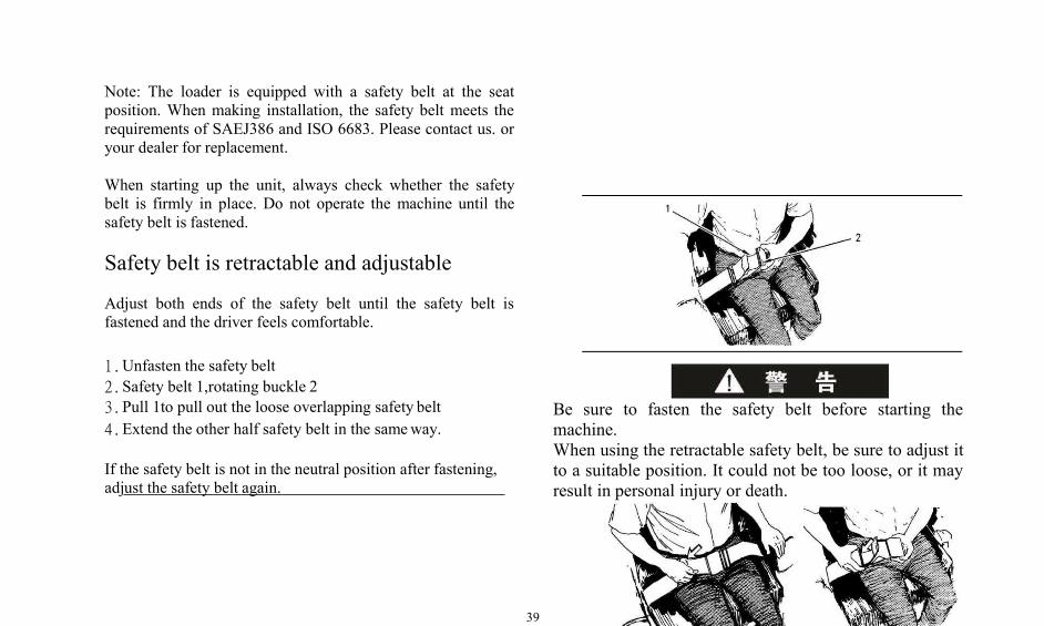
Note: The loader is equipped with a safety belt at the seatposition. When making installation, the safety belt meets therequirements of SAEJ386 and ISO 6683. Please contact us. oryour dealer for replacement.
When starting up the unit, always check whether the safetybelt is firmly in place. Do not operate the machine until thesafety belt is fastened.
Safety belt is retractable and adjustable
Adjust both ends of the safety belt until the safety belt isfastened and the driver feels comfortable.
1.Unfasten the safety belt2.Safety belt 1,rotating buckle 23.Pull 1to pull out the loose overlapping safety belt4.Extend the other half safety belt in the sameway.
If the safety belt is not in the neutral position after fastening,adjust the safety belt again.
Be sure to fasten the safety belt before starting themachine.When using the retractable safety belt, be sure to adjust itto a suitable position. It could not be too loose, or it mayresult in personal injury or death.
40
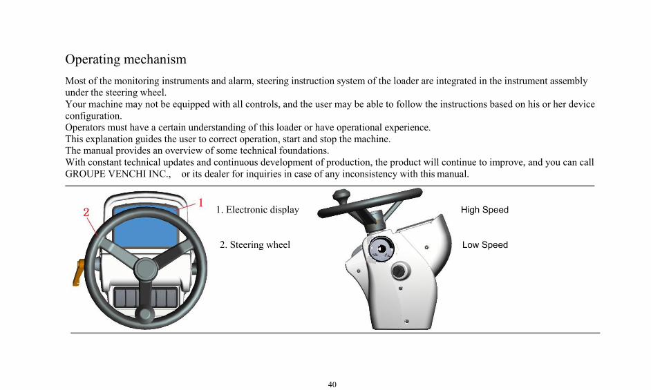
1. Electronic display High Speed
2. Steering wheel Low Speed
Operating mechanismMost of the monitoring instruments and alarm, steering instruction system of the loader are integrated in the instrument assemblyunder the steering wheel.Your machine may not be equipped with all controls, and the user may be able to follow the instructions based on his or her deviceconfiguration.Operators must have a certain understanding of this loader or have operational experience.This explanation guides the user to correct operation, start and stop the machine.The manual provides an overview of some technical foundations.With constant technical updates and continuous development of production, the product will continue to improve, and you can callGROUPE VENCHI INC., or its dealer for inquiries in case of any inconsistency with this manual.
41
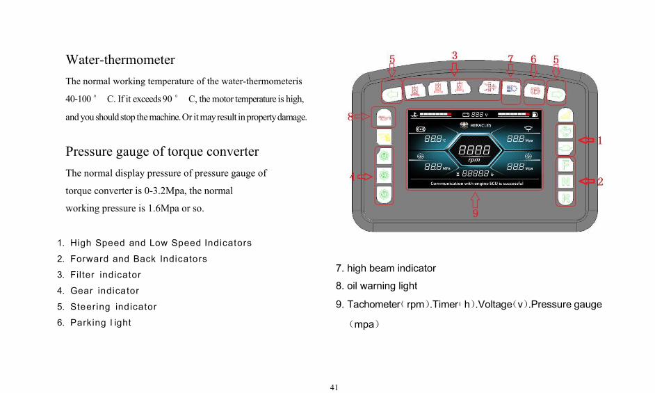
Water-thermometerThe normal working temperature of the water-thermometeris
40-100° C. If it exceeds 90° C, themotor temperature is high,
andyoushouldstop themachine.Or itmayresult inpropertydamage.
Pressure gauge of torque converterThe normal display pressure of pressure gauge of
torque converter is 0-3.2Mpa, the normal
working pressure is 1.6Mpa or so.
1. High Speed and Low Speed Indicators
2. Forward and Back Indicators
3. Filter indicator
4. Gear indicator
7. high beam indicator
8. oil warning light
5. Steering indicator
6. Parking l ight
9. Tachomete(r
(mpa)
rpm).Time(r h).Voltage(v).Pressure gauge
42
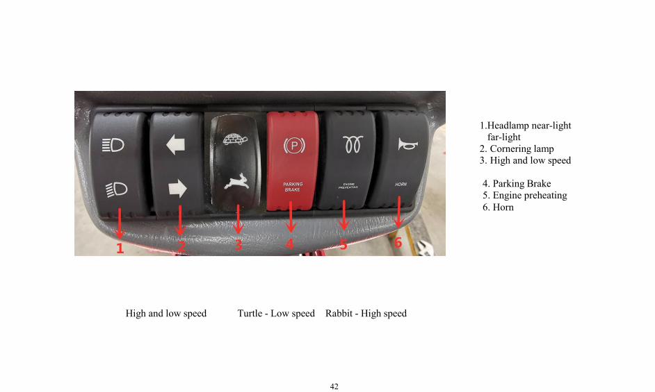
High and low speed Turtle - Low speed Rabbit - High speed
1.Headlamp near-lightfar-light
2. Cornering lamp3. High and low speed
4. Parking Brake5. Engine preheating6. Horn
43
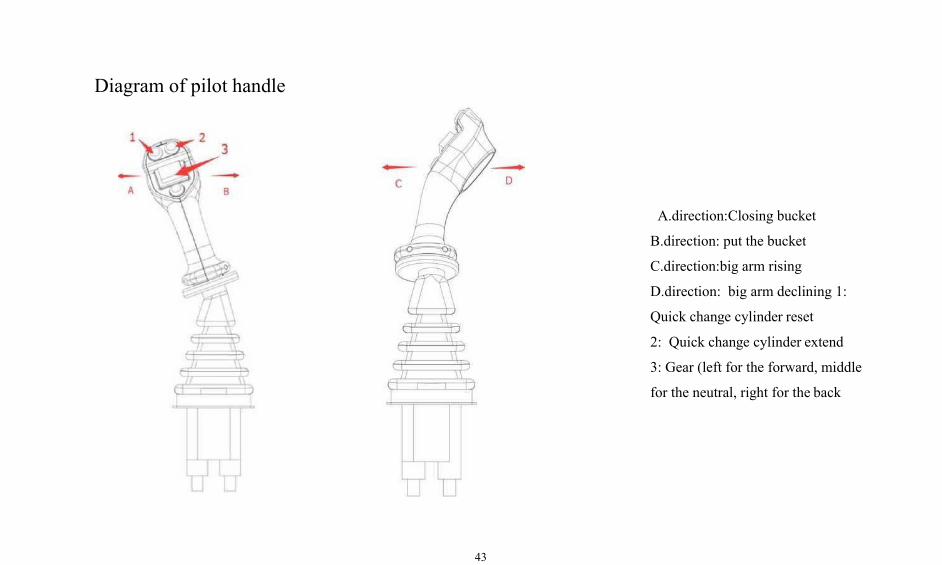
Diagram of pilot handle
A.direction:Closing bucket
B.direction: put the bucket
C.direction:big arm rising
D.direction: big arm declining 1:
Quick change cylinder reset
2: Quick change cylinder extend
3: Gear (left for the forward, middle
for the neutral, right for the back
44
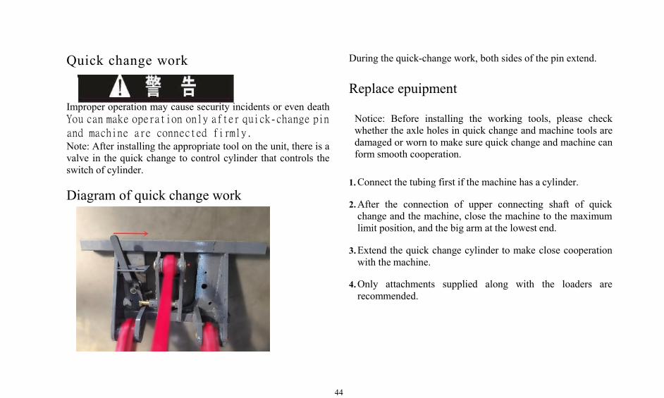
Quick change work
Improper operation may cause security incidents or even deathYou can make operation only after quick-change pinand machine are connected firmly.Note: After installing the appropriate tool on the unit, there is avalve in the quick change to control cylinder that controls theswitch of cylinder.
Diagram of quick change work
During the quick-change work, both sides of the pin extend.
Replace epuipment
Notice: Before installing the working tools, please checkwhether the axle holes in quick change and machine tools aredamaged or worn to make sure quick change and machine canform smooth cooperation.
1.Connect the tubing first if the machine has a cylinder.
2.After the connection of upper connecting shaft of quickchange and the machine, close the machine to the maximumlimit position, and the big arm at the lowest end.
3.Extend the quick change cylinder to make close cooperationwith the machine.
4.Only attachments supplied along with the loaders arerecommended.
45
If the pins and tools on both sides of the device are notsecurely fastened with the machine tools, the tubing maybe damaged.
It may cause serious injury or even death in such case duringthe work.
4. Enter the cab.5. Fasten the safety belt.6. Start the engine.7. Control the button on the pilot handle so that the quickchange cylinder retracts.8. Tilt forward the quick change to reduce the arm so thatthe machine tools can quickly separated from quickchange.Note: After disassembling the machine, check for any wearand tear on the quick-change toolholes and pins.
Unloading equipment
1. Place the loader on a flat surface2. Machine tools are placed on the flat surface.3. The tubing connects the loader and the machine tool(connected by quick coupling).1)Stop the engine2)Move the handle of the quick change cylinder back andforth to remove the pressure in the tubing.3)Use special tools to disassemble hydraulic tubing. Caution:Pay attention to the protective cap of the quick connectorduring disassembly.
Mechanical control valve of oil shifting
circuit
Rotate the mechanical control valve to control the oil circuitswitch.
The mechanical control valve is located on the right side of thequick change.
46
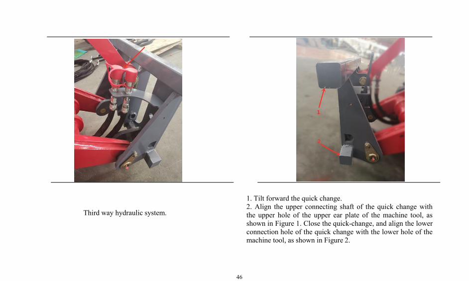
Third way hydraulic system.
1. Tilt forward the quick change.2. Align the upper connecting shaft of the quick change withthe upper hole of the upper ear plate of the machine tool, asshown in Figure 1. Close the quick-change, and align the lowerconnection hole of the quick change with the lower hole of themachine tool, as shown in Figure 2.

47
1. Rotate the mechanical control valve handle to thehorizontal position.
2. The lower pin of quick-change should pass through theworking position of the tool hole.
3. Lift the big arm: When lifting the big arm, observewhether the quick change is firmly connected with themachine.
48
Cigarette lighter
Press the cigarette lighter, cigarette lighter start power heating.After heating is completed, the cigarette lighter willautomatically disconnect the power and bounce, then you canpull out the cigarette lighter to light a cigarette.
Chronograph
The working time that indicates the machine takes "hour" as aunit, the timing range of the hour meter is from 0 to 9999.99hours. When the operator opens the switch (electric lock), theinstrument assembly get electricity to work, the chronographbegin to accumulate time, then the LCD display values are theaccumulated working hours. The value recorded in thechronograph can be used to determine the machine's servicelife.
Wiper switch of front window
There are three gears of the wiper switch of front window :stop, low speed and high speed. The wiper can resetautomatically when it stops. If you move the OFF position of
the switch, the engine will shut down.
Steering wheel
The machine is articulated full hydraulic power steering. Thesteering wheel is in the cab, the steering wheel is connectedwith the full hydraulic steering gear. In the normal operation ofthe machine, when you turn the steering wheel in the clockwisedirection, the machine turn right ; When you turn the steeringwheel counterclockwise, the machine may sheer off.
The features of full hydraulic power steering are as follows:
1. The turning angle of steering wheel is not equal to that ofmachine rotation. You could continuously rotate the steeringwheel to increase the machine steering angle until the requiredsteering position.
2. The faster the steering wheel rotates, the faster the machineturns.
3. The steering wheel does not reset automatically afterrotation.
49
4. The steering angle of the machine remains constant.Therefore, after finishing the machine steering, you shouldreverse the steering wheel, so that the machine can run in thestraight direction.
Speaker switch
There are two speaker switches of the machine, one in thecenter of the steering wheel, and one at the end of the steeringcombination handle. Press any one of the speaker switches, thespeaker will ring. The driver can decide to press the either oneaccording to their operational habits.
Accelerator pedal
The accelerator pedal is located in the right front of the driver'sseat. When it's in the natural position, the engine is in the idlestate. When you depress the accelerator pedal, it will increasethe fuel supply of diesel engine and improve the power outputof the diesel engine.
The engine flameout is achieved by the start switch OFF.
When the engine is running, it will rotate one grid of the startkey of the start switch in anticlockwise direction so as to reachthe OFF position of the start switch, then the engine shut down.
Parking brake handle
The parking brake handle is mounted on the floor surface ofthe cab, it's at the left lower side of the driver's seat. When it ispulled up, the parking brake is closed to implement braking; Italso cuts off power, and the gearbox automatically becomesidle. When you press the brake handle, it will release theparking brake and release the brake.
Way to release the brake: first press the front button of thehandle so that the positioning lock is completely released;Then slowly put down the handle so that the handle can bereleased to the horizontal position. Conversely, whenimplementing the parking brake, you just need to pull up thebrake handle to corresponding position.
Caution: If you do not feel a significant deceleration afterpressing the service brake pedal, please immediately pull upthe parking brake handle and apply an emergency brake.Meanwhile, you should operate the pilot handle, and move the
50
big arm to the lowest position and flip the bucket forward, sothat bucket teeth or bucket lip are inserted or against theground, forcing the machine to stop and ensuring safety.
Steering operation of the machine
1. Release the accelerator pedal to lower the machine speed.2. Depress the service brake pedal to lower the machinespeed.Then the front and back turn light of the machine and thecorresponding turn indicator of the instrumentation assemblywill turn light to warn the front, back and nearby vehicles andpedestrians that the machine is going to make steeringoperation.3. When you turn the steering wheel, then the steering begins.After the machine complete the steering, you should reverselyturn the steering so that the machine can travel in a straight line.4. After completing the steering operation is complete, youshould turn the steering switch to the neutral position, and thenthe turn light and turn indicator light will go out.5. Depress the accelerator pedal to reach the desired enginerotation speed.
Do not turn make steering operation in the slope, you shoulddrive the machine to a flat ground to complete these operations.
Downhill operation
Please select a suitable gear before the downhill. Do not shiftgears during downhill travel. In most cases, both uphill anddownhill use the same gear.
Please keep a low enough downhill speed. When drivingdownhill, please use the service brake to control the travelspeed of the machine. If you use the service brake when themachine is running at high speed, the brakes and the drive axleoil may overheat that cause serious wear and damages tobrakes.
51
Machinery operationPreparation before operation
Before operation, please use the machine to flatten the workarea, remove the bumps, fill the pits, remove the operationalobstacles of the wet surface and clean the large and sharpstones on the site to prevent the tires from laceration.
If the machine is to be used to load or unload the materialsfrom truck or hopper, you should adjust the limit height of thelifting limit device of whole big arm according to the height oftruck or hopper so that the bucket of the loader can be safelytaken out of the truck or hopper.
Operation of material transportation
Self-transportation can be taken in the following cases:
1. Too soft pavement; Ground without the formation; Or theroad cannot bear the truck.
2. When the transportation distance is within 500m, it is noteconomical to use the trunk.
During transportation, please keep the lower hinge point of thebig arm in the transport position (about 500mm from theground), and backward shift the bucket to the limit position(limit block of bucket may contacts the big arm), so as toensure smooth and safe transportation operations withoutspreading any material.
The transportation speed depends on the transport distance andthe road conditions. When the machine crosses the depressionsor recesses, the accelerator pedal should be relaxed. Ifnecessary, you should use the service brake to make "inchingbraking" to slowly cross the obstacles to reduce the impact onmachine and material spreading.
Warning: Do not carry bucket to higher position fortransport operation, otherwise it may cause the machinetilting.
52
Discharge operation
1. Discharge to truck or hopper
When the loader with full materials is 15m away from thetruck or hopper, you should relax the accelerator pedal toapproach the truck or hopper at low speed.
Handle the working device joystick so that the big armcontinuously rise to the limit height, then the big arm stoprising.
When the bucket is located right above the truck or hopper, thedriver depresses the brake pedal to stop the machine. And thenthe driver pushes the working device joystick to the right to tiltthe bucket forward, so that the material can be poured into thetruck or hopper.
If the truck body length is more than twice the width of thebucket, the discharge should start from the front of the body.
Note: When discharging the material, the impact strengthbetween the bucket stop block and the big arm should not betoo large, and the number of impacts should not be too many toprevent any damage to the machine.
After completing the machine discharging, the driver pulls theworking device joystick to the left side to the final position,then the bucket rotates backward until the bucket is kept flat,then the control handle automatically returns to its neutralposition.
After the bucket is completely out of the truck or hopper, thedriver can lower the big arm while waling for the next cycle.

53
Turn off the engine
Caution: Do not turn off the engine immediately after theload work, as this may cause overheating and accelerate wearof engine component.
1. Please make the engine idle for 5 minutes so as torealize uniform cooling of the parts.
Park of machineStop the machine
1. Park the machine on a level surface. If the machine mustbe parked on a slope, you should use a wedge block to wedgethe wheel.1. Please close the left and right doors.2. Depress the service brake pedal to stop the machine3. Set the pilot handle to "Neutral position".4. Pull up the parking brake handle.5. Lower all working device to the ground and press thebucket slightly downward.
2. Turn the engine start switch to the OFF position andremove the key.
3. Turn the switch board to the neutral or OFF position.
Lower the work device when the
engine shuts down
Please make sure that no one is around the machine beforelowering the work device
Note: For the machine with an electro-hydraulic
54
joystick, the engine start switch must be in the ON
position to lower the working device. After the
work device is lowered, you should turn the engine
start switch to the OFF position.
Move all the joysticks to the "DOWN" position so as tolower the work device to the floor or to the trailer. When thejoystick is released, they will return to the "HOLD" position.
Leave the machine
1. Please close the left and right doors
2. Use the ladders and handrails when you leave themachine. Face the machine and use both hands. Make surethere is no debris on the ladders before you leave the machine.
3. Check whether there is debris within the engine room.Clean all debris and paper to prevent fire.
4. Remove all flammable materials to reduce the risk of fire.Properly dispose these debris.
5. Turn the battery negative switch to the OFF position.
6. If there is no antifreezing solution in the machine, youshould timely turn on all water drain valve of the engine toempty all cooling liquid in the cooling system and evaporatorof the air conditioning system when you park in winter toprevent frost crack of the machine. If the machine has beenadded with antifreezing solution, please refer to theinstructions of Dial Plate of Antifreezing Solution.
Storage of machine
Before storage1. Wash and dry each part of the machine, and then storethem in a dry warehouse. If the machine can only be stored inthe open air, it should be stopped in the ground that drainsmore easily and covered with canvas.
2. Fill the fuel tank, add lubricating grease to movement pinand transmission shaft, and then replace the hydraulic oil.
55
3. Brush a thin layer of grease on the exposed section of thehydraulic oil piston rod.
4. Remove the battery from the machine, and store itseparately.
5. If the temperature drops below 0 ° C, you should addantifreezing solution to the engine cooling water, and allowthe antifreezing solution to reach the engine body and theevaporator of air conditioning system. Or you can empty thewater in the cooling system, and please also empty the waterin evaporator of air conditioning system.
During storage
1. You should start the car once a month to run each system.Please add lubricating grease to each movement pin andtransmission shaft so that the moving parts can be lubricated.Please also charge the battery.
2. Please wipe off the grease on the piston rod of thehydraulic cylinder before starting the vehicle. After finishing
the operation, apply a thin layer of grease.
3. Brush antirust agent in the parts that corrode easily.
Warning: If antirust agent is used indoors, pleaseregularly open doors and windows to maintain ventilationto remove toxic gases.
Before reusing
Replace the lubricating oil of engine, gearbox and drive axle,hydraulic oil, brake fluid and antifreezing solution.
Add lubricating grease to all movement pins andtransmission shaft.
Before starting the machine, wipe the grease from the pistonrod of the hydraulic cylinder.
Note: If the loader is stored without monthly rust
56
protection, please consult your dealer.
Transport of machine
Shipment of machine
Note: Please observe national and local regulations on weight,length, width and height restrictions of the materials whenmaking shipment.
Please investigate the height, width and allowable carryingcapacity of the transport route before shipment. The totalheight, total width and total weight of the machine after it isplaced on the transport vehicle shall not exceed the relevantprovisions.
Please remove ice, snow and other slippery materials fromthe platform and transport vehicles before loading. This willprevent slipping during loading and will also prevent themachine from moving during transport.
Drag of machineDrag the failed machine
Improper drag of a failed machine may result inpersonal injury or death. Wedge the tires beforeloosening the brakes to prevent the machine fromrolling.
The machine can not be dragged except in an emergency.Drag is only used to drag the machine to the place where it iseasy to repair. The drag distance of the machine can not bemore than 10km and the drag speed can not exceed 10km/h.If you need to move the machine over a long distance, youmust use a trailer for transportation.
57
In order to properly carry out the drag steps, the followingrecommendations should be observed: If the machine can'tdrive due to the failure of engine or braking system. In thiscase, you should remove the axis pin that connects theparking brake chamber and parking brake lever to forciblyrelease the parking brake.
Protective devices must be provided on the dragging machineso that it can protect the driver in case of any unexpectedbreak of the dragging rigging or dragging bar.
No one is allowed on the hauled machine unless a driver isneeded to control the steering or braking.
Please make sure that the dragging rigging or dragging bar isstrong enough to pull the machine. The dragging rigging ordragging bar is at least 1.5 times heavier than the grossweight of the towed machine.
Use a rope with a rope loop or a steel wire rope with an endring as a dragging tool. Set up an observer in a safe location.If the cable begins to break or begin to spread out, theobserver should stop dragging.
If the dragging machine moves while the hauled machine
keeps static, you should stop dragging.
Keep the minimum angle of the dragging rigging with theright ahead less than 25°.
The quick movement of the machine can overload thedragging rigging or dragging bar. This can cause the break ofdragging rigging or dragging bar.
Uniform movement of the machine is more conducive to drag.
Normally, the trailer should be the same size as the machinebeing dragged. The trailer should have sufficient brakingcapacity, weight and power to control the uphill and drivingdistance of the two machines.
When making dragging, all personnel should be away fromboth sides of the dragging rigging to prevent any injury dueto breaking dragging rigging.
In order to provide adequate control and braking, it may benecessary to connect a larger machine to the failed machine,
58
which prevents the failed machine from losing control androlling during downhill.
When the dragged machine goes downhill, in order to havesufficient control and braking capability, a large trailer orother machine should be connected behind the draggedmachine to prevent the machine from losing control androlling.
Dragging during the engine operation
During the engine operation, you can make short distancedragging in some cases. At this time, the transmission systemand the steering system must be operable.
You can only make short distance machine dragging. If themachine is dragged out of the quagmire or dragged to theroadside, the driver must operate the machine by thedirection of the dragging rigging.
Please strictly follow all instructions outlined in the "Drag ofmachine".
It is not possible to point out all requirements in differentcases. For details on dragging a failed machine, pleaseconsult your . dealer.
59
M a i n t e n a n c e M a n u a l
Note: Please read and understand the contents of thismanual carefully so that you can properly maintain andcare the machine. Proper maintenance is of greatsignificance to ensure safety and extend the service life ofthe machine.
Maintenance Guide
Correct maintenance method
Learn how to properly service your machine, follow thecorrect maintenance and inspection procedures shown inthis manual. If there is any problem with your machine,please repair it before operation or contact your dealer.
Check the machine before startingevery day
1. Check instrumentation.2. Check the liquid level of cooling liquid, fuel and oil.3. Check the leakage, knot wear and damage of hose andsteel pipe.4. Make patrol inspection of the general phenomenon,sound, heat of the machine.5. Check for loose or missing parts.
Maintain the machine during thespecified period
Carry out all recommended maintenance methods in themaintenance guide.
Maintenance tips
1. Use recommended fuels and lubricants.2. Do not adjust the engine control throttle and the safetyvalve of hydraulic system.
60
3. Protect the electrical components from contacting withwater and water vapor.4. Do not disassemble electrical components, such assensors.5. Use the recommended genuine of our. parts.
Clean engine oil
Please clean engine oil and keep the oil or grease containerclean. Do not let debris into the oil or grease.
Check the discharged oil or used filtercartridge.
After changing the oil or replacing the filter cartridge, pleasecheck the old oil and the filter cartridge for metal filing andimpurities.
If large amounts of metal filing and impurities are found,please report to the supervisor and take appropriate action.
Prevent something falling into the inside ofthe machineBe careful not to drop nuts, bolts or tools inside the machinewhen you open the inspection window or the oil filler forinspection.
If these things fall into the machine, please remove themimmediately.
Clothes pockets can only carry necessary things for checkingrather than some unnecessary things.
Dusty environment
The following points should be noted in dusty environments:
Check whether the dust in air filter is blocked. The time toclean the air filter should be shorter than the specified time.
Clean the radiator core regularly to prevent clogging. Alwaysclean and replace the fuel filter.
Clean the electrical installation, especially the starter motor
61
and engine, to prevent dust build-up.
Avoid mixing oil
Avoid the mixing oil of different brands. If you need to usedifferent brands of oil, you must remove the old oil on themachine.
Lock the inspection coverOpening and Closing the Engine Cover1 Apply the parking brake, lower the attachments to theground, place the transmission in neutral and stop theengine.2 Unlock the security lock A. It is recommended that thecover is kept locked.3 Lift the Engine Cover B until it is fully open.
Closing the Engine Cover1 Pull down the engine cover B until the catch engages.2 Lock the security lock A and remove the key.
62
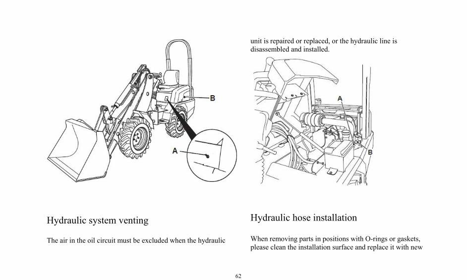
Hydraulic system venting
The air in the oil circuit must be excluded when the hydraulic
unit is repaired or replaced, or the hydraulic line isdisassembled and installed.
Hydraulic hose installation
When removing parts in positions with O-rings or gaskets,please clean the installation surface and replace it with new

63
parts. Do not forget to install O-rings and gaskets.
When installing the hose, do not twist or bend the hose into asmall diameter ring. This can damage the hose andsignificantly shorten the hose's service life.
Choose fuels and lubricants that match the environment.
Use only fuels and lubricants that match the ambienttemperature.
Check the electrical wiring
If the fuse burns out frequently or there is a sign of shortcircuit, please immediately find out the cause and repair it orcontact your . dealer.
1. Inspect the fuse wire for damage or capacity discrepancies,check whether there is a circuit break or short circuit, andcheck the loosening terminal and tighten any loose parts.2. Check the circuit of storage battery, starting motor andalternator.3. For reasons checking and correction, please contact your .dealer.
Air conditioning checking
Check whether the blow rate switch of air conditioningsystem is in the natural wind position, and whether thechange-over switch is in the OFF position. If it is not, set it tothe appropriate position.
Checking of instrument
Check whether the instrument is running well, and whetherthe lighting equipment, lights, speakers, wipers can work

64
normally. In case of any abnormality, please contact your .dealer.
Caution: Before starting the engine, make sure that noperson other than the operator is working on or near themachine. Always ensure that the machine is under thecontrol of the operator.
Preparation before maintenance
Please park the machine as follows before maintenance:
1. Park the machine on a flat surface.
2. Lower the bucket to the ground.
3. Reduce the engine rotation speed to idle and run for threeminutes.
4. Turn the start switch to OFF. Remove the key from theswitch. (Do not leave the machine unmanned if it isnecessary to perform maintenance while the engine isrunning.)
5. Place the pilot control handle in the neutral position.
6. When the machine doesn't make any operation, pleasehang the "Do Not Operate" label on the joystick.
Running-in of new vehicle
Running-in of new vehicle plays an important role inextending the service life of the machine, eliminating thehidden trouble and avoiding the occurrence of major failure.The user must operate and maintain the machine inaccordance with the instructions in this manual regarding therunning-in of new vehicle after purchasing the machine, andthen use the machine normally.
Requirements of running-in of newvehicle:
1. The period of running-in of new vehicle is 100 hours.
2. After starting machine, first you should idle for 5

65
minutes. The machine should start with a steady low speedthrottle and then gradually increase the speed.
3. During the running-in period, the forward and backwardgears should be evenly arranged to running-in.
4. Except for an emergency, you should avoid a suddenstart, sudden acceleration, sudden turn and sudden braking.
5. It is appropriate to load loose materials during the periodof running-in. Please don't be too hasty or fast during theoperation. During the period of running-in, the loadingweight shall not exceed 70% of the rated load and the speedshall not exceed 70% of the rated maximum speed.
6. Please note the lubrication conditions of the machine,and replace or add lubricants and grease according to thespecified time period.
7. Please always pay attention to the temperature ofgearbox, torque converter, front and rear axles, wheel hub,parking brakes, intermediate support shafts and hydraulic oil,engine cooling liquid and engine oil. If there is anyphenomenon of overheating, you should find out the reasons
for elimination.
8. Check the fastening of bolts and nuts of each part.After eight hours of running-in of newvehicle, the following work should becarried out:
Please comprehensively inspect fastening situation of boltsand nuts of various parts, especially cylinder head bolts ofdiesel engine, exhaust pipe bolts, fixing bolts of front andrear axle, rim nuts, connecting bolts of transmission shaft,fixing bolts of diesel engine, fixing bolts of gearbox and boltsof front and rear frame hinges.
1. Check the tightness degree of the fan belt, the engine beltand the air conditioning compressor belt.
2. Check the oil level of gearbox, drive axle and dieselengine.
3. Check the hydraulic system and braking system forleakage.
66
4. Check the joystick and throttle system for leakage.
5. Check the temperature and connection conditions ofelectrical system components, power supply of engine,lighting and the turn signal lamp.
Note: Please follow the relevant operating procedureswhen checking various oil levels.
Work after the expiration of running-inof new vehicle
1. Please comprehensively inspect fastening situation ofbolts and nuts of various parts, especially cylinder head boltsof diesel engine, exhaust pipe bolts, fixing bolts of front andrear axle, rim nuts, connecting bolts of transmission shaft,fixing bolts of diesel engine, fixing bolts of gearbox and boltsof front and rear frame hinges.
2. Check the degree of tightness of the fan belt, the enginebelt, and the air conditioner compressor belt.
3. Check the hydraulic system and braking system forleakage.
4. Replace the transmission shaft of and lubricating oil ofdrive axle.
5. Replace the fine filter of gearbox oil and clean the rudefilter of gearbox oil.
6. Clean the return oil filter core of the hydraulic oil.
Caution: When replacing transmission oil of gearbox,lubricating oil of drive axle and fine filter of gearbox oil,you should follow the relevant operating instructions.
Regular maintenance
Caution: Read and understand all safety information,warnings and instructions before performing anyoperations or any maintenance procedure
67
It is requiredthatthemaintenanceworkshouldbe
basedon the firstexpirationtimeofworkinghours
orcalendar.
In extremely severe, dusty or humid working conditions,there is a need for more frequent lubrication maintenancethan specified in "Regular maintenance".
During maintenance, the maintenance items listed in theoriginal requirements should be repeated. For example,during a 500-hour or 3 months maintenance project, themaintenance items listed in 250 working hours, 50 workinghours, every 10 hours or every day should be performedsimultaneously.
Maintenance of every 10 workinghours or every day
1.Check the battery and battery switch.2. Check the engine oil level.
3. Check the liquid level of cooling liquid.4. Check the hydraulic oil level.5. Check the fuel level.6. Eliminate water and impurities from the fuel pre-filterand the crude oil filter from the engine.7. Patrol inspection8. Visually check the engine fan and drive belt.9. Check the work conditions of lighting and instrument.1 0. Check the tire pressure and damage conditions.11. Check the working status of the reverse alarm.12. Add lubricating oil to the transmission shaftaccording to the instructions of machine lubricationdiagram posted on the loader.
Maintenance of every 50 workinghours or weekly maintenance
1. First check the maintenance items described above.
2. Check the oil level of gearbox.
3. Check the clearance between the brake shoe of the
68
parking brake and the drum brake in the first 50 workinghours and adjust it if it's inappropriate. Then check it every250 working hours.
4. Tighten the connecting bolts of all transmission shafts.
5. For air-conditioned machines, you need to clean thereturn air filter and new air filter of evaporator, check thetightness of compressor transmission belt, and check whetherthere is oil, dirt, debris, etc. in the condenser that may affectthe heat distributing effect of the condenser.
6. Keep the battery terminals clean and brush them withVaseline to avoid acid mist corrosion on the terminal.
7. Check the lubrication conditions of eachlubrication point. Please fill the grease to eachlubrication point according to the instructions ofmachine lubrication diagram posted on the loader.
Maintenance of every 100 working hours orevery two weeks
1.First check the maintenance items described above.
2. Replace the gearbox oil in the first working hours, thenchange the gear oil every1,000 working hours. If it can meetthe working hours, you should change the gearbox oil at leastonce each year.
When replacing the gearbox oil, you should change the finefilter of and clean the crude filter inside the gearbox oil shell.
3. Replace the drive axle gear oil in the first 100 workinghours and replace the drive axle gear oil every 1000 hours. Ifit can't meet the working hours, you should change the driveaxle gear oil at least once each year.
4. Clean the engine cylinder head. Sweep the heatsinkgroup.
5. Clean oil-filter screen of fuel tank rack.
69
Maintenance of every 250 workinghours or every month
1. First check the maintenance items described above.
2. Check the tightening torque of the rim mounting bolts.
3. Check the tightening torque of the gearbox and themounting bolts of engine.4. Check the working device, welding seam of front andrear frames and fixed bolts for cracks and looseness.
5. Check oil level of front and rear axle.
6. Check the obstruction warning light of air filter. The airfilter element should be cleaned or replaced if the alarmlight is lighted.7. Check the intake air system of the engine.8. Replace the engine oil and engine oil filter9. Replace the cooling liquid filter of engine.1 0. Replace the filter element of return oil filter of
hydraulic system in the first 250 working hours, Thenreplace the filter element of return oil filter of hydraulicsystem every 1000 hours.
11. Check the tension and damage situation of engine belt,air conditioning compressor belt.
12. For air-conditioned machines, please check whetherthere is enough refrigerant in the air-conditioning tank.
13. For air-conditioned machines, please clean the insideand outside air filter of the cab.
14. Check the traffic braking capacity and parking brakingcapacity.
Maintenance of every 500 workinghours or every three months.
1..First check the maintenance items described above.
70
2. Check concentration of antifreezing solution andconcentration of cooling liquid additive
3. Replace the fuel pre-filter and fine and crude fuel filteron the engine.
4. Tighten the connection bolts of the front and rear axleand frames.
5. Check if the fixing bolts of the frame hinge pins areloose.
Maintenance of every 1000 workinghours or every six months.1. First check the maintenance items described above.2. Adjust the engine valve clearance3. Check the idler bearing and fan shaft casing.4. Replace the gearbox oil, replace the gearbox oil filter,and clean the filter in the gearbox oil pan.5. Replace the drive axle gear oil.
6. Replace the filter element of return oil filter of hydraulicsystem.7. Clean the fuel tank.8. Tighten fixed bolts of all batteries and clean the top ofthe battery.9. For air-conditioned machines, the outside air filter forthe cab needs to be changed.
Every 2000 working hours or every year
1. First check the maintenance items described above.2. Adjust the engine valve clearance3. Check the idler bearing and fan shaft casing4. Replace the gearbox oil, replace the gearbox oil filter,and clean the filter in the gearbox oil pan.5. Replace the drive axle gear oil.6. Replace the filter element of return oil filter of hydraulicsystem.7. Clean the fuel tank.8. Tighten fixed bolts of all batteries and clean the top ofthe battery.9. For air-conditioned machines, the outside air filter for
71
the cab needs to be changed.
Every 2000 working hours or every year
1. First check the maintenance items described above.
2. Replace the cooling liquid, cooling liquid filter, andclean the cooling system. If it can't meet working hours,replace the cooling liquid at least once every twoyears.
3. Replace the hydraulic oil, clean the fuel tank, check thesuction pipe
4. Check the work conditions of braking system and thebraking system. If necessary, you should make disassemblyto check the wear pattern of friction plate.
5. By measuring the natural settling volume of thecylinder to check the components, the distributionvalve and air tightness of working cylinder.
6. For air-conditioned machine, you should check whetherthere is crack, wear or oil foam of the cooling pipe and waterpipe of air condition, and check pipe joint and pipe clamp forlooseness.7. For air-conditioned machine, please replace the interiorair filter of the cab8. Check the flexibility of the steering system.
Tire inflation
It is recommended that you inflate the tire with dry nitrogenand adjust the tire pressure. This includes all machinesequipped with rubber tires. Nitrogen is an inert gas that doesnot support combustion in the tire.
The use of nitrogen not only reduces the risk of explosion, italso helps to prevent oxidation and rubber aging and rimparts corrosion.
Personnel who use inflatable equipment will be required to
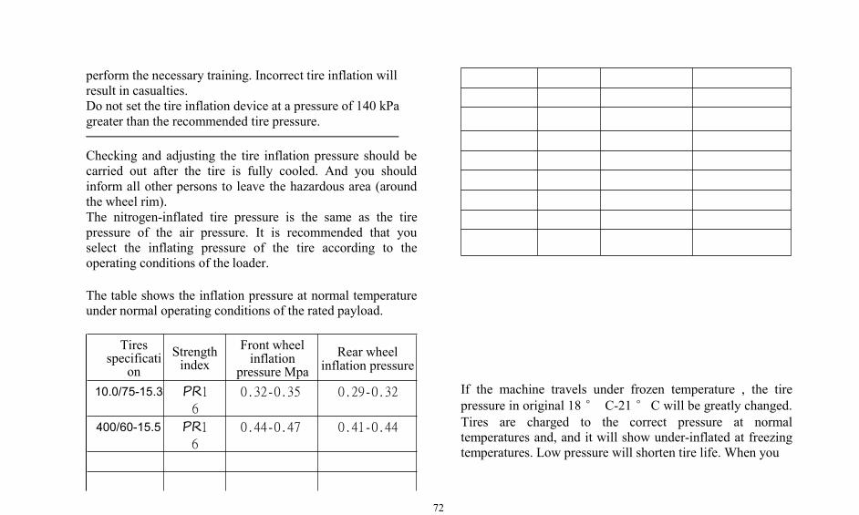
72
perform the necessary training. Incorrect tire inflation willresult in casualties.Do not set the tire inflation device at a pressure of 140 kPagreater than the recommended tire pressure.
Checking and adjusting the tire inflation pressure should becarried out after the tire is fully cooled. And you shouldinform all other persons to leave the hazardous area (aroundthe wheel rim).The nitrogen-inflated tire pressure is the same as the tirepressure of the air pressure. It is recommended that youselect the inflating pressure of the tire according to theoperating conditions of the loader.
The table shows the inflation pressure at normal temperatureunder normal operating conditions of the rated payload.
Tiresspecificati
onStrengthindex
Front wheelinflation
pressure MpaRear wheel
inflation pressure
10.0/75-15.3 PR1
6
0.32-0.35 0.29-0.32
400/60-15.5 PR16
0.44-0.47 0.41-0.44
If the machine travels under frozen temperature , the tirepressure in original 18° C-21°C will be greatly changed.Tires are charged to the correct pressure at normaltemperatures and, and it will show under-inflated at freezingtemperatures. Low pressure will shorten tire life. When you
73
are unsure of the tire's inflation pressure, please consult your .dealer.
Note: If the machine is running at high speed for longdistance, it should stop for 30 minutes for every 45kilometers, so that the tire can fully dissipate heat.
Technical specification for lubricating oil
Oil change intervals and approximate adding capacityCaution: During inspection, maintenance, testing and adjustment of the machine, when removing any hydraulic line or
disassembling any liquid containing parts, it is necessary to prepare the appropriate container for collection of liquid. And you
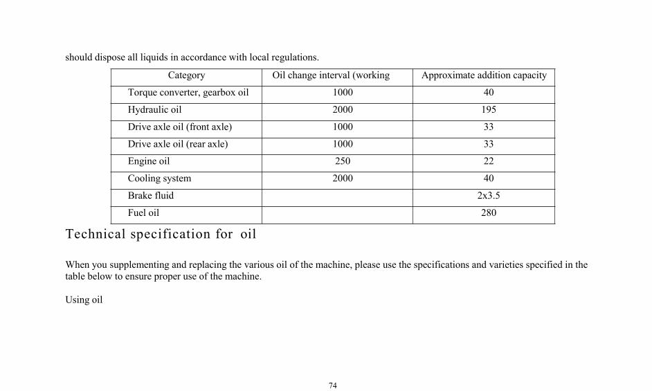
74
should dispose all liquids in accordance with local regulations.
Category Oil change interval (working Approximate addition capacity
Torque converter, gearbox oil 1000 40
Hydraulic oil 2000 195
Drive axle oil (front axle) 1000 33
Drive axle oil (rear axle) 1000 33
Engine oil 250 22
Cooling system 2000 40
Brake fluid 2x3.5
Fuel oil 280
Technical specification for oil
When you supplementing and replacing the various oil of the machine, please use the specifications and varieties specified in thetable below to ensure proper use of the machine.
Using oil

75
CategoryName
Application positionSummer oil Winter oil
Engine oil SAE/5W-30CD SAE/5W-30CD Diesel engine
Engine fuelSouth No. 0 Light diesel oil No. 0 Light diesel oil Diesel engine
North No. 0 Diesel oil No. 20 Light diesel oil Diesel engine
Hydraulic oil HM68 Anti - wearhydraulic oil
HV68 Low - temperature anti -wear hydraulic oil Hydraulic system, steering system
Lubricating grease No.3 Molybdenum disulfide lithium-based greaseRolling bearing, sliding bearing, working devicepin, steering cylinder pin, frame pin, cardan
joint, etc.
Torque converter oil AF8 Hydraulic transmission oil Torque converter, power shift gearbox
Gear Oil SAE85W-90 Heavy duty wheel gear oil Drive axle transmission andwheel side deceleration
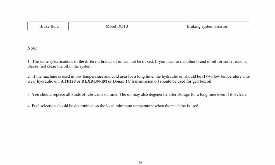
76
Brake fluid Mobil DOT3 Braking system assistor
Note:
1. The same specifications of the different brands of oil can not be mixed. If you must use another brand of oil for some reasons,please first clean the oil in the system.
2. If the machine is used in low temperature and cold area for a long time, the hydraulic oil should be HV46 low temperature anti-wear hydraulic oil. ATF220 or DEXRON-IM or Donax TC transmission oil should be used for gearboxoil.
3. You should replace all kinds of lubricants on time. The oil may also degenerate after storage for a long time even if it isclean.
4. Fuel selection should be determined on the local minimum temperature when the machine is used.
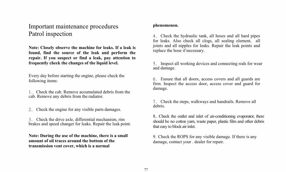
77
Important maintenance proceduresPatrol inspection
Note: Closely observe the machine for leaks. If a leak isfound, find the source of the leak and perform therepair. If you suspect or find a leak, pay attention tofrequently check the changes of the liquid level.
Every day before starting the engine, please check thefollowing items:
1. Check the cab. Remove accumulated debris from thecab. Remove any debris from the radiator.
2. Check the engine for any visible parts damages.
3. Check the drive axle, differential mechanism, rimbrakes and speed changer for leaks. Repair the leak point.
Note: During the use of the machine, there is a smallamount of oil traces around the bottom of thetransmission vent cover, which is a normal
phenomenon.
4. Check the hydraulic tank, all hoses and all hard pipesfor leaks. Also check all clogs, all sealing element, alljoints and all nipples for leaks. Repair the leak points andreplace the hose if necessary.
5. Inspect all working devices and connecting rods for wearand damage.
6. Ensure that all doors, access covers and all guards arefirm. Inspect the access door, access cover and guard fordamage.
7. Check the steps, walkways and handrails. Remove alldebris.
8.. Check the outlet and inlet of air-conditioning evaporator, thereshould be no cotton yarn, waste paper, plastic film and other debristhat easy to block air inlet.
9. Check the ROPS for any visible damage. If there is anydamage, contact your . dealer for repair.
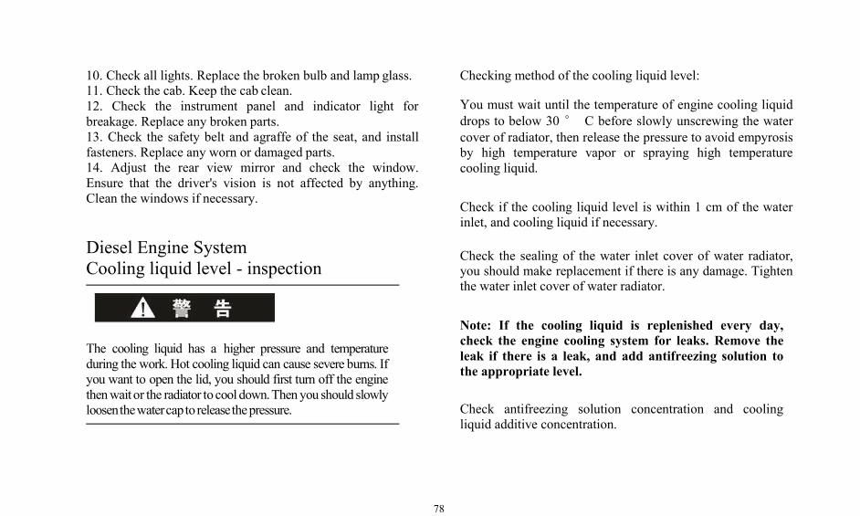
78
10. Check all lights. Replace the broken bulb and lamp glass.11. Check the cab. Keep the cab clean.12. Check the instrument panel and indicator light forbreakage. Replace any broken parts.13. Check the safety belt and agraffe of the seat, and installfasteners. Replace any worn or damaged parts.14. Adjust the rear view mirror and check the window.Ensure that the driver's vision is not affected by anything.Clean the windows if necessary.
Diesel Engine SystemCooling liquid level - inspection
The cooling liquid has a higher pressure and temperatureduring the work. Hot cooling liquid can cause severe burns. Ifyou want to open the lid, you should first turn off the enginethenwaitor the radiator to cool down.Thenyou should slowlyloosenthewatercapto releasethepressure.
Checking method of the cooling liquid level:
You must wait until the temperature of engine cooling liquiddrops to below 30 ° C before slowly unscrewing the watercover of radiator, then release the pressure to avoid empyrosisby high temperature vapor or spraying high temperaturecooling liquid.
Check if the cooling liquid level is within 1 cm of the waterinlet, and cooling liquid if necessary.
Check the sealing of the water inlet cover of water radiator,you should make replacement if there is any damage. Tightenthe water inlet cover of water radiator.
Note: If the cooling liquid is replenished every day,check the engine cooling system for leaks. Remove theleak if there is a leak, and add antifreezing solution tothe appropriate level.
Check antifreezing solution concentration and coolingliquid additive concentration.
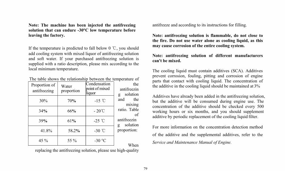
79
Note: The machine has been injected the antifreezingsolution that can endure -30°C low temperature beforeleaving the factory.
If the temperature is predicted to fall below 0 ℃, you shouldadd cooling system with mixed liquor of antifreezing solutionand soft water. If your purchased antifreezing solution issupplied with a ratio description, please mix according to thelocal minimum temperature.
The table shows the relationship between the temperature ofthe
antifreezing solutionand the
mixingratio. Table
ofantifreezing solutionproportion:
Whenreplacing the antifreezing solution, please use high-quality
antifreeze and according to its instructions for filling.
Note: antifreezing solution is flammable, do not close tothe fire. Do not use water alone as cooling liquid, as thismay cause corrosion of the entire cooling system.
Note: antifreezing solution of different manufacturerscan't be mixed.
The cooling liquid must contain additives (SCA). Additivesprevent corrosion, fouling, pitting and corrosion of engineparts that contact with cooling liquid. The concentration ofthe additive in the cooling liquid should be maintained at 3%
Additives have already been added in the antifreezing solution,but the additive will be consumed during engine use. Theconcentration of the additive should be checked every 500working hours or six months, and you should supplementadditive by periodic replacement of the cooling liquid filter.
For more information on the concentration detection method
of the additive and the supplemental additives, refer to the
Service and Maintenance Manual of Engine.
Proportion ofantifreezing
Waterproportion
Condensationpoint of mixedliquor
30% 70% -15℃
34% 66% - 20℃
39% 61% -25℃
41.8% 58.2% -30℃
45 % 55 % -30 °C
80
Cooling liquid– Addition
The cooling liquid has a higher pressure and temperatureduring the work. Hot cooling liquid can cause severe burns. Ifyou want to open the lid, you should first turn off the enginethen wait or the radiator to cool down. Then you shouldslowly loosen the water cap to release the pressure.
The procedure of adding cooling liquid is as follows:
As heat absorption capacity of antifreezing solution to engineis lower than water, if adding the antifreezing solution intothe engine before complete mixing with water may causeengine overheating.
When the cooling liquid is injected, the air must be ventedfrom the engine cooling system.
Do not add cooling liquid to high-temperature engine, or it
may cause damage to the engine. You should wait it until theengine temperature is below 30° C!
Cooling liquid – Replacement
During the maintenance, inspection, testing and adjustment ofthe machine, when disassembling any hydraulic circuit ordisassembling any liquid containing parts, it is necessary toprepare the appropriate container for the collection of liquid.You should all liquids in accordance with local regulations.
The cooling liquid has a higher pressure and temperatureduring the work. Hot cooling liquid can cause severe burns. Ifyou want to open the lid, you should first turn off the enginethen wait or the radiator to cool down. Then you shouldslowly loosen the water cap to release the pressure.
In every 2,000 working hours or every year (whicheveroccurs first), you should replace the cooling liquid in coolingsystem thoroughly and clean the cooling system. Prior to this,the cooling system should be cleaned if the cooling liquid is
81
polluted, the engine is overheated, or a foam appears in theradiator.
The procedure for cleaning the cooling system is as follows:
Turn on the power negative switch, insert the key into thestart switch and turn clockwise to the first gear, connect thevehicle power supply.
Turn the air conditioning system switch to warm air.
Turn the engine water inlet valve to the on-position.
Start the engine, idle running for 5 minutes, then turn downthe engine. Then turn the start switch to the first gear, connectthe machine power supply.
The switch of air conditioning system is in the warm air, sothat the electromagnetic valve of the air conditioning is inopen mode.
You must wait until the cooling liquid temperature dropsbelow 30 ° C before slowly unscrewing the radiator watercover to release the pressure.
Open the water drain valve at the bottom of the radiator, drainthe cooling liquid from the engine and hold it with a container.
After the engine cooling liquid is drained, close the drainvalve on the bottom of the water radiator.
Check whether all water pipes and pipe clamps in the coolingsystem are damaged, and replace them if necessary. Checkthe water radiator for leaks, damage and dirt accumulation,and clean and repair them as necessary.
Add the cleaning fluid that mixed by water and sodiumcarbonate into the engine cooling system, with the mixingratio of 0.5kgsodium carbonate in every 23 liters of water.Level should reach the level of normal use of the engine, andmaintain stability within 10-15 minutes.
Note: When injecting cleaning fluid into cooling system,the air must be vented from the engine cooling system.During the cleaning process of the entire cooling system,do not close the water radiator water cover when theengine is running.
82
Keep the water radiator water cover open and start the engine.When the cooling liquid temperature rises above 80° C, runthe engine for 5-10 minutes.
Note: When the cooling liquid temperature can not reachEngine cooling liquid is toxic and can not be drunk. Please dispose itin accordancewith local laws.
80 ° C or more, please use a hard paper to close thewater cover of the water radiator.
Turn off the engine and drain the cleaning fluid.
Add clean water to the engine cooling system to the normalservice level and keep it for 10-15 minutes. Keep the watercover of water radiator open and start the engine. When thecooling liquid temperature rises above 80 ° C, run theengine for 5-10 minutes.
Turn off the engine and drain the water from the coolingsystem. If the discharged water is still dirty, the system mustbe cleaned again until the discharged water becomes clean.Replace the new cooling liquid filter and close all drain plugs.Then add new cooling liquid according to the procedures of"cooling liquid-Addition" described above.
Air Filter Maintenance Indicator -Checking
Turn down the engine, open the engine cover, you can see theair filter maintenance indicator.
When the yellow piston of the indicator light rises to the redarea, the air cleaner element should be maintained.
Air filter main element- Cleaning /Replacement
Note: If the instrument panel is equipped with an engine airfilter clogging alarm indicator, when the indicator light, the
83
engine air filter of the engine should be maintained.
Turn the engine off and open the engine hood.Remove the air filter cover.Rotate and take out the main filter element along the shelldirection
Check main filter element.
1. If the folds and the gasket are damaged, you need toreplace the main filter element.2. If the main filter element is not damaged, clean the mainfilter element.
Clean the inwall of the air cleaner housing.
Clean the main filter element, and use the compressed air (thepressure is not greater than 300 kPa) to blow the main filterelement from inside to outside.
It's prohibited to use compressed air to blow the main filterelement from the outside to insider; It's prohibited to use oiland water to clean the main filter element.
Caution: Do not knock when cleaning the main filterelement, or it may cause damage to the engine.
After cleaning the main filter element, please use the electriclamp for inspection. If any pore or particle is found, youshould replace a new main filter element.
Install the clean main filter element into the air cleanerhousing to ensure that the main filter element and housing areevenly sealed and installed in place.
Clean and install the air filter cover to ensure that the air filtergasket is evenly connected with air cleaner housing.
Note: the main filter element must be replaced aftercleaning and maintenance for 4-5 times. During cleaningand maintenance of the main filter element, it'sprohibited to disassembly and assembly safety filterelement.
Close the engine hood.
84
Transmission systemGearbox oil level– checking
Check the oil level by the oil level switch next to the fillerpipe. There are three switches of oil level, the highest for thehighest liquid level, and the lowest for the minimum liquidlevel.
Checking procedure of the gearbox oil level is as follows:
Check the cold oil level before starting the refrigerator cart;The purpose for checking the oil level is to ensure enough oilbefore starting. It is very important for loaders that have beenout of service for quite some time.
Before starting the engine, open the upper oil level switch; Ifthe oil discharges, then it can be activated. If there is nodischarging oil, you should add enough oil before starting it.
Place the loader on a flat surface, put the shifting joystick inthe neutral position, pull up the parking brake handle, andinstall the frame bumper bar to prevent the movement and
shift of loader.
Start the engine, make idle running after running about fiveminutes, and then open the oil level switch. The gearbox oillevel should between the highest liquid level and the lowestliquid level of the oil level switch. If the oil discharges fromthe upper oil level switch, then you should emit part ofgearbox oil by the bottom oil draining plug of the gearbox. Ifthe oil level is above the lower oil level switch, please addsome gearbox oil.
Note: Too high or too low gearbox oil level will causedamages to the gearbox, so please keep the gearbox oillevel in the correct position.
Note: During the process of checking the gearbox oil leveland replacing the gearbox oil, you must pay greatattention to cleanliness and can not allow the dirt into thegearbox system so as to avoid damage to the gearbox.
Gearbox oil - replacement
Caution: During inspection, maintenance, testing and
85
adjustment of the machine, when removing any hydraulicline or disassembling any liquid containing parts, it isnecessary to prepare the appropriate container forcollection of liquid. And you should dispose all liquids inaccordance with local regulations.
The gearbox oil must be replaced after the machine reaches100 hours for the first time. Then the gearbox oil must bereplaced every 1000 working hours. The gearbox oil must bereplaced at least once each year.
1. Place the loader on a flat surface with the pilot operatinglever in the neutral position, apply a brake stop, and attachthe frame steering protection device to prevent the movementand shift of loader
2. Start the engine and run it at idle speed for 3-5 minutes,then turn down the engine.
3. Unscrew the oil drain plug on the lower left side of thegearbox and hold it with a container.
Note: Because the gearbox oil temperature is still high atthis time, so please wear protective equipment and make
careful operation so as to avoid personal injury.
4. Unscrew the oil drain plug on the lower side of the oilradiator of torque converter, and hold it with a container. Andthen unscrew the air bleed plug above the oil radiator oftorque converter to speed up the oil discharge rate.
5. Clean the attached scrap iron in the drain plug withmagnet, and clean the scrap iron of the gearbox inwall.
6. Install the gearbox drain plug and the oil drain plug andthe corresponding seals below the torque converter oilradiator.
7. Unscrew the refueling plug above the torque converter oilradiator, and add clean gearbox oil from the oil filler oftorque converter oil radiator. After filling the gearbox oil inradiator, screw the air bleed plug and the refueling plug.
8. Unscrew the gearbox filler cap and add clean gearbox oilfrom the oil filling pipe. The gearbox oil level should be atthe maximum level that the oil level switch limits.
9. Start the engine, make it idle after running about five
86
minutes, and then open the oil level switch. Check the oillevel. The oil level should be between the highest liquid leveland the lowest liquid level. If it's excessive, please dischargesome oil.
10. Tighten the filler cap clockwise.
Note: Before replacing the gearbox oil, pay attention tocover the parking brake to avoid parking brake frictionplate is attached with oil that reduce the brakingperformance.
Gearbox oil filter - replacement
Caution: During inspection, maintenance, testing andadjustment of the machine, you must use a container to holdthe liquid. When removing any hydraulic line ordisassembling any liquid containing parts, it is necessary toprepare the appropriate container for collection of liquid. Andyou should dispose all liquids in accordance with localregulations.
Drive axle - oil level checking
Caution: When adding and discharging oil of the driveaxle, or unscrewing the plug, be careful of the splashinghot oil.
1. Park the machine on a flat surface. Then use smallthrottle to slowly move the machine so that the oil drain plugof the wheel rim section of one of the axles is in a horizontalposition.
Since the oil drain plug of front and rear drive axles can notbe in the horizontal position simultaneously, the oil level ofthe front and rear axles should be checked in twice.
2. Place the pilot operating lever in the neutral position andpull up the parking brake lever to prevent the car frommoving.
3. Clean the surrounding area of the two wheel-side oildrain plugs of the drive axle, and remove the oil drain plugfor observation, the oil level within the drive axle should bein the lower edge of the oil drain hole.
87
If the oil level is below the lower edge of the oil drain hole,please add clean drive axle oil. You should observe about 5minutes after refueling, it is ok if the oil level can be stable.
4. Screw the oil drain plug.
5. Perform the oil level check of another drive axle asdescribed above.
Drive axle - drive axle oil replacement
Caution: During inspection, maintenance, testing andadjustment of the machine, when removing any hydraulicline or disassembling any liquid containing parts, it isnecessary to prepare the appropriate container forcollection of liquid. And you should dispose all liquids inaccordance with local regulations. The oil draining shallbe carried out after the vehicle has been driven for aperiod of time so that the precipitated impurities withinthe axle housing can be fully suspended.
Method to replace the drive axle oil is as follows
1. First drive the loader for a period of time so that theprecipitated impurities within the axle housing can be fullysuspended. And then drive the machine to a flat surface,move the vehicle with small throttle so that one of the driveaxles and the oil drain plug of wheel edges can be in thelowest position simultaneously, so the front and rear driveaxle shall be replaced with oil in twice.
2. Turn down the engine, keep the pilot operating handle inneutral position, pull up the parking brake handle, install theframe steering locking device to prevent the vehicle frommoving.
3. Unscrew the wheel edge oil drain plug of drive axle andthe drain plug in the middle of the axle housing, then drainthe oil and hold it with a container.
Caution: Since the drive axle oil may be at a hightemperature, please wear protective equipment andhandle it carefully to avoid personal injury.
4. Screw the oil drain plug in the middle of the axle.
5. Start the engine, press the parking brake lever to release

88
the parking brake. Gearbox in the gear I, slowly move thevehicle with small throttle, so that the oil level checking scaleof the drive axle wheel rim in the horizontal position. Thenturn down the engine, keep the gearbox in neutral, and pullup the parking brake handle.
Drive axle - drive axle oil replacement
6. Add clean drive axle oil from the oil drain hole of thetwo-side drive axle wheel rim until the oil level reaches theoil drain hole lower edge of the two sides of the front axlewheels. You should observe about 5 minutes after refueling,it's ok if the oil level can be stable.
7. Screw the oil drain plugs at both ends of the front driveaxle.
8. Replace the oil of another drive axle as described above.
Hydraulic systemHydraulic oil level– checking
1. Drive the machine to a flat site, then lower the bucket tothe ground before flameout of the engine, and align the frontand rear frames without intersection angle.
2. Turn down the engine and remove the key, check thelevel gauge of hydraulic tank, the oil level should be withinrange of 15 mm in the middle scale of the level gauge.
3. If the oil level is low, then add the hydraulic oil.
Hydraulic oil - Addition
The hydraulic tank is located on the right rear side of themachine
1. Slowly loosen the air filter cover of hydraulic tank torelieve pressure. Remove the filter cover.
89
2. Add hydraulic oil, and check the level gauge of the hydraulictank. The hydraulic level should be within range of 15 mm in themiddlescaleof thelevelgauge.
3. Safely filter the cover.
Hydraulic oil - replacement
Caution: During the maintenance, inspection, testing andadjustment of the machine, when disassembling anyhydraulic circuit or disassembling any liquid containingparts, it is necessary to prepare the appropriate containerfor the collection of liquid. You should all liquids inaccordance with local regulations.
Note: During the oil replacement operation, please pay greatattention to hydraulic oil cleanliness and you can not let thedirt into the hydraulic system.
1. Park the machine in a flat open space, pull up the parkingbrake, and install the steering locking device.
2. Start the engine and run it at idle speed for ten minutes,
during which repeatedly lift up or down the big arm, forwardor backward the bucket so as to increase the hydraulic oiltemperature.
3. Lift the big arm to the highest position, backward thebucket to the maximum position, and turn down the engine.
4. Push the bucket lever forward to make the bucket turnforward under the self-weight, remove the oil in the rotatingcylinder, push the boom joystick forward after the bucket isin position. The big arm will drop with the effect of selfweight, then drain the oil in the big arm cylinder.
5. Clean the lower oil drain hole of the hydraulic oil tank,unscrew the oil valve, drain the hydraulic oil, and hold it witha container. At the same time, open the air filter cover andspeed up the oil discharge process.
Caution: Since the hydraulic fluid may be at a hightemperature, please wear protective equipment andhandle it carefully to avoid personal injury.
6. For the oil inlet of the hydraulic oil radiator of diesel oil,please drain the residual hydraulic oil in the radiator.
90
7. Remove the return oil filter cover of the hydraulic oil tank,and remove the return oil filter and replace the new filterelement.
8. If the hydraulic oil tank is equipped with an oil filterelement, remove the oil absorbing filter element cover of thehydraulic oil tank, remove the oil absorbing filter element,and replace a new filter element.
9. Open the air filter cover, remove the oil adding filterelement.
10.Clean the air cleaner cover, oil adding filler element andoil drain plug with incombustible solvent. Spin-dry or usecompressed air to thoroughly dry the air filter cover, oiladding filter element and oil drain plug.
11. Install the oil drain plug of hydraulic oil tank, return oilfilter, oil adding filter element, air filter cover and the oil inletof hydraulic oil radiator.
12. Remove the oil return pipe above the hydraulic oilradiator and add clean hydraulic oil from the return port ofthe hydraulic oil radiator. After filling, install the return pipeof the hydraulic oil radiator.
13. Add cleanhydraulic oil from the oil filler of the hydraulic oiltank so that the oil level reaches the upper scale of the hydraulic oillevelgauge,andscrewtheairfiltercover.
14. Remove the frame locking mechanism and start theengine. Operate the pilot joystick, and lift up and down thebig arm for 2-3 times, and put forward and backward of thebucket, and turn it left and right to the maximum angle, sothat the cylinder and oil are filled with hydraulic oil. The youshould start the engine for 5 minutes at idle to vent air fromthe system.
15. Turndownthe engineand open thehydraulic tank fuel cap, addclean hydraulic oil until the oil level is within range of 15 mm in themiddlescaleof the levelgauge.
Severely contaminated hydraulic oil -replacement
Caution: During the maintenance, inspection, testing andadjustment of the machine, when disassembling anyhydraulic circuit or disassembling any liquid containing parts,it is necessary to prepare the appropriate container for the
91
collection of liquid. You should all liquids in accordance withlocal regulations.
Note: During the oil replacement operation, you shouldpay great attention to hydraulic oil cleanliness, don'tallow debris into the hydraulic system.
1. Park the machine on a flat surface, pull up the parkingbrake, and install the steering locking device.
2. Start the engine and run it at idle speed for 10 minutes,during which repeatedly lift up or down the big arm,forward or backward the bucket.
3. Lift the big arm to its highest position and lean thebucket back up to the maximum position, and turn down theengine.
4. Push the pilot joystick forward, the bucket will forwardturn with the effect of self weight. Drain the oil in bucketcylinder, push the big arm joystick forward after the bigarm turn in place. The big arm under will drop with theeffect of self weight that drain the oil in a big arm cylinder.
5. Clean the lower oil drain hole of the hydraulic oil tank,unscrew the oil valve, drain the hydraulic oil, and hold itwith a container. At the same time, open the air filter coverand speed up the oil discharge process.
Caution: Since the hydraulic fluid may be at a hightemperature, please wear protective equipment andhandle it carefully to avoid personal injury.
6. Disassemble one side of all tubes to drain the remaininghydraulic oil in the steering cylinder, hydraulic oil radiatorand a variety of tubes.
7. After the discharge of oil, install the oil drain plug ofhydraulic oil tank and all disassembling tubes.
8. Open the air filter cover of hydraulic oil tank, add cleanhydraulic oil to the lower scale of level gauge.
9. Replace the oil in accordance with the "hydraulic oil -replacement" program and then replace the return oil filterelement and oil absorbing filter element, clean the air filtercover, refueling filter element and hydraulic oil tank.
92
Braking SystemService brake performance– inspection
Note: Before the service brake performance inspection,the braking system should be working properly toensure that the brake can be used for emergencybraking in case of an emergency.
The performance inspection of the braking system shouldbe in the hard, dry, flat ground, and there is no people andobstacles around the machine. Before carrying out theinspection, fasten the safety belt.
1. Start the machine so that the machine travels at a speed of28 km/h. Depress the brake pedal for full brake, and keep thepilot joystick in neutral position and implement parking brake,release brake pedal after the machine stops. Check the car'sbraking distance, the braking distance should be less than15m.
2. Start the machine so that the machine travels at a speed of28 km/h. Make point brake, and it should quickly showbraking phenomenon without deviation.
If the test distance is greater than 15 m , consult your . dealerand request that the brake be inspected. The necessary repairsshall be performed before the machine is put back intoservice.
Parking Brake Performance - Inspection
Caution: Always check the parking brake performance ofthe machine to ensure the parking safety and the brakingcapability during emergency braking.
1. Adjust the tire pressure of the machine to the specifiedvalue, lay the bucket flat that about 300mm from the ground.And confirm that the machine has good braking performance.
2. Start the engine, face the machine to the ramp with agradient of 18°. The road should be flat and dry, and youshould ensure the normal working of the machine parkingbraking system.
3. Depress the parking brake pedal to stop the machine. Putthe pilot joystick in the neutral position, and turn down the
93
engine.
4. Implement parking brake, slowly release the servicebrake pedal, and check whether the machine is still in situ.
If the machine is moving during the inspection, consult your .dealer and request that the brake be inspected. The necessaryrepairs shall be performed before the machine is put back intoservice.
Caution: If the machine is moving during inspection, itmay cause injury!
Electric System
Maintenance of storage battery
Caution: Never make a lit cigarette or open flame near thebattery.
When you need to contact the storage battery during the work,please wear safety glasses and rubber gloves and wearprotective clothes.
Batteries contain sulfuric acid that can cause blindness orsevere burns.
In case of contacting with sulfuric acid, please flush it withclear water and seek medical attention as soon as possible.
The engine shall be turned off before the battery-relatedoperation.
Battery checking
The battery is located at the rear of the rear machine hood.
Clean the battery terminals and the battery surface with aclean cloth.
After a period of time, the vibration of the machine operationwill make the battery plate loose. To prevent the battery fromloosening, always check that the nut in the center of theplaten is tightened. Tighten it in case of looseness.
Note: After a period of time, the vibration of the machinerunning will loosen the battery terminal and cable connector.
94
In order to prevent possible loosening, always check theloosing phenomenon of the connection of battery terminaland cable connector.
Storage battery installation
If the battery electric eye shows the green battery, you canfirmly and securely put it into the rear-end of the battery foruse.
1. Turn the battery negative switch in the off status. Turnthe start switch to the OFF position and unplug the key.
2. Clean the battery terminals and the battery surface with aclean cloth. Never use gasoline or any other organic solventsor cleaning agents.
3. When the wire is connected, connect the batterypositive pole to the positive pole of the engine, and thenconnect the negative pole of the battery to the negative poleof the engine.
Warning: You must recognize which is the positiveterminal and which is the negative terminal, theassembly error will cause serious damage to the battery.
Warning: Keep the environment ventilated whilecharging, do not smoke and avoid introduction of fireduring the charging.
If the battery is not properly handled while the battery isbeing charged, it will have the danger of battery explosion.
Reasons of power-lack of storage batteries
1. When the vehicle is not activated, too long opening timeof the vehicle electrical appliances and other abnormal uses.
2. Long-term driving of vehicles, vehicle leakage current orthe installation of additional electrical appliances, resulting inbattery power discharging.
3. The vehicle starts frequently.
4. Vehicle charging system failure, such as electronic
95
components failure of the engine machine, the chargingvoltage of engine voltage regulator is set too low, looseengine drive belt, indicating battery can not be properlycharged that lead to power-lack of storage batteries, blackbattery electric eye and machine startup failure.
5. Unloaded batteries are stored for more than 6 months.
Power-lack of storage batteries that caused by the abovereasons can be back to normal by timely and correctelectricity supplement.
Charging steps of storage batteries:
1. Remove the battery from the machine, clean the batteryterminals and battery surface with a clean cloth, and removethe surface oxide skin.
Note: When assembling the battery, you should first connectthe positive connection of the battery. When disassemblingthe battery, you should first disconnect the positiveconnection of the battery.
2. Check the battery, the battery can not be charged in the
following cases:
1) Batteries with broken shell or acid leakage can't becharged, and they should be disposed as scrap.
2) Batteries with broken end post can't be charged, theyshould be disposed as scrap.
3) Bouffant batteries that cause by over-discharge orovercharge can't be charged, they should be disposed as scrap.
3. Under room temperature, connect the positive chargingclip of the charger to the positive terminal of the battery, andthen connect the negative charging clip to the negativeterminal of the battery.
4. It is recommended to charge the battery with a voltagelimit of 6.0 volts (The maximum can not exceed 1 6.2 volts),until the battery terminal voltage is 16.0 volts and the voltagedifference within one hour is less than 0.05 volts, whichshows it is fully charged.
5. If you can't meet the conditions of charging with limitedvoltage, you can make constant current charging in
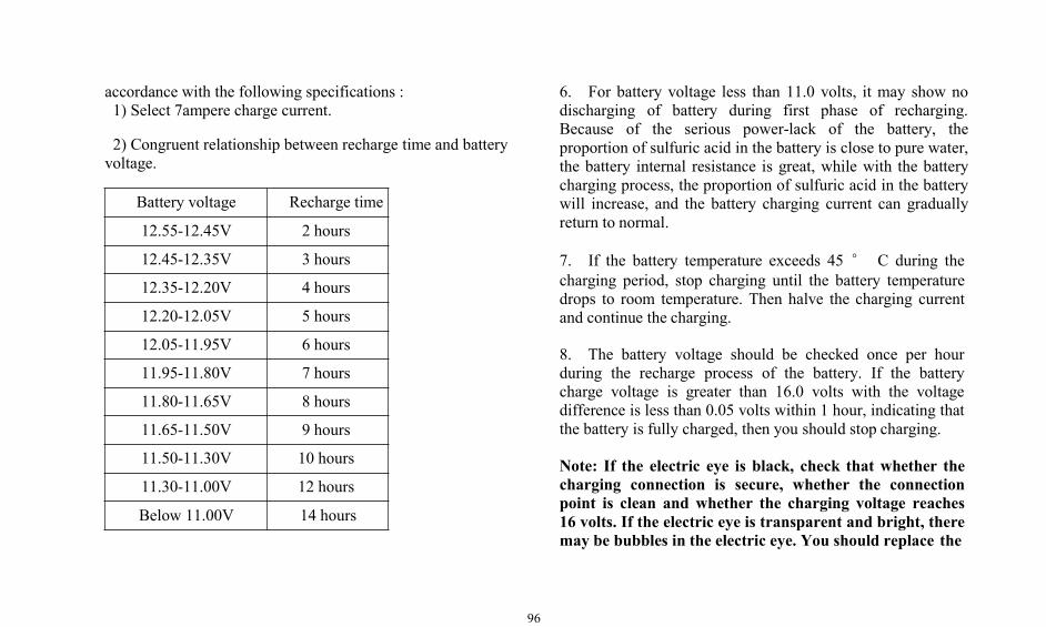
96
accordance with the following specifications :1) Select 7ampere charge current.
2) Congruent relationship between recharge time and batteryvoltage.
Battery voltage Recharge time
12.55-12.45V 2 hours
12.45-12.35V 3 hours
12.35-12.20V 4 hours
12.20-12.05V 5 hours
12.05-11.95V 6 hours
11.95-11.80V 7 hours
11.80-11.65V 8 hours
11.65-11.50V 9 hours
11.50-11.30V 10 hours
11.30-11.00V 12 hours
Below 11.00V 14 hours
6. For battery voltage less than 11.0 volts, it may show nodischarging of battery during first phase of recharging.Because of the serious power-lack of the battery, theproportion of sulfuric acid in the battery is close to pure water,the battery internal resistance is great, while with the batterycharging process, the proportion of sulfuric acid in the batterywill increase, and the battery charging current can graduallyreturn to normal.
7. If the battery temperature exceeds 45 ° C during thecharging period, stop charging until the battery temperaturedrops to room temperature. Then halve the charging currentand continue the charging.
8. The battery voltage should be checked once per hourduring the recharge process of the battery. If the batterycharge voltage is greater than 16.0 volts with the voltagedifference is less than 0.05 volts within 1 hour, indicating thatthe battery is fully charged, then you should stop charging.
Note: If the electric eye is black, check that whether thecharging connection is secure, whether the connectionpoint is clean and whether the charging voltage reaches16 volts. If the electric eye is transparent and bright, theremay be bubbles in the electric eye. You should replace the
97
battery if it shows white after gently shaking.
After charging the battery, brush Vaseline in the end post toprevent the electric erosion.
The maintenance of the storage batteryduring the machine storage.
1. If the machine is stored for more than 15 days, pleasedisconnect the negative battery cable.
2. Check the battery every three months for the state ofcharge. Batteries voltage that greater than 12.4 volts arenormally charged batteries. Batteries voltage that less than12.4 volts are power-lack batteries.
3. You should make recharging in case of power-lackbatteries. The recharging shall be implemented according torecharging procedures.
3. For vehicles that don't disconnect battery connection,you should check the battery voltage status once a month. Forbatteries with a voltage less than 12.4 volts shall be recharged
in accordance with the recharging procedure.
4. For battery in the vehicle that stored for more than oneyear, if it's not recharged according to the above requirements,you should replace the battery and dispose it as scrap.
Scrap of the battery
During the scrap process of the batteries, their internal leadplate, acid materials, plastic shell will cause different degreesof environmental pollution due to the external structuraldamages or other reasons,Therefore, you can not arbitrarilydiscard discarded batteries, and you should send them to aprofessional battery processing station or a local recycle binset by battery manufacturer (if any) for processing.
Air Conditioning SystemDetection of air conditioners
Warning: Inhalation of the refrigerant gas from the airconditioner through the lit cigarettes or other smoking
98
methods, or inhalation of smoke emitted from a flame incontact with the air conditioner refrigerant, it can result inpersonal injury or death. Do not smoke when servicing the airconditioner or where refrigerant gas may be present.
1. Start the engine and let the engine run at high idle speed.2. Allow the air conditioning system to keep stable runningfor 2 minutes.3. Check the refrigerant in the system, touch the suction pipeand the exhaust pipe. If the system contains refrigerant, theexhaust pipe is warmer than the suction duct. If the systemdoes not contain refrigerant or the system has a very smallamount of refrigerant, the cooling effect will be poor.
Check the refrigerant in the fluid reservoir
When opening air conditioning, you can check whether therefrigerant is sufficient by observing whether there arebubbles of refrigerant in the fluid reservoir through the sightglasses in the fluid reservoir. If there are a large number ofbubbles, the refrigerant is insufficient; If there is only a verysmall amount of bubbles or no bubbles but with flowingrefrigerant, the refrigerant is sufficient.
Other maintenanceCheck and replace the bucket and bucketteeth
Warning: Bucket falling will cause casualties, please fixthe bucket before replacing the bucket teeth
Check the bucket teeth and side buckets for wear and damage,and take the following procedure to maintain bucket and sidebuckets if necessary.1. Lift the bucket and place the cushion block under thebucket2. Lower the bucket to the cushion block and turn off theengine.3. Remove bolts, bucket teeth and side buckets.4. Clean all contact surfaces.5. If the reverse side of the teeth is not worn, you can use thereverse side of the teeth. Side buckets can not be flipped.6. Tighten the bolts to the specified torque. Start the engine.7. Raise the bucket and remove the cushion block. Lower thebucket to the ground.8. After operation for a few hours, check whether the bolttorque is appropriate.
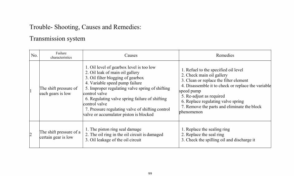
99
Trouble- Shooting, Causes and Remedies:
Transmission system
No. Failurecharacteristics Causes Remedies
1 The shift pressure ofeach gears is low
1. Oil level of gearbox level is too low2. Oil leak of main oil gallery3. Oil filter blogging of gearbox4. Variable speed pump failure5. Improper regulating valve spring of shiftingcontrol valve6. Regulating valve spring failure of shiftingcontrol valve7. Pressure regulating valve of shifting controlvalve or accumulator piston is blocked
1. Refuel to the specified oil level2. Check main oil gallery3. Clean or replace the filter element4. Disassemble it to check or replace the variablespeed pump5. Re-adjust as required6. Replace regulating valve spring7. Remove the parts and eliminate the blockphenomenon
2 The shift pressure of acertain gear is low
1. The piston ring seal damage2. The oil ring in the oil circuit is damaged3. Oil leakage of the oil circuit
1. Replace the sealing ring2. Replace the seal ring3. Check the spilling oil and discharge it
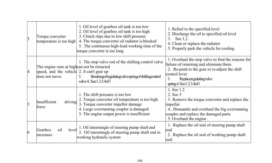
100
3 Torque convertertemperature is too high
1. Oil level of gearbox oil tank is too low2. Oil level of gearbox oil tank is too high3. Clutch slips due to low shift pressure4. The torque converter oil radiator is blocked5. The continuous high-load working time of thetorque converter is too long
1. Refuel to the specified level2. Discharge the oil to specified oil level3. See 1,24. Clean or replace the radiator5. Properly park the vehicle for cooling
4The engine runs at highspeed, and the vehicledoes not move
1. The stop valve rod of the shifting control valvecan not be retracted2. It can't gear up3. Breakingofregulatingvalvespringofshiftingcontrolvalve4..See1.2.3.4of1
1. Overhaul the stop valve to find the reasons forfailure of returning and eliminate them.2. Re-push to the gear or re-adjust the shiftcontrol lever3. Replaceregulatingvalvespring4.See1.2.3.4of1
5 Insufficient drivingforce
1. The shift pressure is too low2. Torque converter oil temperature is too high3. Torque converter impeller damage4. Large overrunning coupler is damaged5. The engine output power is insufficient
1. See 1.22. See 33. Remove the torque converter and replace theimpeller4.. Dismantle and overhaul the big overrunningcoupler and replace the damaged parts5. Overhaul the engine
6 Gearbox oil levelincreases
1. Oil intermingle of steering pump shaft end2. Oil intermingle of steering pump shaft end inworking hydraulic system
1. Replace the oil seal of steering pump shaftend2. Replace the oil seal of working pump shaftend.
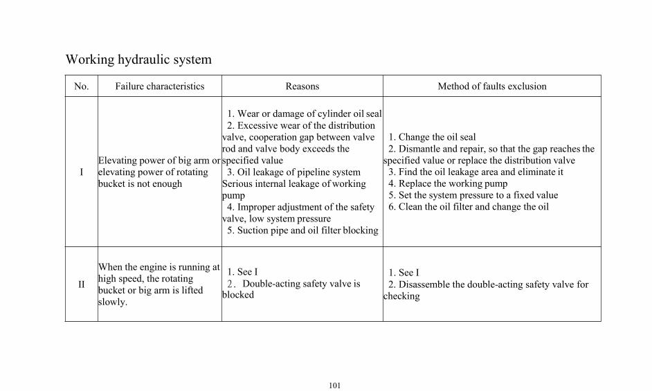
101
Working hydraulic system
No. Failure characteristics Reasons Method of faults exclusion
IElevating power of big arm orelevating power of rotatingbucket is not enough
1. Wear or damage of cylinder oil seal2. Excessive wear of the distributionvalve, cooperation gap between valverod and valve body exceeds thespecified value3. Oil leakage of pipeline systemSerious internal leakage of workingpump4. Improper adjustment of the safetyvalve, low system pressure5. Suction pipe and oil filter blocking
1. Change the oil seal2. Dismantle and repair, so that the gap reaches thespecified value or replace the distribution valve3. Find the oil leakage area and eliminate it4. Replace the working pump5. Set the system pressure to a fixed value6. Clean the oil filter and change the oil
II
When the engine is running athigh speed, the rotatingbucket or big arm is liftedslowly.
1. See I2. Double-acting safety valve isblocked
1. See I2. Disassemble the double-acting safety valve forchecking
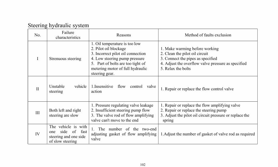
102
Steering hydraulic systemNo. Failure
characteristics Reasons Method of faults exclusion
I Strenuous steering
1. Oil temperature is too low2. Pilot oil blockage3. Incorrect pilot oil connection4. Low steering pump pressure5. Part of bolts are too tight ofmetering motor of full hydraulicsteering gear.
1. Make warming before working2. Clean the pilot oil circuit3. Connect the pipes as specified4. Adjust the overflow valve pressure as specified5. Relax the bolts
II Unstable vehiclesteering
1.Insensitive flow control valveaction 1. Repair or replace the flow control valve
III Both left and rightsteering are slow
1. Pressure regulating valve leakage2. Insufficient steering pump flow3. The valve rod of flow amplifyingvalve can't move to the end
1. Repair or replace the flow amplifying valve2. Repair or replace the steering pump3. Adjust the pilot oil circuit pressure or replace thespring
IV
The vehicle is withone side of faststeering and one sideof slow steering
1. The number of the two-endadjusting gasket of flow amplifyingvalve
1.Adjust the number of gasket of valve rod as required
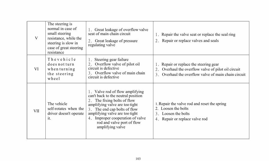
103
V
The steering isnormal in case ofsmall steeringresistance, while thesteering is slow incase of great steeringresistance
1. Great leakage of overflow valveseat of main chain circuit
2. Great leakage of pressureregulating valve
1. Repair the valve seat or replace the seal ring2. Repair or replace valves and seals
VI
T h e v e h i c l edoes no t t u r nwhen tu r n i ngthe s t e e r i ngwhee l
1. Steering gear failure2. Overflow valve of pilot oilcircuit is defective3. Overflow valve of main chaincircuit is defective
1. Repair or replace the steering gear2. Overhaul the overflow valve of pilot oil circuit3. Overhaul the overflow valve of main chain circuit
VII
The vehicleself-rotates when thedriver doesn't operateit.
1. Valve rod of flow amplifyingcan't back to the neutral position2. The fixing bolts of flowamplifying valve are too tight3. The end cap bolts of flowamplifying valve are too tight4. Improper cooperation of valve
rod and valve port of flowamplifying valve
1.Repair the valve rod and reset the spring2. Loosen the bolts3. Loosen the bolts4. Repair or replace valve rod
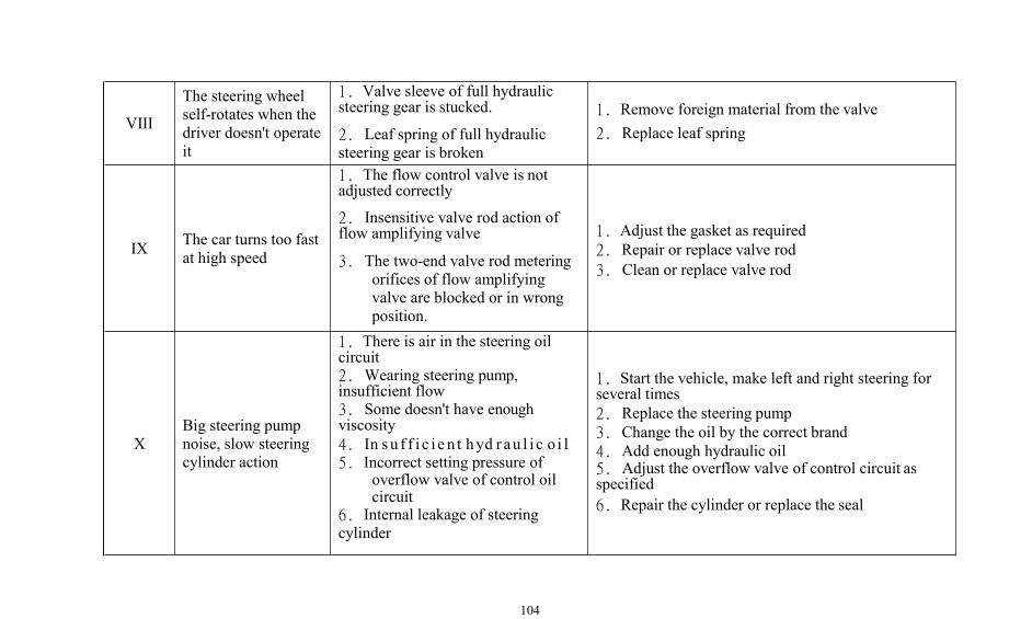
104
VIII
The steering wheelself-rotates when thedriver doesn't operateit
1. Valve sleeve of full hydraulicsteering gear is stucked.
2. Leaf spring of full hydraulicsteering gear is broken
1. Remove foreign material from the valve2. Replace leaf spring
IX The car turns too fastat high speed
1. The flow control valve is notadjusted correctly
2. Insensitive valve rod action offlow amplifying valve
3. The two-end valve rod meteringorifices of flow amplifyingvalve are blocked or in wrongposition.
1. Adjust the gasket as required2. Repair or replace valve rod3. Clean or replace valve rod
XBig steering pumpnoise, slow steeringcylinder action
1. There is air in the steering oilcircuit2. Wearing steering pump,insufficient flow3. Some doesn't have enoughviscosity4. In su f f i c i e n t hyd r au l i c o i l5. Incorrect setting pressure of
overflow valve of control oilcircuit
6. Internal leakage of steeringcylinder
1. Start the vehicle, make left and right steering forseveral times2. Replace the steering pump3. Change the oil by the correct brand4. Add enough hydraulic oil5. Adjust the overflow valve of control circuit asspecified6. Repair the cylinder or replace the seal
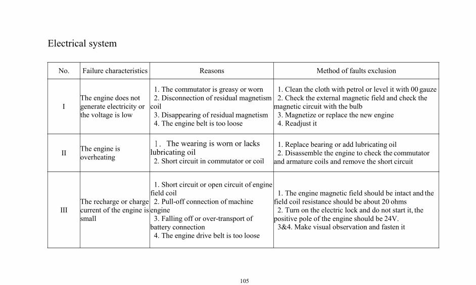
105
Electrical system
No. Failure characteristics Reasons Method of faults exclusion
IThe engine does notgenerate electricity orthe voltage is low
1. The commutator is greasy or worn2. Disconnection of residual magnetismcoil3. Disappearing of residual magnetism4. The engine belt is too loose
1. Clean the cloth with petrol or level it with 00 gauze2. Check the external magnetic field and check themagnetic circuit with the bulb3. Magnetize or replace the new engine4. Readjust it
II The engine isoverheating
1. The wearing is worn or lackslubricating oil2. Short circuit in commutator or coil
1. Replace bearing or add lubricating oil2. Disassemble the engine to check the commutatorand armature coils and remove the short circuit
IIIThe recharge or chargecurrent of the engine issmall
1. Short circuit or open circuit of enginefield coil2. Pull-off connection of machineengine3. Falling off or over-transport ofbattery connection4. The engine drive belt is too loose
1. The engine magnetic field should be intact and thefield coil resistance should be about 20 ohms2. Turn on the electric lock and do not start it, thepositive pole of the engine should be 24V.3&4. Make visual observation and fasten it
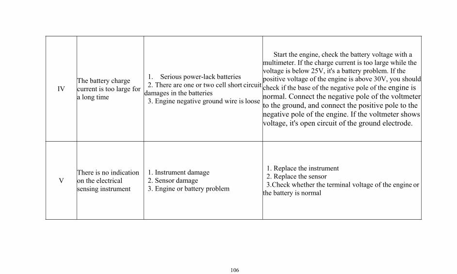
106
IVThe battery chargecurrent is too large fora long time
1. Serious power-lack batteries2. There are one or two cell short circuitdamages in the batteries3. Engine negative ground wire is loose
Start the engine, check the battery voltage with amultimeter. If the charge current is too large while thevoltage is below 25V, it's a battery problem. If thepositive voltage of the engine is above 30V, you shouldcheck if the base of the negative pole of the engine isnormal. Connect the negative pole of the voltmeterto the ground, and connect the positive pole to thenegative pole of the engine. If the voltmeter showsvoltage, it's open circuit of the ground electrode.
VThere is no indicationon the electricalsensing instrument
1. Instrument damage2. Sensor damage3. Engine or battery problem
1. Replace the instrument2. Replace the sensor3.Check whether the terminal voltage of the engine orthe battery is normal
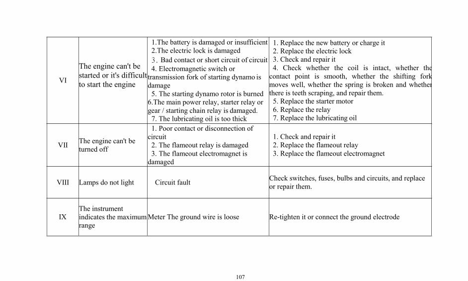
107
VI
The engine can't bestarted or it's difficultto start the engine
1.The battery is damaged or insufficient2.The electric lock is damaged3. Bad contact or short circuit of circuit4. Electromagnetic switch ortransmission fork of starting dynamo isdamage5. The starting dynamo rotor is burned6.The main power relay, starter relay orgear / starting chain relay is damaged.7. The lubricating oil is too thick
1. Replace the new battery or charge it2. Replace the electric lock3. Check and repair it4. Check whether the coil is intact, whether thecontact point is smooth, whether the shifting forkmoves well, whether the spring is broken and whetherthere is teeth scraping, and repair them.5. Replace the starter motor6. Replace the relay7. Replace the lubricating oil
VII The engine can't beturned off
1. Poor contact or disconnection ofcircuit2. The flameout relay is damaged3. The flameout electromagnet isdamaged
1. Check and repair it2. Replace the flameout relay3. Replace the flameout electromagnet
VIII Lamps do not light Circuit fault Check switches, fuses, bulbs and circuits, and replaceor repair them.
IXThe instrumentindicates the maximumrange
Meter The ground wire is loose Re-tighten it or connect the ground electrode
Related Documents