Operator’s Manual Original Instructions (EN) Register your product at www.Toro.com Form No. 3352-776 Wheel Horse ) XL 380H Lawn Tractor Model No. 71428—Serial No. 250000001 and Up

Welcome message from author
This document is posted to help you gain knowledge. Please leave a comment to let me know what you think about it! Share it to your friends and learn new things together.
Transcript

Operator’s Manual
Original Instructions (EN)Register your product at www.Toro.com
Form No. 3352-776
Wheel Horse� XL 380H LawnTractorModel No. 71428—Serial No. 250000001 and Up
2
� 2005 by The Toro Company8111 Lyndale Avenue SouthBloomington, MN 55420-1196
Contact us at www.Toro.comAll Rights Reserved
Printed in the USA
CALIFORNIA
Proposition 65 Warning
The engine exhaust from this product containschemicals known to the State of California to causecancer, birth defects, or other reproductive harm.
Warning
Important The engine in this product is not equippedwith a spark arrester muffler. It is a violation of CaliforniaPublic Resource Code Section 4442 to use or operate thisengine on any forest-covered, brush-covered, orgrass-covered land as defined in CPRC 4126. Other statesor federal areas may have similar laws.
This spark ignition system complies with CanadianICES-002.
Ce système d’allumage par étincelle de véhicule estconforme à la norme NMB-002 du Canada.
The enclosed Engine Owner’s Manual is supplied forinformation regarding The U.S. EnvironmentalProtection Agency (EPA) and the California EmissionControl Regulation of emission systems, maintenanceand warranty.
Keep this engine Owner’s Manual with your unit.Should this engine Owner’s Manual become damagedor illegible, replace immediately. Replacements may beordered through the engine manufacturer.
ContentsPage
Introduction 3. . . . . . . . . . . . . . . . . . . . . . . . . . . . . . . . . Safety 3. . . . . . . . . . . . . . . . . . . . . . . . . . . . . . . . . . . . . .
Safe Operating Practices 3. . . . . . . . . . . . . . . . . . . . Toro Riding Mower Safety 5. . . . . . . . . . . . . . . . . . . Slope Chart 7. . . . . . . . . . . . . . . . . . . . . . . . . . . . . . . Safety and Instruction Decals 9. . . . . . . . . . . . . . . . .
Gasoline and Oil 12. . . . . . . . . . . . . . . . . . . . . . . . . . . . . Recommended Gasoline 12. . . . . . . . . . . . . . . . . . . . . Using Stabilizer/Conditioner 12. . . . . . . . . . . . . . . . . Filling the Fuel Tank 12. . . . . . . . . . . . . . . . . . . . . . . Checking the Engine Oil Level 12. . . . . . . . . . . . . . .
Operation 13. . . . . . . . . . . . . . . . . . . . . . . . . . . . . . . . . . . Controls 13. . . . . . . . . . . . . . . . . . . . . . . . . . . . . . . . . Using the Parking Brake 13. . . . . . . . . . . . . . . . . . . . Positioning the Seat 14. . . . . . . . . . . . . . . . . . . . . . . . Operating the Headlights 14. . . . . . . . . . . . . . . . . . . . Using the Blade Control (PTO) 14. . . . . . . . . . . . . . . Setting the Height-of-Cut 14. . . . . . . . . . . . . . . . . . . .
PageStarting the Engine 14. . . . . . . . . . . . . . . . . . . . . . . . . Stopping the Engine 15. . . . . . . . . . . . . . . . . . . . . . . . Using the Safety Interlock System 15. . . . . . . . . . . . . Testing the Safety Interlock System 16. . . . . . . . . . . . Pushing the Tractor Manually 17. . . . . . . . . . . . . . . . Driving the Tractor Forward or Backward 17. . . . . . . Stopping the Tractor 17. . . . . . . . . . . . . . . . . . . . . . . . Side Discharging or Mulching the Grass 18. . . . . . . . Installing the Discharge Cover 18. . . . . . . . . . . . . . . . Operating Tips 18. . . . . . . . . . . . . . . . . . . . . . . . . . . .
Maintenance 19. . . . . . . . . . . . . . . . . . . . . . . . . . . . . . . . . Recommended Maintenance Schedule 19. . . . . . . . . Servicing the Engine Oil 20. . . . . . . . . . . . . . . . . . . . Servicing the Air Cleaner 21. . . . . . . . . . . . . . . . . . . . Servicing the Spark Plug 22. . . . . . . . . . . . . . . . . . . . Cleaning the Cooling System 23. . . . . . . . . . . . . . . . . Servicing the Brake 23. . . . . . . . . . . . . . . . . . . . . . . . Greasing and Lubricating the Tractor 24. . . . . . . . . . Checking the Tire Pressure 24. . . . . . . . . . . . . . . . . . Servicing the Battery 24. . . . . . . . . . . . . . . . . . . . . . . Draining the Fuel Tank 26. . . . . . . . . . . . . . . . . . . . . . Replacing the Fuel Filter 27. . . . . . . . . . . . . . . . . . . . Servicing the Transaxle Fluid 27. . . . . . . . . . . . . . . . Servicing the Fuse 28. . . . . . . . . . . . . . . . . . . . . . . . . Servicing the Headlights 28. . . . . . . . . . . . . . . . . . . . Servicing the Blade 29. . . . . . . . . . . . . . . . . . . . . . . . Removing the Mower 30. . . . . . . . . . . . . . . . . . . . . . . Installing the Mower 31. . . . . . . . . . . . . . . . . . . . . . . Replacing the Blade Drive Belt 33. . . . . . . . . . . . . . . Leveling the Mower from Side-to-Side 33. . . . . . . . . Adjusting the Front-to-Rear Blade Slope 34. . . . . . . . Washing the Underside of the Mower 35. . . . . . . . . . Cleaning and Storing the Tractor 36. . . . . . . . . . . . . . Wiring Diagram 37. . . . . . . . . . . . . . . . . . . . . . . . . . .
Troubleshooting 38. . . . . . . . . . . . . . . . . . . . . . . . . . . . . . The Toro Total Coverage Guarantee 40. . . . . . . . . . . . . .
IntroductionRead this manual carefully to learn how to operate andmaintain your product properly. The information in thismanual can help you and others avoid injury and productdamage. Although Toro designs and produces safeproducts, you are responsible for operating the productproperly and safely.
You may contact Toro directly at www.Toro.com forproduct and accessory information, help finding a dealer, orto register your product.
3
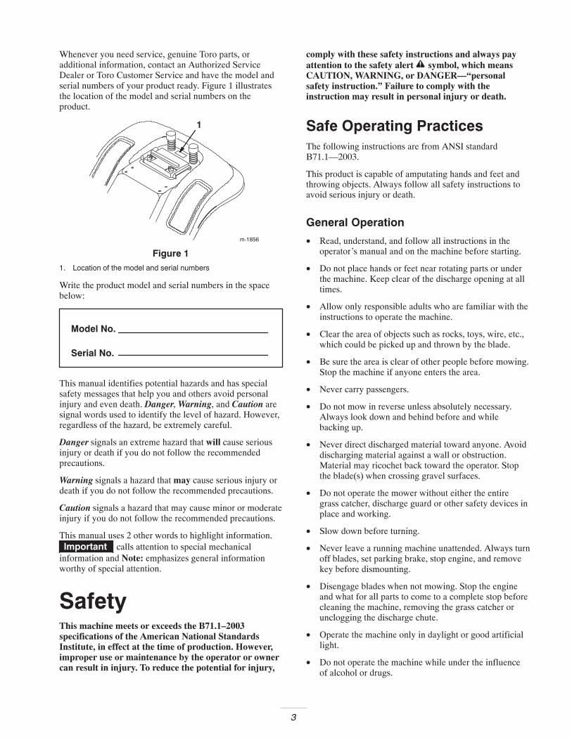
Whenever you need service, genuine Toro parts, oradditional information, contact an Authorized ServiceDealer or Toro Customer Service and have the model andserial numbers of your product ready. Figure 1 illustratesthe location of the model and serial numbers on theproduct.
m-1856
1
Figure 11. Location of the model and serial numbers
Write the product model and serial numbers in the spacebelow:
Model No.
Serial No.
This manual identifies potential hazards and has specialsafety messages that help you and others avoid personalinjury and even death. Danger, Warning, and Caution aresignal words used to identify the level of hazard. However,regardless of the hazard, be extremely careful.
Danger signals an extreme hazard that will cause seriousinjury or death if you do not follow the recommendedprecautions.
Warning signals a hazard that may cause serious injury ordeath if you do not follow the recommended precautions.
Caution signals a hazard that may cause minor or moderateinjury if you do not follow the recommended precautions.
This manual uses 2 other words to highlight information.Important calls attention to special mechanical
information and Note: emphasizes general informationworthy of special attention.
SafetyThis machine meets or exceeds the B71.1–2003specifications of the American National StandardsInstitute, in effect at the time of production. However,improper use or maintenance by the operator or ownercan result in injury. To reduce the potential for injury,
comply with these safety instructions and always payattention to the safety alert symbol, which meansCAUTION, WARNING, or DANGER—“personalsafety instruction.” Failure to comply with theinstruction may result in personal injury or death.
Safe Operating PracticesThe following instructions are from ANSI standardB71.1—2003.
This product is capable of amputating hands and feet andthrowing objects. Always follow all safety instructions toavoid serious injury or death.
General Operation
• Read, understand, and follow all instructions in theoperator’s manual and on the machine before starting.
• Do not place hands or feet near rotating parts or underthe machine. Keep clear of the discharge opening at alltimes.
• Allow only responsible adults who are familiar with theinstructions to operate the machine.
• Clear the area of objects such as rocks, toys, wire, etc.,which could be picked up and thrown by the blade.
• Be sure the area is clear of other people before mowing.Stop the machine if anyone enters the area.
• Never carry passengers.
• Do not mow in reverse unless absolutely necessary.Always look down and behind before and whilebacking up.
• Never direct discharged material toward anyone. Avoiddischarging material against a wall or obstruction.Material may ricochet back toward the operator. Stopthe blade(s) when crossing gravel surfaces.
• Do not operate the mower without either the entiregrass catcher, discharge guard or other safety devices inplace and working.
• Slow down before turning.
• Never leave a running machine unattended. Always turnoff blades, set parking brake, stop engine, and removekey before dismounting.
• Disengage blades when not mowing. Stop the engineand what for all parts to come to a complete stop beforecleaning the machine, removing the grass catcher orunclogging the discharge chute.
• Operate the machine only in daylight or good artificiallight.
• Do not operate the machine while under the influenceof alcohol or drugs.
4
• Watch for traffic when operating near or crossingroadways.
• Use extra care when loading or unloading the machineinto a trailer or truck.
• Always wear safety goggles or safety glasses with sideshields when operating mower.
• Data indicates that operators, age 60 years and above,are involved in a large percentage of ridingmower–related injuries. These operators shouldevaluate their ability to operate the riding mower safelyenough to protect themselves and others from seriousinjury.
• Always follow the recommendations for wheel weightsor counterweights.
Slope Operation
Slopes are a major factor related to loss-of-control andtip-over accidents, which can result in severe injury ordeath. All slopes require extra caution. If you cannot backup the slope or if you feel uneasy on it, do not mow it.
• Mow up and down slopes, not across.
• Watch for holes, ruts, bumps, rocks or other hiddenobstacles. Uneven terrain could overturn the machine.Tall grass can hide obstacles.
• Choose a low ground speed so you will not have to stopor shift while on a slope.
• Do not mow on wet grass. Tires may lose traction.
• Always keep the machine in gear when going downslopes. Do not shift to neutral and coast downhill.
• Avoid starting, stopping or turning on a slope. If tireslose traction, disengage the blades and proceed slowlystraight down the slope.
• Keep all movement on slopes slow and gradual. Do notmake sudden changes in speed or direction, which couldcause the machine to roll over.
• Use extra care while operating mower with grasscatchers or other attachments; they can affect thestability of the machine. Do not use on steep slopes.
• Do not try to stabilize the machine by putting your footon the ground.
• Do not mow near drop-offs, ditches, or embankments.The machine could suddenly turn over if a wheel goesover the edge of a cliff or ditch, or if an edge caves in.
Children
Tragic accidents can occur if the operator is not alert to thepresence of children. Children are often attracted to themachine and the mowing activity. Never assume thatchildren will remain where you last saw them.
• Keep children out of the mowing area and under thewatchful care of a responsible adult, not the operator.
• Be alert and turn the machine off if children enter thearea.
• Before and while backing or changing direction, lookbehind, down, and side–to–side for small children.
• Never carry children, even with the blades off. Theymay fall off and be seriously injured or interfere withsafe machine operation.
• Children who have been given rides in the past maysuddenly appear in the mowing area for another rideand be run over or backed over by the mower.
• Never allow children to operate the machine.
• Use extra care when approaching blind corners, shrubs,trees, or other objects that may block your view of achild.
Towing
• Tow only with a machine that has a hitch designed fortowing. Do not attached towed equipment except at thehitch point.
• This product has a limited towing capacity for smallattachments, such as leaf sweepers, rollers or carts. Thecombined weight of the attachment and load should notexceed the weight of the tractor. Use of these types ofattachments should be limited to flat ground.
• Never allow children or others in or on towedequipment.
• On slopes, the weight of towed equipment may cause aloss of traction and control.
• Travel slowly and allow extra distance to stop.
Service
Safe Handling of Gasoline
To avoid personal injury or property damage, use extremecare in handling gasoline. Gasoline is extremely flammableand the vapors are explosive.
• Extinguish all cigarettes, cigars, pipes and othersources of ignition.
• Use only an approved gasoline container.
• Never remove the gas cap or add fuel when theengine is running. Allow the engine to cool beforerefueling.
• Never refuel the machine indoors.
• Never store the machine or fuel container wherethere is an open flame, spark, or pilot light such as awater heater or other appliances.
5
• Never fill containers inside a vehicle or on a truck ortrailer with a plastic liner. Always place containerson the ground away from your vehicle before filling.
• Remove gas-powered equipment from the truck ortrailer and refuel it on the ground. If this is notpossible, then refuel such equipment with a portablecontainer, rather than from a gasoline dispensernozzle.
• Keep the nozzle in contact with the rim of the fueltank or container opening at all times until thefueling is complete. Do not use a nozzle lock-opendevice.
• If fuel is spilled on clothing, change clothingimmediately.
• Never overfill the fuel tank. Replace gas cap andtighten securely.
General Service
• Never run a machine inside a closed area.
• Keep nuts and bolts tight to be sure the equipment is insafe working condition.
• Never tamper with safety devices. Check their properoperation regularly.
• Keep the machine free of grass, leaves, or other debrisbuild-up. Clean up oil or fuel spillage fuel soakeddebris. Allow the machine to cool before storing.
• If you strike a foreign object, stop and inspect themower. Repair, if necessary, before restarting.
• Never make any adjustments or repairs with the enginerunning.
• Check grass catcher components and the dischargeguard frequently and replace with manufacturer’srecommended parts, when necessary.
• Mower blades are sharp and can cut. Wrap the blade(s)or wear gloves, and use extra caution when servicingthem.
• Check brake operation frequently. Adjust and service asrequired.
• Maintain or replace safety and instruction decals asnecessary.
Toro Riding Mower SafetyThe following list contains safety information specificto Toro products or other safety information that youmust know that is not included in the ANSI standards.
• Stop the engine, disconnect spark plug wire(s) andremove key before performing any service, repairs,maintenance or adjustments.
• Never leave a running machine unattended. Always turnoff blades, set parking brake, stop engine, and removethe ignition and KeyChoice™ keys before dismounting.
• Keep hands, feet, hair and loose clothing away fromattachment discharge area, underside of mower and anymoving parts while engine is running.
• Do not touch equipment or attachment parts which maybe hot from operation. Allow to cool before attemptingto maintain, adjust or service.
• Battery acid is poisonous and can cause burns. Avoidcontact with skin, eyes and clothing. Protect your face,eyes and clothing when working with a battery.
• Battery gases can explode. Keep cigarettes, sparks andflames away from battery.
• Use only Toro approved attachments. Warranty may bevoided if used with unapproved attachments.
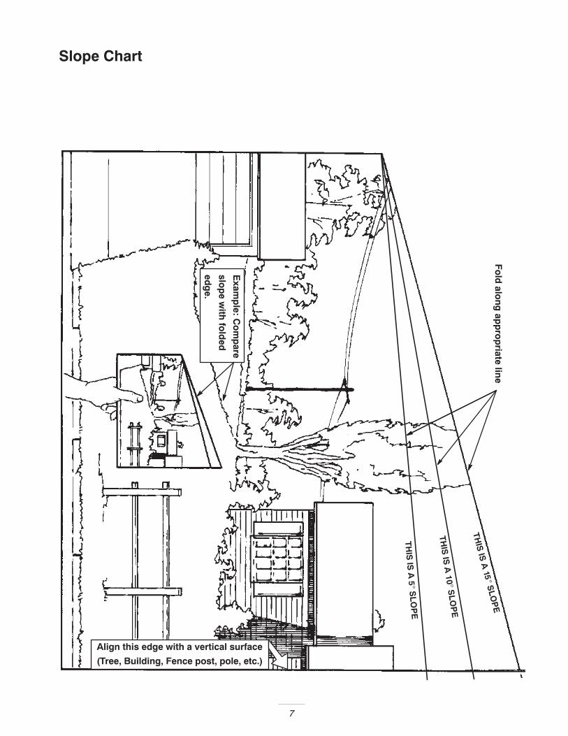
• Do not mow across slopes exceeding 5 degrees.
• Do not mow up slopes exceeding 10 degrees.
• Do not mow down slopes exceeding 15 degrees.
• If a steep slope must be ascended, back up the hill, anddrive forward down the hill, keeping the machine ingear.
• Use only genuine Toro replacement parts to ensure thatoriginal standards are maintained.

6
7
Slope ChartF
old
alon
g ap
pro
priate lin
e
Align this edge with a vertical surface
(Tree, Building, Fence post, pole, etc.)
Exam
ple: C
om
pare
slop
e with
fold
ed
edg
e.

8
9
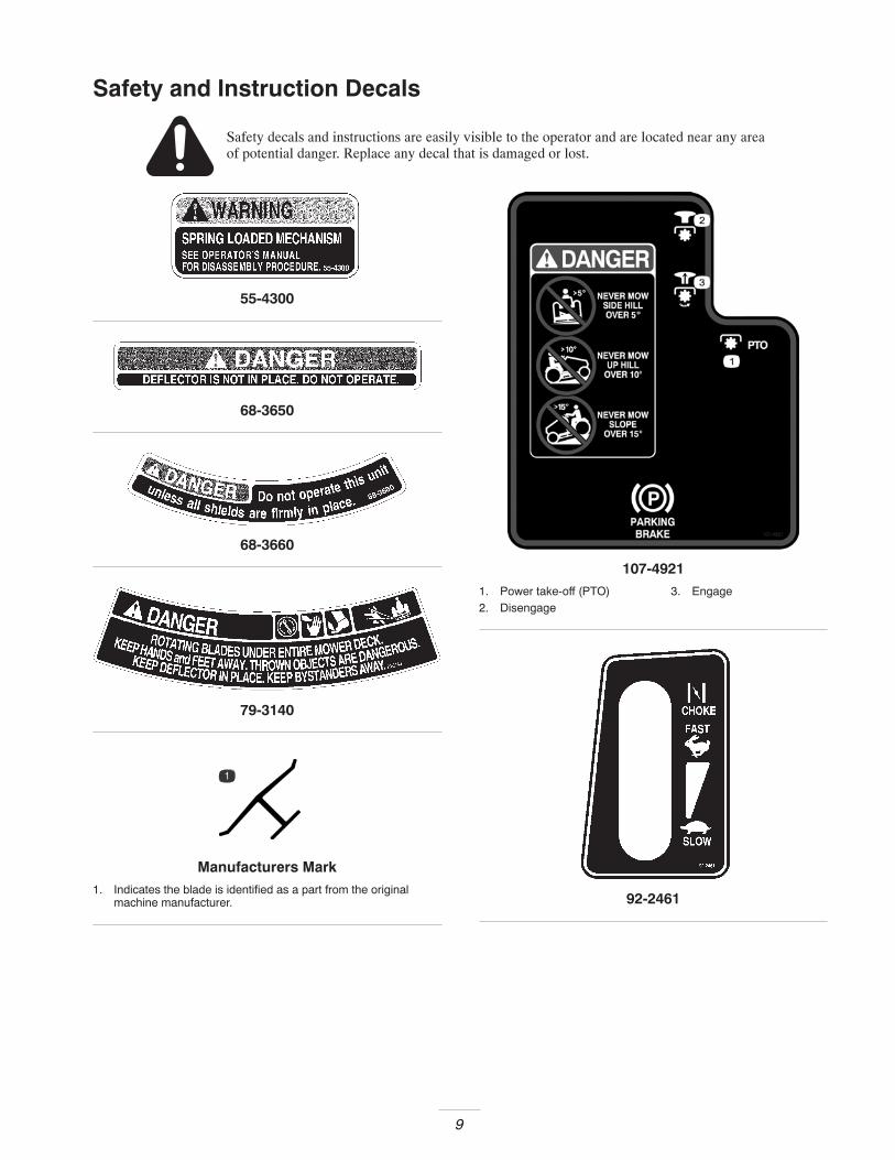
Safety and Instruction Decals
Safety decals and instructions are easily visible to the operator and are located near any areaof potential danger. Replace any decal that is damaged or lost.
55-4300
68-3650
68-3660
79-3140
Manufacturers Mark1. Indicates the blade is identified as a part from the original
machine manufacturer.
107-49211. Power take-off (PTO)2. Disengage
3. Engage
92-2461

10
93-1122
93-66791. Engine
99-2985
99-5339
108-7817
99-8139
11
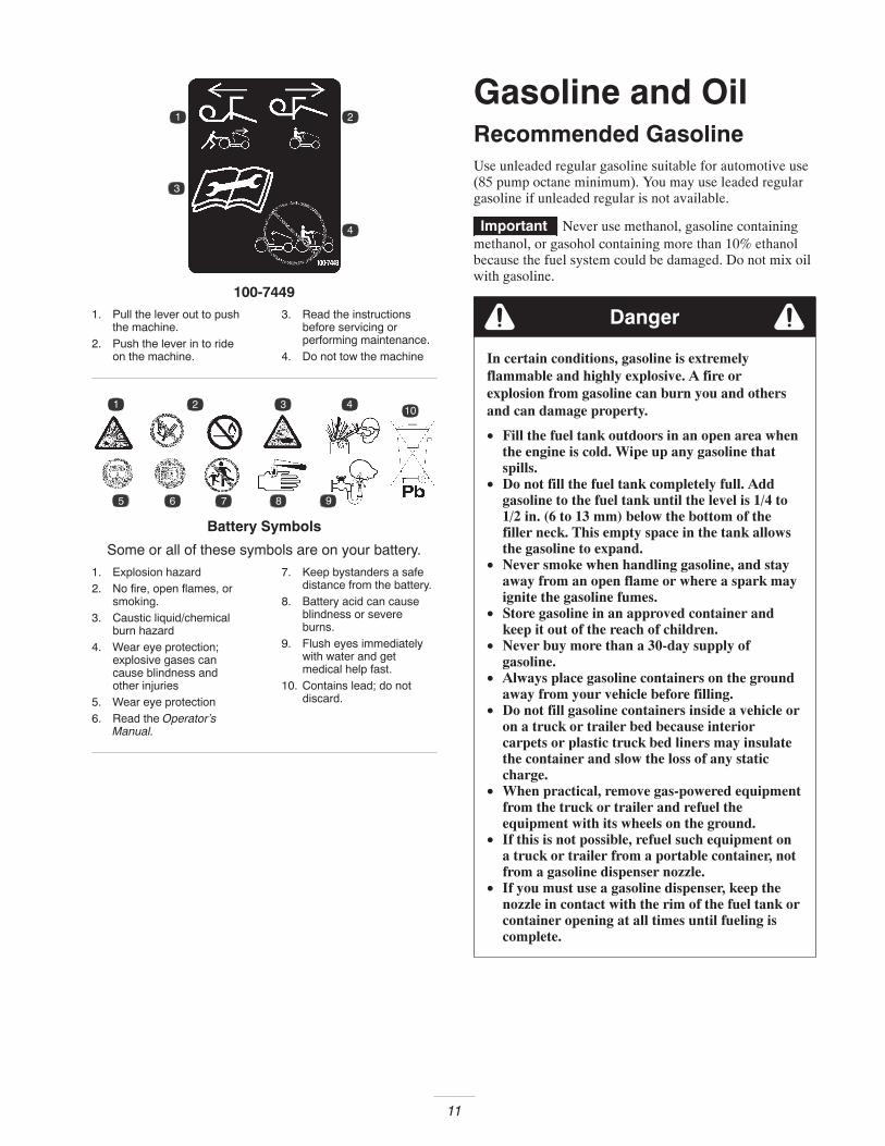
100-74491. Pull the lever out to push
the machine.2. Push the lever in to ride
on the machine.
3. Read the instructionsbefore servicing orperforming maintenance.
4. Do not tow the machine
Battery Symbols
Some or all of these symbols are on your battery.
1. Explosion hazard2. No fire, open flames, or
smoking.3. Caustic liquid/chemical
burn hazard4. Wear eye protection;
explosive gases cancause blindness andother injuries
5. Wear eye protection6. Read the Operator’s
Manual.
7. Keep bystanders a safedistance from the battery.
8. Battery acid can causeblindness or severeburns.
9. Flush eyes immediatelywith water and getmedical help fast.
10. Contains lead; do notdiscard.
Gasoline and OilRecommended GasolineUse unleaded regular gasoline suitable for automotive use(85 pump octane minimum). You may use leaded regulargasoline if unleaded regular is not available.
Important Never use methanol, gasoline containingmethanol, or gasohol containing more than 10% ethanolbecause the fuel system could be damaged. Do not mix oilwith gasoline.
Danger
In certain conditions, gasoline is extremelyflammable and highly explosive. A fire orexplosion from gasoline can burn you and othersand can damage property.
• Fill the fuel tank outdoors in an open area whenthe engine is cold. Wipe up any gasoline thatspills.
• Do not fill the fuel tank completely full. Addgasoline to the fuel tank until the level is 1/4 to1/2 in. (6 to 13 mm) below the bottom of thefiller neck. This empty space in the tank allowsthe gasoline to expand.
• Never smoke when handling gasoline, and stayaway from an open flame or where a spark mayignite the gasoline fumes.
• Store gasoline in an approved container andkeep it out of the reach of children.
• Never buy more than a 30-day supply ofgasoline.
• Always place gasoline containers on the groundaway from your vehicle before filling.
• Do not fill gasoline containers inside a vehicle oron a truck or trailer bed because interiorcarpets or plastic truck bed liners may insulatethe container and slow the loss of any staticcharge.
• When practical, remove gas-powered equipmentfrom the truck or trailer and refuel theequipment with its wheels on the ground.
• If this is not possible, refuel such equipment ona truck or trailer from a portable container, notfrom a gasoline dispenser nozzle.
• If you must use a gasoline dispenser, keep thenozzle in contact with the rim of the fuel tank orcontainer opening at all times until fueling iscomplete.
12
Using Stabilizer/ConditionerUse a fuel stabilizer/conditioner in the tractor to provide thefollowing benefits:
• It keeps gasoline fresh during storage for up to 90 days.For longer storage, drain the fuel tank.
• It cleans the engine while it runs.
• It eliminates gum-like varnish buildup in the fuelsystem, which causes hard starting.
Important Do not use fuel additives containingmethanol or ethanol.
Add the correct amount of fuel stabilizer/conditioner to thegasoline.
Note: A fuel stabilizer/conditioner is most effective when itis mixed with fresh gasoline. To minimize the chance ofvarnish deposits in the fuel system, use a fuelstabilizer/conditioner at all times.
Filling the Fuel Tank1. Stop the engine and wait for all moving parts to stop.
2. Set the parking brake.
3. Clean around the fuel tank cap and remove the cap.
4. Add unleaded regular gasoline to the fuel tank until thelevel is 1/4 to 1/2 in. (6 to 13 mm) below the bottom ofthe filler neck. Do not fill the fuel tank completelyfull.
Note: This space in the tank allows gasoline to expand.
5. Install the fuel tank cap securely.
6. Wipe up any gasoline that spills.
Checking the Engine Oil LevelBefore you start the engine and use the tractor, check the oillevel in the engine crankcase; refer to Checking the OilLevel on page 20.
OperationNote: Determine the left and right sides of the tractor fromthe normal operating position.
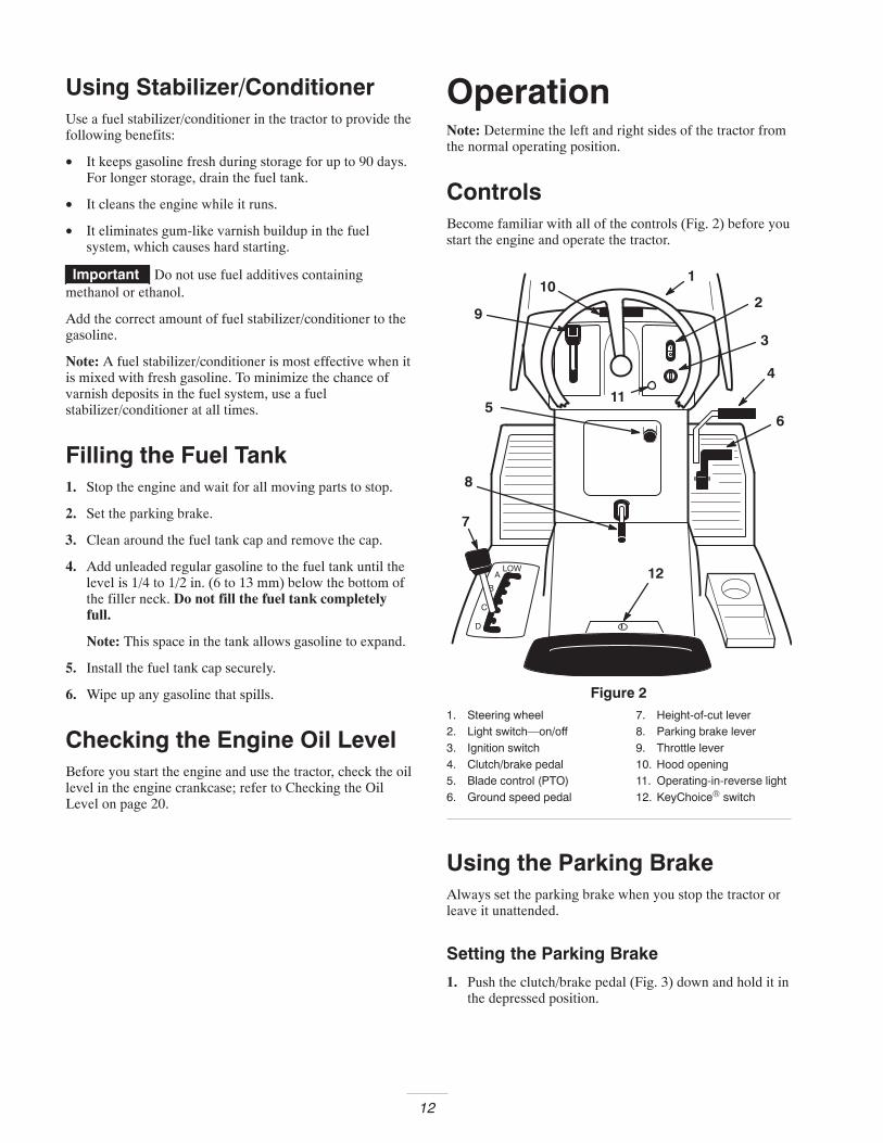
ControlsBecome familiar with all of the controls (Fig. 2) before youstart the engine and operate the tractor.
12
11
1
2
3
4
56
7
8
9
10
Figure 21. Steering wheel2. Light switch—on/off3. Ignition switch4. Clutch/brake pedal5. Blade control (PTO)6. Ground speed pedal
7. Height-of-cut lever8. Parking brake lever9. Throttle lever10. Hood opening11. Operating-in-reverse light12. KeyChoice® switch
Using the Parking BrakeAlways set the parking brake when you stop the tractor orleave it unattended.
Setting the Parking Brake
1. Push the clutch/brake pedal (Fig. 3) down and hold it inthe depressed position.
13
1
2
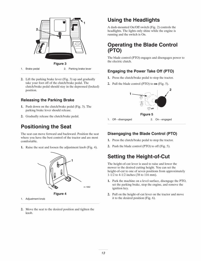
Figure 31. Brake pedal 2. Parking brake lever
2. Lift the parking brake lever (Fig. 3) up and graduallytake your foot off of the clutch/brake pedal. Theclutch/brake pedal should stay in the depressed (locked)position.
Releasing the Parking Brake
1. Push down on the clutch/brake pedal (Fig. 3). Theparking brake lever should release.
2. Gradually release the clutch/brake pedal.
Positioning the SeatThe seat can move forward and backward. Position the seatwhere you have the best control of the tractor and are mostcomfortable.
1. Raise the seat and loosen the adjustment knob (Fig. 4).
m-1862
1
Figure 41. Adjustment knob
2. Move the seat to the desired position and tighten theknob.
Using the HeadlightsA dash-mounted On/Off switch (Fig. 2) controls theheadlights. The lights only shine while the engine isrunning and the switch is On.
Operating the Blade Control(PTO)The blade control (PTO) engages and disengages power tothe electric clutch.
Engaging the Power Take Off (PTO)
1. Press the clutch/brake pedal to stop the tractor.
2. Pull the blade control (PTO) to on (Fig. 5).
12
Figure 51. Off—disengaged 2. On—engaged
Disengaging the Blade Control (PTO)
1. Press the clutch/brake pedal to stop the tractor.
2. Push the blade control (PTO) to off (Fig. 5).
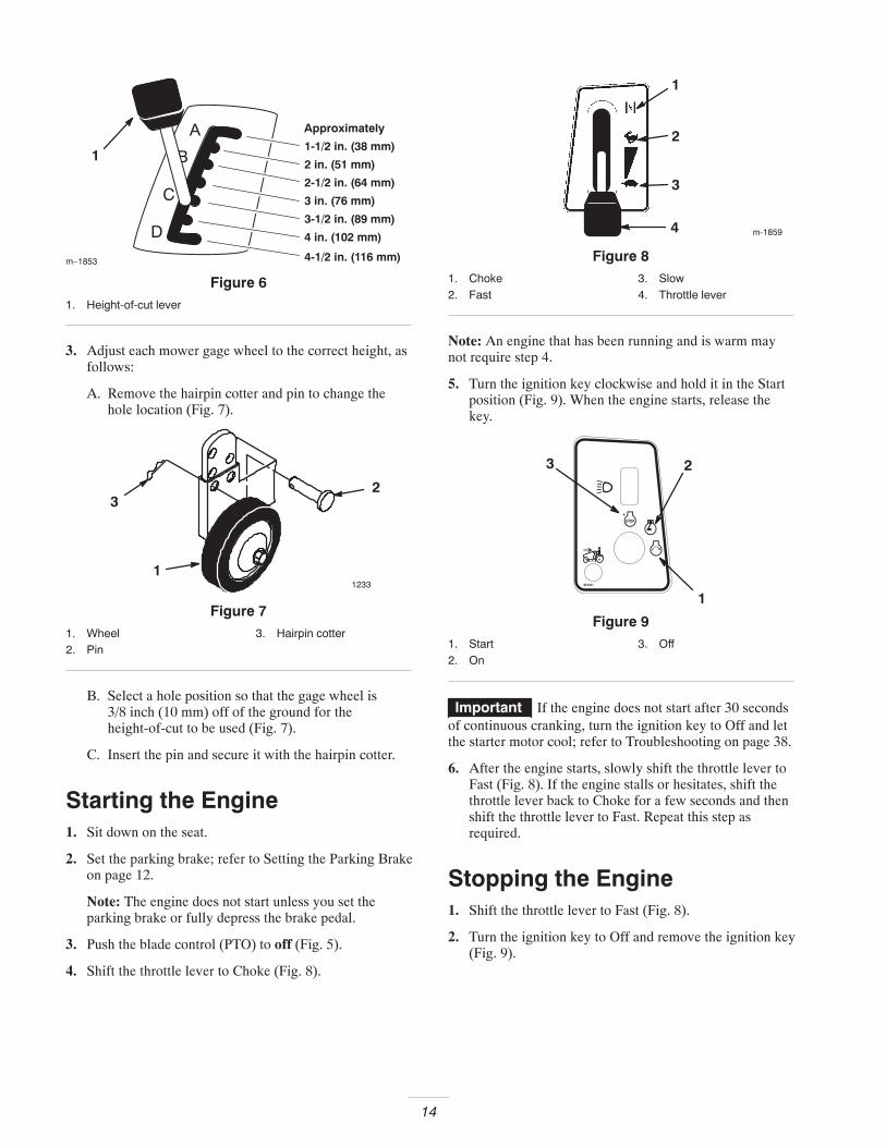
Setting the Height-of-CutThe height-of-cut lever is used to raise and lower themower to the desired cutting height. You can set theheight-of-cut to one of seven positions from approximately1-1/2 to 4-1/2 inches (38 to 116 mm).
1. Park the machine on a level surface, disengage the PTO,set the parking brake, stop the engine, and remove theignition key.
2. Pull on the height-of-cut lever on the tractor and moveit to the desired position (Fig. 6).
14
m–1853
1
4-1/2 in. (116 mm)
1-1/2 in. (38 mm)
2 in. (51 mm)
2-1/2 in. (64 mm)
3 in. (76 mm)
3-1/2 in. (89 mm)
4 in. (102 mm)
Approximately
Figure 61. Height-of-cut lever
3. Adjust each mower gage wheel to the correct height, asfollows:
A. Remove the hairpin cotter and pin to change thehole location (Fig. 7).
12331
23
Figure 71. Wheel2. Pin
3. Hairpin cotter
B. Select a hole position so that the gage wheel is3/8 inch (10 mm) off of the ground for theheight-of-cut to be used (Fig. 7).
C. Insert the pin and secure it with the hairpin cotter.
Starting the Engine1. Sit down on the seat.
2. Set the parking brake; refer to Setting the Parking Brakeon page 12.
Note: The engine does not start unless you set theparking brake or fully depress the brake pedal.
3. Push the blade control (PTO) to off (Fig. 5).
4. Shift the throttle lever to Choke (Fig. 8).
m-1859
1
2
3
4
Figure 81. Choke2. Fast
3. Slow4. Throttle lever
Note: An engine that has been running and is warm maynot require step 4.
5. Turn the ignition key clockwise and hold it in the Startposition (Fig. 9). When the engine starts, release thekey.
3 2
1
Figure 91. Start2. On
3. Off
Important If the engine does not start after 30 secondsof continuous cranking, turn the ignition key to Off and letthe starter motor cool; refer to Troubleshooting on page 38.
6. After the engine starts, slowly shift the throttle lever toFast (Fig. 8). If the engine stalls or hesitates, shift thethrottle lever back to Choke for a few seconds and thenshift the throttle lever to Fast. Repeat this step asrequired.
Stopping the Engine1. Shift the throttle lever to Fast (Fig. 8).
2. Turn the ignition key to Off and remove the ignition key(Fig. 9).
15
Using the Safety InterlockSystem
If the safety interlock switches are disconnected ordamaged, the tractor could operate unexpectedly,causing personal injury.
• Do not tamper with the interlock switches.• Check the operation of the interlock switches
daily and replace any damaged switches beforeoperating the tractor.
Caution
Understanding the Safety InterlockSystem
The safety interlock system is designed to prevent theengine from starting unless:
• You are sitting on the seat.
• The brake pedal is depressed.
• The blade control (PTO) is in the Disengage position.
The safety interlock system is designed to stop the engine ifyou do the following:
• You rise from the seat when the brake pedal is released.
• You rise from the seat while the blade control (PTO) isin the Engage position.
• You shift into reverse while the blade control (PTO) isin the Engage position.
Setting the KeyChoice� Switch toOperate in Reverse
An interlock feature on the tractor prevents the powertake-off (PTO) from operating when you back up thetractor. If you shift the ground speed switch into Reversewith the PTO engaged (i.e., with the mower blades or otherattachment running), the engine will stop. Do not mow inreverse unless it is absolutely necessary.
If you need to use the blade control (PTO) while backingup, turn off the interlock feature using the KeyChoiceswitch located near the seat bracket (Fig. 10).
Danger
You could back over a child or bystander while themower blades or other attachment is engaged andcause serious injury or death.
• Do not mow in reverse unless it is absolutelynecessary.
• Do not insert the KeyChoice key unless it isabsolutely necessary.
• Always look backward and down beforebacking up.
• Use the KeyChoice switch only if you are certainno children or other bystanders will enter themowing area.
• Be very observant after deactivating theinterlock because the sound of the engine mayprevent you from noticing that a child orbystander has entered the work area.
• Always remove both the ignition and KeyChoicekeys and put them in a safe place out of thereach of children or unauthorized users whenleaving the tractor unattended.
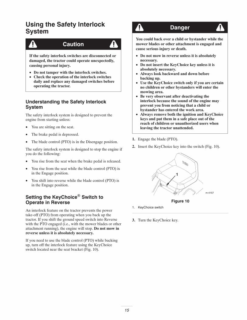
1. Engage the blade (PTO).
2. Insert the KeyChoice key into the switch (Fig. 10).
1
m-4157
Figure 101. KeyChoice switch
3. Turn the KeyChoice key.
16
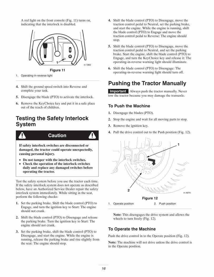
A red light on the front console (Fig. 11) turns on,indicating that the interlock is disabled.
m-18631
Figure 111. Operating-in-reverse light
4. Shift the ground speed switch into Reverse andcomplete your task.
5. Disengage the blade (PTO) to activate the interlock.
6. Remove the KeyChoice key and put it in a safe placeout of the reach of children.
Testing the Safety InterlockSystem
If safety interlock switches are disconnected ordamaged, the tractor could operate unexpectedly,causing personal injury.
• Do not tamper with the interlock switches.• Check the operation of the interlock switches
daily and replace any damaged switches beforeoperating the tractor.
Caution
Test the safety system before you use the tractor each time.If the safety interlock system does not operate as describedbelow, have an Authorized Service Dealer repair the safetyinterlock system immediately. While sitting in the seat,perform the following checks:
1. Set the parking brake. Shift the blade control (PTO) toEngage, and turn the ignition key to Start: The engineshould not crank.
2. Shift the blade control (PTO) to Disengage and releasethe parking brake. Turn the ignition key to Start: Theengine should not crank.
3. Set the parking brake, shift the blade control (PTO) toDisengage, and start the engine. While the engine isrunning, release the parking brake and rise slightly fromthe seat: The engine should stop.
4. Shift the blade control (PTO) to Disengage, move thetraction control pedal to Neutral, set the parking brake,and start the engine. While the engine is running, shiftthe blade control (PTO) to Engage and move thetraction control pedal to Reverse: The engine shouldstop.
5. Shift the blade control (PTO) to Disengage, move thetraction control pedal to Neutral, and set the parkingbrake. Start the engine, shift the blade control (PTO) toEngage, and turn the KeyChoice key and release it: Theoperating-in-reverse warning light should illuminate.
6. Shift the blade control (PTO) to Disengage: Theoperating-in-reverse warning light should turn off.
Pushing the Tractor ManuallyImportant Always push the tractor manually. Never
tow the tractor because you may damage the transaxle.
To Push the Machine
1. Disengage the blades (PTO).
2. Stop the engine and wait for all moving parts to stop.
3. Remove the ignition key.
4. Pull the drive control out to the Push position (Fig. 12).
1
2m-4974
Figure 121. Operate position 2. Push position
Note: This disengages the drive system and allows thewheels to turn freely (Fig. 12).
To Operate the Machine
Push the drive control in to the Operate position (Fig. 12).
Note: The machine will not drive unless the drive control isin the Operate position.
17
Driving the Tractor Forward orBackwardThe throttle control regulates the engine speed as measuredin RPM (revolutions per minute). Shift the throttle leverinto the Fast position for best performance.
1. Release the parking brake; refer to Releasing theParking Brake on page 13.
Important To avoid transmission damage, alwaysrelease the parking brake before moving the ground speedpedal.
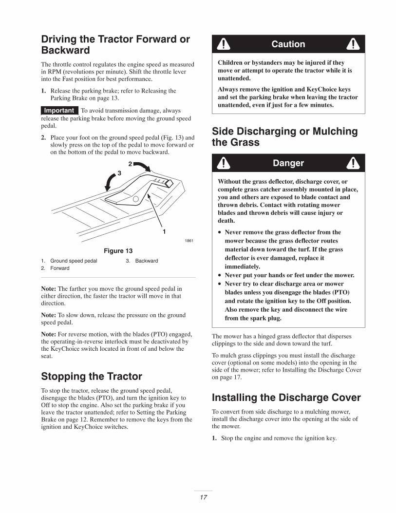
2. Place your foot on the ground speed pedal (Fig. 13) andslowly press on the top of the pedal to move forward oron the bottom of the pedal to move backward.
1
23
1861
Figure 131. Ground speed pedal2. Forward
3. Backward
Note: The farther you move the ground speed pedal ineither direction, the faster the tractor will move in thatdirection.
Note: To slow down, release the pressure on the groundspeed pedal.
Note: For reverse motion, with the blades (PTO) engaged,the operating-in-reverse interlock must be deactivated bythe KeyChoice switch located in front of and below theseat.
Stopping the TractorTo stop the tractor, release the ground speed pedal,disengage the blades (PTO), and turn the ignition key toOff to stop the engine. Also set the parking brake if youleave the tractor unattended; refer to Setting the ParkingBrake on page 12. Remember to remove the keys from theignition and KeyChoice switches.
Children or bystanders may be injured if theymove or attempt to operate the tractor while it isunattended.
Always remove the ignition and KeyChoice keysand set the parking brake when leaving the tractorunattended, even if just for a few minutes.
Caution
Side Discharging or Mulchingthe Grass
Danger
Without the grass deflector, discharge cover, orcomplete grass catcher assembly mounted in place,you and others are exposed to blade contact andthrown debris. Contact with rotating mowerblades and thrown debris will cause injury ordeath.
• Never remove the grass deflector from themower because the grass deflector routesmaterial down toward the turf. If the grassdeflector is ever damaged, replace itimmediately.
• Never put your hands or feet under the mower.• Never try to clear discharge area or mower
blades unless you disengage the blades (PTO)and rotate the ignition key to the Off position.Also remove the key and disconnect the wirefrom the spark plug.
The mower has a hinged grass deflector that dispersesclippings to the side and down toward the turf.
To mulch grass clippings you must install the dischargecover (optional on some models) into the opening in theside of the mower; refer to Installing the Discharge Coveron page 17.
Installing the Discharge CoverTo convert from side discharge to a mulching mower,install the discharge cover into the opening at the side ofthe mower.
1. Stop the engine and remove the ignition key.
18
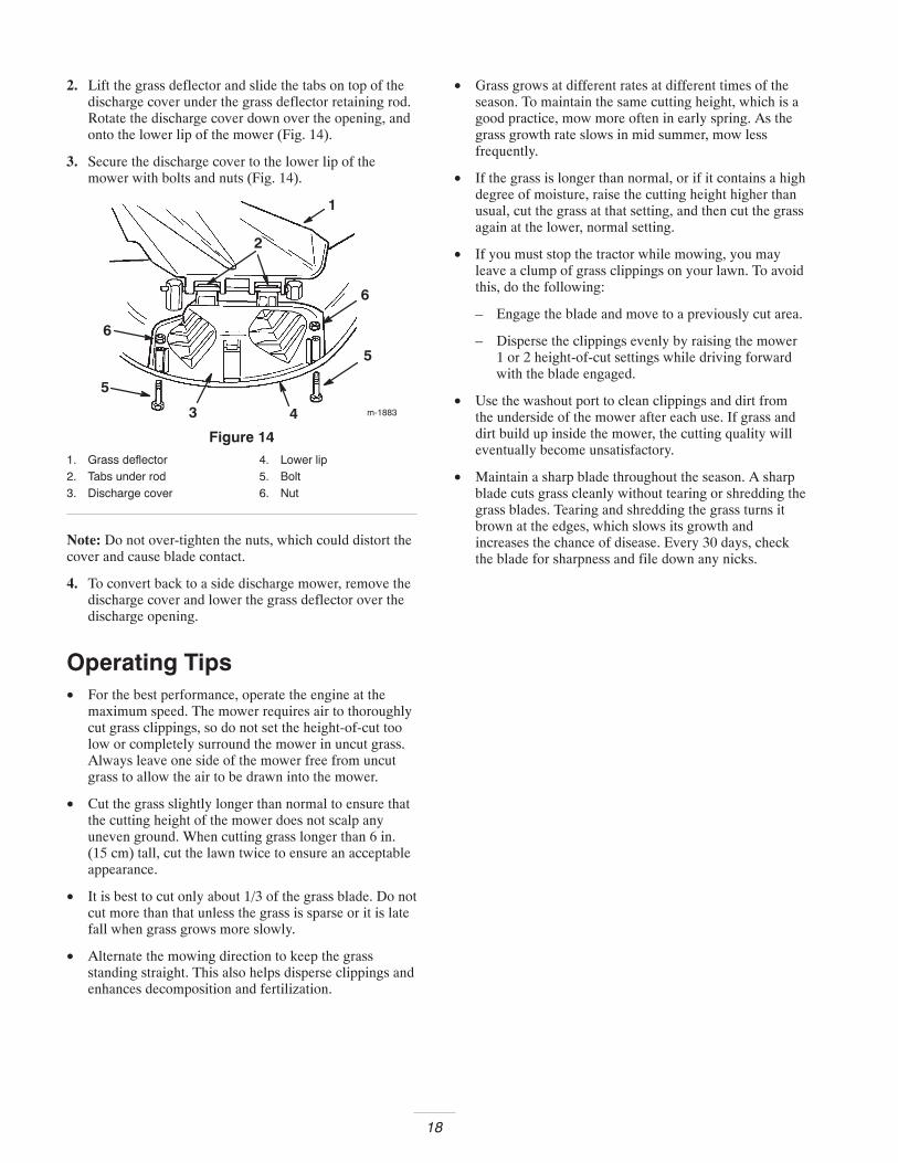
2. Lift the grass deflector and slide the tabs on top of thedischarge cover under the grass deflector retaining rod.Rotate the discharge cover down over the opening, andonto the lower lip of the mower (Fig. 14).
3. Secure the discharge cover to the lower lip of themower with bolts and nuts (Fig. 14).
m-1883
1
6
5
43
6
5
2
Figure 141. Grass deflector2. Tabs under rod3. Discharge cover
4. Lower lip5. Bolt6. Nut
Note: Do not over-tighten the nuts, which could distort thecover and cause blade contact.
4. To convert back to a side discharge mower, remove thedischarge cover and lower the grass deflector over thedischarge opening.
Operating Tips• For the best performance, operate the engine at the
maximum speed. The mower requires air to thoroughlycut grass clippings, so do not set the height-of-cut toolow or completely surround the mower in uncut grass.Always leave one side of the mower free from uncutgrass to allow the air to be drawn into the mower.
• Cut the grass slightly longer than normal to ensure thatthe cutting height of the mower does not scalp anyuneven ground. When cutting grass longer than 6 in.(15 cm) tall, cut the lawn twice to ensure an acceptableappearance.
• It is best to cut only about 1/3 of the grass blade. Do notcut more than that unless the grass is sparse or it is latefall when grass grows more slowly.
• Alternate the mowing direction to keep the grassstanding straight. This also helps disperse clippings andenhances decomposition and fertilization.
• Grass grows at different rates at different times of theseason. To maintain the same cutting height, which is agood practice, mow more often in early spring. As thegrass growth rate slows in mid summer, mow lessfrequently.
• If the grass is longer than normal, or if it contains a highdegree of moisture, raise the cutting height higher thanusual, cut the grass at that setting, and then cut the grassagain at the lower, normal setting.
• If you must stop the tractor while mowing, you mayleave a clump of grass clippings on your lawn. To avoidthis, do the following:
– Engage the blade and move to a previously cut area.
– Disperse the clippings evenly by raising the mower1 or 2 height-of-cut settings while driving forwardwith the blade engaged.
• Use the washout port to clean clippings and dirt fromthe underside of the mower after each use. If grass anddirt build up inside the mower, the cutting quality willeventually become unsatisfactory.
• Maintain a sharp blade throughout the season. A sharpblade cuts grass cleanly without tearing or shredding thegrass blades. Tearing and shredding the grass turns itbrown at the edges, which slows its growth andincreases the chance of disease. Every 30 days, checkthe blade for sharpness and file down any nicks.
19
MaintenanceRecommended Maintenance Schedule
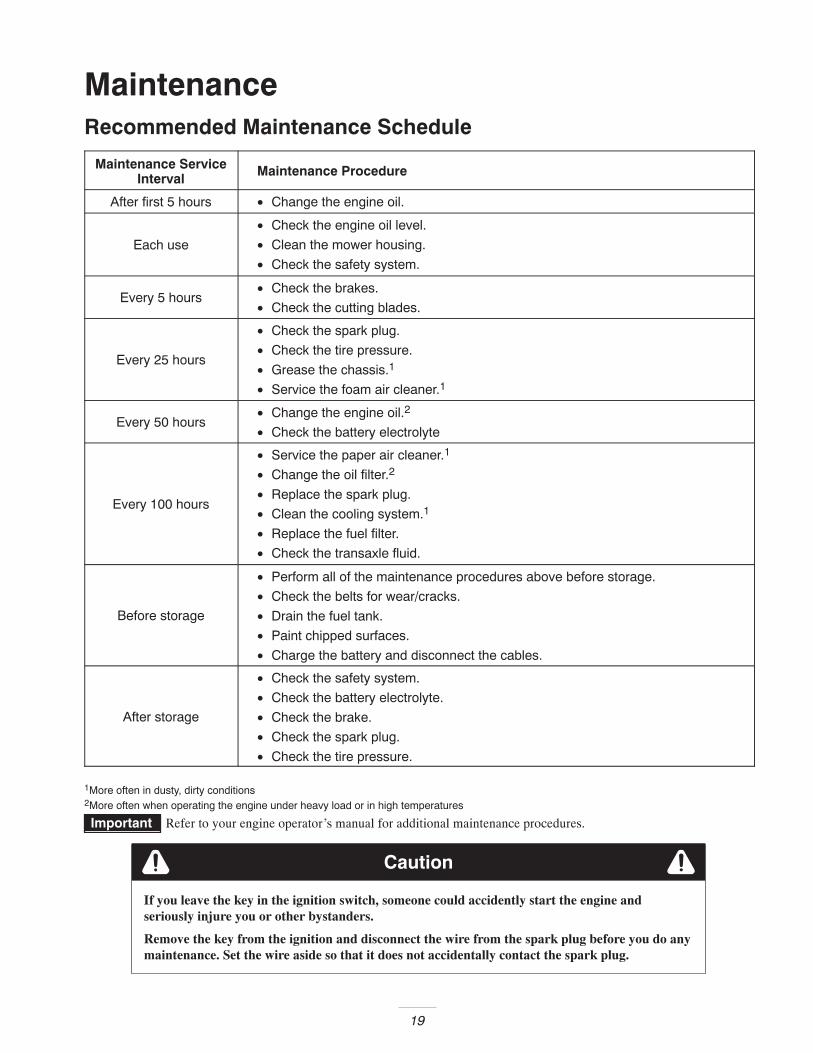
Maintenance ServiceInterval Maintenance Procedure
After first 5 hours • Change the engine oil.
Each use
• Check the engine oil level.
• Clean the mower housing.
• Check the safety system.
Every 5 hours• Check the brakes.
• Check the cutting blades.
Every 25 hours
• Check the spark plug.
• Check the tire pressure.
• Grease the chassis.1
• Service the foam air cleaner.1
Every 50 hours• Change the engine oil.2
• Check the battery electrolyte
Every 100 hours
• Service the paper air cleaner.1
• Change the oil filter.2
• Replace the spark plug.
• Clean the cooling system.1
• Replace the fuel filter.
• Check the transaxle fluid.
Before storage
• Perform all of the maintenance procedures above before storage.
• Check the belts for wear/cracks.
• Drain the fuel tank.
• Paint chipped surfaces.
• Charge the battery and disconnect the cables.
After storage
• Check the safety system.
• Check the battery electrolyte.
• Check the brake.
• Check the spark plug.
• Check the tire pressure.
1More often in dusty, dirty conditions2More often when operating the engine under heavy load or in high temperatures
Important Refer to your engine operator’s manual for additional maintenance procedures.
Caution
If you leave the key in the ignition switch, someone could accidently start the engine andseriously injure you or other bystanders.
Remove the key from the ignition and disconnect the wire from the spark plug before you do anymaintenance. Set the wire aside so that it does not accidentally contact the spark plug.
20
Servicing the Engine OilCheck the oil level daily or after every 8 hours.
Change the oil after the first 5 operating hours and every 50operating hours thereafter.
Note: Change the oil more frequently when operatingconditions are extremely dusty or sandy.
Oil Type: Detergent oil (API service SF, SG, SH, SJ, orhigher)
Crankcase Capacity: 48 oz. or 1-1/2 qt. (1400 cc or 1.4 l)without the oil filter; 56 oz. or 1-3/4 qt. (1700 cc/1.7 l) withthe oil filter
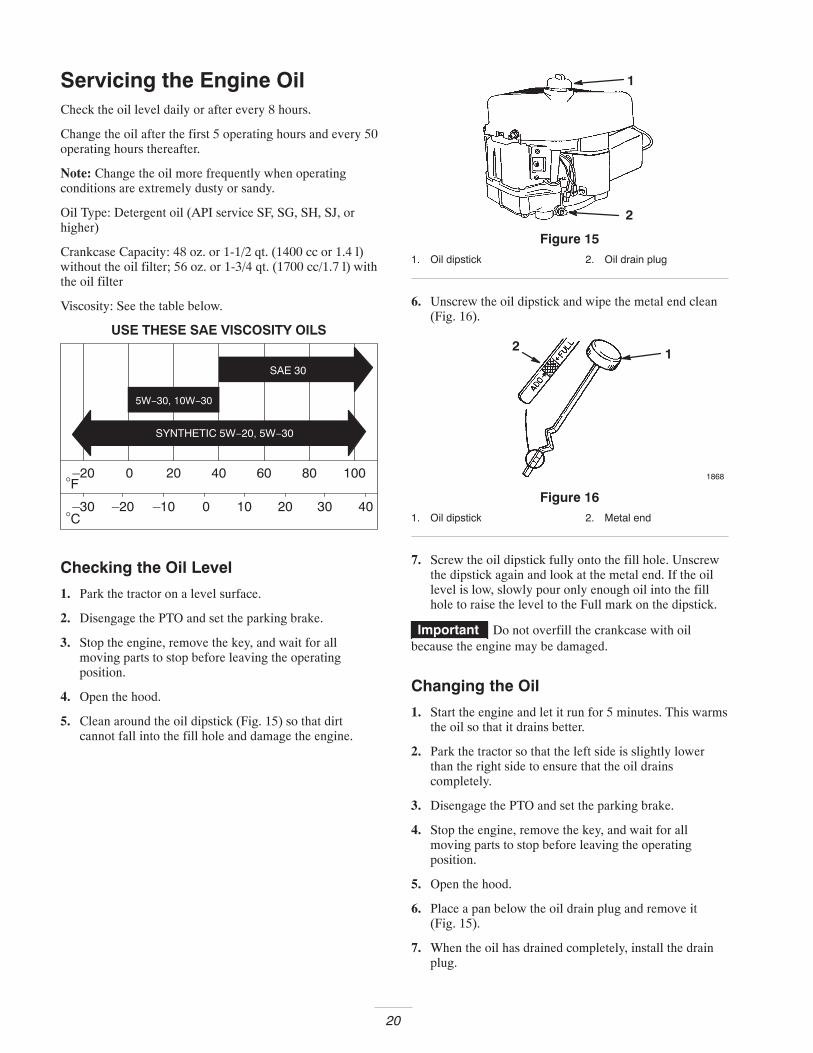
Viscosity: See the table below.
F–20 0 20 40 60 80 100
°
C–30
°–20 –10 0 10 20 30 40
USE THESE SAE VISCOSITY OILS
Checking the Oil Level
1. Park the tractor on a level surface.
2. Disengage the PTO and set the parking brake.
3. Stop the engine, remove the key, and wait for allmoving parts to stop before leaving the operatingposition.
4. Open the hood.
5. Clean around the oil dipstick (Fig. 15) so that dirtcannot fall into the fill hole and damage the engine.
2
1
Figure 151. Oil dipstick 2. Oil drain plug
6. Unscrew the oil dipstick and wipe the metal end clean(Fig. 16).
12
1868
Figure 161. Oil dipstick 2. Metal end
7. Screw the oil dipstick fully onto the fill hole. Unscrewthe dipstick again and look at the metal end. If the oillevel is low, slowly pour only enough oil into the fillhole to raise the level to the Full mark on the dipstick.
Important Do not overfill the crankcase with oilbecause the engine may be damaged.
Changing the Oil
1. Start the engine and let it run for 5 minutes. This warmsthe oil so that it drains better.
2. Park the tractor so that the left side is slightly lowerthan the right side to ensure that the oil drainscompletely.
3. Disengage the PTO and set the parking brake.
4. Stop the engine, remove the key, and wait for allmoving parts to stop before leaving the operatingposition.
5. Open the hood.
6. Place a pan below the oil drain plug and remove it(Fig. 15).
7. When the oil has drained completely, install the drainplug.
21
Note: Dispose of the used oil at a certified recycling center.
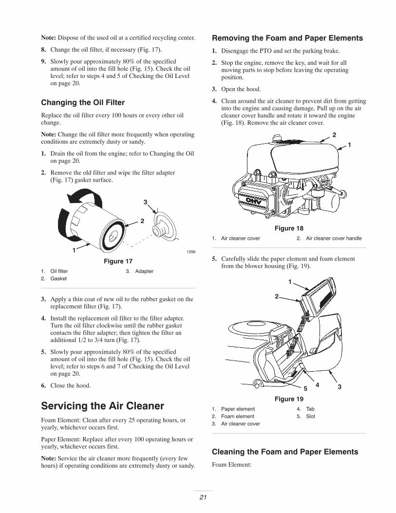
8. Change the oil filter, if necessary (Fig. 17).
9. Slowly pour approximately 80% of the specifiedamount of oil into the fill hole (Fig. 15). Check the oillevel; refer to steps 4 and 5 of Checking the Oil Levelon page 20.
Changing the Oil Filter
Replace the oil filter every 100 hours or every other oilchange.
Note: Change the oil filter more frequently when operatingconditions are extremely dusty or sandy.
1. Drain the oil from the engine; refer to Changing the Oilon page 20.
2. Remove the old filter and wipe the filter adapter(Fig. 17) gasket surface.
12561
2
3
Figure 171. Oil filter2. Gasket
3. Adapter
3. Apply a thin coat of new oil to the rubber gasket on thereplacement filter (Fig. 17).
4. Install the replacement oil filter to the filter adapter.Turn the oil filter clockwise until the rubber gasketcontacts the filter adapter; then tighten the filter anadditional 1/2 to 3/4 turn (Fig. 17).
5. Slowly pour approximately 80% of the specifiedamount of oil into the fill hole (Fig. 15). Check the oillevel; refer to steps 6 and 7 of Checking the Oil Levelon page 20.
6. Close the hood.
Servicing the Air CleanerFoam Element: Clean after every 25 operating hours, oryearly, whichever occurs first.
Paper Element: Replace after every 100 operating hours oryearly, whichever occurs first.
Note: Service the air cleaner more frequently (every fewhours) if operating conditions are extremely dusty or sandy.
Removing the Foam and Paper Elements
1. Disengage the PTO and set the parking brake.
2. Stop the engine, remove the key, and wait for allmoving parts to stop before leaving the operatingposition.
3. Open the hood.
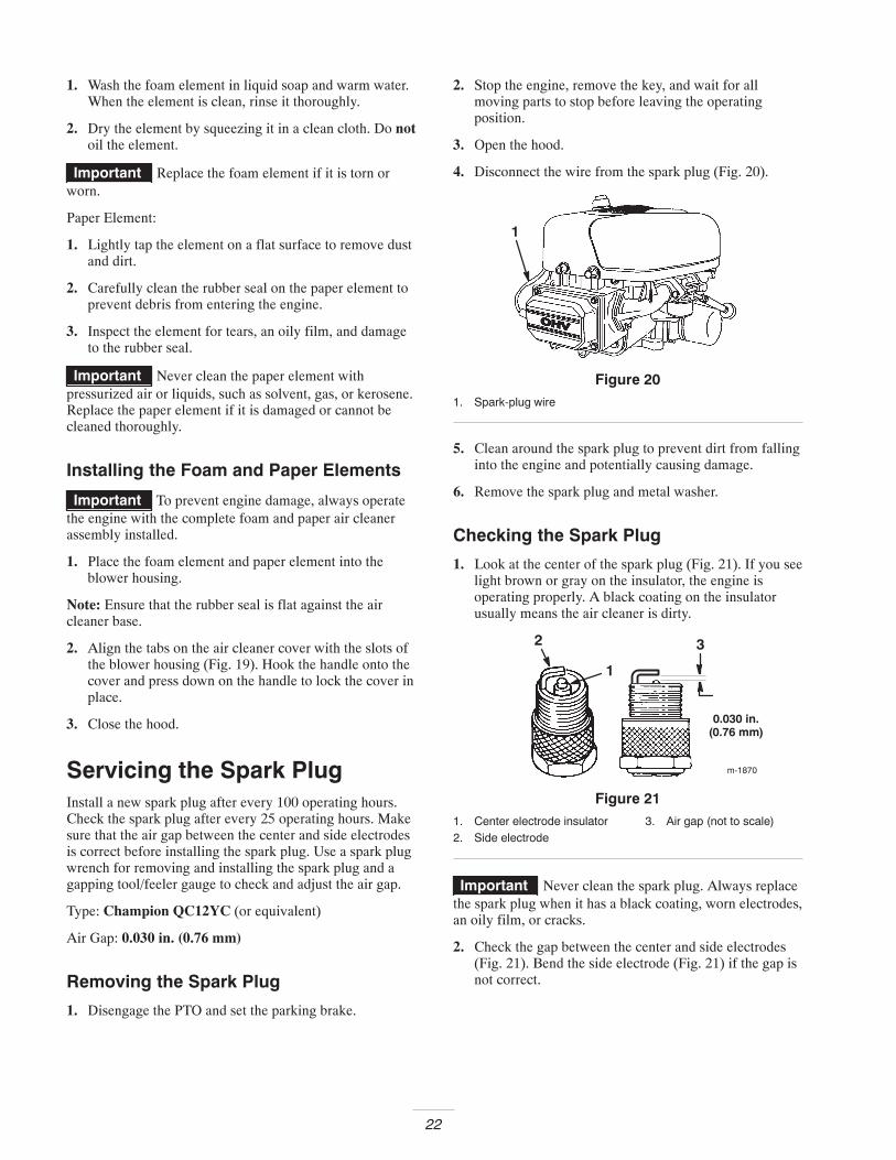
4. Clean around the air cleaner to prevent dirt from gettinginto the engine and causing damage. Pull up on the aircleaner cover handle and rotate it toward the engine(Fig. 18). Remove the air cleaner cover.
1
2
Figure 181. Air cleaner cover 2. Air cleaner cover handle
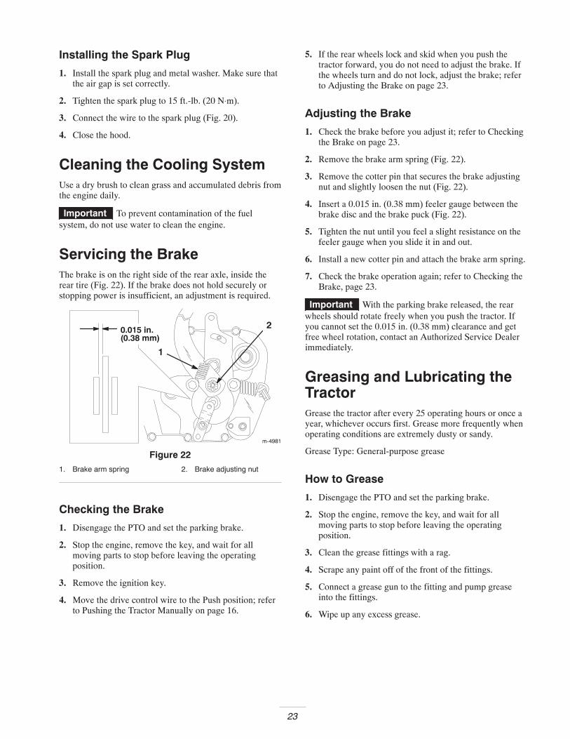
5. Carefully slide the paper element and foam elementfrom the blower housing (Fig. 19).
2
1
35 4
Figure 191. Paper element2. Foam element3. Air cleaner cover
4. Tab5. Slot
Cleaning the Foam and Paper Elements
Foam Element:
22
1. Wash the foam element in liquid soap and warm water.When the element is clean, rinse it thoroughly.
2. Dry the element by squeezing it in a clean cloth. Do notoil the element.
Important Replace the foam element if it is torn orworn.
Paper Element:
1. Lightly tap the element on a flat surface to remove dustand dirt.
2. Carefully clean the rubber seal on the paper element toprevent debris from entering the engine.
3. Inspect the element for tears, an oily film, and damageto the rubber seal.
Important Never clean the paper element withpressurized air or liquids, such as solvent, gas, or kerosene.Replace the paper element if it is damaged or cannot becleaned thoroughly.
Installing the Foam and Paper Elements
Important To prevent engine damage, always operatethe engine with the complete foam and paper air cleanerassembly installed.
1. Place the foam element and paper element into theblower housing.
Note: Ensure that the rubber seal is flat against the aircleaner base.
2. Align the tabs on the air cleaner cover with the slots ofthe blower housing (Fig. 19). Hook the handle onto thecover and press down on the handle to lock the cover inplace.
3. Close the hood.
Servicing the Spark PlugInstall a new spark plug after every 100 operating hours.Check the spark plug after every 25 operating hours. Makesure that the air gap between the center and side electrodesis correct before installing the spark plug. Use a spark plugwrench for removing and installing the spark plug and agapping tool/feeler gauge to check and adjust the air gap.
Type: Champion QC12YC (or equivalent)
Air Gap: 0.030 in. (0.76 mm)
Removing the Spark Plug
1. Disengage the PTO and set the parking brake.
2. Stop the engine, remove the key, and wait for allmoving parts to stop before leaving the operatingposition.
3. Open the hood.
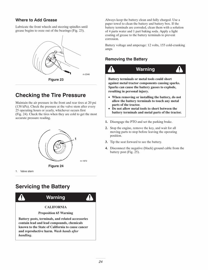
4. Disconnect the wire from the spark plug (Fig. 20).
1
Figure 201. Spark-plug wire
5. Clean around the spark plug to prevent dirt from fallinginto the engine and potentially causing damage.
6. Remove the spark plug and metal washer.
Checking the Spark Plug
1. Look at the center of the spark plug (Fig. 21). If you seelight brown or gray on the insulator, the engine isoperating properly. A black coating on the insulatorusually means the air cleaner is dirty.
m-1870
0.030 in.(0.76 mm)
2 3
1
Figure 211. Center electrode insulator2. Side electrode
3. Air gap (not to scale)
Important Never clean the spark plug. Always replacethe spark plug when it has a black coating, worn electrodes,an oily film, or cracks.
2. Check the gap between the center and side electrodes(Fig. 21). Bend the side electrode (Fig. 21) if the gap isnot correct.
23
Installing the Spark Plug
1. Install the spark plug and metal washer. Make sure thatthe air gap is set correctly.
2. Tighten the spark plug to 15 ft.-lb. (20 N⋅m).
3. Connect the wire to the spark plug (Fig. 20).
4. Close the hood.
Cleaning the Cooling SystemUse a dry brush to clean grass and accumulated debris fromthe engine daily.
Important To prevent contamination of the fuelsystem, do not use water to clean the engine.
Servicing the BrakeThe brake is on the right side of the rear axle, inside therear tire (Fig. 22). If the brake does not hold securely orstopping power is insufficient, an adjustment is required.
m-4981
1
20.015 in.(0.38 mm)
Figure 221. Brake arm spring 2. Brake adjusting nut
Checking the Brake
1. Disengage the PTO and set the parking brake.
2. Stop the engine, remove the key, and wait for allmoving parts to stop before leaving the operatingposition.
3. Remove the ignition key.
4. Move the drive control wire to the Push position; referto Pushing the Tractor Manually on page 16.
5. If the rear wheels lock and skid when you push thetractor forward, you do not need to adjust the brake. Ifthe wheels turn and do not lock, adjust the brake; referto Adjusting the Brake on page 23.
Adjusting the Brake
1. Check the brake before you adjust it; refer to Checkingthe Brake on page 23.
2. Remove the brake arm spring (Fig. 22).
3. Remove the cotter pin that secures the brake adjustingnut and slightly loosen the nut (Fig. 22).
4. Insert a 0.015 in. (0.38 mm) feeler gauge between thebrake disc and the brake puck (Fig. 22).
5. Tighten the nut until you feel a slight resistance on thefeeler gauge when you slide it in and out.
6. Install a new cotter pin and attach the brake arm spring.
7. Check the brake operation again; refer to Checking theBrake, page 23.
Important With the parking brake released, the rearwheels should rotate freely when you push the tractor. Ifyou cannot set the 0.015 in. (0.38 mm) clearance and getfree wheel rotation, contact an Authorized Service Dealerimmediately.
Greasing and Lubricating theTractorGrease the tractor after every 25 operating hours or once ayear, whichever occurs first. Grease more frequently whenoperating conditions are extremely dusty or sandy.
Grease Type: General-purpose grease
How to Grease
1. Disengage the PTO and set the parking brake.
2. Stop the engine, remove the key, and wait for allmoving parts to stop before leaving the operatingposition.
3. Clean the grease fittings with a rag.
4. Scrape any paint off of the front of the fittings.
5. Connect a grease gun to the fitting and pump greaseinto the fittings.
6. Wipe up any excess grease.
24
Where to Add Grease
Lubricate the front wheels and steering spindles untilgrease begins to ooze out of the bearings (Fig. 23).
m-2346
Figure 23
Checking the Tire PressureMaintain the air pressure in the front and rear tires at 20 psi(138 kPa). Check the pressure at the valve stem after every25 operating hours or yearly, whichever occurs first(Fig. 24). Check the tires when they are cold to get the mostaccurate pressure reading.
m-1872
1
Figure 241. Valve stem
Servicing the Battery
CALIFORNIA
Proposition 65 Warning
Battery posts, terminals, and related accessoriescontain lead and lead compounds, chemicalsknown to the State of California to cause cancerand reproductive harm. Wash hands afterhandling.
Warning
Always keep the battery clean and fully charged. Use apaper towel to clean the battery and battery box. If thebattery terminals are corroded, clean them with a solutionof 4 parts water and 1 part baking soda. Apply a lightcoating of grease to the battery terminals to preventcorrosion.
Battery voltage and amperage: 12 volts, 155 cold-crankingamps
Removing the Battery
Battery terminals or metal tools could shortagainst metal tractor components causing sparks.Sparks can cause the battery gasses to explode,resulting in personal injury.
• When removing or installing the battery, do notallow the battery terminals to touch any metalparts of the tractor.
• Do not allow metal tools to short between thebattery terminals and metal parts of the tractor.
Warning
1. Disengage the PTO and set the parking brake.
2. Stop the engine, remove the key, and wait for allmoving parts to stop before leaving the operatingposition.
3. Tip the seat forward to see the battery.
4. Disconnect the negative (black) ground cable from thebattery post (Fig. 25).
25
1
2
3
4
5
m-4965
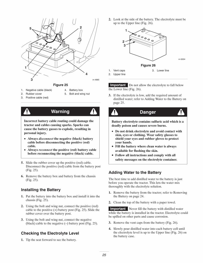
Figure 251. Negative cable (black)2. Rubber cover3. Positive cable (red)
4. Battery box5. Bolt and wing nut
Incorrect battery cable routing could damage thetractor and cables causing sparks. Sparks cancause the battery gasses to explode, resulting inpersonal injury.
• Always disconnect the negative (black) batterycable before disconnecting the positive (red)cable.
• Always reconnect the positive (red) battery cablebefore reconnecting the negative (black) cable.
Warning
5. Slide the rubber cover up the positive (red) cable.Disconnect the positive (red) cable from the battery post(Fig. 25).
6. Remove the battery box and battery from the chassis(Fig. 25).
Installing the Battery
1. Put the battery into the battery box and install it into thechassis (Fig. 25).
2. Using the bolt and wing nut, connect the positive (red)cable to the positive (+) battery post (Fig. 25). Slide therubber cover over the battery post.
3. Using the bolt and wing nut, connect the negative(black) cable to the negative (–) battery post (Fig. 25).
Checking the Electrolyte Level
1. Tip the seat forward to see the battery.
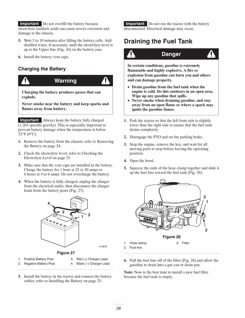
2. Look at the side of the battery. The electrolyte must beup to the Upper line (Fig. 26).
m-5004
1
23
Figure 261. Vent caps2. Upper line
3. Lower line
Important Do not allow the electrolyte to fall belowthe Lower line (Fig. 26).
3. If the electrolyte is low, add the required amount ofdistilled water; refer to Adding Water to the Battery onpage 25.
Danger
Battery electrolyte contains sulfuric acid which is adeadly poison and causes severe burns.
• Do not drink electrolyte and avoid contact withskin, eyes or clothing. Wear safety glasses toshield your eyes and rubber gloves to protectyour hands.
• Fill the battery where clean water is alwaysavailable for flushing the skin.
• Follow all instructions and comply with allsafety messages on the electrolyte container.
Adding Water to the Battery
The best time to add distilled water to the battery is justbefore you operate the tractor. This lets the water mixthoroughly with the electrolyte solution.
1. Remove the battery from the tractor; refer to Removingthe Battery on page 24.
2. Clean the top of the battery with a paper towel.
Important Never fill the battery with distilled waterwhile the battery is installed in the tractor. Electrolyte couldbe spilled on other parts and cause corrosion.
3. Remove the vent caps from the battery (Fig. 26).
4. Slowly pour distilled water into each battery cell untilthe electrolyte level is up to the Upper line (Fig. 26) onthe battery case.
26
Important Do not overfill the battery becauseelectrolyte (sulfuric acid) can cause severe corrosion anddamage to the chassis.
5. Wait 5 to 10 minutes after filling the battery cells. Adddistilled water, if necessary, until the electrolyte level isup to the Upper line (Fig. 26) on the battery case.
6. Install the battery vent caps.
Charging the Battery
Charging the battery produces gasses that canexplode.
Never smoke near the battery and keep sparks andflames away from battery.
Warning
Important Always keep the battery fully charged(1.265 specific gravity). This is especially important toprevent battery damage when the temperature is below32°F (0°C).
1. Remove the battery from the chassis; refer to Removingthe Battery on page 24.
2. Check the electrolyte level; refer to Checking theElectrolyte Level on page 25.
3. Make sure that the vent caps are installed in the battery.Charge the battery for 1 hour at 25 to 30 amps or6 hours at 4 to 6 amps. Do not overcharge the battery.
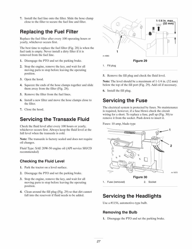
4. When the battery is fully charged, unplug the chargerfrom the electrical outlet, then disconnect the chargerleads from the battery posts (Fig. 27).
4
12
3
������
Figure 271. Positive Battery Post2. Negative Battery Post
3. Red (+) Charger Lead4. Black (–) Charger Lead
5. Install the battery in the tractor and connect the batterycables; refer to Installing the Battery on page 25.
Important Do not run the tractor with the batterydisconnected. Electrical damage may occur.
Draining the Fuel Tank
Danger
In certain conditions, gasoline is extremelyflammable and highly explosive. A fire orexplosion from gasoline can burn you and othersand can damage property.
• Drain gasoline from the fuel tank when theengine is cold. Do this outdoors in an open area.Wipe up any gasoline that spills.
• Never smoke when draining gasoline, and stayaway from an open flame or where a spark mayignite the gasoline fumes.
1. Park the tractor so that the left front side is slightlylower than the right side to ensure that the fuel tankdrains completely.
2. Disengage the PTO and set the parking brake.
3. Stop the engine, remove the key, and wait for allmoving parts to stop before leaving the operatingposition.
4. Open the hood.
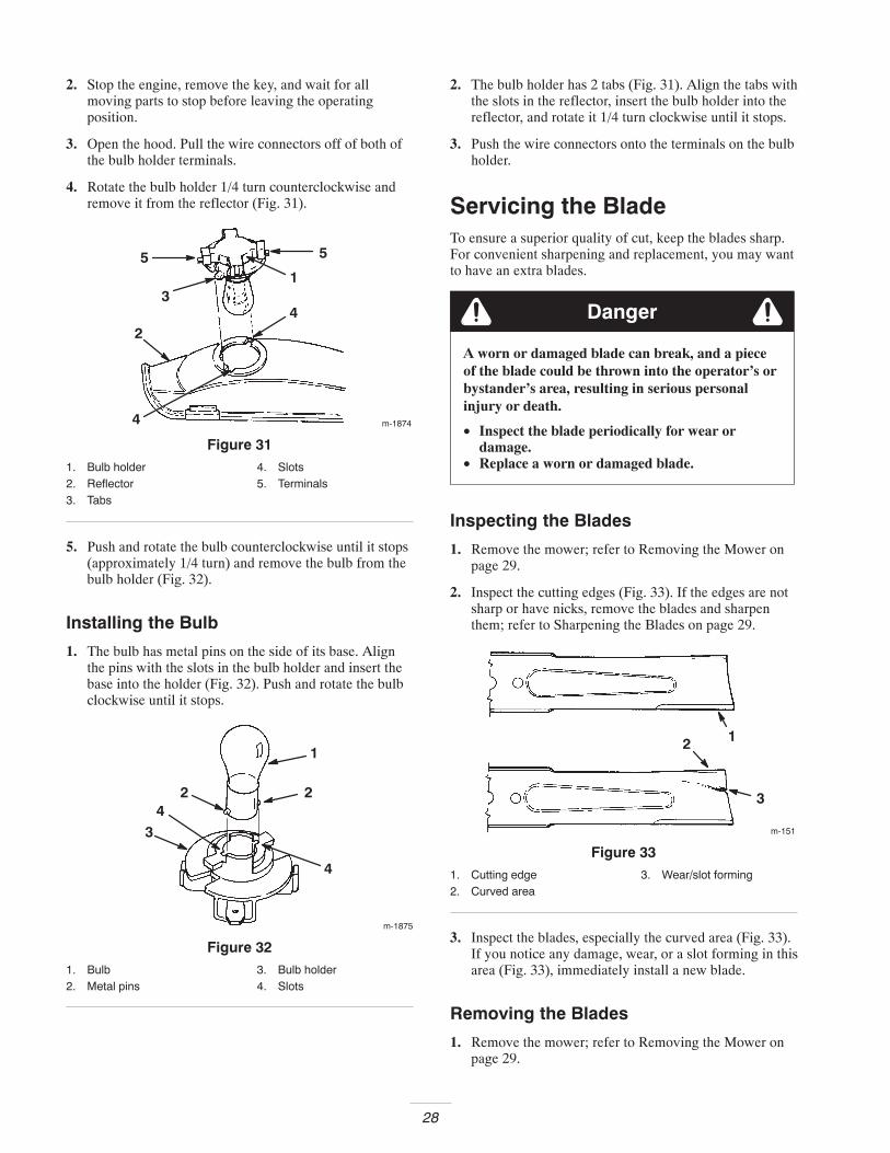
5. Squeeze the ends of the hose clamp together and slide itup the fuel line toward the fuel tank (Fig. 28).
1
3
2
Figure 281. Hose clamp2. Fuel line
3. Filter
6. Pull the fuel line off of the filter (Fig. 28) and allow thegasoline to drain into a gas can or drain pan.
Note: Now is the best time to install a new fuel filterbecause the fuel tank is empty.
27
7. Install the fuel line onto the filter. Slide the hose clampclose to the filter to secure the fuel line and filter.
Replacing the Fuel FilterReplace the fuel filter after every 100 operating hours oryearly, whichever occurs first.
The best time to replace the fuel filter (Fig. 28) is when thefuel tank is empty. Never install a dirty filter if it isremoved from the fuel line.
1. Disengage the PTO and set the parking brake.
2. Stop the engine, remove the key, and wait for allmoving parts to stop before leaving the operatingposition.
3. Open the hood.
4. Squeeze the ends of the hose clamps together and slidethem away from the filter (Fig. 28).
5. Remove the filter from the fuel lines.
6. Install a new filter and move the hose clamps close tothe filter.
7. Close the hood.
Servicing the Transaxle FluidCheck the fluid level after every 100 hours or yearly,whichever occurs first. Always keep the fluid level at thefull level when the transaxle is cold.
Note: The transaxle is factory sealed and does not requireoil changes.
Fluid Type: SAE 20W-50 engine oil (API service SH/CDrecommended)
Checking the Fluid Level
1. Park the tractor on a level surface.
2. Disengage the PTO and set the parking brake.
3. Stop the engine, remove the key, and wait for allmoving parts to stop before leaving the operatingposition.
4. Clean around the fill plug (Fig. 29) so that dirt cannotfall into the reservoir if fluid needs to be added.
(32 mm)
m-4983
1
1-1/4 in. max.
Figure 291. Fill plug
5. Remove the fill plug and check the fluid level.
Note: The level should be a maximum of 1-1/4 in. (32 mm)below the top of the fill port (Fig. 29). Add oil if necessary.
6. Install the fill plug.
Servicing the FuseThe electrical system is protected by fuses. No maintenanceis required, however, if a fuse blows check the circuitwiring for a short. To replace a fuse, pull up (Fig. 30) toremove it from the socket. Push down to insert it.
Fuses: 10 amp, blade-type
m-1672
1
2
Figure 301. Fuse (removed) 2. Socket
Servicing the HeadlightsUse a #1156, automotive-type bulb.
Removing the Bulb
1. Disengage the PTO and set the parking brake.
28
2. Stop the engine, remove the key, and wait for allmoving parts to stop before leaving the operatingposition.
3. Open the hood. Pull the wire connectors off of both ofthe bulb holder terminals.
4. Rotate the bulb holder 1/4 turn counterclockwise andremove it from the reflector (Fig. 31).
m-1874
1
2
3
4
4
5 5
Figure 311. Bulb holder2. Reflector3. Tabs
4. Slots5. Terminals
5. Push and rotate the bulb counterclockwise until it stops(approximately 1/4 turn) and remove the bulb from thebulb holder (Fig. 32).
Installing the Bulb
1. The bulb has metal pins on the side of its base. Alignthe pins with the slots in the bulb holder and insert thebase into the holder (Fig. 32). Push and rotate the bulbclockwise until it stops.
m-1875
1
2
34
2
4
Figure 321. Bulb2. Metal pins
3. Bulb holder4. Slots
2. The bulb holder has 2 tabs (Fig. 31). Align the tabs withthe slots in the reflector, insert the bulb holder into thereflector, and rotate it 1/4 turn clockwise until it stops.
3. Push the wire connectors onto the terminals on the bulbholder.
Servicing the BladeTo ensure a superior quality of cut, keep the blades sharp.For convenient sharpening and replacement, you may wantto have an extra blades.
Danger
A worn or damaged blade can break, and a pieceof the blade could be thrown into the operator’s orbystander’s area, resulting in serious personalinjury or death.
• Inspect the blade periodically for wear ordamage.
• Replace a worn or damaged blade.
Inspecting the Blades
1. Remove the mower; refer to Removing the Mower onpage 29.
2. Inspect the cutting edges (Fig. 33). If the edges are notsharp or have nicks, remove the blades and sharpenthem; refer to Sharpening the Blades on page 29.
m-151
12
3
Figure 331. Cutting edge2. Curved area
3. Wear/slot forming
3. Inspect the blades, especially the curved area (Fig. 33).If you notice any damage, wear, or a slot forming in thisarea (Fig. 33), immediately install a new blade.
Removing the Blades
1. Remove the mower; refer to Removing the Mower onpage 29.
29
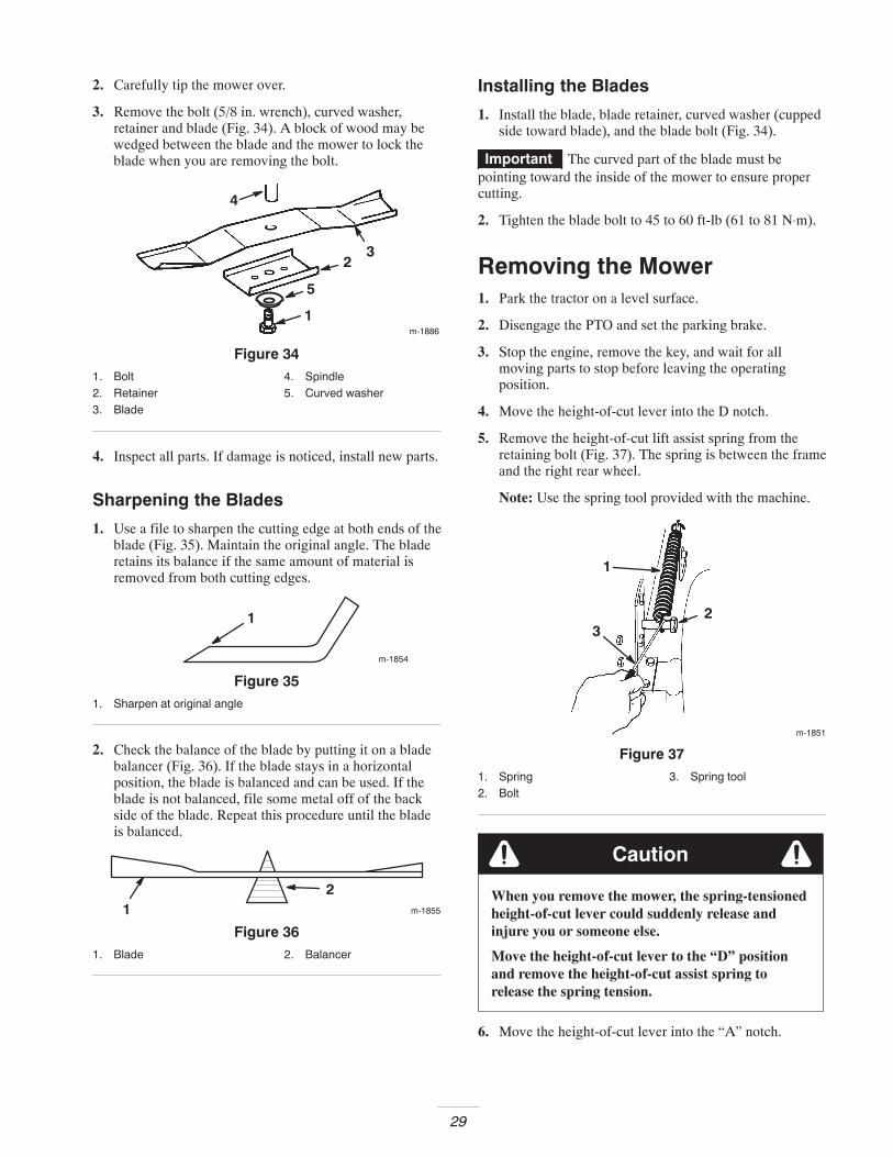
2. Carefully tip the mower over.
3. Remove the bolt (5/8 in. wrench), curved washer,retainer and blade (Fig. 34). A block of wood may bewedged between the blade and the mower to lock theblade when you are removing the bolt.
m-1886
1
23
4
5
Figure 341. Bolt2. Retainer3. Blade
4. Spindle5. Curved washer
4. Inspect all parts. If damage is noticed, install new parts.
Sharpening the Blades
1. Use a file to sharpen the cutting edge at both ends of theblade (Fig. 35). Maintain the original angle. The bladeretains its balance if the same amount of material isremoved from both cutting edges.
m-1854
1
Figure 351. Sharpen at original angle
2. Check the balance of the blade by putting it on a bladebalancer (Fig. 36). If the blade stays in a horizontalposition, the blade is balanced and can be used. If theblade is not balanced, file some metal off of the backside of the blade. Repeat this procedure until the bladeis balanced.
m-185512
Figure 361. Blade 2. Balancer
Installing the Blades
1. Install the blade, blade retainer, curved washer (cuppedside toward blade), and the blade bolt (Fig. 34).
Important The curved part of the blade must bepointing toward the inside of the mower to ensure propercutting.
2. Tighten the blade bolt to 45 to 60 ft-lb (61 to 81 N⋅m).
Removing the Mower1. Park the tractor on a level surface.
2. Disengage the PTO and set the parking brake.
3. Stop the engine, remove the key, and wait for allmoving parts to stop before leaving the operatingposition.
4. Move the height-of-cut lever into the D notch.
5. Remove the height-of-cut lift assist spring from theretaining bolt (Fig. 37). The spring is between the frameand the right rear wheel.
Note: Use the spring tool provided with the machine.
1
23
m-1851
Figure 371. Spring2. Bolt
3. Spring tool
When you remove the mower, the spring-tensionedheight-of-cut lever could suddenly release andinjure you or someone else.
Move the height-of-cut lever to the “D” positionand remove the height-of-cut assist spring torelease the spring tension.
Caution
6. Move the height-of-cut lever into the “A” notch.
30
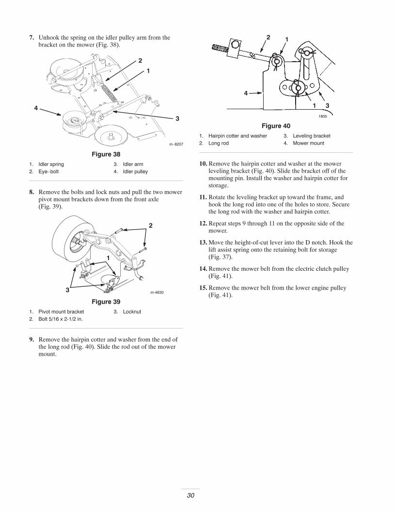
7. Unhook the spring on the idler pulley arm from thebracket on the mower (Fig. 38).
m–8207
4
2
1
3
Figure 381. Idler spring2. Eye–bolt
3. Idler arm4. Idler pulley
8. Remove the bolts and lock nuts and pull the two mowerpivot mount brackets down from the front axle(Fig. 39).
m-4630
1
2
3
Figure 391. Pivot mount bracket2. Bolt 5/16 x 2-1/2 in.
3. Locknut
9. Remove the hairpin cotter and washer from the end ofthe long rod (Fig. 40). Slide the rod out of the mowermount.
1805
3
2 1
1
4
Figure 401. Hairpin cotter and washer2. Long rod
3. Leveling bracket4. Mower mount
10. Remove the hairpin cotter and washer at the mowerleveling bracket (Fig. 40). Slide the bracket off of themounting pin. Install the washer and hairpin cotter forstorage.
11. Rotate the leveling bracket up toward the frame, andhook the long rod into one of the holes to store. Securethe long rod with the washer and hairpin cotter.
12. Repeat steps 9 through 11 on the opposite side of themower.
13. Move the height-of-cut lever into the D notch. Hook thelift assist spring onto the retaining bolt for storage(Fig. 37).
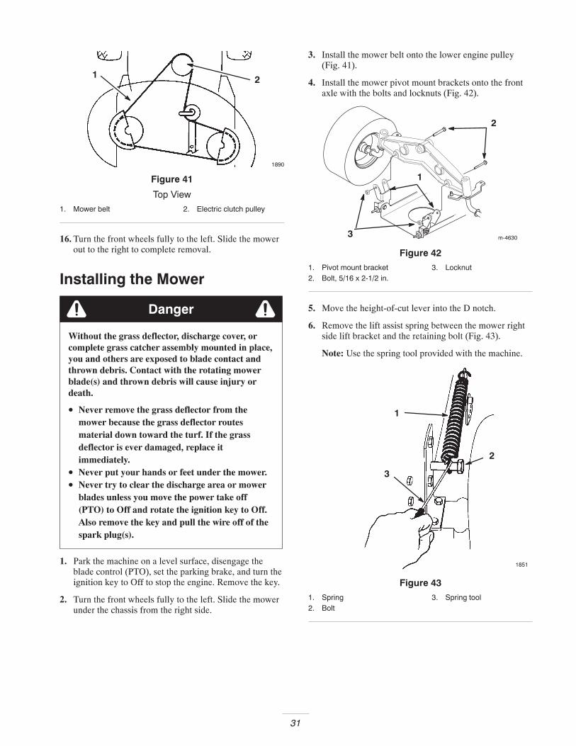
14. Remove the mower belt from the electric clutch pulley(Fig. 41).
15. Remove the mower belt from the lower engine pulley(Fig. 41).
31
1890
21
Figure 41
Top View
1. Mower belt 2. Electric clutch pulley
16. Turn the front wheels fully to the left. Slide the mowerout to the right to complete removal.
Installing the Mower
Danger
Without the grass deflector, discharge cover, orcomplete grass catcher assembly mounted in place,you and others are exposed to blade contact andthrown debris. Contact with the rotating mowerblade(s) and thrown debris will cause injury ordeath.
• Never remove the grass deflector from themower because the grass deflector routesmaterial down toward the turf. If the grassdeflector is ever damaged, replace itimmediately.
• Never put your hands or feet under the mower.• Never try to clear the discharge area or mower
blades unless you move the power take off(PTO) to Off and rotate the ignition key to Off.Also remove the key and pull the wire off of thespark plug(s).
1. Park the machine on a level surface, disengage theblade control (PTO), set the parking brake, and turn theignition key to Off to stop the engine. Remove the key.
2. Turn the front wheels fully to the left. Slide the mowerunder the chassis from the right side.
3. Install the mower belt onto the lower engine pulley(Fig. 41).
4. Install the mower pivot mount brackets onto the frontaxle with the bolts and locknuts (Fig. 42).
m-4630
1
2
3
Figure 421. Pivot mount bracket2. Bolt, 5/16 x 2-1/2 in.
3. Locknut
5. Move the height-of-cut lever into the D notch.
6. Remove the lift assist spring between the mower rightside lift bracket and the retaining bolt (Fig. 43).
Note: Use the spring tool provided with the machine.
1
2
3
1851
Figure 431. Spring2. Bolt
3. Spring tool
32
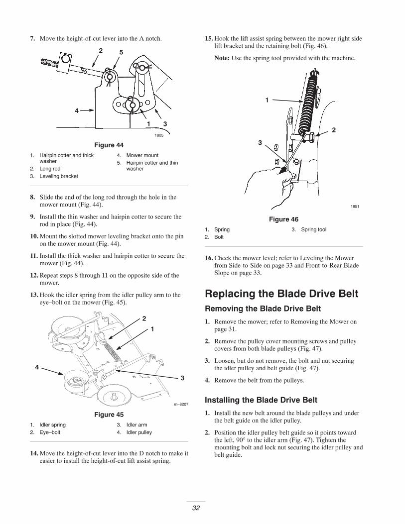
7. Move the height-of-cut lever into the A notch.
1805
3
2 5
1
4
Figure 441. Hairpin cotter and thick
washer2. Long rod3. Leveling bracket
4. Mower mount5. Hairpin cotter and thin
washer
8. Slide the end of the long rod through the hole in themower mount (Fig. 44).
9. Install the thin washer and hairpin cotter to secure therod in place (Fig. 44).
10. Mount the slotted mower leveling bracket onto the pinon the mower mount (Fig. 44).
11. Install the thick washer and hairpin cotter to secure themower (Fig. 44).
12. Repeat steps 8 through 11 on the opposite side of themower.
13. Hook the idler spring from the idler pulley arm to theeye–bolt on the mower (Fig. 45).
m–8207
4
2
1
3
Figure 451. Idler spring2. Eye–bolt
3. Idler arm4. Idler pulley
14. Move the height-of-cut lever into the D notch to make iteasier to install the height-of-cut lift assist spring.
15. Hook the lift assist spring between the mower right sidelift bracket and the retaining bolt (Fig. 46).
Note: Use the spring tool provided with the machine.
1
2
3
1851
Figure 461. Spring2. Bolt
3. Spring tool
16. Check the mower level; refer to Leveling the Mowerfrom Side-to-Side on page 33 and Front-to-Rear BladeSlope on page 33.
Replacing the Blade Drive BeltRemoving the Blade Drive Belt
1. Remove the mower; refer to Removing the Mower onpage 31.
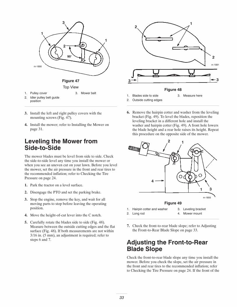
2. Remove the pulley cover mounting screws and pulleycovers from both blade pulleys (Fig. 47).
3. Loosen, but do not remove, the bolt and nut securingthe idler pulley and belt guide (Fig. 47).
4. Remove the belt from the pulleys.
Installing the Blade Drive Belt
1. Install the new belt around the blade pulleys and underthe belt guide on the idler pulley.
2. Position the idler pulley belt guide so it points towardthe left, 90° to the idler arm (Fig. 47). Tighten themounting bolt and lock nut securing the idler pulley andbelt guide.
33
2
3
90°
1
1
m-1890
Figure 47
Top View
1. Pulley cover2. Idler pulley belt guide
position
3. Mower belt
3. Install the left and right pulley covers with themounting screws (Fig. 47).
4. Install the mower; refer to Installing the Mower onpage 31.
Leveling the Mower fromSide-to-SideThe mower blades must be level from side to side. Checkthe side-to-side level any time you install the mower orwhen you see an uneven cut on your lawn. Before you levelthe mower, set the air pressure in the front and rear tires tothe recommended inflation; refer to Checking the TirePressure on page 24.
1. Park the tractor on a level surface.
2. Disengage the PTO and set the parking brake.
3. Stop the engine, remove the key, and wait for allmoving parts to stop before leaving the operatingposition.
4. Move the height-of-cut lever into the C notch.
5. Carefully rotate the blades side to side (Fig. 48).Measure between the outside cutting edges and the flatsurface (Fig. 48). If both measurements are not within3/16 in. (5 mm), an adjustment is required; refer tosteps 6 and 7.
m-1891
2
33
21
Figure 481. Blades side to side2. Outside cutting edges
3. Measure here
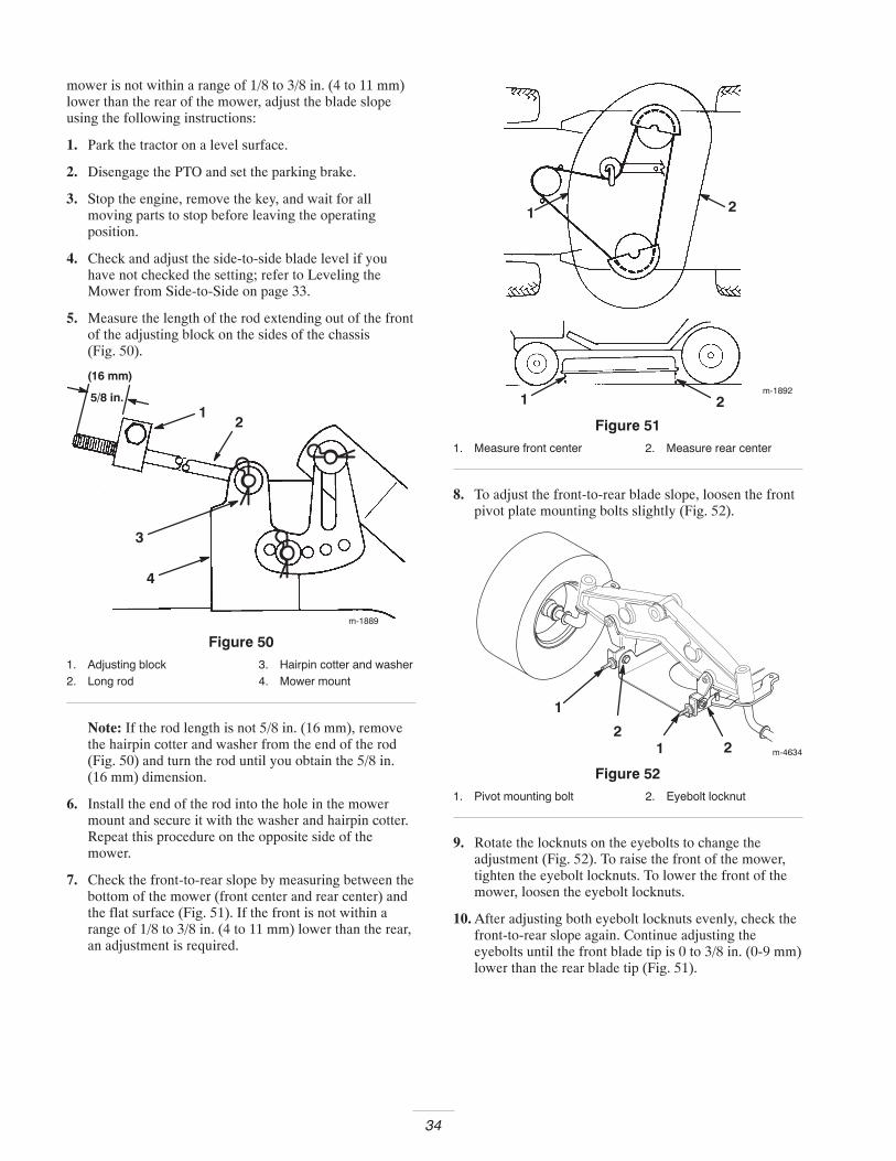
6. Remove the hairpin cotter and washer from the levelingbracket (Fig. 49). To level the blades, reposition theleveling bracket in a different hole and install thewasher and hairpin cotter (Fig. 49). A front hole lowersthe blade height and a rear hole raises its height. Repeatthis procedure on the opposite side of the mower.
m-1805
3
2 1
1
4
Figure 491. Hairpin cotter and washer2. Long rod
3. Leveling bracket4. Mower mount
7. Check the front-to-rear blade slope; refer to Adjustingthe Front-to-Rear Blade Slope on page 33.
Adjusting the Front-to-RearBlade SlopeCheck the front-to-rear blade slope any time you install themower. Before you check the slope, set the air pressure inthe front and rear tires to the recommended inflation; referto Checking the Tire Pressure on page 24. If the front of the
34
mower is not within a range of 1/8 to 3/8 in. (4 to 11 mm)lower than the rear of the mower, adjust the blade slopeusing the following instructions:
1. Park the tractor on a level surface.
2. Disengage the PTO and set the parking brake.
3. Stop the engine, remove the key, and wait for allmoving parts to stop before leaving the operatingposition.
4. Check and adjust the side-to-side blade level if youhave not checked the setting; refer to Leveling theMower from Side-to-Side on page 33.
5. Measure the length of the rod extending out of the frontof the adjusting block on the sides of the chassis(Fig. 50).
5/8 in.
(16 mm)
12
3
4
m-1889
Figure 501. Adjusting block2. Long rod
3. Hairpin cotter and washer4. Mower mount
Note: If the rod length is not 5/8 in. (16 mm), removethe hairpin cotter and washer from the end of the rod(Fig. 50) and turn the rod until you obtain the 5/8 in.(16 mm) dimension.
6. Install the end of the rod into the hole in the mowermount and secure it with the washer and hairpin cotter.Repeat this procedure on the opposite side of themower.
7. Check the front-to-rear slope by measuring between thebottom of the mower (front center and rear center) andthe flat surface (Fig. 51). If the front is not within arange of 1/8 to 3/8 in. (4 to 11 mm) lower than the rear,an adjustment is required.
m-18921 2
1 2
Figure 511. Measure front center 2. Measure rear center
8. To adjust the front-to-rear blade slope, loosen the frontpivot plate mounting bolts slightly (Fig. 52).
m-4634
1
21 2
Figure 521. Pivot mounting bolt 2. Eyebolt locknut
9. Rotate the locknuts on the eyebolts to change theadjustment (Fig. 52). To raise the front of the mower,tighten the eyebolt locknuts. To lower the front of themower, loosen the eyebolt locknuts.
10. After adjusting both eyebolt locknuts evenly, check thefront-to-rear slope again. Continue adjusting theeyebolts until the front blade tip is 0 to 3/8 in. (0-9 mm)lower than the rear blade tip (Fig. 51).
35
11. When the front-to-rear slope is correct, tighten the pivotplate mounting bolts (Fig. 52).
12. When the front-to-rear blade slope is correct, recheckthe side-to-side level of the mower; refer to Levelingthe Mower from Side-to-Side on page 33.
Washing the Underside of theMowerAfter each use, wash the underside of the mower to preventgrass buildup for improved mulch action and clippingdispersal.
1. Park the tractor on a level surface.
2. Disengage the PTO and set the parking brake.
3. Stop the engine, remove the key, and wait for allmoving parts to stop before leaving the operatingposition.
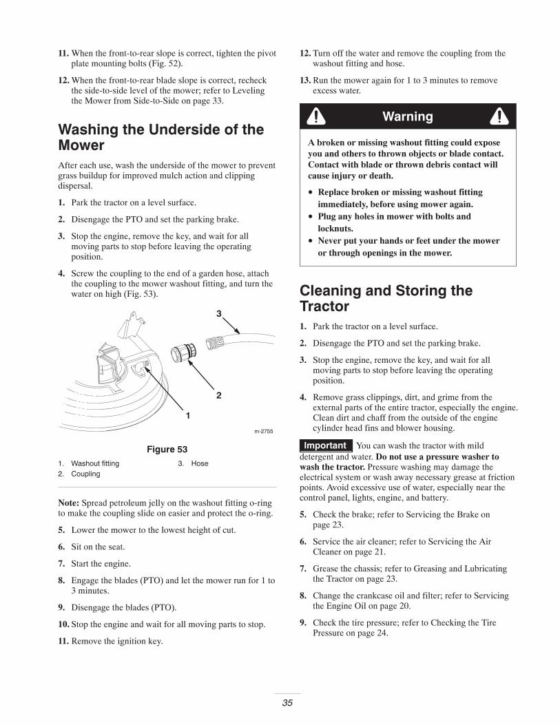
4. Screw the coupling to the end of a garden hose, attachthe coupling to the mower washout fitting, and turn thewater on high (Fig. 53).
1
m-2755
2
3
Figure 531. Washout fitting2. Coupling
3. Hose
Note: Spread petroleum jelly on the washout fitting o-ringto make the coupling slide on easier and protect the o-ring.
5. Lower the mower to the lowest height of cut.
6. Sit on the seat.
7. Start the engine.
8. Engage the blades (PTO) and let the mower run for 1 to3 minutes.
9. Disengage the blades (PTO).
10. Stop the engine and wait for all moving parts to stop.
11. Remove the ignition key.
12. Turn off the water and remove the coupling from thewashout fitting and hose.
13. Run the mower again for 1 to 3 minutes to removeexcess water.
A broken or missing washout fitting could exposeyou and others to thrown objects or blade contact.Contact with blade or thrown debris contact willcause injury or death.
• Replace broken or missing washout fittingimmediately, before using mower again.
• Plug any holes in mower with bolts andlocknuts.
• Never put your hands or feet under the moweror through openings in the mower.
Warning
Cleaning and Storing theTractor1. Park the tractor on a level surface.
2. Disengage the PTO and set the parking brake.
3. Stop the engine, remove the key, and wait for allmoving parts to stop before leaving the operatingposition.
4. Remove grass clippings, dirt, and grime from theexternal parts of the entire tractor, especially the engine.Clean dirt and chaff from the outside of the enginecylinder head fins and blower housing.
Important You can wash the tractor with milddetergent and water. Do not use a pressure washer towash the tractor. Pressure washing may damage theelectrical system or wash away necessary grease at frictionpoints. Avoid excessive use of water, especially near thecontrol panel, lights, engine, and battery.
5. Check the brake; refer to Servicing the Brake onpage 23.
6. Service the air cleaner; refer to Servicing the AirCleaner on page 21.
7. Grease the chassis; refer to Greasing and Lubricatingthe Tractor on page 23.
8. Change the crankcase oil and filter; refer to Servicingthe Engine Oil on page 20.
9. Check the tire pressure; refer to Checking the TirePressure on page 24.
36
10. Prepare the tractor for storage when non-use occursover 30 days. Prepare tractor for storage as follows.
A. Add a petroleum based stabilizer/conditioner to fuelin the tank. Follow the mixing instructions from thestabilizer manufacturer. (1 oz. per gallon). Do notuse an alcohol based stabilizer (ethanol ormethanol).
Note: A fuel stabilizer/conditioner is most effectivewhen mixed with fresh gasoline and used at all times.
B. Run the engine to distribute conditioned fuelthrough the fuel system (5 minutes).
C. Stop the engine, allow it to cool, and drain the fueltank; refer to Draining the Fuel Tank on page 26.
D. Restart the engine and run it until it stops.
E. Choke or prime the engine.
F. Start and run the engine until it will not start. Usethe primer, if equipped on the tractor, several timesto ensure that no fuel remains in the primer system.
G. Dispose of fuel properly. Recycle as per local codes.
Important Do not store stabilizer/conditioned gasolineover 90 days.
11. Remove the spark plug and check its condition; refer toServicing the Spark Plug on page 22. With the sparkplug removed from the engine, pour 2 tablespoons ofengine oil into the spark plug hole. Use the electricstarter to crank the engine and distribute the oil insidethe cylinder. Install the spark plug; refer to Servicingthe Spark Plug on page 22. Do not install the wire onthe spark plug.
12. Disconnect the negative battery cable. Clean the batteryand battery terminals. Check the electrolyte level andcharge it fully; refer to Servicing the Battery onpage 24. Leave the negative battery cable disconnectedfrom the battery during storage.
Important The battery must be fully charged to preventit from freezing and being damaged at temperatures below32°F (0°C). A fully charged battery can be stored duringthe winter season without recharging.
13. Check and tighten all bolts, nuts, and screws. Repair orreplace any part that is damaged or defective.
14. Paint all scratched or bare metal surfaces. Paint isavailable from an Authorized Service Dealer.
15. Store the tractor in a clean, dry garage or storage area.Remove the ignition and KeyChoice keys from themower and keep them in a memorable place. Cover thetractor to protect it and keep it clean.
37
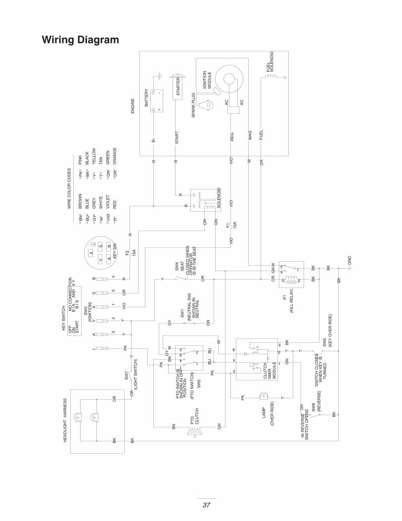
Wiring Diagram
Y
BS
I
GN
BN
TG
N
BU
TT
GY
21
BK
OR
OR4
GN
RR
Y
Y YRB Y
X
GN
W
SW
3
A
GNV
IO
WH
ITE
W
GR
EY
GY
GN
TY
EN
GIN
EB
K
BK
BK
PK
OR
PK
BK
BU
BN
W
Y
3
OR
GY(I
GN
ITIO
N)
BK
BKW
5
VIO
R
KE
Y S
W
VIO
OR
VIO
LET
RE
DRB
U
BN
BLU
E
OR
BK
PK
PT
OC
LUT
CH
PK
AI PK
X
SH
OW
N IN
NE
UT
RA
L
VIO
BK
ORS
WRTAN
YE
LLO
W
WIR
E C
OLO
R C
OD
ES
SW
ITC
H O
PE
NS
IN R
EV
ER
SE
SW
ITC
H C
LOS
ES
WH
EN
KE
Y IS
TU
RN
ED
PT
O S
WIT
CH
ISS
HO
WN
IN O
FF
PO
SIT
ION
OR
HE
AD
LIG
HT
H
AR
NE
SS
GN
D
OF
F
N
O C
ON
NE
CT
ION
ON
B I
A
A
ND
X
YS
TAR
T
B I
S
KE
Y S
WIT
CH
ORVIORGR
EE
N
OR
AN
GE
BR
OW
NP
INK
BLA
CK
(OV
ER
RID
E)
LAM
P SW
6(R
EV
ER
SE
)
1
25
4
7
8
(PT
O S
WIT
CH
)
SW
2SW
7
(LIG
HT
SW
ITC
H)
15A
F1
2
3
5
41
K1
(KIL
L R
ELA
Y)
CLO
SE
D W
HE
NO
PE
RA
TO
RIS
IN T
HE
SE
AT
15A
F2
SW
1
(NE
UT
RA
L S
W)
SE
AT
SW
4
CLU
TC
HN
MIR
MO
DU
LE
1
3
2
4
65
(KE
Y O
VE
R R
IDE
)S
W5
SO
LEN
OID
B+ F
UE
L
STA
RT
AC
RE
G
AC
+–
BA
TT
ER
Y
FU
EL
SO
LEN
OID
MA
G
STA
RT
ER
IGN
ITIO
NM
OD
ULE
SP
AR
K P
LUG

38
TroubleshootingProblem Possible Causes Corrective Action
The starter does not crank. 1. The blades (PTO) areengaged.
1. Shift the blade control (PTO)lever to Disengaged.
2. The parking brake is not on. 2. Set the parking brake.
3. The battery is dead. 3. Charge the battery.
4. The electrical connections arecorroded or loose.
4. Check the electricalconnections for good contact.
5. A fuse is blown. 5. Replace the fuse.
6. A relay or switch is damaged. 6. Contact an Authorized ServiceDealer.
The engine will not start, startsh d f il t k i
1. The operator is not seated. 1. Sit on the seat.ghard, or fails to keep running.
2. The fuel tank is empty. 2. Fill the fuel tank with gasoline.
3. The air cleaner is dirty. 3. Clean or replace the air cleanerelement.
4. The spark plug wire is loose ordisconnected.
4. Install the wire on the sparkplug.
5. The spark plug is pitted, fouled,or the gap is incorrect.
5. Install a new, correctly-gappedspark plug.
6. The choke is not closing. 6. Adjust the throttle cable.
7. There is dirt in the fuel filter. 7. Replace the fuel filter.
8. The idle speed is too low or themixture is incorrect.
8. Adjust the carburetor idlespeed and idle mixture.
9. Dirt, water, or stale fuel is in thefuel system.
9. Contact an Authorized ServiceDealer.
The engine overheats. 1. The engine load is excessive. 1. Shift into lower gear to reduceground speed.
2. The oil level in the crankcase islow.
2. Add oil to the crankcase.
3. The cooling fins and airpassages under the engineblower housing are plugged.
3. Remove the obstruction fromthe cooling fins and airpassages.

39
Problem Corrective ActionPossible Causes
The engine loses power. 1. The engine load is excessive. 1. Shift into lower gear to reduceground speed.
2. The air cleaner is dirty. 2. Clean the air cleaner element.
3. The oil level in the crankcase islow.
3. Add oil to the crankcase.
4. The cooling fins and airpassages under the engineblower housing are plugged.
4. Remove the obstruction fromthe cooling fins and airpassages.
5. The spark plug is pitted, fouled,or the gap is incorrect.
5. Install a new, correctly-gappedspark plug.
6. The vent hole in the fuel cap isplugged.
6. Clean or replace the fuel cap.
7. There is dirt in the fuel filter. 7. Replace the fuel filter.
8. Dirt, water, or stale fuel is in thefuel system.
8. Contact an Authorized ServiceDealer.
There is abnormal vibration. 1. The cutting blades are bent orunbalanced.
1. Install a new cutting blades.
2. The blade mounting bolt isloose.
2. Tighten the blade mountingbolt.
3. The engine mounting bolts areloose.
3. Tighten the engine mountingbolts.
4. There is a loose engine pulley,idler pulley, or blade pulley.
4. Tighten the appropriate pulley.
5. The engine pulley is damaged. 5. Contact an Authorized ServiceDealer.
The blades does not rotate. 1. The blade drive belt is worn,loose, or broken.
1. Install a new blade drive belt.
2. The blade drive belt is off of thepulley.
2. Install a blade drive belt andcheck the idler pulley and beltguides for the correct position.
The tractor does not drive. 1. The drive control is in the Pushposition.
2. The traction belt is worn, loose,or broken.
1. Move the drive control to theOperate position.
2. Contact an Authorized ServiceDealer.
3. The traction belt is off of thepulley.
3. Contact an Authorized ServiceDealer.
The cutting height is uneven. 1. The tire pressure is incorrect. 1. Set the tire pressure.g g
2. The mower is not level. 2. Level the mower fromside-to-side and front-to-rear.
3. The underside of the mower isdirty.
3. Clean the underside of themower.

ConsumerLawn TractorsandLawn & GardenTractors
The Toro Total Coverage GuaranteeA Two-Year Full Warranty
(Limited Warranty for Commercial Use)
Conditions and Products CoveredThe Toro Company and its affiliate, Toro Warranty Company,pursuant to an agreement between them, jointly promise to repairany Toro Product used for normal residential purposes* if defectivein materials or workmanship. The following time periods applyfrom the date of purchase:
Products Warranty Period
• All Products and Attachments 2 year full warranty• 300, 400XT, and 5xi Series:
Frame 5 year full warrantyFront Axle 5 year full warrantyDrive Shaft (5xi Series Only) 5 year full warranty
• All Batteries 1 year full warranty
This warranty covers both the cost of parts and labor, andtransportation within a fifteen mile radius of the servicing dealer.
This warranty applies to all consumer Lawn Tractors, Lawn andGarden Tractors, and their attachments.
* Normal residential purposes means use of the product on thesame lot as your home. Use at more than one location isconsidered commercial use, and the commercial use warrantywould apply.
Limited Warranty for Commercial UseToro Consumer Products and attachments used for commercial,institutional, or rental use are warranted against defects inmaterials or workmanship for the following time periods from thedate of purchase:
Products Warranty Period
• 300, 400XT, and 5xi Series:Liquid Cooled Gas Engines 1 year limited warrantyAir Cooled Gas and DieselEngines
2 year limited warranty
All other items 1 year limited warranty• All other Lawn Tractors and
Lawn & Garden Tractors90 day limited warranty
Instructions for Obtaining Warranty ServiceIf you think that your Toro Product contains a defect in materials orworkmanship, follow this procedure:
1. Contact any Toro Authorized or Master Service Dealer toarrange service at their dealership. To locate a dealerconvenient to you, refer to the Yellow Pages of your telephonedirectory (look under “Lawn Mowers”) or access our website atwww.Toro.com. U.S. Customers may also call toll free:866–854–9035 to use our 24-hour Toro dealer locator system.
2. Bring the product and your proof of purchase (sales receipt) tothe Service Dealer.
If for any reason you are dissatisfied with the Service Dealer’sanalysis or with the assistance provided, contact us at:
Customer Care Department, Consumer DivisionToro Warranty Company8111 Lyndale Avenue SouthBloomington, MN 55420-1196Toll Free: 866–854–8930 (U.S. customers)Toll Free: 866–854–9033 (Canada customers)
Owner ResponsibilitiesYou must maintain your Toro Product by following the maintenanceprocedures described in the operator’s manual. Such routinemaintenance, whether performed by a dealer or by you, is at yourexpense.
Items and Conditions Not CoveredThere is no other express warranty except for special emissionsystem coverage on some products. This express warranty doesnot cover:
• Cost of regular maintenance service or parts, such as filters,fuel, lubricants, tune-up parts, blade sharpening, brake andclutch adjustments.
• Any product or part which has been altered or misused orrequired replacement or repair due to normal wear, accidents,or lack of proper maintenance.
• Repairs necessary due to improper fuel, contaminants in thefuel system, or failure to properly prepare the fuel system priorto any period of non-use over three months.
• Pickup and delivery charges for distances beyond a fifteenmile radius from an Authorized Toro Service Dealer.
All repairs covered by this warranty must be performed by anAuthorized Toro Service Dealer using Toro approved replacementparts.
General ConditionsRepair by an Authorized Toro Service Dealer is your sole remedyunder this warranty.
Neither The Toro Company nor Toro Warranty Company is liablefor indirect, incidental or consequential damages in connectionwith the use of the Toro Products covered by this warranty,including any cost or expense of providing substitute equipment orservice during reasonable periods of malfunction or non-usepending completion of repairs under this warranty.
Some states do not allow exclusions of incidental or consequentialdamages, or limitations on how long an implied warranty lasts, sothe above exclusions and limitations may not apply to you.
This warranty gives you specific legal rights, and you may alsohave other rights which vary from state to state.
Countries Other than the United States or CanadaCustomers who have purchased Toro products exported from the United States or Canada should contact their Toro Distributor (Dealer)to obtain guarantee policies for your country, province, or state. If for any reason you are dissatisfied with your Distributor’s service orhave difficulty obtaining guarantee information, contact the Toro importer. If all other remedies fail, you may contact us at Toro WarrantyCompany.
Part No. 374-0045 Rev. B
Related Documents