WHEATSTONE BRIDGE OVERVIEW Micro Pressure Sensors & The Wheatstone Bridge Learning Module

Welcome message from author
This document is posted to help you gain knowledge. Please leave a comment to let me know what you think about it! Share it to your friends and learn new things together.
Transcript

WHEATSTONE BRIDGE OVERVIEW
Micro Pressure Sensors & The Wheatstone Bridge Learning Module
This Wheatstone Bridge Overview provides information on the electronic circuitry of a Wheatstone bridge. This overview will help you to understand how a Wheatstone bridge is used for sensing changes in pressure when used in a micro pressure sensor.
Unit Overview
v Define the variable components of the Wheatstone bridge
v Describe how the Wheatstone bridge works
Objectives
Introduction to Wheatstone Bridge
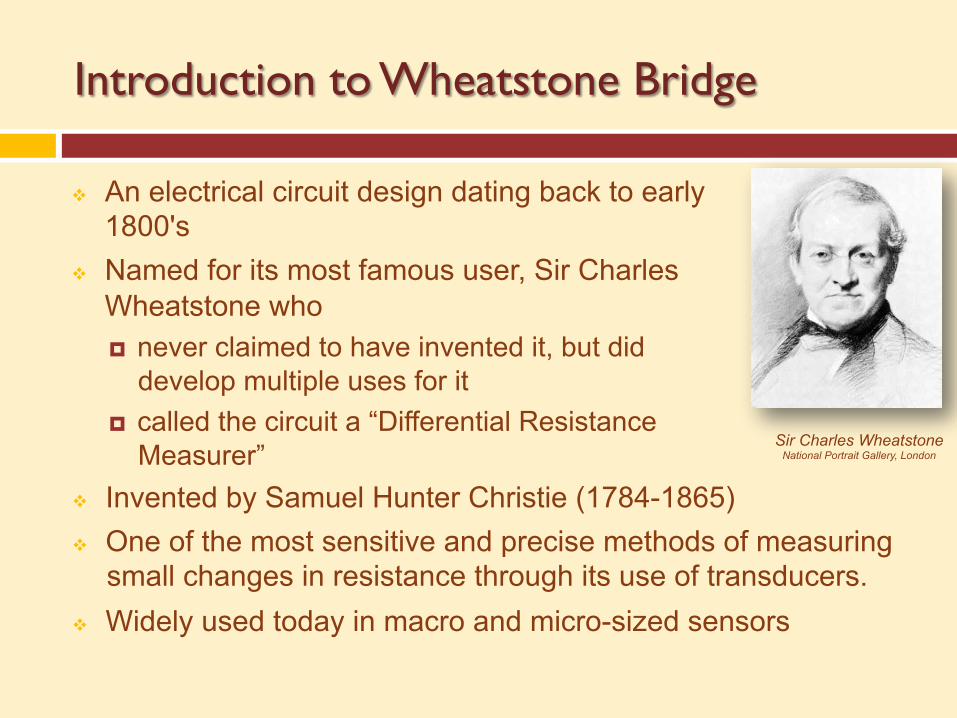
v An electrical circuit design dating back to early 1800's
v Named for its most famous user, Sir Charles Wheatstone who ¤ never claimed to have invented it, but did
develop multiple uses for it ¤ called the circuit a “Differential Resistance
Measurer” Sir Charles Wheatstone
National Portrait Gallery, London
v Invented by Samuel Hunter Christie (1784-1865) v One of the most sensitive and precise methods of measuring
small changes in resistance through its use of transducers. v Widely used today in macro and micro-sized sensors
The Wheatstone Bridge
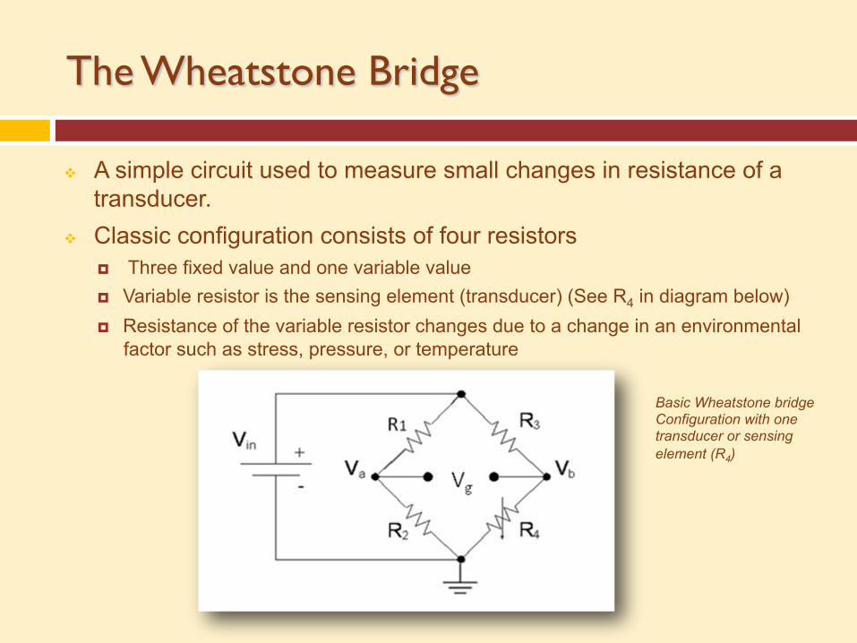
v A simple circuit used to measure small changes in resistance of a transducer.
v Classic configuration consists of four resistors ¤ Three fixed value and one variable value ¤ Variable resistor is the sensing element (transducer) (See R4 in diagram below) ¤ Resistance of the variable resistor changes due to a change in an environmental
factor such as stress, pressure, or temperature
Basic Wheatstone bridge Configuration with one transducer or sensing element (R4)

The Wheatstone Bridge – 2 Variable Resistors
v Maximized effect of the input v Provides the largest voltage variation as a function of the changing input v Has 2 fixed resistors & 2 variable resistors (transducers/sensing elements) v DC voltage source (Vin) such as a battery or power supply v Output voltage (Vg) represents the difference in the transducers’ resistance
values to the reference resistance of the bridge configuration v Design allows for the measurement of very small changes in the environmental
factor that affects the transducers while greatly suppressing electrical noise and thus improving the “signal to noise ratio”
Basic Wheatstone Bridge Configuration with two transducers
or sensing elements (R1 and R4)
Background Circuits
v There are three concepts discussed here which are needed to understand Wheatstone bridges: ¤ Resistor voltage dividers ¤ Ohm’s Law (I=V/R) ¤ Kirchoff’s Circuit Laws
Resistor Voltage Dividers
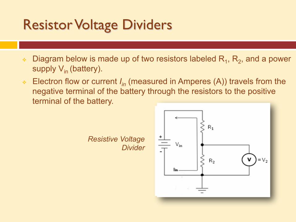
v Diagram below is made up of two resistors labeled R1, R2, and a power supply Vin (battery).
v Electron flow or current Iin (measured in Amperes (A)) travels from the negative terminal of the battery through the resistors to the positive terminal of the battery.
Resistive Voltage Divider
Ohm’s Law
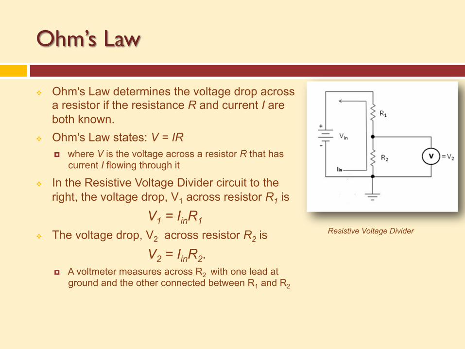
v Ohm's Law determines the voltage drop across a resistor if the resistance R and current I are both known.
v Ohm's Law states: V = IR ¤ where V is the voltage across a resistor R that has
current I flowing through it
v In the Resistive Voltage Divider circuit to the right, the voltage drop, V1 across resistor R1 is
V1 = IinR1 v The voltage drop, V2 across resistor R2 is
V2 = IinR2. ¤ A voltmeter measures across R2 with one lead at
ground and the other connected between R1 and R2
Resistive Voltage Divider
Ohm’s Law cont…
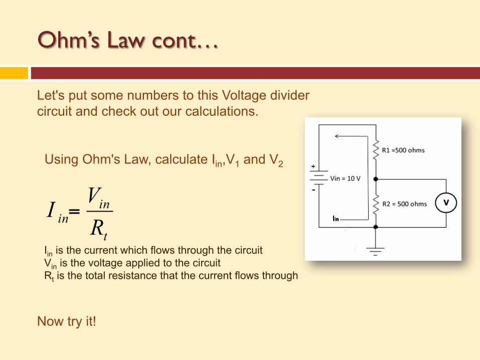
Let's put some numbers to this Voltage divider circuit and check out our calculations.
Using Ohm's Law, calculate Iin,V1 and V2
Now try it!
t
inin RVI =
Iin is the current which flows through the circuit Vin is the voltage applied to the circuit Rt is the total resistance that the current flows through
Ohm’s Law cont…
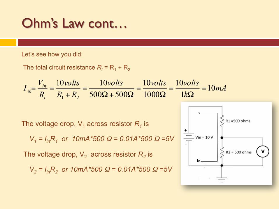
Let’s see how you did:
The total circuit resistance Rt = R1 + R2
The voltage drop, V1 across resistor R1 is
V1 = IinR1 or 10mA*500 Ω = 0.01A*500 Ω =5V
The voltage drop, V2 across resistor R2 is
V2 = IinR2 or 10mA*500 Ω = 0.01A*500 Ω =5V
mAkvoltsvoltsvolts
RRvolts
RVIt
inin 10
110
100010
5005001010
21
=Ω
=Ω
=Ω+Ω
=+
==
Kirchoff ’s Law
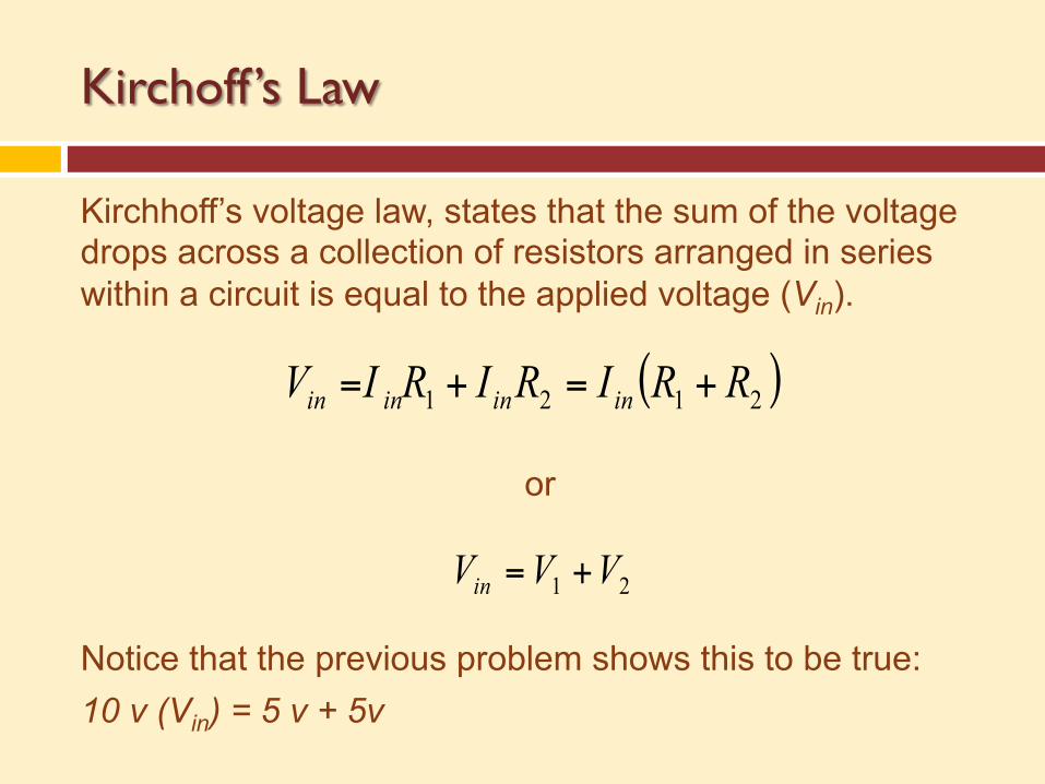
Kirchhoff’s voltage law, states that the sum of the voltage drops across a collection of resistors arranged in series within a circuit is equal to the applied voltage (Vin). Notice that the previous problem shows this to be true: 10 v (Vin) = 5 v + 5v
( )2121 RRIRIRIV inininin +=+=
21 VVVin +=
or
Kirchoff ’s Law cont…
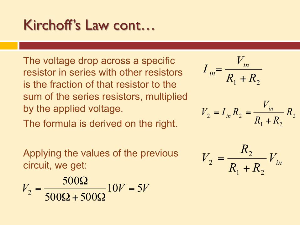
The voltage drop across a specific resistor in series with other resistors is the fraction of that resistor to the sum of the series resistors, multiplied by the applied voltage. The formula is derived on the right. Applying the values of the previous circuit, we get:
21 RRV
I inin +=
2
2122 R
RRV
RIV inin +
==
inVRR
RV
21
22 +=
VVV 510500500
5002 =
Ω+Ω
Ω=
Kirchoff ’s Law cont…
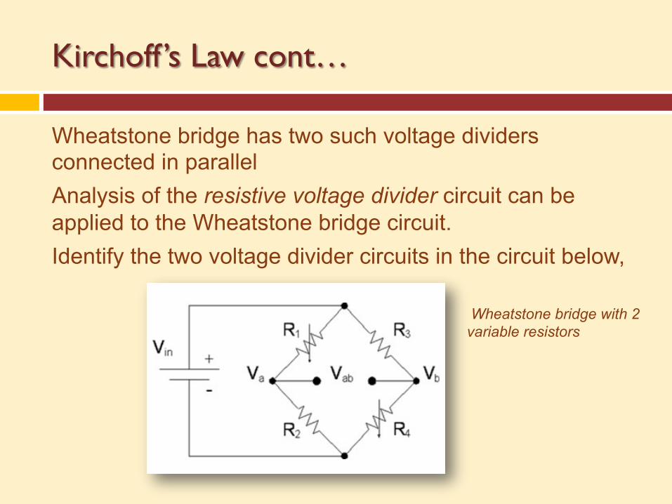
Wheatstone bridge has two such voltage dividers connected in parallel Analysis of the resistive voltage divider circuit can be applied to the Wheatstone bridge circuit. Identify the two voltage divider circuits in the circuit below,
Wheatstone bridge with 2 variable resistors
Wheatstone Bridge and Difference Voltage
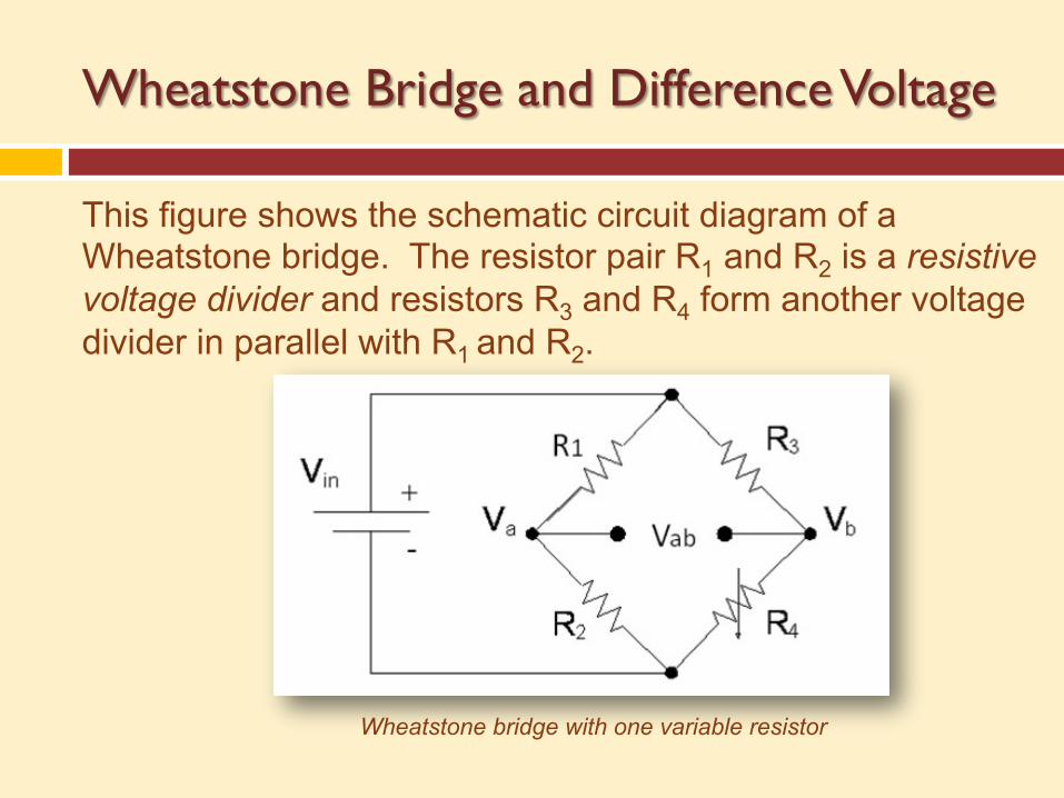
This figure shows the schematic circuit diagram of a Wheatstone bridge. The resistor pair R1 and R2 is a resistive voltage divider and resistors R3 and R4 form another voltage divider in parallel with R1 and R2.
Wheatstone bridge with one variable resistor
Wheatstone Bridge and Difference Voltage cont…
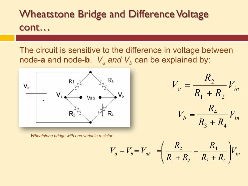
The circuit is sensitive to the difference in voltage between node-a and node-b. Va and Vb can be explained by:
Wheatstone bridge with one variable resistor
ina VRR
RV
21
2
+=
inb VRR
RV43
4
+=
inabba VRR
RRR
RVVV ⎟⎟⎠
⎞⎜⎜⎝
⎛
+−
+==−
43
4
21
2
Wheatstone Bridge and Difference Voltage cont…
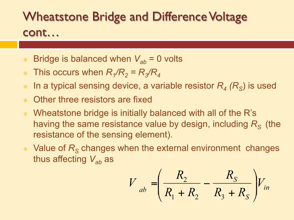
v Bridge is balanced when Vab = 0 volts v This occurs when R1/R2 = R3/R4 v In a typical sensing device, a variable resistor R4 (RS) is used v Other three resistors are fixed v Wheatstone bridge is initially balanced with all of the R’s
having the same resistance value by design, including RS (the resistance of the sensing element).
v Value of RS changes when the external environment changes thus affecting Vab as
inS
Sab
VRR
RRR
RV ⎟⎟⎠
⎞⎜⎜⎝
⎛
+−
+=
321
2
One Variable Resistor
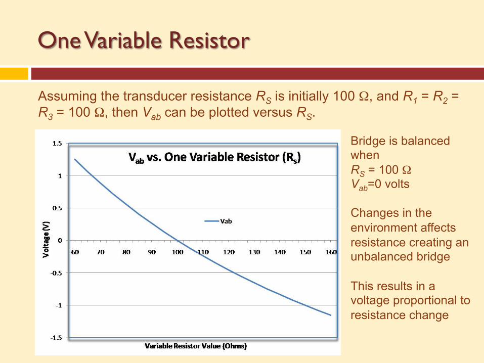
Assuming the transducer resistance RS is initially 100 Ω, and R1 = R2 = R3 = 100 Ω, then Vab can be plotted versus RS.
Bridge is balanced when RS = 100 Ω Vab=0 volts Changes in the environment affects resistance creating an unbalanced bridge This results in a voltage proportional to resistance change
Two Variable Resistors
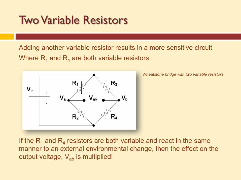
Adding another variable resistor results in a more sensitive circuit Where R1 and R4 are both variable resistors If the R1 and R4 resistors are both variable and react in the same manner to an external environmental change, then the effect on the output voltage, Vab is multiplied!
Wheatstone bridge with two variable resistors
Two Variable Resistors
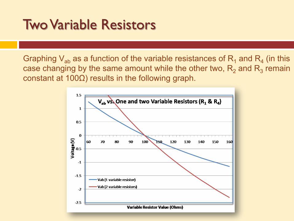
Graphing Vab as a function of the variable resistances of R1 and R4 (in this case changing by the same amount while the other two, R2 and R3 remain constant at 100Ω) results in the following graph.
Wheatstone Bridge as a Micro Pressure Sensor
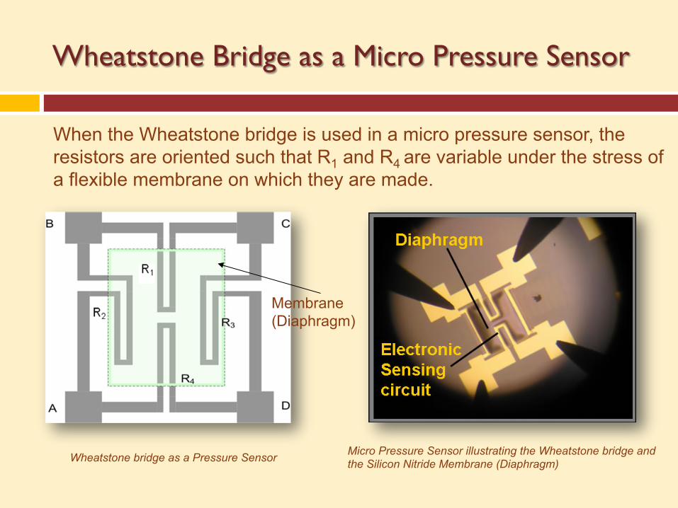
When the Wheatstone bridge is used in a micro pressure sensor, the resistors are oriented such that R1 and R4 are variable under the stress of a flexible membrane on which they are made.
Wheatstone bridge as a Pressure Sensor Micro Pressure Sensor illustrating the Wheatstone bridge and the Silicon Nitride Membrane (Diaphragm)
Membrane (Diaphragm)
Calibration
v To calibrate a Wheatstone bridge as a pressure transducer, a series of known pressure differences is applied to the sensing element(s).
v The output voltage (Vab) is measured using a voltmeter
v Vab versus pressure is plotted v When an unknown pressure is applied and the output
voltage read, the calibration curve of Vab vs. Pressure can be used to determine the actual pressure.
v Wheatstone bridge is a simple circuit used to measure transducer responses by measuring changes in voltage.
v Basic circuit analysis is used to determine the resistance when the bridge is balanced.
v Any changes in transducer resistance cause the bridge to be unbalanced providing a voltage roughly proportional to the change in resistance and corresponding to the change in pressure.
v A voltmeter measures the output of the Wheatstone bridge which can be equated to a corresponding pressure.
v In a micro pressure sensor where the Wheatstone bridge is the sensing circuit, its output can be amplified and processed to send information or to initiate a mechanical response.
Summary

Made possible through grants from the National Science Foundation Department of Undergraduate Education #0830384, 0902411, and 1205138.
Any opinions, findings and conclusions or recommendations expressed in this material are those of the authors and creators, and do not necessarily
reflect the views of the National Science Foundation.
Southwest Center for Microsystems Education (SCME) NSF ATE Center © 2012 Regents of the University of New Mexico
Content is protected by the CC Attribution Non-Commercial Share Alike
license.
Website: www.scme-nm.org
Acknowledgements
Revised Feb 2017
Related Documents


